aluminium modular ceiling system
TRANSCRIPT

Technical Manual (Installation Guide)
ALUMINIUM MODULAR CEILING SYSTEM
USGBoral.com Interior Linings Ceilings Cornice Finishes Systems Solutions

Systems Solutions
CEILING SYSTEM 1
Introduction 1
Applications 1
Features and Benefits 1
Load Tables 2
Configuration A (Preferred Method) 3
Configuration B 3
SEISMIC DESIGN 4
Introduction 4
General Layout 5
Suspension Hangers 6
Main Runners 6
Cross Runners 7
Perimeter Wall Angles 7
C-Splines 7
SEISMIC ACCESSORIES AND INSTALLATION DETAILS 9
ASC8 Seismic Clip 9
Perimeter Fixing 9
Free/Floating Connection 11
Seismic Breaks 12
Installation notes 12
Back Bracing 14
Installation of Perimeter Tiles 15
SEISMIC CEILING INSTALLATION ORDER PROCESS 16
Installation Notes 16
COMPONENTS LIST 18
ACCESSORIES LIST 19
TABLE OF CONTENTS
All works undertaken to prescribe the use of or to install USG Boral’s products and systems must be performed by experienced and, where required by applicable laws, appropriately licensed personnel. USG Boral’s products and systems must be installed in accordance with USG Boral’s installation manual, Systems+, and any other product or system specific literature issued by USG Boral. If installation works are not performed in compliance with such product literature, by experienced and licensed personnel, or are incorrectly performed by experienced or licensed personnel, there is a serious risk that the works, application and performance of the relevant system or products will be compromised, which could result in property damage, injury or death.
All personnel who undertake works to install USG Boral’s products and systems must comply with all applicable health and safety laws, including wearing appropriate personal protection equipment. If personnel do not comply with applicable health and safety laws, including by not wearing appropriate personal protection equipment, there is a serious risk of injury or death.
All of USG Boral’s products and systems must only be used for the uses identified in this document (and any other product or system specific literature issued by USG Boral from time to time). Before prescribing or using any USG Boral product or system for any other use, you must contact USG Boral.
All recommended component parts for USG Boral’s products and systems should be used and not substituted for other products. If component parts are substituted, there is a serious risk that the works, application and performance of the relevant system or products will be compromised, which could result in property damage, injury or death.
IntroductionUSG Boral’s Aluminium Modular Grid System comes in a top hat profile; this suspended ceiling system is suitable for premium office developments (commonly known as ‘A Grade’ office buildings) or general offices.
The suspension system is composed of a grid of structural components, that provides support for the ceiling tiles and comes in three module sizes of:
• 1200mm x 1200mm (1200 module)
• 1350mm x 1350mm (1350 module)
• 1500mm x 1500mm (1500 module)
Each module can accommodate up to 3, 4 or 5 tiles depending on the configuration specified by the Architect (Figure 1). The centre profile of the Main and Cross Runners appear continuous in both directions in this ceiling system. The Main Runners are the primary support. Abutting sections of Main Runners are joined with connector plates to ensure the members continuity. The Cross Runners have interlocking tab ends that simplify installation and allow it to be removed and replaced without damage to the components. The ceiling tiles used may need to be removed for access to ventilating systems or other services such as electrical or fire sprinkler systems within the plenum space. Any one or more tiles in the module may be readily removed without use of special tools for access to the plenum area, and may, thereafter, just as readily be replaced.
The modules can be fitted with either Mineral Fibre or Metal Ceiling Tiles. Light fittings are commonly fitted in the centre of the module. USG Boral offer a range of Mineral Fibre and Metal Ceiling Tiles in various sizes, face patterns and perforations to suit project specific designs. Metal Tiles can be manufactured with penetrations to fit service requirements. Contact USG Boral for more information*.
*Lead times may apply
Applications• A Grade Office Buildings
• General Offices
• Banks
• Reception / Lobbies
• Board Rooms
• Education Facilities
• Conference Centres
Features and Benefits• Very clean appearance, unobtrusive with minimal
exposed grid
• Grid sections are demountable to install full height partitions
• Tiles are independent of each other and can easily be removed without the use of tools
• Installation is fast, easy and neat with a range of interlocking accessories
• Can be disassembled, ensuring re-use of components
• This system has been tested to ASTM C635/ C635M-17 and ASTM E3090/E3090M-17: Ensures appropriate load carrying capabilities for USG Boral’s ceiling tiles
• Compliance: Grid system can be designed to comply with earthquake requirements of AS 1170.4, NZS 1170.5 and comply with AS/NZS 2785 Suspended Ceilings – Design and Installation
• Warranty: Available for all products when installed in accordance with USG Boral specifications
CEILING SYSTEM
BVT has been engaged by USG Boral to conduct a compliance assessment of USG Boral’s Aluminium Modular Ceiling System and associated documentation to AS/NZS 2785:2020. BVT has completed a review on the following:
• USG Boral testing of Aluminium Modular Ceiling
• Generic layout of Aluminium Modular Ceiling
• Aluminium Modular Ceiling Installation Guide
• USG Boral Aluminium Modular Ceiling Seismic Design
Based on our review of the documentation provided by USG Boral the ceiling system fully complies with AS/NZS 2785:2020. (Subject to specific project design and installation in accordance with AS/NZS 2785:2020)
17-September-2019
BVT Engineering Professional Services
1
Aluminium Modular Ceiling System
CEILING SYSTEM
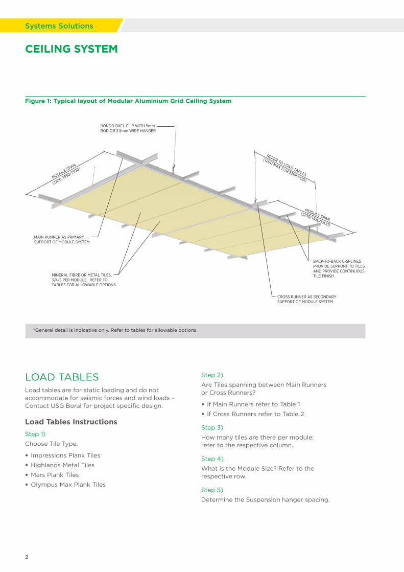
MAIN RUNNER AS PRIMARY SUPPORT OF MODULE SYSTEM
MINERAL FIBRE OR METAL TILES,3/4/5 PER MODULE. REFER TO TABLES FOR ALLOWABLE OPTIONS
MODULE SPAN
(1200/1350/15
00)
MODULE SPAN(1200/1350/1500)
RONDO DXCL CLIP WITH 5mmROD OR 2.5mm WIRE HANGER
BACK-TO-BACK C-SPLINESPROVIDE SUPPORT TO TILES AND PROVIDE CONTINUOUS TILE FINISH
CROSS RUNNER AS SECONDARYSUPPORT OF MODULE SYSTEM
REFER TO LOAD TABLES
(1200 MAX FOR 5MM ROD)
Figure 1: Typical layout of Modular Aluminium Grid Ceiling System
*General detail is indicative only. Refer to tables for allowable options.
LOAD TABLES Load tables are for static loading and do not accommodate for seismic forces and wind loads – Contact USG Boral for project specific design.
Load Tables Instructions
Step 1)
Choose Tile Type:
• Impressions Plank Tiles
• Highlands Metal Tiles
• Mars Plank Tiles
• Olympus Max Plank Tiles
Step 2)
Are Tiles spanning between Main Runners or Cross Runners?
• If Main Runners refer to Table 1
• If Cross Runners refer to Table 2
Step 3)
How many tiles are there per module: refer to the respective column.
Step 4)
What is the Module Size? Refer to the respective row.
Step 5)
Determine the Suspension hanger spacing.
2
Systems Solutions

Maximum Suspension Hanger spacing (mm)
Additional services (Lighting, insulation etc.) = 3.0 kg/m2 or less
No. of Panels / Configuration**
Tile Type† Module Size 3 Tiles per Module 4 Tiles per Module 5 Tiles per Module
Impressions Plank Tiles
Highlands Metal Tiles
Mars Plank Tiles
Olympus Max Plank Tiles
1200mm x 1200mm ≤1200 ≤1200 ≤1200
1350mm x 1350mm NA NA ≤1200
1500mm x 1500mm NA NA ≤900
CEILING SYSTEM
LOAD TABLE 1: PREFERRED METHOD
LOAD TABLE 2
Maximum Suspension Hanger spacing (mm)*
Additional services (Lighting, insulation etc.) = 3.0 kg/m2 or less
No. of Panels / Configuration**
Tile Type† Module Size 3 Tiles per Module 4 Tiles per Module 5 Tiles per Module
Impressions Plank Tiles
Highlands Metal Tiles
Mars Plank Tiles
Olympus Max Plank Tiles
1200mm x 1200mm ≤1200 ≤1200 ≤1200
1350mm x 1350mm ≤1200 ≤1200 ≤1200
1500mm x 1500mm ≤900 ≤900 ≤900
* This table is only applicable for 5mm rod hangers. If using 2.5mm wire hanger, contact USG Boral.
** Configuration A, as shown, spans tiles between Main Runners (spline perpendicular to Main Runners)
† For tile weights greater than 5.6 kg/m2 refer to USG Boral
* Configuration B, as shown, spans tiles between Cross Runners (spline perpendicular to Cross Runners)
** For Tiles greater than 5.6 kg/m2 refer to USG Boral
† For tile weights greater than 5.6 kg/m2 refer to USG Boral
Configuration A
Configuration B
Main Runner
Main Runner
Cross Runner
Cross Runner
Spline
Spline
Load tables are for static loading and do not accommodate for seismic forces
3
Aluminium Modular Ceiling System

IntroductionSeismic compliance refers to the use of approved systems and designs that meet the seismic design requirements of a building project to provide life safety to occupants and maintain building function during and after an earthquake. Non-structural components often represent a high percentage of a project’s capital investment. Failure of these components in an earthquake has the potential to cause harm, block egress, impede rescue efforts and can disrupt the building’s function. The basic objectives of seismic design for non-structural components are to provide life safety, minimise property loss and prevent functional loss.
Seismic design solutions include:
Method 1: Perimeter Restrained Ceilings
a) Perimeter fixing on adjacent edges
Ceiling is fixed to the perimeter on two adjacent sides and a seismic sliding joint is used on the opposite sides. Lateral loads are transferred from the ceiling to the perimeter support (wall/bulkhead/partition) through the perimeter fixing (Figure 2).
b) Perimeter fixing on more than two edges (with seismic breaks)
To accommodate installation of ceilings with longer spans, the ceiling is split up into smaller sections by means of seismic breaks. The ceiling can then be fixed to the perimeter on opposite sides. Lateral loads are transferred through perimeter fixings to the main structure. Seismic breaks can be constructed in one or two directions (Figure 3). Seismic breaks in ceilings may also be required at the location of movement joints or seismic breaks in the main structure.
Method 2: Back Braced Ceilings
a) Back Bracing in two directions
In this method, the ceiling is restrained to the structure above with a series of back braces. Floating connections are required around the entire perimeter, as the ceiling may not be braced to both the structure above and the perimeter. Bracing shall be placed at 45° (nominal) angles in both directions as shown in Figure 4 and in accordance with manufacturers specifications.
b) Back Bracing in one direction
Bracing in one direction is used in long corridors and rooms. In this method, the ceiling is restrained to the structure above with a series of back braces only in one direction. A floating connection is required on perimeters as shown in Figure 5, as the ceiling may not be braced to both the structure above and the perimeter. Bracing shall be placed at 45° (nominal) angles in one direction as shown in Figure 5 and in accordance with manufacturers specifications.
SEISMIC DESIGN
Figure 2: Perimeter fixing on adjacent edges
Figure 3: Perimeter fixing on more than two edges
Fixed
Float
Ceiling
FixedFixe
d
Seis
mic
bre
ak
Fixed
Fixed
Ceiling
FixedFixe
d Seis
mic
bre
ak
Seismic break
Fixed
Ceiling
Float
Float
Fixe
d
4
Systems Solutions
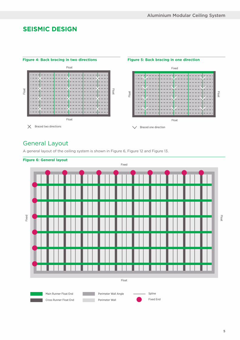
Figure 4: Back bracing in two directions Figure 5: Back bracing in one direction
Figure 6: General layout
Float
Float
FloatFloa
t
Braced two directions
Fixed
Float
FloatFloa
tBraced one direction
General LayoutA general layout of the ceiling system is shown in Figure 6, Figure 12 and Figure 13.
Main Runner Float End
Fixed
Float
Fixe
d Float
Cross Runner Float End
SplinePerimeter Wall Angle
Perimeter Wall Fixed End
SEISMIC DESIGN
5
Aluminium Modular Ceiling System
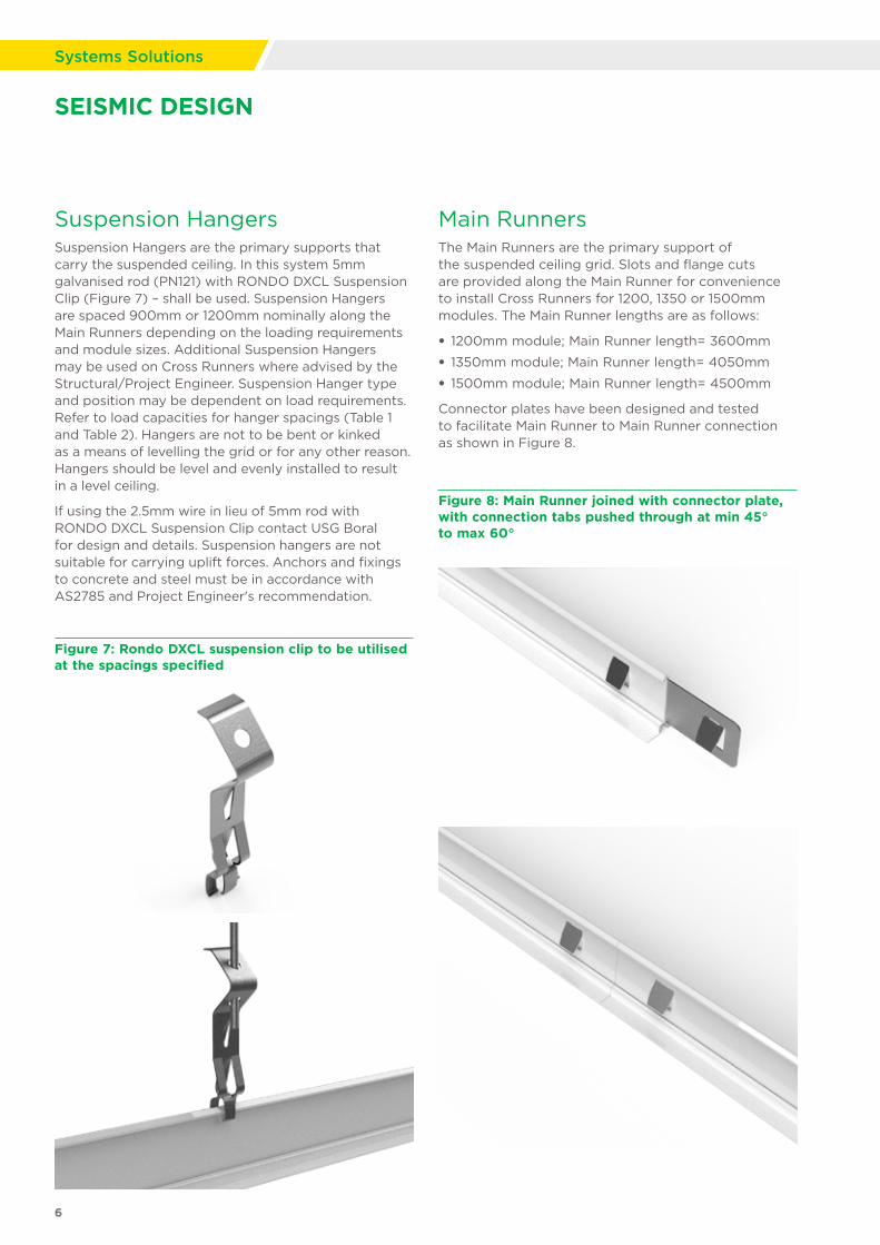
Suspension Hangers Suspension Hangers are the primary supports that carry the suspended ceiling. In this system 5mm galvanised rod (PN121) with RONDO DXCL Suspension Clip (Figure 7) – shall be used. Suspension Hangers are spaced 900mm or 1200mm nominally along the Main Runners depending on the loading requirements and module sizes. Additional Suspension Hangers may be used on Cross Runners where advised by the Structural/Project Engineer. Suspension Hanger type and position may be dependent on load requirements. Refer to load capacities for hanger spacings (Table 1 and Table 2). Hangers are not to be bent or kinked as a means of levelling the grid or for any other reason. Hangers should be level and evenly installed to result in a level ceiling.
If using the 2.5mm wire in lieu of 5mm rod with RONDO DXCL Suspension Clip contact USG Boral for design and details. Suspension hangers are not suitable for carrying uplift forces. Anchors and fixings to concrete and steel must be in accordance with AS2785 and Project Engineer's recommendation.
Figure 7: Rondo DXCL suspension clip to be utilised at the spacings specified
Figure 8: Main Runner joined with connector plate, with connection tabs pushed through at min 45° to max 60°
Main RunnersThe Main Runners are the primary support of the suspended ceiling grid. Slots and flange cuts are provided along the Main Runner for convenience to install Cross Runners for 1200, 1350 or 1500mm modules. The Main Runner lengths are as follows:
• 1200mm module; Main Runner length= 3600mm
• 1350mm module; Main Runner length= 4050mm
• 1500mm module; Main Runner length= 4500mm
Connector plates have been designed and tested to facilitate Main Runner to Main Runner connection as shown in Figure 8.
SEISMIC DESIGN
6
Systems Solutions

SEISMIC DESIGN
Perimeter Wall AnglesWall angles (Figure 10) are typically installed around the perimeter of suspended ceilings. There are three wall angle options available for the Modular grid system:
• L-shaped wall angle
• Shadowline wall angle
• Seismic Shadowline wall angle
The Seismic Shadowline wall angle is designed and tested for seismic applications. It must be used in conjunction with the ASC8 clip.
Figure 10:
Figure 11: Steel C-Spline (Shown back-to-back in Tile)
C-Splines C-Splines provide support to the Mineral Fibre Tiles. They are inserted into the BESK profiled edge of the Mineral Fibre Tiles (Figure 11). C-Splines sit back to back of each other spanning between Main Runners (Preferred method; Configuration A; Table 1 ) or span between Cross Runners (Configuration B; Table 2). C-Splines come in the following lengths to suit varying module sizes:
• 1200mm module system; Spline length= 1185mm
• 1350mm module system; Spline length= 1385mm
• 1500mm module system; Spline length= 1485mm
Figure 9: Cross Runners intersecting through Main Runner slot
Cross RunnersThe Cross Runners (Figure 9) act as the secondary support of the suspended ceiling grid and connect through the Main Runners. The lengths of the Cross Runners are as below:
• 1200mm in the 1200 module
• 1350mm in the 1350 module
• 1500mm in the 1500 module
a) Shadowline Wall Angle
b) Generic Wall Angle
c) Seismic Shadowline Wall Angle
7
Aluminium Modular Ceiling System
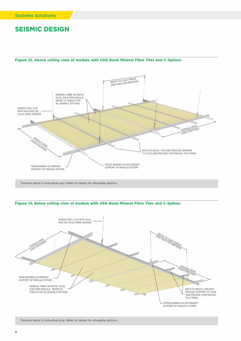
Figure 12: Above ceiling view of module with USG Boral Mineral Fibre Tiles and C-Splines
Figure 13: Below ceiling view of module with USG Boral Mineral Fibre Tiles and C-Splines
MINERAL FIBRE OR METAL TILES, 3/4/5 PER MODULE REFER TO TABLES FOR ALLOWABLE OPTIONS
RONDO DXCL CLIP WITH 5mm ROD OR 2.5mm WIRE HANGER
CROSS RUNNER AS SECONDARY SUPPORT OF MODULE SYSTEM
BACK-TO-BACK C-SPLINES PROVIDE SUPPORT TO TILES AND PROVIDE CONTINUOUS TILE FINISH
MODULE SPAN
(1200/1350/1500)
MODULE SPAN
(1200/1350/1500)
REFER TO LOAD TABLES
(1200 MAX FOR 5MM ROD)
MAIN RUNNER AS PRIMARY SUPPORT OF MODULE SYSTEM
MAIN RUNNER AS PRIMARY SUPPORT OF MODULE SYSTEM
MINERAL FIBRE OR METAL TILES,3/4/5 PER MODULE. REFER TO TABLES FOR ALLOWABLE OPTIONS
MODULE SPAN
(1200/1350/15
00)
MODULE SPAN(1200/1350/1500)
RONDO DXCL CLIP WITH 5mmROD OR 2.5mm WIRE HANGER
BACK-TO-BACK C-SPLINESPROVIDE SUPPORT TO TILES AND PROVIDE CONTINUOUS TILE FINISH
CROSS RUNNER AS SECONDARYSUPPORT OF MODULE SYSTEM
REFER TO LOAD TABLES
(1200 MAX FOR 5MM ROD)
*General detail is indicative only. Refer to tables for allowable options.
*General detail is indicative only. Refer to tables for allowable options.
SEISMIC DESIGN
8
Systems Solutions

SEISMIC ACCESSORIES AND INSTALLATION DETAILS
ASC8 Seismic Clip For seismic applications, the ASC8 (Figure 14) has been specially designed by USG Boral to accommodate the various seismic bracing methods. When used in conjunction with the Seismic Shadowline wall angle, the ASC8 clip is to be utilised in either the Fixed or Floating connection. The ASC8 clip is also designed for creating separations or Seismic Breaks in the ceiling as required.
• The ASC8 Seismic Connector is used in conjunction with an appropriate perimeter wall angle
• The ASC8 Seismic Connector is to be installed on both Main and Cross Runners at the perimeter in a fix/float system design as described in this guide and approved by the Structural/Project Engineer.
Figure 14: ASC8 Seismic Connector
Perimeter Fixing
Fixed Connection When fixing to the perimeter, it is required that the perimeter support (wall/bulkhead/partition) that the ceiling is fixed to, be designed to withstand the lateral loads exerted from the ceiling. If the ceiling is fixed to a wall, a nogging must be installed at the ceiling height to connect the perimeter wall angle (refer to Figure 15 and Method 1 (a) on page 4 for more information).
9
Aluminium Modular Ceiling System
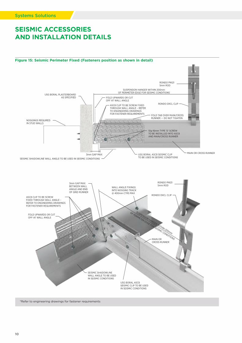
FOLD UPWARDS OR CUTOFF AT WALL ANGLE
ASC8 CLIP TO BE SCREW FIXED THROUGH WALL ANGLE –REFER TO ENGINEERING DRAWINGS FOR FASTENER REQUIREMENTS
3mm GAP MAXBETWEEN WALLANGLE AND END OF GRID RUNNER
SEISMIC SHADOWLINE WALL ANGLE TO BE USED IN SEISMIC CONDITIONS
USG BORAL ASC8 SEISMIC CLIP TO BE USED IN SEISMIC CONDITIONS
MAIN OR CROSS RUNNER
SUSPENSION HANGER WITHIN 200mm
OF PERIMETER EDGE FOR SEISMIC CONDITIONS
RONDO DXCL CLIP
RONDO PN1215mm ROD
WALL ANGLE FIXINGSINTO NOGGING TRACK@ 400mm CTRS MAX
SEISMIC ACCESSORIES AND INSTALLATION DETAILS
Figure 15: Seismic Perimeter Fixed (Fasteners position as shown in detail)
NOGGINGS REQUIRED IN STUD WALLS
FOLD UPWARDS OR CUTOFF AT WALL ANGLE
FOLD TAB OVER MAIN/CROSS RUNNER — DO NOT TIGHTEN
ASC8 CLIP TO BE SCREW FIXED THROUGH WALL ANGLE – REFER TO ENGINEERING DRAWINGS FOR FASTENER REQUIREMENTS
SEISMIC SHADOWLINE WALL ANGLE TO BE USED IN SEISMIC CONDITIONS
10g-16mm TYPE ‘D’ SCREW TO BE INSTALLED INTO ASC8AND MAIN/CROSS RUNNER
USG BORAL ASC8 SEISMIC CLIPTO BE USED IN SEISMIC CONDITIONS
MAIN OR CROSS RUNNER
SUSPENSION HANGER WITHIN 200mmOF PERIMETER EDGE FOR SEISMIC CONDITIONS
RONDO DXCL CLIP
USG BORAL PLASTERBOARDAS SPECIFIED
RONDO PN1215mm ROD
3mm GAP MAX
*Refer to engineering drawings for fastener requirements
10
Systems Solutions

Figure 16: Seismic Perimeter Float (Fasteners position as shown in detail)
Free/Floating ConnectionWhen floating at the perimeter, there needs to be adequate space (minimum 20mm; refer to Engineers design) between the Main/Cross Runner and the wall angle to accommodate for lateral seismic movement in the ceiling (refer to Figure 16 and Method 1 (a) on page 4 for more information).
NOGGINGS REQUIRED IN STUD WALLS
FOLD UPWARDS OR CUTOFF AT WALL ANGLE
ASC8 CLIP TO BE SCREW FIXED THROUGH WALL ANGLE –REFER TO ENGINEERING DRAWINGS FOR FASTENER REQUIREMENTS
SEISMIC SHADOWLINE WALL ANGLETO BE USED IN SEISMIC CONDITIONS
FOLD TAB OVER MAIN/CROSS RUNNER — DO NOT TIGHTEN, ALLOW FOR SLIDING MOVEMENT
10g-16mm TYPE ‘D’ SCREW TO BE INSTALLED INTO ASC8 AND MAIN/CROSS RUNNER IN MIDDLE OF SLOT — DO NOT TIGHTEN TO ALLOW FOR MOVEMENT
MAIN OR CROSS RUNNER
SUSPENSION HANGER WITHIN 200mmOF PERIMETER EDGE FOR SEISMIC CONDITIONS
RONDO DXCL CLIP
RONDO PN1215mm ROD
20-25mm NOMINAL CLEARANCE. PROJECT ENGINEER TO CONFIRMALLOWANCE FOR STRUCTURAL MOVEMENT PRIOR TO CONSTRUCTION.
USG BORAL PLASTERBOARD
NOGGING OMITTEDFOR CLARITY
FOLD UPWARDS OR CUTOFF AT WALL ANGLE
ASC8 CLIP TO BE SCREW FIXED THROUGH WALL ANGLE – REFER TO ENGINEERING DRAWINGS FOR FASTENER REQUIREMENTS
10g-16mm TYPE ‘D’ SCREW – DO NOT TIGHTEN TO ALLOW FOR MOVEMENT
SEISMIC SHADOWLINE WALL ANGLE TO BE USED IN SEISMIC CONDITIONS
MAIN OR CROSS RUNNER
SUSPENSION HANGER WITHIN 200mm
OF PERIMETER EDGE FOR SEISMIC CONDITIONS
RONDO DXCL CLIP
RONDO PN1215mm ROD
WALL ANGLE FIXINGS INTO NOGGING TRACK @ 400mm CTRS MAX
20-25mm NOMINAL CLEARANCE.PROJECT ENGINEER TO CONFIRMALLOWANCE FOR STRUCTURALMOVEMENT PRIOR TO CONSTRUCTION
SEISMIC ACCESSORIES AND INSTALLATION DETAILS
*Refer to engineering drawings for fastener requirements
11
Aluminium Modular Ceiling System
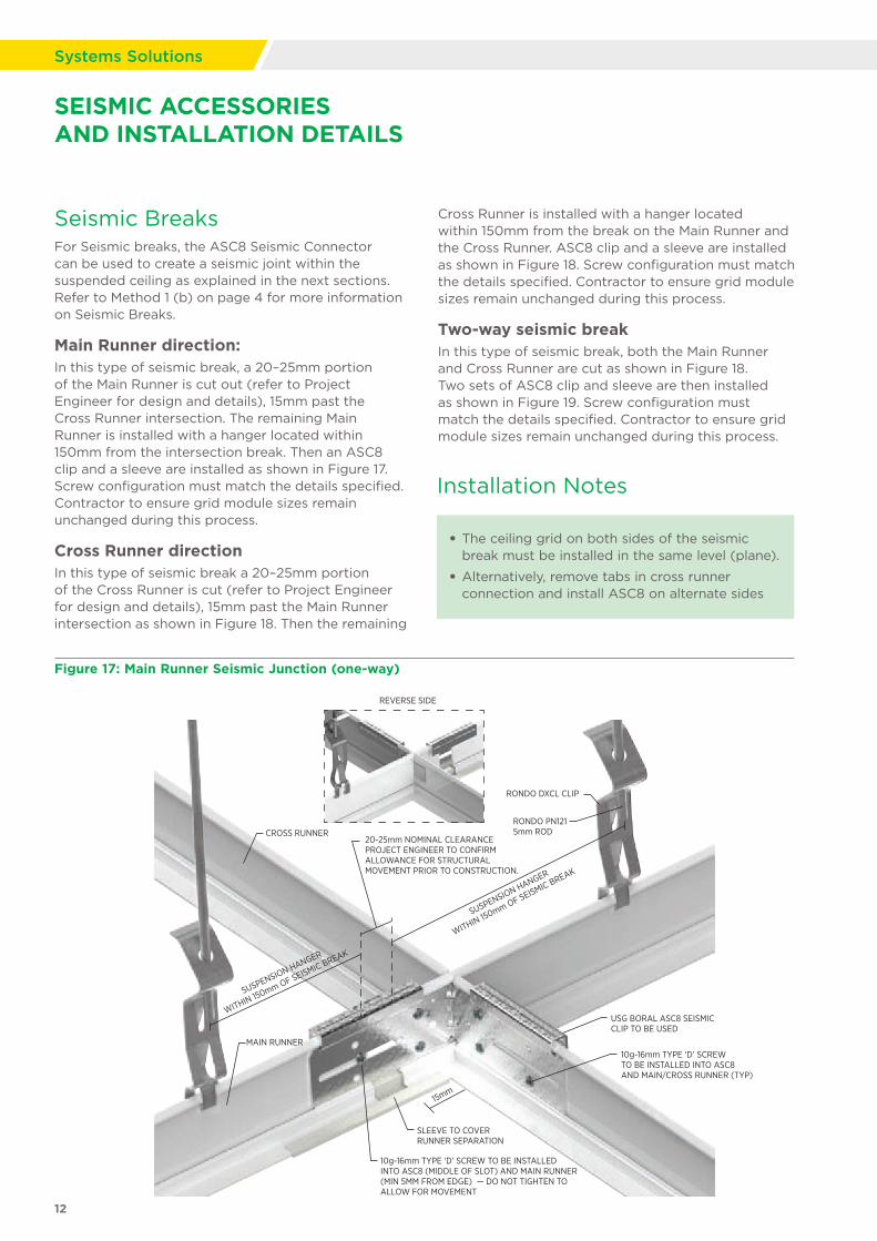
Figure 17: Main Runner Seismic Junction (one-way)
Seismic BreaksFor Seismic breaks, the ASC8 Seismic Connector can be used to create a seismic joint within the suspended ceiling as explained in the next sections. Refer to Method 1 (b) on page 4 for more information on Seismic Breaks.
Main Runner direction:In this type of seismic break, a 20–25mm portion of the Main Runner is cut out (refer to Project Engineer for design and details), 15mm past the Cross Runner intersection. The remaining Main Runner is installed with a hanger located within 150mm from the intersection break. Then an ASC8 clip and a sleeve are installed as shown in Figure 17. Screw configuration must match the details specified. Contractor to ensure grid module sizes remain unchanged during this process.
Cross Runner directionIn this type of seismic break a 20–25mm portion of the Cross Runner is cut (refer to Project Engineer for design and details), 15mm past the Main Runner intersection as shown in Figure 18. Then the remaining
Cross Runner is installed with a hanger located within 150mm from the break on the Main Runner and the Cross Runner. ASC8 clip and a sleeve are installed as shown in Figure 18. Screw configuration must match the details specified. Contractor to ensure grid module sizes remain unchanged during this process.
Two-way seismic breakIn this type of seismic break, both the Main Runner and Cross Runner are cut as shown in Figure 18. Two sets of ASC8 clip and sleeve are then installed as shown in Figure 19. Screw configuration must match the details specified. Contractor to ensure grid module sizes remain unchanged during this process.
RONDO DXCL CLIP
RONDO PN1215mm ROD
REVERSE SIDE
CROSS RUNNER
SUSPENSION HANGER
WITHIN 150mm OF SEISMIC BREAK
SUSPENSION HANGER
WITHIN 150mm OF SEISMIC BREAK
20-25mm NOMINAL CLEARANCEPROJECT ENGINEER TO CONFIRM ALLOWANCE FOR STRUCTURALMOVEMENT PRIOR TO CONSTRUCTION.
USG BORAL ASC8 SEISMICCLIP TO BE USED
SLEEVE TO COVERRUNNER SEPARATION
MAIN RUNNER
15mm
10g-16mm TYPE ‘D’ SCREWTO BE INSTALLED INTO ASC8AND MAIN/CROSS RUNNER (TYP)
10g-16mm TYPE ‘D’ SCREW TO BE INSTALLED INTO ASC8 (MIDDLE OF SLOT) AND MAIN RUNNER (MIN 5MM FROM EDGE) — DO NOT TIGHTEN TO ALLOW FOR MOVEMENT
SEISMIC ACCESSORIES AND INSTALLATION DETAILS
• The ceiling grid on both sides of the seismic break must be installed in the same level (plane).
• Alternatively, remove tabs in cross runner connection and install ASC8 on alternate sides
Installation Notes
12
Systems Solutions
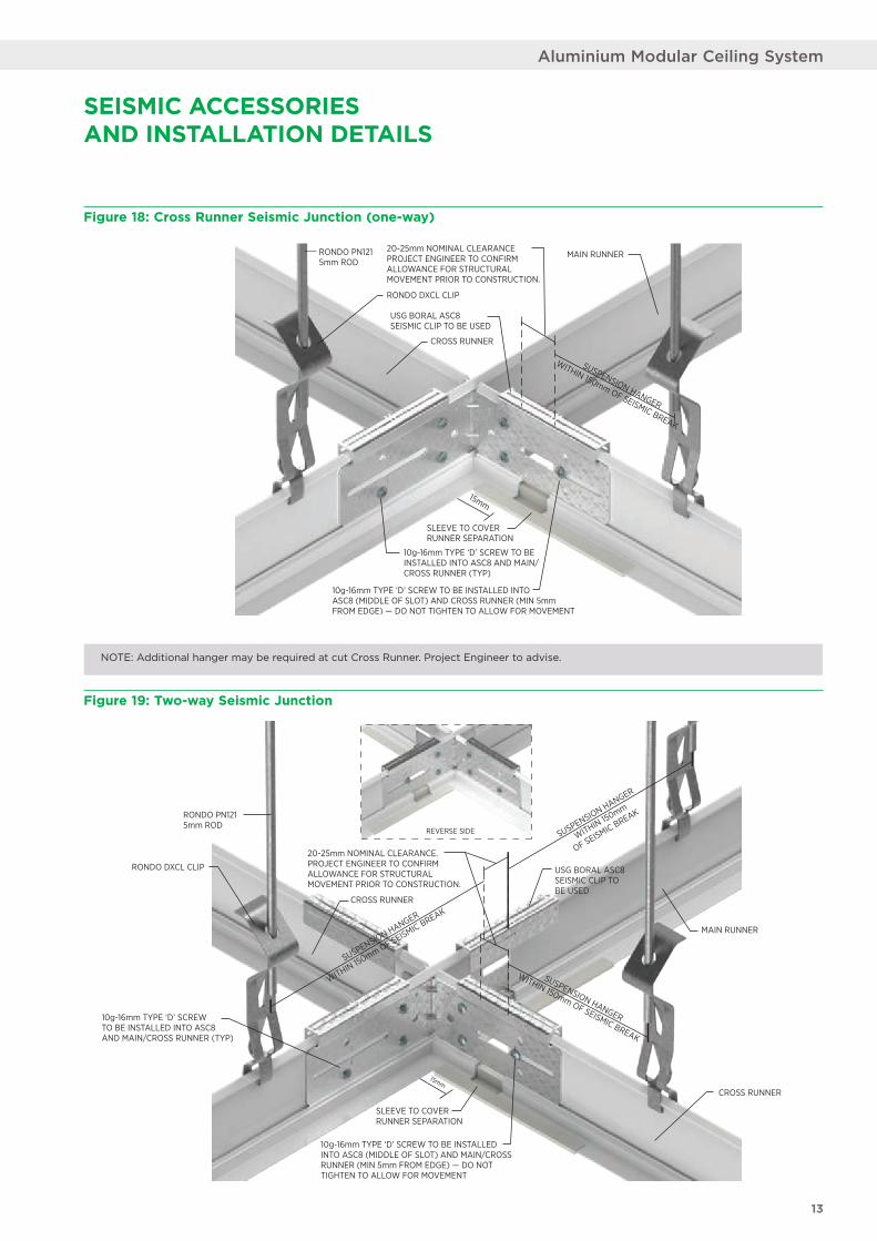
Figure 18: Cross Runner Seismic Junction (one-way)
Figure 19: Two-way Seismic Junction
RONDO DXCL CLIP
RONDO PN1215mm ROD
CROSS RUNNER
20-25mm NOMINAL CLEARANCEPROJECT ENGINEER TO CONFIRM ALLOWANCE FOR STRUCTURALMOVEMENT PRIOR TO CONSTRUCTION.
15mm
USG BORAL ASC8 SEISMIC CLIP TO BE USED
SLEEVE TO COVERRUNNER SEPARATION
MAIN RUNNER
10g-16mm TYPE ‘D’ SCREW TO BE INSTALLED INTO ASC8 AND MAIN/CROSS RUNNER (TYP)
10g-16mm TYPE ‘D’ SCREW TO BE INSTALLED INTO ASC8 (MIDDLE OF SLOT) AND CROSS RUNNER (MIN 5mmFROM EDGE) — DO NOT TIGHTEN TO ALLOW FOR MOVEMENT
SUSPENSION HANGER
WITHIN 150mm OF SEISMIC BREAK
NOTE: Additional hanger may be required at cut Cross Runner. Project Engineer to advise.
REVERSE SIDE
RONDO PN1215mm ROD
RONDO DXCL CLIP
20-25mm NOMINAL CLEARANCE.PROJECT ENGINEER TO CONFIRMALLOWANCE FOR STRUCTURALMOVEMENT PRIOR TO CONSTRUCTION.
SLEEVE TO COVERRUNNER SEPARATION
10g-16mm TYPE ‘D’ SCREWTO BE INSTALLED INTO ASC8AND MAIN/CROSS RUNNER (TYP)
10g-16mm TYPE ‘D’ SCREW TO BE INSTALLED INTO ASC8 (MIDDLE OF SLOT) AND MAIN/CROSS RUNNER (MIN 5mm FROM EDGE) — DO NOT TIGHTEN TO ALLOW FOR MOVEMENT
CROSS RUNNER
MAIN RUNNER
CROSS RUNNER
USG BORAL ASC8SEISMIC CLIP TOBE USED
SUSPENSION HANGER
WITHIN 150mm OF SEISMIC BREAK
SUSPENSION HANGER
WITHIN 150mm OF SEISMIC BREAK
SUSPENSION HANGER
WITHIN 150mm
OF SEISMIC BREAK
15mm
SEISMIC ACCESSORIES AND INSTALLATION DETAILS
13
Aluminium Modular Ceiling System
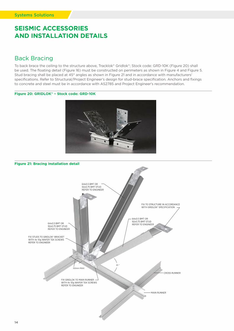
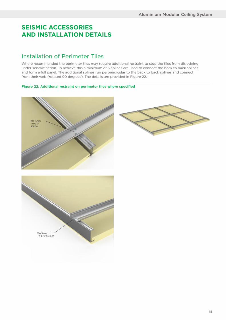
Back BracingTo back brace the ceiling to the structure above, Tracklok® Gridlok®; Stock code: GRD-10K (Figure 20) shall be used. The floating detail (Figure 16) must be constructed on perimeters as shown in Figure 4 and Figure 5. Stud bracing shall be placed at 45° angles as shown in Figure 21 and in accordance with manufacturers' specifications. Refer to Structural/Project Engineer’s design for stud-brace specification. Anchors and fixings to concrete and steel must be in accordance with AS2785 and Project Engineer's recommendation.
Figure 20: GRIDLOK® – Stock code: GRD-10K
Figure 21: Bracing installation detail
CROSS RUNNER
MAIN RUNNER
FIX TO STRUCTURE IN ACCORDANCEWITH GRIDLOK® SPECIFICATION
64x0.5 BMT OR92x0.75 BMT STUDREFER TO ENGINEER64x0.5 BMT OR
92x0.75 BMT STUDREFER TO ENGINEER
64x0.5 BMT OR92x0.75 BMT STUDREFER TO ENGINEER
FIX STUDS TO GRIDLOK® BRACKETWITH 4x 10g WAFER TEK SCREWSREFER TO ENGINEER
50mm MAX
FIX GRIDLOK TO MAIN RUNNERWITH 4x 10g WAFER TEK SCREWSREFER TO ENGINEER
45 °
SEISMIC ACCESSORIES AND INSTALLATION DETAILS
14
Systems Solutions
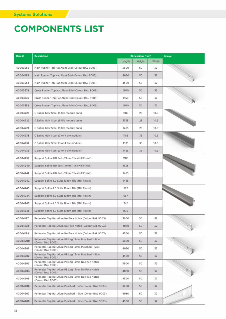
Installation of Perimeter TilesWhere recommended the perimeter tiles may require additional restraint to stop the tiles from dislodging under seismic action. To achieve this a minimum of 3 splines are used to connect the back to back splines and form a full panel. The additional splines run perpendicular to the back to back splines and connect from their web (rotated 90 degrees). The details are provided in Figure 22.
Figure 22: Additional restraint on perimeter tiles where specified
10g-16mm TYPE ‘D’ SCREW
10g-16mm TYPE ‘D’ SCREW
SEISMIC ACCESSORIES AND INSTALLATION DETAILS
15
Aluminium Modular Ceiling System

1 Contact USG Boral for seismic design and details.
2 Check the length and width of the ceiling area with architectural drawings.
3 Determine the plenum depth and map access locations (approved by Architect).
4 Determine the fixity status at the perimeter along with any bracing methods based on engineering drawings (approved by Engineer).
5 Determine the location of any seismic gaps (joints) within the main structure (approved by Engineer and Architect).
6 Determine the location of seismic gaps within the ceiling, based on seismic design (approved by Engineer).
7 Plan the layout of the grid to ensure the module sizes adjacent to perimeter are almost equal and within a satisfactory size range in terms of aesthetics (approved by Architect).
8 Install nogging tracks at ceiling height to the fixed perimeters of the ceiling. Refer to steel framing supplier for details.
9 Install the perimeter wall angle.
• Wall angles require a nogging located at ceiling level of the suspended ceiling system (as mentioned in Step 8, this is to assist in transferring the loads back into the structure). The seismic wall angle should be fixed through the plasterboard into the nogging at 400mm max centres. Screws to be specified by the Structural /Project Engineer.
SEISMIC CEILING INSTALLATION ORDER PROCESS
10 Install the suspension hangers as required (Figure 7).
• Fixing of the hanger to the structure above with proprietary fasteners shall be installed in accordance with the manufacturer’s recommendations, fasteners shall be fully compliant with AS/NZS 2785.
• Hangers using the RONDO DXCL clip shall not vary from the vertical by more than 5°.
• Hangers are not to be bent or kinked.
• Main Runner hangers are suspended depending on module size chosen; refer to Table 1 and 2 for hanger spacing. Additional hangers may be required.
– 1200 x 1200mm module
– 1350 x 1350mm module
– 1500 x 1500mm module
• Suspension hangers are required to be placed within 150mm of all Main Runners connector plates. Depending on module size and hanger starting positions this may require additional hangers to be installed to meet this requirement.
• Suspension hangers in seismically designed ceilings will need to be located within 200mm around the perimeter on all sides, suspending both Main and Cross Runners (Figure 15, Figure 16).
• Additional suspension hangers are required at seismic breaks (Figure 17, Figure 18, Figure 19).
• Refer to AS/NZS 2785 and NZS 4219 for service clearance guidelines
• Individual services that are greater than 7.5kg or outside of the 3kg/m2 allowance presented in the load tables (pages 3) are to be suspended and braced independently of the modular grid system.
• Refer to Structural /Project Engineer for back bracing distances. For maximum back bracing distances refer to AS/NZS 2785
Installation Notes
16
Systems Solutions
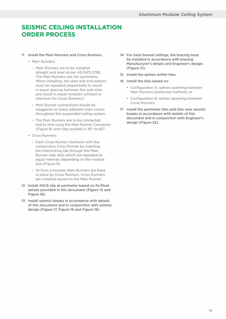
11 Install the Main Runners and Cross Runners.
• Main Runners:
– Main Runners are to be installed straight and level as per AS/NZS 2785. The Main Runners are not symmetric. When installing, the start and end pattern must be repeated sequentially to result in equal spacing between the web slots and result in equal modules (utilised to interlock the Cross Runners).
– Main Runner connections should be staggered on every adjacent main runner throughout the suspended ceiling system
– The Main Runners are to be connected end to end using the Main Runner Connector (Figure 8) with tabs pushed in 45° to 60°.
• Cross Runners:
– Each Cross Runner interlocks with the consecutive Cross Runner by inserting the interlocking tab through the Main Runner web slots which are repeated at equal intervals depending on the module size (Figure 9).
– To form a module, Main Runners are fixed in place by Cross Runners. Cross Runners are installed square to the Main Runner.
12 Install ASC8 clip at perimeter based on fix/float details provided in this document (Figure 15 and Figure 16).
13 Install seismic breaks in accordance with details of this document and in conjunction with seismic design (Figure 17, Figure 18 and Figure 19).
14 For back braced ceilings, the bracing must be installed in accordance with bracing Manufacturer's details and Engineer's design. (Figure 21).
15 Install the splines within tiles.
16 Install the tiles based on:
• Configuration A: splines spanning between Main Runners (preferred method); or
• Configuration B: splines spanning between Cross Runners.
17 Install the perimeter tiles and tiles near seismic breaks in accordance with details of this document and in conjunction with Engineer's design (Figure 22).
SEISMIC CEILING INSTALLATION ORDER PROCESS
17
Aluminium Modular Ceiling System
COMPONENTS LIST
Item # Description Dimensions (mm) Image
Length Height Width
40003568 Main Runner Top Hat Alum Grid (Colour RAL 9003) 3600 50 32
40004195 Main Runner Top Hat Alum Grid (Colour RAL 9003) 4050 50 32
40003553 Main Runner Top Hat Alum Grid (Colour RAL 9003) 4500 50 32
40003633 Cross Runner Top Hat Alum Grid (Colour RAL 9003) 1200 50 32
40004196 Cross Runner Top Hat Alum Grid (Colour RAL 9003) 1350 50 32
40003552 Cross Runner Top Hat Alum Grid (Colour RAL 9003) 1500 50 32
40004223 C Spline Galv Steel (5 tile module only) 1185 25 10.9
40004222 C Spline Galv Steel (5 tile module only) 1335 25 10.9
40004221 C Spline Galv Steel (5 tile module only) 1485 25 10.9
40004238 C Spline Galv Steel (3 or 4 tile module) 1185 35 10.9
40004237 C Spline Galv Steel (3 or 4 tile module) 1335 35 10.9
40004236 C Spline Galv Steel (3 or 4 tile module) 1485 35 10.9
40004239 Support Spline HD Suits 19mm Tile (Mill Finish) 1185
40004240 Support Spline HD Suits 19mm Tile (Mill Finish) 1335
40004241 Support Spline HD Suits 19mm Tile (Mill Finish) 1485
40004242 Support Spline LD Suits 19mm Tile (Mill Finish) 1485
40004243 Support Spline LD Suits 19mm Tile (Mill Finish) 592
40004244 Support Spline LD Suits 19mm Tile (Mill Finish) 667
40004245 Support Spline LD Suits 19mm Tile (Mill Finish) 742
40004246 Support Spline LD Suits 19mm Tile (Mill Finish) 890
40004197 Perimeter Top Hat Alum No Face Notch (Colour RAL 9003) 3600 50 32
40004198 Perimeter Top Hat Alum No Face Notch (Colour RAL 9003) 4050 50 32
40004199 Perimeter Top Hat Alum No Face Notch (Colour RAL 9003) 4500 50 32
40004200 Perimeter Top Hat Alum PB Leg 13mm Punched 1-Side (Colour RAL 9003) 3600 50 32
40004201 Perimeter Top Hat Alum PB Leg 13mm Punched 1-Side (Colour RAL 9003) 4050 50 32
40004202 Perimeter Top Hat Alum PB Leg 13mm Punched 1-Side (Colour RAL 9003) 4500 50 32
40004203 Perimeter Top Hat Alum PB Leg 13mm No Face Notch (Colour RAL 9003) 3600 50 32
40004204 Perimeter Top Hat Alum PB Leg 13mm No Face Notch (Colour RAL 9003) 4050 50 32
40004205Perimeter Top Hat Alum PB Leg 13mm No Face Notch (Colour RAL 9003)
4500 50 32
40004206 Perimeter Top Hat Alum Punched 1-Side (Colour RAL 9003) 3600 50 32
40004207 Perimeter Top Hat Alum Punched 1-Side (Colour RAL 9003) 4050 50 32
40004208 Perimeter Top Hat Alum Punched 1-Side (Colour RAL 9003) 4500 50 32
18
Systems Solutions
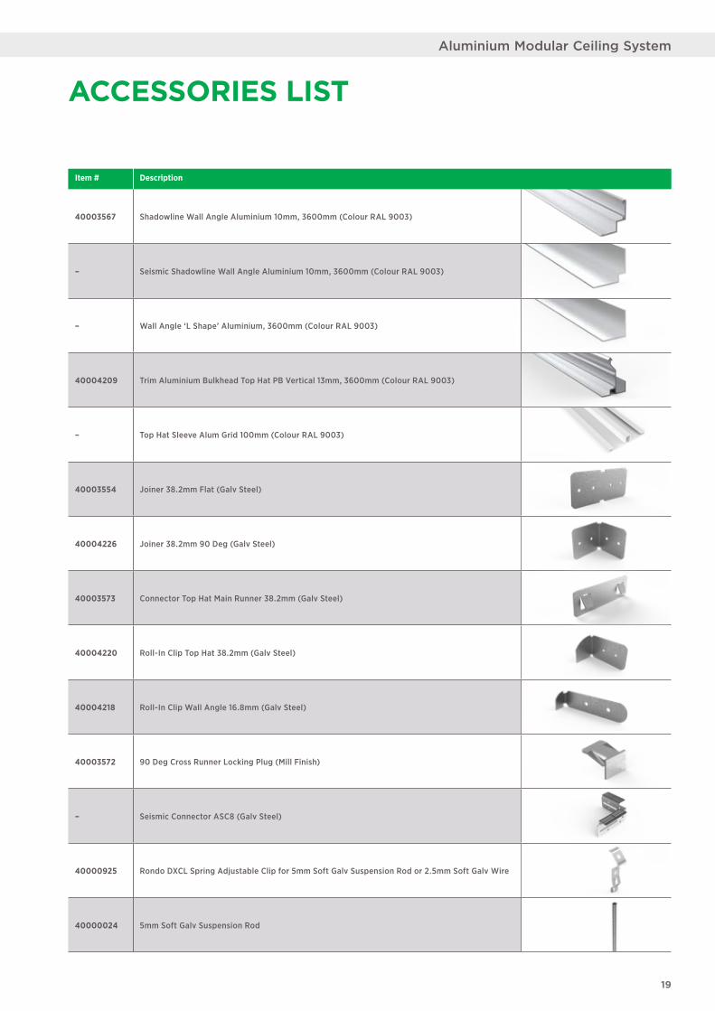
Item # Description
40003567 Shadowline Wall Angle Aluminium 10mm, 3600mm (Colour RAL 9003)
– Seismic Shadowline Wall Angle Aluminium 10mm, 3600mm (Colour RAL 9003)
– Wall Angle ‘L Shape’ Aluminium, 3600mm (Colour RAL 9003)
40004209 Trim Aluminium Bulkhead Top Hat PB Vertical 13mm, 3600mm (Colour RAL 9003)
– Top Hat Sleeve Alum Grid 100mm (Colour RAL 9003)
40003554 Joiner 38.2mm Flat (Galv Steel)
40004226 Joiner 38.2mm 90 Deg (Galv Steel)
40003573 Connector Top Hat Main Runner 38.2mm (Galv Steel)
40004220 Roll-In Clip Top Hat 38.2mm (Galv Steel)
40004218 Roll-In Clip Wall Angle 16.8mm (Galv Steel)
40003572 90 Deg Cross Runner Locking Plug (Mill Finish)
– Seismic Connector ASC8 (Galv Steel)
40000925 Rondo DXCL Spring Adjustable Clip for 5mm Soft Galv Suspension Rod or 2.5mm Soft Galv Wire
40000024 5mm Soft Galv Suspension Rod
ACCESSORIES LIST
19
Aluminium Modular Ceiling System

NOTES
20
Systems Solutions
21
Aluminium Modular Ceiling System
STANDARDS AND BUILDING CODES
USG Boral uses the following standards in its testing for compliance with the Building Codes of Australia and New Zealand:
AS/NZ 2785 Suspended Ceilings, Design and InstallationAS/NZ 1170.0 Structural Design ActionsAS 1170.4 Earthquake Loads (Australia)NZS 1170.5 Structural Design Actions (New Zealand) Part 5NZS 4219 Seismic performance of engineering systems in buildingsAS2946 – 1991 Suspended ceilings, recessed luminaires and air diffusers
— Interface requirements for physical compatibility
USG Boral recommends that all Suspended Grid Ceiling Systems be installed in accordance with ‘AS/NZS 2785 Suspended ceilings – Design and Installation’ for information and guidance and Project Engineers design documents.
Ceiling layout should be planned prior to installation to determine grid configuration, direction etc. and to ensure that all fixing points are compatible with structural members and/or other services. Installation of grid and ceiling tiles shall not begin until the building is closed in, fully glazed, roof watertight and residual moisture from wet trades such as plaster, concrete and terrazzo has dissipated.
REQUIREMENTSSuspended ceilings are finished products intended for interior use and should be treated accordingly.
DELIVERY, STORAGE AND HANDLINGAll materials shall be delivered in their original, unopened packages and stored for as short a time as possible, in an enclosed shelter providing protection from exposure to the elements and damage by/to other trades. Damaged, deteriorated or obviously faulty material is not to be installed and shall be removed from the premises. Materials should be handled in such a manner as to prevent racking distortion or physical damage.
MATERIALSMain Runners, Cross Runners, Wall Trims and Supporting Splines are made from extruded aluminium, C-Splines and other connection clips are from steel. Fasteners to be as specified in detail.
CUTTING We recommend protective equipment (eye, hand, ear protective equipment etc.) be worn when handling and cutting metal products (AS 2161) and that hands are washed pre and post contact. Suitable tools shall be used for cutting aluminium parts for safety and to maintain smooth finishes.
© 2021 USG BORAL. All rights reserved. The trademarks USG BORAL, INNOVATION INSPIRED BY YOU, Partiwall, Multiframe, IntRwall, TecASSIST, SOUNDSTOP, FIRESTOP, SHAFTLINER, WETSTOP, FIRE+WETSTOP, FIREPACK and Wet Area Sealant are trademarks or registered trademarks of USG Boral Building Products or one or more of its affiliates. SHEETROCK and FIBEROCK Aqua-Tough are trademarks owned by United States Gypsum Company and used under license.Gridlok and Tracklok are registered trademarks of Tracklok Limited. USG Boral Building Products Pty Limited – ABN 84 004 231 976 251 Salmon Street, Port Melbourne, VIC. 3207
UB1327 05/21
PRODUCT INFORMATIONSee USGBoral.com for the most up-to-date product information.
SALES ENQUIRIES1800 003 377
TECHNICAL ASSISTANCETecASSIST™ – 1800 811 222 [email protected]
There are many variables that can influence construction projects, which affect whether a particular construction technique is appropriate. Before proceeding with any project, we recommend you obtain professional advice to ascertain the appropriate construction techniques to suit the particular circumstances of your project. We recommend you use qualified tradespersons to install this system.
The technical information contained in this manual was correct at the time of printing. Building systems, details and product availability are, however, subject to change. To ensure the information you are using is current, USG Boral recommends you review the latest building information available on the USG Boral website.
AustraliaNew Zealand
USG Boral Building Products Pty Ltd251 Salmon Street Port Melbourne Victoria 3207 Australia
USGBoral.com Interior Linings Ceilings Cornice Finishes Systems SolutionsUSGBoral.com Interior Linings Ceilings Cornice Finishes Systems Solutions