alterpath acs v.2.6.1 command reference...
TRANSCRIPT
AlterPath™ ACS Command Reference Guide
Software Version 2.6.1
Cyclades Corporation3541 Gateway BoulevardFremont, CA 94538 USA1.888.CYCLADES (292.5233)1.510.771.61001.510.771.6200 (fax)http://www.cyclades.com
Release Date: April 2006Part Number: PAC0193
ALTERPATH AlterPath ACS32
LINUX
INSIDE

© 2006 Cyclades Corporation, all rights reserved
Information in this document is subject to change without notice.
The following are registered or registration-pending trademarks of Cyclades Corporation in the United States and other countries: Cyclades and AlterPath.
All trademarks, trade names, logos and service marks referenced herein, even when not specifically marked as such, belong to their respective companies and are not to be considered unprotected by law.

.................................................................
Table of Contents
Preface xixPurpose . . . . . . . . . . . . . . . . . . . . . . . . . . . . . . . . . . . . . . . . . . . . . . . . . . . . . . . . . . . xixAudience and User Levels. . . . . . . . . . . . . . . . . . . . . . . . . . . . . . . . . . . . . . . . . . . . . xix
New Users . . . . . . . . . . . . . . . . . . . . . . . . . . . . . . . . . . . . . . . . . . . . . . . . . . . . . . xixPower Users . . . . . . . . . . . . . . . . . . . . . . . . . . . . . . . . . . . . . . . . . . . . . . . . . . . . . xx
How to use the CLI . . . . . . . . . . . . . . . . . . . . . . . . . . . . . . . . . . . . . . . . . . . . . . . . . . xxiModes of Operation . . . . . . . . . . . . . . . . . . . . . . . . . . . . . . . . . . . . . . . . . . . . . . xxiKeywords meanings . . . . . . . . . . . . . . . . . . . . . . . . . . . . . . . . . . . . . . . . . . . . . . xxiiInteractive Mode . . . . . . . . . . . . . . . . . . . . . . . . . . . . . . . . . . . . . . . . . . . . . . . . . xxiiCLI arguments. . . . . . . . . . . . . . . . . . . . . . . . . . . . . . . . . . . . . . . . . . . . . . . . . . . xxvOther important features of the CLI . . . . . . . . . . . . . . . . . . . . . . . . . . . . . . . . . . xxvList of CLI Keywords . . . . . . . . . . . . . . . . . . . . . . . . . . . . . . . . . . . . . . . . . . . . xxvii
. . . . . . . . . . . . . . . . . . . . . . . . . . . . . . . . . . . . . . . . . . . . . . . . How to use this Guide xxxConventions and Symbols. . . . . . . . . . . . . . . . . . . . . . . . . . . . . . . . . . . . . . . . . . . . xxxi
Typeface and Fonts . . . . . . . . . . . . . . . . . . . . . . . . . . . . . . . . . . . . . . . . . . . . . . xxxiHypertext Links. . . . . . . . . . . . . . . . . . . . . . . . . . . . . . . . . . . . . . . . . . . . . . . . . xxxiGlossary Entries . . . . . . . . . . . . . . . . . . . . . . . . . . . . . . . . . . . . . . . . . . . . . . . . xxxiQuick Steps . . . . . . . . . . . . . . . . . . . . . . . . . . . . . . . . . . . . . . . . . . . . . . . . . . . . xxxiParameter Syntax . . . . . . . . . . . . . . . . . . . . . . . . . . . . . . . . . . . . . . . . . . . . . . . xxxii
Brackets and Hyphens (dashes) . . . . . . . . . . . . . . . . . . . . . . . . . . . . . . . . . xxxiiEllipses. . . . . . . . . . . . . . . . . . . . . . . . . . . . . . . . . . . . . . . . . . . . . . . . . . . . xxxiiPipes. . . . . . . . . . . . . . . . . . . . . . . . . . . . . . . . . . . . . . . . . . . . . . . . . . . . . . xxxiiGreater-than and Less-than signs. . . . . . . . . . . . . . . . . . . . . . . . . . . . . . . . xxxiiSpacing and Separators . . . . . . . . . . . . . . . . . . . . . . . . . . . . . . . . . . . . . . xxxiii
Cautionary and Instructional Information. . . . . . . . . . . . . . . . . . . . . . . . . . . . xxxiiiNetworking Settings . . . . . . . . . . . . . . . . . . . . . . . . . . . . . . . . . . . . . . . . . . . . . . . . . . . 1
Performing Basic Network Configuration Using the wiz Command . . . . . . . . . . . 1Log Into ACS Through the Console . . . . . . . . . . . . . . . . . . . . . . . . . . . . . . . . 1
Password . . . . . . . . . . . . . . . . . . . . . . . . . . . . . . . . . . . . . . . . . . . . . . . . . . . . . . . . . 2Security Advisory . . . . . . . . . . . . . . . . . . . . . . . . . . . . . . . . . . . . . . . . . . . . . . . . . . 2Use the wiz Command to Configure Network Parameters . . . . . . . . . . . . . . . . . . . 4

Table of Contents
iv
Selecting A Security Profile. . . . . . . . . . . . . . . . . . . . . . . . . . . . . . . . . . . . . . . . . . . . . . 6To Select a Security Profile . . . . . . . . . . . . . . . . . . . . . . . . . . . . . . . . . . . . . . . 6CLI Mode . . . . . . . . . . . . . . . . . . . . . . . . . . . . . . . . . . . . . . . . . . . . . . . . . . . . . 6
Enabling Serial Ports . . . . . . . . . . . . . . . . . . . . . . . . . . . . . . . . . . . . . . . . . . . . . . . . . . . 9To Enable a Serial Port [VI method] . . . . . . . . . . . . . . . . . . . . . . . . . . . . . . . . 9To Enable a Serial Port [CLI method] . . . . . . . . . . . . . . . . . . . . . . . . . . . . . . . 9
ChaChapter 2 - Device Access 11Accessing Serial Ports . . . . . . . . . . . . . . . . . . . . . . . . . . . . . . . . . . . . . . . . . . . . . . . . . 11
Default Configuration Parameters . . . . . . . . . . . . . . . . . . . . . . . . . . . . . . . . . . . . . 12Opening and closing a Telnet session to a serial port . . . . . . . . . . . . . . . . . . . . . . 12Opening and closing an SSH session to a serial port. . . . . . . . . . . . . . . . . . . . . . . 13Accessing Serial Ports using “ts_menu” . . . . . . . . . . . . . . . . . . . . . . . . . . . . . . . . 13
Calling ts_menu without arguments. . . . . . . . . . . . . . . . . . . . . . . . . . . . . . . . 13Calling ts_menu with arguments . . . . . . . . . . . . . . . . . . . . . . . . . . . . . . . . . . 14How to close the session from ts_menu (from the console of your unit). . . . 15How to close the session from ts_menu (from a Telnet/SSH session to your unit)
16CLI Mode - ts_menu . . . . . . . . . . . . . . . . . . . . . . . . . . . . . . . . . . . . . . . . . . . 17
Data Buffering . . . . . . . . . . . . . . . . . . . . . . . . . . . . . . . . . . . . . . . . . . . . . . . . . . . . . . . 18Ramdisks . . . . . . . . . . . . . . . . . . . . . . . . . . . . . . . . . . . . . . . . . . . . . . . . . . . . . . . . 19Linear vs. Circular Buffering. . . . . . . . . . . . . . . . . . . . . . . . . . . . . . . . . . . . . . . . . 19How to Configure VI mode - Parameters Involved and Passed Values . . . . . . . . 19
CLI Method - Data Buffering. . . . . . . . . . . . . . . . . . . . . . . . . . . . . . . . . . . . . 23Menu Shell . . . . . . . . . . . . . . . . . . . . . . . . . . . . . . . . . . . . . . . . . . . . . . . . . . . . . . . . . . 25
How to use . . . . . . . . . . . . . . . . . . . . . . . . . . . . . . . . . . . . . . . . . . . . . . . . . . . . . . . 25How to configure . . . . . . . . . . . . . . . . . . . . . . . . . . . . . . . . . . . . . . . . . . . . . . . . . . 25
Setting up the Menu Shell . . . . . . . . . . . . . . . . . . . . . . . . . . . . . . . . . . . . . . . 26Assigning ports to the Menu Shell . . . . . . . . . . . . . . . . . . . . . . . . . . . . . . . . . 27CLI Method - Terminal Profile Menu . . . . . . . . . . . . . . . . . . . . . . . . . . . . . . 28
Clustering using Ethernet Interface . . . . . . . . . . . . . . . . . . . . . . . . . . . . . . . . . . . . . . . 29How to Configure Clustering. . . . . . . . . . . . . . . . . . . . . . . . . . . . . . . . . . . . . . . . . 29
VI mode . . . . . . . . . . . . . . . . . . . . . . . . . . . . . . . . . . . . . . . . . . . . . . . . . . . . . 29Clustering using NAT (Enhanced). . . . . . . . . . . . . . . . . . . . . . . . . . . . . . . . . . . . . . . . 35
New Parameters and Commands . . . . . . . . . . . . . . . . . . . . . . . . . . . . . . . . . . . . . . 36
AlterPath ACS Command Reference Guide v
Examples: . . . . . . . . . . . . . . . . . . . . . . . . . . . . . . . . . . . . . . . . . . . . . . . . . . . . 37How it works . . . . . . . . . . . . . . . . . . . . . . . . . . . . . . . . . . . . . . . . . . . . . . . . . . . . . 38General Configuration . . . . . . . . . . . . . . . . . . . . . . . . . . . . . . . . . . . . . . . . . . . . . . 39
Master ACS Configuration. . . . . . . . . . . . . . . . . . . . . . . . . . . . . . . . . . . . . . . 40Slave-1 ACS Configuration . . . . . . . . . . . . . . . . . . . . . . . . . . . . . . . . . . . . . . 42Slave-2 ACS Configuration . . . . . . . . . . . . . . . . . . . . . . . . . . . . . . . . . . . . . . 42Slave-3 ACS Configuration . . . . . . . . . . . . . . . . . . . . . . . . . . . . . . . . . . . . . . 43Example of starting CAS session commands. . . . . . . . . . . . . . . . . . . . . . . . . 43CLI Method - Clustering . . . . . . . . . . . . . . . . . . . . . . . . . . . . . . . . . . . . . . . . 44
47
Chapter 3 - Authentication 47Device Authentication . . . . . . . . . . . . . . . . . . . . . . . . . . . . . . . . . . . . . . . . . . . . . . . . . 47
How to configure . . . . . . . . . . . . . . . . . . . . . . . . . . . . . . . . . . . . . . . . . . . . . . . . . . 48VI mode - Parameters involved and passed values . . . . . . . . . . . . . . . . . . . . 48CLI Method - Authentication . . . . . . . . . . . . . . . . . . . . . . . . . . . . . . . . . . . . . 51
One Time Password Authentication on the ACS . . . . . . . . . . . . . . . . . . . . . . . . . 52Editing the otp.conf File . . . . . . . . . . . . . . . . . . . . . . . . . . . . . . . . . . . . . . . . . . . . 55Running the /bin/do_create_otpdb Script . . . . . . . . . . . . . . . . . . . . . . . . 57How User are Registered with OTP and Obtain OTP Passwords . . . . . . . . . . . . . 58
Obtaining and Using One Time Passwords for Dial-ins . . . . . . . . . . . . . . . . . . . . . . . 61To configure user access to the serial ports . . . . . . . . . . . . . . . . . . . . . . . . . . . . . . 63To configure authentication type for device console access. . . . . . . . . . . . . . . . . 64To configure an authentication server. . . . . . . . . . . . . . . . . . . . . . . . . . . . . . . . . . 65
To activate the configuration.. . . . . . . . . . . . . . . . . . . . . . . . . . . . . . . . . . . . . 65To save the configuration. . . . . . . . . . . . . . . . . . . . . . . . . . . . . . . . . . . . . . . . 65To exit the CLI mode. . . . . . . . . . . . . . . . . . . . . . . . . . . . . . . . . . . . . . . . . . . 65
Access Control via Radius Attribute NAS-Port-id . . . . . . . . . . . . . . . . . . . . . . . . 65NIS Client . . . . . . . . . . . . . . . . . . . . . . . . . . . . . . . . . . . . . . . . . . . . . . . . . . . . . . . 66NIS Client Configuration. . . . . . . . . . . . . . . . . . . . . . . . . . . . . . . . . . . . . . . . . . . . 67Testing the Configuration . . . . . . . . . . . . . . . . . . . . . . . . . . . . . . . . . . . . . . . . . . . 68nsswitch.conf file format . . . . . . . . . . . . . . . . . . . . . . . . . . . . . . . . . . . . . . . . . . . . 68
Examples . . . . . . . . . . . . . . . . . . . . . . . . . . . . . . . . . . . . . . . . . . . . . . . . . . . . 69Kerberos Authentication . . . . . . . . . . . . . . . . . . . . . . . . . . . . . . . . . . . . . . . . . . . . . . . 70
Table of Contents
vi
Kerberos Server Authentication with Tickets support. . . . . . . . . . . . . . . . . . . . . . 70How Kerberos Works . . . . . . . . . . . . . . . . . . . . . . . . . . . . . . . . . . . . . . . . . . . 70
Configuring ACS to use Kerberos Tickets authentication . . . . . . . . . . . . . . . . . . 71ACS Configuration. . . . . . . . . . . . . . . . . . . . . . . . . . . . . . . . . . . . . . . . . . . . . 71
Kerberos Server Authentication . . . . . . . . . . . . . . . . . . . . . . . . . . . . . . . . . . . . . . 74LDAP Authentication . . . . . . . . . . . . . . . . . . . . . . . . . . . . . . . . . . . . . . . . . . . . . . . . . 77
Active Directory . . . . . . . . . . . . . . . . . . . . . . . . . . . . . . . . . . . . . . . . . . . . . . . . . . 80What needs to be set in the /etc/ldap.conf . . . . . . . . . . . . . . . . . . . . . . . . . . . 80
Enabling TACACS+ Authorization for Serial Ports . . . . . . . . . . . . . . . . . . . . . . . 81Group Authorization . . . . . . . . . . . . . . . . . . . . . . . . . . . . . . . . . . . . . . . . . . . . . . . . . . 83
Configuring a TACACS+ authentication server . . . . . . . . . . . . . . . . . . . . . . . . . . 83Configuring an LDAP authentication server . . . . . . . . . . . . . . . . . . . . . . . . . . . . . 86
Linux-PAM . . . . . . . . . . . . . . . . . . . . . . . . . . . . . . . . . . . . . . . . . . . . . . . . . . . . . . . . . 87The Linux-PAM Configuration Directory. . . . . . . . . . . . . . . . . . . . . . . . . . . . . . . 89
Configuration File Syntax . . . . . . . . . . . . . . . . . . . . . . . . . . . . . . . . . . . . . . . 89Module Path. . . . . . . . . . . . . . . . . . . . . . . . . . . . . . . . . . . . . . . . . . . . . . . . . . . . . . 92Arguments . . . . . . . . . . . . . . . . . . . . . . . . . . . . . . . . . . . . . . . . . . . . . . . . . . . . . . . 96
Shadow Passwords. . . . . . . . . . . . . . . . . . . . . . . . . . . . . . . . . . . . . . . . . . . . . . . . . . . . 97Certificate for HTTP Security . . . . . . . . . . . . . . . . . . . . . . . . . . . . . . . . . . . . . . . . . . . 98
Procedure . . . . . . . . . . . . . . . . . . . . . . . . . . . . . . . . . . . . . . . . . . . . . . . . . . . . . . . . 98User Configured Digital Certificate. . . . . . . . . . . . . . . . . . . . . . . . . . . . . . . . . . . . . . 100X.509 Certificate on SSH . . . . . . . . . . . . . . . . . . . . . . . . . . . . . . . . . . . . . . . . . . . . . 101
To configure X.509 certificate for SSH. . . . . . . . . . . . . . . . . . . . . . . . . . . . . . . . 101vi Mode. . . . . . . . . . . . . . . . . . . . . . . . . . . . . . . . . . . . . . . . . . . . . . . . . . . . . 101CLI Mode . . . . . . . . . . . . . . . . . . . . . . . . . . . . . . . . . . . . . . . . . . . . . . . . . . . 102Script Mode . . . . . . . . . . . . . . . . . . . . . . . . . . . . . . . . . . . . . . . . . . . . . . . . . 102
To connect to ACS using SSH X.509 certificate. . . . . . . . . . . . . . . . . . . . . . . . . 103To connect to ACS’s serial ports using SSH X.509 certificate . . . . . . . . . . . . . . 103
Chapter 4 - Network 105Introduction . . . . . . . . . . . . . . . . . . . . . . . . . . . . . . . . . . . . . . . . . . . . . . . . . . . . . . . . 105Basic Network Settings . . . . . . . . . . . . . . . . . . . . . . . . . . . . . . . . . . . . . . . . . . . . . . . 105
Hostname . . . . . . . . . . . . . . . . . . . . . . . . . . . . . . . . . . . . . . . . . . . . . . . . . . . . . . . 105VI mode . . . . . . . . . . . . . . . . . . . . . . . . . . . . . . . . . . . . . . . . . . . . . . . . . . . . 106

AlterPath ACS Command Reference Guide vii
CLI Method - Hostname. . . . . . . . . . . . . . . . . . . . . . . . . . . . . . . . . . . . . . . . 106IP address and Netmask. . . . . . . . . . . . . . . . . . . . . . . . . . . . . . . . . . . . . . . . . . . . 106
VI mode . . . . . . . . . . . . . . . . . . . . . . . . . . . . . . . . . . . . . . . . . . . . . . . . . . . . 106CLI Method - IP address . . . . . . . . . . . . . . . . . . . . . . . . . . . . . . . . . . . . . . . 108
DHCP Client . . . . . . . . . . . . . . . . . . . . . . . . . . . . . . . . . . . . . . . . . . . . . . . . . . . . . . . 109VI mode . . . . . . . . . . . . . . . . . . . . . . . . . . . . . . . . . . . . . . . . . . . . . . . . . . . . 109Files related to DHCP: . . . . . . . . . . . . . . . . . . . . . . . . . . . . . . . . . . . . . . . . . 111CLI Method - DHCP . . . . . . . . . . . . . . . . . . . . . . . . . . . . . . . . . . . . . . . . . . 111
Routes and Default Gateway . . . . . . . . . . . . . . . . . . . . . . . . . . . . . . . . . . . . . . . . . . . . . 112VI mode . . . . . . . . . . . . . . . . . . . . . . . . . . . . . . . . . . . . . . . . . . . . . . . . . . . . 113CLI Method - Routes . . . . . . . . . . . . . . . . . . . . . . . . . . . . . . . . . . . . . . . . . . 114
DNS Server and Domain Name. . . . . . . . . . . . . . . . . . . . . . . . . . . . . . . . . . . . . . . . . 115VI mode . . . . . . . . . . . . . . . . . . . . . . . . . . . . . . . . . . . . . . . . . . . . . . . . . . . . 115CLI Method - DNS and Domain Name . . . . . . . . . . . . . . . . . . . . . . . . . . . . 115
Bonding . . . . . . . . . . . . . . . . . . . . . . . . . . . . . . . . . . . . . . . . . . . . . . . . . . . . . . . . . . . 116VI mode . . . . . . . . . . . . . . . . . . . . . . . . . . . . . . . . . . . . . . . . . . . . . . . . . . . . 117CLI Method - Bonding . . . . . . . . . . . . . . . . . . . . . . . . . . . . . . . . . . . . . . . . . 117
Hosts . . . . . . . . . . . . . . . . . . . . . . . . . . . . . . . . . . . . . . . . . . . . . . . . . . . . . . . . . . . . . 121VI mode . . . . . . . . . . . . . . . . . . . . . . . . . . . . . . . . . . . . . . . . . . . . . . . . . . . . 121CLI Method - Hosts . . . . . . . . . . . . . . . . . . . . . . . . . . . . . . . . . . . . . . . . . . . 122
TCP Keepalive . . . . . . . . . . . . . . . . . . . . . . . . . . . . . . . . . . . . . . . . . . . . . . . . . . . . . . 123How it works . . . . . . . . . . . . . . . . . . . . . . . . . . . . . . . . . . . . . . . . . . . . . . . . . . . . 123
VI mode . . . . . . . . . . . . . . . . . . . . . . . . . . . . . . . . . . . . . . . . . . . . . . . . . . . . 123CLI Method - TCP Keep Alive . . . . . . . . . . . . . . . . . . . . . . . . . . . . . . . . . . 124
Filters and Network Address Translation . . . . . . . . . . . . . . . . . . . . . . . . . . . . . . . . . . . 124Description. . . . . . . . . . . . . . . . . . . . . . . . . . . . . . . . . . . . . . . . . . . . . . . . . . . . . . 124Structure of the iptables . . . . . . . . . . . . . . . . . . . . . . . . . . . . . . . . . . . . . . . . . . . . 125
Table . . . . . . . . . . . . . . . . . . . . . . . . . . . . . . . . . . . . . . . . . . . . . . . . . . . . . . . 125Chain. . . . . . . . . . . . . . . . . . . . . . . . . . . . . . . . . . . . . . . . . . . . . . . . . . . . . . . 125Rule. . . . . . . . . . . . . . . . . . . . . . . . . . . . . . . . . . . . . . . . . . . . . . . . . . . . . . . . 126
Syntax . . . . . . . . . . . . . . . . . . . . . . . . . . . . . . . . . . . . . . . . . . . . . . . . . . . . . . . . . 126Command . . . . . . . . . . . . . . . . . . . . . . . . . . . . . . . . . . . . . . . . . . . . . . . . . . . 127Rule Specification . . . . . . . . . . . . . . . . . . . . . . . . . . . . . . . . . . . . . . . . . . . . 129
Match Extensions. . . . . . . . . . . . . . . . . . . . . . . . . . . . . . . . . . . . . . . . . . . . . . . . . 132
Table of Contents
viii
TCP Extensions . . . . . . . . . . . . . . . . . . . . . . . . . . . . . . . . . . . . . . . . . . . . . . 133UDP Extensions . . . . . . . . . . . . . . . . . . . . . . . . . . . . . . . . . . . . . . . . . . . . . . 134ICMP Extension . . . . . . . . . . . . . . . . . . . . . . . . . . . . . . . . . . . . . . . . . . . . . . 135
Multiport Extension . . . . . . . . . . . . . . . . . . . . . . . . . . . . . . . . . . . . . . . . . . . . . . . 135Target Extensions . . . . . . . . . . . . . . . . . . . . . . . . . . . . . . . . . . . . . . . . . . . . . . . . 135
LOG . . . . . . . . . . . . . . . . . . . . . . . . . . . . . . . . . . . . . . . . . . . . . . . . . . . . . . . 136REJECT (filter table only) . . . . . . . . . . . . . . . . . . . . . . . . . . . . . . . . . . . . . . 136SNAT (NAT table only). . . . . . . . . . . . . . . . . . . . . . . . . . . . . . . . . . . . . . . . 137DNAT (nat table only) . . . . . . . . . . . . . . . . . . . . . . . . . . . . . . . . . . . . . . . . . 138MASQUERADE (nat table only). . . . . . . . . . . . . . . . . . . . . . . . . . . . . . . . . 138REDIRECT (NAT table only) . . . . . . . . . . . . . . . . . . . . . . . . . . . . . . . . . . . 139
How to configure it . . . . . . . . . . . . . . . . . . . . . . . . . . . . . . . . . . . . . . . . . . . . . . . 139VI method. . . . . . . . . . . . . . . . . . . . . . . . . . . . . . . . . . . . . . . . . . . . . . . . . . . 140
VPN Configuration . . . . . . . . . . . . . . . . . . . . . . . . . . . . . . . . . . . . . . . . . . . . . . . . . . 140Applications of IPsec. . . . . . . . . . . . . . . . . . . . . . . . . . . . . . . . . . . . . . . . . . . . . . 141
Using secure tunnels to create a VPN . . . . . . . . . . . . . . . . . . . . . . . . . . . . . 141Road Warriors . . . . . . . . . . . . . . . . . . . . . . . . . . . . . . . . . . . . . . . . . . . . . . . 141Before you start . . . . . . . . . . . . . . . . . . . . . . . . . . . . . . . . . . . . . . . . . . . . . . 142
"Road Warrior" configuration . . . . . . . . . . . . . . . . . . . . . . . . . . . . . . . . . . . . . . . 143Necessary Information . . . . . . . . . . . . . . . . . . . . . . . . . . . . . . . . . . . . . . . . . 143Setup on the "Road Warrior" machine . . . . . . . . . . . . . . . . . . . . . . . . . . . . . 144Setup on the ACS . . . . . . . . . . . . . . . . . . . . . . . . . . . . . . . . . . . . . . . . . . . . . 145
VPN configuration . . . . . . . . . . . . . . . . . . . . . . . . . . . . . . . . . . . . . . . . . . . . . . . . . . . 145Authentication Keys . . . . . . . . . . . . . . . . . . . . . . . . . . . . . . . . . . . . . . . . . . . 147
IPsec Management. . . . . . . . . . . . . . . . . . . . . . . . . . . . . . . . . . . . . . . . . . . . . . . . 148The IPsec Daemon . . . . . . . . . . . . . . . . . . . . . . . . . . . . . . . . . . . . . . . . . . . . 148NAT-Transversal . . . . . . . . . . . . . . . . . . . . . . . . . . . . . . . . . . . . . . . . . . . . . 149Adding and Removing a Connection . . . . . . . . . . . . . . . . . . . . . . . . . . . . . . 149Starting and Stopping a Connection . . . . . . . . . . . . . . . . . . . . . . . . . . . . . . . 149IPsec whack . . . . . . . . . . . . . . . . . . . . . . . . . . . . . . . . . . . . . . . . . . . . . . . . . 150
The IPsec Configuration Files in Detail . . . . . . . . . . . . . . . . . . . . . . . . . . . . . . . 150Description . . . . . . . . . . . . . . . . . . . . . . . . . . . . . . . . . . . . . . . . . . . . . . . . . . 150Conn Sections. . . . . . . . . . . . . . . . . . . . . . . . . . . . . . . . . . . . . . . . . . . . . . . . 153Config Section . . . . . . . . . . . . . . . . . . . . . . . . . . . . . . . . . . . . . . . . . . . . . . . 156CLI Method - VPN Configuration . . . . . . . . . . . . . . . . . . . . . . . . . . . . . . . . 158
SNMP. . . . . . . . . . . . . . . . . . . . . . . . . . . . . . . . . . . . . . . . . . . . . . . . . . . . . . . . . . . . . 161Configuration. . . . . . . . . . . . . . . . . . . . . . . . . . . . . . . . . . . . . . . . . . . . . . . . . . . . 164
VI Method - Involved parameters and passed values. . . . . . . . . . . . . . . . . . 164
AlterPath ACS Command Reference Guide ix
CLI Method - SNMP . . . . . . . . . . . . . . . . . . . . . . . . . . . . . . . . . . . . . . . . . . 164SUDO Configuration Group . . . . . . . . . . . . . . . . . . . . . . . . . . . . . . . . . . . . . . . . . . . 166CronD. . . . . . . . . . . . . . . . . . . . . . . . . . . . . . . . . . . . . . . . . . . . . . . . . . . . . . . . . . . . . 168
How to configure . . . . . . . . . . . . . . . . . . . . . . . . . . . . . . . . . . . . . . . . . . . . . . . . . 168Dual Power Management. . . . . . . . . . . . . . . . . . . . . . . . . . . . . . . . . . . . . . . . . . . . . . 171Data Buffering . . . . . . . . . . . . . . . . . . . . . . . . . . . . . . . . . . . . . . . . . . . . . . . . . . . . . . 172Syslog-ng . . . . . . . . . . . . . . . . . . . . . . . . . . . . . . . . . . . . . . . . . . . . . . . . . . . . . . . . . . 173
Port Slave Parameters Involved with syslog-ng . . . . . . . . . . . . . . . . . . . . . . . . . 173The Syslog Functions . . . . . . . . . . . . . . . . . . . . . . . . . . . . . . . . . . . . . . . . . . . . . 174Syslog-ng and its Configuration . . . . . . . . . . . . . . . . . . . . . . . . . . . . . . . . . . . . . 174
Some examples of defining actions:. . . . . . . . . . . . . . . . . . . . . . . . . . . . . . . 184Syslog-ng configuration to use with Syslog buffering feature . . . . . . . . . . . . . . 189
VI Method . . . . . . . . . . . . . . . . . . . . . . . . . . . . . . . . . . . . . . . . . . . . . . . . . . 189Syslog-ng configuration to use with multiple remote Syslog servers . . . . . . . . . 190
VI Method . . . . . . . . . . . . . . . . . . . . . . . . . . . . . . . . . . . . . . . . . . . . . . . . . . 190CLI Method - Syslog . . . . . . . . . . . . . . . . . . . . . . . . . . . . . . . . . . . . . . . . . . 191
How Syslog Messages are generated. . . . . . . . . . . . . . . . . . . . . . . . . . . . . . . . . . . . . 192Generated Syslog Messages . . . . . . . . . . . . . . . . . . . . . . . . . . . . . . . . . . . . . . . . 192DCD ON/OFF Syslog messages . . . . . . . . . . . . . . . . . . . . . . . . . . . . . . . . . . . . . 196
How to configure . . . . . . . . . . . . . . . . . . . . . . . . . . . . . . . . . . . . . . . . . . . . . 196Examples . . . . . . . . . . . . . . . . . . . . . . . . . . . . . . . . . . . . . . . . . . . . . . . . . . . . . . . 197
Generating Alarms (Syslog-ng) . . . . . . . . . . . . . . . . . . . . . . . . . . . . . . . . . . . . . . . . . 197How to configure . . . . . . . . . . . . . . . . . . . . . . . . . . . . . . . . . . . . . . . . . . . . . . . . . 198
VI method - Configuration to use with Alarm Feature . . . . . . . . . . . . . . . . 198CLI Method - Alarm Notification . . . . . . . . . . . . . . . . . . . . . . . . . . . . . . . . 202
Terminal Appearance. . . . . . . . . . . . . . . . . . . . . . . . . . . . . . . . . . . . . . . . . . . . . . . . . 204VI Method - Involved parameters and passed values. . . . . . . . . . . . . . . . . . 204CLI Method - Banner . . . . . . . . . . . . . . . . . . . . . . . . . . . . . . . . . . . . . . . . . . 205
Centralized Management . . . . . . . . . . . . . . . . . . . . . . . . . . . . . . . . . . . . . . . . . . . . . . 206VI Method - Involved parameters and passed values. . . . . . . . . . . . . . . . . . 207
Steps for using Centralized Configuration . . . . . . . . . . . . . . . . . . . . . . . . . . . . . 209Date, Time, Timezone, and Daylight Savings . . . . . . . . . . . . . . . . . . . . . . . . . . . . . . 210
Date and Time . . . . . . . . . . . . . . . . . . . . . . . . . . . . . . . . . . . . . . . . . . . . . . . . . . . 210Daylight Savings Time . . . . . . . . . . . . . . . . . . . . . . . . . . . . . . . . . . . . . . . . . 212CLI Method - Date and Time . . . . . . . . . . . . . . . . . . . . . . . . . . . . . . . . . . . . 215

Table of Contents
x
Setting Local Timezone. . . . . . . . . . . . . . . . . . . . . . . . . . . . . . . . . . . . . . . . . . . . 216Configuring using set_timezone. . . . . . . . . . . . . . . . . . . . . . . . . . . . . . . . . . 216Configuring Using CLI. . . . . . . . . . . . . . . . . . . . . . . . . . . . . . . . . . . . . . . . . 218
NTP (Network Time Protocol) . . . . . . . . . . . . . . . . . . . . . . . . . . . . . . . . . . . . . . . . . 219VI mode configuration . . . . . . . . . . . . . . . . . . . . . . . . . . . . . . . . . . . . . . . . . 219CLI Method - NTP . . . . . . . . . . . . . . . . . . . . . . . . . . . . . . . . . . . . . . . . . . . . 220
Session Sniffing . . . . . . . . . . . . . . . . . . . . . . . . . . . . . . . . . . . . . . . . . . . . . . . . . . . . . 221VI Method - Involved parameters and passed values. . . . . . . . . . . . . . . . . . 222CLI Method - Session Sniffing. . . . . . . . . . . . . . . . . . . . . . . . . . . . . . . . . . . 223
Saveconf and Restoreconf . . . . . . . . . . . . . . . . . . . . . . . . . . . . . . . . . . . . . . . . . . . . . 224Saveconf Utility . . . . . . . . . . . . . . . . . . . . . . . . . . . . . . . . . . . . . . . . . . . . . . 224Restoreconf Utility . . . . . . . . . . . . . . . . . . . . . . . . . . . . . . . . . . . . . . . . . . . . 225CLI Method - Save/Restore Configuration . . . . . . . . . . . . . . . . . . . . . . . . . 226
Start and Stop Services . . . . . . . . . . . . . . . . . . . . . . . . . . . . . . . . . . . . . . . . . . . . . . . 226How to Configure Them . . . . . . . . . . . . . . . . . . . . . . . . . . . . . . . . . . . . . . . . . . . 229
Security Profiles. . . . . . . . . . . . . . . . . . . . . . . . . . . . . . . . . . . . . . . . . . . . . . . . . . . . . 230CLI Method - Selecting a Pre-defined Security Profile . . . . . . . . . . . . . . . . 231CLI Method - Configuring a Custom Profile . . . . . . . . . . . . . . . . . . . . . . . . 234
Chapter 6 - AlterPath PM integration 241Introduction to AlterPath Power Management . . . . . . . . . . . . . . . . . . . . . . . . . . . . . 241Power Management Configuration . . . . . . . . . . . . . . . . . . . . . . . . . . . . . . . . . . . . . . 241
Prerequisites for Power Management. . . . . . . . . . . . . . . . . . . . . . . . . . . . . . 243Configuring Power Management . . . . . . . . . . . . . . . . . . . . . . . . . . . . . . . . . 243CLI Method - IPDU Configuration . . . . . . . . . . . . . . . . . . . . . . . . . . . . . . . 244How to change the IPDU Password . . . . . . . . . . . . . . . . . . . . . . . . . . . . . . . 247
Accessing the AlterPath PM regular menu from the Console Session . . . . . . . . 250Using the Power Management Utility . . . . . . . . . . . . . . . . . . . . . . . . . . . . . . . . . 251Manage Devices Plugged into a Single Outlet . . . . . . . . . . . . . . . . . . . . . . . . . . 252Manage Devices Plugged into Multiple Outlets . . . . . . . . . . . . . . . . . . . . . . . . . 255To Manage Multiple IPDUs from the Command Line . . . . . . . . . . . . . . . . . . . . 257To Manage Power Through the Console . . . . . . . . . . . . . . . . . . . . . . . . . . . . . . . 259Power Management for Authorized Users (firmware version prior to 2.2.0) . . . 265
Adding an user of the pmusers group. . . . . . . . . . . . . . . . . . . . . . . . . . . . . . 265Changing the group of an already existing user . . . . . . . . . . . . . . . . . . . . . . 265

AlterPath ACS Command Reference Guide xi
pm command . . . . . . . . . . . . . . . . . . . . . . . . . . . . . . . . . . . . . . . . . . . . . . . . . . . . 266Turning the outlet off . . . . . . . . . . . . . . . . . . . . . . . . . . . . . . . . . . . . . . . . . . 268Locking the outlets . . . . . . . . . . . . . . . . . . . . . . . . . . . . . . . . . . . . . . . . . . . . 269Retrieving the status of the outlets . . . . . . . . . . . . . . . . . . . . . . . . . . . . . . . . 270
pmCommand command. . . . . . . . . . . . . . . . . . . . . . . . . . . . . . . . . . . . . . . . . . . . 270Listing the commands available for the AlterPath PM . . . . . . . . . . . . . . . . 272Cycling all the outlets . . . . . . . . . . . . . . . . . . . . . . . . . . . . . . . . . . . . . . . . . . 273Unlocking the outlets 1, 5 and 8. . . . . . . . . . . . . . . . . . . . . . . . . . . . . . . . . . 273Retrieving the status of all outlets . . . . . . . . . . . . . . . . . . . . . . . . . . . . . . . . 273Turning the outlet off . . . . . . . . . . . . . . . . . . . . . . . . . . . . . . . . . . . . . . . . . . 273
ACS Firmware Upgrade . . . . . . . . . . . . . . . . . . . . . . . . . . . . . . . . . . . . . . . . . . . . . . 274Upgrade Process . . . . . . . . . . . . . . . . . . . . . . . . . . . . . . . . . . . . . . . . . . . . . . . . . 274
SNMP Proxy . . . . . . . . . . . . . . . . . . . . . . . . . . . . . . . . . . . . . . . . . . . . . . . . . . . . . . . 275How to Configure . . . . . . . . . . . . . . . . . . . . . . . . . . . . . . . . . . . . . . . . . . . . . . . . 275
Examples: . . . . . . . . . . . . . . . . . . . . . . . . . . . . . . . . . . . . . . . . . . . . . . . . . . . 277
Chapter 7 - PCMCIA Cards Integration 279Supported Cards. . . . . . . . . . . . . . . . . . . . . . . . . . . . . . . . . . . . . . . . . . . . . . . . . . . . . 279
Tools for Configuring and Monitoring PCMCIA Devices . . . . . . . . . . . . . . . . . 279Ejecting Cards . . . . . . . . . . . . . . . . . . . . . . . . . . . . . . . . . . . . . . . . . . . . . . . . . . . 280
PCMCIA Network devices configuration . . . . . . . . . . . . . . . . . . . . . . . . . . . . . . . . . 280Ethernet PC cards . . . . . . . . . . . . . . . . . . . . . . . . . . . . . . . . . . . . . . . . . . . . . . . . 280VI Method . . . . . . . . . . . . . . . . . . . . . . . . . . . . . . . . . . . . . . . . . . . . . . . . . . . . . . 280
Removing the configuration from a Ethernet PCMCIA device . . . . . . . . . . 281CLI Method - Ethernet PCMCIA. . . . . . . . . . . . . . . . . . . . . . . . . . . . . . . . . 281
Wireless LAN PC Cards . . . . . . . . . . . . . . . . . . . . . . . . . . . . . . . . . . . . . . . . . . . 282Removing the configuration from a wireless PCMCIA device . . . . . . . . . . 283CLI Method - Wireless PCMCIA. . . . . . . . . . . . . . . . . . . . . . . . . . . . . . . . . 284
Modem PC Cards. . . . . . . . . . . . . . . . . . . . . . . . . . . . . . . . . . . . . . . . . . . . . . . . . 285VI Method . . . . . . . . . . . . . . . . . . . . . . . . . . . . . . . . . . . . . . . . . . . . . . . . . . 285
GSM Card Configuration . . . . . . . . . . . . . . . . . . . . . . . . . . . . . . . . . . . . . . . . . . 292VI Method . . . . . . . . . . . . . . . . . . . . . . . . . . . . . . . . . . . . . . . . . . . . . . . . . . 292CLI Method . . . . . . . . . . . . . . . . . . . . . . . . . . . . . . . . . . . . . . . . . . . . . . . . . 292
CDMA Card Configuration . . . . . . . . . . . . . . . . . . . . . . . . . . . . . . . . . . . . . . . . . 293vi Method . . . . . . . . . . . . . . . . . . . . . . . . . . . . . . . . . . . . . . . . . . . . . . . . . . . 294CLI Method . . . . . . . . . . . . . . . . . . . . . . . . . . . . . . . . . . . . . . . . . . . . . . . . . 295
Table of Contents
xii
ISDN PC Cards . . . . . . . . . . . . . . . . . . . . . . . . . . . . . . . . . . . . . . . . . . . . . . . . . . 297VI Method . . . . . . . . . . . . . . . . . . . . . . . . . . . . . . . . . . . . . . . . . . . . . . . . . . 297Establishing a Callback with your ISDN PC Card. . . . . . . . . . . . . . . . . . . . 298Establishing a Callback with your ISDN PC Card (2nd way) . . . . . . . . . . . 301CLI Method - ISDN PCMCIA . . . . . . . . . . . . . . . . . . . . . . . . . . . . . . . . . . . 302
Media Cards . . . . . . . . . . . . . . . . . . . . . . . . . . . . . . . . . . . . . . . . . . . . . . . . . . . . . . . . 303How it works . . . . . . . . . . . . . . . . . . . . . . . . . . . . . . . . . . . . . . . . . . . . . . . . 304CLI Method - Media Cards PCMCIA . . . . . . . . . . . . . . . . . . . . . . . . . . . . . 307
How to Save/Load Configuration to/from CF/IDE . . . . . . . . . . . . . . . . . . . . . . . 308Generic Dial-Out . . . . . . . . . . . . . . . . . . . . . . . . . . . . . . . . . . . . . . . . . . . . . . . . . 310Configuring the generic-dial.conf . . . . . . . . . . . . . . . . . . . . . . . . . . . . . . . . . . . . 312Configuring Generic Dial-Out . . . . . . . . . . . . . . . . . . . . . . . . . . . . . . . . . . . . . . . 312
Chapter 8 - Profile Configuration 317The pslave.conf file . . . . . . . . . . . . . . . . . . . . . . . . . . . . . . . . . . . . . . . . . . . . . . . 317pslave.conf common parameters . . . . . . . . . . . . . . . . . . . . . . . . . . . . . . . . . . . . . 318
ACS1 only: . . . . . . . . . . . . . . . . . . . . . . . . . . . . . . . . . . . . . . . . . . . . . . . . . . 329pslave.conf CAS (Console Access Server) parameters . . . . . . . . . . . . . . . . . . . . 331pslave.conf TS (Terminal Server) parameters . . . . . . . . . . . . . . . . . . . . . . . . . . . 347pslave.conf Dial-in parameters . . . . . . . . . . . . . . . . . . . . . . . . . . . . . . . . . . . . . . 349pslave.conf Bidirectional Telnet parameters . . . . . . . . . . . . . . . . . . . . . . . . . . . . 352Using the CLI interface to configure common parameters . . . . . . . . . . . . . . . . . 355
General State Parameters:. . . . . . . . . . . . . . . . . . . . . . . . . . . . . . . . . . . . . . . 355Other State Parameters: . . . . . . . . . . . . . . . . . . . . . . . . . . . . . . . . . . . . . . . . 355
Examples for configuration testing . . . . . . . . . . . . . . . . . . . . . . . . . . . . . . . . . . . . . . 356Console Access Server . . . . . . . . . . . . . . . . . . . . . . . . . . . . . . . . . . . . . . . . . . . . 356Terminal Server . . . . . . . . . . . . . . . . . . . . . . . . . . . . . . . . . . . . . . . . . . . . . . . . . . 360Dial-in Access . . . . . . . . . . . . . . . . . . . . . . . . . . . . . . . . . . . . . . . . . . . . . . . . . . . 361
Chapter 9 - Additional Features and Applications 365Windows 2003 Server Management . . . . . . . . . . . . . . . . . . . . . . . . . . . . . . . . . . . . . 365
How it works . . . . . . . . . . . . . . . . . . . . . . . . . . . . . . . . . . . . . . . . . . . . . . . . . . . . 365Parameters: . . . . . . . . . . . . . . . . . . . . . . . . . . . . . . . . . . . . . . . . . . . . . . . . . . 366Switches:. . . . . . . . . . . . . . . . . . . . . . . . . . . . . . . . . . . . . . . . . . . . . . . . . . . . 366
How to Configure . . . . . . . . . . . . . . . . . . . . . . . . . . . . . . . . . . . . . . . . . . . . . . . . 374

AlterPath ACS Command Reference Guide xiii
VI mode - Parameters Involved and Passed Values. . . . . . . . . . . . . . . . . . . 374Server Commands . . . . . . . . . . . . . . . . . . . . . . . . . . . . . . . . . . . . . . . . . . . . . . . . 378
IPMI Configuration . . . . . . . . . . . . . . . . . . . . . . . . . . . . . . . . . . . . . . . . . . . . . . . . . . 380How it works . . . . . . . . . . . . . . . . . . . . . . . . . . . . . . . . . . . . . . . . . . . . . . . . . . . . 380IPMI [ipmitool] . . . . . . . . . . . . . . . . . . . . . . . . . . . . . . . . . . . . . . . . . . . . . . . . . . 380
Name. . . . . . . . . . . . . . . . . . . . . . . . . . . . . . . . . . . . . . . . . . . . . . . . . . . . . . . 380Usage . . . . . . . . . . . . . . . . . . . . . . . . . . . . . . . . . . . . . . . . . . . . . . . . . . . . . . 380Options . . . . . . . . . . . . . . . . . . . . . . . . . . . . . . . . . . . . . . . . . . . . . . . . . . . . . 381Expressions. . . . . . . . . . . . . . . . . . . . . . . . . . . . . . . . . . . . . . . . . . . . . . . . . . 381IPMI [CLI] . . . . . . . . . . . . . . . . . . . . . . . . . . . . . . . . . . . . . . . . . . . . . . . . . . 382
Line Printer Daemon . . . . . . . . . . . . . . . . . . . . . . . . . . . . . . . . . . . . . . . . . . . . . . . . . 383CAS Port Pool . . . . . . . . . . . . . . . . . . . . . . . . . . . . . . . . . . . . . . . . . . . . . . . . . . . . . . 385
How to Configure it . . . . . . . . . . . . . . . . . . . . . . . . . . . . . . . . . . . . . . . . . . . . . . . 386VI method. . . . . . . . . . . . . . . . . . . . . . . . . . . . . . . . . . . . . . . . . . . . . . . . . . . 386
Billing . . . . . . . . . . . . . . . . . . . . . . . . . . . . . . . . . . . . . . . . . . . . . . . . . . . . . . . . . . . . 388General Feature Description . . . . . . . . . . . . . . . . . . . . . . . . . . . . . . . . . . . . . . . . 388How to configure it . . . . . . . . . . . . . . . . . . . . . . . . . . . . . . . . . . . . . . . . . . . . . . . 388
VI method - Passed Values and Involved Parameters . . . . . . . . . . . . . . . . . 388
Data Buffering Section: . . . . . . . . . . . . . . . . . . . . . . . . . . . . . . . . . . . . . . . . . . . . . . . . . 389How it works . . . . . . . . . . . . . . . . . . . . . . . . . . . . . . . . . . . . . . . . . . . . . . . . . . . . 389
Disk Space Issue. . . . . . . . . . . . . . . . . . . . . . . . . . . . . . . . . . . . . . . . . . . . . . 390Billing Wizard . . . . . . . . . . . . . . . . . . . . . . . . . . . . . . . . . . . . . . . . . . . . . . . . . . . 390How to Configure . . . . . . . . . . . . . . . . . . . . . . . . . . . . . . . . . . . . . . . . . . . . . . . . 390
To configure a port for billing . . . . . . . . . . . . . . . . . . . . . . . . . . . . . . . . . . . 390
Appendix A - New User Background Information 393User and Passwords . . . . . . . . . . . . . . . . . . . . . . . . . . . . . . . . . . . . . . . . . . . . . . . . . . 393Who is logged in and what they are doing. . . . . . . . . . . . . . . . . . . . . . . . . . . . . . . . . 394Linux File Structure . . . . . . . . . . . . . . . . . . . . . . . . . . . . . . . . . . . . . . . . . . . . . . . . . . 395Basic File Manipulation. . . . . . . . . . . . . . . . . . . . . . . . . . . . . . . . . . . . . . . . . . . . . . . 395The VI Editor . . . . . . . . . . . . . . . . . . . . . . . . . . . . . . . . . . . . . . . . . . . . . . . . . . . . . . . 397The Routing Table . . . . . . . . . . . . . . . . . . . . . . . . . . . . . . . . . . . . . . . . . . . . . . . . . . . 398

Table of Contents
xiv
Secure Shell Session . . . . . . . . . . . . . . . . . . . . . . . . . . . . . . . . . . . . . . . . . . . . . . . . . 399The Session Channel Break Extension . . . . . . . . . . . . . . . . . . . . . . . . . . . . . . . . 400
How it works in SSH Server (all.protocol is socket_ssh) . . . . . . . . . . . . . . 401How it works in SSH Client . . . . . . . . . . . . . . . . . . . . . . . . . . . . . . . . . . . . . 401Configuring the Session Channel Break Extension in SSH Server . . . . . . . 402
The Process Table . . . . . . . . . . . . . . . . . . . . . . . . . . . . . . . . . . . . . . . . . . . . . . . . . . . 403TS Menu Script . . . . . . . . . . . . . . . . . . . . . . . . . . . . . . . . . . . . . . . . . . . . . . . . . . . . . 403
Appendix B - Upgrades and Troubleshooting 407Upgrades . . . . . . . . . . . . . . . . . . . . . . . . . . . . . . . . . . . . . . . . . . . . . . . . . . . . . . . . . . 407
The Upgrade Process . . . . . . . . . . . . . . . . . . . . . . . . . . . . . . . . . . . . . . . . . . . . . . 407CLI Method - Firmware Upgrade. . . . . . . . . . . . . . . . . . . . . . . . . . . . . . . . . 409
Troubleshooting . . . . . . . . . . . . . . . . . . . . . . . . . . . . . . . . . . . . . . . . . . . . . . . . . . . . . 410Flash Memory Loss . . . . . . . . . . . . . . . . . . . . . . . . . . . . . . . . . . . . . . . . . . . . . . . 410Hardware Test . . . . . . . . . . . . . . . . . . . . . . . . . . . . . . . . . . . . . . . . . . . . . . . . . . . 412
Port Test . . . . . . . . . . . . . . . . . . . . . . . . . . . . . . . . . . . . . . . . . . . . . . . . . . . . 412To start the Port test,. . . . . . . . . . . . . . . . . . . . . . . . . . . . . . . . . . . . . . . . . . . 413Port Conversation . . . . . . . . . . . . . . . . . . . . . . . . . . . . . . . . . . . . . . . . . . . . . 413Test Signals Manually . . . . . . . . . . . . . . . . . . . . . . . . . . . . . . . . . . . . . . . . . 414
Single User Mode . . . . . . . . . . . . . . . . . . . . . . . . . . . . . . . . . . . . . . . . . . . . . . . . 415Using a different speed for the Serial Console . . . . . . . . . . . . . . . . . . . . . . . . . . 417Setting the Maximum Number of Bytes Received by the Interface . . . . . . . . . . 417
To set a limit of bytes received by the interface per second: . . . . . . . . . . . . 418LEDs . . . . . . . . . . . . . . . . . . . . . . . . . . . . . . . . . . . . . . . . . . . . . . . . . . . . . . . . . . . . . 419
CPU LEDs . . . . . . . . . . . . . . . . . . . . . . . . . . . . . . . . . . . . . . . . . . . . . . . . . . . . . . 419Rear Panel LEDs . . . . . . . . . . . . . . . . . . . . . . . . . . . . . . . . . . . . . . . . . . . . . . . . . 420
Ethernet Connector . . . . . . . . . . . . . . . . . . . . . . . . . . . . . . . . . . . . . . . . . . . . 420Console Connector . . . . . . . . . . . . . . . . . . . . . . . . . . . . . . . . . . . . . . . . . . . . 420Serial Connector . . . . . . . . . . . . . . . . . . . . . . . . . . . . . . . . . . . . . . . . . . . . . . 420
Administration parameters in the CLI interface . . . . . . . . . . . . . . . . . . . . . . . . . 421Boot configuration parameters: . . . . . . . . . . . . . . . . . . . . . . . . . . . . . . . . . . 421Administration Menu: . . . . . . . . . . . . . . . . . . . . . . . . . . . . . . . . . . . . . . . . . 422
Appendix C - Cabling and Hardware Information 423

AlterPath ACS Command Reference Guide xv
General Hardware Specifications . . . . . . . . . . . . . . . . . . . . . . . . . . . . . . . . . . . . . . . 423The RS-232 Standard. . . . . . . . . . . . . . . . . . . . . . . . . . . . . . . . . . . . . . . . . . . . . . 425Cable Length . . . . . . . . . . . . . . . . . . . . . . . . . . . . . . . . . . . . . . . . . . . . . . . . . . . . 426
Connectors . . . . . . . . . . . . . . . . . . . . . . . . . . . . . . . . . . . . . . . . . . . . . . . . . . . . . . . . . 426Straight-Through vs. Crossover Cables . . . . . . . . . . . . . . . . . . . . . . . . . . . . . . . . 427Which cable should be used?. . . . . . . . . . . . . . . . . . . . . . . . . . . . . . . . . . . . . . . . 428Cable Diagrams . . . . . . . . . . . . . . . . . . . . . . . . . . . . . . . . . . . . . . . . . . . . . . . . . . 428
Cable Packages . . . . . . . . . . . . . . . . . . . . . . . . . . . . . . . . . . . . . . . . . . . . . . . . . . . . . 429Cable No. 1: Cyclades RJ-45 to DB-25 Male, straight-through. . . . . . . . . . 429Cable No. 2: Cyclades RJ-45 to DB-25 Female/Male, crossover . . . . . . . . 429Cable No. 3: Cyclades RJ-45 to DB-9 Female, crossover . . . . . . . . . . . . . . 430Cable No. 4: Cyclades RJ-45 to Cyclades RJ-45, straight-through . . . . . . . 430Cable No. 5: Cyclades/Sun Netra Cable. . . . . . . . . . . . . . . . . . . . . . . . . . . . 431
Adapters . . . . . . . . . . . . . . . . . . . . . . . . . . . . . . . . . . . . . . . . . . . . . . . . . . . . . . . . 431Loop-Back Connector for Hardware Test . . . . . . . . . . . . . . . . . . . . . . . . . . 432
Cyclades\Sun Netra Adapter . . . . . . . . . . . . . . . . . . . . . . . . . . . . . . . . . . . . . . . . 432RJ-45 Female to DB-25 Male Adapter . . . . . . . . . . . . . . . . . . . . . . . . . . . . . . . . 433RJ-45 Female to DB-25 Female Adapter . . . . . . . . . . . . . . . . . . . . . . . . . . . . . . 433RJ-45 Female to DB-9 Female Adapter . . . . . . . . . . . . . . . . . . . . . . . . . . . . . . . 433
ACS1-only Cabling Information . . . . . . . . . . . . . . . . . . . . . . . . . . . . . . . . . . . . . . . . 434ACS1 Connectors . . . . . . . . . . . . . . . . . . . . . . . . . . . . . . . . . . . . . . . . . . . . . . . . 434ACS1-only Cabling Information . . . . . . . . . . . . . . . . . . . . . . . . . . . . . . . . . . . . . 435
The RS-485 Standard . . . . . . . . . . . . . . . . . . . . . . . . . . . . . . . . . . . . . . . . . . 435Cable #1: Terminal Block to Terminal Block, crossover half duplex . . . . . . . . . 435Cable #2: Terminal Block to Terminal Block, crossover full duplex . . . . . . . . . 436
Appendix D - Copyrights 439Bash . . . . . . . . . . . . . . . . . . . . . . . . . . . . . . . . . . . . . . . . . . . . . . . . . . . . . . . 439Bootparamd . . . . . . . . . . . . . . . . . . . . . . . . . . . . . . . . . . . . . . . . . . . . . . . . . 439Busybox . . . . . . . . . . . . . . . . . . . . . . . . . . . . . . . . . . . . . . . . . . . . . . . . . . . . 439Cron . . . . . . . . . . . . . . . . . . . . . . . . . . . . . . . . . . . . . . . . . . . . . . . . . . . . . . . 439DHCPCD . . . . . . . . . . . . . . . . . . . . . . . . . . . . . . . . . . . . . . . . . . . . . . . . . . . 439Flex . . . . . . . . . . . . . . . . . . . . . . . . . . . . . . . . . . . . . . . . . . . . . . . . . . . . . . . . 440GNU . . . . . . . . . . . . . . . . . . . . . . . . . . . . . . . . . . . . . . . . . . . . . . . . . . . . . . . 440HardHat Linux . . . . . . . . . . . . . . . . . . . . . . . . . . . . . . . . . . . . . . . . . . . . . . . 440IPSec. . . . . . . . . . . . . . . . . . . . . . . . . . . . . . . . . . . . . . . . . . . . . . . . . . . . . . . 440

Table of Contents
xvi
IPtables . . . . . . . . . . . . . . . . . . . . . . . . . . . . . . . . . . . . . . . . . . . . . . . . . . . . . 440Linux Kernel. . . . . . . . . . . . . . . . . . . . . . . . . . . . . . . . . . . . . . . . . . . . . . . . . 440Net-SNMP . . . . . . . . . . . . . . . . . . . . . . . . . . . . . . . . . . . . . . . . . . . . . . . . . . 440NTP. . . . . . . . . . . . . . . . . . . . . . . . . . . . . . . . . . . . . . . . . . . . . . . . . . . . . . . . 441OpenSSH . . . . . . . . . . . . . . . . . . . . . . . . . . . . . . . . . . . . . . . . . . . . . . . . . . . 441OpenSSL. . . . . . . . . . . . . . . . . . . . . . . . . . . . . . . . . . . . . . . . . . . . . . . . . . . . 441PAM . . . . . . . . . . . . . . . . . . . . . . . . . . . . . . . . . . . . . . . . . . . . . . . . . . . . . . . 441Portslave . . . . . . . . . . . . . . . . . . . . . . . . . . . . . . . . . . . . . . . . . . . . . . . . . . . . 441RSYNC. . . . . . . . . . . . . . . . . . . . . . . . . . . . . . . . . . . . . . . . . . . . . . . . . . . . . 441Syslog-ng . . . . . . . . . . . . . . . . . . . . . . . . . . . . . . . . . . . . . . . . . . . . . . . . . . . 441Tinylogin . . . . . . . . . . . . . . . . . . . . . . . . . . . . . . . . . . . . . . . . . . . . . . . . . . . 442UCD-SNMP . . . . . . . . . . . . . . . . . . . . . . . . . . . . . . . . . . . . . . . . . . . . . . . . . 442WEBS . . . . . . . . . . . . . . . . . . . . . . . . . . . . . . . . . . . . . . . . . . . . . . . . . . . . . . 442ZLIB . . . . . . . . . . . . . . . . . . . . . . . . . . . . . . . . . . . . . . . . . . . . . . . . . . . . . . . 442
Glossary 443Authentication . . . . . . . . . . . . . . . . . . . . . . . . . . . . . . . . . . . . . . . . . . . . . . . 443Break Signal . . . . . . . . . . . . . . . . . . . . . . . . . . . . . . . . . . . . . . . . . . . . . . . . . 443Console Access Server (CAS) . . . . . . . . . . . . . . . . . . . . . . . . . . . . . . . . . . . 443Console Port . . . . . . . . . . . . . . . . . . . . . . . . . . . . . . . . . . . . . . . . . . . . . . . . . 443Cluster. . . . . . . . . . . . . . . . . . . . . . . . . . . . . . . . . . . . . . . . . . . . . . . . . . . . . . 443Flash . . . . . . . . . . . . . . . . . . . . . . . . . . . . . . . . . . . . . . . . . . . . . . . . . . . . . . . 444In-band network management . . . . . . . . . . . . . . . . . . . . . . . . . . . . . . . . . . . 444IP packet filtering . . . . . . . . . . . . . . . . . . . . . . . . . . . . . . . . . . . . . . . . . . . . . 444KVM Switch (KVM) . . . . . . . . . . . . . . . . . . . . . . . . . . . . . . . . . . . . . . . . . . 444Mainframe . . . . . . . . . . . . . . . . . . . . . . . . . . . . . . . . . . . . . . . . . . . . . . . . . . 444MIBs . . . . . . . . . . . . . . . . . . . . . . . . . . . . . . . . . . . . . . . . . . . . . . . . . . . . . . . 444Out-of-band network management. . . . . . . . . . . . . . . . . . . . . . . . . . . . . . . . 444Off-line data buffering . . . . . . . . . . . . . . . . . . . . . . . . . . . . . . . . . . . . . . . . . 445Profile . . . . . . . . . . . . . . . . . . . . . . . . . . . . . . . . . . . . . . . . . . . . . . . . . . . . . . 445RADIUS . . . . . . . . . . . . . . . . . . . . . . . . . . . . . . . . . . . . . . . . . . . . . . . . . . . . 445RISC . . . . . . . . . . . . . . . . . . . . . . . . . . . . . . . . . . . . . . . . . . . . . . . . . . . . . . . 445RS-232 . . . . . . . . . . . . . . . . . . . . . . . . . . . . . . . . . . . . . . . . . . . . . . . . . . . . . 445Secure Shell (SSH) . . . . . . . . . . . . . . . . . . . . . . . . . . . . . . . . . . . . . . . . . . . . 445Server Farm . . . . . . . . . . . . . . . . . . . . . . . . . . . . . . . . . . . . . . . . . . . . . . . . . 445Shadow Password. . . . . . . . . . . . . . . . . . . . . . . . . . . . . . . . . . . . . . . . . . . . . 445SNMP . . . . . . . . . . . . . . . . . . . . . . . . . . . . . . . . . . . . . . . . . . . . . . . . . . . . . . 446

AlterPath ACS Command Reference Guide xvii
Telnet . . . . . . . . . . . . . . . . . . . . . . . . . . . . . . . . . . . . . . . . . . . . . . . . . . . . . . 446Terminal Server . . . . . . . . . . . . . . . . . . . . . . . . . . . . . . . . . . . . . . . . . . . . . . 446TTY . . . . . . . . . . . . . . . . . . . . . . . . . . . . . . . . . . . . . . . . . . . . . . . . . . . . . . . 446U Rack height unit . . . . . . . . . . . . . . . . . . . . . . . . . . . . . . . . . . . . . . . . . . . . 447X.509 . . . . . . . . . . . . . . . . . . . . . . . . . . . . . . . . . . . . . . . . . . . . . . . . . . . . . . 447

Table of Contents
xviii

.................................................................
PrefacePreface
PurposeThis Reference Guide covers configuration and administration of the Cyclades™ AlterPath ACS using VI and Command Line Interface (CLI) methods.
VI is a text editor for UNIX type systems, therefore related configuration involves editing text files. All available features in the ACS can be configured using the VI editor. For each configuration method, the feature have an indicator where the configuration is done using the VI editor or the CLI (when available). For further information about how to use the VI editor, consult Appendix A - New User Information.
Audience and User LevelsThis command reference guide is intended for the users who are responsible for the deployment and day-to-day operation and maintenance of the AlterPath ACS. It assumes that the reader understands networking basics and is familiar with the terms and concepts used in Local and Wide Area Networking. UNIX and Linux users will find the configuration process very familiar. It is not necessary to be a UNIX expert, to get the ACS up and running. There are two audiences or user levels for this manual:
New UsersThese are users new to Linux and/or UNIX with a primarily PC/Microsoft background. You might want to brush up on such things as common Linux/UNIX commands and how to use the VI editor prior to attempting installation and configuration. This essential background information appears in “Appendix A - New User Background Information” on page 393. It is recommended that New Users configure the ACS using a Web browser following the User’s Guide that is totally based on the Web Interface. However, new users can also configure the ACS with VI or the CLI.

Preface
xx
Power UsersThese are UNIX/Linux experts who will use this manual mostly for reference. Power Users can choose between configuring the AlterPath ACS via Web browser, vi, or CLI.
Note: The AlterPath ACS is based on an embedded Linux operating system. Configurations are done using the VI text editor or the CLI. If you are f new to Linux, it is advisable to refer to the ACS Installation, Administration, and User Guide, which is focused on the ACS Web Manager.
Note: Appendix A - New User Background Information has a section dedicated to the VI text editor and its commands.

AlterPath ACS Command Reference Guide xxi
How to use the CLI
How to use the CLIThroughout the manual a number of features can be configured using the CLI interface instead of the VI editor. The CLI tool is preferred by many network and system administrators since it allows for automation of configuration through scripting, and provides a simple way to document and record a system’s configuration. This section introduces the CLI tool and provides information on how to use the interface.
Modes of Operation
Note: Each invocation of the CLI should: o return a value to the shell indicating success or failure of the command o return a text string if any error occurred (no text returned if successful
For example, from the ACS prompt, to change the hostname you can directly do:[root@CAS root]#/bin/CLI config network hostsettings hostname <host_name>
Both modes are oriented by keywords that allow the moving from one state to another. Each state will have a specific set of keywords attached to it.
Note: Strings with spaces in CLI Batch Mode must be quoted with both single and double quotes. To enter strings with spaces using the Batch Mode the user must type '"<string1 string2>"' . Example:# CLI config network hostsettings banner "'Welcome to ACS'"
Table 1-1: Modes of Operation
Mode Description
Interactive Commands are read from standard input
File Batch Commands are taken from a file (-f <file>)
Batch Commands are taken from command line arguments

Preface
xxii
Keywords meanings1. Changing from one state to another.
Example: Entering configuration mode or exiting from configuration mode. Once the CLI goes to one state it will remain in this state until another keyword is entered to change the state.
2. Specifying a function or an action to be performed.
Example: Apply changes (runconfig), save changes into flash (savetoflash), back up configuration script (backupconfig), upgrade firmware (upgradefw), connect to a console (console), and so on.
3. Specifying a set of parameters to be configured.
Example: cli> config securitysecurity>adduser username john password john12 admin yes biouser no shell /bin/sh
4. Specifying a parameter to be changed.
Example:cli> network hostsettingshostsettings> dhcp yes
Interactive Mode The CLI has some features in order to easy its use. All of them are described in the lines below:
1. AutoComplete of keywords using the tab key.
2. Cursor movement keys:
• <Ctrl> a - Move to the start of the current line.
• <Ctrl> e - Move to the end of the line.
• <Ctrl> b - Move back a character (same as <left arrow key>).
• <Ctrl> f - Move forward a character (same as <right arrow key).
• <Esc> b - Move back to the start of the current or previous word. Words are composed of letters and digits.

AlterPath ACS Command Reference Guide xxiii
How to use the CLI
• <Esc> f - Move forward to the end of the next word. Words are composed of letters and digits.
• <Ctrl> l - Clear the screen and redraw the current line, leaving the current line at the top of the screen.
3. Command History keys:
• <Ctrl> n - Move `forward' through the history list, fetching the next command (same as <down arrow key>).
• <Ctrl> p - Move `back' through the history list, fetching the previous command (same as <up arrow key>)
Note: The command history buffer is only available for the last 500 commands in the current session. The history is cumulative, so terminating the session will not clear the buffer. This means a user can login to the CLI and go back over the commands entered by a previous user.
4. Changing text keys:
• <Ctrl> d - Delete the character under the cursor (same as <delete key>)
• <Ctrl> h - Same as <Backspace key>
• <Ctrl> k - Kill the text from the cursor to the end of the line.
• <Ctrl> u - Kill backward from the cursor to the beginning of the current line.
• <Ctrl> w - Kill the word behind point.
• <Esc> d - Kill from point to the end of the current word, or if between words, to the end of the next word
• <Esc> <tab> - This displays the current value of the parameter keyword entered. You can then edit the value
For example: To display the current value for domain and edit it.cli> config network hostsettingshostsettings> domain [press <Esc> <Tab> now]

Preface
xxiv
You see:hostsettings> domain cyclades.com
5. Special Keywords
Special keywords are global and can be used in any state. For these special keywords to work, they must either be entered before the rest of the keywords for that state, or they must be the only word in the command line.
• quit - It finishes the CLI session.
• return - It goes back to the previous state.
• info - This shows the help info available for the current state. For example, user can enter the network more and type ‘info’ and a brief overview about network configuration may be presented. Or he can type ‘info config network’ from the cli> prompt. Depending on the screen size of the user’s current shell, users may page through the info. If the info text lines exceeds the number of lines capable of being shown in the screen, the user will get the option to type ‘m’ for more, ‘b’ for back, or ‘q’ for quit.
• show - Display the configuration parameter(s). It's valid only in configuration state. For example, the following displays some configurations for port 1.
Example:cli> config physicalports 1Ports[1]> show general
general:alias:protocol: consoletelnetspeed: 9600flow: noneparity: nonedatasize: 8stopbits: 1

AlterPath ACS Command Reference Guide xxv
How to use the CLI
CLI argumentsWhen invoking the CLI interface by typing CLI in the shell prompt, you can pass some arguments to it. A brief description follows.
• -q - suppresses the output of error messages from the CLI.• -t <time> - the timeout in minutes. Default 10 minutes.• -T - disable idle timeout. Same as "-t 0"• -s - save changes to flash (same as savetoflash keyword) (batch mode
only)• -r - activate changes (same as runconfig keyword) (batch mode only)• -f <filename> - executes the commands in the file <filename>
Other important features of the CLI1. Only one user logged in as “root” or “admin” can have an active CLI or
Web Manager session. A second user who connects through the CLI or the Web Manager as the “root” or “admin” has a choice to abort the session or close the other user’s session.
Note: If there are cron jobs running through automated scripts, a “root” or “admin” user login can cause the automated cron jobs to fail. Make sure that the users with administrative privileges are aware of this.
2. CLI has three possible user levels:
• Root user (Linux root user) - Has access to the full functionality of the CLI. Has ‘shell’ command in the CLI that gives the user access to the ACS Linux shell prompt. (See note below)
• Admin - Has access to the full functionality of the CLI except for the ‘shell’ command. An admin user will not have access to the ACS Linux shell prompt. (See note below)
• Regular user - Has only limited functionality of the CLI. Only has access to cli->applications functionality.

Preface
xxvi
Note: Users can change the login shell in /etc/passwd to execute /bin/CLI so that they will get the CLI right away when they log into the ACS. If user, root is configured to have /bin/CLI as the user’s default shell, the user can still have access to the ACS shell prompt by executing the command ‘shell’ from the CLI. Any other users who configured /bin/CLI as their default shell won’t have the ‘shell’ command so they won’t be able to have access to the ACS shell prompt.
3. The CLI will generate syslog messages when the user open or close a session and for each command executed.
Examples:Apr 19 17:51:44 src_dev_log@swes-129 CLI[413]: User root starts an interactive CLI session.cli>config
Apr 19 16:18:02 src_dev_log@swes-129 CLI[412]: User root executed [config]config>
Apr 19 16:28:02 src_dev_log@swes-129 CLI[412]: Session closed due idletimeout
Apr 19 17:54:23 src_dev_log@swes-129 CLI[413]: User root executed [quit]
Apr 19 17:54:23 src_dv_log@swes-129 CLI[413]: User root finishes the CLI session
4. The CLI will write every command executed in interactive mode in the file "~/.history". This file will keep the last 1000 commands executed in any CLI session.

AlterPath ACS Command Reference Guide xxvii
How to use the CLI
List of CLI KeywordsThe following table list the keywords accessible through the CLI interface.
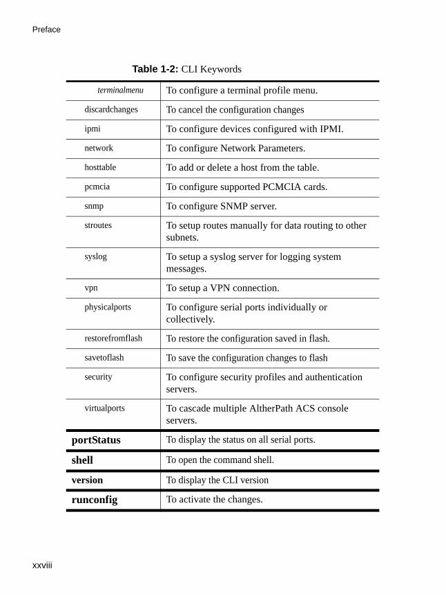
Table 1-2: CLI Keywords
administration
backupconfig To restore/save configurations from/to a FTP server or a storage device.
sessions To manage sessions
kill - End a session to a specific serial port.
list - Display the list of current serial port connections.
upgradefw To upgrade the firmware. Provide a domain name or the IP address of the server
applications
connect To access the console server connection menu.
pm To access the ACS power management menu.
view To display the data buffer files for a serial port.
config
administration
bootconfig To configure boot configuration parameters.
date/time To set the date and timer.
notifications To set up alarm notifications.
ntp To configure Network Time Protocol.
timezone To select and set a GMT zone.
application
Preface
xxviii
terminalmenu To configure a terminal profile menu.
discardchanges To cancel the configuration changes
ipmi To configure devices configured with IPMI.
network To configure Network Parameters.
hosttable To add or delete a host from the table.
pcmcia To configure supported PCMCIA cards.
snmp To configure SNMP server.
stroutes To setup routes manually for data routing to other subnets.
syslog To setup a syslog server for logging system messages.
vpn To setup a VPN connection.
physicalports To configure serial ports individually or collectively.
restorefromflash To restore the configuration saved in flash.
savetoflash To save the configuration changes to flash
security To configure security profiles and authentication servers.
virtualports To cascade multiple AltherPath ACS console servers.
portStatus To display the status on all serial ports.
shell To open the command shell.
version To display the CLI version
runconfig To activate the changes.
Table 1-2: CLI Keywords

AlterPath ACS Command Reference Guide xxix
How to use the CLI
info To display a brief description on the current CLI parameter.
quit To exit the CLI mode.
return To go up one level in the CLI menu structure.
show To display the current configuration information.
Table 1-2: CLI Keywords
Preface
xxx
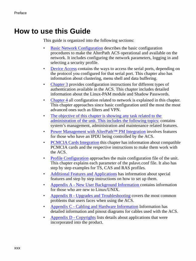
How to use this GuideThis guide is organized into the following sections:
• Basic Network Configuration describes the basic configuration procedures to make the AlterPath ACS operational and available on the network. It includes configuring the network parameters, logging in and selecting a security profile.
• Device Access contains the ways to access the serial ports, depending on the protocol you configured for that serial port. This chapter also has information about clustering, menu shell and data buffering.
• Chapter 3 provides configuration instructions for different types of authentication available in the ACS. This chapter includes detailed information about the Linux-PAM module and Shadow Passwords.
• Chapter 4 all configuration related to network is explained in this chapter. This chapter approaches since basic configuration until the most the most advanced ones such as filters and VPN.
• The objective of this chapter is showing any task related to the administration of the unit. This includes the following topics: contains system’s management, administration and maintenance related features.
• Power Management with AlterPath™ PM Integration involves features for those who have an IPDU being controlled by the ACS.
• PCMCIA Cards Integration this chapter has information about compatible PCMCIA cards and the respective instructions to make them work with the ACS.
• Profile Configuration approaches the main configuration file of the unit. This chapter explains each parameter of the pslave.conf file. It also has step by step examples for TS, CAS and RAS profiles.
• Additional Features and Applications has information about special features and step by step instructions on how to set up them.
• Appendix A - New User Background Information contains information for those who are new to Linux/UNIX.
• Appendix B - Upgrades and Troubleshooting covers the most common problems that users faces when using the ACS.
• Appendix C - Cabling and Hardware Information Information has detailed information and pinout diagrams for cables used with the ACS.
• Appendix D - Copyrights lists details about applications that were incorporated into the product.

AlterPath ACS Command Reference Guide xxxi
Conventions and Symbols
• Glossary contains information about specific words and terms used in this manual.
Conventions and SymbolsThis section explains the significance of each of the various fonts, formatting, and icons that appear throughout this guide.
Typeface and FontsThis guide uses the Times New Roman typeface for most of the body text and Courier for terminal keyboard inputs and responses, such as a command line instruction or data that you would receive back on the monitor, such as an error message. An example of this would be: # telnet 200.200.200.1 7001
Hypertext LinksReferences to another section of this manual are hypertext links are underlined (and are also blue in the PDF version of the manual). When you click on them in the PDF version of the manual, you will be taken to that section.
Glossary EntriesTerms that can be found in the glossary are underlined and slightly larger than the rest of the text. These terms hyperlinked to the glossary.
Quick StepsStep-by-step instructions for installing and configuring the ACS are numbered with a summarized description of the step for quick reference. Underneath the quick step is a more detailed description. Steps are numbered 1, 2, 3, and so on.
For example:
1. Modify the pslave.conf file.
You will modify four Linux files to let the ACS know about its local environment. Open the file plsave.conf and add the following lines...

Preface
xxxii
Parameter SyntaxThis manual uses standard Linux command syntax and conventions for the parameters described within it.
Brackets and Hyphens (dashes)Brackets ([]) indicate that the parameter inside them is optional, meaning that the command will be accepted as is if the parameter is not defined. When the text inside the brackets starts with a dash (-) or indicates a list of characters, or both, the parameter can be one of the letters listed within the brackets.
Example: iptables [-ADC] chain rule-specification [options]
EllipsesEllipses (...) indicate that the latest parameter can be repeated as many times as needed. Usually this is used to describe a list of subjects.
Example: ls [OPTION]...[FILE]...
PipesThe pipe (|) indicates that one or the other of the words separated by this character should be used in the command.
Example: netstat {--statistics|-s} [--tcp|-t] [--udp|-u] [--raw|-w]
When a configuration parameter is defined, the Linux command syntax conventions will be also used. Differences will be noted.
Greater-than and Less-than signsWhen the text is encapsulated with the “<>” characters, the meaning of the text will be considered, and not the literal text. When the text is not encapsulated, the literal text will be considered.

AlterPath ACS Command Reference Guide xxxiii
Conventions and Symbols
Spacing and SeparatorsThe list of users in the following example must be separated by semicolons (;); the outlets should be separated by commas (,) to indicate a list or with dashes(-) to indicate range; there should not be any spaces between the values.
sXX.pmusers: The user access list. For example: jane:1,2;john:3,4. The format of this field is:[<username>:<outlet list>][;<username>:<outlet list>...]
where <outlet list>'s format is:[<outlet number>|<outlet start>-<outlet end>][,<outlet number>|<outlet start>-<outlet end>]...
Cautionary and Instructional InformationNote boxes contain instructional or cautionary information that the reader especially needs to bear in mind. There are three levels of information:
Note: WARNING: A very important type of tip or warning. Do not ignore this information.
Note: IMPORTANT: An important tip that should be read. Review all of these notes for critical information.
Note: TIP: An informational tip or tool that explains and/or expedites the use of the product.

Preface
xxxiv

.................................................................
Chapter 1Basic Network Configuration
This chapter describes the procedures for setting up the basic network configuration to make AlterPath ACS available on the network. In addition, it provides procedures to login, change the default password, and setup the security profile.
Configuring network setting using the VI method or the CLI method are described in Chapter , “” in detail.
Networking SettingsThis following section describes how to configure the network parameters using the wiz command, vi, or CLI where applicable. The instructions assume that you are installing a new AlterPath ACS in your network, or you are restarting an existing unit from factory default parameters.
Performing Basic Network Configuration Using the wiz Command
The following procedure assumes that a hardware connection is made between the ACS’s console port and the COM port of a computer.
Log Into ACS Through the Console From your terminal emulation application, log into the console port as root.ACS login: rootPassword: tslinux
Note: IMPORTANT: It is strongly recommended to change the default password “tslinux” to a new password before setting up the ACS for secure access.
Basic Network Configuration
2
PasswordChange the “root” password. The default /etc/passwd file has the user “root” with password “tslinux”. You should change the password for user “root” as soon as possible.
To change any user password, run the command:# passwd <user>
Security AdvisoryThe following Security Advisory appears the first time ACS is powered on, or when the unit is reset to factory default parameters. After you have configured the basic network settings, a Security Profile must be selected before proceeding to other configuration procedures, such as user and port settings. See Selecting A Security Profile on how to configure a profile using CLI. See the ACS Installation, Administration, and User Guide for detailed information on security profiles and configuration options using the Web Manager.

AlterPath ACS Command Reference Guide 3
Networking Settings
Figure 1-1: Security Advisory

Basic Network Configuration
4
Use the wiz Command to Configure Network Parameters
1. Launch the Configuration Wizard by entering the wiz command:[root@CAS etc]# wiz
The system brings up a configuration wizard banner similar to the following figure and begins running the wizard.
Figure 1-2: Configuration Wizard Startup Screen
2. At the prompt “Set to defaults?”, enter n to change the defaults.Set to defaults (y/n)[n]: n
3. Press Enter to accept the default hostname, otherwise enter your own hostname.Hostname [CAS]: fremont_branch_ACS
4. Press Enter to keep DHCP enabled, or enter “n” to specify a static IP address for ACS.
By default, ACS uses the IP address provided by the DHCP server. If your network does not use DHCP, then ACS will default to 192.168.160.10.
********************************************** *****C O N F I G U R A T I O N W I Z A R D************************************************Current configuration:
Hostname: CASDHCP: disabledSystem IP: 192.168.48.11Domain name: cyclades.comPrimary DNS Server: 192.168.44.21Second DNS Server: #Gateway IP: 192.168.48.1Network Mask: 255.255.252.0
Set to defaults? (y/n) [n]:

AlterPath ACS Command Reference Guide 5
Networking Settings
Do you want to use DHCP to automatically assign an IP for your system? (y/n) [n] :
5. Change the default static IP address, see your network administrator to obtain a valid IP address.System IP[192.168.160.10]: ACS_IP_address
6. Enter the domain name.Domain name[cyclades.com]: domain_name
7. Enter the IP address for the Primary DNS (domain name) server.Primary DNS Server[192.168.44.21]: DNS_server_IP_address
8. Enter the IP address for the gateway.Gateway IP[eth0]: gateway_IP_address
9. Enter the netmask for the subnetwork.Network Mask[#] : netmask
The network configuration parameters appear.
10. Enter y after the prompts shown in the following screen example. Are all these parameters correct? (y/n)[n]: y
Do you want to activate your configurations now? (y/n)[y]: y
Do you want to save your configuration to Flash? (y/n)[n]: y
11. To confirm the configuration, enter the ifconfig command.

Basic Network Configuration
6
Selecting A Security ProfileA security profile must be selected before proceeding further with configuration of ACS. For detailed information on security profiles see ACS Installation, Administration, and User Guide.
To Select a Security ProfileSelect a pre-defined Security Profile, or define a Custom profile for specific services.
The available profiles are:
• Secure: Disables all protocols except SSHv2, HTTPS, and SSH to Serial Ports.
• Moderate: Enables SSHv1, SSHv2, HTTP, HTTPS, Telnet, SSH and Raw connections to Serial Ports, ICMP, and HTTP redirection to HTTPS.
• Open: Enables all services, Telnet, SSHv1, SSHv2, HTTP, HTTPS, SNMP, RPC, ICMP and Telnet, SSH and Raw connections to Serial Ports.
• Default: Sets the profile to the same configuration as Moderate profile.• Custom: Configure individual protocols and services and configure
access to ports.
CLI Mode1. Enter the CLI mode
[root@CAS etc]# CLI
2. At the prompt enter the following string.cli > config security profile

AlterPath ACS Command Reference Guide 7
Selecting A Security Profile
The following commands are available under the “profile” prompt.profile>
3. To configure a Default, Moderate, or Secured pre-defined security profile, enter the following string.profile> <moderate>
or,profile> <secured>
or,profile> <default>
4. To configure a custom security profile, navigate to the custom menu.profile > custom
5. From the custom menu enable or disable desired protocols using the following syntax.custom > [protocol] [yes/no]
6. To display the current configuration as shown in the following figure, enter:custom > show
Table 1-1: Available commands under “profile” prompt
custom info open return show
default moderate quit secured

Basic Network Configuration
8
Figure 1-3: Displaying the Current Configuration
custom>show [custom] ftp: no telnet: no .[ssh] ..[ssh_x509] CA_file: hostkey: authorizedkeys: sshv1: yes sshv2: yes sshd_port: 22 root_access: yes snmp: no .[web] http: yes https: yes http_port: 80 https_port: 443 http2https: yes rpc: no ipsec: no icmp: yes .[ports] ssh2sport: yes telnet2sport: yes raw2sport: yes auth2sport: no bidirect: yes

AlterPath ACS Command Reference Guide 9
Enabling Serial Ports
Enabling Serial PortsFrom the factory, ACS is configured with all serial ports disabled.
To Enable a Serial Port [VI method]1. From the terminal window navigate to the portslave directory to edit the
pslave.conf file.[root@CAS /] cd /etc/portslave
[root@CAS portslave]# vi pslave.conf
2. Navigate to Port-specific parameters to uncomment the sxx.tty and enable the serial ports.# Port-specific parameters
#
s1.tty ttyS1#s2.tty ttyS2#s3.tty ttyS3#s4.tty ttyS4#s5.tty ttyS5#s6.tty ttyS6#s7.tty ttyS7#s8.tty ttyS8
To Enable a Serial Port [CLI method]1. Open the CLI interface by issuing the command:
# CLI
2. To enable single or multiple serial ports enter the following command:cli>config physicalports 1,2,3,4 enable yes

Basic Network Configuration
10

.................................................................
ChaChapter 2 - Device AccessChapter 2Device Access
This chapter will introduce all the possible ways to access the serial ports of the ACS. From this point is considered that the unit is properly configured using one of the possible profiles (CAS or TS). More information about how to configure a profile can be found on Chapter 8 - Profile Configuration.
Accessing Serial PortsThere are four ways to access serial ports, depending on the protocol you configured for that serial port: setting all.protocol to socket_server for Telnet access, setting it to socket_ssh for SSH access, or setting it to socket_server_ssh both.
An administrator can access the serial port by statically addressing it (using TCP port number, alias name, or IP address) or by accessing the next free serial port available from an existent pool (by using the pool's TCP port number, alias or IP address).

Device Access
12
Default Configuration ParametersThese are the default configuration settings:
• DHCP enabled (if there is no DHCP Server, IP for Ethernet is 192.168.160.10 with a Netmask of 255.255.255.0)
• CAS configuration• socket_server in all ports (access method is Telnet)• 9600 bps, 8N1• No Authentication
Opening and closing a Telnet session to a serial port
To open a Telnet session to a serial port or the first free serial port belonging to a pool of serial ports, issue the command:# telnet <CAS hostname> <TCP port number>
where:
• <CAS hostname> is the hostname configured in the workstation where the Telnet client will run (through /etc/hosts or DNS table). It can also be just the IP address of the ACS (Ethernet's interface) configured by the user or learned from DHCP.
• <TCP port number> is the number associated to the serial port or pool of serial ports. From factory, 7001 corresponds to serial port 1, 7002 to serial port 2 and so forth, and 3000 is a pool with all serial ports.
To close the Telnet session, just press the Telnet hotkey configured in Telnet client application (usually it's "Ctrl]") and "q" to quit.

AlterPath ACS Command Reference Guide 13
Accessing Serial Ports
Opening and closing an SSH session to a serial port
To open a SSH session to a serial port or the next free serial port from a pool, issue the command:# ssh -l <Username>:<Server> <CAS hostname>
• <Username> is the user configured to access that serial port. It is present either in the local CAS database or in a Radius/Tacacs/LDAP/Kerberos, etc database.
• <Server> can be just the TCP port number assigned for that serial port (7001, 7002, etc), pool of ports (3000, etc), the alias for the server connected to that serial port or the alias of a pool of ports.
• <CAS hostname> is the hostname configured in the workstation where the SSH client will run (through /etc/hosts or DNS table). It can also be just the IP address of the ACS (Ethernet's interface) configured by the user or learned from DHCP.
To close the SSH session, press the hotkey defined for the SSH client followed by a “.”
The default is "~."
Note: Make sure you enter the escape character followed by a “.” at the beginning of a line to close the SSH session.
Accessing Serial Ports using “ts_menu”ts_menu is an application to facilitate connection to the serial ports. The following are the methods of executing the ts_menu command.
• Calling ts_menu without specifying any arguments. • Calling ts_menu with command line arguments• Using CLI to call ts_menu.
Calling ts_menu without argumentsTo access the serial port (Telnet or SSH) using ts_menu, login to the CAS unit and, after receiving the shell prompt, run ts_menu. The servers (aliases) or

Device Access
14
serial ports will be shown as option to start a connection (Telnet/SSH). After typing ts_menu, you will see something similar to the following:
Calling ts_menu with argumentsApart from calling ts_menu with no arguments (which directs the user to the traditional ts_menu interface) this application can be used with the following command line arguments:ts_menu [-u<user>] [-l[c]] [-ro] [-s] [-auth] [<console port>]
The meaning of each argument is:
• -u<user> - Invokes ts_menu as the user named by <user>. This requires a password to be entered. The user have access only to the authorized serial ports.
• -l[c] - Generates a list of all ports that the user has access to and terminates. Port aliases will be presented if defined. For the remote ports (clustering) if port alias is not defined they will be shown as "ip_addr:port" (ip_addr referring to the Slave ACS). The default is displaying ports in alphabetical order, but in case "c" flag is also specified the listing will be sorted by console server (Master unit showing first).
• -ro - Invokes ts_menu in read only mode. It works even if the user is the only one logged to a certain port. In this mode, the user can connect to any port he has access to but cannot type in. He is in sniff mode. A message stating "Read only mode" is provided in case the user attempts to interact
Serial Console Server Connection Menu for your Master Terminal Server
1 ttyS1 2 ttyS2 3 ttyS3 4 ttyS45 ttyS5 6 ttyS6 7 ttyS7 8 ttyS8
Type 'q' to quit, a valid option[1-8], or anything else to refresh:
AlterPath ACS Command Reference Guide 15
Accessing Serial Ports
with that port. Note however that a real sniff session (the user isn't the first one to log to a certain port) is only allowed if he is authorized to.
• -s - Invokes ts_menu in a way that all ports (including Slave ACSs) are presented in a single list sorted in alphabetical order. Not using this option causes the display to be as for the old implementation.
• -auth - For backward compatibility, this option makes the new ts_menu implementation behave as the old one so that authentication is performed again to access each port.
• <console port> - If issued, produces a direct connection to that port. In the case the user doesn't have access to that port or the port doesn't exist, the application returns a "console not found" message and terminates. <console port> can be the port alias or the port number. In case of clustering, port number must include a reference to the Slave ACS as "host:port" (where host is the Slave hostname or IP address).
Other options:
• -p - Display TCP port• -P - Use the TCP port instead of IP address• -i - Display Local IP assigned to the serial port• -s - Show the ports in a sorted order• -u <name> - Username to be used in SSH/Telnet command• -U - Always ask for an username• -e <[^]char> - Escape char used by Telnet or SSH
How to close the session from ts_menu (from the console of your unit)
To close the session from the ts_menu, follow the steps bellow:
1. Enter the escape character.
2. The escape character is shown when you first connect to the port. In character/text Mode, the Escape character is ^]
3. After entering the escape character, the following is shown:
Console escape. Commands are:
• l - go to line mode

Device Access
16
• c - go to character mode
• z - suspend telnet
• b - send break
• t - toggle binary
• e - exit telnet
4. Press “e” to exit from the session and return to the original menu.
5. Select the exit option and you will return to the shell prompt.
How to close the session from ts_menu (from a Telnet/SSH session to your unit)
You have to be sure that a different escape character is used for exiting your Telnet/SSH session; otherwise, if you were to exit from the session created through the ts_menu, you will close your entire Telnet session to your unit. To do this, when you first Telnet/SSH to your unit, use the -e option. So for example, to set Ctrl-? as the escape character, type:# telnet -e ^? 192.168.160.10
# ssh -e ^? [email protected]
To exit from the session created through the ts_menu, just follow Step 1 from above.
To exit from the entire Telnet session to your unit, type the escape character you had set. To exit from the entire SSH session to your unit, type the escape character you had set plus character "."(dot).
Note: To close an SSH session the escape character followed by a “.” must be entered at the beginning of a line.

AlterPath ACS Command Reference Guide 17
Accessing Serial Ports
CLI Mode - ts_menuYou can call ts_menu from the CLI interface.
1. Open the CLI interface by issuing the command:# CLI
2. Call the menu.
To call the ts_menu, access the following menu:cli> applications connect [Enter]
A screen similar to the following will appear:
3. To see the “connect” options, at the following prompt press [tab] twice.cli > applications > connect
The following options display.consolename list readonly
4. To display a list of the available ports run the following command.cli > applications > connect list
Serial Console Server Connection Menu for your Master Terminal Server
1 PM 2 ttyS3 3 ttyS4 4 ttyS5
5 ttyS6 6 ttyS7 7 ttyS8 8 ttyS9
9 ttyS10 10 ttyS11 11 ttyS12 12 ttyS13
13 ttyS14 14 ttyS15 15 ttyS16
Type 'q' to quit, 'b' to return to previous menu, a valid port[1-15], or anything else to refresh:
Device Access
18
5. To connect to the console of a device in a read-only mode run the following command. cli > applications > connect readonly consolename <consolename>
The connection is made to the device and a “Read only mode” message is displayed.
6. To make a direct connection to the console of a device run the following command.cli > applications > connect consolename <consolename>
Exiting the CLI mode.
7. To exit the CLI mode and return to ACS’s shell, type the following command:cli> quit
Data BufferingData buffering can be done in local files or in remote files through NFS. When using remote files, the limitation is imposed by the remote Server (disk/partition space) and the data is kept in linear (sequential) files in the remote Server. When using local files, the limitation is imposed by the size of the available ramdisk. You may wish to have data buffering done in file, syslog or both. For syslog, all.syslog_buffering and conf.DB_facility are the parameters to be dealt with, and syslog-ng.conf file should be set accordingly. (Please see Syslog-ng for the syslog-ng configuration file.) For the file, all.data_buffering is the parameter to be dealt with.
Conf.nfs_data_buffering is a remote network file system where data buffering will be written, instead of using the default directory /var/run/DB. When commented, it indicates local data buffering. The directory tree to which the file will be written must be NFS-mounted and the local path name is /mnt/DB_nfs. The remote host must have NFS installed and the administrator must create, export, and allow reading/writing to this directory. The size of this file is not limited by the value of the parameter s1.data_buffering, though the value cannot be zero since a zero value turns off data buffering.
The conf.nfs_data_buffering parameter format is:<server name or IP address>:<remote pathname>

AlterPath ACS Command Reference Guide 19
Data Buffering
If data buffering is turned on for port 1, for example, the data will be stored in the file ttyS1.data in local directory /var/run/DB or in remote path name and server indicated by conf.nfs_data_buffering.
RamdisksData buffering files are created in the directory /var/run/DB. If the parameter s<nn>.alias is configured for the port <nn>, this name will be used. For example, if the alias is called bunny, the data buffering file will be named bunny.data.
Linear vs. Circular BufferingFor local data buffering, this parameter allows users to buffer data in either a circular or linear fashion. Circular format (cir) is a revolving buffer file that is overwritten whenever the limit of the buffer size (set by all.data_buffering) is reached. In linear format (lin), data transmission between the remote device and the serial port ceases once the 4k bytes Rx buffer in the kernel is reached. Then if a session is established to the serial port, the data in the buffer is shown (all.dont_show_DBmenu or sxx.dont_show_DBmenu must be 2), cleared, and data transmission is resumed. Linear buffering is impossible if flow control is set to none. Default is cir.
How to Configure VI mode - Parameters Involved and Passed Values
To configure Data Buffering, follow the steps bellow:
1. Open the /etc/portslave/pslave.conf file.
All parameters related to Data Buffering are in the pslave.conf file. Change the desired parameters according to the table below:

Device Access
20
Table 2-1: Data buffering parameters in /etc/portslave/pslave.conf file
Parameter Description
all.data_buffering A non zero value activates data buffering (local or remote, according to what was configured in the parameter conf.nfs_data_buffering). If local data buffering, a file is created on the ACS; if remote, a file is created through NFS in a remote server. All data received from the port is captured in this file. If local data buffering, this parameter means the maximum file size (in bytes). If remote, this parameter is just a flag to activate (greater than zero) or deactivate data buffering. When local data buffering is used, each time the maximum file size is reached the oldest 10% of stored data is discarded, releasing space for new data (FIFO system) - circular file. When remote data buffering is used, there's no maximum file size other than the one imposed by the remote server - linear file. This file can be viewed using the normal UNIX tools (cat, vi, more, tail, etc...). Size is in BYTES not kilobytes.
conf.nfs_data_buffering
This is the Remote Network File System where data captured from the serial port will be written instead of being written to the local directory /var/run/ DB. The directory tree to which the file will be written must be NFS-mounted, so the remote host must have NFS installed and the administrator must have created, exported and allowed reading/writing to this directory. The size of this file is not limited by the value of the parameter all.data_buffering, though the value cannot be zero since a zero value turns off data buffering. The size of the file is dependent on the NFS server only (hard drive, partition size, etc.).
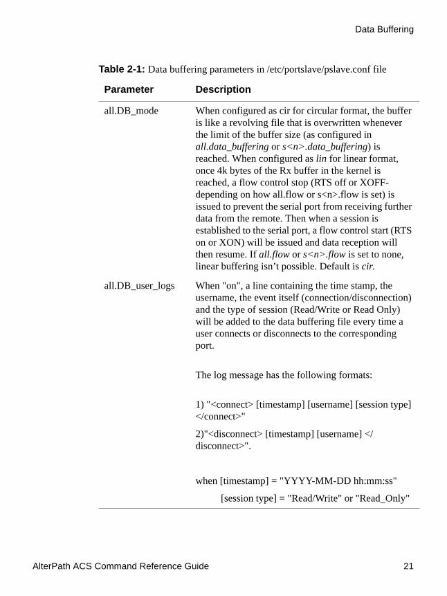
AlterPath ACS Command Reference Guide 21
Data Buffering
all.DB_mode When configured as cir for circular format, the buffer is like a revolving file that is overwritten whenever the limit of the buffer size (as configured in all.data_buffering or s<n>.data_buffering) is reached. When configured as lin for linear format, once 4k bytes of the Rx buffer in the kernel is reached, a flow control stop (RTS off or XOFF-depending on how all.flow or s<n>.flow is set) is issued to prevent the serial port from receiving further data from the remote. Then when a session is established to the serial port, a flow control start (RTS on or XON) will be issued and data reception will then resume. If all.flow or s<n>.flow is set to none, linear buffering isn’t possible. Default is cir.
all.DB_user_logs When "on", a line containing the time stamp, the username, the event itself (connection/disconnection) and the type of session (Read/Write or Read Only) will be added to the data buffering file every time a user connects or disconnects to the corresponding port.
The log message has the following formats:
1) "<connect> [timestamp] [username] [session type] </connect>"
2)"<disconnect> [timestamp] [username] </disconnect>".
when [timestamp] = "YYYY-MM-DD hh:mm:ss"
[session type] = "Read/Write" or "Read_Only"
Table 2-1: Data buffering parameters in /etc/portslave/pslave.conf file
Parameter Description

Device Access
22
all.syslog_buffering
When non zero, the contents of the data buffer are sent to the syslog-ng every time a quantity of data equal to this parameter is collected. The syslog level for data buffering is hard coded to level 5 (notice) and facility is local plus
conf.DB_facility. The file /etc/syslog-ng/syslog-ng.conf
should be set accordingly for the syslog-ng to take some action. For more information about it consult “Syslog-ng” on page 173.
all.syslog_sess This parameter determines whether syslog is generated when a user is connected to the port or not. Originally, syslog is always generated whether the user is connected to the port or not. Now, ACS administrators have the option to NOT have syslog generate messages when there is a user connected to a port. This feature does not affect the local data_buffering file. When set to 0 (default), syslog is always generated. When set to 1, syslog is only generated when there are no users connected to the port sending the data. When a user connects to the port that is sending data, syslog messages stop being generated.
all.dont_show_DBmenu
When zero, a menu with data buffering options is shown when a user connects to a port with a non empty data buffering file. When 1, the data buffering menu is not displayed. When 2, the data buffering menu is not shown but the data buffering file is displayed if not empty. When 3, the data buffering menu is shown, but without the erase and show and erase options.
Table 2-1: Data buffering parameters in /etc/portslave/pslave.conf file
Parameter Description
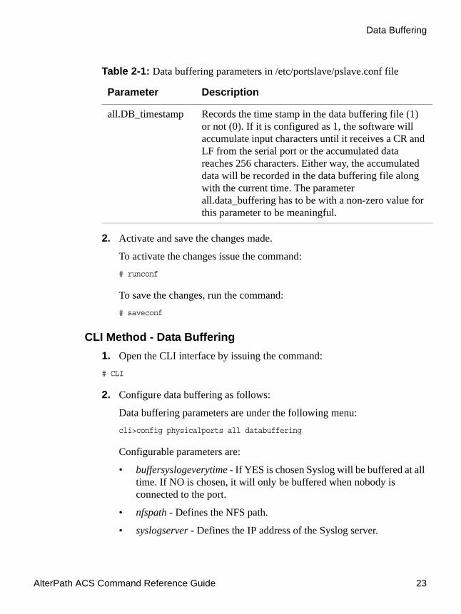
AlterPath ACS Command Reference Guide 23
Data Buffering
2. Activate and save the changes made.
To activate the changes issue the command:# runconf
To save the changes, run the command:# saveconf
CLI Method - Data Buffering1. Open the CLI interface by issuing the command:# CLI
2. Configure data buffering as follows:
Data buffering parameters are under the following menu:cli>config physicalports all databuffering
Configurable parameters are:
• buffersyslogeverytime - If YES is chosen Syslog will be buffered at all time. If NO is chosen, it will only be buffered when nobody is connected to the port.
• nfspath - Defines the NFS path.
• syslogserver - Defines the IP address of the Syslog server.
all.DB_timestamp Records the time stamp in the data buffering file (1) or not (0). If it is configured as 1, the software will accumulate input characters until it receives a CR and LF from the serial port or the accumulated data reaches 256 characters. Either way, the accumulated data will be recorded in the data buffering file along with the current time. The parameter all.data_buffering has to be with a non-zero value for this parameter to be meaningful.
Table 2-1: Data buffering parameters in /etc/portslave/pslave.conf file
Parameter Description

Device Access
24
• filesize - Defines the maximum size of the data buffer file. This parameter must be greater than zero otherwise all parameters relating to data buffering are disregarded.
• showmenu - Controls the DB menu options. Valid values are: yes, no, noerase, file.
• syslogsize - Maximum size of syslog data buffer message.
• mode - Chooses between circular or linear data buffering.
• syslogfacility - Defines the facility number for messages generated by the ACS to be sent to the Syslog server.
• timestamp - Choose YES to enable timestamp and NO to disable it.
3. Activate the configuration.cli> config runconfig
4. Save the configuration.cli> config savetoflash
5. Exiting the CLI mode.
To exit the CLI mode and return to ACS’s shell, type the following command:cli> quit

AlterPath ACS Command Reference Guide 25
Menu Shell
Menu ShellThis application allows you to customize the menu presented to users when they connect to the ACS from a dumb terminal. The menu can be set up to allow users to connect to different servers; thereby, making it quick and easy for users to connect to the those servers on the LAN.
How to useOnce the appropriate configurations are done the user will connect to the ACS using a serial terminal. The user will then automatically receive a menu similar to that shown below:
The user selects the option required to connect to the desired server or to exit the system.
How to configureBasically the configuration for this feature is divided in two parts that are going to be described in this section.
First, it is necessary to assign which users are going to use the Menu Shell by using the proper options provided by the menush_cfg utility. The second part is
Welcome!
1) Sun server2) Dell server3) Linux server4) Quit
Option ==>

Device Access
26
Setting up the Menu Shell1. Type "menush_cfg" and use the options shown below to define the menu
title and menu commands.
2. Choose the second option (Add Menu Option) and complete the requested fields.
The first question will be:Enter the name for the new menu option:
3. Enter a description of the host to be accessed.
The second question defines the action that must be taken:Enter the command for the new menu option:
Note: Action can be telnet host_ip or ssh -l username host_ip where host_ip is the IP address of the server to connect to.
4. Save the changes.
Save the changes made by choosing the fifth option:
5. Save the configuration to Flash
-------------------------------------------------MenuShell Configuration Utility
-------------------------------------------------
Please choose from one of the following options:
1. Define Menu Title2. Add Menu Option3. Delete Menu Option4. List Current Menu Settings5. Save Configuration to Flash6. Quit
Option ==>

AlterPath ACS Command Reference Guide 27
Menu Shell
Assigning ports to the Menu ShellTo configure which ports will prompt the menu shell, and if a given port will require authentication to gain access, follow the steps bellow:
1. If no authentication is required to gain access to the menu:
Configure the following parameters in /etc/portslave/pslave.conf for the ports that will use this menu shell.s<x>.protocol telnetconf.telnet /bin/menushs<x>.authtype none
Where <x> is the port number being configured.
2. If authentication is required to gain access to the menu:
The users default shell must be modified to run the /bin/menush. So in /etc/passwd the shell should be changed as follows. There should be something like:user:FrE6QU:505:505:Embedix User,,,:/home/user:/bin/menush
3. In pslave.conf, the port where the serial terminal is attached must be configured for login with local authentication. Configure the following lines:s<x>.protocol logins<x>.authtype local
Where <x> is the port number being configured.
4. Activating and saving the changes made.
To activate the changes issue the command:# runconf
To save the changes, run the command:# saveconf

Device Access
28
CLI Method - Terminal Profile MenuTo set up which servers the users can access, follow the steps below:
1. Open the CLI interface by issuing the command:# CLI
2. Configure the terminal menu. (In this step we will configure the menu that will be prompted to the user connecting from a dumb terminal.)
a. Enter the terminal menu configuration:cli>config applications terminalmenu
b. Define the menu title, example:terminalmenu>menutitle "Available Servers"
c. Create the entries. The example below will add an entry named “Server1” opening a Telnet connection to 192.168.100.3:
terminalmenu>add actionname Server1 command "telnet 192.168.100.3"
Note: You may also open a SSH connection to the desired server. To do so, substitute “telnet host_ip” with “ssh -l username host_ip”.
3. Activate the configuration.cli>config runconfig
4. Save the configuration.cli> config savetoflash
5. Exiting the CLI mode.
To exit the CLI mode and return to ACS’s shell, type the following command:cli> quit
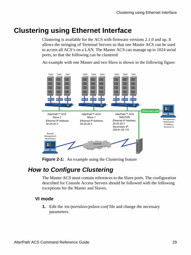
AlterPath ACS Command Reference Guide 29
Clustering using Ethernet Interface
Clustering using Ethernet InterfaceClustering is available for the ACS with firmware versions 2.1.0 and up. It allows the stringing of Terminal Servers so that one Master ACS can be used to access all ACS‘s on a LAN. The Master ACS can manage up to 1024 serial ports, so that the following can be clustered:
An example with one Master and two Slave is shown in the following figure:
Figure 2-1: An example using the Clustering feature
How to Configure ClusteringThe Master ACS must contain references to the Slave ports. The configuration described for Console Access Servers should be followed with the following exceptions for the Master and Slaves.
VI mode1. Edit the /etc/portslave/pslave.conf file and change the necessary
parameters.

Device Access
30
The related file for clustering configuration is /etc/portslave/pslave.conf. To edit this file, run the command:# vi /etc/portslave/pslave.conf
Edit parameters according to the explanation provided in the following table.:
Table 2-2: Master configuration (where it differs from the CAS standard)
Parameter Description Examples/ Valid Values
conf.eth_ip Ethernet Interface IP address. 20.20.20.1
conf.eth_ip_alias Secondary IP address for the Ethernet Interface (needed for clustering feature).
209.81.55.110
conf.eth_mask_alias
Mask for secondary IP address above.
255.255.255.0
all.socket_port This value applies to both the local ports and ports on Slave ACS.
7001+
all.protocol Depends on the application. socket_ssh, socket_server, or socket_server_ssh
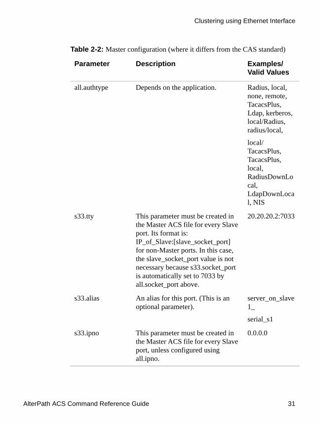
AlterPath ACS Command Reference Guide 31
Clustering using Ethernet Interface
all.authtype Depends on the application. Radius, local, none, remote, TacacsPlus, Ldap, kerberos, local/Radius, radius/local,
local/TacacsPlus, TacacsPlus, local, RadiusDownLocal, LdapDownLocal, NIS
s33.tty This parameter must be created in the Master ACS file for every Slave port. Its format is: IP_of_Slave:[slave_socket_port] for non-Master ports. In this case, the slave_socket_port value is not necessary because s33.socket_port is automatically set to 7033 by all.socket_port above.
20.20.20.2:7033
s33.alias An alias for this port. (This is an optional parameter).
server_on_slave1_
serial_s1
s33.ipno This parameter must be created in the Master ACS file for every Slave port, unless configured using all.ipno.
0.0.0.0
Table 2-2: Master configuration (where it differs from the CAS standard)
Parameter Description Examples/ Valid Values

Device Access
32
s34.tty See s33.tty. 20.20.20.2:7034
s34.alias An alias for this port. server_on_slave1_
serial_s2
s34.ipno See s33.ipno. 0.0.0.0
s35.tty See s33.tty. 20.20.20.2:7035
s35.alias An alias for this port. server_on_slave1_
serial_s3
s35.ipno See s33.ipno. 0.0.0.0
etc. for s36-s64
s65.tty The format of this parameter is
IP_of_Slave:[slave_socket_port] for non-Master ports. The value 7301 was chosen arbitrarily for this example.
20.20.20.3:7301
S65.alias An alias for this port. server_on_slave2_
serial_s1
S65.ipno See s33.ipno. 0.0.0.0
S66.tty See s65.tty. 20.20.20.3:7302
S66.alias An alias for this port. server_on_slave2_
serial_s2
Table 2-2: Master configuration (where it differs from the CAS standard)
Parameter Description Examples/ Valid Values

AlterPath ACS Command Reference Guide 33
Clustering using Ethernet Interface
2. To configure the first Slave unit, follow the table below.
The Slave ACS’s need not be aware that they are being accessed through the Master ACS. You are creating virtual terminals: virtual serial ports. The Slave ACS’s port numbers, however, must agree with those assigned by the Master. To configure the Slave units, follow the table below:
S66.ipno See s33.ipno. 0.0.0.0
S67.tty See s65.tty. 20.20.20.3:7303
S67.alias An alias for this port. server_on_slave2_
serial_s3
S67.ipno See s33.ipno. 0.0.0.0
etc. for s68-s96
Table 2-3: Slave 1 configuration (where it differs from the CAS standard)
Parameter Value for this example
all.protocol socket_server
all.authtype none
conf.eth_ip 20.20.20.2
all.socket_port 7033+
Table 2-2: Master configuration (where it differs from the CAS standard)
Parameter Description Examples/ Valid Values

Device Access
34
3. Configure the ACS second Slave.
To configure the second Slave, follow the parameters of the table below:
4. Activate and save the changes made.
To activate the changes issue the command:# runconf
To save the changes, run the command:# saveconf
5. Access the ports. To access ports from the remote management workstation, use Telnet with the secondary IP address.
a. To access the first port of the Master ACS:# telnet 209.81.55.110 7001
b. To access the first port of the Slave1 ACS:# telnet 209.81.55.110 7033
c. To access the first port of the Slave2 ACS:# telnet 209.81.55.110 7301
Note: SSH can also be used from the remote management workstation.
d. To access the third port of Slave 2:# ssh -l <username>:Server_on_slave2_serial_s3 209.81.55.110
Table 2-4: Slave 2 configuration (where it differs from the CAS standard)
Parameter Value for this example
all.protocol socket_server
all.authtype none
conf.eth_ip 20.20.20.3
all.socket_port 7301+

AlterPath ACS Command Reference Guide 35
Clustering using NAT (Enhanced)
e. To access the fifth port of Slave 2:# ssh -l <username>:7305 209.81.55.110
Note: It is possible to get the clustering channel tunneled by way of IPSec. For more information about IPSec, see VPN Configuration.
Clustering using NAT (Enhanced)With Enhanced Clustering, the CAS ports in the Slave ACS can be configured as SSH or Telnet and can have any type of authentication available. Authentication is performed in the Slave and not in the Master anymore. Additionally, the Master no longer needs to be the default gateway for all Slave ACSs.
Enhanced clustering is available on implementations running Linux 2.4.x versions or newer. This new implementation is based on “iptables/nat” which is only available in these higher versions of Linux. Enhanced Clustering has improved performance and security. Performance is greatly increased because only the NAT translation is performed on the Master ACS. The Master doesn't open an intermediary TCP connection with the Slave ACS. Also if SSH encryption and decryption is desired, it is performed on the Slave.
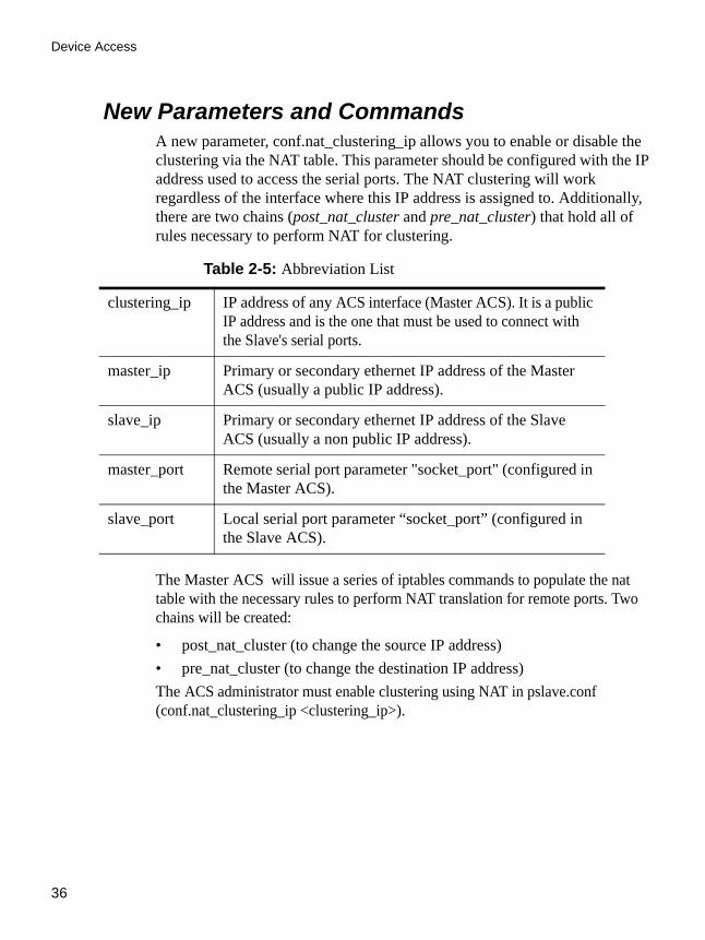
Device Access
36
New Parameters and CommandsA new parameter, conf.nat_clustering_ip allows you to enable or disable the clustering via the NAT table. This parameter should be configured with the IP address used to access the serial ports. The NAT clustering will work regardless of the interface where this IP address is assigned to. Additionally, there are two chains (post_nat_cluster and pre_nat_cluster) that hold all of rules necessary to perform NAT for clustering.
The Master ACS will issue a series of iptables commands to populate the nat table with the necessary rules to perform NAT translation for remote ports. Two chains will be created:
• post_nat_cluster (to change the source IP address)• pre_nat_cluster (to change the destination IP address) The ACS administrator must enable clustering using NAT in pslave.conf (conf.nat_clustering_ip <clustering_ip>).
Table 2-5: Abbreviation List
clustering_ip IP address of any ACS interface (Master ACS). It is a public IP address and is the one that must be used to connect with the Slave's serial ports.
master_ip Primary or secondary ethernet IP address of the Master ACS (usually a public IP address).
slave_ip Primary or secondary ethernet IP address of the Slave ACS (usually a non public IP address).
master_port Remote serial port parameter "socket_port" (configured in the Master ACS).
slave_port Local serial port parameter “socket_port” (configured in the Slave ACS).

AlterPath ACS Command Reference Guide 37
Clustering using NAT (Enhanced)
# iptables -D PREROUTING -t nat -p tcp -j pre_nat_cluster# iptables -D POSTROUTING -t nat -p tcp -j post_nat_cluster# iptables -t nat -F post_nat_cluster# iptables -t nat -F pre_nat_cluster# iptables -t nat -X pre_nat_cluster# iptables -t nat -X post_nat_cluster# iptables -t nat -N pre_nat_cluster# iptables -t nat -N post_nat_cluster# iptables -A PREROUTING -t nat -p tcp -j pre_nat_cluster# iptables -A POSTROUTING -t nat -p tcp -j post_nat_cluster# iptables -A pre_nat_cluster -t nat -p tcp -d <master_ip> --dport <master_port> -j DNAT --to <slave_ip>:<slave_port>.....# iptables -A post_nat_cluster -t nat -p tcp -d <slave_ip> --dport <slave_port> -j SNAT --to <master_ip>.....
At any time you can issue an iptables command to view, change (at his own risk), or delete the rules in the nat table. If the administrator issues a “fwset restore” command he must also execute the command “runconf” to recover the nat table.
ACS clustering was primarily designed to allow a large number of serial ports (in more than one ACS) to be accessed using just one single public IP address. It only works for ports configured with the CAS profile. With iptables you can extend the access to the clustering.
Examples:1. Accessing a Slave ACS with the WebUI from anywhere:
# iptables -A PREROUTING -t nat -p tcp -d 192.168.47.79 --dport 8081 -j DNAT --to 192.168.51.2:80
2. Accessing a public DNS from any Slave ACS:# iptables -A PREROUTING -t nat -p udp -d 64.186.161.2 --dport 53 -j SNAT--to 64.186.161.79:53

Device Access
38
How it worksThe Master ACS will perform two translations for each packet. The destination IP address is translated in the PREROUTING stage. The source IP address is translated in the POSTROUTING stage.
The command to start a Telnet client session looks like this:# telnet <clustering_ip> <master_port>
Also, it will have the same result as the command below issued from a local workstation:# telnet <slave_ip> <slave_port>
The command to start a SSH client session must have the following command line option:# -p <master_port>
The <master_port> will define at least the Slave ACS with which a connection is desired.
For example, you may use the following commands:# ssh -l <username1>:<server1> -p 7101 <master_ip> # ssh -l <username2>:<server2> -p 7101 <master_ip>
The above commands will respectively have the same result as the following commands issued from a local workstation:# ssh -l <username1>:<server1> <slave1_ip> # ssh -l <username2>:<server2> <slave1_ip>
If the parameter <master_port> defines the local IP address assigned to the serial port, the command can be simplified:# ssh -l <username1> -p 7101 <master_ip> # ssh -l <username2> -p 7102 <master_ip>
Also, it will have respectively the same result as the commands below issued from a local workstation:# ssh -l <username1> <slave1_port1_ip> # ssh -l <username2> <slave2_port1_ip>

AlterPath ACS Command Reference Guide 39
Clustering using NAT (Enhanced)
Note: IMPORTANT: In previous clustering implementations, <username?> and <server?> had to be valid in the Master ACS unit. In the newest clustering implementation, <username?> and <server?> must be valid in the Slave unit. In the Master ACS unit, the remote port's alias and authtype parameters are not used. If you wish to access all clustering ports with the SSH command option -p port, you must assign an IP address to the serial port. Do not omit the parameter socket_port in the Master ACS.
General ConfigurationThe configuration for clustering ports is pretty much the same as before. There is only one new parameter in the Master ACS (conf.nat_clustering_ip) that enables or disables the clustering via NAT. The parameters usernames (if authentication is local) and alias for remote ports must be configured now in the related Slave ACS.
In the following configuration examples, looking like “s[1-32].tty ttyS[1-32]” must be seen as 32 lines. For example:s1.tty ttyS1s2.tty ttyS2...s32.tty ttyS32

Device Access
40
Master ACS ConfigurationAll mentioned instructions must be made in the /etc/portslave/pslave.conf file of the Master ACS
#Master box Configuration#Enable Clustering via NAT#
conf.nat_clustering_ip 64.186.161.108
##Primary ethernet IP address (must be the public IP).#
conf.eth_ip 64.186.161.108conf.eth_mask 255.255.255.0
conf.eth_mtu 1500#
# Secondary ethernet IP address#
conf.eth_ip_alias 192.168.170.1conf.eth_mask_alias 255.255.255.0
## Local CAS serial ports (32 socket_ssh ports)#
all.protocol socket_sshall.authtype localall.socket_port 7001+
s[1-32].tty ttyS[1-32]#
#Remote CAS serial ports, slave-1 (32 socket_ssh ports). This kind of#configuration can be used for ssh only; just one entry is necessary.
Figure 2-2: Master ACS: /etc/portslave/pslave.conf

AlterPath ACS Command Reference Guide 41
Clustering using NAT (Enhanced)
s33.tty 192.168.170.2s33.socket_port 7000
s65.protocol socket_servers66.protocol socket_server...s96.protocol socket_server
## Remote CAS serial ports, slave-2 (32 socket_server ports)#
s65.tty 192.168.170.3:7101s66.tty 192.168.170.3:7102....
s96.tty 192.168.170.3:7132
s65.socket_port 8001s66.socket_port 8002...s96.socket_port 8032
## Remote CAS serial ports, slave-3 (32 socket_ssh ports)#
s97.tty 192.168.170.101s98.tty 192.168.170.102s99.tty 192.168.170.103...
Figure 2-2: Master ACS: /etc/portslave/pslave.conf
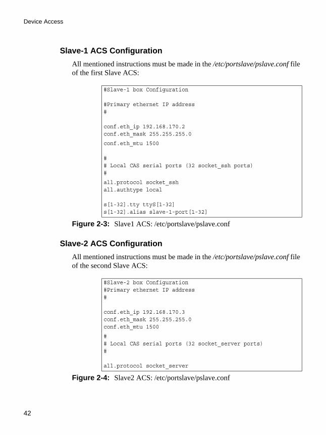
Device Access
42
Slave-1 ACS ConfigurationAll mentioned instructions must be made in the /etc/portslave/pslave.conf file of the first Slave ACS:
Slave-2 ACS ConfigurationAll mentioned instructions must be made in the /etc/portslave/pslave.conf file of the second Slave ACS:
#Slave-1 box Configuration
#Primary ethernet IP address#
conf.eth_ip 192.168.170.2conf.eth_mask 255.255.255.0
conf.eth_mtu 1500
## Local CAS serial ports (32 socket_ssh ports)#
all.protocol socket_sshall.authtype local
s[1-32].tty ttyS[1-32]s[1-32].alias slave-1-port[1-32]
Figure 2-3: Slave1 ACS: /etc/portslave/pslave.conf
#Slave-2 box Configuration#Primary ethernet IP address#
conf.eth_ip 192.168.170.3conf.eth_mask 255.255.255.0conf.eth_mtu 1500
## Local CAS serial ports (32 socket_server ports)#
all.protocol socket_server
Figure 2-4: Slave2 ACS: /etc/portslave/pslave.conf

AlterPath ACS Command Reference Guide 43
Clustering using NAT (Enhanced)
Slave-3 ACS ConfigurationAll mentioned instructions must be made in the /etc/portslave/pslave.conf file of the third Slave ACS:
Example of starting CAS session commandsThe alias, socket_port, or tty must be provided to select which serial port is to be connected to in the Slave ACS 1. # ssh -l <username>:<slave-1-port[1-32]> -p 7000 64.186.161.108
The master_port (socket_port in the Master) will select which serial port is to be connected to in the Slave ACS devices 1 and 2.# telnet 64.186.161.108 80[01-32]
# ssh -l <username> -p [7097-7128] 64.186.161.108
all.authtype localall.socket_port 7101+
s[1-32].tty ttyS[1-32]
#Slave-3 box Configuration# Primary ethernet IP address#
conf.eth_ip 192.168.170.4conf.eth_mask 255.255.255.0conf.eth_mtu 1500
## Local CAS serial ports (32 socket_ssh ports)
#all.protocol socket_sshall.authtype localall.ipno 192.168.170.101+
s[1-32].tty ttyS[1-32]
Figure 2-5: Slave2 ACS: /etc/portslave/pslave.conf
Figure 2-4: Slave2 ACS: /etc/portslave/pslave.conf

Device Access
44
CLI Method - ClusteringThe clustering process is made using the ethernet interface, so that no special connection is needed between the ACS devices. They must be connected in the same physical network.
Use the CLI to configure one ACS (as Master) to control another ACS (Slave), using the following example.
Setup for the example:
• Master ACS - 4 port unit; 172.22.65.2 as IP address• Slave ACS - 32 port unit; 172.22.65.3 as IP address• Telnet protocol to access the serial ports.Procedure:
1. Open the CLI interface by issuing the command:# CLI
2. Add a Slave ACS.cli>config virtualports addslave 172.22.65.3
3. Configure the Slave ACS using the values shown below.
Note: All parameters that have to be configured will be listed, commented and given the correct value for this example.
• numports: This sets the total number of ports of the Slave ACS. The value for this example is 32.
• firstlocalportnum: This parameter will act as the numbering continuation in the Slave ACS. As the Master unit is a 4 port ACS, the first port of the Slave unit will be the first local port number. The value for this example is 5.
• localip: To set the IP address of the Slave ACS. The value for the example is 172.22.65.3.
• firstlocaltcpport: Such as the firstlocalportnum parameter, but setting the tcp port. The value for the example is 7005.

AlterPath ACS Command Reference Guide 45
Clustering using NAT (Enhanced)
• remoteip: The IP address of the Master ACS. The value for this example is: 172.22.65.2.
• firstremotetcpport: Where tcp port numbering starts in the Master ACS The value for this example is: 7001.
• protocol: Protocol used to access the ports. Valid values are: telnet or SSH.
4. Activate the configuration.cli>config runconfig
5. Save the configuration.cli>config savetoflash
6. Test the configuration.
Telnet to port 10 of the Slave ACS. Supposing you are in the same network as the Master ACS, run the command:# telnet 172.22.65.2 7014
You can also edit or delete any previously configured virtual port:
cli>config virtualports editslave <n.n.n.n>cli>config virtualports deleteslave <n.n.n.n>
Where n.n.n.n is the IP address of the configured virtual port.
a. Exiting the CLI mode.
To exit the CLI mode and return to ACS’s shell, type the following command:
cli> quit

Device Access
46

.................................................................
Chapter 3 - AuthenticationChapter 3Authentication
This chapter presents the procedures for assigning and configuring the authentication service(s) that the ACS, system or any of its components and devices will be using. Authentication is the process by which the system, or more specifically, an authentication service such as Kerberos, Ldap or Tacacs, verifies the identity of users (to verify who they claim to be) as well as to confirm receipt of communication to authorized recipients. This chapter includes the following topics:
• Device Authentication• Linux-PAM• Shadow Passwords• Certificate for HTTP Security• X.509 Certificate on SSH
Device AuthenticationAuthentication is the process of identifying an individual, usually based on a username and password. In security systems, authentication is distinct from authorization, which is the process of giving individuals access to system objects based on their identity. Authentication merely ensures that the individual is who he or she claims to be, but says nothing about the access rights of the individual. With the ACS, authentication can be performed locally, or with a remote Radius, TACACS, LDAP database, or Kerberos.

Authentication
48
How to configureFollow the steps below to configure an authentication type.
VI mode - Parameters involved and passed valuesTo configure the authentication type of the ACS, follow the steps below:
1. Edit the /etc/portslave/pslave.conf file.
Edit the all.authtype parameter in the pslave.conf file to specify the type of authentication server being configured. The table below contains a brief description of each authentication type.
Table 3-1: Authentication parameters in /etc/portslave/pslave.conf
Parameter Description
all.authtype Type of authentication used. There are several authentication type options:
• None (no authentication)
Note: This option is invalid when the serial port is configured for Power Management. The system defaults to “Local” if no authentication type is selected.
• Local (authentication is performed using the /etc/passwd file)• Remote (This is for a terminal profile only. The unit takes in a
username but does not use it for authentication. Instead it passes it to the remote server where it is then used for authentication.)
• Radius (authentication is performed using a Radius authentication server)
• TacacsPlus (authentication is performed using a TacacsPlus authentication server)

AlterPath ACS Command Reference Guide 49
Device Authentication
all.authtype (cont.)
• Ldap (authentication is performed against an ldap database using an ldap server. The IP address and other details of the ldap server are defined in the file /etc/ldap.conf)
• Kerberos (authentication is performed using a kerberos server. The IP address and other details of the kerberos server are defined in the file /etc/krb5.conf)
• Local/Radius (authentication is performed locally first, switching to Radius if unsuccessful)
• Radius/Local (the opposite of the previous option)• Local/TacacsPlus (authentication is performed locally first,
switching to TacacsPlus if unsuccessful)• TacacsPlus/Local (the opposite of the previous option)• RadiusDownLocal (local authentication is tried only when the
Radius server is down)• TacacsPlusDownLocal (local authentication is tried only when the
TacacsPlus server is down)• Kerberos/Local (Kerberos authentication is tried first, switching
to Local if unsuccessful)• KerberosDownLocal (local authentication is tried only when the
kerberos server is down)• Ldap/Local (LDAP authentication is tried first, switching to local if
unsuccessful)• LdapDownLocal (local authentication is tried only when the ldap
server is down)• NIS - All authentication types but NIS follow the format all.authtype
<Authentication>DownLocal or <Authentication> (e.g. all.authtype radius or radiusDownLocal or ldap or ldapDownLocal, etc). NIS requires all.authtype to be set as local, regardless if it will be "nis" or its “Downlocal" equivalent. The service related to "nis" or its “Downlocal" equivalent would be configured in the /etc/nsswitch.conf file, not in the /etc/portslave/pslave.conf file.
• OTP - One Time Password authentication is supported for certain types of access. See “One Time Password Authentication on the ACS” on page 52.
• OTP/Local - If normal OTP authentication fails for any reason, a local authentication method will be provided.
Note that this parameter controls the authentication required by the AlterPath ACS. The authentication required by the device to which the user is connecting is controlled separately.
Table 3-1: Authentication parameters in /etc/portslave/pslave.conf
Parameter Description
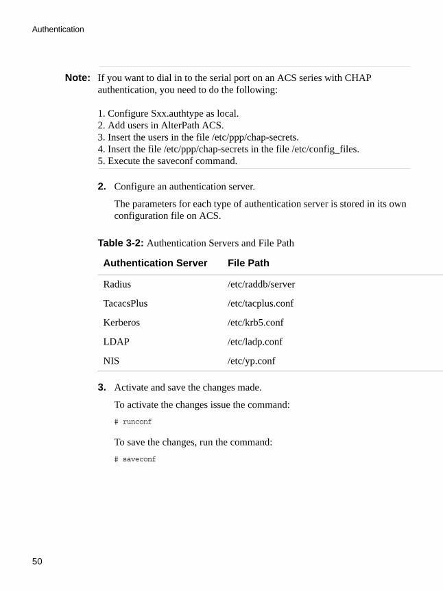
Authentication
50
Note: If you want to dial in to the serial port on an ACS series with CHAP authentication, you need to do the following:
1. Configure Sxx.authtype as local.2. Add users in AlterPath ACS.3. Insert the users in the file /etc/ppp/chap-secrets.4. Insert the file /etc/ppp/chap-secrets in the file /etc/config_files.5. Execute the saveconf command.
2. Configure an authentication server.
The parameters for each type of authentication server is stored in its own configuration file on ACS.
3. Activate and save the changes made.
To activate the changes issue the command:# runconf
To save the changes, run the command:# saveconf
Table 3-2: Authentication Servers and File Path
Authentication Server File Path
Radius /etc/raddb/server
TacacsPlus /etc/tacplus.conf
Kerberos /etc/krb5.conf
LDAP /etc/ladp.conf
NIS /etc/yp.conf
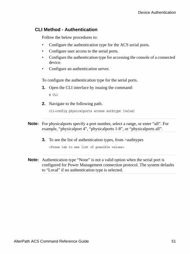
AlterPath ACS Command Reference Guide 51
Device Authentication
CLI Method - AuthenticationFollow the below procedures to:
• Configure the authentication type for the ACS serial ports.• Configure user access to the serial ports.• Configure the authentication type for accessing the console of a connected
device.• Configure an authentication server.
To configure the authentication type for the serial ports.
1. Open the CLI interface by issuing the command:# CLI
2. Navigate to the following path.cli>config physicalports access authtype [value]
Note: For physicalports specify a port number, select a range, or enter “all”. For example, “physicalport 4”, “physicalports 1-8”, or “physicalports all”.
3. To see the list of authentication types, from >authtypes <Press tab to see list of possible values>
Note: Authentication type “None” is not a valid option when the serial port is configured for Power Management connection protocol. The system defaults to “Local” if no authentication type is selected.

Authentication
52
One Time Password Authentication on the ACSThis section describes what the ACS administrator must do to configure OTP authentication.
OPIE (one-time passwords in everything) software on the ACS supports the one time password (OTP) authentication method for some types of access. The OTP authentication method and the OTP/Local fallback option are supported for serial ports, and the OTP authentication method is supported for dial-ins through modem, GSM, and CDMA PCMCIA cards.
Note: OTP authentication is not supported for logins to the OnSite or to KVM ports.
ACS administrators must perform OTP configuration tasks in the order given in the following bulleted list:
• The ACS root user manually enables OTP and configures where to mount the OPIE databases.
• An ACS administrative user may also use the Web Manager or CLI to configure OTP authentication to be used for dial-ins to modem, GSM, and CDMA PCMCIA cards.
• An ACS administrative user may also use the Web Manager, OSD, or CLI to configure OTP or OTP/Local authentication methods for serial port logins or serial port dial-ins, when a modem is connected to a serial port configured for PPP access.
• An ACS administrator must make sure each user who needs to use OTP has a local account on the ACS, is registered with the OTP system, and is able to obtain the OTP passwords, OTP username, and secret pass phrase needed for login.
The following table lists the OTP authentication configuration tasks and where they are documented

AlterPath ACS Command Reference Guide 53
Device Authentication
Table 3-3: Tasks for Configuring OTP Authentication
Task Where Documented
Edit the /etc/otp.conf file to configure the location used for storage of OPIE databases.
“Editing the otp.conf File” on page 55
Run the /bin/do_create_otpdb script to initialize OTP and mount the directory to be used for OPIE database storage.
“To Specify the Location for the OTP Databases” on page 56
Configure OTP or OTP/Local as the authentication method for access to all serial ports or individual serial ports.
Web Manager: “To Configure a Serial Port Login Authentication Method [Expert]” on page 231
OSD:“To Specify an Authentication Method for Serial Ports” on page 457
CLI: cli> config physicalports [specify “all” or a port number from 1-8] access authtype [otp | otplocal]
Configure OTP authentication for dial-ins through PCMCIA modem, GSM, and CDMA cards.
Web Manager: “Configuring a Modem PCMCIA Card” on page 270, “Configuring a GSM PCMCIA Card” on page 274, “Configuring a CDMA PCMCIA Card” on page 280OSD: “To Configure a PCMCIA Card” on page 480CLI: cli> config network pcmcia [specify a slot number “1” or “2”] [specify modem | cdma | gsm] otpauthreq
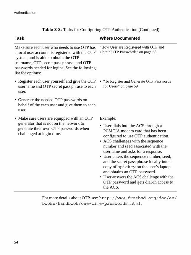
Authentication
54
For more details about OTP, see: http://www.freebsd.org/doc/en/books/handbook/one-time-passwords.html.
Make sure each user who needs to use OTP has a local user account, is registered with the OTP system, and is able to obtain the OTP username, OTP secret pass phrase, and OTP passwords needed for logins. See the following list for options:
“How User are Registered with OTP and Obtain OTP Passwords” on page 58
• Register each user yourself and give the OTP username and OTP secret pass phrase to each user.
• “To Register and Generate OTP Passwords for Users” on page 59
• Generate the needed OTP passwords on behalf of the each user and give them to each user.
• Make sure users are equipped with an OTP generator that is not on the network to generate their own OTP passwords when challenged at login time.
Example:
• User dials into the ACS through a PCMCIA modem card that has been configured to use OTP authentication.
• ACS challenges with the sequence number and seed associated with the username and asks for a response.
• User enters the sequence number, seed, and the secret pass phrase locally into a copy of opiekey on the user’s laptop and obtains an OTP password.
• User answers the ACS challenge with the OTP password and gets dial-in access to the ACS.
Table 3-3: Tasks for Configuring OTP Authentication (Continued)
Task Where Documented
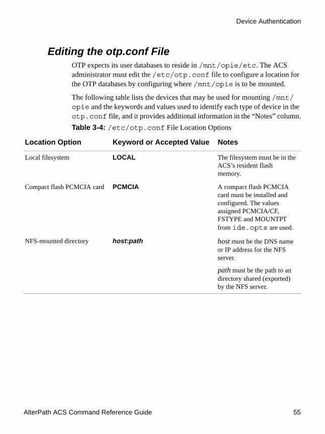
AlterPath ACS Command Reference Guide 55
Device Authentication
Editing the otp.conf File OTP expects its user databases to reside in /mnt/opie/etc. The ACS administrator must edit the /etc/otp.conf file to configure a location for the OTP databases by configuring where /mnt/opie is to be mounted.
The following table lists the devices that may be used for mounting /mnt/opie and the keywords and values used to identify each type of device in the otp.conf file, and it provides additional information in the “Notes” column.Table 3-4: /etc/otp.conf File Location Options
Location Option Keyword or Accepted Value Notes
Local filesystem LOCAL The filesystem must be in the ACS’s resident flash memory.
Compact flash PCMCIA card PCMCIA A compact flash PCMCIA card must be installed and configured. The values assigned PCMCIA/CF, FSTYPE and MOUNTPT from ide.opts are used.
NFS-mounted directory host:path host must be the DNS name or IP address for the NFS server.
path must be the path to an directory shared (exported) by the NFS server.

Authentication
56
To Specify the Location for the OTP Databases1. Log in to the ACS’s console as root.
2. Change to the /etc directory and use a text editor to open the otp.conf file for editing.
3. Set ENABLE=YES.
4. Specify the device where the OTP databases are to be stored.
See Table 3-4 for the accepted values for DEVICE. The following screen example shows specifying an NFS server named
[root@ACS /]# cd /etc[root@ACS /]# vi otp.conf## ENABLE can be 'YES' or 'NO'#ENABLE=NO## Where to mount the otp database#MOUNT_POINT=/mnt/opie## Device specify where otp database will be. it can be:## LOCAL - should be used only if FS is in the built-in IDE/CF# PCMCIA - PCMCIA/CF, FSTYPE and MOUNTPT from ide.opts will be used# host:path - NFS#DEVICE=PCMCIA
# ENABLE can be 'YES' or 'NO'#ENABLE=YES

AlterPath ACS Command Reference Guide 57
Device Authentication
exodus.cyclades.com and the path to a /home/opie directory on the NFS server.
5. Do the procedure under“To Enable OTP and Configure the Location for OTP Databases” on page 57.
Running the /bin/do_create_otpdb ScriptAfter editing the /etc/otp.conf file, the root user needs to log in locally through the ACS’s console port and run the /bin/do_create_otpdb script on the command line. The script does the following:
• Enables OTP• Mounts the location (PCMCIA, local directory, or NFS-mounted
directory) specified in the otp.conf file onto the /mnt/opie directory
• Creates the directory /mnt/opie/etc• Creates the file /mnt/opie/etc/opiekeys• Sets the permissions of the file to mode 0644, the owner of file to "root,"
and the group to "bin"• Creates the directory /mnt/opie/etc/opielocks for the OPIE lock
files• Sets the permissions of this directory to 0700 and the owner and group to
“root”
To Enable OTP and Configure the Location for OTP DatabasesDo this procedure after “To Specify the Location for the OTP Databases” on page 56.
1. Log in locally through the ACS’s console port as root.
2. Run the /bin/do_create_optdb script on the command line.
3. Do the procedure under“To Register and Generate OTP Passwords for Users” on page 59.
DEVICE=exodus.cyclades.com:/home/opie

Authentication
58
How User are Registered with OTP and Obtain OTP Passwords
All users who need to use OTP authentication must have a local account on the ACS, must be registered with the OTP system, and must be able to obtain OTP passwords.
The OPIE commands in the following bulleted list must be executed with the -c option while a user is logged in locally through the ACS’s console port.
• The opiepasswd command to register users• The opiekey command to generate OTP passwords
The requirement for local logins through the console port is enforced for regular users because running the commands through a dial-up or other insecure connection can expose the user passwords, pass phrases, and OTP passwords. The root user can execute these commands without the -c option while logged in over ssh because ssh provides a secure path. The OPIE commands should never be executed over a dial-up connection.
OTP passwords are generated in one of the two following ways:
• By the user or administrator executing the opiekey commandIf the opiekey command is executed by an administrator on behalf of a user, the administrator must provide the username and the secret pass phrase that were used to register the user to the user along with the generated OTP passwords.
• By the user with a password generating device (more likely scenario)If a user has a password generating device, then the user generates the OTP password when challenged at login using the username and secret pass phrase, along with the seed and sequence number (the seed and sequence number are displayed along with the OTP challenge).
The following procedure shows an example of an administrator logging in locally through the console port, registering a user, and generating OTP passwords for the user. The example shows running the adduser command to add the user, but any of the tools available for adding users, including the Web Manager, may be used to configure the user account beforehand.

AlterPath ACS Command Reference Guide 59
Device Authentication
To Register and Generate OTP Passwords for Users Do this procedure for each user who needs to use OTP authentication after “To Enable OTP and Configure the Location for OTP Databases” on page 57.
1. Log in locally through the ACS’s Console port as root or use ssh to log into the ACS’s console.
2. Make sure each user authorized for dial-ins has a local account on the ACS.
Note: You can separately use the Web Manager to add users instead of doing this step.
For example, the following screen shows using the adduser command to add user joe and set the user’s password to “joes_passwd.”
3. Enter the opiepasswd command to register the user.
The following screen example shows using opiepasswd with the -c option while logged in locally through the ACS’s CONSOLE port. If you are logged into the ACS’s console using ssh, do not use the -c option.
The example shows using “joe” as the username and “joes secret pass phrase” as the secret pass phrase.
Note: The secret pass phrase is not the same as the user’s regular login password.
[root@ACS /]# adduser joeNew password: joes_passwdRe-enter new password: joes_passwdPassword changed

Authentication
60
In the example, the opiepasswd command generates a default OPIE sequence number of 499 and a creates a key from the first two letters of the hostname and a pseudo random number, in the example ON93564.
4. The following command line example uses the -n 5 option followed by the 498 to generate 5 passwords ending with sequence number 498.
5. Give the OTP username, secret pass phrase, and any OTP passwords generated in this procedure to the user.
6. Save the changes.
[root@ACS /]# opiepasswd joeAdding joeReminder - Only use this method from the console; NEVER from remote. If you are using telnet, xterm, or a dial-in, type ^C now or exit with no password. Then run opiepasswd without the -c parameter. Using MD5 to compute responses.Enter new secret pass phrase: joes secret pass phraseAgain new secret pass phrase: joes secret pass phrase
ID joe OPIE key is 499 ON93564CITY MARY GLOW ZION MAY ARM[root@ACS /]#
[root@ACS /]# opiekey -n 5 498 CA93564Using MD5 algorithm to compute responses.Enter secret pass phrase: joes secret pass phrase494: WORD ROW GIFT NEXT BLUE MOM495: APEX FONT STAR BEST WIND RED496: ART LILY HOLD AID LAST ALL497: GOLD ARK FISH CAMP SON SKID498: SEE PITY JOY GUST PLAN CITY[root@ACS /]#
[root@ACS /]# saveconf

AlterPath ACS Command Reference Guide 61
Obtaining and Using One Time Passwords for Dial-ins
Obtaining and Using One Time Passwords for Dial-ins
This section is for users who are authorized to dial into the ACS through a external modem or a PCMCIA modem or phone card if the one time password (OTP) authentication method is configured for logins to that device. If you are not sure, ask your ACS administrator. With OTP authentication, you supply a different password whenever you dial-in, so no one who discovers the password used for one session can use that password later to access your account. A one time password is actually a group of six English words (for example: GOLD ARK FISH DOVE SON ZION) that are entered all on the same line at the prompt. You might be given a series of one time passwords; following is an example sequence:
At the first login, you would enter the password from line 498, on the next login, you would enter line 497, and so forth.
Each user who needs to use OTP needs a local user account on the ACS, must be registered with the OTP system, and must be able to obtain the OTP username, OTP secret pass phrase, and OTP passwords needed for logins. See the following list for how the ACS administrator may register and give OTP passwords to users:
• Register all users and give OTP usernames and OTP secret pass phrases to each user.AND
• Generate the needed OTP passwords on behalf of the each user and give them to each user.Some sites choose to print out hard copy lists of OPIE passwords for their users and deliver them by methods such as FAX or FedEx.
OR
495: AMEN FONT STAR SEA WINE RED496: ART LILY HOLY AID LOVE ALL497: GOLD ARK FISH DOVE SON ZION498: SEE PITY JOY HOPE PLAN CITY

Authentication
62
• Make sure users are equipped with an OTP generator that is not on the network to generate their own OTP passwords when challenged at login time.The OTP generator may be a copy of the opiekeys program installed on the user’s workstation or may be an OTP token card.
To Generate an OTP Password When Challenged at Dial-inThis example procedure works when /etc/opiekeys is installed on the user’s workstation.
1. Dial into the ACS through an external modem or a PCMCIA modem or phone card that has been configured to use OTP authentication.
The ACS challenges with a sequence number (also called a counter) and a seed (or key) associated with the username and asks for a response.The seed includes the first two letters of the hostname and a pseudo random number.
The challenge is otp-md5 499 on93564. The sequence number is 499 and the seed is on93564.
2. Obtain an OTP password by performing the following steps.
a. Copy the entire challenge into a window on a computer where the opiekey program is installed.
The otp-md5 portion of the challenge is a symbolic link to the opiekey program and tells opiekey to use the MD5 algorithm. opiepasswd and prompts the user for the user’s secret pass phrase.
b. Enter your secret pass phrase when prompted.
The opiekey program generates a six word OTP password, such as GOLD ARK FISH DOVE SON ZION.
login: usernameotp-md5 499 on93564Response:

AlterPath ACS Command Reference Guide 63
Obtaining and Using One Time Passwords for Dial-ins
3. Copy the OTP password to the window where the login program is waiting with the “Response” prompt.
The sequence number is decremented in the opiekeys file.
To configure user access to the serial ports1. Open the CLI interface by issuing the command:
# CLI
2. Navigate to the following path.cli>config security
This menu lets you execute the following actions:
• adduser - To add an user you need to pass the following parameters: user name <username>; administrator privileges or not <admin - yes|no>; biouser or not <biouser - yes|no>; password <password>; comments <comments>.
Example:security>adduser username john admin no biouser no password john1234
• addgroup - To add a group it is necessary to inform the group name <groupname> and the members <usernames> of this group.
Example:security>addgroup groupname test usernames john,mary
• delgroup - To delete a group it is necessary to inform the name of the group <groupname> you want to delete.
Example:security>delgroup groupname test
• deluser - To delete an existing user, it is necessary to inform the user you want to delete by specifying the <username> parameter.
Example:
Response: GOLD ARK FISH DOVE SON ZION

Authentication
64
security>deluser username cyclades
• loadkey - This options allows you to get the user’s public key by way of scp. The user must be enrolled in the local database of the unit. You must specify the user name <username> and the url <url>. The url must follow this syntax: user@host:pathname.
Example:security>loadkey username root url [email protected]/home/key
• passwd - Change the password of a user. You need to inform the user <username> and the new password <newpassword> of the user.
Example:security>passwd username root newpassword diffucultpasswd1234
To configure authentication type for device console access.
1. Open the CLI interface by issuing the command:# CLI
2. Navigate to the following path.cli>config security authentication authtype <string>
3. To see the list of authentication types, from >authtype<Press tab to see list of possible values>
The following list of authentication types appears.Nis, kerberos, local/Nis, Nis/local, kerberos/local, local/TacacsPlus, NisDownLocal, kerberosDownLocal, local/radius, RadiusDownLocal, ldap, none, TacacsPlus, ldap/local, radius,TacacsPlus/local, ldapDownLocal, radius/local, TacacsPlusDownlocal, and local.
For more information about this, see the all.authtype parameter in Table 3-1, “Authentication parameters in /etc/portslave/pslave.conf,” on page 48

AlterPath ACS Command Reference Guide 65
Obtaining and Using One Time Passwords for Dial-ins
To configure an authentication server.1. Open the CLI interface by issuing the command:
# CLI
2. Navigate to the following path.cli>config security authentication
3. To see the list of authentication server types, from >authentication, press the tab to see the list of possible values. The following list of authentication types appears.nisserver,radiussecret,tacplusauthsvr1,radiustimeout tacplusauthsvr2, krbdomain, radiusacctsvr1, tacplusraccess, krbserver,radiusacctsvr2, secureldap, tacplusretries, ldapbasedomain, radiusauthsvr1, tacplussecret, ldapserver, radiusauthsvr2,tacplusacctsvr1, tacplustimeout, nisdomain, radiusretries,tacplusacctsvr2
4. Configure an authentication server.#config security authentication <server option> <ip address>
To activate the configuration.cli> config runconfig
To save the configuration.cli> config savetoflash
To exit the CLI mode.cli> quit
Access Control via Radius Attribute NAS-Port-idThis feature provides an additional way to control the access to serial ports other than the one based in usernames or groups. The authentication type must be Radius for this feature to function. The Radius server administrator must configure the user (in the radius server database) with one NAS-PORT-id attribute for each serial port that the user is allowed to access.

Authentication
66
In the example below the user ‘alfred’ can access the serial ports ttyS11, ttyS13, and ttyS17:
alfred Auth-Type = Local, Password = ‘alfred’
Service-Type = Framed-User,Framed-Protocol = PPP,NAS-Port-Id = 11,NAS-Port-Id = 13,NAS-Port-Id = 17
The pam_radius module will check whether the NAS-Port-Id matches one of those sent by the radius server. If the radius server does not send the NAS-Port-Id attribute, no check is performed.
No configuration is needed for the ACS. However, the authentication type must be “radius”. Authentications like radiusDownLocal, radius/local, and so on, will not validate the NAS-port-Id if the user was locally authenticated.
NIS ClientNIS (Network Information System) provides simple and generic client-server database access facilities that can be used to distribute information. This makes the network appear as a single system, with the same accounts on all hosts. The objective of this feature is to allow the administrator to manage ACS accounts on a NIS server.
The NIS client feature needs these following files/commands:
Table 3-5: NIS client requirements
File/Command Description
/etc/yp.conf This file contains the configuration used by ypbind.
/etc/domainname.conf
This file contains the NIS domain name (set by the command domainname).
/usr/sbin/ypbind Finds the server for NIS domains and maintains the NIS binding information.
/usr/bin/ypwhich Returns the name of the NIS server that supplies the NIS services.

AlterPath ACS Command Reference Guide 67
Obtaining and Using One Time Passwords for Dial-ins
NIS Client Configuration1. Run the command domainname.
You’ll want to make sure that you have the NIS domain name set.
Command:# domainname [NIS domain name]
show or set the system's NIS/YP domain name, e.g.:# domainname cyclades mycompany-nis
2. Edit the /etc/yp.conf file.
You will need to configure the NIS server. Example: If the NIS server has the IP address 192.168.160.110, you’ll have to add the following line in the file:ypserver 192.168.160.110
3. Edit the /etc/nsswitch.conf file.
Change the /etc/nsswitch.conf file ("System Databases and Name service Switch" configuration file) to include the NIS in the lookup order of the databases.
4. Configure the parameter "<all/sxx>.authype" as "local".
/usr/bin/ypcat Prints the values of all keys from the NIS database specified by map name.
/usr/bin/ypmatch Prints the values of one or more keys from the NIS database specified by map name.
/usr/sbin/domainname
Shell script to read/write the NIS domain name.
Table 3-5: NIS client requirements
File/Command Description
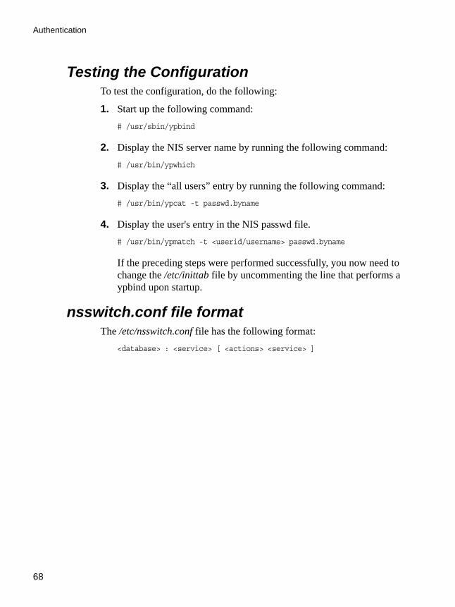
Authentication
68
Testing the ConfigurationTo test the configuration, do the following:
1. Start up the following command:# /usr/sbin/ypbind
2. Display the NIS server name by running the following command:# /usr/bin/ypwhich
3. Display the “all users” entry by running the following command:# /usr/bin/ypcat -t passwd.byname
4. Display the user's entry in the NIS passwd file.# /usr/bin/ypmatch -t <userid/username> passwd.byname
If the preceding steps were performed successfully, you now need to change the /etc/inittab file by uncommenting the line that performs a ypbind upon startup.
nsswitch.conf file formatThe /etc/nsswitch.conf file has the following format:
<database> : <service> [ <actions> <service> ]
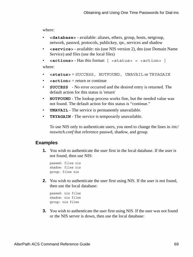
AlterPath ACS Command Reference Guide 69
Obtaining and Using One Time Passwords for Dial-ins
where:
• <database> - available: aliases, ethers, group, hosts, netgroup, network, passwd, protocols, publickey, rpc, services and shadow
• <service> - available: nis (use NIS version 2), dns (use Domain Name Service) and files (use the local files)
• <actions> - Has this format: [ <status> = <action> ]where:
• <status> = SUCCESS, NOTFOUND, UNAVAIL or TRYAGAIN• <action> = return or continue• SUCCESS - No error occurred and the desired entry is returned. The
default action for this status is 'return'• NOTFOUND - The lookup process works fine, but the needed value was
not found. The default action for this status is “continue.”• UNAVAIL - The service is permanently unavailable.• TRYAGAIN - The service is temporarily unavailable.
To use NIS only to authenticate users, you need to change the lines in /etc/nsswitch.conf that reference passwd, shadow, and group.
Examples1. You wish to authenticate the user first in the local database. If the user is
not found, then use NIS:passwd: files nisshadow: files nisgroup: files nis
2. You wish to authenticate the user first using NIS. If the user is not found, then use the local database:passwd: nis filesshadow: nis filesgroup: nis files
3. You wish to authenticate the user first using NIS. If the user was not found or the NIS server is down, then use the local database:

Authentication
70
passwd: nis [UNAVAIL=continue TRYAGAIN=continue] filesshadow: nis [UNAVAIL=continue TRYAGAIN=continue] filesgroup: nis [UNAVAIL=continue TRYAGAIN=continue] files
Kerberos AuthenticationKerberos is a computer network authentication protocol designed for use on insecure networks, based on the key distribution model. It allows individuals communicating over a network to prove their identity to each other while also preventing eavesdropping or replay attacks, and provides for detection of modification and the prevention of unauthorized reading
Kerberos Server Authentication with Tickets support
The ACS has support to interact on a kerberized network. You can find in the next lines a brief explanation about how kerberos works. Later in this section, a practical a step by step example will be presented.
How Kerberos WorksOn a kerberized network, the Kerberos database contains principals and their keys (for users, their keys are derived from their passwords). The Kerberos database also contains keys for all of the network services.
When a user on a kerberized network logs in to their workstation, their principal is sent to the Key Distribution Center (KDC) as a request for a Ticket Granting Ticket (TGT). This request can be sent by the login program (so that it is transparent to the user) or can be sent by the kinit program after the user logs in.
The KDC checks for the principal in its database. If the principal is found, the KDC creates a TGT, encrypts it using the user's key, and sends it back to the user.
The login program or kinit decrypts the TGT using the user's key (which it computes from the user's password). The TGT, which is set to expire after a certain period of time, is stored in your credentials cache. An expiration time is set so that a compromised TGT can only be used for a certain period of time, usually eight hours (unlike a compromised password, which could be used

AlterPath ACS Command Reference Guide 71
Kerberos Authentication
until changed). The user will not have to re-enter their password until the TGT expires or they logout and login again.
When the user needs access to a network service, the client uses the TGT to request a ticket for the service from the Ticket Granting Service (TGS), which runs on the KDC. The TGS issues a ticket for the desired service, which is used to authenticate the user.
Configuring ACS to use Kerberos Tickets authentication
For this example we will consider that a kerberos server with ticket support is properly configured in the network. The manual will only approach the ACS configuration.
Here we will assume that the kerberos server has the following configuration:
• Principal: john• Host (Cyclades ACS): acs48-2.cyclades.com
ACS Configuration
Configuring it for SSH:
1. Configure and start a NTP server
All involved parts must be synchronized with a NTP server. To configure a NTP server see “NTP (Network Time Protocol)” on page 219.
2. Configure authentication and protocol in the /etc/portslave/pslave.conf file. Open the file and edit these parameters:all.authtype localall.protocol socket_ssh.
3. Activate and save the configuration, by issuing the commands:# runconf# saveconf
4. Add an user with the same name as the “principal”, configured in the Kerberos server.# adduser john

Authentication
72
5. Configure the krb5.conf file. The /etc/krb5.conf file must be exactly the same as the one that is in the Kerberos server.
It is highly recommended to copy it directly from the server, instead of editing it. To copy using scp, issue the command:# scp [email protected]:/etc/krb5.conf /etc/krb5.conf
6. Extract the host that is in the Kerberos server database to the ACS:# kadmin -p admin/admin
Where the first “admin” is the service and the second one is the user.
This will prompt a Kerberos server menu. To extract the configured hosts run the following commands in the kadmin menu:kadmin: ktadd host/acs48-2.cyclades.comkadmin: q
To list all configured hosts in the Kerberos server, run the command:# klist -k
The above command will show all hosts added through the ktadd command in the Kerberos server.
7. Configure hostname and domain name.
To configure the hostname and the domain name, issue the commands:# hostname acs48-2# domainname cyclades.com
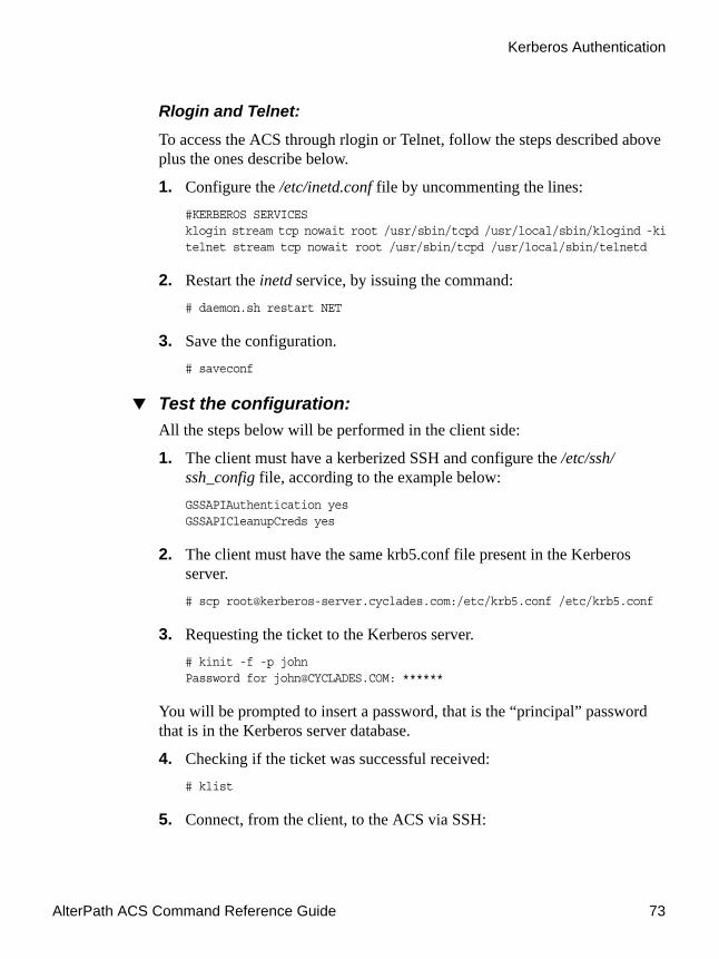
AlterPath ACS Command Reference Guide 73
Kerberos Authentication
Rlogin and Telnet:
To access the ACS through rlogin or Telnet, follow the steps described above plus the ones describe below.
1. Configure the /etc/inetd.conf file by uncommenting the lines:#KERBEROS SERVICESklogin stream tcp nowait root /usr/sbin/tcpd /usr/local/sbin/klogind -kitelnet stream tcp nowait root /usr/sbin/tcpd /usr/local/sbin/telnetd
2. Restart the inetd service, by issuing the command:# daemon.sh restart NET
3. Save the configuration.# saveconf
Test the configuration:All the steps below will be performed in the client side:
1. The client must have a kerberized SSH and configure the /etc/ssh/ssh_config file, according to the example below:GSSAPIAuthentication yesGSSAPICleanupCreds yes
2. The client must have the same krb5.conf file present in the Kerberos server.# scp [email protected]:/etc/krb5.conf /etc/krb5.conf
3. Requesting the ticket to the Kerberos server.# kinit -f -p johnPassword for [email protected]: ******
You will be prompted to insert a password, that is the “principal” password that is in the Kerberos server database.
4. Checking if the ticket was successful received:# klist
5. Connect, from the client, to the ACS via SSH:

Authentication
74
Opening a SSH connection to the ACS itself:#ssh [email protected]
Opening a SSH session to one of the ACS ports:# ssh john:[email protected]
6. Connecting via RLOGIN to the ACS itself, with forwardable tickets (to connect to the ACS ports using ts_menu):# rlogin -l john acs48-2.cyclades.com -F
Then run ts_menu to access the desired serial port.
7. Connecting via Telnet to the ACS itself with forwardable tickets (to connect to the ACS ports using ts_menu):telnet -l john acs48-2.cyclades.com -F
Then run ts_menu to access the desired serial port.
Kerberos Server AuthenticationTo authenticate users on a Kerberos sever, it is necessary to edit two configuration files: pslave.conf and krb5.conf. Below is a step by step example.
1. Edit the /etc/portslave/pslave.conf file.
Open the /etc/portslave/pslave.conf file running the following command:# vi /etc/portslave/pslave.conf
Look for the all.authtype and all.protocol parameters and change their values according to the example below:all.authtype kerberosall.protocol socket_ssh ##or socket_server or socket_server_ssh
To use the Telnet protocol to access the serial ports of the unit, set the all.protocol parameter to socket_server.
To use both Telnet and SSH to access the unit, set the all.protocol parameter to socket_server_ssh. In this example we are using the SSH protocol.
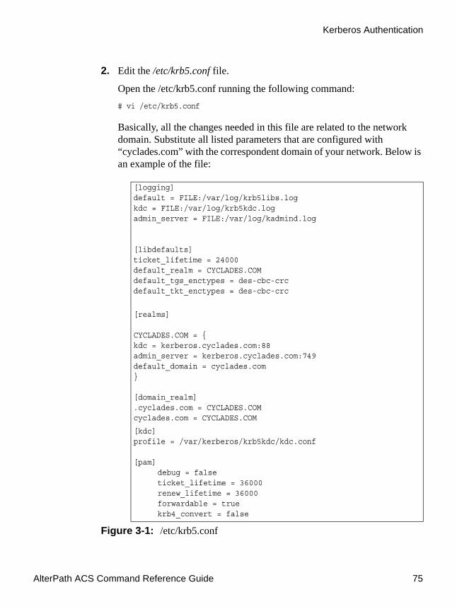
AlterPath ACS Command Reference Guide 75
Kerberos Authentication
2. Edit the /etc/krb5.conf file.
Open the /etc/krb5.conf running the following command:# vi /etc/krb5.conf
Basically, all the changes needed in this file are related to the network domain. Substitute all listed parameters that are configured with “cyclades.com” with the correspondent domain of your network. Below is an example of the file:
[logging]default = FILE:/var/log/krb5libs.logkdc = FILE:/var/log/krb5kdc.logadmin_server = FILE:/var/log/kadmind.log
[libdefaults]ticket_lifetime = 24000default_realm = CYCLADES.COMdefault_tgs_enctypes = des-cbc-crcdefault_tkt_enctypes = des-cbc-crc
[realms]
CYCLADES.COM = {kdc = kerberos.cyclades.com:88admin_server = kerberos.cyclades.com:749default_domain = cyclades.com}
[domain_realm].cyclades.com = CYCLADES.COMcyclades.com = CYCLADES.COM
[kdc]profile = /var/kerberos/krb5kdc/kdc.conf
[pam]debug = falseticket_lifetime = 36000renew_lifetime = 36000forwardable = truekrb4_convert = false
Figure 3-1: /etc/krb5.conf

Authentication
76
3. Activating changes.
To activate the changes made, run the command:# runconf
4. Testing configuration
To test the configuration, it is necessary to access any serial port using the Telnet protocol (this is the case of the approached e.g.). From a remote machine issue the following command:# telnet 192.168.0.1 7001
A prompt will ask for an user and password. Log with the user and password previously configured in the Kerberos server.
In the ACS run the command:# w
The response for this command will be similar to the following:1:03pm up 57 min, 1 user, load average: 0.00, 0.00, 0.00
USER TTY FROM LOGIN@ IDLE JCPU PCPU WHATroot ttyS0 12:07pm 0.00s 1.47s 0.15s /bin/sh /usr/bin
CAS users : 1
USER TTY FROM LOGIN@ PID/Commandcyclades ttyS1 192.168.0.143:1503 01:02pm 512/-RW_srv ttyS
The last line of the command response shows the user “cyclades” accessing the first serial port of the ACS unit.
5. Saving changes.
To save the configuration, run the command:# saveconf

AlterPath ACS Command Reference Guide 77
LDAP Authentication
LDAP AuthenticationHere we are going to describe the basic steps to configure a LDAP server on Linux. We will also give instructions about how to configure the ACS box.
Configuring an LDAP server on LinuxThe steps below are intended to guide the installation of a LDAP server on a generic Linux machine.
1. The packages required for the LDAP servers are:
• db (Sleepycat Berkeley Database)
• openssl (OpenSSL)
• openldap (OpenLDAP)
It's also possible to load the source codes and compile them, but it is easier to load these packages from your distribution CD-ROM or via Internet.
2. Go to the directory /etc/openldap or /usr/local/etc/openldap.
Change the directory running the following command:# cd /usr/local/etc/openldap
Note: The example uses /usr/local path. Change all references of /usr/local if the path is different, and check if the directory/file really exists.

Authentication
78
3. Create the certificates:
To create the certificates, run the following commands in the given sequence:# ln -s /usr/local/bin/openssl.# ln -s /usr/local/ssl/misc/CA.pl.# PATH=$PATH:.# CA.pl -newca <-- answer questions, you MUST fill in "commonName"# CA.pl -newreq <-- repeat# CA.pl -signreq# mv newreq.pem ldapkey.pem# chmod 0600 ldapkey.pem# mv newcert.pem ldapcert.pem
4. Edit slapd.conf. The basic configuration to make it work is:
The basic configuration of the file is like described below:
include /usr/local/etc/openldap/schema/core.schemainclude /usr/local/etc/openldap/schema/cosine.schema
pidfile /usr/local/var/slapd.pidargsfile /usr/local/var/slapd.args
TLSCipherSuite HIGH:MEDIUM:+SSLv2
TLSCertificateFile /usr/local/etc/openldap/ldapcert.pemTLSCertificateKeyFile /usr/local/etc/openldap/ldapkey.pemTLSCACertificateFile /usr/local/etc/openldap/demode/cacert.pem
database bdb
suffix "dc=cyclades,dc=com,dc=br"
rootdn "cn=admin,dc=cyclades,dc=com,dc=br"
rootpw bitadmin
directory /usr/local/var/openldap-data
index objectClass eq
Figure 3-2: slapd.conf Configuration

AlterPath ACS Command Reference Guide 79
LDAP Authentication
5. Start the LDAP server.
To start the server run the command:# /usr/local/libexec/slapd -h "ldap:/// ldaps:///"
This will allow the LDAP server accept both secured mode and non-secure mode.
6. Add entries.
Example:ldapadd -x -D "cn=admin,dc=cyclades,dc=com,dc=br" -w bitadmindn: uid=helio,dc=cyclades,dc=com,dc=brobjectClass: personobjectClass: uidobjectuid: heliocn: Helio Fujimotosn: FujimotouserPassword: bithelio
To list the entries:ldapsearch -x -D "cn=admin,dc=cyclades,dc=com,dc=br" -w bitadmin'(objectClass=*)'
This is enough to set up a LDAP server with some users, for PAM authentication purposes.
Configuring the AlterPath ACS sideTo configure the unit for PAM authentication, follow the steps below:
1. Configure all.protocol as ldap, in /etc/portslave/pslave.conf
2. Configure the /etc/ldap.conf file.
Edit the following parameters:
3. Activating and saving the changes made.
host 200.246.93.95 <== LDAP server IP address or namebase dc=cyclades,dc=com,dc=br <== distinguished name of the search baseuri ldaps://200.246.93.95 <== to use secure LDAP
File Description 3.3: /etc/ldap.conf configuration
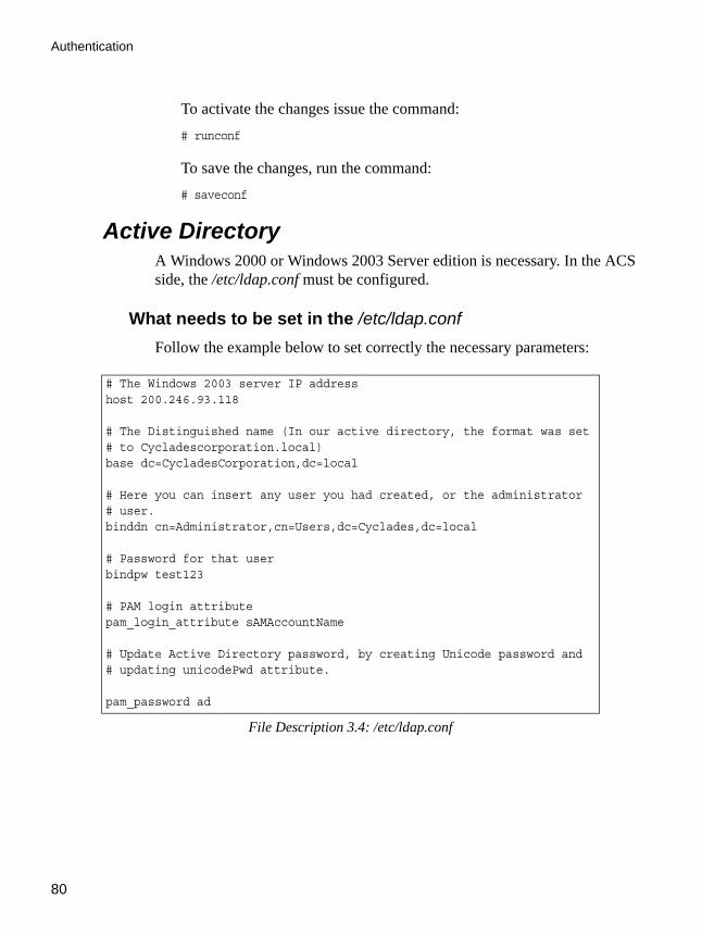
Authentication
80
To activate the changes issue the command:# runconf
To save the changes, run the command:# saveconf
Active DirectoryA Windows 2000 or Windows 2003 Server edition is necessary. In the ACS side, the /etc/ldap.conf must be configured.
What needs to be set in the /etc/ldap.confFollow the example below to set correctly the necessary parameters:
# The Windows 2003 server IP addresshost 200.246.93.118
# The Distinguished name (In our active directory, the format was set# to Cycladescorporation.local)base dc=CycladesCorporation,dc=local
# Here you can insert any user you had created, or the administrator# user.binddn cn=Administrator,cn=Users,dc=Cyclades,dc=local
# Password for that userbindpw test123
# PAM login attributepam_login_attribute sAMAccountName
# Update Active Directory password, by creating Unicode password and# updating unicodePwd attribute.
pam_password ad
File Description 3.4: /etc/ldap.conf

AlterPath ACS Command Reference Guide 81
LDAP Authentication
Enabling TACACS+ Authorization for Serial PortsUsing an authorization method in addition to authentication provides an extra level of system security. By enabling the raccess parameter, administrators require an additional level of security checking. After each user is successfully authenticated through the standard login procedure, the ACS uses TACACS+ to authorize whether or not each user is allowed to access specific serial ports.
By default the raccess parameter is not enabled allowing all users full authorization. When the raccess parameter is enabled, users are denied access unless they have the proper authorization, which must be set on the TACACS+ server itself.
Configuring Authorization with a TACACS+ Server [CLI]1. In CLI mode, enter the following string:
config > security > authentication> tacplusraccess yes
2. To save the configuration, enter the command:
config > savetoflash
Configuring Authorization with a TACACS+ Server [vi]1. Open /etc/tacplus.conf
2. Edit the service parameter to be raccess:
service=raccess
Setting User Authorization Permissions on the TACACS+ Server [vi]The authorization for each user is defined on the TACACS+ server itself in the file /etc/tacacs/tac_plus.cfg on the "Linux Fedora Core 3"
Note: The location of this configuration file may be different on other Linux distributions.
1. On the TACACS+ server, open the file /etc/tacacs/tac_plus.cfg.
2. Edit the following lines:
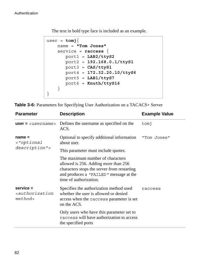
Authentication
82
The text in bold type face is included as an example.
user = tomj{ name = "Tom Jones" service = raccess { port1 = LAB2/ttyS2 port2 = 192.168.0.1/ttyS1 port3 = CAS/ttyS1 port4 = 172.32.20.10/ttyS6 port5 = LAB1/ttyS7 port6 = Knuth/ttyS16 }}
Table 3-6: Parameters for Specifying User Authorization on a TACACS+ Server
Parameter Description Example Value
user = <username> Defines the username as specified on the ACS.
tomj
name = <"optional description">
Optional to specify additional information about user.
This parameter must include quotes.
The maximum number of characters allowed is 256. Adding more than 256 characters stops the server from restarting and produces a "FAILED" message at the time of authorization.
"Tom Jones"
service = <authorization method>
Specifies the authorization method used whether the user is allowed or denied access when the raccess parameter is set on the ACS.
Only users who have this parameter set to raccess will have authorization to access the specified ports
raccess

AlterPath ACS Command Reference Guide 83
Group Authorization
Group AuthorizationThis feature enables the “group” information retrieval from the authentication servers TACACS+, RADIUS, and LDAP, and adds another layer of security by adding a network-based authorization. It retrieves the “group” information from the authentication server and performs an authorization through ACS.
The following sections describe the procedures to configure TACACS+, RADIUS, and LDAP authentication servers, and the corresponding configuration process on ACS.
Configuring a TACACS+ authentication server On the server, add “raccess” service to the user configuration and define which group or groups the user belongs to.
user = <username>{
service = raccess{
group_name = <Group1>[,<Group2,...,GroupN>];
}
}
On the ACS, edit the following parameters in the /etc/tacplus.conf file.
port<#> = <ACS>/<Port>
Specify which serial ports on the ACS the user has authorization to access.
port# is a sequential label used by the ACS.
<ACS> is the name or IP address of the ACS box.
<Port> is the serial port the user can access on the specified ACS box.
port1 = LAB2/ttyS2
Table 3-6: Parameters for Specifying User Authorization on a TACACS+ Server
Parameter Description Example Value

Authentication
84
authhost1=192.168.160.21 accthost1=192.168.160.21secret=secret encrypt=1service=pppprotocol=lcptimeout=10retries=2
authhost1: This address indicates the location of the TacacsPlus authentication server. A second TacacsPlus authentication server can be configured with the parameter authhost2.
accthost1: This address indicates the location of the TacacsPlus accounting server, which can be used to track how long users are connected after being authorized by the authentication server. Its use is optional. If this parameter is not used, accounting will not be performed. If the same server is used for authentication and accounting, both parameters must be filled with the same address. A second TacacsPlus accounting server can be configured with the parameter accthost2.
secret: This is the shared secret (password) necessary for communication between the ACS and the TacacsPlus servers.
encrypt: The default is 1 which means encryption is enabled. To disable encryption change the value to 0.
service: The service that should be enabled. The default is ppp. If you are enabling another service, for example, “raccess” authorization on the TacacsPlus server, then it should be mentioned in this field on ACS.
protocol: The default is lcp (line control protocol). Specify another paramter if required.
timeout: This is the timeout (in seconds) for a TacacsPlus authentication query to be answered.
retries: Defines the number of times each TacacsPlus server is tried before another is contacted. The first server authhost1 is tried for the specified number of times, before the second authhost2, if configured, is contacted and tried for the specified number of times. If the second server fails to respond TacacsPlus authentication fails.

AlterPath ACS Command Reference Guide 85
Group Authorization
Configuring the authorization on ACS to access the serial ports [CLI]1. In CLI mode, enter the following string:cli > config security authentication tacplusraccess yes
cli > config physicalports <serial port number> access users/groups <list of users or group names separated by commas>
2. Save the configuration to flashcli > config > savetoflash
Configuring a RADIUS authentication server1. On the server, edit /etc/raddb/users and add a new string attribute
(ATTRIBUTE Framed-Filter-Id) similar to the following example:
groupuser1 Auth-Type= Local, Password =”xxxx”
Service-Type=Callback-Framed-User,
Callback-Number=”305”,
Framed-Protocol=PPP,
Framed-Filter-
Id=”:group_name=<Group1>[,<Group2>,...,<GroupN>]”,
Fall-Through=No
If the Frame-Filter-Id already exists, just add the group_name to the string starting with a colon “:”
2. On the ACS, edit /etc/raddb/server using the following format:auth1 server[:port] secret [timeout] [retries]acct1 server[:port] secret [timeout] [retries]
Where,
auth1: The firts Radius Authentication Server
acct1: The firts Radius Accountig Server
server : The radius server address.

Authentication
86
port: The port field is optional. The default port name is “radius” and is looked up through /etc/services.
secret: The shared password required for communication between ACS and the Radius server.
retries: The number of times each Radius server is tried before another is contacted
timeout: The default is 3 seconds. The timeout field determines how long the system should wait before responding with a success or failure response from the authentication server.
for example,auth1 172.20.0.2 cyclades 3 5acct1 172.20.0.2 cyclades 3 5
Note: You should configure both parametres auth1 and acct1.
Note: Multiple radius servers can be configured in this file. The servers are tried in the order in which they appear. If a server fails to respond, the next configured server is tried.
Configuring the authorization on ACS to access the serial ports [CLI]In CLI mode, enter the following string:
cli > config physicalports <serial port number> access users/groups <list of users or group names separated by commas>
Save the configuration to flash
2. cli > config > savetoflash
Configuring an LDAP authentication serverOn the server, edit the “info” attribute for the user and add the following syntax.
info: group_name=<Group1>[,<Group2>,...,<GroupN>];

AlterPath ACS Command Reference Guide 87
Linux-PAM
Configuring the authorization on ACS to access the serial ports [CLI]1. In CLI mode, enter the following string:cli > config physicalports <serial port number> access users/groups <list of users or group names separated by commas>
2. Save the configuration to flashcli > config > savetoflash
Linux-PAMLinux-PAM (Pluggable Authentication Modules for Linux) is a suite of shared libraries that enable the local system administrator to choose how applications authenticate users. In other words, without (rewriting and) recompiling a PAM-aware application, it is possible to switch between the authentication mechanism(s) it uses. Indeed, one may entirely upgrade the local authentication system without touching the applications themselves.
It is the purpose of the Linux-PAM project to separate the development of privilege-granting software from the development of secure and appropriate authentication schemes. This is accomplished by providing a library of functions that an application may use to request that a user be authenticated. The PAM library has a series of configuration files located in /etc/pam.d/ to authenticate a user request via the locally available authentication modules. The modules themselves will usually be located in the directory /lib/security and take the form of dynamically loadable object files.
The Linux-PAM authentication mechanism gives the system administrator the freedom to stipulate which authentication scheme is to be used. S/he has the freedom to set the scheme for any/all PAM-aware applications on your Linux system. That is, s/he can authenticate from anything as generous as simple trust (pam_permit) to something as severe as a combination of a retinal scan, a voice print and a one-time password!
Linux-PAM deals with four separate types of (management) task. These are: authentication management, account management, session management, and password management. The association of the preferred management scheme with the behavior of an application is made with entries in the relevant Linux-PAM configuration file. The management functions are performed by modules specified in the configuration file.
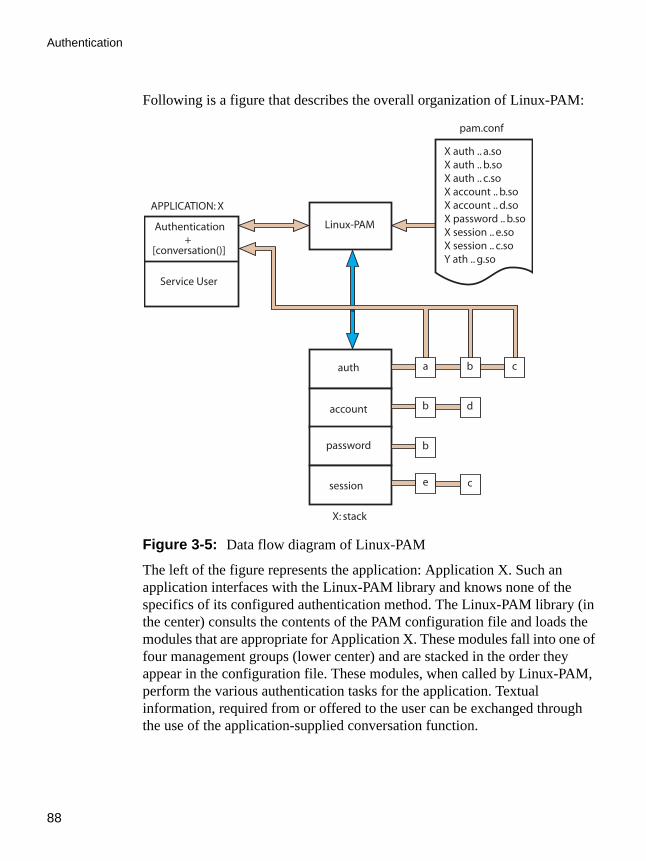
Authentication
88
Following is a figure that describes the overall organization of Linux-PAM:
Figure 3-5: Data flow diagram of Linux-PAM
The left of the figure represents the application: Application X. Such an application interfaces with the Linux-PAM library and knows none of the specifics of its configured authentication method. The Linux-PAM library (in the center) consults the contents of the PAM configuration file and loads the modules that are appropriate for Application X. These modules fall into one of four management groups (lower center) and are stacked in the order they appear in the configuration file. These modules, when called by Linux-PAM, perform the various authentication tasks for the application. Textual information, required from or offered to the user can be exchanged through the use of the application-supplied conversation function.
Authentication+
[conversation()]
Service User
APPLICATION: X
Linux-PAM
auth
account
password
session
a
b
b
e
b
d
c
c
X auth .. a.soX auth .. b.soX auth .. c.soX account .. b.soX account .. d.soX password .. b.soX session .. e.soX session .. c.soY ath .. g.so
pam.conf
X: stack

AlterPath ACS Command Reference Guide 89
Linux-PAM
The Linux-PAM Configuration DirectoryLinux-PAM is designed to provide the system administrator with a great deal of flexibility in configuring the privilege-granting applications of their system. The local configuration of those aspects of system security controlled by Linux-PAM is contained in the directory /etc/pam.d/. In this section we discuss the correct syntax of and generic options respected by entries for the files in this directory.
Configuration File SyntaxThe reader should note that the Linux-PAM-specific tokens are case-insensitive. The module paths, however, are case-sensitive since they indicate a file’s name and reflect the case-dependence of typical Linux file systems. The case-sensitivity of the arguments to any given module is defined for each module in turn.
In addition to the lines described below, there are two special characters provided for the convenience of the system administrator:
# Comments are preceded by this character and extend to the next end-of-line.\ This character extends the configuration lines.
A general configuration line of a file in the /etc/pam.d/ directory has the following form:
filename module-type control-flag module-path arguments
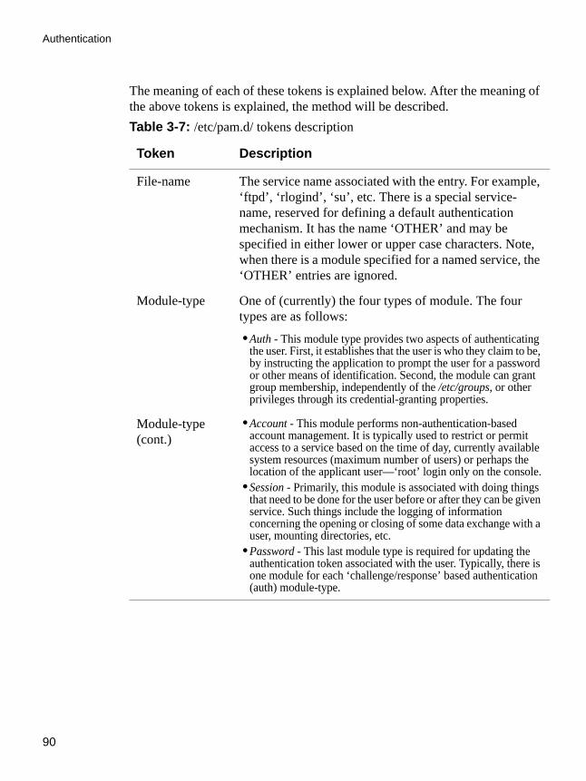
Authentication
90
The meaning of each of these tokens is explained below. After the meaning of the above tokens is explained, the method will be described.Table 3-7: /etc/pam.d/ tokens description
Token Description
File-name The service name associated with the entry. For example, ‘ftpd’, ‘rlogind’, ‘su’, etc. There is a special service-name, reserved for defining a default authentication mechanism. It has the name ‘OTHER’ and may be specified in either lower or upper case characters. Note, when there is a module specified for a named service, the ‘OTHER’ entries are ignored.
Module-type One of (currently) the four types of module. The four types are as follows:
• Auth - This module type provides two aspects of authenticating the user. First, it establishes that the user is who they claim to be, by instructing the application to prompt the user for a password or other means of identification. Second, the module can grant group membership, independently of the /etc/groups, or other privileges through its credential-granting properties.
Module-type (cont.)
• Account - This module performs non-authentication-based account management. It is typically used to restrict or permit access to a service based on the time of day, currently available system resources (maximum number of users) or perhaps the location of the applicant user—‘root’ login only on the console.
• Session - Primarily, this module is associated with doing things that need to be done for the user before or after they can be given service. Such things include the logging of information concerning the opening or closing of some data exchange with a user, mounting directories, etc.
• Password - This last module type is required for updating the authentication token associated with the user. Typically, there is one module for each ‘challenge/response’ based authentication (auth) module-type.

AlterPath ACS Command Reference Guide 91
Linux-PAM
The Linux-PAM library interprets these keywords in the following manner:
Control-flag The control-flag is used to indicate how the PAM library will react to the success or failure of the module it is associated with. Since modules can be stacked (modules of the same type execute in series, one after another), the control-flags determine the relative importance of each module. The application is not made aware of the individual success or failure of modules listed in the ‘/etc/pam.d/ directory. Instead, it receives a summary of success or fail responses from the Linux-PAM library. The order of execution of these modules is that of the entries in the
/etc/pam.d/ directory: The control-flag can be defined with one of two syntaxes. The simpler (and historical) syntax for the control-flag is a single keyword defined to indicate the severity of concern associated with the success or failure of a specific module. There are four such keywords: required, requisite, sufficient and optional.
Table 3-8: /etc/pam.d/ keywords description
Keyword Description
Required This indicates that the success of the module is required for the module-type facility to succeed. Failure of this module will not be apparent to the user until all of the remaining modules (of the same module-type) have been executed.
Table 3-7: /etc/pam.d/ tokens description
Token Description

Authentication
92
Module PathModule Path is the path-name of the dynamically loadable object file--the pluggable module itself. If the first character of the module path is ‘/’, it is
Requisite This is similar to required. However, in the case that such a module returns a failure, control is directly returned to the application. The return value is that associated with the first required or requisite module to fail. Note that this flag can be used to protect against the possibility of a user getting the opportunity to enter a password over an unsafe medium. It is conceivable that such behavior might inform an attacker of valid accounts on a system. This possibility should be weighed against the significant concerns of exposing a sensitive password in a hostile environment.
Sufficient The success of this module is deemed ‘sufficient’ to satisfy the Linux-PAM library that this moduletype has succeeded in its purpose. In the event that no previous required module has failed, no more ‘stacked’ modules of this type are invoked. (Note: in this case subsequent required modules are not invoked.) A failure of this module is not deemed as fatal to satisfying the application.
Optional As its name suggests, this control-flag marks the module as not being critical to the success or failure of the user’s application for service. In general, Linux-PAM ignores such a module when determining if the module stack will succeed or fail. However, in the absence of any definite successes or failures of previous or subsequent stacked modules this module will determine the nature of the response to the application. One example of this latter case is when the other modules return something like PAM_IGNORE.
Table 3-8: /etc/pam.d/ keywords description
Keyword Description

AlterPath ACS Command Reference Guide 93
Linux-PAM
assumed to be a complete path. If this is not the case, the given module path is appended to the default module path: /lib/security.
Currently, the ACS has the following modules available:Table 3-9: Available PAM modules in the ACS
Module Name Description
pam_access Provides logdaemon style login access control.
pam_deny Deny access to all users.
pam_env This module allows the (un)setting of environment variables. The use of previously set environment variables as well as PAM_ITEMs such as PAM_RHOST is supported.
pam_filter This module was written to offer a plug-in alternative to programs like ttysnoop. Since a filter that performs this function has not been written, it is currently only a toy. The single filter provided with the module simply transposes upper and lower case letters in the input and output streams. (This can be very annoying and is not kind to termcap-based editors.)
pam_group This module provides group settings based on the user’s name and the terminal they are requesting a given service from. It takes note of the time of day.
pam_issue This module presents the issue file (/etc/issue by default) when prompting for a username.
pam_lastlog This session module maintains the /var/log/lastlog file. It adds an open entry when called via the pam_open_session()function and completes it when pam_close_session() is called. This module can also display a line of information about the last login of the user. If an application already performs these tasks, it is not necessary to use this module.

Authentication
94
pam_limits This module, through the Linux-PAM open-session hook, sets limits on the system resources that can be obtained in a user session. Its actions are dictated more explicitly through the configuration file discussed in /etc/security/pam_limits.conf.
pam_listfile The listfile module provides a way to deny or allow services based on an arbitrary file.
pam_motd This module outputs the motd file (/etc/motd by default) upon successful login.
pam_nologin Provides standard Unix nologin authentication.
pam_permit This module should be used with extreme caution. Its action is to always permit access. It does nothing else.
pam_radius Provides Radius server authentication and accounting.
pam_rootok This module is for use in situations where the superuser wishes to gain access to a service without having to enter a password.
pam_securetty Provides standard UNIX securetty checking.
pam_time Running a well-regulated system occasionally involves restricting access to certain services in a selective manner. This module offers some time control for access to services offered by a system. Its actions are determined with a configuration file. This module can be configured to deny access to (individual) users based on their name, the time of day, the day of week, the service they are applying for and their terminal from which they are making their request.
pam_tacplus Provides TacacsPlus Server authentication, authorization (account management), and accounting (session management).
Table 3-9: Available PAM modules in the ACS
Module Name Description

AlterPath ACS Command Reference Guide 95
Linux-PAM
pam_unix This is the standard UNIX authentication module. It uses standard calls from the system’s libraries to retrieve and set account information as well as authentication. Usually this is obtained from the /etc/passwd and the /etc/shadow file as well when shadow is enabled.
pam_warn This module is principally for logging information about a proposed authentication or application to update a password.
pam_krb5 The Kerberos module currently used is pam_krb5. This PAM module requires the MIT 1.1+ release of Kerberos, or the Cygnus CNS distribution. It has not been tested against heimdal or any other Kerberos distributions. Important file: /etc/krb5.conf. The krb5.conf file contains Kerberos configuration information, including the locations of KDCs and admin servers for the Kerberos realms of interest, defaults for the current realm and for Kerberos applications, and mappings of hostnames onto Kerberos realms. Normally, you should install your krb5.conf file in the directory/etc. You can override the default location by setting the environment variable KRB5_CONFIG.
pam_ldap Pam_ldap looks for the ldap client configuration file “ldap.conf” in /etc/. Here's an example of the ldap.conf file (partial):
# file name: ldap.conf# This is the configuration file for the LDAP # nameservice# switch library and the LDAP PAM module.# Your LDAP server. Must be resolvable without using# LDAP.host 127.0.0.1# The distinguished name of the search base.base dc=padl,dc=com
Table 3-9: Available PAM modules in the ACS
Module Name Description

Authentication
96
ArgumentsThe arguments are a list of tokens that are passed to the module when it is invoked. They are much like arguments to a typical Linux shell command. Generally, valid arguments are optional and are specific to any given module. Invalid arguments are ignored by a module, however, when encountering an invalid argument, the module is required to write an error to syslog(3).
The following are optional arguments which are likely to be understood by any module. Arguments (including these) are in general, optional.
Table 3-10: List of valid arguments to PAM
Arguments Description
debug Use the syslog(3) call to log debugging information to the system log files.
no_warn Instruct module to not give warning messages to the application.
use_first_pass The module should not prompt the user for a password. Instead, it should obtain the previously typed password (from the preceding auth module), and use that. If that doesn’t work, then the user will not be authenticated. (This option is intended for auth and password modules only).
try_first_pass The module should attempt authentication with the previously typed password (from the preceding auth module). If that doesn’t work, then the user is prompted for a password. (This option is intended for auth modules only).
use_mapped_
pass
This argument is not currently supported by any of the modules in the Linux-PAM distribution because of possible consequences associated with U.S. encryption exporting restrictions.

AlterPath ACS Command Reference Guide 97
Shadow Passwords
Shadow PasswordsThe default /etc/passwd file has the user “root” with password “tslinux”. You should change the password for user “root” as soon as possible.
The AlterPath ACS has support for Shadow Passwords, which enhances the security of the system authentication files.
Note: For ACS release 2.6, Shadow Passwords are enabled by default. If you are upgrading from release 2.3.0-2 (or earlier), a previous configuration is detected and the translation from /etc/passwd to /etc/shadow happens automatically.
expose_account In general, the leakage of some information about user accounts is not a secure policy for modules to adopt. Sometimes information such as user names or home directories, or preferred shell, can be used to attack a user’s account. In some circumstances, however, this sort of information is not deemed a threat: displaying a user’s full name when asking them for a password in a secured environment could- also be called being ‘friendly’. The expose_account argument is a standard module argument to encourage a module to be less discrete about account information as deemed appropriate by the local administrator. Any line in (one of) the configuration file(s), that is not formatted correctly will generally tend (erring on the side of caution) to make the authentication process fail. A corresponding error is written to the system log files with a call to syslog(3).
Table 3-10: List of valid arguments to PAM
Arguments Description

Authentication
98
Certificate for HTTP SecurityThe following procedure enables you to obtain a Signed Digital Certificate. A certificate for the HTTP security is created by a CA (Certificate Authority). Certificates are most commonly obtained through generating public and private keys using a public key algorithm like RSA or X.509. The keys can be generated by using a key generator software.
Procedure1. Enter OpenSSL command.
On a Linux computer, key generation can be done using the OpenSSL package, through the following command:# openssl req -new -nodes -keyout private.key -out public.csr
If this command is used, the following information is required:
Table 3-11: Required information for the OpenSSL package
Parameter Description
Country Name (2 letter code) [AU]: The country code consisting of two letters.
State or Province Name (full name) [Some-State]:
Provide the full name (not the code) of the state.
Locality Name (e.g., city) []: Enter the name of your city.
Organization Name (e.g., company) [Internet Widgits Ltd]:
Organization that you work for or want to obtain the certificate for.
Organizational Unit Name (e.g., section) []:
Department or section where you work.
Common Name (e.g., your name or your server’s hostname) []:
Name of the machine where the certificate must be installed.
Email Address []: Your email address or the administrator’s email address.

AlterPath ACS Command Reference Guide 99
Certificate for HTTP Security
The other requested information can be skipped.
The certificate signing request (CSR) generated by the command above contains some personal (or corporate) information and its public key.
2. Submit CSR to the CA.
The next step is to submit the CSR and some personal data to the CA. This service can be requested by accessing the CA Web site and is not free. There is a list of CAs at the following URLpki-page.org
The request will be analyzed by the CA, for policy approval and to be signed.
3. Upon receipt, install certificate.
After the approval, the CA will send a certificate file to the origin, which we will call Cert.cer, for example purposes. The certificate is also stored on a directory server.
The certificate must be installed in the GoAhead Web server, by following these instructions:
1. Open a Terminal Server session and do the login.
2. Join the certificate with the private key into the file /web/server.pem. #cat Cert.cer private.key > /web/server.pem
3. Copy the certificate to the file /web/cert.pem. #cp Cert.cer /web/cert.pem
4. Include the files /web/server.pem and /web/cert.pem in /etc/config_files.
5. Save the configuration in flash.#saveconf
The certification will be effective in the next reboot.

Authentication
100
User Configured Digital CertificateACS generates its own self-signed SSL certificate for HTTPS using OpenSSL. It is highly recommended that you use the “openssl” tool to generate a self-signed certificate and replace the ACS generated certificate.
Follow the below procedure to generate a self-signed certificate.
1. Open the /etc/req_key file and update the user data with your organization specific data.
2. Remove the files /etc/ca/*.pem
3. Execute the following script.# /bin/firstkssl.sh
4. Reboot ACS or restart theWeb Manager.
# vi /etc/req_key[ req ]default_bits = 1024distinguished_name = cycladesprompt = nox509_extensions = x509v3
[ cyclades ]C = USST = CAL = FremontO = Cyclades CorporationOU = R&DCN = www.cyclades.comemailAddress = [email protected]
[ x509v3 ]subjectKeyIdentifier = hashauthorityKeyIdentifier = keyid:always,issuer:alwaysbasicConstraints = CA:truensComment = "This is just a TEST certificate.nsCertType = server, sslCA

AlterPath ACS Command Reference Guide 101
X.509 Certificate on SSH
X.509 Certificate on SSHThe OpenSSH software included with ACS has support for X.509 certificates. The administrator must activate and configure the SSH to use X.509. In order to implement authentication of SSH sessions through
hange of X.509 certificates, the following configuration is required.
1. The certificates signed and issued by CA (Certification Authority) should be loaded on both user and the client. See the procedures in section 3.7 on how to obtain and install signed digital certificates.
2. Client Identification extracted by OpenSSL command from the client’s certificate, and added to the AuthorizedKeyFile in sshd_config file.
3. Use the following command to extract the client identification#openssl x509 -noout -subject -in cli_cert.crt
4. Change “subject=” to “x509v3-sign-rsa disTinguishednameE:” in the result and append to AuthorizedKeysFile in “sshd_config” file in ACS.
5. Upload hostkey to ACS in /etc/ssh directory.
To configure X.509 certificate for SSHvi Mode
1. Edit /etc/ssh/sshd_config file
2. Uncomment or modify the following lines to read as follows.AllowedCertPurpose sslclientCACertificateFile /etc/ssh/ca/ca-bundle.crtHostKey /etc/ssh/hostkeyChallengeResponseAuthentication noHostbasedAuthentication noStrictModes noPasswordAuthentication noPubkeyAuthentication yesRhostsRSAAuthentication noRSAAuthentication noUsePrivilegeSeparation yes
3. Restart SSH

Authentication
102
CLI Mode1. Enter the CLI mode
[root@CAS etc]# CLI
2. Enter the following string at the cli> promptcli>config network profile custom ssh_x509
At the ssh_x509> prompt, enter the following strings.ssh_x509>CA_file <path and filename of CA certificate>ssh_x509>hostkey <path and filename of hostkeys>
ssh_x509>authorizedkeys <path and filename of authorized keys>
For example:ssh_x509>CA_file /etc/ssh/ca-bundle.crt ssh_x509>hostkey /etc/ssh/hostkeyssh_x509>authorizedkeys /etc/ssh/authorized_keys
To check the configuration, enter the following command at the prompt.ssh_x509>show
The following information should appear.[ssh_x509]CA_file: /etc/ssh/ca-bundle.crthostkey: /etc/ssh/hostkeyauthorizedkeys: /etc/ssh/authorized_keys
Script Mode
1. Run the following “ssh_act_x509” script
[root@CAS root]# ssh_act_x509
The following message appears:
For X509 authentication, first you need to be sure that you had upload the CA certificate, the HostKey and added the proper Authorized Key.
2. Enter the required information at each prompt.AuthorizedKeysFile[/etc/ssh/authorized_keys]:

AlterPath ACS Command Reference Guide 103
X.509 Certificate on SSH
CACertificateFile[/etc/ssh/ca/ca-bundle.crt]:
HostKey[/etc/ssh/ssh_host_key]:
Do you want disable Password Authentication and accept only Certificates?(y/n)
3. Check the configuration in /etc/ssh/sshd_config file.
To connect to ACS using SSH X.509 certificate1. Edit /etc/ssh/sshd_config file. See To configure X.509 certificate for SSH,
if needed.
2. Configure the client you need to access with X.509 certificate
3. Copy the certificate files to ACS. See Certificate for HTTP Security, if needed.
To check if the file was copied, run the following command at the prompt.[root@acs48 root]# ls -l /etc/ssh/ca/ca-bundle.crt
[root@acs48 root]# ls -l /etc/ssh/hostkey
To connect to ACS’s serial ports using SSH X.509 certificate
1. Edit /etc/ssh/sshd_config file. See To configure X.509 certificate for SSH, if needed.
2. Configure the client you need to access with X.509 certificate
3. Copy the certificate files to ACS. See Certificate for HTTP Security, if needed.
To check if the file was copied, run the following command at the prompt.[root@acs48 root]# ls -l /etc/ssh/ca/ca-bundle.crt
[root@acs48 root]# ls -l /etc/ssh/hostkey
4. Configure the serial ports for “socket_ssh” protocol and assign the IP address of the connected device.

Authentication
104

.................................................................
Chapter 4 - NetworkChapter 4Network
IntroductionThis chapter will show important configuration settings regarding the network configuration or any feature related to it. The contents of this chapter is briefly presented below:
• Basic Network Settings• DHCP Client• Routes and Default Gateway• DNS Server and Domain Name• Bonding• Hosts• TCP Keepalive• Filters and Network Address Translation• VPN Configuration
Basic Network SettingsThis section will show how to configure basic network parameters. This includes configuration of ip addresses, netmasks and hostname.
HostnameThe most basic network related configuration is setting up a hostname. In the ACS this can be done editing the /etc/hostname file.
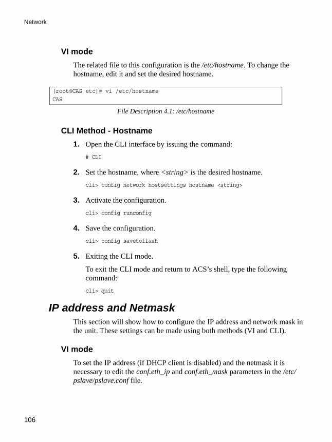
Network
106
VI modeThe related file to this configuration is the /etc/hostname. To change the hostname, edit it and set the desired hostname.
CLI Method - Hostname1. Open the CLI interface by issuing the command:
# CLI
2. Set the hostname, where <string> is the desired hostname.cli> config network hostsettings hostname <string>
3. Activate the configuration.cli> config runconfig
4. Save the configuration.cli> config savetoflash
5. Exiting the CLI mode.
To exit the CLI mode and return to ACS’s shell, type the following command:cli> quit
IP address and NetmaskThis section will show how to configure the IP address and network mask in the unit. These settings can be made using both methods (VI and CLI).
VI modeTo set the IP address (if DHCP client is disabled) and the netmask it is necessary to edit the conf.eth_ip and conf.eth_mask parameters in the /etc/pslave/pslave.conf file.
[root@CAS etc]# vi /etc/hostname
CAS
File Description 4.1: /etc/hostname
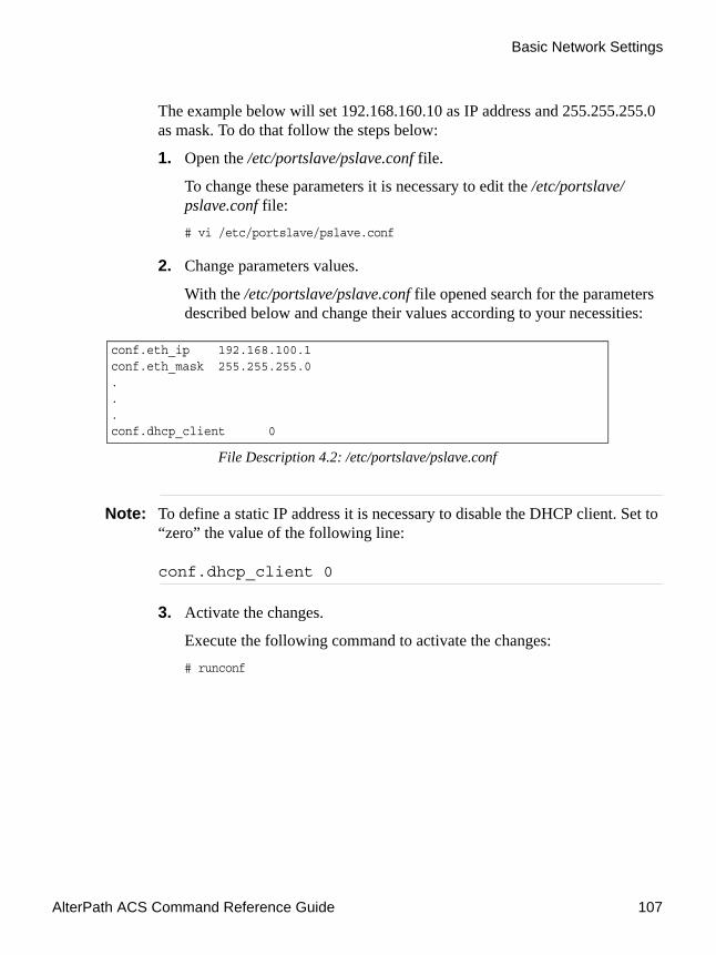
AlterPath ACS Command Reference Guide 107
Basic Network Settings
The example below will set 192.168.160.10 as IP address and 255.255.255.0 as mask. To do that follow the steps below:
1. Open the /etc/portslave/pslave.conf file.
To change these parameters it is necessary to edit the /etc/portslave/pslave.conf file:# vi /etc/portslave/pslave.conf
2. Change parameters values.
With the /etc/portslave/pslave.conf file opened search for the parameters described below and change their values according to your necessities:
Note: To define a static IP address it is necessary to disable the DHCP client. Set to “zero” the value of the following line:
conf.dhcp_client 0
3. Activate the changes.
Execute the following command to activate the changes:# runconf
conf.eth_ip 192.168.100.1conf.eth_mask 255.255.255.0...conf.dhcp_client 0
File Description 4.2: /etc/portslave/pslave.conf

Network
108
4. Test the configuration
Now you will want to make sure that the ports have been set up properly. Ping the ACS from a remote machine. Using the Windows OS open a command prompt window, type in the following, and then press Enter:# ping <IP assigned to the ACS by DHCP or you>
Example:# ping 192.168.160.10
If you receive a reply, your ACS connection is OK. If there is no reply see Appendix C - Cabling and Hardware Information.
5. Telnet to the server connected to the first port of the ACS. (This will only work if you selected socket_server or socket_server_ssh as your all.protocol parameter.)
While still in the DOS window, type the following and then press Enter:# telnet <IP assigned to the ACS by DHCP or you> 7001
Example:# telnet 192.168.160.10 7001
If everything is configured correctly, a Telnet session should open on the server connected to Port 1. If not, check the configuration, follow the above steps again, and check Appendix C - Software Upgrade and Troubleshooting.
6. Save the changes.
Execute the following command to save the configuration:# saveconf
CLI Method - IP addressIt is also possible to configure the IP address and netmask using the CLI interface. This example will set 192.168.160.10 as IP address and 255.255.255.0 as mask. To configure it, follow the steps below:
1. Open the CLI interface by issuing the command:# CLI

AlterPath ACS Command Reference Guide 109
DHCP Client
2. Configure the unit’s IP addresscli> config network hostsettings primipaddress 192.168.160.10
Where 192.168.160.10 is the desired IP address.
3. Configure the unit’s network mask address.cli> config network hostsettings primsubnetmask 255.255.255.0
Where 255.255.255.0 is the desired subnet mask.
4. Activate the configuration.cli> config runconfig
5. Save the configuration.cli> config savetoflash
6. Exit the CLI mode and return to the ACS shell.cli> quit
DHCP ClientDHCP is a protocol that allows network administrators to assign IP addresses automatically to network devices. Without DHCP (or a similar protocol like BOOTP), each device would have to be manually configured. DHCP automatically sends a new IP address to a connected device when it is moved to another location on the network. DHCP uses the concept of a fixed time period during which the assigned IP address is valid for the device it was assigned for. This “lease” time can vary for each device. A short lease time can be used when there are more devices than available IP numbers. For more information, see RFC 2131.
VI modeThe DHCP client on the Ethernet Interface can be configured in two different ways, depending on the action the ACS should take in case the DHCP Server does not answer the IP address request:
1. No action is taken and no IP address is assigned to the Ethernet Interface (most common configuration):

Network
110
2. In the /etc/portslave/pslave.conf file set the global parameter conf.dhcp_client to 1.
3. Still in the portslave.conf file comment all other parameters related to the Ethernet Interface (conf.eth_ip, etc.).
4. Add the necessary options to the file /etc/network/dhcpcd_cmd (some options are described later in this session).
5. The ACS restores the last IP address previously provided in another boot and assigns this IP address to the Ethernet Interface. For the very first time the unit is powered ON, the IP address restored is 192.168.160.10 in case of failure in the DHCP. The unit goes out from the factory with DHCP enabled (conf.dhcp_client 2):
6. Set the global parameter conf.dhcp_client to 2.
7. Comment all other parameters related to the Ethernet Interface (conf.eth_ip, etc.).
8. Add the following lines to the file /etc/config_files (from factory file already present in /etc/config_files):
9. Add the option “-x” to the factory default content of the file /etc/network/dhcpcd_cmd:
Note: From the factory, /etc/network/dhcpcd_cmd already has such content.
10. Add all other necessary options to the file /etc/network/dhcpcd_cmd (some options are described later in this section).
In both cases if the IP address of the ACS or the default gateway are changed, the ACS will adjust the routing table accordingly.
/etc/network/dhcpcd_cmd/etc/dhcpcd-eth0.save
Figure 4-3: /etc/config_files
/sbin/dhcpcd -l 3600 -x -c /sbin/handle_dhcp
Figure 4-4: /etc/network/dhcpcd_cmd

AlterPath ACS Command Reference Guide 111
DHCP Client
Files related to DHCP:
Note: Do not modify the -c /bin/handle_dhcp option.
CLI Method - DHCP1. Open the CLI interface by issuing the command:
# CLI
Table 4-1: DHCP related files and commands
Command/File Description
/bin/handle_dhcp The script which is run by the DHCP client each time an IP address negotiation takes place.
/etc/network/dhcpcd_cmd
Contains a command that activates the DHCP client (used by the cy_ras program). Its factory contents are:
/bin/dhcpcd -c /bin/handle_dhcp
The options available that can be used on this command line are:
• -D - This option forces dhcpcd to set the domain name of the host to the domain name parameter sent by the DHCP Server. The default option is to NOT set the domain name of the host to the domain name parameter sent by the DHCP Server.
• -H - This option forces dhcpcd to set the host name of the host to the hostname parameter sent by the DHCP Server. The default option is to NOT set the host name of the host to the hostname parameter sent by the DHCP Server.
• -R - This option prevents dhcpcd from replacing the existing /etc/resolv.conf file.

Network
112
2. Activate/Deactivate DHCP in the unit.cli> config network hostsettings dhcp <option>
Where possible values for <option> are: yes to activate DHCP or no to deactivate it.
3. Activate the configuration.cli> config runconfig
4. Save the configuration.cli> config savetoflash
5. Exiting the CLI mode.
To exit the CLI mode and return to ACS’s shell, type the following command:cli> quit
Routes and Default GatewayThe ACS has a static routing table that can be seen using the commands:
# route
or# netstat -rn
The file /etc/network/st_routes is the ACS method for configuring static routes. Routes should be added to the file (which is a script run when the ACS is initialized) or at the prompt (for temporary routes) using the following syntax:
route [add|del] [-net|-host] target netmask nt_msk [gw gt_way] interf
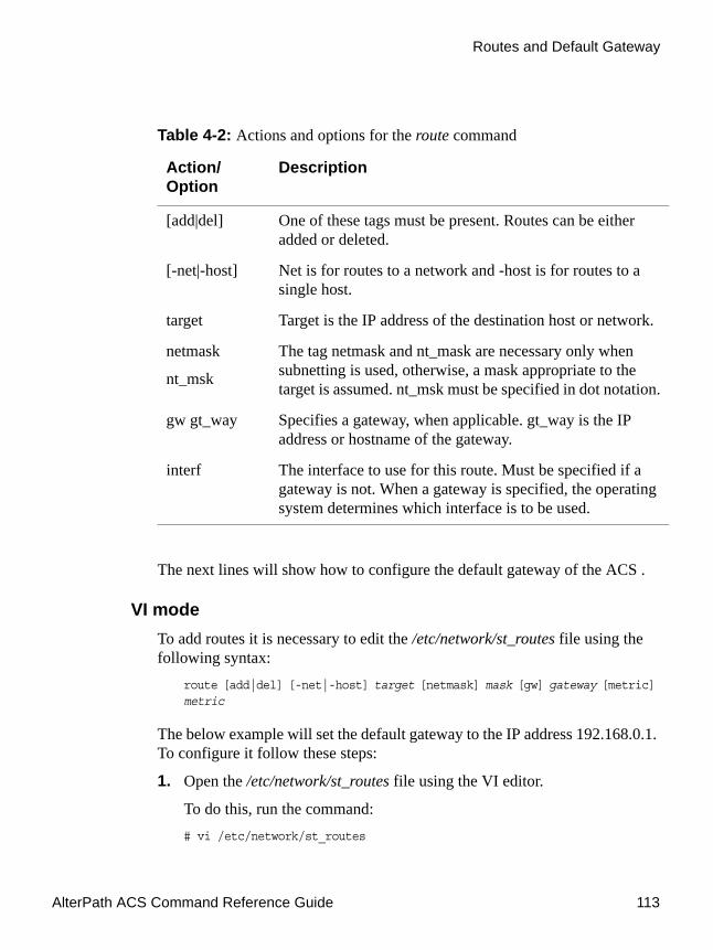
AlterPath ACS Command Reference Guide 113
Routes and Default Gateway
The next lines will show how to configure the default gateway of the ACS .
VI modeTo add routes it is necessary to edit the /etc/network/st_routes file using the following syntax:
route [add|del] [-net|-host] target [netmask] mask [gw] gateway [metric] metric
The below example will set the default gateway to the IP address 192.168.0.1. To configure it follow these steps:
1. Open the /etc/network/st_routes file using the VI editor.
To do this, run the command:# vi /etc/network/st_routes
Table 4-2: Actions and options for the route command
Action/Option
Description
[add|del] One of these tags must be present. Routes can be either added or deleted.
[-net|-host] Net is for routes to a network and -host is for routes to a single host.
target Target is the IP address of the destination host or network.
netmask
nt_msk
The tag netmask and nt_mask are necessary only when subnetting is used, otherwise, a mask appropriate to the target is assumed. nt_msk must be specified in dot notation.
gw gt_way Specifies a gateway, when applicable. gt_way is the IP address or hostname of the gateway.
interf The interface to use for this route. Must be specified if a gateway is not. When a gateway is specified, the operating system determines which interface is to be used.

Network
114
2. Inserting the default route.
Insert into this file the default route using one of the following commands:# route add -net 0.0.0.0 netmask 0.0.0.0 gw 192.168.0.1
the same route can be added in the following way:# route add default gw 192.168.0.1
To add a default route to the 192.168.0.1 IP address, just ONE of the above commands must be inserted into the file /etc/network/st_routes.
3. Save the changes made.
To save the changes run the following command:# saveconf
CLI Method - RoutesBasically all configuration regarding the addition of static routes can be done accessing the following menu of the CLI interface:
cli> config network stroutes
The example below will show how to add a default gateway in the unit:
1. Open the CLI interface by issuing the command:# CLI
2. Inserting the default route. The default gateway of the below example will be 192.168.0.1cli> config network stroutes add default gateway 192.168.0.1
3. Activate the configuration.cli> config runconfig
4. Save the configuration.cli> config savetoflash
5. Exiting the CLI mode.

AlterPath ACS Command Reference Guide 115
DNS Server and Domain Name
To exit the CLI mode and return to ACS’s shell, type the following command:cli> quit
DNS Server and Domain NameDNS server is a host that resolves host names in the network. This is related to the domain name of the unit, both configurations are made in the same file, so they will be presented together in this section.
VI modeTo set the DNS server and the domain name of your network edit the /etc/resolv.conf file. The below example will configure “cyclades.com” as domain and 192.168.0.2 as DNS. To configure it follow the steps below:
1. Open the /etc/resolv.conf file.
It is necessary to edit this file, to do this, run the command:# vi /etc/resolv.conf
2. Configure the /etc/resolv.conf file
The syntax of this file must be as the following example:
3. Save the configuration.
To save all changes made, run the command:# saveconf
CLI Method - DNS and Domain NameThe example below will set up cyclades.com as domain name and 192.168.0.2 as DNS server of the ACS .
1. Open the CLI interface by issuing the command:# CLI
domain cyclades.com#Domain name for the network
nameserver 192.168.0.2#DNS server for the network
Figure 4-5: /etc/resolv.conf

Network
116
2. Configuring cyclades.com as domain name.cli> config network hostsettings domain cyclades.com
Note: This parameter is disregarded when DHCP is enabled.
3. Configure the primary DNS server IP address.cli> config network hostsettings primdnsserver 192.168.0.2
Note: This parameter is disregarded when DHCP is enabled.
4. Activate the configuration.cli> config runconfig
5. Save the configuration.cli> config savetoflash
6. Exit the CLI mode and return to the ACS shell.cli> quit
BondingThe ACS provides failover Ethernet bonding using a PCMCIA card as a second Ethernet port. Bonding enables redundancy for the Ethernet devices, using the standard Ethernet interface as the primary mode of access and one PCMCIA card as a secondary mode of access.
When bonding is enabled, both the Ethernet port and the PCMCIA cards are configured with the same IP address and the same MAC address. So the PCMCIA interface automatically takes the place of the standard Ethernet interface if any conditions prevent access to the ACS through the primary Ethernet port. When the standard interface regains functionality, it automatically assumes its role as the primary interface, and all connection sessions are kept up with no interruption.

AlterPath ACS Command Reference Guide 117
Bonding
VI modeTo set the failover Ethernet bonding, edit the /etc/bonding.opts file. To configure it follow the steps below:
1. Open the /etc/bonding.opts file.
It is necessary to edit this file, to do this, run the command:# vi /etc/bonding.opts
2. Configure the /etc/bonding.opts file
The syntax of this file must be as the following example:
3. Save the configuration.
To save all changes made, run the command:# saveconf
CLI Method - BondingThe example below will set up cyclades.com as domain name and 192.168.0.2 as DNS server of the ACS .
1. Open the CLI interface by issuing the command:# CLI
2. Enter the bonding menu.cli> config network hostsettings bonding
enabled = < YES | NO > <--- make the bonding feature active if true and inactive otherwise
miimon = <positive integer value> <--- this parameter is the interval, in milliseconds, in which the active interface will be checked to see if it is still communicating.
updelay = <positive integer value> <--- this parameter will define the time, in milliseconds, that the system will wait to make the primary interface active again after it has been detected as up.
File Description 4.6: /etc/bonding.opts

Network
118
3. Enable failover bonding.bonding> enabled yes
To disabled fail-over bonding, type the following command:bonding> enabled no
Note: NOTE: This parameter is disregarded when DHCP is enabled.
4. Configure the interval, in milliseconds, in which the active interface will be checked to see if it is still communicating.bonding> miimon <positive integer value>
5. Configure the time, in milliseconds, that the system will wait to make the primary interface active again after it has been detected as up.bonding> updelay <positive integer value>
6. Optionally, confirm values.bonding> show
A display similar to the following example appears:
7. Activate the configuration.cli> config runconfig
8. Save the configuration.cli> config savetoflash
bonding>show
[bonding]
enabled: no
miimon: 100
updelay: 200
Figure 4-7: Bonding Default Configuration

AlterPath ACS Command Reference Guide 119
Bonding
The failover is enabled.
9. Exiting the CLI mode.
To exit the CLI mode and return to ACS’s shell, type the following command:cli> quit
10. Check the bonding configuration
To check if the feature is active, execute the ifconfig command in the Linux shell.[root@CAS /]# ifconfig
Information similar to that shown in the following figure will be displayed.

Network
120
Figure 4-8: Using the ifconfig command to check if bonding is active
After the failover is enabled, the bonded Ethernet interfaces are referred to as “bond0”. eth0 and eth1 in the above example, represents the two physical interfaces. To check which physical interface is the primary and which is the failover, look for the status “NOARP”. The interface which
[root@CAS /]# ifconfigbond0 Link encap:Ethernet HWaddr 00:60:2E:00:4F:97 inet addr:172.20.0.131 Bcast:172.20.255.255 Mask:255.255.0.0 UP BROADCAST RUNNING MASTER MULTICAST MTU:1500 Metric:1 RX packets:484130 errors:0 dropped:0 overruns:0 frame:0 TX packets:234236 errors:0 dropped:0 overruns:0 carrier:0 collisions:0 txqueuelen:0 RX bytes:40453479 (38.5 MiB) TX bytes:25311651 (24.1 MiB)
eth0 Link encap:Ethernet HWaddr 00:60:2E:00:4F:97 inet addr:172.20.0.131 Bcast:172.20.255.255 Mask:255.255.0.0 UP BROADCAST RUNNING SLAVE MULTICAST MTU:1500 Metric:1 RX packets:237695 errors:0 dropped:0 overruns:0 frame:0 TX packets:121503 errors:0 dropped:0 overruns:0 carrier:0 collisions:0 txqueuelen:100 RX bytes:19993021 (19.0 MiB) TX bytes:14356423 (13.6 MiB) Base address:0xe00
eth1 Link encap:Ethernet HWaddr 00:60:2E:00:4F:97 inet addr:172.20.0.131 Bcast:172.20.255.255 Mask:255.255.0.0 UP BROADCAST RUNNING NOARP SLAVE MULTICAST MTU:1500 Metric:1 RX packets:246435 errors:0 dropped:0 overruns:0 frame:0 TX packets:112733 errors:0 dropped:0 overruns:0 carrier:0 collisions:0 txqueuelen:100 RX bytes:20460458 (19.5 MiB) TX bytes:10955228 (10.4 MiB) Interrupt:9 Base address:0x300
lo Link encap:Local Loopback inet addr:127.0.0.1 Mask:255.0.0.0 UP LOOPBACK RUNNING MTU:1500 Metric:1 RX packets:0 errors:0 dropped:0 overruns:0 frame:0 TX packets:0 errors:0 dropped:0 overruns:0 carrier:0 collisions:0 txqueuelen:0 RX bytes:0 (0.0 iB) TX bytes:0 (0.0 iB)
[root@CAS /]#

AlterPath ACS Command Reference Guide 121
Hosts
has the “NOARP” status (eth1 in the above case) is the failover. eth0 is sending and receiving packets, eth1 is in active and standby mode.
Note: IMPORTANT: If you have IP Filtering rules set before bonding is activated, the interface reference in the firewall IP filtering will be eth0. You need to change the interface to bond0 in order to reference the bonded interface.
For example, There is a rule to drop the SSH packets to access the ACS box with no Bonding:[root@CAS /]# iptables -A INPUT -p tcp –dport 22 -i eth0 -j REJECT
If you activate Bonding you need to change the rule to reference the bonded interface:[root@CAS /]# iptables -A INPUT -p tcp –dport 22 -i bond0 -j REJECT
For more information on setting up filters and structure of iptables, see “Filters and Network Address Translation” on page 124
HostsThis file should contain the IP address for the Ethernet interface and the same hostname that you entered in the /etc/hostname file. It may also contain IP addresses and host names for other hosts in the network. The file /etc/hosts is consulted before the DNS server and is used to convert a name into an IP address.
VI modeTo configure this file follow the steps below:
1. Open the /etc/hosts file.
To open the file, run the command:# vi /etc/hosts

Network
122
This file should also contain IP addresses and host names for other hosts in the network. The syntax of this file is the following:
Enter as many hosts as necessary, following the above syntax.
2. Saving the configuration.
To save all the changes made, run the command:# saveconf
CLI Method - HostsThe example below will add a host named test with IP address 192.168.0.111 in the known hosts file of the ACS .
1. Open the CLI interface by issuing the command:# CLI
2. Add a host named test with IP address 192.168.0.111.cli> config network hosttable add hostip 192.168.0.111 name test
You can repeat this step as many times as necessary.
3. Activate the configuration.cli> config runconfig
4. Save the configuration.cli> config savetoflash
5. Exiting the CLI mode.
To exit the CLI mode and return to ACS ’s shell, type the following command:cli> quit
127.0.0.1 localhost192.168.160.10 CAS192.168.160.2 dns-server
Figure 4-9: /etc/hosts

AlterPath ACS Command Reference Guide 123
TCP Keepalive
TCP KeepaliveThe objective of this feature is to allow the ACS to recognize when the socket client (SSH or Telnet) goes down without closing the connection properly. Currently, if this happens in a serial port the system administrator must close the connection manually or nobody else can access that port anymore.
How it worksThe TCP engine of ACS will send a tcp keepalive message (ACK) to the client. If the maximum retry number is reached without an answer from the client, the connection is closed.
VI modeThe configuration is done in the file /bin/init_proc_fs using the linux proc filesystem.
# Enable TCP keepalive timer in ACS (six retries with ten seconds# of interval from each other).
# keepalive interval when the client is answering
echo 20 > /proc/sys/net/ipv4/tcp_keepalive_time
# keepalive interval when the client is not answering.
echo 10 > /proc/sys/net/ipv4/tcp_keepalive_intvl
# number of retries
echo 6 > /proc/sys/net/ipv4/tcp_keepalive_probes
# Enable TCP keepalive timer (six retries with twenty seconds# of interval from each other).
echo 20 > /proc/sys/net/ipv4/tcp_keepalive_timeecho 6 > /proc/sys/net/ipv4/tcp_keepalive_probes
Figure 4-10:/bin/init_proc_fs

Network
124
CLI Method - TCP Keep Alive1. .Open the CLI interface by issuing the command:
# CLI
2. Configure the pool interval (ms).
The command below will set a 50 ms pool interval.cli>config physicalports all other tcpkeepalive 50
3. Activate the configuration.cli> config runconfig
4. Save the configuration.cli> config savetoflash
5. Exit the CLI mode and return to the ACS shell.cli> quit
Filters and Network Address TranslationThe Filter feature is available for firmware versions 2.1.0 and above; the Network Address Translation (NAT) feature is available for firmware versions 2.1.1 and above.
DescriptionIP filtering consists of blocking or not the passage of IP packets, based on rules which describe the characteristics of the packet, such as the contents of the IP header, the input/output interface, or the protocol. This feature is used mainly in firewall applications, which filter the packets that could crack the network system or generate unnecessary traffic in the network.
Network Address Translation (NAT) allows the IP packets to be translated from local network to global network, and vice-versa. This feature is particularly useful when there is demand for more IP addresses in the local network than available as global IP addresses. In the ACS, this feature will be

AlterPath ACS Command Reference Guide 125
Filters and Network Address Translation
used mainly for clustering (one “Master” Console server works as the interface between the global network and the “slave” Console servers).
The ACS uses the Linux utility iptables to set up, maintain and inspect both the filter and the NAT tables of IP packet rules in the Linux kernel. Besides filtering or translating packets, the iptables utility is able to count the packets which match a rule, and to create logs for specific rules.
Structure of the iptablesThe iptables are structured in three levels: table, chain, and rule. A table can contain several chains, and each chain can contain several rules.
TableThe table indicates how the iptables will work. There are currently three independent tables supported by the iptables, but only two will be used:
• filter: This is the default table.• nat: This table is consulted when a packet that creates a new connection is
encountered.
ChainEach table contains a number of built-in chains and may also contain user-defined chains. The built-in chains will be called according to the type of packet. User-defined chains will be called when a rule which is matched by the packet points to the chain. Each table has a particular set of built-in chains.
For the filter table:
• INPUT - For packets coming into the box itself.• FORWARD - For packets being routed through the box.• OUTPUT - For locally-generated packets.
For the nat table:
• PREROUTING - For altering packets as soon as they come in.• OUTPUT - For altering locally-generated packets as soon as they come in.• POSTROUTING - For altering packets as they are about to go out.

Network
126
RuleEach chain has a sequence of rules. These rules contain:
• How the packet should appear in order to match the rule -> Some infor-mation about the packet is checked according to the rule, for example, the IP header, the input and output interfaces, the TCP flags and the protocol.
• What to do when the packet matches the rule -> The packet can be accepted, blocked, logged or jumped to a user-defined chain. For the nat table, the packet can also have its source IP address and source port altered (for the POSTROUTING chain) or have the destination IP address and destination port altered (for the PREROUTING and OUTPUT chain).
When a chain is analyzed, the rules of this chain are reviewed one-by-one until the packet matches one rule. If no rule is found, the default action for that chain will be taken.
SyntaxAn iptables tutorial is beyond the scope of this manual. For more information on iptables, see the iptables man page (not included with the ACS) or the how-to: http://www.netfilter.org or http://www.iptables.org
The syntax of the iptables command is:# iptables -command chain rule-specification [-t table] [options]# iptables -E old-chain-name new-chain-name
where:
• table - Can be filter or nat. If the option -t is not specified, the filter table will be assumed.
• chain - Is one of the following:for filter table: INPUT, OUTPUT, FORWARD or a user-created chain.for nat table: PREROUTING, OUTPUT, POSTROUTING or a user-cre-ated chain.

AlterPath ACS Command Reference Guide 127
Filters and Network Address Translation
CommandOnly one command can be specified on the command line unless otherwise specified below. For all the long versions of the command and option names, you need to use only enough letters to ensure that iptables can differentiate it from all other options.Table 4-3: iptables commands options
Command Description
-A --append Append one or more rules to the end of the selected chain. When the source and/or destination names resolve to more than one address, a rule will be added for each possible address combination.
-D --delete Delete one or more rules from the selected chain. There are two versions of this command. The rule can be specified as a number in the chain (starting at 1 for the first rule) or as a rule to match.
-R --replace Replace a rule in the selected chain. If the source and/or destination names resolve to multiple addresses, the command will fail. Rules are numbered starting at 1.
-I - - insert Insert one or more rules in the selected chain as the given rule number. Thus if the rule number is 1, the rule or rules are inserted at the head of the chain. This is also the default if no rule number is specified.
-L - - list List all rules in the selected chain. If no chain is selected, all chains are listed. It is legal to specify the -Z (zero) option as well, in which case the chain(s) will be atomically listed and zeroed. The exact output is affected by the other arguments given.
-F - -flush Flush the selected chain. This is equivalent to deleting all the rules one-by-one.

Network
128
-Z - -zero Zero the packet and byte counters in all chains. It is legal to specify the -L, --list (list) option as well, to see the counters immediately before they are cleared. (See above.)
-N --new-chain
New chain. Create a new user-defined chain by the given name. There must be no target of that name already.
-X --delete-chain
Delete the specified user-defined chain. There must be no references to the chain. If there are, you must delete or replace the referring rules before the chain can be deleted. If no argument is given, it will attempt to delete every non-built-in chain in the table.
-P - -policy Set the policy for the chain to the given target. Only non-user-defined chains can have policies, and neither built-in nor user-defined chains can be policy targets.
-E - -rename-chain
Rename the user-specified chain to the user-supplied name. This is cosmetic, and has no effect on the structure of the table.
-h --help Help. Gives a (currently very brief) description of the command syntax.
Table 4-3: iptables commands options
Command Description

AlterPath ACS Command Reference Guide 129
Filters and Network Address Translation
Rule SpecificationThe following parameters make up a rule specification (as used in the add, delete, insert, replace and append commands):Table 4-4: iptables rules specifications
Parameter
Description
-p - -protocol[!]protocolThe protocol of the rule or of the packet to check. The specified protocol can be one of tcp, udp, icmp, or all, or it can be a numeric value, representing one of these protocols or a different one. A protocol name from /etc/protocols is also allowed. A "!" argument before the protocol inverts the test. The number zero is equivalent to all. Protocol all will match with all protocols and is taken as default when this option is omitted.
-s - -source[!]address[/mask]Source specification. Address can be either a hostname, a network name, or a plain IP address. The mask can be either a network mask or a plain number, specifying the number of 1's at the left side of the network mask. Thus, a mask of 24 is equivalent to 255.255.255.0. A "!" argument before the address specification inverts the sense of the address. The flag - -src is a convenient alias for this option.
-d - -destination[!]address[/mask]
Destination specification. See the description of the -s (source) flag for a detailed description of the syntax. The flag - -dst is an alias for this option.

Network
130
-j - - jump target
This specifies the target of the rule; i.e., what to do if the packet matches it. The target can be a user-defined chain (other than the one this rule is in), one of the special built-in targets which decide the fate of the packet immediately, or an extension (see EXTENSIONS below). If this option is omitted in a rule, then matching the rule will have no effect on the packet's fate, but the counters on the rule is incremental. The special built-in targets are :
• ACCEPT means to let the packet through. • DROP means to drop the packet on the floor. • QUEUE means to pass the packet to userspace (if supported by the
kernel). • RETURN means stop traversing this chain and resume at the next rule
in the previous (calling) chain. If the end of a built-in chain is reached or a rule in a built-in chain with target RETURN is matched, the target specified by the chain policy determines the fate of the packet.
-i - -in-interface[!][name]
Optional name of an interface via which a packet is received (for packets entering the INPUT and FORWARD chains). When the "!" argument is used before the interface name, the sense is inverted. If the interface name ends in a "+" then any interface which begins with this name will match. If this option is omitted, the string "+" is assumed, which will match with any interface name.
Table 4-4: iptables rules specifications
Parameter
Description

AlterPath ACS Command Reference Guide 131
Filters and Network Address Translation
-o - -out-interface[!][name]
Optional name of an interface via which a packet is going to be sent (for packets entering the FORWARD and OUTPUT chains). When the "!" argument is used before the interface name, the sense is inverted. If the interface name ends in a "+" then any interface which begins with this name will match. If this option is omitted, the string "+" is assumed, which will match with any interface name.
[!] -f - -fragment
This means that the rule only refers to second and further fragments of fragmented packets. Since there is no way to tell the source or destination ports of such a packet (or ICMP type), such a packet will not match any rules which specify them. When the "!" argument precedes the "-f" flag, the rule will only match head fragments, or unfragmented packets.
-c - -set-counters PKTS BYTES
This enables the administrater to initialize the packet and byte counters of a rule (during INSERT, APPEND, REPLACE operations).
-v - -verbose
Verbose output. This option makes the list command show the interface address, the rule options (if any), and the TOS masks. The packet and byte counters are also listed, with the suffix 'K', 'M' or 'G' for 1000, 1,000,000 and 1,000,000,000 multipliers respectively (but see the -x flag to change this). For appending, insertion, deletion and replacement, this causes detailed information on the rule or rules to be printed.
Table 4-4: iptables rules specifications
Parameter
Description

Network
132
Match ExtensionsIptables can use extended packet matching modules. These are loaded in two ways: implicitly, when -p or - -protocol is specified, or with the -m or - -match option, followed by the matching module name; after these, various extra command line options become available, depending on the specific module.
-n - -numeric
Numeric output. IP addresses and port numbers will be printed in numeric format. By default, the program will try to display them as host names, network names, or services (whenever applicable).
-x - -exact
Expand numbers. Display the exact value of the packet and byte counters, instead of only the rounded number in K's (multiples of 1000) M's (multiples of 1000K) or G's (multiples of 1000M). This option is only relevant for the -L command.
- -line-numbers
When listing rules, add line numbers to the beginning of each rule, corresponding to that rule's position in the chain.
Table 4-4: iptables rules specifications
Parameter
Description

AlterPath ACS Command Reference Guide 133
Filters and Network Address Translation
TCP ExtensionsThese extensions are loaded if the protocol specified is tcp or “-m tcp” is specified. It provides the following options:
Table 4-5: TCP extensions
TCP extension Description
- -source-port [!] [port[:port]]
Source port or port range specification. This can either be a service name or a port number. Inclusive range can also be specified, using the format port:port. If the first port is omitted, "0" is assumed; if the last is omitted, “65535” is assumed. If the second port is greater then the first they will be swapped. The flag - -sport is an alias for this option.
- -destination-port [!] [port[:port]]
Destination port or port range specification. The flag
- -dport is an alias for this option.
- - tcp-flags [!] mask comp Match when the TCP flags are as specified. The first argument is the flags which we should examine, written as a comma-separated list, and the second argument is a comma-separated list of flags which must be set. Flags are: SYN ACK FIN RST URG PSH ALL NONE. Hence the command iptables
-A FORWARD -p tcp - -tcp-flags SYN,ACK,FIN,RST SYN will only match packets with the SYN flag set, and the ACK, FIN and RST flags unset.

Network
134
UDP ExtensionsThese extensions are loaded if the protocol udp is specified or “-m udp” is specified. It provides the following options:
[!] - -syn Only match TCP packets with the SYN bit set and the ACK and FIN bits cleared. Such packets are used to request TCP connection initiation; for example, blocking such packets coming in an interface will prevent incoming TCP connections, but outgoing TCP connections will be unaffected. It is equivalent to
- -tcp-flags SYN,RST,ACK SYN.
If the "!" flag precedes the "- -syn," the sense of the option is inverted.
- - tcp-option [!] number Match if TCP option set.
Table 4-6: UDP extensions
UDP extension Description
- -source-port [!] [port[:port]]
Source port or port range specification. See the description of the - -source-port option of the TCP extension for details.
- -destination-port [!] [port[:port]]
Destination port or port range specification. See the description of the - -destination-port option of the TCP extension for details.
Table 4-5: TCP extensions
TCP extension Description

AlterPath ACS Command Reference Guide 135
Filters and Network Address Translation
ICMP ExtensionThis extension is loaded if the protocol icmp is specified or “-m icmp” is specified. It provides the following option:
Multiport ExtensionThis module matches a set of source or destination ports. Up to 15 ports can be specified. It can only be used in conjunction with -m tcp or -m udp.
Target ExtensionsIptables can use extended target modules. The following are included in the standard distribution.
Table 4-7: ICMP extensions
ICMP extension Description
- - icmp-type [!] typename
This allows specification of the ICMP type, which can be a numeric ICMP type, or one of the ICMP type names shown by the command:
iptables -p icmp -h
Table 4-8: Multiport extensions
Multiport extension Description
- -source-port [port[,port]] Match if the source port is one of the given ports.
- -destination-port [port[,port]]
Match if the destination port is one of the given ports.
- -port [port[,port]] Match if the both the source and destination port are equal to each other and to one of the given ports.
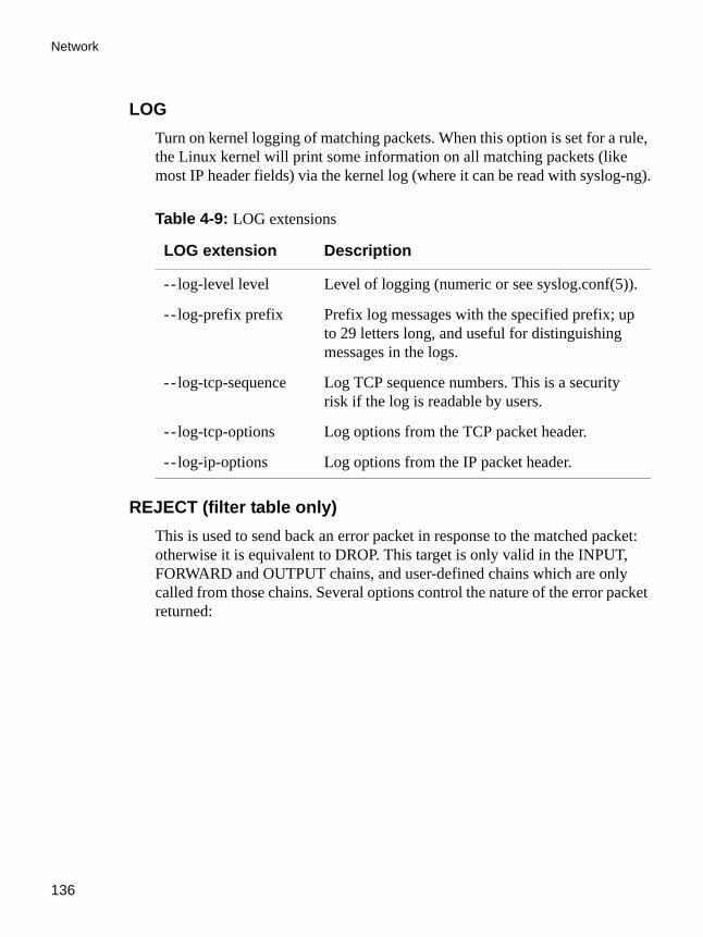
Network
136
LOGTurn on kernel logging of matching packets. When this option is set for a rule, the Linux kernel will print some information on all matching packets (like most IP header fields) via the kernel log (where it can be read with syslog-ng).
REJECT (filter table only)This is used to send back an error packet in response to the matched packet: otherwise it is equivalent to DROP. This target is only valid in the INPUT, FORWARD and OUTPUT chains, and user-defined chains which are only called from those chains. Several options control the nature of the error packet returned:
Table 4-9: LOG extensions
LOG extension Description
- - log-level level Level of logging (numeric or see syslog.conf(5)).
- - log-prefix prefix Prefix log messages with the specified prefix; up to 29 letters long, and useful for distinguishing messages in the logs.
- - log-tcp-sequence Log TCP sequence numbers. This is a security risk if the log is readable by users.
- - log-tcp-options Log options from the TCP packet header.
- - log-ip-options Log options from the IP packet header.

AlterPath ACS Command Reference Guide 137
Filters and Network Address Translation
SNAT (NAT table only)This target is only valid in the nat table, in the POSTROUTING chain. It specifies that the source address of the packet should be modified (and all future packets in this connection will also be mangled), and rules should cease being examined. It takes one option:
Table 4-10: LOG extension
LOG extension Description
- -reject-with type The type given can be icmp-net-unreachable, icmp-host-unreachable, icmp-port-unreachable, icmp-proto-unreachable, icmp-net-prohibited or icmp-host-prohibited, which return the appropriate ICMP error message (port-unreachable is the default). The option echo-reply is also allowed; it can only be used for rules which specify an ICMP ping packet, and generates a ping reply. Finally, the option tcp-reset can be used on rules which only match the TCP protocol: this causes a TCP RST packet to be sent back. This is mainly useful for blocking ident probes which frequently occur when sending mail to broken mail hosts (which won't accept your mail otherwise).

Network
138
DNAT (nat table only)This target is only valid in the nat table, in the PREROUTING and OUTPUT chains, and user-defined chains which are only called from those chains. It specifies that the destination address of the packet should be modified (and all future packets in this connection will also be mangled), and rules should cease being examined. It takes one option:
MASQUERADE (nat table only)This target is only valid in the nat table, in the POSTROUTING chain. It should only be used with dynamically assigned IP (dialup) connections: if you
Table 4-11: SNAT target
SNAT target Description
- - to-source <ipaddr>[-<ipaddr>][:port-port]
This can specify a single new source IP address, an inclusive range of IP addresses, and optionally, a port range (which is only valid if the rule also specifies -p tcp or -p udp). If no port range is specified, then source ports below 1024 will be mapped to other ports below 1024: those between 1024 and 1023 inclusive will be mapped to ports below 1024, and other ports will be mapped to 1024 or above. Where possible, no port alteration will occur.
Table 4-12: DNAT target
DNAT target Description
- - to-destination <ipaddr>[-<ipaddr>][:port-port]
This can specify a single new destination IP address, an inclusive range of IP addresses, and optionally, a port range (which is only valid if the rule also specifies -p tcp or -p udp). If no port range is specified, then the destination port will never be modified.
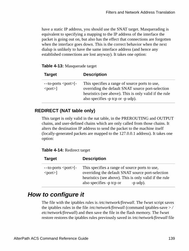
AlterPath ACS Command Reference Guide 139
Filters and Network Address Translation
have a static IP address, you should use the SNAT target. Masquerading is equivalent to specifying a mapping to the IP address of the interface the packet is going out on, but also has the effect that connections are forgotten when the interface goes down. This is the correct behavior when the next dialup is unlikely to have the same interface address (and hence any established connections are lost anyway). It takes one option:
REDIRECT (NAT table only)This target is only valid in the nat table, in the PREROUTING and OUTPUT chains, and user-defined chains which are only called from those chains. It alters the destination IP address to send the packet to the machine itself (locally-generated packets are mapped to the 127.0.0.1 address). It takes one option:
How to configure itThe file with the iptables rules is /etc/network/firewall. The fwset script saves the iptables rules in the file /etc/network/firewall (command iptables-save > /etc/network/firewall) and then save the file in the flash memory. The fwset restore restores the iptables rules previously saved in /etc/network/firewall file
Table 4-13: Masquerade target
Target Description
- - to-ports <port>[-<port>]
This specifies a range of source ports to use, overriding the default SNAT source port-selection heuristics (see above). This is only valid if the rule also specifies -p tcp or -p udp).
Table 4-14: Redirect target
Target Description
- - to-ports <port>[-<port>]
This specifies a range of source ports to use, overriding the default SNAT source port-selection heuristics (see above). This is only valid if the rule also specifies -p tcp or -p udp).

Network
140
(command iptables-restore </etc/network/firewall). This command is executed at boot to invoke the last configuration saved.
VI method1. Execute fwset restore.
This script will restore the IP Tables chains and rules configured in the /etc/network/firewall file. This script can be called in the process, whenever the user wants to restore the original configuration.
2. Add the chains and rules using the command line.
See details of the iptables syntax earlier in this chapter.
3. Execute iptables-save > /etc/network/firewall.
This program will save all the rules and chains of all the tables in the /etc/network/firewall file.
4. Execute updatefiles /etc/network/firewall.
This program will save the configuration to the flash memory.
VPN ConfigurationThe IPSec protocol provides encryption and authentication services at the IP level of the network protocol stack. Working at this level, IPSec can protect any traffic carried over IP, unlike other encryption which generally protects only a particular higher-level protocol (PGP for mail, SSH for login, SSL for Web work and so on). The implementation of IPSec used by the ACS is Openswan 2.3.0.
IPsec can be used on any machine which does IP networking. Dedicated IPsec gateway machines can be installed wherever required to protect traffic. IPsec can also run on routers, on firewall machines, on various application servers, and on end-user desktop or laptop machines.
IPsec is used mainly to construct a secure connection (tunnel) between two networks (ends) over a not-necessarily-secure third network. In our case, the IPsec will be used to connect the ACS securely to a host or to a whole network configurations frequently called host-to-network and host-to-host tunnel. Considering practical aspects, this is the same thing as a VPN, but here one or both sides have a degenerated subnet (only one machine).

AlterPath ACS Command Reference Guide 141
VPN Configuration
Applications of IPsecBecause IPsec operates at the network layer, it is remarkably flexible and can be used to secure nearly any type of Internet traffic.
Two applications, however, are extremely widespread:
• A Virtual Private Network, or VPN, allows multiple sites to communicate with the Console Server securely over an insecure Internet by encrypting all communication between the sites and the Console Server.
• Road Warriors connect to the Console Server from home, or perhaps from a hotel somewhere.
A somewhat more detailed description of each of these applications is below. Our Quick Start section will show you how to build each of them.
Using secure tunnels to create a VPNA VPN, or Virtual Private Network, lets the Console Server and a whole network communicate securely when the only connection between them is over an untrusted third network. The method is to put a security gateway machine in the network and create a security tunnel between the Console Server and this gateway. The gateway machine and the Console Server encrypt packets entering the untrusted network and decrypt packets as they leave the network it, thus creating a secure tunnel through it.
Road WarriorsThe typical Road Warrior is a traveler connecting to the Console Server from a laptop machine. For purposes of this document:
• Anyone with a dynamic IP address is a Road Warrior. • Any machine doing IPsec processing is a gateway. Think of the single-
user Road Warrior machine as a gateway with a degenerate subnet (one machine: itself) behind it.
These require a somewhat different setup from VPN gateways with static addresses and with client systems behind them, but are basically not problematic. There are some difficulties which appear for some Road Warrior connections:

Network
142
• Road Warriors who get their addresses via DHCP may have a problem. Openswan can quite happily build and use a tunnel to such an address, but when the DHCP lease expires, Openswan does not know that. The tunnel fails, and the only recovery method is to tear it down and rebuild it.
• If Network Address Translation (NAT) is applied between the two IPsec Gateways, this breaks IPsec. IPsec authenticates packets on an end-to-end basis, to ensure they are not altered en route. NAT rewrites packets as they go by.
In most situations, however, Openswan supports Road Warrior connections just fine.
Before you startThis is a quick guide to set up two common configurations: VPN and Road Warrior. There are two examples: a Road Warrior using RSA signature and a VPN using RSA signature. When listing the configuration of the remote side (the equipment the ACS will create a tunnel with) these examples will assume the other end is also running the Openswan. If it is not your case, make the appropriate conversions for your IPsec software.
Setup and test networking
Before trying to get Openswan working, you should configure and test IP networking on the Console Server and on the other end. IPsec can not function without a working IP network beneath it. Many reported Openswan problems turn out to actually be problems with routing or firewalling. If any actual IPsec problems turn up, you often cannot even recognize them (much less debug them) unless the underlying network is right.
Enabling IPsec on your ACS
The IPsec is disabled by default in the Console Server family. To enable it you must edit the file /etc/daemon.d/ipsec.sh change “ENABLE=NO” to “ENABLE=YES” and run the “saveconf” command. To start IPSEC, type “daemon.sh restart IPSEC” <enter>. IPSEC will start automatically during subsequent reboots if you have saved /etc/daemon.d/ipsec.sh with “saveconf”.
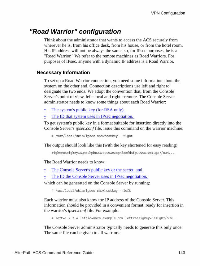
AlterPath ACS Command Reference Guide 143
VPN Configuration
"Road Warrior" configurationThink about the administrator that wants to access the ACS securely from wherever he is, from his office desk, from his house, or from the hotel room. His IP address will not be always the same, so, for IPsec purposes, he is a "Road Warrior." We refer to the remote machines as Road Warriors. For purposes of IPsec, anyone with a dynamic IP address is a Road Warrior.
Necessary InformationTo set up a Road Warrior connection, you need some information about the system on the other end. Connection descriptions use left and right to designate the two ends. We adopt the convention that, from the Console Server's point of view, left=local and right =remote. The Console Server administrator needs to know some things about each Road Warrior:
• The system's public key (for RSA only). • The ID that system uses in IPsec negotiation. To get system's public key in a format suitable for insertion directly into the Console Server's ipsec.conf file, issue this command on the warrior machine:
# /usr/local/sbin/ipsec showhostkey --right
The output should look like this (with the key shortened for easy reading): rightrsasigkey=AQNe6hpbROGVES6uXeCxpnd88fdafpO0w5OT0s1LgR7/oUM...
The Road Warrior needs to know:
• The Console Server's public key or the secret, and • The ID the Console Server uses in IPsec negotiation. which can be generated on the Console Server by running:
# /usr/local/sbin/ipsec showhostkey --left
Each warrior must also know the IP address of the Console Server. This information should be provided in a convenient format, ready for insertion in the warrior's ipsec.conf file. For example:
# left=1.2.3.4 [email protected] leftrsasigkey=0s1LgR7/oUM...
The Console Server administrator typically needs to generate this only once. The same file can be given to all warriors.

Network
144
Setup on the "Road Warrior" machineSimply add a connection description us-to-Console Server, with the left and right information you gathered above to the ipsec.conf file of the warrior system. This might look like:
Note: IMPORTANT! The connection name line: "conn us-to-acs" must start on the first column of the line. All other lines after that line must be indented by a single TAB. This is mandatory.
# pre-configured link to Console Server conn us-to-acs
# information obtained from Console Server adminleft=1.2.3.4 # Console Server IP [email protected]# real keys are much longer than shown hereleftrsasigkey=0s1LgR7/oUM...# warrior stuffright=%[email protected]=0s1LgR7/oUM# Start this connection when IPsec starts auto=start
Figure 4-11:Road Warrior ipsec.conf file

AlterPath ACS Command Reference Guide 145
VPN configuration
Setup on the ACSAdding Road Warrior support so people can connect remotely to your Console Server is straightforward. Just create the file /etc/warrior.connection and add the following lines to this file:
Note: IMPORTANT! The connection name line: "conn gate-xy" must start on the first column of the line. All other lines after that line must be indented by a single TAB. This is mandatory.
VPN configurationOften it may be useful to have explicitly configured IPsec tunnels between the Console Server and a gateway of an office with a fixed IP address (in this case every machine on the office network would have a secure connection with the Console Server), or between the Console Server and the Console Server administrator machine, which must, in this case, have a fixed IP address.
conn [email protected]=0s1LgR7/oUM...# allow connection attempt from any address# attempt fails if caller cannot authenticateright-angle# authentication [email protected]=0s1LgR7/oUM...# Add this connection to the database when IPsec startsautoload
Figure 4-12:ACS ipsec.conf file
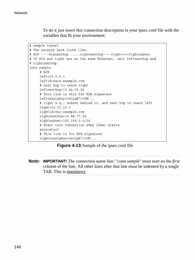
Network
146
To do it just insert this connection description in your ipsec.conf file with the variables that fit your environment:
Note: IMPORTANT! The connection name line: "conn sample" must start on the first column of the line. All other lines after that line must be indented by a single TAB. This is mandatory.
# sample tunnel# The network here looks like:# ACS ----acsnexthop......rightnexthop----right====rightsubnet# If ACS and right are on the same Ethernet, omit leftnexthop and# rightnexthop. conn sample
# ACS left=10.0.0.1 [email protected] # next hop to reach right leftnexthop=10.44.55.66 # This line is only for RSA signature leftrsasigkey=0s1LgR7/oUM... # right s.g., subnet behind it, and next hop to reach left right=10.12.12.1 [email protected] rightnexthop=10.88.77.66 rightsubnet=192.168.0.0/24 # Start this connection when IPsec starts auto=start# This line is for RSA signaturerightrsasigkey=0s1LgR7/oUM...
Figure 4-13:Sample of the ipsec.conf file
AlterPath ACS Command Reference Guide 147
VPN configuration
Note: TIP. There is an alternative way to configure the left and right ipsec rsa keys. Instead of typing (copy/paste) the entire rsa key in the fields: leftrsasigkey and rightrsasigkey inside the /etc/ipsec.conf file, the administrator can just type in the filename where the rsa key was generated. Example:
leftrsasigkey=@file /etc/ACS48AL.lrsa
The keyword @file and at least one space must precede the filename. Do not forget to include the path of the files containing the RSA keys in the /etc/config_files file.
The good part is that this connection descriptor can be added to both the Console Server and the other end. This is the advantage of using left and right instead of using local remote parameters.
If you give an explicit IP address for left (and left and right are not directly connected), then you must specify leftnexthop (the router which Console Server sends packets to in order to get them delivered to right). Similarly, you may need to specify rightnexthop.
Authentication KeysTo build a connection, the Console Server and the other end must be able to authenticate each other. For Openswan, the default is public key authentication based on the RSA algorithm. IPsec does allow several other authentication methods. On this chapter you will learn how to generate authentication keys and how to exchange keys between systems.
Generating an RSA key pair
The Console Server doesn't have an RSA key pair by default. It will be generated on the first reboot after you have enabled the IPsec daemon in the file /etc/daemon.d/ipsec.sh. You also can generate your key pair by issuing the following commands as root:
# /usr/local/sbin/ipsec newhostkey --bits <key length> --output /etc/ipsec.secrets
# chmod 600 /etc/ipsec.secrets

Network
148
Key generation may take some time. In addition, the Console Server needs a lot of random numbers and therefore needs and uses traffic on the Ethernet to generate them. It is also possible to use keys in other formats, not generated by Openswan. This may be necessary for interoperation with other IPsec implementations.
Exchanging authentication keys
Once your ACS 's key is in ipsec.secrets, the next step is to send your public key to everyone you need to set up connections with and collect their public keys. To extract the public part in a suitable format you can use the ipsec_showhostkey command. For VPN or Road Warrior applications, use one of the following:
If your ACS is the left side of the tunnel:# /usr/local/sbin/ipsec showhostkey --left
If your ACS is the right side of the tunnel:# /usr/local/sbin/ipsec showhostkey --right
These two produce the key formatted for insertion in an ipsec.conf file. Public keys need not be protected as fanatically as private keys. They are intended to be made public; the system is designed to work even if an enemy knows all the public keys used. You can safely make them publicly accessible. For example, put a gateway key on a Web page or make it available in DNS, or transmit it via an insecure method, such as email.
IPsec ManagementAfter you have all the configuration done you need to manage all tunnels and manage IPsec itself. This section will show you a few commands that have proven to be useful when managing IPsec and IPsec connections.
The IPsec DaemonThe IPsec daemon (PLUTO) is the program that loads and negotiates the connections. To start the IPsec daemon use the following command:
# /usr/local/sbin/ipsec setup --start

AlterPath ACS Command Reference Guide 149
VPN configuration
Similarly, this command accepts the usual daemon commands as stop and restart.
The ipsec daemon is automatically initialized when you boot your Console Server equipment.
NAT-TransversalACS 2.6 uses Openswan 2.3.0, which has support for NAT-Transversal. NAT-T allows IPSec to be used behind any NAT device by encapsulating ESP (Encapsulated Security Payload) in UDP.
Add the following line to /etc/ipsec.conf file to enable NAT-Transversal.nat_transversal=yes
Adding and Removing a ConnectionAll the connections can be loaded to the IPsec database at boot time if these connections have the auto parameter set to add. However if a certain connection doesn't have this option set and you wish to add this connection manually you can use the following command:
# /usr/local/sbin/ipsec auto --add <connection name>
Similarly, to take a connection out of the IPsec database you can use the command:
# /usr/local/sbin/ipsec auto --delete <connection name>
Once a connection descriptor is in the IPsec internal database, IPsec will accept the other end to start the security connection negotiation. You can also start its negotiation as explained in the next section.
Starting and Stopping a ConnectionAll the connections can be negotiated at boot time if these connections have the auto parameter set to start. However if a certain connection doesn't have this option set, you can set it. Once a connection descriptor is in the IPsec internal database, you can start its negotiation using the command:
# /usr/local/sbin/ipsec auto --up <connection name>
Similarly to close a tunnel you use the command:

Network
150
# /usr/local/sbin/ipsec auto --down <connection name>
Below you can see the output of a successful up operation: [root@acs_cas root]# ipsec auto --up test 104 "test" #5: STATE_MAIN_I1: initiate 106 "test" #5: STATE_MAIN_I2: sent MI2, expecting MR2 108 "test" #5: STATE_MAIN_I3: sent MI3, expecting MR3 004 "test" #5: STATE_MAIN_I4: ISAKMP SA established 112 "test" #6: STATE_QUICK_I1: initiate 004 "test" #6: STATE_QUICK_I2: sent QI2, IPsec SA established
IPsec whackThe ipsec whack command show the status of the connections.
[root@acs_cas root]# ipsec whack --status000 interface ipsec0/eth0 64.186.161.96 000 000 "test": 64.186.161.96[@micro]...64.186.161.128[@ACS ] 000 "test": ike_life: 3600s; ipsec_life: 28800s; rekey_margin: 540s; rekey_fuzz: 100%; keyingtries: 0000 "test": policy: RSASIG+ENCRYPT+TUNNEL+PFS; interface: eth0; routed 000 "test": newest ISAKMP SA: #5; newest IPsec SA: #6; route owner: #6 000 000 #6: "test" STATE_QUICK_I2 (sent QI2, IPsec SA established); EVENT_SA_REPLACE in 28245s; newest IPSEC; route owner 000 #6: "test" [email protected] [email protected]@64.186.161.128 [email protected] 000 #5: "test" STATE_MAIN_I4 (ISAKMP SA established); EVENT_SA_REPLACE in 3019s; newest ISAKMP
As you can see, it shows almost the same information shown by the ipsec auto -up command. You can use this command if the up command doesn't show anything on the screen (it can happen depending on the ACS syslog configuration).
The IPsec Configuration Files in DetailThis section will describe the file /etc/ipsec.conf in detail.
DescriptionThe ipsec.conf file specifies most configuration and control information for the Openswan IPsec subsystem. (The major exception is secrets for

AlterPath ACS Command Reference Guide 151
VPN configuration
authentication; ipsec.secrets) Its contents are not security-sensitive unless manual keying is being done for more than just testing, in which case the encryption and authentication keys in the descriptions for the manually-keyed connections are very sensitive (and those connection descriptions are probably best kept in a separate file, via the include facility described below).
The file is a text file, consisting of one or more sections. White space followed by # followed by anything to the end of the line is a comment and is ignored, as are empty lines which are not within a section.
A line which contains include and a file name, separated by white space, is replaced by the contents of that file, preceded and followed by empty lines. If the file name is not a full pathname, it is considered to be relative to the directory containing the including file. Such inclusions can be nested. Only a single filename may be supplied, and it may not contain white space, but it may include shell wildcards for example:
include ipsec.*.conf
The intention of the include facility is mostly to permit keeping information on connections, or sets of connections, separate from the main configuration file. This permits such connection descriptions to be changed, copied to the other security gateways involved, etc., without having to constantly extract them from the configuration file and then insert them back into it. Note the also parameter (described below) which permits splitting a single logical section (e.g., a connection description) into several actual sections.
A section begins with a line of the form:type name
where type indicates what type of section follows, and name is an arbitrary name which distinguishes the section from others of the same type. (Names must start with a letter and may contain only letters, digits, periods, underscores, and hyphens.) All subsequent non-empty lines which begin with white space are part of the section; comments within a section must begin with white space too. There may be only one section of a given type with a given name.
Lines within the section are generally of the following form:parameter=value
Network
152
(Note the mandatory preceding TAB.) There can be white space on either side of the =. Parameter names follow the same syntax as section names, and are specific to a section type. Unless otherwise explicitly specified, no parameter name may appear more than once in a section.
An empty value stands for the system default value (if any) of the parameter, i.e., it is roughly equivalent to omitting the parameter line entirely. A value may contain white space only if the entire value is enclosed in double quotes ("); a value cannot itself contain a double quote, nor may it be continued across more than one line.
Numeric values are specified to be either an integer (a sequence of digits) or a decimal number (sequence of digits optionally followed by . and another sequence of digits).
There is currently one parameter which is available in any type of section:
also
The value is a section name; the parameters of that section are appended to this section, as if they had been written as part of it. The specified section must exist, must follow the current one, and must have the same section type. (Nesting is permitted, and there may be more than one also in a single section, although it is forbidden to append the same section more than once.) This allows, for example, keeping the encryption keys for a connection in a separate file from the rest of the description, by using both an also parameter and an include line.
A section with name %default specifies defaults for sections of the same type. For each parameter in it, any section of that type which does not have a parameter of the same name gets a copy of the one from the %default section. There may be multiple %default sections of a given type, but only one default may be supplied for any specific parameter name, and all %default sections of a given type must precede all non-%default sections of that type. %default sections may not contain also parameters.
Currently there are two types of sections: a config section specifies general configuration information for IPsec, while a conn section specifies an IPsec connection.

AlterPath ACS Command Reference Guide 153
VPN configuration
Conn SectionsA conn section contains a connection specification, defining a network connection to be made using IPsec. The name given is arbitrary, and is used to identify the connection to ipsec_auto and ipsec_manual. Here's a simple example:
To avoid trivial editing of the configuration file to suit it to each system involved in a connection, connection specifications are written in terms of left and right participants, rather than in terms of local and remote. Which participant is considered left or right is arbitrary; IPsec figures out which one it is being run on based on internal information. This permits using identical connection specifications on both ends.
Many of the parameters relate to one participant or the other; only the ones for left are listed here, but every parameter whose name begins with left has a right counterpart, whose description is the same but with left and right reversed.
Parameters are optional unless marked required; a parameter required for manual keying need not be included for a connection which will use only automatic keying, and vice versa.
Conn parameters: General. The following parameters are relevant to both automatic and manual keying. Unless otherwise noted, for a connection to work, in general it is necessary for the two ends to agree exactly on the values of these parameters. The two ends can be defined as Left or Local, and Right or Remote.
• left (local) and right (remote) IP: The IP address of the participant's network interface. If it is the magic value %defaultroute, and inter-faces=%defaultroute is used in the config setup section, left will be filled
conn sntleft=10.11.11.1 leftsubnet=10.0.1.0/24 leftnexthop=172.16.55.66 right=192.168.22.1 rightsubnet=10.0.2.0/24rightnexthop=172.16.88.99 keyingtries=0 # be very persistent
File Description 4.14: part of the /etc/ipsec.conf file

Network
154
in automatically with the local address of the default-route interface (as determined at IPsec startup time). This also overrides any value supplied for leftnexthop. (Either left or right may be %defaultroute, but not both.) The magic value %any signifies an address to be filled in (by automatic keying) during negotiation; the magic value %opportunistic signifies that both left and leftnexthop are to be filled in (by automatic keying) from DNS data for left's client.
• left(local) and right (remote) subnet: Private subnet behind the left and right participants, expressed as network/netmask.
• left(local) and right (remote) nexthop: NextHop gateway IP address for the left and right participant connection to the public network.
Conn parameters: Automatic Keying. The following parameters are relevant only to automatic keying, and are ignored in manual keying. Unless otherwise noted, for a connection to work, in general it is necessary for the two ends to agree exactly on the values of these parameters.
• auto: What operation, if any, should be done automatically at IPsec star-tup; currently- accepted values are add (signifying an ipsec auto --add), route (signifying that plus an ipsec auto --route), start (signifying that plus an ipsec auto --up), and ignore (also the default) (signifying no automatic startup operation). This parameter is ignored unless the plutoload or plu-tostart configuration parameter is set suitably; see the config setup discus-sion below.
• auth: Whether authentication should be done as part of ESP encryption, or separately using the AH protocol, acceptable values are esp (the default) and ah.
• authby: How the two security gateways should authenticate each other. Acceptable values are secret for shared secrets (the default) and rsasig for RSA digital signatures.
• leftid and rightid: How the left and right participant should be identified for authentication. Defaults to left. Can be an IP address or a fully-qualified domain name preceded by @ (which is used as a literal string and not resolved).
• leftrsasigkey and rightrsasigkey: The left and right participants public key for RSA signature authentication, in RFC 2537 format. The magic value %none means the same as not specifying a value (useful to override a

AlterPath ACS Command Reference Guide 155
VPN configuration
default). The value %dnsondemand means the key is to be fetched from DNS at the time it is needed. The value %dnsonload means the key is to be fetched from DNS at the time the connection description is read from ipsec.conf. Currently this is treated as %none if right=%any or right=%opportunistic. The value %dns is currently treated as %dnsonload but will change to %dnsondemand in the future. The identity used for the left participant must be a specific host, not %any or another magic value. Caution: if two connection descriptions specify different public keys for the same leftid, confusion and madness will ensue.
• pfs: Whether Perfect Forward Secrecy of keys is desired on the connec-tion's keying channel. (With PFS, penetration of the key-exchange proto-col does not compromise keys negotiated earlier.) Acceptable values are yes (the default) and no.
• keylife: How long a particular instance of a connection (a set of encryp-tion/ authentication keys for user packets) should last, from successful negotiation to expiry. Acceptable values are an integer optionally fol-lowed by s (a time in seconds) or a decimal number followed by m, h, or d (a time in minutes, hours, or days respectively) (default 8.0h, maximum 24h).
• rekey: Whether a connection should be renegotiated when it is about to expire. Acceptable values are yes (the default) and no.
• rekeymargin: How long before connection expiry or keying-channel expiry should attempts to negotiate a replacement begin. Acceptable values as for keylife (default 9m).
• redeyfuzz: Maximum percentage by which rekeymargin should be ran-domly increased to randomize rekeying intervals (important for hosts with many connections). Acceptable values are an integer, which may exceed 100, followed by a %.
• keyingtries: How many attempts (an integer) should be made to negotiate a connection, or a replacement for one, before giving up (default 3). The value 0 means never give up.
• ikelifetime: How long the keying channel of a connection (buzzphrase: ISAKMP SA) should last before being renegotiated. Acceptable values as for keylife.
• compress: Whether IPComp compression of content is desired on the con-nection. Acceptable values are yes and no (the default).

Network
156
Conn parameters: Manual Keying. The following parameters are relevant only to manual keying, and are ignored in automatic keying. Unless otherwise noted, for a connection to work, in general it is necessary for the two ends to agree exactly on the values of these parameters. A manually-keyed connection must specify at least one of AH or ESP.
• esp: ESP encryption/authentication algorithm to be used for the connec-tion, e.g. 3des-md5-96.
• espenckey: ESP encryption key. • espauthkey: ESP authentication key. • espreplay_window: ESP replay-window setting. An integer from 0 to 64.
Relevant only if ESP authentication is being used. • ah: AH authentication algorithm to be used for the connection, e.g. hmac-
md5-96. Default is not to use AH. • ahkey: Required if ah is present. AH authentication key • ahreplay_window: AH replay-window setting. An integer from 0 to 64.
Config SectionAt present, the only config section known to the IPsec software is the one named setup, which contains information used when the software is being started. Here's an example:
Parameters are optional unless marked required. The currently-accepted parameter names in a config setup section are:
• interfaces: Required. Virtual and physical interfaces for IPsec to use: a sin-gle virtual= physical pair, a quoted list of pairs separated by white space, or %defaultroute, which means to find the interface d that the default route points to, and then act as if the value was ipsec0=d.
config setupinterfaces="ipsec0=eth1 ipsec1=ppp0" klipsdebug=none plutodebug=all manualstart= plutoload="snta sntb sntc sntd" plutostart=
File Description 4.15: part of the /etc/ipsec.conf file

AlterPath ACS Command Reference Guide 157
VPN configuration
• forwardcontrol: Whether setup should turn IP forwarding on (if it's not already on) as IPsec is started, and turn it off again (if it was off) as IPsec is stopped. Acceptable values are yes and (the default) no.
• klipsdebug: How much KLIPS debugging output should be logged. An empty value, or the magic value none, means no debugging output (the default). The magic value all means full output.
• plutodebug: How much Pluto debugging output should be logged. An empty value, or the magic value none, means no debugging output (the default). The magic value all means full output.
• dumpdir: In what directory should things started by setup (notably the Pluto daemon) be allowed to dump core. The empty value (the default) means they are not allowed to.
• manualstart: Which manually-keyed connections to set up at startup (can be empty, a name, or a quoted list of names separated by white space).
• plutoload: Which connections (by name) to load into Pluto's internal data-base at startup (can be empty, a name, or a quoted list of names separated by white space); see ipsec_auto for details. Default is none. If the special value %search is used, all connections with auto=add, auto=route, or auto=start are loaded.
• plutostart: Which connections (by name) to attempt to negotiate at startup (can be empty, a name, or a quoted list of names separated by white space). Any such names which do not appear in plutoload are implicitly added to it. Default is none. If the special value %search is used, all con-nections with auto=route or auto=start are routed, and all connections with auto=start are started.
• plutowait: Specify if Pluto should wait for each plutostart negotiation attempt to finish before proceeding with the next one. Values are yes (the default) or no.
• prepluto: Shell command to run before starting Pluto. For example, to decrypt an encrypted copy of the ipsec.secrets file. It's run in a very sim-ple way. Complexities like I/O redirection are best hidden within a script. Any output is redirected for logging, so running interactive commands is difficult unless they use /dev/tty or equivalent for their interaction. Default is none.
• postpluto: Shell command to run after starting Pluto (e.g., to remove a decrypted copy of the ipsec.secrets file).
Network
158
• fragicmp: Whether a tunnel need to fragment a packet should be reported back with an ICMP message, in an attempt to make the sender lower his PMTU estimate. Acceptable values are yes (the default) and no.
• packetdefault: What should be done with a packet which reaches KLIPS (via a route into a virtual interface) but does not match any route. Accept-able values are pass (insecure unless you really know what you're doing), drop (the default), and reject (currently same as drop).
• hidetos: Whether a tunnel packet's TOS field should be set to 0 rather than copied from the user packet inside. Acceptable values are yes (the default) and no.
• uniqueids: Whether a particular participant ID should be kept unique, with any new (automatically keyed) connection using an ID from a different IP address deemed to replace all old ones using that ID. Acceptable values are yes and no (the default).
• overridemtu: Value that the MTU of the ipsec interface(s) should be set to, overriding IPsec's (large) default. This parameter is needed only in special situations.
CLI Method - VPN ConfigurationIt is possible to configure almost everything using the CLI interface. You just won’t be able to generate the RSA keys neither copy the keys of remote hosts. Be sure to do it before entering the CLI mode.
1. Open the CLI interface by issuing the command:# CLI
2. Access the VPN menu.cli> config network vpn
This menu lets you add, edit or delete a VPN connection. When adding or editing a connection, you’ll be prompted to configure the following parameters:

AlterPath ACS Command Reference Guide 159
VPN configuration
How each parameter works and their respective descriptions can be found just above in the section Conn parameters: General.
3. Activate the configuration.cli> config runconfig
4. Save the configuration.cli> config savetoflash
Table 4-15: VPN parameters
Parameter Values
connectionname
<name> - Edit mode only
authprotocol <esp|ah>
authmethod <rsa|secret>
rightid <id>
rightip <n.n.n.n>
rightnexthop <hop>
rightsubnet <n.n.n.n>
rightrsa <rsa key>
leftid <id>
leftip <n.n.n.n>
leftnexthop <hop>
leftsubnet <n.n.n.n>
leftrsa <rsa key>
bootaction <ignore|add|start>
secret <secret>

Network
160
5. Connection management.
After configuring the VPN connection you will have to manage the VPN connections in the prompt shell. The CLI does not provide management utilities. Find more information on “IPsec Management” on page 148.
6. Exiting the CLI mode.
To exit the CLI mode and return to ACS’s shell, type the following command:cli> quit

.................................................................
Chapter 5Administration
The objective of this chapter is showing any task related to the administration of the unit. This includes the following topics:
• SNMP• CronD• Dual Power Management• Syslog-ng• Generating Alarms (Syslog-ng)• Terminal Appearance• Centralized Management• Date, Time, Timezone, and Daylight Savings• Session Sniffing• Saveconf and Restoreconf• Start and Stop Services• Security Profiles
SNMPShort for Simple Network Management Protocol: a set of protocols for managing complex networks. The first versions of SNMP were developed in the early 80s. SNMP works by sending messages, called protocol data units (PDUs), to different parts of a network. SNMP-compliant devices, called agents, store data about themselves in Management Information Bases (MIBs) and return this data to the SNMP requesters.
ACS uses the net-snmp package (http://www.net-snmp.org).
Note: IMPORTANT! Check the SNMP configuration before gathering information about ACS by SNMP. There are different types of attacks an unauthorized user can implement to retrieve sensitive information

Administration
162
contained in the MIB. By default, the SNMP configuration in ACS cannot permit the public community to read SNMP information.
The net-snmp supports snmp version 1, 2 and 3. To use SNMP version 1 or 2 (community), you need to configure the communities in the snmp config file (/etc/snmp/snmpd.conf). For example, to include the communities cyclades and public, you need add the following lines in /etc/snmp/snmpd.conf:
To use SNMP version 3 (username/password), perform the following steps:
1. Create a file /etc/snmp/snmpd.local.conf with the following line: # createUser <username> MD5 <password> DES
For example :# createUser usersnmp MD5 user_snmp_passwd DES
Note: The SNMP v3 password must be fewer than 31 characters.
2. Edit the /etc/snmp/snmpd.conf file.
If the user has permission to read only, to add the line : # rouser <username> (eg.: rouser usersnmp).
If the user has permission to read and write, to add the line :# rwuser <username> (eg.: rwuser usersnmp).
3. Include the following line in /etc/config_files: /etc/snmp/snmpd.local.conf
You can configure the /etc/snmp/snmpd.conf file as indicated later in this section.
# cyclades is read-write communityrwcommunity cyclades# public is a read-only community rocommunity public
Figure 5-1: part of the /etc/snmp/snmpd.conf file

AlterPath ACS Command Reference Guide 163
SNMP
a. Snmp version 1
• RFC1155 - SMI for the official MIB tree
• RFC1213 - MIB-II
b. Snmp version 2
• RFC2578 - Structure of Management Information Version 2 (SMIv2)
• RFC2579 - Textual Conventions for SMIv2
• RFC2580 - Conformance Statements for SMIv2
c. Snmp version 3
• RFC2570 - Introduction to Version 3 of the Internet-standard Network Management Framework.
• RFC2571 - An Architecture for Describing SNMP Management Frameworks.
• RFC2572 - Message Processing and Dispatching for the Simple Network Management Protocol (SNMP).
• RFC2573 - SNMP Applications.
• RFC2574 - User-based Security Model (USM) for version 3 of the Simple Network Management Protocol (SNMPv3).
• RFC2575 - View-based Access Control Model (VACM) for the Simple Network Management Protocol (SNMP).
• RFC2576 - Coexistence between Version 1, Version 2, and Version 3 of the Internet-standard Network Management Framework.
d. Private UCD SNMP mib extensions (enterprises.2021)
• Information about memory utilization (/proc/meminfo)
• Information about system status (vmstat)
• Information about net-snmp packet

Administration
164
e. Private Cyclades Vendor MIB (enterprises.2925)
• ACS remote Management Object Tree (cyclades.4). This MIB permits you to get informations about the product, to read/write some configuration items and to do some administration commands. (For more details see the cyclades.mib file.)
ConfigurationThis section describe how to configure the SNMP using the VI editor.
VI Method - Involved parameters and passed valuesThe followings steps shows how to configure SNMP v1 and v2 using /etc/snmp/snmpd.conf file.
1. To define the public community, insert the following line in the /etc/snmp/snmp.conf file. This is a read-only access to the MIB (Management Information Base) values.
rocommunity public <“default”, hostname, or network/mask> .1
2. Save the configuration changes in the snmp.conf file.[root@CAS root]# saveconf
3. Restart the SNMP daemon to read the new configuration.[root@CAS root]# daemon.sh restart SNMP
CLI Method - SNMPYou can configure SNMP v1, v2 and v3 just using the CLI interface. The steps below will give an overview of this process.
1. Open the CLI interface by issuing the command:# CLI
2. Configuring SNMP v1/v2.cli>config network snmp v1v2 add community test1 oid .1 permission ro source 192.168.0.200
The command presented above will configure SNMP v1/v2 with the following characteristics:

AlterPath ACS Command Reference Guide 165
SNMP
• community: test1
• OID: .1
• permission: ro (read only)
• source (allowed host): 192.168.0.200
3. Configuring SNMP v3.cli>config network snmp v3 add username john password john1234 oid .1 permission ro
The command presented above will configure SNMP v1/v2 with the following characteristics:
• username: john
• password: john1234
• OID: .1
• permission: ro (read only)
Note: The SNMP v3 password must be less than 31 characters.
4. Activate the configuration.cli>config runconfig
5. Test the configuration.
Considering that the targeted ACS has the IP address 192.168.0.1 and the Linux machine from where the commands will be issued is 192.168.0.200, run the following commands:
For SNMP v1/v2# snmpwalk -v 2c -c test1 192.168.0.1 .1
For SNMP v3# snmpwalk -v 3 -u john -l authpriv -a MD5 -A john1234 -x DES -X john1234 192.168.0.1 .1
6. Save the configuration.

Administration
166
cli> config savetoflash
7. Exit the CLI mode and return to the ACS shell.cli> quit
SUDO Configuration GroupSUDO configuration group allows users belonging to the administrator (admin) group, by way of commands from the shell command line, to configure the ACS’s features provided by the Web Management Interface (WMI) and Command Line Interface (CLI).
This feature is particularly useful for AlterPath Manager (APM) access by a user from admin group, as opposed to the user root. Users from the admin group will be able to execute commands needed by the APM to configure ACS features from the shell command line, using the SUDO command.
Note: As supplied, the ACS (version 2.6.1 and up) will provide a user “admin” from the admin group with the password “cyclades.” The username “admin” cannot be added or deleted from the Web Management Interface (WMI) or the Command Line Interface (CLI), so if a user with the username “admin” belonging to the admin group is required, a shell script must be executed by user “root” from the shell command line.
Setting up ACS for SUDO configuration groupFor a user from the admin group to be allowed to execute commands needed by the AlterPath Manager to configure ACS features, the commands must use the sudo command from the shell command line. Commands requiring root access privileges are executed by an admin user with the following command:$ sudo shell_command_|shell_utility|ACS_utility [other required parameters]
The configuration of a user with the username “admin” belonging to the admin group will be made my user “root” by executing the shell script:#addadmin

AlterPath ACS Command Reference Guide 167
SUDO Configuration Group
How to configure SUDO configuration groupThe sudoers configuration file has already been configured to allow execution and modification of commands, utilities and configuration files by a user from the admin group. If other commands, utilities and configuration files are needed, the sudoers file (etc/sudoers) is edited to included them.
If a user with username “admin” belonging to the admin group is required, the shell script “addadmin” must be executed by user “root” to configure it.
The following table shows where the files must be configured.:
Configuration by vi mode
The sudoers file can be edited by user “root” either to exclude or to include commands, utilities, and configuration files that are to be used with the sudo command by users from the admin group.
Note: The sudoers file is not saved to flash automatically. If you make changes to this file and wish to save the changes, follow the standard procedure to save the config_files file.
Configuration using the shell command line
Commands requiring root access privileges are executed by an admin user as follows:$ sudo shell_command|shell_utility|ACS_utility [other required parameters]
To create a user “admin,” execute the addadmin utility:$ addadmin <ENTER>
Table 5-1: “Global Options” parameters (syslog-ng configuration)
Configuration Option vi CLI WMI
shell command
line
/etc/sudoers file X -- -- --
sudo command -- -- -- X
addadmin utility -- -- -- X
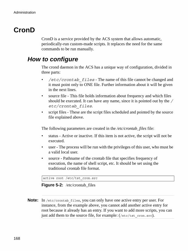
Administration
168
CronDCronD is a service provided by the ACS system that allows automatic, periodically-run custom-made scripts. It replaces the need for the same commands to be run manually.
How to configureThe crond daemon in the ACS has a unique way of configuration, divided in three parts:
• /etc/crontab_files - The name of this file cannot be changed and it must point only to ONE file. Further information about it will be given in the next lines.
• source file - This file holds information about frequency and which files should be executed. It can have any name, since it is pointed out by the /etc/crontab_files.
• script files - These are the script files scheduled and pointed by the source file explained above.
The following parameters are created in the /etc/crontab_files file:
• status - Active or inactive. If this item is not active, the script will not be executed.
• user - The process will be run with the privileges of this user, who must be a valid local user.
• source - Pathname of the crontab file that specifies frequency of execution, the name of shell script, etc. It should be set using the traditional crontab file format.
Note: In /etc/crontab_files, you can only have one active entry per user. For instance, from the example above, you cannot add another active entry for root because it already has an entry. If you want to add more scripts, you can just add them to the source file, for example: (/etc/tst_cron.src).
active root /etc/tst_cron.src
Figure 5-2: /etc/crontab_files
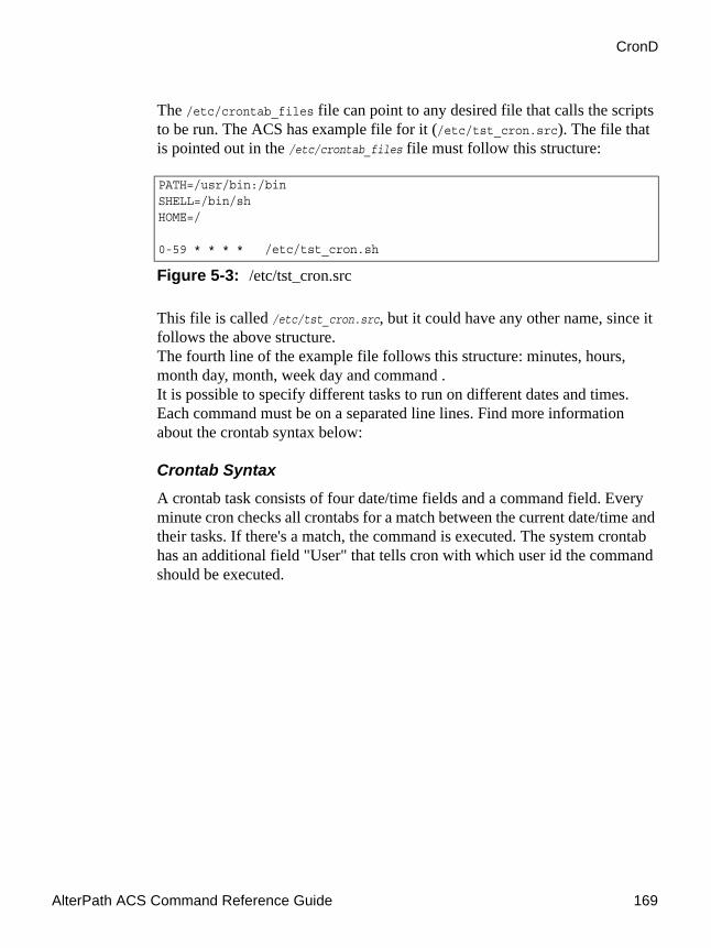
AlterPath ACS Command Reference Guide 169
CronD
The /etc/crontab_files file can point to any desired file that calls the scripts to be run. The ACS has example file for it (/etc/tst_cron.src). The file that is pointed out in the /etc/crontab_files file must follow this structure:
This file is called /etc/tst_cron.src, but it could have any other name, since it follows the above structure. The fourth line of the example file follows this structure: minutes, hours, month day, month, week day and command . It is possible to specify different tasks to run on different dates and times. Each command must be on a separated line lines. Find more information about the crontab syntax below:
Crontab Syntax
A crontab task consists of four date/time fields and a command field. Every minute cron checks all crontabs for a match between the current date/time and their tasks. If there's a match, the command is executed. The system crontab has an additional field "User" that tells cron with which user id the command should be executed.
PATH=/usr/bin:/binSHELL=/bin/shHOME=/
0-59 * * * * /etc/tst_cron.sh
Figure 5-3: /etc/tst_cron.src

Administration
170
The fields are:
• Min - minute of execution, 0-59• Hour - hour of execution, 0-23• Mday - day of month of execution, 1-31• Month - month of execution, 1-12 (or names)• Wday - day of week of execution, 0-7 (0 or 7 is sunday, or names)• Command - Anything that can be launched from the command line
Possible values for the fields:
• * - matches all values, e.g. a * in month means: "every month"• x-y - matches the range x to y, e.g. 2-4 in Mday means "on the 2nd, 3rd,
and 4th of the month"• x/n - in range x with frequency n, e.g. */2 in Hour means "every other
hour"
Month also accepts names, e.g. jan, Feb (case insensitive). This does not support ranges, though. Weekdays can also be given as names, such as Sun, Mon., and so on.
VI Method - Involved parameters and passed values
Example:
In this step-by-step example you will configure a script named tst_cron.sh to run every minute. This example just explains the necessary steps, because actually all files are already present in the ACS by default.
1. Activate the crond daemon in the /etc/crontab_files.
As explained before this file configures which file contains information about which scripts are going to be run. Activate the daemon, by editing the /etc/crontab_files changing the line, like below:
active root /etc/tst_cron.src

AlterPath ACS Command Reference Guide 171
Dual Power Management
2. Edit the /etc/tst_cron.src, to specify which scripts will be executed.
This file must point out all scripts to be executed. It also specifies the periodicity of execution of each script, according to the following syntax:
0-59 * * * * /etc/tst_cron.sh
In this case, the tst_cron.sh script will run every minute.
3. Save the changes.
Execute the following command in to save the configuration:# saveconf
4. Activate changes.
To activate the changes it is necessary to reboot the ACS by issuing the command:
# reboot
Dual Power ManagementThe ACS comes with two power supplies which it can self-monitor. If either of them fails, two actions are performed: sounding a buzzer and generating a syslog message. This automanagement can be disabled (no actions are taken) or enabled (default), any time by issuing the commands:# signal_ras buzzer off
# signal_ras buzzer on
To disable the buzzer in boot time, edit the shell script /bin/ex_wdt_led.sh and remove the keyword “buzzer.” The buzzer won’t sound if there is a power failure in any power supply. This parameter does not affect the behavior of the command “signal_ras buzzer on/off.” To make this change effective even after future reboots, create a line with “/bin/ex_wdt_led.sh” in /etc/config_files, save and quit that file and run saveconf.
Note: This section applies only to the dual power supply model of the ACS.
How to configure
Administration
172
There are no parameters to be configured. However, if you want to generate alarms in case of a power failure, the syslog-ng.conf file must be changed. See the section Generating Alarms.
Data BufferingThe data from the serial ports is buffered at all times by default. The data buffering parameter in the PortSlave configuration determines if the data is buffered whether or not the user is connected to the port. The ACS administrator has the option to disable data buffering when a user is connected to the port without affecting the syslog buffering.
The parameter sXX.data_buffering_sess in the PortSlave configuration operates as follows:
• When active, data will be buffered only when there is no connection to the port.
• When inactive (the default state), data will be buffered at all times.The parameter data_buffer_mode store_and_forward (found in pslave) performs the following functions:
• It enables the ACS to buffer data locally only when there is no connection to the port, similar to what is used in syslog data logging.
• It informs the ACS to play back the collected content of any data buffer file when a connection is open, then flush (empty) the file so that it is ready to begin collecting data again if the connection is dropped for any reason.
How to configure sXX.data_buffering_sess and sXX.dont_show)dbmenu parameter1. Configure the data_buffering_sess parameter.cli> config physicalports [‘all’|range] databuffering bufferonlynosession [yes/no]
where: “yes” = data buffered only when there is no connection to the port “no” = data buffered at all times
2. Configure the dont_show_dbmenu parameter.cli> config physicalports 1 databuffering showmenu fileanderase

AlterPath ACS Command Reference Guide 173
Syslog-ng
Syslog-ngThe syslog-ng daemon provides a modern treatment to system messages. Its basic function is to read and log messages to the system console, log files, other machines (remote syslog servers) or users as specified by its configuration file. In addition, syslog-ng is able to filter messages based on their content and to perform an action (for example, to send an e-mail or pager message). In order to access these functions, the syslog-ng.conf file needs some specific configuration.
The configuration file (default: /etc/syslog-ng/syslog-ng.conf) is read at startup and is reread after reception of a hangup (HUP) signal. When reloading the configuration file, all destination files are closed and reopened as appropriate. The syslog-ng reads from sources (files, TCP/UDP connections, syslogd clients), filters the messages and takes an action (writes in files, sends snmptrap, pager, e-mail or syslogs to remote servers).
There are five steps required for configuring syslog-ng:
Step 1: Define Global Options
Step 2: Define Sources
Step 3: Define Filters.
Step 4: Define Actions (Destinations).
Step 5: Connect all of the above.
These five tasks are going to be explained in this section.
Port Slave Parameters Involved with syslog-ng• conf.facility - This value (0-7) is the Local facility sent to the syslog-ng
from PortSlave.• conf.DB_facility - This value (0-7) is the local facility sent to the syslog-
ng with data when syslog_buffering and/or alarm is active. When nonzero, the contents of the data buffer are sent to the syslog-ng every time a quantity of data equal to this parameter is collected. The syslog level for data buffering is hard coded to level five (notice) and facility local[0+ conf.DB_facility]. The file /etc/syslog-ng/syslog-ng.conf should

Administration
174
be set accordingly for the syslog-ng to take some action. Example value: 0.
• all.syslog_buffering - When nonzero, the contents of the data buffer are sent to the syslog-ng every time a quantity of data equal to this parameter is collected. The syslog message is sent to syslog-ng with NOTICE level and LOCAL[0+conf.DB_facility] facility.
The Syslog FunctionsThis section shows the characteristics of the syslog-ng that is implemented for all members of the ACS family. It is divided into three parts:
1. Syslog-ng and its Configuration
2. Syslog-ng Configuration to use with Syslog Buffering Feature
3. Syslog-ng Configuration to use with Multiple Remote Syslog Servers
Syslog-ng and its ConfigurationThe five steps previously mentioned are detailed below.
1. Specify Global Options.
You can specify several global options to syslog-ng in the options statement:
options { opt1(params); opt2(params); ... };
where optN can be any of the following:Table 5-2: “Global Options” parameters (syslog-ng configuration)
Option Description
time_reopen(n) The time to wait before a dead connection is re-established.
time_reap(n) The time to wait before an idle destination file is closed.
sync_freq(n) The number of lines buffered before written to file. (The file is synced when this number of messages has been written to it.)
mark_freq(n) The number of seconds between two MARKS lines.

AlterPath ACS Command Reference Guide 175
Syslog-ng
2. Define sources.
To define sources use this statement:
log_fifo_size(n) The number of lines fitting to the output queue.
chain_hostname
(yes/no) or long_hostname
(yes/no)
Enable/disable the chained hostname format.
use_time_recvd
(yes/no)
Use the time a message is received instead of the one specified in the message.
use_dns (yes/no) Enable or disable DNS usage. syslog-ng blocks on DNS queries, so enabling DNS may lead to a Denial of Service attach.
gc_idle_threshold(n) Sets the threshold value for the garbage collector, when syslog-ng is idle. GC phase starts when the number of allocated objects reach this number. Default: 100.
gc_busy_threshold(n) Sets the threshold value for the garbage collector. When syslog-ng is busy, GC phase starts.
create_dirs(yes/no)
Enable the creation of new directories.
owner(name) Set the owner of the created file to the one specified. Default: root.
group(name) Set the group of the created file to the one specified. Default: root.
perm(mask) Set the permission mask of the created file to the one specified. Default: 0600.
Table 5-2: “Global Options” parameters (syslog-ng configuration)
Option Description
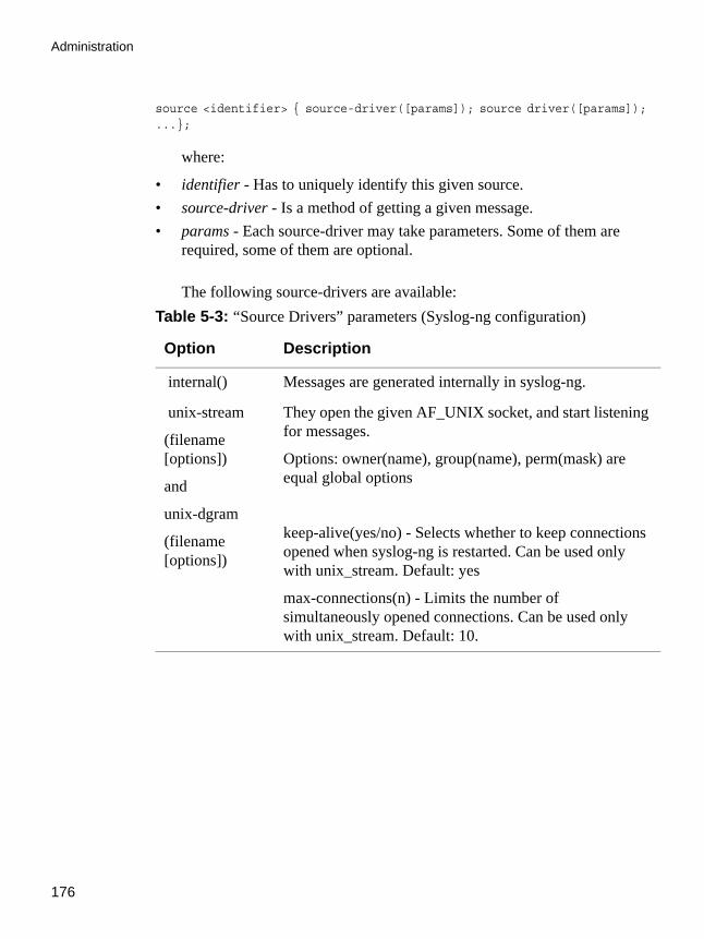
Administration
176
source <identifier> { source-driver([params]); source driver([params]); ...};
where:
• identifier - Has to uniquely identify this given source.• source-driver - Is a method of getting a given message.• params - Each source-driver may take parameters. Some of them are
required, some of them are optional.
The following source-drivers are available:Table 5-3: “Source Drivers” parameters (Syslog-ng configuration)
Option Description
internal() Messages are generated internally in syslog-ng.
unix-stream
(filename [options])
and
unix-dgram
(filename [options])
They open the given AF_UNIX socket, and start listening for messages.
Options: owner(name), group(name), perm(mask) are equal global options
keep-alive(yes/no) - Selects whether to keep connections opened when syslog-ng is restarted. Can be used only with unix_stream. Default: yes
max-connections(n) - Limits the number of simultaneously opened connections. Can be used only with unix_stream. Default: 10.

AlterPath ACS Command Reference Guide 177
Syslog-ng
Some Examples of Defining Sources:
1. To read from a file: source <identifier> {file(filename);};
a. Example to read messages from “/temp/file1” file: source file1 {file(‘/temp/file1’);};
b. Example to receive messages from the kernel:source s_kernel { file(‘/proc/kmsg’); };
tcp([options])
and
udp([options])
These drivers let you receive messages from the network, and as the name of the drivers show, you can use both TCP and UDP.
None of tcp() and udp() drivers require positional parameters. By default they bind to 0.0.0.0:514, which means that syslog-ng will listen on all available interfaces.
Options:
ip(<ip address>) - The IP address to bind to. Default: 0.0.0.0.
port(<number>) - UDP/TCP port used to listen messages. Default: 514.
max-connections(n) - Limits the number of simultaneously opened connections. Default: 10.
file(filename) Opens the specified file and reads messages.
pipe(filename) Opens a named pipe with the specified name, and listens for messages. (You'll need to create the pipe using mkfifo command).
Table 5-3: “Source Drivers” parameters (Syslog-ng configuration)
Option Description

Administration
178
2. To receive messages from local syslogd clients: source sysl {unix-stream(‘/dev/log’);};
3. To receive messages from remote syslogd clients:source s_udp { udp(ip(<cliente ip>) port(<udp port>)); };
a. Example to listen to messages from all machines on UDP port 514:source s_udp { udp(ip(0.0.0.0) port(514));};
b. Example to listen to messages from one client (IP address=10.0.0.1) on UDP port 999:source s_udp_10 { udp(ip(10.0.0.1) port(999)); };
4. Define filters.
To define filters use this statement:filter <identifier> { expression; };
where:
• identifier - Has to uniquely identify this given filter.
• expression - Boolean expression using internal functions, which has to evaluate to true for the message to pass.
The following internal functions are available:Table 5-4: “Filters” parameters (Syslog-ng configuration)
Option Description
facility(<facility code>)
Selects messages based on their facility code.
level(<level code>) or priority(<level code>)
Selects messages based on their priority.
program(<string>)
Tries to match the <string> to the program name field of the log message.

AlterPath ACS Command Reference Guide 179
Syslog-ng
Some examples of defining filters:
a. To filter by facility:filter f_facilty { facility(<facility name>); };
Examples:
filter f_daemon { facility(daemon); };filter f_kern { facility(kern); };filter f_debug { not facility(auth, authpriv, news, mail); };
b. To filter by level: filter f_level { level(<level name>);};
Examples:filter f_messages { level(info .. warn)};filter f_emergency { level(emerg); };filter f_alert { level(alert); };
c. To filter by matching one string in the received message:filter f_match { match(‘string’); };
Example to filter by matching the string “named”:filter f_named { match(‘named’); };
d. To filter ALARM messages (note that the following three examples should be one line):filter f_alarm { facility(local[0+<conf.DB_facility>]) and level(info) and match('ALARM') and match('<your string>'); } ;
host(<string>) Tries to match the <string> to the hostname field of the log message.
match(<string>)
Tries to match the <string> to the message itself.
Table 5-4: “Filters” parameters (Syslog-ng configuration)
Option Description

Administration
180
Example to filter ALARM message with the string “kernel panic”:filter f_kpanic { facility(local[0+<conf.DB_facility>]) and level(info) and match('ALARM') and match('kernel panic'); };
Example to filter ALARM message with the string “root login”:filter f_root { facility(local[0+<conf.DB_facility>]) and level(info) and match('ALARM') and match('root login'); };
e. To eliminate SSHD debug messages:filter f_sshd_debug { not program('sshd') or not level(debug); };
f. To filter the syslog_buffering:filter f_syslog_buf { facility(local[0+<conf.DB_facility>]) and level(notice); };
g. Define Actions.
To define actions use this statement (note that the statement should be one line):destination <identifier> {destination-driver([params]); destination-driver([param]);..};
where:
• identifier - Has to uniquely identify this given destination.
• destination driver - Is a method of outputting a given message.
• params - Each destination-driver may take parameters. Some of them required, some of them are optional.

AlterPath ACS Command Reference Guide 181
Syslog-ng
The following destination drivers are available:Table 5-5: “Destination Drivers” parameters (Syslog-ng configuration)
Option Description
file(filename[options])
This is one of the most important destination drivers in syslog-ng. It allows you to output log messages to the named file. The destination filename may include macros (by prefixing the macro name with a '$' sign) which gets expanded when the message is written. Since the state of each created file must be tracked by syslog-ng, it consumes some memory for each file. If no new messages are written to a file within 60 seconds (controlled by the time_reap global option), it's closed, and its state is freed.

Administration
182
file(filename[options])
continuation...
Available macros in filename expansion:
• HOST - The name of the source host where the message originated from.
• FACILITY - The name of the facility the message is tagged as coming from.
• PRIORITY or LEVEL - The priority of the message.• PROGRAM - The name of the program the message was
sent by.• YEAR, MONTH, DAY, HOUR, MIN, SEC - The year,
month, day, hour, min, sec of the message was sent.• TAG - Equals FACILITY/LEVEL.• FULLHOST - The name of the source host and the
source-driver: • <source-driver>@<hostname>• MSG or MESSAGE - The message received.
FULLDATE - The date of the message was sent.
Available options:
• log_fifo_size(number) - The number of entries in the output file.
• sync_freq(number) - The file is synced when this number of messages has been written to it.
• owner(name), group(name), perm(mask) - Equals global options.
• template(“string”) - Syslog-ng writes the “string” in the file. You can use the MACROS in the string.
• encrypt(yes/no) - Encrypts the resulting file.• compress(yes/no) - Compresses the resulting file using
zlib.
pipe(filename[options])
This driver sends messages to a named pipe. Available options:
owner(name), group(name), perm(mask) - Equals global options.
template(“string”) - Syslog-ng writes the “string” in the file. You can use the MACROS in the string.
Table 5-5: “Destination Drivers” parameters (Syslog-ng configuration)
Option Description
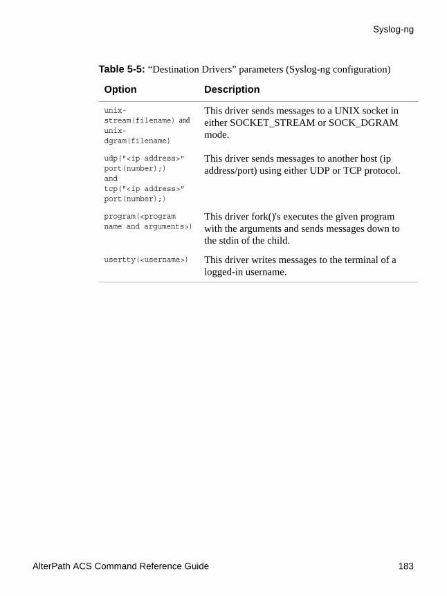
AlterPath ACS Command Reference Guide 183
Syslog-ng
unix-stream(filename) and unix-dgram(filename)
This driver sends messages to a UNIX socket in either SOCKET_STREAM or SOCK_DGRAM mode.
udp("<ip address>" port(number);)andtcp("<ip address>" port(number);)
This driver sends messages to another host (ip address/port) using either UDP or TCP protocol.
program(<program name and arguments>)
This driver fork()'s executes the given program with the arguments and sends messages down to the stdin of the child.
usertty(<username>) This driver writes messages to the terminal of a logged-in username.
Table 5-5: “Destination Drivers” parameters (Syslog-ng configuration)
Option Description

Administration
184
Some examples of defining actions:1. To send e-mail:destination <ident> { pipe(‘/dev/cyc_alarm’ template(‘sendmail <pars>’));};
where ident: uniquely identifies this destination. Parameters:
• -t <name>[,<name>] - To address
• [-c <name>[,<name>]] - CC address
• [-b <name>[,<name>]] - Bcc address
• [-r <name>[,<name>]] - Reply-to address
• -f <name> - From address
• -s \"<text>\" - Subject
• -m \”<text message>\” - Message
• -h <IP address or name> - SMTP server
• [-p <port>] - Port used. default:25
To mount the message, use this macro:
• $FULLDATE - The complete date when the message was sent.
• $FACILITY - The facility of the message.
• $PRIORITY or $LEVEL - The priority of the message.
• $PROGRAM - The message was sent by this program (BUFFERING or SOCK).
• $HOST - The name of the source host.
• $FULLHOST - The name of the source host and the source driver. Format: <source>@<hostname>
• $MSG or $MESSAGE - The message received.
Example to send e-mail to [email protected] (SMTP's IP address 10.0.0.2) from the e-mail address [email protected] with subject “ALARM”. The

AlterPath ACS Command Reference Guide 185
Syslog-ng
message will carry the current date, the host-name of this ACS and the message that was received from the source.
2. To send to pager server (sms server):destination <ident> {pipe(‘/dev/cyc_alarm’ template(‘sendsms <pars>’));};
where ident: uniquely identify this destination
• pars: -d <mobile phone number>
• -m \’<message - max.size 160 characters>\’
• -u <username to login on sms server>
• -p <port sms - default : 6701>
• <server IP address or name>
Example to send a pager to phone number 123 (Pager server at 10.0.0.1) with message carrying the current date, the hostname of this ACS and the message that was received from the source:
3. To send snmptrapdestination <ident> {pipe(‘/dev/cyc_alarm’ template(‘snmptrap <pars>’)); };
destination d_mail1 {pipe('/dev/cyc_alarm'
template('sendmail -t [email protected] -f [email protected] -s \”ALARM\” \\-m \'$FULLDATE $HOST $MSG\' -h 10.0.0.2'));
};
Figure 5-4: Send e-mail example
destination d_pager {pipe(‘/dev/cyc_alarm’ template(‘sendsms -d 123 -m \’$FULLDATE $HOST $MSG\’ 10.0.0.1’));
};
Figure 5-5: To send a pager phone example
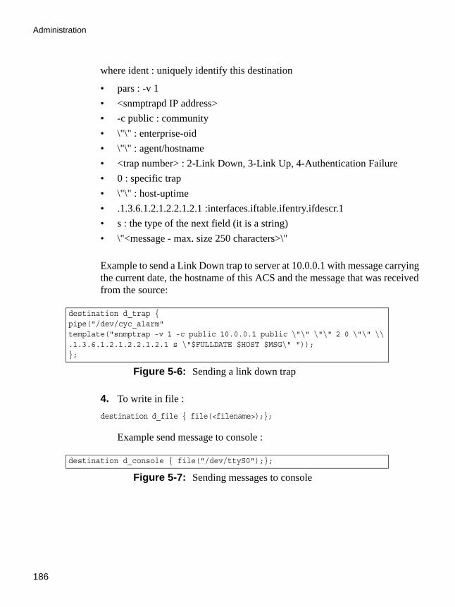
Administration
186
where ident : uniquely identify this destination
• pars : -v 1• <snmptrapd IP address>• -c public : community• \"\" : enterprise-oid• \"\" : agent/hostname• <trap number> : 2-Link Down, 3-Link Up, 4-Authentication Failure• 0 : specific trap• \"\" : host-uptime• .1.3.6.1.2.1.2.2.1.2.1 :interfaces.iftable.ifentry.ifdescr.1• s : the type of the next field (it is a string)• \"<message - max. size 250 characters>\"
Example to send a Link Down trap to server at 10.0.0.1 with message carrying the current date, the hostname of this ACS and the message that was received from the source:
4. To write in file : destination d_file { file(<filename>);};
Example send message to console :
destination d_trap {pipe("/dev/cyc_alarm" template("snmptrap -v 1 -c public 10.0.0.1 public \"\" \"\" 2 0 \"\" \\ .1.3.6.1.2.1.2.2.1.2.1 s \"$FULLDATE $HOST $MSG\" ")); };
Figure 5-6: Sending a link down trap
destination d_console { file("/dev/ttyS0");};
Figure 5-7: Sending messages to console

AlterPath ACS Command Reference Guide 187
Syslog-ng
Example to write a message in /var/log/messages file:
destination d_message { file("/var/log/messages"); };
Figure 5-8: Writing messages to file

Administration
188
5. To write messages to the session of a logged-in user: destination d_user { usertty("<username>"); };
Example to send message to all sessions with root user logged:
6. To send a message to a remote syslogd server:destination d_udp { udp("<remote IP address>" port(514)); };
Example to send syslogs to syslogd located at 10.0.0.1 :
7. Connect all of the above.
To connect the sources, filters, and actions, use the following statement. (Actions would be any message coming from one of the listed sources. A match for each of the filters is sent to the listed destinations.)
log { source(S1); source(S2); ...
filter(F1);filter(F2);...
destination(D1); destination(D2);... };
where :
• Sx - Identifier of the sources defined before.
• Fx - Identifier of the filters defined before.
• Dx - Identifier of the actions/destinations defined before.
destination d_userroot { usertty("root"); };
Figure 5-9: Sending messages to logged user
destination d_udp1 { udp("10.0.0.1" port(514)); };
Figure 5-10:Sending syslogs to a remote server

AlterPath ACS Command Reference Guide 189
Syslog-ng
Examples connecting sources, filters and actions:
1. To send all messages received from local syslog clients to console:log { source(sysl); destination(d_console);};
2. To send only messages with level alert and received from local syslog clients to all logged root user:
log { source(sysl); filter(f_alert); destination(d_userroot); };
3. To write all messages with levels info, notice, or warning and received from syslog clients (local and remote) to /var/log/messages file:
log { source(sysl); source(s_udp); filter(f_messages); destination(d_messages); };
4. To send e-mail if message received from local syslog client has the string “kernel panic”:
log { source(sysl); filter(f_kpanic); destination(d_mail1); };
5. To send e-mail and pager if message received from local syslog client has the string “root login”:
log { source(sysl); filter(f_root); destination(d_mail1); destination(d_pager); };
6. To send messages with facility kernel and received from syslog clients (local and remote) to remote syslogd:
log { source(sysl); source(s_udp); filter(f_kern); destination(d-udp1); };
Syslog-ng configuration to use with Syslog buffering feature
This configuration example uses the syslog buffering feature, and sends messages to the remote syslogd (10.0.0.1).
VI Method1. Configure /etc/portslave/pslave.conf file parameters.

Administration
190
In the pslave.conf file the parameters of the syslog buffering feature are configured as:
2. Add lines to /etc/syslog-ng/syslog-ng.conf file.
Add the following lines by VI to the file:
Syslog-ng configuration to use with multiple remote Syslog servers
This configuration example is used with multiple remote syslog servers.
VI Method1. Configure pslave.conf parameters.
In the pslave.conf file the facility parameter is configured as:
conf.DB_facility 1all.syslog_buffering 100
Figure 5-11:portslave.conf necessary configuration
#local syslog clientssource src { unix-stream("/dev/log"); };destination d_buffering { udp("10.0.0.1"); };
filter f_buffering { facility(local1) and level(notice); };#send only syslog_buffering messages to remote serverlog { source(src); filter(f_buffering); destination(d_buffering); };
Figure 5-12:portslave.conf necessary configuration
conf.facility 1
Figure 5-13:portslave.conf “facility” configuration

AlterPath ACS Command Reference Guide 191
Syslog-ng
2. Add lines to /etc/syslog-ng/syslog-ng.conf file.
CLI Method - SyslogYou can configure Syslog by following the steps below:
1. Open the CLI interface by issuing the command:# CLI
2. Configure the syslog facility number.
This is the facility number for the messages. The remote Syslog server filters received messages according to this parameter.
cli>config network syslog facility <local0-local7>
Possible values for it ranges from local0 - local7
3. Set up the server IP address to where syslog messages will be sent .
In this example the server will have the fictitious IP address 200.200.200.1.
# local syslog clientssource src { unix-stream("/dev/log"); };
# remote server 1 - IP address 10.0.0.1 port default destination d_udp1 { udp("10.0.0.1"); };
# remote server 2 - IP address 10.0.0.2 port 1999 destination d_udp2 { udp("10.0.0.2" port(1999););};
# filter messages from facility local1 and level info to warning filter f_local1 { facility(local1) and level(info..warn);};
# filter messages from facility local 1 and level err to alert filter f_critic { facility(local1) and level(err .. alert);};
# send info, notice and warning messages to remote server udp1 log { source(src); filter(f_local1); destination(d_udp1); };
# send error, critical and alert messages to remote server udp2 log { source(src); filter(f_critic); destination(d_udp2); };
Figure 5-14:syslog-ng.conf configuration

Administration
192
cli>config network syslog add server 200.200.200.1
You can repeat this step as many times as necessary, depending on the quantity of remote servers you want to add.
4. Activate the configuration.cli> config runconfig
5. Save the configuration.cli> config savetoflash
6. Exit the CLI mode.
To exit the CLI mode and return to ACS ’s shell, issue the command:cli> quit
How Syslog Messages are generatedThe ACS can generate syslog messages, which enable system administrators to monitor changes in the box. When certain actions/conditions are met through the web interface as well as through CLI or commands which users enter from a shell prompt, the system generates and sends messages to the syslog-ng file.
The messages use the following format:
• Level - the syslog level used• Tag - a fixed string used by the user to create filters• Text - the text that contains the condition or action.
Generated Syslog MessagesThe syslog messages are generated as a result of specific actions or conditions are as follows:
ACS generates syslog messages when the following conditions are met:

AlterPath ACS Command Reference Guide 193
How Syslog Messages are generated
Table 5-6: ACS Syslog Messages Format
Level Tag Text
info [PMD]-Serial Port p
One or more IPDUs were added to the chain. This chain has now X IPDUs and Y outlets
info AUTH User [xyz] for session [abc] successfully authenticated
Note: this syslog message applies only to Web sessions and not to regular console (telnet or SSH) sessions.
info AUTH User [xyz] for session [abc] logged out
Note: this syslog message applies only to Web sessions and not to regular console (telnet or SSH) sessions.
info AUTH Cancel new admin [abc] login
Note: this syslog message applies only to Web sessions and not to regular console (telnet or SSH) sessions.
info AUTH Session [%d] timed out", sid
Note: this syslog message applies only to Web sessions and not to regular console (telnet or SSH) sessions.
info CONFIG Configuration saved to flash
info CONFIG New configuration activated
info CONFIG Password changed for user [xyz] by user [abc]
info CONFIG User [xyz] added by user [abc]
info CONFIG User [xyz] deleted by user [abc]
info CONFIG Network daemon [daemon name] stopped

Administration
194
info APPLICATION User [abc] connected to port [x] (ttySx) via socket server
info APPLICATION User [abc] connected to port [x] (ttySx) via socket ssh
alert [PMD]-Serial Port p
Outlet X has been turned OFF by user <username>
alert [PMD]-Serial Port p
Outlet X has been turned ON by user <username>
alert [PMD]-Serial Port p
OVER CURRENT on IPDU #X (current: <current detected> threshold:<threshold configured>)
alert [PMD]-Serial Port p
One or more IPDUs were removed from the chain. This chain has now X IPDUs and Y outlets
alert AUTH User [xyz] login failed
Note: this syslog message applies only to Web sessions and not to regular console (telnet or SSH) sessions.
alert AUTH User [%s] login failed. There exists another admin session
Note: this syslog message applies only to Web sessions and not to regular console (telnet or SSH) sessions.
alert AUTH Previous admin session terminated by new admin [abc] login
Note: this syslog message applies only to Web sessions and not to regular console (telnet or SSH) sessions.
Table 5-6: ACS Syslog Messages Format
Level Tag Text
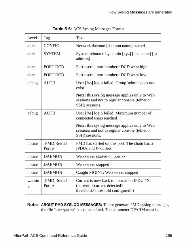
AlterPath ACS Command Reference Guide 195
How Syslog Messages are generated
Note: ABOUT PMD SYSLOG MESSAGES: To not generate PMD syslog messages, the file "/etc/pmd.sh" has to be edited. The parameter DPARM must be
alert CONFIG Network daemon [daemon name] started
alert SYSTEM System rebooted by admin [xyz] [hostname] [ip address]
alert PORT DCD Port <serial port number> DCD went high
alert PORT DCD Port <serial port number> DCD went low
debug AUTH User [%s] login failed. Group 'admin' does not exist
Note: this syslog message applies only to Web sessions and not to regular console (telnet or SSH) sessions.
debug AUTH User [%s] login failed. Maximum number of connected users reached
Note: this syslog message applies only to Web sessions and not to regular console (telnet or SSH) sessions.
notice [PMD]-Serial Port p
PMD has started on this port. The chain has X IPDUs and W outlets.
notice DAEMON Web server started on port xx
notice DAEMON Web server stopped
notice DAEMON Caught SIGINT: Web server stopped
warning
[PMD]-Serial Port p
Current is now back to normal on IPDU #X (current: <current detected> threshold:<threshold configured>)
Table 5-6: ACS Syslog Messages Format
Level Tag Text
Administration
196
changed from "" to "-s". After this, the command “saveconf" and "daemon restart PMD" must be run.
You can use the information provided in the table above to create filters and generate alarms about events that happens in the ACS itself. More about this issue will be approached in the next section of this chapter.
DCD ON/OFF Syslog messagesThe ACS can generate an alert when a serial console cable is removed from the console server or the server/network equipment attached to the console is powered down. Also if a modem is in use then to detected if the modem is still powered on and active.
The DCD signal will be monitored and a syslog message will be generated whenever the state of the signal changes. The syslog message can be handled by syslog-ng to generate an event notification.
How to configureThe necessary steps to enable syslog messages generation in the ACS will be described below:
1. Open the /etc/portslave/pslave.conf file.# vi /etc/portslave/pslave.conf
2. Set the all.dcd or sXX.dcd parameter to 1 in the /etc/portslave/pslave.conf file.
all.dcd 1
orsXX.dcd 1
Where XX is the desired port number.
3. Configure the syslog-ng.conf file to monitor DCD status.
You can see a practical example here: “Generating messages and sending them to console if the DCD signal changes its state.” on page 197
4. Save the configuration.

AlterPath ACS Command Reference Guide 197
Generating Alarms (Syslog-ng)
# saveconf
The source for all generated Syslog messages are “src_dev_log”, the only exceptions are Syslog messages generated when DCD goes on/off, that is “s_kernel”. You can follow the table on Page 193 to create filters and/or trigger alarms.
ExamplesTo configure the examples given below edit the /etc/syslog-ng/syslog-ng.conf and add the presented lines.
1. Generating Syslog messages to be sent to console, when the user root tries to connect together with an already logged root user.
filter f_info { level(info); }filter f_named { match("AUTH"); };destination console { usertty("root"); };log { source(src_dev_log); filter(f_info, f_named); destination(console); };
2. Generating messages and sending them to console when any user login attempt fails.
filter f_info { level(alert); };filter f_named { match("AUTH"); };destination console { usertty("root"); };log { source(src_dev_log); filter(f_info, f_named); destination(console); };
3. Generating messages and sending them to console if the DCD signal changes its state.
filter f_dcdchg { level(alert) and match("PORT DCD") };destination console { usertty("root"); };log { source(s_kernel); filter(f_dcdchg); destination(console); };
Generating Alarms (Syslog-ng)This feature helps the administrator to manage the servers. It filters the messages received by the serial port (the server’s console) based on the contents of the messages. It then performs an action, such as sending an email or pager message. To configure this feature, you need to configure filters and actions in the syslog-ng.conf file. (You can read more about syslog-ng in the Syslog-ng section.)
Administration
198
How to configureAlarm generation is strictly related to the syslog-ng configuration. It is highly recommended to read the Syslog-ng section before configuring this feature. This section will show practical examples of utilization of this feature.
The /etc/portslave.conf related parameters are:
• conf.DB_facility - This value (0-7) is the Local facility sent to the syslog-ng with data when syslog_buffering and/or alarm is active.
• all.alarm - When nonzero, all data received from the port is captured and sent to syslog-ng with INFO level and LOCAL[0+conf.DB_facility] facility. This parameter must be set to a non zero value to activate alarm generation.
The syslog-ng reads from sources (files, TCP/UDP connections, syslogd clients), filters the messages and takes an action (writes in files, sends snmptrap, pager, email or syslogs).
Basically, alarms are triggered by a combination of sources, filters and destinations. To connect the sources, filters and actions (any message coming from one of the listed sources, matching the filters (each of them) is sent to the listed destinations). Use this statement:log { source(S1); source(S2); ...filter(F1);filter(F2);...destination(D1); Destination(D2);...};
For more information about sources, destinations and filters, please refer to the Syslog-ng section. This
VI method - Configuration to use with Alarm FeatureThis configuration example is used for the alarm feature.
1. Configure the /etc/portslave/pslave.conf file parameter.
In the /etc/portslave/pslave.conf file the parameters of the alarm feature are configured as:
all.alarm 1conf.DB_facility 2
2. Configure the /etc/syslog-ng/syslog-ng.conf. file:

AlterPath ACS Command Reference Guide 199
Generating Alarms (Syslog-ng)
This step has the objective to configure the /etc/syslog-ng/syslog-ng.conf file. Several examples will be given here. All commands are present (commented) in the original syslog-ng.conf file by default. Choose the example that best fits to your application.
Example 1 - To send all messages received from local syslog clients to consoleInsert the lines below at the END of the file syslog-ng.conf file, keeping all lines above commented.
Example 2 - To send only messages with level alert and received from local syslog clients to all logged root userInsert the lines below at the END of the file syslog-ng.conf file, keeping all lines above commented.
source sysl {unix-stream("/dev/log");};destination d_console { file("/dev/ttyS0");};log { source(sysl); destination(d_console);};
Figure 5-15:part of the /etc/syslog-ng/syslog-ng.conf file
source sysl {unix-stream("/dev/log");};filter f_alert { level(alert); };destination d_userroot { usertty("root"); };log { source(sysl); filter(f_alert); destination(d_userroot); };
Figure 5-16:part of the /etc/syslog-ng/syslog-ng.conf file

Administration
200
Example 3 - Write all messages with levels info, notice or warning and received from syslog clients (local and remote) to /var/log/ mes-sages file :Insert the lines below at the END of the file syslog-ng.conf file, keeping all lines above commented.
Example 4 - Send e-mail if message received from local syslog client has the string "kernel panic".Insert the lines below at the END of the file syslog-ng.conf file, keeping all lines above commented.
source sysl {unix-stream("/dev/log");};source s_udp { udp(ip(<ip client>) port(<udp port>)); };filter f_messages { level(info..warn);};destination d_message { file("/var/log/messages"); };log { source(sysl); source(s_udp); filter(f_messages); destination(d_messages);};
Figure 5-17:part of the /etc/syslog-ng/syslog-ng.conf file
source sysl {unix-stream("/dev/log");};filter f_kpanic{facility(local1) and level(info) and match("ALARM") and match("kernel panic");};destination d_mail1 {
pipe("/dev/cyc_alarm"template("sendmail -t [email protected] -f [email protected] -s \"ALARM\" \\
-m \"$FULLDATE $HOST $MSG\" -h 10.0.0.2"));};
log { source(sysl); filter(f_kpanic); destination(d_mail1); };
Figure 5-18:part of the /etc/syslog-ng/syslog-ng.conf file

AlterPath ACS Command Reference Guide 201
Generating Alarms (Syslog-ng)
Example 5 - Send e-mail and pager if message received from local syslog client has the string "root login".Insert the lines below at the END of the file syslog-ng.conf file, keeping all lines above commented.
Example 6 - Send messages with facility kernel and received from syslog clients (local and remote) to remote syslogdInsert the lines below at the END of the file syslog-ng.conf file, keeping all lines above commented.
3. Activate changes.
To activate the changes made, run the following commands in the presented order:
# runconf# killall syslog-ng# syslog-ng
source sysl {unix-stream("/dev/log");};filter f_root {facility(local1) and level(info) and match("ALARM") and match("root login");};destination d_mail1 {
pipe("/dev/cyc_alarm"template("sendmail -t [email protected] -f [email protected] -s \"ALARM\" \\
-m \"$FULLDATE $HOST $MSG\" -h 10.0.0.2"));};
destination d_pager {pipe("/dev/cyc_alarm"
template("sendsms -d 123 -m \"$FULLDATE $HOST $MSG\" 10.0.0.1"));};log { source(sysl); filter(f_root); destination(d_mail1); destination(d_pager); };
Figure 5-19:part of the /etc/syslog-ng/syslog-ng.conf file
source sysl {unix-stream("/dev/log");};source s_udp { udp(ip(<ip client>) port(<udp port>)); };filter f_kern { facility(kern); };destination d_udp1 { udp("10.0.0.1" port(514)); };log { source(sysl); source(s_udp); filter(f_kern); destination(d-udp1); };
Figure 5-20:part of the /etc/syslog-ng/syslog-ng.conf file

Administration
202
The first command activate the changes made in the /etc/portslave/pslave.conf file. The second and the third commands activate the changes made in the /etc/syslog-ng/syslog-ng.conf file.
4. Save the changes to the flash memory.
To save the changes made, run the command:# saveconf
CLI Method - Alarm NotificationThe CLI interface allows the configuration of alarm notifications when is an event is generated in any port of the ACS . Generating alarms for the ACS itself is not customizable using the CLI interface.
Into the CLI interface all options are under the following menu:cli> config administration notifications
There you’ll have the options:
• addemail - Sends a message to the configured e-mail address if the defined string appears.
• addpager - Sends a message to the configured pager if the defined string appears.
• addsnmptrap - Sends a snmp trap to the configured server if the defined string appears.
• alarm - Activates/Deactivates the alarm feature. If you don't enable it, syslog messages won’t be generated when there is incoming data from the ports.
• delete - Deletes any previously configured string.• edit - Edit any previously configured string.
Example: The below example will configure the ACS to send an e-mail every time root user logs into a server connected to the a port. We will configure the trigger string as “root login”. Note that the server connected to the ACS must be properly configured to send Syslog messages.
1. Open the CLI interface by issuing the command:# CLI
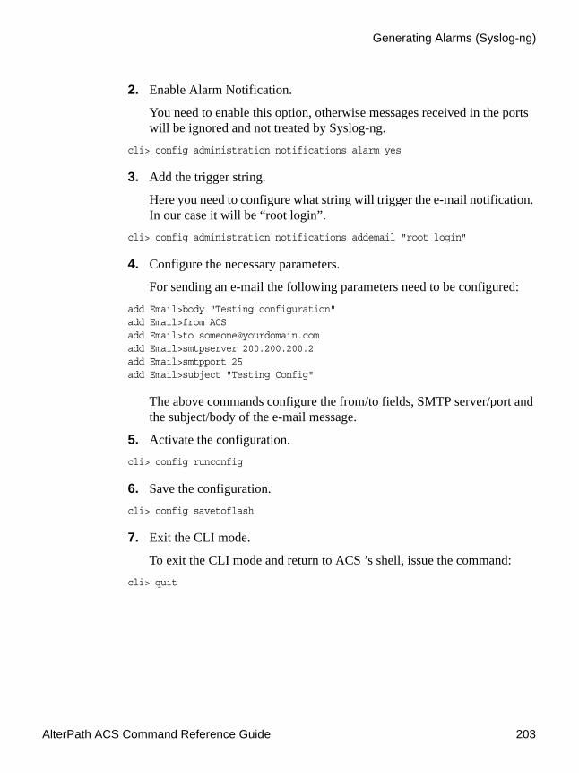
AlterPath ACS Command Reference Guide 203
Generating Alarms (Syslog-ng)
2. Enable Alarm Notification.
You need to enable this option, otherwise messages received in the ports will be ignored and not treated by Syslog-ng.
cli> config administration notifications alarm yes
3. Add the trigger string.
Here you need to configure what string will trigger the e-mail notification. In our case it will be “root login”.
cli> config administration notifications addemail "root login"
4. Configure the necessary parameters.
For sending an e-mail the following parameters need to be configured:add Email>body "Testing configuration"add Email>from ACSadd Email>to [email protected] Email>smtpserver 200.200.200.2add Email>smtpport 25add Email>subject "Testing Config"
The above commands configure the from/to fields, SMTP server/port and the subject/body of the e-mail message.
5. Activate the configuration.cli> config runconfig
6. Save the configuration.cli> config savetoflash
7. Exit the CLI mode.
To exit the CLI mode and return to ACS ’s shell, issue the command:cli> quit
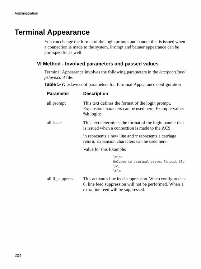
Administration
204
Terminal AppearanceYou can change the format of the login prompt and banner that is issued when a connection is made to the system. Prompt and banner appearance can be port-specific as well.
VI Method - Involved parameters and passed valuesTerminal Appearance involves the following parameters in the /etc/portslave/pslave.conf file:Table 5-7: pslave.conf parameters for Terminal Appearance configuration
Parameter Description
all.prompt This text defines the format of the login prompt. Expansion characters can be used here. Example value: %h login:
all.issue This text determines the format of the login banner that is issued when a connection is made to the ACS.
\n represents a new line and \r represents a carriage return. Expansion characters can be used here.
Value for this Example:\r\n\ Welcome to terminal server %h port S%p \n\ \r\n
all.lf_suppress This activates line feed suppression. When configured as 0, line feed suppression will not be performed. When 1, extra line feed will be suppressed.

AlterPath ACS Command Reference Guide 205
Terminal Appearance
CLI Method - BannerTo configure certain parameters for a specific serial port:
1. Open the CLI interface by issuing the command:# CLI
2. Configure the desired banner.
The command below will configure “testing banner” as the default banner for all ports.
cli> config physicalports all other banner “testing banner”
You can configure different banners for different ports, all you have to do is to change the ALL parameter to the desired port number or port range. Eg. 1 or 1-3 (from port 1 to 3).
3. Activate the configuration.cli> config runconfig
all.auto_answer_input
This parameter is used in conjunction with the next parameter, auto_answer_output. If configured and if there is no session established to the port, this parameter will constantly be compared and matched up to the string of bytes coming in remotely from the server. If a match is found, the string configured in auto_answer_output is sent back to the server. To represent the ESC character as part of this string, use the control character, ^[.
all.auto_answer_output
This parameter is used in conjunction with the previous parameter, auto_answer_input. If configured, and if there is no session established to the port, this parameter is sent back to the server when there is a match between the incoming data and auto_answer_input. To represent the ESC character as part of this string, use the control character, ^[.
Table 5-7: pslave.conf parameters for Terminal Appearance configuration
Parameter Description

Administration
206
4. Save the configuration.cli> config savetoflash
5. Exit the CLI mode.
To exit the CLI mode and return to ACS ’s shell, issue the command:cli> quit
Centralized ManagementThe ACS allows centralized management through the use of a Master pslave.conf file. Administrators should consider this approach to configure multiple ACS . Using this feature, each unit has a simplified pslave.conf file where a Master include file is cited. This common configuration file contains information for all units, properly divided in separate sections, and would be stored on one central server. This file, in our example shown in the following figure, is /etc/portslave/TScommon.conf. It must be downloaded to each ACS .
Note: Centralized management can mean one big configuration file (the common file) that is placed in a management host. This same file would be downloaded into all ACS boxes (each of those boxes would include a tiny config file and that big common file). In this application, there may or may not be clustering involved. The user may want to access each box individually, without passing through la central point (master), using the common file just to make his/her life easier in regard to maintain the config file. This user could ALSO add the clustering application on a daily basis. Clustering does NOT require a common config file. A common config file does NOT apply to clustering,
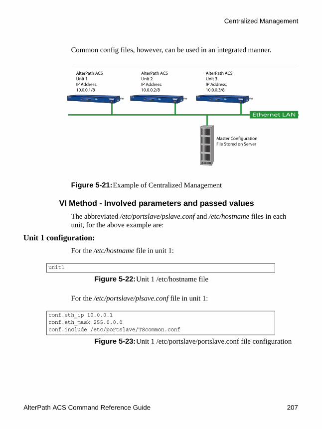
AlterPath ACS Command Reference Guide 207
Centralized Management
Common config files, however, can be used in an integrated manner.
Figure 5-21:Example of Centralized Management
VI Method - Involved parameters and passed valuesThe abbreviated /etc/portslave/pslave.conf and /etc/hostname files in each unit, for the above example are:
Unit 1 configuration: For the /etc/hostname file in unit 1:
For the /etc/portslave/plsave.conf file in unit 1:
unit1
Figure 5-22:Unit 1 /etc/hostname file
conf.eth_ip 10.0.0.1conf.eth_mask 255.0.0.0conf.include /etc/portslave/TScommon.conf
Figure 5-23:Unit 1 /etc/portslave/portslave.conf file configuration

Administration
208
Unit 2 configuration: For the /etc/hostname file in unit 2:
For the /etc/portslave/plsave.conf file in unit 2:
Unit 3 configuration: For the /etc/hostname file in unit 3:
For the /etc/portslave/plsave.conf file in unit 3:
unit2
Figure 5-24:Unit 2 /etc/hostname file
conf.eth_ip 10.0.0.2conf.eth_mask 255.0.0.0conf.include /etc/portslave/TScommon.conf
Figure 5-25:Unit 2 /etc/portslave/portslave.conf file configuration
unit3
Figure 5-26:Unit 3 /etc/hostname file
conf.eth_ip 10.0.0.3conf.eth_mask 255.0.0.0conf.include /etc/portslave/TScommon.conf
Figure 5-27:Unit 3 /etc/portslave/portslave.conf file configuration
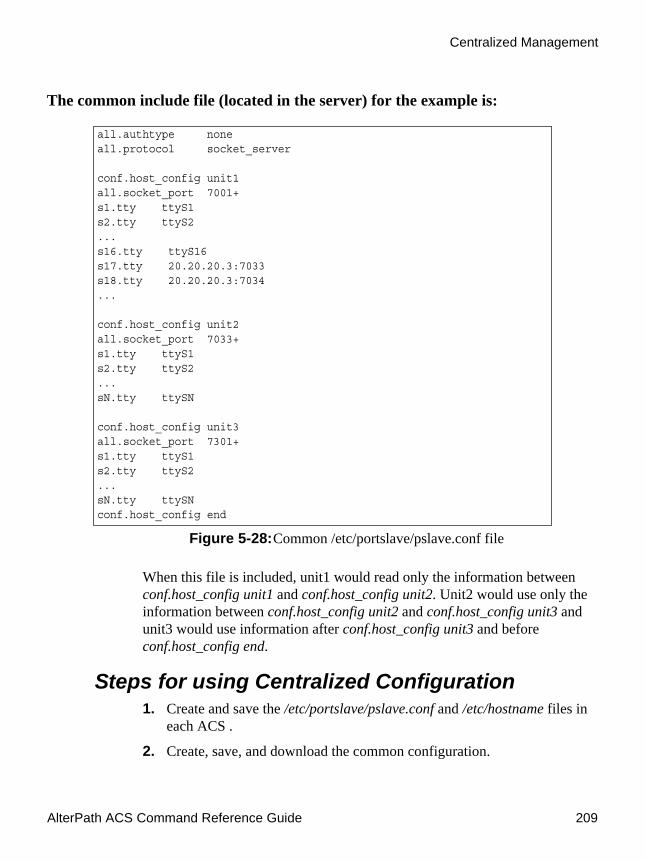
AlterPath ACS Command Reference Guide 209
Centralized Management
The common include file (located in the server) for the example is:
When this file is included, unit1 would read only the information between conf.host_config unit1 and conf.host_config unit2. Unit2 would use only the information between conf.host_config unit2 and conf.host_config unit3 and unit3 would use information after conf.host_config unit3 and before conf.host_config end.
Steps for using Centralized Configuration1. Create and save the /etc/portslave/pslave.conf and /etc/hostname files in
each ACS .
2. Create, save, and download the common configuration.
all.authtype noneall.protocol socket_server
conf.host_config unit1 all.socket_port 7001+s1.tty ttyS1s2.tty ttyS2...s16.tty ttyS16s17.tty 20.20.20.3:7033s18.tty 20.20.20.3:7034...
conf.host_config unit2 all.socket_port 7033+s1.tty ttyS1s2.tty ttyS2...sN.tty ttySN
conf.host_config unit3 all.socket_port 7301+s1.tty ttyS1s2.tty ttyS2...sN.tty ttySNconf.host_config end
Figure 5-28:Common /etc/portslave/pslave.conf file

Administration
210
Create and save the common configuration file on the server, then download it (probably using scp) to each unit. Make sure to put it in the directory set in the pslave.conf file (/etc/portslave in the example).
3. Execute the command runconf on each unit.
4. Test each unit.
If everything works, add the line /etc/portslave/TScommon.conf to the /etc/config_files file.
5. Save the file and close it.
6. Execute the saveconf command.
Note: NOTE: The included file /etc/portslave/TScommon.conf cannot contain another include file (i.e., the parameter conf.include must not be defined). Also, <max ports of ACS > + N(+) is done same way as serial port.
Date, Time, Timezone, and Daylight SavingsTo adjust the date and time, use the date command. Timezone is configured using the CLI utility or with the Web Manager Interface (see ACS Installation, Administration, and User Guide for using the WMI to set time, date, and timezone information).
Note: Setting the system timezone creates a new file called /etc/localtime, which erases /etc/TIMEZONE.
Date and TimeDate and time are set separately within the CLI. To reach and display the current time, date, and timezone settings from the cli> prompt, type the following:cli>config administration date/timedate/time>show [date/time] date: 03/28/2006 time: 10:11:45 PST

AlterPath ACS Command Reference Guide 211
Date, Time, Timezone, and Daylight Savings
Setting the DateThe date command prints or sets the system date. date mm/dd/yyyy
where:
• mm = month• dd = day• yyyy = year
For example: date/time>date 03/28/2006
displays:date/time>show date date: 03/28/2006
Setting the TimezoneThe date command prints or sets the system time. Press TAB twice to show all of the available parameters that can be set using the timezone option:cli>config administrationadministration>timezonetimezone>custom info quit return show standardtimezone>show
For example:
date/time>time 09:40:00
displays:date/time>show time time: 09:40:00 PST
Note: The target timezone acronym (PST in the example) is shown by default.

Administration
212
Daylight Savings TimeWhen the dst parameter is set to “on,” the ACS will automatically adjust its time information to comply with the time shift appropriate to the target timezone. For states, countries, or regions that do not observe daylight savings time, the dst parameter must be set to “off” even if other regions in the target timezone do observe the daylight savings time change.
In rare occurences or under special circumstances, a region or country might require that a customized daylight savings time be used. Such circumstances might require a temporary or permanent change of date for the beginning and ending of daylight time, or a time offset greater or less than the usual one hour. Instructions for customizing the daylight savings time parameters are given below.
Customizing the Daylight Savings Time (DST) SettingAlterPath ACS 2.6.1 allows you to customize the ACS for a non-standard daylight savings time target timezone, if applicable.
1. To customize the automated daylight savings time for the target timezone using the CLI, begin with:
cli>config administration timezone custom
2. Press TAB twice to get a list of parameters:custom>acronym dstendday dststartday info showdst dstendtime dststarttime quit zonelabeldstacronym dstsave gmtoff return

AlterPath ACS Command Reference Guide 213
Date, Time, Timezone, and Daylight Savings
3. Type show and press Enter to get a list of the current settings:custom>show [custom] zonelabel: Pacific acronym: PST gmtoff: -8:00 dst: on dstacronym: PDT dstsave: 01:00 dststartday: 04/02 dststarttime: 02:00 dstendday: 10/29 dstendtime: 02:00
The following table defines and describes the use of each of the parameters available.
Table 5-8: Daylight Savings Time Custom Parameters
Parameter Definition and Use
zonelabel Can be any custom name you choose (such as, “London,” “ChicagoOffice,” or “Sydney”), or can be a numerical value. “Pacific” is shown in the example.
acronym The abbreviated name for the zonelabel. In the example shown, “PST” is used for “Pacific Standard Time.”
gmtoff GMT Offset: This is the number of hours either ahead (+) or behind (-) Greenwich Mean Time (GMT) in hours. For PST (shown), the offset is -8:00 hours.
dst Daylight Savings Time (DST): Set to “on” for custom daylight savings time settings to be active.
dstacronym The abbreviated name used to describe the timezone when daylight savings time is in effect. “PDT” for Pacific Daylight Time is used in the example.

Administration
214
4. From the custom> prompt, enter the appropriate date and time for each of the parameters shown above. Use the show command to verify that your entries have been accepted.
custom>show [custom] zonelabel: Pacific acronym: PST gmtoff: -8:00 dst: on dstacronym: PDT dstsave: 01:00 dststartday: 04/01 dststarttime: 02:00 dstendday: 07/17 dstendtime: 02:00
5. Return to the cli> prompt and activate the configuration.cli>config runconfig
6. Save the configuration:cli> config savetoflash
dstsave This is the amount of time that the clock moves forward or back at the beginning and end of daylight savings time for the target timezone.
dststartday The day (mm/dd) that DST starts for the target timezone. Date in example is for year 2006.
dststarttime The precise time of day (hh:mm) that DST starts for the target timezone.
dstendday The date (mm/dd) that DST will end for the target timezone. Date in example is for year 2006.
dstendtime The precise time of day (hh:mm) that DST ends for the target timezone.
Table 5-8: Daylight Savings Time Custom Parameters
Parameter Definition and Use
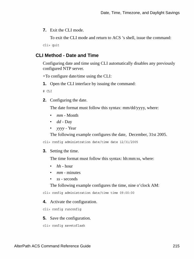
AlterPath ACS Command Reference Guide 215
Date, Time, Timezone, and Daylight Savings
7. Exit the CLI mode.
To exit the CLI mode and return to ACS ’s shell, issue the command:cli> quit
CLI Method - Date and TimeConfiguring date and time using CLI automatically disables any previously configured NTP server.
+To configure date/time using the CLI:
1. Open the CLI interface by issuing the command:# CLI
2. Configuring the date.
The date format must follow this syntax: mm/dd/yyyy, where:
• mm - Month• dd - Day• yyyy - YearThe following example configures the date, December, 31st 2005.
cli> config administration date/time date 12/31/2005
3. Setting the time.
The time format must follow this syntax: hh:mm:ss, where:
• hh - hour• mm - minutes• ss - secondsThe following example configures the time, nine o’clock AM:
cli> config administration date/time time 09:00:00
4. Activate the configuration.cli> config runconfig
5. Save the configuration.cli> config savetoflash

Administration
216
6. Exit the CLI mode.
To exit the CLI mode and return to ACS ’s shell, issue the command:cli> quit
Setting Local TimezoneYou can set the time to your local timzone using the set_timezone command or the CLI utility. The system uses GMT (Greenwich Mean Time) as a reference point.
Configuring using set_timezone1. From a shell within the ACS box, run set_timezone as root by entering the
following command:#set_timezone
The following options appear:

AlterPath ACS Command Reference Guide 217
Date, Time, Timezone, and Daylight Savings
2. Type the number corresponding to your Local GMT and press <Enter>.
A message verifies your selection. For example if you choose 8, the system displays the following message:
Your choice was: GMT+4
Please choose the time zone where this machine is located.
0)GMT1)1h West GMT2)10h West GMT3)11h West GMT4)12h West GMT5)2h West GMT6)3h West GMT7)4h West GMT8)5h West GMT9)6h West GMT10)7h West GMT11)8h West GMT12)9h West GMT13)1h East GMT14)10h East GMT15)11h East GMT16)12h East GMT17)13h East GMT18)14h East GMT19)2h East GMT20)3h East GMT21)4h East GMT22)5h East GMT23)6h East GMT24)7h East GMT25)8h East GMT26)9h East GMTType your option:
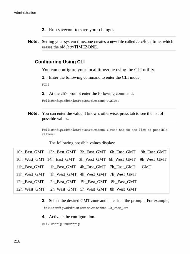
Administration
218
3. Run saveconf to save your changes.
Note: Setting your system timezone creates a new file called /etc/localtime, which erases the old /etc/TIMEZONE.
Configuring Using CLIYou can configure your local timezone using the CLI utility.1. Enter the following command to enter the CLI mode.#CLI
2. At the cli> prompt enter the following command.#cli>config>administration>timezone <value>
Note: You can enter the value if known, otherwise, press tab to see the list of possible values.
#cli>config>administration>timezone <Press tab to see list of possible values>
The following possible values display:
3. Select the desired GMT zone and enter it at the prompt. For example, #cli>config>administration>timezone 2h_West_GMT
4. Activate the configuration.cli> config runconfig
10h_East_GMT 13h_East_GMT 3h_East_GMT 6h_East_GMT 9h_East_GMT
10h_West_GMT 14h_East_GMT 3h_West_GMT 6h_West_GMT 9h_West_GMT
11h_East_GMT 1h_East_GMT 4h_East_GMT 7h_East_GMT GMT
11h_West_GMT 1h_West_GMT 4h_West_GMT 7h_West_GMT
12h_East_GMT 2h_East_GMT 5h_East_GMT 8h_East_GMT
12h_West_GMT 2h_West_GMT 5h_West_GMT 8h_West_GMT

AlterPath ACS Command Reference Guide 219
NTP (Network Time Protocol)
5. Save the configuration.cli> config savetoflash
6. Exit the CLI mode.cli> quit
NTP (Network Time Protocol)The ntpclient is a Network Time Protocol (RFC-1305) client for UNIX- and Linux-based computers. In order for the ACS to work as a NTP client, the IP address of the NTP server must be set in the file /etc/daemon.d/ntpclient.conf. The program /bin/daemon.sh reads the configuration file (/etc/daemon.d/ntpclient.conf) and runs with the settings of this file.
VI mode configurationThe file /etc/daemon.d/ntpclient.conf has all the configurable parameters. The parameters that are not presented in the table below should not be changed.
1. Edit the /etc/daemon.d/ntpclient.conf and change the parameters according to the table below:
Table 5-9: /etc/daemon.d/ntpclient.conf parameters
Parameter Description
ENABLE This parameter enables the NTP client. It defaults to NO, to enable it choose “YES”.
NTPSERVER NTP server ip address.
NTPINTERVAL Time in seconds to ask server.
NTPCOUNT Specifies how many times the server will be asked. 0 means forever.

Administration
220
2. Activate and save the changes made.
To activate the configuration, issue the following command:# daemon.sh NTP restart
To save the changes, run the command:# saveconf
CLI Method - NTPTo configure an NTP server using the CLI follow the steps below:
1. Open the CLI interface by issuing the command:# CLI
2. Set the IP address of the NTP server.cli> config administration ntp xxx.xxx.xxx.xxx
Where xxx.xxx.xxx.xxx is the IP address of the NTP server.
Note: To deactivate the NTP service you just need to configure date by issuing the command:cli> config administration date/time date <mm/dd/yyyy>
3. Activate the configuration.cli> config runconfig
NTP_OPT Other ntp parameters. The possible values for this parameter are listed below:
• -d -> Print diagnostics• -h hostname -> NTP server host (mandatory).• -l -> Attempt to lock local clock to server using adjtimex(2).• -p port -> Local NTP client UDP port.• -r -> Replay analysis code based on stdin.• -s -> Clock set (if count is not defined this sets count to 1).
Table 5-9: /etc/daemon.d/ntpclient.conf parameters
Parameter Description
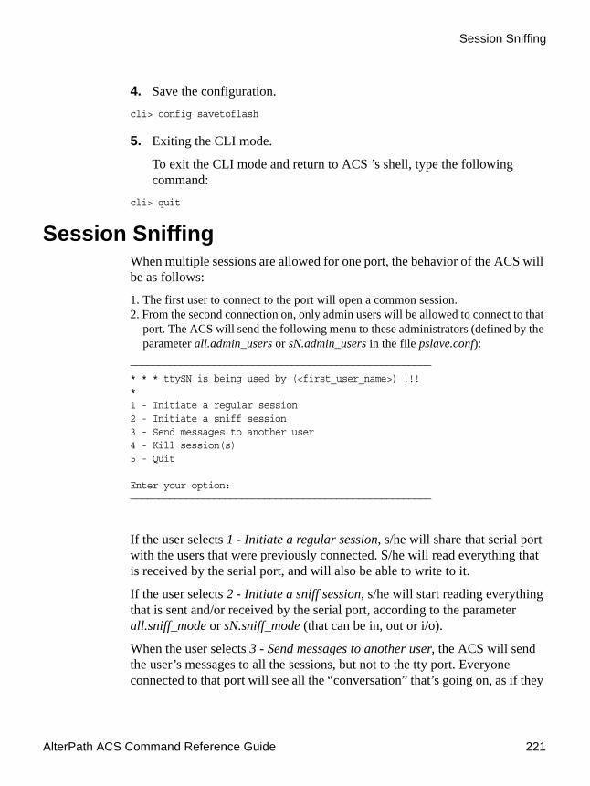
AlterPath ACS Command Reference Guide 221
Session Sniffing
4. Save the configuration.cli> config savetoflash
5. Exiting the CLI mode.
To exit the CLI mode and return to ACS ’s shell, type the following command:
cli> quit
Session SniffingWhen multiple sessions are allowed for one port, the behavior of the ACS will be as follows:
1. The first user to connect to the port will open a common session.2. From the second connection on, only admin users will be allowed to connect to that
port. The ACS will send the following menu to these administrators (defined by the parameter all.admin_users or sN.admin_users in the file pslave.conf):
——————————————————————————————————————————————————————* * * ttySN is being used by (<first_user_name>) !!!*1 - Initiate a regular session2 - Initiate a sniff session3 - Send messages to another user4 - Kill session(s)5 - Quit
Enter your option:——————————————————————————————————————————————————————
If the user selects 1 - Initiate a regular session, s/he will share that serial port with the users that were previously connected. S/he will read everything that is received by the serial port, and will also be able to write to it.
If the user selects 2 - Initiate a sniff session, s/he will start reading everything that is sent and/or received by the serial port, according to the parameter all.sniff_mode or sN.sniff_mode (that can be in, out or i/o).
When the user selects 3 - Send messages to another user, the ACS will send the user’s messages to all the sessions, but not to the tty port. Everyone connected to that port will see all the “conversation” that’s going on, as if they
Administration
222
were physically in front of the console in the same room. These messages will be formatted as:
[Message from user/PID] <<message text goes here>> by the ACS. To inform the ACS that the message is to be sent to the serial port or not, the user will have to use the menu.
If the administrator chooses the option 4 - Kill session(s), the ACS will show him/her a list of the pairs PID/username, and s/he will be able to select one session typing its PID, or “all” to kill all the sessions. If the administrator kills all the regular sessions, his session initiates as a regular session automatically.
Option 5 - Quit will close the current session and the TCP connection.
Only for the administrator users: Typing all.escape_char or sN.escape_char from the sniff session or “send message mode” will make the ACS show the previous menu. The first regular sessions will not be allowed to return to the menu. If you kill all regular sessions using the option 4, your session initiates as a regular session automatically.
VI Method - Involved parameters and passed valuesSession sniffing involves the following parameters in the /etc/portslave/pslave.conf:
• all.admin_users - This parameter determines which users can receive the sniff menu. When users want access per port to be controlled by administrators, this parameter is obligatory and authType must not be none. User groups (defined with the parameter conf.group) can be used in combination with user names in the parameter list. Example values: peter, john, user_group.
• all.sniff_mode - This parameter determines what other users connected to the very same port (see parameter admin_users below) can see of the session of the first connected user (main session): in shows data written to the port, out shows data received from the port, and i/o shows both streams, whereas no means sniffing is not permitted.The second and later sessions are called sniff sessions and this feature is activated whenever the protocol parameter is set to socket_ssh, socket_server, or socket_server_ssh. Example value: out.
• all.escape_char - This parameter determines which character must be typed to make the session enter menu mode. The possible values are

AlterPath ACS Command Reference Guide 223
Session Sniffing
<CTRL-a> to <CTRL-z>. Represent the CTRL with character: ^. This parameter is only valid when the port protocol is socket_server or socket_ssh. Default value is ^z.
• all.multiple_sessions - If it is configured as no, only two users can connect to the same port simultaneously. If it is configured as yes, more than two simultaneous users can connect to the same serial port. A “Sniffer menu” will be presented to the user and they can choose either to open a sniff session; to open a read and/or write session; to cancel a connection; or to send a message to other users connected to the same serial port. If it is configured as RW_sessions, only read and/or write sessions will be opened, and the sniffer menu will not be presented. If it is configured as sniff_session only, a sniff session will be opened, and the sniffer menu won’t be presented. Default value: no.
• all.multiuser_notif - Multiple User notification selects if users of a certain serial port should receive a warning message every time a new user logs in or out. By default this parameter is not activated. The warning messages doesn't go to the buffering file and will be like the following example:
WARNING: New user connected to this port.Current number of users: x
orWARNING: User disconnection from this port.Current number of users: x
Where x is the current number of connected users. The last user will know he/she is alone again when x = 1.
CLI Method - Session SniffingTo configure session sniffing using the CLI interface follow the steps:
1. Open the CLI interface by issuing the command:# CLI
2. Configure sniffing parameters.
The multiuser state configuration is under the menu:
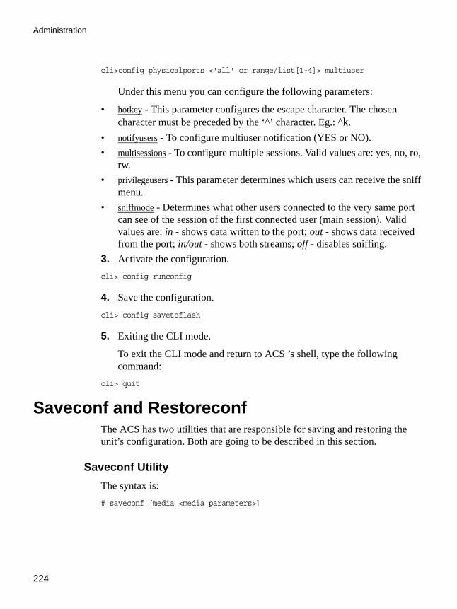
Administration
224
cli>config physicalports <'all' or range/list[1-4]> multiuser
Under this menu you can configure the following parameters:
• hotkey - This parameter configures the escape character. The chosen character must be preceded by the ‘^’ character. Eg.: ^k.
• notifyusers - To configure multiuser notification (YES or NO).• multisessions - To configure multiple sessions. Valid values are: yes, no, ro,
rw.• privilegeusers - This parameter determines which users can receive the sniff
menu.• sniffmode - Determines what other users connected to the very same port
can see of the session of the first connected user (main session). Valid values are: in - shows data written to the port; out - shows data received from the port; in/out - shows both streams; off - disables sniffing.
3. Activate the configuration.cli> config runconfig
4. Save the configuration.cli> config savetoflash
5. Exiting the CLI mode.
To exit the CLI mode and return to ACS ’s shell, type the following command:
cli> quit
Saveconf and RestoreconfThe ACS has two utilities that are responsible for saving and restoring the unit’s configuration. Both are going to be described in this section.
Saveconf UtilityThe syntax is: # saveconf [media <media parameters>]
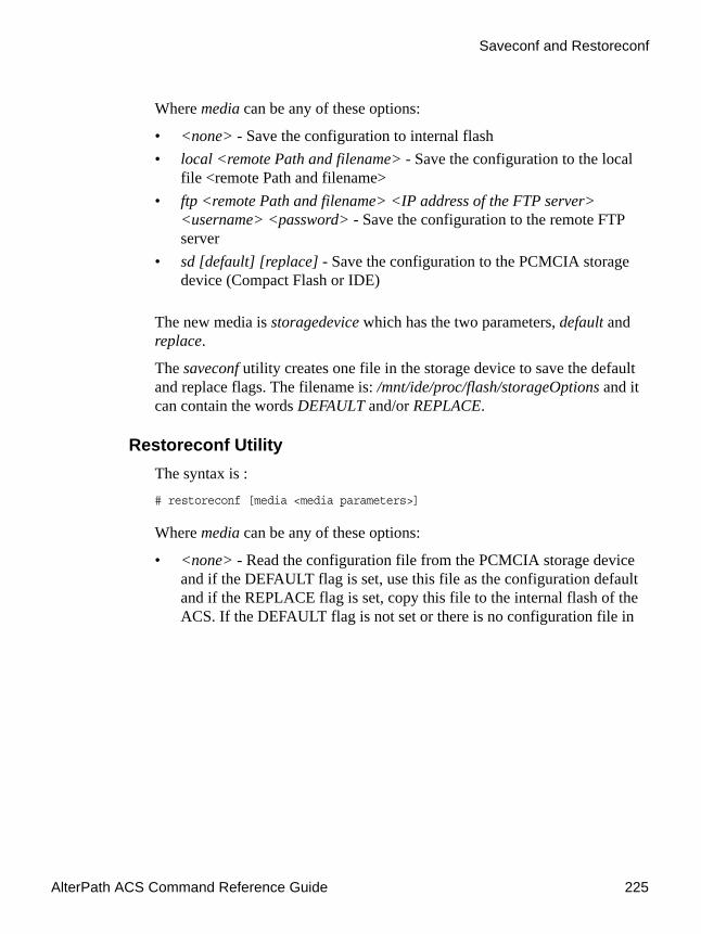
AlterPath ACS Command Reference Guide 225
Saveconf and Restoreconf
Where media can be any of these options:
• <none> - Save the configuration to internal flash• local <remote Path and filename> - Save the configuration to the local
file <remote Path and filename>• ftp <remote Path and filename> <IP address of the FTP server>
<username> <password> - Save the configuration to the remote FTP server
• sd [default] [replace] - Save the configuration to the PCMCIA storage device (Compact Flash or IDE)
The new media is storagedevice which has the two parameters, default and replace.
The saveconf utility creates one file in the storage device to save the default and replace flags. The filename is: /mnt/ide/proc/flash/storageOptions and it can contain the words DEFAULT and/or REPLACE.
Restoreconf UtilityThe syntax is : # restoreconf [media <media parameters>]
Where media can be any of these options:
• <none> - Read the configuration file from the PCMCIA storage device and if the DEFAULT flag is set, use this file as the configuration default and if the REPLACE flag is set, copy this file to the internal flash of the ACS. If the DEFAULT flag is not set or there is no configuration file in

Administration
226
the PCMCIA storage device, read the configuration from the internal flash
• local <remote Path and filename> - Read the configuration from the local file <remote Path and filename>.
• ftp <remote Path and filename> <IP address of the FTP server> <username> <password> - Read the configuration from the remote FTP server
• sd - Read the configuration from the PCMCIA storage device (Compact Flash or IDE) and if the REPLACE flag is set, copy the file to the internal flash of the ACS.
CLI Method - Save/Restore ConfigurationConfiguration can be saved/restored through the following menus:
• Saving the configuration to the internal flash memorycli>config savetoflash
• Saving the configuration to a PCMCIA storage device:cli>administration backupconfig saveto sd [default] [replace]
• Saving the configuration to a remote server using FTP protocol:cli>administration backupconfig saveto ftpserverip <n.n.n.n> pathname <string> username <string> password <string>
• Loading the configuration from a PCMCIA storage device:cli>administration backupconfig loadfrom sd [default] [replace]
• Loading the configuration from a remote server using FTP protocol:cli>administration backupconfig loadfrom ftpserverip <n.n.n.n> pathname <string> username <string> password <string>
Start and Stop ServicesThis feature allows daemons (services) to be enabled or disabled without need of reboot the unit. A simple engine detects configuration changes (file comparison). This feature is implemented with shell scripts. There is one main shell script called daemon.sh and one sourced shell script (included by
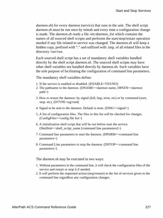
AlterPath ACS Command Reference Guide 227
Start and Stop Services
daemon.sh) for every daemon (service) that runs in the unit. The shell script daemon.sh must be run once by inittab and every time a configuration change is made. The daemon.sh reads a file /etc/daemon_list which contains the names of all sourced shell scripts and performs the start/stop/restart operation needed if any file related to service was changed. The daemon.sh will keep a hidden copy, prefixed with “.” and suffixed with .tmp, of all related files in the directory /var/run.
Each sourced shell script has a set of mandatory shell variables handled directly by the shell script daemon.sh. The sourced shell scripts may have other shell variables not handled directly by daemon.sh. Such variables have the sole purpose of facilitating the configuration of command line parameters.
The mandatory shell variables define:
1. If the service is enabled or disabled. (ENABLE=YES/NO) 2. The pathname to the daemon. (DNAME=<daemon name, DPATH=<daemon
path>)
3. How to restart the daemon: by signal (kill, hup, term, etc) or by command (start, stop. etc). (DTYPE=sig/cmd)
4. Signal to be sent to the daemon. Default is term. (DSIG=<signal>)
5. A list of configuration files. The files in this list will be checked for changes. (ConfigFiles=<config file list>)
6. A initialization shell script that will be run before start the service. (ShellInit=<shell_script_name [command line parameters]>)
7. Command line parameters to start the daemon. (DPARM=<command line parameters>)
8. Command Line parameters to stop the daemon. (DSTOP=<command line parameters>)
The daemon.sh may be executed in two ways:
1. Without parameters in the command line, it will check the configuration files of the service and restart or stop it if needed.
2. It will perform the requested action (stop/restart) in the list of services given in the command line regardless any configuration changes.

Administration
228
The command daemon.sh help will display a list of services available. Currently the following services are handled by daemon.sh. The first column is the service ID, the second is the name of the shell script file.
The following example will restart power management and Data Buffering services and it will stop SSH and network timer client services: # daemon.sh PMD stop SSH NTP restart DB
NIS /etc/daemon.d/ypbind.conf
RPC /etc/daemon.d/portmap.conf
DB /etc/daemon.d/cy_buffering.sh
NET /etc/daemon.d/inetd.sh
LOG /etc/daemon.d/syslog.sh
SSH /etc/daemon.d/sshd.sh
NTP /etc/daemon.d/ntpclient.conf
SNMP /etc/daemon.d/snmpd.sh
IPSEC /etc/daemon.d/ipsec.sh
PMD /etc/daemon.d/pmd.sh
LP /etc/daemon.d/lpd.sh
WEB /etc/daemon.d/webui.conf
GDF /etc/daemon.d/gendial.sh

AlterPath ACS Command Reference Guide 229
Start and Stop Services
How to Configure ThemExample of sourced shell script that activates the ntpclient service (type sig).
Example of sourced shell script that activates the ipsec service.
# This file defines the NTP client configuration
ENABLE=NO # Must be "NO" or "YES" (uppercase)DNAME=ntpclient # daemon nameDPATH=/bin # daemon pathShellInit= # Performs any required initializationConfigFiles= # configuration files DTYPE=sig # must be "sig" or "cmd" (lowercase)DSIG=kill # signal to stop/restart the daemon (lowercase)
# if it's hup term will be used to stop the daemon
# daemon command line parametersNTPSERVER="-h 129.6.15.28" # NTP server ip addressNTPINTERVAL="-l 300" # Time in seconds to ask serverNTPCOUNT="-c 0" # counter : 0 means foreverDPARM="$NTPCOUNT $NTPSERVER $NTPINTERVAL"DSTOP=
Figure 5-29:/etc/daemon.d/ntpclient.conf file
# This file defines the ipsec configurationENABLE=NO # Must be "NO" or "YES" (uppercase)DNAME=ipsec # daemon nameDPATH=/usr/local/sbin # daemon pathShellInit=/etc/ipsec.init # Performs any required initializationConfigFiles= # configuration filesDTYPE=cmd # must be "sig" or "cmd"DSIG=kill # signal to stop/restart the daemon (lowercase)
# if it's hup term will be used to stop the daemon# daemon command line parametersDPARM="setup --start"DSTOP="setup --stop"
Figure 5-30:/etc/daemon.d/ipsec.sh file

Administration
230
Security ProfilesA Security Profile consists of a set of parameters that can be set to control access to the ACS. The ACS offers three pre-defined security profiles, Secured, Moderate, Open, and an option to configure a Custom profile. A fifth option, Default sets the parameters to the same as Moderate.
The following tables illustrates the properties for each of the Security Profiles. The enabled services in each profile is designated with a check mark. Note that the Default option will set the parameters to the same as Moderate, and the Custom Profile allows for individual configurations.
Table 5-10: Enabled services to access the ACS box for each security profile.
Table 5-11: Enabled services to access the serial ports for each profile.
Access to ACS
Secured Moderate Open Default Custom
Telnet
SSHv1 Port 22
SSHv2 Port 22
Allow SSH root access
HTTP Port 80
HTTPS Port 443
HTTP redirection to HTTPS
Access to Serial Ports
Secured Moderate Open Default Custom
Console (Telnet)

AlterPath ACS Command Reference Guide 231
Security Profiles
Table 5-12: Enabled protocols for each profile shown with a check mark.
CLI Method - Selecting a Pre-defined Security Profile1. Open the CLI interface by issuing the command:
#CLI
2. Enter the Security Profile menu:
cli> config security profile
3. Type one of the pre-defined Security Profiles and press Enter:
profile> secured moderate open default
4. To view the details of the selected profile, type the command:
Console (SSH)
Console (Raw)
Serial Port Authentication
Bidirect (Dynamic Mode Support)
Other Services
Secured Moderate Open Default Custom
SNMP
RPC
ICMP
FTP
IPSec
Access to Serial Ports
Secured Moderate Open Default Custom

Administration
232
profile> show

AlterPath ACS Command Reference Guide 233
Security Profiles
A window similar to following appears showing the details of the profile:
profile>show [profile] [open]: custom [moderate]: custom [secured]: custom .[custom] ftp: no telnet: yes ..[ssh] sshv1: yes sshv2: yes sshd_port: 22 root_access: no snmp: yes ..[web] http: yes https: yes http_port: 80 https_port: 443 http2https: no rpc: yes ipsec: no icmp: yes ..[ports] ssh2sport: yes telnet2sport: yes raw2sport: yes auth2sport: no
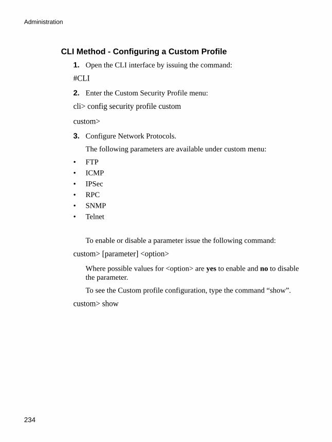
Administration
234
CLI Method - Configuring a Custom Profile1. Open the CLI interface by issuing the command:
#CLI
2. Enter the Custom Security Profile menu:
cli> config security profile custom
custom>
3. Configure Network Protocols.
The following parameters are available under custom menu:
• FTP• ICMP• IPSec• RPC• SNMP • Telnet
To enable or disable a parameter issue the following command:
custom> [parameter] <option>
Where possible values for <option> are yes to enable and no to disable the parameter.
To see the Custom profile configuration, type the command “show”.
custom> show

AlterPath ACS Command Reference Guide 235
Security Profiles
A window similar to the following appears showing the details of the profile:
4. Configure Secure Shell (SSH) options.
custom>show [custom] ftp: no telnet: yes .[ssh] sshv1: yes sshv2: yes sshd_port: 22 root_access: no snmp: yes .[web] http: yes https: yes http_port: 80 https_port: 443 http2https: no rpc: yes ipsec: no icmp: yes .[ports] ssh2sport: yes telnet2sport: yes raw2sport: yes auth2sport: no
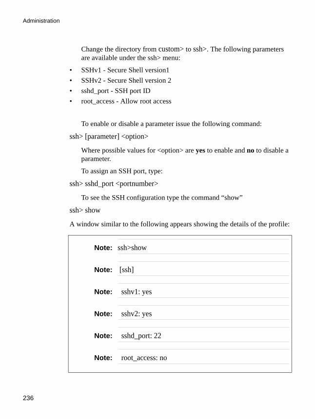
Administration
236
Change the directory from custom> to ssh>. The following parameters are available under the ssh> menu:
• SSHv1 - Secure Shell version1• SSHv2 - Secure Shell version 2• sshd_port - SSH port ID• root_access - Allow root access
To enable or disable a parameter issue the following command:
ssh> [parameter] <option>
Where possible values for <option> are yes to enable and no to disable a parameter.
To assign an SSH port, type:
ssh> sshd_port <portnumber>
To see the SSH configuration type the command “show”
ssh> show
A window similar to the following appears showing the details of the profile:
Note: ssh>show
Note: [ssh]
Note: sshv1: yes
Note: sshv2: yes
Note: sshd_port: 22
Note: root_access: no

AlterPath ACS Command Reference Guide 237
Security Profiles
5. Configure Web Access Protocols.
Change the directory from custom> to web>. The following parameters are available under the web> menu:
• http • http_port • http2https • https • https_port
To enable or disable a parameter type the command:
web> [parameter] <option>
Where possible values for <option> are yes to enable and no to disable a parameter.
To assign an http or https port, type:
web> http <portnumber> https <portnumber>
To see the web configuration type the command “show”.

Administration
238
ssh> show
6. Configure Access to Serial Ports.
Change the directory from custom> to ports>. The following parameters are available under the ports> menu:
• auth2sport - Authentication to Access Serial Ports• ssh2sport - SSH to Serial Ports• raw2sport - Raw Connection to Serial Ports• telnet2sport - Telnet to Serial Ports
To enable or disable a parameter issue the command:
ports> [parameter] <option>
Where possible values for <option> are yes to enable and no to disable a parameter.
To see the ports configuration type the command “show”
Note: web>show
Note: [web]
Note: http: yes
Note: https: yes
Note: http_port: 80
Note: https_port: 443
Note: http2https: no
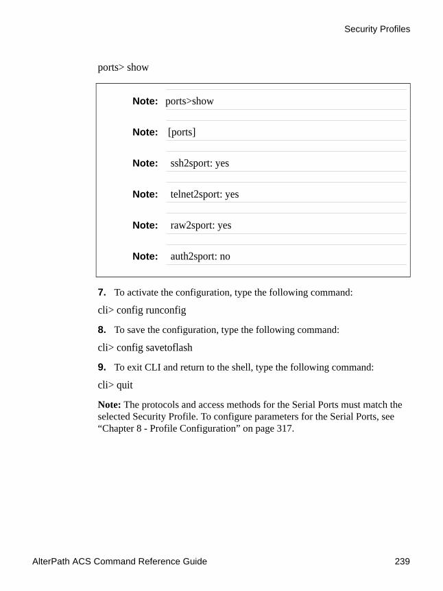
AlterPath ACS Command Reference Guide 239
Security Profiles
ports> show
7. To activate the configuration, type the following command:
cli> config runconfig
8. To save the configuration, type the following command:
cli> config savetoflash
9. To exit CLI and return to the shell, type the following command:
cli> quit
Note: The protocols and access methods for the Serial Ports must match the selected Security Profile. To configure parameters for the Serial Ports, see “Chapter 8 - Profile Configuration” on page 317.
Note: ports>show
Note: [ports]
Note: ssh2sport: yes
Note: telnet2sport: yes
Note: raw2sport: yes
Note: auth2sport: no

Administration
240

.................................................................
Chapter 6Chapter 6 - AlterPath PM integrationPower Management with
AlterPath™ PM Integration
Introduction to AlterPath Power Management The AlterPath™ PM is a family of Intelligent Power Distribution Units (IPDUs) that enables remote power control of servers and network gear. Through a serial port, the administrator can use the AlterPath PM to control all the equipment connected to its outlets, using operations like On, Off, Cycle, Lock, and Unlock.
When used in conjunction with Cyclades console servers, the AlterPath PM delivers easier management capabilities and faster problem solving by integrating console access and power control into a single interface. The administrator can, for example, reboot the data center equipment when it crashes, without leaving his console session (Telnet or SSH). To do that, the administrator must simply press a configurable hotkey and select the appropriate option from the menu displayed in the session.
This chapter approaches all configuration that is integrated with the AlterPath ACS. Below are the sections that are going to be presented in this chapter:
• Power Management Configuration• ACS Firmware Upgrade• SNMP Proxy
Power Management ConfigurationThe ACS can have multiple PMs connected to serial ports that are configured for power management. Devices can be plugged into outlets on the PMs and also connected to other serial ports on the ACS. In addition one or more outlets can be configured for each port and controlled individually or simultaneously with other outlets in a
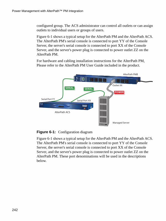
Power Management with AlterPath™ PM Integration
242
configured group. The ACS administrator can control all outlets or can assign outlets to individual users or groups of users.
Figure 6-1 shows a typical setup for the AlterPath PM and the AlterPath ACS. The AlterPath PM's serial console is connected to port YY of the Console Server, the server's serial console is connected to port XX of the Console Server, and the server's power plug is connected to power outlet ZZ on the AlterPath PM.
For hardware and cabling installation instructions for the AlterPath PM, Please refer to the AlterPath PM User Guide included in the product.
Figure 6-1: Configuration diagram
Figure 6-1 shows a typical setup for the AlterPath PM and the AlterPath ACS. The AlterPath PM's serial console is connected to port YY of the Console Server, the server's serial console is connected to port XX of the Console Server, and the server's power plug is connected to power outlet ZZ on the AlterPath PM. These port denominations will be used in the descriptions below.
POWER
SERIAL SERIAL
ALTERPATHLINUX
INSIDE
A C S
AlterPathAdvanced Console Server
TM
TM
AlterPath
PM8
Serial Port YYSerial Port XX
Outlet XX
AlterPath ACS
Managed Server
AlterPath PM8

AlterPath ACS Command Reference Guide 243
Power Management Configuration
Prerequisites for Power ManagementIn order to control individual outlets or groups of outlets from the Multi Outlet Control page, the following prerequisites must be met:
• An AlterPath PM must be plugged into one of the serial ports, and that serial port must be configured for power management.
• A device must be plugged into at least one outlets on the PM, and this device must be connected to a serial port.
• The PM and the outlet numbers to which the device is plugged must be configured on the serial port to which the device is connected.
Configuring Power ManagementThere are two different methods for configuring Power Management — the VI method and the CLI method, detailed below.
VI Method - Involved parameters and passed values
1. Set the parameters to the port YY where the AlterPath PM is connected:
• sYY.protocol: New protocol Integrated Power Distribution Unit. For example: ipdu.
• sYY.pmtype: The IPDU manufacturer. For example: cyclades.
• sYY.pmusers: The user access list. For example: jane:1,2;john:3,4. The format of this field is:
[<username>:<outlet list>][;<username>:<outlet list>...]
where <outlet list>'s format is:
[<outlet number>|<outlet start>-<outlet end>][,<outlet number>|<outlet start>-<outlet end>]
The list of users must be separated by semicolons (;); the outlets should be separated by commas (,) to indicate a list or with dashes (-) to indicate range; there should not be any spaces between the values.
• sYY.pmNumOfOutlets: the number of outlets of the AlterPath PM. Default: 8.

Power Management with AlterPath™ PM Integration
244
• sYY.pmsessions: Only users logged in with the connection method defined by this parameter will be allowed to access the IPDU unit. It is also necessary to define the authentication method in the sXX.authtype parameter and configure the sXX.users parameter in order to allow users to access the IPDU port. Valid values are: "none" , "ssh", "telnet" or "ssh_telnet".
Note: IMPORTANT: By defining the sYY.pmsessions parameter and making all other necessary configuration, an user can access the IPDU directly by opening a SSH or Telnet connection to the desired port. The user will be prompted to enter the username and password, then he/she will have direct access to the pmCommand menu.
2. Set the parameters to the other ports where the servers are connected:
• all.protocol: Protocols for the CAS profile. For example: socket_server, socket_raw, socket_ssh.
• all.pmkey: The hot-key that starts a power management session. Default: ^p (Ctrl-p).
• sYY.pmoutlet: The outlet list where the server XX is plugged. The outlet is passed as a pair /PM_serial_port.outlet_number/. If the server has a dual power supply, the outlets are separated by space char. For example, one power supply is plugged in the second outlet of the IPDU connected in serial port 1. The other is plugged in the third outlet of the IPDU connected in serial port 5. The value is 1.2 5.3".
Note: SXX.PMUSERS: The ellipses in the field format for sXX.pmusers means that you can add as many users as you need. The [ ] indicates that the parameter is optional, again indicating that you can configure more than one user. The separator is the semicolon.
CLI Method - IPDU ConfigurationThe CLI allows you to set some ports to the pm protocol. Configuring a port with the pm protocol means that you have an IPDU connected to it. Then you

AlterPath ACS Command Reference Guide 245
Power Management Configuration
will have to configure power management parameters in other ports that are not configured as protocol pm.
Example: To show how power management works in the CLI, we will approach a practical example.
Suppose that we have a 4-port ACS unit and an IPDU, with eight outlets, connected to serial port 1 of the ACS.
To manage the IPDU we will have to configure port 1 as pm protocol and then associate which ports (anyone, but port 1) of the ACS unit will be allowed to issue power management commands to port 1.
1.Open the CLI interface by issuing the command.# CLI
2. Enable the serial port that the IPDU is connected to. For example, serial port 1 is being configured for IPDU.
cli>config physicalports 1 enable yes
3. Configure the serial port that the IPDU is connected to. For example, serial port 1 is being configured for IPDU.
cli>config physicalports 1 general protocol pm
You can specify from what type of session (SSH, Telnet or both) users will be allowed to connect to the IPDU.
cli>config physicalports 1 general pmsessions ssh
The command above restricted the access to the IPDU port, only for users that connect to the AlterPath ACS via SSH. Valid values for the pmsessions parameter are: ssh, telnet, ssh_telnet and none.
4. Configure from which ports of the ACS, commands to the configured IPDU port will be allowed to be issued.
We will allow users connected to serial port 2, to run power management commands to the IPDU connected to the serial port1 of the ACS.
cli>config physicalports 2 powermanagement
powermanagement>enable addoutlet pm 1 outlets 1,2

Power Management with AlterPath™ PM Integration
246
The above configuration makes an association between the outlet numbers (outlet 1 and outlet 2) and the power strip connected at port 1. The logic means that this server's power cords are plugged into outlet 1 and 2 of the power strip connected to port 1.
5. Configure allowed users.
You can restrict access to IPDU units just for some users, to do that issue the command:
enable> pmusers test1,test2
The command above allows the users test1 and test2 to run power management commands into the IPDU connected to serial port 1.
6. Configure the hotkey.
You also need to define a hotkey, otherwise users will not be able to open the IPDU menu:
enable> pmkey ^i
7. Check the configurationenable> show
You should be prompted with something like this:[enable]pmkey: ^ipmusers: test1,test2[PM Alias and Outlet Number]:Port1 - [no alias] Outlets:1,2
8. Activate the configuration.
a. Return to the main menu by running the command:enable> returnpowermanagement> returnconfig>
b. From the main menu, run the command:config > runconfig
9. Save the configuration.config > savetoflash
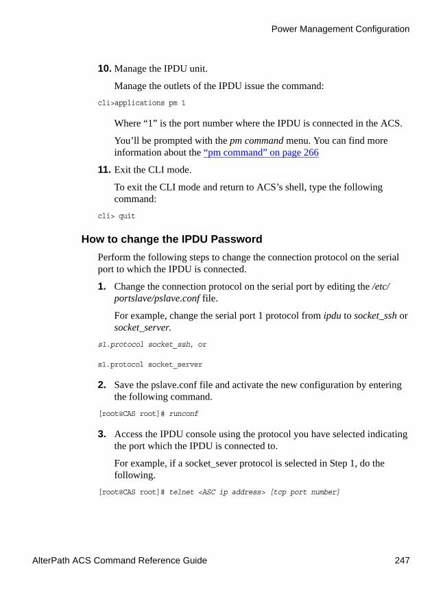
AlterPath ACS Command Reference Guide 247
Power Management Configuration
10. Manage the IPDU unit.
Manage the outlets of the IPDU issue the command:cli>applications pm 1
Where “1” is the port number where the IPDU is connected in the ACS.
You’ll be prompted with the pm command menu. You can find more information about the “pm command” on page 266
11. Exit the CLI mode.
To exit the CLI mode and return to ACS’s shell, type the following command:
cli> quit
How to change the IPDU PasswordPerform the following steps to change the connection protocol on the serial port to which the IPDU is connected.
1. Change the connection protocol on the serial port by editing the /etc/portslave/pslave.conf file.
For example, change the serial port 1 protocol from ipdu to socket_ssh or socket_server.
s1.protocol socket_ssh, or
s1.protocol socket_server
2. Save the pslave.conf file and activate the new configuration by entering the following command.
[root@CAS root]# runconf
3. Access the IPDU console using the protocol you have selected indicating the port which the IPDU is connected to.
For example, if a socket_sever protocol is selected in Step 1, do the following.
[root@CAS root]# telnet <ASC ip address> [tcp port number]

Power Management with AlterPath™ PM Integration
248
where the TCP port number is the serial port that the IPDU is connected to.
The following prompt appears:Entering charater/text Mode
Escape character is ^]
AlterPath PMCopyright (c) 2002-2003 Cyclades CorporationV 2.6.1 March, 2006[PM]: IPDU: 2[PM]: OUT: 16Username:
4. Login to the IPDU console.
Login to the IPDU using the factory-default username/password admin/pm8.
5. Change the IPDU password using the passwd command in the IPDU console as follows.
The pm> command appears after you login.
Enter the passwd command at the prompt, and follow the prompts to enter the new password.
pm> passwdPassword:Re-enter password:Username/password set for user admin.pm>
6. Save the new password by issuing the command:pm>save
The following prompt will appear:Saving configuration to flash on IPDU #1 ... Done.pm>
7. Close the connection to access the IPDU console by entering the escape character ^] (Ctrl-])

AlterPath ACS Command Reference Guide 249
Power Management Configuration
8. Edit the /etc/pm.* config file and change the passwd parameter as follows:
admPasswd="<put the password you saved in IPDU>"
b) Save the new pm.* file and activate the new configuration by entering the following command.
[root@CAS root]# saveconf
9. Change the connection protocol for the serial port back to the original IPDU.
a. Edit /etc/portslave/pslave.conf file as follows:s1.protocol ipdu
b. b) Save the pslave.conf file and enter the following command to activate the new configuration.
[root@CAS root]# runconf
10. Restart the pmd process for the new configuration file to take effect.
pmd is a Linux daemon process to control the communication between ACS and PM.
a. Execute the ps command to note the current pmd process[root@CAS root]# ps -fe|grep pmd 878 root 644 S /bin/pmd 1108 root 552 S grep pmd
b. Restart the pmd process by issuing the following command.[root@CAS root]# daemon.sh restart PMD
The system prompts the following:[root@CAS root]# Sep 22 14:32:04 src_dev_log@CAS showlogmsg:/bin/daemon.sh: CONFIG: Network daemon [pmd] started
Check to see if the process restarted. Note the process ID, which should be different from the earlier executed ps command.
[root@CAS root]# ps -fe|grep pmd 1126 root 680 S /bin/pmd 1130 root 552 S grep pmd

Power Management with AlterPath™ PM Integration
250
Accessing the AlterPath PM regular menu from the Console Session
The Power Management Utility can be used to manage power on devices plugged into one or more outlets on an AlterPath PM. The PM Utility can be started by the following two methods.
Method 1: Issue the pm command, which will invoke the following menu and prompt:
The following table explains each menu item, its use and behavior.
---------------------------------------------------------Cyclades CorporationPower Management Menu v1.0------------------------------------------------------------------------------------------------------------------Cyclades Power Management Menu---------------------------------------------------------
1. Exit 2. individual ipdus 3. multi-outlet device 4.InfoPlease choose an option:

AlterPath ACS Command Reference Guide 251
Power Management Configuration
Method 2: Issue the pmCommand
Use: pmCommand <serial port number> <command> <arguments>
where:
<serial port number> is the serial port number configured as IPDU
<command> <arguments> are the PM command and its arguments.
See the list of commands in Table 6.2.
Using the Power Management Utility You can use the Power Management Utility to control IPDUs and individual outlets.
Table 6-1: Menu Options for PM Utility
Command Description
Exit Exits the PM Utility and returns to the ACS shell.
Individual IPDUs
Invokes a menu for controlling and monitoring IPDUs and for controlling power on their individual outlets.
See “Manage Devices Plugged into a Single Outlet” on page 252 for more details.
Multi-outlet device
Invokes a menu for controlling power on groups of outlets connected to devices. These outlets can be on the same or on different IPDUs.
See “Manage Devices Plugged into Multiple Outlets” on page 255 for more details.
Info Shows help text explaining each option.

Power Management with AlterPath™ PM Integration
252
Manage Devices Plugged into a Single OutletSelecting option “2” for “Individual IPDUs” from the PM menu invokes the following prompt:
Entering the serial port number that is configured for power management brings up the following menu options:
The following table explains each menu item, its use and behavior.
Give serial port number:
----------------------------------------------------------------Cyclades CorporationPower Management Menu v1.0----------------------------------------------------------------PowerPort: PMNumber of units: 2Serial Port: 1--------------------------------------------------------------------------------------------------------------------------------Cyclades Power Management Menu
PowerPort: PM----------------------------------------------------------------1. Return 9. Status 17. Factory Default2. Help 10. Power Up Interval 18. Reboot3. Who Am I 11. Name 19. Restore4. On 12. Current 20. Save5. Off 13. Temperature 21. Syslog6. Cycle 14. Version 22. Alarm7. Lock 15. Buzzer8. Unlock 16. Current Protection
Please choose an option:
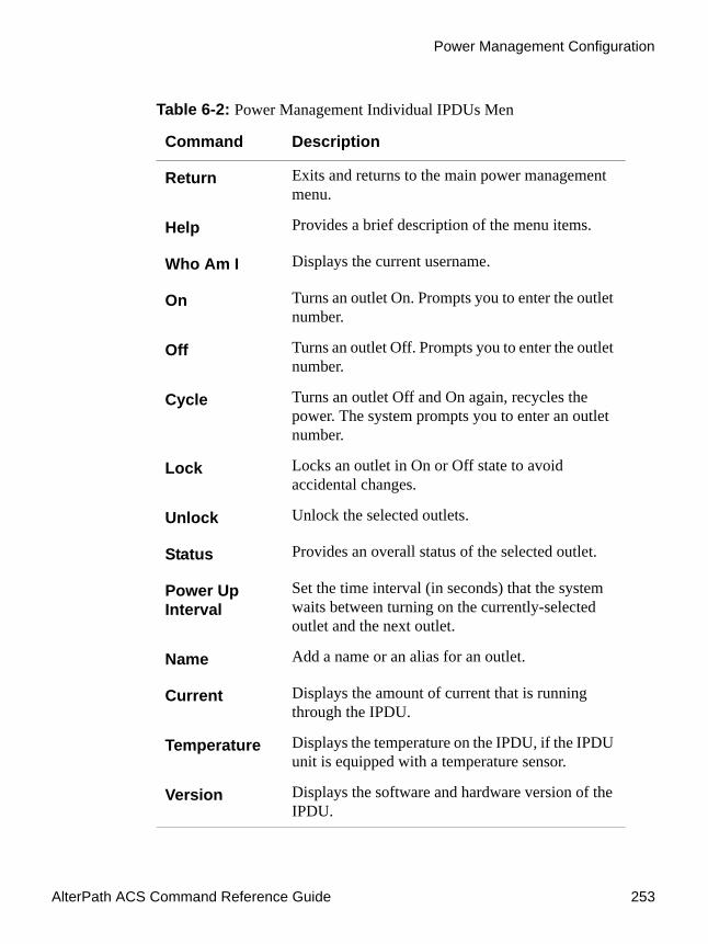
AlterPath ACS Command Reference Guide 253
Power Management Configuration
Table 6-2: Power Management Individual IPDUs Men
Command Description
Return Exits and returns to the main power management menu.
Help Provides a brief description of the menu items.
Who Am I Displays the current username.
On Turns an outlet On. Prompts you to enter the outlet number.
Off Turns an outlet Off. Prompts you to enter the outlet number.
Cycle Turns an outlet Off and On again, recycles the power. The system prompts you to enter an outlet number.
Lock Locks an outlet in On or Off state to avoid accidental changes.
Unlock Unlock the selected outlets.
Status Provides an overall status of the selected outlet.
Power Up Interval
Set the time interval (in seconds) that the system waits between turning on the currently-selected outlet and the next outlet.
Name Add a name or an alias for an outlet.
Current Displays the amount of current that is running through the IPDU.
Temperature Displays the temperature on the IPDU, if the IPDU unit is equipped with a temperature sensor.
Version Displays the software and hardware version of the IPDU.

Power Management with AlterPath™ PM Integration
254
Buzzer Configures a buzzer to sound when a specified alarm threshold has reached. Options are On to activate and Off to deactivate.
Current Protection
Activate or deactivate the current protection. This option is to prevent the outlets from being turned on, if the current on the IPDU exceeds the specified threshold.
Factory Default
Restores the factory defaults.
Reboot Restarts the IPDUs in chain.
Restore Restores the configuration saved in flash.
Save Saves the current configuration in flash.
Syslog Activates or deactivates the syslogging and alarm notifications.
Alarm Select a current value to set an alarm notification when the current exceeds the selected threshold.
Table 6-2: Power Management Individual IPDUs Men
Command Description

AlterPath ACS Command Reference Guide 255
Power Management Configuration
Once you select a command, the following options may occur:
• If command you select applies to the PM unit, then the command will be issued
• If command you select applies to the outlets, the following prompt appears
Enter one or more outlet numbers separated by commas or dashes, as shown in the following screen example, or enter “all.”
Manage Devices Plugged into Multiple OutletsYou can use the Power Management Utility to simultaneously control all outlets that are configured to the same serial port, regardless of whether the outlets are on the same PM. This option is applicable to devices with multiple power supplies.
Selecting option “3” for “Multi-outlet Devices” from the PM menu invokes the following menu and prompt:
The following table explains each menu item, its use and behavior.
Outlet name or outlet number(? for help, m for main menu):
Outlet name or outlet number(? for help, m for main menu): 1,3,5
-----------------------------------------------------------Cyclades Power Management Menu-----------------------------------------------------------------1. Return 4. Cycle 6. Unlock 8. Show2. On 5. Lock 7. Status 9. Info3. Off
Please choose an option:

Power Management with AlterPath™ PM Integration
256
Table 6-3: Menu Options for Multi-Outlet Control PM Utility
Command Description
Return Takes the user back to the first menu.
On Powers on all the outlets belonging to this multi-outlet device.
Off Powers off all the outlets belonging to this multi-outlet device.
Cycle Turns the outlets off and back on.
Lock Locks all the outlets belonging to the multi-outlet device so that no command can be executed on them, except an unlock command.
Unlock Unlocks all the outlets belonging to this multi-outlet device.
Status Issue individual status commands on each of the outlets belonging to this multi-outlet device as in the following example:
These are the status for these outlets in the IPDU attached to ttyS3Outlet Name Status Users Interval (s) 1 Unlocked ON 0.50 4 Unlocked ON 0.50 5 Unlocked ON 0.50

AlterPath ACS Command Reference Guide 257
Power Management Configuration
Note: The multi-outlet device menu is inaccessible if there are no devices configured with pmoutlet parameter in /etc/portslave/pslave.conf. You need to configure the “sxx.pmoutlet” line in pslave.conf file.
In the following example, the Sun Server is a multi-outlet device connected to outlet 7 of IPDU 1 and outlet 2 of IPDU 2. The sequence of power up interval is 1.7 then 2.2.
s3.pmoutlet 1.7, 2.2
s3. alias Sun Server
To Manage Multiple IPDUs from the Command Line
1. Connect to the CONSOLE port of the ACS or use Telnet or SSH to access the ACS, and log in.
2. Enter the pm command.[root@CAS root]# pm
Show Shows which outlets in which ipdu chain belong to the multi-outlet device as in the following example:
alias: (null) port: ttyS4 outlets: 3.1 3.5 3.4where ttyS4 is the serial port that the device is con-nected to and 3.1, 3.5, and 3.4 indicate ports 1, 5, and 4 on a PM that is connected to port 3.
Info Shows help text explaining each option.
Table 6-3: Menu Options for Multi-Outlet Control PM Utility
Command Description

Power Management with AlterPath™ PM Integration
258
The power management menu displays as shown in the following screen example.
To control power on multi-outlet devices, Enter the number 3. .
The power management utility displays as shown in the following screen example.
3. Enter the number that corresponds to the desired option (“On,” “Off,” “Cycle,” “Lock,” “Unlock,” “Status,” “Show,” or “Info.”
The following prompt appears
4. Enter the number or alias of the serial port to which the multi-outlet device is connected.
Cyclades CorporationPower Management Menu v1.0----------------------------------------------------------------------------------------------------------------------Cyclades Power Management Menu-----------------------------------------------------------1. Exit 2. individual ipdus 3. multi-outlet device 4.InfoPlease choose an option:
1. Exit 2. individual ipdus 3. multi-outlet device 4.InfoPlease choose an option: 3
-----------------------------------------------------------Cyclades Power Management Menu-----------------------------------------------------------1. Return 4. Cycle 6. Unlock 8. Show2. On 5. Lock 7. Status 9. Info3. Off
Please choose an option:
Please supply the serial port number or the alias for the multi-outlet devicesIf in doubt, type ? followed by enter and a list of available devices will be shown

AlterPath ACS Command Reference Guide 259
Power Management Configuration
The command is executed.
To Manage Power Through the Console1. Open a console session.
Open a Telnet or SSH session for the serial port.
2. Access the IPDU regular menu.
This should be done, for example, when the server crashes and it necessary to change the power status. Type the pre-configured hot-key.
If the user does not have permission to access any outlet, the following message will appear, and you will return to the Console Session:
It was impossible to start a Power Management SessionYou can't access any Power Management functionality.Please contact your Console Server Administrator.
If the user does not have permission to access the outlet(s) of this server, but can access another outlet, the following message will appear:
You cannot manage the outlet(s) of this server.Please enter the outlet(s) (or 'h' for help):
The user should type the outlet(s) he wants to manage, before reaching the main menu. The main menu will appear only if the user has permission for this/these outlet(s). Typing 'h' will cause the session to show text explaining what to type, and 'l' will cause the PM session to be logged out, and the user to return to the Console Session. If the user has permission to access the outlet(s) of this server, these outlets will be managed by the PM session.
3. Regular User Menu.

Power Management with AlterPath™ PM Integration
260
This is the AlterPath PM regular user menu:
-------------------------------------------------------------------Cyclades Power Management Menu
PowerPort: PM-------------------------------------------------------------------1. Return 6. Cycle 11. Name2. Help 7. Lock 12. Current3. Who Am I 8. Unlock 13. Temperature4. On 9. Status 14. Version5. Off 10. Power Up Interval
Please choose an option:
Figure 6-2: AlterPath PM regular menu
Table 6-4: AlterPath PM regular user menu options
Option Description
Return Exits and returns to the main power management menu.
Help Provides a brief description of the menu items.
Who Am I Displays the current username.
On Turns an outlet On. Prompts you to enter the outlet number.
Off Turns an outlet Off. Prompts you to enter the outlet number.
Cycle Turns an outlet Off and On again, recycles the power. The system prompts you to enter an outlet number.
Lock Locks an outlet in On or Off state to avoid accidental changes.
Unlock Unlock the selected outlets.

AlterPath ACS Command Reference Guide 261
Power Management Configuration
4. Check the status of the server's outlet or the outlet list.
Status Provides an overall status of the selected outlet.
Power Up Interval
Set the time interval (in seconds) that the system waits between turning on the currently-selected outlet and the next outlet.
Name Add a name or an alias for an outlet.
Current Displays the amount of current that is running through the IPDU.
Temperature Displays the temperature on the IPDU, if the IPDU unit is equipped with a temperature sensor.
Version Displays the software and hardware version of the IPDU.
Table 6-4: AlterPath PM regular user menu options
Option Description

Power Management with AlterPath™ PM Integration
262
Type '9' and wait for the answer. For example:
5. Reboot the server.
If the outlet(s) is/are locked, the user must unlock the outlet(s) first (option 8 - Unlock). The Cycle command turns the power off for some
Please choose an option: 9
Outlet name or outlet number(all for all, ? for help, m for main menu): 1-3
Outlet Name Status Users Interval (s) 1 pm Unlocked ON 0.50 2 Unlocked ON 0.50 3 Unlocked ON 0.50
-------------------------------------------------------------------Cyclades Power Management Menu
PowerPort: PM-------------------------------------------------------------------1. Return 6. Cycle 11. Name2. Help 7. Lock 12. Current3. Who Am I 8. Unlock 13. Temperature4. On 9. Status 14. Version5. Off 10. Power Up Interval
Please choose an option:
Figure 6-3: Outlet Status

AlterPath ACS Command Reference Guide 263
Power Management Configuration
seconds and the turn it on again. Type '6' and wait for the answer. For example:
6. Manage other outlets. Use the following procedure.
To Manage Other OuletsPerform this procedure if you need to access other outlets.
1. Enter option “9. Status” to view the Outlets you are authorized to manage, and at the Outlent name or outlet number prompt, type “all”.
Please choose an option: 6
Outlet name or outlet number(? for help, m for main menu): 1
1: Outlet turned off.1: Outlet turned on.
-------------------------------------------------------------------Cyclades Power Management Menu
PowerPort: PM-------------------------------------------------------------------1. Return 6. Cycle 11. Name2. Help 7. Lock 12. Current3. Who Am I 8. Unlock 13. Temperature4. On 9. Status 14. Version5. Off 10. Power Up Interval
Please choose an option:
Figure 6-4: Outlet Cycle

Power Management with AlterPath™ PM Integration
264
2. Select a command from the menu and then select the outlet that you are authorized to manage.
From this point, all the commands will be related to the 2nd outlet of the IPDU in the port 1.
3. Return to the Console Session.
The user can exit from the PM session and return to the Console Session in three ways:
Please choose an option: 9
Outlet name or outlet number(all for all, ? for help, m for main menu): all
Outlet Name Status Users Interval (s) 1 pm Unlocked ON 0.50 2 Unlocked ON 0.50 3 Unlocked ON 0.50 9 Unlocked ON 1.25 10 Unlocked ON 0.50 11 Unlocked ON 0.50 12 Unlocked ON 0.50 13 Unlocked ON 0.50 14 Unlocked ON 0.50 15 Unlocked ON 0.50 16 Unlocked ON 0.50
-------------------------------------------------------------------Cyclades Power Management Menu
PowerPort: PM-------------------------------------------------------------------1. Return 6. Cycle 11. Name2. Help 7. Lock 12. Current3. Who Am I 8. Unlock 13. Temperature4. On 9. Status 14. Version5. Off 10. Power Up Interval
Please choose an option:
Figure 6-5: Changing the outlet list

AlterPath ACS Command Reference Guide 265
Power Management Configuration
a. Type the hot-key again, any time.
b. If the session is waiting for a menu option, type the option 1 - Exit.
c. If the session is waiting for the outlet, type 'l'.
When the user leaves the PM session, the following message will appear:
Exit from PM session
Power Management for Authorized Users (firmware version prior to 2.2.0)
The administrator or any user that belongs to the pmusers group, can log onto the Console server itself, and have total control over all the IPDU outlets. An additional menu, with more options than the regular menu, is provided for the administrator and users contained in the pmusers group to manage any IPDU.
There are two commands which can be used to manage the IPDU. The first one (pm) deals with menu options, while the second one (pmCommand) deals with the commands as they are sent to the IPDU, and requires more knowledge about the AlterPath-PM commands.
Adding an user of the pmusers groupOnly the root user and users belonging to the pmusers group can do power management by using the pm or pmCommand. To add an user as member of the pmusers group, log in as "root" and run the 'adduser' command with the following syntax: # adduser -G pmusers <username>
Changing the group of an already existing userIt is also possible to change the group of an already existing user. In this example we will change the groups of the already existing users: “cyclades” and “test”. To do that follow the steps below:
1. Open the file /etc/group.
To open this file, run the command:# vi /etc/group

Power Management with AlterPath™ PM Integration
266
2. Adding the “cyclades” and “test” users to the pmusers group.
To change the group of these users, look for the line that begins with “pmusers”. At the end of this line, just after the ´:´ character, insert the “cyclades” and “testusers”.
webadmin:504:rootpmusers:505:cyclades,testcyclades:x:506:test:x:507:
3. Save the configuration.
To save the changes done, run the command:# saveconf
pm commandThe pm command provides a menu that can be reached by typing the following command, from the prompt.
# pm <IPDU port>

AlterPath ACS Command Reference Guide 267
Power Management Configuration
-----------------------------------------------------------Cyclades CorporationPower Management Menu v1.0-----------------------------------------------------------PowerPort: PMNumber of units: 2Serial Port: 1-----------------------------------------------------------Cyclades Power Management MenuPowerPort: PM-----------------------------------------------------------1. Exit 9. Status 17. Factory Default2. Help 10. Power Up Interval 18. Reboot3. Who Am I 11. Name 19. Restore4. On 12. Current 20. Save5. Off 13. Temperature 21. Syslog6. Cycle 14. Version 22. Alarm7. Lock 15. Buzzer8. Unlock 16. Current Protection
Please choose an option: 2Exit ----------------------- ExitHelp ----------------------- Show this helpWho Am I ------------------- Display the username currently logged inOn ------------------------- Turn on outletsOff ------------------------ Turn off outletsCycle ---------------------- Power cycle outletsLock ----------------------- Lock outlets in current stateUnlock --------------------- Unlock outletsStatus --------------------- Display state of the outletsPower Up Interval ---------- Set/read the power up intervalName ----------------------- Name an outletCurrent -------------------- Set/Read/Reset the currentTemperature ---------------- Set/Read/Reset the temperatureVersion -------------------- Show the software and hardware versionBuzzer --------------------- Set/read the buzzerCurrent Protection --------- Set/read the over current protectionFactory Default ------------ Bring the unit to factory configurationReboot --------------------- Reboot the units in chainRestore -------------------- Restore the configuration in flashSave ----------------------- Save the current configuration in flashSyslog --------------------- Set/read the syslogAlarm ---------------------- Set/read the alarm status
Figure 6-6: pm command options

Power Management with AlterPath™ PM Integration
268
Some of these options require the outlet number (On, Off, Cycle, Lock, Unlock, Status), and others don't. In the first case, when the option is selected, the number of the outlet will be asked. The user can enter one or more outlets (separated by commas or dashes), or “all,” to apply the option to all the outlets.
Following are examples of some things which can be done through this command.
Turning the outlet off
----------------------------------------------------------------------Cyclades Power Management MenuPowerPort: pm10----------------------------------------------------------------------1. Exit 9. Status 17. Factory Default2. Help 10. Power Up Interval 18. Reboot3. Who Am I 11. Name 19. Restore4. On 12. Current 20. Save5. Off 13. Temperature 21. Syslog6. Cycle 14. Version 22. Alarm7. Lock 15. Buzzer8. Unlock 16. Current Protection
Please choose an option: 5Outlet name or outlet number(? for help, m for main menu): 1
1: Outlet turned off.
Figure 6-7: Turning the outlet off

AlterPath ACS Command Reference Guide 269
Power Management Configuration
Locking the outletsWhen the outlet is locked, the previous status cannot be changed, until the outlet is unlocked. This means that if the outlet was on, it cannot be turned off and, if it was off, it cannot be turned on.
---------------------------------------------------------------------Cyclades Power Management MenuPowerPort: pm10---------------------------------------------------------------------1. Exit 9. Status 17. Factory Default2. Help 10. Power Up Interval 18. Reboot3. Who Am I 11. Name 19. Restore4. On 12. Current 20. Save5. Off 13. Temperature 21. Syslog6. Cycle 14. Version 22. Alarm7. Lock 15. Buzzer8. Unlock 16. Current Protection
Please choose an option: 7Outlet name or outlet number(? for help, m for main menu): 1-3
1: Outlet locked.2: Outlet locked.3: Outlet locked.
Figure 6-8: Locking the outlet

Power Management with AlterPath™ PM Integration
270
Retrieving the status of the outlets
pmCommand commandThrough pmCommand command, the administrator has access to other options beyond the menu options, because he will be accessing the IPDU itself. The administrator must have a good knowledge of the AlterPath PM command set to use it.
Cyclades Power Management MenuPowerPort: pm10---------------------------------------------------------------------1. Exit 9. Status 17. Factory Default2. Help 10. Power Up Interval 18. Reboot3. Who Am I 11. Name 19. Restore4. On 12. Current 20. Save5. Off 13. Temperature 21. Syslog6. Cycle 14. Version 22. Alarm7. Lock 15. Buzzer8. Unlock 16. Current Protection
Please choose an option: 9
Outlet name or outlet number(all for all,? for help, m for main menu): all
Outlet Name Status Users Interval (s) 1 pm Locked ON 0.50 2 Unlocked ON 0.50 3 Unlocked ON 0.50 4 Unlocked ON 0.50 5 Unlocked ON 0.50 6 Unlocked ON 0.50 7 Unlocked ON 0.50 8 Unlocked ON 0.50 9 Unlocked ON 1.25 10 Unlocked ON 0.50 11 Unlocked ON 0.50 12 Unlocked ON 0.50 13 Unlocked ON 0.50 14 Unlocked ON 0.50 15 Unlocked ON 0.50 16 Unlocked ON 0.50
Figure 6-9: Turning the outlet off

AlterPath ACS Command Reference Guide 271
Power Management Configuration
There are two ways to use this command. If only the IPDU port is passed as an argument, it will appear in a prompt where the administrator can write the command. Otherwise, the arguments after the IPDU port will be considered the PM command.
Syntax:pmCommand <IPDU port> [<command>]
For example: [root@CAS root]# pmCommand 1-----------------------------------------------------------------------Cyclades CorporationPower Management Command Prompt v1.1-----------------------------------------------------------------------Power Name: PM
[PM]
The following are examples of some things which can be done through this command.

Power Management with AlterPath™ PM Integration
272
Listing the commands available for the AlterPath PM[root@CAS root]# pmCommand 1 help
• exit ----------------------- Exit• help ----------------------- Show this help• menu ---------------------- Start the menu driven text interface(pm)• whoami -------------------- Display the username currently logged in• getname ------------------- Get the name of the server• on ------------------------- Turn on outlets• off ------------------------ Turn off outlets• cycle ---------------------- Power cycle outlets• lock --------------------- Lock outlets in current state• unlock -------------------Unlock outlets• status --------------------Display state of the outlets• interval ------------------ Set/read the power up interval• name -------------------- Name an outlet• current ------------------ Set/Read/Reset the current• temperature ------------- Set/Read/Reset the temperature• ver ------------------------ Show the software and hardware version• buzzer --------------------- Set/read the buzzer• currentprotection ---------- Set/read the over current protection• factory_defaults ----------- Bring the unit to factory configuration• reboot ---------------------Reboot the units in chain• restore -------------------- Restore the configuration in flash• save -----------------------Save the current configuration in flash• syslog ---------------------Set/read the syslog• alarm ----------------------Set/read the alarm statusType 'help <command>' to see details of <command>

AlterPath ACS Command Reference Guide 273
Power Management Configuration
Cycling all the outlets [Cyclades - Power Management Prompt]# cycle 4,5
4: Outlet turned off.
5: Outlet turned off.
4: Outlet turned on.
5: Outlet turned on.
Unlocking the outlets 1, 5 and 8[Cyclades - Power Management Prompt]# unlock 1, 5, 8
1: Outlet unlocked.5: Outlet unlocked.8: Outlet unlocked.
Retrieving the status of all outlets[Cyclades - Power Management Prompt]# status all
Outlet Name Status Users Interval (s) 1 pm Unlocked ON 0.50 2 Unlocked ON 0.50 3 Unlocked ON 0.50 4 Unlocked ON 0.50 5 Unlocked ON 0.50 6 Unlocked ON 0.50 7 Unlocked ON 0.50 8 Unlocked ON 0.50
Turning the outlet off[Cyclades - Power Management Prompt]# off 2
2: Outlet turned off.

Power Management with AlterPath™ PM Integration
274
ACS Firmware UpgradeIt is possible to upgrade the firmware of the IPDU unit connected to any serial port of the ACS. It is also possible to upgrade the whole daisy-chain of AlterPath PM units, since the unit(s) before the targeted one has firmware version 1.2.2 or greater.
Upgrade ProcessTo upgrade the firmware of the PM units follow the steps below:
1. Download the firmware.
The first step of the upgrade process will be the download of the new firmware. Cyclades provides a directory on its FTP site where it is possible to check for new firmware and download them to the ACS. It is recommended to download the new firmware to the /tmp directory because files in this directory are deleted during the boot process.
2. Run the pmfwupgrade application.
After downloading call the application named pmfwupgrade. This application has the following syntax:
# pmfwupgrade [-h] [-f] [-F] [-v] <serial port number>[:<unit number>] <filename>
where :
• -h = Show the help message and exit• -f = The upgrade is done without asking any questions• -F = The upgrade is done without waiting logical connection with the
AlterPath PM. This is should be used after possible power failure during the upgrade process.
• -v = show messages about the status of the upgrade.• <serial port number> = the serial port where the PM unit is
connected• [:<unit number>] = number of the PM unit when in daisy-chain. If is
not used, all units in the serial port will have the firmware upgraded, when possible
• <filename> = complete path of the file that has the PM firmware (default: /tmp/pmfirmware)

AlterPath ACS Command Reference Guide 275
SNMP Proxy
Note: IMPORTANT! If the AlterPath PM unit is not configured with the default password, it will be necessary to inform it to the ACS by editing the /etc/pm.cyclades file and changing the parameter admPasswd with the correct password.
Note: The pmfwupgrade application will try to stop all the process that are using the serial port. Just type YES to proceed into the upgrade process. Another message will prompt asking for confirmation to proceed with the upgrade process. Type ‘y’ to upgrade the PM unit firmware.
Note: WARNING! Depending on the hardware version of the AlterPath PM, it is possible that all outlets completely powers off during the upgrade process. Make sure to shutdown all devices connected to them before starting the firmware upgrade process.
SNMP ProxyThe SNMP Proxy for Power management feature allows the Cyclades ACS console servers to proxy SNMP requests to the Cyclades Intelligent Power Distribution Units. This allows SNMP clients to query and control the remote IPDU using standard set and get commands.
How to Configure You should ensure that the AlterPath PM is correctly installed and configured by following the procedure outlined in section Figure of this Reference Guide. You must also ensure that SNMP is correctly configured by following the configuration instructions in the SNMP section of Figure .
Power Management with AlterPath™ PM Integration
276
The parameters and features that can be controlled in the remote IPDU are as follows:
• The number AlterPath PM units connected to a given console server• The number of the outlets connected to a given port• The number the AlterPath PM units connected to this port (when a daisy-
chain configuration is being used). • The instantaneous RMS current being drawn from each of the AlterPath
PM unit(s) connected to this port. • The software version of the AlterPath PM unit(s) connected to this port • The temperature of the AlterPath PM unit(s) connected to this port • The name of the outlet as configured in the AlterPath PM.• The alias of the server that is configured as using this outlet • The name of the serial console connection that corresponds to the host
which this outlet controls power.• The status of the outlet
. power status : 0 (off), 1 (on), 3 (unknow)
. lock state : 0 (unlock), 1 (lock) , 2 (unknow)This feature will allow the user to control the AlterPath PM outlets using SNMP set commands. These following actions will be allowed to each outlet by this feature :
1) ON2) OFF 3) CYCLE 4) LOCK
Note: IMPORTANT! The ACS proxies all SNMP requests to the AlterPath PM unit. Therefore there is a small delay if an outlet cycling is requested by the snmpset command. To successfully cycle an outlet, a 4 second or higher timeout must be specified. To run this command for more than one outlet or for units configured as daisy-chain, this time should be recalculated.

AlterPath ACS Command Reference Guide 277
SNMP Proxy
Examples:This feature allows the user do these following SNMP requests:
1. Get the number of ACS/TS serial ports that has PM connected to:# snmpget -m all -v 2c -t 4 -c cyclades 10.10.0.1 .cyNumberOfPM <enter>enterprises.cyclades.cyACSMgmt.cyPM.cyNumberOfPM.0 = 2
2. Get the number of outlets of the PM connected to serial port 16:# snmpget -m all -v 2c -t 4 -c cyclades 10.10.0.1 .cyPMNumberOutlets.16 <enter>enterprises.cyclades.cyACSMgmt.cyPM.cyPMtable.cyPMEntry.cyPMNumberOutlets.16 = 8
3. Get the number of units of the PM connected to serial port 14:# snmpget -m all -v 2c -t 4 -c cyclades 10.10.0.1 .cyPMNumberUnits.14 <enter>enterprises.cyclades.cyACSMgmt.cyPM.cyPMtable.cyPMEntry.cyPMNumberUnits.14 = 2
For more examples and MIB definition, search the online FAQ at:http://www.cyclades.com/support/faqs.php

Power Management with AlterPath™ PM Integration
278

.................................................................
Chapter 7Chapter 7 - PCMCIA Cards IntegrationPCMCIA Cards Integration
PCMCIA slots allow for enhanced functionality with support for many interface cards, such as Ethernet, modem (V.90, GSM, CDMA, and ISDN) and wireless LAN.
Supported CardsFor a list of the supported PCMCIA cards, refer to the AlterPath ACS web site at http://www.cyclades.com/products/3/alterpath_acs, or go to www.cyclades.com > Products > IT Infrastructure Management > AlterPath ACS > Click here for a list of supported PCMCIA cards.
Tools for Configuring and Monitoring PCMCIA Devices
During the ACS boot, the /etc/init.d/pcmcia script loads the PCMCIA core drivers and the cardmgr daemon. The cardmgr daemon is responsible for monitoring PCMCIA sockets, loading client drivers when needed, and running user-level scripts in response to card insertions and removals.
• lsmod - This command shows the modules loaded for the PCMCIA devices.
• cardctl - This command can be used to check the status of a socket, or to see how it is configured. Just type cardctl to see the syntax of the command. cardctl config displays the card configuration. cardctl ident can be used to get card identification information. cardctl eject stops the application and unloads the client driver, and cardctl insert re-loads the driver and re-starts the application.
Note: NOTE: “cardctl suspend”, “cardctl resume” and “cardctl reset” are not supported.

280
Ejecting CardsYou can insert the card anytime, and the drivers should be loaded automatically. But you will need to run cardctl eject before ejecting the card to stop the application using the card. Otherwise the ACS may hang during the card removal. You must specify the slot number when using the cardctl command. For example:
cardctl eject 0 for the lower slot
and
cardctl eject 1 for the upper slot
PCMCIA Network devices configurationEthernet PC cards
The ACS Ethernet device has the eth0 name. The first PCMCIA Ethernet card or wireless LAN card detected will receive the eth1 name, the second card will be eth2.cardmgr will read the network settings from the /etc/network/interfaces and assign an IP to eth1.
Note: Before changing the /etc/network/interfaces file, unload the network client driver using cardctl eject.
VI MethodThe factory default for the /etc/network/interfaces file has the following lines:
# auto eth1#iface eth1 inet static# address 192.168.0.42# network 192.168.0.0# netmask 255.255.255.0# broadcast 192.168.0.255# gateway 192.168.0.1
File Description 7.1: part of the /etc/network/interfaces file

AlterPath ACS Command Reference Guide 281
PCMCIA Network devices configuration
Remove the # in the beginning of the line, and change the IPs to suit your network configuration. For instance, you may want the following configuration:
Don't forget to run saveconf to save this configuration in the flash, so that it can be restored in the next boot. Run cardctl insert to load the network drivers with the new configuration.
Note: IMPORTANT: Do not use ifconfig to change the network settings for the PCMCIA device. Otherwise, you may be unable to unload the network driver during “cardctl eject” and the ACS may hang. The correct way is to change the /etc/network/interfaces file.
Removing the configuration from a Ethernet PCMCIA deviceBefore removing the configuration from an Ethernet PCMCIA card configured in ACS, you should first run “cardctl eject <slot number>” and then delete the lines of the desired interface from the /etc/network/interfaces file.
CLI Method - Ethernet PCMCIATo configure an Ethernet PCMCIA card using the CLI, follow the steps:
1.Open the CLI interface by issuing the command:# CLI
2. Configure the IP address and network mask.
auto eth1iface eth1 inet static
address 192.168.162.10network 192.168.162.0netmask 255.255.255.0broadcast 192.168.162.255gateway 192.168.162.1
File Description 7.2: part of the /etc/network/interfaces file

282
Supposing that the PCMCIA card is placed on slot 1 of the unit, run the command:
cli>config network pcmcia 2 ethernet ip 192.168.0.100 mask 255.255.255.0
This command will configure 192.168.0.100 as IP address and 255.255.255.0 as netmask.
3. Save the configuration.cli>config savetoflash
4. Activating the configuration.
Due to CLI restrictions, the configuration must be activated in the shell prompt, by running the two commands below in the presented sequence:
# cardctl eject# cardctl insert
5. Exiting the CLI mode.
To exit the CLI mode and return to ACS’s shell, type the following command:
cli> quit
Wireless LAN PC CardsFirst do the appropriate PCMCIA network configuration. Additionally, the configuration of the wireless driver is done in the following file:
/etc/pcmcia/wireless.opts
For instance, to configure the network name as MyPrivateNet, and the WEP encryption key as secu1, the following settings could be added to the default “*,*,*,*)" entry :
*,*,*,*)INFO="This is a test"ESSID="MyPrivateNet"KEY="s:secu1"
File Description 7.3: part of the /etc/pcmcia/wireless.opts file
AlterPath ACS Command Reference Guide 283
PCMCIA Network devices configuration
Note: The "s:" prefix in the KEY line indicates that the key is an ASCII string, as opposed to hex digits. Five ASCII characters or ten hexadecimal digits could be entered for WEP 64-bit (also known as 40-bit) and 13 ASCII characters or 26 hexadecimal digits could be entered for WEP 128-bit (also known as 104-bit). Any ascii characters will be accepted if it starts with "s:" otherwise only characters between [0-9,a-f] will be accepted. Check your PCMCIA card specifications.
There is a generic sample in the end of the wireless.opts file that explains all possible settings. For more details in wireless configuration, search for manpage iwconfig on the Internet. The parameters in wireless.opts are used by the iwconfig utility. After changing any of the parameters, run “cardctl eject” followed by cardctl insert to load the new settings. Also, run saveconf to save the new settings to flash. iwconfig eth1 shows the basic wireless parameters set in eth1. iwlist allows to list frequencies, bit-rates, encryption, etc. The usage is:
iwlist eth1 frequencyiwlist eth1 channeliwlist eth1 apiwlist eth1 accesspointsiwlist eth1 bitrateiwlist eth1 rateiwlist eth1 encryptioniwlist eth1 keyiwlist eth1 poweriwlist eth1 txpoweriwlist eth1 retry
Removing the configuration from a wireless PCMCIA deviceBefore removing the configuration from a Wireless PCMCIA card configured in ACS, you should first run “cardctl eject <slot number>” and then delete the lines of the desired interface from the /etc/network/interfaces file.
284
CLI Method - Wireless PCMCIABasically you just need to configure 4 parameters to have a wireless network up and running:
• ESSID - is the identifying name of an 802.11b wireless network. By specifying the ESSID in your client setup is how you make sure that you connect to your wireless network instead of your neighbors network by mistake.
• IP address - The IP address of the wireless interface• Network Mask - Network mask of the wireless interface• Encryption - Enables WEP data encryption, not necessary to have a
wireless network up, but strongly recommended due to security issues.
To configure a wireless PCMCIA card using the CLI, follow the steps:1. Plug the PCMCIA wireless device into one of the available slots (slot 2,
for this example) and open the CLI interface by issuing the command:# CLI
2. Configure the basic parameters.
The command below will configure 192.168.100.1 as IP address and 255.255.255.0 as network mask:
cli>config network pcmcia 2 wireless ip 192.168.100.1 mask 255.255.255.0
Now we need to configure the ESSID (Extended Service Set ID), that will be the string “test” for this example:
cli>config network pcmcia 2 wireless essid test
3. Set the security parameters.
It is strongly recommended to enable encryption on wireless connections. The following command will enable connection encryption and set the string “test1” as key.
cli>config network pcmcia 2 wireless encrypt yes key s:test1
Note: IMPORTANT: Check the note about WEP keys on Page 283.

AlterPath ACS Command Reference Guide 285
PCMCIA Network devices configuration
4. Activae the configuration.cli>config runconfig
5. Save the configuration.cli>config savetoflash
6. Exiting the CLI mode.
To exit the CLI mode and return to ACS’s shell, type the following command:
cli> quit
Modem PC CardsThe modem device gets the /dev/ttySn name, where n is the number of embedded serial devices plus 1. For instance, if the ACS has 32 onboard serial devices, the modem card becomes the /dev/ttyS33.
VI MethodWhen a modem card is detected, cardmgr starts a script which loads mgetty for the modem device automatically. mgetty provides the login screen to the remote user. mgetty may also be configured to start PPP (pppd) and let PPP login the caller. The steps to allow PPP connections are:
1. Enable login and PAP authentication in /etc/mgetty/login.config.
Enable the desired authentication in /etc/mgetty/login.config. For instance, you may want the following authentication in /etc/mgetty/login.config to enable PAP and system password database authentication:
/AutoPPP/ - a_ppp /usr/local/sbin/pppd auth -chap +pap login nobsdcomp nodeflate
2. Create a user name in /etc/ppp/pap-secrets.
If +pap authentication was selected, create a user name in/etc/ppp/pap-secrets. For instance, you may add the following line:
mary * marypasswd *
3. Create the user for login in the Radius server.

286
If the login option was used, create the user either locally (by running adduser) or create the user in the Radius server for Radius authentication.
4. Copy the /etc/ppp/options.ttyXX as /etc/ppp/options.ttyS33 (the modem port).
Copy the /etc/ppp/options.ttyXX to have the device name assigned to the pcmcia modem. For instance, if the modem is the ttyS33, /etc/ppp/options.ttyXX should be copied as /etc/ppp/options.ttyS33. If you are not sure which ttySxx is the modem device, do a "ls -al /dev/modem" with the modem inserted.
5. Uncomment local and remote IPs in /etc/ppp/options.ttyS33.
Uncomment the line that assigns the local and remote IPs in /etc/ppp/options.ttyS33 (or whatever is the tty name in your system). For instance, you may want to assign 192.168.0.1 for local ip, and 192.168.0.2 for the remote ip.
6. Save /etc/ppp/options.ttyS33 in flash.
7. Create an entry in /etc/config_files.
It should have the name of the file you created, so that the new file can be saved to the flash. For instance, you will have to add a line with /etc/ppp/options.ttyS33 in /etc/config_files.
8. Run saveconf to save the files listed in /etc/config_files to the flash.
9. Insert the pcmcia modem if not inserted yet.
10. Run ps to see that mgetty is running.
The ACS is ready to receive dial in calls.
11. Establish PPP connection with the ACS.
From the remote system, use pppd to dial and establish a PPP connection with the ACS. The remote system should have the login user name set in their /etc/ppp/pap-secrets to have a successful login in to the ACS.
Establishing a Callback with your Modem PC CardSetting up a callback system serves two purposes:
1. Cost savings: reversing line charges - allows your company to call you back.

AlterPath ACS Command Reference Guide 287
PCMCIA Network devices configuration
2. Security: makes sure users are who they pretend to be by calling a well-known or pre-configured number back.
The steps to allow callback are divided into two parts. Part One is the configuration for the Advanced Secure Console Port ServerACS (Server Side ACS Setup). Part Two is the configuration for the client side.
Server Side ACS Setup1. Enable authentication.
Enable the desired authentication in /etc/mgetty/login.config. For instance, you may want the following authentication in /etc/mgetty/login.config to enable PAP and system password database authentication:
/AutoPPP/ - a_ppp /usr/local/sbin/pppd auth -chap +pap login
nobsdcomp nodeflate
2. Configure a pseudo callback user.
Add the following line to /etc/mgetty/login.config with the appropriate values. At the end of the file there is a line, like the presented below:
*- - /bin/login @
Do this before the above presented line:<pseudo callback name>--/sbin/callback -S <phone number of the client>
for example: call-- /sbin/callback -S 12345
Where, 'call' is the pseudo callback name and '123456' is the number to dial back.
Note: 1.The order of configuration in /etc/mgetty/login.config matters. By default, it has the line * - - /bin/login @ at the end of the file. This line allows any user to log in and be verified by the login program. If you were to add the callback line after this line, the callback program will not be initiated when you try logging in. Instead, the login program will be used to verify you since it was encountered first. List the callback users first if you want the option of having some users access the callback program and the others the login program.

288
call--/sbin/callback -S 12345call2--/sbin/callback -S 77777*--/bin/login @
The example above will allow you to have the option whether or not you want to use the callback functionality. If you log in with call or call2, then callback starts immediately. If you log in as anybody else other than call or call2, callback will not start and you'll be verified by the login program.
Don't use * instead of some callback user name. Mgetty will fall to infinite callback.
If you don't specify a telephone number, callback will ask for a number after you log in as the pseudo callback user.
a. If you plan to login through PPP with PAP authentication create pap user name in /etc/ppp/pap-secrets.
Add a line similar to the following: (include the quotes and the two asterisks).
"myUserName"*"myUserNamePassword"*
If you plan to login through PPP follow steps 4 - 9 in the section above on Modem PC Cards.
b. Create users.
Step 1: Create a new user with the command adduser myUserName.
This will create an entry in /etc/passwd that resembles this:myUserName:$1$/3Qc1pGe$./h3hzkaJQJ/:503:503:Embedix User,,,:/home/myUserName:/bin/sh
Step 2: If you want to limit myUserName to getting ONLY PPP access and NOT shell access to the server, edit the entry for myUserName in /etc/passwd.
Do this by replacing /bin/sh with a pathname to a script that you will be creating later. In the following example, the script is: /usr/ppp/ppplogin

AlterPath ACS Command Reference Guide 289
PCMCIA Network devices configuration
myUserName:$1$/3Qc1pGe$./h3hzkaJQJ/:503:503:EmbedixUser,,,:/home/myUserName:/usr/ppp/ppplogin
c. If you executed Step 5b, create the ppp login script.
Step 1: Create a script called /etc/ppp/ppplogin following this format:#!/bin/shexec /usr/local/sbin/pppd <ppp options>
Step 2: Make script executable.
Type chmod 755 /etc/ppp/ppplogin.
Step 3: Save this file to flash.
Save this file to flash so the next time the ACS gets rebooted, you won't lose the new file. Add /etc/ppp/ppplogin into /etc/config_files. Now execute saveconf.
d. Change permission of pppd.
Type chmod u+s /usr/local/sbin/pppd
Note: TIP. To prevent from always having to manually change permission every time your ACS reboots:1. Edit /etc/users_scripts by uncommenting the following line:
/bin/chmod_pppd
2. Add /etc/users_scripts into /etc/config_files. 3. Execute saveconf. The next time the ACS reboots, this change will be in effect. You should not need to manually change the pppd permission.
Your ACS is now ready to establish a callback connection.
See Client Side Setup to start the callback connection.
Client Side Setup1. Activate Show Terminal Window option.

290
(From Win2000) Go to your Connection window (the window to dial the ACS ) -> Properties -> Security -> look for Interactive Logon and Scripting -> click on Show Terminal Window.
2. Disable/enable encryption protocols.
If you are going to be using PPP connection with PAP authentication, make sure you disable all other encryption protocols. From Win2000, go to your Connection window (the window to dial the ACS) -> Properties -> Security -> click on Advanced (custom settings) -> click on Settings -> click on Allow these protocols -> disable all protocols except the PAP one.
3. Set up modem init string.
It is very important that before callback hangs the call, the modem in the Windows box does not tell Windows that the call has been dropped. Otherwise, Windows Dial-up Networking will abort everything (because it thinks the call was dropped with no reason). (From Win2000) Go to Windows' control panel -> Phone and Modem -> Modems -> choose your modem -> Properties -> Advanced -> add &c0s0=1 to Extra Settings.
4. Call your ACS.
a. Dial to the ACS modem using either the normal username or the ppp username that you created in Step 5 when configuring the server side.
b. Once a connection is made, you get a login prompt.
c. Login with the pseudo callback name to start the callback.
d. Your connection gets dropped. The ACS is now calling you back.
e. After reconnection to you, you get a login prompt again.
f. Now you can:
• Log in through character mode: Log in with username and password. You will get the ACS shell prompt.
• Log in through ppp: Click on Done on the Terminal Window.

AlterPath ACS Command Reference Guide 291
PCMCIA Network devices configuration
CLI Method - Modem PCMCIATo configure a modem PCMCIA card using the CLI, follow the steps:
1. Open the CLI interface by issuing the command:# CLI
2. Enable the PCMCIA modem and configuring it.
The line below configures a PCMCIA modem placed on slot 2 with local IP address 10.0.0.1 and remote IP address 10.0.0.2
cli>config network pcmcia 2 modem ppp yes localip 10.0.0.1 remoteip 10.0.0.2
3. Enabling callback (OPTIONAL STEP).
Supposing that the PCMCIA modem is placed in slot2, to enable the callback feature, run the following commands in the given sequence:
cli>config network pcmcia 2 modemmodem>ppp yesmodem>enablecallback yesmodem>callbacknum 55552515 localip 10.0.0.1 remoteip 10.0.0.2
4. Activating the configuration.cli>config runconfig
5. Save the configuration.cli>config savetoflash
6. Exit the CLI mode.
To exit the CLI mode and return to ACS’s shell, type the following command:
cli> quit
7. Create users.
Note: The CLI does not automatically provide the PPP nor the system users addition, so you will have to add them through the shell. Please see: “Create a user name in /etc/ppp/pap-secrets.” on page 285 and “Create the user for login in the Radius server.” on page 285.
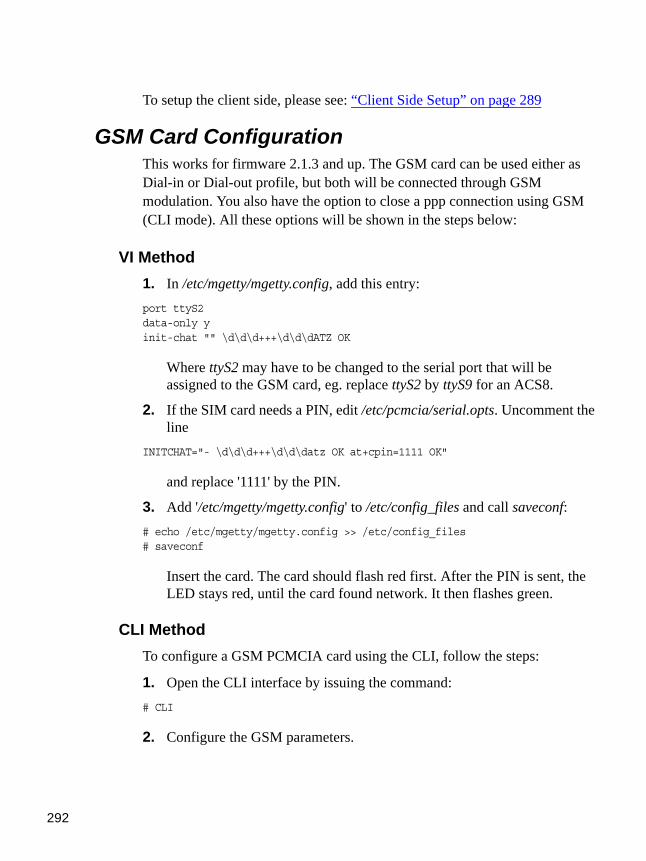
292
To setup the client side, please see: “Client Side Setup” on page 289
GSM Card ConfigurationThis works for firmware 2.1.3 and up. The GSM card can be used either as Dial-in or Dial-out profile, but both will be connected through GSM modulation. You also have the option to close a ppp connection using GSM (CLI mode). All these options will be shown in the steps below:
VI Method1. In /etc/mgetty/mgetty.config, add this entry:port ttyS2data-only yinit-chat "" \d\d\d+++\d\d\dATZ OK
Where ttyS2 may have to be changed to the serial port that will be assigned to the GSM card, eg. replace ttyS2 by ttyS9 for an ACS8.
2. If the SIM card needs a PIN, edit /etc/pcmcia/serial.opts. Uncomment the line
INITCHAT="- \d\d\d+++\d\d\datz OK at+cpin=1111 OK"
and replace '1111' by the PIN.
3. Add '/etc/mgetty/mgetty.config' to /etc/config_files and call saveconf:# echo /etc/mgetty/mgetty.config >> /etc/config_files# saveconf
Insert the card. The card should flash red first. After the PIN is sent, the LED stays red, until the card found network. It then flashes green.
CLI Method To configure a GSM PCMCIA card using the CLI, follow the steps:
1. Open the CLI interface by issuing the command:# CLI
2. Configure the GSM parameters.
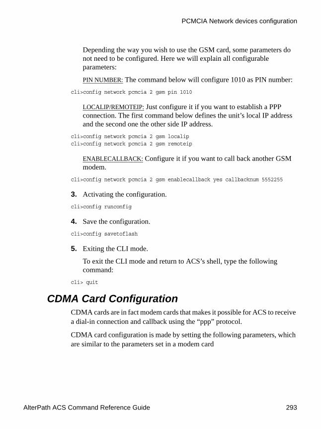
AlterPath ACS Command Reference Guide 293
PCMCIA Network devices configuration
Depending the way you wish to use the GSM card, some parameters do not need to be configured. Here we will explain all configurable parameters:
PIN NUMBER: The command below will configure 1010 as PIN number:cli>config network pcmcia 2 gsm pin 1010
LOCALIP/REMOTEIP: Just configure it if you want to establish a PPP connection. The first command below defines the unit’s local IP address and the second one the other side IP address.
cli>config network pcmcia 2 gsm localipcli>config network pcmcia 2 gsm remoteip
ENABLECALLBACK: Configure it if you want to call back another GSM modem.
cli>config network pcmcia 2 gsm enablecallback yes callbacknum 5552255
3. Activating the configuration.cli>config runconfig
4. Save the configuration.cli>config savetoflash
5. Exiting the CLI mode.
To exit the CLI mode and return to ACS’s shell, type the following command:
cli> quit
CDMA Card ConfigurationCDMA cards are in fact modem cards that makes it possible for ACS to receive a dial-in connection and callback using the “ppp” protocol.
CDMA card configuration is made by setting the following parameters, which are similar to the parameters set in a modem card

294
.
vi Method1. In /etc/mgetty/mgetty.config, add this entry:port ttyxxspeed 57600data-only yinit-chat "" \d\d\d+++\d\d\dATZ OK AT$QCVAD=4 OK
Where xx is the serial port number that will be assigned to the CDMA card.
2. In /etc/pcmcia/serial.opts, add this entry:
Table 7-1: CDMA configuration parameters
Parameter Description
Local and Remote IP addresses (optional)
IP addresses used by “ppp” connection and set in /etc/ppp/options.ttyXX file, where XX is the serial port being configured.
The syntax is local_IP:remote_IP
Phone number (optional)
This number will be used by the callback feature when activated and set in /etc/mgetty/login.config file.
Speed This parameter defines the speed that ACS uses to access the card. The parameter is set in /etc/mgetty/mgetty.config file.
Additional Initialization (optional)
Set an additional initialization parameter to be sent to the card. There is a default command sequence to initialize the card, but if an additional initialization command is required by the card, it can be added using the feature.
The command sequence is set in /etc/mgetty/mgetty.config file.

AlterPath ACS Command Reference Guide 295
PCMCIA Network devices configuration
*,0,*) INFO="Modem Slot 1 Setup" LINK="/dev/modem" INITCHAT="- \d\d\d+++\d\d\datz OK" INITTAB="/sbin/mgetty" start_fn () { return; } stop_fn () { return; } NO_CHECK=n NO_FUSER=n ;;
3. If configuring a local and remote IP, modify local_IP:remote_IP entry in /etc/ppp/options.ttyXX file.
4. To enable the call back feature, add the following entry to /etc/mgetty/login.config
PSEUDO_CB_NAME - - /sbin/callback -S PHONE (PSEUDO_CB_NAME=cbuser)
At the end of the login.config file there is a line similar to the following:*- - /bin/login @
Enter the below command before the above mentioned line:<pseudo callback name>--/sbin/callback -S <phone number of the client>
for example: call-- /sbin/callback -S 5551212
Where, 'call' is the pseudo callback name and '5551212' is the number to dial back.
CLI Method To configure a CDMA PCMCIA card using the CLI method, follow the below steps:
1.Open the CLI interface by issuing the command:# CLI
2. Configure the CDMA parameters.
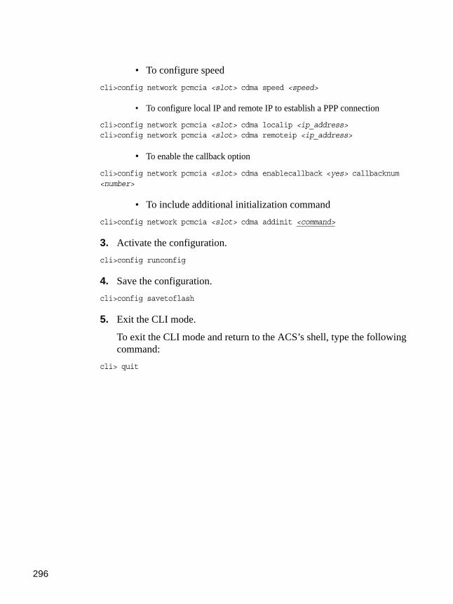
296
• To configure speedcli>config network pcmcia <slot> cdma speed <speed>
• To configure local IP and remote IP to establish a PPP connection
cli>config network pcmcia <slot> cdma localip <ip_address>cli>config network pcmcia <slot> cdma remoteip <ip_address>
• To enable the callback option
cli>config network pcmcia <slot> cdma enablecallback <yes> callbacknum <number>
• To include additional initialization commandcli>config network pcmcia <slot> cdma addinit <command>
3. Activate the configuration.cli>config runconfig
4. Save the configuration.cli>config savetoflash
5. Exit the CLI mode.
To exit the CLI mode and return to the ACS’s shell, type the following command:
cli> quit

AlterPath ACS Command Reference Guide 297
PCMCIA Network devices configuration
ISDN PC CardsYou can establish synchronous PPP connections with ISDN cards. The ipppd is the daemon that handles the synchronous PPP connections.
VI Method
How to configure dial in1. Create a user.
Create a user in /etc/ppp/pap-secrets or in /etc/ppp/chap-secrets, depending if you want PAP or CHAP authentication. You will also have to create a user in /etc/ppp/pap-secrets if you want radius or local authentication. In case you don't want to repeat all the user database from the radius server an option is to use '*' as the user in /etc/ppp/pap-secrets:
* * "" *
2. Change the options in /etc/pcmcia/isdn.opts to fit your environment.
Make sure that $DIALIN is set to "yes." Set the desired authentication in DIALIN_AUTHENTICATION. For instance, "+pap" for PAP, "+chap" for CHAP, "login auth" or "login +pap" for radius, "login auth" or "login +pap" for local. When "login auth" or "login +pap" are used, PAM libraries are used so /etc/pam.d/login should be also configured.
3. Run saveconf to save your changes to the flash.
4. If the ISDN card is not inserted, it is time to insert the card.
ipppd is started automatically. Go to step 6.
5. Restart script.
If the card was already inserted, you will need to restart the isdn script to re-load any changed configuration. To restart the script, issue:
# /etc/pcmcia/isdn stop ippp0# /etc/pcmcia/isdn start ippp0
6. You can dial from the remote system to the ACS for a PPP connection.
7. To hang up the connection from the ACS side, issue:# isdnctrl hangup ippp0

298
How to configure dial out1. Create a user.
Create a user in /etc/ppp/pap-secrets or in /etc/ppp/chap-secrets,depending if you want PAP or CHAP authentication.
2. Change options.
Change the options in /etc/pcmcia/isdn.opts to fit your environment. Make sure that $DIALIN is set to "no". Set $USERNAME to the user name provided by your ISP.
3. Run saveconf to save your changes to the flash.
4. If the ISDN card is not inserted, it is time to insert the card.
ipppd is started automatically. Go to step 6.
5. Restart script.
If the card was already inserted, you will need to restart the isdn script to reload any changed configuration. To restart the script, issue:
# /etc/pcmcia/isdn stop ippp0# /etc/pcmcia/isdn start ippp0
6. To dial out, issue the command:# isdnctrl dial ippp0
7. To hangup the connection from the ACS side, just issue:# isdnctrl hangup ippp0
Establishing a Callback with your ISDN PC CardFor the same cost saving reasons explained in Establishing a Callback with your Modem PC Card, the ISDN card in the ACS can be configured to callback client machines after receiving dial in calls.
The steps to allow callback are divided into two parts. Part One is the configuration for the ACS (ACS Setup) as callback server. Part Two is the configuration of a Windows 2000 Professional computer as callback client.

AlterPath ACS Command Reference Guide 299
PCMCIA Network devices configuration
ACS setup (Callback Server)1. Change the parameters in /etc/pcmcia/isdn.opts to fit your environment.
2. Set the callback number in DIALOUT_REMOTENUMBER:DIALOUT_REMOTENUMBER="8358662" # Remote phone that you want to dial to
Note: If your isdn line supports caller id, it is recommended that you also configure the DIALIN_REMOTENUMBER and enable secure calls. Otherwise skip to step 3.
DIALIN_REMOTENUMBER="8358662" #Remote phone from which you will receive# calls
SECURE="on" # "on" = incoming calls accepted only if # remote phone matches DIALIN_REMOTENUMBER;# "off" = accepts calls from any phone. "on" # will work only if your line has the caller# id info.
3. Make sure the CALLBACK is set to “in” in /etc/pcmcia/isdn.opts file.CALLBACK="in"# "in" will enable callback for incoming calls.
4. Uncomment line with user "mary" in /etc/ppp/pap-secrets.
5. Save changes to flash.# saveconf
6. Activate the changes by stopping and starting the isdn script:# /etc/pcmcia/isdn stop ippp0# /etc/pcmcia/isdn start ippp0
The ACS side is done.
Windows 2000 Professional configuration (Callback Client)1. Create user “mary” with password “marypasswd” in Control Panel->
"User and Passwords".
2. Create a dial-up connection that uses “Modem - AVM ISDN Internet (PPP over ISDN) (AVMISDN1)”.
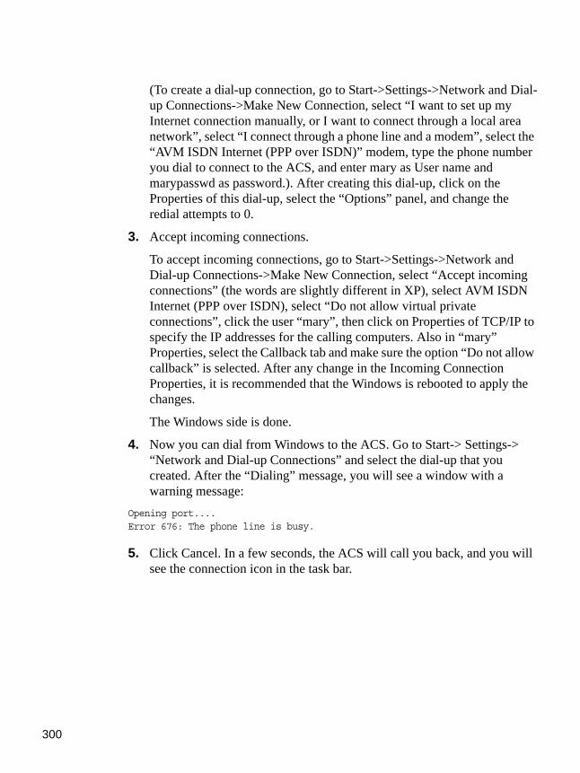
300
(To create a dial-up connection, go to Start->Settings->Network and Dial-up Connections->Make New Connection, select “I want to set up my Internet connection manually, or I want to connect through a local area network”, select “I connect through a phone line and a modem”, select the “AVM ISDN Internet (PPP over ISDN)” modem, type the phone number you dial to connect to the ACS, and enter mary as User name and marypasswd as password.). After creating this dial-up, click on the Properties of this dial-up, select the “Options” panel, and change the redial attempts to 0.
3. Accept incoming connections.
To accept incoming connections, go to Start->Settings->Network and Dial-up Connections->Make New Connection, select “Accept incoming connections” (the words are slightly different in XP), select AVM ISDN Internet (PPP over ISDN), select “Do not allow virtual private connections”, click the user “mary”, then click on Properties of TCP/IP to specify the IP addresses for the calling computers. Also in “mary” Properties, select the Callback tab and make sure the option “Do not allow callback” is selected. After any change in the Incoming Connection Properties, it is recommended that the Windows is rebooted to apply the changes.
The Windows side is done.
4. Now you can dial from Windows to the ACS. Go to Start-> Settings-> “Network and Dial-up Connections” and select the dial-up that you created. After the “Dialing” message, you will see a window with a warning message:
Opening port....Error 676: The phone line is busy.
5. Click Cancel. In a few seconds, the ACS will call you back, and you will see the connection icon in the task bar.
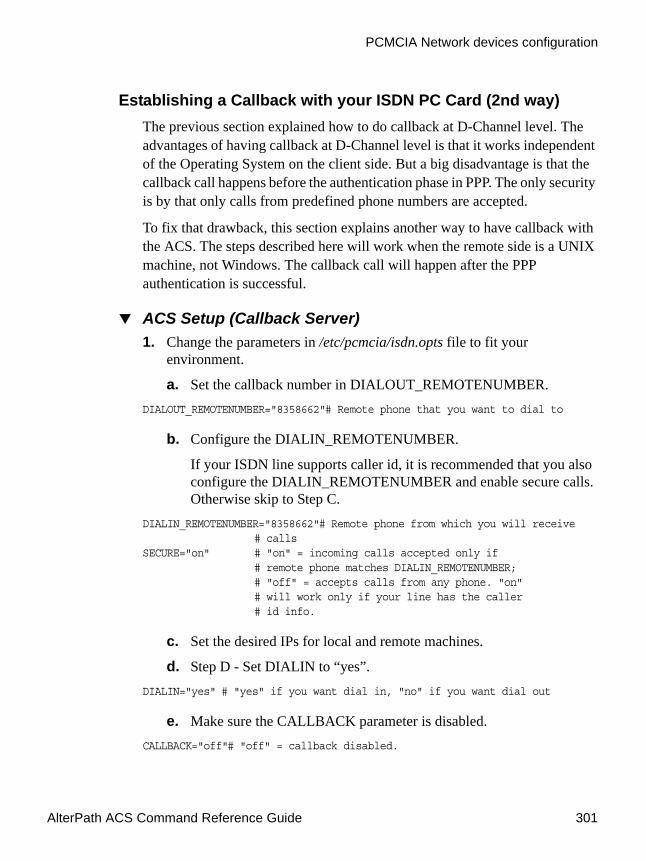
AlterPath ACS Command Reference Guide 301
PCMCIA Network devices configuration
Establishing a Callback with your ISDN PC Card (2nd way)The previous section explained how to do callback at D-Channel level. The advantages of having callback at D-Channel level is that it works independent of the Operating System on the client side. But a big disadvantage is that the callback call happens before the authentication phase in PPP. The only security is by that only calls from predefined phone numbers are accepted.
To fix that drawback, this section explains another way to have callback with the ACS. The steps described here will work when the remote side is a UNIX machine, not Windows. The callback call will happen after the PPP authentication is successful.
ACS Setup (Callback Server)1. Change the parameters in /etc/pcmcia/isdn.opts file to fit your
environment.
a. Set the callback number in DIALOUT_REMOTENUMBER.DIALOUT_REMOTENUMBER="8358662"# Remote phone that you want to dial to
b. Configure the DIALIN_REMOTENUMBER.
If your ISDN line supports caller id, it is recommended that you also configure the DIALIN_REMOTENUMBER and enable secure calls. Otherwise skip to Step C.
DIALIN_REMOTENUMBER="8358662"# Remote phone from which you will receive# calls
SECURE="on" # "on" = incoming calls accepted only if# remote phone matches DIALIN_REMOTENUMBER;# "off" = accepts calls from any phone. "on"# will work only if your line has the caller# id info.
c. Set the desired IPs for local and remote machines.
d. Step D - Set DIALIN to “yes”.DIALIN="yes" # "yes" if you want dial in, "no" if you want dial out
e. Make sure the CALLBACK parameter is disabled.CALLBACK="off"# "off" = callback disabled.
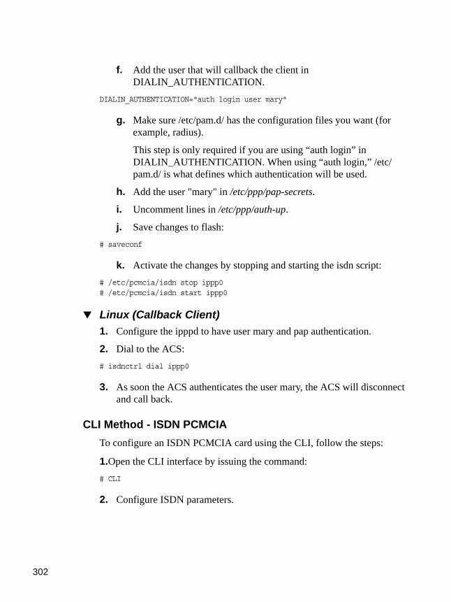
302
f. Add the user that will callback the client in DIALIN_AUTHENTICATION.
DIALIN_AUTHENTICATION="auth login user mary"
g. Make sure /etc/pam.d/ has the configuration files you want (for example, radius).
This step is only required if you are using “auth login” in DIALIN_AUTHENTICATION. When using “auth login,” /etc/pam.d/ is what defines which authentication will be used.
h. Add the user "mary" in /etc/ppp/pap-secrets.
i. Uncomment lines in /etc/ppp/auth-up.
j. Save changes to flash:# saveconf
k. Activate the changes by stopping and starting the isdn script:# /etc/pcmcia/isdn stop ippp0# /etc/pcmcia/isdn start ippp0
Linux (Callback Client)1. Configure the ipppd to have user mary and pap authentication.
2. Dial to the ACS: # isdnctrl dial ippp0
3. As soon the ACS authenticates the user mary, the ACS will disconnect and call back.
CLI Method - ISDN PCMCIATo configure an ISDN PCMCIA card using the CLI, follow the steps:
1.Open the CLI interface by issuing the command:# CLI
2. Configure ISDN parameters.

AlterPath ACS Command Reference Guide 303
Media Cards
Depending the way you wish to use the ISDNISDN card, some parameters do not need to be configured. Here we will explain all configurable parameters:
LOCALIP/REMOTEIP: Just configure it if you want to establish a PPP connection. The first command below defines the unit’s local IP address and the second one the other side IP address.
cli>config network pcmcia 2 isdn localipcli>config network pcmcia 2 isdn remoteip
ENABLECALLBACK: Configure it if you want to call back another ISDN modem.
cli>config network pcmcia 2 isdn enablecallback yes callbacknum 55552244
3. Activating the configuration.cli>config runconfig
4. Save the configuration.cli>config savetoflash
5. Exiting the CLI mode.
To exit the CLI mode and return to ACS’s shell, type the following command:
cli>quit
Media CardsMedia cards (compact flash, hard drives) are small memory cards with a capacity up to 5 Gigabytes. They can be used like a normal hard disk drive using IDE. Using an adapter, CF cards can be used in PCMCIA slots. Such an adapter is very cheap, because the PCMCIA and CF card standard are the same, only the pin layout and the socket is different. On the market, there are also small PCMCIA hard drives available, eg. a drive from Toshiba with a capacity of 5GB (Toshiba MK5002MPL). CF card support can be used in the ACS for storing files. This would be especially useful for example to save the configuration. CF cards cannot be rewritten indefinitely. For this reason, CF should not be used for logging.

304
For data buffering, a PCMCIA hard drive is ideal:
• data will not be lost on power loss / crash / reboot of the CAS. • no dependency on an NFS server that may fail.
How it worksWhen inserting an adapter with a CF card or a PCMCIA hard drive, an ide device appears. This can be mounted, eg. by:
# mkdir /mnt/ide # mount /dev/hda1 /mnt/ide
Apart from the ext2 filesystem, the VFAT filesystem will be supported. This makes it easy to exchange data with a Windows system. To create a vfat filesystem, the it is possible to run the utility mkdosfs .
To initialize a card with VFAT, do:
# echo ",,0x0e" | sfdisk /dev/hda# mkdosfs /dev/hda1
For ext2 filesystem, do:
# echo ",,L" | sfdisk /dev/hda
The "mke2fs" utility, is the system creator for ext2 filesystems, and can be run like the following example:
# mke2fs /dev/hda1
In addition, an utility to create or partition the CF has been added. For this, the program sfdisk will be used. sfdisk can be easily used for scripting, so it can be called from the prompt shell.
To check an ext2 or vfat filesystem, the utility fsck has been added.
# fsck -t <ftype> /dev/<hdxx>
When the card is inserted, cardmgr loads the ide-cs module, which depends on ide-mod.o. This in turn loads ide-probe-mod.o, which recognizes the CF as a disk, and ide-disk.o will be loaded. From this point on, the partitions (usually one) can be mounted using mount. If the filesystem is vfat, the modules fat.o and vfat.o will be loaded.

AlterPath ACS Command Reference Guide 305
Media Cards
VI Method - Configuration1. Insert the card.
2. Automatic compact flash mounting.
The compact flash will mount automatically because by default, the parameter DO_MOUNT is set to YES in the /etc/pcmcia/ide.opts file. Below is an example of the file:
These parameters can be changed:
• DO_FSTAB - If set to 'y', an entry in /etc/fstab will be created. This parameter defaults to "n" if not mentioned in the /etc/pcmcia/ide.opts file.
• DO_FSCK - A boolean (y/n) setting. Specifies if the filesystem should be checked before being mounted. This parameter defaults to “n” in the /etc/pcmcia/ide.opts file.
# ATA/IDE drive adapter configuration# The address format is "scheme,socket,serial_no[,part]".## For multi-partition devices, first return list of partitions in# $PARTS. Then, we'll get called for each partition.
case "$ADDRESS" in*,*,*,1)
#INFO="Sample IDE setup"DO_FSTAB="y" ; DO_FSCK="n" ; DO_MOUNT="y"FSTYPE="vfat"#OPTS=""MOUNTPT="/mnt/ide"[ -d $MOUNTPT ] || mkdir $MOUNTPT;;
*,*,*)PARTS="1"# Card eject policy optionsNO_CHECK=nNO_FUSER=n;;
esac
Figure 7-4: /etc/pcmcia/ide.opts file

306
• DO_MOUNT - If set to ‘y’, the card will be mounted automatically upon insertion. This parameter defaults to ‘n’ if not mentioned in the /etc/pcmcia/ide.opts file.
• FS_TYPE - Can be either 'vfat' or 'ext2'. Determines the filesystem type.
• MOUNTPT - The mount point where the partition will be mounted.
• NO_CHECK/NO_FUSER - Boolean (y/n) settings for card eject policy. If NO_CHECK is true, then “cardctl eject” will shut down a device even if it is busy. If NO_FUSER is true, then the script will not try to kill processes using an ejected device. These parameters defaults to "n" if not mentioned in the /etc/pcmcia/ide.opts file.
• PARTS - A list of partitions to be mounted. The conf file will be called again for each partition. In the example above, there is an entry only for partition '1', but you can eg. set PARTS="1 3 4" and add entries for the case statement like:
*,*,*,3)# settings for partition 3 ;;*,*,*,4)# settings for partition 4;;
To give different configuration for slot 0 and 1, the second parameter in the case statement can be used. For example:
*,0,*,1)# settings for slot 0;;*,1,*,1)# settings for slot 1;;
3. Save the configuration.
To save any configuration done in the /etc/pcmcia/ide.opts file is necessary to run the command:
# saveconf

AlterPath ACS Command Reference Guide 307
Media Cards
Note: WARNING: Before removing the media pcmcia card from the ACS you MUST run “cardctl eject”, otherwise data might not be correctly written to disk and result in corruption of the media. Correct operation of the ACS is not guaranteed if eject is not executed.
CLI Method - Media Cards PCMCIAMounting PCMCIA storage devices using the CLI is extremely simple. Just follow the steps below:
1.Open the CLI interface by issuing the command:# CLI
2. Enable the Compact Flash or mini hard drive.
Supposing that the PCMCIA card is placed on slot 1 of the unit, run the command:
cli>config network pcmcia 1 cflash enable yes
To enable data buffering on this device run the command:cli>config network pcmcia 2 cflash databuf yes
3. Activate the configuration.cli>config runconfig
4. Save the configuration.cli>config savetoflash
5. Check the configuration
The device should be mounted under the /mnt/ide directory.
6. Exit the CLI mode.
To exit the CLI mode and return to ACS’s shell, type the following command:
cli> quit

308
Note: WARNING: Before removing the media pcmcia card from the ACS you MUST run “cardctl eject”, from the shell prompt (not possible using the CLI), otherwise data might not be correctly written to disk and result in corruption of the media. Correct operation of the ACS is not guaranteed if eject is not executed.
How to Save/Load Configuration to/from CF/IDE It is also possible to save and restore the configuration file to/from any PCMCIA-connected file system. By configuring the saveconf utility, you can enable the ACS to save the configuration to PCMCIA-mounted file system and define the type of the configuration saved in the device.
There are two ways in which the admin can define this feature:
• default - the system will apply the configuration in the storage device to the current running system after reboot
• replace - the system will use the configuration in the storage device to replace the existing one in the internal flash of the ACS.
The PCMCIA cards are detected when they are inserted in the slot. If the card is a storage device (Compact Flash or IDE), the system mounts the file system ext2 in the /mnt/ide directory.
During the boot time, before the call of the restoreconf from the internal flash, the system checks for the existence of a config file in the /mnt/ide/proc/flash/script directory. If the DEFAULT flag is set, the system will use the file in the storage device as the config file. If the DEFAULT flag is not set then the system will use the file in internal flash as the config file.
Saveconf Utility
The syntax is:
# saveconf sd [default | replace]

AlterPath ACS Command Reference Guide 309
Media Cards
The saveconf utility will allow to save configuration to PCMCIA mounted file system and will define the type of the configuration saved in the device. The administrator can define the following types :
• default: the configuration in the storage device should be applied to the current running system after reboot
• replace: the configuration in the storage device should be used to replace the existing in the internal flash of the ACS.
The saveconf utility creates one file in the storage device to save the default and replace flags. The filename is: /mnt/ide/proc/flash/storageOptions and it can contain the words DEFAULT and/or REPLACE.
Restoreconf Utility
The syntax is:
# restoreconf sd [default | replace]
The restoreconf utility can read the configuration from storage device mounted file system and do the following actions:
• default: the configuration is used as the config file (it overrides the internal flash configuration during the boot time)
• replace: the configuration is copied to the internal flash and is used as the config file.
CLI Method: backupconfigTo save/restore the configuration to/from a PCMCIA media card follow the steps below:
1.Open the CLI interface by issuing the command:# CLI
2. Save the configuration to a Storage Device:cli> administration backupconfig saveto sd [default] [replace]
3. Restore the configuration from a Storage Device:cli> administration backupconfig loadfrom sd

310
4. Exiting the CLI mode.
To exit the CLI mode and return to ACS’s shell, type the following command:
cli> quit
Generic Dial-OutThis feature allows an application to connect from a central office to a remote location for retrieving system status. The remote system can then send asynchronous alarm notification to the application at the central office.
The connection between the central office and the remote location can be done using TCP/IP over an Ethernet network (In-Band), or through a GSM/GPRS and CDMA/1xRTT profiles (Out-of-Band).
Currently “dial-out” application is supported. Use the “/etc/generic-dial.conf” file to configure dial-out ppp connections through a GPRS and 1xRTT profiles. The following example illustrates a dial-out configuration with a wireless ppp connection. The text in bold type face indicates edited text.
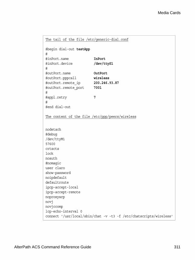
AlterPath ACS Command Reference Guide 311
Media Cards
The tail of the file /etc/generic-dial.conf
#begin dial-out testApp##inPort.name InPort#inPort.device /dev/ttyS1##outPort.name OutPort#outPort.pppcall wireless#outPort.remote_ip 200.246.93.87#outPort.remote_port 7001##appl.retry 7##end dial-out
The content of the file /etc/ppp/peers/wireless
nodetach#debug/dev/ttyM157600crtsctslocknoauth#nomagicuser claroshow-passwordnoipdefaultdefaultrouteipcp-accept-localipcp-accept-remotenoproxyarpnovjnovjccomplcp-echo-interval 0connect '/usr/local/sbin/chat -v -t3 -f /etc/chatscripts/wireless'

312
Configuring the generic-dial.confThe file "/etc/generic-dial.conf" contains sections that corresponds to instances of generic-dial applications. For example,
# begin <application-type> [instanceID]
#....
#....
# end <application-type>
Where [instanceID] is an optional string to identify a particular instance, and <application type> corresponds to specific application(s) built over the infrastructure. Within each application the parameters needed to create the objects for that specific instance is inserted.
Configuring Generic Dial-Out1. To enable the generic dial-out application, configure the desired ports
with the protocol parameter in /etc/portslave/pslave.conf.
For example:s<N>.protocol generic_dial
where <N> is the port number.
2. To enable dial-out for the ports chosen in pslave.conf, configure the file /etc/generic-dial.conf as described in the following table.
Table 7-2: /etc/generic-dial.conf file configuration
Parameter Description
begin <dial-out> [<instance-id>] Begins the dial-out application. Optionally specify a name for the particular instance.
inPort.name <name> A label for the incoming port to be used in log messages.

AlterPath ACS Command Reference Guide 313
Media Cards
inPort.device </dev/ttyXX> The modem device used for this interface.
inPort.speed <9600> Connection speed.
inPort.datasize <8> The number of data bits.
inPort.parity [ none | even | odd ] None, even, or odd.
inPort.stopbits <1> The number of stop bits.
inPort.flowctrl [ none | hw | sw ] Gateway or interface address used for the route.
outPort.name <name> A label for the outgoing port to be used in log messages.
outPort.pppcall <filename> Name of file that the pppd reads options from. The file is located at /etc/ppp/peers/filename.
outPort.remote_ip <IP address> IP address of remote work station to be connected to.
outPort.remote_port <port> Remote TCP port for connections from this interface.
outPort.connection [ permanent | on_demand ]
Specifies how to maintain the outgoing path:
• permanent – always connected.
• on_demand – connects only when data enters through the serial port.
outPort.timeout <timeout> (seconds) Specify the inactivity time in seconds after which the connection is dropped. Any value other than zero enables the timeout.
Table 7-2: /etc/generic-dial.conf file configuration
Parameter Description

314
3. Configure the PPP options (pppd) in /etc/ppp/peers/<name>
Where <name> is the same as the <filename> variable specified in the outPort.pppcall <filename> parameter in /etc/generic-dial.conf.
The following example shows the /etc/ppp/peers/wirelss file.
In this example note that the “connect” script initiates the connection. The file “wireless” executes using the “chat” automated modem communication scrip with the parameters -v (verbose mode), -t (timeout), and -f (read the chat script from the /etc/chatscripts/wireless file).
appl.retry <interval> (minutes) Specify the time to wait before reconnecting after a connection failure.
end <dial-out> Ends the dial-out application.
[root@CAS root]# more /etc/ppp/peers/wirelessnodetach#debug/dev/ttyM157600crtsctslocknoauth#nomagicuser claroshow-passwordnoipdefaultdefaultrouteipcp-accept-localipcp-accept-remotenoproxyarpnovjnovjccomplcp-echo-interval 0connect '/usr/local/sbin/chat -v -t3 -f /etc/chatscripts/wireless'
Table 7-2: /etc/generic-dial.conf file configuration
Parameter Description

AlterPath ACS Command Reference Guide 315
Media Cards
l. Edit the /etc/pcmcia/serial.opts file:
a. If the SIM card (GSM) needs a PIN, uncomment the following line and replace 1111 with the PIN.
b. To inactivate mgetty on the specified port so that the port will be directly controlled by the pppd application, comment out the following line.
m. Activate the function to automatically restart the dial-out application after reboot.
Edit the following parameter in the /etc/daemon.d/gendial.sh file to enable the "automatically established" feature. The script restarts the dial-out function after a reboot.
a) Set the parameter as described below.ENABLE = YES
b) Save the gendial.sh configuration file by issuing the following command in ACS.
[root@CAS root]# saveconf
n. To Activate the dial-out function, issue the following command.
Note: Note: It is not necessary to reboot the ACS to activate the dial-out function. You can do this by restarting the GDF daemon.
[root@CAS root]# daemon.sh restart GDF
A message similar to the following displays, confirming the GDF daemon restart.
[root@CAS root]# Sep 23 18:06:10 src_dev_log@CAS showlogmsg: /bin/daemon.sh: CONFIG: Network daemon [generic-dial] started
INITCHAT="- \d\d\d+++\d\d\datz OK at+cpin=1111 OK"
#INITTAB="/sbin/mgetty"

316
The default route is not replaced in the static router table. The following message displays.
[root@CAS root]# Sep 23 18:06:17 src_dev_log@CAS pppd[1028]: not replacing existing default route to eth0 [172.20.0.1]
o. To change a static route or create a new one.
a) Edit the parameters in the /etc/network/st_routes file.
b) Activate the new routes by issuing the following command:#> runconf
c) Save the new configuration to flash.#> saveconf
d) Check the routes by issuing the following command.#> route -n

.................................................................
Chapter 8Chapter 8 - Profile ConfigurationProfile Configuration
This chapter begins with a table containing parameters common to all profiles, followed by tables with parameters specific to a certain profile. You can find samples of the pslave configuration files (pslave.conf, .cas, .ts, and .ras) in the /etc/portslave directory.
Then all possible profiles (CAS, TS and RAS) and the necessary parameters that need to be configured in the /etc/portslave/pslave.conf file. This chapter includes the following sections:
• The pslave.conf file• Examples for configuration testing
The pslave.conf fileThis is the main configuration file (/etc/portslave/pslave.conf) that contains most product parameters and defines the functionality of the ACS .
There are three basic types of parameters in this file:
• conf.* parameters are global or apply to the Ethernet interface.• all.* parameters are used to set default parameters for all ports.• s#.* parameters change the default port parameters for individual ports. An all.* parameter can be overridden by a s#.* parameter appearing later in the pslave.conf file (or vice-versa).
Note: TIP. You can do a find for each of these parameters in vi, once you open this file by typing:/ <your string>To search the file downward for the string specified after the /.

Profile Configuration
318
pslave.conf common parametersThe tables below present all parameters with their respective descriptions. The first table presents parameters that are common for any profile. The second, third and fourth tables define specific parameters for CAS, TS and Dial-in profiles respectively.
Table 8-1: /etc/portslave/pslave.conf common parameters
Parameter Description Factory Configuration
conf.dhcp_client It defines the dhcp client operation mode.
Valid values:
0 - DHCP disabled
1 - DHCP active
2 - DHCP active and the unit saves the last IP assigned by the DHCP server in flash.
2
conf.eth_ip_alias Secondary IP address for the Ethernet interface (needed for clustering feature).
Note: This parameter is inactive by default. To activate, uncomment the parameter and set the desired value.
0
conf.eth_mask_alias
Mask for the secondary IP address above.
Note: This parameter is inactive by default. To activate, uncomment the parameter and set the desired value.
0
conf.rlogin It defines the location of rlogin utility
Note: This is a parameter specific to TS profile.
/usr/local/bin/rlogin-radius

AlterPath ACS Command Reference Guide 319
conf.facility The local facility sent to syslog-ng from PortSlave.
7
conf.group Used to group users to simplify the configuration of the parameter all.users later on. This parameter can be used to define more than one group.
Note: This parameter is inactive by default. To activate, uncomment the parameter and set the desired value.
0
conf.eth_ip Configured in Appendix . This is the IP address of the Ethernet interface. This parameter, along with the next two, is used by the cy_ras program to OVERWRITE the file /etc/network/ifcfg_eth0 as soon as the command “runconf” is executed. The file /etc/network/ifcfg_eth0 should not be edited by the user unless the cy_ras configuration is not going to be used.
Note: This parameter is inactive by default. To activate, uncomment the parameter and set the desired value.
0 (IP address received from DHCP Server)
conf.eth_mask The mask for the Ethernet network.
Note: This parameter is inactive by default. To activate, uncomment the parameter and set the desired value.
0 (IP mask received from DHCP Server)
Table 8-1: /etc/portslave/pslave.conf common parameters
Parameter Description Factory Configuration

Profile Configuration
320
conf.eth_mtu The Maximum Transmission Unit size, which determines whether or not packets should be broken up.
1500
conf.lockdir The lock directory, which is /var/lock for the ACS . It should not be changed unless the user decides to customize the operating system.
/var/lock
all.dcd DCD signal (sets the tty parameter CLOCAL). Valid values are 0 or 1. If all.dcd=0, a connection request will be accepted regardless of the DCD signal and the connection will not be closed if the DCD signal is set to DOWN. If all.dcd=1 a connection request will be accepted only if the DCD signal is UP and the connection will be closed if the DCD signal is set to DOWN.
0
Table 8-1: /etc/portslave/pslave.conf common parameters
Parameter Description Factory Configuration

AlterPath ACS Command Reference Guide 321
all.users Restricts access to ports by user name (only the users listed can access the port or, using the character “!”, all but the users listed can access the port.) In this example, the users joe, mark and members of
user_group cannot access the port. A single comma and spaces/tabs may be used between names. A comma may not appear between the “!” and the first user name. The users may be local, Radius or TacacsPlus. User groups (defined with the parameter conf.group) can be used in combination with user names in the parameter list. Notice that these are common users, not administrators.
Note: This parameter is inactive by default. To activate, uncomment the parameter and set the desired value.
null
all.issue This text determines the format of the login banner that is issued when a connection is made to the ACS . \n represents a new line and \r represents a carriage return. Expansion characters can be used here. The default parameter is:
\r\n\ Welcome to Console Server Management Server %h port S%p \n\\r\n
See Description column
Table 8-1: /etc/portslave/pslave.conf common parameters
Parameter Description Factory Configuration

Profile Configuration
322
all.prompt This text defines the format of the login prompt. Expansion characters can be used here.
%h login:
all.media It defines media type RS232/RS484 and operation mode half/full duplex.Valid values for all products :
• rs232 - RS232 (default value).• rs232_half - RS232 with RTS legacy half duplex• rs232_half_cts - RS232 with RTS legacy half
duplex and CTS control
Valid values for the ACS1 only :
• rs485_half - RS485 half duplex with out terminator
• rs485_half_terminator - RS485 half duplex with terminator
• rs485_full_terminator - RS485 full duplex with terminator
• rs422 - alike rs485_full_terminator
Note: This parameter is inactive by default. To activate, uncomment the parameter and set the desired value.
rs232
all.netmask It defines the network mask for the serial port.
255.255.255.255
all.mtu It defines the maximum transmit unit 1500
all.mru It defines the maximum receive unit 1500
all.sysutmp It defines whether portslave must write login records. Valid values are yes or no.
1
Table 8-1: /etc/portslave/pslave.conf common parameters
Parameter Description Factory Configuration

AlterPath ACS Command Reference Guide 323
all.pmtype Name of the IPDU manufacturer.
Note: This parameter is inactive by default. To activate, uncomment the parameter and set the desired value.
null
all.pmusers List of the outlets each user can access.
Note: This parameter is inactive by default. To activate, uncomment the parameter and set the desired value.
null
all.pmkey The hotkey that identifies the power management command.
Note: This parameter is inactive by default. To activate, uncomment the parameter and set the desired value.
off
Table 8-1: /etc/portslave/pslave.conf common parameters
Parameter Description Factory Configuration

Profile Configuration
324
all.sttyCmd The TTY is programmed to work as configured and this user-specific configuration is applied over that serial port. Parameters must be separated by a space. The following example sets :
-igncr
This tells the terminal not to ignore the carriage-return on input,
-onlcr
Do not map newline character to a carriage return or newline character sequence on output,
opost
Post-process output, -icrnl
Do not map carriage-return to a newline character on input.
all.sttyCmd -igncr -onlcr opost -icrnl
Note: This parameter is inactive by default. To activate, uncomment the parameter and set the desired value.
null
Table 8-1: /etc/portslave/pslave.conf common parameters
Parameter Description Factory Configuration

AlterPath ACS Command Reference Guide 325
all.utmpfrom It allow the administrator to customize the field "FROM" in the login records (utmp file). It is displayed in the "w" command.
The default value is "%g:%P.%3.%4"
%g : process id
%P : Protocol
%3 : Third nibble of remote IP
%J : Remote IP
Note: In the pslave.conf file there is a list of all expansion variables available.
"%g:%P.%3.%4"
all.radnullpass It defines whether the access to users with null password in the radius server must be granted or not.
0
all.speed The speed for all ports. 9600
all.datasize The data size for all ports. 8
all.stopbits The number of stop bits for all ports. 1
all.parity The parity for all ports. none
Table 8-1: /etc/portslave/pslave.conf common parameters
Parameter Description Factory Configuration

Profile Configuration
326
all.authtype Configured in Chapter 2, “Device Authentication” on page 47. Type of authentication used. There are several authentication type options:
•none (no authentication)• local (authentication is performed using the /etc/
passwd file)•remote (This is for a terminal profile only. The
unit takes in a username but does not use it for authentication. Instead it passes it to the remote server where it is then used for authentication.)
•radius (authentication is performed using a Radius authentication server)
•TacacsPlus (authentication is performed using a TacacsPlus authentication server)
• ldap (authentication is performed against an ldap database using an ldap server. The IP address and other details of the ldap server are defined in the file /etc/ldap.conf)
none
Table 8-1: /etc/portslave/pslave.conf common parameters
Parameter Description Factory Configuration

AlterPath ACS Command Reference Guide 327
all.authtype
continuation...
•kerberos (authentication is performed using a kerberos server. The IP address and other details of the kerberos server are defined in the file /etc/krb5.conf)
• local/radius (authentication is performed locally first, switching to Radius if unsuccessful)
•radius/local (the opposite of the previous option)
• local/TacacsPlus (authentication is performed locally first, switching to TacacsPlus if unsuccessful)
•TacacsPlus/local (the opposite of the previous option)
•RadiusDownLocal (local authentication is tried only when the Radius server is down)
•TacacsPlusDownLocal (local authentication is tried only when the TacacsPlus server is down)
•kerberosDownLocal (local authentication is tried only when the kerberos server is down)
• ldapDownLocal (local authentication is tried only when the ldap server is down)
•NIS - All authentication types but NIS follow the format all.authtype <Authentication> DownLocal or <Authentication> (e.g. all.authtype radius or radiusDownLocal or ldap or ldapDownLocal, etc). NIS requires all.authtype to be set as local, regardless if it will be "nis" or its “Downlocal" equivalent. The service related to "nis" or its “Downlocal" equivalent would be configured in the /etc/nsswitch.conf file, not in the /etc/portslave/pslave.conf file.
Note: This parameter controls the authentication required by the ACS . The authentication required by the device to which the user is connecting is controlled separately.
Table 8-1: /etc/portslave/pslave.conf common parameters
Parameter Description Factory Configuration

Profile Configuration
328
all.break_sequence
This parameter is the string that is used to send a break to the TTY. It is only valid if TTY protocol is socket_ssh, socket_server, or socket_server_ssh.
~break
all.break_interval This parameter defines the break duration in milliseconds. It is valid if TTY protocol is socket_ssh,socket_server, socket_server_ssh, or ssh-2 (client).
500
all.flow This sets the flow control to hardware, software, or none.
none
Table 8-1: /etc/portslave/pslave.conf common parameters
Parameter Description Factory Configuration

AlterPath ACS Command Reference Guide 329
all.protocol Defines the protocol used to connect with the ACS . For each profile there are some valid values:
• CAS profile:- socket_server when Telnet is used.
- socket_ssh when SSHv1 or SSHv2 is used.
- socket_server_ssh when Telnet or SSHv1 or SSHv2 is used.
- raw_data to exchange data in transparent mode. It is similar to “socket_server” mode, but without Telnet negotiation, breaks to serial ports, etc.
• TS profile:- login requests username and password.- rlogin receives username from the ACS and requests a password.- Telnet- SSHv1- SSHv2- socket_clientIf the protocol is configured as Telnet or socket_client the socket_port parameter needs to be configured.
• Bidirectional Telnet profile: socket_server (CAS), and login (TS)
• RAS profile: slip, cslip, ppp, ppp_only• Power Management: ipdu• Serial Printer : lpd• Billing profile: billing
ACS1 only:• Automation profile: "modbus", in this case, serial
mode can be ascii or rtu. To enable "modbus" it is necessary to uncomment the related line as shown below:
# Modbus/TCP Protocolmodbus stream tcp nowait.1000root /bin/modbusd modbusd
Then, enable it by running the command:daemon.sh restart NET
• PPP over leased lines (only authentication PAP/CHAP): “ppp_only”
• PPP with terminal post dialing (Auto detect PPP): “ppp”
socket_server
Table 8-1: /etc/portslave/pslave.conf common parameters
Parameter Description Factory Configuration

Profile Configuration
330
all.web_WinEMS
Defines whether or not management of Windows Emergency Management Service is allowed from the Web.
Note: This parameter is inactive by default. To activate, uncomment the parameter and set the desired value.
no
all.xml_monitor A non-zero value activates XML monitoring. All XML data received from the port is captured and sent to syslog-ng with facility LOCAL<DB_facility> and priority INFO. The format of the message is "XML_MONITOR (ttySx) [data]". XML tags are sent by Windows Server 2003 Emergency Management Services during boot or crash. You can read more on XML_MONITOR in:
/etc/syslog-ng/syslog-ng.conf
Note: This parameter is inactive by default. To activate, uncomment the parameter and set the desired value.
0
Table 8-1: /etc/portslave/pslave.conf common parameters
Parameter Description Factory Configuration

AlterPath ACS Command Reference Guide 331
pslave.conf CAS (Console Access Server) parameters
You can configure additional CAS features with the parameters given on the following tables.
In addition to the above parameters which are common to all local and remote access scenarios, you can also configure the following parameters for additional options. Many of the parameters are unique to CAS, but some also
all.translation Defines whether or not to perform translation of Fn-keys (e.g. F8 key) from one terminal type to VT-UTF8. Currently only translation from xterm to VT-UTF8 is supported.
Note: This parameter is inactive by default. To activate, uncomment the parameter and set the desired value.
null
sX.pmoutlet sX indicates the serial port number to which the PM hardware is connected. The pmoutlet part of the parameter indicates the outlet # on the PM hardware that manages the server/network equipment in question.
8
s1.tty The device name for the port is set to the value given in this parameter. If a device name is not provided for a port, it will not function.
Note: This parameter is disable by default. To activate, uncomment the parameter.
disabled
Table 8-1: /etc/portslave/pslave.conf common parameters
Parameter Description Factory Configuration

Profile Configuration
332
apply to TS and Dial-in port profiles. These are going to be indicated in the appropriate instances.
Table 8-2: CAS specific parameters for the pslave.conf
Parameter Description Factory Configuration
conf.nfs_data_buffering This is the Remote Network File System where data captured from the serial port will be written instead of being written to the local directory /var/run/DB. The directory tree to which the file will be written must be NFS-mounted, so the remote host must have NFS installed and the administrator must create, export and allow reading/writing to this directory. The size of this file is not limited by the value of the parameter all.data_buffering, though the value cannot be zero since a zero value turns off data buffering. The size of the file is dependent on the NFS server only (hard drive, partition size, etc.).
Note: This parameter is inactive by default. To activate, uncomment the parameter and set the desired value.
null
conf.DB_facility This value (0-7) is the Local facility sent to the syslog with the data when syslog_buffering is active. The file /etc/syslog-ng/syslog-ng.conf contains a mapping between the facility number and the action (see more on Table , “Syslog-ng,” on page 173).
7

AlterPath ACS Command Reference Guide 333
conf.nat_clustering_ip IP address of any ACS interface (master box). It is a public IP address (e.g. Ethernet's interface IP address) and it is the one that must be used to connect the slave's serial ports. You can use the same value assigned to the Ethernet's IP address as that of the master box in the chain.
Note: This parameter is inactive by default. To activate, uncomment the parameter and set the desired value.
0
all.ipno This is the default IP address of the ACS 's serial ports. The “+” indicates that the first port should be addressed as 192.168.1.101 and the following ports should have consecutive values. Any host can access a port using its IP address as long as a path to the address exists in the host's routing table.
Note: This parameter is inactive by default. To activate, uncomment the parameter and set the desired value.
0
all.netmask It defines the network mask for the serial port.
255.255.255.255
Table 8-2: CAS specific parameters for the pslave.conf
Parameter Description Factory Configuration

Profile Configuration
334
all.DTR_reset This parameter specifies the behavior of the DTR signal in the serial port. If set to zero the DTR signal will be ON if there is a connection to the serial port, otherwise OFF. If set from 1 to 99 the DTR signal will be always ON. A value greater or equal 100 specifies for how long (in milliseconds) the DTR signal will be turned off before it is turned back on again when a connection to the serial port is closed.
100
all.break_sequence This parameter is the string that is used to send a break to the TTY. It is only valid if TTY protocol is socket_ssh, socket_server, or socket_server_ssh.
~break
all.break_interval This parameter defines the break duration in milliseconds. It is valid if TTY protocol is socket_ssh.
500
all.modbus_smode Communication mode through the serial ports. This parameter is meaningful only when modbus protocol is configured. The valid options are ascii (normal TX/RX mode) and rtu (some time constraints are observed between characters while transmitting a frame). If not configured, ASCII mode will be assumed.
Note: This parameter is inactive by default. To activate, uncomment the parameter and set the desired value.
ascii
Table 8-2: CAS specific parameters for the pslave.conf
Parameter Description Factory Configuration
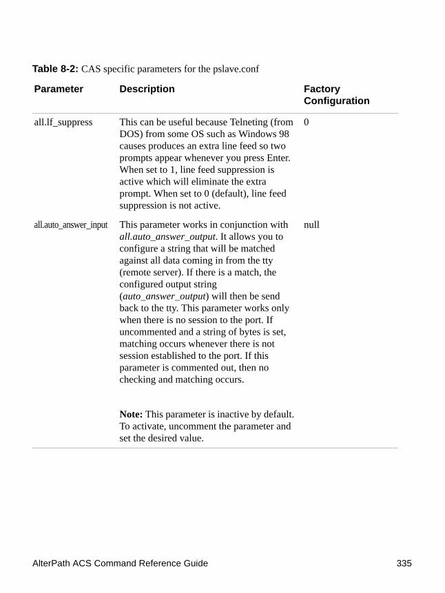
AlterPath ACS Command Reference Guide 335
all.lf_suppress This can be useful because Telneting (from DOS) from some OS such as Windows 98 causes produces an extra line feed so two prompts appear whenever you press Enter. When set to 1, line feed suppression is active which will eliminate the extra prompt. When set to 0 (default), line feed suppression is not active.
0
all.auto_answer_input This parameter works in conjunction with all.auto_answer_output. It allows you to configure a string that will be matched against all data coming in from the tty (remote server). If there is a match, the configured output string (auto_answer_output) will then be send back to the tty. This parameter works only when there is no session to the port. If uncommented and a string of bytes is set, matching occurs whenever there is not session established to the port. If this parameter is commented out, then no checking and matching occurs.
Note: This parameter is inactive by default. To activate, uncomment the parameter and set the desired value.
null
Table 8-2: CAS specific parameters for the pslave.conf
Parameter Description Factory Configuration
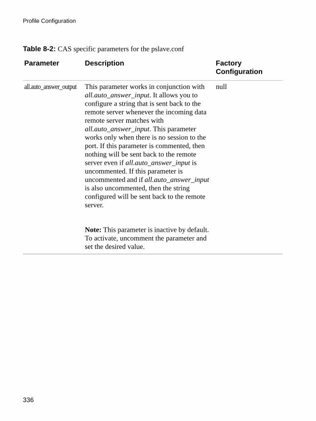
Profile Configuration
336
all.auto_answer_output This parameter works in conjunction with all.auto_answer_input. It allows you to configure a string that is sent back to the remote server whenever the incoming data remote server matches with all.auto_answer_input. This parameter works only when there is no session to the port. If this parameter is commented, then nothing will be sent back to the remote server even if all.auto_answer_input is uncommented. If this parameter is uncommented and if all.auto_answer_input is also uncommented, then the string configured will be sent back to the remote server.
Note: This parameter is inactive by default. To activate, uncomment the parameter and set the desired value.
null
Table 8-2: CAS specific parameters for the pslave.conf
Parameter Description Factory Configuration

AlterPath ACS Command Reference Guide 337
all.poll_interval Valid only for protocols socket_server and raw_data. When not set to zero, this parameter sets the wait for a TCP connection keep-alive timer. If no traffic passes through the ACS for this period of time, the ACS will send a line status message to the remote device to see if the connection is still up. If not configured, 1000 ms is assumed (the unit for this parameter is ms). If set to zero, line status messages will not be sent to the socket client.
Note: This parameter is inactive by default. To activate, uncomment the parameter and set the desired value.
1000
all.socket_port In the CAS profile, this defines an alternative labeling system for the ACS ports. The “+” after the numerical value causes the serial interfaces to be numbered consecutively. In this example, serial interface 1 is assigned the port value 7001,serial interface 2 is assigned the port value 7002, etc. One example on how this could be used is in the case of all.protocol or s<n>.protocol socket_ssh and the port value (7001, 7002, etc), if supplied by the SSH client like username:port value, the SSH client will be directly connected with the serial interface.
7001+
Table 8-2: CAS specific parameters for the pslave.conf
Parameter Description Factory Configuration

Profile Configuration
338
all.data_buffering A non zero value activates data buffering (local or remote, according to what was configured in the parameter conf.nfs_data_buffering see Table , “Data Buffering,” on page 18 in Chapter 1). If local data buffering, a file is created on the ACS ; if remote, a file is created through NFS in a remote server. All data received from the port is captured in this file.
If local data buffering, this parameter means the maximum file size (in bytes). If remote, this parameter is just a flag to activate (greater than zero) or deactivate data buffering. When local data buffering is used, each time the maximum is reached the oldest 10% of stored data is discarded, releasing space for new data (FIFO system) - circular file. When remote data buffering is used, there's no maximum file size other than the one imposed by the remote server - linear file. This file can be viewed using the normal Unix tools (cat, vi, more, etc.). Size is in bytes not kilobytes. See Data Buffering for details.
0
Table 8-2: CAS specific parameters for the pslave.conf
Parameter Description Factory Configuration

AlterPath ACS Command Reference Guide 339
all.DB_mode When configured as cir for circular format, the buffer works like a revolving file at all times. The file is overwritten whenever the limit of the buffer size (as configured in all.data_buffering or s<n>.data_buffering) is reached. As for linear format (lin), once the limit of the kernel buffer size is reached (4k), a flow control stop (RTS off or XOFF-depending on how all.flow or s<n>.flow is set) is issued automatically to the remote device so that it will stop sending data to the serial port. Then, when a session is established to the serial port, the data in the buffer is shown to the user if not empty (dont_show_DBmenu parameter assumed to be 2), cleared, and a flow control start (RTS on or XON) is issued to resume data transmission. Once exiting the session, linear data buffering resumes. If all.flow or s<n>.flow is set to none, linear buffering is not possible as there is no way to stop reception through the serial line. Default is cir.
cir
Table 8-2: CAS specific parameters for the pslave.conf
Parameter Description Factory Configuration

Profile Configuration
340
all.DB_timestamp Records the time stamp in the data buffering file (1) or not (0). If it is configured as 1, the software will accumulate input characters until it receives a CR and LF from the serial port or the accumulated data reaches 256 characters. Either way, the accumulated data will be recorded in the data buffering file along with the current time. The parameter all.data_buffering has to be with a non-zero value for this parameter to be meaningful.
Note: This parameter is inactive by default. To activate, uncomment the parameter and set the desired value.
0
all.syslog_buffering
When non zero, the contents of the data buffer are sent to the syslog-ng every time a quantity of data equal to this parameter is collected. The syslog level for data buffering is hard coded to level 5 (notice) and facility local[0+conf.DB_facility]. The file /etc/syslog-ng/syslog-ng.conf should be set accordingly for the syslog-ng to take some action. (See Table , “Data Buffering,” on page 18 to use it with Syslog Buffering Feature.)
0
Table 8-2: CAS specific parameters for the pslave.conf
Parameter Description Factory Configuration

AlterPath ACS Command Reference Guide 341
all.syslog_sess Syslog_buffering must be activated for the following to work. When 0, syslog messages are always generated whether or not there is a session to the port sending data to the unit. When 1, syslog messages are NOT generated when there IS a session to the port sending data to the unit, but resumes generation of syslog messages when there IS NOT a session to the port.
0
all.dont_show_DBmenu When zero, a menu with data buffering options is shown when a non empty data buffering file is found.
• When 1, the data buffering menu is not shown. When 2, the data buffering menu is not shown but the data buffering file is shown if not empty.
• When 3, the data buffering menu is shown, but without the erase and show and erase options.
Note: This parameter is inactive by default. To activate, uncomment the parameter and set the desired value.
0
all.alarm When non zero, all data received from the port are captured and sent to syslog-ng with level INFO and local[0+conf.DB_facility]facility. The syslog-ng.conf file should be set accordingly, for the syslog-ng to take some action (please see Table , “Syslog-ng,” on page 173 for the syslog-ng configuration file).
0
Table 8-2: CAS specific parameters for the pslave.conf
Parameter Description Factory Configuration

Profile Configuration
342
all.billing_records Billing file size configuration. A non-zero value defines the maximum number of billing records within a billing file. Zero stops billing recording. The billing files are located at /var/run/DB and are named cycXXXXX-YYMMDD.hhmmss.txt (e.g., cycTS100-030122.153611.txt.
50
all.billing_timeout Billing timeout configuration. A non-zero value defines how long (minutes) a billing file should be waiting for records before close. After a file is closed, this file is available for transfer and a new one is opened. Zero means “no timeout” and so the file is only closed after “billing_records” are received.
60
all.billing_eor Defines the character sequence that terminates each billing record. Any character sequence is valid, including '\r' or '^M' (carriage return), '\n' or '^J' (new line), etc..."
"\n"
Table 8-2: CAS specific parameters for the pslave.conf
Parameter Description Factory Configuration
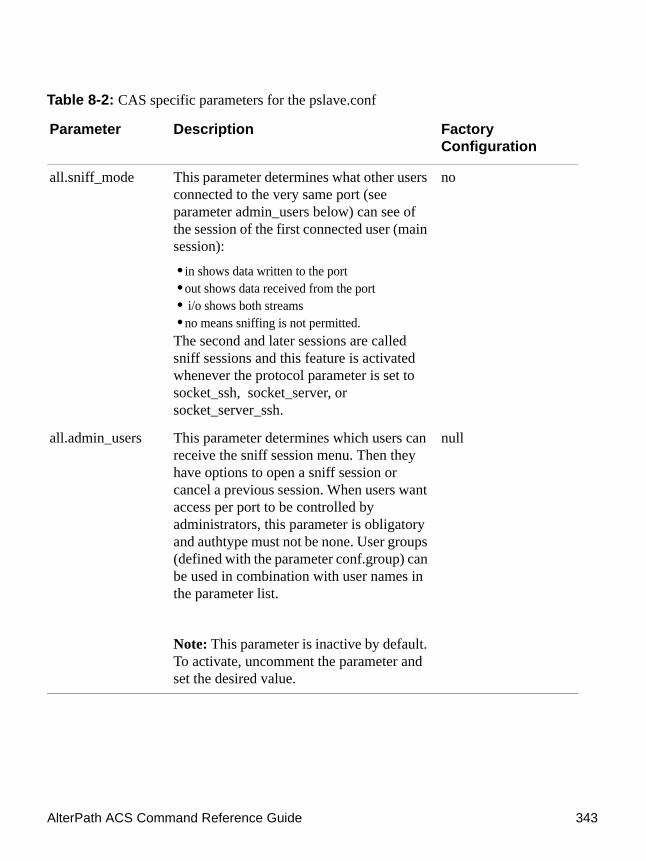
AlterPath ACS Command Reference Guide 343
all.sniff_mode This parameter determines what other users connected to the very same port (see parameter admin_users below) can see of the session of the first connected user (main session):
• in shows data written to the port • out shows data received from the port• i/o shows both streams• no means sniffing is not permitted.
The second and later sessions are called sniff sessions and this feature is activated whenever the protocol parameter is set to socket_ssh, socket_server, or socket_server_ssh.
no
all.admin_users This parameter determines which users can receive the sniff session menu. Then they have options to open a sniff session or cancel a previous session. When users want access per port to be controlled by administrators, this parameter is obligatory and authtype must not be none. User groups (defined with the parameter conf.group) can be used in combination with user names in the parameter list.
Note: This parameter is inactive by default. To activate, uncomment the parameter and set the desired value.
null
Table 8-2: CAS specific parameters for the pslave.conf
Parameter Description Factory Configuration
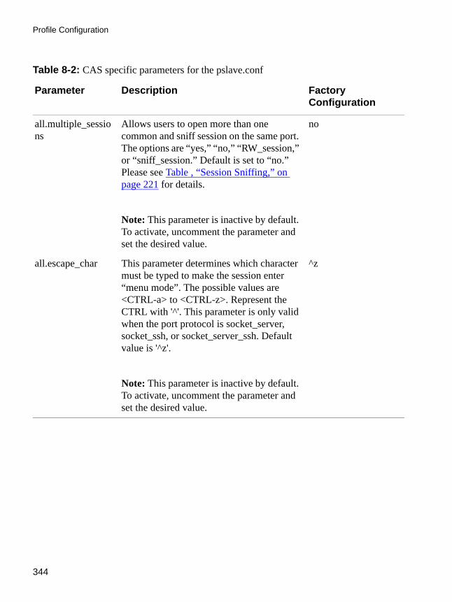
Profile Configuration
344
all.multiple_sessions
Allows users to open more than one common and sniff session on the same port. The options are “yes,” “no,” “RW_session,” or “sniff_session.” Default is set to “no.” Please see Table , “Session Sniffing,” on page 221 for details.
Note: This parameter is inactive by default. To activate, uncomment the parameter and set the desired value.
no
all.escape_char This parameter determines which character must be typed to make the session enter “menu mode”. The possible values are <CTRL-a> to <CTRL-z>. Represent the CTRL with '^'. This parameter is only valid when the port protocol is socket_server, socket_ssh, or socket_server_ssh. Default value is '^z'.
Note: This parameter is inactive by default. To activate, uncomment the parameter and set the desired value.
^z
Table 8-2: CAS specific parameters for the pslave.conf
Parameter Description Factory Configuration

AlterPath ACS Command Reference Guide 345
all.tx_interval Valid for protocols socket_server and raw_data. Defines the delay (in milliseconds) before transmission to the Ethernet of data received through a serial port. If not configured, 100ms is assumed. If set to zero or a value above 1000, no buffering will take place.
Note: This parameter is inactive by default. To activate, uncomment the parameter and set the desired value.
100
all.idleinterval Specifies how long (in minutes) a connection can remain inactive before it is cut off. If it set to zero, the connection will not time out.
Note: This parameter is inactive by default. To activate, uncomment the parameter and set the desired value.
0
s1.alias Alias name given to the server connected to the serial port. Server_connected.
Note: This parameter is inactive by default. To activate, uncomment the parameter and set the desired value.
null
Table 8-2: CAS specific parameters for the pslave.conf
Parameter Description Factory Configuration
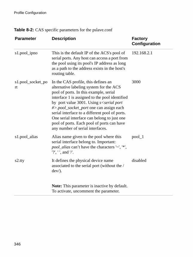
Profile Configuration
346
s1.pool_ipno This is the default IP of the ACS's pool of serial ports. Any host can access a port from the pool using its pool's IP address as long as a path to the address exists in the host's routing table.
192.168.2.1
s1.pool_socket_port
In the CAS profile, this defines an alternative labeling system for the ACS pool of ports. In this example, serial interface 1 is assigned to the pool identified by port value 3001. Using s<serial port #>.pool_socket_port one can assign each serial interface to a different pool of ports. One serial interface can belong to just one pool of ports. Each pool of ports can have any number of serial interfaces.
3000
s1.pool_alias Alias name given to the pool where this serial interface belong to. Important: pool_alias can’t have the characters '~', '*', '?', ' ', and '/'.
pool_1
s2.tty It defines the physical device name associated to the serial port (without the /dev/).
Note: This parameter is inactive by default. To activate, uncomment the parameter.
disabled
Table 8-2: CAS specific parameters for the pslave.conf
Parameter Description Factory Configuration

AlterPath ACS Command Reference Guide 347
pslave.conf TS (Terminal Server) parametersThe following parameters are unique to a TS setup except where indicated.
s8.tty It defines the physical device name associated to the serial port (without the /dev/).
Note: This parameter is inactive by default. To activate, uncomment the parameter.
disabled
Table 8-3: TS specific parameters for the pslave.conf file
Parameter Description Factory Configuration
conf.telnet Location of the Telnet utility /usr/bin/telnet
conf.ssh Location of the SSH utility. /bin/ssh
conf.locallogins This parameter is only necessary when authentication is being performed for a port. When set to one, it is possible to log in to the ACS directly by placing a “!” before your login name, then using your normal password. This is useful if the Radius authentication server is down.
1
all.host The IP address of the host to which the terminals will connect.
192.168.160.8
all.term This parameter defines the terminal type assumed when performing rlogin or Telnet to other hosts.
vt100
Table 8-2: CAS specific parameters for the pslave.conf
Parameter Description Factory Configuration
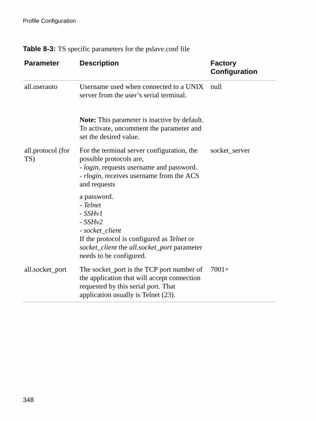
Profile Configuration
348
all.userauto Username used when connected to a UNIX server from the user’s serial terminal.
Note: This parameter is inactive by default. To activate, uncomment the parameter and set the desired value.
null
all.protocol (for TS)
For the terminal server configuration, the possible protocols are,- login, requests username and password.- rlogin, receives username from the ACS and requests
a password.- Telnet- SSHv1- SSHv2- socket_clientIf the protocol is configured as Telnet or socket_client the all.socket_port parameter needs to be configured.
socket_server
all.socket_port The socket_port is the TCP port number of the application that will accept connection requested by this serial port. That application usually is Telnet (23).
7001+
Table 8-3: TS specific parameters for the pslave.conf file
Parameter Description Factory Configuration

AlterPath ACS Command Reference Guide 349
pslave.conf Dial-in parametersThe following parameters are unique to a Dial-in setup except where indicated.
all.telnet_client_mode
When the protocol is Telnet, this parameter configured as BINARY (1) causes an attempt to negotiate the Telnet Binary option on both input and output with the Telnet server. So it puts the Telnet client in binary mode. The acceptable values are "0" or "1", where "0" is text mode (default) and "1" is a binary mode.
Note: This parameter is inactive by default. To activate, uncomment the parameter and set the desired value.
0
s16.tty (TS) It defines the physical device name associated to the serial port (without the /dev/).
Note: This parameter is inactive by default. To activate, uncomment the parameter.
disabled
Table 8-4: Dial-in specific parameters for the pslave.conf
Parameter Description Factory Configuration
conf.pppd Location of the ppp daemon with Radius.
/usr/local/sbin/pppd
Table 8-3: TS specific parameters for the pslave.conf file
Parameter Description Factory Configuration

Profile Configuration
350
all.netmask It defines the network mask for the serial port.
255.255.255.255
all.ipno (CAS and Dial-in)
See description in CAS section. 192.168.1.101+
all.initchat Modem initialization string.
Note: This parameter is inactive by default. To activate, uncomment the parameter and set the desired value.
null
Table 8-4: Dial-in specific parameters for the pslave.conf
Parameter Description Factory Configuration

AlterPath ACS Command Reference Guide 351
all.autoppp all.autoppp PPP options to auto-detect a ppp session. The cb-script parameter defines the file used for callback and enables negotiation with the callback server. Callback is available in combination with Radius Server authentication. When a registered user calls the ACS , it will disconnect the user, then call the user back. The following three parameters must be configured in the Radius Server: attribute Service_type(6): Callback Framed; attribute Framed_Protocol(7): PPP; attribute Callback_Number(19): the dial number (example: 50903300).
Note: This parameter is inactive by default. To activate, uncomment the parameter and set the desired value.
null
Table 8-4: Dial-in specific parameters for the pslave.conf
Parameter Description Factory Configuration

Profile Configuration
352
pslave.conf Bidirectional Telnet parametersBidirectional Telnet protocol or “Dynamic Mode” supports both “socket_server” connection (CAS) and “login” (TS) profiles. Both connection protocols are supported on one port, however, connections cannot be opened simultaneously.
ACS accepts the incoming TCP connection directed to a serial port as a socket_server connection. When the serial port is configured for “login”, the TCP connection is refused.
The “login” mode allows the administrator to build custom menus using the “menush_cfg” MenuShell Configuration Utility. When the attached terminal
all.pppopt all.pppopt PPP options when user has already been authenticated.
Note: This parameter is inactive by default. To activate, uncomment the parameter and set the desired value.
null
all.protocol For the Dial-in configuration, the available protocols are ppp, ppp_only, slip, and cslip.
ppp
s32.tty See the s1.tty entry in the CAS section.
Note: This parameter is inactive by default. To activate, uncomment the parameter.
disabled
Table 8-4: Dial-in specific parameters for the pslave.conf
Parameter Description Factory Configuration

AlterPath ACS Command Reference Guide 353
is powered on and the keyboard’s [Enter] key is pressed, a login banner and a login prompt is displayed.
If the user does not login within a configurable time frame, the serial port returns to an idle state.
The following parameters are specific to the Bidirectional Telnet in the /etc/portslave/pslave.conf file.
See See “CAS specific parameters for the pslave.conf” on page 332., and See “TS specific parameters for the pslave.conf file” on page 347. for the respective parameters.
To configure Bidirectional Telnet
CLI MethodFollow the below steps to configure Bidirectional Telnet protocol.
1. Open the CLI interface by issuing the command:# CLI
2. Activate bidirectional Telnet
Table 8-5: Bidirectional Telnet specific parameters for pslave.conf
Parameter Description Example
sxx.protocol The connection protocol for the specified serial port.
s1.protocol bidirect
sxx.authtype The authentication method configured for the serial port.
s1.authtype local
sxx.logintimeout The time (in seconds) for the serial port to return to idle state, if the user does not login.
s1.logintimeout 60
sxx.sh The shell command used to present a menu to the user.
s1.sh /bin/menush
“xx” represents the serial port number being configured.

Profile Configuration
354
cli> config physicalports <'all' or range/list[1-4]> general protocol <protocolname>
3. To specify a login timeoutcli> config physicalports <'all' or range/list[1-4]> access logintimeout <login timeout in seconds>
4. Save the configuration.cli> config savetoflash
5. Exit the CLI mode.
To exit the CLI mode and return to ACS’s shell, type the following command:
cli> quit
To configure a menu shellEnter the following command at the prompt.[root@CAS /]# menush_cfg
The following configuration utility is displayed allowing you to configure a menu shell for the user.--------------------------------------MenuShell Configuration Utility--------------------------------------
Please choose from one of the following options:
1. Define Menu Title2. Add Menu Option3. Delete Menu Option4. List Current Menu Settings5. Save Configuration to Flash6. Quit

AlterPath ACS Command Reference Guide 355
Using the CLI interface to configure common parameters
You can configure some of the physical port parameters that were presented in the previous pages, using the CLI interface.
General State Parameters:General configurations are under the menu:cli>config physicalports <'all' or range/list[1-4]> general
Under this menu you can configure the following parameters:
• alias - To configure an alias to a server connected to the serial port.• datasize - This parameter configures the number of bits per character. Valid
values are: 5-8.• flow - Set the flow control. Valid values are: none, hard for hardware and soft
for software.• parity - To configure the parity. Valid values are: none, even and odd.• protocol - This parameter configures the protocol that will be used to connect
to the ports. Valid values are: bidirectionaltelnet, consoleraw, cslip, ppp, slip, telnet, consolessh, local, pppnoauth, sshv1, consoletelnet, pm, rawsocket, sshv2.
• speed - Configure the serial port speed. Valid values are: 300 1200 2400 4800 9600 14400 19200 28800 38400 57600 76800 115200 230400 460800 921600
• stopbits - This parameter configures the number of stop bits.
Valid values are: 1 and 2.
Other State Parameters:Other state configurations are under the menu:cli>config physicalports <'all' or range/list[1-4]> other

Profile Configuration
356
Under this menu you can configure the following parameters:
• authbio - Configure if an AlterPath Bio authentication scanner is used.• banner - This parameters sets the banner that will be issued when the user
connects to the port. Strings must be entered between “” (double quotes).• breakinterval - To set break interval in milliseconds (ms).• breaksequence - To set the break sequence. Usually a character sequence,
~break (Ctrl-b)• host - IP address of the device you are connecting to.• idletimeout - This parameter configures idle timeout in minutes.• portip - To configure an ip alias to the serial port.• sttyoptions - To configure stty parameters.• tcpkeepalive - To configure pool interval in milliseconds (ms).• tcpport - To configure socket port number. Four digit values are valid for this
parameter. Eg.: 7001.• terminaltype - The terminal type when using a TS profile for connecting to a
host system. • winems - Enables/Disables windows EMS.
Examples for configuration testingThe following three examples are just given to test a configuration. The steps should be followed after configuring the ACS.
Console Access ServerWith the ACS set up as a CAS you can access a server connected to the ACS through the server’s serial console port from a workstation on the LAN or WAN. There is no authentication by default, but the system can be configured for authentication to be performed by a Radius server, a TacacsPlus server, or even by a local database. Either Telnet or SSH can be used.
See Appendix A - New User Background Information for more information about SSH. This Chapter contains all the necessary information to configure a fully-functional CAS environment. Consult the tables above and configure the necessary parameters for the /etc/portslave/pslave.conf file according to your environment.

AlterPath ACS Command Reference Guide 357
Examples for configuration testing
An example of a CAS environment is shown in the following figure. This configuration example has local authentication, an Ethernet interface provided by a router, and serially-connected workstations
.
Figure 8-1: Console Access Server diagram
The following diagram, shows additional scenarios for the ACS: both remote and local authentication, data buffering, and remote access.
Serial
Serial
Serial
10/100BT
10/100BTInternet
Workstation
IP Address200.200.200.1
Ethernet Switch
Alterpath ACSwith Local Authentication
Router
Socket Port7008
192.168.1.108
Socket Port7002
192.168.1.102
Socket Port7001
192.168.1.101
ALTERPATHLINUX
INSIDE
A C SAlterPathAdvanced Console Server
TM
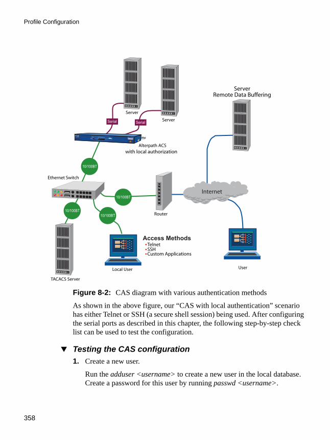
Profile Configuration
358
Figure 8-2: CAS diagram with various authentication methods
As shown in the above figure, our “CAS with local authentication” scenario has either Telnet or SSH (a secure shell session) being used. After configuring the serial ports as described in this chapter, the following step-by-step check list can be used to test the configuration.
Testing the CAS configuration1. Create a new user.
Run the adduser <username> to create a new user in the local database. Create a password for this user by running passwd <username>.
Server
Server
TACACS Server
Router
UserLocal User
Serial Serial
10/100BT
10/100BT
10/100BT10/100BT
Ethernet Switch
Alterpath ACSwith local authorization
Access MethodsTelnetSSHCustom Applications
Internet
ALTERPATHLINUX
INSIDE
A C SAlterPathAdvanced Console Server
TM
ServerRemote Data Buffering

AlterPath ACS Command Reference Guide 359
Examples for configuration testing
2. Confirm physical connection.
Make sure that the physical connection between the ACS and the servers is correct. A cross cable (not the modem cable provided with the product) should be used. Please see Appendix C - Cabling and Hardware Information for pin-out diagrams.
3. Confirm that server is set to same parameters as the ACS.
The ACS has been set for communication at 9600 bps, 8N1. The server must also be configured to communicate on the serial console port with the same parameters.
4. Confirm routing.
Also make sure that the computer is configured to route console data to its serial console port (Console Redirection).
Telnet to the server connected to port 1.
From a server on the LAN (not from the console), try to Telnet to the server connected to the first port of the ACS using the following command:
# telnet 200.200.200.1 7001
For both Telnet and SSH sessions, the servers can be reached by either:
a. Ethernet IP of the ACS and assigned socket port.
or
b. Individual IP assigned to each port.
If everything is configured correctly, a Telnet session should open on the server connected to port 1. If not, check the configuration, follow the steps above again, and check the troubleshooting appendix.
5. Activate the changes.
Now continue on “Activate the changes.” on page 107 through “Save the changes.” on page 108 listed in Chapter , “”.
Note: It is possible to access the serial ports from Microsoft stations using some off-the-shelf packages. Although Cyclades is not liable for those packages, successful tests were done using at least one of them. From the application’s

Profile Configuration
360
viewpoint running on a Microsoft station, the remote serial port works like a regular COM port. All the I/O with the serial device attached to the ACS is done through socket connections opened by these packages and a COM port is emulated to the application.
Terminal ServerThe ACS provides features for out-of-band management via the configuration of terminal ports. All ports can be configured as terminal ports. This allows a terminal user to access a server on the LAN. The terminal can be either a dumb terminal or a terminal emulation program running on a PC.
Figure 8-3: Terminal Server diagram
No authentication is used in the example shown above and rlogin is chosen as the protocol. After configuring the serial ports as described in this chapter, the following step-by-step check list can be used to test the configuration.
1. Create a new user.
Router
Serial
Serial
10/100BT
10/100BT
Ethernet Switch
Internet
VT-100 Terminal
PC Running TerminalApplication (VT-100)
ServerIP Address:
200.200.200.3
> asd f jkl;> xyz mmddyy /md> login:
ALTERPATHLINUX
INSIDE
A C SAlterPathAdvanced Console Server
TM
Alterpath ACS

AlterPath ACS Command Reference Guide 361
Examples for configuration testing
Since authentication was set to none, the ACS will not authenticate the user. However, the Linux Server receiving the connection will. Create a new user on the server called test and provide him with the password test.
2. Confirm that the server is reachable.
From the console, ping 200.200.200.3 to make sure the server is reachable.
3. Check physical connections.
Make sure that the physical connection between the ACS and the terminals is correct. A cross cable (not the modem cable provided with the product) should be used. Please see the Appendix C - Cabling and Hardware Information for pin-out diagrams.
4. Confirm that terminals are set to same parameters as the ACS .
The ACS has been set for communication at 9600 bps, 8N1. The terminals must also be configured with the same parameters.
5. Log onto server with new username and password.
From a terminal connected to the ACS , try to login to the server using the username and password configured in step one.
6. Activate changes.
Now continue on “Activate the changes.” on page 107 through “Save the changes.” on page 108 listed in Chapter , “”.
Dial-in AccessThe ACS can be configured to accommodate out-of-band management. Ports can be configured on the ACS to allow a modem user to access the LAN. Radius authentication is used in this example and ppp is chosen as the protocol on the serial (dial-up) lines. Cyclades recommends that a maximum of two ports be configured for this option.

Profile Configuration
362
Figure 8-4: Ports configured for dial-in access
After configuring the serial ports as described in this Chapter, the following step-by-step check list can be used to test the configuration.
1. Create a new user.
Since Radius authentication was chosen, create a new user on the Radius authentication server called test and provide them with the password test.
2. Confirm that the Radius server is reachable.
From the console, ping 200.200.200.2 to make sure the Radius authentication server is reachable.
3. Confirm physical connections.
Router
Serial Serial
10/100BT
10/100BT
Ethernet Switch
Internet
Modem
Modem
DialupManagement Station
IP Addr: 200.200.200.42
DialupManagement Station
IP Addr: 200.200.200.11
Syslog Servers
IP Address200.200.200.3
IP Address200.200.200.2
ALTERPATHLINUX
INSIDE
A C SAlterPathAdvanced Console Server
TM
Alterpath ACS

AlterPath ACS Command Reference Guide 363
Examples for configuration testing
Make sure that the physical connection between the ACS and the modems is correct. The modem cable provided with the product should be used. Please see Appendix C - Cabling and Hardware Information for pinout diagrams.
4. Confirm modem settings.
5. The ACS has been set for communication at 57600 bps, 8N1. The modems should be programmed to operate at the same speed on the DTE interface.
6. Confirm routing.
Also make sure that the computer is configured to route console data to the serial console port.
7. Perform a test dial-in.
Try to dial in to the ACS from a remote computer using the username and password configured in step one. The computer dialing in must be configured to receive its IP address from the remote access server (the ACS in this case) and to use PAP authentication.
8. Activate changes.
Now continue on “Activate the changes.” on page 107 through “Save the changes.” on page 108 listed in Chapter , “”.

Profile Configuration
364

.................................................................
Chapter 9Chapter 9 - Additional Features and ApplicationsAdditional Features and
Applications
This chapter covers special features or applications that does not fit into any of the previous chapters. The following features will be shown in this chapter:
• Windows 2003 Server Management• IPMI Configuration • Line Printer Daemon• CAS Port Pool• Billing
Windows 2003 Server ManagementEmergency Management Services (EMS) is a new feature in the Windows 2003 Server that allows out-of-band remote management and system recovery tasks. All Emergency Management Services output is accessible using a terminal emulator connected to the server serial port. Besides the normal character mode output sent to the serial console, Windows also sends xml tags. Those tags can be captured and processed by the ACS so that the administrator can automate the actions to be taken.
You can manage the server through the Special Administration Console (SAC), which is the console when connected directly to the Windows Server through Telnet or SSH session.
How it worksTo manage a Windows 2003 server it is necessary to enable the EMS (Emergency Management Services) service using the following syntax:
bootcfg /ems [EDIT|OFF|ON] [/s [computer] [/u [[domain\]user] /p password [/baud baud_rate] [/port communications_port] /id line_number

Additional Features and Applications
366
Where:
Parameters:• EDIT - Allows changes to port and baud rate settings by changing the
redirect=COMx setting in the [bootloader] section. The value of COMx is set to the value of the /port.
• OFF - Disables output to a remote computer. Removes the /redirect switch from the specified line_number and the redirect=comX setting from the [boot loader] section.
• ON - Enables remote output for the specified line_number. Adds a /redi-rect switch to the specified line_number and a redirect=comX setting to the [boot loader] section. The value of comX is set by the /port.
Switches:• /ems - Enables the user to add or change the settings for redirection of the
EMS console to a remote computer. By enabling EMS, you add a "redi-rect=Port#" line to the [boot loader] section of the BOOT.INI file and a /redirect switch to the specified operating system entry line. The EMS fea-ture is enabled only on servers.
• /baud baud_rate - Specifies the baud rate to be used for redirection. Do not use if remotely administered output is being disabled. Valid values are: 9600, 19200, 38400, 57600, 115200
• /id line_number - Specifies the operating system entry line number in the [operating systems] section of the Boot.ini file to which the operating sys-tem load options are added. The first line after the [operating systems] section header is 1.
• /p password - Specifies the password of the user account that is specified in /u.
• /port communications_port - Specifies the COM port to be used for redi-rection. Do not use if remotely administered output is being disabled. BIOSSET get BIOS settings to determine portCOM1COM2COM3COM4

AlterPath ACS Command Reference Guide 367
Windows 2003 Server Management
• /s computer - Specifies the name or IP address of a remote computer (do not use backslashes). The default is the local computer.
• /u [[domain\]user] - Runs the command with the account permissions of the user specified by User or Domain\User. The default is the permissions of the current logged on user on the computer issuing the command.
With the EMS service enabled in the Windows machine, just configure the ACS as CAS profile to manage the Windows 2003 server.
• Windows sends xml tags in the following situations:• During Windows installation, it sends <channel-switch> with the setup
logs.• During boot, it sends the <machine-info> information. • When switching channels, it sends the <channel-switch> information. • During system crash, it sends the <BP> to indicate BreakPoint.
The <machine-info> tag is emitted once by Windows Server during its system boot sequence. This tag is also emitted as part of the <BP> tag. The following elements are included in <machine-info> tag:Table 9-1: machine info tag
Element Description
<guid> It is the GUID that uniquely identifies the server platform. Normally, this is an SMBIOS provided identification. If no such value is available, all 0’s GUID string is used (see sample encoding below).
<name> Is the system name.
<os-build-number> Is a numeric string that identifies a successive Windows Build.

Additional Features and Applications
368
A sample encoding of this tag follows:
The console environment provided by the serial port is called Special Administration Console (SAC). In the SAC command line, each time we enter the “cmd” command we create a channel. A channel is the “Command Prompt” environment, where you can enter the Command Prompt commands
<os-product> Is the name of the Windows Server 2003 product currently running on this server. It is one of the following:
• Windows Server 2003 Datacenter Edition• Windows Server 2003 Embedded• Windows Server 2003 Enterprise Edition• Windows Server 2003
<os-service-pack> Is an alphanumeric string that identifies the most up-to-date service pack installed. If none installed, the string is None.
<os-version> Is the numeric identification of the Windows version currently running.
<processor-architecture>
Is either x86 or IA64, designating the two processor architectures currently supported by Windows Server 2003.
<?xml><machine-info><name>NTHEAD-800I-1</name><guid>00000000-0000-0000-0000-000000000000</guid><processor-architecture>x86</processor-architecture><os-version>5.2</os-version><os-build-number>3735</os-build-number><os-product>Windows Server 2003 Enterprise Edition</os-product><os-service-pack>None</os-service-pack></machine-info>
Figure 9-1: Machine info sample tag
Table 9-1: machine info tag
Element Description
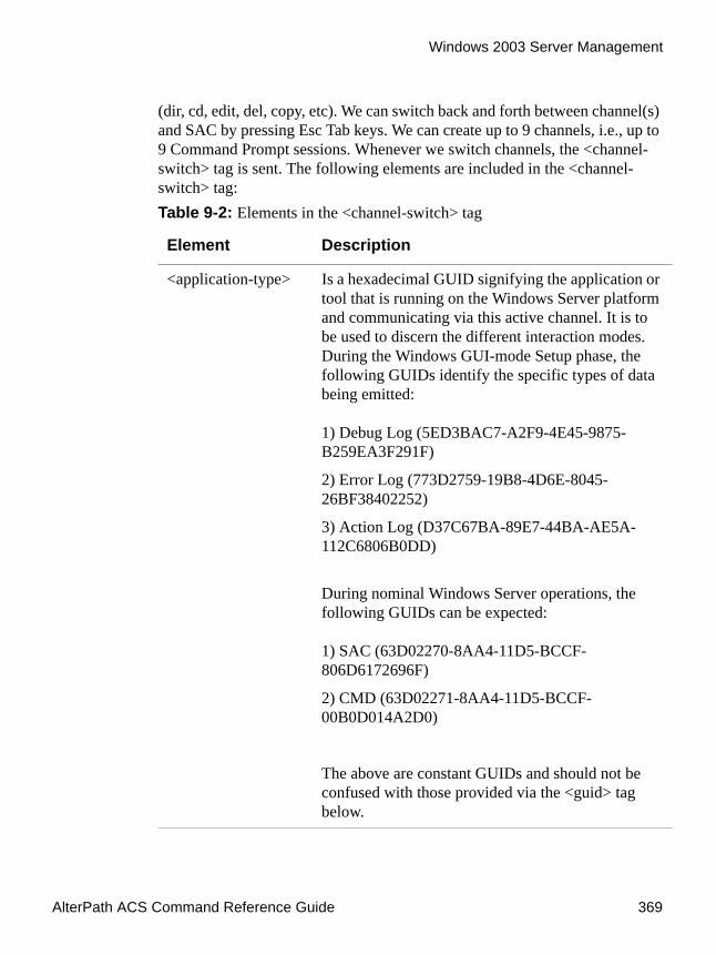
AlterPath ACS Command Reference Guide 369
Windows 2003 Server Management
(dir, cd, edit, del, copy, etc). We can switch back and forth between channel(s) and SAC by pressing Esc Tab keys. We can create up to 9 channels, i.e., up to 9 Command Prompt sessions. Whenever we switch channels, the <channel-switch> tag is sent. The following elements are included in the <channel-switch> tag:Table 9-2: Elements in the <channel-switch> tag
Element Description
<application-type> Is a hexadecimal GUID signifying the application or tool that is running on the Windows Server platform and communicating via this active channel. It is to be used to discern the different interaction modes. During the Windows GUI-mode Setup phase, the following GUIDs identify the specific types of data being emitted:
1) Debug Log (5ED3BAC7-A2F9-4E45-9875-B259EA3F291F)
2) Error Log (773D2759-19B8-4D6E-8045-26BF38402252)
3) Action Log (D37C67BA-89E7-44BA-AE5A-112C6806B0DD)
During nominal Windows Server operations, the following GUIDs can be expected:
1) SAC (63D02270-8AA4-11D5-BCCF-806D6172696F)
2) CMD (63D02271-8AA4-11D5-BCCF-00B0D014A2D0)
The above are constant GUIDs and should not be confused with those provided via the <guid> tag below.

Additional Features and Applications
370
<description> Is the user-friendly name of the active channel. For the GUI-Mode Setup tool they are:
Debug Log (Setup tracing log)
Error Log (Setup errors log)
Action Log (Setup actions log)
For the Windows Server, they are:
SAC (Special Administration Console)
CMD (Command Prompt)
Table 9-2: Elements in the <channel-switch> tag
Element Description

AlterPath ACS Command Reference Guide 371
Windows 2003 Server Management
<guid> Is a hexadecimal GUID that identifies a specific instance of a channel. During a life-span of a Windows Server (between any two system boots), there is a total of 10 channels being allocated. Of those, one can be expected a GUID for each of the following channel types:
1) GUI-Mode Setup Debug Log
2) GUI-Mode Setup Error Log
3) GUI-Mode Setup Action Log
4) SAC
The remaining GUIDs are of the CMD channel type. For example, during Windows setup, there are 3 GUIDs assigned to Setup, 1 to SAC and the remaining 6 to CMD. However, during normal Windows operations, there is 1 GUID assigned to SAC and the remaining 9 to CMD.
These GUIDs are created a new for each instance of channels, and should not be confused with the constant GUIDs provided via the <application-type> tag above.
Table 9-2: Elements in the <channel-switch> tag
Element Description

Additional Features and Applications
372
A sample encoding of the SAC channel tag follows:
<name> Is the system name of the active channel. For the GUI-mode Setup tool, they are the file names where the data is written:
1) Debug Log (setuplog.txt)2) Error Log (setuperr.log)3) Action Log (setupact.log)
For Windows Server, they are:
1) SAC (SAC)2) CMD (Cmdnnnn), where nnnn indicates the corresponding channel number
<type> Is the type of data being emitted on the active channel. Currently, there are two types of data supported:
1) Raw for the 3 GUI-Mode Setup channels
2) VT-UTF8 for the SAC and CMD channels
<channel-switch><name>SAC</name><description>Special Administration Console</description><type>VT-UTF8</type><guid>1aee4cc0-cff3-11d6-9a3d-806e6f6e6963</guid><application-type>63d02270-8aa4-11d5-bccf-806d6172696f</application-type></channel-switch>
Figure 9-2: SAC channel tag example
Table 9-2: Elements in the <channel-switch> tag
Element Description

AlterPath ACS Command Reference Guide 373
Windows 2003 Server Management
A sample encoding of the CMD channel tag follows:
A sample encoding of the GUI-Mode Setup Debug Log channel tag follows:
The <BP> tag is emitted when the Windows Server system halts such that only elements of the kernel are the most recently operating logic.
<channel-switch><name>Cmd0001</name><description>Command Prompt</description><type>VT-UTF8</type><guid>970438d1-12bb-11d7-8a92-505054503030</guid><application-type>63d02271-8aa4-11d5-bccf-00b0d014a2d0</application-type></channel-switch>
Figure 9-3: CMD channel tag example
<channel-switch><name>setuplog.txt</name><description>Setup tracing log</description><type>Raw</type><guid>6f28e904-1298-11d7-b54e-806e6f6e6963</guid><application-type>5ed3bac7-a2f9-4e45-9875-b259ea3f291f</application-type></channel-switch>
Figure 9-4: GUI-Mode setup debug log channel tag example
Table 9-3: <BP> tags description
Element Description
<INSTANCE CLASSNAME=>
Is the type of break point. Currently, there is only one type emitted, i.e. “Blue Screen” which indicates the system was halted prematurely. It is represented by the CLASSNAME=”BLUESCREEN” value.
<machine-info> Is described above.
<PROPERTY NAME=>
Provides additional details, such as error code of the abnormal condition that caused the break point.
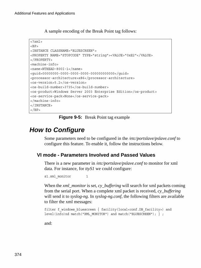
Additional Features and Applications
374
A sample encoding of the Break Point tag follows:
How to ConfigureSome parameters need to be configured in the /etc/portslave/pslave.conf to configure this feature. To enable it, follow the instructions below.
VI mode - Parameters Involved and Passed ValuesThere is a new parameter in /etc/portslave/pslave.conf to monitor for xml data. For instance, for ttyS1 we could configure:s1.xml_monitor 1
When the xml_monitor is set, cy_buffering will search for xml packets coming from the serial port. When a complete xml packet is received, cy_buffering will send it to syslog-ng. In syslog-ng.conf, the following filters are available to filter the xml messages:filter f_windows_bluescreen { facility(local<conf.DB_facility>) andlevel(info)nd match("XML_MONITOR") and match("BLUESCREEN"); } ;
and:
<?xml><BP><INSTANCE CLASSNAME="BLUESCREEN"><PROPERTY NAME="STOPCODE" TYPE="string"><VALUE>"0xE2"</VALUE></PROPERTY><machine-info><name>NTHEAD-800I-1</name><guid>00000000-0000-0000-0000-000000000000</guid><processor-architecture>x86</processor-architecture><os-version>5.2</os-version><os-build-number>3735</os-build-number><os-product>Windows Server 2003 Enterprise Edition</os-product><os-service-pack>None</os-service-pack></machine-info></INSTANCE></BP>
Figure 9-5: Break Point tag example

AlterPath ACS Command Reference Guide 375
Windows 2003 Server Management
filter f_windows_boot { facility(local<conf.DB_facility>) andlevel(info) and match("XML_MONITOR") andnot match("BLUESCREEN") and match("machine-info"); } ;
Once the desired message is filtered, we have to define which actions we would like to take. Syslog-ng will create macros that can give easy access for the administrators to access the xml information. If the administrator uses these macros, syslog-ng replaces the macros by the data received in the xml packet. For instance, the following table shows the macros that are available when filter f_windows_bluescreen is successful and the examples of values that can replace the macros:Table 9-4: f_windows_boot macros
Macro Description Value to replace macro
$<INSTANCE CLASSNAME=>
Reason for the break point. Currently there is only one type, BLUESCREEN.
BLUESCREEN
$<PROPERTY NAME=>
Additional details about break point.
STOPCODE
$<VALUE> Additional details about break point.
0xE2
$<name> Machine name MY_WIN_SERVER
$<guid> GUID that uniquely identifies this server. If no such value is available, all 0’s GUID string is used.
4c4c4544-8e00-4410-8045-80c04f4c4c20
$<processor-architecture>
Processor architecture. It can be either x86 or IA64.
x86
$<os-version> Windows version. 5.2

Additional Features and Applications
376
For the f_windows_boot, the following macros are available:
$<os-product> Which Windows Server product. It can be: Windows Server 2003 Datacenter Edition, Windows Server 2003 Embedded, Windows Server 2003 Enterprise Edition or Windows Server 2003.
Windows Server 2003
$<os-service-pack> Alphanumeric string that identifies the most up-to-date service pack installed. If none installed, the string is None.
None
$<tty> ACS serial port tty or alias name.
S1.ttyS1
Table 9-5: f_windows_boot available macros
Macro Description Value to replace macro
$<name> Machine name MY_WIN_SERVER
$<guid> GUID that uniquely identifies this server. If no such value is available, all 0’s GUID string is used.
4c4c4544-8e00-4410-8045-80c04f4c4c20
Table 9-4: f_windows_boot macros
Macro Description Value to replace macro

AlterPath ACS Command Reference Guide 377
Windows 2003 Server Management
As an example on how we can use above macros, let’s say we want the ACS to send an e-mail to the administrator whenever a crash happens. The e-mail should have the information about the reason of the crash, machine name and
$<processor-architecture>
Processor architecture. It can be either x86 or IA64.
x86
$<os-version> Windows version. 5.2
$<os-build-number> Numeric string that identifies a successive Windows Build.
3763
$<os-product> Which Windows Server product. It can be: Windows Server 2003 Datacenter Edition, Windows Server 2003 Embedded, Windows Server 2003 Enterprise Edition or Windows Server 2003.
Windows Server 2003
$<os-service-pack> Alphanumeric string that identifies the most up-to-date service pack installed. If none installed, the string is None.
None
$<tty> ACS serial port tty or alias name.
S2.server_connected_to_serial2
Table 9-5: f_windows_boot available macros
Macro Description Value to replace macro

Additional Features and Applications
378
windows version information. So we just have to create the following entry in syslog-ng.conf:
And the following entry will activate the win2003mail action when the f_windows_bluescreen filter is successful:source src { unix-stream("/dev/log"); };
log { source(src); filter(f_windows_bluescreen); destination(win2003mail); };
Server Commands The following are the different commands and their descriptions that can be sent to the server.
destination win2003mail { pipe("/dev/cyc_alarm"template("sendmail -t [email protected] -f acs -s \"\Server $<name> crashed\" -m \'\Break Point: $<INSTANCE CLASSNAME=> $<PROPERTY NAME=> $<VALUE>\Server: $<name>\OS: $<os-product>\Build: $<os-build-number> Version: $<os-version>\Service Pack: $<os-service-pack>\Processor: $<processor-architecture>\Server GUID: $<guid>\ACS port: $<tty>\\' -h mail.cyclades.com "));};
Figure 9-6: Send e-mail when crashing example
Table 9-6: Server Commands
Command Set Description
ch Channel management commands.
ch -ci <#> Close a channel by its number.
cmd Create a Command Prompt channel.
ch -si <#> Switch to another channel (from Channel 0).
d Dump the current kernel log.
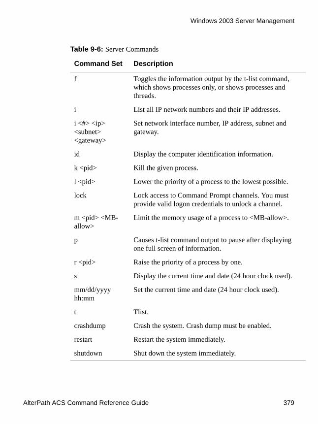
AlterPath ACS Command Reference Guide 379
Windows 2003 Server Management
f Toggles the information output by the t-list command, which shows processes only, or shows processes and threads.
i List all IP network numbers and their IP addresses.
i <#> <ip> <subnet> <gateway>
Set network interface number, IP address, subnet and gateway.
id Display the computer identification information.
k <pid> Kill the given process.
l <pid> Lower the priority of a process to the lowest possible.
lock Lock access to Command Prompt channels. You must provide valid logon credentials to unlock a channel.
m <pid> <MB-allow>
Limit the memory usage of a process to <MB-allow>.
p Causes t-list command output to pause after displaying one full screen of information.
r <pid> Raise the priority of a process by one.
s Display the current time and date (24 hour clock used).
mm/dd/yyyy hh:mm
Set the current time and date (24 hour clock used).
t Tlist.
crashdump Crash the system. Crash dump must be enabled.
restart Restart the system immediately.
shutdown Shut down the system immediately.
Table 9-6: Server Commands
Command Set Description

Additional Features and Applications
380
IPMI ConfigurationIntelligent Platform Management Interface (IPMI) is a service-level protocol and implementation that provides intelligent management to servers (and other system types in the future). IPMI allows server control and monitoring by means of a small "always-on" computer located on the server's motherboard called the Baseboard Management Controller (BMC) that can respond to IPMI commands out-of-band.
The ACS has an implementation of IPMI over LAN which allows the unit to control power (i.e. power cycle) on these servers and also to obtain sensor readings such as CPU temperature(s), fan speed(s) etc.
The IPMI support in the ACS extends it’s functionality so that the unit can be used for serial console access to the servers and also provide power control through the IPMI protocol.
How it worksThis program lets you manage Intelligent Platform Management Interface (IPMI) functions of either the local system or of a remote system, using IPMI V1.5. These functions include printing FRU information, LAN configuration, sensor readings, and remote chassis power control.
You can configure IPMI using the following methods:
• ipmitool – IPMI Configuration• CLI – IPMI [CLI]
IPMI [ipmitool]Utility for controlling IPMI-enabled devices.
Nameipmitool
Usage ipmitool [-hvV] -I interface -H hostname [-L privlvl] [-A authType] [-P password] <expression>

AlterPath ACS Command Reference Guide 381
IPMI Configuration
OptionsUse the following options to configure IPMI.
Expressions1.0 chassis
1.1 status Returns information about the high-level status of the system chassis and main power subsystem
Table 9-7: Options for ipmitool
Option Description Valid Values
-h Get basic usage help from the command line. N/A
-v Increase verbose output level. This option may be specified multiple times to increase the level of debug output.
N/A
-V Display version information. N/A
-I <interface> Selects IPMI interface to use. lan | lanplus | open
-H <address> Remote server address, can be IP address or hostname. This option is required for the LAN interface connection.
N/A
-U <username> Remote username. Default is NULL.
-L <privlvl> Force session privilege level. USER | OPERATOR | ADMIN.
Default is USER
-A <authtype Force session authentication type. PASSWORD | MD5 | MD2
-P <password> Remote server password. Valid password for specified username account.

Additional Features and Applications
382
1.2 poh Returns the Power-On Hours counter
1.3 identify <interval>Controls the front panel identify light. Default is 15. Use 0 to turn off.
1.4 restart_causeQueries the chassis for the cause of the last system restart
1.5 policy Sets the chassis power policy in the event power failure
1.5.1 list – Return supported policies
1.5.2 always-on – Turn on when power is restored
1.5.3 previous – Return to previous state when power is restored
1.5.4 always-off – Stay off after power is restored
1.6 power Performs a chassis control command to view and change the power state
1.6.1 status – Show current chassis power status
1.6.2 on – Power up chassis
1.6.3 off – Power down chassis into soft off
1.6.4 cycle – Provide power off interval of at least 1 second
1.6.5 reset – Perform a hard reset
1.7 sensor
1.7.1 list – Lists sensors and thresholds in a wide table format
IPMI [CLI]You can configure IPMI using the ipmi keyword and the following attributes in CLI mode:
1.0 config – enter into configuration state
1.1 ipmi – configure IPMI devices
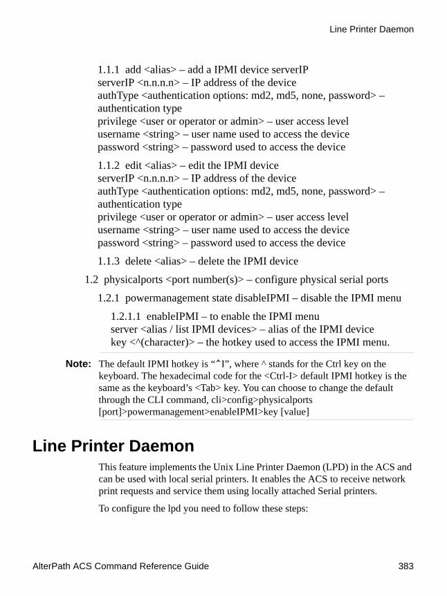
AlterPath ACS Command Reference Guide 383
Line Printer Daemon
1.1.1 add <alias> – add a IPMI device serverIP serverIP <n.n.n.n> – IP address of the deviceauthType <authentication options: md2, md5, none, password> – authentication typeprivilege <user or operator or admin> – user access levelusername <string> – user name used to access the devicepassword <string> – password used to access the device
1.1.2 edit <alias> – edit the IPMI deviceserverIP <n.n.n.n> – IP address of the deviceauthType <authentication options: md2, md5, none, password> – authentication typeprivilege <user or operator or admin> – user access levelusername <string> – user name used to access the devicepassword <string> – password used to access the device
1.1.3 delete <alias> – delete the IPMI device
1.2 physicalports <port number(s)> – configure physical serial ports
1.2.1 powermanagement state disableIPMI – disable the IPMI menu
1.2.1.1 enableIPMI – to enable the IPMI menuserver <alias / list IPMI devices> – alias of the IPMI device key <^(character)> – the hotkey used to access the IPMI menu.
Note: The default IPMI hotkey is “^I”, where ^ stands for the Ctrl key on the keyboard. The hexadecimal code for the <Ctrl-I> default IPMI hotkey is the same as the keyboard’s <Tab> key. You can choose to change the default through the CLI command, cli>config>physicalports [port]>powermanagement>enableIPMI>key [value]
Line Printer DaemonThis feature implements the Unix Line Printer Daemon (LPD) in the ACS and can be used with local serial printers. It enables the ACS to receive network print requests and service them using locally attached Serial printers.
To configure the lpd you need to follow these steps:

Additional Features and Applications
384
1. Setup the serial port where the serial printer is connected.
Edit the /etc/portslave/pslave.conf file (PortSlave configuration) and set the protocol of the serial port as "lpd".
Example: s2.protocol lpd
a. Create the printer definition.
Edit the /etc/printcap file and configure the printer. The spool directory is created automatically by cy_ras process. Example:
b. Enable the printer daemon.
Edit the file /etc/lpd.sh and change the option ENABLE to YES
c. Allow clients to use the service.
Edit the file /etc/hosts.lpd and include the hosts name that you allow to user the ACS printers.
#comment# primary printer name and alias# lp |lp2| serial printer on port ttyS2 #suppress header and/or banner page# :sh: #spool directory - the name is fixed as lp_ttySnn when nn is the#serial port number# :sd=/var/spool/lpd/lp_ttyS2: #printer device # :lp=/dev/ttyS2: #log filename # :lf=/var/log/lpd.log: #set serial port speed as 115.200 bps # :br115200:lp|lp2| serial printer on port ttyS2:\ :sh: \ :sd=/var/spool/lpd/lp_ttyS2: \ :lp=/dev/ttyS2: \ :lf=/var/log/lpd.log:
Figure 9-7: /etc/printcap file

AlterPath ACS Command Reference Guide 385
CAS Port Pool
Note: The lpd needs to translate the IP address of the request message to the host name, check your resolv.conf file.
d. Restart the processes, use the command "runconf" and "daemon.sh".
e. Save the configuration in flash, use the command "saveconf".
In your Linux client machine type the following command to check the ACS configuration is OK:
# lpr -P lp@<ACS IP address> <file that you want printer> <enter>
CAS Port PoolThis feature is available for the ACS 2.1.4 onward. CAS Port Pooling allows you to access a free serial port from a pool in addition to the original feature where you could access a specific serial port. When you access a serial port through the pool the features sniff session and multiple sessions are not available. This feature is available for serial ports configured as CAS profile only.
You can define more than one pool of serial ports. Each serial port can only belong to ONE pool.The pool is uniquely identified by a four parameter scheme:
• protocol, • pool_ipno, • pool_alias, and • pool_socket_port
The three new parameters: pool_ipno, pool_alias, and pool_socket_port have the same meaning as ipno, alias, and socket_port respectively. Ports belonging to the same pool MUST be configured with the same value in these fields.
It is strongly recommended that you configure the same values in all parameters related to authentication for all serial ports belonging to a pool. Some of the authentication parameters are users, admin_users, and authtype.
You can access the serial ports from a pool with the same commands you use today to access a specific serial port. You just need to use pool_ipno,

Additional Features and Applications
386
pool_alias, or pool_socket_port instead ipno, alias, or socket_port respectively in the SSH/Telnet command.
When a connection request arrives using one of pool_ipno, pool_alias, or pool_socket_port the ACS will look for the first free serial port from the pool and that port will be assigned to connection. If there is no serial port free in the pool the connection is just dropped.
How to Configure itThe configuration for this feature is made directly in the /etc/portslave/pslave.conf file. Don’t forget to activate and save the configuration by issuing the commands runconf and saveconf respectively.
VI methodFollowing is an example of serial port pool configuration:

AlterPath ACS Command Reference Guide 387
CAS Port Pool
In the example above, there are two pools:
# Serial port pool: pool-1#s1.tty ttyS1s1.protocol socket_servers1.socket_port 7001 // TCP port # for specific allocation s1.pool_socket_port 3000 // TCP port # for the pool s1.ipno 10.0.0.1 // IP address for specific allocation s1.pool_ipno 10.1.0.1 // IP address for the pool s1.alias serial-1 // alias for specific allocation s1.pool_alias pool-1 // alias for the pool s2.tty ttyS2s2.protocol socket_servers2.socket_port 7002 // TCP port # for specific allocation s2.pool_socket_port 3000 // TCP port # for the pool s2.ipno 10.0.0.2 // IP address for specific allocation s2.pool_ipno 10.1.0.1 // IP address for the pool s2.alias serial-2 // alias for specific allocation s2.pool_alias pool-1 // alias for the pool ## Serial port pool: pool-2#s3.tty ttyS3s3.protocol socket_sshs3.socket_port 7003 // TCP port # for specific allocation s3.pool_socket_port 4000 // TCP port # for the pool s3.ipno 10.0.0.3 // IP address for specific allocation s3.pool_ipno 10.2.0.1 // IP address for the pool s3.alias serial-3 // alias for specific allocation s3.pool_alias pool-2 // alias for the pool s4.tty ttyS4s4.protocol socket_sshs4.socket_port 7004 // TCP port # for specific allocation s4.pool_socket_port 4000 // TCP port # for the pool s4.ipno 10.0.0.4 // IP address for specific allocation s4.pool_ipno 10.2.0.1 // IP address for the pool s4.alias serial-4 // alias for specific allocation s4.pool_alias pool-2 // alias for the pool
Figure 9-8: Part of the /etc/portslave/pslave.conf file

Additional Features and Applications
388
• pool-1 (identified by Protocol socket_server, TCP port #3000, IP 10.1.0.1, and alias pool-1)
• pool-2 (identified by Protocol socket_ssh, TCP port #4000, IP 10.2.0.1, and alias pool-2)
The serial ports ttyS1 and ttyS2 belong to the pool-1. The serial ports ttyS3 and ttyS4 belong to the pool-2.
You can access specifically serial port ttyS1 by using TCP port 7001, IP address 10.0.0.1 or alias serial-1. If the ttyS1 is being used by somebody else the connection will be dropped if the user is not a admin_user. Alternately, you can access ttyS1 through pool (if it's free) using TCP port 3000, IP 10.1.0.1 or alias pool-1. If it is not free ttyS2 will be automatically allocated. Additionally, if ttyS2 is not free, the connection will be dropped.
BillingAll ACS family of products can be used as an intermediate buffer to collect serial data (like billing tickets from a PBX), making them available for a posterior file transfer. Different ports can have simultaneous "billing sessions".
General Feature DescriptionACS reads the serial port and saves the information to Ramdisk files, which is limited to the maximum number of records per file. After the files are closed, they are available for transfer at /var/run/DB, or an alternate path defined by the user in the pslave.conf file. See Table 8-2 on page 332 for additional details on billing file configuration.
How to configure itThe configuration for this feature is made in the /etc/portslave/plsave.conf file. Billing parameters can be configured using the VI method and by using the wizard.
VI method - Passed Values and Involved ParametersOpen the /etc/portslave/pslave.conf file and configure the following parameters according to your application:
• all.protocol - billing
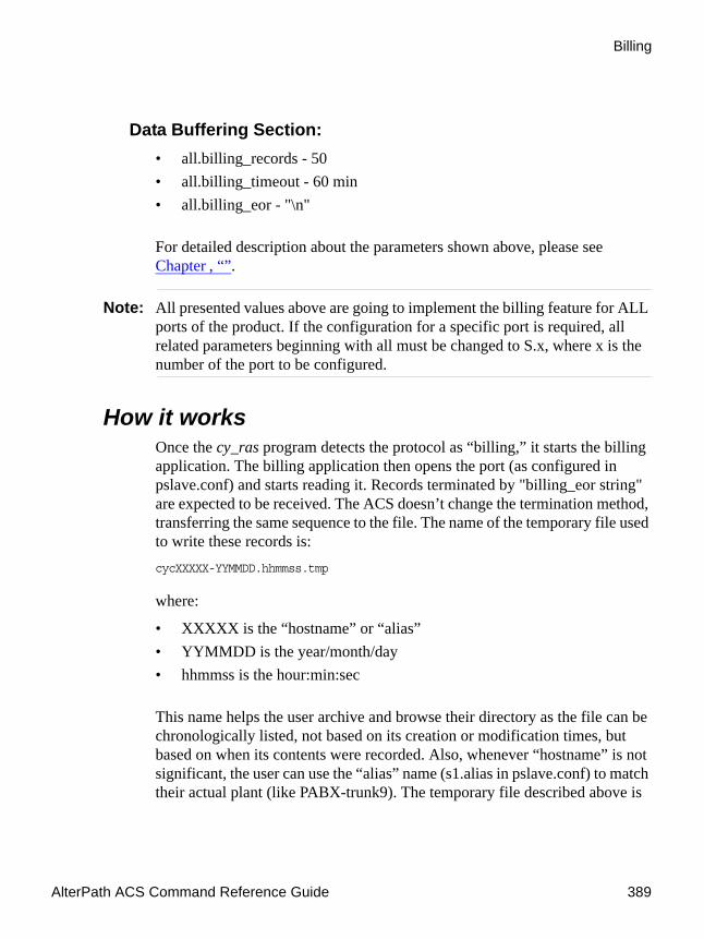
AlterPath ACS Command Reference Guide 389
Billing
Data Buffering Section:• all.billing_records - 50• all.billing_timeout - 60 min• all.billing_eor - "\n"
For detailed description about the parameters shown above, please see Chapter , “”.
Note: All presented values above are going to implement the billing feature for ALL ports of the product. If the configuration for a specific port is required, all related parameters beginning with all must be changed to S.x, where x is the number of the port to be configured.
How it worksOnce the cy_ras program detects the protocol as “billing,” it starts the billing application. The billing application then opens the port (as configured in pslave.conf) and starts reading it. Records terminated by "billing_eor string" are expected to be received. The ACS doesn’t change the termination method, transferring the same sequence to the file. The name of the temporary file used to write these records is:cycXXXXX-YYMMDD.hhmmss.tmp
where:
• XXXXX is the “hostname” or “alias”• YYMMDD is the year/month/day• hhmmss is the hour:min:sec
This name helps the user archive and browse their directory as the file can be chronologically listed, not based on its creation or modification times, but based on when its contents were recorded. Also, whenever “hostname” is not significant, the user can use the “alias” name (s1.alias in pslave.conf) to match their actual plant (like PABX-trunk9). The temporary file described above is

Additional Features and Applications
390
closed and renamed to cycXXXXX-YYMMDD.hhmmss.txt and a new temporary file is opened when:
• the maximum number of records specified by “billing_records” is reached• the lifetime specified by “billing_timeout” finishesIf no record is received within a file lifetime period, no file will be actually saved.
Note: A zero-value for “billing_records” stops the application and a zero-value for “billing_timeout” means no timeout is desired and so the file will only be closed after “billing_records” are received.
Disk Space IssueIt is important to note that there is a protection against disk space problems. If you configure flow control to “hardware” for the serial port (all.flow = hard in the pslave.conf file), the application monitors the available disk space and if it is less than 100 Kb, the serial interface deactivates “RTS” signal on the RS-232. “RTS” is reactivated once the disk free space is greater than 120 Kb.
Billing WizardThis feature improves the billing application by using a script and automating the upload of the billing records files from the ACS to a remote server using FTP or SSH.
How to ConfigureThe config_billing.sh script is used to configure a serial port for billing protocol, and configure upload scripts using FTP or SSH. The config_billing.sh script configures the files /etc/billing_up.conf /etc/billing_crontab, and /etc/crontab_files.
To configure a port for billing1. Execute the config_billing.sh and enter the parameters to be configured.Usage: config_billing.sh [X] [options]

AlterPath ACS Command Reference Guide 391
Billing
where:
X is the port number to be configured[options] are:
-s speed-d data size-b stopbit-p parity-r billing records-e billing EOR (this parameter must be on " ", like "\n")-D billing dir-S serverFarm-t date-T timeout-i ip-n netmask-R route-u upload
Any parameter that is not specified will remain unchanged. The following parameters are configured by default for billing.
sxx.authtype nonesxx.protocol billingsxx.flow nonesxx.dcd 0sxx.sniff_mode no
Select the -u option to execute the billing_upload_files.sh script. The script presents the following sequential menu where the upload options can be configured.[root@CAS etc]# billing_upload_files.shTransfer Mode (ftp or scp)[ftp]:Local Directory[/var/run/DB]:Remote server IP [192.168.1.101]:Remote directory [/var/billing]:User [billing]:Password [billing]:Upload Interval in minutes []:

Additional Features and Applications
392
Note: Instead of running the -u option, the /etc/billing_up.conf can be configured manually to change the parameters. If the parameters remains unchanged the default parameters are uploaded.
Note: If the “scp” transfer mode is selected and there is no defined authentication, the script generates a key and uploads to the server. The key must be stored on the server with the appropriate configuration.
2. Execute saveconf
3. Restart ACS to activate the options related to billing upload.
.................................................................
Appendix AAppendix A - New User Background InformationNew User Background Information
This appendix has the objective to introduce new users with commands, file structure, processes, programs and other features used by the AlterPath ACS operating system. This appendix includes the following sections:
• User and Passwords• Who is logged in and what they are doing?• Linux File Structure• Basic File Manipulation• The VI Editor• The Routing Table• Secure Shell Session• The Process Table• TS Menu Script
User and PasswordsA username and password is necessary to log in to the ACS. The user “root” is predefined with a password “tslinux”. The password should be changed as soon as possible to avoid unauthorized access.
To change the password for the “root” , enter the following command.# passwd
To create a regular user (without root privileges), enter the following command:# adduser user_name
To change the password for a regular user, enter the following command.# passwd user_name

New User Background Information
394
To log out, type “logout” at the command prompt.
A regular user who wants to run the command su - to become a superuser needs to:
1. Make sure the group wheel is already created.
An administrator with root access would run the following command: # addgroup wheel
In file /etc/group there should be a line with at least the following:wheel::zzz:
2. Belong to the group wheel.
An administrator with root access would edit /etc/group file and insert the username at the end of the wheel line. For example, for user steve, the administrator would edit the line in file/etc/group:
wheel::zzz:
to add "steve" at the end like this:wheel::zzz:steve
Who is logged in and what they are doingThe command “w” displays information about the users currently on the machine, and their processes. It calls two commands: w_ori and w_cas. The w_ori is the new name of the original command “w” and the w_cas shows the CAS sessions information.
The header of w_ori shows, in this order: the current time, how long the system has been running, how many users are currently logged on (excluded the CAS users), and the system load averages for the past 1, 5, and 15 minutes.
The following entries are displayed for each user (excluded the CAS users): login name, the tty name, the remote host, login time, idle time, JCPU time (it is the time used by all processes attached to the tty), PCPU time (it is the time used by the current process, named in the “what” field), and the command line of their current process.

AlterPath ACS Command Reference Guide 395
Linux File Structure
The header of w_cas shows how many CAS users are currently logged on. The following entries are displayed for each CAS user: login name, the tty name, the remote host and remote port, login time, the process ID and the command line of the current process.
Linux File StructureThe Linux file system is organized hierarchically, with the base (or root) directory represented by the symbol “/”. All folders and files are nested within each other below this base directory. The directories located just below the base directory are:
• /home - Contains the work directories of system users.• /bin - Contains applications and utilities used during system initialization.• /dev - Contains files for devices and ports.• /etc - Contains configuration files specific to the operating system.• /lib - Contains shared libraries.• /proc - Contains process information.• /mnt - Contains information about mounted disks.• /opt - Location where packages not supplied with the operating system are
stored.• /tmp - Location where temporary files are stored.• /usr - Contains most of the operating system files.
Basic File ManipulationThe basic file manipulation commands allow the user to copy, delete, and move files and create and delete directories.
cp file_name destination
a) cp text.txt /tmp
b) cp /chap/robo.php ./excess.php
Copies the file indicated by file_name to the path indicated by destination. a) Copies the file text.txt in the current directory to the tmp directory.
b) Copies the file robo.php in the chap directory to the current directory and renames the copy excess.php.

New User Background Information
396
Other commands allow the user to change directories and see the contents of a directory.
Shortcuts:
rm file_name Removes the file indicated by file_name.
mv file_name destination Moves the file indicated by file_name to the path indicated by destination.
mkdir directory_name
a) mkdir spot
b) mkdir /tmp/snuggles
Creates a directory named directory_name.
a) creates the directory spot in the current directory.
b) creates the directory snuggles in the directory tmp.
rmdir directory_name Removes the directory indicated by directory_name.
pwd Supplies the name of the current directory. While logged in, the user is always “in” a directory. The default initial directory is the user's home directory: /home/<username>
ls [options] directory_name
Lists the files and directories within directory_name. Some useful options are -l for more detailed output and -a which shows hidden system files.
cd directory_name Changes the directory to the one specified.
cat file_name Prints the contents of file_name to the screen.
. (one dot) Represents the current directory.
.. (two dots) Represents one directory above the current directory (i.e. one directory closer to the base directory).

AlterPath ACS Command Reference Guide 397
The VI Editor
The VI EditorTo edit a file using the VI editor, type:vi file_name
Vi is a three-state line editor: it has a command mode, a line mode and an editing mode. If in doubt as to which mode you are in, press the <ESC> key which will bring you to the command mode.
When you enter the VI program, you are automatically in command mode. To navigate to the part of the file you wish to edit, use the following keys:
Having arrived at the location where text should be changed, use these commands to modify the text (note commands “i” and “o” will move you into
Table A-1: vi modes
Mode What is done there How to get there
Command mode
Navigation within the open file.
Press the <ESC> key.
Editing mode Text editing. See list of editing commands below.
Line mode File saving, opening, etc. Exiting from vi.
From the command mode, type “:” (colon).
Table A-2: vi navigation commands
h Moves the cursor to the left (left arrow).
j Moves the cursor to the next line (down arrow).
k Moves the cursor to the previous line (up arrow).
l Moves the cursor to the right (right arrow).

New User Background Information
398
edit mode and everything typed will be taken literally until you press the <ESC> key to return to the command mode).
After you have finished modifying a file, enter line mode (by typing “:” from command mode) and use one of the following commands:
The Routing TableThe ACS has a static routing table that can be seen using the commands:# route
or# netstat -rn
The file /etc/network/st_routes is the ACS’s method for configuring static routes. Routes should be added to the file (which is a script run when the ACS is initialized) or at the prompt (for temporary routes) using the following syntax:
Table A-3: vi file modification commands
i Inserts text before the cursor position (everything to the right of the cursor is shifted right).
o Creates a new line below the current line and insert text (all lines are shifted down).
dd Removes the entire current line.
x Deletes the letter at the cursor position.
Table A-4: vi line mode commands
w Saves the file (w is for write).
wq Saves and closes the file (q is for quit).
q! Closes the file without saving.
w file Saves the file with the name <file>.
e file Opens the file named <file>.

AlterPath ACS Command Reference Guide 399
Secure Shell Session
route [add|del] [-net|-host] target netmask nt_msk [gw gt_way] interf
• [add|del] - One of these tags must be present. Routes can be either added or deleted.
• [-net|-host] - Net is for routes to a network and -host is for routes to a single host.
• target - Target is the IP address of the destination host or network.• netmask and nt_msk - The tag netmask and nt_mask are necessary only
when subnetting is used, otherwise, a mask appropriate to the target is assumed. nt_msk must be specified in dot notation.
• gw and gt_way - Specifies a gateway, when applicable. gt_way is the IP address or hostname of the gateway.
• interf - The interface to use for this route. Must be specified if a gateway is not. When a gateway is specified, the operating system determines which interface is to be used.
Secure Shell SessionSSH is a command interface and protocol often used by network administrators to connect securely to a remote computer. SSH replaces its non-secure counterpart rsh and rlogin. There are two versions of the protocol, SSHv1 and SSHv2. The ACS offers both. The command to start an SSH client session from a UNIX workstation is:ssh -t <user>@<hostname>
where
• <user> = <username>:ttySnn or<username>:socket_port or<username>:ip_addr or<username>:alias
Note: “alias” is a physical port alias. It can be configured in the file pslave.conf.
An example:

New User Background Information
400
username: cycladesmycompanyACS16 IP address:192.168.160.1host name: acs16servername for port 1:file_server
ttyS1 is addressed by IP 10.0.0.1 or socket port 7001. The various ways to access the server connected to the port are:ssh -t cyclades:ttyS1@acs16ssh -t cyclades:7001@acs16ssh -t cyclades:10.0.0.1@acs16ssh -t cyclades:file_server@acs16ssh -t -l cyclades:10.0.0.1 acs16ssh -t -l cyclades:7001 acs16
For OpenSSH clients, version 4.1p1 or later SSHv2 is the default. In that case, the -1 flag is used for SSHv1.# ssh -t cyclades:7001@acs16
# ssh -t -2 cyclades:7001@acs16
# ssh -t cyclades:7001@acs16
(openssh 4.1p1 or later - ACS version 2.1.0 or later -> SSHv2 will be used)# ssh -t -1 cyclades:7001@acs16
(OpenSSH 4.1p1 or later - ACS version 2.1.0 or later -> SSHv1 will be used)
To log in to a port that does not require authentication, the username is not necessary:ssh -t -2 :ttyS1@acs16
Note: In this case, the file sshd_config must be changed in the following way:PermitRootLogin YesPermitEmptyPassword Yes
The Session Channel Break ExtensionThis feature was introduced in ACS version 2.1.3. It is a method of sending a break signal during a SSHv2 terminal session. The implementation is defined by “Session Channel Break Extension: draft-ietf-secsh-break-00.txt” (IETF Internet-Draft document).

AlterPath ACS Command Reference Guide 401
Secure Shell Session
In the previous versions of ACS there was one break length measured in milliseconds. The current version of ACS supports the parameter <all/Sx>.break_interval, which is used with all.break_sequence (<all/Sxx>.break_sequence). This has improved the SSH-break implementation.
The SSHv2-client receives a command (“<ssh escape char>B" or "<break_sequence>”, for example:"~break" and sends one "break request" to SSH-server. The SSH-server receives the "break request" and sends a break command to the serial port. The SSH client can then send the break duration (break interval) so the user can configure this value using the command line (" -B <break interval in milliseconds> ", for example: "ssh -l <user>:<port> <ACS IP Server > -B <breakinterval in milliseconds>").
How it works in SSH Server (all.protocol is socket_ssh)The serial driver accepts the parameter break interval in the break command. If the SSHv2, then the server accepts and treats the "break request" sent by the client. The "break request" defines the break-length in milliseconds. The server sends a break command with the break-length to the serial driver to perform the break in the serial port. If the parameter all.break_sequence is configured and the server finds the sequence in the data received from client, the server sends a break command with all.break_interval to serial driver.
How it works in SSH Client The SSH client has an option " -B <break interval in milliseconds> ", for example, "ssh -l <user>:<port> <ACS IP Server > -B <breakinterval in milliseconds>".
When the user types "<ssh-escape>B" (where ssh-escape is "~") or "<break_sequence>" the client sends a "break request" to ssh-server. When ACS calls the ssh-client automatically, it uses the parameter all.break_interval to calls the ssh-2 client.

New User Background Information
402
Configuring the Session Channel Break Extension in SSH Server
1. Configure the parameter break_interval, and break_sequence in /etc/portslave/pslave.conf.
This can be done by the admin using the VI editor. For example,all.break_interval 500all.break_sequence ~break
Enter the following commands.#runconf#saveconf
2. Send a BREAK by typing <ENTER> + the break sequence configured + the key corresponding to a given command (from SysRq). If you send an invalid command key, it will simply display the help (the SysRq HELP).
For example,
a. Establish an SSH connection to the ACS console port.ssh -l <user>:<socket_port> <ACS_TS_IP>
b. You can get the kernel's attention by sending a BREAK signal.<ENTER> + ~break
The Result will be:SysRq : HELP : loglevel0-8 reBoot Crash tErm kIll saK showMem Nice powerOff showPc unRaw Sync showTasks Unmount
or if you type:<ENTER> + ~breakp
The Result will be:SysRq : Show Regs
Pid: 0, comm: swapperEIP: 0060:[<c010103b>] CPU: 0EIP is at default_idle+0x23/0x29EFLAGS: 00000246 Not tainted (2.6.10-1.771_FC2)EAX: 00000000 EBX: 00010809 ECX: de0f3000 EDX: 0baf3110

AlterPath ACS Command Reference Guide 403
The Process Table
ESI: 00099100 EDI: c03dc120 EBP: 00461007 DS: 007b ES: 007bCR0: 8005003b CR2: b7ff2000 CR3: 19b6a000 CR4: 000006d0[<c010108f>] cpu_idle+0x1f/0x34
The Process TableThe process table shows which processes are running. Type ps -a to see a table similar to the following.
To restart the cy_ras process use its process ID or execute the command:# runconf
This executes the ps command, searches for the cy_ras process id, then sends the signal hup to the process, all in one step. Never kill cy_ras with the signals -9 or SIGKILL.
TS Menu ScriptThe ts_menu script can be used to avoid typing long Telnet or SSH commands. It presents a short menu with the names of the servers connected to the serial ports of the ACS. The server is selected by its corresponding number. ts_menu must be executed from a local session: via console, Telnet, SSH, dumb terminal connected to a serial port, etc. Only ports configured for console access (protocols socket_server, socket_ssh, or socket_server_ssh) will be presented. To start having familiarity with this application, run ts_menu - h:# ts_menu -h
Table A-5: Process Table
PID UID VmSize State Command
1 root 592 S /sbin/inetd
31 root 928 S /sbin/inetd
32 root 584 S /sbin/cy_ras
36 root 1148 S /sbin/cy_wdt_led wdt led
154 root 808 R /ps -a

New User Background Information
404
USAGE: ts_menu options {<console port>}-p : Display Tcp port-P : Use the TCP port instead just IP-i : Display Local Ip assigned to the serial port-u <name> : Username to be used in ssh/telnet command-U : Always ask for an username-e <[^]char> : Escape char used by telnet or ssh-l[c] : Sorted list ports (c option sort by console server) and exit-auth : Interactive authentication-ro : Read Only mode-s : Show sorted ports<console port> : Connect direct to [console port]
Below is an example on how TS Menu can be used:# ts_menu
Master and Slaves Console Server Connection Menu
1 TSJen8002 test.Cyclades.com3 az84.Cyclades.com4 64.186.190.855 az85.Cyclades.com
Type 'q' to quit, a valid option [1-5], or anything else to refresh:
By selecting 1 in this example, the user will access the local serial ports on that ACS. If the user selects 2 through 5, remote serial ports will be accessed. This is used when there is clustering (one ACS master box and one or more ACS slave boxes).
If the user selects 1, the following screen is displayed:Serial Console Server Connection Menu for your Master Terminal Server
1 ttyS12 ttyS23 s3alias
Type 'q' to quit, 'b' to return to previous menu, a valid option[1-3], or anything else to refresh:
Options 1 to 3 in this case are serial ports configured to work as a CAS profile. Serial port 3 is presented as an alias name (s3alias). When no name is configured in pslave.conf, ttyS<N> is used instead. Once the serial port is selected, the username and password for that port (in case there is a per-user

AlterPath ACS Command Reference Guide 405
TS Menu Script
access to the port and -U is passed as parameter) will be presented, and access is granted.
To access remote serial ports, the presentation will follow a similar approach to the one used for local serial ports.
The ts_menu script has the following line options:
-p : Displays Ethernet IP Address and TCP port instead of server names.ACS: Serial Console Server Connection menu
1 209.81.55.79 70012 209.81.55.79 70023 209.81.55.79 70034 209.81.55.79 70045 209.81.55.79 70056 209.81.55.79 7006
Type 'q' to quit, a valid option [1-6], or anything else to refresh :
-i : Displays Local IP assigned to the serial port instead of server names.ACS: Serial Console Server Connection menu
1 192.168.1.1012 192.168.1.1023 192.168.1.103 4 192.168.1.1045 192.168.1.1056 192.168.1.106
Type 'q' to quit, a valid option [1-6], or anything else to refresh :
-u <name> : Username to be used in the SSH/Telnet command. The default username is that used to log onto the ACS.
-h : Lists script options.

New User Background Information
406

.................................................................
Appendix BAppendix B - Upgrades and TroubleshootingUpgrades and Troubleshooting
This appendix has the objective to cover the most common problems that users faces when using the ACS . This appendix will also show the necessary steps to upgrade the firmware of the ACS unit and how to correctly interpret the CPU LED status.
UpgradesUsers should upgrade the ACS whenever there is a bug fix or new features that they would like to have. Below are the six files added by Cyclades to the standard Linux files in the /mnt/flash directory when an upgrade is needed. They are:
• boot_alt - alternate boot code• boot_conf - active boot code• boot_ori - original boot code• config.tgz - ACS configuration information• zImage - Linux kernel image
The Upgrade ProcessTo upgrade the ACS , follow these steps:
1. Log in to the ACS as root.
Provide the root password if requested.
a. Go to the /mnt/flash directory using the following command:cd /mnt/flash
b. FTP to the host where the new firmware is located.
Log in using your username and password. Go to the directory where the firmware is located. Select binary transfer and “get” the firmware file.

Upgrades and Troubleshooting
408
# ftp
ftp> open serverftp> user adminftp> Password: adminpwftp> cd /tftpbootftp> binftp> get zImage.134 zImageftp> quit
Note: The destination file name in the /mnt/flash directory must be zImage. Example (hostname = server; directory = /tftpboot; username= admin; password = adminpw; firmware filename on that server = zImage.134).
Note: Due to space limitations, the new zImage file may not be downloaded with a different name, then renamed. The ACS searches for a file named zImage when booting and there is no room in flash for two zImage files.
c. Verify zImage.
To make sure the downloaded file is not corrupted and to verify the zImage saved in flash run the following command:
md5sum /mnt/flash/zImage
The system responds with a message similar to the following:5bcc7d9b3c61502b5c9269cbecd20317 /mnt/flash/zImage
d. Check the system’s response against the “.md5” zImage text file on the tftp server.
For example, the zImage zvmppccs.1005_qa.acs-k26.md5 text file contains the following information:
5bcc7d9b3c61502b5c9269cbecd20317 /tftpboot/zvmppccs.1005_qa.acs-k26
If the alphanuemeric string matches the downloaded file is not corrupted.
e. Issue the command reboot.# reboot

AlterPath ACS Command Reference Guide 409
Upgrades
f. Confirm that the new Linux kernel has taken over.
After rebooting, the new Linux kernel will take over. This can be confirmed by typing the following to see the Linux kernel version:
# cat /proc/version
CLI Method - Firmware UpgradeTo upgrade the ACS firmware follow the steps below:
1.Open the CLI interface by issuing the command:# CLI
2. Upgrade the firmware.
All you need to know to upgrade the ACS’s firmware is the remote IP address of the FTP server and the path of the image file in the remote server.
For the example given we will use:
• FTP Server: 192.168.100.111
• Path: /images/zImage
• User: john
• Password: john1234cli> administration upgradefw ftpsite 192.168.100.111 username john password john1234 filepathname /images/zImage checksum no
3. Return to the main menu by issuing the commandcli>return
4. Activate the configuration.cli>config runconfig
5. Save the configuration.cli> config savetoflash
6. Exit the CLI mode.

Upgrades and Troubleshooting
410
To exit the CLI mode and return to ACS’s shell, type the following command:
cli> quit
7. Reboot the unit (shell prompt).
To make the changes effective, reboot the unit by issuing the command (in the shell prompt):
#reboot
8. Testing the configuration (shell prompt).
To check if the version of the installed image, run the command:# cat /proc/version
TroubleshootingFlash Memory Loss
If the contents of flash memory are lost after an upgrade, please follow the instructions below to restore your system:
1. Turn the ACS OFF, then back ON.
2. Using the console, wait for the self test messages.
If you get no boot messages, verify that you have the correct setting, otherwise press “s” immediately after powering ON to skip an alternate boot
code. ACS will boot using its original boot code.
3. During the self test, press <Esc> after the Ethernet test.Testing Ethernet .........................
4. When the Watch Dog Timer prompt appears, press <Enter>.Watchdog timer ((A)ctive or (I)nactive) [I] :
5. Choose the option Network Boot when asked.Firmware boot from ((F)lash or (N)etwork) [N] :

AlterPath ACS Command Reference Guide 411
Troubleshooting
6. Select the TFTP option instead of BOOTP. The host must be running TFTPD and the new zImage file must be located in the proper directory. For example, /tftpboot for Linux.
Boot type ((B)ootp,(T)ftp or Bot(H)) [H] :
7. Enter the filename of the zImage file on the host.Boot File Name [zvmppccs.1004_qa.acs-k26] :
8. Enter the IP address of the Ethernet interface.IP address assigned to Ethernet interface [192.168.48.11] :
9. Enter the IP address of the host where the new zImage file is located.Server's IP address [192.168.49.127] :
10. Accept the default MAC address by pressing <Enter>. MAC address assigned to Ethernet [00:60:2E:01:6B:61] :
11. When the “Fast Ethernet” prompt appears, press <Enter>.Fast Ethernet ((A)uto Neg, 100 (B)tH, 100 Bt(F), 10 B(t)F, 10 Bt(H)) [A] :
ACS should begin to boot off the network and the new image will be downloaded and begin running in RAM. At this point, follow the upgrade process in section B.1 above to save the new zImage file into flash again.
Note: Possible causes for the loss of flash memory may include: downloaded wrong zImage file, downloaded as ASCII instead of binary; problems with flash memory.
If the ACS booted properly, the interfaces can be verified using ifconfig and ping. If ping does not work, check the routing table using the command route. Of course, all this should be tried after checking that the cables are connected correctly.
The file /etc/config_files contains a list of files that are affected by saveconf and restoreconf commands. At the command prompt issue the command cat /etc/config_files to see the list of files that are available in the flash and are loaded into the RAMDisk at the boot time.
Upgrades and Troubleshooting
412
Note: IMPORTANT! If any of the files listed in /etc/config_files is modified, the ACS administrator must execute the command saveconf before rebooting the ACS or the changes will be lost. If a file is created (or a filename altered), its name must be added to this file before executing saveconf and rebooting.
Note: IMPORTANT! Cyclades Technical Support is always ready to help with any configuration problems. Before calling, execute the command
# cat /proc/version
and note the Linux version and ACS version written to the screen. This will speed the resolution of most problems.
Hardware TestA hardware test called tstest is included with the ACS firmware. It is a menu-driven program, run by typing tstest at the command prompt. The various options are described below. Note that the ACS should not be tested while in use as the test will inactivate all ports. You should inactivate all processes that may use the serial ports: inetd, sshd, cy_ras, and cy_buffering. Following are the hardware test steps:
1. signal_ras stop.
2. Perform all hardware tests needed.
3. signal_ras start.
Port TestEither a cross cable or a loop-back connector is necessary for this test. Their pinout diagrams are supplied in Appendix C - Cabling and Hardware Information. Connect the loop-back connector to the modem cable and then connect the modem cable to the port to be tested (or connect a crossover cable between two ports to be tested).

AlterPath ACS Command Reference Guide 413
Troubleshooting
When tstest senses the presence of the cable or connector, the following information is displayed on your screen.HW Test/Linux
This tool is for internal use ONLY!
It should not be used if the serial port is configured and/or running.
Press any key to continue or <ESC> to cancel ==>
To start the Port test, 1. Select option 2 "Test Asynchronous Ports"
2. Enter the media type [(0) RS232 (1) RS485-FULL] :
For example, 0 for RS232
When the test runs with a cable or connector without the DSR signal (see the pinout diagram for the cable or connector being used), errors will appear in the DSR column. This does not indicate a problem with the port.
Port ConversationThis test sends and receives data on the selected port. One way to run this test is to place a loop-back connector on the port to be tested and begin. Enter the number of the port and a baud rate (9600 is a typical value). Type some letters, and if the letters appear on the screen, the port is working. If the letters do not appear on the screen (which also occurs if the loop-back connector is removed), the port is not functioning correctly.
A second method that can be used to test the port is to connect it to a modem with a straight cable. Begin the test and type “at”. The modem should respond with “OK”, which will appear on the screen. Other commands can be sent to the modem or to any other serial device. Press Ctrl-Q to exit the terminal emulation test.

Upgrades and Troubleshooting
414
Test Signals ManuallyThis test confirms that signals are being sent and received on the selected port. Neither the loop-back connector nor the cross cable are necessary. Enter the number of the port to be tested and begin the test.
Figure B-1: Initial Test
First, type Ctrl-D to see the X in the DTR column move position, then type Ctrl-R to see the X in the RTS column change position. If each of the Xs moves in response to its command, the signals are being sent. Another method to test the signals is to use a loop-back connector. Enter the number of the port with the loopback connector and start the test. In this case, when Ctrl-D is typed, the Xs in the first three columns will move as shown below.
Figure B-2: Second screen, showing changed positions
This is because the test is receiving the DTR signal sent through the DCD and DSR pins. When Ctrl-R is typed, the Xs in the RTS and CTS columns should move together. If the Xs change position as described, the signals are being sent and received correctly.
State DTR DCD DSR RTS CTS
ON X X
OFF X X X
State DTR DCD DSR RTS CTS
ON X X X X
OFF X

AlterPath ACS Command Reference Guide 415
Troubleshooting
Single User ModeThe ACS has a single user mode used:
• when a user with root privileges’s name or password is lost or forgotten• after an upgrade or downgrade that leaves the ACS unstable• after a configuration change that leaves the ACS inoperative or unstable.Type the word “ single” (include the blank space before the word) during boot using a console connection. This cannot be done using a Telnet or other remote connection. The initial output of the boot process is shown below.Entry Point = 0x00002120loaded at: 00002120 0000D370relocated to: 00300020 0030B270board data at: 003052C8 0030537Crelocated to: 002FF120 002FF1D4zimage at: 00008100 0006827Erelocated to: 00DB7000 00E1717Einitrd at: 0006827E 0024F814relocated to: 00E18000 00FFF596avail ram: 0030B270 00E18000Linux/PPC load: root=/dev/ram
After printing “Linux/PPC load: root=/dev/ram,” the ACS waits approximately 10 seconds for user input. This is where the user should type “<sp>single” (spacebar, then the word “single”). When the boot process is complete, the Linux prompt will appear on the console:[root@(none) /]#
If the password or username was forgotten, execute the following commands:# passwd# saveconf# reboot
For configuration problems, you have two options:
1. Edit the file(s) causing the problem with vi, then execute the commands:[root@CAS root]# saveconf[root@CAS root] # reboot
2. Reset the configuration by executing the following commands:

Upgrades and Troubleshooting
416
[root@CAS root]# defconf
The following warning message displays.
WARNING: this will erase all of your current configuration and restore the system's factory default configuration. This action is irreversible and the ACS must be rebooted to apply that.
Enter y or N at the following prompt.
Are you sure you wish to continue? (y/N)
If you entered ‘y’, type reboot at the following prompt.
[root@CAS root]# reboot
The system reboots and displays the following message.Sep 27 19:39:09 src_dev_log@CAS reboot: The system is going down. Rebooted by root.
If the problem is due to an upgrade/downgrade, a second downgrade/upgrade will be necessary to reverse the process. First, the network must be initialized in order to reach a FTP server. Execute the following script, replacing the parameters with values appropriate for your system. The gw and mask parameters are optional. [root@CAS root]# config_eth0 ip 200.200.200.1 mask 255.255.255.0 gw 200.200.200.5
Edit the file(s) causing the problem with vi, then execute the commands:[root@CAS root]# saveconf
[root@CAS root]# reboot
At this point, the DNS configuration in the file /etc/resolv.conf should be checked. Then download the kernel image using the ftp command.

AlterPath ACS Command Reference Guide 417
Troubleshooting
Using a different speed for the Serial ConsoleThe serial console is originally configured to work at 9600 bps. If you want to change that, it is necessary to change the configuration following the steps:
1. Run bootconf. The user will be presented with the screen:Current configurationMAC address assigned to Ethernet [00:60:2e:00:16:b9]IP address assigned to Ethernet interface [192.168.160.10]Watchdog timer ((A)ctive or (I)nactive) [A]Firmware boot from ((F)lash or (N)etwork) [F]Boot type ((B)ootp,(T)ftp or Bot(H)) [T]Boot File Name [zvmppcts.bin]Server's IP address [192.168.160.1]Console speed [9600](P)erform or (S)kip Flash test [P](S)kip, (Q)uick or (F)ull RAM test [F]Fast Ethernet ((A)uto Neg, (1)00 BtH, 100 Bt(F), 10 B(t)F, 10 Bt(H)) [A]Fast Ethernet Maximum Interrupt Events [0]Maximum rate of incoming bytes per second [0]:
2. Type <Enter> for all fields but the Console Speed. When presented the following line:
Do you confirm these changes in flash ( (Y)es, (N)o (Q)uit ) [N] :
3. Enter Y and the changes will be saved in flash.
4. Logout and login again to use the console at the new speed.
Setting the Maximum Number of Bytes Received by the Interface
You can avoid CPU overload by setting a limit to the rate of bytes received. The bootconf utility offers a way of setting this limit. The default is set to 0, which disables the function. For optimum performance set the value to: 50000.
Just inform the maximum allowed rate of bytes to be received, or 0 disable completely the feature (all bytes will be processed at any rate). An optimum rate determined by Cyclades during the testing process was 50000. Notice that, though bigger values won't cause harm (will only make the system more
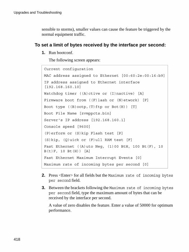
Upgrades and Troubleshooting
418
sensible to storms), smaller values can cause the feature be triggered by the normal equipment traffic.
To set a limit of bytes received by the interface per second:1. Run bootconf.
The following screen appears:
2. Press <Enter> for all fields but the Maximum rate of incoming bytes per second field.
3. Between the brackets following the Maximum rate of incoming bytes per second field, type the maximum amount of bytes that can be received by the interface per second.
A value of zero disables the feature. Enter a value of 50000 for optimum performance.
Current configuration
MAC address assigned to Ethernet [00:60:2e:00:16:b9]
IP address assigned to Ethernet interface [192.168.160.10]
Watchdog timer ((A)ctive or (I)nactive) [A]
Firmware boot from ((F)lash or (N)etwork) [F]
Boot type ((B)ootp,(T)ftp or Bot(H)) [T]
Boot File Name [zvmppcts.bin]
Server's IP address [192.168.160.1]
Console speed [9600]
(P)erform or (S)kip Flash test [P]
(S)kip, (Q)uick or (F)ull RAM test [F]
Fast Ethernet ((A)uto Neg, (1)00 BtH, 100 Bt(F), 10 B(t)F, 10 Bt(H)) [A]
Fast Ethernet Maximum Interrupt Events [0]
Maximum rate of incoming bytes per second [0]

AlterPath ACS Command Reference Guide 419
LEDs
Note: Using larger values does not harm your system but makes it more sensible to storms. Using smaller values, however, can trigger this feature be triggered by the normal equipment traffic.
4. When presented the following line:
Do you confirm these changes in flash ( (Y)es, (N)o (Q)uit ) [N] :
Enter Y to save the changes in flash.
LEDsCPU LEDs
Normally the CPU status LED should blink consistently one second on, one second off. If this is not the case, an error has been detected during the boot. The blink pattern can be interpreted via the following table:
Note: The Ethernet error mentioned in the above table will occur automatically if the Fast Ethernet link is not connected to an external hub during the boot. If
Table B-1: CPU LED Code Interpretation
Event CPU LED Morse code
Normal Operation S (short, short, short . . . )
Flash Memory Error - Code L (long, long, long . . . )
Flash Memory Error - Configuration
S, L
Ethernet Error S, S, L
No Interface Card Detected S, S, S, L
Network Boot Error S, S, S, S, L
Real-Time Clock Error S, S, S, S, S, L
Upgrades and Troubleshooting
420
the Fast Ethernet is not being used or is connected later, this error can be ignored.
Rear Panel LEDsThe ACS' rear panel has connectors (serial, console and Ethernet) with some LEDs that have the following functionality:
Ethernet Connector• Col (collision) - Shows collision on the LAN every time the unit tries to
transmit an Ethernet packet.• DT/LK (data transaction/link state) - DT flashes when there's data
transmitted to or received from the LAN. It's hardware-controlled. LK keeps steady if the LAN is active. The green LED is Data Transaction activity and the yellow one is LinK state.
• 100 - If 100BT is detected the LED lights on. If 10BT is detected it turns off.
Console Connector• CP - CPU activity. It flashes at roughly 1 second intervals.• P1 - Power supply #1 ON.• P2 - Power supply #2 ON.
Serial Connector• LK - DTR. It's software-controlled.• DT - Data transmitted to or received from the serial line. It's hardware-
controlled.

AlterPath ACS Command Reference Guide 421
LEDs
Administration parameters in the CLI interfaceSome of the procedures described above can be configured using the CLI interface. Below we will divide it into boot and administration configuration:
Boot configuration parameters:To configure boot parameters access the menu:cli>config administration bootconfig
Entering this menu you will be able to configure the following parameters:
• boottype - Chooses the network boot type. Valid values are: tftp, bootp or both.
• bootunit - Sets from where the unit will boot from. Valid values are: flash and network.
• consolespeed - To configure the console speed. Valid values are: 115200, 57600, 38400, 19200, 9600 and 4800.
• ethernetip - Temporary IP address assigned to the Ethernet interface.• ethernetmode - Fast Ethernet mode. Valid values for this field are: auto,
10F, 10H, 100H, 100F.• filename - File name of the image placed in the tftp server.• flashtest - Enables or disables the flash test. Valid values are: full and skip.• maxevents - Maximum number of Ethernet events handled at once.• ramtest - Chooses the type of ram test. Valid values are: full, quick and
skip.• tftpserver - Sets up the IP address of the tftpserver.• wdt - To enable/disable wdt (watch dog timer).

Upgrades and Troubleshooting
422
Administration Menu:Basically the administration section of the CLI interface is divided in 3 parts: Session Management, Backup Configuration and Firmware Upgrade that was already approached in this chapter; see “CLI Method - Firmware Upgrade” on page 409
Session Management:
To manage sessions, access:cli>administration sessions
This menu lets you do following:
• kill - To cancel a connection to the serial port <n>• list - Lists the current sessions
Backup Configuration
It is possible to save/restore configurations to/from a FTP server.
To configure it, access the menu:cli>administration backupconfig
The following options can be set up:
• loadfrom - When loading configuration from a server it is necessary to specify: server IP address <serverip>; username <username>; password <password>; path <pathname>.
• saveto - The same parameters of the loadfrom command must be specified.Example: The command below will load configuration from a server with IP address 192.168.0.1, username “john”, password “john1234” and the configuration file located at /home/configuration.backupconfig>loadfrom serverip 192.168.0.1 pathname /home/configuration username john password john1234

.................................................................
Appendix CAppendix C - Cabling and Hardware InformationCabling and Hardware Information
This appendix will show all hardware specifications of the ACS . It will also show all cables and connectors characteristics.
General Hardware SpecificationsThe power consumption and heat dissipation, environmental conditions and physical specifications of the ACS are listed below.
Table C-1: ACS Products Power Consumption and Heat Dissipation
Cyclades AlterPath ACS Products Power Consumption and Heat Dissipation
Input = 120Vac Input = 230 Vac
Model Power (watts)
Heat Exchange (BTU/hr.)
Power (Watts)
Heat Exchange (BTU/hr.)
ACS1 12 41.0 17 58.1
ACS4 16 54.6 25 85.4
ACS8 18 61.5 28 95.6
ACS16 22 75.1 30 102.5
ACS32 24 81.0 32 109.3
ACS48 26 88.8 35 119.5

Cabling and Hardware Information
424
Table C-2: ACS environmental conditions
Environmental Information
ACS1 ACS4 ACS8 ACS16 ACS32 ACS48
Operating Temperature
50F to 122F
(10ºC to 50ºC)
50F to 112F
(10ºC to 44ºC)
50F to 112F
(10ºC to 44ºC)
50F to 112F
(10ºC to 44ºC)
50F to 112F
(10ºC to 44ºC)
50F to 112F
(10ºC to 44ºC)
Relative
Humidity
10 - 90%, non-
condensing
10 - 90%, non-
condensing
10 - 90%, non-
condensing
10 - 90%, non-
condensing
10 - 90%, non-
condensing
10 - 90%, non-
condensing
Table C-3: ACS physical information
Physical Information
ACS1 ACS4 ACS8 ACS16 ACS32 ACS48
External Dimensions
2.76in.x
3.35in.x
1.18 in.
8,5in.x
4,75in.
x1 in.
8.5 in.x
4.75 in.x
1 in.
17 in. x
8.5 in.x
1.75 in.
17 in.x
8.5 in.x
1.75 in.
17 in. x
8.5 in.x
1.75 in.
Weight 0.3 lb. 1.5 lb. 1.6 lb. 6 lb. 6.2 lb. 8 lb.
Table C-4: ACS Safety Information
Safety Information
ACS1 ACS4 ACS8 ACS16 ACS32 ACS48
Approvals FCC and CE, Class A
AlterPath ACS Command Reference Guide 425
General Hardware Specifications
The following section has all the information you need to purchase or build cables to the ACS . It focuses on information related to the RS-232 interface, which applies not only to the ACS but also to any RS-232 cabling.
The RS-232 StandardRS-232C, EIA RS-232, or simply RS-232 refer to a standard defined by the Electronic Industries Association in 1969 for serial communication. More than 30 years later, more applications have been found for this standard than its creators could have imagined. Almost all electronic devices nowadays have serial communication ports.
RS-232 was defined to connect Data Terminal Equipment, (DTE, usually a computer or terminal) to Data Communication Equipment (DCE, usually a modem):DTE > RS-232 > DCE > communication line > DCE > RS-232 > DTE
RS-232 is now mostly being used to connect DTE devices directly (without modems or communication lines in between). While that was not the original intention, it is possible with some wiring tricks. The relevant signals (or wires) in a RS-232 cable, from the standpoint of the computer (DTE), are:
• Receive Data (RxD) and Transmit Data (TxD) - The actual data signals• Signal Ground (Gnd) - Electrical reference for both ends• Data Terminal Ready (DTR) - Indicates that the computer (DTE) is active• Data Set Ready (DSR) - Indicates that the modem (DCE) is active.• Data Carrier Ready (DCD) - Indicates that the connection over the com-
munication line is active• CTS (Clear to Send, an input) - Flow control for data flowing from DTE
to DCE• RTS (Request to Send, an output) - Flow control for data flowing from
DCE to DTE
Not all signals are necessary for every application, so the RS-232 cable may not need all 7 wires. The RS-232 interface defines communication parameters such as parity, number of bits per character, number of stop-bits and the baud rate. Both sides must be configured with the same parameters. That is the first thing to verify if you think you have the correct cable and things still do not work. The most common configuration is 8N1 (8 bits of data per character, no parity bit included with the data, 1 stop-bit to indicate the end of a character).
Cabling and Hardware Information
426
The baud rate in a RS-232 line translates directly into the data speed in bits per second (bps). Usual transmission speeds range between 9,600 bps and 19,200bps (used in most automation and console applications) to 115,200 bps (used by the fastest modems).
Cable LengthThe original RS-232 specifications were defined to work at a maximum speed of 19,200 bps over distances up to 15 meters (or about 50 feet). That was 30 years ago. Today, RS-232 interfaces can drive signals faster and through longer cables. As a general rule, consider:
• If the speed is lower than 38.4 kbps, you are safe with any cable up to 30 meters (100 feet)
• If the speed is 38.4 kbps or higher, cables should be shorter than 10 meters (30 feet)
• If your application is outside the above limits (high speed, long distances), you will need better quality (low impedance, low-capacitance) cables.
Successful RS-232 data transmission depends on many variables that are specific to each environment. The general rules above are empirical and have a lot of safety margins built-in.
ConnectorsThe connector traditionally used with RS-232 is the 25-pin D-shaped connector (DB-25). Most analog modems and most older computers and serial equipment use this connector. The RS-232 interface on DB-25 connector always uses the same standard pin assignment.
The 9-pin D-shaped connector (DB-9) saves some space and is also used for RS-232. Most new PC COM ports and serial equipment (specially when compact size is important) uses this connector. RS-232 interfaces on DB-9 connectors always use the same standard pin assignment.
The telephone-type modular RJ-45 plug and jack are very compact, inexpensive and compatible with the phone and Ethernet wiring systems present in most buildings and data centers. Most networking equipment and new servers use RJ-45 connectors for serial communication. Unfortunately there is no standard RS-232 pin assignment for RJ-45 connectors. Every equipment vendor has its own pin assignment.

AlterPath ACS Command Reference Guide 427
Connectors
Most connectors have two versions. The ones with pins are said to be “male” and the ones with holes are said to be “female.”
Straight-Through vs. Crossover CablesThe RS-232 interface was originally intended to connect a DTE (computer, printer and other serial devices) to a DCE (modem) using a straight-through cable (all signals on one side connecting to the corresponding signals on the other side one-to-one). By using some “cabling tricks,” we can use RS-232 to connect two DTEs as is the case in most modern applications.
A crossover (a.k.a. null-modem) cable is used to connect two DTEs directly, without modems or communication lines in between. The data signals between the two sides are transmitted and received and there are many variations on how the other control signals are wired. A “complete” crossover
Table C-5: Cables and their pin specifications
RS-232 Signal
Name/Function(Input/Output)
DB-25 pins (Standard)
DB-9 pins(Standard)
RJ-45 pins (Cyclades)
Chassis Safety Ground 1 Shell Shell
TxD Transmit Data (O) 2 3 3
RxD Receive Data (I) 3 2 6
DTR Data Terminal Ready (O)
20 4 2
DSR Data Set Ready (I) 6 6 8
DCD Data Carrier Detect (I) 8 1 7
RTS Request To Send (O) 4 7 1
CTS Clear To Send (I) 5 8 5
GnD Signal Ground 7 5 4

Cabling and Hardware Information
428
cable would connect TxD with RxD, DTR with DCD/DSR, and RTS with CTS on both sides. A “simplified” crossover cable would cross TxD and RxD and locally short-circuit DTR with DCD/DSR and RTS with CTS.
Which cable should be used?First, look up the proper cable for your application in the table below. Next, purchase standard off-the-shelf cables from a computer store or cable vendor. For custom cables, refer to the cable diagrams to build your own cables or order them from Cyclades or a cable vendor.
Cable DiagramsBefore using the following cable diagrams refer to the tables above to select the correct cable for your application. Sometimes, crossover cables are wired slightly differently depending on the application. A “complete” crossover cable would connect the TxD with RxD, DTR with DCD/DSR, and RTS with CTS across both sides. A “simplified” crossover cable would cross TxD and RxD and locally short-circuit DTR with DCD/DSR and RTS with CTS.
Most of the diagrams in this document show the “complete” version of the crossover cables, with support for modem control signals and hardware flow
Table C-6: Which cable to use
To Connect To Use Cable
DCE DB-25 Female (standard)
• Analog Modems
• ISDN Ter-minal Adapters
Cable 1:
RJ-45 to DB-25 M straight-through (Custom). This custom cable can be ordered from Cyclades or other cable vendors. A sample is included with the product (“straight-through”).
DTE RJ-45 Cyclades (custom)
• All Cycla-des Con-sole Ports
Cable 2:
RJ-45 to RJ-45 crossover (custom). A sample is included with the product (“straight-through”) This custom cable can be ordered from Cyclades or other cable vendors using the provided wiring diagram.

AlterPath ACS Command Reference Guide 429
Cable Packages
control. Applications that do not require such features have just to configure NO hardware flow control and NO DCD detection on their side. Both ends should have the same configuration for better use of the complete version of the cables.
Note: NOTE: These cables appear in Cable Package #1 and/or Cable Package #2. You may or may not find them in your box depending on which package you received.
Cable PackagesCable No. 1: Cyclades RJ-45 to DB-25 Male, straight-through
Application: This cable connects Cyclades products (serial ports) to modems and other DCE RS-232 devices. It is included in both Cable Package #1 and #2.
Figure C-1: Cable 1 - Cyclades RJ-45 to DB-25 Male, straight-through
Cable No. 2: Cyclades RJ-45 to DB-25 Female/Male, crossoverThis cable connects Cyclades products (serial ports) to console ports, terminals, printers and other DTE RS-232 devices. If you are using Cable Package #1, after connecting the appropriate adapter to the RJ-45 straight-through cable, you will essentially have the cable shown in this picture. If you
RJ-45Custom
TxD 3RxD 6Gnd 4
DTR 2DSR 8DCD 7
RTS 1CTS 5
DB-25Male
TxD 2RxD 3Gnd 7
DTR 20DSR 6DCD 8
RTS 4CTS 5

Cabling and Hardware Information
430
are using Cable Package #2, no assembly is required. You will have the cable shown below.
Cable No. 3: Cyclades RJ-45 to DB-9 Female, crossoverThis cable connects Cyclades products (serial ports) to console ports, terminals, printers and other DTE RS-232 devices. If you are using Cable Package #1, after connecting the appropriate adapter to the RJ-45 straight-through cable, you will essentially have the cable shown in this picture. If you are using Cable Package #2, no assembly is required. You will have the cable shown below.
Figure C-2: Cable 3 - Cyclades RJ-45 to DB-9 Female, crossover
Cable No. 4: Cyclades RJ-45 to Cyclades RJ-45, straight-through
This cable is the main cable that you will use. Along with one of the adapters provided (RJ-45 to DB-9 or RJ-45 to DB-25) you can create a crossover cable like the ones explained in Cable #2 or #3 for configuration or to connect to a server. This cable is only included in Cable Package. #1.
RJ-45Custom
TxD 3RxD 6Gnd 4
DTR 2DSR 8DCD 7
DB-9Female
RxD 2TxD 3Gnd 4
DSR 6DCD 1DTR 4

AlterPath ACS Command Reference Guide 431
Cable Packages
Figure C-3: Cable 4 - Cyclades RJ-45 to Cyclades RJ-45, straight-through
Cable No. 5: Cyclades/Sun Netra CableThis Adapter attaches to a Cat 3 or Cat 5 network cable. It is usually used in console management applications to connect Cyclades products to a Sun Netra server or to a Cisco product. This cable is included in Cable Package #2.
Figure C-4: Cable 5 - Cyclades RJ-45 to Sun Netra RJ-45, adapter cable
AdaptersThe following four adapters are included in the product box. A general diagram is provided below and then a detailed description is included for each adapter.
RJ-45Male
TxD 3RxD 6Gnd 4DTR 2DSR 8DCD 7RTS 1CTS 5
RJ-45Male
TxD 3RxD 6Gnd 4DTR 2DSR 8DCD 7RTS 1CTS 5
RJ-45Male (Cyclades)
DSR 8DCD 7RxD 6Gnd 4CTS 5RTS 1TxD 3DTR 2
RJ-45Male (Sun)
RTS 1DTR 2TXD 3Gnd 4 CTS 5RxD 6DCD 7

Cabling and Hardware Information
432
Loop-Back Connector for Hardware TestThe use of the following DB-25 connector is explained in the Troubleshooting chapter. It is included in both Cable Package #1 and #2.
Figure C-5: Loop-Back Connector (Style may vary; end is blank)
Cyclades\Sun Netra AdapterThis Adapter attaches to a Cat 3 or Cat 5 network cable. It is usually used in console management applications to connect Cyclades products to a Sun Netra server or to a Cisco product. At one end of the adapter is the black CAT.5e Inline Coupler box with a female RJ-45 terminus, from which a 3-inch-long black Sun Netra-labeled cord extends, terminating in an RJ-45 male connector. This adapter is included in Cable Package #2.
Figure C-6: Cyclades\Sun Netra Adapter
Loop-Back
TxD 2RxD 3RTS 4CTS 5DSR 6DCD 8DTR 20
CAT.5eINLINE COUPLER
Sun Netra/Cisco
DSR 8DCD 7RxD 6Gnd 4CTS 5RTS 1TxD 3DTR 2
Cyclades
RTS 1DTR 2TXD 3Gnd 4 CTS 5RxD 6DCD 7

AlterPath ACS Command Reference Guide 433
Cable Packages
RJ-45 Female to DB-25 Male AdapterThe following adapter may be necessary. It is included in Cable Package #1.
Figure C-7: RJ-45 Female to DB-25 Male Adapter
RJ-45 Female to DB-25 Female AdapterThe following adapter may be necessary. It is included in Cable Package #1.
Figure C-8: RJ-45 Female to DB-25 Female Adapter
RJ-45 Female to DB-9 Female AdapterThe following adapter may be necessary. This is included in Cable Package #1.
RJ-45End View
RJ-45 (F)
RTS 1DTR 2
TxD 3GND 4CTS 5RxD 6DCD 7DSR 8
DB-25 (M)
5 CTS6 DSR8 DCD3 RxD7 GND4 RTS2 TXD 20 DTR
RJ-45End View
RJ-45 (F)
RTS 1DTR 2
TxD 3GND 4CTS 5RxD 6DCD 7DSR 8
DB-25 (F)
5 CTS6 DSR8 DCD3 RxD7 GND4 RTS2 TXD 20 DTR

Cabling and Hardware Information
434
Figure C-9: RJ-45 Female to DB-9 Female Adapter
ACS1-only Cabling InformationACS1 Connectors
Table C-7: RS-485 Pinout for the ACS1 - Connector pin assignment
RS-485 Signal Name/Function Terminal Block pins
Chassis Not in use 1
TXA- Transmit Data - (A) 2
TXB+ Transmit Data + (B) 3
RXA- Receive Data - (A) 4
RXB Receive Data + (B) 5
Chassis Not in use 6
RJ-45 (F)
RTS 1DTR 2
TXD 3Gnd 4CTS 5RxD 6DCD 7 8
DB-9 (F)
8 CTS1 DCD6 DSR2 RxD5 Gnd7 RTS3 TxD
4 DTR
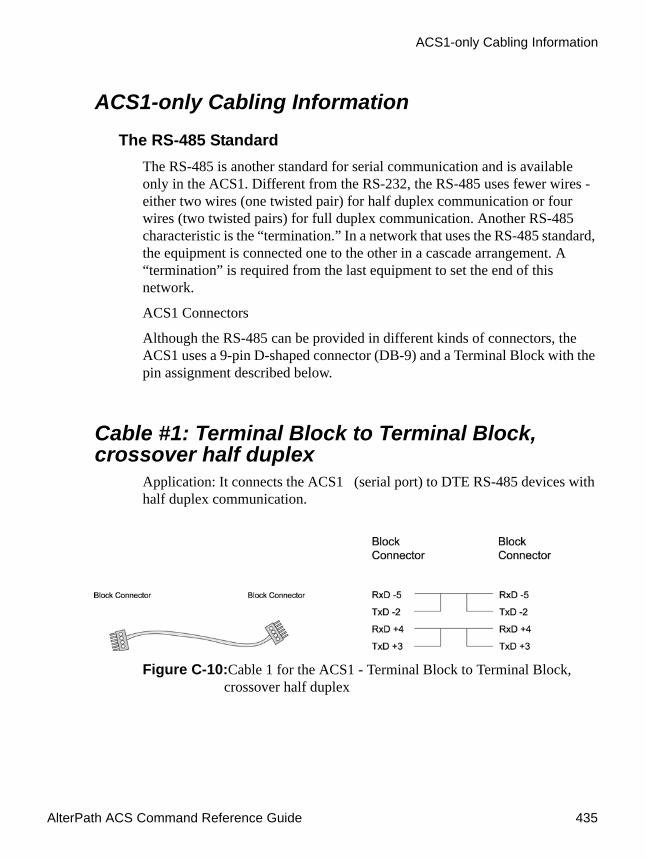
AlterPath ACS Command Reference Guide 435
ACS1-only Cabling Information
ACS1-only Cabling InformationThe RS-485 Standard
The RS-485 is another standard for serial communication and is available only in the ACS1. Different from the RS-232, the RS-485 uses fewer wires - either two wires (one twisted pair) for half duplex communication or four wires (two twisted pairs) for full duplex communication. Another RS-485 characteristic is the “termination.” In a network that uses the RS-485 standard, the equipment is connected one to the other in a cascade arrangement. A “termination” is required from the last equipment to set the end of this network.
ACS1 Connectors
Although the RS-485 can be provided in different kinds of connectors, the ACS1 uses a 9-pin D-shaped connector (DB-9) and a Terminal Block with the pin assignment described below.
Cable #1: Terminal Block to Terminal Block, crossover half duplex
Application: It connects the ACS1 (serial port) to DTE RS-485 devices with half duplex communication.
Figure C-10:Cable 1 for the ACS1 - Terminal Block to Terminal Block, crossover half duplex
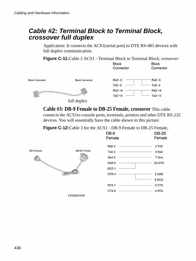
Cabling and Hardware Information
436
Cable #2: Terminal Block to Terminal Block, crossover full duplex
Application: It connects the ACS1(serial port) to DTE RS-485 devices with full duplex communication.
Figure C-11:Cable 2 ACS1 - Terminal Block to Terminal Block, crossover
full duplex
Cable #3: DB-9 Female to DB-25 Female, crossover This cable connects the ACS1to console ports, terminals, printers and other DTE RS-232 devices. You will essentially have the cable shown in this picture:
Figure C-12:Cable 3 for the ACS1 - DB-9 Female to DB-25 Female,
crossover

AlterPath ACS Command Reference Guide 437
ACS1-only Cabling Information

Cabling and Hardware Information
438

.................................................................
Appendix DAppendix D - CopyrightsCopyrights
The Cyclades AlterPath ACS is based in the HardHat Linux distribution, developed by Montavista Software for embedded systems. Additionally, several other applications were incorporated into the product, in accordance with the free software philosophy.
The list below contains the packets and applications used in the Cyclades AlterPath ACS and a reference to their maintainers. The copyrights notices required in some packets are placed in the /COPYRIGHTS directory of the Cyclades AlterPath ACS .
BashBourne Again Shell version 2.0.5a. Extracted from the HardHat Linux distribution.http://www.gnu.org/software/bash
BootparamdNetKit Bootparamd version 0.17ftp://ftp.uk.linux.org/pub/linux/Networking/netkit
BusyboxBusyBox version 1.0 ftp://ftp.lineo.com/pub/busybox/
CronPaul Vixie's cron version 3.0.1. [email protected]
DHCPCDPhysTech DHCP Client Daemon version 1.3.20.p10. http://www.phystech.com/download/dhcpcd.html
Copyrights
440
FlexFlex version [email protected]: This product includes software developed by the University of California, Berkeley and its contributors
GNUThe GNU projecthttp://www.gnu.org
HardHat LinuxMontaVista Software - HardHat version 2.1http://www.montavista.com
IPSecThe Linux Openswan IPsec version 2.3.0http://www.openswan.org
IPtablesNetfilter IPtables version 1.2.2. Extracted from the HardHat Linux distribution.http://www.netfilter.org
Linux KernelLinux Kernel version 2.2.17 2.4.18. Extracted from the HardHat Linux distribution http://www.kernel.org
Net-SNMPSourceForge Net-SNMP project version 5.2.1.2http://sourceforge.net/projects/net-snmp/

AlterPath ACS Command Reference Guide 441
NTPNTP client http://doolittle.faludi.com/ntpclient/
OpenSSHOpenSSH version 4.1p1http://www.openssh.orgCOPYRIGHT: This product includes software developed by the University ofCalifornia, Berkeley and its contributors.
OpenSSLOpenSSL Project version 0.9.8http://www.openssl.orgCOPYRIGHT: This product includes software developed by the OpenSSL Project for use in the OpenSSL Toolkit. (http://www.openssl.org/)COPYRIGHT: This product includes cryptographic software written by Eric Young ([email protected])
PAMLinux PAM version 0.75http://www.kernel.org/pub/linux/libs/pam/
PortslaveSourceForge Portslave project version 2000.12.25. (modified). Includes pppd version 2.4.1 and rlogin version 8.10http://sourceforge.net/projects/portslave/
RSYNCrsync version 2.5.5http://rsync.samba.org/rsync/
Syslog-ngSyslog new generation version 1.5.17http://www.balabit.hu/products/syslog-ng/

Copyrights
442
TinyloginTinyLogin version 0.80 ftp://ftp.lineo.com/pub/tinylogin/
UCD-SNMPSourceForge Net-SNMP project version 5.2.1.2http://sourceforge.net/projects/net-snmp/
WEBSGoAhead WEBS version 2.1 (modified)http://goahead.com/webserver/webserver.htmCopyright (c) 20xx GoAhead Software, Inc. All Rights Reserved
ZLIBzlib version 1.2.3 http://www.gzip.org/zlib/

.................................................................
GlossaryGlossary
AuthenticationAuthentication is the process of identifying an individual, usually based on a username and password. In security systems, authentication is distinct from authorization, which is the process of giving individuals access to system objects based on their identity. Authentication merely ensures that the individual is who he or she claims to be, but says nothing about the access rights of the individual. (Source: www.webopedia.com)
Break SignalA break signal is generated in an RS-232 serial line by keeping the line in zero for longer than a character time. Breaks at a serial console port are interpreted by Sun servers as a signal to suspend operation and switch to monitor mode.
Console Access Server (CAS)A CAS has an Ethernet LAN connection and many RS-232 serial ports. It connects to the console ports of servers and networking equipment and allows convenient and secure access from a single location.
Console PortMost of the equipment in a data center (servers, routers, switches, UPS, PBX, etc.) has a serial console port for out-of-band management purposes.
ClusterA cluster is a group of one or more computers working as a group to execute a certain task. From the user standpoint, a cluster acts as a large computer system.
Glossary
444
FlashFlash refers to a type of memory that can be erased and reprogrammed in units of memory known as blocks rather than one byte at a time; thus, making updating to memory easier.
In-band network managementIn a computer network, when the management data is accessed using the same network that carries the data, this is called “in-band management.”
IP packet filteringThis is a set of facilities in network equipment that allows the filtering of data packets based on source/destination addresses, protocol, TCP port number and other parameters. Packet filtering is one of the main functions of a firewall.
KVM Switch (KVM)Keyboard-Video-Mouse Switches connect to the KVM ports of many computers and allow the network manager to access them from a single KVM station.
MainframeLarge, monolithic computer system.
MIBsManagement Information Bases. SNMP-compliant devices, called agents, store data about themselves in MIBs and return this data to the SNMP requesters.
Out-of-band network managementIn a computer network, when the management data is accessed through a network that is independent of the network used to carry data, this is called “out-of-band network management.”

AlterPath ACS Command Reference Guide 445
Off-line data bufferingThis is a CAS feature that allows capture of console data even when there is no one connected to the port.
ProfileUsage setup of the ACS : either as a Console Access Server (CAS), a Terminal Server, or a Remote Access Server.
RADIUSProtocol between an authentication server and an access server to authenticate users trying to connect to the network.
RISCReduced Instruction Set Computer. This describes a computer processor architecture that uses a reduced set of instructions (and achieves performance by executing those instructions very fast.) Most UNIX servers (Sun Sparc, HP, IBM RS6000, Compaq Alpha) were designed with a processor using a RISC architecture. The Intel ® x86 architecture.
RS-232A set of standards for serial communication between electronic equipment defined by the Electronic Industries Association in 1969. Today, RS-232 is still widely used for low-speed data communication.
Secure Shell (SSH)SSH has the same functionality as Telnet (see definition below), but adds security by encrypting data before sending it through the network.
Server FarmA collection of servers running in the same location (see Cluster).
Shadow PasswordNormally, each user's password is stored, encrypted, in the file /etc/passwd. This file must be readable by all users so that certain system functions will

Glossary
446
operate correctly. This means that copies of user's encrypted passwords are easily obtained, making it possible to run an automated password-guessing program against them. Shadow passwords, on the other hand, store the encrypted passwords in a separate highly-protected file, making it much more difficult to crack passwords.
SNMPShort for Simple Network Management Protocol, a set of protocols for managing complex networks. The first versions of SNMP were developed in the early 80s. SNMP works by sending messages, called protocol data units (PDUs), to different parts of a network. SNMP-compliant devices, called agents, store data about themselves in Management Information Bases (MIBs) and return this data to the SNMP requesters. (Source: Webopedia)
TelnetTelnet is the standard set of protocols for terminal emulation between computers over a TCP/IP connection. It is a terminal emulation program for TCP/IP networks such as the Internet. The Telnet program runs on your computer and connects your PC to a server on the network. You can then enter commands through the Telnet program and they will be executed as if you were entering them directly on the server console. This enables you to control the server and communicate with other servers on the network. To start a Telnet session, you must log in to a server by entering a valid username and password. Telnet is a common way to remotely control Web servers. (from webopedia.com)
Terminal ServerA terminal server has one Ethernet LAN port and many RS-232 serial ports. It is used to connect many terminals to the network. Because they have the same physical interfaces, terminal servers are sometimes used as console access servers.
TTYThe UNIX name for the COM (Microsoft) port.

AlterPath ACS Command Reference Guide 447
U Rack height unitA standard computer rack has an internal width of 17 inches. Rack space on a standard rack is measured in units of height (U). One U is 1.75 inches. A device that has a height of 3.5 inches takes 2U of rack space.
X.509A widely used standard for defining digital certificates. X.509 is an ITU recommendation, which means that it has not yet been officially defined or approved for standardized usage. As a result, companies have implemented the standard in different ways. For example, both Netscape and Microsoft use X.509 certificates to implement SSL in their Web servers and browsers. But an X.509 Certificate generated by Netscape may not be readable by Microsoft products, and vice versa.

Glossary
448