alternative processes in batch circuit board cleaninginfohouse.p2ric.org/ref/29/28441.pdf · batch...
TRANSCRIPT

ALTERNATIVE PROCESSES
IN BATCH CIRCUIT
BOARD CLEANING
SINCE 1964


CONTENTS
General Overview
Batch Aqueous Cleaning
Batch Cleaning with Semi-Aqueous Solvents
Alcohol-Water Cleaning in a Batch System
Other Features and Characteristics of ECD’s Batch Cleaning Systems
Appendix A Cleanliness Monitoring and the MlL-P-28809 Test
Appendix B Semi-Aqueous Batch Cleaning of SMDs
Page
1
4
8
12
17
A-I
B- 1
i

GENERAL OVERVIEW
In the early years of circuit board production, the boards were usually soldered using a pure rosin flux, which in its solid state is agood insulator. Since the circuitry at that time was relatively non- critical as to impedance and surface leakage, many of them were not cleaned at all. Solderability problems soon led to the addition of activators to the rosin. These activators, while improving the soldering, were soluble in water and yielded highly ionized molecules in aqueous solutions and reduced resistivity. In high ambient humidity, leakage currents and corrosion appeared, generating the need for removing the flux from the boards. Early cleaning methods revolved around alcohols, ketones, and chlorinated hydrocarbons. The cleaning agents were generally applied in dip-and-brush and spray sinks. Some of the solvents tended to cause other problems when left on the boards, especially if they were to be subsequently coated. This led to a wash and rinse in deionized water, which proved to be highly effective in removing trapped contaminants and preventing blisters in the coating.
The labor intensiveness, personnel hazards, and other deficiencies associated with dip tanks and spray sinks forced the search for more efficient methods, all of which led to the development of both in-line and batch cleaning systems. Some of the first attempts at batch equipment involved the use of commercial dishwashers, primarily because they were inexpensive, and because they offered an economical alternative to in-line solvent cleaning.
Development of inorganic and organic water-soluble fluxes that washed off readily with water, encouraged the use of the batch cleaners. The shortcomings of the household and commercial dish washers led to numerous modifications by users, including the addition of screens, disconnecting heaters, changing process cycles, and introducing deionized water into the process. Prohibition of water-soluble fluxes by military and aerospace specifications temporarily reduced the popularity of aqueous batch cleaning until it was revived again by the development of rosin flux removal by saponification using alkaline detergents. The military has recently indicated a relaxation of its insistence on the use of CFC solvents and has expressed a willingness to adopt other agents so long as they prove as good or better in cleaning power.
The search for effective substitutes for CFCs led to development of saponifiers, semi-aqueous solvents, and hydrogenated CFCs to replace them. With the ultimate demise of CFCs as mandated by the Montreal Protocol, work is progressing at an accelerated pace to replace them. With the completion of Phase 1 Benchmark Testing, and the entry into Phase 2 evaluations, new agents appear with astonishing frequency. Batch systems have kept pace with the introduction of the new chemistries, and excellent systems are on the market now that effectively use the aqueous, semi-aqueous, and alcohol-water cleaning agents. Also worth emphasis is the technique of following in-line solvent cleaning with
1

batch aqueous washing and rinsing, a method that results in a state of cleanliness in which ess$ntially no residue can be detected.
Engineering studies at Electronic Controls Design (ECD) in the development of the Model 7300 MEG-A-RINSE SMDBbatch cleaning system, have steered efforts to develop a cleaning method using an alcohol and water mix, This is certain to play a large and important part in the cleaning of boards to very high levels of cleanliness and with essentially no effect on the environment.
Which of these cleaning agents is the best for a particular application depends partly on the material constituents of the boards and compo- nents. Certain chemistries, for example, have a detrimental effect on certain metals, others attack some plastics, so there is no one solution for every problem; each must be approached with careful analysis of the case at hand.
Batch aqueous cleaning of printed wiring assemblies has been used successfully for several years as a highly economic and productive alternative to in-line cleaning systems. The graph in Figure 1. illustrates the cost comparisons between in-line and batch systems, indicating that even for reasonably large board production, batch systems are
2 Batch Systems 128 1 0 by IO” boards per hour
I I 1
50 100 1 50 200 300 400
ASSEMBLIES PER YEAR (X 1000)
Figure 1. Cost Comparison: Model 6300 Batch System vs. In-Line.

economically competitive and, in addition, provide a degree of control unachievable with in-line systems. Batch cleaning has been with us long enough now that it is without question a highly effective, mature, and cost-effective process.
In the past few years advancements in technology, techniques, and instrumentation have greatly enhanced the basic batch process. Innovations and refinements in process monitoring and documentation have had asignificant effect on the ability to achieve new levels of process control. Improved instrumentation has provided more precise monitoring and measuring of cleanliness, even to the point of being able to the detect noticeable effects that carbon dioxide has on the measurement. Improved cleanliness monitoring also has made correlation with MIL-Spec levels a relatively simple matter.
With all the recent advances in batch cleaning methods, cleaning agents, and equipment, it appears that a comprehensive overview and update of batch aqueous cleaning and its implications are now in order. The following pages constitute an attempt bring these thoughts together.
3

BATCH AQUEOUS CLEANING
Choosing the Cleaning Agent To remove water-soluble fluxes, water is obviously a good choice as a
cleaning agent. It’s cheap, it’s non-ionizing, and it’s abundant, at least in most parts of the world. In a well-designed system, water washing and rinsing may be all that’s required. Water rinsing of water-soluble fluxes is highly effective but only if the resistivity of the rinse water is closely monitored. In fact, with the right process control, rinsing with deionized water has proved good enough to be used even in semiconductor fabrication. More stubborn fluxes may call for the addition of saponifiers.
Saponifier Use and Characteristics Removal of rosin fluxes without using CFC solvents requires
saponifiers, which are highly effective in many applications, including surface mount assemblies. The process of saponification, in its essentials, uses an alkaline chemical to convert rosin to a water soluble soap that rinses freely with water. Saponification has several other advantages, among them are:
1. It removes ionic soils and, with detergent additives, also removes and
2. The saponifying chemicals and the wash residue are biodegradable
3. The chemicals are low foaming, and are also low in toxicity volatility. 4. The ingredients do not attack platings or substrate markings and do
5. The solution is inexpensive. 6. Most important, it achieves a very high degree of board cleanliness.
neutralizes water-soluble acid fluxes.
and can be dumped into sanitary sewer systems.
not remove component markings.
System Requirements for Efficiency and Consistency A properly designed batch aqueous system is capable of achieving a
higher degree of surface cleanliness than an in-line washer. A batch washer outperforms almost any of the more expensive in-line washers, especially the ones with fixed conveyor speeds. To realize the main benefits of batch cleaning, precise control of process parameters is essential. In particular, the timing of the cleaning and rinsing to a specified resistivity is crucial to process consistency and should not be left to the operator. This clearly points up the need for automatic monitoring and controlling systems such as those in the equipment described below.
To ensure consistent washing and rinsing results, a carefully designed board loading and stacking system is also necessary. Even though rotating spray nozzles minimize shielding or shadowing effects, proper spacing of the assemblies is essential for thorough cleaning. Again the
4

equipment portrayed below has racks specifically designed for easy loading, proper spacing, and optimal cleaning patterns.
One reason for superior cleaning with batch aqueous systems is easy to understand: wash and rinse times are usually longer than in an in-line washer. Consequently, cleaning and rinsing agents are in contact longer with surface contaminants, and residues with lower solubility are removed more effectively. Applicable Equipment
Models 600 and 6300pP from ECD are examples of the best of the modern systems now on the market for aqueous cleaning with and without saponifiers. The low-cost Model 600 Aqua-QuikB is intended for production processes in which versatility of control is not required. The 600 is pre-programmed at the factory for the most common production conditions. Its parameters, however, can be easily changed by the users if needed.
k Drver
~ _ _ _ _ _ _ _
Figure 2. The 6300uP Mainframe and Sensor System.
The Model 63OOwP contains not onlv the basic requirements for effective processing, but also some features that enh’ance production control and provides documentation as well. The diagram in Figure 2. illustrates the basic components of the washer itself. Here are some of the main characteristics:
1. Asturdy stainless steel cabinet that is durable and easy to keep clean. 2. An oversized pump motor for long-term reliability. 3. Programmable control of all major parameters such as pre-rinse and
wash times, chemistry concentration with automatic addition, the number of final rinses, drying cycle time, and lot identification.
4. Automatic rinse-water conductivity monitoring and final resistivity control.
5

5. Water level sensing for quicker and more accurate filling, and drain-flow sensing to reduce cycle times and achieve greater throughput.
6. Systems for monitoring and automatically controlling water tempera- ture (especially useful during long wash cycles), and for monitoring rinse water conductivity and the number of rinse cycles required to achieve the selected level of cleanliness.
7. An LED display of machine status, temperatures and resistivity, and a built-in printer for dated and timed documentation of all essential process cycles and data.
8. Options for automatic chemistry addition (saponifier or neutrilizer), chemistry level sensors, and a convection dryer attachment.
Process control as good as this ensures repeatable consistently superior results with economy of operation and high throughput.
Completing the Batch Aqueous System To round out a complete ECD batch aqueous cleaning system, several
accessory items are available to enhance productivity and economy of operation, including a DI Water Heater, a Water Classifier that tests and diverts waste water for additional treatment as necessary, a Dual Chem-Feed system for automatic chemistry addition, a Convection Dryer to accelerate board drying, and a Recirculating Air Oven for off-line drying, which is especially useful as a preliminary to conformal coating.
Batch Aqueous Cleaning After Solvent Cleaning - Ultra Cleanliness As mentioned in the introduction, the use of batch cleaners such as
the Model 600 Aqua-Quik and the 63OOkP for washing and rinsing after solvent cleaning, results in a cleanliness level that cannot be measured by any of the standard test methods. A state for which the term “Ultra-cleanliness” was coined.
Much has been said about the advantages of solvent cleaning when clearances between components and board surface are very small. But there is also good evidence that solvents and solvent mixtures are not as effective as water at removing ionic soils. This being the case, we believe that the most effective solvent cleaning process uses the solvents to penetrate and remove contamination from under the components, then deionized rinse water for final cleaning to be sure that all remaining ions are removed.
In fact, cleanliness problems are caused by physical processes activated by water or humidity, and the assemblies must operate in an atmosphere containing water. Using water in the cleaning process, then, is avalid test in itself, and tends to raise confidence in the whole process.
Supporting evidence for this assertion comes from tests conducted and documented by Carl Tautscher, which were conducted over a period of several months in normal production environments. Referring to the chart in Figure 3., it will be seen that several kinds of assemblies were first cleaned in a vapor degreaser using four different solvents (labeled ‘A”, “B, “C”, and “D” in the graph). The same assemblies were then cleaned in a batch aqueous washer with 2% saponifier then rinsed in water. Some of the assemblies were tested with an Omegameter(?) immediately after vapor degreasing, and some after batch washing, after which the resulting
6

values were compiled. It is apparent that in all cases the range of ionic cleanliness levels measured after batch aqueous cleaning was signific- antly better than those cleaned only with solvent.
Contamination per Unit Area - MIL-P-28809 Test- d S q . cm.
. 5! w 3
1.5
Sample Ouantrty
7 Solvent Only
1
. 5! m 3
M 5 L i m i t
NOTE. Each sample ton- s i l ts of 50 or more assemblies.
30 18 21
7
Post-Aqueous Cleaning with Saponifier
5
4
3
2
1
18 45 27 30
Figure 3. The Effects of Aqueous Cleaning after Solvent Cleaning.
Those in the business of making PCB assemblies are, at one time or Batch Aqueous Cleaning and the MIL-P-28809 Test
another, concerned with complying with the requirements of MIL-P-28809 test. One of the sticking points is the apparent need for 2 megohm-cm test water in order to meet the final test level of the same purity. Empirical data gathered in a series of tests of the effect of dilution factors, however, prove conclusively that rinse water with a resistivity as low as 40 kilohms-cm will suffice. An explanation of the test procedures and conclusions are presented in Appendix A for those who wish to review them.
( 1 ) Trademark of Alpha Metals, Inc.
7

BATCH CLEANING WITH SEMI-AQUEOUS SOLVENTS
An Introduction to Semi-Aqueous Processes
appeared in the past few years, mainly terpene hydrocarbons and hydrocarbon formulations. Examples include Petroferm’s terpene hydrocarbon Bioact EC-7 and a hydrocarbon-based solvent from DuPont called Axarel 38; others are certain to follow. Studies thus far indicate that these agents clean as well or better than CFCs and with none of the destructive effects on the ozone.
Terpene hydrocarbon agents are chlorine-free, noncorrosive, and biodegradable. Many terpenes and terpenoids are, indeed, used in flavoring and scent materials, and as food additives. Many are listed as GRAS (Generally Recognized As Safe) and are regarded as non-toxic and non-injurious to standard drain systems.
While relatively new to the electronics industry, semi-aqueous solvents have been found to be highly effective in removing a wide range of fluxes, including all rosins, water soluble fluxes, and synthetic activated fluxes.
Terpenes have also demonstrated their superiority over some chlorinated fluorocarbons in dissolving flux residue and in removing these residues from under low-clearance components, even from spaces on the order of 0.001 inch. The effectiveness of terpenes has been ascribed to their superior dissolution performance, which results from their wetting and penetration characteristics. Other hydrocarbon solvents are expected to have similar characteristics.
Developed specifically to replace CFCs, semi-aqueous solvents have
System Needs for Effective Semi-aqueous Cleaning A basic system for PWAcleaning with semi-aqueous solvents includes
solvent immersion or spray, and requires an external water rinse. A practical and effective system will include close monitoring and control of all parameters in the cleaning and rinsing cycles in order to achieve an acceptable level of cleanliness.
For successful semi-aqueous cleaning, then, well-controlled water rinsing is necessary, and the equipment should be capable of close and accurate control of the process and precise monitoring of the final rinse water. Although any standard washing and rinsing facility may suffice, a well-controlled batch system such as ECD’s 6300pP or Model 600 is a better choice.
See Appendix B for the results of two independent studies concerning the effectiveness of semi-aqueous bath cleaning.
Design Requirements for Semi-aqueous Cleaning Equipment New cleaning agents always present new problems in designing
equipment and systems for containment, use, and disposition of the
8

cleaning agents. Semi-aqueous solvents are no exception because of their adverse effects on many of the materials that are routinely used in aqueous washers. For example, terpenes swell and soften most rubber compounds, and to some degree they cause many plastic materials to swell. Terpene's penetration ability, which is such an advantage in PWA cleaning, also allows it to leak through very small crevices, so leak control is also more difficult.
Terpene hydrocarbon solvents are also flammable, designated as a Class II Combustible Liquid. By comparison, alcohol with a lower flash point, is designated Class I Flammable. Ventilation of a cleaning system is therefore of prime importance to prevent concentrations of combustible gasses. The problem, however is certainly no greater and probably much smaller than that encountered in soldering machines, for example. A minimum vent rate must be established and maintained, (a common procedure with drying ovens), and safety controls must be included to signal a ventilation system failure.
Con ta m i n ation Sample cel I
Spill Con- tai n ment
e Printing Controller
Diffusion Assembly
Sensor Sensor
Exhaust Plenum - ,Air
'Flow
Sensor
L r ::E. $ U D
To Floor Sensor
I I / I Nitrogen Drain
5-gallon Shipping Container
Pressure Sensor
Figure 4. Operational and Safety Features of the Model 6307.
9

Designing for Safety Safety of the system has been the over-riding design criterion in the
development of the Model 6307 Semi-Aqueous Cleaner, and involves several factors and features.
For both reliability and safety, pressured nitrogen is used to dispense the solvent, preventing the addition of oxygen and precluding the need for pumps. By this method, the solvent is delivered directly from the shipping container, preventing spillage and cleanup. In case of power loss or nitrogen pressure drop, solvent flows back into the container. Nitrogen is also used to purge the wash chamber, thus reducing the oxygen content and the flammability of the contents. The pressure of the nitrogen supply is constantly monitored to provide additional protection.
To keep the air in and around the system as free of solvent fumes as possible, air is pulled in from the bottom periphery of the machine, moved up around the wash chamber and exhausted out the top. An air vacuum sensor monitors the air flow and automatically shuts the system down if the air flow is interrupted.
that the temperature of the contents of the wash chamber is maintained well below the flash point.
and the motor automatically shuts down if a predetermined temperature is exceeded. The normal operating temperature of the motor is low enough that it will run with no hazard even if it is completely submerged in the solvent.
machine and discharge directly into the drain system. A tray collects dripping solvent when transferring parts from one place to another, such as the water rinse facility.
Monitoring and Controlling Solvent Contamination In deciding how to monitor the contamination level of the solvent, the
best method was determined to be a system for monitoring its specific gravity. Pure EC-7, for example, has a specific gravity of about ,850. As
Accurate temperature monitoring has been designed in to make sure
The temperature of the main drive motor is also monitored continuously, 4
Spills and drips from the wash chamber are caught directly under the
0 890
0 885
0 880
0 875
0 870
0 865
0 860
0 855
0 850
S G
0% 4% 8% 12% 16% 20% 2 4%
P e r c e n t R o s i n by W t
Figure 5. Specific Gravity of EC-7 vs. % Rosin Load by Weight.

rosin is dissolved, the density increases. The density is also affected somewhat by temperature. The contamination of solvent in the Model 6307, then, is determined by extracting a sample, measuring its specific gravity, and sounding an alarm when a predetermined level is reached. The temperature of the sampling chamber is monitored to provide temperature compensation to the measurement.
Programmable Controls Essential In order to minimize monitoring and to free the operator for other tasks,
certain automatic controls are necessary. In the Model 6307 the contamination level of the solvent is continuously checked by a specific gravity sensor. The solvent sump level is also monitored continuously.
The Model 6307 controller also provides automatic filling, washing, and draining and features control and programmability of all essential machine functions and parameters plus a display unit and a thermal printer.
Programmable Functions: 1. Wash cycle time 2. Nitrogen purge time 3. Solvent drip-off time 4. Solvent replacement point
Displays 1. Solvent specific gravity (temperature compensated) 2. Cycle time remaining 3. Motor and sump temperatures 4. Cycle status
Printer 1. Time and date 2. Temperatures of the motor, the sump, and the sample chamber 3. Solvent specific gravity 4. Cycle times 5. Program 6. Alarm points 7. Machine number 8. Batch number
Figure 6. Sample 6307 Program and Cleaning Cycle Printouts..
11

ALCOHOL-WATER CLEANING IN A BATCH SYSTEM
A New Solution to an Old Problem Although CFCs are likely to be mainly replaced either by HCFCs or
semi-aqueous solvents, there are some inherent problems with both. As mentioned in the introduction, there is no single solution to the problems associated with circuit board cleaning. In that respect it resembles the search for the perfect solvent; there just isn’t one. Isopropyl alcohol is not new to board cleaning, having been one of the earliest ones used in brush and spray setups of the past. But it seemed worthyof further examination. As a result of recent studies, ECD engineers are of the opinion that the next important step in the evolution of board cleaning is a batch washing system using an alcohol-water mix, not as part of the traditional cleanliness test method, but as the cleaning process itself. Alcohol and water mixes have been used in Europe for some time with excellent success. The need for a system using that method has become increasingly apparent in this country.
Electronic Controls Design, Inc., in the development of its Model 7300 MEG-A-RINSE@ SMD, has produced a system that combines an aqueous cleaner with an alcohol-water cleaning cycle, both closely controlled to ensure a cleanliness level that meets or exceeds MIL-P- 28809 requirements.
The Omegameter test results in Figure 7., which compares various cleaning methods, demonstrates the obvious benefits of the alcohol- water rinse cleaning method: Cleaning with CFCs produces boards with an ionic contamination of about 15 micrograms per square inch; saponifier-aqueous cleaning is about the same. Adding the IPA-water rinse brings cleanliness levels down to the 1.5 to 1.8 microgram per square inch region.
Cleaning and Control Processes The 7300 offers two basic cleaning methods depending on whether
the flux is water soluble or not. If the boards contain rosin flux the 7300 is programmed through a saponifier cycle followed by a water rinse and a final wash in a continuously purified solution of 75% alcohol and 25% water at an elevated temperature. For water soluble fluxes a simple water rinse plus the alcohol-water cycle is adequate to attain the most stringent cleanliness requirement. Since this process emulates the traditional Omegameter test method, post-wash testing is entirely unnecessary. Thus the 7300 system is suited for both military or commercial customers and users.

I 20
m
5
0
E E 3
i : I I
CFC Clean Saponifier Saponifier + IPA PROCESS
Figure 7. Box Plot of Omegameter Test Results.
After a 15-minute rinse in alcohol-water, the resistivity is constantly monitored until an end point of 2 megohms-cm is exceeded, thus ensuring an equivalent ionic residue level of 10 micrograms per square inch or less. Since the alcohol-water rinse is done at elevated tempera- tures, this pass-fail method makes any other test process unnecessary; once the boards have passed, they are clean.
Environmental and Economic Factors In the Model 7300, the used alcohol-water mixture is recirculated
through a deionizing column and a filter and back to a holding tank for reuse. Alcohol loss, therefore, is only by dragout and evaporation and is minimal. Because of its evaporative characteristics, alcohol reduces board drying time to a small fraction of that required for water. The cost of alcohol is less than 20% of semi-aqueous solvents and only about 2% of CFCs, indicating a substantial potential reduction in material expenses. Easily made from natural products, alcohol is abundant in every part of the country and the world, and it has little adverse effects on the environment.
To further reduce costs and impacts on the environment, ECD offers an optional waste-water classifier that diverts waste water for further treat men t if required. Programmable Control
To achieve consistently clean boards, precise control of all the processes is a necessity. The Model 7300’s control unit monitors and controls all cycle functions, including pre-wash times, wash times, number of rinses, dry cycle, chemistry concentration, and the testing cycles. Programming is done by the operator, who enters the cycle parameters on the controller’s front panel. While operating, the controller indicates the current cycle status on the easy-to-read LED display. During the cycle, the 7300 prints essential cycle parameters as well as the batch lot number, with current day and time.
13

Programmable Functions: 1. Pre-wash time 2. Wash cycle time 3. Chemistry concentration 4. Minimum number of rinses 5. Wash temperature 6. Waste classification 7. Use of batch numbers 8. Lot number 9. Machine number
10. Date and time 11. Dry time 12. Test rinse time
Displays: 1. Alcohol percentage
2. Cycle time remaining 3. Sump temperature 4. Sump resistivity 5. Cycle status
1. Time and date 2. Temperatures of motor, sump, and the sample chamber 3. Alcohol percentage 4. Cycle times and process measurements 5. Alarm points 6. Machine number 7. Batch number 8. Lot number
In order to minimize monitoring and to free the operator for other tasks, the operation of the 7300 has been highly automated. Sensors have been placed in strategic locations to monitor processes and fluid levels and to control replenishment and refilling. Others sense temperatures and air flow. The alcoholhvater ratio is continuously checked by a specific gravity sensor. When the ratio departs from normal, additional alcohol is added automatically. The level of the sump is also monitored.
Safety Requirements and Precautions Because the system uses alcohol, safety has been an important design
criterion in the development of the Model 7300. First, the alcohol is stored in an external, double-walled enclosure. In case of power loss, the solution flows back into the container. Nitrogen is used to purge the wash chamber, thus reducing the oxygen content and the flammability of the contents. The pressure of the nitrogen supply is constantly monitored to provide additional protection.
To keep the air in and around the system free of flammable fumes, air is pulled in from the bottom periphery of the machine, moved up around the wash chamber and exhausted out the top. Air vacuum sensors
(temperature compensated)
Printer:
14

monitor the air flow and automatically shut the system down in case the air flow is interrupted.
Accurate temperature monitoring has been incorporated to make sure that the temperature of the contents of the wash chamber and sump is maintained well below the critical level. The temperature of the main motor is also monitored continuously, and the motor automatically
Door Interlock Switch Exhaust Plenum
DI Fill
IPA Valve Close
Column Holding Tank '
.. I
ALCOHOL CONTROL UNIT IACUl . . . .. . . . . . .. . ... .... . . . . .. ... . . .,
Figure 8. Safety and Operational Features of the Model 7300.
down if the maximum temperature is exceeded. As a further precaution, a leak detector senses any leakage around the pump seals.
Cleaning circuit boards with the alcohol-water mix in a well-designed system like the Model 7300 MEG-A-RINSE SMD, is an effective, verifiable, and safe method for arriving at cleanliness levels that will satisfy any military and commercial user, using either rosin or water-soluble fluxes. It will do so at a lower cost than any other method and without the traditional problems with waste disposal and other negative effects on the environment.
15

Sample Printouts
Batch X0257 Batch Number, 01/01/90 00:07:32 L o t 0 0 6 c Date,Time,and *********-********* LO' Number
* 7300 MG-A-RINSE StQ * * Vers ion 01.16 * Machine her 12 * version
PROGRAM LISTINGS . Number
. . . . . . . . . . . . . . . . . . . . . . Mach,ne
WATER CLEANING YES PRE-WASH 01 m i n WASH 05 m i n R I NSE 01 m i n CHEM I STRY MAX #RINSES MIN #RINSES MAX WASH TEMP 139 F WASH TEMP 120 F MIN WASH TEMP 100 F MIN FINAL RES .500 M CLASSIFY WASTE W R02
01 % Programmed 10 ea Washingand o3 EA Water Rinsing
Parameters t ALCOHOL CLEANING YES
NITFCGEN PURGE 0 1 m i n ALCOHOL WASH 15 m i n MAX ALcoH3L CONC 73 % ALCOHOL CONC 68 % MIN ALCOHOL CONC 63 % MAX MOTOR TEMP 129 F MAX CLEAN TEMP 140 F CLEAN TEMP 115 F MIN CLEAN TEPP 090 F MIN FINAL RES 2.00 M
DRY 10 m i n PRINT W E ON . . . . . . . . . . . . . . . . . . . .
Programmed Alcohol Washing Parameters t
Batch #0257 01/01/90 01:30:17 Lot009 . . . . . . . . . . . . . . . . . . . . * 7300 MEG-A-RINSE SM) * * Version 01.16 * * Machine N h e r 12 * . . . . . . . . . . . . . . . . . . . .
CLEAN I NG CYCLE WATER YES ALCOHOL YES
PRE-WASH 01 F i n a l Res Sulp Tenp
>WASH 05 Chemistry F i n a l r e s Sulp Tenp
Sulp Tenp
F i n a l Res Sulp Tenp
F i n a l Res Sulp Tenp
>RINSE 01 01 F i n a l Res
>RINSE 02 01
>RINSE 03 01
WATER WASH 0 1 : 3 0 : 2 3 - ~ ~ 2 g .335 M 105 F
01 : 32:46
O1 % Resistivity M -After Watei
121 F Washing 01 : 39: 07
.612 M 131 F
ALcoH3L WASH NITROCfN PURGE 01:47:18
N i t r o g e n 66.8 PSI ALCOHOL WASH 01:48:48
Alcohol Conc 69 % Final
F i n a l Res 5.30 M c- Sulp Tenp 105 F Washing
After Alcohol
Motor Tarp 104 F DRAINING 04 02:04:21
DRY 10 02:08:36 Passed TEST RESULT Final
CYCLE CCMPLETE 02:18:36 ........................ ****PASSED****- 7::F
Figure 9. Sample Model 7300 Program and Cycle Printouts.
16

OTHER FEATURES AND CHARACTERISTICS OF ECD BATCH SYSTEMS
ECD systems clean boards on edge so that cohesional and adhesional forces better remove contaminants from small spaces and prevent puddling of the cleaning agent. This is particularly true of boards with SMDs. Stacked vertically, the boards also drain better with less dragout and more even cleaning with no side-to-side differences.
All four systems use dual, counter-rotating wash arms driven by a high- capacity pump to flood every assembly at a recirculation rate of 60 gallons per minute (only 2% gallons are actually used per cycle). The arms rotate at a minimum speed of 24 rpm - a rate calculated as optimal for fast, thorough cleaning. Rotating-nozzle spray arms eliminate the “shading” of components that occurs with fixed nozzles, and the intermittency of the spray application inherent in rotary-nozzles pumps contaminants from under the parts. The axial pump is driven by a heavy-duty motor to deliver the maximum amount of water with a minimum of expended energy.
Board loading is easier in the large, logically-structured stainless-steel interiors, which accept boards up to 18 by 20 inches (with an optional long diffusion accessory). The baskets are made of strong, heavy-gauge wire coated with Plastisor, a durable, rubberized material that resists cracking, chipping, or peeling, and is ESDS-safe. Other features include loop-design removable rack dividers and protective cradles and a view window (optional with some systems) that allows visibility of the interior.
Bibliography: Carl J. Tautscher, E-Systems, Inc. 1. NEPCON fast Paper, Boston, June 7988: Practical Batch Water Cleaning Techniques Yield Reliability and Economy for Small and Mid-Size Users. 2. Aqueous Assembly Cleaning with Batch Washers, A Novatech Research Corporation Publication.
17


APPENDIX A
CLEANLINESS MONITORING AND THE MIL-P-28809 TEST
The MIL-P-28809 Test Procedure - A Reminder 50.3.3 Test Procedure. Direct the test solution (75% isopropyl alcohol and 25% water), in a fine stream, onto both sides of the assembly until 10 ml of the test solution is collected for each square inch of assembly area. Assembly area includes the area of both sides of the board plus an estimate of the area of the components mounted thereon. Wash the assembly for a minimum of one minute. It is imperative that the initial washings be included in the test sample. Measure the resistivitykonduc- tivity of the collected test solution with a conductivity bridge or other instrument of equivalent range and accuracy. Note: All laboratory ware must be scrupulously clean. Preferably, laboratory ware used for this test should be reserved for this test and not used elsewhere (see 50.3.4). Alternative test methods specified in 40.5.1 and 50.3.4.1 may be used.
It seems reasonable to assume that to achieve the MIL-spec final test level of 2 megohm-cm, that it is necessary to ensure that the final rinse water of the cleaning process achieves the same resistivity or better. Empirical data accumulated in a series of tests indicate clearly, however, that the rinse water doesn’t have to be much better than 40 kilohms-cm to accomplish the same purpose. The following example will serve to illustrate this important point. A Question of Water Volumes and Retainment
inch. If that 10 ml were to be distributed over the surface of a one-square- inch board (Figure A-I), the layer thickness would be .61 inch. Obviously this volume is very large compared to the amount of contaminated water left on the board after cleaning.
The MlL-P-28809 test requires a solution application of 10 ml per square
Figure A-I. Equivalent Water Layer a t a Volume of 10 ml per Square Inch.

In running empirical tests of the dilution factor, a number of different PC assemblies were measured and dried. The required volume of MIL-spec solution (75% alcohol, 25% water) was measured out and sprayed over the assemblies, catching the solution in a container. The volume of solution left over was carefully measured and the percentage of loss calculated. The results appear in Figure A-2 below.
Beginning Final Volume , Volume
Sol. DI
536 531 533
360 354 357.5
897.6 892.6 894.6
10-1401-003
Percent L o s t
Sol. DI
.933 .560
1.66 .694
.557 .334 I I I
BOO-1901-03 6.6 6.8
Figure A-2. MI L-P-28809 Volume Testing Experiment.
The tests were repeated using deionized water instead of the MIL-spec solution. The considerable variation in the amount of solution retained is explained by the differences in the assemblies, some of which had a number of sockets and other mechanical entrapment components. In all cases, however, the amount of solution retained was less than 2% of the test vo I ume .
Tracing a Drop of Contaminated Water Through the Process If we assume that, during the cleaning process, all contamination was
removed and concentrated in the final rinse water that surrounds the board and its components (Figure A-3), we can trace a droplet of contaminated solution through the MIL test.
Figure A-3. The Assembly in Contaminated Water.
After the rinse water is drained from the assembly, small droplets of contaminated solution remain (Figure A-4).
i
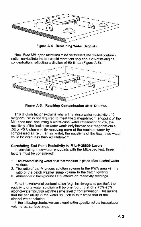
Figure A-4 Remaining Water Droplets.
Now, if the MIL-spec test were to bepetformed, the diluted contami- nation carried into the test would represent only about 2% of its original concentration, reflecting a dilution of 50 times (Figure A-5).
Figure A-5. Resulting Contamination after Dilution.
This dilution factor explains why a final rinse water resistivity of 2 megohm- cm is not required to meet the 2 megohm-cm endpoint of the MIL-spec test. Assuming a worst-case water retainment of 2%, the resistivity of the final rinse water would only have to be 2 megohm-cm X .02 or 40 kilohm-cm. By removing more of the retained water by compressed air (e.g., an air knife), the resistivity of the final rinse water could be even less than 40 kilohm-cm.
Correlating End Point Resistivity to MIL-P-28809 Levels In correlating rinse-water endpoints with the MIL-spec test, three
factors must be considered:
1 . The effect of using water as a test medium in place of an alcohol-water mixture.
2. The ratio of the MIL-spec solution volume to the PWA area vs. the ratio of the batch washer sump volume to the batch loading.
3. Atmospheric background C02 effects on resistivity readings.
For a known level of contamination (e.g., in micrograms per liter), the resistivity of a water solution will be one fourth that of a 75%-25% alcohol-water solution with the same level of contamination. This means that the sensitivity in the water solution is four times that of the alcohol-water solution.
volume vs. surface area. In the following charts, we can examine the question of the test solution
A-3

The chart in Figure A-6 shows conservatively the number of boards that can be loaded into a typical batch washer. The numbers along the axes indicate the board size. The numbers inside the chart are the number of boards of a particular size that can be loaded into the machine.
Figure A-6. Washer Load Capacity by Board Size.
Figure A-7. uses the selected board size to compute the total surface area represented by the load factors in Figure A-6.
By using the areas from Figure A-7. and assuming batch cleaner sump capacity of 2.5 gallons, the chart in Figure A-8 then calculates the number
A-4

of times that the MIL-spec surface area to volume ration is exceeded. For example, loading 32 10 by 10 inch assemblies (from Figure A-8.) into the cleaner would result in a total area 6.4 times that required by the MIL-spec test.
Figure A-8. The number of Times that the MIL-spec Area Requirement i s exceeded.
Figure A-9. asks the question in reverse order by showing the number of boards of a given size that would be required to meet the MIL-spec requirement. In our example, only five 10 by 10 inch boards meet the requirement while 32 can actually be loaded into the machine.
Figure A-9. The Number of Boards Required to Meet MI L-spec Area Requirement.
A-5

The Effects of C02 on Background Resistivity Levels Atmospheric carbon dioxide is present in all manufacturing locations
to some degree. Since the rinse water in the batch washer is continuously sprayed through the air in the cleaning chamber, C02 is dissolved into the water, which then ionizes and reduces the resistivity of the rinse water. This effect is quite dramatic, and it can quickly reduce semiconductor- grade 18 megohm-cm rinse water to resistivities below 100 kilohm-cm even though no other contaminant is present. The physical phenomena that determine this background of equilibrium resistivity level are many. Her are a few of them:
1. The amount of C02 in the air, which can vary with altitude and location. Operations that use C02 as a coolant may affect the levels of C02 near the batch cleaner.
2. The amount of C02 in the washer is affected by the vapor pressure of the water, which is influenced by its temperature, typically 100 to 140 degrees Fin most batch cleaners. The amount of C02 dissolved in water is therefore a function of temperature, which is why carbonated beverages bubble as they are warmed.
3. Two ionic equilibria govern the ionization of CQ2
Each of these processes is affected by the temperature of the solution. 4. Most resistivity meters are temperature-compensated to 25 degrees
C based on the presence of sodium chloride as the contaminant in the solution. Where C02 is the major contaminant, this assumption is obviously false.
Owing to the large number of variables, a theoretical approach to the limiting resistivity of water in equilibrium in air was not attempted. Instead an empirical approach was taken. In the experiment, water was continuously sprayed over a load of PC assemblies in a batch washer. Part of the water in the sump was recirculated through a mixed bed deionizer and returned to the sump. The resistivity and temperature were monitored both in the sump and at the outlet of the deionizer. A small aquarium pump was used to continuously bubble air through the water in the sump. By using the temperature feature of the controller, the sump temperature was held constant, and the resistivity allowed to stabilize. The process was repeated at several temperatures. The results are charted in Figure A-10 below.
megohm-cm range, depending on the temperature.
sometimes found in real cleaning situations where many (five or more) deionized water rinses are used. This effect is caused by the partially
As the chart demonstrates, typical resistivity levels are in the 1 to 2
It must be noted that higher resistivity readings than these are

1.807
0
g 1. 0
.-
.- rn 1.00
t l.1//
0.80 I
50 60 70 80 90 100 110 120 130
Temperature
Figure A-IO. Resistivity Effects of C02 as Influenced by Water Temperature.
sealed cleaning chamber in which C02 slowly leaves the water. When the door is momentarily opened and the process restarted, however, the resistivity immediately drops to lower levels.
Summing it All Up From the above discussion, it is apparent that resistivities equivalent
to MIL-spec requirements can be achieved even with the background effects. It has been shown that a 2 megohm-cm test level is equivalent to 500 kilohm-cm resistivity level in water (2 megohm-cm divided by 4) . This is less than the 1 to 2 megohm-cm reading and is easily achieved even with background resistivity. Of course increased sensitivity can be had by putting more than the minimum number of boards into the washer. From our dilution exercise above we know that the residual contamination will be further diluted.
In all this discussion it was assumed that all the contamination was removed from under the components and was in solution during the final rinse. These particles must be removed or made soluble during the most aggressive saponification part of the cleaning cycle or before the final rinse. The purpose of the final rinse is to dilute any remaining ionic contamination.
A-7


APPENDIX B
SEMI-AQUEOUS BATCH CLEANING OF SMDS
The effectiveness of cleaning with semi-aqueous agents has been attested to by several independent studies, two of which are cited below.
In a study by Cray Research Company in 1989, several boards, each 4 by 8 inches and containing 96 components were cleaned in both a Freon in-line cleaning process and with semi-aqueous solvents in an ECD Model 6307 followed by water rinsing in an ECD 6300. The results, including allowances for rosin loading of the semi-aqueous solvent were as follows:
Cleaner Type Equivalent Contamination and Loading Milligrams of NaCl per square inch
Freon TMS Clean EC-7
EC-7 10% loaded EC-7 15% loaded EC-7 20% loaded
.0038 ,0031
.0031
.0043 ,0060
DuPont Electronics also conducted a study in 1989 using as test models wave-soldered Gore test boards. After cleaning in an ECD 6307 with KCD-9438 followed by water rinsing, the boards were given a 15-minute ionic test with an Omegameter 600 with the following results:
Flux Type K1585 A611F
Rep RA RMA
2.0 0.8 1.6 1.1 2.1 0.4 2.1 0.8 1.7 1.5
Average 1.9 Std. Dev. 0.21 0 Variance 0.044
0.92 0.366 0.134
B-1

The engineer supervising the test said in his report, “The ionic tests
Other tests support the thesis that semi-aqueous board cleaning with are outstanding - as good as we’ve seen.”
an aqueous rinse is consistently effective, and that they indicate that cleaning SMD boards in a vertical position produces better results because of the increased flow of solvent under the components. One such test, which compared cleaning with a CFC-alcohol blend with the semi-aqueous blend produced the following results:
Cleaner Type
CFC-Alcohol Semi-aqueous, new Semi-aqueous, 10% rosin loaded
Equivalent Contamination Milligrams of NaCl/sq. in.
3.8 3.1
3.1
Waste Disposal In order to determine typical effluent waste concentrations, 17 tin-lead
plated boards, 7.25 by 8.25 inches, with large unmasked ground planes were cleaned in EC-7 solvent and rinsed with water. Samples of the rinse water were taken at each stage of the rinsing process and tested for BOD (Biochemical Oxygen Demand) and lead concentration. Here are the results:
Process Step
Pre-rinse Wash Rinse 1 Rinse 2 Rinse 2
BOD mg/l Lead mg/l
285 27 9 9 3
< O . l <O.l <o. 1 <O.l <0.1
Chemistry and Water Usage
be about 3 grams per square foot of board material. Water usage in the Model 63OOp.P is approximately 10 gallons per load or 2.5 gallons each for pre-wash, wash, 1st rinse, and final rinse.
The loss of solvent due to dragout in the Model 6307 is estimated to


Represented by:
Electronic Controls Design, Inc. 4287-A S.E. International Way Milwaukie, Oregon 97222-8825 (503) 659-6100 (800) 323-4548 FAX: 503-659-4422