alphabetical index i to vii transformer brackets 4-1 to 4-2 · anchor eight way expanding ... dead...
TRANSCRIPT

Alphabetical Index i to vii
Anchors and Guying 1-1 to 1-16
Grounding 2-1 to 2-7
Crossarms, Braces and Gains 3-1 to 3-8
Transformer Brackets 4-1 to 4-2
Brackets 5-1 to 5-2
Arrester Brackets 6-1 to 6-2
Bolts, Nuts and Washers 7-1 to 7-15
Insulator Pins 8-1 to 8-4
Insulator Hardware 9-1 to 9-12
Line Post Hardware 10-1 to 10-3
Porcelain Insulators 11-1
Cable Material 12-1 to 12-6
Cabinets 13-1 to 13-2
Miscellaneous 14-1 to 14-6
Tools 15-1
Numerical Index i to iii

Above Ground Secondary Junction Box ........... 14-3 Adapter Clevis...................................................... 9-1 Lead Pin Head ........................................ 8-2 Plate, Clevis Strain ................................. 9-9 Plate, Transformer .................................. 4-2 Socket Clevis .......................................... 9-1 Adjustable Thrust Fitting .......................................... 3-7 Pole Mount ........................................... 14-5 Aerial Cable Clamp ........................................... 12-5 Anchor Eight Way Expanding............................. 1-1 Plate, Square ........................................... 1-1 Power Installed Screw ............................ 1-2 Power Installed Screw, Heavy Duty....... 1-2 Rock........................................................ 1-6 Rock, Extension...................................... 1-6 Rock, Sliding Cone Wedge .................... 1-7 Rod, Auxiliary Eye................................. 1-3 Rod, Coupling......................................... 1-4 Rod, Single, Double, Triple Eye............. 1-5 Screw ...................................................... 1-2 Shackle ................................................... 9-3 Angle Alley Arm Brace..................................... 3-4 Clamp (Twisted & Straight) ................. 9-10 Mounting Fittings ................................. 10-2 Thimble Eye Bolts .................................. 7-5 Thimble Eyelet ....................................... 7-9 Arrester Cutout, Combination Bracket ................. 6-1 Cutout, Combination, 27 KV.................. 6-2 Auxiliary Meter Box.......................................... 13-2 Ball Clevis...................................................... 9-1 Eye Oval ................................................. 9-2
Ball, cont... Eye Round .............................................. 9-2 Link, Shoulder Eye Bolt ......................... 7-6 Socket Tongue........................................ 9-2 Band-it Band ..................................................... 15-1 Buckle................................................... 15-1 Tool ...................................................... 15-1 Bands, Pole (regular type) ................................. 1-13 Bolt Angle Thimble Eye ................................ 7-5 Carriage .................................................. 7-3 Double Arming....................................... 7-3 Double Arming Oval Eye....................... 7-4 Eyes ........................................................ 7-9 Head Clevis ............................................ 9-8 Machine .................................................. 7-1 Oval Eye................................................. 7-4 Shoulder Eye .......................................... 7-6 Shoulder Eye, Ball Link ......................... 7-6 Silicon Bronze ........................................ 7-1 Spool, Double Upset............................... 7-7 Spool, Single Upset ................................ 7-7 Straight Thimble Eye.............................. 7-5 U ............................................................. 7-8 Brace Angle Alley Arm.................................... 3-4 Crossarm, Angle Arm............................. 3-4 Crossarm, Angle Steel ............................ 3-5 Crossarm, Flat Steel ............................... 3-3 Brackets Arrester, 27 KV ...................................... 6-2 Corner Construction ............................. 9-12 Corner, Assembly................................. 12-1 Cutout-Arrester Combination, Single..... 6-1 Dead End .............................................. 12-2 Neutral Wire ......................................... 12-4 Offset Pole............................................ 12-1 Pole Top ............................................... 10-1 Secondary Mid-Span, 3 & 4 Wire .......... 5-2
i
Page Page

Brackets cont... Spreader ..................................................5-1 Stand Off (post type insulator)..............10-1 Swing Type...........................................9-12 Swinging Angle ....................................12-2 Transformer Cluster Mounting ...............4-1 Wood Crossarm ....................................9-12 Cabinets Auxiliary Meter Box.............................13-2 Cable T.V..............................................13-2 Single Transformer ...............................13-1 Triple Transformer................................13-1 Cable Clamp, Aerial........................................12-5 Guard ......................................................2-6 Guard Straps ...........................................2-7 Hanger, Suspension Clamp...................12-4 Lashing Clamp......................................12-4 Marker, Underground ...........................14-4 Reel Stand.............................................14-4 Spreader, Secondary, Diamonite ..........12-6 T.V. Cabinets ........................................13-2 Carriage Bolts ......................................................7-3 Centre Phase Assembly .......................................3-7 Clamps Aerial Cable ..........................................12-5 Angle, Straight ......................................9-10 Angle, Twisted......................................9-10 Cable Lashing .......................................12-4 Ground Rod ............................................2-1 Ground, Copper - Splice ........................2-4 Ground Support ......................................2-3 Guy .........................................................1-8 Line Post Insulator Conductor ..............10-2 Single Bolt Angle ...................................9-9 Straight Line ...........................................9-6 Suspension, Cable Hanger ....................12-4 Suspension, Curved & Straight.............12-3 Universal...............................................12-3 X, Y & Z ...............................................12-5
Clevis Adapter ................................................... 9-1 Adapter, Socket ...................................... 9-1 Ball ......................................................... 9-1 Double Eye ............................................. 9-3 Bolt Head................................................ 9-8 Dead End ................................................ 9-8 Double, 90o............................................. 9-5 Double, Straight...................................... 9-5 Secondary ............................................. 9-11 Spool Insulator ..................................... 9-11 Strain Adapter Plate................................ 9-9 Strain Plate (extension assembly)......... 1-14 Thimble .................................................. 9-8 Clips Ground Wire........................................... 2-3 Ground Wire, Copper ............................. 2-3 Throat ..................................................... 2-7
Connector Ground Rod ............................................ 2-2 Live Line Pigtail ..................................... 9-7 Copper Ground Clamp ........................................ 2-4 Ground Connector Plates........................ 2-4 Ground Wire Clips ................................. 2-3 Corner Attachment ........................................... 12-2 Bracket Assembly................................. 12-1 Construction Bracket ............................ 9-12 Cotter Key ....................................................... 7-11 Pin......................................................... 7-11 Coupling, Anchor Rod......................................... 1-4 Cross Bracing Hardware...................................... 3-8 Crossarm Angle Pins .............................................. 8-2 Brace, Angle Arm................................... 3-4
Page Page
ii

Crossarm, cont... Brace, Angle Steel ..................................3-5 Brace, Flat Steel......................................3-3 Gains .......................................................3-6 Gains, Spiked..........................................3-6 Hollow Steel ...........................................3-1 Reinforcing Plate ....................................3-1 Steel ........................................................3-3 Wood.......................................................3-2 Wood, Bracket ......................................9-12 Curved Suspension Clamps ...............................12-3 Washers.................................................7-15 Cutouts, Arrester Combination Brackets Single ......................................................6-1 27 KV Series...........................................6-2 Dead End Bracket ..................................................12-2 Clevis ......................................................9-8 Diamonite Secondary Cable Spreaders..............12-6 Discs, Phasing, Plastic & Metal ........................1-15 Double Arm Angle Support.................................3-5 Arming Bolts ..........................................7-3 Arming Oval Eye Bolts...........................7-4 Clevis, 90o .............................................9-5 Clevis, Straight .......................................9-5 Eye Clevis...............................................9-3 Eye Socket ..............................................9-3 Links - Figure 8 (Plain & Twisted).........9-4 Upset Spool Bolt.....................................7-7 Drive Hook, Pilot Point .....................................7-11 Driver, Ground Rod .............................................2-1 Epoxy Rod .........................................................1-15 Extension Assembly, Strain Plate Clevis...............1-14
Extension, cont... Pin, Pole Top ..........................................8-1 Pole Top................................................12-1 Rock Anchor...........................................1-6 Rod .........................................................1-4 Straps ....................................................1-14 Eye Ball, Oval................................................9-2 Ball, Round.............................................9-2 Bolt .........................................................7-9 Clevis, Double ........................................9-3 Socket, Double........................................9-3 Thimble, Anchor Rod .............................1-5 Eye Nuts Oval ........................................................7-9 Strand......................................................7-8 Thimble, Single, Double, Triple .............1-3 Eyelets, Angle Thimble .......................................7-9 Figure-8 Double Link, Plain & Twisted ..............9-4 Fill Rings (washers) ...........................................7-12 Fittings Adjustable Thrust....................................3-7 Angle Mounting....................................10-2
Flagram..............................................................14-4 Flat Steel Crossarm Brace....................................3-3 Gains Crossarm.................................................3-6 Crossarm, Spiked....................................3-6 Gradient Control Mat...........................................2-4 Ground Clamp - Splice, Copper...........................2-4 Connection Plates, Copper......................2-4 Plate ........................................................2-2 Rod (copper bonded) ..............................2-2
iii
Page Page

Ground, cont... Rod Clamp ..............................................2-1 Rod Connector ........................................2-2 Rod Drivers.............................................2-1 Rod, Steel................................................2-1 Support Clamp ........................................2-3 Wire Clips...............................................2-3 Wire Clips, Copper .................................2-3 Wire Moulding........................................2-5 Guards Cable .......................................................2-6 Cable, Straps ...........................................2-7 Guy .......................................................1-11 Hub .......................................................1-11 Guy Clamps ....................................................1-8 Guards...................................................1-11 Hooks......................................................1-9 Hooks, Combination ...............................1-9 Strain Insulator, Porcelain.....................11-1 Strain Plates ..........................................1-10 Strand....................................................1-10 Strut, Sidewalk......................................1-11 Thimbles .................................................1-8 Hasp, Padlock Bail.............................................14-1
Heavy Duty Insulator Pins...................................8-4 Hexagon Nuts ......................................................7-8 Hollow Steel Crossarms.......................................3-1 Hooks Guy .........................................................1-9 Guy, Combination...................................1-9 Pilot Point Drive ...................................7-11 Sky, (Pulling Hook)................................9-8 Hub Guard .........................................................1-11 Insulator Clevis, Spool.........................................9-11 Guy Strain, Porcelain............................11-1
Insulator, cont... Line Post, Conductor Clamp ................ 10-2 Pins (long shank) .................................... 8-3 Pins (primary drop wire) ........................ 8-4 Pins (short shank) ................................... 8-3 Pins, Heavy Duty.................................... 8-4 Saddle, Line Post .................................. 10-3 Spool, Porcelain.................................... 11-1 Studs (for line post insulators).............. 10-3 Jenny Reel ......................................................... 14-5 Jumper Studs ....................................................... 9-6 Junction Box, Frame & Cover ............................ 14-1 Box, Secondary, Above Ground........... 14-3 Unit, Underground Multiplex............... 14-2 Kabar Underground Multiplex Junction Unit.... 14-2 Key, Cotter …………………………………….7-11 Lag Screws ........................................................ 7-10 Lead Pin Head Adapter ....................................... 8-2 Line Post Insulator Conductor Clamp ................................. 10-2 Saddle ................................................... 10-3
Link Figure-8 Double, Plain & Twisted ......... 9-4 Strain (with plate) ................................. 1-13 Strain ...................................................... 9-4 Live Line Pigtail Connector ................................ 9-7 Machine Bolts...................................................... 7-1 Marker, Underground Cable.............................. 14-4 Mat, Gradient Control ......................................... 2-4 Meter Box, Auxiliary......................................... 13-2
Page Page
iv

Moulding Ground Wire ...........................................2-5 Wood ......................................................2-5 Mount, Pole (adjustable)....................................14-5 Multiplex Junction Unit, Underground..............14-2 Neutral Wire Bracket .........................................12-4 Nuts Hex..........................................................7-8 Oval Eye .................................................7-9 Square .....................................................7-8 Strand, Eye..............................................7-8 Offset Pole Bracket............................................12-1 Padlock .............................................................14-1 Bail-Hasp .............................................14-1 Phasing Discs.....................................................1-15 Pilot Point Drive Hook ......................................7-11 Pins Cotter ....................................................7-11 Crossarm Angle ......................................8-2 Insulator (long shank) .............................8-3 Insulator (Primary Drop Wire) ...............8-4 Insulator (short shank) ............................8-3 Insulator, Heavy Duty.............................8-4 Pole Top (pressed steel)..........................8-1 Pole Top Angle .......................................8-2 Pole Top Extension.................................8-1 Plates Clevis Strain Adapter..............................9-9 Crossarm Reinforcing.............................3-1 Ground ....................................................2-2 Ground Connection, Copper ...................2-4 Guy Strain.............................................1-10 Lift, 2 & 3 Hole ....................................1-10 Pole Bearing ...........................................1-7 Strain Yoke ...........................................1-12
Plates, cont... Strain, Clevis.........................................1-14 Transformer Adapter...............................4-2 Transformer Mounting............................4-2 Platform, Pole ....................................................14-6 Pole Bands (regular type)..............................1-13 Bearing Plates .........................................1-7 Bracket, Offset ......................................12-1 Mount (adjustable)................................14-5 Platform ................................................14-6 Top Angle Pin.........................................8-2 Top Bracket ..........................................10-1 Top Extension.......................................12-1 Top Extension Pin...................................8-1 Top Pin (Pressed Steel)...........................8-1 Porcelain Insulators............................................11-1 Preforms Dead End ..............................................1-16 Guy .......................................................1-16 Service Ends .........................................1-16 Reel Jenny .....................................................14-5 Stand, Cable ..........................................14-4 Rings, Fill (washers) ..........................................7-12 Rods Anchor, Single, Double, Triple Eye........1-5 Epoxy....................................................1-15 Extension ................................................1-4 Ground (copper bonded)........................2-2 Ground, Steel ..........................................2-1 Round Washers ..................................................7-13 Saddle, Line Post Insulator ................................10-3 Screws, Lag........................................................7-10
v
Page Page

Secondary Cable Spreaders, Diamonite .................12-6 Clevis ....................................................9-11 Junction Box, Above Ground ...............14-3 Mid Span Bracket ...................................5-2 Serving Sleeves....................................................1-8 Shackle, Anchor...................................................9-3 Single Bolt Angle Clamp...................................9-9 Phase Combination Bracket....................6-1 Phase Combination Bracket, 27 KV.......6-2 Transformer Cabinet .............................13-1 Upset Spool Bolt.....................................7-7 SkyHook,(PullingHook)......................................9-8 Socket Ball, Tongue ...........................................9-2 Clevis Adapter ........................................9-1 Double Eye .............................................9-3 Spiked Crossarm Gains........................................3-6
Spool Bolts, Double ..........................................7-7 Bolts, Single............................................7-7 Insulators ..............................................11-1 Spreader Brackets ..................................................5-1 Secondary Cable, Diamonite ................12-6 Spring Lock Washers.........................................7-13 Spur Washers .....................................................7-15 Square Nuts.........................................................7-8 Washers ...............................................7-14 Stand, Cable Reel...............................................14-4 Stand Off Bracket ..............................................10-1
Staples ................................................................2-5 Steel Crossarms ...............................................3-3 Crossarm Brace Flat................................3-3 Ground Rods...........................................2-1 Straight Double Clevis .........................................9-5 Line Clamp .............................................9-6 Thimble Eye Bolts ..................................7-5 Strain Guy, Insulators, Porcelain.....................11-1 Guy Plates .............................................1-10 Link.........................................................9-4 Link (with plate) ...................................1-13 Plate, Clevis (extension assembly) .......1-14 Yoke Plates ...........................................1-12 Strand Guy .......................................................1-10 Eye Nuts..................................................7-8 Straps Cable Guard ............................................2-7 Extension ..............................................1-14 Strut, Sidewalk Guy...........................................1-11 Studs Insulator (for line post insulator) ..........10-3 Jumper.....................................................9-6 Support, Double Arm Angle ................................3-5 Suspension Clamp, Cable Hanger............................12-4 Clamps .................................................12-3 Swing Type Bracket...........................................9-12 Swinging Angle Bracket ....................................12-2 Tapered Centering Washer ................................7-11
Page Page
vi

Thimble Adapter, Lead Pin Head..........................8-2 Clevis ......................................................9-8 Eye Bolts, Angle.....................................7-5 Eye Bolts, Straight ..................................7-5 Eyelet, Angle ..........................................7-9 Guy .........................................................1-8
Three Phase Combination Bracket (27 KV) ........6-2 Throat Clips .........................................................2-7 Tie Wire, # 4 ......................................................12-6 Tongue, Ball Socket.............................................9-2 Tool, Band-it......................................................15-1
Tower & Suspension Fittings ..............................9-1 Transformer Adapter Plates.........................................4-2 Cabinet (Single & Triple) .....................13-1 Cluster Mounting Bracket.......................4-1 Mounting Plate........................................4-2
Two Phase Combination Bracket (27 KV) ..........6-2 Triple Transformer Cabinet ...............................13-1 U-Bolts ................................................................7-8 Underground Cable Marker ........................................14-4 Multiplex Junction Unit ........................14-2 Universal Clamps...............................................12-3 Washers Curved ..................................................7-15 Fill Rings ..............................................7-12 Round....................................................7-13 Spring Lock ..........................................7-13 Spur.......................................................7-15 Square ...................................................7-14
Washers, cont... Tapered Centering.................................7-11 Wire Neutral, Bracket ....................................12-4 Tie, # 4 ..................................................12-6 Wood Moulding.................................................2-5 Crossarms ...............................................3-2 Crossarms Bracket ................................9-12 X, Y, & Z Clamps..............................................12-5 Yoke, Strain Plates.............................................1-12
vii
Page Page

♦ Heavy gauge steel
♦ Four reinforcing ribs and four flanges
♦ Plates welded together at right angles. Ribs positioned concave and convex to plates ensuring maximum holding power and resistance to deformation of the unit
♦ Nut retainer welded to underside of plate providing positive guide for anchor rod (at 900 to pulling force of rod at all times)
Anchor Plates Square
Cat. No. Area Sq. Inches
Dimensions Inches
Rod Dia.
Inches
Shipping Wt. lbs
(100 pcs)
Std. Pkg
K152-12 150 12-1/2 X 12-1/2 1/2 or 5/8 1050 1
K152-14 200 14-1/2 X 14-1/2 5/8 or 3/4 1200 1
K152-16 250 16-1/4 X 16-1/4 5/8 or 3/4 1300 1
K152-18 300 18 X 18 5/8, 3/4 or 1 1600 1
K152-21 400 21 X 21 3/4, 1 or 1-1/4 2400 1
K152-24 400 24 X 24 3/4, 1 or 1-1/4 2700 1
Eight Way Expanding Anchor (steel) Cat. No Size Anchor
and Hole Inches
Max. Size Rod
Inches
Area Expanded Sq. Inches
Holding Strength
Classification
Shipping Wt. lbs
(100 pcs)
Std. Pkg
K150-8 8 3/4 135 12000 lbs 1000 5
K150-10 10 1 200 20000 lbs 1900 3
♦ Easy to install
♦ Contoured blades cut readily into undisturbed earth
♦ Deeply ribbed and embossed for greater strength
♦ Recommended for all soil types
K152-12
ANCHORS & GUYING
1-1
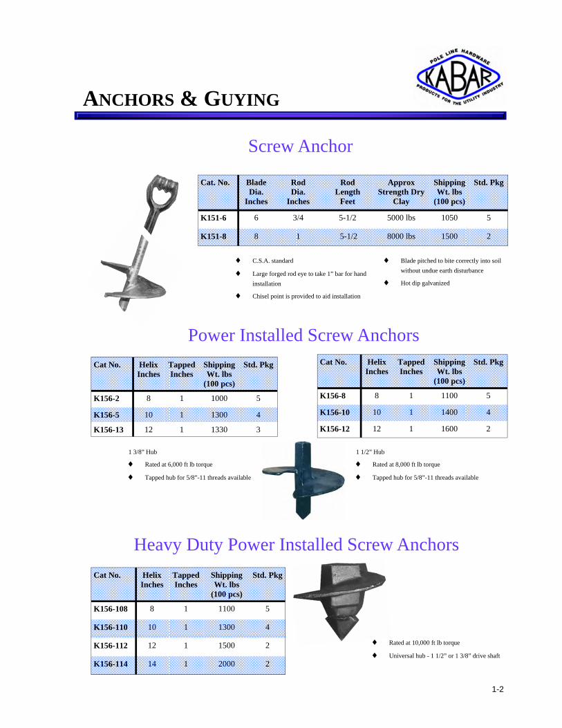
Screw Anchor
Power Installed Screw Anchors Cat No. Helix
Inches Tapped Inches
Shipping Wt. lbs
(100 pcs)
Std. Pkg
K156-2 8 1 1000 5
K156-5 10 1 1300 4
K156-13 12 1 1330 3
Cat No. Helix Inches
Tapped Inches
Shipping Wt. lbs
(100 pcs)
Std. Pkg
K156-8 8 1 1100 5
K156-10 10 1 1400 4
K156-12 12 1 1600 2
1 3/8” Hub
♦ Rated at 6,000 ft lb torque
♦ Tapped hub for 5/8”-11 threads available
1 1/2” Hub
♦ Rated at 8,000 ft lb torque
♦ Tapped hub for 5/8”-11 threads available
Heavy Duty Power Installed Screw Anchors Cat No. Helix
Inches Tapped Inches
Shipping Wt. lbs
(100 pcs)
Std. Pkg
K156-108 8 1 1100 5
K156-110 10 1 1300 4
K156-112 12 1 1500 2
K156-114 14 1 2000 2
Cat. No. Blade Dia.
Inches
Rod Dia.
Inches
Rod Length
Feet
Approx Strength Dry
Clay
Shipping Wt. lbs
(100 pcs)
Std. Pkg
K151-6 6 3/4 5-1/2 5000 lbs 1050 5
K151-8 8 1 5-1/2 8000 lbs 1500 2
♦ C.S.A. standard
♦ Large forged rod eye to take 1” bar for hand installation
♦ Chisel point is provided to aid installation
♦ Blade pitched to bite correctly into soil without undue earth disturbance
♦ Hot dip galvanized
♦ Rated at 10,000 ft lb torque
♦ Universal hub - 1 1/2” or 1 3/8” drive shaft
1-2
ANCHORS & GUYING
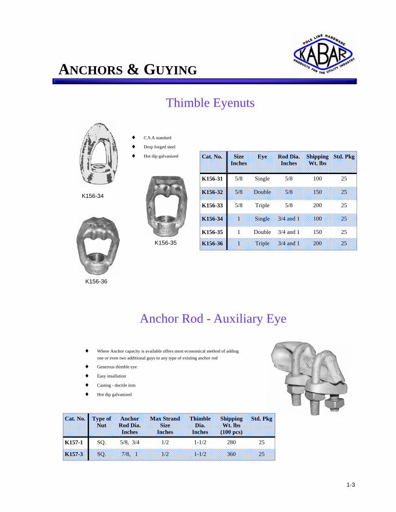
Thimble Eyenuts
Cat. No. Size Inches
Eye Rod Dia. Inches
Shipping Wt. lbs
Std. Pkg
K156-31 5/8 Single 5/8 100 25
K156-32 5/8 Double 5/8 150 25
K156-33 5/8 Triple 5/8 200 25
K156-34 1 Single 3/4 and 1 100 25
K156-35 1 Double 3/4 and 1 150 25
K156-36 1 Triple 3/4 and 1 200 25
♦ C.S.A standard
♦ Drop forged steel
♦ Hot dip galvanized
Anchor Rod - Auxiliary Eye
Cat. No. Type of Nut
Anchor Rod Dia.
Inches
Max Strand Size
Inches
Thimble Dia.
Inches
Shipping Wt. lbs
(100 pcs)
Std. Pkg
K157-1 SQ. 5/8, 3/4 1/2 1-1/2 280 25
K157-3 SQ. 7/8, 1 1/2 1-1/2 360 25
♦ Where Anchor capacity is available offers most economical method of adding one or even two additional guys to any type of existing anchor rod
♦ Generous thimble eye
♦ Easy insallation
♦ Casting - ductile iron
♦ Hot dip galvanized
K156-34
K156-35
K156-36
1-3
ANCHORS & GUYING

Cat. No. Rod Dia.
Inches
Length Feet
Thread Dia.
Inches
Shipping Wt. lbs. (100 pcs)
Std. Pkg
K156-21 5/8 7 5/8 750 10
K156-22 3/4 7 1 900 10
K156-23 1 7 1 1300 5
K156-41 5/8 3-1/2 5/8 400 10
K156-42 3/4 3-1/2 1 585 10
K156-43 1 3-1/2 1 985 5
♦ Drop forged both ends
♦ Hot dip galvanized
Extension Rods
Anchor Rod Coupling
Cat No. Size Inches
Threads
Shipping Wt. lbs
(100 pcs)
Std. Pkg
K156-353 5/8 11 50 50
K156-354 1 8 66 50
♦ Hot dip galvanized
1-4
ANCHORS & GUYING

Single Thimble Eye
Cat No. Rod Dia.
Inches
Length Feet
Shipping Wt. lbs
(100 pcs)
Std. Pkg
K153-5806 5/8 6 720 5
K153-5807 5/8 7 800 5
K153-5808 5/8 8 900 5
K153-3406 3/4 6 984 5
Cat.No. Rod Dia.
Inches
Length Feet
Shipping Wt. lbs
(100 pcs)
Std. Pkg
K153-3407 3/4 7 1130 5
K153-3408 3/4 8 1290 5
K153-3409 3/4 9 1430 5
K153-3410 3/4 10 1560 5
♦ Drop forged steel - galvanized
♦ Supplied with one square nut ♦ Minimum Thread length - 2”
Triple Thimble Eye
K155
Cat No. Rod Dia.
Inches
Length Feet
Shipping Wt. lbs. (100 pcs)
Std Pkg.
K155-1009 1 9 2530 1
K155-1010 1 10 2810 1
K155-1012 1 12 3400 1
Cat No. Rod Dia.
Inches
Length Feet
Shipping Wt. lbs. (100 pcs)
Std Pkg.
K155-3407 3/4 7 1610 1
K155-1007 1 7 1970 1
K155-1008 1 8 2250 1
♦ Drop forged steel - galvanized
♦ Supplied with one square nut ♦ Minimum Thread length - 2”
K154
Double Thimble Eye
Cat No. Rod Dia.
Inches
Length Feet
Shipping Wt. lbs
(100 pcs)
Std. Pkg
K154-5806 5/8 6 750 5
K154-5807 5/8 7 830 5
K154-5808 5/8 8 930 5
K154-3406 3/4 6 1010 5
K154-3407 3/4 7 1160 5
Cat No. Rod Dia.
Inches
Length Feet
Shipping Wt. lbs
(100 pcs)
Std. Pkg
K154-3408 3/4 8 1320 5
K154-3409 3/4 9 1610 5
K154-3410 3/4 10 1800 3
K154-1008 1 8 2350 2
K154-1009 1 9 2900 2
K154-1010 1 10 3400 2
♦ Drop forged steel - galvanized
♦ Supplied with one square nut ♦ Minimum Thread length - 2”
K153
Anchor Rods
1-5
ANCHORS & GUYING

1-6
Rock Anchor
Cat No. Rod Dia.
Inches
Rod Length Inches
Shipping Wt. lbs
(100 pcs)
Std Pkg.
K161-12 1 12 300 10
K161-18 1 18 500 10
♦ Drop forged thimble eye
♦ Heavy wedge and split end
♦ Hot dip galvanized
Rock Anchor Extensions
Cat No. Rod Dia.
Inches
Rod Length
Feet
Load lbs.
Shipping Wt. lbs
(100 pcs)
Std. Pkg
K160-1 5/8 3 12500 500 4
K160-2 3/4 3 18500 750 4
K160-3 3/4 4 18500 850 4
K160-4 3/4 5 18500 1000 4
♦ Safety bolts 3/4” x 4 1/2” included
♦ Used where rock formation is near surface
♦ Drop forged with the clevis swedged to rod
♦ Double thimble eye for one or two guy strand wires
♦ Hot dip galvanized
ANCHORS & GUYING

1-7
Rock Anchor Sliding Cone Wedges
Cat No. Rod Dia.
Inches
Rod Length Inches
Shipping Wt. lbs
(100 pcs)
Std. Pkg
K148-15 3/4 15 337 4
K148-30 3/4 30 675 4
K148-53 3/4 53 750 4
K148-60 3/4 60 850 4
K148-72 3/4 72 1000 4
K148-84 3/4 84 1270 4
K148-96 3/4 96 1500 4
Cat No. Rod Dia. Inches
Rod Length Inches
Shipping Wt. lbs
(100 pcs)
Std. Pkg
K149-30 1 30 500 4
K149-36 1 36 600 4
K149-60 1 60 1250 4
K149-72 1 72 1500 4
K149-96 1 96 1800 4
Pole Bearing Plates
♦ Two required per pole
♦ Provides firm footing for pole or structure
♦ Increases resistance to uplift
♦ Machine and lag bolts not included - order separately
♦ Hot dip galvanized
Cat No. Shipping Wt. lbs
(100 pcs)
Std. Pkg
K170 3600 1 Pr.
♦ Rods - hot dip galvanized
♦ Wedge - oxide inhibiting coating
♦ Other Lengths on Request
K148 Wedge 1 3/4” Dia. Drilled Hole 1 7/8” Dia.
K149 Wedge 2 1/4” Dia. Drilled Hole 2 3/8” Dia.
ANCHORS & GUYING

1-8
Serving Sleeves
Cat No. No. Bolts
Size Bolts
Inches
Length Inches
Strand Size
Inches
Type Shipping Wt. lbs
(100 pcs)
Std. Pkg
K162-1 1 1/2 1-1/2 3/16 - 7/16 medium 23 50
K162-2 2 1/2 3-1/2 3/16 - 7/16 medium 126 25
K162-3 3 1/2 6 3/16 - 7/16 medium 235 25
K162-4 3 5/8 6 5/16 - 1/2 heavy 300 25
Guy Clamps
♦ C.S.A. Standard
♦ Made from hot rolled, open hearth steel with special high strength steel bolts
♦ All clamps have straight smooth clamping surface giving greater holding power
♦ Clamp bars punched to accommodate shoulders of bolts to prevent bolts from turning. Also permits assembling from either side
♦ Hot dip galvanized
K162-2
K162-4
Cat. No Strand Size
Inches
Length Inches
Shipping Wt. lbs
(100 pcs)
Std. Pkg
K49-1 5/16 1-1/2 5 100
K49-2 3/8 1-3/4 6 100
K49-3 7/16 2 7 100
♦ Eliminates frayed ends on guy wire
♦ Protects lineman’s hands
♦ Speedy & economical to install - no special tools required
♦ Hot dip galvanized
Guy Thimbles Cat. No Size
Strand Inches
Shipping Wt. lbs
(100 pcs)
Std. Pkg
K164-1 3/8 10 500
K164-2 1/2 21 250
K164-3 5/8 25 100
♦ Made of pressed steel and grooved to fit various sizes of guy strands
♦ Grooves avoid sharp kinks in guy wire
♦ Hot dip galvanized
♦ Other sizes on request
ANCHORS & GUYING

Guy Hooks K133-AX Cat No. No.
Mtg. Hole
Second Mtg. Hole
Inches
Max. Bolt Dia.
Inches
Max. Strand Dia.
Inches
Thimble Dia.
Inches
Shipping Wt. lbs
(100 pcs)
Std. Pkg
K133-AX 1 - 3/4 1/2 1-3/8 110 25
K133-2* 1 - 3/4 1/2 1-3/8 160 25
K133-3 1 - 1 5/8 1-3/8 220 25
K133-4 2 1/2 3/4 1/2 1-3/8 158 25
K133-5* 2 1/2 3/4 1/2 1-3/8 120 25
Cat No. Upper Hole Dia.
Inches
Lower Hole Dia.
Inches
Max. Strand Dia.
Inches
Thimble Dia.
Inches
Pin Dia.
Inches
Shipping Wt. lbs
(100 pcs)
Std. Pkg
K345-1 3/4 5/8 1/2 1-3/8 5/8 200 25
K345-2 3/4 5/8 1/2 1-3/8 3/4 200 25
K345-3 1 1 — — 7/8 700 25
♦ Used with strand or fiberglass strain insulators
♦ Malleable iron casting
♦ Hot dip galvanized
♦ *Add ACS for concrete or steel poles (no spurs)
Combination Guy Hooks
K345-1 K345-3
K133-3
K133-2
♦ C.S.A. Standard
♦ Almat guy hook ideally suited for down or head guying
♦ Teeth & spurs down slot on wood pole
♦ Used on any angle to 90o
♦ Takes 5/8” or 3/4” bolt
♦ Can also be used on concrete or steel poles ( add “ CS” to CAT NO. )
♦ Lower hole for lag screw or bolt to prevent twisting
♦ * No spurs - for concrete or steel poles.
1-9
ANCHORS & GUYING

1-10
Guy Strain Plates Cat No. Hook Size Shipping
Wt. lbs (100 pcs)
Std. Pkg
K45-1 No 4 x 8 x 12g 100 25
K45-2 Yes 4 x 8 x 12g 110 25
♦ Prevents guy strands cutting into wood pole
♦ Hook is useful when a downpull is required
Cat No. Bolt Dia. Inches
Bolt Hole Inches
Plate Size Inches
Shipping Wt. lbs
(100 pcs)
Std. Pkg
K46-1 5/8 11/16 x 15/16 2-1/2 x 7 x 3/16 90 50
K46-2 3/4 13/16 x 1-1/16 2-1/2 x 7 x 1/4 119 40
K46-3 1 1-1/16 x 5/16 2-1/2 x 7 x 5/16 141 30
2 - Hole Lift Plates - Curved
Cat No. Bolt Dia. Inches
Bolt Hole Inches
Plate Size Inches
Shipping Wt. lbs
(100 pcs)
Std. Pkg
K46-6 5/8 11/16 x 15/16 2-1/2 x 7 x 3/16 86 50
K46-7 3/4 13/16 x 1-1/16 2-1/2 x 7 x 1/4 115 40
K46-8 1 1-1/16 x 5/16 2-1/2 x 7 x 5/16 139 30
3 - Hole Lift Plates - Curved
♦ Six nail holes provided
♦ Formed steel - Hot dip galvanized
Guy Strand Strand
Dia. Inches
Breaking Strength Hard Crucible
Grade 110 Grade 180
Shipping Wt. lbs
(1000 ft.)
1/4 *3950 *6450 129
5/16 *6800 11150 222
3/8 *8250 13500 270
7/16 11900 19500 388
1/2 *15600 *25550 510
* C.S.A. Standard
♦ Used for guying
♦ Supplied in coils of 250 & 500 ft. Galvanized
♦ Other sizes on request
ANCHORS & GUYING

Hub Guards
Guy Guards Cat No. Length
Feet Material Shipping
Wt. lbs (100 pcs)
Std. Pkg
K47-2 7 Half Round 1100 5
K47-3 8 Half Round 1250 4
K47-4 7 Half Hex 1100 10
K47-5 7 Plastic Full Round 315 10
Cat No. Size Inches
Radius Inches
Shipping Wt. lbs
(100 pcs)
Std. Pkg
K50-1 16 x 18 x 1/8 7-1/2 1100 1
K50-2 16 x 30 x 3/16 7-1/2 2750 1
♦ Used to protect poles from vehicle collision
♦ Holes are 9/16” for 1/2” lag bolts
♦ Hot dip galvanized
K47-2,3,4
♦ Steel hot dip galvanized
♦ Supplied with clamp for easy installation
K47-5
♦ Tough, durable polyethylene, clamps attached
♦ Available in highway yellow or grass green - specify
Sidewalk Guy Struts
Cat No. Pipe Size Inches
Description Shipping Wt lbs
(100 pcs)
Std. Pkg
K43-1 2 Guy Clamp Fitting 300 15
K43-2 2 Pole Plate Fitting 200 15
K43-3* 2 to 2-1/2 Guy Clamp Fitting 500 10
K43-4* 2 to 2-1/2 Pole Plate Fitting 400 10
K47-2 K47-3
♦ C.S.A. Standard
♦ Provides head clearance over sidewalk
♦ Used with standard steel pipe
♦ Fittings supplied with set screws
♦ Malleable casting
♦ * Add “A” to Cat No. for Aluminum
K43-2
K43-1
K43-4
K43-3
K47-2
K47-3
1-11
ANCHORS & GUYING

1-12
Strain Yoke Plates
Cat No. Thickness Inches
A Inches
B Inches
C Inches
Shipping Wt. lbs
(100 pcs)
Std. Pkg
K177-1 1/2 5 2-1/2 4-5/8 320 5
K177-2 5/8 8 2-5/16 4-11/16 600 5
K177-3 5/8 8 4-3/8 6-3/4 800 5
K177-4 5/8 17-7/8 4-9/16 7 1600 5
K177-5 5/8 13 3-11/16 6 1040 5
K177-6 5/8 12 5 6 700 5
♦ Some of the strain yoke plates available are shown here. Special yoke plate made to customer’s specifications.
♦ Specify dimensions “A” & “B” strength requirements, number of holes required and sizes.
♦ Plate made from structural steel plate.
♦ All corners rounded to decrease corona effect
♦ Hot dip galvanized
B C
A K177-5
K177-3
K177-4
K177-1 K177-6
ANCHORS & GUYING

B
Strain Links (with Plate)
Cat No. Rod Dia.
Inches
A Inches
B Inches
C Inches
D Inches
E Inches
Ultimate Strength
lbs
Shipping Wt. lbs
(100 pcs)
Std. Pkg
K182-1 5/8 5-7/8 1-3/8 1-5/8 1-3/4 1/2 25000 350 10
K182-2 3/4 6-1/8 1-3/8 1-7/8 1-3/4 5/8 35000 450 10
K182-3 7/8 7 1-1/2 2-3/8 2 5/8 50000 750 5
K182-4 1 8 1-3/4 3 2-1/2 5/8 65000 950 1
K182-5 1-1/4 8-1/2 2 3-1/2 3 5/8 100000 1350 1
♦ Used for deadending on all structures and towers
♦ All parts hot dip galvanized
A
C
D E
Pole Bands (Regular Type)
Cat No. Pipe Size Inches
Dia. Inches
Shipping Wt. lbs
(100 pcs)
Std. Pkg
K30-3 3-1/2 4 325 5
K30-4 4 4-1/2 340 5
K30-5 5 5-9/16 410 5
K30-6 6 6-5/8 430 5
K30-7 7 7-5/8 470 10
K30-8 8 8-5/8 500 8
K30-9 9 9-5/8 550 8
Cat No. Pipe Size Inches
Dia. Inches
Shipping Wt. lbs
Std. Pkg
K31-3 3-1/2 4 380 5
K31-4 4 4-1/2 410 10
K31-5 5 5-9/16 460 10
K31-6 6 6-5/8 500 8
K31-7 7 7-5/8 530 8
K31-8 8 8-5/8 560 8
K31-9 9 9-5/8 600 5
♦ Formed from 1/4” x 1 1/2” flat steel bar
♦ Specify size of bolt required when ordering
♦ Machine bolts supplied for clamping at take off points
♦ Pole bands designed to accept either 1/2” or 5/8” x 2” machine bolts, both at clamp and take off areas
♦ Hot dip galvanized
♦ Other sizes on request
1-13
ANCHORS & GUYING

Strain Plate Clevis (Extension Assembly)
Cat No. A Inches
B Inches
Shipping Wt. lbs
(100 pcs)
Std. Pkg
K53-7 7-1/2 9 220 25
K53-13 13-1/2 15 300 15
K53-19 19-1/2 21 400 10
K53-27 27-1/2 29 500 10
K53-32 32 33-1/2 600 10
B
A
♦ Used to provide additional clearance between primary conductor and ground
♦ Hot dip galvanized
♦ Other sizes and drilling on request
♦ Ring fills or spacing washers - order separately
Extension Straps
Cat No. A Inches
B Inches
C Inches
Thickness Inches
Holes Inches
Shipping Wt. lbs
(100 pcs)
Std. Pkg
K52-3 3 4-1/2 1-1/2 1/4 11/16 44 10/Bundle
K52-6 6 7-3/4 1-1/2 1/4 11/16 100 10/Bundle
K52-8 8 9-3/4 1-1/2 1/4 11/16 120 10/Bundle
K52-10 10 11-3/4 1-1/2 1/4 11/16 140 10/Bundle
K52-12 12 13-3/4 1-1/2 3/8 11/16 210 10/Bundle
K52-14 14 15-3/4 2 3/8 11/16 179 10/Bundle
K52-18 18 19-3/4 1-1/2 1/4 11/16 300 10/Bundle
K52-32 32 33-1/2 1-1/2 1/4 11/16 352 10/Bundle
A B
C
♦ C.S.A. Standard
♦ Provides additional clearance between primary conductor and ground
♦ Other sizes and drilling on request
♦ Hot dip galvanized
1-14
ANCHORS & GUYING

1-15
Epoxy Rod
Cat. No A Inches
B Inches
Shipping Wt. lbs
(100 Pcs)
Std. Pkg
CC15-121* 21-1/2 12 280 10
CC15-181* 27-1/2 18 290 10
CC15-241* 33-1/2 24 300 10
CC15-301* 39-1/2 30 310 10
CC15-361* 45-1/2 36 320 10
B
A
Plastic Phasing Disc Cat No. Wall
Thickness Inches
Shipping Wt. lbs
(100 Pcs)
Std. Pkg.
Phasing Disc - Blue .070 3 100
Phasing Disc - Red .070 3 100
Phasing Disc - White .070 3 100
Phasing Disc - Yellow .070 3 100
♦ FITTINGS: High Strength Aluminum Alloy
♦ ROD: Fiberglass with Ultraviolet Protective Coating
♦ 15,000 LB Min. Ultimate Tensile Strength
♦ Includes one roller. (see last digit of Cat No.)
♦ *If required, specify 0 or 2 rollers by changing last digit of Cat No. accordingly.
♦ Larger sizes available on request
POLYETHYLENE
Metal Phasing Disc
Order by Colour
Wall Thickness
Inches
Shipping Wt. lbs
(100 Pcs)
Std. Pkg.
TR3PH .070 15 100
METAL
♦ Specify colour when ordering - blue, red or white
ANCHORS & GUYING

Cat. No Nominal Size
Inches
Construction Mean. Dia.
Inches
Strength lbs
Length Inches
Colour Shipping Wt. lbs
(100 Pcs)
Std. Pkg
1/4-25-GN 1/4 3 or 7-Wire .249 6650 25 Yellow 34 50
9/32-28-GN 9/32 7-Wire .285 8950 28 Blue 54 50
5/16-30-GN 5/16 3 or 7-Wire .327 11200 30 Black 70 50
3/8-35-GN 3/8 3 or 7-Wire .360 15400 35 Orange 104 50
7/16-38-GN 7/16 7-Wire .432 20800 38 Green 160 25
1/2-45-GN 1/2 7 or 19-Wire .495 26900 45 Blue 254 25
GUY PREFORM
SERVICE ENDS
Cat No. Size A.W.G. Circular
Mills
Type Dia. Inches Min. Holding
lbs
Length Inches
Colour Shipping Wt. lbs
(100 Pcs)
Std. Pkg
19-ADN 6 ACSR .193 590 19 Blue 11 75
22-ADN 4 “ .250 1000 22 Orange 20 40
24-ADN 2 “ .316 1499 24 Red 23 40
26-ADN 2 “ .331 1864 26 Green 26 50
28-ADN 1/0 “ .398 2291 28 Yellow 30 40
31-ADN 2/0 “ .447 2838 31 Blue 40 30
35-ADN 3/0 “ .520 3512 35 Orange 35 25
37-ADN 4/0 “ .563 4434 37 Red 37 25
39-ADN 266.800cm “ .642 6030 39 Black 39 20
44-ADN 336.400cm “ ..721 7476 44 Green 44 20
DEAD END PREFORM
GUY PREFORM
Preforms
Cat No. Size A.W.G. Circular
Mills
Length Inches
Colour Shipping Wt. lbs
(100 Pcs)
Std. Pkg.
10-SSG 6 10 Blue 6 200
12-SSG 5 12 Green 10 100
13-SSG 4 13 Orange 12 100
14-SSG 3 14 Black 15 100
15-SSG 2 15 Red 16 100
17-SSG 1 17 Blue 35 40
19-SSG 1/0 19 Yellow 40 40
21-SSG 2/0 21 Black 45 40
23-SSG 3/0 23 Green 50 30
26-SSG 4/0 26 Orange 54 50
1-16
ANCHORS & GUYING

Steel Ground Rods
Cat No. Dia. Inches
Length Feet
Point Shipping Wt. lbs
(100 pcs)
Std. Pkg
K61-1 5/8 6 Cone 600 5
K61-2 5/8 10 Cone 1000 5
K61-3 3/4 6 Cone 900 5
K61-4 3/4 8 Cone 1200 5
K61-5 3/4 10 Cone 1500 5
K61-7 5/8 7 Cone 700 5
K61-8 5/8 8 Cone 800 5
K61-20 3/4 8 Tapered 1200 5
K61-21 3/4 10 Tapered 1500 5
K56-1
K56-1
♦ Formed from 3/16” x 1 3/4” steel and furnished with one 1/2” x 2 1/4” square head steel set screw, two 1/2” square nuts and two 1/2” round washers
♦ Will accommodate No. 8 to 2/0 stranded conductor
Ground Rod Clamps (Steel)
♦ Ground rod 5/8” and 3/4” dia. are galvanized full length.
♦ Ground Rod Clamps - No’s K56-1 or K56-2 are designed for use on 1/2”, 5/8”, & 3/4” rods, and must be ordered separately.
K56-2
♦ Made from 3/16” x 1 3/4” steel and furnished with square head set screw 1/2” x 2/14” long, 2 square nuts, and one specially formed bracket
♦ Will accommodate any conductor up to 1/2” diameter
Cat No. Shipping Wt. lbs
(100 pcs)
Std. Pkg
K56-1 66 50
K56-2 66 50
♦ Both clamps are designed for use on regular or sectional type 1/2”, 5/8” and 3/4” steel ground rods
♦ Both clamps are hot dip galvanized
Ground Rod Drivers Cat No. Shipping
Wt. lbs (100 pcs)
Std. Pkg
K181-A 2700 1
K181-B 1500 1
♦ Driver made from 1.9” diameter extra heavy steel pipe 4’ long with 4” PLUG doweled and welded in top end
♦ Extension made from 7/8” carbon steel rod doweled and welded into 1.9” diameter extra heavy steel pipe 9” long
♦ Hot dip galvanized
K181-A
K181-B
K56-2
2-1
GROUNDING

2-2
Cat. No Dia. Inches
Length Feet
Shipping Wt. lbs
(100 pcs)
Std. Pkg
K62-7 1/2 7 440 5
K62-8 1/2 8 505 5
K63-6 5/8 6 575 5
K63-8 5/8 8 765 5
K63-10 5/8 10 955 5
K64-6 3/4 6 855 5
K64-8 3/4 8 1140 5
K64-10 3/4 10 1425 5
♦ Heavy uniform covering of electrolytic copper
♦ Corrosion resistant
♦ Easy Driving
♦ Bronze connectors should be used with copper bonded ground rods
Cat. No Rod Dia. Inches
Wire Range Max. Min.
Thread Size
UNC-2A
Shipping Wt. lbs
(100 pcs)
Std. Pkg
K56-58 5/8 1/0 Str. 8 Sol. 7/16-14 29 50
K56-34 3/4 1/0 Str. 8 7/16-14 33 100
Ground Rod Connectors (Bronze)
♦ Non ferrous casting with clamping screw which clamps ground wire to copper bonded ground rod
♦ Floating pressure bar distributes pressure evenly over large area of ground bar
Ground Rods (Copper Bonded)
16”
10”
Cat No. Shipping Wt. lbs
(100 pcs)
Std. Pkg
K61-56 1100 1
♦ Complete with 3/4” Ground Rod Connection Post
♦ Hot dip galvanized
♦ 5/8” post available upon request
♦ Ground Rod Clamp not included. Order separately. Cat No. K56-1, K56-2 or K56-34
Ground Plate
GROUNDING

Ground Support Clamp
♦ Ground support clamp made of self aging aluminum casting alloy
♦ Body drilled and tapped oversize to suit 5/8” - 11 UNC galivanized steel machine bolt. Bolt not included
♦ For .222 to .546 Alumiweld or galvanized steel cable to #9 solid copper wire K56-4
Ground Wire Clips
Cat No. A Inches
B Inches
D Inches
R Inches
Shipping Wt. lbs
(100 pcs)
Std. Pkg
K57-1 1-1/2 3/4 9/32 3/16 4.5 100
K57-2 1-1/2 3/4 9/32 15/16 6 100
♦ Made from 1/8” x 3/4” mild steel
♦ Used to fasten ground wires on steel stuctures
♦ Accommodates conductor range of 1/0 to 2000 MCM AWG stranded copper
♦ Galvanized
Copper Ground Wire Clips Cat No. A
Inches B
Inches D
Inches R
Inches Shipping Wt. lbs
(100 pcs)
Std. Pkg
K57-6C 1-1/2 3/4 9/32 3/16 5 100
♦ Made from 1/8” x 3/4” copper flat bar
♦ Used for clamping stranded wire
♦ Made to Ontario Hydro Spec.
D R
A
B
D R
A
B
Cat No. Shipping Wt. lbs
(100 pcs)
Std. Pkg
K56-4 40 50
2-3
GROUNDING

2-4
Copper Ground Clamp - Splice
C
A D
Cat No. A Inches
B Inches
C Inches
D Inches
Shipping Wt. lbs
(100 pcs)
Std. Pkg
K57-20 7/16 1-13/16 1 19/32 20 100
♦ Made from copper alloy
♦ Used for splicing parallel non-tension to flat surface
B
Copper Ground Connection Plates
♦ Made of hard copper plate with slots to accomodate split bolt connectors for No. 6 copper wire
♦ Separate connections allow for easy testing and inspection
♦ Lag bolts and split bolt connectors to be ordered separately
Cat No. Shipping Wt. lbs
(100 pcs)
Std. Pkg
K54-1 112 25
K54-2 216 25
Gradient Control Mat ♦ 6 ft x 4 ft with 6" x 6" mesh made from 1/4” dia. steel rod, with provision to install 3
ground connectors
♦ Mat is used with all operation switch positions in sub station enclosures as called for in Canadian Electrical Code
♦ Hot dip galvanized
♦ Other sizes on request
6-Way K54-2
3-Way K54-1
Cat No. Mesh Spacing
Shipping Wt. lbs
(100 pcs)
Std. Pkg
K10933 6” x 6” 2800 1 K10933-1 6” x 3” 2700 1
GROUNDING

2-5
Ground Wire Moulding
Staples Cat. No A
Inches B
Inches C
Inches Shipping Wt. lbs
(100 pcs)
Std. Pkg
K920-1 3/8 1-1/4 1/8 1 500
K920-2 11/16 2 3/16 3 500
K920-3 1-1/16 2 3/16 4 500
K920-4 3/4 3 No. 4 ga. 6 100
K920-5 1-1/16 3 No. 4 ga. 8 100
K920-6 2-3/8 3 .232 8 50
Cat. No Wire Groove Dia.
Inches
Length Feet
Shipping Wt. lbs
(1000 ft.)
Std. Pkg
K9805P 1/2 8 60 1000 ft.
♦ Extruded flexible polyethylene moulding
♦ Supplied in 8 ft. lengths and fastened to pole by staple K920-2
♦ Please specify black or gray
Wood Moulding
Cat. No Wire Groove Dia.
Inches
Length Feet
Shipping Wt. lbs
(1000 ft.)
Std. Pkg
K918 1/2 8 65 1000 ft. ♦ Treated with green wood preservative
B
A
C
GROUNDING

Cable Guards Cat No. Width
Inches Length
Feet Shipping Wt. lbs
(100 pcs)
Std. Pkg
K48-3 1-1/4 3 264 5
K48-4 1-1/4 5 440 5
K48-5 1-1/4 8 760 5
K48-6 2-1/4 5 900 5
K48-7 2-1/4 8 1300 5
K48-8 3-1/4 5 1100 5
K48-9 3-1/4 8 2000 3
K48-10 3-3/4 5 1500 3
K48-11 3-3/4 8 2167 3
K48-12 4-3/8 8 2800 3
K48-13 5 5 1800 3
K48-14 5 8 3200 3
K48-15 6 5 2200 3
K48-16 6 8 3500 3
Cat No. Width Inches
Length Feet
Shipping Wt. lbs
(100 pcs)
Std. Pkg
K48-3F 1-1/4 3 276 5
K48-4F 1-1/4 5 460 5
K48-5F 1-1/4 8 840 5
K48-6F 2-1/4 5 940 5
K48-7F 2-1/4 8 1300 5
K48-8F 3-1/4 5 1540 5
K48-9F 3-1/4 8 1867 3
K48-10F 3-3/4 5 1520 5
K48-11F 3-3/4 8 2467 3
♦ Larger sizes on request
♦ Steel galvanized or aluminum extruded
♦ * For aluminum add “A” to Cat No.
♦ Larger sizes on request
♦ Steel galvanized or aluminum extruded
♦ *For aluminum add “A” to Cat No.
PLAIN
FLARED
2-6
GROUNDING

Throat Clips
Cat No. Radius Inches
Cable Guard Size
Inches
Mounting Hole Size
Inches
Shipping Wt. lbs
(100 pcs)
Std. Pkg
K48-29 3/8 3/4 9/32 24 50
K48-30 5/8 1-1/4 9/32 26 25
K48-31 1 2-1/4 15/32 34 25
K48-32 1-5/8 3-1/4 7/16 60 25
K48-33 1-7/8 3-3/4 7/16 80 25
♦ Cast aluminum alloy
♦ Larger sizes on request
Cable Guard Straps
Cat No. Cable Guard Size
Inches
Strap Size Inches
Hole Dia.
Inches
Shipping Wt. lbs
(100 pcs)
Std. Pkg
K48-20 3/4 1/8 x 3/4 9/32 12 100
K48-21 1-1/4 1/8 x 3/4 9/32 15 100
K48-22 2-1/4 1/8 x 3/4 9/32 25 100
K48-23 3-1/4 3/16 x 1 11/32 38 100
K48-24 3-3/4 3/16 x 1 11/32 70 100
K48-25 4-3/4 3/16 x 1 11/32 80 100
K48-26 5 3/16 x 1 11/32 100 100
♦ Steel galvanized
♦ *For aluminum add “A” to Cat No.
♦ Larger sizes on request
2-7
GROUNDING

3-1
Crossarm Reinforcing Plate
♦ Formed from 1/4” x 4” steel plate with pressed rib vertically to give extra strength
♦ Clamps over side of crossarm to prevent checking or splitting at attachment point
♦ Hot dip galvanized
♦ Other sizes on request
3/16”
4”
4” 3/4”
8”
Hollow Steel Crossarms
Cat No. A Inches
B Inches
Thickness Inches
K Feet
L Feet
M Inches
N Inches
P Inches
Load lbs
Shipping Wt. lbs
(100 pcs)
Std. Pkg
K7-1 4 4 .1500 5-1/2 2-1/2 — 15 — 3000 5500 1
K7-2 4 4 .3125 9-1/2 4-1/2 24 18 — 3500 15200 1
K7-3 6 4 .1880 7-1/2 3-1/2 24 18 — 4000 10300 1
K7-4 6 4 .3120 10-1/2 5 24 18 — 4000 21700 1
K7-5 6 4 .3750 12-1/2 6 24 18 18 4000 29800 1
K7-6 4 4 .1500 4’ 10” 2’ 2” 24 18 — 3000 4700 1
K7-7 4 4 .1880 7-1/2 3-1/2 24 18 — 4000 9000 1
K7-8 4 4 .3125 10-1/2 3-1/2 24 18 — 4000 16200 1
♦ Made from hollow H.S.S. (square or rectangular) tubing to C.S.A. M-81
♦ Dead ending for all applications
♦ Can be mounted on wood, concrete or steel poles
♦ All crossarms supplied with welded end caps to prevent bird nesting
♦ Hot dip galvanized after fabrication
Cat No. Shipping Wt. lbs
(100 pcs)
Std. Pkg
K9-1 438 8
K
L
N
P M
B
A
CROSSARMS, BRACES AND GAINS

Wood Crossarms
No. of Arm
A Feet & Inches
B Inches
C Inches
Pin Holes Inches
Mounting Hole
Inches
No. of Pins
Shipping Wt. lbs
(100 pcs)
Std. Pkg
20 2’ 0” 2-3/4 3-3/4 1-1/4 11/16 2 500 1
21 3’ 4” 3-3/4 4-3/4 1-1/2 11/16 2 1365 1
21D 3’ 4” 3-3/4 4-3/4 9/16 11/16 2 1370 1
22 6’ 10” 3-3/4 3-3/4 1-1/2 13/16 2 2210 1
22A 6’ 10” 3-3/4 4-3/4 11/16 13/16 2 2805 1
22D 6’ 10” 3-3/4 4-3/4 13/16 13/16 2 2800 1
25A 4’ 11” 3-3/4 4-3/4 11/16 13/16 2 2015 1
25D 3’ 10” 3-3/4 4-3/4 9/16 11/16 2 1575 1
28 3’ 10” 3-3/4 4-3/4 1-1/2 11/16 2 1570 1
40 5’ 0” 3-3/4 3-3/4 1-1/4 11/16 4 1620 1
41 5’ 6” 3-3/4 4-3/4 1-1/2 11/16 4 2255 1
41D 5’ 6” 3-3/4 4-3/4 9/16 11/16 4 2260 1
42 6’ 4” 3-3/4 4-3/4 1-1/2 11/16 4 2500 1
42D 6’ 4” 3-3/4 4-3/4 9/16 11/16 4 2505 1
43 9’ 10” 3-3/4 4-3/4 1-1/2 13/16 4 3800 1
43A 9’ 10” 3-3/4 4-3/4 11/16 13/16 4 3810 1
43D 9’ 10” 3-3/4 4-3/4 13/16 13/16 4 3805 1
44 8’ 4” 3-3/4 4-3/4 1-1/2 11/16 4 3200 1
44D 8’ 4” 3-3/4 4-3/4 9/16 11/16 4 3205 1
60 7’ 0” 3-1/4 3-1/4 1-1/4 11/16 6 1700 1
61 7’ 8” 3-3/4 4-3/4 1-1/2 11/16 6 3140 1
61D 7’ 8” 3-3/4 4-3/4 9/16 11/16 6 3145 1
62 9’ 4” 3-3/4 4-3/4 1-1/2 11/16 6 3600 1
62D 9’ 4” 3-3/4 4-3/4 9/16 11/16 6 3605 1
80 9’ 0” 3-1/4 4-1/4 1-1/4 11/16 8 2860 1
81 9’ 10” 3-3/4 4-3/4 1-1/2 11/16 8 3800 1
81D 9’ 10” 3-3/4 4-3/4 9/16 13/16 8 3805 1
♦ Where 9/16” holes are required for 1/2” dia. steel pins add suffix D to Cat. No
♦ For larger dia. steel pins specify when ordering
♦ Made of No. 1 B.C Fir coastal grade
♦ Order by number
♦ Add D1 for 11/16” holes
B C
A
3-2
CROSSARMS, BRACES AND GAINS

Steel Crossarms
Cat No. A Inches
B Inches
C Inches
Shipping Wt. lbs
Std. Pkg
K24-1 30 8 4 2900 1
K24-2 40 8 4 3500 1
K24-3 52 8 4 4100 1
♦ Made from heavy duty channel steel with malleable crossarm gain an integral part
♦ Wood pole mounting
♦ *Add suffix “CS” to Cat No. for concrete or steel poles
♦ All parts supplied except mounting bolts
♦ All parts hot dip galvanized
♦ Other sizes on request
Flat Steel Crossarm Brace
Cat. No. A Inches
B Inches
Shipping Wt. lbs
(100 pcs)
Std. Pkg
K11-1 18 16 112 10
K11-2 20 18 128 25
K11-3 22 20 144 25
K11-4 24 22 160 25
K11-5 26 24 176 25
K11-6 28 26 192 25
K11-7 30 28 208 25
K11-8 32 30 212 25
K11-9 34 32 232 25
K11-10 36 34 248 25
K11-11 40 38 280 25
♦ C.S.A. standard
♦ Flat rolled steel bar
♦ Hot dip galvanized
♦ Special sizes on request
B
9/16” 7/16”
A
A
C B
3-3
CROSSARMS, BRACES AND GAINS

Crossarm Brace Angle Arm
Cat No. Size of Angle Inches
A Inches
B Inches
C Inches
Shipping Wt. lbs
(100 pcs)
Std. Pkg
K13-1 1-1/2 x 1-1/2 x 3/16 45 42 12 830 5
K13-2 1-1/2 x 1-1/2 x 3/16 51 48 18 1000 5
K13-3 1-1/2 x 1-1/2 x 3/16 63 60 18 1160 5
K13-4 1-1/2 x 1-1/2 x 3/16 75 72 22 1300 5
K13-5 1-3/4 x 1-3/4 x 3/16 63 60 18 1330 5
K13-6 1-3/4 x 1-3/4 x 3/16 69 66 20 1500 5
K13-7 1-3/4 x 1-3/4 x 3/16 75 72 22 1540 5
♦ Provides rigid support for heavy crossarms
♦ 4 spurs ensure positive positioning on wood or concrete poles
♦ Provided with shoulders to ensure positive locking of mounting bolt
♦ 9/16” holes for mounting to crossarms
♦ 11/16” hole for pole mounting
♦ Steel, hot dip galvanized
♦ Other sizes on request
Cat No. Size of Angle Inches
Length Feet
Shipping Wt. lbs
(100 pcs)
Std. Pkg
K14-1 1-1/2 x1-1/2 x 3/16 5 1100 1
K14-2 1-1/2 x1-1/2 x 3/16 6 1300 5
K14-3 1-1/2 x1-1/2 x 3/16 7 1465 5
K14-4 1-3/4 x1-3/4 x 3/16 7 2100 5
♦ C.S.A. Standard
♦ Made from steel angle with linemen’s step
♦ Used to support distribution conductors on one side of pole
♦ 11/16” hole for pole attachment
♦ 9/16” hole for crossarm
♦ Hot dip galvanized
Angle Alley Arm Brace
B A
C
3-4
CROSSARMS, BRACES AND GAINS

3-5
Crossarm Brace - Angle Steel
Cat No. Size of Angle Inches
Total Length
Feet & Inches
Centre to Center
Feet & Inches
C Inches
D Inches
E Inches
Hole Dia.
Inches
Shipping Wt. lbs
(100 pcs)
Std. Pkg
K15-1 1-1/2 x 1-1/2 x 1/8 4’ 5” 4’ 3” 1 3 3/4 9/16 540 5
K15-2 1-1/2 x 1-1/2 x 1/8 5’ 2” 5’ 1 3 3/4 9/16 640 5
K15-3 3 x 3 x 1/4 8’ 8-5/16” 8’ 5-5/16” 1-1/2 4-1/2 2 13/16 4250 1
♦ For all types of poles
♦ Hot dip galvanized
♦ Other sizes available on request
Double Arm Angle Support
Cat No. Shipping Wt. lbs
(100 pcs)
Std. Pkg
K77-1 750 5
D
E C
♦ Mounted on underside of wood or steel crossarms to support suspension assemblies up to maximum of 45o
♦ All parts hot dip galvanized
♦ Supplied as shown
CROSSARMS, BRACES AND GAINS

3-6
♦ Tapped 3/8” hole for ground attachment
♦ For use with round distribution and transmission arms
♦ Eliminates wood-to-wood contact and lessens probability of decay
♦ Pole arm contacts face and shelf surfaces of Gain - lower portion of Gain offers “wedge” against overturn and vertical movement. Thru bolt in
tension in which it is strongest - not shear
♦ Thru bolt always passes through diametric center of pole arm eliminating costly field drilling
♦ Only one attachment bolt required
♦ One piece will accept range of pole arm diameters
Cat No. Pole Arm Dia. Range Inches
Max. Bolt Dia. Inches
Shipping Wt. lbs
(100 pcs)
Std. Pkg
K115-1 6 - 12 1 530 10
K117-1 8 - 12 1 320 10
Crossarm Gains
Spiked Crossarm Gains
Cat No. Pole Dia. Inches
A Inches
B Inches
Max. Bolt Dia. Inches
Hole Shape Material Shipping Wt. lbs
(100 pcs)
Std. Pkg
K85-1A Any 4 5 3/4 T-Slot Aluminum 90 40
K85-2 5 to 10 4 6 7/8 Round Steel 220 25
K85-3 6 to 12 4-5/8 6 7/8 Round Steel 152 25
K85-4 8 to 15 5 6 7/8 Round Steel 260 25
K85-5 Any 4 4 7/8 Oval Malleable 150 25
A B
K85-3
K85-1A
Slotted ♦ For pole crossarms or spar connection for 3/4” bolts
♦ Made from 1/4” steel plate
♦ Used at junction of wood poles, spars or timbers to provide good bearing surfaces and to increase allowable physical load
♦ To attain a good bearing surface, gains must be seated securely
♦ All gains hot dip galvanized
K115-1
Round Crossarms
Square Crossarms
K117-1
CROSSARMS, BRACES AND GAINS

Adjustable Thrust Fitting
Cat No. Description Shipping Wt. lbs
(100 pcs)
Std. Pkg
K85-15 Complete fitting 5/16” material
(except 3/4” through bolt)
1800 2
♦ On Gulfport Structures, Kabar Adjustable Thrust Fittings join phase to support spars
♦ The following items must be ordered separately: assembly bolts, curved washers and lock nuts
Centre Phase Assembly
Cat No. Shipping Wt. lbs
(100 pcs)
Std. Pkg
K114 600 1
♦ On Gulfport structures the Kabar Centre Phase Assembly supports the middle insulator string
♦ Supplied, hot dip galvanized yoke plate, two clevis links and ball clevis fitting
♦ Order separately, shoulder eye bolts, curved washers and lock nuts
3-7
CROSSARMS, BRACES AND GAINS

Cross Bracing Hardware
Cat No. Shipping Wt. lbs
(100 pcs)
Std. Pkg
K111 7700 1
♦ For H-frame construction, use Kabar Cross Bracing Hardware and insure a well balanced and mechanically strong structure
♦ Supplied as a unit, required fitting, washers, lag bolts and lock nuts for bracing one structure
♦ Through bolts must be ordered separately (3/4 “ dia. ) so that proper length may be supplied
3-8
CROSSARMS, BRACES AND GAINS

4-1
♦ Rigid V-shaped construction
♦ Lifting eyes provided for raising with bracket or complete with two outer transformers in place.
♦ Holes are provided for attaching bracing bolts. Bolts for pole mounting not inculded
♦ Cluster mounting bracket complete with 6 adapter plates.
♦ Stabilizing braces are recommended for K10-3 & K10-6
♦ Hot dip galvanized
Cat No. A Inches
B Inches
C Inches
D Inches
E Inches
Shipping Wt. lbs
(100 pcs)
Std. Pkg
K10-1 29-7/8 11-3/8 15 15 23-1/2 40 1 set
K10-3 34-1/4 12-7/8 22 15 30-1/2 65 1 set
K10-6 34-3/8 12-1/8 29 22 37-1/2 100 1 set
Transformer Cluster Mounting Bracket
B
C
D
E
A
B
Cat No. Take Off B Inches
Shipping Wt. lbs
(100 Pcs)
Std. Pkg
K10-10 Single 9 2200 1 set
K10-12 Triple 9 4500 1 set
Single and Triple Take Off
K10-12 Triple Take Off
TRANSFORMER BRACKETS

Transformer Mounting Plate
♦ Mounting plate (two required) are used to mount transformers directly to pole, eliminating wood cross-arms and transformer hangers
♦ Hot dip galvanized
A
L
C
B
Cat No. A Inches
B Inches
C Inches
L Inches
Shipping Wt. lbs
(100 pcs)
Std. Pkg
K21-6 2-1/2 3 2-3/4 9 2400 3
Transformer Adapter Plates
Cat No. Duty Plate Thickness
Inches
B Inches
Shipping Wt. lbs
(100 pcs)
Std. Pkg
K21-2 Light 1/4 4 900 5 Sets
K21-4 Heavy 7/16 5 1100 5 sets
♦ Light duty plates used for transformers up to 1300 lbs. wt.
♦ Heavy duty plates for transformers up to 2200 Lbs
♦ Two plates required (upper and lower) for each transformer installation
B
Upper Plate with Jumper Lugs
Lower Plate without Jumper Lugs
K21-2 K21-4
4-2
TRANSFORMER BRACKETS

5-1
Spreader Brackets
with Carriage Bolt - 5/8” x 7”
Cat No. Shipping Wt. lbs
(100 pcs)
Std. Pkg
K96-07 180 10
with Double Upset Spool Bolt
Cat No. A Inches
T Inches
Shipping Wt. lbs
(100 pcs)
Std Pkg.
K96-8 8 5 250 10
K96-10 10 6 275 10
K96-12 12 6 300 10
K96-14 14 6 325 10
K96-16 16 6 350 10
♦ Insulator- grey plastic with ultra-violet inhibitors
♦ All ferrous parts hot dip galvanized
♦ Max. vertical load - 2,000 lbs
♦ 5/8” oval eye nut
♦ Messenger clamp - formed flat bar steel 1/8” x 1 5/16”
♦ Carriage bolt comes with 2” long stand off collar
♦ Double Upset Spool bolt comes with 2 - 2 1/4” square washers and 5/8” square nut
6”
4 3/8”
1 1/2”
T
A
K96-10
BRACKETS
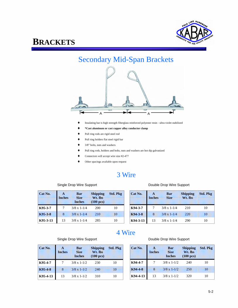
Secondary Mid-Span Brackets
♦ Insulating bar is high strength fiberglass reinforced polyester resin - ultra-violet stabilized
♦ *Cast aluminum or cast copper alloy conductor clamp
♦ Pull ring rods are rigid steel rod
♦ Pull ring holders flat steel rigid bar
♦ 3/8” bolts, nuts and washers
♦ Pull ring rods, holders and bolts, nuts and washers are hot dip galvanized
♦ Connectors will accept wire size #2-477
♦ Other spacings available upon request
Cat No. A Inches
Bar Size
Inches
Shipping Wt. lbs
(100 pcs)
Std. Pkg
K95-3-7 7 3/8 x 1-1/4 200 10
K95-3-8 8 3/8 x 1-1/4 210 10
K95-3-13 13 3/8 x 1-1/4 285 10
Cat No. A Inches
Bar Size
Inches
Shipping Wt. lbs
(100 pcs)
Std. Pkg
K95-4-7 7 3/8 x 1-1/2 230 10
K95-4-8 8 3/8 x 1-1/2 240 10
K95-4-13 13 3/8 x 1-1/2 310 10
Cat No. A Inches
Bar Size
Inches
Shipping Wt. lbs
(100 pcs)
Std. Pkg
K94-4-7 7 3/8 x 1-1/2 240 10
K94-4-8 8 3/8 x 1-1/2 250 10
K94-4-13 13 3/8 x 1-1/2 320 10
Cat No. A Inches
Bar Size
Shipping Wt. lbs
Std. Pkg
K94-3-7 7 3/8 x 1-1/4 210 10
K94-3-8 8 3/8 x 1-1/4 220 10
K94-3-13 13 3/8 x 1-1/4 290 10
4 Wire Double Drop Wire Support Single Drop Wire Support
Single Drop Wire Support Double Drop Wire Support
3 Wire
A A
5-2
BRACKETS

6-1
Cutout - Arrester Combination Brackets
Cat No. L Inches
A Inches
Shipping Wt. lbs
(100 pcs)
Std. Pkg
K87-6 6 specify 300 5
K87-13 13-1/2 3-1/4 600 6
K87-18 18 3-1/4 640 4
A
L
Single Phase
K87-13
Cat No. L Inches
A Inches
Shipping Wt. lbs
(100 pcs)
Std. Pkg
K83-19 19 10 360 5
K83-23 23-1/2 13 420 5
K83-19
C
A K86-13
Cat. No A Inches
C Inches
Shipping Wt. lbs
(100 pcs)
Std. Pkg
K86-6 6 8 300 20
K86-8 8-3/4 8 380 25
K86-13 12-3/4 8 450 10
ARRESTER BRACKETS

6-2
K89-1LH ♦ K89-1 consists of K89-3 with K83-5L
♦ K89-2 consists of K89-3 with K83-2L
♦ K89-1LH has rubber coating as shown
♦ Hot dip galvanized
Cat No. A Inches
B Inches
Shipping Wt. lbs
(100 pcs)
Std. Pkg
K89-1 59 38 3000 1
K89-2 59 38 3000 1
K89-1LH 59 38 3000 1
Cat No. L Inches
Shipping Wt. lbs
(100 pcs)
Std. Pkg
K83-2 60 3000 1
K83-2L 59 2700 1
K83-5 60 3000 1
K83-6 60 3000 1
K83-5L 54 2700 1
Cat No. A Inches
B Inches
C Inches
Shipping Wt. lbs
(100 pcs)
Std. Pkg
K89-3 27-1/2 8-3/8 6 800 1
K89-3CA 27 - - 800 1
B
A
C
K89-3
Single Phase
Three Phase
(27 KV Series)
L
K83-2L
L
K83-5L
Cutout - Arrester Combination Brackets
Two Phase
K89-1 B
A
ARRESTER BRACKETS
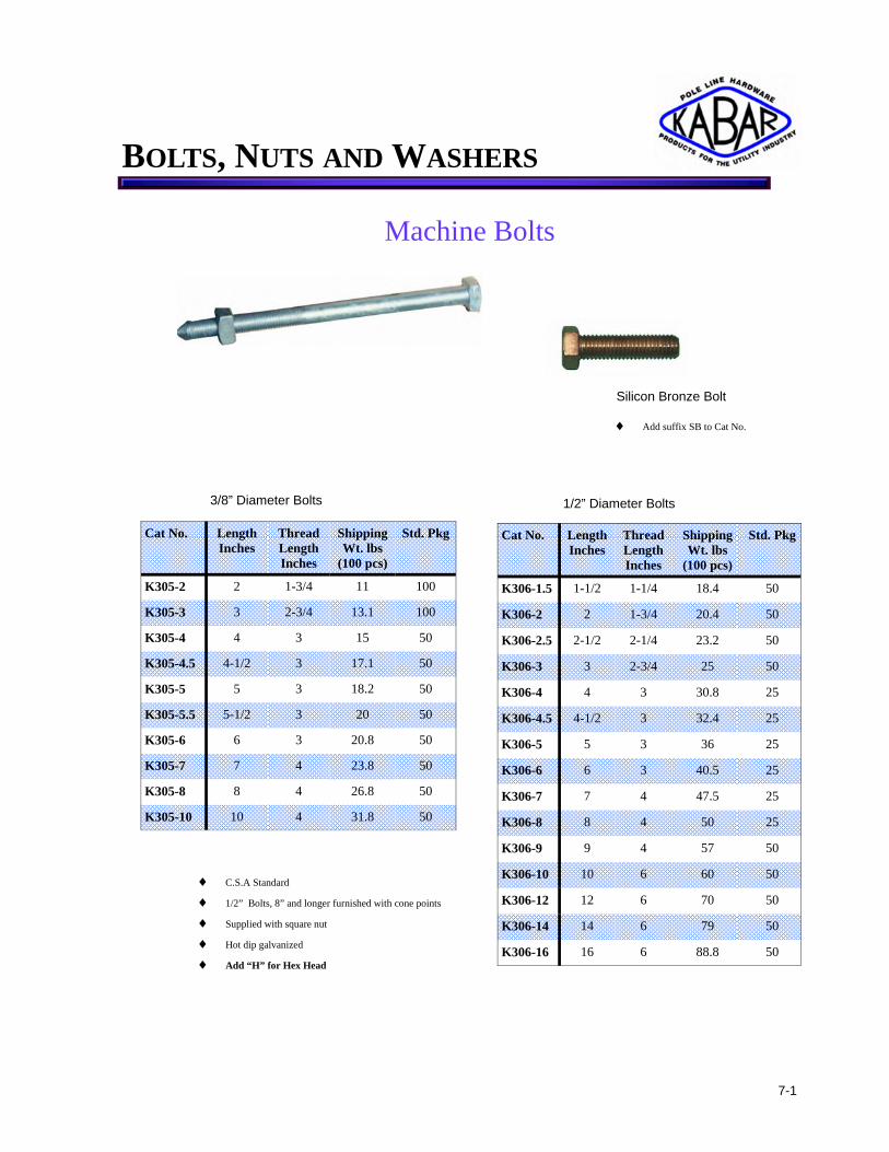
Machine Bolts
♦ C.S.A Standard
♦ 1/2” Bolts, 8” and longer furnished with cone points
♦ Supplied with square nut
♦ Hot dip galvanized
♦ Add “H” for Hex Head
Cat No. Length Inches
Thread Length Inches
Shipping Wt. lbs
(100 pcs)
Std. Pkg
K306-1.5 1-1/2 1-1/4 18.4 50
K306-2 2 1-3/4 20.4 50
K306-2.5 2-1/2 2-1/4 23.2 50
K306-3 3 2-3/4 25 50
K306-4 4 3 30.8 25
K306-4.5 4-1/2 3 32.4 25
K306-5 5 3 36 25
K306-6 6 3 40.5 25
K306-7 7 4 47.5 25
K306-8 8 4 50 25
K306-9 9 4 57 50
K306-10 10 6 60 50
K306-12 12 6 70 50
K306-14 14 6 79 50
K306-16 16 6 88.8 50
1/2” Diameter Bolts
Cat No. Length Inches
Thread Length Inches
Shipping Wt. lbs
(100 pcs)
Std. Pkg
K305-2 2 1-3/4 11 100
K305-3 3 2-3/4 13.1 100
K305-4 4 3 15 50
K305-4.5 4-1/2 3 17.1 50
K305-5 5 3 18.2 50
K305-5.5 5-1/2 3 20 50
K305-6 6 3 20.8 50
K305-7 7 4 23.8 50
K305-8 8 4 26.8 50
K305-10 10 4 31.8 50
3/8” Diameter Bolts
Silicon Bronze Bolt ♦ Add suffix SB to Cat No.
7-1
BOLTS, NUTS AND WASHERS

Machine Bolts
♦ C.S.A Standard
♦ Bolts 8” and longer furnished with cone points
♦ Supplied with square nut
♦ Hot dip galvanized
♦ Add “H” for Hex Head
Cat No. Length Inches
Thread Length Inches
Shipping Wt. lbs
(100 pcs)
Std. Pkg
K307-7 7 4 78 25
K307-8 8 4 86 25
K307-9 9 4 94 25
K307-10 10 4 102 25
K307-12 12 6 115 25
K307-14 14 6 130 25
K307-16 16 6 145 25
K307-18 18 6 160 25
K307-20 20 6 175 25
K307-22 22 6 190 25
K307-24 24 6 209 25
K307-26 26 6 226 25
Cat No. Length Inches
Thread Length Inches
Shipping Wt. lbs
(100 pcs)
Std. Pkg
K308-8 8 4 130 25
K308-10 10 6 150 25
K308-12 12 6 175 25
K308-14 14 6 200 25
K308-16 16 6 225 25
K308-18 18 6 245 25
K308-20 20 6 270 25
K308-22 22 6 300 25
K308-24 24 6 320 25
K308-26 26 6 340 25
K308-28 28 6 360 25
Cat No. Length Inches
Thread Length Inches
Shipping Wt. lbs
(100 pcs)
Std. Pkg
K309-18 18 6 359 25
K309-20 20 6 395 25
K309-22 22 6 430 25
K309-24 24 6 465 25
K309-26 26 6 495 25
K309-28 28 6 530 25
K309-30 30 6 560 25
K309-32 32 6 600 25
K309-34 34 6 635 25
K309-36 36 6 760 25
7/8” Diameter Bolts 3/4” Diameter Bolts
5/8” Diameter Bolts
K309
Silicon Bronze Bolt
♦ Add suffix SB to Cat No.
7-2
BOLTS, NUTS AND WASHERS

Double Arming Bolts
Cat No. Length Inches
Shipping Wt. lbs
(100 pcs)
Std. Pkg
K316-10 10 124 25
K316-12 12 138 25
K316-14 14 152 25
K316-16 16 165 25
K316-18 18 180 25
K316-20 20 195 25
K316-22 22 210 25
K316-24 24 225 25
K316-26 26 252 25
K316-28 28 260 25
K316-30 30 270 25
5/8” Diameter
Cat No. Length Inches
Shipping Wt. lbs
(100 pcs)
Std. Pkg
K317-12 12 230 25
K317-14 14 250 25
K317-16 16 270 25
K317-18 18 290 25
K317-20 20 310 25
K317-22 22 330 25
K317-24 24 350 25
K317-26 26 370 25
K317-28 28 390 25
K317-30 30 410 25
3/4” Diameter
♦ C.S.A standard
♦ Full thread
♦ 4 nuts per bolt
♦ Both ends cone pointed
♦ Hot dip galvanized
Carriage Bolts
♦ C.S.A. Standard
3/8” Diameter
Cat No. Length Inches
Thread Length Inches
Shipping Wt. lbs (100 pcs)
Std. Pkg
K311-3 3 1 13 100
K311-3.5 3 -1/2 1 15 100
K311-4 4 1 16 100
K311-4.5 4 -1/2 1 17 100
K311-5 5 1 19 100
K311.5.5 5 -1/2 1 20 100
K311-6 6 1 24 100
Cat No. Length Inches
Thread Length Inches
Shipping Wt. lbs
(100 pcs)
Std. Pkg
K312-3 3 1 -1/4 25 100
K312-3.5 3 -1/2 1 -1/4 28 100
K312-4 4 1 -1/4 32 100
K312-4.5 4 -1/2 1 -1/4 33 100
K312-5 5 1 -1/4 35 100
K312.5.5 5 -1/2 1 -1/4 38 100
K312-6 6 1 -1/4 42 100
1/2” Diameter
♦ Drop forged steel ♦ Hot dip galvanized ♦ Full thread upon request
7-3
BOLTS, NUTS AND WASHERS

Oval Eye Bolts 5/8” Diameter
Cat No. Length Inches
Thread Length Inches
Shipping Wt. lbs
(100 pcs)
Std. Pkg
K321-6 6 3 122 25
K321-8 8 4 136 25
K321-10 10 4 150 25
K321-12 12 6 168 25
K321-14 14 6 186 25
K321-16 16 6 204 25
K321-18 18 6 222 25
K321-20 20 6 250 25
K321-22 22 6 270 25
Cat No. Length Inches
Thread Length Inches
Shipping Wt. lbs
(100 pcs)
Std. Pkg
K322-6 6 3 185 25
K322-8 8 4 205 25
K322-10 10 4 225 25
K322-12 12 6 250 25
K322-14 14 6 275 25
K322-16 16 6 295 25
K322-18 18 6 320 25
K322-20 20 6 345 25
K322-22 22 6 370 25
3/4” Diameter
Double Arming Oval Eye Bolts
♦ Oval eyes are drop forged
♦ Lengths are measured under eye
♦ Eye bolts are cone pointed
♦ Inside eye 1 1/2” x 2”
Cat No. Length Inches
Thread Length Inches
Shipping Wt. lbs
(100 pcs)
Std. Pkg
K323-14 14 12 212 20
K323-16 16 14 224 20
K323-18 18 16 240 20
K323-20 20 18 252 20
K323-22 22 20 282 20
K323-24 24 22 320 20
K323-26 26 24 350 20
K323-28 28 26 375 20
5/8“ Diameter
Cat No. Length Inches
Thread Length Inches
Shipping Wt. lbs
(100 pcs)
Std. Pkg
K324-16 16 14 304 20
K324-18 18 16 330 20
K324-20 20 18 370 20
K324-22 22 20 384 15
K324-24 24 22 390 15
K324-26 26 24 425 15
K324-28 28 26 460 15
K324-30 30 28 493 15
K324-32 32 30 530 10
3/4” Diameter
♦ C.S.A. standard
♦ Oval eyes are drop forged
♦ Lengths are measured under eye
♦ Eye bolts are cone pointed
♦ Inside eye 1 1/2” x 2”
♦ 4 nuts per bolt
7-4
BOLTS, NUTS AND WASHERS

7-5
♦ C.S.A. standard
♦ Drop forged steel cone pointed
♦ Threads are 6” long
♦ Each bolt supplied with one nut
♦ Hot dip galvanized
Straight Thimble Eye Bolts
Cat No. Length Inches
Shipping Wt. lbs
(100 pcs)
Std. Pkg
K329-8 8 205 25
K329-10 10 225 25
K329-12 12 250 25
K329-14 14 275 25
K329-16 16 295 25
K329-18 18 320 25
K329-20 20 345 25
Cat No. Length Inches
Shipping Wt. lbs (100 pcs)
Std. Pkg
K330-10 10 210 25
K330-12 12 235 25
K330-14 14 260 25
K330-16 16 285 25
K330-18 18 310 25
K330-20 20 330 25
5/8” Diameter
3/4” Diameter
Angle Thimble Eye Bolts
Cat No. Length Inches
Shipping Wt. lbs
(100 pcs)
Std. Pkg
K332-8 8 130 25
K332-10 10 148 25
K332-12 12 166 25
K332-14 14 184 25
K332-16 16 202 25
K332-18 18 220 25
K332-20 20 238 25
5/8” Diameter
Cat No. Length Inches
Shipping Wt. lbs
(100 pcs)
Std. Pkg
K333-10 10 200 25
K333-12 12 225 25
K333-14 14 250 25
K333-16 16 275 25
K333-18 18 300 25
K333-20 20 330 25
3/4” Diameter
♦ C..S.A. standard
♦ Drop forged steel cone pointed
♦ Hot dip galvanized
♦ Thread length is 6” min.
♦ Each bolt supplied with one nut
♦ Bent at 45o angle
BOLTS, NUTS AND WASHERS

Shoulder Eye Bolts
Cat No. Length Inches
Thread Length Inches
Shipping Wt. lbs
(100 pcs)
Std. Pkg
K326-8 8 4 212 25
K326-10 10 4 224 25
K326-12 12 6 240 25
K326-14 14 6 252 25
K326-16 16 6 282 25
K326-18 18 6 320 25
K326-20 20 6 350 25 ♦ Length measured under shoulder
♦ C.S.A. Standard
♦ Drop forged steel
Ball Link Shoulder Eye Bolts
Cat No. Length Inches
Thread Length Inches
Shipping Wt. lbs
(100 pcs)
Std. P{kg
K325-8 8 4 185 25
K325-10 10 4 200 25
K325-12 12 6 216 25
K325-14 14 6 230 25
K325-16 16 6 246 25
K325-18 18 6 262 25
5/8” Diameter 3/4” Diameter
♦ One square nut
♦ Hot dip galvanized
Cat No. Length Inches
Thread Length Inches
Shipping Wt. lbs
(100 pcs)
Std. Pkg
K327-8 8 4 185 25
K327-10 10 4 200 25
K327-12 12 6 217 25
K327-14 14 6 231 25
K327-16 16 6 246 25
K327-18 18 6 263 25
Cat No. Length Inches
Thread Length Inches
Shipping Wt. lbs
(100 pcs)
Std. Pkg
K328-8 8 4 212 25
K328-10 10 4 224 25
K328-12 12 6 240 25
K328-14 14 6 252 25
K328-16 16 6 282 25
K328-18 18 6 320 25
K328-20 20 6 352 25
5/8” Diameter 3/4” Diameter
♦ C.S.A. standard
♦ Linkeye and shoulder bolt are drop forged
♦ One square nut ♦ Provides flexible joint for dead ending on suspension attachment
♦ Hot dip galvanized
7-6
BOLTS, NUTS AND WASHERS

7-7
♦ C.S.A. standard
♦ Drop forged steel
♦ Supplied complete as shown
♦ Used to support neutral wire in rural or light contruction
♦ Spool insulator to be ordered separately
♦ Wrench flats provided on shank
♦ Cotter pin hole located 4 1/8” from the shoulder
♦ Hot dip galvanized
4 5/8”
2” Min.
T
A
Single Upset Spool Bolts
Cat No. A Inches
T Inches
Shipping Wt. lbs
(100 pcs)
Std. Pkg
K126-8D 8 4 150 25
K126-10D 10 6 170 25
K126-12D 12 6 190 25
K126-14D 14 6 210 25
K126-16D 16 6 230 25
Cat No. A Inches
T Inches
Shipping Wt. lbs (100 pcs)
Std. Pkg
K126-8 8 4 140 25
K126-10 10 6 160 25
K126-12 12 6 180 25
K126-14 14 6 200 25
K126-16 16 6 220 25
Double Upset Spool Bolts 5/8”
5 1/4”
A
T
5/8”
BOLTS, NUTS AND WASHERS

U Bolts
Cat No. Shipping Wt. lbs
(100 pcs)
Std. Pkg
K120* 63 50
♦ *Specify if required black or hot dip galvanized and number of nuts required (hex or square)
♦ Please accompany order with a sketch showing dimensions A,B,C,D & T
Standard Type
♦ Used in a vast variety of applications
Medium Type
♦ Used extensively on tower arms and other steel structures for attaching insulator strings
Square Nuts Hexagon Nuts Cat No.
Bolt Size
Inches
Shipping Wt. lbs
(100 pcs)
Std. Pkg
K4-1 3/8 3 100
K4-2 1/2 10 50
K4-3 5/8 11.5 200
K4-4 3/4 23.5 150
K4-5 7/8 46 50
K4-6 1 50 50
K4-1
K5-1
♦ C.S.A. Standard
♦ Made from grade “A” steel
♦ Hot dip galvanized
♦ Tapped UNC thread over size
Cat No.
Bolt Size
Inches
Shipping Wt. lbs
(100 pcs)
Std. Pkg
K5-1 3/8 3 100
K5-2 1/2 10 50
K5-3 5/8 11.5 200
K5-4 3/4 23.5 150
K5-5 7/8 46 50
K5-6 1 50 50
Strand Eye Nuts Cat No. Bolt
Dia. Inches
Minimun Strength
lbs
Shipping Wt. lbs
(100 pcs)
Std. Pkg
K498-1 1/2 7700 90 25
K498-2 5/8 12400 84 50
K498-3 3/4 18300 82 25
C
T
D
A
B
♦ Drop forged steel
♦ Hot dip galvanized
♦ Used for span & single head guying
7-8
BOLTS, NUTS AND WASHERS

7-9
♦ Used for dead ending suspension insulators
♦ Drop forged steel
♦ Hot dip galvanized
Oval Eye Nuts
Cat No. Bolt Dia.
Inches
Strength lbs
Shipping Wt. lbs
(100 pcs)
Std. Pkg
K450-1 1/2 7700 47 50
K450-2 5/8 12400 60 50
K450-3 3/4 18300 60 50
Angle Thimble Eyelet
Cat No. Bolt Dia.
Inches
Strand Dia.
Inches
Strength lbs
Shipping Wt. lbs
(100 pcs)
Std. Pkg
K496-1 11/16 3/16 TO 1/2 12400 134 50
K496-2 13/16 3/16 TO 1/2 18300 128 50
♦ Drop forged steel
♦ Bent at 45o angle
♦ Used to assemble upper end of guy on ground
♦ Hot dip galvanized
Cat No. Bolt Dia.
Inches
Bolt Hole
Inches
Inside Eye
Inches
Shipping Wt. lbs
(100 pcs)
Std. Pkg
K499-1* 3/4 13/16 x 1 1 -1/4 x 3 125 50
K499-2* 5/8 11/16 x 1 1 -1/4 x 3 125 50
♦ Used for dead-ending on crossarms
♦ Hot dip galvanized
♦ * Add “F” for Drop Forged
♦ Bolt can be inserted at an angle as hole is elongated
Bolt Eyes
BOLTS, NUTS AND WASHERS

Lag Screws
Cat. No A Inches
L Inches
Min. Thread Length Inches
Shipping Wt. lbs
(100 pcs)
Std. Pkg
K335-2 1/4 2 1-1/2 3 100
K335-2.5 1/4 2-1/2 1-3/4 4 100
K335-3 1/4 3 2 6 100
K335-3.5 1/4 3-1/2 2-1/4 7 100
K335-4 1/4 4 2-1/2 8 100
K336-2.5 5/16 2-1/2 1-3/4 6 100
K336-3 5/16 3 2 7 100
K336-3.5 5/16 3-1/2 2-1/4 8 100
K337-2.5 3/8 2-1/2 1-3/4 9 100
K337-3 3/8 3 2 11 100
K337-3.5 3/8 3-1/2 2-1/4 12 100
K337-4 3/8 4 2-1/2 13 100
K337-4.5 3/8 4-1/2 2-3/4 15 100
K338-2.5 1/2 2-1/2 1-3/4 17 100
K338-3 1/2 3 2 20 100
K338-3.5 1/2 3-1/2 2-1/4 22 100
K338-4 1/2 4 2-1/2 25 100
K338-4.5 1/2 4-1/2 2-3/4 28 100
K338-5 1/2 5 3 30 100
K338-6 1/2 6 3-1/2 35 100
K339-4 5/8 4 2-1/2 38 100
K339-5 5/8 5 3 46 100
K339-6 5/8 6 3-1/2 54 100
♦ Lag screws are furnished with pilot point, gimlet point or fetter drive
♦ Hot dip galvanized
*Add suffix “F” to Cat. No for Fetter drive, “G” for Gimlet point, “P” for Pilot point
Gimlet Point
A
L
Pilot Point
7-10
BOLTS, NUTS AND WASHERS

7-11
Cotter Key Cat. No Length
Inches Shipping Wt. lbs
(100 pcs)
Std. Pkg
K6 1-3/4 3 100
K6-2 2-1/4 4 100
Pilot Point Drive Hook Cat. No Dia. of
Steel Inches
L Inches
T Inches
Shipping Wt. lbs
(100 pcs)
Std. Pkg
K124 7/16 5-1/2 2-1/2 31 50
♦ Hot dip galvanized
♦ Made of high strength steel
L T
Cat No. Hole Dia. In Centre
Inches
To Fit Pinhole Dia.
Inches
Shipping Wt. lbs
(100 pcs)
Std. Pkg
K1-1 9/16 1-1/2 64 100
K1-2 11/16 1-1/2 62 100
K1-3 13/16 1-1/2 60 100
♦ Used on wood crossarms
♦ Aluminum alloy
Tapered Centering Washers
Cotter Pin Cat No. Dia.
Inches Length Inches
Shipping Wt. lbs
(100 Pcs)
Std. Pkg
K12-1 5/8 2 3/8 23.75 100
K12-2 5/8 13 1/2 116 100
K12-3 5/8 4 1/2 38 100
K12-4 5/8 1 13/16 20 100
♦ Easy Installation
♦ Flat surface for driving
♦ Steel
♦ Hot dip galvanized
♦ Stainless Steel
K6
K6-2
BOLTS, NUTS AND WASHERS

Fill Rings (Washers)
Cat No. Thickness Inches
Shipping Wt. lbs
(100 Pcs)
Std. Pkg
K1834-18* 1/8 6 500
K1834-316* 3/16 10 500
K1834-14* 1/4 15 400
K1834-516* 5/16 17 300
K1834-38* 3/8 20 300
K1834-716* 7/16 23 200
K1834-12* 1/2 26 200
K1834-916* 9/16 30 200
K1834-58* 5/8 34 200
K1834-1116* 11/16 37 200
K1834-34* 3/4 40 150
K1834-1316* 13/16 43 150
K1834-78* 7/8 46 150
K1834-1516* 15/16 50 100
K1834-1* 1 55 100
♦ *Malleable iron or steel
♦ Made to Ontario spec. M246-73
♦ Used in assembly of steel structures as fill rings or spacers
♦ Hot dip galvanized
I.D. O.D.
Cat No. Thickness Inches
Shipping Wt. lbs
(100 Pcs)
Std. Pkg
K1812-18* 1/8 5.5 500
K1812-316* 3/16 9 500
K1812-14* 1/4 13.5 400
K1812-516* 5/16 15.5 300
K1812-38* 3/8 18 300
K1812-716* 7/16 20.5 200
K1812-12* 1/2 23.5 200
K1812-916* 9/16 27 200
K1812-58* 5/8 31.5 200
K1812-1116* 11/16 33.5 200
K1812-34* 3/4 36 150
K1812-1316* 13/16 38 150
K1812-78* 7/8 41.5 150
K1812-1516* 15/16 45 100
K1812-1* 1 49.5 100
I.D. 11/16” O.D. 1 1/2”
I.D. 13/16” O.D. 1 3/4”
7-12
BOLTS, NUTS AND WASHERS

Spring Lock Washers
Cat No. Bolt Dia.
Inches
Steel Size
Inches
Shipping Wt. lbs
(100 pcs)
Std. Pkg
K3-1 3/8 .141 X .094 .7 100
K3-2 1/2 .171 X .125 1.5 100
K3-3 5/8 .203 X .156 2.5 100
K3-4 3/4 .234 X .188 4.3 100
K3-5 7/8 .266 X .219 7 100
K3-6 1 .297 X .250 9.5 100
♦ C.S.A. Standard
♦ Hot dip galvanized
Round Washers
♦ C.S.A. Standard
♦ Hot dip galvanized
Cat No. Bolt Dia.
Inches
Hole Dia.
Inches
Outside Dia.
Inches
Thickness Inches
Shipping Wt. lbs
(100 pcs)
Std. Pkg
K20-1 3/8 7/16 1 5/64 2 100
K20-2 1/2 9/16 1 -3/8 7/64 3 100
K20-3 5/8 11/16 1 -3/4 9/64 8 100
K20-4 3/4 13/16 2 9/64 10 100
K20-5 7/8 1 2 -1/4 9/64 14 100
K20-6 1 1 -1/8 2 -1/2 9/64 17 100
K20-7 1 -1/4 1 -3/8 2 -3/4 11/64 19 100
7-13
BOLTS, NUTS AND WASHERS

Square Washers
♦ C.S.A. Standard
♦ Hot dip galvanized
♦ Special sizes on request
K16-2
Cat No. Size Washer Inches
Hole Dia. Inches
Bolt Dia. Inches
Shipping Wt. lbs
(100 pcs)
Std. Pkg
K16-1 2 x 2 x 1/8 9/16 1/2 14 200
K16-2 2 x 2 x 3/16 9/16 1/2 21 200
K16-3 2 x 2 x 1/8 11/16 1/2 or 5/8 21 200
K16-4 2 x 2 x 3/16 11/16 1/2 or 5/8 21 200
K16-5 2 x 2 x 3/16 13/16 3/4 21 200
K16-6 2 -1/4 x 2 -1/4 x 3/16 11/16 1/2 or 5/8 21 200
K16-7 2 -1/4 x 2 -1/4 x 3/16 13/16 3/4 21 100
K16-8 3 x 3 x 3/16 13/16 5/8 or 3/4 63 100
K16-9 3 x 3 x 1/4 13/16 5/8 or 3/4 63 100
K16-10 3 -1/4 x 3 -1/4 x 1/4 13/16 5/8 or 3/4 70 100
K16-11 3 -1/2 x 3 -1/2 x 3/8 13/16 5/8 or 3/4 125 100
K16-12 4 x 4 x 3/16 13/16 5/8 or 3/4 87 100
K16-13 4 x 4 x 1/4 13/16 5/8 or 3/4 120 50
K16-14 4 x 4 x 1/4 15/16 3/4 or 7/8 114 50
K16-15 4 x 4 x 3/8 15/16 5/8 or 7/8 176 50
K16-16 4 x 4 x 3/8 1 -1/16 1 178 50
K16-17 4 x 4 x 1/2 1 -1/16 1 216 50
K16-18 6 x 6 x 3/8 15/16 3/4 or 7/8 370 50
K16-19 6 x 6 x 3/8 1 -1/16 1 360 50
K16-20 6 x 6 x 1/2 1 -1/8 1 530 10
7-14
BOLTS, NUTS AND WASHERS

7-15
Cat No. Size Washer Inches
Hole Dia.
Inches
Bolt Dia.
Inches
Shipping Wt. lbs
(100 pcs)
Std. Pkg
K17-0 2 x 2 x 3/16 13/16 5/8 or 3/4 22.5 200
K17-01 2 x 2 x 3/16 11/16 1/2 or 5/8 25 200
K17-1 2 -1/4 x 2 -3/16 x 3/16 11/16 5/8 or 1/4 27 200
K17-2 2 -1/4 x 2 -3/16 x 3/16 13/16 5/8 or 3/4 27 200
K17-3 3 x 2 -7/8 x 1/4 11/16 1/2 or 5/8 64 50
K17-4 3 x 2 -7/8 x 1/4 13/16 5/8 or 3/4 64 50
K17-5 3 x 2 -7/8 x 3/8 15/16 3/4 or 7/8 64 50
K17-6 3 -1/4 x 3 -1/8 x 1/4 13/16 5/8 or 3/4 150 50
K17-7 3 -1/4 x 3 -1/8 x 3/8 13/16 5/8 or 3/4 52 50
K17-8 3 -1/2 x 3 -3/8 x 3/8 13/16 5/8 or 3/4 60 50
K17-9 4 x 3 -7/8 x 3/16 13/16 5/8 or 3/4 55 50
K17-10 4 x 3 -7/8 x 1/4 13/16 5/8 or 3/4 100 50
K17-11 4 x 3 -7/8 x 1/4 15/16 3/4 or 7/8 114 50
K17-12 4 x 3 -7/8 x 3/8 15/16 3/4 or 7/8 172 50
K17-13 4 x 3 -7/8 x 3/8 1 1/8 1 172 50
K17-14 4 x 3 -7/8 x 1/2 1 1/8 1 233 50
K17-15 6 x 5 -7/8 x 3/8 1 1/8 1 150 50
K17-16 6 x 5 -7/8 x 1/2 13/16 5/8 or 3/4 528 100
K17-17 6 x 5 -7/8 x 1/2 1 1/8 1 526 100
K17-18 5 x 5 x 1/2 15/16 3/4 or 7/8 364 100
K17-19 2 x 3 -1/4 x 1/4 11/ 16 5/8 46 100
K17-20 4 x 3 -7/8 x 3/8 13/16 5/8 173 100
K17-21 4 x 5 x 3/8 13/16 5/8 300 100
Curved Washers
♦ C.S.A. Standard
♦ Steel
♦ Hot dip galvanized
♦ Special sizes on request
K17-2
Cat No. For Bolt Dia.
Inches
Shipping Wt. lbs
(100 pcs)
Std. Pkg
K2-2 1/2 9 100
K2-3 5/8 10 100
K2-4 3/4 10 100
Spur Washers
♦ C.S.A. Standard
♦ Steel
♦ Hot dip galvanized
BOLTS, NUTS AND WASHERS

Pole Top Pin (Pressed Steel)
♦ C.S.A. Standard
♦ Provides additional clearance between primary conductor and ground
♦ Other sizes and drilling on request
♦ Hot dip galvanized
Cat No. A Inches
B Inches
C Inches
Shipping Wt. lbs
(100 pcs)
Std. Pkg
K201-3 24 8 1-3/8 600 10
K201-5 18 8 1 380 10
K201-6 24 8 1 500 10
B
A
C
1 1/2”
13/16”
Pole Top Extension Pin
♦ Made from heavy duty channel
♦ Extra strength for supporting conductor above wood pole top
♦ C.S.A. die cast lead threads (specify 1” or 1 3/8”)
♦ Hot dip galvanized
Cat No. A Inches
C Inches
Shipping Wt. lbs
(100 pcs)
Std. Pkg
K200-1 36 1 1050 1
K200-2 44 1 1200 1
K200-3 48 1 1500 1
K200-4 36 1 3/8 1100 1
K200-5 44 1 3/8 1250 1
K200-6 48 1 3/8 1550 1
A
C
8-1
INSULATOR PINS
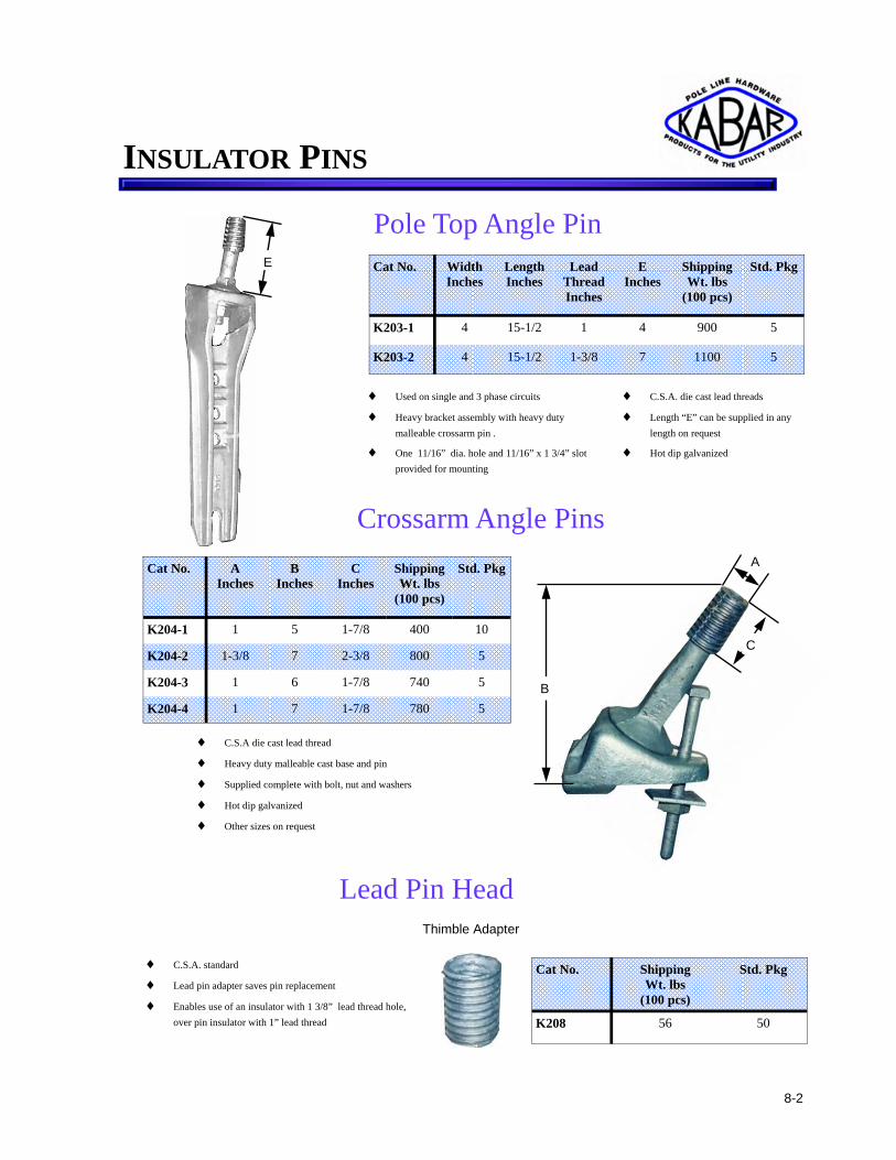
Pole Top Angle Pin Cat No. Width
Inches Length Inches
Lead Thread Inches
E Inches
Shipping Wt. lbs
(100 pcs)
Std. Pkg
K203-1 4 15-1/2 1 4 900 5
K203-2 4 15-1/2 1-3/8 7 1100 5
♦ Used on single and 3 phase circuits
♦ Heavy bracket assembly with heavy duty malleable crossarm pin .
♦ One 11/16” dia. hole and 11/16” x 1 3/4” slot provided for mounting
♦ C.S.A. die cast lead threads
♦ Length “E” can be supplied in any length on request
♦ Hot dip galvanized
Lead Pin Head Thimble Adapter
♦ C.S.A. standard
♦ Lead pin adapter saves pin replacement
♦ Enables use of an insulator with 1 3/8” lead thread hole, over pin insulator with 1” lead thread
Cat No. Shipping Wt. lbs
(100 pcs)
Std. Pkg
K208 56 50
Crossarm Angle Pins Cat No. A
Inches B
Inches C
Inches Shipping Wt. lbs
(100 pcs)
Std. Pkg
K204-1 1 5 1-7/8 400 10
K204-2 1-3/8 7 2-3/8 800 5
K204-3 1 6 1-7/8 740 5
K204-4 1 7 1-7/8 780 5
♦ C.S.A die cast lead thread
♦ Heavy duty malleable cast base and pin
♦ Supplied complete with bolt, nut and washers
♦ Hot dip galvanized
♦ Other sizes on request
C
A
B
E
8-2
INSULATOR PINS

Insulator Pins ( Long Shank) Cat No. A
Inches B
Inches C
Inches D
Inches E
Inches F
Inches Shipping Wt. lbs
(100 pcs)
Std. Pkg
K206-1 1/2 3-3/4 5-1/2 1-3/4 1 2 125 25
K206-2 1/2 4-3/4 5-1/2 1-3/4 1 2 130 25
K206-6 5/8 4-3/4 5-1/2 2 1 2-1/2 165 25
K206-7 5/8 4-3/4 6-1/2 2 1 2-1/2 170 25
K206-8 5/8 6 4-3/4 2 1 2-1/2 180 25
K206-9 5/8 6 5-1/2 2 1 2-1/2 185 25
K206-10 5/8 6 6-1/2 2 1 3 195 25
K206-11 5/8 6 8 2-1/2 1 3 200 25
K206-12 5/8 6 5-1/2 2 1-3/8 3 195 25
K206 16 3/4 4-3/4 5-3/4 2 1 3 230 25
K206-17 3/4 6 5-3/4 2 1 3 250 25
K206-18 3/4 6 6-3/4 2 1 3 260 25
K206-19 3/4 6 5-3/4 2 1-3/8 3 290 25
K206-20 3/4 6 6-3/4 2 1-3/8 3 310 25
K206-21 3/4 6 7 2 1 3 265 25
B
A
D
E
C
F
♦ C.S.A. die cast lead thread
♦ Drop forged pins - equipped with square nut.
♦ Tapered body for maximum strength
♦ Hot dip galvanized
Insulator Pins (Short Shank) Cat No. A
Inches B
Inches C
Inches D
Inches E
Inches Shipping Wt. lbs
(100 pcs)
Std. Pkg
K207-0 5/8 4-3/4 1-1/2 2-1/2 1 100 25
K207-1 5/8 5 1-1/2 2-1/2 1 120 25
K207-2 3/4 12 1-3/4 3-1/4 1-3/8 760 10
K207-3 3/4 6 1-1/2 2-1/2 1 188 25
K207-4 3/4 8 1-1/2 3-1/4 1-3/8 555 15
K207-5 3/4 13 1-3/4 3-1/4 1-3/8 800 5 C
E
D A
B
♦ C.S.A. die cast lead thread
♦ Drop forged pins - equipped with split lock washer and square nut.
♦ Tapered body for maximum strength
♦ Hot dip galvanized
8-3
INSULATOR PINS

8-4
Insulator Pins (Primary Drop Wire)
Cat No. Thread Dia.
Inches
Thread Length Inches
A Inches
B Inches
C Inches
Shipping Wt. lbs
(100 pcs)
Std. Pkg
K205-1 1 1-3/4 7 5/8 - 11 2-1/4 108 25
K205-2 1 1-3/4 9 5/8 - 11 2-1/4 120 25
K205-3 1 1-3/4 10 5/8 - 11 2-1/4 128 25
K205-4 1 1-3/4 12 5/8 - 11 2-1/4 144 25
K205-5 1 1-3/4 17 5/8 - 11 11 180 25
K205-6 1 1-3/4 20 5/8 - 11 11 204 25
K205-7 1 1-3/4 24 5/8 - 11 16 300 15
K205-8 1-3/8 2 12 3/4 - 10 2-1/4 252 25
K205-9 1-3/8 2 24 3/4 - 10 2-1/4 253 15
♦ Round steel bar supplied with two nuts
♦ Washers not included
♦ C.S.A. die cast lead thread
♦ Hot dip galvanized
♦ Other sizes on request
Cat No. A Inches
B Inches
C Inches
D Inches
E Inches
F Inches
Shipping Wt. lbs
(100 pcs)
Std. Pkg
K215-1 5/8 7 6 3-1/4 1-3/8 2-1/4 260 25
K215-2 5/8 7 7 3-1/4 1-3/8 2-1/4 260 25
K215-3 5/8 8 6 3-1/4 1-3/8 2-1/4 450 10
K215-4 5/8 8 7 3-1/4 1-3/8 2-1/4 525 10
K215-5 3/4 8 7 3-1/4 1-3/8 3 487 10
K215-6 3/4 12 7 3-1/4 1-3/8 3 730 5
K215-7 3/4 13 7 3-1/4 1-3/8 3 790 5
K215-8 3/4 6 7 3-1/4 1-3/8 3 365 10
K215-9 3/4 7 7 3-1/4 1-3/8 3 426 10
Heavy Duty Insulator Pins
A
D
E
F
B
A
C
♦ Heavy duty malleable with steel stud complete with spur washer and nut
♦ C.S.A. die cast lead thread
♦ Hot dip galvanized
♦ Other sizes and hex nuts on request
B
C
INSULATOR PINS
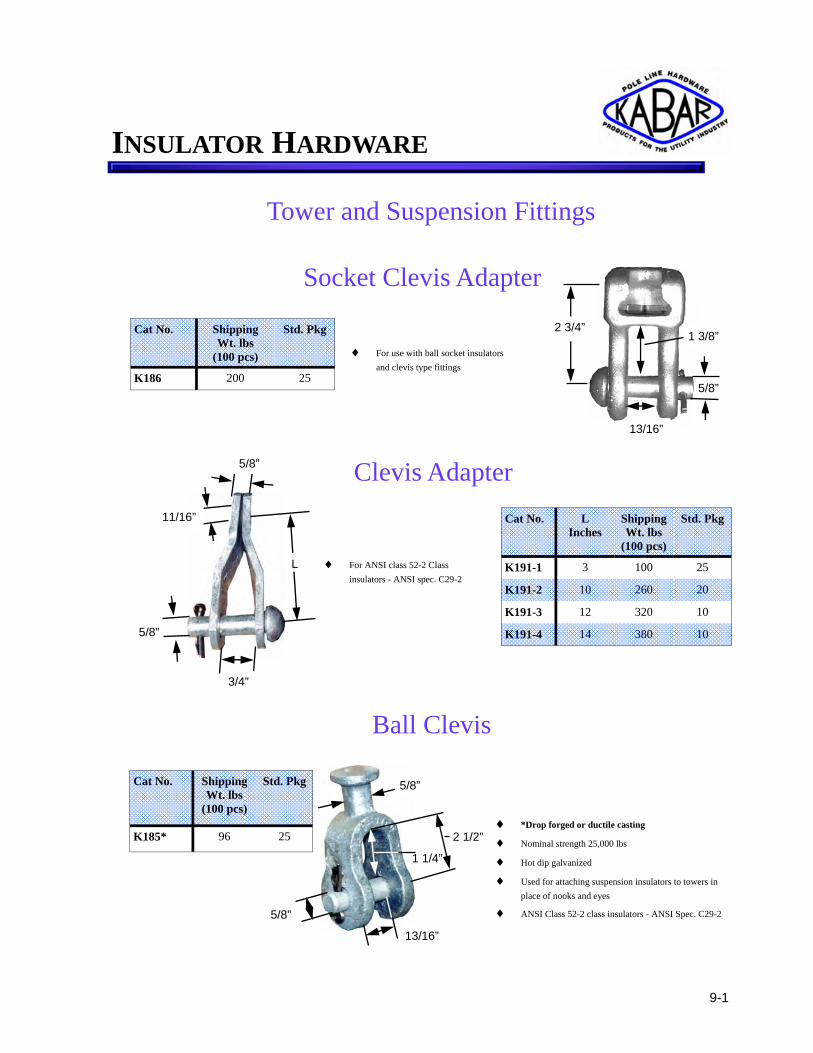
5/8”
Socket Clevis Adapter
Clevis Adapter
5/8”
L
11/16”
5/8”
3/4”
Cat No. L Inches
Shipping Wt. lbs
(100 pcs)
Std. Pkg
K191-1 3 100 25
K191-2 10 260 20
K191-3 12 320 10
K191-4 14 380 10
♦ For ANSI class 52-2 Class insulators - ANSI spec. C29-2
Tower and Suspension Fittings
Cat No. Shipping Wt. lbs
(100 pcs)
Std. Pkg
K186 200 25
♦ For use with ball socket insulators and clevis type fittings
Ball Clevis
♦ *Drop forged or ductile casting
♦ Nominal strength 25,000 lbs
♦ Hot dip galvanized
♦ Used for attaching suspension insulators to towers in place of nooks and eyes
♦ ANSI Class 52-2 class insulators - ANSI Spec. C29-2
2 1/2”
5/8”
5/8”
13/16”
1 1/4”
Cat No. Shipping Wt. lbs
(100 pcs)
Std. Pkg
K185* 96 25
1 3/8” 2 3/4”
13/16”
9-1
INSULATOR HARDWARE

Ball Eye Oval
♦ *Drop forged or ductile casting
♦ Nominal strength 25,000 lbs
♦ Hot dip galvanized
11/16”
1” 2”
3 1/2”
Ball Eye Round
Ball Socket Tongue
♦ Hot dip galvanized
♦ Nominal strength 25,000 lbs
Cat No. L Inches
Shipping Wt. lbs
(100 pcs)
Std. Pkg
K184-1 5/8 140 25
K184-2 3/4 148 25
K184-3 13/16 152 25
K187 K194-1
Cat No. Shipping Wt. lbs
(100 pcs)
Std. Pkg
K187* 100 25
Cat No. Shipping Wt. lbs
(100 pcs)
Std. Pkg
K194-1* 90 50
1 1/16”
L
9/16”
2 7/32”
9-2
INSULATOR HARDWARE

9-3
Double Eye Clevis
Double Eye Socket
Cat No. Hole Dia.
Inches
Shipping Wt. lbs
(100 pcs)
Std. Pkg
K190* 11/16 200 25
♦ *Ductile or malleable casting
♦ Can be supplied with bolt
♦ Ultimate strength 25,000 lbs
♦ Hot dip galvanized
Cat No. Hole Dia.
Inches
Shipping Wt. lbs
(100 pcs)
Std. Pkg
K189* 11/16 260 25
♦ *Ductile or malleable casting
♦ Ultimate strength 25,000 lbs
♦ Hot dip galvanized
Anchor Shackle
♦ Ultimate load: as forged - 30,000 lbs 135 kN.min. *heat treated - 60,000 lbs 266 kN min.
♦ *Add suffix “LT” for Heat Treated
♦ Hot dip galvanized
Cat No. Bolt Type Dia. Inches
Shipping Wt. lbs
(100 pcs)
Std. Pkg
K196-1 Clevis Pin 5/8 152 25
K196-1B Hex Head 5/8 152 25
K196-2 Clevis Pin 3/4 152 25
K196-2B Hex Head 3/4 152 25
1 3/4”
2 3/8”
2 3/8”
2 3/16”
INSULATOR HARDWARE

9-4
Figure - 8 Double Links
Plain
90o Twisted K188-1
♦ Drop forged steel
♦ Nominal strength - 18,000 lbs.
♦ Heat treated strength - 25,000 lbs
♦ Hot dip galvanized
7/8”
1 1/8” 1 1/8”
3 3/8”
K188-2
Strain Link
Cat No. Yield lbs
Ultimate Strength
lbs
A Inches ± 1/8
B Inches ± 1/8
D Inches
Shipping Wt. lbs
(100 pcs)
Std. Pkg
K182-34 40000 60000 1-1/8 3-5/8 3/4 144 25
♦ Drop forged
♦ Heat treated
♦ Hot dip galvanized
Cat No. Shipping Wt. lbs
(100 pcs)
Std. Pkg
K188-1 76 50
K188-2 76 50
A
B
D
INSULATOR HARDWARE

Straight Double Clevis
♦ Double clevises are ductile castings
♦ *Add “B“ to Cat No. for machine bolt, nut and cotter key.
♦ All ferrous parts hot dip galvanized
♦ Ultimate strength 30,000 lbs
Cat No. L Inches
Shipping Wt. lbs
(100 pcs)
Std. Pkg
K180-1* 4 300 20
7/8”
L
90 o Double Clevis
Cat No. L Inches
Shipping Wt. lbs
(100 pcs)
Std. Pkg
K183-2* 3-5/8 240 20
L ♦ Double clevises are ductile castings
♦ *Add suffix “B” to Cat No. for machine bolt, nut and cotter key
♦ All ferrous parts hot dip galvanized
♦ Ultimate strength 30,000 lbs
7/8”
9-5
INSULATOR HARDWARE

Cat No. Range Minimun Maximum
Shipping Wt. lbs
(100 pcs)
Std. Pkg
K240-1* .25 .60 185 10
K240-1D* .25 .60 190 10
K240-2* .50 .93 260 10
K240-2D* .50 .93 265 10
Straight Line Clamp
♦ High strength aluminum body
♦ Captured steel U bolts, steel cotter bolts, S.S. cotter key
♦ Wave seat
♦ Pulling and lifting eye
♦ Provision for jumper stud
♦ *Add “D” for drilled for stud
Cat. No Description Shipping Wt. lbs
(100 pcs)
Std. Pkg
K241-1 Jumper Holding Stud 125 25
K241-2 Straight Jumper Stud 100 25
K241-3 120o Jumper Stud 105 25
K241-4 100o Jumper Stud 125 25
Jumper Studs
♦ Kabar connector consists of straight line dead end clamp incorporating machined double tapered hole which can accommodate a straight jumper stud
♦ Clamps available in heat-treated aluminum alloy only
♦ Straight jumper studs are made from electrolytic copper bar with the tapered end tinned providing good conductivity between the clamp and stud
♦ Jumper Holding Stud - steel, hot dip galvanized
K-240-1D
K241-1
K241-3
K241-4
9-6
INSULATOR HARDWARE

Live Line Pigtail Connectors
K241-7
Cat No. MCM Strands Shipping Wt. lbs
(100 pcs)
Std. Pkg
K241-6 350 61 253 15
K241-62 500 61 290 15
♦ For single connection designed to be compressed on a conductor and clamped to a stud of a live line connecion
♦ Commonly used to isolate overhead equipment within a distribution system or change out
K241-6
Cat No. MCM Strands Shipping Wt. lbs
(100 pcs)
Std. Pkg
K241-7 350 61 250 10
K241-72 500 61 250 10
♦ Copper compression terminal , 2 hole NEMA pad for extra flex conductor
2 1/8” 4 1/8”
3”
K241-5 Cat No. MCM Strands Shipping
Wt. lbs (100 pcs)
Std. Pkg
K241-5 350 61 280 15
9-7
INSULATOR HARDWARE
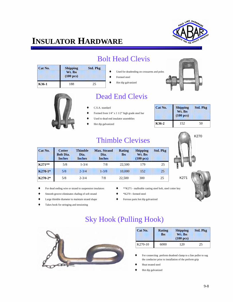
9-8
♦ Used for deadending on crossarms and poles
♦ Formed steel
♦ Hot dip galvanized
Dead End Clevis ♦ C.S.A. standard
♦ Formed from 1/4” x 1 1/2” high grade steel bar
♦ Used to dead end insulator assemblies
♦ Hot dip galvanized
Cat No. Shipping Wt. lbs
(100 pcs)
Std. Pkg
K36-2 152 50
Bolt Head Clevis Cat No. Shipping
Wt. lbs (100 pcs)
Std. Pkg
K36-1 188 25
Thimble Clevises Cat No. Cotter
Bolt Dia. Inches
Thimble Dia.
Inches
Max. Strand Dia.
Inches
Rating lbs
Shipping Wt. lbs
(100 pcs)
Std. Pkg
K271** 5/8 1-3/4 7/8 22,500 179 25
K270-1* 5/8 2-3/4 1-3/8 10,000 152 25
K270-2* 5/8 2-3/4 7/8 2 22,500 300 25
♦ For dead ending wire or strand to suspension insulators
♦ Smooth groove eliminates chafing of soft strand
♦ Large thimble diameter to maintain strand shape
♦ Takes hook for stringing and tensioning
K270
K271
♦ **K271 - malleable casting steel bolt, steel cotter key
♦ *K270 - formed steel
♦ Ferrous parts hot dip galvanized
Sky Hook (Pulling Hook) Cat No. Rating
lbs Shipping Wt. lbs
(100 pcs)
Std. Pkg
K270-10 6000 120 25
♦ For connecting preform deadend clamp to a line puller to sag the conductor prior to installation of the preform grip
♦ Heat treated steel
♦ Hot dip galvanized
INSULATOR HARDWARE

9-9
Single Bolt Angle Clamp
A B
B
D
E
Cat No. A Inches
B Inches
Hole Dia.
Inches
D Inches
E Inches
Plate Width Inches
Ultimate Strength
(Single Plate)
Yield Strength
(Single Plate)
Shipping Wt. lbs
(100 pcs)
Std. Pkg
K176-1 2-3/16 31/32 13/16 4-3/4 3/8 1-3/4 27000 lbs 19000 lbs 280 15
K176-2 5-1/4 2-7/16 1-5/16 10-1/8 3/4 4 83000 lbs 55000 lbs 500 10
♦ Made from high grade steel bar heat treated
♦ Bolts are of high grade steel
♦ Hot dip galvanized
Clevis Strain Adapter Plates
♦ High strength aluminum alloy
♦ Cable size .300” to 1.125” diameter
♦ Ultimate tensile strength 12,500 lbs
♦ Cable clamping force 700 lbs -inches
♦ High strength bolt with permanently attached nut for high torque.
♦ Can be used with hot stick
♦ Recommended for use with ACSR and all aluminum conductors
13/16”
4 3/16”
5 1/4” K239-4
Cat No. Shipping Wt. lbs
(100 pcs)
Std. Pkg
K239-4 250 10 5/8”
INSULATOR HARDWARE

9-10
Angle Clamp Twisted
11/16” 1 3/8”
1”
3 3/16”
4 1/4”
♦ High strength aluminum alloy
♦ Cable size .200” to .700” diameter
♦ Ultimate tensile strength 7,000 lbs
♦ Angle clamps attached to the eye of suspension insulator for use on rural lines or with eyebolt to carry neutral wires
♦ Adaptable for use at angle from 30o to 120o
Angle Clamp Straight
♦ High strength aluminum alloy
♦ Cable size .250” to 1.125” diameter
♦ Ultimate tensile strength 12,000 lbs
♦ Angle clamps attached to the eye of suspension insulator for use on rural lines or with eyebolt to carry neutral wires
♦ Adaptable for use at angle from 30o to 120o
5/8”
13/16”
4 3/16”
5 1/4”
K239-3
Cat No. Shipping Wt. lbs
(100 pcs)
Std. Pkg
K239-2 128 25
Cat No. Shipping Wt. lbs
(100 pcs)
Std. Pkg
K239-3 250 20
INSULATOR HARDWARE

9-11
K35-1
Type N Base to centre of insulator 4”
Secondary Clevises Spool Insulator Clevises
(ANSI Class 53-2) K35-2
Type M Base to centre of insulator 4” & 8”
♦ Clevises made from 1/4” x 2” flat steel bar, supplied with 5/8” cotter pins and cotter keys
♦ Mounting holes are 11/16”
♦ Spool insulators to be ordered separately.
♦ All ferrous parts are hot dip galvanized
K35-6
Base to centre of insulator 3 3/8”
♦ Clevises formed channel supplied with 5/8” cotter pin and cotter key
♦ Mounting holes are 11/16”
♦ All ferrous parts are hot dip galvanized
♦ Spool insulators to be ordered separately
Base to centre of insulator 2 1/4”
♦ Flat steel 3/16” x 1 1/2” galvanized
♦ Supplied with cotter pin and cotter key
♦ *Complete with spool insulator
♦ Other sizes on request
Cat No. Shipping Wt. lbs
(100 pcs)
Std. Pkg
K35-1 220 25
K35-2 458.5 12
K35-6 160 20
K35-10* 140 25
K35-10
INSULATOR HARDWARE

Wood Crossarms Bracket
♦ Used on wood crossarms for deadending secondary circuits
♦ Hex head bolts and nuts available if necessary
♦ Hot dip galvanized
♦ Other sizes on request
Cat No. Shipping Wt. lbs
Std. Pkg
K35-4 100 10
Corner Construction Brackets
♦ Used with suspension insulators to give clearance at angle position
♦ U-Bolt supplied
♦ Other sizes on request
♦ Steel, hot dip galvanized
1’ 2-1/8”
Cat No. Size Inches
Type Extension Inches
Shipping Wt. lbs
(100 pcs)
Std. Pkg
K79-10 3/8 x 2 Rigid 10 700 1
K79-15 1/2 x 2 Rigid 15 1400 1
Swing Type Bracket Cat No. Clearance
Inches Shipping Wt. lbs
(100 pcs)
Std. Pkg
K78-10 10 700 5
K78-11 11 650 5
K78-12 12 1400 5
K78-13 13 1350 5
♦ Gives clearance at angle on corner construction
♦ K78-11 and K78-13 are without Ball Link
♦ Steel, hot dip galvanized
12”
12”
K78-12
9-12
INSULATOR HARDWARE

Stand Off Bracket (Post Type Insulator)
Pole Top Bracket
♦ Heavy duty bracket for line post insulator mounting
♦ Can also be used with steel pin with pin type insulator
♦ K80-5 and K80-18 have side plates for mounting insulator pins and insulators for 90o take off
♦ Hot dip galvanized
Cat No. A Inches
Slot Size
Inches
Hole Dia.
Inches
Shipping Wt. lbs
(100 pcs)
Std. Pkg
K80-1 3 13/16 x 1-1/4 13/16 650 10
K80-2 9 13/16 x 1-1/4 13/16 1100 1
K80-5 9 13/16 x 1-1/4 13/16 1300 1
K80-18 18 13/16 x 1-1/4 13/16 2100 1
K80-2
A
K80-18
A
Cat No. Pole Mtg. Dia.
Inches
Bolt Centers Inches
Stud Dia.
Inches
Straight or
Angle
Duty Shipping Wt. lbs
(100 pcs)
Std. Pkg
K81-1 5/8 8 3/4 Straight Heavy 1200 5
K81-3 5/8 8 3/4 Specify Medium 800 5
K81-4 5/8 8 3/4 Angle Heavy 1000 5
♦ For use with Line Post Insulators
♦ Lower attachment hole is slotted to compensate for any drilling errors in pole
♦ Damaged insulator can be replaced without removing bracket
♦ Hot dip galvanized
K81-4 K81-3 K81-1
10-1
LINE POST HARDWARE

10-2
Angle Mounting Fittings
♦ 3/4” tapped hole
♦ Reduce stress on crossarm and on insulator
♦ Permits the use of one Line Post for turning corners or other angle construction
♦ Made from malleable iron
♦ Hot dip galvanized
2 3/8”
4 1/2”
3 3/4”
4”
13/16”
Cat No. Shipping Wt. lbs
(100 pcs)
Std. Pkg
K88-2 500 10
Line Post Insulator Conductor Clamps
Cat No. Conductor Range Inches
No. of Bolts
Shipping Wt. lbs
(100 pcs)
Std. Pkg
K58-1 .220 to .635 2 140 25
K58-2 .5 to 1.06 2 135 20
K58-3 .300 to .875 1 100 15
K58-4 .375 to 1.125 1 167 15
K58-4
K58-2 K58-3
♦ Body and keeper are made from high aluminum alloy
♦ Bolts of high tensile steel
♦ Design for use with horizontal or vertical post insulators
♦ Keepers are reversible to fit different size of conductor
♦ All clamps supplied with anti-static stainless steel spring
♦ K58-3 is single bolt - can be used with hot line sticks
LINE POST HARDWARE

Line Post Insulator Saddle
Cat No. Shipping Wt. lbs
(100 pcs)
Std. Pkg
K86 350 10
♦ For heavy duty or extra factors of safety
♦ Used to prevent splitting of arms
♦ Steel construction
♦ Hot dip galvanized
Cat No. A Inches
B Inches
C Inches
Shipping Wt. lbs
(100 pcs)
Std. Pkg
K59-1 3/4 2-1/8 3/4 76 50
K59-2 3/4 6-7/8 3/4 176 25
K59-3 5/8 6-7/8 3/4 100 25
K59-4 3/4 2-1/8 7/8 90 50
K59-5 3/4 7-1/2 7/8 200 25
K59-6 7/8 3-1/2 7/8 75 100
K59-7 7/8 8 7/8 266 15
♦ Made from high strength forging steel
♦ All studs made with hexagon to fit 11/16” wrench
♦ Studs also available with end hexagon for 9/16” socket wrench
♦ Ultimate strength in tension 21,000 lbs. min.
♦ Hot dip galvanized
Insulator Studs (for Line Post Insulators)
B
C C
A
B
A
10-3
LINE POST HARDWARE

Spool Insulators
A
Cat No. A Inches
ANSI Class
Tensile Strength
lbs
Shipping Wt. lbs
(100 pcs)
Std. Pkg
K2023 3-1/2 54-1 10000 200 24
K2025 4-1/4 54-2 12000 200 24
K2033 5-1/2 54-3 20000 265 20
K2029 6-1/2 54-4 20000 445 9
B
A
Guy Strain Insulators
Cat No. A Inches
B Inches
ANSI Class
Transverse Strength
lbs
Shipping Wt. lbs
(100 pcs)
Std. Pkg
K2030 2-1/4 2-1/8 53-1 2000 47 60
K2031 3-1/8 3 53-2 3000 120 40
K2030B 2 1/4 2 1/4 53-1 2050 44 60
11-1
PORCELAIN INSULATORS

Offset Pole Bracket
Cat No. Shipping Wt. lbs
(100 pcs)
Std. Pkg
K466 655 1
♦ Provides 12” spacing from pole
♦ 3 bolt guy clamps included can be installed on 5 KV or 15 KV systems
♦ Steel, hot dip galvanized
Corner Bracket Assembly
♦ Configuration maintained at corners allows for conductor phase identification
♦ Mounting bolts and spool insulators ordered separately
♦ Steel, hot dip galvanized
Cat No. Shipping Wt. lbs
(100 pcs)
Std. Pkg
K465 1700 1
Pole Top Extension
Cat No. Shipping Wt. lbs
(100 pcs)
Std. Pkg
K468 1100 5
♦ Gives adequate pole space on existing poles
♦ Allows extended tangent construction
♦ 3 bolt guy clamp included
♦ Mounting bolts ordered separately
♦ Steel, hot dip galvanized
12-1
CABLE MATERIAL

Dead End Bracket Cat No. Shipping
Wt. lbs (each)
Std. Pkg
K467 24 1
♦ Maintains neat configuration
♦ For any type of pole
♦ Mounting bolts ordered separately
♦ Steel, hot dip galvanized
Swinging Angle Bracket
♦ Mounted to swing free with line
♦ Supplied with back plate for added support
♦ Guying attachment also supplied
♦ Mounting bolts not included
♦ Steel, hot dip galvanized
Cat No. Shipping Wt. lbs
(100 pcs)
Std. Pkg
K469 1600 1
Corner Attachment
Cat No. Shipping Wt. lbs
(100 pcs)
Std. Pkg
K294 212 25
♦ 35o to 60o angles... all messengers
♦ Fastened to pole with one through bolt
♦ Use with any messenger or guy grip
♦ In most cases, either span or down guy can be attached with same bolt
♦ Thimble design will accept all types of messenger dead ending devices for both inside and outside angles from 35o to 60o
♦ Sufficient clearance from pole, even on maximum outside angle, is assured
♦ Pole contacting surface is curved for stability
12-2
CABLE MATERIAL

Universal Clamps Cat No. Nut
Type Strand Size
Range Inches
Conductor Size Stranded Range
Inches
U Bolt Dia.
Inches
Shipping Wt. lbs
(100 pcs)
Std. Pkg
K44-1 Hex 3/16 to 3/8 No. 6 - 2/0 3/8 61 25
K44-2 Hex 1/2 to 9/16 No. 1 - 4/0 1/2 133 25
♦ Can be used on regular guy strand as well as relative soft types for both guying and dead ending applications
♦ Each size clamp accomodates a wide range of strand diameters
♦ Separating block & keeper - malleable iron
♦ U bolts & nuts - steel
♦ All parts hot dip galvanized
Curved Suspension Clamps
Cat No. Type Mtg. Hole Dia.
Inches
Overall Length Inches
Strand Size
Inches
Shipping Wt. lbs
(100 pcs)
Std. Pkg
K42-1 3 Bolt Light 11/16 7 1/4 to 7/16 290 25
♦ For supporting messenger strand at angles in the line
♦ Curved ends prevent damage to strand wires
♦ Rounded strand grooves
♦ Steel, hot dip galvanized
Suspension Clamps Cat No. Type Overall
Length Inches
Mtg. Hole Dia.
Inches
Strand Size Inches
Shipping Wt. lbs
(100 pcs)
Std. Pkg
K41-1 1 Hole 2-3/8 11/16 1/4 to 7/16 76 25
K41-2 3 Hole 5-3/4 11/16 1/4 to 7/16 224 25
♦ One hole type for light cables & on cable arms
♦ Three hole for heavy cable & long spans
♦ Two 1/2” high strength bolts are assembled on 3 hole clamp
♦ Rounded strand grooves
♦ Steel, hot dip galvanized
K41-1
K41-2
12-3
CABLE MATERIAL

Cat No. Shipping Wt. lbs
(100 pcs)
Std. Pkg
K91-1* 150 50
K91-2* 40 50
♦ Used to support neutral conductor when using overhead lines
♦ Spurs prevent bracket turning on pole
♦ High strength aluminum
♦ *Can also be supplied in malleable; use Cat No. K91-2
Neutral Wire Brackets
Cable Lashing Clamps Cat No. Shipping
Wt. lbs Std. Pkg Std. Ctn
K90-1 16 100 300
♦ For securing lashing wire at end of span
♦ Bolt end is peened over to prevent nuts running off
♦ Can be securely attached to messenger before taking up tension on cable lashing wire
K91-1
K91-2
Suspension Clamp, Cable Hanger
K292
K296
Cat No. Shipping Wt. lbs
(100 Pcs)
Std. Pkg
K292 57 25
K296 147 25
K292
♦ Curved Groove - Tangent construction or angles to 35o
♦ For solid wire messenger .109” to .134” bare or covered
♦ Accomodates 5/8” Dia. pole mounting bolt
K296
♦ Curved Groove - Tangent construction or angles to 10o
♦ Clamp gripping length - 3 1/4”
♦ Will support cable through 200 pair, No 19
12-4
CABLE MATERIAL

12-5
Cat No. Shipping Wt. lbs
(100 pcs)
Std. Pkg
K193-1 200 25
K333 200 15
K178* 750 6
Aerial Cable Clamp
♦ Ductile iron casting
♦ Curved clamping groove for sag of span
♦ Teeth on feet resist bending
♦ Hot dip galvanized
♦ * Heavy Duty
X, Y & Z Clamps
Cat No. Type A Inches
B Inches
C Inches
D Inches
E Inches
Shipping Wt. lbs
(100 pcs)
Std. Pkg
K490-1 X 2-1/8 4-3/8 1-1/4 11/16 3/4 150 20
K490-2 Y 2-7/8 5-1/4 1-5/8 1 1-1/8 200 10
K490-3 Z 3-3/4 6 2-1/8 1-7/16 1-9/16 200 10
K193-1
♦ All parts hot dip galvanized
K178 K333
D B
E
C A
CABLE MATERIAL

12-6
# 4 Tie Wire
Diamonite Secondary Cable Spreaders
♦ Provides dependable separation for tapping either triplex, reverse lay or parallel lay secondary.
♦ High Alumina Ceramic material which is non tracking and weathering with dielectric and mechanical strengths.
♦ Appearance - Because of the high strength of Diamonite material, a minimum cross-section is required. With less mass required and being off white in colour, the noticeability of our spacer is reduced to a minimum.
♦ Provision for tying conductor with tie wire.
♦ Cat. DTW-3 offers the most economical spreader where only three wire secondary is encountered.
♦ Cat. DTW-4 accommodates either three or four wire secondary. It also provides considerably larger cable seat area, both in width and conductor diameters.
DTW-3 DTW-4
Cat No. Shipping Wt. lbs
Std. Pkg
# 4 Tie Wire 60 425 Meters
CABLE MATERIAL

Single Transformer Cabinets
Cat No. Shipping Wt. lbs
(100 pcs)
Std. Pkg
K520-1-40 300 1
♦ Can be used singly or in multiples to house transformers on concrete or metal pads
♦ Side covers can be removed for making connections, if required
♦ Top cover is easily removed to isolate defective transformer
♦ Two hinged doors with provision for Hydro padlock on each door
♦ Protected vents and screens
Triple Transformer Cabinets
Cat No. Shipping Wt. lbs
(100 pcs)
Std. Pkg
K520-3-70 1300 1
♦ No panels between compartments
♦ Copper grounding bar 1/4” x 1” attached to base at front and back of each module and jumpered between sections
♦ Bars are drilled and tapped, supplied c/w 3/8” x 1 1/2” silicon bronze bolts and lock washers
♦ 3 sections shipped separately and bolted together in the field
♦ Each door has a handle and clasp for padlocks
♦ Each section is supplied with 8 offset hold down brackets with 13/16” holes
♦ Painted green (other colours on request)
40” 40”
54”
80”
70” 70” 70”
13-1
CABINETS

Auxiliary Meter Box
Cat No. Shipping Wt. lbs
(100 pcs)
Std. Pkg
K440 60 1
♦ Standard size 30” x 30” x 12”
♦ For indoor or outdoor applications
♦ Made to Ontario Hydro Spec. M-361 & M-440
♦ Finish - painted
♦ Other sizes available to meet any requirement
Cable T.V. Cabinets
♦ Made from heavy guage steel
♦ Equipped with special lock to prevent easy burglary
D
C B
A
Cat No. A Inches
B Inches
C Inches
D Inches
Shipping Wt. lbs
(100 pcs)
Std. Pkg
K400-14 14 14 6 1 (2) 20 1
K400-20 20 20 8 2 (2) 30 1
K400-24 24 18 8 2 (3) 40 1
K400-30 30 20 8 3 (3) 50 1
K400-33 30 30 10 3 (3) 60 1
13-2
CABINETS

14-1
Cat. No. A Inches
B Inches
C Inches
Shipping Wt. lbs
(100 pcs)
Std. Pkg
K650-12 14 12-3/4 13-3/4 2500 1
K650-18 20 18-3/4 18 4800 1
♦ Grey iron casting - black tar paint finished
♦ Cover retained by 1/2” by 1” hex head cap screw flush with top of cover
♦ Lifting pocket is provided for easy removal of cover
♦ 3 equidistant holes are provided in the side of the frame for anchoring
Junction Box-Frame and Cover ( Hand Hole )
Padlock Bail - Hasp
K650-12
A
B
C
Cat No. A Inches
B Inches
C Inches
Shipping Wt. lbs
(100 pcs)
Std. Pkg
K52-20 1-3/4 2-3/4 1-1/2 68 50
K52-21 1-3/4 3-5/8 1-3/4 80 25
♦ K52-20 and K52-21 are used where two different locks are required to allow joint access to a sub-station
K52-20
A
B
Padlock Features
♦ Heel & Toe locking Shackle
♦ Mushroom Pins
♦ Brass pins, bolts and plugs
♦ Key removable in locked or unlocked position
♦ Pick resistant key way
C
MISCELLANEOUS

Kabar Underground Multiplex Junction Unit
Cat No. Power Range Length Inches
Width Inches
Height Inches
Shipping Wt. lbs
(100 pcs)
Std. Pkg
K500-3 15KV - 200A - 1Ph. - 3 Ways 44 21-1/2 24 18000 1
K500-4 15KV - 200A - 1Ph. - 4 Ways 44 21-1/2 24 18000 1
K501-333 15KV - 200A - 3Ph. - 3 Ways 54 27 24 20000 1
K501-444 15KV - 200A - 3Ph. - 4 Ways 54 27 24 20000 1
K502-3 27KV - 200A - 1Ph. - 3 Ways 44 30 30 20000 1
K502-4 27KV - 200A - 1Ph. - 4 Ways 44 30 30 20000 1
K503-333 27KV - 200A - 3Ph. - 3 Ways 74 60 30 40000 1
K503-444 27KV - 200A - 3Ph. - 4 Ways 74 60 30 40000 1
K502-3-35 35KV - 200A - 1Ph. - 3 Ways 44 30 30 20000 1
K502-4 -35 35KV - 200A - 1Ph. - 4 Ways 44 30 30 20000 1
K503-333-35 35KV - 200A - 3Ph. - 3 Ways 74 60 30 40000 1
K503-444-35 35KV - 200A - 3Ph. - 4 Ways 74 60 30 40000 1
Advantages...
♦ Creates savings by having shorter conductor runs
♦ Eliminates hazardous water problems
♦ Straight “pull away” when removing load break elbows from modules
♦ All connections are made above ground
♦ Easier to isolate faults on a system
♦ Other configurations upon request
14-2
MISCELLANEOUS

Above Ground Secondary Junction Box
Cat. No Output Shipping Wt. lbs
each
Std. Pkg
K507- * -1 single connection 200 1
K507- * -2 dual connection 200 1 24“
30” 34”
Considerations ♦ Transformer Congestion -Maximum Number of Services in each Transformer is 8 (locally)
♦ Transformers Required = 4 -To achieve 32 Unit Output
♦ Cost of Transformers
♦ No Available Real Estate -Limited Room Available for Transformer -Blast Walls -Sewers and Watermains
Concerns ♦ Supply Cable -Suggest 500kcmil Alum -Parallel Duct for Replacement -Cold Load Start-up
♦ Grounding Requirements -1 Ground Rod
* Example K507-20-2 = 20 Output from 2 Input Sources ie. - 2 Separate Transformer feeds
* -8 to 32 Unit Output to be specified upon ordering -Standard Feature -100- 200 Amp Service -220 V Delta, 2 Phase to ground connection
14-3
MISCELLANEOUS

♦ Used as warning to motorists that workmen are in the area and also as grounding device to protect hydro crews working on overhead lines
♦ Three coloured flags can be used during daylight or amber solar switch flashing during darkness
♦ Ideal for rural areas
♦ Steel cast hammer drives flagram easily into road verge
♦ Reusable for many years
♦ Easily carried & stored on Hydro and telephone line trucks
♦ Made to Ontario Hydro Spec. M278
Flagram
Underground Cable Marker Cat No. Type Shipping
Wt. lbs (100 pcs)
Std. Pkg
K602 Steel Pipe 1500 1
K602-2 Angle 1500 1
♦ Made from steel pipe or angle
♦ Hot dip galvanized
♦ Installed over underground high voltage cable to prevent digging or driving stakes
♦ K602 made to Ontario Hydro Spec. M343
Cat No. Shipping Wt. lbs
(100 pcs)
Std. Pkg
K600 25 1
Cable Reel Stand
Cat No. Shipping Wt. lbs
(100 pcs)
Std. Pkg
K610-1 400 1
♦ Easily assembled and dismantled on site to give minimum storage requirements
♦ Accomodates wire reels with overall width of 40”, 52” and up to 54” in diameter
♦ Made to Ontario Hydro dwg. X4337-R10
K602
14-4
MISCELLANEOUS

Pole Mount (Adjustable)
Cat No. Accessories Pole Butt Dia.
Inches
Shipping Wt. lbs
(100 pcs)
Std. Pkg
K916 3 Legs casting 6 Adjustable “J” bolts
6 Clamping bands 3 Sets of anchors
8 thru 11
11 thru 15
17500 1
♦ Templates and base specification supplied on request
♦ Special arrangement available for pole diameter 15” to 20” (and over) and 6” to 8”
Jenny Reel
Cat No. Shipping Wt. lbs (each)
Std. Pkg
K44 10.5 1
♦ Made from round and flat bar
♦ Hot dip galvanized
♦ Used for holding guy wire coil
14 1/4”
19 1/4”
28 1/2”
14-5
MISCELLANEOUS

14-6
Pole Platform
♦ Rural Area Applications
♦ Assisting Line Crews to Transcend Ground Obstacles
♦ To Provide a Safe and Level Operating Surface to Line Crew
♦ Manufactured from High Strength Steel
♦ Hot Dip Galvanized
Cat No. Shipping Wt. lbs (each)
Length feet
Width feet
Std. Pkg
Pole Platform 160 4 3 1
Hardware Not Included
♦ Recommend: 7/8” Nuts and Bolts (K309 Series- Specify Length), Curved Washers and Spring Lock Washers
MISCELLANEOUS

15-1
Band-it Band
Band-it Buckle
♦ Ear-Lokt Buckles in Type 201 stainless steel are designed to accomodate both single and double wrap clamps.
♦ Unique teeth and ears provide for maximum clamping strength
Cat No. UIC No. Width Inches
Shipping Wt. lbs
(100 Pcs)
Std. Pkg
C251 13251 3/16 .16 100
C252 13252 1/4 .3 100
C253 13253 3/8 .8 100
C254 13254 1/2 2.1 100
C255 13255 5/8 2.4 100
C256 13256 3/4 3.7 100
Cat No. UIC No. Width Inches
Thickness Inches
Shipping Wt. lbs
(100 feet)
Std. Pkg
C201 13201 3/16 .015 1.2 1
C202 13202 1/4 .020 1.7 1
C203 13203 3/8 .025 3.2 1
C204 13204 1/2 .030 5.1 1
C205 13205 5/8 .030 6.4 1
C206 13206 3/4 .030 7.7 1
♦ Band-it Band in Type 201 stainless steel has been the industry standard for nearly 60 years with its superior yield and tensile strength properties for maximum clamping strength
♦ All sizes feature fully rounded smooth edges for safety and easy installation
♦ Drop forged with tensioning capability of over 2,400 lbs. and built-in cutter
♦ Spring loaded gripper lever, Friction held cutoff lever with plastic grip, Blue, epoxy powder coated finish, Spin handle retaining ring
Band-it Tool Cat No. UIC No. Shipping
Wt. lbs (each)
Std. Pkg
C001 13001 4.4 1
TOOLS

Page C001 ..........................................................15-1 C201 to C206.............................................15-1 C251 to C256.............................................15-1 CC15-121 to CC15-361.............................1-15 DTW-3 to DTW-4 .......................................12-6 K1-1 to K1-3 ..............................................7-11 K2-2 to K2-4 ..............................................7-15 K3-1 to K3-6 ..............................................7-13 K4-1 to K4-6 ................................................7-8 K5-1 to K5-6 ................................................7-8 K6 to K6-2 .................................................7-11 K7-1 to K7-8 ................................................3-1 K9-1 ............................................................3-1 K10-2 to K10-12 ..........................................4-1 K11-1 to K11-11...........................................3-3 K12-1 to K 12-4 .........................................7-11 K13-1 toK13-7 .............................................3-4 K14-1 to K14-4 ............................................3-4 K15-1 to K15-3 ............................................3-5 K16-1 to K16-20 ........................................7-14 K17-0 to K17-21 ........................................7-15 K20-1 to K20-7...........................................7-13 K21-2 to K21-6.............................................4-2 K24-1 to K24-3 ............................................3-3 K30-3 to K30-9...........................................1-13 K31-3 to K31-9 ..........................................1-13 K35-1 to K35-10.........................................9-11 K35-4 ........................................................9-12 K36-1 to K36-2 ............................................9-8 K41-1 to K41-2 ..........................................12-3 K42-1 ........................................................12-3 K43-1 to K43-4 ..........................................1-11 K44 ............................................................14-5 K44-1 to K44-2 ..........................................12-3 K45-1 to K45-2...........................................1-10 K46-1 to K46-8 ..........................................1-10 K47-2 to K47-5 ..........................................1-11 K48-3 to K48-16 ..........................................2-6 K48-3F to K48-11F .....................................2-6 K48-20 to K48-33 ........................................2-7 K49-1 to K49-3 ............................................1-8 K50-1 to K50-2 ..........................................1-11 K52-3 to K52-32 ........................................1-14 K52-20 to K52-21.......................................14-1 K53-7 to K53-32 ........................................1-14 K54-1 to K54-2 ............................................2-4
Page K56-1 to K56-2 ....................................... 2-1 K56-4 ....................................................... 2-3 K56-34 to K56-58 .................................... 2-2 K57-1 to K57-6C ..................................... 2-3 K57-20 .................................................... 2-4 K58-1 to K58-4 ...................................... 10-2 K59-1 to K59-7 ...................................... 10-3 K61-1 to K61-21 ...................................... 2-1 K61-56 .................................................... 2-2 K62-7 to K62-8 ........................................ 2-2 K63-6 to K63-10 ...................................... 2-2 K64-6 to K64-10 ...................................... 2-2 K77-1 ....................................................... 3-5 K78-10 to K78-13 .................................. 9-12 K79-10 to K79-15 .................................. 9-12 K80-1 to K80-18 .................................... 10-1 K81-1 to K81-4 ...................................... 10-1 K83-2 to K83-6 ........................................ 6-2 K83-19 to K83-23 .................................... 6-1 K85-1 to K85-5 ........................................ 3-6 K85-15 .................................................... 3-7 K86 ........................................................ 10-3 K86-6 to K86-13 ...................................... 6-1 K87-6 to K87-18 ...................................... 6-1 K88-2 ..................................................... 10-2 K89-1 to K89-3 ........................................ 6-2 K90-1 ..................................................... 12-4 K91-1 to K91-2 ...................................... 12-4 K94-3-7 to K94-3-13 ............................... 5-2 K94-4-7 to K94-4-13 ............................... 5-2 K95-3-7 to K95-3-13 ............................... 5-2 K95-4-7 to K95-4-13 ............................... 5-2 K96-07...................................................... 5-1 K96-8 to K96-16 ...................................... 5-1 K111 ........................................................ 3-8 K114 ........................................................ 3-7 K115-1 …................................................. 3-6 K117-1 .................................................... 3-6 K120 ........................................................ 7-8 K124 ...................................................... 7-11 K126-8 to K126-16 .................................. 7-7 K133-1 to K133-6 .................................... 1-9 K148-15 to K148-96 ................................ 1-7 K149-30 to K149-96 ................................ 1-7 K150-8 to K150-10 .................................. 1-1 K151-6 to K151-8 .................................... 1-2
i

Page K152-12 to K152-24 ....................................1-1 K153-3406 to K153-3410 ............................1-5 K153-5806 to K153-5808 ............................1-5 K154-1008 to K154-1010 ............................1-5 K154-3406 to K154-3410 ............................1-5 K154-5806 to K154-5808 ............................1-5 K155-1007 to K155-1012 ............................1-5 K155-3407................................................... 1-5 K156-2 to K156-13...................................... 1-2 K156-21 to K156-23.................................... 1-4 K156-31 to K156-36 ................................... 1-3 K156-41 to K156-43 ................................... 1-4 K156-108 to K156-114 ............................... 1-2 K156-353 to K156-354 ............................... 1-4 K157-1 to K157-3 ....................................... 1-3 K160-1 to K160-4 ....................................... 1-6 K161-12 to K161-18 ................................... 1-6 K162-1 to K162-4 ....................................... 1-8 K164-1 to K164-3 ....................................... 1-8 K170 ........................................................... 1-7 K176-1 to K176-2 ....................................... 9-9 K177-1 to K177-6 ..................................... 1-12 K178 ......................................................... 12-5 K180-1 ........................................................ 9-5 K181A to 181B ........................................... 2-1 K182-1 to K182-5 ..................................... 1-13 K182-34 ...................................................... 9-4 K183-2 ........................................................ 9-5 K184-1 to K184-3 ....................................... 9-2 K185 ........................................................... 9-1 K186 ........................................................... 9-1 K187 ........................................................... 9-2 K188-1 to K188-2 ....................................... 9-4 K189 ........................................................... 9-3 K190 ........................................................... 9-3 K191-1 to K191-4 ....................................... 9-1 K193-1 ...................................................... 12-5 K194-1 ........................................................ 9-2 K196-1 to K196-2 ....................................... 9-3 K200-1 to K200-6 ....................................... 8-1 K201-3 to K201-6 ....................................... 8-1 K203-1 to K203-2 ....................................... 8-2 K204-1 to K204-4 ....................................... 8-2 K205-1 to K205-9 ....................................... 8-4 K206-1 to K206-21 ..................................... 8-3 K207-0 to K207-5 ....................................... 8-3
Page K208 ............................................................8-2 K215-1 to K215-9 ........................................8-4 K239-2 to K239-3 ......................................9-10 K239-4 ........................................................9-9 K240-1 to K240-2 ........................................9-6 K241-1 to K241-4 ........................................9-6 K241-5 to K241-72 ......................................9-7 K270-1 to K270-10 ......................................9-8 K271-1 ........................................................9-8 K292 ..........................................................12-4 K294...........................................................12-2 K296...........................................................12-4 K305-2 to K305-10.......................................7-1 K306-1.5 to K306-16....................................7-1 K307-7 to K307-26.......................................7-2 K308-8 to K308-28.......................................7-2 K309-18 to K309-36.....................................7-2 K311-3 to K311-6.........................................7-3 K312-3 to K312-6.........................................7-3 K316-10 to K316-30.....................................7-3 K317-12 to K317-30.....................................7-3 K321-6 to K321-22.......................................7-4 K322-6 to K322-22.......................................7-4 K323-14 to K323-28.....................................7-4 K324-16 to K324-32.....................................7-4 K325-8 to K325-18.......................................7-6 K326-8 to K326-20.......................................7-6 K327-8 to K327-18.......................................7-6 K328-8 to K328-20.......................................7-6 K329-8 to K329-20.......................................7-5 K330-10 to K330-20.....................................7-5 K332-8 to K332-20.......................................7-5 K333...........................................................12-5 K333-10 to K333-20.....................................7-5 K335-2 to K335-4......................................7-10 K336-2 to K336-3.5....................................7-10 K337-2.5 to K337-4.5.................................7-10 K338-2.5 to K338-6....................................7-10 K339-4 to K339-6.......................................7-10 K345-1 to K345-3.........................................1-9 K400-14 to K400-33...................................13-2 K440...........................................................13-2 K450-1 to K450-3.........................................7-9 K465...........................................................12-1 K466...........................................................12-1 K467...........................................................12-2
ii

iii
Page K468...........................................................12-1 K469...........................................................12-2 K490-1 to K490-3.......................................12-5 K496-1 to K496-2.........................................7-9 K498-1 to K498-3.........................................7-8 K499-1 to K499-2.........................................7-9 K500-3 to K500-4.......................................14-2 K501-333 to K501-444...............................14-2 K502-3 to K502-4-35..................................14-2 K503-333 to K503-444-35..........................14-2 K507 Series ...............................................14-3 K520-1-40 ..................................................13-1 K520-3-70 ..................................................13-1 K600...........................................................14-4 K602 to K602-2..........................................14-4 K610-1 .......................................................14-4 K650-12 to K650-18...................................14-1 K916...........................................................14-5 K918.............................................................2-5 K920-1 to K920-6.........................................2-5 K1812-1 to K1812-1516.............................7-12 K1834-1 to K1834-1516.............................7-12 K2023.........................................................11-1 K2025.........................................................11-1 K2029.........................................................11-1 K2030.........................................................11-1 K2030B .....................................................11-1 K2031.........................................................11-1 K2033.........................................................11-1 K9805P ........................................................2-5 K10933 to K10933-1....................................2-4 PHASING DISCS.......................................1-15 POLE PLATFORM.....................................14-6 TR3PH .......................................................1-15 1/4-25-GN ..................................................1-16 9/32-28-GN ................................................1-16 5/16-30-GN ................................................1-16 3/8-35-GN ..................................................1-16 7/16-38-GN ................................................1-16 1/2-45-GN ..................................................1-16 10-SSG to 26-SSG ....................................1-16 19-ADN to 44-ADN ....................................1-16