almost-ready-to-fly radio controlled model airplane -...
TRANSCRIPT
READ THROUGH THIS INSTRUCTION MANUALFIRST. IT CONTAINS IMPORTANT INSTRUCTIONSAND WARNINGS CONCERNING THE ASSEMBLYAND USE OF THIS MODEL.
HCAZ3005 for HCAA2025 V1.0Entire Contents © Copyright 2004
Champaign, Illinois(217) 398-8970
E-mail: [email protected]
INSTRUCTION MANUAL
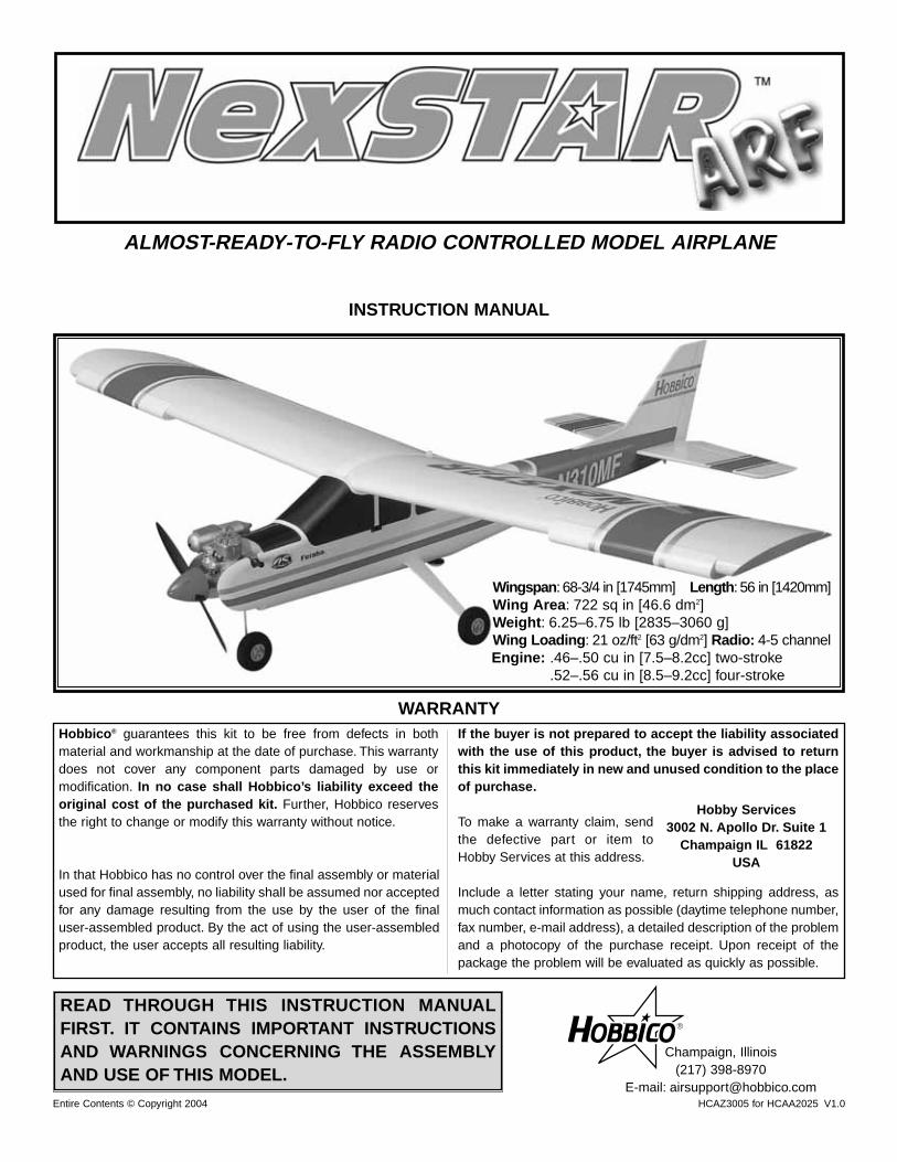
ALMOST-READY-TO-FLY RADIO CONTROLLED MODEL AIRPLANE
Wingspan: 68-3/4 in [1745mm] Length: 56 in [1420mm] Wing Area: 722 sq in [46.6 dm2]Weight: 6.25–6.75 lb [2835–3060 g]Wing Loading: 21 oz/ft2 [63 g/dm2] Radio: 4-5 channel Engine: .46–.50 cu in [7.5–8.2cc] two-stroke
.52–.56 cu in [8.5–9.2cc] four-stroke
Hobbico® guarantees this kit to be free from defects in bothmaterial and workmanship at the date of purchase. This warrantydoes not cover any component parts damaged by use ormodification. In no case shall Hobbico’s liability exceed theoriginal cost of the purchased kit. Further, Hobbico reservesthe right to change or modify this warranty without notice.
In that Hobbico has no control over the final assembly or materialused for final assembly, no liability shall be assumed nor acceptedfor any damage resulting from the use by the user of the finaluser-assembled product. By the act of using the user-assembledproduct, the user accepts all resulting liability.
If the buyer is not prepared to accept the liability associatedwith the use of this product, the buyer is advised to returnthis kit immediately in new and unused condition to the placeof purchase.
To make a warranty claim, sendthe defective part or item toHobby Services at this address.
Include a letter stating your name, return shipping address, asmuch contact information as possible (daytime telephone number,fax number, e-mail address), a detailed description of the problemand a photocopy of the purchase receipt. Upon receipt of thepackage the problem will be evaluated as quickly as possible.
WARRANTY
Hobby Services3002 N. Apollo Dr. Suite 1
Champaign IL 61822USA

INTRODUCTION . . . . . . . . . . . . . . . . . . . . . . . . . . . . . . 2AMA . . . . . . . . . . . . . . . . . . . . . . . . . . . . . . . . . . . . . . . 2SAFETY PRECAUTIONS . . . . . . . . . . . . . . . . . . . . . . . 3DECISIONS YOU MUST MAKE . . . . . . . . . . . . . . . . . . . 3Radio Equipment . . . . . . . . . . . . . . . . . . . . . . . . . . . . . . 3Engine Recommendations . . . . . . . . . . . . . . . . . . . . . . . 3ADDITIONAL ITEMS REQUIRED . . . . . . . . . . . . . . . . . 4
Hardware and Accessories . . . . . . . . . . . . . . . . . . . . . 4Building Supplies . . . . . . . . . . . . . . . . . . . . . . . . . . . . 4Optional Supplies and Tools . . . . . . . . . . . . . . . . . . . . 4
IMPORTANT BUILDING NOTES . . . . . . . . . . . . . . . . . . 4KIT INSPECTION . . . . . . . . . . . . . . . . . . . . . . . . . . . . . 5ORDERING REPLACEMENT PARTS . . . . . . . . . . . . . . 6ASSEMBLY . . . . . . . . . . . . . . . . . . . . . . . . . . . . . . . . . . 9
Assemble the Wing. . . . . . . . . . . . . . . . . . . . . . . . . . . 9Install the Engine . . . . . . . . . . . . . . . . . . . . . . . . . . . 11Alternate Engine Installation . . . . . . . . . . . . . . . . . . . 13Landing Gear Installation . . . . . . . . . . . . . . . . . . . . . 14Install the Tail Surfaces . . . . . . . . . . . . . . . . . . . . . . . 16Radio Installation . . . . . . . . . . . . . . . . . . . . . . . . . . . 17
GET THE MODEL READY TO FLY . . . . . . . . . . . . . . . 20Charge the Batteries. . . . . . . . . . . . . . . . . . . . . . . . . 20Check the Control Directions . . . . . . . . . . . . . . . . . . 20Check the Control Throws. . . . . . . . . . . . . . . . . . . . . 21Adjust the Throttle . . . . . . . . . . . . . . . . . . . . . . . . . . 21Balance the Model . . . . . . . . . . . . . . . . . . . . . . . . . . 22Identify Your Model . . . . . . . . . . . . . . . . . . . . . . . . . . 22
AMA SAFETY CODE . . . . . . . . . . . . . . . . . . . . . . . . . 23ENGINE SAFETY PRECAUTIONS . . . . . . . . . . . . . . . 23CHECK LIST . . . . . . . . . . . . . . . . . . . . . . . . . . . . . . . . 24FINAL PREPARATIONS . . . . . . . . . . . . . . . . . . . . . . . 24
Gather Your Tools . . . . . . . . . . . . . . . . . . . . . . . . . . . 24At the Shop Checklist . . . . . . . . . . . . . . . . . . . . . . . . 24Flight Preparation . . . . . . . . . . . . . . . . . . . . . . . . . . . 25Check the Frequency . . . . . . . . . . . . . . . . . . . . . . . . 25Check the Controls . . . . . . . . . . . . . . . . . . . . . . . . . . 25Range Check the Radio . . . . . . . . . . . . . . . . . . . . . . 25Fueling the Nexstar ARF. . . . . . . . . . . . . . . . . . . . . . 25
FLYING . . . . . . . . . . . . . . . . . . . . . . . . . . . . . . . . . . . . 26Taxiing . . . . . . . . . . . . . . . . . . . . . . . . . . . . . . . . . . . 26Takeoff . . . . . . . . . . . . . . . . . . . . . . . . . . . . . . . . . . . 26Flight . . . . . . . . . . . . . . . . . . . . . . . . . . . . . . . . . . . . 26Landing . . . . . . . . . . . . . . . . . . . . . . . . . . . . . . . . . . 26
MAINTENANCE TIPS . . . . . . . . . . . . . . . . . . . . . . . . . 27AFTER YOU MASTER THE NEXSTAR ARF . . . . . . . . 27
Removing the SpeedBrakes Training Flaps . . . . . . . . 27Removing the SpinControl Airfoil Extensions. . . . . . . 27Installing Dual Aileron Servos . . . . . . . . . . . . . . . . . . 27
NEXSTAR SELECT ARF FAQs . . . . . . . . . . . . . . . . . . 30FIN SKETCH . . . . . . . . . . . . . . . . . . . . . . . . . . . . . . . . 31
Congratulations and thank you for purchasing a HobbicoNexSTAR ARF, the next generation in Radio ControlTrainers. You have made the right decision by purchasing a“real” model airplane with the latest in aerodynamic andassembly technologies. Once assembled and set up, theNexSTAR will give you many hours of relaxing easy flying.Under the guidance of an experienced flight instructor, allyou have to do is to concentrate on learning to fly. And afteryou have mastered the NexSTAR, your engine and radiomay be transferred to your next model.
For the latest technical updates or manual corrections to theHobbico NexSTAR ARF, visit the Hobbico web site atwww.hobbico.com. Open the “Airplanes” link, and thenselect the Hobbico NexSTAR ARF. If there is new technicalinformation or changes to this model a “tech notice” box willappear in the upper left corner of the page.
We urge you to join the AMA (Academy of ModelAeronautics) and a local R/C club. The AMA is thegoverning body of model aviation and membership isrequired to fly at AMA clubs. Though joining the AMAprovides many benefits, one of the primary reasons to joinis liability protection. Coverage is not limited to flying atcontests or on the club field. It even applies to flying at publicdemonstrations and air shows. Failure to comply with theSafety Code (excerpts printed in the back of the manual)may endanger insurance coverage. Additionally, trainingprograms and instructors are available at AMA club sites tohelp you get started the right way. There are over 2,500AMA chartered clubs across the country. Contact the AMAat the address or toll-free phone number below:
Academy of Model Aeronautics5151 East Memorial DriveMuncie, IN 47302-9252Tele. (800) 435-9262Fax (765) 741-0057
Or via the Internet at: http://www.modelaircraft.org
IMPORTANT!!!Two of the most important things you can do to preserve theradio controlled aircraft hobby are to avoid flying near full-scale aircraft and avoid flying near or over groups of people.
AMA
INTRODUCTIONTABLE OF CONTENTS
2

1. Your Hobbico NexSTAR ARF should not be considered atoy, but rather a sophisticated, working model that functionsvery much like a full-size airplane. Because of itsperformance capabilities, the Hobbico NexSTAR ARF, if notassembled and operated correctly, could possibly causeinjury to yourself or spectators and damage to property.
2. You must assemble the model according to theinstructions. Do not alter or modify the model, as doing somay result in an unsafe or unflyable model. In a few casesthe instructions may differ slightly from the photos. In thoseinstances the written instructions should be considered ascorrect.
3. You must take time to build straight, true and strong.
4. You must use an R/C radio system that is in first-classcondition, and a correctly sized engine and components(fuel tank, wheels, etc.) throughout the building process.
5. You must correctly install all R/C and other componentsso that the model operates correctly on the ground and inthe air.
6. You must check the operation of the model before everyflight to insure that all equipment is operating and that themodel has remained structurally sound. Be sure to checkclevises or other connectors often and replace them if theyshow any signs of wear or fatigue.
7. If you are not an experienced pilot or have not flown thistype of model before, we recommend that you get theassistance of an experienced pilot in your R/C club for yourfirst flights. If you’re not a member of a club, your local hobbyshop has information about clubs in your area whosemembership includes experienced pilots.
Remember: Take your time and follow the instructions toend up with a well-built model that is straight and true.
This is a partial list of items required to finish the HobbicoNexSTAR ARF that may require planning or decisionmaking before starting to build. Order numbers are providedin parentheses.
There are four different ways you can set up your NexSTAR.The “standard,” most economical setup would be to use fourservos - three servos in the fuselage (for the throttle, rudderand elevator) and one servo in the wing for the ailerons.Thisrequires only a standard, 4-channel radio. The secondoption would be to use two servos in the wing (one for eachaileron). Using two aileron servos will increase the roll rate(for when you are ready to graduate to slightly moreadvanced aerobatics).This option will require a Y-harness toconnect the servos, but a standard 4-channel radio may stillbe used. The third option would be to “mix” the two aileronservos electronically so the ailerons can be operated asboth ailerons and flaps (flaperons). Doubling the ailerons asflaps adds another dimension to your flying regimen as youwill be able to execute super-slow landings and flight. Theuse of flaperons will require a minimum 5-channel computerradio for mixing the servos electronically. The fifth option isfor those who have a 5-channel, non-computer radio, butstill desire functional flaps. This will require a sixth servo tooperate the flaps separately. Instructions are provided onhow to cut the ailerons so the inboard portion can beoperated as flaps. All of these options may be done withstandard servos and the regular 500mAh-600mAh batterypack that came with your radio (special servos or a largerbattery pack are not required).
The recommended engine size range for the HobbicoNexSTAR ARF is .46 to .50 two-stroke or .52 to .56 four-stroke.If an engine in the upper end of the size range is used,remember that this is a model that is intended to fly at scale-like speeds, so throttle management should be practiced. Anyengine in the lower range will be able to fly this model withauthority. Therefore, the engines in the high range are onlyrecommended for modelers who fly at high altitude.
Engine Recommendations
Radio Equipment
DECISIONS YOU MUST MAKE
NOTE:We, as the kit manufacturer, provide you with a top quality
kit and great instructions, but ultimately the quality of your
finished model depends on how you build it; therefore, we cannot
in any way guarantee the performance of your completed model,
and no representations are expressed or implied as to the
performance or safety of your completed model.
PROTECT YOUR MODEL,YOURSELF& OTHERS...FOLLOW THESE
IMPORTANT SAFETY PRECAUTIONS
3
4
In addition to the items listed in the “Decisions You MustMake” section, the following is a list of hardware andaccessories required to finish the Hobbico NexSTAR ARF.Order numbers are provided in parentheses.
❏ 6" [150mm] Servo extension (HCAM2701 for Futaba®)❏ R/C foam rubber (1/4" HCAQ1000, or 1/2" HCAQ1050)❏ 3/4" to 1" [19 to 25mm] Heavy duty transparent tape❏ Hook & loop material (1" x 6" [25 x 150mm] GPMQ4480)❏ Stick-on segmented lead weights (GPMQ4485)
If you decide to install two aileron servos in your wing connectedto the same channel, you will also need the following:
❏ 1 additional standard servo (for a total of 5)❏ Y-harness (HCAM2751 for Futaba)❏ 12" [300mm] servo extension (HCAM2711 for Futaba)❏ 2 Control horns❏ 4 2-56 x 3/4" screws❏ 2 Nylon clevises❏ 2 Nylon faslinks❏ 2 Silicone retainers❏ 2 2-56 x 6" pushrods
If you decide to install two aileron servos in your wingconnected to different channels for flaperons, you will need:
❏ 1 additional standard servo for a total of 5❏ 5-channel computer radio ❏ (2) 12" [300mm] servo extension (HCAM2711 for Futaba)❏ 6" [150mm] servo extension (HCAM2701 for Futaba) ❏ 2 Control horns❏ 4 2-56 x 3/4" screws❏ 2 Nylon clevises❏ 2 Nylon faslinks❏ 2 Silicone retainers ❏ 2 2-56 x 6" pushrods
If you decide to install two aileron servos and one flap servoin your wing, you will need:
❏ All materials listed in one of the options above❏ 1 additional standard servo for a total of 6❏ 6" [150mm] servo extension (HCAM2701 for Futaba)❏ 2 Nylon clevises ❏ 2 Nylon faslinks❏ 2 Silicone retainers ❏ 2 2-56 x 6" pushrods
In addition to common household tools and hobby tools, thisis the “short list” of the most important items required tobuild the Hobbico NexSTAR ARF.
❏ #1 Hobby knife (HCAR0105)❏ #11 blades (5-pack, HCAR0211)❏ 3/4" to 1" [19mm to 25mm] Heavy duty transparent tape.❏ Threadlocker thread locking cement (GPMR6060)❏ Small metal file (TAMR4046)
Here is a list of optional tools mentioned in the manual thatwill help you build the Hobbico NexSTAR ARF.
❏ Top Flite® MonoKote® sealing iron (TOPR2100) ❏ Pliers with wire cutter (HCAR0630)❏ Switch & Charge Jack Mounting Set (GPMM1000)❏ Servo horn drill (HCAR0698)❏ AccuThrow™ Deflection Gauge (GPMR2405) ❏ CG Machine™ (GPMR2400)❏ Precision Magnetic Prop Balancer™ (TOPQ5700)
There are two types of screws used in this kit:
Socket Head Cap screws are designated by a number and a length.
For example #6 x 3/4"
This is a number six screw that is 3/4" long.
Machine screws are designated by a number, threads perinch, and a length.
For example 4-40 x 3/4"
This is a number four screw that is 3/4" long with fortythreads per inch.
·Photos and sketches are placed before the step theyrefer to. Frequently you can study photos in followingsteps to get another view of the same parts.
·SHCS is the abbreviation for Socket Head Cap Screwwhich is a machine screw with a socket head.
· The stabilizer and wing incidences and engine thrustangles have been factory-built into this model. However,some technically-minded modelers may wish to checkthese measurements anyway. To view this informationvisit the web site at www.hobbico.com and click on“Technical Data.” Due to manufacturing tolerances whichwill have little or no effect on the way your model will fly,please expect slight deviations between your model andthe published values.
· To convert inches to millimeters, multiply inches by25.4 (25.4mm = 1")
IMPORTANT BUILDING NOTES
Optional Supplies & Tools
Building Supplies
Hardware & Accessories
ADDITIONAL ITEMS REQUIRED

Before starting to build, take an inventory of this kit to make sure it is complete, and inspect the parts to make sure theyare of acceptable quality. If any parts are missing or are not of acceptable quality, or if you need assistance with assembly,contact Product Support. When reporting defective or missing parts, use the part names exactly as they are written in theKit Contents list.
Great Planes Product Support Telephone: (217) 398-8970, ext. 53002 N Apollo Drive, Suite 1 Fax: (217) 398-7721
Champaign, IL 61822 E-mail: [email protected]
KIT INSPECTION
5
Parts photographed1. Fuselage2. Wings3. Wheels 4. Engine mount 5. 2mm Control rods 6. Wing joiner rods7. IsoSmooth engine mount 8. 11" x 5" [280 x 127mm] NexSTAR nylon propeller 9. Assembled fuel tank
10. 2-1/2" [64mm] Spinner 11. Nose landing gear 12. 1/4-20 x 2" [51mm] Nylon wing bolt 13. EasyAlign tail bolts 14. CenterCore wing Joiner 15. Fin/Rudder16. Aluminum main landing gear 17. Stab/elevator 18. SpeedBrakes training flaps 19. Leading Edge Airfoil Extensions
Parts not photographed4 Nylon clevis4 Nylon Faslinks4 Silicone retainers2 Nylon Aileron Control Horns4 #4 x 3/4" [19mm] Wood screws6 #4 x 5/16" [8mm] Machine screws4 4mm x 3/4" [19mm] Machine screws4 4mm x 1-1/8" [30mm] Machine screws4 4mm Nuts4 4mm Washers4 4mm Lock washers2 Nylon control horns4 #2 x 1/2" [12mm] Wood screws 2 Screw-lock pushrod connector
1
2
3
4
65 7 8 9 10 11 12
16
13 14
15
19
18
17
Replacement parts for the Hobbico NexSTAR ARF areavailable using the order numbers in the Replacement PartsList that follows.The fastest, most economical service can beprovided by your hobby dealer or mail-order company.
To locate a hobby dealer, visit the Hobbico web site atwww.hobbico.com. Choose “Where to Buy” at the bottomof the menu on the left side of the page. Follow theinstructions provided on the page to locate a U.S., Canadianor International dealer. If a hobby shop is not available,replacement parts may also be ordered from TowerHobbies® at www.towerhobbies.com, or by calling toll free(800) 637-6050.
Parts may also be ordered directly from Hobby Services bycalling (217) 398-0007, or via facsimile at (217) 398-7721,but full retail prices and shipping and handling charges willapply. Illinois and Nevada residents will also be chargedsales tax. If ordering via fax, include a Visa® or MasterCard®
number and expiration date for payment.
Mail parts orders and payments by personal check to:Hobby Services
3002 N Apollo Drive, Suite 1Champaign IL 61822
Be certain to specify the order number exactly as listed inthe Replacement Parts List. Payment by credit card orpersonal check only; no C.O.D.
If additional assistance is required for any reason contactProduct Support by e-mail at:
[email protected] by telephone at (217) 398-8970.
REPLACEMENT PARTS LIST Order Number Description How to purchaseHCAA3736 . . Wing kit . . . . . . . . . . . .Local hobby dealerHCAA3737 . . Spin-Control Airfoil
Extensions/Speed Brakes . . . . . . . . . . . . .Local hobby dealer
HCAA3738 . . Fuselage kitw/o engine mount . . . .Local hobby dealer
HCAA3739 . . Engine mount . . . . . . .Local hobby dealerHCAA3740 . . IsoSmooth
engine mount . . . . . . . .Local hobby dealerHCAA3741 . . Tail set . . . . . . . . . . . . .Local hobby dealerHCAA3742 . . Landing gear . . . . . . . .Local hobby dealerHCAA3743 . . Decal set . . . . . . . . . . .Local hobby dealerHCAA3744 . . NexSTAR nylon
11 x 5 prop . . . . . . . . .Local hobby dealerMissing pieces . .Contact Product SupportInstruction manualContact Product SupportFull-size plans . . . . . . . . . . . .Not available
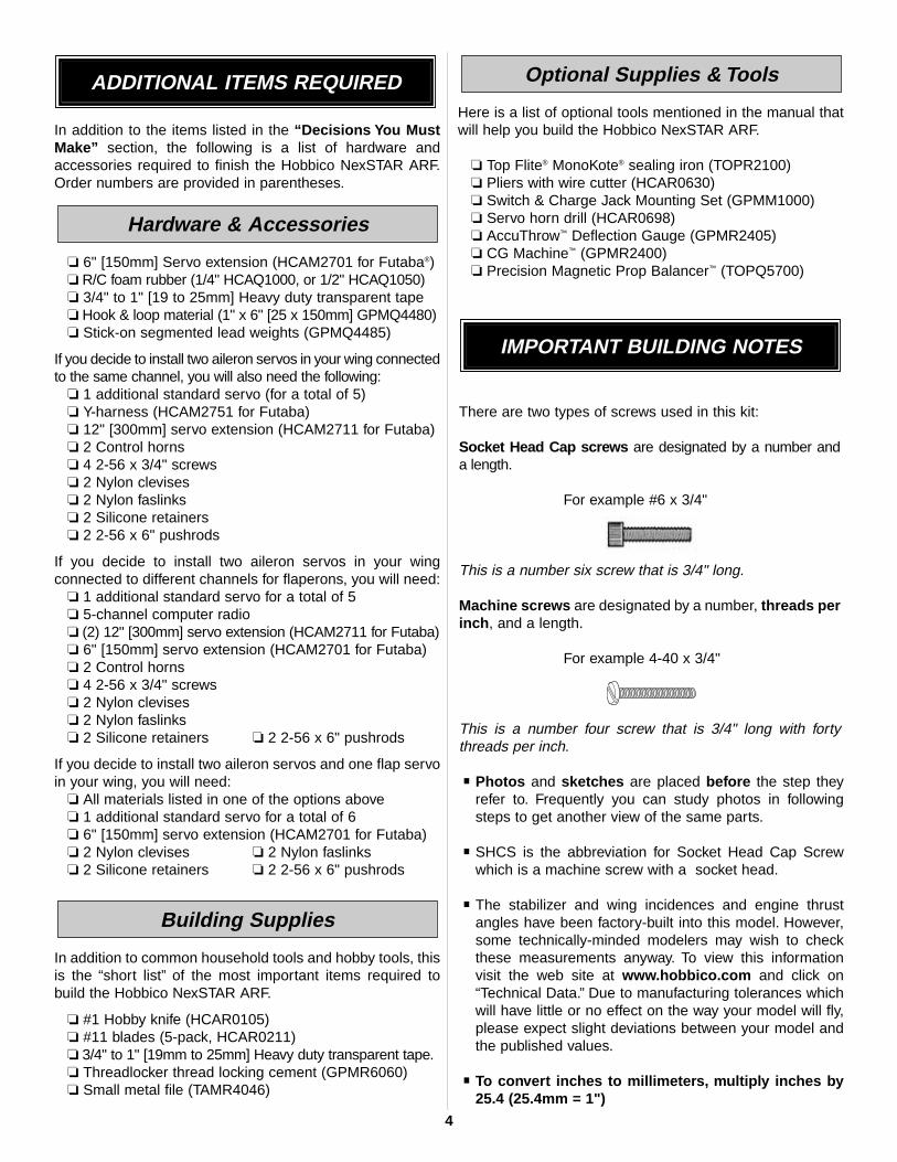
This new mount may look like other aluminum enginemounts, but make no mistake, it is unique. The enginemounting lugs are installed in rubber boots that absorbengine vibration to protect your airframe and radiocomponents, increasing their life span. The IsoSmoothengine mount works so well that you should check yourpropeller for nicks or cracks, because with this mount, youwon't feel a thing.
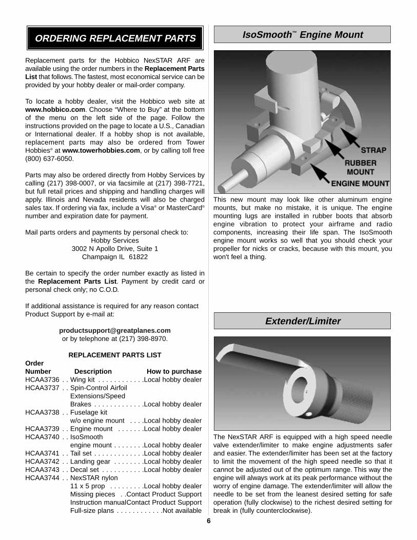
The NexSTAR ARF is equipped with a high speed needlevalve extender/limiter to make engine adjustments saferand easier. The extender/limiter has been set at the factoryto limit the movement of the high speed needle so that itcannot be adjusted out of the optimum range. This way theengine will always work at its peak performance without theworry of engine damage. The extender/limiter will allow theneedle to be set from the leanest desired setting for safeoperation (fully clockwise) to the richest desired setting forbreak in (fully counterclockwise).
Extender/Limiter
IsoSmooth™ Engine MountORDERING REPLACEMENT PARTS
6

The wings of most trainers are mounted with rubber bands.This allows for some flexibility in case of a hard landing.Rubber bands work well, but they are just plain ugly and amess. The PivotFlex Wing Mounting System combines thelooks of a bolt-on system with the flexibility of rubber bands.The new system allows the wing to move under suddenloads (such as a wing tip hitting the ground) and will releasethe wing from the airplane under extreme loads such as acrash—all that while looking great.
The EasyAlign Tail Mounting System aligns the stabilizerwith the fuselage and fin while tightening the tail bolts. Thetail bolts slide into blocks in the fuselage under thestabilizer. As the tail bolts are tightened, both the fin andstab are aligned and secured while strengthening the aftarea of the fuselage. No tools are necessary for installation.
To speed and simplify assembly, the Hobbico NexSTARARF comes equipped with the SnapGear Landing Gear.This new gear offers effortless and tool less main landinggear installation. It takes only a few seconds to install thelanding gear and it can also be removed from the fuselagein seconds.
The Hobbico NexSTAR ARF uses a three-line fuel linesystem to simplify fueling and de-fueling.
Three-Line Fuel System
SnapGear™ Landing Gear
EasyAlign™ Tail Mounting System
PivotFlex™ Wing Mounting System
7

The CenterCore wing rib is a nylon part that comespreinstalled onto one of the wing halves. It performs severalfunctions: it aligns the two wing halves; it is a mount for theaileron servo; the incorporated wing dowel holds the wing inplace; and it holds and aligns the wing bolt to the PivotFlex™
Wing Mounting System. Joining the wing halves and winginstallation on the fuselage has never been easier.
These are the extensions that are installed at the leadingedge near the tips of the wings. These extensions weredeveloped by NASA (National Aeronautics and SpaceAdministration) to help light airplanes prevent stalls andspins during landing approaches. That is exactly what theydo for your NexSTAR ARF. They slow down the airplane,increase its stall resistance and prevent it from spinning, alldesired characteristics of a trainer airplane. The wingextensions can be removed after you become proficient withthe NexSTAR ARF, for faster, more aerobatic performance.
The SpeedBrakes Training Flaps were designed to allow yourNexSTAR ARF to fly slower, reduce top speed and shortenthe landing approach. Thanks to these flaps, your NexSTARARF will bleed off speed quickly when the throttle is reducedso that long landing approaches are not necessary.Additionally, the top speed is considerably reduced to makethe airplane easier to handle. These SpeedBrakes can alsobe removed after acquiring some experience with theairplane for faster, more aerobatic performance.
SpeedBrakes™ Training Flaps
SpinControl™ Airfoil Extensions
CenterCore™ Wing Rib
8

For this section you will need:
Note: The following steps show the assembly of the wingusing one aileron servo. For a 2-servo installation, pleaserefer to the section “After You Master the NexSTAR in itsOriginal Form” on page 27.
❏ 1. Mark a line on the bottom of the wings 1/4" [6mm] fromthe end of the tips.
❏ 2. Install the Airfoil Extensions on both wings as shownusing 3/4" to 1" [19 to 25mm] heavy duty clear plastic tape.
❏ 3. Locate the Spin-Control Airfoil Extension decals on thedecal sheet and apply them to both wings following thescheme on the top of both wings. Also apply the NexSTARdecal on the top of the left or right wing.
❏ 4. Install the CenterCore wing rib on the right wing usingtwo #4 x 3/4" [19mm] screws.
❏ 5. Install the aileron servo as shown using the hardwaresupplied by the manufacturer.
1 Left wing1 Right wing2 Airfoil extensions2 SpeedBrakes training
flaps1 CenterCore wing rib1 Steel wing rod1 Anti-Rotation steel pin2 Nylon clevises2 Nylon faslinks2 Silicone retainers2 2-56 X 6" [150mm]
pushrods
2 Nylon horns4 #4 x 3/4" [19mm]
Wood screws6 #4 x 5/16" [8mm]
Wood screws1 Standard servo1 Phillips screwdriver
3/4" to 1" [19 to25mm] Heavy dutyclear plastic tape
Assemble the Wing
ASSEMBLY
9

❏ 6. Install the wing rod and the anti-rotation pin into theright wing.
❏ 7. Carefully slide the left wing all the way onto the rod andinto the CenterCore wing rib until it stops.
❏ 8. Use two more #4 x 3/4" [19mm] screws to hold the twowing halves together.
❏ 9. Cut and bend a 2mm x 6"[150mm] pushrod to matchthe sketch above. Make a left and a right pushrod.
❏ 10. Cut a servo arm as shown above and use a HobbicoServo Horn Drill (or a #48 or 5/64" [2mm] drill bit) to enlargethe servo arm holes. Install the arm on the servo. Install aclevis and a clevis retainer on the threaded end of thepushrods. Slide the unthreaded end of the pushrod into yourservo arms and install Faslinks to secure them.
10

❏ 11. Install the nylon horns on the aileron torque rods.Thread them in until the bottom of the horn is about 1/2"[12mm] from the wing surface. Connect the clevises to thehorns. Slip the clevis retainers over the clevises.
❏ 12. Locate one of the SpeedBrakes Training flaps. Thereare three small holes drilled into the trailing edge of the wingnear the center. Install the flap to the wing using three #4 x1/4" [6mm] screws. The inner end of the flap should alignwith the end of the aileron.
❏ 13. Install the other flap onto the other wing using threemore #4 x 1/4" [6mm] screws. The wing is now complete.
Note: Install the leading edge extensions and the flapsfor your initial flights. The airplane has been designedaround them and it performs better as a trainer with theminstalled. Never attempt to fly the airplane for the first timewithout them or with just one of the devices as the model willbe difficult to trim. Do not let anyone’s opinion get in the way.Install both these devices for your initial flights. If aftera few flights you decide to remove the extensions or flaps,then read the section “After You Master the NexSTAR in itsOriginal Form” on page 27.
For this section you will need:
❏ 1. Slide the fuel tank into the fuel tank compartment.Make sure the fuel tubing comes out through the hole in thefirewall. Slide the fuel tank in until the neck of the fuel tankcomes out the firewall as shown above. Use a Phillipsscrewdriver to tighten the fuel tank screw and secure thetank in place.
❏ 2. Use four 4mm x 20mm machine screws and four 4mmwashers to install the engine mount as shown above. UseGreat Planes Thread Locking Compound on the machinescrews before you tighten them.
EngineFuel tankMetal engine mount
4 4mm x 20mm Enginemount machinescrews
IsoSmooth completeengine mount
4 4mm x 30mmIsoSmooth enginemount screws
4 4mm Nuts8 4mm Washers4 4mm Lock washers
2-56 x 17-1/2"[445mm] pushrod.Phillips screwdriver
Install the Engine
11

❏ 3. Install the IsoSmooth rubber boots on the enginemounting lugs. The IsoSmooth rubber boots have beendesigned to fit most .46 size engines. If the boots do not fityour engine, then you will have to use an alternate methodto install your engine (see below).
❏ 4. Use four 4mm x 30mm machine screws, four 4mmwashers, four 4mm lock washers and four 4mm nuts to secure
the engine with the IsoSmooth nylon bracket on the enginemount. Use Great Planes Thread Locking Compound on thescrews to prevent them from coming loose with vibration.
❏ 5. Install a clevis and a clevis retainer on the threadedend of the 17-1/2" [445mm] pushrod. Bend the pushrodslightly as shown above to clear the engine mounting bolts.
❏ 6. Slide the pushrod into the guide tube and then connectthe clevis to the carburetor arm as shown above. Slip theclevis retainer onto the clevis.
❏ 7. Mount the muffler on the engine following your enginemanufacturer’s recommendations. Also, install the glow plugand connect the fuel lines to the engine. The red line goesto the pressure tap on the muffler, the green line goes to theneedle valve, and the blue line is the fill line. Cap the fill linewith the aluminum plug supplied.
12

❏ 8. Install the spinner backplate, propeller, propellerwasher and propeller nut to the engine. Align the propellerwith the marks on the spinner backplate and then tightenthe propeller nut securely.
❏ 9. Fit the spinner cone to the back plate. Then, use aPhillips screwdriver to tighten the spinner screws snugly, butnot over-tight.
Selecting the correct propeller for anairplane is very important. YourNexSTAR ARF comes equipped witha specially-designed nylon 11x5propeller (HCAA3744) with paintedtips. The painted tips are a safetyfeature that will help you see thepropeller arc as the engine is running.
Propeller (HCAA3744)
Keep away from the propeller while the engine is running.The engine size used on the NexSTAR ARF is powerfulenough to cause damage if anything (including you) gets inthe propeller arc. The propeller is made out of flexible nylonso that it won’t break on light contact with the runway orweeds. If the propeller ever gets in contact with anythingwhile the engine is running, inspect it before running itagain. Check for cracks, scuffled tips or unbalanced blades.If necessary, replace the propeller. The Hobbico NexSTARARF was designed around an 11x5 propeller for best
performance. The 11x5 propeller helps keep the airplanespeed down at full throttle; it increases takeoff performanceon any surface, including tall grass; and it acts as a brakewhen the nose is pointed down. Should you ever need toreplace the propeller, replace it with the same or similar11x5 propeller.There is no benefit to using a larger propelleror one with more pitch.
Carefully balance your propeller and spare propellersbefore you fly. An unbalanced prop can be the single mostsignificant cause of vibration that can damage your model.
We use a Top Flite Precision Magnetic Prop Balancer™
(TOPQ5700) in the workshop and keep a Great PlanesFingertip Prop Balancer (GPMQ5000) in our flight box.
Your engine is now installed.
❏ 1. If the engine rubber boots do not fit the engine of yourchoice, you will have to install the engine as shown aboveusing two metal straps (included), four 4mm x 30mm, four4mm nuts, four 4mm washers and four 4mm lock washers.
Alternate Engine Installation
13

For this section you will need:
❏ 1. File two flat spots on the nose gear wire as shown above.
❏ 2. Install the nylon nose gear bracket to the firewall usingtwo 4 x 20mm machine screws and two 4mm flat washers.Use Great Planes Thread Locking Compound on themachine screws before tightening them.
❏ 3. Place a wheel collar in the nylon steering arm asshown. Use the 4 x 6mm [1/4"] machine screw on the wheelcollar. Slide the steering pushrod’s “Z” bend through thehole in the steering arm.
❏ 4. Slide the steering arm’s pushrod into its guide tube.Install the nose landing gear leg through the nylon bracket,the steering arm and then the engine mount. Tighten thescrew on the steering arm.
❏ 5. Install the nose wheel on the nose gear wire. Use twowheel collars, one on each side of the wheel, to align it andsecure it in place. Apply some Great Planes Thread LockingCompound to the screws.
❏ 6. Install a wheel axle on each aluminum landing gearleg. File a flat spot near the end of the axle.
❏ 7. Install a wheel on each of the axles and then securethem with a wheel collar. Use some Great Planes ThreadLocking Compound on the screws.
Nose gear wireAluminum main gear(2 parts)
3 Wheels2 Landing gear axles1 Nylon nose gear
bracket2 4mm x 19mm
Machine screws
2 4mm Washers1 Steering arm5 4mm Wheel collars1 Steering pushrod
Phillips screwdriverMetal file
Landing Gear Installation
14

❏ 8. Slide one of the main landing gear legs into the landinggear slot as shown above. Push it in until you hear a “click”or until it does not slide in any more. Note: The two landinggear legs are identical, so it does not matter which one youinstall on the left side or right side of the airplane.
❏ 9. Install the other landing gear leg on the other side ofthe fuselage the same way. Once they are both installed,apply a light force to pull them out. You should not be ableto pull them out. If they do pull out, then push them back inagain until they are secured properly. Note: The legs may fita little loose inside the pocket. This is normal as long as youare not able to pull the landing gear legs out.
Landing gear installation is complete.
Note: Should you ever need to remove the landing gearfrom the fuselage, insert a screwdriver into the hole underthe fuselage farther from the leg you want to remove. Applylight pressure to the tab inside the hole and pull the landinggear leg out. Once the tab is moved, the screwdriver mustbe removed to allow the leg to come all the way out. Do thesame with the other landing gear leg.
Note: If your landing gear does not insert easily in thefuselage or it does not lock in, clean up any glue or paintblobs that may be on the gear or in the mountingmechanism. Insert the gear again and make sure it doeslock in.
Note: If your landing gear legs spread after a hard landing,remove the legs from the airplane and bend them back tothe correct position with a vise. Do not try to straighten thelegs while installed in the airplane as that may damage theSnap Gear Landing Gear mechanism.
15

For this section you will need:
Note: It is recommended that you apply the fuselage, staband fin decals at this point. It is easier to do when the partsare all apart.
❏ 1. Install a nylon clevis and a clevis retainer on the twosteel pushrods. Slide both pushrods into their guide tubes inthe tail of the airplane.
❏ 2. Position a nylon control horn on the bottom of the rightelevator all the way against its inner edge. Mark the locationof the control horn mounting holes. Drill through the markswith a 1/16" [1.6mm] drill bit. Secure the control horn to theelevator using two #2 x 1/2" [12mm] screws.
❏ 3. Position a nylon control horn on the rudder as shownabout 1/8" [3mm] from the bottom edge. Note that one of theedges of the control horn is aligned with the hinge line of therudder. Mark the location of the control horn mountingholes. Drill through the marks with a 1/16" [1.6mm] drill bit.Secure the control horn to the rudder using two #2 x 1/2"[12mm] screws.
❏ 4. Insert the horizontal stabilizer into the stab slot asshown above. Insert the two nylon fin tail bolts half-way intothe bottom fuselage and into the stab to hold it in place.
❏ 5. Place the fin over the sketch found on the last page ofthe manual and make sure the fin rods are bent at the sameangle as the ones shown on the sketch. This step is criticalto make the fin installation easier.
StabilizerFin
2 Control horns4 #2 x 1/2 [12mm]
Screws2 Nylon tail bolts
2 Nylon clevises
2 Silicone clevis
retainers
2 2mm Steel pushrods
Phillips screwdriver
Install the Tail Surfaces
16

❏ 6. Insert the vertical stabilizer into the fin slot as shownabove. During installation, make sure the rudder controlhorn is below the elevator so that it does not interfere. It maytake a little maneuvering to slide the aft fin rod in front of thewood block in the fuselage slot.
❏ 7.Tighten the bolts until they fit snugly against the bottomof the fuselage. Note: Over tightening these bolts willdamage the nylon threads and may cause in flight failure.Do not over tighten these bolts.
❏ 5. Connect both the elevator and rudder pushrod clevisesto their control horns. Use the second hole from the outer tipof the control horn for both of them. This will allow you toobtain the recommended throws. Slide the silicone cleviskeeper over the clevis.
Tail assembly is complete.
For this section you will need:
❏ 1. Install the elevator, rudder and throttle servos in thefuselage servo tray as shown above using the hardwaresupplied by the radio manufacturer.
3 Standard size servos1 6" [150mm] Extension
servo mountingHardware
2 Faslinks
2 Complete screw-lockpushrod connectorsFoam sheetPliersPhillips screwdriver
Radio Installation
17

❏ 2. Wrap the receiver and the battery with foam and theninstall them on the radio tray. Use the hook and loopmaterial supplied to secure them in place.
❏ 3. Install a 6" [150mm] extension on the receiver’s aileronchannel. Connect the radio switch to the receiver and thebattery.Use heat shrink tubing to secure the battery connection.Install the radio tray in the fuselage with two #4 x 3/8" [9mm]wood screws. Connect all the servos to the receiver.
❏ 4. Install the radio switch to the fuselage on the opposite sideof the muffler. If you desire, you can also install a charge jack.This will allow you to charge the batteries or check their voltageat the field without taking off the wing. In the instruction manualairplane we installed an Ernst charge jack.
❏ 5. Route the receiver antenna under the servo tray. Installa retainer on it and then slip it through the plastic guide tubein the middle until it exits at the aft end of the airplane.Secure the antenna with tape. Turn on the transmitter andthen the receiver and center all the trims on the transmitter.
❏ 6. Cut the elevator, throttle and the rudder servo arms asshown. Install a Screw-Lock Pushrod Connector on the throttleand the rudder arm as shown above. Note the holes where theScrew-Lock Pushrod Connectors are connected.
18
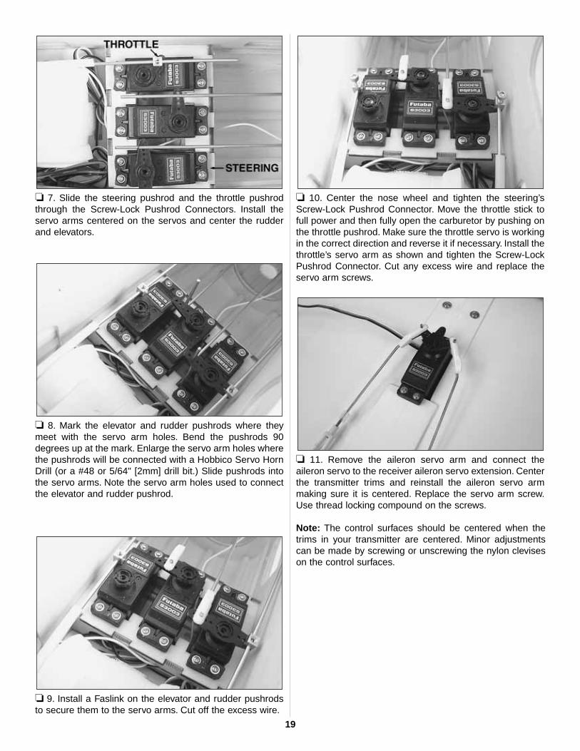
❏ 7. Slide the steering pushrod and the throttle pushrodthrough the Screw-Lock Pushrod Connectors. Install theservo arms centered on the servos and center the rudderand elevators.
❏ 8. Mark the elevator and rudder pushrods where theymeet with the servo arm holes. Bend the pushrods 90degrees up at the mark. Enlarge the servo arm holes wherethe pushrods will be connected with a Hobbico Servo HornDrill (or a #48 or 5/64" [2mm] drill bit.) Slide pushrods intothe servo arms. Note the servo arm holes used to connectthe elevator and rudder pushrod.
❏ 9. Install a Faslink on the elevator and rudder pushrodsto secure them to the servo arms. Cut off the excess wire.
❏ 10. Center the nose wheel and tighten the steering’sScrew-Lock Pushrod Connector. Move the throttle stick tofull power and then fully open the carburetor by pushing onthe throttle pushrod. Make sure the throttle servo is workingin the correct direction and reverse it if necessary. Install thethrottle’s servo arm as shown and tighten the Screw-LockPushrod Connector. Cut any excess wire and replace theservo arm screws.
❏ 11. Remove the aileron servo arm and connect theaileron servo to the receiver aileron servo extension. Centerthe transmitter trims and reinstall the aileron servo armmaking sure it is centered. Replace the servo arm screw.Use thread locking compound on the screws.
Note: The control surfaces should be centered when thetrims in your transmitter are centered. Minor adjustmentscan be made by screwing or unscrewing the nylon cleviseson the control surfaces.
19

Now the plane is assembled, but there are a few things thatmust be done before it will be ready to fly.You must carefullyperform all of the following Setup procedures. If possible,have your flight instructor assist you.
If you have not yet charged the batteries, you may stillproceed. However, as the batteries have not yet been fullycharged, they may not provide enough power to make it allthe way through the setup procedures. If the batteries quitworking, set your tools aside and charge the batteries asdescribed in the instruction manual for the radio controlsystem that you are using.Follow the battery charging instructions that came with yourradio control system to charge the batteries. You shouldalways charge your transmitter and receiver batteries thenight before you go flying, and at other times asrecommended by the radio manufacturer.
❏ 1. Move the right control stick on the transmitter to theright as shown in the photo. Observe the direction theailerons move.
The right aileron should move up and the left aileron shouldmove down. Moving the control stick to the left should makethe ailerons move the opposite way. If the ailerons do notrespond as described, reverse the direction using thereversing switch for the aileron on the face of thetransmitter. If necessary, refer to the instructions in yourradio instruction manual to identify and operate thereversing switch.
❏ 2. Move the right stick down and observe the direction theelevator moves.
Moving the right stick down should make the elevator moveup. Note that moving the elevator stick down moves theelevator up (which, in flight, pushes the tail down, thusincreasing the angle of the wing and making the modelclimb). The best way to keep this in mind is to think in termsof a pilot in an airplane. He pulls the control stick back to“pull up” the nose of the plane.
Check Control Direction
CAUTION: Unless the instructions that came with yourradio system state differently, the initial charge on newtransmitter and receiver batteries should be done for 15hours using the slow-charger that came with the radiosystem. This will “condition” the batteries so that the nextcharge may be done using the fast-charger of your choice.If the initial charge is done with a fast-charger, thebatteries may not reach their full capacity and you may beflying with batteries that are only partially charged.
Charge the Batteries
GET THE MODEL READY TO FLY
20
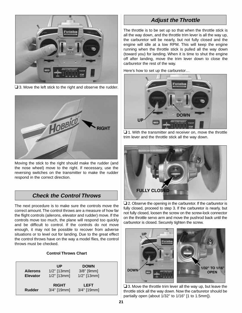
❏ 3. Move the left stick to the right and observe the rudder.
Moving the stick to the right should make the rudder (andthe nose wheel) move to the right. If necessary, use thereversing switches on the transmitter to make the rudderrespond in the correct direction.
The next procedure is to make sure the controls move thecorrect amount.The control throws are a measure of how farthe flight controls (ailerons, elevator and rudder) move. If thecontrols move too much, the plane will respond too quicklyand be difficult to control. If the controls do not moveenough, it may not be possible to recover from adversesituations or to level out for landing. Due to the great effectthe control throws have on the way a model flies, the controlthrows must be checked.
Control Throws Chart
The throttle is to be set up so that when the throttle stick isall the way down, and the throttle trim lever is all the way up,the carburetor will be nearly, but not fully closed and theengine will idle at a low RPM. This will keep the enginerunning when the throttle stick is pulled all the way down(toward you) for landing. When it is time to shut the engineoff after landing, move the trim lever down to close thecarburetor the rest of the way.
Here’s how to set up the carburetor…
❏ 1. With the transmitter and receiver on, move the throttletrim lever and the throttle stick all the way down.
❏ 2. Observe the opening in the carburetor. If the carburetor isfully closed, proceed to step 3. If the carburetor is nearly, butnot fully closed, loosen the screw on the screw-lock connectoron the throttle servo arm and move the pushrod back until thecarburetor is closed. Securely tighten the screw.
❏ 3. Move the throttle trim lever all the way up, but leave thethrottle stick all the way down. Now the carburetor should bepartially open (about 1/32" to 1/16" [1 to 1.5mm]).
Adjust the Throttle
UP DOWNAilerons 1/2" [13mm] 3/8" [9mm] Elevator 1/2" [13mm] 1/2" [13mm]
RIGHT LEFTRudder 3/4" [19mm] 3/4" [19mm]
Check the Control Throws
21

❏ 4. Move the throttle stick on the transmitter all the way up.The carburetor should be fully open.
❏ 5. If you are not able to achieve these settings, more orless movement may be required from the throttle pushrod.The same as the control surface throws, this is done byrelocating the clevis on the carburetor arm to the other hole,or by relocating the pushrod connector on the servo arm toanother hole.
DO NOT DISREGARD THIS STEP!This important step is also referred to as “checking the
C.G.” (center of gravity). Simply stated, the center of gravityis the point at which the model balances when lifted underthe wing. If the C.G. is too far forward, the model will be“nose-heavy” and could be difficult to takeoff and land andlose some of its self-correcting tendencies. If the C.G. is toofar aft, the model will be “tail-heavy” and the controls may betoo sensitive, making the model too difficult to control—especially for an inexperienced pilot! Follow the instructionsto balance the model correctly, thus giving you the greatestchances for success!
❏ 1. There is a decal with two black lines on the undersideof the wing. Those mark the forward and aft CG limit for theNexSTAR ARF. The forward CG limit is 3-3/16" [81mm]. Theaft CG limit is 3-9/16" [90mm] from the LE.
❏ 2. Make certain the model is in “ready-to-fly” conditionwith all components mounted and installed (propeller,spinner, landing gear, etc.). The fuel tank must be empty.
❏ 3. Mount the wing to the fuselage with the nylon wingbolt. Lift the model on both sides of the fuselage with yourfingertips between the two lines on the bottom of the wing.
❏ 4. If the fuselage is level when lifting the model with yourfingers anywhere between the lines, the C.G. is correct.Proceed to the checklist in the following section. If you cannotfind a spot between the two lines where the airplane balances,then either one of the following will happen: If the tail dropswhen lifting the model, the plane is tail heavy and will requirenose weight to balance. If the nose drops, the plane is noseheavy and will require tail weight. Do not be concerned if yourmodel requires a few ounces of nose or tail weight. Almost allmodels require additional weight to balance and fly correctly!
If additional weight is required to balance the plane, purchase GreatPlanes® Self Adhesive Lead Weights (GPMQ4485).The weight issegmented in 1/4 oz. increments and is easy to work with. If addingweight to the tail, attach it to the left side of the fuselage (oppositethe muffler) under the stab. If adding weight to the nose, attach it tothe inside of the fuselage side next to the engine.
❏ 5. If you found it necessary to add weight, recheck theC.G. after doing so.
Whether you fly at an R/C club or somewhere on your own, youshould have your name, telephone number, address and AMAnumber on or in your model so it can be identified and returnedin case it lands somewhere away from the flying site. Fill out theI.D. tag found in the back of the manual and use spray adhesiveor tape to stick it in the model.
Identify your Model
Balance the Model
22

Read and abide by the following excerpts from the Academyof Model Aeronautics Safety Code. For the complete SafetyCode refer to Model Aviation magazine, the AMA web siteor the Code that came with your AMA license.
GENERAL1. I will not fly my model aircraft in sanctioned events, airshows, or model flying demonstrations until it has beenproven to be airworthy by having been previously,successfully flight tested.
2. I will not fly my model aircraft higher than approximately400 feet within 3 miles of an airport without notifying theairport operator. I will give right-of-way and avoid flying inthe proximity of full-scale aircraft. Where necessary, anobserver shall be utilized to supervise flying to avoid havingmodels fly in the proximity of full-scale aircraft.
3. Where established, I will abide by the safety rules for theflying site I use, and I will not willfully and deliberately fly mymodels in a careless, reckless and/or dangerous manner.
5. I will not fly my model unless it is identified with my nameand address or AMA number, on or in the model. Note: Thisdoes not apply to models while being flown indoors.
7. I will not operate models with pyrotechnics (any devicethat explodes, burns, or propels a projectile of any kind).
RADIO CONTROL1. I will have completed a successful radio equipment groundcheck before the first flight of a new or repaired model.
2. I will not fly my model aircraft in the presence ofspectators until I become a qualified flier, unless assisted byan experienced helper.
3. At all flying sites a straight or curved line(s) must beestablished in front of which all flying takes place with theother side for spectators. Only personnel involved with flyingthe aircraft are allowed at or in the front of the flight line.Intentional flying behind the flight line is prohibited.
4. I will operate my model using only radio controlfrequencies currently allowed by the FederalCommunications Commission.
5. I will not knowingly operate my model within threemiles of any pre-existing flying site except inaccordance with the frequency sharing agreementlisted [in the complete AMA Safety Code].
9. Under no circumstances may a pilot or other person toucha powered model in flight; nor should any part of themodel other than the landing gear, intentionally touchthe ground, except while landing.
Keep all engine fuel in a safe place, away from high heat,sparks or flames, as fuel is very flammable. Do not smokenear the engine or fuel and remember that engine exhaustgives off a great deal of deadly carbon monoxide. Thereforedo not run the engine in a closed room or garage.
Get help from an experienced pilot when learning to operate engines.
Use safety glasses when starting or running engines.
Do not run the engine in an area of loose gravel or sand; thepropeller may throw such material in your face or eyes.
Keep your face and body as well as all spectators away from theplane of rotation of the propeller as you start and run the engine.
Keep these items away from the prop: loose clothing, shirtsleeves, ties, scarfs, long hair or loose objects such aspencils or screwdrivers that may fall out of shirt or jacketpockets into the prop.
Use a “chicken stick” or electric starter to start the engine.Do not use your fingers to flip the propeller. Make certain theglow plug clip or connector is secure so that it will not popoff or otherwise get into the running propeller.
Make all engine adjustments from behind the rotating propeller.
The engine gets hot! Do not touch it during or right afteroperation. Make sure fuel lines are in good condition so fuelwill not leak onto a hot engine, causing a fire.
To stop a glow engine, cut off the fuel supply by closing offthe fuel line or following the engine manufacturer’srecommendations. Do not use hands, fingers or any otherbody part to try to stop the engine. To stop a gasolinepowered engine, an on/off switch should be connected tothe engine coil. Do not throw anything into the propeller of arunning engine.
Failure to follow these safety precautions may resultin severe injury to yourself and others.
ENGINE SAFETY PRECAUTIONSAMA SAFETY CODE (excerpts)
23

❏ 1. Fuel proof all areas exposed to fuel or exhaustresidue such as the wing saddle area, etc.
❏ 2. Check the C.G. according to the measurementsprovided in the manual.
❏ 3. Be certain the battery and receiver are securelymounted in the fuse. Simply stuffing them into placewith foam rubber is not sufficient.
❏ 4. Extend your receiver antenna and make sure it hasa strain relief inside the fuselage to keep tension offthe solder joint inside the receiver.
❏ 5. Use threadlocking compound to secure criticalfasteners such as the set screws that hold the wheelaxles to the struts, screws that hold the carburetor arm(if applicable), screw-lock pushrod connectors, etc.
❏ 6. Add a drop of oil to the axles so the wheels willturn freely.
❏ 7. Make sure all hinges are securely glued in place.
❏ 8. Reinforce holes for wood screws with thin CAwhere appropriate (servo mounting screws, cowlmounting screws, etc.).
❏ 9. Confirm that all controls operate in the correct directionand the throws are set up according to the manual.
❏ 10. Make sure there are silicone retainers on all theclevises and that all servo arms are secured to theservos with the screws included with your radio.
❏ 11. Secure connections between servo wires and Y-connectors or servo extensions, and theconnection between your battery pack and theon/off switch with vinyl tape, heat shrink tubing orspecial clips suitable for that purpose.
❏ 12. Make sure any servo extension cords you mayhave used do not interfere with other systems(servo arms, pushrods, etc.).
❏ 13. Make sure the fuel lines are connected and are not kinked.
❏ 14. Balance your propeller (and spare propellers).
❏ 15. Tighten the propeller nut and spinner.
❏ 16. Place your name, address, AMA number andtelephone number on or inside your model.
❏ 17. Cycle your receiver battery pack (if necessary) andmake sure it is fully charged.
❏ 18. If you wish to photograph your model, do so beforeyour first flight.
❏ 19. Range check your radio when you get to the flying field.
If you haven't already done so, refer to the Futabainstruction manual for the radio control system and chargethe batteries in the plane and in the transmitter overnightthe night before you go flying.
In addition to the equipment required to fuel and start theengine mentioned near the beginning of the manual, youshould start a collection of tools that may be required foradjustments and maintenance at the flying field. Thefollowing is a list of the most important items.
Now it's time to do a final check before taking the model tothe field. These checks are best done in the peace andcomfort of your own shop, so take the time now to makecertain your model is ready.
❏ 1. Check to see that the screws on the wheel collars thathold on the wheels are fully tightened.
❏ 2. Be certain the silicone retainers on all the nylonclevises are in position.
❏ 3. Make certain the elevator, rudder and aileronsrespond in the correct directions.
❏ 4. Make certain the wing is securely joined.
❏ 5. Check to see that the fin bolts that hold the fin andstab in position are present and secure. These maybecome slightly loose after the first 10-15 flights.
❏ 6. Make certain the propeller and spinner are secure.
❏ 7. Make certain you have balanced the model accordingto the instructions.
❏ 8. Check to see that the screws that hold the servo armsto the servos are present and secure.
❏ 9. Make certain you have filled out the I.D. card andplaced it inside the model.
At-the-Shop Checklist
1 Medium (#1) Phillipsscrewdriver
1 Medium (#1) flatscrewdriver
1 5/16" (or 8mm) Socketwrench (for glow plug)
1 7/16" (or 11mm) Wrenchor crescent wrench (forpropeller nut)
Gather your Tools
FINAL PREPARATIONSCheck List
24

Flight preparation is to be done at the flying field.
Be certain your flight instructor performs these followingchecks with you.1. Get the frequency clip from the frequency control boardat your flying site.2. Connect the aileron extension and mount the wing to thefuselage with the nylon wing bolt supplied with this kit.3. Turn on the transmitter and receiver. One at a time, operateeach control on the airplane using the sticks on the transmitter.Make certain each control is responding correctly.This must bedone before every flight.There are several types of malfunctionsthat can be discovered by performing this elementary task, thussaving your model!
A range check must be performed before the first flight of anew model. It is not necessary to do a range check beforeevery flight (but it is a good idea to perform a range checkbefore the first flight of each day). A range check is the finalopportunity to reveal any radio malfunctions, and to becertain the system has adequate operational range.1. Turn on the transmitter and receiver. Leave the transmitterantenna all the way down. Walk away from the model whilesimultaneously operating the controls. Have an assistant standby the model and tell you what the controls are doing to confirmthat they operate correctly. You should be able to walkapproximately 100 feet from the model and still have controlwithout any “glitching“ or inadvertent servo operation.2. If everything operates correctly, return to the model andstart the engine. Perform the range check with your
assistant holding the plane with the engine running atvarious speeds. If the servos chatter or move inadvertently,there may be a problem. Do not fly the plane! With theassistance of your instructor, look for loose servoconnections or binding pushrods. Also be certain you arethe only one on your frequency, and that the battery hasbeen fully charged.
The NexSTAR ARF comes with a three-line fuel line system.Tofuel the airplane, remove the fuel line plug from the filling line(green) and connect the fuel pump to it. Disconnect the pink linefrom the exhaust. Fill the tank until fuel comes out the pink line.Re-connect the pink line to the exhaust nipple. Replace the plugto the fill line. The airplane is now fueled. It is not required butit is highly recommended that the fuel tank be filled all theway up before each flight. A full fuel tank will give you 12 to15 minutes of flight time.To remove fuel from the fuel tank, remove the fuel line plugfrom the filling line (green) and connect the pump to it.Pump out any fuel that may be in the fuel tank. Replace thefuel line plug to the green line. NOTE:You may have to lowerthe nose of the airplane to completely de-fuel the tank.
Fueling the NexSTAR ARF
Range Check the Radio
Check the Controls
IMPORTANT: Your radio control system transmits asignal on a certain frequency. Be certain you know whatthe frequency is. This is expressed as a two-digit number(42, 56, etc.), and can be found on the container thetransmitter came in and is also located on the transmitter.There are several different frequencies, but there is still achance that someone else at the flying field may be onthe same frequency as you. If you turn on yourtransmitter while that person is flying, a crash will result.NEVER turn on your transmitter until you havepermission from your instructor, and until you havepossession of the frequency clip used for frequencycontrol at the flying site.
Check the Frequency
FLIGHT PREPARATION
25

Do not attempt to fly by yourself. The Hobbico NexSTARARF has many features that make learning to fly R/C aneasier experience, but the help from an instructor isinvaluable. An instructor is going to be able to inspect yourairplane to make sure everything is working correctly andhe will also be able to give you a few tips and comments onhow to improve your flying. Also, make sure you fly at anAMA sanctioned flying field.
Remember, it is assumed that your instructor is operatingthe model for you.Before the model is ready for takeoff, it must first be set up to rollstraight down the runway. With the engine running at a low idle,place the plane on the runway and, if your flying field permits,stand behind the model. Advance the throttle just enough toallow the model to roll. If the model does not roll straight downthe runway, shut the engine off and adjust the nose gearpushrod as necessary. Do not use the rudder trim to correct thenose wheel because this will also affect the rudder. Note:Crosswinds may affect the direction the model rolls, so this testshould be done in calm conditions, or with the model facingdirectly into the wind.
If possible, takeoff directly into the wind. If you are experienced,taking off in a crosswind is permissible (and sometimesnecessary—depending upon the prevailing wind conditions andrunway heading).Taking off into the wind will help the model rollstraight and also reduces ground speed for takeoff. Taxi themodel onto the runway or have an assistant carry it out and setit down, pointing down the runway into the wind. When ready,gradually advance the throttle while simultaneously using theleft stick (rudder/nose wheel) to steer the model. Gain as muchspeed as the runway and flying site will practically allow beforegently applying up elevator lifting the model into the air.Be readyto make immediate corrections with the ailerons to keep the
wings level, and be smooth on the elevator stick, allowing themodel to establish a gentle climb to a safe altitude beforemaking the first turn (away from yourself). Do not “yank” backthe elevator stick forcing the plane into too steep of a climbwhich could cause the model to quit flying and stall.
Once airborne, maintain a steady climb and make the initial turnaway from the runway. When at a comfortable, safe altitude,throttle back to slow the model, thus giving you time to think andreact. The Hobbico NexSTAR ARF should fly well at half orslightly less than half throttle. Adjust the trims so the plane fliesstraight and level. After flying around for a while, and while still ata safe altitude with plenty of fuel, practice slow flight and executepractice landing approaches by reducing the throttle further tosee how the model handles when coming in to land. Add powerto see how the model climbs as well.Continue to fly around whilelearning how the model responds. Mind your fuel level, but usethis first flight to become familiar with the model before landing.
When ready to land, pull the throttle stick fully back while flyingdownwind just before making the 180-degree turn toward therunway. Allow the nose of the model to pitch downward togradually bleed off altitude.Continue to lose altitude, but maintainairspeed by keeping the nose down while turning. Apply upelevator to level the plane when it reaches the end of the runwayand is about five to ten feet off the ground. If the model is too faraway, carefully add a small amount of power to fly the modelcloser. If going too fast, smoothly advance the throttle and allowthe model to gain airspeed, then apply elevator to climbout andgo around to make another attempt.When finally ready to touchdown, continue to apply up elevator, but not so much that theairplane will climb. Continue to apply up elevator while the planedescends until it gently touches down.The NexSTAR ARF has been designed to make steep landingapproaches so that the landing approach is short and easy.TheSpeed Brake Training Flaps excel at maintaining flying speedeven in steep dives, and when the airplane is leveled-out, theyalso help to increase lift. You can also make a long landingapproach and use throttle to keep the airplane flying at a verylow speed until you reach the runway threshold where youshould cut the throttle for the airplane to land.After you have landed and shut the engine off, adjust thepushrods on the ailerons, elevator and rudder as necessaryso the trim levers on the transmitter may be returned tocenter. This will not be required on any of the controls thatdid not need trim adjustments.
Landing
Flight
Takeoff
Taxiing
IMPORTANT: Be aware of your proximity to R/C clubsites. If there is an R/C site within six miles of where youare flying, and if you are operating your model on thesame frequency at the same time as somebody else,there is a strong possibility that one or both models willcrash due to radio interference. There is great potentialfor an out-of-control model to cause property damageand/or severe personal injury. We strongly urge you to flyat an R/C club site where frequency control is in effect soyou can be assured you will be the only one flying onyour channel.
FLYING
26

✔ After flying for the day, use your fuel pump to drainexcess fuel from the tank.
✔ After each day's flying, use spray cleaner and papertowels to thoroughly clean the model. After a completeflight there will be a fair amount of exhaust oil residuesprayed on your fuselage. Do not be concerned with this.It is normal. The oil used in model engines does notcompletely burn with combustion.
✔ The Hobbico NexSTAR ARF is factory-covered with iron-on model covering film. Should repairs ever be required,the covering can be patched with new pieces of iron-oncovering. Among several types of covering that will work,Top Flite MonoKote film may be used to make repairpatches to this model. MonoKote is packaged in six-footrolls, but some hobby shops also sell it by the foot. If onlya small piece of covering is needed for a minor patch,perhaps a fellow modeler would give you some. Thecovering is applied with a model airplane covering iron,but in an emergency a regular iron set to a lowertemperature could be used.
✔ Check all screws that hold the wings together, tail bolts,engine bolts, wheel collars, etc.
✔ Check all the high-stress areas for cracks or fatigue suchas the landing gear area, the wing mounting area, staband fin mounting area. Before storing the model until thenext fly day, wrap some paper towels around the engine.Some oil may accumulate and drip off of the engine andmuffler while the airplane is stored.
After you feel comfortable flying the Hobbico NexSTAR ARFand you want to improve its high speed performance, thefirst thing you can do is to remove the SpeedBrakes TrainingFlaps. Remove the six screws that hold them in place. TheNexSTAR ARF was optimized to fly with the flaps on, so ifyou remove them, you will have to retrim the elevator.Without flaps, the NexSTAR ARF will try to pitch down (nosedown) until you re-trim it. Without the SpeedBrakes TrainingFlaps, the airplane will fly much faster at any throttle settingand longer landing approaches will be needed. Also, theNexSTAR ARF will not slow down as quickly when the noseis pointed down and stall speed will increase slightly.
The second thing you can do to improve the high speed andaerobatic performance of the Hobbico NexSTAR ARF is toremove the SpinControl Airfoil Extensions.These extensions atthe leading edge of the wings are held in place with tape thatcan be carefully removed. Once you remove these extensions,you will need to re-trim your elevator to align it with thestabilizer. The SpinControl Airfoil Extensions produce theopposite effect of the SpeedBrakes Training Flaps in pitch,so if you remove both, the net pitch effect would be almostnon existent. After you remove these extensions, theNexSTAR ARF will be faster and able to spin and snap. Also,the stall speed will increase slightly.
Dual Aileron Servos.The Hobbico NexSTAR ARF comes equipped with dual aileronservo trays for dual aileron servos. If you wish to use flaperonsyou will need to upgrade your radio system to 6 channels. Toinstall the dual aileron servos, use the following instructions.
For this section you will need:
1 Additional aileronservo (same type asthat already installedin your NexStar)
1 “Y” harness2 2 mm Pushrods2 Nylon clevises2 Clevis retainers
2 Faslinks1 Servo mounting
hardware set1 Screwdriver1 Wire cutter1 Pliers1 Thin CA
Dual Aileron Servos
SpinControl Airfoil Extensions
SpeedBrakes Training Flaps
AFTER YOU MASTER THE NEXSTARARF IN ITS ORIGINAL FORM
Clean Up
MAINTENANCE TIPS
27

❏ 1. Disconnect the aileron servo pushrods from the aileronhorns and remove the original aileron servo.
❏ 2. Locate the dual aileron servo trays in the wing. Theyare located on the underside of the wing at the 6th bay infrom the wing tip. Trim the covering over the opening anduse a sealing iron to seal the covering to the tray.
❏ 3. Connect both servos to the “Y” harness. Make sure the“Y” harness exits through the hole in the center of the wing.Use the strings pre-installed inside the wings to pull theservo leads. Install the aileron servos into the trays.
❏ 4. Install the aileron control horn (not included) on theaileron as shown above. Make sure you use thin CA toreinforce the holes in the aileron.
❏ 5. Cut the servo arm as shown above. Use a 6"[152mm]pushrod, a clevis, clevis retainer and Faslink to make thenecessary aileron pushrod.
❏ 6. Set up your new dual servos on your radio to have thesame aileron throw as the original airplane. Center theservo arms and install the servo arm screws on them.
Your dual aileron servo installation is now finished.
Note: To install flaperons, you will need to upgrade to a radiocapable of flaperon mixing. In this case, the two aileron servoleads will connect to two different channels in your receiver.Follow your radio manufacturer's instructions to setup theflaperon mixing in your Hobbico NexSTAR ARF.
28

The Hobbico NexSTAR Select can also be equipped withdual aileron servos and flaps. To set up the airplane thisway, you need to follow the above instructions for the dualservo installation and then install the flaps as indicatedbelow. The necessary hinges on the wing were locatedwhere needed when the wing was built.
For this section you will need :
❏ 1. Draw a line on the aileron 10" [254mm] away from theaileron end at the root and use a hobby saw to cut theaileron at that line.
❏ 2. Install the flap servo in the center of the wing, wherethe original aileron servo was.
❏ 3. Using one of the 6" [152mm] pushrods, a nylon clevis,clevis retainer and a Faslink, make a pushrod and connectit to the flap servo and flap horn as shown above.
❏ 4. Bend the second pushrod as shown above andconnect it to the first with two 5/32"[4mm] wheel collars.Tighten the two 6-32x1/4" [6.4mm] socket head cap screwsto secure the two flap pushrods together as shown above.
❏ 5. The flaps should only be able to move down 1/2" [13mm].There is no up movement for the flaps.
Flap installation is finished.
Note: To install dual servo and flaps, you will need toupgrade to a 6 Channel radio. In this case, the two aileronservo leads will connect to two different channels in yourreceiver and then the flap servo to another channel. Followyour radio manufacturer's instructions to set up the aileronmixing and flaps in your Hobbico NexSTAR Select.
1 Additional servo to beused for flaps.
1 6"[152mm] Servoextension
2 2 mm Pushrods2 Nylon clevises1 Faslink
2 5/32"[4mm] Wheelcollars
2 6-32x1/4" [6.4mm]Socket head capscrews.
1 Screwdriver
Dual Aileron Servos & Flaps
29

Q. What should I do if the SnapGear landing gear legswill not lock in place?
A. The tolerances for the SnapGear locking mechanism arevery tight. Sometimes a little bit of paint or burrs on the inneredges of the landing gear legs may prevent the mechanismfrom locking. To fix this, clean up the inner edges that areinserted into the fuselage.To do so, use medium-grit sandpaperto smooth the inner edges until the mechanism locks.
Q. What should I do if the wing bolt does not line upwith the PivotFlex Wing Mount?
A. By design, the PivotFlex Wing Mount nut should be about1mm forward from the wing bolt so that when the wing isinstalled, it is always being pushed forward. To install thebolt, align the wing with the PivotFlex Wing Mount and thencarefully push the bolt down into the CenterCore wing ribuntil you hear a light pop. This means that the bolt is nowaligned with the nut and you can tighten it up.
Q. What size is the wing bolt?
A. The wing bolt is a 1/4-20 x 2" nylon bolt (GPMQ4402).
Q. Why is the engine pointing to the right and down?
A. The angles you are seeing are called "Thrust Angles".The engine is pointing to the right (when looking at theairplane from behind) to compensate for the torque thespinning propeller produces. The engine is also pointingdown to offset some of the additional lift the airplanegenerates when it picks up speed. A trainer airplane, suchas the NexSTAR will still climb slightly at full power. Allairplanes need some right thrust and down thrust. The rightthrust angle for the NexSTAR is 3 degrees to the right. Thedown thrust angle for the NexSTAR is 4 degrees withrespect to the wing incidence.
Q.Why is it that my airplane does not want to fly straight?
A. If your airplane always wants to turn in one direction or itwants to climb or yaw, then it is likely that the airplane is outof trim. To make the airplane fly straight, adjust the trimlevers on your transmitter (see page 18, step 5 for thelocation of the trim levers). The trim levers adjust thecentering point of your control surfaces. Using them, youcan adjust your airplane so that it flys straight.
Q.What should I do if the fin rods and fin bolts won't align?
A. Lay your fin over the fin sketch on page 31 of this manualand make sure that the fin rods align properly with thedrawing. Bend the rods if necessary.
Q. How long can I fly before needing to recharge my TXand RX batteries?
A. If your battery is in good condition and it is fully charged,you should be able to safely make three 15 minute flights(assuming you are using a standard 600mAh Rx battery). Itis always safer to check the battery voltage before eachflight to make sure it is above the recommended minimumvoltage using a voltmeter (HCAP0351). Also, the best wayto charge you receiver and transmitter batteries is to use themanufacturer's charger.
NEXSTAR SELECT ARF FAQ
30

31
Co
rrec
t A
ng
le
Ro
ds
Fin

32