alma system verification - eso
TRANSCRIPT

ALMA system verification Richard Sramek*a, Koh-Ichiro Moritaa, Masahiro Sugimotoa, Peter Napiera, Maurizio Miccolisa,
Pavel Yagoubovb, Denis Barkatsa, William Denta, Satoki Matsushitac, Nicholas Whyborna, Shin'ichiro Asayamaa, Javier Marti-Canalesd, Ravinder Bhatiaa, Eugene DuValla, Samantha Blaira
aJoint ALMA Observatory (JAO), Alonso de Cordova 3107, Vitacura, Santiago, Chile; bESO, Karl-Schwarzschild-Strasse 2, D-85748 Garching bei Muenchen, Germany; c Institute of Astronomy &
Astrophysics, Academia Sinica, P.O.Box 23-141, Taipei 106, Taiwan, R.O.C.; dESO, E-ELT Project, Alonso de Cordova 3107, Vitacura, Santiago, Chile
ABSTRACT
The ALMA aperture synthesis radio telescope is under construction in northern Chile. This paper presents the organization and process of ALMA System Verification. The purpose of System Verification is to measure the performance of the integrated instrument with respect to the ALMA System Technical Requirements. The System Technical Requirements flow down from the Science Requirements of the telescope and are intended to guide the design of the array and set the standards for technical performance. The process of System Verification will help determine how well the ALMA telescope meets its science goals. Some verification results are discussed.
Keywords: ALMA, System Engineering, System Verification
1. INTRODUCTION ALMA, the Atacama Large Millimeter/submillimeter Array, is an international astronomy facility and synthesis radio telescope currently under construction in the Atacama Desert of northern Chile at an altitude of 5,000 meters above sea level. With completion in 2013, ALMA will consist of a main array of 50 12-meter diameter antennas plus the Atacama Compact Array (ACA) consisting of four 12-meter antennas and twelve 7-meter diameter antennas. When fully outfitted, the 66 antennas will be able to observe in ten bands in the frequency range 31 GHz to 950 GHz.
(For more information on the ALMA telescope presented at these 2012 SPIE Conferences, see Plenary Session presentation �“ALMA construction and early science�” by Thijs de Graauw, Thursday 5-Jul-2012, and paper 8444-89.)
This paper presents the organization, process and some results of the top level performance verification of the telescope, System Verification (SV). The purpose of SV, which is a component of project System Engineering (SE), is to measure the performance of the integrated instrument with respect to the ALMA System Technical Requirements[1] (see paper 8449-6 for more discussion of ALMA System Engineering).
SV is different from system Assembly, Integration and Verification (AIV) testing which is largely done through testing after integration and unit testing of each outfitted antenna as it is being accepted into the array. It is also different from Commissioning and Science Verification (CSV), which starts with the assembled & integrated array and carries it forward to its final state as a functioning scientific instrument. CSV tasks include developing observing, calibration and test procedures, developing user interfaces, plus debugging these procedures and interfaces. For example, the CSV group develops measurement procedures for system temperature, antenna pointing, antenna focus, instrumental delays, antenna baseline measurements, etc. It also develops and implements calibration techniques such as interferometric amplitude and phase calibration, bandpass calibration and polarization calibration. All of these efforts are critical to SV. (See papers 8449-24, 8444-126 and 8444-90 concerning AIV and CSV).
Although the purpose of System Verification is different from AIV and CSV, there is large overlap in the methods and procedures used and SV draws heavily upon the techniques and results of CSV and AIV. Where possible, synergies are exploited such that tests conducted by these groups for their own needs, are also used as verification of design performance with respect to the system requirements.
!"#$%&'()*+&,)%&,-."(#"%+,/+0+*1#2+*,345,+&.6+&,(7,8)""7,9:,;6+225,<#(+"6#,!.0=#>>.5,?+0+%,@:,?)005,A"#1:,#B,;A3C,4#0:,DEEE5,DEEEFG,H,I,FJKF,;A3C,H,LLL,1#&+M,JFNN'NDOPKFPQKD,H,&#.M,KJ:KKKNPKF:RFSEER
A"#1:,#B,;A3C,4#0:,DEEE,,DEEEFG'K
Downloaded From: http://proceedings.spiedigitallibrary.org/ on 11/27/2012 Terms of Use: http://spiedl.org/terms

2. ALMA SYSTEM REQUIREMENTS The ALMA System Technical Requirements[1] flow down from the Science Requirements[2] of the telescope and are intended to guide the design of the array and set the standards for technical performance.
There are a total of 108 system requirements. Of these, 65 need to be verified by system level tests, usually on-the-sky astronomical observations, utilizing at least a subset of the full array. Eleven of the system requirements can best be verified by combining tests done at the sub-system level. For example, the phase drift of the complete LO chain is difficult to separate from tropospheric delay variations during observing tests, but can be estimated from the RSS sum of the drift of LO chain components. Finally, thirty two system requirements can be verified by review of the design and construction reports; these are more like design guidelines rather that system performance requirements.
Significant parts of the ALMA System Technical Requirements [1] are the notes and explanatory text. The short phrase of the text of a requirement might leave questions of interpretation. The notes can provide more detail on the meaning and intent of a requirement, the reasoning or analysis behind the value of a performance requirement and possibly suggestions for a verification procedure; the notes are important in defining the requirement.
Some principal areas of the System Requirements and their impact on achieving the performance goals of ALMA are:
antenna surface accuracy - array sensitivity;
antenna pointing accuracy - array sensitivity and image quality (including mosaic images);
primary beam characteristics and their stability - mosaic image quality and target intensity accuracy;
receiver temperatures - array sensitivity;
cross-polarization levels - polarization intensity accuracy;
cross-polarization stability with time, angle and frequency - calibration needed to achieve polarization intensity accuracy;
radiometric gain stability with time - single dish autocorrelation sensitivity;
interferometric phase and amplitude stability with time and angle - calibration needed to achieve array sensitivity and target position and amplitude accuracy;
spectral bandpass stability - spectral dynamic range in interferometric and autocorrelation modes;
spurious signal levels - spectral dynamic range and array sensitivity and image quality;
spurious signal suppression - spectral dynamic range and array sensitivity and image quality;
return to phase after frequency change and/or bandpass change - phase calibration needed to achieve required array phase accuracy;
array switching time between target/calibrator sources and between observing frequencies - phase calibration needed to achieve required array phase accuracy.
3. SYSTEM VERIFICATION PLAN AND STATUS The SV tests are carried out as a multidisciplinary effort by scientists, engineers and control software developers. A plan for conducting ALMA SV[3] and a report on the current SV status[4] was prepared by Koh-Ichiro Morita.
Of the sixty-five system requirements that need verifications by test, about forty tests are currently ongoing. Five tests are being done by the AIV group as part of their regular acceptance of outfitted antennas (e.g., receiver temperature measurements, antenna surface accuracy, gain stability measurements, etc.). Based on these results, a summary report will be prepared by the SV team verifying the compliance of the design with the system requirements.
Most verification tests are being conducted as a joint effort of the SV team and the CSV diagnostic group. For those tests which need astronomical measurements, the SV team will prepare measurement procedures and control scripts in collaboration with the CSV group. In general, astronomical measurements at the array high site greatly depend on the weather conditions, telescope conditions, priority of CSV projects, and the Early Science schedule. Therefore, the SV
A"#1:,#B,;A3C,4#0:,DEEE,,DEEEFG'F
Downloaded From: http://proceedings.spiedigitallibrary.org/ on 11/27/2012 Terms of Use: http://spiedl.org/terms

team leaves execution of these measurements to CSV. The analysis of the measurements is done by the SV team or CSV diagnostics group. The final reporting is done by the SV team. In the same manner, some of the verification tests are also done in collaboration with the Array Systems Group (the ASG is an element of ALMA observatory operations).
The permanent SV staff of 4 people (2.7 FTE) will soon be augmented by two additional staff to be transferred from the ALMA system engineering group. However, the group is quite small and progress on the SV tasks is only possible with major contributions from people in the ASG, project SE, sub-system SE groups and a large effort for the CSV staff.
Currently about 30% of SV work has been accomplished with emphasis on those requirements that impact a broad range of potential observations, where there may be a serious deficiency in meeting the performance requirement, where it is suspected that there is a design flaw that needs to be understood and/or addressed, where the requirement is critical to ALMA performance, or where very little is known about system performance regarding the requirement..
As the SV tasks are being carried out, at times problems are uncovered of unknown origin, either in performance or in actually conducting the tests. The SV effort then turns into a diagnostic effort, isolating the problem, assisting with forming a mitigation plan and, if needed, suggesting a design change. About a third of the SV effort is consumed in such diagnostic effort.
4. EXAMPLES OF REQUIREMENT VERIFCIATION In is not practical to discuss in this short paper the current verification status of all of the ALMA requirements. However, a few examples presented here will serve to illustrate typical verification tests and results.
4.1 Return to Phase
It is important that an interferometer array like ALMA return to the same phase as the array is switched from one observing frequency to another and then back again to the original frequency. The interferometer phases at the two frequencies do not need to be the same, but they do need to remain constant, at least to within the permitted variations with time, on the time scale of the external calibration period.
Return to phase is most important for fast switching phase calibration where the calibration band and target observing band might be different. The phase at the two frequencies can be determined by external calibration using an unresolved calibrator source, but for reasons of observing efficiency, this period is typically about 300 seconds.
Achieving return to phase is done through hardware and control software design of the entire LO chain, so it is a rather encompassing system level requirement and test. An example of return to phase testing is show in Figure 1, taken from a CSV report by Ed Fomalont [5].
Figure 1 shows the phase (top plot) and phase difference (bottom plot) versus time at two ALMA bands; the Band 3 data is observed at 86.3 GHz and Band 6 data at 230.6 GHz. The observations at the two bands are interleaved, switching at an 85 second interval, thus returning to the same frequency after 170 seconds. The top plot alone can be used to demonstrate return to phase and can be used for system verification. The requirement is that return to phase be achieved to better than 22 fsec, which is 0.7 deg at 86 GHz (Band 3). In this example, the variations are typically a few times greater than, this and, even at the short baseline used here of 70 meters, are likely due to atmospheric delay changes. Repeating the test under the best conditions of atmospheric stability is needed.
Demonstrating LO performance to the extremely high accuracy required by ALMA is very difficult outside a controlled laboratory environment. As mentioned earlier, a series of sub-system lab tests may in the end be the best verification. However, it should be noted, that any software/hardware failure that undermines the return to phase is likely to result in wildly large errors, so even the result given here is very encouraging.
The bottom plot of Figure 1 shows how well phase transfer between frequencies can be used to calibrate phase at a high frequency using a calibrator at a lower frequency. The stability shown is adequate for imaging and will be greatly improved when software upgrades bring the switching period down from 170 second to 10 or 20 seconds.
A"#1:,#B,;A3C,4#0:,DEEE,,DEEEFG'T
Downloaded From: http://proceedings.spiedigitallibrary.org/ on 11/27/2012 Terms of Use: http://spiedl.org/terms
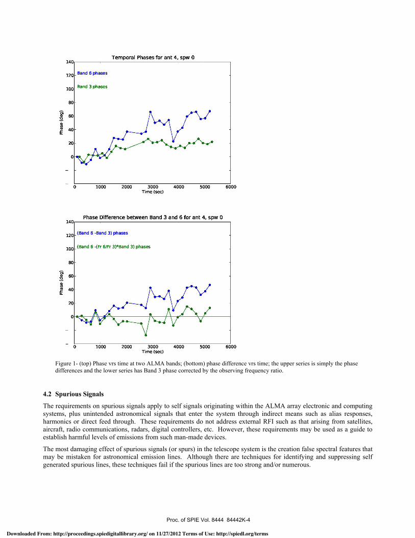
Figure 1- (top) Phase vrs time at two ALMA bands; (bottom) phase difference vrs time; the upper series is simply the phase differences and the lower series has Band 3 phase corrected by the observing frequency ratio.
4.2 Spurious Signals
The requirements on spurious signals apply to self signals originating within the ALMA array electronic and computing systems, plus unintended astronomical signals that enter the system through indirect means such as alias responses, harmonics or direct feed through. These requirements do not address external RFI such as that arising from satellites, aircraft, radio communications, radars, digital controllers, etc. However, these requirements may be used as a guide to establish harmful levels of emissions from such man-made devices.
The most damaging effect of spurious signals (or spurs) in the telescope system is the creation false spectral features that may be mistaken for astronomical emission lines. Although there are techniques for identifying and suppressing self generated spurious lines, these techniques fail if the spurious lines are too strong and/or numerous.
A"#1:,#B,;A3C,4#0:,DEEE,,DEEEFG'E
Downloaded From: http://proceedings.spiedigitallibrary.org/ on 11/27/2012 Terms of Use: http://spiedl.org/terms
There are two basic types of spurious signals, those that are incoherent among antennas and those that are coherent. The incoherent spurious signals are a problem for autocorrelation observations, but not for interferometry which uses cross-correlations between antennas. The coherent spurious signals are a problem for both.
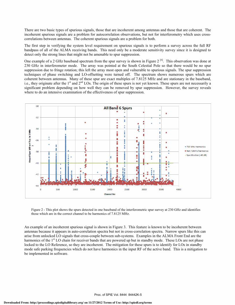
The first step in verifying the system level requirement on spurious signals is to perform a survey across the full RF bandpass of all of the ALMA receiving bands. This need only be a moderate sensitivity survey since it is designed to detect only the strong lines that might not be amenable to spur suppression.
One example of a 2 GHz baseband spectrum from the spur survey is shown in Figure 2 [6]. This observation was done at 230 GHz in interferometer mode. The array was pointed at the South Celestial Pole so that there would be no spur suppression due to fringe rotation; this left the array most open and vulnerable to spurious signals. The spur suppression techniques of phase switching and LO-offsetting were turned off. The spectrum shows numerous spurs which are coherent between antennas. Many of these spur are exact multiples of 7.8125 MHz and are stationary in the baseband, i.e., they originate after the 1st and 2nd LOs. The origin of these spurs is not yet known. These spurs are not necessarily a significant problem depending on how well they can be removed by spur suppression. However, the survey reveals where to do an intensive examination of the effectiveness of spur suppression.
Figure 2 - This plot shows the spurs detected in one baseband of the interferometric spur survey at 230 GHz and identifies those which are in the correct channel to be harmonics of 7.8125 MHz.
An example of an incoherent spurious signal is shown in Figure 3. This feature is known to be incoherent between antennas because it appears in auto-correlation spectra but not in cross-correlation spectra. Narrow spurs like this can arise from unlocked LO signals that cross-couple between sub-systems. Examples in the ALMA Front End are the harmonics of the 1st LO chain for receiver bands that are powered up but in standby mode. These LOs are not phase locked to the LO Reference, so they are incoherent. The mitigation for these spurs is to identify for LOs in standby mode safe parking frequencies which do not have harmonics in the input RF of the active band. This is a mitigation to be implemented in software.
A"#1:,#B,;A3C,4#0:,DEEE,,DEEEFG'S
Downloaded From: http://proceedings.spiedigitallibrary.org/ on 11/27/2012 Terms of Use: http://spiedl.org/terms
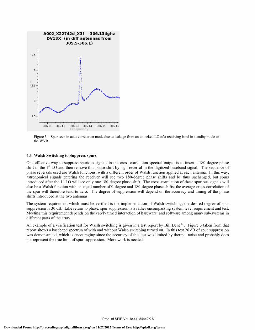
Figure 3 - Spur seen in auto-correlation mode due to leakage from an unlocked LO of a receiving band in standby mode or the WVR.
4.3 Walsh Switching to Suppress spurs
One effective way to suppress spurious signals in the cross-correlation spectral output is to insert a 180 degree phase shift in the 1st LO and then remove this phase shift by sign reversal in the digitized baseband signal. The sequence of phase reversals used are Walsh functions, with a different order of Walsh function applied at each antenna. In this way, astronomical signals entering the receiver will see two 180-degree phase shifts and be thus unchanged, but spurs introduced after the 1st LO will see only one 180-degree phase shift. The cross-correlation of these spurious signals will also be a Walsh function with an equal number of 0-degree and 180-degree phase shifts; the average cross-correlation of the spur will therefore tend to zero. The degree of suppression will depend on the accuracy and timing of the phase shifts introduced at the two antennas.
The system requirement which must be verified is the implementation of Walsh switching; the desired degree of spur suppression is 30 dB. Like return to phase, spur suppression is a rather encompassing system level requirement and test. Meeting this requirement depends on the carely timed interaction of hardware and software among many sub-systems in different parts of the array.
An example of a verification test for Walsh switching is given in a test report by Bill Dent [7]. Figure 3 taken from that report shows a baseband spectrun of with and without Walsh switching turned on. In this test 26 dB of spur suppression was demonstrated, which is encouraging since the accuracy of this test was limited by thermal noise and probably does not represent the true limit of spur suppression. More work is needed.
A"#1:,#B,;A3C,4#0:,DEEE,,DEEEFG'O
Downloaded From: http://proceedings.spiedigitallibrary.org/ on 11/27/2012 Terms of Use: http://spiedl.org/terms

Figure 3 �– Cross-correlation spectra with and without Walsh 180-degree phase switching (note the change in scale in the two plots). When Walsh Switching is turned on the strongest spurious signals, which are off scale on the left hand plot, are suppressed by >26 dB.
4.4 Antenna Location (Array Baseline) Stability
The ability of the array to produce precise radio images depends on knowing the vector separation of the antennas to high accuracy. These measurements are made astronomically, but can take about an hour of array time, so such �“baseline�” determinations would ideally be done only once every couple weeks. Therefore there is a system requirement that the antenna locations be stable to better than 65 microns over a time scale of 14 days.
Verification of this requirement is done by repeatedly measuring the array baselines and looking for variations. Figure 4 show the results of one such study by Masahiro Sugimoto [8]. Baselines were measured every two to three hours for a 24 hour period. This series of measurements shows shifts of baseline vector components of many tenths of a millimeter, far beyond the specification. It is not clear if these are true shifts in the location of the antenna axis intersection or if the results are due to possible errors in applying atmosphere delay corrections. This is currently being investigated.
ACKNOWLEDGEMENTS
It is not possible to acknowledge all of the ALMA staff members that are contributing to System Verification. The listed authors are just a sampling of the many people in Chile, Europe, North America and Asia who are aiding this effort.
This paper is dedicated to the memory of Koh-Ichiro Morita, recently deceased, who until 7-May-2012 lead the ALMA System Verification effort.
A"#1:,#B,;A3C,4#0:,DEEE,,DEEEFG'N
Downloaded From: http://proceedings.spiedigitallibrary.org/ on 11/27/2012 Terms of Use: http://spiedl.org/terms

Figure 3 �– The components of the vector separation of two antennas; the measurements were repeated eight times in a 24 hour period. The two data points for each measurement represent two different analysis methods (delay and phase) for determining the baseline vector. The changes in the vector during this period are more than allowed, but measurement errors like improper atmospheric delay corrections have not been ruled out.
REFERENCES
[1] Sramek, R. and Haupt, C., �“ALMA System Technical Requirements for 12m Array�”, 21-Sep-2006, ALMA-80.04.00.00-005-B-SPE.
[2] Wootten, A. and Wilson, T., �“ALMA Scientific Specifications and Requirements�”, 28-Jul-2006, ALMA-90.00.00.00-001-A- SPE.
[3] Morita, K., �“ALMA System Verification Progress Plan�”, 29-Apr-2012 Draft, SYSE-88.00.00.00-0002-A-PLA.
[4] Morita, K., �“ALMA System Verification Progress Report�”, 29-Apr-2012 Draft, SYSE-88.00.00.00-0003-A-REP.
[5] Fomalont, E.,�“Band 3 to Band 6 Phase Transfer�”, 24-Mar-2011, ALMA JIRA issue CSV-413 [6] Napier, P., �“Spur survey Band 6�”, 31-May-2011, ALMA JIRA issue AIV-1475. [7] Dent, W., �“Effect of 180 deg Walsh switching on spurious signals�”, 25-Aug-2011, ALMA JIRA issue AIV-1475. [8] Sugimoto, M., �“An interim report of analysis of 24hrs baseline measurement�”, 01-Feb-2012, ALMA JIRA issue
CSV-457.
A"#1:,#B,;A3C,4#0:,DEEE,,DEEEFG'D
Downloaded From: http://proceedings.spiedigitallibrary.org/ on 11/27/2012 Terms of Use: http://spiedl.org/terms