allen-bradley plc5 driver configuration...
TRANSCRIPT

WebAccess Configuration Manual AB PLC5
Version 7.0 rev 0a Advantech Corp., Ltd. page 1
Allen-Bradley PLC5 Driver
Configuration Manual

WebAccess Configuration Manual AB PLC5
Version 7.0 rev 0a Advantech Corp., Ltd. page 1-1
Table of Contents
Allen-Bradley PLC5 Driver Configuration Manual 1
1. AB PLC5 Configuration 2
1.1 AB PLC5 ............................................................................................. 2 1.2 Module Settings .................................................................................. 2
2. WebAccess Configuration 3
2.1 Port ..................................................................................................... 3 2.1.1 Check the port number .......................................................... 3 2.1.2 WebAccess Comport Page ................................................... 5 2.1.3 Comport Number ................................................................... 5 2.1.4 Description ............................................................................. 6 2.1.5 Baud Rate .............................................................................. 6 2.1.6 Data Bits ................................................................................ 6 2.1.7 Stop Bits ................................................................................ 6 2.1.8 Parity...................................................................................... 6 2.1.9 Scan Time ............................................................................. 6 2.1.10 Timeout .................................................................................. 6 2.1.11 Retry Count ........................................................................... 7 2.1.12 Auto Recover Time ................................................................ 7 2.1.13 Hand Shake RTS ................................................................... 7 2.1.14 Hand Shake DTR .................................................................. 7 2.1.15 Backup Port ........................................................................... 8
2.2 Device ................................................................................................. 8 2.2.1 Unit Number .......................................................................... 8 2.2.2 Checksum .............................................................................. 8
2.3 Block ................................................................................................... 9 2.4 Tag ...................................................................................................... 9
2.4.1 Parameter .............................................................................. 9 2.4.2 Address ................................................................................. 9 2.4.3 Scaling Type .......................................................................... 9
2.5 Supported Block List ......................................................................... 10 2.6 Main Parameter List ......................................................................... 10
WebAccess Configuration Manual AB PLC5
Version 7.0 rev 0a Advantech Corp., Ltd. page 2
1. AB PLC5 Configuration
1.1 AB PLC5
The WebAccess SCADA Node provides an interface to the Allen-Bradley PLC5
series of Programmable PLCs using the DF1 protocol. This manual describes
using a Serial RS232 or RS422 connection from the SCADA node to a DF1
compatible device.
The WebAccess ABPLC5 Device Driver uses the DF1 protocol (Full Duplex
Mode) to communicate to Allen-Bradley PLC5 series processors.
1.2 Module Settings
Open the configuration software given with your PLC and set the PLC port
that you want to connect to WebAccess with the following settings.
Remember that the port should support DF1 protocol (Usually only the
Channel 0 does).
RS232/422
Full-Full Duplex DF1 Point-to-Point
8 Data Bits
1 Stop Bit
Parity = None
Error Checking = CRC (Cyclic Redundancy Check)
Handshaking or Modem Flow Disabled
Typical is 19200 baud. 9600 to 19200 (or faster) recommended.
Port configured as a DF1 Slave (required to communicate with
WebAccess SCADA node)

WebAccess Configuration Manual AB PLC5
Version 7.0 rev 0a Advantech Corp., Ltd. page 3
2. WebAccess Configuration
2.1 Port
The ABPLC5 protocol uses a serial port. Even if you use a serial port server or
a USB to serial converter the apparent port in your computer (and therefore
the port to select in WebAccess) is a serial port.
2.1.1 Check the port number
If you are using a comport emulator and you do not know the port number
then open the “Start Menu” and right click on “Computer” and select
“Manage”
In the device manager section you can see the list of COM ports on your
computer and recognize the virtual port by its driver name

WebAccess Configuration Manual AB PLC5
Version 7.0 rev 0a Advantech Corp., Ltd. page 4

WebAccess Configuration Manual AB PLC5
Version 7.0 rev 0a Advantech Corp., Ltd. page 5
2.1.2 WebAccess Comport Page
Open your WebAccess Configuration and select the SCADA node you want to
add the device to. Then select “Add a new Comport”
All the settings in this page must match the settings in all the modules
attached to the port. So all the modules attached to the same comport must
have the same settings.
2.1.3 Comport Number
The Serial Comport requires the comport number to match that of the
physical interface (e.g. COM1, COM2, COM3, etc) on the SCADA Node.

WebAccess Configuration Manual AB PLC5
Version 7.0 rev 0a Advantech Corp., Ltd. page 6
2.1.4 Description
This is an optional field used for user reference.
2.1.5 Baud Rate
For the ABPLC5 modules the typical baud rate is 19200.
This must match the baud rate configured in the module and the eventual RS-
485 to RS-232 converter.
2.1.6 Data Bits
The packets can have 7 or 8 Data Bits. The typical setting for ABPLC5 is 8
bits.
2.1.7 Stop Bits
The packets can have 1 or 2 Stop Bits. The typical setting for ABPLC5 is 1
Stop bit.
2.1.8 Parity
The Parity can be None, Odd, Even or Disabled. The typical setting for Adam
ABPLC5 is Parity = None.
2.1.9 Scan Time
This is the time in milliseconds to scan the Devices. This must match the
ability of the device to respond. A typical scan rate is 1 per second.
If the Device cannot respond as fast as the SCAN Time entered, WebAccess
will scan at a slower rate.
2.1.10 Timeout
With a 1 second scan rate, a typical Time Out = 200 Milliseconds.
Timeout is the time waited before re-sending a communications packet that
did not have a reply.
Timeout specifies how long the software waits for a response to a data
request, specifically to wait for a reply from one packet. A recommended
value is one-fifth the scan rate, longer if the communication device is slow.
Combined with Retry count, Timeout also determines time to consider a
device or port as BAD. Timeout is the time to wait since last communication
packet sent without a reply. Time is in milliseconds. Slow or poor quality
communications require longer timeout. The faster the communications, the
shorter the timeout required. Shorter timeouts result in faster reconnects
after communication failures.

WebAccess Configuration Manual AB PLC5
Version 7.0 rev 0a Advantech Corp., Ltd. page 7
2.1.11 Retry Count
A typical Retry count = 3.
Number of times to retry communications if no reply is received from a device.
Combined with Timeout, also determines time to consider a device or port as
BAD.
This is the number of times after the first attempt has failed that
communication should be attempted before indicating a failure. (If Retry
count is 3, a total of 4 failed requests have occurred before tags are marked
bad). Specifically, this is how many times to send a single packet after the
field device fails to respond to the first packet. After the retry count is
exceeded, all the tags in the packet are marked with asterisks and the next
packet of requests is sent. A reasonable value is 3 to 5 times. After this
number of tries, the tags in this packet are marked as "fail to respond" (i.e.
asterisks) and are disabled. In reality, increasing the number of retries hides
failures on the part of the field device to respond to a request. Essentially,
increasing the retries gives the field device more chances to reply.
2.1.12 Auto Recover Time
A typical Auto Recover Time = 60 Seconds.
Auto Recover Time is the time to wait before attempting to re-establish
communications with a BAD device or port.
If communications to the PLC is unusually slow due to hardware,
communications or network issues, you might consider increasing this value.
If communications to the PLC or RTU fails frequently, you may want to
decrease this number in order to have WebAccess try to re-establish
communications sooner.
If communications to the PLC, RTU or device Fails (i.e. exceeds Timeout)
WebAccess will wait the Auto Recover Time before trying to re-establish
communications.
2.1.13 Hand Shake RTS
The typical setting for ABPLC5 is HandShakeRts = No.
The RTS (Request To Send) signal is raised and lowered on the Serial
Communications Port if this value set to Yes. RTS is determined by settings
in the field device. Refer to your device interface manual to determine the
value for this field and the type of cable used.
2.1.14 Hand Shake DTR
The typical setting for ABPLC5 is HandShakeDtr = No.
WebAccess Configuration Manual AB PLC5
Version 7.0 rev 0a Advantech Corp., Ltd. page 8
The DTR (Data Terminal Ready) signal raised and lowered on the Serial
Communications Port if this value is set to Yes. DTR is determined by settings
in the field device and the type of cable used.
2.1.15 Backup Port
The Backup Port has not been tested for ABPLC5
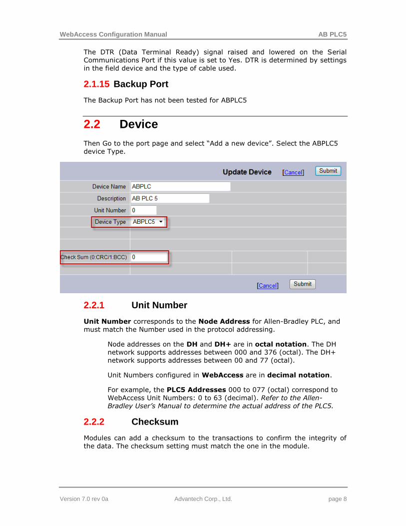
2.2 Device
Then Go to the port page and select “Add a new device”. Select the ABPLC5
device Type.
2.2.1 Unit Number
Unit Number corresponds to the Node Address for Allen-Bradley PLC, and
must match the Number used in the protocol addressing.
Node addresses on the DH and DH+ are in octal notation. The DH
network supports addresses between 000 and 376 (octal). The DH+
network supports addresses between 00 and 77 (octal).
Unit Numbers configured in WebAccess are in decimal notation.
For example, the PLC5 Addresses 000 to 077 (octal) correspond to
WebAccess Unit Numbers: 0 to 63 (decimal). Refer to the Allen-
Bradley User’s Manual to determine the actual address of the PLC5.
2.2.2 Checksum
Modules can add a checksum to the transactions to confirm the integrity of
the data. The checksum setting must match the one in the module.

WebAccess Configuration Manual AB PLC5
Version 7.0 rev 0a Advantech Corp., Ltd. page 9
2.3 Block
There are no preset blocks in the ABPLC5 driver but it is possible for the user
to set custom blocks if necessary.
2.4 Tag
If you do not use all the channels in the device and you want to reduce your
tag count you can add the parameters one by one using “Add tag”.
2.4.1 Parameter
The parameter gives the type of tag you want to import. Try to select a
parameter as close to the tag type as possible because it will fill the other
option with the default parameters.
2.4.2 Address
The address in ABPLC5 driver starts with letters representing the data type
followed by the file number then “:” and the position of the tag in the file (For
Example N7:1). Some types (like input and output) do not need a file number.
2.4.3 Scaling Type
If the data sent by the module is not in a human readable unit you can use
the scaling to change the unit and display a more convenient unit in the node.
In most cases a linear scaling type will be sufficient.

WebAccess Configuration Manual AB PLC5
Version 7.0 rev 0a Advantech Corp., Ltd. page 10
2.5 Supported Block List
There are no predefined blocks in ABPLC5 driver.
2.6 Main Parameter List
Parameter Data Type
Description Address format
AI Analog Analog Input I:000
AO Analog Analog Output O:000
B Analog Binary B3:0
BT_DLEN Analog Blk Transmit Word Count BT10:0.DLEN
BT_ELEM Analog Blk Word Num BT10:0.ELEM
BT_FILE Analog Blk File-Type Num BT10:0.FILE
BT_G Analog Blk I/O Group BT10:0.RGS
BT_R Analog Blk I/O Rack BT10:0.RGS
BT_RLEN Analog Blk Req. Word Count BT10:0.RLEN
BT_S Analog Blk Slot BT10:0.RGS
C_ACC Analog Counter Accumulated Value C5:0.ACC
C_PRE Analog Counter Preset Value C5:0.PRE
D Analog BCD D10:0
F Analog Floating Point F8:0
MG_DLEN Analog Message Res./Intern. Use MG10:0.DLEN
MG_ERR Analog Message Error Code MG10:0.ERR
MG_RLEN Analog Message Request Length MG10:0.RLEN
N Analog Integer N7:0
PD_BIAS Analog PID Output Bias % PD10:0.BIAS
PD_DB Analog PID Dead Band PD10:0.DB
PD_DVDB Analog PID Deviation Alarm DB PD10:0.DVDB
PD_DVN Analog PID Deviation Alarm - PD10:0.DVN

WebAccess Configuration Manual AB PLC5
Version 7.0 rev 0a Advantech Corp., Ltd. page 11
Parameter Data Type
Description Address format
PD_DVP Analog PID Deviation Alarm + PD10:0.DVP
PD_ERR Analog PID Error PD10:0.ERR
PD_KD Analog PID Derivative Time PD10:0.KD
PD_KI Analog PID Integral Gain PD10:0.KI
PD_KP Analog PID Proportional Gain PD10:0.KP
PD_MAXI Analog PID Input Range Maximum PD10:0.MAXI
PD_MAXO Analog PID Output Limit High % PD10:0.MAXO
PD_MAXS Analog PID Set-Point Maximum PD10:0.MAXS
PD_MINI Analog PID Input Range Minimum PD10:0.MINI
PD_MINO Analog PID Output Limit Low % PD10:0.MINO
PD_MINS Analog PID Set-Point Minimum PD10:0.MINS
PD_OUT Analog PID Output % PD10:0.OUT
PD_PV Analog PID Process Variable PD10:0.PV
PD_PVDB Analog PID PV Alarm Dead Band PD10:0.PVDB
PD_PVH Analog PID PV Alarm High PD10:0.PVH
PD_PVL Analog PID PV Alarm Low PD10:0.PVL
PD_SO Analog PID Set Output % PD10:0.SO
PD_SP Analog PID Set Point PD10:0.SP
PD_TIE Analog PID Tieback % PD10:0.TIE
PD_UPD Analog PID Update Time PD10:0.UPD
R_LEN Analog Control Length R6:0.LEN
R_POS Analog Control Position R6:0.POS
S Analog Status S:0
SC__PRE Analog SFC Preset Value SC10:0.PRE
SC__TIM Analog SFC Active Time SC10:0.TIM
ST_LEN Analog ASCII String Length ST10:0.LEN

WebAccess Configuration Manual AB PLC5
Version 7.0 rev 0a Advantech Corp., Ltd. page 12
Parameter Data Type
Description Address format
T_ACC Analog Accumulated Value T4:0.ACC
T_PRE Analog Preset Value T4:0.PRE
BT_CO discrete Blk Trans Continue BT10:0.CO
BT_DN discrete Blk Trans Done BT10:0.DN
BT_EN discrete Blk Trans Enable BT10:0.EN
BT_ER discrete Blk Trans Error BT10:0.ER
BT_EW discrete Blk Trans Enabled Waiting BT10:0.EW
BT_NR discrete Blk Trans No Response BT10:0.NR
BT_RW discrete Blk Trans Read/Write BT10:0.RW
BT_ST discrete Blk Trans Start BT10:0.ST
BT_TO discrete Blk Trans Time Out BT10:0.TO
C_CD discrete Counter Down Enable C5:0.CD
C_CU discrete Counter Up Enable C5:0.CU
C_DN discrete Counter Done C5:0.DN
C_OV discrete Counter Overflow C5:0.OV
C_UN discrete Counter Underflow C5:0.UN
DI discrete DI I:000/00
DO discrete DO O:000/00
MG_CO discrete Message Continuous MG10:0.CO
MG_DN discrete Message Done MG10:0.DN
MG_EN discrete Message Enable MG10:0.EN
MG_ER discrete Message Error MG10:0.ER
MG_EW discrete Message Enabled Waiting MG10:0.EW
MG_NR discrete Message No Response MG10:0.NR
MG_ST discrete Message Start Transmit MG10:0.ST
PD_CA discrete PID Control Action PD10:0.CA

WebAccess Configuration Manual AB PLC5
Version 7.0 rev 0a Advantech Corp., Ltd. page 13
Parameter Data Type
Description Address format
PD_CL discrete PID Cascaded Loop PD10:0.CL
PD_CT discrete PID Cascaded Type PD10:0.CT
PD_DO discrete PID Derivative PD10:0.DO
PD_DVN
A discrete PID Dev High Alarm PD10:0.DVNA
PD_DVPA discrete PID Dev Low Alarm PD10:0.DVPA
PD_EN discrete PID Enable PD10:0.EN
PD_EWD discrete PID Error Within DB PD10:0.EWD
PD_INI discrete PID Initialized PD10:0.INI
PD_MO discrete PID Station (auto/manual) PD10:0.MO
PD_OLH discrete PID Output Limit High PD10:0.OLH
PD_OLL discrete PID Output Limit Low PD10:0.OLL
PD_PE discrete PID Equation Type PD10:0.PE
PD_PVHA discrete PID PV High Alarm PD10:0.PVHA
PD_PVLA discrete PID PV Low Alarm PD10:0.PVLA
PD_PVT discrete PID PV Tracking PD10:0.PVT
PD_SPOR discrete PID SP Out of Range PD10:0.SPOR
PD_SWM discrete PID Software A/M Mode PD10:0.SWM
R_DN discrete Control Done R6:0.DN
R_EM discrete Control Empty R6:0.EM
R_EN discrete Control Enable R6:0.EN
R_ER discrete Control Error R6:0.ER
R_EU discrete Control Enable Unloading R6:0.EU
R_FD discrete Control Found R6:0.FD
R_IN discrete Control Inhibit Compare R6:0.IN
R_UL discrete Control Unload R6:0.UL
SC_DN discrete SFC Done SC10:0.DN

WebAccess Configuration Manual AB PLC5
Version 7.0 rev 0a Advantech Corp., Ltd. page 14
Parameter Data Type
Description Address format
SC_ER discrete SFC Step Eroded SC10:0.ER
SC_FS discrete SFC First Scan SC10:0.FS
SC_LS discrete SFC Last Scan SC10:0.LS
SC_OV discrete SFC Timer Overflow SC10:0.OV
SC_SA discrete SFC Scan Active SC10:0.SA
T_DN discrete Timer Done T4:0.DN
T_EN discrete Timer Enable T4:0.EN
T_TT discrete Timer Timing T4:0.TT
ST text ASCII String ST10:0