allegiant main cpu interface software command console...
TRANSCRIPT
EN CCL User Guide
BOSCH
Allegiant® Main CPU Interface SoftwareCommand Console LanguageLTC 8100, LTC 8200, LTC 8300, LTC 8500, LTC 8600, LTC 8800 and LTC 8900 Series, CPU Revision 8.6
Preface
This guide describes how to use the Allegiant® Main CPU Interface Software Command Console Language. This guide includes a complete list of the avail-able commands, code samples and associated response information.
Audience
This guide is intended for ssystem integrators who are familiar with the Alle-giant Matrix Switch control system and have experience with developing inter-faces to products using ASCII-based commands.
Prerequisites
An LTC 8100, LTC 8200, LTC 8300, LTC 8500, LTC 8600, LTC 8800 and LTC 8900 Series Allegiant system, CPU Firmware revision Level 8.6 or later.
Document Conventions
The following conventions apply throughout this manual:
Convention Description
THIS TYPFACE Denotes an actual command or piece of syntax.
this typeface Denotes actual code that you can use, but you must type the code exactly as shown.
this typeface Denotes a variable for which you must supply a value.
underscore Denotes a default setting.
.
.
.
Indicates that there are (or could be) intervening or additional commands.
{ } Indicates a group of valid parameters, one of which is required.
[ ] Indicates a group of optional parameters. None are required, but you may select one of them.
EN | iii

Related Publications
Refer to the latest Bosch Security Systems Databook for the most up-to-date datasheets. To obtain a copy of the Databook, please contact your local Bosch representative.
You can also visit the Bosch Security Systems World Wide Web site at: http://www.boschsecurity.com to view a current listings of our publications.
EN | iv Bosch Security Systems | September 7, 2005
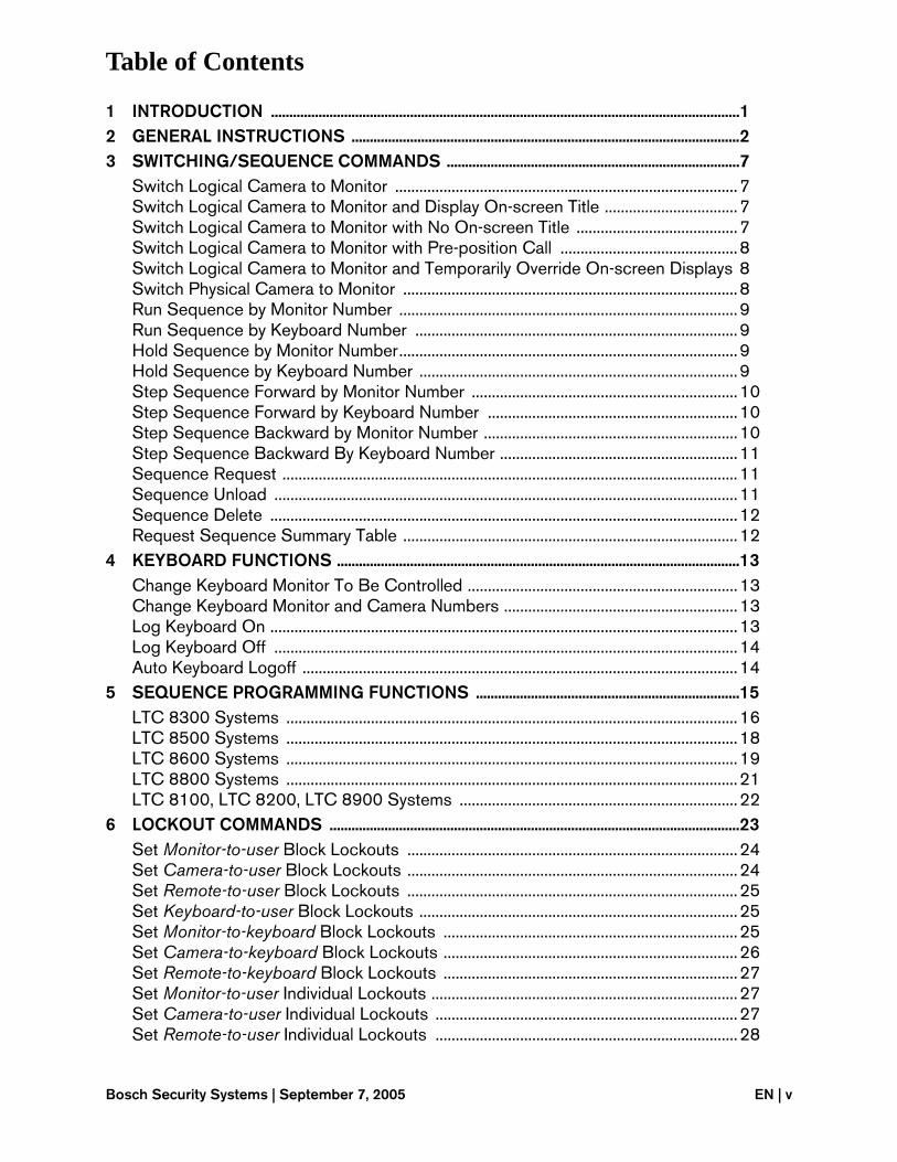
Table of Contents
1 INTRODUCTION ................................................................................................................................12 GENERAL INSTRUCTIONS ..........................................................................................................23 SWITCHING/SEQUENCE COMMANDS ................................................................................7
Switch Logical Camera to Monitor .....................................................................................7Switch Logical Camera to Monitor and Display On-screen Title .................................7Switch Logical Camera to Monitor with No On-screen Title ........................................7Switch Logical Camera to Monitor with Pre-position Call ............................................8Switch Logical Camera to Monitor and Temporarily Override On-screen Displays 8Switch Physical Camera to Monitor ...................................................................................8Run Sequence by Monitor Number ....................................................................................9Run Sequence by Keyboard Number ................................................................................9Hold Sequence by Monitor Number....................................................................................9Hold Sequence by Keyboard Number ...............................................................................9Step Sequence Forward by Monitor Number ..................................................................10Step Sequence Forward by Keyboard Number ..............................................................10Step Sequence Backward by Monitor Number ...............................................................10Step Sequence Backward By Keyboard Number ...........................................................11Sequence Request .................................................................................................................11Sequence Unload ...................................................................................................................11Sequence Delete ....................................................................................................................12Request Sequence Summary Table ...................................................................................12
4 KEYBOARD FUNCTIONS ..............................................................................................................13Change Keyboard Monitor To Be Controlled ...................................................................13Change Keyboard Monitor and Camera Numbers ..........................................................13Log Keyboard On ....................................................................................................................13Log Keyboard Off ...................................................................................................................14Auto Keyboard Logoff ............................................................................................................14
5 SEQUENCE PROGRAMMING FUNCTIONS ........................................................................15LTC 8300 Systems ................................................................................................................16LTC 8500 Systems ................................................................................................................18LTC 8600 Systems ................................................................................................................19LTC 8800 Systems ................................................................................................................21LTC 8100, LTC 8200, LTC 8900 Systems .....................................................................22
6 LOCKOUT COMMANDS ................................................................................................................23Set Monitor-to-user Block Lockouts ..................................................................................24Set Camera-to-user Block Lockouts ..................................................................................24Set Remote-to-user Block Lockouts ..................................................................................25Set Keyboard-to-user Block Lockouts ...............................................................................25Set Monitor-to-keyboard Block Lockouts .........................................................................25Set Camera-to-keyboard Block Lockouts .........................................................................26Set Remote-to-keyboard Block Lockouts .........................................................................27Set Monitor-to-user Individual Lockouts ............................................................................27Set Camera-to-user Individual Lockouts ...........................................................................27Set Remote-to-user Individual Lockouts ...........................................................................28
Bosch Security Systems | September 7, 2005 EN | v
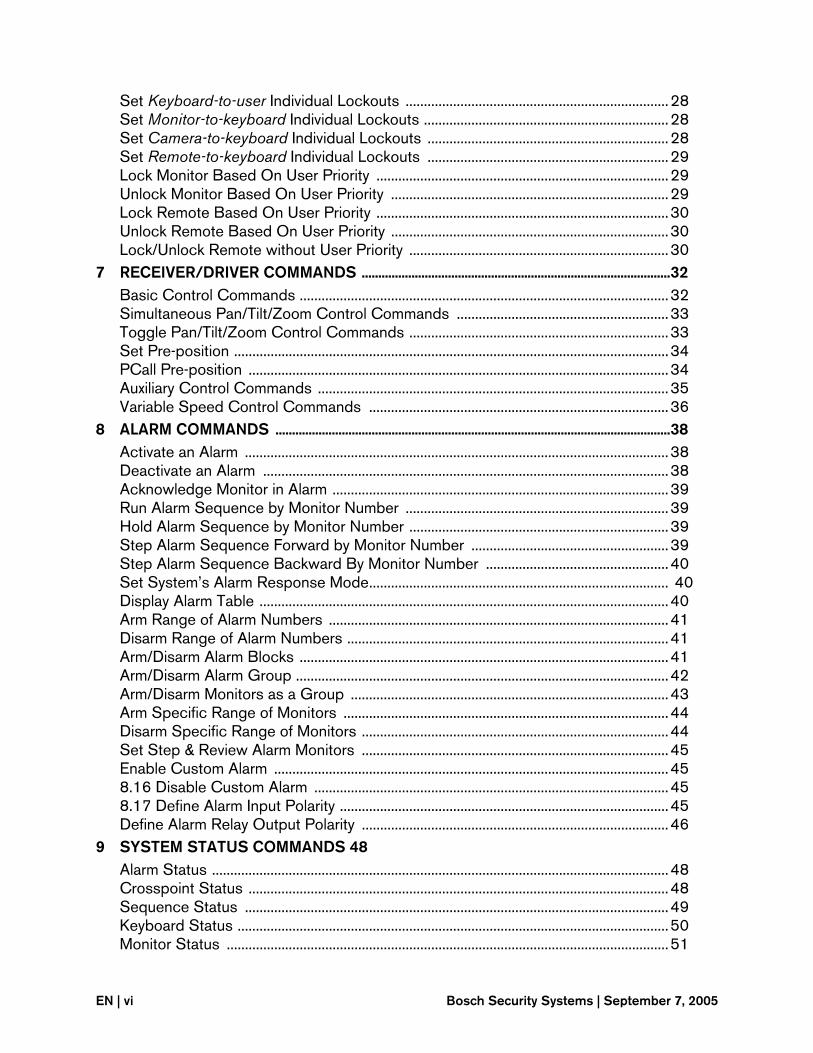
Set Keyboard-to-user Individual Lockouts ........................................................................28Set Monitor-to-keyboard Individual Lockouts ...................................................................28Set Camera-to-keyboard Individual Lockouts ..................................................................28Set Remote-to-keyboard Individual Lockouts ..................................................................29Lock Monitor Based On User Priority ................................................................................29Unlock Monitor Based On User Priority ............................................................................29Lock Remote Based On User Priority ................................................................................30Unlock Remote Based On User Priority ............................................................................30Lock/Unlock Remote without User Priority .......................................................................30
7 RECEIVER/DRIVER COMMANDS .............................................................................................32Basic Control Commands .....................................................................................................32Simultaneous Pan/Tilt/Zoom Control Commands ..........................................................33Toggle Pan/Tilt/Zoom Control Commands .......................................................................33Set Pre-position .......................................................................................................................34PCall Pre-position ...................................................................................................................34Auxiliary Control Commands ................................................................................................35Variable Speed Control Commands ..................................................................................36
8 ALARM COMMANDS .......................................................................................................................38Activate an Alarm ....................................................................................................................38Deactivate an Alarm ...............................................................................................................38Acknowledge Monitor in Alarm ............................................................................................39Run Alarm Sequence by Monitor Number ........................................................................39Hold Alarm Sequence by Monitor Number .......................................................................39Step Alarm Sequence Forward by Monitor Number ......................................................39Step Alarm Sequence Backward By Monitor Number ..................................................40Set System’s Alarm Response Mode.................................................................................. 40Display Alarm Table ................................................................................................................40Arm Range of Alarm Numbers .............................................................................................41Disarm Range of Alarm Numbers ........................................................................................41Arm/Disarm Alarm Blocks .....................................................................................................41Arm/Disarm Alarm Group ......................................................................................................42Arm/Disarm Monitors as a Group .......................................................................................43Arm Specific Range of Monitors .........................................................................................44Disarm Specific Range of Monitors ....................................................................................44Set Step & Review Alarm Monitors ....................................................................................45Enable Custom Alarm ............................................................................................................458.16 Disable Custom Alarm .................................................................................................458.17 Define Alarm Input Polarity ..........................................................................................45Define Alarm Relay Output Polarity ....................................................................................46
9 SYSTEM STATUS COMMANDS 48Alarm Status .............................................................................................................................48Crosspoint Status ...................................................................................................................48Sequence Status ....................................................................................................................49Keyboard Status ......................................................................................................................50Monitor Status .........................................................................................................................51
EN | vi Bosch Security Systems | September 7, 2005
10 VIDEO DETECTION COMMANDS .............................................................................................53Execute Automatic Video Scan ...........................................................................................53Enable/Disable Video Monitoring of Input ........................................................................53Disable Video Monitoring of All Inputs ...............................................................................53Video Detection Status ..........................................................................................................54Enable/Disable Monitors for Video Loss Events .............................................................54Enable/Disable Allegiant Keyboard for Video Loss Events ...........................................55
11 LTC 8016 BILINXTM DATA INTERFACE UNIT (DIU) COMMANDS .........................56Specify DIU Interface Port 5..................................................................................................6
12 ALLEGIANT COAXIAL TRANSMISSION SYSTEM (ACTS) COMMANDS ..............57Close ACTS Remote Module Relay ...................................................................................57Open ACTS Remote Module Relay ...................................................................................57Toggle ACTS Remote Module Relay .................................................................................57Enable/Disable ACTS Audio Group ...................................................................................58Enable/Disable ACTS Audio Following on Monitor ........................................................58Specify ACTS Interface Port ................................................................................................58
13 ON-SCREEN DISPLAY COMMANDS ......................................................................................59Set Time Format ......................................................................................................................59Set Date Format ......................................................................................................................59Set Camera Title .....................................................................................................................59Set Extended Character Camera Title ...............................................................................59Set Monitor Title ......................................................................................................................60Select Monitor Title Option ..................................................................................................60Select Monitor Status Option ..............................................................................................60Enable On-screen Controllable Camera Indicator ..........................................................60Designate Camera as Controllable .....................................................................................61Set Monitor Overlay Position ...............................................................................................61Enable/Disable Monitor Overlay ..........................................................................................62Set Monitor Overlay Brightness ..........................................................................................62Monitor Message Override ...................................................................................................62Override Top Line of On-screen Display ...........................................................................63Override Bottom Line of On-screen Display ....................................................................63Broadcast Message ...............................................................................................................63Enable Video Loss Raster Generator .................................................................................64Set Raster Format ...................................................................................................................64
14 SYSTEM COMMANDS ....................................................................................................................65Request System Software Revision Number ...................................................................65Reset System ...........................................................................................................................65Abbreviate CCL Command ..................................................................................................65Request Camera Hash Value ...............................................................................................65Set Hexadecimal Mode .........................................................................................................66Set Decimal Mode ..................................................................................................................66Set Time ....................................................................................................................................66Display Time .............................................................................................................................66
Bosch Security Systems | September 7, 2005 EN | vii
Set Date .....................................................................................................................................66Display Date .............................................................................................................................67Display Date and Time ...........................................................................................................67Send Message from Biphase Port ......................................................................................67Send Data Packet from Biphase Port ................................................................................68Sound Keyboard Beep ..........................................................................................................69Define Direct RS-232 Port Mode .......................................................................................70Define Indirect RS-232 Port Mode .....................................................................................70Display Direct RS-232 Port Mode .......................................................................................71Echo Message .........................................................................................................................71Print Message ..........................................................................................................................71Display External Interface Port Configuration Status .....................................................71Set Direct RS-232 Allegiant Interface Port Parameters .................................................72Request Direct RS-232 Port Parameters...........................................................................72Set Indirect RS-232 Allegiant Interface Port Parameters .............................................72Request Indirect RS-232 Allegiant Interface Port Parameters......................................73Enable Indirect Allegiant RS-232 Keyboard Communication Mode............................73Enable Direct Allegiant RS-232 Keyboard Communication Mode ..............................75Enable Time Event Function ..................................................................................................75Disable Time Event Function ................................................................................................75Enable/Disable Trunk Caching ............................................................................................76Default Camera Numbers .....................................................................................................76Display Index Camera Number ............................................................................................77Display Index Monitor Number - Valid for LTC 8900 Systems Only ...........................77Display Logical Camera Number .........................................................................................77Display Logical Monitor Number - Valid for LTC 8900 Systems Only .......................78Specify Allegiant LTC 8900 General Task Processing Mode .....................................78Specify Allegiant Custom Alarm Task Processing Mode ..............................................78Define Video Standard ..........................................................................................................79Default System to Factory Settings ....................................................................................79
15 ALLEGIANT DIAGNOSTIC COMMANDS ...............................................................................81Display Detected Cameras ...................................................................................................81CPU Flash Memory Check ...................................................................................................81Display CPU Parameter Settings ........................................................................................81Display Input Module Status ................................................................................................82Display Crosspoint Status ....................................................................................................83Display Satellite Trunk Status ..............................................................................................83List Bootscreen Script Program ..........................................................................................83Enable/Disable Command Script Debug Mode ..............................................................83Display Matrix Bay Firmware Revisions - LTC 8900 Series Only ................................84Time Since Last CPU Reset .................................................................................................84Diagnostic Commands - LTC 8590 ACTS Series Only ................................................84
16 ERROR MESSAGES .........................................................................................................................86
EN | viii Bosch Security Systems | September 7, 2005
1 INTRODUCTION
The Command Console Language (CCL) is a maintained set of commands that is used to control the functions of an Allegiant® Series LTC 8100, LTC 8200, LTC 8300, LTC 8500, LTC 8600, LTC 8800, or an LTC 8900 switching/controller system through the use of its integral RS-232C port. A personal computer, dumb terminal, or the Hyperterminal program supplied with Microsoft Windows® may be used to communicate with the Allegiant system to control various system func-tions, including video switching, receiver/driver actions, and alarms.
This capability allows the Allegiant system to be interfaced with external software which typically is used to sense alarms or handle access control on an existing com-puter system. It is strongly recommended that only qualified programmers who are already familiar with the Allegiant system operation make use of this interfacing fea-ture.
EN | 1
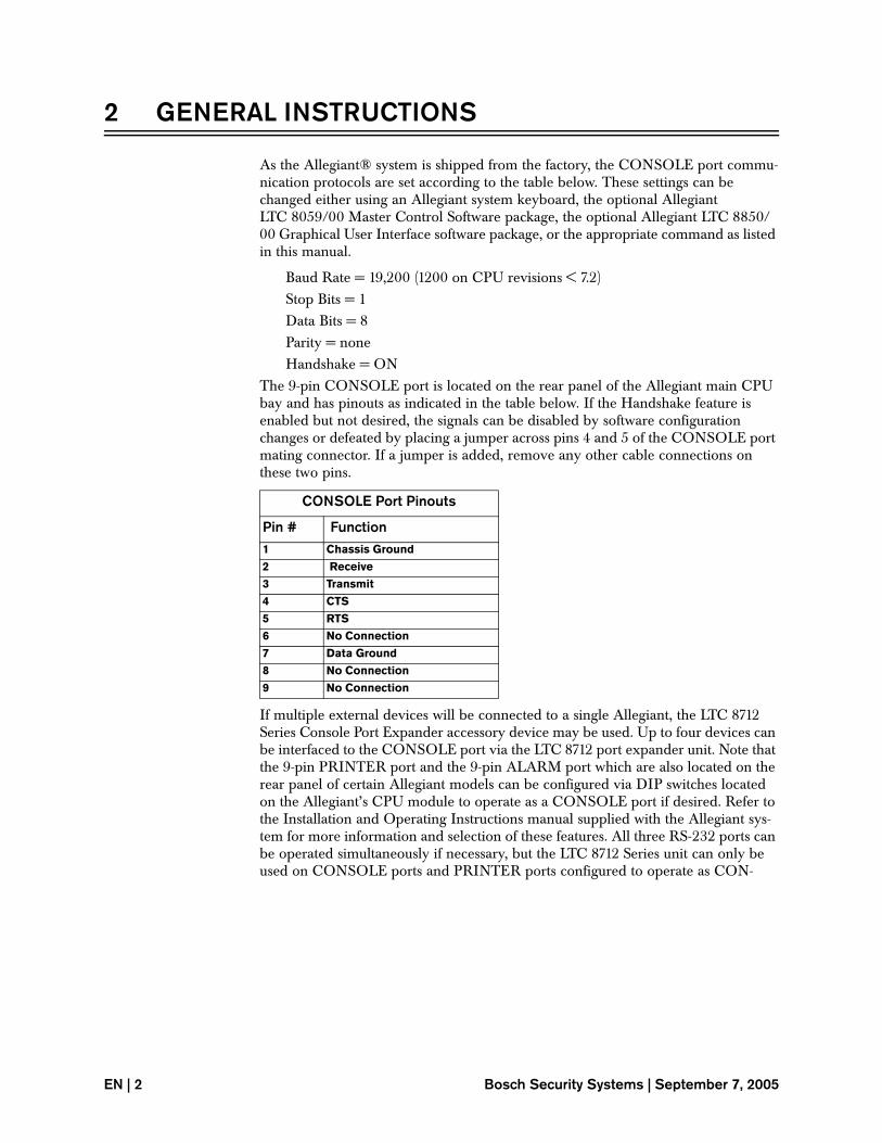
2 GENERAL INSTRUCTIONS
As the Allegiant® system is shipped from the factory, the CONSOLE port commu-nication protocols are set according to the table below. These settings can be changed either using an Allegiant system keyboard, the optional Allegiant LTC 8059/00 Master Control Software package, the optional Allegiant LTC 8850/00 Graphical User Interface software package, or the appropriate command as listed in this manual.
Baud Rate = 19,200 (1200 on CPU revisions < 7.2)Stop Bits = 1Data Bits = 8Parity = noneHandshake = ON
The 9-pin CONSOLE port is located on the rear panel of the Allegiant main CPU bay and has pinouts as indicated in the table below. If the Handshake feature is enabled but not desired, the signals can be disabled by software configuration changes or defeated by placing a jumper across pins 4 and 5 of the CONSOLE port mating connector. If a jumper is added, remove any other cable connections on these two pins.
If multiple external devices will be connected to a single Allegiant, the LTC 8712 Series Console Port Expander accessory device may be used. Up to four devices can be interfaced to the CONSOLE port via the LTC 8712 port expander unit. Note that the 9-pin PRINTER port and the 9-pin ALARM port which are also located on the rear panel of certain Allegiant models can be configured via DIP switches located on the Allegiant’s CPU module to operate as a CONSOLE port if desired. Refer to the Installation and Operating Instructions manual supplied with the Allegiant sys-tem for more information and selection of these features. All three RS-232 ports can be operated simultaneously if necessary, but the LTC 8712 Series unit can only be used on CONSOLE ports and PRINTER ports configured to operate as CON-
CONSOLE Port Pinouts
Pin # Function1 Chassis Ground
2 Receive
3 Transmit
4 CTS
5 RTS
6 No Connection
7 Data Ground
8 No Connection
9 No Connection
EN | 2 Bosch Security Systems | September 7, 2005
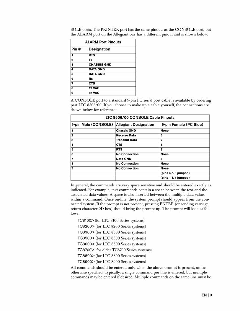
SOLE ports. The PRINTER port has the same pinouts as the CONSOLE port, but the ALARM port on the Allegiant bay has a different pinout and is shown below.
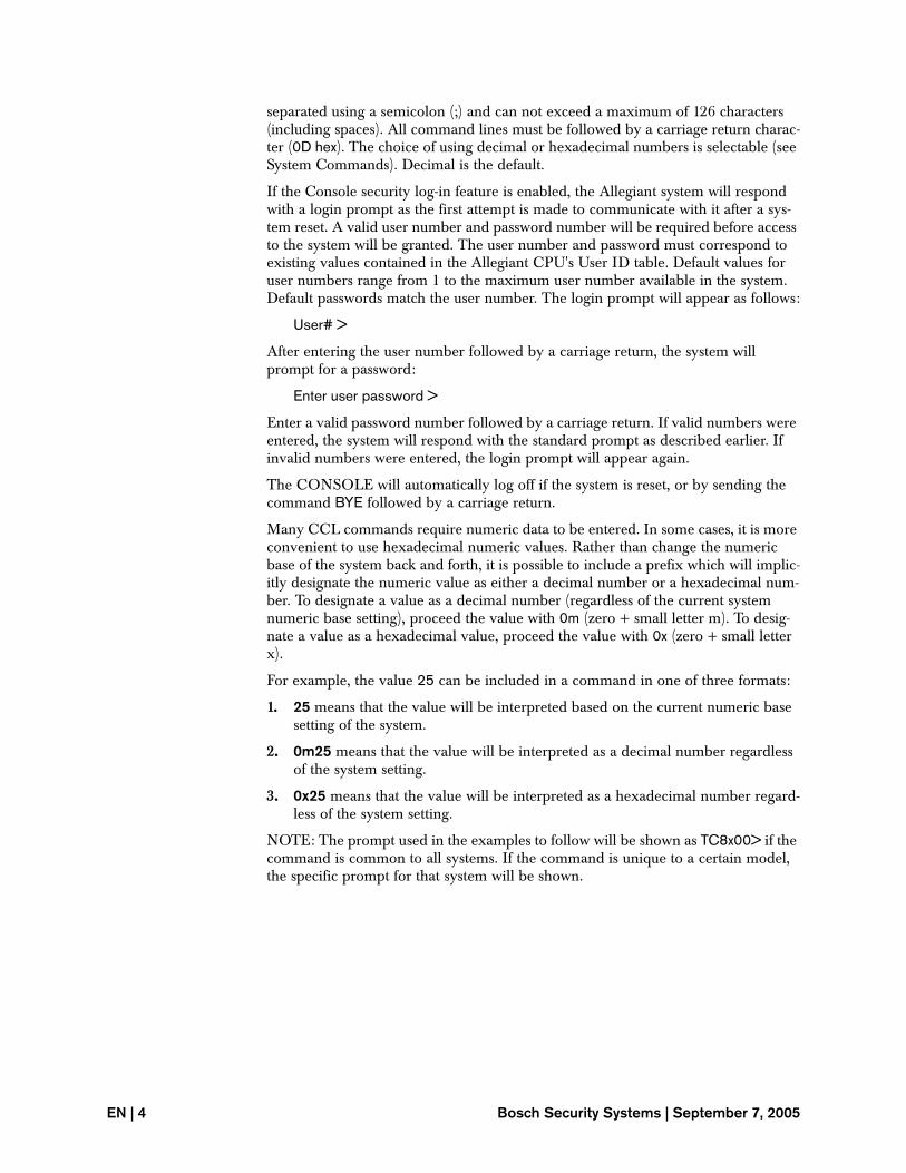
A CONSOLE port to a standard 9-pin PC serial port cable is available by ordering part LTC 8506/00. If you choose to make up a cable yourself, the connections are shown below for reference.
In general, the commands are very space sensitive and should be entered exactly as indicated. For example, text commands contain a space between the text and the associated data values. A space is also inserted between the multiple data values within a command. Once on-line, the system prompt should appear from the con-nected system. If the prompt is not present, pressing ENTER (or sending carriage return character 0D hex) should bring the prompt up. The prompt will look as fol-lows:
TC8100> (for LTC 8100 Series systems)TC8200> (for LTC 8200 Series systems)TC8300> (for LTC 8300 Series systems)TC8500> (for LTC 8500 Series systems)TC8600> (for LTC 8600 Series systems)TC8700> (for older TC8700 Series systems)TC8800> (for LTC 8800 Series systems)TC8900> (for LTC 8900 Series systems)
All commands should be entered only when the above prompt is present, unless otherwise specified. Typically, a single command per line is entered, but multiple commands may be entered if desired. Multiple commands on the same line must be
ALARM Port Pinouts
Pin # Designation1 RTS
2 Tx
3 CHASSIS GND
4 DATA GND
5 DATA GND
6 Rx
7 CTS
8 12 VAC
9 12 VAC
LTC 8506/00 CONSOLE Cable Pinouts
9-pin Male (CONSOLE) Allegiant Designation 9-pin Female (PC Side)1 Chassis GND None
2 Receive Data 3
3 Transmit Data 2
4 CTS 1
5 RTS 8
6 No Connection None
7 Data GND 5
8 No Connection None
9 No Connection None
(pins 4 & 6 jumped)
(pins 1 & 7 jumped)
EN | 3
separated using a semicolon (;) and can not exceed a maximum of 126 characters (including spaces). All command lines must be followed by a carriage return charac-ter (0D hex). The choice of using decimal or hexadecimal numbers is selectable (see System Commands). Decimal is the default.
If the Console security log-in feature is enabled, the Allegiant system will respond with a login prompt as the first attempt is made to communicate with it after a sys-tem reset. A valid user number and password number will be required before access to the system will be granted. The user number and password must correspond to existing values contained in the Allegiant CPU's User ID table. Default values for user numbers range from 1 to the maximum user number available in the system. Default passwords match the user number. The login prompt will appear as follows:
User# >
After entering the user number followed by a carriage return, the system will prompt for a password:
Enter user password >
Enter a valid password number followed by a carriage return. If valid numbers were entered, the system will respond with the standard prompt as described earlier. If invalid numbers were entered, the login prompt will appear again.
The CONSOLE will automatically log off if the system is reset, or by sending the command BYE followed by a carriage return.
Many CCL commands require numeric data to be entered. In some cases, it is more convenient to use hexadecimal numeric values. Rather than change the numeric base of the system back and forth, it is possible to include a prefix which will implic-itly designate the numeric value as either a decimal number or a hexadecimal num-ber. To designate a value as a decimal number (regardless of the current system numeric base setting), proceed the value with 0m (zero + small letter m). To desig-nate a value as a hexadecimal value, proceed the value with 0x (zero + small letter x).
For example, the value 25 can be included in a command in one of three formats:
1. 25 means that the value will be interpreted based on the current numeric base setting of the system.
2. 0m25 means that the value will be interpreted as a decimal number regardless of the system setting.
3. 0x25 means that the value will be interpreted as a hexadecimal number regard-less of the system setting.
NOTE: The prompt used in the examples to follow will be shown as TC8x00> if the command is common to all systems. If the command is unique to a certain model, the specific prompt for that system will be shown.
EN | 4 Bosch Security Systems | September 7, 2005
Three distinct conventions are used in this manual when specifying camera and remote device numbers. They are best understood by reviewing the following exam-ple table which depicts an LTC 8500 Series system.
The Index column is a sequential list of numbers ranging from 1 to the maximum number associated with the particular Allegiant system. The Physical column repre-sents the actual number of video inputs found on the rear panel of an Allegiant matrix bay. The Logical column represents the camera number which is entered by operators via system keyboards, which is displayed on the text overlay of system monitors. When shipped from the factory, the system’s logical camera number is the same as the index number. Using the Allegiant’s LTC 8059/00 Master Control Soft-ware package or the LTC 8850 Graphical User Interface software, the logical cam-era numbers can be redesignated to any 3 or 4 digit number. An example of this is shown in line two of the table above.
Note that index numbers that range above the quantity of physical numbers are pro-vided exclusively for use in Allegiant satellite system configurations.
As a reference, the maximum ranges for the numbering system are listed in the table below:
Index No. Physical No. Logical No.1 1 1
2 2 999
3 3 3
(Continue Series) “ “
63 63 63
64 64 64
65 (Not Applicable) 65
66 (Not Applicable) 66
(Continue Series) “ “
319 “ 319
320 (Not Applicable) 320
System Index No. Physical No. Logical No.LTC 8100 1 to 264 1 to 8 Any 4 digits
LTC 8200 1 to 272 1 to 16 Any 4 digits
LTC 8300 1 to 288 1 to 32 Any 4 digits
LTC 8500 1 to 320 1 to 64 Any 3 digits
LTC 8600 1 to 1152 1 to 128 Any 4 digits
LTC 8800 1 to 2304 1 to 256 Any 4 digits
LTC 8900 1 to 4608 1 to 4096 Any 4 digits
EN | 5
These index, physical, and logical numbers are used with certain commands to specify the camera or remote devices being controlled. Note that no duplicate cam-era numbers are permitted within the same system. Please be careful to use the appropriate number type as instructed.
System User numbers available in an Allegiant system range from 1 to 32 (1 to 128 in LTC 8900 systems). Using the Allegiant’s LTC 8059/00 Master Control Software package or the LTC 8850 Graphical User Interface software package, this User index number range can be redesignated to any nonduplicate 3 digit logical User number. When shipped from the factory, the system’s logical user number is the same as the index user number. Both index and logical type user numbers are used in various commands listed in this manual. Please be careful to use the appropriate number type as instructed.
Again, it is recommended that only professional programmers make use of the Alle-giant interfacing feature, since certain commands may affect the performance of the system.
EN | 6 Bosch Security Systems | September 7, 2005
Switch Logical Camera to Monitor
3 SWITCHING/SEQUENCE COMMANDS
3.1 Switch Logical Camera to Monitor
FORMAT = LCM (logical camera#) (logical monitor#)
EXAMPLE: To switch monitor number 5 to view logical camera number 2, the fol-lowing command is used:
TC8x00 > LCM 2 5
NOTE: This command utilizes a logical camera number designation. Since the Alle-giant has the capability of renumbering the physical video inputs, use of the logical camera number switch command will ensure correct selections regardless of the sys-tem configuration.
This command does not affect the current state (on or off) of the on-screen title dis-play. If the on-screen title must be forced to either the on or off state, the LCM+ or LCM– commands described below should be used.
Use of this command to control video switching when interfacing to Allegiant Satel-lite system configurations is strongly recommended.
3.2 Switch Logical Camera to Monitor and Display On-screen Title
FORMAT = LCM+ (logical camera#) (logical monitor#)
EXAMPLE: To switch monitor number 5 to view logical camera number 2 (and enable the on-screen title display), the following command is used:
TC8x00 > LCM+ 2 5
NOTE: This command is identical to the LCM command described above, except the on-screen title will be instantly activated if it was previously off.
If display of the on-screen title is not desired, the LCM– command described below should be used.
3.3 Switch Logical Camera to Monitor with No On-screen Title
FORMAT = LCM– (logical camera#) (logical monitor#)
EXAMPLE: To switch monitor number 5 to view logical camera number 2 (and blank the on-screen display), the following command is used:
TC8x00 > LCM– 2 5
NOTE: This command is identical to the LCM+ command described above, except the on-screen title will be instantly blanked when this command is used.
EN | 7
3.4 Switch Logical Camera to Monitor with Pre-position Call
FORMAT = LCMP (logical camera#) (logical monitor#) (pre-position#)
EXAMPLE: To switch logical camera 1 to monitor 2 and activate the camera’s pre-position function 3, enter the following command:
TC8x00 > LCMP 1 2 3
With the exception of the pre-position activation function, the LCMP command is identical to the LCM command described above.
3.5 Switch Logical Camera to Monitor and Temporarily Override On-screen Displays
FORMAT = X-TITLES (index monitor#) (index camera#) “16 characters” “16 charac-ters”
EXAMPLE: To switch index monitor 2 to display index camera 1 and temporarily override their normal text displays with new text, enter the following command:
TC8x00 > X-TITLES 2 1 “Top Title” “Bottom Title”
Up to 16 character text messages can be used. If either or both text lines are not to be overridden, send a –1 value in place of the text message. To restore either or both lines to their original titles, send a 0 (zero) value in place of the text messages. A sys-tem reset will also restore the displays to their original titles.
NOTE: Because of a hardware limitation in the LTC 8500 system, a space is auto-matically inserted between the third and fourth characters in a top line override message.
3.6 Switch Physical Camera to Monitor
FORMAT = MON+CAM (physical monitor#) (physical camera#)
EXAMPLE: To switch monitor number 5 to view the camera physically connected to video input number 2, enter the following:
TC8x00 > MON+CAM 5 2
NOTE: Numeric values in this command should not exceed the physical design capacity of the Allegiant system being controlled. This command should also be used with caution in Allegiant systems where the camera numbers have been redes-ignated and no longer correspond to the actual video inputs. In systems that have been redesignated, it is recommended to use the LCM logical camera number switch commands described previously.
EN | 8 Bosch Security Systems | September 7, 2005
Run Sequence by Monitor Number
3.7 Run Sequence by Monitor Number
FORMAT = MON-RUN (monitor#)
EXAMPLE: If monitor number 2 is currently loaded with a sequence in the HOLD mode, the sequence may be run by the following command:
TC8x00 > MON-RUN 2
NOTE: A sequence must currently be loaded on the monitor.
3.8 Run Sequence by Keyboard Number
FORMAT = RUN (keyboard#)
EXAMPLE: If keyboard number 2 (where 2 is the actual port the keyboard is con-nected to on the Allegiant main bay) is currently controlling a monitor where a sequence is currently in the HOLD mode, the sequence may be run by the follow-ing command:
TC8x00 > RUN 2
NOTE: A sequence must already be loaded on the monitor and the keyboard must be controlling that monitor. If a sequence is already running when this command is used, the sequence will immediately advance to the next step.
3.9 Hold Sequence by Monitor Number
FORMAT = MON-HOLD (monitor#)
EXAMPLE: If monitor number 2 contains a sequence currently in the RUN mode, the sequence may be stopped by the following command:
TC8x00 > MON-HOLD 2
3.10 Hold Sequence by Keyboard Number
FORMAT = HOLD (keyboard#)
EXAMPLE: If keyboard number 2 (where 2 is the actual port the keyboard is con-nected to on the Allegiant main bay) is currently controlling a monitor where a sequence is currently in the RUN mode, the sequence may be stopped by the fol-lowing command:
TC8x00 > HOLD 2
NOTE: The keyboard must be currently controlling the monitor which is running the sequence.
EN | 9
3.11 Step Sequence Forward by Monitor Number
FORMAT = MON-NEXT (monitor#)
EXAMPLE: If monitor number 2 is currently loaded with a sequence which was previously running in the forward direction and is now in the HOLD mode, the sequence may be advanced one step forward by the following command:
TC8x00 > MON-NEXT 2
If the sequence was previously running in the reverse direction and is now in the HOLD mode, this command will change the direction only. If the sequence is cur-rently running in the forward direction, this command will cause the sequence to immediately advance one step. If the sequence is currently running in the reverse direction, this command will change the direction, causing it to now run in the for-ward direction.
3.12 Step Sequence Forward by Keyboard Number
FORMAT = NEXT (keyboard#)
EXAMPLE: If keyboard number 2 (where 2 is the actual port the keyboard is con-nected to on the Allegiant main bay) is currently controlling a monitor where a sequence was previously running in the forward direction and is now in the HOLD mode, the sequence may be advanced one step forward by the following command:
TC8x00 > NEXT 2
NOTE: The keyboard must be currently controlling the monitor which the sequence is loaded on.
If the sequence was previously running in the reverse direction and is now in the HOLD mode, this command will change the direction only. If the sequence is cur-rently running in the forward direction, this command will cause the sequence to immediately advance one step. If the sequence is currently running in the reverse direction, this command will change the direction, causing it to now run in the for-ward direction.
3.13 Step Sequence Backward by Monitor Number
FORMAT = MON-PREV (monitor#)
EXAMPLE: If monitor number 2 is currently loaded with a sequence which was previously running in the reverse direction and is now in the HOLD mode, the sequence may be advanced one step backwards by the following command:
TC8x00 > MON-PREV 2
If the sequence was previously running in the forward direction and is now in the HOLD mode, this command will change the direction only. If the sequence is cur-rently running in the reverse direction, this command will cause the sequence to immediately advance one step backwards. If the sequence is currently running in the forward direction, this command will change the direction, causing it to now run in the reverse direction.
EN | 10 Bosch Security Systems | September 7, 2005
Step Sequence Backward By Keyboard Number
3.14 Step Sequence Backward By Keyboard Number
FORMAT = PREV (keyboard#)
EXAMPLE: If keyboard number 2 (where 2 is the actual port the keyboard is con-nected to on the Allegiant main bay) is currently controlling a monitor where a sequence was previously running in the reverse direction and is now in the HOLD mode, the sequence may be advanced one step backwards by the following com-mand:
TC8x00 > PREV 2
NOTE: The keyboard must be currently controlling the monitor which the sequence is loaded on. If the sequence was previously running in the forward direc-tion and is now in the HOLD mode, this command will change the direction only. If the sequence is currently running in the reverse direction, this command will cause the sequence to immediately advance one step backwards. If the sequence is cur-rently running in the forward direction, this command will change the direction, causing it to now run in the reverse direction.
3.15 Sequence Request
FORMAT = SEQ-REQ (sequence#) (monitor#)
EXAMPLE: If sequence number 5 is to be loaded onto monitor number 2, enter the following command:
TC8x00 > SEQ-REQ 5 2
NOTE: This command does not check user priority levels and will replace any existing sequence currently loaded on the monitor. The sequence must also be a valid sequence (either contain the monitor number if an absolute sequence or be a relative sequence) for the monitor it is to be loaded onto. Error number 51 will be returned if not. Salvo sequences must also be 'loaded' onto valid monitors and must not be started on a monitor where the sequence will exceed the number of monitors available. If the monitor numbers are exceeded, error number 52 will be returned.
3.16 Sequence Unload
FORMAT = SEQ-ULD (monitor#)
EXAMPLE: If a sequence is currently loaded on monitor number 5, it may be removed from the monitor by the following command:
TC8x00 > SEQ-ULD 5
NOTE: This command does not check user priority levels and therefore will unload any current sequence. Also note that this command does not delete the sequence from the system. The sequence is still stored in the system and may be reloaded as desired. If a sequence is not currently loaded, no action will result.
EN | 11
3.17 Sequence Delete
FORMAT = DEL-SEQ (sequence#)
EXAMPLE: If sequence number 9 is to be deleted from the system, enter the fol-lowing command:
TC8x00 > DEL-SEQ 9
NOTE: This command irrevocably deletes the sequence from the system. If the sequence does not currently exist, no action is taken. There will be a short delay (typically 1 or 2 seconds) after this command is sent before the system can accept a new command.
3.18 Request Sequence Summary Table
FORMAT = DIR
EXAMPLE: If a listing of the sequence summary table is desired, enter the follow-ing command:
TC8x00 > DIR
The system responds with a table of information indicating sequence numbers, sequence names, and sequence lengths for all sequences which are stored in the sys-tem memory.
EN | 12 Bosch Security Systems | September 7, 2005
Change Keyboard Monitor To Be Controlled
4 KEYBOARD FUNCTIONS
4.1 Change Keyboard Monitor To Be Controlled
FORMAT = CHG-MON (monitor#) (keyboard#)
EXAMPLE: If keyboard number 1 is to be switched to monitor number 4 to control the camera currently displayed on monitor 4, enter the following command:
TC8x00 > CHG-MON 4 1
NOTE: This command only changes the monitor which is to be controlled. The camera displayed on that monitor is not affected as it is in the next command listed below. This command can be used to change the keyboard to a monitor which has a sequence already loaded. The sequence may then be started, stopped, etc. using the proper command as described above. Note that the keyboard must be in the logged-in state. Error number 41 will be returned if not.
4.2 Change Keyboard Monitor and Camera Numbers
FORMAT = MON-CAM (monitor#) (keyboard#) (camera#)
EXAMPLE: If keyboard number 1 (where 1 is the actual port the keyboard is con-nected to on the Allegiant main bay) is to be switched to monitor number 4 to view index camera number 8, enter the following command:
TC8x00 > MON-CAM 4 1 8
NOTE: This command not only changes the monitor which is to be controlled by the keyboard, it also permits callup of a particular camera as part of the command. Note that the keyboard must be in the logged-in state. Error number 41 will be returned if not.
4.3 Log Keyboard On
FORMAT = KBD-LOGON (keyboard#) (index user#)
EXAMPLE: If logical user number 3 is to be logged-on to system keyboard number 1 (where 1 is the actual port the keyboard is connected to on the Allegiant main bay), enter the following command:
TC8x00 > KBD-LOGON 1 3
NOTE: This command duplicates the function of an operator logging-in on a system keyboard.
EN | 13
4.4 Log Keyboard Off
FORMAT = KBD-LOGOFF (keyboard#)
EXAMPLE: If system keyboard number 1 (where 1 is the actual port the keyboard is connected to on the Allegiant main bay) is to be logged-off, enter the following command:
TC8x00 > KBD-LOGOFF 1
NOTE: This command duplicates the function of logging-off of a system keyboard. Also note that the command will force the keyboard to log-off regardless of the dip switch setting on the Allegiant’s CPU, which determines activation of the log-in fea-ture.
4.5 Auto Keyboard Logoff
FORMAT = _AUTO_KBD_LOGOFF (time)
EXAMPLE: To set a 5 minute time delay before inactive system keyboards will be automatically logged-off, enter the following command:
TC8x00> _AUTO_KBD_LOGOFF 300
This command enables a feature that automatically logs-off any system keyboard that has been inactive for the specified period of time. It is similar to Keyboard User Function 42 except that the time delay can be any number of seconds, up to a max-imum of 99999999 seconds (approximately 3 years). To disable the auto logoff fea-ture, enter a time value of zero.
The command is valid only if the system keyboard log-in function is enabled. (Refer to Keyboard User Function 27 or the option in the Parameter table of the Allegiant Master Control Software to enable/disable keyboard log-in function.)
EN | 14 Bosch Security Systems | September 7, 2005
Auto Keyboard Logoff
5 SEQUENCE PROGRAMMING FUNCTIONS
Sequence programming requires an interactive process between the Allegiant sys-tem and an external computing device. A sequence program must be generated using the computing device, then the tabulated information must be transferred into the Allegiant system using strict guidelines.
The computing device must contain or determine the following information before transfer to the Allegiant system can be made:
1. Sequence name - 8 characters max.
2. Sequence number - range is 1 to 60.
3. Monitors used in sequence - determined from sequence table.
4. Length of sequence - determined from sequence table based on the total num-ber of steps in the sequence.
5. Sequence type - must be specified as Absolute or Relative.
6. Overwrite authority - used when the sequence already exists in the Allegiant system.
7. Camera ID hash number - to insure camera numbers used in sequence match those programmed in the Allegiant system. To calculate the camera hash num-ber, multiply each camera’s logical ID number by its index number.
The camera hash is the sum of these products, modulo 65536 (10000 hex). Trunk inputs and unconfigured cameras are not included in the calculation. If necessary, you can use the CAMERA-HASH command described in the System Commands section of this manual to report the system’s current HASH value.
8. Actual sequence table with camera, monitor, dwell times, and any remote con-trol information - Operator programmed.
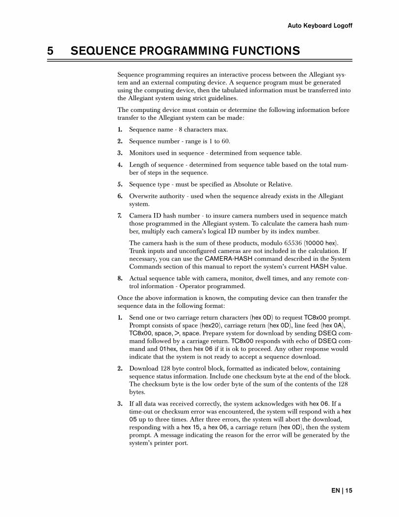
Once the above information is known, the computing device can then transfer the sequence data in the following format:
1. Send one or two carriage return characters (hex 0D) to request TC8x00 prompt. Prompt consists of space (hex20), carriage return (hex 0D), line feed (hex 0A), TC8x00, space, >, space. Prepare system for download by sending DSEQ com-mand followed by a carriage return. TC8x00 responds with echo of DSEQ com-mand and 01hex, then hex 06 if it is ok to proceed. Any other response would indicate that the system is not ready to accept a sequence download.
2. Download 128 byte control block, formatted as indicated below, containing sequence status information. Include one checksum byte at the end of the block. The checksum byte is the low order byte of the sum of the contents of the 128 bytes.
3. If all data was received correctly, the system acknowledges with hex 06. If a time-out or checksum error was encountered, the system will respond with a hex 05 up to three times. After three errors, the system will abort the download, responding with a hex 15, a hex 06, a carriage return (hex 0D), then the system prompt. A message indicating the reason for the error will be generated by the system’s printer port.
EN | 15
After a short time to evaluate the control block data (for reasons other than time-outs or checksum errors), the system returns a status byte consisting of one of the following:
4. Note that hex 06, then the system prompt, will be returned after all responses except hex 82 and hex 80. With error responses, a Sequence Download Aborted message will be generated by the system’s printer port. If an error response is received, the control block will need to be downloaded again once the appropri-ate corrective action is taken.
5. 5. Download actual sequence table information in one or more blocks contain-ing 128 bytes. Format as indicated in the appropriate section to follow.
5.1 LTC 8300 Systems
The LTC 8300 control block of 128 bytes must consist of the following:
• LTC 8300 Camera hash number - If the system camera numbers have not been redesignated and range from 1 to 32 (with cameras 33 to 288 unconfigured), the camera hash number is 2CB0 hex, which would make byte 20 equal to 2C hex and byte 21 equal to B0 hex.
• The LTC 8300 Sequence table is transferred in blocks of 128 bytes plus a check-sum. Each block contains up to 12 sequence steps (unused steps are zero filled).
Hex Code Meaning82 OK to proceed and overwrite existing sequence.
80 OK to proceed with new sequence download.
20 Incorrect camera hash number; Abort.
10 Sequence currently Running (Sequence must be in stop mode before overwrite possible); Abort.
04 Sequence currently in Edit mode; Abort.
02 Sequence currently exists and Overwrite byte has not been set (see the following); Abort.
01 Insufficient room in memory; Abort.
BYTE CONTENTS0 Set bits of 8 bit word corresponding to monitors used in sequence. BYTE 0 =
monitors 1–6 with 2 most significant bits always reset. If Relative sequence, the LSB bit of the 8 bit word must always be set; if not, shift bytes right until this condition is met.
1, 2, 3 Always reset.
4 MSB bit always set. Next bit set if Relative sequence or reset if Absolute sequence. Other bits always reset (Relative = hex C0, Absolute = hex 80).
5 Relative monitor difference value. For Relative sequences, value is equal to the number of times the 8 bit word in BYTE 0 was shifted. If Absolute sequence, byte is reset.
6–13 Sequence name - ASCII characters padded with spaces (hex 20).
14 Contains MSB # of actual sequence steps.
15 Contains LSB # of actual sequence steps.
16, 17 All bits set.
18 Sequence number (0–59 or 0–3B hex).
19 Set to 1 for Overwrite of existing sequence, set to 0 if Overwrite is not desired.
20 MSB camera hash number. See the following.
21 LSB camera hash number. See the following.
22–127 Always reset.
EN | 16 Bosch Security Systems | September 7, 2005
LTC 8300 Systems
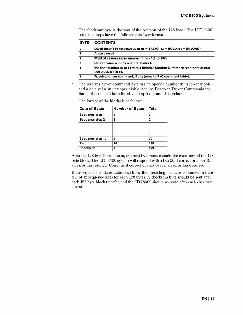
The checksum byte is the sum of the contents of the 128 bytes. The LTC 8300 sequence steps have the following six byte format:
• The receiver driver command byte has an opcode number in its lower nibble and a data value in its upper nibble. See the Receiver/Driver Commands sec-tion of this manual for a list of valid opcodes and data values.
The format of the blocks is as follows:
After the 128 byte block is sent, the next byte must contain the checksum of the 128 byte block. The LTC 8300 system will respond with a hex 06 if correct or a hex 15 if an error has resulted. Continue if correct or start over if an error has occurred.
If the sequence contains additional lines, the preceding format is continued in trans-fers of 12 sequence lines for each 128 bytes. A checksum byte should be sent after each 128 byte block transfer, and the LTC 8300 should respond after each checksum is sent.
BYTE CONTENTS0 Dwell time (1 to 60 seconds or 61 = SALVO, 62 = HOLD, 63 = UNLOAD).
1 Always reset.
2 MSB of camera index number minus 1(0 to 287).
3 LSB of camera index number minus 1.
4 Monitor number (0 to 5) minus Relative Monitor Difference (contents of con-trol block BYTE 5).
5 Receiver driver command, if any (refer to R/C command table).
Data of Bytes Number of Bytes TotalSequence step 1 6 6
Sequence step 2 6 1 2
. . .
. . .
. . .
Sequence step 12 6 72
Zero fill 56 128
Checksum 1 129
EN | 17
5.2 LTC 8500 Systems
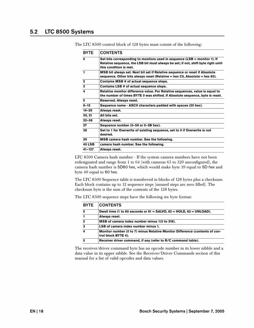
The LTC 8500 control block of 128 bytes must consist of the following:
LTC 8500 Camera hash number - If the system camera numbers have not been redesignated and range from 1 to 64 (with cameras 65 to 320 unconfigured), the camera hash number is 5D60 hex, which would make byte 39 equal to 5D hex and byte 40 equal to 60 hex.
The LTC 8500 Sequence table is transferred in blocks of 128 bytes plus a checksum. Each block contains up to 12 sequence steps (unused steps are zero filled). The checksum byte is the sum of the contents of the 128 bytes.
The LTC 8500 sequence steps have the following six byte format:
The receiver/driver command byte has an opcode number in its lower nibble and a data value in its upper nibble. See the Receiver/Driver Commands section of this manual for a list of valid opcodes and data values.
BYTE CONTENTS0 Set bits corresponding to monitors used in sequence (LSB = monitor 1). If
Relative sequence, the LSB bit must always be set; if not, shift byte right until this condition is met.
1 MSB bit always set. Next bit set if Relative sequence or reset if Absolute sequence. Other bits always reset (Relative = hex C0, Absolute = hex 80).
2 Contains MSB # of actual sequence steps.
3 Contains LSB # of actual sequence steps.
4 Relative monitor difference value. For Relative sequences, value is equal to the number of times BYTE 0 was shifted. If Absolute sequence, byte is reset.
5 Reserved. Always reset.
6–13 Sequence name - ASCII characters padded with spaces (20 hex).
14–29 Always reset.
30, 31 All bits set.
32–36 Always reset.
37 Sequence number (0–59 or 0–3B hex).
38 Set to 1 for Overwrite of existing sequence, set to 0 if Overwrite is not desired.
39 MSB camera hash number. See the following.
40 LSB camera hash number. See the following.
41–127 Always reset.
BYTE CONTENTS0 Dwell time (1 to 60 seconds or 61 = SALVO, 62 = HOLD, 63 = UNLOAD).
1 Always reset.
2 MSB of camera index number minus 1(0 to 319).
3 LSB of camera index number minus 1.
4 Monitor number (0 to 7) minus Relative Monitor Difference (contents of con-trol block BYTE 4).
5 Receiver driver command, if any (refer to R/C command table).
EN | 18 Bosch Security Systems | September 7, 2005

LTC 8600 Systems
The format of the blocks is as follows:
After the 128 byte block is sent, the next byte must contain the checksum of the 128 byte block. The LTC 8500 system will respond with a hex 06 if correct or a hex 15 if an error has resulted. Continue if correct or start over if an error has occurred.
If the sequence contains additional lines, the preceding format is continued in trans-fers of 12 sequence lines for each 128 bytes. A checksum byte should be sent after each 128 byte block transfer, and the LTC 8500 should respond after each checksum is sent.
5.3 LTC 8600 Systems
The LTC 8600 control block of 128 bytes must consist of the following:
LTC 8600 Camera hash number - If the system camera numbers have not been redesignated and range from 1 to 128 (with cameras 129 to 1152 unconfigured), the camera hash number is CAC0 hex, which would make byte 20 equal to CA hex and byte 21 equal to C0 hex.
The LTC 8600 Sequence table is transferred in blocks of 128 bytes plus a checksum. Each block contains up to 12 sequence steps (unused steps are zero filled). The
Data of Bytes Number Bytes TotalSequence step 1 6 6
Sequence step 2 6 12
. . .
. . .
. . .
Sequence step 12 6 72
Zero fill 56 128
Checksum 1 129
BYTE CONTENTS0, 1 Set bits of 16 bit word corresponding to monitors used in sequence. BYTE 0 =
monitors 9–16, BYTE 1 = monitors 1–8 (LSB = monitor 1). If Relative Sequence, the LSB bit of the 16 bit word must always be set; if not, shift bytes right until this condition is met.
2, 3 Always reset.
4 MSB bit always set. Next bit set if Relative sequence or reset if Absolute sequence. Other bits always reset (Relative = hex C0, Absolute = hex 80).
5 Relative monitor difference value. For Relative sequences, value is equal to the number of times the 16 bit word in BYTES 0,1 was shifted. If Absolute sequence, byte is reset.
6–13 Sequence name - ASCII characters padded with spaces (20 hex).
14 Contains MSB # of actual sequence steps.
15 Contains LSB # of actual sequence steps.
16, 17 All bits set.
18 Sequence number (0–59 or 0–3B hex).
19 Set to 1 for Overwrite of existing sequence, set to 0 if Overwrite is not desired.
20 MSB camera hash number. See the following.
21 LSB camera hash number. See the following.
22–127 Always reset.
EN | 19
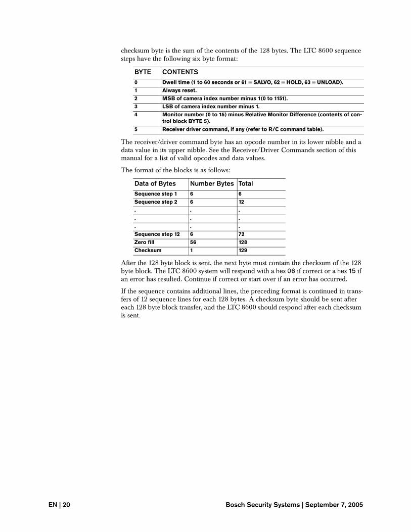
checksum byte is the sum of the contents of the 128 bytes. The LTC 8600 sequence steps have the following six byte format:
The receiver/driver command byte has an opcode number in its lower nibble and a data value in its upper nibble. See the Receiver/Driver Commands section of this manual for a list of valid opcodes and data values.
The format of the blocks is as follows:
After the 128 byte block is sent, the next byte must contain the checksum of the 128 byte block. The LTC 8600 system will respond with a hex 06 if correct or a hex 15 if an error has resulted. Continue if correct or start over if an error has occurred.
If the sequence contains additional lines, the preceding format is continued in trans-fers of 12 sequence lines for each 128 bytes. A checksum byte should be sent after each 128 byte block transfer, and the LTC 8600 should respond after each checksum is sent.
BYTE CONTENTS0 Dwell time (1 to 60 seconds or 61 = SALVO, 62 = HOLD, 63 = UNLOAD).
1 Always reset.
2 MSB of camera index number minus 1(0 to 1151).
3 LSB of camera index number minus 1.
4 Monitor number (0 to 15) minus Relative Monitor Difference (contents of con-trol block BYTE 5).
5 Receiver driver command, if any (refer to R/C command table).
Data of Bytes Number Bytes TotalSequence step 1 6 6
Sequence step 2 6 12
. . .
. . .
. . .
Sequence step 12 6 72
Zero fill 56 128
Checksum 1 129
EN | 20 Bosch Security Systems | September 7, 2005
LTC 8800 Systems
5.4 LTC 8800 Systems
The LTC 8800 control block of 128 bytes must consist of the following:
LTC 8800 Camera hash number - If the system camera numbers have not been redesignated and range from 1 to 256 (with cameras 257 to 2304 unconfigured), the camera hash number is D580 hex, which would make byte 20 equal to D5 hex and byte 21 equal to 80 hex.
The LTC 8800 Sequence table is transferred in blocks of 128 bytes plus a checksum. Each block contains up to 12 sequence steps (unused steps are zero filled). The checksum byte is the sum of the contents of the 128 bytes. The LTC 8800 sequence steps have the following six byte format:
The receiver/driver command byte has an opcode number in its lower nibble and a data value in its upper nibble. See the Receiver/Driver Commands section of this manual for a list of valid opcodes and data values.
BYTE CONTENTS0-3 Set the lower 32 bits of a 64-bit word corresponding to monitors used in
sequence. BYTE 0 = monitors 25–32, BYTE 1 = monitors 17–24, BYTE 2 = moni-tors 9–16, BYTE 3 = monitors 1–8 (LSB = monitor 1). If Relative sequence, the LSB bit of the 64 bit word must always be set; if not, shift bytes right until the condition is met. See also BYTES 32–35 below.
4 MSB bit always set. Next bit set if Relative sequences or reset if Absolute sequence. Other bits always reset (Relative = hex C0, Absolute = hex 80).
5 Relative monitor difference value. For Relative sequences, value is equal to the number of times the 64 bit word in BYTES 0–3, and 32–35 was shifted. If Absolute sequence, byte is reset.
6-13 Sequence name - ASCII characters padded with spaces (20 hex).
14 Contains MSB number of actual sequence steps.
15 Contains LSB number of actual sequence steps.
16, 17 All bits set.
18 Sequence number (0–59 or 0–3B hex).
19 Set to 1 for Overwrite of existing sequence, set to 0 if Overwrite is not desired.
20 MSB camera hash number. See below.
21 LSB camera hash number. See below.
22–31 Always reset.
32–35 Set the higher 32 bits of a 64 bit word corresponding to monitors used in sequence. BYTE 32 = monitors 57–64, BYTE 33 = monitors 49–56, BYTE 34 = monitors 41–48, BYTE 35 = monitors 33–40 (LSB = monitor 33). If Relative Sequence, the LSB bit of the 64 bit word (in BYTE 3 above) must always be set; if not, shift bytes right until this condition is met. See also BYTES 0-3 above.
36–127 Always reset.
BYTE CONTENTS0 Dwell time (1 to 60 seconds or 61 = SALVO, 62 = HOLD, 63 = UNLOAD.
1 Always reset.
2 MSB of camera index number minus 1 (0 to 2303).
3 LSB of camera index number minus 1.
4 Monitor number (0 to 63) minus Relative Monitor Difference (contents of con-trol block BYTE 5).
5 Receiver driver command, if any (refer to R/C command table).
EN | 21
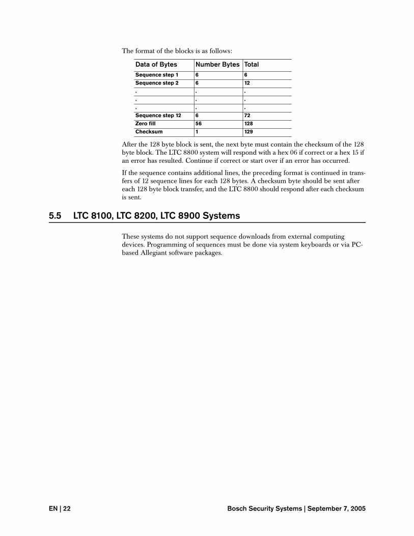
The format of the blocks is as follows:
After the 128 byte block is sent, the next byte must contain the checksum of the 128 byte block. The LTC 8800 system will respond with a hex 06 if correct or a hex 15 if an error has resulted. Continue if correct or start over if an error has occurred.
If the sequence contains additional lines, the preceding format is continued in trans-fers of 12 sequence lines for each 128 bytes. A checksum byte should be sent after each 128 byte block transfer, and the LTC 8800 should respond after each checksum is sent.
5.5 LTC 8100, LTC 8200, LTC 8900 Systems
These systems do not support sequence downloads from external computing devices. Programming of sequences must be done via system keyboards or via PC-based Allegiant software packages.
Data of Bytes Number Bytes TotalSequence step 1 6 6
Sequence step 2 6 12
. . .
. . .
. . .
Sequence step 12 6 72
Zero fill 56 128
Checksum 1 129
EN | 22 Bosch Security Systems | September 7, 2005
LTC 8100, LTC 8200, LTC 8900 Systems
6 LOCKOUT COMMANDS
Lockout commands are used to restrict users or system keyboards from gaining access to certain system functions.
Users may be restricted from operating keyboards, selecting monitors, viewing cam-eras, and controlling remote devices. System keyboards may be restricted from accessing monitors, cameras, and remote devices (receiver/drivers).
The locks may be installed either in blocks or individually based on user or key-board numbers. Block type lock commands would be used when it is necessary to reassign system wide restrictions associated with a lockout table.
Individual type lock commands would be used when it is necessary to reassign restrictions for only a single user or a single keyboard. These commands duplicate the lockout table functions found in the Allegiant’s LTC 8059/00 Master Control Software package or the LTC 8850/00 Graphical User Interface software package.
Note that if the system log-on feature is not enabled, the user related restrictions will appear to be based upon system keyboards (at least until the limit of physical key-boards supported by the system is exceeded). The system keyboards are automati-cally defaulted by the system to be associated with a user number when the log-on feature is not enabled, i.e., keyboard 1 is defaulted to user 1, keyboard 2 to user 2, and so on.
In the block type lock commands, certain user and keyboard data values are deter-mined using a bit-map concept. If a bit is set to logical 1, the corresponding user or keyboard would be restricted from accessing the device. For LTC 8100, LTC 8200, LTC 8300, LTC 8500, LTC 8600, and LTC 8800 Series systems supporting 32 differ-ent users (or keyboards if the log-in feature is not enabled) in the system, the bit-map would consist of a 32 bit word (four data bytes), where the least significant bit represents user (or keyboard) number 1. In LTC 8900 systems, the 128 Users in the system would consist of a 128 bit word (sent as 4 groups of 4 data bytes).
If applicable, leading zeros at the beginning of the individual data groups do not need to be included. If all bits of a data group are logical zeros, only a single zero needs to be sent to represent that group.
For keyboard bit-maps, the LTC 8100, LTC 8200, and LTC 8500 systems support 8 or less keyboards, so the keyboard bit-map would consist of a single 8 bit word (1 data byte). With LTC 8600 systems, 16 keyboards are permitted, so the keyboard bit-map would consist of a 16 bit word (2 data bytes). LTC 8800 and LTC 8900 sys-tems support 64 keyboards, so 4 data bytes are required.
In individual type lock commands, the lock data value must be set to logical 1 for the device to be locked or logical 0 to be unlocked. The examples below assume that the current numeric base is Hexadecimal.
Priority based monitor locks are also available that can be set/removed according to user number. These commands duplicate the monitor lock/unlock functions which can be entered via a system keyboard.
There will be a short delay (typically 1 or 2 seconds) after lockout commands are sent before the system can accept a new command.
EN | 23
6.1 Set Monitor-to-user Block Lockouts
This command configures a lockout table that determines which system users are permitted access to a specific system monitor. When a user is restricted from a sys-tem monitor, the currently displayed camera cannot be changed by the user if the keyboard is currently controlling the monitor when the lock is installed. If the key-board is not currently controlling the monitor, the user will not be able to select the locked monitor.
FORMAT = LOCK-MON-USR (monitor#) (user bit-map)
EXAMPLE: If Users 4, 5, 7, 8, 15, and 25 are to be restricted from accessing moni-tor number 2, enter the following command (using hex base):
TC8x00> LOCK-MON-USR 2 010040D8
Same command formatted for LTC 8900 system:
TC8900> LOCK-MON-USR 2 00000000 00000000 00000000 010040D8
Since leading zeros are not absolutely necessary, the same command for an LTC 8900 system can be sent as follows:
TC8900> LOCK-MON-USR 2 0 0 0 10040D8
6.2 Set Camera-to-user Block Lockouts
This command configures a lockout table that determines which system users are permitted access to a specific system camera. When a user is restricted from access-ing a system camera, the camera cannot be switched to any monitor by the user. Since the user cannot access the camera, any remote (receiver/driver) associated with the camera is not controllable by the user.
FORMAT = LOCK-CAM-USR (index camera#) (user bit-map)
EXAMPLE: If Users 4, 5, 7, 8, 15, and 25 are to be restricted from accessing camera number 250, enter the following command (using hex base):
TC8x00> LOCK-CAM-USR FA 010040D8
Same command formatted for LTC 8900 system:
TC8900> LOCK-CAM-USR FA 00000000 00000000 00000000 010040D8
Since leading zeros are not absolutely necessary, the same command for an LTC 8900 system can be sent as follows:
TC8900> LOCK-CAM-USR FA 0 0 0 10040D8
EN | 24 Bosch Security Systems | September 7, 2005
Set Remote-to-user Block Lockouts
6.3 Set Remote-to-user Block Lockouts
This command configures a lockout table that determines which system users are permitted access to control the remote (receiver/driver) associated with a system camera.
FORMAT = LOCK-REM-USR (index remote#) (user bit-map)
EXAMPLE: If Users 4, 5, 7, 8, 15, and 25 are to be restricted from accessing the remote associated with camera number 202, enter the following command (using hex base):
TC8x00> LOCK-REM-USR CA 010040D8
Same command formatted for LTC 8900 system:
TC8900> LOCK-REM-USR CA 00000000 00000000 00000000 010040D8
Since leading zeros are not absolutely necessary, the same command for a LTC 8900 system can be sent as follows:
TC8900> LOCK-REM-USR CA 0 0 0 10040D8
6.4 Set Keyboard-to-user Block Lockouts
This command configures a lockout table that determines which system users are permitted access to a specific system keyboard. The system log-on feature must be enabled when using this command. When users are restricted from accessing a sys-tem keyboard, they are prohibited from logging-on to that keyboard.
FORMAT = LOCK-KBD-USR (keyboard#) (user bit-map)
EXAMPLE: If Users 4, 5, 7, 8, 15, and 25 are to be restricted from accessing key-board number 3, enter the following command (using hex base):
TC8x00> LOCK-KBD-USR 3 010040D8
Same command formatted for LTC 8900 system:
TC8900> LOCK-KBD-USR 3 00000000 00000000 00000000 010040D8
Since leading zeros are not absolutely necessary, the same command for a LTC 8900 system can be sent as follows:
TC8900> LOCK-KBD-USR 3 0 0 0 10040D8
6.5 Set Monitor-to-keyboard Block Lockouts
This command configures a lockout table that determines which system keyboards are permitted access to a specific system monitor. When a keyboard is restricted from a system monitor, the currently displayed camera cannot be changed if the keyboard is currently controlling the monitor when the lock is installed. If the key-board is not currently controlling the monitor, it will be prohibited from selecting the locked monitor. Note that the restrictions will apply regardless of the user associ-ated with the keyboard.
FORMAT = LOCK-MON-KBD (monitor#) (keyboard bit-map)
EN | 25
EXAMPLE: If keyboards 4, 5, 7, 8, 15, and 25 on a LTC 8800 system are to be restricted from accessing monitor number 2, enter the following command (using hex base):
TC8x00> LOCK-MON-KBD 2 010040D8
Same command formatted for LTC 8900 system:
TC8900> LOCK-MON-KBD 2 00000000 010040D8
Since leading zeros are not absolutely necessary, the same command for a LTC 8900 system can be sent as follows:
TC8900> LOCK-MON-KBD 2 0 10040D8
NOTE: The first example is shown for an LTC 8800 system which supports 32 key-boards. The second example shows the format for an LTC 8900 system which sup-ports 64 keyboards. The keyboard bit-map value must be changed accordingly for LTC 8300 systems (4 keyboards are supported), LTC 8500 systems (8 keyboards are supported), or LTC 8600 systems (16 keyboards are supported).
6.6 Set Camera-to-keyboard Block Lockouts
This command configures a lockout table that determines which system keyboards are permitted access to a specific system camera. Note that the restrictions will apply regardless of the User associated with the keyboard. Since the keyboard cannot access the camera, any remote (receiver/driver) associated with the camera is not controllable by the locked keyboard.
FORMAT = LOCK-CAM-KBD (index camera#) (keyboard bit-map)
EXAMPLE: If keyboards 4, 5, 7, 8, 15, and 25 on an LTC 8800 system are to be restricted from accessing camera number 250, enter the following command (using hex base):
TC8x00> LOCK-CAM-KBD FA 010040D8
Same command formatted for LTC 8900 system:
TC8900> LOCK-CAM-KBD FA 00000000 010040D8
Since leading zeros are not absolutely necessary, the same command for an LTC 8900 system can be sent as follows:
TC8900> LOCK-CAM-KBD FA 0 10040D8
NOTE: The first example is shown for an LTC 8800 system which supports 32 key-boards. The second example shows the format for an LTC 8900 system which sup-ports 64 keyboards. The keyboard bit-map value must be changed accordingly for LTC 8300 systems (4 keyboards are supported), LTC 8500 systems (8 keyboards are supported), or LTC 8600 systems (16 keyboards are supported).
EN | 26 Bosch Security Systems | September 7, 2005
Set Remote-to-keyboard Block Lockouts
6.7 Set Remote-to-keyboard Block Lockouts
This command configures a lockout table that determines which system keyboards are permitted access to control the remote (receiver/driver) associated with a system camera.
FORMAT = LOCK-REM-KBD (index remote#) (keyboard bit-map)
EXAMPLE: If keyboards 4, 5, 7, 8, 15, and 25 on an LTC 8800 system are to be restricted from accessing the remote associated with camera number 202, enter the following command (using hex base):
TC8x00> LOCK-REM-KBD CA 010040D8
Same command formatted for LTC 8900 system:
TC8900> LOCK-REM-KBD CA 00000000 010040D8
Since leading zeros are not absolutely necessary, the same command for an LTC 8900 system can be sent as follows:
TC8900> LOCK-REM-KBD CA 0 10040D8
NOTE: The first example is shown for an LTC 8800 system which supports 32 key-boards. The second example shows the format for an LTC 8900 system which sup-ports 64 keyboards. The keyboard bit-map value must be changed accordingly for LTC 8300 systems (4 keyboards are supported), LTC 8500 systems (8 keyboards are supported), or LTC 8600 systems (16 keyboards are supported).
6.8 Set Monitor-to-user Individual Lockouts
This command permits an individual user to be restricted from accessing a system monitor. When a user is restricted from a system monitor, the currently displayed camera cannot be changed by the user if the keyboard is currently controlling the monitor when the lock in installed. If the keyboard is not currently controlling the monitor, the user will not be able to select the locked monitor.
FORMAT = SET-MON-USR-LOCK (monitor#) (index user#) (lock data)
EXAMPLE: If user 4 is to be restricted from accessing monitor number 2, enter the following command (using hex base):
TC8x00> SET-MON-USR-LOCK 2 4 1
6.9 Set Camera-to-user Individual Lockouts
This command permits an individual user to be restricted from accessing a system camera. When a user is restricted from accessing a system camera, the camera can-not be switched to any monitor by the user. Since the user cannot access the camera, any remote (receiver/driver) associated with the camera is not controllable by the user.
FORMAT = SET-CAM-USR-LOCK (index camera#) (index user#) (lock data)
EXAMPLE: If user 4 is to be restricted from accessing camera number 18, enter the following command (using hex base):
TC8x00> SET-CAM-USR-LOCK 12 4 1
EN | 27
6.10 Set Remote-to-user Individual Lockouts
This command permits an individual user to be restricted from controlling the remote (receiver/driver) associated with a system camera.
FORMAT = SET-REM-USR-LOCK (index remote#) (index user#) (lock data)
EXAMPLE: If user 14 is to be restricted from accessing the remote associated with camera number 33, enter the following command (using hex base):
TC8x00> SET-REM-USR-LOCK 21 E 1
6.11 Set Keyboard-to-user Individual Lockouts
This command permits an individual user to be restricted from accessing a specific system keyboard. The system logon feature must be enabled when using this com-mand. When users are restricted from accessing a system keyboard, they are prohib-ited from logging on to that keyboard.
FORMAT = SET-KBD-USR-LOCK (keyboard#) (index user#) (lock data)
EXAMPLE: If user 10 is to be restricted from accessing keyboard number 3, enter the following command (using hex base):
TC8x00> SET-KBD-USR-LOCK 3 A 1
6.12 Set Monitor-to-keyboard Individual Lockouts
This command permits a keyboard to be restricted from accessing a system monitor. When a keyboard is restricted from a system monitor, the currently displayed cam-era cannot be changed if the keyboard is currently controlling the monitor when the lock is installed. If the keyboard is not currently controlling the monitor, it will be prohibited from selecting the locked monitor.
NOTE: The restrictions will apply regardless of the user associated with the key-board.
FORMAT = SET-MON-KBD-LOCK (monitor#) (keyboard#) (lock data)
EXAMPLE: If keyboard 4 is to be restricted from accessing monitor number 11, enter the following command (using hex base):
TC8x00> SET-MON-KBD-LOCK B 4 1
6.13 Set Camera-to-keyboard Individual Lockouts
This command permits a keyboard to be restricted from accessing a system camera. When a keyboard is restricted from accessing a system camera, the camera cannot be switched to any monitor using the keyboard. Since the keyboard will not permit
EN | 28 Bosch Security Systems | September 7, 2005
Set Remote-to-keyboard Individual Lockouts
access to a camera, any remote (receiver/driver) associated with the camera is not controllable from the keyboard.
NOTE: The restrictions will apply regardless of the user associated with the key-board.
FORMAT = SET-CAM-KBD-LOCK (index camera#) (keyboard#) (lock data)
EXAMPLE: If keyboard 4 is to be restricted from accessing camera number 18, enter the following command (using hex base):
TC8x00> SET-CAM-KBD-LOCK 12 4 1
6.14 Set Remote-to-keyboard Individual Lockouts
This command permits a keyboard to be restricted from controlling the remote (receiver/driver) associated with a system camera.
FORMAT = SET-REM-KBD-LOCK (index remote#) (keyboard#) (lock data)
EXAMPLE: If keyboard 14 is to be restricted from accessing the remote associated with camera number 33, enter the following command (using hex base):
TC8x00> SET-REM-KBD-LOCK 21 E 1
6.15 Lock Monitor Based On User Priority
This command permits a monitor to be locked based on a user number. It duplicates the same function that an operator does when activating the Monitor-lock-on com-mand using a system keyboard. Once the monitor is locked, only the operator who locked it or those operators with a higher priority would be able to control its video switching.
FORMAT = LOCK-MONITOR (monitor#) (logical user#)
EXAMPLE: If monitor 4 is to be locked by logical user number 8, enter the follow-ing command:
TC8x00> LOCK-MONITOR 4 8
6.16 Unlock Monitor Based On User Priority
This command permits a locked monitor to be unlocked based on a user number. It duplicates the same function that an operator does when activating the Monitor-lock-off command using a system keyboard. The monitor can only be unlocked by the operator who locked it or by those operators with a higher priority.
FORMAT = UNLOCK-MONITOR (monitor#) (logical user#)
EXAMPLE: If monitor 6 is to be unlocked by logical user number 2, enter the fol-lowing command:
TC8x00> UNLOCK-MONITOR 6 2
EN | 29
6.17 Lock Remote Based On User Priority
This command provides the capability to restrict control over receiver/drivers based on the priority level of a user number. It duplicates the same function that an opera-tor does when activating the Lock <camera number> On command using a system keyboard. Once the remote device is locked, only the operator who locked it or those operators with higher priority levels would be able to control it. If the remote device is already locked by an operator with a higher priority level, no action will occur.
FORMAT = LOCK-REMOTE (logical camera#) (user index#)
EXAMPLE: If the receiver/driver associated with camera 6 is to be locked by user index number 3, enter the following command:
TC8x00> LOCK-REMOTE 6 3
If this command is issued to a 'master' system operating in an Allegiant Satellite sys-tem configuration, an XRL Lock/Unlock command (refer to separate description of this command) will automatically be propagated from the Master to the Satellite. If this action is not desired, the XRL command should be used in instead of this com-mand.
6.18 Unlock Remote Based On User Priority
This command permits a locked receiver/driver to be unlocked based on the prior-ity level of a user number. It duplicates the same function that an operator does when activating the Lock <camera number> Off command using a system keyboard. The remote device can only be unlocked by the operator who locked it or by those operators with a higher priority level. If the remote device had been locked by an operator with a higher priority level, no action will occur.
FORMAT = UNLOCK-REMOTE (logical camera#) (user index#)
EXAMPLE: If the receiver/driver associated with camera 7 is to be unlocked by user index number 2, enter the following command:
TC8x00> UNLOCK-REMOTE 7 2
If this command is issued to a 'master' system operating in an Allegiant Satellite sys-tem configuration, an XRL Lock/Unlock command (refer to separate description of this command) will automatically be propagated from the Master to the Satellite. If this action is not desired, the XRL command should be used in instead of this com-mand.
EN | 30 Bosch Security Systems | September 7, 2005
Lock/Unlock Remote without User Priority
6.19 Lock/Unlock Remote without User Priority
This command is somewhat similar to the User-based Remote Lock commands described above, except that it unconditionally assigns a level 1 priority to the Remote Lock being activated. Only keyboard operators having level 1 priority will be able to remove the Lock.
To activate a Remote Lock enter a data value of 1. To deactivate a Remote Lock, enter a data value of 0.
Note that this command does not 'propagate' the Lock/Unlock function to Allegiant Satellite systems, so its use is advantageous in systems configurations where this functionality is not desired.
FORMAT = XRL (logical camera number) (lock data)
EXAMPLE: To activate a Remote Lock on logical camera number 5, enter the fol-lowing command:
TC8x00> XRL 5 1
EN | 31
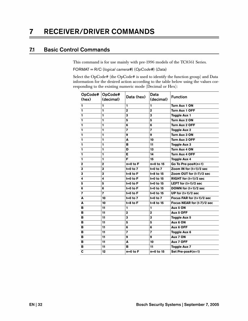
7 RECEIVER/DRIVER COMMANDS
7.1 Basic Control Commands
This command is for use mainly with pre-1996 models of the TC8561 Series.
FORMAT = R/C (logical camera#) (OpCode#) (Data)
Select the OpCode# (the OpCode# is used to identify the function group) and Data information for the desired action according to the table below using the values cor-responding to the existing numeric mode (Decimal or Hex):
OpCode# (hex)
OpCode# (decimal) Data (hex) Data
(decimal) Function
1 1 1 1 Turn Aux 1 ON
1 1 2 2 Turn Aux 1 OFF
1 1 3 3 Toggle Aux 1
1 1 5 5 Turn Aux 2 ON
1 1 6 6 Turn Aux 2 OFF
1 1 7 7 Toggle Aux 2
1 1 9 9 Turn Aux 3 ON
1 1 A 10 Turn Aux 3 OFF
1 1 B 11 Toggle Aux 3
1 1 D 13 Turn Aux 4 ON
1 1 E 14 Turn Aux 4 OFF
1 1 F 15 Toggle Aux 4
2 2 n=0 to F n=0 to 15 Go To Pre-pos#(n+1)
3 3 t=0 to 7 t=0 to 7 Zoom IN for (t+1)/2 sec
3 3 t=8 to F t=8 to 15 Zoom OUT for (t-7)/2 sec
4 4 t=0 to F t=0 to 15 RIGHT for (t+1)/2 sec
5 5 t=0 to F t=0 to 15 LEFT for (t+1)/2 sec
6 6 t=0 to F t=0 to 15 DOWN for (t+1)/2 sec
7 7 t=0 to F t=0 to 15 UP for (t+1)/2 sec
A 10 t=0 to 7 t=0 to 7 Focus FAR for (t+1)/2 sec
A 10 t=8 to F t=8 to 15 Focus NEAR for (t-7)/2 sec
B 11 1 1 Aux 5 ON
B 11 2 2 Aux 5 OFF
B 11 3 3 Toggle Aux 5
B 11 5 5 Aux 6 ON
B 11 6 6 Aux 6 OFF
B 11 7 7 Toggle Aux 6
B 11 9 9 Aux 7 ON
B 11 A 10 Aux 7 OFF
B 11 B 11 Toggle Aux 7
C 12 n=0 to F n=0 to 15 Set Pre-pos#(n+1)
EN | 32 Bosch Security Systems | September 7, 2005

Simultaneous Pan/Tilt/Zoom Control Commands
EXAMPLE: To activate pre-position # 16 on camera # 1, enter the following com-mand:
TC8x00>R/C 1 2 15
NOTE: Since the decimal mode is being assumed, the numeric value for the data was selected from the decimal column in the table. Also note that the actual number of seconds a time dependent command will be activated may only approximate the value entered.
7.2 Simultaneous Pan/Tilt/Zoom Control Commands
(TC8561A Series Receiver/Drivers and TC8561 Series Receiver/Drivers require software version 204 or higher)
FORMAT = REMOTE-ACTION (logical camera#) (data1) (data2)
For this command, the control functions in the remote device are determined according to the bit-mapped data1 and data2 contents. This format allows for multi-ple functions to be performed simultaneously. A logic 1 in a bit position means that the associated function will be activated. After a command is sent, the activated functions will remain active until they are cancelled by sending the command again with both data fields set to 0. The format for data1 and data2 is as follows:
EXAMPLE: To activate the receiver/driver left and down functions for camera number 2, send the following command:
TC8x00 > REMOTE-ACTION 2 16 8
Since the decimal mode is being assumed, the values for data1 and data2 were determined using the decimal equivalents for the left and down functions.
7.3 Toggle Pan/Tilt/Zoom Control Commands
(TC8561A Series Receiver/Drivers and TC8561 Series Receiver/Drivers require software version 204 or higher)
FORMAT = REMOTE-TGL (logical camera#) (data1) (data2)
For the Toggle commands, the control information is selected according to the bit-mapped data1 and data2 contents.
This format allows for multiple functions to be performed simultaneously. A logic 1 in a bit position means that the associated function will be toggled (turned ON if currently OFF, or turned OFF if currently ON). A Cancel All command can be sent which immediately turns OFF all pan/tilt/zoom functions by setting the MSB of data1. Note that once the function is activated, it will remain active until either the command is sent again or the Cancel All command is sent. The format for data1 and data2 is as follows:
EN | 33
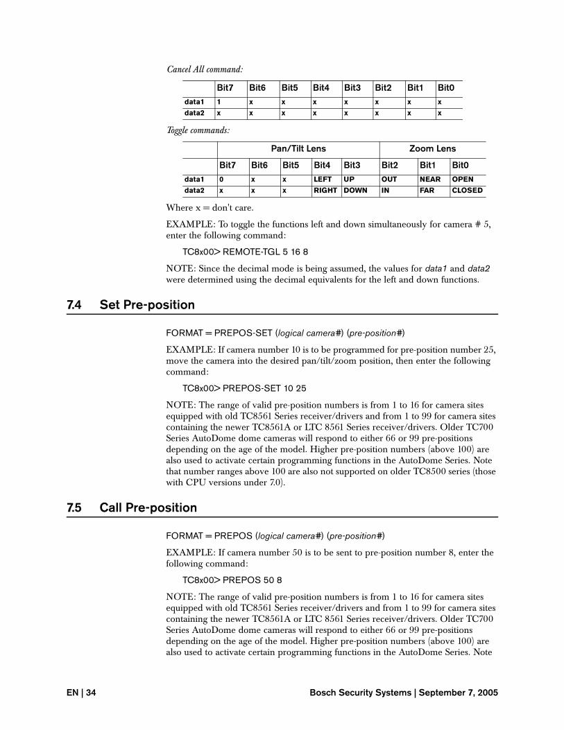
Cancel All command:
Toggle commands:
Where x = don't care.
EXAMPLE: To toggle the functions left and down simultaneously for camera # 5, enter the following command:
TC8x00> REMOTE-TGL 5 16 8
NOTE: Since the decimal mode is being assumed, the values for data1 and data2 were determined using the decimal equivalents for the left and down functions.
7.4 Set Pre-position
FORMAT = PREPOS-SET (logical camera#) (pre-position#)
EXAMPLE: If camera number 10 is to be programmed for pre-position number 25, move the camera into the desired pan/tilt/zoom position, then enter the following command:
TC8x00> PREPOS-SET 10 25
NOTE: The range of valid pre-position numbers is from 1 to 16 for camera sites equipped with old TC8561 Series receiver/drivers and from 1 to 99 for camera sites containing the newer TC8561A or LTC 8561 Series receiver/drivers. Older TC700 Series AutoDome dome cameras will respond to either 66 or 99 pre-positions depending on the age of the model. Higher pre-position numbers (above 100) are also used to activate certain programming functions in the AutoDome Series. Note that number ranges above 100 are also not supported on older TC8500 series (those with CPU versions under 7.0).
7.5 Call Pre-position
FORMAT = PREPOS (logical camera#) (pre-position#)
EXAMPLE: If camera number 50 is to be sent to pre-position number 8, enter the following command:
TC8x00> PREPOS 50 8
NOTE: The range of valid pre-position numbers is from 1 to 16 for camera sites equipped with old TC8561 Series receiver/drivers and from 1 to 99 for camera sites containing the newer TC8561A or LTC 8561 Series receiver/drivers. Older TC700 Series AutoDome dome cameras will respond to either 66 or 99 pre-positions depending on the age of the model. Higher pre-position numbers (above 100) are also used to activate certain programming functions in the AutoDome Series. Note
Bit7 Bit6 Bit5 Bit4 Bit3 Bit2 Bit1 Bit0data1 1 x x x x x x x
data2 x x x x x x x x
Pan/Tilt Lens Zoom Lens
Bit7 Bit6 Bit5 Bit4 Bit3 Bit2 Bit1 Bit0data1 0 x x LEFT UP OUT NEAR OPEN
data2 x x x RIGHT DOWN IN FAR CLOSED
EN | 34 Bosch Security Systems | September 7, 2005
Auxiliary Control Commands
that number ranges above 100 are also not supported on older LTC 8500 Series (those with CPU versions under 7.0).
7.6 Auxiliary Control Commands
The following series of auxiliary control commands can be used instead of the R/C series auxiliary control commands listed above. In addition, the Latch type com-mands listed below provide the ability to control level type adjustments associated with the AutoDome Series of dome cameras. Note that these commands were not supported on older LTC 8500 Series (those with CPU versions under 7.0).
Auxiliary OnFORMAT = AUX-ON (logical camera#) (auxiliary#)
EXAMPLE: If auxiliary number 5 is to be activated on receiver/driver number 8, enter the following command:
TC8x00> AUX-ON 8 5
NOTE: No action will result if the remote device being controlled does not support the Auxiliary# value sent. Note that this command was not supported on older LTC 8500 Series (those with CPU versions under 7.0).
Auxiliary OffFORMAT = AUX-OFF (logical camera#) (auxiliary#)
EXAMPLE: If auxiliary number 4 is to be deactivated on receiver/driver number 9, enter the following command:
TC8x00> AUX-OFF 9 4
NOTE: No action will result if the remote device being controlled does not support the Auxiliary# value sent. Note that this command was not supported on older LTC 8500 Series (those with CPU versions under 7.0).
Auxiliary ToggleFORMAT = AUX-TGL (logical camera#) (auxiliary#)
EXAMPLE: If auxiliary number 2 is to be toggled on receiver/driver number 6, enter the following command:
TC8x00> AUX-TGL 6 2
NOTE: No action will result if the remote device being controlled does not support the Auxiliary# value sent. Note that this command was not supported on older LTC 8500 Series (those with CPU versions under 7.0).
Latch Auxiliary OnFORMAT = LATCH-AUX-ON (logical camera#) (auxiliary#)
EXAMPLE: If auxiliary number 5 is to be latched on receiver/driver number 8, enter the following command:
TC8x00> LATCH-AUX-ON 8 5
This command is useful for making level type adjustments on the AutoDome series of cameras.
EN | 35
NOTE: No action will result if the remote device being controlled does not support the Auxiliary# value sent.
NOTE: This command was not supported on older LTC 8500 Series (those with CPU versions under 7.0).
Latch Auxiliary OffFORMAT = LATCH-AUX-OFF (logical camera#) (auxiliary#)
EXAMPLE: If auxiliary number 5 is to be unlatched on receiver/driver number 8, enter the following command:
TC8x00> LATCH-AUX-OFF 8 5
This command is useful for making level type adjustments on the AutoDome Series of cameras.
NOTE: No action will result if the remote device being controlled does not support the Auxiliary# value sent. Note that this command was not supported on older LTC 8500 Series (those with CPU versions under 7.0).
Cancel Auxiliary LatchFORMAT = CANCEL-AUX-LATCH (logical camera #)
EXAMPLE: To stop operation of a LATCH-AUX-ON or LATCH-AUX-OFF command on receiver/driver number 8, enter the following command:
TC8x00> CANCEL-AUX-LATCH 8
This command will cancel a continuously operating level adjustment (started by LATCH-AUX-ON or LATCHAUX-OFF) on an AutoDome camera.
NOTE: This command was not supported on older LTC 8500 Series (those with CPU versions under 7.0).
7.7 Variable Speed Control Commands
The following series of variable speed control commands are used to control the variable speed functions of the AutoDome Series of dome cameras. Once a variable speed command is received by the AutoDome, it will continue to operate until the all off or another control command is received.
FORMAT = VARSPEED_PTZ [logical camera #] [pan speed] [tilt speed] [zoom speed] [function code]
Where:
logical camera # = the logical number of the camera to be controlled.pan speed = a number from 0 to F (hexadecimal); 0 = slowest, F = fastest.tilt speed = a number from 0 to F (hexadecimal); 0 = slowest, F = fastest.zoom speed = a number from 0 to 7; 0 = slowest, 7 = fastest.function code = selected from the following table:
EN | 36 Bosch Security Systems | September 7, 2005
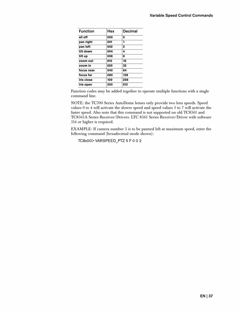
Variable Speed Control Commands
Function codes may be added together to operate multiple functions with a single command line.
NOTE: the TC700 Series AutoDome lenses only provide two lens speeds. Speed values 0 to 4 will activate the slower speed and speed values 5 to 7 will activate the faster speed. Also note that this command is not supported on old TC8561 and TC8561A Series Receiver/Drivers. LTC 8561 Series Receiver/Driver with software 514 or higher is required.
EXAMPLE: If camera number 5 is to be panned left at maximum speed, enter the following command (hexadecimal mode shown):
TC8x00> VARSPEED_PTZ 5 F 0 0 2
Function Hex Decimalall off 000 0
pan right 001 1
pan left 002 2
tilt down 004 4
tilt up 008 8
zoom out 010 16
zoom in 020 32
focus near 040 64
focus far 080 128
iris close 100 256
iris open 200 512
EN | 37

8 ALARM COMMANDS
It is recommended that the following commands listed for arming/disarming only be used when the alarm response mode has been selected using the system key-board or the SET-ALM-CONFIG command described to follow. If the system has been programmed using the LTC 8059/00 Master Control Software or the LTC 8850/00 Graphical User Interface software, the arm/disarm commands must conform exactly to the programmed monitor group alarm configurations or incor-rect operations may result.
NOTE: In the default mode, the alarm number activated corresponds to a camera having the same number, i.e., alarm #1 activates camera #1. This relationship can be reassigned using the LTC 8059/00 Master Control Software or the LTC 8850 Graphical User Interface software packages so that an alarm number may refer to any camera number and even include multiple cameras (up to 4 per alarm).
Also note that the following commands will not effect the way the system responds to the alarmed camera. The way the system responds is determined by which alarm response mode is active and how the individual cameras and monitors have been armed.
8.1 Activate an Alarm
FORMAT = +ALARM (alarm#)
EXAMPLE: To activate alarm number 6, enter the following command:
TC8x00>+ALARM 6
NOTE: Before this command can be used again for the same alarm number, the –ALARM command described below must first be sent.
8.2 Deactivate an Alarm
FORMAT = –ALARM (alarm#)
EXAMPLE: To deactivate previously activated alarm number 6, enter the following command:
TC8x00>-ALARM 6
This command must always be sent to reset an existing alarm before another +ALARM command with the same alarm number is sent.
EN | 38 Bosch Security Systems | September 7, 2005
Acknowledge Monitor in Alarm
8.3 Acknowledge Monitor in Alarm
FORMAT = MON-ACK-ALARM (monitor number)
EXAMPLE: To acknowledge an alarm camera currently being displayed on alarm monitor 3, enter the following command:
TC8x00 > MON-ACK-ALARM 3
This command duplicates the function of the Acknowledge button on an Allegiant system keyboard. If the command is used in an inapplicable manner, an appropriate alarm related error number will be returned.
8.4 Run Alarm Sequence by Monitor Number
FORMAT = MON-ALM-RUN (monitor number)
EXAMPLE: If monitor number 2 contains a sequence of alarm cameras currently in the Hold mode, the alarm sequence may be run by the following command:
TC8x00 > MON-ALM-RUN 2
This command duplicates the function of the Run button on an Allegiant system keyboard. If an alarm sequence is already running when this command is used, the sequence will immediately advance to the next step.
8.5 Hold Alarm Sequence by Monitor Number
FORMAT = MON-ALM-HOLD (monitor number)
EXAMPLE: If monitor number 2 is currently running a sequence of cameras in alarm, the alarm sequence may be stopped by the following command:
TC8x00 > MON-ALM-HOLD 2
This command duplicates the function of the Hold button on an Allegiant system keyboard.
8.6 Step Alarm Sequence Forward by Monitor Number
FORMAT = MON-ALM-NEXT (monitor number)
EXAMPLE: If monitor number 2 contains a sequence of alarm cameras which was previously running in the forward direction and is now in the Hold mode, the alarm sequence may be advanced one step forward using the following command:
TC8x00 > MON-ALM-NEXT 2
This command duplicates the function of the Next button on an Allegiant system keyboard. If the alarm sequence was previously running in the reverse mode and is now in the Hold mode, this command will change the direction of the alarm sequence only. If the alarm sequence is currently running in the reverse direction, this command will change the direction, causing it to now run in the forward direc-tion.
EN | 39
8.7 Step Alarm Sequence Backward By Monitor Number
FORMAT = MON-ALM-PREV (monitor number)
EXAMPLE: If monitor number 2 contains a sequence of alarm cameras which was previously running in the reverse direction and is now in the Hold mode, the alarm sequence may be advanced one step backwards, using the following command:
TC8x00 > MON-ALM-PREV 2
This command duplicates the function of the Previous button on an Allegiant sys-tem keyboard. If the alarm sequence was previously running in the forward mode and is now in the Hold mode, this command will change the direction of the alarm sequence only. If the alarm sequence is currently running in the forward direction, this command will change the direction, causing it to now run in the reverse direc-tion.
8.8 Set System’s Alarm Response Mode
FORMAT = SET-ALM-CONFIG (data)
EXAMPLE: To set the system to respond using the preconfigured Basic alarm response mode, enter the following command:
TC8x00 > SET-ALM-CONFIG 1
To set the system to respond using the preconfigured Autobuild alarm response mode, use a data value of 2. To set the system to respond using the preconfigured Sequence& Display alarm response mode, use a data value of 3. This command duplicates the functions available for selecting one of the system’s preconfigured alarm response modes, using either a system keyboard (User Function 19), or the AutoSet feature available in the Allegiant PC-based configuration software package. Refer to the system main installation manual for complete details on the 3 preconfig-ured alarm response modes.
8.9 Display Alarm Table
FORMAT = ARM-TBL
EXAMPLE: To display a table that shows the arm/disarm status of the system alarms, enter the following command:
TC8x00> ARM-TBL
Alarms that are enabled will be shown in the table using the letter A. Those alarms that are disabled will be shown using the symbol - (hyphen).
Since the alarm status for each alarm is shown for every system monitor, it is not rec-ommended to issue this command to an LTC 8900 system. The table width to dis-play the status for 512 monitors exceeds the typical page width, so it will be somewhat difficult to decipher the displayed data as it wraps around using multiple lines. If necessary, the display generation can be interrupted at any time by issuing Ctrl-C.
EN | 40 Bosch Security Systems | September 7, 2005
Arm Range of Alarm Numbers
8.10 Arm Range of Alarm Numbers
FORMAT = ARM-ALARMS (low alarm number) (high alarm number)
EXAMPLE: To arm a range of alarm numbers from 1 to 5, enter the following com-mand:
TC8x00> ARM-ALARMS 1 5
The specified alarms will be enabled for all the alarm monitor groups supported in the system.
8.11 Disarm Range of Alarm Numbers
FORMAT = DISARM-ALARMS (low alarm number) (high alarm number)
EXAMPLE: To disarm a range of alarm numbers from 5 to 10, enter the following command:
TC8x00> ARM-ALARMS 5 10
The specified alarms will be disabled for all the alarm monitor groups supported in the system.
8.12 Arm/Disarm Alarm Blocks
FORMAT = ALARM-TBL (data) (alarm#)
This command duplicates the system keyboard's Alarm ON/OFF function. The data field must be selected from the Binary Progression Table (see Section 8.11) according to which monitors the alarm will be armed/disarmed on.
Each alarm to be armed/disarmed must be entered this way. The system alarm ranges are as follows: 1–64 for LTC 8100, LTC 8200, and LTC 8300; 1–128 for LTC 8500; 1–512 for LTC 8600; 1–1024 for LTC 8800; and 1–2048 for LTC 8900 sys-tems. Note that existing Allegiant Series alarm accessory products are only capable of supporting 1024 physical alarms on LTC 8900 systems, but up 2048 are available via an external interface using CCL commands.
• For the LTC 8100, MAX-MON is 2, and MAX DATA is 3 (hex 03).
• For the LTC 8200, MAX-MON is 5, and MAX DATA is 31 (hex 1F).
• For the LTC 8300, MAX-MON is 6, and MAX DATA is 63 (hex 3F).
• For the LTC 8500, MAX-MON is 8, and MAX DATA is 255 (hex FF).
• For the LTC 8600, MAX-MON is 16, and MAX DATA is 65535 (hex FFFF).
• For the LTC 8800, MAX-MON is 64, and MAX DATA is hex FFFFFFFFFFFFFFFF. Data should be entered as two separate values (most sig-nificant 32 bits, then least significant 32 bits).
• For the LTC 8900, MAX-MON is 512, and MAX DATA would consist of 128 F hex characters! Because of this large number, the data field needs to be split into 16 separate packets, each having 32 bits. If possible, do not include leading zeros in the individual packets, because the entire command must fit into the line capac-ity of 127 characters. Due to this limit, there will be certain combinations of this command that will be impossible to send.
EN | 41
EXAMPLE: To enable alarms on monitors 1 and 2 for alarm input 5, enter the fol-lowing command:
TC8x00>ALARM-TBL 3 5
NOTE: This command only arms/disarms alarm inputs. Each system monitor must also be armed/disarmed to correspond with the alarm inputs.
There will be a short delay (typically 1 or 2 seconds) after this command is sent before the system can accept a new command.
8.13 Arm/Disarm Alarm Group
FORMAT = GROUP-ALARM-TBL (data) (alarm#)
This command is similar to the ALARM-TBL command described in the preceding section, but is used to arm/disarm Alarm Groups rather than alarm monitor num-bers. Note that this command must be used carefully when working with the moni-tor Alarm Group alarm concept, since each system can be configured to have a single Alarm Group encompassing all system monitors, or multiple Alarm Groups, each having a different quantity of system monitors.
The data field must be selected from the Binary Progression Table shown in Section 8.11, according to which Alarm Groups will be armed/disarmed. Each alarm to be armed/disarmed must be entered this way. The system alarm ranges are as follows: 1–64 for LTC 8100, LTC8200, and LTC 8300; 1–128 for LTC 8500; 1–512 for LTC 8600; 1–1024 for LTC 8800; and 1–2048 for LTC 8900 systems. Note that existing Allegiant Series alarm accessory products are only capable of supporting 1024 phys-ical alarms on LTC 8900 systems, but up 2048 are available via an external interface using CCL commands.
• For the LTC 8100, MAX-MON is the maximum number of possible Alarm Groups which equals 2, and MAX DATA is 3 (hex 03).
• For the LTC 8200, MAX-MON is the maximum number of possible Alarm Groups which equals 5, and MAX DATA is 31 (hex 1F).
• For the LTC 8300, MAX-MON is the maximum number of possible Alarm Groups which equals 6, and MAX DATA is 63 (hex 3F).
• For the LTC 8500, MAX-MON is the maximum number of possible Alarm Groups which equals 8, and MAX DATA is 255 (hex FF).
• For the LTC 8600, MAX-MON is the maximum number of possible Alarm Groups which equals 16, and MAX DATA is 65535 (hex FFFF).
• For the LTC 8800, MAX-MON is the maximum number of possible Alarm Groups which equals 64, and MAX DATA is hex FFFFFFFFFFFFFFFF. Data should be entered as two separate values (most significant 32 bits, then least sig-nificant 32 bits).
• For the LTC 8900, MAX-MON is the maximum number of possible Alarm Groups which equals 512, and MAX DATA would consist of 128 F hex charac-ters! Because of this large number, the data field must be split into 16 separate packets, each having 32 bits. If possible, do not include leading zeros in the indi-vidual packets, because the entire command must fit into the line capacity of 127 characters. Due to this limit, there are certain combinations of this com-mand that will be impossible to send.
EN | 42 Bosch Security Systems | September 7, 2005
Arm/Disarm Monitors as a Group
EXAMPLE: To enable alarms on Alarm Group 1 and 2 for alarm input 5, enter the following command:
TC8x00> GROUP-ALARM-TBL 3 5
NOTE: This command only arms/disarms alarm inputs. Each Alarm Group must also be armed/disarmed to correspond with the desired alarm inputs.
There is a short delay (typically 1 or 2 seconds) after this command is sent before the system can accept a new command.
8.14 Arm/Disarm Monitors as a Group
FORMAT = MON-ARM (data)
This command is similar to using the system keyboard's User Monitor ON/OFF function, but effects all monitors in the system simultaneously. The data field is selected from the Binary Progression Table shown below, according to which step/review monitors will be armed/disarmed. One command is structured to arm/dis-arm all monitors in the system at the same time. Note that this command must be used carefully when working with the Monitor Group alarm concept. Ensure that at least one Step monitor is armed for each Monitor Group that is being armed. If this is not done, no monitors will be armed in that Monitor Group. Since there can be 1 or 2 Monitor Groups in an LTC 8100, (1 to 5 in a LTC 8200, 1 to 8 in a LTC 8500, 1 to 16 in a LTC 8600, 1 to 64 in a LTC 8800, and 1 to 512 in a LTC 8900), this can become a very complex command.
• For the LTC 8100, MAX-MON is 2, and MAX DATA is 3 (hex 03).
• For the LTC 8200, MAX-MON is 5, and MAX DATA is 31 (hex 1F).
• For the LTC 8300, MAX-MON is 6, and MAX DATA is 63 (hex 3F).
• For the LTC 8500, MAX-MON is 8, and MAX DATA is 255 (hex FF).
• For the LTC 8600, MAX-MON is 16, and MAX DATA is 65535 (hex FFFF).
• For the LTC 8800, MAX-MON is 64, and MAX DATA is hex FFFFFFFFFFFFFFFF. Data should be entered as two separate values (most sig-nificant 32 bits, then least significant 32 bits).
• For the LTC 8900, MAX-MON is 512, and MAX DATA would consist of 128 F hex characters. Because of this large number, the data field must be split into 16 sep-arate packets, each having 32 bits. If possible, do not include leading zeros in the individual packets, because the entire command must fit into the line capac-ity of 127 characters. Due to this limit, there will be certain combinations of this command that are impossible to send.
EXAMPLE: To arm monitors 1 and 2 to respond to alarms, enter the following command:
TC8x00>MON-ARM 3
EN | 43

There is a short delay (typically 1 or 2 seconds) after this command is sent before the system can accept a new command.
8.15 Arm Specific Range of Monitors
FORMAT = ARM-MONITORS (starting index monitor number) (ending index moni-tor number)
EXAMPLE: To arm monitors 2 through 5, enter the following command:
TC8x00> ARM-MONITORS 2 5
This command can also be used to arm a single monitor by specifying the same number as the starting monitor number and the ending monitor number. In this for-mat, the command essentially duplicates the system keyboard's User Monitor ON function.
EXAMPLE: To arm only monitor 6, enter the following command:
TC8x00> ARM-MONITORS 6 6
8.16 Disarm Specific Range of Monitors
FORMAT = DISARM-MONITORS (starting index monitor number) (ending index monitor number)
EXAMPLE: To disarm monitors 3 through 7, enter the following command:
TC8x00> DISARM-MONITORS 3 7
This command can also be used to disarm a single monitor by specifying the same number as the starting monitor number and ending monitor number. In this format, the command essentially duplicates the system keyboard's User Monitor OFF func-tion.
EXAMPLE: To disarm only monitor 8, enter the following command:
TC8x00> DISARM-MONITORS 8 8
Monitors to be Armed Data ContentsMAX-MON . . . 4 3 2 1
- . . . - - - - 0 All monitors disarmed
- . . . - - - A 1 Monitor 1 armed
- . . . - - A - 2 Monitor 2 armed
- . . . - - A A 3 Monitors 1 & 2 armed
- . . . - A - - 4 Monitor 3 armed
- . . . - A - A 5 Monitors 1 & 3 armed
.
(Continue Series)
.
A . . . A A - A MAX DATA-2 Monitor 2 disarmed
A . . . A A A - MAX DATA-1 Monitor 1 disarmed
A . . . A A A A MAX DATA All monitors armed
EN | 44 Bosch Security Systems | September 7, 2005
Set Step & Review Alarm Monitors
8.17 Set Step & Review Alarm Monitors
FORMAT = REVIEW-MON (Review monitor #) STEP-MON (Step monitor #)
EXAMPLE: To assign monitor number 1 as a Review monitor and monitor number 2 as a Step monitor, enter the following two commands:
TC8x00>REVIEW-MON 1
TC8x00>STEP-MON 2
Any system monitor may be designated as either a Review or a Step monitor, but there must be at least 1 Step monitor in any Monitor Group. Since there can be 1 or 2 Monitor Groups in an LTC 8100 (1 to 5 in an LTC 8200, 1 to 8 in an LTC 8500, 1 to 16 in an LTC 8600, 1 to 64 in an LTC 8800 and 1 to 512 in an LTC 8900), this command must conform to the existing Monitor Group configuration if the system is to function properly. Note that the ARM/DISARM ALARM table must also be valid for the desired monitors before alarm video will be displayed. If there are no system conflicts, the assigned monitor will also be armed.
8.18 Enable Custom Alarm
FORMAT = ENABLE-CUSTOM-ALARM (data 1) (data 2)
EXAMPLE: If Custom Alarm numbers 1 through 4 are to be enabled, enter the fol-lowing command:
TC8x00 > ENABLE-CUSTOM-ALARM 1 4
To enable a single alarm number, you can omit the second data value. To enable all Custom Alarms, omit both data values.
8.19 Disable Custom Alarm
FORMAT = DISABLE-CUSTOM-ALARM (data 1) (data 2)
EXAMPLE: If Custom Alarm numbers 1 through 4 are to be disabled, enter the fol-lowing command:
TC8x00 > DISABLE-CUSTOM-ALARM 1 4
To disable a single alarm number, you can omit the second data value. To disable all Custom Alarms, omit both data values.
8.20 Define Alarm Input Polarity
NOTE: This command is only applicable to Allegiant LTC 8100, LTC 8200, and LTC 8300 systems.
FORMAT = __ALARM__POLARITY (data)
This command is used to configure the integral alarm inputs of the Allegiant systems to accept either normally open (default) or normally closed contacts. The data parameter consists of a binary progression table of bits that correspond to the alarm inputs. Using a binary progression table, each alarm input can be individually con-figured to operate as either polarity type. A bit would be set to logical 1 to designate
EN | 45
inputs as normally closed (contact opens to activate an alarm), or logical 0 to desig-nate inputs as the default normally open (contact closes to activate an alarm).
The least significant bit represents alarm input 1. The maximum data value would depend on the Allegiant model. For LTC 8100 (alarm inputs = 8), the max value (to configure all alarms as normally closed) would be decimal 255 or hexadecimal FF; for LTC 8200 (alarm inputs = 16), max value is decimal 65535 or hexadecimal FFFF; for LTC 8300 (alarm inputs = 32), max value is decimal 4294967295 or hexa-decimal FFFFFFFF.
EXAMPLE 1: Configure LTC 8100 to accept normally closed contacts for alarm inputs 1–4 and normally open contacts for alarm inputs 5–8 (shown using a decimal data parameter).
TC8x00 > __ALARM__POLARITY 15
EXAMPLE 2: Configure LTC 8100 to accept normally closed contacts for even numbered alarm inputs and normally open contacts for odd numbered alarm inputs (shown using a decimal data parameter).
TC8x00 > __ALARM__POLARITY 170
EXAMPLE 3: Configure LTC 8300 to accept normally closed contacts for even numbered alarm inputs and normally open contacts for odd numbered alarm inputs (shown using a decimal data parameter).
TC8x00 > __ALARM__POLARITY 2863311530
Issuing the command without specifying a data value will display the current alarm input configuration. Issuing the command on an incompatible Allegiant system will result in the response UNIMPLEMENTED.
8.21 Define Alarm Relay Output Polarity
NOTE: This command is only applicable to Allegiant LTC 8100, LTC 8200, and LTC 8300 systems.
FORMAT = __RELAY__POLARITY (data)
This command is used to configure the alarm relay outputs as either normally open (close on alarm) or normally closed. The data parameter consists of a binary pro-gression table of bits that correspond to the relays. Using a binary progression table, each alarm relay can be individually configured to operate as either polarity type. A bit would be set to logical 1 to designate relays as normally closed (relay opens on an alarm condition), or logical 0 to designate relays as default normally open (relay closes on an alarm condition). The least significant bit represents alarm relay 1.
The maximum data value would depend on the Allegiant model. For LTC 8100 (alarm relays = 2), the max value (to configure both relays as normally closed) would be decimal/hexadecimal 3; for LTC 8200 (alarm relays = 5), max value is decimal 31 or hexadecimal 1F; for LTC 8300 (alarm relays = 6), max value is deci-mal 63 or hexadecimal 3F.
EN | 46 Bosch Security Systems | September 7, 2005

Define Alarm Relay Output Polarity
EXAMPLE 1: Configure LTC 8100 to generate normally closed contacts for alarm relay 1 and normally open contacts for relay 2 (shown using a decimal data parame-ter).
TC8x00 > __RELAY__POLARITY 1
EXAMPLE 2: Configure LTC 8300 to generate normally closed contacts for relays 1, 2, and 3 and normally open contacts for alarm relays 4 and 5 (shown using a dec-imal data parameter).
TC8x00 > __RELAY__POLARITY 7
EN | 47
9 SYSTEM STATUS COMMANDS
Status commands are useful for determining various real time conditions of the switching system. After any of the commands listed below are sent, the Allegiant responds with an echo of the status command, the NAK (15 hex) character (except on all systems prior to CPU software revision number 5.1, where a space character (20 hex) is sent instead), the data bytes as explained in the following, and a check-sum byte (the sum of the data bytes module 256).
The prompt (TC8x00>) is returned after the status response has been completed. Note that the examples below show the responses after the command has been ech-oed by the system.
9.1 Alarm Status
This command is used to determine the alarm status of the system.
FORMAT = ALM-STATUS
RESULT: The number of returned data bytes corresponds to the number of bits required to represent the total number of alarms in the relevant system. For LTC 8100, LTC 8200, and LTC 8300 systems, 8 data bytes are required to represent the 64 alarms in the system. LTC 8500 systems respond with 16 data bytes (128 alarm numbers). LTC 8600 systems respond with 64 data bytes (512 alarm num-bers). LTC 8800 systems respond with 128 data bytes (1024 alarm numbers). The LTC 8900 responds with 256 data bytes (2048 alarm numbers). Bits which are set represent active alarms. For each byte, the LSB represents the lowest alarm number.
EXAMPLE: For an LTC 8300 with alarm numbers 2, 9, and 42 in alarm, the status response (shown in hex) is as follows: 15 02 01 00 00 00 02 00 00 05.
9.2 Crosspoint Status
This command is used to determine the camera-to-monitor switching status.
FORMAT = MON-STATUS
RESULT: The system responds for each monitor in the system with 2 data bytes. The first data byte pair corresponds to the index camera number switched to moni-tor 1. The first byte of the pair represents the high order part of the index camera number, and the second byte of the pair corresponds to the low order part of the index camera number.
Camera numbers are index numbers starting at zero (LTC 8100 = 0 to 263, LTC 8200 = 0 to 271, LTC 8300 = 0 to 287, LTC 8500 = 0 to 319, LTC 8600 = 0 to 1151, LTC 8800 = 0 to 2303, and LTC 8900 0 to 4607).
EXAMPLE: For an LTC 8600 with cameras 1, 10, 25, 36, 40, 52, 58, 64, 80, 85, 93, 99, 102, 115, 123, and 128 on monitors 1 through 16 respectively, the status response (shown in hex) is as follows:
15 00 00 00 09 00 18 00 23 00 27 00 33 00 39 00 3F 00 4F 00 54 00 5C 00 62 00 65 00 72 00 7A 00 7F 47.
EN | 48 Bosch Security Systems | September 7, 2005
Sequence Status
9.3 Sequence Status
This command reports information concerning sequences loaded on the system monitors.
FORMAT = SEQ-STATUS
RESULT: The response contains information on both the monitor alarm status of the system and the sequence status. The alarm status data bytes precede the data bytes for the sequence information.
The alarm status data is sent as a bitmap of the monitors in alarm. Each byte of data represents up to 8 monitors. A single data byte is sent for LTC 8100, LTC 8200, LTC 8300, and LTC 8500 systems; 2 bytes for LTC 8600 systems; 8 bytes for LTC 8800 systems; and 64 bytes for LTC 8900 systems. The least significant bit (LSB) represents the lowest monitor number. The first byte corresponds to monitors 1 to 8. Bits which are set represent monitors in alarm. If a monitor is currently in alarm, the sequence data corresponding to that monitor is not valid during the alarm condition.
The sequence information is sent as a packet of five data bytes for each monitor in the system. There will be 2 data packets for LTC 8100 systems, 5 data packets for LTC 8200 systems, 6 data packets for LTC 8300 systems, 8 for LTC 8500 systems, 16 for LTC 8600 systems, 64 for LTC 8800 systems, and 512 for LTC 8900 systems. The content of the five data bytes is generated as follows:
The first byte of the packet contains the sequence number (0 to 255 for LTC 8900, 0 to 59 for all others). If no sequence is loaded on the monitor, this value contains 255 (FF hex), and the data contained in the following bytes is invalid and should be ignored.
The second byte of the packet contains the index number of the user (0 to 127 for LTC 8900, 0 to 31 for all others) who loaded the sequence. The value 255 (FF hex) may be sent if no sequence is loaded.
The third byte of the packet contains the number of the keyboard (0 to 1 for LTC 8100 systems, 0 to 3 for LTC 8200 and LTC 8300 systems, 0 to 7 for LTC 8500 systems, 0 to 15 for LTC 8600 systems, 0 to 31 for LTC 8800 systems, and 0 to 63 for LTC 8900 systems) which was used to load the sequence. If a system keyboard was not used or if no sequence is loaded, the value is considered undefined and will typ-ically contain 255 (FF hex).
The fourth byte of the packet contains the status of the sequence. If no sequence is loaded, the value is considered undefined and should be ignored. In a sequence containing multiple monitors, this data is valid only for the lowest monitor number programmed in the sequence. The data is generated as follows:
0 = Sequence in hold backwards.1 = Sequence in run backwards.2 = Sequence in hold forwards.3 = Sequence in run forwards.
The fifth byte of the packet contains the number of the lowest monitor number (monitor 1 = 0) in a sequence containing multiple monitors. This data is necessary to determine the correct sequence status as indicated above.
EN | 49
The value 255 (FF hex) may be sent if no sequence is loaded. Since a single byte is used for this purpose, the status for only the first 256 monitors (out of a possible 512) are available in LTC 8900 systems.
EXAMPLE (For system not in alarm): For an LTC 8600 with a forward running sequence number 34 loaded onto and programmed only for monitor 2 by User 3 using keyboard number 4, the response (shown in hex) will be as follows:
15 00 00 FF FF FF 02 FF 21 02 03 03 01 FF FF FF 02 FF FF FF FF 02 FF FF FF FF 02 FF FF FF FF 02 FF FF FF FF 02 FF FF FF FF 02 FF FF FF FF 02 FF FF FF FF 02 FF FF FF FF 02 FF FF FF FF 02 FF FF FF FF
9.4 Keyboard Status
This command is used to determine the current status of the various system key-boards.
FORMAT = KBD-STATUS
RESULT: The system responds for each keyboard in the system with a five byte packet of data. There are 2 data packets for LTC 8100 systems, 4 data packets for LTC 8200 and LTC 8300 systems, 8 data packets for LTC 8500 systems, 16 for LTC 8600 systems, 32 for LTC 8800 systems, and 64 for LTC 8900 systems. The first packet represents data for keyboard 1, the second for keyboard 2, etc. The first byte of each packet contains the monitor number (monitor 1 starts at zero) currently being controlled by the keyboard. Since a single byte is used for this purpose, the status for only the first 256 monitors (out of a possible 512) are available in LTC 8900 systems.
The second byte of the packet contains the index user number (User 1 = zero) cur-rently assigned to the keyboard.
The third byte of the packet represents log-on and installed status. Bit 0 of the third byte represents the log-on condition. If set, the keyboard is currently logged-on; if 0, all other information is invalid. Bit 6 of the third byte represents the installed status. If set, the keyboard is considered installed (non-installed keyboards are not polled by the system); if 0, all other information is invalid.
The fourth byte of the packet is generated as follows:
• Bit 7 is set whenever the logged-in operator is controlling a remote (receiver/driver) on systems containing CPU revision level 5.2 or higher. In systems prior to level 5.2, this bit is always reset.
• Bits 0 to 6 contain the high order index camera number data.
The fifth byte of the packet contains the low order index camera number data (cam-era 1 = zero).
EXAMPLE: For an LTC 8500 system with the following conditions:
1. All keyboards are installed and logged-in.
2. User 1 is logged-in to keyboard 1, User 2 to keyboard 2, etc.
3. Keyboard 1 is controlling monitor 1 which displayed camera 1, keyboard 2 is controlling monitor 2 and camera 2, etc.
EN | 50 Bosch Security Systems | September 7, 2005
Monitor Status
The status response (shown in hex) is as follows:
15 00 00 41 00 00 01 01 41 00 01 02 02 41 00 02 03 03 41 00 03 04 04 41 00 04 05 05 41 00 05 06 06 41 00 06 07 07 41 00 07 5C.
9.5 Monitor Status
This command reports the information contained in the status section of the text overlay displayed on the system monitor screens.
FORMAT = MON-STATUS-LINE
RESULT: The system responds with a 3 byte packet for each system monitor. The LTC 8100 contains a total of 6 data bytes (2 data packets plus checksum); the LTC 8200 contains a total of 15 data bytes (5 data packets); the LTC 8300 contains a total of 18 data bytes (6 data packets); the LTC 8500 contains a total of 24 data bytes (8 data packets); the LTC 8600 has 48 data bytes (16 data packets); the LTC 8800 has 192 (64 data packets); and the LTC 8900 has 1536 data bytes (512 data packets). The first packet corresponds to the status of monitor 1.
NOTE: Certain bytes of this command are not valid in LTC 8900 systems having sequence numbers greater than 63.
The first byte of the packet is generated as follows:
• If bit 7 (the most significant bit) is set, the remaining bits represent an error number being displayed. Current error numbers range from 1 to 96. A com-plete listing of the error numbers and their meanings can be found in the Alle-giant Series Installation and Operating Instruction manual.
• If bit 7 is clear and bit 2 is set, the remaining bits represent the number of a user who locked a monitor or a remote. This is displayed on the monitor text overlay immediately after either error 3 (remote locked) or error 4 (monitor locked) is displayed, occurring whenever someone unsuccessfully attempts to access a locked monitor or remote. The system first displays the error number for a few seconds, then the number of the user who locked the device. To translate the value of the status byte into the user number (when bit 7 is clear and bit 2 is set), use the following formula:
user = (data div 8) * 4 + (data mod 4) + 1
• If both bits 7 and 2 are clear, bits 4 to 6 represent the alarm switcher state as fol-lows:
40 (hex) = No alarm sequence.00 (hex) = Alarm sequence stopped backwards.10 (hex) = Alarm sequence running backwards.20 (hex) = Alarm sequence stopped forwards.30 (hex) = Alarm sequence running forwards.
If both bits 7 and 2 are clear, bit 1 is set if someone has locked the monitor. Bit 0 is set if someone has locked the current remote device.
EN | 51
The second byte of the packet is generated as follows:
• Bits 6 and 7 indicate the sequence type (invalid in LTC 8900 systems where sequence is greater than 99):
00 (hex) = No sequence loaded.40 (hex) = Absolute type sequence loaded.80 (hex) = Relative type sequence loaded.
• Bits 4 and 5 indicate the monitor armed status:
00 (hex) = Monitor not armed.10 (hex) = Monitor armed as Step type monitor.20 (hex) = Monitor armed as Display type monitor.30 (hex) = Data temporarily unavailable (alarm response currently being
updated).
• Bit 3 indicates the current camera armed status:
00 (hex) = Camera not armed.08 (hex) = Camera armed.
• Bits 0 to 2 indicate the switching sequence state:
04 (hex) = No sequence loaded.00 (hex) = Sequence stopped backwards.01 (hex) = Sequence running backwards.02 (hex) = Sequence stopped forwards.03 (hex) = Sequence running forwards.
The third byte of the packet is generated as follows (invalid in LTC 8900 systems where sequence is greater than 63):
• Bits 6 and 7 indicate the current alarm status:
00 (hex) = Monitor not in alarm.40 (hex) = Current camera being displayed in alarm.80 (hex) = Monitor is in alarm, current camera is not in alarm.
• Bits 0 to 5 indicate the sequence number:
0 = No sequence loaded.
Not 0 = Represents loaded sequence number (1 to 60).
EXAMPLE: For an LTC 8500 system with the following conditions:
1. Monitor 1 is running Absolute sequence number 5 in the forward direction, is not armed for alarms, and is displaying a camera with a remote lock.
2. Monitor 2 is locked and is running an Alarm sequence in the forward direction.
3. All other system monitors have no sequences, are not armed for alarms, and have no locks.
The response will be as follows:
15 41 43 05 32 1C 40 40 04 00 40 04 00 40 04 00 40 04 00 40 04 00 40 04 00 AF.
EN | 52 Bosch Security Systems | September 7, 2005
Execute Automatic Video Scan
10 VIDEO DETECTION COMMANDS
NOTE: The following applies to LTC 8100, LTC 8200, LTC 8300, LTC 8600, LTC 8800, and LTC 8900 Systems only.
The LTC 8100, LTC 8200, LTC 8300, LTC 8600, LTC 8800, and LTC 8900 systems have the capability of detecting and monitoring the presence of the video signals applied to their inputs. The Video Detection commands listed below provide a means to:
(a) Automatically scan the inputs, identify those inputs presently receiving video, and begin monitoring them;
(b) Individually enable or disable the monitoring of a specific input;
(c) Interrogate the current detection status; and
(d) Assign which monitors and keyboards will respond to video loss events.
10.1 Execute Automatic Video Scan
To execute an automatic scan of all video inputs to identify those inputs receiving video, enter the following:
TC8x00> AUTO-INSTALL
After this command has been executed, the system begins monitoring the status of all inputs which were found to have video present. When a monitored input loses or regains video, the system will print a message on the printer.
10.2 Enable/Disable Video Monitoring of Input
FORMAT = INSTALL-CAM (input) (data)
A single video input may be enabled or disabled for video loss monitoring. In the command above, the camera’s physical video BNC number is entered as the input value. To enable the input to be monitored, the value 1 (or any non-zero value) is entered for the data. To disable the input from being monitored, enter a 0 for the data value. Legal physical input numbers are 1 to 8 for an LTC 8100, 1 to 16 for an LTC 8200, 1 to 32 for an LTC 8300, 1 to 128 for an LTC 8600, 1 to 256 for an LTC 8800, and 1 to 4096 for an LTC 8900.
EXAMPLE: To enable system camera number 5 (actually physical BNC number 5) to be monitored for loss of its video signal, enter the following command:
TC8x00> INSTALL-CAM 5 1
10.3 Disable Video Monitoring of All Inputs
To disable video loss monitoring of all of the Allegiant’s video inputs, enter the fol-lowing command:
TC8x00 > UNINSTALL-ALL
The Allegiant will no longer respond to video loss events or send messages to its printer port when video signals are lost.
EN | 53
10.4 Video Detection Status
This feature is used to interrogate the system to determine the current video input status. The status data indicates which inputs are receiving video signals and which inputs are being monitored for video loss. (The system always looks for video on every input, but only monitored inputs will cause the system to generate a warning message when video is lost or regained.) To obtain the latest status report, enter the command as follows:
TC8x00> VIDEO-STATUS
After the command is echoed back to the console, the Allegiant sends the NAK (15 hex) character (except on systems prior to CPU software revision number 5.1, where a space character (20 hex) is sent instead), followed by the video status data, and a checksum. The checksum is an 8-bit sum of the video status data bytes. The number of data bytes will be equal to the number of local physical camera inputs (8 for an LTC 8100, 16 for an LTC 8200, 32 for an LTC 8300, 128 for an LTC 8600, 256 for an LTC 8800, and 4096 for an LTC 8900) divided by 4. Each byte contains status information for four cameras in the following format:
I3 V3 I2 V2 I1 V1 I0 V0
V0 is bit 0 (the least significant bit); I3 is bit 7 (the most significant). V0 will be 1 if the first camera represented in this byte has video present. I0 will be 1 if system monitoring of the camera input has been enabled. V0 is valid regardless of the value of I0. Subsequent data bytes will each contain data for 4 cameras in the same fashion until status information is received for all inputs.
10.5 Enable/Disable Monitors for Video Loss Events
When a system monitor is enabled for video loss response, an internal raster gener-ator displays the on-screen number/title for the camera channel which has lost its video input signal.
FORMAT = MON-VIDLOSS-RESPONSE (monitor bitmap group) (secondary moni-tor bitmap group)
EXAMPLE: To enable video loss response for system monitor numbers 1, 33, and 34 in an LTC 8800 system (64 monitor capacity), enter the following command:
TC8x00 > MON-VIDLOSS-RESPONSE 3 1
The first monitor bitmap group value is sufficient to cover the monitor numbers associated with LTC 8100, LTC 8200, LTC 8300, LTC 8500, and LTC 8600 systems (16 monitors maximum). For LTC 8800 and LTC 8900 systems, the first group value applies to the most significant 32 system monitors. For LTC 8800 systems (64 moni-tor capacity) a secondary monitor bitmap group which would apply to system mon-itors 1 to 32 is also necessary. For LTC 8900 systems (512 monitor capacity), a total of 16 monitor group bitmap values must be specified. Each bit in the bitmap group corresponds to a system monitor and must be set to true (logical 1) to enable responses or false (logical 0) to disable responses to video loss events.
EN | 54 Bosch Security Systems | September 7, 2005
Enable/Disable Allegiant Keyboard for Video Loss
10.6 Enable/Disable Allegiant Keyboard for Video Loss Events
When a system keyboard is enabled for video loss response, it generates a single beep whenever a video loss event occurs in the Allegiant system.
FORMAT = KBD-VIDLOSS-RESPONSE (keyboard bitmap group) (secondary key-board bitmap group)
EXAMPLE: To enable video loss response for system keyboard numbers 1, 2, and 3 in an LTC 8500 system (8 keyboard capacity), enter the following command:
TC8x00 > KBD-VIDLOSS-RESPONSE 7
The first keyboard bitmap group value is sufficient to cover the keyboard numbers associated with LTC 8100, LTC 8200, LTC 8300, LTC 8500 and LTC 8600 systems (16 keyboards maximum). For LTC 8800 and LTC 8900 systems (64 keyboard capacity), the first group value applies to the most significant 32 system keyboards. The secondary keyboard bitmap group applies to system keyboards 1 to 32 in LTC 8800 and LTC 8900 systems. Each bit in the bitmap group corresponds to a system keyboard and must be set to true (logical 1) to enable responses or false (log-ical 0) to disable responses to video loss events.
EN | 55
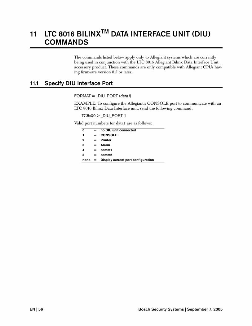
11 LTC 8016 BILINXTM DATA INTERFACE UNIT (DIU) COMMANDS
The commands listed below apply only to Allegiant systems which are currently being used in conjunction with the LTC 8016 Allegiant Bilinx Data Interface Unit accessory product. These commands are only compatible with Allegiant CPUs hav-ing firmware version 8.5 or later.
11.1 Specify DIU Interface Port
FORMAT = _DIU_PORT (data1)
EXAMPLE: To configure the Allegiant's CONSOLE port to communicate with an LTC 8016 Bilinx Data Interface unit, send the following command:
TC8x00 > _DIU_PORT 1
Valid port numbers for data1 are as follows:
0 = no DIU unit connected
1 = CONSOLE
2 = Printer
3 = Alarm
4 = comm1
5 = comm2
none = Display current port configuration
EN | 56 Bosch Security Systems | September 7, 2005
Close ACTS Remote Module Relay
12 ALLEGIANT COAXIAL TRANSMISSION SYSTEM (ACTS) COMMANDS
The ACTS commands listed below apply only to Allegiant systems which are cur-rently being used in conjunction with the LTC 8590 Series Allegiant CTS hardware products. Since the ACTS Series were discontinued in 2001, there is no need to sup-port these commands in new system interfaces.
Note: These commands apply to CPU’s having firmware versions 8.0 to 8.4.
12.1 Close ACTS Remote Module Relay
FORMAT = CTS-CLOSE-RELAY (logical camera#) (relay#)
EXAMPLE: To close relay 1 associated with camera 3 on the LTC 8598/x0 ACTS Remote Module, send the following command:
TC8x00 > CTS-CLOSE-RELAY 3 1
Although valid relay numbers range from 1 to 4, current LTC 8589 hardware pro-vides 2 relays only.
12.2 Open ACTS Remote Module Relay
FORMAT = CTS-OPEN-RELAY (logical camera#) (relay#)
EXAMPLE: To open relay 2 associated with camera 4 on the LTC 8598/x0 ACTS Remote Module, send the following command:
TC8x00 > CTS-OPEN-RELAY 4 2
Although valid relay numbers range from 1 to 4, current LTC 8589 hardware pro-vides 2 relays only.
12.3 Toggle ACTS Remote Module Relay
FORMAT = CTS-TOGGLE-RELAY (logical camera#) (relay#)
EXAMPLE: To toggle (close if opened; open if closed) the relay 1 associated with camera 3 on the LTC 8598/x0 ACTS Remote Module, send the following com-mand:
TC8x00 > CTS-TOGGLE-RELAY 3 1
Although valid relay numbers range from 1 to 4, current LTC 8589 hardware pro-vides 2 relays only.
EN | 57
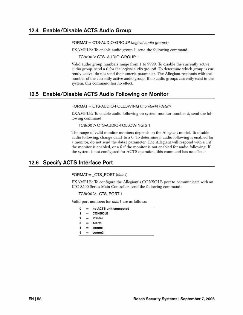
12.4 Enable/Disable ACTS Audio Group
FORMAT = CTS-AUDIO-GROUP (logical audio group#)
EXAMPLE: To enable audio group 1, send the following command:
TC8x00 > CTS- AUDIO-GROUP 1
Valid audio group numbers range from 1 to 9999. To disable the currently active audio group, send a 0 for the logical audio group#. To determine which group is cur-rently active, do not send the numeric parameter. The Allegiant responds with the number of the currently active audio group. If no audio groups currently exist in the system, this command has no effect.
12.5 Enable/Disable ACTS Audio Following on Monitor
FORMAT = CTS-AUDIO-FOLLOWING (monitor#) (data1)
EXAMPLE: To enable audio following on system monitor number 5, send the fol-lowing command:
TC8x00 > CTS-AUDIO-FOLLOWING 5 1
The range of valid monitor numbers depends on the Allegiant model. To disable audio following, change data1 to a 0. To determine if audio following is enabled for a monitor, do not send the data1 parameter. The Allegiant will respond with a 1 if the monitor is enabled, or a 0 if the monitor is not enabled for audio following. If the system is not configured for ACTS operation, this command has no effect.
12.6 Specify ACTS Interface Port
FORMAT = _CTS_PORT (data1)
EXAMPLE: To configure the Allegiant’s CONSOLE port to communicate with an LTC 8590 Series Main Controller, send the following command:
TC8x00 > _CTS_PORT 1
Valid port numbers for data1 are as follows:
0 = no ACTS unit connected
1 = CONSOLE
2 = Printer
3 = Alarm
4 = comm1
5 = comm2
EN | 58 Bosch Security Systems | September 7, 2005
Set Time Format
13 ON-SCREEN DISPLAY COMMANDS
13.1 Set Time Format
To set the time format to be displayed in either the 12 or 24 hour mode, enter one of the following:
TC8x00>12HR (for 12 hour AM/PM display)
TC8x00>24HR (for 24 hour display)
13.2 Set Date Format
To set the date to be displayed in any one of 3 formats, enter one of the following:
TC8x00>STANDARD-DF (for day/month/year format)
TC8x00>US-DF (for month/day/year format)
TC8x00>ASIAN-DF (for year/month/day format)
13.3 Set Camera Title
FORMAT = CAM-TITLE “CAMERA_NAME” (index camera#)
EXAMPLE: To program the title LOADING DOCK for camera number 6, enter the following command:
TC8x00> CAM-TITLE “LOADING DOCK” 6
NOTE: The title may contain a maximum of 16 characters (including spaces). This command is suitable for use with standard PC keyboard characters. To utilize the Allegiant’s extended character set, the CAM-XTITLE command (explained below) must be used. Since the camera title is stored in nonvolatile memory, there will be a short delay (typically 1 or 2 seconds) after this command is sent before the system can accept a new command.
13.4 Set Extended Character Camera Title
FORMAT = CAM-XTITLE (index camera#) (character value1) . . . (character value 16)
EXAMPLE: To program a title for index camera number 9 that will consist of extended Allegiant characters (character values shown are examples only), enter the following command:
TC8x00 > CAM-XTITLE 9 1234 902 500 1586 290
The values to use for the extended characters can be obtained from the Allegiant Character ROM tables found in the Allegiant’s Installation and Operating Instruc-tion manual. A maximum of 16 single width extended characters can be entered for each camera. In many instances, extended Allegiant characters are comprised of double width characters.
EN | 59
For double width characters, the same value must be entered in consecutive posi-tions. If double width characters are used, the first double width character must begin in an odd field (i.e., 1st character, 3rd character, 11th character, etc.). If less than 16 characters are entered, space characters are automatically appended to the title.
13.5 Set Monitor Title
FORMAT = PUT.MSG “MONITOR_NAME” (monitor#)
EXAMPLE: To enter the title MONITOR #3 for monitor number 3, enter the fol-lowing command:
TC8x00>PUT.MSG “MONITOR #3” 3
The title may contain a maximum of 12 characters (spaces included). Also note that the specific monitor must have the monitor message feature enabled. This must be selected by either using the MON-MSG command listed below or through the USER function using the system keyboard. Refer to the system operation manual for further instructions on USER function 5 procedure. Since the monitor title is stored in nonvolatile memory, there will be a short delay (typically 1 or 2 seconds) after this command is sent before the system can accept a new command.
13.6 Select Monitor Title Option
FORMAT = MON-MSG (monitor#)
EXAMPLE: To select the monitor title option instead of the monitor status display for monitor number 3, enter the following command:
TC8x00>MON-MSG 3
This command duplicates the USER function 5 using a system keyboard.
13.7 Select Monitor Status Option
FORMAT = MON-STAT (monitor#)
EXAMPLE: To select the monitor status option instead of the monitor title display for monitor number 3, enter the following command:
TC8x00>MON-STAT 3
This command duplicates the USER function 5 using a system keyboard.
13.8 Enable On-screen Controllable Camera Indicator
FORMAT = _CAMERA_CONTROL_STATUS (data)
EXAMPLE: To enable the on-screen display of the Allegiant’s controllable camera indicator, enter the following command:
TC8x00 > _CAMERA_CONTROL_STATUS 1
EN | 60 Bosch Security Systems | September 7, 2005
Designate Camera as Controllable
To disable the display of the indicator character, send the command with a data value of 0 (zero). The indicator character appears in the monitor status area of the on-screen display for cameras which have been configured as controllable. Cameras may be designated as controllable using either the CAMERA_CONTROLLABLE command (described below), the Master Control Software, the Allegiant GUI soft-ware package, or via Allegiant keyboard User Function 35.
This command utilizes an on-screen character which may not be available if the sys-tem was purchased with a custom character set. Under these circumstances, an incorrect character may be displayed.
13.9 Designate Camera as Controllable
FORMAT = CAMERA_CONTROLLABLE (index camera number) (data)
EXAMPLE: To designate Allegiant camera number 5 as a controllable camera, enter the following command:
TC8x00 > CAMERA_CONTROLLABLE 5 1
This command is used to designate which system cameras are equipped with pan/tilt/zoom functions. Cameras which are designated as controllable will display an on-screen indicator in the monitor status area of the system monitors. To remove the designation for a controllable camera, send the command with a data value of 0 (zero). The controllable camera on-screen indicator feature must also be enabled (see CAMERA_CONTROL_STATUS command) to view the special indicator char-acter. Cameras may also be designated as controllable using either the _CAMERA_CONTROL_STATUS command (described above), the Master Control Software, the Allegiant GUI software package, or via the Allegiant keyboard User Function 35.
This command utilizes an on-screen character which may not be available if the sys-tem was purchased with a custom character set. Under these circumstances, an incorrect character may be displayed.
13.10 Set Monitor Overlay Position
This command sets the position of the overlay information on a system monitor. The x-data value ranges from 0 (far left of screen) to 7 (far right of screen). The y-data value ranges from 0 (top of screen) to 15 (bottom of screen). Valid ranges for monitor numbers are LTC 8100 = 2, LTC 8200 = 5, LTC 8300 = 6, LTC 8500 = 8, LTC 8600 = 16, LTC 8800 = 64, and LTC 8900 = 512.
FORMAT = MON-OVERLAY-POS (monitor#) (X-data) (Y-data)
EXAMPLE: To position the overlay information on monitor number 1 to a center screen setting, enter the following command:
TC8x00>MON-OVERLAY-POS 1 2 5
EN | 61
13.11 Enable/Disable Monitor Overlay
This command determines which sections of the overlay information will be dis-played on a system monitor. The data1 value determines if the camera number, titles, and status information will be displayed. The data2 value determines if time and data information will be displayed. Enter a 1 in the appropriate position if the information is to be displayed or a 0 for it to be disabled. Valid ranges for monitor numbers are LTC 8100 = 2, LTC 8200 = 5, LTC 8300 = 6, LTC 8500 = 8, LTC 8600 = 16, LTC 8800 = 64, and LTC 8900 = 512. Currently, the LTC 8500 sys-tem does not support the selection to display time/date only (data1=0, data2=1).
FORMAT = MON-OVL-ENABLE (monitor#) (data1) (data2)
EXAMPLE: To set the overlay information on monitor number 1 to display time and data information only, enter the following command:
TC8x00>MON-OVL-ENABLE 1 0 1
13.12 Set Monitor Overlay Brightness
This command sets the white brightness of a monitor’s overlay information. The data value ranges from 0 (full brightness) to 3 (dimmest setting). Valid ranges for monitor numbers are LTC 8100 = 2, LTC 8200 = 5, LTC 8300 = 6, LTC 8500 = 8, LTC 8600 = 16, LTC 8800 = 64, and LTC 8900 = 512.
FORMAT = MON-BRIGHTNESS (monitor#) (data)
EXAMPLE: To set the overlay information on monitor number 1 to its brightest set-ting, enter the following command:
TC8x00>MON-BRIGHTNESS 1 0
13.13 Monitor Message Override
This command provides a means to temporarily override the normal monitor/status overlay section of a system’s monitor to display a 12 character message. The mes-sage will be displayed until the system is reset (either via the reset system command or via an AC power off/on cycle) or by issuing the command without the text field. Since messages sent using this command are stored in temporary memory, they can be changed frequently and will update on the displays more quickly than using the PUT-MSG monitor title command described earlier. The System monitor(s) must be set to their Monitor Titles (rather than Status displays) option for this feature to operate (see also MONMSG command described above). Valid ranges for monitor numbers are LTC 8100 = 2, LTC 8200 = 5, LTC 8300 = 5, LTC 8500 = 8, LTC 8600 = 16, LTC 8800 = 64, and LTC 8900 = 512.
FORMAT = MON-MSG-OVERRIDE (monitor#) “MESSAGE”
EXAMPLE: To override the standard monitor message on monitor number 1, enter the following command:
TC8x00>MON-MSG-OVERRIDE 1 “TEST MESSAGE”
NOTE: The Monitor Title overlay option must be active for these messages to be displayed.
EN | 62 Bosch Security Systems | September 7, 2005
Override Top Line of On-screen Display
13.14 Override Top Line of On-screen Display
This command is similar to the MON-MSG-OVERRIDE command described above. With this command, the top left side of the normal on-screen title display can be replaced (the time display is not affected). Since this command is also stored in tem-porary memory, it may be changed frequently and has no update delay associated with it. Up to 16 characters (15 for LTC 8500 systems) may be included in the mes-sage.
FORMAT = TOP-TITLE-OVERRIDE (monitor#) “16 character max”
EXAMPLE: To display a special message in the top line of the on-screen text, use the following command:
TC8x00 > TOP-TITLE-OVERRIDE 1 “This is a sample”
To return the title to its normal display mode, the command can be sent again with-out specifying the text parameter, or the system can be reset (power off/on). The left side of the top line of the on-screen text can be blanked out completely by sending this command with no text between the quotes.
13.15 Override Bottom Line of On-screen Display
This command is similar to the TOP-TITLE-OVERRIDE command described above. With this command, the bottom left side of the normal on-screen title display can be replaced (the date display is not affected). Since this command is also stored in tem-porary memory, it may be changed frequently and has no update delay associated with it. Up to 16 characters (15 for LTC 8500 systems) may be included in the mes-sage.
FORMAT = BOTTOM-TITLE-OVERRIDE (monitor#) “16 character max”
EXAMPLE: To display a special message in the bottom line of the on-screen text, use the following command:
TC8x00 > BOTTOM-TITLE-OVERRIDE 1 “This is a sample”
To return the title to its normal display mode, the command can be sent again with-out specifying the text parameter, or the system can be reset (power off/on). The left side of the bottom line of the on-screen text can be blanked out completely by send-ing this command with no text between the quotes.
13.16 Broadcast Message
To broadcast a temporary message (default time = 10 seconds) of up to 24 characters (12 characters for LTC 8500 systems) in length to ALL monitors, enter the following command:
TC8500>BROADCAST “ABCDEFGHIJKL”
TC8x00>BROADCAST “ABCDEFGHIJKLMNOPQRSTUVWX”
EN | 63
14 SYSTEM COMMANDS
14.1 Request System Software Revision Number
To request the software revision information of the system, enter the following com-mand:
TC8x00>REVISION
The system will respond with two sets of numbers on the same line that the com-mand was entered. The first number will represent the current CPU operating level of the system. The second number (displayed in parenthesis) is an internal number used by the Allegiant PC-based Software packages to determine version compatibil-ity.
14.2 Reset System
To duplicate a power off and on reset condition to the system, enter the following command:
TC8x00>RESET-SYSTEM
The reset message will then be displayed.
14.3 Abbreviate CCL Command
Some CCL commands are rather awkward to manually type in, especially when troubleshooting a problem. To simplify this situation, it is possible to define an abbreviated name for an existing CCL command. To define a new name, enter the following command:
TC8x00> ABBR (new name) (existing name)
The CCL command with the new name can now be used in addition to the existing CCL command. The new name will remain valid until the system is reset or pow-ered off/on.
14.4 Request Camera Hash Value
Logical camera numbers being used in sequences programmed by an external com-puting device must match those programmed in the Allegiant system. Using system default settings, this would always be the case. In situations where the system’s logi-cal camera numbers have been changed, a problem will occur. To ensure that this situation doesn’t occur, a camera hash value is included as part of any sequence download. Information on how to calculate and use the camera hash value can be found in the Sequence Functions section of this manual. If necessary, the command below can be used to obtain the current value directly from an operating system. Enter the following command to request the camera hash value:
TC8x00>CAMERA-HASH
EN | 64 Bosch Security Systems | September 7, 2005
Set Hexadecimal Mode
Starting with CPU firmware version 8.2, a 32-bit CRC value of the logical camera numbers will be displayed immediately after the camera hash value. This number is used for internal development purposes and should be ignored.
14.5 Set Hexadecimal Mode
If numeric values are to be entered in hexadecimal format, enter the command as follows:
TC8x00>HEX
14.6 Set Decimal Mode
If numeric values are to be entered in decimal format, enter the command as fol-lows:
TC8x00>DECIMAL
14.7 Set Time
To set the time in the system, enter the time in a 24 hour format in the form shown below:
TC8x00>!TIME (hour) (minute) (second)
EXAMPLE: To set the time for 1:00 PM, enter the following command:
TC8x00>!TIME 13 0 0
The updated time will then be displayed on all monitors.
14.8 Display Time
To display the time on the current output device, issue the following command:
TC8x00>TIME
03:14:34 (system time will be displayed)
14.9 Set Date
To set the date in the system, enter the date in the following format:
TC8x00>!DATE (month) (day) (year)
EXAMPLE: To set the date for June 4, 1989, enter the following command:
TC8x00>!DATE 6 4 89
The updated date will then be displayed on all monitors.
EN | 65
14.10 Display Date
To display the date on the current output device, issue the following command:
TC8x00>DATE
03-09-89 (system date displayed)
14.11 Display Date and Time
To display the system date using a 4-digit year format along with the system time in a 24 hour format, issue the following command:
TC8x00 > DATE-TIME
Fri 2 Jul 1999 13:08:12 (system date and time is displayed)
14.12 Send Message from Biphase Port
This command is used to send a single text message out the Allegiant’s biphase con-trol code port. This can be a powerful feature when used in Allegiant systems con-figured to operate in a Master/Satellite configuration. Since a biphase control code data line must be connected to each remote system in a Satellite configuration, this becomes a convenient method for sending CCL commands from the Master system to the remote Satellite systems. Note that it is not necessary to include a carriage return character at the end of the message text because one is automatically appended to the command.
FORMAT = _SEND_SAT (Satellite address - 1) “message”
EXAMPLE: To generate alarm number 2 in a remote Satellite system having address 1, send the alarm CCL command to the remote system using the following command:
TC8x00 > _SEND_SAT 0 “+ALARM 2”
When sending commands to Satellite systems that include numeric data, it is recom-mended to use hexadecimal numeric values. System generated Satellite commands include the hex numeric base command, so the Satellite system will normally be in the hexadecimal base mode. If decimal values must be used, include the decimal numeric base specifier (0m) to implicitly identify decimal values as shown below:
EXAMPLE: To generate the (decimal) alarm number 14 in a remote Satellite system having address 1, send the alarm CCL command to the remote system using the fol-lowing command:
TC8x00 > _SEND_SAT 0 “+ALARM 0m14”
A special case exists when the Master system is sending a command to generate a CCL Broadcast message at a Satellite location. In this case, the message portion of the command must be enclosed in double quotes. For example, to have the Satellite system broadcast “hello” to all of its system monitors, the command from the Master would be:
TC8x00 > _SEND_SAT 0 “Broadcast ““hello””
EN | 66 Bosch Security Systems | September 7, 2005
Send Data Packet from Biphase Port
If an Allegiant system is combined with a stand-alone LTC 8780 Series Data Con-verter Unit, this command provides the capability to generate customized text strings for controlling external RS-232 capable devices which support the use of text commands.
14.13 Send Data Packet from Biphase Port
This command is similar to the _SEND_SAT command described previously except it allows you to send generalized numeric values and/or ASCII strings. If multiple data parameters are sent, they are automatically concatenated into a single data packet when the command is issued.
FORMAT = _SEND_BIPHASE (address) (data 1) (data 2) (data 3) . . . (data n)
Where:
address is the value that corresponds to the configured address in the exter-nal device which will receive and decode the command being issued. When sending data to a camera’s receiver/driver, this value is equal to the receiver/driver address minus 1. When sending data to a Satellite system, this value is equal to the Satellite address plus the decimal number 14335. (Use 14336 for Satellite 1, 14337 for Satellite 2, etc. up to 14591 for Satellite 256.)
data 1, data 2, . . . . data n are the values that correspond to the numeric or ASCII data included in the transmission. When sending receiver/driver protocol commands, the first data byte should correspond to the Opcode byte associated with these types of commands (refer to document Receiver/Driver and AutoDome Control Code Protocol for more information on using receiver/driver protocol commands). Note that it is not necessary to include the Length Byte associated with the receiver/driver protocol because it is automatically inserted by the system into the data packet. Sub-sequent data values would include the data bytes associated with the Op-code byte being sent. The Checksum byte associated with the receiver/driver protocol is also calculated and included in the data packet automati-cally.
Text strings should be enclosed in quotes. Each character will be broken into its associated ASCII character and sent as an individual byte.
Parameter values which are being passed into a command when it is being used in an Allegiant system’s Script must be preceded by a single tick mark ( ‘ ).
Carriage return codes (code number 13) are not automatically included. If sending CCL commands, this must be included after the text/data portion of the CCL mes-sage packet. To ensure the implicit use of decimal numbers, the decimal numeric specifier 0m should precede the value, as in 0m13.
EXAMPLE 1 - Alarm activation message to Satellite address to activate alarm 1:
_SEND_BIPHASE 14336 “+ALARM 1” 0m13
EXAMPLE 2 - Sample Script for use in Satellite system configurations to activate/deactivate both Master and remote Satellite alarms. Appropriate Custom Alarm responses can be used to generate the alm_on (alarm#) and alm_off (alarm#) com-mands.
EN | 67
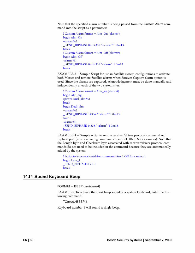
Note that the specified alarm number is being passed from the Custom Alarm com-mand into the script as a parameter:
! Custom Alarm format = Alm_On (alarm#)begin Alm_On+alarm %1_ SEND_BIPHASE 0m14336 “+alarm” ‘1 0m13break! Custom Alarm format = Alm_Off (alarm#)begin Alm_Off-alarm %1_ SEND_BIPHASE 0m14336 “-alarm” ‘1 0m13break
EXAMPLE 3 — Sample Script for use in Satellite system configurations to activate both Master and remote Satellite alarms when Forever Capture alarm option is used. Since the alarms are captured, acknowledgement must be done manually and independently at each of the two system sites:
! Custom Alarm format = Alm_sig (alarm#)begin Alm_sigspawn: Dual_alm %1breakbegin Dual_alm+alarm %1_ SEND_BIPHASE 14336 “+alarm” ‘1 0m13wait 1-alarm %1_SEND_BIPHASE 14336 “-alarm” ‘1 0m13break
EXAMPLE 4 — Sample script to send a receiver/driver protocol command out Biphase port (as when issuing commands to an LTC 0600 Series camera). Note that the Length byte and Checksum byte associated with receiver/driver protocol com-mands do not need to be included in the command because they are automatically added by the system:
! Script to issue receiver/driver command Aux 1 ON for camera 1begin Cam_1_SEND_BIPHASE 0 7 1 1break
14.14 Sound Keyboard Beep
FORMAT = BEEP (keyboard#)
EXAMPLE: To activate the short beep sound of a system keyboard, enter the fol-lowing command:
TC8x00>BEEP 3
Keyboard number 3 will sound a single beep.
EN | 68 Bosch Security Systems | September 7, 2005
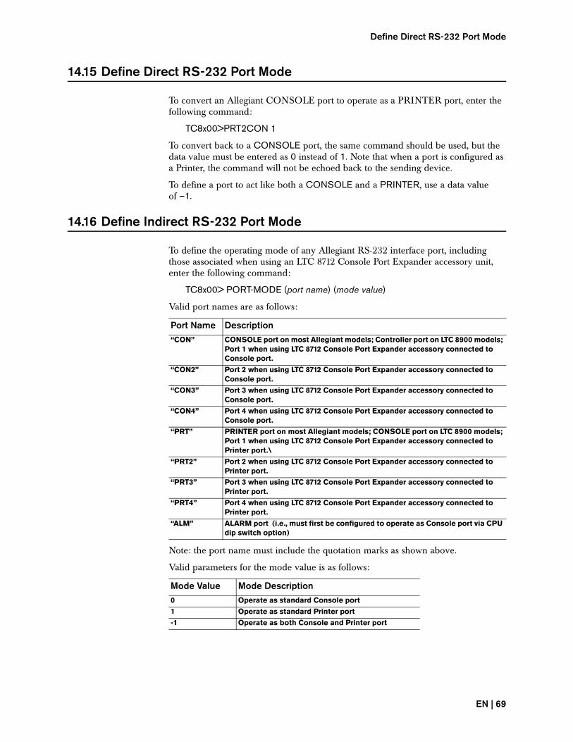
Define Direct RS-232 Port Mode
14.15 Define Direct RS-232 Port Mode
To convert an Allegiant CONSOLE port to operate as a PRINTER port, enter the following command:
TC8x00>PRT2CON 1
To convert back to a CONSOLE port, the same command should be used, but the data value must be entered as 0 instead of 1. Note that when a port is configured as a Printer, the command will not be echoed back to the sending device.
To define a port to act like both a CONSOLE and a PRINTER, use a data value of –1.
14.16 Define Indirect RS-232 Port Mode
To define the operating mode of any Allegiant RS-232 interface port, including those associated when using an LTC 8712 Console Port Expander accessory unit, enter the following command:
TC8x00> PORT-MODE (port name) (mode value)
Valid port names are as follows:
Note: the port name must include the quotation marks as shown above.
Valid parameters for the mode value is as follows:
Port Name Description“CON” CONSOLE port on most Allegiant models; Controller port on LTC 8900 models;
Port 1 when using LTC 8712 Console Port Expander accessory connected to Console port.
“CON2” Port 2 when using LTC 8712 Console Port Expander accessory connected to Console port.
“CON3” Port 3 when using LTC 8712 Console Port Expander accessory connected to Console port.
“CON4” Port 4 when using LTC 8712 Console Port Expander accessory connected to Console port.
“PRT” PRINTER port on most Allegiant models; CONSOLE port on LTC 8900 models; Port 1 when using LTC 8712 Console Port Expander accessory connected to Printer port.\
“PRT2” Port 2 when using LTC 8712 Console Port Expander accessory connected to Printer port.
“PRT3” Port 3 when using LTC 8712 Console Port Expander accessory connected to Printer port.
“PRT4” Port 4 when using LTC 8712 Console Port Expander accessory connected to Printer port.
“ALM” ALARM port (i.e., must first be configured to operate as Console port via CPU dip switch option)
Mode Value Mode Description0 Operate as standard Console port
1 Operate as standard Printer port
-1 Operate as both Console and Printer port
EN | 69
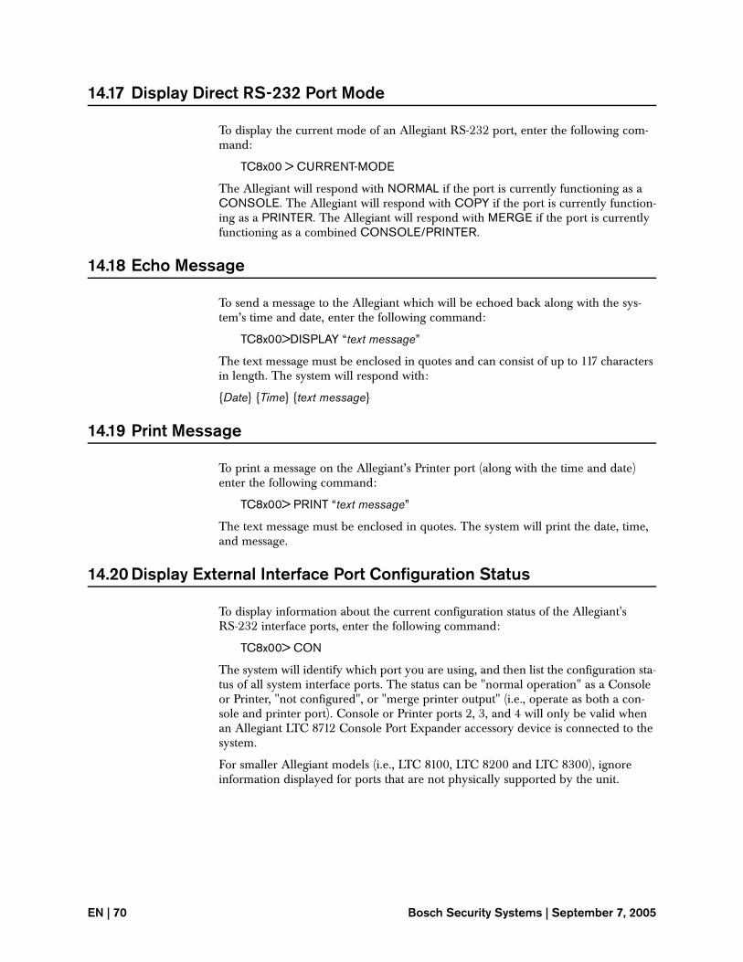
14.17 Display Direct RS-232 Port Mode
To display the current mode of an Allegiant RS-232 port, enter the following com-mand:
TC8x00 > CURRENT-MODE
The Allegiant will respond with NORMAL if the port is currently functioning as a CONSOLE. The Allegiant will respond with COPY if the port is currently function-ing as a PRINTER. The Allegiant will respond with MERGE if the port is currently functioning as a combined CONSOLE/PRINTER.
14.18 Echo Message
To send a message to the Allegiant which will be echoed back along with the sys-tem’s time and date, enter the following command:
TC8x00>DISPLAY “text message”
The text message must be enclosed in quotes and can consist of up to 117 characters in length. The system will respond with:
{Date} {Time} {text message}
14.19 Print Message
To print a message on the Allegiant’s Printer port (along with the time and date) enter the following command:
TC8x00> PRINT “text message”
The text message must be enclosed in quotes. The system will print the date, time, and message.
14.20 Display External Interface Port Configuration Status
To display information about the current configuration status of the Allegiant's RS-232 interface ports, enter the following command:
TC8x00> CON
The system will identify which port you are using, and then list the configuration sta-tus of all system interface ports. The status can be "normal operation" as a Console or Printer, "not configured", or "merge printer output" (i.e., operate as both a con-sole and printer port). Console or Printer ports 2, 3, and 4 will only be valid when an Allegiant LTC 8712 Console Port Expander accessory device is connected to the system.
For smaller Allegiant models (i.e., LTC 8100, LTC 8200 and LTC 8300), ignore information displayed for ports that are not physically supported by the unit.
EN | 70 Bosch Security Systems | September 7, 2005
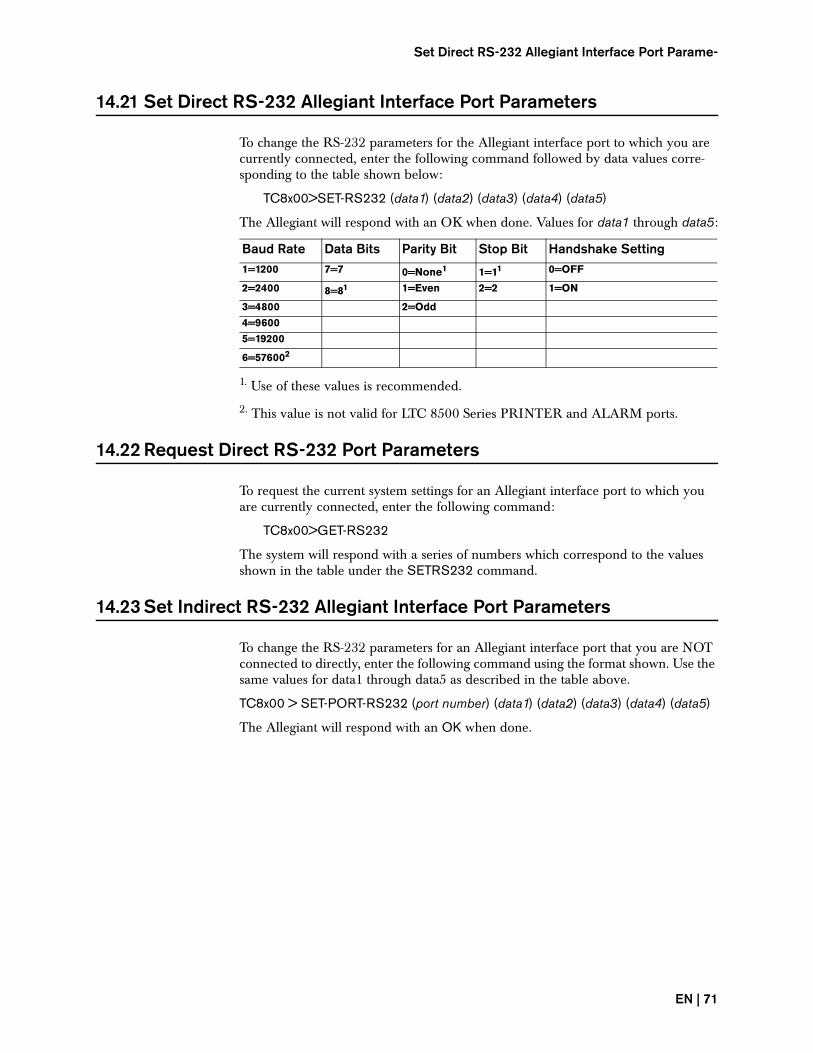
Set Direct RS-232 Allegiant Interface Port Parame-
14.21 Set Direct RS-232 Allegiant Interface Port Parameters
To change the RS-232 parameters for the Allegiant interface port to which you are currently connected, enter the following command followed by data values corre-sponding to the table shown below:
TC8x00>SET-RS232 (data1) (data2) (data3) (data4) (data5)
The Allegiant will respond with an OK when done. Values for data1 through data5:
1. Use of these values is recommended.
2. This value is not valid for LTC 8500 Series PRINTER and ALARM ports.
14.22 Request Direct RS-232 Port Parameters
To request the current system settings for an Allegiant interface port to which you are currently connected, enter the following command:
TC8x00>GET-RS232
The system will respond with a series of numbers which correspond to the values shown in the table under the SETRS232 command.
14.23 Set Indirect RS-232 Allegiant Interface Port Parameters
To change the RS-232 parameters for an Allegiant interface port that you are NOT connected to directly, enter the following command using the format shown. Use the same values for data1 through data5 as described in the table above.
TC8x00 > SET-PORT-RS232 (port number) (data1) (data2) (data3) (data4) (data5)
The Allegiant will respond with an OK when done.
Baud Rate Data Bits Parity Bit Stop Bit Handshake Setting1=1200 7=7 0=None1 1=11 0=OFF
2=2400 8=81 1=Even 2=2 1=ON
3=4800 2=Odd
4=9600
5=19200
6=576002
EN | 71
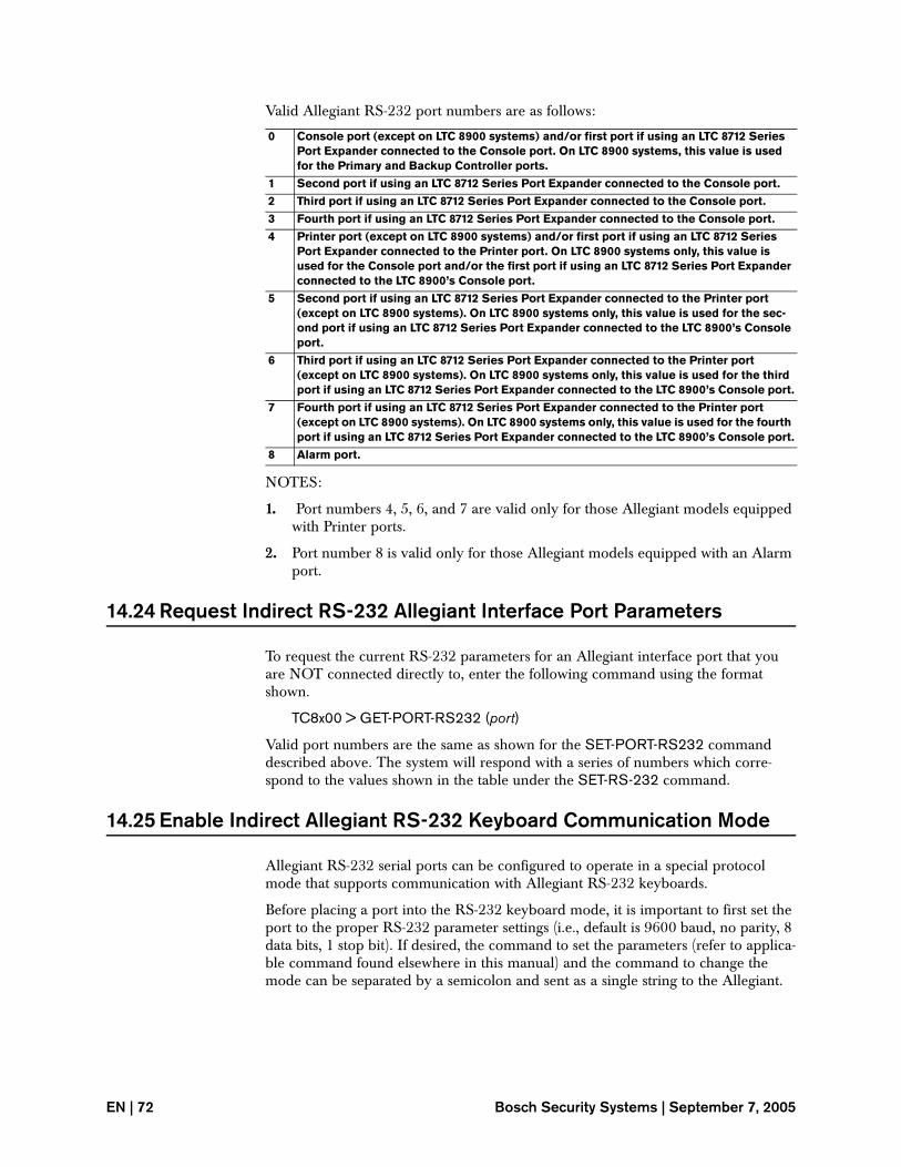
Valid Allegiant RS-232 port numbers are as follows:
NOTES:
1. Port numbers 4, 5, 6, and 7 are valid only for those Allegiant models equipped with Printer ports.
2. Port number 8 is valid only for those Allegiant models equipped with an Alarm port.
14.24 Request Indirect RS-232 Allegiant Interface Port Parameters
To request the current RS-232 parameters for an Allegiant interface port that you are NOT connected directly to, enter the following command using the format shown.
TC8x00 > GET-PORT-RS232 (port)
Valid port numbers are the same as shown for the SET-PORT-RS232 command described above. The system will respond with a series of numbers which corre-spond to the values shown in the table under the SET-RS-232 command.
14.25 Enable Indirect Allegiant RS-232 Keyboard Communication Mode
Allegiant RS-232 serial ports can be configured to operate in a special protocol mode that supports communication with Allegiant RS-232 keyboards.
Before placing a port into the RS-232 keyboard mode, it is important to first set the port to the proper RS-232 parameter settings (i.e., default is 9600 baud, no parity, 8 data bits, 1 stop bit). If desired, the command to set the parameters (refer to applica-ble command found elsewhere in this manual) and the command to change the mode can be separated by a semicolon and sent as a single string to the Allegiant.
0 Console port (except on LTC 8900 systems) and/or first port if using an LTC 8712 Series Port Expander connected to the Console port. On LTC 8900 systems, this value is used for the Primary and Backup Controller ports.
1 Second port if using an LTC 8712 Series Port Expander connected to the Console port.
2 Third port if using an LTC 8712 Series Port Expander connected to the Console port.
3 Fourth port if using an LTC 8712 Series Port Expander connected to the Console port.
4 Printer port (except on LTC 8900 systems) and/or first port if using an LTC 8712 Series Port Expander connected to the Printer port. On LTC 8900 systems only, this value is used for the Console port and/or the first port if using an LTC 8712 Series Port Expander connected to the LTC 8900’s Console port.
5 Second port if using an LTC 8712 Series Port Expander connected to the Printer port (except on LTC 8900 systems). On LTC 8900 systems only, this value is used for the sec-ond port if using an LTC 8712 Series Port Expander connected to the LTC 8900’s Console port.
6 Third port if using an LTC 8712 Series Port Expander connected to the Printer port (except on LTC 8900 systems). On LTC 8900 systems only, this value is used for the third port if using an LTC 8712 Series Port Expander connected to the LTC 8900’s Console port.
7 Fourth port if using an LTC 8712 Series Port Expander connected to the Printer port (except on LTC 8900 systems). On LTC 8900 systems only, this value is used for the fourth port if using an LTC 8712 Series Port Expander connected to the LTC 8900’s Console port.
8 Alarm port.
EN | 72 Bosch Security Systems | September 7, 2005
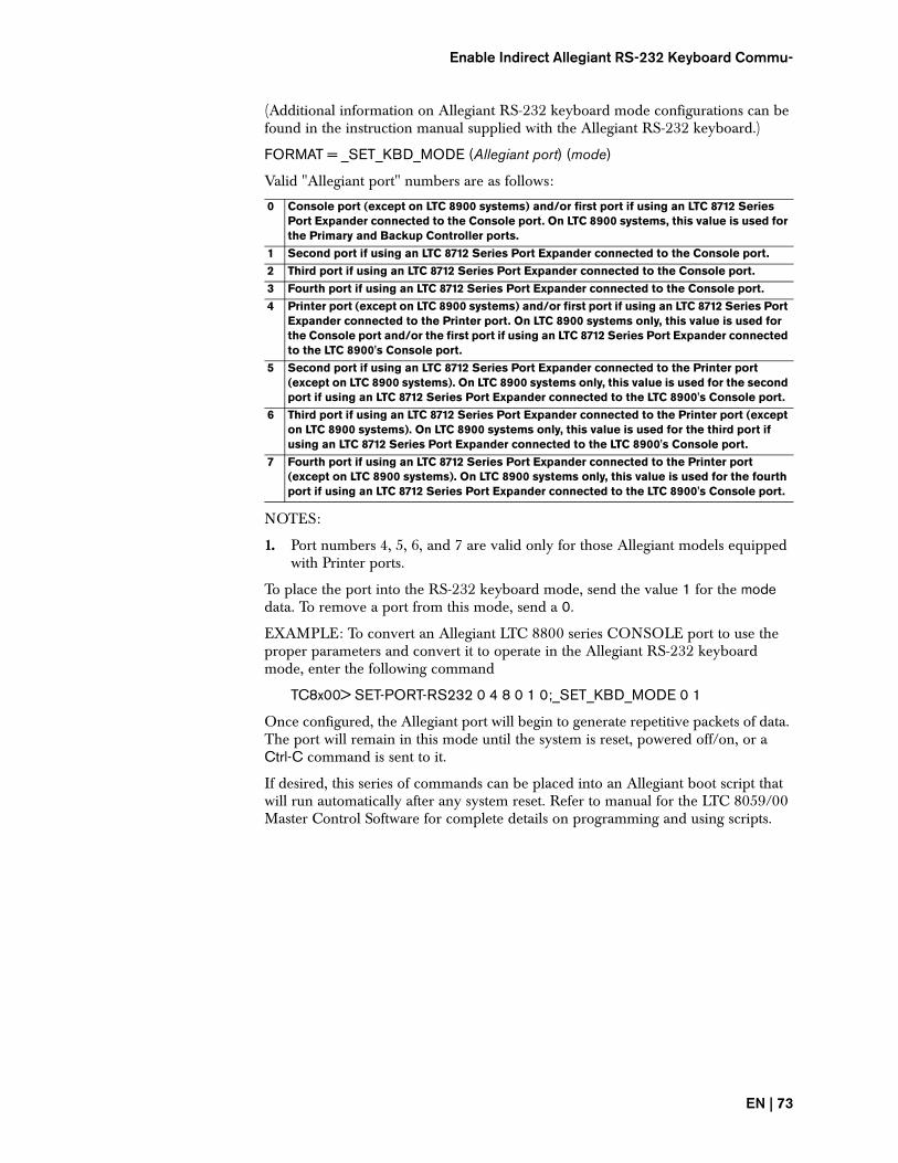
Enable Indirect Allegiant RS-232 Keyboard Commu-
(Additional information on Allegiant RS-232 keyboard mode configurations can be found in the instruction manual supplied with the Allegiant RS-232 keyboard.)
FORMAT = _SET_KBD_MODE (Allegiant port) (mode)
Valid "Allegiant port" numbers are as follows:
NOTES:
1. Port numbers 4, 5, 6, and 7 are valid only for those Allegiant models equipped with Printer ports.
To place the port into the RS-232 keyboard mode, send the value 1 for the mode data. To remove a port from this mode, send a 0.
EXAMPLE: To convert an Allegiant LTC 8800 series CONSOLE port to use the proper parameters and convert it to operate in the Allegiant RS-232 keyboard mode, enter the following command
TC8x00> SET-PORT-RS232 0 4 8 0 1 0;_SET_KBD_MODE 0 1
Once configured, the Allegiant port will begin to generate repetitive packets of data. The port will remain in this mode until the system is reset, powered off/on, or a Ctrl-C command is sent to it.
If desired, this series of commands can be placed into an Allegiant boot script that will run automatically after any system reset. Refer to manual for the LTC 8059/00 Master Control Software for complete details on programming and using scripts.
0 Console port (except on LTC 8900 systems) and/or first port if using an LTC 8712 Series Port Expander connected to the Console port. On LTC 8900 systems, this value is used for the Primary and Backup Controller ports.
1 Second port if using an LTC 8712 Series Port Expander connected to the Console port.
2 Third port if using an LTC 8712 Series Port Expander connected to the Console port.
3 Fourth port if using an LTC 8712 Series Port Expander connected to the Console port.
4 Printer port (except on LTC 8900 systems) and/or first port if using an LTC 8712 Series Port Expander connected to the Printer port. On LTC 8900 systems only, this value is used for the Console port and/or the first port if using an LTC 8712 Series Port Expander connected to the LTC 8900's Console port.
5 Second port if using an LTC 8712 Series Port Expander connected to the Printer port (except on LTC 8900 systems). On LTC 8900 systems only, this value is used for the second port if using an LTC 8712 Series Port Expander connected to the LTC 8900's Console port.
6 Third port if using an LTC 8712 Series Port Expander connected to the Printer port (except on LTC 8900 systems). On LTC 8900 systems only, this value is used for the third port if using an LTC 8712 Series Port Expander connected to the LTC 8900's Console port.
7 Fourth port if using an LTC 8712 Series Port Expander connected to the Printer port (except on LTC 8900 systems). On LTC 8900 systems only, this value is used for the fourth port if using an LTC 8712 Series Port Expander connected to the LTC 8900's Console port.
EN | 73
14.26 Enable Direct Allegiant RS-232 Keyboard Communication Mode
This command is very similar to the "_SET_KBD_MODE" command, except it is used to configure only the port that is in direct communication with the external computing device.
FORMAT = _ENABLE_KBD_MODE
EXAMPLE: To convert an Allegiant's CONSOLE port to the proper parameters and convert it to operate in the Allegiant RS-232 keyboard mode, enter the follow-ing command
TC8x00> SET-PORT-RS232 0 4 8 0 1 0;_ ENABLE_KBD_MODE
Once configured, the Allegiant port will begin to generate repetitive packets of data. The port will remain in this mode until the system is reset, powered off/on, or a Ctrl-C command is sent to it.
14.27 Enable Time Event Function
This command is used to enable the operation of Time Events functions which have been previously programmed into the Allegiant system. The actual Time Event functions can only be programmed into an Allegiant using one of the Allegiant PC-based software packages (LTC 8059/00 MCSW or LTC 8850/00 GUI).
FORMAT = ENABLE-TEVENT: (first event) (last event)
EXAMPLE: To enable operation of the first 5 system Time Events, enter the follow-ing command:
TC8x00 > ENABLE-TEVENT: 1 5
To enable a single event, specify only the first event parameter. To enable all Time Events, do not include either parameter.
14.28 Disable Time Event Function
This command is used to disable the operation of Allegiant Time Events functions.
FORMAT = DISABLE-TEVENT: (first event) (last event)
EXAMPLE: To disable the operation of the first 5 Time Events, enter the following command:
TC8x00 > DISABLE-TEVENT: 1 5
To disable a single event, specify only the first event parameter. To disable all Time Events, do not include either parameter.
EN | 74 Bosch Security Systems | September 7, 2005
Enable/Disable Trunk Caching
14.29 Enable/Disable Trunk Caching
This command is only applicable to Allegiant systems operating in a cascaded Satel-lite configuration. A cascaded Satellite system is a system where a Master system has a Satellite which is the Master of another Satellite. In systems of this type, it is possi-ble to experience an undesirable switching effect due to unbalanced trunk lines. Unbalanced trunk lines occur when there are more trunk lines between the top level Master and its middle level Satellite/Master than there are between the middle level Satellite/Master and the lowest level Satellite. In this situation, an internal system trunk caching function can cause undesirable switching at the middle level Satellite/Master when the top level Master is finished viewing a camera from the low level Satellite. This command allows the trunk caching function to be disabled.
After issuing this command, the system must be rest or powered off/on before the new setting takes effect.
FORMAT = _DISABLE_TRUNK_CACHING (data)
EXAMPLE: To disable the trunk caching function, enter the following command:
TC8x00 > _DISABLE_TRUNK_CACHING (1)
To return to system defaults, the trunk caching function can be restored by sending the command with a data value of 0. This command duplicates Allegiant system keyboard User Function 41.
14.30 Default Camera Numbers
The default camera number ranges on CPUs prior to revision 6.8 set all logical cam-era numbers equal to their index number values. Starting with CPU revision 6.8 and higher, the logical camera numbers above the system’s physical capacity will be defaulted to an unconfigured state. Normally this command would not need to be used, but in some cases it may be necessary to convert the camera numbers back to the old default values to maintain compatibility with older external interface pro-grams which have used sequence downloads. To reconfigure the logical camera numbers back to their old default values, enter the following command:
TC8x00> _RECONFIGURE_CAMERA_NUMBERS 1
NOTE: This command will not affect any camera inputs which have been desig-nated as Trunk lines. Also, the command may be issued with a numeric value of zero to set the camera numbers to the new default values.
There will be a short delay (typically 1 or 2 seconds) after this command is sent before the system can accept a new command.
EN | 75
14.31 Display Index Camera Number
In systems where the Logical camera numbers have been redesignated, this com-mand is used to display the associated Index camera number assigned to the speci-fied Logical camera number.
FORMAT = FIND-LOG-CAM (logical camera#)
EXAMPLE: If you want to determine the Index camera number assigned to Logical camera number 1, enter the following command:
TC8x00 > FIND-LOG-CAM 1
The system will respond on the same line with the associated Index camera number. Note that it is only possible to reassign Logical camera numbers using one of the Allegiant PC-based software packages.
14.32 Display Index Monitor Number - Valid for LTC 8900 Systems Only
In LTC 8900 systems where the Logical monitor numbers have been redesignated, this command is used to display the associated Index monitor number assigned to the specified Logical monitor number.
FORMAT = FIND-LOG-MON (logical monitor#)
EXAMPLE: If you want to determine the Index monitor number assigned to Logi-cal monitor number 1, enter the following command:
TC8x00 > FIND-LOG-MON 1
The system will respond on the same line with the associated Index monitor num-ber. Note that it is only possible to reassign Logical monitor numbers in LTC 8900 systems using one of the Allegiant PC-based software packages.
14.33 Display Logical Camera Number
In systems where the Logical camera numbers have been redesignated, this com-mand is used to display the associated Logical camera number assigned to the spec-ified Index camera number.
FORMAT = GET-CAM-LOG-NUM (index camera#)
EXAMPLE: If you want to determine the Logical camera number assigned to Index camera number 1, enter the following command:
TC8x00 > GET-CAM-LOG-NUM 1
The system will respond on the same line with the associated Logical camera num-ber. Note that it is only possible to reassign Logical camera numbers using one of the Allegiant PC-based software packages.
EN | 76 Bosch Security Systems | September 7, 2005
Display Logical Monitor Number - Valid for LTC 8900
14.34 Display Logical Monitor Number - Valid for LTC 8900 Systems Only
In LTC 8900 systems where the Logical monitor numbers have been redesignated, this command is used to display the associated Logical monitor number assigned to the specified Index monitor number.
FORMAT = GET-MON-LOG-NUM (logical camera#)
EXAMPLE: If you want to determine the Logical monitor number assigned to Index monitor number 1, enter the following command:
TC8x00 > GET-MON-LOG-NUM 1
The system will respond on the same line with the associated Logical monitor num-ber. Note that it is only possible to reassign Logical monitor numbers in LTC 8900.
14.35 Specify Allegiant LTC 8900 General Task Processing Mode
(Applicable to Allegiant LTC 8900 Models Only)
In its default mode, the redundant CPU unit in an LTC 8900 series Allegiant system will temporarily pause the running of video sequences and other system tasks while a Mirroring update (i.e., a status change in the Primary CPU is copied over to the Backup CPU) is underway. This is done so that the CPU is able to support the pro-cessing of frequent status changes in the system. In systems that do not experience several status changes each minute, the pausing functionality can be defeated using the following command:
FORMAT = _ENABLE_MSTR_SEQ_SW_INH 0
To restore operation back to factory default mode, enter 1 for the parameter value, or reset the system.
If erratic system operation is noticed after using this command, set the system back to factory defaults.
If desired, this command can be placed into an Allegiant boot script that will run automatically after any system reset. Refer to manual for the LTC 8059/00 Master Control Software for complete details on programming and using scripts.
14.36 Specify Allegiant Custom Alarm Task Processing Mode
(Applicable to large model Allegiant Systems)
In its default mode, the CPUs in large model Allegiant systems will temporarily pause the processing of system alarms if it becomes busy processing Custom Alarm tasks and other user defined scripts. This action may not be desired especially if the Custom Alarm tasks are not as critical as being able to quickly respond to large vol-umes of alarms (i.e., several hundred each minute). The following command will create a separate task where the processing of Custom Alarm responses will be deferred until the CPU has time to address them:
FORMAT = _ENABLE_DEFERRED_CCL 1
To restore Alarm processing back to its default mode, enter 0 for the parameter value or reset the system.
EN | 77
If erratic Custom Alarm responses are noticed after using this command, set the sys-tem back to factory defaults.
If desired, this command can be placed into an Allegiant boot script that will run automatically after any system reset. Refer to manual for the LTC 8059/00 Master Control Software for complete details on programming and using scripts.
14.37 Define Video Standard
The LTC 8100, LTC 8200, LTC 8300, LTC 8600, LTC 8800, and LTC 8900 systems contain an integral raster generator which is used in conjunction with the system’s video loss message feature. The raster format of this internal generator should be set to match the type of signals being used in the system (either NTSC or PAL). Nor-mally, this setting is configured at the factory and should never require attention. In the unlikely event that the format must be changed, the following command can be used to set the desired format to NTSC mode:
FORMAT = _VIDEO_FORMAT (data1)
EXAMPLE: To set the video standard to NTSC, enter the following command:
TC8x00> _VIDEO_FORMAT 1
To force a PAL mode, specify 0 for the data1 value. For NTSC, specify a value of 1. Do not specify a parameter with the command to display the current video stan-dard. The system must be reset or powered off/on before the new setting takes effect. Once configured, the unit will remain in the specified mode until changed.
14.38 Enable Video Loss Raster Generator
This command controls the internal raster generator which is used in conjunction with the system’s video loss message feature. It is only valid on LTC 8100, LTC 8200, LTC 8300, LTC 8600, LTC 8800, and LTC 8900 systems.
TC8x00>_VIDLOSS_SYNC_GEN 1
To disable the raster generator, change the numeric value to zero.
14.39 Default System to Factory Settings
To reset the system to the factory default settings, enter the following command:
TC8x00>DEFAULT
When this command is entered, the system will reset to the following conditions:
1. Console, printer, and alarm ports are set to 19,200/8/1/none/off.
2. Time/date to 10:00, 1/1/90, 12Hr, US format.
3. Basic alarm response mode, with Monitor 1 and Monitor 2 armed for all alarms.
4. Alarm dwell time is set to two seconds on LTC 8500 Series systems and one sec-ond on LTC 8300, LTC 8600, LTC 8800, and LTC 8900 Series systems.
5. All alarm titles are disabled.
6. Broadcast timer is set to 10 seconds.
EN | 78 Bosch Security Systems | September 7, 2005
Default System to Factory Settings
7. All keyboards are polled.
8. Boot screen memory is cleared.
9. All sequences are deleted.
10. Monitor overlays are enabled, set to full brightness, and positioned at the bot-tom center of screen.
11. All lockout tables are cleared.
12. All monitors display camera 1.
13. Keyboards are set to control monitors corresponding to keyboard port num-bers.
14. All camera numbers are set to correspond to physical inputs. Camera titles set to Camera Title?
15. Monitor titles are set to MONITOR 00XX.
16. System is set to Limited Printing mode (not applicable on LTC 8900 systems).
17. Use of default camera is enabled on Log-in.
18. Administrator is enabled for multiple keyboard Log-in.
19. Leading zeros are displayed in 3 digit format for camera numbers on LTC 8300, LTC 8600, LTC 8800, and LTC 8900 Series.
20. Monitor and alarm crosspoint and alarm active data are sent to the biphase line on LTC 8300, LTC 8600, LTC 8800, and LTC 8900 Series.
21. User table is reset to default.
22. All time-events are deleted.
NOTE: There will be a considerable delay (typically 15 to 60 seconds) after this command is sent before the system is operational again.
EN | 79
15 ALLEGIANT DIAGNOSTIC COMMANDS
Allegiant diagnostic commands are not intended to be used by an external interface device during normal service operation. They are typically used during develop-ment of the interface software or in conjunction with factory technical support per-sonnel. The commands listed below have been included solely for this purpose.
15.1 Display Detected Cameras
This command responds with a listing of camera numbers which have been detected by the system’s video loss feature. This command is not applicable to LTC 8500 systems, which do not currently support the video loss detection feature (the word none will always be returned).
TC8x00> WORKING-CAMS
15.2 CPU Flash Memory Check
Prior to upgrading the firmware in a CPU via a mot file download, it is best to verify the protected sectors of the flash memory. To verify the integrity of the CPU’s flash memory, enter the following command:
TC8x00> _DUMP_FLASH_MAP
This command will show information about which memory sectors are write-pro-tected and which are not for each bank of memory. For example, an LTC 8800 or LTC 8900 will respond with:
OF: FE FF FF FF
The first OF: or other characters in this position, reflects a bitmap of the flash banks which have been detected and can be ignored. After that, the FE indicates that only a single sector in the first bank is write-protected. This is the sector that contains the boot code for downloading firmware upgrades and it is the only one that should ever show up as being write-protected. Note that the number of FF pairs that are dis-played will depend on the model. If you see anything other than FE in this position or FF anywhere else, do not attempt to upgrade the CPU firmware using the down-load process. The flash memory ICs must be replaced. In some cases, you may see all FFs. In this case, the boot sector is not write protected. You can still upgrade the flash (not recommended), but if it fails for any reason during the firmware down-load, you will most likely never be able to establish communication again.
15.3 Display CPU Parameter Settings
This command will display the current contents of the Allegiant CPU’s Parameters Table. The response will include information on the Allegiant’s RS-232 configura-tions and various other system related settings. The current functions of the Alle-giant CPU’s Dip Switch settings are also shown.
An example response from an LTC 8800 system is shown below:
TC8800> PARAM-TBL
EN | 80 Bosch Security Systems | September 7, 2005
Display Input Module Status
LTC 8800 Video Switching System Parameter Table
KBD INSTALLED
Broadcast Duration: 10 s
MISCELLANEOUS OPTIONS
15.4 Display Input Module Status
This command displays the number of Video Input modules installed in an Alle-giant system matrix bay. When issued to the LTC 8100, LTC 8200, or LTC 8300, a value of 1 will always be returned. This command is not applicable to LTC 8500 systems (the word none will always be returned). LTC 8600 and LTC 8800 systems will return a value between 1 and 8, which corresponds to the actual number of input modules currently installed in the main CPU bay.
When issued to an LTC 8900 system, the response will show a hexadecimal repre-sentation where each bit corresponds to an individual module installed for both Input and Output matrix bays for all possible system matrix bays. Locations having the value 0 indicates that the associated matrix bay is not currently connected or is nonexistent in the system. Each of the 8 rows of numbers displayed corresponds to a monitor number range. Row 1 corresponds to Input and Output matrix bays associ-ated with monitors 1 to 64; row 2 is for monitors 65 to 128; etc. The first value in each row displays the number of output cards installed in the monitor bay. The next
INTERFACE CONSOLE PRINTER ALARM COMM1 COMM2 KEYBOARDBaud: 19200 19200 19200 125 K 125 K 9600
Stop Bits: 1 1 1 2 1 1
Data Bits: 8 8 8 8 8 8
Parity: None None None MultiDrp MultiDrp None
Handshake: No No No No No No
1 2 3 4 5 6 7 8 9 10 11 12 13 14 15 16
17 18 19 20 21 22 23 24 25 26 27 28 29 30 31 32
Sys Adm Login Mult: Yes XPoint 1-32 to SDA: No Alm Status 1- 256: No
Change Cam on Logon: Yes Xpoint 33-64 to SDA: No Alm Status 257- 512: No
Kbd 1-8 on Expander: No Logical Cam Xpoints: No Alm Status 513- 768: No
Camera Leading Zero: Yes Limited Printing: Yes Alm Status 769-1024: No
Four-digit Cam Num: No Variable-speed OSRD: Yes Alarm Xpoint to SDA: No
Display Cam Control: No Override Lost Video: Yes Require Kbd login: Yes
Require Con login: No Expand Console Port: No Expand Printer Port: No
Slow VOM Updates: No
DIP Sw# COMMENT STATUS
0.3 Force Expanded Console Mode No
0.4 Force Exp Con 57600 Baud No
1.1 not used Off
1.2 Use Alarm Port as Console No
1.3 Old kbd 4/8 poll-byte selection Off
1.4 Printer defaults to normal console Yes
1.5 Enable Login selection Yes
1.6 not used Off
1.7 New keyboard communications format Yes
1.8 Custom comm parms and boot screen Yes
EN | 81
16 values in each row correspond to the number of input modules installed in the first level Input bays. The first of these 16 values represents the camera bay for cam-eras 1 to 256; the second is for cameras 257 to 512; etc. The remaining 4 values in each row correspond to the number of input modules installed in the second level Input bays.
In all cases, the hexadecimal values can be interpreted as follows: Convert the hexa-decimal value to its binary number equivalent. The least significant bit (right most value) corresponds to the module installed in slot 1 (the left most slot when viewed from front of bay). All 0 bits correspond to empty slots. All 1 bits correspond to slots where modules are installed.
TC8x00> VIMS-INSTALLED
15.5 Display Crosspoint Status
When this command is issued, a response will be returned showing the cameras cur-rently switched to the system monitors. This is more commonly referred to as Cros-spoint status.
TC8x00> _DUMP_XP
Each value of the response represents a camera number. The first value is the cam-era on Monitor 1; the second value is the camera on Monitor 2; etc.
15.6 Display Satellite Trunk Status
When issued to the Master system in a Satellite system configuration, this command displays information on the state of its Satellite Trunk video lines.
TC8x00> TRUNK-DIAG
15.7 List Bootscreen Script Program
This command will list any stored command script program currently residing in the Allegiant’s CPU memory. Each script line will be preceded with a line number. At the end of the script listing, information is also included about the status of the Allegiant keyboard’s STAR key and the current mode of the script debugging fea-ture.
TC8x00> Bootscreen
15.8 Enable/Disable Command Script Debug Mode
This command enables/disables the Allegiant CPU’s Command Script debug mode. If a user programmed Command Script function is not operating properly, use of the Command Script debug mode may be helpful in locating the source of errors in the script program.
TC8x00 > SCRIPT-DEBUG (data)
To enter the debug mode, a 0 (zero) should be entered for the data parameter. To exit the debug mode, a 1 should be used for the data parameter.
EN | 82 Bosch Security Systems | September 7, 2005
Display Matrix Bay Firmware Revisions - LTC 8900
15.9 Display Matrix Bay Firmware Revisions - LTC 8900 Series Only
When this command is issued to an LTC 8900 system CPU bay, a response will be returned listing the firmware version numbers of all of the video input and video output matrix bays connected to the system.
TC8x00> BAY-REVISION
Each line of the response will represent a matrix bay which will be identified by a 2 number pair. If the second number is 0, the number pair will always refer to a mon-itor bay. Number pair 1,0 represents the monitor bay with monitors 1 to 64 con-nected to it; number 2,0 represents the monitor bay for monitors 65 to 128; etc.
If the second number is not 0, the number pair refers to a camera bay. Number pair 1,1 represents the camera bay with cameras 1 to 256 connected to it which is associ-ated with monitor bay 1; number 1,2 represents the camera bay with cameras 257 to 512 connected to it which is associated with monitor bay 1; number 2,1 represents the camera bay with cameras 1 to 256 connected to it which is associated with mon-itor bay 2; etc.
The bay’s firmware revision number will be displayed immediately after the two numbers. Other board revision numbers for internal use will also be displayed and should be completely ignored.
15.10 Time Since Last CPU Reset
During troubleshooting of the system, it is sometimes helpful to know how long the CPU has been in operation since its last reset. This information can be determined using the following command:
C8x00> CLOCK-TICK
The CPU will respond with the number of seconds that have passed since the last CPU reset, including power off/on resets.
15.11 Diagnostic Commands - LTC 8590 ACTS Series Only
The ACTS commands listed below apply only to Allegiant systems which are cur-rently being used in conjunction with the LTC 8590 Series Allegiant CTS hardware products. Since the ACTS Series were discontinued in 2001, there is no need to use these commands in new system interfaces.
Display Revision Number of LTC 8016 Bilinx Data Interface UnitsThis command is used to display the revision numbers of all LTC 8016 DIUs that are connected to the Allegiant system:
TC8x00> _DIU_REVISION
The response will display a table showing 4-digit values for all LTC 8016 units that can be supported by the Allegiant model being used. Only those units actually con-nected to the Allegiant will show actual revision information. The values for units that are not connected will show all zeros.
EN | 83
Send ACTS Debugging Messages to Allegiant PrinterThis command enables ACTS debugging messages to be sent to the Allegiant Printer port.
TC8x00> _DEBUG_CTS 1
To disable ACTS debugging, substitute a 0 instead of the 1 parameter. To ask the current status of Printer port debugging messages, do not use any parameter. When asked, either a 0 (disabled) or a 1 (enabled) value will be returned.
Display ACTS Software RevisionThis command will display the software revision of all LTC 8590 Series Main Con-trol units connected to the Allegiant.
TC8x00> _CTS_REVISION
Groups of 0000 will be returned where no units are detected. The total quantity of 0000 groups varies depending on the number of units supported by the Allegiant model being debugged.
Display ACTS CamerasThis command displays the designated camera numbers (values configured via the thumbwheels of the LTC 8590 Series Remote units) of all cameras connected using ACTS hardware devices.
TC8x00> _CTS_CAMERAS
The value 0 is returned for positions where no cameras are detected. The total quan-tity of 0 values varies depending on the number of units supported by the Allegiant model being debugged.
Display ACTS Alarm Input StatesThis command displays the current status of the LTC 8590 Series Remote unit’s alarm inputs.
TC8x00> CTS-DIGITAL-INPUTS
Since the Remote units support 3 alarm inputs, the display represents a binary value of the simultaneous alarm states. A value of 00 indicates no alarm conditions are active. The value 00 is also returned for positions where no units are detected. The total quantity of 00 values varies depending on the number of units supported by the Allegiant model being debugged.
Activate/Display ACTS Relay Output StatesThis command is used to activate/deactivate/display the LTC 8590 Series Remote unit’s relay outputs. The format of the command is as follows:
TC8x00> CTS-RELAY-MASK camera-number relay-mask
The camera-number parameter is the designated camera number configured in the ACTS Remote unit’s Thumbwheel. The relay-mask parameter is the binary value representing the status of the relay outputs. Although valid relay numbers range from 1 to 4, current LTC 8589 hardware provides 2 relays only. Do not specify a relaymask parameter with the command to ask the current status of the Remote unit’s relay outputs.
EN | 84 Bosch Security Systems | September 7, 2005
Diagnostic Commands - LTC 8590 ACTS Series Only
16 ERROR MESSAGES
The following list describes the error messages generated by the Allegiant systems when an improper command has been received. Messages due to internal system errors are displayed along with date and time of occurrence.
• Error in Command’s Parameters
• ERROR: not enough arguments
• ERROR: too many arguments
• ERROR: expected numeric (radix-name) argument
• ERROR: expected argument in quotes
• ERROR: overflow evaluating numeric argument
• ERROR: argument(s) out of range
• ERROR: arguments should be in ascending order
• Undefined logical camera number given in command parameter:
• ERROR: invalid camera number
• Unknown CCL command:
• Console Command “(unrecognized command)” not found
• Entered string matches two or more CCL commands:
• Console Command “(string)” ambiguous
• •Undocumented CCL command has not been implemented:
• UNIMPLEMENTED
• CCL command is not valid for this unit:
• ERROR: command not supported on this system
• Not enough stack space to process command:
• ERROR: insufficient stack space
• Not enough heap space to process command:
• ERROR: out of memory
• Error with undocumented ABBR command:
• Abbreviation Table Full
• Error with SET-STAR command:
• ERROR: could not find script
• Error with undocumented CLR-BOOT command:
• **FAILED**
EN | 85
• Error with KBD-LOGON command:
• ERROR: invalid user ID number
• ERROR: user locked out of keyboard
• Error executing SEQ-REQ command:
• ERROR (two character error number per below):
6 = monitor-lockout table locks system administrator from monitor
50 = sequence does not exist
51 = absolute sequence requested on wrong monitor
52 = monitor number too high for this relative sequence
56 = sequence is currently being edited
• Internal system error due to reprogramming of alarm tables while alarms are active:
• SYSTEM WARNING: ALARM VIDEO DISCARDED DUE TO RECONFIG-URATION OF ALARM SYSTEM
• Internal system error due to alarm overflow (thousands of alarm videos are simultaneously displayed):
• SYSTEM WARNING: ALARM (number) DISCARDED DUE TO INTERNAL ALARM SYSTEM OVERFLOW
• Internal system error due to monitor being armed while too many alarms are active:
• SYSTEM WARNING: ALARM VIDEO DISCARDED DUE TO INTERNAL ALARM SYSTEM OVERFLOW
• Internal system error due to hardware eeprom error (should never happen):
• SYSTEM WARNING: EEPROM WRITE ERROR
• Internal system error due to recursive eeprom usage (should never happen):
• SYSTEM WARNING: INTERNAL EEPROM PRIVILEGE STACK OVER-FLOW
• Internal errors when printing out system messages (should never happen):
• SYSTEM ERROR: ILLEGAL TABLE MESSAGE NUMBER
• SYSTEM ERROR: ILLEGAL SYSTEM MESSAGE NUMBER
• SYSTEM ERROR: UNKNOWN MESSAGE TYPE
• Internal error in heap memory management (should never happen):
• HEAP ERROR: (error code)
• Internal error with undocumented RADIX command (should never happen):
• ERROR: unknown radix!
EN | 86 Bosch Security Systems | September 7, 2005
Diagnostic Commands - LTC 8590 ACTS Series Only
• Internal system error due to semaphore deadlock or time-out (should never happen):
• SEVERE SYSTEM WARNING: SEMAPHORE DEADLOCK Sem = (n); task = (n); owner = (n)
• SEVERE SYSTEM WARNING: semaphore TIMEOUT Sem = (n); task = (n); owner = (n)
• Error while processing a bootscreen script:
• SCRIPT ERROR on line (n): out of memory while processing arguments syntax error in script command out of memory while processing .FOR loop no matching .FOR for .NEXT command unknown error
• Error using MON-CAM or CHG-MON command when specifying a logged-off keyboard:
• ERROR 41
EN | 87

EN | 88 Bosch Security Systems | September 7, 2005
© 2005 Bosch Security Systems GmbHF01U010845-01 | Updated September 7, 2005 | Data subject to change without notice
AmericasBosch Security Systems130 Perinton ParkwayFairport, New York, 14450 USAPhone: +1 (585) 223 4060
+1 800 289 [email protected]://www.boschsecurity.us
Europe, Middle East, AfricaBosch Security Systems B.V.P.O. Box 800025600 JB Eindhoven, The NetherlandsPhone: +31 (0) 40 27 83955Fax: +31 (0) 40 27 [email protected]://www.boschsecurity.com
Asia-PacificBosch Security Systems Pte Ltd38C Jalan PemimpinSingapore 577180Phone: +65 6319 3450Fax: +65 6319 [email protected]://www.boschsecurity.com