all about measuring pressure - manoraz.com · types of pressure pressure measurement compares a...
TRANSCRIPT

33
All About Measuring Pressure

Preface
Alongside temperature, pressure is one of the most important andmost measured variables for applications in research andengineering.
A large number of measuring tasks have become indispensable fora wide range of applications in the foodstuffs industry, in heating,sanitation and air-conditioning, in power generation andtechnology, in process engineering and in many other areas.
Whatever the application, when it comes to measuring pressurethere are some important parameters which have to be observed ifreliable results are to be achieved.
In addition to knowledge of the various units, familiarity with thedifferent types of pressure, and their definition, is fundamental tomeasurement.
The Technical manual deals first and foremost with the contextsurrounding the electronic pressure measuring process.
The aim of this practical guide is to both enable newcomers to gainan overview of the relevant parameters, and to serve as a referencework for professionals in the industry.
We are grateful for any ideas you may have and will be happy toincorporate these into the next edition.
The Board of Directors
Burkart Knospe Wolfgang Hessler Martin Schulz
4 5
17 IX. Accuracy
1. The right meter for the particular application2. Linearity3. Temperature coefficient4. Hysteresis
20 X. The measuring process
20 XI. Overload versus static pressure
22 XII. Measuring in liquids
1. Static admission pressure2. Measuring pressure in liquids
25 XIII. Which gases can be measured?
6 XIV. Pressure shocks
27 XV. Measuring flows with a pitot tube
1. Determining air density2. Sources of error in pitot tube measurement3. Measuring flows above 100 m/s4. Advantages of measuring flows using a differential
pressure meter and pitot tube
34 XVI. Calibration
36 XVII. Some applications
6 I. The definition of pressure
6 II. Units
1. SI units 2. About the units
7 III. Conversion table
8 IV. Types of pressure and their definition/basis
1. Absolute pressure = p abs2. Positive pressure3. Negative pressure4. Differential pressure = ³ p5. Atmospheric air pressure = p atm
6. Pressure meters and their areas of application
10 V. Pressure measuring processes
1. Various liquid pressure meters– U-tube manometers– inclined-tube manometers– float manometers
2. Elastic element pressure meters3. Electric pressure measuring processes
13 VI. Advantages of electric pressure meters
13 VII. Description of the Testo measuring principle1. Measuring pressure according to the piezoresistive
principle2. Inductive pressure measurement
15 VIII. Pressure and temperature
Parameter
Pressure
Page Content Page Content
7
Parameter
Pressure
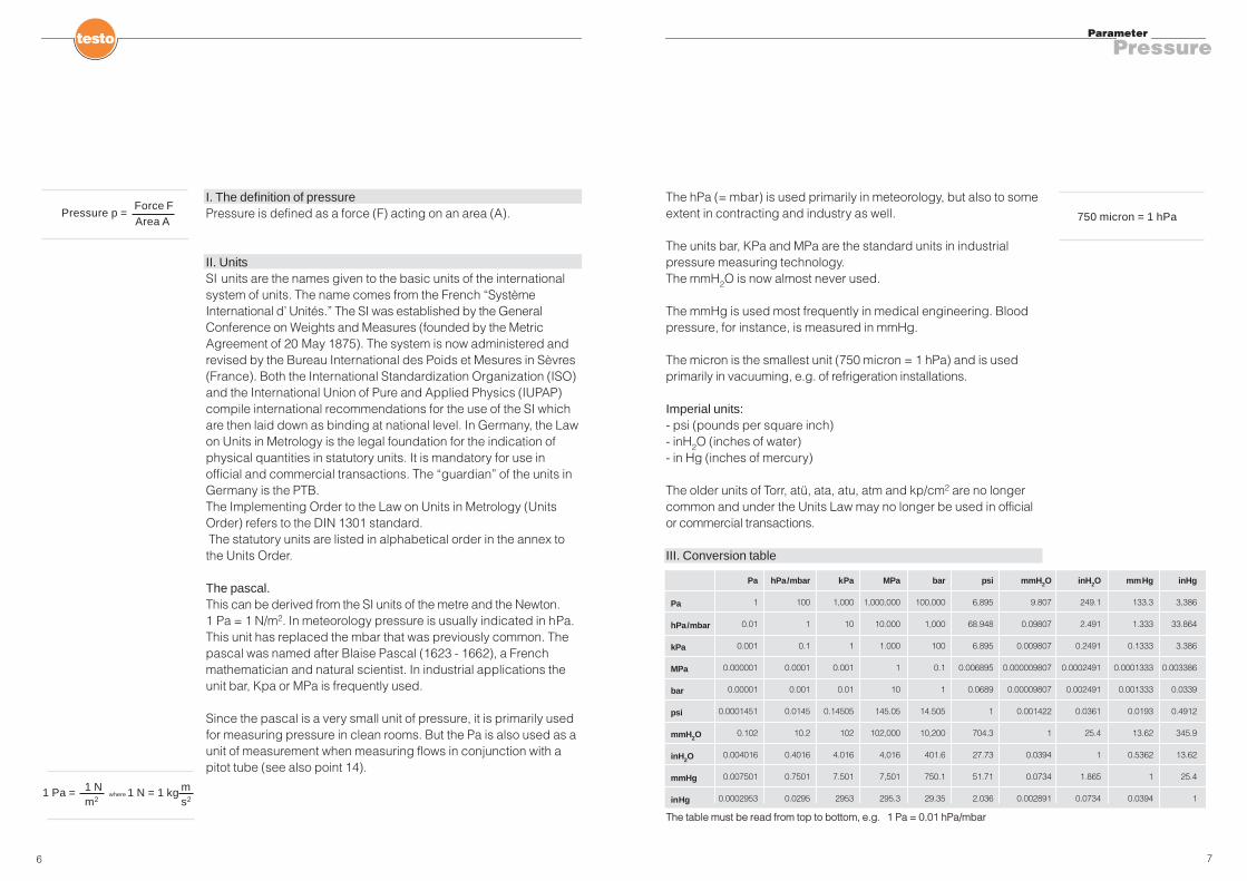
I. The definition of pressurePressure is defined as a force (F) acting on an area (A).
II. UnitsSI units are the names given to the basic units of the internationalsystem of units. The name comes from the French “SystèmeInternational d’ Unités.” The SI was established by the GeneralConference on Weights and Measures (founded by the MetricAgreement of 20 May 1875). The system is now administered andrevised by the Bureau International des Poids et Mesures in Sèvres(France). Both the International Standardization Organization (ISO)and the International Union of Pure and Applied Physics (IUPAP)compile international recommendations for the use of the SI whichare then laid down as binding at national level. In Germany, the Lawon Units in Metrology is the legal foundation for the indication ofphysical quantities in statutory units. It is mandatory for use inofficial and commercial transactions. The “guardian” of the units inGermany is the PTB.The Implementing Order to the Law on Units in Metrology (UnitsOrder) refers to the DIN 1301 standard.The statutory units are listed in alphabetical order in the annex tothe Units Order.
The pascal.This can be derived from the SI units of the metre and the Newton.1 Pa = 1 N/m2. In meteorology pressure is usually indicated in hPa.This unit has replaced the mbar that was previously common. Thepascal was named after Blaise Pascal (1623 - 1662), a Frenchmathematician and natural scientist. In industrial applications theunit bar, Kpa or MPa is frequently used.
Since the pascal is a very small unit of pressure, it is primarily usedfor measuring pressure in clean rooms. But the Pa is also used as aunit of measurement when measuring flows in conjunction with apitot tube (see also point 14).
The hPa (= mbar) is used primarily in meteorology, but also to someextent in contracting and industry as well.
The units bar, KPa and MPa are the standard units in industrialpressure measuring technology.The mmH2O is now almost never used.
The mmHg is used most frequently in medical engineering. Bloodpressure, for instance, is measured in mmHg.
The micron is the smallest unit (750 micron = 1 hPa) and is usedprimarily in vacuuming, e.g. of refrigeration installations.
Imperial units:- psi (pounds per square inch)- inH2O (inches of water)- in Hg (inches of mercury)
The older units of Torr, atü, ata, atu, atm and kp/cm2 are no longercommon and under the Units Law may no longer be used in officialor commercial transactions.
III. Conversion table
6
Pressure p = Force FArea A
1 Pa = where 1 N = 1 kg1 Nm2
ms2
750 micron = 1 hPa
1
0.01
0.001
0.000001
0.00001
0.0001451
0.102
0.004016
0.007501
0.0002953
Pa
100
1
0.1
0.0001
0.001
0.0145
10.2
0.4016
0.7501
0.0295
hPa/mbar
Pa
hPa/mbar
kPa
MPa
bar
psi
mmH2O
inH2O
mmHg
inHg
1,000
10
1
0.001
0.01
0.14505
102
4.016
7.501
2953
kPa
1,000,000
10.000
1.000
1
10
145.05
102,000
4,016
7,501
295.3
MPa
100,000
1,000
100
0.1
1
14.505
10,200
401.6
750.1
29.35
bar
6,895
68.948
6.895
0.006895
0.0689
1
704.3
27.73
51.71
2.036
psi
9.807
0.09807
0.009807
0.000009807
0.00009807
0.001422
1
0.0394
0.0734
0.002891
mmH2O
249.1
2.491
0.2491
0.0002491
0.002491
0.0361
25.4
1
1.865
0.0734
inH2O
133.3
1.333
0.1333
0.0001333
0.001333
0.0193
13.62
0.5362
1
0.0394
mmHg
3,386
33.864
3.386
0.003386
0.0339
0.4912
345.9
13.62
25.4
1
inHg
The table must be read from top to bottom, e.g. 1 Pa = 0.01 hPa/mbar

8 9
Parameter
Pressure
IV. Types of pressurePressure measurement compares a current pressure with areference pressure. Pressure measuring technology distinguishesbetween the following types of pressure, enabling a statement to bemade about the relationship between the measuring pressure andthe reference pressure.
Absolute pressure relates to the vacuous space of the universe(zero pressure).
Absolute pressure:– measured pressure above absolute zero– reference, ideal vacuum– measuring pressure is always greater than reference pressure
Positive pressure:– measured pressure above the barometric daily air pressure– reference ambient pressure– measuring pressure is always greater than reference pressure
Negative pressure:– measured pressure below the barometric daily air pressure– reference ambient pressure– measuring pressure is always less than reference pressure
Differential pressure:– measured pressure above or below any desired reference pressure– measuring pressure is always greater than reference pressure
Patm
This is the most important pressure for life on earth. Atmosphericpressure arises through the weight of the atmosphere thatsurrounds the earth. The atmosphere extends up to an altitude ofabout 500 km. Air pressure decreases constantly up to this altitude(absolute pressure p abs = zero). Atmospheric air pressure is alsoaffected by weather-related fluctuations. On average, p atm at sealevel is 1013.25 hPa. However, it can fluctuate by up to ±5 %according to highs or lows in the weather.
Pressure meters and their areas of applicationWhat are known as differential pressure meters can measurepositive pressure and negative pressure as well as differentialpressure. The important thing here is to connect the right pressure tothe right connection, i.e. a positive pressure to the + and a negativepressure to the – connection. With the right connection, a differentialpressure meter can cover the entire measuring range in both thepositive and the negative direction.If a meter has a measuring range of 0...200 hPa, for instance, apositive pressure, a negative pressure and a differential pressurewithin the 200 hPa range can be measured.
Why always the correct pressure at the right connection?If a meter is used to measure a negative pressure and this isconnected to the + connection, some meters will indicate a part oftheir measuring range with a – sign, but will stop after a certainvalue (both to protect the sensor and because all pressure sensorsare only calibrated in the positive range). If the user does not takethis into account, incorrect measuring results will be obtained.Some other meters indicate “out of range” on the display after acertain measured value.
Barometric pressure can be measured with absolute pressuremeters. There are two types of barometric atmospheric pressure.One is the pressure related to the particular altitude, the other theabsolute pressure converted to sea level. The converted absolutepressure is primarily used in meteorology in order to ensure
Differential pressure
Positive pressure
Negative pressure
Absolute pressure
PressureVacuumPressure types
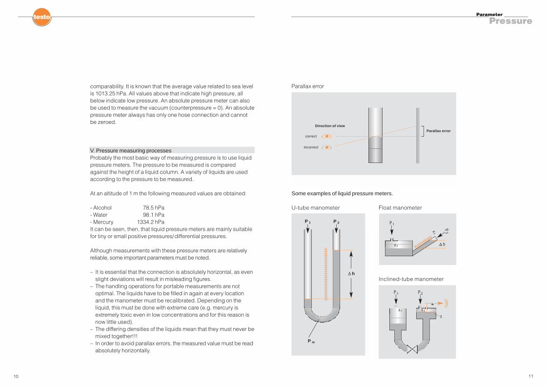
Some examples of liquid pressure meters.
U-tube manometer
Inclined-tube manometer
11
Parameter
Pressure
comparability. It is known that the average value related to sea levelis 1013.25 hPa. All values above that indicate high pressure, allbelow indicate low pressure. An absolute pressure meter can alsobe used to measure the vacuum (counterpressure = 0). An absolutepressure meter always has only one hose connection and cannotbe zeroed.
V. Pressure measuring processesProbably the most basic way of measuring pressure is to use liquidpressure meters. The pressure to be measured is comparedagainst the height of a liquid column. A variety of liquids are usedaccording to the pressure to be measured.
At an altitude of 1 m the following measured values are obtained:
- Alcohol 78.5 hPa- Water 98.1 hPa- Mercury 1334.2 hPaIt can be seen, then, that liquid pressure meters are mainly suitablefor tiny or small positive pressures/differential pressures.
Although measurements with these pressure meters are relativelyreliable, some important parameters must be noted.
– It is essential that the connection is absolutely horizontal, as evenslight deviations will result in misleading figures.
– The handling operations for portable measurements are notoptimal. The liquids have to be filled in again at every locationand the manometer must be recalibrated. Depending on theliquid, this must be done with extreme care (e.g. mercury isextremely toxic even in low concentrations and for this reason isnow little used).
– The differing densities of the liquids mean that they must never bemixed together!!!
– In order to avoid parallax errors, the measured value must be readabsolutely horizontally.
10
Parallax error
Parallax errorcorrect
Direction of view
incorrect
P 1 P 2
A 1
S
A 2
P 1 P 2
P m
∆ h
∆ h
P 1
P2
A 1
A1
Float manometer
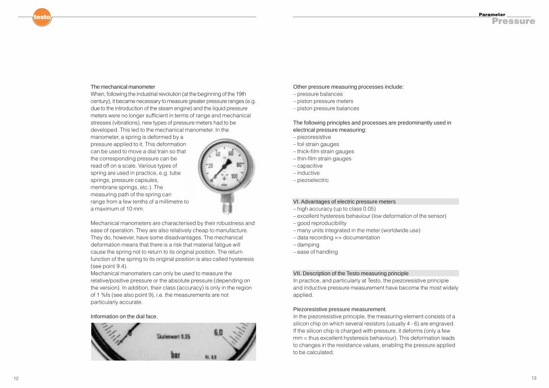
The mechanical manometerWhen, following the industrial revolution (at the beginning of the 19thcentury), it became necessary to measure greater pressure ranges (e.g.due to the introduction of the steam engine) and the liquid pressuremeters were no longer sufficient in terms of range and mechanicalstresses (vibrations), new types of pressure meters had to bedeveloped. This led to the mechanical manometer. In themanometer, a spring is deformed by apressure applied to it. This deformationcan be used to move a dial train so thatthe corresponding pressure can beread off on a scale. Various types ofspring are used in practice, e.g. tubesprings, pressure capsules,membrane springs, etc.). Themeasuring path of the spring canrange from a few tenths of a millimetre toa maximum of 10 mm.
Mechanical manometers are characterised by their robustness andease of operation. They are also relatively cheap to manufacture.They do, however, have some disadvantages. The mechanicaldeformation means that there is a risk that material fatigue willcause the spring not to return to its original position. The returnfunction of the spring to its original position is also called hysteresis(see point 9.4).Mechanical manometers can only be used to measure therelative/positive pressure or the absolute pressure (depending onthe version). In addition, their class (accuracy) is only in the regionof 1 %fs (see also point 9), i.e. the measurements are notparticularly accurate.
Information on the dial face.
13
Parameter
Pressure
Other pressure measuring processes include: – pressure balances– piston pressure meters– piston pressure balances
The following principles and processes are predominantly used inelectrical pressure measuring:– piezoresistive– foil strain gauges– thick-film strain gauges– thin-film strain gauges– capacitive– inductive– piezoelectric
VI. Advantages of electric pressure meters– high accuracy (up to class 0.05)– excellent hysteresis behaviour (low deformation of the sensor)– good reproducibility– many units integrated in the meter (worldwide use)– data recording => documentation– damping– ease of handling
VII. Description of the Testo measuring principleIn practice, and particularly at Testo, the piezoresistive principleand inductive pressure measurement have become the most widelyapplied.
Piezoresistive pressure measurement.In the piezoresistive principle, the measuring element consists of asilicon chip on which several resistors (usually 4 - 6) are engraved.If the silicon chip is charged with pressure, it deforms (only a fewmm = thus excellent hysteresis behaviour). This deformation leadsto changes in the resistance values, enabling the pressure appliedto be calculated.
12
14 15
Parameter
Pressure
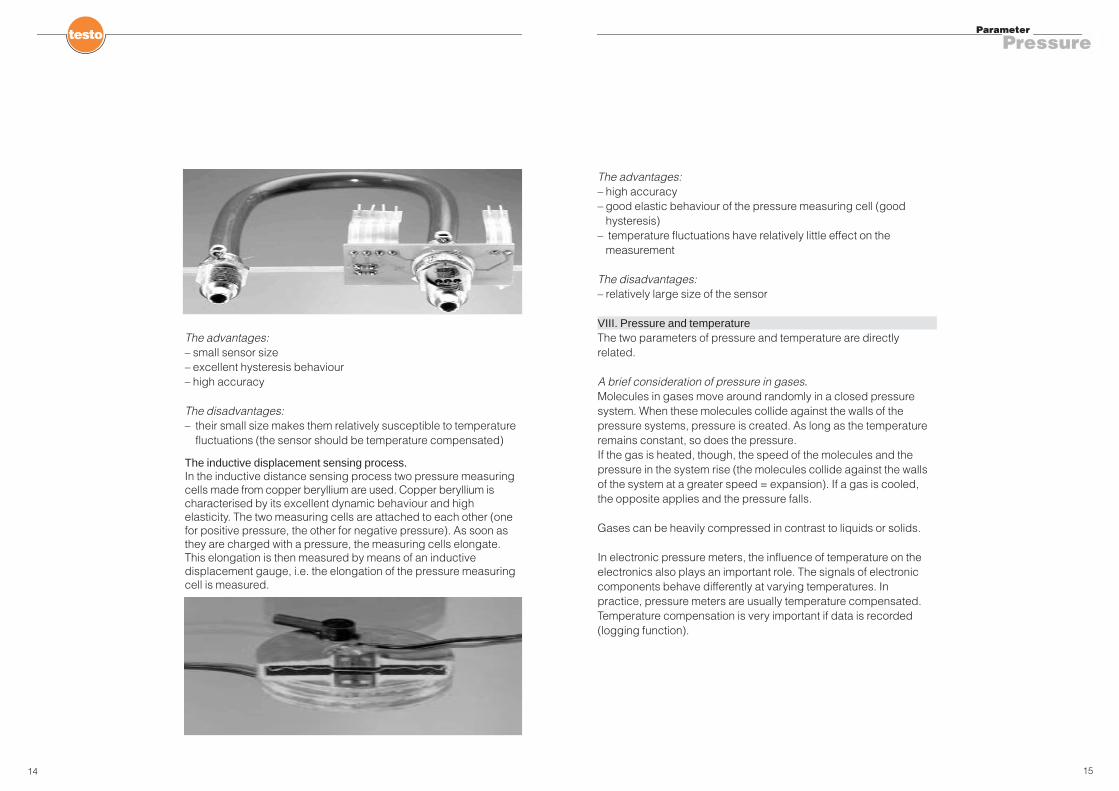
The advantages:– small sensor size– excellent hysteresis behaviour– high accuracy
The disadvantages:– their small size makes them relatively susceptible to temperature
fluctuations (the sensor should be temperature compensated)
The inductive displacement sensing process.In the inductive distance sensing process two pressure measuringcells made from copper beryllium are used. Copper beryllium ischaracterised by its excellent dynamic behaviour and highelasticity. The two measuring cells are attached to each other (onefor positive pressure, the other for negative pressure). As soon asthey are charged with a pressure, the measuring cells elongate.This elongation is then measured by means of an inductivedisplacement gauge, i.e. the elongation of the pressure measuringcell is measured.
The advantages:– high accuracy– good elastic behaviour of the pressure measuring cell (good
hysteresis)– temperature fluctuations have relatively little effect on the
measurement
The disadvantages:– relatively large size of the sensor
VIII. Pressure and temperatureThe two parameters of pressure and temperature are directlyrelated.
A brief consideration of pressure in gases.Molecules in gases move around randomly in a closed pressuresystem. When these molecules collide against the walls of thepressure systems, pressure is created. As long as the temperatureremains constant, so does the pressure.If the gas is heated, though, the speed of the molecules and thepressure in the system rise (the molecules collide against the wallsof the system at a greater speed = expansion). If a gas is cooled,the opposite applies and the pressure falls.
Gases can be heavily compressed in contrast to liquids or solids.
In electronic pressure meters, the influence of temperature on theelectronics also plays an important role. The signals of electroniccomponents behave differently at varying temperatures. Inpractice, pressure meters are usually temperature compensated.Temperature compensation is very important if data is recorded(logging function).
16 17
Parameter
Pressure
An example:Assumption: In a production factory without a night shift, i.e. wherethere is no operation at night, a malfunction occurs in an installationto which a pressure measuring system is connected. For reasons ofcost, the factory heating is turned down at night. A manometriccapsule connected to the system keeps a long-term record. Thepressure in the system is kept constant by means of a compressor.
What does the pressure meter now record and show?
Meter 1 = not temperature compensatedThe meter indicates a fall in the values as the room becomesincreasingly colder. Once the room is heated up again the next day,the meter shows that the pressure is rising again until a constantroom temperature is reached. Yet the pressure in the system hasremained constant.
Meter 2 = temperature compensatedThe meter shows the actual (permanently the same) value in thesystem, even though the ambient temperature has changed.
Conclusion: If long-term monitoring is to be carried out, it isessential that the pressure meter is temperature compensated.If only a brief check or short measurement of a pressure system iscarried out, there is no need to have offset temperaturecompensation since the meter is zeroed before the measurementand so temperature influences will not become a factor.
Caution: Extreme temperature differences such as those which canoccur in winter (meter was in the car the whole night at e.g. –10 °Cand is then used for measurement in a room at 20° C) cannot beoffset even by optimal temperature compensation. It is thereforeessential that the meter is adjusted to the temperature over a longperiod (approx. 0.5 h, depending on the temperature difference).The optimum solution is to let the meter adjust unpressurized andswitched on.
Temperature compensation is a very awkward and cost-intensivematter, since the meters are adjusted in the climatic cabinet at 2 - 3temperatures. It takes some time until the temperatures in theclimatic cabinet are stable.
IX. Accuracy (influencing factors)The accuracy of pressure meters is usually indicated in classes.Thus class 1.0 = accurate to within 1 % of the measuring range (fs =full scale, fv = final value).
Example:Differential pressure meter with measuring range 1000 hPa, class 1 => absolute accuracy ±10 hPa.
It is important to remember the basis on which a manufacturerstates his accuracy. There are two variations:fs / fv = of full scale / final valuemv = of measured value
There is no single meter for all applications in pressuremeasurement. This is because of the class. Since the error isindicated as a % of fv, the absolute error rises as the measuringrange increases. This means that if most applications lie in the lowhPa range and higher pressures are measured only sporadically, ameter with a high measuring range would not be appropriate. Afterall, since the absolute error in the high measuring range is relativelyhigh, the measuring error in the lower pressure ranges is much toolarge (see chart “The right meter for the application”). Onealternative for these cases of a limited range is to use meters with avariable measuring range. The final value is divided into twomeasuring ranges. However, in these meters one of the twomeasuring ranges has a higher class and the other a lower class(example: the testo 520 for a small measuring range has class 0.5;for a large measuring range class 0.2). It can therefore occur thattwo or more meters have to be used to achieve accuratemeasurements in the small and the large measuring range.
18 19
Parameter
Pressure
return to its original form (to the zero point). Put more simply: if a spring is extended to its maximum and this extension thenrelaxes, the spring should adopt its original status again.
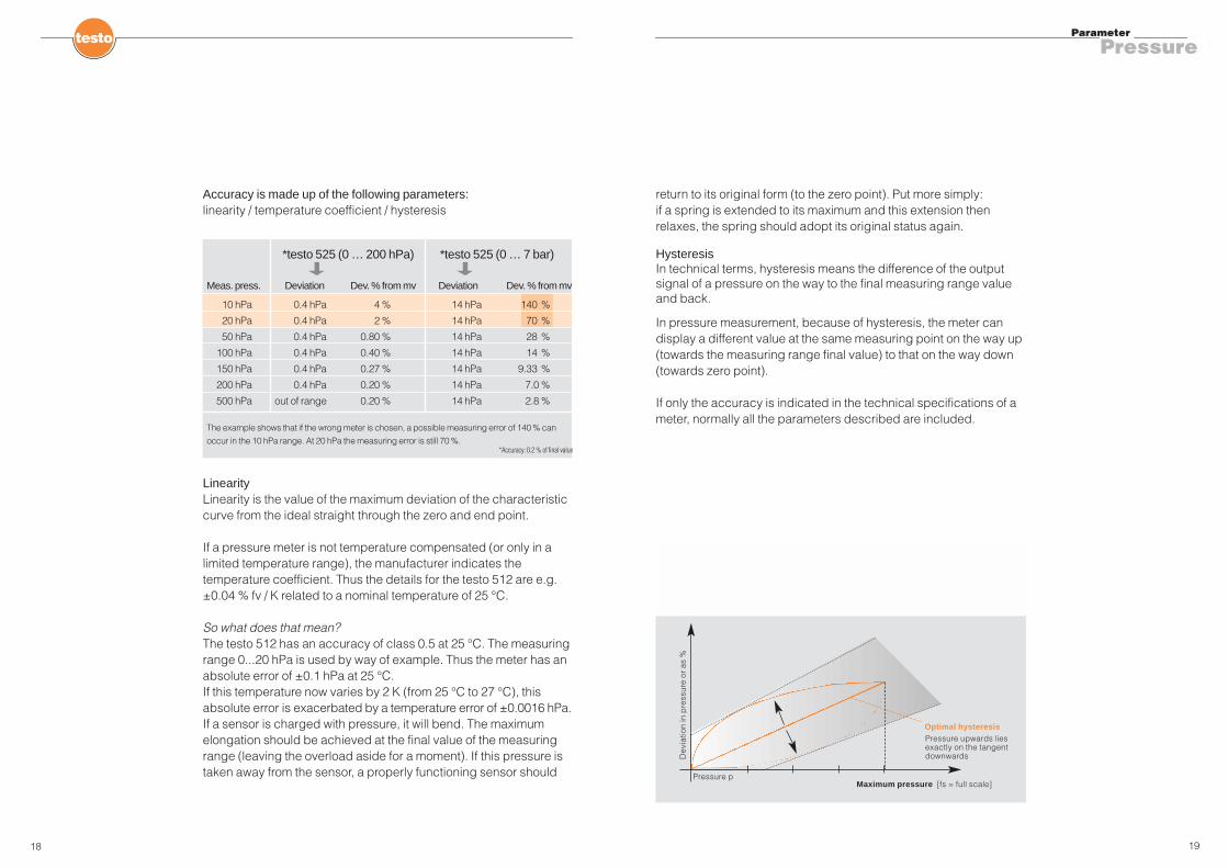
HysteresisIn technical terms, hysteresis means the difference of the outputsignal of a pressure on the way to the final measuring range valueand back.
In pressure measurement, because of hysteresis, the meter candisplay a different value at the same measuring point on the way up(towards the measuring range final value) to that on the way down(towards zero point).
If only the accuracy is indicated in the technical specifications of ameter, normally all the parameters described are included.
Accuracy is made up of the following parameters:linearity / temperature coefficient / hysteresis
LinearityLinearity is the value of the maximum deviation of the characteristiccurve from the ideal straight through the zero and end point.
If a pressure meter is not temperature compensated (or only in alimited temperature range), the manufacturer indicates thetemperature coefficient. Thus the details for the testo 512 are e.g.±0.04 % fv / K related to a nominal temperature of 25 °C.
So what does that mean?The testo 512 has an accuracy of class 0.5 at 25 °C. The measuringrange 0...20 hPa is used by way of example. Thus the meter has anabsolute error of ±0.1 hPa at 25 °C.If this temperature now varies by 2 K (from 25 °C to 27 °C), thisabsolute error is exacerbated by a temperature error of ±0.0016 hPa.If a sensor is charged with pressure, it will bend. The maximumelongation should be achieved at the final value of the measuringrange (leaving the overload aside for a moment). If this pressure istaken away from the sensor, a properly functioning sensor should
*testo 525 (0 … 200 hPa) *testo 525 (0 … 7 bar)
Meas. press. Deviation Dev. % from mv Deviation Dev. % from mv
10 hPa 0.4 hPa 4 % 14 hPa 140 %
20 hPa 0.4 hPa 2 % 14 hPa 70 %
50 hPa 0.4 hPa 0.80 % 14 hPa 28 %
100 hPa 0.4 hPa 0.40 % 14 hPa 14 %
150 hPa 0.4 hPa 0.27 % 14 hPa 9.33 %
200 hPa 0.4 hPa 0.20 % 14 hPa 7.0 %
500 hPa out of range 0.20 % 14 hPa 2.8 %
The example shows that if the wrong meter is chosen, a possible measuring error of 140 % can
occur in the 10 hPa range. At 20 hPa the measuring error is still 70 %.*Accuracy: 0.2 % of final value
Maximum pressure [fs = full scale]
Optimal hysteresis
Dev
iatio
n in
pre
ssur
e or
as
%
Pressure p
Pressure upwards liesexactly on the tangentdownwards
20 21
Parameter
Pressure
error of ±54.11 m/s. This figure is absolutely out of the question!
It can be seen, then, that the measuring range of 7 bar is much toogreat. So what next? A meter with a small range but which canwithstand a high static pressure must be used instead. If we makethe same calculation as before, but use a testo 525 with ameasuring range of 0...25 hPa and a class of 0.1 (this meter acceptsa static pressure of maximum 7 bar even in the smallest measuringrange of 25 hPa), the maximum error at a flow rate of 10 m/s is thenonly ±0.1933 m/s.
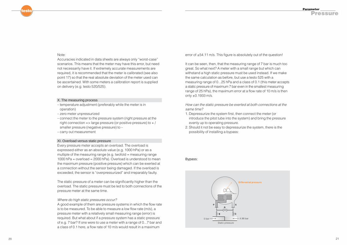
How can the static pressure be exerted at both connections at thesame time?1. Depressurize the system first, then connect the meter (or
introduce the pitot tube into the system) and bring the pressureevenly up to operating pressure.
2. Should it not be easy to depressurize the system, there is thepossibility of installing a bypass:
Bypass:
Note:Accuracies indicated in data sheets are always only “worst-case”scenarios. This means that the meter may have this error, but neednot necessarily have it. If extremely accurate measurements arerequired, it is recommended that the meter is calibrated (see alsopoint 17) so that the real absolute deviation of the meter used canbe ascertained. With some meters a calibration report is suppliedon delivery (e.g. testo 520/525).
X. The measuring process– temperature adjustment (preferably while the meter is in
operation)– zero meter unpressurized– connect the meter to the pressure system (right pressure at the
right connection => large pressure (or positive pressure) to + /smaller pressure (negative pressure) to –
– carry out measurement
XI. Overload versus static pressureEvery pressure meter accepts an overload. The overload isexpressed either as an absolute value (e.g. 1000 hPa) or as amultiple of the measuring range (e.g. twofold = measuring range1000 hPa = overload = 2000 hPa). Overload is understood to meanthe maximum pressure (positive pressure) which can be exerted ata connection without the sensor being damaged. If the overload isexceeded, the sensor is “overpressurized” and irreparably faulty.
The static pressure of a meter can be significantly higher than theoverload. The static pressure must be led to both connections of thepressure meter at the same time.
Where do high static pressures occur?A good example of them are pressure systems in which the flow rateis to be measured. To be able to measure a low flow rate (m/s), apressure meter with a relatively small measuring range (error) isrequired. But what about if a pressure system has a static pressureof e.g. 7 bar? If one were to use a meter with a range of 0...7 bar anda class of 0.1 here, a flow rate of 10 m/s would result in a maximum
A
Static pressure
B C
4.98 bar5 bar
� �
� �
�
Differential pressure
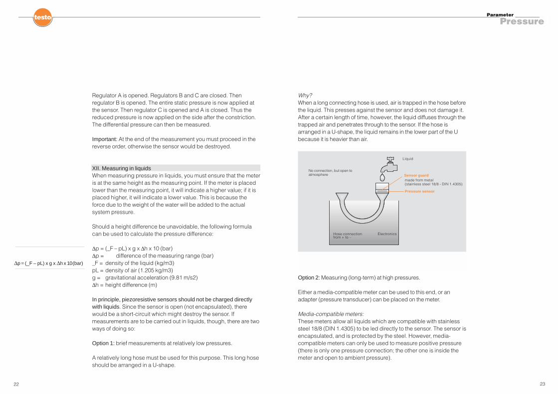
Why?When a long connecting hose is used, air is trapped in the hose beforethe liquid. This presses against the sensor and does not damage it.After a certain length of time, however, the liquid diffuses through thetrapped air and penetrates through to the sensor. If the hose isarranged in a U-shape, the liquid remains in the lower part of the Ubecause it is heavier than air.
Option 2: Measuring (long-term) at high pressures.
Either a media-compatible meter can be used to this end, or anadapter (pressure transducer) can be placed on the meter.
Media-compatible meters:These meters allow all liquids which are compatible with stainlesssteel 18/8 (DIN 1.4305) to be led directly to the sensor. The sensor isencapsulated, and is protected by the steel. However, media-compatible meters can only be used to measure positive pressure(there is only one pressure connection; the other one is inside themeter and open to ambient pressure).
23
Parameter
Pressure
Regulator A is opened. Regulators B and C are closed. Thenregulator B is opened. The entire static pressure is now applied atthe sensor. Then regulator C is opened and A is closed. Thus thereduced pressure is now applied on the side after the constriction.The differential pressure can then be measured.
Important: At the end of the measurement you must proceed in thereverse order, otherwise the sensor would be destroyed.
XII. Measuring in liquidsWhen measuring pressure in liquids, you must ensure that the meteris at the same height as the measuring point. If the meter is placedlower than the measuring point, it will indicate a higher value; if it isplaced higher, it will indicate a lower value. This is because theforce due to the weight of the water will be added to the actualsystem pressure.
Should a height difference be unavoidable, the following formulacan be used to calculate the pressure difference:
∆p = (_F – pL) x g x ∆h x 10 (bar)∆p = difference of the measuring range (bar)_F = density of the liquid (kg/m3)pL = density of air (1.205 kg/m3)g = gravitational acceleration (9.81 m/s2)∆h = height difference (m)
In principle, piezoresistive sensors should not be charged directlywith liquids. Since the sensor is open (not encapsulated), therewould be a short-circuit which might destroy the sensor. Ifmeasurements are to be carried out in liquids, though, there are twoways of doing so:
Option 1: brief measurements at relatively low pressures.
A relatively long hose must be used for this purpose. This long hoseshould be arranged in a U-shape.
22
∆p = (_F – pL) x g x ∆h x 10(bar)
Sensor guard
Pressure sensor
ElectronicsHose connectionfrom + to –
made from metal(stainless steel 18/8 - DIN 1.4305)
Liquid
No connection, but open toatmosphere

AdapterThe use of adapters offers the advantage that the meter can beemployed to measure in both gases and liquids.
If only positive pressure is to be measured, one adapter is used; ifdifferential pressure is to be measured, two adapters are used.
XIII. Which gases can be measured?You must take particular note of the moisture content of gaseousmixtures, as this can lead to condensed water being produceddepending on the dew point temperature. Condensate and particlesof dirt can damage the sensor or lead to incorrect readings!
The following are allowed:Gases (e.g. argon, xenon etc.)Instrument air (dry, clean air)
O2 OxygenH2 HydrogenN2 NitrogenO2/N2 Oxygen/nitrogen mixtureCO2/N2 Carbon dioxide/nitrogenCO/N2 Carbon monoxide/nitrogenC3/H8 PropaneHe HeliumH2/He Hydrogen/heliumNO/N2 Nitrogen monoxide/nitrogenSF6 Sulphur hexafluoride
Natural gas (not too moist)
25
Parameter
Pressure
The structure of piezoresistive sensors does not allow bothconnections to be encapsulated at the same time, since theelectronics are located immediately behind the sensor.
Measuring with one or two adapters.An adapter can be plugged into many pressure meters. Thisadapter contains a separating membrane which keeps the liquidaway from the sensor. It should be noted that such adapters are notsuitable for every meter.
Why is that so?If the adapter is plugged into a pressure meter, an exactly defineddead volume of air is trapped. If the separating membrane is thencharged with liquid pressure, the membrane deforms, compressesthe dead volume of air and presses on the sensor. Should this deadvolume not coincide exactly with the meter, not only will incorrectmeasuring values be displayed, but the final measuring range valueof the meter will not be reached or could be exceeded. It is very important that the adapter is always plugged into the meterwhen unpressurized and only then charged with pressure.
24

measurements per second. The software developed for this meterenables these 10 / 20 measurements per second to be transferredto a laptop, where they can be stored and processed.
XV. Measuring flows with a pitot tubeThe air-flow speed can be measured using a differential pressuremeter and a pitot tube. The measuring principle.
27
Parameter
Pressure
XIV. Pressure shocksNow and then what are known as pressure shocks have to bemeasured. The problem with such pressure shocks is that theyoccur within fractions of a second. Thus a meter which offers veryrapid measuring intervals is needed. There is no point, for instance,in using a meter with a smallest memory interval of 1 second, sincethe pressure shock occurs within fractions of a second. The metermust perform several measurements every second and it must bepossible to record these.
Pressure shocks can occur in:
– industrial extraction facilities (where the filters are cleaned bymeans of a pressure shock)
– pressure surges in domestic services pipe systems– pressure shocks in metal casting– pressure surges in liquid-carrying pipes (often arising when
pumps are switched off or started up)– pressure surges in systems as a result of quick-acting valves
and fittings– pressure shocks in compressors of refrigeration systems
To measure and evaluate pressure shocks, we are using thetesto 525 as an example. The meter performs 10 / 20
26
Pres
sure
in h
Pa
Pressure shock

The air density plays an important role in pitot tube measurement.
Factors in air density.
Thus air density is heavily influenced by:– the absolute air pressure– the temperature of the gas– the content of the water vapour (humidity)
It is very awkward to measure the density. The user has to measurethe parameters that determine density and then calculate thedensity, or work it out from tables.
It must first be ensured that the measuring medium is air. Air is agaseous mixture with a constant composition. The usualfluctuations in the composition have no significant effect on themeasuring result.
In general, if the air density is not calculated, the normal air densityof 1293 g/m3 is assumed (absolute pressure = 1013.25 hPa/mbar;temperature = 0 °C; air humidity = 0 %RH).
29
Parameter
Pressure
The back pressure arises at the tip of the tube when this is heldagainst the direction of flow. Two hoses connect the pitot tube to theactual measuring sensor; the pressure sensor (make connection“a” at the + connection and connection “b” at the – connection).Both the sum of dynamic pressure + static pressure and the purestatic pressure are transferred to the pressure sensor.This sensor determines the difference between the two pressures.The result is the dynamic flow pressure. This is directly related to theprevailing flow velocity. If the gas density is known, converting thepressure to the flow velocity is simply a matter of working out a rootfunction of what is known as Bernoulli’s equation(after Daniel Bernoulli, Swiss mathematician, 1700-1782).
v (m/s) = flow velocity in m/sp diff = dynamic differential pressure in Parho = air density in (kg/m3)
28
���v (m/s) = rho
2 • p diff
DifferentialBarometric pressure
Metres above MSL
Absolute pressure in duct
Temperature
Humidity
Density

the hose of the “b” connection with the – connection of the pressuresensor. Inaccurate pressure sensorNot every pressure sensor is suitable for measuring air flow, particularlyin the lower range. What is important is the accuracy of the sensor, asabsolute accuracy is used to calculate errors.
An example:
Testo pressure probes for the multi-function meters
0638.1345; measuring range 0...100 Pa; accuracy ±(0.3 Pa + 0.5 % mv)
0638.1445; measuring range 0...10 hPa; accuracy ±0.03 hPa (= 3 Pa)
0638.1545; measuring range 0...100 hPa; accuracy (0...20 hPa)±0.1 hPa (= 10 Pa)
It can be seen from the graph that the probe with the measuringrange 0...100 hPa has a deviation of ±1.55 m/s (= 31 % measuringerror) in the lower range of e.g. 5 m/s. The significantly moreaccurate 100 Pa probe has an error of only ±0.12 m/s (= ±2.4 %).
31
Parameter
Pressure
Errors in pitot tube measurementFor information: the value at 1013 hPa/mbar, temperature = 20 °C,air humidity = 50 % is 1199 g/m3.
Incorrect air density valueThe influence of the individual parameters on the density appearsplausible. Cold air is heavier, while warm air is lighter. If the air iswarmer than assumed, therefore, its density will be lower and thecalculated flow velocity will be too fast. The same will happen if theair is more humid than assumed.If you forget to adjust the air pressure when travelling into themountains, the pressure and hence the density fall. The valuescalculated for the flow velocity will then be too low.
Pitot tube cloggedThe pitot tube is relatively easy to service and maintain. In contrast tothe vane probe, there is no bearing which can become dirty and novane to be bent. Nevertheless, before every measurement a visualinspection must be carried out (is the tube kinked? is there visibledamage?) as well as what is referred to as a blow-through test(blowing into the connections a and b and feeling whether airescapes from the upper end of the pitot tube).
Incorrect arrangement in the ductA further important factor is the position of the pitot tube in the duct.If the opening is not exactly in the direction of flow, the measuringresults will be misleading. Since the tip cannot be seen in the duct,connection “b” can be used as the reference. It runs exactly parallelto the measuring tip. In order to ensure the correct flow stream, turnthe pitot tube slowly backwards and forwards and compare themeasuring results. The pitot tube is in its optimal location at theplace where the highest value is read.
Hoses kinkedIt is important to ensure that the hoses are not kinked between thepitot tube and the pressure sensor (take care with very flexiblehoses!!!), because this could produce misleading results.Hoses not properly connectedConnect the hose of the “a” connection with the + connection and
30
Errors of diverse pressure probes when measuring air flow with a Pitot tube
Erro
rs
Air flow
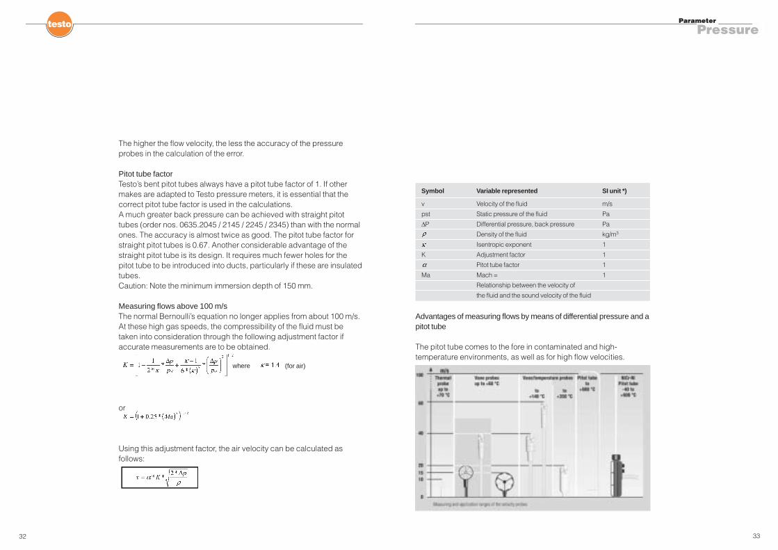
Advantages of measuring flows by means of differential pressure and apitot tube
The pitot tube comes to the fore in contaminated and high-temperature environments, as well as for high flow velocities.
33
Parameter
Pressure
32
The higher the flow velocity, the less the accuracy of the pressureprobes in the calculation of the error.
Pitot tube factorTesto’s bent pitot tubes always have a pitot tube factor of 1. If othermakes are adapted to Testo pressure meters, it is essential that thecorrect pitot tube factor is used in the calculations. A much greater back pressure can be achieved with straight pitottubes (order nos. 0635.2045 / 2145 / 2245 / 2345) than with the normalones. The accuracy is almost twice as good. The pitot tube factor forstraight pitot tubes is 0.67. Another considerable advantage of thestraight pitot tube is its design. It requires much fewer holes for thepitot tube to be introduced into ducts, particularly if these are insulatedtubes.Caution: Note the minimum immersion depth of 150 mm.
Measuring flows above 100 m/sThe normal Bernoulli’s equation no longer applies from about 100 m/s.At these high gas speeds, the compressibility of the fluid must betaken into consideration through the following adjustment factor ifaccurate measurements are to be obtained.
or
Using this adjustment factor, the air velocity can be calculated asfollows:
Symbol Variable represented SI unit *)
v Velocity of the fluid m/s
pst Static pressure of the fluid Pa
∆P Differential pressure, back pressure Pa
Density of the fluid kg/m3
Isentropic exponent 1
K Adjustment factor 1
Pitot tube factor 1
Ma Mach = 1
Relationship between the velocity of
the fluid and the sound velocity of the fluid
where (for air)
35
Parameter
Pressure
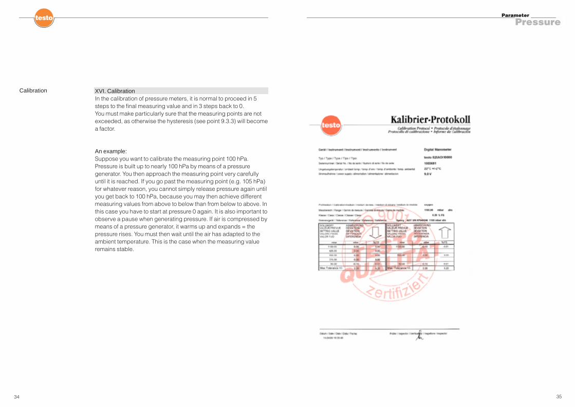
XVI. CalibrationIn the calibration of pressure meters, it is normal to proceed in 5steps to the final measuring value and in 3 steps back to 0.You must make particularly sure that the measuring points are notexceeded, as otherwise the hysteresis (see point 9.3.3) will becomea factor.
An example:Suppose you want to calibrate the measuring point 100 hPa.Pressure is built up to nearly 100 hPa by means of a pressuregenerator. You then approach the measuring point very carefullyuntil it is reached. If you go past the measuring point (e.g. 105 hPa)for whatever reason, you cannot simply release pressure again untilyou get back to 100 hPa, because you may then achieve differentmeasuring values from above to below than from below to above. Inthis case you have to start at pressure 0 again. It is also important toobserve a pause when generating pressure. If air is compressed bymeans of a pressure generator, it warms up and expands = thepressure rises. You must then wait until the air has adapted to theambient temperature. This is the case when the measuring valueremains stable.
34
Calibration

37
XVII. Some applications
- Positive pressure / negative pressure in clean rooms- Measurements in pressure systems (compressor performance)- On burners (draft measurement Pa + gas flow pressure hPa +
combustion chamber pressure hPa + pneumatic bond + supplyair velocity m/s + air load m/s)
- Leakage test according to DVGW / TRGI (preliminary/maininspection)
- Filter check- Pressure shocks (extraction systems)- Meteorological measurements (absolute pressure)- Measurements in laboratories (changes in ambient pressure
during experiments/tests)- Leakage searches/consumption rates on compressed air
systems by means of leakage function (pressure loss /dimensioning of the system)
- Pressure measurement on refrigeration systems- Calibration- Service and maintenance of pumps- Consumption measurement of gases by measuring pressure
loss
36
Parameter
Pressure