alignment, pointing and sizing instrumentation
TRANSCRIPT
1ALIGNMENT, POINTING, etc.from: 'Electro-Optical Instrumentation' by S.Donati, 2004, © Prentice Hall (USA)
AlignmentAlignment, , PointingPointing and and SizingSizing InstrumentationInstrumentation
Summary
• propagation of Gaussian beams
• laser beam position sensing ◊ with quadrant PD
◊ with PSD ◊ with Reticles
Instruments being developed
• laser level
• wire diameter sensor
• particle sizing

2ALIGNMENT, POINTING, etc.from: 'Electro-Optical Instrumentation' by S.Donati, 2004, © Prentice Hall (USA)
Laser used in E-O Instrumentation
Table I - Classes of electro-optical instruments and the lasers they use_____________________________________________________________________________________________
Application Typical Laser Main Characteristic_____________________________________________________________________________________________
• ALIGNMENT, POINTING He-Ne andand TRACKING GaAlAsP diode collimation, beam quality
• DIAMETER SENSORand PARTICLE SIZING He-Ne collimation, beam quality
• TELEMETERS- geodimeter (d>1 km) solid state (Nd, etc.) high peak-power (Q-switched)- topograph (d<1 km) GaAlAs diode high-frequency modulation
• INTERFEROMETERS He-Ne temporal coherence, 6-digit for dimensional metrology wavelength-accuracy
• Doppler VELOCIMETERS He-Ne, Ar, SHG Nd spatial coherence, beam quality
• ESPI vibration analyzers He-Ne, Ar, SHG Nd spatial coherence, beam quality
• FOG gyroscopes and GaAlAs diode high radiance,Fiber Optics Sensors and SLED controlled temporal coherence
3ALIGNMENT, POINTING, etc.from: 'Electro-Optical Instrumentation' by S.Donati, 2004, © Prentice Hall (USA)
L z
r2w 0
2w
mirror mirror
r1
¦2 w0
z z
ZFfd
pinhole
r 2
w0w 0L
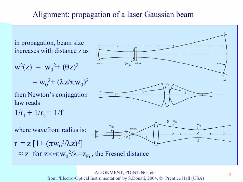
in propagation, beam sizeincreases with distance z as
w2(z) = w02+ (θz)2
= w02+ (λz/πw0)2
then Newton’s conjugationlaw reads1/r1 + 1/r2 = 1/f
where wavefront radius is:
r = z [1+ (πw02/λz)2]
≈ z for z>>πw02/λ=zFr , the Fresnel distance
Alignment: propagation of a laser Gaussian beam
4ALIGNMENT, POINTING, etc.from: 'Electro-Optical Instrumentation' by S.Donati, 2004, © Prentice Hall (USA)
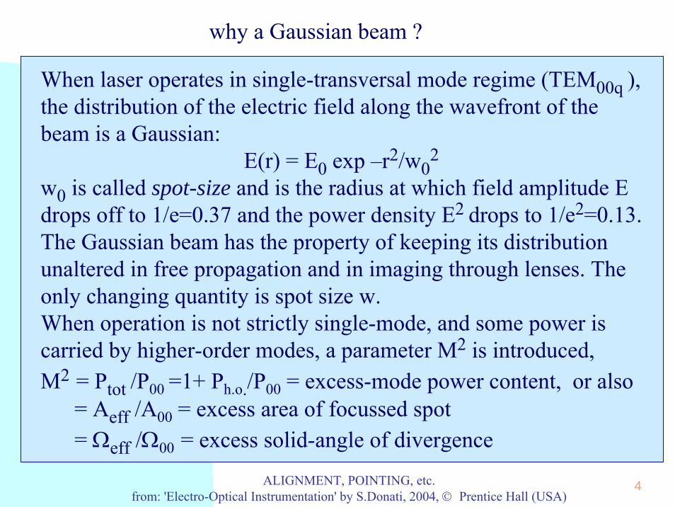
When laser operates in single-transversal mode regime (TEM00q ), the distribution of the electric field along the wavefront of the beam is a Gaussian:
E(r) = E0 exp –r2/w02
w0 is called spot-size and is the radius at which field amplitude E drops off to 1/e=0.37 and the power density E2 drops to 1/e2=0.13.The Gaussian beam has the property of keeping its distributionunaltered in free propagation and in imaging through lenses. The only changing quantity is spot size w.When operation is not strictly single-mode, and some power iscarried by higher-order modes, a parameter M2 is introduced,M2 = Ptot /P00 =1+ Ph.o./P00 = excess-mode power content, or also
= Aeff /A00 = excess area of focussed spot= Ωeff /Ω00 = excess solid-angle of divergence
why a Gaussian beam ?

5ALIGNMENT, POINTING, etc.from: 'Electro-Optical Instrumentation' by S.Donati, 2004, © Prentice Hall (USA)
why TEM modes ?
• Each TEM00 mode is accompanied by transversal modes TEMpqN with a distribution Epq(r, φ) = E0 Πp(r/w0) cos(qφ) exp –r2/w0
2, where Πp is a polinomial of order p. • The main spatial dependence is again a Gaussian, but because of the polynomial, the distribution is broader and has zeroes in it.• Transversal modes have a spot size, again defined as the radius containing86% of the beam power, larger than the fundamental longitudinal mode w0 and increasing with mode order.
Field distributions of lowest-order transversal modes TEMpq
TEM 00 TEM TEMTEM 01 10 11 TEM 12TEM 21 20
TEM

6ALIGNMENT, POINTING, etc.from: 'Electro-Optical Instrumentation' by S.Donati, 2004, © Prentice Hall (USA)
the minimum of w2 is found by differentiating respect to w02 and
equating to zero. We thus obtain:∂w2/∂w0
2 = 1- (λz/πw02)2 = 0,
whence w0 = √(λz/π)In the span –z ..+z, the beam size is minimum at middle, w=w0and becomes w=√2w0 at the ends of the span.Example. For a He-Ne laser with plano-concave cavity and L=20 cm, r1=∞, r2=KL with K=5, we get:w0L =√(λ/π)(K-1) L =0.282 mm as the laser beam waist. Location of the waist is just at the output mirror.
Minimum Spot Size
L z
r2w0
2w
mirror mirror

7ALIGNMENT, POINTING, etc.from: 'Electro-Optical Instrumentation' by S.Donati, 2004, © Prentice Hall (USA)
If we wish to cover a total span of 40 meters, or z=±20m, fromthe above we get
w0 = √(λz/π) =√(0.63x10-6x20/3.14) = 2 mmas the necessary beam waist. Then, we need a magnification m=w0/w0L=2/0.282 = 7.1Rather than using a single lens, it’s better to employ a collimating telescope to get the magnification (see below).At the output of the telescope we take the beam size as√2w0, so we need a magnification F/f = √2w0/w0L =1.41x7.1= 10 and we can easily obtain it (e.g. with F=200 mm, f=20 mm).
Minimum Spot Size 2
¦2 w0
z z
Z
Ffd
pinhole
w0w
0L
8ALIGNMENT, POINTING, etc.from: 'Electro-Optical Instrumentation' by S.Donati, 2004, © Prentice Hall (USA)
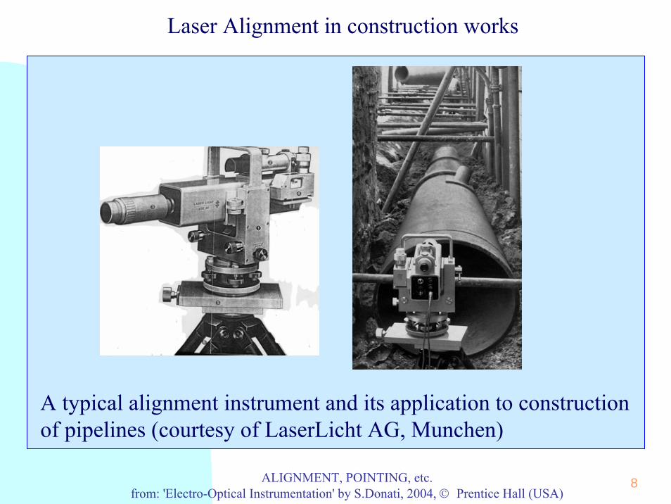
Laser Alignment in construction works
A typical alignment instrument and its application to constructionof pipelines (courtesy of LaserLicht AG, Munchen)

9ALIGNMENT, POINTING, etc.from: 'Electro-Optical Instrumentation' by S.Donati, 2004, © Prentice Hall (USA)
Marine channel light
coded flash light
coded flash lightcontinuous light
HORIZONTAL RANGE: 6 NAUTICAL MILES
HEIGHT ABOVE SEA LEVEL: 10 m
1 2
2
1
θ
Channel light helps the ship maneuver in its homing to the harbor – important in streamy waters with submerged rocks. The 10-mW He-Ne gets a 6 n.mi range

10ALIGNMENT, POINTING, etc.from: 'Electro-Optical Instrumentation' by S.Donati, 2004, © Prentice Hall (USA)
Safety: something to care about
Will 10-mW be a safe power we may use outdoors ? Though a rare event, this power may occasionally becaptured by the eye of an observer.Actually, this power is a potential hazard.When using lasers in a instrument, we have to care aboutlaser safety.Several International Committees (IEC, ANSI, LIA, MIL) have issued laser-safety Standards, the most acceptedbeing the IEC Standard.Lasers are classified according to power, wavelength, CW or Pulsed mode, and taking into account spot-size and divergence

11ALIGNMENT, POINTING, etc.from: 'Electro-Optical Instrumentation' by S.Donati, 2004, © Prentice Hall (USA)
LASER Safety
1
10
0.1
400 700 1000
wavelength (nm)
power (mW)
5
1400
3
CLASS 1
CLASS 2
CLASS 3A
CLASS 3B
CLASS 3A1
100
1000500
10000
CLASS 4
180 300
1.5
0.008
0.0004
0.6
0.8
4
Laser safety classification vs λfor CW lasers according to IEC Laser Safety Standard 825.• Class 1 is for intrinsically safesources, going from fractions of mW’s (VIS) to mW’s (IR). • Class 2 is for lasers in the VIS, where eye-blink reflex permits a larger CW power (1mW). • Safety measures are minimal for Class 1 & 2: a label for the emission aperture and a warningnot to stare into the laser beam.
Typical Class 1 or 2 products are: bar-code laser scanner, alignment and pointing systems, laser interferometers, sinewavemodulated telemeters.

12ALIGNMENT, POINTING, etc.from: 'Electro-Optical Instrumentation' by S.Donati, 2004, © Prentice Hall (USA)
LASER Safety (2)
• Class 3A laser and equipment are safe to naked eye vision, and the limit is 5mW in VIS, whereas in IR and UV is less as the blink reflex is absent. • In Class 3B, the CW power in the VIS goes from 5 mW to 500 mW. This laser isalways dangerous for direct vision, so it requires a turn-on key for operation byauthorized personnel and warning sign in the area of operation. • Class 4 lasers are most dangerous. For CW sources, Class 4 is just ≥0.5 W.Unintentional reflections (rings, metallic objects) may scatter into eyes power in excess of MPE (maximum permissible exposure). Operation requires restrictedaccess, warning signs and acoustic and red light alarms for laser switch-on.
•All CO2 power lasers for welding and mechanical tooling are Class 4. • Pulsed telemeters easily exceed Class 3B limits, falling under
specifications for open-air and atmosphere propagation.• The ocular risk zone (ORZ) shall be shielded by appropriate barriers
from the public (safety distance of 3 to 6 m).• The DOR (distance of ocular risk) is where power falls below the
MPE level, making operation become safe.
13ALIGNMENT, POINTING, etc.from: 'Electro-Optical Instrumentation' by S.Donati, 2004, © Prentice Hall (USA)
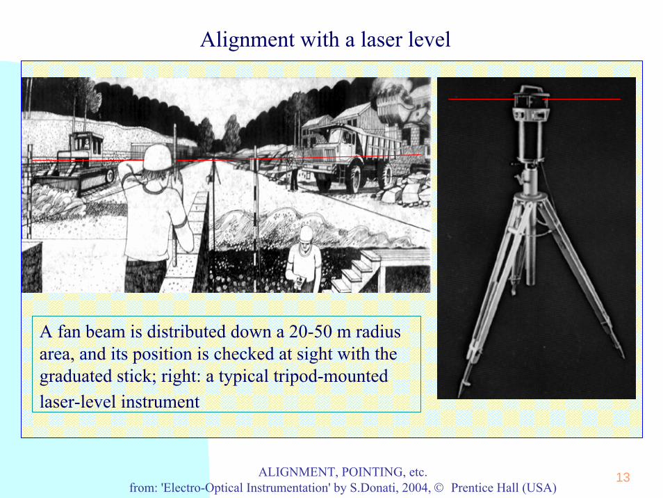
Alignment with a laser level
A fan beam is distributed down a 20-50 m radiusarea, and its position is checked at sight with the graduated stick; right: a typical tripod-mountedlaser-level instrument

14ALIGNMENT, POINTING, etc.from: 'Electro-Optical Instrumentation' by S.Donati, 2004, © Prentice Hall (USA)
Terrain leveling in rice crops
Another popular application of laser levels is terrain leveling. Some crops and rice in particular require a large quantity of flooding. To save water, leveling of terrain within <1 cm on acres is demanded. Laser levels are used for measurement.
15ALIGNMENT, POINTING, etc.from: 'Electro-Optical Instrumentation' by S.Donati, 2004, © Prentice Hall (USA)
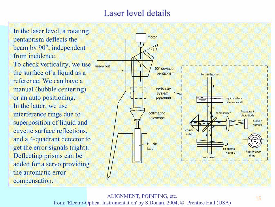
Laser Laser levellevel detailsdetails
He Ne laser
45°
90° deviation pentaprism
collimating telescope
verticality system (optional)
beam out
motor
to pentaprism
tilt prisms (X and Y)
corner cube
beamsplitter
liquid surface reference cell
4-quadrant photodiode
X and Y outputs
from laser
interference rings
In the laser level, a rotatingpentaprism deflects the beam by 90°, independentfrom incidence. To check verticality, we usethe surface of a liquid as a reference. We can have a manual (bubble centering) or an auto positioning. In the latter, we useinterference rings due tosuperposition of liquid and cuvette surface reflections, and a 4-quadrant detector toget the error signals (right). Deflecting prisms can beadded for a servo providingthe automatic error compensation.
16ALIGNMENT, POINTING, etc.from: 'Electro-Optical Instrumentation' by S.Donati, 2004, © Prentice Hall (USA)
Laser Level: He-Ne vs LDs
As an easy choice to start with, He-Ne lasers have been used in laser levels since because of their:
• emission in the visible (λ=633 nm)• beam spatial quality (single-mode, or M2=1.02 typ.)
• good pointing stability of the beam (typ. ε<0.1 mrad)• low-to-moderate price
Drawbacks however, were:• relatively bulky size
• low overall power efficiency• questionable ruggedness
In recent years, laser diodes in quaternary materials (InGaAsP) have catched up, starting just from the drawback of He-Ne’s, and now they are in the reach of He-Ne except for pointingstability, a critical issue only in extended range and high accuracy applications
17ALIGNMENT, POINTING, etc.from: 'Electro-Optical Instrumentation' by S.Donati, 2004, © Prentice Hall (USA)
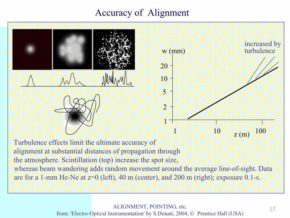
Accuracy of Alignment
10
1
5
20
1 10 100
2
w (mm)
z (m)
increased byturbulence
Turbulence effects limit the ultimate accuracy ofalignment at substantial distances of propagation through the atmosphere. Scintillation (top) increase the spot size,whereas beam wandering adds random movement around the average line-of-sight. Data are for a 1-mm He-Ne at z=0 (left), 40 m (center), and 200 m (right); exposure 0.1-s.

18ALIGNMENT, POINTING, etc.from: 'Electro-Optical Instrumentation' by S.Donati, 2004, © Prentice Hall (USA)
Alignment: how to pinpoint the laser spot
• In an alignment system, after tailoring the beam to yieldthe smallest spot size, we have to poinpoint the spot • Pinpointing may be performed by sight, as in construction works where we need a resolution of a fraction of the beam spot size (typically ≈1 mm)• For more exacting applications, like mechanical, navaland avionic constructions, we will use a photodetector -to generate en error signal proportional to misalignment.The photodetector may be either a specially designed, position-sensing device (Quadrant PD, PSD) or a normalone acting in combination to a reticle.
(like in the laser level)

19ALIGNMENT, POINTING, etc.from: 'Electro-Optical Instrumentation' by S.Donati, 2004, © Prentice Hall (USA)
Position Sensing with a Quadrant Photodiode
S1 S2
S3S4
section shown at right
n
p
cathode
S1 S2anodes
X
Y
n
p
S1 S2
n+
SiO 2
light in
p+
cathode
light in
Quadrant photodiode for pointing applications. Left: the segmented 4-electrodes structure; right: section of the pn photodiode structure with metal electrodes for backside light input (top) and section of a p+pn structure forfront light input (bottom)

20ALIGNMENT, POINTING, etc.from: 'Electro-Optical Instrumentation' by S.Donati, 2004, © Prentice Hall (USA)
Position Sensing with a Quadrant Photodiode
+V bb
R_
+
R_
+
R_
+
R_
+
_
+
_
+
S3
S2
S1
S4 -S 3
1-S
4-S
2-S-S1 2 3 4+S
Y -axis coordinate
X -axis coordinate
-SS1 3+S2 4-S
sum/subtraction
transresistance preamplifiers
+S-S
X or Y
+S max
+Rph
-Rph
XS or SY
RphR /s = 0.01
= 0.1
= 0.3
= 0.5
-S max
wdz
'
'
Dependence of the coordinate signal SX (or SY) from the true coordinate X (or Y) of a light spot. For small spot (Rs/ Rph≤0.01) the response is a square wave with a small dead band at X=0 (or Y=0). If Rs is not so small, the response is smoothed and we find analmost linear response near to X=0 (or Y=0).
Op-amp circuit forcomputing the coordinate signals SXand SY from the outputsof the quadrant PD
21ALIGNMENT, POINTING, etc.from: 'Electro-Optical Instrumentation' by S.Donati, 2004, © Prentice Hall (USA)
Position Sensing with a Quadrant Photodiode
X, Y marks
active area
input beam
θ
focal plane
objective lens
X = θF
position sensitive detector
input beam
Y
X
Y
Xθ
θ
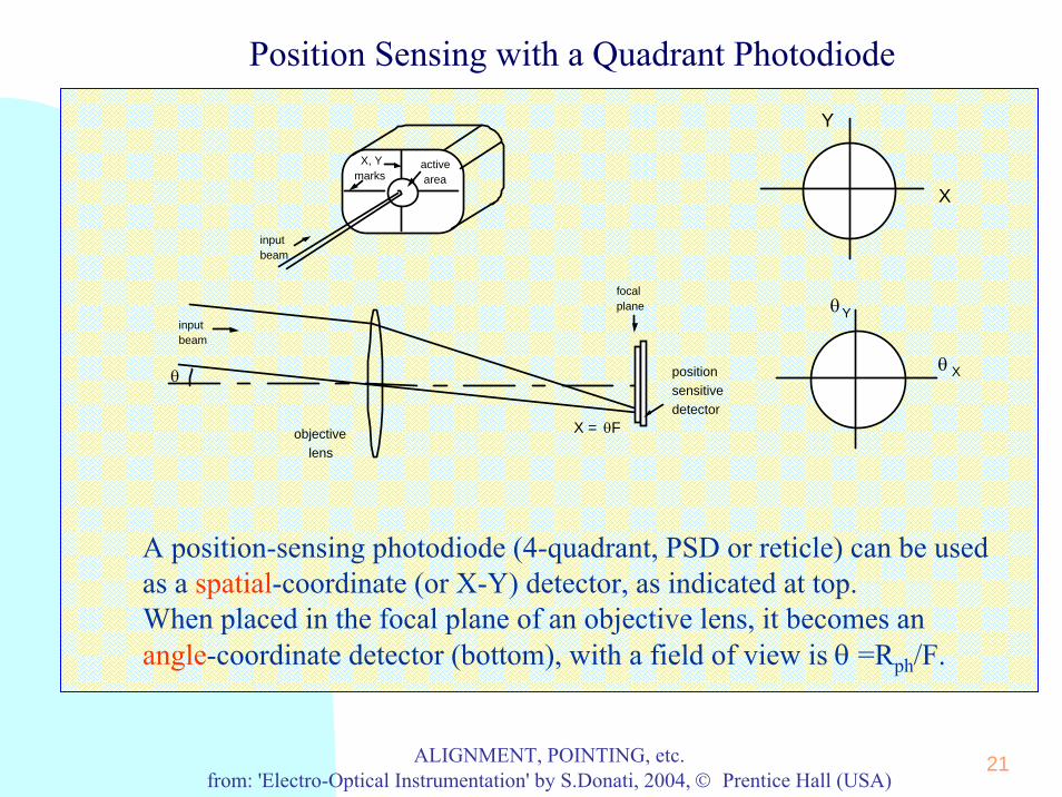
A position-sensing photodiode (4-quadrant, PSD or reticle) can be usedas a spatial-coordinate (or X-Y) detector, as indicated at top.When placed in the focal plane of an objective lens, it becomes anangle-coordinate detector (bottom), with a field of view is θ =Rph/F.

22ALIGNMENT, POINTING, etc.from: 'Electro-Optical Instrumentation' by S.Donati, 2004, © Prentice Hall (USA)
Position Sensing with a PSD Photodiode
x2SSx1
0 x L
n
p
photon in
i-+ Iph
y2SSy1
n
p
i-+
0 y L
Sx1
x2SSy1
Sy2
yx
section along y
section along x
Iph
xR
Sx1 x2
(L-x)R
S
_
+Sx1
x2S
Sy2
Sy2
Sy1
_
+
_
+
_
+
X or Y
XS
YS
X YS or S
-1 -0.5 +0.5 +1
+1
-1
(anode, negative bias)
(cathode, positive bias)
+Vbb
bb-V
Iph
(anode, negative bias)
(cathode, positive bias)
_
+
_
+
The PSD photodiode is a normal pin junction with lightlydoped thin p and n regions. Light at x,y generates a photocurrent, shared betweenX and Y electrodes. We get X, Y signals as the difference between currents out from electrodes Sx2-Sx1 and Sy2-Sy1. Currents are sunk by the virtual ground of an op-ampstage, so that linearity is goodand the effect of R negligible. The (+) inputs of op-amp stage are used to set the bias, +Vbband -Vbb, of X, Y stripes.

23ALIGNMENT, POINTING, etc.from: 'Electro-Optical Instrumentation' by S.Donati, 2004, © Prentice Hall (USA)
Position Sensing with Reticles
θ
focal planeobjective lens
X=θF
detector rotating reticle
S
ref
ρ
R s
ωtπ 2π 3π0ψ=0
V ref
ψ0
ωt
π 2π 3π ωt
Rs0ρ
Vmax
0
V signal
V signal
ψ0
Position sensing by a rotatingreticle: light from a bright spot at the angle θ is imaged by the objective lens on the focal plane, where it is chopped by the reticleplaced in front of the photodetector. By comparing the phaseshift of the square waveform from the photodetector and of a reference, the position ψ0 of the source isdetermined. The amplitude of the signal carries information on the polar coordinate ρ similar to that of the quandrant PD.
last, if we cannotafford a PSD or a Q-D…

24ALIGNMENT, POINTING, etc.from: 'Electro-Optical Instrumentation' by S.Donati, 2004, © Prentice Hall (USA)
Position Sensing with Reticles
The rising-sunreticle provides animprovedsuppression toextended sources(top). The digitalreadout reticle(bottom) suppliesboth ρ and ψcoordinates in digital format.
T=0
T = 0.5
T=1
ψ=0
0
V ref
ψ0
π 2π ωt
ref
T = 0.5
ψ=0
ωtπ 2π0
V 1
V 2
ψ2
ref
V signal
ρ ψ1
2ρ ψ
2ωt
ωt
1ψ
1ρ
ρ2
π 2π ωt
ψ0
1
ωtπ 2π

25ALIGNMENT, POINTING, etc.from: 'Electro-Optical Instrumentation' by S.Donati, 2004, © Prentice Hall (USA)
AlignmentAlignment, , PointingPointing and and SizingSizing InstrumentationInstrumentation
Summary• propagation of Gaussian beams• laser beam position sensing ◊ with quadrant PD
◊ with PSD ◊ with Reticles
• diffraction
InstrumentsInstruments beingbeing developeddeveloped
• laser • laser levellevel
• • wirewire diameterdiameter sensorsensor
• • particleparticle sizingsizing

26ALIGNMENT, POINTING, etc.from: 'Electro-Optical Instrumentation' by S.Donati, 2004, © Prentice Hall (USA)
Measurements by Diffraction
Diffraction of the laser beam is ideally suited for dimensionalmeasurements of small particles, because it• is non-contact
• is fast and accurate• has a wide dynamic range
Driven by applications, the developments of diffraction-basedinstruments have led to:
• diameter sensors for measuring wires in industrialmanufacturing (metal, textiles, optical fibers)
• particle size analyzers (ceramic, cemet and alloy powders,particulate monitoring, biological/medical sorting)
27ALIGNMENT, POINTING, etc.from: 'Electro-Optical Instrumentation' by S.Donati, 2004, © Prentice Hall (USA)
Wire Diameter Measurement by Diffraction
+D/2
-D/2
E0
x
z
ξ
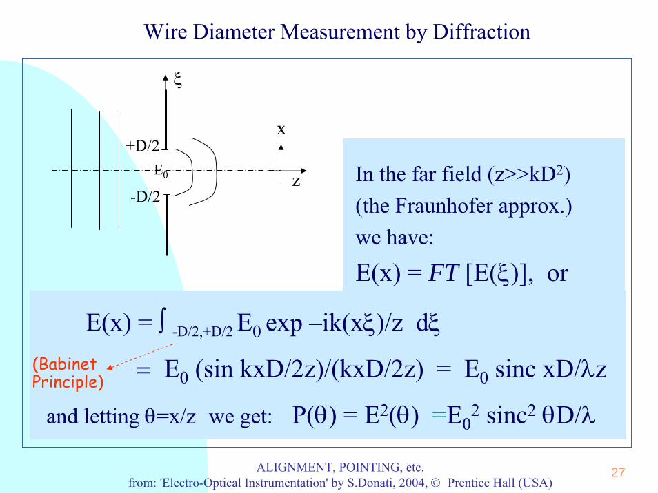
E(x) = ∫ -D/2,+D/2 E0 exp –ik(xξ)/z dξ
= E0 (sin kxD/2z)/(kxD/2z) = E0 sinc xD/λz
and letting θ=x/z we get: P(θ) = E2(θ) =E02 sinc2 θD/λ
In the far field (z>>kD2)(the Fraunhofer approx.) we have:
E(x) = FT [E(ξ)], or
(BabinetPrinciple)

28ALIGNMENT, POINTING, etc.from: 'Electro-Optical Instrumentation' by S.Donati, 2004, © Prentice Hall (USA)
Wire Diameter Measurement by Diffraction (2)
He Ne laser
collimating telescope
wiredetector
F
X = F θ
X
π ξ P(θ) = 2sin
2(π ξ)
ξ= θ D/λ+1.0-1.0
Placing a lens with focal F in front of the detector, we getX= Fθ in the focal plane, and the zeroes are at Xz=±Fλ/D.Then, we compute the diameter as D = Fλ/Xz
As a function of θ,P(θ) =E0
2 sinc2 θD/λ has the first zeroes at θD/λ=±1.
29ALIGNMENT, POINTING, etc.from: 'Electro-Optical Instrumentation' by S.Donati, 2004, © Prentice Hall (USA)
Wire Diameter Measurement by Diffraction (3)
We need a long focal length F to get a sizeable Xz, especiallyfor large diameters D. For example, for D= 100μm and λ=0.633 μm, the angle of first zero is θ=±.633/100=6.3 mrad, and we need F=500 mm to get a not-so-small zero coordinate XZ=6.3 10-3 500= 3.15 mm. This tells us that large diameters (say >1mm) will be at the boarderline of measurement. On the other hand, small diameters (comparable to λ) will beeasily recognized, until their zero escapes out of the (necessarily finite) focal plane size scanned by the detector. If Ddet is such a size (let’s say =50 mm), then we can measuredown to Xz =Ddet or D= Fλ/Ddet= 500 0.63 10-3/50= 6.3 μm.
30ALIGNMENT, POINTING, etc.from: 'Electro-Optical Instrumentation' by S.Donati, 2004, © Prentice Hall (USA)
Wire Diameter Measurement by Diffraction (4)
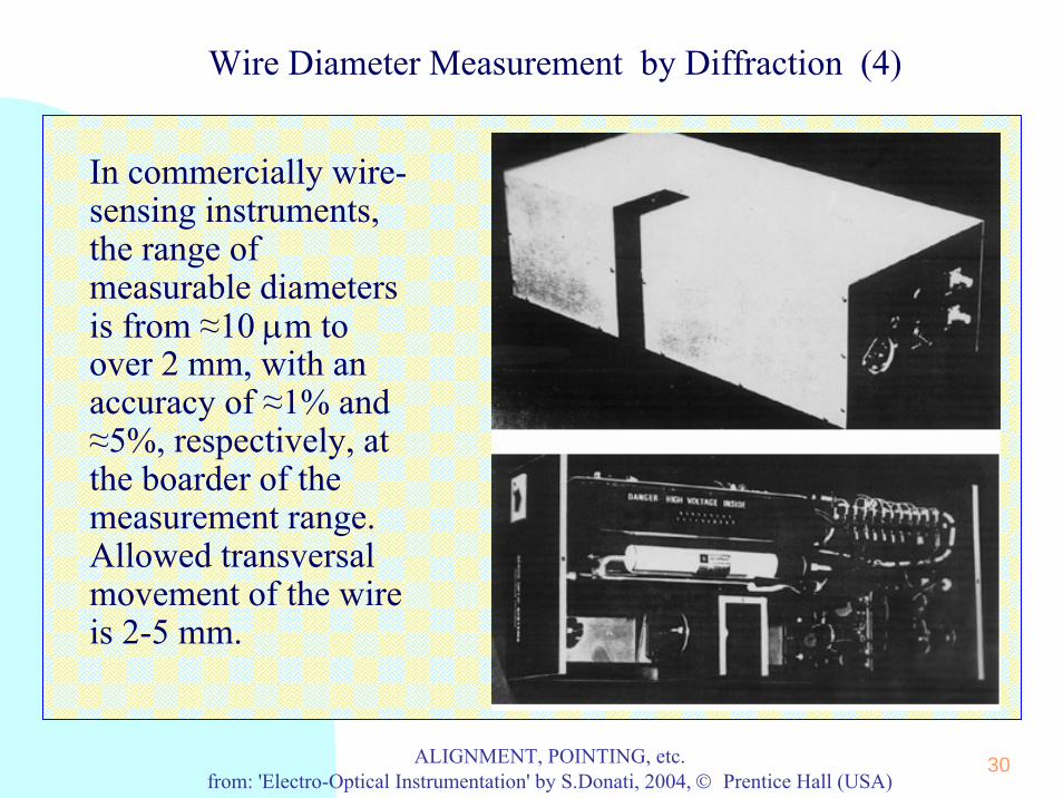
In commercially wire-sensing instruments, the range of measurable diametersis from ≈10 μm toover 2 mm, with anaccuracy of ≈1% and ≈5%, respectively, at the boarder of the measurement range. Allowed transversalmovement of the wireis 2-5 mm.

31ALIGNMENT, POINTING, etc.from: 'Electro-Optical Instrumentation' by S.Donati, 2004, © Prentice Hall (USA)
Particle Size Measurement
A particle-size analyzer is based on the diffraction of a light beam (typ. a 5-mW He-Ne laser) projected on a cell containing the particles in a liquidsuspension. A piezoceramic ultrasound shaker avoids flocculation of particles. At the output of the cell, a lens collects light diffracted at angle θand converts the far-field in a focal plane distribution I(R), with R=θF. Distribution I(R) is then measured by the photodetector. The technique is called LAELS (low-angle elastic light scattering)
He Ne laser
collimating telescope
PZT ceramic
detector
F
R = F θ
R
R=θ F
small D
large D
0
I(R)
32ALIGNMENT, POINTING, etc.from: 'Electro-Optical Instrumentation' by S.Donati, 2004, © Prentice Hall (USA)
Particle Size Measurement (2)
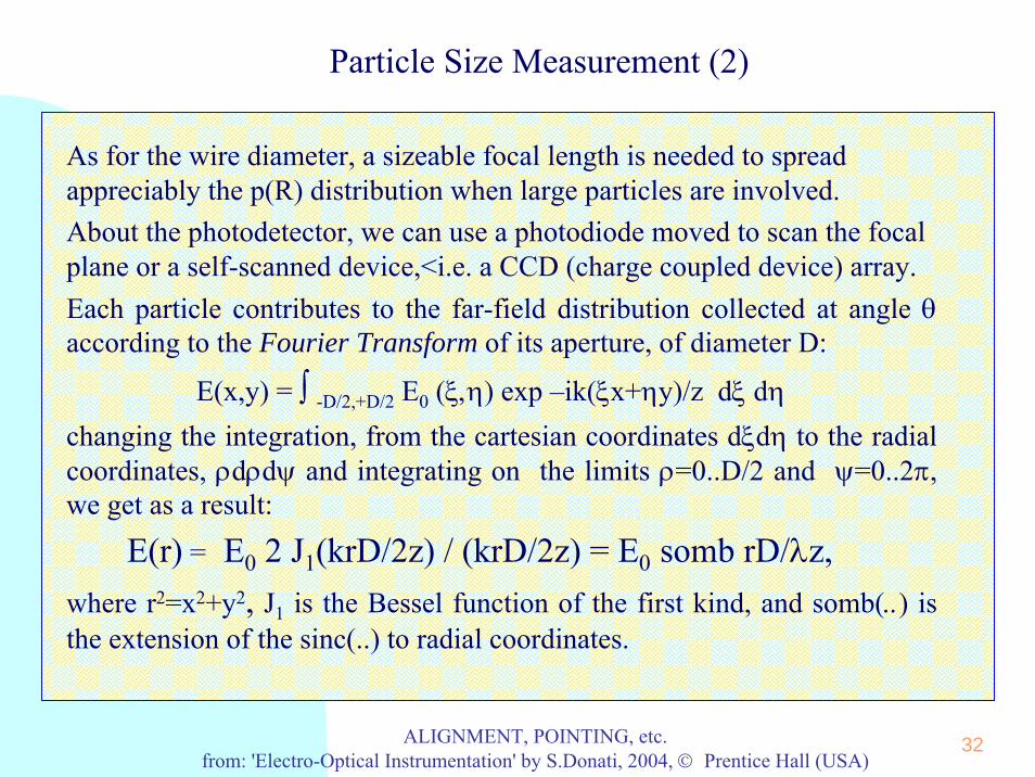
As for the wire diameter, a sizeable focal length is needed to spreadappreciably the p(R) distribution when large particles are involved. About the photodetector, we can use a photodiode moved to scan the focalplane or a self-scanned device,<i.e. a CCD (charge coupled device) array.Each particle contributes to the far-field distribution collected at angle θ according to the Fourier Transform of its aperture, of diameter D:
E(x,y) = ∫ -D/2,+D/2 E0 (ξ,η) exp –ik(ξx+ηy)/z dξ dη
changing the integration, from the cartesian coordinates dξdη to the radialcoordinates, ρdρdψ and integrating on the limits ρ=0..D/2 and ψ=0..2π, we get as a result:
E(r) = E0 2 J1(krD/2z) / (krD/2z) = E0 somb rD/λz,where r2=x2+y2, J1 is the Bessel function of the first kind, and somb(..) isthe extension of the sinc(..) to radial coordinates.

33ALIGNMENT, POINTING, etc.from: 'Electro-Optical Instrumentation' by S.Donati, 2004, © Prentice Hall (USA)
Particle Size Measurement (3)
The intensity (or power density) contributed by a particle with diameter D is then:
I(r) = E02 somb2 r D/λz
Now, let’s consider a distribution of diameters.Let particles be distributed according to a p(D) function, and we
understand that p is a probability density function — this means that dp= p(D)dD is the elemental probability of finding a diameter in the rangeD —D+dD, that p is non-negative (p≥0), and that it is normalized to unity, ∫0-∞ p(D)dD =1.
Now, each sample dp of particles contributes to the far fielddistribution with an intensity dI= somb2rD/λz dp, and, summing up on the diameters from 0 to ∞ we get:
I(r,z) = ∫0, ∞ I0 somb2 r D/λz p(D) dD(intensity, not field is compounded because of the scatterer random positions !)

34ALIGNMENT, POINTING, etc.from: 'Electro-Optical Instrumentation' by S.Donati, 2004, © Prentice Hall (USA)
Particle Size Measurement (4)
Last, we introduce the angular coordinate θ of output, letting r/z= sin θ, and obtain the scattered-power distribution as:
P(θ) = I0 ∫ 0-∞ somb2[(D/λ)sin θ] p(D) dDor, in terms of the focal-plane coordinate R when a lens with focal lenght F isused, being sin θ = R/F:
P(R) = I0 ∫0-∞ somb2(RD/λF) p(D) dDNow, we want to calculate the unknown distribution p(D) of particle size, after the far field intensity I(θ) is measured. The kernel of the Fredholm’sintegral, somb2[Dsinθ/λ], is a given term because we can compute it for any pair of θ and D values at a given λ.However, the problem is known in physics as an ill-conditioned one because p(D) is multiplied by the kernel, and the result is integrated on D so that details in p(D) are smoothed out. For example, very large particles only affect a small interval in I(θ) near θ≈0, whereas very small ones give only a little increase of I(θ) at large θ.

35ALIGNMENT, POINTING, etc.from: 'Electro-Optical Instrumentation' by S.Donati, 2004, © Prentice Hall (USA)
Particle Size Measurement (5)
Another source of error is the constant scattering coefficient tacitly assumed in writing dI= somb2 rD/λz dp. This holds for large-particles, D>>λ, whereas for intermediate and small particles Qext varies appreciably. (see next slide)From these considerations, the measurement range best suited for the LAELSnormally goes from a few μm to perhaps a few mm in diameter. At small D, the limit comes from the Rayleigh approximation, whereas at large D it depends on the size of the detector, due to measure at θ≈0 without disturbance from the undiffracted beam.Because we are unable to solve the kernel equation exactly in all cases, we try to maximize the information content picked out from the experiment bymeasuring I(θ). We repeat the measurement at as many angles θ as the outcomes I(θ) are found appreciably different. With information provided by the I(θ) set, the kernel integral will limit resolution to a certain value, beyond which the solution becomes affected by a large oscillating error. We then optimize the solution by increasing resolution (or number of D’s) until the computed p(D) starts being affected .

36ALIGNMENT, POINTING, etc.from: 'Electro-Optical Instrumentation' by S.Donati, 2004, © Prentice Hall (USA)
Particle Size Meas.: scattering and extinction
0 1 2 3 4r/ λ
0
1
2
3
Mieintermediate
Ray
leig
h
Q = A / π rsc2
ext
n =1.33 + 0.05in = 1.44
• In the Rayleigh regime r<<λ, the scattering is nearly isotropicin angle and the extinction factorQext varies as (r/λ)4. • When r increases up to aboutr≈λ, (intermediate regime) the scattering function f(θ) is mainlyforward and the extinction factorincreases up to ≈2-4.• For r>>λ we enter in the Mieregime, extinction Qext is nearlyconstant at ≈2 and f(θ) is stronglypeaked forward.
dPdΩ
P θ
Rayleigh r<<λ
intermediate r - λ
Mie r>>λ

37ALIGNMENT, POINTING, etc.from: 'Electro-Optical Instrumentation' by S.Donati, 2004, © Prentice Hall (USA)
Methods for Particle Size Measurement
Methods to solve for P(D) from measured data I(θ) -- AnalyticalAnalytical InversionInversion
p(D) = -[(4π/D)2/λ] ∫θ=0-∞ K(πDsinθ/λ) d[θ3 I(πDsinθ/λ)] /I0a theoretically nice result but impractical to be used.
-- LeastLeast SquareSquare MethodMethodUsing a discrete approximation for P(D)=pk and I(θ)=In and letting Snk= somb2[(Dk/λ)sinθn] , we get a set of equations:
In = Σk=1..K Snk pk (n=1..N)N is the number of angular measurements performed on the intensity, K is the number of unknown diameters.We start withK<N and close the set adding N-K equations from the LSM condition, sought from:
ε2 = Σn=1..N [ In - Σk=1..K Snk pk]2 = min

38ALIGNMENT, POINTING, etc.from: 'Electro-Optical Instrumentation' by S.Donati, 2004, © Prentice Hall (USA)
Methods for Particle Size Measurement (2)
Taking the derivative respect pk‘s and equating to zero gives:
0 = ∂(ε2)/∂pk = Σn=1..N 2[ In - Σk=1..K Snk pk](-Snk)and rearranging we get
Jh = Σk=1..K Zhk pk (h=1..K)where we have let Jh =Σn=1..N InSnh and Znk= Σn=1..N Snk
2
Now, the number of equations is equal to the number of unknown and we can solve for pk with standard algebra.
p(D)
D (μm)
10 20 50 1005 200
2
4
(arb. unit)
Usually, the range of diameterof interest may be large (forexample, two decades from 2 to200μm) but the number of affordable diameter is modest(e.g. K=6-9) at ±10% accuracy.

39ALIGNMENT, POINTING, etc.from: 'Electro-Optical Instrumentation' by S.Donati, 2004, © Prentice Hall (USA)
Methods for Particle Size Measurement (3)
-Iterative Methods. They are based on the following approach: if the set of diameter pk is correct, it should give the measureddistribution In.calc= ΣkCnk pk. If these values In.calc differ fromexperimental values Ik.meas, then we may expect to approach the solution if we multiply pk by Ik.meas/Ik.calc.Using pk
(M+1) = Ik.meas/Ik.calc pk(M) and repeating an adequate
number of iterations M, pk should converge to the correctsolution (there is no clear sign of convergence, however)A refinement of Chahine’s method consists in weighting the iteration by the normalized kernel, Snk/ Σn=1..NSnk, usingpk
(M+1) = (Snk/Σn=1..NSnk)(Ik.meas/Ik.calc) pk(M)
In this way, spurious peaks found in Chahine’s method are suppressed, and resolution and dynamic range are improved.

40ALIGNMENT, POINTING, etc.from: 'Electro-Optical Instrumentation' by S.Donati, 2004, © Prentice Hall (USA)
Methods for Particle Size Measurement (4)
Common errors in LAEL are: finite size of detector, beam waist effects, lensvignetting, and undiffracted beam (θ=0), important for small θ (large D). To suppress the undiffracted beam, better than let a stop to block it out, wecan use the filtering known as reverse Fourier-transform illumination, with a convergent beam to illuminate the cell. Diffracted rays (dotted lines) are focussed on axis for each θ, and pass through the pinhole, whereasundiffracted rays arrive out-of-axis and are blocked.
pinhole filter
normal focal plane
filtered plane
L1 L2 L3
F f f
41ALIGNMENT, POINTING, etc.from: 'Electro-Optical Instrumentation' by S.Donati, 2004, © Prentice Hall (USA)
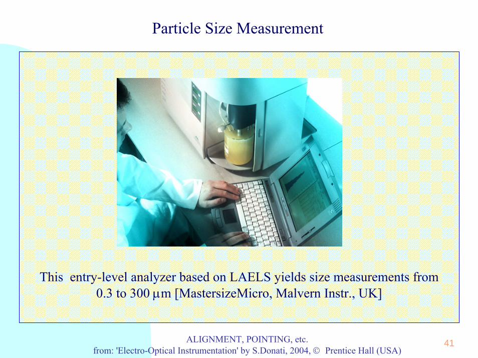
Particle Size Measurement
This entry-level analyzer based on LAELS yields size measurements from0.3 to 300 μm [MastersizeMicro, Malvern Instr., UK]

42ALIGNMENT, POINTING, etc.from: 'Electro-Optical Instrumentation' by S.Donati, 2004, © Prentice Hall (USA)
Particle Size Measurement
An example of an-easy-to-get particle size pdf p(D) and cumulative P(D) distribution measured by a commercial instrument (courtesy of CILAS)
43ALIGNMENT, POINTING, etc.from: 'Electro-Optical Instrumentation' by S.Donati, 2004, © Prentice Hall (USA)
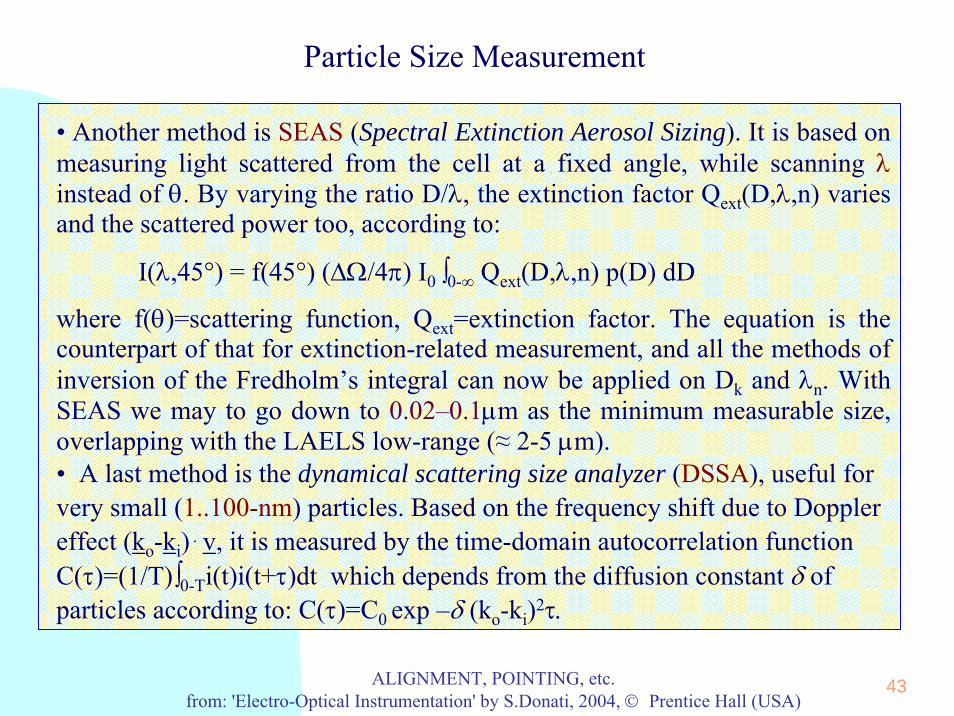
Particle Size Measurement
• Another method is SEAS (Spectral Extinction Aerosol Sizing). It is based on measuring light scattered from the cell at a fixed angle, while scanning λinstead of θ. By varying the ratio D/λ, the extinction factor Qext(D,λ,n) variesand the scattered power too, according to:
I(λ,45°) = f(45°) (ΔΩ/4π) I0 ∫0-∞ Qext(D,λ,n) p(D) dD
where f(θ)=scattering function, Qext=extinction factor. The equation is the counterpart of that for extinction-related measurement, and all the methods of inversion of the Fredholm’s integral can now be applied on Dk and λn. WithSEAS we may to go down to 0.02–0.1μm as the minimum measurable size, overlapping with the LAELS low-range (≈ 2-5 μm).• A last method is the dynamical scattering size analyzer (DSSA), useful forvery small (1..100-nm) particles. Based on the frequency shift due to Dopplereffect (ko-ki) . v, it is measured by the time-domain autocorrelation functionC(τ)=(1/T)∫0-Ti(t)i(t+τ)dt which depends from the diffusion constant δ of particles according to: C(τ)=C0 exp –δ (ko-ki)2τ.

44ALIGNMENT, POINTING, etc.from: 'Electro-Optical Instrumentation' by S.Donati, 2004, © Prentice Hall (USA)
Particle Size Measurement
A SEAS particle size analyzer uses scattering data at 135° to sortsubmicronic particulate (typ. of metropolitan area pollutants) from 0.02 to
0.1 μm [by CILAS, France]

45ALIGNMENT, POINTING, etc.from: 'Electro-Optical Instrumentation' by S.Donati, 2004, © Prentice Hall (USA)
Particle Size Measurement
A modern particle-size analyzer based on diffraction and extinction(LAELS + SEAS), performs diameter measurements from 0.02 to 2500 μm
[by CILAS, France]

46ALIGNMENT, POINTING, etc.from: 'Electro-Optical Instrumentation' by S.Donati, 2004, © Prentice Hall (USA)
Particle Size Measurement
A second example of particle size pdf p(D) and cumulative P(D) of a bi-modal distribution, more difficult because with both small and largeparticles, as measured by a commercial instrument

47ALIGNMENT, POINTING, etc.from: 'Electro-Optical Instrumentation' by S.Donati, 2004, © Prentice Hall (USA)
Particle Size Measurement
A third example of particle size pdf p(D) and cumulative P(D) of a distribution with both small and very large particles, as measured by a commercial granulometer (courtesy of CILAS)