algorithms and tools for petri nets. proceedings of the
TRANSCRIPT

UNIVERSITAT AUGSBURG
Algorithms and Tools for Petri Nets -Proceedings of the Workshop AWPN 2018
Robert Lorenz , Johannes Metzger (Eds.)
Report 2018-02 Oktober 2018
INSTITUT FUR INFORMATIKD-86135 AUGSBURG

Copyright c© Robert LorenzJohannes Metzger (Eds.)Institut fur InformatikUniversitat AugsburgD–86135 Augsburg, Germanyhttp://www.Informatik.Uni-Augsburg.DE— all rights reserved —

Contents
Full papers
Jacek Chodak, Monika Heiner:Spike - a command line tool for continuous, stochastic & hybrid simulation of(coloured) Petri nets . . . . . . . . . . . . . . . . . . . . . . . . . . . . . . . . . . . . . . . . . . . . . . . . . . . . . . . . . . 1
Jorg Desel:Can a Single Transition Stop an Entire Petri Net? . . . . . . . . . . . . . . . . . . . . . . . . . . . . . . . . 7
Ekkart Kindler, Petur Ingi Egilsson, Lom Messan Hillah:Using the Event Coordination Notation for Validation . . . . . . . . . . . . . . . . . . . . . . . . . . . . 13
Juraj Mazari, Gabriel Juhas, Milan Mladoniczky:Petriflow in Actions: Events Call Actions Call Events . . . . . . . . . . . . . . . . . . . . . . . . . . . . 21
Milan Mladoniczky, Gabriel Juhas, and Juraj Mazari:Process Communication in Petriflow: A Case Study . . . . . . . . . . . . . . . . . . . . . . . . . . . . . 27
Daniel Moldt, Dennis Schmitz, Michael Haustermann, Matthias Feldmann, DavidMosteller, Thomas Wagner, Jan Henrik Rowekamp, Lawrence Cabac, Michael Simon:Some Ideas for Modeling a Generic IoT- and Edge-Computing Architecture . . . . . . . . 33
Jan Henrik Rowekamp:Investigating the Java Spring Framework to Simulate Reference Nets with Renew . . 41
Extended Abstracts
Johannes Metzger, Robert Lorenz:Detecting Noise in Event-Logs using Statistical Inference . . . . . . . . . . . . . . . . . . . . . . . . 49
Joachim Schmidberger, Matthias Feldmann, Daniel Moldt:A Browser Based Tool for Workflow Guided Tutorials . . . . . . . . . . . . . . . . . . . . . . . . . . . 51
Michael Simon, Daniel Moldt:About the Development of a Curry-Coloured Petri Net Simulator . . . . . . . . . . . . . . . . . 53
Martin Wincierz, Daniel Moldt, Michael Haustermann:Improvement of the Renew Editor User Interface . . . . . . . . . . . . . . . . . . . . . . . . . . . . . . . . 55


Preface
The Algorithms and Tools for Petri Nets (AWPN) workshop is organized by the SpecialInterest Group ”Petri nets and related system models” of the German Gesellschaft furInformatik (GI) with the focus on algorithms and tools for Petri nets.
AWPN 2018 took place at Augsburg University in Germany on October 11-12. Theemphasis of the meeting was on the exchange of experiences and discussions.
Papers did not undergo a detailed reviewing process, but were inspected for rele-vance with respect to the topics of AWPN 2018. Papers related to theoretical issues foranalysis, validation and simulation of Petri nets, on application and adaption of Petrinet based modeling techniques to different application areas and on experiences withthe implementation of visualization, analysis, simulation and teaching tools were pre-sented at AWPN 2018. Overall, the quality of the submitted papers was very good andall submissions matched the workshop goals very well.
The workshop startet with an invited talk on Carl Adam Petri’s Synchronic Distanceby Jorg Desel (without being published in the proceedings). Seven full papers and fourextended abstracts were presented at the workshop. We thank the authors and the pre-senters for their contributions.
Enjoy reading the proceedings!
Robert Lorenz, Johannes MetzgerOctober 2018


Part I
Full Papers


Spike - a command line tool forcontinuous, stochastic & hybrid simulation
of (coloured) Petri nets
Jacek Chodak, Monika Heiner
Computer Science Institute, Brandenburg University of TechnologyPostbox 10 13 44, 03013 Cottbus, Germany
[email protected], [email protected]://www-dssz.informatik.tu-cottbus.de
Abstract Spike is a command line tool for continuous, stochastic & hy-brid simulation of (coloured) Petri nets (PN). It allows import from andexport to various PN data formats. Its abilities comprise the manipu-lation of PN models by changing arc weights, markings or functions. Italso unfolds coloured PN. To comply with the demand for reproduciblesimulation experiments, Spike is supported by a script language whichallows for model and simulation configuration.
Keywords: continuous, stochastic, hybrid, coloured (hierarchical) Petrinets · simulation · configuration · reproducibility
1 Objectives
Many tools allow simulation of PN models. However, most of them have a graph-ical user interface (GUI) which usually involves additional dependencies andhinders batch processing. Simulation of PN models can be a time and memoryconsuming process. For performance reasons such simulations should be deleg-ated to run on a server side. Due to the reasons above, GUI tools are not wellsuitable to be executed on a server.
Running simulation on a server helps to save user resources and speeds upsimulations. On a server, the user can schedule multiple simulation experimentswhich can be executed simultaneously or sequentially. Often, a user wants tocheck how a model behaves for different sets of parameters. In this case, the useris forced to make changes in the model using an appropriate tool. Each time amodel is changed, the simulation needs to be repeated. To compare how a modelbehaves under different types of simulation (stochastic, continuous, hybrid), it isnecessary to configure, each time separately, the simulation and the model. Thisscenario can require to use separate tools for different types of simulations.
To ensure reproducible simulations, all parameters of model and simulationconfigurations have to be saved. To simplify the workflow, the configuration ofthe model and simulation should be supported by a script language, which allowseasy modification of parameters.
1

Jacek Chodak, Monika Heiner
Spike is meant for running different types of simulations of PN models. Itis supported by configuration scripts which permit to configure the model aswell as the simulation and to run sequentially multiple simulation experiments.Storing configurations in scripts allows Spike to reproduce simulations in a userfriendly way.
2 Functionality
Spike is a slim, but powerful brother of Snoopy [2] - it is the latest addition to thePetriNuts family of tools for modelling, analysis and simulation with Petri nets,specifically tailored to the investigation of biochemical reaction networks. Themain focus of Spike lays on efficient and reproducible simulation of PN models.Spike also offers import and export of various exchange data formats and somebasic reduction of PN models.
Simulation Similar to Snoopy, Spike is capable to run three basic types of sim-ulations: stochastic, continuous and hybrid, each comes with several algorithms.Simulation of coloured stochastic, continuous and hybrid PN models is supportedby unfolding them automatically to uncoloured models.
A given model is simulated according to the specified simulation type, des-pite of place and transition types in the model. That means all places and trans-itions are converted to the appropriate type. For example if a user wants torun stochastic simulation on a continuous model, all places and transitions areconverted to the stochastic type. Likewise for stochastic models to be simulatedcontinuously, all stochastic transitions are converted to continuous type.
Simulation results can be saved in CSV files which can be used later for ana-lysis and visualisation. They may comprise user-defined combinations of tracesof place markings, transition rates, as well as observers (auxiliary variables).
Conversion Spike supports the following data formats of PN models:
– ANDL and CANDL - human readable formats for Petri nets and ColouredPetri nets, respectively, used internally by the PetriNuts framework,
– SBML (the Systems Biology Markup Language) - an XML-based repres-entation format designed to exchange computational models of biologicalprocesses [4],
– PNML - an XML-based interchange format for Petri nets [6],– ERODE - a tool for the evaluation and reduction of chemical reaction net-
works [1].
Table 1 shows the data format conversions currently supported by Spike.
Reduction Spike is also able reduce structurally the model, by pruning cleansiphons and constant places. In both cases, clean siphons and constant places
2

Spike – a Petri net simulator with CLI
Table 1. Data format conversions currently supported by Spike.
From To
ANDL PNML, ERODECANDL ANDL, PNML, ERODESBML ANDL, PNML, ERODEERODE ANDL, PNML
can be calculated by Spike or loaded from a file. It is also possible to save resultsof the calculation to a file, which can be used later by Spike or for other analysispurposes.
Further reductions may be applied by converting a model to the ERODEformat, if the model is to be read as ordinary differential equations (ODEs).Reductions of a model can have a significant impact on simulation time.
Reproducibility To comply with the demand for reproducible simulations,Spike reads a script which allows for model and simulation configuration. Thestructure of the script is easily readable for the user and does not require anyspecial tools for editing: a simple text editor is enough.
The configuration script allows among others:
– definition of constants, e.g.:
cons tant s : {// name o f a group , s ee ANDL s p e c i f i c a t i o na l l : {
/∗ i f constant does not e x i s t∗ then i t w i l l be c reated and∗ can be used in the con f i gu ra t i on ,∗ f o r example in d e f i n i n g a p lace marking∗/M: ”D/2 + 1”}
}– set marking for places, e.g.:
p l a c e s : {// example o f use o f the newly c rea ted constant MP: ”1000 ‘(M,M)”P 2 2 : 500
}– definition of auxiliary variables (observers) which allow for extra measures
by defining numerical functions; depending on the type of observer, it can bedefined for places, transitions or simultaneously for places, transitions andconstants, e.g.:
3

Jacek Chodak, Monika Heiner
obs e rve r s : {p lace : {
OP01 : {f unc t i on : ” P 1 1 + P 2 3 ”
}}
}– defining multiple simulation configurations, which permits to run multiple
experiments for one model configuration;– defining multiple exports of simulation results by use of regular expressions
over the nodes of which the simulation traces are to be recorded; it is possibleto combine the results of places, transitions and observers, coloured anduncoloured, in one file, e.g.:
export : {// Array o f p l a c e s to save ,// i n c l u d i n g co l o r ed p l a c e s l i k e P// in t h i s example ( i f empty , export a l l )p l a c e s : [ ” P 1 1 ” , ”OP01” , ”Grid .∗” , ”D” , ”P” ]// Array o f t r a n s i t i o n s to save ,// i n c l u d i n g co l o r ed t r a n s i t i o n st r a n s i t i o n s : [ ” t 3 1 1 1 2 ” , ” t3 ” , ” t3 ” ]// Array o f ob s e rve r s to save ( i f empty , export a l l )ob s e rve r s : [ ”M01” , ”OT01” ]to : ”sim01− f i l e 0 1 . csv ”
}export : {. . .}
3 Architecture
Spike is written in C++, it is available for Linux, Mac and Windows. It has amodular structure, where the modules are basically decoupled from each other.This allows for easily adding new features.
Modules communicate with each other using command patterns and a queueof commands which is globally accessible. Each module has its own list of com-mands with specific parameters, which must be registered to the queue duringinitialisations of a module. Table 2 shows a summary of all commands currentlyavailable in Spike.
Commands are processed in a sequential way. Each command is executedby the module which is responsible for it. Let’s consider the following use caseillustrated in Fig. 1 – the execution of a simple configuration script. When thecommand ”exe” is at the head of the command queue, the module Configurewill execute it. During execution, the configuration module communicates withother modules by appending new commands to the queue.
4

Spike – a Petri net simulator with CLI
Table 2. List of Spike’s modules with their commands.
Module Command Description
Main version display version of SpikeCLI help display help for a given commandConfiguration exe execute configuration scriptConverter load load a model from a given file
save save a model to a given fileprune prune a modeleval evaluate constants and placesunfold unfold a coloured model
Simulation sim run a simulation of the model
4 Use cases
Spike permits to run simulations on a server as well as on the user side. It can bedone in batch mode or by integration of Spike as a service. Algorithm 1 illustratesa typical scenario, which allows, e.g., to compare how a model behaves underdifferent types of simulation algorithms or under different configurations of agiven simulation algorithm.
The discussion of more scenarios exceeds the given space limit.
Algorithm 1: Use case to run multiple simulation configurations.
1 Load model2 Set model configuration3 Set simulation configurations4 for each simulation configuration do5 Run simulation6 Save results of the simulation
7 end
5 Comparison with other tools
So far there is no tool, which allows to conveniently configure simulation exper-iments with support of a wide range of time-dependent Petri nets classes andsimulation types. For comparison of Spike, two tools were chosen which providepartially similar functionality.
COPASI [3] supports stochastic and hybrid simulation of biochemical net-works. It allows the definition of multiple result exports. However, there is nodirect support for Petri nets. Configuration files follow an XML-based format,which hinders their readability by a user.
Renew (The Reference Net Workshop) [5] supports modelling and simulation.It permits simulation on a server [7]. However, the Renew core does not supportquantitative (stochastic, continuous and hybrid) net classes.
5

Jacek Chodak, Monika Heiner
CLI exeload
unfoldevalsim
Command queue
Configurationload, unfold, eval, sim
ConverterSimulation
load, unfold, eval
exe exe
sim
Figure 1. This example shows the flow of commands through the modules of Spikewhen a user types the command ”exe”.
To summarise, Spike is specifically suitable for scenarios, when user experi-ments require different configurations of a model and/or simulation.
6 Installation
Spike is available for Linux, Mac and Windows. Binaries can be downloaded fromits website http://www-dssz.informatik.tu-cottbus.de/DSSZ/Software/Spike.See also Spike’s website for installation instruction and manual. Currently, Spikeis under extensive development and we are open for suggestions.
Acknowledgement
Spike uses software libraries that have been developed by former staff membersand numerous student projects at Brandenburg University of Technology, chairData Structures and Software Dependability.
References
1. Cardelli, L., Tribastone, M., Tschaikowski, M., Vandin, A.: ERODE: A Tool for theEvaluation and Reduction of Ordinary Differential Equations. In: TACAS 20017.pp. 310–328. Springer, LNCS 10206 (2017)
2. Heiner, M., Herajy, M., Liu, F., Rohr, C., Schwarick, M.: Snoopy – A Unifying PetriNet Tool. In: ATPN 2012. pp. 398–407. Springer, LNCS 7347 (2012)
3. Hoops, S., Sahle, S., Gauges, R., Lee, C., Pahle, J., Simus, N., Singhal, M., Xu,L., Mendes, P., Kummer, U.: Copasi–a complex pathway simulator. Bioinformatics22(24), 3067–3074 (2006)
4. Hucka, M.: Systems biology markup language (sbml). Encyclopedia of Computa-tional Neuroscience pp. 2943–2944 (2015)
5. Kummer, O., Wienberg, F., Duvigneau, M., Schumacher, J., Kohler, M., Moldt, D.,Rolke, H., Valk, R.: An Extensible Editor and Simulation Engine for Petri Nets:Renew. In: ATPN 2004. pp. 484–493. Springer, LNCS 3099 (2004)
6. Petri Net Markup Language (PNML): Systems and software engineering – High-level Petri nets – Part 2: Transfer format (2009), ISO/IEC 15909–2:2011
7. Polasek, P., Janousek, V., Ceska, M.: Petri net simulation as a service. In: PNSE@Petri Nets. pp. 353–362 (2014)
6

Can a Single TransitionStop an Entire Petri Net?
Jorg Desel
FernUniversitat in Hagen, [email protected]
Abstract. A transition t stops a place/transition Petri net if each reach-able marking of the net enables only finite occurrence sequences withoutoccurrences of t (i.e., every infinite occurrence sequence contains occur-rences of t). Roughly speaking, when t is stopped then all transitions ofthe net stop eventually. This short contribution shows how to identifystopping transitions during the construction of the coverability graph ofthe net.
1 Introduction
We consider the following problem in this paper: Assume a place/transition Petrinet (without inhibitor arcs or capacity restrictions) and a transition t of this net.Given any reachable marking m of the net, can we eventually stop the behaviorof the net by forbidding occurrences of t in occurrence sequences enabled atm, or, equivalently, does no reachable marking m enable an infinite occurrencesequence without occurrences of t?
Apparently, this question is relevant for several applications of Petri nets.For example, given a robot (or any kind of machine) modeled by a Petri net, cansome component modeled by a particular transition be used as a cut out? As weknow from our computers, immediate stops are not always desirable, but ratherforced shut down processes. A transition t stops a Petri net model if it enforcesa shutdown process which will eventually lead to a marking which enables notransition, except possibly transition t.
The problem tackled in this article could be solved by any standard mech-anism involving temporal logics, for example the temporal logic LTL. In [4] itis shown that the model checking problem for Petri nets and LTL formulas isdecidable, although according algorithms applied to unbounded Petri nets havea huge complexity. Instead, this article provides a solution which is purely basedon Petri net analysis techniques. A typical advantage of these techniques is thatthe user gets more insight to the actual behavior of the net. Often, analysismethods tailored for Petri nets are more efficient as analysis techniques basedon a translation to other languages, at least for certain classes of inputs. Thismight also be the case for the approach presented in this paper; a detailed studyto identify such classes is, however, still missing and a topic for further research.
Throughout this paper we consider place/transition Petri nets without ca-pacity restrictions or inhibitor arcs. We call these place/transition Petri nets
7

just nets. As usual, we assume that the sets of places and transitions of a netare finite. We do, however, consider unbounded nets, i.e., nets with unboundedplaces (a place is unbouded if, for any number b, some reachable marking as-signs more than b tokens to the place). We assume the standard notations ofnets to be known, including the concept of a coverability graph for unboundednets (this concept goes back to [5]). The coverability graph represents aspectsof infinite behavior by finite means, and thus abstracts heavily from behavioraldetails. However, it can be used to identify if a place is bounded. As we willshow, the coverability does not contain information about stopping transitions,but a modified variant of it does.
For definitions and notations, see any textbook on Petri nets, e.g. [6], or [3].In particular we will use the concepts of reachability tree and graph, as wellas of coverability tree and graph. Notice that often the coverability graph isdefined as a result of a non-deterministic algorithm and his hence not unique.The algorithm constructs the reachability graph for bounded nets and a finitecoverability graph otherwise.
2 Terminating Petri nets
To warm up, we first consider the question whether a net terminates eventually,i.e., whether all its occurrence sequences are finite.
Obviously, a bounded net terminates if and only if its reachability graph hasno cycles. In fact, if the reachability graph has a cycle, then each occurrencesequence from the initial marking to any marking represented by a vertex ofthe cycle can be extended infinitely, following the arcs of the cycle (rememberthat each vertex of the reachability graph represents a reachable marking). Con-versely, a bounded net has only finitely many reachable markings, because theset of places of the net is finite. Since each occurrence sequence corresponds toa directed path of the reachability graph, each infinite occurrence sequence cor-responds to a directed path that passes through at least one vertex more thanonce; thus the reachability graph has a cycle.
Unbounded nets do not terminate anyway. To see this, consider the construc-tion of the reachability tree. Since the set of transitions is finite, each vertex ofthis tree has finitely many immediate successors. By Konig’s Lemma, the treehas an infinite path, corresponding to an infinite occurrence sequence.
Hence, an obvious algorithm to check termination of a net first checks bound-edness, for example by the coverability graph construction. In case the consid-ered net is bounded, the algorithm constructs the reachabilty graph and checkswhether this graph has a cycle. Actually, this two-step approach is not neces-sary, because the coverability graph of a bounded net equals its reachabilitygraph, and cyclicity of this graph is implicitly checked during the coverabilitygraph construction. A perhaps more elegant algorithm1 first adds a place to thenet which has all transitions of the net in its pre-set and no transition in its
1 communicated by Karsten Wolf
8
post-set, and then checks boundedness of this place, again by construction ofthe coverability graph. Obviously, this additional place is bounded if and only ifthe length of all occurrence sequences is bounded. Since the set of transitions isfinite, this is the case if and only if there is no infinite occurrence sequence.
3 Termination after stopping a transition – bounded case
We now come back to the question asked initially: Does a net terminate if a giventransition t of the net is stopped eventually? This is the converse of the question:Is there an infinite occurrence sequence, enabled at some reachable marking,without occurrences of t? An even simpler formulation of the same property is: Isthere an initially enabled infinite occurrence with only finitely many occurrencesof t? In fact, an infinite occurrence sequence enabled at a reachable marking mis suffix of an infinite sequence enabled initially, and the finite prefix up to mcan contain only finitely many occurrences of t. Conversely, assume an infiniteoccurrence sequences containing only finitely many occurrences of t. Then theminimal prefix containing all these t-occurrences leads to a reachable markingwhich enables the according infinite suffix without occurrences of t. In the sequel,we say that a transition t stops the net if every infinite occurrence sequence ofthe net contains infinitely many occurrences of t.
For bounded nets, there is again a very simple algorithmic solution to theproblem whether a transition t stops its net: Construct the reachability graphand check whether every cycle of this graph contains at least one arc labeled by t.If there is a cycle without t-labeled arc, then – as above – some infinite occurrencesequence starts with a finite sequence to some vertex of this cycle (which mightinclude occurrences of t) and then runs along the cycle infinitely. Conversely,assume that each cycle has at least one t-labeled arc. Each infinite occurrencesequence passes through some vertex of the reachability graph infinitely often.All (infinitely many) subsequences between two subsequent passes through thatvertex correspond to a cycle. By assumption all these subsequences contain anoccurrence of t, whence t occurs infinitely often in the sequence.
Algorithmically, we can delete all t-labeled arcs in the reachability graph(which does not necessarily lead to a connected graph) and check for cycles.
4 Dito – unbounded case
Finally, we consider the case that the considered net is unbounded. Does iteventually terminate provided a given transition t occurs only finitely often?Unfortunately, the coverability graph does not bring immediate help. Considerthe simple example of a net with only one initially unmarked place, a singleinput transition i, and a single output transition o (see Figure 1).
In this example, transition i eventually stops the net, whereas transition odoes not. However, both transitions occur in the coverability graph in quite thesame way, namely as labels of arcs leading from the ω-marking labeled by ω toitself. These are the only cycles of this coverability graph. While the complete
9

Fig. 1. A simple net and its coverability grap
coverability graph does thus not lead to an algorithmic solution, we can solvethe problem during its construction, as shown below.
Remember that, during the (nondeterministic) construction of the coverabil-ity graph, we compare new ω-markings with already constructed ω-markings.An ω-marking is a marking of the places of a net where some places can havethe entry ω, meaning that these places can carry arbitrarily many tokens. Whena new vertex of the coverability graph is constructed, the algorithm comparesthe ω-marking m corresponding to this new vertex with the ω-markings m′ cor-responding to vertices which are on paths from the initial vertex to the new one(according to the graph constructed so far). If, for all places, the new marking mis identical to m′, then the new vertex is identified with the vertex correspond-ing to m′. Otherwise, if m(s) ≥ m′(s) for each place s (where ω > n for everyinteger n), then m is modified as follows: For each place s with m(s) > m′(s),we set m(s) := ω, because the sequence from the vertex corresponding to m′
to the newly constructed vertex can be repeated arbitrarily often, leading to anunbounded token growth on the place s.
In the above example, the marking reached by the occurrence of transitioni is greater than the initial marking for the only place of the net; hence inthe coverability graph this place receives an ω-entry. Further occurrences oftransition i are possible, leading to the same ω-marking, because ω alreadymeans “arbitrarily many”. Notice, however, that transition i can occur infinitelyoften, no matter if transition o occurs, whereas o cannot occur arbitrarily oftenwithout i, and in particular there is no infinite occurrence sequence o o o . . .enabled at any marking, a fact which is not reflected by the coverability graph.
Now we come back to the problem whether some transition t eventually stopsits net. To this end, we modify the coverability graph construction as follows.When adding a new vertex and comparing ω-markings with previously reachedω-markings, we also look at the occurrence sequences leading from the previouslyreached ω-marking to the current one. If all such sequences contain at least oneoccurrence of t, we proceed as in the original algorithm. Otherwise, we considerthe occurrence sequences without t leading from a previously reached ω-markingm′ to the actual ω-marking m which satisfy m′(s) ≤ m(s) for each place. Wedefine the effect of an occurrence sequence to a place s as the difference betweenthe number of occurrences of output transitions in the sequence and the numberof occurrences of input transitions of the sequence. That is, by the occurrenceof the sequence, the token count on s is decreased or increased by the effect ofthe sequence to s. If m(s) 6= ω then the effect of the occurrence sequence to smust not be negative by construction. However, if m(s) = ω, then the occurrence
10

sequence might actually decrease the number of tokens on s, as it happens inour example by the short occurrence sequence o.
If we find an occurrence sequence (without t) from some suitable previouslyreached markingm′ tom with non-negative effect to all places s, then we stop thealgorithm with output no, i.e., the algorithm comes to the result that transitiont does not stop the net. Otherwise we proceed as in the usual construction ofthe coverability graph. If the construction algorithm reaches its regular end, i.e.,if it never answered no, then it delivers the output yes, thus detecting that tactually stops the net.
If we apply our modified algorithm to the above trivial example and askwhether o stops the net, then we immediately identify the occurrence sequence
m0i−→ m which neither contains o nor has a negative effect on any place (but
a positive effect on the only existing place). So the algorithm terminates withoutput no. If we apply it with respect to transition i, then the only relevant cycleis given by the arc labeled by o, which is actually a loop. The short occurrencesequence o decreases the token count of the only existing place. So it has a nega-tive effect to this place. Therefore, the algorithm finally constructs the completecoverability tree and ends with output yes.
To prove the algorithm correct, we first observe that it proceeds like the usualcoverability graph construction algorithm, except that it might terminate earlier.So it terminates eventually, as the unmodified coverability graph constructionalgorithm terminates eventually.
If the algorithm terminates with ouput no, then there is an ω-marking inthe coverability graph constructed so far which enables an occurrence sequencewithout occurrences of t and with non-negative effect to all places. Rememberthat an ω-marking enables a finite occurrence sequence if the regular markingconstructed by replacing all ω-entries by the length of the sequence enables theoccurrence sequence (this replacement ensures that none of the transitions of thesequence lacks tokens on places marked by ω). By construction of the coverabilitygraph, we can actually reach such a marking by pumping up the sets of tokenson all ω-marked places. Since the occurrence sequence has no negative effect toany place, the marking reached by the sequence assigns at least as many tokensto each place as the marking enabling the sequence. Therefore, the occurrencesequence can be repeated infinitely often. Thus, transition t does not stop thenet.
Conversely, assume that a transition t does not stop the net. We proceed in-directly and assume that the algorithm stops with output yes, thus constructingthe full coverability graph. Since t does not stop the net, there exists a reach-able marking m that enables an infinite occurrence sequence without t. In thisoccurrence sequence, we reach markings m′ and m′′ (reached after m′) such thatm′′(s) ≥ m′(s) for each place s (this is the core of the proof of finiteness ofthe coverability graph, based on Dickson’s Lemma). Let σ be the occurrencesequence leading from m′ to m′′. Clearly, σ also does not contain t, and it has anon-negative effect to all places. It is known that the ω-markings of the cover-ability graph cover all reachable markings. Hence some ω-marking m′
ω covers m′,
11

i.e., m′ω(s) ≥ m′(s) for each place s. During the construction of the coverability
graph the algorithm will find out that m′ω enables σ, which leads to another
ω-marking m′′ω covering m′′. However, comparing m′′
ω with m′ω and considering
the occurrence sequence σ would lead to an earlier termination of the algorithmwith output no – a contradiction.
5 Conclusion
We have shown how to decide whether a single transition is able to stop anentire net, i.e., with only finitely many occurrences of t the net terminates even-tually. The proposed algorithm can easily be generalized to sets of transitions(if we forbid all transitions of this set at some marking, will the net eventuallyterminate?). Another obvious generalization refers to arc weights; the procedureworks for nets with arc weights with only small changes.
Other tool for identifying transitions that stop a net are given by transitioninvariants, which are closely related to cyclic occurrence sequences, and by tran-sition sur-invariants, which are related to occurrence sequence with non-negativeeffect to all places. Both types of invariants can be derived by linear algebraicmeans, see e.g. [1]. These techniques lead to much more efficient algorithms, butunfortunately provide only sufficient criteria for termination problems.
Yet another approach to solve the problem is to consider cycles in coverabilitygraphs (see [2]), representing cyclic behavior. The calculation of such cyclesrequires, however, by far more effort than the algorithms suggested in the presentcontribution.
References
1. Jorg Desel. Basic linear algebraic techniques for place/transition nets. In Reisigand Rozenberg [7], pages 257–308.
2. Jorg Desel. On cyclic behaviour of unbounded Petri nets. In Josep Carmona, Mi-hai T. Lazarescu, and Marta Pietkiewicz-Koutny, editors, 13th International Con-ference on Application of Concurrency to System Design, ACSD 2013, Barcelona,Spain, 8-10 July, 2013, pages 110–119. IEEE Computer Society, 2013.
3. Jorg Desel and Wolfgang Reisig. Place/transition Petri nets. In Reisig and Rozen-berg [7], pages 122–173.
4. Javier Esparza. Decidability of model checking for infinite-state concurrent systems.Acta Inf., 34(2):85–107, 1997.
5. Richard M. Karp and Raymond E. Miller. Parallel program schemata. J. Comput.Syst. Sci., 3(2):147–195, 1969.
6. Wolfgang Reisig. Petri Nets: An Introduction, volume 4 of EATCS Monographs onTheoretical Computer Science. Springer, 1985.
7. Wolfgang Reisig and Grzegorz Rozenberg, editors. Lectures on Petri Nets I: Ba-sic Models, Advances in Petri Nets, based on the Advanced Course on Petri Nets,Dagstuhl, September 1996, volume 1491 of Lecture Notes in Computer Science.Springer, 1998.
12

Using the Event Coordination Notation forValidation
Ekkart Kindler1, Petur Ingi Egilsson1, and Lom Messan Hillah2
1 DTU Compute, Technical University of Denmark2 Univ. Paris Nanterre & Sorbonne Universite CNRS, LIP6, Paris
1 Introduction
The Event Coordination Notation (ECNO) can be used for defining how relatedmodel elements in a system must coordinate their behaviour. It can be usedto model software systems and then generate the code from these models fullyautomatically [1]. In a previous study, we demonstrated that a large softwaresystem, a workflow management system, could be modelled by ECNO and thenthe code for it could be generated automatically [2, 3].
The ECNO, however, can also be used for rapid prototyping, where the gener-ated code is just a means to try out specific behaviour; the generated code is notthe final result. Once the prototyping results in the desired behaviour, the sys-tem is implemented manually; for example, when the code runs in a distributedway3. In that case, the ECNO model can serve as more than just a prototypefor the final implementation: in the end, we can use the original ECNO modelto validate the final implementation.
This idea first came up when we used ECNO for modelling a large anddistributed banking system [4] for prototyping. It roughly took a day or twoto come up with a first model and play with the automatically generated code.Initially, we used this model for prototyping only. Later, in his masters’ project,Egilsson [5] designed and implemented an extension of the ECNO Tool, whichthen allowed us to validate an implementation of the banking system against theECNO prototype.
This paper discusses this idea of validating manual implementations againstECNO models and some of its main ingredients. In Sect. 2, we briefly introducethe core ideas of ECNO by using an example. In Sect. 3, we discuss the statespace of ECNO models. In Sect. 4, we describe traces as an abstraction of theobserved behaviour of the manually implemented system. In Sect. 5, we showhow a trace of the implementation can be validated against the ECNO modelby mapping the trace to the state space of the ECNO model.
2 ECNO by Example
To explain the main idea of ECNO, we use the simple introductory examplefrom the ECNO report [1]. It models a company in which workers are required
3 Up to now, the ECNO code generator cannot generate such code automatically.
13

to jointly do some jobs. Only if all the workers that are needed for the job areavailable, the job can be done. To make things slightly more interesting, weassume that the workers share cars for coming in for work and for leaving again.Therefore, the workers sharing the same car will arrive and depart together. Andonly when a worker is at work, the worker is available for doing a job.
The underlying structure of this system is modelled as a class diagram inFig. 1. The association between classes Worker and Car represent which workersshare the same car. The association between classes Worker and Job representswhich workers are needed for doing a job. A worker can be assigned many jobs– but a worker can only do one job at a time. Note that a single job may needmore than one worker to participate.
Fig. 1. Structural model
Figure 2 shows an object diagram with an example situation of a companywith some workers, jobs and cars and how they are related.
vw:Car bmw:Car
cleo:Workerbert:Workerali:Worker dan:Worker
ab:Jobacd:Jobabcd:Job
d:Job
Fig. 2. Some configuration of a company
For modelling the system’s behaviour, the ECNO distinguishes between thelife cycles of objects and the coordination of the behaviour among the differentobjects. For clarity, objects that have a life cycle and for which the ECNO defineshow to coordinate their behaviour are called elements.
14

The basis for defining and coordinating behaviour in ECNO are events. Tothis end, the ECNO allows us to define the types of events in the system. In ourworkers example, the events are arrive and depart, which mean that the workersand cars are arriving at or departing from the work site. Moreover, there is theevent doJob, which means that a job is done; and there is an event cancelJob,which means that an existing job is cancelled.
These events are formally defined in the ECNO coordination diagram of Fig. 3– shown as rounded rectangles. More importantly, the coordination diagramdefines the coordination of how different elements are supposed to participate inevents together. To this end, it equips some parts of the structural model fromFig. 1 with some additional annotations, which are explained below.
Worker
arrive
depart
doJob
Job
doJob
cancelJob
Car
arrive
depart
arrive depart doJob
job: Job
cancelJob
arrive->ONE
depart->ONE
doJob->ONE
car
1
assigned
*
needed
*
passenger
*
doJob->ALL
arrive->ALL
depart->ALL
Fig. 3. Coordination diagram
When a Car is ready to participate in an arrive event, the coordination dia-gram requires that all workers sharing that car participate in this arrive event,too. To this end, there is a box with label arrive in the Car. This box is called acoordination set for event arrive of element Car. This coordination set is linkedto the reference passenger with an annotation arrive->ALL. This annotation iscalled a coordination annotation and says that for a given car participating inan arrive event, every passenger (i. e. every worker at the other end of the linkcorresponding to passenger in the given situation) must also participate in thearrive event. Now, for a Worker participating in an arrive event, there is anothercoordination set for arrive, which imposes additional requirements of other el-ements participating. The Worker has a coordination set with a coordinationannotation arrive->ONE linked to reference car. This means that for a Workerparticipating in an arrive event, there must be one Car at the end of the link carthat must also participate in that arrive event. This gives us a combination ofdifferent elements participating in different events. Once such a combination ofelements and events meets all the coordination requirements of the coordinationdiagram for each event, we call this combination an interaction. An interactioncan be executed, which means that all involved elements execute the associatedevents in an atomic way.
15

Now, we assume that all workers have arrived at work and that the con-figuration is as shown in Fig. 2. This means that, according to their life cycle,each worker can participate in a doJob event. Let us assume that cleo wouldwant to participate in a doJob event. Since there is a coordination set for eventdoJob for Worker, other elements would be required to participate. The coordi-nation annotation doJob->ONE would require one of the jobs assigned to cleo toparticipate in the doJob event, too. In our example, there are two possibilities:job acd and abcd. Let us investigate job acd. The coordination set of Job forevent doJob with the coordination annotation doJob->ALL linked to referenceneeded, specifies that all workers at the end of the link also need to participatein the doJob event. For the job acd, this would be the workers ali, cleo, and dan.The worker cleo is already participating in the doJob event – we started fromthere. But, now ali and dan also need to participate. This way, the coordinationdiagram makes sure that also all needed workers participate in the doJob eventwhen the job acd does.
Note that, in our example, all elements participate in the same event. Ingeneral however, there can be more events involved in an interaction, and evena single element can participate in different events at the same time.
As mentioned before, the coordination diagram defines only the coordinationof the behaviour among different elements. The life cycle for each element isdefined separately: the life cycle defines when an element can participate inan event. In ECNO, one possibility for defining the life cycle for an element isthrough ECNO nets, which are a form of Petri nets. Figures 4 and 5 show the lifecycles of a worker and a car, respectively. We omit the life cycle of the jobs here.The transitions labelled with the respective events indicate when the elementcan participate in which event.
home 1
t1
work
t2 a = arrive();d = depart();
j = doJob(workers = self());t3
Fig. 4. Life cycle of a Worker
home
work
1
t1t2 a = arrive();d = depart();
Fig. 5. Life cycle of a Car
In this paper, an ECNO model consists of a structural model, the coordina-tion diagram and the ECNO nets for the life cycles of the elements.
16

3 ECNO State Space
The state space of such an ECNO model, basically, consists of the states, whichrepresent situations like the one shown in Fig. 2, where additionally for eachelement the state of its life cycle of and the value of each of its attributes wouldbe stored. In our case, the state of the life cycle would be a vector of naturalnumbers representing the marking of the resp. ECNO net.
The transitions of the state space would be the interactions. For each in-teraction in the state space, the involved elements, the links between them andwhich events are associated with which elements and links are represented.
Figure 6 shows an abstract representation of a part of the state space of theexample from Sect. 2. The details of the states are not represented in that figureat all, since the focus of the validation is on the interactions.
3
State 1
link link
5 1 6
arrive
trigger event
trigger
17
State 3
State 9
link
6 10
doJob
trigger event
trigger
link
6 10
doJob
trigger event
trigger
21
State 2
4 link link
3 2 4
arrive
trigger event
triggerState
4
7 link
7
cancelJob
trigger event
trigger
Fig. 6. Abstract representation of a part of the state space
The ECNO Tool4 provides a state space generator, which systematically gen-erates the state space for an ECNO application starting from some initial con-figuration. Actually, it is also possible for the user to run the ECNO applicationnormally and record the fragment of the state space which the application comesby while running.
4 See http://www2.compute.dtu.dk/ ekki/projects/ECNO/
17

4 Traces
As an abstraction of the behaviour of the implementation of the system, weuse traces. Each trace corresponds to one execution of the system, which is rep-resented as a sequence diagram showing how the different parts of the systeminvoke each other. Figure 7 shows an example of a trace of the final implementa-tion of our example. This trace corresponds to the workers cleo and dan arrivingat work together and then dan doing job d. The separation of the two steps isindicated by the green bars, which represent a state in the state space. But thegreen bars are actually not part of the trace. They will be computed later whenmapping the trace to the state space.
Fig. 7. Implementation behavior: Traces
Egilsson [5] implemented a tracer that could record a trace in the runningimplementation. It basically used AspectJ for recording the relevant methodinvocations.
5 Mapping Traces to State Space
The most important part of validating an implementation against an ECNOmodel (or actually its state space) is identifying parts of the trace which corre-spond to an interaction in the state space. These parts will be called segmentsof the trace (the parts between the green bars in Fig. 7). The tricky part is thatinteractions in ECNO are executed atomically, whereas the segments in tracesare not executed atomically and can actually be intertwined. But, the segments
18

of the communication in the sequence diagram need to correspond to a completeinteraction in the state space. And the validation consists of computing segmentsin traces and mapping them to interactions in the state space.
The mapping algorithm looks for the communication among the same ele-ments in the trace, which also can be found as a link in an interaction. But,there can be more than one invocation for one link between these elements ina trace and the order can be arbitrary. The mapping algorithms starts match-ing the communication from the beginning of the trace to the interactions inthe state space starting from its initial state. And once all communication foran interaction is found the segment is created at this point; the end of whichcorresponds to the next state. From there, the process continues with a lot ofbacktracking for alternative matches.
Egilsson [5] implemented such a mapping algorithm and showed that com-puting such mappings was feasible for the original banking example. Figure 8shows the idea of this mapping with a short trace and a small excerpt of thestate space from the original banking example.
insertCard: Transition
Card Inserted
link link
np hw ctrl
insertCard
trigger event
trigger
No Card Inserted
1
24
4
44
3 3 31
Fig. 8. Mapping
Of course, there are much more details in the mapping algorithm, which wecannot discuss here (see Egilsson [5] for more information).
19

6 Conclusion
In this paper, we have discussed the main idea of how to validate the finalimplementation of a system against its original ECNO specification. More detailscan be found in Egilsson’s master thesis [5]. But even this thesis is just thebeginning, since ECNO has more features which are not yet covered by themapper implemented in the master thesis.
References
1. Kindler, E.: Coordinating interactions: The Event Coordination Notation. TechnicalReport DTU Compute Technical Report 2014-05, DTU Compute, Kgs. Lyngby,Denmark (2014)
2. Jepsen, J.: Realizing a workflow engine with the Event Coordination Notation. Mas-ter’s thesis, Technical University of Denmark, DTU Compute (2013) IMM-M.Sc.-2013-101.
3. Jepsen, J., Kindler, E.: The Event Coordination Notation: Behaviour modellingbeyond mickey mouse. In Roubtsova, E., McNeile, A., Kindler, E., Gerth, C., eds.:Behavior Modeling – Foundations and Applications. International Workshops, BM-FA 2009-2014, Revised Selected Papers. Volume 6368 of LNCS. Springer (2015)
4. The EU FP7 MIDAS project - 318786: Deliverable 5.1: Methods andtools for the intelligent planning and scheduling of test campaigns,http://web.itainnova.es/midas/dissemination/public-deliverables/d5-1-methods-and-tools-for-the-intelligent-planning-and-scheduling-of-test-campaigns/. (2013)
5. Egilsson, P.I.: Model-based software validation: Validating distributed systemsagainst ECNO specifications. Master’s thesis, Technical University of Denmark,DTU Compute (2016)
20
Petriflow in Actions:Events Call Actions Call Events
Juraj Mazari1,2, Gabriel Juhas1,2,3, and Milan Mladoniczky1,2
1 Faculty of Electrical Engineering and Information TechnologySlovak University of Technology in Bratislava,
Ilkovicova 3, 812 19 Bratislava, Slovakia,2 NETGRIF, s.r.o.,
Jana Stanislava 28/A, 841 05 Bratislava, [email protected]
Home page: http://www.netgrif.com3 BIREGAL s. r. o.,
Klincova 37/B, 821 08 Bratislava, [email protected]
Home page: http://www.biregal.com
Abstract. In this paper, we present how to model complex businessprocesses and synchronisation between their instances using Petriflowlanguage which extends Petri Nets with other components. Small snip-pets of code called Actions are introduced to show the capabilities ofinter-process communication. Examples of searching, constructing newinstances, executing tasks, and data manipulation are provided.
Keywords: Petriflow, Business process modelling, Inter-process com-munication
1 Petriflow
Petriflow language is an XML based extension of Petri nets[1]. As the underly-ing model, we use place/transition nets enriched by reset arcs, inhibitor arcs andread arcs. The read arcs appear quite necessary in order to model an unboundednumber of concurrent reading of data in a case. To meet modern business mod-elling requirements other layers were brought to the language on top of Petrinets. Roles are the first layer to extend Petri nets. Roles layer defines who canfire transitions to which they are bound. Data variables were added as the secondlayer on top of modelled processes. Data variables represent all properties of aninstance of a process during its life-cycle. Data variables are bound to transitionsby dataRef tag in the underlying XML creating a dataset of the transition. Tohave more control over process instance data, data field actions were added toPetriflow. Actions can define relations or dependencies between data fields inthe model of a process or generate values based on a process instance state. Allextensions and layers create the right tool for modelling complex, yet simple tounderstand models of any process that comes to mind.
21

Each transition represents a task [2] that can be executed when the transitionis enabled. The task life-cycle can be modelled with a Petri net in figure 1. Eachtask consists of four basic events:
1. Assign - triggered when an actor starts the task execution,2. Delegate - triggered when an actor assigns the task to another actor,3. Cancel - triggered when an actor stops the task execution,4. Finish - triggered when an actor finishes the task execution.
Process roles restrict which event can be triggered by which actor. Data fieldscan be edited only if the task is active and only by the actor executing the task.
Fig. 1. Task representation net
2 Petriflow universe
Petriflow universe consists of a set of process models and their instances - cases.Each case is a deep copy of the original process model with its own set of data.This concept is similar to relational databases.
Process model represents an entity. In analogy to a relational database, Pet-riflow model represents a table. It defines a set of data variables one can workwith, their data types and validations which is an analogy to table columns.Table rows represent instances of given entity. In Petriflow cases are instances ofthe original model. Set of tables forms a database, in our universe it is a processdriven application working with multiple Petriflow models.
In relational databases, foreign keys are used to create relationships betweentables. Since Petriflow is focused on processes we use tasks and events to transferdata between cases and change the state (marking) of a case.
3 Inter-process communication
Inter-process communication can be used to model complex real-life processes bycreating an interface between distinct Petriflow models. This interface consists
22

of models transitions and its events, which can be triggered by an authorisedactor. This means that one case can create a new instance of Petriflow model,read and write tasks data, and trigger events on tasks. Each task event (assign,delegate, cancel, finish) can be triggered by an application user or from anotherprocess using Actions.
Actions are small pieces of Groovy code, that can be executed at differentplaces in our model. They can be used to change data variables values andbehaviour, change case attributes such as title or icon. Customer specific actionscan be defined in the application and used in the model as well.
Actions can be triggered by following events:
– assign task,– delegate task,– cancel task,– finish task,– read value of data field,– set a new value of data field.
A very important feature of Petriflow is that it allows specifying if the actionshould be triggered before the event or after. Some actions need to be executedbefore the event due to change in the marking of the net or if a failure in executionof the action should prevent the event.
Imagine that we have a custom function, one updating document record in aDMS via a web service. A task will update document status on its finish event. Itshould not be possible to finish this task if the update fails. Other action needsto be executed after the finish event. For example, a task called aTask should beassigned to a user immediately after the finish event of the current task producestokens. Both actions can be assigned to the same event.
Listing 1.1. Example of case search
<event type=” f i n i s h ”><a c t i o n s phase=” pre ”>
<ac t i on>updateDocumentRecord ( )
</ ac t i on></ a c t i o n s><a c t i o n s phase=” post ”>
<ac t i on>ass ignTask ( aTask , user )
</ ac t i on></ a c t i o n s>
</ event>
As it was already illustrated above, actions can not only be triggered by theseevents, but actions can trigger events on other tasks (as an event assignTask
assigned aTask to a user inside of an action). Moreover, actions can be used tosearch for an entity (case, transition, task etc.), create a new case and work withdata of a different case.
23
3.1 Finding objects
Searching for information is a fundamental part of every enterprise application.In terms of inter-process communication, search action is used to find a specificinstance to read or change its data values, or to find a task that should beexecuted in order to continue.
Actions use QueryDSL language to formulate search predicates. Search predi-cates use an example search object called it. It supports complex querying usinglogical operators and dynamic expressions. Every entity can be searched by anyof its properties. This allows to search for a case with a specific data variablevalue:
Listing 1.2. Example of case search
List<Case> ca s e s = f indCases ( {i t . dataSet . get ( ” emai l ” ) . eq ( ” mazar i@netgr i f . com” )
} )Case aCase = f indCase ( {
i t . author . id . eq ( loggedUser ( ) . id )} )
For each entity, there are two find actions. One that will return a list of allentities that match the given predicate. The other will always return only oneentity, even if multiple entities match the predicate. In that case, the first entityis returned.
In the example above, it.dataSet returns the set of all data variables ofexample case it. get("email") returns the data variable with id "email" ofthat dataset. The rest of the predicate compares the value of this data variable"email" with a string "[email protected]".
3.2 Creating new instances
Creating new cases is the basic function in each process-driven application. Tocreate a new instance we only need a reference or the Id of the net. All the otherparameters such as case title, colour and author are optional and default valueswill be used.
Listing 1.3. Example of case constructor
Case aCase = createCase ( ” insurance ” , ”My insurance ” )
In this example a new case will be created by calling the createCase actionwith Petriflow net Id and case title.
3.3 Triggering task event
As mentioned before, each of the four basic task events can be triggered by anaction. These actions take a transition Id or task reference as the first parameter.The second parameter is the actor whose identity will be used to trigger the
24

event. If the parameter is omitted logged user will be used instead. Imagine thatwe have a net with data variable email and another net called "some net" witha transition "first task".
Listing 1.4. Triggering task event
i f ( emai l . va lue != null ) {de f user = f indUser ( i t . emai l . eq ( emai l . va lue ) )de f nC = createCase ( i d e n t i f i e r : ” some net ” , author : user )ass ignTask ( ” f i r s t t a s k ” , nC, user )
}In the example above, email refers to a data variable of the current case with
id "email". The user whose email equals to the value of the variable email isstored to the local variable user. Then a new case of "some net" is constructedby the found user stored in the local variable user. The constructed case is storedin the local variable nC. Finally calling assignTask function will assign the founduser to the task with id "first task" of the constructed case of "some net".
3.4 Reading and writing data
Data variables in Petriflow are bound to transitions and can be accessed byreading and writing using these transitions. Since only authorised actors canexecute transitions this allows you to restrict access to data values of each modelusing process roles. In addition, data behaviour can be defined that specifies ifthe value is visible, optional, required or hidden. This behaviour not only restrictsthe read and write operations but also restricts triggering of the finish event. Ifthe required data variable does not have a proper value task cannot be finished.
To read the tasks dataset we need to specify the task data of which shouldbe read. This can be done by providing:
1. reference of the task itself by calling findTask which returns the task object,2. reference of the tasks transition (works only on tasks in the current case),3. tasks id and case.
Function getData will use the third method of specifying the task. It will returna map where the key is the data variable Id and the value is the data variable.Returned data variable can be used to access the value of the data variableand other properties such as title, placeholder, behaviour attributes specifyingwhether it is required, editable, hidden, etc.
Imagine that we have a net with transition with id "view limit", with datavariable with id "actual limit" such that data variable "actual limit" be-longs to the dataset of transition "view limit".
Listing 1.5. Reading data values
de f usecase = f indCase ({ i t . t i t l e . eq ( ” Limits ” ) })de f data = getData ( ” v i e w l i m i t ” , usecase )change a c t u a l l i m i t va lue {
data [ ” r emote l im i t ” ] . va lue}
25
In the example above, first case with title "Limits" is returned to the localvariable usecase. Then the dataset of transition "view limit" is returned tothe local variable data in form of a map described above. Then value of thedata variable "actual limit" of the current case is set to the same value as thevalue of data variable "remote limit" in first case with title "Limits" whichis stored in the local variable usecase. Writing data works similarly to reading,the first parameter specifies a task, the second parameter is a map of new valueswith data variable Id as the key.
Listing 1.6. Writing data values
de f aCase = f indCase ({ i t . t i t l e . eq ( ” Limits ” ) })setData ( ” e d i t l i m i t ” , aCase , [ ” new l imi t ” : 10000 ] )
The example above set the value of the data variable "new limit" in thedataset of the transition "edit limit" of the first case with title "Limits"
stored in local variable aCase to the value 10000.It is not mandatory to provide values of all data variables that are bound
to the task. In some scenarios, you want to set new values in steps, especiallyif the values are dependent on each other. For example, there can be one datafield where a user can enter a country name and a second data field where hehas to select a city of the chosen country. In that case, you would need to firstcall setData to select the country, then call getData to read the list of citiesand finally select one city by calling setData again.
4 Conclusion
Inter-process communication is the future of Petriflow. This concept has provento be simple enough for customers to understand it and also simple to modelat the same time. Multiple applications using its modelling capabilities weredeveloped and deployed to production.
Inter-process communication opens new possibilities of modelling real-lifescenarios. Hotel reservations, online shopping, accounting information system,these are just examples of applications that can be now developed using Petri-flow. Whole user management could be replaced with a right Petriflow modelallowing to further customise the application.
References
1. Mladoniczky, M., Juhas, G., Mazari, J., Gazo, T., Makan, M.: Petriflow: Rapidlanguage for modelling Petri nets with roles and data fields. Algorithms and Toolsfor Petri Nets, 45. (2017)
2. Riesz, M., Seckar, M., Juhas, G.: PetriFlow: A Petri Net Based Framework forModelling and Control of Workflow Processes. In ACSD/Petri Nets Workshops (pp.191-205). (2010)
3. Van der Aalst, W. M.: The application of Petri nets to workflow management.Journal of circuits, systems, and computers, 8.01, 21-66. (1998)
26

Process Communication in Petriflow:A Case Study
Milan Mladoniczky1,2, Gabriel Juhas1,2,3, and Juraj Mazari1,2
1 Faculty of Electrical Engineering and Information TechnologySlovak University of Technology in Bratislava,
Ilkovicova 3, 812 19 Bratislava, Slovakia,Home page: https://fei.stuba.sk
2 NETGRIF, s.r.o.,Jana Stanislava 28/A, 841 05 Bratislava, Slovakia
Home page: https://netgrif.com3 BIREGAL s. r. o.,
Klincova 37/B, 821 08 Bratislava, [email protected]
Home page: http://www.biregal.com
Abstract. In this paper, we explain the usage of Petriflow language ina multi-process environment with inter-process communication via pro-cess events. We introduce an example that demonstrates the advantagesof Petriflow language when synchronisation between two and more pro-cesses is required.
Keywords: Petri nets · workflow · Petriflow · process events · inter-process communication · Petriflow actions
1 Introduction
Petriflow[1] is modelling language for developing process-driven applications. It isbased on Petri nets with an extension of reset, inhibitor, and read arcs to enablemultiple concurrent readings on a transition. Petriflow can be divided into severallayers. The first layer is a Petri net process model itself. Process roles are thesecond layer of Petriflow language. They provide access control over transitionsof a process model. The third layer also called data-set of a process, consists ofall data variables of a model. The fourth and the last layer are actions. Actionsare small snippets of code written in Groovy programming language. Actions area powerful tool in Petriflow language. They can define relations between datavariables of a process, generate values, communicate with external services orsynchronise different instances of processes.
When a Petriflow process model is deployed to an application server, toexecute process, an instance of the process is created. In Petriflow, an instanceof a process is also called a case. A case is a deep copy of the original process withits specific marking and data-set values. In Petriflow, each enabled transition is
27

a task[2]. A task consists of four events: assign, cancel, delegate, finish. Eachtask event can be triggered, by a user or a system, to execute a specific functionof a task. Petriflow provides means to react to such events via actions. It is alsopossible to trigger process events inside of an action and created chain of eventsand reaction influencing different instances of different processes.
2 Multi-process environment
The real world is very complex. It is one of many reasons why process-drivenapplications consist of a vast number of processes. It is important to be able todefine a way of process communication. Petriflow allows to model inter-processcommunication with process events and actions. All events can be invoked bysome system entity, like system user or another process. Also, a reaction can bedefined to every process event in a form of an action. The important part of inter-process communication is the search of all entities of a process model. Petriflowprovides search capabilities via library QueryDSL that is easy to use and enablesto write both simple and complex queries on every entity of a process model.With Petriflow capabilities, we can model processes that can communicate witheach other within an application environment.[3]
3 Process hierarchy
It is rather difficult to model a hierarchy in an observed system with originalconcept of Petri nets. Even more, if the observed system is very large. A net thattries to capture the hierarchy of a system often results to be large and cumber-some to work with. For modelling hierarchy and encapsulation of componentsof a system, Nested Petri nets[4] are usually used. Nested Petri nets model asystem behaviour in different levels of detail to define relations between partsof an observed system. Nested Petri nets can become difficult to read when amodelled system has multiple levels of complexity. However, modelling hierarchybetween processes can be also achieved by writing invocation and reaction to theevents in processes in Petriflow language.
Let us introduce an example of this problem. An observed system, whichbehaviour will be synthesised into Petriflow process models, consists of threeentities.
1. Volume - An abstract representation of a whole space inside the system.
2. Folder - An abstract representation of a part of the system space that is aspecified part of the volume. The volume of the system can contain one ormore folders. A folder also can contain one or more sub-folders.
3. File - An abstract representation of the smallest entity of the system. Everyfile has to be located inside a folder. A file cannot be further divided andcreate other system entities.
28

Fig. 1. The Volume process
From an analysis of the three system entities, three Petriflow models arecreated. Each model consists of transitions to manage the modelled system entityand its data-set.
The Volume process, in the Figure 1, contains data variables for a name ofa volume instance, a name for a new folder, and an array of reference objects toall Folder process instances which are located inside the system volume.
Fig. 2. The Folder process
The Figure 2 illustrates the Folder process. The process has data-set con-taining data variables of an array of its sub-folders and an array of its files.
The File process, in the Figure 3 is quite simple. Its data-set contains refer-ence to its parent and raw bytes of it content.
It is clear, from the models in Figure 1, Figure 2, and Figure 3, that keytransitions are Create a folder in the Volume process, Constructor, Createa folder, Create a file in the Folder process and Constructor in the Fileprocess. As these models are written in Petriflow language each enabled tran-
29
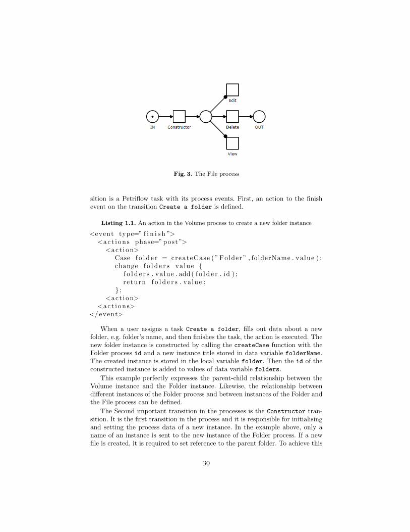
Fig. 3. The File process
sition is a Petriflow task with its process events. First, an action to the finishevent on the transition Create a folder is defined.
Listing 1.1. An action in the Volume process to create a new folder instance
<event type=” f i n i s h ”><a c t i o n s phase=” post ”>
<ac t i on>Case f o l d e r = createCase ( ” Folder ” , folderName . va lue ) ;change f o l d e r s va lue {
f o l d e r s . va lue . add ( f o l d e r . id ) ;r e turn f o l d e r s . va lue ;
} ;<ac t i on>
<a c t i o n s></ event>
When a user assigns a task Create a folder, fills out data about a newfolder, e.g. folder’s name, and then finishes the task, the action is executed. Thenew folder instance is constructed by calling the createCase function with theFolder process id and a new instance title stored in data variable folderName.The created instance is stored in the local variable folder. Then the id of theconstructed instance is added to values of data variable folders.
This example perfectly expresses the parent-child relationship between theVolume instance and the Folder instance. Likewise, the relationship betweendifferent instances of the Folder process and between instances of the Folder andthe File process can be defined.
The Second important transition in the processes is the Constructor tran-sition. It is the first transition in the process and it is responsible for initialisingand setting the process data of a new instance. In the example above, only aname of an instance is sent to the new instance of the Folder process. If a newfile is created, it is required to set reference to the parent folder. To achieve this
30
functionality, the required data value can be sent to the Constructor task of anewly created File instance.
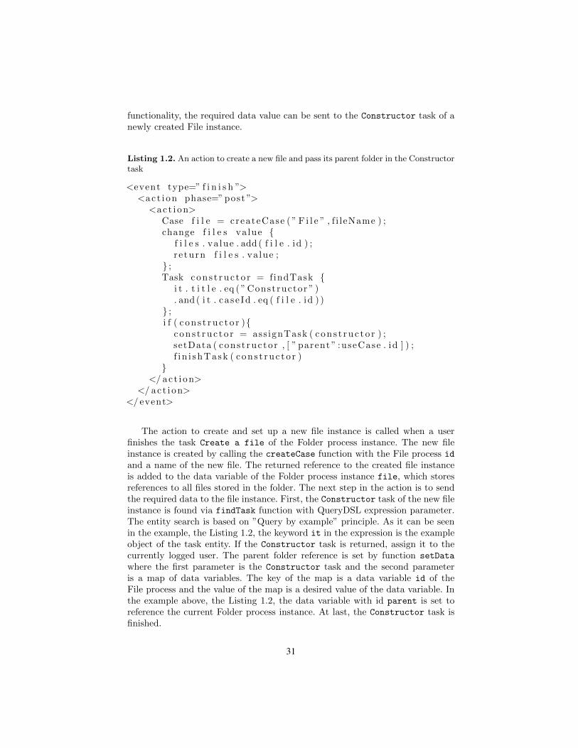
Listing 1.2. An action to create a new file and pass its parent folder in the Constructortask
<event type=” f i n i s h ”><ac t i on phase=” post ”>
<ac t i on>Case f i l e = createCase ( ” F i l e ” , f i leName ) ;change f i l e s va lue {
f i l e s . va lue . add ( f i l e . id ) ;r e turn f i l e s . va lue ;
} ;Task cons t ruc to r = findTask {
i t . t i t l e . eq ( ” Constructor ” ). and ( i t . ca se Id . eq ( f i l e . id ) )
} ;i f ( c on s t ruc to r ){
con s t ruc to r = ass ignTask ( con s t ruc to r ) ;setData ( cons t ructor , [ ” parent ” :useCase . id ] ) ;f i n i shTask ( con s t ruc to r )
}</ ac t i on>
</ ac t i on></ event>
The action to create and set up a new file instance is called when a userfinishes the task Create a file of the Folder process instance. The new fileinstance is created by calling the createCase function with the File process id
and a name of the new file. The returned reference to the created file instanceis added to the data variable of the Folder process instance file, which storesreferences to all files stored in the folder. The next step in the action is to sendthe required data to the file instance. First, the Constructor task of the new fileinstance is found via findTask function with QueryDSL expression parameter.The entity search is based on ”Query by example” principle. As it can be seenin the example, the Listing 1.2, the keyword it in the expression is the exampleobject of the task entity. If the Constructor task is returned, assign it to thecurrently logged user. The parent folder reference is set by function setData
where the first parameter is the Constructor task and the second parameteris a map of data variables. The key of the map is a data variable id of theFile process and the value of the map is a desired value of the data variable. Inthe example above, the Listing 1.2, the data variable with id parent is set toreference the current Folder process instance. At last, the Constructor task isfinished.
31

4 Conclusion
Inter-process communication modelled in Petriflow language can be applied tothe countless applications. As the example illustrated in this paper, it can beused to express hierarchy between instances of different processes. It can be alsoused to separate often repeated parts of a process as a standalone process modeland then referenced from the original process. Even large and complex processescan be modelled with communication via Petriflow process events with ease andpreserved readability of Petri nets.
References
1. Mladoniczky, M., Juhas, G., Mazari, J., Gazo, T. and Makan, M.: Petriflow: Rapidlanguage for modelling Petri nets with roles and data fields. Proceedings of theWorkshop Algorithms and Tools for Petri nets 2017, October 19-20, 2017, TechnicalUniversity of Denmark, Kgs. Lyngby, Denmark, (2017)
2. Riesz, M., Seckar, M., Juhas, G.: PetriFlow: A Petri Net Based Framework forModelling and Control of Workflow Processes. In ACSD/Petri Nets Workshops (pp.191-205). (2010)
3. Mazari, J., Juhas, G., Mladoniczky, M.: Petriflow in Actions:Events Call ActionsCall Events. Proceedings of the Workshop Algorithms and Tools for Petri nets 2018,October 11-12, 2018, University of Augsburg, Germany, (2018)
4. Irina A. Lomazova, Philippe Schnoebelen: Some decidability results for nested Petrinets. Springer LNCS 1755, 208-220 (2000)
5. Van der Aalst, W. M.: The application of Petri nets to workflow management.Journal of circuits, systems, and computers, 8.01, 21-66 (1998)
32
Some Ideas for Modeling a Generic IoT- andEdge-Computing Architecture
Daniel Moldt, Dennis Schmitz, Michael Haustermann, Matthias Feldmann,David Mosteller, Thomas Wagner, Jan Henrik Röwekamp, Lawrence Cabac,
and Michael Simon
University of Hamburg, Faculty of Mathematics, Informatics and Natural Sciences,Department of Informatics, http://www.informatik.uni-hamburg.de/TGI/
Abstract The application area of the Internet of Things (IoT) has con-tinued to increase in recent years. However, adequate modeling meta-phors regarding the design and specification of the relationships andinteractions between versatile entities are still lacking. Edge computingprovides a more specific design due to the given purpose or context ofentities (devices, services, and applications).In this paper, we introduce a four-level architecture for edge computingsystems. It helps modelers gain clarity about the relationships and inter-actions between entities and, thus, specify efficient and well-structuredIoT architectures. Using an exemplary context, we discuss the four levelsand point out the mental challenges that are addressed by this modelingperspective.
Keywords: Modeling, Software Architectures, Reference Nets, Petri Nets,IoT, Edge-Computing
1 Introduction
The continuously increasing number of processors requires more and more ad-vanced software architectures. Simple single processor-based machines have de-veloped via simple networks and distributed computing systems to the currenthighly distributed, large-scale systems/ultra large scale systems (ULSS) (see[11]). With the notion of IoT (Internet of Things), an even larger scale of systemshas to be addressed. Processors and systems are now omnipresent and require aconceptual embedding in the ULSS architectures. The challenge for informaticsis to provide adequate hardware and software systems for such environments.
Shah proposes to integrate IoT systems into (cognitive) agent systems [14].This contribution does not focus on the technical aspects. Instead, we propose ageneral modeling architecture that refers to entities at different modeling levels.These relations are supposed to support modelers to choose the right level ofabstraction for each entity in ULSS architectures.
Specifically, we address the modeling problems of edge computing applica-tions. Our proposed four-level reference architecture is called Edge-Mulan. Inthis paper, we restrict our discussions to the general aspects that are relevant
33

for modeling edge computing-based systems (which might be/are embedded inULSS). For the Edge-Mulan architecture, we will explain the main propertiesof the four-levels and their three general relations briefly.
In the following Section 2 we will briefly give an overview of our previouswork, especially Mulan, on which we build our new proposal. The referencearchitecture Edge-Mulan for edge computing is then introduced in Section 3based on the Mulan reference architecture. In Section 4 we embed our workinto the work of others. We end with a brief discussion, a conclusion and anoutlook in Section 5.
2 Our Previous Related Work
This section covers an excerpt of our previous work that is highly relevant tothe context of this paper.
In our group, we have developed several proposals for modeling and imple-menting complex system architectures. They all are based on Coloured Petrinets [8] and Reference nets [9], which are high-level Petri nets and allow model-ing complex systems while covering concurrency, non-determinism, conflicts andseveral other essential properties of systems. With Renew we have an integrateddevelopment environment (IDE) [3] that, among other purposes, serves for de-signing, specifying, implementing and executing applications that are built withReference nets.
Our base reference architecture for the development of complex systems iscalled Mulan (Multi-agent Nets Reference Architecture) [12,2]. Mulan has fourmajor modeling entities multi-agent system, Platform, Agent and Protocol withthree principal relationships (see Figure 1). Due to the flexibility of our modelingtechnique, each entity can implement any of these three relationships (e.g., forour Mulan system we often extend platforms to behave as agents). This allowsfor arbitrarily nested hierarchies. Using value semantics for nets (at most onereference to each Reference net is allowed within the whole system) nesting isstrictly hierarchical. Borusan et al. call this the physical relation [1] and commu-nication can only be done in a clear context. Nevertheless, reference semanticsallow any number of references to an entity. Borusan et al. call this the logicalrelation.
A Mulan model is used to specify an entire multi-agent system (MAS). Themulti-agent system net represents the complete system to be modeled includingthe platforms. The relationship between the multi-agent system net and theplatforms is the provision and usage of communication services, respectively.Platforms provide a more specific service environment for autonomous agentsdepending on the purpose of the overall system. Agents are located on platformsand consist of protocols.
One of the extensions of Mulan is called Organ. It takes a more abstractperspective than Mulan and provides a reference architecture for organization-oriented contexts [17]. In [18] organizations (as opposed to agents) are proposedas the basic building blocks of systems and homogeneously published in [17] as
34
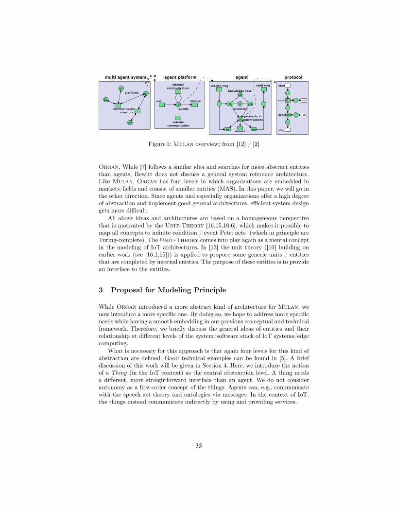
Figure 1: Mulan overview; from [12] / [2]
Organ. While [7] follows a similar idea and searches for more abstract entitiesthan agents, Hewitt does not discuss a general system reference architecture.Like Mulan, Organ has four levels in which organizations are embedded inmarkets/fields and consist of smaller entities (MAS). In this paper, we will go inthe other direction. Since agents and especially organizations offer a high degreeof abstraction and implement good general architectures, efficient system designgets more difficult.
All above ideas and architectures are based on a homogeneous perspectivethat is motivated by the Unit-Theory [16,15,10,6], which makes it possible tomap all concepts to infinite condition / event Petri nets (which in principle areTuring-complete). The Unit-Theory comes into play again as a mental conceptin the modeling of IoT architectures. In [13] the unit theory ([10] building onearlier work (see [16,1,15])) is applied to propose some generic units / entitiesthat are completed by internal entities. The purpose of these entities is to providean interface to the entities.
3 Proposal for Modeling Principle
While Organ introduced a more abstract kind of architecture for Mulan, wenow introduce a more specific one. By doing so, we hope to address more specificneeds while having a smooth embedding in our previous conceptual and technicalframework. Therefore, we briefly discuss the general ideas of entities and theirrelationship at different levels of the system/software stack of IoT systems/edgecomputing.
What is necessary for this approach is that again four levels for this kind ofabstraction are defined. Good technical examples can be found in [5]. A briefdiscussion of this work will be given in Section 4. Here, we introduce the notionof a Thing (in the IoT context) as the central abstraction level. A thing needsa different, more straightforward interface than an agent. We do not considerautonomy as a first-order concept of the things. Agents can, e.g., communicatewith the speech-act theory and ontologies via messages. In the context of IoT,the things instead communicate indirectly by using and providing services.
35

Taking the above considerations into account, we end up with our modelingprinciple called Edge-Mulan (or for short EdgeN). The name indicates thenear relation to Mulan and Organ. This is necessary since the arbitrarily highlevel of nesting of abstraction levels is a central feature of edge computing. Dueto the modeling bias / application area of our reference architecture we want toachieve the top level as Cloud and not Edge or Fog. We define the four levelsfrom top to bottom as follows:
– cloud is the top-level environment that provides computing and storageresource as well as communication, security, privacy, reliability and infras-tructure services
– rooms reside in a cloud and provide a certain set of local services; also anintegration of multiple rooms within the cloud is allowed. The term roomimplies a physical embedding. However, considering the room as contextwill allow for a logical arrangement of overlapping modeling.
– things reside in rooms. They encapsulate the structure, minimal resources,and their possible behavior. Things can provide services and can access theservices that are provided by other things, rooms and the cloud. Rules thatdescribe the thing handles certain behavior options and resources that mightenable behavior or provide means in general.
– parts implement the specific properties of the things. The direct usage ofrules and resources provided/ held/controlled by the thing might be usedvia services.
Figure 2 illustrates the four levels and their relations analogously to Figure 1that illustrates the Mulan architecture. Since we do not want to go into thedetails of the individual units in this contribution, only some of the entities’basic internal functionalities and references are depicted.
Figure 2: Edge-Mulan overview
To illustrate the advantages of this modeling principle, we consider the fol-lowing smart workplace. The building is the cloud and consists of several physicalspaces. These physical spaces can each be a room, and some physical spaces caneven be combined into one digital room. Each room consists of several things
36

and may provide services through these things. Every employee is wearing atransponder. The transponder is a thing that is build up by multiple parts (e.g.RFID chip, battery, storage, Bluetooth, WiFi). When the employee enters thedigital room kitchen, the water in the coffee machine may be preheated, or thekettle turned on because the employee prefers to drink tea at this time of day.In this case, the transponder and the coffee machine or the kettle are relatedbecause both are digitally located in the same room. The room interacts with thetransponder and asks for the habits of the employee. Next, the room interactswith a thing (the coffee machine or kettle) to serve the employee.
In the above example, the kitchen (room) is the context in which the ben-efits of edge computing are used. The transponder does not have to communi-cate with a central data center in the building (cloud); instead, it just uses thekitchen to communicate with the named devices (things). On the other hand, thekitchen provides the communication infrastructure and thus, the communicationbetween the devices is standardized. The intuitive mapping of real entities andtheir relations to Edge-Mulan entities and their relations is one of the mainadvantages of this modeling principle.
In the individual units of Edge-Mulan, their structure, internal behaviorand relevant IoT concepts such as security, privacy, energy, resources, and com-munication must be covered. In this contribution, we will not further examinethese specific characteristics. The explicit specification of entities, possible re-lationships, and standardized interfaces facilitates modeling within each level.If these concepts were too abstract, efficiency in designing and specifying suchsystems would suffer. Modelers could not build the models and systems quicklyand well enough. The same applies when sufficient abstract concepts are missing.
4 Related Work
Carrez et al. published a comprehensive investigation and their results fromthe Internet of Things – Architecture project [5]. Among others, they proposea functional-composition for their architecture. Locality principles similar totoday’s edge computing method are also taken into account. Additionally, theyprovide well-descriptive and motivating real-world examples. However, they donot consider a clear modeling strategy for a hierarchical / reference architecture.
In [4] health tracking is addressed. Edge computing is used to implementan optimal environment for such applications. However, safety and privacy, aswell as functionality, are relevant topics that need to be addressed besides thetechnical efficiency. For these topics, modeling proposals are missing so far.
Health systems are good examples of the challenges posed by new opportu-nities in the development of distributed applications. For a user and its environ-ment (containing, for example, doctors, family, pharmacies, medical institutions,insurances, technical equipment, medical devices and supporting machines, le-gal or social requirements, security, and privacy) several different contexts exist.There are often inconsistencies in the requirements for each context. This typeof context separation and the separation of a user’s interests/roles must be ad-
37
dressed both by user support systems and by the user’s environment systems.Edge-Mulan provides such means in a generic form. We cover concepts suchas logical and physical entities and their relationship, autonomy, encapsulation,concurrency, (non-)determinism, conflict, synchronization, abstraction.
5 Conclusion
In this contribution, we presented our ideas on supporting modelers for edge com-puting architectures with an adequate modeling principle to allow an optimalapplication/IT-alignment. These ideas lead to the proposal of a four-level refer-ence architecture called Edge-Mulan that contains a cloud, platforms, thingsand parts from top to bottom and their relations and interactions. This archi-tecture supports modelers in their mental challenges in modeling well-structuredand efficient IoT architectures. It is based on Reference Nets, which can holdreferences to other nets, allowing any desired hierarchical structuring. Each en-tity contains its structure and internal behavior, which is not fully covered byour proposed architecture and often depends on the specific context.
However, without powerful tool support, such an architecture will not be ap-plicable in practice. Suitable modeling constructs must be provided for designingand specifying the properties and relationships of individual entities. The mod-elers must be empowered to use such concepts intuitively, easily, directly andefficiently. We will consider complex social systems (like large worldwide dis-tributed teams and organizations) with complex processes and numerous devicesand subsystems to test our proposal. How to ensure privacy and security in het-erogeneous systems is of particular interest. Future work should be in line withour current efforts of meta-modeling, distributed simulation, expressive model-ing concepts/constructs within our Petri net environment and incorporation ofleading-edge technology.
References
1. A. Borusan and D. Moldt. A method for developing CIM-systems with colouredPetri nets. In Michel Cotsafis and Francois Vernadat, editors, Advances in Factoriesof the Future, CIM and Robotics, pages 91–100. Elsevier, Amsterdam London NewYork, 1993.
2. L. Cabac. Modeling Petri Net-Based Multi-Agent Applications. Dissertation, Uni-versity of Hamburg, Department of Informatics, Vogt-Kölln Str. 30, D-22527 Ham-burg, April 2010.
3. L. Cabac, M. Haustermann, and D. Mosteller. Renew 2.5 - towards a comprehensiveintegrated development environment for petri net-based applications. In F. Kordonand D. Moldt, editors, Application and Theory of Petri Nets and Concurrency -37th International Conference, PETRI NETS 2016, Toruń, Poland, June 19-24,2016. Proceedings, volume 9698 of Lecture Notes in Computer Science, pages 101–112. Springer-Verlag, 2016.
4. S. Distefano, D. Bruneo, F. Longo, G. Merlino, and A. Puliafito. Personalizedhealth tracking with edge computing technologies. BioNanoScience, 7(2):439–441,Jun 2017.
38

5. F. Carrez et al. Internet of Things - Architecture IoT-A Deliverable D1.5 - Final Ar-chitectural Reference Model for the IoT v3.0. Available at: https://www.iotforum.org/wp-content/uploads/2014/09/D1.5-20130715-VERYFINAL.pdf, 2013. On-line; accessed 20.09.2018.
6. M. Hewelt. Grundlegende Konstrukte einer einheitentheoretischen Modellierung-stechnik. Diploma thesis, University of Hamburg, Department of Informatics, Vogt-Kölln Str. 30, D-22527 Hamburg, 2010.
7. C. Hewitt. Perfect disruption: The paradigm shift from mental agents to orgs.IEEE Internet Computing, 13(1):90–93, 2009.
8. K. Jensen. Coloured Petri Nets: Volume 1; Basic Concepts, Analysis Methods andPractical Use. EATCS Monographs on Theoretical Computer Science. Springer-Verlag, Berlin Heidelberg New York, 1992.
9. O. Kummer. Referenznetze. Logos Verlag, Berlin, 2002.10. D. Moldt. Petrinetze als Denkzeug. In B. Farwer and D. Moldt, editors, Object
Petri Nets, Processes, and Object Calculi, number FBI-HH-B-265/05 in Report ofthe Department of Informatics, pages 51–70, Vogt-Kölln Str. 30, D-22527 Ham-burg, August 2005. University of Hamburg, Department of Computer Science.
11. L. Northrop. Ultra-Large-Scale Systems: The Software Challenge of the Future.Software Engineering Institute, Carnegie Mellon, 2006.
12. H. Rölke. Modellierung von Agenten und Multiagentensystemen – Grundlagen undAnwendungen, volume 2 of Agent Technology – Theory and Applications. LogosVerlag, Berlin, 2004.
13. B. Schleinzer. Flexible und hierarchische Multiagentensysteme – Modellierungund prototypische Erweiterung von Mulan und Capa. Diploma thesis, Universityof Hamburg, Department of Informatics, Vogt-Kölln Str. 30, D-22527 Hamburg,December 2007.
14. V. S. Shah. Multi-agent cognitive architecture-enabled iot applications of mobileedge computing. Annales des Télécommunications, 73(7-8):487–497, 2018.
15. V. Tell and D. Moldt. Ein Petrinetzsystem zur Modellierung selbstmodifizierenderPetrinetze. In Karsten Schmidt and Christian Stahl, editors, Proceedings of the12th Workshop on Algorithms and Tools for Petri Nets (AWPN 05), pages 36–41.Humboldt Universität zu Berlin, Fachbereich Informatik, 2005.
16. R. Valk. Modelling of task flow in systems of functional units. Technical Re-port FBI-HH-B-124/87, University of Hamburg, Department of Computer Science,Vogt-Kölln Str. 30, D-22527 Hamburg, 1987.
17. M. Wester-Ebbinghaus. Von Multiagentensystemen zu Multiorganisationssystemen– Modellierung auf Basis von Petrinetzen. Dissertation, University of Hamburg,Department of Informatics, Vogt-Kölln Str. 30, D-22527 Hamburg, 12 2010.
18. M. Wester-Ebbinghaus and D. Moldt. Auf dem Weg zu organisationsori-entierter Softwareentwicklung. Available at: http://www.informatik.uni-hamburg.de/TGI/publikationen/public/data/2006/Wester+06/Wester+06.pdf,September 2006.
39

40

Investigating the Java Spring Framework toSimulate Reference Nets with Renew
Jan Henrik Röwekamp
University of Hamburg, Faculty of Mathematics, Informatics and Natural Sciences,Department of Informatics, http://www.informatik.uni-hamburg.de/TGI/
Abstract Renew as a simulator for reference nets does not offer anative web based communication technology. To bring it towards run-ning a single distributed simulation implementing modern communica-tion means is a crucial step. The Java Spring Framework offers interest-ing capabilities to achieve this goal. However, the implementation is notstraightforward and therefore advantages and disadvantages are investi-gated in this paper. Concluding the advantages outweigh the disadvan-tages.
Keywords: Petri Nets, Reference Nets, Distributed Simulation, Syn-chronous Channels, Spring, Renew
1 Introduction
Reference nets have been introduced by Kummer around the year 2000[11]. Theyare a high-level Petri net formalism based on the Java Programming language1and colored Petri nets. One crucial part of reference nets is the differentiationbetween net and net instance. Similar to a class in object oriented programminga net only fixes structural aspects and initial markings, but is never simulateditself. Using this analogy a net instance correlates to an object, in a way, thatarbitrary amounts of net instances may be generated from one net during thesimulation. Reference nets follow the nets within nets paradigm [18] and realize itby enabling to hold references to other net instances as token value. Net instancereference tokens may be used to create new or destroy net instances and alsoto interact with them. As for communication the mechanism of synchronouschannels are used [5,10].
In figure 1 an example of a simulation of two reference nets can be found.Upon start of the simulation a net instance of NetA is created. The net instanceof NetA then proceeds to create a net instance of NetB and passes the string"Hello!" over the synchronous channel "ch". The single transition of NetB mayonly fire if it can synchronize with another transition to bind a value to parametermsg. After all transitions have fired, the bottom most place in the sole instanceof NetA holds a reference to the net instance of NetB created earlier, while thebottom most place in NetB holds the string value "Hello!".1 http://www.java.com/
41

NetA NetB
Figure 1: NetA example and NetB example with synchronous channel ch
A simulator capable of simulating reference nets is the reference net workshop(Renew)2 [3] maintained by our research group at the University of Hamburg.Renew is based on Java and essentially allows for reference nets to utilize arbi-trary Java code as transition inscription.
2 Motivation, Vision and Goals
As the number of simulated net instances is essentially unknown prior to exe-cution of the simulation, and also Renew in its current form is optimized forsingle machine execution, the question arises to utilize multiple machines forvery large simulations. The central topic this paper is to be filed under thereforeis scalability of the Renew simulator. The vision behind the research and theultimate goal is to be able to dynamically launch additional simulation partsupon demand, that are communicating with each other using synchronous chan-nels. As this is a vision it is most definitely not addressed in total here, but givento draw the big picture. This paper is related to but in itself independent fromearlier publications [14] [13].
3 Related Work
Early steps towards distribution have already been taken early on by using Javanetwork code in transition inscriptions. While this basically allows communica-tion between multiple simulations, it essentially breaks the formalism and thetrue concurrency semantics of Petri nets. Communication should be done usingsynchronous channels. Several further early approaches were made and publishedin respective papers, e.g., [7,17,9,4,8,12].
[1] utilizes virtual machines in cloud environments. However the usage islimited to single execution runs and the solution does not distribute the entire
2 http://www.renew.de/
42

model itself. The simulations in virtual machines are run in isolation and are notpart of one big simulation.
An approach by [2] used web technologies, but only for external communica-tion. The core simulation by itself is not altered.
A first attempt in really distributing the simulation in itself was undertakenby Simon [15,16] . The method rewrote some parts of the Renew core simulationto use Java RMI. However, this method was limited in regard to binding searchfor activation checks of transitions. Also, setting up Java RMI can be tediouswork, when connecting new instances dynamically.
4 Implementing a RESTful Renew Core
Looking at recent developments in distributed systems a trend towards RESTfulwebservices [6] based on HTTP is apparent. RESTful services are stateless andusually also offer interfaces, that implement idempotency. To implement a RESTservice in Java there are several options, like implementing it directly using aTomcat webserver or frameworks. One of the most popular frameworks is theSpring Framework3 by Pivotal. Spring is in essence a dependency injection andinversion of control framework useful for enterprise level development. Comingwith a built-in webserver and using annotations it also features extremely ac-celerated development of RESTful webservices. Spring is therefore a very strongcandidate to be included in Renew to achieve flexibility in regards to dynami-cally launching simulation parts.
This paper addresses thoughts about what needs to be changed within theRenew software to incorporate the Java Spring Framework. Combining Springwith our previous research will enable us to bundle Renew/Spring instancesusing containerization like Docker4 to deploy multiple instances dynamically.The way this will be achieved, will be covered in a later paper and is out ofscope here.
5 Spring in Renew
For the remainder of this paper it will be discussed how REST/Spring maybe integrated into Renew. A general idea of the change can be found withinfigure 2. On the left side the current implementation is depicted. Several pluginsaccess the simulation core. (Not every plugin needs to interact necessarily withthe simulation core itself) On the right side the proposed new method can beseen. The core has been splitted into independent parts, which are tied togetherby Spring. Plugins are now interacting with the Spring layer instead of the coredirectly.
3 https://spring.io/4 http://www.docker.com/
43

Figure 2: System net example and Object net example with synchronous chan-nel ch
5.1 Data Transfer
First of all using Spring the data transfer is usually realized with JSON5. There-fore only key value tuples may be passed limiting the use of objects to serializableones. Also, to use custom Java objects a converter for simple objects need to beimplemented or the programmer needs to implement a JSON-serialization. Thisrequires synchronous channels to utilize value semantics or more sophisticatedtechniques like global unique object identifiers. Transferring nets by value is pos-sible, as Renew can serialize nets into .rnw files. Transferring net instances mayrequire more thought as they might hold complex tokens, that possibly referenceobjects, which are not inherently serializable.
5.2 Compatibility With Existing Renew Plugins
Spring should also be realized as Renew plugin, so the base simulator couldstill be used without this addition. Also, compatibility to the present pluginecosystem would be highly desirable to make the Spring based simulation coreavailable to previous research based on the original core. This could be achievedby implementing existing interfaces, but certainly constrains the development ofthe Spring based core.
In general such a plugin would change behaviour of the underlying simulationcore similar to the Distribution plugin by Simon [15,16]. It should be consideredto define a special type of plugin like "core plugin" for plugins changing basefunctionality and by that possibly breaking other plugins.
5.3 Compatibility With Other Services
RESTful webservices are widespread throughout organizations, companies andthe internet. Using an underlying framework capable of the same protocol wouldenable far easier communication and integration of foreign services and by thateasing the further research and development of the Renew software.5 Java Script Object Notation
44

5.4 Architecture
A typical Spring application listens to events and fires actions upon events, whichcorrelates pretty well with the simulation of net instances, especially distributedones, that listen for incoming messages. Spring also synergizes well with a micro-service architecture, so the simulation core might be broken down into separateparts even more.
Further, the dependency injection functionality of spring can be utilized todynamically load nets and net instances of these.
5.5 Development Activity
Spring is very active in terms of development and new emerging technologies andprotocols are likely to be implemented into Spring by the community. Renewcould take advantage of this fact to stay up to date more easily. As an exampleSpring also supports the relatively new GraphQL6, which was initially releasedin 2015. GraphQL is in direct competition with REST and might likely replaceit in the future.
5.6 Drawbacks
On the downside, Spring is a very large framework, increasing the difficulty forfurther contributors to the Renew project. Another negative aspect is the de-pendency on another framework, that requires maintenance and possibly securityrelevant updates to be implemented.
5.7 Challenges
The main challenge in implementing Spring into the simulation core is to keep theproven algorithms for binding search, firing and unification intact. Distributingthese algorithms has been discussed by Kummer back in 2002[11] and a firstattempt at Java RMI based distribution was undertaken by [16] in 2016. Similarproblems are bound to arise while implementing a Spring based version of thesimulation core.
6 Conclusion and Outlook
The idea of incorporating the Java Spring framework into the simulation core ofthe reference net simulator software Renew has been presented. Spring comeswith a great amount of possibilities for Renew as the drawback of increased com-plexity of the application itself. Transferring the simulation core into a Springbased version enables compatibility to other REST based webservices and pos-sibly yields a far more scalable architecture.
Further research will include a first prototype of a Spring based Renew core,as well as considerations about a possible microservice architecture of Renew.6 https://graphql.org/
45

References1. Bendoukha, S.: Multi-Agent Approach for Managing Workflows in an Inter-Cloud
Environment. Dissertation, University of Hamburg, MIN Faculty (2016)2. Betz, T., Cabac, L., Duvigneau, M., Wagner, T., Wester-Ebbinghaus, M.: Software
engineering with Petri nets: a Web service and agent perspective. Transactions onPetri Nets and Other Models of Concurrency IX (ToPNoC) pp. 41–61 (Dec 2014)
3. Cabac, L., Haustermann, M., Mosteller, D.: Renew 2.5 - towards a comprehensiveintegrated development environment for petri net-based applications. In: Kordon,F., Moldt, D. (eds.) PETRI NETS 2016, Toruń, Poland, June 19-24, 2016. Pro-ceedings. LNCS, vol. 9698, pp. 101–112. Springer (2016)
4. Chiola, G., Ferscha, A.: Distributed simulation of Petri nets. IEEE Parallel Distrib.Technol. 1(3), 33–50 (Aug 1993)
5. Christensen, S., Hansen, N.: Coloured Petri nets extended with channels for syn-chronous communication. In: Valette, R. (ed.) ICATPN. LNCS, vol. 815, pp. 159–178. Springer (1994)
6. Fielding, R.T.: Architectural Styles and the Design of Network-based SoftwareArchitectures. Ph.D. thesis, University of California, Irvine (2000), aAI9980887
7. Hauschildt, D.: A Petri net implementation. Fachbereichsmitteilung FBI-HH-M-145/87, University of Hamburg, Department of Computer Science (1987)
8. Kaim, W.E., Kordon, F.: An integrated framework for rapid system prototypingand automatic code distribution. In: Proceedings of RSP, Grenoble, France. pp.52–61. IEEE (1994)
9. Kordon, F.: Prototypage de systèmes parallèles à partir de réseaux de Petri colorés,application au langage Ada dans un environment centralisé ou réparti. Dissertation,Université P & M Curie (May 1992)
10. Kummer, O.: Simulating synchronous channels and net instances. In: Desel, J.,Kemper, P., Kindler, E., Oberweis, A. (eds.) 5. Workshop AWPN. pp. 73–78. No.Forschungsbericht Nr. 694, Fachbereich Informatik, Universität Dortmund (1998)
11. Kummer, O.: Referenznetze. Logos Verlag, Berlin (2002)12. Pommereau, F., de la Houssaye, J.: Faster simulation of (coloured) petri nets using
parallel computing. In: van der Aalst, W.M.P., Best, E. (eds.) PETRI NETS.LNCS, vol. 10258, pp. 37–56. Springer (2017)
13. Röwekamp, J.H., Moldt, D., Simon, M.: A simple prototype of distributed execu-tion of reference nets based on virtual machines. In: Proceedings of the Algorithmsand Tools for Petri Nets (AWPN) Workshop 2017. pp. 51–57 (Oct 2017)
14. Röwekamp, J.H., Moldt, D., Feldmann, M.: Investigation of containerizing dis-tributed Petri net simulations. In: Moldt, D., Kindler, E., Rölke, H. (eds.) Appli-cations and Theory of Petri Nets and Concurrency. CEUR Workshop Proceedings,vol. 2138, pp. 133–142. CEUR-WS.org (2018), http://ceur-ws.org/Vol-2138/
15. Simon, M.: Concept and Implementation of Distributed Simulations in Renew.Bsc thesis, University of Hamburg, Department of Informatics (2014)
16. Simon, M., Moldt, D.: Extending Renew’s algorithms for distributed simulation.In: Cabac, L., Kristensen, L.M., Rölke, H. (eds.) PNSE’16. CEUR Workshop Pro-ceedings, vol. 1591, pp. 173–192. CEUR-WS.org (2016)
17. Taubner, D.: On the implementation of Petri nets. In: Rozenberg, G. (ed.) Advancesin Petri Nets 1988. LNCS, vol. 340, pp. 418–439. Springer (1988)
18. Valk, R.: Petri nets as token objects - an introduction to elementary object nets.In: Desel, J., Silva, M. (eds.) 19th International Conference on Application andTheory of Petri nets, Lisbon, Portugal. pp. 1–25. No. 1420 in LNCS, Springer,Berlin Heidelberg New York (1998)
46

Part II
Extended Abstracts


Detecting Noise in Event Logs using Statistical Inference
Johannes Metzger and Robert Lorenz
Department of Computer ScienceUniversity of Augsburg, Germany
[email protected]@informatik.uni-augsburg.de
In [1], Dumas advocates event structures, and in particular labelled prime eventstructures (LPES), as the unifying representation of process models and event logs inthe context of process mining. In [2], a new technique for the representation of the non-sequential behavior of concurrent systems based on LPES is presented. This techniqueextends LPES by a list of cutoff events in order to finitely represent inifinite behavior.The resulting model is the most compact and the most expressive existing representationof the non-sequential behavior of concurrent systems. In particular, it may represent thebehavior of arbitrary bounded place/transition Petri nets (p/t-nets).
Based on these results, we are developing a synthesis-based two-step approach forprocess discovery in the area of process mining:
– First step (preprocessing): Construct an LPES with cutoff-list from an event logthrough detecting noise, causality, concurrency and loops.
– Second step (synthesis): Synthesize a Petri net from the result of the first step.
Since LPES with cutoff-lists are the most general existing model representing thebehavior of concurrent systems, in the first step, causal structures can be detected withless loss of information than with approaches using other models, as for example Petrinet based models. That means, LPES with cutoff-lists have a lower representational biasin the context of process mining compared to other models.
Concerning the second step, in [2], the authors present a theory for the token flowregion based synthesis of bounded p/t-nets from LPES with cutoff-lists. The unfoldingof the synthesized p/t-net includes the given LPES and has minimal additional behavior.In [3], a practical implementation is provided together with first experimental results.
An important aspect of the first step is the detection of noise. We present a newapproach for the detection of noise using statistical methods. The main advantage ofthis new approach is the obtained statistical foundation of the results including an upperbound for the risk of false classification of traces (as noise or not as noise) and flexibleadaptability of the used probability for the occurrence of noise.
Our approach is based on counting the number of occurrences of a pair of directneighbors ab within the traces of the event log (frequency of ab). Roughly speaking,we identify such an occurrence as noise if the number of occurrences is ”very low”compared to the number of all pairs xy with predecessor x = a or follower y = b. Forthe decision, we use one-sided hypothesis tests based on the binomial distribution foreach pair ab. We formulate the following two hypotheses:
– Null hypothesis H0 : p ≤ p0: The occurrence of ab should be considered as noise.
49

– Alternative hypothesisH1 : p > p0: The occurrence of ab should not be consideredas noise.
The value p0 is the probability for the occurrence of noise and p is the probability forthe occurrence of the pair ab within a trace of the event log. The choice of p0 dependson the considered event log and field of application. A higher value of p0 leads to theclassification of more pairs xy as noise.
The aim is to restrict the risk of falsely inferring that H1 is true when indeed H0
is (error type 1), by fixing an upper bound α. That means, we determine the smallestvalue k, such that
p(frequency of ab ≥ k | p ≤ p0) ≤ α,and decide for H1 if the frequency of ab is greater or equal to k.1
If a trace contains a pair ab which is classified as noise, we omit the whole trace,i.e. we delete the trace from the event log and do not consider it for the construction ofthe LPES.
Note that not all kinds of noise can be detected through considering frequencies ofdirect neighbors. The classification and treatment of such kinds of noise is a directionof future research.
Further steps in the construction of an LPES from an event log are the detection ofcausality, concurrency and loops. A simple possibility for the detection of causality andconcurrency is to proceed as in the α-algorithm and its improvements using informationabout direct neighbors from the noise-free event log.
The detection of loops is a direction of future research, since existing techniquescannot be adapted to LPES with a list of cutoff events.
References
1. M. Dumas and L. Garcıa-Banuelos. Process mining reloaded: Event structures as a unifiedrepresentation of process models and event logs. In R. Devillers and A. Valmari, editors,Application and Theory of Petri Nets and Concurrency, volume 9115 of Lecture Notes inComputer Science, pages 33–48. Springer International Publishing, 2015.
2. G. Juhas and R. Lorenz. Synthesis of bounded Petri Nets from Prime Event Structures withCutting Context. In W. M. P. van der Aalst, R. Bergenthum, and J. Carmona, editors, Proceed-ings of the International Workshop on Algorithms & Theories for the Analysis of Event Data2016 Satellite event of the conferences: 37th International Conference on Application andTheory of Petri Nets and Concurrency Petri Nets 2016 and 16th International Conference onApplication of Concurrency to System Design ACSD 2016, Torun, Poland, June 20-21, 2016.,volume 1592 of CEUR Workshop Proceedings, pages 58–77. CEUR-WS.org, 2016.
3. R. Lorenz, J. Metzger, and L. Sorokin. Synthesis of bounded petri nets from prime eventstructures with cutting context using wrong continuations. In Proceedings of the InternationalWorkshop on Algorithms & Theories for the Analysis of Event Data 2017 Satellite event of theconferences: 38th International Conference on Application and Theory of Petri Nets and Con-currency Petri Nets 2017 and 17th International Conference on Application of Concurrencyto System Design ACSD 2017, Zaragoza, Spain, June 26-27, 2017., pages 21–38, 2017.
1 In this setting, we control the false classification of noise by α. It is also possible to exchangeH0 and H1: then the false classification of ”normal behavior” is controlled by α.
50

A Browser Based Tool forWorkflow Guided Tutorials
Joachim Schmidberger, Matthias Feldmann, and Daniel Moldt
University of Hamburg, Faculty of Mathematics, Informatics and Natural Sciences,Department of Informatics, http://www.informatik.uni-hamburg.de/TGI/
Overview For the support of our teaching projects Web-based support of thelearning process is needed. Here we discuss the development of our browser-based tool for workflow guided tutorials with JointJS and Vue.js frameworks inJavascript and HTML templates.Keywords: Petri nets, workflow nets, education, tutorials, Javascript
Motivation As described in [1] we support our teaching project workflows withdetailed process descriptions during the first weeks. To support automation ofthese processes we strived for a browser-based tool support to allow for an evenbetter teaching process. So we were looking for the best solution.
Problem For the description of the processes, we use a kind of workflow nets. Anatural implementation would be to use Renew as the execution engine. How-ever, we experienced that students expect access to such a tool from anywherewith their usual look and feel. A browser-based alternative had, therefore, to bediscussed. Former solutions were outdated, as can be seen in our browser-basedimplementation in the project Sisol1 from 2005.
Approach Since the workflows were created with the help of the tool Renew2,they were available in the tool’s rnw file format. Import and export functions tothe XML based file format PNML already exist in Renew. The planned Web ap-plication needs to read, parse, display and simulate these files. Since the PNMLexporter does not provide all formatting information (e.g. arc waypoints), theapplication should also contain an editor for the loaded nets. The desired processusing the application is to step through the workflow by clicking on task tran-sitions, starting from the initial marking of the net. Meanwhile, the applicationdisplays the corresponding exercise texts for the activated tasks.
A prototype was created using HTML and Javascript. In the first step, var-ious graphics frameworks for Javascript were tested for their fitness. There aremultiple ways to create a web-based application. A framework provides muchhelp getting started since templates can be used to output values from JavaScriptto the HTML document. Frameworks also provide a predefined structure and
1 http://www.informatik.uni-hamburg.de/TGI/forschung/projekte/sisol/tutorial_big.gif
2 Renew homepage: http://www.renew.de
51
already implement a structure for inter-component communication. In the fast-moving world of Javascript development, one of the first experiences was thatactive development and maintenance of the frameworks had to be one decisiveselection criteria.
The first prototype developed with Draw2d Touch3 as a graphical frameworkwas no longer executable after the switch to the next browser generation. Atthe time of writing this text, the further development of the framework wasdiscontinued. JointJS4 and mxGraph5 were shortlisted because they have anactive developer community. mxGraph offers all the classic editing features, whileJointJS provides better support for simulations. The current prototype is basedon JointJS, which already offers a simple Petri net plugin.
Vue.js6 was chosen as the basic framework since it is lightweight and usesnative Javascript without syntax extensions. This combined with the large, activecommunity makes it easy to learn the framework. Additionally, Vue.js is used bylarge companies like Alibaba, Baidu, and Tencent which increases the probabilitythat it will be further developed in the future.
Results The current prototype already supports the functionality to read anddisplay PNML files by converting these into JSON Objects which are then ren-dered with JointJS. Basic editing and simulation functionality is available. Atthis point, it is evident that the tools currently chosen are well suited for theintended tutorial support. Reading through the tasks on the tutorials can nowbe simulated in corresponding workflow nets.
Open problems and outlook For the next prototypes, the editing functions haveto be extended, and the persistence of the tutorials has to be ensured. Thesynchronization between workflow simulation and task display still has to beimplemented. The project could then prove its usefulness in lessons by usingthe application instead of the worksheets. The workflows also show the progressthe students have made in the exercise. In future works, this could be used toanalyze the progress and optimize the exercises. There could be a version of thetool for the teacher that displays the current status of the learners in differentcolored tokens. A connection of the tool to Redmine to open task related ticketscould also be a useful addition.
References
1. D. Schmitz, D. Moldt, L. Cabac, D. Mosteller, and Haustermann M. UtilizingPetri Nets for Teaching in Practical Courses on Collaborative Software Engineering.In ACSD 2016, Toruń, Poland, June 19-24, 2016, pages 74–83. IEEE ComputerSociety, 2016.
3 Draw2d homepage: http://www.draw2d.org/draw2d/4 Jointjs Homepage: https://www.jointjs.com/5 Mxgraph homepage: https://github.com/jgraph/mxgraph6 Vue.js Homepage: www.vuejs.org
52

About the Development of aCurry-Coloured Petri Net Simulator
Michael Simon and Daniel Moldt
University of Hamburg, Faculty of Mathematics, Informatics and Natural Sciences,Department of Informatics, http://www.informatik.uni-hamburg.de/TGI/
Overview / Motivation Several inscription languages for Petri net simulatorsexist to extend the expressibility and usability of Petri nets in system develop-ment. Renew uses Java and attempts to add a functional language (Scheme)were successful with respect to language, however, the performance was poorand the language (and its implementation) do not allow for side effect free de-velopment. CPN-Tools uses Standard ML as the inscription language. This toolis very widely used, however, ML has side effects. A former tool inscribed withHaskell had only poor usability.
Avoiding side effects has the underlying promise that analysis of such netsmight be easier. Therefore, a new attempt was made to develop a Petri netsimulator that incorporates a language without side effects. After some investi-gations about the best options the purely functional logic programming languageCurry was chosen. Haskell as the implementation language was therefore a nat-ural choice. In the following, we briefly sketch the development and the mainfeatures of the newly introduced Petri net formalism.
Approach Following the Paose-Approach (Petri net-based, Agent- andOrganization-Oriented Software Engineering) the most critical aspectswere addressed in a stepwise approach. Based on our experiences with Renewand Java as the implementation language and a thorough investigation about thestate-of-the-art of similar simulators several features were identified that shouldbe covered in the new simulator. The complete work and the development processare described in the master thesis of the first author.
As in Renew the concurrency and the practical usability of the simulatorwas a of high priority. Since Coloured Petri nets (CPN) by Kurt Jensen is thebasic formalism the transition binding was of central interest. To avoid the devel-opment of a whole graphical interface just for CCPN Renew was used for thegraphical user interface (gui). This required some modification within the Re-new framework what was also done in context of the master thesis as a smallerportion of the workload. Several milestones were set up to reach a fully usablesimulator. In a systematic way the key features of the tool were developed.
Results A graphical user interface was made available via a new Renew plugin.Editing, inspection, observation and control of CCPN nets and simulations wasimplemented via an XML interface. As the first step for the provision of analysistools the reachability graph can be generated under the gui control.
53

CCPN can be used as a software library by other Haskell programs. Severalinterfaces are available to control the simulation. Access to the net markings andthe firing of specific transition sequences are made available.
The Petri net formalism allows the inscription of the nets with Curry code.Concurrent Haskell implementation allows for the execution in an efficient man-ner. Most important is that transition execution happens without side effects.The strictly strongly typed programming language environment allows to ensurethis together with the software design of the binding and firing rules implementedfor CCPN. The evaluation of functions does not have side effects and the logicprogram evaluation for the transition binding search are of central importance.
Overall, CCPN provides a new powerful Petri net formalism based on a logicprograming language, what is the central idea of the master thesis. The startingtime of a simulation is relatively high due to the prototypical implementation.Emphasize was laid on the usability study of the different features within thesimulation. All features could be implemented in a very efficient way. The searchfor transition bindings to fire is delegated to the underlying Curry compiler.It is central to the simulation algorithm which is inspired by Renew and im-plemented in Haskell. Doing so, the upcoming developments within the Haskelland Curry language development can directly improve the CCPN simulator.Therefore, important parts heavily rely on the KiCS2 Curry compiler1.
Modelers can define purely functional logic programs for initial place mark-ings and transition inscriptions. Two main libraries allow, via the Curry compilerand its libraries, for dynamically compiled and loaded nets and software. Thesimulator core is agnostic to the inscription language and does not depend on theKiCS2 Curry compiler integration. Other CPN formalisms are therefore possi-ble in the future. Three interface provide sufficient means and different levels touse and control of CCPN. Embedding into the Renew environment via XMLallows a convenient usage.
Open problems and outlook Optimization of the compilation can be acquired bythe pre-compilation of time intensive parts. Usage of compilation results shouldreduce the setup time for a simulation considerably. For this some strategies haveto be designed for our domain and the intended use of CCPN. Once everythingis compiled the simulation is executed fast. User experiences are therefore muchbetter during the simulation runs. CCPN is based on the current 0.6.0 stableversion of the KiCS2 compiler. KiCS2’s current development release adds typeclasses similar to Haskell, a major type system improvement. Porting CCPN isnecessary to use this new feature and future KiCS2 improvements.
Most interesting is the extension of the CCPN formalism itself. Test arcs ornets-within-nets or other hierarchy concepts are highly interesting. Due to theconcurrent implementation and the functional language background distributedsimulation is of high interest. Most importantly the options of analysis of thenet formalism is very promising.
1 see http://www-ps.informatik.uni-kiel.de/kics2/
54

Improvement of the Renew Editor User Interface
Martin Wincierz, Daniel Moldt, and Michael Haustermann
University of Hamburg, Faculty of Mathematics, Informatics and Natural Sciences,Department of Informatics, http://www.informatik.uni-hamburg.de/TGI/
Overview / Motivation For most of it’s existence, the user interface of Renewhas used the same graphical framework and window management. For severalusage scenarios this was not the state-of-the-art anymore. Here we discuss someimprovements for a better user experience of Renew.
Problem The original graphical interface was developed on the basis of the frame-work JHotDraw1 by Erich Gamma. There was no architectural design for a plu-gin system, when Renew branched from JHotDraw. In the master thesis ofthe first author2 two main goals were addressed: 1) (Maintainability) Enablethe graphical interface to be more easily extendable via plugins. 2) (Usability)Improve the general usability of Renew.
Approach Former attempts to improve the Renew GUI were used to checkoptions. Other tools that are used in a similar manner as Renew (e.g. otherPetri Net editors such as CPN-Tools or graphical editors such as GIMP) wereanalyzed for useful features and design patterns. Furthermore experiences fromseveral smaller development studies, student thesis and teaching projects werecollected and checked for the most pressing needs of improvement.
A list of improvements were set up and systematically tested for possiblerealizations. It is important to notice that the two main goals required differentlevels of investigation. For the plugin extensibility the internal design of Renewhad to be improved. Some technical debts had to taken into account and partsof the software had to be re-engineered. For the usability, alternative designs ofthe interface and features of the software had to investigated.
Based on these thorough investigations several decisions had to be madeabout what could be done within the given timeframe of the master thesisof Wincierz. For the methodological setting the software development Paose-approach3 (Petri net-based, Agent- and Organization-Oriented Software Engi-neering) was applied: involvement of users (at the architectural and the appli-cation level respectively). deep analysis of the given system; definition of clearsprint results; systematic prototyping with state-of-the-art agile methods; sepa-ration of concerns by dividing problems into manageable parts.1 JHotDraw: http://www.jhotdraw.org2 Wincierz, Martin: Verbesserung der Erweiterbarkeit und Benutzbarkeit der grafis-
chen Oberfläche des Petrinetz Simulators Renew, University of Hamburg, 20183 Paose: http://paose.de
55

Results Improving the maintainability required the main efforts during this de-velopment process. Integrating the Docking Frames framework4 allowed shiftingseveral functionality to an external library. Workload of maintaining the codewithin the Renew development team now changes. The framework will need tobe monitored and continuously be integrated into our code base. Future devel-opment will, however, be much easier since extensibility is improved due to thebetter support of plugin architectures by the framework.
Via the usage of several design patterns (bridge, adapter, factory, observer,etc.) the maintainability of the Renew code base could be enhanced consider-ably. Reimplementation of the DrawApplication class improved the readabilityof the corresponding code base. Many code comments were added to the in-spected code (improvement of readability) and new code was created directlywith comments (ensuring readability). Java assertions were partially applied toallow for validation of interface conditions. Overall the maintainability of theRenew code base was improved considerably. At the same time new featurescould and can be added in an easier way.
Usability improvements resulted directly from the usage of the new graphicalframework. The look-and-feel with respect to the window management followsnow more modern styles. Zooming was implemented and hence directly supportstask adequacy. Context-sensitive information can now be acquired more easilyby new plugin-based tools. Control of the program was shifted from a purelymenu-based system to the usage of buttons with graphical icons which clearlycommunicate their meaning. This facilitates easier learning of the application’sfeatures and their faster control by expert users. Tool bars can now be adaptedvia individual configurations and at runtime the window management is moreflexible with dock-able windows. Overall the usability has been improved in manyfacets without losing former features.
Open problems and outlook While several aspects could be improved, multiple upto now hidden problems were revealed. Future work can be done by improvementof the menu management. Since future plugins need to register their own newmenus, general conventions regarding naming and menu usage as well as moreautomation in ordering these menus would be of help. I/O Operations can beimproved. Due to the new framework and the decoupling of representation andI/O operations other kinds of graphics than Renew drawings could be openedand displayed. The aesthetics of the Renew GUI still does not match currentexpectations of UI design. For acceptance at teaching and practical use the intu-itive representation and usage of the functionality has to be taken into account.Newest trends in usability have to be obeyed to keep the motivation high. Dueto the size of Renew and its whole eco system of tools and frameworks a com-plete analysis of the user interface has not been done. Further improvements arepossible in many parts.
4 http://www.Docking-Frames.org
56