algorithmic safety measures for intelligent industrial co
TRANSCRIPT

Algorithmic Safety Measures for Intelligent Industrial Co-Robots
Changliu Liu and Masayoshi Tomizuka, Fellow, IEEE
Abstract— In factories of the future, humans and robots areexpected to be co-workers and co-inhabitants in the flexibleproduction lines. It is important to ensure that humans androbots do not harm each other. This paper is concerned withfunctional issues to ensure safe and efficient interactions amonghuman workers and the next generation intelligent industrialco-robots. The robot motion planning and control problem in ahuman involved environment is posed as a constrained optimalcontrol problem. A modularized parallel controller structure isproposed to solve the problem online, which includes a baselinecontroller that ensures efficiency, and a safety controller thataddresses real time safety by making a safe set invariant.Capsules are used to represent the complicated geometry ofhumans and robots. The design considerations of each moduleare discussed. Simulation studies which reproduce realisticscenarios are performed on a planar robot arm and a 6 DoFrobot arm. The simulation results confirm the effectiveness ofthe method.
I. INTRODUCTION
In modern factories, human workers and robots are twomajor workforces. For safety concerns, the two are normallyseparated with robots confined in metal cages, which limitsthe productivity as well as the flexibility of production lines.In recent years, attention has been directed to remove thecages so that human workers and robots may collaborate tocreate a human-robot co-existing factory [1]. Those robotsworking in a human-involved environment are called co-robots.
The potential benefits of co-robots are huge and extensive,e.g. they may be placed in human-robot teams in flexibleproduction lines [2] as shown in Fig.1, where robot armsand human workers cooperate in handling workpieces, andautomated guided vehicles (AGV) co-inhabit with humanworkers to facilitate factory logistics [3]. Automotive man-ufacturers Volkswagen and BMW [4] have took the lead tointroduce human-robot cooperation in final assembly lines in2013.
In the factories of the future, more and more interactionsamong humans and industrial robots are anticipated to takeplace as shown in Fig.2. In such environments, safety isone of the biggest concerns [5], which attracts attentionfrom standardization bodies [6], as well as from majorrobot manufacturers including Kuka, Fanuc, Nachi, Yaskawa,Adept and ABB [7]. However, most of these researches arefocused on intrinsic safety, i.e. safety in mechanical design[8], actuation [9] and low level motion control [10]. Safetyduring social interactions with humans, which are key to
*This work was supported by the Berkeley fellowship awarded toChangliu Liu and by FANUC Corporation.
C.Liu and M.Tomizuka are with University of California, Berkeley, CA94720 USA (e-mail: changliuliu, [email protected]).
Fig. 1: Flexible production lines in the future, which involvehuman robot co-operation and co-inhabitance.
Fig. 2: Human robot interactions
intelligence (including perception, cognition and high levelmotion planning and control), still needs to be explored.
On the other hand, several successful implementationsof non-industrial co-robots have been reported, e.g. homeassist robots [11] and nursing robots [12]. Complex softwarearchitectures are developed to equip the robots with variouscognition, learning and motion planning abilities. However,those robots are mostly of human-size or smaller size withslow motion, which may not be cost-efficient for industrialapplications. To fully realize a human-robot co-existing fac-tory, the software design methodology for fast co-robots,especially those that are large in size, with multiple linksand complicated dynamics, needs to be explored.
In order to make the industrial co-robots human-friendly,they should be equipped with the abilities [13] to: (1) collectenvironmental data and interpret such data, (2) adapt todifferent tasks and different environments, and (3) tailor itselfto the human workers’ needs. The first ability is a perceptionproblem, while the second and third are control problems thatare of interest in this paper.
The challenges for control are (i) coping with complexand time-varying human motion, and (ii) assurance of real

time safety without sacrificing efficiency. An constrainedoptimal control problem is formulated to describe this prob-lem mathematically. And a unique modularized controllerarchitecture will be proposed to solve the problem. Thecontroller architecture is based on two online algorithmsproposed by the authors: the safe set algorithm (SSA) [14]and the safe exploration algorithm (SEA) [15], which confinethe robot motion in a safe region regarding the predictedhuman motion. The modularized architecture 1) treats theefficiency goal and the safety goal separately and allowsmore freedom in designing robot behaviors, 2) is compatiblewith existing robot motion control algorithms and can dealwith complicated robot dynamics, 3) guarantees real timesafety, and 4) are good for parallel computation.
The remainder of the paper is organized as follows: insection II, the constrained optimization problem will bedescribed; in section III, the controller architecture in solvingthe optimization problem will be proposed, together withthe design considerations of each module. Case studies withrobot arms are performed in section IV. Section V concludesthe paper.
II. ALGORITHMIC SAFETY MEASURES: THEOPTIMIZATION PROBLEM
As shown in Fig.1, co-robots can co-operate as well asco-inhabit with human workers. In this paper, safety in co-inhabitance and contactless co-operation will be addressedas they form basic interaction types during human robotinteractions. Since the interaction is contactless, robots andhumans are independent to one another in the sense that thehumans’ inputs will not affects the robots’ dynamics in theopen loop. However, humans and robots are coupled togetherin the closed loop, since they will react to others’ motions[14].
A. Problem Formulation
Denote the state of the robot of interest as xR ∈ Rn andthe robot’s control input as uR ∈ Rm where n,m ∈ N .Assume the robot dynamics is affine1 , i.e.
xR = f(xR) + h(xR)uR (1)
The task or the goal for the robot is denoted as GR,which can be 1) a settle point in the Cartesian space (e.g.a workpiece the robot needs to get), 2) a settle point in theconfiguration space (e.g. a posture), 3) a path in the Cartesianspace or 4) a trajectory in the configuration space.
The robot should fulfill the aforementioned tasks safely.Let xH be the state of humans and other moving robotsin the system, which are indexed as H = 1, 2, · · · , N.Then the system state is x = [xTR, x
TH ]T . Denote the collision
1Any system can have an affine form through dynamic extension. SupposexR = F (xR, uR). Define xe
R = [xTR, uT
R]T . Let the new control input beueR = uR. Then the new system
xeR =
[F (xe
R)0
]+
[01
]ueR
is affine.
Fig. 3: Illustration of the safe set XS (blue area) on thesystem’s state space and the safe region on the robot’s statespace (green area) according to the human configuration.
free state space as XS , e.g. XS = x : d(xH , xR) > 0where d measures the minimum distance among the robot,the humans and all other moving robots. Figure 3 illustratesXS in blue, which is the off-diagonal area in the system’sstate space. Given the human configuration, the constraint onthe robot’s state space RS(xH) is a projection from XS , e.g.RS(xH) = xR : [xTR, x
TH ]T ∈ XS, which is time varying
with xH . Hence, two steps are needed to safely control therobot motion: 1) predicting the human motion; and 2) findingthe safe region for the robot (green area in Fig.3) based onthe prediction.
B. The Optimization Problem
The requirement of the co-robot is to finish the tasks GR
efficiently while staying in the safe region RS(xH), whichleads to the following optimization problem [16]:
min J(xR, uR, GR) (2)s.t. uR ∈ Ω, xR ∈ Γ, xR = f(xR) + h(xR)uR (3)
xR ∈ RS(xH) (4)
where J is a goal related cost function to ensure efficiency,Ω is the constraint on control inputs, Γ is the state space con-straint (e.g. joint limits, stationary obstacles). The problem ishard to solve since the safety constraint RS(xH) is nonlinear,non-convex and time varying with unknown dynamics.
There are numerical methods in solving non-convex op-timizations, e.g. sequential convex optimization [17], A*search [18] and Monte-Carlo based rapidly-exploring randomtrees (RRT) method [19]. However, the computation loadsare too high for online applications on industrial co-robots.On the other hand, analytical methods such as potentialfield methods [20] and sliding mode methods [21] havelow computation loads. But they generally do not emphasizeoptimality. Moreover, the motion patterns of human subjects(or other intelligent robots) are much more complicated thanthose of general obstacles due to interactions, e.g. xH may bea function of xR. To solve the problem, a safe set algorithm(SSA) was proposed to identify the dependency of xH onxR online and regulate the control input of the robot in asupervisory loop so as for the system state to stay in thesafe set XS [14]. A safe exploration algorithm (SEA) wasbuilt upon SSA to reflect the uncertainties in the predictionof xH in robot motion control [15]. These two methods
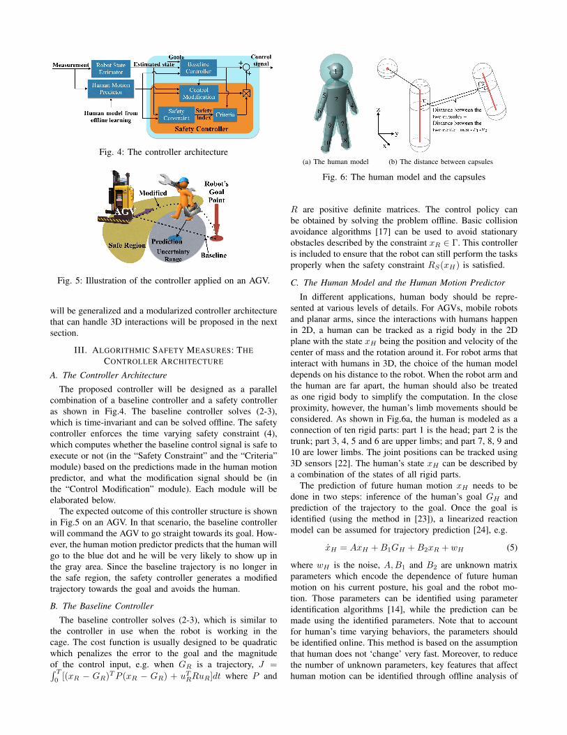
Fig. 4: The controller architecture
Fig. 5: Illustration of the controller applied on an AGV.
will be generalized and a modularized controller architecturethat can handle 3D interactions will be proposed in the nextsection.
III. ALGORITHMIC SAFETY MEASURES: THECONTROLLER ARCHITECTURE
A. The Controller Architecture
The proposed controller will be designed as a parallelcombination of a baseline controller and a safety controlleras shown in Fig.4. The baseline controller solves (2-3),which is time-invariant and can be solved offline. The safetycontroller enforces the time varying safety constraint (4),which computes whether the baseline control signal is safe toexecute or not (in the “Safety Constraint” and the “Criteria”module) based on the predictions made in the human motionpredictor, and what the modification signal should be (inthe “Control Modification” module). Each module will beelaborated below.
The expected outcome of this controller structure is shownin Fig.5 on an AGV. In that scenario, the baseline controllerwill command the AGV to go straight towards its goal. How-ever, the human motion predictor predicts that the human willgo to the blue dot and he will be very likely to show up inthe gray area. Since the baseline trajectory is no longer inthe safe region, the safety controller generates a modifiedtrajectory towards the goal and avoids the human.
B. The Baseline Controller
The baseline controller solves (2-3), which is similar tothe controller in use when the robot is working in thecage. The cost function is usually designed to be quadraticwhich penalizes the error to the goal and the magnitudeof the control input, e.g. when GR is a trajectory, J =∫ T
0[(xR − GR)TP (xR − GR) + uTRRuR]dt where P and
(a) The human model (b) The distance between capsules
Fig. 6: The human model and the capsules
R are positive definite matrices. The control policy canbe obtained by solving the problem offline. Basic collisionavoidance algorithms [17] can be used to avoid stationaryobstacles described by the constraint xR ∈ Γ. This controlleris included to ensure that the robot can still perform the tasksproperly when the safety constraint RS(xH) is satisfied.
C. The Human Model and the Human Motion Predictor
In different applications, human body should be repre-sented at various levels of details. For AGVs, mobile robotsand planar arms, since the interactions with humans happenin 2D, a human can be tracked as a rigid body in the 2Dplane with the state xH being the position and velocity of thecenter of mass and the rotation around it. For robot arms thatinteract with humans in 3D, the choice of the human modeldepends on his distance to the robot. When the robot arm andthe human are far apart, the human should also be treatedas one rigid body to simplify the computation. In the closeproximity, however, the human’s limb movements should beconsidered. As shown in Fig.6a, the human is modeled as aconnection of ten rigid parts: part 1 is the head; part 2 is thetrunk; part 3, 4, 5 and 6 are upper limbs; and part 7, 8, 9 and10 are lower limbs. The joint positions can be tracked using3D sensors [22]. The human’s state xH can be described bya combination of the states of all rigid parts.
The prediction of future human motion xH needs to bedone in two steps: inference of the human’s goal GH andprediction of the trajectory to the goal. Once the goal isidentified (using the method in [23]), a linearized reactionmodel can be assumed for trajectory prediction [24], e.g.
xH = AxH +B1GH +B2xR + wH (5)
where wH is the noise, A,B1 and B2 are unknown matrixparameters which encode the dependence of future humanmotion on his current posture, his goal and the robot mo-tion. Those parameters can be identified using parameteridentification algorithms [14], while the prediction can bemade using the identified parameters. Note that to accountfor human’s time varying behaviors, the parameters shouldbe identified online. This method is based on the assumptionthat human does not ‘change’ very fast. Moreover, to reducethe number of unknown parameters, key features that affecthuman motion can be identified through offline analysis of
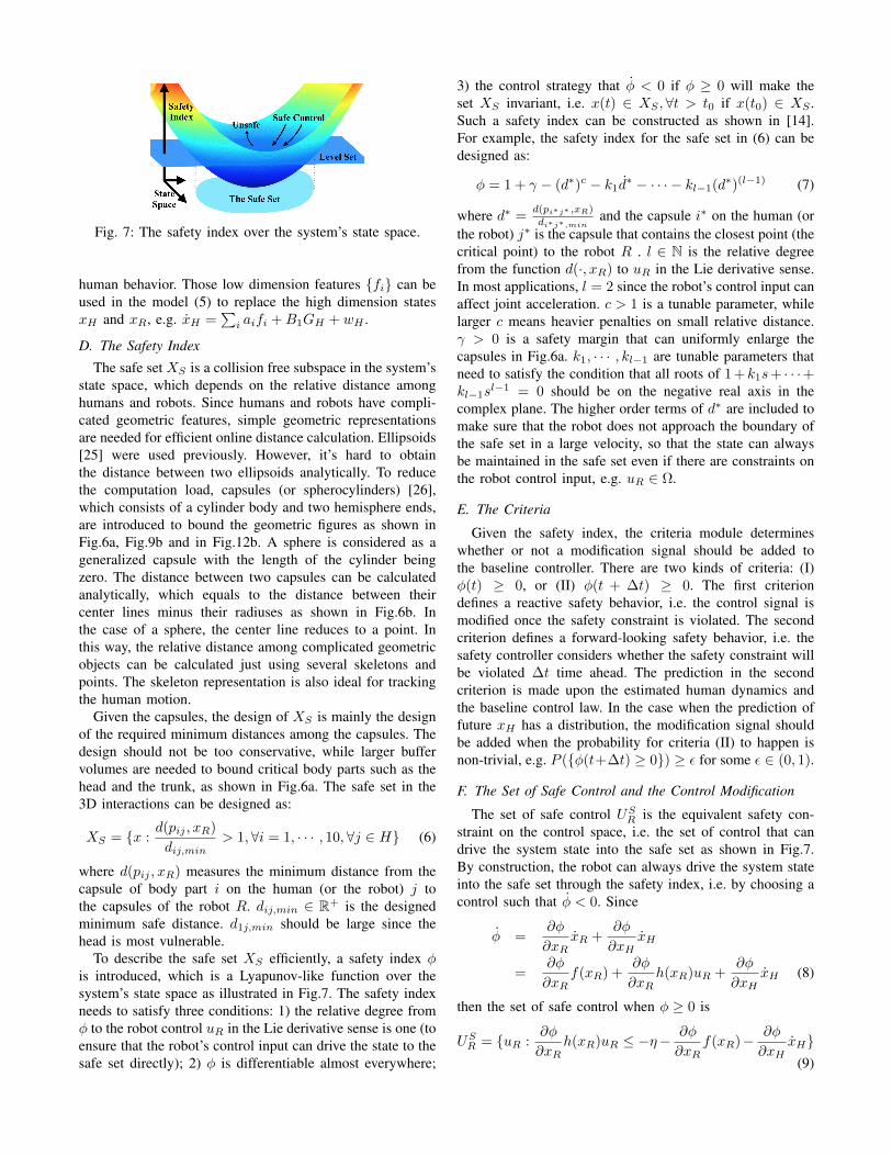
Fig. 7: The safety index over the system’s state space.
human behavior. Those low dimension features fi can beused in the model (5) to replace the high dimension statesxH and xR, e.g. xH =
∑i aifi +B1GH + wH .
D. The Safety Index
The safe set XS is a collision free subspace in the system’sstate space, which depends on the relative distance amonghumans and robots. Since humans and robots have compli-cated geometric features, simple geometric representationsare needed for efficient online distance calculation. Ellipsoids[25] were used previously. However, it’s hard to obtainthe distance between two ellipsoids analytically. To reducethe computation load, capsules (or spherocylinders) [26],which consists of a cylinder body and two hemisphere ends,are introduced to bound the geometric figures as shown inFig.6a, Fig.9b and in Fig.12b. A sphere is considered as ageneralized capsule with the length of the cylinder beingzero. The distance between two capsules can be calculatedanalytically, which equals to the distance between theircenter lines minus their radiuses as shown in Fig.6b. Inthe case of a sphere, the center line reduces to a point. Inthis way, the relative distance among complicated geometricobjects can be calculated just using several skeletons andpoints. The skeleton representation is also ideal for trackingthe human motion.
Given the capsules, the design of XS is mainly the designof the required minimum distances among the capsules. Thedesign should not be too conservative, while larger buffervolumes are needed to bound critical body parts such as thehead and the trunk, as shown in Fig.6a. The safe set in the3D interactions can be designed as:
XS = x :d(pij , xR)
dij,min> 1,∀i = 1, · · · , 10,∀j ∈ H (6)
where d(pij , xR) measures the minimum distance from thecapsule of body part i on the human (or the robot) j tothe capsules of the robot R. dij,min ∈ R+ is the designedminimum safe distance. d1j,min should be large since thehead is most vulnerable.
To describe the safe set XS efficiently, a safety index φis introduced, which is a Lyapunov-like function over thesystem’s state space as illustrated in Fig.7. The safety indexneeds to satisfy three conditions: 1) the relative degree fromφ to the robot control uR in the Lie derivative sense is one (toensure that the robot’s control input can drive the state to thesafe set directly); 2) φ is differentiable almost everywhere;
3) the control strategy that φ < 0 if φ ≥ 0 will make theset XS invariant, i.e. x(t) ∈ XS ,∀t > t0 if x(t0) ∈ XS .Such a safety index can be constructed as shown in [14].For example, the safety index for the safe set in (6) can bedesigned as:
φ = 1 + γ − (d∗)c − k1d∗ − · · · − kl−1(d∗)(l−1) (7)
where d∗ =d(pi∗j∗ ,xR)
di∗j∗,minand the capsule i∗ on the human (or
the robot) j∗ is the capsule that contains the closest point (thecritical point) to the robot R . l ∈ N is the relative degreefrom the function d(·, xR) to uR in the Lie derivative sense.In most applications, l = 2 since the robot’s control input canaffect joint acceleration. c > 1 is a tunable parameter, whilelarger c means heavier penalties on small relative distance.γ > 0 is a safety margin that can uniformly enlarge thecapsules in Fig.6a. k1, · · · , kl−1 are tunable parameters thatneed to satisfy the condition that all roots of 1 +k1s+ · · ·+kl−1s
l−1 = 0 should be on the negative real axis in thecomplex plane. The higher order terms of d∗ are included tomake sure that the robot does not approach the boundary ofthe safe set in a large velocity, so that the state can alwaysbe maintained in the safe set even if there are constraints onthe robot control input, e.g. uR ∈ Ω.
E. The Criteria
Given the safety index, the criteria module determineswhether or not a modification signal should be added tothe baseline controller. There are two kinds of criteria: (I)φ(t) ≥ 0, or (II) φ(t + ∆t) ≥ 0. The first criteriondefines a reactive safety behavior, i.e. the control signal ismodified once the safety constraint is violated. The secondcriterion defines a forward-looking safety behavior, i.e. thesafety controller considers whether the safety constraint willbe violated ∆t time ahead. The prediction in the secondcriterion is made upon the estimated human dynamics andthe baseline control law. In the case when the prediction offuture xH has a distribution, the modification signal shouldbe added when the probability for criteria (II) to happen isnon-trivial, e.g. P (φ(t+∆t) ≥ 0) ≥ ε for some ε ∈ (0, 1).
F. The Set of Safe Control and the Control Modification
The set of safe control USR is the equivalent safety con-
straint on the control space, i.e. the set of control that candrive the system state into the safe set as shown in Fig.7.By construction, the robot can always drive the system stateinto the safe set through the safety index, i.e. by choosing acontrol such that φ < 0. Since
φ =∂φ
∂xRxR +
∂φ
∂xHxH
=∂φ
∂xRf(xR) +
∂φ
∂xRh(xR)uR +
∂φ
∂xHxH (8)
then the set of safe control when φ ≥ 0 is
USR = uR :
∂φ
∂xRh(xR)uR ≤ −η−
∂φ
∂xRf(xR)− ∂φ
∂xHxH
(9)

where η ∈ R+ is a margin and xH comes from humanmotion predictor. When xH has a distribution, let Π be thecompact set that contains major probability mass of xH , e.g.P (xH ∈ Π) ≥ 1− ε for a small ε. Then the inequality in(9) should hold for all xH ∈ Π [15], as illustrated in Fig.3.
The non convex state space constraint RS(xH) is thentransferred to a linear constraint on the control space in (9).In this way, the modification signal is the optimal value to beadded to the baseline control law such that the final controllies in the set of safe control,
∆uR = arg minuoR+u∈US
R∩Ω∩UΓuTQu (10)
where Q ∈ Rm×m is positive definite which determines ametric on the robot’s control space. To obtain optimality, Qshould be close enough to the metric imposed by the costfunction J in (2), e.g. Q ≈ d2J/du2
R where J is assumedto be convex in uR. UΓ is the equivalent constraint on thecontrol space of the state space constraint Γ, which can beconstructed following the same procedure of constructingUSR . Equation (10) is a convex optimization problem and
is easy to solve. In the case that USR ∩ Ω ∩ UΓ is empty, a
smaller margin η can be chosen so that the feasible controlset becomes nonempty.
IV. CASE STUDIES
Simulation studies are performed to evaluate the safetymeasures on scenarios shown in Fig.1. The cases for AGVsand mobile robots are studied in [23]. In this paper, theinteractions among robot arms and humans will be studied.The architecture of the simulation system is shown in Fig.8,which consists of the human loop, the robot loop and theenvironment. The human subject is in the human loop, whocan observe the virtual environment through the screen andwhose reaction will be captured by the sensors (e.g. touchpador Kinect). The human animator reads the tracking data fromthe sensors and sends the human figure to the environmentfor display. In the robot loop, the robot animator reads thenoisy human data from the environment, computes the safeand efficient trajectory and then sends the real time robotfigure to the environment.
A. Planar Robot Arm
The planar robot arm is shown in Fig.9a. Denote thejoint angle as θ = [θ1, θ2]T . The dynamic equation of therobot arm is M(θ)θ + N(θ, θ) = τR where M(·) is thegeneralized inertia matrix and N(·, ·) is the Coriolis and
Fig. 8: The simulation system
(a) The planar robot arm (b) The simulation environment
Fig. 9: The planar robot arm and the simulation environment
centrifugal forces [27]. Both functions depend on the robotstate xR = [θT , θT ]T . uR = τR is the torque input. The statespace equation of the planar robot is affine:
xR =
[θ
−M−1(θ)N(θ, θ)
]+
[0
M−1(θ)
]uR (11)
The simulation environment is shown in Fig.9b wherethe robot arm is wrapped in two capsules. The verticaldisplacement of the robot arm is ignored. The human isshown as a blue circle, which is controlled in real time bya human user through a multi-touch pad. Both the humanand the robot need to approach their respective goal pointsin minimum time. New goals will be generated when the oldone is approached.
The baseline controller is designed as a computed torquecontroller with settle point GR. The safety index is designedas φ = D−d2− d, where d measures the minimum distancebetween the human and the robot arm and D = d2
min(1 +γ). The sampling frequency is 20hz. Due to the limitationof bandwidth, both reactive and forward-looking criteria areused, in order not to violate the safety constraints betweentwo samples. The set of safe control US
R(k) at time k isthe intersection of the two sets: U1 = uR(k) : φ(k) ≤ ηwhen φ(k) ≥ 0 and U2 = uR(k) : φ(k + 1) < 0. Thecomputation of U1 follows from (9). The computation of U2
is similar and is discussed in details in [15]. The metric Q ischosen to be M(θ), which puts larger penalties on the torquemodification applied to heavier link, thus is energy efficient.
The simulation result is shown in Fig.10 and Fig.11. Thefirst plot in Fig.10 shows the critical point on the arm that isthe closest to the human capsule. The orange area representsthe first link (y = 0 is the base) and yellow area representsthe second link (y = 0.55m is the endpoint). The second plotshows the distance from the robot endpoint to the robot’sgoal position. The third plot shows the relative distance dbetween the robot capsules and the human capsule, whilethe red area represents the danger zone d < dmin. Thebars in the fourth plot illustrate whether the safety controlleris active (green) or not (white) at each time step. Duringthe simulation, the robot was close to its goal at k = 55and at k = 110 before it finally approached it at k = 220.However, since the human was too close to the robot in thattwo cases, going to the goal was dangerous. Then the safetycontroller went active and the robot arm detoured to avoid

20 40 60 80 100 120 140 160 180 200 2200
0.5
m
Critical position on the link
20 40 60 80 100 120 140 160 180 200 2200
0.2
0.4Distance to the Goal
m
20 40 60 80 100 120 140 160 180 200 2200
0.5
Relative distance d between the human and the robot
m
20 40 60 80 100 120 140 160 180 200 2200
0.5
1Safety Controller Activity
Fig. 10: The simulation profile of the planar robot
(a) k = 110 : 5 : 140 (b) k = 160 : 5 : 220
Fig. 11: The simulated response of the planar robot
the human. This scenario is also illustrated in Fig.11(a), the5-times down-sampled snapshots from time step 110 to 140,denote as k = 110 : 5 : 140. Lighter color corresponds tosmaller k. Due to the safety controller, the relative distancewas always maintained above the danger zone. Figure 11(b)shows the snapshots at k = 160 : 5 : 220. As the human wasfar from the robot arm, the safety controller was inactive andthe robot finally approached its goal.
B. Six Degree of Freedom Robot Arm
In this case study, the Fanuc M16iB robot arm is used asshown in Fig.2 and the simulation environment is shown inFig.12a. Capsules are calculated for both the human and therobot as shown in Fig.12b. The radius of the capsules are de-signed such that one uniform minimum distance requirementdmin = 0.2m can be used for all capsules. Denote the robotstate as xR = [θT , θT ]T where θ = [θ1, θ2, θ3, θ4, θ5, θ6]T
are the joint angles. uR = θ is the joint acceleration. Thecontrol modification is done in the kinematic level. A perfectlow level tracking controller is assumed. The state spaceequation of the robot arm is linear:
xR = AxR +BuR (12)
where AR =
[06×6 I6×6
06×6 06×6
]and BR =
[06×6
I6×6
].
(a) The 3D simulation environment (b) The capsules
Fig. 12: The 3D simulation environment
GR is to follow a path in the Cartesian space. The baselinecontroller is a feedback and feedforward controller. Thehuman is moving around the robot arm. The safety index isthe same as in the previous case, e.g. φ = D−d2− d, whered is computed analytically [28]. The sampling frequency is20hz. The forward-looking criteria is used. The set of safecontrol is US
R(k) = uR(k) : φ(k + 1) < 0, and Q = I .The simulation results are shown in Fig.13, Fig.14 and
Fig.15. The first plot in Fig.13 shows the critical capsuleID on the robot arm that contains the closest point to thehuman and the second plot shows the critical capsule ID onthe human that contains the closest point to the robot. Duringinteractions, those critical points changed from time to time.The minimum distance between the human and the robotis shown in the third figure, which was maintained abovethe danger zone during the simulation. The tracking erroris shown in the fourth plot. When the human was far fromthe robot, perfect tracking can be achieved from k = 100to k = 200. When the human went close to the robot atk = 230, the safety controller took over and moved the robotarm away from the human, at the cost of large tracking error.The snapshots at k = 230 : 5 : 250 are shown in Fig.14.Another human avoidance behavior at k = 310 : 10 : 350is shown in Fig.15, with the solid spheres representing thereference path at each time step. The robot stopped trackingthe path that moved towards the human by moving backward.In this simulation, the human subject can only control theplanar movement of the dummy. The simulation that captureshuman’s whole body movement using Kinect is shown in thevideo attachment.
The algorithms are run in Matlab (using .m file) on amacbook of 2.3 GHz using Intel Core i7. The running timeof the safety controller is shown in Table I. The averagerunning time of the safety controller is 9.5ms, which isdominated by the time in finding the critical points, e.g.calculating the minimum distance between the robot and thehuman. This is because finding the critical points involves6 × 10 distance calculations between capsules. If only thefirst three joints of the robot arm are considered, e.g. onlythree robot capsules are used in calculation, the running timeis reduced to 5.5ms. If the number of human capsules isreduced to two, the running time for the safety controlleris reduced to 2.7ms. Moreover, the running time of the

TABLE I: Running time of the safety controller
Robot arm:degree offreedom
Humanmodel
Running timeof the safety
controller
Running timein finding
critical points6 DoF 10 capsules 9.5ms 8.8ms3 DoF 10 capsules 5.5ms 5.0ms6 DoF 2 capsules 2.7ms 2.0ms3 DoF 10 spheres 0.77ms 0.40ms
Fig. 13: The simulation profile of the 6DoF robot arm
safety controller is only 0.77ms if the human geometryis represented using spheres. However, the spheres cannotdescribe the geometry as accurate as the capsules do andmay be too conservative. In conclusion, current algorithmscan support at least 100Hz sampling frequency and thecomputation time can be further reduced if faster algorithmsare developed for distance calculation.
V. DISCUSSIONS AND CONCLUSIONS
This paper discussed the algorithmic safety measures forindustrial robots working in a human-involved environment.The control problem was posed as a constrained optimalcontrol problem and a unique parallel controller structurewas proposed to solve the problem. The control problemwas separated into two parts: the efficiency goal with time-invariant constraints and the time-varying safety constraint.The first part was solved by the baseline controller and thesafety constraint was enforced by the safety controller. Thisseparation is ideal due to the following reasons:• There is no need to solve the original problem in a
long time horizon, since the uncertainties of the hu-man motion will accumulate. And the safety constraintRS(xH) is only active in a small amount of time asevidenced in the simulations. The separation respectsdifferent natures of the constraints, by allowing thebaseline controller to do long term planning without thetime varying constraint and letting the safety controllerto do local modification regarding the time varyingconstraint.
• This separation can also be validated by analyticallysolving the optimal control problem. Suppose GR =
(a) The lateral view (b) The top view
Fig. 14: The simulated response of the 6DoF robot arm:scenario 1
xR = 0 and J =∫ T
0(xTRPxR +uTRRuR)dt. Let Ω,Γ
be the whole space and RS(xH) = xR : φ(xR, xH) <0. Assume h(xR) = B. Then the Lagrangian [29] ofthe optimal control problem (2-4) is
L = xTRPxR + uTRRuR + λ(f(xR) +BuR) + ηφ (13)
where λ, η are adjoint variables and η = 0 if φ < 0. Thepartial derivatives from L to uR is Lu = 2(RuR)T +λB + ηφxR
B. Setting Lu = 0, the optimal control lawbecomes
uR = −1
2R−1BTλT − 1
2ηR−1BTφTxR
(14)
where the first term on the RHS is not related to thesafety constraint, which can be viewed as the baselinecontrol law; the second term is concerned with thesafety constraint, which is nontrivial only if φ ≥ 0,e.g. the safety constraint is violated. Nonetheless, theoptimality of this separation will be studied for morecomplicated problems in the future.
Moreover, the separation offers more freedom in designingthe robot behavior and is good for parallel computation.
In conclusion, the controller design procedure is:1) Design the baseline controller that can handle the goal
and the time invariant constraints.2) Wrap every moving rigid body with a capsule to
simplify the geometry.3) Design the safe set XS which specifies the required
distance among capsules.4) Design the safety index φ based on the safe set XS
and the robot dynamics.5) Choose the control modification criteria and design the
control modification metric Q.6) Design the human motion predictor.To fully realize the scenario in Fig.1, more aspects in
the controller design needs to be investigated. For example,as the number of agents in the system increases, the non-convexity of the problem will increase. Methods to avoidlocal optima need to be developed. Moreover, the safe controlmethod for human robot cooperation that involves contactsalso needs to be studied.

(a) The lateral view
(b) The left view
Fig. 15: The simulated response of the 6DoF robot arm:scenario 2
Nonetheless, the controller structure proposed is of im-portance as it is a method to handle constraints of differentnatures and to deal with multiple objectives, whose effec-tiveness is demonstrated both in simulation and in analysis.
REFERENCES
[1] G. Charalambous, “Human-automation collaboration in manufactur-ing: Identifying key implementation factors,” in Proceedings of Er-gonomics & Human Factors, 2013 International Conference on. CRCPress, 2013, p. 59.
[2] J. Kruger, T. Lien, and A. Verl, “Cooperation of human and machinesin assembly lines,” CIRP Annals-Manufacturing Technology, vol. 58,no. 2, pp. 628–646, 2009.
[3] G. Ulusoy, F. Sivrikaya-Serifoglu, and U. Bilge, “A genetic algorithmapproach to the simultaneous scheduling of machines and automatedguided vehicles,” Computers and Operations Research, vol. 24, no. 4,pp. 335–351, 1997.
[4] “Working with robots: Our friends electirc,” The Economist, Sep2013. [Online].
[5] T. S. Tadele, T. J. d. Vries, and S. Stramigioli, “The safety of domesticrobots: a survey of various safety-related publications,” Robotics andAutomation Magazine, IEEE, pp. 134–142, Sep 2014.
[6] C. Harper and G. Virk, “Towards the development of internationalsafety standards for human robot interaction,” International Journalof Social Robotics, vol. 2, no. 3, pp. 229–234, 2010.
[7] T. M. Anandan. (2014, Sep) Major robot OEMs fast-tracking cobots.[Online].
[8] G. Hirzinger, A. Albu-Schaffer, M. Hahnle, I. Schaefer, and N. Sporer,“On a new generation of torque controlled light-weight robots,” in Pro-ceedings of Robotics and Automation (ICRA), 2001 IEEE InternationalConference on, vol. 4. IEEE, 2001, pp. 3356–3363.
[9] M. Zinn, B. Roth, O. Khatib, and J. K. Salisbury, “A new actuationapproach for human friendly robot design,” The International Journalof Robotics Research, vol. 23, no. 4-5, pp. 379–398, 2004.
[10] R. C. Luo, H. B. Huang, C. Yi, and Y. W. Perng, “Adaptive impedancecontrol for safe robot manipulator,” in Proceedings of IntelligentControl and Automation (WCICA), 2011 9th World Congress on.IEEE, 2011, pp. 1146–1151.
[11] K. Yamazaki, R. Ueda, S. Nozawa, M. Kojima, K. Okada, K. Mat-sumoto, M. Ishikawa, I. Shimoyama, and M. Inaba, “Home-assistantrobot for an aging society,” Proceedings of the IEEE, vol. 100, no. 8,pp. 2429–2441, 2012.
[12] J. Pineau, M. Montemerlo, M. Pollack, N. Roy, and S. Thrun,“Towards robotic assistants in nursing homes: Challenges and results,”Robotics and Autonomous Systems, vol. 42, no. 3, pp. 271–281, 2003.
[13] S. Haddadin, M. Suppa, S. Fuchs, T. Bodenmuller, A. Albu-Schaffer,and G. Hirzinger, “Towards the robotic co-worker,” in RoboticsResearch, ser. Springer Tracts in Advanced Robotics, C. Pradalier,R. Siegwart, and G. Hirzinger, Eds. Springer Berlin Heidelberg,2011, vol. 70, pp. 261–282.
[14] C. Liu and M. Tomizuka, “Control in a safe set: Addressing safety inhuman robot interactions,” in Dynamic Systems and Control Confer-ence (DSCC). ASME, 2014, p. V003T42A003.
[15] ——, “Safe exploration: Addressing various uncertainty levels inhuman robot interactions,” in American Control Conference (ACC),2015, pp. 465 – 470.
[16] N. E. Du Toit and J. W. Burdick, “Robot motion planning in dynamic,uncertain environments,” Robotics, IEEE Transactions on, vol. 28,no. 1, pp. 101–115, 2012.
[17] J. Schulman, J. Ho, A. Lee, I. Awwal, H. Bradlow, and P. Abbeel,“Finding locally optimal, collision-free trajectories with sequentialconvex optimization,” in Robotics: Science and Systems (RSS), 2013.
[18] E. A. Sisbot, L. F. Marin-Urias, X. Broquere, D. Sidobre, andR. Alami, “Synthesizing robot motions adapted to human presence,”International Journal of Social Robotics, vol. 2, no. 3, pp. 329–343,2010.
[19] J. J. Kuffner and S. M. LaValle, “RRT-connect: An efficient approachto single-query path planning,” in Proceedings of Robotics and Au-tomation (ICRA), 2000 IEEE International Conference on, vol. 2.IEEE, 2000, pp. 995–1001.
[20] D.-H. Park, H. Hoffmann, P. Pastor, and S. Schaal, “Movement re-production and obstacle avoidance with dynamic movement primitivesand potential fields,” in Proceedings of Humanoid Robots, 2008 IEEE-RAS International Conference on. IEEE, 2008, pp. 91–98.
[21] L. Gracia, F. Garelli, and A. Sala, “Reactive sliding-mode algorithmfor collision avoidance in robotic systems,” Control Systems Technol-ogy, IEEE Transactions on, vol. 21, no. 6, pp. 2391–2399, 2013.
[22] L. A. Schwarz, A. Mkhitaryan, D. Mateus, and N. Navab, “Humanskeleton tracking from depth data using geodesic distances and opticalflow,” Image and Vision Computing, vol. 30, no. 3, pp. 217–226, 2012.
[23] C. Liu and M. Tomizuka, “Modeling and controller design of coop-erative robots in workspace sharing human-robot assembly teams,” inProceedings of Intelligent Robots and Systems (IROS), 2014 IEEE/RSJInternational Conference on. IEEE, 2014, pp. 1386–1391.
[24] W. Zhang, X. Chen, J. Bae, and M. Tomizuka, “Real-time kinematicmodeling and prediction of human joint motion in a networkedrehabilitation system,” in American Control Conference (ACC), 2015,pp. 5800–5805.
[25] C.-S. Tsai, J.-S. Hu, and M. Tomizuka, “Ensuring safety in human-robot coexistence environment,” in Proceedings of Intelligent Robotsand Systems (IROS), 2014 IEEE/RSJ International Conference on.IEEE, 2014, pp. 4191–4196.
[26] V. Macagon and B. Wunsche, “Efficient collision detection for skele-tally animated models in interactive environments,” in Proceedings ofIVCNZ, vol. 3. Citeseer, 2003, pp. 378–383.
[27] H. Cheng, “Vision and inertial sensor based drive trains control,” Ph.D.dissertation, University of California at Berkeley, 2010.
[28] D. Eberly, Robust Computation of Distance Between Line Segments,Geometric Tools, LLC, 2015.
[29] R. F. Hartl, S. P. Sethi, and R. G. Vickson, “A survey of the maximumprinciples for optimal control problems with state constraints,” SIAMreview, vol. 37, no. 2, pp. 181–218, 1995.