ala5 2-wire 4-20ma atex load cell amplifier 2-wire 4-20ma atex . load cell amplifier . ... the...
TRANSCRIPT
ALA5 2-Wire 4-20mA ATEX
Load Cell Amplifier ICA5ATEX Strain Gauge or Load Cell Analogue Amplifier Mounted Inside
an In-Line Stainless Steel Enclosure (ILEATEX)
User Manual mantracourt.com

Mantracourt Electronics Limited ALA5, ILEAtex and ICA5Atex User Manual
1
Contents Chapter 1 The ALA5 ..................................................................................................................... 2 Chapter 2: Installing the ALA5 ........................................................................................................ 2 Pre Installation ............................................................................................................................ 2 Connections: ............................................................................................................................... 3 Standard cable: ........................................................................................................................... 3 Table 1 ..................................................................................................................................... 3 Cable colour code: ....................................................................................................................... 4 Alternative Cable types .................................................................................................................. 4 Figure 2.1 Connection Details for the ALA5 .......................................................................................... 4 Output Connections ...................................................................................................................... 5 Output Shunt Resistance Formula ..................................................................................................... 5 Chapter 3: Calibration .................................................................................................................. 5 Chapter 4: Changing the Gain and Offset Ranges................................................................................. 6 Figure 4.1 .................................................................................................................................. 6 Calculating the Gain Resistor (R2) ..................................................................................................... 7 Offset Resistor (R1) ...................................................................................................................... 7 Chapter 5: OEM Customers ............................................................................................................ 7 The ICA5ATEX Connections .............................................................................................................. 8 ILEATEX Enclosure ........................................................................................................................ 8 Chapter 6: Specifications .............................................................................................................. 9 Table 6.1 ICA5ATEX – 4-20mA 2 wire Specifications ................................................................................ 9 Table 6.2 ILEATEX Enclosure Specifications .......................................................................................... 9 Environmental Approvals ............................................................................................................... 10 Appendix A: Special Conditions of Safe Use ...................................................................................... 10 ATEX Marking: ............................................................................................................................ 11 EC DECLARATION OF CONFORMITY ................................................................................................. 12 ALA5 Certificate: ....................................................................................................................... 13 ICA5ATEX Certificate: ................................................................................................................. 17 ILEATEX Certificate: ..................................................................................................................... 21
Mantracourt Electronics Limited ALA5, ILEAtex and ICA5Atex User Manual
2
Chapter 1 The ALA5 The ALA5 is an ATEX certified (intrinsic safety) 2-wire 4-20mA amplifier providing a wide range of signal conditioning for Strain Gauges, Load Cells, Pressure and Torque Transducers. Combining the ICA5ATEX miniature loadcell amplifier with the stainless steel ILEATEX enclosure produces a compact, robust and certified in-line amplifier suitable for use in zones 0, 1, and 2 in hazardous locations. The ICA5ATEX is designed for a 1k bridge, however, 350R can be used at the expense of noise and drift performance. Please note: the ICA5ATEX amplifier’s output is uni-polar output i.e. zero strain input = 4mA and full range input = 20mA output. Sensitivity adjustment, between 0.5 mV/V and 55 mV/V is achieved by a combination of the SPAN (gain) resistor R2 (see fig 4.1) and associated fine adjustment by potentiometer. Chapter 4 gives details of how to calculate a new value for R2 to suit loadcell outputs other than the factory set 2.5mV/V. Similarly transducer ZERO can be compensated for in the module. This adjustment is to compensate for slight errors in the strain gauge and not to offset tare. The value of R1 (see fig 4.1) can be modified to increase the trim range of the zero point (see chapter 4).
Chapter 2: Installing the ALA5 Pre Installation Carefully remove the ALA5 unit from its shipment box. Check that the unit is complete and undamaged. The ALA5 can be installed in any industrial environment providing the following limits and ATEX conditions of use are met. Please refer to Appendix A – ‘Special conditions of safe use’
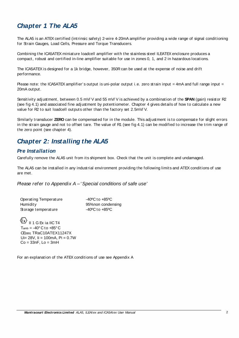
Operating Temperature -40ºC to +85ºC Humidity 95% non condensing Storage temperature -40ºC to +85ºC
II 1 G Ex ia IIC T4 Tamb = -40°C to +85°C CE0891 TRaC10ATEX11247X Ui= 28V, Ii = 100mA, Pi = 0.7W Co = 33nF, Lo = 3mH For an explanation of the ATEX conditions of use see Appendix A
Mantracourt Electronics Limited ALA5, ILEAtex and ICA5Atex User Manual
3
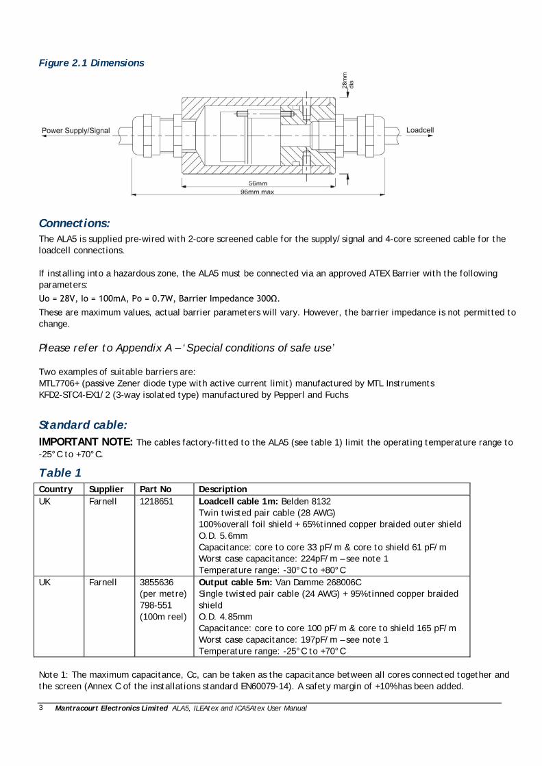
Figure 2.1 Dimensions
Connections: The ALA5 is supplied pre-wired with 2-core screened cable for the supply/signal and 4-core screened cable for the loadcell connections. If installing into a hazardous zone, the ALA5 must be connected via an approved ATEX Barrier with the following parameters:
Uo = 28V, Io = 100mA, Po = 0.7W, Barrier Impedance 300Ω.
These are maximum values, actual barrier parameters will vary. However, the barrier impedance is not permitted to change. Please refer to Appendix A – ‘Special conditions of safe use’ Two examples of suitable barriers are: MTL7706+ (passive Zener diode type with active current limit) manufactured by MTL Instruments KFD2-STC4-EX1/2 (3-way isolated type) manufactured by Pepperl and Fuchs
Standard cable: IMPORTANT NOTE: The cables factory-fitted to the ALA5 (see table 1) limit the operating temperature range to -25°C to +70°C.
Table 1 Country Supplier Part No Description UK Farnell 1218651 Loadcell cable 1m: Belden 8132
Twin twisted pair cable (28 AWG) 100% overall foil shield + 65% tinned copper braided outer shield O.D. 5.6mm Capacitance: core to core 33 pF/m & core to shield 61 pF/m Worst case capacitance: 224pF/m – see note 1 Temperature range: -30°C to +80°C
UK Farnell 3855636 (per metre) 798-551 (100m reel)
Output cable 5m: Van Damme 268006C Single twisted pair cable (24 AWG) + 95% tinned copper braided shield O.D. 4.85mm Capacitance: core to core 100 pF/m & core to shield 165 pF/m Worst case capacitance: 197pF/m – see note 1 Temperature range: -25°C to +70°C
Note 1: The maximum capacitance, Cc, can be taken as the capacitance between all cores connected together and the screen (Annex C of the installations standard EN60079-14). A safety margin of +10% has been added.
Mantracourt Electronics Limited ALA5, ILEAtex and ICA5Atex User Manual
4
The ground connection conductor should have sufficient cross-sectional area to ensure a low impedance path to attenuate RF interference.
Cable colour code: Power/signal Red Supply + Green Com
Loadcell Orange/White +Exc White/Orange -Exc Blue/White +In White/Blue -In
Alternative Cable types The type of cable used should be suitable for use in the hazardous area with particular regard to the certified -40°C to +85°C temperature range of the ALA5. The cable should comprise twin twisted pairs of cables – four-core for the loadcell and a single pair for the power/signal. Each cable should have an overall braid to ensure a good EMC seal with the glands on the ALA5.
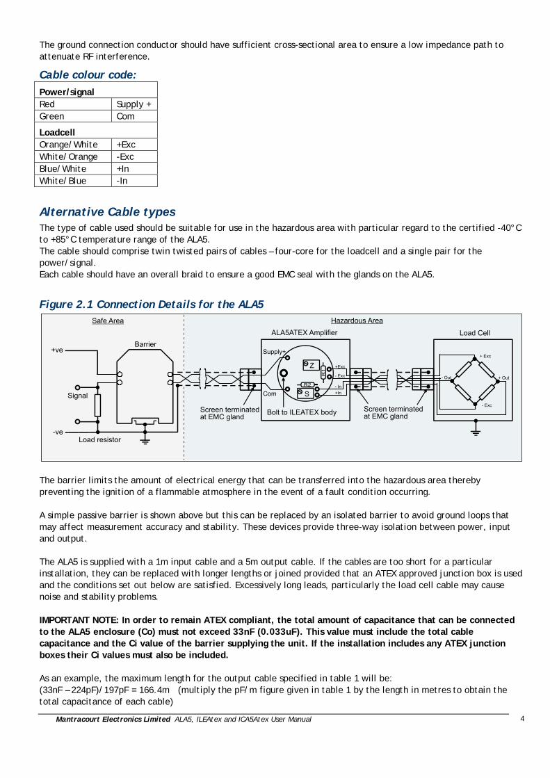
Figure 2.1 Connection Details for the ALA5
The barrier limits the amount of electrical energy that can be transferred into the hazardous area thereby preventing the ignition of a flammable atmosphere in the event of a fault condition occurring. A simple passive barrier is shown above but this can be replaced by an isolated barrier to avoid ground loops that may affect measurement accuracy and stability. These devices provide three-way isolation between power, input and output. The ALA5 is supplied with a 1m input cable and a 5m output cable. If the cables are too short for a particular installation, they can be replaced with longer lengths or joined provided that an ATEX approved junction box is used and the conditions set out below are satisfied. Excessively long leads, particularly the load cell cable may cause noise and stability problems. IMPORTANT NOTE: In order to remain ATEX compliant, the total amount of capacitance that can be connected to the ALA5 enclosure (Co) must not exceed 33nF (0.033uF). This value must include the total cable capacitance and the Ci value of the barrier supplying the unit. If the installation includes any ATEX junction boxes their Ci values must also be included. As an example, the maximum length for the output cable specified in table 1 will be: (33nF – 224pF)/197pF = 166.4m (multiply the pF/m figure given in table 1 by the length in metres to obtain the total capacitance of each cable)

Mantracourt Electronics Limited ALA5, ILEAtex and ICA5Atex User Manual
5
Please refer to Appendix A – ‘Special conditions of safe use’ For special cable types e.g. high temperature, armoured etc. please contact Mantracourt Electronics.
Output Connections The ICA5ATEX analogue output is 4 to 20mA. The power and signal are combined in a single pair cable, simplifying installation. N.B. Neither connection to the output load is electrically common to the load cell. The following formula gives the suitable range of shunt resistance for low supply voltage operation.
Output Shunt Resistance Formula The shunt resistance must be less than: ((V supply -9) / 20mA) – Rwiring e.g. assuming 10 Ohms wiring resistance and 24V supply: Max shunt resistance = ((24 - 9) / 0.02) –10 = 740 Ohms
Chapter 3: Calibration In order to calibrate the ALA5 the cover of the enclosure must be removed as follows: Mechanical tools required: 1.5mm hex key, 14mm AF spanner and flat-blade screwdriver, maximum width 1.5mm.
1. Remove the two grub screws using a
1.5mm hex key
2. Loosen the gland furthest away from the
grub screw holes using a 14mm AF spanner.
Mantracourt Electronics Limited ALA5, ILEAtex and ICA5Atex User Manual
6
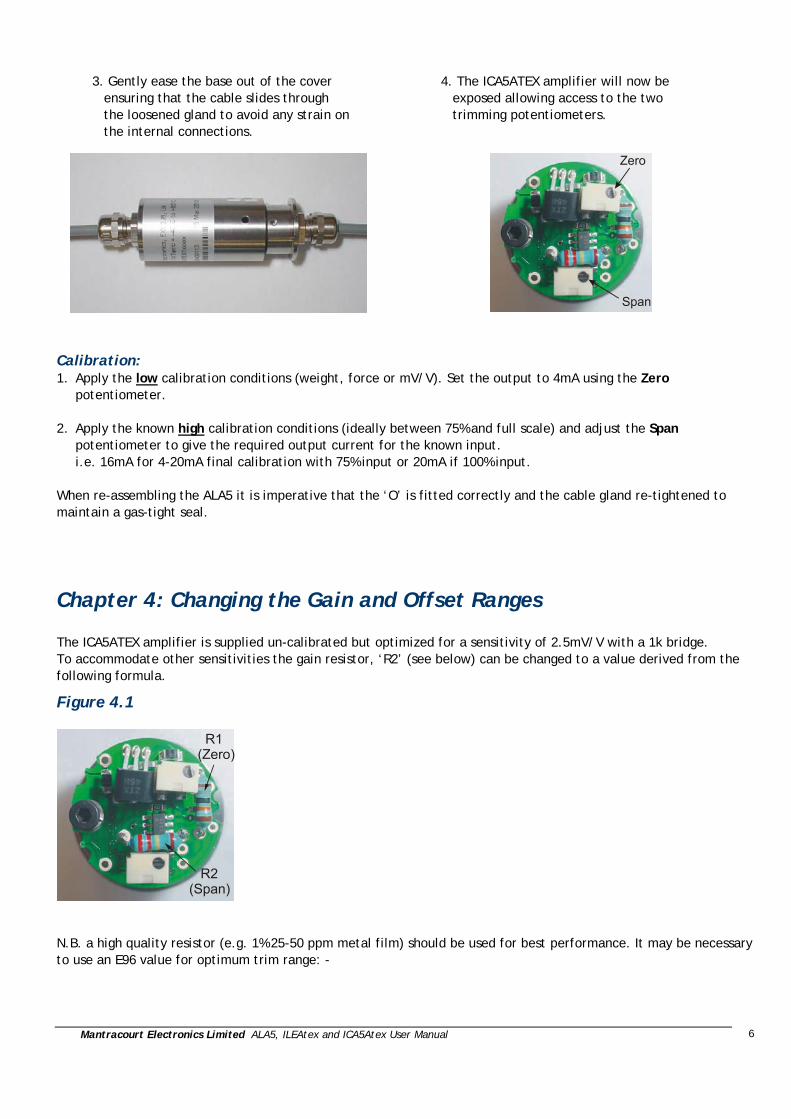
3. Gently ease the base out of the cover
ensuring that the cable slides through the loosened gland to avoid any strain on the internal connections.
4. The ICA5ATEX amplifier will now be
exposed allowing access to the two trimming potentiometers.
Calibration: 1. Apply the low calibration conditions (weight, force or mV/V). Set the output to 4mA using the Zero
potentiometer. 2. Apply the known high calibration conditions (ideally between 75% and full scale) and adjust the Span
potentiometer to give the required output current for the known input. i.e. 16mA for 4-20mA final calibration with 75% input or 20mA if 100% input.
When re-assembling the ALA5 it is imperative that the ‘O’ is fitted correctly and the cable gland re-tightened to maintain a gas-tight seal.
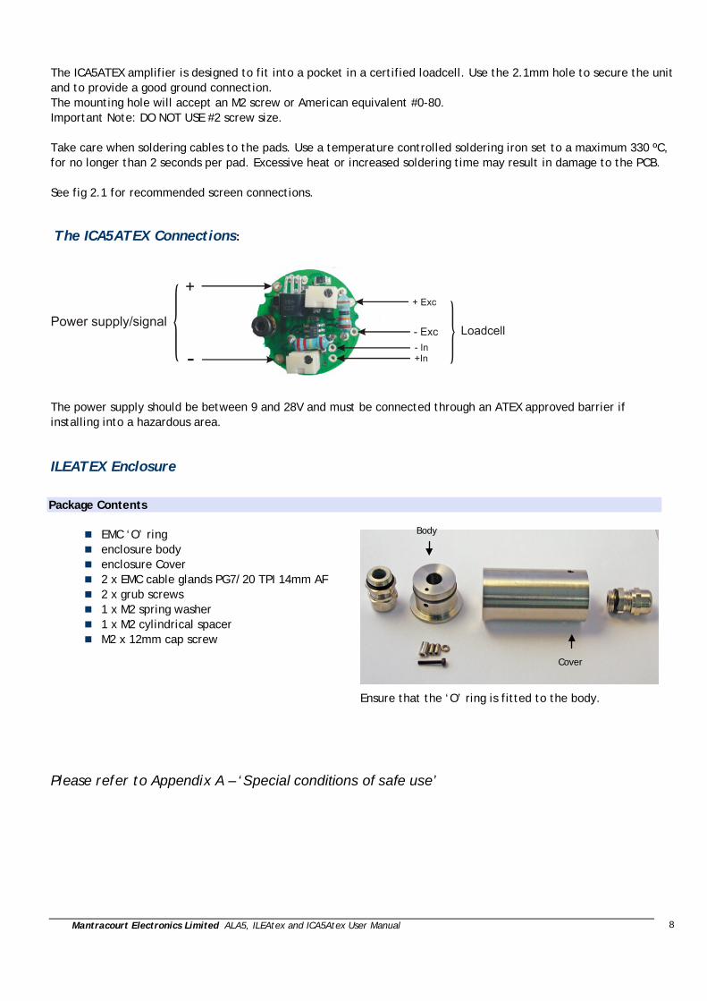
Chapter 4: Changing the Gain and Offset Ranges The ICA5ATEX amplifier is supplied un-calibrated but optimized for a sensitivity of 2.5mV/V with a 1k bridge. To accommodate other sensitivities the gain resistor, ‘R2’ (see below) can be changed to a value derived from the following formula.
Figure 4.1
N.B. a high quality resistor (e.g. 1% 25-50 ppm metal film) should be used for best performance. It may be necessary to use an E96 value for optimum trim range: -

Mantracourt Electronics Limited ALA5, ILEAtex and ICA5Atex User Manual
7
Calculating the Gain Resistor (R2)
−
×= 10
)/(2.10692VexcVmV
R k Ohms
Where VmV / is the sensitivity of the load cell (in mV/V), Vexc is the excitation voltage (in volts). The following table gives calculated values of Vexc for various standard load cell impedances:
Load Cell Impedance Excitation voltage (Vexc) 350 0.53 700 0.87 1000 1.08 1400 1.29 2000 1.51 5000 1.97 e.g. For a 2.5mV/V 1000 Ohm load cell : R2 = 386k Ohms – use 390k (nearest preferred value) Use the following formulae to calculate the excitation voltage for cell impedances not given in the table:
−×+
=6exp10762.4)/1(
1Rcell
Rx Ohms
+×
=1300
5.2Rx
RxVexc Volts
e.g. for a 500 Ohm load cell: Rx = 498.8 Ohms Excitation Voltage, Vexc = 0.693V
Offset Resistor (R1) The value of R1 can be changed to offset the zero point, if outside the normal trimming range (±2% FS). Its value will also depend on the impedance of the load cell. The factory-fitted value, 180k is optimised for a 1000 Ohm cell. If a 350 Ohm cell is used, R1 should be reduced to 30k to achieve a trim range of ±2% FS
Chapter 5: OEM Customers IMPORTANT: OEM customers must hold a notified body Quality Assurance Notification (QAN) if the ICA5ATEX is to be installed into a Mantracourt ATEX approved ‘generic’ enclosure. If installed into a non-ATEX approved enclosure, the whole assembly must be submitted for ATEX certification by an appropriate body. Please refer to Appendix A – ‘Special conditions of safe use’
Mantracourt Electronics Limited ALA5, ILEAtex and ICA5Atex User Manual
8
The ICA5ATEX amplifier is designed to fit into a pocket in a certified loadcell. Use the 2.1mm hole to secure the unit and to provide a good ground connection. The mounting hole will accept an M2 screw or American equivalent #0-80. Important Note: DO NOT USE #2 screw size. Take care when soldering cables to the pads. Use a temperature controlled soldering iron set to a maximum 330 ºC, for no longer than 2 seconds per pad. Excessive heat or increased soldering time may result in damage to the PCB. See fig 2.1 for recommended screen connections.
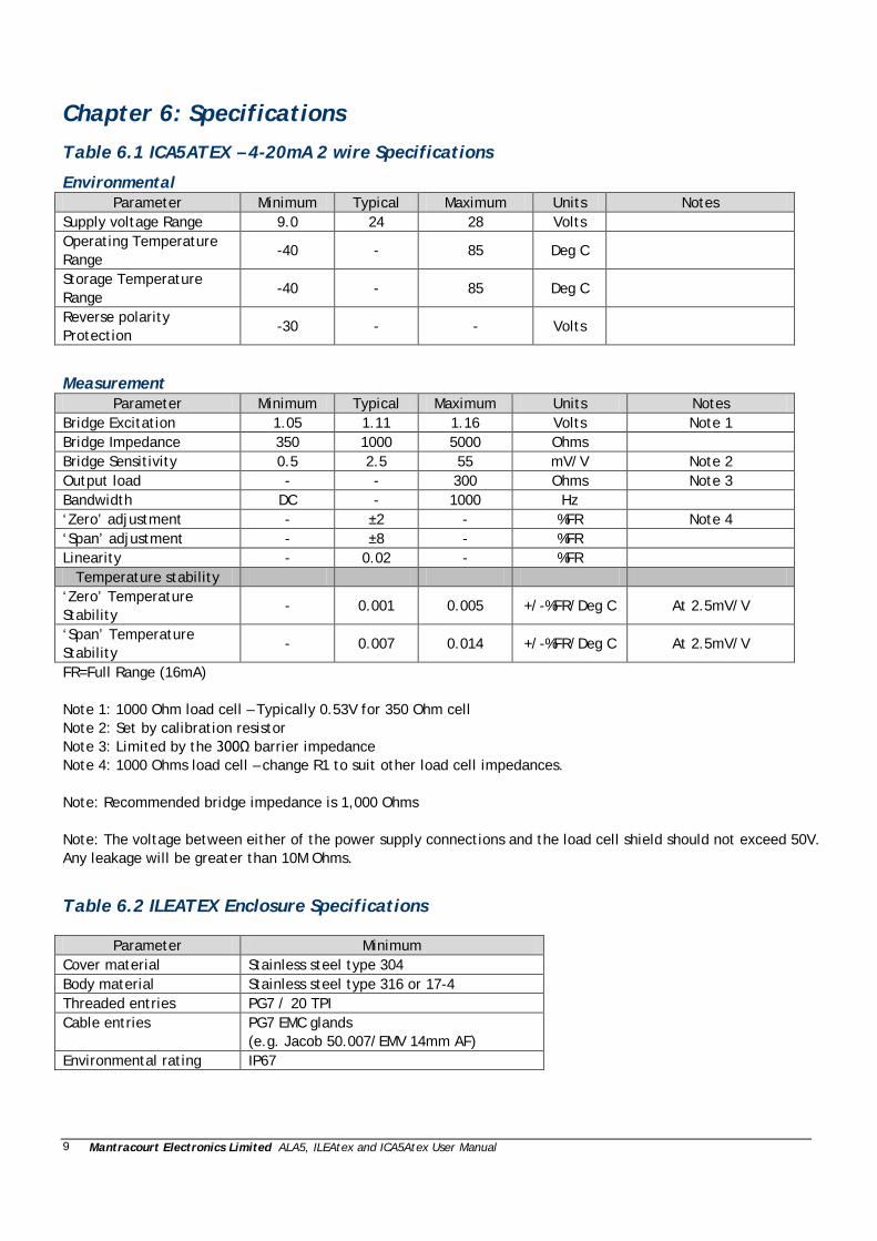
The ICA5ATEX Connections:
The power supply should be between 9 and 28V and must be connected through an ATEX approved barrier if installing into a hazardous area.
ILEATEX Enclosure
Package Contents
EMC ‘O’ ring enclosure body enclosure Cover 2 x EMC cable glands PG7/20 TPI 14mm AF 2 x grub screws 1 x M2 spring washer 1 x M2 cylindrical spacer M2 x 12mm cap screw
Ensure that the ‘O’ ring is fitted to the body.
Please refer to Appendix A – ‘Special conditions of safe use’
Body
Cover
Mantracourt Electronics Limited ALA5, ILEAtex and ICA5Atex User Manual
9
Chapter 6: Specifications
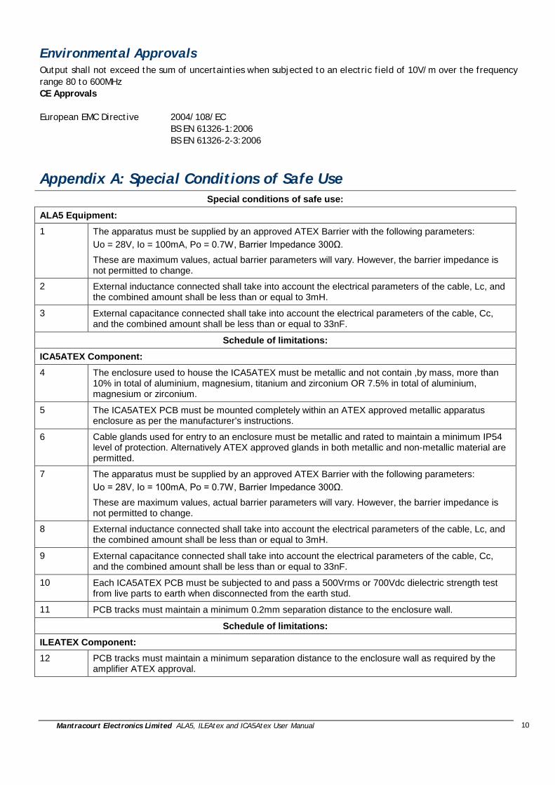
Table 6.1 ICA5ATEX – 4-20mA 2 wire Specifications
Environmental Parameter Minimum Typical Maximum Units Notes
Supply voltage Range 9.0 24 28 Volts Operating Temperature Range
-40 - 85 Deg C
Storage Temperature Range
-40 - 85 Deg C
Reverse polarity Protection
-30 - - Volts
Measurement Parameter Minimum Typical Maximum Units Notes
Bridge Excitation 1.05 1.11 1.16 Volts Note 1 Bridge Impedance 350 1000 5000 Ohms Bridge Sensitivity 0.5 2.5 55 mV/V Note 2 Output load - - 300 Ohms Note 3 Bandwidth DC - 1000 Hz ‘Zero’ adjustment - ±2 - %FR Note 4 ‘Span’ adjustment - ±8 - %FR Linearity - 0.02 - %FR
Temperature stability ‘Zero’ Temperature Stability
- 0.001 0.005 +/-%FR/Deg C At 2.5mV/V
‘Span’ Temperature Stability
- 0.007 0.014 +/-%FR/Deg C At 2.5mV/V
FR=Full Range (16mA) Note 1: 1000 Ohm load cell – Typically 0.53V for 350 Ohm cell Note 2: Set by calibration resistor Note 3: Limited by the 300Ω barrier impedance Note 4: 1000 Ohms load cell – change R1 to suit other load cell impedances. Note: Recommended bridge impedance is 1,000 Ohms Note: The voltage between either of the power supply connections and the load cell shield should not exceed 50V. Any leakage will be greater than 10M Ohms.
Table 6.2 ILEATEX Enclosure Specifications
Parameter Minimum Cover material Stainless steel type 304 Body material Stainless steel type 316 or 17-4 Threaded entries PG7 / 20 TPI Cable entries PG7 EMC glands
(e.g. Jacob 50.007/EMV 14mm AF) Environmental rating IP67
Mantracourt Electronics Limited ALA5, ILEAtex and ICA5Atex User Manual
10
Environmental Approvals Output shall not exceed the sum of uncertainties when subjected to an electric field of 10V/m over the frequency range 80 to 600MHz CE Approvals European EMC Directive
2004/108/EC BS EN 61326-1:2006 BS EN 61326-2-3:2006
Appendix A: Special Conditions of Safe Use Special conditions of safe use:
ALA5 Equipment: 1 The apparatus must be supplied by an approved ATEX Barrier with the following parameters:
Uo = 28V, Io = 100mA, Po = 0.7W, Barrier Impedance 300Ω. These are maximum values, actual barrier parameters will vary. However, the barrier impedance is not permitted to change.
2 External inductance connected shall take into account the electrical parameters of the cable, Lc, and the combined amount shall be less than or equal to 3mH.
3 External capacitance connected shall take into account the electrical parameters of the cable, Cc, and the combined amount shall be less than or equal to 33nF.
Schedule of limitations:
ICA5ATEX Component: 4 The enclosure used to house the ICA5ATEX must be metallic and not contain ,by mass, more than
10% in total of aluminium, magnesium, titanium and zirconium OR 7.5% in total of aluminium, magnesium or zirconium.
5 The ICA5ATEX PCB must be mounted completely within an ATEX approved metallic apparatus enclosure as per the manufacturer’s instructions.
6 Cable glands used for entry to an enclosure must be metallic and rated to maintain a minimum IP54 level of protection. Alternatively ATEX approved glands in both metallic and non-metallic material are permitted.
7 The apparatus must be supplied by an approved ATEX Barrier with the following parameters: Uo = 28V, Io = 100mA, Po = 0.7W, Barrier Impedance 300Ω. These are maximum values, actual barrier parameters will vary. However, the barrier impedance is not permitted to change.
8 External inductance connected shall take into account the electrical parameters of the cable, Lc, and the combined amount shall be less than or equal to 3mH.
9 External capacitance connected shall take into account the electrical parameters of the cable, Cc, and the combined amount shall be less than or equal to 33nF.
10 Each ICA5ATEX PCB must be subjected to and pass a 500Vrms or 700Vdc dielectric strength test from live parts to earth when disconnected from the earth stud.
11 PCB tracks must maintain a minimum 0.2mm separation distance to the enclosure wall.
Schedule of limitations:
ILEATEX Component: 12 PCB tracks must maintain a minimum separation distance to the enclosure wall as required by the
amplifier ATEX approval.
Mantracourt Electronics Limited ALA5, ILEAtex and ICA5Atex User Manual
11
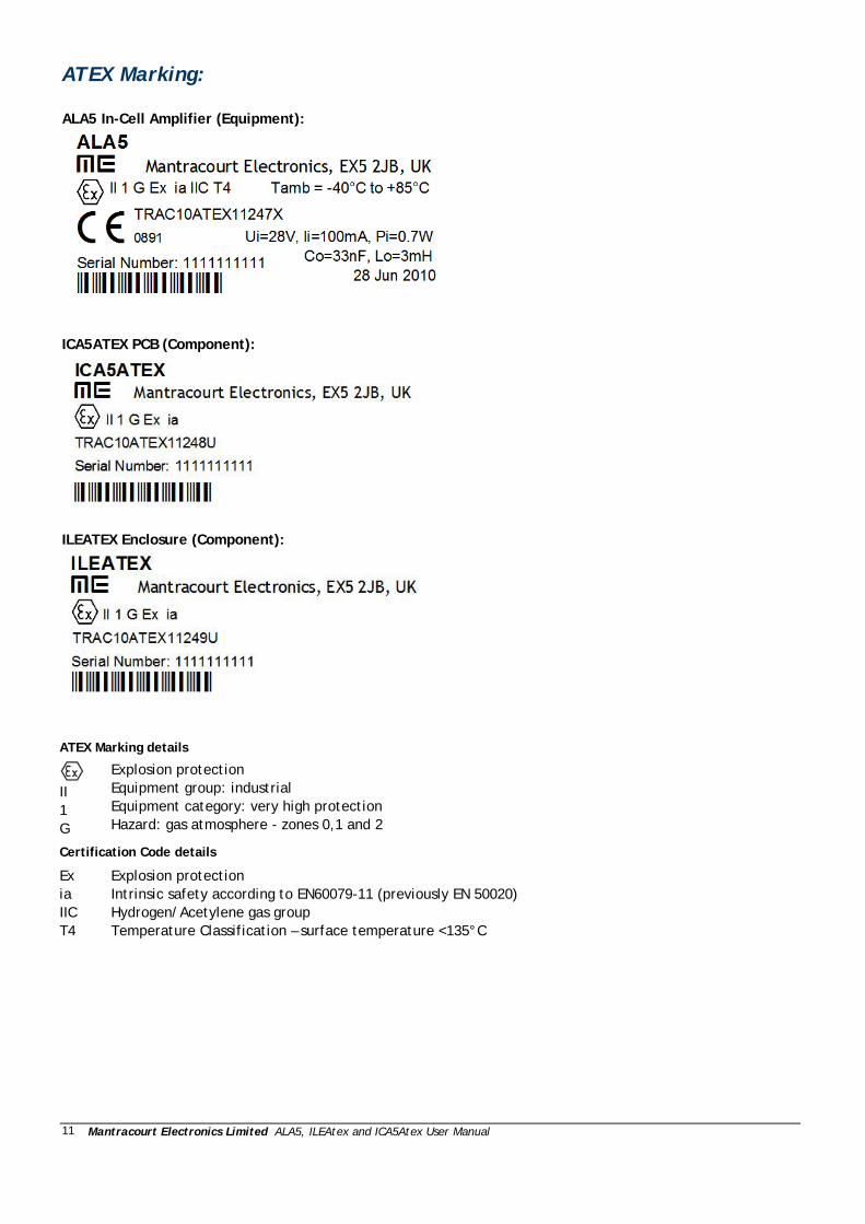
ATEX Marking: ALA5 In-Cell Amplifier (Equipment):
ICA5ATEX PCB (Component):
ILEATEX Enclosure (Component):
ATEX Marking details
II 1 G
Explosion protection Equipment group: industrial Equipment category: very high protection Hazard: gas atmosphere - zones 0,1 and 2
Certification Code details
Ex ia IIC T4
Explosion protection Intrinsic safety according to EN60079-11 (previously EN 50020) Hydrogen/Acetylene gas group Temperature Classification – surface temperature <135°C

Mantracourt Electronics Limited ALA5, ILEAtex and ICA5Atex User Manual
12
EC DECLARATION OF CONFORMITY EC DECLARATION OF CONFORMITY Declaration No. ALA5-ATEX-DOC We, the undersigned: Name of Manufacturer Mantracourt Electronics Ltd Address: The Drive, Farrington, Exeter, Devon, EX5 2JB Country: United Kingdom Declare under our sole responsibility that the following apparatus: Product description: In-Cell Amplifier compromising ICA5ATEX and ILEATEX components. Model or Type No.: ALA5 Brand name: N/A Is in conformity with the following relevant EC legislation: ATEX directive 94/9/EC EMC directive 2004/108/EC Based on the following harmonised standards: EN60079-0:2006 EN60079-11:2007 EN60079-26:2007 BS EN 61326-2-3:2006 BS EN 61326-1:2006 The following Notified Body has been involved in the conformity assessment process: Notified Body TRaC EMC & Safety Ltd Notified Body No. 0891 Role: Issue of ATEX EC Type Examination certificate Certificate No. TRaC10ATEX11247X Additional information: ATEX coding II 1 G Ex ia IIC T4 Name and position of person binding the manufacturer or authorised representative: Signature
Name Mr Brett James Function Design Manager Location Mantracourt Electronics Ltd Date of issue 11th May 2010

Mantracourt Electronics Limited ALA5, ILEAtex and ICA5Atex User Manual
13
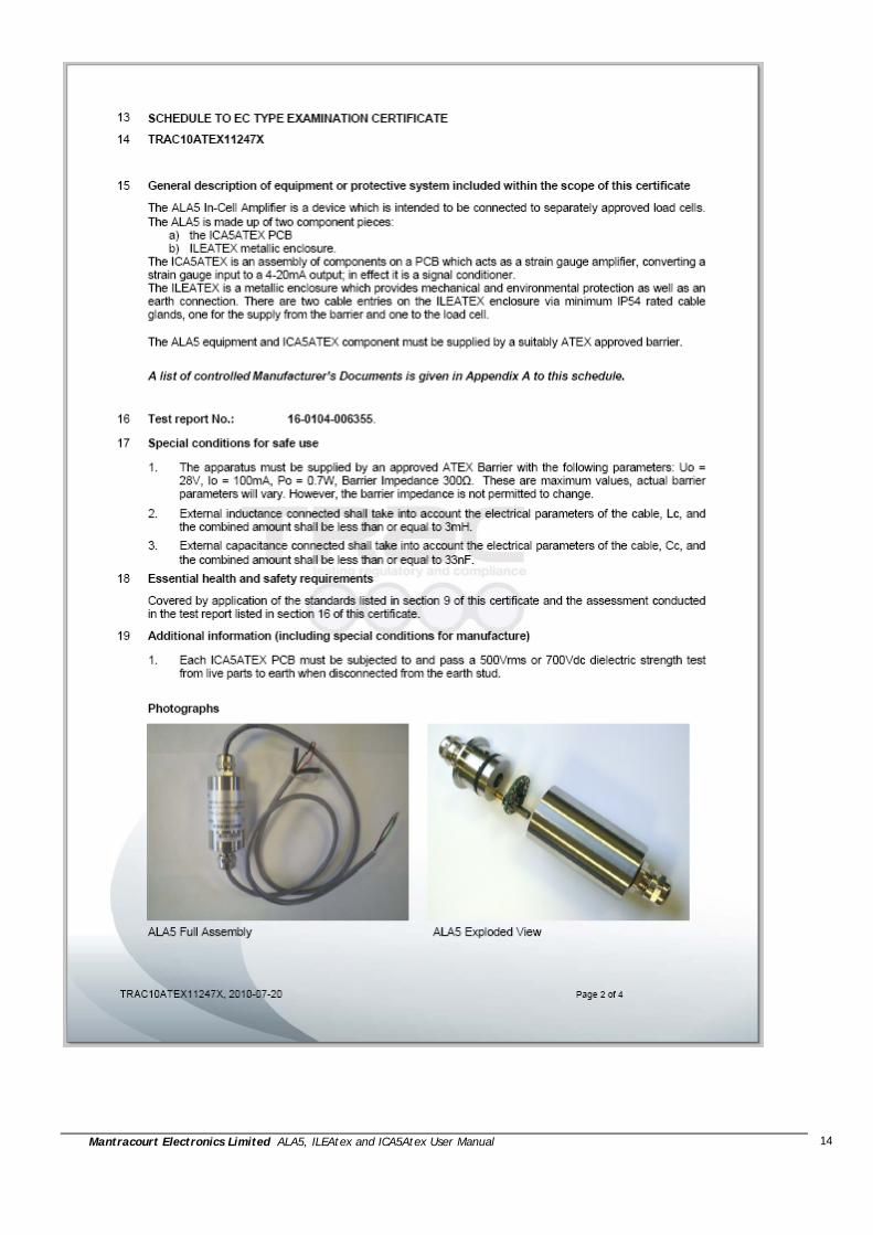
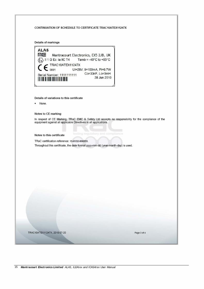
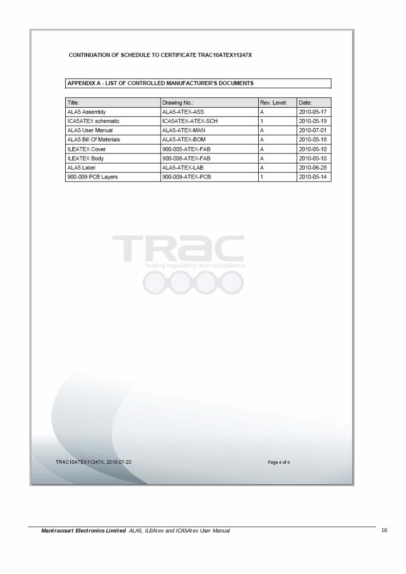
ALA5 Certificate:
Mantracourt Electronics Limited ALA5, ILEAtex and ICA5Atex User Manual
14
Mantracourt Electronics Limited ALA5, ILEAtex and ICA5Atex User Manual
15
Mantracourt Electronics Limited ALA5, ILEAtex and ICA5Atex User Manual
16
Mantracourt Electronics Limited ALA5, ILEAtex and ICA5Atex User Manual
17
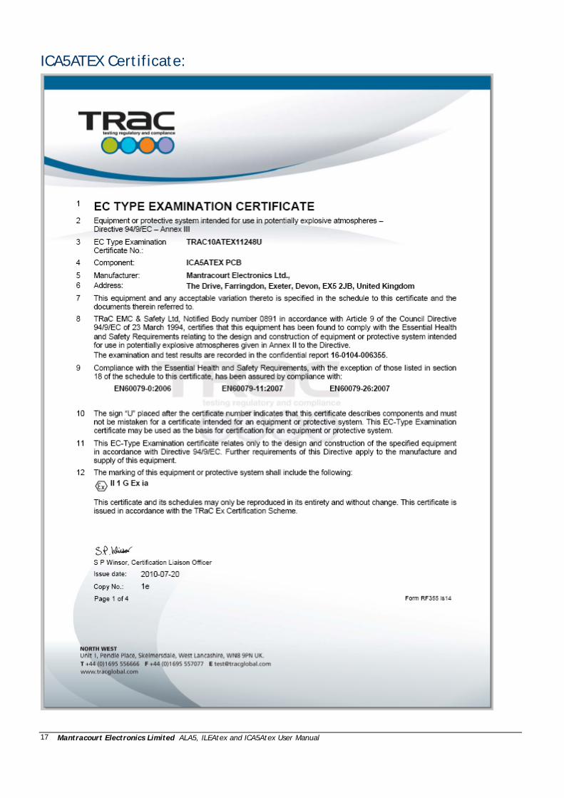
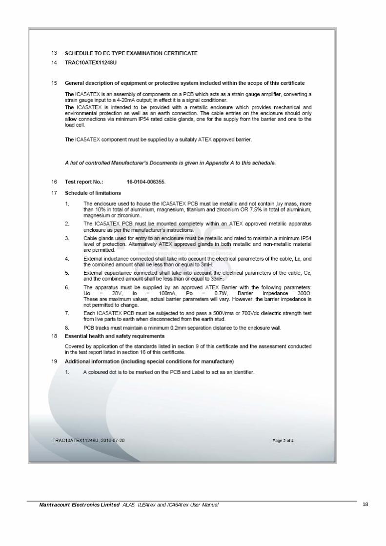
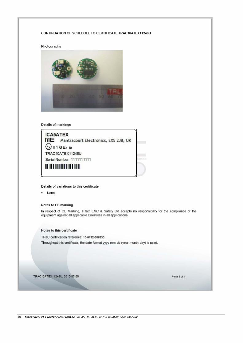
ICA5ATEX Certificate:
Mantracourt Electronics Limited ALA5, ILEAtex and ICA5Atex User Manual
18
Mantracourt Electronics Limited ALA5, ILEAtex and ICA5Atex User Manual
19

Mantracourt Electronics Limited ALA5, ILEAtex and ICA5Atex User Manual
20
Mantracourt Electronics Limited ALA5, ILEAtex and ICA5Atex User Manual
21
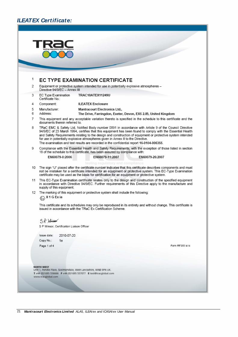
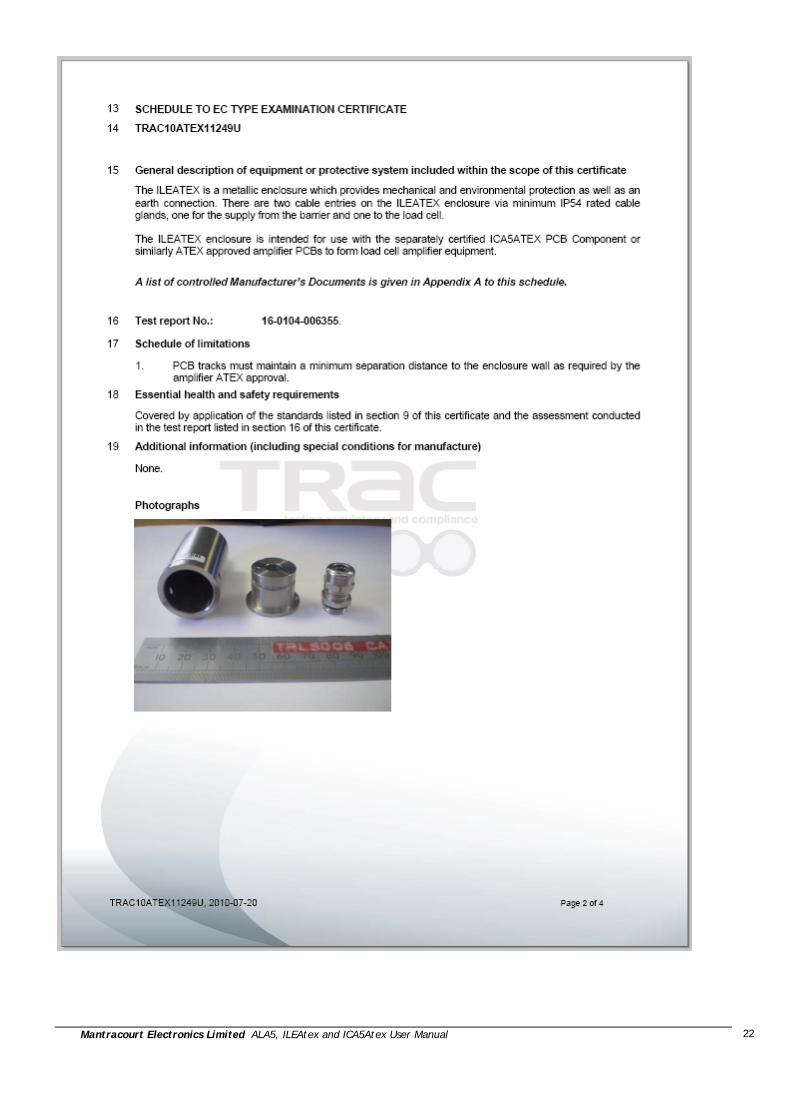
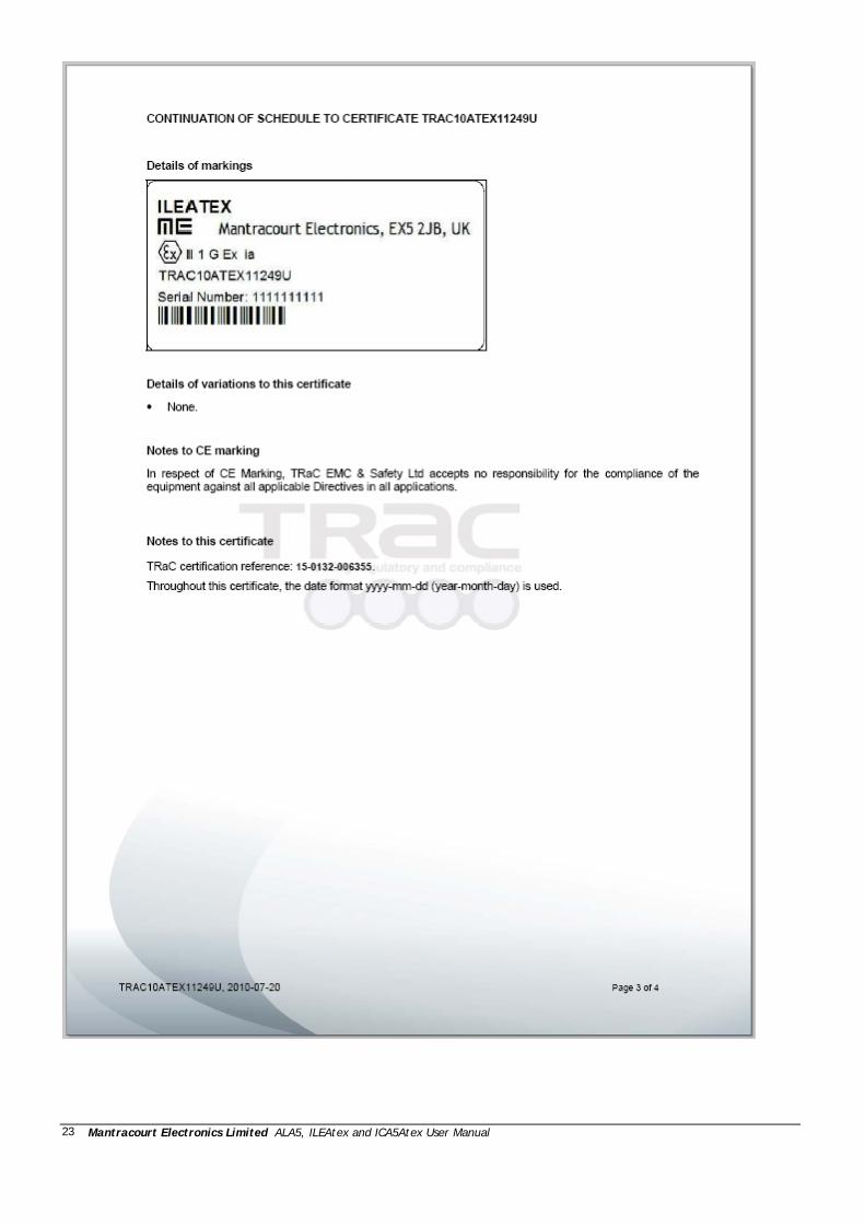
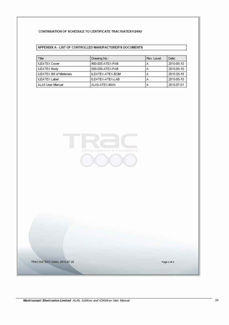
ILEATEX Certificate:
Mantracourt Electronics Limited ALA5, ILEAtex and ICA5Atex User Manual
22
Mantracourt Electronics Limited ALA5, ILEAtex and ICA5Atex User Manual
23
Mantracourt Electronics Limited ALA5, ILEAtex and ICA5Atex User Manual
24

Mantracourt Electronics Limited ALA5, ILEAtex and ICA5Atex User Manual
25
In the interests of continued product development, Mantracourt Electronics Limited reserves the right to alter product specifications without prior notice.
Doc No. 517-918 Issue 1.4 11.04.14