akoduo user manual the new generation of controllers for
TRANSCRIPT
2100H602 Ed.01 we make it easy
AKODUO User Manual
The new generation of controllers for compressor
racks
GB

2
Minimum requirements
Chapter 1: Introduction
Chapter 2: Control unit: DUOControl
Chapter 3: User terminal: DUOVision
Chapter 4: Compressor regulation
Chapter 5: Fan regulation
Chapter 6: Alarm management
Chapter 7: Other functionalities
Appendix A: Technical specifications
Appendix B: Selection of the DUOControl controller
Appendix C: User parameters
Appendix D: Cable for connection to the local MODBUS network
Page 3
Page 6
Page 31
Page 84
Page 89
Page 93
Page 96
Page 98
Page 105
Page 107
Page 116
we make it easy
AKO Electromecànica thanks you and congratulates you on the purchase of our product, the development and manufacture of which involved the most innovative technologies, as well as rigorous production and quality control processes.
Our commitment to achieving customer satisfaction and our continuous efforts to improve day by day are confirmed by the various quality certificates obtained.
This is a high performance, technologically advanced product. Its operation and the final performance achieved will depend, to a great extent, on correct planning, installation, configuration and commissioning. Please read this manual carefully before proceeding to install it and respect the indications in the manual at all times.
Only qualified personnel may install the product or carry out technical support.
This product has been developed for use in the applications described in the manual. AKO Electromecànica does not guarantee its operation in any use not foreseen in this document and accepts no liability in the case of damage of any type which may result from incorrect use, configuration, installation or commissioning.
Complying with and enforcing the regulations applying to installations where our products are destined to be used is the responsibility of the installer and the customer. AKO Electromecànica accepts no liability for damage which may occur due to failure to comply with these regulations. Rigorously follow the instructions described in this manual.
In order to extend the lifetime of our products to the maximum, the following points must be observed:
Do not expose electronic equipment to dust, dirt, water, rain, moisture, high temperatures, chemical agents or corrosive substances of any type.Do not subject equipment to knocks or vibrations or attempt to handle them in any way differently to that indicated in the manual.Do not under any circumstances exceed the specifications and limitations indicated in the manual.Respect the indicated environmental conditions for operation and storage at all times.During installation and on completion of this, avoid the presence of loose, broken or unprotected cables or cables in poor condition. These may constitute a risk for the equipment and its users.
AKO Electromecànica reserves the right to make any modification to the documentation and the product without prior notification.

3
1.- INTRODUCTION
The AKODUO controller family forms part of the new generation of electronic controls for regulating the capacity of refrigerating plant.
DUOControl carries out the management of the installed components, the detection of alarms and the recording of events (historical log of alarms and hours of operation of the compressors).
As display units, DUOControl enables the use of the DUOVision terminal and AKO-5004 Server Software.
La nueva generación de controladores para centrales de compresores
The new controllers generation for compressor racks and condenser fans
AKO-21006: Control unit with 6 outputs
AKO-21012: Control unit with 12 outputs
AKO-21018: Control unit with 18 outputs
DUOVision: User terminal
we make it easy

4
GENERAL CHARACTERISTICS
Usability: A family of products especially designed to make configuration and monitoring of
refrigeration plant easy.
Modularity: Model selection according to current and future needs.
Reliability: Use of automation technology as Control Hardware.
Unlimited number of operations: Control with transistor outputs (TRT).
Connectivity: Enables MODBUS connection for remote control / monitoring (AKO-5004).
DUOControl
Designed for refrigerating plant with compressors of equal characteristics
Flexible wiring: Multiple compressor – fan configurations
Up to 6 compressors (with up to 4 stages each)
Up to 8 fans
Compressor ON/OFF control
Fan ON/OFF or inverter control: 4-20 mA output with built in PI Control
Algorithms for compressor rotation: Sequential or by hours of operation
Algorithm for fan rotation: Sequential
Selectable algorithm for compressor control: Neutral Zone or Proportional Band
Selectable algorithm for fan control: Neutral Zone or Proportional Band
3 Inputs for 4-20 mA probes: Evaporation pressure, Condensation pressure and Air ambient temperature
Floating condensation
Pump-Down: By time or level
Energy saving: Programmable interval synchronised with the internal real time clock
Options for working with any refrigerant gas in bar, and in bar and °C with R404A -
R134A - R717 - R22 - R410A - R507A - R744 (CO )2
Reading of probes in the analogue input module itself
we make it easy

5
Safety circuit for each element controlled (compressors, fans and inverter)
3 Fixed digital Inputs: General high pressure switch, General low pressure switch and Manual/Automatic selector.
Alarm RY Output (provided an output is available depending on configuration)
DIN rail mounting
2 User terminals: DUOVision or AKO-5004
Programming assistant: Basic installation configuration.
Input/Output test: Wizard for checking input/output wiring.
Dual multicolour graphic screen: Provides more information than conventional Displays.
Dynamic display of compressor and fan status
Intuitive menus with on-screen help: System programming without the instruction manual.
7-key navigator
Password for access to configuration parameters
DUOVision
we make it easy

6
2.- Control unit: DUOControl
The family of DUOControl controllers is made up of:
AKO-21006 Controller with 6 outputs made up of:
1 AKO-21801 Module: Control unit with 8 digital inputs and 6 digital outputs
1 AKO-21802 Module: Extension unit with 3 inputs and 1 output at 4-20 mA
AKO-21012 Controller with 12 outputs made up of:
1 AKO-21801 Module: Control unit with 8 digital inputs and 6 digital outputs
1 AKO-21802 Module: Extension unit with 3 inputs and 1 output at 4-20 mA
1 AKO-21803 Module: Extension unit with 2 digital inputs and 6 digital outputs
AKO-21018 Controller with 18 outputs made up of:
1 AKO-21801 Module: Control unit with 8 digital inputs and 6 digital outputs
1 AKO-21802 Module: Extension unit with 3 inputs and 1 output at 4-20 mA
2 AKO-21803 Modules: Extension unit with 2 digital inputs and 6 digital outputs
we make it easy

7
When you purchase an AKO-21006/12/18 you receive all the modules which make them up, although each of the modules can also be purchased separately.
The following table summarises the composition of the three DUOControl models.
It is recommended that the connection be made when all the modules have been fixed to
the DIN rail to prevent breakage of the flat cables.
2.1.- INTERCONNECTION OF THE MODULES
The modules are connected together using the side connector on each module:
CONTROL UNIT
4-20 mA UNIT
DIGITAL UNIT
DIGITAL INPUTS
DIGITAL OUTPUTS
4-20 mA INPUTS
4-20 mA OUTPUTS
AKO-21006
8
6
AKO-21012
AKO-21801
AKO-21802
1 x AKO-21803
10
12
3
1
AKO-21018
2 x AKO-21803
12
18
we make it easy

8
The position each of the modules needs to occupy is shown below:
we make it easy AKODUO
we make it easy AKODUO
we make it easy AKODUO
we make it easy AKODUO
we make it easy AKODUO
we make it easy AKODUO
we make it easy AKODUO
we make it easy AKODUO
we make it easy AKODUO
The modular design of DUOControl enables a controller to be expanded by adding a new AKO-21803 module to its right, up to a maximum of 2. Likewise, it is also possible to remove one of the AKO-21803 modules.
Example: By adding 1 x AKO-21803 module, the AKO-21006 controller becomes an
AKO-21012. If one more of these modules is added (2 in total), this controller becomes an AKO-21018.
AKO-21006
AKO-21012
AKO-21018
AKO-21801 AKO-21802 AKO-21803 AKO-21803 Equipment / Modules
we make it easy

9
2.2.- TECHNICAL DESCRIPTION OF THE MODULES
AKO-21801
Module responsible for carrying out the following tasks:
SOFTWARE
Control of Inputs / Outputs.
Algorithm for compressor and fan control.
Alarm management.
Recording of events (Alarm log).
MODBUS communication in slave mode.
Communication with the user terminal (DUOVision and AKO-5004).
HARDWARE
DUOVision communication interface.
MODBUS communication interface.
Interface for connecting to other modules.
8 Insulated Digital Inputs.
6 Insulated transistor Digital Outputs.
Appendix A includes the technical specifications for this module.
we make it easy

10
1.- Position of the DIN rail.
2.- Module earth connector.
3.- DIN rail clamp.
4.- Upper terminal block.
5.- Interface for communication with other modules.
6.- Lower terminal block.
D1.- Module status display.
POWER LED always ON in normal operation.
RUN LED always ON in normal operation.
ERR LED always OFF in normal operation.
Appendix A includes the technical specifications for this module.
The purpose of each of the terminals is described in Section 2.3.
D2.- Status LEDs for the digital Inputs and
Outputs.
INPUT with LED ON: +24 V in the
corresponding terminal.
INPUT with LED OFF: 0 V in the
corresponding terminal.
OUTPUT with LED ON: +24 V in the
corresponding terminal.
OUTPUT with LED OFF: 0 V in the
corresponding terminal.
we make it easy

11
AKO-21802
Module for managing 4-20 mA inputs and outputs.
1.- Position of the DIN rail.
2.- Module earth connector.
3.- DIN rail clamp.
4.- Upper terminal block (3 x 4-20 mA Inputs).
5/6.- Interface for communication with other modules.
7.- Lower terminal block (1 x 4-20 mA Output).
8.- Button to select the input to be shown on the module Display.
The Display (D) makes it possible to see the current flowing through each of the inputs and
outputs. The input or output desired is selected using the button (8).
we make it easy

12
1.- 4-digit display with one decimal.
2.- Digit to indicate the input or output to which the value corresponds. The value of this will increase on
pressing the button (8).
0 — 4-20 mA input current from the evaporation pressure probe.
1 — 4-20 mA input current from the condensation pressure probe.
2 — 4-20 mA input current from the Ambient air temperature probe.
4 — 4-20 mA output current to control the fan inverter.
Do not take the values on Display (D) into account when this digit is any other than the values mentioned.
Appendix A includes the technical specifications for this module.
The purpose of each of the terminals is described in Section 2.3.
1
2
we make it easy

13
1.- Position of the DIN rail.
2.- DIN rail clamp.
3.- Upper terminal block (2 Digital Inputs and 2 Digital Outputs).
4/5.- Interface for communication with other modules.
6.- Lower terminal block (4 Digital Outputs).
D.- 8 LEDs representing the voltage present in each terminal:
LED ON: +24 V present in the corresponding terminal.
LED OFF: 0 V present in the corresponding terminal.
SUPPLY LED: Lit when the module is connected and correctly supplied with power.
Appendix A includes the technical specifications for this module.
The purpose of each of the terminals is described in Section 2.3.
AKO-21803
Extension module for digital inputs and outputs.
2 Digital Inputs
6 Digital Outputs
we make it easy

14
2.3.- WIRING TERMINALS
The following figure shows the layout of the terminals and their labelling.
TerminalFunction
ControllerLabel AKO-21018
AKO-21012 Controller
Label TerminalFunction
AKO-21802 AKO-21803 AKO-21803 AKO-21801
AKO-21802 AKO-21803 AKO-21801
we make it easy

15
AKO-21006
The terminals for the AKO-21801 and AKO-21802 modules always have the same notation. In the case of AKO-21803 modules, the notation of the terminals depends on the position occupied.
Fixed wiring terminals: Not depending on the
installation.
NC: Not connected
TU+: Connection to the DUOVision user
terminal
TU-: Connection to the DUOVision user
terminal
TUS: Connection to the DUOVision user
terminal
24V: +24 V supply from the control panel
0V: 0 V line from the control panel
T: Earth from the control panel
I1: General high pressure switch
I2: General low pressure switch
I3: MANUAL/AUTOMATIC selector from
the control panel
Terminals can be classified as follows, according to their function:
Variable wiring terminals: Vary according to the
installation.
I4 – I12: Connection depends on the
installation
O1 – O18: Connection depends on the
installation
4-20 mA input and output terminals:
VAR+/VAR-: Inverter for the fans
PE+/PE-: Suction probe
PC+/PC-: Discharge probe
TE+/TE-: Ambient air temperature probe
TerminalFunction
ControllerLabel AKO-21802 AKO-21801
we make it easy
16
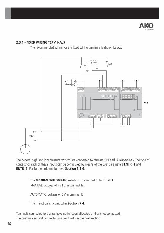
2.3.1.- FIXED WIRING TERMINALS
The recommended wiring for the fixed wiring terminals is shown below:
The general high and low pressure switchs are connected to terminals I1 and I2 respectively. The type of contact for each of these inputs can be configured by means of the user parameters ENTR_1 and ENTR_2. For further information, see Section 3.3.6.
The MANUAL/AUTOMATIC selector is connected to terminal I3.
MANUAL: Voltage of +24 V in terminal I3.
AUTOMATIC: Voltage of 0 V in terminal I3.
Their function is described in Section 7.4.
Terminals connected to a cross have no function allocated and are not connected.
The terminals not yet connected are dealt with in the next section.
we make it easy
17
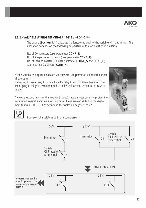
2.3.2.- VARIABLE WIRING TERMINALS (I4-I12 and O1-O18)
The wizard (Section 3.1.) allocates the function to each of the variable wiring terminals. This allocation depends on the following parameters of the refrigeration installation:
No. of Compressors (user parameter CONF_1)No. of Stages per compressor (user parameter CONF_2).No. of Fans or inverter use (user parameters CONF_5 and CONF_6).Alarm output (parameter CONF_4).
Examples of a safety circuit for a compressor:
+24 V +24 V
C1
C1
C1 C1
+24 V +24 V
T-C1 T-C1
Thermistor Thermistor
Switch Oil Pressure Differential
Switch Oil Pressure Differential
SIMPLIFICATION
Contact type can be c o n f i g u r e d b y means of parameter ENTR 3
All the variable wiring terminals are via transistors to permit an unlimited number of operations.Therefore, it is necessary to connect a 24 V relay to each of these terminals. The use of plug-in relays is recommended to make replacement easier in the case of failure.
The compressors, fans and the inverter (if used) have a safety circuit to protect the installation against anomalous situations. All these are connected to the digital input terminals (I4 – I12) as defined in the tables on pages 23 to 27.
we make it easy
18
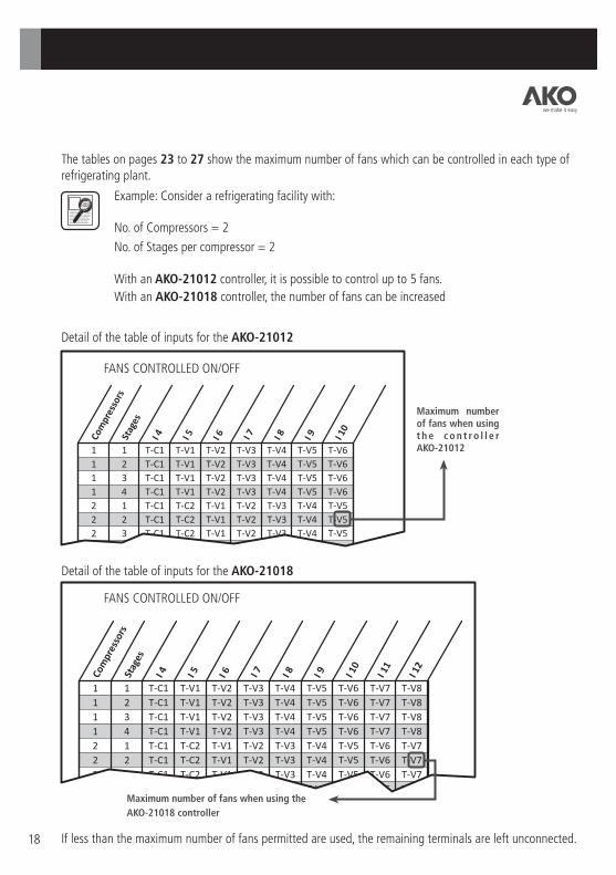
The tables on pages 23 to 27 show the maximum number of fans which can be controlled in each type of refrigerating plant.
Example: Consider a refrigerating facility with:
No. of Compressors = 2
No. of Stages per compressor = 2
With an AKO-21012 controller, it is possible to control up to 5 fans.
With an AKO-21018 controller, the number of fans can be increased
If less than the maximum number of fans permitted are used, the remaining terminals are left unconnected.
Com
pres
sors
Stag
es
I 4 I 5 I 6 I 7 I 8 I 9 I 10
I 11
I 12
1 1 T-C1 T-V1 T-V2 T-V3 T-V4 T-V5 T-V6 T-V7 T-V8
1 2 T-C1 T-V1 T-V2 T-V3 T-V4 T-V5 T-V6 T-V7 T-V8
1 3 T-C1 T-V1 T-V2 T-V3 T-V4 T-V5 T-V6 T-V7 T-V8
1 4 T-C1 T-V1 T-V2 T-V3 T-V4 T-V5 T-V6 T-V7 T-V8
2 1 T-C1 T-C2 T-V1 T-V2 T-V3 T-V4 T-V5 T-V6 T-V7
2 2 T-C1 T-C2 T-V1 T-V2 T-V3 T-V4 T-V5 T-V6 T-V7
2 3 T-C1 T-C2 T-V1 T-V2 T-V3 T-V4 T-V5 T-V6 T-V7
2 4 T-C1 T-C2 T-V1 T-V2 T-V3 T-V4 T-V5 T-V6 T-V7
FANS CONTROLLED ON/OFF
1 1 T-C1 T-V1 T-V2 T-V3 T-V4 T-V5 T-V6
1 2 T-C1 T-V1 T-V2 T-V3 T-V4 T-V5 T-V6
1 3 T-C1 T-V1 T-V2 T-V3 T-V4 T-V5 T-V6
1 4 T-C1 T-V1 T-V2 T-V3 T-V4 T-V5 T-V6
2 1 T-C1 T-C2 T-V1 T-V2 T-V3 T-V4 T-V5
2 2 T-C1 T-C2 T-V1 T-V2 T-V3 T-V4 T-V5
2 3 T-C1 T-C2 T-V1 T-V2 T-V3 T-V4 T-V5
2 4 T-C1 T-C2 T-V1 T-V2 T-V3 T-V4
Com
pres
sors
Stag
es
I 4 I 5 I 6 I 7 I 8 I 9 I 10
FANS CONTROLLED ON/OFF
Maximum number of fans when using t h e c o n t r o l l e r AKO-21012
Maximum number of fans when using the
AKO-21018 controller
Detail of the table of inputs for the AKO-21012
Detail of the table of inputs for the AKO-21018
we make it easy
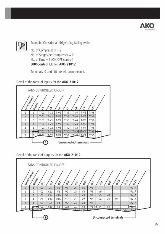
Example: Consider a refrigerating facility with:
No. of Compressors = 2
No. of Stages per compressor = 2
No. of Fans = 3 (ON/OFF control)
DUOControl Model: AKO-21012
Terminals I9 and I10 are left unconnected.
19
1 1 T-C1 T-V1 T-V2 T-V3 T-V4 T-V5 T-V6
1 2 T-C1 T-V1 T-V2 T-V3 T-V4 T-V5 T-V6
1 3 T-C1 T-V1 T-V2 T-V3 T-V4 T-V5 T-V6
1 4 T-C1 T-V1 T-V2 T-V3 T-V4 T-V5 T-V6
2 1 T-C1 T-C2 T-V1 T-V2 T-V3 T-V4 T-V5
2 2 T-C1 T-C2 T-V1 T-V2 T-V3 T-V4 T-V5
2 3 T-C1 T-C2 T-V1 T-V2 T-V3 T-V4 T-V5
2 4 T-C1 T-C2 T-V1 T-V2 T-V3 T-V4
Com
pres
sors
Stag
es
I 4 I 5 I 6 I 7 I 8 I 9 I 10
FANS CONTROLLED ON/OFF
Detail of the table of inputs for the AKO-21012
Unconnected terminals A
Com
pres
sors
Stag
es
O 1
O 2
O 3
O 4
O 5
O 6
O 7
O 8
O 9
O 1
0
O 1
1
O 1
2
1 1 C1 V1 V2 V3 V4 V5 V6 Ry_A
1 2 C1 C1a V1 V2 V3 V4 V5 V6 Ry_A
1 3 C1 C1a C1b V1 V2 V3 V4 V5 V6 Ry_A
1 4 C1 C1a C1b C1c V1 V2 V3 V4 V5 V6 Ry_A
2 1 C1 C2 V1 V2 V3 V4 V5 Ry_A
2 2 C1 C1a C2 C2a V1 V2 V3 V4 V5 Ry_A
2 3 C1 C1a C1b C2 C2a C2b V1 V2 V3 V4 V5 Ry_A
FANS CONTROLLED ON/OFF
Detail of the table of outputs for the AKO-21012
Unconnected terminals B
we make it easy

20
The digital inputs and outputs from the above example are connected as follows:
B
A
B
a a
we make it easy

21
KC1 KC2 KV1 KV2 KV3 KC1a KC2a
KC1_C KC2_C KV1_C KV2_C KV3_C
L1
N
PARTIALISATION C1
PARTIALISATION C2
In this wiring example, the terminals with fixed function and the 4-20mA inputs/outputs are absent (Section 2.3.1.).
M M M M M
Compressor C2 Compressor C1
Fan V1 Fan V2 Fan V3
N
L3
L2
L1
KC1_C KC2_C KV1_C KV2_C KV3_C
we make it easy
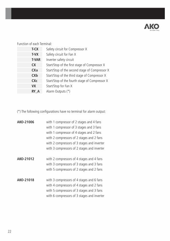
Function of each Terminal:
T-CX Safety circuit for Compressor X
T-VX Safety circuit for Fan X
T-VAR Inverter safety circuit
CX Start/Stop of the first stage of Compressor X
CXa Start/Stop of the second stage of Compressor X
CXb Start/Stop of the third stage of Compressor X
CXc Start/Stop of the fourth stage of Compressor X
VX Start/Stop for Fan X
RY_A Alarm Outputs (*)
22
(*) The following configurations have no terminal for alarm output:
AKO-21006 with 1 compressor of 2 stages and 4 fans
with 1 compressor of 3 stages and 3 fans
with 1 compressor of 4 stages and 2 fans
with 2 compressors of 2 stages and 2 fans
with 2 compressors of 3 stages and inverter
with 3 compressors of 2 stages and inverter
AKO-21012 with 2 compressors of 4 stages and 4 fans
with 3 compressors of 3 stages and 3 fans
with 5 compressors of 2 stages and 2 fans
AKO-21018 with 3 compressors of 4 stages and 6 fans
with 4 compressors of 4 stages and 2 fans
with 5 compressors of 3 stages and 3 fans
with 6 compressors of 3 stages and inverter
we make it easy
23
FANS CONTROLLED ON/OFF
Com
pres
sors
1
1
1
1
2
2
3
4
T-V1
T-V1
T-V1
T-V1
T-C2
T-C2
T-C2
T-C2
T-C1
T-C1
T-C1
T-C1
T-C1
T-C1
T-C1
T-C1
1
2
3
4
1
2
1
1
T-V2
T-V2
T-V2
T-V2
T-V1
T-V1
T-C3
T-C3
T-V3
T-V3
T-V3
T-V2
T-V2
T-V1
T-C4
T-V4
T-V4
T-V3
T-V2
T-V1
Stag
es
I4 I5 I6 I7 I8FANS CONTROLLED BY INVERTER
1
1
1
1
2
2
2
3
3
4
D-2
D-2
D-2
D-2
D-2
D-2
D-2
D-2
D-2
D-2
D1
D1
D1
D1
D1
D1
D1
D1
D1
D1
1
2
3
4
1
2
3
1
2
1
D-3
D-3
D-3
D-3
D-3
D-3
D-3
D-3
D-3
D-3
T-C1
T-C1
T-C1
T-C1
T-C1
T-C1
T-C1
T-C1
T-C1
T-C1
T-VAR
T-VAR
T-VAR
T-VAR
T-C2
T-C2
T-C2
T-C2
T-C2
T-C2
T-VAR
T-VAR
T-VAR
T-C3
T-C3
T-C3
T-VAR
T-VAR
T-C4 T-VAR
Com
pres
sors
St
ages
I1 I2 I3 I4 I5 I6 I7 I8
FANS CONTROLLED ON/OFF
1
1
1
1
2
2
3
4
V1
C1a
C1a
C1a
C2
C1a
C2
C2
C1
C1
C1
C1
C1
C1
C1
C1
1
2
3
4
1
2
1
1
V2
V1
C1b
C1b
V1
C2
C3
C3
V3
V2
V1
C1c
V2
C2a
V1
V1
V4
V3
V2
V1
V3
V1
V2
V1
RY_A
V4
V3
V2
RY_A
V2
RY_A
RY_A
Com
pres
sors
St
ages
O
1
O2
O3
O4
O5
O6
FANS CONTROLLED BY INVERTER
1
1
1
1
2
2
2
3
3
4
C1a
C1a
C1a
C2
C1a
C1a
C2
C1a
C2
C1
C1
C1
C1
C1
C1
C1
C1
C1
C1
1
2
3
4
1
2
3
1
2
1
C1b
C1b
C2
C1b
C3
C2
C3
C1c
C2a
C2
C2a
C4
C2a
C3
RY_A
RY_A
RY_A
RY_A
RY_A
RY_A
C2b
RY_A
C3a
RY_A
Com
pres
sors
St
ages
O
1
O2
O3
O4
O5
O6
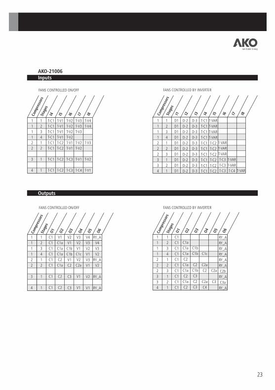
Inputs AKO-21006
Outputs
we make it easy

24
Inputs AKO-21012
Outputs
FANS CONTROLLED ON/OFF
1
1
1
1
2
2
2
2
3
3
3
4
4
5
5
6
T-V1
T-V1
T-V1
T-V1
T-C2
T-C2
T-C2
T-C2
T-C2
T-C2
T-C2
T-C2
T-C2
T-C2
T-C2
T-C2
T-C1
T-C1
T-C1
T-C1
T-C1
T-C1
T-C1
T-C1
T-C1
T-C1
T-C1
T-C1
T-C1
T-C1
T-C1
T-C1
1
2
3
4
1
2
3
4
1
2
3
1
2
1
2
1
T-V2
T-V2
T-V2
T-V2
T-V1
T-V1
T-V1
T-V1
T-C3
T-C3
T-C3
T-C3
T-C3
T-C3
T-C3
T-C3
T-V3
T-V3
T-V3
T-V3
T-V2
T-V2
T-V2
T-V2
T-V1
T-V1
T-V1
T-C4
T-C4
T-C4
T-C4
T-C4
T-V4
T-V4
T-V4
T-V4
T-V3
T-V3
T-V3
T-V3
T-V2
T-V2
T-V2
T-V1
T-V1
T-C5
T-C5
T-C5
T-V5
T-V5
T-V5
T-V5
T-V4
T-V4
T-V4
T-V4
T-V3
T-V3
T-V3
T-V2
T-V2
T-V1
T-V1
T-C6
T-V6
T-V6
T-V6
T-V6
T-V5
T-V5
T-V5
T-V4
T-V4
T-V3
T-V3
T-V2
T-V2
T-V1
Com
pres
sors
St
ages
I4 I5 I6 I7 I8 I9 I10
FANS CONTROLLED ON/OFF
1
1
1
1
2
2
2
2
3
3
3
4
4
5
5
6
V1
C1a
C1a
C1a
C2
C1a
C1a
C1a
C2
C1a
C1a
C2
C1a
C2
C1a
C2
C1
C1
C1
C1
C1
C1
C1
C1
C1
C1
C1
C1
C1
C1
C1
C1
1
2
3
4
1
2
3
4
1
2
3
1
2
1
2
1
V2
V1
C1b
C1b
V1
C2
C1b
C1b
C3
C2
C1b
C3
C2
C3
C2
C3
V3
V2
V1
C1c
V2
C2a
C2
C1c
V1
C2a
C2
C4
C2a
C4
C2a
C4
V4
V3
V2
V1
V3
V1
C2a
C2
V2
C3
C2a
V1
C3
C5
C3
C5
V5
V4
V3
V2
V4
V2
C2b
C2a
V3
C3a
C2b
V2
C3a
V1
C3a
C6
V6
V5
V4
V3
V5
V3
V1
C2b
V4
V1
C3
V3
C4
V2
C4
V1
V6
V5
V4
V4
V2
C2c
V2
C3a
C4a
C4a
V6
V5
V5
V3
V1
V3
C3b
V1
C5
V4
V2
V4
V1
V2
C5a
V3
V2
V3
V1
RY_A
RY_A
RY_A
RY_A
RY_A
RY_A
RY_A
V4
RY_A
RY_A
V3
RY_A
RY_A
RY_A
V2
RY_A
Com
pres
sors
St
ages
O4
O5
O6
O7
O8
O9
O10
O11
O12
O3
O2
O1
we make it easy

25
Inputs AKO-21012
Outputs
FANS CONTROLLED BY INVERTER
1
1
1
1
2
2
2
2
3
3
3
4
4
5
5
6
D2
D2
D2
D2
D2
D2
D2
D2
D2
D2
D2
D2
D2
D2
D2
D2
D1
D1
D1
D1
D1
D1
D1
D1
D1
D1
D1
D1
D1
D1
D1
D1
1
2
3
4
1
2
3
4
1
2
3
1
2
1
2
1
D3
D3
D3
D3
D3
D3
D3
D3
D3
D3
D3
D3
D3
D3
D3
D3
T-C1
T-C1
T-C1
T-C1
T-C1
T-C1
T-C1
T-C1
T-C1
T-C1
T-C1
T-C1
T-C1
T-C1
T-C1
T-C1
T-VAR
T-VAR
T-VAR
T-VAR
T-C2
T-C2
T-C2
T-C2
T-C2
T-C2
T-C2
T-C2
T-C2
T-C2
T-C2
T-C2
T-VAR
T-VAR
T-VAR
T-VAR
T-C3
T-C3
T-C3
T-C3
T-C3
T-C3
T-C3
T-C3
T-VAR
T-VAR
T-VAR
T-C4
T-C4
T-C4
T-C4
T-C4
T-VAR
T-VAR
T-C5
T-C5
T-C5
T-VAR
T-VAR
T-C6 T-VAR
Com
pres
sors
St
ages
I1 I2 I3 I4 I5 I6 I7 I8 I9 I1
0
I11
I12
FANS CONTROLLED BY INVERTER
1
1
1
1
2
2
2
2
3
3
3
4
4
5
5
6
C1a
C1a
C1a
C2
C1a
C1a
C1a
C2
C1a
C1a
C2
C1a
C2
C1a
C2
C1
C1
C1
C1
C1
C1
C1
C1
C1
C1
C1
C1
C1
C1
C1
C1
1
2
3
4
1
2
3
4
1
2
3
1
2
1
2
1
C1b
C1b
C2
C1b
C1b
C3
C2
C1b
C3
C2
C3
C2
C3
C1c
C2a
C2
C1c
C2a
C2
C4
C2a
C4
C2a
C4
C2a
C2
C3
C2a
C3
C5
C3
C5
C2b
C2a
C3a
C2b
C3a
C3a
C6
C2b
C3
C4
C4
C2c
C3a
C4a
C4a
C3b
C5 C5a
Com
pres
sors
St
ages
O4
O5
O6
O7
O8
O9
O3
O2
O1
O10
O11
O12
RY_A
RY_A
RY_A
RY_A
RY_A
RY_A
RY_A
RY_A
RY_A
RY_A
RY_A
RY_A
RY_A
RY_A
RY_A
RY_A
we make it easy

26
Inputs AKO-21018
Outputs
FANS CONTROLLED ON/OFF
1
1
1
1
2
2
2
2
3
3
3
3
4
4
4
4
5
5
5
6
6
T-V1
T-V1
T-V1
T-V1
T-C2
T-C2
T-C2
T-C2
T-C2
T-C2
T-C2
T-C2
T-C2
T-C2
T-C2
T-C2
T-C2
T-C2
T-C2
T-C2
T-C2
T-C1
T-C1
T-C1
T-C1
T-C1
T-C1
T-C1
T-C1
T-C1
T-C1
T-C1
T-C1
T-C1
T-C1
T-C1
T-C1
T-C1
T-C1
T-C1
T-C1
T-C1
1
2
3
4
1
2
3
4
1
2
3
4
1
2
3
4
1
2
3
1
2
T-V2
T-V2
T-V2
T-V2
T-V1
T-V1
T-V1
T-V1
T-C3
T-C3
T-C3
T-C3
T-C3
T-C3
T-C3
T-C3
T-C3
T-C3
T-C3
T-C3
T-C3
T-V3
T-V3
T-V3
T-V3
T-V2
T-V2
T-V2
T-V2
T-V1
T-V1
T-V1
T-V1
T-C4
T-C4
T-C4
T-C4
T-C4
T-C4
T-C4
T-C4
T-C4
T-V4
T-V4
T-V4
T-V4
T-V3
T-V3
T-V3
T-V3
T-V2
T-V2
T-V2
T-V2
T-V1
T-V1
T-V1
T-V1
T-C5
T-C5
T-C5
T-C5
T-C5
T-V5
T-V5
T-V5
T-V5
T-V4
T-V4
T-V4
T-V4
T-V3
T-V3
T-V3
T-V3
T-V2
T-V2
T-V2
T-V2
T-V1
T-V1
T-V1
T-C6
T-C6
T-V6
T-V6
T-V6
T-V6
T-V5
T-V5
T-V5
T-V5
T-V4
T-V4
T-V4
T-V4
T-V3
T-V3
T-V3
T-V2
T-V2
T-V2
T-V1
T-V1
T-V7
T-V7
T-V7
T-V7
T-V6
T-V6
T-V6
T-V6
T-V5
T-V5
T-V5
T-V5
T-V4
T-V4
T-V4
T-V3
T-V3
T-V3
T-V2
T-V2
T-V8
T-V8
T-V8
T-V8
T-V7
T-V7
T-V7
T-V7
T-V6
T-V6
T-V6
T-V6
T-V5
T-V5
T-V5
T-V4
T-V4
T-V3
T-V3
Com
pres
sors
St
ages
I4 I5 I6 I7 I8 I9 I10
I11
I12
FANS CONTROLLED ON/OFF
1
1
1
1
2
2
2
2
3
3
3
3
4
4
4
4
5
5
5
6
6
V1
C1a
C1a
C1a
C2
C1a
C1a
C1a
C2
C1a
C1a
C1a
C2
C1a
C1a
C1a
C2
C1a
C1a
C2
C1a
C1
C1
C1
C1
C1
C1
C1
C1
C1
C1
C1
C1
C1
C1
C1
C1
C1
C1
C1
C1
C1
1
2
3
4
1
2
3
4
1
2
3
4
1
2
3
4
1
2
3
1
2
V2
V1
C1b
C1b
V1
C2
C1b
C1b
C3
C2
C1b
C1b
C3
C2
C1b
C1b
C3
C2
C1b
C3
C2
V3
V2
V1
C1c
V2
C2a
C2
C1c
V1
C2a
C2
C1c
C4
C2a
C2
C1c
C4
C2a
C2
C4
C2a
V4
V3
V2
V1
V3
V1
C2a
C2
V2
C3
C2a
C2
V1
C3
C2a
C2
C5
C3
C2a
C5
C3
V5
V4
V3
V2
V4
V2
C2b
C2a
V3
C3a
C2b
C2a
V2
C3a
C2b
C2a
V1
C3a
C2b
C6
C3a
V6
V5
V4
V3
V5
V3
V1
C2b
V4
V1
C3
C2b
V3
C4
C3
C2b
V2
C4
C3
V1
C4
V7
V6
V5
V4
V6
V4
V2
C2c
V5
V2
C3a
C2c
V4
C4a
C3a
C2c
V3
C4a
C3a
V2
C4a
V8
V7
V6
V5
V7
V5
V3
V1
V6
V3
C3b
C3
V5
V1
C3b
C3
V4
C5
C3b
V3
C5
V8
V7
V6
V6
V4
V2
V4
V1
C3a
V2
C4
C3a
C5a
C4
C5a
V8
V7
V7
V5
V3
V5
V2
C3b
V3
C4a
C3b
V1
C4a
C6
V8
V6
V4
V6
V3
C3c
V4
C4b
C3c
V2
C4b
C6a
V7
V5
V4
V1
V5
V1
C4
V3
C5
V1
V6
V5
V2
V2
C4a
V4
C5a
V2
V7
V6
V3
V3
C4b
C5b
V3
V4
C4c
V1
V5
V1
V2
Com
pres
sors
St
ages
O4
O5
O6
O7
O8
O9O3O2
O1
O10
O11
O12
O13
O14
O15
O16
O17
O18
RY_A
RY_A
RY_A
RY_A
RY_A
RY_A
RY_A
RY_A
RY_A
RY_A
RY_A
V6
RY_A
RY_A
RY_A
V2
RY_A
RY_A
V3
RY_A
RY_A
we make it easy

27
Inputs AKO-21018
Outputs
FANS CONTROLLED BY INVERTER
1
1
1
1
2
2
2
2
3
3
3
3
4
4
4
4
5
5
5
6
6
6
D2
D2
D2
D2
D2
D2
D2
D2
D2
D2
D2
D2
D2
D2
D2
D2
D2
D2
D2
D2
D2
D2
D1
D1
D1
D1
D1
D1
D1
D1
D1
D1
D1
D1
D1
D1
D1
D1
D1
D1
D1
D1
D1
D1
1
2
3
4
1
2
3
4
1
2
3
4
1
2
3
4
1
2
3
1
2
3
D3
D3
D3
D3
D3
D3
D3
D3
D3
D3
D3
D3
D3
D3
D3
D3
D3
D3
D3
D3
D3
D3
T-C1
T-C1
T-C1
T-C1
T-C1
T-C1
T-C1
T-C1
T-C1
T-C1
T-C1
T-C1
T-C1
T-C1
T-C1
T-C1
T-C1
T-C1
T-C1
T-C1
T-C1
T-C1
T-VAR
T-VAR
T-VAR
T-VAR
T-C2
T-C2
T-C2
T-C2
T-C2
T-C2
T-C2
T-C2
T-C2
T-C2
T-C2
T-C2
T-C2
T-C2
T-C2
T-C2
T-C2
T-C2
T-VAR
T-VAR
T-VAR
T-VAR
T-C3
T-C3
T-C3
T-C3
T-C3
T-C3
T-C3
T-C3
T-C3
T-C3
T-C3
T-C3
T-C3
T-C3
T-VAR
T-VAR
T-VAR
T-VAR
T-C4
T-C4
T-C4
T-C4
T-C4
T-C4
T-C4
T-C4
T-C4
T-C4
T-VAR
T-VAR
T-VAR
T-VAR
T-C5
T-C5
T-C5
T-C5
T-C5
T-C5
T-VAR
T-VAR
T-VAR
T-C6
T-C6
T-C6
T-VAR
T-VAR
T-VAR
Com
pres
sors
St
ages
I1 I2 I3 I4 I5 I6 I7 I8 I9 I10
I11
I12
FANS CONTROLLED BY INVERTER
1
1
1
1
2
2
2
2
3
3
3
3
4
4
4
4
5
5
5
6
6
6
C1a
C1a
C1a
C2
C1a
C1a
C1a
C2
C1a
C1a
C1a
C2
C1a
C1a
C1a
C2
C1a
C1a
C2
C1a
C1a
C1
C1
C1
C1
C1
C1
C1
C1
C1
C1
C1
C1
C1
C1
C1
C1
C1
C1
C1
C1
C1
C1
1
2
3
4
1
2
3
4
1
2
3
4
1
2
3
4
1
2
3
1
2
3
C1b
C2
C1b
C1b
C3
C2
C1b
C1b
C3
C2
C1b
C1b
C3
C2
C1b
C3
C2
C1b
C2a
C2
C1c
C2a
C2
C1c
C4
C2a
C2
C1c
C4
C2a
C2
C4
C2a
C2
C2
C3
C2a
C2
C3
C2a
C2
C5
C3
C2a
C5
C3
C2a
C2a
C3a
C2b
C2a
C3a
C2b
C2a
C3a
C2b
C6
C3a
C2b
C3
C2b
C4
C3
C2b
C4
C3
C4
C3
C3a
C2c
C4a
C3a
C2c
C4a
C3a
C4a
C3a
C3
C3b
C3
C5
C3b
C5
C3b
C3a
C4
C3a
C5a
C4
C5a
C4
C4a
C3b
C4a
C6
C4a
C4b
C3c
C4b
C6a
C4b
C5
C5 C6
RY_A
RY_A
RY_A
RY_A
RY_A
RY_A
RY_A
RY_A
RY_A
RY_A
RY_A
RY_A
RY_A
RY_A
RY_A
RY_A
RY_A
RY_A
RY_A
RY_A
RY_A
C6b C6a
C5a
C5a
C5b
C5b
Com
pres
sors
St
ages
O4
O5
O6
O7
O8
O9
O3
O2
O1
O10
O11
O12
O13
O14
O15
O16
O17
O18
we make it easy

2.3.3.- 4-20 mA INPUT AND OUTPUT TERMINALS
The controllers have:
· 3 x 4-20 mA inputs for suction, discharge and Ambient air temperature probes
· 1 x 4-20 mA output to control a Inverter
The wiring for all these 4-20 mA inputs/outputs is as follows:
The Ambient air probe measures the ambient temperature of the air flowing through the condenser to cool the refrigerant. This information is necessary to control the condensation pressure/temperature when using floating condensation.
It is recommended that the probe be located near the condenser in a protected place.
28
SUCTION PROBE4-20mA
DISCHARGE PROBE4-20mA
PT100 / 4-20mATRANSMITER
AMBIENT AIRTEMPERATURE
PROBE
INVERTER + INVERTER -
4-20mA(Inverter only)
we make it easy
29
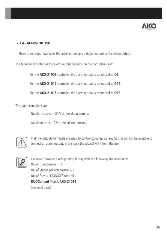
2.3.4.- ALARM OUTPUT
If there is an output available, the assistant assigns a digital output as the alarm output.
No alarm active: +24 V at the alarm terminal.
An alarm active: 0 V at the alarm terminal.
The terminal allocated as the alarm output depends on the controller used:
For the AKO-21006 controller, the alarm output is connected to O6.
For the AKO-21012 controller, the alarm output is connected to O12.
For the AKO-21018 controller, the alarm output is connected to O18.
If all the outputs terminals are used to control compressors and fans, it will not be possible to
connect an alarm output. In this case the wizard will inform the user.
Example: Consider a refrigerating facility with the following characteristics:
No. of Compressors = 2
No. of Stages per compressor = 2
No. of Fans = 3 (ON/OFF control)
DUOControl Model: AKO-21012
(See next page)
The alarm conditions are:
we make it easy

30
Wiring of the inputs and outputs for the previous example:
KC1 KC2 KV1 KV2 KV3 KC1a KC2a
KC1_C KC2_C KV1_C KV2_C KV3_C
L1
N
PARTIALISATION C1
PARTIALISATION C2
KALARM
Indicator Alarm
we make it easy

31
The DUOVision terminal allows the user to:Start up an installation: Wizard and entry of values into the user parametersMonitor the installation: Dynamic graphic displayAdjust the operation of the installation: HELP to facilitate the adjustment of user parametersDisplay logs: Log of alarms and accumulated operation of the compressors
DUOVision is made up of the DISPLAY and the NAVIGATOR.
3.- User terminal: DUOVision (AKO-21701).
DISPLAY NAVIGATOR
The DISPLAY is made up of 2 screens. The background colour of each of these can be configured by means of user parameters.
The NAVIGATOR has 7 keys. The function of each of these depends on the screen.
SET
HELP (?)
SET
¿ ESC ESC UP
DOWN LEFT
RIGHT
we make it easy

The power supply and communication connector for DUOVision is at the rear.
CONNECTOR
Wiring of DUOVision:
32
The use of the same power supply lines for the DUOControl controller and the DUOVision user terminal is recommended.
The technical specifications of the DUOVision user terminal and the steps to follow to mount it in the panel are detailed in Appendix A.
+
24 V
-
we make it easy

33
3.1.- WIZARD
The WIZARD runs:
The WIZARD guides the user through the process of configuring and starting up the refrigerating facility. It enables you to:
Check the wiring for the control panel.Inform the DUOControl of the installation characteristics.Adjust essential parameters for the initial start up of the installation.
When the DUOVision is connected to the DUOControl with no prior configuration (default parameters).When the DUOVision is connected to the DUOControl after a change of model brought about by expansion or contraction of the DUOControl (for further information see Section 2.1).
On pressing the RIGHT+SET+LEFT keys on the DUOVision when the t icon is shown on the screen. This icon appears for a few seconds when the equipment is started up or when the MANUAL/AUTOMATIC selector is moved to the MANUAL position, provided no compressor or fan is operating.
The WIZARD asks a series of questions to which the user needs to respond.
SCREEN W-0: LANGUAGE
Select the desired language.NAVIGATOR function:
UP and DOWN: Move the cursor through the possible responses
SET: Confirm the preselected response
ESC: Return to SCREEN W-0
OTHERS: No function
Language
EspañolEnglishFrancaisDeutschItaliano
WIZARD VALUE
we make it easy
WIZARDDEFAULT parameters
VALUENoYes
WIZARDType of Fan Control
ON/OFFInverter
VALUE
34
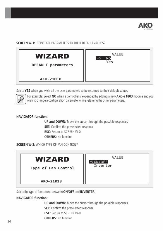
NAVIGATOR function:
NAVIGATOR function:
UP and DOWN: Move the cursor through the possible responses
UP and DOWN: Move the cursor through the possible responses
SET: Confirm the preselected response
SET: Confirm the preselected response
ESC: Return to SCREEN W-0
ESC: Return to SCREEN W-0
OTHERS: No function
OTHERS: No function
SCREEN W-2: WHICH TYPE OF FAN CONTROL?
Select the type of fan control between ON/OFF and INVERTER.
SCREEN W-1: REINSTATE PARAMETERS TO THEIR DEFAULT VALUES?
Select YES when you wish all the user parameters to be returned to their default values.
For example: Select NO when a controller is expanded by adding a new AKO-21803 module and you wish to change a configuration parameter while retaining the other parameters.
we make it easy

WIZARDNo. compressors
VALUE
WIZARDNo. Compressor stages
VALUE
35
SCREEN W-4: HOW MANY STAGES PER COMPRESSOR?
NAVIGATOR function:
UP and DOWN: Enter the number of stages for each compressor
SET: Confirm the entered value and go on to the next screen
ESC: Return to SCREEN W-0
OTHERS: No function
SCREEN W-3: HOW MANY COMPRESSORS IN THE INSTALLATION?
NAVIGATOR function:
UP and DOWN: Enter the number of compressors in the facility
SET: Confirm the entered value and go on to the next screen
ESC: Return to SCREEN W-0
OTHERS: No function
The number of stages per compressor coincides with the number of outputs reserved for each compressor.
we make it easy

Active when poweredActive when not powered
WIZARDCompr. capacity reduction
VALUE
WIZARDNo. Fans
VALUE
36
SCREEN W-6: HOW MANY FANS IN THE INSTALLATION?
NAVIGATOR function:
UP and DOWN: Enter the number of fans in the facility
SET: Confirm the entered value and go on to the next screen
ESC: Return to SCREEN W-0
OTHERS: No function
SCREEN W-5: WHAT TYPE OF PARTIAL LOADING ACTIVATION?
Select “ ” or “ ” considering the type of compressors used.For further information, see Section 3.3.1.
Active when powered Active when not powered
UP and DOWN: Move the cursor through the possible responses
SET: Confirm the preselected response
ESC: Return to SCREEN W-0
OTHERS: No function
we make it easy

WIZARDAlarm output activated
OUTPUT ASSIGNED 18
WIZARDInputs-Outputs Test
NoYes
VALUE
37
SCREEN W-8: TESTING OF INPUT/OUTPUT WIRING
This screen allows you to choose the action to carry out in the WIZARD:Select the YES option to check the control panel wiring.Select the NO option to continue with the W-9 assistant screen without checking the wiring.
UP and DOWN: Move the cursor through the possible responses
SET: Confirm the preselected response
ESC: Return to SCREEN W-0
OTHERS: No function
SCREEN W-7: ALARM OUTPUT
Notification of whether it has been possible to allocate a terminal as an alarm output will appear on the screen. To understand in which cases it is not possible to have such an output available, see Section 2.3.2.
NAVIGATOR function:
NAVIGATOR function:
SET: Confirm the preselected response
ESC: Return to SCREEN W-0
OTHERS: No function
we make it easy

HIGH LOW MAAU
38
HIGH LOW MAAU
The status of the inputs is shown in the area on the left of the Display.
Safety circuits for the fans (or inverter)
General high pressure switch
General low pressure switch
MANUAL/AUTOMATIC selector
Safety circuit for the compressors
The open contact icon c means that there is a voltage of 0 V in the corresponding terminal. On
the other hand, if the icon shows a closed contact b , this means that there is a voltage of +24 V in the terminal.
The area to the right of the Display enables the output terminals to be controlled:
Fans (or inverter)
Alarm Output
Compressors
Partial loadings
Move the cursor using the UP, DOWN, RIGHT and LEFT keys to select the element in the installation you wish to control. The SET key allows you to:Apply a voltage of +24 V to the control terminal for a compressor, partial loading or fan.In this case, the corresponding icon will appear indicating that the output is active.Apply a voltage of 0 V to the control terminal for a compressor, partial loading or fan.
SCREEN W-I/O
In the case that YES is selected, the display screen will be similar to that below:
we make it easy

39
The alarm output is indicated by the bell icon. Press SET to activate it R or deactivate it T.
Press ESC to exit from I/O TESTING and return to SCREEN W-1.
Chapter 2 explains how to identify the control function of each of the terminals.
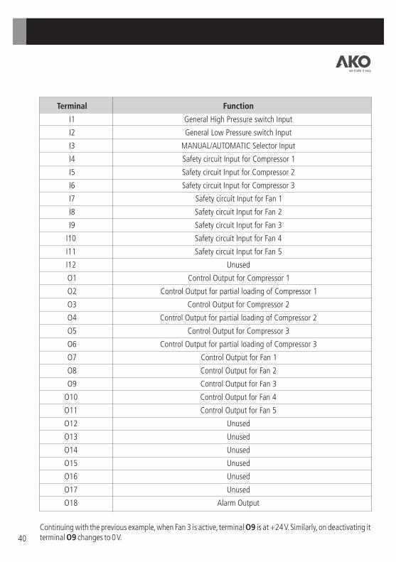
Example: Consider the following refrigerating facility:
Controller Model: AKO-21018
No. of Compressors: 3
No. of Stages per Compressor: 2
No. of Fans: 5 (ON/OFF Control)
The functions of all the DUOControl controller terminals are defined using the tables included in Chapter 2.
In the case of using a inverter, it is possible to change the current by selecting the fan icon and using the LEFT and RIGHT keys.
To activate a compressor's stages, press SET as many times as the compressor has stages.
we make it easy
40
Function
General High Pressure switch Input
General Low Pressure switch Input
MANUAL/AUTOMATIC Selector Input
Safety circuit Input for Compressor 1
Safety circuit Input for Compressor 2
Safety circuit Input for Compressor 3
Safety circuit Input for Fan 1
Safety circuit Input for Fan 2
Safety circuit Input for Fan 3
Safety circuit Input for Fan 4
Safety circuit Input for Fan 5
Unused
Control Output for Compressor 1
Control Output for partial loading of Compressor 1
Control Output for Compressor 2
Control Output for partial loading of Compressor 2
Control Output for Compressor 3
Control Output for partial loading of Compressor 3
Control Output for Fan 1
Control Output for Fan 2
Control Output for Fan 3
Control Output for Fan 4
Control Output for Fan 5
Unused
Unused
Unused
Unused
Unused
Unused
Alarm Output
Terminal
I1
I2
I3
I4
I5
I6
I7
I8
I9
I10
I11
I12
O1
O2
O3
O4
O5
O6
O7
O8
O9
O10
O11
O12
O13
O14
O15
O16
O17
O18
Continuing with the previous example, when Fan 3 is active, terminal O9 is at +24 V. Similarly, on deactivating it terminal O9 changes to 0 V.
we make it easy

WIZARDRefrigerant type
CHANGING VALUE INVOLVESDEFAULT VALUES
VALUEGENERIC
R134AR717R22R410AR507
R404A
WIZARDUnits
CHANGING VALUE INVOLVESDEFAULT VALUES
VALUE
41
SCREEN W-9: WHICH TYPE OF REFRIGERANT GAS?
Select the refrigerant gas used in the installation. If it is not in the list, choose GENERIC. In this case the DUOControl will only be able to work in bar as the working unit.
NAVIGATOR function:
NAVIGATOR function:
UP and DOWN: Move the cursor through the possible responses
SET: Confirm the preselected response
ESC: Return to SCREEN W-8
OTHERS: No function
SCREEN W-10: WHICH WORKING UNITS?
DUOControl controllers can work by temperature (ºC) or pressure (bar).The unit selected affects some of the user parameters.For further information on the user parameters affected, see Appendix C.
UP and DOWN: Change the value of the selected digit
SET: Confirm the preselected response
ESC: Return to SCREEN W-8
OTHERS: No function
we make it easy

-1.0
WIZARDSuction Probe - 4mA
VALUE
WIZARDSuction Probe - 20mA
VALUE
42
SCREEN W-11: SUCTION PROBE – PRESSURE VALUE (bar) FOR A CURRENT OF 4 mA
Enter the pressure equivalent to an output current of 4 mA from the suction probe.
NAVIGATOR function:
UP and DOWN: Change the value of the selected digit
LEFT and RIGHT: Move the digit selection
SET: Confirm the preselected response
ESC: Return to SCREEN W-8
OTHERS: No function
SCREEN W-12: SUCTION PROBE – PRESSURE VALUE (bar) FOR A CURRENT OF 20 mA
Enter the pressure equivalent to an output current of 20 mA from the suction probe.
NAVIGATOR function:
UP and DOWN: Change the value of the selected digit
LEFT and RIGHT: Move the digit selection
SET: Confirm the preselected response
ESC: Return to SCREEN W-8
OTHERS: No function
we make it easy

-1.0
WIZARDDischarge Probe - 4mA
VALUE
WIZARDDischarge Probe - 20mA
VALUE
43
SCREEN W-13: DISCHARGE PROBE – PRESSURE VALUE (bar) FOR A CURRENT OF 4 mA
Enter the pressure equivalent to an output current of 4 mA from the discharge probe.
SCREEN W-14: DISCHARGE PROBE – PRESSURE VALUE (bar) FOR A CURRENT OF 20 mA
Enter the pressure equivalent to an output current of 20 mA from the discharge probe.
NAVIGATOR function:
UP and DOWN: Change the value of the selected digit
LEFT and RIGHT: Move the digit selection
SET: Confirm the preselected response
ESC: Return to SCREEN W-8
OTHERS: No function
NAVIGATOR function:
UP and DOWN: Change the value of the selected digit
LEFT and RIGHT: Move the digit selection
SET: Confirm the preselected response
ESC: Return to SCREEN W-8
OTHERS: No function
we make it easy

WIZARDEvap. Setpoint (SP)
VALUE
WIZARDCondensation SP
VALUE
44
SCREEN W-15: EVAPORATION SET POINT VALUE
Evaporation pressure set point.
SCREEN W-16: CONDENSATION SET POINT VALUE
Condensation pressure set point.
NAVIGATOR function:
UP and DOWN: Change the value of the selected digit
LEFT and RIGHT: Move the digit selection
SET: Confirm the preselected response
ESC: Return to SCREEN W-8
OTHERS: No function
NAVIGATOR function:
UP and DOWN: Change the value of the selected digit
LEFT and RIGHT: Move the digit selection
SET: Confirm the preselected response
ESC: Return to SCREEN W-8
OTHERS: No function
we make it easy

WIZARDSAVE DATA
NoYes
VALUE
45
SCREEN W-17: CONFIRMING THE CONFIGURATION
Select YES to confirm ALL the data entered and transfer them to the DUOControl.Select NO to delete the data and return to the initial wizard screen.If the data is confirmed, the wizard will close and proceed to MONITORING THE INSTALLATION.
IMPORTANT: The 8 icon indicates that the data is being saved. If the equipment is disconnected or the power supply fails while this icon is showing, the equipment will return to the last saved configuration.
NAVIGATOR function:
UP and DOWN: Move the cursor through the possible responses
SET: Confirm the preselected response
ESC: Return to SCREEN W-0
OTHERS: No function
we make it easy

Monday
R.TEM
46
3.2.- MONITORING THE INSTALLATION
The MONITORING SCREEN shows all the information required for determining the status of the refrigerating facility:
The MONITORING SCREEN appears:
When the wizard closes.On starting up a previously configured DUOControl controller.On returning from the USER PARAMETER AND LOGS MENU.
MONITORING SCREEN
Monday
R.TEM
Year/Month/Day Hours : Minutes Day of the week
Evaporation Set Point
Condensation Set Point
Energy Saving operating
Condensation Pressure reading
Evaporation Pressure reading
Refrigerant
Floating Condensation Active Ambient air Temperature reading
Manual mode
Saving data
we make it easy
47
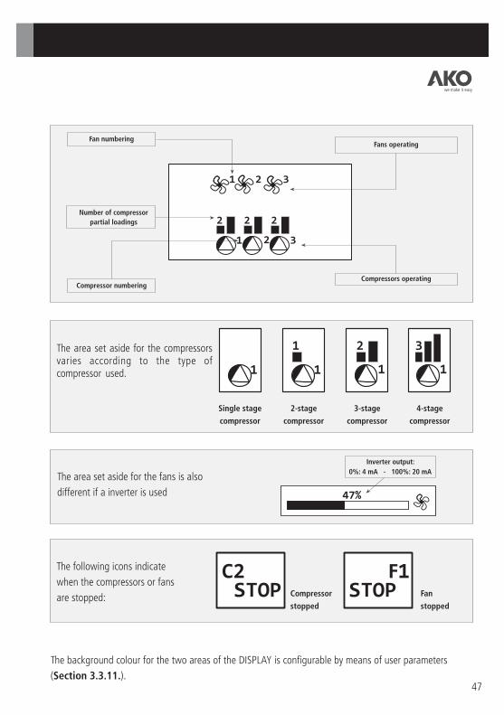
Fan numbering Fans operating
Number of compressor
partial loadings
Compressor numbering Compressors operating
The area set aside for the compressors varies according to the type of compressor used.
Single stage
compressor
2-stage
compressor
3-stage
compressor
4-stage
compressor
The area set aside for the fans is also
different if a inverter is used
Inverter output:
0%: 4 mA - 100%: 20 mA
The following icons indicate
when the compressors or fans
are stopped: Compressor
stopped
Fan
stopped
The background colour for the two areas of the DISPLAY is configurable by means of user parameters
(Section 3.3.11.).
we make it easy
F

Monday
R.TEM
COMPR. 1 SAFETY CIRCUITCOMPR. 2 SAFETY CIRCUITFAN 2 SAFETY CIRCUIT
48
The Energy Saving a and Floating Condensation $ icons only appear when these are active.
The Communication Error icon j appears when there is an error in the communication between the DUOControl and the DUOVision.
The ALARM icon B appears when there is an alarm active. In this case the background colour of the left-hand side area flashes red. To see which alarms are active, press the HELP (?) key. The list of active alarms is shown in real time on the right-hand side of the Display.
Press the ESC key to go back to displaying the status of the fans and compressors.
Within the MONITORING SCREEN, the function of the keys is as follows:
NAVIGATOR function:
UP and DOWN: Change the display units
SET: Press for 3 seconds to enter the user parameter and logs menu.
HELP (?): See the list of active alarms
ESC: Clear the list of active alarms
OTHERS: No function
The manual mode icon 1 appears when there is 24 V present at input I3.
0 This icon indicates that the DUOControl is shut down and so is not regulating the refrigerating installation.
IMPORTANT: The 8 icon indicates that the data is being saved. If the equipment is disconnected or the power supply fails while this icon is showing, the equipment will return to the last saved configuration when it restarts.
we make it easy

No. CompressorsNo. Compressor stagesCompr. capacity reductionAlarm output activatedType of fan controlNo. FansRefrigerant typeUnits
INSTALLATION CONFIG.
No. CompressorsNo. Compressor stagesCompr. capacity reductionAlarm output activatedType of fan controlNo. FansRefrigerant typeUnits
INSTALLATION CONFIG.
49
3.3.- USER PARAMETERS AND LOGS
When the SET key is pressed for 3 seconds on the MONITORING SCREEN, the USER PARAMETER AND LOGS MENU is displayed. It is possible to activate PASSWORD protection in the TERM_1 parameter.
CONFIGURATION AND LOG SCREEN:
DISPLAY OF LOGS
DESCRIPTION OF SELECTED FOLDER
USER PARAMETER FOLDERS
The user parameter and logs are grouped into folders depending on their function.To make it easier to find a user parameter, all the parameters included in the selected folder are listed in the right-hand area of the DISPLAY.
NAVIGATOR function:
UP, DOWN, RIGHT and LEFT: Select the desired folder
SET: Confirm the selected folder to proceed to adjusting some of its parameters
ESC: Return to the MONITORING SCREEN
OTHERS: No function
we make it easy
INSTALLATION CONFIG.

50
3.3.1.- CONFIGURING THE INSTALLATION
User parameters related to the structure of the refrigerating installation. As a change in these parameters would involve a change in
the behaviour of the installation, it is only possible to modify the parameters in this folder by means of the WIZARD (See Section 3.1.).
Within this folder the function of the NAVIGATOR is as follows:
UP and DOWN: Select the desired parameter
HELP (?): Display the help window for the parameter selected in the area on the
right of the Display. Press ESC to exit.
ESC: Return to the CONFIGURATION AND LOGS SCREEN
OTHERS: No function
Parameter: No. of Compressors
Code: CONF_1
Description: Number of compressors present in the installation
Parameter: No. of Stages per Compressor
Code: CONF_2
Description: Number of stages per compressor
For a compressor without partial loadings, the number of stages is 1.
For a compressor with 1 partial loading, the number of stages is 2.
For a compressor with 2 partial loadings, the number of stages is 3.
For a compressor with 3 partial loadings, the number of stages is 4.
we make it easy
No. CompressorsNo. Compressor stagesCompr. capacity reductionAlarm output activatedType of fan controlNo. FansRefrigerant typeUnits

0 VDC 24 VDC 24 VDC
0 of 2 1 of 2 2 of 2
0 VDC 0 VDC 24 VDC
Active when powered
Active when not powered
Compressor Stages ON Partial loading-a
0 VDC 24 VDC 24 VDC
0 of 2 1 of 2 2 of 2
Compressor Stages ON
24 VDC 24 VDC 0 VDC
Partial loading-a
51
Parameter: Compressor capacity reduction contact
Code: CONF_3
Description: Type of activation for compressor partial loadings.This can be selected between:
The DUOControl activates partial loading with +24 VDC to increase refrigerating power.
: The DUOControl activates partial loading with +0 VDC to increase refrigerating power.
Active when powered:
Active when not powered
For a compressor without partial loadings:
Compressor
0 VDC
24 VDC
Stages ON
0 of 1
1 of 1
Active when not powered
Compressor
0 VDC
24 VDC
Stages ON
0 of 1
1 of 1
Active when powered
Active when powered
Active when not powered
Compressor
Compressor
Stages ON
Stages ON
Partial loading-a
Partial loading-a
Partial loading-b
Partial loading-b
2 of 3
2 of 3
24 VDC 0 VDC 3 of 3
3 of 3
24 VDC 24 VDC
1 of 3
1 of 3
0 VDC 0 VDC 0 VDC 0 VDC 0 of 3
0 of 3
0 VDC
0 VDC
24 VDC
24 VDC
24 VDC
24 VDC
24 VDC
24 VDC 24 VDC 24 VDC 0 VDC 0 VDC
24 VDC 24 VDC 24 VDC 0 VDC
we make it easy
For a compressor with 2 partial loadings (3 stages):
For a compressor with 1 partial loadings (2 stages):

52
Compressor
0 VDC
24 VDC
24 VDC
24 VDC
24 VDC
Stages ON
0 of 4
1 of 4
2 of 4
3 of 4
4 of 4
Partial loading-a
0 VDC
0 VDC
24 VDC
24 VDC
24 VDC
Partial loading-b
0 VDC
0 VDC
0 VDC
24 VDC
24 VDC
Partial loading-c
0 VDC
0 VDC
0 VDC
0 VDC
24 VDC
For a compressor with 3 partial loadings:
Compressor
0 VDC
24 VDC
24 VDC
24 VDC
24 VDC
Stages ON
0 of 4
1 of 4
2 of 4
3 of 4
4 of 4
Partial loading-a
24 VDC
24 VDC
0 VDC
0 VDC
0 VDC
Partial loading-b
24 VDC
24 VDC
24 VDC
0 VDC
0 VDC
Partial loading-c
24 VDC
24 VDC
24 VDC
24 VDC
0 VDC
Active when not powered
Active when powered
Parameter: Alarm Output Activated
Code: CONF_4
Description: Notifies whether it has been possible to use a controller terminal as an alarm output.Section 2.3.2. shows in which cases this functionality is not available.
Parameter: Fan Control Type
Code: CONF_5
Description: Type of condenser fan control
ON/OFF: ALL/NOTHING control
INVERTER: INVERTER control
Parameter: No. of Fans
Code: CONF_6
Description: Number of condenser fans
Modification of this parameter is only permitted by means of the Programming Assistant.
we make it easy
53
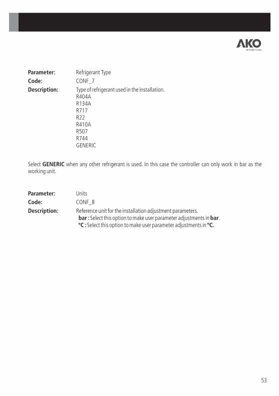
Parameter: Refrigerant Type
Code: CONF_7
Description: Type of refrigerant used in the installation.R404AR134AR717R22R410AR507R744GENERIC
Parameter: Units
Code: CONF_8
Description: Reference unit for the installation adjustment parameters. bar : Select this option to make user parameter adjustments in bar. ºC : Select this option to make user parameter adjustments in ºC.
Select GENERIC when any other refrigerant is used. In this case the controller can only work in bar as the working unit.
we make it easy

54
3.3.2.- EVAPORATION
User parameters relating to the adjustment of the evaporation circuit.
With the cursor in the left-hand area of the Display, the function of the NAVIGATOR is as follows:UP and DOWN: Select the desired parameterSET: Confirm the selected user parameter to modify its value (right-hand area of the Display)HELP (?): Display the help window for the parameter selected in the right-hand area of the DisplayESC: Return to the CONFIGURATION AND LOGS SCREENOTHERS: No function
With the cursor in the right-hand area of the Display, the function of the NAVIGATOR is as follows:UP and DOWN: To adjust the value of the selected digit or select the desired optionLEFT and RIGHT: Move the digit selection (only for numeric user parameters)SET: Confirm the numeric value or the option selectedHELP (?): Display the help window for the parameter selected in the right-hand area of the Display. Press ESC to clear.
Parameter: Evaporation SP
Code: EVAP_1
Description: Adjustment of evaporation Set Point
Parameter: Upper limit Evap. SP
Code: EVAP_2
Description: Maximum permitted value for the parameter EVAP_1
Units: According to CONF_8 parameter
Units: According to CONF_8 parameter
Evap. Setpoint (SP)Upper limit Evap. SPLower limit Evap. SPCompressors rotationCompressor ControlPositive Diff. Slow ZoneNegative Diff. Slow ZonePositive Diff. Fast Zone
Negative Diff. Fast ZoneActivate Pump-DownPump-Down DelayPump-Down SetPoint
we make it easy

According to CONF_8 parameter
According to CONF_8 parameter
55
Parameter: Lower limit Evap. SP
Code: EVAP_3
Units:
Description: Minimum value permitted for
parameter EVAP_1.
EVAP_2
EVAP_1
EVAP_3
Upper variation margin
Lower variation margin
Parameter: Compressor Rotation
Code: EVAP_4
Description: Type of compressor rotation.DUOControl controllers have 2 algorithms implemented for selecting the compressors to start and/or stop.OPERATING HOURS: Always starts the available compressor with the least accumulated operating time and always stops the compressor with the most accumulated operating time.
SEQUENTIAL: The order in which the compressors are started/stopped is set by the connection to the DUOControl. For further information, see Chapter 4.
Parameter: Compressor Control
Code: EVAP_5
Description: To define the algorithm used to control the compressors.
NEUTRAL ZONE
PROPORTIONAL BAND
For further information, see Chapter 4.
Parameter: Positive Differential Slow Zone
Code: EVAP_6
Units:
Description: Bandwidth of the POSITIVE SLOW ZONE used in the definition of the algorithms
for controlling the compressors.
For further information, see Chapter 4.
According to CONF_8 parameter
Parameter: Negative Differential Slow Zone
Code: EVAP_7
Units:
Description: Bandwidth of the NEGATIVE SLOW ZONE used in the definition of the algorithms
for controlling the compressors.
For further information, see Chapter 4.
we make it easy

According to CONF_8 parameter
According to CONF_8 parameter
Seconds
According to CONF_8 parameter
56
Parameter: Positive Differential Fast Zone
Code: EVAP_8
Units:
Description: Bandwidth of the POSITIVE FAST ZONE used in the definition of the
algorithms for controlling the compressors.
For further information, see Chapter 4.
Parameter: Negative Differential Fast Zone
Code: EVAP_9
Units:
Description: Bandwidth of the NEGATIVE FAST ZONE used in the definition of the
algorithms for controlling the compressors.
For further information, see Chapter 4.
Parameter: Activate Pump-Down
Code: EVAP_10
Description: Activates the Pump-Down functionality.
NO: Do not activate Pump-Down.
YES: Activate the Pump-Down process.
For further information, see Chapter 7.
Parameter: Pump-Down Delay
Code: EVAP_11
Units:
Description: Maximum operating time of the last active stage.
For further information, see Chapter 7.
Parameter: Pump-Down SetPoint
Code: EVAP_12
Units:
Description: Set Point for Pump-Down.
For further information, see Chapter 7.
IMPORTANT: The 8 icon indicates that the data is being saved. If the equipment is disconnected or the power supply fails while this icon is showing, the equipment will return to the last saved configuration.
we make it easy

According to CONF_8 parameter
According to CONF_8 parameter
57
3.3.3.- CONDENSATION
User parameters relating to the adjustment of the condensation circuit.
Parameter: Condensation SetPoint
Code: COND_1
Units:
Description: Adjustment of condensation Set Point
Parameter: Upper limit Condensation SetPoint
Code: COND_2
Units:
Description: Maximum permitted value for the parameter COND_1
With the cursor in the left-hand area of the Display, the function of the NAVIGATOR is as follows:UP and DOWN: Select the desired parameterSET: Confirm the selected user parameter to modify its value (right-hand area of the Display)HELP (?): Display the help window for the parameter selected in the right-hand area of the DisplayESC: Return to the CONFIGURATION AND LOGS SCREENOTHERS: No function
With the cursor in the right-hand area of the Display, the function of the NAVIGATOR is as follows:UP and DOWN: To adjust the value of the selected digit or select the desired optionLEFT and RIGHT: Move the digit selection (only for numeric user parameters)SET: Confirm the numeric value or the option selectedHELP (?): Display the help window for the parameter selected in the right-hand area of the Display. Press ESC to clear.
Condensation SPUpper limit Cond. SP Lower limit Cond. SPFan ControlPositive Diff. Slow ZoneNegative Diff. Slow ZonePositive Diff. Fast ZoneNegative Diff. Fast Zone
Activate Floating Cond.Proportional valueIntegrative value
we make it easy

According to CONF_8 parameter
According to CONF_8 parameter
According to CONF_8 parameter
According to CONF_8 parameter
58
COND_2
COND_1
COND_3
Upper variation margin
Lower variation margin
Parameter: Lower limit Condensation SetPoint
Code: COND_3
Units:
Description: Minimum value permitted for
parameter COND_1
Parameter: Fan Control
Code: COND_4
Description: Type of algorithm for condenser fan control.
NEUTRAL ZONE
PROPORTIONAL BAND
For further information, see Chapter 5.
Parameter: Positive Differential Slow Zone
Code: COND_5
Units:
Description: Bandwidth of the POSITIVE SLOW ZONE used in the definition of the algorithms for controlling the condensation circuit.For further information, see Chapter 5.
Parameter: Negative Differential Slow Zone
Code: COND_6
Units:
Description: Bandwidth of the NEGATIVE SLOW ZONE used in the definition of the algorithms for controlling the condensation circuit.For further information, see Chapter 5.
Parameter: Positive Differential Fast Zone
Code: COND_7
Units:
Description: Bandwidth of the POSITIVE FAST ZONE used in the definition of the algorithms for controlling the condensation circuit.For further information, see Chapter 5.
we make it easy

According to CONF_8 parameter
59
Parameter: Negative Differential Fast Zone
Code: COND_8
Units:
Description: Bandwidth of the NEGATIVE FAST ZONE used in the definition of the algorithms for controlling the condensation circuit. For further information, see Chapter 5.
Parameter: Activate Floating Cond.
Code: COND_9
Description: Activation/Deactivation of floating condensation. To activate this functionality it is essential to have the Ambient air temperature probe installed. NO: Do not activate floating condensation YES: Activate floating condensation For further information, see Chapter 5.
Parameter: Proportional value
Code: COND_10
Description: Adjustment of the PI control proportional value to regulate the 4-20 mA output for the inverter for the condenser fans. For further information, see Chapter 5.
Parameter: Integrative value
Code: COND_11
Description: Adjustment of the PI control integrative value to regulate the 4-20 mA output for the inverter for the condenser fans. For further information, see Chapter 5.
IMPORTANT: The 8 icon indicates that the data is being saved. If the equipment is disconnected or the power supply fails while this icon is showing, the equipment will return to the last saved configuration.
we make it easy

ºC
ºC
60
3.3.4.- FLOATING CONDENSATION
Parameters relating to the adjustment of the algorithm used for floating condensation.
Parameter: Minimum Condensation Temp.
Code: CONDF_1
Units:
Description: Minimum condensation temperature. Depends on the type of expansion valve and the
refrigerant used in the refrigerating installation.
Parameter used to adjust floating condensation. For further information, see Chapter 7.
Parameter: Condenser Temperature Difference
Code: CONDF_2
Units:
Description: DT for the Condenser used.
Parameter used to adjust floating condensation. For further information, see Chapter 7.
With the cursor in the left-hand area of the Display, the function of the NAVIGATOR is as follows:UP and DOWN: Select the desired parameterSET: Confirm the selected user parameter to modify its value (right-hand area of the Display)HELP (?): Display the help window for the parameter selected in the right-hand area of the DisplayESC: Return to the CONFIGURATION AND LOGS SCREENOTHERS: No function
With the cursor in the right-hand area of the Display, the function of the NAVIGATOR is as follows:UP and DOWN: To adjust the value of the selected digit or select the desired optionLEFT and RIGHT: Move the digit selection (only for numeric user parameters)SET: Confirm the numeric value or the option selectedHELP (?): Display the help window for the parameter selected in the right-hand area of the Display. Press ESC to clear.
IMPORTANT: The 8 icon indicates that the data is being saved. If the equipment is disconnected or the power supply fails while this icon is showing, the equipment will return to the last saved configuration.
Min. Condensation Temp.Condenser Temp. Differ.
we make it easy

With the cursor in the left-hand area of the Display, the function of the NAVIGATOR is as follows:UP and DOWN: Select the desired parameterSET: Confirm the selected user parameter to modify its value (right-hand area of the Display)HELP (?): Display the help window for the parameter selected in the right-hand area of the DisplayESC: Return to the CONFIGURATION AND LOGS SCREENOTHERS: No function
With the cursor in the right-hand area of the Display, the function of the NAVIGATOR is as follows:UP and DOWN: To adjust the value of the selected digit or select the desired optionLEFT and RIGHT: Move the digit selection (only for numeric user parameters)SET: Confirm the numeric value or the option selectedHELP (?): Display the help window for the parameter selected in the right-hand area of the Display. Press ESC to clear.
Bar
Bar
61
3.3.5.- CONFIGURING THE PROBES
User parameters relating to the calibration and scaling of the probes used: Suction Probe, Discharge Probe and Ambient air Temperature Probe.
Parameter: Suction Probe - 4 mA
Code: SOND_1
Units:
Description: Pressure equivalent to an output current of 4 mA from the suction probe.
Parameter: Suction Probe - 20mA
Code: SOND_2
Units:
Description: Pressure equivalent to an output current of 20 mA from the suction probe.
Suction Probe - 4mASuction Probe - 20mASuction Probe - OffsetDischarge Probe - 4mADischarge Probe - 20mADischarge Probe - OffsetAmb. air probe ConnectedAmb. air probe - 4mA
Amb. air probe - 20mAAmb. air probe - Offset
we make it easy

Bar
Bar
Bar
Bar
62
Parameter: Suction Probe - Offset Code: SOND_3 Units:
Units:
Units:
Units:
Description: Suction probe offset.
Parameter: Discharge Probe - 4 mA Code: SOND_4
Description: Pressure equivalent to an output current of 4 mA from the discharge probe.
Parameter: Discharge Probe - 20mA Code: SOND_5
Description: Pressure equivalent to an output current of 20 mA from the discharge probe.
Parameter: Discharge Probe - Offset Code: SOND_6
Description: Discharge probe offset.
Parameter: Ambient air probe Connected Code: SOND_7 Description: Activation/deactivation of the temperature probe.
NO: Do not activate the YES: Activate the The measures the temperature of the air flowing through the condenser to cool the refrigerant. This value is needed for the calculation of the Set Point for the condensation circuit when floating condensation is active. It is also possible to activate the temperature probe if floating condensation is NOT active.
Ambient air Ambient air
Ambient air Ambient air
Ambient air
temperature probe.temperature probe.
probe
Parameter: Ambient air Probe - 4 mA Code: SOND_8 Units: ºCDescription: Temperature equivalent to an output current of 4 mA from the temperature probe. Ambient air
Parameter: Ambient air Probe - 20mA Code: SOND_9 Units: ºCDescription: Temperature equivalent to an output current of 20 mA from the temperature
probe. Ambient air
Parameter: Ambient air Probe - Offset Code: SOND_10 Units: ºCDescription: Ambient air temperature probe offset.
IMPORTANT: The 8 icon indicates that the data is being saved. If the equipment is disconnected or the power supply fails while this icon is showing, the equipment will return to the last saved configuration.
we make it easy

63
3.3.6.- CONFIGURING THE DIGITAL INPUTS
User parameters relating to digital inputs: General High Pressure , General Low Pressure and Safety circuits for the inverter, Compressors and Fans.
switchswitch
With the cursor in the left-hand area of the Display, the function of the NAVIGATOR is as follows:UP and DOWN: Select the desired parameterSET: Confirm the selected user parameter to modify its value (right-hand area of the Display)HELP (?): Display the help window for the parameter selected in the right-hand area of the DisplayESC: Return to the CONFIGURATION AND LOGS SCREENOTHERS: No function
With the cursor in the right-hand area of the Display, the function of the NAVIGATOR is as follows:UP and DOWN: To adjust the value of the selected digit or select the desired optionLEFT and RIGHT: Move the digit selection (only for numeric user parameters)SET: Confirm the numeric value or the option selectedHELP (?): Display the help window for the parameter selected in the right-hand area of the Display. Press ESC to clear.
High Pressure SwitchLow Pressure SwitchCompressor safety circuitFan safety circuit
we make it easy
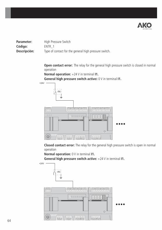
64
Parameter: High Pressure Switch
Código: ENTR_1
Descripción: Type of contact for the general high pressure . switch
Open contact error: The relay for the general high pressure is closed in normal operation
Normal operation: +24 V in terminal I1.
General high pressure switch active: 0 V in terminal I1.
switch
Closed contact error: The relay for the general high pressure is open in normal operation
Normal operation: 0 V in terminal I1.
General high pressure switch active: +24 V in terminal I1.
switch
we make it easy

Open contact error: The relay for the general low pressure is closed in normal operation
Normal operation: +24 V in terminal I2.
General low pressure switch active: 0 V in terminal I2.
switch
Closed contact error: The relay for the general low pressure is open in normal operation
Normal operation: 0 V in terminal I2.
General low pressure switch active: +24 V in terminal I2.
switch
65
Parameter: Low Pressure Switch
Code: ENTR_2
Description: Type of contact for the general low pressure . switch
PB
PB
we make it easy

66
Parameter: Compressor Safety Circuit
Code: ENTR_3
Description: Type of safety circuit for the compressors.
Open contact error: The safety circuit for the compressors is closed in normal operation
Normal operation: +24 V in the input terminals for the compressor safety circuits
Safety circuit activated: 0 V in the input terminals for the compressor safety circuits
Closed contact error: The safety circuit for the compressors is open in normal operation
Normal operation: 0 V in the input terminals for the compressor safety circuits
Safety circuit activated: +24 V in the input terminals for the compressor safety circuits
T-C1
T-C1
we make it easy

67
Parameter: Fan Safety Circuit
Code: ENTR_4
Description: Type of safety circuit for the fans.
Open contact error: The safety circuit for the fans is closed in normal operation
Normal operation: +24 V in the input terminals for the fan safety circuits
Safety circuit activated: 0 V in the input terminals for the fan safety circuits
Closed contact error: The safety circuit for the fans is open in normal operation
Normal operation: 0 V in the input terminals for the fan safety circuits
Safety circuit activated: +24 V in the input terminals for the fan safety circuits
T-V1
T-V1
IMPORTANT: The 8 icon indicates that the data is being saved. If the equipment is disconnected or the power supply fails while this icon is showing, the equipment will return to the last saved configuration.
we make it easy

68
3.3.7.- ENERGY SAVING
User parameters for configuring the Energy Saving function.
For further information on this functionality, see Section 7.3.
Parameter: Day(s) of the week
Code: AENR_1
Description: Days of the week on which the energy saving process is to be run.DEACTIVATED: Function deactivatedMONDAY: Only on MondaysTUESDAY: Only on TuesdaysWEDNESDAY: Only on WednesdaysTHURSDAY: Only on ThursdaysFRIDAY: Only on FridaysSATURDAY: Only on SaturdaysSUNDAY: Only on SundaysMONDAY - SUNDAY: From Monday to SundayMONDAY - SATURDAY: From Monday to SaturdayMONDAY - FRIDAY: From Monday to Friday
With the cursor in the left-hand area of the Display, the function of the NAVIGATOR is as follows:UP and DOWN: Select the desired parameterSET: Confirm the selected user parameter to modify its value (right-hand area of the Display)HELP (?): Display the help window for the parameter selected in the right-hand area of the DisplayESC: Return to the CONFIGURATION AND LOGS SCREENOTHERS: No function
With the cursor in the right-hand area of the Display, the function of the NAVIGATOR is as follows:UP and DOWN: To adjust the value of the selected digit or select the desired optionLEFT and RIGHT: Move the digit selection (only for numeric user parameters)SET: Confirm the numeric value or the option selectedHELP (?): Display the help window for the parameter selected in the right-hand area of the Display. Press ESC to clear.
Day(s) of the weekStart - HourStart - MinuteEnergy Saving Duration Evap. Diff. Energy Saving
we make it easy

69
Parameter: Start - Hour
Code: AENR_2
Units:
Description: Hour for starting the Energy Saving function.
Parameter: Start - Minutes
Code: AENR_3
Units:
Description: Minutes for starting the Energy Saving function.
Parameter: Energy Saving Duration
Code: AENR_4
Units:
Description: Duration of the Energy Saving function.
Parameter: Evap. Diff. Energy Saving
Code: AENR_5
Units:
Description: The value of this parameter added to the Evaporation Set Point (EVAP_1)
gives the Set Point during the Energy Saving function.
Example: Let us consider an installation with an: EVAPORATION SP = -10ºC (EVAP_1)where we wish to configure Energy Saving functionality in the following way: To start the Energy Saving function on Fridays at 10:15 pm for a duration of 20 hours. Evaporation Set Point during Energy Saving: 0ºC
With these requirements, the related user parameters will be configured using the following values:
AENR_1 = Friday AENR_2 = 22 hours AENR_3 = 15 minutes AENR_4 = 20 hours AENR_5 = +10ºC
EVAP_1 Evaporation SP
Evaporation Set Point during Energy Saving
AENR_5 Differential during Energy Saving
According to CONF_8 parameter
Hours
Minutes
Hours
IMPORTANT: The 8 icon indicates that the data is being saved. If the equipment is disconnected or the power supply fails while this icon is showing, the equipment will return to the last saved configuration.
we make it easy

70
3.3.8.- TIMING
User parameters relating to the configuration of timing protection for the compressors and fans.
Parameter: Fan MIN. time ON
Code: TEMP_1
Units:
Description: Minimum operating time for the condenser fans after each start up.This parameter is useful for preventing an excessive number of fan starts and stops.
Seconds
With the cursor in the left-hand area of the Display, the function of the NAVIGATOR is as follows:UP and DOWN: Select the desired parameterSET: Confirm the selected user parameter to modify its value (right-hand area of the Display)HELP (?): Display the help window for the parameter selected in the right-hand area of the DisplayESC: Return to the CONFIGURATION AND LOGS SCREENOTHERS: No function
With the cursor in the right-hand area of the Display, the function of the NAVIGATOR is as follows:UP and DOWN: To adjust the value of the selected digit or select the desired optionLEFT and RIGHT: Move the digit selection (only for numeric user parameters)SET: Confirm the numeric value or the option selectedHELP (?): Display the help window for the parameter selected in the right-hand area of the Display. Press ESC to clear.
Fan MIN. time ONFan MIN. time OFFFan ON-ON Delay SlowFan OFF-OFF Delay Slow.Fan ON-ON Delay FastFan OFF-OFF Delay FastCompressor T. MIN. ONCompressor T. MIN. OFF
Compr. ON-ON Delay SlowCompr. OFF-OFF Delay SlowCompr. ON-ON Delay FastCompr. OFF-OFF Delay Fast
we make it easy

71
Parameter: Fan MIN. time OFF
Code: TEMP_2
Units:
Description: Minimum stop time for the condenser fans.
This parameter is useful for preventing an excessive number of fan starts and stops.
Parameter: Fan ON-ON Delay Slow
Code: TEMP_3
Units:
Description: Minimum time between start ups of different fans within the slow control
zone.
Adjustment of this parameter is very important in defining dynamic control of
the fans: Neutral Zone or Proportional Band
For further information, see Chapter 5.
Parameter: Fan OFF-OFF Delay Slow
Code: TEMP_4
Units:
Description: Minimum time between shutdowns of different fans within the slow control
zone.
Adjustment of this parameter is very important in defining dynamic control of
the fans: Neutral Zone or Proportional Band
For further information, see Chapter 5.
Parameter: Fan ON-ON Delay Fast
Code: TEMP_5
Units:
Description: Minimum time between start ups of different fans within the fast control
zone.
Adjustment of this parameter is very important in defining dynamic control of
the fans: Neutral Zone or Proportional Band
For further information, see Chapter 5.
Seconds
Seconds
Seconds
Seconds
we make it easy

72
Parameter: Fan OFF-OFF Delay Fast
Code: TEMP_6
Units:
Description: Minimum time between shutdowns of different fans within the fast control
zone.
Adjustment of this parameter is very important in defining dynamic control of
the fans: Neutral Zone or Proportional Band
For further information, see Chapter 5.
Parameter: Compressor T. MIN. ON
Code: TEMP_7
Units:
Description: Minimum operating time for the compressors.
This parameter is useful for preventing an excessive number starts and stops of the
compressors.
Parameter: Compressor T. MIN. OFF
Code: TEMP_8
Units:
Description: Minimum stop time for the compressors.
This parameter is useful for preventing an excessive number starts and stops of the
compressors.
Parameter: Compr. ON-ON Delay Slow
Code: TEMP_9
Units:
Description: Minimum time between the starting of different compressor stages in the
slow control zone.
Adjustment of this parameter is very important in defining dynamic control of
the compressors: Neutral Zone or Proportional Band
For further information, see Chapter 4.
Seconds
Seconds
Seconds
Seconds
we make it easy

73
Parameter: Compr. OFF-OFF Delay Slow
Code: TEMP_10
Units:
Description: Minimum time between shutdowns of different compressor stages in the
slow control zone.
Adjustment of this parameter is very important in defining dynamic control of
the compressors: Neutral Zone or Proportional Band
For further information, see Chapter 4.
Parameter: Compr. ON-ON Delay Fast
Code: TEMP_11
Units:
Description: Minimum time between the starting of different compressor stages in the
fast control zone.
Adjustment of this parameter is very important in defining dynamic control of
the compressors: Neutral Zone or Proportional Band
For further information, see Chapter 4.
Parameter:
Code: TEMP_12
Units:
Description: Minimum time between shutdowns of different compressor stages in the fast control zone.
Adjustment of this parameter is very important in defining dynamic control of
the compressors: Neutral Zone or Proportional Band
For further information, see Chapter 4.
Seconds
Seconds
Seconds
Compr. OFF-OFF Delay Fast
IMPORTANT: The 8 icon indicates that the data is being saved. If the equipment is disconnected or the power supply fails while this icon is showing, the equipment will return to the last saved configuration.
we make it easy

74
3.3.9.- PROTECTIONS AND ALARMS
User parameters defining the behaviour of the installation in case of error or alarm.
Parameter: Stgs.ON Aspir. Probe Fail
Code: PROT_1
Description: Number of compressor stages operating when there is a suction probe error.
Parameter: Fans ON Disch.Probe Fail
Code: PROT_2
Description: Number of fans operating when there is a discharge probe error.In the case of using a inverter to control the fans, enter the value as a percentage (%) between 0 and 100.
With the cursor in the left-hand area of the Display, the function of the NAVIGATOR is as follows:UP and DOWN: Select the desired parameterSET: Confirm the selected user parameter to modify its value (right-hand area of the Display)HELP (?): Display the help window for the parameter selected in the right-hand area of the DisplayESC: Return to the CONFIGURATION AND LOGS SCREENOTHERS: No function
With the cursor in the right-hand area of the Display, the function of the NAVIGATOR is as follows:UP and DOWN: To adjust the value of the selected digit or select the desired optionLEFT and RIGHT: Move the digit selection (only for numeric user parameters)SET: Confirm the numeric value or the option selectedHELP (?): Display the help window for the parameter selected in the right-hand area of the Display. Press ESC to clear.
Stgs.ON Aspir. Probe FailFans ON Disch.Probe FailHP circuit Pre-AlarmHP circuit Pre-Alarm DiffLP circuit Pre-AlarmLP circuit Pre-Alarm DiffMAX T. Comp. Mainten.Start-up Alarms Delay
we make it easy

Parameter: HP circuit Pre-Alarm
Code: PROT_3
Units:
Description: Maximum value for high pressure in normal operation.The objective of this alarm is to prevent activation of the general high pressure switch, which would lead to the immediate shutdown of the installation. For further information, see Chapter 6.The value of this parameter must be set below the activation pressure for the general high pressure switch.If the discharge pressure exceeds the value defined by this parameter, the compressor stages will gradually be shut down with a time period defined by the parameter TEMP_12.If the high pressure pre-alarm occurs 5 times or more within one hour, the installation will remain shutdown until it is reset manually.
Parameter: HP circuit Pre-Alarm Diff
Code: PROT_4
Units:
Description: High pressure pre-alarm differential.
For further information, see Chapter 6.
Parameter: LP circuit Pre-Alarm
Code: PROT_5
Units:
Description: Minimum value for the suction pressure in normal operation.If the pressure falls below this value, the Low Circuit Pre-Alarm will appear.It is recommended that this parameter be set at a value above the activation pressure for the general low pressure switch so as to inform the user that there is an anomaly in the installation before the general low pressure switch acts.
Bar
Bar
Bar
75
we make it easy

76
Parameter: LP circuit Pre-Alarm Diff
Code: PROT_6
Units:
Description: Low pressure pre-alarm differential.
For further information, see Chapter 6.
Parameter: MAX T. Comp. Mainten.
Code: PROT_7
Units:
Description: Maximum number of accumulated operating hours for a compressor between two
consecutive maintenance operations.
If a compressor exceeds the value of this parameter, an alarm appears.
If the parameter is 0, the alarm remains deactivated.
Parameter: Start-up Alarms Delay
Code: PROT_8
Units:
Description: Delay for the pre-alarms for the high and low circuits.
Defines a period of time for the installation to stabilise after starting
the DUOControl until high and low pre-alarms are detected and handled.
Parameter: Alarm Output Delay
Code: PROT_9
Units:
Description: Delay between the activation of an alarm and the change of state in the Alarm output.
Bar
Hours
Seconds
Seconds
IMPORTANT: The 8 icon indicates that the data is being saved. If the equipment is disconnected or the power supply fails while this icon is showing, the equipment will return to the last saved configuration.
we make it easy

77
3.3.10.- DATE AND TIME
User parameters for entering the date and time.
This folder enables the date and time to be set in the DUOControl.The summer/winter clock change needs to be carried out manually by the user.
Parameter: Minutes
Code: FECH_1
Parameter: Hour
Code: FECH_2
Parameter: Day of the week
Code: FECH_3
Parameter: Day
Code: FECH_4
Parameter: Month
Code: FECH_5
Parameter: Year
Code: FECH_6
With the cursor in the left-hand area of the Display, the function of the NAVIGATOR is as follows:UP and DOWN: Select the desired parameterSET: Confirm the selected user parameter to modify its value (right-hand area of the Display)HELP (?): Display the help window for the parameter selected in the right-hand area of the DisplayESC: Return to the CONFIGURATION AND LOGS SCREENOTHERS: No function
With the cursor in the right-hand area of the Display, the function of the NAVIGATOR is as follows:UP and DOWN: To adjust the value of the selected digit or select the desired optionLEFT and RIGHT: Move the digit selection (only for numeric user parameters)SET: Confirm the numeric value or the option selectedHELP (?): Display the help window for the parameter selected in the right-hand area of the Display. Press ESC to clear.
IMPORTANT: The 8 icon indicates that the data is being saved. If the equipment is disconnected or the power supply fails while this icon is showing, the equipment will return to the last saved configuration.
MinuteHourDay of the weekDayMonthYear
we make it easy

78
3.3.11.- CONFIGURING DUOVision
Configuration of the DUOVision user terminal.
Parameter: Password
Code: TERM_1
Description: Access code for modifying user parameters.
If the value of the access code is 0, this protection is deactivated.
With the cursor in the left-hand area of the Display, the function of the NAVIGATOR is as follows:UP and DOWN: Select the desired parameterSET: Confirm the selected user parameter to modify its value (right-hand area of the Display)HELP (?): Display the help window for the parameter selected in the right-hand area of the DisplayESC: Return to the CONFIGURATION AND LOGS SCREENOTHERS: No function
With the cursor in the right-hand area of the Display, the function of the NAVIGATOR is as follows:UP and DOWN: To adjust the value of the selected digit or select the desired optionLEFT and RIGHT: Move the digit selection (only for numeric user parameters)SET: Confirm the numeric value or the option selectedHELP (?): Display the help window for the parameter selected in the right-hand area of the Display. Press ESC to clear.
PasswordMODBUS addressAdj. Contrast and ColourLanguage
we make it easy

79
Parameter: MODBUS address
Code: TERM_2
Description: Setting the address of the DUOControl controller within a local MODBUS
network.
Parameter: Adjusting Contrast and Colour
Code: TERM_3
Description: Configuration of the contrast and background colour for the two Display zones when showing the MONITORING SCREEN.
IMPORTANT: The 8 icon indicates that the data is being saved. If the equipment is disconnected or the power supply fails while this icon is showing, the equipment will return to the last saved configuration.
we make it easy

80
3.3.12.- MODEL AND SOFTWARE VERSIONS
Displaying the DUOControl model and the Software versions.
Within this folder the function of the NAVIGATOR is as follows:
UP and DOWN: Select the desired parameter
HELP (?): Display the help window for the parameter selected in the right-hand area of the Display. Press ESC to clear.
ESC: Return to the CONFIGURATION AND LOGS SCREEN
OTHERS: No function
Parameter: DUOControl Model
Code: MODE_1
Description: Displaying the model of DUOControl used.
Parameter: DUOControl SW version
Code: SWC_1
Description: Displaying the Firmware version of the DUOControl controller.
Parameter: DUOVision SW version
Code: SWC_2
Description: Displaying the Firmware version of the DUOVision user terminal.
DUO Control ModelDUO Control SW VersionDUO Vision SW Version
we make it easy

81
The DUOControl controllers record the activation and deactivation of the alarms. The alarm log holds a record of the last 50
alarm events. For further information regarding the detection of alarms, see Chapter 6.
3.3.13.- ALARM LOG
There is a text string corresponding to each of the alarms, as shown in the following table:
ALARM TYPE Safety circuit for compressor 1 Safety circuit for compressor 2 Safety circuit for compressor 3 Safety circuit for compressor 4 Safety circuit for compressor 5 Safety circuit for compressor 6 Safety circuit for fan 1 Safety circuit for fan 2 Safety circuit for fan 3 Safety circuit for fan 4 Safety circuit for fan 5 Safety circuit for fan 6 Safety circuit for fan 7 Safety circuit for fan 8 General low pressure switch General high pressure switch High pressure pre-alarm Low pressure pre-alarm Discharge probe error Suction probe error Ambient air temperature probe error Inverter safety circuit Installation blocking due to frequent high pressure Compressor maintenance
ALARM ACTIVATION ON CSCMP1 ON CSCMP2 ON CSCMP3 ON CSCMP4 ON CSCMP5 ON CSCMP6 ON CSFAN1 ON CSFAN2 ON CSFAN3 ON CSFAN4 ON CSFAN5 ON CSFAN6 ON CSFAN7 ON CSFAN8 ON PRESOSE ON PRESOSC ON PREALRME ON PREALRMC ON SDESCAR ON SASPIRA ON STEXT ON CSVAR ON BLOQINST ON MANTCMP
ALARM DEACTIVATION OFFCSCMP1 OFFCSCMP2 OFFCSCMP3 OFFCSCMP4 OFFCSCMP5 OFFCSCMP6 OFFCSFAN1 OFFCSFAN2 OFFCSFAN3 OFFCSFAN4 OFFCSFAN5 OFFCSFAN6 OFFCSFAN7 OFFCSFAN8 OFFPRESOSE OFFPRESOSC OFFPREALRME OFFPREALRMC OFFSDESCAR OFFSASPIRA OFFSTEXT OFFCSVAR OFFBLOQINST OFFMANTCMP
DISPLAY MESSAGE
ALARM LOG
ERASE LOGDISPLAY
we make it easy

82
DATE OF EVENT
TIME OF EVENT ALARM
DESCRIPTION
Parameter: DISPLAY
Code: ALRM_1
Description: Displaying the list of alarms in date and time order.The UP and DOWN keys are used to scan through the list.
Parameter: ERASE LOG
Code: ALRM_2
Description: Initialize the alarm memory by erasing all the previous information.NO: Do not erase the alarm logYES: Erase the alarm log
DATE TIME ALARM
we make it easy

Parameter:
Code:
Description: Enables the resetting of the “maintenance” timer for a compressor.The timer to be reset to zero is selected using the UP and DOWN keys. Press the SET key to reset the selected timer.
RESET MAINT. TIMERS
TCOMP_2
83
3.3.14.- ACCUMULATED OPERATION OF THE COMPRESSORS
Timer display for the compressors.
DUOControl controllers have timers for each compressor:
Accumulated operating time for the compressors: Shows the time the compressor has run since its commissioning. It is advisable to set this to zero only when it is first put into service.
Time since the last service: Shows the time the compressor has run since its last maintenance operation. It is advisable to reset this to zero after each service.
Each of the individual timers can be set to zero.
Parameter: RESET TOTAL TIMERS
Code: TCOMP_1
Description: Enables the resetting of the “accumulated operating time” for a compressor.The timer to be reset to zero is selected using the UP and DOWN keys. Press the SET key to reset the selected timer.
COMP HOURS TOTAL MAINT
OPERATING TIME
RESET MAINT. TIMERSRESET TOTAL TIMERS
we make it easy
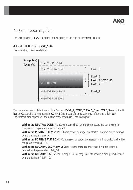
84
4.- Compressor regulation
The user parameter EVAP_5 permits the selection of the type of compressor control:
4.1.- NEUTRAL ZONE (EVAP_5=0):
Five operating zones are defined.
Pevap (bar)
Tevap (ºC)
EVAP_8
EVAP_6 EVAP_1 (EVAP SP)
EVAP_7
EVAP_9
POSITIVE FAST ZONE
POSITIVE SLOW ZONE
NEUTRAL ZONE
NEGATIVE SLOW ZONE
NEGATIVE FAST ZONE
The parameters which delimit each of the 5 zones (EVAP_6, EVAP_7, EVAP_8 and EVAP_9) are defined in bar or ºC according to the parameter CONF_8 (in the case of using a GENERIC refrigerant, only in bar).The control action depends on the suction probe reading in the following way:
Within the NEUTRAL ZONE: No action is carried out on the compressors (no compressors or compressor stages are started or stopped).
Within the POSITIVE SLOW ZONE: Compressors or stages are started in a time period defined by the parameter TEMP_9.
Within the POSITIVE FAST ZONE: Compressors or stages are started in a time period defined by the parameter TEMP_11.
Within the NEGATIVE SLOW ZONE: Compressors or stages are stopped in a time period defined by the parameter TEMP_10.
Within the NEGATIVE FAST ZONE: Compressors or stages are stopped in a time period defined by the parameter TEMP_12.
we make it easy

85
4.2.- PROPORTIONAL BAND (EVAP_5=1):
Five operating zones are defined.
Pevap (bar)
Tevap (ºC) POSITIVE FAST ZONE
POSITIVE SLOW ZONE
NEGATIVE SLOW ZONE
NEGATIVE FAST ZONE
The parameters which delimit each of the 5 zones (EVAP_6, EVAP_7, EVAP_8 and EVAP_9) are defined in bar or ºC according to the parameter CONF_8 (in the case of using a GENERIC refrigerant, only in bar).The PROPORTIONAL BAND is divided into as many levels as there are stages in the installation. These levels determine the start or stop points for the stages.
EVAP_8
EVAP_6 EVAP_1 (EVAP SP)
EVAP_7
EVAP_9
we make it easy

Example: Compressor facility with 3 x 2-stage compressors.
EVAPORATION SP (EVAP_1): -10ºC
POSITIVE SLOW ZONE DIFFERENTIAL WITH RESPECT TO EVAP_SP (EVAP_6): 2ºC
NEGATIVE SLOW ZONE DIFFERENTIAL WITH RESPECT TO EVAP_SP (EVAP_7): 4ºC
The start/stop points for the compressors or stages will be located at the following evaporation pressure levels:
Pevap (bar) Tevap (ºC)
EVAP_6=2ºC
EVAP_1=-10ºC
EVAP_7=4ºC
-8ºC
-9ºC
-10ºC
-11ºC
-12ºC
-13ºC
-14ºC
No. of ACTIVE STAGES
6 Stages
5 Stages
4 Stages
3 Stages
2 Stages
1 Stage
0 Stages
(EVAP_6 + EVAP_7)
(CONF_1 x CONF_2)
t
86
we make it easy

87
The activation/deactivation points for the compressors or stages are:
Stage 1ª2ª3ª4ª5ª6ª
Start -13ºC -12ºC -11ºC -10ºC -9ºC -8ºC
Stop -14ºC -13ºC -12ºC -11ºC -10ºC -9ºC
The control action depends on the suction probe reading in the following way:
Within the PROPORTIONAL BAND: the minimum time interval between startups of compressors
or stages is defined by the parameter TEMP_9, while the minimum time interval between
shutdowns of compressors or stages will be defined by the parameter TEMP_10.
Within the POSITIVE SLOW ZONE: the time between startups of compressors or stages is defined by the parameter TEMP_9.
Within the POSITIVE FAST ZONE: the time between startups of compressors or stages is defined by the parameter TEMP_11.
Within the NEGATIVE SLOW ZONE: the time between shutdowns of compressors or stages is defined by the parameter TEMP_10.
Within the NEGATIVE FAST ZONE: the time between shutdowns of compressors or stages is defined by the parameter TEMP_12.
we make it easy

88
4.3.- MANAGEMENT OF COMPRESSOR STARTUP/SHUTDOWN
The parameter EVAP_4 defines the management of compressor startups/shutdowns:
OPERATING HOURS: Method based on the compressor s accumulated operating times.Selection of the compressor to start up: The compressor with the least accumulated operating time starts.Selection of the compressor to shutdown: The compressor with the most accumulated operating time stops.
SEQUENTIAL: Method based on the priority level of the compressors. The level of priority of each compressor is defined in the following way during the wiring of the control panel:
'
Compressor 1 Highest priority
Compressor 2
Compressor 3
Compressor 4
Compressor 5
Compressor 6 Lowest priority
Selection of the compressor to start up: The highest priority compressor starts.
The management of the compressors does not take into account those which have been temporarily disabled (safety circuit activated, timed protections, etc).
we make it easy

89
5.- Fan regulation
Fans can be controlled ON/OFF or via a 4-20 mA signal by means of a inverter.
5.1.- MANAGEMENT OF ON/OFF FANS (CONF_5=0).
The parameter COND_4 defines the type of regulation for fans controlled ON/OFF.
NEUTRAL ZONE (COND_4=0): Five operating zones are defined.
Pcond (bar)
Tcond (ºC)
COND_7
COND_5 COND_1 (COND SP)
COND_6
COND_8
POSITIVE FAST ZONE
POSITIVE SLOW ZONE
NEUTRAL ZONE
NEGATIVE SLOW ZONE
NEGATIVE FAST ZONE
The parameters which delimit each of the 5 zones (COND_5, COND_6, COND_7 and COND_8) are defined in bar or ºC according to the parameter CONF_8 (only in bar in the case that CONF_7 = GENERIC).The control action depends on the discharge probe reading in the following way:
Within the NEUTRAL ZONE: No action is carried out on the fans (fans are neither started nor stopped).
Within the POSITIVE SLOW ZONE: Fans are started in a time period defined by the parameter TEMP_3.
Within the POSITIVE FAST ZONE: Fans are started in a time period defined by the parameter TEMP_5.
Within the NEGATIVE SLOW ZONE: Fans are stopped in a time period defined by the parameter TEMP_4.
Within the NEGATIVE FAST ZONE: Fans are stopped in a time period defined by the parameter TEMP_6.
we make it easy
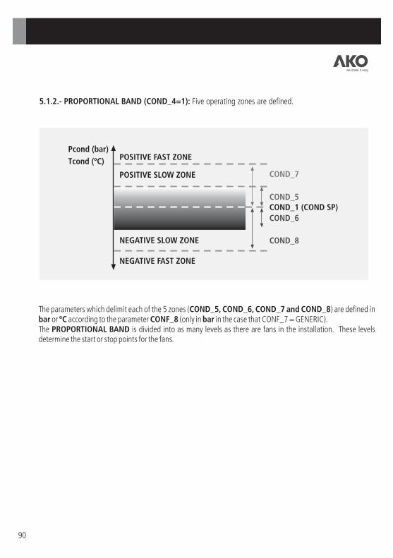
90
5.1.2.- PROPORTIONAL BAND (COND_4=1): Five operating zones are defined.
Pcond (bar)
Tcond (ºC) POSITIVE FAST ZONE
POSITIVE SLOW ZONE
NEGATIVE SLOW ZONE
NEGATIVE FAST ZONE
The parameters which delimit each of the 5 zones (COND_5, COND_6, COND_7 and COND_8) are defined in bar or ºC according to the parameter CONF_8 (only in bar in the case that CONF_7 = GENERIC).The PROPORTIONAL BAND is divided into as many levels as there are fans in the installation. These levels determine the start or stop points for the fans.
COND_7
COND_5 COND_1 (COND SP)
COND_6
COND_8
we make it easy

91
Example: Condenser with 6 fans.
CONDENSATION SP (COND_1): + 45ºC
POSITIVE SLOW ZONE DIFFERENTIAL WITH RESPECT TO COND_SP (COND_5): 4ºC
NEGATIVE SLOW ZONE DIFFERENTIAL WITH RESPECT TO COND_SP (COND_6): 8ºC
The start/stop points for the stages are located at the following evaporation pressure levels:
Pvap (bar) Tcond (ºC)
EVAP_5=4ºC
EVAP_1=45ºC
EVAP_6=8ºC
49ºC
47ºC
45ºC
43ºC
41ºC
39ºC
37ºC
No. of FANS
6 Fans
5 Fans
4 Fans
3 Fans
2 Fans
1 Fan
0 Fans
(COND_5 + COND_6)
(CONF_6)
t
PROPORTIONAL BAND
Fan 123456
Start 39ºC 41ºC 43ºC 45ºC 47ºC 49ºC
Stop 37ºC 39ºC 41ºC 43ºC 45ºC 47ºC
The activation/deactivation points for the different fans are:
The control action depends on the discharge probe reading in the following way:Within the PROPORTIONAL BAND: the minimum time interval between startups of fans is defined by the parameter TEMP_3, while the minimum time interval between shutdowns of fans will be defined by the parameter TEMP_4.
we make it easy

92
Within the POSITIVE SLOW ZONE: the time between startups of different fans is defined by the parameter TEMP_4.Within the POSITIVE FAST ZONE: the time between startups of different fans will be defined by the parameter TEMP_6.
Within the NEGATIVE SLOW ZONE: the time between shutdowns of different fans is defined by the parameter TEMP_3.Within the NEGATIVE FAST ZONE: the time between shutdowns of different fans is defined by the parameter TEMP_5.
5.1.3.- MANAGEMENT OF FAN STARTUP/SHUTDOWNThe management of fan startups/shutdowns is based on levels of priority. The level of priority of each fan is defined during the wiring of the control panel.
Fan 1 Highest priority Fan 2 Fan 3 Fan 4 Fan 5 Fan 6 Fan 7 Fan 8 Lowest priority
Need to start a fan: The highest priority fan starts.Need to stop a fan: The lowest priority fan stops.
The management of the fans does not take into account those which have been temporarily disabled (safety circuit activated, timed protections active, etc).
5.2.- MANAGEMENT OF FANS BY INVERTER (CONF_5=1)The DUOControl has a 4-20 mA output to control the inverter for the fans.The regulation of the 4-20 mA signal is carried out using a PI (Proportional-Integral) algorithm adjusted by means of the following user parameters:PROPORTIONAL ACTION (COND_10): is the proportional coefficient for the PI. The higher the parameter, the faster is the PI response.
we make it easy
93
6.- Alarm management
DUOControl controllers enable the following alarms to be detected:Safety circuit for the compressorsSafety circuit for the fans (or inverter)General high pressure switchGeneral low pressure switchHigh pressure pre-alarmLow pressure pre-alarmSuction probe errorDischarge probe errorAmbient air probe errorCompressor maintenance
The DUOVision user terminal shows each of the active alarms on screen and records them in the alarm log.
SAFETY CIRCUIT FOR THE COMPRESSORSA compressor stops automatically when its safety circuit activates and starts normal operation again when this deactivates.
SAFETY CIRCUIT FOR THE FANSA fan stops automatically when its safety circuit activates and starts normal operation again when this deactivates.
SAFETY CIRCUIT FOR THE INVERTERAll the compressors stop in turn when the safety circuit for the inverter activates. They return to normal operation again when this deactivates.
GENERAL HIGH PRESSURE SWITCHDUOControl controllers gradually shutdown all the compressors when the general high pressure switch is activated. The regulation of the compressors returns to normal when the pressure switch is reset (manually or automatically).
The installation is blocked when the general high pressure switch is activated 5 times or more in one hour. There are two options for unblocking it:- Disconnecting the DUOControl power supply and reconnecting it.- Changing the status of the I3 input from AUTOMATIC to MANUAL and back to AUTOMATIC again.
we make it easy
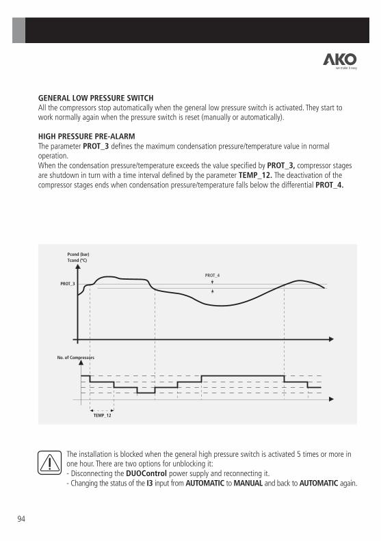
94
GENERAL LOW PRESSURE SWITCHAll the compressors stop automatically when the general low pressure switch is activated. They start to work normally again when the pressure switch is reset (manually or automatically).
HIGH PRESSURE PRE-ALARMThe parameter PROT_3 defines the maximum condensation pressure/temperature value in normal operation.When the condensation pressure/temperature exceeds the value specified by PROT_3, compressor stages are shutdown in turn with a time interval defined by the parameter TEMP_12. The deactivation of the compressor stages ends when condensation pressure/temperature falls below the differential PROT_4.
The installation is blocked when the general high pressure switch is activated 5 times or more in one hour. There are two options for unblocking it:- Disconnecting the DUOControl power supply and reconnecting it.- Changing the status of the I3 input from AUTOMATIC to MANUAL and back to AUTOMATIC again.
Pcond (bar)
Tcond (ºC)
PROT_3
No. of Compressors
TEMP_12
PROT_4
we make it easy

95
LOW PRESSURE PRE-ALARM
The parameter PROT_5 defines the minimum evaporation pressure/temperature value in normal operation.
When the evaporation pressure/temperature exceeds the value specified by PROT_5, compressor stages are shutdown in turn with a time interval defined by the parameter TEMP_12. The deactivation of the compressor stages ends when evaporation pressure/temperature falls below the differential PROT_6.
Pevap (bar)
Tevap (ºC)
PROT_5
No. of Compressors
TEMP_12
PROT_6
SUCTION PROBE ERRORA suction probe error occurs when the measured value is outside the probe's range. While this error exists, as many compressor stages are activated as there are specified in the parameter PROT_1. A delay of 2 minutes is fixed from the detection of this error to the initiation of the function.
DISCHARGE PROBE ERRORA discharge probe error occurs when the value to be measured is outside the probe's range. While this error exists, as many fans are activated as there are specified by the parameter PROT_2. AMBIENT AIR PROBE ERRORAn ambient air probe error occurs when the value to be measured is outside the probe's range. While this error exists, floating condensation is deactivated and the condensation value becomes the value specified in the parameter COND_1.
PREVENTIVE MAINTENANCE OF THE COMPRESSORSThis alarm is activated when one of the compressors exceeds the hours of operation defined in parameter PROT_7. Once preventive maintenance has been carried out, setting the compressor's timer for accumulated hours of operation to zero is recommended to deactivate the alarm.
we make it easy

96
7.1.- Pump-Down (EVAP_10).
This function controls the shutdown of the last operating compressor stage.
Pump-Down starts when there is only one compressor operating. The shutdown of this stage takes place when:
This single stage operates for a period of time in excess of that defined by the user parameter EVAP_11.
The suction pressure/temperature falls below the Pump-Down Set Point (EVAP_12).
7.- Other functionalities
Pevap (bar)
Tevap (ºC)
No. ACTIVE
STAGES
ALL
LAST
STAGE
Timer
(Secs)
Timer
(Secs)
EVAP_11 Case 1: Shutdown due to PUMP DOWN SP
EVAP_11 Case 2: Shutdown due to time
EVAP_12 (PUMP-DOWN. SP)
EVAP_1 + EVAP_8
EVAP_1 + EVAP_6
EVAP_1 (EVAP SP)
EVAP_1 - EVAP_7
EVAP_1 - EVAP_9
t
t
t
t
The graphs above show the two shutdown modes. In case 1, the final stage is shutdown when the evaporation pressure/temperature falls below the Set Point for Pump-Down (EVAP_12), even though the interval defined by the parameter EVAP_11 has not been exceeded.
On the other hand, the last compressor shuts down in case 2 because the time is exceeded.
we make it easy

97
7.2.- Floating Condensation (COND_9)
Unlike constant condensation, Floating Condensation adjusts the condensation Set Point according to the Ambient air temperature and other installation parameters. The aim of this is to reduce the installation's electricity consumption. To achieve efficient regulation of the discharge pressure, the user needs to enter the DT for the condenser used (CODF_2) and the minimum condensation temperature (CODF_1). Both parameters are closely linked to the installation: condenser type, expansion valve, refrigerant, etc.
If there is an error in the Ambient air probe reading, a constant condensation pressure/temperature will be used, defined by parameter COND_1.
This function cannot be enabled if the type of refrigerant selected is GENERIC (parameter CONF_7).
7.3.- Energy Saving (AENR_1)
The Energy Saving function enables the Evaporation SET POINT to be adjusted during a specified time period in order to reduce electricity consumption.
Examples of applications:
ELECTRICITY TARIFF: To lower the evaporation Set Point when kWh costs are at their lowest.
INACTIVITY OF COLD ROOMS: To increase the evaporation Set Point in those periods when there is little activity in the installation.
It is necessary to set the following user parameters to adjust this function:
AENR_1, AENR_2, AENR_3: Schedules for activation of Energy Saving
AENR_4: Duration of Energy Saving
AENR_5: Evaporation Set Point variation during Energy Saving
7.4.- MANUAL/AUTOMATIC selector
The operation of the DUOControl controller depends on the status of this selector. When it is in the AUTOMATIC position the controller regulates the compressors and fans (or inverter) automatically according to the control algorithms and the specified user adjustments.
When this is switched to the MANUAL position, all the compressors and fans are progressively stopped until the refrigerating facility is shutdown. This function enables:
The installation to be shutdown in a controlled manner to permit modification of critical setting parameters (programming assistant).
The operation of the compressors and fans to be checked manually.
we make it easy

98
Ambient temperature for operation
Ambient temperature for storage
Power Supply
- Power supply voltage
Rated value
Permissible range
- Current drawn
typical value
maximum configuration (typ.)
- Protection against change of polarity
- Insulated 24 V power supply for inputs
- Power consumption
No. of Inputs/Outputs
- Built in digital inputs
- Built in digital outputs
Interfaces
- Display Interface
- MODBUS Interface
Memory
- Memory for user programs and constants
- Memory for data
- Data backup:
Backup duration
Charging time connected
0ºC to 50ºC
-30ºC to 70ºC
24 VDC
19.2 V to 30 V
120 mA
400 mA
Yes
No
6W
8
6
DUOVision
RS-485
Flash EPROM
SRAM
Yes, with battery
40 days at 25ºC
100% in 12 hours
A.1.- AKO-21801 Technical Specifications
Appendix A:- Technical Specifications
we make it easy

99
Built in digital inputs
- Number of inputs
- Electronic insulation of the inputs
- Input types
- Input voltage
Rated value
Signal at 0 (IEC 1131-2)
Signal at 1 (IEC 1131-2)
- Input current at 24 VDC
%IX 1062.02 (E 62.02) inputs
%IX 1062.07 (E 62,07) inputs
Built in outputs
- Number of outputs
- Electronic insulation of the outputs
- Total load current with voltage of 24 VDC
Resistive load / inrush current
L / R = 20 ms
L / R = 30 ms
L / R = 40 ms
L / R = 60 ms
- Total load current
- Output leakage current
- Minimum cut-off value
- Short-circuits and overload protection
- Protection against transient overvoltage
Weight
8
1,500 VAC
PNP and NPN
24 VDC
0 to +5 V
+15 to +30
7 mA
9 mA
6 transistors
1,500 VAC
1 A for outputs O1 and O2,
0.5 A for the other outputs
4 x 0.5 A + 2 x 1 A
<200 mA
12 V
Yes, thermal
Yes
400 g
we make it easy

100
A.2.- AKO-21802 Technical Specifications
Power is supplied from the central unit to the analogue extensions at 5 V and 24 VDC.
The analogue value is shown in a customised format for each channel in a 4-digit display. The channel number is selected using the button on the front.
Notice: The extensions must be connected and disconnected without power supply.
Notice: In the 4-20 mA current configuration, the probe must be capable of supplying 20 mA with 10 VDC (min). On the other hand, the input is not protected against voltages between 10 VDC and 18 VDC and these may cause errors or damage the input.
Ambient temperature for operation
Ambient temperature for storage
- No. of analogue inputs
- No. of analogue outputs
- Scale of values shown
- 50 / 60 Hz filtering
- Maximum power consumption
Analogue inputs
- Rated range
- Maximum values
- Electronic insulation of the inputs
- Resolution
- Minimum resolution at the input (± 1LSB)
- Precision at full scale
- Range of word values read by the central unit
- Error amplification between two channels
- Input impedance
Analogue outputs
- Rated value
- Maximum current
- Electronic insulation of the outputs
- Resolution
- Minimum output resolution (± 1 LSB)
- Range of word values
- Total error at full-scale
- Acquisition delay
- Maximum resistance
0ºC to 50ºC
-30ºC to 70ºC
4
2
+/- 9999
YES
3 W
Current
4 —20 mA
+/- 25 mA
500 V
12 bits
+/- 5mA
0.8 %
0 - 32767
70 dB
100 W
Current
0 —20 mA
20 mA
500 V
12 bits
+/- 5mA
0 - 32767
1.3%
50 ms
400 W200 g Weight
we make it easy

101
A.3.- AKO-21803 Technical Specifications
Power is supplied to the binary extension units at 5 V from the central unit.
Notice: The extensions must be connected and disconnected without power supply.
Ambient temperature for operation
Ambient temperature for storage
Built in binary inputs
- No. of inputs
- Electronic insulation of the inputs
- Input types
- Input voltage
Rated value
Signal at 0 (IEC 1131-2)
Signal at 1 (IEC 1131-2)
- Input current at 24 VDC
- Filtering time for one input
Built in outputs
- No. of outputs
- Electronic insulation of the outputs
- Total load current under voltage:
Resistive load / inrush current
L/R = 20 ms
L/R = 30 ms
L/R= 40 ms
L/R= 60 ms
- Total load current
- Output leakage current
- Output loss voltage
- Minimum cut-off voltage
Weight
0ºC to 50ºC
-30ºC to 70ºC
2
1,500 VAC
PNP
24 VDC
0 to +5 V
+15 to +30 V
4 mA
5 ms
6 transistors
1,500 VAC
0.5 A
0.5 A / 0.5 Hz
0.5 A / 0.3 Hz
0.5 A / 0.2 Hz
0.5 A / 0.1 Hz
6 x 0.5 A
<200 mA
0.5 V to 500 mA (max)
12 V
220 g
we make it easy
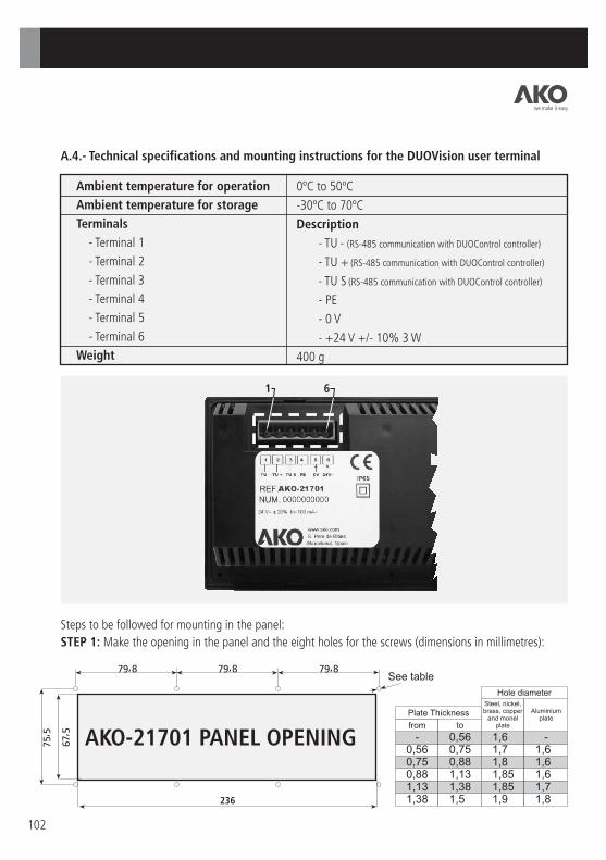
236
102
A.4.- Technical specifications and mounting instructions for the DUOVision user terminal
Ambient temperature for operation
Ambient temperature for storage
Terminals
- Terminal 1
- Terminal 2
- Terminal 3
- Terminal 4
- Terminal 5
- Terminal 6
Weight
0ºC to 50ºC
-30ºC to 70ºC
Description
- TU - (RS-485 communication with DUOControl controller)
- TU + (RS-485 communication with DUOControl controller)
- TU S (RS-485 communication with DUOControl controller)
- PE
- 0 V
- +24 V +/- 10% 3 W
400 g
1 6
Steps to be followed for mounting in the panel:
STEP 1: Make the opening in the panel and the eight holes for the screws (dimensions in millimetres):
AKO-21701 PANEL OPENING
See table
Plate Thickness
Hole diameterSteel, nickel, brass, copper
and monel plate
Aluminium plate
from to
we make it easy

103
STEP 2: Remove the front cover.
STEP 3: Place the user interface inside the space in the panel and fix it into place using the 8 screws
supplied.
Remark: If an IP65 installation is desired, rubber gasket should be installed correctly between DUOVision
and Plate as it is shown in next picture.
STEP 4: Replace the front cover.
Panel Gasket
Gasket
Gasket groove
we make it easy

104
A.5.- Physical dimensions
AKO-21801
AKO-21802
AKO-21803
67 m
m
52 m
m
51 mm 280 mm
90 m
m
DUOVision
we make it easy

105
Appendix B:- Selection of the DUOControl controller
No. OF FANS
CO
MPR
ESSO
RS
STA
GES
1
2
3
4
1
2
3
4
1
2
3
4
1
2
3
4
1
2
3
4
1
2
3
4
1
2
3
4
5
6
1 2 3 4 5 6 7 8
21006 21012 21018
21006 21012 21018
21006 21012 21018
21006 21012 21018
21006 21012 21018
21006 21012 21018
21012 21018
21012 21018
21006 21012 21018
21012 21018
21012 21018
21018
21006 21012 21018
21012 21018
21018
21018
21012 21018
21012 21018
21018
21012 21018
21018
WITHOUT ALARM OUTPUT
21006 21012 21018
21006 21012 21018
21006 21012 21018
21006 21012 21018
21006 21012 21018
21006 21012 21018
21012 21018
21012 21018
21006 21012 21018
21012 21018
21012 21018
21018
21006 21012 21018
21012 21018
21018
21018
21012 21018
21012 21018
21018
21012 21018
21018
No. OF FANS
CO
MPR
ESSO
RS
STA
GES
1
2
3
4
1
2
3
4
1
2
3
4
1
2
3
4
1
2
3
4
1
2
3
4
1
2
3
4
5
6
1 2 3 4 5 6 7 8
WITH ALARM OUTPUT
Steps to select the appropriate DUOControl:
1.- Choose the type of control for the fans (ON/OFF or via INVERTER): One table or the other is used depending on this information.
2.- Decide the No. of compressors to be used and the No. of stages per compressor:This information defines the row in the table.
3.- Decide whether an alarm output is needed:This defines whether the left- or right-hand side of the table is used.
4.- Decide the No. of fans for the installation (only necessary for ON/OFF control):This information defines the column in the table.
FANS CONTROLLED ON/OFF
we make it easy

WITH ALARM OUTPUT
106
WITHOUT ALARM OUTPUT CO
MPR
ESSO
RS
STA
GES
1
2
3
4
1
2
3
4
1
2
3
4
1
2
3
4
1
2
3
4
1
2
3
4
1
2
3
4
5
6
21006
21006
21006
21006
21006
21006
21006 21012
21012
21006
21006 21012
21012
21018
21006
21012
21018
21018
21012
21012
21018
21012
21018
21018
As an example, consider a refrigerating facility with the following characteristics:
3 equal compressors with 1 part loading (2 stages)
2 fans with ON/OFF control
The DUOControl model which meets the requirements of the installation is the AKO-21012.
If control is carried out using inverter, the controller to select would be the AKO-21006.
NOTE: Any of the controllers can carry out the same functions as the one immediately inferior to it in the series, but not the other way around.
FANS CONTROLLED BY INVERTER
we make it easy

107
Appendix C:- User Parameters
A list of all the user parameters used to configure the operation of DUOControl controllers.
The following table contains the following fields:
Register Code: User parameter coding used within this manual.
Parameter: Text which appears on the screen
Description: Description of the parameter
R/W?: Type of parameter
R: Read only (can be modified within the programming assistant)
R/W: Read and Write
Maximum Value: Maximum value of the parameter depending on the working units
Minimum Value: Minimum value of the parameter depending on the working units
Default Value: Default value of the parameter depending on the working units
Units: Measurement units depending on the parameter
Comments: Useful information for interpreting the value of each user parameter
we make it easy

108
INS
TA
LL
AT
ION
C
ON
FIG
UR
AT
ION
CO
NF
_1
N
o. o
f C
om
pre
sso
rs
NU
MB
ER
OF
CO
MP
RE
SS
OR
S
R6
16
1-
CO
NF
_2
N
o. o
f S
tag
es p
er
Co
mp
resso
r N
UM
BE
R O
F S
TA
GE
S P
ER
CO
MP
RE
SS
OR
R
41
41
-
CO
NF
_3
C
ap
acit
y R
ed
ucti
on
Co
nta
ct
CO
MP
RE
SO
R C
AP
AC
ITY
RE
DU
CT
ION
CO
NTA
CT
R
- -A
ctiv
e w
hen p
ow
ere
d/A
ctiv
e w
hen n
ot pow
ere
d
CO
NF
_4
A
larm
Ou
tpu
t A
cti
vate
d
AL
AR
M O
UT
PU
T A
CT
IVA
TE
D?
R
CO
NF
_5
F
an
Co
ntr
ol Typ
e
TY
PE
OF
FA
N C
ON
TR
OL
R
10
10
-O
N/O
FF
/ IN
VE
RT
ER
CO
NF
_6
N
o. o
f F
an
s
NU
MB
ER
OF
FA
NS
R
81
81
-M
AX
IMU
M N
UM
BE
R O
F F
AN
S
CO
NF
_7
R
efr
igera
nt
Typ
e
TY
PE
OF
RE
FR
IGE
RA
NT
R
70
70
-
GE
NE
RIC
R404A
R
134A
R
717
R22
R410A
R
507
R744
CO
NF
_8
U
nit
s
UN
ITS
R
10
10
-B
ar
/ ºC
we make it easy
MA
X
MA
X
MIN
M
IN
DE
FA
ULT
VA
LU
E
DE
FA
ULT
VA
LU
E
PA
RA
ME
TE
RC
OD
E
US
ER
PA
RA
ME
TE
R
DE
SC
RIP
TIO
N
R/W
?
Bar
ºCU
NIT
S
OT
HE
RS
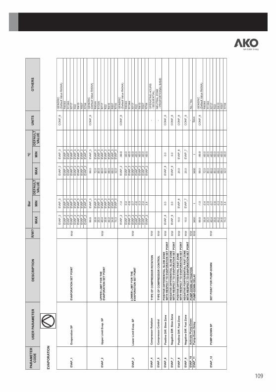
109
EV
AP
OR
AT
ION
R/W
U
pp
er
Lim
it E
vap
. S
PU
PP
ER
LIM
IT F
OR
TH
E
EV
AP
OR
AT
ION
SE
T P
OIN
T
EV
AP
_2
3.4
E
VA
P_2
-6
0.0
EV
AP
_4
C
om
pre
sso
r R
ota
tio
n
TY
PE
OF
CO
MP
RE
SS
OR
RO
TA
TIO
N
R/W
EV
AP
_5
C
om
pre
sso
r C
on
tro
l T
YP
E O
F C
OM
PR
ES
SO
R C
ON
TR
OL
R
/W
EV
AP
_6
P
osit
ive D
iff.
Slo
w Z
on
eP
OS
ITIV
E D
IFF
ER
EN
TIA
L S
LO
W Z
ON
E
WIT
H R
ES
PE
CT
TO
EV
AP
OR
AT
ION
SE
T P
OIN
T
R/W
E
VA
P_8
0.0
E
VA
P_8
0.0
EV
AP
_7
N
eg
ati
ve D
iff.
Slo
w Z
on
eN
EG
AT
IVE
W
ITH
RE
SP
EC
T T
O E
VA
PO
RA
TIO
N S
ET
PO
INT
D
IFF
ER
EN
TIA
L S
LO
W Z
ON
E
R/W
E
VA
P_9
0.0
E
VA
P_9
0.0
EV
AP
_8
P
osit
ive D
iff.
Fast
Zo
ne
PO
SIT
IVE
W
ITH
RE
SP
EC
T T
O E
VA
PO
RA
TIO
N S
ET
PO
INT
D
IFF
ER
EN
TIA
L F
AS
T Z
ON
E
R/W
10.0
E
VA
P_6
20.0
E
VA
P_6
EV
AP
_9
N
eg
ati
ve D
iff.
Fast
Zo
ne
NE
GA
TIV
E F
WIT
H R
ES
PE
CT
TO
EV
AP
OR
AT
ION
SE
T P
OIN
T
DIF
FE
RE
NT
IAL
FA
ST
ZO
NE
R
/W
10.0
E
VA
P_7
20.0
E
VA
P_7
EV
AP
_10
A
cti
vate
Pu
mp
-Do
wn
P
UM
P-D
OW
N A
CT
IVA
TIO
N
R/W
E
VA
P_11
P
um
p-D
ow
n D
ela
y
PU
MP
-DO
WN
DE
LA
Y
R/W
3600
13600
1
EV
AP
_2
EV
AP
_2
E
VA
P_3
C
ON
F_8
R/W
E
VA
PO
RA
TIO
N S
ET
PO
INT
E
vap
ora
tio
n S
P
GE
NE
RIC
(Defa
ult
Valu
e R
404A
)
EV
AP
_2
EV
AP
_2
EV
AP
_2
EV
AP
_2
EV
AP
_2
EV
AP
_2
EV
AP
_2
EV
AP
_3
EV
AP
_3
EV
AP
_3
EV
AP
_3
EV
AP
_3
EV
AP
_3
EV
AP
_3
EV
AP
_1
R404A
R134A
R717
R22
R410
R507
R744
OP
ER
AT
ING
HO
UR
S
/ S
EQ
UE
NT
IAL:
NE
UT
RA
L Z
ON
E / P
RO
PO
RT
ION
AL B
AN
D
No / Y
es
99.9
E
VA
P_3
99.0
E
VA
P_3
G
EN
ER
IC(D
efa
ult
Valu
e R
404A
)
35.8
E
VA
P_3
72.0
E
VA
P_3
25.0
E
VA
P_3
80.0
E
VA
P_3
40.4
E
VA
P_3
80.0
E
VA
P_3
35.6
E
VA
P_3
80.0
E
VA
P_3
44.2
E
VA
P_3
68.0
E
VA
P_3
34.6
E
VA
P_3
68.0
E
VA
P_3
74.3
32.0
R404A
R134A
R717
R22
R410
R507
R744
CO
NF
_8
EV
AP
_2
-1
.0
EV
AP
_2
-9
9.9
R/W
E
VA
P_3
L
ow
er
Lim
it
E
vap
.S
PL
OW
ER
LIM
IT F
OR
TH
E
EV
AP
OR
AT
ION
SE
T P
OIN
T
GE
NE
RIC
(Defa
ult
Valu
e R
404A
)
EV
AP
_2
-0
.4
EV
AP
_2
-6
0.0
EV
AP
_2
-0
.8
EV
AP
_2
-6
0.0
EV
AP
_2
-0
.7
EV
AP
_2
-6
0.0
EV
AP
_2
-0
.6
EV
AP
_2
-6
0.0
EV
AP
_2
-0
.3
EV
AP
_2
-6
0.0
EV
AP
_2
-0
.4
EV
AP
_2
-6
0.0
R404A
R134A
R717
R22
R410
R507
R744
CO
NF
_8
- -
CO
NF
_8
CO
NF
_8
CO
NF
_8
CO
NF
_8
-
Secs
99.9
-1
.0
99.0
-9
9.9
R/W
E
VA
P_12
P
UM
P-D
OW
N S
P
SE
T P
OIN
T F
OR
PU
MP
-DO
WN
GE
NE
RIC
(Defa
ult
Valu
e R
404A
) 35.8
-0
.4
72.0
-6
0.0
25.0
-0
.8
80.0
-6
0.0
40.4
-0
.7
80.0
-6
0.0
35.6
-0
.6
80.0
-6
0.0
44.2
-0
.3
68.0
-6
0.0
34.6
-0
.4
68.0
-6
0.0
74.3
3.4
32.0
-6
0.0
R404A
R134A
R717
R22
R410
R507
R744
CO
NF
_8
EV
AP
_2
E
VA
P_3
EV
AP
_2
EV
AP
_2
EV
AP
_2
EV
AP
_2
EV
AP
_2
EV
AP
_2
EV
AP
_2
EV
AP
_3
EV
AP
_3
EV
AP
_3
EV
AP
_3
EV
AP
_3
EV
AP
_3
EV
AP
_3
EV
AP
_3
E
VA
P_3
we make it easy
MA
X
MA
X
MIN
M
IN
DE
FA
ULT
VA
LU
E
DE
FA
ULT
VA
LU
E
PA
RA
ME
TE
RC
OD
E
US
ER
PA
RA
ME
TE
R
DE
SC
RIP
TIO
N
R/W
?
Bar
ºCU
NIT
S
OT
HE
RS

110
CO
ND
EN
SA
TIO
N
CO
ND
_1
C
on
den
sati
on
SP
CO
ND
_2
C
ON
D_3
C
ON
D_2
C
ON
D_3
C
ON
F_8
G
EN
ER
IC(D
efa
ult
Valu
e R
404A
)
CO
ND
_2
C
ON
D_3
C
ON
D_2
C
ON
D_3
R
404A
CO
ND
_2
C
ON
D_3
C
ON
D_2
C
ON
D_3
R
134A
CO
ND
_2
C
ON
D_3
C
ON
D_2
C
ON
D_3
R
717
CO
ND
_2
C
ON
D_3
C
ON
D_2
C
ON
D_3
R
22
CO
ND
_2
C
ON
D_3
C
ON
D_2
C
ON
D_3
R
410
CO
ND
_2
C
ON
D_3
C
ON
D_2
C
ON
D_3
R
507
CO
ND
_2
C
ON
D_3
C
ON
D_2
C
ON
D_3
R
744
R/W
C
ON
DE
NS
AT
ION
SE
T P
OIN
T
CO
ND
_2
U
pp
er
Co
nd
. S
P
Lim
it
99.9
C
ON
D_3
99.0
C
ON
D_3
C
ON
F_8
G
EN
ER
IC
(Defa
ult
Valu
e R
404A
)
35.8
C
ON
D_3
72.0
C
ON
D_3
R
404A
25.0
C
ON
D_3
80.0
C
ON
D_3
R
134A
40.4
C
ON
D_3
80.0
C
ON
D_3
R
717
35.6
C
ON
D_3
80.0
C
ON
D_3
R
22
44.2
C
ON
D_3
68.0
C
ON
D_3
R
410
34.6
C
ON
D_3
68.0
C
ON
D_3
R
507
74.3
C
ON
D_3
32.0
C
ON
D_3
R
744
R/W
U
PP
ER
LIM
IT F
OR
TH
EC
ON
DE
NS
AT
ION
SE
T P
OIN
T
CO
ND
_3
L
ow
er
Co
nd
. S
P
Lim
it
R/W
L
OW
ER
LIM
IT F
OR
TH
EC
ON
DE
NS
AT
ION
SE
T P
OIN
T
CO
ND
_2
-1
.0
CO
ND
_2
-9
9.9
C
ON
F_8
G
EN
ER
IC
(Defa
ult
Valu
e R
404A
)
CO
ND
_2
-0
.8
CO
ND
_2
-6
0.0
R
134A
CO
ND
_2
-0
.7
CO
ND
_2
-6
0.0
R
717
CO
ND
_2
-0
.6
CO
ND
_2
-6
0.0
R
22
CO
ND
_2
-0
.3
CO
ND
_2
-6
0.0
R
410
CO
ND
_2
-0
.4
CO
ND
_2
-6
0.0
R
507
CO
ND
_2
3.4
C
ON
D_2
-6
0.0
R
744
CO
ND
_2
-0
.4
CO
ND
_2
-6
0.0
R
404A
CO
ND
_4
F
an
Co
ntr
ol
TY
PE
OF
FA
N C
ON
TR
OL
R
/W
-N
EU
TR
AL Z
ON
E
PR
OP
OR
TIO
NA
L B
AN
D
CO
ND
_5
P
osit
ive D
iff.
Slo
w Z
on
eP
OS
ITIV
E
W
ITH
RE
SP
EC
T T
O C
ON
DE
NS
AT
ION
SE
T P
OIN
T
DIF
FE
RE
NT
IAL
SL
OW
ZO
NE
R/W
C
ON
D_7
0.0
C
ON
D_7
0.0
C
ON
F_8
CO
ND
_6
N
eg
ati
ve D
iff.
Slo
w Z
on
eN
EG
AT
IVE
W
ITH
RE
SP
EC
T T
O C
ON
DE
NS
AT
ION
SE
T P
OIN
T
DIF
FE
RE
NT
IAL
SL
OW
ZO
NE
R/W
C
ON
D_8
0.0
C
ON
D_8
0.0
C
ON
F_8
CO
ND
_7
P
osit
ive D
iff.
Fast
Zo
ne
PO
SIT
IVE
WIT
H R
ES
PE
CT
TO
CO
ND
EN
SA
TIO
N S
ET
PO
INT
D
IFF
ER
EN
TIA
L F
AS
T Z
ON
ER
/W
20.0
C
ON
D_5
40.0
C
ON
D_5
C
ON
F_8
CO
ND
_8
N
eg
ati
ve
D
iff.
Fast
Zo
ne
NE
GA
TIV
E
WIT
H R
ES
PE
CT
TO
CO
ND
EN
SA
TIO
N S
ET
PO
INT
D
IFF
ER
EN
TIA
L F
AS
T Z
ON
ER
/W
20.0
C
ON
D_6
40.0
C
ON
D_6
C
ON
F_8
CO
ND
_9
A
cti
vate
Flo
ati
ng
Co
nd
. A
CT
IVA
TE
FL
OA
TIN
G C
ON
DE
NS
AT
ION
?R
/W
-N
oY
es
CO
ND
_10
P
rop
ort
ion
al V
alu
eA
DJU
ST
ME
NT
OF
IN
VE
RT
ER
P-I
CO
NT
RO
L -
PR
OP
OR
TIO
NA
L V
AL
UE
P
R/W
100
1100
1%
CO
ND
_11
In
teg
ral V
alu
eA
DJU
ST
ME
NT
OF
IN
VE
RT
ER
P
-I C
ON
TR
OL
- IN
TE
GR
AL
VA
LU
E I
R/W
30
130
1S
ecs
we make it easy
MA
X
MA
X
MIN
M
IN
DE
FA
ULT
VA
LU
E
DE
FA
ULT
VA
LU
E
PA
RA
ME
TE
RC
OD
E
US
ER
PA
RA
ME
TE
R
DE
SC
RIP
TIO
N
R/W
?
Bar
ºCU
NIT
S
OT
HE
RS
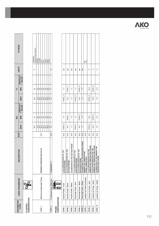
111
FL
OA
TIN
G
CO
ND
EN
SA
TIO
N
CO
ND
EN
SE
R ∆
T
R/W
20
620
6ºK
CO
DF
_2
C
on
den
ser
tem
p. d
iffe
ren
ce
99.0
-6
099.0
28
ºCG
EN
ER
IC(D
efa
ult
Valu
e R
404A
)
72.0
-6
072.0
-6
0R
404A
80.0
-6
080.0
-6
0R
134A
80.0
-6
080.0
-6
0R
717
80.0
-6
080.0
-6
0R
22
68.0
-6
068.0
-6
0R
410
68.0
-6
068.0
-6
0R
507
32.0
-6
032.0
-6
0R
744
R/W
M
INIM
UM
CO
ND
EN
SA
TIO
N V
AL
UE
C
OD
F_1
M
inim
um
Co
nd
en
sati
on
Tem
p.
PR
OB
E
CO
NF
IGU
RA
TIO
N
Su
cti
on
Pro
be –
4 m
A
4 m
A C
ON
FIG
UR
AT
ION
OF
TH
ES
UC
TIO
N P
RO
BE
R
/W
SO
ND
_2
-1
.0
SO
ND
_2
-1
.0
Bar
Su
cti
on
Pro
be -
20m
A
20 m
A C
ON
FIG
UR
AT
ION
OF
TH
ES
UC
TIO
N P
RO
BE
R
/W
40.0
S
ON
D_1
40.0
S
ON
D_1
B
ar
Su
cti
on
Pro
be -
Off
set
CA
LIB
RA
TIO
N O
F T
HE
SU
CT
ION
PR
OB
E
R/W
1.0
-1
.0
1.0
-1
.0
Bar
4 m
A C
ON
FIG
UR
AT
ION
OF
TH
ED
ISC
HA
RG
E P
RO
BE
R
/W
SO
ND
_5
-1
.0
SO
ND
_5
-1
.0
Bar
Dis
ch
arg
e P
rob
e -
20m
A
20 m
A C
ON
FIG
UR
AT
ION
OF
TH
ED
ISC
HA
RG
E P
RO
BE
R
/W
40.0
S
ON
D_4
40.0
S
ON
D_4
B
ar
Dis
ch
arg
e P
rob
e -
Off
set
CA
LIB
RA
TIO
N O
F T
HE
DIS
CH
AR
GE
PR
OB
E
R/W
1.0
-1
.0
1.0
-1
.0
Bar
Am
bie
nt
air
Pro
be C
on
necte
d
AM
BIE
NT
AIR
TE
MP
ER
AT
UR
E
PR
OB
E C
ON
NE
CT
ED
?
R/W
-
No
Yes
4 m
A C
ON
FIG
UR
AT
ION
FO
R T
HE
T
EM
PE
RA
TU
RE
PR
OB
E
AM
BIE
NT
AIR
R
/W
SO
ND
_9
-5
0.0
S
ON
D_9
-5
0.0
ºC
20 m
A C
ON
FIG
UR
AT
ION
FO
R T
HE
T
EM
PE
RA
TU
RE
PR
OB
E
AM
BIE
NT
AIR
R
/W
150.0
S
ON
D_8
150.0
S
ON
D_8
ºC
CA
LIB
RA
TIO
N O
F T
HE
TE
MP
ER
AT
UR
E P
RO
BE
AM
BIE
NT
AIR
R
/W
10.0
-1
0.0
10.0
-1
0.0
ºC
SO
ND
_1
SO
ND
_2
SO
ND
_3
SO
ND
_4
D
isch
arg
e P
rob
e -
4m
A
SO
ND
_5
SO
ND
_6
SO
ND
_7
SO
ND
_8
A
mb
ien
t air
Pro
be -
4m
A
SO
ND
_9
A
mb
ien
t air
Pro
be -
20m
A
SO
ND
_10
A
mb
ien
t air
Pro
be -
Off
set
we make it easy
MA
X
MA
X
MIN
M
IN
DE
FA
ULT
VA
LU
E
DE
FA
ULT
VA
LU
E
PA
RA
ME
TE
RC
OD
E
US
ER
PA
RA
ME
TE
R
DE
SC
RIP
TIO
N
R/W
?
Bar
ºCU
NIT
S
OT
HE
RS
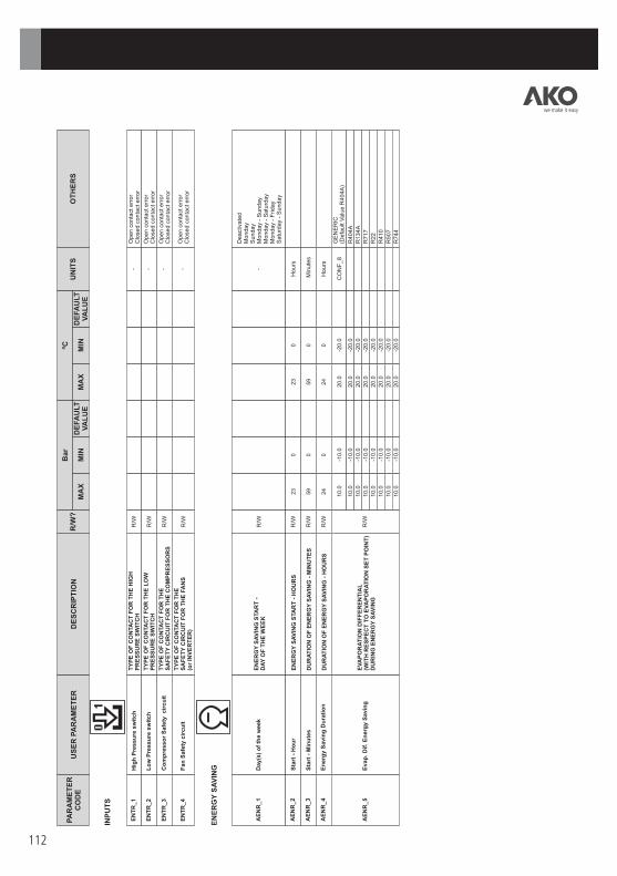
112
INP
UT
S
EN
ER
GY
SA
VIN
G
TY
PE
OF
CO
NTA
CT
FO
R T
HE
HIG
H
PR
ES
SU
RE
SW
ITC
H
R/W
-
Open c
onta
ct e
rror
Clo
sed c
onta
ct e
rror
TY
PE
OF
CO
NTA
CT
FO
R T
HE
LO
W
PR
ES
SU
RE
SW
ITC
H
R/W
-
TY
PE
OF
CO
NTA
CT
FO
R T
HE
SA
FE
TY
CIR
CU
IT F
OR
TH
E C
OM
PR
ES
SO
RS
R
/W
-
TY
PE
OF
CO
NTA
CT
FO
R T
HE
SA
FE
TY
CIR
CU
IT F
OR
TH
E F
AN
S(o
r IN
VE
RT
ER
) R
/W
-
EN
TR
_1
H
igh
Pre
ssu
re s
wit
ch
EN
TR
_2
L
ow
Pre
ssu
re s
wit
ch
EN
TR
_3
C
om
pre
sso
r S
afe
ty cir
cu
it
EN
TR
_4
F
an
Safe
ty c
ircu
it
EN
ER
GY
SA
VIN
G S
TA
RT
-D
AY
OF
TH
E W
EE
K
R/W
-
Deact
ivate
dM
onday
Sunday
Monday
- S
unday
Monday
- S
atu
rday
Monday
- F
riday
Satu
rday
- S
unday
EN
ER
GY
SA
VIN
G S
TA
RT
- H
OU
RS
R
/W
23
023
0H
ours
DU
RA
TIO
N O
F E
NE
RG
Y S
AV
ING
- M
INU
TE
S
R/W
59
059
0M
inute
s
DU
RA
TIO
N O
F E
NE
RG
Y S
AV
ING
- H
OU
RS
R
/W
24
024
0H
ours
AE
NR
_1
D
ay(s
) o
f th
e w
eek
AE
NR
_2
S
tart
- H
ou
r
AE
NR
_3
S
tart
- M
inu
tes
AE
NR
_4
E
nerg
y S
avin
g D
ura
tio
n
10.0
-1
0.0
20.0
-2
0.0
C
ON
F_8
G
EN
ER
IC(D
efa
ult
Valu
e R
404A
)
10.0
-1
0.0
20.0
-2
0.0
R
404A
10.0
-1
0.0
20.0
-2
0.0
R
134A
10.0
-1
0.0
20.0
-2
0.0
R
717
10.0
-1
0.0
20.0
-2
0.0
R
22
10.0
-1
0.0
20.0
-2
0.0
R
410
10.0
-1
0.0
20.0
-2
0.0
R
507
10.0
-1
0.0
20.0
-2
0.0
R
744
R/W
E
VA
PO
RA
TIO
N D
IFF
ER
EN
TIA
L
(WIT
H R
ES
PE
CT
TO
EV
AP
OR
AT
ION
SE
T P
OIN
T)
DU
RIN
G E
NE
RG
Y S
AV
ING
AE
NR
_5
E
vap
. D
if. E
nerg
y S
avin
g
Open c
onta
ct e
rror
Clo
sed c
onta
ct e
rror
Open c
onta
ct e
rror
Clo
sed c
onta
ct e
rror
Open c
onta
ct e
rror
Clo
sed c
onta
ct e
rror
we make it easy
MA
X
MA
X
MIN
M
IN
DE
FA
ULT
VA
LU
E
DE
FA
ULT
VA
LU
E
PA
RA
ME
TE
RC
OD
E
US
ER
PA
RA
ME
TE
R
DE
SC
RIP
TIO
N
R/W
?
Bar
ºCU
NIT
S
OT
HE
RS

113
TIM
ING
MIN
IMU
M F
AN
OP
ER
AT
ING
TIM
E
R/W
3600
13600
1S
ecs
MIN
IMU
M F
AN
ST
OP
TIM
E
R/W
3600
13600
1S
ecs
MIN
IMU
M T
IME
BE
TW
EE
N S
TA
RT
UP
S
OF
DIF
FE
RE
NT
FA
NS
IN T
HE
SL
OW
ZO
NE
R/W
3600
13600
1S
ecs
MIN
IMU
M T
IME
BE
TW
EE
N S
HU
TD
OW
NS
OF
DIF
FE
RE
NT
FA
NS
IN
TH
E S
LO
W Z
ON
E
R/W
3600
13600
1S
ecs
MIN
IMU
M T
IME
BE
TW
EE
N S
TA
RT
UP
S
OF
DIF
FE
RE
NT
FA
NS
IN
TH
E F
AS
T Z
ON
E
R/W
3600
13600
1S
ecs
MIN
IMU
M T
IME
BE
TW
EE
N S
HU
TD
OW
NS
OF
D
IFF
ER
EN
T F
AN
S IN
TH
E F
AS
T Z
ON
E
R/W
3600
13600
1S
ecs
MIN
IMU
M C
OM
PR
ES
SO
R O
PE
RA
TIN
GT
IME
R
/W
3600
13600
1S
ecs
MIN
IMU
M C
OM
PR
ES
SO
R S
TO
P T
IME
R
/W
3600
13600
1S
ecs
MIN
IMU
M T
IME
BE
TW
EE
N S
TA
RT
UP
S
D
IFF
ER
EN
T C
OM
PR
ES
SO
RS
AN
D S
TA
GE
S
IN T
HE
SL
OW
ZO
NE
OF
R/W
3600
13600
1S
ecs
MIN
IMU
M T
IME
BE
TW
EE
N S
HU
TD
OW
NS
O
F D
IFF
ER
EN
T C
OM
PR
ES
SO
RS
AN
D S
TA
GE
SIN
TH
E S
LO
W Z
ON
E
R/W
3600
13600
1S
ecs
MIN
IMU
M T
IME
BE
TW
EE
N S
TA
RT
UP
S
OF
DIF
FE
RE
NT
CO
MP
RE
SS
OR
S A
ND
STA
GE
S
IN T
HE
FA
ST
ZO
NE
R/W
3600
13600
1S
ecs
MIN
IMU
M T
IME
BE
TW
EE
N S
HU
TD
OW
NS
OF
D
IFF
ER
EN
T C
OM
PR
ES
SO
RS
AN
D S
TA
GE
S IN
T
HE
FA
ST
ZO
NE
R
/W
3600
13600
1S
ecs
TE
MP
_1
F
an
MIN
. ti
me O
N
TE
MP
_2
F
an
MIN
. ti
me O
FF
TE
MP
_3
F
an
ON
-ON
Dela
y S
low
TE
MP
_4
F
an
OF
F-O
FF
Dela
y S
low
TE
MP
_5
F
an
ON
-ON
Dela
y F
ast
TE
MP
_6
F
an
OF
F-O
FF
Dela
y F
ast
TE
MP
_7
C
om
pre
sso
r T. M
IN. O
N
TE
MP
_8
C
om
pre
sso
r T. M
IN. O
FF
TE
MP
_9
C
om
pr.
ON
-ON
Dela
y S
low
TE
MP
_10
C
om
pr.
OF
F-O
FF
Dela
y S
low
TE
MP
_11
C
om
pr.
ON
-ON
Dela
y F
ast
TE
MP
_12
C
om
pr.
OF
F-O
FF
Dela
y F
ast
we make it easy
MA
X
MA
X
MIN
M
IN
DE
FA
ULT
VA
LU
E
DE
FA
ULT
VA
LU
E
PA
RA
ME
TE
RC
OD
E
US
ER
PA
RA
ME
TE
R
DE
SC
RIP
TIO
N
R/W
?
Bar
ºCU
NIT
S
OT
HE
RS

114
PR
OT
EC
TIO
NS
A
ND
AL
AR
MS
NU
MB
ER
OF
CO
MP
RE
SS
OR
STA
GE
S
OP
ER
AT
ING
IF
TH
ER
E IS
A S
UC
TIO
N P
RO
BE
FA
IL
R/W
C
ON
F_1
x C
ON
F_2
0.0
C
ON
F_1
x C
ON
F_2
0.0
S
tages
PR
OT
_1
S
tgs.O
N A
sp
ir. P
rob
e F
ail
(*)
If N
O IN
VE
RT
ER
->
CO
NF
_6
If IN
VE
RT
ER
->
100
NU
MB
ER
OF
FA
NS
(%
IF
VA
RIA
BL
E F
RE
Q.
DR
IVE
) O
PE
RA
TIN
G IF
TH
ER
E IS
A
DIS
CH
AR
GE
PR
OB
E
FA
ILR
/W
(*)
0.0
(*
) 0.0
S
tages
PR
OT
_2
F
an
s O
N D
isch
.Pro
be F
ail
.
99.9
-1
.0
99.9
-1
.0
Bar
GE
NE
RIC
(Defa
ult
Valu
e R
404A
)
35.8
-0
.4
35.8
-0
.4
R404A
25.0
-0
.8
25.0
-0
.8
R134A
40.4
-0
.7
40.4
-0
.7
R717
35.6
-0
.6
35.6
-0
.6
R22
44.2
-0
.3
44.2
-0
.3
R410
34.6
-0
.4
34.6
-0
.4
R507
74.3
3.4
74.3
3.4
R
744
R/W
H
P C
ircu
it P
re-A
larm
H
IGH
-P
RE
SS
UR
E C
IRC
UIT
PR
E-A
LA
RM
P
RO
T_3
10.0
0.0
10.0
0.0
B
ar
GE
NE
RIC
(Defa
ult
Valu
e R
404A
)
10.0
0.0
10.0
0.0
R
404A
10.0
0.0
10.0
0.0
R
134A
10.0
0.0
10.0
0.0
R
717
10.0
0.0
10.0
0.0
R
22
10.0
0.0
10.0
0.0
R
410
10.0
0.0
10.0
0.0
R
507
10.0
0.0
10.0
0.0
R
744
R/W
H
P C
ircu
it P
re-A
larm
Dif
. H
IGH
PR
ES
SU
RE
PR
E-A
LA
RM
DIF
FE
RE
NT
IAL
P
RO
T_4
99.9
-1
.0
99.9
-1
.0
Bar
GE
NE
RIC
(Defa
ult
Valu
e R
404A
)
35.8
-0
.4
35.8
-0
.4
R404A
25.0
-0
.8
25.0
-0
.8
R134A
40.4
-0
.7
40.4
-0
.7
R717
35.6
-0
.6
35.6
-0
.6
R22
44.2
-0
.3
44.2
-0
.3
R410
34.6
-0
.4
34.6
-0
.4
R507
74.3
3.4
74.3
3.4
R
744
R/W
L
P C
ircu
it P
re-A
larm
L
OW
PR
ES
SU
RE
CIR
CU
IT P
RE
-AL
AR
M
PR
OT
_5
10.0
0.0
10.0
0.0
B
ar
GE
NE
RIC
(Defa
ult
Valu
e R
404A
)
10.0
0.0
10.0
0.0
R
404A
10.0
0.0
10.0
0.0
R
134A
10.0
0.0
10.0
0.0
R
717
10.0
0.0
10.0
0.0
R
22
10.0
0.0
10.0
0.0
R
410
10.0
0.0
10.0
0.0
R
507
10.0
0.0
10.0
0.0
R
744
R/W
L
P C
ircu
it P
re-A
larm
Dif
. L
OW
PR
ES
SU
RE
PR
E-A
LA
RM
DIF
FE
RE
NT
IAL
P
RO
T_6
MA
X T
. C
om
p. M
ain
ten
.C
OM
PR
ES
SO
R M
AIN
TE
NA
NC
EP
ER
IOD
R
/W
32000
032000
0H
ours
0: D
eact
ivate
d
PR
OT
_7
Sta
rtu
p A
larm
Dela
y
AL
AR
M D
EL
AY
AT
S
TA
RT
UP
TIM
E
R/W
3600
13600
1S
ecs
P
RO
T_8
Ala
rm O
utp
ut
Dela
y
AL
AR
M O
UT
PU
T D
EL
AY
R
/W
3600
13600
1S
ecs
P
RO
T_9
we make it easy
MA
X
MA
X
MIN
M
IN
DE
FA
ULT
VA
LU
E
DE
FA
ULT
VA
LU
E
PA
RA
ME
TE
RC
OD
E
US
ER
PA
RA
ME
TE
R
DE
SC
RIP
TIO
N
R/W
?
Bar
ºCU
NIT
S
OT
HE
RS

115
MA
X
MA
X
MIN
M
IN
DE
FA
ULT
VA
LU
E
DE
FA
ULT
VA
LU
E
PA
RA
ME
TE
RC
OD
E
US
ER
PA
RA
ME
TE
R
DE
SC
RIP
TIO
N
R/W
?
Bar
ºCU
NIT
S
DA
TE
TE
RM
INA
L
CO
NF
IGU
RA
TIO
N
MO
DE
L A
ND
S
W V
ER
SIO
N
DA
Y
R/W
31
-
MO
NT
H
R/W
12
1
-
YE
AR
R/W
99
8
-D
AY
OF
TH
E W
EE
K
R/W
1
-
MO
ND
AY
T
UE
SD
AY
W
ED
NE
SD
AY
T
HU
RS
DA
Y
FR
IDA
Y
SA
TU
RD
AY
S
UN
DA
Y
HO
UR
R/W
23
0
-
MIN
UT
ES
R/W
59
0
-
FE
CH
_1
M
inu
tes
FE
CH
_2
H
ou
r
FE
CH
_3
D
ay o
f th
e w
eek
FE
CH
_4
D
ay
FE
CH
_5
M
on
th
FE
CH
_6
Y
ear
1 810 0
31
12
99
23
59
PA
SS
WO
RD
R
/W
99
099
0-
0: D
EA
CT
IVA
TE
D
MO
DB
US
AD
DR
ES
S
R/W
247
1247
1-
DU
OC
CO
NT
RO
L M
OD
EL
R
-D
UO
CC
ON
TR
OL
SO
FT
WA
RE
VE
RS
ION
R
-
DU
OV
isio
n S
OF
TW
AR
E V
ER
SIO
N
R
-
TE
RM
_1
P
assw
ord
TE
RM
_2
M
OD
BU
S a
dd
ress
MO
DE
_1
D
UO
Co
ntr
ol m
od
el
SW
C_1
D
UO
Co
ntr
ol S
W V
ers
ion
SW
T_1
D
UO
Vis
ion
SW
Vers
ion
OT
HE
RS
we make it easy
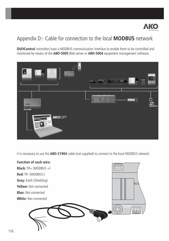
116
Appendix D:- Cable for connection to the local MODBUS network
DUOControl controllers have a MODBUS communication interface to enable them to be controlled and monitored by means of the AKO-5005 Web server or AKO-5004 equipment management software.
It is necessary to use the AKO-21904 cable (not supplied) to connect to the local MODBUS network.
Function of each wire:
Black: TR+ (MODBUS +)
Red: TR- (MODBUS-)
Grey: Earth (Shielding)
Yellow: Not connected
Blue: Not connected
White: Not connected
we make it easy

NOTES:
117
we make it easy

118
NOTES:
we make it easy

NOTES:
119
we make it easy

3521
0060
2 RE
V.00
200
9
AKO ELECTROMECÁNICA, S.A.L. Avenida Roquetes, 30-38 | 08812 Sant Pere de Ribes | Barcelona | Spain Tel. (34) 938 142 700 | Fax (34) 938 934 054 | e-mail: [email protected] | www.ako.com Apartado (P.O. Box), 5 | 08800 Vilanova i la Geltrú | Barcelona | Spain
We reserve the right to supply materials that might vary slightly to those described in our Technical Sheets. Updated information is available on our website: www.ako.com.
we make it easy
we make it easy