airstream interstate motorhome owners manual 2004 · airstream interstate motorhome owners manual...
TRANSCRIPT

AIRSTREAM INTERSTATE MOTORHOME OWNERS MANUAL 2004
INTRODUCTION The Owners Manual for your new Airstream Motorhome is designed to respond to the most frequent inquiries regarding the operation, function and care of the many systems that make modern motor homing a joy. The Airstream Interstate Motorhome is integrated into a Sprinter Van, designed and manufactured by Daimler/Chrysler. Operation of the Sprinter, its engine, power train, and other related components are discussed in the Sprinter Operator’s Manual and other literature provide by Daimler/Chrysler. As a point of reference, those systems discussed in the Daimler/Chrysler literature are warranted by Daimler/Chrysler or their suppliers. Airstream realizes our customers possess varying degrees of expertise in the area of repairing and maintaining the appliances in their motorhome. For this reason, the service and trouble-shooting information found in this manual is directed toward those with average mechanical skills. We also realize you may be more familiar in one area than you are in another. Only you know your capabilities and limitations. We want you to use this manual, and hope you will find the information contained in it useful, however, should you ever feel you may be "getting in over your head" please see your dealer to have the repairs made. The next page of this manual is a table of contents. Point your cursor to the subject, colored blue, you would like to research. Right click your mouse while it is on the subject title and you will be taken to that area of the manual. To get back to table of contents, click on the back arrow in the tool bar at the top of the document. The arrow will be lighted. The next two pages contain an index of subject material in alphabetical order. Note: All information, illustrations and specifications contained in the literature are based on the latest product information available at the time of publication approval. Airstream reserves the right to make changes if and when new materials and/or production techniques are developed that can improve the quality of its product, or when material substitutions are necessary due to availability.
Throughout this manual CAUTION and WARNING notations are used. Failure to observe "CAUTION" can cause equipment damage if not observed.
Failure to observe “ WARNING” can lead to damaged equipment, serious personal injury and/or death if not observed. Please read and follow all cautions and warnings. If any questions arise contact your dealer or the factory customer service department. NOTE: Your Sprinter Van Operator’s and Warranty Manuals contain important cautions, warnings, operational, and warranty information on the Sprinter and its components. All information in the Sprinter manual should be reviewed and followed for your safety. The Airstream Interstate Owner’s Manual may provide addition information and tips on the use of the Van as a motorhome, however, no information in the Airstream manual should be interpreted as advice or directions to disregard or void the warnings, cautions, or other information contained in the Sprinter’s manuals.
© Airstream, Inc. 2003
AIRSTREAM INTERSTATE MOTORHOME OWNERS MANUAL TABLE OF CONTENTS
A. WARRANTY AND SERVICE
Warranty Warranty Explanation Service Reporting Safety Defects Maintenance Schedule
B. DRIVING
Loading Weighing Safety Check List Seat Belts Trailer Towing & Driving Tips Weighing the Motorhome
C. SPRINTER VAN
Component Identification Tire/Wheels Changing a Tire Installing a Wheel
D. CAMPING
Camping Safety Smoke Alarm LP Gas Alarm Overnight Stop Winter Traveling Extended Stay
E. EXTERIOR
Cleaning Roadside Exterior Features Curbside Exterior Features Awning
F. INTERIOR FURNISHINGS AND
ACCESSORIES Lounge, Dinette Vinyl Flooring Counters/Cabinets Wet Bath Interior Skin Fabric
Drapes/Shades
G. PLUMBING
LP (Liquid Petroleum) Gas Water System Water Pump City Water Hookup Exterior Water Service Faucets Drain Valve Locations Toilet Storage and Winterizing Drainage/Waste System
H. ELECTRICAL
Battery Disconnect Power Center 12-volt Operation Interior Lights Monitor Panel TV Antenna Entertainment System Satellite System Telephone Jack
I. 110-Volt System 110-Volt Power
Switch-over Box Shorts and Opens
J. APPLIANCES
Air Conditioner Furnace Refrigerator Range Microwave Oven Water Heater Power Roof Vent
K. SPECIFICATIONS
Coach Chassis
AIRSTREAM INTERSTATE MOTORHOME OWNERS MANUAL TABLE OF CONTENTS
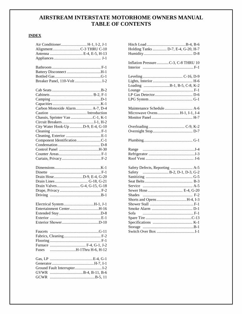
INDEX
Air Conditioner.......................... H-1, I-2, J-1 Alignment........................... C-3 THRU C-10 Antenna ................................. E-4, E-5, H-13 Appliances ............................................... J-1 Bathroom................................................. F-1 Battery Disconnect ..................................H-1 Bottled Gas ..............................................G-1 Breaker Panel, 110-Volt ........................... I-2 Cab Seats .................................................B-2 Cabinets ........................................... B-2, F-1 Camping ..................................................D-1 Capacities ................................................K-1 Carbon Monoxide Alarm................ A-7, D-4 Caution ..................................... Introduction Chassis, Sprinter Van ......................C-1, K-1 Circuit Breakers................................ I-1, H-2 City Water Hook-Up .............D-9, E-4, G-10 Cleaning .................................................. F-1 Cleaning, Exterior ...................................E-1 Component Identification........................C-1 Condensation .......................................... D-8 Control Panel ........................................H-30 Counter Areas.......................................... F-1 Curtain, Privacy....................................... F-2 Dimensions..............................................K-1 Dinette ................................................... F-1 Drain Hose.............................D-9, E-4, G-20 Drain Lines ................................. G-18, G-21 Drain Valves....................... G-4, G-15, G-18 Drape, Privacy ......................................... F-2 Driving ...................................................B-1 Electrical System..............................H-1, J-1 Entertainment Center.............................H-16 Extended Stay..........................................D-8 Exterior ...................................................E-1 Exterior Shower.....................................D-10 Faucets .................................................G-11 Fabrics, Cleaning..................................... F-2 Flooring ................................................... F-1 Furnace .................................... F-4, G-1, J-2 Fuses ..........................H-1Thru H-6, H-12 Gas, LP ...........................................E-4, G-1 Generator ..........................................H-7, I-1 Ground Fault Interrupter........................... I-2 GVWR .................................B-4, B-11, B-6 GCWR .............................................B-5, 11
Hitch Load .......................................B-4, B-6 Holding Tanks .............. D-7, E-4, G-20, H-7 Humidity................................................. D-8 Inflation Pressure............C-3, C-8 THRU 10 Interior ................................................... F-1 Leveling ........................................ C-16, D-9 Lights, Interior ........................................ H-6 Loading ..........................B-1, B-5, C-8, K-2 Lounge ................................................... F-1 LP Gas Detector...................................... D-6 LPG System............................................ G-1 Maintenance Schedule ............................ A-6 Microwave Ovens......................H-1, I-1, J-4 Monitor Panel ......................................... H-7 Overloading .................................... C-9, K-2 Overnight Stop........................................ D-7 Plumbing................................................. G-1 Range ....................................................J-4 Refrigerator ..............................................J-3 Roof Vent ................................................ J-6 Safety Defects, Reporting ...................... A-5 Safety .......................... B-2, D-1, D-3, G-2 Sanitizing ............................................... G-5 Seat Belts ................................................ B-3 Service .................................................. A-5 Sewer Hose................................... E-4, G-20 Shades .................................................. F-2 Shorts and Opens ..............................H-4, I-3 Shower Stall ............................................ F-1 Smoke Alarm ......................................... D-1 Sofa ................................................... F-1 Spare Tire ..............................................C-13 Specifications ........................................ K-1 Storage ...................................................B-1 Switch Over Box ...................................... I-1
AIRSTREAM INTERSTATE MOTORHOME OWNERS MANUAL TABLE OF CONTENTS
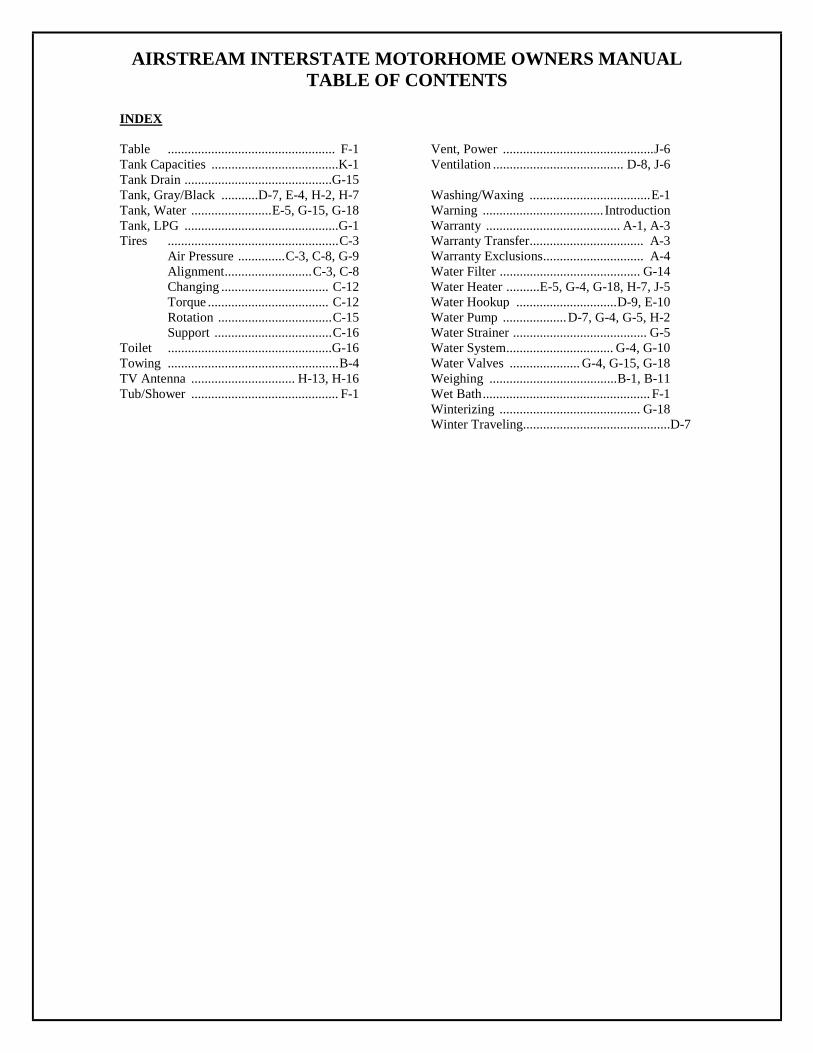
INDEX Table .................................................. F-1 Tank Capacities ......................................K-1 Tank Drain ............................................G-15 Tank, Gray/Black ...........D-7, E-4, H-2, H-7 Tank, Water ........................E-5, G-15, G-18 Tank, LPG ..............................................G-1 Tires ...................................................C-3 Air Pressure ..............C-3, C-8, G-9 Alignment..........................C-3, C-8 Changing ................................ C-12 Torque .................................... C-12 Rotation ..................................C-15 Support ...................................C-16 Toilet .................................................G-16 Towing ...................................................B-4 TV Antenna ............................... H-13, H-16 Tub/Shower ............................................ F-1
Vent, Power .............................................J-6 Ventilation ....................................... D-8, J-6 Washing/Waxing ....................................E-1 Warning .................................... Introduction Warranty ........................................ A-1, A-3 Warranty Transfer.................................. A-3 Warranty Exclusions.............................. A-4 Water Filter .......................................... G-14 Water Heater ..........E-5, G-4, G-18, H-7, J-5 Water Hookup ..............................D-9, E-10 Water Pump ...................D-7, G-4, G-5, H-2 Water Strainer ........................................ G-5 Water System................................ G-4, G-10 Water Valves ..................... G-4, G-15, G-18 Weighing ......................................B-1, B-11 Wet Bath.................................................. F-1 Winterizing .......................................... G-18 Winter Traveling............................................D-7

AIRSTREAM INTERSTATE MOTORHOME OWNERS MANUAL
A-1
WARRANTY and SERVICE
AIRSTREAM INC. LIMITED WARRANTY
WARRANTY COVERAGE When you buy a new Airstream Interstate Motorhome from an authorized Airstream dealer, Airstream, Inc., warrants the motorhome from defects in material and workmanship as follows: BASIC WARRANTY PERIOD This warranty is for 30,000 miles (40,000 Kilometers) or two years, whichever comes first, beginning when the vehicle is delivered to the first retail customer or first placed into demonstrator service. This warranty must have started prior to the accumulation of 4,000 miles in order to be valid. ITEMS COVERED Any part of the motorhome or any component equipment installed by the factory is covered by the basic warranty except the following items, which are not covered:
• House Battery • Generator
The above items will be handled by their respective service points and according to their written policy. This limited warranty does not include failure caused by accident, abuse, normal wear, overload or any cause not attributable to a defect in original material or workmanship of the motorhome or component equipment as installed by the factory. LIMITATION OF IMPLIED WARRANTIES All warranties of merchantability and fitness for a particular purpose, whether written or oral, express or implied, shall extend only for a period of two years from the date of original purchase, or 30,000 miles, whichever comes first. There are no other warranties, which extend beyond those described on the face hereof and which expressly excludes conditions resulting, from normal wear, accident, abuse, exposure or overload. Some states do not allow limitation on how long an implied warranty lasts, so the above limitations may not apply to you. AIRSTREAM'S RESPONSIBILITY The basic Airstream Limited Warranty applies for a period of two years from the date of original purchase or 30,000 miles, whichever comes first, and the application date of all warranties is that indicated on the owner's identification card. Defects in items covered under this Warranty will be corrected without cost upon the return, at the owner's expense, of the motorhome or defective part to an authorized Airstream dealer.

AIRSTREAM INTERSTATE MOTORHOME OWNERS MANUAL
A-2
CARE AND MAINTENANCE This warranty covers only defective material and/or workmanship; adjustments are made at the factory prior to shipment, and rechecked by the dealer prior to delivery to the customer. Adjustments thereafter become a customer responsibility. The owner is also responsible for following all recommendations, instructions and precautions contained in the Airstream Motorhome Owner's Manual and the individual manuals furnished by the chassis, appliance and other manufacturers. INSTALLATIONS NOT COVERED Airstream, Inc., does not accept any responsibility in connection with any of its motorhomes for additional equipment or accessories installed at any dealership or other place of business, or by any other party. Such installation of equipment or accessories by any other party will not be covered by the terms of this warranty. IF REPAIRS ARE NEEDED If your motorhome needs repairs under the terms of the basic Airstream Limited Warranty, you should: 1. Take your motorhome to your selling dealer or other Authorized Airstream Dealer. 2. If the dealer is incapable of making the repair, request that he contact the Service Administration
Department at Airstream, Inc., for technical assistance. 3. If repairs are still not made, the customer should contact:
AIRSTREAM, INC. 419 W. Pike Street - P.O. Box 629 Jackson Center, Ohio 45334-0629
Attention: Owner Relations Department
Furnish the following information: • The complete serial number of the motorhome • Mileage • Date of original purchase • Selling dealer • Nature of service problem and steps or service, which have been performed. (The owner
may be directed to another dealer at the owner's expense.) 4. If, after taking the above steps, repairs are still not complete, the Airstream owner may request the motorhome be allowed to be brought to the Factory Service Center at the owner's expense. DEALER REPRESENTATION EXCLUDED The full extent of the basic Airstream Limited Warranty is set forth-in detail in the folder, and in the explanation of the basic Airstream Limited Warranty covered in the Airstream Motorhome Owner's Manual. Airstream Inc. will not be responsible for additional representations or implied warranties made by any of its dealers to the extent those representations are not a part of, or are contrary to, the terms and conditions of the basic Airstream Limited Warranty.

AIRSTREAM INTERSTATE MOTORHOME OWNERS MANUAL
A-3
CONSEQUENTIAL AND INCIDENTAL DAMAGES Airstream, Inc., will not be responsible for any consequential or incidental expenses or damages resulting from a defect. Incidental expenses include, but are not limited to: travel expenses, gasoline, oil, lodging, meals, telephone tolls, and loss of work and loss of use of the motorhome. Some examples of consequential damages would be: stained curtains due to rain leaks or delaminated floor caused by a plumbing leak. Some states do not allow the exclusion or limitation of incidental or consequential damages, so the above limitation or exclusion may not apply to you. WARRANTY TRANSFER The basic Airstream Limited Warranty is transferable to subsequent owners for the duration of the warranty period. Warranty transfer application forms are available from your dealer or the Airstream Inc. Service Administration Department. CHANGES IN DESIGN Airstream Inc. reserves the right to make changes in design and improvements upon its product without imposing any obligation upon itself to install the same upon its products theretofore manufactured. This warranty gives you specific legal rights, and you may also have other rights, which vary from state to state.

AIRSTREAM INTERSTATE MOTORHOME OWNERS MANUAL
A-4
WARRANTY EXPLANATION Along with your new Airstream motorhome you have purchased the Airstream Limited Warranty. Read your Limited Warranty carefully. It contains the entire agreement with respect to Airstream's obligation on the Limited Warranty on your new vehicle. The terms of the Limited Warranty, and only those terms, will define Airstream's responsibility. When you receive your Limited Warranty file it for safekeeping. Upon proof of purchase date to any Airstream Dealer Service Center, defects in materials or workmanship will be repaired or replaced without cost to the owner for a period of twenty four (24) months from the original purchase date, or 30,000 miles, whichever occurs first. Written warranties of some manufacturers of components of the motorhome will be honored by Airstream for the duration on that manufacturer's warranty. The Airstream Limited Warranty Excludes: Normal Wear: Items such as water purifier packs, curtains, upholstery, floor coverings, window, and vent seals may show wear within the one year Limited Warranty period depending upon the amount of usage, weather and atmospheric conditions. Accident Damage caused by accident is usually visible, and we strongly urge our dealers and customers to inspect the motorhome upon delivery for any damage caused by accident while being delivered to the dealer, or while it is on the dealer's lot. Damage of this nature becomes the dealer's or your responsibility upon acceptance of the motorhome. GLASS BREAKAGE, whether obviously struck or mysterious, is always accidental and covered by most insurance policies. Abuse Lack of customer care and/or improper maintenance, including failure to comply with the terms of the Owner’s Manual, or failure to heed proper vehicle operation shown by the dash instruments is not covered by warranty. Exposure Deterioration by sunlight is possible to such items as tires, curtains or upholstery. Steel or metal surfaces are subject to the elements, causing rust and corrosion that is normal and beyond the control and responsibility of Airstream. Appearance Paint and appearance items that show imperfections, damage to interior and exterior surfaces resulting from abrasion, collision or impact, and broken window glass is not covered by the Airstream Limited Warranty and should be brought to the attention of your Airstream dealer at the time of delivery and during pre-delivery inspection. Overload Overload Damage due to loading beyond capacity or to cause improper balance is not covered by the Airstream Limited Warranty. The Airstream motorhome is engineered to properly handle any normal load. There are limits to the amount of load that can be safely transported depending upon speed and road conditions. If these limits have been exceeded the Airstream Limited Warranty will not cover resulting damage. For additional information on the load capacity of your motorhome consult your Owner's Manual or gross vehicle weight rating plate.

AIRSTREAM INTERSTATE MOTORHOME OWNERS MANUAL
A-5
SPRINTER VAN Airstream, Inc., does not accept any responsibility in connection with any of its motorhomes for the Sprinter Van or its components. The Sprinter Van and its components are covered by DaimlerChrysler Warranties as explained by DaimlerChrysler literature provided with each motorhome. Your Sprinter Van and its components are pre-checked by its manufacturer before delivery to Airstream. All service to the Sprinter Van and its components must be performed by Daimler/Chrysler designated service points according to the manufacturer's warranty and service policies. Daimler/Chrysler Literature is supplied with each Airstream motorhome. The literature gives important information concerning its warranty coverage, maintenance, and operation.
WARNING: Your Sprinter Van Operator’s and Warranty Manuals contain important cautions, warnings, operational, and warranty information on the Sprinter and its components. All information in the Sprinter manual should be reviewed and followed for your safety. The Airstream Interstate Owner’s Manual may provide addition information and tips on the use of the Van as a motorhome, however, no information in the Airstream manual should be interpreted as advice or directions to disregard or void the warnings, cautions, or other information contained in the Sprinter’s manuals. Other Exclusions Tires, battery and the Onan generator are serviced by their respective manufacturers and will be handled by their service centers according to the terms of their written policy. Any warranty forms from these manufacturers should be completed promptly, preferably at time of purchase. SERVICE The Airstream Silver Key Delivery Program is an exclusive Airstream program. Before leaving the factory each vital part of the motorhome is tested for performance. Each test is signed and certified by an inspector. After the motorhome arrives on your dealer's lot all of these vital parts and systems are again tested. When you take delivery of your new motorhome you will receive a complete checkout. Please contact your dealer if you need service. Major service under your Airstream Limited Warranty is available through our nationwide network of Airstream Dealer Service Centers. An up-to-date list of Dealer Service Centers has been provided with your new motorhome. This list is current as of the date of publication. Occasionally dealerships change, or new dealers are added who may not appear on this list. For this reason, it is suggested that you contact your local dealer from time to time and bring your list up to date. He can also provide you with additional copies if you need them. ALL SERVICE CENTERS OPERATE ON AN APPOINTMENT BASIS FOR THE UTMOST EFFICIENCY. When you require service from the Airstream Factory Service Center, or a Certified Dealer Service Center, please contact the service manager for an appointment, and kindly inform him if you are unable to keep the appointment date or wish to change it. Service may be arranged at the Airstream Factory Service Center by contacting the Service Coordinator at: Airstream Factory Service Center
P.O. Box 629 419 W. Pike Street Jackson Center, Ohio 45334-0629 Phone: 937-596-6111 Fax: 937-596-6802

AIRSTREAM INTERSTATE MOTORHOME OWNERS MANUAL
A-6
REPORTING SAFETY DEFECTS If you believe that your vehicle has a defect, which could cause a crash or could cause injury or death, you should immediately inform the National Highway Traffic Safety Administration (NHTSA) in addition to notifying Airstream, Inc. If NHTSA receives similar complaints, it may open an investigation, and if it finds that a safety defect exists in a group of vehicles, it may order a recall and remedy campaign. However, NHTSA cannot become involved in individual problems between you, your dealer, or Airstream, Inc. To contact NHTSA you may either call the Auto Safety Hotline toll-free at 1-800-424-9393 (or 366-0123 in Washington, D.C. area) or write to: NHTSA, U.S. Department of Transportation, Washington, D.C. 20590. You can also obtain other information about motor vehicle safety from the Hotline.

AIRSTREAM INTERSTATE MOTORHOME OWNERS MANUAL
A-7
MAINTENANCE SCHEDULE Living Area
Warning: FAILURE TO MAINTAIN YOUR COACH CAN CAUSE PREMATURE AND UNEXPECTED PARTS BREAKAGE AND/OR ERRATIC OPERATION THAT
MAY BE HAZARDOUS. SERIOUS INJURY COULD RESULT FROM FAILURE TO HEED THIS WARNING. EVERY 1,000 MILES OR 60 DAYS Smoke Alarm Test and replace battery as required. GFI Circuit Breaker Test and record. EVERY 5,000 MILES OR 90 DAYS LPG Regulator Check bottom vent for obstructions Roof Vent Elevator Screws Lubricate with light household oil Living Area Windows Lubricate with light household oil EVERY 10, 000 MILES OR 6 MONTHS Carbon monoxide alarm Vacuum exterior only. EVERY YEAR or 12,000 miles LP Tank Clean, neutralize and coat terminals with petroleum jelly. Seams Check and reseal windows, lights and vents if necessary. Reseal with
Bostik urethane sealant or equivalent as needed. APPLIANCES Appliances have maintenance schedules and advice in their respective Owners/Operation Manuals. These manuals are included in the owner’s packet given to you by your dealer. Please become familiar with and follow all information in these manuals. AUTOMOTIVE See the Sprinter Operators Manual and Maintenance Logbook for Automotive Maintenance schedules and pre-trip inspections.
AIRSTREAM INTERSTATE MOTORHOME OWNERS MANUAL
A-8
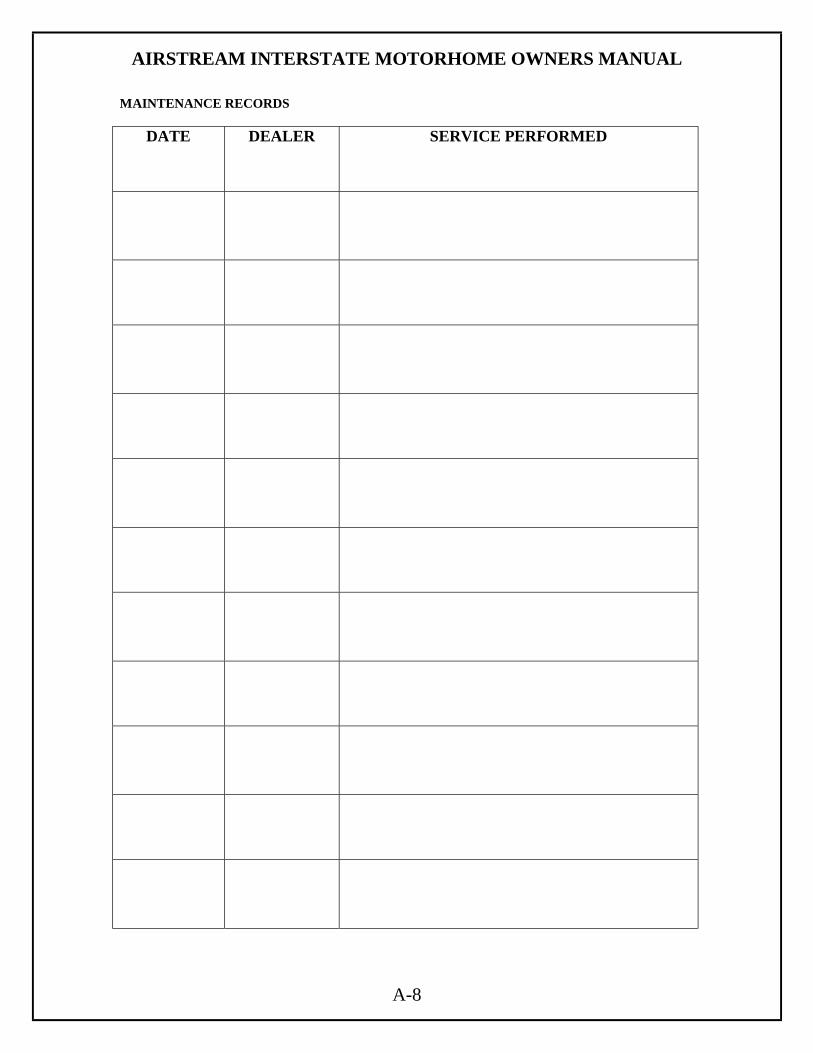
MAINTENANCE RECORDS
DATE DEALER SERVICE PERFORMED
AIRSTREAM INTERSTATE MOTORHOME OWNERS MANUAL
B-1
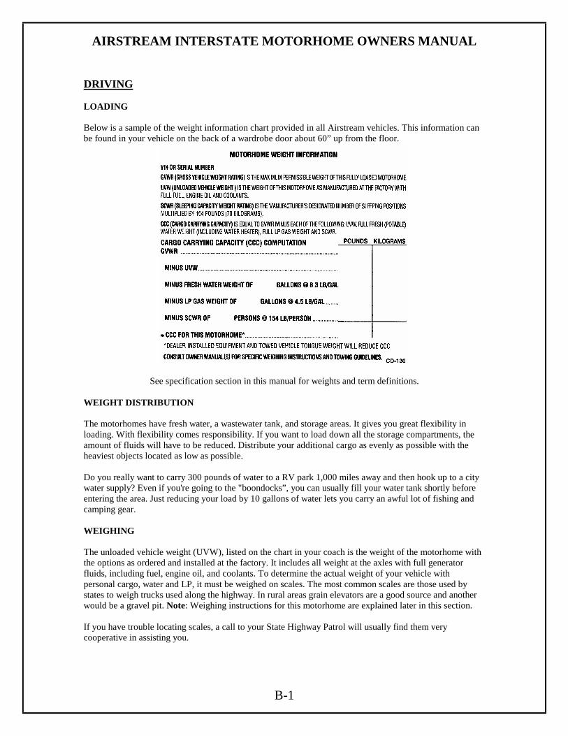
DRIVING LOADING Below is a sample of the weight information chart provided in all Airstream vehicles. This information can be found in your vehicle on the back of a wardrobe door about 60” up from the floor.
See specification section in this manual for weights and term definitions. WEIGHT DISTRIBUTION The motorhomes have fresh water, a wastewater tank, and storage areas. It gives you great flexibility in loading. With flexibility comes responsibility. If you want to load down all the storage compartments, the amount of fluids will have to be reduced. Distribute your additional cargo as evenly as possible with the heaviest objects located as low as possible. Do you really want to carry 300 pounds of water to a RV park 1,000 miles away and then hook up to a city water supply? Even if you're going to the "boondocks”, you can usually fill your water tank shortly before entering the area. Just reducing your load by 10 gallons of water lets you carry an awful lot of fishing and camping gear. WEIGHING The unloaded vehicle weight (UVW), listed on the chart in your coach is the weight of the motorhome with the options as ordered and installed at the factory. It includes all weight at the axles with full generator fluids, including fuel, engine oil, and coolants. To determine the actual weight of your vehicle with personal cargo, water and LP, it must be weighed on scales. The most common scales are those used by states to weigh trucks used along the highway. In rural areas grain elevators are a good source and another would be a gravel pit. Note: Weighing instructions for this motorhome are explained later in this section. If you have trouble locating scales, a call to your State Highway Patrol will usually find them very cooperative in assisting you.

AIRSTREAM INTERSTATE MOTORHOME OWNERS MANUAL
B-2
SAFETY CHECK LIST Your Airstream motorhome should be given a thorough safety check before a trip. Regular use of the following list will provide safe operation of your motorhome and will help you spot any malfunctioning equipment and correct the problem as soon as possible. The list is to help you and may not be all-inclusive. Failure to heed the following items may cause damage to the vehicle or personal injury. EXTERIOR CHECK LIST (BEFORE ENTERING VEHICLE)
1. Check condition of tires for proper inflation.
2. Turn off LPG valve on LPG tank.
3. Check that sewer connections, city water hookup, TV cable/satellite, and all exterior components
are unhooked and properly stowed away.
4. Check that all external compartments and filler openings are properly closed, latched, and/or
locked.
5. Check that items stored on exterior of vehicle are securely tied down.
6. Would any items stored on exterior of vehicle present a clearance problem?
7. Lower and secure TV antenna, (stow satellite dish).
8. Follow all automotive manufacturers recommendations on checking and filling fluid levels.
9. Check exterior lights and general condition of vehicle.
10. Keep tires at recommended inflation pressure.
INTERIOR CHECK LIST (BEFORE DRIVING OFF)
1. It is important that all doors be completely closed during travel.
2. Turn off living area water pump.
3. Check that refrigerator door is fastened.
4. Check that nothing heavy is stored in overhead or high cabinets, which could fall out and cause
injury. Heavy items should be stored in lower cabinets.
5. Stow folding and pedestal tables.
6. Check that counter tops, range top, and shelves are clear of even small items that could become
projectiles in an accident.
7. Do not cook while under way. Hot food or liquid could scald due to a sudden stop or accident.
8. Be sure all LPG controls on the furnace, range and gas/electric refrigerator are turned Off.
9. Check that any internal stowage is securely held in place
10. Check that lights and switches are set in positions safe for travel.
11. Adjust the driver's seat so that you can easily reach and operate all controls. Make sure seat is
locked in position. Do not adjust driver's seat’ swivel, fore or aft mechanism while vehicle is
moving. The seat could move unexpectedly causing loss of control.

AIRSTREAM INTERSTATE MOTORHOME OWNERS MANUAL
B-3
12. Check that front passenger's seat is locked in position - both fore and aft adjustment and swivel
mechanism.
13. The freedom of movement of the brake and accelerator pedals must not be impaired in any way
14. Check rear view mirrors adjustment, inside and outside. Adjust curtains if necessary for maximum
visibility.
15. Secure children in a Federally Approved Child Restraint Device.
16. Fasten your lap belts.
SAFETY SEAT BELTS In the forward driver's area of the motorhome, safety seat belts are provided for the use of the driver and the right front passenger. Safety belts are available for other seats. It is strongly recommended that all occupants remain seated with their safety belts firmly attached while the motorhome is in transit. The driver should adjust his seat so that he is able to reach all controls easily with the belt on, especially able to use all the travel on the foot brake. The belt should be placed as low as possible around the hips to prevent sliding out from under them in case of accident. This places the load of the body on the strong hipbone structure instead of around the soft abdominal area. Two people should never try to use the same seat belt.
Warning: Become familiar with and follow all directions, advice, and warnings pertaining to seats, seat belt operation, and restraint systems, provided in the Sprinter
Operator’s Manual.
Warning: Children must be secured in a Federally Approved Child Restraint Device. Failure to use proper restraints while in transit can result in severe or fatal injuries. Never place an infant seat that faces to the rear on the front passenger seat. Never place an unbelted infant seat on the front passenger seat. Child restraint devices are designed to be secured with lap or lap/shoulder belts. All instructions supplied by the restraint manufacturer must be followed. Statistics have shown children are safer when properly restrained in a rear seating position than in a front seating position.
Often the children traveling in motorhomes are grandchildren. There are times when our love for grandchildren makes us hesitate to properly supervise their actions. Don't hesitate when it comes to their safety. Make sure they are properly restrained.
CHILDREN HAVE LOVED ONES TOO.
IF YOU WON'T BUCKLE UP FOR YOURSELF, BUCKLE UP FOR THEM.
Warning: Drinking or taking drugs and driving can be a very dangerous combination. Even a small amount of alcohol or drugs can affect your reflexes, perception,
and judgment. The possibility of a serious or even fatal accident is sharply increased when you drink or take drugs and drive. Never drink or take drugs and drive or allow anyone to drive after drinking or taking drugs.
AIRSTREAM INTERSTATE MOTORHOME OWNERS MANUAL
B-4
TRAILER TOWING AND DRIVING TIPS (partial excerpts from Sprinter Operators Manual)
Warning: Failure to use proper equipment and driving technique can result in a loss of vehicle control when towing a trailer. Improper towing or failure to follow the instructions contained in this section can result in serious injury.
Follow the guidelines below carefully to assure safe trailer operation. Ask your authorized sprinter or Airstream dealer if you require an explanation of information contained in the sky. Trailer Hitches Only install a trailer hitch receiver approved for your vehicle. For information on availability and installation, please see your authorized Sprinter dealer. The bumpers on your vehicle are not designed for use with clamp type hitches. Do not attach rental hitches or other bumper type hitches to them. To reduce the possibility of damage, remove the hitch ball adapter from the receiver when not in use. Electrical Connections The Sprinter is available with a variety of preinstalled conditions (lines and turn signal indicator and break module installed and/or not installed). Make sure that correct trailer hitch receiver is used. For further information, please see your authorized Sprinter or Airstream Dealer. In order to prevent possible damage to the vehicle's electrical system by incorrectly installing the trailer-wiring plug, we recommend having the harness connected at an authorized Sprinter or Airstream Dealer. Vehicle and Trailer Weights and Ratings Gross Vehicle Weight Rating (GVWR) is the maximum permissible weight of the motorhome. Gross Vehicle Weight (GVW): comprises weight of vehicle including fuel, tools, spare tire, installed accessories, passengers, cargo, and trailer tongue. It must never exceed the GVWR. Gross Axle Weight Rating (GAWR) is a maximum permissible axle weight. Gross Trailer Weight (GTW) is a maximum permissible trailer weight to be towed. Trailer Tongue Weight Rating (TWR) is the maximum permissible weight of the trailer tongue.
• These and other weights are located in the specification section of this manual.
AIRSTREAM INTERSTATE MOTORHOME OWNERS MANUAL
B-5
Since this vehicle is designed and intended primarily as a load-carrying vehicle, towing a trailer will affect handling, durability and economy. Maximum safety and satisfaction depends upon proper use of correct equipment and avoiding overloads and other abusive operation.
Warning: The total weight of the motorhome and trailer must not exceed the GCWR listed in the specification section of this manual. The maximum towing capacity
varies according to the size of the motorhome and its GCWR. Vehicles should be properly equipped for towing trailers. Information on trailer hauling capabilities and special equipment required may be obtained from your Airstream dealer. Loading a Trailer When loading a trailer, you should observe that neither the permissible GTW, nor the GVWR are exceeded. Maximum permissible values are listed on the safety compliance certification labels for the vehicle and for the trailer to be towed. For their location, see the Sprinter Operators Manual. The lowest value listed must be selected when determining how the vehicle and trailer are loaded.
To assist in attaining good handling of the vehicle/trailer combination it is important that the tongue weight be maintained at approximately 10%-15% of the loaded trailer weight, but not to exceed the hitch rating. Tongue loads can be adjusted by proper distribution of the load in the trailer, and can be checked by weighing separately the loaded trailer and then the tongue.
The tongue weight (TW) at the hitch ball must be added to the GVW to prevent exceeding your Sprinter towed vehicles or rear GAWR. When towing trailers, motorhome tires should be inflated to the highest pressures shown on the information plate on the side of the driver’s seal mounting plate. The Cargo Carrying Capacity (CCC) of this vehicle is reduced by the amount that equals the trailer tongue load on the trailer hitch. . Checking Weights of Vehicle and Trailer To assure that the tow vehicle and trailer are in compliance with the maximum permissible weight limits, and to know the actual weights, have the loaded vehicle-trailer combination (tow vehicle including driver, passengers and cargo, trailer fully loaded) weight on commercial scale. Check the vehicles front and rear Gross Axle Weight (GAW), the GTW and TW. The values as measured must not be exceeded, according to the weight listed under "Vehicle and trailer weight and ratings" in this section.

AIRSTREAM INTERSTATE MOTORHOME OWNERS MANUAL
B-6
Attaching a Trailer Please observe maximum permitted trailer dimensions (weight and length). Most states and all Canadian provinces require safety chains between your tow vehicle and trailer. The chains should be crisscrossed under the trailer tongue. It must be attached to the hitch receiver, and not to the vehicles bumper or axle. The sure to leave enough slack in the chains to permit turning corners. Most states and all Canadian provinces required a separate brake system had serious trailer weights.
Warning: The towing vehicle’s braking system is rated for operation at GVWR (GROSS VEHICLE WEIGHT RATING), NOT at the GCWR (GROSS
COMBINED WEIGHT RATING). A separate functioning brake system is required for any towed vehicles or trailers weighing more than 1000 lbs. (450 kg) when fully loaded. NEVER exceed the GVWR (GROSS VEHICLE WEIGHT RATING), or the GAWR (GROSS AXLE WEIGHT RATING) specified on a motorhome certification label. Also NEVER exceed the weight ratings of trailer hitch installed on a motorhome. Failure to heed any part of this warning could result in loss of control of the motorhome and towed vehicle or trailer and may cause an accident and serious injury. For specified towed vehicle braking requirements, consult the Sprinter Operator's manual that comes with this vehicle.
Warning: Do not connect a trailer brake system (if trailer is so equipped) directly to the vehicles hydraulic brake system has your vehicle is equipped with
antilock brakes. If you do, neither the vehicles brakes nor the trailers brakes will function properly. Property damage, injury or death to you or others may be the result. The provided vehicle electrical wiring harness for a trailer towing has a brake signal wire for hookup to a brake controller. Most states and all Canadian provinces require a brake away switch on trailers with a separate brake system. The switch activates the trailer brakes in the possible event that the trailer might separate from the tow vehicle. He should consider using a trailer sleigh control system. For further information see your authorized Sprinter or Airstream dealer.
Towing a Trailer There are many different laws, including speed limit restrictions, having to do with trailer towing. Make sure that your vehicle -- trailer combination will be legal; not only for where you reside, but also for where you'll be driving. He good source for this information can be the police or local authorities. Before you start driving with a trailer, check the trailer’s hitch; brake away switch, safety chains, electrical connections, lighting and tires. Also, adjust the mirrors to permit unobstructed view beyond rear of trailer.
AIRSTREAM INTERSTATE MOTORHOME OWNERS MANUAL
B-7
If the trailer has electric brakes, start your vehicle and trailer moving slowly, and then apply only the trailer brake controller by hand to be sure the brakes are working properly. When towing a trailer, check occasionally to be sure that the load is secure, and that lighting and trailer brakes (if so equipped) are functioning properly. Always secure items in the trailer to prevent load shifts while driving. Take into consideration that when towing a trailer, the handling characteristics are different and less stable from those when operating the vehicle without a trailer. It is important to avoid sudden maneuvers. The vehicle and trailer combination is heavier, and therefore is limited in acceleration inclining ability, and requires longer stopping distances. It is more prone to reacting to side wind gusts, and requires more sensitive steering input. In order to gain skill and an understanding of the vehicles behavior, you should practice turning, stopping in backing up in an area which is free from traffic.
If possible, do not brake abruptly, but rather engage the brake slightly at first to permit trailer to activate its brake. Then increase the braking force. We want every owner to be a safe and courteous driver. A few hours of towing practice in a large empty supermarket lot will make pulling your trailer over the road much easier. Line out two corners for left and right turns. You may also use these corners to practice backing and parking. OBSERVE THAT THE TRACKS MADE BY THE TRAILER WHEELS ARE DISTINCTLY DIFFERENT FROM THOSE MADE BY THE TOW VEHICLE. Studying this will make it easier for you to correct mistakes. Truck or trailer type fender or door grip rear view mirrors are necessary for maximum visibility and in most states the law requires them. After thoroughly inspecting your hitch, brakes, and tires you should be ready to tow. Check traffic, signal that you are about to pull away, and start slowly. Look often in your mirrors, and observe the action of the trailer, then carefully move into the proper lane of traffic. Remember that the trailer wheels will not follow the path of the tow vehicle wheels; therefore, WIDER TURNS ARE NECESSARY WHEN TURNING TO THE LEFT OR TO THE RIGHT. ON FREEWAYS OR EXPRESSWAYS try to pick the lane you want and stay in it. Always maintain plenty of space between you and the car ahead, at least the length of the tow vehicle plus trailer for every ten miles per hour. Remember that in order to pass another vehicle you will need longer to accelerate. You must also allow for the length of the trailer when returning to the right hand lane.
AIRSTREAM INTERSTATE MOTORHOME OWNERS MANUAL
B-8
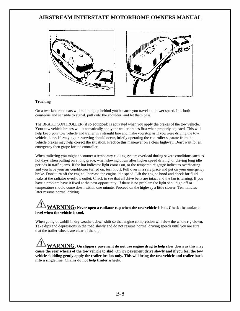
Tracking On a two-lane road cars will be lining up behind you because you travel at a lower speed. It is both courteous and sensible to signal, pull onto the shoulder, and let them pass. The BRAKE CONTROLLER (if so equipped) is activated when you apply the brakes of the tow vehicle. Your tow vehicle brakes will automatically apply the trailer brakes first when properly adjusted. This will help keep your tow vehicle and trailer in a straight line and make you stop as if you were driving the tow vehicle alone. If swaying or swerving should occur, briefly operating the controller separate from the vehicle brakes may help correct the situation. Practice this maneuver on a clear highway. Don't wait for an emergency then grope for the controller. When trailering you might encounter a temporary cooling system overload during severe conditions such as hot days when pulling on a long grade, when slowing down after higher speed driving, or driving long idle periods in traffic jams. If the hot indicator light comes on, or the temperature gauge indicates overheating and you have your air conditioner turned on, turn it off. Pull over in a safe place and put on your emergency brake. Don't turn off the engine. Increase the engine idle speed. Lift the engine hood and check for fluid leaks at the radiator overflow outlet. Check to see that all drive belts are intact and the fan is turning. If you have a problem have it fixed at the next opportunity. If there is no problem the light should go off or temperature should come down within one minute. Proceed on the highway a little slower. Ten minutes later resume normal driving.
WARNING: Never open a radiator cap when the tow vehicle is hot. Check the coolant level when the vehicle is cool. When going downhill in dry weather, down shift so that engine compression will slow the whole rig clown. Take dips and depressions in the road slowly and do not resume normal driving speeds until you are sure that the trailer wheels are clear of the dip.
WARNING: On slippery pavement do not use engine drag to help slow down as this may cause the rear wheels of the tow vehicle to skid. On icy pavement drive slowly and if you feel the tow vehicle skidding gently apply the trailer brakes only. This will bring the tow vehicle and trailer back into a single line. Chains do not help trailer wheels.

AIRSTREAM INTERSTATE MOTORHOME OWNERS MANUAL
B-9
When driving in mud and sand let the momentum carry the rig through. Apply power gently and use as little as possible. Stay in the tracks of the vehicle ahead and keep the tow vehicle in the highest possible gear. If you are stuck it is best to tow out the entire rig together without unhitching. Despite the best hitch you will notice that whenever a large bus or truck overtakes your rig the displaced air first pushes the trailer rear slightly to the right and then affects the front. It may be necessary to steer very slightly, momentarily, toward the bus or truck to help compensate for the sway induced by the passing-vehicle. Do not apply the vehicle brakes, as this can tend to exaggerate the situation. You may find, however, that briefly applying the trailer brakes with your manual control will help eliminate sway.
WARNING: When stopping on a hill or slope, leaving your tow vehicle in gear is not enough for standstill safety. CHOCK THE TRAILER WHEELS to he double sure. Do not use trailer brakes as parking brakes. Backing Up In BACKING UP the important thing to remember is to DO EVERYTHING SLOWLY and to correct immediately if you see the trailer turning the wrong way. Concentrate on the rear of the trailer. With your tow vehicle and trailer in a straight line, back up slowly and turn the bottom of the steering wheel in the direction you want the trailer to go. Watch out the window or in the mirror until the rear of the trailer is pointing in the desired direction. Your tow vehicle will be following the trailer in an arc. Straighten the tow vehicle and trailer by turning the steering wheel more sharply, and then when they are in line, straighten the steering wheel. ALWAYS TRY TO BACK TO YOUR LEFT BECAUSE THE VISIBILITY IS MUCH BETTER. (See Illustration) When you don't make it on the first try it is usually much easier to pull forward to your original position and start over. If your spouse or traveling companion normally directs you when backing they should position themselves forward of the tow vehicle so the driver can easily see them. Their directions should always indicate to the driver the direction the rear of the trailer should go. A little practice in a parking lot with the person giving directions can save a lot of frustration when backing into a campsite.
WARNING: take into consideration that when towing a trailer, the handling characteristics are different and less stable from those with operating
the vehicle without a trailer. It is important to avoid sudden maneuvers. Sudden maneuvers may lead to loss of control over the vehicle -- trailer combination. CAUTION: If the transmission hunts between gears on inclines, manually shift to a lower gear (select "4", "3", "to "2" or "1"). A lower gear and reduction of speed reduces the chances of engine overloading and/or overheating. When going down a long hill, shift into a lower gear and use the engines braking effect. Avoid riding the brakes, thus overheating the vehicle and trailer brakes. If the engine coolant rises to an extremely high temperature (coolant temperature needle approaching the red zone) when the air conditioner is on, turn off the air conditioner. Engine coolant heat can be additionally vented by opening the windows, switching the climate control fan speed to high and setting the temperature control to the maximum hot position. Extreme care must be exercised censure vehicle with a trailer will require additional passing distance ahead that when driving without a trailer. Because your vehicle and trailer is longer then your vehicle alone, you will also need to go much further ahead of the passed vehicle before you can return to your lane.

AIRSTREAM INTERSTATE MOTORHOME OWNERS MANUAL
B-10
Parking
WARNING: to reduce the risk of personal injury, or damage to the vehicle power train, as a result of vehicle/trailer movement, always:
• Keep right foot on the brake pedal. • Shift tear selector lever to position "N". • Have a second person place wheel chocks on downhill side of left and right trailer
wheels. • Slowly release brake pedal cannot vehicle and trailer roll into chocks until stopped. • Firmly depress parking brake pedal. • Move gear selector lever to position "P". • On inclines, turn from wheels towards the road curb.
TOWING YOUR MOTORHOME
The most common equipment is called "reach under hooks". These allow the tow operator to lift on the front suspension of your motorhome without damaging the bumper or other body parts. Another choice is a wheeled dolly. In these, the front tires sit in a cradle supported by its own wheels. The tow operator should be told the weight of your vehicle on the front suspension so they can be properly prepared when they reach you. CAUTION: Considerable damage will occur if the motorhome is improperly lifted for towing purposes. Only qualified professional wrecker service companies with proper equipment should be used. Observe all cautions and warnings in the Sprinter Operator’s manual before towing your motorhome.
WARNING: Do not tow the vehicle if the key cannot be turned in the ignition lock. If the key cannot be turned, the ignition lock remains locked and
the vehicle cannot be steered. With the engine not running there is no power assistance for the braking and steering systems. In this case, it is important to keep in mind that a considerably higher degree of effort is necessary to brake and steer the vehicle. The vehicle must not be towed with the front axle raised and key in position two in the ignition lock as the drive wheels could then lock due to the acceleration skid control (ASR). See the Sprinter Operators Manual for information on the ASR.
AIRSTREAM INTERSTATE MOTORHOME OWNERS MANUAL
B-11
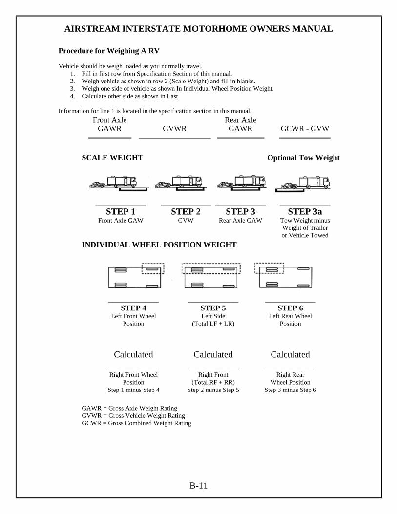
Procedure for Weighing A RV Vehicle should be weigh loaded as you normally travel.
1. Fill in first row from Specification Section of this manual. 2. Weigh vehicle as shown in row 2 (Scale Weight) and fill in blanks. 3. Weigh one side of vehicle as shown In Individual Wheel Position Weight. 4. Calculate other side as shown in Last
Information for line 1 is located in the specification section in this manual.
Front Axle GAWR
GVWR
Rear Axle GAWR
GCWR - GVW
SCALE WEIGHT Optional Tow Weight
___________
STEP 1 Front Axle GAW
___________ STEP 2
GVW
___________ STEP 3
Rear Axle GAW
___________ STEP 3a
Tow Weight minus Weight of Trailer or Vehicle Towed
INDIVIDUAL WHEEL POSITION WEIGHT
___________
STEP 4 Left Front Wheel
Position
___________ STEP 5 Left Side
(Total LF + LR)
___________ STEP 6
Left Rear Wheel Position
Calculated Calculated Calculated ___________ Right Front Wheel
Position Step 1 minus Step 4
___________ Right Front
(Total RF + RR) Step 2 minus Step 5
___________ Right Rear
Wheel Position Step 3 minus Step 6
GAWR = Gross Axle Weight Rating GVWR = Gross Vehicle Weight Rating GCWR = Gross Combined Weight Rating

AIRSTREAM INTERSTATE MOTORHOME OWNERS MANUAL
C-1
SPRINTER VAN Component Identification The Airstream Interstate Motorhome is integrated into a Sprinter Van, designed and manufactured by Daimler/Chrysler. Operation of the Sprinter, its engine, power train, and other related components are discussed in the Sprinter Operator’s Manual and other literature provide by Daimler/Chrysler. As a point of reference, those systems discussed in this literature are warranted by Daimler/Chrysler or their suppliers. If repairs are needed, it may be difficult to determine which parts are the Sprinter manufacturer’s, and which are Airstream's responsibility. The following partial lists show the major components of the van and the company responsible for their servicing. Sprinter Van Serviced by Daimler/Chrysler. See Sprinter Warranty Information Manual for complete instructions. Engine Exterior Automotive lights Transmission Suspension Brakes Drive Axle and Hubs Steering Assembly Rear Shocks Front Spindle, Bearings Automotive Fuse Panel Wheels Parking Brake Alternator Electric Fuel Pump Cruise Control Engine Battery Instrument Panel Cluster Engine Cooling System Tires (see tire manufacturer service center) Doors, cab, side and rear cargo Cab door windows and windshield Automotive electrical system Dash AC/Heater/Defroster Driver’s and Passenger’s Seats and Restraint systems, does not include optional swivel pedestal for passenger seat or seat decorative skirting that is installed by Airstream Inc. In the United States: In Canada: Daimler/Chrysler Motors Company LLC Daimler/Chrysler Canada, Inc. Customer Center Customer Center PO Box 21-8004 PO Box 1621 Auburn Hills, MI. 48321-8004 Windsor, Ontario N9A-4H6 Ph.: 800-992-1997 Ph.: 800 465-2001

AIRSTREAM INTERSTATE MOTORHOME OWNERS MANUAL
C-2
Component Identification (continued) Airstream Components serviced by Airstream Authorized Service Centers Cab Area: Driving light system including lights, switch and harness Passenger seat swivel mechanism Driver’s and passenger’s seat skirting Floor Mats Finish on the center console switch base. Airstream removes, send out for finish and reinstalls. Living Quarters: Interior furniture, wall panels to the rear of the cab seats. Privacy curtain Shades Floor covering Appliances in the lounge/lavy area Fresh water and waste water system components. Non-automotive electrical components including: Monitor panel and its system Converter Automatic switchover box 110-volt system 12 Volt living area system Roof AC Power vent Living area entertainment center Exterior patio light Exterior Roof rack Entertainment center’s Radio and TV antenna Exterior windows excluding windshield, drivers and passenger door Paint (Carrera Designs) Access doors and other living area electrical and plumbing components If you need further clarification or information, contact the Airstream Customer Relations Department at 937-596-6111 before contacting a service center for an appointment. If you wish to write, the address is: Airstream Inc. Attn: Customer Service 419 W. Pike Street P.O. Box 629 Jackson Center, Ohio 45334

AIRSTREAM INTERSTATE MOTORHOME OWNERS MANUAL
C-3
IMPORTANT INFORMATION Your Sprinter Van Operator’s and Warranty Manuals contain important cautions, warnings, operational, and warranty information on the Sprinter and its components. All information in the Sprinter manual should be reviewed and followed for your safety. The Airstream Interstate Owner’s Manual may provide addition information and tips on the use of the Van as a motorhome, however, no information in the Airstream manual should be interpreted as advice or directions to disregard or void the warnings, cautions, or other information contained in the Sprinter’s manuals. TIRES Don't let anyone tell you that underinflation or over inflation is all right. It's not. If you're tires don't have enough air (underinflation) you can get tire flexing, heat build-up, tire overloading, bad handling, bad fuel economy, and bad wear. Too high an air pressure (over inflation) can result in abnormal wear, bad handling, harsh ride, and also increase the chance of damage from road hazards. Tire inflation pressures should be checked at least monthly and when significantly changing the load you plan to carry in your motorhome. Always check tire inflation pressures when the tires are "cold". Standard inflation pressures for tires are listed on a decal mounted on the driver’s seat pedestal. Front and rear pressures are shown for each model and GVWR, and are based on the GVWR and front and rear axle ratings (GAWRs) printed on your vehicle VIN plate and Certification label. Tires must be inflated to these pressures when the vehicle is fully loaded or an axle GAWR is reached. Proper FRONT END ALIGNMENT improves tire tread mileage. Your front-end suspension parts should be inspected periodically and aligned when needed. Improper alignment may or may not cause the vehicle to vibrate. However, improper toe alignment will cause front tires to roll at an angle, which will result in faster tire wear. Incorrect caster or camber alignment will cause your front tires to wear unevenly and can cause the vehicle to "pull" to the left or right. The following section is intended to provide information on tires and how improper care and maintenance may affect your vehicle, its performance, and your safety. If you have any questions on your tires please contact a qualified tire service center or an authorized Sprinter dealer.
AIRSTREAM INTERSTATE MOTORHOME OWNERS MANUAL
C-4
Tire Identification Number
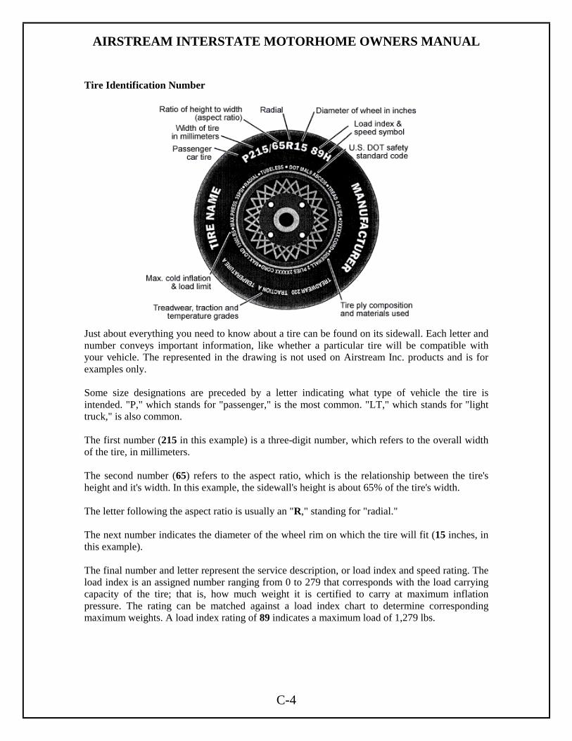
Just about everything you need to know about a tire can be found on its sidewall. Each letter and number conveys important information, like whether a particular tire will be compatible with your vehicle. The represented in the drawing is not used on Airstream Inc. products and is for examples only. Some size designations are preceded by a letter indicating what type of vehicle the tire is intended. "P," which stands for "passenger," is the most common. "LT," which stands for "light truck," is also common. The first number (215 in this example) is a three-digit number, which refers to the overall width of the tire, in millimeters. The second number (65) refers to the aspect ratio, which is the relationship between the tire's height and it's width. In this example, the sidewall's height is about 65% of the tire's width. The letter following the aspect ratio is usually an "R," standing for "radial." The next number indicates the diameter of the wheel rim on which the tire will fit (15 inches, in this example). The final number and letter represent the service description, or load index and speed rating. The load index is an assigned number ranging from 0 to 279 that corresponds with the load carrying capacity of the tire; that is, how much weight it is certified to carry at maximum inflation pressure. The rating can be matched against a load index chart to determine corresponding maximum weights. A load index rating of 89 indicates a maximum load of 1,279 lbs.

AIRSTREAM INTERSTATE MOTORHOME OWNERS MANUAL
C-5
The speed rating is a letter, which indicates the range of speeds at which a tire is certified to carry a load (see the speed symbols chart to determine your tire's maximum speed). Each tire is assigned a rating from A (lowest) to Z (highest). There is one notable exception: the "H" rating falls out of sequence between "U" and "V," and is used for tires certified for speeds up to 130 mph. The Q rating is the lowest commonly used for passenger cars. An "H" -rated tire is certified up to 210 km/h or 130 mph. See Load Index and Speed Rating Charts in this section for further information. Just to recap. A tire marked P215/65R15 89H would have a width of 215 millimeters and an aspect ratio of 65. It would be a radial tire sized for a rim with a 15-inch diameter, feature a load index of 89 (capable of carrying a maximum load of 1,279 pounds) and a speed rating of "H" (indicating it is certified up to 130 miles per hour). It's important to note that markings do not always appear exactly as they do in this example, as tires can be certified under a variety of designations. Uniform Tire Quality Grading Standards Also on the sidewall is The Uniform Tire Quality Grade (UTGQ), which offers three more key pieces of information about a tire: Tread wear: Tread wear is a critical indicator of how much longer your tire will last. In the life of every tire, tread eventually degrades to a degree where the tire can no longer be used safely. Each type of tire is tested under controlled conditions on a government test course and assigned a tread wear grade, which theoretically indicates the useful life of the tread. It's important to remember that this is a theoretical figure and cannot be linked to projected tire mileage, as factors like road surface quality, driving habits, inflation, wheel alignment and rotation come into play. Tread wear grades typically range from 60 to 620 in 20 point increments. The higher the grade, the longer the tread life as measured under government conditions. Traction: Traction grades indicate a tire's braking performance. Traction is tested in a straight-ahead motion on wet pavement. A grade from "A" to "C" is assigned, with "A" signifying the best traction. Temperature: Temperature grades represent a tire's ability to withstand heat under test conditions. Since tires are made of rubber and other materials, which are degraded by high levels of heat, determining their ability to withstand heat is very important. Temperature grades are also assigned A-C with A signifying the most resistance to heat.
AIRSTREAM INTERSTATE MOTORHOME OWNERS MANUAL
C-6
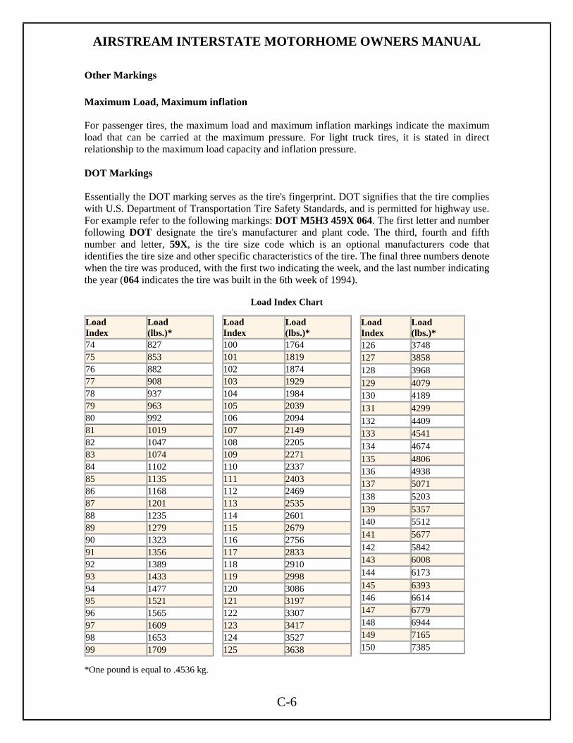
Other Markings Maximum Load, Maximum inflation For passenger tires, the maximum load and maximum inflation markings indicate the maximum load that can be carried at the maximum pressure. For light truck tires, it is stated in direct relationship to the maximum load capacity and inflation pressure. DOT Markings Essentially the DOT marking serves as the tire's fingerprint. DOT signifies that the tire complies with U.S. Department of Transportation Tire Safety Standards, and is permitted for highway use. For example refer to the following markings: DOT M5H3 459X 064. The first letter and number following DOT designate the tire's manufacturer and plant code. The third, fourth and fifth number and letter, 59X, is the tire size code which is an optional manufacturers code that identifies the tire size and other specific characteristics of the tire. The final three numbers denote when the tire was produced, with the first two indicating the week, and the last number indicating the year (064 indicates the tire was built in the 6th week of 1994).
Load Index Chart
Load Index
Load (lbs.)*
74 827 75 853 76 882 77 908 78 937 79 963 80 992 81 1019 82 1047 83 1074 84 1102 85 1135 86 1168 87 1201 88 1235 89 1279 90 1323 91 1356 92 1389 93 1433 94 1477 95 1521 96 1565 97 1609 98 1653 99 1709
Load Index
Load (lbs.)*
100 1764 101 1819 102 1874 103 1929 104 1984 105 2039 106 2094 107 2149 108 2205 109 2271 110 2337 111 2403 112 2469 113 2535 114 2601 115 2679 116 2756 117 2833 118 2910 119 2998 120 3086 121 3197 122 3307 123 3417 124 3527 125 3638
Load Index
Load (lbs.)*
126 3748 127 3858 128 3968 129 4079 130 4189 131 4299 132 4409 133 4541 134 4674 135 4806 136 4938 137 5071 138 5203 139 5357 140 5512 141 5677 142 5842 143 6008 144 6173 145 6393 146 6614 147 6779 148 6944 149 7165 150 7385
*One pound is equal to .4536 kg.

AIRSTREAM INTERSTATE MOTORHOME OWNERS MANUAL
C-7
Speed Rating Chart Speed Symbol Speed (km/h) Speed (mph) A1 5 3 A2 10 6 A3 15 9 A4 20 12 A5 25 16 A6 30 19 A7 35 22 A8 40 25 B 50 31 C 60 37 D 65 40 E 70 43 F 80 50 G 90 56 J 100 62 K 110 68 L 120 75 M 130 81 N 140 87 P 150 94 Q 160 100 R 170 106 S 180 112 T 190 118 U 200 124 H 210 130 V* Above 210 Above 130 V 240 149 W 270 168 Y 300 186 Above 300 Above 186 * For Unlimited V tires without the Service Description, the speed category is over 210 km/h (131 mph).
AIRSTREAM INTERSTATE MOTORHOME OWNERS MANUAL
C-8
Vehicle Placard and Tire Inflation Pressure Label The TIRE AND LOADING INFORMATION placard supplies information on the size and the cold tire inflation pressure for the original equipment tires supplied with your vehicle. It also defines the GVWR as 8,550 pounds. It is located on the side of the driver’s seat pedestal in your vehicle. Tire Terminology Cold Tire Inflation Pressure is the amount of air pressure in a tire, measured in pounds per square inch (psi) before a tire has built up heat from driving or before rising ambient temperatures or the sun’s radiant heat affects it. Maximum Inflation Pressure is the maximum air pressure to which a cold tire may be inflated and is found molded onto the sidewall. Recommended Inflation Pressure is the recommended inflation pressure can be found in your owner's manual or on a label frequently found in the glove box, near the door latch on the driver's side, or other locations on your vehicle. The recommended inflation pressure is not to be confused with the maximum inflation pressure that is shown on the side of the tire. At the recommended inflation pressure, tires will last longer and be less likely to fail, and the car will use less fuel. Serious injury can result from tire failure because of under inflation or overloading. Pressure Reserve means the amount of pressure difference between the vehicle placard tire inflation pressure and the minimum pressure required to support the VEHICLE MAXIMUM LOAD ON THE TIRE. The minimum PRESSURE RESERVE required on a vehicle depends on the capability of the TPMS (Tire Pressure Monitoring System) used on the vehicle. PROPER TIRE INFLATION The level of air in your tires affects your vehicle's overall performance. Not even the highest quality tire will perform well if it's not inflated properly. The correct pressure varies from vehicle to vehicle and depends in part upon driver preference. Each vehicle has a recommended inflation pressure, usually found on a placard on the door section, doorpost, glove door, or fuel door. On the Interstate Motorhome, it is located on the Driver’s seat pedestal.

AIRSTREAM INTERSTATE MOTORHOME OWNERS MANUAL
C-9
Correct tire inflation is a key component in tire care. The recommended inflation pressures for your tires are indicated on the certification label or in your owner’s manual. Since RVs can be loaded with many different configurations, the load on each tire will vary. For this reason, air pressure should be checked based on the load on each individual tire. Cold Inflation Pressure should be adjusted to handle the maximum tire load, and all tires on the axle should carry the same inflation pressure. COLD TIRE INFLATION PRESSURE is the tire pressure checked in the morning before you drive more than a few miles or before rising ambient temperatures or the sun’s radiant heat affects it. Check your tires’ air pressures at least once a month, before each trip and each morning you drive during a trip. Tire pressure should be checked cold, as tire pressure ratings have been designed with typical running heat/pressure build-up in mind. Make sure the valves and caps are free of dirt and moisture. Under Inflation Underinflation brings a higher risk of susceptibility to damage due to road hazards, reduces casing durability, and causes a loss in fuel economy, plus uneven or irregular tire wear. Severe underinflation brings about an increased risk of tread separation, handling difficulties, and possibly tire failure, which is caused by overheating. IMPORTANT: It's a common practice for RV owners to lower tire pressure in their search for a smoother ride. This is not only dangerous, it's relatively ineffective, and as the difference in ride quality is not significant. When minimum inflation pressure requirements are not met, tire durability and optimum operating conditions are compromised. Tire inflation pressure should always meet at least the minimum guidelines for vehicle weight. • It may be necessary to inflate your tires at a truck stop or truck service center in order to achieve adequate air pressure for your coach's needs • Only permanent air seal metal valve caps should be used. • Be safe - if a tire has been run 20% under inflated, it must be dismounted and inspected by a trained professional. It should not be aired up without a full inspection or without using a safety cage. Use a calibrated gauge. If your tire is rated for higher inflation pressures, a special gauge will be required designed for larger tires. • Don't bleed air from warm tires to reduce pressure buildup • Don't inflate tires to cold PSI rating beyond rim specifications HOW OVERLOADING AFFECTS YOUR TIRES Tire pressure is what enables your RV tire to support loads. Overloading your tires can have serious consequences for passengers and your RV. Too much weight can cause stress on your RV's suspension system, brake failure, shock absorber damage, handling and steering problems, irregular tire wear and possible tire failure. Excessive loads or underinflation can lead to an excessive amount of heat and tire failure. If you discover that your tires cannot handle the load, lighten the weight of the load on your tires. Tire pressure should never be reduced below the vehicle manufacturer's recommended levels to support load conditions in order to improve the ride quality of a vehicle. The difference in ride quality is not significant. When minimum inflation pressure requirements are not met, tire durability and optimum operation can be affected.
AIRSTREAM INTERSTATE MOTORHOME OWNERS MANUAL
C-10
TIRE CARE RV Tire Maintenance Checklist VISUAL INSPECTION - What to look for.
• Proper tire size and load range for Gross Axle Weight Rating • Mismatched sizes or types (bias/radial, rib/lug, load range) • Road hazard or extensive curb damage in the tread or sidewall area • Wear conditions - alignment, loose or worn parts • Signs of overloaded or under inflated operation
o Discoloration or waviness in sidewalls from high running temperatures o Distortion or bulging in the bead area near rim flange o Rapid tread wear on a specific wheel position or axle
• Severe sidewall weather cracking o Tire age (can be determined from DOT manufacture date on the tire sidewall) o Storage in direct sunlight or near electrical motor/generator
• Chemical damage from petroleum products (sponginess) • Flat-spotting (brake skid) • Condition of spare tire • Loose lug nuts or broken wheel studs • Rim width correct for tire size • Assess vehicle for accessories/configuration that could contribute to weight bias/overload
and adjust loading or inflation pressure accordingly
MEASUREMENT - What's Important!
• Remaining tread depth o Minimum of 4/32, check with your tire care professional at 6/32 to determine if
replacements are needed o Rotation needed? o Axle and/or dual tread depth differential (4/32nds MAX)
• Inflation pressure o Within 20% of recommended inflation pressure o Tire pressure in-line with max pressure specs of wheel o Recommended pressure restored after tire storage? o For more specifics on tire inflation pressure
• Load by wheel position o Recommend checking load on each wheel position by weighing loaded vehicle.
Include pull-behind vehicles where applicable. o Places that you can weigh your RV include:
! A' Weigh We Go - service at RV rallies or shows ! Truck stop ! Farm co-op or feed mill ! Some sand and gravel yards

AIRSTREAM INTERSTATE MOTORHOME OWNERS MANUAL
C-11
TIRES and WHEELS (partially excerpted from the Sprinter Van Operator's Manual) Check tires regularly for even tread wear; tread depth (note legal requirements) and signs of external damage. Use only wheels and tires of the same size, make and pattern. Do not install tires that are not approved for the size and type of wheel installed on the vehicle itself. Only use those wheel sizes that were delivered to you buy your authorized Sprinter dealer. Use only wheels and tires that have been tested and approved by the vehicle manufacturer. Brake in the tires at moderate speeds for distance of about 65 miles.
Warning: always replace wheel bolts that are damage or rusted. Never apply oil or grease to wheel bolts. Damaged wheel hub threads should be repaired immediately. Incorrect mounting bolts or improperly tighten mounting bolts can cause the wheel to come off. This could cause an accident. Be sure to use the correct mounting bolts. Checked tightness of wheel bolts or nuts regularly and retighten if necessary. After changing a wheel, the wheel bolts or nuts must be tightened once the vehicle has been driven for about 30 miles. If new or repainted wheels are fitted, the wheel bolts or nuts must be retighten again after about 600 to 3000 miles. Fitting other wheel sizes to the vehicle will change the Sprinter's handling characteristics and may lead to an accident resulting in severe personal injuries, death and property damage. Do not use remolded tires. Tighten the wheel bolts or nuts in a cross pattern sequence. Tighten the wheel bolts or nuts to the specified torque with a torque wrench.
Tightening Torque for 8,550 lbs. (vehicle type 2500 C/HC/SHC): Steel Wheel 177 Lbf/ Ft. + or - 7 Lbf. /Ft. Light Alloy Wheel 138 Lbf/ Ft. + or - 14 Lbf. /Ft (optional) Tire Grip Tire grip is greatly reduced on a wet or icy road. Speed and driving style must therefore be adapted to suit road conditions. In winter, install M + S radial tires. Below a tread depth of 1/8 in., tire grip begins to decrease rapidly on wet roads. Hydroplaning Depending on the depth of the water layer on the road, hydroplaning may occur, even at low speeds and with new tires. Reduce vehicle speed, avoid grooves in the road, and apply brakes cautiously in the rain.

AIRSTREAM INTERSTATE MOTORHOME OWNERS MANUAL
C-12
Changing the Tire (partially excerpted from the Sprinter Van Operator's Manual) If you get a flat tire while driving, gradually decrease your speed. Hold the steering wheel firmly and slowly move to a safe place on the side of the road. The pressure of the spare wheel always has to be checked regularly (at least after every tenth time at the filling station). The vehicle tool kit and the jack are located under the hatch in the front passenger foot well.
Warning: The jack is designed exclusively for jacking up the vehicle at the jack take-up brackets built into either side of the vehicle. To help avoid personal injury, use the jack only to lift the vehicle during a wheel change. Never get beneath the vehicle while it is supported by the jack.
• Keep hands and feet away from the area under the lifted the vehicle. • Always firmly set parking brake and block wheels before raising vehicle with jack. • Do not disengage parking brake while vehicle is raised. • Always use the jack on a level surface. • Do not jack the vehicle up more than 1.2 inches between the tire and the surface.
Otherwise, the vehicle may tip over and may cause serious injury or death to you or others.
• Be sure that the jack arm and is fully seated in the jack take-up bracket. • Always lower the vehicle onto sufficient capacity jack stands before working under
the vehicle.
• Precautions when changing a wheel: Tire pressure: See Sprinter Van Operator’s Manual. Wheel bolt torque
Tighten the wheel bolts in a crosswise pattern to the specified torque with torque wrench. Tightening Torque for 8,550 lbs. (vehicle type 2500 C/HC/SHC):
Steel Wheel 177 Lbf/ Ft. + or - 7 Lbf. /Ft. Light Alloy Wheel 138 Lbf/ Ft. + or - 14 Lbf. /Ft (optional)
• Do not damage, grease or oil wheel bolts or their threads. Procedure:
• Park the vehicle on a firm, level, non-slippery surface. • Switch on the hazard warning flasher switch, apply the parking brake, and place the
transmission selector in “P”. • Everyone must leave the vehicle before you jack it up. • Everyone must leave the danger zone, before jacking the vehicle. • The vehicle must be safeguarded in accordance with legal regulations (such as using a
warning triangle). • Prevent vehicle for rolling away by blocking wheels with wheel chocks (not supplied
with vehicle) or sizable woodblocks or stone. On a level road place one chalk in front of and one behind the wheel that is diagonally opposite to the wheel being changed. When changing a wheel on mild uphill or downhill grade, place chocks on the downhill side blocking both wheels of the other axle.
AIRSTREAM INTERSTATE MOTORHOME OWNERS MANUAL
C-13
Changing the Tire (continued)
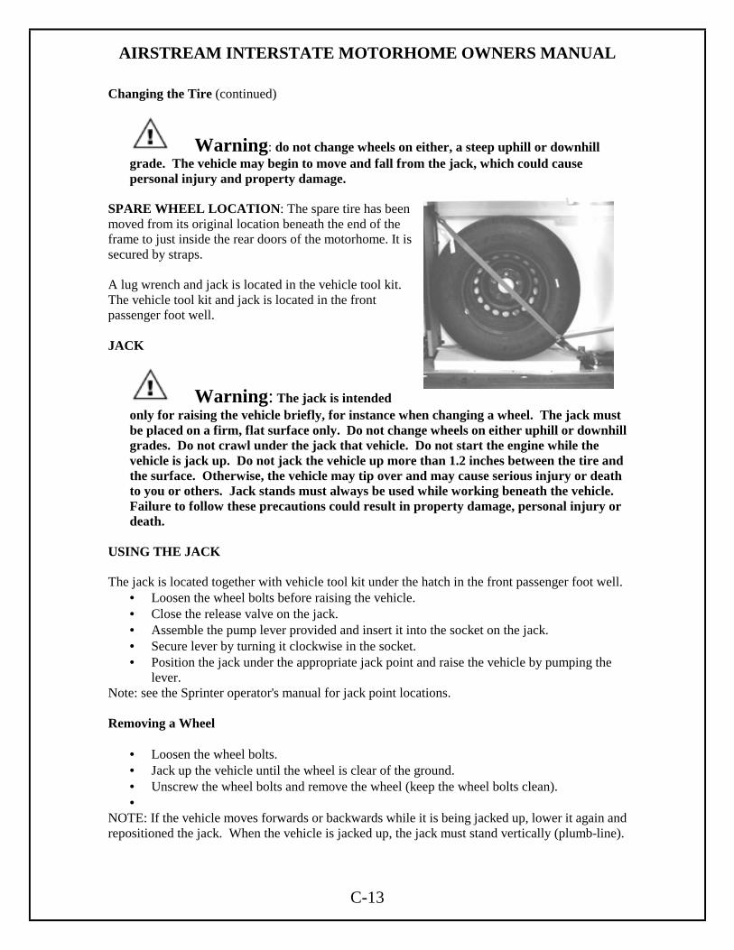
Warning: do not change wheels on either, a steep uphill or downhill grade. The vehicle may begin to move and fall from the jack, which could cause personal injury and property damage.
SPARE WHEEL LOCATION: The spare tire has been moved from its original location beneath the end of the frame to just inside the rear doors of the motorhome. It is secured by straps. A lug wrench and jack is located in the vehicle tool kit. The vehicle tool kit and jack is located in the front passenger foot well. JACK
Warning: The jack is intended only for raising the vehicle briefly, for instance when changing a wheel. The jack must be placed on a firm, flat surface only. Do not change wheels on either uphill or downhill grades. Do not crawl under the jack that vehicle. Do not start the engine while the vehicle is jack up. Do not jack the vehicle up more than 1.2 inches between the tire and the surface. Otherwise, the vehicle may tip over and may cause serious injury or death to you or others. Jack stands must always be used while working beneath the vehicle. Failure to follow these precautions could result in property damage, personal injury or death.
USING THE JACK The jack is located together with vehicle tool kit under the hatch in the front passenger foot well.
• Loosen the wheel bolts before raising the vehicle. • Close the release valve on the jack. • Assemble the pump lever provided and insert it into the socket on the jack. • Secure lever by turning it clockwise in the socket. • Position the jack under the appropriate jack point and raise the vehicle by pumping the
lever. Note: see the Sprinter operator's manual for jack point locations. Removing a Wheel
• Loosen the wheel bolts. • Jack up the vehicle until the wheel is clear of the ground. • Unscrew the wheel bolts and remove the wheel (keep the wheel bolts clean). •
NOTE: If the vehicle moves forwards or backwards while it is being jacked up, lower it again and repositioned the jack. When the vehicle is jacked up, the jack must stand vertically (plumb-line).

AIRSTREAM INTERSTATE MOTORHOME OWNERS MANUAL
C-14
INSTALLING A WHEEL
Warning: different wheel bolts are required for pressed steel and light alloy wheels. Using incorrect wheel lug bolts for the wheels may result in damage to the vehicle or loosening of the wheels. This could cause an accident and personal injury.
NOTE: the optional light alloy wheels are supplied with five short wheel lug bolts enclosed for the steel spare wheel in the vehicle tool kit.
• Before fitting the spare wheel, clean rust and dirt off the contact services of the wheel and the wheel hub, and from the wheel bolts.
• Note the specified wheel and tire size, tire load capacity and speed code. • Do not change the tire's direction of rotation. • Do not damage, grease or oil wheel bolts or their threads.
Centering wheels with wheel bolts
• If dual assemblies are used, before placement, the inner wheel should be inspected to ensure that all ball bearing rings are in proper position.
• Install the wheel and snug the wheel bolts. • Slightly tighten wheel bolts. • Slowly opened jack release valve to lower vehicle until tire is resting on ground. • Tighten the wheel bolts in a crosswise pattern to the specified to work with a torque
wrench. Tightening Torque for 8,550 lbs. (vehicle type 2500 C/HC/SHC):
Steel Wheel 177 Lbf/ Ft. + or - 7 Lbf. /Ft.
Light Alloy Wheel 138 Lbf/ Ft. + or - 14 Lbf. /Ft (optional)
• Remove jack and stow it in the vehicle tool kit. • Check the tire pressure, for tire pressures see Sprinter operator's manual. • Retighten the wheel bolts to the specified torque with a torque wrench after a distance of
approximately 30 miles.
Warning: Only certain tires meeting the tire size/load/speed index ratings contained in the Tire Pressure Tables, to be found from the Index Section of the Sprinter’s Operators or Owners Manual, are certified to conform to FMVSS 120 for the Sprinter Vehicle at this time. Please check your sidewalls of your originally equipped tires for specific makes/sizes, and speed load ratings when you need to replace your tires. To prevent accident, injury or possible death, use only the correct tires for your tire replacement.

AIRSTREAM INTERSTATE MOTORHOME OWNERS MANUAL
C-15
TIRE ROTATION Front and rear tires perform different jobs and can wear differently depending on the types of roads driven, your driving habits, etc. To obtain the longest tire life you should INSPECT AND ROTATE your tires regularly.
Many automotive dealers and tire dealers will perform a free tire inspection to look for uneven or abnormal tire wear. Tires should be rotated every 6,000 to 8,000 miles. For the longest tire life, any time irregular wear is seen have the tires checked, alignment checked, and tires rotated by your truck or tire dealer. Have the cause of uneven wear corrected.
FOR SAME BRAND, LOAD RANGE AND TREAD PATTERN ON ALL TIRES
FRONT AND REAR FRONT and REAR, Alternative
Wheel Bolt Tightening Tighten the wheel bolts in a crosswise pattern to the specified torque with torque wrench. Tightening Torque for 8,550 lbs. (vehicle type 2500 C/HC/SHC): Steel Wheel 177 Lbf/ Ft. + or - 7 Lbf. /Ft. Light Alloy Wheel 138 Lbf/ Ft. + or - 14 Lbf. /Ft (optional)

AIRSTREAM INTERSTATE MOTORHOME OWNERS MANUAL
C-16
TIRE SUPPORT Since motorhomes may sit for long periods of time it is important to properly support the tires if blocks are used for leveling. The following information is provided by the Michelin Technical Group.
Extreme caution must be taken to ensure that the tires are fully supported when using blocks to level motorhomes and/or RV's. The load on the tire should be evenly distributed on the block and in the case of duals, evenly distributed on blocks for both tires. If not property done, the steel cables in the sidewall of the tires may be damaged and could lead to premature fatigue of the sidewall.
The CORRECT methods are shown in Figure 1. Please note that the blocks are wider than the tread and longer than the tire's footprint. This provides maximum support to the tires and assures that the load is evenly distributed throughout the tire's footprint area.
FIGURE 1 CORRECT
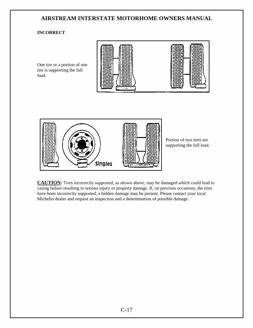
AIRSTREAM INTERSTATE MOTORHOME OWNERS MANUAL
C-17
INCORRECT One tire or a portion of one tire is supporting the full load.
Portion of two tires are supporting the full load.
CAUTION: Tires incorrectly supported, as shown above, may be damaged which could lead to casing failure resulting in serious injury or property damage. If, on previous occasions, the tires have been incorrectly supported, a hidden damage may be present. Please contact your local Michelin dealer and request an inspection and a determination of possible damage.

AIRSTREAM INTERSTATE MOTORHOME OWNERS MANUAL
D-1
CAMPING SAFETY Emergency Exit There are three avenues of escape from the motorhome in the event of an emergency, the driver’s and passenger doors, and the side cargo door. As always, safety should be one of your top priorities. Make sure you, and everyone traveling with you, can operate these doors and exit rapidly without light. A little planning and a quick practice session at each camping site are well worth the time it may take.
Warning: At each campsite make sure you have not parked in such a manner as to block the operation of the doors or the escape avenues by being too close to trees, fences or other impediments. Scenic views are one reason for traveling, but don't park so the beautiful lake or steep cliff is just outside your doors. Do not block access to the doors from the inside or outside of the vehicle.
Warning: Read the directions carefully on the fire extinguisher. If there is ally doubt on the operation, you and your family should practice, then replace or recharge the extinguisher. You will find your local fire department will be happy to assist you and answer any questions.
Warning: DON'T SMOKE IN BED! KEEP MATCHES OUT OF REACH OF SMALL CHILDREN! DON'T CLEAN WITH FLAMMABLE MATERIAL! KEEP FLAMMABLE MATERIAL AWAY FROM OPEN FLAME!
We have all heard these warnings many times, but they are still among the leading causes of fires. Other safety information on the LPG system of your motorhome is located in the Plumbing Section of this manual. SMOKE ALARM OPERATION, TESTING OPERATION: The smoke detector is operating once a fresh battery is installed and testing is complete. When products of combustion are sensed, the unit sounds a loud 85 db pulsating alarm until the air is cleared. HUSH CONTROL: The "HUSH” feature has the capability of temporarily desensitizing the alarm circuit for approximately 7 minutes. This feature is to be used only when a known alarm condition, such as smoke from cooking, activates the alarm. The smoke detector is desensitized by pushing the "HUSH" button on the smoke detector cover. If the smoke is not too dense, the alarm will silence immediately and "Chirp" every 30-40 seconds for approximately 7 minutes. This indicates that the alarm is in a temporarily desensitized condition. The smoke alarm will automatically reset after approximately 7 minutes and sound the alarm if particles of combustion are still present. The "HUSH” feature can be used repeatedly until the air has been cleared of the condition causing the alarm. NOTE: DENSE SMOKE WILL OVERRIDE THE HUSH CONTROL FEATURE AND SOUND A CONTINUOUS ALARM.

AIRSTREAM INTERSTATE MOTORHOME OWNERS MANUAL
D-2
CAUTION: BEFORE USING THE ALARM HUSH FEATURE, IDENTIFY THE SOURCE OF THE SMOKE AND BE CERTAIN A SAFE CONDITION EXISTS. FLASHING L.E.D. LIGHT: This smoke detector is equipped with a flashing red indicator light. The light is located under the test button and will flash every 30-40 seconds to indicate that the smoke detector is receiving power. TESTING: Test by pushing the test button on the cover and holding it down for a minimum of 2 seconds. This will sound the alarm if all the electronic circuitry, horn and battery are working. If no alarm sounds the unit has defective batteries or other failure. You can also test the alarm by blowing smoke into it. TEST THE ALARM WEEKLY TO ENSURE PROPER OPERATION. Erratic or low sound coming from your alarm may indicate a defective detector, and it should be returned for service. FALSE ALARMS Smoke detectors are designed to minimize false alarms. Cigarette smoke will not normally set off the alarm, unless the smoke is blown directly into the detector. Combustion particles from cooking may set off the alarm if the detector is located close to the cooking area. Large quantities of combustible particles are generated from spills or when broiling. Using the fan on a range hood which vents to the outside (non-recirculating type) will also help remove these combustible products from the kitchen. MODEL 0916 HAS A "HUSH" CONTROL that is extremely useful in a kitchen area or other areas prone to nuisance alarms. For more information refer to OPERATION AND TESTING. If the detector does alarm, check for fires first. If a fire is discovered, get out and call the fire department. If no fire is present, check to see if other reasons may have caused the alarm. MAINTENANCE BATTERY REPLACEMENT To replace-the battery remove the detector from the mounting plate by rotating the detector in the direction of the "OFF" arrow on the cover. The Model 0916 Smoke Detector uses one (1) 9-volt battery. The SMOKE DETECTOR is powered by a 9V carbon zinc battery (alkaline battery may also be used). A fresh battery should last for one year under normal operating condition. This detector has a low battery monitor circuit that will cause the detector to "chirp" approximately every 30-40 seconds for a minimum of seven (7) days when the battery gets low. Replace the battery when this condition occurs. USE ONLY THE FOLLOWING 9 VOLT BATTERIES FOR SMOKE DETECTOR REPLACEMENT Carbon-zinc type: EVEREADY 216 OR 1222, GOLD PEAK 1604P OR 1604S Alkaline type: EVEREADY 522; DURACELL MN 1604, Gold Peak 1604A Lithium type: ULTRALIFE U9VL. NOTE: REGULAR TESTING IS RECOMMENDED.
WARNING USE ONLY THE BATTERIES SPECIFIED. USE OF DIFFERENT BATTERIES MAY HAVE A DETRIMENTAL EFFECT ON THE SMOKE DETECTOR. NOTE: IF AFTER BATTERY REPLACEMENT, THE UNIT CONTINUES TO CHIRP, WAIT FOR APPROXIMATELY 7 MINUTES. THE "HUSH" FEATURE MAY HAVE BEEN ACTIVATED ACCIDENTALLY WHILE CHANGING THE BATTERIES AND WILL RESET AUTOMATICALLY

AIRSTREAM INTERSTATE MOTORHOME OWNERS MANUAL
D-3
CLEANING YOUR DETECTOR: To clean your detector remove it from the mounting bracket as outlined in the beginning of this section. You can clean the interior of your detector (sensing chamber) by using your vacuum cleaner hose and vacuuming through the openings around the perimeter of the detector.
The outside of the detector can be wiped with a damp cloth.
AFTER CLEANING, REINSTALL YOUR DETECTOR. TEST YOUR DETECTOR BY USING THE TEST BUTTON.
LIMITATIONS OF SMOKE ALARMS:
WARNING Smoke detectors are devices that can provide early warning of possible fires at a reasonable cost; however, detectors have sensing limitations. Ionization type detectors offer a broad range of fire sensing capability but are better at detecting fast flaming fires than slow smoldering fires. Photoelectric detectors sense smoldering fires better than flaming fires. Home fires develop in different ways and are often unpredictable. Neither type of detector (photoelectric or ionization) is always best, and a given detector may not always provide warning of a fire. In addition, smoke detectors do have limitations. For a battery powered detector the battery must be of the specified type, in good condition, and installed properly. AC powered detectors will not operate if AC power has been cut off such as by an electrical fire or an open fuse. Smoke detectors must be tested regularly to make sure the batteries and the detector circuits are in good operating condition. Smoke detectors cannot provide an alarm if smoke does not reach the detector. Therefore, smoke detectors may not sense fires starting in chimneys, walls, on roofs, on the other side of a closed door or on a different floor. If the detector is located outside the bedroom or on a different floor, it may not wake up a sound sleeper. The use of alcohol or drugs may also impair ones ability to hear the smoke alarm. For maximum protection a smoke detector should be installed in each sleeping area on every level of a home. Although smoke detectors can help save lives by providing an early warning of a fire, they are not a substitute for an insurance policy. Homeowners and renters should have adequate insurance to protect their lives and property. GOOD SAFETY HABITS DEVELOP AND PRACTICE A PLAN OF ESCAPE:
• Make a floor plan indicating all doors used as escape routes from the motorhome. • Have a family meeting and discuss your escape plan, showing everyone what to do in case of fire. • Determine a place outside your home where you all can meet if a fire occurs. • Familiarize everyone with the sound of the Smoke Alarm and train him or her to leave your
motorhome when they hear it. • Practice a fire drill at least every six months or when ever new guests are with you. Practice allows
you to test your plan before an emergency; you may not be able to reach your children. It is important they know what to do.
AIRSTREAM INTERSTATE MOTORHOME OWNERS MANUAL
D-4
WHAT TO DO WHEN THE ALARM SOUNDS:
• Leave immediately by your escape plan. Every second counts, so don't waste time getting dressed or picking up valuables.
• In leaving, don't open any inside door without first feeling its surface. If hot, or if you see smoke seeping through cracks, don't open that door! Instead use your alternate exit. If the inside of the door is cool, place your shoulder against it, open it slightly and be ready to slam it shut if heat and smoke rush in.
• Stay close to the floor if the air is smoky. Breathe shallowly through a cloth, wet if possible. • Once outside go to your selected meeting place and make sure everyone is there. • Call the fire department from your neighbor’s home - not from yours! • Don't return to your home until the fire officials say that it is all right to do so.
There are situations where a smoke detector may not be effective to protect against fire as stated in the NFPA standards 72. For instance: a) Smoking in bed; b) Leaving children home alone. c) Cleaning with flammable liquids, such as gasoline. Further information on fire safety can be obtained in a pamphlet titled "IN A FIRE SECONDS COUNT" published by the NFPA, Batterymarch Park, Quincy, Mass. 02269. SERVICE AND WARRANTY If after reviewing this manual you feel that your smoke alarm is defective in any way, do not tamper with the unit. Return it for servicing to: FYRNETICS, INC., 1055 STEVENSON CT./STE 102W, ROSELLE, IL 60172. (See Warranty for in-warranty returns). CARBON MONOXIDE ALARM The following information is highlights from the folder provided by the alarm manufacturer. The folder, with more detailed information, is contained in your Owners' Packet. Test detector immediately following installation and weekly for proper operation by pushing the test button until the YELLOW L.E.D. lights and a short beep is heard (approximately three seconds). Release the button. The detector will then test itself for proper operation. At completion of the self-test, the alarm will sound and both L.E.D.s will light for 3/4 of a second. The detector then resumes normal operation. NORMAL OPERATION In normal operation the detector will flash the RED L.E.D. once every 30 seconds. WARNING CONDITION If the COSTAR senses a low level of CO The YELLOW L.E.D. will light and the detector will beep every three seconds warning that CO is present. The area should immediately be ventilated. A concentration of 60 PPM within 67 minutes will cause the warning condition. Pushing the test button will silence the warning signal but the YELLOW L.E.D. will stay on. After two hours the warning signal will sound again if the CO source has not been eliminated. If the condition persists there is a possibility that it may cause the unit to enter alarm condition (below). If this occurs pushing the reset button will silence the alarm for 30 minutes.

AIRSTREAM INTERSTATE MOTORHOME OWNERS MANUAL
D-5
ALARM CONDITION If the COSTAR senses unsafe levels of CO, the RED L.E.D. will light up and the alarm will sound. The alarm condition will be signified by a repetitive alarm-sounding pattern of approximately 4.5 seconds on 1.5 second off. Immediate evacuation is required. Pushing the test button will silence the alarm once for approximately 4 minutes. After approximately 4 minutes the alarm will once again sound until the unsafe CO concentration is removed. FAULT CONDITION Periodically the detector's measurement circuit is tested. If an error is detected, the detector will sound twice and the YELLOW L.E.D. will flash twice every 30 seconds. This is an indication of circuit malfunction and that the detector requires immediate servicing. MAINTENANCE Battery Replacement: If tamper resistant pin has been used, refer to "tamper resistant locking pin" for removal instructions. To replace the battery remove the detector from the mounting plate by rotating the detector in the direction of the "OFF" arrow on the cover. The Model 9L-1 CO Detector uses one (1) 9-volt battery. The CO DETECTOR is powered by a 9V alkaline battery. A fresh battery should last for one year under normal operating conditions. This detector has a low battery monitor circuit which will cause the detector to "chirp" and the red LED to flash approximately every 30-40 seconds for a minimum of seven (7) days when the battery gets low. Replace the battery when this condition occurs. USE ONLY THE FOLLOWING 9 VOLT BATTERIES FOR CO DETECTOR REPLACEMENT.
Alkaline type: EVEREADY522; DURACELL MN1604; GOLD PEAK 1604A Lithium type: ULTRALIFE U9VL
NOTE: REGULAR TESTING IS RECOMMENDED.
Warning: USE ONLY THE BATTERIES SPECIFIED. USE OF DIFFERENT BATTERIES MAY HAVE A DETRIMENTAL EFFECT ON THE CO DETECTOR. CLEANING YOUR DETECTOR:
To clean your detector remove it from the mounting bracket as outlined in the beginning of this section. You can clean the interior of your detector by using your vacuum cleaner hose and vacuuming through the openings around the perimeter of the detector. The outside can be wiped with a damp cloth.
AFTER CLEANING, REINSTALL YOUR DETECTOR. TEST YOUR DETECTOR BY USING THE TEST BUTTON.
Test detector weekly for proper operation by pushing the test button until the YELLOW L.E.D. lights and a short beep is heard (approximately three seconds). Release the button. The detector will then test itself for proper operation. At completion of the self-test, the alarm will sound and both L.E.D.s will light for 3/4 of a second. The detector then resumes normal operation.

AIRSTREAM INTERSTATE MOTORHOME OWNERS MANUAL
D-6
SERVICE AND WARRANTY If after reviewing this manual you feel that your CO Detector is defective in any way, do not tamper with the unit. Return it for servicing to: Quantum Group, Inc., 11211 Sorrento Valley Road, Suite Valley Road, Suite V. San Diego, CA 92121.
Or call us toll free (800) 432-5599 E-mail address: [email protected]
LP GAS DETECTOR In the kitchen area of your unit, approximately six inches above the floor, is the LP gas detector. LP gas is a mixture of gases produced and sold commercially as a fuel for heating and cooking appliances. LP gas is highly flammable and, as a result, can be explosive if ignited under certain circumstances. LP gas is heavier than air and, if confined in a closed space, will accumulate close to the floor. When the LP gas concentration in your unit exceeds 2000 PPM the detector will provide a visual and audible alarm by sounding a buzzer and flashing the red LED two times per second.
Warning: Activation of this detector indicates the presence of LP gas, which can cause an explosion and/or fire. This normally indicates a leak in the LP gas installation or a LP gas appliance. Extinguish all open flames, open your windows and door and evacuate the unit immediately. Do not activate any electrical switch. Turn off the LP at your gas bottle(s). DO NOT RE-ENTER YOUR UNIT UNTIL A QUALIFIED REPAIR TECHNICIAN HAS CORRECTED THE PROBLEM. OPERATION Your LP gas detector is wired directly to your vehicle battery and incorporates a 1-amp in-line fuse. When the device is operating normally the green LED will be lit. CAUTION: It is not recommended that the detector be disconnected from the battery during periods of storage. There is a small heater on the sensor of the device, which "burns" away impurities in the air during periods of normal use. During periods when power is interrupted, impurities can build up on the sensor. When power is returned to the detector the detector alarm may activate until the impurities are "burned" off. This could take a number of hours, during which time the alarm will be constantly "on". DETECTOR TEST Press the test button for 5 to 6 seconds until the alarm sounds then release the test button. The red LED should flash and the alarm sound for approximately 4 minutes. This test should be performed at least once a week during normal vehicle operation, and after periods of storage, and before each trip. LOW VOLTAGE Below 10 VDC the detector will continue to operate but will blink alternately green and orange. Below 8 VDC the unit will behave erratically and will eventually shut off. To ensure proper operation, do not operate the unit below 10 VDC. COMPONENT FAILURE The failure of any circuit component will cause the detector to display a continuous orange LED fault light and a short beep indicating failure. If this occurs, immediately contact your dealer or Airstream Customer Service for the name of the nearest detector service center. Please read the operating instructions for your detector, which have been supplied with the paper work of your unit.
Warning: Have a professional technician check all safety related systems yearly or whenever any doubts of their ability to function properly arise.

AIRSTREAM INTERSTATE MOTORHOME OWNERS MANUAL
D-7
OVERNIGHT STOP In time you will develop a knack for spotting wonderful little roadside locations by turning off the main highway and exploring. There are many modern recreational vehicle parks, including State, County and Federal parks with good facilities, where you may obtain hookups of electrical, water and sewer connections. Directories are published which describe in detail these parks and tell what is available in the way of services and hookups.
All you need to do to enjoy the self-contained luxury is to:
1. Turn on LP gas supply and light appliance pilots if required.
2. Turn on water pump and open faucets until air is expelled from the system.
Before moving on, turn off the LP gas and water pump, lower your TV antenna. Check your campsite, both for cleanliness and also to be sure you haven't left anything behind. Make sure everything is properly stowed. Overnight or Weekend Trips On overnight or weekend trips, chances are you will not use up the capacity of the holding tank, deplete the water supply, or run down the battery which supply the living area 12 volt current. Longer Trip On a longer trip, when you have stayed where sewer connections and utility hookups were not available, it will be necessary for you to stop from time to time to dispose of the waste in the holding tank and replenish the water supply. Many gas stations (chain and individually owned) have installed sanitary dumping stations for just this purpose. Booklets are available which list these dumping stations. When you stop for the night, your Airstream motorhome is built to be safely parked in any spot that is relatively level and where the ground is firm. Your facilities are with you. You are self- contained. Try to pick as level a parking spot as possible. WINTER TRAVELING Traveling in your motorhome during the cold winter months can be a most exhilarating experience. There are, of course, certain precautions that must be taken as you would in your home in low temperatures. The Interstate motorhome has 12-Volt heat pad installed with the gray/black combination-holding tank. This pad is individually switched with the switch located next to the monitor panel. To conserve battery power, RV antifreeze may be used to protect the gray/black tank. Battery power will last about 6 hours unless the unit is plugged into a 110-volt shoreline source to operate the converter/battery charger.
Warning: Always shut off the LP gas when gasoline is added to the fuel tank.

AIRSTREAM INTERSTATE MOTORHOME OWNERS MANUAL
D-8
Some states do not allow LPG to be turned on while moving. While traveling in these states you must use your common sense. How cold is it? How long will it be before you can turn the heat back on? Is the temperature dropping or rising? Remember, the wind chill factor when driving 50 MPH will cause the interior of the motorhome to cool much faster than when it is parked. 1.You must have a plentiful supply of propane gas as the heat from the furnace warms the motorhome and keeps the fresh water lines and tank from freezing. 2.If your stay is longer than overnight, you should endeavor to have 120-volt electricity available. The house battery, fully charged, will not last more than about 15 hours in freezing weather, less with use of the holding tank heating pad. Of course, you can run your generator to recharge the battery, or even use the generator continually. Since the generator starts off the house battery, it is recommended to start the generator prior to running the battery down. 3. Minimize use of electricity if 120-volt power source is not available. 4. Leave cabinet doors, wet bath doors and wardrobe doors slightly open at night to allow circulation of air in and around all components 5. Use propylene glycol type antifreeze in wastewater tank to prevent freezing. Quantity of antifreeze needed will vary with ambient temperature and the amount of liquids in tank. 6. For extended stays in cold weather, insulate the water line outside the motorhome. You should remember that low temperatures in combination with high winds cause an equivalent chill temperature much below what your thermometer is reading. For instance, with an outside temperature of zero degrees, and the wind velocity of 10 miles per hour, the equivalent chill temperature is minus 20° F. The exterior water faucet has an in-line valve inside the motorhome. In below freezing temperatures, shut off the valve inside and open the exterior brass valve so it will drain. See the valve section in this book for locations. Condensation It is also important to guard against excessive humidity inside your motorhome during winter campouts. When windows and window frames fog up or "sweat," it means that there is too much moisture in the air. Moisture comes from water vapor and water vapor is the direct result of water evaporating. Many things such as baths and showers, boiling foods, washing dishes, washing clothes, even breathing, contribute to evaporation. The inside air can only absorb so much of this moisture before it becomes saturated. At this point it can hold no more, and any additional water vapor condenses back to liquid water in the form of droplets on any available cool, solid surface. Temperature has a direct effect on the airs saturation point. Cold air holds less moisture than warm air. For this reason, the air immediately adjacent to cold outside walls and windows cools down and causes water vapor to condense and form moisture droplets, even though warmer inside surfaces are still dry. The best way to keep condensation under control is to reduce moisture-producing activities. It is important to provide adequate ventilation and keep the air circulating as much as possible. Use your exhaust fans to remove moisture before water vapor mixes with the air. Open windows slightly once in a while, while operating fans, to bring in drier outside air and aid in overall air circulation. In extremely cold weather, when outside ventilation is not practical, it may be necessary .to use a small dehumidifier to aid in reducing condensation. There is no substitute for common sense in cold weather. Note: The Airstream motorhome is built as a recreational vehicle and is not intended as a permanent dwelling or for more than temporary use in sub-freezing temperatures.

AIRSTREAM INTERSTATE MOTORHOME OWNERS MANUAL
D-9
EXTENDED STAY Making a long trip is not very different from making a weekend excursion. Since everything you need is right at hand, you are at home wherever you go. When packing for an extended trip, take everything you need, but only what you need. When you plan to stay in the same place for several days, weeks or months, you will want your motorhome to be as level as possible. Check the attitude with a small spirit level set on the inside work counter. If a correction is necessary, then you must first level from side to side. This can be done most easily by driving up a small ramp consisting of 2" x 6" boards tapered at both ends. WE DO NOT RECOMMEND PLACING TIRES IN A HOLE FOR LEVELING. Check the tire section of the chassis portion of this manual for information on tire support. Hook Up to Water by attaching a ½ " minimum high-pressure water hose to the city water service. Plug the Electrical Cable into the City Power Service. Be sure you have the wire grounded and have the proper polarity. See Electrical Section for technical details. A Cable/Satellite TV /Telephone Hookup is located on the outside of the motorhome. It is already wired into the existing system, so the exterior connection is all that is required. To use the Generator you simply start it. All switching is done automatically. The generator can be started from the switch above the galley. It is easier on your generator and appliances if you'll allow the generator to reach its normal operating speed (about a minute) prior to applying heavy current loads. Hook your Waste Drain Hose into the Sewer Disposal Facility and attach to the drain outlet in your motorhome. For details on this procedure see Drain and Waste System Section. Turn on the gas supply. Lighting a top range burner to bleed any air from the system will make it easier to start other appliances. When you stay for extended periods where electric or water hookups are not available, you must make regular checks on the condition of your 12-volt battery and the contents of your water tank. Carry drinking water in a clean bucket to refill your tank. When your waste tank nears capacity, move your motorhome to a dumping location.
AIRSTREAM INTERSTATE MOTORHOME OWNERS MANUAL
E-1
EXTERIOR The exterior of your Airstream Interstate motorhome has been painted by Carrera Designs, a company specializing in custom recreational vehicles, with a Sherwin-Williams automotive finish. Carrera Design provides samples of the paint for minor repairs and a use and care brochure with each motorhome as it leaves their facility. The brochure has a paint code sticker containing paint information. This information comes from Carrera Designs Used and Care Brochure. Following these procedures can provide a long lasting, high-gloss finish for your recreational vehicle. These same procedures can also be applied to your everyday automobile, producing the same long-lasting results. Waxes and Polishes Over 90 percent of all automotive finishes are clear coat. The finish on your RV is a state-of-the-art Acrylic Urethane Basecoat/ClearCoat. This means that what you will wash and polish is a clear urethane coating designed to protect the basecoat: the pigmented coating that provides color. As its main function of protecting the basecoat, clearcoats need to be maintained especially in harsh environments. Clearcoats do not fade themselves, but appear to fade or lose gloss as the surface becomes contaminated by the environment. If this contamination is not removed frequently, results will be a dull or low gloss finish. Occasional washing alone will not adequately remove some forms of contamination and will require polishing. Polishes and waxes primarily served the following purposes:
1. To remove minor surface imperfections caused by water spots and acid rain. 2. To remove minor scratches by filling them and leveling the surface. 3. To beautify the paint finish appearances with more depth and high-gloss. 4. To protect the paint finish from the elements.
Do not use products that contain harsh abrasives such as rubbing or polishing compounds. These products should be used by experienced technicians with the proper training and equipment. Most polishes and waxes are designed to clean and polish in one application whether by hand or machine. A machine applied polish will last longer than one applied by hand because the high rpm buffing will create heat, resulting in a deeper wax film with higher gloss. However, a hand applied polish or wax will offer outstanding performance and protect the RVs finish. When applying polish or wax, do so in a shaded area making sure the RV surface is at the specified temperature according to the polish manufacturers recommendations. Due to the variations of polishes and waxes, incorporate the following suggestions into the polishing technique:
1. Condition the polishing pad by rubbing a slight amount of polish on it. 2. Use only the amount of polish specified in the label directions. 3. Work a small area at a time. 4. Rinse off and remove dried polish from crevices, trim and moldings.
For more information, call 574 -- 295 -- 7907.
AIRSTREAM INTERSTATE MOTORHOME OWNERS MANUAL
E-2
How to Care for Your RV Finish Keeping your RV looking its best at all times involves keeping the paint finish clean and in good condition. This means periodic washing and polishing, as well as getting the paint finish repaired as soon as possible when the paint is damage or affected in anyway. The purpose of the paint finish is twofold: (1) Provide an aesthetically pleasing appearance. (2) To protect the vehicle from the environment. Your RV is exposed to many environmental conditions that have an adverse effect on the paint finish:
1. ROAD SALTS AND SODIUM CHLORIDE 2. ROAD TAR/BUGS 3. BIRD DROPPINGS/TREE SAP 4. INDUSTRIAL FALLOUT/ACID RAIN/POLLUTION 5. ULTRAVIOLET EXPOSURE AND MOISTURE
The most common problems resulting from these conditions are corrosion, staining and chemical spotting. These problems can be minimized through regularly scheduled washing and polishing. Washing your RV: Make sure the RVs surface temperature is not too hot, under 90 degrees Fahrenheit, and not in direct sunlight. A shady area is ideal for washing your vehicle as direct sunlight causes water and soap to evaporate too fast, resulting in water spotting. Use a mild soap or detergent. Most auto care stores carry a car wash shampoo. Try to avoid combination wash-n-wax products as these waxes cause buildup and are designed for smaller surfaces. Have two dedicated sponges or wax mitts: one for the paint finish and one for the wheels and under carriage. Brushes or wash mitts that have plastic bristles are acceptable for use on tires and wheel wells, but are not intended for use on the paint finish. Avoid using such items on painted surfaces, as they will damage the RV paint and finish. Wash the wheels and wheel wells first as this removes heavy dirt and debris and prevents it from splattering on already clean panels. Wet the entire area down to remove loose dirt and grime, hand wash one area at time using your dedicated paint finish sponge or wash mitt. Wash from the top and work your way down, frequently rinsing the rinsing to minimize grit abrasion. Follow with a final rinse of water. If This process will remove most contamination from the RVs surface. For stubborn stains such as road tar, use an ammonia based glass cleaner or a small amount of rubbing alcohol on a damp cloth immediately followed by warm soapy water and rinse with clean water. This may not dissolve the road tar, but will loosen tar and bugs stains and remove them from the surface. Do not use solvent based cleaners on bird droppings or tree sap as these are water-based stains and will eventually dissolve using an ammonia based glass cleaner, warm soapy water and a little "elbow grease". Once again, after removing stubborn stains immediately rinse with clean water. Drying the RV is just as important as washing your vehicle as today’s tap water and well water contain many chemicals that could water stain your RVs finish. We suggest using a damp natural or synthetic chamois, however, there are other drying products such as lint free micro-fiber towels that work just as well.
AIRSTREAM INTERSTATE MOTORHOME OWNERS MANUAL
E-3
PRECAUTIONS Careful maintenance for the first 60 days after the paint and clear coat are applied will ensure a long-lasting durable finish. Do not wax or polish for the first 60 days. First 30 days PARKING: Avoid parking under trees or near ocean salt spray. Ice or snow should not be scraped from the painted service: BRUSH OFF! If a motorhome sets more than 24 hours, remove any protective covering (bra) while not being driven. First 30 days WASHING: Commercial washes should be avoided. Wash with cold water using a mild liquid soap. Dry wiping with a drying cloth is not recommended. First 30 days DRIVING: Gravel roads should be avoided. Antifreeze, gasoline or window solvents, if spilled on the painted service should be rinse off with water immediately. Bugs or bird droppings should be rinsed off with water daily.
Follow the simple cautionary measures, and your new finish will give you maximum gloss and durability.
Carrera Designs 1101 Herman Street, Elkhart, Indiana 46516 Phone: 574-295-7907 Facsimile: 574-295-1547 www.carreradesigns.com It is recommended that the caulking and sealant used in external seams and joints such as window frames, light bezels, beltline and rub-rail molding, etc., be checked regularly. If this material has dried out and becomes cracked or checked, or if a portion has fallen out, it should be replaced with fresh material to prevent possible rain leaks. Caulking and sealing material is available from your motorhome dealer and most RV supply stores.

AIRSTREAM INTERSTATE MOTORHOME OWNERS MANUAL
E-4
Roadside Exterior
NOTE: This is a basic explanation of the location and function of exterior features. More in depth explanations of certain feature’s care and maintenance is include in this manual in other sections.
1. City Water Hook-up provides access for city water to your fresh water system. Use ½” minimum hose for water supply.
2. Refrigerator exterior access door and vent provides access to the refrigerator for service and supplies air for the cooling process. Blocking the airflow will affect the operation of your refrigerator.
3. LP Fill Door accesses the remote fill for LP gas. 4. Electric Dump Valve Switch is located on the shower panel inside the rear cargo doors.
Push and hold the switch to open the holding tank dump valve. 5. Fiberglass Running Boards and fender skirts are installed by Airstream. 6. Refrigerator exhaust vent draws air from the refrigerator access door vent across the
refrigerator-cooling unit. Please keep free from obstructions. All vents should be cleaned regularly by a qualified service technician.
7. Radio Antenna, rubber, for living quarters entertainment center. Sprinter has another antenna for the dash unit.
8. Fantastic Roof Vent, exhaust only, complete operating instructions are in the appliance section of this manual. Keep all vents clear to encourage airflow.
9. Roof rack is designed limited use. 100 lbs maximum. All vents must remain clear. 10. Furnace exhaust vent should be cleaned regularly. When operating furnace, be sure
exhaust can escape into a well-ventilated area. Air coming from vent can be hot, when parking the motorhome be sure to have proper clearance in venting area.
11. Sewer Hose Storage contains a sewer hose and connector for the holding tank dump valve.
12. 110 Volt Power Cord Inlet, 30-amp service is required, power cord is stored inside rear cargo doors in a plastic storage compartment.
13. Cable/Satellite TV/Telephone Jack is a weatherproof module pre-wired for cable TV and telephone reception. A portable satellite dish can also be used in the cable connection.
14. Holding Tank Outlet w/Electric Dump Valve is to drain gray/black combination tank. Remove sewer hose from storage compartment, uncap valve outlet, hook hose connector to dump valve bayonet ring. Be sure end of hose is inserted into sewage tank and push/hold remote switch located inside the rear cargo doors.

AIRSTREAM INTERSTATE MOTORHOME OWNERS MANUAL
E-5
Curbside Exterior Features
NOTE: This is a basic explanation of the location and function of exterior features. More in depth explanations of certain feature’s care and maintenance is include in this manual in other sections.
1. Water Fill w/Lock is used to fill the fresh water tank. Use only clean fresh potable
water. 2. Exterior Shower can be used on the water pump or with the city water hook up.
3. Porch Light is switched just inside the side cargo door. 4. Electronic Ignition Water Heater Door and Vent is part of the plumbing system. The
intake vent, drain plug and exhaust vent are located inside this door. Regular maintenance by a qualified service technician is required to keep the water heater operating efficiently.
5. Patio Awning operating and care instructions are including in another section of this
manual. 6. TV Outlet/12 Volt Outlet provides reception for an exterior television. It is pre-wired
and integrated into the Cable TV/Satellite TV system. There is also a 12 Volt cigarette-style outlet for a 12 volt operated television.
7. Power Boosted TV Antenna is wired into TV outlets on exterior of coach and inside unit
at entertainment center cabinet.
8. Holding Tank Vent provides a vent for the black/gray combination tank.
9. Exterior 110 Volt Outlet provides an exterior GFI protected electrical source.
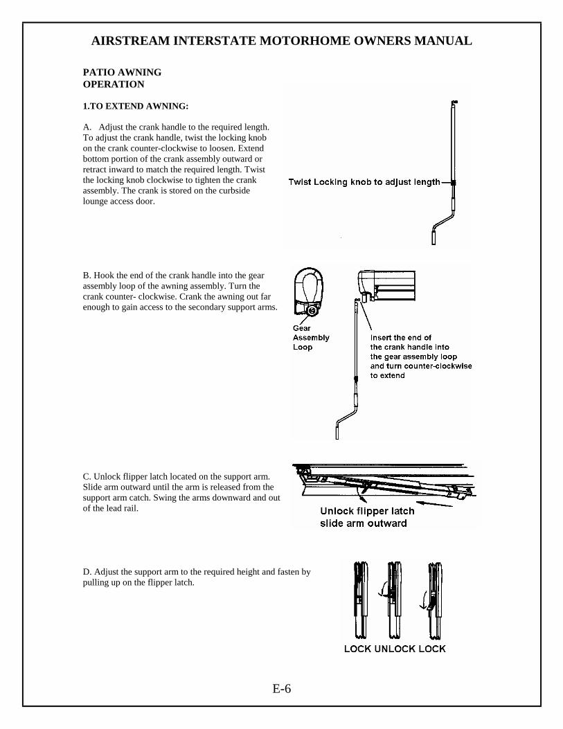
AIRSTREAM INTERSTATE MOTORHOME OWNERS MANUAL
E-6
PATIO AWNING OPERATION 1.TO EXTEND AWNING: A. Adjust the crank handle to the required length. To adjust the crank handle, twist the locking knob on the crank counter-clockwise to loosen. Extend bottom portion of the crank assembly outward or retract inward to match the required length. Twist the locking knob clockwise to tighten the crank assembly. The crank is stored on the curbside lounge access door. B. Hook the end of the crank handle into the gear assembly loop of the awning assembly. Turn the crank counter- clockwise. Crank the awning out far enough to gain access to the secondary support arms. C. Unlock flipper latch located on the support arm. Slide arm outward until the arm is released from the support arm catch. Swing the arms downward and out of the lead rail. D. Adjust the support arm to the required height and fasten by pulling up on the flipper latch.

AIRSTREAM INTERSTATE MOTORHOME OWNERS MANUAL
E-7
E. Unroll the awning completely moving the support arms each time when necessary. F. To use the carport position, drive ground stakes through the holes in the carport foot and into the ground for support. CAUTION. GROUND STAKES WILL NOT PREVENT THE AWNING FROM MOVING IN THE WIND! G. To use the bottom brackets, swing each arm toward the vehicle, lift the bracket pin and position foot into bracket and then release the pin. H. Turn crank until awning is all of the way out. Turn the crank back a partial turn to backwind the awning slightly. This tightens the fabric. 2.TO RETRACT AWNING: A. Remove the support arms from the bottom bracket, or remove the ground stake if in the carport position. B. Slide the support arms together and pivot them into the lead-rail for storage by reversing Step 1C on the previous page. C. Hook the end of the crank handle into the crank loop of the awning assembly. (Right) Roll fabric up by turning the crank handle clockwise, or opposite of what was done to extend the awning. Roll awning up until the lead rail is completely retracted into the case. CAUTION: THE FABRIC MUST ROLL UNDERNEATH THE ROLLER TUBE! ROLLING THE FABRIC OVER THE ROLLER TUBE WILL BLOCK THE GEAR BOX FROM PROPERLY RETRACTING! 3.AWNING USE IN WIND AND RAIN. To prevent water build up on the awning, position one upper arm substantially lower than the other to create enough of a slope for adequate water run off. NOTE: IF WIND OR EXTENDED PERIODS OF RAIN ARE EXPECTED, ROLL UP THE AWNING AND SECURE FOR TRAVEL! CAUTION: THE EFFECTS OF WIND AND RAIN ON ANY AWNING ARE UNPREDICTABLE. SEVER DAMAGE TO THE VEHICLE AND OR THE AWNING MA Y RESULT AND CANNOT BE COVERED BY WARRANTY!
AIRSTREAM INTERSTATE MOTORHOME OWNERS MANUAL
E-8
CARE AND MAINTENANCE 1. CARE OF FABRIC A. VINYL FABRIC. Mildew will not form on the awning material itself, but may form on the dust allowed to accumulate on the canopy. A mild detergent (soap & water) will keep your awning looking new. Once cleaned make sure the awning is rinsed thoroughly and is dried before storing. DO NOT USE BLEACH! B. ACRYLIC FABRIC. A mild detergent (soap &water) should be used to clean the acrylic canopy. Rinse thoroughly and allow the canopy to be dried before rolling up the awning.
CAUTION. DO NOT USE BLEACH, CAUSTIC CLEANERS OR METAL CLEANERS ON ACRYLIC AS THEY WILL CA USE PERMANENT DAMAGE TO FABRIC!
2. PERIODIC MAINTENANCE Like any other part of the RV, an owner should periodically inspect the awning. The following items should be checked. A. All mounting brackets are tight. B. Check all pivot points for enlargements of holes or broken rivets. C. Check end caps for cracking, splitting. D. Check that awning rail is tight against coach and all screws are tight. E. Check canopy for loose stitching and possible shrinkage or puckering.

AIRSTREAM INTERSTATE MOTORHOME OWNERS MANUAL
F-1
INTERIOR The interior of your Airstream motorhome has been designed to take a limited amount of space and provide you with all the comfort, convenience, durability and appearance possible. An understanding of the operational procedures and maintenance techniques of the interior appointments will add to your pleasures, as well as to the long life of your motorhome. Lounges To convert the lounges into a bed, grasp the front edge of the seat, pull straight up and pull it toward the aisle of the motorhome. The backrest will slide down into place automatically. Extending both sofas form a double bed. Dinette The pedestal table is stored under the passenger side lounge on a shelf. Open the aisle door for access. Insert the two stands into the top and then the insert the table into the pedestal braces in the aisle way. Vinyl Floor The vinyl floor in your unit can be cleaned with liquid floor cleaning solutions recommended for vinyl floors and warm water. CAUTION: Warn occupants of the vehicle when fresh wax has been applied, just like a home, the floor will be slippery. Cabinets/Overhead Lockers/Counter areas The furniture is manufactured from of a high-pressure laminate and can be cleaned with soap and water, or you can use a common solvent on tough spots. Furniture polish can be used sparingly. The glass doors on the entertainment center must be cleaned with an anti-static cleaner and cloth. Windex or common ammonia products will damage the coating on the surface. CAUTION: Do not use any abrasive material. Abrasive cleaners, cloths and pads should not be used, as there is the possibility it could scratch the surface. A protective pad should always be placed under hot utensils. Wet Bath To clean your ULTRA/GLAS shower stall unit, use warm water and one of the stronger liquid detergents. Do not use abrasive cleaners; they may scratch and dull the surface of your ULTRA/GLAS unit. Stubborn stains can be removed with solvents such as turpentine, paint thinner or acetone. Restore dulled areas by rubbing with an automotive-type liquid cleaner, and then put the soft glow back into your ULTRA/GLAS unit with a light application of liquid wax.
AIRSTREAM INTERSTATE MOTORHOME OWNERS MANUAL
F-2
INTERIOR (cont) Sink Cleaning can be accomplished using mild liquid detergent with a soft cloth. Rinse carefully and dry. Silver polish will leave spots that cannot be removed. A complete Home Owners Guide for your sinks is supplied in your Owner’s Folder. Please read these instructions before use. Metal Interior Skin The metal interior skin is coated with a baked on acrylic coating. Use soft rags or wash mitts always moving lengthwise with the grain of the aluminum. NEVER rub hard on the coating. Oil, grease, dust and dirt may be removed by washing with a 5% solution in water of commonly used commercial and industrial detergents. Cleaning should be followed by a thorough clean water rinse. Drying the metal with a chamois or a soft cloth may prevent spots and streaks. WHEN WASHING OR WAXING THE METAL, ALWAYS WIPE "WITH" THE GRAIN OF THE METAL. After cleaning and drying, a good grade of nonabrasive automotive paste or liquid wax once a year will increase the life of the finish and help remove minor scratched and abrasions. It will also protect the metal from minor scratches and make subsequent cleaning easier. If a substance is found on the coating that cannot be removed by normal washing procedures, Airstream recommends using DX 330 Acryli-Clean made by PPG Industries. Follow all directions and warnings on the product container. Acryli-Clean should be used by trained personnel only, using the proper equipment under controlled conditions. Use the Acryli-Clean as sparingly as possible to remove oil or grease. Rinse with cool water immediately after use. CAUTION: ABRASIVE POLISHES OR CLEANING SOLVENTS ARE TOO STRONG AND SHOULD NEVER BE USED. RINSE ALL GRIT FROM SURFACE PRIOR TO WASHING. Use soft rags or wash mitts always moving lengthwise with the metal. NEVER rub hard on the coating. Even the softest rag will damage the coating if excessive pressure is applied. Fabric Cleaning Use an automotive upholstery shampoo product or the foam from a mild detergent. With either method, pretest a small area before proceeding. Use professional furniture cleaner when an overall soiled condition is reached. For the Ultra-Leather option use only products and methods approved fro leather cleaning. Front Privacy Drape Unsnap the drapes to remove. Shades Nightshades are lowered and raised by the bars running across the shade. Grasp in the center of the bar or place hands evenly on the bar. Pull the bottom bar up or down to open or close the shade. Rough roads and long trips may cause the pleated shades to move slightly during travel. Tensions on the strings at the sides of the shades adjust the ease of operation and their ability to stay up during travel. Do not over-tighten as this may cause the string to break, requiring service. A feather duster or the soft-bristled brush often found as part of vacuum cleaner attachments, are recommended for cleaning the pleated shades. The longevity of the pleated shades will be increased if the shades are closed, glass shows, when your vehicle is stored.
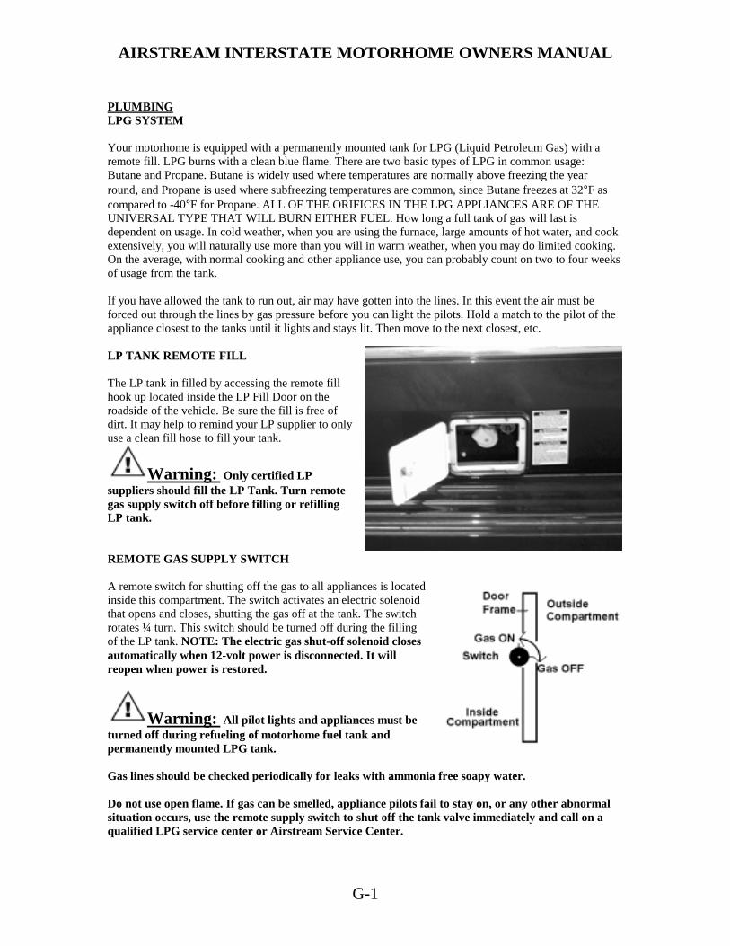
AIRSTREAM INTERSTATE MOTORHOME OWNERS MANUAL
G-1
PLUMBING LPG SYSTEM Your motorhome is equipped with a permanently mounted tank for LPG (Liquid Petroleum Gas) with a remote fill. LPG burns with a clean blue flame. There are two basic types of LPG in common usage: Butane and Propane. Butane is widely used where temperatures are normally above freezing the year round, and Propane is used where subfreezing temperatures are common, since Butane freezes at 32°F as compared to -40°F for Propane. ALL OF THE ORIFICES IN THE LPG APPLIANCES ARE OF THE UNIVERSAL TYPE THAT WILL BURN EITHER FUEL. How long a full tank of gas will last is dependent on usage. In cold weather, when you are using the furnace, large amounts of hot water, and cook extensively, you will naturally use more than you will in warm weather, when you may do limited cooking. On the average, with normal cooking and other appliance use, you can probably count on two to four weeks of usage from the tank. If you have allowed the tank to run out, air may have gotten into the lines. In this event the air must be forced out through the lines by gas pressure before you can light the pilots. Hold a match to the pilot of the appliance closest to the tanks until it lights and stays lit. Then move to the next closest, etc. LP TANK REMOTE FILL The LP tank in filled by accessing the remote fill hook up located inside the LP Fill Door on the roadside of the vehicle. Be sure the fill is free of dirt. It may help to remind your LP supplier to only use a clean fill hose to fill your tank.
Warning: Only certified LP suppliers should fill the LP Tank. Turn remote gas supply switch off before filling or refilling LP tank. REMOTE GAS SUPPLY SWITCH A remote switch for shutting off the gas to all appliances is located inside this compartment. The switch activates an electric solenoid that opens and closes, shutting the gas off at the tank. The switch rotates ¼ turn. This switch should be turned off during the filling of the LP tank. NOTE: The electric gas shut-off solenoid closes automatically when 12-volt power is disconnected. It will reopen when power is restored.
Warning: All pilot lights and appliances must be turned off during refueling of motorhome fuel tank and permanently mounted LPG tank. Gas lines should be checked periodically for leaks with ammonia free soapy water. Do not use open flame. If gas can be smelled, appliance pilots fail to stay on, or any other abnormal situation occurs, use the remote supply switch to shut off the tank valve immediately and call on a qualified LPG service center or Airstream Service Center.
AIRSTREAM INTERSTATE MOTORHOME OWNERS MANUAL
G-2
CAUTION: Moisture in the LPG tank will cause a malfunction of the regulator in controlling proper pressure. This may result in the flame lifting off the burner, or the flame may go out frequently. Many refueling stations will add approximately ¼ to ½ gallon of alcohol to lower the moisture temperature. Moisture will then pass through the regulator without the formation of ice crystals. LPG Regulator The LPG regulators used on Airstream motorhomes are designed for low-pressure service, with a normal outlet pressure setting of 11.5 inches water column. Only personnel trained in the proper procedures, codes, standards, etc., should service regulators. Have the regulator inspected each time the tank is refilled.
Replace any regulator that has had water in the spring case, or shows evidence of external corrosion, or corrosion inside the spring case. Closely examine regulators directly connected to the container valve by means of a solid POL adapter (horizontal mounting) for signs of corrosion. (An Airstream Service Center is recommended for this service.) BASIC RULES FOR SAFETY
Warning: DO NOT store LP containers within vehicle. LP containers are equipped with safety devices that vent gas should the pressure become excessive. DO NOT use cooking appliances for comfort heating. Cooking appliances need fresh air for safe operation. Before operation open overhead vent or turn on exhaust fan and open window. A warning label has been located in the cooking area to remind you to provide an adequate supply of fresh air for combustion. Unlike homes, the amount of oxygen supply is limited due to the size of the recreational vehicle, and proper ventilation when using the cooking appliances will avoid dangers of asphyxiation. It is especially important that cooking appliances not be used for comfort heating as the danger of asphyxiation is greater when the appliance is used for long periods of time. Portable fuel burning equipment, including wood and charcoal grills and stoves, shall not be used inside the recreational vehicle. The use of this equipment inside the recreational vehicle may cause fires or asphyxiation. A Warning Label has been located near the LP gas container. This label reads: DO NOT FILL CONTAINER (S) TO MORE THAN 80% PERCENT OF CAPACITY. Overfilling the LP gas container can result in uncontrolled gas flow that can cause fire or explosion. A properly filled container will contain approximately 80 percent of its volume as liquid LP gas. Do not bring or store LP gas containers, gasoline or other flammable liquids inside the vehicle because a fire or explosion may result.

AIRSTREAM INTERSTATE MOTORHOME OWNERS MANUAL
G-3
Warning: If you smell gas:
1. Extinguish any open flames, pilot lights and all smoking materials.
2. Do not touch electrical switches.
3. Shut off the gas supply at the tank valve(s) or gas supply connection.
4. Open doors and other ventilating openings.
5. Leave the area until odor clears.
6. Have the gas system checked and leakage source corrected before using again.
LP gas regulators must always be installed with the diaphragm vent facing downward. Regulators that are not in compartments have been equipped with a protective cover. Make sure that regulator vent faces downward and that cover is kept in place to minimize vent blockage that could result in excessive gas pressure causing fire or explosion. The regulator at the L.P. tank is under a black plastic cover. The protective cover certainly helps to keep the vent on the regulator from being clogged by wasps or ice, but should still be checked regularly to make sure the vent remains clear.
WARNING: Do not attempt to seal regulator cover.
WARNING: Check vent each time tank is filled to make sure it is clear of obstructions. Gas Regulator Removal/Replacement
1. Shut off main gas supply at the tank.
2. Remove the plastic protective cover from the regulator assembly 3. Using two wrenches, one to hold the line fitting and one to turn the flare nut, disconnect
the regulator from the flexible rubber line. 4. Disconnect the regulator from the tank fitting. Remove regulator. 5. To replace, reverse the removal procedures.

AIRSTREAM INTERSTATE MOTORHOME OWNERS MANUAL
G-4
WATER SYSTEM - SELF-CONTAINED
The fresh water system consists of a city water hook up, fresh water tank fill, fresh water tank and drain valve, water-pump, pump filter, hot and cold water lines, water heater, fresh water line drain valves, and faucets.
To operate the system:
Turn the water heater by-pass valves to normal flow position.
The by-pass valves are located under the galley cabinet, and are accessed by opening the lower door. For normal operation open valves A and C and close valve B. (Reverse the valves and drain the water heater for winterization). Check all drain valves, located inside the rear cargo doors, and turn them to the closed position as needed. Fill the water tank by opening the exterior door marked water fill, remove screw cap and pull the vent plug. A garden hose can now be inserted or it can be filled by using a clean bucket and funnel. It's a good idea to let the water run through the hose for a short time to flush it out. RVers sometimes fill their tanks with "home" water to avoid strange water that may be distasteful to them on short outings. Remember the more water you carry in the fresh water tank, the less cargo carrying capacity you have for other items.
The amount of water in the tank may be checked on the Monitor Panel, or you may fill the tank until water overflows out of the fill. Open the hot side of the galley, wet-bath, or exterior shower faucet and fill the water heater by turning on the water pump switch or by connecting to an exterior city water source. For some time the open faucet will only sputter. This is because the water heater is being filled and air is being pushed out through the lines. Once the water heater is full, a steady stream of water will come from the faucet. NOTE: Do operate the water heater until it is full of water. Now open a cold faucet. It will sputter for a short time, but will soon expel a steady stream. All other faucets can now be opened until all air is expelled. Once the system is filled with water and the faucets are closed, the water pump will shut off. NOTE: To prevent equipment damage the water heater should only be started after the water system is primed and ready for use. When a faucet is opened the pump will come back on automatically. If the faucet is just barely open it is normal for the pump to cycle on and off rapidly. It is normal for a pump to occasionally cycle when all faucets are off to keep the water pressure at the set point. However, if it cycles frequently (more than a few times an hour) the plumbing system and pump should be checked to be sure it is not loosing pressure through a slow water leak or back through the pump. Caution: Turn the water pump off when the motorhome is left unattended.
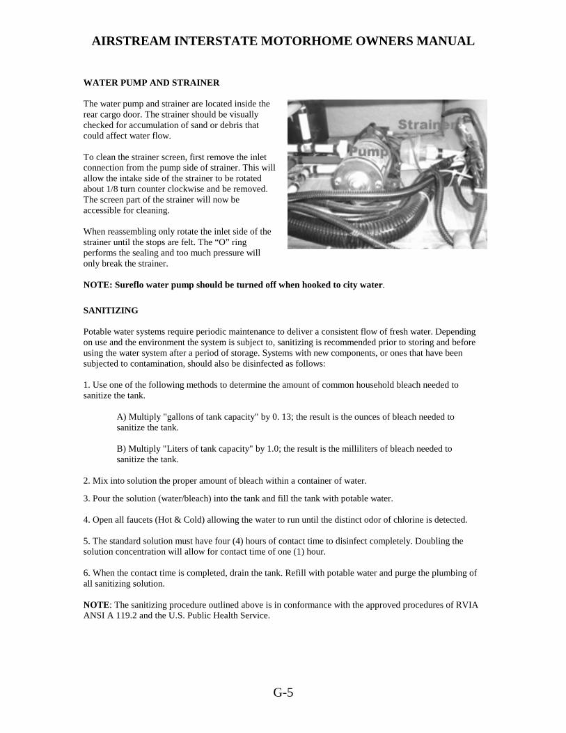
AIRSTREAM INTERSTATE MOTORHOME OWNERS MANUAL
G-5
WATER PUMP AND STRAINER The water pump and strainer are located inside the rear cargo door. The strainer should be visually checked for accumulation of sand or debris that could affect water flow. To clean the strainer screen, first remove the inlet connection from the pump side of strainer. This will allow the intake side of the strainer to be rotated about 1/8 turn counter clockwise and be removed. The screen part of the strainer will now be accessible for cleaning. When reassembling only rotate the inlet side of the strainer until the stops are felt. The “O” ring performs the sealing and too much pressure will only break the strainer. NOTE: Sureflo water pump should be turned off when hooked to city water. SANITIZING Potable water systems require periodic maintenance to deliver a consistent flow of fresh water. Depending on use and the environment the system is subject to, sanitizing is recommended prior to storing and before using the water system after a period of storage. Systems with new components, or ones that have been subjected to contamination, should also be disinfected as follows: 1. Use one of the following methods to determine the amount of common household bleach needed to sanitize the tank.
A) Multiply "gallons of tank capacity" by 0. 13; the result is the ounces of bleach needed to sanitize the tank.
B) Multiply "Liters of tank capacity" by 1.0; the result is the milliliters of bleach needed to sanitize the tank.
2. Mix into solution the proper amount of bleach within a container of water.
3. Pour the solution (water/bleach) into the tank and fill the tank with potable water. 4. Open all faucets (Hot & Cold) allowing the water to run until the distinct odor of chlorine is detected. 5. The standard solution must have four (4) hours of contact time to disinfect completely. Doubling the solution concentration will allow for contact time of one (1) hour. 6. When the contact time is completed, drain the tank. Refill with potable water and purge the plumbing of all sanitizing solution. NOTE: The sanitizing procedure outlined above is in conformance with the approved procedures of RVIA ANSI A 119.2 and the U.S. Public Health Service.
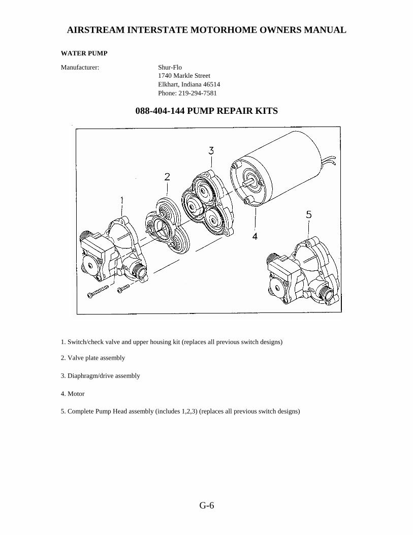
AIRSTREAM INTERSTATE MOTORHOME OWNERS MANUAL
G-6
WATER PUMP Manufacturer: Shur-Flo
1740 Markle Street Elkhart, Indiana 46514 Phone: 219-294-7581
088-404-144 PUMP REPAIR KITS
1. Switch/check valve and upper housing kit (replaces all previous switch designs) 2. Valve plate assembly 3. Diaphragm/drive assembly 4. Motor 5. Complete Pump Head assembly (includes 1,2,3) (replaces all previous switch designs)

AIRSTREAM INTERSTATE MOTORHOME OWNERS MANUAL
G-7
Switch and Check Valve Repair The check valve, hydraulic switch mechanism and micro switch are accessible by removing the switch cover. CAUTION: Care should be taken in removing the switch cover screws. Within the mechanism is a spring under compression. Replacement of Micro Switch Occasionally the micro switch fails or an electrode is broken off. Proceed as follows: Remove the two screws holding the cap to the main body. Remember, this cap retains a spring under compression. With both screws out, allow the spring to extend fully. Then carefully lift off cap and spring. If only the micro switch is at fault, avoid disturbing the hydraulic elements remaining in the head. If examination of the hydraulic parts is required, remove them carefully by pulling. Be sure to note the order of removal. To replace the micro switch, remove the spring and pull out the black retaining ring. This will allow the micro switch to fall free. Replace parts in the reverse sequence: Micro switch, black retainer, and the spring. Reassemble cover to the main body. Switch cap may be pointed up or down as desired, providing wire has not been shorted. After replacing the micro switch, carefully rewire correctly. Note: If the positive wire from the battery is connected to the "B" terminal, the switch is bypassed and the pump cannot shut off, Pressure will build up until the motor stalls. If the proper fuse has been used, it will blow. If a larger fuse than recommended has been used the motor will stall and may burn out. Check Valve Problems Due to contamination from debris or lime build-up, the check valve may fail to properly seat. To correct, clean out the area and replace the check valve element. If checking the check valve with air, be certain to moisten the check valve to get an accurate check. The rubber seals more effectively when wet. Properly installed, the Pump will: PRIME: The pump will automatically prime itself.
AIR-LOCK- Pump will not airlock, as the compression stroke is powerful enough to pressurize the entrapped air and force the check valve open.
RUN DRY: Pump will run dry for extended periods without damage.
BATTERY DRAIN: At free flow, the pump draws a mere 7 to 7 1/2 amps. CHECK VALVE: Built-in check valve prevents back flow and can protect the pump from the dangers of high city water pressure (up to 200 PSI).
FULLY AUTOMATIC: The pump will automatically come on when the faucet or valve is opened. It delivers a smooth, steady flow of water and shuts off automatically when the faucet is closed.
AIRSTREAM INTERSTATE MOTORHOME OWNERS MANUAL
G-8
Trouble Shooting MOTOR DOES NOT OPERATE.
- Is battery discharged? - Are any wires disconnected? - Are terminals corroded'? - Is switch in "ON" position? - Is fuse good? - Is water frozen in pump head?
MOTOR RUNS BUT NO WATER FLOWS.
- Is water tank empty? - Are there kinks in the inlet hose? - Is air leaking into inlet hose fittings? - Is inlet line or iii-line filter plugged? - If using a filter, check the line just before the filter. - Is outlet hose kinked?
MOTOR RUNS BUT WATER "SPUTTERS" Check to be certain that air has been bled off the lines and water heater. Also check for air leaks in the input side of the pump. PUMP CYCLES ON AND OFF WHEN ALL OUTLETS ARE CLOSED. The pump will normally cycle (go on and off) when a faucet is partially opened. If, however, it cycles when all valves are closed, check for a leak in the lines. It may be a leaky toilet valve or a dripping faucet. Do not forget to check the outside city water entry valve. It may be leaking. If no leak can be detected, shut pump off. Remove the output hose where it joins the system (not at the pump). Insert a plug in the hose and clamp it. (You can make a perfect plug from a barb fitting: ½ " size with a cap tightly screwed on the threads.) Turn the pump switch on. The pump should come on, run a few seconds, and then shut off. If it remains off, the problem is NOT the pump. The problem is in the system. If, however, the pump goes on and off, there may be a problem in the pump.
There may be an internal leak in the pump that allows water to escape from the high-pressure area back into the low-pressure area. Look for a pump valve held open or a crack in the plastic parts.
PUMP DOES NOT ACHIEVE SHUT OFF The wall switch may be used for temporary control of the pump. A low battery charge may be the cause, or the pump switch mechanism may be stuck. Try tapping the switch cap on the end of the pump with the handle of a screwdriver. If the pump appears in all other respects to run normally, but fails to shut off, you may have to replace the switch mechanism. PUMP HEAD LEAKS If the pump head leaks, first try to tighten the screws in the pump head assembly until they are snug. CAUTION: Do not over tighten. The leak may be from a crack in the pump head assembly. If so, then replace. One cause of the pump head cracking may be water freezing inside the pump head. If the leaking water is escaping back near the motor, check for a leaking or broken piston.

AIRSTREAM INTERSTATE MOTORHOME OWNERS MANUAL
G-9
Pump Repair
• Screws (A) hold the entire pump head assembly to the motor.
• Screws (B) hold the pump head face to the pump head main body. Screws (C) hold the switch assembly to the front of the pump head.
• Screws (A) would be removed to correct a problem in the "drive train" between the motor and pump head. Screws (A) and (B) would be removed to correct a problem in the pump head valves or pumping chambers.
• Screws (C) would be removed to correct a problem in the automatic switch or check valve. PUMP HEAD REPAIR Motor and drive train. Rarely does a problem occur in this area of the pump head. If a part does fail, it is quite easily replaced. Just be certain to follow closely the sequence of parts as shown in the figure. Also be careful to align the flat surface in the drive adapter with the flat surface on the motor shaft. LUBRICATION If the lubricant appears dried out it should be wiped off the bearing assemblies. A small amount of automotive wheel bearing grease should be applied to both sides of each bearing. FAILURE TO PRIME Failure to prime can be caused by the presence of some foreign matter lodged in the valve preventing it from seating. To correct, remove any such foreign bodies.
CAUTION: Do not remove the stainless steel screens. These filter screens should be cleaned without removing them from the plastic housing.
PUMP CHAMBER REPAIR Replacement of broken piston.
To remove a piston, back out the screw holding the defective piston. Now lift the corner of the diaphragm and remove the broken piston. Insert the new piston through the diaphragm and slide the retaining ring on. Rotate the piston until it drops into place in the drive plate. Replace the screw and tighten until snug. CAUTION: Do not attempt to re-use a piston once it has been removed. The plastic stem, if used a second time, may not hold securely. The second thread path removes additional material and there is then no real bite. REPLACE A DIAPHRAGM To replace a diaphragm follow the procedure used in removing the pistons. After removing the three pistons the diaphragm is loose and easily removed. Screws (A) hold the piston. Screws (B) hold the drive mechanism and should not be removed when replacing piston.

AIRSTREAM INTERSTATE MOTORHOME OWNERS MANUAL
G-10
CITY WATER HOOKUP Use a high-pressure hose of at least ½ " diameter. It should be one that is tasteless, odorless and non- toxic designed for RV use. The city water inlet is a standard garden hose thread. We suggest you carry two lengths of hose. This way you have the ability to reach hookups further away than normal, plus you have a spare hose should one fail or become damaged unexpectedly. Be sure to turn the water heater bypass to the normal flow position as described under the Water System Self-Contained part of this section so it will fill.
After hooking up the hose and turning on the city water valve provided in the park, slowly open a faucet. There will be a lot of spurts and sputtering until all the air is expelled from the motorhome system. If the water heater is empty it will take some time before all the air is expelled and you get a steady flow of water at the faucet. Once a steady flow is achieved at one faucet, the others should be opened long enough to expel the air in the lines going to them. NOTE: The Sureflo water pump should be turned off when hooked to city water. Your plumbing system has a built in pressure regulator to protect your lines and faucets from extremely high pressures on some city water systems. An after-market external regulator is not recommended, as it could lower the water pressure at the inlet and thus to your faucets and shower. Exterior Shower
An exterior shower is provided for your convenience. Be sure to drain the hose and open the valves before opening the low point drain lines for winterization.

AIRSTREAM INTERSTATE MOTORHOME OWNERS MANUAL
G-11
GALLEY FAUCET MODEL 67315C Manufacturer: United States Canada Moen Incorporated Moen Inc. 25300 Al Moen Drive 2816 Bristol Circle North Olmstead, OH. 44070-8022 Oakville, Ontario L6H5s7 www.moen.com For US customer service, warranty, and a local parts outlets contact Moen at 1-800-BUY-MOEN (289-6636). For Canadian service contact: Toronto 905-829-3400, Rest of Canada 1-800-465-6130 Care Instructions As with any fine polished surface, your faucet will retain its shine for years to come with proper care. The LifeShine™ finish on the faucet does not require the extraordinary work needed to maintain most fine polished brass finishes. Be sure to read and follow usage instructions enclosed any scour pad or scrub sponge before use.
• Caution: Do not use pads or sponges that specifically do not recommend use for cleaning polished services.
• Caution: Many pads or sponges with green fibrous surface (such as Scotch-Brite™ heavy
duty scrub sponges) contain microscopic mineral particles that can scratch nearly all polished services, including this faucet finish.
The LifeShine™ finish can be cleaned with most household cleaners (including mild abrasives), when used according to their manufacturers instructions for use.
• Rinse any strong cleaners off immediately after used to maintain the LifeShine™ finish luster. Mild scrubbing with fine steel wool (0000 grade) can remove build up dirt or water stains. Visible water spots on this highly lustrous and reflective finish can be easily wiped off with a cloth dampened with water or with glass cleaner.

AIRSTREAM INTERSTATE MOTORHOME OWNERS MANUAL
G-12
GALLEY FAUCET SERVICE
CAUTION: Always turn water OFF before removing existing faucet or disassembling the valve. Open faucet handle to relieve water pressure and ensure that complete water shutoff has been accomplished. 1. Remove red/blue plug bottom (3) from front of lever handle, remove screw (2) and lever handle (1). Unscrew handle screw (4) and lift off the handle adapter (5) (with handle connector (6) attached). 2. Unscrew collar (9) being careful not to damage the finish, lift out pivot retainer (10). Unscrew the retainer nut using channel locks and remove the O-ring (12) and bearing washer (13). Remove washers (7) and (8) from the cartridge stem 3. Pry out retainer clip (14) with flat bladed screwdriver. 4. Grasp cartridge stem with a pair pliers and pull cartridge (15) straight up and out of body. Reinstall has follows: Install cartridge (15) into valve body with notched flat on stem facing forward. Be sure to position the ears of the cartridge in the front and back. Reinstall the retainer clip (14) that straddles the ears on the cartridge. Continue reassembly by reversing the steps discussed in steps 1-3. Note: To service vacuum breaker assembly, (anti-siphon protection) the hose must be disconnected from the threaded discharge prior to removing the spout receptor (20). To Correct reversed Hot and Cold Positions: (It is necessary to shut off water supplies)
1. Position handle so that it points toward you. Remove handle (follow instructions for SERVICE step 1 only).
2. Turn cartridge stem so that the notch is turned ½ turn or 180
degrees.
3. Reinstall handle following SERVICE instructions.
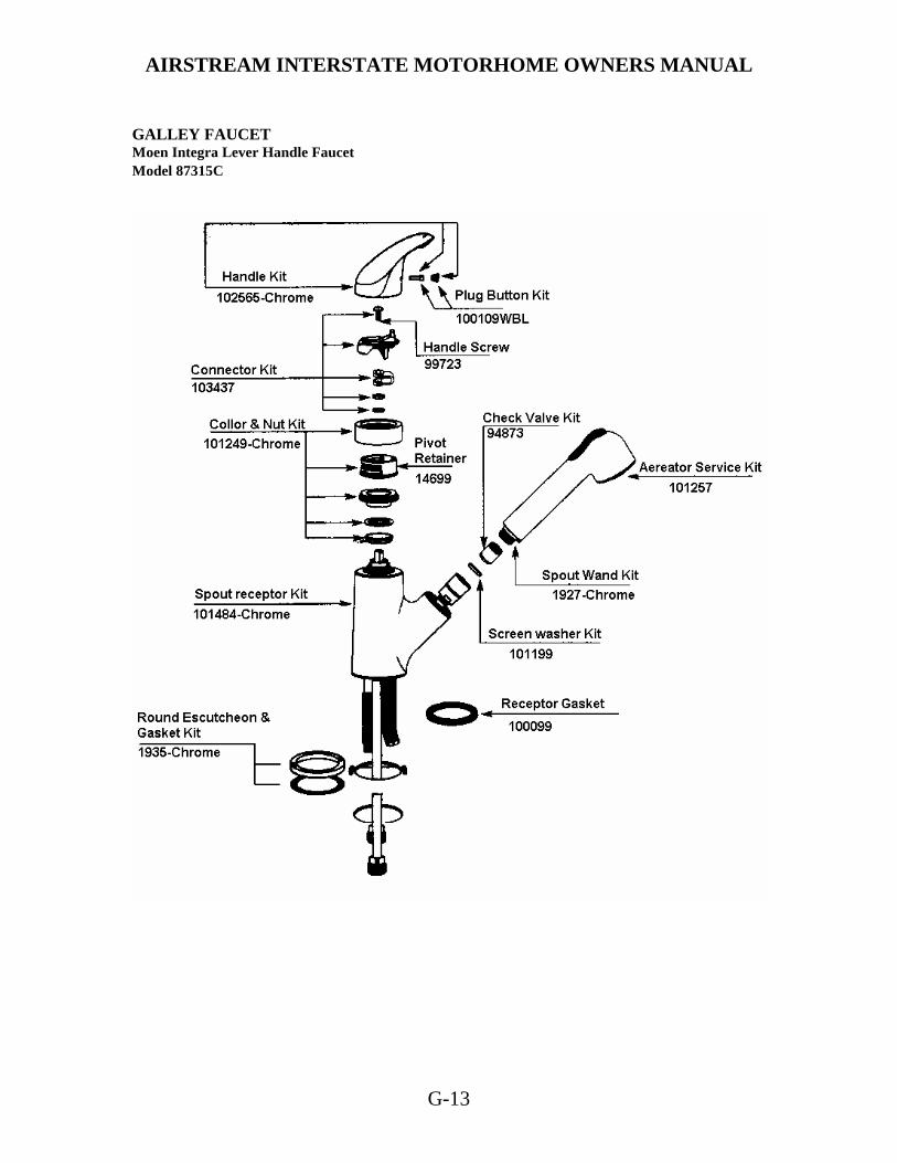
AIRSTREAM INTERSTATE MOTORHOME OWNERS MANUAL
G-13
GALLEY FAUCET Moen Integra Lever Handle Faucet Model 87315C

AIRSTREAM INTERSTATE MOTORHOME OWNERS MANUAL
G-14
Moen Integra Valve Body/Below Deck Parts Fabricated Valve Body (FVB)

AIRSTREAM INTERSTATE MOTORHOME OWNERS MANUAL
G-15
DRAIN VALVE LOCATIONS The fresh water system has three drain valves. All are easily accessible by opening the rear cargo doors.
There are two low point water line drain valves on the Interstate motorhome. They are located just under the wet bath. Line A as pictured above is the hot water line drain valve and line B is the cold water line drain valve.
The fresh water tank drain valve is located near the floor on the right side of the rear compartment.

AIRSTREAM INTERSTATE MOTORHOME OWNERS MANUAL
G-16
TOILET Manufacturer: Thetford Corporation Canada: Thetford Sanitation Ltd. 7101 Jackson Road 2710 Slough Street
Ann Arbor, MI 48103 Mississauga, Ontario 313-769-6000 Canada, L4T 1G3
The RV toilet in your Airstream is a design that has been used for many years. In normal use, when you are hooked up to city water, both pedals are depressed together. This dumps the sewage and flushes fresh water down the side of the bowl. Water will continue to run into the bowl for a short time after the pedals are released. When you wish to conserve water hold the hand-spray head over the bowl and hold down the thumb-operated lever. Now when you depress the pedal all the water is routed through the hand-spray. CAUTION: When you dump the bowl of the toilet make sure all paper and solids have cleared the slide mechanism before you allow it to close. Failure to do so can cause the groove for the slide to become jammed and the slide will no longer close completely. If the problem should occur, a small nail or bent clothes hanger can be used to "pick" the material out of the groove. TROUBLE SHOOTING PROBLEM: Water keeps running into bowl. CAUSE: The blade in the bottom of the bowl is not closing completely, which in turn keeps the water control valve partially open. The groove into which the blade seats when completely closed is clogged with foreign material. REMEDY- Insert the end of a coat hanger or similar object into the sealing groove and remove the foreign material. Avoid damaging the rubber seal while cleaning. PROBLEM: Toilet leaks. There is water on the floor. Specify the problem. Determine if water is leaking from: CAUSE: a. Vacuum breaker.
b. The water-control valve.
c. Bowl to mechanism seal. (If this is the problem, the water would not stay in the bowl.)
d. Closet flange base seal. REMEDY: a. The vacuum breaker. If the vacuum breaker leaks when flushing the toilet, replace
vacuum breaker. b. If the vacuum breaker leaks when the toilet is not in operation, replace the water control valve. c. Leaks at the bowl to mechanism seal. Remove mechanism and replace seal, d. Leaks at closet flange area. Check front and rear closet flange nuts for tightness. If leak continues remove the toilet, check the closet flange height. The height should be between ¼ " and 7/16 " above the floor. Adjust closet flange height accordingly and replace closet flange seal.

AIRSTREAM INTERSTATE MOTORHOME OWNERS MANUAL
G-17
PROBLEM: Foot pedal operates harder than normal or the blade sticks. REMEDY: a. Apply a light film of Silicone spray to blade.
b. Check closet bolt tightness. If closet bolts are over tightened, the mechanism may be distorted.
PROBLEM: Bowl will not hold water; i.e., water leaks from bowl down into the holding tank. REMEDY: Using a bent screwdriver or similar object, scrape the groove in front of the mechanism
blade. Generally paper or other foreign material is lodged in this groove, causing the leak. CAUTION: Use care not to damage the blade seal. Always make certain that the tool is under the lip of the seal, not above it.
The tool can easily be made by bending a coat hanger or screwdriver over about 7/8”. MAINTENANCE If the bowl-sealing blade does not operate freely after extended use, it may be restored to its original, smooth operating condition by applying a light film of silicone spray to the blade. To clean the toilet use Thetford Aqua Bowl or any other high grade, non-abrasive cleaner. Do not use highly concentrated or high acid content household cleaners. They may damage the rubber seals. REMOVAL 1. Shut off water valve behind toilet or main water supply. 2. Disconnect water supply line from toilet. You will probably find a small mirror very useful. 3. Depress pedal and remove nut located in pedal recess. 4. Reach behind toilet and remove nut on opposite side of base from pedals. In some situations you may want to remove the plug in top of the seat designed to give access from above to this nut. NOTE: Always replace flange seal when toilet has been removed. Winterizing Draining Method Disconnect water supply line at water valve. Completely drain the water supply line before winter storage. CAUTION: To avoid damage, when using air pressure to blow water from the lines, be sure toilet valve is in the open position. CAUTION: If water is frozen in the toilet, do not attempt to flush until with the ice thaws. CAUTION: Never use automotive type antifreeze. For Thetford service centers: USA 1-800-521-3032
Canada: 1-888-215-5410
AIRSTREAM INTERSTATE MOTORHOME OWNERS MANUAL
G-18
STORAGE AND WINTERIZING When storing your motorhome for a short or long period, use the same precautions as you would in your own home in regard to perishables, ventilation and rain protection. In addition, for prolonged storage periods flush out all the drain lines and the holding tank. Also, drain the entire water system, including the water heater and the fresh water storage tank. Instructions for draining the water system are explained in the following paragraphs on winterizing. Twice a year, or after a long storage period, we suggest you take your unit into your Airstream dealer for a check-up and cleaning of the gas operated appliances. The main consideration in winterizing is to guard against freezing damage to the hot and cold water systems, the waste drain system (including the traps), the waste holding tanks, the water heater and the battery. To completely winterize your motorhome follow this procedure:
1. Level the motorhome from side to side and front to rear. Open the hot and cold water valves on the exterior water service, lavatory and wet bath.
2. Turn the water pump switch to the OFF position or/and disconnect city water.
3. Open low point valves for the hot and cold water lines and the fresh tank that are located inside the
rear cargo doors. One drain valve or plug is located on the water heater exterior and is accessible through the water heater access door. Remove this plug and allow water to drain. See drain valves and their access in this section.
4. Follow winterizing instructions for your toilet in the toilet section of this manual.
5. While the water is draining from the system, depress hand spray thumb button on the telephone
showerhead and drain all the water. Unscrew the head on spray unit and store. Remove, drain, and store the exterior water service hose and showerhead.
6. After the water has stopped running from the drain lines, fresh water tank, and water heater, apply
at least 60 lbs. of air pressure at the city water inlet. Be sure the toilet valve and all drain valves and faucets are open and pump outlet hose is disconnected. This can be accomplished at a service station. The goal is to force any remaining water from the water heater and remove any water that may be trapped in low areas.
7. Pour a cup of non-toxic antifreeze into the wet bath and galley sink drains to prevent freezing
water in traps.
8. Be sure to open the holding tank valve, and drain and flush the tank thoroughly. (This is very important, as the frozen sewage could seriously damage the tank.)
9. Remove the house battery from your motorhome and store in a cool dry place where there is no
danger of freezing. It is very important for optimum life of your battery to check it periodically and to keep it fully charged. This is especially true in winter months, when the temperature may drop below freezing. If the period of storage is for 30 days or less, you may turn off the battery disconnect switch rather than remove the battery. Continue to check and recharge the battery as needed, at least weekly in severe weather.
10. Remove any items (food, cosmetics, etc.) from the interior that might be damaged by freezing, or
might damage the motorhome if containers break. Daimler/Chrysler recommends disconnecting the engine battery if the vehicle is stored for a long duration. Always disconnect the and connect the ground first. If you remove the battery, follow the same storage tips as explained for the house battery.

AIRSTREAM INTERSTATE MOTORHOME OWNERS MANUAL
G-19
STORAGE AND WINTERIZING (continued) For additional winterizing protection, add non-toxic antifreeze (approved for drinking water systems) to your water lines using the following procedure: 1. Reconnect all lines except the hose to the pump inlet port. Close all drain valves (See Step 3) *2. Turn bypass valves to bypass position. 3. Attach a length of hose to the pump inlet port. This piece of hose should be long enough for the free end to be inserted into and reach the bottom of the antifreeze container. 4. Dilute the antifreeze solution in accordance with the manufacturer's instructions. 5. Open all water faucets. 6. Insert hose length into the antifreeze container, turn the pump switch on, and run the water pump until the antifreeze solution fills all water lines. Flush toilet. Work shower hand spray while holding down in tub. 7. Shut off the pump and close all faucets. 8. Disconnect the hose length from pump inlet fitting and reconnect water system inlet line. *The by-pass valves are located under the galley cabinet lower door. Turn the water heater valves to by-pass flow position. To by-pass the water heater for winterizing, close valves A and C and open valve B (See illustration). For normal operation open valves A and C and close valve B.

AIRSTREAM INTERSTATE MOTORHOME OWNERS MANUAL
G-20
DRAIN AND WASTE SYSTEM The drain and waste system of your motorhome includes a combination gray/black waste holding tank made from molded plastic. The tank enables you to use the toilet, sink, and wet bath drain for several days away from disposal facilities. To empty the tank, attach the sewer hose by pressing the bayonet fitting onto the outlet adapter and rotate clockwise until it feels solid and secure. Attach the outlet end of the hose to the sewage outlet; making sure that the hose is placed so that it will drain completely. The tank has an electric dump valve with a remote switch. The switch is located inside the rear cargo doors on a panel beside the spare tire. The switch activated an electric solenoid that opens the valve. Push and hold the switch until the tank is empty. Release the switch to close the valve. Watch all connections while dumping and release switch if a leak is noticed. When Parked and Connected to Sewer Outlet When you are in a park, and connected to a sewer outlet, keep the tank dump valve closed and empty the tank every few days or whenever it becomes almost full. ONLY BY SENDING A LARGE VOLUME OF LIQUID THROUGH THE TANK AT A TIME WILL TOILET PAPER AND OTHER SOLIDS COMPLETELY WASH AWAY. This practice will avoid the accumulation of solids in the tank, which could lead to an unpleasant cleaning job. Should solids accumulate, close the dump valve, fill the tank about half full with water, then drive the motorhome for a few miles. The turbulence and surging of the water will usually dissolve the solids into suspension so the tank can be drained. Keep the auxiliary tank valve open when connected to a sewer outlet. Draining the tanks as described will protect them from freezing during storage. Use a winterizing solution designed for RV use after draining tank. Heated Tank The Interstate motorhome has 12-Volt heat pad installed with the gray/black combination-holding tank. This pad is individually switched with the switch located next to the monitor panel. To conserve battery power, RV antifreeze may be used to protect the gray/black tank. Battery power will last about 6 hours unless the unit is plugged into a 110-volt shoreline source to operate the converter/battery charger. CAUTION: Never put wet strength paper towels or tissues in your holding tank, since they won't dissolve and can "catch" in the mechanism of the dump valve. Colored toilet tissue is slower to dissolve than white. Most RV accessory stores offer tissue, designed for RVs that will completely dissolve.
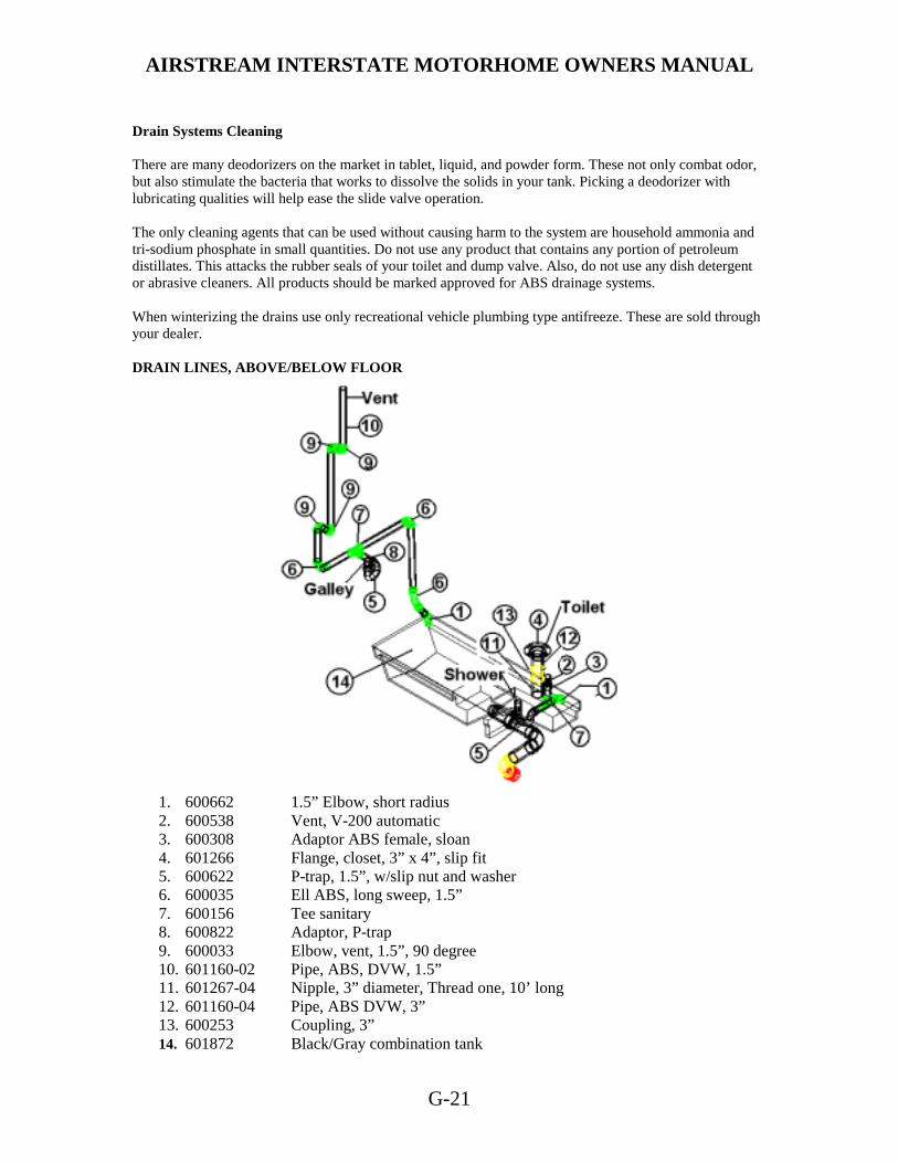
AIRSTREAM INTERSTATE MOTORHOME OWNERS MANUAL
G-21
Drain Systems Cleaning There are many deodorizers on the market in tablet, liquid, and powder form. These not only combat odor, but also stimulate the bacteria that works to dissolve the solids in your tank. Picking a deodorizer with lubricating qualities will help ease the slide valve operation. The only cleaning agents that can be used without causing harm to the system are household ammonia and tri-sodium phosphate in small quantities. Do not use any product that contains any portion of petroleum distillates. This attacks the rubber seals of your toilet and dump valve. Also, do not use any dish detergent or abrasive cleaners. All products should be marked approved for ABS drainage systems. When winterizing the drains use only recreational vehicle plumbing type antifreeze. These are sold through your dealer. DRAIN LINES, ABOVE/BELOW FLOOR
1. 600662 1.5” Elbow, short radius 2. 600538 Vent, V-200 automatic 3. 600308 Adaptor ABS female, sloan 4. 601266 Flange, closet, 3” x 4”, slip fit 5. 600622 P-trap, 1.5”, w/slip nut and washer 6. 600035 Ell ABS, long sweep, 1.5” 7. 600156 Tee sanitary 8. 600822 Adaptor, P-trap 9. 600033 Elbow, vent, 1.5”, 90 degree 10. 601160-02 Pipe, ABS, DVW, 1.5” 11. 601267-04 Nipple, 3” diameter, Thread one, 10’ long 12. 601160-04 Pipe, ABS DVW, 3” 13. 600253 Coupling, 3” 14. 601872 Black/Gray combination tank

AIRSTREAM INTERSTATE MOTORHOME OWNERS MANUAL
H-1
ELECTRICAL SYSTEM 12-Volt System The major portion of electrical power in your Airstream is 12-volt. The 12-volt current powers just about every thing except for the air conditioner and microwave oven. Even the refrigerator’s electronic energy selection is powered by 12 volt. All 12-volt current comes through the battery system located under the roadside lounge. The battery is accessible in the battery box under the lounge. Power from the battery goes to a Type 2 thermal breaker and then to the 12-volt distribution panel located in the converter and then to the rest of the motorhome. Open the brown decorative door on the front of the converter on the front of the lounge base to access the panel and its fuses. A 12-volt layout diagram is shown later in this section. BATTERY DISCONNECT SWITCH The disconnect switch is used to separate the battery from the 12-volt distribution panel and converter charging system. When the switch is turned “use” (on) and the motorhome is plugged into a 110-volt shoreline, the 12-volt distribution panel will receive power from the converter and the battery will be charged through the converter charging system. When the switch is turned to “store” (off) and the motorhome is plugged into a 110-volt shoreline, the 12-volt distribution panel will still receive power from the converter, but the battery is disconnected from the system. The battery will not be drained with the switch in the store position. The converter will not charge the battery with the switch in this position. NOTE: The electric gas shut-off solenoid closes automatically when 12-volt power is disconnected. It will reopen when power is restored. POWER CENTER (Converter, 12-Volt Distribution, 110Volt Distribution) MagneTec 7355 Manufacturer: MagneTec 102 North Main Street Goodland, Indiana 47948 Phone: (800) 443 4859 Fax: (219) 297 2305 The converter/charging system is the interior low voltage electrical system that enables you to use the interior lights, fans, pumps and 12-volt appliances whether operating on self-contained battery power or 120-volt city power. The 12-volt light bulbs give off the same light as regular household bulbs, so that when operating on self-contained battery power, everything works normally except the 110-volt convenience outlets and 110-volt appliances. The converter system is designed to maintain constant output voltages regardless of the variances that occur in city power systems.

AIRSTREAM INTERSTATE MOTORHOME OWNERS MANUAL
H-2
12V POWER CIRCUITS The current in the converter system is 12 volts direct current (12VDC) negative grounded. Power sources that supply 12VDC current to the system are House Battery and Converter. These power sources above are electrically connected to the 12-volt distribution fuse panel that distributes current to interior branch circuits. The circuits provide power to operate all 12-volt DC systems in the living area. The 7300 series power converter is a solid-state electronic power supply and is maintenance free. It is so self-sufficient and quiet that you will probably not know it is working except for the fact that your battery is always charged, and your 12-volt lights and appliances always work. If any 12-volt appliance fails to operate, first check your recreational vehicles 12-volt distribution fuse block located behind the decorative front door in the front right hand corner of the converter and inspect all fuses. If a fuse is opened or blown replace it with the same size fuse (never install a larger use). If the fuse opens again, have an electrician or certified RV technician locate the circuit trouble. Replace blown fuses with Littefuse type 257 fuses only. If the 7300 series power converter is not working, first confirm the RV supply or shoreline cord is plugged into a live circuit. Then check all the 120-volt breakers in your RV distribution panel to make sure they are on. If the breaker is tripped, follow the instructions to reset the breakers. If the breaker trips again, consult an electrician or certified RV technician. CONVERTER OPERATION The MagneTec 7300 series electronic power converter is designed to supply the nominal 12-volt filtered D.C. power for all 12 volt operated devices encountered in RV service. Although the converter is an excellent battery charger, the converter does not require a battery to be connected to it for proper operation. CAUTION: When installing a battery (s) always observe polarity. Connecting a battery reverse polarity will blow the power converter main fuses located on the 12 volt D.C. distribution fuse block. 120 VOLT AC PANEL BOARD The AC panel board section of the series 7300 is located behind the decorative door in the upper left-hand corner. This panel contains the 120 Vac branch circuit breakers for your RV. One of the breakers controls the 120 volt power to the 12 volt converter section located in the lower half of the 7300. This breaker may also control another branch circuit. Check the label next to each breaker for what each branch circuit breaker controls. The 120 volt circuits may be turned “on” my putting their breaker handle up to the on position or “off” by flipping the handle down to the off position. To reset the tripped breaker move handle to off then on.

AIRSTREAM INTERSTATE MOTORHOME OWNERS MANUAL
H-3
CONVERTER COOLING SYSTEM The 7300 electronic fan cooling system is the key to long life and trouble-free operation. The fan is never on more than required to cool electronic components in the converter. You may never hear the fan operate. Converter The converter transforms 120-volt alternating current (AC) into 12-volt direct current (DC). This provides power to charge the motorhome battery and to operate the 12-volt systems, and appliances. The converter is energized only when the motorhome is hooked up to 120-volt city power. Converter Testing A. Confirm 120 volt power is going into converter. B. Disconnect the 12+ wire from the master switch. C. Using a voltmeter check voltage output between heavy positive and negative wires coming out of converter. D. The voltage must be within 13.8 and 14.0 volts. (The meter of the tester should be calibrated periodically.) E. If converter is not within these voltages, have it serviced by a qualified technician or replace it. Converter Removal
1. Disconnect power cord for 120-volt supply.
2. Switch circuit breakers to off position.
3. Open brown decorative Power Center door.
4. Remove 4 screws holding the assembly in place and pull Power Center out. Be careful not to pull
too far and damage wiring.
5. Mark all wiring positions.
6. Remove 110-volt power feed and other wiring.
7. To reinstall, reverse the removal procedures.
AIRSTREAM INTERSTATE MOTORHOME OWNERS MANUAL
H-4
TROUBLE SHOOTING The most common failure in the exterior electrical system is an open circuit. An open circuit is an interruption in the current flow, which may be in either the wire to the component or in the ground return. Check the following areas for open circuits:
1. Light bulb (filament open.) 2. Loose or corroded connections at lighting device. 3. Loose or corroded connections at 7 way connectors. 4. Improper grounding at the lighting device.
A continuity light or an ohmmeter will help you isolate the point of the "open" on the circuit. Another cause of failure is a short circuit usually resulting in a blown fuse or cycling circuit breaker at the power source. The wire coming in contact with a sharp edge usually causes a short. The sharp edge wears the wire's insulation away until the "hot" wire short to ground. Locating Shorts and Opens The key in locating shorts and opens is isolation. The first step is to isolate the circuit with the short or open and then isolate the section of the circuit with the fault. Once the section is identified, the specific problem can be located. The cause may be a loose or corroded connection, cut wire, worn insulation, defective component, etc. The following paragraphs describe methods of isolating shorts and opens. There are several other approaches that may be used; however, these may be used as a guide. Shorts 1. Locate circuit that has short by noting fuse blown or cycling breaker. 2. Remove fuses or wire from breaker, and open all switches. Check for continuity between (+) 12-volt wire or shorted circuit and ground. (If it cannot be determined if the switch is in the open position, remove the lead from the switch.) Continuity to ground indicates there is a short. 3. Remove leads of shorted circuits from converter and components one at a time. After disconnecting each component, check continuity of the (+) 12-volt wire to ground. If there is no continuity the short is in the component removed. If continuity still exists, continue with the following steps. 4. Inspect leads carefully where they pass through the skin or near sharp edges. 5. Note objects attached to skin after manufacturing. The mounting screws or rivets may be causing the short. 6. Remove multi-dome to expose main body of harness. Inspect harness for cause of short, such as rivets or screws in harness or evidence of drilling. 7. If short cannot be found, cut circuit into sections, checking each section for continuity. Shorts can be isolated by this method. 8. Examples of shorts are:
• The (+) 12-volt wire contacting (-) negative wire or grounded surface. • Internal short in a 12-volt component or appliance.

AIRSTREAM INTERSTATE MOTORHOME OWNERS MANUAL
H-5
Opens 1. Check all components on circuit that has open. If all components are without power, begin to look
for open on distribution panel.
2. Check for voltage on each side of the breaker. Check for tightness of crimp on connector and nut.
3. After inspecting all accessible wire on a circuit for opens, further inspection requires removal of interior skin to find the short or the installation of replacement wire. A qualified service center should be contacted for this repair.
4. Examples of open are:
• Wire is cut. • Connector falls off component's terminal. • Loose or corroded connection. • Contacts in switch do not touch
COMMON ELECTRICAL PROBLEMS PROBLEM: No 12-volt power, (Lights and appliances do not work.) CAUSE & REMEDY:
1. Input line and/or battery not connected. Make necessary connections. 2. Battery disconnect switch not turned on, 3. Discharged house battery. Charge battery. 4. Motorhome battery on wrong polarity. Make proper connections to battery terminals.
PROBLEM: Tripping Breaker CAUSE & REMEDY:
1. Overloaded circuit. Turn off switches to reduce load. 2. Electrical short. Find tripping breaker distribution panel and identify circuit. Check the circuit for
defective wiring, lamps or motors. 3. Shorted battery. Replace battery. 4. Battery terminals not properly connected to converter. Make proper connections.
PROBLEM: Dim lights or sluggish fan motor. CAUSE & REMEDY:
1. 25-cycle or 50-cycle power (some foreign countries). Use 60-cycle power. 2. Discharged battery (when operating without 110 volt line) Charge battery. 3. Battery is low on water. Add distilled water to battery.
PROBLEM: Converter will not charge battery. CAUSE & REMEDY:
1. In put line not connected. Connect. 2. Battery not connected or polarity reversed. Connect battery to converter (Check polarity). 3. Bad Battery. Replace. 4. Too many lights and appliances. Reduce electrical load

AIRSTREAM INTERSTATE MOTORHOME OWNERS MANUAL
H-6
12-Volt Operation The only thing you have to do is make sure the house battery does not run down. In normal usage, there isn't any problem, since you would normally be plugged into a 110 volt shoreline at night or when camping. When you're plugged into city power or running the generator, with the battery disconnect turned to “USE”, the converter charges the battery and carries much of the load. Some nights you may not find a place to plug into city power. No problem; you can comfortably run your lights, water pump, and vents in a normal fashion without depleting the battery. If you are not plugged into city power, and you plan on staying longer than a day or two, you'll want to conserve your battery by using as few lights and appliances as possible. Check the monitor system regularly. If you notice the lights becoming dim, it's much easier on the battery if you go ahead and start the generator before the battery run down. Remember the generator starts off the house battery. Do not let the house battery become too depleted to start the generator. The engine battery and house battery are isolated from each other, preventing the house 12-volt system from drawing down the engine battery. In the event the engine battery is depleted, Daimler/Chrysler recommends using a trickle charge only when charging the battery. When jumping the engine battery do not use a power boost. Interior Lights Many interior lights have been included in your motorhome to give you almost infinite variable light intensity. Two light switches are located just inside the side cargo door. One is the patio light switch. The other switch controls the ceiling light, reading lights and fluorescent lights. The fluorescent and reading lights are individually switched also, however they will not work unless the main switch inside the cargo doors is on.
A switch for the wet bath light is just outside its door.
The wardrobe light has its own switch on the light base.
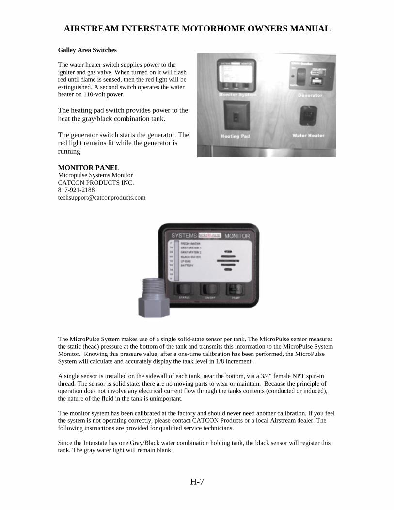
AIRSTREAM INTERSTATE MOTORHOME OWNERS MANUAL
H-7
Galley Area Switches The water heater switch supplies power to the igniter and gas valve. When turned on it will flash red until flame is sensed, then the red light will be extinguished. A second switch operates the water heater on 110-volt power. The heating pad switch provides power to the heat the gray/black combination tank. The generator switch starts the generator. The red light remains lit while the generator is running MONITOR PANEL Micropulse Systems Monitor CATCON PRODUCTS INC. 817-921-2188 [email protected]
The MicroPulse System makes use of a single solid-state sensor per tank. The MicroPulse sensor measures the static (head) pressure at the bottom of the tank and transmits this information to the MicroPulse System Monitor. Knowing this pressure value, after a one-time calibration has been performed, the MicroPulse System will calculate and accurately display the tank level in 1/8 increment. A single sensor is installed on the sidewall of each tank, near the bottom, via a 3/4" female NPT spin-in thread. The sensor is solid state, there are no moving parts to wear or maintain. Because the principle of operation does not involve any electrical current flow through the tanks contents (conducted or induced), the nature of the fluid in the tank is unimportant. The monitor system has been calibrated at the factory and should never need another calibration. If you feel the system is not operating correctly, please contact CATCON Products or a local Airstream dealer. The following instructions are provided for qualified service technicians. Since the Interstate has one Gray/Black water combination holding tank, the black sensor will register this tank. The gray water light will remain blank.

AIRSTREAM INTERSTATE MOTORHOME OWNERS MANUAL
H-8
MONITOR WIRE CONNECTIONS
Red 12VDC, Battery Only Black Ground, Battery Only Purple Water Pump, 15A, 12VDC White LPG Sensor, 90 ohm Fresh Fresh Tank Sensor Gray/Black combo 1 Black Tank Sensor MICROPULSE SYSTEMS MONITOR OPERATION INSTRUCTIONS This example shows the monitor reporting the following: Fresh Water = 1/8 to Empty Black Water = Empty to 5/8 LP Gas = 1/4 Battery = Empty to 5/8 On all diagrams the Letters R=Red, Y=Yellow, G=Green,
Blank=no LED lit.
NORMAL OPERATION The MicroPulse Monitor will display the condition of each system at all times. The tri-color LED beside the system will indicate the condition of the system using the following color code. Fresh Water, LP Gas, Battery are as follows: Green LED = 3/8 to Full Yellow LED = 1/4 Red LED = 1/8 to Empty Gray Water, Black Water are as follows: Green LED = Empty to 5/8 Yellow LED = 3/4 Red LED = 7/8 to Full TO OBTAIN EXACT READING To obtain an exact reading of all systems press and release the status button one time. The monitor will flash the LED beside the system it is about to report. It will than display the exact condition of that system by lighting the bar graph from Empty to Full. The monitor will display the exact condition of each system and then return to normal operation mode. To obtain an exact reading of an individual system press and release the status button until the LED beside the system that you want the condition of is lit. Release the status button and the monitor will display the exact condition of that system by lighting the bar graph from Empty
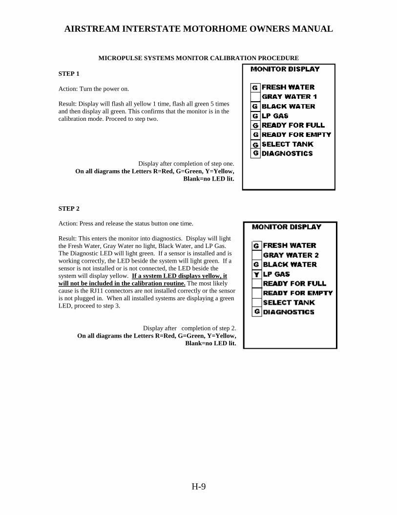
AIRSTREAM INTERSTATE MOTORHOME OWNERS MANUAL
H-9
MICROPULSE SYSTEMS MONITOR CALIBRATION PROCEDURE
STEP 1 Action: Turn the power on. Result: Display will flash all yellow 1 time, flash all green 5 times and then display all green. This confirms that the monitor is in the calibration mode. Proceed to step two.
Display after completion of step one. On all diagrams the Letters R=Red, G=Green, Y=Yellow,
Blank=no LED lit. STEP 2 Action: Press and release the status button one time. Result: This enters the monitor into diagnostics. Display will light the Fresh Water, Gray Water no light, Black Water, and LP Gas. The Diagnostic LED will light green. If a sensor is installed and is working correctly, the LED beside the system will light green. If a sensor is not installed or is not connected, the LED beside the system will display yellow. If a system LED displays yellow, it will not be included in the calibration routine. The most likely cause is the RJ11 connectors are not installed correctly or the sensor is not plugged in. When all installed systems are displaying a green LED, proceed to step 3.
Display after completion of step 2.
On all diagrams the Letters R=Red, G=Green, Y=Yellow, Blank=no LED lit.

AIRSTREAM INTERSTATE MOTORHOME OWNERS MANUAL
H-10
STEP 3 Action: Press and release the status switch 1 time. Display will light Fresh Water, Gray Water no light Black Water, and Select Tank LED’s green. After 2 seconds, the Select Tank LED will turn off and the ready for empty LED will turn light green. Proceed to step 4. On all diagrams the Letters R=Red, Y=Yellow, Blank=no LED lit.
Display after completion of step 3.
On all diagrams the Letters R=Red, G=Green, Y=Yellow, Blank=no LED lit.
STEP 4 Action: Fill all water holding tanks to the level that you want the monitor to report empty. Minimum suggested is liquid just covering the sensor. When all tanks are set to the desired level press and release the status button 1 time. Result: Display will go blank for a few moments while the empty values are being read. When the system has completed reading the empty values Fresh Water, Gray Water 1, Gray Water 2, Black Water, and the Ready For Full LED’s will light green. Proceed to step 5.
Display after completion of step 4. On all diagrams the Letters R=Red, G=Green, Y=Yellow,
Blank=no LED lit.
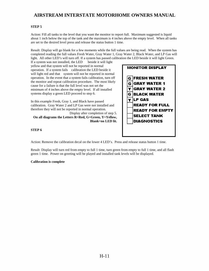
AIRSTREAM INTERSTATE MOTORHOME OWNERS MANUAL
H-11
STEP 5 Action: Fill all tanks to the level that you want the monitor to report full. Maximum suggested is liquid about 1 inch below the top of the tank and the maximum is 4 inches above the empty level. When all tanks are set to the desired level press and release the status button 1 time. Result: Display will go blank for a few moments while the full values are being read. When the system has completed reading the full values Fresh Water, Gray Water 1, Gray Water 2, Black Water, and LP Gas will light. All other LED’s will turn off. If a system has passed calibration the LED beside it will light Green. If a system was not installed, the LED beside it will light yellow and that system will not be reported in normal operation. If a system fails calibration the LED beside it will light red and that system will not be reported in normal operation. In the event that a system fails calibration, turn off the monitor and repeat calibration procedure. The most likely cause for a failure is that the full level was not set the minimum of 4 inches above the empty level. If all installed systems display a green LED proceed to step 6. In this example Fresh, Gray 1, and Black have passed calibration. Gray Water 2 and LP Gas were not installed and therefore they will not be reported in normal operation.
Display after completion of step 5. On all diagrams the Letters R=Red, G=Green, Y=Yellow,
Blank=no LED lit.
STEP 6
Action: Remove the calibration decal on the lower 4 LED’s. Press and release status button 1 time. Result: Display will turn red from empty to full 1 time, turn green from empty to full 1 time, and all flash green 1 time. Power on greeting will be played and installed tank levels will be displayed. Calibration is complete
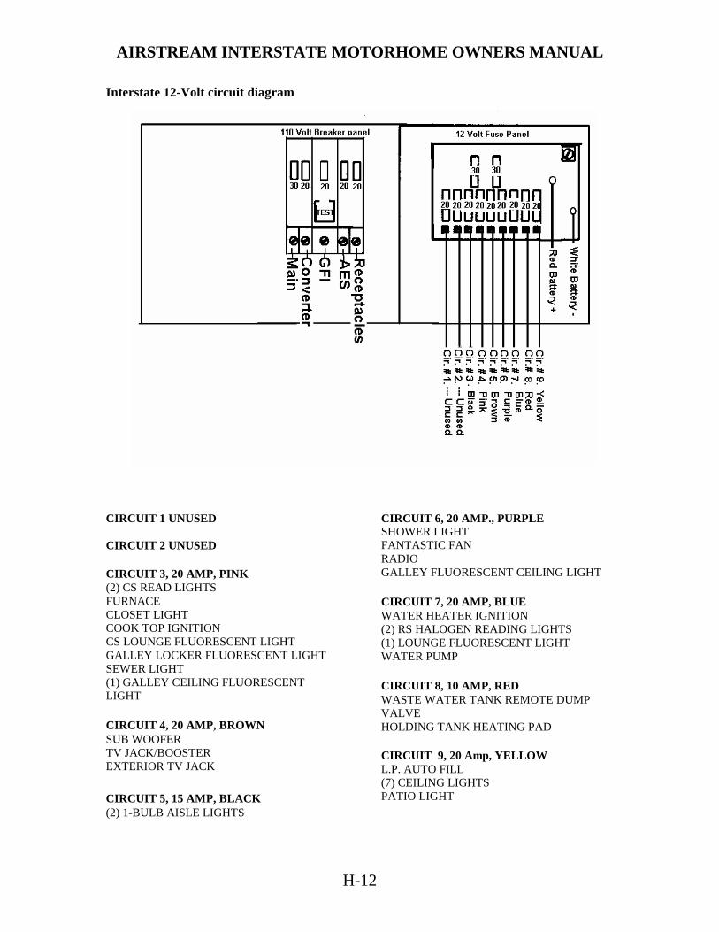
AIRSTREAM INTERSTATE MOTORHOME OWNERS MANUAL
H-12
Interstate 12-Volt circuit diagram
CIRCUIT 1 UNUSED CIRCUIT 2 UNUSED CIRCUIT 3, 20 AMP, PINK (2) CS READ LIGHTS FURNACE CLOSET LIGHT COOK TOP IGNITION CS LOUNGE FLUORESCENT LIGHT GALLEY LOCKER FLUORESCENT LIGHT SEWER LIGHT (1) GALLEY CEILING FLUORESCENT LIGHT CIRCUIT 4, 20 AMP, BROWN SUB WOOFER TV JACK/BOOSTER EXTERIOR TV JACK CIRCUIT 5, 15 AMP, BLACK (2) 1-BULB AISLE LIGHTS
CIRCUIT 6, 20 AMP., PURPLE SHOWER LIGHT FANTASTIC FAN RADIO GALLEY FLUORESCENT CEILING LIGHT CIRCUIT 7, 20 AMP, BLUE WATER HEATER IGNITION (2) RS HALOGEN READING LIGHTS (1) LOUNGE FLUORESCENT LIGHT WATER PUMP CIRCUIT 8, 10 AMP, RED WASTE WATER TANK REMOTE DUMP VALVE HOLDING TANK HEATING PAD CIRCUIT 9, 20 Amp, YELLOW L.P. AUTO FILL (7) CEILING LIGHTS PATIO LIGHT

AIRSTREAM INTERSTATE MOTORHOME OWNERS MANUAL
H-13
TV ANTENNA Manufacturer:
Winegard Company 3000 Kirkwood Street Burlington, Iowa 52601 Phone: 800-843-4741
Raising Antenna to Operating Position Turn elevating crank in "UP" direction until some resistance to turning is noted. Antenna is now in operating position. Check to make sure switch on front TV jack is on. Rotating Antenna Make sure antenna is in "UP" position. Pull down on directional handle with both hands until it disengages ceiling plate and rotate for best picture and sound on television set. Lowering Antenna to Travel Position Rotate antenna until pointer on directional handle aligns with pointer on ceiling plate.
CAUTION: Antenna must be in "down" position while traveling to prevent damage. Turn elevating crank in the "Down" direction until resistance is noted. Antenna is now locked in travel position. Checking Operation
1. Tune TV receiver to nearest station and rotate antenna for best picture and sound. 2. Turn off switch on power supply. Picture on TV receiver should be considerably degraded with the power off. DO'S 1. Do check parking location for obstructions before raising antenna. 2. Do carefully raise, lower and rotate - if difficult, check for cause. 3. Do rotate slowly when selecting station and check fine-tuning on TV set to make sure it is properly adjusted. 4. Do lower antenna before moving vehicle. DON'TS
1. Don't force elevating crank up or down. Check for cause of trouble. 2. Don't rotate directional handle hard against stops. 3. Don't travel with lift in up position. 4. Don't leave lift part way up or down. 5. Don't apply sealing compound or paint over top of base plate or anywhere on lift.

AIRSTREAM INTERSTATE MOTORHOME OWNERS MANUAL
H-14
Maintenance Lubrication To lubricate the elevating gear apply a liberal amount of silicone spray lubricant to the elevating gear with the lift in the down position, then run the lift up and down a few times to distribute lubricant over gears.
Lubricating Rotating Gear Housing
In the event that rotating the antenna becomes difficult, lubricating the bearing surface between the rotating gear housing and the base plate can restore normal operation. Any spray type silicone lubricant may be used. Elevate antenna and remove setscrew from rotating gear housing as shown. Spray lubricant into hole and around edges of gear housing. Rotate gear housing until lubricant coats bearing surfaces and antenna rotates freely. Elevating Shaft Worm Gear Assembly Replacement Procedure NOTE: It is not necessary to remove the rotating gear housing (11) from the base plate (14) or remove the antenna from the roof to replace the shaft and gear assembly. STEP 1: Lower antenna to travel position. Loosen set -screw on elevating crank (23); remove crank, spring (20), and directional handle (19). STEP 2: Remove top retaining ring (5) from top pin (4) holding top elevating tube in rotating gear housing and remove pin.
STEP 3: Remove plug from top of rotating gear housing elevating gear (8) and remove elevating shaft assembly (10). STEP 4: Cut new shaft to same length as one removed. STEP 5: Lubricate worm gear on new elevating shaft assembly with spray silicone lubricant, make sure wave washer, flat washer and quad ring are on lower bearing and insert assembly in housing. STEP 6: Install plastic plug in top of housing, re-engage elevating gear in worm gear, replace pin and retaining ring. STEP 7: Replace directional handle, spring and elevating crank. Make sure setscrew contacts flat on shaft before tightening.

AIRSTREAM INTERSTATE MOTORHOME OWNERS MANUAL
H-15
PARTS DESCRIPTION 1. Antenna Head
2. LM-300 Leveling Mount
3. Boot, Coax Cable
4. Pin, Headed/Grooved
5. Ring, Retaining Snap
6. Spacer, Plastic
7. Grommet, Plastic
8. EG-87 Elevating Gear
9. Tube, Square Elevator
10. Elevating Shaft Assy
11. Housing, Rotating Gear
12. Ring Quad Seal
13. Bearing, Nylon
14. Housing, Base Plate
15. Bearing, Nylon
17. Plate, Ceiling
18. Screw
19. Handle, Directional
20. Spring, Handle
21. Decal, Crank Cover
22. Bearing, Nylon
23. Elevating Crank/Set Screw
27. Boot, Gear Housing
30. Bumper, Rubber
31. Screw
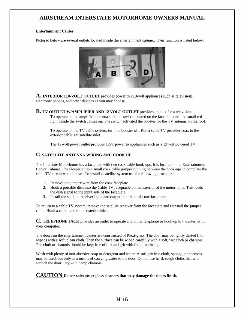
AIRSTREAM INTERSTATE MOTORHOME OWNERS MANUAL
H-16
Entertainment Center Pictured below are several outlets located inside the entertainment cabinet. Their function is listed below.
A. INTERIOR 110-VOLT OUTLET provides power to 110-volt appliances such as televisions, electronic phones, and other devices as you may choose. B. TV OUTLET W/AMPLIFIER AND 12 VOLT OUTLET provides an inlet for a television.
To operate on the amplified antenna slide the switch located on the faceplate until the small red light beside the switch comes on. The switch activated the booster for the TV antenna on the roof. To operate on the TV cable system, turn the booster off. Run a cable TV provider coax to the exterior cable TV/satellite inlet. The 12-volt power outlet provides 12-V power to appliances such as a 12 volt powered TV.
C. SATELLITE ANTENNA WIRING AND HOOK UP The Interstate Motorhome has a faceplate with two coax cable hook-ups. It is located in the Entertainment Center Cabinet. The faceplate has a small coax cable jumper running between the hook-ups to complete the cable TV circuit when in use. To install a satellite system use the following procedure:
1. Remove the jumper wire from the coax faceplate. 2. Hook a portable dish into the Cable TV receptacle on the exterior of the motorhome. This feeds
the dish signal to the input side of the faceplate. 3. Install the satellite receiver input and output into the dual coax faceplate.
To return to a cable TV system, remove the satellite receiver from the faceplate and reinstall the jumper cable. Hook a cable feed to the exterior inlet. C. TELEPHONE JACK provides an outlet to operate a landline telephone or hook up to the internet for your computer. The doors on the entertainment center are constructed of Plexi-glass. The door may be lightly dusted (not wiped) with a soft, clean cloth. Then the surface can be wiped carefully with a soft, wet cloth or chamois. The cloth or chamois should be kept free of dirt and grit with frequent rinsing. Wash with plenty of non-abrasive soap or detergent and water. A soft grit free cloth, sponge, or chamois may be used, but only as a means of carrying water to the door. Do not use hard, rough cloths that will scratch the door. Dry with damp chamois. CAUTION Do use solvents or glass cleaners that may damage the doors finish.
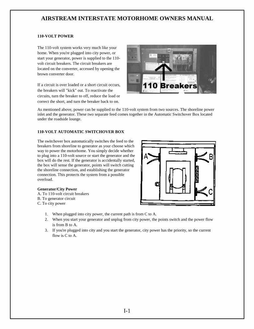
AIRSTREAM INTERSTATE MOTORHOME OWNERS MANUAL
I-1
110-VOLT POWER The 110-volt system works very much like your home. When you're plugged into city power, or start your generator, power is supplied to the 110-volt circuit breakers. The circuit breakers are located on the converter, accessed by opening the brown converter door. If a circuit is over loaded or a short circuit occurs, the breakers will "kick" out. To reactivate the circuits, turn the breaker to off, reduce the load or correct the short, and turn the breaker back to on.
As mentioned above, power can be supplied to the 110-volt system from two sources. The shoreline power inlet and the generator. These two separate feed comes together in the Automatic Switchover Box located under the roadside lounge.
110-VOLT AUTOMATIC SWITCHOVER BOX The switchover box automatically switches the feed to the breakers from shoreline to generator as your choose which way to power the motorhome. You simply decide whether to plug into a 110-volt source or start the generator and the box will do the rest. If the generator is accidentally started, the box will sense the generator, points will switch cutting the shoreline connection, and establishing the generator connection. This protects the system from a possible overload. Generator/City Power A. To 110-volt circuit breakers B. To generator circuit C. To city power
1. When plugged into city power, the current path is from C to A. 2. When you start your generator and unplug from city power, the points switch and the power flow
is from B to A. 3. If you're plugged into city and you start the generator, city power has the priority, so the current
flow is C to A.

AIRSTREAM INTERSTATE MOTORHOME OWNERS MANUAL
I-2
110-Volt Circuit Diagram
There are five 110-volt breakers. Their functions are: Main: All 110 voltage flows through this breaker to the other four breakers. Shutting off this breaker will shut down all 110 systems Converter: This circuit supplies power to operate the converter and its functions.
GFI One of the breakers is a GFI (Ground Fault Interrupter) breaker. The intent of this breaker is to sense any loss of ground before a harmful shock could occur, and kick the breaker out. These sensitive breakers are installed in the circuit feeding the outside receptacle, and galley area. These are the areas where the use of water or the wet ground could put a person in danger of shock. Since the GFI breaker is so sensitive, it is not unusual to have it kick out for no apparent reason. To reset a GFI you must first push the lever down slightly before resetting the breaker. This breaker supplies power to the exterior 110-volt outlet and the galley outlet.
AES: This breaker supplies power to the Automatic Energy Selector Switch. The microwave and roof air conditioner are both wired into this switch. Both appliances cannot be operated at the same time on the circuit. The AES prioritizes the power to the roof AC. If the microwave is used, the switch will cut power to the roof AC and supply power to the microwave. Once the microwave is turned off, power is restored to the AC. Receptacles: This breaker supplies power to the refrigerator and entertainment center outlets.
AIRSTREAM INTERSTATE MOTORHOME OWNERS MANUAL
I-3
Locating Shorts and Opens The key in locating shorts and opens is isolation. The first step to isolate the circuit with the short or open. The second step is to then isolate the section of the circuit with the fault. Once the section is identified, the specific problem can be located. The cause may be a loose or corroded connection, cut wire, worn insulation, or defective component. The following procedure is one method for isolating shorts and opens. SHORTS 1. Isolate the circuit that has the short by noting which circuit has tripped. 2 Disconnect the power inlet cord from the power source. 3. Using the 120V schematic as a reference, disconnect outlet boxes one it a time starting at the box furthest from the distribution panel. After disconnecting each box, check for continuity between the black wire and ground or common (white) wire on the distribution panel side of the circuit. When a continuity light or ohmmeter indicates no continuity, the short is either in the receptacle just removed or the section of Romex wire between this receptacle and the previous receptacle removed. 4. Examples of a short are:
A) The black wire of the 120V system contacting the white wire, bare wire, or grounded surface. B) B) An internal short in a 120V appliance.
Any damaged wire must be replaced. The National Electric Code does not permit splicing 120V wiring outside an outlet box or junction box. Also, the wire must not be exposed to an area such as a sharp metal edge that may damage the wire. OPENS 1. Check all receptacles and components for voltage on the circuit that has the open. 2. If all receptacles and components of the circuit are without power, begin to look for the open in the distribution panel. 3. Inspect for loose or corroded connections and a faulty circuit breaker, 4. Check for power on both ends of circuit breaker. If there is no power on the inlet side of the circuit breaker, the open is between the power cord's male connector and the distribution panel. 5. The open can be isolated by noting the outlets that do not have power. Example: If the bath outlet in the rear bath model has power and the converter has no power, the open is between the bath outlet and converter outlet. 6. Examples of an open are:
A) Loose or corroded connections. B) A wire disconnected from a terminal. C) Contacts in the circuit breaker that do not like contact. D) A broken wire.

AIRSTREAM INTERSTATE MOTORHOME OWNERS MANUAL
J-1
APPLIANCES
Warning: Most LP gas appliances used in recreational vehicles are vented to the outside of the vehicle. Check the exterior areas of your unit for clearance in these areas. Turn all gas operated appliances off when parked close to a gasoline pump, it is possible that gasoline fumes could enter these types of appliances and ignite from the burner flame or automatic igniters, CAUSING A FIRE OR AN EXPLOSION. AIR CONDITIONER Manufacturer: Dometic Sales Corporation
2320 Industrial Parkway P.O. Box 490 Elkhart, IN 46515 Phone: 219-295-5228
Note: Review the air conditioning literature supplied in your Owner's Packet before proceeding. The roof air conditioner used on Airstream motorhomes is one of the most popular on the market today. In your Owner's Packet is a set of literature covering all operating and maintenance instructions. If the literature is misplaced, please contact the air conditioner manufacturer or your Airstream dealer for replacement. A detailed service guide may be ordered from the manufacturer.
Operating the microwave and an air conditioner at the same time will put your electrical system at the edge of maximum draw. If the air conditioner goes into a "start up" cycle, while the microwave is operating, the additional current will probably cause a circuit breaker to kick out. Because of the amount of power drawn by the air conditioner, it is not possible to operate the AC and the microwave at the same time. The Intellitec Automatic Energy Selector Switch explained in the previous section controls this function. The AES prioritizes the power to the roof AC. If the microwave is used, the switch will cut power to the roof AC and supply power to the microwave. Once the microwave is turned off, power is restored to the AC. The voltage to the air conditioner is critical. We commonly refer to 110 or 120 volts, but a check with a voltmeter may find voltage much lower. Your air conditioner will probably not function if the current drops below 105 volts. Low voltage is usually associated with older or poorly maintained motorhome parks, but many people have found their homes, built only twenty or thirty years ago, may not be capable of operating the air conditioner on some receptacles. Parking your motorhome so the power cord can be plugged into a receptacle close to the fuse or circuit breaker box can alleviate the problem. Avoid extension cords and adapters whenever possible. If an extension cord must be used, it should be as short and heavy as possible to provide the most current to the air conditioner. If high temperatures are expected, you should make an effort to park in a shaded area. Starting the air conditioner early in the morning also helps. It is much easier to hold a comfortable temperature than it is to lower the temperature after the interior of the motorhome is already hot.

AIRSTREAM INTERSTATE MOTORHOME OWNERS MANUAL
J-2
FURNACE (See warning at top of page J-1) Manufacturer: Hydro Flame Corporation 1874 South Pioneer Road Salt Lake City, UT 84104 Phone: 801-972-4621 The manufacturer of the furnace in your motorhome has been well known in the RV industry for many years. The furnace burns LP gas, and is powered by 12-volt current from the battery when there is no shoreline hookup or power converter when plugged into 120-volt shoreline. Operating instructions are located in your Owners Packet. If they should become misplaced new literature can be ordered direct from the manufacturer or your Airstream dealer. The manufacturer also offers a detailed service guide for your furnace.
Warning: Carefully read all the manufacturer's instructions prior to operating. NEVER store flammable material next to the furnace or around its exhaust vent on the side of the motorhome. Before starting furnace, check and clear all obstructions from vent area. If warranty service is required use only a service location recommended by the furnace manufacturer or your Airstream dealer.

AIRSTREAM INTERSTATE MOTORHOME OWNERS MANUAL
J-3
REFRIGERATOR (See warning at top of page J-1) Manufacturer: Dometic Sales Corporation 2320
Industrial Parkway P.O. Box 490 Elkhart, Indiana 46514 Phone: 219-295-5228
Review all Dometic Literature supplied in your Owner's Packet or stored in the refrigerator prior to operating. In an absorption refrigerant system ammonia is liquefied in the finned condenser coil at the top rear of the refrigerator. The liquid ammonia then flows into the evaporator (inside the freezer section) and is exposed to a circulating flow of hydrogen gas, which causes the ammonia to evaporate, creating a cold condition in the freezer. The tubing in the evaporator section is specifically sloped to provide a continuous movement of liquid ammonia, flowing downward by gravity, through this section. If the refrigerator is operated out-of-level when the vehicle is not moving, liquid ammonia will accumulate in portions of the evaporator tubing. This will slow the circulation of hydrogen and ammonia gas, or in severe cases, completely block it, resulting in a loss of cooling. Any time the vehicle is parked for several hours with the refrigerator operating the vehicle should be leveled to prevent this loss of cooling. The vehicle needs to be leveled only so it is comfortable to live in (no noticeable sloping of floor or walls). When the vehicle is moving the leveling is not critical, as the rolling and pitching movement of the vehicle will pass to either side of level, keeping the liquid ammonia from accumulating in the evaporator tubing. OPERATION The refrigerator requires 12-volt current to operate even if running on LP or 110 volt modes. The 12-volt is used to power the circuit board that directs the refrigerator functions. When running in a mode such as LP, it means the heat source, by far the largest power requirement; to evaporate the ammonia is being provided by an LP Gas burner.

AIRSTREAM INTERSTATE MOTORHOME OWNERS MANUAL
J-4
RANGE Princess Range Top Manufacturer:
Seaward Products 3721 Capitol Avenue Whittier, CA. 90601-1732 562-699-7997
People using gas ranges in their home will find little difference in the operation of the range in a recreation vehicle. Other customers, used to electric ranges may be a little apprehensive at first; but will quickly gain confidence. The basic operation of the gas ranges have been the same for many years, but please be sure to read all the directions furnished by the manufacturer and located in the Owner's Packet. Excellent service and parts manuals are available from the manufacturer.
Warning: The operation manual for the range contains specialized information, warnings and cautions that if not followed exactly, may result in a fire or explosion causing property damage, personal injury, or death. The manual should be reviewed prior to operating the appliance. If this manual has not been provided with your motorhome, contact the manufacturer listed at the top of the page or Airstream Customer Service to obtain it. MICROWAVE OVEN Only federally certified technicians are permitted to service microwave ovens. For this reason the only service instructions contained in this manual are for removal of the complete oven. If you have a microwave problem please contact the appropriate manufacturer. Dometic Sales Corporation 2320 Industrial Parkway P.O. Box 490 Elkhart, IN 46515 219-295-5228
AIRSTREAM INTERSTATE MOTORHOME OWNERS MANUAL
J-5
WATER HEATER (See warning at top of page J-1) Manufacturer:
Atwood Mobile Products 4750 Hiawatha Drive P.O. Box 1205 Rockford, Illinois 61105 Phone: 815-877-7461
Note: Review the water heater literature supplied in your Owner's Packet before proceeding, CAUTION: Hydrogen gas can be produced in a hot water system served by this heater that has not been used for a long period of time (generally two weeks or more). Hydrogen gas is extremely flammable. To reduce the risk of injury under these conditions, it is recommended that the hot water faucet he opened for several minutes at the kitchen sink before using any electrical appliance connected to the hot water system. If hydrogen is present, there will probably be an unusual sound such as air escaping through the pipe as the water begins to flow. There should be no smoking or open flame near the faucet at the time it is open. Water Heater Draining All models have a drain plug or petcock on the water heater. Access is from the exterior. The plug or valve is usually located in the lower left corner, viewed as you face the exterior of the water heater. SAFETY If your water system is full and cold and the water heater is ignited, the system can produce pressures as high as 120 psi before the relief valve starts to open. Since the water system normally operates in the 40-psi range the water expansion does put unusual stress on the system. This normally does not cause any problems, but the stress is easily alleviated. As the water is heating just open any faucet and run as little as a cup of water. Just removing this small amount of water reduces the pressure build up significantly. For fun, watch the sequence of events your family goes through when you park the motorhome and ignite the water heater. More than likely, someone will run water and relieve the pressure without even realizing it.
AIRSTREAM INTERSTATE MOTORHOME OWNERS MANUAL
J-6
HIGH VOLUME ROOF VENT (OPTIONAL) Manufacturer: FAN-TASTIC VENT CORP.
2083 S. Almont Ave. Imlay City, MI 48444 Burton, MI 48529 1-810 724 3818 1-800 521 0298
The optional high-volume roof vent system is designed to quickly exhaust stale, hot air and draw in fresh air. It's great to use when the outside temperature really doesn't call for air conditioning, but heat has built up in your coach. OPERATING INSTRUCTIONS: 1. Rotate 3-speed switch to desired position, 0-off, 1, 2, and 3. The 3-speed switch must be set at 1, 2 or 3 to activate appliance.
2. Rotate thermostat knob toward 40° (cooler) until dome begins operating.
3. To determine desired temperature setting:
a. Use the wall thermometer on furnace thermostat, or any interior temperature indicator.
b. Operate fan until interior comfort level is achieved. Rotate thermostat knob toward 110' symbol on label until dome begins closing. You now have the location for normal setting.
The thermostat sensor is calibrated approximately 4°. This minimizes rapid recycling of the unit, once desired temperature level is achieved. 4. The rain sensor built into your fan will prevent excessive rain from entering coach through the open dome. Maintain a setting above (to the right of) "rain override" zone and the dome will close when the sensor becomes wet. CAUTION: Do not leave coach unattended with thermostat knob set in the "rain override" zone. 5. A rain sensor override is built into this system so you can operate your fan during light to moderate rains. When sensor is wet, rotate fan thermostat knob to coolest position to override sensor. Dome will open and fan motor will start. When sensor has completely dried, rotate thermostat knob back to desired setting for automatic operation. 6. To close dome in extremely hot conditions, rotate thermostat knob right, past 110º symbol to off. Dome will come down. 7. Always allow dome to completely cycle up and down. If dome "hangs up" in partially open/close position, rotate thermostat knob to extreme right and then left position allowing complete cycles down and up. Now reset to original comfort level.
8. When vehicle is in storage, rotate thermostat knob to right (off), after dome closes, turn 3 speed switch to "O" (off). CLEANING INSTRUCTIONS: 1) Turn fan motor OFF. 2) Remove 8 painted flathead Philips screws around perimeter of screen insert only. 3) Clean screen with soap & water solution and reinstall.

AIRSTREAM INTERSTATE MOTORHOME OWNERS MANUAL
K-1
SPECIFICATIONS Coach NOTE: The weights and measurements in this manual are derived from the best information available at time of this manuals publishing. Please refer to the weight information label placed in your unit and your chassis Owner’s Manual for weights specific to your RV.
DIMENSIONS Exterior Height with Air Conditioner 9 ft. Interior Head Room 6’ 1” Interior Floor Width 68” Exterior Length 22’ Exterior Width 7’ 1” at running boards CAPACITIES LPG Tank 33 lbs. Fresh Water Tank 30 Gal. Gray/Black Combo Holding Tank 23 Gal. Seating Capacity 6 Seating Capacity (lbs.) 924 Sleeping Capacity 2 Sleeping Capacity (lbs.) 308 CHASSIS GVWR 8,550 Lbs GCWR 13,550 lbs. Gross Axle Ratings Front: 3,860 Lbs. Gross Axle Ratings Rear: 5,360 Lbs. GTW 5000 lbs. limit for a Sprinter approved hitch receiver. TWR 500 pounds limit for a Sprinter approved hitch receiver. NCC 1,730 Lbs. UBW 6,580 Lbs. Fuel Tank (DIESEL ONLY) 25 gals. Gross Vehicle Weight Rating (GVWR) is the maximum permissible weight of the motorhome. Unit Base Weight (UBW) is the dry weight of the base unit with the bedroom group/full fuel and w/o options or fluids. Net Carrying Capacity (NCC) is equal to GVWR minus UBW. Gross Combination Weight Rating (GCWR) means the maximum allowable loaded weight of this motorhome and any towed trailer or towed vehicle. Sleeping Capacity Weight Rating (SCWR) is the manufacturer’s designated number of sleeping positions multiplied by 154 pounds (70 kilograms). Gross Axle Weight Rating (GAWR): is the value specified as the load carrying capacity of a single axle system, as measured at the tire-ground interfaces

AIRSTREAM INTERSTATE MOTORHOME OWNERS MANUAL
K-2
CHASSIS (continued) Gross Axle Weight Rating (GAWR) is a maximum permissible weight on an axle. Gross Trailer Weight (GTW) is a maximum permissible trailer weight to be towed. Trailer Tongue Weight Rating (TWR) is the maximum permissible weight of the trailer tongue. NOTE: The Unit Base Weight (UBW) and the Net Carrying Capacity (NCC) is not the same as the Unloaded Vehicle Weight (UVW) and the Cargo Carrying Capacity (CCC) shown on the Motorhome Weight Information tag in your vehicle. The UBW and NCC weights are for the base unit with no options and fluids except for fuel on motorhomes. The UVW and CCC on the Motorhome Weight Information tag are weights for the individual vehicle as built with its options and certain water capacities.
WARNING: The towing vehicle’s braking system is rated for operation at GVWR (GROSS VEHICLE WEIGHT RATING), NOT at the GCWR (GROSS COMBINED WEIGHT RATING). A separate functioning brake system is required for any towed vehicles or trailers weighing more than 1000 lbs. (450 kg) when fully loaded. NEVER exceed the GVWR (GROSS VEHICLE WEIGHT RATING), or the GAWR (GROSS AXLE WEIGHT RATING) specified on a motorhome certification label.
WARNING: Do not exceed the Gross Axle Weight Ratings, the Gross Vehicle Weight Rating , or the Gross Combined Weight Rating when loading your vehicle and/or towing a trailer. Failure to heed any part of this warning could result in loss of control of the motorhome and towed vehicle or trailer and may cause an accident and serious injury.
WARNING: READ AND FOLLOW ALL WARNINGS IN THE FUEL SECTION OF YOUR SPRINTER’S OPERATOR’S MANUAL BEFORE FUELING YOUR VEHICLE.
Warning: NEVER exceed the weight ratings of trailer hitch installed on a motorhome. Failure to heed any part of this warning could result in loss of control of the motorhome and towed vehicle or trailer and may cause an accident, serious and/or fatal injury. For specified towed vehicle braking requirements, consult the chassis owner's manual that comes with this vehicle.