aircrew training manual attack helicopter, ah-64a ...cdn.asktop.net/wp/download/5/tc1_238.pdf · tc...
TRANSCRIPT

TC 1-238
AIRCREW TRAINING MANUAL ATTACK HELICOPTER, AH-64A
SEPTEMBER 2005
DISTRIBUTION RESTRICTION: Approved for public release; distribution is unlimited.
HEADQUARTERS DEPARTMENT OF THE ARMY

This publication is available at Army Knowledge Online (www.us.army.mil) and General Dennis J. Reimer Training and Doctrine
Digital Library at (http://www.train.army.mil).
*TC 1-238
Training Circular Headquarters No. TC 1-238 Department of the Army
Washington, DC, 23 September 2005
AIRCREW TRAINING MANUAL ATTACK HELICOPTER, AH-64A
Contents Page
PREFACE .............................................................................................................vi
Chapter 1 Introduction....................................................................................................... 1-11-1. Crew Station Designation............................................................................ 1-11-2. Symbol Usage and Word Distinctions......................................................... 1-1
Chapter 2 Training.............................................................................................................. 2-1 2-1. Qualification Training .................................................................................. 2-12-2. Refresher Training ...................................................................................... 2-12-3. Mission Training .......................................................................................... 2-22-4. Continuation Training .................................................................................. 2-22-5. Task List ...................................................................................................... 2-32-6. Currency Requirements .............................................................................. 2-92-7. Annual Nuclear, Biological, and Chemical Requirements ........................ 2-10
Chapter 3 Evaluations ....................................................................................................... 3-13-1. Evaluation Principles ................................................................................... 3-13-2. Grading Considerations .............................................................................. 3-23-3. Crewmember Evaluation............................................................................. 3-23-4. Evaluation Sequence .................................................................................. 3-3
Chapter 4 Crewmember Tasks ......................................................................................... 4-14-1. Task Contents ............................................................................................. 4-14-2. Tasks ........................................................................................................... 4-7
Chapter 5 Maintenance Test Pilot Tasks ......................................................................... 5-15-1. Task Contents ............................................................................................. 5-15-2. Task List ...................................................................................................... 5-3
Chapter 6 Crew Coordination ........................................................................................... 6-16-1. Crew Coordination Background .................................................................. 6-16-2. Crew Coordination Elements ...................................................................... 6-1
DISTRIBUTION RESTRICTION: Approved for public release; distribution is unlimited.
*This publications supersedes TC 1-214, 20 May 1992.
i
TC 1-238
6-3. Crew Coordination Basic Qualities .............................................................. 6-26-4. Crew Coordination Objectives ..................................................................... 6-56-5. Standard Crew Terminology........................................................................ 6-6
Glossary .............................................................................................................. Glossary-1
References .......................................................................................................... References-1
Index .................................................................................................................... Index-1
Tasks Task 1000 Participate in a crew mission briefing ................................................................. 4-8Task 1004 Plan a visual flight rules flight............................................................................4-11Task 1006 Plan an instrument flight rules flight ..................................................................4-13Task 1010 Prepare a performance planning card ..............................................................4-15Task 1012 Verify aircraft weight and balance.....................................................................4-26Task 1013 Operate mission planning system.....................................................................4-27Task 1014 Operate aviation life support equipment ...........................................................4-28Task 1022 Perform preflight inspection ..............................................................................4-29Task 1024 Perform before-starting engine through before-leaving helicopter checks....... 4-30TASK 1026 MAINTAIN AIRSPACE SURVEILLANCE........................................................4-32TASK 1028 PERFORM HOVER POWER CHECK..............................................................4-34Task 1032 Perform radio communications procedures ......................................................4-36TASK 1034 PERFORM GROUND TAXI.............................................................................. 4-37TASK 1038 PERFORM HOVERING FLIGHT...................................................................... 4-40TASK 1040 PERFORM VISUAL METEOROLOGICAL CONDITIONS TAKEOFF ............4-44TASK 1041 PERFORM TRAFFIC PATTERN FLIGHT .......................................................4-49TASK 1044 NAVIGATE BY PILOTAGE AND DEAD RECKONING...................................4-51Task 1046 Perform electronically aided navigation ............................................................4-52Task 1048 Perform fuel management procedures .............................................................4-53TASK 1050 PERFORM HIGH-SPEED FLIGHT ..................................................................4-55TASK 1056 PERFORM HIGH/LOW G FLIGHT...................................................................4-56TASK 1058 PERFORM VISUAL METEOROLOGICAL CONDITIONS APPROACH......... 4-57TASK 1062 PERFORM SLOPE OPERATIONS .................................................................. 4-61TASK 1064 PERFORM A ROLL-ON LANDING ................................................................. 4-63Task 1070 Respond to emergencies .................................................................................. 4-65TASK 1072 RESPOND TO ENGINE FAILURE, IN-GROUND EFFECT HOVER...............4-66TASK 1073 RESPOND TO ENGINE FAILURE, OUT-OF-GROUND EFFECT HOVER ....4-68TASK 1074 RESPOND TO ENGINE FAILURE AT CRUISE FLIGHT ................................ 4-70TASK 1075 PERFORM SINGLE-ENGINE LANDING .........................................................4-72TASK 1082 PERFORM AUTOROTATION .......................................................................... 4-74TASK 1085 PERFORM STABILITY AND COMMAND AUGMENTATION SYSTEM-
OFF/BACKUP CONTROL SYSTEM-ON FLIGHT ...........................................4-77TASK 1110 PERFORM ELECTRONIC CONTROL UNIT/DIGITAL ELECTRONIC
CONTROL UNIT LOCKOUT PROCEDURES .................................................4-79TASK 1114 PERFORM ROLLING TAKEOFF..................................................................... 4-81
23 September 2005 ii
Task 1122 Task 1132 Task 1134 Task 1135 Task 1138 Task 1139 Task 1140 Task 1148 TASK 1155 Task 1160 Task 1170 Task 1172 Task 1174 Task 1176 Task 1178 Task 1180 TASK 1182 TASK 1184
Task 1188 TASK 1194 Task 1262 Task 1402 Task 1404
Task 1405 TASK 1406 TASK 1407 TASK 1408 TASK 1409 TASK 1410 TASK 1411 TASK 1412 TASK 1413 TASK 1414 TASK 1415 Task 1416 TASK 1422 Task 1458 Task 1462 Task 1464 Task 1469 Task 1471 Task 1835 TASK 2010 TASK 2043
TC 1-238
Perform target store procedures ...................................................................... 4-85Perform integrated helmet and display sight sytem boresight ......................... 4-86Perform integrated helmet and display sight system operations ..................... 4-88Perform integrated helmet and display sight system video adjustments ......... 4-91Perform target acquisition designation sight boresight .................................... 4-94Perform target acquisition designation sight operational checks ..................... 4-96Perform target acquisition designation sight sensor operations ...................... 4-97Perform data management operations............................................................. 4-99NEGOTIATE WIRE OBSTACLES................................................................. 4-106Operate video recorder .................................................................................. 4-108Perform instrument takeoff ............................................................................. 4-109Perform radio navigation ................................................................................ 4-111Perform holding procedures ........................................................................... 4-112Perform nonprecision approach ..................................................................... 4-113Perform precision approach ........................................................................... 4-114Perform emergency global positioning system recovery procedure .............. 4-115PERFORM UNUSUAL ATTITUDE RECOVERY........................................... 4-117RESPOND TO INADVERTENT INSTRUMENT METEOROLOGICAL CONDITIONS ................................................................................................. 4-119Operate aircraft survivability equipment ......................................................... 4-121PERFORM REFUELING/REARMING OPERATIONS .................................. 4-123Participate in a crew-level after-action review................................................ 4-125Perform tactical flight mission planning .......................................................... 4-127Perform electronic countermeasures/electronic counter-countermeasures procedures...................................................................................................... 4-129Transmit tactical reports (high frequency/voice) ............................................ 4-131PERFORM TERRAIN FLIGHT NAVIGATION............................................... 4-134PERFORM TERRAIN FLIGHT TAKEOFF .................................................... 4-136PERFORM TERRAIN FLIGHT ...................................................................... 4-138PERFORM TERRAIN FLIGHT APPROACH................................................. 4-141PERFORM MASKING AND UNMASKING ................................................... 4-143PERFORM TERRAIN FLIGHT DECELERATION......................................... 4-146PERFORM EVASIVE MANEUVERS............................................................. 4-148PERFORM ACTIONS ON CONTACT ........................................................... 4-150PERFORM FIRING POSITION OPERATIONS ............................................. 4-151CONDUCT DIVING FLIGHT .......................................................................... 4-154Perform weapon initialization procedures ...................................................... 4-156PERFORM FIRING TECHNIQUES................................................................ 4-159Engage target with point target weapons system .......................................... 4-163Engage target with rockets............................................................................. 4-167Engage target with area weapon system ....................................................... 4-170Perform area weapon system dynamic harmonization .................................. 4-173Perform target handover ................................................................................ 4-175Perform night vision system operational checks ............................................ 4-177PERFORM MULTIAIRCRAFT OPERATIONS .............................................. 4-180PERFORM TEAM EMPLOYMENT TECHNIQUES ....................................... 4-183
23 September 2005 iii
TC 1-238
Task 2050 Develop an emergency global positioning system recovery procedure .........4-188Task 2066 Perform extended range fuel system procedures...........................................4-194TASK 2068 PERFORM SHIPBOARD OPERATIONS ......................................................4-198TASK 2081 OPERATE NIGHT VISION GOGGLES ..........................................................4-206TASK 2127 PERFORM COMBAT MANEUVERING FLIGHT ...........................................4-208TASK 2128 PERFORM CLOSE COMBAT ATTACK........................................................4-213Task 2162 Call for indirect fire ..........................................................................................4-217Task 2164 Call for a tactical air strike...............................................................................4-221Task 4000 Perform prior to maintenance test flight checks ................................................. 5-4Task 4001 Perform a maintenance operational check/maintenance test flight
crewmember brief ............................................................................................... 5-5Task 4004 Perform interior checks .......................................................................................5-9Task 4008 Perform before-starting auxiliary power unit checks.........................................5-10Task 4010 Perform starting auxiliary power unit checks ....................................................5-11Task 4012 Perform after-starting auxiliary power unit checks............................................5-12Task 4088 Perform starting engine checks ........................................................................5-14Task 4090 Perform engine runup and systems checks .....................................................5-15Task 4110 Perform before-taxi checks ...............................................................................5-16TASK 4112 PERFORM TAXI CHECKS...............................................................................5-17Task 4114 Perform baseline and normal engine health indicator test ............................... 5-19Task 4123 Perform before-hover checks ...........................................................................5-20TASK 4144 PERFORM HOVER CHECKS ..........................................................................5-21TASK 4160 PERFORM HOVER MANEUVERING CHECKS..............................................5-22TASK 4164 PERFORM DIGITAL AUTOMATIC STABILIZATION EQUIPMENT/HOVER
AUGMENTATION SYSTEM CHECKS ............................................................5-23TASK 4182 PERFORM VISIONIC SYSTEMS CHECKS.....................................................5-25TASK 4184
AUGMENTATION SYSTEM/HOVER POSITION BOX DRIFT CHECK ..........5-26PERFORM -45/-49A DOPPLER DRIFT/-51/-55/-57 HOVER
TASK 4208 PERFORM INITIAL TAKEOFF CHECKS ........................................................5-27TASK 4220 PERFORM MAXIMUM POWER CHECK – LIMITING METHOD .................... 5-28TASK 4221 PERFORM MAXIMUM POWER CHECK – NONLIMITING METHOD ............ 5-31TASK 4222 PERFORM CRUISE FLIGHT CHECKS ...........................................................5-33TASK 4236 PERFORM AUTOROTATION REVOLUTIONS PER MINUTE CHECK ......... 5-34TASK 4238 PERFORM ATTITUDE HOLD CHECK ............................................................5-37TASK 4240 PERFORM MANEUVERING FLIGHT CHECKS .............................................5-38TASK 4242 PERFORM STABILATOR SYSTEM CHECK ..................................................5-39TASK 4258 PERFORM TURBINE GAS TEMPERATURE LIMITER
SETTING/CONTINGENCY POWER CHECK ..................................................5-40Task 4262 Perform communication and navigation equipment checks ............................. 5-42Task 4264 Perform sight/sensor checks ............................................................................5-43Task 4266 Perform weapon systems check ....................................................................... 5-44Task 4276 Perform special/detailed procedures ................................................................5-45Task 4284 Perform engine shutdown checks.....................................................................5-46TASK 4292 PERFORM Vh CHECK .....................................................................................5-47
23 September 2005 iv
TC 1-238
Figures Figure 4-1. Sample DA Form 5701-64-R (front)................................................................... 4-24
Figure 4-2. Sample DA Form 5701-64-R (back) .................................................................. 4-25
Figure 4-3. Sample crew debrief ........................................................................................ 4-126
Figure 4-4. Racetrack pattern.............................................................................................4-184
Figure 4-5. Cloverleaf pattern............................................................................................. 4-185
Figure 4-6. Figure-8 pattern ............................................................................................... 4-185
Figure 4-7. L-pattern........................................................................................................... 4-186
Figure 4-8. Template for recovery procedure diagram ...................................................... 4-193
Figure 4-9. Close combat attack briefing ...........................................................................4-215
Figure 4-10. Sample remote Hellfire request – voice......................................................... 4-219
Figure 4-11. Close air support check-in briefing ................................................................ 4-222
Figure 4-12. Close air support briefing (9-line)................................................................... 4-223
Tables Table 2-1. Aviator base task list ............................................................................................. 2-4
Table 2-2. Aviator mission task list......................................................................................... 2-8
Table 2-3. Maintenance test pilot task list .............................................................................. 2-9
Table 4-1. Effect of height above landing (HAL) surface elevation on visibility minimums........................................................................................................ 4-192
Table 4-2. Step 1 – Determine weight and moment of pylon stores loading ..................... 4-196
Table 4-3. Step 2 – Determine the aircraft lateral center of gravity ................................... 4-196
Table 4-4. Timing options ................................................................................................... 4-224
Table 6-1. Examples of standard words and phrases............................................................ 6-6
23 September 2005 v
TC 1-238
Preface
This aircrew training manual (ATM) standardizes aircrew training programs and flight evaluation procedures. This manual provides specific guidelines for executing AH-64A aircrew training and is based on the battle-focused training principles outlined in FM 7-1. It establishes crewmember qualification; refresher, mission, and continuation training; and evaluation requirements. This manual applies to all Active Army, Army National Guard (ARNG), and U.S. Army Reserve (USAR) AH-64A crewmembers and their commanders.
This manual is not a stand-alone document. All requirements contained in Army regulations (ARs) and TC 1-210 must be met. Implementation of this manual conforms to AR 95-1 and TC 1-210. If the guidance in this manual conflicts with AR 95-1 or TC 1-210, the guidance in those manuals takes precedence.
This manual (in conjunction with AR 95-1 and TC 1-210) will help aviation commanders at all levels develop comprehensive aircrew training programs. By using this ATM, commanders ensure that individual crewmember and aircrew proficiency is commensurate with the unit mission and that aircrews routinely employ standard techniques and procedures.
Standardization officers, evaluators, and unit trainers will use this manual and TC 1-210 as the primary tools to assist the commander in developing and implementing the aircrew training program. Crewmembers will use this manual as a “how to” source for performing crewmember duties. It provides performance standards and evaluation guidelines so crewmembers know the level of performance expected. Each task description explains how the task should be completed to meet the standard.
This manual applies to the Active Army, the Army National Guard (ARNG)/Army National Guard of the United States (ARNGUS), and the U.S. Army Reserve (USAR).
The proponent of this publication is the U.S. Army Training and Doctrine Command (TRADOC). Send comments and recommendations on DA Form 2028 (Recommended Changes to Publications and Blank Forms) through the aviation unit commander to Commander, U.S. Army Aviation Center, ATTN: ATZQ-ES (Attack Section), Building 4503 Kingsman Avenue, Fort Rucker, AL 36362-5263, DSN 558-2532/2531. Recommended changes may also be e-mailed to [email protected].
This publication implements portions of STANAG 3114 (Edition Six)/Air Standard 60/16, Aeromedical Training of Flight Personnel.
Unless this publication states otherwise, masculine nouns and pronouns do not refer exclusively to men.
This publication has been reviewed for operations security considerations.
23 September 2005 vi
TC 1-238
Chapter 1
Introduction
This ATM describes training requirements for crewmembers. It will be used with AR 95-1, AR 600105, AR 600-106, NGR 95-210, TC 1-210, and other applicable publications. The tasks in this ATM enhance individual and aircrew proficiency training. The training focuses on accomplishing tasks that support the unit’s mission. The scope and level of training for individual crewmembers and collective aircrews will be dictated by the mission-essential task list (METL). Commanders must ensure that aircrews are proficient in mission-essential tasks.
1-1. CREW STATION DESIGNATION. The commander will designate a crew station(s) for each crewmember. The individual’s commander’s task list (CTL) must clearly indicate all crew station designations. Crewmembers must train, and maintain, proficiency, in each designated crew station. Instructor pilots (IPs), standardization instructor pilots (SPs), instrument examiners (IEs), and maintenance evaluators (MEs) must maintain proficiency in both pilot seats. Commanders may designate unit trainers (UTs), maintenance pilots (MPs), selected pilots in command (PCs), and pilots (PIs) as dual station crewmembers. Aviators designated to fly from both stations will be evaluated in each seat during annual proficiency and readiness test (APART) evaluations, including dual-seat designated flight activity code (FAC) 3. This does not mean that all tasks must be evaluated in each seat. Chapter 3 of this ATM covers evaluation requirements for multiple crew station designations.
1-2. SYMBOL USAGE AND WORD DISTINCTIONS.
a. Symbol usage. The diagonal (/) is used to indicate “and” or “or.” For example, IP/SP may mean IP and SP, or it may mean IP or SP.
b. Word distinctions. (1) Warnings, cautions, and notes. These segments emphasize critical instructions.
(a) A warning indicates an operating procedure, practice, condition, or statement that, if not followed correctly, could result in personal injury or loss of life.
(b) A caution indicates an operating procedure, practice, condition, or statement that, if not strictly observed, could result in loss of mission effectiveness, long-term hazards to personnel, or damage to (or destruction of) equipment.
(c) A note highlights an essential operating procedure, condition, or statement. (2) Will, must, should, and may. These words distinguish between mandatory, preferred, and
acceptable methods of accomplishment. (a) Will or must indicates a mandatory requirement. (b) Should indicates a preferred, but nonmandatory, method of accomplishment. (c) May indicates an acceptable method of accomplishment.
(3) Night vision devices. (a) Night vision system (NVS) refers to the night vision system attached to the aircraft
system (such as the target acquisition and designation sight (TADS)/pilot night vision system [PNVS]). (b) Night vision goggles (NVG) refers to any night vision goggle image intensifier system
(such as the AN/AVS-6 [ANVIS]). (c) Night vision device (NVD) refers to both NVG and NVS.
23 September 2005 1-1

This page intentionally left blank.
TC 1-238
Chapter 2
Training
This chapter describes requirements for qualification, readiness level (RL) progression, and continuation training. Crewmember qualification requirements will be according to AR 95-1, TC 1210, and this ATM.
2-1. QUALIFICATION TRAINING.
a. Aircraft qualification. Initial or series qualification training will be conducted at the United States Army Aviation Center (USAAVNC) (or a Department of the Army-approved training site) according to a USAAVNC-approved program of instruction.
b. NVG qualification. Initial NVG and AH-64A aircraft NVG qualification will be per this manual and TC 1-210.
(1) Academic training. The crewmember will receive training and demonstrate a working knowledge of the topics in paragraph 3-4b(12) and TC 1-210.
(2) Flight training. The crewmember will receive training from the designated crew station and will demonstrate proficiency in all base tasks marked with an X in the NG column of table 2-1. Each crewmember will also receive training and demonstrate proficiency in any other base tasks specified for NVG on the task list for the crewmember’s position. If designated to perform NVG duties, task 2081 (Operate night vision goggles) becomes a mandatory training and evaluation task and will be added to the aviator’s CTL.
(3) Training restrictions. The following restrictions apply for flight training and operations with NVG:
(a) PNVS and TADS forward-looking infrared (FLIR) remains the primary sensor for night operations and must be operational prior to takeoff.
(b) The pilot will use PNVS if the copilot-gunner (CPG) uses NVG. The backseat crewmember may use NVG during flight if an IP is in the CPG station with PNVS selected.
c. Additional aircraft NVG qualification. The AH-64D and the AH-64A are considered similar aircraft for NVG purposes. If an aviator is qualified in the AH-64A, there is no requirement to conduct an NVG aircraft qualification for the AH-64D.
2-2. REFRESHER TRAINING.
a. Aircraft refresher training. Crewmembers will receive refresher training in the crew station(s) in which they are authorized to perform.
(1) Academic training. Crewmembers will receive training and demonstrate a working knowledge of the applicable topics in paragraph 3-4b and will complete the operator’s manual written examination.
(2) Flight training. Each crewmember will receive training and demonstrate proficiency in either assigned crew station(s) in each base task and in the modes marked with an X in the D, NS, I, and N columns of table 2-1. Each crewmember will complete Gunnery Tables III and/or IV.
b. NVG refresher training. (1) Academic training. Crewmembers will receive training and demonstrate a working
knowledge of the applicable topics in paragraph 3-4b (12).
23 September 2005 2-1
TC 1-238
(2) Flight training. Each crewmember will receive training and demonstrate proficiency in all base tasks marked with an X in the NG column of table 2-1, and in any other base tasks specified for NVG on the task list for the crewmember’s position.
2-3. MISSION TRAINING.
a. Training requirements. (1) Academic training. The crewmember will receive training and demonstrate a working
knowledge of the applicable mission topics in paragraph 3-4b. (2) Flight training. The crewmember will receive flight training and demonstrate proficiency in
the mission and in additional tasks in each mode, as specified on the task list for the crewmember’s position.
b. NVG mission training. NVG mission training will be per the commander’s training program specified tasks and flight hours. When commanders determine a requirement for using NVG in mission profiles, they must develop a mission training program, specify mission tasks, and determine the minimum number of NVG training hours required. Before undergoing NVG mission training, the aviator must complete qualification or refresher training and must be NVG-current in the AH-64A.
(1) Academic training. The crewmember will receive training and demonstrate a working knowledge of the subject areas designated by the commander.
(2) Flight training. The crewmember will receive flight training and demonstrate proficiency in the mission and additional NVG tasks, as specified on the task list for the crewmember’s position.
(3) NVG progression. For NVG progression to RL 1, an aviator must complete an NVG evaluation given at night by an NVG IP or SP in the aircraft. However, the commander may designate an aviator RL 1 for NVG purposes if the aviator's records indicate the aviator was previously NVG mission qualified. The aviator also must demonstrate proficiency in any tasks designated by the gaining unit commander.
(4) Minimum flight hours. Minimum NVG mission training hour requirements are per the commander’s determined requirements and may be included as part of refresher training.
Note 1: The AH-64A and the AH-64D are considered similar aircraft for NVG purposes. If an aviator is qualified in the AH-64D, there is no requirement to conduct an NVG mission qualification for the AH-64A. Only those additional mission tasks not designated in the AH-64A need to be evaluated.
c. MP and ME mission training. Due to the complexity of the AH-64A, MPs and MEs should be limited to duties in their primary aircraft only. They should be required to complete only mission or additional tasks that the commander considers complementary to the mission. Personnel performing duties as MPs should be classified as FAC 2 aviators. Commanders are not authorized to delete any maintenance test pilot (MTP) tasks.
(1) Academic training. The crewmember will receive training and demonstrate a working knowledge of the subject areas in paragraph 3-4b(13).
(2) Flight training. The MP/ME will receive training and demonstrate proficiency in the tasks in table 2-3.
2-4. CONTINUATION TRAINING.
a. Semiannual aircraft flying-hour requirements. (1) Single-seat designated aviator.
(a) FAC 1—70 hours, 63 hours must be flown in the designated crew station. (b) FAC 2—50 hours, 45 hours must be flown in the designated crew station.
23 September 2005 2-2
TC 1-238
(c) FAC 3—No crew duties authorized in Army aircraft. Note 2: At least once annually, FAC 1 and FAC 2 single-seat designated aviators will receive a familiarization flight in the opposite crew station in the aircraft with an IP/SP/IE/UT or in an approved simulation device.
(2) Dual-seat designated aviators (IPs, SPs, IEs, MEs, and commander-designated MPs, UTs, PCs, and PIs).
(a) FAC 1—70 hours, 15 hours must be flown in each crew station. (b) FAC 2—50 hours, 7.5 hours must be flown in each crew station. (c) FAC 3—No crew duties authorized in Army aircraft.
b. Semiannual simulation device flying-hour requirements. (1) Trainers and evaluators (IPs/SPs/IEs/MEs) may credit instructor/operator (I/O) hours
toward their annual simulation device flying-hour requirement. All aviators may apply a maximum of 12 simulation hours flown in a semiannual period toward that period’s semiannual flying hour requirements for a(1) and a(2) above.
(2) Single-seat/dual-seat designated aviator. (a) FAC 1—12 hours. (b) FAC 2—6 hours. (c) FAC 3—24 hours.
Note 3: Flying hour requirements in the designated crew station(s) will be determined by the commander. Hour requirements will be annotated on the DA Form 7120-R (Commander’s Task List).
c. Hood/weather requirements. All FAC 1, 2, and 3 aviators will complete hood or weather requirements, as determined by the commander. This requirement may be completed in the aircraft or simulator. Hour requirements will be annotated on the DA Form 7120-R.
d. Annual task and iteration requirements. (1) FAC 1 and FAC 2. Crewmembers must perform at least one task iteration annually in each
required mode, as indicated in table 2-1 and table 2-2 per the CTL. One iteration of each task that can be trained in the aircraft must be performed in the aircraft. Day iteration tasks performed at night or while using NVDs may be counted for day iterations. The crewmember is responsible for maintaining proficiency in each task. The commander may require additional iterations of specific tasks.
(2) FAC 3. In the simulator, crewmembers must perform at least one iteration annually of each task in the simulator column of table 2-1 and table2-2 per the CTL. The crewmember is responsible for maintaining proficiency in each task. The commander may require additional iterations of specific tasks.
(3) MPs and MEs. In addition to the minimum required annual tasks and iterations, MPs will perform a minimum of four iterations of maintenance test flight (MTF) mission tasks annually. The commander should incorporate 6 hours per test pilot into the annual flying-hour program for MP and ME training and evaluations. MEs will perform two iterations from each flight crew station annually. Each MTF mission task listed is mandatory for an MTF standardization evaluation.
2-5. TASK LIST.
a. Performance task. This ATM differentiates between performance tasks and technical tasks. Performance tasks are primarily designed to measure the ability of the pilot on the controls (P*) to perform, manipulate the controls, and respond to tasks that are affected by the mode of flight. The conditions and mode of flight significantly affect performance tasks; therefore, the tasks specify the mode and conditions under which the task must be performed. Modes and conditions include takeoff, landing, emergency procedure flight, autorotation, terrain flight, actions on contact, firing techniques, hovering
23 September 2005 2-3

TC 1-238
flight, and visual meteorological conditions (VMC) flight maneuver. Performance tasks are listed in upper case and bold throughout this manual.
b. Technical task. Technical tasks measure the pilot’s (PLT) or CPG’s ability to plan, preflight, brief, runup, shutdown, debrief, and operate specific onboard systems, sensors, avionics, and other elements while in flight or on the ground. Technical tasks may be performed under all conditions regardless of the listed task iteration requirements. The mode of flight does not significantly affect technical tasks; therefore, the tasks may be performed or evaluated in any mode. Technical tasks are in lower case and plain type throughout this manual.
Note 4: Task iteration condition code “I” (instrument), as used on DA Form 5484-R (Mission Schedule/Brief), is an independent flight condition (AR 95-1, appendix C). Instrument (H [hood] or W [weather]) condition tasks may be flown at night or during the day per a mission briefing.
:
ith both and “S” and “I” in the EVAL col
Tasks designated as ”N” or “NG” in the EVAL column must be evaluated in those modes; other tasks evaluated in a more demanding mode may be credited toward completion of annual evaluation requirements. “NS” is considered the most demanding mode, followed by “N,” “D,” and finally, “SM.”
Tasks identified w umn may be evaluated during either or both
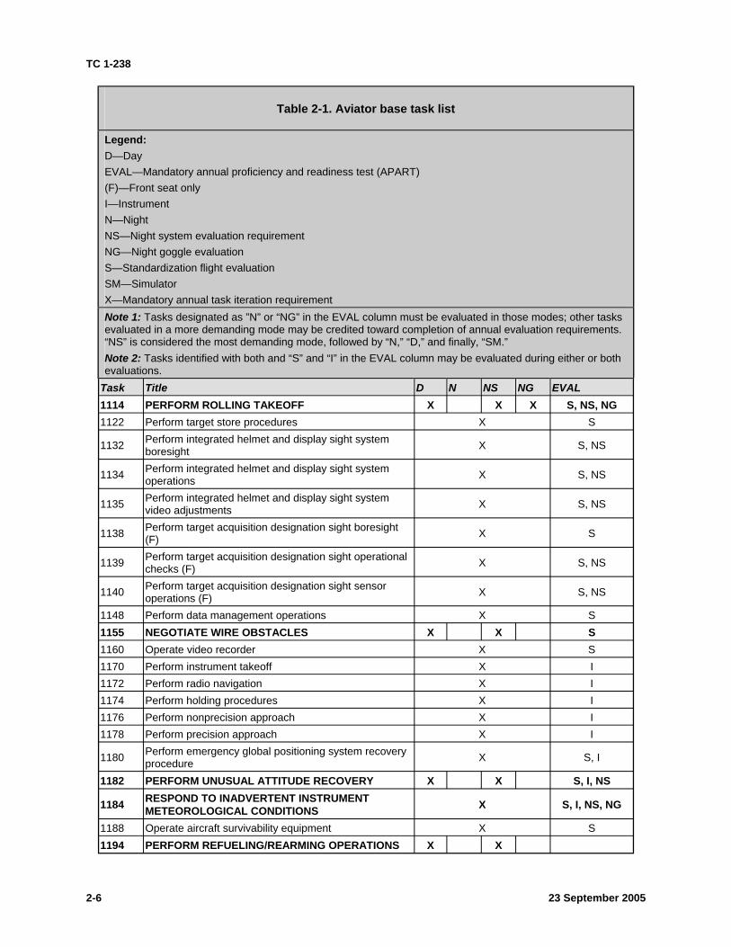
Table 2-1. Aviator base task list
LegendD—Day EVAL—Mandatory annual proficiency and readiness test (APART) (F)—Front seat onlyI—Instrument N—Night NS—Night system evaluation requirement NG—Night goggle evaluation S—Standardization flight evaluation SM—Simulator X—Mandatory annual task iteration requirement Note 1:
Note 2:
Participate in a crew mission briefing
evaluations. Task Title D N NS NG EVAL
1000 X S, I, NS, NG
1004 Plan a visual flight rules flight X S 1006 Plan an instrument flight rules flight X I 1010 Prepare a performance planning card X S, I 1012 Verify aircraft weight and balance X S, I 1013 Operate mission planning system X S 1014 Operate aviation life support equipment X S 1022 Perform preflight inspection X S, I
1024 Perform before-starting engine through before-leaving helicopter checks X S, I
1026 MAINTAIN AIRSPACE SURVEILLANCE X X X X S, I, N, NS, NG 1028 PERFORM HOVER POWER CHECK X X X X S, I, N, NS, NG 1032 Perform radio communications procedures X S, I
23 September 2005 2-4

TC 1-238
Table 2-1. Aviator base task list
Legend: D—Day EVAL—Mandatory annual proficiency and readiness test (APART) (F)—Front seat only I—Instrument N—Night NS—Night system evaluation requirement NG—Night goggle evaluation S—Standardization flight evaluation SM—Simulator X—Mandatory annual task iteration requirement Note 1: Tasks designated as ”N” or “NG” in the EVAL column must be evaluated in those modes; other tasks evaluated in a more demanding mode may be credited toward completion of annual evaluation requirements. “NS” is considered the most demanding mode, followed by “N,” “D,” and finally, “SM.” Note 2: Tasks identified with both and “S” and “I” in the EVAL column may be evaluated during either or both evaluations.
Task Title D N NS NG EVAL 1034 PERFORM GROUND TAXI X X X S, N, NS 1038 PERFORM HOVERING FLIGHT X X X X S, N, NS, NG 1040 PERFORM VISUAL METEOROLOGICAL
CONDITIONS TAKEOFF X X X X S, N, NS, NG
1041 PERFORM TRAFFIC PATTERN FLIGHT X X X X S, N, NS, NG 1044 NAVIGATE BY PILOTAGE AND DEAD RECKONING X X x S, NS, NG 1046 Perform electronically aided navigation X S 1048 Perform fuel management procedures X S, I, NS, NG 1050 PERFORM HIGH-SPEED FLIGHT X X 1056 PERFORM HIGH/LOW G FLIGHT X X 1058 PERFORM VISUAL METEOROLOGICAL
CONDITIONS APPROACH X X X X S, N, NS, NG
1062 PERFORM SLOPE OPERATIONS X X X S, NS, NG 1064 PERFORM A ROLL-ON LANDING X X X S, NG 1070 Respond to emergencies X S, I, N, NS, NG
1072 PERFORM ENGINE FAILURE, IN-GROUND EFFECT HOVER X X
1073 RESPOND TO ENGINE FAILURE, OUT-OF-GROUND EFFECT HOVER X X S, NS
1074 RESPOND TO ENGINE FAILURE AT CRUISE FLIGHT X X X X S, I, N, NS, NG 1075 PERFORM SINGLE-ENGINE LANDING X X X X S, N, NS, NG 1082 PERFORM AUTOROTATION X X S, NS
1085 PERFORM STABILITY AND COMMAND AUGMENTATION SYSTEM-OFF/BACKUP CONTROL SYSTEM-ON FLIGHT
X X S
1110 PERFORM ELECTRONIC CONTROL UNIT/DIGITAL ELECTRONIC CONTROL UNIT LOCKOUT PROCEDURES
X X S
23 September 2005 2-5
TC 1-238
:
evaluations. Task Title 1114 PERFORM ROLLING TAKEOFF 1122 Perform target store procedures
1132 Perform integrated helmet and display sight system boresight
1134 Perform integrated helmet and display sight system operations
1135 Perform integrated helmet and display sight system video adjustments
1138 Perform target acquisition designation sight boresight (F)
1139 Perform target acquisition designation sight operational checks (F)
1140 Perform target acquisition designation sight sensor operations (F)
1148 Perform data management operations 1155 NEGOTIATE WIRE OBSTACLES 1160 Operate video recorder 1170 Perform instrument takeoff 1172 Perform radio navigation 1174 Perform holding procedures 1176 Perform nonprecision approach 1178 Perform precision approach
1180 Perform emergency global positioning system recovery procedure
1182 PERFORM UNUSUAL ATTITUDE RECOVERY
1184 RESPOND TO INADVERTENT INSTRUMENT METEOROLOGICAL CONDITIONS
1188 Operate aircraft survivability equipment 1194 PERFORM REFUELING/REARMING OPERATIONS
ith both and “S” and “I” in the EVAL col
Tasks designated as ”N” or “NG” in the EVAL column must be evaluated in those modes; other tasks evaluated in a more demanding mode may be credited toward completion of annual evaluation requirements. “NS” is considered the most demanding mode, followed by “N,” “D,” and finally, “SM.”
Tasks identified w umn may be evaluated during either or both
Table 2-1. Aviator base task list
LegendD—Day EVAL—Mandatory annual proficiency and readiness test (APART) (F)—Front seat onlyI—Instrument N—Night NS—Night system evaluation requirement NG—Night goggle evaluation S—Standardization flight evaluation SM—Simulator X—Mandatory annual task iteration requirement Note 1:
Note 2:
D N NS NG EVAL X X X S, NS, NG
X S
X S, NS
X S, NS
X S, NS
X S
X S, NS
X S, NS
X S X X S
X S X I X I X I X I X I
X S, I
X X S, I, NS
X S, I, NS, NG
X S X X
23 September 2005 2-6
TC 1-238
Table 2-1. Aviator base task list
Legend: D—Day EVAL—Mandatory annual proficiency and readiness test (APART) (F)—Front seat only I—Instrument N—Night NS—Night system evaluation requirement NG—Night goggle evaluation S—Standardization flight evaluation SM—Simulator X—Mandatory annual task iteration requirement Note 1: Tasks designated as ”N” or “NG” in the EVAL column must be evaluated in those modes; other tasks evaluated in a more demanding mode may be credited toward completion of annual evaluation requirements. “NS” is considered the most demanding mode, followed by “N,” “D,” and finally, “SM.” Note 2: Tasks identified with both and “S” and “I” in the EVAL column may be evaluated during either or both evaluations.
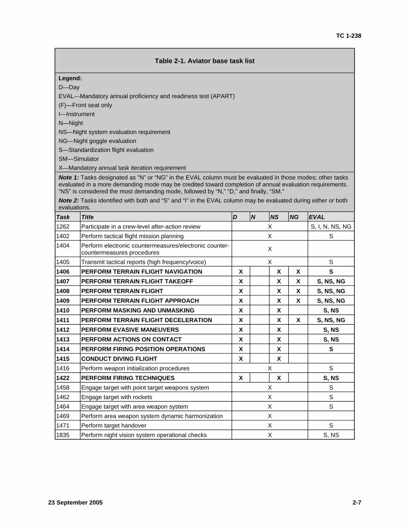
Task Title D N NS NG EVAL 1262 Participate in a crew-level after-action review X S, I, N, NS, NG 1402 Perform tactical flight mission planning X S 1404 Perform electronic countermeasures/electronic counter-
countermeasures procedures X
1405 Transmit tactical reports (high frequency/voice) X S 1406 PERFORM TERRAIN FLIGHT NAVIGATION X X X S 1407 PERFORM TERRAIN FLIGHT TAKEOFF X X X S, NS, NG 1408 PERFORM TERRAIN FLIGHT X X X S, NS, NG 1409 PERFORM TERRAIN FLIGHT APPROACH X X X S, NS, NG 1410 PERFORM MASKING AND UNMASKING X X S, NS 1411 PERFORM TERRAIN FLIGHT DECELERATION X X X S, NS, NG 1412 PERFORM EVASIVE MANEUVERS X X S, NS 1413 PERFORM ACTIONS ON CONTACT X X S, NS 1414 PERFORM FIRING POSITION OPERATIONS X X S 1415 CONDUCT DIVING FLIGHT X X 1416 Perform weapon initialization procedures X S 1422 PERFORM FIRING TECHNIQUES X X S, NS 1458 Engage target with point target weapons system X S 1462 Engage target with rockets X S 1464 Engage target with area weapon system X S 1469 Perform area weapon system dynamic harmonization X 1471 Perform target handover X S 1835 Perform night vision system operational checks X S, NS
23 September 2005 2-7
TC 1-238
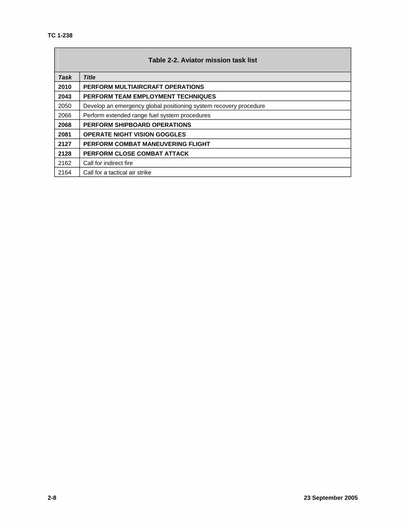
Table 2-2. Aviator mission task list
Task Title 2010 PERFORM MULTIAIRCRAFT OPERATIONS 2043 PERFORM TEAM EMPLOYMENT TECHNIQUES 2050 Develop an emergency global positioning system recovery procedure 2066 Perform extended range fuel system procedures 2068 PERFORM SHIPBOARD OPERATIONS 2081 OPERATE NIGHT VISION GOGGLES 2127 PERFORM COMBAT MANEUVERING FLIGHT 2128 PERFORM CLOSE COMBAT ATTACK 2162 Call for indirect fire 2164 Call for a tactical air strike
23 September 2005 2-8
TC 1-238
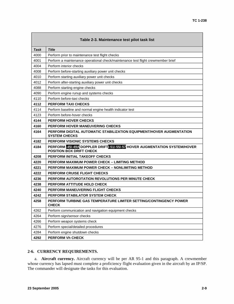
Table 2-3. Maintenance test pilot task list
Title 4000 Perform prior to maintenance test flight checks 4001 4004 Perform interior checks 4008 4010 4012 4088 Perform starting engine checks 4090 4110 Perform before-taxi checks 4112 4114 Perform baseline and normal engine health indicator test 4123 Perform before-hover checks 4144 4160 4164
SYSTEM CHECKS 4182 PERFORM VISIONIC SYSTEMS CHECKS 4184 PERFORM -45/-49A DOPPLER DRIFT/-51/-55/-57
POSITION BOX DRIFT CHECK 4208 4220 4221 4222 PERFORM CRUISE FLIGHT CHECKS 4236 4238 4240 4242 4258
CHECK 4262 Perform communication and navigation equipment checks 4264 Perform sign/sensor checks 4266 4276 4284 4292
2-6. CURRENCY REQUIREMENTS.
a. Aircraft currency.
Task
Perform a maintenance operational check/maintenance test flight crewmember brief
Perform before-starting auxiliary power unit checks Perform starting auxiliary power unit checks Perform after-starting auxiliary power unit checks
Perform engine runup and systems checks
PERFORM TAXI CHECKS
PERFORM HOVER CHECKS PERFORM HOVER MANEUVERING CHECKS PERFORM DIGITAL AUTOMATIC STABILIZATION EQUIPMENT/HOVER AUGMENTATION
HOVER AUGMENTATION SYSTEM/HOVER
PERFORM INITIAL TAKEOFF CHECKS PERFORM MAXIMUM POWER CHECK – LIMITING METHOD PERFORM MAXIMUM POWER CHECK – NONLIMITING METHOD
PERFORM AUTOROTATION REVOLUTIONS PER MINUTE CHECK PERFORM ATTITUDE HOLD CHECK PERFORM MANEUVERING FLIGHT CHECKS PERFORM STABILATOR SYSTEM CHECK PERFORM TURBINE GAS TEMPERATURE LIMITER SETTING/CONTINGENCY POWER
Perform weapon systems check Perform special/detailed procedures Perform engine shutdown checks PERFORM Vh CHECK
Aircraft currency will be per AR 95-1 and this paragraph. A crewmember whose currency has lapsed must complete a proficiency flight evaluation given in the aircraft by an IP/SP. The commander will designate the tasks for this evaluation.
23 September 2005 2-9
TC 1-238
b. NVG currency. Aviators whose currency has lapsed must complete, at a minimum, a 1-hour NVG proficiency evaluation given at night by an NVG IP/SP in the aircraft. The aviator must demonstrate proficiency in all tasks with an NG in the evaluation column of table 2-1. To be considered NVG current, an aviator must participate, every 60 consecutive days, in a 1-hour flight in the aircraft at night or a 1-hour flight in the AH-64A simulator while using the NVGs. Aviators must participate every 120 consecutive days in a 1-hour flight in the aircraft at night while using NVGs.
c. NVS currency. Aviators whose currency has lapsed must complete, at a minimum, a 1-hour NVS proficiency evaluation given at night by an IP/SP in the aircraft. The aviator must demonstrate proficiency in all tasks with an NS in the evaluation column of table 2-1. To be considered NVS current, an aviator must participate, every 60 consecutive days, in one 1-hour flight in the aircraft either at night or during the day with blackout curtains, or a 1-hour flight in the AH-64A simulator while using the NVS. Aviators must participate every 120 consecutive days in a 1-hour flight in the aircraft at night while using NVS.
Note 5: Aviators assigned with the AH-64D as an additional aircraft may maintain NVS and NVG currency in either aircraft.
Note 6: Units may contact Directorate of Evaluation and Standards (DES) for the current approval authority for the use of day curtains in support of NVS currency requirements. Day system (DS) flight training requires the commander to develop an internal standing operating procedure (SOP) that addresses critical parameters of DS flight. The commander must authorize crew station assignments (for example, with an IP or UT in the CPG station), DS egress procedures, and other parameters (such as auxiliary tank restrictions, flight modes, or registration check procedures).
2-7. ANNUAL NUCLEAR, BIOLOGICAL, AND CHEMICAL REQUIREMENTS.
a. Per TC 1-210, crewmembers will receive chemical, biological, radiological, and nuclear (CBRN) training in the tasks listed below if training is required. The commander may select other tasks based on the unit’s mission. If CBRN tasks are selected, the commander will establish a CBRN evaluation program in writing.
z TASK 1026: MAINTAIN AIRSPACE SURVEILLANCE z TASK 1028: PERFORM HOVER POWER CHECK z TASK 1034: PERFORM GROUND TAXI z TASK 1038: PERFORM HOVERING FLIGHT z TASK 1040: PERFORM VISUAL METEOROLOGICAL CONDITIONS TAKEOFF z TASK 1058: PERFORM VISUAL METEOROLOGICAL CONDITIONS
APPROACH
b. Each year, crewmembers will perform at least one iteration of the tasks listed above while wearing mission-oriented protective posture (MOPP) level 4 CBRN gear.
23 September 2005 2-10
TC 1-238
Chapter 3
Evaluations
This chapter describes evaluation principles and grading considerations. It also contains guidelines for conducting academic and hands-on performance testing. Evaluations are a primary means of assessing flight standardization and crewmember proficiency. Evaluations will be conducted per AR 95-1, TC 1-210, and this ATM.
3-1. EVALUATION PRINCIPLES.
a. The value of evaluations depends on adherence to fundamental evaluation principles. These principles are described below.
(1) The evaluators must be selected not only for their technical qualifications, but also for their demonstrated performance, objectivity, and ability to observe and provide constructive comments. These evaluators are the SPs, IPs, IEs, and MEs who assist the commander in administering the aircrew training program (ATP).
(2) The method used to conduct the evaluation must be based on uniform and standard objectives. In addition, it must be consistent with the unit's mission and must strictly adhere to the appropriate SOPs and regulations. The evaluator must ensure a complete evaluation is given in all areas and must refrain from making a personal area of expertise a dominant topic during the evaluation.
(3) All participants must completely understand the purpose of the evaluation. (4) All participants must cooperate to accomplish the evaluation objectives. The evaluation
emphasis is on all participants, not just on the examinee. (5) The evaluation must produce specific findings to identify training needs. The examinee
needs to know what is being performed correctly or incorrectly, and how to make improvements.
b. An evaluation determines the examinee's ability to perform essential tasks to prescribed standards. Flight evaluations determine the examinee’s ability to exercise crew coordination in completing the tasks.
c. The guidelines for evaluating crew coordination are based on a subjective analysis of how effectively a crew performs to accomplish a series of tasks. The evaluator must determine how effectively the examinee employs air crew coordination, as outlined in chapter 6.
d. In all phases of evaluation, the evaluator is expected to perform as an effective crewmember. However, during the evaluation, circumstances may prevent the evaluator from performing as a crewmember. In such cases, a realistic, meaningful, and planned method should be developed to pass this task back to the examinee effectively. During the conduct of the flight evaluation, the evaluator will normally perform as outlined in the task description or as directed by the examinee. At some point, the evaluator may perform a role reversal with the examinee. The examinee must be made aware of both the initiation and termination of role reversals. The examinee must know when he is being supported by a fully functioning crewmember.
Note 1: When evaluating a PC, UT, IP, SP, ME, IE, or unit trainer, the evaluator must advise the examinee that during role reversal he may deliberately perform some tasks or crew coordination outside the standards to check the examinee's diagnostic and corrective action skills.
23 September 2005 3-1
TC 1-238
3-2 23 September 2005
3-2. GRADING CONSIDERATIONS.
a. Academic evaluation. The examinee must demonstrate a working knowledge and understanding of the appropriate subject areas.
b. Flight evaluation. (1) Academic. Some tasks are identified in training and evaluation requirements as tasks
that may be evaluated academically. The examinee must demonstrate a working knowledge of the tasks. Evaluators may use computer-based instruction (CBI), mock ups, or other approved devices to assist in determining the examinee’s knowledge of the task.
(2) In the aircraft or the simulator. Some tasks must be performed and evaluated in the aircraft or the AH-64A simulator. Task standards are based on an ideal situation. Grading is based on meeting the minimum standards. The evaluator must consider deviations (such as high wind, turbulence, or poor visibility) from the ideal conditions during the evaluation. If conditions are not ideal, the evaluator must make appropriate adjustments to the standards.
3-3. CREWMEMBER EVALUATION. Evaluations are conducted to determine the crewmember's ability to perform the tasks on his CTL and to check the crewmember’s understanding of the required academic subjects listed in the ATM. When the examinee is an evaluator/trainer, the recommended procedure is for the evaluator to reverse roles with the examinee. When the evaluator uses this technique, the examinee must understand how the role reversal will be conducted and when it will be in effect. Initial validation of an aviator’s qualifications following a military occupational specialty (MOS)-producing course of instruction/school, such as AH-64A Instructor Pilot Course, Maintenance Test Pilot Course, or Instrument Flight Examiners Course, will be conducted in the aircraft upon return from that course and in the aircraft at each new duty station.
a. Recommended performance and evaluation criteria. (1) PI. The PI must demonstrate a basic understanding of the appropriate academic subjects
from 3-4b. In addition, he must be familiar with his individual aircrew training folder (IATF) and understand the requirements of his CTL.
(2) PC/MP. The PC/MP must meet the requirements in paragraph 3-3a(1). In addition, he must demonstrate sound judgment and maturity in the management of the mission, crew, and assets.
(3) UT. The UT must meet the requirements in paragraph 3-3a(2). In addition, he must be able to instruct in the appropriate tasks and subjects, recognize errors in performance or understanding, make recommendations for improvement, train to standards, and document training.
(4) IP or IE. The IP or IE must meet the requirements in paragraph 3-3a(2). In addition, he must be able to objectively instruct, evaluate, and document performance of the PI, PC, UT, and IE using role reversal for IP (such as aircraft/NVD currency evaluations), IE, UT, and PC as appropriate. He must be able to develop and implement an individual training plan and have a thorough understanding of the requirements and administration of the ATP.
(5) SP. The SP must meet the requirements in paragraph 3-3a(2) and (4). The SP must be able to instruct and evaluate IPs, SPs, UTs, and PCs as appropriate, using role reversal. The SP must also be able to develop and implement a unit training plan and administer the commander's ATP.
(6) ME. The ME must meet the requirements in paragraph 3-3a(1) and (2). The ME must also be able to instruct and evaluate other MEs and MPs using role reversal when required.
Note 2: SPs, IPs, IEs, MEs, and UTs will be evaluated on their ability to apply the learning and teaching process outlined in paragraph 3-4b(14).
TC 1-238
23 September 2005 3-3
b. Academic evaluation criteria. (1) Proficiency flight evaluations (PFE). This evaluation is conducted per AR 95-1 and TC
1-210. The commander or his representative will select the topics to be evaluated from paragraph 2-9. (2) Annual proficiency and readiness test (APART) standardization evaluation D/N/NS.
The IP will evaluate a minimum of two topics from the subject areas in paragraph 3-4b that apply. If evaluated, topics selected will be based on the unit METL. In addition, the evaluator will have the examinee identify at least two aircraft components and discuss their functions.
(3) APART instrument evaluation. The IE will evaluate a minimum of two topics from the subject areas in paragraph 3-4b relative to instrument meteorological conditions (IMC) flight and flight planning. If the evaluated crewmember is an IP/SP/IE, the IE will evaluate the IP/SP/IE’s ability to instruct instrument-related tasks.
(4) Annual NVG evaluation. The NVG IP will evaluate a minimum of two topics from the subject areas in paragraph 3-4b that apply.
(5) APART MP/ME evaluation. The ME will evaluate a minimum of two topics from the appropriate subject areas in paragraph 3-4b with specific emphasis on how they apply to maintenance test flights. Additionally, if the examinee is an ME, the evaluating ME will evaluate paragraph 3-4b(14).
(6) Other ATP evaluations. The SP/IP will evaluate a minimum of two topics from each subject area in paragraph 3-4b that apply.
3-4. EVALUATION SEQUENCE. The evaluation sequence consists of four phases. The evaluator will determine the amount of time devoted to each phase.
a. Phase 1—Introduction. In this phase, the evaluator will— (1) Review the examinee's individual flight records folder (IFRF) and IATF records to
verify that the examinee meets all prerequisites for designation and has a current DA Form 4186 (Medical Recommendation for Flying Duty).
(2) Confirm the purpose of the evaluation, explain the evaluation procedure, and discuss the evaluation standards and criteria to be used.
b. Phase 2—Academic evaluation topics. (1) Tactical and mission operations (FM 1-112, FM 1-114, FM 3-04.140, FM 1-400,
TM 1-1520-238-10, and unit SOP). Topics in this subject area are— • Mission graphics and symbols • Battlefield environment • Mission statement and employment method • Combined-arms operations • Firing techniques • Tactical formations and fire control • Attack by fire/support by fire/NORMA • Firing position selection and reconnaissance • Engagement area operations • Target coordination and control • Fratricide prevention • Fire support and tactical airstrike control • Tactical reports
• Evasive maneuvers • Aviation mission planning station • Terrain flight planning safety • Downed aircraft procedures • Radar countermeasures • Aerial observation—visual/onboard sensors • Reconnaissance operations/mission • Call for and adjust indirect fire • Deck landing and flight operations • Navigational chart, map, and tactical
overlay interpretation • Major United States (U.S.) or allied
equipment and major threat equipment identification
TC 1-238
(2) Mission systems operation and employment (FM 1-112, FM 3-04.140, and TM 1-1520-238-10). Topics in this subject area are—
• Communications • Aircraft survivability equipment • Target acquisition • Target storing, management, and handover • Navigation subsystem • Degraded system operations • High-action display (HAD) messages • TADS operational checks and TADS • Flight/weapons symbology boresight • Integrated helmet and display sight system • Sight/sensor acquisition slaving and cueing
(IHADSS) operation and boresight operations
(3) Weapon system operation and deployment (FM 1-112, FM 3-04.140, and TM 1-1520-238-10). Topics in this subject area are—
• Hellfire missile, semiactive laser (SAL) characteristics
• Hydra 70 rocket characteristics • 30-millimeter ammunition • Combined weapons engagement • Point target weapons system—SAL lock on
after launch (LOAL) • Point target weapon system—SAL lock on
before launch (LOBL)
• Area weapon system • Weapons initialization, arming, and safety • Laser operations (range/designator) • Weapons effects on night vision • Laser operations • Aerial rocket subsystem
(4) Night mission operation and deployment (TC 1-204). Topics in this subject area are—
• Unaided night flight • NVS characteristics and operation • Night visual limitations and techniques • Flight symbology and modes • Visual illusions • Aircrew night and NVD requirements • Helmet display optimization • NVD limitations and techniques • FLIR sensor optimization
• Types of vision • Distance estimation and depth perception • Dark adaptation, night vision protection, and
central night blind spot • Night terrain interpretation, map preparation,
and navigation • Night tactical operations, including aircraft
lighting • Parallax effect
23 September 2005 3-4
TC 1-238
(5) Aircraft and systems (TM 1-1520-238-10). Topics in this subject area are—
• Principal dimensions • Auxiliary power unit • Emergency equipment • Environmental control system • Engines and related equipment • Lighting • Data entry • Electrical power management system • Flight control system • Flight instruments • Hydraulic and pressurized air system (PAS) • Servicing, parking, and mooring • Power train and mast mounted assembly • Fuel system • Main and tail rotor • Utility systems
(6) Operating limitations and restrictions (TM 1-1520-238-10). Topics in this subject area are—
• Wind limitations • Flight envelope limitations—aircraft, • Rotor limits auxiliary tank, navigation • Power limits • Performance chart interpretation • Engine limits • Weather/environmental • Airspeed limits limitations/restrictions • Pressure limits • Weight and balance requirements and • Aircraft system limitations interpretation • Temperature limits • FLIR, NVD limitations • Power limits • Other limitations • Laser limits • ISAQ
(7) Aircraft emergency procedures and malfunction analysis (TM 1-1520-238-10). Topics in this subject area are—
• Emergency terms and definitions • Mission equipment failures/malfunctions • After emergency action • Symbol generator failures • Master warning and caution/advisory panel • Smoke and fume elimination • Emergency exits, equipment, egress, and • Electrical system malfunctions
entrance • Tail rotor malfunctions • Fault detection and isolation system • Chip detectors
procedures • Fuel system malfunctions • Rotor, transmission, and drive system • Environmental control system (ECS) failures
malfunctions • Night vision systems malfunctions • Engine malfunctions and restart procedures • Weapon system malfunctions • Landing and ditching procedures • IHADSS malfunctions • Fires and hot starts • Stability augmentation system • Electrical system failures • (SAS)—OFF/malfunctions/flight • Hydraulic system failures • (BUCS)—ON/backup control system • Landing and ditching • Caution/warning light procedures • Flight control failures/malfunctions
23 September 2005 3-5
TC 1-238
(8) Regulations and publications (AR 95-1, DA Pam 738-751, Department of Defense (DOD) flight information publication (FLIP), TC 1-210, TM 1-1520-238-23 series, TM 1-1520-238-10 chapters 6 and 7, local regulations, and unit SOPs). Topics in this subject area are—
• ATP, IATF/CTL requirements • Flight plan preparation and filing • Unit SOP and local requirements • Crew coordination • DOD FLIPs and maps • Weight and balance requirements • Fuel requirements • Publications required in aircraft • Airspace regulations and usage • Range operations and safety • Visual flight rules (VFR)/instrument flight • Inadvertent IMC procedures
rules (IFR) minimums and procedures • Aviation life support equipment
(9) Aeromedical factors (AR 40-8, FM 3-04.301, and TC 1-204). Topics in this subject area are—
• Flight restrictions due to exogenous factors • Self-imposed stresses • Spatial disorientation • Middle ear discomfort
(10) Aerodynamics (FM 1-203 and TM 1-1520-238-10). Topics pertaining to this subject area are—
• Airflow during hover • Settling with power • Retreating blade stall • Dynamic rollover • Translating tendency • Effective translational lift
(11) Maneuvering flight air worthiness release, AR 95-1, FM 1-112, FM 3-04.140, FM 1-202, FM 1-203, TM 1-1520-238-10, and The Army Aviator’s Handbook for Maneuvering Flight and Power Management). Topics in this subject area are—
• Techniques and considerations • High/low G flight and turns • Transient torque • Vertical stabilizer during diving flight
• Sustained 60-degree turns • Rapid turns • Rotor disc coning and resultant revolutions
per minute (RPM)/torque effects transverse flow
(12) Night vision goggle operation and deployment (ISAQ, FM 3-04.301, TC 1-210, TC 1-204, TM 1-1520-238-10, and unit SOP). Topics in this subject area are—
• Vision, depth perception, and night vision orientation
• Night tactical operations, including lighting
•
• •
Aircraft modification requirements for NVG flight Hemispherical illumination NVG navigation to include map preparation
• • •
Introduction to NVG Night terrain interpretation NVG terrain interpretation, map preparation, and navigation
• NVG effects on distance estimation and depth perception
23 September 2005 3-6

TC 1-238
(13) ME and MP system operations—systems malfunction analysis and troubleshooting (TM 1-1520-238-10, TM 1-1520-238-23 series, TM 1-1520-238-MTF, TM 1-1520-238-T series, and TM 1-2840-248-23). Topics in this subject area are—
• Engine start • Stability augmentation subsystem (SAS) and • Instrument indications hover augmentation system (HAS) • Electrical system • Sensors—TADS and PNVS • Master warning, caution/advisory lights • Test flight weather requirements • Power plant • Local airspace usage • Engine performance check • Fault detection/location system (FD/LS) • Hydraulic system • Test flight weather requirements • Flight controls • Maintenance operation checks • Vibrations • Test flight forms and records • Fuel system • Maintenance test flight requirements • Communications and navigation equipment
(14) SP, IP, IE, ME, UT, and the commander’s evaluator/trainer topics (TC 1-210 and IP Handbook). Topics in this subject area are—
• The learning process • The instructor as a critic • Human behavior • Types of evaluations • Effective communication • Instructional aids • The teaching process • Planning instructional activity • Teaching methods • Techniques of flight instruction
c. Phase 3—Flight evaluation. If this phase is required, the following procedures apply: (1) Briefing. The evaluator will explain the flight evaluation procedure and brief the
examinee on the tasks on which he will be evaluated. When evaluating an evaluator/trainer, the evaluator must advise the examinee that, during role reversal, he may deliberately perform some tasks outside standards to check the examinee's diagnostic and corrective action skills. The evaluator will conduct or have the examinee conduct a crew briefing in accordance with task 1000.
(2) Preflight inspection, engine start, and runup procedures. The evaluator will evaluate the examinee's use of the appropriate TMs/CLs/MTFs, and/or the integrated electronic technical manual as appropriate. The evaluator will have the examinee identify and discuss the function of at least two aircraft systems.
(3) Flight tasks. At a minimum, the evaluator will evaluate those tasks listed on the CTL as mandatory for the designated crew station(s) for the type of evaluation he is conducting, as well as mission or additional tasks selected by the commander. The evaluator, in addition to the commander- selected tasks, may randomly select for evaluation any tasks listed on the mission or additional task list. IPs, SPs, MEs, IEs, and UTs must demonstrate an ability to instruct and/or evaluate appropriate flight tasks. When used as part of the proficiency flight evaluation, the evaluation may include an orientation of the local area, checkpoints, and other pertinent information.
Note 3: During the conduct of any instrument flight evaluation, the aviator’s vision will be restricted to the aircraft instruments. If the aircraft is not under actual IMC conditions, the aviator’s vision will be restricted by a vision limiting device and the appropriate flight symbol will be logged on DA Form 2408-12 (Army Aviator’s Flight Record).
23 September 2005 3-7
TC 1-238
(4) Engine shutdown and after-landing tasks. The evaluator will evaluate the examinee’s use of the appropriate TMs/CLs/MTFs and/or the integrated electronic technical manual as appropriate.
d. Phase 4—Debriefing. Upon completion of the evaluation, the evaluator will— (1) Discuss the examinee's strengths and weaknesses. (2) Offer recommendations for improvement. (3) Tell the examinee whether he passed or failed the evaluation and discuss any tasks not
performed to standards. (4) Complete the applicable forms and ensure that the examinee reviews and initials the
appropriate forms. Note 4: The evaluator will inform the examinee of any restrictions, limitations, or revocations the evaluator will recommend to the commander following an unsatisfactory evaluation.
23 September 2005 3-8
TC 1-238
Chapter 4
Crewmember Tasks
This chapter implements portions of STANAG 3114/Air Standard 60/16.
This chapter contains essential tasks for maintaining crewmember skills. Each task includes the task title, number, conditions, and standards by which performance is measured. Each task also includes a description of crew actions and training and evaluation requirements. This chapter does not contain all the maneuvers that can be performed in the aircraft.
4-1. TASK CONTENTS.
a. Task number. Each ATM task is identified by a ten-digit systems approach to training (SAT) number. The first three digits of each task in this ATM are 011 (U.S. Army Aviation School); the second three digits are 238 (AH-64A attack helicopter). For convenience, only the last four digits are listed in this training circular. The last four digits of —
• Individual tasks are assigned 1000-series numbers.
• Crew tasks are assigned 2000-series numbers.
• Maintenance tasks are assigned 4000-series numbers. Note 1: Additional tasks designated by the commander as mission essential are not included in this ATM. The commander will develop conditions, standards, and descriptions for those additional tasks.
b. Task title. The task title identifies a clearly defined and measurable activity. Titles may be the same in several ATMs.
c. Conditions. The conditions specify the situation (normal operation, wartime, training, or evaluations) under which the task will be performed. They describe the required aspects of the performance environment and must be met before task iterations can be credited. References to AH-64 within this ATM apply only to the AH-64A series. Common conditions are as follows:
(1) Common training/evaluation standards are— (a) When a UT, IP, SP, IE, or ME is required for task training in the aircraft, that
individual will be at one set of flight controls while the training is performed. (b) The following tasks require an IP or SP for training/evaluation in the aircraft:
z Task 1070: Respond to emergencies z TASK 1072: RESPOND TO ENGINE FAILURE, IN-GROUND
EFFECT HOVER z TASK 1073: RESPOND TO ENGINE FAILURE, OUT-OF-GROUND
EFFECT HOVER z TASK 1074: RESPOND TO ENGINE FAILURE AT CRUISE
FLIGHT z TASK 1075: PERFORM SINGLE-ENGINE LANDING z TASK 1082: PERFORM AUTOROTATION
23 September 2005 4-1
TC 1-238
z TASK 1085: PERFORM STABILITY AND COMMAND AUGMENTATION SYSTEM-OFF/BACKUP CONTROL SYSTEMON FLIGHT
z TASK 1110: PERFORM ELECTRONIC CONTROL UNIT/DIGITAL ELECTRONIC CONTROL UNIT LOCKOUT PROCEDURES
z TASK 1182: PERFORM UNUSUAL ATTITUDE RECOVERY (An IP, SP, or IE may conduct the training/evaluation in the aircraft.)
(2) Unless otherwise specified in the conditions, all in-flight training and evaluation will be conducted under VMC. Simulated IMC denote flight solely by reference to flight instruments.
(3) Tasks requiring specialized equipment do not apply to aircraft that do not have the equipment installed.
(4) When NVG are used to accomplish a task, standards will be the same as those for task performance without the NVG.
(5) Common conditions are— (a) In a mission aircraft with required publications, mission equipment and crew, and
items required by AR 95-1. (b) Under visual or instrument meteorological conditions. (c) Day, night, and night vision device employment. (d) In any terrain or climate. (e) In a nuclear, biological, and chemical environment using mission protective
posture equipment. (f) In an electromagnetic environment effects (E3). (g) P* and pilot not on the controls (P) fitted with a boresighted helmet display unit
(HDU). (The PC may approve instances when wearing an HDU during task performance is not desired.)
(6) The aircrew will not attempt the tasks or task elements listed below when performance planning indicates that out-of-ground effect (OGE) power is not available.
z TASK 1040: PERFORM VISUAL METEOROLOGICAL CONDITIONS TAKEOFF (confined area altitude over airspeed)
z TASK 1058: PERFORM VISUAL METEOROLOGICAL CONDITIONS APPROACH (termination to an OGE hover)
z TASK 1073: RESPOND TO ENGINE FAILURE, OUT-OF-GROUND EFFECT HOVER
z TASK 1408: PERFORM TERRAIN FLIGHT (nap-of-the-earth [NOE] flight)
z TASK 1410: PERFORM MASKING AND UNMASKING (unmasking at a hover vertically)
z TASK 1411: PERFORM TERRAIN FLIGHT DECELERATION z Task 1170: Perform instrument takeoff (from a hover)
d. Standards. The standards describe the minimum degree of proficiency or standard of performance to which the task must be accomplished. The terms “without error,” “properly,” and “correctly” apply to all standards. The standards are based on ideal conditions. Many standards are common to several tasks. Individual instructor pilot techniques are neither standards nor used as grading elements. Unless otherwise specified in the individual task, the following common standards apply. Alternate or additional standards will be listed in individual tasks. Standards unique to the
23 September 2005 4-2
TC 1-238
training environment for simulated conditions are established in the training considerations section of each task.
(1) All tasks. (a) Perform crew coordination actions, per chapter 6 and the task description. (b) Do not exceed aircraft limitations.
(2) Hover. (a) Maintain heading ±10 degrees. (b) Maintain altitude ±2 feet or ±10 feet OGE (80 feet above ground level [AGL] or
higher). (c) Do not allow drift to exceed 3 feet in-ground effect (IGE) or 12 feet OGE (80 feet
AGL or higher). (d) Establish and announce a forced landing or single-engine fly-away plan when
operating at an OGE hover. (e) Maintain ground track within 3 feet. (f) Maintain a constant rate of movement for existing conditions. (g) Maintain a constant rate of turn.
(3) In flight. (a) Maintain heading ±10 degrees. (b) Maintain ground track alignment with minimum drift. (c) Maintain altitude ±100 feet. (d) Maintain airspeed ±10 knots. (e) Maintain rate of climb or descent ±200 feet per minute (FPM). (f) Maintain trim ±1 ball width.
(4) All tasks with the auxiliary power unit (APU)/engines operating. (a) Maintain airspace surveillance (task 1026). (b) Apply appropriate environmental considerations.
CAUTION The PC will consider and ensure the crew is aware of the effects of an engine failure during combat maneuvering flight. Airspeed should be maintained between minimum and maximum single-engine airspeed. If an engine failure occurs above or below these airspeeds, torque associated with possible turbine gas temperature (TGT) limiting will immediately double, which will result in rapid rotor decay that may not be recoverable.
Note 2: It is essential for the PC to brief specific duties before entering the aircraft. The ability for either crewmember to perform most aircraft/system functions breaks down the standard delineation of duties. As a result, during an unforeseen event, one crewmember may attempt to resolve the situation alone rather than seek assistance from the other crewmember.
Note 3: Situational awareness information needed for successfully accomplishing these tasks will be provided to each crewmember through their individual HDUs. The PC will approve those instances when it may be desirable not to employ the HDU during the conduct of a flight training mission or a specific flight maneuver.
23 September 2005 4-3
TC 1-238
e. Description. The description explains one or more recommended techniques for accomplishing the task to meet the standards. This manual cannot address all situations and alternate procedures that may be required. Tasks may be accomplished using other techniques, as long as the task is done safely and the standards are met. These actions apply in all modes of flight during day, night, instrument, NVD, and CBRN operations. When specific crew actions are required, the task will be broken down into crew actions and procedures as follows:
(1) Crew actions. These define the portions of a task performed by each crewmember to ensure safe, efficient, and effective task execution. The designations P*, P, PI (pilot, not the PC), PLT, and CPG do not refer to PC duties. When required, PC responsibilities are specified. For all flight tasks, the following responsibilities apply:
(a) Both crewmembers. Perform crew coordination actions and announce malfunctions or emergency conditions. Monitor engine and systems operations and avionics (navigation and communication) as necessary. During VMC, focus attention primarily outside the aircraft, maintain airspace surveillance, and clear the aircraft. Provide timely warning of traffic and obstacles by announcing the type of hazard, direction, distance, and altitude. Crewmembers announce when attention is focused inside the aircraft—except for momentary scans—and announce when attention is focused back outside.
(b) The PC. The PC is responsible for the conduct of the mission and for operating, securing, and servicing the aircraft. The PC will ensure that a crew briefing is accomplished and that the mission is performed per air traffic control (ATC) instructions, regulations, and SOP requirements. He may approve those instances when it may be desirable to not employ the HDU during a task.
(c) The PI. The PI is responsible for completing tasks as assigned by the PC. (d) The P*. The P* is responsible for aircraft control, obstacle avoidance, and the
proper execution of emergency procedures. He will announce any deviation, and the reason, from instructions issued. The P* will announce changes in altitude, attitude, airspeed, or direction. He will announce “braking” when he intends to apply brake pressure.
(e) The P. The P is responsible for navigation, computations, assisting the P* as requested, and the proper execution of emergency procedures. When duties permit, the P will assist the P* with obstacle clearance. The P will acknowledge braking by announcing “guarding.”
(f) The PLT. He is the backseat crewmember. (g) The CPG. He is the front seat crewmember. (h) The trainer/evaluator. When acting as PI during training and evaluations, the
trainer/evaluator will act as a functioning crewmember and perform as required, unless he is training or evaluating pilot response to an ineffective crewmember. In the aircraft he will ensure safe landing areas are available for engine failure training and that aircraft limits are not exceeded. To prevent negative habit transfer during emergency training, he should recover the aircraft from the simulated malfunction within the parameters of the procedure being trained or evaluated.
(2) Procedures. This section explains the portions of a task that an individual or crew accomplishes.
f. Considerations. This section defines considerations for task accomplishment under various flight modes, such as night/NVS/NVG, and various environmental conditions, such as snow/sand/ dust. Crewmembers must consider additional aspects to a task when performing it in different environmental conditions. The inclusion of environmental considerations in a task does not relieve the commander of the requirement to develop an environmental training program per TC 1-210. Common night/NVG/NVS considerations are listed below and will be applied to tasks conducted in N/NVG/NVS modes.
23 September 2005 4-4
TC 1-238
(1) Night and NVD. Wires and other hazards are more difficult to detect and must be accurately marked and plotted on paper maps. Visual barriers (areas so dark it is impossible to determine whether they contain barriers or obstacles) will be treated as physical obstacles. Always use proper scanning techniques to detect traffic and obstacles and to avoid spatial disorientation. The P should make all internal checks, including computations and frequency changes. Altitude and ground speed are difficult to detect and the use of artificial illumination may sometimes be necessary. Determine the need for artificial lighting prior to descending below barriers. Adjust light for best illumination angle without causing excessive reflection into the cockpit. Cockpit controls and switches will be more difficult to locate and identify. Take special precautions to identify and confirm the correct switches and controls.
(2) Night unaided. Use of the white light or weapons flash will impair night vision. The P* should not view white lights, weapons flash, or impact directly. Allow time for dark adaptation or, if necessary, adjust altitude and airspeed until adapted. Exercise added caution if performing flight tasks before reaching full dark adaptation. Poorly lit objects may be more easily detected using peripheral vision, but they may disappear when viewed directly. Use off-center viewing techniques to locate and orient objects.
(3) NVS. The alternating current (AC) coupled PNVS and TADS FLIR both exhibit an inherent AC coupling video effect that pilots can use to enhance the procedures used to avoid terrain flight obstacles. AC coupling is the inherent system operation of AC coupled FLIR systems, such as the system on the AH-64A. Because of the need to denote and exploit terrain flight obstacles, this normal video effect has been descriptively termed “NOE coupling.” Nap-of-the-earth (NOE) coupling (AC coupling) is a positive AC coupling FLIR video effect that is predominately observed and exploited throughout the terrain flight environment. The FLIR video generated by the electrooptical (EO) multiplex (MUX) of the AC coupled system displays horizontal bands of varying shades of gray under many operational conditions. The varying bands of the grayscale scene are generated, for example, when a tree, obstacle, or structure is viewed with a differential background temperature. Objects or obstacles that extend above other surrounding objects or obstacles will have a comparably colder background rendition. A viewed object or obstacle that embodies a distinct cold component (cold backdrop thermal rendition, such as sky) while the rest of that object/obstacle has a warm background (warm backdrop thermal rendition, such as terrain or vegetation) will cause the EO MUX AC coupled FLIR to display a distinct horizontal band separating a lighter or darker shade of gray. This scene discrimination is extremely important for a pilot to comprehend. “NOE coupling” is a cue that can help alert the aircrew to an obstacle or hazard on the immediate horizon that is horizontally opposed to the sensor, or in other words, to the aircraft. During terrain flight, the differential in banding and grayscale definition means that an obstacle is in the flight or sensor’s path. Increasing altitude until the obstacle’s backdrop thermal rendition is relatively uniform will cause the banding to disappear and the viewed object to return to a common grayscale video definition display. The common grayscale object definition, absent the horizontal grayscale banding, means that the aircraft is clear of obstacles, or above the mask. Aircrews must meld “NOE coupling” cues with familiar monocular cues when operating in the terrain/tactical flight environment.
(4) NVD. Use of NVDs degrades distance estimation and depth perception. Aircraft in flight may appear closer than they actually are due to the amplification of navigation lights and the lack of background objects to assist in distance estimation and depth perception. If possible, confirm the distance unaided. Weapons flash may temporarily impair or shut down NVG.
g. Training and evaluation requirements. (1) Task groups.
(a) Performance task. Performance tasks measure the crewmembers’ ability to perform, manipulate the controls, and respond to tasks that are affected by the mode of flight. The
23 September 2005 4-5
TC 1-238
conditions and mode of flight significantly affect performance tasks; therefore, the tasks specify the mode and condition under which the task must be performed. The base tasks listed as performance tasks in table 2-1 specify the applicable modes of flight. The commander must specify the modes for the mission tasks listed as performance tasks in table 2-2. Table 2-2 must have the modes specified by the commander based on the unit METL. These specified modes will be outlined in the unit SOP. Performance tasks are listed in upper case and bold on the commander’s task list.
(b) Technical task. Technical tasks measure the crewmembers’ ability to plan; preflight; brief; runup; and operate specific onboard systems, sensors, or avionics while in flight or on the ground. The conditions and mode of flight do not significantly affect technical tasks; therefore, they may be performed or evaluated in any condition or mode. Technical tasks are listed in lower case and plain type on the commander’s task list.
(2) Training and evaluation requirements define whether the task will be trained or evaluated in the aircraft, simulator, or academic environment. Training and evaluations will be conducted only in the listed environments. Listing aircraft and/or simulator under evaluation requirements does not preclude the evaluator from evaluating elements of the task academically to determine depth of understanding or planning processes. However, the evaluation must include hands-on performance of the task. Chapter 2, table 2-1, lists the modes of flight in which the task must be evaluated. The commander may also select crew tasks and/or additional tasks for evaluation.
(3) There are multiple ways of accomplishing the standards of some tasks. While an aviator must receive initial and sustainment training in the various methods of accomplishing each task, he is not required to receive an extensive evaluation examining the competency of all such methods. For those tasks that contain more than one method of accomplishment, evaluators will determine which method(s) to examine during the evaluation.
h. References. The references are sources of information relating to a particular task. Certain references apply to many tasks. Besides the references listed with each task, the following common references apply as indicated:
(1) All flight tasks (tasks with APU/engines operating). z AR 95-1 z AR 95-20 z FM 1-203 z FM 1-230 z TM 1-1520-238-10 z TM 1-1520-238-CL z TM 1-1520-238-MTF z Department of Defense (DOD) flight information publication (FLIP) z Federal Aviation regulations (FARs)/host country regulations z Unit/local SOPs z Aircraft logbook (DA Form 2408 series) z DA Pam 738-751 z New equipment training team (NETT) supplemental information z Current USAAVNC student handouts
(2) All instrument tasks. z AR 95-1 z FM 1-240 z DOD FLIP
23 September 2005 4-6
TC 1-238
z Aeronautical Information Manual. (3) All tasks with environmental considerations.
z FM 1-202 z TC 1-204
(4) All tasks used in a tactical/weapons situation. z FM 3-04.140 z FM 3-04.111 z FM 1-112 z TC 1-201 z The Army Aviator’s Handbook for Maneuvering Flight and Power Management
(5) All medical tasks—FM 3-04.301
4-2. TASKS.
a. Standards versus descriptions. The description is a preferred method of completing the maneuver to the standards, and it will allow safe accomplishment of the maneuver in most circumstances. Deviations from the task description may be acceptable, provided all standards are still met and the safety of the aircraft and crew is not in question. The commander, trainers, and evaluators are still the final authority in determining whether the method of task accomplishment is unsafe.
b. Task considerations. (1) References to IP in the task conditions include SP. (2) When an UT, IP, or IE is cited as a condition, that individual will be at one set of the
flight controls.
23 September 2005 4-7
TC 1-238
TASK 1000
Participate in a crew mission briefing
CONDITIONS: Before ground or flight operations in an AH-64A helicopter or an AH-64A simulator and given DA Form 5484-R and a unit-approved crew mission briefing checklist.
STANDARDS: Appropriate common standards and the following: 1. The pilot in command (PC) will participate in the task and acknowledge an understanding of DA Form 5484-R. 2. The PC will conduct or supervise an aircrew mission briefing using a unit-approved crew mission briefing checklist. 3. The crewmember receiving the aircrew mission brief will verbally acknowledge a complete understanding of the aircrew mission briefing.
DESCRIPTION: 1. Crew actions.
a. A designated briefing officer will evaluate and brief key areas of the mission to the PC in accordance with AR 95-1. The PC will acknowledge a complete understanding of the mission brief and initial DA Form 5484-R. b. The PC has overall responsibility for the crew mission briefing. The PC will ensure that the pilot (PI) is current and qualified to perform the mission. The PC may direct the other crewmember to perform all or part of the crew briefing. c. The crewmember being briefed will address any questions to the briefer and will acknowledge that he understands the assigned actions, duties, and responsibilities. Lessons learned from previous debriefings should be addressed during the crew briefing, as applicable.
Note 1: An important element of the mission briefing is the crew-level after action review that follows the mission conclusion. (See task 1262.) Note 2: All items on the suggested crewbriefing checklist should be addressed during RL progression and evaluations. For all other flights, the crew may brief asterisked items only as a minimum. 2. Procedures. Brief the mission using a unit-approved crew mission briefing checklist. See the following suggested format for an attack crew briefing checklist. Identify mission and flight requirements that demand effective crewmember communication and proper sequencing and timing of actions.
TRAINING AND EVALUATION REQUIREMENTS: 1. Training will be conducted academically. 2. Evaluation will be conducted academically.
REFERENCES: Appropriate common references.
Suggested Format for Crew Briefing Checklist *1. Mission overview. *2. Flight plan. *3. Weather. Departure, en route, destination, and void time. *4. Flight route. 5. Airspace surveillance procedures. (See task 1026.)
23 September 2005 4-8
TC 1-238
Suggested Format for Crew Briefing Checklist 6. Required items.
a. Personal. *b. Professional. *c. Survival/flight gear.
7. Crew actions, duties, and responsibilities. *a. Transfer of flight controls. b. Two challenge rule. c. Elements of crew coordination:
(1) Communicate positively. (2) Direct assistance. (3) Announce actions. (4) Offer assistance. (5) Acknowledge actions. (6) Be explicit. (7) Provide aircraft control and obstacle advisories. (8) Coordinate action sequence and timing.
8. Emergency actions. *a. Dual engine failure. *b. Dual hydraulic failure/emergency hydraulic switch. c. Fuel pounds per square inch (PSI) engine (ENG) 1 and 2. d. Engine failure out-of-ground effect (OGE) hover. *e. Loss of tail rotor. f. Actions to be performed by P* and P. g. Portable fire extinguisher. h. First aid kits. *i. Egress procedures and rendezvous point. j. Canopy jettison. k. Emergency stores jettison (JETT). *l. Power lever manipulation. m. Chop collar. n. Engine and auxiliary power unit (APU) fire switches/extinguishing bottles. o. Loss of intercommunication system (ICS). p. Unusual attitude recovery. *q. Simulated emergencies.
9. General crew duties. a. Pilot on the controls (P*).
(1) Fly the aircraft with primary focus outside under visual meteorological conditions (VMC), inside under instrument meteorological conditions (IMC). (2) Avoid traffic and obstacles. (3) Cross check helmet mounted display (HMD) symbology/flight instruments, caution/advisory lights, limiting indications, torque/turbine gas temperature (TGT), wind velocity/direction, and engine/system as appropriate. (4) Monitor/transmit on radios as directed by the PC.
b. Pilot not on the controls (P). (1) Assist in traffic and obstacle avoidance. (2) Manage radio presets and set frequencies.
23 September 2005 4-9
TC 1-238
Suggested Format for Crew Briefing Checklist (3) Navigate. (4) Copy clearances, automatic terminal information service (ATIS), and other information. (5) Cross-check engine and related systems. (6) Monitor/transmit on radios as directed by the PC. (7) Read and complete checklist items as required. (8) Set/adjust switches and systems as required.
(a) Internal/external lighting. (b) Anti-ice/deice systems. (c) Other systems/switches as required.
10. Both pilots. a. Weapons (WPNs), sights, and aircraft survivability equipment (ASE) considerations (as applicable). b. Monitor radios. c. Monitor aircraft performance. d. Monitor each other. e. Announce when focused inside for more than 4 seconds (VMC) or as appropriate to the current and
briefed situation.
11. IMC crew duties. *a. Inadvertent IMC (see task 1184). b. During instrument flight rules (IFR) operations.
(1) Instrument takeoff (ITO)/note takeoff time. (2) Level off check. (3) Calculate and monitor times for holding and approaches. (4) Approach/holding brief. (5) When on approach, P watches for the airfield. (6) On breakout and landing environment in sight, notify the P* and, if directed by the PC, land the aircraft. (7) Be prepared to direct the P* for the missed approach procedure, if required. (8) Navigation programming.
*12. Analysis of the aircraft. a. Logbook and preflight deficiencies. b. Performance planning (approved software/performance planning card [PPC]).
(1) Engine torque factor (ETF)/aircraft torque factor (ATF)/TGT limiter settings and cockpit indications. (2) Recomputation of PPC, if necessary. (3) Go/no-go data. (4) Single-engine capability—minimum (MIN)/maximum (MAX) single engine (SE) true airspeed (TAS). (5) Fuel requirements. (6) Performance limitations/restrictions.
c. Mission deviations required based on aircraft analysis. *13. Refuel/rearm procedures. 14. Fighter management. 15. Risk mitigation/considerations.
*16. Crewmembers’ questions, comments, and acknowledgement of the briefing. *17. Conduct a walkaround inspection.
23 September 2005 4-10
TC 1-238
TASK 1004
Plan a visual flight rules flight
CONDITIONS: Before a visual flight rules (VFR) flight in an AH-64A helicopter or an AH-64A simulator and given access to weather information, notices to airmen (NOTAMs), flight planning aids, weight and balance information, and necessary charts, forms, and publications.
STANDARDS: Appropriate common standards and the following: 1. Verify aircraft performance using TM 1-1520-238-10 or approved software. 2. Obtain weather briefing and confirm the weather will be at or above VFR minimums. 3. Plan the mission to meet all requirements for VFR flight. 4. Determine appropriate departure, en route, and arrival procedures. 5. Select routes that avoid hazardous weather and best ensure mission completion. If appropriate, select altitudes that conform to VFR cruising altitudes. 6. Compute the following for each leg of flight:
a. Distance ±1 nautical mile. b. Magnetic heading(s) ±5 degrees. c. True airspeed ±5 knots. d. Ground speed ±5 knots. e. Estimated time en route (ETE) ±3 minutes.
7. Compute the following for the mission: a. Total flight and mission time. b. Fuel requirements ±100 pounds. Ensure the VFR fuel reserve requirement will be met, per AR 95-1.
8. Perform mission risk assessment and mission briefing/briefback per unit standing operating procedure (SOP) and thoroughly brief the other crewmember. 9. Complete and file the flight plan.
DESCRIPTION: 1. Crew actions.
a. The pilot in command (PC) will ensure the pilot (PI) is current and qualified to perform the mission and that the aircraft is properly equipped to accomplish the assigned mission. The PC may direct the PI to complete some portions of the VFR flight planning. b. The PI will complete all assigned elements and report the results to the PC.
2. Procedures. Using appropriate military, Federal Aviation Administration (FAA), or host country facilities, obtain required flight weather information. After ensuring that the flight can be completed under VFR, check NOTAMs and other appropriate sources for restrictions that may apply to the flight. Obtain navigational charts that cover the entire flight area, and allow for changes in routing that weather or terrain may require. Select the course(s) and altitude(s) that will best facilitate mission accomplishment. Determine the magnetic heading, ground speed, and ETE for each leg. Compute total distance and flight time, and calculate the required fuel using the appropriate charts in TM 1-1520-238-10. Determine if the duplicate weight and balance forms in the aircraft logbook apply to the mission, per AR 95-1. Verify that the aircraft weight
23 September 2005 4-11
TC 1-238
and center of gravity (CG) will remain within allowable limits for the entire flight. Complete the appropriate flight plan and file it with the appropriate agency.
NIGHT OR NIGHT VISION DEVICE (NVD) CONSIDERATIONS: Checkpoints used during the day may not be suitable for night or NVD use.
TRAINING AND EVALUATION REQUIREMENTS: 1. Training will be conducted academically. 2. Evaluation will be conducted academically.
REFERENCES: Appropriate common references.
23 September 2005 4-12
TC 1-238
TASK 1006
Plan an instrument flight rules flight
CONDITIONS: Before an instrument flight rules (IFR) flight in an AH-64A helicopter or an AH-64A simulator and given access to weather information, notices to airmen (NOTAMs), flight planning aids, weight and balance information, and necessary charts, forms, and publications.
STANDARDS: Appropriate common standards and the following: 1. Verify performance planning card (PPC) and weight and balance forms using TM 1-1520-238-10 or approved software. 2. Obtain weather briefing and confirm the weather will be at or above IFR minimums for the approach. 3. Plan the mission to meet all requirements for instrument meteorological conditions (IMC) flight. Determine the proper departure, en route, and destination procedures, including an alternate airfield, if required. 4. Select route(s) and altitudes that avoid hazardous weather conditions and conform to IFR cruising altitudes. If off airway, determine the course(s) ±5 degrees. 5. Compute the following for each leg of the flight:
a. Distance ±1 nautical mile. b. True airspeed ±3 knots. c. Ground speed ±5 knots. d. Flight time ±5 minutes. e. Estimated time en route (ETE) ±3 minutes.
6. Compute the following for the mission: a. Total flight and mission time. b. Fuel requirement ±100 pounds. Ensure IFR fuel reserve requirement will be met per AR 95-1.
7. Perform mission risk assessment and mission briefing/briefback. Thoroughly brief the other crewmember. 8. Complete and file the flight plan.
DESCRIPTION: 1. Crew actions.
a. The pilot in command (PC) will ensure the pilot (PI) is current and qualified to perform the mission and that the aircraft is properly equipped to accomplish the assigned mission. The PC may direct the PI to complete some portions of the IFR flight planning. b. The PI will complete the assigned elements and report the results to the PC.
2. Procedures. Using appropriate military, Federal Aviation Administration (FAA), or host country facilities, obtain required flight weather information. Compare destination forecast and approach minimums, and determine if an alternate airfield is required. Check the NOTAMs and other appropriate sources for restrictions that may apply to the flight. Obtain navigation charts that cover the entire flight area, and allow for changes in routing or destination that the weather may require. Select the route(s)/course(s) and altitude(s) that will best facilitate mission accomplishment. When possible, select preferred and alternate routing. Select altitude(s) that
23 September 2005 4-13
TC 1-238
avoid the icing level and turbulence and are above minimum altitudes, conform to the semicircular rule (when applicable), and do not exceed aircraft or equipment limitations. Determine the magnetic heading, ground speed, and ETE for each leg, including flight to the alternate airfield if required. Compute the total distance and flight time, and calculate the required fuel using the appropriate charts in TM 1-1520-238-10 or approved software. Determine if the duplicate weight and balance forms in the aircraft logbook apply to the mission. Verify that the aircraft weight and center of gravity (CG) will remain within allowable limits for the entire flight. Complete the appropriate flight plan and file it with the appropriate agency.
TRAINING AND EVALUATION REQUIREMENTS: 1. Training will be conducted academically. 2. Evaluation will be conducted academically.
REFERENCES: Appropriate common references.
23 September 2005 4-14
TC 1-238
TASK 1010
Prepare a performance planning card
CONDITIONS: This task includes the following conditions: 1. DA Form 5701-64-R (AH-64 Performance Planning Card). Given a completed DD Form 365-4 (Weight and Balance Clearance Form F-Transport/Tactical) or data that includes aircraft basic and gross aircraft weight; the planning pressure altitude (PA) and temperature for takeoff, en route, and destination; TM 1-1520-238-10; and a blank DA Form 5701-64-R. 2. Electronic PPC. Given approved software; DD Form 365-4 or data that includes aircraft basic and gross aircraft weight; and the planning PA and temperature for takeoff, en route, and destination.
Note 1: Condition 1 is required for the standardization evaluation. Both conditions must be completed as part of an aviator’s task iteration requirements. Condition 2 is dependent on software and hardware availability and capabilities. A task iteration worksheet listing all conditions separately is not required.
STANDARDS: Appropriate common standards and the following: 1. Compute performance planning card data using TM 1-1520-238-10 (task condition 1). 2. Obtain performance data from approved software (task condition 2). 3. Compute aircraft performance data for current, maximum, and planned environmental conditions, and correctly interpret and correlate aircraft limitations and capabilities (task condition 1 or 2). 4. Brief the other crewmember on the obtained performance planning data.
DESCRIPTION: 1. Crew actions.
a. The crew will compute or obtain the aircraft performance data using any of the following procedures:
(1) DA Form 5701-64-R performance data computed using TM 1-1520-238-10. (2) Electronic PPC software.
b. The pilot in command (PC) or pilot (PI) will verify that the aircraft meets the performance requirements for the mission and will brief the other crewmember on the obtained performance planning data. c. The PC will ensure that aircraft limitations and capabilities will not be exceeded during flight.
2. Procedures. a. Condition 1 DA Form 5701-64-R. The DA Form 5701-64-R is primarily a pre-mission planning aid used to organize planned aircraft performance data. Additionally, the PPC is used to record remarks that may assist in handling emergency procedures that may arise during the mission. b. Condition 2 electronic PPC. The DA Form 5701-64-R obtained by approved software is an aid for organizing performance planning data. The approved software provides aircrews with an automated method of calculating performance data independently of the aircraft.
23 September 2005 4-15
TC 1-238
3. Methods of performance planning and verification. The two methods of obtaining aircraft performance data have been subdivided into two sections. Section I supports condition 1 and describes the TM 1-1520-238-10 and DA Form 5701-64-R method. Section II describes the automated method.
SECTION I. CONDITION 1: TM 1-1520-238-10, DA FORM 5701-64-R (PPC) METHOD.
The procedures for correctly completing DA Form 5701-64-R and the extrapolation of performance data from TM 1-1520-238-10 chapters 5, 7, and 9, are explained below. An example of DA Form 5701-64-R (figure 4-1 and figure 4-2) follows.
1. Departure. a. Item 1—PA. Record the PA forecast for the time of departure (1a) and the maximum PA that will be encountered during the mission (1b). b. Item 2—FAT. Record the free air temperature (FAT) forecast for the time of departure (2a) and the maximum FAT that will be encountered during the mission (2b). c. Item 3—T/O GWT. Record takeoff gross weight. d. Item 4—LOAD. Record the weight of the external stores during the mission profile that can be jettisoned to improve aircraft performance margins in the event of an emergency condition. e. Item 5—FUEL MSN/TO. Record fuel weight with reserve required at takeoff to complete the mission and takeoff fuel weight.
Note 2: Crewmembers must consider all flight profiles planned for the mission to determine mission fuel and reserve fuel requirements. Further refinement of fuel for mission can be obtained by interpolating data for fuel flow from various stages of the mission, such as periods at a hover or aerial holding at maximum (MAX) endurance true airspeed (TAS).
f. Item 6—ATF. Record the aircraft torque factor. The ATF is a ratio of individual aircraft torque available to specification torque at a reference temperature of +35 degrees Celsius. The ATF is the average of the two ETFs and is allowed to range from 0.9 to 1.0. g. Item 7—ETF. Record the individual engine torque factors. The ETF represents a ratio of individual engine torque available to specification torque at a reference temperature of +35 degrees Celsius. The ETF is allowed to range from 0.85 to 1.0. ETFs are located on the engine health indicator test (HIT) log in the aircraft logbook for each engine. h. Item 8—TR. Torque ratio is used to compute the actual single-/dual-engine maximum torque available with ETFs other than 1.0. If the ETFs are 1.0, record 1.0 in TR block(s) 8. If the ETFs are other than 1.0, compute using the TORQUE FACTOR chart. i. Items 9 and 10—MAX TQ AVAILABLE (DUAL/SINGLE ENG).
Note 3: It essential to understand that while performance is planned using the maximumtorque available charts, the turbine gas temperature (TGT) limiting factor setting cannot be exceeded.
23 September 2005 4-16

TC 1-238
CAUTION During mission planning, crewmembers must be aware that the TGT limiter setting may prevent the engine from reaching the specification torque calculated from the maximum torque available (either dual or single engine) chart.
Certain temperature and pressure altitude combinations will exceed TM 1-1520-238-10, chapter 5, torque limitations. Items 9b and 10b represent actual maximum torque available. During normal aircraft operations, TM 1-1520-238-10, chapter 5, torque limitations shall not be exceeded.
(1) MAX TQ AVAILABLE (DUAL ENG). The maximum torque available (dual engine) is the maximum torque (power) that both engines, collectively, are predicted to produce at a specific pressure altitude and temperature. At warmer temperatures (approximately > 0 °C) the maximum torque available dual engine correlates to the top end (867 °C) of the 30 minute TGT range for the 701 engine and to the top end (878 °C) of the 10 minute TGT range for the 701C engine. However, TGT limiting may enable a value that is either above or below the chart specification torque/TGT value. At colder temperatures (approximately < 0 °C) the maximum torque available dual engine correlates to the maximum torque output of the engine at fuel flow limiting or gas producer turbines speed (NG) limiting conditions as set inside the hydromechanical unit (HMU). Fuel flow or NG limiting can be recognized by power limiting (power turbine speed [NP]/main rotor speed [NR] droop) with no further torque increase possible and TGT at or below maximum values. Correlation of these indications with outside air temperature (OAT) will identify the possible limiting factor. Using the maximum PA (item 1b) and temperature (item 2b) that will be encountered during the mission, record the maximum torque available number in block 9 of the MAX TQ AVAILABLE, DUAL ENG block.
Note 4: If the ATF is 1.0, enter the torque derived in the MAX TQ AVAILABLE, DUAL ENG, block 9.
Note 5: If the ATF is less than 1.0, multiply the specification torque by the torque ratio (block 8, TR, DUAL ENG) to determine actual torque available and enter that value in block 9, or use torque conversion chart.
Note 6: It is important to note that once limiting is occurring in both engines, one engine may produce more than this value while the other engine is producing less. The average of the two numbers (based on ETFs) is supplied in this item.
(2) MAX TQ AVAILABLE (SINGLE ENG). The maximum torque available (single engine) is the maximum torque (power) that engines 1 and 2 are predicted to individually produce at a specific pressure altitude and temperature. The maximum torque available (single engine) correlates to the top end (917 °C) of the 2.5 minute TGT range for the 701 engine and to the top end (903 °C) of the 2.5 minute TGT range for the 701C engine. However, TGT limiting may enable at a value that is either above or below the chart specification torque/TGT value. At colder temperatures, (approximately < 0 °C) the maximum torque available (dual-engine correlates) to the maximum torque output of the engine at fuel flow limiting or NG limiting conditions as set inside the HMU. Fuel flow or
23 September 2005 4-17
TC 1-238
NG limiting can be recognized by power limiting (NP/NR droop) with no further torque increase possible and TGT limiting at or below maximum values. Correlation of these indications with OAT will identify the possible limiting factor. Using the maximum PA (item 1b) and temperature (item 2b) that will be encountered during the mission and the single-engine maximum torque available 2.5 minute limit chart, compute the maximum single-engine torque available as shown in item 9(1), and record the value in the MAX TORQUE AVAILABLE, SINGLE ENG, block 10a.
Note 7: If the ETF is different for each engine, compute maximum torque available (single engine) for each engine using the torque ratio derived from the respective engine ETF. Do not use the ATF.
j. Items 11 and 12—MAX ALLOWABLE GWT (out-of-ground effect [OGE]/in-ground effect [IGE]). The maximum allowable gross weight (OGE/IGE) represents the maximum gross weight under specific environmental conditions with both engines operating for which, using maximum torque available (not to exceed 100 percent), sufficient power is available for OGE or IGE maneuvers. Aircraft with an ATF of 1.0 or maximum torque available (dual engine) equal to or greater than 100 percent (after use of the TORQUE CONVERSION chart or multiplication by the torque ratio) use HOVER CEILING chart or the HOVER chart as described below. Aircraft with an ATF less than 1.0 and a maximum torque available (dual engine) less than 100 percent (after use of the TORQUE CONVERSION chart or multiplication by the torque ratio), use HOVER chart as described below.
Step 1. Using the maximum PA that will be encountered during the mission, enter the hover chart at the PRESSURE ALTITUDE FEET. Move right to the maximum temperature that will be encountered during the mission. Draw a line down to the bottom of the lower grid.
Step 2. OGE. Enter the top left grid, TORQUE PER ENGINE % Q, at MAX TORQUE AVAILABLE, DUAL ENG, item 9a, or the maximum continuous dual-engine torque limit (100 percent), whichever is less. Move down to the 80 (OGE) WHEEL HEIGHT FT line, and then move right to intersect the previously drawn line. Record the gross weight in MAX ALLOWABLE GWT (OGE/IGE), block 11.
Step 3. IGE. Enter the top left grid, TORQUE PER ENGINE % Q, at the MAX TORQUE AVAILABLE, DUAL ENG item 9a, or the maximum continuous dual-engine torque limit (100 percent), whichever is less. Move down to the 5 (foot) WHEEL HEIGHT FT line, and then move right to intersect the previously drawn line. Record the gross weight in MAX ALLOWABLE GWT (OGE/IGE), block 12.
k. Items 13 and 14—GO/NO-GO TORQUE (OGE/IGE). Go/no-go torque represents the power required to hover IGE or OGE at the maximum allowable gross weight. Reference to this during hover power checks is to confirm that the aircraft weight does not exceed the maximum allowable gross weight.
(1) OGE. Step 1. Enter the HOVER chart at departure PRESSURE ALTITUDE FT (item 1b). Move right to the FAT °C line (item 2b), and move down to the maximum allowable GROSS WEIGHT LB OGE (as determined in item 11).
Step 2. Move left to the desired WHEEL HEIGHT FT line (normally the 5-foot line). Move up to TORQUE PER ENGINE % Q. Record the torque value in GO/NO GO TORQUE (OGE/IGE), block 13.
23 September 2005 4-18
TC 1-238
Note 8: This torque correlates to dual-engine operation at the lesser of the MAX TORQUE AVAILABLE, DUAL ENG (item 9a) or the maximum continuous dual-engine torque limit (100 percent) at maximum gross weight OGE (80 feet). If calculated at 5 feet, this torque correlates to MAX torque at 80 feet.
(2) IGE. Step 1. Enter the HOVER chart at departure PRESSURE ALTITUDE FT (item 1b). Move right to the FAT °C line (item 2b), and move down to the maximum allowable GROSS WEIGHT LB IGE (as determined in item 12). If the value in item 12 exceeds the TM 1-1520-238-10 (-10) chapter 5 limit of 21,500 pounds, use 21,500 pounds for this computation.
Step 2. Move left to the desired WHEEL HEIGHT FT line (normally the 5 foot line). Move up to TORQUE PER ENGINE % Q. Record the torque value in GO/NO GO TORQUE (OGE/IGE), block 14.
Note 9: This torque correlates to dual-engine operation at the lesser of the MAX Q AVAIL (DE), item 9, or 100 percent which ever is less, at maximum gross weight IGE (5 feet). If MAX ALLOWABLE GWT (IGE), item 12, is less than the TM 1-1520-238-10 (-10) chapter 5 structural limit of (21,500 pounds), this value should equal MAX TORQUE AVAILABLE (DE), item 9. If MAX ALLOWABLE GWT (IGE), item 12, is greater than the TM 1-1520-238-10 (-10) chapter 5 structural limit (21,500 pounds), this value will equal torque required to hover 5 feet at 21,000 pounds.
l. Items 15 and 16—PREDICTED HOVER TORQUE (OGE/IGE). This value represents the torque required to hover OGE or IGE under specific environmental conditions.
(1) OGE. Step 1. Enter the HOVER chart at departure PRESSURE ALTITUDE FT (item 1a). Move right to the FAT °C line (item 2a), and move down to T/O GWT (item 3).
Step 2. Move left to the 80 (OGE) WHEEL HEIGHT FT line. Move up to TORQUE PER ENGINE % Q. Record the torque value in PREDICTED HOVER TORQUE, block 15.
(2) IGE. Step 1. Enter the HOVER chart at PRESSURE ALTITUDE FT (item 1a). Move right to the FAT °C line (item 2a), and move down to T/O GWT (item 3).
Step 2. Move left to the desired WHEEL HEIGHT FT line (normally the 5 foot line). Move up to TORQUE PER ENGINE % Q. Record the torque value in PREDICTED HOVER TORQUE, block 16.
Note 10: A change in gross weight (GWT) of approximately 200 pounds equates to a change in torque of approximately 1 percent.
23 September 2005 4-19
TC 1-238
2. Cruise Data. Note 11: The cruise charts are predicated on the aircraft’s baseline (primary mission) configuration. When planning for a wing store configuration other than baseline, significant torque, fuel, and true airspeed corrections may be applied to applicable cruise data values. The adjustments based upon the change to baseline configuration are often so negligible that they will go unnoticed by the crew on cockpit displayed indications. The PC will determine when it is necessary to compute adjustments to baseline configuration figures derived from the cruise charts. The following items in this section will contain the necessary information to obtain this data.
a. Item 17—PA. Record the maximum PA that will be encountered during the mission. b. Item 18—FAT. Record the maximum FAT that will be encountered during the mission (2b). c. Item 19—Vne KTAS. Compute and record using the AIRSPEED OPERATING LIMITS chart. d. Item 20—TR. Using maximum environmental conditions for the mission, compute as in item 8 above. e. Item 21—MAX TORQUE AVAILABLE (DUAL ENG). Using maximum environmental conditions for the mission, compute as in item 9 above. f. Item 22—MAX TORQUE AVAILABLE (SINGLE ENG). Using maximum environmental conditions for the mission, compute as in item 10 above. g. Item 23—CRUISE SPEED (DUAL ENG TAS). Using the applicable CRUISE chart, select a cruise TAS (based on mission requirements, aircraft GWT, and power available). Record the value in CRUISE SPEED, block 23. h. Item 24—CRUISE TORQUE (DUAL ENG).
Step 1. Enter the applicable CRUISE chart at the TAS in item 23. Move horizontally to the appropriate aircraft GWT LB line (item 3).
Step 2. Move down to the INDICATED TORQUE PER ENGINE % to read cruise torque. Record this value in CRUISE TORQUE, block 24.
Note 12: To determine corrected torque percent for other than baseline wing store configuration, compute ∆ Q.
i. Item 25—CRUISE FUEL FLOW (DUAL ENG). Using the applicable cruise chart, record the predicted dual-engine fuel flow.
Step 1. Enter the applicable CRUISE chart at the TAS in item 23 above. Move horizontally to the appropriate aircraft GWT LB line (item 3).
Step 2. Move up to the TOTAL FUEL FLOW LB/HOUR to read cruise FUEL FLOW. Record this value in CRUISE FUEL FLOW, block 25.
Note 13: To determine corrected fuel flow for other than baseline wing store configuration, read up from the corrected cruise torque percent (item 24) and record TOTAL FUEL FLOW LB/HOUR in CRUISE FUEL FLOW, block 25.
j. Item 26—MAX R/C OR ENDURANCE TAS. Compute and record. k. Item 27—MAX RANGE TAS. Compute and record. l. Items 28 and 29—SINGLE ENGINE CAPABILITY TAS (MIN/MAX). Minimum and maximum single-engine capability TAS is the minimum/maximum TAS at which the aircraft
23 September 2005 4-20
TC 1-238
can maintain level flight while operating at MAX TQ available (SINGLE ENG) (item 10), with a single engine under specific environmental conditions.
Note 14: Crewmembers must be aware of minimum single engine airspeeds for all departure, cruise, arrival, and low speed/low altitude conditions.
Note 15: If the ETF is different for each engine, compute single-engine capability TAS (minimum/maximum) using maximum torque available (single engine) derived from the lesser of the two ETFs. Do not use the ATF.
Step 1. Enter the bottom of the applicable (items 17 and 18) CRUISE chart at 50 percent of the single-engine contingency, 2.5 minute torque limit or the maximum single engine torque available (item 22), whichever is less. Move up to the first intersection of INDICATED TORQUE PER ENGINE % and the GWT LB line (item 3).
Step 2. Move horizontally to the TRUE AIRSPEED KNOTS line. Record this value in SINGLE ENGINE CAPABILITY TAS (MIN/MAX), block 28.
Step 3. Continue up to the second intersection of torque and the GWT LB line (item 3).
Step 4. Move horizontally to the TRUE AIRSPEED KNOTS line. Record this value in SINGLE ENGINE CAPABILITY TAS (MIN/MAX), block 29.
Note 16: If the GWT LB line is not intercepted, there is insufficient power to maintain level flight with a single engine at the current gross weight.
Step 5. Subtract the weight in item 4a (this equates to jettisoning the external load) from the aircraft GWT (item 3). Repeat steps 1 and 2 above and record the TAS value in REMARKS, item 42.
Note 17: If after jettison the GWT LB line is not intercepted, there is insufficient power to maintain level flight with a single engine at the current gross weight. Refer to item 30 for maximum allowable GWT for single-engine flight, and note that as fuel is consumed, single-engine level flight may be possible.
Note 18: A change in GWT of approximately 200 pounds equates to a change of approximately 1 knot less minimum single engine airspeed and 1 knot greater maximum single engine airspeed.
m. Item 30—MAX ALLOWABLE GWT (SINGLE ENG). Maximum allowable GWT (single engine) is the maximum GWT at which the aircraft can maintain level flight with a single engine under specific environmental conditions.
Note 19: If the ETF is different for each engine, compute the maximum allowable gross weight (single engine) using maximum torque available (single engine) derived from the lesser of the two ETFs. Do not use the ATF.
Step 1. Enter the bottom of the applicable CRUISE chart at 50 percent of the single-engine contingency, 2.5 minute torque limit, or the maximum single engine torque available (item 22), whichever is less. Move up to intersect the MAX R/C or MAX END line.
Step 2. Interpolate maximum gross weight for single-engine flight. Record this value in MAX ALLOWABLE GWT, SINGLE ENG, block 30.
3. Fuel Management (item 31). Use this space to record the in-flight fuel consumption check, including fuel burnout and appropriate visual flight rules (VFR) or instrument flight rules (IFR) reserve. (Task 1138 discusses fuel management procedures.)
23 September 2005 4-21
TC 1-238
4. Arrival. a. Item 32—PA. Record the forecast PA at the destination at estimated time of arrival (ETA). b. Item 33—FAT. Record the forecast FAT at the destination at ETA. c. Item 34—LANDING GWT. Record the estimated landing gross weight. d. Item 35—TR. Using arrival environmental conditions, compute as in item 8 above. e. Item 36—MAX TORQUE AVAILABLE (DUAL ENG). Using arrival environmental conditions, compute the maximum dual-engine torque available as described in item 9. f. Item 37—MAX TORQUE AVAILABLE (SINGLE ENG). Using arrival environmental conditions, compute the maximum single engine torque available as described in item 10. g. Items 38 and 39—MAX ALLOWABLE GWT (OGE/IGE).
(1) OGE. Using arrival environmental conditions, compute the maximum allowable gross weight OGE as described in item 11. (2) IGE. Using arrival environmental conditions, compute the maximum allowable gross weight IGE as described in item 12.
h. Item 40—PREDICTED HOVER TORQUE (IGE). Using arrival environmental conditions and landing gross weight, compute the torque required to hover IGE as described in item 14. i. Item 41—PREDICTED HOVER TORQUE (OGE). Using arrival environmental conditions and landing gross weight, compute the torque required to hover OGE as described in item 13.
5. Remarks (item 42). Use this area to record various pertinent performance planning remarks. Whenever IGE power is not available or is limited, use this area to record the minimum airspeed/power requirements for conducting rolling takeoff(s) and/or roll-on landing(s) in support of task 1114 and/or task 1182. The procedure provides a power (torque percent) margin to avoid, if applicable, turbine gas temperature (TGT), fuel flow, or NG limiting.
a. IGE power limited/unavailable takeoff or landing. To determine required torque percent and TAS for IGE power limited/unavailable takeoff or landing, perform the following steps:
Step 1. Enter the bottom of the applicable CRUISE chart at 5 percent below the MAX TORQUE AVAILABLE (DUAL ENG), item 9a, or at the maximum continuous dual-engine torque limit (100 percent), whichever is less. Move up to the first intersection of INDICATED TORQUE PER ENGINE % and the takeoff or landing GWT LB line as applicable (item 3 or 34).
Step 2. From this point, read horizontally to the TRUE AIRSPEED KNOTS required to conduct a power limited/unavailable rolling takeoff or roll-on landing. Record the torque required and TAS in the REMARKS section.
b. Maximum airspeed with one engine in-op. Record the greater of 67 percent of velocity not to exceed (Vne) (item 19) or MAX rate of climb (R/C) airspeed. c. (Optional) Height-velocity single-engine failure. At the discretion of the PC, use the remarks section to record height-velocity single-engine failure data. Record the minimum/maximum airspeed/altitude combinations using the HEIGHT-VELOCITY SINGLE-ENGINE FAILURE chart that most closely approximates the ambient conditions and aircraft GWT.
23 September 2005 4-22

TC 1-238
Note 20: The low speed area of the cruise charts (below 40 knots) can familiarize crewmembers with the low speed power requirements of the aircraft. This area shows the power margin available for climb or acceleration during maneuvers, such as nap-of-the-earth (NOE) flight. At zero airspeed, the torque represents the torque required to hover OGE. During missions involving high aircraft GWT and/or high PA and/or FAT, this area of the cruise chart must be closely reviewed.
SECTION II. CONDITION 2: ELECTRONIC PERFORMANCE PLANNING METHOD.
Current software release provides AH-64A aircrews with automated pre-mission performance planning independent of the aircraft. The conditions and standards for this task may be achieved solely with the approved software once it is provided to the operator with pre-mission data.
TRAINING AND EVALUATION REQUIREMENTS: 1. Training will be conducted academically. 2. Evaluation will be conducted academically. Condition 1 is required for the standardization evaluation.
REFERENCES: Appropriate common references and the following: TM 1-2840-248-23
23 September 2005 4-23
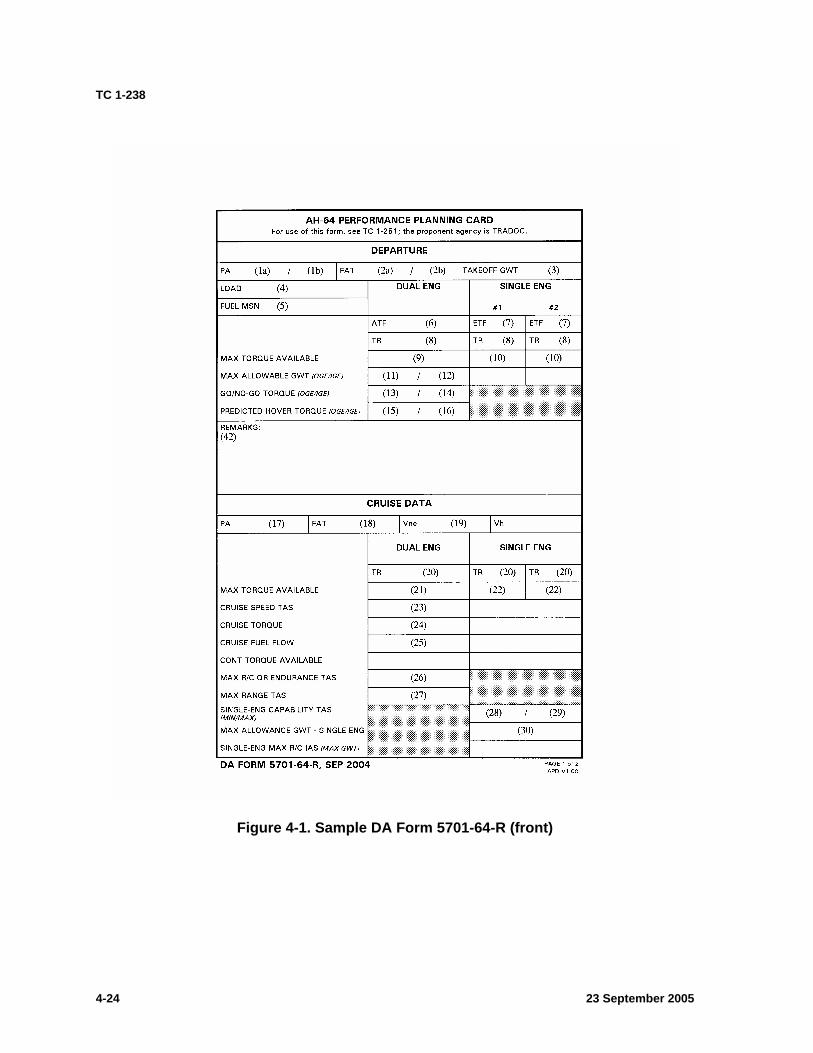
TC 1-238
Figure 4-1. Sample DA Form 5701-64-R (front)
23 September 2005 4-24
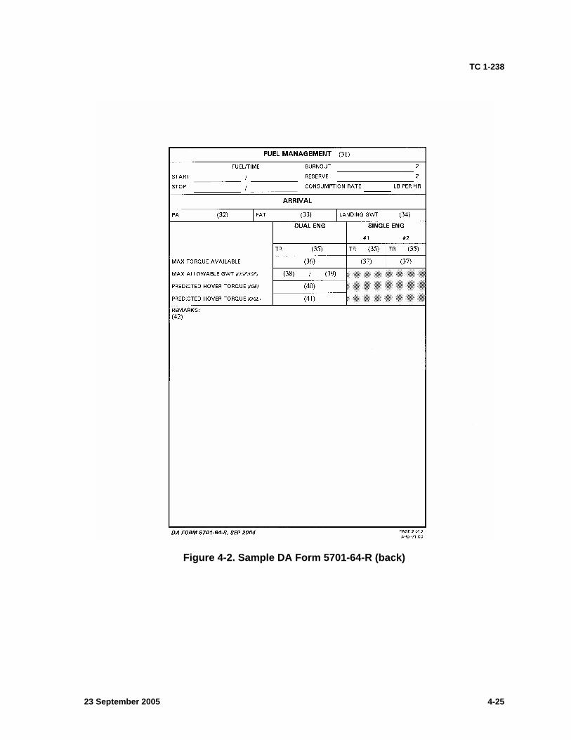
TC 1-238
Figure 4-2. Sample DA Form 5701-64-R (back)
23 September 2005 4-25
TC 1-238
TASK 1012
Verify aircraft weight and balance
CONDITIONS: In an AH-64A helicopter or an AH-64A simulator and given crew weights, aircraft configuration, aircraft weight and balance information, TM 1-1520-238-10, and DD Form 365-4.
STANDARDS: Appropriate common standards and the following: 1. Verify center of gravity (CG) and gross weight remain within aircraft limits for the duration of the flight. 2. Identify all mission or flight limitations imposed by weight or CG.
DESCRIPTION: 1. Crew actions.
a. Using the completed DD Form 365-4 from the aircraft logbook, verify/compute aircraft gross weight and CG. Ensure aircraft gross weight and CG will remain within the allowable limits for the entire flight. Note all gross weight, loading task/maneuver restrictions/limitations. b. If there is no completed DD Form 365-4 that meets mission requirements, refer to the unit weight and balance technician or to TM 55-1500-342-23, and compute a new DD Form 365-4. c. All crewmembers will be briefed on any limitations.
2. Procedures. Verify the aircraft CG in relation to CG limits at predetermined times during the flight when an aircraft’s configuration requires special attention, such as when it is critical to keep a certain amount of fuel in a particular tank. Conduct CG checks for fuel and ammunition expenditures.
Note: Refer to task 2066 for asymmetrical wing store (auxiliary tank) lateral CG computation procedures.
TRAINING AND EVALUATION REQUIREMENTS: 1. Training will be conducted academically. 2. Evaluation will be conducted academically.
REFERENCES: Appropriate common references.
23 September 2005 4-26
TC 1-238
TASK 1013
Operate mission planning system
CONDITIONS: Given approved software, mission briefing, signal operation instructions (SOI) information, weather information, navigational maps, Department of Defense (DOD) flight information publications (FLIPs), intelligence data, and other materials as required.
STANDARDS: 1. Configure and operate the approved software. 2. Evaluate and enter all pertinent weather data. 3. Perform map load and verify map digital aeronautical flight information file (DAFIF) currency. 4. Construct and select appropriate routes as applicable. 5. Download/upload mission data to/from the data transfer cartridge. 6. Download/upload and review post mission files.
DESCRIPTION: 1. Crew actions.
a. The pilot in command (PC) will ensure that pertinent data has been correctly entered into the approved software and subsequently loaded onto the data transfer cartridge (DTC). Depending on the situation, the crew may perform programming cooperatively or independently. The PC will perform, or will task the pilot (PI) to perform, software configuration, data processing, and DTC loading. b. Upon mission completion, the aircrew will perform DTC upload/download procedures as required.
Note: The PC should validate the DTC load whenever other personnel perform data programming. To ensure an accurate data load, the crew may select a hardcopy printout review using the approved software or verify with an aircraft load.
2. Procedures. Conduct in accordance with the current technical bulletin (TB)/technical manual (TM).
TRAINING AND EVALUATION REQUIREMENTS: 1. Task will be trained utilizing the approved software. 2. Task will be evaluated utilizing the approved software.
REFERENCES: Appropriate common references.
23 September 2005 4-27
TC 1-238
TASK 1014
Operate aviation life support equipment
CONDITIONS: Given the appropriate aviation life support equipment (ALSE) for the mission.
STANDARDS: Appropriate common standards in addition to performing operational checks on and inspecting the ALSE.
DESCRIPTION: 1. Crew actions. The pilot in command (PC) will verify that all required ALSE equipment is onboard the aircraft before takeoff. 2. Procedures. Based on mission requirements, obtain the required ALSE. Inspect equipment for serviceability and perform required operational checks. Secure the required ALSE in the aircraft per Operator’s Manual and the unit standing operating procedure (SOP).
TRAINING AND EVALUATION REQUIREMENTS: 1. Training will be conducted academically. 2. Evaluation will be conducted academically.
REFERENCES: Appropriate common references.
23 September 2005 4-28
TC 1-238
TASK 1022
Perform preflight inspection
CONDITIONS: Given an AH-64A helicopter with completed armament safety and ground procedures and in accordance with TM 1-1520-238-10 and TM 1-1520-238-CL.
STANDARDS: Appropriate common standards and the following: 1. Perform the preflight inspections of the aircraft, armament, and any other required equipment. 2. Load aircraft communications security (COMSEC). 3. Enter all appropriate information on DA Form 2408-12, DA Form 2408-13 (Aircraft Status Information Record), and DA Form 2408-13-1 (Aircraft Maintenance and Inspection Record).
DESCRIPTION: 1. Crew actions.
a. The pilot in command (PC) will ensure that a preflight inspection is conducted using TM 1-1520-238-10 and TM 1-1520-238-CL. He may direct the pilot (PI) to complete elements of the aircraft preflight inspection as applicable and will verify that all checks have been completed. The PC will report any aircraft discrepancies that may affect the mission and will ensure the appropriate information is entered on DA Form 2408-12 and DA Form 2408-13. b. The PC will ensure a walkaround inspection is complete prior to flight. c. The PI will complete the assigned elements and report the results to the PC.
2. Procedures. a. Consider the helicopter armed and approach it from the side to avoid danger areas. Ensure the aircraft is in an armament safe status and follow grounding procedures prior to continuing further with the preflight. b. Refer to TM 1-1520-238-CL throughout the conduct of the aircraft preflight inspection. Comply with the preflight checks contained in the TM 1-1520-238-CL checklist and standing operating procedure (SOP) as applicable. c. The PC will ensure that all pertinent COMSEC and global positioning system (GPS) key data has been loaded into the aircraft as applicable.
NIGHT OR NIGHT VISION DEVICE (NVD) CONSIDERATIONS: Tactical situation permitting, use a flashlight with an unfiltered clear lens to supplement available lighting if performing the preflight inspection in the dark. Hydraulic leaks, oil leaks, and other defects are difficult to see with a colored lens flashlight. TC 1-204 contains details on preflight inspection at night.
TRAINING AND EVALUATION REQUIREMENTS: 1. Training will be conducted at the AH-64A aircraft. 2. Evaluation will be conducted at the AH-64A aircraft.
REFERENCES: Appropriate common references.
23 September 2005 4-29
TC 1-238
TASK 1024
Perform before-starting engine through before-leaving helicopter checks
CONDITIONS: In an AH-64A helicopter or an AH-64A simulator and given TM 1-1520-238-10 and TM 1-1520-238-CL.
STANDARDS: Appropriate common standards and the following: 1. Perform procedures and checks using TM 1-1520-238-10 and TM 1-1520-238-CL. 2. Enter appropriate information on DA Form 2408-12, DA Form 2408-13, DA Form2408-13-1, and the health indicator test (HIT) log.
DESCRIPTION: 1. Crew actions.
a. Both crewmembers will complete the required checks pertaining to their assigned crew duties using TM 1-1520-238-10 and TM 1-1520-238-CL. b. The pilot (PLT) will announce auxiliary power unit (APU) and engine starts. c. Both crewmembers will clear the area around the aircraft before APU start and each engine start. During the control sweep and trim check, the force trim may only be momentarily interrupted by setting (and holding) the force trim/hold mode release switch forward on the PLT's cyclic control grip. d. Before starting the engines or performing the runup check, the crew will ensure that all appropriate internal and external lights are operational and set properly. They must make sure the lighting levels and brightness are high enough to for the instruments and systems status to be easily seen. e. Crew coordination, prior to mission commencement, should determine which crewmember will be responsible for avionics.
2. Procedures. Perform the following TM 1-1520-238-10/CL checks: a. Perform interior checks, before-starting APU checks, and starting APU checks in accordance with the TM 1-1520-238-CL checklist. The checklist is designed for most checks to be performed with a degree of PLT/copilot-gunner (CPG) independence. During the checks, overall periodic progress queries directed by each crewmember to the opposite crewmember foster overall crew awareness. The fire detector test should be a cooperative check between the PLT and CPG. The PLT should announce his intention to perform the fire detector test. b. Perform all after-starting APU checks, including optionally installed equipment checks and weapons systems initialization checks (see task 1416). Most checks are performed with a degree of PLT/CPG independence. c. Perform applicable engine start procedures. d. Perform all post rearming or post refueling before-flight checks in accordance with TM 1-1520-238-10, TM 1-1520-238-CL, and unit/local standing operating procedure (SOP) as applicable. e. Perform engine health indicator test, determine if the HIT is within limits, and record the results in the logbook.
23 September 2005 4-30

TC 1-238
NIGHT OR NIGHT VISION DEVICE (NVD) CONSIDERATIONS: Before starting the engines, ensure all internal and external lights are operational and set properly. Internal lighting levels must be high enough for the instruments to be easily seen and to start the engines without exceeding operating limitations.
TRAINING AND EVALUATION REQUIREMENTS: 1. Training may be conducted in the AH-64A aircraft or AH-64A simulator. 2. Evaluation will be conducted in the AH-64A aircraft.
REFERENCES: Appropriate common references.
23 September 2005 4-31
TC 1-238
TASK 1026
MAINTAIN AIRSPACE SURVEILLANCE
CONDITIONS: In an AH-64A helicopter or an AH-64A simulator and with the pilot on the controls (P*) fitted with a boresighted helmet display unit (HDU).
STANDARDS: Appropriate common standards and the following: 1. Clear the aircraft and immediately inform the other crewmember of all air traffic, targets, or obstacles that threaten the aircraft. 2. Announce heading, altitude, or position changes. 3. Alert wingman, team, section, and unit to all sightings of other aircraft, obstacles, or unknowns that may threaten the aircraft. 4. Acknowledge alerts of aircraft, obstacles, or unknowns. 5. Announce when attention will be focused inside the aircraft.
DESCRIPTION: 1. Crew actions.
a. The pilot in command (PC) will brief airspace surveillance performance prior to the flight. The briefing will include applicable visual airspace surveillance considerations. b. The pilot not on the controls (P) will inform the P* of any unannounced heading, altitude, attitude, or position changes. The P will announce his inability to assist due to concentration inside the aircraft. c. When landing, the crew will confirm that the area is suitable and that the aircraft is clear of barriers.
2. Procedures. a. Maintain close surveillance of the surrounding airspace. Keep the aircraft clear from other aircraft and obstacles by maintaining visual (close, mid, and far areas). Immediately inform the opposite crewmember or other aircraft by voice radio of any air traffic or obstacles that pose, or may pose, a threat. Call out the location of traffic or obstacles by the clock position, altitude, and distance method. (The 12 o’clock position is at the nose of the aircraft.) Give distance in kilometers or fractions of kilometers. When reporting air traffic, specify the type of aircraft (fixed-wing or helicopter) and, if known, the model. Give direction of travel; for example, left to right, right to left, climb, or descent. The altitude of the air traffic should be reported as the same, higher, or lower than the altitude of the crew’s aircraft. b. Prior to changing altitude or heading, visually clear the aircraft for hazards and obstacles. Each crewmember will share information and note hazards and obstacles. c. Prior to performing a descending flight maneuver, it may be desirable to perform a clearing “S” turn to the left or right. The clearing “S” turn will provide the aircrew with a greater visual scan area.
NIGHT OR NIGHT VISION DEVICE (NVD) CONSIDERATIONS: The use of proper scanning techniques will assist in avoiding spatial disorientation and in detecting traffic and obstacles. When clearing the aircraft left and right, the cleared area should be coincident with the HDU symbolic field of regard (FOR) limits for the pilot (PLT) and with the target acquisition and designation sight (TADS) FOR for the copilot-gunner (CPG).
23 September 2005 4-32

TC 1-238
TRAINING AND EVALUATION REQUIREMENTS: 1. Training will be conducted in the AH-64A aircraft. 2. Evaluation will be conducted in the AH-64A aircraft.
REFERENCES: Appropriate common references.
23 September 2005 4-33
TC 1-238
TASK 1028
PERFORM HOVER POWER CHECK
CONDITIONS: In an AH-64A helicopter or an AH-64A simulator with the before-takeoff check completed and the pilot on the controls (P*) fitted with a boresighted helmet display unit (HDU).
STANDARDS: 1. Perform the check near the takeoff point and in the direction of takeoff. 2. Maintain a stationary hover ±2 feet and determine, without error, that sufficient power is available to complete the mission.
DESCRIPTION: 1. Crew actions.
a. The P* will announce his intent to perform a hover power check and will remain focused outside the aircraft. He will announce when he terminates the maneuver. b. The pilot in command (PC) will announce specific hover height altitudes, or, as prebriefed, the P* will announce the hover height.
2. Procedures. An initial hover power check will be completed at the beginning of the flight, and pertinent environmental and load considerations will be applied throughout the flight.
a. The P* will announce his intent to bring the aircraft to a stationary hover in the direction of takeoff for a hover power check. Remain focused outside the aircraft and announce when the aircraft is stabilized at the desired hover altitude. Use a 5-foot stationary hover when performing a hover power check unless the mission or terrain constraints dictate otherwise. ATTD/HOVER HOLD may be engaged if desired. If another hover height is required, use that height to compute GO/NO-GO torque and predicted hover torque. b. The pilot not on the controls (P) will monitor the aircraft instruments and verify the power check. He will compare the actual hover performance data to that of the performance planning card (PPC) and will announce the results to the P*. If the torque required to maintain a stationary hover exceeds the GO/NO-GO torque (out-of-ground effect [OGE]) but does not exceed the GO/NO-GO torque (in-ground effect [IGE]), the P* may attempt only IGE maneuvers. If the PPC torque required to maintain a stationary hover does not exceed the GO/NO-GO torque (OGE), then all maneuvers may be attempted. c. If the margin between hover power and GO/NO-GO OGE power is minimal (within 5 percent), an OGE hover power check may be performed to verify OGE power and aircraft controllability. To conduct an OGE hover power check, the P* will apply sufficient collective to ascend to an 80-foot hover or above surrounding obstacles, whichever is higher. He will execute a 360-degree left pedal turn while constantly checking the engine instruments for aircraft power and controllability. He will not exceed aircraft limitations. The P* will terminate the maneuver at an IGE hover, on the ground, or as required. d. If the load or environmental conditions increase significantly (1,000 pounds gross weight, 5 °C, or 1,000-foot pressure altitude [PA]), the crew will perform additional power checks in conjunction with the PPC. e. The P will announce when the hover power check is completed.
23 September 2005 4-34
TC 1-238
SNOW/SAND/DUST CONSIDERATIONS: Do not perform IGE hovering operations if insufficient surface contrast exists to maintain position over the ground. Hovering in a snow/sand/dust condition reduces available ground references and may increase the possibility of spatial disorientation.
Note: Using the search light at night may cause spatial disorientation while among blowing snow/sand/dust.
TRAINING AND EVALUATION REQUIREMENTS: 1. Training may be conducted in the AH-64A aircraft or AH-64A simulator. 2. Evaluation will be conducted in the AH-64A aircraft.
REFERENCES: Appropriate common references.
23 September 2005 4-35
TC 1-238
TASK 1032
Perform radio communications procedures
CONDITIONS: In an AH-64A helicopter or an AH-64A simulator.
STANDARDS: Appropriate common standards and the following: 1. Check, set, and operate aircraft avionics. 2. Establish radio contact with the desired individual, unit, or air traffic control (ATC) facility. 3. Employ standard radio communication procedures, terms, and terminology applicable to the situation. 4. Operate intercom system. 5. Perform two-way radio failure procedures in accordance with Department of Defense (DOD) flight information publication (FLIP).
DESCRIPTION: 1. Crew actions.
a. Per mission requirements, the pilot in command (PC) will assign radio frequencies during the crew briefing and will indicate which crewmember will establish and maintain primary communications. b. The pilot not on the controls (P) should monitor avionics, perform frequency changes, and establish initial contact. He will copy pertinent information and repeat information as requested by the pilot on the controls (P*). In case of two-way radio failure, the P will troubleshoot the avionics and announce results. c. The crewmember will announce information not monitored by the opposite crewmember.
2. Procedures. a. The pilot (PLT)/copilot-gunner (CPG) should access radios, radio modes, and transponder as appropriate. b. Prior to transmitting, the PLT/CPG should select the proper radio/frequency referencing the intercommunication system (ICS) selector switch. Ensure the selected radio is set to the correct mode of operation. Continuously monitor the avionics and, when required, establish communications with the appropriate individual, unit, or ATC facility. The PLT/CPG should ensure that the frequency is clear prior to transmitting. Use the call sign, signal operation instructions (SOI), or tail number appropriate to the situation when acknowledging each communication. Acknowledge all radio transmissions/instructions appropriate to the situation. When instructed (civil airspace), the P or P* should select new frequencies as soon as possible unless instructed to do so at a specified time, fix, or altitude.
TRAINING AND EVALUATION REQUIREMENTS: 1. Training may be conducted in the AH-64A aircraft or AH-64A simulator. 2. Evaluation will be conducted in the AH-64A aircraft.
REFERENCES: Appropriate common references.
23 September 2005 4-36
TC 1-238
TASK 1034
PERFORM GROUND TAXI
CONDITIONS: In an AH-64A helicopter or an AH-64A simulator, on a suitable surface, with the before-taxi check completed, the aircraft cleared, and the pilot on the controls (P*) fitted with a boresighted helmet display unit (HDU).
STANDARDS: Appropriate common standards and the following: 1. Maintain speed appropriate for conditions. 2. Maintain the desired ground track ±3 feet. 3. Apply the torque that is appropriate for the ground taxi condition. 4. Perform taxi check. 5. Maintain level fuselage attitude.
DESCRIPTION: 1. Crew actions.
a. The P* will ensure the parking brake is released and, if required, unlock the tail wheel before starting the ground taxi. The tail wheel will be unlocked prior to applying antitorque pressure for a turn. The P* will announce “braking” when he intends to apply brake pressure. He will announce when the aircraft is clear, his intent to begin ground taxi operations, and the intended direction of turn before turning. The P* will remain focused outside the aircraft. Prior to initial taxi, the P* should direct the pilot not on the controls (P) to call out the BEFORE TAXI CHECK; once taxiing, the TAXI CHECK. He will direct the P to assist in clearing the aircraft during the checks. b. The P will announce “guarding” to acknowledge the P*’s announcement of braking. The P should not apply any pressure against the antitorque pedals when guarding the brakes unless an unsafe situation is detected. The P will call out the BEFORE TAXI CHECK and the TAXI CHECK when directed. He will assist in clearing the aircraft and will provide adequate warning to avoid obstacles.
2. Procedures. Ensure the area is suitable for ground taxi operations. Initiate the taxi by increasing the collective to approximately 27 to 30 percent torque, and then apply a slight amount of cyclic either forward or aft of neutral to begin movement. Avoid excessive strap pack loads and droop-stop pounding by applying appropriate torque for terrain and gross weight. High gross weights and soft, rough, or sloping terrain may require the use of more than 30 percent torque. During single-engine ground taxi (if required after hot refuel, for example), double the required dual-engine taxi torque for a given condition. With the tail wheel unlocked, control the aircraft heading with the pedals and maintain a level attitude with cyclic. The cyclic controls roll attitude. Use left or right pedal input to turn the aircraft while applying lateral cyclic into turns to maintain a level fuselage attitude. Pressure and counter pressure on the antitorque pedals will control rate of turn. HDU symbology (transition and cruise mode), visual display unit (VDU) flight symbology, the standby instruments, and visual cues may be used to reference fuselage roll attitude. Establish a constant speed commensurate to the surface conditions. Use a combination of cyclic, collective, and, when necessary, brakes to regulate taxi speed. The hover mode velocity may be used to establish a constant ground (inertial) speed.
23 September 2005 4-37

TC 1-238
Note 1: Selecting the tail wheel switch will energize the unlock actuator and retract the lock pin; the green advisory light will then illuminate. If the tail wheel fails to unlock, taxi forward a short distance while making light pedal inputs. Toggling the switch to the lock position will deenergize the lock actuator and allow spring force to insert the lock pin when the tail wheel is properly aligned to the center position. When the lock pin is in place, the green advisory light will extinguish.
Note 2: Depending on ground velocity and surface conditions, emergency stops may be performed by applying the wheel brakes, using aerodynamic braking, or bringing the aircraft to a hover.
Note 3: If the tail wheel is unlocked during rearward taxi, the trailing arm tail wheel may swivel 180 degrees, causing momentary heading instability. Use caution so the tail wheel does not caster around suddenly; this puts an excessive load on the tail wheel cam.
Note 4: The P* may temporarily reduce taxi torque to 22 to 24 percent for short periods with limited cyclic displacement. There may be temporary conditions where the P* desires to reduce the rotor down wash component to prevent or reduce negative rotor downwash effects.
Note 5: Excessive cyclic input and insufficient collective application may result in droop-stop pounding or excessive strap pack loading. Collective power application may disengage the squat switch during taxi operations.
NIGHT OR NIGHT VISION DEVICE (NVD) CONSIDERATIONS: 1. Night. The searchlight should be used for unaided ground taxi. 2. Night vision system (NVS).
a. To maintain orientation during taxi, use the head tracker symbology to maintain the aircraft centerline relative to the desired ground track. b. To maintain the desired ground track, reference the heading scale, lubber line, and head tracker symbology. c. Be aware of the location of the sensor and the effects of parallax during turns. d. To reference the aircraft roll attitude, use the transition mode horizon line, NVS line of sight (LOS) skid/slip (trim) ball along with the skid/slip lubber line symbology. To maintain a level fuselage with the tail wheel unlocked, use the cyclic to center the trim ball. With the tail wheel locked, use the cyclic and pedals to center the trim/slip ball. e. To establish and measure a constant rate, use composite forward-looking infrared (FLIR) cues and periodically toggle between transition and hover mode. Hover mode will provide a valid velocity vector through the embedded global positioning inertial navigation system (EGI) while on the ground. f. Be aware that the NVS turrets are mounted relative to the waterline of the aircraft. The aircraft sits on the ground (flat pitch) at +4.9 degrees nose up. During ground operations, the ground appears to tilt during off-axis (left or right of centerline) viewing with the NVS.
SNOW/SAND/DUST CONSIDERATIONS: If ground reference is lost because of blowing snow/sand/dust, lower the collective and neutralize the flight controls until visual reference is reestablished. Taxing at a slower speed may allow sufficient visibility. Use caution when taxiing near other maneuvering aircraft because of limited visual references and relative motion illusion. When initiating ground taxi in snow or ice, apply pressure and counter pressure to the pedals to ensure the
23 September 2005 4-38

TC 1-238
wheels are not frozen to the ground. Using the search/landing light at night may cause spatial disorientation.
TRAINING AND EVALUATION REQUIREMENTS: 1. Training may be conducted in the AH-64A aircraft or AH-64A simulator. 2. Evaluation will be conducted in the AH-64A aircraft.
REFERENCES: Appropriate common references.
23 September 2005 4-39
TC 1-238
TASK 1038
PERFORM HOVERING FLIGHT
CONDITIONS: In an AH-64A helicopter or an AH-64A simulator with the before-takeoff check completed, aircraft cleared, pilot on the controls (P*) fitted with a boresighted helmet display unit (HDU), hover power check completed and given a specific hover height, velocity, heading, or ground track.
STANDARDS: Appropriate common standards and the following: 1. Perform a smooth controlled ascent to a hover. 2. Perform hover power check as appropriate. 3. Execute a smooth controlled descent with minimum drift at touchdown.
DESCRIPTION: 1. Crew actions.
a. The P* will announce his intent to perform a specific hovering flight maneuver and will remain focused outside the aircraft. He will announce his intentions to use the hold modes during the maneuver. He will announce when he terminates the maneuver. During any out-of-ground effect (OGE) hover or low speed OGE hovering operations, the P* will announce his forced landing or single-engine fly-away plan. b. The pilot in command (PC) will announce specific hover height altitudes, or, as prebriefed, the P* will announce the hover height. c. The P* will announce his intended forced landing area or fly-away plan each time the aircraft is brought to an OGE hover.
2. Procedures. a. Takeoff to a hover. With the collective fully down, place the cyclic in a neutral position. Increase the collective with a smooth, positive pressure. Apply pedals to maintain heading and coordinate the cyclic for a vertical ascent. Using outside references, the horizon line, or the trim ball, keep the fuselage level until the main landing gear is off the ground. As the aircraft leaves the ground, check for proper control response and aircraft center of gravity (CG). On reaching the desired hover altitude, perform a power check. b. Hovering flight. Adjust the cyclic to maintain a stationary hover or to move in the desired direction. Control heading with pedals and maintain altitude with the collective. Maintain a constant hover speed. To return to a stationary hover, apply the cyclic in the opposite direction while maintaining altitude with collective and heading with the pedals.
(1) Use hover taxi when slow forward movement is desired or when it may be appropriate to move very short distances. Pilots should avoid this procedure if rotor down wash is likely to cause damage to parked aircraft or if blowing dust/sand could obscure visibility. If it is necessary to operate above 25 feet above ground level (AGL) when hover taxiing, the pilot should initiate a request to air traffic control (ATC).
Note 1: When a hover taxi is unsafe due to deteriorating visual references, determine whether to abort the maneuver, ground taxi, air taxi, or perform a takeoff.
(2) Air taxi is the preferred method for helicopter ground movements on airports provided ground operations and conditions permit. Unless otherwise requested or instructed, pilots are expected to remain below 100 feet AGL. However, if a higher than
23 September 2005 4-40
TC 1-238
normal airspeed or altitude is desired, the request should be made prior to lift-off. The pilot is solely responsible for selecting a safe airspeed for the altitude/operation being conducted. Use of air taxi enables the pilot to proceed at an optimum airspeed/altitude, minimize downwash effect, conserve fuel, and expedite movement from one area to another. Helicopters should avoid overflight of other aircraft, vehicles, and personnel during air taxi operations. Pilots must exercise caution about active runways and must be certain that air taxi instructions are understood. Special cautions may be necessary at unfamiliar airports or airports with multiple/intersecting active runways.
c. Hovering turns. Apply pressure to the desired pedal to begin the turn. Use pressure and counter pressure on the pedals to maintain a constant rate of turn. Coordinate cyclic control to maintain position over the pivot point while maintaining altitude with the collective. (Hovering turns can be made around the vertical axis, nose, or tail of the aircraft.) The origin of the hover mode velocity vector represents a point approximate to the aircraft’s mast. d. Landing from a hover. From a stationary hover, lower the collective to affect a smooth descent to touchdown. Make necessary corrections with the pedals and cyclic to maintain a constant heading and position. Ensure the aircraft remains stable on ground contact. Continue decreasing the collective smoothly and steadily until the entire weight of the aircraft rests on the ground. Neutralize the pedals and cyclic and reduce the collective to the fully down position. If uneven surface conditions are suspected, set the parking brake before starting the descent.
NIGHT OR NIGHT VISION DEVICE (NVD) CONSIDERATIONS: Movement over areas of limited contrast, such as tall grass, water, or desert, tends to cause spatial disorientation. To avoid spatial disorientation, seek hover areas that provide adequate contrast and use proper scanning techniques. If disorientation occurs, perform unusual attitude recovery, apply sufficient power, and execute a go-around. If a go-around is not feasible, try to maneuver the aircraft forward and down to the ground while referencing the velocity vector to limit the possibility of touchdown with sideward or rearward movement.
NIGHT VISION SYSTEM (NVS) CONSIDERATIONS: 1. Takeoff to a hover.
a. Clear the aircraft by slewing the forward-looking infrared (FLIR) sensor within the available field of regard. b. Select visual references to aid in heading, position, and altitude control. Supplement visual references with symbolic information as appropriate. c. Orient the NVS line of sight (LOS) so the selected references remain visible during the maneuver. Align the NVS turret in azimuth to the longitudinal axis of the aircraft to aid in heading control. Depress the NVS turret below level to perceive more ground cues. d. Maintain a fixed-head position during takeoff so that any movement perceived in the imagery is relative to the aircraft and not to the pilot night vision system (PNVS)/target acquisition and designation sight (TADS) turret. e. Use imagery and the appropriate symbology for heading, altitude, and drift (position) control.
23 September 2005 4-41

TC 1-238
2. Hovering flight. a. Select the appropriate symbology mode (hover, bob-up, or transition). b. Clear the aircraft by slewing the FLIR sensor in the direction of travel. Use the acceleration cue and velocity vector to maintain position and imagery for altitude reference. Select references that can be used to determine arrival at the desired termination point. c. When clearance to perform a lateral hover is assured, use the acceleration cue and velocity vector to establish the desired rate and direction of movement. Full-scale deflection of the velocity vector display is equivalent to 7 knots ground speed (GS) in hover mode and 70 knots GS in transition mode. Use imagery to maintain altitude and clearance, and crosscheck heading tape symbology to maintain heading. d. Upon approaching the desired termination point (imagery-provided references), begin decelerating to arrive in a stabilized hover using primarily acceleration cue and velocity vector. Maintain altitude with imagery and a cross-check of radar altitude symbology.
3. Hovering turns. a. Select the appropriate symbology mode (hover or bob-up). b. Stabilize the aircraft while referencing imagery-supplied close-in cues, the acceleration cue and velocity vector, and the radar altitude symbology. c. Clear the aircraft by slewing the FLIR sensor within the field of regard. Use the acceleration cue and velocity vector to maintain a constant position, and use the altitude and vertical speed indicator (VSI) symbols to maintain a constant altitude. Depending on the rate (acceleration) of turn, the acceleration cue will show some displacement even without a velocity vector stemming from the centroid. When clearance to perform a hovering turn is assured, slew the FLIR sensor in the desired direction of turn. Maintain aircraft position, heading, and altitude before turning by referring to the composite imagery, imagery-supplied cues, and appropriate symbols. d. To aid in determining the termination point, select a reference point visible within the instantaneous field of view (FOV) of the FLIR. If the turn is greater than 90 degrees, use the heading symbology to help identify the termination point. e. During the turn, employ a cross-check that scans imagery-supplied cues as well as the altitude and vertical velocity symbols. f. Keep the NVS LOS oriented toward the visual reference point. All movement observed in the imagery will be the result of changes in aircraft attitude rather than turret movement.
4. Landing from a hover. a. Select the desired mode of NVS symbology. b. Use imagery and symbology to control the descent rate (rate of climb indicator/radar altitude [ALT]), drift (acceleration cue and velocity vector), and heading.
Note 2: The location and gimbal limits of the FLIR sensor prevent the P* from seeing the actual touchdown point during this maneuver. The P* must obtain clearance of the intended touchdown point before positioning the aircraft over the point. If the crew suspects uneven surface conditions, the crew should set the parking brakes before initiating the descent.
Note 3: Under normal loading conditions, the aircraft will hover approximately 3 degrees left side low.
Note 4: Using the manual stabilator mode reduces airframe vibration in strong crosswinds or tail winds.
23 September 2005 4-42
TC 1-238
SNOW/SAND/DUST CONSIDERATIONS: Do not perform in-ground effect (IGE) hovering operations if insufficient surface contrast exists to maintain position over the ground. Hovering in a snow/sand/dust condition reduces available ground references and may increase the possibility of spatial disorientation. If necessary to reposition the aircraft in a snow/sand/dust, execute an instrument takeoff. When marginal power exists, do not attempt to ascend to an OGE hover in a snow/sand/dust environment. If it is discovered during an ascent to an OGE hover that OGE power is not available, transition to the instruments and conduct an instrument takeoff using maximum torque available.
Note 5: Using the search light at night may cause spatial disorientation while in blowing snow/sand/dust.
TRAINING AND EVALUATION REQUIREMENTS: 1. Training may be conducted in the AH-64A aircraft or AH-64A simulator. 2. Evaluation will be conducted in the AH-64A aircraft.
REFERENCES: Appropriate common references.
23 September 2005 4-43
TC 1-238
TASK 1040
PERFORM VISUAL METEOROLOGICAL CONDITIONS TAKEOFF
CONDITIONS: In an AH-64A helicopter or an AH-64A simulator with the hover power and before-takeoff checks completed, aircraft cleared, and the pilot on the controls (P*) fitted with a boresighted helmet display unit (HDU).
STANDARDS: Appropriate common standards and the following: 1. Maintain takeoff heading ±10 degrees until clear of the obstacles. 2. Maintain ground track alignment with the takeoff direction. 3. Maintain the aircraft in trim as appropriate for obstacle avoidance. 4. Accelerate to desired airspeed ±10 knots. 5. Apply takeoff power for the selected takeoff in order to reach desired altitude, not to exceed maximum torque (Q) available. Upon reaching maximum rate of climb or desired airspeed, position the collective to establish the desired rate of climb (approximately 500 feet per minute [FPM] for training).
DESCRIPTION: 1. Crew actions.
a. The P* will remain focused outside the aircraft during the maneuver. He will announce the type of takeoff and whether the takeoff is from the ground or from a hover along with his intent to abort or alter the takeoff. The P* will consider snow, sand, and obstacle barrier clearance when he evaluates the power required versus power available. He should not exceed dual-engine torque/turbine gas temperature (TGT) limits during these high-power takeoffs. b. The pilot not on the controls (P) will announce when the aircraft is ready for takeoff. He will remain focused primarily outside the aircraft to assist in clearing the aircraft and to provide adequate warning of obstacles. The P will announce when his attention is focused inside the cockpit. He will select reference points to assist in maintaining the takeoff flight path. The P will monitor power requirements and advise the P* if power limits are being approached. c. The pilot in command (PC) will determine the direction and type of takeoff by analyzing the power available, wind, the long axis of the takeoff area, and the lowest obstacles
2. Procedures. a. For visual meteorological conditions (VMC) takeoff from the ground (10 percent above hover power available), select reference points to maintain ground track. With the cyclic in the neutral position, increase the collective until the aircraft becomes “light on the wheels.” Maintain heading with the pedals. Continue increasing the collective as necessary or to obtain approximately 10 percent above hover torque. Depending upon the configuration of the aircraft and the load, the P* may have to increase the collective to a value greater than 10 percent above hover power to establish the desired climb. As the aircraft leaves the ground, apply forward cyclic as required to accelerate through effective translational lift (ETL) to obtain the desired climb attitude (approximately 90 knots true airspeed [KTAS]). Maintain ground track and keep the aircraft aligned with takeoff direction until clear of obstacles/barriers. Maintain heading with the pedals until clear of obstacles/barriers, and then
23 September 2005 4-44

TC 1-238
place in trim. Upon reaching maximum rate of climb or desired airspeed, position the collective to establish the desired rate of climb (approximately 500 feet per minute [FPM] for training). b. For VMC takeoff from a hover (10 percent above hover power available), select reference points to maintain ground track. Apply forward cyclic to accelerate the aircraft while applying approximately 10 percent torque above hover power or as necessary with the collective without exceeding dual-engine maximum torque. Perform the rest of the maneuver as for a takeoff from the ground. c. For VMC level acceleration takeoff, the aircraft should be accelerated to maximum rate of climb or desired airspeed prior to establishing a climb when surface conditions and obstacles permit. This profile will aid the crew in establishing airspeed and reduce the risks associated with operation in the avoid region should an engine fail. Select reference points to maintain ground track. Place the cyclic and pedals in the neutral position and apply power. As the aircraft leaves the ground, adjust power to approximately 10 percent above hover power (if available) without exceeding dual-engine maximum torque, and apply forward cyclic to establish an accelerative attitude appropriate for the terrain and obstacle avoidance. After accelerating to maximum rate of climb or desired airspeed, adjust the cyclic to continue the acceleration to the desired climb airspeed and maintain the desired ground track. Adjust power upon reaching maximum rate of climb or desired airspeed to obtain the desired rate of climb. Maintain heading with the pedals until clear of obstacles/barriers. Once clear of obstacles/barriers, place the aircraft in trim. After obtaining the desired airspeed, adjust the controls as necessary to stop the acceleration and maintain the desired rate of climb.
Note 1: Avoid rapid and excessive forward cyclic application to prevent main rotor contact with the takeoff surface.
d. During VMC minimum power takeoff (hover power), environmental and helicopter loading may result in the helicopter hovering in-ground effect (IGE) at or near dual-engine maximum torque available. This should be recognized by the crew through accurate performance planning and a hover power check (environmental conditions permitting). If surface conditions are suitable, consideration should be given to performing a rolling takeoff. If surface conditions are unsuitable for a rolling takeoff, the following takeoff may be performed, but the crew should be aware of the limited power margin and its effect on aircraft maneuverability.
Note 2: Due to high gross weight and adverse environmental conditions, the P* will monitor the torque and TGT during takeoff when operating at or near maximum power limits.
(1) For takeoff from the ground, select reference points to maintain ground track. With the cyclic in a neutral position, increase the collective until the helicopter becomes light on the wheels. Apply pressure and counter pressure to the pedals to ensure the helicopter is free to ascend. While maintaining heading with the pedals, continue increasing the collective until the helicopter leaves the ground. As the helicopter leaves the ground, apply forward cyclic as required to avoid obstacles and to accelerate to maximum rate of climb or desired airspeed at an altitude appropriate for the terrain. Expect a slight loss in altitude as the helicopter transitions into forward flight. As the helicopter reaches maximum rate of climb or desired airspeed, adjust the cyclic and collective to obtain the desired rate of climb and use the pedals to maintain heading aligned with ground track until clear of obstacles/barriers. Once clear of obstacles/barriers, place the aircraft in trim. (2) For takeoff from a hover, select reference points to maintain ground track. Apply forward cyclic to accelerate the aircraft while maintaining hover torque. Apply forward
23 September 2005 4-45

TC 1-238
cyclic as required to avoid obstacles and to accelerate to maximum rate of climb, or desired airspeed at an altitude that is appropriate for the terrain. A slight loss in altitude can be expected as the helicopter transitions into forward flight. As the helicopter reaches maximum rate of climb or desired airspeed, adjust the cyclic and collective to obtain the desired rate of climb, and use the pedals to maintain heading aligned with ground track until clear of obstacles/barriers. Once clear of obstacles/barriers, place the aircraft in trim.
Note 3: Once through ETL, 5 degree nose low attitude is recommended for acceleration. Avoid unnecessary accelerative attitudes of more than 10 degrees nose low.
Note 4: The height velocity diagram in TM 1-1520-238-10 displays “avoid areas.” This diagram assumes the availability of a suitable forced landing area in case of engine failure. If surface conditions permit, the P* should accelerate the aircraft to maximum rate of climb airspeed prior to establishing the desired climb rate.
Note 5: Stabilator mode selection will affect the amount of cyclic required to achieve the climb pitch attitude and the power required to accelerate and climb in the desired attitude (drag related). Under normal circumstances, the automatic stabilator program provides an optimum schedule for acceleration. However, the P* can use the manual mode stabilator control to fine-tune drag versus airspeed and achieve lower power requirements for a given airspeed. The P* will announce the use of the manual stabilator.
NIGHT OR NIGHT VISION DEVICE (NVD) CONSIDERATIONS: 1. If sufficient illumination or NVD resolution exists to view obstacles, the P* can accomplish the takeoff in the same manner as a normal VMC takeoff during the day. Physical obstacles and visual obstacles, such as shadows, should be treated the same. If sufficient illumination or NVD resolution does not exist, the P* should perform an altitude-over-airspeed takeoff, power permitting, to ensure obstacle clearance. The P* may perform the takeoff from a hover or from the ground. 2. At night, reduced visual references during the takeoff and throughout the ascent may make it difficult to maintain the desired ground track. The crew should know the surface wind direction and velocity. This will assist the P* in establishing the crab angle required to maintain the desired ground track. 3. Night vision system (NVS) from the ground.
a. Select the hover mode of symbology. b. Use forward-looking infrared (FLIR) imagery and torque symbology to establish the aircraft light on the wheels. c. As the aircraft leaves the ground, verify the desired rate of forward movement by crosschecking the acceleration cue, velocity vector, and composite video. When the velocity vector becomes saturated, select transition mode symbology. d. On climb out, adjust aircraft attitude (horizon line) and climb rate (vertical speed indicator [VSI] symbol) as desired. e. Use available FLIR imagery and velocity vector to establish and maintain ground track.
4. NVS from a hover. a. Select hover mode of symbology. b. As the aircraft accelerates to ETL, verify the desired rate of motion by cross-checking the acceleration cue, velocity vector, and composite video. When the velocity vector becomes saturated, select transition mode symbology.
23 September 2005 4-46
TC 1-238
c. Monitor altitude before ETL using imagery and altitude symbology. d. On climb out, adjust aircraft attitude (horizon line) and climb rate (VSI symbol) as desired. e. Use available FLIR imagery and velocity vector to establish and maintain ground track.
Note 6: The crew must use proper scanning techniques to avoid spatial disorientation.
SNOW/SAND/DUST CONSIDERATIONS: Smoothly increase the collective until the aircraft becomes light on the wheels, approximately 20 percent torque below hover power. Check the controls for proper response. Continue smoothly increasing the collective to maximum torque available without exceeding aircraft limits. As the aircraft leaves the ground, maintain heading with the pedals and a level attitude with the cyclic. Monitor HDU symbology to aid in detecting aircraft drift, rate of climb, attitude, altitude, and airspeed.
1. Out-of-ground effect (OGE) hover power available. Once clear, establish visual flight, accelerate to max rate of climb or desired climb airspeed, and trim the aircraft. If during the ascent it is discovered that insufficient power is available to clear the obscurant, continue to apply maximum torque available and adjust pitch attitude to level attitude for the initial acceleration. Maintain heading with the pedals as in an instrument takeoff. Cross reference HDU symbology and flight instruments as necessary to avoid unusual attitude or aircraft drift. Expect a slight loss in altitude as the helicopter transitions into forward flight. As the aircraft clears the snow/sand/dust cloud and all barriers, establish visual flight, accelerate to max rate of climb or desired airspeed, and trim the aircraft. The P will monitor engine instruments and announce approaching performance limitations. He will also monitor aircraft drift, rate of climb, attitude, and airspeed, and will announce unplanned deviations to the P*. Upon clearing the obscurant, the P will announce when the aircraft is able to continue visual flight. 2. OGE hover power marginal or unavailable.
a. Altitude over airspeed (OGE power marginal). As rate of climb diminishes, continue to apply maximum torque available and adjust pitch attitude to level attitude for the initial acceleration. Maintain heading with the pedals as in an instrument takeoff. Cross reference HDU symbology and flight instruments as necessary to avoid unusual attitude or aircraft drift. Expect a slight loss in altitude as the helicopter transitions into forward flight. As the aircraft clears the snow/sand/dust cloud and all barriers, establish visual flight, accelerate to max rate of climb or desired airspeed, and trim the aircraft. The P will monitor engine instruments and announce approaching performance limitations. He will also monitor aircraft drift, rate of climb, attitude, and airspeed, and will announce unplanned deviations to the P*. Upon clearing the obscurant, the P will announce when the aircraft is able to continue visual flight. b. Airspeed over altitude (OGE power unavailable). As a positive rate of climb is established, continue to apply maximum torque available and adjust pitch attitude to level attitude for the initial acceleration. Maintain heading with the pedals as in an instrument takeoff. Cross reference HDU symbology and flight instruments as necessary to avoid unusual attitude or aircraft drift. Expect a slight loss in altitude as the helicopter transitions into forward flight. As the aircraft clears the snow/sand/dust cloud and all barriers, establish visual flight, accelerate to max rate of climb or desired airspeed, and trim the aircraft. The P will monitor engine instruments and announce approaching performance limitations. He will also monitor aircraft drift, rate of climb, attitude, and airspeed, and will announce unplanned deviations to the P*. Upon clearing the obscurant, the P will announce when the aircraft is able to continue visual flight.
23 September 2005 4-47
TC 1-238
Note 7: Although it is not a requirement to perform a limited visibility takeoff, the P* may adjust the nose-up or nose-down bias of the symbolic horizon line and standby attitude indicator. The pitch bias is commonly set approximately 5 degrees nose high.
Note 8: In some cases, applying collective to blow away loose snow from around the aircraft is beneficial before performing this maneuver.
Note 9: Be prepared to transition to instruments and perform an instrument takeoff if ground reference is lost.
Note 10: Using the search light at night may cause spatial disorientation while in blowing snow/sand/dust.
CONFINED AREA CONSIDERATIONS: A VMC takeoff from a confined area will be initiated in the same manner as a terrain flight takeoff (task 1407). After clearing the barriers, adjust the flight controls as necessary to establish the desired rate of climb and proceed as in a VMC takeoff.
MOUNTAIN/PINNACLE/RIDGELINE CONSIDERATIONS: Analyze winds, obstacles, and density altitude. Perform a hover power check if required. Determine the best takeoff direction and path for conditions. Execute an airspeed-over-altitude takeoff by gaining forward airspeed while maintaining sufficient altitude to clear any obstacles until reaching climb airspeed. After clearing obstacles, accelerate to the desired airspeed.
TRAINING AND EVALUATION REQUIREMENTS: 1. Training may be conducted in an AH-64A aircraft or AH-64A simulator. 2. Evaluation will be conducted in an AH-64A aircraft.
REFERENCES: Appropriate common references.
23 September 2005 4-48
TC 1-238
TASK 1041
PERFORM TRAFFIC PATTERN FLIGHT
CONDITIONS: In an AH-64A helicopter or an AH-64A simulator with the aircraft cleared and the pilot on the controls (P*) fitted with a boresighted helmet display unit (HDU) and given altitudes, airspeeds, and traffic pattern headings.
STANDARDS: Appropriate common standards in addition to completing the before-landing check without error prior to the approach/landing according to TM 1-1520-238-CL.
DESCRIPTION: 1. Crew actions.
a. The P* will remain focused outside the aircraft while in the traffic pattern. He will announce and clear each turn in the pattern. The P* will also announce the type of approach planned, initiation of the approach, intended point of touchdown, and direct assistance as necessary. b. The pilot not on the controls (P) will acknowledge the P* and provide assistance. The P will assist in clearing the aircraft in the traffic pattern and will provide adequate warning of traffic and obstacles detected in the flight path. He will announce when his attention is focused inside the cockpit; for example, when calling out the before-landing check.
2. Procedures. a. Select cruise mode or transition mode flight symbology as desired on the HDU. Remain focused outside the aircraft while in the traffic pattern. Evaluate the wind direction and magnitude, and note external wind cues. Announce and clear each turn in the pattern along with the type of approach planned. b. At the proper airspeed, maneuver the aircraft into position to enter the downwind leg midfield at a 45-degree angle according to local procedures, or as directed by air traffic control (ATC) at traffic pattern altitude. A straight-in or base-leg entry may be used if approved by ATC. Prior to the approach/landing, complete the before-landing check. Prior to turning base, reduce power and airspeed as required and initiate a descent. If performing a straight-in or a base-leg entry, reduce airspeed as if conducting a visual meteorological conditions (VMC) approach (task 1058). Turn to establish base and final leg as appropriate. Maintain the desired ground track. Execute the desired approach. c. For a closed traffic pattern after takeoff, climb straight ahead to the appropriate altitude at climb airspeed, turn to crosswind, and continue the climb. Initiate the turn to downwind and adjust heading as required to maintain the desired ground track. As required, adjust power and attitude to maintain traffic pattern altitude and airspeed.
NIGHT OR NIGHT VISION DEVICE (NVD) CONSIDERATIONS: Maintain a continuous coordinated turn to the downwind leg and establish airspeed and altitude as directed. Initiate the turn from downwind when in a position to make a continuous coordinated turn to the final approach course.
TRAFFIC PATTERN FLIGHT NIGHT VISION SYSTEM (NVS) CONSIDERATIONS: 1. On departure, establish ground track using forward-looking infrared (FLIR) imagery, velocity vector, lubber line, and heading tape. Obtain attitude, altitude, rate of climb, airspeed, and heading information by cross-checking the appropriate symbology.
23 September 2005 4-49
TC 1-238
2. To initiate the turn to downwind, look in the direction of the turn and maneuver the aircraft into the cleared NVS field of view (FOV). Use the horizon symbology to determine pitch and roll angle, and use the rate of climb indicator to maintain desired rate of climb during the turn. 3. On downwind, establish a torque setting (symbology) that will maintain the desired airspeed and altitude. 4. From downwind, look in the direction of the turn and use composite video to maintain altitude and decelerate to initial approach speed. As the turn progresses, the intended landing area will become visible within the pilot night vision system (PNVS) field of regard. Using that relative position information, plan the remainder of the turn to arrive aligned with the intended touchdown area.
TRAINING CONSIDERATIONS: Recommended airspeed for traffic pattern for training is 110 knots true airspeed (KTAS) on downwind and 90 KTAS on crosswind and base.
TRAINING AND EVALUATION REQUIREMENTS: 1. Training will be conducted in the AH-64A aircraft or AH-64A simulator. 2. Evaluation will be conducted in the AH-64A aircraft.
REFERENCES: Appropriate common references.
23 September 2005 4-50
TC 1-238
TASK 1044
NAVIGATE BY PILOTAGE AND DEAD RECKONING
CONDITIONS: In an AH-64A helicopter or an AH-64A simulator and given appropriate maps, plotter, computer, and flight log.
STANDARDS: Appropriate common standards and the following: 1. Maintain orientation within 500 meters of the planned route or within the actual aircraft position if deviation from the planned route is required. 2. Arrive at checkpoints ±3 minutes of adjusted estimated time of arrival (ETA).
DESCRIPTION: 1. Crew actions.
a. The pilot on the controls (P*) will remain focused outside the aircraft and will respond to navigation instructions or cues given by the pilot not on the controls (P). The P* will acknowledge commands issued by the P for heading and airspeed changes necessary to navigate the desired course. The P* will announce significant terrain features to assist in navigation. b. The P will direct the P* to change aircraft heading and airspeed as appropriate to navigate the desired course. The P will use rally terms, specific headings, relative bearings, or key terrain features in accomplishing this task. He will announce all plotted hazards prior to approaching their location. The P will focus his attention primarily inside the cockpit; however, as his workload permits, he will assist in clearing the aircraft and will provide adequate warning to avoid traffic and obstacles.
2. Procedures. Use both pilotage and dead reckoning to maintain the position of the aircraft. Perform a ground speed check as soon as possible by computing the actual time required to fly a known distance or as indicated on the computer display unit (CDU). Adjust estimated times for subsequent legs of the route using actual ground speed. Determine correction for winds, if necessary, so that the airspeed or ground speed and heading can be computed for the remaining legs of the flight. Make heading corrections to maintain the desired course (ground track).
NIGHT OR NIGHT VISION DEVICE (NVD) CONSIDERATIONS: Interior cockpit lighting should be considered when selecting colors for preparing navigation aids, such as maps and knee board notes.
TRAINING AND EVALUATION REQUIREMENTS: 1. Training may be conducted in an AH-64A aircraft or an AH-64A simulator. 2. Evaluation will be conducted in the AH-64A aircraft.
REFERENCES: Appropriate common references.
23 September 2005 4-51
TC 1-238
TASK 1046
Perform electronically aided navigation
CONDITIONS: In an AH-64A helicopter or an AH-64A simulator.
STANDARDS: Appropriate common standards and the following: 1. Ensure navigational system checks are performed in accordance with TM 1-1520-238-10 and TM 1-1520-238-CL. 2. Operate the installed electronically aided navigational system per the appropriate TM and understand how to perform the following:
a. Add/delete/edit/store points. b. Coordinate review. c. Select appropriate point.
3. Determine the position of the aircraft along the route of flight within 100 meters. 4. Arrive at checkpoints ±30 seconds of planned estimated time of arrival (ETA).
DESCRIPTION: 1. Crew actions.
a. The pilot on the controls (P*) will fly the programmed navigation course using appropriate navigation cues provided through the helmet display unit (HDU), computer display unit (CDU), or as directed by the pilot not on the controls (P). b. The P will announce all navigation destination changes and verify the heading. The P* will acknowledge and verify the new navigation heading.
Note 1: Whenever possible, the copilot-gunner (CPG) should refrain from performing most CDU navigation programming duties when performing as the P*.
Note 2: The pilot in command (PC) will ensure situational awareness is maintained at all times due to the CPG’s increased workload and information management challenges.
c. The CPG will perform the preflight configuration, fault detection/location system (FD/LS), and programming procedures. As pertinent to the situation, the CPG will perform route navigation, position verification, and target management procedures.
2. Procedures. Test and programming procedures per the appropriate technical manual.
TRAINING AND EVALUATION REQUIREMENTS: 1. Training may be conducted in an AH-64A aircraft or AH-64A simulator. 2. Evaluation will be conducted in the AH-64A aircraft.
REFERENCES: Appropriate common references.
23 September 2005 4-52
TC 1-238
TASK 1048
Perform fuel management procedures
CONDITIONS: In an AH-64A helicopter or an AH-64A simulator.
STANDARDS: Appropriate common standards and the following: 1. Verify the correct internal auxiliary fuel system (IAFS)/auxiliary tank fuel and quantity. 2. Verify that the required amount of fuel is on board at the time of takeoff. 3. Manually compute an in-flight fuel consumption check 15 to 30 minutes after leveling off or entering the mission profile. 4. Perform fuel management and tank balance procedures.
DESCRIPTION: 1. Crew actions.
a. The pilot in command (PC) will brief fuel management responsibilities before takeoff. He will ensure the other crewmember understands procedures. b. The PC will acknowledge the results of the fuel check. He will initiate an alternate course of action during the flight if the actual fuel consumption varies from the planning value and the flight cannot be completed with the required reserve. c. The pilot not on the controls (P) will announce when he initiates the fuel check and when he completes the fuel check. The P also will announce the results of the fuel check. d. Either crewmember may access the fuel quantity during aircraft runup and will confirm the correct quantity. He will announce to the other crewmember when TO FWD or TO AFT transfer switch is selected during an internal fuel transfer. He will also announce when fuel balancing operations are complete. An aircraft’s configuration may require the aircrew to perform fuel transfer in the instance of unusual aircraft weight and balance center of gravity (CG) considerations.
2. Procedures. a. Before-takeoff initial fuel. Note fuel quantity. Compare total fuel with mission fuel requirements determined during premission planning. If fuel on board is inadequate, refuel the aircraft or abort or revise the mission. b. Fuel consumption check. Compute total pounds per hour, reserve entry time, and burnout time. c. Fuel management. Maintain the aircraft within CG limitations. d. Crossfeed operations. See TM 1-1520-238-10 for proper operation of the crossfeed switch.
Note 1: Failure to monitor fuel balancing operations could result in engine flameout due to fuel starvation.
Note 2: The refuel valve switch (located on the external fuel servicing panel) must be closed for the TRANS switch to operate properly. The transfer pump will not transfer fuel if the refuel valve is open.
23 September 2005 4-53

TC 1-238
TRAINING AND EVALUATION REQUIREMENTS: 1. Training may be conducted in an AH-64A aircraft or an AH-64A simulator. 2. Evaluation will be conducted in an AH-64A aircraft or an AH-64A simulator.
REFERENCES: Appropriate common references.
23 September 2005 4-54
TC 1-238
TASK 1050
PERFORM HIGH-SPEED FLIGHT
CONDITIONS: In an AH-64A helicopter or an AH-64A simulator with the aircraft cleared and the pilot on the controls (P*) fitted with a boresighted helmet display unit (HDU) and given altitudes.
STANDARDS: Appropriate common standards in addition to setting the power to maximum continuous power.
DESCRIPTION: 1. Crew actions.
a. The pilot in command (PC) will consider and ensure the crew is aware of the effects of an engine failure during high-speed flight. If an engine failure occurs above maximum single-engine airspeed, torque will immediately double and associated turbine gas temperature (TGT) will limit, which will result in rapid rotor decay. b. The P* will remain focused outside the aircraft, announce his intent to initiate the maneuver, and direct assistance as necessary. The P* will make smooth and controlled inputs. The P* will only momentarily divert focus during critical portions of the maneuver to ensure trim, torque, and rotor control are maintained. He will also announce recovery from the maneuver. c. The pilot not on the controls (P) will acknowledge the P* and provide assistance. The P will provide adequate warning of traffic or obstacles detected in the flight path. He will announce when attention is focused inside the cockpit; for example, when checking torque (TQ) and TGT.
2. Procedures. Smoothly increase the collective to maximum continuous power (TQ or TGT, whichever comes first). Adjust cyclic as required to maintain altitude and ground track. Maintain the aircraft in trim with the pedals and stabilize the aircraft at Vh in trim.
Note 1: Vh is defined as the maximum airspeed in level flight with maximum continuous power being applied.
Note 2: High-speed flight is a random night system evaluation task element. There is no aircrew training manual (ATM) requirement to train or evaluate this element under night (N) or chemical, biological, radiological, and nuclear (CBRN) conditions.
Note 3: The crew must be aware of the effects of transient torque at high-power settings and the effects of the maximum torque rate attenuator (MTRA) on the 701C.
TRAINING AND EVALUATION REQUIREMENTS: 1. Training will be conducted in the AH-64A aircraft or AH-64A simulator. 2. Evaluation will be conducted in the AH-64A aircraft.
REFERENCES: Appropriate common references.
23 September 2005 4-55

TC 1-238
TASK 1056
PERFORM HIGH/LOW G FLIGHT
CONDITIONS: In an AH-64A helicopter or an AH-64A simulator with the aircraft cleared and the pilot on the controls (P*) fitted with a boresighted helmet display unit (HDU).
STANDARDS: Appropriate common standards and the following: 1. Establish entry altitude ±50 feet. 2. Establish entry airspeed 130 knots true airspeed (KTAS), ±5 KTAS. 3. Attain appropriate G loading.
a. High: +2.0 G, ±0.2 G. b. Low: +0.2, ±0.2 G.
4. Recover to straight and level flight.
DESCRIPTION: 1. Crew actions.
a. The P* will remain focused outside the aircraft. The P* and pilot not on the controls (P) will clear above the aircraft and the P* will announce his intent to initiate the maneuver. b. The P will acknowledge the P* and provide assistance.
2. Procedures. a. Prior to initiating the maneuver, the P and P* will reset the accelerometer. Select the RESET button. The accelerometer indicator will reset to 1G. b. Establish straight-and-level flight on a fixed ground track at a given entry altitude at 130 KTAS with the accelerometer set to one and aircraft cleared above. Announce intent to initiate maneuver. The maneuver is initiated by firmly applying aft cyclic as necessary to achieve +2.0 Gs while maintaining the aircraft in trim with the pedals. The collective should remain fixed or be slightly increased initially to aid vertical (positive) acceleration. As +2.0 Gs are attained and airspeed passes through 110 KTAS, apply forward cyclic to attain +0.2 Gs for a minimum of 1 second, and then recover to straight-and-level.
Note: Minimum altitude is 200 feet above ground level (AGL) during the maneuver.
REFERENCES: Appropriate common references.
23 September 2005 4-56
TC 1-238
TASK 1058
PERFORM VISUAL METEOROLOGICAL CONDITIONS APPROACH
CONDITIONS: In an AH-64A helicopter or an AH-64A simulator with the before-landing check completed and the pilot on the controls (P*) fitted with a boresighted helmet display unit (HDU).
STANDARDS: Appropriate common standards and the following: 1. Select a suitable landing area. 2. Maintain an appropriate approach angle clear of obstacles to the desired point of termination (hover or touchdown). 3. Maintain ground track alignment with the landing direction with minimum drift. 4. Maintain rate of closure appropriate for the conditions. 5. Align aircraft with landing direction as appropriate for obstacle avoidance. 6. Perform a smooth and controlled termination to a hover or to the ground.
DESCRIPTION: 1. Crew actions.
a. The P* will select a flight path, airspeed, and altitude that afford the best observation of the landing area. He will remain focused outside the aircraft to evaluate suitability of the area, evaluate the effects of wind, and clear the aircraft throughout the approach and landing. The P* will announce when he begins the approach, whether the approach will terminate to a hover or to the ground, the intended point of landing, and any deviation to the approach. He will announce the use of the manual stabilator. b. The pilot not on the controls (P) will confirm the suitability of the area, assist in clearing the aircraft, and provide adequate warning of traffic or obstacles. He will acknowledge the use of the manual stabilator and any intent to deviate from the approach. The P will announce when his attention is focused inside the cockpit.
2. Procedures. Evaluate the wind direction and magnitude. This may be done by comparing ground speed (GS) to true airspeed (TAS) or external wind cues. Select an approach angle that allows obstacle clearance while descending to the desired point of termination. Once the termination point is sighted and the approach angle is intercepted (on base or final), adjust the collective as necessary to establish and maintain an appropriate angle. If desired, use the nap-of-the-earth (NOE) approach mode or the manual stabilator mode to enhance forward visibility during the descent. (The P* can also make a pedal input to enhance visibility of the intended touchdown point.) Maintain entry airspeed until the rate of closure appears to be increasing. Adjust airspeed, as necessary, commensurate with power available, obstacles, and intended touchdown point. Select a go-around path. Above the obstacles, maintain ground track alignment and keep the aircraft in trim. Below the obstacles, align the aircraft with the landing direction. Progressively decrease the rate of descent and rate of closure until reaching the termination point (either hover or touchdown) or until a decision is made to perform a go-around.
a. Termination at a hover. The approach to a hover may terminate with a full stop over the planned termination point or continue movement to transition to hovering flight. On short final, progressively decrease the rate of descent and rate of closure until an appropriate hover is established over the intended termination point.
23 September 2005 4-57
TC 1-238
b. Termination on the ground. Proceed as for an approach to a hover, except continue the descent to the ground. Prior to touchdown, if uneven surface conditions are suspected, set the parking brake. Make the touchdown with minimum forward movement. After surface contact, ensure the aircraft remains stable until all movement stops. Smoothly lower the collective to the full down position and neutralize the pedals and cyclic.
Note 1: Steep approaches, or approaches that place the aircraft below effective translational lift (ETL) while out-of-ground effect (OGE), can place the aircraft in potential settling-with-power condition. The crew must be familiar with diagnosing and correcting this condition.
Note 2: The crew should make the decision to go-around if visual contact with the touchdown point is lost or if it is apparent that visual contact will be lost. Hover OGE power may be required in certain situations. Evaluate power required versus power available.
c. Go-around. Perform a go-around if a safe landing is doubtful or if visual reference with the intended termination point is lost. Once climb is established, reassess the situation and develop a new course of action.
NIGHT OR NIGHT VISION DEVICE (NVD) CONSIDERATIONS: 1. Altitude, apparent ground speed, and rate of closure are difficult to estimate at night. The rate of descent during the final 100 feet should be slightly less than during the day to avoid abrupt attitude changes at low altitudes. After establishing the descent during unaided flights, airspeed may be reduced to approximately 40 knots until apparent ground speed and rate of closure seem to be increasing. Progressively decrease the rate of descent and forward speed until termination. 2. Surrounding terrain or vegetation may decrease contrast and degrade depth perception during the approach. Before descending below obstacles, determine the need for artificial lighting. 3. Use proper scanning techniques to avoid spatial disorientation.
NIGHT VISION SYSTEM (NVS) CONSIDERATIONS: 1. To assist in determining rate of descent, the rate of climb indicator and radar altitude readouts may be used. 2. Symbology enhances approach angle determination and maintenance. When the aircraft is aligned with the intended landing area, position the line of sight (LOS) reticle on the intended landing point. The separation between the LOS reticle and the head tracker will provide an approximate angle to touchdown when correlated to aircraft attitude. The attitude of the aircraft varies as a function of the selected stabilator mode. 3. The location and gimbal limits of the forward-looking infrared (FLIR) sensor prevent the P* from seeing the actual touchdown point. To avoid undershooting, establish a new reference point beyond the intended touchdown point.
SNOW/SAND/DUST CONSIDERATIONS: Note 3: Using the search light at night may cause spatial disorientation while in blowing snow/sand/dust.
1. Termination to an OGE hover. This approach requires OGE power and may be used for most snow landings and sand/dust landings where there is only a thin obscurant covering a firm surface. Terminate to a stationary OGE hover over the touchdown area. Slowly lower the collective and allow the aircraft to descend. The descent may be vertical or with forward movement. The rate of descent will be determined by the rate in which the snow/sand/dust is blown from the intended landing point. During the descent, remain above the snow/sand/dust cloud until it dissipates and the touchdown point can be seen.
23 September 2005 4-58

TC 1-238
Note 4: Hovering OGE reduces available ground references due to blowing obscurants and may increase the possibility of spatial disorientation. Be prepared to transition to instruments/symbology and execute an instrument takeoff if ground reference is lost.
Note 5: Steep approaches can place the aircraft in potential settling-with-power condition. The crew must be familiar with diagnosing and correcting this condition.
2. Termination to the surface with no forward speed. This termination should be made to landing areas where slopes, obstacles, or unfamiliar terrain preclude a landing with forward speed, or where it is necessary to put the aircraft at a precise point, such as a forward arming and refueling point (FARP). It may not be recommended to utilize this type of approach to a snow-covered surface unless the surface conditions under the snow are known to be suitable. The termination is made directly to a reference point on the ground with no forward speed. Establish a steeper than normal approach angle at a slightly higher than normal rate of closure. The rate of closure and the approach angle should be such that the aircraft remains above and ahead of the blowing obscurants until the aircrew is close enough to touchdown that the intended point of touchdown can be seen through the obscurants. Cushion the touchdown at the bottom of the approach to avoid a hard landing.
Note 6: Resist the urge to attain a perfectly smooth touchdown. Applying too much collective as the aircraft approaches low altitude ground effect can result in a complete brownout and spatial disorientation. Generally, a 200 to 300 feet per minute (FPM) rate of descent at touchdown is desirable.
3. Termination to the surface with minimal ground roll. This termination may be made to an improved landing surface or a suitable area with minimal ground obstacles. Ensure parking brake is released. Once the appropriate approach angle is intercepted, adjust the collective as necessary to establish and maintain the angle. As the apparent rate of closure appears to increase, progressively reduce the rate of descent and closure to arrive at the touchdown area slightly ahead of the obscurant cloud. At this point, maintain the minimum rate of closure that will ensure the snow/sand/dust cloud remains behind the pilot’s station. When the wheels contact the snow/ground, lower the collective and allow the aircraft to settle. Apply slight aft cyclic at touchdown to conduct aerodynamic braking. Using flight symbology while terminating the approach in white-/brown-out conditions will help the crew maintain the desired aircraft attitude. For additional information, see task 1064.
Note 7: In snow conditions, the above approach should only be conducted in an area where the surface conditions below the snow are known to be suitable for touchdown with forward airspeed.
MOUNTAIN/PINNACLE/RIDGELINE CONSIDERATIONS: 1. Normal. Select an approach angle based on the wind, line of demarcation, density altitude, gross weight, and obstacles. During the approach, continue to determine the suitability of the intended landing point. Motion parallax may make the rate of closure difficult to determine until the aircraft is close to the landing area. When the approach angle is intercepted, decrease collective to establish the descent. Do not allow the aircraft to descend below the line of demarcation. Reduce airspeed to slightly above effective translational lift until the rate of closure can be determined. Progressively decrease the rate of descent and forward airspeed until apparent ground speed is that of a brisk walk. Maintain the aircraft in trim above the obstacles/barriers and aligned with landing direction commensurate with obstacles/barriers. At approximately 50 feet above the touchdown point, the aircraft should begin losing effective translational lift. Do not decelerate the aircraft to an out-of-ground effect hover. Slow the rate of
23 September 2005 4-59
TC 1-238
closure prior to reaching the near edge of the landing area. Evaluate power required to continue and decide whether to continue the approach or initiate a go-around. The decision to go-around should be made before the aircraft descends below the obstacles and before it is decelerated below ETL. If the approach is continued, apply forward cyclic and reduce collective as necessary to maintain the proper descent angle. When possible, try to terminate the approach so that the rotor blades do not extend over the edge of the pinnacle into the rising air. 2. To a hover. Maintain an altitude clear of obstacles with sufficient forward cyclic applied to keep the aircraft moving. When over the touchdown point, reduce collective and descend vertically. 3. To the ground. Maintain an altitude clear of obstacles with sufficient forward cyclic to keep the aircraft moving. Make a smooth and controlled touchdown with zero forward ground speed. After touching down in the landing zone (LZ), perform a stability check prior to lowering the collective to the full down position to determine if the aircraft is securely on the ground.
Note 8: Continuing an approach to a pinnacle or ridgeline after allowing the aircraft to descend below the line of demarcation may cause flight in very turbulent air with poor lift characteristics. Always have a fly-away plan established prior to initiating an approach to a pinnacle or ridgeline.
CONFINED AREA CONSIDERATIONS: 1. Prior to the approach, the crew will perform a landing area reconnaissance to evaluate the size of landing area, suitability of the surface, barriers to the approach path, approach direction, touchdown point, possible takeoff direction, and effects of the wind. On final approach, the crew will perform a low reconnaissance and confirm the suitability of the selected landing area. They will evaluate obstacles that pose a possible hazard and confirm the suitability of the departure path selected during the landing area reconnaissance. If visual contact with the touchdown point is lost or if it is apparent that visual contact will be lost, the crew should make a decision to modify the approach or execute a go-around. If the success of the landing is in doubt, go-around should be initiated before airspeed is reduced below effective translational lift or before descending below the barriers. An approach to the forward one-third of the area will reduce the approach angle and minimize power requirements. 2. Confined areas are more difficult to evaluate at night because of low contrast. To perform successful confined area operations, the crew must know the various methods of determining the height of obstacles. 3. Before conducting confined area operations at night, the crew must ensure that the searchlight is in the desired position. If the crewmembers use the searchlight, their night vision will be impaired for several minutes. Therefore, they must exercise added caution if they resume flight before reaching full dark adaptation.
TRAINING AND EVALUATION REQUIREMENTS: 1. Training may be conducted in an AH-64A aircraft or an AH-64A simulator. 2. Evaluation will be conducted in the AH-64A aircraft.
REFERENCES: Appropriate common references.
23 September 2005 4-60
TC 1-238
TASK 1062
PERFORM SLOPE OPERATIONS
CONDITIONS: In an AH-64A helicopter with the aircraft cleared, before-landing checks completed, and the pilot on the controls (P*) properly fitted with a helmet display unit (HDU).
STANDARDS: Appropriate common standards and the following: 1. Set the parking brake prior to landing. 2. Maintain heading ±5 degrees. 3. Maintain drift within ±1 foot prior to wheel contact, ±0 after wheel contact with the ground. 4. Do not exceed slope limits listed in TM 1-1520-238-10. 5. Perform a smooth, controlled descent and touchdown. 6. Perform a smooth, controlled ascent.
DESCRIPTION: 1. Crew actions.
a. The P* will announce his intent to perform a slope landing and will establish the helicopter over the slope. He will request assistance in setting the brakes and will announce the intended landing area and any deviations from the landing or takeoff. He will ensure the parking brake is set. The P* should be aware of the common tendency to become tense and, as a result, to overcontrol the aircraft while performing the slope operation. The P* will note the aircraft attitude at a hover before starting descent to land on the slope. b. The pilot not on the controls (P) will assist in setting the parking brakes and clearing the aircraft. If the brakes must be set in flight, the copilot-gunner (CPG) should be on the flight controls and will announce “guarding.” The pilot (PLT) will acknowledge the CPG by announcing “braking” and will set the parking brakes. The crew will confirm that the parking brakes are set. c. The P will provide adequate warning of obstacles, unusual drift, or altitude changes. He will confirm suitability of the intended landing area.
2. Procedures. a. Landing. Select a suitable area for slope operations that does not seem to exceed slope limitations. If possible, orient the aircraft into the wind. Set the parking brakes. Select a reference for determining the roll angle during the execution of the maneuver. Announce the initiation of the slope landing. Smoothly lower the collective until the tailwheel or upslope main landing gear contacts the ground. Adjust the cyclic to maintain the aircraft in a level attitude while maintaining heading with the pedals. Continue lowering the collective and simultaneously apply cyclic into the slope to maintain the position of the upslope wheel until the upslope landing gear is firmly on the ground. Coordinate the collective and cyclic to control the rate of attitude change to lower the downslope gear to the ground. With the downslope gear on the ground, simultaneously lower the collective and neutralize the cyclic. To avoid droop-stop pounding, maintain at least 27 to 30 percent torque until the cyclic is centered. If at anytime it is apparent that aircraft limits will be exceeded, terminate the maneuver, return the aircraft to a hover, and reposition to a suitable landing area. b. Takeoff. Before takeoff, announce initiation of an ascent. Maintain neutral cyclic and smoothly raise the collective to 27 to 30 percent torque; then begin applying cyclic into the
23 September 2005 4-61
TC 1-238
slope to maintain the position of the upslope wheel while continuing to raise the collective. Maintain heading with the pedals and simultaneously adjust the cyclic to level the aircraft. As the aircraft leaves the ground, adjust the cyclic to accomplish a vertical ascent to a hover with minimum drift.
Note 1: Available roll angle indicators include transition and cruise mode HDU symbology along with the PLT’s standby attitude indicator and the CPG’s remote attitude indicator. The P will monitor the standby/remote attitude indicator throughout the maneuver.
Note 2: Before conducting slope operations, the crew must understand dynamic rollover characteristics. Note 3: When the tail wheel is locked and on the ground, overcontrolling the pedals results in roll oscillations, which are caused by the tail rotor torque effect.
NIGHT OR NIGHT VISION GOGGLE (NVG) CONSIDERATIONS: When conducting slope operations, determine the need for artificial illumination prior to starting the maneuver. Select reference points to determine slope angles. (References will probably be limited and difficult to ascertain.) If successful completion of the landing is doubtful at any time, abort the maneuver.
NIGHT VISION SYSTEM (NVS) CONSIDERATIONS: 1. The location and gimbal limits of the forward-looking infrared (FLIR) sensor prevent the PLT from seeing the actual touchdown point. He must obtain clearance of the intended touchdown point before positioning the aircraft over the point. 2. The P* must select the desired mode of symbology. 3. During slope operations, the crew must use both FLIR imagery and symbology to successfully complete a slope landing. If relying solely on one or the other, undesirable drift rates and changes in aircraft heading may result.
Note 4: Symbolic skid-and-slip ball is a useful indicator of roll angle.
TRAINING AND EVALUATION REQUIREMENTS: 1. Training may be conducted in an AH-64A aircraft or an AH-64A simulator. 2. Evaluation will be conducted in the AH-64A aircraft.
REFERENCES: Appropriate common references.
23 September 2005 4-62
TC 1-238
TASK 1064
PERFORM A ROLL-ON LANDING
CONDITIONS: In an AH-64A helicopter or an AH-64A simulator with the before-landing check completed and the pilot on the controls (P*) properly fitted with a boresighted helmet display unit (HDU).
STANDARDS: Appropriate common standards and the following: 1. Touchdown at or above effective translational lift (ETL) or, when in-ground effect (IGE) power is not available, at or above the calculated minimum required landing airspeed described in task 1010. 2. Maintain ground track alignment with the landing direction with minimum drift. 3. Maintain a constant approach angle to point of intended touchdown until clear of the obstacles, and then adjust as desired. 4. Maintain runway or suitable landing area alignment ±5 degrees.
DESCRIPTION: 1. Crew actions.
a. The P* will remained focused outside the aircraft throughout the approach and landing. He will announce his intent to perform a roll-on landing, the intended point of landing, and any deviation from the approach. When used, he will announce use of the manual stabilator and the method of braking—“aerodynamic braking” and/or “braking.” b. The pilot not on the controls (P) will confirm suitability of the area, assist in clearing the aircraft, and provide adequate warning of traffic or obstacles. He will acknowledge use of the manual stabilator, the method of braking, and any deviation from the approach. The P will announce when his attention is focused inside the cockpit.
2. Procedures. a. Evaluate the wind direction and velocity by comparing ground speed (GS) to true airspeed (TAS) or external wind cues. Select the desired HDU flight symbology. When the desired approach angle is intercepted, reduce the collective to establish the descent. Assume a decelerating attitude as necessary while maintaining the desired angle of approach with the collective. If desired, use the nap-of-the-earth (NOE) approach or manual stabilator mode to enhance forward visibility during the descent. Before touchdown, confirm that the brakes are released, the tailwheel is locked, and the area is suitable for landing. b. On final approach, once the aircraft is clear of obstacles on the approach path, adjust the approach angle as desired to the intended point of touchdown. After landing, neutralize the cyclic, lower the collective, and, if desired, use aerodynamic braking to help stop the rollout. Apply brakes if necessary. To avoid droop-stop pounding, center the cyclic before lowering the collective.
Note 1: Aerodynamic braking is accomplished by applying aft cyclic with no less than 30 percent dual-engine torque. The amount of torque required will vary based on gross weight of the helicopter and the length of landing area.
Note 2: A roll-on landing may be performed during those approved flight missions where IGE power is not available, such as high density altitude or gross weight. This may be performed in an environment where obscurants such as sand, dust, or snow are present.
23 September 2005 4-63
TC 1-238
NIGHT OR NIGHT VISION DEVICE (NVD) CONSIDERATIONS: Altitude, apparent ground speed, and rate of closure are difficult to estimate at night. The rate of descent at night during the final 100 feet should be slightly slower than during the day to avoid abrupt attitude changes at low altitudes.
NIGHT VISION SYSTEM (NVS) CONSIDERATIONS: Referencing the separation between the line of sight (LOS) reticle and the head tracker, or the position of the cued LOS dot or the field of view box in the field of regard, will provide an approximate angle to touchdown when correlated to aircraft attitude. The attitude of the aircraft varies as a function of the degree of deceleration and stabilator mode that is selected.
UNPREPARED SURFACE CONSIDERATIONS: Closely monitor touchdown speed when landing on a rough or unprepared surface. Depending on the situation and aircraft capabilities, a more aggressive deceleration before touchdown along with pronounced aerodynamic braking after touchdown may be appropriate. Note that the wheel brakes may be less effective. If the surface is soft, exercise care when lowering the collective until the aircraft comes to a complete stop.
TRAINING AND EVALUATION REQUIREMENTS: 1. Training may be conducted in an AH-64A aircraft or an AH-64A simulator. The crew may set a simulated power limit for training. 2. Evaluation will be conducted in the AH-64A aircraft.
REFERENCES: Appropriate common references.
23 September 2005 4-64

TC 1-238
TASK 1070
Respond to emergencies
CONDITIONS: In an AH-64A helicopter with an instructor pilot (IP)/instrument examiner (IE), in an AH-64A simulator, or as an oral exercise and given a specific emergency, caution, advisory, or warning condition detected or as instructed by the IP.
STANDARDS: Appropriate common standards and the following: 1. Analyze the emergency condition or system malfunction. 2. Correctly identify the emergency condition or system malfunction and the effects on further flight or mission accomplishment. 3. Without error, perform the appropriate underlined emergency procedure steps without reference to TM 1-1520-238-10 and TM 1-1520-238-CL. For nonunderlined emergency steps, reference TM 1-1520-238-10 and TM 1-1520-238-CL.
DESCRIPTION: 1. Crew actions. When either crewmember detects an emergency situation, he will immediately alert the other crewmember with a pertinent announcement.
a. The pilot on the controls (P*) will remain focused outside the aircraft to maintain aircraft control and to provide adequate clearance from traffic or obstacles. He will perform or direct the pilot not on the controls (P) to perform the underlined steps in TM 1-1520-238-10 as briefed and will initiate the appropriate type of landing for the emergency. b. The P will perform as directed or briefed. If time permits, he will verify all emergency checks with TM 1-1520-238-10 and TM 1-1520-238-CL. The P will request emergency assistance if appropriate. c. The pilot in command (PC) will include emergency procedure guidance in the crew briefing.
2. Procedures. Analyze the indicators, such as aircraft response, warning/caution/advisory messages, abnormal aircraft noise, and odors. Identify the malfunction and perform the appropriate emergency procedure.
TRAINING AND EVALUATION REQUIREMENTS: The primary purpose of this task is to support the training and evaluation of the emergency procedures referenced in chapter 9 of the operators manual that have not been assigned aircrew training manual (ATM) task numbers.
Note: With the exception of approved program of instruction (POI) tasks supporting the AH-64A aircraft qualification course (AQC)/instructor pilot course (IPC), emergency procedures that have not been assigned a specific ATM task number will only be trained/evaluated (hands-on) in a compatible simulator or through written or oral training/evaluation. Oral training/evaluation may be conducted in the aircraft during a flight mission.
1. Training may be conducted in the AH-64A aircraft or the AH-64A simulator. 2. Evaluation will be conducted in the AH-64A aircraft, AH-64A simulator, or academically.
REFERENCES: Appropriate common references.
23 September 2005 4-65
TC 1-238
TASK 1072
RESPOND TO ENGINE FAILURE, IN-GROUND EFFECT HOVER
CONDITIONS: In an AH-64A helicopter with an instructor pilot (IP) and both power levers in fly, the before-landing check completed, and the pilot on the controls (P*) properly fitted with a boresighted helmet display unit (HDU), or in an AH-64A simulator with the P* properly fitted with a boresighted HDU.
STANDARDS: Appropriate common standards and the following: 1. Recognize the emergency and identify the appropriate corrective actions. 2. Perform the immediate action procedures per TM 1-1520-238-10 and TM 1-1520-238-CL. 3. Maintain heading ±10 degrees. 4. Execute a smooth, controlled descent and touchdown with no lateral drift.
DESCRIPTION: 1. Crew actions.
a. Upon detecting a single-engine failure, the P* will reduce the collective as necessary commensurate with the altitude and airspeed at the time of failure. For example, the collective should not be reduced when an engine fails while the helicopter is hovering below 15 feet. When hovering in-ground effect (IGE), the collective should only be used to cushion the landing; the primary consideration is in maintaining a level attitude. b. If the altitude is above 15 feet and the aircraft is operating at low airspeed or a stationary hover, the P* will reduce the collective only enough to attempt to restore main rotor revolutions per minute (RPM) and establish single-engine flight if possible. Should single-engine flight not be possible, reduce the collective only enough to attempt to restore main rotor RPM, and then apply the remaining collective to cushion the touchdown as the aircraft settles to the ground. Forward airspeed may be desirable to reduce the amount of vertical impact force. c. On a smooth or prepared surface, make ground contact with some forward speed. If over a rough area, use partial or full deceleration with touchdown speed as close to zero as possible. After touchdown, the P* will neutralize the controls and use aerodynamic braking or toe brakes, if required, to assist in stopping ground roll. d. The pilot not on the controls (P) will confirm the emergency, cross-check the instruments, check landing area for hazards, back up the P* on emergency procedures, and assist as directed.
2. Procedures. Adjust the collective as necessary to maintain main rotor speed (NR) within limits. If the aircraft continues to hover, move to a suitable area and land. If the aircraft continues to settle, align the aircraft with the landing direction and make a touchdown with forward roll, surface and area permitting. If over rough, wooded, or sloping terrain, descend vertically with touchdown speed as close to zero as possible. Landing on steep terrain may require adjusting the heading to land nose up-slope.
TRAINING AND EVALUATION REQUIREMENTS: When conducting training in the aircraft, the IP will position the aircraft at an in-ground effect hover above the touchdown area and will note the torque required to maintain the hover. Determine the effect of the wind, right pedal input, and terrain to develop a forced landing or fly-away plan. Consideration will include the possibility of
23 September 2005 4-66
TC 1-238
maneuvering the aircraft to complete the selected plan. Once established at the IGE hover and in a position to land with selected entry point, the IP will initiate the maneuver by announcing “simulated single-engine failure” on a specific engine.
Note 1: For this maneuver, IGE is considered less than 80 feet.
Note 2: Both engine power levers will remain in the fly position during the course of this maneuver. The IP will conduct a thorough ground reconnaissance of the intended landing area prior to conducting this maneuver. The IP will ensure that the aircraft is operated within normal dual-engine torque limits. The IP will ensure that the aircraft does not contact the surface with excessive force, which could result in aircraft damage.
1. Training will be conducted in the AH-64A aircraft or AH-64A simulator. 2. Evaluation will be conducted in the AH-64A aircraft or AH-64A simulator.
REFERENCES: Appropriate common references.
23 September 2005 4-67
TC 1-238
TASK 1073
RESPOND TO ENGINE FAILURE, OUT-OF-GROUND EFFECT HOVER
CONDITIONS: In an AH-64A helicopter with an instructor pilot (IP) or in an AH-64A simulator with out-of-ground effect (OGE) power available, before-landing check completed, and the pilot on the controls (P*) properly fitted with a boresighted helmet display unit (HDU).
STANDARDS: Appropriate common standards and the following: 1. Establish a forced landing or single-engine fly-away plan. 2. Recognize the emergency and identify the appropriate corrective action. 3. Establish single-engine flight with minimum loss of altitude or effect a smooth and controlled touchdown in a suitable area. 4. Establish entry altitude as +50 feet, -0 feet.
DESCRIPTION: 1. Crew actions.
a. During any OGE hover or low-speed OGE hovering operations, the P* will announce his forced landing or single-engine fly-away plan. Upon detecting an engine failure, the P* will announce the emergency situation, adjust the collective as necessary to maintain the rotor within operating limits, and perform the emergency procedure per the operator's manual. After touchdown, the P* will neutralize the controls and use the pedals as necessary to help maintain heading. b. The pilot not on the controls (P) will confirm the emergency, cross-check the instruments, check landing area for hazards, back up the P* on emergency procedure, and assist as directed.
2. Procedures. a. Position the aircraft at an OGE hover in a location to make the force landing area or flyaway plan, and note the torque required to maintain the hover. Determine the effect of the wind, right pedal input, and terrain to develop a forced landing or fly-away plan. Consideration will include the possibility of maneuvering the aircraft to complete the selected plan. b. The IP will initiate the maneuver by announcing “simulated engine failure” on a specific engine. Upon detecting and verifying engine failure, the P* will acknowledge the simulated engine failure with an immediate reduction of collective as necessary to maintain single-engine torque within limitations. At the same time, the P* will apply forward cyclic (approximately 5 to 15 degrees nose low) to descend and will accelerate to minimum single-engine airspeed, or maintain a level fuselage attitude, and land the aircraft (some forward aircraft movement is acceptable depending on the surface area). The P* will perform immediate action steps outlined in TM 1-1520-238-10 and TM 1-1520-238-CL and will announce intentions. Once the aircraft is established at level single-engine flight, the IP may return the power lever to the FLY position. c. Overcontrolling the cyclic may result in a higher rate of descent and greater altitude loss than necessary. As the aircraft accelerates to minimum single-engine airspeed, apply aft cyclic to zero the instantaneous vertical speed indicator (IVSI)/rate of climb indicator (RCI), stop the descent, and establish level flight. Avoid excessive collective reduction during the
23 September 2005 4-68
TC 1-238
entry to prevent the possibility of entering a settling-with-power condition. Evaluate the situation and determine if continued flight is possible or complete a landing as appropriate. If the aircraft continues to settle, jettison wing stores as required and establish single-engine flight. If continued flight is not possible, adjust to a landing attitude and make a touchdown with forward movement, surface and area permitting. Cushion the landing with available power.
Note 1: The IP will not retard the power lever while performing duties as P*. Prior to performing this maneuver with one power lever at IDLE, the IP must ensure that the aircraft can be operated within single-engine limitations.
Note 2: When this task is conducted in the aircraft at or above 400 feet above ground level (AGL), the IP may retard one power lever to IDLE. However, when this task is performed in the aircraft below 400 feet AGL, both power levers must remain in the FLY position. The IP will announce input to or when assuming the aircraft controls.
Note 3: With the combination of high density altitude and gross weight, main rotor speed (NR) may become uncontrollable under single-engine conditions if an aircraft is allowed to enter a settling-with-power condition.
TRAINING AND EVALUATION REQUIREMENTS: 1. Training will be conducted in the AH-64A aircraft or in an AH-64A simulator. The IP will announce “simulated engine failure on engine 1 or engine 2” and will provide adequate verbal warning or corrective action if engine operating limits may be exceeded, such as torque on the fully operating engine. During training under 400 feet AGL, the IP should direct the P* to utilize a dual-engine torque that is derived from 50 percent of the 2.5 minute single-engine torque limit. 2. Evaluation will be conducted in the AH-64A aircraft.
REFERENCES: Appropriate common references.
23 September 2005 4-69
TC 1-238
TASK 1074
RESPOND TO ENGINE FAILURE AT CRUISE FLIGHT
CONDITIONS: In an AH-64A helicopter with an instructor pilot (IP) or in an AH-64A simulator and with the pilot on the controls (P*) properly fitted with a boresighted helmet display unit (HDU).
STANDARDS: Appropriate common standards and the following: 1. Recognize the emergency and identify the appropriate corrective actions. 2. Maintain torque within single-engine limitations. 3. Adjust airspeed to remain within single-engine airspeed limits.
DESCRIPTION: 1. Crew actions.
a. The P* will perform the emergency procedure per TM 1-1520-238-10/CL. He will determine if further flight is possible and determine if there is a need to jettison external wing stores. He will request assistance if appropriate. b. The pilot not on the controls (P) will perform as directed or briefed. If aircraft operating limits may be exceeded, the P will monitor cockpit instruments to provide adequate warning for corrective action. If time permits, he will verify all emergency checks with TM 1-1520-238-10 and TM 1-1520-238-CL. c. During training and prior to performing the maneuver, the IP must ensure the aircraft can be operated within single-engine limitations. He will announce “simulated engine failure on engine 1 or engine 2” and will reduce one power lever to IDLE to initiate the maneuver. The IP will provide adequate verbal warning or corrective action if engine operating limits may be exceeded. He will announce input to or when assuming the aircraft controls.
2. Procedures. Upon hearing the announcement, the P* will immediately detect or verify engine malfunction, acknowledge the simulated engine failure, and announce the emergency action step. Adjust the collective and cyclic as necessary to maintain single-engine torque and main rotor speed (NR) within limits. Select an airspeed that is between velocity safe single-engine (VSSE) and single-engine (SE) velocity not to exceed (Vne) to prevent loss of rotor RPM and altitude. Perform immediate action steps outlined in TM 1-1520-238-10 and TM 1-1520-238-CL, and advise the P of intentions. Evaluate and determine whether continued flight is possible and if the need exists to jettison external wing stores. Evaluate the wind direction and velocity by external wind cues.
Note 1: Per task 1075, the IP may elect to terminate the task with a single-engine landing.
Note 2: When restarting engine 1 in flight, the crew must consider that the crossfeed valves will rotate and could result in a dual-engine flame out.
Note 3: SE Vne is the speed beyond which an average pilot will not be capable of regaining NR after loss of the other engine due to excessive blade pitch and low inertial rotor blades.
23 September 2005 4-70

TC 1-238
TRAINING AND EVALUATION REQUIREMENTS: 1. Training may be conducted in the AH-64A aircraft or in the AH-64A simulator. 2. Evaluation will be conducted in the AH-64A aircraft.
REFERENCES: Appropriate common references.
23 September 2005 4-71
TC 1-238
TASK 1075
PERFORM SINGLE-ENGINE LANDING
CONDITIONS: In an AH-64A helicopter with an instructor pilot (IP) or in an AH-64A simulator with the before-landing check completed and the pilot on the controls (P*) properly fitted with a boresighted helmet display unit (HDU).
STANDARDS: Appropriate common standards and the following: 1. Maintain airspeed at or above velocity safe single-engine (VSSE). At approximately 20 feet above the intended landing area, the airspeed may be reduced below VSSE as required. 2. Maintain ground track alignment with the landing direction with minimum drift. 3. Maintain a constant approach angle to point of intended touchdown until clear of the obstacles, and then adjust as desired. 4. Maintain runway, or suitable landing area, alignment ±5 degrees.
DESCRIPTION: 1. Crew actions.
a. The P* will remain focused outside the aircraft and will clear the aircraft throughout the approach and landing. He will announce the intended point of landing and any deviation from the approach. The P* will announce use of the manual stabilator whenever used. Upon landing, the P* will announce the method of braking—“aerodynamic braking” and/or “braking” (when toe brakes must be used).
Note 1: Aerodynamic braking is accomplished by applying aft cyclic with no less than 30 percent dual-engine torque or no less than 60 percent single-engine torque. The amount of torque required will vary based on gross weight of the helicopter and length of landing area.
b. The pilot not on the controls (P) will remain focused outside the aircraft to assist in clearing and to provide adequate warning of traffic or obstacles. He will provide adequate warning for corrective action if minimum airspeed or engine operating limits (especially torque on the fully operating engine) may be exceeded. The P will acknowledge use of the manual stabilator and any intent to deviate from the approach. He will announce when his attention is focused inside the cockpit. If the P* announces “braking,” the P will acknowledge the maneuver by announcing “guarding.” The P must not apply antitorque pedal pressure when guarding the brakes, and brakes should not be used unless a safe outcome of the maneuver is in doubt.
2. Procedures. a. When the desired approach angle is intercepted, reduce the collective to establish the descent. Avoid steep turns during a reduced-power condition. Assume a decelerating attitude as necessary while maintaining the desired angle of approach with the collective. If desired, use the nap-of-the-earth (NOE) approach or manual stabilator mode to enhance forward visibility during the descent. Once the descent has been initiated, maintain a constant approach angle to the desired touchdown point. Arrive on final approach at a shallow approach angle with the intended touchdown point in sight. b. On final approach, once the aircraft is clear of obstacles, adjust the approach angle as desired to intended touchdown point. Prior to touching down, confirm that the brakes are released, the tailwheel is locked, and the area is suitable for the landing. Once clear of the
23 September 2005 4-72
TC 1-238
obstacle/barriers, align the aircraft with the landing direction. Maintain minimum single-engine airspeed (VSSE). At approximately 20 feet above the intended landing area, the airspeed may be reduced below VSSE as required. Coordinate cyclic, pedals, and collective to effect a smooth touchdown, without exceeding single-engine torque limits. After landing, neutralize the cyclic, adjust the collective as necessary, and, if desired, use aerodynamic braking to assist in stopping the rollout. To avoid droop-stop pounding, center the cyclic before lowering the collective. Apply brakes if necessary.
Note 2: This task may be performed as a continuation of task 1074.
NIGHT OR NIGHT VISION DEVICE (NVD) CONSIDERATIONS: Rate of closure will be much more difficult to detect unaided or under NVDs.
TRAINING AND EVALUATION REQUIREMENTS: 1. Training may be conducted in the AH-64A aircraft with an IP or in the AH-64A simulator. Prior to performing the maneuver, the IP must ensure that the aircraft can be operated within single-engine limitations. The IP will announce input to or when assuming the aircraft controls. 2. Evaluation will be conducted in the AH-64A aircraft or AH-64A simulator.
REFERENCES: Appropriate common references.
23 September 2005 4-73
TC 1-238
TASK 1082
PERFORM AUTOROTATION
CONDITIONS: In an AH-64A helicopter or an AH-64A simulator with an instructor pilot (IP) with the before-landing check completed and given an entry altitude and airspeed.
STANDARDS: Appropriate common standards and the following: 1. Establish entry altitude as directed ±100 feet. 2. Establish entry airspeed ±10 knots true airspeed (KTAS). 3. Select the correct entry point. 4. Visually check and call out main rotor speed (NR), airspeed, and aircraft trim. 5. Ensure that the airspeed at 125 feet above ground level (AGL) is not less than 80 KTAS. 6. Execute a proper deceleration and termination as directed by the IP.
DESCRIPTION: 1. Crew actions.
a. The pilot on the controls (P*) will select a suitable landing site. Upon reaching the correct entry point, the P* will announce “entering autorotation.” If responding to an actual aircraft emergency, either in the aircraft or in the simulator, he will announce the emergency. The P* will smoothly lower the collective (at a positive moderate rate of travel) to the full down position, and then adjust as necessary to maintain NR. He will apply pedal as required to compensate for the decrease in torque, apply cyclic as required (between minimum rate of descent and maximum glide distance airspeed), and initiate a turn as required to maneuver the aircraft toward the intended landing area. He will call out NR, trim, and airspeed, and he will announce any deviations during the maneuver. The P* will perform the emergency procedure per the operator’s manual and the aircrew training manual (ATM). When performing an autorotation with turn within a traffic pattern, he will adjust the cyclic to assume a 90 KTAS attitude and turn as required to the intended touchdown point. The P* will acknowledge any announced alerts, recommendations, or control input made by the pilot not on the controls (P). b. The P will confirm the suitability of the landing area and monitor NR, trim, and airspeed. He will perform actions as directed. He will monitor and back up the performance of the emergency procedures and confirm actions per the checklist (TM 1-1520-238-CL), time permitting. He will alert the P* in time for corrective action if it appears any limitations will be exceeded. If the P must make a control input to prevent exceeding any limitations, he will announce his actions to the P*.
2. Procedures. a. Recognize the emergency and enter autorotation, or, during training, select the correct entry point. An autorotation may be accomplished either “straight in” or “with turn.” When executing an autorotation with turn, aircrews must be aware of the tendency for NR to increase. Smoothly lower the collective (at a moderate rate) to the full down position. Apply pedal as required to maintain the aircraft in trim. Adjust the cyclic to assume a 90 KTAS attitude, and initiate a turn if necessary.
23 September 2005 4-74
TC 1-238
Note 1: When turning to the right, an increase in NR will develop rapidly in relation to the rate of cyclic application. The NR increase can be quite rapid with a corresponding rapid right turn. The increase in NR will be even further aggravated with heavy gross weight aircraft and high density altitude. Adjust the collective as necessary to prevent NR overspeed.
Note 2: When executing an autorotation with turn to the left, a slight to moderate increase in NR will normally occur. However, when right lateral cyclic is applied rapidly from a left turn condition into a right turn condition, an even greater increase in NR will be evident. The increase in NR will be even further aggravated with heavy gross weight aircraft and high density altitude. Adjust the collective as necessary to prevent NR overspeed.
b. During the descent, the P* and P will monitor NR to prevent an overspeed or underspeed condition, and the P* will adjust the collective as necessary to establish and maintain a steady state autorotation. Call out NR, airspeed, and aircraft in trim. c. Prior to reaching 400 feet AGL for a straight-in autorotation and 200 feet for an autorotation with turn, the IP will announce “go-around,” “terminate with power,” or, in the simulator, “touchdown.” Prior to 200 feet AGL, ensure a steady state autorotation is obtained. If conditions are not met, execute a go-around. d. Between 125 and 100 feet AGL, adjust the cyclic for a smooth, progressive deceleration. Maintain ground track and apply pedal to align the aircraft with the direction of touchdown.
(1) Go-around. Upon receiving the “go-around” command, adjust the collective as necessary to arrest the rate of descent while simultaneously maintaining trim with the pedals. Continue to apply sufficient collective to establish a normal climb prior to reaching 200 feet AGL.
Note 3: During application of the collective for a go-around, be aware of the tendency for initial NR decay.
(2) Terminate with power. Upon receiving the command “terminate with power,” maintain steady state autorotation. After initiating the deceleration, adjust the collective to arrest the descent at an altitude that will ensure that the tail wheel will not contact the ground. Ground speed should be the same as for touchdown. (3) Touchdown (actual emergency or simulator). Prior to tail wheel contact, make initial pitch application. Adjust the cyclic and collective to smoothly cushion the main gear onto the landing surface. After the main wheels are on the ground, smoothly lower the collective to full down, neutralize the cyclic, and maintain heading and ground track with the pedals. Use the brakes as necessary to stop roll out.
Note 4: Steady state autorotation is defined as NR within limits, airspeed, torque, and trim, and with aircraft in position to land at the desired touchdown point.
Note 5: When conducting autorotation training/evaluation in the aircraft (power levers to fly), the P* should limit the torque to below 10 percent to ensure that an autorotational descent (not a steep approach) occurs. Torque spikes caused by collective application to arrest NR are acceptable as long as the collective is reduced below 10 percent dual-engine torque. The intent of the torque limit is to ensure the rotor is decoupled from the engines and autorotational descent is established. Establishing and maintaining a NR of greater than 101 percent will also validate an autorotational descent.
NIGHT OR NIGHT VISION DEVICE (NVD) CONSIDERATIONS: Suitable landing areas are much more difficult to locate at night. Plan for areas of lighter contrast, which indicate open areas. Hazards will be difficult to detect in the landing area. Use the search light as appropriate.
23 September 2005 4-75

TC 1-238
NIGHT VISION SYSTEM (NVS) CONSIDERATIONS: 1. The flight characteristics of the aircraft remain the same when performing the task using the forward-looking infrared (FLIR) systems. The crew will have greater situational awareness through the FLIR imagery and displayed helmet display unit (HDU) symbology. Under normal circumstances, the FLIR system field of regard will allow the crew to maintain visual contact with the intended touchdown point during the descent. 2. During training, establish the aircraft at the appropriate entry point with reference to the FLIR imagery and the cruise or transition flight symbology modes displayed on the HDUs. 3. Upon entering the maneuver while reducing the collective, the P* will cross-check the FLIR imagery and reference the displayed flight symbology to maintain aircraft heading, trim, and torque. 4. The radar altitude will help determine the altitude at which the IP will announce the type of landing to be performed. 5. Utilize FLIR imagery and visual cues provided through the FLIR system to maintain landing area alignment and aid in estimating rate of descent and closure.
EVALUATION REQUIREMENTS: 1. Training may be conducted in the AH-64A aircraft or the AH-64A simulator. 2. Evaluation will be conducted in the AH-64A aircraft.
REFERENCES: Appropriate common references.
23 September 2005 4-76
TC 1-238
TASK 1085
PERFORM STABILITY AND COMMAND AUGMENTATION SYSTEM-OFF/BACKUP CONTROL SYSTEM-ON FLIGHT
CAUTION The force trim brakes for all axes that are connected to the pilot’s flight controls. The CPG is disconnected from the pilot’s flight controls and the force trim brakes in a severance between pilot (PLT) and copilot-gunner (CPG) crewstations, or when the CPG engages backup control system (BUCS) by the activation of a shear-pin-actuated decoupler (SPAD).
Selecting force trim off to simulate this condition is prohibited.
CONDITIONS: In an AH-64A helicopter or an AH-64A simulator with an instructor pilot (IP) and with the pilot on the controls (P*) fitted with a boresighted helmet display unit (HDU) during hover, takeoff, cruise, or landing with the aircraft cleared prior to disengaging digital automatic stabilization equipment (DASE) axis stability augmentation system (SAS) channel(s).
STANDARDS: Appropriate common standards and the following: 1. Maintain aircraft control. 2. Recognize the DASE SAS failure/disengagement or simulated BUCS ON emergency and identify the appropriate corrective actions.
DESCRIPTION: 1. Crew actions.
a. The P* will perform or announce emergency procedure immediate action steps as outlined in TM 1-1520-238-10 and TM 1-1520-238-CL. He will announce his intentions and request assistance if appropriate. b. The pilot not on the controls (P) will perform as directed or briefed. If time permits, he will verify all emergency checks with TM 1-1520-238-10 and TM 1-1520-238-CL. He will acknowledge the intentions of the P* and offer assistance. c. For simulating DASE SAS malfunctions, the IP will announce “simulated SAS failure on pitch, roll, or yaw axis.” For simulating BUCS ON, the IP will announce “simulated BUCS ON in pitch, roll, yaw, or collective axis.” He will allow adequate warning if operating limits may be exceeded, and then he will deselect the appropriate SAS axes or press the cyclic DASE release button if desired. The IP will announce input to or when assuming the aircraft controls. The crew will reengage unaffected DASE axes—pitch, roll, yaw, or all channels— when training maneuver is complete.
Note: The purpose for conducting SAS OFF flight is to demonstrate AH-64A flight handling characteristics with DASE SAS channels off and to practice flying the aircraft without SAS functions in one or more DASE axis. This task emulates conditions where the aircraft stabilization equipment has malfunctioned or where BUCS has engaged in one or more axis.
23 September 2005 4-77
TC 1-238
2. Procedures. Upon hearing the announcement or detecting and verifying a SAS malfunction or BUCS ON condition, acknowledge the simulated failure. Adjust the flight controls as necessary to maintain positive control. Evaluate and determine the extent of the DASE SAS malfunction or BUCS ON condition. Perform or announce immediate action steps as outlined in TM 1-1520-238-10 and TM 1-1520-238-CL.
a. DASE SAS malfunction may manifest itself as uncommanded control inputs, which may cause unusual rotor disk movement or aircraft attitude/heading changes. DASE SAS axes failure/disengagement may be recognized by the following:
(1) Reduction in flight control response. (2) MASTER CAUTION light illumination (3) ASE CAUTION WARNING light illumination. (4) DASE channel disengagement, except collective.
b. The aircraft flies with similar characteristics to SAS OFF flight when BUCS ON in an axis. BUCS ON indications may be recognized by the following:
(1) Reduction in flight control response. (2) MASTER CAUTION light illumination (3) BUCS ON CAUTION WARNING light illumination.
NIGHT OR NIGHT VISION SYSTEM (NVS) CONSIDERATIONS: 1. Depending on the ambient light conditions, the aviator should consider using the search/landing light. 2. To aid in preventing spatial disorientation, do not make large or abrupt attitude changes.
TRAINING AND EVALUATION REQUIREMENTS: This task will not be trained or evaluated with any other simulated malfunction.
1. Training may be conducted in the AH-64A aircraft or the AH-64A simulator. 2. Evaluation will be conducted in the AH-64A aircraft or the AH-64A simulator.
REFERENCES: Appropriate common references.
23 September 2005 4-78
TC 1-238
TASK 1110
PERFORM ELECTRONIC CONTROL UNIT/DIGITAL ELECTRONIC CONTROL UNIT LOCKOUT PROCEDURES
CONDITIONS: In an AH-64A helicopter with an instructor pilot (IP) or an AH-64A simulator with the pilot on the controls (P*) properly fitted with a boresighted helmet display unit (HDU) and given an emergency condition that requires operation in digital electronic control unit (DECU)/electronic control unit (ECU) lockout.
STANDARDS: Appropriate common standards and the following: 1. Recognize the emergency and identify the appropriate corrective action. 2. Perform immediate action procedures per TM 1-1520-238-10 and TM 1-1520-238-CL. 3. Place the malfunctioning engine in LOCKOUT mode and maintain torque 5 percent below the good engine (±5 percent). 4. Maintain power turbine speed (NP), gas producer turbines speed (NG), turbine gas temperature (TGT), and torque within limits per TM 1-1520-238-10.
DESCRIPTION: 1. Crew actions.
a. The P* will acknowledge the simulated emergency. The P* will perform or direct the pilot not on the controls (P) to perform the immediate action emergency procedures per the operator’s manual. He will announce when his attention is focused inside the cockpit and will announce the type of landing. b. The P will acknowledge the type of landing and any intent to deviate from the approach. He will announce when his attention is focused inside the cockpit and will confirm proper execution of immediate action steps. He will continually monitor the instruments and aircraft condition and perform other actions as directed. Time permitting, the P will verify the procedures with TM 1-1520-238-10 and TM 1-1520-238-CL.
2. Procedures. a. If attempts to control NP with collective fail, lock out the DECU/ECU and control the NP manually with the power lever. Take manual control of the affected engine by selecting the power lever. Pull up on the detent override, momentarily push the power lever forward to the lockout position, and immediately bring it back to an intermediate position. Control NP, NG, TGT, and torque manually with the power lever and set the locked out engine’s torque to 5 percent below the good engine’s torque (±5 percent). In the event that manual control of the engine cannot be attained, place the engine’s power level in the idle position. Depending on the urgency of the emergency, find a suitable landing area, announce the type of landing, and execute the approach and termination while maintaining NP, NG, TGT, and torque within limits. b. To electronically reset the DECU/ECU, retard the selected power lever to the IDLE position. Announce “power lever reset.” After the IP confirms proper reset, the P*/P will cautiously advance the engine power control lever to the FLY position while monitoring NP, NG, TGT, and torque.
23 September 2005 4-79
TC 1-238
Note 1: The lockout position will electrically lock out DECU/ECU inputs to the hydromechanical unit and, if allowed to remain in lockout, cause the engine to accelerate to maximum power.
Note 2: A locked-out engine’s TGT limiter function is disabled.
Note 3: When the power lever on one engine is retarded to IDLE, the torque on the other engine will double. The crew must monitor the opposite engine’s torque and NP to ensure they remain within engine limitations.
TRAINING AND EVALUATION REQUIREMENTS: 1. Training may be conducted in the AH-64A aircraft with an IP or in the AH-64A simulator. When ready, the IP will initiate the maneuver by announcing “simulated NP failed low” on a specific engine. The IP/P will provide adequate warning for corrective action if engine operating limits (NP, TGT, and torque) may be exceeded. The IP will announce input to or when assuming the aircraft controls. He will confirm the power lever is properly reset upon completion of the task. 2. Evaluation will be conducted in the AH-64A aircraft.
REFERENCES: Appropriate common references.
23 September 2005 4-80
TC 1-238
TASK 1114
PERFORM ROLLING TAKEOFF
WARNING
If a rolling takeoff is aborted, it may be impossible to stop the aircraft before reaching any barriers, depending on the size of the takeoff area and the aircraft’s weight and speed.
Situations requiring this maneuver will usually not permit single-engine flight capabilities.
CONDITIONS: In an AH-64A helicopter or an AH-64A simulator with a suitable takeoff area, ground track reference points selected, before-takeoff check completed, aircraft cleared, and the pilot on the controls (P*) fitted with a boresighted helmet display unit (HDU).
STANDARDS: Appropriate common standards and the following: 1. Before liftoff.
a. Position the stabilator to 0 degrees trailing edge down (TED). b. Establish and maintain a simulated power limit of 10 percent (±3 percent) below hover power or, when in-ground effect (IGE) hover power is limited or not available, as described in the task procedures (±3 percent). c. Accelerate the aircraft while maintaining aircraft longitudinal alignment with the takeoff area’s heading/direction ±5 degrees. d. Do not allow the aircraft nose to drop below the fuselage level until the aircraft leaves the takeoff surface.
2. After liftoff. a. Maintain a simulated power limit of 10 percent (±3 percent) below hover power or, when IGE hover power is not available, as described in the task procedures (±3 percent). b. Maintain takeoff ground track. c. Establish the aircraft in trim commensurate with obstacles. d. Establish and maintain a climb angle appropriate for the terrain and obstacles. e. Accelerate to maximum rate of climb or desired airspeed.
DESCRIPTION: 1. Crew actions.
a. The crew will confirm that the area and surface are suitable for the maneuver. Considerations may include winds, barriers (obstacles/terrain), other hazards, available length of area for takeoff, pressure altitude (PA), temperature, gross weight (GWT), and power available. b. The P* will announce his intent to set the manual stabilator. He will announce when he initiates the maneuver and his intent to abort or alter the takeoff. He will remain focused outside the aircraft during the maneuver.
23 September 2005 4-81
TC 1-238
c. The pilot not on the controls (P) will announce when the aircraft is ready for takeoff and will remain focused primarily outside the aircraft to assist in clearing and to give adequate warning of obstacles. He will verify that the stabilator is set for takeoff. He will monitor power requirements and true air speed and will advise the P* when power limits are being approached.
2. Procedures. Note 1: Pilot technique, power available, winds, and type of runway surface will greatly affect the distance needed to perform a rolling takeoff.
a. With appropriate crew actions completed, select ground reference points for longitudinal alignment with the desired takeoff direction. Set the stabilator to 0 degrees TED to minimize drag. Maintain aircraft position with neutral cyclic and increase the collective to establish the aircraft “light on the wheels,” or 30 to 35 percent torque, to prevent excessive strap pack loads. Begin accelerating the aircraft forward by smoothly applying forward cyclic while progressively increasing the collective to the simulated power limit of 10 percent (±3 percent) below hover power (when IGE power is not available, computed torque derived from the appropriate cruise chart ±3 percent). Place the aircraft in a level longitudinal attitude (minimum drag profile) to facilitate acceleration; do not exceed a level fuselage attitude. Use the pedals to maintain heading aligned with the desired takeoff direction. Maintain takeoff heading with the pedals and cyclic while avoiding excessive cross-controlling. b. On lift-off, trim the aircraft as soon as possible commensurate with surface obstacles. Abrupt pedal input could cause torque to exceed available limit. Accelerating to a higher airspeed before establishing a climb will place the aircraft in a profile allowing for a trade off of airspeed for altitude, which will aid in obstacle clearance. Continuing to trade off airspeed for altitude (cyclic climb) will eventually result in a decreased rate of climb, a loss of airspeed, and an increase of required power for flight. Accelerate the aircraft to the maximum rate of climb or desired airspeed, adjust power to climb, and arrive at the desired altitude. c. Conditions may exist where IGE hover power is not present. Performance planning and knowledge of the limited power margin is crucial. Crews must be aware of the turbine gas temperature (TGT) limiter setting and the onset of rotor droop when encountered. Determine torque for the maneuver by applying collective, not to exceed dual-engine torque limits, while observing the TGT. TGT limiting and maximum torque available are indicated by a droop in main rotor speed (NR) with further increase in collective. The power turbine speed (NP) and NR will decrease if the P* demands any more power at this point. The engines may not reach TGT limiting at the same time due to differences in ETFs. At this setting the crew will note the torque and reduce the collective. This torque value is the maximum torque for the maneuver. Due to fluctuation in torque from flight control inputs and environmental conditions, a torque setting of approximately 3 to 5 percent below the value at which engine TGT limiting was encountered should be used for the maneuver. The crew may also elect to set the torque for the maneuver 5 percent below the dual-engine maximum torque available as calculated on the performance planning card (PPC).
23 September 2005 4-82

TC 1-238
Note 2: A rolling takeoff may be performed during approved flight missions where IGE power is not available (high density altitude or high gross weight). The cruise charts contained in TM 1-1520-238-10 can be used to determine the predicted power and airspeed combination required for a rolling takeoff when IGE power is not available. This airspeed represents the minimum airspeed at which level flight can be maintained under dual-engine conditions. The torque represents the power required to maintain level flight at this gross weight and airspeed combination. This torque is less than actual maximum torque available, which allows for a margin of error to compensate for actual engine limiting and pilot technique. Depending on the aircraft engine type (701 or 701C), two separate but similar procedures are used to extrapolate rolling takeoff power and airspeed data. These procedures allow for a torque percent power buffer margin for both the 701 and 701C engines.
(1) IGE power limited or unavailable takeoff or landing (701). To determine required 701 engine power torque percent and true airspeed (TAS), select the pertinent PA and free air temperature (FAT) cruise chart. Enter the chart at the point where the gross weight of the aircraft intersects the mean point between the MAX TORQUE and the MAX TORQUE-30 MIN limit line, read down to record torque (TQ) percent required, and read horizontally to record the TAS required to conduct a rolling takeoff. (2) IGE power limited or unavailable takeoff or landing (701C). To determine required 701C engine power torque percent and TAS, select the pertinent PA and FAT cruise chart. Enter the chart at the point where the gross weight of the aircraft intersects the MAX TORQUE-30 MIN limit line, read down to record TQ percent required, and read horizontally to record the TAS required to conduct a rolling takeoff.
NIGHT OR NIGHT VISION DEVICE (NVD) CONSIDERATIONS: 1. Night/NVD. If sufficient illumination or NVD resolution to view obstacles exists, accomplish the rolling takeoff in the same manner as during the day. If sufficient illumination or NVD resolution does not exist, a rolling takeoff should not be performed. At night, reduced visual references during the takeoff and throughout the ascent may make it difficult to maintain the desired ground track. Knowledge of the surface wind direction and velocity will assist in establishing the crab angle required to maintain the desired ground track. 2. Night vision system (NVS).
a. Orient the sensor forward in the direction of takeoff. b. Use the transition mode to reference the horizon line symbology. c. Use the horizon line and head tracker symbology to reference longitudinal attitude, and use the skid/slip ball to reference lateral attitude. d. Use the head tracker, heading scale, and lubber line symbology to reference heading. e. Use the velocity vector to reference longitudinal trim and velocity. f. Use vertical speed indicator (VSI) symbology (rate of climb indicator) to confirm that a climb has been established.
SNOW/SAND/DUST CONSIDERATIONS: This task may executed in environments where snow, sand, or dust conditions are present and the surface area is suitable. The maneuver may allow the aircraft to get ahead of the blowing conditions into clear air prior to takeoff. The maneuver should be aborted if visual cues are lost as the aircraft gets light when power is applied. Extreme care should be taken to confirm that the obscurants do not cover rough terrain in the takeoff area that could damage the aircraft. If surface conditions are poor or if adequate power is available, the crew should perform an altitude over airspeed takeoff.
23 September 2005 4-83

TC 1-238
TRAINING AND EVALUATION REQUIREMENTS: 1. Training will be conducted in the AH-64A aircraft. To simulate situations requiring a rolling takeoff, use 10 percent (±3 percent) below hover torque as maximum torque available. Terminate the maneuver when the aircraft has established a positive rate of climb, cleared all obstacles, and achieved maximum rate of climb or desired airspeed. The instructor pilot (IP) will ensure that the P* does not allow the aircraft to slow to a point where it will no longer climb or sustain level flight with simulated power limits. 2. Evaluation will be conducted in the AH-64A aircraft.
REFERENCES: Appropriate common references.
23 September 2005 4-84
TC 1-238
TASK 1122
Perform target store procedures
CONDITIONS: In an AH-64A helicopter or an AH-64A simulator.
STANDARDS: Appropriate common standards and the following: 1. Correctly store the desired target using the target acquisition and designation sight (TADS) or helmet mounted display (HMD). 2. Correctly recall the stored target information.
DESCRIPTION: 1. To store the coordinate data using the TADS UPDT/ST switch, place the reticle of the selected sight on the geographic feature or target, and enter the range from the aircraft to the target. Use laser range, autorange, or manual range. Momentarily position the UPDT/ST to ST to store the target information. The fire control computer (FCC) will begin saving target information consecutively in addresses T71-T80 on the target page. This coordinate now becomes the active target. The FCC will overwrite additional target stores beginning with address T71 on the target page. 2. To recall coordinate data, press the target FAB and locate the desired target address. The display adjacent to the target address will show the latitude (LAT)/longitude (LONG) or universal transverse mercator (UTM) coordinate of that target. The active target information will also be displayed on the weapon (WPN) page.
TRAINING AND EVALUATION REQUIREMENTS: 1. Training may be conducted in the AH-64A aircraft or AH-64A simulator. 2. Evaluation will be conducted in the AH-64A aircraft or AH-64A simulator.
REFERENCES: Appropriate common references.
23 September 2005 4-85
TC 1-238
TASK 1132
Perform integrated helmet and display sight system boresight
CONDITIONS: In an AH-64A helicopter or an AH-64A simulator with integrated helmet and display sight system (IHADSS) video adjustments completed and given TM 1-1520-238-10 and TM 1-1520-238-CL.
STANDARDS: Appropriate common standards and the following: 1. Perform boresight procedures in the proper sequence for the appropriate crew station. 2. Record all discrepancies on DA Form 2408-13-1.
DESCRIPTION: 1. Crew actions. With the IHADSS video adjustments completed, the pilot (PLT) and copilot-gunner (CPG) must boresight their IHADSS. Boresighting requires selection of an IHADSS function to provide an IHADSS line of sight (LOS). When the task is completed, the crewmembers will record any discrepancies on DA Form 2408-13. 2. Procedures.
a. Position the SIGHT SEL switch on the fire control panel to HMD/TADS, STBY, HMD, or NVS. Boresighting requires selection of an IHADSS function to provide an IHADSS LOS. On the interior light control panel, rotate the INST control clockwise out of the OFF position. This controls the intensity of the boresight reticle unit (BRU). Position the BRSIT switch to IHADSS. This places the IHADSS in the boresight mode, inhibits the LOS from the sight electronics unit to the fire control computer, aligns the pilot night vision system (PNVS)/target acquisition and designation sight (TADS) to the BRU LOS, and illuminates the BRU target as set by the INST control. If the PNVS/TADS is slaved to the IHADSS LOS (SIGHT SELECT switch in the HMD/TADS or NVS position) and the boresight mode is selected, the PNVS/TADS will slave to the BRU LOS. Adjust the seat up or down to align the IHADSS LOS reticle to coincide with the BRU target. b. Perform a boresight according to TM 1-1520-238-CL.
(1) If the boresight is valid and accepted by the sight electronics unit (SEU), the message BORESIGHT . . . REQUIRED and the four cueing dots will disappear from the display. (2) If the boresight is invalid, the message BORESIGHT . . . REQUIRED and the four cueing dots will remain on the display. In this case, reboresight the IHADSS using the procedures in a above. (3) Record any discrepancies on DA Form 2408-13.
Note 1: If one or both of the IHADSS boresights are invalid, the boresight can be overridden by holding the collective PLRT/BRSIT HMD switch in the BRSIT HMD position for 10 seconds or until the cueing dots disappear. The message BORESIGHT . . . REQUIRED will remain in the high-action display (HAD) sight status. Caution must be used before taking this action; crewmembers must determine if mission requirements can be met.
Note 2: If the PNVS/ TADS-NVS is slaved to the IHADSS LOS (SIGHT SEL switch in NVS) and the boresight mode is selected, the PNVS/TADS-NVS will slave to the BRU LOS.
23 September 2005 4-86

TC 1-238
TRAINING AND EVALUATION REQUIREMENTS: 1. Training may be conducted in the AH-64A aircraft or AH-64A simulator. 2. Evaluation will be conducted in the AH-64A aircraft.
REFERENCES: Appropriate common references.
23 September 2005 4-87

TC 1-238
4-88 23 September 2005
TASK 1134
Perform integrated helmet and display sight system operations
CONDITIONS: In an AH-64A helicopter or an AH-64A simulator with integrated helmet and display sight system (IHADSS) boresighting and IHADSS video adjustments completed.
STANDARDS: Appropriate common standards and the following: 1. Place the IHADSS into operation. 2. Select the appropriate line of sight. 3. Use the cueing functions.
DESCRIPTION: 1. Crew actions. Either crewmember can accomplish target acquisition with his respective IHADSS by acquiring the ACQ source’s cueing dots. The HMD sight select mode establishes both crewmembers’ IHADSS as the lines of sight. The pilot’s (PLT) (pilot helmet sight [PHS]) and copilot-gunner’s (CPG) (gunner helmet sight [GHS]) lines of sight are provided to the fire control computer (FCC) for processing the commands that control sensor pointing, weapons aiming, sensor/seeker/coordinate data target acquisition, symbol generation, and ranging. The IHADSS enables the crew to effect target handover from one crewmember to the other. Either crewmember can accomplish target acquisition following the cueing dots, or the CPG can accomplish target acquisition by slaving the target acquisition and designation sight (TADS) to the PLT’s line of sight. When either crewmember designates a target for acquisition, he will announce “pilot (or copilot-gunner) target” and will briefly describe the target—for example, “gunner target, BMP.” The opposite crewmember will quickly acquire the target and, as soon as possible after acquiring it, will announce “tally.” If he does not acquire the target, he will announce “no joy.” It is especially critical that the pilot not on the controls (P) relieve the pilot on the controls (P*) of the target acquisition as soon as possible to allow the P* to continue scanning outside the aircraft. 2. Procedures.
a. PLT IHADSS SIGHT options. (1) HMD. In the helmet mounted display (HMD) mode, the pilot night vision system (PNVS) is stowed, and only the selected symbology is displayed. HMD is the line of sight (LOS). (2) NVS. The night vision system (NVS) mode enables the NVS switch on the collective (PNVS or TADS). The selected symbology and sensor are displayed and slaved to the IHADSS LOS. HMD is the LOS. (3) STBY. When the PLT SIGHT SEL control is in the STBY position, the PNVS is stowed, the selected symbology is displayed, and IHADSS LOS data is not provided to the FCC. No pilot LOS is selected.
b. PLT ACQ SEL. (1) CPG. This position gives the PLT the CPG’s selected sight LOS as the cueing reference. (2) NVS FXD. This is not a cueing position. It is used to slave the PNVS fixed forward.
TC 1-238
c. CPG SIGHT SEL. (1) HMD. In this mode, the TADS is stowed and only the selected symbology is displayed. HMD is the LOS. (2) HMD/TADS. In this mode, the TADS is operational and slaved to the IHADSS LOS. The HMD is the actual LOS. If the IHADSS LOS is detected as invalid, the TADS will freeze until valid IHADSS LOS data are obtained. To unslave the TADS for manual control, depress the SLAVE push button on the optical relay tube (ORT) right-hand grip (RHG). The TADS will uncouple from the IHADSS LOS, and the MAN TKR thumb force controller is enabled to control the TADS. However, the FCC will continue to use IHAADS LOS data. Both symbology and video are displayed.
Note 1: When the CPG selects HMD/TADS mode initially, the selected ACQ SEL source will automatically provide cueing without further action by the CPG.
(3) NVS. In the NVS mode, the TADS forward-looking infrared (FLIR) wide field of view (WFOV) is displayed with flight symbology slaved to the IHAADS LOS. All TADS ORT controls are disabled in this mode except LVL, GAIN, GS, ACM, SYM BRT, DSPL BRT, DSPL CONT, AND BRT, FLIR PLRT, VID RCD, and HDD. If the PLT/GND ORIDE switch is on ORIDE, the NVS switch on the collective is enabled (PNVS or TADS) and the head tracker symbology references the CPG IHADSS LOS. The ACQ switch is disabled in the NVS mode.
d. CPG ACQ SEL. (1) TGT—Active target address is LOS reference. (2) FXD—fixed forward LOS reference. (3) PHS—pilot helmet sight LOS reference. (4) TADS—no cueing present. (5) MSL/SKR—tracking missile seeker LOS reference. (6) GHS—gunner helmet sight LOS reference. (7) NAV—Active FLY-TO address is LOS reference
Note 2: For all subsequent changes in the ACQ SEL switch following the initial setup, the SLAVE push button (ORT RHG) must be depressed to provide cueing to the new source. If HMD or HMD/TADS is the selected LOS, only cueing will be provided. If TADS is the selected LOS, the TADS will slave to the selected acquisition source and cueing will be provided whenever the TADS is unslaved and the acquisition source is greater than 4 degrees from the LOS. In the HMD/TADS mode, the TADS will unslave from the CPG IHADSS LOS when the ACQ SEL switch is changed to a new cueing source. When the SLAVE push button is depressed, the TADS will again slave to the CPG IHADSS LOS and cueing will be provided to the new ACQ SEL source. The PLT, however, merely selects CPG on his ACQ SEL switch to receive cueing.
Note 3: When cueing is selected, one cueing dot (azimuth or elevation) or two cueing dots (azimuth and elevation) will appear at the end of the LOS reticle segments. These cueing dots indicate the direction in which one must turn his head to be aligned with the referenced LOS. As the referenced LOS comes into the display field of view (FOV), the cued LOS reticle (dashed reticle) will appear on the helmet display unit (HDU). This reticle represents the LOS of the selected source. As the HDU LOS comes within 4 degrees of the cued LOS reticle, the cueing dots will disappear.
23 September 2005 4-89
TC 1-238
Note 4: With HMD/TADS as the selected copilot-gunner (CPG) LOS, the HMD is the actual LOS. Any weapon action select (WASd’) weapon system will attempt to point wherever the CPG HMD is oriented and, if not inhibited, will fire if the weapons trigger is pulled. If the TADS is not slaved to the HMD, it is possible for the CPG to orient a weapon system in a direction other than where the TADS is oriented.
Note 5: If the IHADSS BRSIT switch is on, the boresight reticle unit (BRU) LOS, rather than the IHADSS LOS, will be sent to the FCC for the station in which the switch is on. The BRU is surveyed in the aircraft to 0 degrees azimuth and -15 degrees elevation relative to the armament datum line (ADL).
Note 6: With NVS as the selected CPG LOS, flight symbology is displayed in the HDU in the pilot’s format.
TRAINING AND EVALUATION REQUIREMENTS: 1. Training may be conducted in the AH-64A aircraft or AH-64A simulator. 2. Evaluation will be conducted in the AH-64A aircraft.
REFERENCES: Appropriate common references.
23 September 2005 4-90
TC 1-238
TASK 1135
Perform integrated helmet and display sight system video adjustments
CONDITIONS: In an AH-64A helicopter or an AH-64A simulator and given TM 1-1520-238-10 and TM 1-1520-238-CL.
STANDARDS: Appropriate common standards and the following: 1. Adjust the video brightness and contrast for best video quality. 2. Align the image using the image rotation collar. 3. Adjust the symbology brightness for best view. 4. Set the focus collar to achieve an infinity of focus.
DESCRIPTION: 1. Crew actions. Record any discrepancies on DA Form 2408-13-1. When troubleshooting, the pilot (PLT) or copilot-gunner (CPG) will coordinate with the opposite crewmember before activating fault detection/location system (FD/LS) on command IHDS. 2. Procedures. Initial integrated helmet and display sight system (IHADSS) video adjustment. IHADSS video adjustment (GRAYSCALE, sizing and centering, BRT/CONT, and infinity focus) is the initial component of IHADSS boresight procedures.
a. SIGHT SEL switch. Position the SIGHT SEL switch on the FIRE CONTROL panel (PLT/CPG) to HMD. If the CPG’s selected sight is target acquisition and designation sight (TADS), brightness and contrast adjustments will affect the optical relay tube (ORT) display rather than the helmet display unit (HDU). b. GRAY SC. The display electronics unit’s (DEU) GRAYSCALE image will be projected in the HDU. Using part of the airframe, such as the windshield frame or instrument display console, note the image’s orientation and adjust the image rotation collar on the HDU until the display image is level. c. IHADSS video BRT and CONTRAST controls.
(1) Sizing and centering. Adjust the DSPL BRT control on the ORT control panel (CPG) or the IHADSS VID BRT control knob on the FIRE CONTROL panel (PLT) from minimum to maximum. Adjust the DSPL CONT control on the ORT control panel (CPG) or the IHADSS VID CONTRAST control knob on the FIRE CONTROL panel (PLT) from minimum to maximum. If necessary, perform an initial focus of the grayscale. This initial focus is to facilitate the sizing and centering process and is not the formal grayscale infinity focus adjustment. If desired, adjust the HDU infinity focus collar to obtain the sharpest raster line focus possible. Make display adjust panel (DAP) electronic focus adjustments only if absolutely necessary. Clear focus of the lines may not be entirely possible due to the overdriven grayscale; therefore, do not attempt to focus adjustment more than necessary to complete the sizing and centering process. Verify display sizing and centering using the grayscale borderlines. The field flattener lens on the face of the cathode ray tube has a visible mask that is used as a reference during the sizing and centering process. The properly sized and centered grayscale will display a barely visible but distinct outer border (field flattener lens mask) that is comprised of four equal sized lines at the top, bottom, left, and right edges of the display. The properly sized and centered display represents a 30-degree by 40-degree field of view (FOV). When grayscale sizing and centering are determined correct, the PLT or CPG can then
23 September 2005 4-91
TC 1-238
continue with grayscale adjustment. When it is determined that an adjustment to grayscale sizing and centering relative to the mask is required, the aviator must perform or have maintenance accomplish the following:
(a) Position the combiner lens and HDU assembly. The combiner lens is positioned correctly when the display is perfectly centered in the lens as viewed by the operator. The four corners of the display will be equally cut off with a correctly positioned combiner lens with no excessive loss of video/symbology. If too much video/symbology is cut off, verify sizing/centering and, if necessary, slide the HDU assembly aft to position the lens closer to the eye. (b) Adjust horizontal sizing and centering potentiometers on the DAP as necessary to make the grayscale’s border (left and right) “adjacent to the mask.” Adjust the vertical sizing and centering potentiometers on the DAP as necessary to make the grayscale border (top and bottom) adjacent to the mask. (Adjacent to the mask means the grayscale’s border lines are touching the mask on all four sides. The lines must be visible, rather than behind the mask, but there must not be a gap between the lines and the mask.) (c) Recheck for a level image before proceeding. If necessary, readjust the image rotation collar and combiner lens assemblies for a level, centered image.
(2) Grayscale adjustment. Adjust the DSPL BRT control on the ORT control panel (CPG) or the IHADSS VID BRT control knob on the fire control panel (PLT) from maximum to minimum. Adjust the DSPL CONT control on the ORT control panel (CPG) or the IHADSS VID CONTRAST control knob on the FIRE CONTROL panel (PLT) from maximum to minimum. Adjust the DSPL BRT control on the ORT control panel (CPG) or the IHADSS VID BRT control knob on the FIRE CONTROL panel (PLT) up until a video background is barely visible and it produces a faint glow across the display. Adjust the DSPL CONT control on the ORT control panel (CPG) or the IHADSS VID CONTRAST control knob on the FIRE CONTROL panel (PLT) just until ten distinct shades of gray are visible from the grayscale pattern. (3) Infinity focus adjustment. Adjust the infinity focus collar on the HDU for sharp raster line definition. Rotate the infinity focus collar, as it is worn, fully counterclockwise. The grayscale will appear blurred. The mechanical focus of the helmet mounted display (HMD) is now set to a positive diopter value, or beyond infinity. If distant objects, such as light sources at night, are present, look through the combiner lens past the windscreen at the most distant object available (200-foot minimum) to keep the eye relaxed for infinite focus. If no distant objects are present, it is important to have the correct mental set and to allow the eye to relax. Generally, when the eye has nothing to focus on, as is the case when the grayscale is completely blurred, the eye will relax to infinite focus. While remaining focused on the distant object, slowly rotate the focus ring clockwise until the center vertical raster lines of the grayscale video first appear in sharp focus, and then immediately stop the rotation. If necessary, blink the eyes periodically during the rotation to ensure they remain relaxed to an infinite focus. The instant the raster line comes into sharp focus, the HDU is adjusted to a true infinity focus (0 diopter) since the human eye is not capable of accommodating beyond infinity. Do not rotate the ring further, as this will always leave the HDU adjustment in a position that will stimulate accommodation away from the relaxed distance focus. If, at this point, it is not possible to focus the raster lines sharply, make adjustments to the electronic focus on the DAP, and then continue with the HDU focus collar adjustment. Deselect the GRAYSCALE by
23 September 2005 4-92

TC 1-238
positioning the VID SEL switch to TADS (CPG) or VID SEL switch to PLT or CPG (PLT). (4) SYM BRT control. With the GRAYSCALE deselected, adjust the SYM BRT control on the ORT control panel (CPG) or IHADSS VID SYM BRT on the FIRE CONTROL panel (PLT) between minimum and maximum, and set where displayed symbology is clearly visible over the background real-world or night vision system (NVS) imagery. Take care not to overbrighten the SYM BRT, as this will create an apparent out-of-focus condition.
Note 1: The variation in visual acuity among aviators is compensated for by the focus ring on the HDU. The infinity focus ring/collar allows each individual to focus the image to infinity.
Note 2: Focusing in on anything less than infinity for a prolonged period of time will cause eye strain and other negative effects.
Note 3: Any loss of video/symbology after a proper IHADSS video adjustment is the result of improper helmet fit, improper combiner lens movement/position, improper HDU movement/position, wearing glasses, or wearing a chemical, biological, radiological, and nuclear (CBRN) protective mask.
TRAINING AND EVALUATION REQUIREMENTS: 1. Training may be conducted in the AH-64A aircraft or AH-64A simulator. 2. Evaluation will be conducted in the AH-64A aircraft.
REFERENCES: Appropriate common references.
23 September 2005 4-93
TC 1-238
TASK 1138
Perform target acquisition designation sight boresight
CONDITIONS: In an AH-64A helicopter or an AH-64A simulator with target acquisition and designation sight (TADS) operational checks completed and given TM 1-1520-238-10 and TM 1-1520-238-CL.
STANDARDS: Appropriate common standards and the following: 1. Perform TADS internal boresight without error. 2. Perform TADS outfront boresight without error.
DESCRIPTION: 1. Crew actions. The copilot-gunner (CPG) will announce when he initiates and completes internal boresighting. 2. Procedures.
a. Internal boresight. Complete the internal TADS boresight before completing the outfront boresight. Boresight the day television (DTV) and the forward-looking infrared (FLIR) sensors to the laser spot, and boresight the direct view optics (DVO) to the DTV. Boresight either the DTV or FLIR sensor first; however, for each sensor, the narrow field of view (NFOV) must be boresighted before the zoom field of view (ZFOV) is boresighted. The aiming reticles in the NFOV and ZFOV of each sensor are the only reticles boresighted to the laser range finder/designator (LRF/D) during TADS boresighting; therefore, use only the NFOV or ZFOV in conjunction with laser operations. Do not boresight the medium field of view (MFOV) and the wide field of view (WFOV) reticles to the LRF/D. Make appropriate adjustments to ensure proper alignment of the sensors with the laser. b. Outfront boresight. Perform the outfront boresight to correct mechanical inaccuracies in the boresight module. The outfront boresight will not adversely impact internal boresights. Outfront boresight is not a requirement for aircraft with modernized target acquisition designation sight (MTADS).
Note 1: Failure to accurately perform the boresight procedure may cause the laser and selected weapons to miss the selected sensor’s target. A recent internal boresight increases the probability of hit (PH) factor for semiactive laser (SAL) missile target engagements.
Note 2: Internal boresight operational considerations. Internal errors can develop in-flight due to temperature changes within the internal components of the TADS (such as thermal drift). As the component modules in the TADS are used, heat is produced, which adversely affects boresight accuracy. When confidence in the boresight is suspect, an in-flight DTV and FLIR internal boresight should be accomplished as often as desired—the recommendation is once every 1 hour and 15 minutes or twice in a 2.5-hour flight. Generally, the more recent the internal boresight, the more accurate the system will be. As long as the CPG validated or performed an outfront boresight prior to flight, there is no requirement or reason to perform outfront boresights following an in-flight internal boresight unless a hard shut down occurred or a CUE update was performed. The TADS electronics unit (TEU) will retain the original accurate outfront boresight correctors throughout the flight.
23 September 2005 4-94

TC 1-238
Note 3: Outfront boresight correctors are initially stored in the TEU’s volatile memory for use during the flight and are subsequently placed in nonvolatile memory during the first proper power-down sequence. Initial boresight correctors will be lost if the system is not properly powered-down at least one time after completing an outfront boresight. Provided that a proper power-down of the TEU was accomplished (correctors store in nonvolatile memory), a subsequent improper power-down will have no adverse effects on the correctors.
TRAINING AND EVALUATION REQUIREMENTS: 1. Training may be conducted in the AH-64A aircraft or AH-64A simulator. 2. Evaluation will be conducted in the AH-64A aircraft or AH-64A simulator.
REFERENCES: Appropriate common references.
23 September 2005 4-95

TC 1-238
TASK 1139
Perform target acquisition designation sight operational checks
CONDITIONS: In an AH-64A helicopter or an AH-64A simulator and given TM 1-1520-238-10 and TM 1-1520-238-CL.
STANDARDS: Appropriate common standards and the following: 1. Perform target acquisition and designation sight (TADS) operational checks without error. 2. Correctly determine the operational status of the TADS.
DESCRIPTION: 1. Crew actions. The copilot-gunner (CPG) will perform operational checks as necessary to determine whether the TADS is operating properly. He will determine the effects of any TADS discrepancies on the mission. He will announce the status of the TADS when the checks are completed and will record any discrepancies on DA Form 2408-13-1. 2. Procedures.
a. The CPG will perform operational checks as necessary to determine whether the TADS is operating properly. He will announce when he completes the checks. b. The crew will determine the effect of a TADS malfunction and whether the system can be used to perform the assigned mission. c. The crew will record any discrepancies on DA Form 2408-13-1.
TRAINING AND EVALUATION REQUIREMENTS: 1. Training may be conducted in the AH-64A aircraft or AH-64A simulator. 2. Evaluation will be conducted in the AH-64A aircraft or AH-64A simulator.
REFERENCES: Appropriate common references.
23 September 2005 4-96
TC 1-238
TASK 1140
Perform target acquisition designation sight sensor operations
CONDITIONS: In an AH-64A helicopter or an AH-64A simulator with the target acquisition and designation sight (TADS) operational check and TADS boresight complete.
STANDARDS: Appropriate common standards and the following: 1. Employ TADS sensors (direct view optics [DVO], day television [DTV], and forward-looking infrared [FLIR]). 2. Acquire a target manually or through an acquisition source using TADS slaving. 3. Track a target with the most appropriate TADS mode available.
DESCRIPTION: 1. Crew actions.
a. The pilot (PLT) flies the aircraft and maintains obstacle clearance while the copilot-gunner (CPG) performs TADS sensor operations. When required for target or area of interest (AOI) intervisibility, the CPG will provide directions to the PLT using clear and concise terms, such as “come-up/down,” “move forward/backward,” “slide left/right,” “mask,” or “unmask.” When practical, the PLT may have the CPG’s video displayed on the visual display unit (VDU). The PLT will announce his intentions of taking control of TADS through the night vision system (NVS) select switch. b. The CPG will operate the TADS in a manner that will take full advantage of the sensor’s optimum capabilities (DVO/DTV/FLIR, fields of view [FOVs], image auto track [IAT]/linear motion compensation [LMC], laser spot tracker [LST], or manually) for a given situation (mission, enemy, terrain and weather, troops and support available, time available [METT-T]) in acquiring, tracking, and identifying targets.
2. Procedures. a. Direct view optics. The DVO is a visible energy (0.4 to 0.7 micron) optical path through the TADS to the optical relay tube (ORT), which provides a real-world view. Select the DVO by placing the sensor switch in the DVO position. While the DVO is selected, the DTV presentation (in the same FOV as selected for DVO) is available for display on the heads-out display (HOD) and the integrated helmet and display sight system (IHADSS) helmet display unit (HDU). “DVO” will appear in the upper left portion of the video (DTV) display to indicate that the DVO has been selected. b. Day television.
(1) The DTV converts near-infrared energy (0.7 to 1.1 microns) to a video signal and routes this signal through the TADS electronics unit (TEU) and symbol generator to the ORT and display electronics unit (DEU). The DTV shares the optical path of the DVO narrow field of view (NFOV) and the laser. The TEU adds the TADS reticle and IAT gates (if the IAT is selected) and routes the video to the symbol generator. There is no direct video capability. (2) The CPG will move the FOV switch to the desired FOV position (W {14.3X}, N {63.5X}, or Z {127X}). The M position will select the wide field of view (WFOV). FOV gates will appear in W and N. The zoom field of view (ZFOV) is actually an electronic underscan of the center 50 percent of the NFOV; therefore, some resolution will be lost.
23 September 2005 4-97
TC 1-238
The symbol generator processes the video, superimposes symbology in conjunction with the fire control computer (FCC), and routes the video to the ORT for display. “DTV” will appear in the upper left portion of the display to indicate that the DTV sensor has been selected.
c. Forward-looking infrared. (1) The FLIR sensor converts intermediate- and far-infrared energy (7.5 to 12 microns) to a video signal and routes it through the TEU and symbol generator to the ORT, VDU, and DEU. (2) By placing the sensor select switch to FLIR, the CPG selects the FLIR as the TADS sensor. The CPG then selects the desired FOV (W {1.2X}, M {6.0X}, N {19.9X}, or Z {39.8X}) by moving the FOV select switch. If selected, the TEU adds the TADS line of sight (LOS) reticle and IAT gates. The symbol generator, in conjunction with the FCC, adds all other appropriate symbology. The WFOV, medium field of view (MFOV), and NFOV are true optical fields of view. The ZFOV is actually an electronic underscan of the center 50 percent of the NFOV; therefore, some resolution will be lost. In target engagements, MFOV is used for target acquisition and NFOV or ZFOV is used for target recognition and engagement.
TRAINING AND EVALUATION REQUIREMENTS: 1. Training may be conducted in the AH-64A aircraft or AH-64A simulator. 2. Evaluation will be conducted in the AH-64A aircraft or AH-64A simulator.
REFERENCES: Appropriate common references.
23 September 2005 4-98
TC 1-238
TASK 1148
Perform data management operations
CONDITIONS: In an AH-64A or an AH-64A simulator and given a data transfer cartridge (DTC).
STANDARDS: Appropriate common standards and the following: 1. Enter and retrieve information via the computer display unit (CDU). 2. Operate the fault detection and location system.
DESCRIPTION: 1. Crew actions. Crewmembers will coordinate selective initiated built-in tests (IBITs). 2. Procedures. The DTC is installed and the data is downloaded via the data transfer receptacle (DTR). DTC autoinitialization occurs when the copilot-gunner (CPG) inserts the DTC into the DTR or upon aircraft power-up with the DTC already installed. The DTC may contain sensitive or classified information that, if not controlled, could present a mission security compromise. The DTC will not normally contain classified or sensitive information in training.
a. Embedded global positioning inertial navigation system (EGI) aircraft. Data entry for aircraft equipped with EGI and -51 software is performed through the CDU. EGI aircraft have a data entry keyboard (DEK) installed, but it is only functional when the BBC is in control. When power is applied, the CDU defaults to the NAV top level page. The CPG enters or edits data by pressing the appropriate CDU keyboard keys to display the character/number strings in the “scratchpad” area of the display (line 8). Pressing the appropriate, active variable action button (VAB) moves the scratchpad data string into the location adjacent to the VAB.
Note 1: Arrows are a normal part of the CDU display. A display arrow pointing toward a VAB indicates that the action or page on the display adjacent to the arrow is available by pressing the VAB. “ADMIN” on the display indicates that the adjacent VAB moves the user to the administrative page. An arrow pointing from a VAB to display text indicates that CPG input to that line of data is possible or that more detailed information on the data line is available to the CPG. “FLY TO 33” on the NAV top level page indicates that by pressing the adjacent VAB, detailed information is available on waypoint 33. A VAB with no display arrow adjacent is not active.
Note 2: The EGI system continuously self-monitors its performance and enables functions according to the system’s evaluations. Three conditional states exist: navigation status (NAV STAT) 1 (present position [PPOS] error estimate of less than 50 meters), NAV STAT 2 (PPOS error between 50 and 201 meters), and NAV STAT 3 (PPOS error of more than 200 meters).
b. NAV pages. The default page is NAV top level page. This page displays information of immediate use to the crew. Present position information, current waypoint and bearing, ground speed, time to waypoint, fault detection/location system (FD/LS) status, and NAV status are shown. The other NAV pages are ADMIN and HBCM. Input of PPOS is available only when NAV STAT is 2 or 3. To change the current FLY TO setting, the CPG enters a valid waypoint or target number (data stored in flight plan [FPLN] list or target list) into the scratchpad temporary line. Pressing VAB 4 will change the FLY TO value to the scratchpad
23 September 2005 4-99
TC 1-238
entry. The CPG can access the ADMIN page by pressing VAB 6. The CPG can press NAV FAB to return to NAV TOP LEVEL PAGE at anytime. c. ADMIN page. The ADMIN pages give the CPG access to date (VAB 1), altitude (VAB 2), mode (land or water) (VAB 3), data presentation mode universal transverse mercator (UTM) grid or L/L (latitude/longitude) (VAB 4), time (VAB 5), barometric pressure (VAB 6), HBCM page (VAB 7), and kilometer or mile display mode (VAB 8).
(1) If global positioning system (GPS) is functioning, VAB 1 is not active. When valid GPS data is not available, the CPG enters the date using MM/DD/YY format. Valid entries are 01–12 for MM, 01–31 for DD, and 00–99 for YY. After entering data in scratchpad, press VAB 1. (2) VAB 2 allows the CPG to enter the present altitude into the navigation system. Valid altitude ranges are -1500–+20,000 feet. Leading 0’s are not required, but manual entry of the minus sign is required for negative altitude values. Enter the data in scratchpad and press VAB 2. (3) Land mode (default) and water mode are available through VAB 3. Navigation mode startup on a moving platform (sea, with or without GPS) requires the CPG to press VAB 3 to set the mode to water. Pressing VAB 3 toggles between the two modes. (4) The CPG can set the display mode of coordinate data to either UTM grid presentation or latitude/longitude format. Pressing VAB 4 toggles between the two modes. (5) A functional GPS automatically enters the time into the navigation system and VAB 5 is not active. If GPS time is not valid, CPG enters time in HHMMSS format. Valid entries are 00–23 for HH, 00–59 for MM, and 00–59 for SS. Enter the data in the scratchpad and press VAB 5. (6) The CPG can enter barometric pressure value (mercury [Hg]) at any time. Valid entries are 27.92–31.92. The CPG enters the data into the scratchpad without decimal point before pressing VAB 6. (7) VAB 7 selects the HBCM page only when the Doppler navigation system (DNS) is “GO.” (8) To change display format from kilometers (km) to nautical miles (nm), the CPG presses VAB 8 to toggle between the two formats.
d. HBCM page. VAB 7 (active with “GO” DNS) allows the CPG to access controls for velocity bias calibration of the DNS. Hover bias calibration mode (HBCM) calibrates the DNS for small velocity errors that may be present in the receiver/transmitter. Current bias correctors appear in lines 3 and 4 of the display. Aircraft must be in stable hover at 5- to 10-foot wheel height (preferably over nonreflective surface, such as short grass or gravel) before initiating calibration.
(1) Press VAB 1 (adjacent to START) to initiate or restart calibration. Observe line 2 display change from HBCM READY to HBCM ACTIVE. Note start of timer display (line 6). (2) If HBCM NO-GO message appears in display line 2, reinitiate calibration by pressing VAB 1 and note indications in (1) above. If TIME BELOW 2 MIN message appears in display line 2, reinitiate calibration and note indications in (1) above. If EXCESSIVE MEM message appears in display line 2, move the aircraft to a nonreflective surface and reinitiate calibration. If BIAS EXCEEDS 0.3 KTS message appears in display line 2, the CPG may reinitiate one more calibration, but if BIAS message appears again, the crew will make an entry on DA Form 2408-13-1.
4-100 23 September 2005
TC 1-238
(3) After a minimum of 2 minutes calibration time, the CPG presses VAB 5 to complete calibration. If HBCM calibration is within limits, the message HBCM GO will appear in line 2. If the message HBCM NO-GO appears, the calibration is out of limits. An in-limit calibration will display the new bias factors in lines 3 and 4. (4) The CPG presses VAB 8 to return to the ADMIN page. To return to the NAV TOP LEVEL page, the CPG presses NAV FAB.
e. Waypoint/target data. The CPG presses FPLN FAB to access the waypoint list page. To access the target list page, the CPG presses TGT FAB.
Note 3: The waypoint list and target list are separately but identically structured. Information in this task applies to operating with both lists. Where minor operating differences occur, each is described separately.
Note 4: Waypoint numbers are 1–40; target numbers are 41–80. Pages are identically numbered, but the page title on CDU display line 2 is different. WPT LIST is the page title for waypoints, and TGT LIST is the page title for targets. WPT LIST displays waypoints 1– 20 on page 1 and waypoints 21–40 on page 2. TGT LIST displays targets 41–60 on page 1 and targets 61–80 on page 2.
f. FPLN pages. FPLN pages are two levels deep. The pages display waypoints in two columns. The first column is on the left side of the CDU display adjacent to VABs 1–4 and has a set of three waypoints on each line. The second column is on the right side of the CDU display adjacent to VABs 5–7. Three adjacent waypoints are in each set for VABs 5 and 6. VAB 7 has two adjacent waypoints. VAB 8 allows the CPG to toggle the display to the other waypoint list page. The CPG can access waypoints 1–20 by pressing the VAB adjacent to the set containing the waypoint of interest. On the second FPLN page, the CPG actions are the same and only waypoints 21–40 are available. To return to the FPLN page, the CPG can press FPLN FAB at anytime.
3. Three symbols are associated with active FLY TOs and active targets on all FPLNs. An asterisk (*) appearing on the right of an active WPT or target identifies it as the active FLY TO location. An outlined cross ( ) symbol to the right of a designator identifies the WPT or target as an active target location. A # symbol to the right of any designator identifies it as both the active FLY TO and the active target location.
a. After the CPG selects a waypoint set from the FPLN waypoint list, a coordinate page displays data on the three waypoints.
(1) When the CPG presses VAB 1–3 with valid coordinate data in the waypoint location and the scratchpad empty, that waypoint becomes the current FLY TO waypoint. (2) When the CPG presses VAB 1–3 with coordinate, identification (ID), altitude, or datum data in the scratchpad, the data (after validation) will replace the appropriate data in the waypoint location. Invalid data will generate an error message. If the CPG presses a VAB corresponding to a coordinate that is either active FLY TO or target, the error message NO MOD TO ACTIVE COORD will appear in the scratchpad. The system does not permit alteration of active waypoints/targets. (3) The CPG uses VAB 4 to select the mode of display for the coordinate data and then toggles between L/L and UTM. (4) VAB 8 allows the CPG to toggle among three operational modes for VABs 5–7. When the mode is VAB5–7 SEL:TGT (the startup system default), pressing a VAB activates the waypoint or target location as the active target. The VAB5–7 SEL:XFER mode causes these VABs to transfer the associated coordinate data to the scratchpad.
23 September 2005 4-101
TC 1-238
When the mode is VAB5–7 SEL:R/B, pressing a VAB displays the range in meters and bearing to the waypoint/target from the aircraft present position.
b. The WPN FAB on the CDU displays the WPN CONTROL page. VAB 1 and VABs 5–8 are nonfunctional on this page. c. Line 2 displays the CPG range source and range (DFLT [default] at startup or AUTO range with invalid CPG line of sight [LOS]). With no data in the scratchpad or an “A” or “0” in the first position of the scratchpad, the CPG presses VAB 2 to select AUTO range. To enter a manual range, the CPG enters the range data into the scratchpad (1–999,999 meters) and presses VAB 2. Other values the CPG may see on this line are LSR (laser range) and NOAR (no AUTO range) (CPG in AUTO with LOS approaching horizon or radar altitude less than 5 meters). d. The CPG can change the active target by entering a valid target or waypoint identifier (TXX or WXX) in the scratchpad and then pressing VAB 3. If no data is present in the scratchpad, pressing VAB 3 displays active target coordinate data. With active target data in the scratchpad, a second press of VAB 3 displays associated data for the active target. Data selected by the CPG through VAB 3 and displayed in the scratchpad is information only. The CPG cannot alter or move this data. e. Target report allows the CPG to see target data overlay on the bottom of his video displays. GPS Zulu time, present position (PPOS) data, video recorder status, and target easting/northing are features of this display enhancement. The default setting is TGT RPT: OFF. To toggle the target report on his video displays, the CPG presses VAB 4. f. The CPG enters laser code information into the fire control computer (FCC) by selecting CODES FAB on the CDU. Eight positions—A through H—are available (one adjacent to each VAB). To enter a laser code, the CPG enters the data into the scratchpad and then presses the VAB corresponding to the desired storage location. Valid data for these entries are 1 or 2 for the first character and 1–8 for the remaining positions. g. The CPG accesses the DATA MENU page by pressing the DATA FAB. Functions available through the DATA MENU page are HAVE QUICK synchronization (HQ SYNC), navigation sensor control (NAV SENSOR CONTROL), NAV STAT, data transfer cartridge functions (DTU), GPS status (GPS STAT), and zeroize functions (ZEROIZE). h. The CPG accesses the NAV STATUS page by pressing VAB 1 on the DATA MENU page. A variety of data on aircraft navigation systems is available to the CPG as information only; the only active button is VAB 8, which takes the CPG back to the DATA MENU page.
(1) Line 1 displays EPE (estimated position error) on the left with error shown in meters. Display is limited to four characters, but actual error may greatly exceed this value. (2) The right side of line 1 displays inertial navigation system (INS) mode of operation. The display is dependent on selected operational mode (land mode or water mode). (3) Line 3 displays INS status on the left side. Any message other than INS GO indicates a fault in the INS system or a subcomponent. (4) The right side of line 3 displays GPS status. Three messages are possible: GPS GO (GPS operational), GPS NOGO (GPS not operational useable), or GPS BATT low (GPS battery voltage low). (5) Line 5 displays DNS and heading attitude reference system (HARS) status information; line 4 is blank. The left side displays DNS status, DNS GO, or DNS NOGO; these are the only messages that may appear. The right side of this line shows current HARS status. This display presents alignment status and system faults to the CPG.
4-102 23 September 2005
TC 1-238
(6) Line 6 displays system annunciator data. Current NAV STAT and FD/LS indicators can cue the CPG to system faults.
i. The CPG accesses the NAV SENSOR CONTROL page through VAB 2 on the DATA MENU page.
(1) Line 1 displays MODE: LAND or MODE: WATER. The CPG can toggle mode by pressing VAB 1. MODE: LAND is the startup default. The CPG selects MODE: WATER when performing airborne or sea starts without GPS or EGI capability. (2) Line 3 is blank unless MODE: WATER is active. Track angle (TKA) xxx/yy knots per hour (KPH) (xxx = ground track/yy = ground speed) will display with dashes for data positions until CPG enters ground track and ground speed through the scratchpad. Entry limitations are 000–359 degrees and 00–99 KPH (or knots [KTS]) respectively. To use this information as an aid to the INS, the CPG must enter both values. (3) VAB 3 toggles DNS RF: ON and DNS RF: OFF. Default is ON at power up. When the squat switch is active and the CPG selects MODE: WATER, DNS RF defaults to DNS RF: OFF. The CPG can manually override this automatic setting. When CPG initiates built-in test (BIT) on DNS with DNS RF: OFF, the system reverts to DNS RF: ON prior to the start of the BIT. This entire line is blank until initialization of the DNS. (4) The CPG presses VAB 8 to return to the DATA MENU page.
j. The CPG accesses the DATA TRANSFER page by pressing VAB 3 on the DATA MENU page. This page controls information loading from a data transfer cartridge to the FCC. Line 6 displays DTU status and DTU LOAD/SAVE prompts.
(1) The CPG can load all data on the DTU by pressing VAB 1. VAB 1 will not load PPOS if the aircraft is off the squat switch; transfer of all other data will occur. (2) Pressing VAB 2 allows the CPG to load only the WPTs into the FPLN pages of the FCC. (3) VAB 3 controls loading of only targets into the FCC. (4) VAB 4 transfers only laser codes to the FCC. (5) VAB 5 loads only PPOS data. (6) VAB 6 permits the CPG to reformat the DTC whenever this location displays DTC INIT; otherwise, this VAB is inactive. (7) The CPG can save critical data in the FCC (such as boresight data, PPOS, altitude, altitude corrections, and magnetic variation [MAGVAR]) to nonvolatile memory. Pressing VAB 7 (adjacent to the FCC SAVE message on the right side of line 5) accomplishes this transfer of data and saves the laser codes, waypoint, target, and PPOS data to the DTC SAVE file. (8) The CPG presses VAB 8 to return to the DATA MENU top page.
k. The CPG accesses the ZEROIZE page by pressing VAB 4 on the DATA MENU page. VABs 2–3 and 5–6 are inactive on this page. The CPG exits this page by pressing VAB 8 to return to the DATA MENU top page.
(1) The CPG can zeroize the FCC waypoint and target lists, FCC laser codes, FCC PPOS, DNS random access memory (RAM), GPS Y CODE keys, and the DTU cartridge by pressing VAB 1. Upon completing this action, the CDU will display the previous page. (2) Pressing VAB 4 zeroizes only the DNS signal data converter (SDC) RAM. (3) VAB 7 allows the CPG to abort a zeroize in progress.
23 September 2005 4-103
TC 1-238
l. To access the GPS STATUS page (the CPG cannot edit data on this page), the CPG presses VAB 5 on the DATA MENU page. The only active VAB on the GPS STATUS page is VAB 8, which returns the CPG to the DATA MENU page.
(1) Line 1 displays FOM X on the left side. Figure of merit is an indicator of GPS performance. The highest value is 1 with 2–9 showing various degrees of performance degradation. A number other than 1–9 indicates system malfunction. (2) The right side of line 1 displays the GPS operational mode. NAV is normal operation, INIT displays during system initialization, and TEST displays during system BIT. (3) Line 3 displays estimated (PPOS) horizontal error (EHEXXXXM) on the left side. The EHE includes a display value between 0000 and 9,999 meters. If the display value is 9,999, actual GPS horizontal error may significantly exceed this value. (4) The right side of line 3 displays estimated vertical error (EVEXXXXM). The EVE includes a display value between 0000 and 9,999 meters. If the display value is 9,999, actual GPS vertical error may significantly exceed this value. (5) The left side of line 4 displays the number of satellites the GPS is using in the satellite vehicle (SV) X format. Valid values for X are 1–5. (6) The right side of line 4 displays P CODE X, which is the number of precise positioning service (PPS) satellites in use by the GPS. Valid values for X are 0–5. (7) The right side of line 4 displays C CODE X, which is the number of standard positioning system (SPS) satellites in use by the GPS. Valid values for X are 0–5. (8) Line 6 displays system annunciator status. (9) The left side of line 7 displays GPS key in unit (KIU) status. KIU VER indicates that the GPS keys are verified. The message KIU UNVER indicates that the GPS keys are unverified. Other messages that may appear here are as follows: KIU INCOR (keys in unit are incorrect), KEY PARITY ERROR (key parity error), and INSUFF KEYS (there are insufficient keys in the GPS). Unverified or unusable keys degrade system accuracy.
m. The CPG accesses the PGM page by pressing the PGM FAB. PGM displays and allows access to the following maintenance related functions: boresight EGI (BST EGI), configuration of FCC (FCC CONFIG), harmonization of area weapon system (AWS HARM), FCC memory read (READ), and alphanumeric display (AND). The PGM page also displays the current software version on line 6 of the top page. To return to the top level page from any lower level page (except for the AND page), the CPG presses VAB 8. From the AND page, the CPG must press PGM FAB to return to the top level page.
4. Crewmembers do not normally alter BST EGI; it is a maintenance function. The CPG should verify BST EGI settings with the values maintained in the aircraft logbook. If the values differ from the values in the FCC, the CPG should reenter the logbook values into the BST EGI page.
a. The CPG accesses BST EGI by pressing VAB 1. On the BST EGI page, VABs 1 and 5–6 are inactive. The remaining VABs, when pressed, enter data from the scratchpad into the associated data area. Valid values for azimuth (AZ), elevation (EL), or ROLL positions are ±99.9 milliradian (mr). The CPG need not enter a plus sign for positive values, but he must enter a minus sign for negative values. The CPG must enter the data as a three-digit number without a decimal point. b. To access the READ page, the CPG presses VAB 4. There are no crewmember functions on this page.
4-104 23 September 2005
TC 1-238
c. The CPG accesses the AWS HARMONIZATION page by pressing VAB 5 on the PGM top level page. VABs 1, 3, 4, 5, and 7 are inactive. VAB 2 allows the CPG to update AWS azimuth correctors in the FCC; VAB 6 allows the CPG to update elevation correctors. Valid entries for these values are ±20.0 mr. The CPG enters the correction value in the scratchpad as a three-digit number (positive values are assumed; a leading minus sign is required for negative values) and then presses the appropriate VAB to enter a value into the data location. d. The CPG accesses the AND by pressing VAB 8 on the PGM top level page. The display of sensor and missile status information on the CDU is for information purposes only. The CPG cannot change data on the AND page through the CDU. The information on line 1 is AND sight status (on the left side) and AND weapon status (on the right side). Line 2 presents AND target acquisition and designation sight (TADS) status information. Line 3 displays AND laser spot tracker (LST)/range finder designator (RFD) status. Line 4 displays AND missile enhancement status. Lines 5–8 display AND missile status information. The two left columns (3 and 4) display the left hand (LH) outboard (OUTBD) pylon missile status. Columns 7 and 8 display the LH INBD pylon missile status. Columns 15 and 16 display the right hand (RH) INBD pylon missile status. Columns 19 and 20 display the RH OUTBD pylon missile status. All other columns of lines 5–8 are blank. To return to the PGM top level page, the CPG must press PGM FAB. e. The FD/LS (fault detection/location system) performs two types of checks: command initiated and continuous. The CPG may enter the FD/LS page to obtain detailed information on a system failure indicated by the FD/LS message on the CDU display or by the illumination of the caution/warning light. The CPG may want to initiate a command test of a system. To access the FD/LS page, the CPG presses the FD/LS FAB on the CDU.
(1) The FD/LS page automatically displays a list of NO-GO subsystem components. An asterisk (*) displays beside the subsystem that initiates the FD/LS annunciator. If more than one screen of faults is present, the CPG presses SPC to page through the status list. After the display presents the last fault item, the message ANY KEY FOR FD/LS MENUS appears on the CDU. The CPG presses any key to display the FD/LS test menu. (2) To initiate an on-command FD/LS test, the CPG enters the two-digit number that corresponds to the system he wants to check. Some checks require crew action. The CPG presses the SPC key on the CDU to acknowledge completing an action. To page through the results of an on-command test, the CPG presses the SPC key on the CDU.
TRAINING CONSIDERATIONS: A combat mission simulator (CMS) with EGI modification is required to train or evaluate this task in the simulator if the crewmembers’ unit aircraft have EGI installed.
TRAINING AND EVALUATION REQUIREMENTS: 1. Training may be conducted in the AH-64A aircraft or AH-64A simulator. 2. Evaluation will be conducted in the AH-64A aircraft or AH-64A simulator.
REFERENCES: Appropriate common references.
23 September 2005 4-105
TC 1-238
TASK 1155
NEGOTIATE WIRE OBSTACLES
CONDITIONS: In an AH-64A helicopter or an AH-64A simulator.
STANDARDS: Appropriate common standards and the following: 1. Locate and accurately estimate the height of wires ±10 feet. 2. Determine the best method to negotiate the wire obstacle. 3. Negotiate the wire obstacle while minimizing the time that the aircraft is unmasked.
DESCRIPTION: 1. Crew actions.
a. The pilot on the controls (P*) will focus his primary attention on scanning outside the aircraft and will confirm visual contact with wires and supporting structures. b. The pilot not on the controls (P) will focus both inside and outside the aircraft. He will give adequate warning to avoid hazards, wires, and poles or support structures. He will also announce when the aircraft is clear. c. The pilot in command (PC) will determine if underflight or ground taxi under-the-wire obstacles will be performed.
2. Procedures. a. Wires or known hazards may be programmed through the approved software and downloaded to the data transfer cartridge (DTC) before flight. During terrain/tactical flight, the copilot-gunner (CPG) may select and display a current fly-to, which will be displayed in both crew stations. Search for both known and unknown wire and other hazards to flight. All programmed waypoints and targets can be located through onboard sensors by selecting TGT or NAV as an acquisition source. b. Crewmembers will announce when wires and other obstacles are seen, and confirm the location of wire obstacles with the other crewmember. Announce the method of negotiating the wires and when the maneuver is initiated. c. Discuss the characteristics of wires and accurately estimate the amount of available clearance between them and the ground to determine the method of crossing. Locate guy wires and supporting poles.
(1) Overflight. Identify the top of the pole and the highest wire. Cross near a pole to help estimate the highest point. Minimize the time that the aircraft is unmasked. (2) Underflight. When underflying, it is required that wires maintain a minimum wire clearance of displayed hover height plus 30 feet. Compute minimum wire height by adding 30 feet to the hover height. This will provide an approximate 12-foot clearance between the top of the aircraft and the wire. Ground speed should be no greater than that of a brisk walk. Ensure lateral clearance from guy wires and poles. (3) Ground taxi. When ground taxiing under wires, the minimum wire height must be 30 feet and the ground taxi must be no greater than that of a brisk walk. During ground taxi only, this will result in an approximate 12-foot clearance between the top of the aircraft and the wire. Ensure lateral clearance from guy wires and poles.
4-106 23 September 2005

TC 1-238
Note: The crew must maintain proper scanning techniques to ensure obstacle avoidance and aircraft clearance.
NIGHT OR NIGHT VISION DEVICE (NVD) CONSIDERATIONS: Wires are difficult to detect at night with NVDs. Wire underflight will not be performed in training unless the location has been checked during daylight conditions and all hazards have been identified.
TRAINING AND EVALUATION REQUIREMENTS: 1. Training may be conducted in the AH-64A aircraft or AH-64A simulator. 2. Evaluation will be conducted in the AH-64A aircraft.
REFERENCES: Appropriate common references.
23 September 2005 4-107
TC 1-238
TASK 1160
Operate video recorder
CONDITIONS: In an AH-64A helicopter or an AH-64A simulator.
STANDARDS: Appropriate common standards and the following: 1. Initialize the videotape recorder. 2. Select a video source. 3. Record and play back video on the desired displays, monitor audio, and employ the event mark. 4. Shut down the videotape recorder.
DESCRIPTION: During the preflight inspection, ensure that a videotape is correctly loaded into the recorder. The copilot-gunner (CPG) will select the appropriate mode on the recorder (STBY, REC, PLAY, or RWND) and the video record for pilot (PLT) or CPG. To record video, place the MODE switch to REC and push the VID REC push button on the optical relay tube (ORT) right-hand grip (RHG). Ensure that the RCDR ON message is displayed in the sight status block of the high-action display. The message only appears in the sight status block of the CPG HAD. It is initially displayed for 8 seconds and then displayed for 8 seconds every minute. When recording is finished, push the VID REC button again to turn off the recorder and eliminate the RCDR ON message. To rewind the tape, place the MODE switch to RWND or position the MODE switch to PLAY and then select REV or FAST REV on the PLAY switch. The CPG will announce “video replay” to the PLT, and the PLT will acknowledge the replay. To view the tape, move the MODE switch to PLAY and position the PLAY switch as desired. The visual display unit (VDU) will display a video to the PLT, and the video will be seen on all CPG displays. Use the navigation (NAV) B selector on the PLT or CPG communication control panel to monitor the tape audio. If an event mark is encountered during playback, the video recorder will automatically stop and freeze the image. To proceed forward or backward past the event mark, place the MODE switch in the STBY position and then back to the PLAY position. When the mission is completed, the recorder must be rewound before power is turned off. Ensure the videotape is unloaded from the recorder.
Note: To proceed past an event mark, the PLAY switch can also be rotated to any position other than its current position.
TRAINING AND EVALUATION REQUIREMENTS: 1. Training will be conducted in the AH-64A aircraft or AH-64A simulator. 2. Evaluation will be conducted in the AH-64A aircraft.
REFERENCES: Appropriate common references.
4-108 23 September 2005
TC 1-238
TASK 1170
Perform instrument takeoff
CONDITIONS: In an AH-64A helicopter under instrument meteorological conditions (IMC) or simulated IMC or in an AH-64A simulator with power check and before-takeoff checks completed and aircraft cleared.
STANDARDS: Appropriate common standards and the following: 1. Set attitude indicator. 2. Maintain required takeoff power. 3. Maintain accelerative climb attitude ±2 bar width. 4. Maintain takeoff heading ±10 degrees. 5. Maintain the aircraft in trim after effective translational lift (ETL). 6. Maintain an appropriate rate of climb ±200 feet per minute (FPM).
DESCRIPTION: 1. Crew actions.
a. The pilot on the controls (P*) will focus primarily outside the aircraft during the visual meteorological conditions (VMC) portion of the maneuver. He will announce when he initiates the maneuver and his intent to abort or alter the takeoff. As the aircraft enters simulated or actual IMC, the P* will make the transition to the flight instruments. b. The pilot not on the controls (P) will announce when ready for takeoff. He will remain focused outside the aircraft to assist in clearing during the VMC portion of the maneuver and to provide adequate warning of obstacles. The P will announce when his attention is focused inside the cockpit; for example, when interfacing with the communication or navigation system. Prior to the aircraft entering actual IMC, the P will monitor and assist with establishing coordinated flight within aircraft operating limits.
2. Procedures. Set the current altimeter setting and, if desired, adjust the attitude indicator/ symbolic horizon line for takeoff (approximately 5 degrees nose high). Align the aircraft with the desired takeoff heading. Smoothly increase the collective until the aircraft becomes “light on the wheels,” which is approximately 20 percent torque below hover power. a. From the ground. Using outside visual references, prevent movement of the aircraft. Check the controls for proper response. While referring to the flight instruments, smoothly increase the collective to obtain takeoff power, which is 15 to 20 percent above actual hover power. As the collective is increased, cross-check the attitude indicator and/or the symbolic horizon line and horizontal situation indicator to maintain the proper attitude (approximately 5 degrees nose high) and constant heading. When takeoff power is reached and the altimeter and vertical speed indicator show a positive climb, adjust pitch attitude to level attitude for the initial acceleration. Maintain heading with the pedals until the airspeed increases (generally 40 to 50 knots true airspeed [KTAS]), and then make the transition to coordinated flight. When approaching climb airspeed, adjust the controls as required to maintain the desired climb airspeed. b. From a hover. On the runway or takeoff pad, align the aircraft with the desired takeoff heading. Set the current altimeter setting and, if desired, adjust the attitude indicator/ symbolic horizon line for takeoff (approximately 5 degrees nose high). Establish the aircraft
23 September 2005 4-109
TC 1-238
at a 5-foot hover, and check the controls for proper response. Using outside visual references, prevent movement of the aircraft. While referring to the flight instruments, smoothly increase the collective to obtain takeoff power, which is 15 to 20 percent above actual hover power. As the collective is increased, cross-check the attitude indicator and/or the symbolic horizon line and horizontal situation indicator to maintain the proper attitude (approximately 5 degrees nose high) and constant heading. When takeoff power is reached and the altimeter and vertical speed indicator show a positive climb, adjust pitch attitude to level attitude for the initial acceleration. Maintain heading with the pedals until the airspeed increases (generally 40 to 50 KTAS), and then make the transition to coordinated flight. When approaching climb airspeed, adjust the controls as required to maintain the desired climb airspeed. c. From forward flight. Establish the aircraft in forward while maintaining VMC. Ensure the departure path is clear of obstacles for the selected rate of climb and airspeed. If desired, engage the attitude hold and initiate a climb into IMC. This method may be used when out-of-ground effect (OGE) hover power is not available.
Note 1: Refer to task 1026 and incorporate applicable procedures for aircraft during this task.
Note 2: Although performing a limited visibility takeoff is not a requirement, the P* mayadjust the nose-up or nose-down bias of the attitude indicator or symbolic horizon line. Commonly, the pitch bias is set approximately 5 degrees nose high.
TRAINING AND EVALUATION REQUIREMENTS: 1. Training may be conducted in the AH-64A aircraft or AH-64A simulator. 2. Evaluation will be conducted in the AH-64A aircraft or AH-64A simulator.
REFERENCES: Appropriate common references.
4-110 23 September 2005
TC 1-238
TASK 1172
Perform radio navigation
CONDITIONS: In an AH-64A helicopter under instrument meteorological conditions (IMC) or simulated IMC or in an AH-64A simulator with navigation equipment checks completed and given an altitude and appropriate navigational publications.
STANDARDS: Appropriate common standards and the following: 1. Power up, test, and initialize the navigation equipment. 2. Tune and identify appropriate navigation aids (NAVAIDs). 3. Determine aircraft position. 4. Intercept and maintain the desired course. 5. Identify station passage.
DESCRIPTION: 1. Crew actions.
a. The pilot on the controls (P*) will remain focused inside the aircraft and will monitor radios and air traffic control (ATC) information. He will acknowledge all directives given by ATC or the pilot not on the controls (P), and he will announce any deviations. Attitude hold mode should be activated by the P* during applicable segments of this task. b. The P will select and announce radio frequencies. He will also monitor radios and ATC information and acknowledge any deviations.
2. Procedures. a. Before conducting flight into instrument flight rules (IFR) conditions, ensure navigation equipment power-up and operational checks were completed during aircraft runup. Conduct navigation equipment operational checks if flight operations are expected to be conducted in marginal visual flight rules (VFR) weather conditions or at other times that the crew is required to navigate to, or receive, a navigation aid, commercial station, or an emergency signal. b. Announce any deviation not directed by ATC or the P, and acknowledge all directives given by the P. c. During simulated IMC only, the P will remain focused outside the aircraft to provide adequate warning of detected obstacles and hazards. He will also announce when his attention is focused inside the cockpit.
Note 1: Refer to task 1026 and incorporate applicable procedures for aircraft during this task.
Note 2: IFR use of the current AH-64A embedded global positioning inertial navigation system (EGI) is not authorized; however, the crew should consider and plan for its use as an emergency backup system.
TRAINING AND EVALUATION REQUIREMENTS: 1. Training may be conducted in the aircraft or AH-64A simulator. 2. Evaluation will be conducted in the aircraft or AH-64A simulator.
REFERENCES: Appropriate common references.
23 September 2005 4-111

TC 1-238
TASK 1174
Perform holding procedures
CONDITIONS: In an AH-64A helicopter under instrument meteorological conditions (IMC) or simulated IMC or in an AH-64A simulator and given altitude, holding instructions, and the appropriate navigational publications.
STANDARDS: Appropriate common standards and the following: 1. Correctly tune and identify the appropriate navigation aids (NAVAIDs). 2. Correctly enter the holding pattern. 3. Correctly time and track holding pattern legs.
DESCRIPTION: 1. Crew actions.
a. The pilot on the controls (P*) will fly headings and altitudes and will adjust inbound and outbound times as directed by air traffic control (ATC) or the pilot not on the controls (P). The P* will announce any deviations, and he will announce ATC information not monitored by the P. He should activate attitude hold mode during applicable segments of the task. b. The P will perform duties as assigned by the P*. He will announce ATC information not monitored by the P* when requested. He will also compute outbound times and headings to adjust for winds and will direct the P* to adjust the pattern as necessary. The P will evaluate the wind direction and magnitude and will note the velocity vector deflection, ground speed, and true airspeed. During simulated IMC only, he will remain focused outside the aircraft to provide adequate warning of detected obstacles and hazards. The P will announce when his attention is focused inside the cockpit.
2. Procedures. a. Analyze the holding instructions and determine the holding pattern and proper entry procedures before arrival at the holding fix. Announce the proposed entry, outbound heading, and inbound course to the other crewmember. (The pilot in command [PC] may delegate this task to the other crewmember.) b. Upon arrival at the holding fix, execute the appropriate holding pattern entry to the predetermined outbound heading, and check the inbound course. Maintain the outbound heading per the Department of Defense (DOD) flight information publication (FLIP) or as directed by ATC. The crew will note the time required to fly the inbound leg and will adjust the outbound course and time accordingly.
Note: Refer to task 1026 and incorporate applicable procedures for aircraft during this task.
TRAINING AND EVALUATION REQUIREMENTS: 1. Training may be conducted in the aircraft or AH-64A simulator. 2. Evaluation will be conducted in the aircraft or AH-64A simulator.
REFERENCES: Appropriate common references.
4-112 23 September 2005

TC 1-238
TASK 1176
Perform nonprecision approach
CONDITIONS: In an AH-64A helicopter under instrument meteorological conditions (IMC), or in an AH-64A simulator under simulated IMC, with before-landing check and applicable navigational equipment operational checks completed and given the appropriate Department of Defense (DOD) flight information publication (FLIP) and approach clearance.
STANDARDS: Appropriate common standards and the following: 1. Perform the approach per AR 95-1, FM 1-240, and the DOD FLIP. 2. During airport surveillance radar (ASR) approaches, make immediate heading and altitude changes issued by air traffic control (ATC), and maintain heading ±5 degrees. 3. Comply with descent minimums prescribed for the approach. 4. Execute the correct missed approach procedure.
DESCRIPTION: 1. Crew actions.
a. The pilot on the controls (P*) will focus primarily inside the aircraft on the instruments and will perform the approach. He will follow the heading/course, altitude, and missed approach directives issued by ATC and the pilot not on the controls (P). The P* will announce any deviation not directed by ATC or the P and will acknowledge all navigation directives. The P* should activate the attitude hold mode during applicable segments of this task. b. The P will perform duties as directed by the P*. The P will call out the approach procedure to the P* and will acknowledge any unannounced deviations. He will monitor outside for visual contact with the landing environment. He will complete the approach when visual meteorological conditions (VMC) are encountered. During simulated IMC only, the P will remain focused outside the aircraft to provide adequate warning of detected obstacles and hazards. He will announce when his attention is focused inside the cockpit.
2. Procedures. Review approach and missed approach procedures before initiating the task. Confirm that the correct navigation aid (NAVAID) and communication frequencies are properly set as required. Note 1: FM 1-240 describes approach procedures.
Note 2: Refer to task 1026 and incorporate applicable procedures for aircraft during this task.
Note 3: The use of forward-looking infrared (FLIR) systems may help detect the runway environment.
TRAINING AND EVALUATION REQUIREMENTS: 1. Training may be conducted in the AH-64A aircraft or AH-64A simulator. 2. Evaluation will be conducted in the AH-64A aircraft or AH-64A simulator.
REFERENCES: Appropriate common references.
23 September 2005 4-113
TC 1-238
TASK 1178
Perform precision approach
CONDITIONS: In an AH-64A helicopter under instrument meteorological conditions (IMC) or simulated IMC, or in an AH-64A simulator, with the before-landing check completed and given the appropriate Department of Defense (DOD) flight information publication (FLIP).
STANDARDS: Appropriate common standards and the following: 1. Perform the approach per AR 95-1, FM 1-240, and the DOD FLIP. 2. Maintain heading ±5 degrees. 3. Make immediate heading and altitude corrections issued by air traffic control (ATC). 4. Comply with the decision height prescribed for the approach. 5. Execute the correct missed approach procedure.
DESCRIPTION: 1. Crew actions.
a. The pilot on the controls (P*) will focus primarily inside the aircraft on the instruments and will perform the approach. He will follow the heading/course, altitude, and missed approach directives issued by ATC and the pilot not on the controls (P). The P* will announce any deviation not directed by ATC or the P and will acknowledge all navigation directives. If the decision height (DH) does not allow visual contact, the P* will announce a missed approach. The P* should activate the attitude hold mode during applicable segments of this task. b. The P will perform duties as directed by the P*. The P will call out the approach procedure to the P* and will acknowledge any unannounced deviations. He will monitor outside for visual contact with the landing environment. He will complete the approach when visual meteorological conditions (VMC) are encountered. During simulated IMC only, the P will remain focused outside the aircraft to provide adequate warning of detected obstacles and hazards. He will announce when his attention is focused inside the cockpit.
2. Procedures. Review approach and missed approach procedures before initiating the task. Confirm that the correct navigation aid (NAVAID) and communication frequencies are properly set as required.
Note 1: FM 1-240 describes approach procedures.
Note 2: Refer to aircrew training manual (ATM) task 1026 and incorporate applicable procedures for aircraft during the conduct of this task.
Note 3: The use of forward-looking infrared (FLIR) systems may help detect the runway environment.
TRAINING AND EVALUATION REQUIREMENTS: 1. Training may be conducted in the AH-64A aircraft or AH-64A simulator. 2. Evaluation will be conducted in the AH-64A aircraft or AH-64A simulator.
REFERENCES: Appropriate common references.
4-114 23 September 2005
TC 1-238
TASK 1180
Perform emergency global positioning system recovery procedure
CONDITIONS: In an AH-64A helicopter under instrument meteorological conditions (IMC) or simulated IMC, or in an AH-64A simulator.
Note 1: Use of the global positioning system (GPS) as an instrument flight rules (IFR) navigational system is not authorized; however, crewmembers should consider and plan for its use as an emergency backup system.
STANDARDS: Appropriate common standards and the following: 1. Maintain airspeed appropriate for the conditions (final approach fix [FAF] to missed approach point [MAP]). 2. Maintain heading ±5 degrees. 3. Comply with descent minimums prescribed for the approach. 4. Execute the correct missed approach procedure.
DESCRIPTION: 1. Crew actions.
a. The pilot in command (PC) will review the approach with the other crewmember before initiating the procedure. He will confirm with the pilot not on the controls (P) the specific approach to be flown, selection of the correct points and communication frequencies, proper entry of waypoints, and proper setting of attitude indications, as required. The PC may assign the P to perform these duties. b. The pilot on the controls (P*) will focus primarily inside the aircraft on the instruments. He will follow the heading/course, altitude, and missed approach directives issued by air traffic control (ATC) and/or the P. The P* will announce any deviation to instructions given by ATC (if available) or the P and will acknowledge all navigation directives. He will apply information provided by the helmet mounted display (HMD), horizontal situation indicator (HSI), or computer display unit (CDU) to the conduct of the emergency GPS approach. c. The P will call out the approach procedure to the P*. The P will select and announce radio frequencies. He will also monitor radios and ATC information not monitored by the P*. If directed by the PC, the P will complete the approach when visual meteorological conditions (VMC) are encountered. During simulated IMC, the P will remain focused outside the aircraft to provide adequate warning of detected obstacles and hazards. He will announce when his attention is focused inside the cockpit. The P will apply information provided by the HMD, HSI, or CDU to the conduct of the emergency GPS approach.
2. Procedures. a. En route to the FAF. After initially completing the inadvertent IMC recovery procedures (task 1184), the P should select the preprogrammed waypoints for the emergency GPS approach, and he should fly to the initial approach fix (IAF) (waypoint hazard [WPTHZ]/control measure [CTRLM]). b. FAF to MAP. As the aircraft arrives at the IAF, conduct a procedure turn, or, for direct entry, continue to the FAF as the next “fly to” waypoint and reduce airspeed to 100 knots true airspeed (KTAS) or less (if desired). The P should set the radar altimeter LO indicator to the minimum descent altitude (MDA) as time permits. During the descent to the MAP, the P will
23 September 2005 4-115
TC 1-238
monitor outside for visual contact with the landing environment and will complete the approach as briefed if VMC are encountered. Consider reducing the airspeed prior to arrival at the MAP in anticipation of a full-stop landing. The forward-looking infrared (FLIR) may be used to help identify the landing area. Once established on the course inbound, control the rate of descent to arrive at the decision height (DH) prior to the MAP. Consideration should be given to the weather conditions; a higher rate of descent may be necessary to arrive at the MDA prior to the MAP. Arriving at this altitude prior to the MAP allows for a greater chance of encountering VMC. c. MAP procedure. If VMC are not encountered, perform the missed approach procedure per the plan upon reaching the MAP. Immediately establish a climb utilizing maximum rate of climb airspeed until established at the minimum safe altitude (MSA).
Note 2: This procedure will only be used for training in simulated IMC or during inadvertent IMC when a nondirectional beacon (NDB) approach or a ground controlled approach (GCA) is unavailable. IFR use of the current AH-64A embedded global positioning inertial navigation system (EGI) is not authorized; however, the crew should consider and plan for its use as an emergency backup system.
NIGHT OR NIGHT VISION SYSTEM (NVS) CONSIDERATIONS: The P should be in a position to assume control of the aircraft at the MAP and to assume control when the landing environment can be determined in the FLIR or visually (unaided). During unaided flight at night, consider using the searchlight to identify the landing environment.
TRAINING AND EVALUATION REQUIREMENTS: 1. Training may be conducted in the AH-64A aircraft or AH-64A simulator. 2. Evaluation will be conducted in the AH-64A aircraft or AH-64A simulator.
REFERENCES: Appropriate common references.
4-116 23 September 2005
TC 1-238
TASK 1182
PERFORM UNUSUAL ATTITUDE RECOVERY
CONDITIONS: In an AH-64A helicopter with a unit trainer (UT), instructor pilot (IP), or instrument examiner (IE), or in an AH-64A simulator, with the pilot on the controls (P*) properly fitted with a boresighted helmet display unit (HDU).
STANDARDS: Appropriate common standards and the following: 1. Analyze aircraft attitude. 2. Use correct recovery procedures in the proper sequence without delay. 3. Recover without exceeding aircraft limitations and with minimum loss of altitude.
DESCRIPTION: 1. Crew actions.
a. The P* will remain focused inside the aircraft during recovery if instrument meteorological conditions (IMC) exist. b. The pilot not on the controls (P) will assist in monitoring the aircraft instruments and will call out attitude, torque, and trim. He will provide adequate warning for corrective action if aircraft operating limitations may be exceeded. He will report any deviation from the assigned altitude to air traffic control (ATC). If the P is not disoriented, he should take the flight controls.
2. Procedures. a. Level the pitch and roll attitude. b. Establish and maintain a heading. c. Adjust torque to cruise or hover power as applicable. d. Trim the aircraft as required to return to level flight.
NIGHT OR NIGHT VISION DEVICE (NVD) CONSIDERATIONS: IMC are not a prerequisite for an unusual attitude. Low-level ambient light may induce visual illusions and spatial disorientation. During night vision goggle (NVG) operations, video noise may contribute to loss of visual cues.
NIGHT VISION SYSTEM (NVS) CONSIDERATIONS: During NVS operations, the P* may experience an unusual attitude despite having visual reference with the earth’s surface. He may also experience an unusual attitude when he loses visual reference as a result of forward-looking infrared (FLIR) image degradation, alternating current (AC) coupling, flight symbology degradation/failure, or sensor failure. Crew coordination during the recovery should be preplanned and prebriefed to conform to the flight condition (day or night) and to the P’s capability to assist. If an unusual attitude is encountered, the method of recovery will vary according to the symbology mode, type of unusual attitude, and flight parameters. If hover or bob-up symbology is used, unusual attitudes will probably involve excessive sink rates during out-of-ground effect (OGE) hovers or masking procedures. Excessive sink rates are sometimes combined with undesirable drift.
1. Hover or bob-up symbology recovery. a. Orient the pilot night vision system (PNVS)/target acquisition and designation sight (TADS) turret toward the nose of the aircraft and minimize head movement during the
23 September 2005 4-117
TC 1-238
recovery. Cross-check the positional relationship of the line of sight (LOS) reticle and the head tracker reference symbol. b. Apply appropriate cyclic to stop any drift. Cross-check the acceleration cue and velocity vector symbology with FLIR imagery and the bob-up box, if displayed. c. If descending, increase the collective pitch control to slow or stop the rate of descent as necessary. Cross-check the torque percentage and vertical speed symbology in conjunction with FLIR imagery. d. Adjust pedals to maintain a constant heading. Cross-check heading tape with FLIR imagery.
2. Transition or cruise symbology recovery sequence. a. Orient the PNVS/TADS turret toward the nose of the aircraft and minimize head movement during the recovery. Align the LOS reticle and the head tracker reference symbol. b. Adjust the cyclic to establish a level pitch-and-roll attitude. Cross-check the horizon line, heading tape, FLIR imagery (if adequate detail is displayed), and airspeed symbology. c. Establish a constant heading. Cross-check the heading tape and FLIR imagery. d. Adjust the collective to arrest aircraft climb or descent. Cross-check torque and altitude readouts.
Note 1: Variations in radar altitude may be observed even without climb or descent in progress.
e. Adjust pedals to trim the helicopter. f. Request assistance from the P as required to assist with recovery. g. Return to mission profile after establishing control.
SNOW/SAND/DUST CONSIDERATIONS: Loss of visual contact can be induced by obscurants other than weather. At low altitudes (where these conditions would be encountered), it is extremely important that the procedures outlined in this task be initiated immediately to prevent ground contact.
TRAINING AND EVALUATION REQUIREMENTS: 1. Training may be conducted in the AH-64A aircraft under visual meteorological conditions (VMC) or in the AH-64A simulator. 2. Evaluation will be conducted in the AH-64A aircraft under VMC or in the AH-64A simulator.
Note 2: The trainer or evaluator will place the aircraft in an unusual attitude and will transfer aircraft controls to the P. The P will acknowledge the transfer of controls and the unusual attitude and will recover the aircraft as P*.
REFERENCES: Appropriate common references.
4-118 23 September 2005
TC 1-238
TASK 1184
RESPOND TO INADVERTENT INSTRUMENT METEOROLOGICAL CONDITIONS
CONDITIONS: In an AH-64A helicopter under instrument meteorological conditions (IMC) or simulated IMC, or in an AH-64A simulator, with the pilot on the controls (P*) properly fitted with a boresighted helmet display unit (HDU).
STANDARDS: Appropriate common standards and the following: 1. Announce IMC and immediately transition to instrument flight. 2. Level the aircraft wings on the attitude indicator or appropriate symbology. 3. Maintain heading, and turn only to avoid known obstacles. 4. Adjust torque to climb power. 5. Adjust to climb airspeed. 6. Maintain aircraft in trim ±1 ball width. 7. Set transponder to emergency. 8. Contact air traffic control (ATC) as appropriate and comply with ATC instructions, local regulations, and standing operating procedure (SOP).
DESCRIPTION: 1. Crew actions.
a. The P* will announce inadvertent IMC. He will transition to instrument flight and begin recovery procedures. He will announce if he is disoriented and unable to recover. b. The pilot not on the controls (P) will announce IMC. He will monitor instruments to assist in recovery, make the appropriate radio calls, and perform any other crew tasks as directed by the P*. He may need to take the controls and implement recovery procedures.
2. Procedures. If inadvertent IMC are encountered, perform the following: a. Correctly adjust bank and pitch attitude to level the wings on the attitude indicator or appropriate symbology. Change flight symbology to either transition or cruise if using the helmet mounted display (HMD). The P* will transition to the flight instruments as soon as practicable. b. Maintain heading using the heading scale symbology (PLT/CPG), HSI, or RMI as appropriate. Turn only to avoid known obstacles. c. Adjust the torque to initiate a climb at or near the maximum torque available or as briefed to ensure obstacle clearance. The crew must be aware of the surrounding terrain and the power limitations caused by environmental conditions. It is imperative to immediately establish a climb. d. Adjust the airspeed to maximum rate of climb airspeed or as briefed. e. Set the transponder to emergency once the aircraft is fully under control.
Note 1: Making torque (TQ) and airspeed (AS) adjustments with the stabilator in the MAN or NOE mode could cause exaggerated aircraft pitch altitudes. When the stabilator is not in AUTO, reset it.
Note 2: When operating in an environment where contact with a surface obstacle is imminent, first give consideration to establishing a rate of climb to clear the obstacle.
23 September 2005 4-119
TC 1-238
NIGHT OR NIGHT VISION DEVICE (NVD) CONSIDERATIONS: Entering IMC with the searchlight on may induce spatial disorientation. The night vision goggles (NVG) may be removed or flipped up once stable flight is established. When using NVG, it may be possible to see through thin obscuration (such as fog and drizzle) with little or no degradation. It may benefit the CPG to continue wearing his NVG. The NVG may assist in recovery by allowing the CPG to see through thin obscuration that would otherwise prevent him from viewing the landing environment.
NIGHT VISION SYSTEM (NVS) CONSIDERATIONS: When IMC are encountered, use the HDU or aircraft instruments to initiate inadvertent instrument meteorological conditions (IIMC) procedures. The preferred method is to use the HDU, and then transition to the aircraft instruments.
SNOW/SAND/DUST CONSIDERATIONS: Inadvertent IMC may be encountered in environments where obscurants such as sand, dust, snow, rain, and smoke are present.
TRAINING AND EVALUATION REQUIREMENTS: 1. Training may be conducted in the AH-64A aircraft or AH-64A simulator. 2. Evaluation will be conducted in the AH-64A aircraft or AH-64A simulator.
REFERENCES: Appropriate common references.
4-120 23 September 2005
TC 1-238
23 September 2005 4-121
TASK 1188
Operate aircraft survivability equipment
CONDITIONS: In an AH-64A helicopter or an AH-64A simulator, or as an oral exercise.
STANDARDS: Appropriate common standards and the following: 1. Perform preflight inspection and prepare the equipment for operation. 2. Initialize (turn on and test) and shut down installed aircraft survivability equipment (ASE). 3. Identify the threat or friendly radar system from the visual display or audio warning. 4. Correctly employ aircraft survivability equipment for detected emitter.
DESCRIPTION: 1. Crew actions.
a. The crew will perform a preflight inspection and will perform or simulate employment procedures, precautions, and BITs as necessary for the AN/ALQ-136(V)5, AN/ALQ-144A(V)3, AN/APR-39A(V)4, M141 (chaff), AN/AVR-2A(V)1, and APX-100(V) with KIT-1C. These procedures will determine the status and operation of each system in the ASE suite and permit employment of these systems with minimal switch positioning. The crew will determine the effect of an ASE system malfunction on the assigned mission, inform appropriate personnel of aircraft status, and record any discrepancies on DA Form 2408-13-1. b. The pilot (PLT) will perform turn-on, self-test, operational checks, operating procedures, and shutdown procedures. The PLT or CPG will evaluate and interpret the ASE voice indica-tions.
2. Procedures. a. Upon arriving at the aircraft, the crew will conduct the preflight check in accordance with the operator’s manual. In addition to checking the general condition and serviceability of the ASE, the crew should confirm with the unit electronic warfare officer (EWO) that the appropriate user data modules (UDMs) are installed for the AN/APR 39A(V)4 and AN/AVR 2A(V)1. The crew will verify the proper settings for the AN/ALQ 136(V)5 and the AN/ALQ 144A(V)3 and the appropriate load for the M141. The crew should also verify the proper settings and load of the APX-100(V) with KIT-1C. b. During the after-starting auxiliary power unit (APU) checks, the CPG will load applicable data transfer cartridge (DTC) data onto the aircraft. The crew will verify that the correct CHAFF settings are displayed and will verify the power-on condition of infrared jammer (IRJAM), radar laser warning receiver (RLWR), and radar jammer (RJAM). The crew will perform the BIT for each system to be tested.
Note: An icon will appear in front of the ownship if the RLWR low band “blade” antenna detects an emission that is not correlated with any of the higher band “spiral” antenna. There is no azimuth information associated with this icon. The icon is presented to alert the crew to possible missile activity.

TC 1-238
4-122 23 September 2005
TRAINING AND EVALUATION REQUIREMENTS: 1. Training may be conducted in the AH-64A aircraft or AH-64A simulator. 2. Evaluation will be conducted in the AH-64A aircraft or AH-64A simulator.
REFERENCES: Appropriate common references.
TC 1-238
TASK 1194
PERFORM REFUELING/REARMING OPERATIONS
CONDITIONS: In an AH-64A helicopter or an AH-64A simulator and given TM 1-1520-238-10 and TM 1-1520-238-CL.
STANDARDS: Appropriate common standards and the following: 1. Ensure refueling procedures are followed. 2. Ensure rearming procedures are followed. 3. Verify (or update) aircraft weight, aircraft balance, and performance data.
DESCRIPTION: 1. Crew actions.
a. The pilot on the controls (P*) will position the aircraft to the refuel or rearm point. He will monitor refuel and rearm procedures. b. The pilot not on the controls (P) will call out the applicable refuel and rearm checks and any standing operating procedure (SOP) checks. He will monitor the aircraft position and will provide adequate warning of obstacles. c. The pilot in command (PC) will verify that the proper types and quantities of ordnance are loaded to meet the mission profile. Once refueled or rearmed, the PC will determine whether there will be any limitations imposed on the flight due to the ordnance and fuel loads. When in-ground effect (IGE) power and a hover area are available, the PC will ensure another hover power check is performed and will check center of gravity (CG) and controllability.
2. Procedures. Properly ground and refuel/rearm the aircraft. Observe the refuel/rearm operations, announce hazards, and initiate appropriate actions. Ensure that the tanks are filled to the required level and/or the aircraft is rearmed as required. When the refueling or rearming is complete, ensure that all caps are secure and/or remove the ground connections as required. Make appropriate entries on DA Form 2408-13.
Note 1: If the CG accuracy is suspect and/or a load compatible DD Form 365-4 does not exist, recompute the DD Form 365-4 to determine any possible limitations on the flight.
Note 2: The mission briefing must factor risk assessment in when dual-engine hot refueling is to be accomplished.
NIGHT OR NIGHT VISION GOGGLES (NVG): Supplement aircraft lighting at the refueling station by using an explosion-proof flashlight with an unfiltered lens to check for leaks and fuel venting.
TRAINING AND EVALUATION REQUIREMENTS: Note 3: When actual refuel/rearm facilities are not available, refuel/rearm pilot (PLT)/copilot-gunner (CPG) procedural training/evaluation may still be conducted from the aircraft and will satisfy the conditions of this task.
23 September 2005 4-123

TC 1-238
1. Training will be conducted with the AH-64A aircraft. 2. Evaluation will be conducted with the AH-64A aircraft.
REFERENCES: Appropriate common references.
4-124 23 September 2005
TC 1-238
TASK 1262
Participate in a crew-level after-action review
CONDITIONS: In an AH-64A helicopter or an AH-64A simulator and given TM 1-1520-238-10 and TM 1-1520-238-CL.
STANDARDS: Appropriate common standards and the following: 1. Perform shutdown procedures and checks. 2. Complete postflight inspection. 3. Enter appropriate information on DA Form 2408-12, DA Form 2408-13, and DA Form 2408-13-1. 4. Pilot in command (PC) ensures a crew debrief is conducted and the DA Form 5484-R is complete.
DESCRIPTION: 1. Crew actions.
a. The pilot not on the controls (P) will call out the after-landing checks and tasks. b. The pilot on the controls (P*) will confirm and announce check completion. c. The crewmembers will complete the required checks pertaining to their assigned crew duties, and they will participate in a crew-level debrief. d. The pilot (PLT) will announce when the PWR levers are IDLE and when they are OFF. The copilot-gunner (CPG) will acknowledge the PLT and will announce when his shutdown is complete.
2. Procedures. a. After-flight checks. Complete the after-flight checks, including after-landing engine shutdown and before-leaving aircraft checks. b. Fire control computer (FCC) save. If desired, the CPG may elect to download the aircraft’s current mission to the data transfer cartridge (DTC) for mission debriefing purposes. Downloading must be concluded before securing the auxiliary power unit (APU). c. Crew debrief. The PC/air mission commander (AMC) will ensure the DA Form 5484-R is complete and will conduct a crew debrief using a checklist similar to the one in figure 4-3. The PC will seek input from the pilot (PI), and the PI will participate in the review. The debrief is intended to constructively review the mission and apply lessons learned into subsequent missions.
TRAINING AND EVALUATION REQUIREMENTS: 1. Training may be conducted in the AH-64A aircraft or AH-64A simulator. 2. Evaluation will be conducted in the AH-64A aircraft.
REFERENCES: Appropriate common references.
23 September 2005 4-125
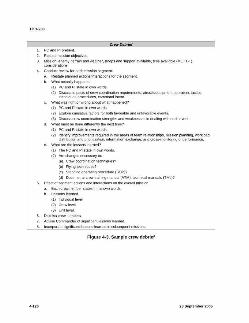
TC 1-238
Crew Debrief 1. PC and PI present. 2. Restate mission objectives. 3. Mission, enemy, terrain and weather, troops and support available, time available (METT-T)
considerations. 4. Conduct review for each mission segment:
a. Restate planned actions/interactions for the segment. b. What actually happened.
(1) PC and PI state in own words. (2) Discuss impacts of crew coordination requirements, aircraft/equipment operation, tactics-
techniques-procedures, command intent. c. What was right or wrong about what happened?
(1) PC and PI state in own words. (2) Explore causative factors for both favorable and unfavorable events. (3) Discuss crew coordination strengths and weaknesses in dealing with each event.
d. What must be done differently the next time? (1) PC and PI state in own words. (2) Identify improvements required in the areas of team relationships, mission planning, workload
distribution and prioritization, information exchange, and cross-monitoring of performance. e. What are the lessons learned?
(1) The PC and PI state in own words. (2) Are changes necessary to:
(a) Crew coordination techniques? (b) Flying techniques? (c) Standing operating procedure (SOP)? (d) Doctrine, aircrew training manual (ATM), technical manuals (TMs)?
5. Effect of segment actions and interactions on the overall mission. a. Each crewmember states in his own words. b. Lessons learned.
(1) Individual level. (2) Crew level. (3) Unit level.
6. Dismiss crewmembers. 7. Advise Commander of significant lessons learned. 8. Incorporate significant lessons learned in subsequent missions.
Figure 4-3. Sample crew debrief
4-126 23 September 2005
TC 1-238
TASK 1402
Perform tactical flight mission planning
CONDITIONS: Before a tactical flight in an AH-64A helicopter or an AH-64A simulator and given a mission briefing, navigational maps, a navigational computer, approved software, and other materials as required.
STANDARDS: Appropriate common standards and the following: 1. Analyze the mission using the factors of mission, enemy, terrain and weather, troops and support available, time available (METT-T). Perform a map/photo reconnaissance using the available map media or photos. Ensure that all known hazards to terrain flight are plotted on the map. 2. Select the appropriate terrain flight modes. 3. Select appropriate primary and alternate routes and enter all of them on a map, route sketch, or into the approved software. 4. Determine the distance ±1 kilometer, ground speed ±5 knots, and estimated time en route (ETE) ±1 minute for each leg of the flight. 5. Determine the fuel required ±100 pounds. 6. Obtain and analyze weather briefing to determine that weather and environmental conditions are adequate to complete the mission.
Note 1: This task specifically focuses on the tactical flight planning aspects of mission planning. The standards of this task may be achieved through exclusive manual means or approved software.
DESCRIPTION: 1. Crew actions.
a. The pilot in command (PC) will ensure that all necessary tactical flight information is obtained and will conduct a thorough crewmember briefing in accordance with the unit standing operating procedure (SOP) and task 1000. He may delegate mission-planning tasks to the other crewmember but retains overall responsibility for mission planning. He will analyze the mission in terms of mission, enemy, terrain and weather, troops and support available, time available (METT-T). b. The pilot (PI) will perform the planning tasks directed by the PC. He will report the results of his planning to the PC.
2. Procedures. Analyze the mission using the factors of METT-T. Conduct a map or aerial photoreconnaissance. Obtain a thorough weather briefing that covers the entire mission, and input as necessary into the approved software. Include sunset and sunrise times, density altitudes, winds, and visibility restrictions. If the mission is to be conducted at night, the briefing should also include moonset and moonrise times, ambient light levels, and an electrooptical forecast, if available. Determine primary and alternate routes, terrain flight modes, and movement techniques. Determine time, distance, and fuel requirements using the navigational computer or approved software. Annotate the map, overlay, or approved software with sufficient information to complete the mission. This information includes waypoint coordinates that define the routes for entry into the approved software. Consider such items as hazards, checkpoints, observation posts, and friendly and enemy positions. Review contingency procedures.
23 September 2005 4-127
TC 1-238
Note 2: Evaluate weather impact on the mission. Considerations should include aircraft performance, limitations on visual sensors, and weapons employment.
NIGHT OR NIGHT VISION DEVICE (NVD) CONSIDERATIONS: More detailed flight planning is required when the flight is conducted in reduced visibility, at night, or in the NVD flight environment. TC 1-204 contains details on night navigation.
TRAINING AND EVALUATION REQUIREMENTS: 1. Training will be conducted academically. 2. Evaluation will be conducted academically.
REFERENCES: Appropriate common references.
4-128 23 September 2005

TC 1-238
TASK 1404
Perform electronic countermeasures/electronic counter-countermeasures procedures
CONDITIONS: In an AH-64A helicopter or an AH-64A simulator and given signal operation instructions (SOI).
STANDARDS: Appropriate common standards and the following: 1. Operate secure communications equipment, avionics, and electronic sensing equipment. 2. Recognize and respond to electronic warfare actions.
DESCRIPTION: 1. Crew actions.
a. The pilot in command (PC) will assign radio frequencies per SOI and mission requirements during the crew briefing. He will indicate which crewmember will establish and maintain primary communications. b. The pilot on the controls (P*) will announce mission information not monitored by the pilot not on the controls (P) and any deviation from directives. c. The P should operate the radio and announce radio frequencies as well as copy and interpret pertinent information. He will announce information not monitored by the P*.
2. Procedures. a. General. Maintain radio discipline at all times. Use electronic communications in the tactical environment only when absolutely necessary. When electronic communication is required, the two modes of operation are secure digital and secure voice (analog). To eliminate confusion and reduce transmission time, use digital messaging, or when operating analog, use standard phrases, words, and codes. Plan what to say before keying the transmitter. Transmit analog information clearly, concisely, and slowly enough to be understood by the receiving station. Keep transmissions under 10 seconds, if possible. b. Digital communication. When there is no jamming, use the lowest frequency modulated power setting required and the highest baud rate.
3. Communication considerations. a. Authentication. Use proper SOI procedures to authenticate all in-flight mission changes and artillery advisories when entering or departing a radio net or when challenged. Authentication can be accomplished through a printed SOI. b. Meaconing, intrusion, jamming, and interference (MIJI) procedures. Keep accurate and detailed records of any MIJI incident suspected to be intentional interference. Report the incident as soon as possible when a secure communications capability exists. c. Identification, friend or foe (IFF) usage. During radio checks, select the appropriate transponder mode. d. Antijamming procedures. To overcome jamming use HAVE QUICK, single channel ground and airborne radio set (SINCGARS), high frequency and/or change the frequency modulated power setting to HIGH. Changes must be coordinated with other aircraft per the unit standing operating procedure (SOP) to ensure uninterrupted reception. e. Other visual methods. Flags, lights, panels, pyrotechnics, hand-and-arm signals, and aircraft maneuvers are some of the possible visual communication methods. The unit SOP and SOI describe these methods in detail.
23 September 2005 4-129

TC 1-238
TRAINING AND EVALUATION REQUIREMENTS: 1. Training may be conducted in the AH-64A aircraft or AH-64A simulator. 2. Evaluation will be conducted in the AH-64A aircraft or AH-64A simulator.
REFERENCES: Appropriate common references.
4-130 23 September 2005
TC 1-238
TASK 1405
Transmit tactical reports (high frequency/voice)
CONDITIONS: In an AH-64A helicopter, an AH-64A simulator, or as an oral exercise.
STANDARDS: 1. Transmit the appropriate report using the proper format and current signal operation instructions (SOI). 2. Transmit tactical reports using tactical standard operating procedures (TSOPs). 3. Transmit/receive digital reports.
DESCRIPTION: 1. Crew actions.
a. The pilot on the controls (P*) will remain focused outside the aircraft to avoid obstacles. He will announce any maneuver or movement prior to execution. The P* should not unmask the aircraft in the same location more than once. b. The pilot not on the controls (P) will assemble and transmit the report using the correct format as specified in the SOI and transmit the report to the appropriate agency. c. Crewmembers must be able to provide timely, concise reports. The P will make the call and transmit the report.
2. Procedures. a. To save time, minimize confusion, and ensure completeness, report information in an established format. Assemble the report in the correct format and transmit it to the appropriate agency. b. Voice reports. Unit TSOPs include line number tactical report examples and provide directives for the handling of the specific reports. The following are common line numbered tactical reports:
(1) Battle damage assessment (BDA) report (voice). A BDA should be submitted following naval gunfire, artillery fire (if requested), or a tactical air strike. Phonetic letters may precede each element (for example, ALPHA, BRAVO, CHARLIE, or DELTA). The standard format for a BDA is given below.
(a) Call sign of observing source. (b) Location of the target. (c) Time strike started and ended. (d) Percentage of target coverage (pertains to the percentage of projectiles that hit the target area). (e) Itemized destruction (f) Remarks. (These may be omitted; however, they may contain additional information, such as the direction the enemy may have taken in leaving the target area.)
(2) Spot report (voice). A crewmember has determined a need to transmit a spot report. Transmit the spot report over secure communications or encrypt the transmission. The standard format for a spot report is given below.
(a) Call sign of observer.
23 September 2005 4-131
TC 1-238
(b) SALUTE (see below). • S—size. • A—activity. • L—location. • U—unit (if known). • T—time. • E—equipment.
(c) What you are doing about it. (3) Enemy shelling, bombing, or chemical, biological, radiological, and nuclear (CBRN) warfare activity report (voice).
(a) Call sign and type of report. (b) Position of observer, grid coordinates encrypted, or secure communications used. (c) Azimuth of flash, sound, or groove of shell (state which) or origin of flight path of missile. (d) Time from (date-time of attack). (e) Time to (for illumination time). (f) Area attacked (either azimuth and distance from observer encrypted or grid coordinates in the clear). (g) Number and nature of guns, mortars, aircraft, or other means of delivery, if known. (h) Nature of fire (for example, barrage or registration) or CBRN-1 type of burst (air or surface) or type of toxic agent. (i) Number and type of bombs, shells, and rockets. (j) Flash-to-bang time in seconds. (k) If CBRN-1, damage (encrypted) or crater diameter. (l) If CBRN-1, fireball width immediately after shock wave. (Do not report if data was obtained more than 5 minutes after detonation.) (m) If CBRN-1, cloud height (top or bottom) 10 minutes after burst. (n) If CBRN-1, cloud width 10 minutes after burst.
Note 1: State units of measure used, such as meters or miles. As a minimum, a CBRN-1 report requires lines A, B, C, D, H, J, and either L or M.
(4) Information using visual signaling techniques. Technology has greatly diminished, but has not completely eliminated, the need to perform visual signaling techniques. The crew will utilize visual signaling techniques per the unit standing operating procedure (SOP), unit directives, or as is situationally advantageous. (5) Meaconing, intrusion, jamming, and interference (MIJI) report (voice). The MIJI report should be forwarded using the most expeditious secure communications means available.
(a) Type of report. Meaconing, intrusion, jamming, or interference. (b) Affected unit. Call sign and suffix. (c) Location. Grid location (encrypted).
4-132 23 September 2005
TC 1-238
(d) Frequency affected. Frequency encrypted. (e) Type of equipment affected; for example, ultrahigh frequency, very high frequency, frequency modulated, or beacon. (f) Type of interference. Type of jamming and type of signal. (g) Strength of interference. Strong, medium, or weak. (h) Time interference started and stopped. If continuing, so state. (i) Interference effectiveness. Estimate percent of transmission blockage. (j) Operator's name and rank. (k) Remarks. List anything else that may be helpful in identifying or locating source of interference and pass it on to higher headquarters by an alternate, secure means.
Note 2: Encryption is required only if information is transmitted over nonsecure means.
TRAINING AND EVALUATION REQUIREMENTS: 1. Training may be conducted in the AH-64A aircraft or AH-64A simulator. 2. Evaluation will be conducted in the AH-64A aircraft or AH-64A simulator.
REFERENCES: Appropriate common references.
23 September 2005 4-133
TC 1-238
TASK 1406
PERFORM TERRAIN FLIGHT NAVIGATION
CONDITIONS: In an AH-64A helicopter or an AH-64A simulator under visual meteorological conditions (VMC) with tactical flight mission planning completed and the pilot on the controls (P*) fitted with a boresighted helmet display unit (HDU).
STANDARDS: Appropriate common standards and the following: 1. During nap-of-the-earth (NOE) flight—
a. Know the en route location within 200 meters (500 meters night vision device [NVD]). b. Locate the final objective within 100 meters. c. Locate and avoid obstacles/hazards.
2. During low-level or contour flight— a. Know the en route location within 500 meters (1,000 meters NVD). b. Locate the final objective within 100 meters. c. Locate and avoid obstacles/hazards.
DESCRIPTION: 1. Crew actions.
a. The pilot on the controls (P*) will remain focused outside the aircraft and will acknowledge all navigational and obstacle clearance instructions given by the pilot not on the controls (P). He will announce the intended direction of flight and any deviation from instructions given by the P. b. The P will provide adequate warning to avoid obstacles detected in the flight path or identified on the map. He will announce when his attention is focused inside the cockpit; for example, when monitoring aircraft systems. c. Terrain flying involves flight close to the earth’s surface. During terrain flight, the crew’s primary concern is the threat and obstacle avoidance.
2. Procedures. Terrain flight navigation requires the crew to work as a team. The crew will remain primarily focused outside the aircraft and respond to navigation instructions and cues. The P* will acknowledge commands for heading and airspeed changes necessary to navigate the desired course. The P will announce significant terrain features and other cues to assist in navigation. The P will announce any verified or perceived hazards to flight and provide instructions and perform actions for obstacle/hazard avoidance. He will change aircraft heading and airspeed as appropriate to navigate the desired course. The P will announce all plotted hazards before approaching their location, using standard terms and specific headings, relative bearings, or key terrain features. When using the HDU, include headings. Point out terrain features as the aircraft approaches them. Use the map and programmed route points to help arrive at a specific checkpoint or turning point. Select the map and scale that provides the best detail for precise navigation. Using standardized terms prevents misinterpretation of information and unnecessary cockpit conversation. At all times the crew must look far enough ahead of the aircraft to avoid hazards.
a. During NOE flight, the crew may use several navigational techniques. In one technique, the crew identifies prominent terrain features that are located some distance ahead of the aircraft and that lie along or near the course. Using these points to key on, the crew
4-134 23 September 2005
TC 1-238
maneuvers the aircraft to take advantage of the terrain and vegetation for concealment. If general navigational techniques do not apply, the crew identifies the desired route by designating a series of successive checkpoints. To remain continuously oriented, they compare actual terrain features with those on the map. b. Contour navigation is less precise than NOE navigation because the contour route is more direct. An effective technique is to combine the use of terrain features and rally terms when giving directions. This will allow the P* to focus his attention outside the aircraft. c. For low-level navigation, the crew can compute time and distance to fly specific headings and airspeeds. The crew can also use radio navigation, depending on the terrain and enemy situation.
Note 1: If the area permits, the crew should navigate at least 20 kilometers during NOE flight training or 40 kilometers during low-level or contour flight training.
Note 2: The aircrew should incorporate the use of approved software resources in coordination with this task. Consideration should be given to the crew utilizing approved software produced strip maps. When possible, the crew should review the digital projections of the proposed routes before conducting the flight.
Note 3: Deviations from the planned route may be necessary to prevent the aircraft from becoming an easily engaged target and to avoid predictability. Depending upon METT-T, avoid the tendency to become locked to a course line. Make the aircraft a difficult target to track and engage.
OVERWATER CONSIDERATIONS: Overwater flight, at any altitude, is characterized by a lack of visual cues; therefore, it has the potential of causing visual illusions. Be alert to any unannounced changes in the flight profile and be prepared to take immediate corrective actions. The radar altimeter low bug should be set to assist in altitude control. Hazards to terrain flight (for example, harbor lights, buoys, wires, and birds) must also be considered during overwater flight.
TRAINING AND EVALUATION REQUIREMENTS: 1. Training may be conducted in an AH-64A aircraft or an AH-64A simulator. 2. Evaluation will be conducted in the aircraft.
REFERENCES: Appropriate common references.
23 September 2005 4-135
TC 1-238
TASK 1407
PERFORM TERRAIN FLIGHT TAKEOFF
CONDITIONS: In an AH-64A helicopter or AH-64A simulator under visual meteorological conditions (VMC) with tactical flight mission planning completed, hover power and before-takeoff checks completed, aircraft cleared, and the pilot on the controls (P*) fitted with a boresighted helmet display unit (HDU).
STANDARDS: Appropriate common standards and the following: 1. Maintain takeoff flight path until clear of obstacles. 2. Apply power as required to clear obstacles without exceeding aircraft limitations.
DESCRIPTION: 1. Crew actions.
a. The pilot on the controls (P*) will remain focused outside the aircraft and will acknowledge all navigational and obstacle clearance instructions given by the pilot not on the controls (P). He will announce whether the takeoff is from the ground or from a hover, intent to abort or alter the takeoff, the intended direction of flight and any deviation from instructions given by the P. b. The P will provide adequate warning to avoid obstacles detected in the flight path or identified on the map. He will announce when his attention is focused inside the cockpit; for example, when monitoring aircraft systems.
2. Procedures. a. Determine the direction of takeoff by analyzing the tactical situation, wind, long axis of the takeoff area, and lowest obstacles. Select reference points to assist in maintaining the takeoff flight path. Remain focused outside the aircraft during the maneuver. If required, reposition the aircraft to maximize the long axis and effects of wind. Align the aircraft with the takeoff reference point and adjust power as required to initiate the takeoff. b. Airspeed over altitude. The crew may select an airspeed over altitude takeoff if sufficient maneuver area exists. Select an abort point in the takeoff direction at which the aircraft must be through effective translational lift. Should the crew decide to abort the takeoff, the abort point will allow adequate area to decelerate and terminate safely without impacting the ground or obstacles. c. Altitude over airspeed. If out-of-ground effect (OGE) power is marginal, the crew should attempt to ascend vertically to an altitude above the obstacles, and then accelerate to forward flight. This takeoff allows the P* to safely abort the takeoff or a forced landing area in the event of rotor droop because of limited power or an engine failure. This type of takeoff will require OGE hover power.
Note 1: The option to ascend vertically allows for the descent back to the point of origin should the takeoff need to be aborted. This also allows for a limited maneuver area clear of possible obstacles in the event of an engine failure.
Note 2: If power is marginal and the possibility exists of exceeding a limit, the crew should monitor for impending performance limiters.
d. Once obstacles are cleared, adjust the flight controls as required to transition into the desired terrain flight mode (nap-of-the-earth [NOE], contour, or low level).
4-136 23 September 2005

TC 1-238
TRAINING AND EVALUATION REQUIREMENTS: Note 3: When turbine gas temperature (TGT) limiters may be reached, the P* should monitor engine gauges for performance.
1. Training may be conducted in an AH-64A aircraft or an AH-64A simulator. 2. Evaluation will be conducted in the aircraft.
REFERENCES: Appropriate common references.
23 September 2005 4-137
TC 1-238
TASK 1408
PERFORM TERRAIN FLIGHT
CONDITIONS: In an AH-64A helicopter or AH-64A simulator under visual meteorological conditions (VMC) with tactical flight mission planning completed and the pilot on the controls (P*) fitted with a boresighted helmet display unit (HDU).
STANDARDS: Appropriate common standards and the following (terrain flight mode): 1. Nap-of-the-earth (NOE) flight (out-of-ground effect [OGE] power required).
a. Fly as close to the earth’s surface as obstacles and visibility will permit. b. Maintain an airspeed appropriate for the terrain, enemy situation, weather, and visibility.
2. Contour flight. a. Maintain an altitude that allows safe clearance of obstacles while generally conforming to the contours of the earth. b. Maintain an airspeed appropriate for the terrain, enemy situation, weather, and visibility. c. Maintain the aircraft in trim.
3. Low-level flight. a. Maintain altitude ±50 feet. b. Maintain airspeed ±10 knots true airspeed (KTAS). c. Maintain the aircraft in trim.
4. Correctly conduct or explain tactical movement procedures. a. Select the correct mode of terrain flight for the level of cover and concealment necessary. b. Conduct tactical movement using traveling, traveling overwatch, or bounding overwatch.
DESCRIPTION: 1. Crew actions.
a. The pilot on the controls (P*) will remain focused outside the aircraft and will acknowledge all navigational and obstacle clearance instructions given by the pilot not on the controls (P). He will announce the intended direction of flight and any deviation from instructions given by the P. b. The P will provide adequate warning to avoid obstacles detected in the flight path or identified on the map. He will announce when his attention is focused inside the cockpit; for example, when monitoring aircraft systems. c. Terrain flying involves flight close to the earth's surface. The modes of terrain flight are NOE, contour, and low-level. The transition mode of flight symbology is the normal mode for terrain flight. The crew will seldom perform pure NOE or contour flight. Instead, they will alternate techniques while maneuvering over the desired route. During terrain flight, the crew's primary concern is the threat and obstacle avoidance.
2. Procedures. Terrain flight mode. Terrain flight is conducted at one of, or a combination of, three distinct modes of flight: (1) NOE; (2) contour; or (3) low level. As applicable, the crew will employ the technique of movement (traveling, traveling overwatch, or bounding overwatch) and the terrain flight mode that best supports the situation. Terrain flight modes and techniques of movement are described below.
4-138 23 September 2005
TC 1-238
Note 1: Crewmembers should consider setting the radar altimeter LO selection to an altitude (above ground level [AGL]) that best supports the tactical situation and mode of flight
a. NOE flight. NOE flight is conducted at varying airspeeds and altitudes as close to the earth's surface as vegetation, obstacles, and ambient light will permit. It is essential to trim the aircraft longitudinally along the NOE flight path to diminish the possibility of striking an obstacle. The AH-64A provides symbolic cues that can be used day or night for establishing and maintaining this NOE flight condition. The symbolic cue for maintaining longitudinal trim during NOE flight has been termed “NOE trim.” Establish NOE trim by initially noting the velocity vector deflection in the transition mode of flight symbology. Slip the aircraft to align with the NOE flight path by applying antitorque pedal pressure corresponding to the direction of the displaced velocity vector. Apply slight cyclic pressure opposite the side of velocity vector displacement if exact ground track is to be maintained. Apply required counterpressure and pressure to the antitorque pedals as necessary to maintain the velocity vector extended at the 12 o’clock position of the line of sight (LOS). b. Contour flight. Contour flight is characterized by varying altitude and relatively constant airspeed, depending on vegetation, obstacles, and ambient light. It generally follows the contours of the earth. c. Low-level flight. Low-level flight is usually performed at a constant airspeed and altitude. It generally is conducted at an altitude that prevents or reduces the chance of detection by enemy forces. d. Techniques of movement and principles of overwatch. Techniques of movement are designed to exploit the mobility of helicopters while employing the fire and maneuver concept. Security is established and maintained by adapting the flight to specific flight modes and techniques of movement in consideration of mission, enemy, terrain and weather, troops and support available, time available (METT-T). Flight modes and techniques of movement incorporate principles of overwatch, which include the following: (1) find the enemy with a minimum of forces; (2) use all available cover and concealment; (3) overwatch lead elements and be prepared to fire and maneuver; and (4) adjust the movement technique and type of terrain flight to the factors of METT-T. The techniques of tactical movement are briefly described below.
(1) Traveling. This technique is used primarily when enemy contact is not likely. It is the fastest method for moving a formation of aircraft but provides the least amount of security. Low-level flight and contour flight at high airspeed are normally used for movement. (2) Traveling overwatch. This technique is used when enemy contact is possible. It is characterized by continuous movement of the main elements. The overwatching element keys its movement to the terrain and its distance from the main element. It remains ready to fire or maneuver, or both, to support the main elements. Contour flight is normally used for movement. Airspeed is generally high and varied depending on the weather, ambient light, terrain, and threat. (3) Bounding overwatch. This technique is used when enemy contact is likely and the greatest degree of concealment is required. Elements move by bounds. One element remains in position to observe, fire, or maneuver before the other element moves. Overwatching elements cover the progress of bounding elements from a covered and concealed position, which offers observation and fields of fire against potential enemy positions. Contour flight and NOE flight are normally used for movement. Airspeed during each bound is varied, depending on the availability of vegetation and terrain for concealment.
23 September 2005 4-139
TC 1-238
OVERWATER CONSIDERATIONS: Overwater flight, at any altitude, is characterized by a lack of visual cues and, therefore, has the potential of causing visual illusions. Be alert to any unannounced changes in the flight profile and be prepared to take immediate corrective actions. The radar altimeter low bug should be set to assist in altitude control. Hazards to terrain flight (for example, harbor lights, buoys, wires, and birds) must also be considered during overwater flight.
TRAINING AND EVALUATION REQUIREMENTS: Note 2: Terrain flight modes (NOE, contour, or low level) are inherent to the performance of tactical movement (traveling, traveling overwatch, or bounding overwatch). Tactical movement procedures may be accomplished orally when resources are not able to facilitate hands-on performance.
1. Training may be conducted in an AH-64A aircraft or an AH-64A simulator. 2. Evaluation will be conducted in the AH-64A aircraft.
REFERENCES: Appropriate common references.
4-140 23 September 2005
TC 1-238
TASK 1409
PERFORM TERRAIN FLIGHT APPROACH
CONDITIONS: In an AH-64A helicopter or AH-64A simulator under visual meteorological conditions (VMC) with tactical flight mission planning completed ,before-landing checks completed, and the pilot on the controls (P*) fitted with a boresighted helmet display unit (HDU).
STANDARDS: Appropriate common standards and the following: 1. Maintain desired approach angle to clear obstacles. 2. Maintain ground track alignment with the selected approach path with minimum drift. 3. Maintain an appropriate rate of closure. 4. Make a smooth, controlled termination at the intended approach point.
DESCRIPTION: 1. Crew actions.
a. The pilot on the controls (P*) will remain focused outside the aircraft and will acknowledge all navigational and obstacle clearance instructions given by the pilot not on the controls (P). He will announce the intended direction of flight and any deviation from instructions given by the P. b. The P will provide adequate warning to avoid preplanned hazards or obstacles detected in the flight path. He will announce when his attention is focused inside the cockpit; for example, when monitoring aircraft systems. c. During terrain flight, the crew's primary concern is the threat and obstacle avoidance.
2. Procedures. a. Initiate the approach from a straight-in or modified pattern, depending on the tactical situation, wind, long axis of the landing area, lowest obstacles and arrival path. Evaluate the wind direction and magnitude noting the ground speed compared to the true airspeed or external wind cues. Use the velocity vector to provide an indication of the aircraft’s flight path and visual imagery to aid in obstacle clearance. b. Maneuver the aircraft as required (straight-in or circle) to intercept the desired approach path. Adjust the airspeed as necessary and keep the landing area in sight at all times. Start the approach upon intercepting an angle appropriate for the tactical situation and that ensures obstacle clearance. The P* may elect to place the helicopter out of nap-of-the-earth (NOE) trim condition to view the landing area or intended touchdown point through the side canopy. The crew must ensure that the fuselage will remain clear of all obstacles in this sideslip condition. Once the aircraft is aligned with the desired landing area and is clear of obstacles, adjust power as required to maneuver to the intended point of landing. Adjust the flight controls as necessary to maintain the line of sight (LOS) on the intended landing point and above any obstacles and continue the approach utilizing the remaining helmet display unit (HDU) symbolic cues in conjunction with visual cues. c. If a successful landing is doubtful or visual reference with the touchdown point is lost, announce initiation of a go-around before reducing airspeed below effective translational lift (ETL) or before descending below obstacles. Whether the approach will terminate to a hover or to the ground, announce the intended point of landing and any deviation from the approach. Announce the intention to use the manual stabilator.
23 September 2005 4-141
TC 1-238
NIGHT OR NIGHT VISION DEVICE (NVD) CONSIDERATIONS: Maintain proper scanning techniques to ensure obstacle avoidance and tail rotor clearance.
NIGHT VISION SYSTEM (NVS) CONSIDERATIONS: Perform a landing area reconnaissance on final while all critical obstacles in and around the landing area are visible within the instantaneous field of view (FOV). Briefly reconnoiter beyond the landing area for a potential go-around route. A deceleration may be required prior to reaching the desired approach angle to arrive on the angle with the correct rate of closure. Obtain rate of closure information from the forward-looking infrared (FLIR) imagery. Relative motion cues are most reliable when the NVS is offset from the aircraft centerline (looking left, right, or down). The crew may cross-check imagery-supplied perception of motion with symbology information, such as the velocity vector. Under no-wind or light-wind conditions, use of the airspeed symbology may give additional information. When obstacles are near, perform this maneuver by maintaining nose-to-tail trim with the pedals and ground track with the cyclic. The velocity vector provides the nose-to-tail relationship reference. The ground track is established and maintained using imagery-supplied cues.
TRAINING AND EVALUATION REQUIREMENTS: 1. Training may be conducted in an AH-64A aircraft or an AH-64A simulator. 2. Evaluation will be conducted in the AH-64A aircraft.
REFERENCES: Appropriate common references.
4-142 23 September 2005

TC 1-238
TASK 1410
PERFORM MASKING AND UNMASKING
CONDITIONS: In an AH-64A helicopter or an AH-64A simulator with the pilot on the controls (P*) properly fitted with a boresighted helmet display unit (HDU) and out-of-ground effect (OGE) power available for unmasking at a hover (vertically).
STANDARDS: Appropriate common standards and the following: 1. Perform a thorough map reconnaissance. 2. Mask the aircraft from enemy visual and electronic detection. 3. Maintain a sufficient distance behind obstacles to allow for safe maneuvering. 4. Move to a new location, if available, before subsequent unmasking. 5. Report observations as directed.
DESCRIPTION: 1. Crew actions.
a. The P* will remained focused outside the aircraft. He will announce the type of masking and unmasking before executing the maneuver. Unless the pilot in command (PC) directs otherwise, the P* may elect to utilize the ATTD/HOVER HOLD modes during the maneuver. His primary concern will be aircraft control while viewing his assigned sector. b. The pilot not on the controls (P) will perform a thorough map reconnaissance to identify natural and manmade features before the unmasking (may be accomplished during tactical flight mission planning or in the aircraft), and announce when ready. The P will primarily view his assigned sector, overlap the P* sector, and warn the P* of obstacles or unanticipated drift and altitude changes. c. The PC will brief the other crewmember on the forced landing/flyaway plan. The PC will assign observation sectors to the other crewmember to maximize the areas scanned during the time unmasked. He will also ensure observations are reported.
2. Procedures. a. Masking in flight. Fly to the destination with the aid of a strip map, digital map, or topographic issued map. Take maximum advantage of terrain and vegetation to prevent exposure of the aircraft to enemy visual observation or electronic detection. Maintain situational awareness and orientation at all times and look far enough ahead on the map for hazards. b. Unmasking in flight. Keep aircraft exposure time to a minimum to prevent enemy visual observation or electronic detection. Gun dish radars may be able to lock onto a target within 2 to 9 seconds.
Note 1: Minimum safe altitude (MSA) is defined as the minimum safe height (AGL) above the surface or obstacles to which the aircraft can descend in a masked condition.
Note 2: Minimum maneuvering altitude (MMA) is defined as the altitude (MSL) above the mask or barriers at which the aircraft may be safely maneuvered.
c. Unmasking at a hover (vertically). OGE hover power required. Ensure that sufficient power is available by referencing performance planning data prior to unmasking. Unless the PC directs otherwise, employ ATTD/HOVER HOLD modes during all the phases of this
23 September 2005 4-143
TC 1-238
maneuver. Apply collective until sufficient altitude is obtained to either visually acquire target area or utilize the target acquisition and designation sight (TADS) to scan over the mask without exceeding aircraft power limitations. The P* will maintain horizontal main rotor blade clearance from the mask in case of a power loss or a tactical need to mask the aircraft quickly. Each crewmember ensures a weapon system/video recorder is activated or ready to employ as appropriate for the mission. Begin the scan by clearing the area around the aircraft, then outward. The P* will be focused outside during the unmasking, and the copilot-gunner (CPG) should be prepared to scan, record, and store areas/objects of interest with the TADS. Unmask at a safe distance from the mask to allow a rapid descent to a masked condition if detected or fired upon. Keep aircraft exposure time to a minimum.
Note 3: A common tendency when masking/remasking vertically is to move forward or rearward while performing this maneuver. Establish reference points to assist in maintaining position during ascents and descents.
Note 4: When operating at high gross weights and limited power margins, the P* will monitor engine performance to prevent possible rotor decay.
d. Unmasking at a hover (laterally). Sometimes unmasking can be accomplished by moving laterally from the mask. Hover the aircraft sideward to provide the smallest silhouette possible to enemy observation or fire. Keep aircraft exposure time to a minimum.
Note 5: When unmasking the helicopter, select a new location that is a significant distance from the previous location and where the target area can still be observed. If the target area is a long distance (2,000 to 3,000 meters) away, moving only 100 meters will still keep the aircraft in the same field of view from the target. However, if the target area is close to the unmasking position, a drift of 100 meters will make a significant difference.
NIGHT OR NIGHT VISION DEVICE (NVD) CONSIDERATIONS: Maintaining altitude and position is more difficult when hovering above 25 feet without aircraft lights. Use the radar altimeter to assist in maintaining altitude and the position box to assist in maintaining aircraft position. Use references such as lights, tops of trees, or manmade objects above and to the front and sides of the aircraft. By establishing a reference angle to these objects, the P* can detect altitude changes by changing his viewing perspective. Hovering near ground features, such as roads, provides ideal references for judging lateral movement. However, the P* may become spatially disoriented when alternating his viewing perspective between high and low references. Therefore, the P* must rely on the P for assistance if he becomes disoriented.
NIGHT VISION SYSTEM (NVS) CONSIDERATIONS: 1. Masking.
a. Using forward-looking infrared (FLIR) imagery and nap-of-the-earth (NOE) coupling, catalog obstacle locations and heights. Determine a minimum safe altitude at which the aircraft is clear of obstacles prior to unmasking. b. Use imagery to select visual reference points for visual orientation during performance of the maneuver. These reference points will assist in maintaining heading and position. c. When a stable hover has been achieved at the desired location, select appropriate symbology. ATTD/HOVER HOLD may be used as desired. The P* will establish and brief the P on a forced landing or flyaway plan.
4-144 23 September 2005
TC 1-238
2. Unmasking. a. Apply collective to initiate the desired rate of ascent. Reference torque and rate of climb indicator (instantaneous vertical speed indicator [IVSI]) symbology. b. Use the cyclic as necessary to maintain position during the ascent. Imagery reference and symbology (position box) will indicate drift or movement from the original position. ATTD/HOVER HOLD may be used during the unmasking. c. Use FLIR imagery-provided cues and heading tape symbology to maintain aircraft heading. d. Once the desired altitude is reached, adjust the collective to maintain altitude. Reference the radar altitude symbology, torque, and rate of climb (IVSI) symbology.
3. Remasking. a. Using the composite display, verify the position. b. Reduce collective to initiate a descent while referencing torque, and the rate of climb indicator (descent). Use FLIR image cues inclusive of NOE coupling to remask. ATTD/HOVER HOLD may be used during the remasking. Ensure that the composite display imagery-position box and/or line of sight (LOS) reticle indicates a return to a vertical position over the place of origin unless unsafe to do so. c. Continue the descent to remask the aircraft but no lower than the established MSA. d. Maintain heading while remasking by referencing imagery-provided cues and heading tape symbology.
Note 6: The P* must not base obstacle clearance on the ability of the aircraft to maintain its position hold alone. The P* must base his decision to descend on FLIR imagery references. He can use position symbology information to enhance aircraft position control. However, the use of symbology alone will not ensure obstacle avoidance.
TRAINING AND EVALUATION REQUIREMENTS: 1. Training may be conducted in an AH-64A aircraft or an AH-64A simulator. 2. Evaluation will be conducted in the AH-64A aircraft.
REFERENCES: Appropriate common references.
23 September 2005 4-145
TC 1-238
TASK 1411
PERFORM TERRAIN FLIGHT DECELERATION
CONDITIONS: In an AH-64A helicopter or an AH-64A simulator with the pilot on the controls (P*) properly fitted with a boresighted helmet display unit (HDU) and out-of-ground effect (OGE) power available.
STANDARDS: Appropriate common standards and the following: 1. Maintain alignment with the desired flight path or nap-of-the-earth (NOE) trim. 2. Maintain obstacle clearance. 3. Decelerate to the desired airspeed or to a full stop at the selected location.
DESCRIPTION: 1. Crew actions.
a. The P* remains focused outside the aircraft. He will announce his intention to decelerate or come to a full stop, any deviation from the maneuver, and the completion of the maneuver. The stabilator NOE approach or manual mode will enhance forward visibility during performance of the maneuver. The P* will announce his intentions to use the manual stabilator. b. The pilot not on the controls (P) will provide adequate warning to avoid obstacles detected in the flight path and will announce when his attention is focused inside the cockpit. c. The crew must clear the area below the aircraft before descending.
2. Procedures. Consider variations in the terrain and obstacles when determining tail rotor clearance.
a. Below effective translational lift (ETL). With terrain and obstacle considerations made, increase the collective just enough to maintain the altitude of the tail rotor while simultaneously applying aft cyclic to slow down to the desired airspeed/groundspeed or come to a full stop. Additional collective may be necessary if transitioning to an OGE hover. Maintain heading with the pedals and make all control movements smoothly. If the attitude of the aircraft is changed too much or too abruptly, returning the aircraft to a level attitude will be difficult, and overcontrolling may result. The rate of climb indicator (instantaneous vertical speed indicator [IVSI]) should be referenced throughout the maneuver. b. Above ETL. With terrain and obstacle considerations made, decelerate the aircraft by applying aft cyclic. Because of the velocity of the aircraft, it may be necessary to decrease collective simultaneously with the aft cyclic application to insure an undesired climb does not develop. Maintain altitude of the tail rotor with coordinated collective and cyclic movements. Maintain heading with pedals and make all control inputs smoothly. If the attitude of the aircraft is changed too much or too abruptly, returning the aircraft to a level attitude will be difficult and overcontrolling may result. The rate of climb indicator (IVSI) should be referenced throughout the maneuver.
NIGHT OR NIGHT VISION DEVICE (NVD) CONSIDERATIONS: Because of the limited field of view (FOV) of the NVD, avoid making abrupt changes in aircraft attitude. An extreme nose-high attitude limits the forward FOV. Maintain proper scanning techniques to ensure obstacle avoidance and tail rotor clearance.
4-146 23 September 2005
TC 1-238
NIGHT VISION SYSTEM (NVS) CONSIDERATIONS: 1. Before initiating the maneuver, refer to the imagery or radar altimeter to determine altitude. 2. Maintain heading by using composite video or imagery and symbology heading tape. 3. As the nose of the aircraft rises, lower the NVS field of view to provide an unobstructed view of obstacles in the flight path. Monitor the rate of closure with the composite video and altitude with the symbolic rate of climb. 4. Monitor the composite video to verify the absence of a climb or descent at termination.
TRAINING AND EVALUATION REQUIREMENTS: 1. Training will be conducted in the AH-64A aircraft. 2. Evaluation will be conducted in the AH-64A aircraft.
REFERENCES: Appropriate common references.
23 September 2005 4-147
TC 1-238
TASK 1412
PERFORM EVASIVE MANEUVERS
CONDITIONS: In an AH-64A helicopter or an AH-64A simulator in a simulated tactical environment with the pilot on the controls (P*) properly fitted with a boresighted helmet display unit (HDU), or as an oral exercise.
STANDARDS: Appropriate common standards and the following: 1. Perform evasive maneuvers appropriate for type of threat. 2. Report actions on contact as directed.
DESCRIPTION: 1. Crew actions. When engaged by the enemy, the crewmember who first identifies the threat will announce the nature of the threat (radar detection or hostile fire) and the direction of the threat.
a. The pilot on the controls (P*) will announce the direction of flight to other aircraft and deploy to cover. He will remain focused outside the aircraft during the evasive maneuver. The P* should be aware that if the pilot not on the controls (P) is returning suppressive fire he may be unavailable for assisting in obstacle avoidance or noting other threat sources. b. The P will remain oriented on the threat location and employ appropriate countermeasures or suppressive fire. He will announce when his attention is focused inside the cockpit; for example, when firing the weapons. The P will be alert for obstacles and new threat sources encountered during the evasive maneuver.
Note 1: The P should note location of threat. A method for the P conducting a target store is the target acquisition and designation sight (TADS) or helmet mounted display (HMD) store functions. If unable, noting the location of a threat (distance and bearing) relative to a known point.
2. Procedures. Fly the helicopter to a concealed area, using the evasive techniques below, as required. Choose a course of action that supports the mission and the intent of the unit commander's directives.
a. Tanks and small arms. Immediately turn away from the fire toward an area of concealment. If concealment is unavailable, make sharp turns of unequal magnitude and at unequal intervals and small changes in altitude to provide the best protection until beyond the effective range of hostile weapons. If the situation permits, employ immediate suppressive fire. b. Large caliber, antiaircraft fire (radar controlled). If the aircraft is equipped with a radar jammer, orient the aircraft toward the threat radar, deploy chaff, and side-slip the aircraft in an attempt to break radar lock. Mask the helicopter. If the helicopter is not equipped with a radar jammer, deploy chaff, execute an immediate 90-degree turn. After turning, do not maintain a straight line of flight or the same altitude for more than 10 seconds before initiating a second 90-degree turn. An immediate descent to nap-of-the-earth (NOE) altitude will reduce the danger. c. Fighters. When in an area where threat fighters are known or suspected to be operating, fly the helicopter at NOE altitude as much as possible. Upon sighting or sensing a fighter, try to mask the helicopter. If the fighter is alone and executes a dive, turn the helicopter toward
4-148 23 September 2005
TC 1-238
the attacker and descend. This maneuver will make the fighter pilot increase his attack angle. Depending on the fighter's dive angle, it may be advantageous to turn sharply and maneuver away once the attacker is committed. The fighter pilot will then have to break off his attack to recover from the maneuver. Once the fighter breaks off his attack, maneuver the helicopter to take advantage of terrain, vegetation, and shadow for concealment. d. Helicopters. Use the appropriate terrain flight maneuvers to break contact with or to evade threat helicopters. e. Heat-seeking missiles. Try to keep helicopter heat sources away from the threat. If a missile is sighted, turn the tail of the helicopter away from the missile and mask the helicopter. f. Antitank-guided missiles. Some missiles fly relatively slowly and can be avoided by rapidly repositioning the helicopter. If terrain or vegetation is not available for masking, remain oriented on the missile as it approaches. As the missile is about to impact, rapidly change the flight path or altitude to evade it. g. Artillery. Depart the impact area and determine chemical, biological, radiological, and nuclear (CBRN) requirements. h. Radar-guided missiles. If the helicopter is equipped with a radar jammer, maintain aircraft orientation toward the threat radar. Maneuver the helicopter to break the line of sight to the radar source while simultaneously activating chaff, if available.
Note 2: If hit by hostile fire, rapidly assess the situation and determine an appropriate course of action. The most important consideration in an emergency is aircraft control. Therefore, the first step is to assess aircraft controllability. Then, check all instruments and warning and caution lights. If a malfunction is indicated, initiate the appropriate emergency procedure. If continued flight is possible, take evasive action. Make a radio call (Mayday or Pan) to report situation, location, and action. Also request assistance if desired. Continue to be alert for unusual control responses, noises, and vibrations. Monitor all instruments for an indication of a malfunction. Fly the aircraft to the nearest secure location. Then, land and inspect the aircraft to determine the extent of damage and whether flight can be continued to a medical or maintenance facility.
NIGHT OR NIGHT VISION DEVICE (NVD) CONSIDERATIONS: Threat elements will be harder to detect. Rapid evasive maneuvers will be more hazardous due to divided attention and limited visibility. Maintain situational awareness with regard to threat and hazard location.
TRAINING AND EVALUATION REQUIREMENTS: 1. Training may be conducted in an AH-64A aircraft or an AH-64A simulator. 2. Evaluation will be conducted in an AH-64A aircraft or an AH-64A simulator.
REFERENCES: Appropriate common references.
23 September 2005 4-149
TC 1-238
TASK 1413
PERFORM ACTIONS ON CONTACT
CONDITIONS: In an AH-64A helicopter or an AH-64A simulator in a simulated tactical environment with the pilot on the controls (P*) properly fitted with a boresighted helmet display unit (HDU) and given a tactical map.
STANDARDS: Appropriate common standards and the following: 1. Locate the enemy. 2. Immediately employ suppressive fires or perform evasive maneuvers. 3. Use correct actions on contact consistent with the tactical situation.
DESCRIPTION: 1. Crew actions. The first crewmember to recognize the threat will immediately announce enemy contact (visual or electronic), type (hostile fire), and location of threat.
a. The pilot on the controls (P*) will position the aircraft to return suppressive fire or deploy to cover. He will announce the direction of flight to evade detection and will direct the pilot not on the controls (P) to remain focused outside the aircraft for clearing. b. The P will remain oriented on threat location and employ appropriate countermeasures and/or suppressive fire. He will announce warning to avoid obstacles and when his attention is focused inside the aircraft, such as when operating the weapons systems. c. The crew will transmit a voice report as required.
2. Procedures. a. Undetected by enemy. Fly the helicopter to a concealed area or bypass, using evasive maneuvers and suppressive fire as per rules of engagement (ROE). Choose a course of action that supports the mission as briefed. b. Detected by enemy. Immediately employ suppressive fires or perform evasive maneuvers. Fly the helicopter to a concealed area or bypass, using evasive maneuvers and suppressive fire as per ROE. Choose a course of action that supports the mission as briefed. c. Meeting engagement. Occurs when direct contact is made with threat and an exchange of fire is imminent. The only course of action is to engage to prevent damage to own ship.
NIGHT OR NIGHT VISION DEVICE (NVD) CONSIDERATIONS: Threat elements will be harder to detect. Rapid evasive maneuvers will be more hazardous. Crewmembers must maintain situational awareness.
TRAINING AND EVALUATION REQUIREMENTS: 1. Training may be conducted in an AH-64A aircraft or an AH-64A simulator. 2. Evaluation will be conducted in an AH-64A aircraft or an AH-64A simulator.
REFERENCES: Appropriate common references.
4-150 23 September 2005
TC 1-238
TASK 1414
PERFORM FIRING POSITION OPERATIONS
CONDITIONS: In an AH-64A helicopter or an AH-64A simulator with the pilot on the controls (P*) properly fitted with a boresighted helmet display unit (HDU).
STANDARDS: Appropriate common standards and the following: 1. Select the firing position and ensure that the target/engagement area is within range and field of fire. 2. Enter the firing position, keeping the aircraft masked from visual or electronic detection. 3. Engage targets as appropriate. 4. Exit the firing position, keeping the aircraft masked from visual or electronic detection.
DESCRIPTION: 1. Crew actions.
a. Perform crew actions outlined in task 1410 and task 1422. b. The pilot on the controls (P*) will remain focused outside the aircraft to provide clearing and to maintain aircraft orientation toward the target. He will announce any maneuver or movement prior to execution. Alternate or backup sources of flight information can be obtained by viewing flight instruments and helmet display unit (HDU) symbology. He will announce all visually or electronically detected threats to the pilot not on the controls (P). c. The P will direct the P* to maneuver the aircraft as necessary to maintain target orientation utilizing standard crew terminology. d. The crew will evaluate the wind and analyze the firing position for the availability of forced landing areas/flyaway plan. They will evaluate the wind direction and magnitude, noting true airspeed compared with ground speed or external wind cues. The crew must decide if they can attain single-engine airspeed; if not, they should plan to land at the selected forced landing area.
2. Procedures. Evaluate winds, enter the firing position, engage the target as appropriate, exit, and reposition to an alternate firing position.
a. Attack by fire/support by fire/battle position. Selection should allow for support of multiple primary firing positions and alternate firing positions. Selection should be based on the following considerations:
(1) Nature of the target. Determine the type of target and thickness of armor or cover. Evaluate the target and any associated weapon systems (antiaircraft artillery [AAA], air defense artillery [ADA], surface-to-air missiles [SAMs]). Evaluate the possibility of collateral damage in accordance with the briefed ROE. (2) Obstacles. This may include physical features, such as the type of terrain or manmade structures. Manmade structures may include protected sites. Associated with protected sites is the probability of civilian population in close proximity to possible target area. Another possible obstacle is limited aircraft performance due to environmental conditions. (3) Range to target. Determine the type of weapon system to be employed. Select a range that allows for maximum standoff distance from the target, if possible, and an adequate
23 September 2005 4-151
TC 1-238
maneuver area for unexpected contacts or events. Consider exposure time, element of surprise, and time required to engage target. (4) Multiple firing position/lanes. Support mutual coverage between aircraft within a team while still allowing sufficient distance for individual maneuvering to avoid becoming a single target for the enemy. This has to support target with minimal exposure time for team elements. (5) Area to maneuver. Allow freedom of movement for maneuver with sufficient distance between aircraft and teams while supporting mutual coverage.
b. Firing position. Select firing positions based on the following considerations: (1) Background. The helicopter should not be silhouetted. (2) Range. The kill zone should be within the last one-third of the weapon's range for aircraft survivability. Range must be within the minimum and maximum effective range of the selected weapon system and should be outside the enemy’s maximum effective range, if possible. (3) Target altitude. The firing position should be level with or higher than the target area, if possible. Altitudes above the target may affect minimum engagement ranges for Hellfire lock on after launch (LOAL) engagements. (4) Sun or full moon. The sun or full moon should be behind or to the side of the helicopter. (5) Shadow. When possible, the firing position should be within an area covered by shadow (weapons flash may be more visible from darker areas). (6) Concealment. Vegetation around the firing area should be sufficient for the helicopter to remain masked. (7) Rotor wash. The location of the firing position should avoid or reduce the visual signal caused by the effect of rotor wash on the surrounding terrain (for example, debris, trees, snow, and dust). (8) Maneuver area. The position should permit concealed entry and exit and obstacle avoidance to successfully accomplish evasive and emergency procedure maneuvers. This may require the establishment of running or diving fire lanes (9) Field of fire. The target/engagement area must be visible throughout the kill zone. The firing position must allow for autonomous direct fire engagements and provide obstacle clearance for ordinance delivery.
Note 1: Crewmembers should consider setting the radar altimeter LO selection to a minimum safe altitude.
NIGHT OR NIGHT VISION GOGGLE (NVG) CONSIDERATIONS: 1. The use of NVG may aid the copilot-gunner (CPG) in detecting obstacles difficult or impossible to identify with the forward-looking infrared (FLIR), such as wires and objects lost due to nap-of-the-earth (NOE) coupling. 2. NVG capability depends on the ambient light level. Navigation, target hand-offs, and assistance to the P* may be more difficult and time consuming when the CPG is wearing NVG because of a lack of symbology, altitude information, rate of climb/descent, and heading references.
4-152 23 September 2005
TC 1-238
NIGHT VISION SYSTEM (NVS) CONSIDERATIONS: 1. The crew may experience NOE coupling while masking the aircraft in and around the firing position. This may limit the crew’s ability to identify terrain or obstacles. 2. The crew may have to re-optimize the target acquisition and designation sight (TADS) once in the firing position.
TRAINING AND EVALUATION REQUIREMENTS: Note 2: Live fire of weapon systems is not required for training and evaluation of this task.
1. Training may be conducted in the AH-64A aircraft or AH-64A simulator. 2. Evaluation will be conducted in the AH-64A aircraft or AH-64A simulator.
REFERENCES: Appropriate common references.
23 September 2005 4-153
TC 1-238
TASK 1415
CONDUCT DIVING FLIGHT
CONDITIONS: In an AH-64A helicopter or an AH-64A simulator with the pilot on the controls (P*) properly fitted with a boresighted helmet display unit (HDU) and a 180-degree clearing turn completed.
STANDARDS: Appropriate common standards and the following: 1. Establish entry altitude 1,500 feet above ground level (AGL) (minimum), ±100 feet. 2. Establish entry airspeed 110 knots true airspeed (KTAS) (normal) or 60 KTAS (steep), ±10 KTAS. 3. Establish a 10- to 15-degree dive angle (normal) or a 25- to 30-degree dive angle (steep). 4. Maintain the aircraft in trim. 5. Recover to level flight before reaching computed velocity not to exceed (Vne) or 500 feet AGL.
DESCRIPTION: 1. Crew actions.
a. The crew will be aware of the characteristics of retreating blades stall and compressibility, effects of blade coning, mushing, and transient torque. b. The pilot on the controls (P*) will remain focused outside the aircraft to clear the aircraft throughout the maneuver. He will verify Vne prior to performing the maneuver. He will announce a normal or steep dive prior to initiating the maneuver and any deviation from the maneuver. He will also announce recovery from the maneuver. c. The pilot not on the controls (P) will provide adequate warning to avoid traffic or obstacles detected in the flight path and any deviation from the parameters of the maneuver. He will also announce when his attention is focused inside the cockpit; for example, when monitoring airspeed, altitude, or main rotor speed (NR).
2. Procedures. a. Normal. From straight-and-level flight at assigned altitude and airspeed, smoothly apply the cyclic to establish a 10- to 15-degree dive angle. Maintain a constant power setting (power required to maintain straight-and-level flight prior to entry) and constant trim. Apply additional right pedal as airspeed increases. Maintain a constant dive angle until the recovery. Start the recovery by verifying cruise torque is applied and smoothly applying aft cyclic at an altitude that will allow the recovery to be completed before reaching computed Vne or descending below 500 feet AGL. b. Steep. From straight-and-level flight at assigned altitude and airspeed, smoothly apply forward cyclic to establish a 25- to 30-degree dive angle. Maintain a constant power setting (power required to maintain straight-and-level flight at 60 KTAS), which does not correlate to a fixed collective position, and constant trim. Apply additional right pedal as the airspeed increases. Maintain a constant dive angle until the recovery. Airspeed and rate of descent will increase rapidly in a steep dive. Start the recovery early enough to complete it before reaching computed Vne or descending below 500 feet AGL. c. Dive recovery techniques. Straight-ahead dive recovery is not always feasible. By incorporating a left or right turn into the dive recovery, descent arrest occurs with a change of
4-154 23 September 2005

TC 1-238
aircraft direction. This maneuver is accomplished by simultaneously turning the aircraft and performing dive pullout. However, sufficient power margin may not be available. During minimum available power dive recovery, aft cyclic input is reduced as G loading builds and the aircraft is allowed to fly out of a dive, as opposed to attempting to establish a climb.
Note 1: Excessive bank angles during recovery offset lift from weight and may require additional altitude for recovery.
Note 2: The collective in a 2G recovery will decrease to the full down position if not checked by the P*.
Note 3: The normal tendency during the recovery pullout from a steep dive angle is failure of the P* to simultaneously recover from the dive and maintain power setting at or above the cruise entry value.
TRAINING AND EVALUATION REQUIREMENTS: 1. Training may be conducted in the AH-64A aircraft or AH-64A simulator. 2. Evaluation will be conducted in the AH-64A aircraft.
REFERENCES: Appropriate common references.
23 September 2005 4-155
TC 1-238
TASK 1416
Perform weapon initialization procedures
CAUTION Do not weapons action switch (WAS) the gun while ground taxiing.
The aircraft’s squat switch may not inhibit the gun from striking the ground.
CONDITIONS: In an AH-64A helicopter with the 30-millimeter gun turret area and the wing pylons clear or in an AH-64A simulator with the pilot on the controls (P*) properly fitted with a boresighted helmet display unit (HDU).
STANDARDS: Appropriate common standards and the following: 1. Perform weapons initialization procedures in accordance with TM 1-1520-238-10/CL. 2. Determine the status of the weapon systems.
DESCRIPTION: 1. Crew actions.
a. The crew will perform weapon system initialization procedures on all flights/missions that involve weapon systems use. The operational checks will be coordinated and accomplished as a crew. These procedures will determine the status and operation of each weapon system and permit firing of each system with minimal switch positioning. b. The copilot-gunner (CPG) will control the coordination of weapon initialization procedural checks unless the pilot in command (PC) directs otherwise. The crew will determine what effect a weapon system malfunction will have on the assigned mission. Inform appropriate personnel of aircraft’s status and record any discrepancies on the DA Form 2408-13-1.
2. Procedures. a. Master ARM/SAFE switch. To activate the weapon systems, apply either SAFE or ARM power to the fire control panels (FCPs). The weapons can be fired only when ARM power is applied. The MASTER switch (OFF, SAFE, ARM) controls SAFE or ARM power to the pilot’s (PLT) FCP and the aerial rocket control system (ARCS). The CPG switch (OFF, SAFE, ARM) controls SAFE or ARM power to the CPG’s FCP. Under normal conditions (in flight with the PLT/GND ORIDE switch off), the PLT’s MASTER switch establishes the highest status achievable on the PLT’s and CPG’s FCPs. For example, if the MASTER switch is positioned to SAFE, the PLT’s green SAFE light illuminates. If the CPG switch is positioned to ARM, only the CPG’s green SAFE light will illuminate. b. PLT/GND ORIDE switch. The PLT/GND ORIDE switch on the CPG’s FCP overrides both the PLT’s MASTER switch and the ground (squat switch) safety inhibit. With the PLT/GND ORIDE switch in the ORIDE position, the ground safety inhibit is eliminated and the master-slave relationship between the MASTER and CPG switches is reversed. Now the
4-156 23 September 2005
TC 1-238
CPG switch establishes the highest status attainable by the PLT’s MASTER switch. When this procedure is conducted on the ground this switch must be on. c. Weapon select switches. Select the desired weapon systems (RKT, GUN, MSL, and LSR).
(1) ARCS. Position the rocket switch to NORM. The PLT must then prepare the ARCS for firing via the aerial rocket control panel. The PLT selects the warhead and fuse combinations loaded (up to five zones). He also selects the penetration and firing quantity desired and establishes the range (manual or automatic) via the range-kilometer (RNGKM) thumb wheels. The zone inventory is displayed in the QTY REM section beneath the ZONE INVENTORY thumb wheel selectors. To arm a zone, the PLT pushes the ZONE SEL buttons. Once a zone is armed, all zones with like armament will also be armed. Any previously armed zone with dissimilar armament will be disarmed. (2) Gun (area weapon system [AWS]). Position the gun switch to NORM. The rounds on board are manually set via the rounds counter in the left-hand forward avionics bay following loading. (3) Missiles (Hellfire).
(a) MSL panel. Select the type of missiles loaded (LASER, RF/IR, IRIS). (Only LASER is currently available.) With SAFE or ARM power applied to the FCP and the MSL MODE switch in STBY, the missile system performs a built-in test (BIT) when the MSL switch is placed in the ON position. The BIT sequence checks the remote hellfire electronics (RHE) (0.8 second), missile launchers (8.0 seconds for four launchers), and each missile (32.0 seconds for a set of four). To bypass or terminate the BIT, place the MODE switch in the desired fire delivery mode (NORM, RIPL, or MAN). With the BIT bypassed, only the RHE status is checked by a continuous fault detection/location system (FD/LS). The STBY position is not an operational fire delivery mode, and the CHAN SEL switch is inoperative in this position. The auxiliary alphanumeric display (AND) will display the missile inventory and status when the BIT is completed. The AND missile inventory and status section will read FAIL if the pylon multiplex remote terminal unit (MRTU) fails, launcher electronics fail, or all missiles on that launcher fail. If the point target weapons system (PTWS) passes the BIT, the 4x4 section will indicate either SAFE or inventory when the missile system is powered. To clear the SAFE message, the CPG must apply ARM power to the FCP and power up the missile system. He may also manually move the launcher SAFE/ARM switch to ARM. If icing conditions are expected, the launcher SAFE/ARM switch must be moved to ARM before ice accumulates on the switch. Select the desired missile delivery mode on the LOAL switch (OFF, DIR, LO, or HI). (b) CPG FCP. Select the appropriate MSL indexers. In both the upper channel and the lower channel, set the appropriate laser code (A through H) and quantity (0 through 3). Normally, autonomous laser code addresses are in the upper channel laser code indexer. Place the preplanned remote designator (air or ground) code address in the lower channel laser code indexer. (The quantity indexer value of zero is read by the RHE as 1; therefore, at least one missile will be maintained in a ready status in each of the upper and lower missile channels.) In the target acquisition and designation sight (TADS) LSR CODE section of the FCP, select the appropriate laser spot tracker (LST) and laser range finder/designator (LRF/D) laser code indexers. The LST indexer normally is set to the remote designator code. The LRF/D indexer is set to the autonomous laser code. Upon completion of the CPG
23 September 2005 4-157
TC 1-238
FCP check, the MSL UPR CHAN and the LRF/D codes should match, enabling autonomous missile engagements. (c) Channel selection. The final step of initialization procedures is establishing the priority channel. To designate the priority channel, momentarily place the CHAN SEL switch to either the UPR or LWR position. The priority channel establishes the laser-coded Hellfire missile that is to be fired. Additionally, the CHAN SEL switch must be actuated for the fire control computer (FCC) to read the MSL MODE switch, MSL LSR CODE (UPR and LWR CHAN) indexers, MSL QTY (UPR and LWR CHAN) indexers, and MSL TYPE switch. When any of these switches and indexers are set or changed, the CHAN SEL switch must be actuated.
(4) LSR switch. Position the LSR switch to ON.
WARNING
When the CPG's FCP is in an armed status and the LASER switch is on, the laser trigger is armed. It is not controlled through the WAS.
d. Laser range finder/designator switch. The LRF/D counter-countermeasure (CCM) switch allows the laser range finder (LRF) to be used with integrity when laser countermeasures are present in the target area. With the switch in the OFF position, the last laser return from the scene of interest determines the range the FCC uses to compute ballistic equations. With the switch in the CCM position, the FCC uses the first laser return. During most laser operations the LRF/D CCM should be left in the off position; however, if either crewmember observes or suspects the selected target may be using countermeasures, the CCM position should be selected. This switch provides CCM for the laser range finder only. e. Weapons action switch. The crew can now activate the desired weapon system. When the weapon system is activated, the appropriate messages (for example, copilot rocket [CRKT], pilot controls gun [PGUN], and CMSL) will be displayed in the PLT’s and CPG’s high-action display (HAD) weapons control section.
Note 1: The CHAN SEL switch is not operational when the MODE switch is in the STBY position.
Note 2: The crew must verify correct operation of each weapon system by observing symbology, HAD messages, caution/warning lights, and weapon action/movement.
TRAINING AND EVALUATION REQUIREMENTS: 1. Training may be conducted in the AH-64A aircraft or AH-64A simulator. The crew should conduct weapon system initialization during regularly scheduled training flights to exercise aircraft armament systems and sustain crew proficiency. 2. Evaluation will be conducted in the AH-64A aircraft or AH-64A simulator.
REFERENCES: Appropriate common references.
4-158 23 September 2005
TC 1-238
TASK 1422
PERFORM FIRING TECHNIQUES
CONDITIONS: In an AH-64A helicopter or an AH-64A simulator with the pilot on the controls (P*) properly fitted with a boresighted helmet display unit (HDU) and aircraft weapons operational checks completed, and given a target to engage.
STANDARDS: Appropriate common standards and the following: 1. Identify the target. 2. Formulate an attack plan (technique, pattern/attack direction, munitions, range [TPM-R]). 3. Determine the attack pattern or direction. 4. Select the appropriate munitions. 5. Determine the range to the target. 6. Employ firing techniques.
DESCRIPTION: 1. Crew duties.
a. The pilot on the controls (P*)/pilot not on the controls (P) will determine the range to the target. b. The pilot in command (PC) will evaluate the situation using the applicable factors of mission, enemy, terrain and weather, troops and support available, time available (METT-T). He will select, or supervise the selection of, the appropriate weapon system and type of fire. c. The crewmember not engaging with a weapon system will focus his attention outside the aircraft to assist with obstacle avoidance.
2. Procedures. a. Attack plan (TPM-R). The first of the critical elements in performing the proper technique of fire is to have an attack plan. Developing the attack plan is the crew’s initial step prior to engaging a target. The basic elements of the attack plan are technique, pattern/attack direction, munitions, and range. The crew must understand these basic elements along with the associated weapon systems and types of munitions to successfully terminate the threat. b. Techniques of fire.
(1) Diving/running fire initial point. The crew selects an initial point about 8 to 10 kilometers from the target. The initial point should be an identifiable terrain feature. The initial point is selected primarily for security and as a function of the desired route to the target. Fly a holding pattern in a secure area. Select an altitude and airspeed appropriate for the environmental conditions as well as the tactical situation. Be aware that predictable actions will make it simple for threat forces to engage and defeat attack helicopter assets. The aircraft departs the initial point toward the target flying contour, using terrain to mask the approach. Longer ranges are preferred for co-op rocket engagements due to the crew firing technique. (2) Diving fire. Diving fire offers the advantages of reduced vulnerability to small arms fire, increased armament load, improved accuracy, and better target acquisition and tracking capabilities. The entry altitude, entry airspeed, dive angle, and recovery altitude will depend on the threat, tactical mission profile, ambient weather conditions, aircraft
23 September 2005 4-159
TC 1-238
gross weight, and density altitude. The PC will establish the entry altitude and airspeed and determine the minimum recovery altitude. Aircraft control is most critical when engaging targets with rockets. Changes in pitch attitude and relative wind affect rockets as they leave the launcher. Regardless of the engagement technique used, aircrews should use the four Ts—target, torque, trim, and target. The following describes the sequence:
(a) Target verified. Crews verify that they are engaging the correct target, and that weapons symbology is correctly aligned. The pilot may select key terrain to assist in lining up on the target. (b) Torque verified. The pilot verifies the torque required to maintain dive entry altitude and does not change it. Any torque changes during the firing sequence will affect the distance that the rockets fly based on the changed induced flow from the rotor system. The pilot will likely have to increase collective throughout the dive to maintain a constant torque setting. (c) Trim verified. The trim of the aircraft includes both horizontal and vertical trim. The pilot should verify and adjust the pitch attitude (vertical trim) for the specific range with the cyclic. The pilot should verify and adjust the trim of the aircraft (horizontal trim) with the pedals before firing. An out-of-trim condition will deflect the rockets toward the trim ball. That is, if the nose of the aircraft is out of trim to the left (right sideslip), the rockets will plane into the relative wind to the right, and vice versa. (d) Target reverified. Finally, the crew reverifies the correct target and symbology alignment.
(3) Running fire. Running fire is an effective weapons delivery technique to use during terrain flight, especially in regions where cover, concealment, and environmental conditions hamper or limit stationery weapons delivery techniques, or antiaircraft artillery (AAA)/surface-to-air missile (SAM) threat may prevent the use of diving fire. Running fire is performed at airspeeds above effective translational lift (ETL) and offers a mix of aircraft survivability and weapons accuracy. Airspeeds above 30 knots eliminate rotor downwash error and provide increased accuracy. Proper crew coordination and section/team briefings are essential to producing continuous fires on the target.
(a) The aircraft departs the initial point toward the target flying contour, using terrain to mask the approach. (b) At maximum usable sensor range, the pilot starts a climb by performing a “bump up” maneuver (as appropriate) to unmask the active line of sight (LOS) and acquire the target. Distance permitting, once the crew acquires and stores the target, the pilot may remask the aircraft and continue inbound until within weapons engagement range. (c) Approximately 500 meters prior to the desired engagement range, the crew performs another bump to reestablish line-of-sight with the target. The magnitude of the bump will depend on threat, friendly situation, range, and desired beaten zone. Closer engagement ranges allow for a smaller beaten zone and more accurate fires, but may make the crew more vulnerable to enemy fire. At the top of the bump, proceed as in diving fire, using the four Ts. (d) Outside the maximum effective range of the threat weapon systems, the pilot begins his break and uses terrain to cover his departure from the target area. Closer engagement ranges will require a break that allows for a safe distance from the exploding ordnance and possible secondary explosions.
4-160 23 September 2005
TC 1-238
(e) Egress the target area at the selected egress point or prior to threat acquisition or weapons range. Return to the initial point and reenter the terrain flight holding pattern, or if re-attack is necessary, continue with the briefed attack pattern, or modify as necessary.
Note 1: Do not fly over the target in running fire.
Note 2: Suggested aircraft speed for weapons delivery and maneuver should be at or near predicted maximum rate of climb airspeed. This will provide for a stable delivery platform while maintaining optimum power settings. In an emergency, or during evasive maneuvers, the aircrew should have sufficient power available to accelerate and depart the area.
Note 3: To avoid fratricide, do not engage anytime target area intervisibility is lost or target confirmation is questionable
(4) Hover fire. Hover fire is delivered when the helicopter is below effective translational lift, either in-ground effect or out-of-ground effect (OGE). It may be stationary or moving, but movement during hover fire is always below ETL airspeed. When using this technique, station time or armament load may need to be reduced because of power limitations. Because the aircraft is less stable at a hover, the accuracy of fin-stabilized weapon systems is reduced. The weapons processor will compensate for certain weapon system anomalies as well as exterior ballistic solutions. When possible, move the aircraft between engagements and use point-type weapons as the preferred method of attack.
(a) During high temperature, high-pressure altitude, and/or high gross-weight conditions, many aircraft hover OGE near their maximum torque available or are unable to hover OGE at all. Pilots must make smooth, deliberate control inputs when narrow power margins exist. (b) When firing at a hover, the pilot verifies proper torque control by setting the collective and ensuring that the vertical speed indicator is steady. The pilot should confirm the pitch of the aircraft with the attitude indicator or symbology. He should keep the aircraft stable to allow the most accurate shots. The pilot can drift with the wind if the threat situation and terrain permit.
Note 4: The four T’s apply to hover fire. Vertical trim and horizontal trim are important when the pilot engages from a hover.
c. Pattern or attack direction. Select the attack pattern or the direction of planned attack. METT-T along with power available will influence the decision to maintain the aircraft in a maneuvering profile or establish a hover to engage targets. The patterns available are the racetrack, cloverleaf, L-pattern or the figure-8 (task 2042). d. Munitions. Select the appropriate type of munitions for the target to be engaged. The type of target and concern for collateral damage may limit certain types of munitions. Consideration of danger close to friendly positions is required for close combat operations. If possible, utilize maximum standoff of selected weapon system. e. Range. The range to the target is critical for accurate employment of all weapon systems. Ranging can be done with the laser, autorange, navigation (NAV), target (TGT) range, or by visually using map reconnaissance. Accurate range to the threat is essential for the crew to select the bump point, start fire line, stop fire line, breakpoint, and initial point or re-attack point when conducting maneuvering flight.
NIGHT OR NIGHT VISION GOGGLE (NVG) CONSIDERATIONS: The crew must consider ambient light levels and available contrast, as well as the factors of METT-T, when selecting the type of fire.
23 September 2005 4-161

TC 1-238
Difficulty in determining aircraft altitude and rate of closure and detecting obstacles will increase the fatigue level of the aircrew. The crew must use proper scanning techniques to avoid obstacles and to prevent spatial disorientation.
TRAINING AND EVALUATION REQUIREMENTS: 1. Training may be conducted in the AH-64A aircraft or AH-64A simulator. 2. Evaluation will be conducted in the AH-64A aircraft or AH-64A simulator.
REFERENCES: Appropriate common references.
4-162 23 September 2005
TC 1-238
TASK 1458
Engage target with point target weapons system
CONDITIONS: This task includes one of the following three conditions: 1. In an AH-64A helicopter with training missiles loaded, target acquisition and designation sight (TADS) internal and outfront boresight completed, weapons systems initialization completed, and the pilot on the controls (P*) fitted with a boresighted helmet display unit (HDU). 2. In an AH-64A helicopter on a gunnery range with live or training missiles loaded, target acquisition and designation sight (TADS) internal and outfront boresight completed, weapons systems initialization completed, and the pilot on the controls (P*) fitted with a boresighted helmet display unit (HDU). 3. In an AH-64A simulator with TADS internal and outfront boresight completed, weapons systems initialization completed, and the P* fitted with a boresighted HDU.
Note 1: Satisfactorily completing the task in any one of the above conditions will satisfy the minimum requirement for the standardization evaluation. Either condition 2 or 3 is required to complete Gunnery Tables III and IV for readiness level (RL) 2 progression. Completing any one of the three conditions will satisfy an aviator’s task iteration requirement. A task iteration worksheet listing all three conditions separately is not necessary.
STANDARDS: Appropriate common standards and the following: 1. Correctly select the appropriate missile delivery mode (lock on before launch [LOBL] or lock on after launch [LOAL]). 2. Correctly select the appropriate designation techniques (autonomous or remote). 3. Correctly select the proper firing mode (normal, rapid, or ripple). 4. Correctly engage targets with the Hellfire based on missile operational parameters and the tactical situation.
DESCRIPTION: 1. Crew actions.
a. The crewmember performing the target engagement will announce when ready to engage and when the engagement is complete. He will announce which side of the aircraft the missile will launch from, the type of missile, whether firing on a single target or multiple targets, and each missile firing. b. The opposite crewmember will acknowledge that the crewmember performing the target engagement is ready to engage and will confirm appropriate actions through the high-action display (HAD) or visual display unit (VDU). c. The P* will make an announcement whenever he intends to unmask, remask, or reposition the aircraft and will maneuver the aircraft into prelaunch constraints.
Note 2: Selecting and displaying the opposite crewmember’s video improves crew coordination and increases situational awareness during the execution of this task.
23 September 2005 4-163
TC 1-238
2. Procedures a. Copilot-gunner (CPG) Hellfire missile engagements.
(1) Select the desired fire delivery mode (NORM, RIPL, or MAN) using the MODE switch on the MSL panel. (2) Rotate the LOAL switch to the desired missile delivery mode on the MSL panel. LOBL may be manually or automatically selected. Manual selection is accomplished by positioning the LOAL switch to OFF. Automatic selection occurs when a priority channel missile acquires and locks onto a properly coded laser energy return before missile launch. The automatic function occurs without regard to the LOAL switch position for A model and C model missiles only. (3) Use the CHAN SEL switch to designate the priority channel (UPR or LWR). (4) Position the laser range finder/designator (LRF/D) counter-countermeasure (CCM) switch as desired. (5) Select the missile system by positioning the weapons action switch (WAS) (optical relay tube [ORT] left hand grip [LHG]) inboard to (M). For remote missile launches utilizing LOAL LO or HI, the CPG may choose to WAS missiles on the cyclic. (6) Direct the P* to align the aircraft within firing constraints. (7) To launch a missile, lift the protective cover over the ORT LHG trigger switch and pull the trigger to the first detent. (During LOBL engagements, pulling the trigger to the second detent will not launch the missile if the missile seeker is not locked onto laser energy. During LOAL engagements, pulling the trigger to the second detent will override performance constraints and allow a missile to be launched.) (8) Track, designate, and destroy the target as required.
Note 3: Prior to launch, the pilot (PLT) or CPG should verify that the missile being fired is on the correct code for the engagement. For autonomous engagements, check that the priority channel matches the LRF/D channel. For remote engagements, ensure the priority channel matches the requested code.
b. Pilot Hellfire missile engagements. (1) Rotate the LOAL switch to the desired missile delivery mode on the MSL panel. LOBL may be manually or automatically selected. Manual selection is accomplished by positioning the LOAL switch to OFF. Automatic selection occurs when a priority channel missile acquires and locks onto a properly coded laser energy return before missile launch. The automatic function occurs without regard to the LOAL switch position for A model and C model missiles only. (2) Prioritize a missile channel via the LSR CODE switch (UPR or LWR). (3) Select the missile system by positioning the cyclic WAS right to (M). (4) P* aligns aircraft as necessary to establish missile in constraints. (5) To launch a missile, lift the protective cover over the cyclic trigger switch and pull the trigger to the first detent. (During LOBL engagements, pulling the trigger to the second detent will not launch the missile if the missile seeker is not locked onto laser energy. During LOAL engagements, pulling the trigger to the second detent will override performance constraints and allow a missile to be launched.)
4-164 23 September 2005

TC 1-238
(a) The PLT may perform remote rapid-fire engagements. However, the CPG must have a priority missile channel QTY indexer value of 2 or 3 selected and encoded. (b) Only manual ripple fire missile engagements may be accomplished by the PLT. These engagements require two remote designators (air and ground), one coded identically to each of the CPG’s selected UPR or LWR channel laser codes. Additionally, the previously displayed missile messages (MSL LNCH, TOF = XX, FIRE . . . MISSILES, and LASE X . . . TARGET) disappear each time the PLT reprioritizes the missile channel via the LSR code switch.
Note 4: The missile system takes priority over the rocket system. Consequently, when one crewmember activates rockets and the other crewmember activates missiles, the fire control computer (FCC) will cease rocket operations and activate the missiles.
Note 5: The FCC gives PLT-activated missiles the highest weapons priority if the CPG becomes incapacitated.
Note 6: In all fire delivery modes, only the priority channel missiles can be fired
Note 7: The prerequisites for the ripple (RIPL) mode are that both the UPR CHAN and LWR CHAN have missiles loaded and have different codes. If these requirements are not met, the missile system automatically defaults to the NORM mode even though the RIPL mode is selected.
Note 8: The LOAL switch is read directly by the remote hellfire electronics (RHE). Therefore, initial switch settings and subsequent changes to settings occur without the need for CHAN SEL switch action.
Note 9: Once missiles are loaded with the alternate channel code, the RHE will not take missiles from that channel to replenish a priority channel.
Note 10: The LRF/D CCM switch allows the laser range finder (LRF) to be used with integrity when laser countermeasures are present in the target area. With the switch in the off position, the last laser return from the scene of interest determines the range the FCC uses to compute ballistic equations. With the switch in the CCM position, the FCC uses the first laser return. During most laser operations the LRF/D CCM should be left in the off position, however, if either crewmember observes or suspects the selected target may be using countermeasures, the CCM position should be selected. This switch provides CCM for the LRF only.
Note 11: The PLT has ultimate missile system action authority. He can override missiles or rockets previously activated by the CPG.
Note 12: If the launch sequence fails, the auxiliary alphanumeric display (AND) status and inventory section for that missile will show missile abort (M over A). This indicates that the launch sequence was initiated and either the battery or the missile pneumatics failed and no motor fire signal was initiated.
Note 13: Range for all pilot independent weapons engagements is supplied by the aerial rocket control system (ARCS) panel range setting.
23 September 2005 4-165
TC 1-238
Note 14: LOAL LO or HI may be used for autonomous engagements. These delivery modes may provide greater range and a better impact angle on targets. When utilizing LOAL LO or HI in an autonomous mode ensure the TADS line of sight (LOS) is within 7.5 degrees of the armament datum line (ADL). This will ensure the missile is in constraints regardless of the presented symbology.
TRAINING AND EVALUATION REQUIREMENTS: 1. Training may be conducted in the aircraft or AH-64A simulator. 2. Evaluation will be conducted in the aircraft or AH-64A simulator.
Note 15: Live fire is not required for training and evaluation of this task.
REFERENCES: Appropriate common references.
4-166 23 September 2005
TC 1-238
TASK 1462
Engage target with rockets
CONDITIONS: This task includes one of the following three conditions: 1. In an AH-64A helicopter with rocket simulators installed, target acquisition and designation sight (TADS) internal and outfront boresight completed, weapons systems initialization completed, and the pilot on the controls (P*) fitted with a boresighted helmet display unit (HDU). 2. In an AH-64A helicopter on a gunnery range with live rockets loaded, target acquisition and designation sight (TADS) internal and outfront boresight completed, weapons systems initialization completed, and the pilot on the controls (P*) fitted with a boresighted helmet display unit (HDU). 3. In an AH-64A simulator with TADS internal and outfront boresight completed, weapons systems initialization completed, and the P* fitted with a boresighted HDU.
Note 1: Satisfactorily completing the task in any one of the above conditions will satisfy the minimum requirement for the standardization evaluation. Either condition 2 or 3 is required to complete Gunnery Tables III and IV for readiness level (RL) 2 progression. Completing any one of the three conditions will satisfy an aviator’s task iteration requirement. A task iteration worksheet listing all three conditions separately is not necessary.
STANDARDS: Appropriate common standards and the following: 1. Place the system into operation. 2. Engage the target with pilot (PLT) or copilot-gunner (CPG) independent mode of aerial rocket control system (ARCS) firing. 3. Engage the target with cooperative mode of ARCS firing.
DESCRIPTION: 1. Crew actions.
a. The P* will announce whenever he intends to unmask, remask, climb for diving fire, accelerate/decelerate for running fire or reposition the aircraft and will maneuver the aircraft into constraints. b. The pilot not on the controls (P) will assist in monitoring the aircraft’s position while the P* maneuvers the aircraft into coincidence with the rocket-steering cursor constraints and will provide adequate warning for obstacle avoidance. c. The PLT should fire the rockets during a cooperative rocket mode target engagement. The crewmember who is to conduct the target engagement will announce his intention to conduct an independent or cooperative rocket engagement. He will announce the type and quantity of rockets to be fired, when ready to engage, and when the engagement is completed. The opposite crewmember will acknowledge all announcements and will confirm the actions of the first crewmember through the high-action display (HAD) or visual display unit (VDU).
Note 2: Selecting and displaying the opposite crewmember’s video and sight improves crew coordination and increases situational awareness during the execution of this task.
23 September 2005 4-167
TC 1-238
2. Procedures. a. Independent rocket engagements.
(1) To engage targets with the ARCS in the independent mode, the PLT or CPG will arm the appropriate fire control panel (FCP) and position the RKT switch to NORM. The PLT’s FCP must be on SAFE or ARM. The PLT then selects and arms a zone via the ZONE SEL push buttons on the ARCS panel. Additionally, he must select the quantity of rockets to be fired. The PLT or CPG will momentarily position the cyclic weapons action switch (WAS) left to rockets (R). The fire control computer (FCC) must have line of sight (LOS) and range data to employ the ARCS. The PLT or CPG will select a sight via the SIGHT SEL switch. The FCC will use the range data from the station in which the rockets were activated. (2) The crewmember that activated the rockets must acquire and track the target with the selected sight while maintaining the LOS reticle on the target. When the CPG positions the WAS to R, all displays show the rocket-steering cursor. Articulation constraints, of +4.2 to -15.2 degrees, are indicated by the top and bottom horizontal legs of the rocket-steering cursor. The solid I-beam also indicates the helicopter orientation required to meet the FCC-calculated firing constraints. During hover fire, the P* aligns the helicopter into firing constraints by “stepping” on the I-beam. During running fire, the P* aligns the helicopter into firing constraints with the cyclic while maintaining aircraft trim. Firing constraints are met when the rocket-steering cursor overlays the LOS reticle and the LOS is over the desired impact point. The top and bottom horizontal legs of the solid I-beam must be above and below the center of the LOS reticle, respectively. Hover-fire engagements can be accomplished to approximately 4,500 meters without changing aircraft pitch attitude. At ranges beyond 4,500 meters, pitch attitude changes (nose-up) may have to be made to meet firing constraints. (3) To fire the rockets, lift the protective cover over the cyclic trigger and pull the trigger to the first detent. The selected number of rockets will fire. If the trigger is released before the selected quantity is fired, firing stops and the ARCS resets for the next salvo. The crewmember that activated the rocket initializes the time of flight (TOF) based on the range in his HAD. As rockets are fired, the QTY REM indicator on the PLT’s ARCP will count down to continually indicate the rocket inventory.
b. Cooperative rocket engagements. (1) The cooperative mode provides the greatest precision in rocket delivery. Position the CPG’s SIGHT SEL switch to TADS to obtain the most accurate sight. The FCC will use the CPG-selected LOS and range data in the fire solution and will disregard the PLT LOS and range data. This allows the P* to look where necessary without impacting on the firing solution. During direct-fire engagements (LOS established with the target), laser range should be used for hover fire and target range for running/diving fire. During indirect rocket engagements (aircraft masked from the target), the use of laser range is not possible. Therefore, manual or target range should be used. (2) To engage targets, both the PLT and CPG must select the rocket system by placing the RKT switch to NORM. The PLT selects and arms a zone via the ZONE SEL push buttons on the ARCP. The PLT selects the quantity of rockets to be fired via the QTY thumb wheel on the ARCP. The PLT activates the rockets by momentarily positioning the cyclic WAS to R. The CPG activates rockets by positioning the optical relay tube (ORT) WAS to R. The FCC interprets this dual rocket action as cooperative rockets. (3) When the cooperative mode is selected, the rocket-steering cursor is displayed to both crewmembers. The solid I-beam symbol indicates that the rocket system is in an
4-168 23 September 2005
TC 1-238
articulation mode under control of the FCC. It also indicates the helicopter orientation required to meet the FCC-calculated firing constraints. During hover fire, the P* aligns the helicopter into firing constraints by “stepping” on the I-beam. During running fire, the P* aligns the helicopter into firing constraints with the cyclic while maintaining aircraft trim. Firing constraints are met when the rocket-steering cursor overlays the LOS reticle and the LOS is over the desired impact point. The top and bottom horizontal legs of the solid I-beam must be above and below the center of the LOS reticle, respectively. (4) The P* maneuvers the aircraft to meet launch constraints and fires the rockets using the cyclic trigger. However, the CPG may also fire the rockets by using his ORT WPN TRIG. (The second detent overrides performance inhibits but not safety inhibits.)
Note 3: If it is found that a zone inventory thumbwheel setting is incorrect after selecting a zone, the pilot must rotate the thumbwheel to the new setting and reselect the zone.
Note 4: Range for all pilot independent weapons engagements range is supplied by the ARCS panel range setting.
Note 5: The GND STOW position is not an operational firing position because the FCC provides no ballistic solution for ground stow. The GND STOW position is used to manually place the pylons in the ground stow position (-5 degrees). This also occurs automatically when the squat switch indicates that the aircraft is on the ground.
Note 6: During a cooperative engagement, both crewmembers should monitor the aircraft position to provide adequate warning for obstacle avoidance.
TRAINING AND EVALUATION REQUIREMENTS: 1. Training may be conducted in the AH-64A aircraft or AH-64A simulator. 2. Evaluation will be conducted in the AH-64A aircraft or AH-64A simulator.
Note 7: Live fire is not required for training and evaluation of this task.
REFERENCES: Appropriate common references.
23 September 2005 4-169
TC 1-238
TASK 1464
Engage target with area weapon system
CONDITIONS: This task includes one of the following three conditions: 1. In an AH-64A helicopter with target acquisition and designation sight (TADS) internal and outfront boresight completed, weapons systems initialization completed, and the pilot on the controls (P*) fitted with a boresighted helmet display unit (HDU). 2. In an AH-64A helicopter on a gunnery range with live 30-millimeter loaded, TADS internal and outfront boresight completed, weapons systems initialization completed, area weapon system (AWS) harmonization completed, and the P* fitted with a boresighted HDU. 3. In an AH-64A simulator with TADS internal and outfront boresight completed, weapons systems initialization completed, and the P* fitted with a boresighted HDU.
Note 1: Satisfactorily completing the task in any one of the above conditions will satisfy the minimum requirement for the standardization evaluation. Either condition 2 or 3 is required to complete Gunnery Tables III and IV for readiness level (RL) 2 progression. Completing any one of the three conditions will satisfy an aviator’s task iteration requirement. A task iteration worksheet listing all three conditions separately is not necessary.
STANDARDS: Appropriate common standards and the following: 1. Place the system into operation. 2. Conduct AWS harmonization procedure, if required. 3. Engage the target by employing the appropriate type of AWS firing as directed.
DESCRIPTION: 1. Crew actions.
a. The P* will announce when he intends to unmask, remask, climb for diving fire, accelerate/decelerate for running fire, or reposition the aircraft and will maneuver the aircraft into constraints. b. The pilot not on the controls (P) will assist in monitoring the aircraft’s position while the P* maneuvers the aircraft and will provide adequate warning for obstacle avoidance. c. The crewmember intending to perform the target engagement will announce his intention to conduct a gun engagement, when he is ready to engage, and when the engagement is completed. The opposite crewmember will acknowledge all announcements and will confirm the actions of the crewmember performing the target engagement through the high-action display (HAD) or visual display unit (VDU) displaying the opposite crewmember’s video.
Note 2: Selecting and displaying the opposite crewmember’s video improves crew coordination and increases situational awareness during the execution of this task.
2. Procedures. a. Normal gun engagements.
(1) Pilot (PLT) or copilot-gunner (CPG), arm the appropriate fire control panel (FCP). (2) Position the GUN switch to NORM. (3) Select a sight via the SIGHT SEL switch.
4-170 23 September 2005
TC 1-238
(4) The PLT or CPG may activate the gun by momentarily placing the weapons action switch (WAS) on the cyclic forward to the gun (G) position. The CPG may also activate the gun by placing the optical relay tube (ORT) WAS forward to the G position.
(a) Direct. The line of sight (LOS) reticle is the aiming reticle for the AWS in the NORM mode. The crewmember that activates the guns must acquire and track the target with the LOS reticle of the selected sight. When activated, the gun moves from the stow position to the command LOS as modified by the fire control computer (FCC) superelevation range correction. Each crewmember has equal priority when activating the AWS. The crewmember that last activated the gun controls it. The crewmember controlling the gun will have the message RNDS # # # # in the HAD weapons status section. The number of rounds remaining will decrease as rounds are expended. The engagements are most accurate when the CPG activates the AWS on the ORT, uses TADS as the selected sight, and ranges the target with the laser range finder/designator (LRF/D). (b) Indirect. The CPG may employ the AWS during indirect fire engagements (aircraft masked from the target). To do this, the target coordinate data must be manually entered in the computer display unit (CDU), or automatically stored by a previous target store. The TADS can then be slaved to the target to provide LOS and navigation range data. Once the gun is activated, the FCC will position it in azimuth and elevation so that the rounds will impact at the target location. If the range in the HAD exceeds the maximum elevation of the gun or an azimuth limit, the message LIMITS will replace RNDS # # # # in the HAD.
b. Fixed-gun engagements. (1) To engage targets in the fixed mode, place the GUN switch to the FXD position. The gun will remain in the stowed position until activated using the WAS. When activated, the gun will relocate and remain at the fixed position (0 degrees azimuth and +6 degrees elevation). The cued LOS reticle (broken crosshair) is the aiming reticle for a fixed gun. It is displayed only to the crewmember that activated the gun and is visible when the sight is oriented forward.
WARNING
When the selected sight is off axis and the cued LOS reticle is not
accidental firings.
visible, the display does not indicate that the gun is in the FXD mode. Consequently, the crewmember that activates the gun must be aware that he has selected GUN-FXD to prevent
(2) In the FXD mode, the FCC drives the cued LOS reticle in elevation based on the range data displayed to the crewmember activating the gun. Therefore, the aircraft must be maneuvered to place the cued LOS reticle over the target. (3) Once the cued LOS reticle is positioned over the target and the range displayed is appropriate, the gun may be fired. The number of rounds remaining will be displayed in the HAD and will decrease as rounds are expended. The gun will fire until the trigger is released, the burst limit is reached, the gun fails, or the ammunition supply is depleted.
Note 3: Range for all pilot independent weapons engagements range is supplied by the ARCS panel range setting.
23 September 2005 4-171
TC 1-238
Note 4: Automatic range with helmet mounted display (HMD) LOS is not recommended in the FXD mode because of the dynamics in the displayed range and the resultant dynamics in the cued LOS aiming reticle.
Note 5: The FCC will use the range data displayed to the crewmember activating the gun. The FCC limits the fire control solution to a maximum range of 4,000 meters.
Note 6: Moving the selected LOS up or down will cause a corresponding change in the rounds impact point during normal gun engagements.
Note 7: The pilot has ultimate authority of the aircraft arm status. For the CPG to arm the aircraft, either the pilot must have the ARM/SAFE switch in ARM or the CPG must have PLT/GND ORIDE on.
TRAINING AND EVALUATION REQUIREMENTS: 1. Training may be conducted in the AH-64A aircraft or AH-64A simulator. 2. Evaluation will be conducted in the AH-64A aircraft or AH-64A simulator.
Note 8: Live fire is not required for training and evaluation of this task.
REFERENCES: Appropriate common references.
4-172 23 September 2005
TC 1-238
TASK 1469
Perform area weapon system dynamic harmonization
CONDITIONS: This task includes one of the following three conditions: 1. In an AH-64A helicopter with target acquisition and designation sight (TADS) internal and outfront boresight completed, weapons systems initialization completed, and the pilot on the controls (P*) fitted with a boresighted helmet display unit (HDU). 2. In an AH-64A helicopter on a gunnery range with 30-millimeter (mm) loaded, TADS internal and outfront boresight completed, weapons systems initialization completed and the P* fitted with a boresighted HDU. 3. In an AH-64A simulator with TADS internal and outfront boresight completed, weapons systems initialization completed, and the P* fitted with a boresighted HDU.
Note 1: Satisfactorily completing the task in any one of the above conditions will satisfy the minimum requirement for the standardization evaluation. Either condition 2 or 3 is required to complete Gunnery Tables III and IV for readiness level (RL) 2 progression. Completing any one of the three conditions will satisfy an aviator’s task iteration requirement. A task iteration worksheet listing all three conditions separately is not necessary.
STANDARDS: Appropriate common standards and the following: 1. Maintain heading of aircraft to the target 0±5 degrees. 2. Maintain altitude 100 feet ±20 feet above target altitude. 3. Maintain range of 1,000±10 meters from target. 4. Use NORM firing mode. 5. Place 5 out of 10 rounds in the target (Boyevaya Mashina Pekhoty [BMP] frontal). 6. Accurately transcribe (or describe) dynamic harmonization data to the aircraft’s logbook boresight corrector’s card.
DESCRIPTION: 1. Crew actions. To correct for inherent captive boresight harmonization kit (CBHK) gun corrector errors, the copilot-gunner (CPG) and pilot (PLT) will perform or describe the correct procedures for accomplishing an area weapons system harmonization. 2. Procedures.
a. PLT. Clear and, in coordination with the CPG, position the aircraft within a range of 1,000±10 meters away from the area weapon system (AWS) harmonization target. Hover the aircraft 100 feet ±20 feet above target altitude, and maintain heading ±5 degrees. Once the aircraft has been correctly positioned for range, heading, and altitude, engage hover hold. b. CPG. Locate the boresight corrector’s sheet in the aircraft’s logbook for the purpose of checking CBHK correctors and for recording the results of the dynamic harmonization. Check the GUN CBHK correctors located through the fault detection/location system (FD/LS) “B” on the computer display unit (CDU). If any of the correctors are found in error, edit the GUN BORESIGHT correctors and make those needed changes to reflect the corrector’s sheet. The AWS harmonization target should be the size of a BMP frontal target. Set the sight select switch on the fire control panel (FCP) to TADS. Acquire and track the target for harmonization (range of 1,000±10 meters). Set the TADS sensor select switch to
23 September 2005 4-173
TC 1-238
day television (DTV). Set the TADS field of view (FOV) switch to N (narrow) or Z (zoom). ARM the aircraft. Press the laser trigger switch on the ORT right handgrip to the first detent and ensure the displayed range is accurate from 1,000 meters ±10 meters. Re-lase target and confirm range. Once satisfied with the range, select DTV wide or narrow field of view (FOV). Set the weapons action switch (WAS) on the ORT left handgrip to GUN. Press the weapons trigger on the ORT left handgrip and fire one 10-round burst, and note the centroid of impact. Place the A/S switch on the ARMAMENT control panel to SAFE. Set the WAS to GUN to deselect the gun. Select the PGM variable action button (VAB) on the CDU, and then select AWS HARM. Using the AWS harmonization guide in TM 1-1520-238-10/CL, enter the corrector DELTAs as appropriate, using VAB 2 or VAB 6 as appropriate, to enter correction factors into FCC. Validate the AWS harmonization by reengaging the dynamic harmonization target from the same point, range, and altitude with 10 rounds. If readjustment is necessary, input new values from guide in DELTAS. Repeat procedure while reducing FOV as appropriate to DTV-NFOV until center of impact is verified to be within zoom FOV. Once harmonization is complete, enter the AWS HAMONIZATION TOTALS from the CDU into the aircraft logbook. A harmonized aircraft should be able to place 10 out of 10 rounds through an 18-meter AWS fan (AWS-range dependent).
TRAINING AND EVALUATION REQUIREMENTS: 1. Training may be conducted in the AH-64A aircraft or AH-64A simulator. 2. Evaluation will be conducted in the AH-64A aircraft or AH-64A simulator.
Note 2: Live fire is not required for training and evaluation of this task.
REFERENCES: Appropriate common references.
4-174 23 September 2005
TC 1-238
TASK 1471
Perform target handover
CONDITIONS: In an AH-64A helicopter or AH-64A simulator with the pilot on the controls (P*) fitted with a boresighted helmet display unit (HDU), and given a condition to perform a target handover. Appropriate handover methods will be determined by the type of equipment, unit mission-essential task list (METL), and established communication procedures.
STANDARDS: Appropriate common standards and the following: 1. Crew internal.
a. Select the correct ACQ SEL switch setting. b. Conduct target handover. c. Receive the target handover.
2. Laser spot tracker (LST). a. Perform laser code data entry procedures. b. Select the correct laser tracker code. c. Employ the laser tracker.
3. Target handover to wingman (voice). a. Hand over a target to another helicopter. b. Receive and process a voice method target handover.
DESCRIPTION: 1. Crew actions.
a. The pilot on the controls (P*) may send/receive a target handover. b. The pilot not on the controls (P) will send/receive a target handover.
2. Procedures. a. Crew internal. The target handover procedure is used to quickly acquire targets detected by the other crewmember. The pilot (PLT) can use the helmet mounted display (HMD) to hand over and acquire targets. The copilot-gunner (CPG) can use the target acquisition and designation sight (TADS) or HMD.
(1) PLT to CPG. The PLT will alert the CPG of a target by announcing and describing the target. The following are examples: “gunner, target; tank” or “gunner, target; troops.” The target may be acquired by cueing (HMD) or slaving (TADS). Select the PLT’s line of sight (pilot helmet sight [PHS]) on the ACQ SEL switch. If TADS is the selected LOS, depressing the slave button on the ORT RHG will slave the TADS to the PLT’s LOS. The CPG will de-slave when the LOS stabilizes on the target. If HMD is the selected line of sight (LOS), cueing dots and/or the cued LOS reticle will appear. The CPG will move his LOS reticle in the direction indicated until the cued reticle and his LOS are overlaid. When the target is detected and cueing is no longer required, the CPG will announce “tally” to the PLT. If the target is not detected, the CPG will announce “no joy.” (2) CPG to PLT. The CPG will alert the PLT by announcing and briefly describing the target. The following are examples: “pilot, target; tank” or “pilot, target; truck.” The target will be acquired by the PLT by selecting the CPG position on the ACQ SEL switch. When the cueing dots and/or cued LOS reticle appears, the PLT will move his
23 September 2005 4-175
TC 1-238
LOS reticle in the direction indicated until the cued reticle and his LOS are overlaid. When the target is detected and cueing is no longer required, the PLT will announce “tally” to the CPG. If the target is not detected, the PLT will announce “no joy.”
b. LST target handover. The CPG employs the LST in conjunction with the TADS to acquire targets that are handed over via coded laser energy in coordination with another aircraft or compatible ground designator. This may be accomplished either by an automatic or manual LST. Upon acquiring the laser spot, the CPG will turn off the LST prior to announcing “tally”. The LST is not boresighted to the day television (DTV) or forward-looking infrared (FLIR) LOS, and, as a result, the selected sensor LOS may not be directly over the intended target. The CPG will announce “tally” to the designator when the target is detected and lasing is no longer required. If the target is not detected, the CPG will announce “no joy.”
Note 1: Using the automatic mode of the LST places the TADS in a programmed 30- by 60- degree search pattern. Situational awareness must be maintained to prevent disorientation.
Note 2: When the laser spot is detected during manual mode operations, the MAN TKR is disabled. The LOS reticle will be locked on the laser spot until the LST is turned OFF or the laser spot is lost.
Note 3: When the laser spot is detected during automatic mode of LST, the search pattern will stop and the LOS reticle will be locked on the laser spot. If the laser spot is lost prior to disengaging the LST, the programmed search pattern will start over.
c. Target handover to wingman (voice). The transmitting aircrew will provide the following to the receiving aircraft:
(1) Target description. (2) Target location in clock position, distance, and direction of movement. If the target is an aircraft, include whether it is high, low, or level.
Note 4: Local units may adjust the example provided that the procedures are standardized.
NIGHT OR NIGHT VISION GOGGLE (NVG) CONSIDERATIONS: Obstacle avoidance is especially critical during crew-internal target handovers because both crewmembers may be looking in the same direction. Target handovers should be accomplished as quickly as possible so that normal scan patterns can be resumed.
TRAINING AND EVALUATION REQUIREMENTS: 1. Training may be conducted in the AH-64A aircraft or AH-64A simulator. 2. Evaluation will be conducted in the AH-64A aircraft or AH-64A simulator.
REFERENCES: Appropriate common references.
4-176 23 September 2005
TC 1-238
TASK 1835
Perform night vision system operational checks
CONDITIONS: In an AH-64A helicopter or an AH-64A simulator, with grayscale integrated helmet and display sight system (IHADSS) optimization completed, and given TM 1-1520-238-10 and TM 1-1520-238-CL.
STANDARDS: Perform night vision system (NVS) operational checks along with appropriate common standards.
DESCRIPTION: 1. Crew actions.
a. The crew will perform the NVS operational checks, including turning on the system and adjusting the forward-looking infrared (FLIR). b. The pilot on the controls (P*) or pilot not on the controls (P) will announce when he takes control of the alternate sensor and when he completes the check. c. When troubleshooting, the pilot (PLT) or copilot-gunner (CPG) will coordinate with the opposite crewmember before activating the fault detection/location system (FD/LS).
2. Procedures. a. Optimization.
(1) The PLT and CPG will independently set their SIGHT SEL switch on the FIRE CONTROL panel to NVS and the PLT may set the ACQ SEL to FIXED. If FIXED is selected, the NVS sensor's turret will be fixed forward in the zero-degree azimuth and elevation position. NORM commands the NVS to the normal flight position that allows the crewmembers’ IHADSS line of sight (LOS) to control the azimuth and elevation positioning based on their head position. In the CPG station, selecting the NVS will replace weapons symbology with flight symbology. With the appropriate NVS mode selected, the PLT and CPG will check and ensure that the NVS NOT COOL message is not present on the helmet display unit’s (HDU) high-action display (HAD). (2) Each will then accomplish the following adjustments. Adjust the FLIR LEVEL control, on the FIRE CONTROL panel (PLT) or optical relay tube (ORT) (CPG), to full counterclockwise (CCW). Adjust the FLIR GAIN control, on the FIRE CONTROL panel (PLT) or ORT (CPG), to full CCW. Adjust the FLIR LEVEL control, on the FIRE CONTROL panel (PLT) or ORT (CPG), CW until the FLIR imagery begins to bloom. Adjust the FLIR GAIN control, on the FIRE CONTROL panel (PLT) or ORT (CPG), CW until contrast or FLIR imagery is acceptable. Adjust the FLIR LEVEL control, on the FIRE CONTROL panel (PLT) or ORT (CPG), to optimize FLIR imagery. Adjust the FLIR GAIN control, on the FIRE CONTROL panel (PLT) or ORT (CPG), to optimize FLIR imagery. Set the ACM switch on the FIRE CONTROL (PLT) or ORT (CPG) to on, observe the FLIR imagery on the HDU, and then set the switch as desired. When the switch is placed forward (up) to the ACM position the FLIR level and gain controls are disabled and automatic adjustment should occur for varying scene thermal content and polarity switching. Placing the switch to the aft (down) position will enable the FLIR level and gain potentiometers.
b. NVS FLIR polarity check. With the NVS optimized, the PLT and CPG will perform a NVS FLIR polarity check. The PLT and CPG will independently set their B/S PLRT switch,
23 September 2005 4-177
TC 1-238
on the collective grip, to white hot PLRT. The CPG may additionally select PLRT from the right ORT handgrip. The pilot night vision system (PNVS) and target acquisition and designation sight (TADS) FLIR polarity will initialize in black hot, so when the button is initially activated the polarity will change to white hot as required. The FLIR polarity will continue to change from black to white hot alternately each time the switch is placed to the polarity position. Set the B/S PLRT switch to PLRT. The FLIR polarity will change to black hot. Set the B/S PLRT switch to the desired polarity, black or white. c. Flight symbology check. The PLT and CPG both must check their independent flight symbology as described in this paragraph. Verify that the transition mode’s symbology is displayed on the HDU. The system will initialize in the transition mode. Set the SYM SEL switch, on the cyclic grip, to hover mode. Verify that the hover mode’s symbology is displayed on the HDU. Set the SYM SEL switch, on the cyclic grip, to bob-up mode. Verify that the bob-up mode’s symbology is displayed on the HDU. Set the SYM SEL switch, on the cyclic grip, to cruise mode. Verify that the cruise mode’s symbology is displayed on the HDU. Set the SYM SEL switch to the transition mode. d. NVS FLIR registration check.
(1) Before proceeding with the registration check, the CPG should verify PNVS and TADS captive boresight harmonization kit (CBHK) correctors. A proper registration check will not occur if the PNVS or TADS correctors are incorrect. The aircraft armament section uses a CBHK to determine boresight correctors for the PNVS, TADS, GUN, and pylons. Aviators are only authorized to verify and correct CBHK values to the current CBHK values as recorded in the logbook. To access the corrector’s page, select the computer display unit (CDU) FD/LS and enter “B.” With the BORESIGHT page displayed, enter the corresponding number from the edit (ED) column for the system that is to be checked (22 for TADS, 31 for PNVS) as appropriate, and verify (and correct if necessary) the correctors. Registration is performed to ensure that the PNVS and NVS TADS turrets are, in fact, looking at the same point as the aviator. When the PLT or CPG boresights the PNVS or NVS TADS FLIR, he electrically corrects for minor errors between his visual LOS and the electrical LOS of the integrated helmet unit (IHU). A good helmet fit is important not only for aviator comfort but also for maintaining proper boresight. If the aviator shifts his helmet for any reason after boresighting, he will have changed the relationship between his visual LOS and the IHU’s electrical LOS. This change in LOS relationship can result in a perceivable difference between where the aviator is looking and where the PNVS or NVS/HMD-TADS is pointing. (2) Set the SIGHT SEL switch to NVS. The NVS sensor's turret movement should now be coincident with head movements. Select a reference object approximately 90 feet in front of the aircraft. Align the aircraft with a real-world object or align an object with the aircraft along the 0-degree azimuth (AZ) and 0-degree elevation (EL) line as measured by the head tracker or ACQ fixed cued LOS. The object being viewed must be at least 90 feet in front of the PNVS or NVS TADS FLIR. If the object is not aligned along the 0-degree AZ and 0-degree EL (aircraft LOS) line or is closer than 50 feet, accurate registration will be difficult because of parallax. With an acceptable registration reference object visible to both the PLT and CPG, check the registration (alignment differential) between the thermal image and reference object (AZ and EL). If the real-world image and the FLIR image are not superimposed within the specification limits, perform another boresight and recheck the registration.
4-178 23 September 2005
TC 1-238
Note 1: The allowable registration error is 1 foot in AZ/EL at 90 feet. The open center position of the LOS reticle is equivalent to 1 foot at 90 feet. When there is no other acceptable registration reference object, an individual may be positioned in front of the aircraft within the superimposed head tracker. The individual will require a light visible to both the PLT and CPG. The individual may hold the light at approximately the center of the torso. This allows the PLT and CPG to determine the quality of real-world and image alignment. By viewing the light, the aviator is able to determine the registration point in a darkened environment.
e. Unity magnification check. Check the unity magnification of the FLIR image and reference object for a 1-to-1 relationship. The NVS TADS FLIR image will appear to be slightly larger than the real-world viewed image because of its inherent 1.2 magnification versus the PNVS’ 1.1 magnification. f. Infinity focus check. Check the FLIR’s infinity focus by placing the LOS on the horizon, relaxing the eye, concentrating on the thermal image, and changing symbology modes. Considering that a grayscale infinity focus was previously accomplished, the symbology should remain in focus. If the symbology is not in focus, use the procedures described in task 1436. If the FLIR image is not focused out to infinity, contact maintenance personnel and make any appropriate DA Form 2408-13-1 comments.
Note 2: Initial infinity focus of symbology is accomplished during the gray scale checks.
g. Alternate NVS sensor check. The PLT or CPG will announce when he takes control of the alternate sensor and when he completes the check. Set the NVS select switch, on the collective flight grip, to TADS or PNVS as desired. Check selected sensor's turret movement coincident with real world image. Set the NVS select switch, on the collective flight grip, to the primary sensor or as desired.
TRAINING AND EVALUATION REQUIREMENTS: 1. Training may be conducted in the AH-64A aircraft or AH-64A simulator. 2. Evaluation will be conducted in the AH-64A aircraft or AH-64A simulator.
REFERENCES: Appropriate common references.
23 September 2005 4-179
TC 1-238
TASK 2010
PERFORM MULTIAIRCRAFT OPERATIONS
CONDITIONS: In an AH-64A helicopter or an AH-64A simulator and given a unit tactical standing operating procedure (TSOP).
STANDARDS: Appropriate common standards and the following: 1. Participate in a formation flight briefing in accordance with unit standing operating procedure (SOP). 2. Perform formation flight as briefed.
DESCRIPTION: 1. Crew actions.
a. The pilot on the controls (P*) will focus primarily outside the aircraft, keeping track of other aircraft on the route of flight. He will announce any maneuver or movement before execution and inform the pilot not on the controls (P) if visual contact is lost with other aircraft. He will execute instrument meteorological conditions (IMC) breakup as briefed. b. The P will provide adequate warning of traffic or obstacles detected in the flight path and identified on the map. He will assist in maintaining aircraft separation. He will inform the P* if visual contact is lost with other aircraft and if threat elements are detected or sighted. He will perform duties as briefed. He will notify the P* when his attention is focused inside the aircraft.
2. Procedures. Maneuver into the flight formation, changing position as required. Maintain horizontal and vertical separation for the type of formation being flown. If the tactical situation requires, perform techniques of movement as briefed.
Note 1: The P* must keep the P thoroughly informed to what he is observing and doing throughout the formation flight or multiship operation. Normally the pilot (PLT) will be on the controls utilizing the pilot night vision system (PNVS). The copilot-gunner (CPG) may be out of the NVS NORM position utilizing target acquisition and designation sight (TADS) or TADS ACQ-GHS on occasions in the NARROW and ZOOM fields of view (FOVs) during the execution of his duties. The constricted perceptual limits of NARROW and ZOOM FOV necessitate the need for the P* to inform the CPG where they are at in time and space. This is especially important in the case of a pilot's integrated helmet and display sight system (IHADSS) failure that requires the CPG to take over aided flight duties. Keeping the CPG informed will reduce the negative effects of transitioning from a TADS NARROW or ZOOM frame of mind to a wide field of view (WFOV) perspective of time and space. The P should frequently assist the P* by communicating his situational awareness perceptions and formation/multiship observations. Additionally the pilot not on the controls should assist the P* by monitoring aircraft systems and scanning the air route for possible intruders or other hazards and obstacles to the integrity and security of the flight.
NIGHT OR NIGHT VISION DEVICE (NVD) CONSIDERATIONS: Increase the interval between aircraft to a minimum of three to five rotor disks. Keep changes in the formation to a minimum. All crewmembers must avoid fixation by using proper scanning techniques.
1. Night. During unaided night flight, the crew should use formation and position lights to aid in maintaining the aircraft's position in the formation.
4-180 23 September 2005
TC 1-238
2. NVD. The reduced infrared signature of the AH-64A makes multiship operations in general and PNVS formation flights challenging tasks initially. The PNVS and NVS NORM TADS-forward-looking infrared (FLIR) presents a two-dimensional image which makes depth determination and rates of closure difficult to detect and measure. When conducting formation flight, the crew must learn to use FLIR cues to maintain visual reference and separation from other aircraft.
NIGHT VISION SYSTEM (NVS) CONSIDERATIONS: 1. NVS. The multiship/formation procedures found in TC 1-204 generally apply to NVS operations. However, to exploit advantages and diminish limitations of the AH-64A’s PNVS and NVS-TADS FLIR, certain techniques and procedures should be modified. 2. FLIR optimization. Formation/multiship flight FLIR optimization normally requires dynamic adjustments to the gain and level settings as the flight transitions into and out of the various modes of flight. The night system crew will normally find it necessary to reoptimize its specific FLIR sensors each time a flight mode transition is made or as changing environmental conditions dictate. NVS NORM operations with the TADS FLIR will normally require more frequent reoptimization than that of the PNVS. 3. Polarity determination. Many environmental and sensor performance factors will effect the personal determination of which polarity is ideal for application at a specific given place and time. As FLIR images vary in quality and contrast, switching polarities can be a useful tool in maintaining visual contact with the other multiship operation aircraft. This is particularly important when experiencing adverse effects of alternating current (AC) coupling. 4. Performance distinctions between NVS-TADS and PNVS. The capabilities and limitations of the PNVS are fairly well known and documented. However, the pilot in command (PC) and the other PLT or CPG must also possess a basic understanding of performance distinctions that exist between the NVS NORM WFOV TADS FLIR and the PNVS.
a. The f-stop (“f-number”) differential. The PNVS and TADS each possess an objective lens of a different size and corresponding “f-number.” The PNVS has a larger objective lens, f/1.5, which collects more energy than the smaller TADS WFOV FLIR objective lens, f/2.3. Because the oversized PNVS objective lens collects more infrared (IR) energy, during times of attenuation a normal functioning PNVS will be superior to that of the TADS for flight task functions. The TADS with its reduced IR energy collecting capability will be more susceptible to IR energy attenuation phenomena, such as particles in the air, during operations at or near IR crossover. b. Automatic low-frequency gain limiting circuit. The PNVS and TADS each possess differing abilities to cope with the negative effects of AC coupling, such as during rolling maneuvers or in a turn. The primary disadvantages of AC coupling, direct current droop, and undershoot are most noticeable during rolling maneuvers when utilizing the NVS NORM TADS FLIR or TADS WFOV FLIR with GHS as the slaved acquisition source. The TADS is not equipped with automatic low frequency gain limiting (ALFGL) circuitry. TADS AC coupling video image degradation will worsen as a bank angle is increased. Negative effects within the PNVS itself are albeit a problem of the past with the inclusion of ALFGL circuitry.
5. NVS multiship formations. In support of the tactical unit’s mission-essential task list (METL), the aircrew will develop those skills necessary to participate in NVS multiship formation flight. The unit SOP will likely incorporate some variations to the two most common NVS FLIR formations. The first formation, NVS staggered right, is a flight formation designed for deploying a formation of FLIR aircraft at no lower than low-level terrain flight mode. The
23 September 2005 4-181
TC 1-238
second common formation is NVS free cruise which is designed for the tactical deployment of NVS aircraft in the nap-of-the-earth (NOE) and contour terrain flight modes.
a. NVS echelon trail right. The aircrew will fly as part of the NVS staggered right formation when en route to a specific control point or destination at no less than low-level flight altitudes. The formation is essentially a highbred trail formation flown with a 20-degree offset (echelon) that takes full advantage of the NVS’ 40-degree field of view. The formation requires a great deal of P* skill and attention. A 20-degree echelon allows for the safe egress of aircraft from the formation and also allows for safe position changes. The aircrew will be prebriefed as to what the required minimum horizontal (normally 3, 5, or 7) and vertical (as desired or SOP), rotor disk separation will be between aircraft. The aircrew will normally participate as part of a team or section. The unit SOP and threat will dictate any horizontal separation of participating teams or sections. Vertical separation will be flown per unit SOP and briefing. If either the PLT or CPG is the P* using the NVS NORM TADS FLIR, a minimum step-up of 5 to 10 feet will be required to maintain aircraft FLIR video intervisibility in turns (roll attitude) due to the negative AC coupling video effect. b. NVS free cruise. The NVS free cruise multiship formation provides participating aircrews with lateral flexibility and greater horizontal distance between aircraft. Combined with an effective scanning technique, NVS free cruise allows more time to scan the terrain and horizon for obstacles, threat, and other aircraft. It will allow flexibility of movement during NOE and contour flight. NVS free cruise allows movement up to 45 degrees either side of lead aircraft. During NVS flight, utilization of only the right 45-degree sector simplifies chalk number and team identification. An independent team wingman may find it more effective to be allowed the freedom of maneuver of both 45-degree sectors. Horizontal separation will normally equal 8 to 12 rotor disks until reaching a designated control measure, and from that point any further separation will be dictated by SOP and mission, enemy, terrain and weather, troops and support available, time available (METT-T). Vertical separation of teams and sections will vary with terrain, obstacles, and the tactical situation.
6. AC coupling effects in rolling (banking) flight. To reduce the adverse effects of AC coupling, reduce the amount of sky visible within the NVS NORM TADS FLIR (the ALFGL circuited PNVS is not normally affected) field of view. To reduce the visible horizon in a turn or rolling maneuver, depress the NVS sensor just enough to view more of the terrain below the horizon. As part of a formation flight performing a turn (change of heading), a trailing aircraft must reduce the visible horizon by viewing the preceding aircraft from a higher vertical separation aspect, normally 10 feet. This preventative NVS NORM TADS FLIR technique helps ensure that the light emitting diodes (LEDs) are operating within their operational limitations by decreasing the drastic signal changes from the IR detectors.
Note 2: White-hot polarity provides the best resolution and reference during NVS formations.
TRAINING AND EVALUATION REQUIREMENTS: 1. Training will be conducted in the AH-64A aircraft. 2. Evaluation will be conducted in the AH-64A aircraft.
REFERENCES: Appropriate common references.
4-182 23 September 2005
TC 1-238
TASK 2043
PERFORM TEAM EMPLOYMENT TECHNIQUES
CONDITIONS: In an AH-64A helicopter with a properly fitted helmet display unit (HDU) and aircraft cleared.
STANDARDS: 1. Assign team responsibilities and position. 2. Correctly respond to threat and employ weapons as necessary. 3. Maintain situational orientation of objective, friendly ground forces, and team members.
DESCRIPTION: 1. Crew actions.
a. The pilot on the controls (P*) will remain primarily focused outside the aircraft throughout the engagement. The P* will attempt to make smooth and controlled inputs. Desired pitch and roll angles are best determined by referencing aircraft attitude with the outside horizon and/or HDU symbology. The P* will only momentarily divert focus during critical portions of the engagement to respond to an aircraft system failure or monitor for performance limitations. He will announce the technique of firing to be performed and any deviation from the maneuver. He will also announce recovery from the engagement. b. The pilot not on the controls (P) will provide adequate warning to avoid enemy fire, obstacles, or traffic detected in the flight path and any deviation from the parameters of the maneuver. He will also announce when his attention is focused inside the cockpit, for example, when monitoring airspeed, altitude, attitude, or rotor revolutions per minute (RPM).
2. Procedures. The following attack patterns are primarily employed during a two-aircraft mission. The actual pattern is less critical than coordinating the direction of traffic (outbound turn to inbound heading), the break turn direction, and the flight formed call. These three items should be briefed regardless of the selected pattern; for example, “slayer 1, slayer 2 clover leaf, right turns, left breaks.” The lead will announce the type of engagement pattern. Upon rejoining with the lead after the outbound turn, the wing will inform the lead that he is safely off the target and team integrity is reestablished. The lead aircraft is responsible for reconnaissance and accurate fires on the target, while its wingman is responsible for maintaining protective overwatch of the lead and suppressive fires, if necessary. The distance between the lead and wing (suggested 500 to 700 meters) should allow the wing to provide the lead with supporting fires and allow the lead aircraft room to maneuver without influencing the wing’s flight path. The length of the inbound course is determined by threat, terrain, and friendly situation. The inbound course should allow for adequate acquisition time and standoff distance. The first track inbound may be a dry run to locate the target, followed by engaging on subsequent patterns. Formations may be adjusted as determined by the tactical environment.
Note 1: One technique for the wingman is to offset 45 degrees from lead aircraft on in-bound run, regardless of attack pattern type. This allows the wingman to suppress from a different avenue of approach and not fly down the gun barrel of the enemy. It also allows the wingman the opportunity to get proper spacing and be able to break off the engagement at a greater standoff range than the lead.
23 September 2005 4-183
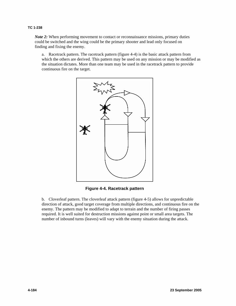
TC 1-238
Note 2: When performing movement to contact or reconnaissance missions, primary duties could be switched and the wing could be the primary shooter and lead only focused on finding and fixing the enemy.
a. Racetrack pattern. The racetrack pattern (figure 4-4) is the basic attack pattern from which the others are derived. This pattern may be used on any mission or may be modified as the situation dictates. More than one team may be used in the racetrack pattern to provide continuous fire on the target.
Figure 4-4. Racetrack pattern
b. Cloverleaf pattern. The cloverleaf attack pattern (figure 4-5) allows for unpredictable direction of attack, good target coverage from multiple directions, and continuous fire on the enemy. The pattern may be modified to adapt to terrain and the number of firing passes required. It is well suited for destruction missions against point or small area targets. The number of inbound turns (leaves) will vary with the enemy situation during the attack.
4-184 23 September 2005
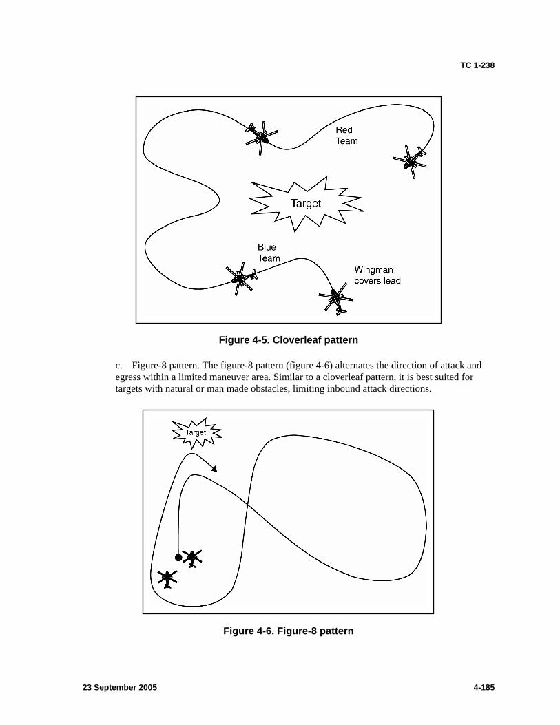
TC 1-238
Figure 4-5. Cloverleaf pattern
c. Figure-8 pattern. The figure-8 pattern (figure 4-6) alternates the direction of attack and egress within a limited maneuver area. Similar to a cloverleaf pattern, it is best suited for targets with natural or man made obstacles, limiting inbound attack directions.
Figure 4-6. Figure-8 pattern
23 September 2005 4-185
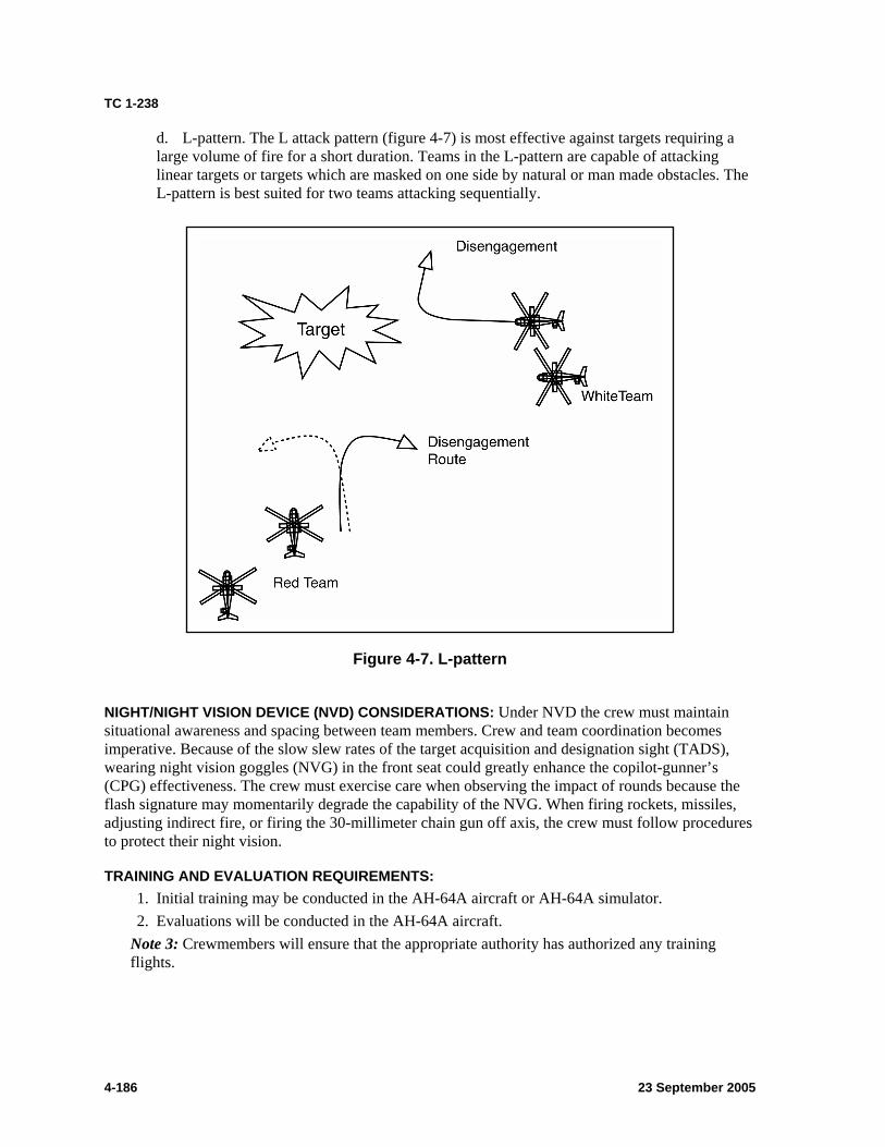
TC 1-238
d. L-pattern. The L attack pattern (figure 4-7) is most effective against targets requiring a large volume of fire for a short duration. Teams in the L-pattern are capable of attacking linear targets or targets which are masked on one side by natural or man made obstacles. The L-pattern is best suited for two teams attacking sequentially.
Figure 4-7. L-pattern
NIGHT/NIGHT VISION DEVICE (NVD) CONSIDERATIONS: Under NVD the crew must maintain situational awareness and spacing between team members. Crew and team coordination becomes imperative. Because of the slow slew rates of the target acquisition and designation sight (TADS), wearing night vision goggles (NVG) in the front seat could greatly enhance the copilot-gunner’s (CPG) effectiveness. The crew must exercise care when observing the impact of rounds because the flash signature may momentarily degrade the capability of the NVG. When firing rockets, missiles, adjusting indirect fire, or firing the 30-millimeter chain gun off axis, the crew must follow procedures to protect their night vision.
TRAINING AND EVALUATION REQUIREMENTS: 1. Initial training may be conducted in the AH-64A aircraft or AH-64A simulator. 2. Evaluations will be conducted in the AH-64A aircraft.
Note 3: Crewmembers will ensure that the appropriate authority has authorized any training flights.
4-186 23 September 2005

TC 1-238
REFERENCES: Tasks 1000, 1010, 1014, 1042, 1127, 1146, 1153, 1162, 1245, 1414, 1422, 1428, 1458, 1462, 1464, 1823, 2125, and 2157 TM 1-1520-238-10 TM 1-1520-238-CL Unit standing operating procedure (SOP) The Army Aviator’s Handbook for Maneuvering Flight and Power Management
23 September 2005 4-187
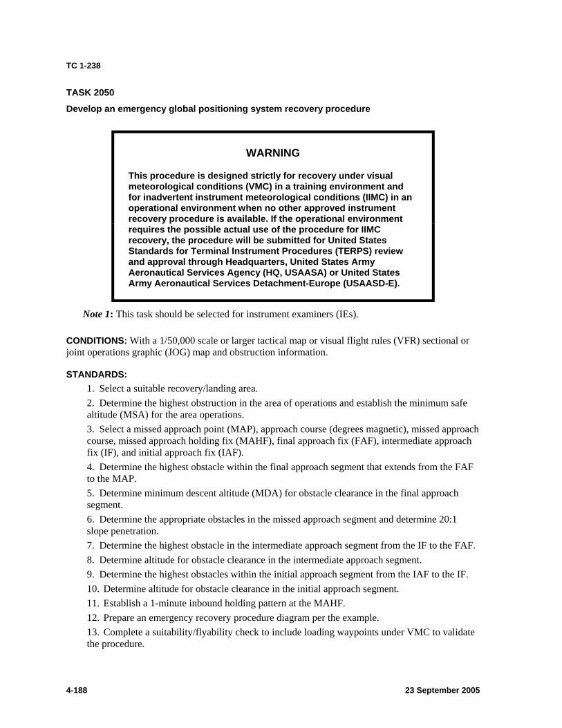
TC 1-238
TASK 2050
Develop an emergency global positioning system recovery procedure
WARNING
requires the possible actual use of the procedure for IIMC
This procedure is designed strictly for recovery under visual meteorological conditions (VMC) in a training environment and for inadvertent instrument meteorological conditions (IIMC) in an operational environment when no other approved instrument recovery procedure is available. If the operational environment
recovery, the procedure will be submitted for United States Standards for Terminal Instrument Procedures (TERPS) review and approval through Headquarters, United States Army Aeronautical Services Agency (HQ, USAASA) or United States Army Aeronautical Services Detachment-Europe (USAASD-E).
Note 1: This task should be selected for instrument examiners (IEs).
CONDITIONS: With a 1/50,000 scale or larger tactical map or visual flight rules (VFR) sectional or joint operations graphic (JOG) map and obstruction information.
STANDARDS: 1. Select a suitable recovery/landing area. 2. Determine the highest obstruction in the area of operations and establish the minimum safe altitude (MSA) for the area operations. 3. Select a missed approach point (MAP), approach course (degrees magnetic), missed approach course, missed approach holding fix (MAHF), final approach fix (FAF), intermediate approach fix (IF), and initial approach fix (IAF). 4. Determine the highest obstacle within the final approach segment that extends from the FAF to the MAP. 5. Determine minimum descent altitude (MDA) for obstacle clearance in the final approach segment. 6. Determine the appropriate obstacles in the missed approach segment and determine 20:1 slope penetration. 7. Determine the highest obstacle in the intermediate approach segment from the IF to the FAF. 8. Determine altitude for obstacle clearance in the intermediate approach segment. 9. Determine the highest obstacles within the initial approach segment from the IAF to the IF. 10. Determine altitude for obstacle clearance in the initial approach segment. 11. Establish a 1-minute inbound holding pattern at the MAHF. 12. Prepare an emergency recovery procedure diagram per the example. 13. Complete a suitability/flyability check to include loading waypoints under VMC to validate the procedure.
4-188 23 September 2005
TC 1-238
Note 2: If unable to complete a suitability/flyability check due to the operational environment, the commander should consider an elevated risk when using this recoveryprocedure.
DESCRIPTION: Note 3: All altitudes are in feet, all waypoints are in LAT/LONG, all distances are in nautical miles (nm), and visibility is in statue miles (SM). The Flight Information Handbook (FIH) has the necessary conversion tables.
1. Select the most suitable recover/landing area. Determine the MSA for the landing area. Use the off route obstruction clearance altitude-CONUS (OROCA) or off route terrain clearance altitude-OCONUS (ORTCA) elevation from the en route low altitude (ELA) chart for the area of operations. Select the highest altitude within 30 nm of the MAP. If an ELA is not available, the minimum sector altitude will be determined by adding 1,000 feet to the maximum elevation figures (MEF). When a MEF is not available, apply the 1,000 feet rule to the highest elevation within 30 nm of the MAP. Minimum sector altitudes can be established with sectors not less than 90 degrees and with sector obstacle clearance having a 4 nm overlap. Rounding is allowed to the next higher 100-foot increment. 2. All waypoints (IAF, IF, FAF, MAP, and MAHF) will be verified by two separate global positioning system navigation (GPS NAV) systems, such as Doppler global positioning navigation system (DGNS), embedded global positioning inertial navigation system (EGI), or precise lightweight global positioning system receiver (PLGR). 3. Approach segment construction.
a. Final approach segment. The final approach segment begins at the FAF and ends at the MAP.
(1) Determine the MAP (normally associated with the landing area or threshold). (2) Determine the FAF. The minimum distance is 2 nm from the MAP. The optimum length is 3 nm. The maximum length is 10 nm. (3) Determine the area of consideration for obstacle clearance. Starting 0.3 nm prior to the FAF, draw a line that is 1.2 nm long on both sides of centerline (total 2.4 nm) perpendicular to the final approach course; 0.3 nm past the MAP, draw a line that is 1 nm long on both sides of the centerline (total 2 nm) perpendicular to the final approach course. Complete the trapezoid by connecting the outer ends of the lines. This trapezoid is the area of consideration for obstacle clearance. (4) Determine MDA obstacle clearance. Locate the highest obstacle in the final segment trapezoid. Add 250 feet of required obstacle clearance (ROC) and round up to the next higher 20-foot increment.
Note 4: For visibility requirements, use table 4-1, page 4-197.
b. Missed approach segment. The missed approach segment starts at the 0.3 nm prior to the MAP and ends at a holding point designated by a MAHF clearance limit. Optimum routing is straight ahead (within 15 degrees of the final approach course) to a direct entry. However, a turning missed approach may be designated if needed for an operational advantage.
(1) Determine the MAHF. The maximum distance is 7.5 nm from the MAP to the MAHF. (2) Starting 0.3 nm prior the MAP, draw a line perpendicular to the missed approach course that is 1 nm long on both sides of the centerline (total 2 nm).
23 September 2005 4-189
TC 1-238
(3) At the MAHF, draw a line perpendicular to the missed approach course that is 2 nm long on both sides of the centerline (total 4 nm). (4) Complete the trapezoid by connecting the outer ends of the lines. This trapezoid is the area of consideration for missed approach surface and the 20 to 1 obstacle clearance evaluation. (5) If a turning missed approach is developed, use a flight path turning radius of 1.3 nm until a straight line from the apex of the radius can be made to the missed approach holding pattern (MAHP) (usually made back to the FAF). The outer edge of the area should have a 2.6 nm radius. Once the turn is completed, the missed approach area should be expanded to 2 nm on both sides of centerline at the MAHF. The outer edge will be a straight line from the left outer edge of the primary area of final segment to the point 2 nm perpendicular to the MAHP. (6) Missed approach obstacle clearance. This surface begins over the MAP at a height of MDA minus required obstacle clearance (ROC). The missed approach surface area ascends uniformly at the rate of 1 foot vertically for each 20 feet horizontally (20H:1V). Evaluate the 20:1 surface from 0.3 nm past the MAP to the MAHF. The height of the missed approach surface over an obstacle is determined by measuring the straight line distance from 0.3 nm line past the MAP to the obstacle defining the 20:1 surface. If obstacles penetrate the surface area, establish a higher climb gradient or a higher MDA, move the MAP, or turn the missed approach. (7) Where the 20:1 surface reaches a height of 1,000 feet below the MSA, further application of the surface is not required.
Note 5: To determine the maximum allowable height of an obstacle at a given point, measure the distance from the obstacle to the 0.3 nm point as described above in paragraph 3b(6). Multiply the distance by 304 (20:1 ratio) and add to the beginning 20:1 surface height. If there is no penetration, the area is clear. If the surface has not reached the MSA at the MAHF, specify a climb to the MSA.
Note 6: The area for the missed approach holding falls within the MSA area; therefore, the MSA altitude will normally be used as the MAHF altitude if it meets the surface evaluation requirements.
c. Intermediate approach segment. The intermediate segment begins at the IF and ends at the FAF.
(1) Determine the IF. The minimum distance is 3 nm from the FAF. The maximum length is 5 nm. (2) Starting 1 nm prior to the IF, draw a line that is 2 nm long on both sides of centerline (total 4 nm) perpendicular to the intermediate approach course; at the FAF, draw a line that is 1.2 nm long on both sides of the centerline (total 2.4 nm) perpendicular to the intermediate approach course. Complete the trapezoid by connecting the outer ends of the lines. This trapezoid is the area of consideration for obstacle clearance. (3) The angle(s) of offset from the final approach course may not exceed 60 degrees. (4) Intermediate segment altitude. Locate the highest obstacle in the intermediate segment trapezoid. Add 500 feet of ROC and round to the nearest 100 feet. Use this altitude en route to the FAF.
d. Initial approach segment. The initial approach segment begins at the IAF and ends at the IF.
4-190 23 September 2005
TC 1-238
(1) Determine the IAF. Up to three IAFs are allowed. The minimum distance is 3 nm from the IF. The maximum length is 10 nm. (2) Starting 1 nm prior to the IAF and at the IF, draw a line 2 nm long on both sides of centerline (total 4 nm) perpendicular to the initial approach course. Complete the rectangular box by connecting the outer ends of the lines. This box is the area of consideration for obstacle clearance. (3) The angle(s) of offset from the intermediate course may not exceed 60 degrees. (4) For other than straight configurations, connect the outside of the boxes by drawing a 2 nm arc (from the IF) between the initial and intermediate segments. (5) Initial approach segment altitude. Locate the highest obstacle in the initial segment box. Add 1,000 feet of ROC and round to the nearest 100 feet. Use this altitude en route to the IF. (6) IAF obstacle clearance. Use the MSA altitude en route to the IAF within 30 nm.
4. Prepare the procedure diagram showing “FOR VFR TRAINING AND EMERGENCY USE ONLY” twice conspicuously in the plan view. Prior to publication, the diagram will include, as a minimum, all those items included in the example procedure diagram. 5. Complete a flight check under VMC in an aircraft to finalize the procedure and validate the diagram. The flight should validate the following:
a. Locations. IAF, IF, FAF, MAP, and MAHF. b. Obstacles. c. Approach course. d. Obstacle clearance. e. Altitudes. MDA, FAF, IF, IAF, MSA/holding pattern altitude.
6. Once a successful flyability/suitability check has been completed, the diagram will be validated by the developer in the lower marginal data area. Once validated by the developer, the procedure must be approved by at least the high-risk approval authority of the unit in the lower marginal data area prior to publication.
Note 7: Digital maps may be used to complete the initial planning for these procedures. Templates made to the appropriate scale may be used as well.
RECOVERY PROCEDURE DIAGRAM: 1. The recovery procedure diagram is a pictorial representation of the procedure to recover the aircraft under VMC using the aircraft navigation system. The procedure is based on crewmember-entered coordinates into the aircraft navigation system. 2. The procedure diagram may be computer generated or hand sketched. The diagram need not be as detailed as a Department of Defense (DOD)-approved chart, but it must provide all data necessary to execute the procedure.
a. Margin identification. (1) Top margin includes approach course, landing area length, touchdown zone elevation, procedure name, landing area name, city and state, landing area lighting, missed approach procedure, and frequencies. (2) Bottom margin includes developer’s printed name, date of development, developer’s signature, check pilot’s printed name, date of flight check, check pilot’s signature, approval authority’s printed name, date of approval, and approval authority’s signature.
23 September 2005 4-191
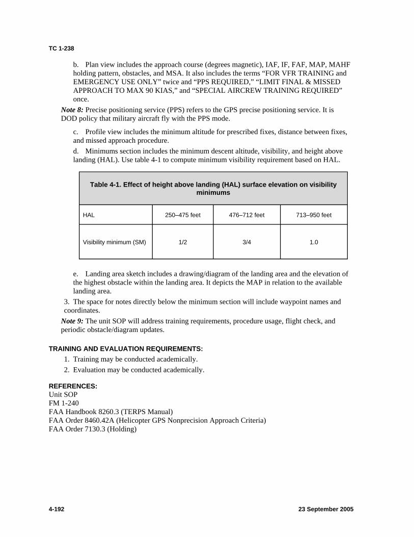
TC 1-238
b. Plan view includes the approach course (degrees magnetic), IAF, IF, FAF, MAP, MAHF holding pattern, obstacles, and MSA. It also includes the terms “FOR VFR TRAINING and EMERGENCY USE ONLY” twice and “PPS REQUIRED,” “LIMIT FINAL & MISSED APPROACH TO MAX 90 KIAS,” and “SPECIAL AIRCREW TRAINING REQUIRED” once.
Note 8: Precise positioning service (PPS) refers to the GPS precise positioning service. It is DOD policy that military aircraft fly with the PPS mode.
c. Profile view includes the minimum altitude for prescribed fixes, distance between fixes, and missed approach procedure. d. Minimums section includes the minimum descent altitude, visibility, and height above landing (HAL). Use table 4-1 to compute minimum visibility requirement based on HAL.
Table 4-1. Effect of height above landing (HAL) surface elevation on visibility minimums
HAL 250–475 feet 476–712 feet 713–950 feet
Visibility minimum (SM) 1/2 3/4 1.0
e. Landing area sketch includes a drawing/diagram of the landing area and the elevation of the highest obstacle within the landing area. It depicts the MAP in relation to the available landing area.
3. The space for notes directly below the minimum section will include waypoint names and coordinates.
Note 9: The unit SOP will address training requirements, procedure usage, flight check, and periodic obstacle/diagram updates.
TRAINING AND EVALUATION REQUIREMENTS: 1. Training may be conducted academically. 2. Evaluation may be conducted academically.
REFERENCES: Unit SOP FM 1-240 FAA Handbook 8260.3 (TERPS Manual) FAA Order 8460.42A (Helicopter GPS Nonprecision Approach Criteria) FAA Order 7130.3 (Holding)
4-192 23 September 2005
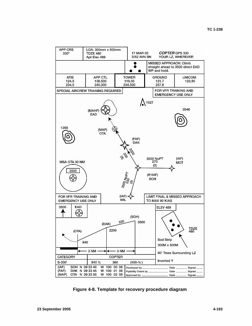
TC 1-238
Figure 4-8. Template for recovery procedure diagram
23 September 2005 4-193
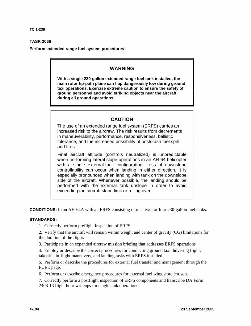
TC 1-238
4-194 23 September 2005
TASK 2066
Perform extended range fuel system procedures
WARNING
With a single 230-gallon extended range fuel tank installed, the main rotor tip-path plane can flap dangerously low during ground taxi operations. Exercise extreme caution to ensure the safety of ground personnel and avoid striking objects near the aircraft during all ground operations.
CAUTION The use of an extended range fuel system (ERFS) carries an increased risk to the aircrew. The risk results from decrements in maneuverability, performance, responsiveness, ballistic tolerance, and the increased possibility of postcrash fuel spill and fires.
Final aircraft attitude (controls neutralized) is unpredictable when performing lateral slope operations in an AH-64 helicopter with a single external-tank configuration. Loss of downslope controllability can occur when landing in either direction. It is especially pronounced when landing with tank on the downslope side of the aircraft. Whenever possible, the landing should be performed with the external tank upslope in order to avoid exceeding the aircraft slope limit or rolling over.
CONDITIONS: In an AH-64A with an ERFS consisting of one, two, or four 230-gallon fuel tanks.
STANDARDS: 1. Correctly perform preflight inspection of ERFS. 2. Verify that the aircraft will remain within weight and center of gravity (CG) limitations for the duration of the flight. 3. Participate in an expanded aircrew mission briefing that addresses ERFS operations. 4. Employ or describe the correct procedures for conducting ground taxi, hovering flight, takeoffs, in-flight maneuvers, and landing tasks with ERFS installed. 5. Perform or describe the procedures for external fuel transfer and management through the FUEL page. 6. Perform or describe emergency procedures for external fuel wing store jettison. 7. Correctly perform a postflight inspection of ERFS components and transcribe DA Form 2408-13 flight hour writeups for single tank operations.

TC 1-238
23 September 2005 4-195
DESCRIPTION: 1. Crew actions. Before operating with external fuel tanks, the pilot in command (PC) will ensure that the aircraft remains within lateral CG limits throughout the flight. Careful consideration must be given to the offload of any wing stores in flight. The crew will familiarize themselves with, and adhere to, ERFS requirements and limitations contained in the Interim Statement of Airworthiness Qualification (ISAQ), safety of flight bulletin, operator's manual, and unit standing operating procedure (SOP). 2. Procedures.
a. Crew mission briefing. In addition to the standard crew briefing, aircrews will also brief the following when performing ERFS operations:
(1) Emergency procedures to include— (a) Single-engine considerations. (b) Tank location effects on emergency egress procedures. (c) Tank jettison procedures including cartridge malfunction procedures when jettison failure occurs. (d) Fire in flight.
(2) Tank and gross weight maneuver limitations. (3) Fuel transfer operations. (4) Weapons employment considerations/procedures. (5) As applicable, single-tank ISAQ limitations. (6) Warnings and cautions.
b. Lateral CG envelope. Later CG determination is accomplished in three steps. (1) First, the crewmember must calculate and record stores data moments (table 4-2) from the boundary line (BL) and weight (WT) data. (2) Second, using table 4-3, the crewmember determines total weight sum (inclusive alternating current [AC] gross weight [GWT]) and sum of total moment. (3) Lastly, the crewmember enters these values into the ISAQ lateral CG chart to determine lateral CG. Calculate weight and moment of pylon stores loading by entering launcher/tank weight. Add ordnance/fuel weight; then multiply stores total by ARM BL to obtain stores moment. For lateral CG computation (table 4-3), tally and record the basic weight (item 1, column [1]) and multiply by BL (item 1, column [2]) to determine moment (item 1, column [3]). Enter internal fuel weight (item 2, column [1]) and crew weight (item 3, column [1]). Enter weight for items not included in basic weight (item 4, column [1]) and total stores weight from table 4-2 (stores total pounds [lb]) into table 4-3, item 5, column (1). Enter total stores moment from table 4-3, item 5, column (3) by multiplying column (1) and then column (2). Using the ISAQ lateral CG chart find the value corresponding to table 4-3 item 5 column (1) total weight on the left side of ISAQ chart; move laterally until intersecting the inches from centerline value (total stores moment from table 4-2 total moment). The intersection represents the calculated lateral CG of the helicopter. The calculated lateral CG must be within the allowable limits of the ISAQ lateral CG chart.
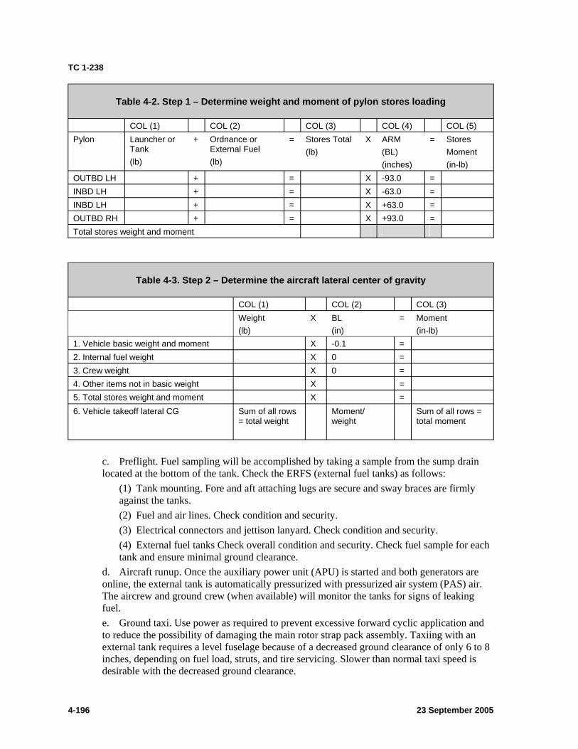
TC 1-238
Table 4-2. Step 1 – Determine weight and moment of pylon stores loading
COL (1) COL (2) COL (3) COL (4) COL (5) Pylon Launcher or
Tank (lb)
+ Ordnance or External Fuel (lb)
= Stores Total (lb)
X ARM (BL) (inches)
= Stores Moment (in-lb)
OUTBD LH + = X -93.0 = INBD LH + = X -63.0 = INBD LH + = X +63.0 = OUTBD RH + = X +93.0 = Total stores weight and moment
Table 4-3. Step 2 – Determine the aircraft lateral center of gravity
COL (1) COL (2) COL (3) Weight
(lb) X BL
(in) = Moment
(in-lb) 1. Vehicle basic weight and moment X -0.1 = 2. Internal fuel weight X 0 = 3. Crew weight X 0 = 4. Other items not in basic weight X = 5. Total stores weight and moment X = 6. Vehicle takeoff lateral CG Sum of all rows
= total weight Moment/ weight
Sum of all rows = total moment
c. Preflight. Fuel sampling will be accomplished by taking a sample from the sump drain located at the bottom of the tank. Check the ERFS (external fuel tanks) as follows:
(1) Tank mounting. Fore and aft attaching lugs are secure and sway braces are firmly against the tanks. (2) Fuel and air lines. Check condition and security. (3) Electrical connectors and jettison lanyard. Check condition and security. (4) External fuel tanks Check overall condition and security. Check fuel sample for each tank and ensure minimal ground clearance.
d. Aircraft runup. Once the auxiliary power unit (APU) is started and both generators are online, the external tank is automatically pressurized with pressurized air system (PAS) air. The aircrew and ground crew (when available) will monitor the tanks for signs of leaking fuel. e. Ground taxi. Use power as required to prevent excessive forward cyclic application and to reduce the possibility of damaging the main rotor strap pack assembly. Taxiing with an external tank requires a level fuselage because of a decreased ground clearance of only 6 to 8 inches, depending on fuel load, struts, and tire servicing. Slower than normal taxi speed is desirable with the decreased ground clearance.
4-196 23 September 2005
TC 1-238
f. Hovering flight. Depending on load and variable power conditions, a hover power check will not always be possible. When applicable, ensure that hover performance data was extrapolated from the hover charts dashed line (drag versus power differential) for auxiliary tank installation. With the ERFS installed, a 2 percent increase in hover torque at 5 feet is not uncommon. g. Takeoff. Prior to takeoff, the crew will ensure that the auxiliary fuel buttons are deselected so that an accurate fuel check can be initiated. When power is marginal, or in-ground effect (IGE) power is not available, a rolling takeoff is either desirable or mandated. Once the rolling takeoff is initiated and obstacles have been cleared, the aircraft continues to accelerate to maximum (MAX) rate of climb (R/C) airspeed. MAX R/C should be maintained until reaching the desired altitude. h. In-flight fuel checks and fuel management. Fuel burn rate check procedures must be performed by purely employing the internal fuel tanks and their associated fuel page indications. After the initial fuel check has been completed, the external fuel transfer capability is checked to insure serviceability. Transferring any additional fuel is at the discretion of the PC. Fuel management procedures will be conducted in accordance with chapter two of TM 1-1520-238-10 and task 1138.
Note: Refer to task 1138, paragraphs 2e(4)and 2e(5), for more specific information.
i. Maneuvering flight. Flight maneuvers must not exceed the limits described in TM 1-1520-238-10, chapter five, or the airworthiness release (AWR). j. Emergency procedures. The operator’s manual does not address any specific ERFS emergency procedures other than external fuel wing store jettison. In a four-tank configuration, selectively jettisoning external fuel tanks potentially causes two major problems. If external tanks are jettisoned off of one side, it may cause a lateral CG problem. Additionally, the ability to refuel the internal tank(s) from the remaining ERFS is lost. k. Landing. Consider the terrain and suitability of the landing area. The pylons are fixed at 4 degrees, decreasing the ground clearance. If the tanks are full, a roll-on landing should be executed whenever the terrain and area allows. l. Postflight. Conduct postflight checks by checking the same ERFS components inspected during the preflight checks. When one external fuel tank is mounted on either inboard pylon along with any combination of weapons stores, flight hours will be entered on DA Form 2408-13. m. ERFS refueling. All tanks are gravity refueled only, and will only be accomplished cold. Refer to task 1811.
TRAINING AND EVALUATION REQUIREMENTS: 1. Training will be conducted in the AH-64A aircraft 2. Evaluation will be conducted in the AH-64A aircraft
REFERENCES: Appropriate common references.
23 September 2005 4-197
TC 1-238
TASK 2068
PERFORM SHIPBOARD OPERATIONS
CONDITIONS: In an AH-64A helicopter or an AH-64A simulator, provided with a field deck landing spot area or a designated ship, with a deck landing qualification (DLQ) pilot in command (PC), unit trainer (UT), or instructor pilot (IP).
Note 1: Units and assigned aviators will fully adhere to the Army/Air/Navy Force Deck Landing Operations Memorandum of Understanding (MOU) and JP 3-04.1 procedures. This includes presail forecasting and scheduling, conferencing, initial qualification, currency requirements, and applicable waiver procedures.
STANDARDS: 1. Participate in a crew mission briefing. 2. Ensure that the data transfer cartridge (DTC) has been properly loaded with the ship’s actual location or predicted aircraft runup location and that the navigation (NAV) mode has been enabled for SEA. 3. Initialize the embedded global positioning inertial navigation system’s (EGI) NAV MODE at SEA for either stationary or moving conditions. 4. Hover power check and takeoff.
a. Perform takeoff to a hover at the time-synchronized moment where the deck moves the least. b. Perform hover power check at prescribed hover height ±2 feet with drift not to exceed 3 feet. c. Slide out over the side of the ship and perform a normal takeoff parallel to the line-up line or as otherwise directed. d. Use correct radio phraseology and communication procedures.
5. Inbound. a. Contact the designated ship on the correct voice frequency with the briefed call sign prior to entering the control area (50 miles out when possible). b. Provide the designated ship with aircraft position, crew, fuel remaining, ammunition/rockets/missiles on board, and any emergency problems with the aircraft, including hung or misfired ordnance.
6. Pattern. a. Enter or exit the prescribed pattern. b. Pattern altitude as directed, or as standard for type of pattern flown ±50 feet. c. Pattern airspeed as directed ±10 knots true airspeed (KTAS).
7. Approach and landing. a. Maintain flight track coincident with the landing direction of the deck. b. Cross the deck at briefed deck height plus 15 feet or as otherwise instructed. c. Perform a normal approach to a point above the assigned spot (intended point of landing), with the helicopter aligned with ship's centerline at touchdown. d. Perform a landing from a hover and touchdown at the timed moment that the ship moves the least.
4-198 23 September 2005
TC 1-238
e. Use correct terminology to relay landing sequence. 8. After-landing deck operations and procedures.
a. Inform ground personnel of any onboard ammunition, rockets, or missiles and provide warning for hung or misfired ordnance. b. Participate in Combat Information Center mission debriefing.
9. Emergency procedures. a. Explain or execute procedures for lost communication and navigation aid (NAVAID) failures while conducting flight operations over the sea. b. Explain or execute procedures for aircraft emergencies while conducting flight operations over the sea. c. Explain or execute procedures for flight deck emergencies from the cockpit.
10. Perform crew coordination per chapter 6 and the task description.
DESCRIPTION: 1. Crew actions.
a. During overwater flight, the pilot on the controls (P*) will maintain briefed altitude above the water with assistance provided by the pilot not on the controls (P). b. The P will alert the P* to any descent that might violate minimum briefed altitudes. c. The crew must be thoroughly familiar with the various communication methods and terminology/phraseology used by Naval personnel from vessels equipped with landing deck spots. Communication is a critical aspect of deck landing operations and the Navy uses a variety of communication methods. Radio voice communication is the primary means for conveying and receiving instructions while other shipboard methods include flags, lights, colored clothing identification (ID), and arm and hand signals.
(1) Flags. The signal flags for helicopter operations are the Hotel or the Foxtrot flags. If the flag is all the way up the mast, the deck is green (cleared for helicopter operations). If the flag is at half-mast, the deck is fouled (not cleared for helicopter operations). (2) Light beacons. The deck status lights system includes a light fixture with three lenses or rotating beacons. They are normally located on a high point in the pilot’s (PLT) and copilot-gunner’s (CPG) fields of vision and are used to indicate the flight deck's ability to operate aircraft. Red indicates fouled deck (when ship is operating airborne aircraft) or clear to start engines (when ship has aircraft on deck). Amber is used for rotor engagement or disengagement, and green indicates clear to launch and recover helicopters. Deck status lights are normally for communication with flight deck personnel only. Pilots will not use the deck status lights for clearance for engine start, rotor engagement, takeoff, or landing. Pilots will follow landing signal enlisted (LSE) or landing signal officer (LSO) signals. (3) Hand and arm signals (at night, wands and flashlights). Hand and arm signals, at night wands and flashlights, are used throughout deck landing operations as referenced in JP 3-04.1.
23 September 2005 4-199
TC 1-238
2. Procedures. a. Premission, runup, and before takeoff deck operations and procedures.
(1) JP5. Because of its high flash point, JP5 is exclusively used on Navy and Coast Guard vessels. The PC’s premission performance planning should include JP5 fuel considerations. Engine operating characteristics may change because of lower operating temperatures. Slower acceleration, lower engine speed, harder starting, and greater range may be experienced. (2) Approved software EGI SEA MODE data download. The PC should ensure that a valid aircraft (EGI) initialization coordinate is loaded into the DTC along with the command to initialize the EGI in the SEA MODE. The PLT or CPG will perform a DTU page NAVIGATION button (R6) selective load as part of the DTU load procedures. Selecting the NAVIGATION button (R6) will command the signal processor to disregard the last coordinate stored at shutdown and use the provided NAVIGATION load coordinate for EGI initialization. The NAVIGATION button will also command the MODE for EGI initialization; SEA or LAND. The DTC’s initialization coordinate should be the actual location of a stationary ship or the estimated location of a moving ship when the aircraft is runup. (3) Aircraft runup procedures. After accomplishing the aircraft preflight, the PLT and CPG are authorized to board the aircraft and complete all checks up to starting the engines. During the runup checks, the PLT or CPG must initiate the appropriate SEA ALIGN mode for the EGI and set the FUEL page TYPE to JP5 or as appropriate. When ready to perform the engine start procedures, request permission from the helicopter control officer (HCO) to start the engines. A red deck status light will be provided in coordination with the LSE for clearance to start engines. The LSE will signal the clearance to start engine one followed by engine two. Once clearance is received the PLT will perform a rotor lock start for two engines. When both engines are online, request permission to engage the rotor (rotor brake off). Rotor engagement is accomplished under a yellow deck status light. The LSE is responsible for ensuring that helicopters, on signal, are safely started, engaged, launched, recovered, and shut down.
(a) EGI initialization. If not already loaded to the DTC, the PLT or CPG will have to input a valid universal transverse mercator (UTM) or latitude (LAT)/longitude (LONG) coordinate to the EGI through the tactical situation display (TSD) UTIL page. Additionally, if the DTC has not been preset to initiate EGI initialization in the SEA MODE (through a selective NAVIGATION DTU load), the PLT or CPG will have to select the NAV MODE button (B1) and select SEA. With the SEA MODE selected, [either through an automatic command from a NAVIGATION selective load or through a manual selection of the NAV button (B1)], an ALIGN MODE option bloc will be displayed, encompassing two option buttons: STAT (L4) and MOVE (L5). The PLT or CPG will select the pertinent ALIGN MODE option button for the conditions. (b) Fuel page. During runup, the PLT or CPG will access the A/C FUEL page and change the FUEL page TYPE (R6) to JP5 if using auxiliary tanks.
b. Hover power check and takeoff. When all prelaunch checks have been completed, signal the LSE, LSO, or HCO. Transmit a request for takeoff to the helicopter control station or primary flight control tower. The PLT will also turn the aircraft's navigation lights to bright (dim at night), which will signal his readiness for launch to the deck crews. When takeoff clearance is granted and all tiedowns have been removed, the pilot is cleared to take off at the LSE’s signal. Perform a hover power check before leaving the deck to ensure sufficient
4-200 23 September 2005
TC 1-238
power is available for flight. Announce if any drifting over the deck is observed. After a hover power check, slide right to clear the ship. Depart from the ship on a 45-degree angle from the bow. (Single spot ships may require a hovering turn before takeoff.) Effects of the wind will be more noticeable when operating on ships that are underway. Once the helicopter has cleared the ship, the pilot will signal or report “ops normal,” souls on board, and total fuel in hours and minutes, unless prohibited by operational restrictions. Before departing the pattern, or unless instructed otherwise, the PLT or CPG will turn the landing light on and perform a “fly by.” A “fly by” provides the tower and other personnel the opportunity to check the aircraft for obvious signs of problems. Additionally, the “fly by” provides the PLT and CPG one last opportunity to land before extending away from the landing deck spots. c. Inbound procedures. From the PLT’s and CPG’s perspective, a sequence of events occurs when flying inbound (returning or initial arrival) for landing on a ship. The ship will be executing a series of evolutions to receive the inbound helicopter. Having received an overhead message in advance of scheduled operations, the aircrew will know the ship’s location, assigned radio and navigation aid frequencies, and time expected to arrive overhead the ship. Aircrews are expected to check in with the ship before entering the control area (50 miles out is preferred when possible), electronic emission control conditions permitting. When voice communicating with the ship, use prebriefed call signs. The aircraft will be asked for position, souls on board, and fuel remaining. The ship's secondary controlled airspace, the control zone, extends out 5 nautical miles in radius and up to 2,500 feet above the sea. When reaching the periphery of the control zone, or when otherwise instructed, make radio contact with the ship to receive pertinent landing information and instructions. These include deck status information (red, not ready to conduct flight operations, or green, ready to conduct flight operations); base recovery course of ship (magnetic heading of ship during aircraft recovery); ship velocity; wind speed and direction over the deck; pitch and roll of the ship; and altimeter setting.
Note 2: Regardless of whether the aircraft’s EGI was initially aligned on land or at sea, ensure that the TSD NAV B2 button is in SEA mode when operating over water for an extended period. When in flight, changing the TSD NAV B2 mode button from LAND to SEA will enable a Doppler radar return bias that is favorable to overwater flight; it will not cause the EGI to realign.
Note 3: Total fuel will be determined as the time that engine “flame out” (fuel exhaustion) can be expected. If the aircraft is leaving the tower's control, this report will be given to the combat information center or helicopter direction center.
Note 4: When illumination is low or operating in reduced visibility, the horizon may not be visible, and the crew will have to make nearly constant reference to the helmet display unit’s (HDU) hover or transition mode symbology set.
d. Pattern. Depending on the amount of air traffic around the ship, either the primary flight control (PRIFLY) or the helicopter dibection center (HDC) may initially direct an inbound aircraft to enter into a Delta pattern. Delta patterns are flown at 1, 3, or 6 miles from the ship. (The distance flown depends on pattern segment location and if flying a port or starboard upwind). A normal Delta pattern entry altitude is 1,000 feet mean sea level unless directed otherwise, followed by a descent to 300 feet mean sea level/above ground level (AGL). Delta pattern aircraft will eventually receive instructions to enter the Charlie pattern. The standard landing pattern (Charlie pattern) is the Case I visual meteorological conditions (VMC) helicopter landing pattern. The night Case I helicopter landing pattern is a modified altitude (200 feet) Charlie pattern. The landing patterns for all ship types are essentially the same.
23 September 2005 4-201
TC 1-238
Principal differences to plan for are flight deck elevations and obstructions in proximity to the landing area that become factors in transitioning from the approach to landing profile. Establish and maintain aircraft flight in the Charlie pattern at 300 feet (200 feet night vision device [NVD]) with a velocity of 90 KTAS (80 knots indicated airspeed [KIAS]). The P will provide altitude, airspeed, radio, and situational position awareness assistance throughout the pattern. After takeoff, and when an aircraft will remain in the Charlie pattern for training, upon reaching 300 feet (200 feet NVD), start a standard rate turn to the right or left while continuing to accelerate to 90 KTAS. This is done so the crew can pick up a visual sighting of the ship/lights at the departure point. When the ship is sighted, it may be necessary to decrease or increase the bank angle to maintain the pattern (30 degrees maximum during NVD). Turn the anticollision light on call the break to the ship. When abeam the opposite lineup line on the ship, an “abeam” call will be made to the ship to include a call informing the ship of which pilot is on the controls, such as “front seat”/“backseat.” Conduct a before-landing check and the PLT will turn the anticollision light off. Announce crossing the stern position (crossing the wake) of the ship. Commence the approach for landing not later than on the downwind leg abeam the intended point of landing. Return to a standard rate turn to the left or right to line up for the final approach to landing. The left or right turn to final will be made to intercept the 45-degree line at the 90-degree position for ships with offset landing centerlines, or to intercept the ship's wake for an up-the-stern final approach. The crew will individually make an announcement when the aircraft is lined up with the lineup lines. JP 3-04.1 depicts the typical landing pattern and control zones and restrictions for amphibious assault ship, landing platform helicopter (LPH)/general purpose amphibious assault ship (LHA)/general purpose amphibious assault ship (with internal dock) (LHD) class ships, which is a slight modification to the approach used for smaller, single-spot ships. e. Approach and landing. The landing areas will have different lengths and widths, depending on the type of ship and number of landing spots. A deck landing area will have a perimeter safety net, perimeter lines, and red lights outlining the landing area. Two white lineup lines will form an X through the landing area on one or two spot decks. The lineup lines will have white lights that can only be seen from the final approach position. At the center of the X, there is a white circle with an amber light in the center. The circle is used for landing. The main landing gear of the helicopter must be placed inside the circle. Some ship and landing platforms will have floodlights to light up the landing areas. These only light up the deck, and will not blind the flight crew. The PC must be aware of deck landing wind limitations. The Navy’s wind limitation envelope model was established for a normal approach to the spot, with the helicopter aligned with ship's centerline at touchdown.
(1) Normal approach. The greatest difference between land and sea helicopter landing operations occurs from short final to wheels on deck. For both, the rate of closure to the intended landing spot is affected by head winds, but the sea environment, short, final, and landing segments are complicated by the relative motion of the ship’s movement through the water. If the approach for landing is being conducted to a moving ship, lateral corrections may be made to stay online with the landing area. During day operations, the pilot in the backseat should normally make the landing. During NVD operations either the pilot night vision system (PNVS) pilot or night vision system (NVS) target acquisition and designation sight (TADS)-forward-looking infrared (FLIR) can land the aircraft. While on the approach for landing, the stabilator should be driven fully down to increase forward visibility. While on final, the LSE warns of the approach to the landing area with hand and arm signals. As the helicopter approaches the flight deck, he must avoid the tendency to fixate on the movement of white water from the ship’s waterline to the wake. The PLT and CPG must also anticipate burble effects of wind around the
4-202 23 September 2005
TC 1-238
superstructure of the ship. Frequently, as smaller ships approach the flight deck, there is a potential for them to get hung up by an “invisible wall,” which is an area of pressure or wind that requires a correction of additional power and nose attitude to transition. The stabilator should be reset just before reaching any anticipated “invisible wall.” As soon as the “wall” is overcome, immediately cancel the power and nose correction. Refer to the radar altitude readout on the HDU to assist in maintaining a safe height for crossing the deck (briefed deck height plus 15 feet). As the approach progresses, make an announcement when the deck begins to pass under the nose. Clear the aircraft and call out when the main landing gear is over the deck, when the tail wheel is over the deck, and then in increments of 5 feet until the main gear is within 5 feet of the circle. Then, call out 1-foot increments until the mains are centered over the circle and cleared to descend. When hovering over the deck, it is extremely important to guard against drift and a tendency to overcorrect. Constantly monitor for drift. Scan should not be limited to the immediate flight deck vicinity, but should also take in the horizon, the ship's amidships, and the flight deck area. The amidships (middle of the ship) is the area of least movement as seas increase in intensity. This will reduce the propensity to “chase the deck,” which makes the shipboard landing more difficult. The horizon is the primary hover attitude reference while the ship’s structure will assist in remaining over the landing area. The ship’s pitching and rolling motion makes the horizon attitude reference imperative. Once the ship is stabilized with the tail cleared and mains over the deck, attempt to land. If seas are rough and the ship is in motion, “smooth” landings cannot be obtained. Place the aircraft “firmly” on the deck. The tail-wheel will be locked and the brakes set. Landing lights will not be used for landing because they will blind the deck crews.
Note 5: When the P* makes an approach on the 45-degree bearing to land immediately in front of a spot occupied by another helicopter (on LHD/LHA/LPH class ships), rotor clearances (main and tail) between the two aircraft during the final portion of a 45-degree approach are significantly reduced. When the P* makes an approach to a spot immediately in front of a spot occupied by another helicopter, the final portion of the approach on the 45-degree bearing should terminate at a point directly abeam the intended landing spot. From this point the final transition is flown by sliding sideways to a hover over the landing spot.
Note 6: The hover mode’s symbolic velocity vector can be helpful on a stationary ship but can be a hindrance in some situations on moving ships. If a ship is moving, the crew should have already received information pertaining to the ship’s speed and developed a mental image of how the resultant velocity vector deflection and magnitude will appear while at a stationary hover over the moving deck. The flight path vector (FPV) may be displayed over a moving ship while stabilized above a point.
Note 7: With good night illumination, use the horizon and the ship for hover reference while operating over the ship. During low or no illumination nights, the aviator will only have the ship’s structure for reference. Care must be taken for landing operations during these periods.
Note 8: Landing lights will only be used in case of emergencies. The using unit should provide night vision goggles (NVG) to the applicable deck crew while performing NVD deck operations.
Note 9: The landing signal officer is responsible for the visual control of aircraft in the terminal phase of the approach immediately before landing.
(2) Smokelight approach. The smokelight approach is used as a last resort when available equipment will not allow emergency visibility approach (ELVA) procedures to
23 September 2005 4-203
TC 1-238
be used, or when the ship cannot be visually acquired using ELVA procedures and ditching is considered imminent. Both the ship’s commanding officer and the pilot in command (or detachment officer in charge) must have agreed to attempt the procedure. The aircraft will be positioned 2 miles behind the ship and will proceed inbound on the 180-degree radial relative to the base recovery course (BRC). The aircraft will descend at the pilot's discretion to arrive at approximately 40 feet and 40 knots, 1 mile behind the ship. Ship’s personnel drop smoke or matrix lights every 15 seconds (or other prearranged intervals), and the pilot is kept informed of the number of smokelights in the water. The pilot at the controls follows the smokelights up the ship’s wake, adjusting the closure rate until there is visual contact with the ship. Helicopter control station (HCS) will receive a “gear down” report from the pilot before the aircraft maneuvers over the deck.
Note 10: The safe launch and recovery wind limitations are presented in NWP-42 and Commandant, United States Coast Guard Instruction (COMDTINST) M3710.2 (series).
Note 11: Considerable differences may exist between a ship’s flight deck winds and those measured by bridge-level anemometers. However, aircraft wind limitations are based on winds measured by the windward bridge-level anemometer. When operating at or near the outer wind limits the probability of damage increases sharply when wind gusts exceed 10 knots. Also, the maximum safe wind in conjunction with excessive ship pitch or roll can make flight operations unacceptably hazardous; therefore, operations shall be adjusted accordingly. Common sources of turbulence are stack gasses and wash, ship superstructures, deck protrusions, and rotor wash or jet blast caused by the takeoff and landing of adjacent aircraft.
Note 12: When performing stationary hovering flight over a moving ship’s landing deck spot, the velocity vector deflection and magnitude will be coincident to the velocity of the ship.
Note 13: During day operations, the TADS or PNVS FLIR video can be used to help provide visual cues during the approach and landing phase in conjunction with the NVS FIXED or BORESIGHT position.
Note 14: A wave off or a hold signal is a mandatory signal and must be followed if given by the LSE.
f. After landing. Unless the aircraft is to be independently refueled and then rearmed for an immediate turnaround, the aircraft will normally be chocked and chained to the deck. The aircrew will be prebriefed as to what flyaway gear requirements exist. After all shutdown and postflight procedures are completed, the PLT and CPG will report to the combat information center (CIC) for mission debriefing.
Note 15: During rough sea operations, chains will be used to secure aircraft to the deck before passengers are allowed to deplane or enplane.
Note 16: While the aircraft is on the deck of a moving ship, care must be taken not to move the cyclic while the ship pitches or rolls. Movement of the cyclic could cause the rotor to dip down to extreme low positions. Use the ship’s structure for reference.
g. Aircraft/navigation aid (NAVAID) emergency and lost communication procedures. Emergencies where navigation aids or communications are available should be handled according to procedures prescribed in JP 3-04.1. Lost communication and lost NAVAID procedures should be according to the Flight Information Handbook (FIH) and JP 3-04.1. Emergency procedures for aircraft system failures are covered in TM 1-1520-238-10/CL.
4-204 23 September 2005
TC 1-238
When an aircraft emergency occurs, the crew must execute the immediate action steps, and then contact the tower and explain the exact nature of the emergency. The nature of some emergencies will require priority or diversionary measures. As much deck as possible will be made available for emergency helicopter landings. The optimum relative wind should be determined for the nature of the emergency landing and the ship maneuvered as necessary. Once the aircraft is on final approach, it is imperative that the ship hold a steady course.
TRAINING AND EVALUATION REQUIREMENTS: 1. Training may be conducted in the AH-64A aircraft or AH-64A simulator. 2. Evaluation will be conducted in the AH-64A aircraft.
REFERENCES: Appropriate common references and the following: COMDTINST M3710.2 series *FM 1-564 JP 3-04.1 NATOPS manuals NWP-42
23 September 2005 4-205

TC 1-238
TASK 2081
OPERATE NIGHT VISION GOGGLES
CONDITIONS: In an AH-64A helicopter, an AH-64A simulator, or as an oral exercise.
STANDARDS: 1. Inspect the night vision goggles (NVG) before use. 2. Operate NVG. 3. Identify or describe indications of impending NVG failure. 4. Perform or describe emergency procedures for NVG failure.
DESCRIPTION: 1. Crew actions.
a. The pilot (PLT) will acknowledge NVG failure when announced by the copilot-gunner (CPG). b. The CPG will utilize NVG for navigation and obstacle avoidance. He will not wear NVG while on the flight controls, except during an actual emergency situation or during training with an instructor pilot (IP)/standardization instructor pilot (SP). c. The pilot in command (PC) will determine if the mission must be modified or aborted after NVG failure.
2. Procedures. a. Ensure the NVG are within inspection dates, and check for serviceability. Adjust for proper fit, focus, and diopter setting. After use, ensure batteries are removed and store the unit in the NVG carrying case. b. Impending NVG failure is usually indicated by flickering or dimming in one or both tubes or illumination of the 30-minute low-voltage warning indicator. Impending NVG failures are not always easily discernible by the crewmember. Upon indication of NVG failure, perform the following:
(1) Immediately announce “goggle failure.” (2) If conducting nap-of-the-earth (NOE) or contour flight, begin a climb at a rate that will ensure obstacle avoidance. (Omit this procedure if the CPG is not the pilot on the controls [P*].) (3) Transfer the flight controls to the IP or PLT. (Omit this procedure if the CPG is not the P*.) (4) Switch to the second battery and advise the IP/PLT of restored vision or of continued failure. (5) Replace the failed battery when conditions and time permit. (6) If vision is not restored, remove the NVG and use the target acquisition and designation sight (TADS).
Note 1: NVG tube failure is infrequent, and usually ample warning is provided. Only occasionally will a tube fail completely in a short time. Rarely will both tubes fail at the same time. There is no remedy for in-flight tube failure.
TRAINING AND EVALUATION REQUIREMENTS:
4-206 23 September 2005

TC 1-238
Note 2: The backseat crewmember can only operate NVG with an NVG IP/SP in the front seat with pilot night vision system (PNVS) selected as the sensor.
1. Training will be conducted at night in the AH-64A aircraft. 2. Evaluation will be conducted at night in the AH-64A aircraft, with a NVG IP/SP.
REFERENCES: Appropriate common references.
23 September 2005 4-207
TC 1-238
TASK 2127
PERFORM COMBAT MANEUVERING FLIGHT
CONDITIONS: In an AH-64A in an approved training area or simulated tactical environment with a properly fitted helmet display unit (HDU) and aircraft cleared.
STANDARDS: Appropriate common standards and the following: 1. Establish entry altitude ±100 feet. 2. Establish entry airspeed +10 knots true airspeed (KTAS). 3. Maintain the aircraft in trim +1 ball width. 4. Maintain aircraft within limits and flight envelope.
CAUTION Do not exceed G limits versus gross weight and airspeed limitations outlined in TM 1-1520-238-10, chapter 5.
Note 1: To avoid undesired control inputs, such as force trim overshoot, while maneuvering, either maintain the force trim interrupted throughout the maneuver or leave force trim engaged until maneuver is completed.
DESCRIPTION: 1. Crew actions.
a. The pilot in command (PC) will consider and ensure the crew is aware of the effects of an engine failure during combat maneuvering flight. Airspeed should be maintained between minimum and maximum single-engine airspeed. If an engine failure occurs above or below these airspeeds, torque will immediately double. This is associated with possible turbine gas temperature (TGT) limiting, which will result in rapid rotor decay that may not be recoverable. b. The pilot on the controls (P*) will remain primarily focused outside the aircraft throughout the maneuvers. The P* will make smooth and controlled inputs. Desired pitch and roll angles are best determined by referencing aircraft attitude with the outside horizon and/or HDU symbology. The P* will only momentarily divert focus during critical portions of the maneuver to ensure that trim, torque, and rotor control are maintained. He will announce the maneuver to be performed and any deviation from the maneuver. He will also announce recovery from the maneuver. c. The pilot not on the controls (P) will provide adequate warning to avoid enemy, obstacles, or traffic detected in the flight path and any deviation from the parameters of the maneuver. He will also announce when his attention is focused inside the cockpit; for example, when monitoring airspeed, altitude, attitude, or main rotor speed (NR).
2. Procedures. a. Decelerating turn. The decelerating turn is used to rapidly change the direction of the aircraft at low-level altitudes while trading energy to maintain safe operational altitude. The angle of bank, airspeed, gross weight, and environmental conditions at the initiation of the
4-208 23 September 2005
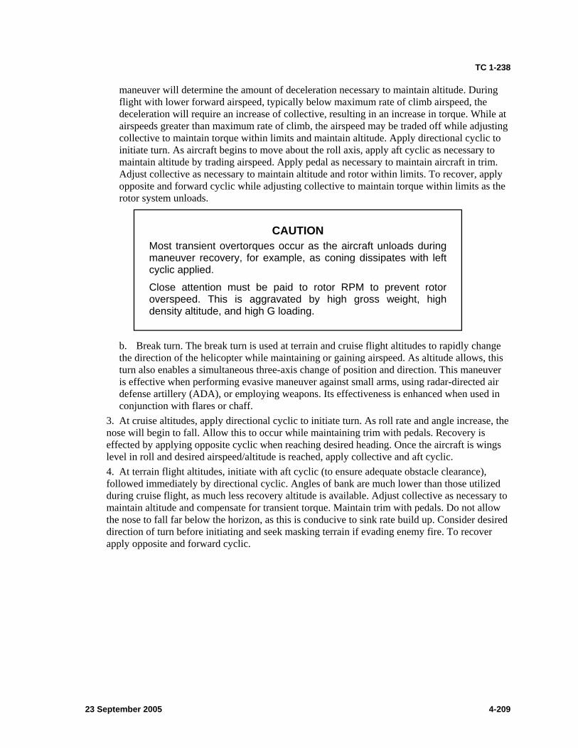
TC 1-238
maneuver will determine the amount of deceleration necessary to maintain altitude. During flight with lower forward airspeed, typically below maximum rate of climb airspeed, the deceleration will require an increase of collective, resulting in an increase in torque. While at airspeeds greater than maximum rate of climb, the airspeed may be traded off while adjusting collective to maintain torque within limits and maintain altitude. Apply directional cyclic to initiate turn. As aircraft begins to move about the roll axis, apply aft cyclic as necessary to maintain altitude by trading airspeed. Apply pedal as necessary to maintain aircraft in trim. Adjust collective as necessary to maintain altitude and rotor within limits. To recover, apply opposite and forward cyclic while adjusting collective to maintain torque within limits as the rotor system unloads.
CAUTION Most transient overtorques occur as the aircraft unloads during maneuver recovery, for example, as coning dissipates with left cyclic applied.
Close attention must be paid to rotor RPM to prevent rotor overspeed. This is aggravated by high gross weight, high density altitude, and high G loading.
b. Break turn. The break turn is used at terrain and cruise flight altitudes to rapidly change the direction of the helicopter while maintaining or gaining airspeed. As altitude allows, this turn also enables a simultaneous three-axis change of position and direction. This maneuver is effective when performing evasive maneuver against small arms, using radar-directed air defense artillery (ADA), or employing weapons. Its effectiveness is enhanced when used in conjunction with flares or chaff.
3. At cruise altitudes, apply directional cyclic to initiate turn. As roll rate and angle increase, the nose will begin to fall. Allow this to occur while maintaining trim with pedals. Recovery is effected by applying opposite cyclic when reaching desired heading. Once the aircraft is wings level in roll and desired airspeed/altitude is reached, apply collective and aft cyclic. 4. At terrain flight altitudes, initiate with aft cyclic (to ensure adequate obstacle clearance), followed immediately by directional cyclic. Angles of bank are much lower than those utilized during cruise flight, as much less recovery altitude is available. Adjust collective as necessary to maintain altitude and compensate for transient torque. Maintain trim with pedals. Do not allow the nose to fall far below the horizon, as this is conducive to sink rate build up. Consider desired direction of turn before initiating and seek masking terrain if evading enemy fire. To recover apply opposite and forward cyclic.
23 September 2005 4-209
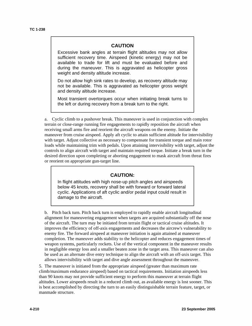
TC 1-238
CAUTION Excessive bank angles at terrain flight altitudes may not allow sufficient recovery time. Airspeed (kinetic energy) may not be available to trade for lift and must be evaluated before and during the maneuver. This is aggravated as helicopter gross weight and density altitude increase.
Do not allow high sink rates to develop, as recovery altitude may not be available. This is aggravated as helicopter gross weight and density altitude increase.
Most transient overtorques occur when initiating break turns to the left or during recovery from a break turn to the right.
a. Cyclic climb to a pushover break. This maneuver is used in conjunction with complex terrain or close-range running fire engagements to rapidly reposition the aircraft when receiving small arms fire and reorient the aircraft weapons on the enemy. Initiate the maneuver from cruise airspeed. Apply aft cyclic to attain sufficient altitude for intervisibility with target. Adjust collective as necessary to compensate for transient torque and main rotor loads while maintaining trim with pedals. Upon attaining intervisibility with target, adjust the controls to align aircraft with target and maintain required torque. Initiate a break turn in the desired direction upon completing or aborting engagement to mask aircraft from threat fires or reorient on appropriate gun-target line.
CAUTION: In flight attitudes with high nose-up pitch angles and airspeeds below 45 knots, recovery shall be with forward or forward lateral cyclic. Applications of aft cyclic and/or pedal input could result in damage to the aircraft.
b. Pitch back turn. Pitch back turn is employed to rapidly enable aircraft longitudinal alignment for maneuvering engagement when targets are acquired substantially off the nose of the aircraft. The turn may be initiated from terrain flight or tactical cruise altitudes. It improves the efficiency of off-axis engagements and decreases the aircrew's vulnerability to enemy fire. The forward airspeed at maneuver initiation is again attained at maneuver completion. The maneuver adds stability to the helicopter and reduces engagement times of weapon systems, particularly rockets. Use of the vertical component in the maneuver results in negligible energy loss and a smaller beaten zone in the target area. This maneuver can also be used as an alternate dive entry technique to align the aircraft with an off-axis target. This allows intervisibility with target and dive angle assessment throughout the maneuver.
5. The maneuver is initiated from the appropriate airspeed (greater than maximum rate climb/maximum endurance airspeed) based on tactical requirements. Initiation airspeeds less than 90 knots may not provide sufficient energy to perform this maneuver at terrain flight altitudes. Lower airspeeds result in a reduced climb out, as available energy is lost sooner. This is best accomplished by directing the turn to an easily distinguishable terrain feature, target, or manmade structure.
4-210 23 September 2005
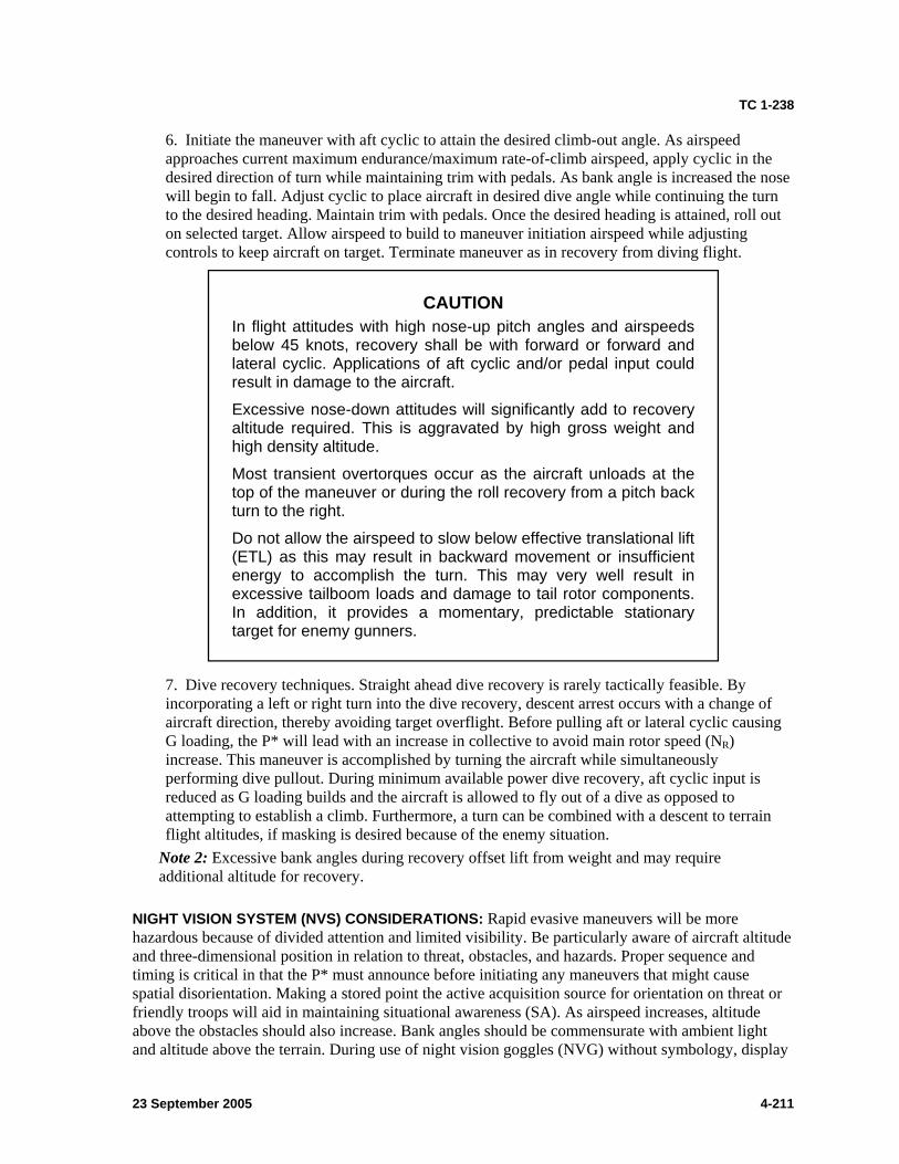
TC 1-238
6. Initiate the maneuver with aft cyclic to attain the desired climb-out angle. As airspeed approaches current maximum endurance/maximum rate-of-climb airspeed, apply cyclic in the desired direction of turn while maintaining trim with pedals. As bank angle is increased the nose will begin to fall. Adjust cyclic to place aircraft in desired dive angle while continuing the turn to the desired heading. Maintain trim with pedals. Once the desired heading is attained, roll out on selected target. Allow airspeed to build to maneuver initiation airspeed while adjusting controls to keep aircraft on target. Terminate maneuver as in recovery from diving flight.
CAUTION In flight attitudes with high nose-up pitch angles and airspeeds below 45 knots, recovery shall be with forward or forward and lateral cyclic. Applications of aft cyclic and/or pedal input could result in damage to the aircraft.
Excessive nose-down attitudes will significantly add to recovery altitude required. This is aggravated by high gross weight and high density altitude.
Most transient overtorques occur as the aircraft unloads at the top of the maneuver or during the roll recovery from a pitch back turn to the right.
Do not allow the airspeed to slow below effective translational lift (ETL) as this may result in backward movement or insufficient energy to accomplish the turn. This may very well result in excessive tailboom loads and damage to tail rotor components. In addition, it provides a momentary, predictable stationary target for enemy gunners.
7. Dive recovery techniques. Straight ahead dive recovery is rarely tactically feasible. By incorporating a left or right turn into the dive recovery, descent arrest occurs with a change of aircraft direction, thereby avoiding target overflight. Before pulling aft or lateral cyclic causing G loading, the P* will lead with an increase in collective to avoid main rotor speed (NR) increase. This maneuver is accomplished by turning the aircraft while simultaneously performing dive pullout. During minimum available power dive recovery, aft cyclic input is reduced as G loading builds and the aircraft is allowed to fly out of a dive as opposed to attempting to establish a climb. Furthermore, a turn can be combined with a descent to terrain flight altitudes, if masking is desired because of the enemy situation.
Note 2: Excessive bank angles during recovery offset lift from weight and may require additional altitude for recovery.
NIGHT VISION SYSTEM (NVS) CONSIDERATIONS: Rapid evasive maneuvers will be more hazardous because of divided attention and limited visibility. Be particularly aware of aircraft altitude and three-dimensional position in relation to threat, obstacles, and hazards. Proper sequence and timing is critical in that the P* must announce before initiating any maneuvers that might cause spatial disorientation. Making a stored point the active acquisition source for orientation on threat or friendly troops will aid in maintaining situational awareness (SA). As airspeed increases, altitude above the obstacles should also increase. Bank angles should be commensurate with ambient light and altitude above the terrain. During use of night vision goggles (NVG) without symbology, display
23 September 2005 4-211
TC 1-238
will require greater crew coordination to monitor torque, airspeed, trim, and rates of descent information not present in the NVG.
TRAINING AND EVALUATION REQUIREMENTS: 1. Training. Initial training will be conducted by an instructor pilot (IP) and evaluated in the aircraft. Continuation training may be conducted by qualified crewmembers in the AH-64A simulator or aircraft. 2. Evaluations will be conducted in the AH-64A aircraft.
Note 3: Crewmembers will ensure that the appropriate authority has authorized any training flights.
REFERENCES: Appropriate common references.
4-212 23 September 2005
TC 1-238
TASK 2128
PERFORM CLOSE COMBAT ATTACK
CONDITIONS: In an AH-64A helicopter, an AH-64A simulator, or as an oral exercise.
STANDARDS: Appropriate common standards and the following: 1. Participate in a close combat attack (CCA) briefing on the mission. 2. Develop and transmit or receive a CCA briefing. 3. Correctly identify friendly locations. 4. Transmit the attack plan to team member, using technique, pattern/attack direction, munitions, range (TPM-R) format or unit standing operating procedure (SOP).
DESCRIPTION: 1. Crew actions.
a. Throughout the close combat attack mission, the pilot on the controls (P*) will remain focused outside the aircraft to avoid obstacles. b. The pilot not on the controls (P) will assist the P* as necessary and will announce when his attention is focused inside the cockpit. c. The crew will establish communications with ground forces in contact on a predetermined frequency and receive or request information using the CCA briefing checklist provided in this document (figure 4-9) or in accordance with unit SOP. d. The crew will positively identify friendly unit locations. e. The crew will formulate an attack plan and transmit it to other team members. As a minimum, techniques, patterns, munitions, and ranges will be briefed and understood.
2. Procedures. Using Army attack/armed reconnaissance aircraft to support a ground maneuver element in contact is considered a close combat attack. In today’s world this could take place anywhere on the battle field, in close or deep operations and in any terrain. Friendly ground troops that are within 1,000 meters of the enemy are doctrinally considered to be in contact with the enemy; attacking enemy forces that are within 1 kilometer (km) of the friendlies requires special procedures to minimize fratricide. During any operation in close proximity to troops, it is imperative that the crew understand who they are working with and have direct communication with the troops on the ground.
a. Danger close is defined as a probability of incapacitation equaling 0.1 percent, or a 1 in 1,000 chance of friendlies being wounded. The ground commander must be informed that he assumes responsibility for friendly casualties when a target is danger close. The ground commander must approve danger close fires by transmitting his initials to the firing crew. The following “risk estimate distances” are for probabilities of incapacitation of 0.1 percent in accordance with FM 3-09.32 procedures for the joint application of firepower. They are for combat only and assume shooting parallel to friendlies.
(1) High explosive (HE) rockets (RKTs) 240 meters (2) 30-millimeter high explosive/dual purpose (HEDP) 40 meters (3) Hellfire 105 meters
Note 1: Shooting perpendicular to friendly locations exposes ground forces to great risk because of the likelihood of rounds landing short, or long and the danger of ricochets.
23 September 2005 4-213
TC 1-238
b. The air mission commander must have direct communication with the ground commander on the scene to provide direct fire support. After receiving the CCA brief from the ground troops, the pilots must be able to positively identify the location of the friendlies before shooting. Methods for marking the location of friendlies and the enemy include, but are not limited to, laser handover, tracer fire, marking rounds (flares or mortars), smoke grenades, signal mirrors, VS-17 panels, infrared (IR) strobe lights, laser pointers, or chemical sticks (which can be tied onto a string and swung overhead like a “buzz saw”).
Note 2: If the troops in contact do not have a CCA briefing checklist, the close air support (CAS) briefing (9-line) minus the first 4 lines will suffice. Pilots must also be prepared to request the information when working with inexperienced ground personnel.
Note 3: When throwing smoke the pilot will call out the color of the smoke and the ground commander will confirm. Never call the color of the smoke before it is thrown.
Note 4: At no time should the crew insert friendly locations as a target/threat. Only insert the friendly location as a waypoint or control measure during the conduct of a CCA.
c. Once the crew has identified both the enemy and friendly locations, flight lead will formulate a plan and brief his other team members. Using TPM-R or unit SOP will aid in conveying the plan to other team members.
(1) Techniques. Techniques of fire include running, diving, or hover fire. Type of threat, terrain, visibility, winds, density altitude, gross weight of the aircraft, and the proximity to friendly troops will be considered when selecting a mode of fire. Another technique could be running fire with a bump to acquire targets. (2) Patterns. When selecting a pattern refer to task 2042. Patterns include but are not limited to race track, cloverleaf, L-attack, or figure-8. Direction of turns and direction of breaks must be briefed also. When performing hovering fire, brief standard or nonstandard stack. (3) Munitions. Munitions selected must be appropriate for the target and provide the most standoff capability. Accuracy and reliability must be considered when firing near friendly troops. Collateral damage could be another consideration in some areas of operation. (4) Range. When briefing range, include distance from target where inbound engagement will initiate and at what range the break will be executed to prevent overflying the target and to stay outside of the enemy’s engagement range.
Note 5: Critical to the success of the CCA mission, aircrews must have a clearly defined “end-state” for any engagement. Crews must understand the target, threat, and desired effects to develop an attack plan that best meets the desired end-state while minimizing risk to the aircrews and collateral damage around the target.
4-214 23 September 2005
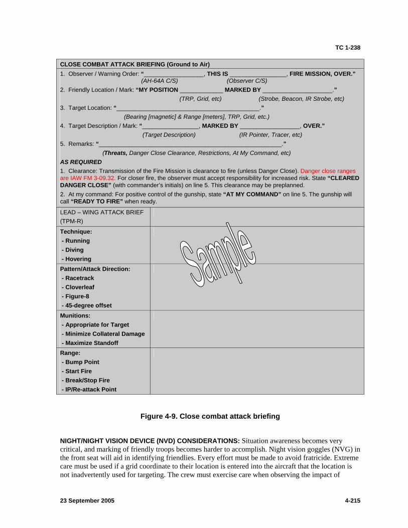
TC 1-238
CLOSE COMBAT ATTACK BRIEFING (Ground to Air) 1. Observer / Warning Order: “__________________, THIS IS _________________, FIRE MISSION, OVER.”
(AH-64A C/S) (Observer C/S) 2. Friendly Location / Mark: “MY POSITION _____________ MARKED BY _____________________.”
(TRP, Grid, etc) (Strobe, Beacon, IR Strobe, etc) 3. Target Location: “___________________________________________.”
(Bearing [magnetic] & Range [meters], TRP, Grid, etc.) 4. Target Description / Mark: “_________________, MARKED BY __________________, OVER.”
(Target Description) (IR Pointer, Tracer, etc) 5. Remarks: “_______________________________________________________.”
(Threats, Danger Close Clearance, Restrictions, At My Command, etc) AS REQUIRED 1. Clearance: Transmission of the Fire Mission is clearance to fire (unless Danger Close). Danger close ranges are IAW FM 3-09.32. For closer fire, the observer must accept responsibility for increased risk. State “CLEARED DANGER CLOSE” (with commander’s initials) on line 5. This clearance may be preplanned. 2. At my command: For positive control of the gunship, state “AT MY COMMAND” on line 5. The gunship will call “READY TO FIRE” when ready.
LEAD – WING ATTACK BRIEF (TPM-R)
Technique: - Running
- Diving - Hovering Pattern/Attack Direction: - Racetrack - Cloverleaf - Figure-8 - 45-degree offset Munitions: - Appropriate for Target - Minimize Collateral Damage - Maximize Standoff
Range: - Bump Point - Start Fire
- Break/Stop Fire - IP/Re-attack Point
Figure 4-9. Close combat attack briefing
NIGHT/NIGHT VISION DEVICE (NVD) CONSIDERATIONS: Situation awareness becomes very critical, and marking of friendly troops becomes harder to accomplish. Night vision goggles (NVG) in the front seat will aid in identifying friendlies. Every effort must be made to avoid fratricide. Extreme care must be used if a grid coordinate to their location is entered into the aircraft that the location is not inadvertently used for targeting. The crew must exercise care when observing the impact of
23 September 2005 4-215

TC 1-238
rounds because the flash signature may momentarily degrade the capability of the NVG. When firing rockets, missiles, adjusting indirect fire, or firing the 30mm chain gun off axis, the crew must follow procedures to protect their night vision.
TRAINING AND EVALUATION REQUIREMENTS: 1. Training may be conducted in the aircraft or AH-64A simulator. 2. Evaluation will be conducted in the AH-64A aircraft, AH-64A simulator, or orally.
REFERENCES: Appropriate common references and the following: FM 3-09.32 FM 17-95 FM 90-21 JP 3-09.3 TC 1-201 Unit standing operating procedure (SOP)
4-216 23 September 2005
TC 1-238
TASK 2162
Call for indirect fire
CONDITIONS: In an AH-64A helicopter, an AH-64A simulator, or as an oral exercise.
STANDARDS: 1. Artillery/aerial indirect fire method (voice).
a. Remain oriented on the target while repositioning the aircraft. b. Mask and unmask the aircraft as required. c. Adjust indirect fire or provide precision-coded laser energy on the target, using the appropriate call-for-fire element. d. Receive and process an aerial indirect fire (aerial rocket control system [ARCS]/30 millimeter) mission request. e. Conduct indirect aerial fire and perform any subsequent adjustments as necessary.
2. Perform crew coordination actions in accordance with chapter 6 and the task description.
DESCRIPTION: Note 1: A call for fire is not wholly specific to artillery units; it is also used during the conduct of indirect aerial fires. The precision navigation (embedded global positioning inertial navigation system [EGI]) capabilities of the AH-64A and advanced weapons processors allows for precise indirect fire engagements with rockets, 30-millimeter, remote semiactive laser (SAL) Hellfire engagements, and other laser-guided munitions, such as the Copperhead.
1. Crew actions. a. The pilot on the controls (P*) will remain focused outside the aircraft to clear the aircraft throughout the maneuver. He will mask and unmask the aircraft as required, ensuring that he does not use the same location more than once. He will remain oriented on the target while repositioning the aircraft. b. The pilot not on the controls (P) will make the call using the procedures in FM 6-30 and FM 3-04.140 as applicable. He will indicate target location by either grid coordinates or shift from a known point and make subsequent adjustments. The P may request flight time of the rounds, or “splash,” for a warning of 5 seconds before the impact. He will send an “end of mission” message with a battle damage assessment or an “unable to observe” message. c. The target observing crew will determine the need to call for indirect artillery, indirect aerial (rocket [RKT]/30 millimeter), or a remote SAL missile. The P will normally make the call. He will indicate the target location through grid coordinates, by a shift from a known point, or on a preplanned point. He will adjust indirect artillery or indirect aerial fire, or he will conduct SAL remote Hellfire. d. The target observer/designator P* will remain focused outside the aircraft to avoid obstacles during the maneuver. He should not unmask the aircraft in the same location more than once. The P should normally request the time of flight for artillery fire. Time of flight requests for indirect aerial fire and remote SAL missiles will be determined by the situation. Time of flight information can be used by the P to know when to direct the P* to unmask for observation of rounds impact. Alternatively, the P may request “splash,” which provides a 5-second alert before impact or “laser-on” for a remote Hellfire laser delay.
23 September 2005 4-217
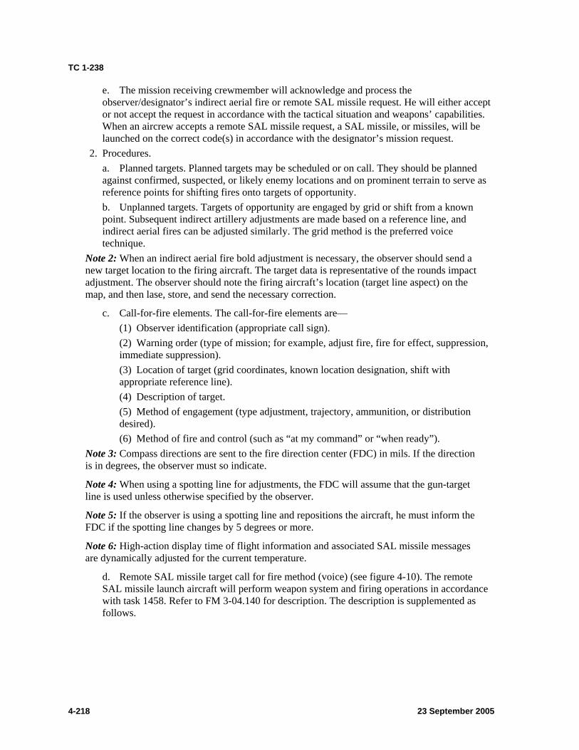
TC 1-238
e. The mission receiving crewmember will acknowledge and process the observer/designator’s indirect aerial fire or remote SAL missile request. He will either accept or not accept the request in accordance with the tactical situation and weapons’ capabilities. When an aircrew accepts a remote SAL missile request, a SAL missile, or missiles, will be launched on the correct code(s) in accordance with the designator’s mission request.
2. Procedures. a. Planned targets. Planned targets may be scheduled or on call. They should be planned against confirmed, suspected, or likely enemy locations and on prominent terrain to serve as reference points for shifting fires onto targets of opportunity. b. Unplanned targets. Targets of opportunity are engaged by grid or shift from a known point. Subsequent indirect artillery adjustments are made based on a reference line, and indirect aerial fires can be adjusted similarly. The grid method is the preferred voice technique.
Note 2: When an indirect aerial fire bold adjustment is necessary, the observer should send a new target location to the firing aircraft. The target data is representative of the rounds impact adjustment. The observer should note the firing aircraft’s location (target line aspect) on the map, and then lase, store, and send the necessary correction.
c. Call-for-fire elements. The call-for-fire elements are— (1) Observer identification (appropriate call sign). (2) Warning order (type of mission; for example, adjust fire, fire for effect, suppression, immediate suppression). (3) Location of target (grid coordinates, known location designation, shift with appropriate reference line). (4) Description of target. (5) Method of engagement (type adjustment, trajectory, ammunition, or distribution desired). (6) Method of fire and control (such as “at my command” or “when ready”).
Note 3: Compass directions are sent to the fire direction center (FDC) in mils. If the direction is in degrees, the observer must so indicate.
Note 4: When using a spotting line for adjustments, the FDC will assume that the gun-target line is used unless otherwise specified by the observer.
Note 5: If the observer is using a spotting line and repositions the aircraft, he must inform the FDC if the spotting line changes by 5 degrees or more.
Note 6: High-action display time of flight information and associated SAL missile messages are dynamically adjusted for the current temperature.
d. Remote SAL missile target call for fire method (voice) (see figure 4-10). The remote SAL missile launch aircraft will perform weapon system and firing operations in accordance with task 1458. Refer to FM 3-04.140 for description. The description is supplemented as follows.
4-218 23 September 2005
TC 1-238
(1) The sender’s call for fire warning order element should include “REMOTE SAL” in the verbiage and the number of missiles when desiring more than one. (2) SAL missile time of flight is only required when specifically requested in the call for fire targeting-information element, or by standing operating procedure (SOP). (3) Other coordinating calls may have to be made by the mission receiving aircraft before the “ready” call, including when safety or performance constraints cannot be immediately achieved and aircraft reposition or other adjustment is necessary. (4) Local units may adjust the example provided in FM 3-04.140. A standardization effort should be made to follow the referenced format as closely as possible.
SAMPLE REMOTE HELLFIRE REQUEST – VOICE (Spoken portions of procedure are in bold text or inside bold quotation marks)
1. Alert: “___________________ this is: _____________________ Remote, over!” Target description: “________________________________” 2. Location: “_____________________________” (Grid or distance & bearing) 3. Attack method: a. Delivery mode: “________________________________________________” b. Number of missiles: “_____________________________________________” c. Laser code: “______________________________________________________” d. Time interval between missiles: “______________________________________” 4. “At my command.” (Unless otherwise stated.) 5a. The firing aircraft should evaluate the request and respond to the designating aircraft with: “___________________this is _________________________,” “accept” or “reject,” “Over.” 5b. If accepted, the firing aircraft must position itself as necessary to make the shot, obtain firing constraints, and respond: “________________ this is _________________, Ready. Time of flight _________, over.” 6. When the designating aircraft is ready for the missile, it will respond: “This is ____________,” “Fire, over.” 7. The firing aircraft should announce: “Shot, over.” 8. Designating aircraft should “Lase" the target until impact or for 20 seconds beyond the expected missile time on target. 9. If another target is located in the same area, an additional missile can be fired if the designator transmits “Repeat, over” to the launching aircraft. If more than one additional missile is desired, the call should include the number of missiles, as in, “Repeat, three missiles, over.”
Figure 4-10. Sample remote Hellfire request – voice
Note 7: If another target is located in the same area, an additional missile can be fired if the designator transmits “REPEAT, OVER” to the launching aircraft. If more than one additional missile is desired, the call should include the number of missiles, as in “REPEAT, THREE MISSILES, OVER.”
NIGHT OR NIGHT VISION GOGGLE (NVG) CONSIDERATIONS: The crew must exercise care when observing the impact of artillery rounds because the flash signature may momentarily degrade the capability of the NVG. The P* should not directly observe the impact of the rounds. If the crew is unaided, their night vision will be impaired for a short time if they directly observe the impact. When adjusting indirect fire, the crew must follow procedures to protect their night vision.
23 September 2005 4-219

TC 1-238
TRAINING AND EVALUATION REQUIREMENTS: 1. Training may be conducted in the AH-64A aircraft, in an AH-64A simulator or orally. 2. Evaluation will be conducted in the AH-64A aircraft, in an AH-64A simulator or orally.
REFERENCES: Appropriate common references and the following: FM 3-04.140 FM 6-30 Unit SOP
4-220 23 September 2005
TC 1-238
TASK 2164
Call for a tactical air strike
CONDITIONS: In an AH-64A helicopter, an AH-64A simulator, or as an oral exercise.
STANDARDS: Appropriate common standards and the following: 1. Participate in a close air support (CAS) briefing on the mission. 2. Transmit a CAS briefing (9-line) report (figure 4-12) and a close air support check-in briefing (figure 4-11). 3. Transmit attack methods, firepower timing options, and targeting methods. 4. Transmit to the forward air controller or fighter-bomber an accurate battle damage assessment.
DESCRIPTION: 1. Crew actions.
a. Throughout the coordinated tactical air strike mission, the pilot on the controls (P*) will remain focused outside the aircraft to avoid obstacles. b. The pilot not on the controls (P) will assist the P* as necessary and will announce when his attention is focused inside the cockpit. c. The P, if participating in a tactical air strike or CAS mission will transmit a close air support check-in brief. As a helicopter pilot, the P must be ready to act as the air mission commander (AMC) and be prepared to receive the close air support check-in brief. d. The crew will establish contact with the forward air controller on a predetermined frequency and provide the CAS briefing 9-line information.
2. Procedures. Tactical air strikes are conducted between United States (U.S.) Army aircraft and attack fighter/bomber aircraft from the Navy, Marines, and Air Force. Close air support is a formalized Air Force tactical air strike procedure that consists of air attacks against enemy targets that are in close proximity to friendly forces. Typical targets are enemy troop concentrations, fixed positions, and armored units of immediate concern to ground forces. Normally, an Air Force forward air controller or tactical air control party (TACP) will control close air support aircraft. To make sure that urgent or emergency requirements for CAS are satisfied when the forward air controller is not available, the tactical Air Force commander and ground force commander must establish procedures and responsibilities. Once established, the air liaison officer acts as the interface between the air support operations center and the maneuver commander. The crew will establish contact with the forward air controller on a predetermined frequency and coordinate a preplanned CAS, or immediate CAS request, as follows.
a. Preplanned requests. Those requirements foreseen early enough to be included in the joint air tasking order (ATO) are submitted as preplanned requests. As soon as the requirements for a tactical air strike are identified during the planning process, planners submit a preplanned request, prior to the cut-off time as specified by HQ. Planners prepare preplanned requests by using DD Form 1972 (Joint Tactical Air Strike Request). Submission procedures (including numbering system and timeframe for inclusion in the ATO) for preplanned requests are theater-specific, and detailed guidance should be found in unit standing operating procedures (SOPs).
23 September 2005 4-221
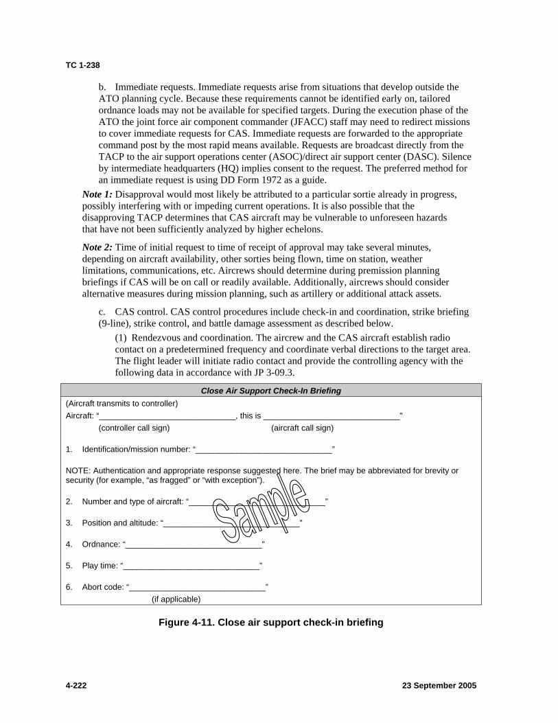
TC 1-238
b. Immediate requests. Immediate requests arise from situations that develop outside the ATO planning cycle. Because these requirements cannot be identified early on, tailored ordnance loads may not be available for specified targets. During the execution phase of the ATO the joint force air component commander (JFACC) staff may need to redirect missions to cover immediate requests for CAS. Immediate requests are forwarded to the appropriate command post by the most rapid means available. Requests are broadcast directly from the TACP to the air support operations center (ASOC)/direct air support center (DASC). Silence by intermediate headquarters (HQ) implies consent to the request. The preferred method for an immediate request is using DD Form 1972 as a guide.
Note 1: Disapproval would most likely be attributed to a particular sortie already in progress, possibly interfering with or impeding current operations. It is also possible that the disapproving TACP determines that CAS aircraft may be vulnerable to unforeseen hazards that have not been sufficiently analyzed by higher echelons.
Note 2: Time of initial request to time of receipt of approval may take several minutes, depending on aircraft availability, other sorties being flown, time on station, weather limitations, communications, etc. Aircrews should determine during premission planning briefings if CAS will be on call or readily available. Additionally, aircrews should consider alternative measures during mission planning, such as artillery or additional attack assets.
c. CAS control. CAS control procedures include check-in and coordination, strike briefing (9-line), strike control, and battle damage assessment as described below.
(1) Rendezvous and coordination. The aircrew and the CAS aircraft establish radio contact on a predetermined frequency and coordinate verbal directions to the target area. The flight leader will initiate radio contact and provide the controlling agency with the following data in accordance with JP 3-09.3.
Close Air Support Check-In Briefing (Aircraft transmits to controller) Aircraft: “______________________________, this is ______________________________”
(controller call sign) (aircraft call sign)
1. Identification/mission number: “______________________________”
NOTE: Authentication and appropriate response suggested here. The brief may be abbreviated for brevity or security (for example, “as fragged” or “with exception”).
2. Number and type of aircraft: “______________________________”
3. Position and altitude: “______________________________”
4. Ordnance: “______________________________”
5. Play time: “______________________________”
6. Abort code: “______________________________” (if applicable)
Figure 4-11. Close air support check-in briefing
4-222 23 September 2005
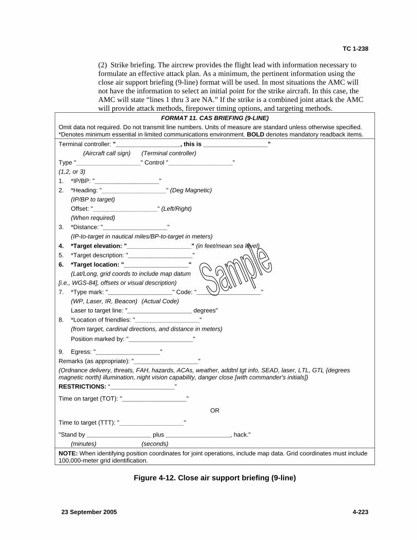
TC 1-238
(2) Strike briefing. The aircrew provides the flight lead with information necessary to formulate an effective attack plan. As a minimum, the pertinent information using the close air support briefing (9-line) format will be used. In most situations the AMC will not have the information to select an initial point for the strike aircraft. In this case, the AMC will state “lines 1 thru 3 are NA.” If the strike is a combined joint attack the AMC will provide attack methods, firepower timing options, and targeting methods.
FORMAT 11. CAS BRIEFING (9-LINE) Omit data not required. Do not transmit line numbers. Units of measure are standard unless otherwise specified. *Denotes minimum essential in limited communications environment. BOLD denotes mandatory readback items. Terminal controller: "___________________, this is ___________________"
(Aircraft call sign) (Terminal controller) Type "___________________" Control "___________________" (1,2, or 3) 1. *IP/BP: "___________________" 2. *Heading: "___________________" (Deg Magnetic)
(IP/BP to target) Offset: "___________________" (Left/Right)
(When required) 3. *Distance: "___________________"
(IP-to-target in nautical miles/BP-to-target in meters) 4. *Target elevation: "___________________" (in feet/mean sea level) 5. *Target description: "___________________" 6. *Target location: "___________________"
(Lat/Long, grid coords to include map datum [i.e., WGS-84], offsets or visual description) 7. *Type mark: "___________________" Code: "___________________"
(WP, Laser, IR, Beacon) (Actual Code) Laser to target line: "___________________ degrees"
8. *Location of friendlies: "___________________" (from target, cardinal directions, and distance in meters) Position marked by: "___________________"
9. Egress: "___________________" Remarks (as appropriate): "___________________" (Ordnance delivery, threats, FAH, hazards, ACAs, weather, addtnl tgt info, SEAD, laser, LTL, GTL {degrees magnetic north} illumination, night vision capability, danger close [with commander's initials]) RESTRICTIONS: “___________________”
Time on target (TOT): "___________________"
OR
Time to target (TTT): "___________________"
"Stand by ___________________ plus ___________________, hack." (minutes) (seconds)
NOTE: When identifying position coordinates for joint operations, include map data. Grid coordinates must include 100,000-meter grid identification.
Figure 4-12. Close air support briefing (9-line)
23 September 2005 4-223
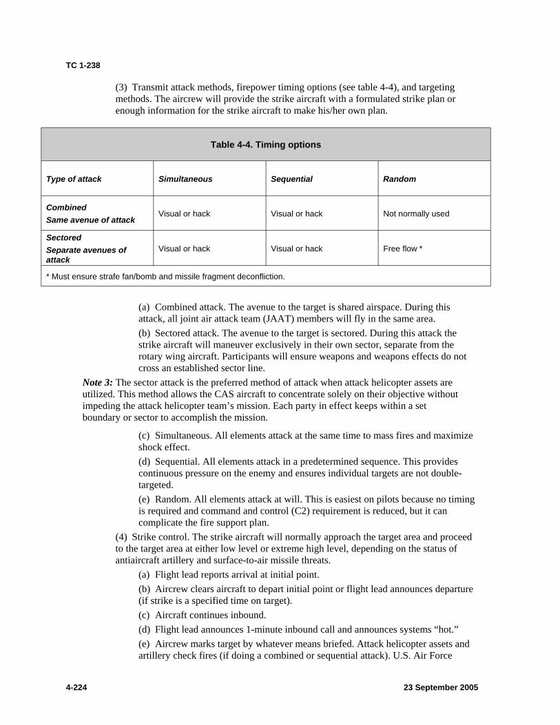
TC 1-238
(3) Transmit attack methods, firepower timing options (see table 4-4), and targeting methods. The aircrew will provide the strike aircraft with a formulated strike plan or enough information for the strike aircraft to make his/her own plan.
Table 4-4. Timing options
Type of attack Simultaneous Sequential Random
Combined Same avenue of attack
Visual or hack Visual or hack Not normally used
Sectored Separate avenues of attack
Visual or hack Visual or hack Free flow *
* Must ensure strafe fan/bomb and missile fragment deconfliction.
(a) Combined attack. The avenue to the target is shared airspace. During this attack, all joint air attack team (JAAT) members will fly in the same area. (b) Sectored attack. The avenue to the target is sectored. During this attack the strike aircraft will maneuver exclusively in their own sector, separate from the rotary wing aircraft. Participants will ensure weapons and weapons effects do not cross an established sector line.
Note 3: The sector attack is the preferred method of attack when attack helicopter assets are utilized. This method allows the CAS aircraft to concentrate solely on their objective without impeding the attack helicopter team’s mission. Each party in effect keeps within a set boundary or sector to accomplish the mission.
(c) Simultaneous. All elements attack at the same time to mass fires and maximize shock effect. (d) Sequential. All elements attack in a predetermined sequence. This provides continuous pressure on the enemy and ensures individual targets are not double-targeted. (e) Random. All elements attack at will. This is easiest on pilots because no timing is required and command and control (C2) requirement is reduced, but it can complicate the fire support plan.
(4) Strike control. The strike aircraft will normally approach the target area and proceed to the target area at either low level or extreme high level, depending on the status of antiaircraft artillery and surface-to-air missile threats.
(a) Flight lead reports arrival at initial point. (b) Aircrew clears aircraft to depart initial point or flight lead announces departure (if strike is a specified time on target). (c) Aircraft continues inbound. (d) Flight lead announces 1-minute inbound call and announces systems “hot.” (e) Aircrew marks target by whatever means briefed. Attack helicopter assets and artillery check fires (if doing a combined or sequential attack). U.S. Air Force
4-224 23 September 2005
TC 1-238
(USAF) aircrews usually will request a laser “spot.” U.S. Navy (USN) and U.S. Marine Corps (USMC) will request a “sparkle” (laser). During CAS missions, use common terms that can be understood by all, such as “laser on”/“laser off.” (f) Flight lead identifies target marking and announces/verifies target marks to aircrew. He may announce “no joy,” meaning that a visual confirmation of the target area has not been completed.
Note 4: If the strike is within close proximity to friendly units, the strike aircraft will not deliver ordnance until he gets a “CLEARED HOT” call from a qualified forward air controller. The ground commander will assess the risk and determine the type of control (type 1, 2, or 3) that will be used prior to weapons release.
(g) Wingmen commence their respective passes in the same sequence and manner as described above. (h) The strike will continue until the target is neutralized, the aircraft delivers their ordnance (Winchester), or the aircraft reach their fuel (bingo) limit.
(5) The battle damage assessment (BDA) is transmitted by the observer following the strike. The flight lead will request a BDA from the controlling forward air controller or aircrew.
NIGHT/NIGHT VISION DEVICE (NVD) CONSIDERATIONS: The crew must exercise care when observing the impact of rounds because the flash signature may momentarily degrade the capability of the night vision goggles (NVG). When adjusting indirect fire, the crew must follow procedures to protect their night vision.
TRAINING AND EVALUATION REQUIREMENTS: 1. Training may be conducted in the aircraft or AH-64A simulator. 2. Evaluation will be conducted in the AH-64A aircraft, AH-64A simulator, or orally.
REFERENCES: Appropriate common references and the following: FM 3-09.32 FM 17-95 FM 90-21 JP 3-09.3 TC 1-201 Unit standing operating procedure (SOP)
23 September 2005 4-225

This page intentionally left blank.

TC 1-238
Chapter 5
Maintenance Test Pilot Tasks
This chapter describes the tasks that are essential for maintaining maintenance crewmember skills. It defines the task title, number, conditions and standards by which performance is measured. A description of crew actions, along with training and evaluation requirements is also provided. Tasks described in this chapter are to be performed by qualified AH-64A maintenance test pilots in accordance with AR 95-1. This chapter contains tasks and procedures to be used by contractor maintenance test pilots in accordance with AR 95-20 (DLAI 8210.1), section 1.11 (publications). If a discrepancy is found between this chapter and TM 1-1520-238-MTF, the MTF takes precedence.
5-1. TASK CONTENTS.
a. Task number. Each ATM task is identified by a ten-digit systems approach to training number that corresponds to the maintenance test pilot tasks listed in chapter 2 (table 2-3). For convenience, only the last four digits are referenced in this training circular.
b. Task title. The task title identifies a clearly defined and measurable activity. Task titles may be the same in several ATMs, but task content may vary for the specific airframe.
c. Conditions. The conditions specify the common wartime or training/evaluation conditions under which the MTP tasks will be performed.
d. Standards. The standards describe the minimum degree of proficiency or standard of performance to which the task must be accomplished. Standards are based on ideal conditions. The following common standards apply to all MTP tasks:
(1) Brief the rated crewmember (RCM) or ground crewmember (NCM) on the procedures and applicable warnings and cautions for the task to be performed.
(2) State the reason for performing the specific task and answer questions about system location, operation, and function.
(3) Assess any malfunctions or discrepancies as they occur and apply appropriate corrective actions or troubleshooting procedures.
(4) Use the oral callout and confirmation method, and announce the initiation and completion of each check.
(5) Perform crew coordination actions per the task description and chapter 6.
e. Description. The description explains how the elements of the task should be completed to meet the standards. When specific crew actions are required, the task will be broken down into crew actions and procedures as follows:
(1) Crew actions. These define the portions of a task to be performed by each crewmember to ensure safe, efficient and effective task execution. The P* indication does not imply PC or MP duties. When required, P* or MP responsibilities are specified. All tasks in this chapter are to be performed only by qualified MEs, MPs, or student maintenance test pilots undergoing qualification training, as outlined in AR 95-1. The MP is the PC in all situations, except when undergoing training or evaluation by an ME. For all tasks, MP actions and responsibilities are applicable to MEs. When
23 September 2005 5-1
TC 1-238
two MEs are jointly conducting the training/evaluation, or two MPs are jointly performing test flight tasks, the mission brief will designate the aviator assuming PC responsibilities.
(2) Procedures. This section describes the actions that the MP/ME performs or directs the RCM/NCM to perform in order to execute the task to standard.
(3) Expanded procedures. Some procedures listed in TM 1-1520-238-MTF as bulleted items have expanded procedures/methods that are not given in the MTF manual. This ATM expands these items in procedural text descriptions. Only the required procedures are expanded in this ATM in order to provide clarification on preferred methods of accomplishing these procedures. Expansion of these checks within the MTF would clutter the checklist format of the MTF manual. If a check is not expanded within the procedural descriptions of this ATM, it is because the MTF clearly identifies the preferred method of accomplishment.
f. Considerations. This section defines training, evaluation, and other considerations for task accomplishment under various conditions.
g. Training and evaluation requirements. Some of the tasks incorporate more than one check from TM 1-1520-238-MTF. This section defines the checks in each task that, at a minimum, must be evaluated on an evaluation flight. The evaluator may select additional checks for evaluation. Training and evaluation requirements define whether the task will be trained or evaluated in the aircraft, simulator, or academic environment. Training and evaluations will be conducted only in the listed environments, but may be done in any or all combinations. Listing only “aircraft” under evaluation requirements does not preclude the ME from evaluating elements of the task academically to determine the depth of understanding of systems or troubleshooting processes. However, the evaluation must include hands-on performance of the task in the listed environment(s). If one or more checks are performed unsatisfactorily, the task will be graded unsatisfactory. However, when the task is reevaluated, only those unsatisfactory checks must be reevaluated.
h. References. The references are sources of information relating to that particular task. In addition to the common references listed in chapter 4, the following references apply to all MTP tasks:
z Aircraft logbook and historical records z AR 700-138 z DA Pam 738-751 z FM 3.04-500 z TM 1-1500-328-23 z TM 1-1520-238-10 z TM 1-1520-238-CL z TM 1-1520-238-MTF z TM 1-1520-238-23 series manuals z TM 1-1500-204-23 series manuals z TM 1-2840-248-23 z TM 1-6625-724-13&P z TM 9-1230-476-30 z TM 9-1270-221-23 z TM 1-1270-476-30 z TM 11-5826-227-34 z TM 1-5855-265-20
23 September 2005 5-2
TC 1-238
z TM 11-5895-1184-23 z Applicable airworthiness directives or messages from Aviation and Missile Command
(AMCOM)
5-2. TASK LIST.
a. Standards versus descriptions. MPs and MEs are reminded that task descriptions may contain required elements for successful completion of a given task. When a standard for the task is to “brief the RCM on the conduct of the maneuver,” for example, those crew actions specified in the description are required. Attention to the use of the words “will,” “should,” or “may” throughout the text of a task description is crucial.
b. Critical tasks. All AH-64A maintenance tasks are critical tasks.
23 September 2005 5-3
TC 1-238
TASK 4000
Perform prior to maintenance test flight checks
CONDITIONS: In an AH-64A helicopter.
STANDARDS: 1. Perform the preflight inspection according to TM 1-1520-238-10 and TM 1-1520-238-CL. 2. Determine the suitability of the aircraft for flight and the mission to be performed. 3. Perform procedures and checks in sequence per TM 1-1520-238-MTF.
DESCRIPTION: 1. Crew actions.
a. The maintenance pilot (MP) will ensure a thorough preflight inspection is conducted. TM 1-1520-238-CL will be used to conduct the preflight inspection; however, the inspection will be conducted according to chapter 8 of TM 1-1520-238-10. The MP may direct the rated crewmember (RCM), if available, to complete some elements of the aircraft preflight inspection as appropriate, but the MP will verify that all checks have been completed. The MP will ensure that the aircraft logbook forms and records are reviewed and that appropriate entries are made per DA Pam 738-751. b. The RCM should complete the assigned elements and report the results to the MP.
2. Procedures. Review the aircraft forms and records to determine the necessary checks and tasks to be performed. Use additional publications and references as necessary. Conduct a risk assessment of the mission. Preflight the aircraft with special emphasis on areas or systems where maintenance was performed. Verify all test equipment is installed and secured as applicable.
TRAINING AND EVALUATION REQUIREMENTS: 1. Training may be conducted in the aircraft or academically. 2. Evaluation will be conducted in the aircraft.
REFERENCES: Appropriate common references.
23 September 2005 5-4

TC 1-238
TASK 4001 Perform a maintenance operational check/maintenance test flight crewmember brief
CONDITIONS: Given a maintenance operational check (MOC)/maintenance test flight (MTF) crew briefing checklist.
STANDARDS: 1. Determine required MOCs and MTF maneuvers to be completed. 2. Brief crewmembers on required actions, responsibilities, and safety considerations for each MOC/MTF maneuver to be completed. 3. Ensure each crewmember has appropriate safety equipment. For the ground crewmember, this includes eye, hearing, head, and skin protection. Ensure the flight crewmember has the appropriate equipment for flight. Ensure all crewmembers understand the importance of their responsibilities during all phases of the MOC/MTF. 4. The crewmembers receiving the aircrew mission brief will verbally acknowledge a complete understanding of the aircrew mission briefing. 5. Perform procedures and checks in sequence per TM 1-1520-238-MTF.
DESCRIPTION: 1. A designated briefing officer will evaluate key areas of the mission and will brief the mission maintenance pilot (MP) accordingly per AR 95-1. The MP will acknowledge a complete understanding of the mission brief and will initial DA Form 5484-R. Designated briefing officers will utilize risk management techniques in accordance with AR 95-1 and TC 1-210. 2. The MP will ensure a thorough evaluation of all maintenance actions is completed. The MP will determine which MOCs/MTF maneuvers will be completed. The MP should review each MOC/MTF maneuver to be completed. If possible, the MP, rated crewmember (RCM), and ground crewmember should conduct this review as a crew. If this is not feasible, the MP, with all crewmembers present at the aircraft, should complete a condensed review of each MOC/MTF maneuver. The MP will use the enclosed briefing template or a briefing template similar in content to accomplish the brief. This template includes the minimum information for a MOC/MTF crewmember brief. Units should modify the template as needed to include specific mission requirements or other necessary changes that reflect unit particular items. 3. The crewmembers being briefed will address any questions to the briefer and will acknowledge that they understand their assigned actions, duties, and responsibilities. Lessons learned from previous debriefings should be addressed as applicable during the crew briefing.
PROCEDURES: 1. Brief the mission using a unit approved MOC/MTF crew briefing checklist. A suggested format for a MOC/MTF crew briefing checklist follows. Identify mission and flight requirements that will demand the crewmembers’ effective communication and proper sequencing and timing of actions. 2. MOCs should be performed in a logical, safe order. Turn-on and testing of systems, if not specified in maintenance manuals, will be conducted in accordance with the order of power-up per TM 1-1520-238-CL/MTF.
23 September 2005 5-5
TC 1-238
a. Ground crewmember (NCM). (1) The MP will ensure ground crewmembers have appropriate safety clothing/equipment. The MP should ensure positive, direct communication is available between the crew and the ground crewmember. (2) All crewmembers should remove jewelry, including watches, rings, or loose medallions, prior to movement on or around the aircraft. All loose items in pockets should be secured. Pockets should be closed. Communication cords and other equipment/tools should be under positive control at all times when on or around the aircraft. Accountability of all equipment before, during, and after completion of MOCs will be completed prior to securing cowlings/panels. A foreign object damage (FOD) inspection will also be completed. (3) If communication between the maintenance test pilot (MTP) and ground crewmembers is lost, ground crew should reestablish communication before MOCs resume. All crewmembers should remain in visual contact unless direct communication is provided.
b. Rated crewmember (RCM). (1) The MTF will be conducted in accordance with TM 1-1520-238-CL and TM 1-1520-238-MTF. Both crewmembers will be familiar with the maneuvers to be accomplished and with their individual duties. (2) Duties will be performed per the crew brief or, if a situation arises that was not covered by the mission brief, as dictated by the MP. (3) The MP will ensure that a final walkaround inspection is completed prior to flight.
TRAINING AND EVALUATION REQUIREMENTS: Task will be trained and evaluated academically and orally.
REFERENCES: AR 95-1 FM 3-04.300 TM 1-1520-238-10 TM 1-1520-238-CL Unit standing operating procedure (SOP)
23 September 2005 5-6
TC 1-238
Maintenance Operational Check (MOC)/Maintenance Test Flight (MTF) Crew Briefing Checklist 1. Mission overview
a. Purpose of the test flight b. Maneuvers to be performed
2. Weather 3. Notices to airmen (NOTAMs) 4. Airspace surveillance procedures 5. Required items, mission equipment, and personnel (including special/test equipment—security, location, and operation) 6. Crew actions, duties, and responsibilities
a. Transfer of flight controls and two challenge rule (1) Dual engine failure (2) Dual hydraulic failure/emergency hydraulic switch (3) Fuel pounds per square inch (PSI) engine (ENG) 1 and 2 (4) Engine failure out-of-ground effect (OGE) hover (5) Loss of tail rotor (6) Actions to be performed by P* and P (7) Portable fire extinguisher (8) First aid kits (9) Egress procedures and rendezvous point (10) Canopy jettison (11) Emergency stores jettison (JETT) (12) Power lever manipulation (13) Chop collar (14) Engine and auxiliary power unit (APU) fire switches/extinguishing bottles (15) Loss of intercommunication system (ICS) (16) Unusual attitude recovery (17) Simulated emergencies
b. Pilot not on the controls (P) (1) Primary focus outside while performing MTF maneuvers (2) Provide traffic and obstacle avoidance/advisories (3) Manage radios and set transponder (4) Copy clearances, automatic terminal information service (ATIS), and MTF data as directed by the
MP (5) Cross-check instruments (pilot [PLT]) (6) Monitor/transmit on radios as directed by the MP (7) Read and complete checklist items as required (8) Set/adjust switches and systems as required (9) Announce when focused inside for more than 3 to 4 seconds (VMC) or as appropriate to the current
situation 7. Crewstation (PLT/copilot-gunner [CPG]) specific
a. Weapons and aircraft survivability equipment (ASE) considerations (as applicable) b. Record test flight data as directed by MP
8. Analysis of the aircraft a. Logbook and preflight deficiencies b. Performance planning
23 September 2005 5-7
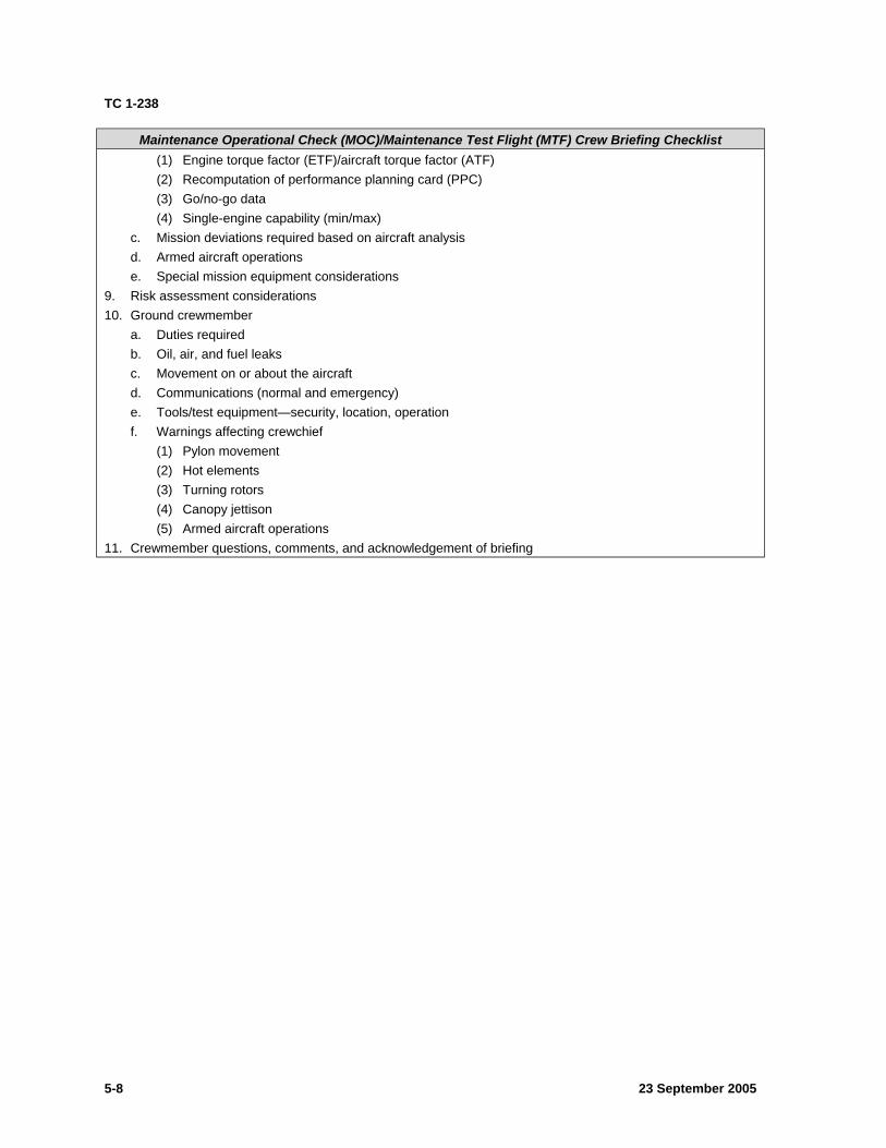
TC 1-238
Maintenance Operational Check (MOC)/Maintenance Test Flight (MTF) Crew Briefing Checklist (1) Engine torque factor (ETF)/aircraft torque factor (ATF) (2) Recomputation of performance planning card (PPC) (3) Go/no-go data (4) Single-engine capability (min/max)
c. Mission deviations required based on aircraft analysis d. Armed aircraft operations e. Special mission equipment considerations
9. Risk assessment considerations 10. Ground crewmember
a. Duties required b. Oil, air, and fuel leaks c. Movement on or about the aircraft d. Communications (normal and emergency) e. Tools/test equipment—security, location, operation f. Warnings affecting crewchief
(1) Pylon movement (2) Hot elements (3) Turning rotors (4) Canopy jettison (5) Armed aircraft operations
11. Crewmember questions, comments, and acknowledgement of briefing
23 September 2005 5-8
TC 1-238
TASK 4004
Perform interior checks
CONDITIONS: In an AH-64A helicopter or combat mission simulator (CMS).
STANDARDS: Perform procedures and checks in sequence in accordance with TM 1-1520-238-MTF.
DESCRIPTION: 1. Crew actions.
a. The maintenance pilot (MP) will perform the required checks in sequence. He should direct assistance from the rated crewmember (RCM) or ground crewmember (NCM) if available. b. The RCM and/or NCM should assist the MP as directed.
2. Procedures. Brief the RCM and/or NCM as required. Perform the interior checks in maintenance test flight (MTF) sequence. Direct the RCM to perform the required checks at his crew station and announce check completion. If necessary, brief the RCM on the procedures required to perform the checks at the copilot-gunner (CPG) station.
Note: B For backup control system (BUCS) aircraft, defer brake check, pedal adjustments, and BUCS locks (if installed) removal until after starting auxiliary power unit (APU) and generators online.
TRAINING AND EVALUATION REQUIREMENTS: 1. Training may be conducted in the aircraft, a CMS, or academically. 2. Evaluation will be conducted in the aircraft.
REFERENCES: Appropriate common references.
23 September 2005 5-9

TC 1-238
TASK 4008
Perform before-starting auxiliary power unit checks
CONDITIONS: In an AH-64A helicopter or combat mission simulator (CMS).
STANDARDS: Perform procedures and checks in sequence per TM 1-1520-238-MTF.
DESCRIPTION: 1. Crew actions.
a. The maintenance pilot (MP) will perform the required checks in sequence. He should direct assistance from the rated crewmember (RCM) or ground crewmember (NCM) if available. b. The RCM and/or NCM should assist the MP as directed.
2. Procedures. a. The MP will confirm the presence of the ENG OUT AUDIO with the opposite crewmember, and then reset the audio. b. The MP will check that the selected radio is tuned to an internal frequency and will ensure that the transmitter selector switch on the communication system control (CSC) is set to the desired radio. The MP will check internal communications with the opposite crewmember and ground crewmember(s) utilizing cyclic intercommunication system (ICS) rocker position, then RADIO rocker position, the right floor mike, and then HOT MIC and voice operated transmitter (VOX) switch positions on the ICS switch on the CSC panel. The MP will confirm that all crewmembers had positive communications in all switch positions. The opposite RCM will check that the selected radio is tuned to an internal frequency and ensure that the transmitter selector switch on the ICS panel is set to the desired radio. The RCM will check internal communications with the opposite crewmember and ground crewmember(s) utilizing cyclic ICS rocker position, then RADIO rocker position, both left and right floor mikes, and then HOT MIC and VOX switch positions on the ICS switch on the CSC panel. The RCM will confirm that all crewmembers had positive communications in all switch positions. The NCM will confirm communications capabilities with the crew.
TRAINING AND EVALUATION REQUIREMENTS: 1. Training may be conducted in the aircraft, a CMS, or academically. 2. Evaluation will be conducted in the aircraft.
REFERENCES: Appropriate common references.
23 September 2005 5-10
TC 1-238
TASK 4010
Perform starting auxiliary power unit checks
CONDITIONS: In an AH-64A helicopter or combat mission simulator (CMS).
STANDARDS: Perform procedures and checks in sequence per TM 1-1520-238-MTF.
DESCRIPTION: 1. Crew actions.
a. The maintenance pilot (MP) will coordinate with and brief the rated crewmember (RCM), ground crewmember (NCM) and any additional ground support personnel before the auxiliary power unit (APU) start. He will brief all concerned personnel on procedures to be followed in the event of emergency. The MP will direct the RCM and NCM to aid in maintaining the APU exhaust and keeping stabilator areas clear during the APU start sequence and any subsequent ground checks. b. The RCM and/or NCM should assist the MP as directed.
2. Procedures. Brief the RCM and/or NCM as necessary; confirm that the fireguard is posted if available and the APU exhaust area is clear. The RCM in the pilot (PLT) station will confirm that there is fuel in the AFT fuel cell, electrical power available, and a minimum of 2,600 pounds per square inch (PSI) available in the accumulator. Announce initiation of the APU start.
Note: During a normal APU start, the power takeoff (PTO) clutch should engage in approximately 10 to 15 seconds (60 percent APU speed), and the APU ON light should illuminate approximately 15 to 30 seconds (95 percent APU speed) after initiation of the start.
TRAINING AND EVALUATION REQUIREMENTS: 1. Training may be conducted in the aircraft, a CMS, or academically. 2. Evaluation will be conducted in the aircraft.
REFERENCES: Appropriate common references.
23 September 2005 5-11
TC 1-238
TASK 4012
Perform after-starting auxiliary power unit checks
CONDITIONS: In an AH-64A helicopter or combat mission simulator (CMS).
STANDARDS: Perform procedures and checks in sequence in accordance with TM 1-1520-238-MTF.
DESCRIPTION: 1. Crew actions.
a. The maintenance pilot (MP) will perform the required checks in sequence. He should direct assistance from the rated crewmember (RCM) or ground crewmember (NCM) as appropriate. b. The RCM and/or NCM should assist the MP as directed.
2. Procedures. Brief the RCM and NCM (as required) on the checks to be performed and the procedures they will follow to accomplish the checks. Direct them to monitor the area around the aircraft pylons and stabilator during the checks in order to minimize hazards to personnel and equipment during the checks.
a. Park brake check. B Backup control system (BUCS) locks (if installed) should be removed, one crewstation at a time, after generators are online. Both crewmembers should check pedal extend and retract through full range, and then set and lock pedals at a comfortable position. The RCM in the pilot (PLT) station will apply pressure to the brakes until the parking brake handle releases, and seats full in. The RCM in the PLT station will apply pressure to the brakes and then pull the park brake handle out. The RCM in the PLT station will relax brake pressure while holding handle out, and then release the park brake handle and ensure the handle remains out. The RCM in the copilot-gunner (CPG) station will apply brake pressure, and the RCM in the PLT stations will confirm that the brake handle releases to the full-in position. The RCM in the CPG station will apply pressure to the brakes, and the RCM in the PLT station will pull the brake handle out. The RCM in the PLT station will have the RCM in the CPG station relax pressure on the brake pedals and ensure the park brake handle remains out. b. Exterior and interior lights check. The RCM in the PLT station will turn on all exterior lighting. The NCM will check red and white anticollision lights, navigation lights in the BRT and DIM positions and all formation lights. The RCM in the PLT station will turn the searchlight on and actuate the light forward, left, right, rear, and then turn the light OFF. Verify with NCM all searchlight functions. The RCM in the CPG station will turn on the searchlight; actuate it forward, left, right, rear, OFF, and STOW. The RCM will confirm with NCM all searchlight functions. The RCM in the PLT station will confirm that the searchlight will not come out of the STOW position with the NCM outside by turning on the searchlight and trying to extend it out of the STOW position. Both crewmembers will check map lights, floodlights, and cockpit backlighting for function. c. Canopy doors check. Close the CPG station canopy door and verify the CANOPY light is still present on the PLT’s caution/warning panel. Close the PLT station door and verify the CANOPY light extinguishes. Open CPG station door and verify the CANOPY light illuminates on PLT’s caution/warning panel. Secure CPG station door, and verify the CANOPY light is extinguished. d. Flight controls sweep and force trim checks.
23 September 2005 5-12
TC 1-238
(1) Ensure that all flight controls are centered. Ensure that opposite crewmember is clear of all controls and that both PLT and CPG collective frictions are set at zero. (2) Without interrupting force trim, start with cyclic. From center position, displace cyclic approximately 1 to 2 inches from center forward, left, right, and aft, verifying freedom of movement and feel spring tension in each direction. (3) Interrupt force trim and displace cyclic full forward. Move cyclic through full sweep either clockwise or counterclockwise. Note freedom of movement, no binding, and correlating blade pitch changes in all blades. Return cyclic to center position. Both crewmembers will verify cyclic stick movement correlation through full range of travel. (4) With force trim interrupted, displace directional control pedals full left. Confirm with ground crewmember outside that tail rotor swashplate is full in and correlating blade movement. Displace directional control pedals full right, and confirm with ground crewmember outside that tail rotor swashplate is full out and correlating blade movement. During both pedal movements, note freedom of movement and no binding. Ground crewmember should confirm smooth motion in and out of tail rotor swashplate assembly with no ratcheting. (5) Pull collective full up and then full down. Verify freedom of movement, no binding, and correlating blade movement outside. (6) Interrupt force trim and displace cyclic to one control quadrant while displacing pedals left or right. Release force trim interrupt. Verify equal feel spring tension in all directions while moving cyclic approximately 1 to 2 inches forward, left, right, and aft. Relax control pressures and allow cyclic to return to center position. Push in opposite pedal from displaced pedal position and note feel spring pressure pushes pedal back to trimmed setting. Interrupt force trim, displace cyclic to different control quadrant, and set pedals to opposite pedal input. Release force trim. Verify equal feel spring tension in all directions while moving cyclic approximately 1 to 2 inches forward, left, right, and aft. Relax control pressures and allow cyclic to return to center position. Push in opposite pedal from displaced pedal position and note feel spring pressure pushes pedal back to trimmed setting. Interrupt force trim; reset controls back to centered position. Release force trim. (7) Repeat steps 1–6 in opposite crewstation. Trim checks in opposite crewstation should check two opposite quadrants.
TRAINING AND EVALUATION REQUIREMENTS: 1. Training may be conducted in the aircraft, in a CMS, or academically. 2. Evaluation will be conducted in the aircraft.
REFERENCES: Appropriate common references.
23 September 2005 5-13
TC 1-238
TASK 4088
Perform starting engine checks
CONDITIONS: In an AH-64A helicopter or combat mission simulator (CMS).
STANDARDS: Perform procedures and checks in sequence in accordance with TM 1-1520-238-MTF.
DESCRIPTION: 1. Crew actions.
a. The maintenance pilot (MP) will perform the checks in sequence. He should coordinate with and direct assistance from the additional rated crewmember (RCM) and/or ground support personnel if available. The MP will visually or by intercom reconfirm the location of any crewmembers or support personnel not visible from the cockpit before engine start. b. The RCM, ground crewmember (NCM), and any ground support personnel should assist the MP as directed.
2. Procedures. Brief and coordinate with the RCM, NCM, and any additional ground personnel as necessary. Perform starting engines in maintenance test flight (MTF) sequence.
TRAINING AND EVALUATION REQUIREMENTS: 1. Training may be conducted in the aircraft, in a CMS, or academically. 2. Evaluation will be conducted in the aircraft.
REFERENCES: Appropriate common references.
23 September 2005 5-14
TC 1-238
TASK 4090
Perform engine runup and systems checks
CONDITIONS: In an AH-64A helicopter or combat mission simulator (CMS).
STANDARDS: Perform procedures and checks in sequence in accordance with TM 1-1520-238-MTF.
DESCRIPTION: 1. Crew actions.
a. The maintenance pilot (MP) will perform the checks in sequence. He should coordinate with and direct assistance from the rated crewmember (RCM) and ground crewmember (NCM) as appropriate. b. The RCM and/or NCM should assist the MP as directed.
2. Procedures. The aircrew and the ground crew will continue to monitor the area around the aircraft and announce when their checks are completed. They will perform engine runup and systems checks in maintenance test flight (MTF) sequence.
TRAINING AND EVALUATION REQUIREMENTS: 1. Training may be conducted in the aircraft, in a CMS, or academically. 2. Evaluation will be conducted in the aircraft.
REFERENCES: Appropriate common references.
23 September 2005 5-15

TC 1-238
TASK 4110
Perform before-taxi checks
CONDITIONS: In an AH-64A helicopter or combat mission simulator (CMS), with engine runup checks completed.
STANDARDS: Perform procedures and checks in sequence per TM 1-1520-238-MTF.
DESCRIPTION: 1. Crew actions.
a. The maintenance pilot (MP) will perform the before taxi checks in maintenance test flight (MTF) sequence. b. The rated crewmember (RCM) and ground crewmember (NCM) should assist the MP as directed.
2. Procedures. Perform the before taxi checks in MTF sequence. Coordinate with the RCM and ground crew as appropriate.
TRAINING AND EVALUATION REQUIREMENTS: 1. Training may be conducted in the aircraft, in a CMS, or academically. 2. Evaluation will be conducted in the aircraft.
REFERENCES: Appropriate common references and the following: Task 4114
23 September 2005 5-16
TC 1-238
TASK 4112
PERFORM TAXI CHECKS
CONDITIONS: In an AH-64A helicopter or combat mission simulator (CMS), on a suitable surface, with the before-taxi checks completed, and the aircraft cleared.
STANDARDS: 1. Maintain constant speed appropriate for conditions. 2. Maintain the desired ground track ±3 feet. 3. Apply the torque that is appropriate for the ground taxi condition. 4. Perform taxi check. 5. Maintain level fuselage attitude ±3 degrees roll on attitude indicator (±1 trim ball). 6. Perform procedures and checks in sequence in accordance with TM 1-1520-238-MTF.
DESCRIPTION: 1. Crew actions.
a. The maintenance pilot (MP) will perform the checks in sequence and remain focused outside during taxi operations. He may direct assistance from the rated crewmember (RCM) as necessary. The MP will ensure that the parking brake is released and will unlock the tail wheel if required before starting the ground taxi. The MP will announce when the aircraft is clear, his intent to begin ground taxi operations, and the intended direction. The MP will unlock the tail wheel, clear the aircraft, and announce direction of turn before turning. He will announce “braking” when he intends to apply brake pressure. The MP will remain focused outside the aircraft. The MP will direct the pilot not on the controls (P) to call out the TAXI CHECK and to assist in clearing the aircraft during the checks. b. The P will announce “guarding” to acknowledge the pilot on the controls’ (P*)
when guarding the brakes unless an unsafe condition is detected. B The copilot-gunner’s announcement of “braking.” He should not apply any pressure against the antitorque pedals
(CPG) shear-pin-actuated decoupler (SPAD) assembly breakout forces are approximately 15 percent higher than the breakout forces required for the pilot’s (PLT) SPAD assemblies. The P will call out the taxi check when directed. He will assist in clearing the aircraft and will provide adequate warning to avoid obstacles. The P will announce when his attention is focused inside the cockpit. c. The RCM and/or ground crewmember (NCM) should assist the MP as directed.
2. Procedures. a. Ensure the area is suitable for ground taxi operations. Initiate the taxi by insuring flight controls are centered; then increase collective to approximately 27 to 30 percent torque; then apply a slight amount of cyclic in the direction of desired taxi. During single-engine ground taxi (if required after hot refuel, for example), double the required dual-engine taxi torque for a given condition. When the aircraft begins moving, maintain the collective at a power setting of not less than 27 to 30 percent torque. Control the aircraft heading with the pedals and maintain a level attitude with cyclic. Roll attitude is controlled with the cyclic. Use left or right pedal input to turn the aircraft in conjunction with applying lateral cyclic into turns to maintain a level fuselage attitude ±3 degrees.
23 September 2005 5-17
TC 1-238
b. Rate of turn will be controlled so that lateral acceleration will not displace the trim ball greater than ±1 trim ball width as referenced to the reference lines. The turn and slip indicator, standby attitude indicator, and symbology (transition mode and trim ball), as well as outside visual cues, may be used to reference fuselage roll attitude. Establish a constant speed commensurate to the conditions. To regulate taxi speed, use a combination of cyclic, collective, and when necessary brakes. The hover mode velocity may be used to establish a constant ground (inertial) speed. Be aware that high gross weights and soft, rough, or sloping terrain may require the use of 32 to 40 percent torque. c. During taxi check, check wheel brakes from both crewstations. Both crewmembers check engine instruments for normal indications. Both crewmembers check flight instruments for proper indications of left and right turns on symbology, proper trim ball and turn and slip indications, and proper indications of changes in aircraft attitude during taxi. Minor collective applications can be made during taxi to check for proper vertical speed indicator (VSI) indications. Check proper functioning of all symbology and symbology modes on visual display unit (VDU), heads-out display (HOD)/heads down display (HDD), and helmet display unit (HDU).
TRAINING AND EVALUATION REQUIREMENTS: 1. Training may be conducted in the aircraft, in a CMS, or academically. 2. Evaluation will be conducted in the aircraft.
REFERENCES: Appropriate common references.
23 September 2005 5-18
TC 1-238
TASK 4114 Perform baseline and normal engine health indicator test
CONDITIONS: In an AH-64A helicopter or combat mission simulator (CMS).
STANDARDS: Perform procedures and checks in sequence in accordance with TM 1-1520-238-MTF.
DESCRIPTION: 1. Crew actions.
a. The maintenance pilot (MP) will perform the checks in sequence. b. The rated crewmember (RCM) should assist the MP as directed.
2. Procedures. Perform the procedure as outlined in TM 1-1520-238-MTF.
TRAINING AND EVALUATION REQUIREMENTS: 1. Training may be conducted in the aircraft, in a CMS, or academically. 2. Evaluation will be conducted in the aircraft.
REFERENCES: Appropriate common references.
23 September 2005 5-19
TC 1-238
TASK 4123
Perform before-hover checks
CONDITIONS: In an AH-64A or combat mission simulator (CMS).
STANDARDS: Perform procedures and checks in sequence in accordance with TM 1-1520-238-MTF.
DESCRIPTION: 1. Crew actions.
a. Each crewmember will complete the required checks pertaining to his assigned crew station per TM 1-1520-238-MTF. b. The rated crewmember (RCM) should assist the maintenance pilot (MP) as directed.
2. Procedures. Perform the before-hover checks in maintenance test flight (MTF) sequence and announce when the checks are completed. Direct assistance from the RCM as necessary.
TRAINING AND EVALUATION REQUIREMENTS: 1. Training may be conducted in the aircraft, in a CMS, or academically. 2. Evaluation will be conducted in the aircraft.
REFERENCES: Appropriate common references.
23 September 2005 5-20
TC 1-238
TASK 4144
PERFORM HOVER CHECKS
CONDITIONS: In an AH-64A helicopter or AH-64A combat mission simulator (CMS), with performance planning information available, at an appropriate hover height.
STANDARDS: 1. Maintain a stationary hover at the selected altitude ±2 feet. 2. Maintain heading ±10 degrees. 3. Maintain minimal aircraft drift. 4. Determine that sufficient power is available to complete the mission. 5. Perform procedures and checks in sequence in accordance with TM 1-1520-238-MTF.
DESCRIPTION: 1. Crew actions.
a. The maintenance pilot (MP) will perform the checks in sequence and remain focused outside during hover operations. The MP may direct assistance from the rated crewmember (RCM) as necessary. b. The RCM should assist the MP as directed.
2. Procedures. Place pilot (PLT) MASTER switch and copilot-gunner (CPG) ARM switch to the SAFE position. Announce intent to bring the aircraft to a hover. Direct the RCM to observe the pylons and confirm they articulate properly for the existing configuration. Verify normal controllability, stability, and center of gravity and the illumination of both SAFE lights. Use a stationary 5-foot hover when performing this task unless the mission or terrain constraints dictate otherwise. If another hover height is required, use that height to compute go/no-go torque and predicted hover torque. Note the vibration levels and stabilator effect on vibration through the full range of stabilator travel. Confirm that instrumentation and symbology indicate appropriately (minimize movement of the velocity vector and acceleration cue to the extent possible). Direct the RCM to monitor the aircraft instruments, symbology, and radar altimeter to
-45/-49A confirm proper functioning, and compare the actual performance data to the computed performance planning card (PPC) data. Initialize the navigation system as required.
TRAINING AND EVALUATION REQUIREMENTS: 1. Training may be conducted in the aircraft, in a CMS, or academically. 2. Evaluation will be conducted in the aircraft.
REFERENCES: Appropriate common references and the following: Task 1038
23 September 2005 5-21
TC 1-238
TASK 4160
PERFORM HOVER MANEUVERING CHECKS
CONDITIONS: In an AH-64A helicopter or combat mission simulator (CMS).
STANDARDS: 1. Do not exceed a 30-degree-per-second turn rate. 2. Maintain a 5- to 10-foot main wheel height during hovering turns, forward and sideward hover flight, and a 10- to 15-foot main wheel height when performing rearward hover flight. 3. Maintain minimal aircraft drift. 4. Maintain heading ±10 degrees. 5. Perform procedures and checks in sequence in accordance with TM 1-1520-238-MTF.
DESCRIPTION: 1. Crew actions.
a. The maintenance pilot (MP) will perform the checks in sequence and remain focused outside during hover operations. The MP may direct assistance from the rated crewmember (RCM) as necessary. b. The RCM should assist the MP as directed.
2. Procedures. Direct the RCM to assist with clearing the aircraft and providing warning of obstacles, unusual drift, or altitude changes. Direct the RCM to confirm that his instruments and symbology are functioning properly during the maneuvers. Establish a 5- to 10-foot hover height into the wind. Announce intent to perform left and right 90-degree pedal turns from initial heading without retrimming. During the hovering turns, verify aircraft controllability and response, and proper functioning of instrumentation and symbology. Announce intent to perform a forward, lateral, or rearward hovering flight maneuver and remain focused outside the aircraft. The execution speed of the maneuvers should not exceed hover symbology saturation. Without retrimming, apply cyclic input in the desired direction of flight; note that no excessive inputs are required and that the desired aircraft response and controllability are achieved. Confirm that the symbology correlates to the aircraft movement; then relax control pressure, and allow the cyclic to return to the trimmed position. The aircraft should drift to a stop.
TRAINING AND EVALUATION REQUIREMENTS: 1. Training may be conducted in the aircraft, in a CMS, or academically. 2. Evaluation will be conducted in the aircraft.
REFERENCES: Appropriate common references.
23 September 2005 5-22
TC 1-238
TASK 4164
PERFORM DIGITAL AUTOMATIC STABILIZATION EQUIPMENT/HOVER AUGMENTATION SYSTEM CHECKS
CONDITIONS: In an AH-64A helicopter or combat mission simulator (CMS).
STANDARDS: 1. Maintain hover flight at a 5- to10-foot wheel height during left and right pedal turns. 2. Maintain minimal aircraft drift. 3. Maintain altitude ±20 feet out-of-ground effect (OGE) (80 feet above ground level [AGL] or higher). 4. Maintain a constant rate of turn not to exceed 30 degrees per second. 5. Perform procedures and checks in sequence in accordance with TM 1-1520-238-MTF.
DESCRIPTION: 1. Crew actions.
a. The maintenance pilot (MP) will perform the checks in sequence and remain focused outside during hover operations. The MP may direct assistance from the rated crewmember (RCM) as necessary. b. The RCM should assist the MP as directed.
2. Procedures. Direct the RCM to assist in clearing the aircraft and provide adequate warning of obstacles, unusual drift, or altitude changes. Establish a stabilized 5- to 10-foot hover height. Note the aircraft stability for reference, interrupt force trim for a minimum of 5 seconds, and then engage hover augmentation system (HAS) mode. The MP will relax control pressures and note any change in the aircraft attitude from the trimmed condition. Announce intent to perform left and right 90-degree pedal turns from initial heading. During the hovering turns, verify aircraft controllability and response, and confirm proper functioning of instrumentation and symbology. Confirm the aircraft heading is maintained within ±5 degrees of the newly selected heading. Note any tendency of aircraft attitude change from the selected position. The MP will state forced landing plan, ensure the crew is familiar with conditions conducive to settling with power, and confirm availability of OGE power prior to ascent. Without displacing the pedals, increase collective to 15 to 20 percent above hover torque and climb to a stabilized OGE hover at 80 feet or above the highest obstacle. Confirm the aircraft maintains the original heading within ±5 degrees. Reduce collective and reestablish a stabilized 5- to 10-foot hover height. Momentarily set the force trim switch to the OFF position and then back to the ON position, and confirm that HAS mode disengages. Announce termination of the maneuver.
Note 1: Maintain sufficient distance from obstacles to allow safe maneuvering area in the event of a single-engine failure. Note 2: OGE power is required for this maneuver. Note 3: Conditions during this maneuver could be conducive to setting with power.
23 September 2005 5-23

TC 1-238
TRAINING AND EVALUATION REQUIREMENTS: 1. Training may be conducted in the aircraft, in a CMS, or academically. 2. Evaluation will be conducted in the aircraft.
REFERENCES: Appropriate common references.
23 September 2005 5-24
TC 1-238
TASK 4182
PERFORM VISIONIC SYSTEMS CHECKS
CONDITIONS: In an AH-64A helicopter or combat mission simulator (CMS) with target acquisition and designation sight (TADS) drift null check completed.
STANDARDS: 1. Maintain hover flight at a 5- to 10-foot wheel height. 2. Do not allow drift to exceed 3 feet. 3. Maintain a constant rate of turn not to exceed 30 degrees per second. 4. Perform procedures and checks in sequence per TM 1-1520-238-MTF.
DESCRIPTION: 1. Crew actions.
a. The maintenance pilot (MP) will perform the checks in sequence and will remain focused outside during hover operations. The MP may direct assistance from the rated crewmember (RCM) as necessary. b. The RCM should assist the MP as directed.
2. Procedures. Direct the RCM to assist in maintaining obstacle clearance and providing feedback regarding any unusual drift or altitude changes. Direct the RCM to slew the TADS to a target at a distance of 500 meters or more. Select narrow field of view (NFOV) in either the day television (DTV) or the forward-looking infrared (FLIR), maneuver the aircraft heading to align with the TADS line of sight (LOS), and minimize turret drift. Brief the RCM not to attempt to re-center the crosshairs on the target during the remainder of the maneuver. Announce intent to perform 90-degree left and right pedal turns from TADS LOS while pivoting around the TADS. The target should remain within narrow field of view during the check.
TRAINING AND EVALUATION REQUIREMENTS: 1. Training may be conducted in the aircraft, in a CMS, or academically. 2. Evaluation will be conducted in the aircraft.
REFERENCES: Appropriate common references.
23 September 2005 5-25
TC 1-238
5-26 23 September 2005
TASK 4184
PERFORM -45/-49A DOPPLER DRIFT/-51/-55/-57 HOVER AUGMENTATION SYSTEM/HOVER POSITION BOX DRIFT CHECK
CONDITIONS: In an AH-64A helicopter or combat mission simulator (CMS).
STANDARDS: 1. Maintain heading ±10 degrees. 2. Do not allow drift to exceed 3 feet. 3. Maintain hover flight at a 5- to 10-foot wheel height. 4. Perform procedures and checks in sequence per TM 1-1520-238-MTF.
DESCRIPTION: 1. Crew actions.
a. The maintenance pilot (MP) will perform the checks in sequence and remain focused outside during hover operations. The MP may direct assistance from the rated crewmember (RCM) as necessary. b. The RCM should assist the MP as directed.
2. Procedures. Announce intent to perform the hover box drift check. Perform the hover box drift check in maintenance test flight (MTF) sequence.
TRAINING AND EVALUATION REQUIREMENTS: 1. Training may be conducted in the aircraft, in a CMS, or academically. 2. Evaluation will be conducted in the aircraft.
REFERENCES: Appropriate common references.
TC 1-238
TASK 4208
PERFORM INITIAL TAKEOFF CHECKS
CONDITIONS: In an AH-64A helicopter or combat mission simulator (CMS) with the hover power and before-takeoff checks completed and the aircraft cleared.
STANDARDS: 1. Confirm hover augmentation system (HAS) engagement prior to takeoff. 2. Initiate the takeoff from an appropriate hover altitude ±2 feet. 3. Maintain the takeoff heading ±10 degrees. 4. Maintain trim ±1 ball width. 5. Maintain ground track alignment with the takeoff direction with minimum drift. 6. Maintain aircraft in trim above 50 feet. 7. Perform procedures and checks in sequence per TM 1-1520-238-MTF.
DESCRIPTION: 1. Crew actions.
a. The maintenance pilot (MP) will perform the checks in sequence and remain focused outside during takeoff. The MP may direct assistance from the rated crewmember (RCM) as necessary. b. The RCM should assist the MP as directed.
2. Procedures. Announce initiation of the takeoff and any intent to abort or alter the takeoff as the situation warrants. Set the NVS mode switch to the FIXED position, and verify normal sensor operation on the helmet display unit (HDU) or visual display unit (VDU). Direct the RCM to set the NVS mode switch to the FIXED position and to confirm normal sensor operation using the HDU and the heads-out display (HOD). Direct the RCM to announce when ready for takeoff and to remain focused outside the aircraft to assist in clearing and providing adequate warning of obstacles. During takeoff, confirm HAS disengagement at 15 knots ground speed or 50 knots true airspeed (KTAS). Verify normal stabilator scheduling, flight control positioning, and aircraft response. Note vibration levels and entry airspeed at which they are encountered, instrument indications, and sensor operation. Ensure engine torque matching is maintained within 5 percent.
Note: Avoid nose-low accelerative attitudes in excess of 10 degrees during takeoff.
TRAINING AND EVALUATION REQUIREMENTS: 1. Training may be conducted in the aircraft, in a CMS, or academically. 2. Evaluation will be conducted in the aircraft.
REFERENCES: Appropriate common references and the following: Task 1109
23 September 2005 5-27
TC 1-238
TASK 4220
PERFORM MAXIMUM POWER CHECK – LIMITING METHOD
CONDITIONS: In an AH-64A helicopter, or combat mission simulator (CMS).
STANDARDS: 1. Do not exceed the engine torque limits. 2. Maintain entry airspeed 110±10 knots indicated airspeed (KIAS). 3. Determine the appropriate test altitude. 4. Maintain the aircraft in trim. 5. Maintain the selected check altitude ±200 feet. 6. Take engine readings at the performance limit. 7. Calculate the engine and aircraft torque factor. 8. Perform procedures and checks in sequence per TM 1-1520-238-MTF.
DESCRIPTION: 1. Crew actions.
a. The maintenance pilot (MP) will remain focused primarily inside the aircraft throughout the maneuver to avoid exceeding aircraft limitations. The MP will brief the rated crewmember (RCM) on the conduct of the maneuver and on any specific crew actions or duties to be performed. b. The RCM should assist the MP as directed.
2. Procedures. Brief the RCM to remain focused outside and to maintain airspace surveillance. Set the altimeter to 29.92 inches mercury (Hg), and select an appropriate heading for an unrestricted climb. Confirm the ANTI-ICE switch is in the OFF position. Perform the following procedures for the appropriate ambient conditions:
Note 1: Do not engage attitude hold during this maneuver.
3. Limiting method. a. As necessary, establish a climb at 110 KIAS and 100 percent dual-engine torque or maximum torque available, whichever is less. Adjust the collective as necessary to maintain this torque setting until one of the three following conditions occur:
Note 2: Airspeed may be adjusted during the climb based on environmental conditions.
(1) The engine being checked reaches the normal dual-engine turbine gas temperature (TGT) limit and is identified as power limiting at a TGT limit. (2) The engine being checked reaches a fuel flow limit as a result of gas producer turbines speed (NG) limiting. This condition is indicated by power limiting below the normal TGT limit and occurs at colder ambient temperatures. (3) Ambient conditions prevent flight to an altitude at which power limiting would occur. Refer to the nonlimiting method.
b. Stop the climb and level out at or above the altitude at which power limiting was observed. Establish level cruise flight with power turbine speed (NP R) at -701 100 percent/-701C
)/main rotor speed (N 101 percent. Maintain altitude by allowing forward airspeed to
23 September 2005 5-28
TC 1-238
increase, and smoothly increase the collective until the dual-engine torques are approximately 80 to 85 percent. Maintain altitude by adjusting cyclic as necessary throughout the remainder of the maneuver. Select and slowly retard the power lever on the non-test engine until one of the three following conditions occur:
(1) The non-test engine reaches 60 percent torque. (2) The test engine reaches 100 percent torque. (3) The TGT on the test engine reaches the normal dual-engine TGT setting or fuel flow, or NG limiting occurs.
c. In order to confirm that the engine being checked is power limiting, increase collective slightly or retard the power lever on the non-test engine until a NP/NR droop of approximately 2 percent is observed. If a 2 percent droop is not achieved, maintain altitude by allowing forward airspeed to increase, and smoothly increase the collective until a 2 percent reduction in NP/NR is observed. If a 2 percent droop still cannot be achieved and weather conditions do not permit climbing to a higher altitude, perform the maximum power check using the nonlimiting method. d. Upon establishing a 2 percent droop in NP/NR, monitor the TGT indications of the test engine for fluctuations. If the TGT does not stabilize within the normal dual-engine limiter range within 10 to 15 seconds after the last collective or power lever input, discontinue the maximum power check. e. Depending on the method used to induce the 2 percent NP/NR reduction, either gradually decrease collective pitch or advance the power lever of the non-test engine enough to reestablish the NP/NR to 100 percent -701 or 101 percent -701C while maintaining the TGT at the observed limiter setting. Allow the engine instrument indications to stabilize for 30 seconds, and ask the RCM to record the pressure altitude (PA), free air temperature (FAT), TGT, torque, NG, and airspeed (KIAS) indications called out from the pilot (PLT) station.
4. Contingency power check. The contingency power check may be accomplished in conjunction with the maximum power check, providing power limiting was the result of the TGT limiter and not of NG /fuel flow limiting. Perform the contingency power check as follows:
a. Reduce collective until the combined torque of both engines is less than the torque of the engine being checked when TGT limiting was established. b. Retard the power lever of the non-test engine to IDLE, and confirm the engine instrument indications are stable at IDLE. c. Increase collective to the torque setting at which TGT limiting was observed. Continue to gradually increase collective until the TGT is 10 degrees above the observed normal limiter setting.
Note 3: When increasing collective back to the previously noted torque setting, the collective must be moved slowly due to torque doubling on the test engine.
d. Reduce collective, and advance the power lever of the non-test engine to FLY. Verify torque matching and reestablish cruise flight. e. Repeat the maximum power check and contingency check for the other engine as required. Calculate the engine torque factor (ETF) and aircraft torque factor (ATF) using TM 1-2840-248-23, and record the data on the maintenance test flight (MTF) checksheet. Update the new aircraft ETF/ATF data for later inclusion in the aircraft forms and records.
23 September 2005 5-29

TC 1-238
TRAINING AND EVALUATION REQUIREMENTS: 1. Training may be conducted in the aircraft, in a CMS, or academically. 2. Evaluation will be conducted in the aircraft.
REFERENCES: Appropriate common references.
23 September 2005 5-30

TC 1-238
TASK 4221
PERFORM MAXIMUM POWER CHECK – NONLIMITING METHOD
CONDITIONS: In an AH-64A helicopter or combat mission simulator (CMS).
STANDARDS: 1. Establish entry airspeed of 110±10 knots indicated airspeed (KIAS). 2. Do not exceed the engine torque limits. 3. Determine the appropriate test altitude. 4. Maintain the aircraft in trim. 5. Maintain the selected test altitude ±200 feet. 6. Maintain the selected heading ±10 degrees throughout the check. 7. Take engine readings at the performance limit. 8. Calculate the engine and aircraft torque factor 9. Perform procedures and checks in sequence per TM 1-1520-238-MTF.
DESCRIPTION: 1. Crew actions.
a. The maintenance pilot (MP) will remain focused primarily inside the aircraft throughout the maneuver to avoid exceeding aircraft limitations. The MP will brief the rated crewmember (RCM) on the conduct of the maneuver and on any specific crew actions or duties to be performed. b. The RCM should assist the MP as directed.
)to develop 100 percent power turbine speed (NP R-701C
)/main rotor speed (N. Set the altimeter to 29.92 inches mercury (Hg), and ensure the ANTI-ICE switch is
-701 or 101 percent 2. Procedures. Establish level flight in trim at the highest altitude that will allow the test engine
selected to OFF. Note 1: The contingency power check will not be accomplished in conjunction with the nonlimiting method maximum power check.
Note 2: Do not engage attitude hold during this maneuver.
a. While maintaining a constant pressure altitude, adjust the collective pitch to obtain a dual-engine torque indication of 80 to 85 percent. Gradually retard the power lever of the non-test engine until the test engine indicates 100 percent torque with the NP/NR at 100 percent -701 or 101 percent -701C. Do not retard the power lever of the non-test engine to a position that would result in a torque indication of less than 60 percent for that engine.
Note 3: The nonlimiting method assumes a power setting of 100 percent torque on the test engine and is designed to allow a maximum power check to be performed at a TGT less than normal dual-engine limiter setting. It is not necessary to droop the engine-rotor revolutions per minute (ENG-RTR RPM) to perform this nonlimiting procedure.
b. If a torque of 100 percent is not achieved, maintain pressure altitude and allow forward airspeed to increase as collective is gradually increased until the test engine indicates 100 percent torque. Adjust the power lever of the non-test engine to maintain torque above 60
23 September 2005 5-31
TC 1-238
percent. A minimum torque split of 10 percent must be maintained to prevent torque oscillations. c. Allow the engine instrument indications to stabilize for 30 seconds, and ask the RCM to record pressure altitude (PA), free air temperature (FAT), TGT, torque, gas producer turbines speed (NG), and airspeed (KIAS) indications called out from the pilot (PLT) station. Reduce collective and advance the power lever of the non-test engine to FLY. Verify torque matching and reestablish cruise flight. d. Repeat the maximum power check and contingency check for the other engine as required. Calculate the engine torque factor (ETF) and aircraft torque factor (ATF) using TM 1-2840-248-23, and record the data on the maintenance test flight (MTF) checksheet for later inclusion in the aircraft forms and records.
TRAINING AND EVALUATION REQUIREMENTS: 1. Training may be conducted in the aircraft, in a CMS, or academically. 2. Evaluation will be conducted in the aircraft.
REFERENCES: Appropriate common references.
23 September 2005 5-32

TC 1-238
TASK 4222
PERFORM CRUISE FLIGHT CHECKS
CONDITIONS: In an AH-64A helicopter or combat mission simulator (CMS).
STANDARDS: 1. Maintain airspeed 110±10 knots indicated airspeed (KIAS). 2. Maintain the aircraft in trim ±1 ball width. 3. Maintain the selected check altitude ±100 feet. 4. Maintain the selected heading ±10 degrees throughout the check. 5. Perform procedures and checks in sequence per TM 1-1520-238-MTF.
DESCRIPTION: 1. Crew actions.
a. The maintenance pilot (MP) will perform the checks in sequence and will remain focused primarily outside to avoid traffic or obstacles. The MP may direct assistance from the rated crewmember (RCM) as necessary. b. The RCM should assist the MP as directed.
2. Procedures. Establish straight-and-level flight at 110 KIAS. Note any unusual vibrations, noises, or instrument indications, and confirm proper sensor operation. The MP will set his altimeter to 29.92 inches mercury (Hg). Initiate the instrument correlation check between both stations using call and response for all engine and flight instruments indications. Announce the initiation or completion and results of the fuel check. Direct the RCM to assist the MP in maintaining airspace clearance.
TRAINING AND EVALUATION REQUIREMENTS: 1. Training may be conducted in the aircraft, in a CMS, or academically. 2. Evaluation will be conducted in the aircraft.
REFERENCES: Appropriate common references and the following: Task 1138
23 September 2005 5-33
TC 1-238
TASK 4236
PERFORM AUTOROTATION REVOLUTIONS PER MINUTE CHECK
CONDITIONS: In an AH-64A helicopter or combat mission simulator (CMS) with the before-landing check completed and at a predetermined entry altitude and airspeed.
STANDARDS: 1. Predetermine the autorotation revolutions per minute (RPM) for the pressure altitude (PA), free air temperature (FAT), and gross weight. 2. Identify a suitable emergency landing area within gliding distance. 3. Complete before-landing check. 4. Take readings in a stabilized autorotational descent at 80±5 knots indicated airspeed (KIAS), in trim, with collective full down. 5. Complete the power recovery prior to descent below 500 feet above ground level (AGL). 6. Maintain heading ±10 degrees. 7. Maintain trim ±1 ball width. 8. Perform procedures and checks in sequence per TM 1-1520-238-MTF.
DESCRIPTION: 1. Crew actions.
a. The maintenance pilot (MP) will brief the rated crewmember (RCM) on the conduct of the maneuver and any specific actions or duties he is to perform. During the mission planning phase, the intended record altitude should be determined and the target main rotor speed (NR) should be calculated. Both will be determined prior to initiating the maneuver. The MP will announce initiation of the autorotation and his intent to alter or abort the maneuver. Brief the RCM to remain focused outside the aircraft during the maneuver. b. The RCM should assist the MP as directed.
2. Procedures. Brief the RCM on the conduct of the maneuver and direct him to remain focused outside the aircraft to provide airspace surveillance and obstacle clearance. Select an autorotation area that will permit a safe descent and an emergency touchdown landing. Determine wind direction.
Note 1: Do not engage attitude hold during this maneuver
Note 2: During high gross weights and high density altitude conditions, the NR could easily exceed aircraft limitations. When the target NR is high (>107 percent), a reduction in gross weight or density altitude will reduce the target and the possibility of an inadvertent rotor overspeed.
a. Set the altimeter to 29.92 inches mercury (Hg) for PA reference. Establish level flight at the selected record altitude and allow the outside air temperature (OAT) to stabilize. Record the PA, FAT, and fuel quantity. Calculate the target autorotation RPM using the charts in chapter 5 of the maintenance test flight (MTF).
23 September 2005 5-34
TC 1-238
CAUTION Under various combinations of PA, FAT, and aircraft gross weight (GWT), single-engine maximum torque available will not support level flight at 90 knots true airspeed (KTAS). In these circumstances, the entry altitude must allow time for a collective reduction below half of the single-engine maximum torque available and for the reduction of one power lever to idle. The aircraft may be in a slight descent. After verifying engine operational at idle, continued entry into the autorotation may be completed.
b. Climb a minimum of 1,000 feet above the record altitude and establish level flight at 80 KIAS. Reduce collective to less than 54 percent dual-engine torque or half of the maximum computed single-engine torque for that day, whichever is less. Select and retard one engine power lever to IDLE, and confirm that the gas producer turbines speed (NG) of the engine selected to IDLE is above 63 percent and stable.
Note 3: When each power lever is returned to the IDLE position, verify main transmission (XMSN) sprag clutch disengagement by monitoring both power turbine speed (NP) indications to ensure NP drops below NR.
c. Confirm that the intended forced landing area is within gliding distance. Reduce the collective to the full-down position, and monitor the NR to confirm that it does not exceed limitations. With the NR stabilized, retard the other engine power lever to IDLE while observing rotor RPM for excessive decay or overspeed. Confirm the second engine NG is above 63 percent and stable. d. Establish and maintain a stabilized 80 KIAS autorotational descent, in trim, before reaching the record altitude. Note any abnormal vibrations and verify that aircraft controllability remains normal. Confirm the NR is within aircraft limits. If the limits for NR, aircraft trim, or airspeed may be exceeded, announce any intended corrective actions. e. At the record altitude, insure steady state autorotation and record the percent of NR and fuel remaining. f. Announce “power recovery,” advance both power levers to FLY, and adjust collective if necessary to maintain NR and NP below 110 percent. Increase collective as necessary to climb, ensuring that torque matching is apparent (clutches engaged) before increasing the collective to approximately 60 percent torque. Monitor systems instruments for indications of excessive NP/NR decay.
Note 4: A 2 to 4 percent NR droop is acceptable. Excessive rotor decay during a normal power recovery may indicate an inoperable or misadjusted collective potentiometer.
Note 5: When possible, all autorotation RPM checks will be performed over a prepared surface where crash facilities are available.
23 September 2005 5-35

TC 1-238
TRAINING AND EVALUATION REQUIREMENTS: 1. Training may be conducted in the aircraft, in a CMS, or academically. 2. Evaluation will be conducted in the aircraft.
REFERENCES: Appropriate common references.
23 September 2005 5-36
TC 1-238
TASK 4238
PERFORM ATTITUDE HOLD CHECK
CONDITIONS: In an AH-64A helicopter or combat mission simulator (CMS).
STANDARDS: 1. Maintain airspeed 110±10 knots indicated airspeed (KIAS). 2. Maintain the aircraft in trim. 3. Maintain the selected check altitude ±100 feet. 4. Perform procedures and checks in sequence per TM 1-1520-238-MTF.
DESCRIPTION: 1. Crew actions.
a. The maintenance pilot (MP) will perform the checks in sequence and will remain focused primarily outside to avoid traffic or obstacles. The MP may direct assistance from the rated crewmember (RCM) as necessary. b. The RCM should assist the MP as directed.
2. Procedures. Establish straight-and-level flight at 110 KIAS in trim, and note true airspeed (TAS) correlation. Engage the ATTD/HOVER HOLD switch. Relax control pressures and verify that the aircraft attitude is reasonably maintained. Perform left and right 20-degree bank angle turns without re-trimming, and observe that the aircraft maintains trim within one-half ball width. Actuate the cyclic aircraft survivability equipment (ASE) release switch, and verify that all ASE switches unlatch. Verify MASTER CAUTION and ASE caution lights in both crewstations. Verify aircraft is less stable, but controllable. Reengage ASE channels. Confirm ASE caution lights are extinguished in both crewstations. Reestablish level flight at 110 KIAS.
Note: Reference the symbolic trim ball during turns.
TRAINING AND EVALUATION REQUIREMENTS: 1. Training may be conducted in the aircraft, in a CMS, or academically. 2. Evaluation will be conducted in the aircraft.
REFERENCES: Appropriate common references.
23 September 2005 5-37
TC 1-238
TASK 4240
PERFORM MANEUVERING FLIGHT CHECKS
CONDITIONS: In an AH-64A helicopter or combat mission simulator (CMS).
STANDARDS: 1. Maintain airspeed 110±10 knots indicated airspeed (KIAS). 2. Maintain the aircraft in trim. 3. Maintain the selected check altitude ±200 feet. 4. Perform procedures and checks in sequence per TM 1-1520-238-MTF.
DESCRIPTION: 1. Crew actions.
a. The maintenance pilot (MP) will perform the checks in sequence and will remain focused primarily outside to avoid traffic or obstacles. The MP may direct assistance from the rated crewmember (RCM) as necessary. b. The RCM should assist the MP as directed.
2. Procedures. Establish straight-and-level flight at 110 KIAS, in trim, and note vibration levels and control positions. Confirm the maneuver area is clear. Reduce collective for a 20-percent torque indication while coordinating the cyclic as necessary to maintain airspeed. Note any rotor instability, vibrations, or abnormal control positioning. Continue to maintain 110 KIAS, and initiate a climb by increasing collective to attain maximum continuous power. Again, note any rotor instability or unusual control positioning. Resume normal cruise flight at 110 KIAS.
Note 1: Do not engage attitude hold during this maneuver.
Note 2: If unusual vibrations are encountered during the bank angle turns prior to reaching 60 degrees, terminate the maneuver at the bank angle where vibrations were encountered.
TRAINING AND EVALUATION REQUIREMENTS: 1. Training may be conducted in the aircraft, in a CMS, or academically. 2. Evaluation will be conducted in the aircraft.
REFERENCES: Appropriate common references.
23 September 2005 5-38
TC 1-238
TASK 4242
PERFORM STABILATOR SYSTEM CHECK
CONDITIONS: In an AH-64A helicopter or combat mission simulator (CMS).
STANDARDS: 1. Maintain entry airspeed 110±10 knots indicated airspeed (KIAS). 2. Maintain the aircraft in trim. 3. Maintain the selected check altitude ±100 feet. 4. Maintain the selected heading ±10 degrees throughout the check. 5. Perform procedures and checks in sequence per TM 1-1520-238-MTF.
DESCRIPTION: 1. Crew actions.
a. The maintenance pilot (MP) will perform the checks in sequence and will remain focused primarily outside to avoid traffic or obstacles. The MP may direct assistance from the rated crewmember (RCM) as necessary. b. The RCM should assist the MP as directed.
2. Procedures. Establish straight-and-level flight at 110 KIAS in trim. Engage the NOE/APRCH switch on the pilot’s (PLT) aircraft survivability equipment (ASE) control panel. Reduce collective and coordinate cyclic as necessary to gradually reduce airspeed while maintaining the selected altitude. Decelerate to less than 80 knots true airspeed (KTAS). Verify that the stabilator repositions to 25 degrees trailing edge down, and note the true airspeed of the stabilator-repositioning threshold. Increase collective and apply cyclic to initiate gradual level flight acceleration above 80 KTAS. Again, verify that the stabilator repositions, and note the true airspeed of the stabilator-repositioning threshold. Depress the stabilator reset button, verify that the nap-of-the-earth (NOE) approach mode switch disengages, and confirm that the stabilator resumes automatic programming.
Note: An excessive nose-low attitude may be experienced with abrupt collective and cyclic application during acceleration. The MP should avoid excessive pitch angles throughout the entire maneuver.
TRAINING AND EVALUATION REQUIREMENTS: 1. Training may be conducted in the aircraft, a CMS, or academically. 2. Evaluation will be conducted in the aircraft.
REFERENCES: Appropriate common references.
23 September 2005 5-39
TC 1-238
TASK 4258
PERFORM TURBINE GAS TEMPERATURE LIMITER SETTING/CONTINGENCY POWER CHECK
CONDITIONS: In an AH-64A helicopter or combat mission simulator (CMS).
STANDARDS: 1. Establish entry airspeed 110±10 knots indicated airspeed (KIAS). 2. Do not exceed the engine torque limits. 3. Maintain the aircraft in trim. 4. Maintain test altitude ±200 feet. 5. Maintain the selected heading ±10 degrees throughout the check. 6. Take engine readings at the performance limit. 7. Correctly determine the turbine gas temperature (TGT) limiter setting, and verify contingency power is enabled on the test engine. 8. Perform procedures and checks in sequence per TM 1-1520-238-MTF.
DESCRIPTION: 1. Crew actions.
a. The maintenance pilot (MP) will announce when he initiates the maneuver, when he intends to abort the maneuver, and when he completes the maneuver. He will remain focused primarily inside the aircraft on the instruments throughout the maneuver to avoid exceeding aircraft limitations. b. The rated crewmember (RCM) should assist the MP as directed.
2. Procedures. Establish 110 KIAS cruise flight at the predetermined check altitude. If required, set the ANIT-ICE ENG INLET switch to the ON position. Verify anti-ice start bleed valve (AISBV) opening by illumination of green advisory lights, illumination of caution warning lights (until appropriate temperature is reached), and a 50-degree rise in-engine TGT. Brief the RCM to remain focused outside and to maintain airspace surveillance.
Note 1: Do not engage attitude hold during this maneuver.
Note 2: Setting the ANTI-ICE to the ON position at higher TGT values may result in rotor droop if the resulting TGT rise causes the engine to become TGT limited.
a. Maintain altitude by allowing forward airspeed to increase while smoothly increasing the collective until the dual-engine torques are approximately 80 to 85 percent. Maintain altitude by adjusting cyclic as necessary throughout the remainder of the maneuver. b. Identify and retard the power lever of the engine not being checked until a torque split of at least 10 percent between engines is observed (not less than 60 percent on the engine not being checked) or until a 2-percent droop of power turbine speed (NP)/main rotor speed (NR) occurs, whichever comes first. As the power lever is retarded, expect the torque on the engine being checked to increase. Do not allow the torque on the test engine to exceed 110 percent or the torque on the non-test engine to drop below 60 percent. Do not allow NR to droop more than 4 percent. c. Continue to retard the power lever on the engine not being checked until a 2-percent droop of NP/NR is established. If a 2-percent droop in NP/NR cannot be established at 60
23 September 2005 5-40

TC 1-238
percent torque on the non-test engine, increase collective to attain the droop. Do not exceed 110 percent torque on the test engine, and do not allow the torque on the non-test engine to drop below 60 percent or rise above 75 percent. Allow the engine indications to stabilize at the limiter setting for 10 seconds. d. Direct the RCM to record the TGT and torque value of the test engine called out from the pilot (PLT) station. e. Reduce collective until the combined torque of both engines is less than the torque of the test engine when TGT limiting was established. f. Retard the power lever of the non-test engine to IDLE to enable contingency power on the test engine. Confirm the non-test engine remains stable at IDLE.
Note 3: When contingency power is enabled, TGT responds rapidly to small collective changes.
Note 4: When increasing collective back to the previously noted torque setting, the collective must be moved slowly due to torque doubling on the test engine.
g. Increase collective to the previously noted torque setting at which TGT limiting was observed. Continue to gradually increase collective until the TGT is a minimum of 10 degrees above the observed normal limiter setting. Do not exceed 122 percent torque.
Note 5: The ability to increase TGT at least 10 degrees above the determined TGT limiting value is a valid indication of an engine control system that is performing correctly.
h. Reduce the collective and advance the power lever of the engine at IDLE to FLY. Verify torque matching and reestablish normal cruise flight. i. Repeat the procedure for the other engine as required. j. Set the ENG INLET ANTI-ICE switch to OFF. Confirm the ENG 1/ENG 2 advisory lights extinguish immediately and the ENG 1/ENG 2 ANTI-ICE caution/warning lights extinguish within 90 seconds. Verify decrease in TGT for ENG 1 and ENG 2. k. Reestablish cruise flight.
TRAINING AND EVALUATION REQUIREMENTS: 1. Training may be conducted in the aircraft, in a CMS, or academically. 2. Evaluation will be conducted in the aircraft.
REFERENCES: Appropriate common references.
23 September 2005 5-41
TC 1-238
TASK 4262
Perform communication and navigation equipment checks
CONDITIONS: In an AH-64A helicopter or combat mission simulator (CMS).
STANDARDS: 1. Maintain airspeed 110±10 knots indicated airspeed (KIAS). 2. Maintain the aircraft in trim. 3. Maintain the selected check altitude ±100 feet. 4. Maintain the selected heading ±10 degrees throughout the check. 5. Perform procedures and checks in sequence per TM 1-1520-238-MTF.
DESCRIPTION: 1. Crew actions.
a. The maintenance pilot (MP) will remain focused outside during the procedure, maneuver as appropriate for the procedure, and maintain airspace surveillance. The MP will perform the automatic direction finder (ADF) radio check and will direct assistance from the rated crewmember (RCM) in accomplishing additional communication and navigation checks. b. The RCM should assist the MP as directed.
2. Procedures. Brief the RCM on the check procedures, and direct him to assist with maintaining airspace surveillance.
a. Tune the ADF receiver to a known station, and verify that the ADF bearing pointer indicates a steady lock and tracks to the selected station. Confirm the ADF bearing pointer indicates appropriately during station passage. b.displays proper fly-to indications, system update capabilities (other than navigation status [NAV STAT] 1), and target store functioning
-51/-55/-57. Verify the embedded global positioning inertial navigation system (EGI)
c.capabilities, and target store functioning.
-45/-49A. Verify the Doppler displays proper fly-to indications, system update
d. Confirm with air traffic control (ATC) or a tactical radar site that the transponder is transmitting the appropriate information on all available modes. Coordinate with ATC for emergency mode check. e. Adjust all available communication radios to the appropriate frequencies, and establish communications to verify acceptable transmission and reception ranges. If possible, attempt communications contact at extended ranges to confirm proper transmission output and squelch settings.
TRAINING AND EVALUATION REQUIREMENTS: 1. Training may be conducted in the aircraft, in a CMS, or academically. 2. Evaluation will be conducted in the aircraft.
REFERENCES: Appropriate common references.
23 September 2005 5-42
TC 1-238
TASK 4264
Perform sight/sensor checks
CONDITIONS: In an AH-64A helicopter or combat mission simulator (CMS).
STANDARDS: 1. Maintain airspeed 110±10 knots indicated speed (KIAS). 2. Maintain the aircraft in trim. 3. Maintain the selected check altitude ±100 feet. 4. Maintain the selected heading ±10 degrees throughout the check. 5. Perform procedures and checks in sequence per TM 1-1520-238-MTF.
DESCRIPTION: 1. Crew actions.
a. The maintenance pilot (MP) will perform the sight/sensor system checks and will direct assistance from the rated crewmember (RCM) as necessary to accomplish the checks and to maintain airspace surveillance. b. The RCM should assist the MP as directed.
2. Procedures. Brief the RCM on the check procedures, and direct him to assist with maintaining airspace surveillance.
a. Complete the pilot night vision system (PNVS) check by verifying the system’s operational capability as required. b. Complete the target acquisition and designation sight (TADS) system check by verifying the system’s operational capability as required.
TRAINING AND EVALUATION REQUIREMENTS: 1. Training may be conducted in the aircraft, in the CMS, or academically. 2. Evaluation will be conducted in the aircraft.
REFERENCES: Appropriate common references.
23 September 2005 5-43
TC 1-238
TASK 4266
Perform weapon systems check
CONDITIONS: In an AH-64A helicopter or combat mission simulator (CMS).
STANDARDS: 1. Ensure weapon systems are safe and cleared. 2. Maintain entry airspeed 110±10 knots indicated airspeed (KIAS). 3. Maintain the aircraft in trim. 4. Maintain the selected check altitude ±100 feet. 5. Maintain the selected heading ±10 degrees throughout the check. 6. Perform procedures and checks in sequence per TM 1-1520-238-MTF.
DESCRIPTION: 1. Crew actions.
a. The maintenance pilot (MP) will remain focused outside during the procedures and will maintain airspace surveillance. The MP should direct assistance from the rated crewmember (RCM) with weapons systems switch functions needed to complete the checks. b. The rated crewmember (RCM) should assist the MP as directed.
2. Procedures. Brief the RCM on the check procedures, and direct him to assist with maintaining airspace surveillance. Perform the weapons systems checks in maintenance test flight (MTF) sequence.
TRAINING AND EVALUATION REQUIREMENTS: 1. Training may be conducted in the aircraft, in a CMS, or academically. 2. Evaluation will be conducted in the aircraft.
REFERENCES: Appropriate common references.
23 September 2005 5-44
TC 1-238
TASK 4276
Perform special/detailed procedures
CONDITIONS: In an AH-64A helicopter or combat mission simulator (CMS).
STANDARDS: Perform procedures and checks in sequence per TM 1-1520-238-MTF.
DESCRIPTION: 1. Crew actions.
a. The maintenance pilot (MP) will perform the checks in sequence. He should direct assistance from the rated crewmember (RCM) as necessary to complete the checks and/or to maintain obstacle avoidance or airspace surveillance as appropriate. b. The RCM should assist the MP as directed.
2. Procedures. Brief the RCM on the check(s) to be performed. Perform any required checks for installed equipment for which special/detailed procedures are published in section IV of the maintenance test flight (MTF) and for which no specific task has been separately published in TC 1-238 or elsewhere. Use additional reference publications as required. If these checks are performed during an MP or maintenance evaluator (ME) evaluation, the evaluated crewmember should demonstrate a working knowledge of the system, a familiarity with published operational checks, and an understanding and practical application of published charts, graphs, and worksheets.
TRAINING AND EVALUATION REQUIREMENTS: 1. Training may be conducted in the aircraft, in a CMS, or academically. 2. Evaluation will be conducted in the aircraft.
REFERENCES: Appropriate common references.
23 September 2005 5-45
TC 1-238
TASK 4284
Perform engine shutdown checks
CONDITIONS: In an AH-64A helicopter or combat mission simulator (CMS).
STANDARDS: Perform procedures and checks in sequence per TM 1-1520-238-MTF, and determine the status of the aircraft.
DESCRIPTION: 1. Crew actions.
a. The maintenance pilot (MP) will perform the shutdown checks in sequence. He should direct assistance from the rated crewmember (RCM) and ground crewmember (NCM) as necessary. The MP will ensure that the post-flight inspection is conducted using TM 1-1520-238-10 and TM 1-1520-238-CL. The MP may direct the RCM and NCM, if available, to assist with securing and tying down the aircraft while he conducts the post-flight inspection. The MP will ensure that the aircraft status is entered in the logbook and that appropriate entries from the maintenance test flight (MTF) checksheet are transcribed on the aircraft forms and historical records per DA Pam 738-751. The MP will back-brief the NCM and/or maintenance support personnel on the condition of the aircraft and will coordinate for repairs or corrective adjustments as necessary. b. The RCM and NCM should assist the MP as directed.
2. Procedures. a. Direct the RCM and NCM, if available, to assist in maintaining the engine exhaust and stabilator areas clear during the shutdown sequence and any subsequent ground checks. b. Post-flight the aircraft with special emphasis on areas or systems where maintenance was performed. (Check for security, condition, and leakage as appropriate.) c. Verify all test equipment is removed and secure unless another maintenance test flight requiring the equipment is anticipated. d. If the mission is complete, close out the MTF checksheet.
TRAINING AND EVALUATION REQUIREMENTS: 1. Training may be conducted in the aircraft, in a CMS, or academically. 2. Evaluation will be conducted in the aircraft.
REFERENCES: Appropriate common references.
23 September 2005 5-46

TC 1-238
TASK 4292
PERFORM Vh CHECK
CONDITIONS: In an AH-64A helicopter or combat mission simulator (CMS).
STANDARDS: 1. Establish entry airspeed 110±10 knots indicated airspeed (KIAS). 2. Maintain the aircraft in trim. 3. Maintain the selected check altitude ±100 feet. 4. Maintain the selected heading ±10 degrees throughout the check. 5. Perform procedures and checks in sequence per TM 1-1520-238-MTF.
DESCRIPTION: 1. Crew actions.
a. The maintenance pilot (MP) will perform the checks in sequence and will remain focused primarily outside to avoid traffic or obstacles. The MP may direct assistance from the rated crewmember (RCM) as necessary. b. The RCM should assist the MP as directed.
2. Procedures. While maintaining altitude, a level-flight attitude, and trim, smoothly increase collective until maximum torque (100 percent or maximum torque available, whichever is less), 102 percent (NG), 860±9 °C -701, or 866±9 °C -701C (TGT), or airspeed limit is reached. Note any abnormal vibrations or control responses, and verify that the collective does not reach the full up position before a maximum allowable limit of engine performance is reached. Resume normal cruise flight.
TRAINING AND EVALUATION REQUIREMENTS: 1. Training may be conducted in the aircraft, in a CMS, or academically. 2. Evaluation will be conducted in the aircraft.
REFERENCES: Appropriate common references.
23 September 2005 5-47

This page intentionally left blank.
TC 1-238
Chapter 6
Crew Coordination
This chapter describes the background of crew coordination development. It also describes the crew coordination elements, basic qualities, and objectives, as found in the Army Aircrew Coordination Enhancement Training Program.
Note 1: Digitization of the crew compartments has expanded and redefined the lines of responsibility for each crewmember. The ability for either crewmember to perform most aircraft/system functions from his crew station breaks down the standard delineation of duties and has added capabilities in training and in combat. This could mean that during an unforeseen event, one crewmember may attempt to resolve the situation on his own rather than seek assistance from the other crewmember. It is essential for the PC to brief specific duties prior to stepping into the aircraft. Effective sharing of tasks relies on good crew coordination and information management.
6-1. CREW COORDINATION BACKGROUND. An analysis of U.S. Army aviation accidents revealed that a significant percentage of these accidents resulted from one or more crew coordination errors committed before or during the mission flight. Often an accident was the result of a sequence of undetected crew errors that combined to produce a catastrophic result. Additional research showed that even when accidents are avoided, these same errors can result in degraded mission performance. A systematic analysis of these error patterns identified specific areas where crew-level training could reduce the occurrence of such errors and break the error chains leading to accidents and poor mission performance.
6-2. CREW COORDINATION ELEMENTS. Broadly defined, aircrew coordination is the interaction between crewmembers necessary for the safe, efficient, and effective performance of tasks. The essential elements of crew coordination are described below.
a. Communicate positively. Good cockpit teamwork requires positive communication among crewmembers. Communication is positive when the sender directs, announces, requests, or offers information; the receiver acknowledges the information; and the sender confirms the information, based on the receiver's acknowledgment or action.
b. Direct assistance. A crewmember directs assistance when he cannot maintain aircraft control, position, or clearance. He also directs assistance when he cannot properly operate or troubleshoot aircraft systems without help from the other crewmembers.
c. Announce actions. To ensure effective and well-coordinated actions in the aircraft, all crewmembers must be aware of the expected movements and unexpected individual actions. Each crewmember will announce any actions that affect the actions of the other crewmembers.
d. Offer assistance. A crewmember provides assistance or information that has been requested. He also offers assistance when he sees that another crewmember needs help.
e. Acknowledge actions. Communications in the aircraft must include supportive feedback to ensure that crewmembers correctly understand announcements or directives.
23 September 2005 6-1
TC 1-238
f. Be explicit. Crewmembers should use clear terms and phrases and positively acknowledge critical information. They must avoid using terms that have multiple meanings, such as “right,” “back up,” or “I have it.” Crewmembers must also avoid using indefinite modifiers, such as “Do you see that tree?” or “You are coming in a little fast.”
g. Provide aircraft control and obstacle advisories. Although the P* is responsible for aircraft control, the other crewmembers may need to provide aircraft control information regarding airspeed, altitude, or obstacle avoidance.
h. Coordinate action sequence and timing. Proper sequencing and timing ensure that the actions of one crewmember mesh with the actions of the other crewmembers.
6-3. CREW COORDINATION BASIC QUALITIES. The crew coordination elements are further broken down into a set of 13 basic qualities. Each basic quality is defined in terms of observable behaviors. The paragraphs below summarize these basic qualities.
a. Flight team leadership and crew climate are established and maintained. This quality addresses the relationships among the crew and the overall climate of the flight deck. Aircrews are teams with a designated leader and clear lines of authority and responsibility. The PC sets the tone for the crew and maintains the working environment. Effective leaders use their authority but do not operate without the participation of other crewmembers. When crewmembers disagree on a course of action, they must be effective in resolving the disagreement. Specific goals include the following:
(1) The PC actively establishes an open climate where crewmembers freely talk and ask questions.
(2) Crewmembers value each other for their expertise and judgment. They do not allow differences in rank and experience to influence their willingness to speak up.
(3) Alternative viewpoints are a normal and occasional part of crew interaction. Crewmembers handle disagreements in a professional manner, avoiding personal attacks or defensive posturing.
(4) The PC actively monitors the attitudes of crewmembers and offers feedback when necessary. Each crewmember displays the proper concern for balancing safety with mission accomplishment.
b. Pre-mission planning and rehearsal are accomplished. Pre-mission planning includes all preparatory tasks associated with planning the mission. These tasks include planning for VFR, IFR, and terrain flight. They also include assigning crewmember responsibilities and conducting all required briefings and briefbacks. Pre-mission rehearsal involves the crew's collectively visualizing and discussing expected and potential unexpected events for the entire mission. Through this process, all crewmembers think through contingencies and actions for difficult segments or unusual events associated with the mission and develop strategies to cope with contingencies. Specific goals include the following:
(1) The PC ensures that all actions, duties, and mission responsibilities are partitioned and clearly assigned to specific crewmembers. Each crewmember actively participates in the mission planning process to ensure a common understanding of mission intent and operational sequence. The PC prioritizes planning activities so that critical items are addressed within the available planning time.
(2) The crew identifies alternate courses of action in anticipation of potential changes in mission, enemy, terrain and weather, troops and support available, time available (METT-T) and is fully prepared to implement contingency plans as necessary. Crewmembers mentally rehearse the entire mission by visualizing and discussing potential problems, contingencies, and responsibilities.
23 September 2005 6-2
TC 1-238
(3) The PC ensures that crewmembers take advantage of periods of low workload to rehearse upcoming flight segments. Crewmembers continuously review remaining flight segments to identify required adjustments. Their planning is consistently ahead of critical lead times.
c. Appropriate decisionmaking techniques are applied. Decisionmaking is the act of rendering a solution to a problem and defining a plan of action. It must involve risk assessment. The quality of decisionmaking and problem solving throughout the planning and execution phases of the mission depends on the information available, time constraints, and level of involvement and information exchange among crewmembers. The crew's ability to apply appropriate decisionmaking techniques based on these criteria has a major impact on the choice and quality of their resultant actions. Although the entire crew should be involved in the decisionmaking and problem solving process, the PC is the key decisionmaker. Specific goals include the following:
(1) Under high-time stress, crewmembers rely on a pattern-recognition decision process to produce timely responses. They minimize deliberation consistent with the available decision time. Crewmembers focus on the most critical factors influencing their choice of responses. They efficiently prioritize their specific information needs within the available decision time.
(2) Under moderate- to low-time stress, crewmembers rely on an analytical decision process to produce high-quality decisions. They encourage deliberation when time permits. To arrive at the most unbiased decision possible, crewmembers consider all important factors influencing their choice of action. They consistently seek all available information relative to the factors being considered.
d. Actions are prioritized and workload is equitably distributed. This quality addresses the effectiveness of time and workload management. It assesses the extent to which the crew, as a team, avoids distractions from essential activities, distributes and manages workload, and avoids individual task overload. Specific goals include the following:
(1) Crewmembers are always able to identify and prioritize competing mission tasks. They never ignore flight safety and other high-priority tasks. They appropriately delay low-priority tasks until those tasks do not compete with more critical tasks. Crewmembers consistently avoid nonessential distractions so that these distractions do not impact task performance.
(2) The PC actively manages the distribution of mission tasks to prevent the overloading of any crewmember, especially during critical phases of flight. Crewmembers watch for workload buildup on others and react quickly to adjust the distribution of task responsibilities.
e. Unexpected events are managed effectively. This quality addresses the crew's performance under unusual circumstances that may involve high levels of stress. Both the technical and managerial aspects of coping with the situation are important. Specific goals include the following:
(1) Crew actions reflect extensive rehearsal of emergency procedures in prior training and pre-mission planning and rehearsal. Crewmembers coordinate their actions and exchange information with minimal verbal direction from the PC. They respond to the unexpected event in a composed, professional manner.
(2) Each crewmember appropriately or voluntarily adjusts individual workload and task priorities with minimal verbal direction from the PC. The PC ensures that each crewmember is used effectively when responding to the emergency and that the workload is efficiently distributed.
f. Statements and directives are clear, timely, relevant, complete, and verified. This quality refers to the completeness, timeliness, and quality of information transfer. It includes the crew's use of standard terminology and feedback techniques to verify information transfer. Emphasis is on the quality of instructions and statements associated with navigation, obstacle clearance, and instrument readouts. Specific goals include the following:
23 September 2005 6-3
TC 1-238
(1) Crewmembers consistently make the required callouts. Their statements and directives are always timely.
(2) Crewmembers use standard terminology in all communications. Their statements and directives are clear and concise.
(3) Crewmembers actively seek feedback when they do not receive acknowledgment from another crewmember. They always acknowledge understanding of intent and request clarification when necessary.
g. Mission situational awareness is maintained. This quality considers the extent to which crewmembers keep each other informed about the status of the aircraft and the mission. Information reporting helps the aircrew maintain a high level of situational awareness. The information reported includes aircraft position and orientation, equipment and personnel status, environmental and battlefield conditions, and changes to mission objectives. Awareness of the situation by the entire crew is essential to safe flight and effective crew performance. Specific goals include the following:
(1) Crewmembers routinely update each other and highlight and acknowledge changes. They take personal responsibility for scanning the entire flight environment, considering their assigned workload and areas of scanning.
(2) Crewmembers actively discuss conditions and situations that can compromise situational awareness. These include, but are not limited to, stress, boredom, fatigue, and anger.
h. Decisions and actions are communicated and acknowledged. This quality addresses the extent to which crewmembers are kept informed of decisions made and actions taken by another crewmember. Crewmembers should respond verbally or by appropriately adjusting their behaviors, actions, or control inputs to clearly indicate that they understand when a decision has been made and what it is. Failure to do so may confuse crews and lead to uncoordinated operations. Specific goals include the following:
(1) Crewmembers announce decisions and actions, stating their rationale and intentions as time permits. The P verbally coordinates the transfer of, or inputs to, controls before action.
(2) Crewmembers always acknowledge announced decisions or actions and provide feedback on how these decisions or actions will affect other crew tasks. If necessary, they promptly request clarification of decisions or actions.
i. Supporting information and actions are sought from the crew. This quality addresses the extent to which supporting information and actions are sought from the crew by another crewmember, usually the PC. Crewmembers should feel free to raise questions during the flight regarding plans, revisions to plans, actions to be taken, and the status of key mission information. Specific goals include the following:
(1) The PC encourages crewmembers to raise issues or offer information about safety or the mission. Crewmembers anticipate impending decisions and actions and offer information as appropriate.
(2) Crewmembers always request assistance from others before they become overloaded with tasks or before they must divert their attention from a critical task.
j. Crewmember actions are mutually cross-monitored. This quality addresses the extent to which a crew uses cross-monitoring as a mechanism for breaking error chains that lead to accidents or degraded mission performance. Crewmembers must be capable of detecting each other's errors. Such redundancy is particularly important when crews are tired or overly focused on critical task elements and thus more prone to make errors. Specific goals include the following.
23 September 2005 6-4
TC 1-238
(1) Crewmembers acknowledge that crew error is a common occurrence and the active involvement of the entire crew is required to detect and break the error chains that lead to accidents. They constantly watch for crew errors affecting flight safety or mission performance. They monitor their own performance as well as that of others. When they note an error, they quickly and professionally inform and assist the crewmember committing the error.
(2) The crew thoroughly discusses the two-challenge rule before executing the mission. When required, they effectively implement the two-challenge rule with minimal compromise to flight safety.
Note 2: The two-challenge rule allows one crewmember to automatically assume the duties of another crewmember who fails to respond to two consecutive challenges. For example, the P* becomes fixated, confused, task overloaded, or otherwise allows the aircraft to enter an unsafe position or attitude. The P first asks the P* if he is aware of the aircraft position or attitude. If the P* does not acknowledge this challenge, the P issues a second challenge. If the P* fails to acknowledge the second challenge, the P assumes control of the aircraft.
k. Supporting information and actions are offered by the crew. This quality addresses the extent to which crewmembers anticipate and offer supporting information and actions to the decisionmaker—usually the PC—when apparently a decision must be made or an action taken. Specific goals include the following:
(1) Crewmembers anticipate the need to provide information or warnings to the PC or P* during critical phases of the flight. They provide the required information and warnings in a timely manner.
(2) Crewmembers anticipate the need to assist the PC or P* during critical phases of flight. They provide the required assistance when needed.
l. Advocacy and assertion are practiced. This quality concerns the extent to which crewmembers are proactive in advocating a course of action they consider best, even when others may disagree. Specific goals include the following:
(1) While maintaining a professional atmosphere, crewmembers state the rationale for their recommended plans and courses of action when time permits. They request feedback to make sure others have correctly understood their statements or rationale. Time permitting, other crewmembers practice good listening habits; they wait for the rationale before commenting on the recommended plans or courses of action.
(2) The PC actively promotes objectivity in the cockpit by encouraging other crewmembers to speak up despite their rank or experience. Junior crewmembers do not hesitate to speak up when they disagree with senior members; they understand that more experienced aviators can sometimes commit errors or lose situational awareness. Every member of the crew displays a sense of responsibility for adhering to flight regulations, operating procedures, and safety standards.
m. Crew-level after-action reviews are conducted. This quality addresses the extent to which crewmembers review and critique their actions during or after a mission segment, during periods of low workload, or during the mission debriefing. Specific goals include the following:
(1) The crew critiques major decisions and actions. They identify options and factors that should have been discussed and outline ways to improve crew performance in future missions.
(2) The critique of crew decisions and actions is professional. “Finger-pointing” is avoided; the emphasis is on education and improvement of crew performance.
6-4. CREW COORDINATION OBJECTIVES. The crew coordination elements and basic qualities are measured to determine if the objectives of the crew coordination program have been met.
23 September 2005 6-5
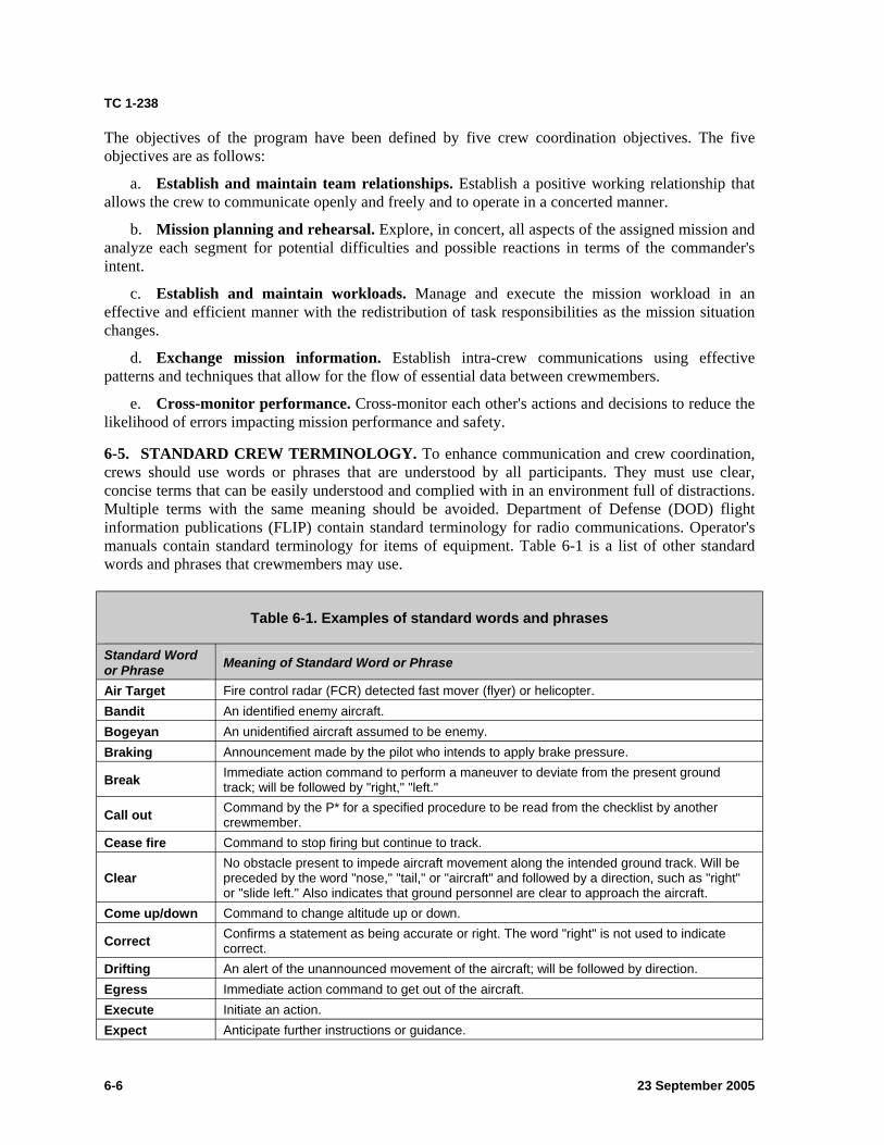
TC 1-238
The objectives of the program have been defined by five crew coordination objectives. The five objectives are as follows:
a. Establish and maintain team relationships. Establish a positive working relationship that allows the crew to communicate openly and freely and to operate in a concerted manner.
b. Mission planning and rehearsal. Explore, in concert, all aspects of the assigned mission and analyze each segment for potential difficulties and possible reactions in terms of the commander's intent.
c. Establish and maintain workloads. Manage and execute the mission workload in an effective and efficient manner with the redistribution of task responsibilities as the mission situation changes.
d. Exchange mission information. Establish intra-crew communications using effective patterns and techniques that allow for the flow of essential data between crewmembers.
e. Cross-monitor performance. Cross-monitor each other's actions and decisions to reduce the likelihood of errors impacting mission performance and safety.
6-5. STANDARD CREW TERMINOLOGY. To enhance communication and crew coordination, crews should use words or phrases that are understood by all participants. They must use clear, concise terms that can be easily understood and complied with in an environment full of distractions. Multiple terms with the same meaning should be avoided. Department of Defense (DOD) flight information publications (FLIP) contain standard terminology for radio communications. Operator's manuals contain standard terminology for items of equipment. Table 6-1 is a list of other standard words and phrases that crewmembers may use.
Standard Word or Phrase Meaning of Standard Word or Phrase
Air Target Fire control radar (FCR) detected fast mover (flyer) or helicopter. An identified enemy aircraft. An unidentified aircraft assumed to be enemy. Announcement made by the pilot who intends to apply brake pressure.
Table 6-1. Examples of standard words and phrases
Clear
Bandit Bogeyan Braking
Break
Call out
Cease fire
Come up/down
Correct correct. Drifting An alert of the unannounced movement of the aircraft; will be followed by direction. Egress Immediate action command to get out of the aircraft. Execute Initiate an action. Expect Anticipate further instructions or guidance.
No obstacle present to impede aircraft movement along the intended ground track. Will be preceded by the word "nose," "tail," or "aircraft" and followed by a direction, such as "right" or "slide left." Also indicates that ground personnel are clear to approach the aircraft.
Immediate action command to perform a maneuver to deviate from the present ground track; will be followed by "right," "left." Command by the P* for a specified procedure to be read from the checklist by another crewmember. Command to stop firing but continue to track.
Command to change altitude up or down. Confirms a statement as being accurate or right. The word "right" is not used to indicate
23 September 2005 6-6
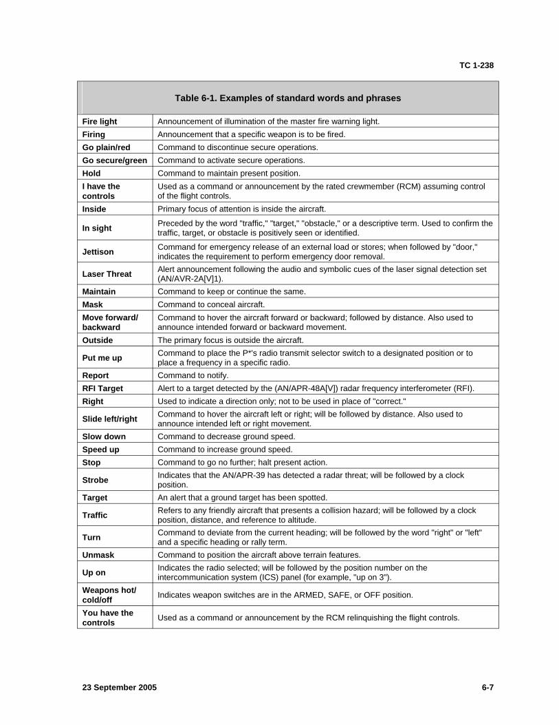
TC 1-238
Table 6-1. Examples of standard words and phrases
Fire light Announcement of illumination of the master fire warning light. Firing Announcement that a specific weapon is to be fired. Go plain/red Command to discontinue secure operations. Go secure/green Command to activate secure operations. Hold Command to maintain present position. I have the Used as a command or announcement by the rated crewmember (RCM) assuming control controls of the flight controls. Inside Primary focus of attention is inside the aircraft.
In sight Preceded by the word "traffic," "target," "obstacle," or a descriptive term. Used to confirm the traffic, target, or obstacle is positively seen or identified.
Jettison Command for emergency release of an external load or stores; when followed by "door," indicates the requirement to perform emergency door removal.
Laser Threat Alert announcement following the audio and symbolic cues of the laser signal detection set (AN/AVR-2A[V]1).
Maintain Command to keep or continue the same. Mask Command to conceal aircraft. Move forward/ Command to hover the aircraft forward or backward; followed by distance. Also used to backward announce intended forward or backward movement. Outside The primary focus is outside the aircraft.
Put me up Command to place the P*'s radio transmit selector switch to a designated position or to place a frequency in a specific radio.
Report Command to notify. RFI Target Alert to a target detected by the (AN/APR-48A[V]) radar frequency interferometer (RFI). Right Used to indicate a direction only; not to be used in place of "correct."
Slide left/right Command to hover the aircraft left or right; will be followed by distance. Also used to announce intended left or right movement.
Slow down Command to decrease ground speed. Speed up Command to increase ground speed. Stop Command to go no further; halt present action.
Strobe Indicates that the AN/APR-39 has detected a radar threat; will be followed by a clock position.
Target An alert that a ground target has been spotted.
Traffic Refers to any friendly aircraft that presents a collision hazard; will be followed by a clock position, distance, and reference to altitude.
Turn Command to deviate from the current heading; will be followed by the word "right" or "left" and a specific heading or rally term.
Unmask Command to position the aircraft above terrain features.
Up on Indicates the radio selected; will be followed by the position number on the intercommunication system (ICS) panel (for example, "up on 3").
Weapons hot/ cold/off Indicates weapon switches are in the ARMED, SAFE, or OFF position.
You have the controls Used as a command or announcement by the RCM relinquishing the flight controls.
23 September 2005 6-7

This page intentionally left blank.
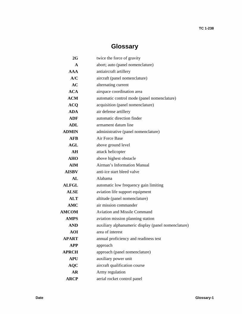
TC 1-238
Glossary
2G twice the force of gravity A abort; auto (panel nomenclature)
AAA antiaircraft artillery A/C aircraft (panel nomenclature) AC alternating current
ACA airspace coordination area ACM automatic control mode (panel nomenclature) ACQ acquisition (panel nomenclature) ADA air defense artillery ADF automatic direction finder ADL armament datum line
ADMIN administrative (panel nomenclature) AFB Air Force Base AGL above ground level
AH attack helicopter AHO above highest obstacle AIM Airman’s Information Manual
AISBV anti-ice start bleed valve AL Alabama
ALFGL automatic low frequency gain limiting ALSE aviation life support equipment
ALT altitude (panel nomenclature) AMC air mission commander
AMCOM Aviation and Missile Command AMPS aviation mission planning station
AND auxiliary alphanumeric display (panel nomenclature) AOI area of interest
APART annual proficiency and readiness test APP approach
APRCH approach (panel nomenclature) APU auxiliary power unit AQC aircraft qualification course
AR Army regulation ARCP aerial rocket control panel
Date Glossary-1
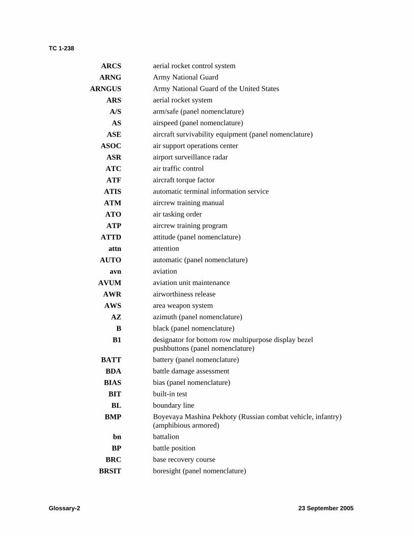
TC 1-238
ARCS aerial rocket control system ARNG Army National Guard
ARNGUS Army National Guard of the United States ARS aerial rocket system A/S arm/safe (panel nomenclature) AS airspeed (panel nomenclature)
ASE aircraft survivability equipment (panel nomenclature) ASOC air support operations center
ASR airport surveillance radar ATC air traffic control ATF aircraft torque factor
ATIS automatic terminal information service ATM aircrew training manual ATO air tasking order ATP aircrew training program
ATTD attitude (panel nomenclature) attn attention
AUTO automatic (panel nomenclature) avn aviation
AVUM aviation unit maintenance AWR airworthiness release AWS area weapon system
AZ azimuth (panel nomenclature) B black (panel nomenclature)
B1 designator for bottom row multipurpose display bezel pushbuttons (panel nomenclature)
BATT battery (panel nomenclature) BDA battle damage assessment BIAS bias (panel nomenclature)
BIT built-in test BL boundary line
BMP Boyevaya Mashina Pekhoty (Russian combat vehicle, infantry) (amphibious armored)
bn battalion BP battle position
BRC base recovery course BRSIT boresight (panel nomenclature)
Glossary-2 23 September 2005
TC 1-238
BRT brightness (panel nomenclature) BRU boresight reticle unit
B/S boresight (panel nomenclature) BS backseat
BST boresight (panel nomenclature) BUCS backup control system
C Celsius C2 command and control
CAS close air support CBHK captive boresight harmonization kit
CBI computer-based instruction CBRN chemical, biological, radiological, and nuclear
CCA close combat attack CCM counter-countermeasure CCW counter clockwise CDU computer display unit
CG center of gravity CHAN missile channel (panel nomenclature)
CIC combat information center CL(s) checklist(s) CMS combat mission simulator
CMSL copilot missile (panel nomenclature) col column
COMDTINST Commandant, United States Coast Guard Instruction COMSEC communications security CONFIG configuration (panel nomenclature)
CONT continuous (panel nomenclature); contrast (panel nomenclature) CONUS continental United States COORD coordinate (panel nomenclature)
COPTER helicopter CPG copilot-gunner
CPOS computed present position CRKT copilot rocket
CRS course C/S call sign
CSC communication system control CTL commander’s task list
23 September 2005 Glossary-3
TC 1-238
CTRLM control measure CW continuous wave (panel nomenclature)
D day DA Department of the Army
DAFIF digital aeronautical flight information file DAP display adjust panel
DASC direct air support center DASE digital automatic stabilization equipment
DC District of Columbia DD Department of Defense (form) DE dual engine (panel nomenclature)
DECU digital electronic control unit DEG degree DEK data entry keyboard DEU display electronics unit
DFLT default (panel nomenclature) DGNS Doppler global positioning navigation system
DH decision height DIR direct (panel nomenclature)
DLAI Defense Logistics Agency Instruction DLQ deck landing qualification DMS data management system DNS Doppler navigation system DOD Department of Defense
DP display processor DS day system
DSN Defense Switched Network DSPL display (panel nomenclature) DTC data transfer cartridge DTR data transfer receptacle DTU data transfer unit (panel nomenclature) DTV day television DVO direct view optics
E3 electromagnetic environment effects ECS environmental control system ECU electronic control unit
ED edit (panel nomenclature)
Glossary-4 23 September 2005
TC 1-238
EGI embedded global positioning inertial navigation system EL elevation (panel nomenclature)
ELA en route low altitude elev elevation
ELVA emergency low visibility approach EMERG emergency (panel nomenclature)
ENG/ENG1/ENG2 engine/engine 1/engine 2 EO electrooptical
EPE estimated position error ERFS extended range fuel system
ETA estimated time of arrival etc. et cetera
ETE estimated time en route ETF engine torque factor ETL effective translational lift eval evaluation
EVE estimated vertical error EWO electronic warfare officer
F front seat FAA Federal Aviation Administration FAB fixed action button (panel nomenclature) FAC flight activity code FAF final approach fix FAH final attack heading FAR Federal Aviation Regulation
FARP forward arming and refueling point FAT free air temperature FCC fire control computer FCP fire control panel FCR fire control radar FDC fire direction center
FD/LS fault detection/location system FIH Flight Information Handbook
FLIP flight information publication FLIR forward-looking infrared FLT flight FM field manual
23 September 2005 Glossary-5
TC 1-238
FOD foreign object damage FOM figure of merit (panel nomenclature) FOR field of regard FOV field of view
FPLN flight plan (panel nomenclature) FPM feet per minute FPV flight path vector
FT feet (panel nomenclature) FWD forward (panel nomenclature) FXD fixed (panel nomenclature)
G force of gravity; gravity GA Georgia
GCA ground controlled approach GHS gunner helmet sight (panel nomenclature) GND ground (panel nomenclature) GPS global positioning system
GPS NAV global positioning system navigation Gs force of gravity (32.2 feet per second) GS ground speed
GTL gun target line GWT gross weight (panel nomenclature)
H hood (used to indicate instrument condition tasks) HAD high-action display HAL height above landing
HARM harmonization (panel nomenclature) HARS heading attitude reference system
HAS hover augmentation system HBCM hover bias calibration mode
HCO helicopter control officer HCS helicopter control station HDC helicopter dibection center HDD heads down display HDU helmet display unit
HE high explosive HEDP high explosive/dual purpose
Hg mercury HI high (panel nomenclature)
Glossary-6 23 September 2005
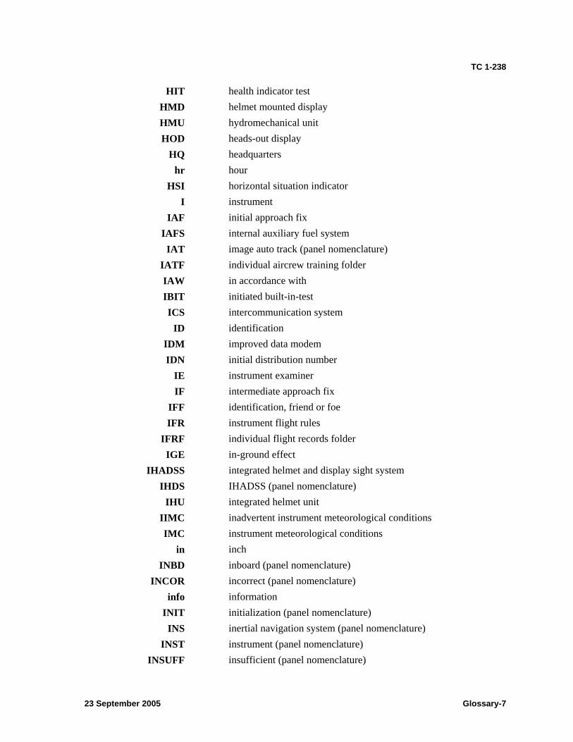
TC 1-238
HIT health indicator test HMD helmet mounted display HMU hydromechanical unit HOD heads-out display
HQ headquarters hr hour
HSI horizontal situation indicator I instrument
IAF initial approach fix IAFS internal auxiliary fuel system
IAT image auto track (panel nomenclature) IATF individual aircrew training folder IAW in accordance with IBIT initiated built-in-test ICS intercommunication system
ID identification IDM improved data modem IDN initial distribution number
IE instrument examiner IF intermediate approach fix
IFF identification, friend or foe IFR instrument flight rules
IFRF individual flight records folder IGE in-ground effect
IHADSS integrated helmet and display sight system IHDS IHADSS (panel nomenclature)
IHU integrated helmet unit IIMC inadvertent instrument meteorological conditions IMC instrument meteorological conditions
in inch INBD inboard (panel nomenclature)
INCOR incorrect (panel nomenclature) info information
INIT initialization (panel nomenclature) INS inertial navigation system (panel nomenclature)
INST instrument (panel nomenclature) INSUFF insufficient (panel nomenclature)
23 September 2005 Glossary-7
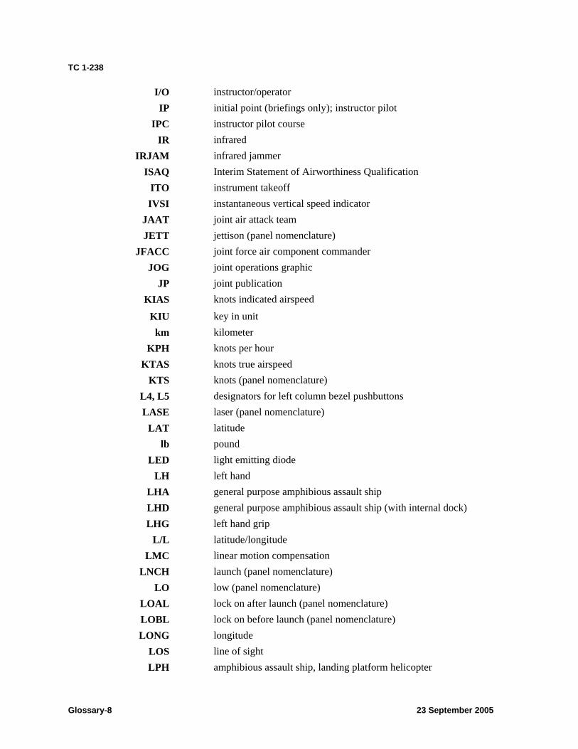
TC 1-238
I/O instructor/operator IP initial point (briefings only); instructor pilot
IPC instructor pilot course IR infrared
IRJAM infrared jammer ISAQ Interim Statement of Airworthiness Qualification
ITO instrument takeoff IVSI instantaneous vertical speed indicator
JAAT joint air attack team JETT jettison (panel nomenclature)
JFACC joint force air component commander JOG joint operations graphic
JP joint publication KIAS knots indicated airspeed
KIU key in unit km kilometer
KPH knots per hour KTAS knots true airspeed
KTS knots (panel nomenclature) L4, L5 designators for left column bezel pushbuttons LASE laser (panel nomenclature)
LAT latitude lb pound
LED light emitting diode LH left hand
LHA general purpose amphibious assault ship LHD general purpose amphibious assault ship (with internal dock) LHG left hand grip
L/L latitude/longitude LMC linear motion compensation
LNCH launch (panel nomenclature) LO low (panel nomenclature)
LOAL lock on after launch (panel nomenclature) LOBL lock on before launch (panel nomenclature) LONG longitude
LOS line of sight LPH amphibious assault ship, landing platform helicopter
Glossary-8 23 September 2005
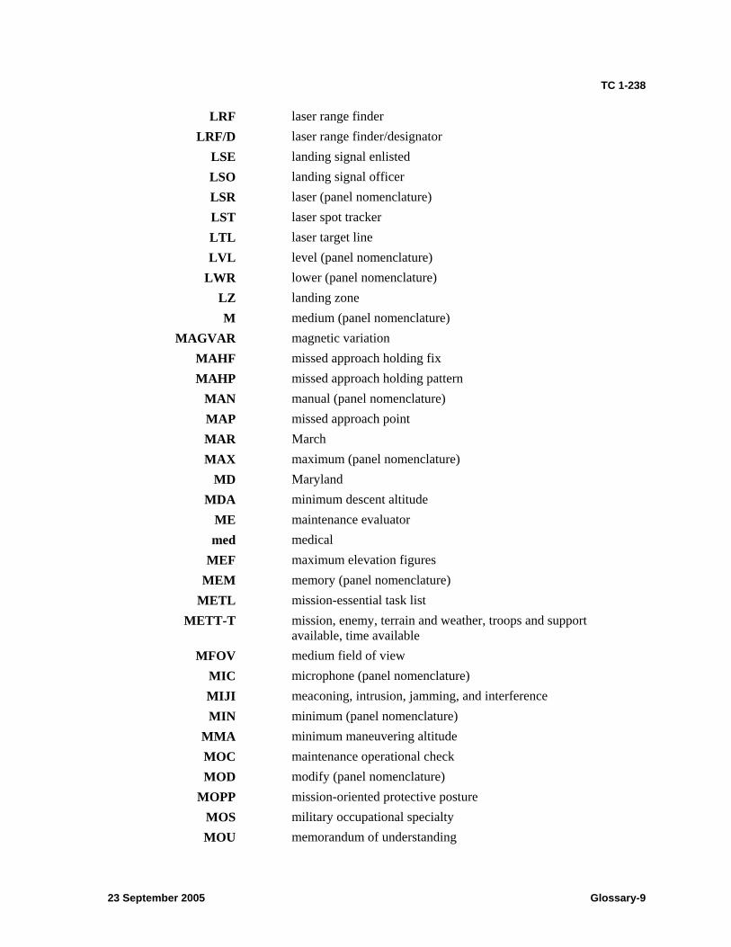
TC 1-238
LRF laser range finder LRF/D laser range finder/designator
LSE landing signal enlisted LSO landing signal officer LSR laser (panel nomenclature) LST laser spot tracker LTL laser target line LVL level (panel nomenclature)
LWR lower (panel nomenclature) LZ landing zone M medium (panel nomenclature)
MAGVAR magnetic variation MAHF missed approach holding fix MAHP missed approach holding pattern
MAN manual (panel nomenclature) MAP missed approach point MAR March MAX maximum (panel nomenclature)
MD Maryland MDA minimum descent altitude
ME maintenance evaluator med medical
MEF maximum elevation figures MEM memory (panel nomenclature)
METL mission-essential task list METT-T mission, enemy, terrain and weather, troops and support
available, time available MFOV medium field of view
MIC microphone (panel nomenclature) MIJI meaconing, intrusion, jamming, and interference MIN minimum (panel nomenclature)
MMA minimum maneuvering altitude MOC maintenance operational check MOD modify (panel nomenclature)
MOPP mission-oriented protective posture MOS military occupational specialty MOU memorandum of understanding
23 September 2005 Glossary-9
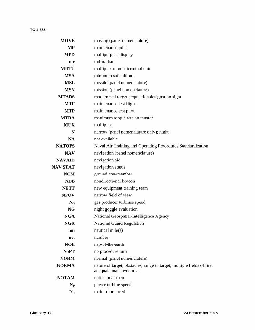
TC 1-238
MOVE moving (panel nomenclature) MP maintenance pilot
MPD multipurpose display mr milliradian
MRTU multiplex remote terminal unit MSA minimum safe altitude MSL missile (panel nomenclature) MSN mission (panel nomenclature)
MTADS modernized target acquisition designation sight MTF maintenance test flight MTP maintenance test pilot
MTRA maximum torque rate attenuator MUX multiplex
N narrow (panel nomenclature only); night NA not available
NATOPS Naval Air Training and Operating Procedures Standardization NAV navigation (panel nomenclature)
NAVAID navigation aid NAV STAT navigation status
NCM ground crewmember NDB nondirectional beacon
NETT new equipment training team NFOV narrow field of view
NG gas producer turbines speed NG night goggle evaluation
NGA National Geospatial-Intelligence Agency NGR National Guard Regulation
nm nautical mile(s) no. number
NOE nap-of-the-earth NoPT no procedure turn
NORM normal (panel nomenclature) NORMA nature of target, obstacles, range to target, multiple fields of fire,
adequate maneuver area NOTAM notice to airmen
NP power turbine speed NR main rotor speed
Glossary-10 23 September 2005
TC 1-238
NS night system evaluation requirement NVD night vision device NVG night vision goggle(s) NVS night vision system
NWP naval warfare publication OAT outside air temperature
OCONUS outside the continental United States OGE out-of-ground effect
ops operations ORIDE override (panel nomenclature)
OROCA off route obstruction clearance altitude-CONUS ORT optical relay tube
ORTCA off route terrain clearance altitude-OCONUS OTA over the air
OUTBD outboard P pilot not on the controls
P* pilot on the controls PA pressure altitude
Pam pamphlet para paragraph PAS pressurized air system
PC pilot in command PERF performance (panel nomenclature)
PFE proficiency flight evaluation(s) PGM program (panel nomenclature)
PGUN pilot controls gun PH probability of hit
PHS pilot helmet sight PI pilot
PLGR precise lightweight global positioning system receiver PLRT polarity (panel nomenclature)
PLT pilot PNVS pilot night vision system
POI program of instruction PPC performance planning card
PPOS present position PPS precise positioning service
23 September 2005 Glossary-11

TC 1-238
PRIFLY primary flight control PSI pounds per square inch
PTO power takeoff PTWS point target weapons system
Pub publication PWR power (panel nomenclature)
Q torque QTY quantity (panel nomenclature)
R rockets R6 designator for right column bezel pushbuttons
RAM random access memory R/C rate of climb
RCD/RCDR recorder (panel nomenclature) RCI rate of climb indicator
RCM rated crewmember REC record (panel nomenclature) REM remaining (panel nomenclature) REV reverse (panel nomenclature)
RF radio frequency (panel nomenclature) RFD range finder designator RFI radar frequency interferometer RH right hand
RHE remote hellfire electronics RHG right-hand grip RIPL ripple (panel nomenclature)
RJAM radar jammer RKT rocket (panel nomenclature)
RL readiness level RLWR radar laser warning receiver RNDS rounds (panel nomenclature)
RNG range ROC required obstacle clearance ROE rules of engagement RPM revolutions per minute RPT report (panel nomenclature) RTR rotor (panel nomenclature)
RWND rewind (panel nomenclature)
Glossary-12 23 September 2005

TC 1-238
S standardization flight evaluation SA situational awareness
SAL semiactive laser SALUTE size, activity, location, unit, time, and equipment
SAM surface-to-air missile SAS stability augmentation subsystem SAT systems approach to training
SC scale (panel nomenclature) SCAS stability and command augmentation system
SDC signal data converter SE single engine
SEAD suppression of enemy air defenses SEL select (panel nomenclature) SEP September SEU sight electronics unit
SINCGARS single channel ground and airborne radio set SKR seeker (panel nomenclature)
SM simulator (aviator base task list only); statue miles; visibility minimum
SOI signal operation instructions SOP standing operating procedure
SP standardization instructor pilot SP1/SP2 system processor 1 or 2
SPAD shear-pin-actuated decoupler SPC space (panel nomenclature) SPS standard positioning system
ST store (panel nomenclature) STANAG standardization agreement
STAT status (panel nomenclature) STBY standby (panel nomenclature)
SV satellite vehicle SYM symbol (panel nomenclature)
SYNC synchronization (panel nomenclature) TACP tactical air control party TADS target acquisition and designation sight
TAS true airspeed TB technical bulletin
23 September 2005 Glossary-13
TC 1-238
TC training circular TDZE touch down zone
TED trailing edge down TERPS United States Standards for Terminal Instrument Procedures
TESS tactical engagement simulation system TEU target acquisition and designation sight electronics unit TGT target (panel nomenclature only); turbine gas temperature TKA track angle TKR tracker (panel nomenclature)
TM technical manual T/O takeoff (DA Form 5701-64-R) TO takeoff (panel nomenclature)
TOF time of flight TOT time on target
TPM-R technique, pattern/attack direction, munitions, range TQ torque (panel nomenclature) TR torque ratio
TRADOC United States Army Training and Doctrine command TRANS transfer (panel nomenclature)
TRIG trigger (panel nomenclature) TRP target reference point TSD tactical situation display
TSOP tactical standing operating procedure TTT time to target
UDM user data module UNICOM universal communications
UNVER unverified (panel nomenclature) UPD/UPDT update (panel nomenclature)
UPR upper (panel nomenclature) U.S. United States
USAASA United States Army Aeronautical Services Agency USAASD-E United States Army Aeronautical Services Detachment-Europe USAAVNC United States Army Aviation Center
USAF United States Air Force USAR United States Army Reserve USCG United States Coast Guard USMC United States Marine Corps
Glossary-14 23 September 2005
TC 1-238
USN UT
UTIL UTM VAB VDU VER VFR
Vh VID
VMC Vne
VOX VSI
VSSE
W
WAS WASd’ WFOV
WGS-84 WP
WPN WPT
WPTHZ WT
XFER XMSN
Z ZFOV
United States Navy unit trainer utility (panel nomenclature) universal transverse mercator variable action button visual display unit verified (panel nomenclature) visual flight rules velocity, horizontal video (panel nomenclature) visual meteorological conditions velocity not to exceed voice operated transmitter vertical speed indicator velocity safe single-engine
white; wide (panel nomenclature), weather (used to indicate instrument condition tasks) weapons action switch weapon action select wide field of view World Geodetic System 1984 weapons processor weapon (panel nomenclature) waypoint (panel nomenclature) waypoint hazard weight transfer (panel nomenclature) transmission zoom (panel nomenclature) zoom field of view
23 September 2005 Glossary-15

This page intentionally left blank.
TC 1-238
References
SOURCES USED Sources quoted or paraphrased in this publication.
ARMY REGULATIONS
AR 95-10. Department of Defense (DOD) Notice to Airmen (NOTAM) System. 1 January 1997. AR 600-106. Flying Status for Nonrated Army Aviation Personnel. 8 December 1998.
DEPARTMENT OF DEFENSE AIRMAN'S INFORMATION MANUAL
DOD AIM 86-100. Operation and Maintenance Overview General Triservice Mode 4 Handbook. May 1987.
This publication is available from Commanding Officer, ATTN: Code 2111, Naval Electronic Systems Engineering Activity, St. Inigoes, MD 20684-0010, or WR-ALC/MMAM-AIMS, ATTN: DOD AIMSPO, Robins AFB, Georgia 31098-5609.
ELECTRONIC TECHNICAL MANUAL
EM 0061. Helicopter, Apache, AH 64-Series. 1 May 2005.
FIELD MANUALS
FM 3-04.111 (FM 1-111). Aviation Brigades. 21 August 2003. FM 3-04.300 (FM 1-300). Flight Operations Procedures. 26 April 2004 FM 3-3. Chemical and Biological Contamination Avoidance. 16 November 1992. FM 3-3-1. Nuclear Contamination Avoidance. 9 September 1994 (will be revised as FM 3-11.3). FM 3-11 (FM 3-100). Multiservice Tactics, Techniques, and Procedures for Nuclear, Biological,
and Chemical Defense Operations. 10 March 2003. FM 3-11.4 (FM 3-4). Multiservice Tactics, Techniques, and Procedures for Nuclear, Biological,
and Chemical (NBC) Protection. 2 June 2003. FM 3-25.26 (FM 21-26). Map Reading and Land Navigation. 20 July 2001. FM 6-02.72 (FM 11-1). Tactical Radios Communications Procedures for Tactical Radios in a
Joint Environment. 14 June 2002. FM 7-1 (FM 25-101). Battle Focused Training. 15 September 2003. FM 10-67-1 (FM 10-68). Concepts and Equipment of Petroleum Operations. 2 April 1998 (will
be revised as FM 4-20.12). FM 17-95. Cavalry Operations. 24 December 1996 (will be revised as FM 3-20.95). FM 21-31. Topographical Symbols. 19 June 1961 (will be revised as FM 3-34.31). FM 21-60. Visual Signals. 30 September 1987 (will be revised as FM 3-21.60).
INTERNATIONAL STANDARDIZATION AGREEMENT
STANAG 3114 AMD (Edition Seven). Aeromedical Training of Flight Personnel. 22 May 2003.
NONMILITARY PUBLICATION
Aeronautical Information Manual: Official Guide to Basic Flight Information and ATC Procedures. 17 February 2005.
23 September 2005 References-1
TC 1-238
This publication is available from the FAA at http://www.faa.gov/atpubs.
TECHNICAL BULLETIN
TB MED 524. Occupational and Environmental Health: Control of Hazards to Health From Laser Radiation. 20 June 1985.
TECHNICAL MANUALS
TM 1-1500-328-23. Aeronautical Equipment Maintenance Management Policies and Procedures. 30 July 1999.
TM 1-1520-238-CL. Operator's Checklist for Helicopter, Attack, AH-64A Apache. 31 August 1994.
TM 1-1520-238-10. Operator's Manual for Helicopter, Attack, AH-64A Apache. 31 August 1994. TM 1-1520-251-MTF. Maintenance Test Flight Manual for Helicopter, Attack, AH-64D
Longbow Apache. 15 March 1998. TM 1-2840-248-23. Aviation Unit and Intermediate Maintenance Manual for Engine, Aircraft
Turboshaft; Models T700-GE-700, T700-GE-701, T700-GE-701C. 1 June 1999. TM 11-5810-262-10. Operator’s Manual for Speech Security Equipment KY-58 (NSN 5810-00-
449-0154). 31 May 1990. TM 11-5841-281-12. Operator's and Organizational Maintenance Manual for Doppler
Navigation Set, AN/ASN-128 (NSN 5841-01-064-9738) (EIC: JK4). 30 May 1979. TM 11-5841-283-12. Aviation Unit Maintenance Manual for Radar Signal Detecting Set,
AN/APR-39(V) (NSN 5841-01-023-7112). 9 August 1983. TM 11-5855-263-10. Operator's Manual for Aviator's Night Vision Imaging System (ANVIS),
AN/AVS-6(V)1 (NSN 5855-01-138-4749) (EIC: IPR) and AN/AVS-6(V)2 (NSN 5855-01-138-4748) (EIC: IPQ), AN/AVS-6(V)1A (5855-01-439-1745) (EIC: IPW). 1 February 2004.
TM 11-5865-200-12. Operator's and Aviation Unit Maintenance Manual for Aviation Unit Maintenance (AVUM) Countermeasures Sets, AN/ALQ-144A(V)1 (NSN 5865-01-299-5859) and AN/ALQ-144(V)3 (5865-01-299-5860). 15 March 2002.
TM 11-5865-202-12. Operator's and Aviation Unit Maintenance Manual for Countermeasures Set, AN/ALQ-136(V)1 (NSN 5865-01-127-6880), AN/ALQ-136(V)5 (5865-01-186-9130). 1 August 1986.
TM 11-5895-1199-12. Operator's and Organizational Maintenance for Mark-XII IFF System. 1 July 1984.
TM 55-1500-342-23. Army Aviation Maintenance Engineering Manual for Weight and Balance. 29 August 1986.
DOCUMENTS NEEDED These documents must be available to the intended users of this publication.
ARMY REGULATIONS
*AR 40-8. Temporary Flying Restrictions Due to Exogenous Factors. 17 August 1976. *AR 95-1. Flight Regulations. 1 September 1997. *AR 95-2. Air Traffic Control, Airspace, Airfields, Flight Activities, and Navigational Aids.
10 August 1990. AR 95-20. Contractor’s Flight and Ground Operations. 13 November 2002.
*This source was also used to develop this publication.
References-2 23 September 2005

TC 1-238
*AR 600-105. Aviation Service of Rated Army Officers. 15 December 1994. AR 700-138. Army Logistics Readiness and Sustainability. 26 February 2004.
DEPARTMENT OF THE ARMY FORMS
DA Form 2028. Recommended Changes to Publications and Blank Forms.DA Form 2408-12. Army Aviator's Flight Record. DA Form 2408-13. Aircraft Status Information Record. DA Form 2408-13-1. Aircraft Maintenance and Inspection Record.DA Form 2408-13-2. Related Maintenance Actions Record. DA Form 2408-14-1. Uncorrected Fault Record (Aircraft). DA Form 2408-18. Equipment Inspection List.DA Form 4186. Medical Recommendation for Flying Duty.DA Form 5484-R. Mission Schedule/Brief. DA Form 5701-64-R. AH-64 Performance Planning Card. DA Form 7120-R. Commander’s Task List.
DEPARTMENT OF THE ARMY PAMPHLETS
DA Pam 350-38. Standards in Weapons Training. 1 October 2002. *DA Pam 738-751. Functional Users Manual for the Army Maintenance Management System-
Aviation (TAMMS-A). 15 March 1999.
DEPARTMENT OF DEFENSE FLIGHT INFORMATION PUBLICATION
Department of Defense Flight Information Handbook. 14 April 2005. DOD FLIPs are available from Director, US Army Aeromedical Services Agency, ATTN:
ATAS-AI, 9325 Gunston Road, Suite N319, Fort Belvoir, VA 22060-5582. This publication is available from the NGA at http://164.214.2.62/products/digitalaero/index.html.
DEPARTMENT OF DEFENSE FORMS
DD Form 365-4. Weight and Balance Clearance Form F-Transport/Tactical.DD Form 1972. Joint Tactical Air Strike Request.
FEDERAL AVIATION ADMINISTRATION PUBLICATIONS
Airman's Information Manual FAR Part 91. General Operating and Flight Rules. March 1974. Available from Director, US Army Aeronautical Services Agency, ATTN: MOAS-AI, Cameron
Station, Alexandria, Virginia 22304-5050. Aviation Instructor Pilot Handbook, AC 60-14. Note: AC 60-14 is issued to all U.S. Army IP students with a USAAVNC cover and Aviation
Training Brigade listed as the proponent. FAA Handbook 8260.3. Terminal Instrument Procedures (TERPS) Handbook. FAA Order 7130.3. Holding. FAA Order 8460.42A. Helicopter Global Positioning System Nonprecision Approach Criteria.
23 September 2005 References-3

TC 1-238
FIELD MANUALS
*FM 1-100. Army Aviation Operations. 21 February 1997 (will be revised as FM 3-04.100). *FM 1-112. Attack Helicopter Operations. 2 April 1997 (will be revised as FM 3-04.112). *FM 1-114. Air Cavalry Squadron and Troop Operations. 1 February 2000 (will be revised as
FM 3-04.114). *FM 1-202. Environmental Flight. 23 February 1983 (will be revised as FM 3-04.202). *FM 1-203. Fundamentals of Flight. 3 October 1988 (will be revised as FM 3-04.203). *FM 1-230. Meteorology for Army Aviators. 30 September 1982 (will be revised as FM 3-
04.230). *FM 1-240. Instrument Flying and Navigation for Army Aviators. 15 December 1984 (will be
revised as FM 3-04.240). *FM 1-400. Aviator's Handbook. 31 May 1983 (will be revised as FM 3-04.400). *FM 1-564. Shipboard Operations. 29 June 1997 (will be revised as FM 3-04.564). *FM 3-04.140 (FM 1-140). Helicopter Gunnery. 14 July 2003. *FM 3-04.301 (FM 1-301). Aeromedical Training for Flight Personnel. 29 September 2000. FM 3-04.500 (FM 1-500). Army Aviation Maintenance. 26 September 2000. *FM 3-04.508 (FM 1-508). Aviation Life Support System Maintenance Management and
Training Programs. 23 April 2004. *FM 3-04.513 (FM 1-513). Battlefield Recovery and Evacuation of Aircraft. 27 September 2000. FM 3-09.32. (J-Fire) Multiservice Procedures for the Joint Application of Firepower. 29 October
2004. *FM 6-30. Tactics, Techniques, and Procedures for Observed Fire. 16 July 1991 (will be revised
as FM 3-09.3). *FM 90-21. (JAAT) Multi-Service Procedures for Joint Air Attack Team Operations. 3 June 1998
(will be revised as FM 3-09.33).
JOINT PUBLICATIONS
JP 3-04.1. Joint Tactics, Techniques and Procedures for Shipboard Helicopter Operations. 10 December 1997.
JP 3-09.3. Joint Tactics, Techniques, and Procedures for Close Air Support (CAS). 3 September 2003.
NATIONAL GUARD REGULATION
NGR 95-210. Army National Guard: General Provisions and Regulations for Aviation Training. 1 July 1991.
National Guard Bureau publications are available from Chief, National Guard Bureau, ATTN: NGB-DAY, Washington, DC 20310-2500.
OTHER PUBLICATIONS Aircraft logbook and historical records Applicable airworthiness directives or messages from Aviation and Missile Command
(AMCOM) Army Aviator’s Handbook for Maneuvering Flight and Power Management Current USAAVNC student handouts Federal Aviation Regulations (FARs)/host country regulations
References-4 23 September 2005
TC 1-238
Interim Statement of Airworthiness Qualification (ISAQ) Naval Warfare Publication (NWP)-42. Shipboard Helicopter Operating Procedures. 1 March
1993. New equipment training team (NETT) supplemental information Operator’s manual and checklist Safety flight bulletins Standing operating procedures Unit standing operating procedures
TECHNICAL MANUALS
TM 1-1270-476-30. Aviation Intermediate Maintenance Manual for Target Acquisition Designation Sight (TADS) Assembly AN/ASQ-170. 20 August 2001.
TM 1-1500-204-23-1. Aviation Unit Maintenance (AVUM) and Aviation Intermediate Maintenance (AVIM) Manual for General Aircraft Maintenance (General Maintenance and Practices) Volume 1. 31 July 1992.
TM 1-1500-204-23-2. Aviation Unit Maintenance (AVUM) and Aviation Intermediate Maintenance (AVIM) Manual for General Aircraft Maintenance (Pneudraulics Maintenance and Practices) Volume 2. 31 July 1992.
TM 1-1500-204-23-3. Aviation Unit Maintenance (AVUM) and Aviation Intermediate Maintenance (AVIM) Manual for General Aircraft Maintenance (Maintenance Practices for Fuel and Oil Systems) Volume 3. 31 July 1992.
TM 1-1500-204-23-4. Aviation Unit Maintenance (AVUM) and Aviation Intermediate Maintenance (AVIM) Manual for General Aircraft Maintenance (Electrical and Instrument Maintenance Procedures and Practices) Volume 4. 31 July 1992.
TM 1-1500-204-23-5. Aviation Unit Maintenance (AVUM) and Aviation Intermediate Maintenance (AVIM) Manual for General Aircraft Maintenance (Propeller, Rotor, and Powertrain Maintenance Practices) Volume 5. 31 July 1992.
TM 1-1500-204-23-6. Aviation Unit Maintenance (AVUM) and Aviation Intermediate Maintenance (AVIM) Manual for General Aircraft Maintenance (Hardware and Consumable Materials) Volume 6. 31 July 1992.
TM 1-1500-204-23-7. Aviation Unit Maintenance (AVUM) and Aviation Intermediate Maintenance (AVIM) Manual for General Aircraft Maintenance (Nondestructive Testing and Flaw Detection Procedures and Practices) Volume 7. 31 July 1992.
TM 1-1500-204-23-8. Aviation Unit Maintenance (AVUM) and Aviation Intermediate Maintenance (AVIM) Manual for General Aircraft Maintenance (Machine and Welding Shop Practices) Volume 8. 31 July 1992.
TM 1-1500-204-23-9. Aviation Unit Maintenance (AVUM) and Aviation Intermediate Maintenance (AVIM) Manual for General Aircraft Maintenance (Tools and Ground Support Equipment) Volume 9. 31 July 1992.
TM 1-1500-204-23-10. Aviation Unit Maintenance (AVUM) and Aviation Intermediate Maintenance (AVIM) Manual for General Aircraft Maintenance (Sheet Metal Shop Practices) Volume 10. 31 July 1992.
TM 1-1520-238-MTF. Maintenance Test Flight Manual for Helicopter, Attack, AH-64A Apache. 31 August 1994.
23 September 2005 References-5
TC 1-238
TM 1-1520-238-T-1. Aviation Unit Maintenance Manual for Army AH-64A Helicopter, (NSN 1520-01-106-9519) (EIC: RHA) Fault Detection/Location System. 31 March 1992.
TM 1-1520-238-T-2. Aviation Unit and Intermediate Troubleshooting Manual for Army Model AH64A Helicopter (NSN 1520-01-106-9519) (EIC: RHA) Master Failure Symptom Index. 31 August 1992.
TM 1-1520-238-T-3. Aviation Unit Maintenance Manual for Army Model AH-64A Helicopter (NSN 1520-01-106-9519) (EIC: RHA) Multiplex Read Codes.30 April 1992.
TM 1-1520-238-T-4. Aviation Unit and Intermediate Troubleshooting Manual for Army Model AH64A Helicopter (NSN 1520-01-106-9519) (EIC: RHA). 30 April 1992.
TM 1-1520-238-T-5. Aviation Unit and Intermediate Troubleshooting Manual for Army Model AH64A Helicopter (NSN 1520-01-106-9519) (EIC: RHA). 30 April 1992.
TM 1-1520-238-T-6. Aviation Unit and Intermediate Troubleshooting Manual for Army Model AH64A Helicopter (NSN 1520-01-106-9519) (EIC: RHA). 30 June 1992.
TM 1-1520-238-T-7. Aviation Unit and Intermediate Troubleshooting Manual for Army Model AH64A Helicopter (NSN 1520-01-106-9519) (EIC: RHA). 30 April 1992.
TM 1-1520-238-T-8. Aviation Unit and Intermediate Troubleshooting Manual for Army Model AH64A Helicopter (NSN 1520-01-106-9519) (EIC: RHA). 30 April 1992.
TM 1-1520-238-T-9. Aviation Unit and Intermediate Troubleshooting Manual for Army Model AH64A Helicopter (NSN 1520-01-106-9519) (EIC: RHA) Theory of Operation. 30 April 1992.
TM 1-1520-238-T-10. Aviation Unit and Intermediate Troubleshooting Manual for Army Model AH64A Helicopter (NSN 1520-01-106-9519) (EIC: RHA) Wiring Diagrams. 31 August 1992.
TM 1-1520-238-23-1. Aviation Unit and Intermediate Maintenance Manual for Volume 1 of 9 Helicopter, Attack, AH-64A Apache (NSN 1520-01-106-9519) (EIC: RHA). 16 May 1994.
TM 1-1520-238-23-2. Aviation Unit and Intermediate Maintenance Manual for Volume 2 of 9 Helicopter, Attack, AH-64A Apache (NSN 1520-01-106-9519) (EIC: RHA). 16 May 1994.
TM 1-1520-238-23-3. Aviation Unit and Intermediate Maintenance Manual for Volume 3 of 9 Helicopter, Attack, AH-64A Apache (NSN 1520-01-106-9519) (EIC: RHA). 16 May 1994.
TM 1-1520-238-23-4. Aviation Unit and Intermediate Maintenance Manual for Volume 4 of 9 Helicopter, Attack, AH-64A Apache (NSN 1520-01-106-9519) (EIC: RHA). 16 May 1994.
TM 1-1520-238-23-5. Aviation Unit and Intermediate Maintenance Manual for Volume 5 of 9 Helicopter, Attack, AH-64A Apache (NSN 1520-01-106-9519) (EIC: RHA). 16 May 1994.
TM 1-1520-238-23-6. Aviation Unit and Intermediate Maintenance Manual for Helicopter, Attack, AH-64A Apache (NSN 1520-01-106-9519) (EIC: RHA). 16 May 1994.
TM 1-1520-238-23-7-1. Aviation Unit and Intermediate Maintenance Manual for Helicopter, Attack, AH-64A Apache Apache (NSN 1520-01-106-9519) (EIC: RHA). 16 May 1994.
TM 1-1520-238-23-7-2. Aviation Unit and Intermediate Maintenance Manual for Helicopter, Attack, AH-64A Apache (NSN 1520-01-106-9519) (EIC: RHA). 16 May 1994.
TM 1-1520-238-23-8. Aviation Unit and Intermediate Maintenance Manual for Volume 8 of 9 Helicopter, Attack, AH-64A Apache (NSN 1520-01-106-9519) (EIC: RHA). 16 May 1994.
TM 1-1520-238-23-9. Aviation Unit and Intermediate Maintenance Manual for Volume 9 of 9 Helicopter, Attack, AH-64A Apache (NSN 1520-01-106-9519) (EIC: RHA). 16 May 1994.
TM 1-1520-238-23P-1. Aviation Unit and Intermediate Maintenance Repair Parts and Special Tools List for Helicopter, Attack, AH-64A Apache (NSN 1520-01-106-9519). 28 May 1996.
References-6 23 September 2005
TC 1-238
TM 1-1520-238-23P-2. Aviation Unit and Intermediate Maintenance Repair Parts and Special Tools List for Helicopter, Attack, AH-64A Apache (NSN 1520-01-106-9519). 28 May 1996.
TM 1-1520-238-23P-3. Aviation Unit and Intermediate Maintenance Repair Parts and Special Tools List for Helicopter, Attack, AH-64A Apache (NSN 1520-01-106-9519). 28 May 1996.
TM 1-1520-238-23P-4. Aviation Unit and Intermediate Maintenance Repair Parts and Special Tools List for Helicopter, Attack, AH-64A Apache (NSN 1520-01-106-9519). 24 April 2004.
TM 1-1520-238-23P-5. Aviation Unit and Intermediate Maintenance Repair Parts and Special Tools List for Helicopter, Attack, AH-64A Apache (NSN 1520-01-106-9519). 28 May 2004.
TM 1-5855-265-20. Aviation Unit Maintenance Manual for Pilot Night Vision Sensor (PNVS) Assembly AN/AAQ-11 (NSN 5855-01-120-7831) EIC (RHA) AN-64-A Attack Helicopter. 6 August 2001.
TM 1-6625-724-13&P. Operator's, Aviation Unit, and Intermediate Maintenance Manual Including Repair Parts and Special Tools List for Test Set, Aviation Vibration Analyzer (AVA) with Version 7.01 PN 29313107 (NSN 6625-01-282-3746). 3 July 2002.
TM 9-1230-476-30. Aviation Intermediate Maintenance Manual for Army AH-64A Helicopter, Fire Control System. 22 March 1985.
TM 9-1270-221-23. Aviation Unit and Intermediate Maintenance Manual for Fire Control Subsystem Helmet Directed: M142. 11 April 1991.
TM 11-5826-227-34. Direct Support and General Support Maintenance Manual: Direction Finder Sets AN/ARN-89 (NSN 5826-00-790-6453) and AN/ARN-89A (5826-00-151-2685), and AN/ARM-89B (5826-01-021-3289). 7 January 1971.
TM 11-5895-1184-23. Aviation Unit and Intermediate Maintenance Manual for Symbol Generator, MX-10465/ASQ (NSN 5820-01-172-2886). 1 July 1985.
TRAINING CIRCULARS *TC 1-201. Tactical Flight Procedures. 20 January 1984. *TC 1-204. Night Flight Techniques and Procedures. 27 December 1988. *TC 1-210. Aircrew Training Program Commander’s Guide to Individual and Crew
Standardization. 3 October 1995. TC 1-215. Aircrew Training Manual, Observation Helicopter, OH-58A/C and OH-6
Aviator/Aeroscout Observer. 2 March 1993.
U.S. NAVY AND COAST GUARD PUBLICATIONS
Commandant Instruction (COMDTINST) M3710.2 series. Naval Air Training and Operating Procedures Standardization (NATOPS) manuals
READINGS RECOMMENDED These readings contain relevant supplemental information.
FM 7-0 (FM 25-100). Training the Force. 22 October 2002. TM 11-5895-1632-10. Operator’s Manual for Improved Data Modem (IDM) MD-1295/A (NSN
5895-01-426-5318) (EIC: N/A). 1 October 2003.
23 September 2005 References-7

This page intentionally left blank.

academic evaluation topics, 3-3 after-action reviews, 6-5 checklist:
aircrew briefing, 4-8 continuation training, 2-3 crew coordination, 6-1 crew terminology, 6-6 crewmember evaluation, 3-2 cross-monitoring, 6-4 currency requirements, 2-9 decisionmaking techniques, 6-3 evaluation
debriefing, 3-8 evaluation principles, 3-1 evaluation sequence, 3-3 evaluators
selection of, 3-1 flight evaluation, 3-7
TC 1-238
Index grading considerations, 3-2 leadership, 6-2 mission training, 2-2 nuclear, biological, and chemical training, 2-10 performance task, 2-4 premission planning, 6-2 qualification training, 2-1 refresher training, 2-1 situational awareness, 6-4 statements and directives, 6-3 task conditions, 4-1 task description, 4-4 task list, 2-4 task standards, 4-2 technical task, 2-4 unexpected events, 6-3 workload distribution, 6-3
23 September 2005 Index-1

This page intentionally left blank.
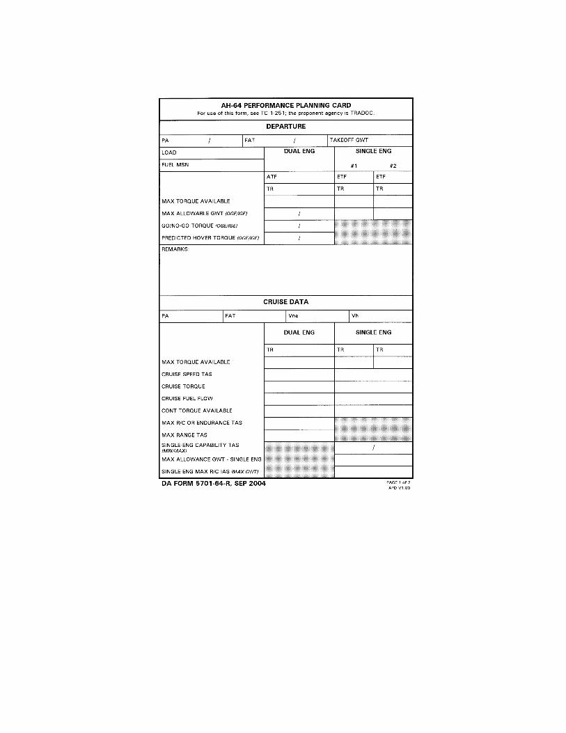

This page intentionally left blank.


This page intentionally left blank.
TC 1-238 23 September 2005
By order of the Secretary of the Army:
PETER J. SCHOOMAKER General, United States Army
Chief of Staff
Official:
SANDRA R. RILEY Administrative Assistant to the Secretary of the Army
0526503
DISTRIBUTION: Active Army, Army National Guard, and U.S. Army Reserve: To be distributed in accordance with the initial distribution number (IDN) 114621, requirements for TC 1-238.

This page intentionally left blank.


PIN: 082793-000