aircraft protection during washing and painting - skybrary · pdf fileduring washing and...
TRANSCRIPT

12 Safety first #17 | JANUARY 2014
Case Study n°1
What happened?An A320 performed a landing with the Nose Landing Gear (NLG) in a position of about 90° from the aircraft centreline (fig. 1). The aircraft landed safely and stopped on the runway. The NLG was damaged.
Why did it happen?Inspection of parts confirmed traces of water in the Nose Wheel Steering (NWS) feedback sensors and water ingress inside the NLG turning tube.
During the flight, the water froze and blocked the sensors. The sensors could therefore no longer provide the correct feedback on the NLG position. The Brake System Control Unit (BSCU) tried to align the NWS to the aircraft centreline. In absence of a correct feedback signal, the NWS was rotated further until the steering system was detected as faulty. The hydraulic supply to the steering system was shut-off, but the NWS was already at an almost 90° position from the centreline and could not be re-centred mechanically.
Aircraft Protection, during Washing and Painting
IntroductionNon-adherence to the correct aircraft wash-ing/cleaning and painting procedures regu-larly generate safety events.
This article will illustrate, through real in-ser-vice occurrences, that even activities per-formed primarily to improve the appearance of the aircraft and better display the airline logo may affect the safety of operations.
The lessons learnt from these events are com-mon: washing or painting an aircraft must be done according to the published procedures and using the correct equipment. These are specified in the Aircraft Maintenance Manual (AMM), Structure Repair Manual (SRM) and Tool and Equipment Manual (TEM).
Figure 1Water ingress in the NLG tube caused a A320
to land with a NLG at 90 ° from the centreline
Uwe EGGERLINGSenior Director SafetyEngineering & MaintenanceCustomer Services

13Safety first #17 | JANUARY 2014
Further investigation on the maintenance history revealed that the aircraft had a scheduled maintenance check just few flights prior to the reported event. During the check, the maintenance provider performed aircraft external cleaning using a high pressure jet device. Consequently, water entered into the NLG and feedback sensors through a vent hole located at the top of the NLG.
Lessons learnedPay special attention to the instructions and cautions requesting to use protective devices as required in the AMM procedures for external cleaning of the aircraft.
The instructions and cautions are applicable for all sensors and probes such as Angle of Attack sensors, pitot probes, temperature sensors, static probes, ice detection probes,…
In particular, do not use high pressure jets or vapour for cleaning. This type of equipment can force water and moisture into the parts and cause damage to them.
Case Study n°2
What happened?An aircraft was re-painted by a third party maintenance organisation. The operator discovered, before the aircraft
References:
– AMM 12-21-11 Page Block 301, “External Cleaning”
– AMM 32-11-00 Page Block 701, “Main Gear Cleaning / Painting”
– AMM 32-21-00 Page Block 701, “Nose Gear Cleaning / Painting”
– Operators Information Transmission (OIT), ref. 999.0067/13, dated 26 Sep 2013
Subject: ATA 34 – Protection of Angle of Attack (AoA) sensors during aircraft exterior cleaning. This OIT reminds operators of the AoA sensor protection to be used during aircraft exterior cleaning and the importance of respecting this guidance.
– Operator Information Transmission (OIT), ref. SE 999.0042/10, dated 06 May 2010
Subject: ATA 32 – Water ingress in nose wheel steering feedback sensors.
Figure 2A clear plastic film over the static ports was left on the aircraft
when it was handed back to the operator
was returned into service, that there was a clear plastic film over one of the static ports that was almost impossible to detect visually (fig. 2, 3 & 4).
If the clear plastic film had not been discovered and removed, it would have caused incorrect indications on the related cockpit instruments
Why did it happen?Inadequate protections were applied during aircraft painting in such a way that they were difficult to see from the ground. As a result, they were not removed after the painting job was done.
The transparent plastic was only noticed because of the presence of air bubbles under the film.
Lessons learnedFollow the AMM and SRM instructions for stripping, paint removal, cleaning and painting as summarised below:
Aircraft Maintenance Manual (AMM)
In AMM chapter 51-75-11 PB 701 – Stripping/paint removal – cleaning/ paint-ing, the following Warning and Caution are included:
– The “Caution” provides a list of ma-terials, areas, and parts for which a correct protection from chemical paint strippers are required. This list includes:Rubber, all composite parts, acrylic ma-terials, aerodynamic smoother, metal bonded edges, pitot tubes, sensors, static ports, engine air intake, pre-cooler air outlet screen, engine exhaust duct, APU exhaust, APU intakes and outlets, air conditioning ram air inlets, landing gears, door seals, access doors, cab-in window and windshield panels and seals, electrical equipment and cables, plastic materials, external ski panel joints, high strength steel parts, drain holes, vents, and all antennas.
14 Safety first #17 | JANUARY 2014
– The “Warning” notice highlights that adhesive tapes must not be applied on the probes, ducts, and sensors (static, pitot, TAT, AoA). Only specified tools should be used to seal the aircraft, which will ensure:
• Correct protection of the aircraft equipments
• Good visibility from the ground
• Ease of removal
The Warning notice also explains how the incomplete removal of tapes or tape adhesive from probes, ducts or sensors may lead to incorrect indications on the related cockpit instruments.
Tool and Equipment Manual (TEM)
The description of the protective equip-ments is given in the Tool and Equipment Manual (TEM)
Structure Repair Manual (SRM)
Chapter 51-75-11 contains recommen-dations for stripping and paint removal. The SRM provides also cautions in chap-ter 51-75-12, Repair of Paint Coatings, about the materials, areas and parts af-fected by the painting activities, which must be properly protected. A caution includes instructions to remove all mask-ing materials upon work completion, with a special attention to pitot heads and static ports.
Part No. 98D10103500001( FAPE3)
Designation COVER-STATIC PROBE
DescriptionThis tool is used to blank the static probes. Note: this tool is in the flight kit.
See drawings 98D10103500 COVER STATIC PROBE
ReferencesAMM 10-11-00 AMM 12-21-11 AMM 34-21-00
Figure 4Fig 4: TEM description of the static probe cover
ConclusionIn-service experience has taught us that even activities performed on the aircraft mainly for cosmetic reasons, like washing or painting, may have an impact on the safety of opera-tions.
The in-service incidents described in this article illustrate the need to care-fully follow the indicated instructions available in the Aircraft Maintenance Manual, Structure Repair Manual as well as Tool and Equipment Manual.
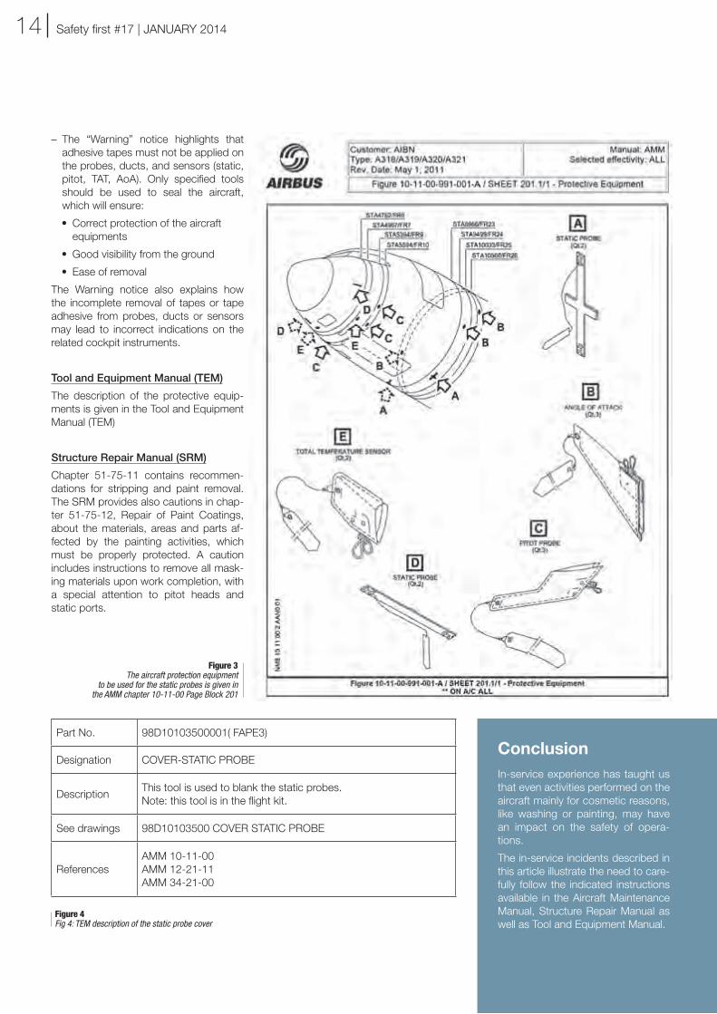
Figure 3The aircraft protection equipment
to be used for the static probes is given in the AMM chapter 10-11-00 Page Block 201