air power systems concept and theory - graco inc. power systems v2.pdf · air power systems concept...
TRANSCRIPT
Graco, Inc. P.O. Box 1441 Minneapolis, MN 55440-1441 ©1996 Graco Inc. Form No. 321-035 6/95 Rev 2 SL Training 11/14
Air Power Systems Concept and Theory

Compressed Air
Compressed Air Compressed air is air under pressure greater than atmospheric pressure, 14.7 psi (.1 MPa, 1 bar). In a compressed state, air holds great amounts of potential energy. When expanded rapidly to a lower pressure in a controlled condition, it provides the power necessary to operate paint sprayers, air tools, air motors and a variety of other equipment. Note: The typical operating range for a compressed air supply in an industrial plant or maintenance shop is between 40 - 150 psi (.28 – 1.03 MPa, 2.8 - 10.3 bar). Compressed air is measured on the basis of the volume used per unit time, cubic feet per minute, cfm (cubic meters per minute - m³/min), at a given pressure, psi (MPa, bar). The reference to a volume of compressed air is always based on a measurement of air in its free state, or atmospheric pressure. This is called standard cubic feet per minute (scfm) or cubic meters per minute (m³/min). When a pump uses 10 cfm (.30 m³/min) at 100 psi (.69 MPa, 6.9 bar), it is using 10 cfm (.30 m³/min) of free air that has been compressed to 2.46 cu. ft. (.07 m3) at 100 psi (.69 MPa, 6.9 bar). The pump is then actually using 2.46 cu. ft. (.07 m3) at 100 psi (.69 MPa, 6.9 bar), but the measurement of its consumption is on the basis of “free air” taken into the compressor or 10 scfm (.30 m³/min). This assures “standard” measurement regardless of pressure.

Figure 1 shows the economic benefit of operating a pump at the lowest possible air pressure that will still meet the minimum requirements of pump output. When 40 psi (.28 MPa, 2.8 bar), 70 psi (.48 MPa, 4.8 bar) and 100 psi (.69 MPa, 6.9 bar) pressures are applied to one cubic foot (.03 m3) of free air, the degree of air compression increases with the increase in pressure. As rapid expansion of the compressed air to a lower pressure occurs, system operating pressure determines to what point expansion stops. The further the compressed air is allowed to expand, the more air volume the compressor will be able to supply to the air motor. More air volume for motor consumption means the compressor will work less at 40 psi (.28 MPa, 2.8 bar) to produce the same amount of air volume as in a 100 psi (.69 MPa, 6.9 bar) system.
05807 Figure 1 Low Air Pressure Benefits
1 cu. ft. .78 cu. ft. 0.32 cu. ft. 0.246 cu.ft.
1 cu. ft. of 1 cu. ft. of Air at 1 cu. ft. of 1 cu. ft. of Free Air 40 psi pressure Air at 70 psi Air at 100
Pressure psi pressure

For example, the pump performance chart for a Standard 10:1 Pump (Figure 2) shows that air consumption at 100 psi (.69 MPa, 6.9 bar) for a desired fluid flow of .3 gpm (1.1 lpm) is 4.6 scfm (.14 m³/min) while air consumption at 40 psi (.28 MPa, 2.8 bar) for a .3 gpm (1.1 lpm) fluid flow is 1.4 scfm (.04 m³/min).
05663 Figure 2 Standard 10:1 Pump Performance Chart

Progress Check Directions: After answering the following questions, compare your answers with those provided in the answer key following the progress check. If you respond to any items incorrectly, return to the text and review the appropriate topics.
1. Compressed air is measured on the basis of the ____ used per unit time at a given
____.
a. Pressure, volume
b. Volume, pressure
c. GPM (lpm), pressure
d. GPM (lpm), volume
2. The reference to volume of compressed air is always a measurement of air in its ____ or
atmospheric pressure.
a. Barometric
b. Pressurized
c. Standard
d. Free state
3. As rapid expansion of the compressed air to a lower pressure occurs, system operating
pressure determines to what point expansion stops. The further the compressed air is
allowed to expand, the more air volume the system will be able to supply the air motor.
a. True
b. False

Answers to Progress Check
1. B. Volume, pressure
2. D. Free state
3. A. True

Air Power System Component ID and Function
Air Compressor An air compressor is a machine that increases the pressure of air from atmospheric pressure, to higher levels. It is typically powered by an electric motor. However, compressors can also be powered by diesel or gas engines. There are two main air compressor designs:
Positive Displacement
Dynamic
Positive Displacement Positive displacement compressors decrease the volume and increase the pressure of a quantity of air by mechanical means. There are two basic types of positive displacement compressors:
Reciprocating Compressors
Rotary Screw Compressors

Reciprocating air compressors (Figure 3) use the reciprocating motion of a piston in a cylinder to compress the air. As the piston enters the down stroke, air is drawn into the cylinder from atmosphere through an air inlet valve. During up stroke, the piston compresses the air and forces it through a discharge control valve and out of the compressor. Figure 3 illustrates a Single-Acting, Single-Stage, Reciprocating Air Compressor. Single-Acting means that the compression of air only occurs on one end of the cylinder. A Double-Acting Compressor compresses air on both ends of the cylinder. The Single-Acting Compressor is the most common of the reciprocating types. Single-Stage means that air is drawn in, pressurized and discharged in one stroke. Two-Stage Compressors compress air to an intermediate pressure in a first cylinder and then to a higher pressure in a second cylinder. Single Stage compressors are used for continuous operation pressure ranges up to 100 psi (.7 MPa, 7 bar) and 150 psi (1.0 MPa, 10.3 bar) for intermittent operation. Two Stage Compressors are used for pressure ranges between 100 psi (.7 MPa, 7 bar) and 200 psi (1.4 MPa, 14 bar). Note: Compressors using design variations of the reciprocating positive displacement compressor can also be found in industry. Their basic operating principles are the same.
05808 Figure 3 Single-Acting, Single-Stage, Reciprocating Air Compressor
Air
discharge
Air inlet
Discharge
control
valve
Inlet control
valve
Cylinder
Air being
compressed
Piston

Rotary Screw air compressors are also positive displacement type units. However, instead of a piston, the rotary screw compressor increases pressure through the action of two intermeshing rotors within a twin-bore housing (Figure 4). Air is trapped between the rotors and housing. As it moves along the rotor, air volume is decreased and pressure is increased because the allowable space for the trapped air is progressively reduced.
05809 Figure 4 The intermeshing rotors of a Rotary Screw Compressor
Intermeshing
rotors
Twin base housing

Dynamic Dynamic air compressors use the rotation of impellers to transfer pressure to atmospheric air. The most common dynamic compressor is a Centrifugal / Axial air compressor (Figure 5). This type compressor is typically made up of a spinning impeller inside a closed circular housing. Air is drawn in at the center and accelerated by the centrifugal force of the spinning impeller. The energy created by the moving air is converted into pressure in the diffuser and forced out of the compressor through narrow discharge porting. Dynamic type compressors are used to create low and medium pressures. Note: Compressors using design variations of the Centrifugal / Axial compressor can also be found in industry. Their basic operating principles are the same.
05810 Figure 5 Centrifugal / Axial Air Compressor
Diffuser
Spinning
impeller
Air
discharge
Air inlet
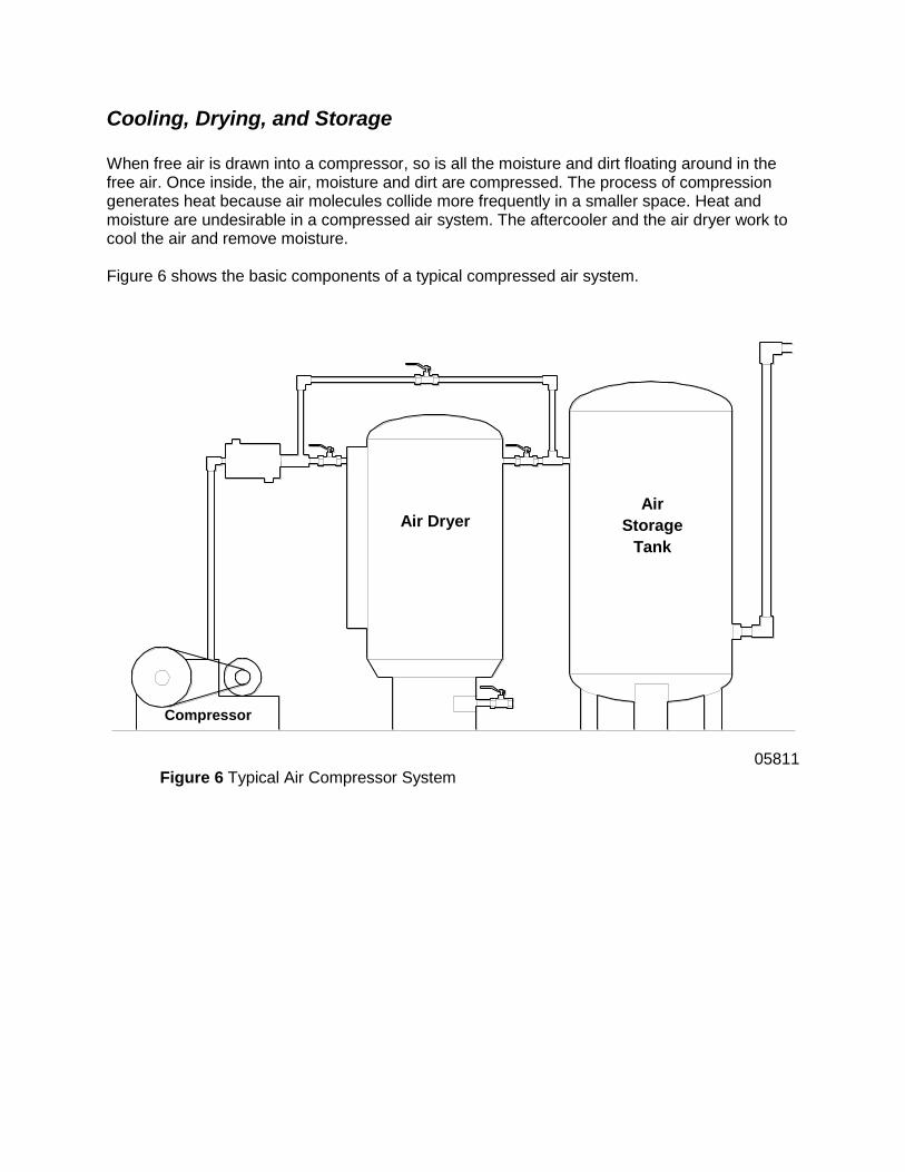
Cooling, Drying, and Storage When free air is drawn into a compressor, so is all the moisture and dirt floating around in the free air. Once inside, the air, moisture and dirt are compressed. The process of compression generates heat because air molecules collide more frequently in a smaller space. Heat and moisture are undesirable in a compressed air system. The aftercooler and the air dryer work to cool the air and remove moisture. Figure 6 shows the basic components of a typical compressed air system.
05811 Figure 6 Typical Air Compressor System
Air Dryer Air
Storage
Tank
Compressor

Compressed air discharges from the compressor and enters the aftercooler. The aftercooler is a device containing a series of tubes and fins which use ambient air to condense out moisture in the compressed air. This condensation process also works to cool the air. Approximately 80% of the moisture is removed by the aftercooler. However, the remaining 20% is still not acceptable air quality in a manufacturing environment. A large portion of the remaining 20% moisture is removed by an air dryer or a series of air dryers. The most common types of air dryers are refrigerated and desiccant air dryers. Refrigerated air dryers are the most economical type of dryer. Warm, saturated air is cooled to form condensation, which is then mechanically separated from the air. After separation, the air is reheated and discharged back into the system. Desiccant air dryers pass the compressed air through a desiccant bed which absorbs the moisture. This type of dryer is used when system requirements demand dew points as low as -150°F (-100°C).
Other kinds of air dryers include Deliquescent and Membrane types. Deliquescent air dryers use a chemical action to remove the moisture. Membrane air dryers absorb water vapor through hollow membrane walls. Once moisture content and temperature have been reduced, the compressed air usually goes into a large storage tank. The storage tank is tapped off into a header system that delivers the compressed air to the air driven devices in the plant.

Progress Check Directions: After answering the following questions, compare your answers with those provided in the answer key following the progress check. If you respond to any items incorrectly, return to the text and review the appropriate topics.
1. Positive displacement air compressors increase the volume and decrease the pressure
of a quantity of air by mechanical means.
a. True
b. False
2. What are the two main air compressor designs?
______________________________________________________________________
______________________________________________________________________
3. The _______ is a cylindrical device containing a series of tubes and fins which uses
ambient air to condense out moisture in the compressed air.
a. Aftercooler
b. Compressor
c. Storage tank
d. Air dryer

Answers to Progress Check
1. B. False (Positive displacement air compressors decrease the volume and increase the
pressure of a quantity of air by mechanical means)
2. Positive Displacement, Dynamic
3. A. Aftercooler
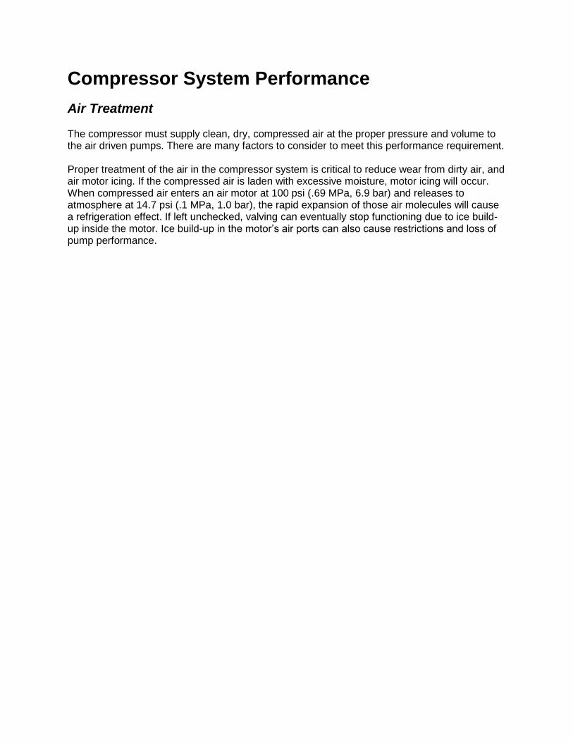
Compressor System Performance
Air Treatment The compressor must supply clean, dry, compressed air at the proper pressure and volume to the air driven pumps. There are many factors to consider to meet this performance requirement. Proper treatment of the air in the compressor system is critical to reduce wear from dirty air, and air motor icing. If the compressed air is laden with excessive moisture, motor icing will occur. When compressed air enters an air motor at 100 psi (.69 MPa, 6.9 bar) and releases to atmosphere at 14.7 psi (.1 MPa, 1.0 bar), the rapid expansion of those air molecules will cause a refrigeration effect. If left unchecked, valving can eventually stop functioning due to ice build-up inside the motor. Ice build-up in the motor’s air ports can also cause restrictions and loss of pump performance.

Filter: Many air lines are made of commercial steel tubing or pipe, which are constantly being fed a supply of air laden with oxygen and moisture. Put air, oxygen, moisture and steel together and you have rust. As rust and scale come loose, they will travel through the plumbing and cause excessive wear and poor motor performance. Other contaminants include dirt and liquid aerosols. Graco recommends filters to remove these contaminants. There are many types of filters. They include air line filters, coalescing oil removal filters, oil vapor absorbers and high temperature afterfilters. Air line filters are very versatile. They can be used in both oil-lubricated and non-lubricated compressors. A good air line filter can remove oil aerosols with an efficiency of over 70 percent. The cyclone style air line filter (Figure 8) uses centrifugal action and a filter element to remove water and foreign particles from the compressed air supply. As air enters the filter, stationary internal fins cause the air to rotate which causes the heavier particles to fly out and collect on the side wall. The collected material is removed by opening the drain valve at the bottom of the bowl. The air flows through the filter element and exits the filter. Note: Drain traps are critical for compressor system efficiency. They are located on headers and equipment. Drain traps can be operated manually, automatically on demand, or by electric timers. Demand-operated drain traps are the most efficient.
Figure 8 Cyclone Filter
Body
Air in
Deflector
Element
Air Out
Metal
Bowl
Baffle
Quiet
Chamber
Auto Drain
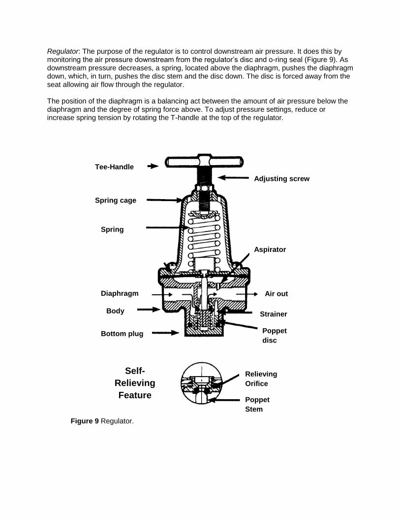
Regulator: The purpose of the regulator is to control downstream air pressure. It does this by monitoring the air pressure downstream from the regulator’s disc and o-ring seal (Figure 9). As downstream pressure decreases, a spring, located above the diaphragm, pushes the diaphragm down, which, in turn, pushes the disc stem and the disc down. The disc is forced away from the seat allowing air flow through the regulator. The position of the diaphragm is a balancing act between the amount of air pressure below the diaphragm and the degree of spring force above. To adjust pressure settings, reduce or increase spring tension by rotating the T-handle at the top of the regulator.
Figure 9 Regulator.
Tee-Handle
Spring cage
Spring
Diaphragm
Body
Bottom plug
Adjusting screw
Aspirator
Air out
Strainer
Poppet
disc
Self-
Relieving
Feature
Relieving
Orifice
Poppet
Stem

Lubricator: The function of the lubricator is to apply a metered amount of lubricant to the pneumatic equipment, to prolong life expectancy. When compressed air is not moving, pressure in the air line and the lubricator’s fluid bowl is equal (Figure 10). No lubricant is being applied. As air starts flowing to the air motor, air line pressure drops. The pressure differential that results pushes small amounts of lubricant from high pressure fluid bowl up through the riser tube and into the air line. A control knob on the top of the unit regulates the oil flow.
Figure 10 Lubricator
Adjustment
knob
Locking
Cap
Needle valve
Sight Glass
Air Out
Sight Glass
Bowl Oil
Reservoir
Dip Tube
By-Pass
Valve
Air In
Ventura

As already mentioned, aftercooler and air dryer(s) should be located at the discharge of the compressor to remove moisture and cool the compressed air. Should you find excessive oil weeping from equipment, the source could very well be the air compressor. When a compressor is worn out, it will leak oil. Possible solutions would be compressor service or some type of oil separator or scrubber. Undersized compressors mean icing problems for pumps. If the compressor is too small for the system it will run too much of the time, run hot, and be very inefficient. The less efficient the compressor, the hotter it will run. Excessively hot air will pass through the aftercooler and air dryer too rapidly. Instead of cooling, condensing and dropping its moisture where it is supposed to, the air will pass through the air storage tank and cool in the header system, and little moisture will be removed from the air supply.
Pressure and Volume Providing adequate air pressure and volume to a pumping system is dependent upon:
Your knowledge of the pumping system’s requirements
The pump ratio
Note: Refer to Graco’s Concept and Theory Training Module Pump Ratio and Performance Charts Form No. 321-042 for additional information.
The compressor’s pressure and volume capabilities
Existing air consumption demands already placed on the compressor system
Amount of line loss (frictional pressure) in the system
Note: Compressed air is not unlike flowing fluids in that pressure is lost as it flows through pipes and hoses. The Technical Data section in the back of the Industrial Fluid Handling Products catalog Form No. 303-706 provides compressed air friction loss charts that assist with pipe and hose selection to minimize pressure drop in air lines.
Formulas There are some very helpful formulas to approximate SCFM (m³/min) and horsepower, Brake Horsepower - BHP (Metric Horsepower - MHP), requirements for a system. In a situation where there is a multiple pump application, it is nice to be able to determine if there is enough air volume and horsepower available. The SCFM (m³/min) / Horsepower approximation formulas are as follows:
1. Approximate SCFM (m³/min) = Ratio of the Pump X GPM (lpm)
2a. BHP (MHP) for an Electric Compressor = SCFM (m³/min) divided by 4
2b. BHP (MHP) for a Gas/Diesel Compressor = SCFM (m³/min) divided by 2
For example, a multiple pump application system involving eight pumps is required to deliver 2 gpm (7.6 lpm) each. What will the air consumption requirements for each pump be? Approximate SCFM (m³/min) levels can be determined by:
1. Taking the ratio of the pump recommended for the application and multiplying it by the
flow rate. If the pump were a 5:1 Monark at 2 gpm (7.6 lpm), the approximate SCFM
(m³/min) required for the pumping job would be 10 scfm (.28 m³/min) per pump or 80
SCFM (2.3 m³/min) for all eight pumps.
2. The next step would be determining the horsepower requirement to deliver that amount
of air volume.
Rough estimates for horsepower requirements can be determined by dividing the amount of air volume from Step 1, 10 scfm (.28 m³/min), by 4 if an electric compressor is being used or considered and by 2 if a gas or diesel compressor is being used or considered.
For an electric compressor, 2.5 horsepower capacity per pump would be required to
deliver the required volume continuously.
For a gas or diesel compressor, 5 horsepower capacity per pump would be required to
deliver the required volume continuously.
The SCFM (m³/min) and Horsepower formulas are handy tools because many customers only think in terms of air pressure; not air volume. So when you ask your customer, “How big is your compressor?” and he says, “It’s approximately 75 psi (.52 MPa, 5.2 bar)”. You will be able to do a quick evaluation of the situation by yourself.

Progress Check Directions: After answering the following questions, compare your answers with those provided in the answer key following the progress check. If you respond to any items incorrectly, return to the text and review the appropriate topics.
1. Graco recommends that moisture level in the air being supplied to air motors be at a
dew point of ____ and an air temperature of ____ to minimize air motor icing conditions.
a. 55°F (11°C), 80°F (27°C)
b. 65°F (18°C), 70°F (21°C)
c. 70°F (21°C), 55°F (11°C)
d. 55°F (11°C), 70°F (21°C)
2. The function of the lubricator is to apply a metered amount of lubrication to the air
compressor to prolong life expectancy.
a. True
b. False
3. ______ compressors mean icing problems for pumps.
a. Undersized
b. Oversized
c. Diesel / gas
d. Electric
4. List four of the five factors that determine whether a compressed air system will provide
adequate volume and pressure.
______________________________________________________________________
______________________________________________________________________
______________________________________________________________________
______________________________________________________________________

Answers to Progress Check
1. D. 55°F (11°C), 70°F (21°C)
2. B. False (The function of the lubricator is to apply a metered amount of lubricant to the
air motor to prolong life expectancy)
3. A. Undersized
4. Knowledge of the pumping system’s requirements
The pump ratio
The compressor’s pressure and volume capabilities
Existing air consumption demands already placed on the compressor system
The amount of line pressure loss (friction loss) in the system