air-ground telemetry systems for research...
TRANSCRIPT

AIR-GROUND TELEMETRY SYSTEMSFOR RESEARCH HELICOPTERS
Item Type text; Proceedings
Authors Kasper, Eugene F.; Leong, Gary
Publisher International Foundation for Telemetering
Journal International Telemetering Conference Proceedings
Rights Copyright © International Foundation for Telemetering
Download date 20/05/2018 20:34:45
Link to Item http://hdl.handle.net/10150/605377
AIR-GROUND TELEMETRY SYSTEMS FOR RESEARCH HELICOPTERS
Eugene F. Kasper Gary Leong
Army/NASA Rotorcraft Division Aeroflightdynamics Directorate (AMRDEC) U.S. Army Aviation and Missile Command
Ames Research Center Moffett Field CA 94035-1000
ABSTRACT This paper describes the development of a compact mobile telemetry system using commercial-off-the-shelf components. The personal computer-based systems support microwave pulse code modulation and serial spread-spectrum radio modem telemetry. The mobile ground station provides data display and archiving of test activities, air-ground communications between experimenters and the flight test crew, and acts as a flight test Differential Global Positioning System base station. The success of the systems indicates that functional telemetry capabilities can be established for small flight test programs at modest cost.
KEYWORDS Telemetry, Helicopter Flight Test, Radio Modems, Commercial-off-the-shelf systems, Global Positioning System (GPS)
INTRODUCTION With the transfer of NASA flight test assets from Ames Research Center (ARC) to Dryden Flight Research Center in 1997, telemetry (TM) facilities previously used at Ames became too costly for the programs conducted by the U.S. Army Aeroflightdynamics Directorate (AFDD) and the Army/NASA Rotorcraft Division. To support development and testing of the JUH-60A Rotorcraft Aircrew Systems Concepts Airborne Laboratory (RASCAL)1, which required high data rate transmission of a large number of engineering parameters, and aerodynamics flight test programs using AFDD’s EH-60L helicopter, engineers without significant TM expertise were tasked to develop a compact mobile air-ground telemetry system. Literature and product searches showed a wide range of products were available. However, most were designed for highly dynamic applications (e.g., missiles, ordnance, high speed aircraft), were

costly, and were tailored for use on large test ranges. AFDD’s helicopter test requirements involved, in contrast, relatively low dynamics and short ranges; high data throughput was more critical. At that time, new generations of PC-based telemetry systems were being marketed that showed the promise of providing good TM performance for relatively low cost even when integrated and used by non-experts. The systems chosen, integrated, and operated by AFDD and ARC engineers, have demonstrated good performance and effective test support. The success in integration and use of these small TM systems demonstrates that high rate remote data acquisition can be accomplished effectively by small teams with limited resources (e.g., university researchers, small commercial enterprises). This paper will present the technical architecture of the two TM systems, a high data rate microwave pulse-code modulation (PCM) system for RASCAL and a spread-spectrum radio modem serial system for the EH-60L, used in AFDD flight test programs. Observed performance of the systems will be discussed, and costs and performance differences will be compared.
SYSTEM DESCRIPTIONS OVERVIEW AND REQUIREMENTS As a result of the literature and product searches conducted by AFDD and ARC engineers, it was decided to develop a TM system based on generic Intel-based personal computers networked through Microsoft Windows NT running commercial-off-the-shelf (COTS) TM hardware and software. The ground station was to provide engineering data display and archive while providing a facility for program managers, test directors, and investigators to monitor the progress of flight tests and communicate with the flight test crew. The display system in the TM ground station was to provide experimenters with near real-time views of aircraft system, state, or performance parameters; these views were to be customizable to display any of the parameters transmitted over the air-ground TM link, in various formats (e.g., virtual strip charts, cockpit instruments, etc.), limited primarily by the size and resolution of the monitors installed in the ground station. The archive capability ensured that test data would be available for post-test analysis in the event of an aircraft system malfunction. Under normal conditions, the data recorded on the aircraft are considered “truth,” since those data are not subject to the signal degradation inherent in radio frequency (RF) TM transmission. The mobility provided by installing the ground station on a truck nominally allowed operations away from Moffett Federal Airfield and/or optimization of line-of-sight between the aircraft and ground station in the test area.

Figure 1: Telemetry Ground Station Exterior Figure 2: Telemetry Ground Station Interior MOTOR VEHICLE PLATFORM The ground station is installed in a 1985 Chevrolet truck (figure 1). The gross internal dimensions of the ground station are 4.1 meters (13 feet, 6 inches) long, 2.3 meters (7 feet, 6 inches) wide, and 2.1 meters (7 feet) high (figure 2). Descriptions of the various telemetry systems installed in the ground station are provided later in this paper. JUH-60A RASCAL TELEMETRY SYSTEM The RASCAL airborne telemetry segment uses a Motorola PowerPC microprocessor-based computer running Wind River Systems’ VxWorks to pack a critical subset of aircraft 1553 bus data, pass them to an SBS/Berg 4422 VME bit synchronizer/commutator, and transmit them through the air-ground TM link to the mobile ground station. All available aircraft sensor data are recorded on-board the aircraft on an Iomega Jaz removable hard drive cartridge on the PowerPC computer. To monitor rotor system loads real-time, analog and digital strain gauge information is taken from the rotor and telemetered from the rotating platform on the main rotor head to the fixed aircraft receiver, designated the Remote Measurement Unit (RMU). The RMU packs rotating platform data with additional fixed platform data to a PCM stream and passes it to the PowerPC computer where it is combined with aircraft 1553 bus data. The RF link between the RASCAL aircraft and the TM ground station (figure 3) consists of an Aydin Vector T100L RF exciter (5 watts at 1.4525 GHz) feeding, through a signal splitter, two TECOM 101002 omnidirectional antennas mounted on the nose of the aircraft. At the ground station, the RF signal is received by a manually-steered TECOM 401020R antenna (12 dBi gain, 35° beamwidth at the –3 dB points) mounted on a photographic tripod and a Miteq AMF-1F-012016-07-10P low noise amplifier (LNA) (16 dB gain, 0.70 dB noise figure). The path analysis in figure 3 demonstrates that with the 16 dB gain of the LNA between the receive antenna and the receiver

board, performance was predicted to be satisfactory over a 37 kilometer (20 nautical mile) transmission path; in-flight signal strength measurements at various locations in the test area confirm this prediction.
Figure 3: RASCAL Air-Ground Radio Frequency TM Link The ground station receiver architecture is shown in figure 4. The ground station uses two networked generic Pentium II computers, the “TM Server” and the “TM Client,” using Windows NT. The TM receiver, an SBS/Berg 4487-PL (sensitivity of –85 dBm for a 10-6 bit error rate and a 10 dB noise figure), is an ISA board mounted in the TM server computer. In turn, the 4487-PL feeds a SBS/Berg 4422 Bit Synchronizer/Decommutator card, also installed in the TM server computer. Together, these boards provide the detected and decommutated TM data to the SBS DataXpress software system. In addition to receiving and processing the data provided by the 4487 and 4422 cards, DataXpress also controls the configuration and operation of these boards. DataXpress is further described later in this paper.

Figure 4: Ground TM Receiver and Computer Systems
As mentioned above, the TM server contains the receiver, bit synchronizer, and decommutator hardware, hosts the DataXpress software, and displays data selected by the user. The TM client computer, which also has DataXpress installed, acts as an additional display driver, taking data received from the server and displaying them on a separate monitor. The operator/experimenters at each display can set up independent formats to meet their needs. In addition, an additional computer is used to record the data stored in the DataXpress archives on an Iomega Jaz cartridge or CD-R and, through a Datum bc637 time and frequency processor, distributes GPS-based IRIG-B time to the telemetry computers.

Figure 5: DataXpress Data Flow 2
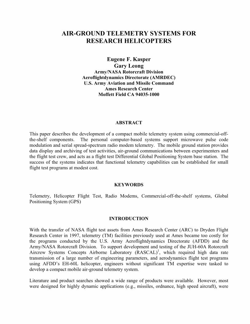
The major functions of the TM ground station are provided by DataXpress, a software package that provides network data acquisition, data archive and playback, limit checking, alarm generation, data conversion, derived data processing, and graphical data displays. DataXpress consists of a number of interconnected modules (figure 5). In Project Manager, the user defines a project by entering the hardware settings for the 4487 receiver and 4422 bit-synchronizer/decommutator cards and defines the data words of interest. The hardware setup and data word definitions are stored as a configuration setup and saved to the Configuration Database. Prior to a specific test operation, the user selects the appropriate project from among the defined projects; the System Controller then loads the necessary settings from the Configuration Database and activates the hardware to begin receiving telemetry. During operation, the PCM stream enters the telemetry server through the 4487 receiver and is decommutated at the 4422, under control of the Device Server. The received and decommutated data are placed in the Current Tag Table (CTT) and become available for DataXpress applications. In the System Controller, hardware status can be monitored and adjustment to hardware settings can be made, along with control of the data archiving functions. The Tag Explorer is used to convert the raw data into engineering units and display the contents of those words in real-time. Displays in the ground station (figure 6) currently include flight instruments (attitude indicator, airspeed, altitude, heading), engine and transmission instruments (engine speeds, rotor speed, and fuel flow), control positions, system discretes, RF signal strength, modulation deviation, and electronic strip charts showing engineering data of interest.
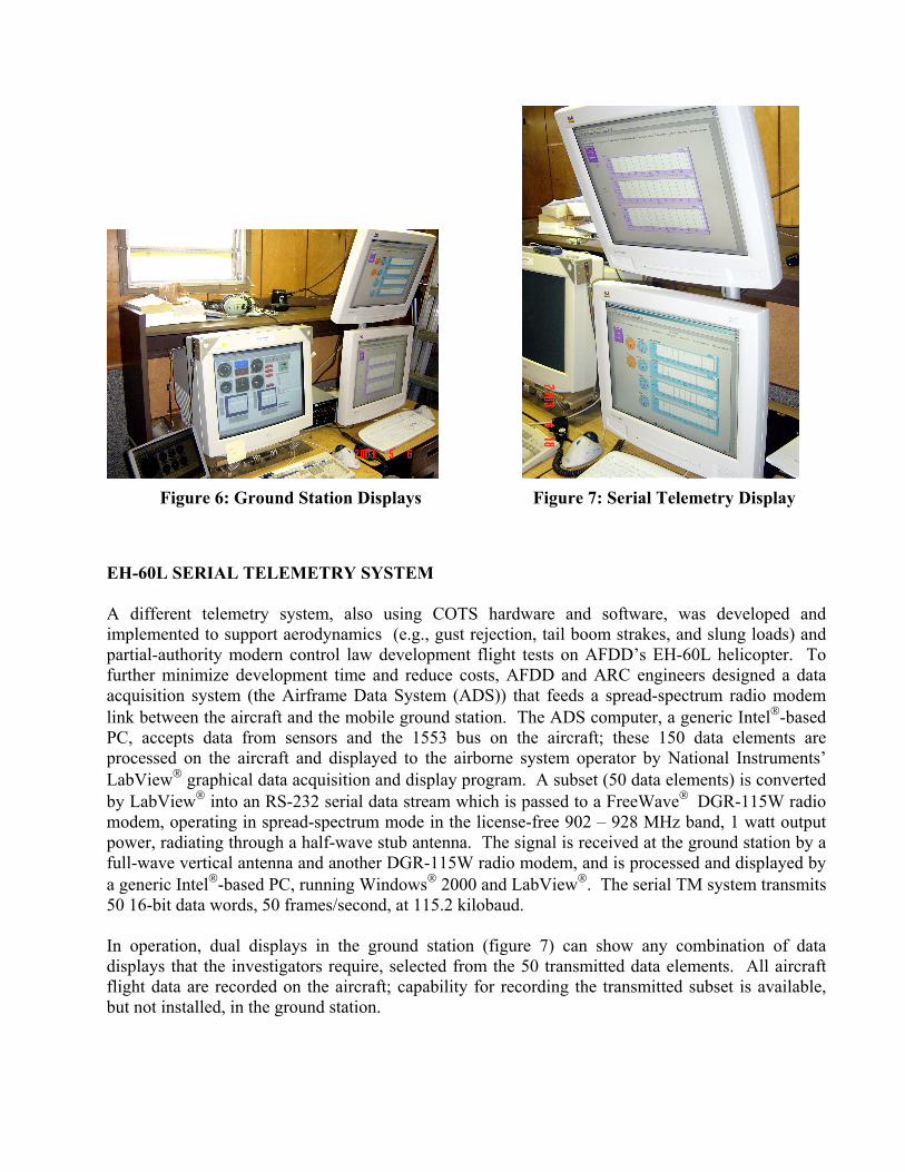
Figure 6: Ground Station Displays Figure 7: Serial Telemetry Display
EH-60L SERIAL TELEMETRY SYSTEM A different telemetry system, also using COTS hardware and software, was developed and implemented to support aerodynamics (e.g., gust rejection, tail boom strakes, and slung loads) and partial-authority modern control law development flight tests on AFDD’s EH-60L helicopter. To further minimize development time and reduce costs, AFDD and ARC engineers designed a data acquisition system (the Airframe Data System (ADS)) that feeds a spread-spectrum radio modem link between the aircraft and the mobile ground station. The ADS computer, a generic Intel-based PC, accepts data from sensors and the 1553 bus on the aircraft; these 150 data elements are processed on the aircraft and displayed to the airborne system operator by National Instruments’ LabView graphical data acquisition and display program. A subset (50 data elements) is converted by LabView into an RS-232 serial data stream which is passed to a FreeWave DGR-115W radio modem, operating in spread-spectrum mode in the license-free 902 – 928 MHz band, 1 watt output power, radiating through a half-wave stub antenna. The signal is received at the ground station by a full-wave vertical antenna and another DGR-115W radio modem, and is processed and displayed by a generic Intel-based PC, running Windows 2000 and LabView. The serial TM system transmits 50 16-bit data words, 50 frames/second, at 115.2 kilobaud. In operation, dual displays in the ground station (figure 7) can show any combination of data displays that the investigators require, selected from the 50 transmitted data elements. All aircraft flight data are recorded on the aircraft; capability for recording the transmitted subset is available, but not installed, in the ground station.

OPERATIONAL RESULTS The PCM telemetry system demonstrated its capabilities during the development and testing of the RASCAL RFCS, through the milestone first in-flight engagement of the control system on August 31, 2001, and in flight tests supporting development of advanced model-following control laws and Runway Independent Aircraft Operations (RIAOps). During RASCAL flight test programs, PCM telemetry performance has been satisfactory throughout the test area (five mile radius of Moffett Federal Airfield). The range is limited by the ability of the antenna operator to visually track the aircraft in flight. However, received signal strength measurements indicate a reception range of 37 kilometers (20 miles) is attainable if automatic tracking is implemented. In addition to range constraints, line-of-sight between the aircraft transmitting antennas and the ground station receiving antenna has affected system performance. For example, loss of RF link, increased data dropouts, or both, have been noted when the aircraft was banking toward, or climbing tail-on away from the ground station. In these conditions, the transmitting antennas are partially shielded by the body of the aircraft. Since test data are not normally taken in these conditions, these limitations have not adversely affected the conduct of RASCAL flight tests. For the serial TM system, range tests using text files transmitted between the aircraft and the ground station using HyperTerminal have indicated a dependable transmission range of over 28 kilometers/15 nautical miles. Flight test telemetry has been completely dependable throughout the test area, currently the Moffett Federal Airfield Class “C” airspace (i.e., 9 kilometer/5 nautical mile radius). The success and responsiveness of the TM operation have expanded the projects supported and the data provided. The mobile ground station has been equipped to act as a local-area differential GPS (DGPS) base station, both Radio Technical Commission for Maritime Services (RTCM)-standard and carrier phase/real-time kinematic, for performance measurement during RIAOps landing approach development and aircraft handling qualities tests. To improve support, several upgrades and additional functions are planned, all adhering to the concept of using relatively low-cost, simple, and easy-to-use COTS systems. These include upgrades of the computer motherboards to support current commercial processor speeds, upgrades to the operating systems to more recent versions of Windows, GPS-based trajectory displays, and development and installation of a video downlink to permit ground-based investigators to monitor pilots’ display symbology.
COMPARISION OF PCM AND SERIAL TELEMETRY SYSTEMS The two telemetry systems used by the AFDD helicopters were developed to satisfy different requirements. Table 1 presents a comparison of some germane technical metrics between the two systems. To support development and flight test of RASCAL’s full-authority fly-by-wire control system, specifically monitoring control servo behavior and aircraft response at the ground station in real time, high data rates are required; with the PCM system, throughput is 272 frames of 262 16-bit words per second (i.e., 1.15 Mbits/sec). The aerodynamic tests flown by the EH-60L helicopter do not require monitoring the number of data elements at the ground station; the data rate permitted by Federal Communications Commission rules for license-free spread-spectrum operation in the 902

MHz band is adequate to transmit all required data between the aircraft and the ground. A wider selection of display elements are available using the PCM system.
PCM System3 Serial System4
Carrier Frequency 1452.5 MHz 900 - 928 MHz Spread Spectrum
Modulation Bi-Phase L GFSK Bit Rate (bps) 1,150,000 155,200
Loopwidth 0.50% N/A Bits/Word 16 16
Words/Frame 262 50 Receiver Sensitivity -85 dBm* -108 dBm*
Range 37 km/20 nmi 28 km/15 nmi
* Specified for a 10-6 bit error rate
Table 1: Comparison Between PCM and Serial Telemetry Systems Operationally, the serial TM system has been easier to use than the PCM system. The PCM system requires manually tracking the aircraft with the microwave receiving antenna during tests, whereas the serial system uses an omnidirectional receiving antenna that does not require tracking. Besides the resulting reduced workload, received data quality has, subjectively, been better using the serial TM system; data/signal dropouts caused by unfavorable aircraft/ground station aspect angles have not been noted during EH-60L flight tests. In addition, only one computer in the ground station is required for EH-60L serial TM vice the two required for dual display RASCAL/PCM operations. This is the result of using Windows-NT (which lacks support for dual monitor video cards) as the operating system for the PCM system; planned upgrades of this system will correct this problem by migrating to Windows 2000, and a current-generation motherboard and microprocessor. Software complexities are of similar magnitude between the two systems. For the DataXpress PCM system, software development is concentrated on programming the 1553 data bus devices to properly format system data into messages and pass the messages to the PowerPC computer on the RASCAL aircraft; in the ground station, graphical user interfaces in DataXpress make configuration of the receiver, decommutator, and displays fairly straightforward. For the LabView-based serial TM system, programming and configuration of both the airborne and ground elements require solid LabView programming expertise; changing configuration on-the-fly is difficult at best. For both systems, software development has been a critical task in the successful implementation of the TM capabilities. From a cost perspective, although both systems use COTS components, the PCM system was more expensive to develop and install than the serial TM system. The PCM system required procurement of a microwave transmitter, a receiver card, two bit sync/decommutator cards, two microwave blade antennae, a microwave receive antenna, low-noise amplifier, and software suite; total cost was approximately $45,000. On the other hand, the serial system uses two radio modems, two antennae, and two licenses for LabView; total cost was approximately $6,000. It is to be emphasized that the PCM system has a great deal more actual and potential capacity in terms of throughput than the serial system as currently installed. Both systems are well-tailored to their flight test requirements:
the serial system does not have sufficient capability to support RASCAL flight tests, whereas the PCM system has far more capacity than the EH-60L flight test programs have required up to now.
CONCLUSION Two different telemetry systems have been developed to support helicopter flight test programs at Moffett Federal Airfield. These systems have performed well in support of their respective flight test programs. Capabilities and costs of the two systems are significantly different, with PCM telemetry having higher capability at higher cost than the serial telemetry system; however, both systems have been developed with specific test requirements in mind and are well-tailored to each. The successes of these systems show effective telemetry systems can be developed, fielded, and operated for appropriate flight test programs at moderate costs using COTS hardware and software by engineers without specific telemetry expertise.
ACKNOWLEDGEMENTS The authors would like to acknowledge the contributions of Benny Cheung, Mary Feibusch, Zsolt Halmos, Thomas Kaisersatt, Gilbert Kojima, Alan Lee, Daniel Loney , Ernesto Moralez III, David Nishikawa, Zoltan Szoboszlay, and the Raytheon Aerospace Corporation Aircraft Support Branch. Their advice and assistance have been critical to the successful accomplishment of the TM development and operation program.
REFERENCES 1 Moralez, Ernesto III, et. al., “Flight Research Qualification of the Army/RASCAL Variable-Stability Helicopter,” American Helicopter Society 58th Annual Forum, Montreal, Quebec, Canada, June 2002. 2 SBS Technologies, Inc., DataXpress Guide to Device Servers, Version 1.2, Albuquerque NM, June 1999, Page 1-3, Figure 1-1. 3 SBS Technologies, Inc., 4487 Telemetry Receivers, Revision E, Carlsbad CA, March 1999, Page 1-2. 4 FreeWave Technologies, Inc., FreeWave Spread Spectrum Wireless Data Transceiver User Manual, Boulder CO, 2002, Page 59.