air-core transformer electrical modeling - psi.ch · lp(sh), nh coupling, x1000 lp, nh measured...
TRANSCRIPT

10 Jan 2007, PSI Villigen M. ParalievSlide 1
PAUL SCHERRER INSTITUT
Air-core transformer electrical modelingTwo ideal coupled resonant circuits
Simplified Circuit Equivalent Circuit
The differential system has no general analytic solution except for LC=LsCs. The oscillations of the system are not necessarily periodic. Differential system Solution
-1.2
-0.8
-0.4
0
0.4
0.8
1.2
0 1 2 3
Cycles
No
rmal
ized
Am
plit
ud
e
u1u2
Critical coupling Wave forms
For critical coupling (Kc=0.6) the oscillation consist of the fundamental and the second harmonic. The signal is not symmetric with respect to zero. The ratio between pos. and neg. maximum is 1.78.
10 Jan 2007, PSI Villigen M. ParalievSlide 2
PAUL SCHERRER INSTITUT
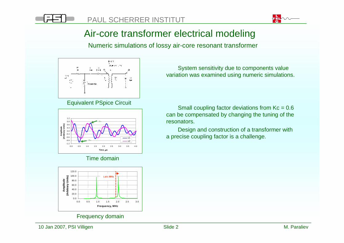
Air-core transformer electrical modeling
System sensitivity due to components value variation was examined using numeric simulations.
Small coupling factor deviations from Kc = 0.6 can be compensated by changing the tuning of the resonators.
Design and construction of a transformer with a precise coupling factor is a challenge.
Numeric simulations of lossy air-core resonant transformer
Equivalent PSpice Circuit
0.0
20.0
40.0
60.0
80.0
100.0
120.0
0.0 0.5 1.0 1.5 2.0 2.5 3.0
Frequency, MHz
Am
plit
ud
e(A
rbitr
ary
Un
its)
1.871 MHz
Time domain
Frequency domain
-1.2
-0.9
-0.6
-0.3
0.0
0.3
0.6
0.9
1.2
0.0 0.5 1.0 1.5 2.0 2.5 3.0 3.5 4.0
Time, � s
Am
plitu
de(A
rbitr
ary
Uni
ts)
u1
u2Uneg
Upos

10 Jan 2007, PSI Villigen M. ParalievSlide 3
PAUL SCHERRER INSTITUT
Air-core transformer electrical modeling
The study used two criteria: – Maximum output amplitude – Maximum positive to negative peak
voltage ratio
The varied parameters were coupling factorand primary resonator tuning (varying the primary capacitance).
The value of the resistor in primary side was iteratively determined to ensure that the loss factor is kept constant (~30% per cycle)
The determination of negative to positive peak voltage ratio was difficult because, if there is no significant loss in the system, after many cycles the negative peak could appear as positive one.
Parametric study of lossy air-core resonant transformer
Normalized secondary peak voltage amplitude as function of coupling and
primary capacitance with 30% loss factor
Negative to positive peak voltage ratio of secondary voltage as function of coupling and
primary capacitance with 30% loss factor

10 Jan 2007, PSI Villigen M. ParalievSlide 4
PAUL SCHERRER INSTITUT
Air-core transformer magnetic modeling
The full 3D numerical simulation is limited by:
Ø enormous aspect ratio;Ø excitation pulse length limitations
Simplified geometry was a necessity.
Numerical and physical modeling of the transformer
Electromagnetic field distribution simulation
ç Used physical models
Measurements on scaled physical models:
Ø confirmed 3D numeric simulations
Ø confirmed scalability of the air-core coils / transformers
Ø defined the best geometry of the air-core transformer
Ø showed the sensitivity of the transformer to surrounding space and close metal objects

10 Jan 2007, PSI Villigen M. ParalievSlide 5
PAUL SCHERRER INSTITUT
Air-core transformer magnetic modeling
Coupling factor K is given by the formula:
where L and Lsh are the values of primary inductance when the secondary is open and shorted. The coils are used in autotransformer mode and one turn primary.
The relative error between the simulated and measured inductance values was <6% and coupling values <1%. Simulation conditions were kept strictly unchanged for L and Lsh (meshing, coil geometry, etc.).
Insensitivity to coupling errors because meshing errors tend to cancel.
Physical models vs. 3D numeric simulations
0.62%0.03%0.41%0.58%0.68%Coupling factor error, %
1.80%0.97%1.81%2.66%5.07%Lsh relative error, %
1.01%1.01%1.01%1.01%1.01%L relative error, %
0.6200.6580.6990.7610.858coupling, -
678625563436290Lsh, nH
11011101110111011101L, nH
Simulated
0.6240.6570.7020.7660.864coupling, -
666619553451276Lsh, nH
10901090109010901090L, nH
Measured
20161284Number of turns
An additional conductor is placed in 3D model in order to shorten the secondary.
Measured values vs. simulated values and the relative errors between them.
L
LLK sh−=

10 Jan 2007, PSI Villigen M. ParalievSlide 6
PAUL SCHERRER INSTITUT
Air-core transformer magnetic modeling
Mutual inductance of air-core transformers depends only on geometry.
Using the definitions of magnetic flux density B, magnetic flux , self inductance L, mutual inductance M and coupling factor K, inductances scale linearly with the geometrical dimensions and the coupling factor stays constant.
Air-core transformers scalability
Basic relations
iL
Φ=
� •=ΦS
sdB��
�×=34
.
r
rLdiB
���
πµ
rB
1~
r~Φ
rL ~
1
21
iM
Φ= rM ~
SP LL
MK = constK =
0
100
200
300
400
500
600
0 20 40 60 80 100 120
Coil Perimeter, cm
Lp(sh), nH
Coupling, x1000
Lp, nH
Measured results

10 Jan 2007, PSI Villigen M. ParalievSlide 7
PAUL SCHERRER INSTITUT
Air-core transformer magnetic modeling
To optimize the coupling factor of air-core transformer the influence of the coils shape was studied. The model coils were used in autotransformer mode.
Three basic configurations were compared:Ø Spiral shape with peripheral excitationØ Spiral shape with central excitationØ Helical shape
Highest coupling factor is obtained for peripherally excited spiral secondary coil.
The higher the number of turns (higher step up ratio) the lower the coupling.
Optimal air-core transformer geometry – coil shape and excitation
Coupling factor vs. number secondary turns for three different configurations
Excitation scheme
0.00
0.20
0.40
0.60
0.80
1.00
0 2 4 6 8 10 12 14
Turns
Co
up
ling
Spiral Peripheral
Helix
Spiral Central ç Spiral coil model
ç Helical coil model

10 Jan 2007, PSI Villigen M. ParalievSlide 8
PAUL SCHERRER INSTITUT
Air-core transformer magnetic modeling
Another factor that influences the coupling is the transformer diameter and the conductor cross-section.
The larger the transformer diameter and the wider the strip the higher the coupling.
Conductors span is kept 15mm for all coils.
Optimal air-core transformer geometry – coil dimensions and conductor cross-section
Influence of conductor cross section dimensions
Influence of coil diameter
0.20
0.40
0.60
0.80
1.00
0 2 4 6 8 10 12 14Turns
Co
up
ling
Spiral Strip 50x1Spiral Strip 14x1
Helix Strip 50x1Helix Strip 14x1
0.20
0.40
0.60
0.80
1.00
0 2 4 6 8 10 12 14Turns
Co
up
ling
Helix D380 Strip 14x1Helix D220 Strip 14x1Helix D380 Strip 50x1Helix D220 Strip 50x1
Helix D220 mm
Helix D380 mm
Spiral Dm380 mm
Conductor
Shape
Strip 14x1 mm Strip 50x1 mm

10 Jan 2007, PSI Villigen M. ParalievSlide 9
PAUL SCHERRER INSTITUT
Air-core transformer magnetic modeling
The conductor cross-section shape was studied. The two extreme cases was investigated. Conductors span was kept constant.
Ø Round conductorØ Strip conductor (width >> thickness)
Coupling factor depends on the perimeter of the conductor cross-section and it is relatively insensitive to the conductor cross-section shape.
Optimal air-core transformer geometry – conductor cross section
Strip 14x1 mm
Perimeter 30 mm
Influence of coil cross-section shape
Helix D380 mm
Spiral Dm380 mm
Conductor
Shape
Strip 14x1 mm Round D9 mm
0.20
0.40
0.60
0.80
1.00
0 2 4 6 8 10 12 14Turns
Co
up
ling
Spiral Round Ø9
Spiral Strip 14x1Helix Round Ø9
Helix Strip 14x1
Round D9 mm
Perimeter 28.3 mm

10 Jan 2007, PSI Villigen M. ParalievSlide 10
PAUL SCHERRER INSTITUT
Air-core transformer magnetic modeling
There was a concern about the deterioration of the transformer performance due to limited surrounding space and near large metal objects.
Optimal air-core transformer geometry – proximity effects
0.521401920.521401930.61170270D165/28/0.5mm (1MHz)
0.511842480.511852500.60210330D165/14/0.5mm (1MHz)
KLsh, nHL, nHKLsh, nHL, nHKLsh, nHL, nH
With central pieceWithout central piece
In the tankFree space
Primary Loop type
Surrounding space influence on air-core transformer model - Scaling coefficient 3.64 (04 Oct 2004)
Coupling factor deteriorated by 15% due to limited surrounding space. The metal stalk in the center of the transformer did not show any significant further deterioration.
The study gave an input for the electrical simulations. Later on, the comparison between the estimated values based, on the scaled models, and the
real transformer values showed good agreement.
Secondary (Oct 2004)
Primary (Dec 2006)
Primary (Oct 2004)
Coil
Primary and secondary estimation
Since the final shape of the coil was not known the model was not exact19%1078 nH903 nH248 nH
Since the final shape of the coil was not known the model was not exact6%133 uH141 uH290 uH
1%1078 nH1088 nH150 nH
NoteErrorMeasuredEstimationModel

10 Jan 2007, PSI Villigen M. ParalievSlide 11
PAUL SCHERRER INSTITUT
500kV Pulser design
The shortest possible secondary length gives the shortest pulse length. A planar spiral secondary coil with peripheral single-turn primary was chosen.
The secondary consist of 16.5 turns of 4mm diameter copper tube (compatible with 3.6 mm semi-rigid coax cable)
To prevent voltage breakdown the transformer is operated in sulfur hexafluoride (SF6) gas at up to 5 bar.
The transformer base is made out of Acrylglas (Plexiglas). OD 600 mm, ID 240 mm. On one face is a spiral channel for the conductor and on the other corrugations to prevent surface discharges.
Air-core transformer
Air-core transformer (3D model)
Single turn Cu strip primary, transformer base with spiral channel for 16.5 turn secondary
winding and connecting terminals (secondary conductor is not shown)