air cooled water chillers and heat pumps s a g t i r …
TRANSCRIPT

RGC AIR COOLED WATER CHILLERS AND HEAT PUMPS
WITH CENTRIFUGAL FANS53.5 ÷ 200 kW IN COOLING MODE
57.5 ÷ 214 kW IN HEATING MODE
TECHNICAL MANUAL
FRIGERANT G
RE
FRIGERANT G
AS
E
CO-FRIEND
LYE
CO-FRIEND
LY

2
The manufacturer declines all responsibility for any inaccuracies in this manual due to printing or typing errors.
The reserves the right to modify the products contents in this catalogue without previous notice.

TABLE OF CONTENTS
THIS MANUAL IS DIVIDED INTO SECTIONS. THEIR NAMES APPEAR IN THE HEADING OF EACH PAGE.
3
GENERAL SPECIFICATIONS . . . . . . . . . . . . . . . . . . . . . . . . . . . . .5
PRESENTATION OF THE UNIT . . . . . . . . . . . . . . . . . . . . . . . . . .5
IDENTIFICATION CODE OF THE UNIT . . . . . . . . . . . . . . . . . . .5
DESCRIPTION OF THE COMPONENTS . . . . . . . . . . . . . . . . . .6
HYDRAULIC AND COOLING CIRCUIT COMPONENTS . . . . . .8
DESUPERHEATER UNIT VD . . . . . . . . . . . . . . . . . . . . . . . . . . . .9
TOTAL HEAT RECOVERY UNIT VR . . . . . . . . . . . . . . . . . . . . .10
ACCESSORIES AND OPTIONAL EQUIPMENT . . . . . . . . . . . . . . .11
ACCESSORIES . . . . . . . . . . . . . . . . . . . . . . . . . . . . . . . . . . . . . .11
MECHANICAL OPTIONS . . . . . . . . . . . . . . . . . . . . . . . . . . . . . . .14
ELECTRICAL OPTIONS . . . . . . . . . . . . . . . . . . . . . . . . . . . . . . .14
TECHNICAL SPECIFICATIONS AND STANDARD
PERFORMANCES - IR COOLING UNIT ONLY . . . . . . . . . . . . . . .15
TECHNICAL SPECIFICATIONS OF UNIT
AB STANDARD UNIT / AS LOW NOISE UNIT . . . . . . . . . . . . . .15
STANDARD PERFORMANCES
AB STANDARD UNIT / AS LOW NOISE UNIT . . . . . . . . . . . . . .16
DESUPERHEATER UNIT (VD) . . . . . . . . . . . . . . . . . . . . . . . . . .18
RECOVERED HEATING CAPACITY DESUPERHEATER UNIT (VD) . .19
TOTALE HEAT RECOVERY UNIT (VR) . . . . . . . . . . . . . . . . . . .20
RECOVERED HEATING CAPACITY TOTAL HEAT RECOVERY UNIT (VD) 21
TECHNICAL SPECIFICATIONS AND STANDARD
PERFORMANCES - IP HEAT PUMP UNITS . . . . . . . . . . . . . . . . .22
TECHNICAL SPECIFICATIONS OF UNIT
AB STANDARD UNIT / AS LOW NOISE UNIT . . . . . . . . . . . . . . . . .22
STANDARD PERFORMANCES IN COOLING MODE
AB STANDARD UNIT / AS LOW NOISE UNIT . . . . . . . . . . . . . . . . .23
STANDARD PERFORMANCES IN HEATING MODE
AB STANDARD UNIT / AS LOW NOISE UNIT . . . . . . . . . . . . . . . . .25
DESUPERHEATER UNIT (VD) . . . . . . . . . . . . . . . . . . . . . . . . . .26
RECOVERED HEATING CAPACITY DESUPERHEATER UNIT (VD) . .27
CORRECTION FACTOR FOR THE USE OF GLYCOL . . . . . . . . . . . . .28
CORRECTION FACTOR FOR THE USE OF GLYCOL IN HEATING MODE .28
CORRECTION FACTOR FOR THE USE OF GLYCOL IN COOLING MODE 28
GENERAL SPECIFICATIONS - BRINE UNIT BR - BP . . . . . . . . . . . . .29
SPECIFIC DATA FOT BRINE UNIT (BR-BP) . . . . . . . . . . . . . . . . . . .29
NOISE LEVELS . . . . . . . . . . . . . . . . . . . . . . . . . . . . . . . . . . . . . . . .30
AB STANDARD UNIT . . . . . . . . . . . . . . . . . . . . . . . . . . . . . . . . . . .30
AS LOW NOISE UNIT . . . . . . . . . . . . . . . . . . . . . . . . . . . . . . . . . .30
OPERATING RANG . . . . . . . . . . . . . . . . . . . . . . . . . . . . . . . . . . . . .31
OPERATING RANGE . . . . . . . . . . . . . . . . . . . . . . . . . . . . . . . . . .31
WATER PRESSURE DROP PLATE HEAT EXCHANGER . . . . . . .32
WATER PRESSURE DROP OF THE DESUPERHEATER VD . . . .33
WATER PRESSURE DROP TOTAL HEAT RECOVERY VR . . . . .34
WORKING HEAD OF THE HYDRONIC KIT
MP AM STD,MP SS STD AND MPM AM STD . . . . . . . . . . . . . . .35
WORKING HEAD OF THE HYDRONIC KIT
MP AM HP1,MP SS HP1 AND MPM AM HP1 . . . . . . . . . . . . . . . . .36
MAXIMUM VOLUME OF WATER . . . . . . . . . . . . . . . . . . . . . . . . . .37
MAXIMUM WATER VOLUME OF THE SYSTEM
WITH HYDRONIC KIT . . . . . . . . . . . . . . . . . . . . . . . . . . . . . . . . .37
DIMENSIONAL DATA . . . . . . . . . . . . . . . . . . . . . . . . . . . . . . . . . . .38
OVERALL DIMENSIONS . . . . . . . . . . . . . . . . . . . . . . . . . . . . . . .38
DESCRIPTION OF THE COMPONENTS . . . . . . . . . . . . . . . . . .39
MINIMUM OPERATIVE SPACE . . . . . . . . . . . . . . . . . . . . . . . . . .39
WEIGHT DURING OPERATION AND TRANSPORT . . . . . . . . . . .40

4

5
Presentation of the unit
This new series of industrial chillers and heat pumps has been designed to meet the demands of global markets in the small-
medium power industrial and commercial plants. Units are compact and highly configurable, built to fit different types of plants
so to meet the needs of highly qualified engineers.
Units are water chillers and heat pumps air condensed with centrifugal fans suitable for outdoor and indoor installation: the struc-
ture and panels are robust, made of galvanized and painted steel; all fasteners are made of stainless steel or galvanized steel,
the frame containing the electrical equipment and all the components exposed to weather have a minimum IP54 degree of pro-
tection.
This series is composed of 12 models divided in four sizes with nominal cooling capacity from 53.5 to 200 kW and heating capa-
city from 57.5 to 214 kW.
The units product cold water from 5 to 25°C (in summer) and hot water from 30 to 55°C (in winter) and they can be equipped
with continuous adjustment of centrifugal fans speed in order to allow the units to operate both with low outdoor temperature in
cooling mode and with high outdoor temperature in heating mode as well as to reduce noise emissions (IMV accessory).
All the units are equipped with 2 scroll compressors arranged in pairs (tandem) on 1 circuit operating with environmental
friendly R410A gas, brazed plate heat exchanger completely insulated and protected by water side with a differential pressure
control and with an antifreeze electrical heater, coil heat exchanger made of louver aluminum fins and copper tubes, double inlet
centrifugal fans with forward curved blades and transmission with belts and pulleys by a thermal protected motor, on-board elec-
trical control panel equipped with control system to manage the main functions.
Hydronic group (MP) composed of fittings and connections is available as an accessory with 1 or 2 pumps and also with high
available head pumps or with Inverter modulating pump; the accessory Water Storage Tank (SAA) is completely insulated and
available on delivery side or for primary-secondary hydraulic circuit (Victaulic connections already in place) depending on the
kind of plants to serve.
A variety of other accessories are available to extend the capabilities of the units.
During the design of the units particular attention has been given to achieve high system efficiency, to reduce overall energy con-
sumptions and sound levels in order to meet the increasingly restrictive laws in terms of noise. Upon request, you can choose
for a Low noise Unit (AS) which provides sound attenuation thanks to sound absorbing insulation in compressors area and sound
jackets on compressors.
All units are accurately build in compliance with the existing standards and are individually tested in factory. Only electrical and
hydraulic connections are required for installation.
GENERAL SPECIFICATIONS
Identification code of the unit
The codes that identify the units are listed below and include the sequences of letters that determine
the meanings for the various versions and set-ups.
The available special versions are described below:
VB: Standard unit.
VD: Desuperheater unit (available forboth IR units and IP units)
Produces cold water in the same way as the standard version plus hot water from 30 to 70°C at the same time. This is achieved by
installing a water-refrigerant gas heat exchanger between the compressor and coils in order to recover 15 to 20% of the heating capa-
city that would otherwise be dispersed in the air.VR: Total Heat Recovery unit
Produces cold water as in the standard version plus hot water at a temperature of 35 to 50°C at the same time. This is achieved thanksto a water-refrigerant gas heat exchanger that totally recovers the heating capacity that would otherwise be dispersed in the air. Thetotal heat recovery function is enabled and disabled by means of a valve on the compressor delivery of each circuit: when the tempe-rature of the water that enters the recuperator drops, the valve switches the hot gas flow from the condensing coils to the recovery heatexchanger. On the other hand, when the temperature of the water reaches the set-point, the valve shuts off the heat recuperator andswitches the hot gas flow to the condensing coils.
IR- units suitable for hydronic plant installation operating as chillers.IP- units suitable for hydronic plant installation operating as heat pumps.BR- units suitable for hydronic plant installation with Brine solutions operating as chillers.BP- units suitable for hydronic plant installation with Brine solutions operating as heat pumps.
Unit version Acoustic VersionAB - Standard unitAS - Low noise unit
Unit model
N° Compressor
Type of Refrigerant0 - R410A
Power Supply5 - 400V-3ph~50Hz
Operating rangeM - Medium temperature. Units are suitable to be installed in temperate climate sites. A - High temperature. Units are suitable to be installed in tropical climate sites.
Unit type
RGC IP - 50.2 - VB - AB - 0 - M - 5
VB - Standard VersionVD - Desuperheater unitVR - Total heat recovery unit

GENERAL SPECIFICATIONS
Description of the components
The complete series of industrial chillers and heat pumps for use in hydronic systems includes 12 constructional sizes rang
from 53.5 to 200 kW in the cooling mode and from 57.5 to 214 kW in the heating mode.
Main components:
1. Fans. It is composed of single and/or twin dual-intake centrifugal fans with forwards blades curved, balanced both statically
and dynamically in compliance with ISO 1940 class 6.3 standards. The screw conveyor, rotor and frame are made of galva-
nized plate, while the shaft is made of C40 steel. The fan is coupled via belt and pulley to a 4-pole, three-phase, asynchro-
nous motor secured on a special tightener slide, with protection class IP55, insulation class F and suitable for continuous ser-
vice (S1) with sufficient thermal margin in the event of overloads of limited duration. The pulley fitted on the motor has a varia-
ble diameter and, within certain limits, enables adjusting the speed of rotation of the fan in order to obtain the desired air flow
rate and useful static head.
2. Electric control and monitoring panel. This is housed in a metal casing in which the various electrical components are posi-
tioned on one metal plate.
2a. The power section includes:
• Main door-locking circuit-breaker.
• Fuse-holder that can be isolated with protection fuse triad for each compressor.
• Fuse-holder that can be isolated with protection fuse for compressor oil heaters and antifreeze (if installed).
• Control contactor for each compressor.
• Protection fuse for the ventilation unit.
• Fan speed regulating board.
• Contactor and magnetothermic switch to protect the pump (if the Hydronic Kit accessory is installed).
• Pump contactor (if the Hydronic Kit accessory is installed).
• Phase presence and sequence monitoring device on power supply
2b. The auxiliary section includes:
• Fuses on the auxiliary transformer.
• Fuses for fans protection
• Electromagnetic noise filter
• Adjusting fan speed board
• Insulating and safety transformer to power the auxiliary circuit.
2c. The microprocessor monitoring section includes:
• User interfacing terminal with display.
• On-off key.
• Operating mode selector key.
• Compressor on-off display LED.
• Operational mode LED
• Antifreeze heaters activated indicator LED.
• Fans on-off dislay LED
• Pumps on-off display LED
• Check-control with fault code display
• Defrosting, alarm, economy, stand-by LED.
• ON / Stand-by remote - Summer/Winter (E/I) remote selection (IP unit only).
Control system main functions: temperature control of the water produced by the unit, smart defrosting control, compressor
and pump operating hour counter, timing and cycling of start-ups, input parameters by keyboard, alarms management, operating
mode change (only IP unit), dynamic set-point (climatic control), “Adaptive” function for better temperature control for unit without
storage tank. If you installed the hydronic kit these functions are enabled: antifreeze with pump, start-up cycle after prolonged
inactivity (anti-sticking), if the hydronic kit installed has 2 pumps there is a cycling between each pump to ensure an equivalent
lifetime, with inverter modulating hydronic kit the water flow of the plant can be adjusted.
Digital input functions: low pressure, high pressure, high temperature on compressor supply, phase presence and sequence
monitoring device on power supply, differential water pressure control, compressors thermal protection, fans thermal protection,
pumps thermal protection (only if installed MP accessory), remote ON/OFF and remote operating mode change (only IP unit),
recovery enabling (only for the VR Version), recovery Pump Thermal Protective (only for the VR Version), recovery differential
water pressure control (only for the VR Version).
Digital output functions: compressor start-up, pump start-up (only with MP accessory), plate heat exchanger electrical heater,
remote general alarm, 4-way valve (only IP unit), recovery valve management (only for the VR Version), recovery pump mana-
gement (only for the VR Version).
Analogic input functions: in and out water temperature, coil temperature probe, external air temperature probe (if present), in
and out recovery water temperature (only for the VR Version)..
Analogic output functions: continuous adjustment of centrifugal fans rotating speed by inverter (only if installed IMV acces-
sory), continuous adjustment of pump rotating speed.
°C
MODE
6

17
2
3
5
4
6
3. Compressors. They are the SCROLL type with orbiting coil equipped with built-in thermal protection and oil heater. The AS
unit includes: a soundproofing jacket for the compressors, an acoustic cladding around the compartment where they are hou-
sed, to reduce noise level. All units are equipped with two compressors connected in parallel (1 single cooling circuit) which
can operate at the same time (100% cooling power) or individually (50% of the cooling power), thus adapting to the diffe-
rent thermal loads of the system supplied.
4. Frame structure made of galvanized sheet metal panels coated with polyurethane powder paint to ensure maximun pro-
tection against adverse weather conditions.
5. Evaporator made of brazed stainless steel plates (AISI 316). It is installed in a shell of heat-insulating material to prevent
the formation of condensation and heat exchanges towards the outside. Standard supply also includes antifreeze heater a dif-
ferential pressure switch on the water circuit to avoid the risk of freezing if the water flow is shut off for some reason.
6. Condensing coils, the aluminium finned pack type with shaped profile to increase the heat exchange coefficient and with
copper pipes arranged in staggered rows. A sub-cooling section is integrated into the lower part.
7. Covering panels, made of galvanized sheet metal coated with polyurethane powder paint to ensure maximun protection
against adverse weather conditions
8.One-way valves (IP unit only), allowing the coolant to pass into the appropriate exchangers, depending on the operating
cycle.
9. 4-way cycle reversal valve (IP unit only), reverses the flow direction of the coolant as the summer/winter operating mode
is changed.
GENERAL SPECIFICATIONS
7

12
11
8
17
13
20
21
16
19
15
18
1410
Hydraulic and cooling circuit components
10. Drain Pan Kit (standard for IP version). Provides a pan under the coil to drain the condensing water, fitted with 1/2" outlet
connection positioned opposite the electric control panel.
11. Fluid cock. Ball type, this allows the gas flow on the fluid line to be turned on and off. Along with the cock on the compres-
sor delivery, it allows the components of the fluid line to be subjected to extraordinary maintenance work and the compressors
to be replaced if necessary (without discharging the coolant from the unit).
12. Compressor delivery cock. Ball type, allows the gas delivered to the compressors to be turned on and off.
13. Dehydrator filter. Mechanical type. Retains impurities and traces of moisture in the circuit. Hermetic type for models 50÷80;
cartridge type for models 90÷200.
14. Fluid and humidity indicator. Signals when fluid passes through the circuit, indicating that the coolant charge is correct.
The fluid indicator light also indicates the amount of moisture in the coolant by changing colour.
15. Low pressure switch (N°1 of series IR version, N°2 of series IP version). With fixed setting. It is installed on the suction
pipe and blocks the compressors if the operating pressures drop below the tolerated values. Automatically resets as the pres-
sure increases. If it activates frequently, the unit will block and can only be restarted by resetting via the user interface terminal.
16. High pressure switch (n°2). With fixed setting. Are is installed on the delivery pipe and blocks the compressors if the ope-
rating pressures exceed the tolerated values. If it activates, the unit will block and can only be restarted by resetting via the user
interface terminal.
17. Thermostatic valve. With external equalizer, this supplies the evaporator correctly, keeping the selected overheating degree
at a steady level.
18. Water differential pressure switch. This is standard supply and is installed on the connections between the water inlet and
outlet of the exchanger. It stops the unit if it activates.
19. Pressure taps: 1/4 " SAE (7/16" UNF) type with flow regulator. Allow the operating pressure of the system to be mea-
sured: compressor delivery, lamination component inlet, compressor intake.
20. Pressure taps: 5/16 " SAE type with flow regulator. Allow the charge/discharge of the gas from the system, precisely from
compressor outlet an expansion valve inlet.
21. Electrical heating elements to heat the compressor oil. "Belt" type. These activate when the compressor turns off and
keep the temperature of the oil sufficiently high so as to prevent coolant from migrating during these pauses.
Safety valve. Installed on the delivery pipe of the compressors, this operates if extreme faults should occur in the plant.
Fluid receiver (IP unit only), this is a plenum tank that accounts for variations to the coolant charge the machine must supply
as the summer/winter operating mode varies.
Fluid separator (IP unit only), on the compressor intake to protect against possible fluid back-flows.
GENERAL SPECIFICATIONS
8

Desuperheater unit VD (available for both IR units and IP units)
Hydraulic and chilling circuit components:
1. Desuperheater. Specially designed for the specific version. Plate type, made of stainless steel (AISI 316). It is installed within a shell of thermal barrier insulating material to prevent heat exchanges towards the outside. Standard supplyalso includes an electric antifreeze heater to prevent the parts from freezing during the winter, when the system remains at a stand-still (if not drained).
2. Water safety valve.On the heat recovery inlet pipe. It acts whenever faulty service leads to an operating pressure in the plum-bing system that exceeds the valve opening value (Fig.1).
3. Water drain cock for emptying the exchangers and pipes of the machine dedicated to heat recovery (Fig. 1).4. Air vent. Accessed by removing the front panels. It consists of a manually operated valve installed in the highest part of the
water pipes. To use in conjunction with the water drain cocks situated in the rear part of the unit, for emptying the exchangersand pipes dedicated to heat recovery.
GENERAL SPECIFICATIONS
4
3
1
2
9

10
1
2
5
3
4
Total Heat Recovery VR (only available for IR units)
Hydraulic and cooling circuit components:
1. Heat recovery exchanger. Specially designed for the specific version. Plate type, made of stainless steel (AISI 316). It is
installed within a shell of thermal barrier insulating material to prevent heat dispersion towards the outside. Standard supply
also includes an electric antifreeze heater to prevent the parts from freezing during the winter, if is it not drained.
2. Differential water pressure switch. Installed on exchanger. It disables the heat recovery version if activated owing to lack of
water flowing through the recovery exchangers.
3. Heat recovery management valve. This delivers refrigerant to the condensing coils or heat recovery exchanger, depending
on demands for hot water, and into the appropriate exchangers depending on whether hot water is required or not.
4. Fluid receiver. This is a plenum tank that accounts for the refrigerant charge variations required by the machine as the ope-
rating modes change (condensing in air or in water).
5. One-way valves. Make the refrigerant obligatorily pass through the appropriate heat exchangers (coils / heat exchanger),
depending on the operating mode.
GENERAL SPECIFICATIONS

11
ACCESSORIES AND OPTIONAL EQUIPMENT
Accessories
AVG - Rubber vibration dampers. Consisting of 4/6 rubber vibration dampers to fit under the unit. Reduce the
extent to which the mechanical vibrations created by the compressors and fans during normal operation are trans-
mitted to the bearing surface of the machine. The insulating degree of the vibration dampers is about 85%.
GM - Pressure gauge unit. Consisting of 2 pressure gauges that display the pressure values of the refrigerating
fluid on the compressor suction and delivery sides.
GP - Protective grilles. These are metal grilles installed to protect the finned banks.
SAA - Water storage tank. Made of adequately thick painted sheet metal, this reduces the number of compressor start-ups and
fluctuations in the temperature of the water conveyed to the users. It is insulated with thermal barrier material to prevent the for-
mation of condensation and heat exchanges towards the outside.
Water storage tank. It consists of:
Water draining. On-off action by means of a cock that can be accessed by removing the rear panel, positioned on the side
of the unit opposite to the electric panel.
Air vent. Accessed by removing the rear panel positioned on the side of the unit opposite to the electric panel. It consists of
a manually operated valve installed on the highest part of the wet pipes.
Antifreeze heater connection. 1”1/4 female threaded connection pre-engineered for installation of the antifreeze heater
(RAG accessory).
Water safety valve, on the rear part of the tank. It acts whenever faulty service leads to an operating pressure in the hydrau-
lic circuit that exceeds the valve opening value.
BCN- Drain Pan Kit (M). Provides a pan under the coil to drain the condensing water, fitted with 1/2" outlet connection posi-
tioned opposite to the electric control panel.
KT - the following kits are available (this accessory is mandatory if the Hydronic Kit is not installed).
- Victaulic connection kit. This accessory consists of steel pipes insulated with thermal barrier material and allows the water
inlet/outlet to be connected straight inside the unit.
- Complete pipe kit. This accessory consists of steel pipes insulated with thermal barrier material and allows the water
inlet/outlet connection to be routed to the machine.
- Water storage tank pipe kit. This accessory consists of steel pipes insulated with thermal barrier material and allows the
water inlet/outlet connection to be routed to the machine.
NB: YOU CAN CHOOSE ONLY ONE KIT.
• MP. Hydronic Kit (M). Consists of:
1 On-off ball valves. Turn components such as the water filter, surge chamber and pump on and off when they require routi-
ne or extraordinary maintenance.
2 Metal gauze water filter. Can be turned on and off and inspected. It is installed on the pump delivery side. Prevents machi-
ning residues (dust, swarf, etc.) in the water pipes from entering the plate-type heat exchanger.
3 Hydraulic pump. Circulates water around the system. The pumps have a low/high head and suit the majority of installation
requirements. The pumps are safeguarded by a magnetothermics installed in the chiller’s electric panel.
4 Surge chamber. This is a closed, diaphragm type chamber. It absorbs the variations in the volumes of water in the system
caused by temperature variations.
5 Water filling. Manual function with control positioned on the side of the unit opposite the electric panel and turned on and off
by a cock that can be accessed by removing the rear panel.
6 Water pressure gauge. Connected to the water fill pipe. Displays the pressure of the water in the system.
7 Water safety valve.
8 Water outlet.
9 Air vent.
10 Antifreeze heater connection (RAG accessory).

12
ACCESSORIES AND OPTIONAL EQUIPMENT
MP. Hydronic Kit.
MP : Hydronic Kit with 1 o 2 Pumps (The second pump, mounted in parallel to the first, allows to have a spare pump
to be activated in case of failure of the first). Besides the pumps, this accessory is equipped with all the hydraulic compo-
nents (water filter, expansion tank, on-off valves, water pressure gauge, air vent, water outlet) required for complete installa-
tion and easy maintenance. Different water accumulation tank configurations are therefore available in combination
with the Hydronic Kit accessory:
MP1 / MP2 AM 2P STD: Accumulation on the Plant Delivery side (Standard)(A): The pump draws water from the system,sends it to the plate exchanger and from thence to the inertial accumulation tank. During normal operating conditions, thepump in this configuration is able to provide a residue head from 86 to 150 kPa (from 9 to 15 m.w.c.) for the circulating water.
MP1 / MP2 AM 2P HP1: Accumulation on the Plant Delivery side (High)(B).: The pump draws water from the system, sendsit to the plate exchanger and from thence to the inertial accumulation tank. During normal operating conditions, the pump inthis configuration is able to provide a residue head from 198 to 255 kPa (from 20 to 25 m.w.c.) for the circulating water.
MP1 / MP2 PS 2P STD: Accumulation pre-engineered for the primary and secondary circuit : The sole function of thepump is to circulate the water around the primary circuit: this circuit includes the accumulation tank and plate exchanger (chil-ler water circuit). The installer must mount the pumping section relative to the secondary circuit formed by the accumulationtank (with the pre-engineered wet connections) and the system served. No high working head version available.
MP1 / MP2 SS 2P STD: Hydronic Kit without Water Storage Tank (Standard) (A). The pump draws water from the system,sends it to the plate heat exchanger and returns it to the system. During normal operating conditions, the pump in this confi-gurations can provide a residue head from 86 to 150 kPa (from 9 to 15 m w.c.).
MP1 / MP2 SS 2P HP1: Hydronic Kit without Water Storage Tank (High Working Head) (B). The pump draws water fromthe system, sends it to the plate heat exchanger and returns it to the system. During normal operating conditions, the pumpin this configurations can provide a residue head from 198 to 255 kPa (from 20 to 25 m w.c.).
MP1M AM 2P STD: Accumulation on the Plant Delivery side (Standard)(A): The pump draws water from the system,sends it to the plate exchanger and from thence to the inertial accumulation tank. During normal operating conditions, thepump in this configuration is able to provide a residue head from 86 to 150 kPa (from 9 to 15 m.w.c.) for the circulating water. The Inverter control enables the calibration of the plant water flow directly from the control panel permitting: energy savings
compared to a traditional setting, reduction of water hammer in the pipes thanks to gradual start-ups and shutdowns, noise
reduction of the pump, reducing starting current and improved thermal protection against overload.
MP1M AM 2P HP1: Accumulation on the Plant Delivery side (High)(B).: The pump draws water from the system, sends itto the plate exchanger and from thence to the inertial accumulation tank. During normal operating conditions, the pump in thisconfiguration is able to provide a residue head from 198 to 255 kPa (from 20 to 25 m.w.c.) for the circulating water. TheInverter control enables the calibration of the plant water flow directly from the control panel permitting: energy savings com-pared to a traditional setting, reduction of water hammer in the pipes thanks to gradual start-ups and shutdowns, noise reduc-tion of the pump, reducing starting current and improved thermal protection against overload.
MP1M SS 2P STD: Hydronic Kit without Water Storage Tank (Standard) (A). The pump draws water from the system,sends it to the plate heat exchanger and returns it to the system. During normal operating conditions, the pump in this confi-gurations can provide a residue head from 86 to 150 kPa (from 9 to 15 m w.c.). The Inverter control enables the calibrationof the plant water flow directly from the control panel permitting: energy savings compared to a traditional setting, reductionof water hammer in the pipes thanks to gradual start-ups and shutdowns, noise reduction of the pump, reducing starting cur-rent and improved thermal protection against overload.
MP1M SS 2P HP1: Hydronic Kit without Water Storage Tank (High Working Head) (B). The pump draws water from thesystem, sends it to the plate heat exchanger and returns it to the system. During normal operating conditions, the pump inthis configurations can provide a residue head from 198 to 255 kPa (from 20 to 25 m w.c.). The Inverter control enables thecalibration of the plant water flow directly from the control panel permitting: energy savings compared to a traditional setting,reduction of water hammer in the pipes thanks to gradual start-ups and shutdowns, noise reduction of the pump, reducingstarting current and improved thermal protection against overload.
(A): For the working head values depending on the water flow rate, consult the Standard Working Head MP-AM graph.
(B): For the working head values depending on the water flow rate, consult the High Working Head MP-AM graph.
NOTE: (M): Installed (F): To be installed by customers
NOTE: It is essential to purchase the units with either the KT or MP accessory described previously.
The choice of one automatically excludes the other.

13
ACCESSORIES AND OPTIONAL EQUIPMENT
VICTAULIC CONNECTION KIT COMPLETE PIPE KIT WATER STORAGE TANK PIPE KIT
M1P PS 2P STDM1P AM 2P STD
M2P PS 2P STDM2P AM 2P HP1
M1P AM 2P HP1
M2P AM 2P STD
M1P SS 2P STD M1P SS 2P HP1
M2P SS 2P STD M2P SS 2P HP1

14
ACCESSORIES AND OPTIONAL EQUIPMENT
Mechanical options
Special finned heat exchangers
• Coils with copper fins
• Coils with tin-coated copper fins
• Coils with aluminium fins with acrylic, epoxy or hydrophilic coating.
Electrical options
Other power source voltage rating (contact our technical department).
CR - Remote control (F). This can be used to select all the monitoring and display functions of the control unit on
the machine at a maximum distance of 100 meters away. It must be installed by using a cable with three strands
or three wires in PVC of the N07-VK type with a 1mm2 section. The transmission line must be installed in a race-
way separate from any electric powering wires (230/400 V).
The control unit has the following buttons:
MODE key : used to select the operating mode
ON/OFF key : used to turn the unit ON/OFF and to reset the alarms
Mode + ON/OFF keys : used to access and quit the various menu levels
UP key: scrolls forwards through the menu items or increases the value of a parameter
Tasto DOWN: scrolls backwards through the menu items or decreases the value of a para-
meter.
KOP - Programmer clock (F). Allows the unit to be turned on and off depending on the programmed time setting (up to 14
switching actions can be programmed as required throughout the 7 days of the week).
RAG: Antifreeze heating element for the accumulation tank (M/F). Plug type. This activates in parallel with the evaporator’s
antifreeze heating element and keeps the water at a temperature able to prevent ice from forming when the unit remains idle
during the winter.
TAT- High Temperature Thermostat (M). Two thermostats in series on compressors outlet pipes preserve operation not allo-
wing temperature to rise up than a specified non adjustable value.
SND- External Air Probe (M). External air probe mounted near coil allows smart defrosting, climatic variation of setpoint and
enables heat pump stop reducing the external air temperature below a setpoint.
INT - Serial interface (F). Allows serial communication on RS485 by MODBUS protocol
IMV- Fan motor inverter(M). Adjusts continuously centrifugal fan speed in order to allow the units to operate both with low
outdoor temperature in cooling mode and with high outdoor temperature in heating mode.
FLS - Flow switch (F). Paddle flow switch on the water circuit to avoid the risk of freezing if the water flow is shut off for some
reason.
SS - Soft Starter (M). Soft starter for compressor, reduce the maximum starting current up to 60% of nominal starting current.
RIF - Capacitors for power factor corrections (M). Capacitors for power factor corrections increase power factor cos φ
(>0.91) and reduce power input.
MTC - Magnetothermic switch (M). Magnetothermic switch on all loads place of fuses.
CSF - Voltage monitor and sequence meter (M). The device enables control of the correct sequence of power phases and
the lack of any phases. It also ensures that the unit works within ± 10% the rated voltage (MIN=360 V - RATED=400V -
MAX=440V). It blocks the unit if the voltage is outside the limits provided for.
NOTE: (M): Installed (F): To be installed by customers

15
TECHNICAL SPECIFICATIONS AND STANDARD PERFORMANCES - IR COOLING UNIT ONLY
Technical specifications of unit AB Standard Unit / AS Low noise Unit
Compressor
Heat Exchanger
Fan
Coil
Water Storage Tank (SAA accessory)
Data referred to standard operating condition.
(1): water temperature: in 12°C - out 7°C air temperature: in 35°C d.b.
(2): water temperature: in 40°C - out 45°C air temperature: in 7°C d.b. 87% RH
(3): Adjustable changing the diameter of the motors pulley
(MP): with standard hydronic kit MP AM STD and MP SS STD
(SAA): with storage tank
(E): data declared according to LCP EUROVENT certification program, Total power input is corrected of external available static pressure as defined in UNI EN
14511:2008
Model 50 60 70 80 90 100 115 130 145 160 180 200 UM
Power supply 400V - 3ph - 50 Hz V-ph-Hz
Type of refrigerant R410A /
Circuits 1 n°
Cooling capacity (1) (E) 53.5 58.6 68.8 78.7 91.0 102 112 126 143 158 180 200 kW
Compressors power input (1) 16.5 18.5 21.7 25.6 28.2 31.6 35.5 40.5 45.0 50.5 56.0 62.8 kW
Compressors EER 3.24 3.17 3.17 3.07 3.23 3.23 3.15 3.11 3.18 3.13 3.21 3.18 -
Total power input (1) 22.0 24.0 27.2 31.1 34.4 37.8 44.5 49.5 61.5 67.0 78.0 84.8 kW
Total power input (1) (E) 18.0 20.0 23.3 27.3 30.6 34.1 37.9 42.9 52.9 58.7 66.5 73.7 kW
Total EER 2.43 2.44 2.53 2.53 2.65 2.70 2.52 2.55 2.33 2.36 2.31 2.36 -
Total EER (E) 2.97 2.93 2.95 2.88 2.97 2.99 2.96 2.94 2.70 2.69 2.71 2.71 -
ESEER (E) 4.10 4.04 4.07 3.98 4.10 4.13 4.08 4.05 3.73 3.71 3.74 3.74 -
Water flow rate (1) 2.56 2.80 3.29 3.76 4.35 4.87 5.35 6.02 6.83 7.55 8.60 9.56 l/s
Water pressure drops (1) (E) 42 51 48 40 40 40 40 39 39 39 58 57 kPa
Working head (1) (MP) 135 116 97 75 143 129 113 92 116 95 141 107 kPa
Type Scroll /
Quantity 2 n°
Load steps 0-50-100 %
Oil charge CP1 3.25 3.25 3.25 3.25 3.25 4.7 4.7 6.8 6.8 6.3 6.3 6.3 l
Oil charge CP2 3.25 3.25 3.25 3.25 4.7 4.7 6.8 6.8 6.3 6.3 6.3 6.3 l
Type Centrifugal -
Quantity 1 2 3 4 n°
Total air flow rate 29050 29050 28100 27680 41460 40100 47440 47440 62190 59820 82920 79760 m3/h
Working head NOM/MAX (3) 50 / 150 rpm
Power input 5.5 6.2 9 16.5 22 kW
Type Brazed plates /
Quantity 1 n°
Water volume 3.6 3.6 4.6 5.4 7.6 8.4 9.7 10.9 12.6 14.5 11.1 13.0 l
Type Aluminum fins and copper tubes /
Quantity 1 n°
Front area 3.38 4.72 5.90 7.41 m2
Water volume 200 400 460 l
Safety valve setting 600 kPa
Surge chamber volume 12 24 l
Surge chamber default pressure 150 kPa
Max. operating pressure 1000 800 kPa
Electrical Data
Units without hydronic kit
Units with hydronic kit MP AM STD and MP SS STD (1 or 2 pumps)
Units with hydronic kit MP AM HP1 and MP SS HP1 (1 or 2 pumps)
Total maximum power input [ FLA ] 52.7 55.3 62.8 73.1 80.6 86.1 101 109 138 152 178 193 A
Total maximum power input [ FLI ] 30.3 32.5 35.9 40.3 47.1 52.7 60.9 65.6 82.7 91.5 108 119 kW
Total maximum starting current [ MIC ] 150 151 177 215 269 275 328 336 389 403 498 513 A
Total maximum power input [ FLA ] 55.9 58.5 66.0 76.3 85.4 90.9 106 114 144 158 186 201 A
Total maximum power input [ FLI ] 32.1 34.3 37.7 42.1 50.0 55.6 63.8 68.5 85.9 94.7 113 124 kW
Total maximum starting current [ MIC ] 153 155 180 218 274 279 333 341 394 409 507 521 A
Total maximum power input [ FLA ] 58.9 61.6 69.0 79.3 86.8 92.4 109 117 146 161 189 204 A
Total maximum power input [ FLI ] 34.1 36.3 39.7 44.1 50.8 56.5 65.6 70.3 87.5 96.3 115 126 kW
Total maximum starting current [ MIC ] 156 158 183 221 275 281 336 345 397 411 509 524 A
Units with hydronic kit MP PS STD (1 or 2 pumps)
Total maximum power input [ FLA ] 55.2 57.8 65.3 75.6 84.0 89.5 104 113 143 157 185 199 A
Total maximum power input [ FLI ] 31.7 33.9 37.3 41.7 48.9 54.5 62.7 67.4 85.6 94.4 112 123 kW
Total maximum starting current [ MIC ] 152 154 180 218 273 278 331 340 394 408 505 519 A

16
TECHNICAL SPECIFICATIONS AND STANDARD PERFORMANCES - IR COOLING UNIT ONLY
Tw= Outlet water temperature °C kWf = refrigerating power (kW). kWa = Power input of compressors (kW)
The standard performances refer to a 5°C temperature difference between the water entering and leaving the plate-type heat exchanger and to operation of the unit
with all fans at top speed. A 0.44 x 10⁻⁴ m2 K/W fouling factor has also been considered with the unit installed at zero meters above sea level (Pb = 1013mbar).
Standard performances AB Standard unit / AS Low noise Unit
Mod. 50-100
MOD. Tw
OUTDOOR AIR TEMPERATURE (°C D.B.)
20 25 30 35 40 45 50
kWf kWa kWf kWa kWf kWa kWf kWa kWf kWa kWf kWa kWf kWa
50
5 61.1 11.6 57.0 13.3 53.9 14.7 50.6 16.2 47.1 17.8 43.6 19.4 40.0 21.0
6 62.8 11.7 58.6 13.4 55.4 14.8 52.0 16.3 48.4 18.0 44.8 19.6 41.1 21.2
7 64.6 11.8 60.3 13.6 57.0 15.0 53.5 16.5 49.8 18.2 46.1 19.8 42.3 21.4
8 66.4 11.9 62.0 13.7 58.6 15.1 55.0 16.7 51.2 18.4 47.4 20.0 - -
9 68.2 12.1 63.7 13.9 60.2 15.3 56.5 16.8 52.6 18.6 48.7 20.2 - -
10 70.1 12.2 65.4 14.0 61.8 15.4 58.0 17.0 54.0 18.8 50.0 20.4 - -
11 71.8 12.3 67.1 14.1 63.4 15.6 59.5 17.2 55.4 18.9 51.3 20.6 - -
12 73.8 12.4 68.9 14.3 65.1 15.7 61.1 17.4 56.9 19.1 52.7 20.8 - -
60
5 66.9 13.0 62.4 14.9 59.0 16.5 55.4 18.1 51.5 20.0 47.7 21.8 43.9 23.6
6 68.7 13.1 64.2 15.1 60.7 16.6 56.9 18.3 53.0 20.2 49.1 22.0 45.1 23.8
7 70.7 13.2 66.0 15.2 62.4 16.8 58.6 18.5 54.5 20.4 50.5 22.2 46.4 24.0
8 72.8 13.4 67.9 15.4 64.2 17.0 60.3 18.7 56.1 20.6 51.9 22.5 - -
9 74.8 13.5 69.8 15.6 66.0 17.1 61.9 18.9 57.6 20.8 53.4 22.7 - -
10 76.7 13.7 71.6 15.7 67.7 17.3 63.6 19.1 59.1 21.0 54.8 22.9 - -
11 78.7 13.8 73.5 15.9 69.5 17.5 65.2 19.3 60.7 21.2 56.2 23.2 - -
12 80.8 13.9 75.5 16.0 71.3 17.6 67.0 19.5 62.3 21.4 57.7 23.4 - -
70
5 78.5 15.2 73.3 17.5 69.3 19.3 65.0 21.3 60.5 23.5 56.1 25.6 51.5 27.6
6 80.7 15.4 75.3 17.7 71.2 19.5 66.9 21.5 62.2 23.7 57.6 25.8 52.9 27.9
7 83.1 15.5 77.5 17.9 73.3 19.7 68.8 21.7 64.0 23.9 59.3 26.1 54.5 28.2
8 85.4 15.7 79.7 18.1 75.4 19.9 70.7 21.9 65.8 24.2 61.0 26.4 - -
9 87.8 15.9 81.9 18.2 77.5 20.1 72.7 22.2 67.6 24.4 62.6 26.6 - -
10 90.1 16.0 84.1 18.4 79.5 20.3 74.6 22.4 69.4 24.7 64.3 26.9 - -
11 92.4 16.2 86.2 18.6 81.6 20.5 76.5 22.6 71.2 24.9 66.0 27.2 - -
12 94.9 16.3 88.6 18.8 83.8 20.7 78.6 22.8 73.1 25.2 67.7 27.4 - -
80
5 89.8 18.0 83.9 20.7 79.3 22.8 74.4 25.1 69.2 27.7 64.1 30.2 58.9 32.6
6 92.3 18.1 86.2 20.9 81.5 23.0 76.5 25.3 71.1 27.9 65.9 30.5 60.5 32.9
7 95.0 18.3 88.7 21.1 83.9 23.2 78.7 25.6 73.2 28.2 67.8 30.8 62.3 33.3
8 97.7 18.5 91.2 21.3 86.2 23.5 80.9 25.9 75.3 28.5 69.7 31.1 - -
9 100 18.7 93.7 21.5 88.6 23.7 83.2 26.1 77.4 28.8 71.7 31.4 - -
10 103 18.9 96.2 21.7 91.0 23.9 85.4 26.4 79.4 29.1 73.6 31.7 - -
11 106 19.1 98.7 21.9 93.3 24.2 87.5 26.7 81.5 29.4 75.4 32.0 - -
12 109 19.3 101 22.2 95.8 24.4 89.9 26.9 83.7 29.7 77.5 32.3 - -
90
5 104 19.8 97.0 22.8 91.7 25.1 86.0 27.7 80.1 30.5 74.1 33.2 68.1 35.9
6 107 20.0 100 23.0 94.2 25.3 88.4 27.9 82.3 30.8 76.2 33.5 70.0 36.3
7 110 20.2 103 23.2 97.0 25.6 91.0 28.2 84.7 31.1 78.4 33.9 72.0 36.6
8 113 20.4 105 23.5 100 25.9 93.6 28.5 87.1 31.4 80.6 34.3 - -
9 116 20.6 108 23.7 102 26.1 96.2 28.8 89.5 31.7 82.9 34.6 - -
10 119 20.8 111 23.9 105 26.4 98.7 29.1 91.8 32.1 85.1 34.9 - -
11 122 21.0 114 24.2 108 26.6 101 29.4 94.2 32.4 87.2 35.3 - -
12 126 21.2 117 24.4 111 26.9 104 29.7 96.7 32.7 89.6 35.6 - -
100
5 116 22.2 109 25.5 103 28.1 96.4 31.0 89.7 34.2 83.1 37.2 76.3 40.3
6 120 22.4 112 25.7 106 28.4 99.1 31.3 92.2 34.5 85.4 37.6 78.4 40.6
7 123 22.6 115 26.0 109 28.7 102 31.6 94.9 34.8 87.9 38.0 80.7 41.1
8 127 22.9 118 26.3 112 29.0 105 31.9 97.6 35.2 90.4 38.4 - -
9 130 23.1 121 26.6 115 29.3 108 32.3 100 35.6 92.9 38.8 - -
10 134 23.3 125 26.8 118 29.6 111 32.6 103 35.9 95.3 39.2 - -
11 137 23.5 128 27.1 121 29.8 113 32.9 106 36.3 97.8 39.5 - -
12 141 23.8 131 27.4 124 30.1 117 33.2 108 36.6 100 39.9 - -

17
TECHNICAL SPECIFICATIONS AND STANDARD PERFORMANCES - IR COOLING UNIT ONLY
Tw= Outlet water temperature °C kWf = refrigerating power (kW). kWa = Power input of compressors (kW)
The standard performances refer to a 5°C temperature difference between the water entering and leaving the plate-type heat exchanger and to operation of the unit
with all fans at top speed. A 0.44 x 10⁻⁴ m2 K/W fouling factor has also been considered with the unit installed at zero meters above sea level (Pb = 1013mbar).
Mod. 115-200
MOD. Tw
OUTDOOR AIR TEMPERATURE (°C D.B.)
20 25 30 35 40 45 50
kWf kWa kWf kWa kWf kWa kWf kWa kWf kWa kWf kWa kWf kWa
115
5 128 24.9 119 28.7 113 31.6 106 34.8 98.5 38.4 91.3 41.8 83.8 45.2
6 131 25.1 123 28.9 116 31.9 109 35.1 101 38.7 93.8 42.2 86.1 45.7
7 135 25.4 126 29.2 119 32.2 112 35.5 104 39.1 96.5 42.7 88.6 46.1
8 139 25.7 130 29.5 123 32.6 115 35.9 107 39.6 99.2 43.1 - -
9 143 25.9 133 29.8 126 32.9 118 36.3 110 40.0 102 43.6 - -
10 147 26.2 137 30.1 129 33.2 121 36.6 113 40.4 105 44.0 - -
11 150 26.5 140 30.4 133 33.5 125 37.0 116 40.7 107 44.4 - -
12 154 26.7 144 30.7 136 33.9 128 37.3 119 41.1 110 44.9 - -
130
5 144 28.4 134 32.7 127 36.0 119 39.7 111 43.8 103 47.7 94.3 51.6
6 148 28.7 138 33.0 130 36.4 122 40.1 114 44.2 106 48.2 96.9 52.1
7 152 29.0 142 33.3 134 36.7 126 40.5 117 44.6 109 48.7 100 52.6
8 156 29.3 146 33.7 138 37.1 130 40.9 121 45.1 112 49.2 - -
9 161 29.6 150 34.0 142 37.5 133 41.4 124 45.6 115 49.7 - -
10 165 29.9 154 34.4 146 37.9 137 41.8 127 46.0 118 50.2 - -
11 169 30.2 158 34.7 149 38.3 140 42.2 130 46.5 121 50.7 - -
12 174 30.5 162 35.1 153 38.6 144 42.6 134 46.9 124 51.2 - -
145
5 163 31.6 152 36.3 144 40.0 135 44.1 126 48.6 117 53.0 107 57.3
6 168 31.9 157 36.7 148 40.4 139 44.5 129 49.1 120 53.5 110 57.9
7 173 32.2 161 37.0 152 40.8 143 45.0 133 49.6 123 54.1 113 58.5
8 178 32.6 166 37.5 157 41.3 147 45.5 137 50.1 127 54.7 - -
9 182 32.9 170 37.8 161 41.7 151 46.0 141 50.6 130 55.2 - -
10 187 33.2 175 38.2 165 42.1 155 46.4 144 51.2 134 55.8 - -
11 192 33.5 179 38.6 170 42.5 159 46.9 148 51.7 137 56.3 - -
12 197 33.9 184 39.0 174 42.9 163 47.3 152 52.2 141 56.9 - -
160
5 180 35.4 168 40.8 159 44.9 149 49.5 139 54.6 129 59.5 118 64.3
6 185 35.8 173 41.2 164 45.3 154 50.0 143 55.1 132 60.1 122 64.9
7 191 36.1 178 41.6 168 45.8 158 50.5 147 55.7 136 60.7 125 65.6
8 196 36.5 183 42.0 173 46.3 162 51.1 151 56.3 140 61.4 - -
9 202 36.9 188 42.5 178 46.8 167 51.6 155 56.8 144 62.0 - -
10 207 37.3 193 42.9 183 47.2 171 52.1 159 57.4 148 62.6 - -
11 212 37.6 198 43.3 187 47.7 176 52.6 164 58.0 151 63.2 - -
12 218 38.0 203 43.7 192 48.2 181 53.1 168 58.5 156 63.8 - -
180
5 205 39.3 192 45.2 181 49.8 170 54.9 158 60.5 147 66.0 135 71.4
6 211 39.7 197 45.6 186 50.3 175 55.4 163 61.1 151 66.6 138 72.0
7 217 40.1 203 46.1 192 50.8 180 56.0 167 61.7 155 67.3 142 72.8
8 223 40.5 209 46.6 197 51.4 185 56.6 172 62.4 160 68.0 - -
9 230 40.9 214 47.1 203 51.9 190 57.2 177 63.0 164 68.7 - -
10 236 41.3 220 47.5 208 52.4 195 57.8 182 63.7 168 69.4 - -
11 242 41.7 226 48.0 213 52.9 200 58.3 186 64.3 173 70.1 - -
12 248 42.1 232 48.5 219 53.4 206 58.9 191 64.9 177 70.8 - -
200
5 228 44.1 213 50.7 202 55.9 189 61.6 176 67.9 163 74.0 150 80.0
6 235 44.5 219 51.2 207 56.4 194 62.2 181 68.5 167 74.7 154 80.8
7 241 44.9 225 51.7 213 57.0 200 62.8 186 69.2 172 75.5 158 81.6
8 248 45.4 232 52.3 219 57.6 206 63.5 191 70.0 177 76.3 - -
9 255 45.9 238 52.8 225 58.2 211 64.1 197 70.7 182 77.1 - -
10 262 46.3 244 53.3 231 58.7 217 64.8 202 71.4 187 77.8 - -
11 269 46.8 251 53.8 237 59.3 222 65.4 207 72.1 192 78.6 - -
12 276 47.2 258 54.4 244 59.9 229 66.0 213 72.8 197 79.4 - -

18
TECHNICAL SPECIFICATIONS AND STANDARD PERFORMANCES - IR COOLING UNIT ONLY
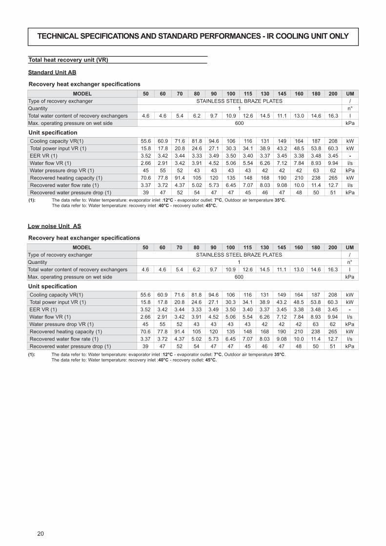
(1): The data refer to: Water temperature: evaporator inlet :12°C - evaporator outlet: 7°C, Outdoor air temperature 35°C.
The data refer to: Water temperature: recovery inlet :40°C - recovery outlet: 45°C.
Desuperheater unit (VD)
Recovery heat exchanger specifications
Standard Unit AB
Unit specification
Cooling capacity VD(1) 55.6 60.9 71.6 81.8 94.6 106 116 131 149 164 187 208 kW
Compressor power input VD (1) 15.8 17.8 20.8 24.6 27.1 30.3 34.1 38.9 43.2 48.5 53.8 60.3 kW
Total power input VD (1) 21.3 23.3 26.3 30.1 33.3 36.5 43.1 47.9 59.7 65.0 75.8 82.3 kW
EER VD (1) 2.61 2.61 2.72 2.72 2.84 2.90 2.69 2.73 2.50 2.52 2.47 2.53 -
Water flow VD (1) 2.66 2.91 3.42 3.91 4.52 5.06 5.54 6.26 7.12 7.84 8.93 9.94 l/s
Water pressure drop VD (1) 45 55 52 43 43 43 43 42 42 42 63 62 kPa
Recovered heating capacity (1) 15.7 17.6 20.0 23.6 27.1 30.4 34.4 38.4 44.0 49.3 55.4 61.3 kW
Recovered water flow rate (1) 0.75 0.84 0.96 1.13 1.29 1.45 1.64 1.83 2.10 2.36 2.65 2.93 l/s
Recovered water pressure drop (1) 9 11 14 19 15 18 11 14 18 22 18 21 kPa
MODEL 50 60 70 80 90 100 115 130 145 160 180 200 UM
Type of recovery exchanger STAINLESS STEEL BRAZE PLATES /
Quantity 1 n°
Total water content of recovery exchangers 0.6 0.6 0.6 0.6 0.8 0.8 1.3 1.3 1.3 1.3 1.8 1.8 l
Max. operating pressure on wet side 600 kPa
Recovery heat exchanger specifications
Low noise Unit AS
Unit specification
Cooling capacity VD(1) 55.6 60.9 71.6 81.8 94.6 106 116 131 149 164 187 208 kW
Compressor power input VD (1) 15.8 17.8 20.8 24.6 27.1 30.3 34.1 38.9 43.2 48.5 53.8 60.3 kW
Total power input VD (1) 21.3 23.3 26.3 30.1 33.3 36.5 43.1 47.9 59.7 65.0 75.8 82.3 kW
EER VD (1) 2.61 2.61 2.72 2.72 2.84 2.90 2.69 2.73 2.50 2.52 2.47 2.53 -
Water flow VD (1) 2.66 2.91 3.42 3.91 4.52 5.06 5.54 6.26 7.12 7.84 8.93 9.94 l/s
Water pressure drop VD (1) 45 55 52 43 43 43 43 42 42 42 63 62 kPa
Recovered heating capacity (1) 15.7 17.6 20.0 23.6 27.1 30.4 34.4 38.4 44.0 49.3 55.4 61.3 kW
Recovered water flow rate (1) 0.75 0.84 0.96 1.13 1.29 1.45 1.64 1.83 2.10 2.36 2.65 2.93 l/s
Recovered water pressure drop (1) 9 11 14 19 15 18 11 14 18 22 18 21 kPa
MODEL 50 60 70 80 90 100 115 130 145 160 180 200 UM
Type of recovery exchanger STAINLESS STEEL BRAZE PLATES /
Quantity 1 n°
Total water content of recovery exchangers 0.6 0.6 0.6 0.6 0.8 0.8 1.3 1.3 1.3 1.3 1.8 1.8 l
Max. operating pressure on wet side 600 kPa
(1): The data refer to: Water temperature: evaporator inlet :12°C - evaporator outlet: 7°C, Outdoor air temperature 35°C.
The data refer to: Water temperature: recovery inlet :40°C - recovery outlet: 45°C.

19
TECHNICAL SPECIFICATIONS AND STANDARD PERFORMANCES - IR COOLING UNIT ONLY
Recovered heating capacity Desuperheater unit (VD)
kWtr = RECOVERED HEATING CAPACITY [KW]
TWR = Desuperheater outlet water temperature, Δtin-out= 5°C
MOD. TWROUTDOOR AIR TEMPERATURE (°C D.B.)
25 30 35 40 45
kWtr = RECOVERED HEATING CAPACITY [KW]
50
30 12.8 14.7 16.9 19.3 22.0
35 12.9 14.8 17.0 19.4 22.1
40 12.6 14.4 16.6 18.9 21.6
45 11.9 13.7 15.7 17.9 20.5
50 10.9 12.5 14.3 16.4 18.7
55 9.5 10.9 12.5 14.3 16.3
60 7.7 8.8 10.1 11.6 13.2
65 5.5 6.4 7.3 8.4 9.5
70 3.0 3.5 4.0 4.6 5.2
60
30 14.6 16.8 19.0 21.7 24.6
35 14.6 16.8 19.0 21.7 24.6
40 14.2 16.3 18.6 21.2 24.0
45 13.5 15.5 17.6 20.1 22.8
50 12.4 14.2 17.0 18.5 20.9
55 10.9 12.5 15.0 16.3 18.4
60 9.0 10.4 12.5 13.5 15.3
65 6.8 7.9 9.4 10.2 11.6
70 4.3 4.9 5.9 6.4 7.2
70
30 16.6 19.0 21.6 24.7 28.0
35 16.6 19.0 21.6 24.7 28.0
40 16.1 18.6 21.1 24.1 27.3
45 15.3 17.6 20.0 22.8 25.9
50 14.0 16.2 18.4 21.0 23.8
55 12.4 14.2 16.2 18.5 20.9
60 10.3 11.8 13.4 15.4 17.4
65 7.8 8.9 10.2 11.6 13.1
70 4.8 5.6 6.3 7.2 8.2
80
30 19.4 22.2 25.4 29.2 33.4
35 19.4 22.3 25.5 29.3 33.6
40 19.0 21.7 24.9 28.6 32.8
45 18.0 20.6 23.6 27.1 31.1
50 16.4 18.8 21.6 24.8 28.4
55 14.4 16.5 18.9 21.7 24.8
60 11.8 13.5 15.5 17.8 20.4
65 8.6 9.9 11.3 13.0 14.9
70 5.0 5.7 6.5 7.5 8.6
90
30 22.5 25.6 29.2 33.3 37.8
35 22.6 25.7 29.3 33.4 38.0
40 22.1 25.1 28.6 32.6 37.1
45 20.9 23.8 27.1 30.9 35.1
50 19.1 21.8 24.8 28.3 32.1
55 16.7 19.1 21.7 24.7 28.1
60 13.7 15.6 17.8 20.3 23.1
65 10.1 11.5 13.1 14.9 17.0
70 5.9 6.7 7.6 8.7 9.9
100
30 25.5 29.0 33.0 37.5 42.5
35 25.3 28.8 32.8 37.3 42.2
40 24.7 28.1 32.0 36.3 41.1
45 23.5 26.7 30.4 34.5 39.1
50 21.7 24.7 28.2 32.0 36.2
55 19.5 22.1 25.2 28.6 32.4
60 16.7 19.0 21.6 24.5 27.8
65 13.4 15.2 17.3 19.6 22.2
70 9.5 10.8 12.3 14.0 15.8
MOD. TWROUTDOOR AIR TEMPERATURE (°C D.B.)
25 30 35 40 45
kWtr = RECOVERED HEATING CAPACITY [KW]
115
30 29.1 33.0 37.5 42.5 48.1
35 28.9 32.8 37.3 42.3 47.8
40 28.2 31.9 36.2 41.1 46.5
45 26.7 30.3 34.4 39.0 44.1
50 24.7 28.0 31.7 36.0 40.7
55 21.9 24.9 28.3 32.0 36.2
60 18.6 21.1 24.0 27.2 30.7
65 14.6 16.6 18.8 21.4 24.2
70 10.0 11.4 12.9 14.6 16.5
130
30 32.3 36.6 41.5 47.1 53.2
35 32.3 36.6 41.5 47.1 53.2
40 31.5 35.6 40.5 45.9 51.9
45 29.8 33.8 38.4 43.5 49.2
50 27.4 31.1 35.3 40.0 45.2
55 24.2 27.4 31.1 35.2 39.9
60 20.1 22.8 25.9 29.3 33.2
65 15.2 17.3 19.6 22.2 25.1
70 9.6 10.8 12.3 14.0 15.8
145
30 36.7 41.7 47.4 53.6 60.5
35 36.8 41.8 47.5 53.8 60.6
40 35.9 40.8 46.4 52.5 59.2
45 34.1 38.7 44.0 49.8 56.2
50 31.3 35.6 40.4 45.7 51.5
55 27.5 31.3 35.5 40.2 45.4
60 22.8 25.9 29.4 33.3 37.6
65 17.1 19.5 22.1 25.0 28.2
70 10.5 11.9 13.5 15.3 17.3
160
30 41.5 47.1 53.4 60.5 68.2
35 41.4 47.1 53.3 60.4 68.1
40 40.3 45.8 52.0 58.8 66.3
45 38.3 43.5 49.3 55.8 62.9
50 35.2 40.0 45.4 51.3 57.9
55 31.2 35.4 40.1 45.4 51.2
60 26.1 29.7 33.7 38.1 42.9
65 20.1 22.8 25.9 29.3 33.0
70 13.1 14.8 16.8 19.0 21.5
180
30 46.6 53.0 60.0 68.0 76.6
35 46.5 52.9 59.9 67.8 76.5
40 45.3 51.5 58.4 66.1 74.5
45 43.0 48.9 55.4 62.7 70.7
50 39.6 45.0 51.0 57.7 65.0
55 35.0 39.8 45.1 51.1 57.6
60 29.4 33.4 37.8 42.8 48.3
65 22.6 25.7 29.1 32.9 37.1
70 14.7 16.7 18.9 21.4 24.1
200
30 51.6 58.6 66.4 75.2 84.8
35 51.5 58.5 66.3 75.1 84.6
40 50.2 57.0 64.6 73.1 82.4
45 47.6 54.1 61.3 69.4 78.2
50 43.8 49.8 56.4 63.8 72.0
55 38.8 44.0 49.9 56.5 63.7
60 32.5 36.9 41.8 47.4 53.4
65 25.0 28.4 32.2 36.4 41.1
70 16.2 18.5 20.9 23.7 26.7
20
(1): The data refer to: Water temperature: evaporator inlet :12°C - evaporator outlet: 7°C, Outdoor air temperature 35°C.
The data refer to: Water temperature: recovery inlet :40°C - recovery outlet: 45°C.
Total heat recovery unit (VR)
Recovery heat exchanger specifications
Standard Unit AB
Unit specification
Cooling capacity VR(1) 55.6 60.9 71.6 81.8 94.6 106 116 131 149 164 187 208 kW
Total power input VR (1) 15.8 17.8 20.8 24.6 27.1 30.3 34.1 38.9 43.2 48.5 53.8 60.3 kW
EER VR (1) 3.52 3.42 3.44 3.33 3.49 3.50 3.40 3.37 3.45 3.38 3.48 3.45 -
Water flow VR (1) 2.66 2.91 3.42 3.91 4.52 5.06 5.54 6.26 7.12 7.84 8.93 9.94 l/s
Water pressure drop VR (1) 45 55 52 43 43 43 43 42 42 42 63 62 kPa
Recovered heating capacity (1) 70.6 77.8 91.4 105 120 135 148 168 190 210 238 265 kW
Recovered water flow rate (1) 3.37 3.72 4.37 5.02 5.73 6.45 7.07 8.03 9.08 10.0 11.4 12.7 l/s
Recovered water pressure drop (1) 39 47 52 54 47 47 45 46 47 48 50 51 kPa
MODEL 50 60 70 80 90 100 115 130 145 160 180 200 UM
Type of recovery exchanger STAINLESS STEEL BRAZE PLATES /
Quantity 1 n°
Total water content of recovery exchangers 4.6 4.6 5.4 6.2 9.7 10.9 12.6 14.5 11.1 13.0 14.6 16.3 l
Max. operating pressure on wet side 600 kPa
(1): The data refer to: Water temperature: evaporator inlet :12°C - evaporator outlet: 7°C, Outdoor air temperature 35°C.
The data refer to: Water temperature: recovery inlet :40°C - recovery outlet: 45°C.
Recovery heat exchanger specifications
Low noise Unit AS
Unit specification
Cooling capacity VR(1) 55.6 60.9 71.6 81.8 94.6 106 116 131 149 164 187 208 kW
Total power input VR (1) 15.8 17.8 20.8 24.6 27.1 30.3 34.1 38.9 43.2 48.5 53.8 60.3 kW
EER VR (1) 3.52 3.42 3.44 3.33 3.49 3.50 3.40 3.37 3.45 3.38 3.48 3.45 -
Water flow VR (1) 2.66 2.91 3.42 3.91 4.52 5.06 5.54 6.26 7.12 7.84 8.93 9.94 l/s
Water pressure drop VR (1) 45 55 52 43 43 43 43 42 42 42 63 62 kPa
Recovered heating capacity (1) 70.6 77.8 91.4 105 120 135 148 168 190 210 238 265 kW
Recovered water flow rate (1) 3.37 3.72 4.37 5.02 5.73 6.45 7.07 8.03 9.08 10.0 11.4 12.7 l/s
Recovered water pressure drop (1) 39 47 52 54 47 47 45 46 47 48 50 51 kPa
MODEL 50 60 70 80 90 100 115 130 145 160 180 200 UM
Type of recovery exchanger STAINLESS STEEL BRAZE PLATES /
Quantity 1 n°
Total water content of recovery exchangers 4.6 4.6 5.4 6.2 9.7 10.9 12.6 14.5 11.1 13.0 14.6 16.3 l
Max. operating pressure on wet side 600 kPa
TECHNICAL SPECIFICATIONS AND STANDARD PERFORMANCES - IR COOLING UNIT ONLY
21
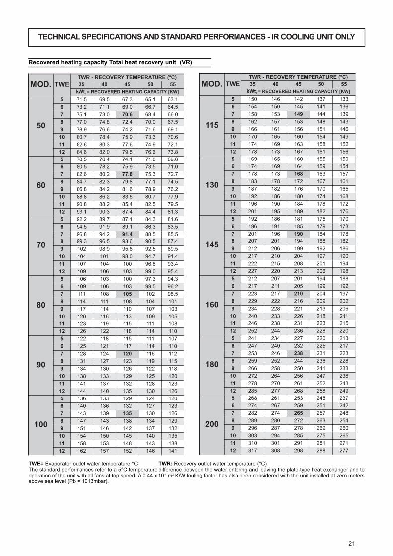
Recovered heating capacity Total heat recovery unit (VR)
MOD. TWE
TWR - RECOVERY TEMPERATURE (°C)
35 40 45 50 55
kWtr = RECOVERED HEATING CAPACITY [KW]
50
5 71.5 69.5 67.3 65.1 63.1
6 73.2 71.1 69.0 66.7 64.5
7 75.1 73.0 70.6 68.4 66.0
8 77.0 74.8 72.4 70.0 67.5
9 78.9 76.6 74.2 71.6 69.1
10 80.7 78.4 75.9 73.3 70.6
11 82.6 80.3 77.6 74.9 72.1
12 84.6 82.0 79.5 76.6 73.8
60
5 78.5 76.4 74.1 71.8 69.6
6 80.5 78.2 75.9 73.5 71.0
7 82.6 80.2 77.8 75.3 72.7
8 84.7 82.3 79.8 77.1 74.5
9 86.8 84.2 81.6 78.9 76.2
10 88.8 86.2 83.5 80.7 77.9
11 90.8 88.2 85.4 82.5 79.5
12 93.1 90.3 87.4 84.4 81.3
70
5 92.2 89.7 87.1 84.3 81.6
6 94.5 91.9 89.1 86.3 83.5
7 96.8 94.2 91.4 88.5 85.5
8 99.3 96.5 93.6 90.5 87.4
9 102 98.9 95.8 92.5 89.5
10 104 101 98.0 94.7 91.4
11 107 104 100 96.8 93.4
12 109 106 103 99.0 95.4
80
5 106 103 100 97.3 94.3
6 109 106 103 99.5 96.2
7 111 108 105 102 98.5
8 114 111 108 104 101
9 117 114 110 107 103
10 120 116 113 109 105
11 123 119 115 111 108
12 126 122 118 114 110
90
5 122 118 115 111 107
6 125 121 117 114 110
7 128 124 120 116 112
8 131 127 123 119 115
9 134 130 126 122 118
10 138 133 129 125 120
11 141 137 132 128 123
12 144 140 135 130 126
100
5 136 133 129 124 120
6 140 136 132 127 123
7 143 139 135 130 126
8 147 143 138 134 129
9 151 146 142 137 132
10 154 150 145 140 135
11 158 153 148 143 138
12 162 157 152 146 141
MOD. TWE
TWR - RECOVERY TEMPERATURE (°C)
35 40 45 50 55
kWtr = RECOVERED HEATING CAPACITY [KW]
115
5 150 146 142 137 133
6 154 150 145 141 136
7 158 153 149 144 139
8 162 157 153 148 143
9 166 161 156 151 146
10 170 165 160 154 149
11 174 169 163 158 152
12 178 173 167 161 156
130
5 169 165 160 155 150
6 174 169 164 159 154
7 178 173 168 163 157
8 183 178 172 167 161
9 187 182 176 170 165
10 192 186 180 174 168
11 196 190 184 178 172
12 201 195 189 182 176
145
5 192 186 181 175 170
6 196 191 185 179 173
7 201 196 190 184 178
8 207 201 194 188 182
9 212 206 199 192 186
10 217 210 204 197 190
11 222 215 208 201 194
12 227 220 213 206 198
160
5 212 207 201 194 188
6 217 211 205 199 192
7 223 217 210 204 197
8 229 222 216 209 202
9 234 228 221 213 206
10 240 233 226 218 211
11 246 238 231 223 215
12 252 244 236 228 220
180
5 241 234 227 220 213
6 247 240 232 225 217
7 253 246 238 231 223
8 259 252 244 236 228
9 266 258 250 241 233
10 272 264 256 247 238
11 278 270 261 252 243
12 285 277 268 258 249
200
5 268 261 253 245 237
6 274 267 259 251 242
7 282 274 265 257 248
8 289 280 272 263 254
9 296 287 278 269 260
10 303 294 285 275 265
11 310 301 291 281 271
12 317 308 298 288 277
TWE= Evaporator outlet water temperature °C TWR: Recovery outlet water temperature (°C)The standard performances refer to a 5°C temperature difference between the water entering and leaving the plate-type heat exchanger and tooperation of the unit with all fans at top speed. A 0.44 x 10⁻⁴ m2 K/W fouling factor has also been considered with the unit installed at zero metersabove sea level (Pb = 1013mbar).
TECHNICAL SPECIFICATIONS AND STANDARD PERFORMANCES - IR COOLING UNIT ONLY

22
TECHNICAL SPECIFICATIONS AND STANDARD PERFORMANCES - IP HEAT PUMP UNITS
Technical specifications of unit AB Standard Unit / AS Low noise Unit
Fan
Type Centrifugal -
Quantity 1 2 3 4 n°
Total air flow rate 29050 29050 28100 27680 41460 40100 47440 47440 62190 59820 82920 79760 m3/h
Working head NOM/MAX (3) 50 /150 rpm
Power input 5.5 6.2 9 16.5 22 kW
Model 50 60 70 80 90 100 115 130 145 160 180 200 UM
Power supply 400V - 3ph - 50 Hz V-ph-Hz
Type of refrigerant R410A /
Circuits 1 n°
Cooling capacity (1) (E) 52.9 57.5 67.2 74.1 89.2 99.0 110 122 138 154 178 198 kW
Compressors power input (1) 16.7 18.4 21.8 24.7 28.0 31.4 35.4 40.0 43.9 49.8 55.0 62.5 kW
Compressors EER 3.17 3.13 3.08 3.00 3.19 3.15 3.11 3.05 3.14 3.09 3.24 3.17 -
Total power input (1) 22.2 23.9 27.3 30.2 34.2 37.6 44.4 49.0 60.4 66.3 77.0 84.5 kW
Total power input (1) (E) 18.2 19.9 23.4 26.4 28.4 32.0 37.8 42.4 51.8 58.0 65.5 73.4 kW
Total EER 2.38 2.41 2.46 2.45 2.61 2.63 2.48 2.49 2.28 2.32 2.31 2.34 -
Total EER (E) 2.91 2.89 2.87 2.81 3.14 3.09 2.91 2.88 2.66 2.66 2.72 2.70 -
ESEER (E) 4.01 3.99 3.96 3.87 4.33 4.27 4.02 3.97 3.68 3.66 3.75 3.72 -
Water flow rate (1) 2.53 2.75 3.21 3.54 4.26 4.73 5.26 5.83 6.59 7.36 8.50 9.46 l/s
Water pressure drops (1) (E) 41 49 46 35 38 38 39 37 36 37 57 56 kPa
Working head (1) (MP) 138 120 102 85 149 137 117 98 125 100 144 109 kPa
Heating capacity (2) (E) 57.5 62.6 73.8 82.3 98.7 109 124 135 153 171 195 214 kW
Compressors power input (2) 16.7 18.5 21.9 25.1 29.0 31.4 36.4 40.1 45.1 50.0 56.2 62.6 kW
Compressor COP 3.44 3.39 3.37 3.28 3.40 3.48 3.41 3.37 3.39 3.42 3.47 3.42 -
Total power input (2) 22.2 24.0 27.4 30.6 35.2 37.6 45.4 49.1 61.6 66.5 78.2 84.6 kW
Total power input (2) (E) 18.2 20.0 23.5 26.8 29.4 32.0 38.8 42.5 53.0 58.2 66.7 73.5 kW
Total COP 2.59 2.61 2.69 2.69 2.80 2.90 2.73 2.75 2.48 2.57 2.49 2.53 -
Total COP (E) 3.16 3.13 3.14 3.07 3.36 3.41 3.20 3.18 2.89 2.94 2.92 2.91 -
Water flow rate (2) 2.75 2.99 3.53 3.93 4.72 5.22 5.92 6.45 7.31 8.17 9.32 10.23 l/s
Water pressure drops (2) (E) 48 58 55 44 47 46 49 45 45 46 68 65 kPa
Working head (2) (MP) 117 102 84 69 121 112 92 80 101 81 120 93 kPa
Data referred to standard operating condition.
(1): water temperature: in 12°C - out 7°C air temperature: in 35°C d.b.
(2): water temperature: in 40°C - out 45°C air temperature: in 7°C d.b. 87% RH
(3): Adjustable changing the diameter of the motors pulley
(MP): with standard hydronic kit MP AM STD and MP SS STD
Compressor
Heat Exchanger
Coil
Water Storage Tank (SAA accessory)
Type Scroll /
Quantity 2 n°
Load steps 0-50-100 %
Oil charge CP1 3.25 3.25 3.25 3.25 3.25 4.7 4.7 6.8 6.8 6.3 6.3 6.3 l
Oil charge CP2 3.25 3.25 3.25 3.25 4.7 4.7 6.8 6.8 6.3 6.3 6.3 6.3 l
Type Brazed plates /
Quantity 1 n°
Water volume 3.6 3.6 4.6 5.4 7.6 8.4 9.7 10.9 12.6 14.5 11.1 13.0 l
Type Aluminum fins and copper tubes /
Quantity 1 n°
Front area 3.38 4.72 5.90 7.41 m2
Water volume 200 400 460 l
Safety valve setting 600 kPa
Surge chamber volume 12 24 l
Surge chamber default pressure 150 kPa
Max. operating pressure 1000 800 kPa
Units without hydronic kit
Units with hydronic kit MP AM STD and MP SS STD (1 or 2 pumps)
Units with hydronic kit MP AM HP1 and MP SS HP1 (1 or 2 pumps)
Total maximum power input [ FLA ] 52.7 55.3 62.8 73.1 80.6 86.1 101 109 138 152 178 193 A
Total maximum power input [ FLI ] 30.3 32.5 35.9 40.3 47.1 52.7 60.9 65.6 82.7 91.5 108 119 kW
Total maximum starting current [ MIC ] 150 151 177 215 269 275 328 336 389 403 498 513 A
Total maximum power input [ FLA ] 55.9 58.5 66.0 76.3 85.4 90.9 106 114 144 158 186 201 A
Total maximum power input [ FLI ] 32.1 34.3 37.7 42.1 50.0 55.6 63.8 68.5 85.9 94.7 113 124 kW
Total maximum starting current [ MIC ] 153 155 180 218 274 279 333 341 394 409 507 521 A
Total maximum power input [ FLA ] 58.9 61.6 69.0 79.3 86.8 92.4 109 117 146 161 189 204 A
Total maximum power input [ FLI ] 34.1 36.3 39.7 44.1 50.8 56.5 65.6 70.3 87.5 96.3 115 126 kW
Total maximum starting current [ MIC ] 156 158 183 221 275 281 336 345 397 411 509 524 A
Units with hydronic kit MP PS STD (1 or 2 pumps)
Total maximum power input [ FLA ] 55.2 57.8 65.3 75.6 84.0 89.5 104 113 143 157 185 199 A
Total maximum power input [ FLI ] 31.7 33.9 37.3 41.7 48.9 54.5 62.7 67.4 85.6 94.4 112 123 kW
Total maximum starting current [ MIC ] 152 154 180 218 273 278 331 340 394 408 505 519 A
Electrical Data
(SAA): with storage tank
(E): data declared according to LCP EUROVENT certification program, Total
power input is corrected of external available static pressure as defined in
UNI EN 14511:2008

23
TECHNICAL SPECIFICATIONS AND STANDARD PERFORMANCES - IP HEAT PUMP UNITS
Standard performances in cooling mode AB Standard Unit / AS Low noise Unit
Tw= Outlet water temperature in °C kWf = refrigerating power (kW). kWa = Power input of compressors (kW)
The standard performances refer to a 5°C temperature difference between the water entering and leaving the plate-type heat exchanger and to operation of the unit
with all the fans to top speed. A 0.44 x 10⁻⁴ m2 K/W fouling factor has also been considered with the unit installed at zero meters above sea level (Pb = 1013mbar).
Mod. 50-100
MOD. Tw
OUTDOOR AIR TEMPERATURE (°C D.B.)
20 25 30 35 40 45 50
kWf kWa kWf kWa kWf kWa kWf kWa kWf kWa kWf kWa kWf kWa
50
5 60.4 11.7 56.4 13.5 53.3 14.9 50.0 16.4 46.5 18.1 43.1 19.7 39.6 21.3
6 62.1 11.8 57.9 13.6 54.8 15.0 51.4 16.5 47.8 18.2 44.3 19.9 40.7 21.5
7 63.9 11.9 59.6 13.7 56.4 15.1 52.9 16.7 49.2 18.4 45.6 20.1 41.9 21.7
8 65.7 12.1 61.3 13.9 58.0 15.3 54.4 16.9 50.6 18.6 46.9 20.3 - -
9 67.5 12.2 63.0 14.0 59.6 15.5 55.9 17.1 52.0 18.8 48.2 20.5 - -
10 69.3 12.3 64.7 14.2 61.1 15.6 57.4 17.2 53.4 19.0 49.4 20.7 - -
11 71.0 12.4 66.3 14.3 62.7 15.8 58.8 17.4 54.8 19.2 50.7 20.9 - -
12 73.0 12.6 68.1 14.5 64.4 15.9 60.4 17.6 56.2 19.4 52.1 21.1 - -
60
5 65.6 12.9 61.3 14.9 57.9 16.4 54.4 18.0 50.6 19.9 46.8 21.7 43.0 23.4
6 67.5 13.0 63.0 15.0 59.5 16.5 55.9 18.2 52.0 20.1 48.1 21.9 44.2 23.7
7 69.4 13.2 64.8 15.1 61.3 16.7 57.5 18.4 53.5 20.3 49.5 22.1 45.5 23.9
8 71.4 13.3 66.6 15.3 63.0 16.9 59.1 18.6 55.0 20.5 51.0 22.4 - -
9 73.4 13.4 68.5 15.5 64.7 17.0 60.8 18.8 56.5 20.7 52.4 22.6 - -
10 75.3 13.6 70.3 15.6 66.5 17.2 62.4 19.0 58.0 20.9 53.7 22.8 - -
11 77.2 13.7 72.1 15.8 68.2 17.4 64.0 19.2 59.5 21.1 55.1 23.0 - -
12 79.3 13.8 74.0 15.9 70.0 17.5 65.7 19.3 61.1 21.3 56.6 23.3 - -
70
5 76.7 15.3 71.6 17.6 67.7 19.4 63.5 21.4 59.1 23.6 54.8 25.7 50.3 27.8
6 78.8 15.4 73.6 17.8 69.6 19.6 65.3 21.6 60.8 23.8 56.3 25.9 51.7 28.0
7 81.1 15.6 75.7 17.9 71.6 19.8 67.2 21.8 62.5 24.0 57.9 26.2 53.2 28.3
8 83.4 15.8 77.9 18.1 73.6 20.0 69.1 22.0 64.3 24.3 59.5 26.5 - -
9 85.7 15.9 80.0 18.3 75.7 20.2 71.0 22.3 66.1 24.5 61.2 26.8 - -
10 88.0 16.1 82.1 18.5 77.7 20.4 72.9 22.5 67.8 24.8 62.8 27.0 - -
11 90.2 16.2 84.2 18.7 79.7 20.6 74.8 22.7 69.6 25.0 64.4 27.3 - -
12 92.7 16.4 86.5 18.9 81.8 20.8 76.8 22.9 71.4 25.3 66.2 27.5 - -
80
5 84.6 17.3 79.0 19.9 74.7 22.0 70.1 24.2 65.2 26.7 60.4 29.1 55.5 31.5
6 86.9 17.5 81.1 20.1 76.7 22.2 72.0 24.4 67.0 26.9 62.0 29.4 57.0 31.8
7 89.5 17.7 83.5 20.3 79.0 22.4 74.1 24.7 68.9 27.2 63.9 29.7 58.7 32.1
8 92.0 17.9 85.9 20.6 81.2 22.7 76.2 25.0 70.9 27.5 65.7 30.0 - -
9 94.5 18.0 88.2 20.8 83.4 22.9 78.3 25.2 72.8 27.8 67.5 30.3 - -
10 97.0 18.2 90.6 21.0 85.6 23.1 80.4 25.5 74.8 28.1 69.3 30.6 - -
11 100 18.4 92.9 21.2 87.8 23.3 82.4 25.7 76.7 28.4 71.0 30.9 - -
12 102 18.6 95.4 21.4 90.2 23.6 84.7 26.0 78.8 28.6 73.0 31.2 - -
90
5 102 19.6 95.0 22.6 89.9 24.9 84.3 27.5 78.5 30.3 72.7 33.0 66.8 35.7
6 105 19.8 97.7 22.8 92.4 25.1 86.7 27.7 80.6 30.5 74.7 33.3 68.6 36.0
7 108 20.0 101 23.0 95.1 25.4 89.2 28.0 83.0 30.9 76.9 33.6 70.6 36.4
8 111 20.3 103 23.3 97.7 25.7 91.7 28.3 85.3 31.2 79.0 34.0 - -
9 114 20.5 106 23.5 100 25.9 94.3 28.6 87.7 31.5 81.2 34.4 - -
10 117 20.7 109 23.8 103 26.2 96.8 28.9 90.0 31.8 83.4 34.7 - -
11 120 20.9 112 24.0 106 26.4 99.2 29.2 92.3 32.1 85.5 35.0 - -
12 123 21.1 115 24.2 109 26.7 102 29.4 94.8 32.5 87.8 35.4 - -
100
5 113 22.0 105 25.3 100 27.9 93.6 30.8 87.1 33.9 80.7 37.0 74.1 40.0
6 116 22.2 108 25.6 103 28.2 96.2 31.1 89.5 34.3 82.9 37.3 76.1 40.4
7 120 22.5 112 25.8 105 28.5 99.0 31.4 92.1 34.6 85.3 37.7 78.4 40.8
8 123 22.7 115 26.1 108 28.8 102 31.7 94.7 35.0 87.7 38.1 - -
9 126 22.9 118 26.4 111 29.1 105 32.1 97.3 35.3 90.1 38.5 - -
10 130 23.2 121 26.7 114 29.4 107 32.4 100 35.7 92.5 38.9 - -
11 133 23.4 124 26.9 117 29.7 110 32.7 102 36.0 94.9 39.3 - -
12 137 23.6 127 27.2 121 29.9 113 33.0 105 36.4 97.5 39.7 - -

24
Mod. 115-200
Tw= Outlet water temperature in °C kWf = refrigerating power (kW). kWa = Power input of compressors (kW)
The standard performances refer to a 5°C temperature difference between the water entering and leaving the plate-type heat exchanger and to operation of the unit
with all the fans to top speed. A 0.44 x 10⁻⁴ m2 K/W fouling factor has also been considered with the unit installed at zero meters above sea level (Pb = 1013mbar).
TECHNICAL SPECIFICATIONS AND STANDARD PERFORMANCES - IP HEAT PUMP UNITS
MOD. Tw
OUTDOOR AIR TEMPERATURE (°C D.B.)
20 25 30 35 40 45 50
kWf kWa kWf kWa kWf kWa kWf kWa kWf kWa kWf kWa kWf kWa
115
5 126 24.8 117 28.6 111 31.5 104 34.7 96.8 38.3 89.6 41.7 82.3 45.1
6 129 25.1 120 28.8 114 31.8 107 35.0 99.4 38.6 92.1 42.1 84.6 45.5
7 133 25.3 124 29.1 117 32.1 110 35.4 102 39.0 94.8 42.5 87.1 46.0
8 137 25.6 127 29.5 121 32.5 113 35.8 105 39.4 97.5 43.0 - -
9 140 25.9 131 29.8 124 32.8 116 36.1 108 39.8 100 43.4 - -
10 144 26.1 134 30.1 127 33.1 119 36.5 111 40.2 103 43.9 - -
11 148 26.4 138 30.3 130 33.4 122 36.9 114 40.6 105 44.3 - -
12 152 26.6 142 30.6 134 33.8 126 37.2 117 41.0 108 44.7 - -
130
5 139 28.1 130 32.3 123 35.6 115 39.2 107 43.2 99.4 47.1 91.3 51.0
6 143 28.3 134 32.6 126 35.9 119 39.6 110 43.6 102 47.6 93.8 51.4
7 147 28.6 137 32.9 130 36.3 122 40.0 114 44.1 105 48.1 96.6 52.0
8 151 28.9 141 33.3 134 36.7 125 40.4 117 44.6 108 48.6 - -
9 156 29.2 145 33.6 137 37.0 129 40.8 120 45.0 111 49.1 - -
10 160 29.5 149 34.0 141 37.4 132 41.3 123 45.5 114 49.6 - -
11 164 29.8 153 34.3 145 37.8 136 41.7 126 45.9 117 50.1 - -
12 168 30.1 157 34.6 149 38.2 139 42.1 130 46.4 120 50.5 - -
145
5 158 30.8 147 35.4 139 39.0 130 43.1 121 47.5 112 51.7 103 55.9
6 162 31.1 151 35.8 143 39.4 134 43.5 125 47.9 116 52.2 106 56.5
7 167 31.4 156 36.1 147 39.8 138 43.9 128 48.4 119 52.8 109 57.0
8 171 31.8 160 36.5 151 40.3 142 44.4 132 48.9 122 53.3 - -
9 176 32.1 164 36.9 155 40.7 146 44.8 136 49.4 126 53.9 - -
10 181 32.4 169 37.3 160 41.1 150 45.3 139 49.9 129 54.4 - -
11 185 32.7 173 37.6 164 41.5 154 45.7 143 50.4 132 54.9 - -
12 190 33.0 178 38.0 168 41.9 158 46.2 147 50.9 136 55.5 - -
160
5 176 34.9 164 40.2 155 44.3 146 48.8 135 53.8 125 58.7 115 63.5
6 181 35.3 169 40.6 159 44.7 150 49.3 139 54.3 129 59.2 118 64.0
7 186 35.6 174 41.0 164 45.2 154 49.8 143 54.9 133 59.8 122 64.7
8 191 36.0 178 41.4 169 45.7 158 50.4 147 55.5 136 60.5 - -
9 196 36.4 183 41.9 173 46.1 163 50.9 151 56.1 140 61.1 - -
10 202 36.7 188 42.3 178 46.6 167 51.4 155 56.6 144 61.7 - -
11 207 37.1 193 42.7 183 47.0 171 51.9 159 57.2 148 62.3 - -
12 212 37.5 198 43.1 188 47.5 176 52.4 164 57.7 152 62.9 - -
180
5 203 38.6 190 44.4 179 48.9 168 53.9 157 59.4 145 64.8 133 70.1
6 209 39.0 195 44.8 184 49.4 173 54.4 161 60.0 149 65.4 137 70.7
7 215 39.4 201 45.3 190 49.9 178 55.0 166 60.6 153 66.1 141 71.5
8 221 39.8 206 45.8 195 50.4 183 55.6 170 61.3 158 66.8 - -
9 227 40.2 212 46.2 200 50.9 188 56.2 175 61.9 162 67.5 - -
10 233 40.6 218 46.7 206 51.4 193 56.7 180 62.5 166 68.2 - -
11 239 41.0 223 47.2 211 52.0 198 57.3 184 63.1 171 68.8 - -
12 246 41.4 229 47.6 217 52.5 203 57.8 189 63.7 175 69.5 - -
200
5 226 43.9 211 50.5 199 55.6 187 61.3 174 67.6 161 73.7 148 79.6
6 232 44.3 217 50.9 205 56.1 192 61.9 179 68.2 166 74.3 152 80.4
7 239 44.7 223 51.5 211 56.7 198 62.5 184 68.9 171 75.1 157 81.2
8 246 45.2 229 52.0 217 57.3 204 63.2 189 69.6 175 75.9 - -
9 253 45.7 236 52.5 223 57.9 209 63.8 195 70.3 180 76.7 - -
10 259 46.1 242 53.1 229 58.5 215 64.5 200 71.0 185 77.5 - -
11 266 46.6 248 53.6 235 59.0 220 65.1 205 71.7 190 78.2 - -
12 273 47.0 255 54.1 241 59.6 226 65.7 210 72.4 195 79.0 - -

25
Standard performances in heating mode AB Standard Unit / AS Low noise Unit
Tw= Outlet water temperature in °C kWt = heating output (kW). kWa = Power input of compressors (kW)
The standard performances refer to a 5°C temperature difference between the water entering and leaving the plate-type heat exchanger, out-
door air with 87% relative humidity and to operation of the unit with all the fans to top speed. A 0.44 x 10⁻⁴ m2 K/W fouling factor has also
been considered with the unit installed at zero meters above sea level (Pb = 1013mbar).
NOTE
For air temperatures of less than 7°C, the heating capacity is declared without considering the effect of the thawing cycles, strictly cor-
related with the humidity in the outdoor air.
TECHNICAL SPECIFICATIONS AND STANDARD PERFORMANCES - IP HEAT PUMP UNITS
MOD. Tw
OUTDOOR AIR TEMPERATURE (°C D.B.)
-6 -2 2 6 9 12 15
kWt kWa kWt kWa kWt kWa kWt kWa kWt kWa kWt kWa kWt kWa
50
30 43.9 11.9 50.3 12.0 55.0 12.1 58.5 12.2 62.7 12.3 67.1 12.5 71.7 12.6
35 43.7 13.2 50.0 13.3 54.7 13.4 58.2 13.5 62.4 13.7 66.7 13.8 71.4 14.0
40 43.4 14.7 49.7 14.7 54.4 14.9 57.9 15.0 62.0 15.2 66.3 15.4 71.0 15.5
45 43.1 16.3 49.4 16.4 54.0 16.6 57.5 16.7 61.6 16.9 65.9 17.1 70.5 17.3
50 42.8 18.1 49.1 18.2 53.6 18.5 57.1 18.6 61.2 18.8 65.4 19.0 70.0 19.2
60
30 47.8 13.2 54.8 13.2 60.0 13.4 63.8 13.5 68.4 13.7 73.1 13.8 78.2 14.0
35 47.6 14.6 54.5 14.7 59.7 14.9 63.4 15.0 68.0 15.1 72.7 15.3 77.8 15.5
40 47.3 16.2 54.2 16.3 59.3 16.6 63.1 16.6 67.6 16.8 72.3 17.0 77.4 17.2
45 47.0 18.0 53.9 18.1 58.9 18.4 62.6 18.5 67.2 18.7 71.8 18.9 76.8 19.1
50 46.7 20.1 53.5 20.2 58.5 20.4 62.6 20.6 66.7 20.8 71.3 21.0 76.3 21.3
70
30 56.4 15.6 64.6 15.7 70.6 15.9 75.1 16.0 80.6 16.2 86.1 16.4 92.1 16.5
35 56.1 17.3 64.2 17.4 70.3 17.6 74.7 17.7 80.1 17.9 85.7 18.1 91.7 18.3
40 55.7 19.2 63.9 19.3 69.9 19.6 74.3 19.7 79.7 19.9 85.2 20.2 91.1 20.4
45 55.4 21.4 63.4 21.5 69.4 21.8 73.8 21.9 79.1 22.2 84.6 22.4 90.5 22.7
50 55.0 23.7 63.0 23.9 68.9 24.2 73.3 24.3 78.6 24.6 84.0 24.9 89.9 25.2
80
30 62.8 17.9 72.0 18.0 78.8 18.2 83.8 18.3 89.8 18.5 96.1 18.8 103 19.0
35 62.5 19.8 71.7 19.9 78.4 20.2 83.3 20.3 89.4 20.5 95.6 20.8 102 21.0
40 62.2 22.0 71.2 22.1 77.9 22.5 82.9 22.6 88.9 22.8 95.0 23.1 102 23.4
45 61.7 24.5 70.8 24.6 77.4 25.0 82.3 25.1 88.3 25.4 94.4 25.7 101 26.0
50 61.3 27.2 70.3 27.4 76.8 27.7 81.7 27.9 87.6 28.2 93.7 28.6 100 28.9
90
30 75.4 20.6 86.4 20.8 94.5 21.1 100 21.2 108 21.4 115 21.7 123 21.9
35 75.0 22.9 85.9 23.0 94.0 23.3 100 23.5 107 23.7 115 24.0 123 24.3
40 74.6 25.4 85.5 25.6 93.5 25.9 99.4 26.1 107 26.4 114 26.7 122 27.0
45 74.0 28.3 84.9 28.4 92.8 28.8 98.7 29.0 106 29.3 113 29.7 121 30.0
50 73.5 31.4 84.3 31.6 92.2 32.1 98.0 32.2 105 32.6 112 33.0 120 33.4
100
30 83.4 22.4 95.5 22.5 105 22.8 111 22.9 119 23.2 127 23.5 136 23.7
35 82.9 24.8 95.1 24.9 104 25.3 111 25.4 119 25.7 127 26.0 136 26.3
40 82.5 27.5 94.5 27.7 103 28.1 110 28.3 118 28.6 126 28.9 135 29.2
45 81.9 30.6 93.9 30.8 103 31.2 109 31.4 117 31.8 125 32.1 134 32.5
50 81.3 34.0 93.2 34.2 102 34.7 108 34.9 116 35.3 124 35.7 133 36.1
115
30 94.7 25.9 109 26.1 119 26.4 126 26.6 135 26.9 145 27.2 155 27.5
35 94.2 28.7 108 28.9 118 29.3 126 29.5 135 29.8 144 30.1 154 30.5
40 93.7 31.9 107 32.1 117 32.6 125 32.8 134 33.1 143 33.5 153 33.9
45 93.0 35.5 107 35.7 117 36.2 124 36.4 133 36.8 142 37.2 152 37.7
50 92.4 39.5 106 39.7 116 40.2 123 40.5 132 40.9 141 41.4 151 41.9
130
30 103 28.5 118 28.7 129 29.1 137 29.3 147 29.6 158 30.0 169 30.3
35 103 31.6 118 31.8 129 32.3 137 32.5 147 32.8 157 33.2 168 33.6
40 102 35.2 117 35.4 128 35.9 136 36.1 146 36.5 156 36.9 167 37.3
45 101 39.1 116 39.3 127 39.9 135 40.1 145 40.6 155 41.0 166 41.5
50 101 43.5 115 43.7 126 44.3 134 44.6 144 45.1 154 45.6 164 46.1
145
30 117 32.1 134 32.3 146 32.7 156 32.9 167 33.3 179 33.7 191 34.1
35 116 35.6 133 35.8 146 36.3 155 36.5 166 36.9 178 37.3 190 37.8
40 116 39.6 132 39.8 145 40.3 154 40.6 165 41.1 177 41.5 189 42.0
45 115 44.0 132 44.2 144 44.8 153 45.1 164 45.6 175 46.1 188 46.7
50 114 48.9 131 49.2 143 49.9 152 50.1 163 50.7 174 51.3 186 51.9
160
30 131 35.6 150 35.8 164 36.3 174 36.5 187 36.9 200 37.4 214 37.8
35 130 39.4 149 39.7 163 40.2 173 40.5 186 40.9 199 41.4 212 41.9
40 129 43.9 148 44.1 162 44.7 172 45.0 185 45.5 197 46.0 211 46.6
45 128 48.7 147 49.0 161 49.7 171 50.0 183 50.6 196 51.2 210 51.7
50 127 54.2 146 54.5 160 55.3 170 55.6 182 56.2 195 56.9 208 57.5
180
30 149 40.0 171 40.2 187 40.8 199 41.0 213 41.5 228 42.0 244 42.5
35 148 44.3 170 44.6 186 45.2 198 45.5 212 46.0 226 46.5 242 47.1
40 147 49.3 169 49.6 185 50.3 196 50.6 211 51.2 225 51.7 241 52.3
45 146 54.8 168 55.1 183 55.9 195 56.2 209 56.8 224 57.5 239 58.1
50 145 60.9 167 61.3 182 62.1 194 62.5 208 63.2 222 63.9 238 64.6
200
30 164 44.6 187 44.8 205 45.4 218 45.7 234 46.2 250 46.8 267 47.3
35 163 49.4 186 49.7 204 50.4 217 50.7 233 51.2 249 51.8 266 52.4
40 162 54.9 185 55.2 203 56.0 216 56.3 231 57.0 247 57.6 264 58.3
45 161 61.0 184 61.4 201 62.2 214 62.6 230 63.3 246 64.0 263 64.8
50 160 67.9 183 68.3 200 69.2 213 69.6 228 70.4 244 71.2 261 72.0

26
!
TECHNICAL SPECIFICATIONS AND STANDARD PERFORMANCES - IP HEAT PUMP UNITS
(1): The data refer to: Water temperature: evaporator inlet :12°C - evaporator outlet: 7°C, Outdoor air temperature 35°C.
The data refer to: Water temperature: recovery inlet :40°C - recovery outlet: 45°C.
NOTE : THE HEATING CAPACITY RECOVERED BY THE DESUPERHEATER EXCLUSIVELY REFERS TO UNITS
OPERATING IN THE COOLING MODE.
Desuperheater unit (VD)
Recovery heat exchanger specifications
Standard Unit AB
Unit specification
Cooling capacity VD(1) 55.0 59.8 69.9 77.1 92.8 103 114 127 144 160 185 206 kW
Compressor power input VD (1) 16.0 17.7 20.9 23.7 26.9 30.1 34.0 38.4 42.1 47.8 52.8 60.0 kW
Total power input VD (1) 21.5 23.2 26.4 29.2 33.1 36.3 43.0 47.4 58.6 64.3 74.8 82.0 kW
EER VD (1) 2.56 2.58 2.65 2.64 2.80 2.84 2.65 2.68 2.46 2.49 2.47 2.51 -
Water flow VD (1) 2.63 2.86 3.34 3.68 4.43 4.92 5.45 6.07 6.88 7.64 8.84 9.84 l/s
Water pressure drop VD (1) 44 53 49 38 41 41 42 40 40 40 61 60 kPa
Recovered heating capacity (1) 15.2 17.0 19.4 22.9 26.2 29.2 33.2 37.1 42.4 47.5 52.4 58.1 kW
Recovered water flow rate (1) 0.73 0.81 0.93 1.10 1.25 1.39 1.58 1.77 2.03 2.27 2.50 2.78 l/s
Recovered water pressure drop (1) 8 10 13 18 14 17 10 13 17 20 16 19 kPa
MODEL 50 60 70 80 90 100 115 130 145 160 180 200 UM
Type of recovery exchanger STAINLESS STEEL BRAZE PLATES /
Quantity 1 n°
Total water content of recovery exchangers 0.6 0.6 0.6 0.6 0.8 0.8 1.3 1.3 1.3 1.3 1.8 1.8 l
Max. operating pressure on wet side 600 kPa
Recovery heat exchanger specifications
Low noise Unit AS
Unit specification
Cooling capacity VD(1) 55.0 59.8 69.9 77.1 92.8 103 114 127 144 160 185 206 kW
Compressor power input VD (1) 16.0 17.7 20.9 23.7 26.9 30.1 34.0 38.4 42.1 47.8 52.8 60.0 kW
Total power input VD (1) 21.5 23.2 26.4 29.2 33.1 36.3 43.0 47.4 58.6 64.3 74.8 82.0 kW
EER VD (1) 2.56 2.58 2.65 2.64 2.80 2.84 2.65 2.68 2.46 2.49 2.47 2.51 -
Water flow VD (1) 2.63 2.86 3.34 3.68 4.43 4.92 5.45 6.07 6.88 7.64 8.84 9.84 l/s
Water pressure drop VD (1) 44 53 49 38 41 41 42 40 40 40 61 60 kPa
Recovered heating capacity (1) 15.2 17.0 19.4 22.9 26.2 29.2 33.2 37.1 42.4 47.5 52.4 58.1 kW
Recovered water flow rate (1) 0.73 0.81 0.93 1.10 1.25 1.39 1.58 1.77 2.03 2.27 2.50 2.78 l/s
Recovered water pressure drop (1) 8 10 13 18 14 17 10 13 17 20 16 19 kPa
MODEL 50 60 70 80 90 100 115 130 145 160 180 200 UM
Type of recovery exchanger STAINLESS STEEL BRAZE PLATES /
Quantity 1 n°
Total water content of recovery exchangers 0.6 0.6 0.6 0.6 0.8 0.8 1.3 1.3 1.3 1.3 1.8 1.8 l
Max. operating pressure on wet side 600 kPa
!
(1): The data refer to: Water temperature: evaporator inlet :12°C - evaporator outlet: 7°C, Outdoor air temperature 35°C.
The data refer to: Water temperature: recovery inlet :40°C - recovery outlet: 45°C.
NOTE : THE HEATING CAPACITY RECOVERED BY THE DESUPERHEATER EXCLUSIVELY REFERS TO UNITS
OPERATING IN THE COOLING MODE.

27
TECHNICAL SPECIFICATIONS AND STANDARD PERFORMANCES - IP HEAT PUMP UNITS
Recovered heating capacity Desuperheater unit (VD)
kWtr = RECOVERED HEATING CAPACITY [KW]
TWR = Desuperheater outlet water temperature, Δtin-out= 5°C
MOD. TWROUTDOOR AIR TEMPERATURE (°C D.B.)
25 30 35 40 45
kWtr = RECOVERED HEATING CAPACITY [KW]
50
30 12.4 14.2 16.3 18.6 21.2
35 12.4 14.2 16.4 18.7 21.3
40 12.2 13.9 16.0 18.3 20.8
45 11.5 13.2 15.2 17.4 19.8
50 10.6 12.1 13.9 15.9 18.1
55 9.3 10.6 12.2 14.0 15.9
60 7.6 8.8 10.1 11.5 13.1
65 5.7 6.5 7.5 8.5 9.7
70 3.3 3.8 4.4 5.0 5.7
60
30 13.9 15.9 18.2 20.8 23.6
35 14.0 16.0 18.3 20.9 23.8
40 13.7 15.7 17.9 20.4 23.2
45 13.0 14.9 17.0 19.4 22.1
50 11.9 13.7 16.4 17.8 20.2
55 10.4 12.0 14.4 15.6 17.7
60 8.6 9.9 11.9 12.9 14.6
65 6.4 7.3 8.8 9.5 10.8
70 3.8 4.3 5.2 5.6 6.4
70
30 15.9 18.2 20.8 23.7 27.0
35 15.9 18.3 20.9 23.9 27.1
40 15.6 17.9 20.4 23.3 26.5
45 14.8 17.0 19.4 22.2 25.2
50 13.6 15.6 17.8 20.3 23.1
55 11.9 13.7 15.6 17.8 20.3
60 9.8 11.3 12.9 14.7 16.7
65 7.3 8.3 9.5 10.9 12.4
70 4.3 4.9 5.6 6.4 7.3
80
30 18.7 21.5 24.6 28.2 32.0
35 18.8 21.6 24.7 28.3 32.2
40 18.3 21.1 24.2 27.6 31.4
45 17.4 20.0 22.9 26.2 29.8
50 15.9 18.3 21.0 24.0 27.3
55 13.9 16.0 18.4 21.0 23.9
60 11.4 13.2 15.1 17.2 19.6
65 8.4 9.7 11.1 12.7 14.5
70 4.9 5.7 6.5 7.4 8.4
90
30 21.7 24.8 28.2 32.3 36.7
35 21.8 24.9 28.3 32.4 36.8
40 21.2 24.3 27.6 31.6 36.0
45 20.1 23.0 26.2 30.0 34.1
50 18.4 21.1 24.0 27.4 31.2
55 16.1 18.5 21.0 24.0 27.3
60 13.2 15.2 17.2 19.7 22.4
65 9.8 11.2 12.7 14.5 16.5
70 5.7 6.5 7.4 8.5 9.6
100
30 24.4 27.8 31.5 35.8 40.5
35 24.5 27.9 31.6 35.9 40.6
40 23.9 27.2 30.8 35.0 39.6
45 22.6 25.7 29.2 33.2 37.5
50 20.7 23.5 26.7 30.3 34.3
55 18.1 20.6 23.3 26.5 30.0
60 14.8 16.8 19.1 21.7 24.5
65 10.8 12.3 14.0 15.9 18.0
70 6.2 7.0 8.0 9.1 10.3
MOD. TWROUTDOOR AIR TEMPERATURE (°C D.B.)
25 30 35 40 45
kWtr = RECOVERED HEATING CAPACITY [KW]
115
30 27.8 31.6 35.9 40.6 45.8
35 27.8 31.6 35.9 40.6 45.8
40 27.1 30.8 35.0 39.6 44.7
45 25.7 29.3 33.2 37.6 42.5
50 23.7 26.9 30.5 34.6 39.1
55 20.9 23.8 27.0 30.6 34.5
60 17.5 19.9 22.6 25.6 28.9
65 13.4 15.2 17.3 19.6 22.1
70 8.6 9.8 11.1 12.6 14.2
130
30 31.2 35.3 40.1 45.4 51.4
35 31.2 35.3 40.1 45.4 51.4
40 30.4 34.5 39.1 44.3 50.1
45 28.9 32.7 37.1 42.0 47.5
50 26.5 30.0 34.1 38.6 43.7
55 23.4 26.5 30.1 34.1 38.5
60 19.5 22.1 25.1 28.4 32.1
65 14.8 16.8 19.1 21.6 24.4
70 9.4 10.6 12.0 13.6 15.4
145
30 35.7 40.6 46.0 52.1 58.8
35 35.7 40.5 45.9 52.0 58.7
40 34.7 39.5 44.7 50.6 57.2
45 33.0 37.4 42.4 48.1 54.3
50 30.3 34.5 39.0 44.2 49.9
55 26.9 30.5 34.6 39.2 44.2
60 22.5 25.6 29.0 32.9 37.1
65 17.4 19.7 22.3 25.3 28.6
70 11.3 12.9 14.6 16.5 18.7
160
30 39.8 45.2 51.2 58.0 65.5
35 39.9 45.3 51.4 58.2 65.7
40 39.0 44.3 50.1 56.8 64.2
45 36.9 41.9 47.5 53.8 60.8
50 33.8 38.3 43.4 49.2 55.6
55 29.5 33.5 38.0 43.0 48.6
60 24.2 27.4 31.1 35.2 39.7
65 17.7 20.1 22.8 25.8 29.1
70 10.1 11.5 13.0 14.8 16.7
180
30 43.9 49.8 56.5 64.0 72.2
35 44.1 50.0 56.7 64.2 72.5
40 43.0 48.8 55.3 62.7 70.8
45 40.7 46.3 52.4 59.4 67.0
50 37.3 42.3 47.9 54.3 61.3
55 32.6 37.0 41.9 47.5 53.6
60 26.6 30.3 34.3 38.8 43.8
65 19.5 22.2 25.1 28.5 32.1
70 11.2 12.7 14.4 16.3 18.4
200
30 48.7 55.3 62.6 70.9 80.1
35 48.8 55.5 62.8 71.2 80.4
40 47.7 54.1 61.3 69.5 78.5
45 45.2 51.3 58.1 65.8 74.3
50 41.3 46.9 53.1 60.2 68.0
55 36.1 41.0 46.4 52.6 59.4
60 29.5 33.5 38.0 43.1 48.6
65 21.6 24.6 27.8 31.5 35.6
70 12.4 14.1 15.9 18.1 20.4

28
CORRECTION FACTOR FOR THE USE OF GLYCOL
Percentage Of glycol in mass / volume 0 / 0 10 / 9.6 20 / 19.4 30 / 29.4 40 / 39.6
Freezing point [°C] 0 -3.3 -7 -13 -21
Heating capacity CCPF Power input CCPA 1.000 0.990 0.975 0.965 0.955
Compressor power input CCPA 1.000 1.010 1.020 1.030 1.040
Water flow rate CCQA 1.000 1.018 1.032 1.053 1.082
Water pressure drop CCDP 1.000 1.026 1.051 1.077 1.103
Percentage Of glycol in mass / volume 0 / 0 10 / 8.9 20 / 18.1 30 / 27.7 40 / 37.5
Freezing point [°C] 0 -3.2 -8 -14 -22
Heating capacity CCPF Power input CCPA 1.000 0.995 0.985 0.975 0.970
Compressor power input CCPA 1.000 1.010 1.015 1.020 1.030
Water flow rate CCQA 1.000 1.038 1.062 1.091 1.127
Water pressure drop CCDP 1.000 1.026 1.051 1.077 1.103
Percentage Of glycol in mass / volume 0 / 0 10 / 9.6 20 / 19.4 30 / 29.4 40 / 39.6
Freezing point [°C] 0 -3.3 -7 -13 -21
Cooling capacity CCPF Power input CCPA 1.00 0.98 0.96 0.94 0.92
Compressor power input CCPA 1.00 0.99 0.98 0.95 0.93
Water flow rate CCQA 1.00 1.01 1.03 1.06 1.09
Water pressure drop CCDP 1.00 1.05 1.11 1.22 1,38
Percentage Of glycol in mass / volume 0 / 0 10 / 8.9 20 / 18.1 30 / 27.7 40 / 37.5
Freezing point [°C] 0 -3.2 -8 -14 -22
Cooling capacity CCPF Power input CCPA 1.00 0.99 0.98 0.97 0.95
Compressor power input CCPA 1.00 1.00 0.99 0.99 0.98
Water flow rate CCQA 1.00 1.04 1.08 1.12 1.16
Water pressure drop CCDP 1.00 1.08 1.16 1.25 1.35
Correction factor for the use of glycol IN HEATING MODE
Correction factor for the use of glycol IN COOLING MODE
Correction factor for the use of ethylene glycol with water produced between 30÷55ºC.
Correction factor for the use of Propylene Glycol with water produced between 30÷55ºC.
Correction factor for the use of ethylene glycol with water produced between 5÷20ºC.
Correction factor for the use of Propylene Glycol with water produced between 5÷20ºC.

29
GENERAL SPECIFICATIONS - BRINE UNIT BR - BP
Specific data fot Brine Unit (BR-BP)
Correction factors to apply to the basic version data
A calculation example showing how the table is used is given below.
Consider unit IR 160.2 in the Basic Version with air temperature: in 35°C d.b. and water temperature out 7°C:
- Cooling capacity of the Basic Version unit (VB): PfVB = 158 kW
- Power input of the Compressors in the Basic Version unit (VB): PassCP,VB= 53.2 kW
- Water Flow Rate of the Basic Version unit (VB): QVB= 7.55 l/s
- Water pressure drop of the Basic Version unit (VB): ΔpVB= 39 kPa
- with 30% brine and -2°C temperature of the water produced
The corresponding values for the Brine Unit are:
- Cooling capacity PfBR/BP = PfVB x (0.725) = 115 kW
- Compressor power input PassCP,BR/BP = PassCP,VB x (0.92)= 48.9 kW
- Water flow rate QBR/BP= QVB x (0.78)= 5.89 l/s
- Water pressure drop ΔpBR/BP =ΔpVB x (1.155)= 32 kPa
If you need to calculate the performances of the unit with outdoor air temp. different than 35°C, you have to use the values for PfVB and
PassCP,VB reported on the tables standard performances for the requisited air temp. and with water leaving temp=7°C.
With PfVB calculate QVB and using the graph water pressure drop Basic Version you have ΔpVB. Then apply the corrective coefficients indica-
ted on the tables for BR-BP.
In case of other type of antifreezing fluid please contact our sales office.
ETHYLENE GLYCOL PROPYLENE GLYCOL
Percentage Of glycol
in mass / volume10 / 8.9
freezing point [°C] -3.2
Produced water
temperature4 2 0 -2 -4 -6 -8 -10 -12 4 2 0 -2 -4 -6 -8 -10 -12
Cooling capacityr c.f. 0.926 0.869 0.812 - - - - - - 0.890 0.819 0.751 - - - - - -
Compressor power input c.f. 0.974 0.964 0.954 - - - - - - 0.974 0.964 0.954 - - - - - -
Water flow rate c.f. 0.943 0.885 0.828 - - - - - - 0.943 0.885 0.828 - - - - - -
Water pressure drop c.f. 1.040 1.045 1.050 - - - - - - 1.040 1.045 1.050 - - - - - -
Percentage Of glycol
in mass / volume20 / 18.1
freezing point [°C] -8
Produced water
temperature4 2 0 -2 -4 -6 -8 -10 -12 4 2 0 -2 -4 -6 -8 -10 -12
Cooling capacityr c.f. 0.912 0.855 0.798 0.738 0.683 - - - - 0.874 0.807 0.740 0.690 0.641 - - - -
Compressor power input c.f. 0.967 0.957 0.947 0.927 0.897 - - - - 0.945 0.935 0.925 0.900 0.875 - - - -
Water flow rate c.f. 0.955 0.895 0.836 0.773 0.715 - - - - 0.915 0.845 0.774 0.723 0.671 - - - -
Water pressure drop c.f. 1.090 1.095 1.100 1.110 1.120 - - - - 1.110 1.115 1.120 1.130 1.140 - - - -
Percentage Of glycol
in mass / volume30 / 27.7
freezing point [°C] -14
Produced water
temperature4 2 0 -2 -4 -6 -8 -10 -12 4 2 0 -2 -4 -6 -8 -10 -12
Cooling capacityr c.f. 0.899 0.842 0.785 0.725 0.670 0.613 0.562 - - 0.869 0.799 0.729 0.680 0.630 0.583 0.536 - -
Compressor power input c.f. 0.960 0.950 0.940 0.920 0.890 0.870 0.840 - - 0.935 0.923 0.910 0.888 0.865 0.838 0.810 - -
Water flow rate c.f. 0.967 0.905 0.844 0.780 0.720 0.659 0.604 - - 0.934 0.859 0.784 0.731 0.678 0.627 0.576 - -
Water pressure drop c.f. 1.140 1.145 1.150 1.155 1.160 1.175 1.190 - - 1.160 1.175 1.190 1.200 1.210 1.255 1.300 - -
Percentage Of glycol
in mass / volume40 / 37.5
freezing point [°C] -22
Produced water
temperature4 2 0 -2 -4 -6 -8 -10 -12 4 2 0 -2 -4 -6 -8 -10 -12
Cooling capacityr c.f. 0.884 0.827 0.770 0.710 0.655 0.598 0.547 0.490 0.437 0.848 0.784 0.719 0.670 0.620 0.570 0.520 0.478 0.438
Compressor power input c.f. 0.880 0.870 0.860 0.840 0.810 0.790 0.760 0.724 0.686 0.865 0.855 0.845 0.820 0.795 0.773 0.750 0.714 0.680
Water flow rate c.f. 1.150 1.151 1.153 1.154 1.155 1.157 1.158 1.159 1.161 1.116 1.114 1.112 1.110 1.108 1.107 1.105 1.103 1.101
Water pressure drop c.f. 1.190 1.195 1.200 1.210 1.220 1.235 1.250 1.269 1.290 1.230 1.275 1.320 1.375 1.430 1.500 1.570 1.642 1.724

30
NOISE LEVELS
The noise levels refer to units operating in the nominal conditions (water temperature:inlet: 12°C - outlet: 7°C, Outdoor air temperature 35°C), due to a change of external airtemperature noise levels may change to ensure proper functioning of the unit within ope-rating range.The acoustic pressure levels are calculated 1/ 5 / 10 meters away from the outer surfaceof the unit operating in the free field and resting on a reflecting surface (directional factorof 2).
SWL = Sound power levels, with reference to 1x10-12 W.The Total sound power level in dB(A) measured in compliance with ISO 9614 stan-dards, is certified according to the Eurovent certification program and it is the onlymandatory value (the values of octave band in the table are indicative).Eurovent certification (E) exclusively refers to the Total Sound Power in db(A), which istherefore the only binding acoustic specification (the values of the Octave bands in thetable are indicative).SPL = Sound pressure levels, with reference to 2x10⁻⁵ Pa.The sound pressure levels are values calculated by applying the ISO-3744 relation(Eurovent 8/1) and refer to a distance of 1 meter away from the external surface ofunits operating in the open field with directivity factor 2 (Q=2) and the units operating innominal conditions in the cooling mode.
AS Low noise unit
AB Standard unit
Mod.
SWL (dB)SPL (dBA)
Octave bands (Hz) Total
63 125 250 500 1000 2000 4000 8000 dB dB(A)(E) 1m 5m 10m
50 83.3 82.0 82.4 84.4 82.5 83.4 80.9 75.5 91 89 71 62 57
60 83.3 82.0 82.4 84.4 82.5 83.4 80.9 75.5 91 89 71 62 57
70 83.3 82.0 82.4 84.4 82.5 83.4 80.9 75.5 91 89 71 62 57
80 83.3 82.0 82.4 84.4 82.5 83.4 80.9 75.5 91 89 71 62 57
90 85.8 84.2 83.9 85.9 84.5 85.4 84.0 80.0 94 91 73 65 59
100 85.8 84.2 83.9 85.9 84.5 85.4 84.0 80.0 94 91 73 65 59
115 94.6 91.1 90.4 92.1 89.8 90.1 88.9 84.5 100 96 78 69 64
130 94.6 91.1 90.4 92.1 89.8 90.1 88.9 84.5 100 96 78 69 64
145 95.2 91.7 91.0 92.7 90.4 90.7 89.5 85.1 101 97 79 70 65
160 95.2 91.7 91.0 92.7 90.4 90.7 89.5 85.1 101 97 79 70 65
180 101.8 98.2 96.8 95.7 93.3 89.8 83.6 85.5 105 98 79 71 66
200 101.8 98.2 96.8 95.7 93.3 89.8 83.6 85.5 105 98 79 71 66
Mod.
SWL (dB)SPL (dBA)
Octave bands (Hz) Total
63 125 250 500 1000 2000 4000 8000 dB dB(A)(E) 1m 5m 10m
50 80.2 78.9 79.3 81.3 79.4 80.3 77.8 72.4 88 86 68 59 54
60 80.2 78.9 79.3 81.3 79.4 80.3 77.8 72.4 88 86 68 59 54
70 80.2 78.9 79.3 81.3 79.4 80.3 77.8 72.4 88 86 68 59 54
80 80.2 78.9 79.3 81.3 79.4 80.3 77.8 72.4 88 86 68 59 54
90 82.8 81.2 80.9 82.9 81.5 82.4 81.0 77.0 91 88 70 62 56
100 82.8 81.2 80.9 82.9 81.5 82.4 81.0 77.0 91 88 70 62 56
115 91.6 88.1 87.4 89.1 86.8 87.1 85.9 81.5 97 93 75 66 61
130 91.6 88.1 87.4 89.1 86.8 87.1 85.9 81.5 97 93 75 66 61
145 92.2 88.7 88.0 89.7 87.4 87.7 86.5 82.1 98 94 76 67 62
160 92.2 88.7 88.0 89.7 87.4 87.7 86.5 82.1 98 94 76 67 62
180 98.8 95.2 93.8 92.7 90.3 86.8 80.6 82.5 102 95 76 68 63
200 98.8 95.2 93.8 92.7 90.3 86.8 80.6 82.5 102 95 76 68 63
(E): data declared according to LCP EUROVENT certification program. The values are for units without options and accessories.
Open field
Q=2

31
OPERATING RANGE
In these applications, it’s advisable to use brine.
With condensation control accessory (IMV)
With condensation control accessory (IMV)
COOLING MODE
HEATING MODE
Operating range
The graphs below give the operating ranges within which correct operation of the units is guaranteed.
The use of the units in conditions differing from those indicated will void the warranty with which the product is supplied.
In the following table, there are the thermal water head limit values of the unit.
Thermal Water Head Limit value
Minimum °C 3
Maximum °C 8
7-7
30
45
5550
2
[°C]
[°C B.S.]40
OUTLET WATER
TEMPERATURE
OUTDOOR AIR
TEMPERATURE
0 15 35 5040
5
7
25
[°C]
[°C B.S.]-10
OUTLET WATER
TEMPERATURE
ΔT Water= 5°C
OUTDOOR AIR
TEMPERATURE
COOLING MODE Brine Unit BR - BP
0 35 43 46-10
-5
5
[°C]
[°C B.S.]-12
15
OUTLET WATER
TEMPERATURE
OUTDOOR AIR
TEMPERATURE
Use water glicol as specified in the paragraph “Specification data for Brine Unit BR - BP”.
Note: Make sure the water flow is within the minimum and maximum pressure drop as reported "water pressure
drop plate heat exchanger ".

32
WATER PRESSURE DROP PLATE HEAT EXCHANGER
The graph below illustrates the water pressure drop values in kPa depending on the flow rate in liters/second. The operating
range is delimited by the minimum and maximum values given in the next table.
Wate
r p
res
su
re d
rop
(k
Pa
)
Water flow rate (l/s)
Operation range
Unit Size 50 60 70 80 90 100 115 130 145 160 180 200 UM NOTES
Graph reference 1 2 3 4 5 6 7 8 9 10 11Q=Water flow
rate
Δp=Water pressu-
re drop
Lower limit value
Q 1.2 1.5 1.9 2.2 2.4 2.7 3.1 3.5 3.8 3.6 4.0 l\s
Δp 10 kPa
Upper limit value
Q 4.8 5.8 7.3 8.5 9.3 10.4 11.9 13.4 14.9 13.8 15.5 l\s
Δp 150 kPa
Max. operating pressure on
wet side600 kPa
10
20
30
40
50
60
70
80
90
100
110
120
130
140
150
0.50 2.50 4.50 6.50 8.50 10.50 12.50 14.50 16.50
2 3 4 5 6 7 8 9101 11

33
WATER PRESSURE DROP OF THE DESUPERHEATER VD
The graph below illustrates the water pressure drop values in kPa depending on the flow rate in liters/second, for the Special
Versions with Desuperheater (VD) in both the units that operate in the Cooling mode only (IR) and in Heat Pump units (IP).
The operating range is delimited by the minimum and maximum values given in the next table.
Wate
r p
ressu
re d
rop
(k
Pa
)
Water flow rate (l/s)
Operation range
Unit Size 50 60 70 80 90 100 115 130 145 160 180 200 UM NOTES
Graph reference 1 2 3 4Q=Water flow
rate
Δp=Water pressu-
re drop
Lower limit value
Q 0.8 1.0 1.5 1.9 l\s
Δp 10 kPa
Upper limit value
Q 3.0 3.9 5.7 7.4 l\s
Δp 150 kPa
Max. operating
pressure on wet side600 kPa
10
20
30
40
50
60
70
80
90
100
110
120
130
140
150
0.00 1.00 2.00 3.00 4.00 5.00 6.00 7.00 8.00
2 3 41

34
WATER PRESSURE DROP TOTAL HEAT RECOVERY VR
The graph below illustrates the water pressure drop values in kPa depending on the flow rate in liters/second, for the Special
Versions with Total heat recovery (VD) in both the units that operate in the Cooling mode only (IR).
The operating range is delimited by the minimum and maximum values given in the next table.
Wate
r p
ress
ure
dro
p (
kP
a)
Water flow rate (l/s)
Operation range
10
20
30
40
50
60
70
80
90
100
110
120
130
140
150
0.5 1.5 2.5 3.5 4.5 5.5 6.5 7.5 8.5 9.5 10.5 11.5 12.5 13.5 14.5 15.5 16.5 17.5 18.5 19.5 20.5 21.5
2 3 4 5 6 7 910 1181
Unit Size 50 60 70 80 90 100 115 130 145 160 180 200 UM NOTES
Graph reference 1 2 3 4 5 6 7 8 9 10 11Q=Water flow
rate
Δp=Water pressu-
re drop
Lower limit value
Q 1.71 1.71 1.92 2.16 2.64 2.98 3.33 3.74 4.19 4.56 5.10 5.62 l\s
Δp 10 kPa
Water flow
recovery (1)Q 3.37 3.72 4.37 5.02 5.73 6.45 7.07 8.03 9.08 10 11.4 12.7 l/s
Pressure drop
recovery (1)Δp 39 47 52 54 47 47 45 46 47 48 50 51 kPa
Upper limit value
Q 3.37 3.72 4.37 5.02 5.73 6.45 7.07 8.03 9.08 10 11.4 12.7 l\s
Δp 150 kPa
Max. operating
pressure on wet side600 kPa
(1): water temperature: evaporator inlet 12°C - evaporator outlet 7°C
water temperature: recovery inlet 40°C - recovery outlet 45°C

35
WORKING HEAD OF THE HYDRONIC KIT MP AM STD, MP SS STD AND MPM AM STD
The following graph gives the head values (kPa) depending on the water flow rate (liters/second). The operating range is deli-
mited by the minimum and maximum values given in the next table.
Working head is the one on the wet module outlet minus all the water pressure drop of the unit.
For hydronic kit with inverter pump (MPM) the graphic is at the maximum pump speed, for lower speed values curve decrea-
ses according to the following formulas:
Operation range
Wo
rkin
g h
ead
(kP
a)
Water flow rate (l/s)
Unit Size 50 60 70 80 90 100 115 130 145 160 180 200 UM NOTES
Graph reference 1 2 3 4 5 6 7 8 9 10 11Q=Water
flow rateLower limit value
Q
1.25 1.50 1.88 2.19 2.41 2.68 3.06 3.47 3.85 3.57 4.00 l\s
Upper limit value 4.00 4.36 4.61 6.71 7.00 7.29 7.48 9.32 9.58 11.00 11.40 l\s
Max. operating pressu-
re on wet side600 kPa
n: pump speed [Hz]
Q: water flow [l/s]
H: working head [kPa]
P: power input [kW]
0
50
100
150
200
250
300
350
400
1.00 2.00 3.00 4.00 5.00 6.00 7.00 8.00 9.00 10.00 11.00
2
3
4
5
6
7
8
9
10
11
1
n1 = 100%
30% ≤ n2 ≤ 100%

36
HIGH WORKING HEAD OF THE HYDRONIC KIT MP AM HP1, MP SS HP1 AND MPM AM HP1
The following graph gives the head values (kPa) depending on the water flow rate (liters/second). The operating range is deli-
mited by the minimum and maximum values given in the next table.
Working head is the one on the wet module outlet minus all the water pressure drop of the unit.
For hydronic kit with inverter pump (MPM) the graphic is at the maximum pump speed, for lower speed values curve decrea-
ses according to the following formulas:
Operation range
Wo
rkin
g H
ead
(kP
a)
Water flow rate (l/s)
Unit Size 50 60 70 80 90 100 115 130 145 160 180 200 UM NOTES
Graph reference 1 2 3 4 5 6 7 8 9 10 11Q=Water
flow rateLower limit value
Q
1.25 1.50 1.88 2.19 2.41 2.68 3.06 3.47 3.85 3.57 4.00 l\s
Upper limit value 4.82 5.31 5.65 7.67 7.96 9.29 9.65 11.03 11.32 11.85 12.21 l\s
Max. operating pressu-
re on wet side600 kPa
n: pump speed [Hz]
Q: water flow [l/s]
H: working head [kPa]
P: power input [kW]
0
50
100
150
200
250
300
350
400
450
500
1.00 2.00 3.00 4.00 5.00 6.00 7.00 8.00 9.00 10.00 11.00 12.00
2
3
4
51
6
7
10
11
8
9
n1 = 100%
30% ≤ n2 ≤ 100%

37
MAXIMUM VOLUME OF WATER
Maximum volume of water in the system with wet module
Before filling the water system, it is advisable to consider the type of installation in question, i.e. check the difference in level bet-
ween the wet module and user. The following table gives the maximum water content of the water supply system in liters, depen-
ding on the capacity of the standard surge chamber supplied and the pressure at which it should be charged. The surge cham-
ber setting must be regulated to suit the maximum positive difference in level of the user.
Maximum setting value 600 kPa.
With a positive H of more than 12.25 meters, calculate the surge chamber’s service charge value in kPa using the formula below:
Surge chamber service charge= [H/10.2+0.3]x100 = [kPa]
NOTE: In case A, make sure that the user’s lowest point is able to withstand the global pressure.
Tab.1
NOTE: If the unit operates with brine, calculate the real volume of the system by taking into account the corrective factors for the
volume of the system given in the table below.
Corrective factors per total maximum volume of the system with brine
% of brine 0% 10% 20% 30% 40%
Cooling Mode 1.000 0.738 0.693 0.652 0.615
Heating Mode 1.000 0.855 0.811 0.769 0.731
Model 50-60-70-80 90-100-110-115-130-145-160-180-200
Surge chamber volume (liters) 12 24
Thermal expansion of water (10-40°C) 0.0074
Thermal expansion of water (10-60°C) 0.0167
H (meters)Surge chamber
pressure (kPa)
Maximum total volume of water supply system (liters)
IR IP IR IP
Case A H <0 150 (standard) 1043 461 2085 921
Case B
0 < H < 12.25 150 (standard) 1043 461 2085 921
15 177 980 435 1960 870
20 226 866 384 1732 768
25 275 753 334 1505 667
30 324 640 283 1279 566
U= User
CASE B
CASE A
U
U

38
DIMENSIONAL DATA
Overall dimensions
1
1
1
1
11
10
1312
9
2
2
2
8
8
8
11
109
28
3
5
3
5
3
5
3
5
4
4
4
4
169
234
1732
1760
370500
51084
2
3343
23412366
2483* 3633322
5555654505653343
450565
1047* 862 120 2341
826 130 2366
476 2483*3322
363
25
1097
1104
57047954 178
130120862
25
1097
1047*25826476
555565
1730
688565450
2501
565218420479
70
70
70
954
897* 2525
947
570479
1104
54
54
1783375
110587256
120631
450565450565178
169
1732
1760
335
435
44570
8
24801849*
169
234
2132
2160
370500
51084
2
6
7
6
7
6
7
6
7
11
10
1312
9
11
10
1312
9
169
234
70
4097
4076502 1550* 1661* 363
852 130 30941735 120 2222
388518
53284
2
224 565 368 565 368 565 368 565 494
25 1047 * 251097
2132
2160
101 479 524
1104
Mod. 50-60-70-80
Mod. 90-100
Mod. 115-130-145-160
Mod. 180-200
*: Center distance of vibration damper holes
*: Center distance of vibration damper holes
*: Center distance of vibration damper holes
*: Center distance of vibration damper holes

39
Fig.1 Fig.2D
1000
1000
500
Modello 50-80 90-100 115-200
D [mm] 800 1000
DIMENSIONAL DATA
Minimum operative space
If it is intended to install the unit outdoors
without the channel for expelling delivery
air, a length of channel must nevertheless
be provided as shown in Fig. 2 to ensure
that rainwater cannot get into the unit and
endanger its correct operation, is positioned
in a hole, allow double values for the func-
tional spaces.
In the case of operation of multiple units,
the functional spaces must be doubled.
N.B. For the distribution of loads on the
supports, see the section “Weights and cen-
tres of gravity in operation”.
Description of the components
1 - Access panel to electric panel’s power section
2 - Access panel to compressor compartment
3 - Vibration damper fixing holes (4 pcs)
4 - Coil protection grilles (accessory)
5 - ø 65 mm lifting holes
6 - ø 22 mm input hole for accessory cables
7- ø 60 mm hole for electric power supply input
8 - Access panel to pump compartment9 - Water inlet for MP AM STD and MP SS STD
10 - Water inlet for KT and MP PS STD11 - Water outlet 12 - Water inlet for Desuperheater
(only VD-VR version)13 - Water outlet for Desuperheater
(only VD-VR version)Note (1): Victaulic connections Kit do notallow external connections.
Rif. 50÷80 90÷200
VICTAULICCONNECTIONS
KIT
IN (1)2"M 2 ½"M
OUT (1)
PIPES KIT
COMPLETE
IN 101 ½" VIC 2" VIC
OUT 11
PIPES KIT
WITH TANK
IN 10 1 ½" VIC 2" VIC
OUT 11 2" VIC 2 ½" VIC
M1P M2P
AM STD
IN 92" VIC 2 ½" VIC
OUT 11
M1P M2PAM HP1
IN 92" VIC 2 ½" VIC
OUT 11
M1P M2P
SS STD
IN 9 2" VIC 2 ½" VIC
OUT 11 1 ½" VIC 2" VIC
M1P M2PSS HP1
IN 9 2" VIC 2 ½" VIC
OUT 11 1 ½" VIC 2" VIC
M1P M2P
PS STD
IN 102" VIC 2 ½" VIC
OUT 11
VDIN 12
1 ¼" VIC 1 ¼" VICOUT 13
VRIN 12
2" VIC 2 ½" VICOUT 13
OUT MAIN EXCHANGER
OUT RECOVERY EXCHANGER
IN MAIN EXCHANGER
IN RECOVERY EXCHANGER

40
WEIGHT DURING OPERATION AND TRANSPORT
UNIT WITHOUT WATER STORAGE TANK
Unit WITHOUT Hydronic Kit
Weight during transport Weight during operation
IR Version IP Version IR Version IP Version
Acustic version AB-AS AB-AS
Mod. Weight [Kg] Weight [Kg]
50 663 695
60 663 695
70 702 735
80 727 759
90 1011 1050
100 1091 1130
115 1278 1322
130 1305 1349
145 1341 1388
160 1389 1439
180 1549 1600
200 1593 1643
Acustic version AB-AS AB-AS
Mod. Weight [Kg] Weight [Kg]
50 666 698
60 667 699
70 706 739
80 732 765
90 1018 1057
100 1099 1138
115 1288 1332
130 1316 1360
145 1356 1401
160 1404 1453
180 1564 1614
200 1608 1658
Acustic version AB-AS AB-AS
Mod. Weight [Kg] Weight [Kg]
50 778 810
60 778 810
70 817 850
80 842 874
90 1155 1194
100 1235 1274
115 1434 1478
130 1461 1505
145 1497 1544
160 1545 1595
180 1748 1799
200 1792 1842
Acustic version AB-AS AB-AS
Mod. Weight [Kg] Weight [Kg]
50 798 830
60 799 831
70 838 871
80 865 897
90 1184 1223
100 1265 1304
115 1467 1511
130 1495 1539
145 1535 1580
160 1583 1632
180 1793 1843
200 1837 1887
Acustic version AB-AS AB-AS
Mod. Weight [Kg] Weight [Kg]
50 737 769
60 737 769
70 776 809
80 801 833
90 1115 1154
100 1195 1234
115 1383 1426
130 1410 1453
145 1446 1493
160 1494 1543
180 1690 1741
200 1734 1785
Acustic version AB-AS AB-AS
Mod. Weight [Kg] Weight [Kg]
50 948 980
60 949 981
70 989 1022
80 1015 1047
90 1496 1535
100 1577 1616
115 1766 1810
130 1794 1838
145 1834 1879
160 1882 1931
180 2168 2218
200 2212 2262
Acustic version AB-AS AB-AS
Mod. Weight [Kg] Weight [Kg]
50 842 874
60 842 874
70 881 914
80 906 938
90 1245 1283
100 1325 1363
115 1524 1568
130 1551 1594
145 1587 1634
160 1635 1684
180 1868 1919
200 1912 1963
Acustic version AB-AS AB-AS
Mod. Weight [Kg] Weight [Kg]
50 1070 1102
60 1070 1102
70 1110 1143
80 1136 1168
90 1645 1684
100 1726 1765
115 1929 1972
130 1957 2000
145 1996 2042
160 2044 2094
180 2373 2423
200 2417 2467
Unit WITH Hydronic Kit
Weight during transport Weight during operation
IR Version IP Version IR Version IP Version
UNIT WITH WATER STORAGE TANK
Unit WITHOUT Hydronic Kit
Weight during transport Weight during operation
IR Version IP Version IR Version IP Version
Unit WITH Hydronic Kit
Weight during transport Weight during operation
IR Version IP Version IR Version IP Version
NOTA: For Desuperheater versions VD the total weight increases of 4%. For Heat recovery versions VR the total
weight increases of 10%.

����

����

43
The manufacturer declines all responsibility for any inaccuracies in this manual due to printing or typing errors.
The reserves the right to modify the products contents in this catalogue without previous notice.

Co
d.
3Q
E2
46
46