air-cooled screw chiller -...
TRANSCRIPT

R134a75 to 350 RT
A i r C o n d i t i o n i n g S y s t e m
Air-Cooled Screw Chiller
Introduction
LS air-cooled water chillers are complete self-contained automatic refrigerating units that include the latest in
engineering components arranged to provide a compact and efficient unit Each unit is completely assembled
factory wired evacuated charged tested and comes complete and ready for installation Each unit consists of
multiple air-cooled condensers with integral sub-cooler sections one or more accessible semi-hermetic double-
screw compressors star-delta starters flooded type shell-and-tube evaporator and complete refrigerant piping
Liquid line components included are manual liquid line shutoff valves charging valves filter-driers liquid line
solenoid valves sight glassmoisture indicators and electronic expansion valves
Inspection When the equipment is received all items should be carefully checked against the bill of lading to ensure a
complete shipment All units should be carefully inspected for damage upon arrival The unitrsquos serial plate should
be checked before unloading the unit to be sure that it agrees with the power supply available Physical damage to
unit after acceptance is not the responsibility of LS Company
General Description
Nomenclature
S A X X X C S A H - 3 Y FEvaporator type F-flooded
Start mode Y-Δ
Power 3-380V 50Hz 4-415V 50Hz 5-440V 50Hz 6 -380V 60Hz
H-high ambient S-standard ambient
Refrigerant A-R134a
Modules S-single D-double T-triple
Chiller type C-cooled water chiller
Capacity (RT)
Cooling mode Air cooled
Compressor type Semi-hermetic screw
LS Air-Cooled Screw Chillers 02
Compressor
Type The semi-hermetic twin screw compressor used in Model SA liquid chillers has the advantage of hermetically sealing the refrigerant and lubricating oil inside the compressor while allowing technicians access to service and repair internal moving parts Capacity Control Is achieved using a slide valve which automatically modulates compressor capacity in 4 steps 25 50 75 and 100 with equivalent reductions in energy consumption Compressor Starting The compressor starts fully unloaded using the star-delta (YΔ) method to minimize starting current inrush Compressor Characteristics Using the optimum screw rotor profile and precision machining of all components achieves minimum operating clearances to ensure the highest volumetric and compression efficiency and minimum friction
and windage losses The nodular cast iron compressor casing encloses compressor electric motor and oil separator in a single accessible housing ensuring the minimum levels of noise breakout and vibration This rugged structure ensures stable and reliable operation in ambient temperatures ranging from -15 to +55˚c
Cooler
All SA liquid chillers are fitted with a single cooler of the bull ldquoFloodedrdquo shell and tube type having refrigerant in the shell and chilled water inside the tubes The shell is of welded alloy steel construction with steel tube sheets and copper heat exchange tubes Removable steel water boxes at both ends of the cooler allow tube cleaning without disturbing the refrigerant circuit Tubes are mechanically expanded into tube sheets with double grooves to ensure leak tight and trouble free operation Multiple compressor circuit chillers have coolers with separate refrigeration circuits for each compressor Each refrigeration circuit is provided with its own double safety
Specifications
System Flow Chart
Note This is the flow chart of single refrigerant circuit type of air-cooled screw liquid chiller For multi refrigerant circuit chillers each compressor has its own separate circuit as above
LS Air-Cooled Screw Chillers 03
Specifications (Continued)
pressure relief valve All chillers are fitted with drain valves on the removable heads and shell All coolers are factory insulated with 25mm of closed cell expanded synthetic rubber with all joints vapor sealed Coolers are designed in accordance with ASME guidelines and are rated according to the following pressures
REFRIGERANT SIDE WATER SIDE
KgSq cm LbsSq cm KgSq Inch LbsSq Inch
DESIGN PRESSURE 16 230 105 145
TEST PRESSURE 18 260 125 180
High efficiency heat transfer bull tubes are used in Model SA coolers having the external ( re f r igerant s ide) sur face expanded with ldquosaw toothrdquo type fins The inside surface has helical grooves to induce a swirling motion in the chilled water which improves heat transfer efficiency
Air Cooled CondenserCondenser coils are constructed from copper tubes with spiral bull grooves on their inside surface to maximize heat transfer efficiency Aluminum condenser fins have a corrosion resistant and hydrophilic coating to minimize dust and moisture accumulation and ensure a long working life The fins have rippled and louvered surfaces to improve heat dissipation efficiency Each condenser section comprises 4 coils in a
reversed M arrangement which ensures that at least 3 coils are always shaded from direct solar r a d i a t i o n a n d c a n t h e re f o re operate satisfactorily in ambient temperature up to 52˚C (125˚F)
Condenser fans are axial type using high strength pressed and bull formed aluminum alloy fan blades mechanically attached to rustless steel fan hubs Fan motors are waterproof rated to IP-54 with class lsquoFrsquo insulation suitable for operation in temperatures from -20˚c to 65˚c (-4˚F to 150˚F)
Electronic Expansion ValveThis is a standard feature on each refrigeration circuit on all Model SA liquid chillers Electronic expansion valves ensure stable operation throughout their operating range and precisely
control the refrigerant flow through the cooler The very low pressure losses associated with electronic expansion v a l v e s e n s u r e s t h a t f u l l operating cost savings can be achieved during cooler seasons when ambient temperatures and condensing pressures are reduced
EconomizerThis is a standard feature of all Model SA liquid chillers Economizers improve the efficiency of the compressor and refrigeration system and increase the capacity of the chiller
Control CenterAll SA liquid chillers are bull equipped with a factory fitted and wired control center mounted on one end of the chil ler unit The high voltage section incorporates compressor and fan contractors and safety controls and is protected by a door interlocked isolator The low voltage control section is accessed by a separate lockable door and houses the microprocessor controller and LED screen displaying operating and historical date
For high ambient units a double panel (panel within a panel) bull arrangement is used with thermostatically controlled fans to
ventilate the inter-panel space and prevent ldquosun-bakingrdquo in tropical areas causing excessively high temperatures inside the panel
LS Air-Cooled Screw Chillers 04
Factory Options
Remote Monitoring SystemA remote monitoring system is available as an accessory for field installation
Vibration IsolatorsA feature of all Model SA chillers is their very low levels of noise and vibration For most outdoor installations where chillers are positioned directly on a ground level concrete slab chillers can be quite satisfactorily mounted on the neoprene isolation pads that are supplied with the unit For installation on building roofs or in sensitive noise areas (hospitals studios and some residential areas) pre selected spring type isolators are available as a factory option ndash shipped loose for field installation
High Static Condenser Fans These are available for certain models to provide increased airflow over condenser coils and increased cooling capacity or increased static pressure in installations where exhaust air has to be ducted away from the chiller Specific performance data and costs can be provided for this option on application to LS Air Conditioning Co
Anti- Freeze HeatersFor installations where ambient temperatures can fall to 0˚c or below factory installed and thermostatically controlled heater mats are available as an accessory to prevent freezing of water inside the cooler tubes and waterboxes
Optimisation Main Auxiliary Unit For multi chiller installations an optional ldquoMaster Controllerrdquo can be factory fitted to one of the chillers This ldquoMaster Controllerrdquo will sequence up to four additional ldquoSlaverdquo chillers to optimize chiller running hoursrsquo and energy consumption
Multi-compressor OptionModels SA125 and SA150 are also available with 2-compressor and refrigeration circuits
ESD(Energy Saving Drive) Reduce Energy UseThe energy saving drive (ESD) technology revolutionized the performance of air cooled chillers ESD is a complete and high-quality device with a variable frequency drive inside By modulating the frequency of the input power it can always match chiller capacity to the building load and significantly lower energy consumption And if an ESD is installed in the constant-speed chiller almost 20 of the energy will be saved
This graph shows typical energy savings when an ESD is installed on a constant speed chiller
Reduce electrical demand chargesAlong with lowering energy consumption an ESD delivers other cost saving benefits like the possible elimination of electrical demand charges Electrical demand charges may be reduced because the motor will always start at low frequencies and maintain inrush current at or below full load amps And the electronics and circuitry can be designed for Minimum Current Amps which reduces the size and cost of chiller wiring
Reduce Motor StressAnother important benefit of an ESD installation is that it reduces stress on your chillerrsquos motor Unlike conventional motor starters an ESD avoids the sudden current surges that shock motors and drives during start-up Starting the compressor slowly and then bringing it up to speed gradually reduces equipment stress
13
11
09
07
05
03100 75 50 25
KWt
on
Load ()
ESDNon-ESD
LS Air-Cooled Screw Chillers 05
Physical Data - High Ambient Models
MODEL SA 75 100 125 150 170 210 225 250 270 300 325 350
Nominal cooling capacity(kW) 263 3447 4433 5196 608 689 788 8866 9243 10337 11323 12426
Power supply 3PH 380220V 50Hz
Nominal total power(kW) 1156 1501 1935 2261 2742 3021 3436 387 4274 4521 4956 5426
Normal running current(A) 2339 2861 3672 4303 5218 5722 6533 7344 7626 8583 9394 10172
Safety protectionHighlow pressure protection water flow failier protection low water temperature protection
motor overload phase-failure and phase sequence protection
Compressor
Type Rotary Screw Compressor
Quantity 1 1 1 1 2 2 2 2 2 3 3 3
Motor Kw 1084 1393 1791 2081 2526 2805 3184 3582 3986 4197 4596 5066
Oil charge liters 20 23 28 28 2323 2323 2328 2828 2828 282828 282828 282828
Air cooled condenser
Fan motor type Axial
Quantity of fan motor 4 6 8 10 66 66 68 88 88 666 668 668
Motor Kw (each) 18 18 18 18 18 18 18 18 18 18 18 18
Fan RPM 960 960 960 960 960 960 960 960 960 960 960 960
Heat exchanger type High Efficiency Copper Tube with Aluminum Fins
Chilled water cooler
Type Shell and tube high efficiency heat exchanger
Water side working pressure(KgSq cm) 14
Nominal flow(msup3h) 46 591 76 891 1042 1181 1351 152 1584 1772 1941 213
Water resistance(kPa) 50 50 55 55 55 60 58 60 60 65 65 65
Water pipe diameter(DN) 100 100 125 125 150 150 150 150 150 200 200 200
Refrigerant
Type R134a
Charge Circuit (kg) 165 220 275 330 185185 210210 210230 250250 275275 210210210 210210230 210210250
No of Circuits 1 1 1 1 2 2 2 2 2 3 3 3
Outline dimension
length(mm) 3150 3950 4950 6000 7050 7050 8550 9550 9550 10650 11650 11650
width(mm) 2200
height(mm) 2400
Net weight of unit(kg) 3464 4159 4557 5380 6253 7462 7615 7868 8340 9118 9726 10018
Operating weight of unit(kg) 3727 4519 4964 5835 6711 8010 8172 8444 9021 9839 10495 10810
Noise dB(A) 74 74 74 78 78 78 78 79 79 80 80 80
Note 1 The nominal cooling capacities (stated above) are at chilled water temperatures of 127˚c and ambient of 46˚c 2 Fouling Factor of evaporator is 0086 m2middotkkW 3 Specification may be changed without further notification 4 The unit conforms to standard ARI 550590-98 5 The cooling capacity and power supply is measured with the economizer at the nominal operating conditions defined in Note 1 above 6 Noise dB Sound pressure level at 10 meters
LS Air-Cooled Screw Chillers 06
Physical Data - Standard Ambient Models
MODEL SA 75 100 125 150 170 210 225 250 270 300 325 350
Nominal cooling capacity(kW) 2632 3519 4627 5351 5912 7038 8146 8619 9254 10557 1137 11975
Power supply 3PH 380220V 50Hz
Nominal total power(kW) 829 1104 1451 1679 1868 2208 2555 2708 2902 3312 3569 3896
Normal running current(A) 1508 204 2624 3073 3532 408 4664 4954 5248 612 6704 7084
Safety protectionHighlow pressure protection water flow failier protection low water temperature protection
motor overload phase-failure and phase sequence protection
Compressor
Type Rotary Screw Compressor
Quantity 1 1 1 1 2 2 2 2 2 3 3 3
Motor Kw 765 1008 1323 1519 1676 2016 2331 2452 2646 3024 3249 3576
Oil charge liters 15 23 23 28 1818 2323 2323 2323 2828 232323 232323 232328
Air cooled condenser
Fan motor type Axial
Quantity of fan motor
4 6 8 10 66 66 68 88 88 666 668 668
Motor Kw (each) 16 16 16 16 16 16 16 16 16 16 16 16
Fan RPM 960 960 960 960 960 960 960 960 960 960 960 960
Heat exchanger type High Efficiency Copper Tube with Aluminum Fins
Chilled water cooler
Type Shell and tube high efficiency heat exchanger
Water side working pressure(KgSq cm) 14
Nominal flow(msup3h) 451 612 793 917 1042 1224 1396 1477 1586 1809 1999 2127
Water resistance(kPa)
50 50 55 55 58 58 58 60 60 65 65 65
Water pipe diameter(DN) 100 100 125 125 150 150 150 150 150 200 200 200
Refrigerant
Type R134a
Charge Circuit (kg) 130 215 250 300 175175 185185 210230 250250 275275 210210210 210210230 210210250
No of Circuits 1 1 1 1 2 2 2 2 2 3 3 3
Outline dimension
length(mm) 3150 3950 4950 6000 7050 7050 8550 9550 9550 10650 11650 11650
width(mm) 2200
height(mm) 2400
Net weight of unit(kg) 3424 4219 4476 5355 6173 7402 7504 7706 7889 9058 9585 10018
Operating weight of unit(kg) 3687 4489 4883 5810 6631 7950 8061 8282 8570 9779 10354 10665
Noise dB(A) 74 74 74 78 78 78 78 79 79 80 80 80
Note 1 The nominal cooling capacities (stated above) are at chilled water temperatures of 127˚c and ambient of 35˚c 2 Fouling Factor of evaporator is 0086 m2middotkkW 3 Specification may be changed without further notification 4 The unit conforms to standard ARI 550590-98 5 The cooling capacity and power supply is measured with the economizer at the nominal operating conditions defined in Note 1 above 6 Noise dB Sound pressure level at 10 meters
LS Air-Cooled Screw Chillers 07
Ratings - High Ambient Models
MODEL
Leaving Chilled Liquid
˚C
Condenser Air Entering Temperature ˚C
25 30 35 40 46 50
cool Power cool Power cool Power cool Power cool Power cool PowerKW KW KW KW KW KW KW KW KW KW KW KW
SA075
5 299 69 297 74 272 78 262 83 252 107 232 112
7 319 72 308 77 290 81 280 86 263 116 250 116
10 339 76 332 80 320 85 309 90 289 117 278 121
12 348 78 334 83 328 88 317 93 306 120 295 125
15 357 80 344 86 335 92 322 96 311 125 309 130
SA100
5 392 93 385 99 375 105 362 111 332 137 309 143
7 409 97 392 109 380 119 367 145 345 150 332 148
10 421 102 403 112 391 125 376 150 353 152 349 156
12 439 105 420 115 406 138 388 153 376 154 382 161
15 450 109 439 120 423 142 398 156 388 161 393 167
SA125
5 496 111 475 119 451 126 435 372 422 162 393 168
7 529 116 507 124 481 131 465 398 443 194 423 175
10 578 122 557 129 531 138 513 440 491 206 470 183
12 612 126 590 134 561 142 543 465 519 212 499 190
15 661 131 636 139 606 148 586 502 560 219 539 197
SA150
5 622 152 596 162 566 172 545 182 492 214 458 199
7 662 158 636 168 603 178 582 188 520 226 492 206
10 725 166 698 177 664 188 642 198 582 233 547 217
12 767 172 739 183 702 194 680 205 616 240 581 224
15 827 178 797 189 759 202 733 213 665 249 627 233
SA170
5 689 185 660 197 662 208 604 206 579 264 539 275
7 704 192 675 204 645 216 626 213 608 274 579 285
10 724 202 694 214 677 227 642 224 626 287 644 300
12 750 208 719 221 692 235 684 231 645 297 684 310
15 788 216 733 229 728 245 704 241 663 310 738 322
SA210
5 758 202 790 215 710 228 692 239 666 296 614 309
7 778 210 743 223 730 237 702 248 689 307 667 320
10 801 221 776 235 741 249 721 260 709 323 701 336
12 817 228 799 243 782 258 751 269 735 334 727 348
15 997 237 956 252 907 268 773 280 842 346 840 362
Note 1 High ambient models are suitable for operation in ambient temperatures up to 52˚c (125˚F) 2 Fouling factor of evaporator is 0086 m2middotkkW 3 Specification may be changed without further notification 4 The unit conforms to standard ARI 550590-98 5 The cooling capacity and power supply is measured with the economizer 6 Power consumption values include compressors and fans
LS Air-Cooled Screw Chillers 08
Ratings - High Ambient Models (Continued)
MODEL
Leaving Chilled Liquid
˚C
Condenser Air Entering Temperature ˚C
25 30 35 40 46 50
cool Power cool Power cool Power cool Power cool Power cool PowerKW KW KW KW KW KW KW KW KW KW KW KW
SA225
5 958 267 973 278 992 289 821 298 768 335 745 317
7 978 296 993 309 1012 321 838 331 787 344 760 352
10 1163 299 1181 312 1204 324 997 335 936 351 904 356
12 1232 305 1251 319 1275 331 1056 341 994 357 958 363
15 1330 311 1350 325 1376 337 1140 348 1073 370 1034 370
SA250
5 1077 300 1094 313 1115 325 923 335 869 348 745 356
7 1099 333 1116 348 1138 361 942 372 887 387 760 396
10 1308 336 1328 351 1354 365 1121 376 1056 391 904 400
12 1385 343 1406 358 1433 372 1187 384 1118 399 958 408
15 1495 350 1518 365 1547 379 1281 391 1206 406 1034 416
SA270
5 1145 256 1096 272 1041 313 1005 304 932 383 901 400
7 1220 265 1171 281 1111 325 1074 316 924 427 968 414
10 1335 278 1286 296 1224 341 1184 332 1104 418 1076 434
12 1413 288 1361 303 1295 353 1253 343 1168 432 1143 450
15 1526 388 1470 316 1397 367 1353 356 1260 448 1233 467
SA300
5 1243 307 1191 323 1131 343 1077 365 1000 460 966 479
7 1325 319 1272 335 1206 356 1152 379 1034 452 1038 497
10 1450 334 1396 353 1329 374 1269 398 1184 501 1154 522
12 1534 376 1477 364 1406 387 1345 411 1252 518 1226 540
15 1656 391 1596 379 1518 402 1451 426 1352 539 1323 560
SA325
5 1380 384 1402 401 1429 417 1183 430 1109 446 745 457
7 1408 427 1430 446 1458 463 1207 477 1132 496 760 508
10 1676 431 1702 450 1735 467 1437 482 1347 501 904 513
12 1775 440 1802 459 1837 477 1521 492 1426 511 958 523
15 1915 448 1945 468 1983 486 1642 501 1540 521 1034 533
SA350
5 1511 421 1534 439 1564 456 1295 470 1218 489 745 500
7 1542 467 1566 488 1596 507 1322 522 1243 543 760 556
10 1835 472 1863 493 1899 512 1573 528 1479 548 904 561
12 1943 481 1973 502 2011 522 1666 538 1566 559 958 572
15 2097 491 2129 512 2171 532 1798 549 1690 570 1034 583
Note 1 High ambient models are suitable for operation in ambient temperatures up to 52˚c (125˚F) 2 Fouling Factor is 0086 m2middotkkW 3 Specification may be changed without further notification 4 The unit conforms to standard ARI 550590-98 5 The cooling capacity and power supply is measured with the economizer 6 Power consumption values include compressors and fans
LS Air-Cooled Screw Chillers 09
Ratings - Standard Ambient Models
MODEL
Leaving Chilled Liquid
˚C
Condenser Air Entering Temperature ˚C
25 30 35 40 46 50
cool Power cool Power cool Power cool Power cool Power cool PowerKW KW KW KW KW KW KW KW KW KW KW KW
SA075
45 263 71 295 75 240 80 232 84 212 105 196 108
5 272 72 303 76 247 81 238 85 220 106 202 111
6 280 72 314 77 255 81 246 87 227 106 210 112
7 290 74 325 79 263 83 255 89 235 109 218 115
10 316 78 355 82 291 88 281 93 260 115 241 120
12 335 81 286 85 307 91 297 96 275 119 257 124
15 361 82 286 89 332 95 320 99 296 124 277 128
SA100
45 335 93 343 336 327 105 315 111 289 138 269 143
5 363 94 348 341 330 106 319 112 291 139 272 144
6 374 96 359 352 341 108 330 113 301 140 282 146
7 386 98 371 364 352 110 341 116 314 143 291 149
10 424 103 407 400 388 116 374 122 346 151 326 157
12 448 106 432 423 410 119 399 127 366 155 345 164
15 483 110 465 457 443 123 430 132 394 164 372 169
SA125
45 473 123 453 130 429 139 414 407 403 178 374 186
5 477 123 457 131 434 140 419 411 406 179 379 187
6 493 125 473 133 448 142 434 424 421 181 392 190
7 508 128 488 137 463 145 447 440 435 186 407 194
10 557 134 535 143 510 152 494 486 482 194 452 202
12 589 140 568 148 538 157 522 514 508 200 480 210
15 636 145 612 153 582 164 564 555 549 208 518 217
SA150
45 546 143 523 153 498 162 477 170 431 201 402 187
5 551 144 529 154 503 163 483 172 436 201 407 188
6 569 146 546 155 519 164 502 173 451 205 421 191
7 588 150 564 159 535 168 517 178 468 210 436 194
10 643 157 620 167 589 178 570 187 517 220 485 205
12 681 163 656 173 624 183 604 193 547 227 515 211
15 734 168 707 179 673 191 651 201 590 236 555 220
Note 1 Standard models are designed for operation in ambient temperatures up to 46˚c (115 ˚F) When ambient temperatures rise above 46˚c compressors will progressively unload to prevent trips on high pressuretemperaturecurrent 2 Fouling factor of evaporator is 0086 m2middotkkW 3 Specification may be changed without further notification 4 The unit conforms to standard ARI 550590-98 5 The cooling capacity and power supply is measured with the economizer 6 Power consumption values include compressors and fans
LS Air-Cooled Screw Chillers 10
Ratings - Standard Ambient Models (Continued)
MODEL
Leaving Chilled Liquid
˚C
Condenser Air Entering Temperature ˚C
25 30 35 40 46 50
cool Power cool Power cool Power cool Power cool Power cool PowerKW KW KW KW KW KW KW KW KW KW KW KW
SA170
45 571 159 547 171 547 179 501 177 477 227 445 236
5 576 159 553 170 554 180 506 178 485 229 451 238
6 596 162 571 173 571 182 524 180 501 232 468 242
7 614 166 591 177 591 187 541 184 519 234 485 246
10 673 175 649 185 650 196 596 194 574 248 539 259
12 711 180 685 192 689 203 631 200 607 257 572 268
15 768 187 739 198 742 211 681 209 655 268 617 278
SA210
45 718 188 688 201 653 213 629 222 580 276 534 288
5 724 189 695 202 659 214 635 223 586 276 540 289
6 749 192 718 204 682 216 658 228 606 281 565 292
7 773 197 741 208 704 221 680 232 628 287 587 299
10 846 206 814 219 775 233 750 243 694 302 651 315
12 895 214 862 228 820 241 793 251 734 313 692 325
15 965 221 929 236 886 250 856 262 820 323 749 338
SA270
45 992 241 952 257 905 294 873 287 809 360 782 374
5 1004 242 962 257 913 296 882 288 817 363 791 378
6 1038 245 993 261 944 300 912 292 845 367 818 383
7 1070 250 1029 266 975 307 942 298 876 374 849 392
10 1172 263 1129 279 1074 322 1039 314 969 395 944 411
12 1240 272 1194 287 1136 333 1099 324 1025 408 1003 424
15 1339 367 1289 298 1226 347 1187 337 1105 423 1082 442
SA320
45 1091 288 1047 304 994 323 947 344 878 434 849 452
5 1102 290 1056 306 1003 325 956 346 887 437 857 455
6 1138 295 1091 311 1038 330 990 351 916 443 888 462
7 1175 302 1128 318 1070 338 1021 359 950 448 921 471
10 1286 317 1238 334 1179 354 1126 377 1050 475 1023 495
12 1360 356 1311 345 1247 367 1193 390 1110 491 1087 512
15 1468 371 1416 359 1347 381 1287 404 1199 511 1173 532
Note 1 Standard models are designed for operation in ambient temperatures up to 46˚c (115 ˚F) When ambient temperatures rise above 46˚c compressors will progressively unload to prevent trips on high pressuretemperaturecurrent 2 Fouling factor of evaporator is 0086 m2middotkkW 3 Specification may be changed without further notification 4 The unit conforms to standard ARI 550590-98 5 The cooling capacity and power supply is measured with the economizer 6 Power consumption values include compressors and fans
LS Air-Cooled Screw Chillers 11
Water Pressure Drop Through Evaporator
Line Symbol
A SA075 SA100
B SA125 SA150
C SA170 SA210
D SA250 SA270
E SA300
F SA325 SA350
Water Pressure Drop
Pres
sure
Dro
p (k
Pa)
Water Flow Rate (ls)
LS Air-Cooled Screw Chillers 12
Operating Limitations
MODEL SA75 100 125 150 170 210
Min Max Min Max Min Max Min Max Min Max Min Max
Water Leaving Temp ˚C 45 to 15
Cooling Range (Entering ndash Leaving) ˚C 3 to 20
Evaporator Flow Rate m3h 18 57 30 59 32 86 33 105 42 107 41 126
Evaporator Pressure Drop kPa 85 100 11 120 11 130 12 110 13 115 12 118
Maximum Water side Pressure bar 10
Air Entering Temperature ˚C -10 to 52
Fan Available Static Pressure kPa 10
Maximum Refrigerant Side Pressure bar 16
Power Supply Voltage 3PH 380 50Hz 340 to 420
Max Running Current(A)High Ambient Model 3509 4292 5508 6455 7827 8583
Standard Ambient Model 292 391 501 594 7151 7841
MODEL SA225 250 270 300 325 350
Min Max Min Max Min Max Min Max Min Max Min Max
Water Leaving Temp ˚C 45 to 15
Cooling Range (Entering ndash Leaving) ˚C 3 to 20
Evaporator Flow Rate m3h 49 138 53 155 48 159 55 188 57 200 64 220
Evaporator Pressure Drop kPa 15 122 18 128 18 128 21 134 21 134 22 138
Maximum Water side Pressure bar 10
Air Entering Temperature ˚C -10 to 52
Fan Available Static Pressure kPa 10
Maximum Refrigerant Side Pressure bar 16
Power Supply Voltage 3PH 380 50Hz 340 to 420
Max Running Current(A)High Ambient Model 978 11016 11439 12875 14091 15258
Standard Ambient Model 8935 10064 10451 11763 12874 1394
Max running Current values included compressors and fans
LS Air-Cooled Screw Chillers 13
Electrical Data
1 Compressor Unit- Standard ambient model
SA MODEL Volts(V) Freq(Hz)Compressor Fans
RLA MCC Start Amps Qty RLA
075 380 50 131 216 328 4 5
100 380 50 174 292 435 6 5
125 380 50 223 365 558 8 5
150 380 50 258 422 645 10 5
- High ambient model
SA MODEL Volts(V) Freq(Hz)Compressor Fans
RLA MCC Start Amps Qty RLA
075 380 50 214 271 535 4 5
100 380 50 256 317 640 6 5
125 380 50 327 404 818 8 5
150 380 50 380 490 951 10 5
2 Compressor Unit- Standard ambient model
SA MODEL Volts(V) Freq(Hz) SystemCompressor Fans
RLA MCC Start Amps Qty RLA
170 380 50l 161 271 403 6 5
ll 161 271 403 6 5
210 380 50l 174 292 435 6 5
ll 174 292 435 6 5
225 380 50l 174 292 435 6 5
ll 223 365 558 8 5
250 380 50l 193 317 483 8 5
ll 223 365 558 8 5
270 380 50l 223 365 558 8 5
ll 223 365 558 8 5
- High ambient model
SA MODEL Volts(V) Freq(Hz) SystemCompressor Fans
RLA MCC Start Amps Qty RLA
170 380 50l 231 292 577 6 5
ll 231 292 577 6 5
210 380 50l 256 317 640 6 5
ll 256 317 640 6 5
225 380 50l 256 317 818 6 5
ll 327 404 818 8 5
250 380 50l 327 404 818 8 5
ll 327 404 818 8 5
270 380 50l 341 422 853 8 5
ll 341 422 853 8 5
LS Air-Cooled Screw Chillers 14
Electrical Data (Continued)
3 Compressor Unit- Standard ambient model
SA MODEL Volts(V) Freq(Hz) SystemCompressor Fans
RLA MCC Start Amps Qty RLA
300 380 50
l 174 292 435 6 5
ll 174 292 435 6 5
lll 174 292 435 6 5
325 380 50
l 174 292 435 6 5
ll 174 292 435 6 5
lll 223 365 558 8 5
350 380 50
l 193 317 483 6 5
ll 193 317 483 6 5
lll 223 365 558 8 5
- High ambient model
SA MODEL Volts(V) Freq(Hz) SystemCompressor Fans
RLA MCC Start Amps Qty RLA
300 380 50
l 256 317 640 6 5
ll 256 317 640 6 5
lll 256 317 640 6 5
325 380 50
l 256 317 640 6 5
ll 256 317 640 6 5
lll 327 404 818 8 5
350 380 50
l 295 365 738 6 5
ll 295 365 738 6 5
lll 327 404 818 8 5
Note RLA Rated Load Amps MCC Maximum Continuous Current
LS Air-Cooled Screw Chillers 15
Electrical Data (Continued)
High Ambient Model for 46˚C Nominal Ambient Operation Electricity Supply 380350
Model NoChiller Total Power Input Nominal
Running AmpsMaximum
Running AmpsMaximumStart AmpsNominal Kw Maximum Kw
SA-75 1156 1734 2339 3509 6417
SA-100 1501 2252 2861 4292 7683
SA-125 1935 2903 3672 5508 9816
SA-150 2261 3392 4303 6455 11409
SA-170 2742 4113 5218 7827 6927
SA-210 3021 4532 5722 8583 7683
SA-225 3436 5154 6533 9780 9816
SA-250 3870 5803 7344 11016 9816
SA-270 4274 6411 7626 11439 10239
SA-300 4521 6782 8583 12875 7683
SA-325 4956 7434 9394 14091 9816
SA-350 5426 8139 10172 15258 11409
Note 1 Chiller total power includes all compressors and condenser fans running 2 Nominal Kw and Amps (above) apply when chiller is operating in an ambient temperature of 46˚c with leaving chilled water temperature of 7˚c 3 Max Kw and Amps (above) apply when chiller is operating at extreme limits beyond which safety controls will prevent higher values 4 Max Start Amps occur when the last compressor starts while all other compressors and condenser fans are already running 5 Max running Amps values include compressors and fans
Standard Model for 35˚C Nominal Ambient Operation Electricity Supply 380350
Model NoChiller Total Power Input Nominal
Running AmpsMaximum
Running AmpsMaximumStart AmpsNominal Kw Maximum Kw
SA-75 829 1244 1508 2920 3924
SA-100 1104 1656 2040 3910 8280
SA-125 1451 2177 2624 5010 6672
SA-150 1679 2519 3073 5940 7719
SA-170 1868 2802 3532 7151 4398
SA-210 2208 3312 4080 7841 8280
SA-225 2555 3833 4664 8935 6672
SA-250 2708 4062 4954 10064 6672
SA-270 2902 4353 5248 10451 6672
SA-300 3312 4968 6120 11763 8280
SA-325 3569 5354 6704 12874 6672
SA-350 3896 5844 7084 13940 7719
Note 1 Chiller total power includes all compressors and condenser fans running 2 Nominal Kw and Amps (above) apply when chiller is operating in an ambient temperature of 35˚c with a leaving chilled water temperature of 7˚c 3 Max Kw and Amps (above) apply when chiller is operating at extreme limits beyond which safety controls will prevent higher values 4 Max Start Amps occur when the last compressor starts while all other compressors and condenser fans are already running 5 Max running Amps values include compressors and fans
LS Air-Cooled Screw Chillers 16
Chiller Control
Automatic PLC ControllerModel SA liquid chillers are equipped with PLC controllers which are housed in the low voltage section of the unit Control Center The primary functions of the PLC are
To automatically start and stop the chiller in response to bullldquoCooling Demandrdquo signalsTo start and stop individual compressors and associated bullcondenser fans and to modulate the compressor capacity by unloading the compressor slide valve in response to unit cooling load To activate and control peripheral equipment (ie chilled water bull pumps)To continuously monitor operating temperatures and safety bull controls and display readouts both locally and remotely
Optimization ndash Main Auxiliary UnitFor multi-compressor units an optimization function is bull available to equalize the running time of each compressorcondenser assemblyFor multi chiller installations one unit can be selected as the bull ldquomasterrdquo and its controller will sequence up to 4 ldquoslaverdquo chillers (option)
Automatic and remote control of peripherals
Remote startstop function via cabled connectionbull OnOff of chiller and system peripherals together with bull functional monitoring can be achieved through remote BMS System
Time Table RunningUp to 3 startstop programmes day can be achieved
Soft Loading Function
This ensures that the chiller will operate stably during system start up when large fluctuations in cooling load can occur
Analogue data display functionThis function monitors and displays analog signals of
refrigeration system temperatures and pressures
Network Control FunctionModel SA liquid chillers have interfaces for RS-232 amp RS-485 bull and can work with MODBUS protocolsEach chiller can operate as a ldquoMasterrdquo or ldquoSlaverdquo unit in a group bull control network (option)
LS Air-Cooled Screw Chillers 17
Typical Starter Diagram-1 Compressor
VP
107
D24
ZY
X
WV
U
R11
S11
R2PB
106
D24 T2R2
380V TR
R02
T2220V
700V
A
R01
T01
NFB2
10A
S
2M
1M
S2M
164 2M
161
158
1MS
S0T0
R0
T1S1
R160
0VNF
B1
301
302
303
88 F4 F4
88
U42V
42F3
V41
U41
W42
W41 51
FM4
U31
V31
U32V
32
F188
V21
V22
F1
W11 51
W12
U22
U21
F2W
22
W21 51F288
FM3
FM2
V11
U11
V12
U12 FM
1
W32
W31 51F3
KM1
KM2
KM3
231
230
C2C1R2 G
ITCT
AI3
T2
232
88F1
88F2
88F3
F151F251
F351
R2 T2
171
172
173
233
88F4F451
174
3PH
380V
AC 5
060
HZ
MAI
N PO
WER
SUP
PLY
TO C
ONT
ROL
PANE
L
R02
R02
R02
R2 R2
303
302
301
R223
123
2
KM1
KM3
KM2
230
233
MP
VP
106
107
D24
106
107
D24
E
R2
GAI
3
GAI
3
GAI
3
R2R2
301
301
302
302
303
303
230
230
231
231
232
232
233
233
STAR
TER
PNL
CONT
ROL
PNL
BODY
WIR
ING ST
OP
SGL
EMER
GERN
CYAB
NORM
AL S
GL
MOT
ORamp
POW
ERTR
ANSD
UCER
SGL
CU
RREN
T
CONT
ACTO
R SI
GNAL
COO
LING
FANS
SIG
AL
FRO
M C
ONT
ROL
PANE
LTO
CO
NTRO
L PA
NEL
T2
T2 T2
R2 R2R2
POW
ERCT
RL P
ANEL
3
FRO
MT
O C
ONT
ROL
PANE
L
2
THE
SE PA
RTS
ARE
LOCA
TED
ON
CHIL
LER
BODY
Note
1
T
HESE
PART
S AR
E LO
CATE
D IN
CO
NTRO
L PA
NEL
ELEC
TRIC
AL PA
RT L
IST
11M
2M
SM
AGNE
TIC
CONT
ACTO
R
2NF
B1M
OLDE
D CA
SED
CIR
CUIT
BRE
AKER
3NF
B2NO
FUS
E BR
EAKE
R
4TR
TRAN
SFO
RMER
700V
A
5PB
EMER
GERN
CY S
TOP
SWIT
CH
6M
PM
OTO
R PR
OTEC
T RE
LAY
7VP
POW
ER P
ROTE
CTO
R
8IT
AMPE
RE T
RANS
DUC
ER
9CT
CURR
ENT
TRAN
SFO
RMER
1088
F1-4
MAG
NETI
C CO
NTAC
TOR
1151
F1-4
THER
MAL
REL
AY
12FM
1-4
COO
LING
FAN
13FA
NCO
OLI
NG FA
N
14KM
1-3
AUX
RELA
Y CO
NTAC
TFR
OM C
ONTR
OL P
NL
T11
11 1412L2 L3L1
1 4325 6
CO
MP
MOT
OR
M2
M1 NL
L1
MP
L3L2
FAN
101
102
100
103
105
106
104
107
COM
R21
T21
FSSW
D24
F15
A
EE
R22
223
220
222
221
PU
COM
COM
COM
D24
CHXC
201
200
RS
110
111
COM
D24
OUT
C0Y0
Y1Y2
Y3Y7
Y6Y5
DVP
-16S
P
Y4
SS
X0X1
X2X3
X4X5
X6X7
IN
24V
0V GN
LDVP
PS02
TP04
-+
G0
24RS
-485
HP LP
OL
OP
MP
EKD
VP
FG1
T2R2
HQ
R20
T20
MCC
B10
A
FAN
KM2
340
POW
ER 1
PH 2
20VA
C 50
60H
Z
2
3 4
V3V1
V2V0
NF
T21
R21
EE
E
402
401
403
404
KM2
XC406
405
D24
101
102
D24SW
RS
D24
103
PU
CH
T2
T2 T2
R2 R2
106
MP107
D24
106
107
D24
R2
GAI
3
AI3
G
GAI
3VP
E
1 2 43
ELEC
TRIC
AL PA
RT L
IST
1FS
FLO
W S
WIT
CH
2PU
CHW
PUM
P IN
TERL
OCK
SGL
FRO
M U
SER
3SW
REM
OTE
STAR
TST
OP S
IGNA
LFR
OM
USE
R
4RS
REM
OTE
RESE
T SI
GNAL
FRO
M U
SER
5VP
POW
ER P
ROTE
CT R
ELAY
6M
PM
OTO
R PR
OTEC
T RE
LAY
7HP
HIGH
PER
SSUR
E SW
ITCH
8LP
LOW
PRE
SSUR
E SW
ITCH
9O
LO
IL L
EVEL
SW
ITCH
10O
PO
IL D
IFF
PRES
SURE
SW
ITCH
11TE
01EC
HW TE
MPE
RATU
RE S
ENSO
RPT
100
12TE
02LC
HW TE
MPE
RATU
RE S
ENSO
RPT
100
13TE
03FI
N TE
MPE
RATU
RE S
ENSO
RPT
100
14TE
04SU
CTIO
N TE
MPRE
ATUR
E SEN
SOR
PT10
0
15TE
05EX
HAUS
T TEM
PREA
TURE
SEN
SOR
PT10
0
16EP
EVAP
PRES
SURE
TRA
NSM
ITTER
17CP
COND
PRES
SURE
TRA
NSM
ITTER
18IT
CURR
ENT T
RANS
DUCE
R SIG
NAL
19KM
1-3
AUX
RELA
Y (C
ONT
ACTO
R)
20CH
AUX
RELA
Y (C
HW P
UMP)
21XC
AUX
RELA
Y (F
AULT
)
22PY
SPRA
Y LIQ
UID
SOLE
NOID
VAL
VE
23ET
SE L
ECTR
ONIC
EXPA
NSIO
N
VALV
E
24SV
1SO
LENO
ID V
ALVE
25
25SV
2SO
LENO
ID V
ALVE
75
26SV
3SO
LENO
ID V
ALVE
50
27HQ
OIL
HEA
TER
28FA
NCO
OLI
NG FA
NS
29M
CCB
MOL
DED
CASE
CIRC
UIT
BREA
KER
30N
FNO
ISE
FILT
ER
31F1
-2FU
SE
32V0
-3VA
RIST
ER
33TR
TRAN
SFO
RMER
34EK
DD
RIVE
R M
OD
ULE
-ETS
35EC
ECON
OMIZE
R SOL
ENOI
D VA
LVE
36
PBEM
ERGE
RNCY
STO
P SW
ITCH
120
OUT
C0Y0
Y1Y2
Y3Y7
Y6Y5
DVP
-08S
N
Y4
224
225
226
COM
D24
1C1B
1A
TE01
2C2B
2A
TE02
3C3B
3A4C
4B4A
5C5B
5A
TE05
COM
D24
COM
D24
24V
G
CH1
FGI-
L-
DVP
-04P
T
L+FG
I-L-
L+
L+L-
I-FG
L+L-
I-FG
CH2
CH3
CH4
0V24
V
G
CH1
FGI-
L-
DVP
-04P
T
L+FG
I-L-
L+
L+L-
I-FG
L+L-
I-FG
CH2
CH3
CH4
0V
COM
D24 E
+-EP AI
1
+-CP AI
2
78 AI
3G
IT
AO1
ACO
M
TO E
KD
DVP
-06X
ACH
1
COM
I+V+
0V24
V
GCO
MI+
V+
CH2
COM
I+V+
CH3
COM
I+V+
COM
I+V+
COM
I+V+
CH4
CH5
CH6
D24
COM
302
303 30
330
230
1
R2R2
R2
KM1
KM3
KM2
231
232
23023
123
223
0
231
232
230
-
DVP
-12S
AIN
0V24
V
G
OUT
SS C0
X0X1
X2X3
Y0C1
RS-4
85
+
X4X5
X6X7
Y1C2
Y2Y3
227
KM1
KM2
KM3
ECPY
SV1
SV3
SV2
AC22
024
VTR
R23
T23
R21
T21
F21
A R33
20VA
TO E
LEC
EXPV
ALVE
(ETS
)
501
502
503
504
302
303
301
301
EKD
24VA
C
-
12
56
78
ETS
2122
2425
26+
20
FRO
M P
LC
D24
120
CH
AO1
ACOM
410
TO P
LC
TE03
TE04
230
231
232
233
233
233
233
EE
FOR CHW PUMPSTARTSTOP SGL
FOR COMPRESSOR RUNSTOP INDICATION
FOR FAULTINDICATIONFOR FAULTINDICATION
TO U
SER
S M
CC
FOR CHW PUMPINTERLOCK
FOR REMOTE STARTSTOP SGL
FOR REMOTERESTART SGL
FRO
M U
SER
S M
CC
CONT
ROL
PNL
STAR
TER
PNL
BODY
WIR
ING
POW
ERCT
RL P
ANEL
ABNO
RMAL
SGL
MOT
ORamp
POW
ER TRAN
SDUC
ER S
GLCU
RREN
T
FRO
M S
TART
ER PA
NEL
CONT
ACTO
R SI
GNAL
COO
LING
FANS
RUN
STO
P
TO S
TART
ER PA
NEL
FANS
RUN
SGL
NOTE
SUPP
LIED
BY
USER
S
LOCA
TED
ON
CHIL
LER
BODY
FRO
MT
O S
TART
ER PA
NEL
FRO
MT
O U
SER
S M
CC
R2R0
2R2R0
2
R2R0
2
PB
STO
P SG
LEM
ERGE
RNCY
11 1412L2 L3L1
VP-A
AZAY
AX
AWAV
AU
R2
PB
R2 T2
380VTR
R02
T2
220V
R01
T01
NFB2
10A
S-A
2M-A
1M-A
S-A
2M-A
161 2M
158
1MS
AT1
AS1
AR1
600V
NFB1
-A
301
302
303
-A88
F1
AU1 FM
1
KM1
KM2
KM3
-A
-A-A
-A
-A-A
-A
S-B
2M-B
171 2M
168
1MS
304
305
306
KM1
KM2
KM3
-B-B
-B
-B-B
-B
AU AV AW
106
D24 T2R2
M2
M1 NL
L1
MP-
A
L3L2
BU BV BW
123
D24 T2R2
M2
M1 NL
L1
MP-
B
L3L2
FAN
88F
1-A
230
323
321
51F1
51F3
-A-A
88F
3-A
88F
5-A23
2 326
325
51F5
51F6
-A-A
88F
6-A
88F
1-B
329
327
51F1
51F3
-B-B
88F
3-B
88F
5-B
51F5
51F6
-B-B
88F
6-B
231
233
244
246
245
247
T2
AT0
AS0
AR0
D24
107
ABZ
BYBX
BWBV
BU
S-B
2M-B
1M-B
BT1
BS1
BR1
600V
NFB1
-B
B
BT0
BS0
BR0
VP-B
D24
124
11 1412L2 L3L1
-A51
F1
AV1
AW1
-A88
F2
AU2 FM
2-A
-A51
F2
AV2
AW2
-A88
F3
AU3 FM
3-A
-A51
F3
AV3
AW3
-A88
F4
AU4 FM
4-A
-A51
F4
AV4
AW4
CO
MP
MOT
OR
-B88
F1
BU1 FM
1-B
-B51
F1
BV1
BW1
-B88
F2
BU2 FM
2-B
-B51
F2
BV2
BW2
-B88
F3
BU3 FM
3-B
-B51
F3
BV3
BW3
-B88
F4
BU4 FM
4-B
-B51
F4
BV4
BW4
CO
MP
MOT
OR
T2
T2 T2
R2 R2
302
303
106
302
30330
330
230
1
R2R2
R223
123
2
KM1
KM3
KM2
233
-A-A
-A
MP
301
301
230 23
123
223
323
0
231
232
233
230
-A-AVP
107
D24
106
107
D24
E
R2R0
2
R02
R02
R2 R2
R2AI
G
AIG
AIG
AI5
AI5AI
5
305
306
123
305
30630
630
530
4
R2R2
R224
524
6
KM1
KM3
KM2
247
-B-B
-B
MP
304
304
244 24
524
624
724
4
245
246
247
244
-B-BVP
124
D24
123
124
D24
E
AIG
AIG
AIG
AI6
AI6AI
6
AC2
AC1
R2 G
IT-A
CT-A
AI5
T2
BC2
BC1
R2 G
IT-B
CT-B
AI6
T2
3PH
380V
AC 5
060
HZ
MAI
N PO
WER
SUP
PLY
3PH
380V
AC 5
060
HZ
MAI
N PO
WER
SUP
PLY
TO C
ONT
ROL
PANE
L
3
FRO
MT
O C
ONT
ROL
PANE
L
2
THE
SE PA
RTS
ARE
LOCA
TED
ON
CHIL
LER
BODY
Note
1
T
HESE
PART
S AR
E LO
CATE
D IN
CO
NTRO
L PA
NEL
STAR
TER
PNL
CONT
ROL
PNL
BODY
WIR
ING
STO
P SG
LEM
ERGE
RNCY
ABNO
RMAL
SGL
-AM
OTO
RampPO
WER
TRAN
SDUC
ER S
GL
CURR
ENT-
APO
WER
CTRL
PAN
EL TO C
ONT
ROL
PANE
L
CONT
ACTO
R SI
GNAL
-ACO
OLI
NG FA
NS S
IGAL
-A
FRO
M C
ONT
ROL
PANE
L
STAR
TER
PNL
CONT
ROL
PNL
BODY
WIR
ING AB
NORM
AL S
GL-B
MOT
ORamp
POW
ER TRAN
SDUC
ER S
GL
CURR
ENT-
B
TO C
ONT
ROL
PANE
L
CONT
ACTO
R SI
GNAL
-BCO
OLI
NG FA
NS S
IGAL
-B
FRO
M C
ONT
ROL
PANE
L
ELEC
TRIC
AL PA
RT L
IST
11M
2M
SM
AGNE
TIC
CONT
ACTO
R
2NF
B1M
OLDE
D CA
SED
CIR
CUIT
BRE
AKER
3NF
B2NO
FUS
E BR
EAKE
R
4TR
TRAN
SFO
RMER
700V
A
5PB
EMER
GERN
CY S
TOP
SWIT
CH
6M
PM
OTO
R PR
OTEC
T RE
LAY
7VP
POW
ER P
ROTE
CTO
R
8IT
AMPE
RE T
RANS
DUC
ER
9CT
CURR
ENT
TRAN
SFO
RMER
1088
F1-6
MAG
NETI
C CO
NTAC
TOR
1151
F1-6
THER
MAL
REL
AY
12FM
1-6
COO
LING
FAN
13FA
NCO
OLI
NG FA
N
14KM
1-3
AUX
RELA
Y CO
NTAC
TFR
OM CO
NTRO
L PNL
1 4325 6
1 4325 6
-A88
F5
AU5 FM
5-A
-A51
F5
AV5
AW5
-A88
F6
AU6 FM
6-A
-A51
F6
AV6
AW6
-B88
F5
BU5 FM
5-B
-B51
F5
BV5
BW5
-B88
F6
BU6 FM
6-B
-B51
F6
BV6
BW6
88F
2-A
322
51F2 -A
324
51F4
-A
88F
4-A
328
51F2 -B
88F
2-B
51F4 -B
88F
4-B
330
331
332
LS Air-Cooled Screw Chillers 18
Typical Schematic Diagram-1 Compressor
VP
107
D24
ZY
X
WV
U
R11
S11
R2PB
106
D24 T2R2
380V TR
R02
T2220V
700V
A
R01
T01
NFB2
10A
S
2M
1M
S2M
164 2M
161
158
1MS
S0T0
R0
T1S1
R160
0VNF
B1
301
302
303
88 F4 F4
88
U42V
42F3
V41
U41
W42
W41 51
FM4
U31
V31
U32V
32
F188
V21
V22
F1
W11 51
W12
U22
U21
F2W
22
W21 51F288
FM3
FM2
V11
U11
V12
U12 FM
1
W32
W31 51F3
KM1
KM2
KM3
231
230
C2C1R2 G
ITCT
AI3
T2
232
88F1
88F2
88F3
F151F251
F351
R2 T2
171
172
173
233
88F4F451
174
3PH
380V
AC 5
060
HZ
MAI
N PO
WER
SUP
PLY
TO C
ONT
ROL
PANE
L
R02
R02
R02
R2 R2
303
302
301
R223
123
2
KM1
KM3
KM2
230
233
MP
VP
106
107
D24
106
107
D24
E
R2
GAI
3
GAI
3
GAI
3
R2R2
301
301
302
302
303
303
230
230
231
231
232
232
233
233
STAR
TER
PNL
CONT
ROL
PNL
BODY
WIR
ING ST
OP
SGL
EMER
GERN
CYAB
NORM
AL S
GL
MOT
ORamp
POW
ERTR
ANSD
UCER
SGL
CU
RREN
T
CONT
ACTO
R SI
GNAL
COO
LING
FANS
SIG
AL
FRO
M C
ONT
ROL
PANE
LTO
CO
NTRO
L PA
NEL
T2
T2 T2
R2 R2R2
POW
ERCT
RL P
ANEL
3
FRO
MT
O C
ONT
ROL
PANE
L
2
THE
SE PA
RTS
ARE
LOCA
TED
ON
CHIL
LER
BODY
Note
1
T
HESE
PART
S AR
E LO
CATE
D IN
CO
NTRO
L PA
NEL
ELEC
TRIC
AL PA
RT L
IST
11M
2M
SM
AGNE
TIC
CONT
ACTO
R
2NF
B1M
OLDE
D CA
SED
CIR
CUIT
BRE
AKER
3NF
B2NO
FUS
E BR
EAKE
R
4TR
TRAN
SFO
RMER
700V
A
5PB
EMER
GERN
CY S
TOP
SWIT
CH
6M
PM
OTO
R PR
OTEC
T RE
LAY
7VP
POW
ER P
ROTE
CTO
R
8IT
AMPE
RE T
RANS
DUC
ER
9CT
CURR
ENT
TRAN
SFO
RMER
1088
F1-4
MAG
NETI
C CO
NTAC
TOR
1151
F1-4
THER
MAL
REL
AY
12FM
1-4
COO
LING
FAN
13FA
NCO
OLI
NG FA
N
14KM
1-3
AUX
RELA
Y CO
NTAC
TFR
OM C
ONTR
OL P
NL
T11
11 1412L2 L3L1
1 4325 6
CO
MP
MOT
OR
M2
M1 NL
L1
MP
L3L2
FAN
101
102
100
103
105
106
104
107
COM
R21
T21
FSSW
D24
F15
A
EE
R22
223
220
222
221
PU
COM
COM
COM
D24
CHXC
201
200
RS
110
111
COM
D24
OUT
C0Y0
Y1Y2
Y3Y7
Y6Y5
DVP
-16S
P
Y4
SS
X0X1
X2X3
X4X5
X6X7
IN
24V
0V GN
LDVP
PS02
TP04
-+
G0
24RS
-485
HP LP
OL
OP
MP
EKD
VP
FG1
T2R2
HQ
R20
T20
MCC
B10
A
FAN
KM2
340
POW
ER 1
PH 2
20VA
C 50
60H
Z
2
3 4
V3V1
V2V0
NF
T21
R21
EE
E
402
401
403
404
KM2
XC406
405
D24
101
102
D24SW
RS
D24
103
PU
CH
T2
T2 T2
R2 R2
106
MP107
D24
106
107
D24
R2
GAI
3
AI3
G
GAI
3VP
E
1 2 43
ELEC
TRIC
AL PA
RT L
IST
1FS
FLO
W S
WIT
CH
2PU
CHW
PUM
P IN
TERL
OCK
SGL
FRO
M U
SER
3SW
REM
OTE
STAR
TST
OP S
IGNA
LFR
OM
USE
R
4RS
REM
OTE
RESE
T SI
GNAL
FRO
M U
SER
5VP
POW
ER P
ROTE
CT R
ELAY
6M
PM
OTO
R PR
OTEC
T RE
LAY
7HP
HIGH
PER
SSUR
E SW
ITCH
8LP
LOW
PRE
SSUR
E SW
ITCH
9O
LO
IL L
EVEL
SW
ITCH
10O
PO
IL D
IFF
PRES
SURE
SW
ITCH
11TE
01EC
HW TE
MPE
RATU
RE S
ENSO
RPT
100
12TE
02LC
HW TE
MPE
RATU
RE S
ENSO
RPT
100
13TE
03FI
N TE
MPE
RATU
RE S
ENSO
RPT
100
14TE
04SU
CTIO
N TE
MPRE
ATUR
E SEN
SOR
PT10
0
15TE
05EX
HAUS
T TEM
PREA
TURE
SEN
SOR
PT10
0
16EP
EVAP
PRES
SURE
TRA
NSM
ITTER
17CP
COND
PRES
SURE
TRA
NSM
ITTER
18IT
CURR
ENT T
RANS
DUCE
R SIG
NAL
19KM
1-3
AUX
RELA
Y (C
ONT
ACTO
R)
20CH
AUX
RELA
Y (C
HW P
UMP)
21XC
AUX
RELA
Y (F
AULT
)
22PY
SPRA
Y LIQ
UID
SOLE
NOID
VAL
VE
23ET
SE L
ECTR
ONIC
EXPA
NSIO
N
VALV
E
24SV
1SO
LENO
ID V
ALVE
25
25SV
2SO
LENO
ID V
ALVE
75
26SV
3SO
LENO
ID V
ALVE
50
27HQ
OIL
HEA
TER
28FA
NCO
OLI
NG FA
NS
29M
CCB
MOL
DED
CASE
CIRC
UIT
BREA
KER
30N
FNO
ISE
FILT
ER
31F1
-2FU
SE
32V0
-3VA
RIST
ER
33TR
TRAN
SFO
RMER
34EK
DD
RIVE
R M
OD
ULE
-ETS
35EC
ECON
OMIZE
R SOL
ENOI
D VA
LVE
36
PBEM
ERGE
RNCY
STO
P SW
ITCH
120
OUT
C0Y0
Y1Y2
Y3Y7
Y6Y5
DVP
-08S
N
Y4
224
225
226
COM
D24
1C1B
1A
TE01
2C2B
2A
TE02
3C3B
3A4C
4B4A
5C5B
5A
TE05
COM
D24
COM
D24
24V
G
CH1
FGI-
L-
DVP
-04P
T
L+FG
I-L-
L+
L+L-
I-FG
L+L-
I-FG
CH2
CH3
CH4
0V24
V
G
CH1
FGI-
L-
DVP
-04P
T
L+FG
I-L-
L+
L+L-
I-FG
L+L-
I-FG
CH2
CH3
CH4
0V
COM
D24 E
+-EP AI
1
+-CP AI
2
78 AI
3G
IT
AO1
ACO
M
TO E
KD
DVP
-06X
ACH
1
COM
I+V+
0V24
V
GCO
MI+
V+
CH2
COM
I+V+
CH3
COM
I+V+
COM
I+V+
COM
I+V+
CH4
CH5
CH6
D24
COM
302
303 30
330
230
1
R2R2
R2
KM1
KM3
KM2
231
232
23023
123
223
0
231
232
230
-
DVP
-12S
AIN
0V24
V
G
OUT
SS C0
X0X1
X2X3
Y0C1
RS-4
85
+
X4X5
X6X7
Y1C2
Y2Y3
227
KM1
KM2
KM3
ECPY
SV1
SV3
SV2
AC22
024
VTR
R23
T23
R21
T21
F21
A R33
20VA
TO E
LEC
EXPV
ALVE
(ETS
)
501
502
503
504
302
303
301
301
EKD
24VA
C
-
12
56
78
ETS
2122
2425
26+
20
FRO
M P
LC
D24
120
CH
AO1
ACOM
410
TO P
LC
TE03
TE04
230
231
232
233
233
233
233
EE
FOR CHW PUMPSTARTSTOP SGL
FOR COMPRESSOR RUNSTOP INDICATION
FOR FAULTINDICATIONFOR FAULTINDICATION
TO U
SER
S M
CC
FOR CHW PUMPINTERLOCK
FOR REMOTE STARTSTOP SGL
FOR REMOTERESTART SGL
FRO
M U
SER
S M
CC
CONT
ROL
PNL
STAR
TER
PNL
BODY
WIR
ING
POW
ERCT
RL P
ANEL
ABNO
RMAL
SGL
MOT
ORamp
POW
ER TRAN
SDUC
ER S
GLCU
RREN
T
FRO
M S
TART
ER PA
NEL
CONT
ACTO
R SI
GNAL
COO
LING
FANS
RUN
STO
P
TO S
TART
ER PA
NEL
FANS
RUN
SGL
NOTE
SUPP
LIED
BY
USER
S
LOCA
TED
ON
CHIL
LER
BODY
FRO
MT
O S
TART
ER PA
NEL
FRO
MT
O U
SER
S M
CC
R2R0
2R2R0
2
R2R0
2
PB
STO
P SG
LEM
ERGE
RNCY
11 1412L2 L3L1
VP-A
AZAY
AX
AWAV
AU
R2
PB
R2 T2
380VTR
R02
T2
220V
R01
T01
NFB2
10A
S-A
2M-A
1M-A
S-A
2M-A
161 2M
158
1MS
AT1
AS1
AR1
600V
NFB1
-A
301
302
303
-A88
F1
AU1 FM
1
KM1
KM2
KM3
-A
-A-A
-A
-A-A
-A
S-B
2M-B
171 2M
168
1MS
304
305
306
KM1
KM2
KM3
-B-B
-B
-B-B
-B
AU AV AW
106
D24 T2R2
M2
M1 NL
L1
MP-
A
L3L2
BU BV BW
123
D24 T2R2
M2
M1 NL
L1
MP-
B
L3L2
FAN
88F
1-A
230
323
321
51F1
51F3
-A-A
88F
3-A
88F
5-A23
2 326
325
51F5
51F6
-A-A
88F
6-A
88F
1-B
329
327
51F1
51F3
-B-B
88F
3-B
88F
5-B
51F5
51F6
-B-B
88F
6-B
231
233
244
246
245
247
T2
AT0
AS0
AR0
D24
107
ABZ
BYBX
BWBV
BU
S-B
2M-B
1M-B
BT1
BS1
BR1
600V
NFB1
-B
B
BT0
BS0
BR0
VP-B
D24
124
11 1412L2 L3L1
-A51
F1
AV1
AW1
-A88
F2
AU2 FM
2-A
-A51
F2
AV2
AW2
-A88
F3
AU3 FM
3-A
-A51
F3
AV3
AW3
-A88
F4
AU4 FM
4-A
-A51
F4
AV4
AW4
CO
MP
MOT
OR
-B88
F1
BU1 FM
1-B
-B51
F1
BV1
BW1
-B88
F2
BU2 FM
2-B
-B51
F2
BV2
BW2
-B88
F3
BU3 FM
3-B
-B51
F3
BV3
BW3
-B88
F4
BU4 FM
4-B
-B51
F4
BV4
BW4
CO
MP
MOT
OR
T2
T2 T2
R2 R2
302
303
106
302
30330
330
230
1
R2R2
R223
123
2
KM1
KM3
KM2
233
-A-A
-A
MP
301
301
230 23
123
223
323
0
231
232
233
230
-A-AVP
107
D24
106
107
D24
E
R2R0
2
R02
R02
R2 R2
R2AI
G
AIG
AIG
AI5
AI5AI
5
305
306
123
305
30630
630
530
4
R2R2
R224
524
6
KM1
KM3
KM2
247
-B-B
-B
MP
304
304
244 24
524
624
724
4
245
246
247
244
-B-BVP
124
D24
123
124
D24
E
AIG
AIG
AIG
AI6
AI6AI
6
AC2
AC1
R2 G
IT-A
CT-A
AI5
T2
BC2
BC1
R2 G
IT-B
CT-B
AI6
T2
3PH
380V
AC 5
060
HZ
MAI
N PO
WER
SUP
PLY
3PH
380V
AC 5
060
HZ
MAI
N PO
WER
SUP
PLY
TO C
ONT
ROL
PANE
L
3
FRO
MT
O C
ONT
ROL
PANE
L
2
THE
SE PA
RTS
ARE
LOCA
TED
ON
CHIL
LER
BODY
Note
1
T
HESE
PART
S AR
E LO
CATE
D IN
CO
NTRO
L PA
NEL
STAR
TER
PNL
CONT
ROL
PNL
BODY
WIR
ING
STO
P SG
LEM
ERGE
RNCY
ABNO
RMAL
SGL
-AM
OTO
RampPO
WER
TRAN
SDUC
ER S
GL
CURR
ENT-
APO
WER
CTRL
PAN
EL TO C
ONT
ROL
PANE
L
CONT
ACTO
R SI
GNAL
-ACO
OLI
NG FA
NS S
IGAL
-A
FRO
M C
ONT
ROL
PANE
L
STAR
TER
PNL
CONT
ROL
PNL
BODY
WIR
ING AB
NORM
AL S
GL-B
MOT
ORamp
POW
ER TRAN
SDUC
ER S
GL
CURR
ENT-
B
TO C
ONT
ROL
PANE
L
CONT
ACTO
R SI
GNAL
-BCO
OLI
NG FA
NS S
IGAL
-B
FRO
M C
ONT
ROL
PANE
L
ELEC
TRIC
AL PA
RT L
IST
11M
2M
SM
AGNE
TIC
CONT
ACTO
R
2NF
B1M
OLDE
D CA
SED
CIR
CUIT
BRE
AKER
3NF
B2NO
FUS
E BR
EAKE
R
4TR
TRAN
SFO
RMER
700V
A
5PB
EMER
GERN
CY S
TOP
SWIT
CH
6M
PM
OTO
R PR
OTEC
T RE
LAY
7VP
POW
ER P
ROTE
CTO
R
8IT
AMPE
RE T
RANS
DUC
ER
9CT
CURR
ENT
TRAN
SFO
RMER
1088
F1-6
MAG
NETI
C CO
NTAC
TOR
1151
F1-6
THER
MAL
REL
AY
12FM
1-6
COO
LING
FAN
13FA
NCO
OLI
NG FA
N
14KM
1-3
AUX
RELA
Y CO
NTAC
TFR
OM CO
NTRO
L PNL
1 4325 6
1 4325 6
-A88
F5
AU5 FM
5-A
-A51
F5
AV5
AW5
-A88
F6
AU6 FM
6-A
-A51
F6
AV6
AW6
-B88
F5
BU5 FM
5-B
-B51
F5
BV5
BW5
-B88
F6
BU6 FM
6-B
-B51
F6
BV6
BW6
88F
2-A
322
51F2 -A
324
51F4
-A
88F
4-A
328
51F2 -B
88F
2-B
51F4 -B
88F
4-B
330
331
332
LS Air-Cooled Screw Chillers 19
Typical Starter Diagram-2 Compressor
VP
107
D24
ZY
X
WV
U
R11
S11
R2PB
106
D24 T2R2
380V TR
R02
T2220V
700V
A
R01
T01
NFB2
10A
S
2M
1M
S2M
164 2M
161
158
1MS
S0T0
R0
T1S1
R160
0VNF
B1
301
302
303
88 F4 F4
88
U42V
42F3
V41
U41
W42
W41 51
FM4
U31
V31
U32V
32
F188
V21
V22
F1
W11 51
W12
U22
U21
F2W
22
W21 51F288
FM3
FM2
V11
U11
V12
U12 FM
1
W32
W31 51F3
KM1
KM2
KM3
231
230
C2C1R2 G
ITCT
AI3
T2
232
88F1
88F2
88F3
F151F251
F351
R2 T2
171
172
173
233
88F4F451
174
3PH
380V
AC 5
060
HZ
MAI
N PO
WER
SUP
PLY
TO C
ONT
ROL
PANE
L
R02
R02
R02
R2 R2
303
302
301
R223
123
2
KM1
KM3
KM2
230
233
MP
VP
106
107
D24
106
107
D24
E
R2
GAI
3
GAI
3
GAI
3
R2R2
301
301
302
302
303
303
230
230
231
231
232
232
233
233
STAR
TER
PNL
CONT
ROL
PNL
BODY
WIR
ING ST
OP
SGL
EMER
GERN
CYAB
NORM
AL S
GL
MOT
ORamp
POW
ERTR
ANSD
UCER
SGL
CU
RREN
T
CONT
ACTO
R SI
GNAL
COO
LING
FANS
SIG
AL
FRO
M C
ONT
ROL
PANE
LTO
CO
NTRO
L PA
NEL
T2
T2 T2
R2 R2R2
POW
ERCT
RL P
ANEL
3
FRO
MT
O C
ONT
ROL
PANE
L
2
THE
SE PA
RTS
ARE
LOCA
TED
ON
CHIL
LER
BODY
Note
1
T
HESE
PART
S AR
E LO
CATE
D IN
CO
NTRO
L PA
NEL
ELEC
TRIC
AL PA
RT L
IST
11M
2M
SM
AGNE
TIC
CONT
ACTO
R
2NF
B1M
OLDE
D CA
SED
CIR
CUIT
BRE
AKER
3NF
B2NO
FUS
E BR
EAKE
R
4TR
TRAN
SFO
RMER
700V
A
5PB
EMER
GERN
CY S
TOP
SWIT
CH
6M
PM
OTO
R PR
OTEC
T RE
LAY
7VP
POW
ER P
ROTE
CTO
R
8IT
AMPE
RE T
RANS
DUC
ER
9CT
CURR
ENT
TRAN
SFO
RMER
1088
F1-4
MAG
NETI
C CO
NTAC
TOR
1151
F1-4
THER
MAL
REL
AY
12FM
1-4
COO
LING
FAN
13FA
NCO
OLI
NG FA
N
14KM
1-3
AUX
RELA
Y CO
NTAC
TFR
OM C
ONTR
OL P
NL
T11
11 1412L2 L3L1
1 4325 6
CO
MP
MOT
OR
M2
M1 NL
L1
MP
L3L2
FAN
101
102
100
103
105
106
104
107
COM
R21
T21
FSSW
D24
F15
A
EE
R22
223
220
222
221
PU
COM
COM
COM
D24
CHXC
201
200
RS
110
111
COM
D24
OUT
C0Y0
Y1Y2
Y3Y7
Y6Y5
DVP
-16S
P
Y4
SS
X0X1
X2X3
X4X5
X6X7
IN
24V
0V GN
LDVP
PS02
TP04
-+
G0
24RS
-485
HP LP
OL
OP
MP
EKD
VP
FG1
T2R2
HQ
R20
T20
MCC
B10
A
FAN
KM2
340
POW
ER 1
PH 2
20VA
C 50
60H
Z
2
3 4
V3V1
V2V0
NF
T21
R21
EE
E
402
401
403
404
KM2
XC406
405
D24
101
102
D24SW
RS
D24
103
PU
CH
T2
T2 T2
R2 R2
106
MP107
D24
106
107
D24
R2
GAI
3
AI3
G
GAI
3VP
E
1 2 43
ELEC
TRIC
AL PA
RT L
IST
1FS
FLO
W S
WIT
CH
2PU
CHW
PUM
P IN
TERL
OCK
SGL
FRO
M U
SER
3SW
REM
OTE
STAR
TST
OP S
IGNA
LFR
OM
USE
R
4RS
REM
OTE
RESE
T SI
GNAL
FRO
M U
SER
5VP
POW
ER P
ROTE
CT R
ELAY
6M
PM
OTO
R PR
OTEC
T RE
LAY
7HP
HIGH
PER
SSUR
E SW
ITCH
8LP
LOW
PRE
SSUR
E SW
ITCH
9O
LO
IL L
EVEL
SW
ITCH
10O
PO
IL D
IFF
PRES
SURE
SW
ITCH
11TE
01EC
HW TE
MPE
RATU
RE S
ENSO
RPT
100
12TE
02LC
HW TE
MPE
RATU
RE S
ENSO
RPT
100
13TE
03FI
N TE
MPE
RATU
RE S
ENSO
RPT
100
14TE
04SU
CTIO
N TE
MPRE
ATUR
E SEN
SOR
PT10
0
15TE
05EX
HAUS
T TEM
PREA
TURE
SEN
SOR
PT10
0
16EP
EVAP
PRES
SURE
TRA
NSM
ITTER
17CP
COND
PRES
SURE
TRA
NSM
ITTER
18IT
CURR
ENT T
RANS
DUCE
R SIG
NAL
19KM
1-3
AUX
RELA
Y (C
ONT
ACTO
R)
20CH
AUX
RELA
Y (C
HW P
UMP)
21XC
AUX
RELA
Y (F
AULT
)
22PY
SPRA
Y LIQ
UID
SOLE
NOID
VAL
VE
23ET
SE L
ECTR
ONIC
EXPA
NSIO
N
VALV
E
24SV
1SO
LENO
ID V
ALVE
25
25SV
2SO
LENO
ID V
ALVE
75
26SV
3SO
LENO
ID V
ALVE
50
27HQ
OIL
HEA
TER
28FA
NCO
OLI
NG FA
NS
29M
CCB
MOL
DED
CASE
CIRC
UIT
BREA
KER
30N
FNO
ISE
FILT
ER
31F1
-2FU
SE
32V0
-3VA
RIST
ER
33TR
TRAN
SFO
RMER
34EK
DD
RIVE
R M
OD
ULE
-ETS
35EC
ECON
OMIZE
R SOL
ENOI
D VA
LVE
36
PBEM
ERGE
RNCY
STO
P SW
ITCH
120
OUT
C0Y0
Y1Y2
Y3Y7
Y6Y5
DVP
-08S
N
Y4
224
225
226
COM
D24
1C1B
1A
TE01
2C2B
2A
TE02
3C3B
3A4C
4B4A
5C5B
5A
TE05
COM
D24
COM
D24
24V
G
CH1
FGI-
L-
DVP
-04P
T
L+FG
I-L-
L+
L+L-
I-FG
L+L-
I-FG
CH2
CH3
CH4
0V24
V
G
CH1
FGI-
L-
DVP
-04P
T
L+FG
I-L-
L+
L+L-
I-FG
L+L-
I-FG
CH2
CH3
CH4
0V
COM
D24 E
+-EP AI
1
+-CP AI
2
78 AI
3G
IT
AO1
ACO
M
TO E
KD
DVP
-06X
ACH
1
COM
I+V+
0V24
V
GCO
MI+
V+
CH2
COM
I+V+
CH3
COM
I+V+
COM
I+V+
COM
I+V+
CH4
CH5
CH6
D24
COM
302
303 30
330
230
1
R2R2
R2
KM1
KM3
KM2
231
232
23023
123
223
0
231
232
230
-
DVP
-12S
AIN
0V24
V
G
OUT
SS C0
X0X1
X2X3
Y0C1
RS-4
85
+
X4X5
X6X7
Y1C2
Y2Y3
227
KM1
KM2
KM3
ECPY
SV1
SV3
SV2
AC22
024
VTR
R23
T23
R21
T21
F21
A R33
20VA
TO E
LEC
EXPV
ALVE
(ETS
)
501
502
503
504
302
303
301
301
EKD
24VA
C
-
12
56
78
ETS
2122
2425
26+
20
FRO
M P
LC
D24
120
CH
AO1
ACOM
410
TO P
LC
TE03
TE04
230
231
232
233
233
233
233
EE
FOR CHW PUMPSTARTSTOP SGL
FOR COMPRESSOR RUNSTOP INDICATION
FOR FAULTINDICATIONFOR FAULTINDICATION
TO U
SER
S M
CC
FOR CHW PUMPINTERLOCK
FOR REMOTE STARTSTOP SGL
FOR REMOTERESTART SGL
FRO
M U
SER
S M
CC
CONT
ROL
PNL
STAR
TER
PNL
BODY
WIR
ING
POW
ERCT
RL P
ANEL
ABNO
RMAL
SGL
MOT
ORamp
POW
ER TRAN
SDUC
ER S
GLCU
RREN
T
FRO
M S
TART
ER PA
NEL
CONT
ACTO
R SI
GNAL
COO
LING
FANS
RUN
STO
P
TO S
TART
ER PA
NEL
FANS
RUN
SGL
NOTE
SUPP
LIED
BY
USER
S
LOCA
TED
ON
CHIL
LER
BODY
FRO
MT
O S
TART
ER PA
NEL
FRO
MT
O U
SER
S M
CC
R2R0
2R2R0
2
R2R0
2
PB
STO
P SG
LEM
ERGE
RNCY
11 1412L2 L3L1
VP-A
AZAY
AX
AWAV
AU
R2
PB
R2 T2
380VTR
R02
T2
220V
R01
T01
NFB2
10A
S-A
2M-A
1M-A
S-A
2M-A
161 2M
158
1MS
AT1
AS1
AR1
600V
NFB1
-A
301
302
303
-A88
F1
AU1 FM
1
KM1
KM2
KM3
-A
-A-A
-A
-A-A
-A
S-B
2M-B
171 2M
168
1MS
304
305
306
KM1
KM2
KM3
-B-B
-B
-B-B
-B
AU AV AW
106
D24 T2R2
M2
M1 NL
L1
MP-
A
L3L2
BU BV BW
123
D24 T2R2
M2
M1 NL
L1
MP-
B
L3L2
FAN
88F
1-A
230
323
321
51F1
51F3
-A-A
88F
3-A
88F
5-A23
2 326
325
51F5
51F6
-A-A
88F
6-A
88F
1-B
329
327
51F1
51F3
-B-B
88F
3-B
88F
5-B
51F5
51F6
-B-B
88F
6-B
231
233
244
246
245
247
T2
AT0
AS0
AR0
D24
107
ABZ
BYBX
BWBV
BU
S-B
2M-B
1M-B
BT1
BS1
BR1
600V
NFB1
-B
B
BT0
BS0
BR0
VP-B
D24
124
11 1412L2 L3L1
-A51
F1
AV1
AW1
-A88
F2
AU2 FM
2-A
-A51
F2
AV2
AW2
-A88
F3
AU3 FM
3-A
-A51
F3
AV3
AW3
-A88
F4
AU4 FM
4-A
-A51
F4
AV4
AW4
CO
MP
MOT
OR
-B88
F1
BU1 FM
1-B
-B51
F1
BV1
BW1
-B88
F2
BU2 FM
2-B
-B51
F2
BV2
BW2
-B88
F3
BU3 FM
3-B
-B51
F3
BV3
BW3
-B88
F4
BU4 FM
4-B
-B51
F4
BV4
BW4
CO
MP
MOT
OR
T2
T2 T2
R2 R2
302
303
106
302
30330
330
230
1
R2R2
R223
123
2
KM1
KM3
KM2
233
-A-A
-A
MP
301
301
230 23
123
223
323
0
231
232
233
230
-A-AVP
107
D24
106
107
D24
E
R2R0
2
R02
R02
R2 R2
R2AI
G
AIG
AIG
AI5
AI5AI
5
305
306
123
305
30630
630
530
4
R2R2
R224
524
6
KM1
KM3
KM2
247
-B-B
-B
MP
304
304
244 24
524
624
724
4
245
246
247
244
-B-BVP
124
D24
123
124
D24
E
AIG
AIG
AIG
AI6
AI6AI
6
AC2
AC1
R2 G
IT-A
CT-A
AI5
T2
BC2
BC1
R2 G
IT-B
CT-B
AI6
T2
3PH
380V
AC 5
060
HZ
MAI
N PO
WER
SUP
PLY
3PH
380V
AC 5
060
HZ
MAI
N PO
WER
SUP
PLY
TO C
ONT
ROL
PANE
L
3
FRO
MT
O C
ONT
ROL
PANE
L
2
THE
SE PA
RTS
ARE
LOCA
TED
ON
CHIL
LER
BODY
Note
1
T
HESE
PART
S AR
E LO
CATE
D IN
CO
NTRO
L PA
NEL
STAR
TER
PNL
CONT
ROL
PNL
BODY
WIR
ING
STO
P SG
LEM
ERGE
RNCY
ABNO
RMAL
SGL
-AM
OTO
RampPO
WER
TRAN
SDUC
ER S
GL
CURR
ENT-
APO
WER
CTRL
PAN
EL TO C
ONT
ROL
PANE
L
CONT
ACTO
R SI
GNAL
-ACO
OLI
NG FA
NS S
IGAL
-A
FRO
M C
ONT
ROL
PANE
L
STAR
TER
PNL
CONT
ROL
PNL
BODY
WIR
ING AB
NORM
AL S
GL-B
MOT
ORamp
POW
ER TRAN
SDUC
ER S
GL
CURR
ENT-
B
TO C
ONT
ROL
PANE
L
CONT
ACTO
R SI
GNAL
-BCO
OLI
NG FA
NS S
IGAL
-B
FRO
M C
ONT
ROL
PANE
L
ELEC
TRIC
AL PA
RT L
IST
11M
2M
SM
AGNE
TIC
CONT
ACTO
R
2NF
B1M
OLDE
D CA
SED
CIR
CUIT
BRE
AKER
3NF
B2NO
FUS
E BR
EAKE
R
4TR
TRAN
SFO
RMER
700V
A
5PB
EMER
GERN
CY S
TOP
SWIT
CH
6M
PM
OTO
R PR
OTEC
T RE
LAY
7VP
POW
ER P
ROTE
CTO
R
8IT
AMPE
RE T
RANS
DUC
ER
9CT
CURR
ENT
TRAN
SFO
RMER
1088
F1-6
MAG
NETI
C CO
NTAC
TOR
1151
F1-6
THER
MAL
REL
AY
12FM
1-6
COO
LING
FAN
13FA
NCO
OLI
NG FA
N
14KM
1-3
AUX
RELA
Y CO
NTAC
TFR
OM CO
NTRO
L PNL
1 4325 6
1 4325 6
-A88
F5
AU5 FM
5-A
-A51
F5
AV5
AW5
-A88
F6
AU6 FM
6-A
-A51
F6
AV6
AW6
-B88
F5
BU5 FM
5-B
-B51
F5
BV5
BW5
-B88
F6
BU6 FM
6-B
-B51
F6
BV6
BW6
88F
2-A
322
51F2 -A
324
51F4
-A
88F
4-A
328
51F2 -B
88F
2-B
51F4 -B
88F
4-B
330
331
332
LS Air-Cooled Screw Chillers 20
Typical Schematic Diagram-2 Compressor
101
102
100
103
105
106
104
107
COM
R21
T21
FSSW
D24
F15
A
EE
R22
223
220
222
221
PU
COM
COM
COM
D24
CHXC20
120
0
RS
110
111
COM
D24
OUT
C0Y0
Y1Y2
Y3Y7
Y6Y5
DVP
-16S
P
Y4
SS
X0X1
X2X3
X4X5
X6X7
IN
24V
0V GN
LDVP
PS02
TP04
-+
G0
24RS
-485
HP LP
OL
OP
MP
EKD
VP
121
FG1
T2R2
HQ
R20
T20
MCC
B10
A
FAN
KM2
340
2
3 4
V3V1
V2V0
NF
R21
EE
E
120
OUT
C0Y0
Y1Y2
Y3Y7
Y6Y5
DVP
-08S
N
Y4
224
225
226
COM
D24
1C1B
1A
TE01
2C2B
2A
TE02
3C3B
3A4C
4B4A
5C5B
5A
TE05
6B6A
TE06
COM
D24
COM
D24
24V
G
CH1
FGI-
L-
DVP
-04P
T
L+FG
I-L-
L+
L+L-
I-FG
L+L-
I-FG
CH2
CH3
CH4
0V24
V
G
CH1
FGI-
L-
DVP
-04P
T
L+FG
I-L-
L+
L+L-
I-FG
L+L-
I-FG
CH2
CH3
CH4
0V
COM
D24
E
+-EP
-A AI1
+-CP
-A AI2
78 AI
5AI
G
IT-A
AO1
ACO
M
TO E
XD-A
DVP
-06X
ACH
1
COM
I+V+
0V24
V
GCO
MI+
V+
CH2
COM
I+V+
CH3
COM
I+V+
COM
I+V+
COM
I+V+
CH4
CH5
CH6
D24
COM
6C
-
DVP
-12S
AIN
0V24
V
G
OUT
SS C0
X0X1
X2X3
Y0C1
RS-4
85
+
X4X5
X6X7
Y1C2
Y2Y3
227
-A -A
-A -A
-A-A
-A
122
123
124
112
113
HP LP
OL
OP
MP
VP-B -B
-B -B
-B-B
125
-B
KM1
-AKM
2-A
KM3
-AEC -A
PY -ASV
1-A
SV2
-ASV
3-A
OUT
C0Y0
Y1Y2
Y3Y7
Y6Y5
DVP
-08S
N
Y4
7C7B
7A8C
8B8A
CH1
FGCO
MI+
DVP
-04A
D
V+
CH2
CH3
CH4
0V24
V
G
FGCO
MI+
V+
FGCO
MI+
V+FG
COM
I+V+
78 AI
6AI
G
IT-B
COM
D24
AO2
ACO
M
TO E
XD-B
D24
COM
AI3
AI4
+- EP
-B+
- CP-B
TE03
TE04
TE07
TE08
AC22
024
VTR
R23
T23
R21
T21
F22
A R33
FRO
M P
LC
20VA
EKD
24VA
C
-
12
56
78
ETS
2122
2425
26+
20D2
412
0
-AEK
D24
VAC
-
12
56
78
ETS
2122
2425
26+
20
-B
501
502
503
504
505
506
507
508EK
D
-AHQ
KM2
341 -B
-A-B
402
401
403
404
KM2
KM2
406
405
408
407
-A-B
T2
T2 T2
R2 R2
302
303
106
303
302
301
R2R2
R223
123
2
KM1
KM3
KM2
-A-A-A
-A
MP
301
230
-AVP -A
107
D24
106
107
E
-A
R2
D24
101
102
D24SW
RS
D24
103
PU
XCCH
231
232
230
231
232
230
AIG
AI5
AI5
AIG AI
GAI
5
T21
305
306
123
R2R2
R2
KM1
KM3
KM2
-B-B-B
-B
MP
304
-BVP -B
124
D24
E
-B
AIG
AI6
AI6
AIG AI
GAI
6
123
124
305
306
304
245
244
246
245
244
246
245
244
246
CH
AO1
ACOM
410
TO P
LC
D24
125
CH
AO2
ACOM
411
230
231
232
233
FANS
RUN
SGL
237
234
KM1
KM2
KM3
EC
235
236
-B-B
-B-B
-A
240
241
242
243
PYSV
1SV
3SV
2
244
245
246
247
FANS
RUN
SGL
-B-B
-B-B
-B
233
233
233
247 24
7
247
FAN
FAN
-1-2
-3
R2R0
2R2R0
2
R2R0
2
PB
EE
E
D24
D24
POW
ER 1
PH 2
20VA
C 50
60H
Z
TO E
LEC
EXPV
ALVE
(ETS
-A)
TO E
LEC
EXPV
ALVE
(ETS
-B)
FRO
M P
LCTO
PLC
FOR CHW PUMPSTARTSTOP SGL
FOR COMPRESSOR A RUNSTOP INDICATION
FOR COMPRESSOR BRUNSTOP INDICATION
FOR FAULTINDICATIONFOR FAULTINDICATION
TO U
SER
S M
CC
FOR CHW PUMPINTERLOCK
FOR REMOTE STARTSTOP SGL
FOR REMOTERESTART SGL
FRO
M U
SER
S M
CC
CONT
ROL P
NL
STAR
TER P
NL
BODY
WIR
ING
STOP
SGL
EMER
GERN
CYPO
WER
CTRL
PAN
ELAB
NORM
AL-A
SGL
MOTO
RampPO
WER
TRAN
SDUC
ER SG
LCU
RREN
T-A
FRO
M S
TART
ER PA
NEL
CONT
ACTO
R SIG
NAL
COOL
ING
FANS
RUN
STOP
TO S
TART
ER PA
NEL
ABNO
RMAL
-B SG
LMO
TORamp
POW
ERTR
ANSD
UCER
SGL
CURR
ENT-B
FRO
M S
TART
ER PA
NEL
CONT
ACTO
R SIG
NAL
COOL
ING
FANS
RUN
STOP
TO S
TART
ER PA
NEL
ELEC
TRIC
AL PA
RT L
IST
1FS
FLO
W S
WIT
CH
2PU
CHW
PUM
P IN
TERL
OCK
SGL
FROM
USE
R
FROM
USE
R
FROM
USE
R
3SW
REMO
TE ST
ART
STOP
SIGN
AL
4RS
REM
OTE
RESE
T SI
GNAL
5VP
POW
ER P
ROTE
CT R
ELAY
6M
PM
OTO
R PR
OTEC
T RE
LAY
7HP
HIGH
PER
SSUR
E SW
ITCH
8LP
LOW
PRE
SSUR
E SW
ITCH
9O
LO
IL L
EVEL
SW
ITCH
10O
POI
L DIFF
PRE
SSUR
E SW
ITCH
11TE
01EC
HW TE
MPER
ATUR
E SE
NSOR
PT10
0
12TE
02LC
HW TE
MPER
ATUR
E SEN
SOR
PT10
0
13TE
03FIN
TEMP
ERAT
URE S
ENSO
R A
PT10
0
14TE
04SU
CTIO
N TE
MPRE
ATUR
E SEN
SOR A
PT10
0
15TE
05EX
HAUS
T TEM
PREA
TURE
SENS
OR A
PT10
0
16TE
06FIN
TEMP
ERAT
URE S
ENSO
R B
PT10
0
17TE
07SU
CTIO
N TE
MPRE
ATUR
E SEN
SOR B
PT10
0
18TE
08EX
HAUS
T TEM
PREA
TURE
SEN
SOR B
PT10
0
19EP
EVAP
PRES
SURE
TRA
NSMI
TTER
20CP
COND
PRES
SURE
TRA
NSMI
TTER
21IT
CURR
ENT T
RANS
DUCE
R SIG
NAL
22KM
1-3
AUX
RELA
Y (C
ONT
ACTO
R)
23CH
AUX
RELA
Y (C
HW P
UMP)
24XC
AUX
RELA
Y (F
AULT
)
25PY
SPRA
Y LIQ
UID
SOLE
NOID
VALV
E
26ET
SEL
ECTR
ONIC
EXPA
NSIO
N
VALV
E
27SV
1SO
LENO
ID V
ALVE
25
28SV
2SO
LENO
ID V
ALVE
75
29SV
3SO
LENO
ID V
ALVE
50
30HQ
OIL
HEA
TER
31FA
NCO
OLI
NG FA
NS
32M
CCB
MOLD
ED CA
SE CI
RCUI
T BR
EAKE
R
33N
FNO
ISE
FILT
ER
34F1
-2FU
SE
35V0
-3VA
RIST
ER
36TR
TRAN
SFO
RMER
37EK
DD
RIVE
R M
OD
ULE
-ETS
38EC
ECON
OMIZE
R SOL
ENOI
D VA
LVE
39
PBEM
ERGE
RNCY
STO
P SW
ITCH
1 2 43NOTE
SUPP
LIED
BY U
SERS
LOCA
TED
ON C
HILL
ER B
ODY
FROM
TO
STAR
TER
PANE
L
FROM
TO
USER
S M
CC
302
303
301
305
306
304
11 1412L2 L3L1
VP-A
AZAY
AX
AWAV
AU
R2
PB
R2 T2
380VTR
R02
T2
220V
R01
T01
NFB2
10A
S-A
2M-A
1M-A
S-A
2M-A
161 2M
158
1MS
AT1
AS1
AR1
NFB1
-A
301
302
303
-A88
F1
AU1 FM
1
KM1
KM2
KM3
-A
-A-A
-A
-A-A
-A
S-B
2M-B
171 2M
168
1MS
304
305
306
KM1
KM2
KM3
-B-B
-B
-B-B
-B
AU AV AW
122
D24 T2R2
M2
M1 NL
L1
MP-
A
L3L2
BU BV BW
127
D24 T2R2
M2
M1 NL
L1
MP-
B
L3L2
FAN
88F
1-A
230
323
321
51F1
51F3
-A-A
88F
3-A
88F
5-A23
2
327
325
51F5
51F7
-A-A
88F
7-A
88F
1-B
331
329
51F1
51F3
-B-B
88F
3-B
88F
5-B
51F5
51F6
-B-B
88F
6-B
231
233
244
246
245
247
T2
AT0
AS0
AR0
D24
123
ABZ
BYBX
BWBV
BU
S-B
2M-B
1M-B
BT1
BS1
BR1
NFB1
-B
B
BT0
BS0
BR0
VP-B
D24
130
11 1412L2 L3L1
-A51
F1
AV1
AW1
-A88
F2
AU2 FM
2-A
-A51
F2
AV2
AW2
-A88
F3
AU3 FM
3-A
-A51
F3
AV3
AW3
-A88
F4
AU4 FM
4-A
-A51
F4
AV4
AW4
CO
MP
MOT
OR
-B88
F1
BU1 FM
1-B
-B51
F1
BV1
BW1
-B88
F2
BU2 FM
2-B
-B51
F2
BV2
BW2
-B88
F3
BU3 FM
3-B
-B51
F3
BV3
BW3
-B88
F4
BU4 FM
4-B
-B51
F4
BV4
BW4
CO
MP
MOT
OR
T2
T2 T2
R2 R2
302
303
122
302
30330
330
230
1
R2R2
R223
123
2
KM1
KM3
KM2
233
-A-A
-A
MP
301
301
230 23
123
223
323
0
231
232
233
230
-A-AVP
123
D24
122
123
D24
E
R2R0
2
R02
R02
R2 R2R2AI
G
AIG
AI7
AI7AI
7
305
306
127
305
30630
630
530
4
R2R2
R224
524
6
KM1
KM3
KM2
247
-B-B
-B
MP
304
304
244 24
524
624
724
4
245
246
247
244
-B-BVP
130
D24
127
130
D24
E
AIG
AIG
AIG
AI8
AI8AI
8
AC2
AC1
R2 AIG
IT-A
CT-A
AI7
T2
BC2
BC1
R2 AIG
IT-B
CT-B
AI8
T2
3PH
380V
AC 5
060
HZ
MAI
N PO
WER
SUP
PLY
3PH
380V
AC 5
060
HZ
MAI
N PO
WER
SUP
PLY
TO C
ONT
ROL
PANE
L
3
FRO
MT
O C
ONT
ROL
PANE
L
2
THE
SE PA
RTS
ARE
LOCA
TED
ON
CHIL
LER
BODY
Note
1
T
HESE
PART
S AR
E LO
CATE
D IN
CO
NTRO
L PA
NEL
STAR
TER
PNL
CONT
ROL
PNL
BODY
WIR
ING ST
OP
SGL
EMER
GERN
CYAB
NORM
AL S
GL-A
MOT
ORamp
POW
ERTR
ANSD
UCER
SGL
CU
RREN
T-A
POW
ERCT
RL P
ANEL TO
CO
NTRO
L PA
NEL
CONT
ACTO
R SI
GNAL
-ACO
OLI
NG FA
NS S
IGAL
-A
STAR
TER
PNL
CONT
ROL
PNL
BODY
WIR
ING AB
NORM
AL SG
L-B
MOT
ORampP
OWER
TRAN
SDUC
ER SG
LCU
RREN
T-B
TO C
ONT
ROL
PANE
L
CONT
ACTO
R SIG
NAL-
BCO
OLIN
G FA
NS SI
GAL-
B
1 4325 6
1 4325 6
-A88
F5
AU5 FM
5-A
-A51
F5
AV5
AW5
-A88
F6
AU6 FM
6-A
-A51
F6
AV6
AW6
-B88
F5
BU5 FM
5-B
-B51
F5
BV5
BW5
-B88
F6
BU6 FM
6-B
-B51
F6
BV6
BW6
88F
2-A
322
51F2 -A
324
51F4 -A
88F
4-A
330
51F2 -B
88F
2-B
51F4 -B
88F
4-B
332
333
334
-A88
F7
AU7 FM
7-A
-A51
F7
AV7
AW7
-A88
F8
AU8 FM
8-A
-A51
F8
AW8
AV8
326
51F6 -A
88F
6-A
328
51F8 -A
88F
8-A
S-C
2M-C
181 2M
178
1MS
307
308
309
KM1
KM2
KM3
-C-C
-C
-C-C
-C
88F
1-C
337
335
51F1
51F3
-C-C
88F
3-C
88F
5-C
51F5
51F6
-C-C
88F
6-C
260
262
261
263
336
51F2 -C
88F
2-C
51F4 -C
88F
4-C
338
339
340
CU CV CW
134
D24 T2R2
M2
M1 NL
L1
MP-
C
L3L2
CZCY
CX
CWCV
CU
S-C
2M-C
1M-C
CT1
CS1
CR1
NFB1
-C
C
BT0
BS0
BR0
VP-C
D24
135
11 1412L2 L3L1
-C88
F1
CU1 FM
1-C
-C51
F1
CV1
CW1
-C88
F2
CU2 FM
2-C
-C51
F2
CV2
CW2
-C88
F3
CU3 FM
3-C
-C51
F3
CV3
CW3
-C88
F4
CU4 FM
4-C
-C51
F4
CV4
CW4
CO
MP
MOT
OR
134
308
309
R2R2
R2
KM1
KM3
KM2
-C-C
-C
MP
307
261
262
263
260
-C-CVP
135
D24
134
135
D24
E
AIG3
AIG3
AIG3
AI9
AI9AI
9
CC2
CC1
R2 AIG
IT-C
CT-C
AI9
T2
3PH
380V
AC 5
060
HZM
AIN
POW
ER S
UPPL
YST
ARTE
R PN
L
CONT
ROL
PNL
BODY
WIR
ING AC
NORM
AL S
GL-C
MOT
ORamp
POW
ERTR
ANSD
UCER
SGL
CU
RREN
T-C
TO C
ONT
ROL
PANE
L
CONT
ACTO
R SI
GNAL
-CCO
OLI
NG FA
NS S
IGAL
-C
1 4325 6
-C88
F5
CU5 FM
5-C
-C51
F5
CV5
CW5
-C88
F6
CU6 FM
6-C
-C51
F6
CV6
CW6
261
262
263
260
261
262
263
260
308
309
307
308
309
307 EL
ECTR
ICAL
PART
LIS
T1
1M2
MS
MAG
NETI
C CO
NTAC
TOR
2NF
B1MO
LDED
CASE
D CI
RCUI
T BR
EAKE
R
3NF
B2NO
FUS
E BR
EAKE
R
4TR
TRAN
SFO
RMER
1000
VA
5PB
EMER
GERN
CY S
TOP
SWIT
CH
6M
PM
OTO
R PR
OTEC
T RE
LAY
7VP
POW
ER P
ROTE
CTO
R
8IT
AMPE
RE T
RANS
DUC
ER
9CT
CURR
ENT
TRAN
SFO
RMER
1088
F1-8
MAG
NETI
C CO
NTAC
TOR
1151
F1-8
THER
MAL
REL
AY
12FM
1-8
COO
LING
FAN
13FA
NCO
OLI
NG FA
N
14KM
1-3
AUX
RELA
Y CO
NTAC
TFR
OM CO
NTRO
L PNL
AIG
FRO
M C
ONT
ROL
PANE
LFR
OM
CO
NTRO
L PA
NEL
FRO
M C
ONT
ROL
PANE
L
101
102
100
103
121
122
120
123
COM
R21
T21
FSSW
D24
F15
A
EE
R22
223
220
222
221
PU
COM
COM
COM
D24
CHXC20
120
0RS
110
111
COM
D24
OUT
C0Y0
Y1Y2
Y3Y7
Y6Y5
DVP
-16S
P
Y4
SS
X0X1
X2X3
X4X5
X6X7
IN
24V
0V GN
LDVP
PS02
TP04
-+
G0
24RS
-485
HP LP
OL OP
MP
EKD
VP
125
FG1
T2R2
HQ
R20
T20
MCC
B10
A
FAN
KM2
340
2
3 4
V3V1
V2V0
NF
R21
EE
E
124
224
225
226
COM
D24
1C1B
1A
TE01
2C2B
2A
TE02
3C3B
3A4C
4B4A
5C5B
5A
TE05
6B6A
TE06
COM
D24
COM
D24
24V
G
CH1
FGI-
L-
DVP
-04P
T
L+FG
I-L-
L+
L+L-
I-FG
L+L-
I-FG
CH2
CH3
CH4
0V24
V
G
CH1
FGI-
L-
DVP
-04P
T
L+FG
I-L-
L+
L+L-
I-FG
L+L-
I-FG
CH2
CH3
CH4
0V
COM
D24
E
+-EP
-B AI3
+-CP
-B AI4
AO2
ACO
M
TO E
XD-B
DVP
-06X
ACH
1
COM
I+V+
0V24
V
GCO
MI+
V+
CH2
COM
I+V+
CH3
COM
I+V+
COM
I+V+
COM
I+V+
CH4
CH5
CH6
D24
COM
6C
227
-A -A
-A -A
-A-A
-A
126
127
130
112
113
HP LP
OL OP
MP
VP-B -B
-B -B
-B-B
131
-B
KM1
-AKM
2-A
KM3
-AEC -A
PY -ASV
1-A
SV2
-ASV
3-A
OUT
C0Y0
Y1Y2
Y3Y7
Y6Y5
DVP
-08S
N
Y4
7C7B
7A8C
8B8A
CH1
FGCO
MI+
DVP
-04A
D
V+
CH2
CH3
CH4
0V24
V
G
FGCO
MI+
V+
FGCO
MI+
V+FG
COM
I+V+
78 AI
9AI
G
IT-C
COM
D24
AO3
ACO
M
TO E
XD-C
D24
COM
AI5
AI6
+- EP
-C+
- CP-C
TE03
TE04
TE07
TE08
AC22
024
VTR
R23
T23
R21
T21
F22
A R33
FRO
M P
LC
30VA
EKD
24VA
C
-
12
56
78
ETS
2122
2425
26+
20D2
412
4
-AEK
D24
VAC
-
12
56
78
ETS
2122
2425
26+
20
-B
501
502
503
504
505
506
507
508
EKD
-AHQ
KM2
341 -B
-A-B
401
KM2
KM2
-A-B
T2
T2 T2
R2 R2
302
303
122
303
302
301
R2R2
R223
123
2
KM1
KM3
KM2
-A-A-A
-A
MP
301
230
-AVP -A
123
D24
122
123
E
-A
R2
D24
101
102
D24SW
RS
D24
103
PU
CH
231
232
230
231
232
230
AIG
AI7
AI7
AIG AI
GAI
7
T21
305
306
127
R2R2
R2
KM1
KM3
KM2
-B-B-B
-B
MP
304
-BVP -B
130
D24
E
-B
AIG
AI8
AI8
AIG AI
GAI
8
127
130
305
306
304
245
244
246
245
244
246
245
244
246
CH
AO1
ACOM
410
TO P
LC
D24
131
CH
AO2
ACOM
411
230
231
232
233
FANS
RUN
SGL
237
234
KM1
KM2
KM3
EC
235
236
-B-B
-B-B
-A
240
241
242
243
PYSV
1SV
3SV
2
244
245
246
247
FANS
RUN
SGL
-B-B
-B-B
-B
233
233
233
247 24
7
247
FAN
FAN
-1-2
-3
R2R0
2R2R0
2
R2R0
2
PB
EE
E
D24
D24
POW
ER 1
PH 2
20VA
C 50
60H
Z
TO E
LEC
EXPV
ALVE
(ETS
-A)
TO E
LEC
EXPV
ALVE
(ETS
-B)
FRO
M P
LCTO
PLC
FOR CHW PUMPSTARTSTOP SGL
FOR COMPRESSOR A RUNSTOP INDICATION
FOR COMPRESSOR BRUNSTOP INDICATION
TO U
SER
S M
CC
FOR CHW PUMPINTERLOCK
FOR REMOTE STARTSTOP SGL
FOR REMOTERESTART SGL
FRO
M U
SER
S M
CC
CONT
ROL
PNL
STAR
TER
PNL
BODY
WIR
ING
STOP
SGL
EMER
GERN
CYPO
WER
CTRL
PAN
ELAB
NORM
AL-A
SGL
MOT
ORampP
OWER
TRAN
SDUC
ER SG
LCU
RREN
T-A
FRO
M S
TART
ER PA
NEL
CONT
ACTO
R SIG
NAL
COOL
ING
FANS
RUN
STOP
TO S
TART
ER PA
NEL
ABNO
RMAL
-B SG
LM
OTOR
ampPOW
ERTR
ANSD
UCER
SGL
CURR
ENT-B
FRO
M S
TART
ER PA
NEL
CONT
ACTO
R SIG
NAL
COOL
ING
FANS
RUN
STOP
TO S
TART
ER PA
NEL
302
303
301
305
306
304
OUT
C0Y0
Y1Y2
Y3Y7
Y6Y5
DVP
-08S
N
Y4
OUT
C0Y0
Y1Y2
Y3Y7
Y6Y5
DVP
-08S
N
Y4
9C9B
9A
TE09
10B
10ATE
10
COM
D24
24V
G
CH1
FGI-
L-
DVP
-04P
T
L+FG
I-L-
L+
L+L-
I-FG
L+L-
I-FG
CH2
CH3
CH4
0V
10C
11C
11B
11A TE
11
E
253
250
252
251
254
255
256
257
KM1
-CKM
2-C
KM3
-CEC -C
PY -CSV
1-C
SV2
-CSV
3-C
260
261
262
263
FANS
RUN
SGL
-C
OUT
C0Y0
Y1Y2
Y3Y7
Y6Y5
DVP
-16S
P
Y4
SS
X0X1
X2X3
X4X5
X6X7
IN
132
133
114
115
HP LP
OL OP
-C -C
-C -C
134
135
MP
VP-C
-C
136
-CEKD
COM
-
DVP
-10S
XIN
0V24
V
G
OUT
V0+
I0+
V1+
I1+
C0
X0X1
X2X3
SS
Y0Y1
COM
V0+
I0+
V1+
I1+
DA
AD
RS-4
85
+
+-EP
-A AI1
+-CP
-A AI2
AO1
ACO
M
TO E
XD-A
78 AI
8AI
G
IT-B
78 AI
7AI
G
IT-A
EKD
24VA
C
-
12
56
78
ETS
2122
2425
26+
20
-C
509
510
511
512
D24
136
CH
AO3
ACOM
412
TO E
LEC
EXPV
ALVE
(ETS
-C)
FRO
M P
LCTO
PLC
XC
FOR FAULTINDICATIONFOR FAULTINDICATION
402
403
404
405
406
407
408
409
410
KM2
-C
FOR COMPRESSOR CRUNSTOP INDICATION
HQ
KM2
342 -C
-C
308
309
134
R2R2
R2
KM1
KM3
KM2
-C-C-C
-C
MP
307
-CVP -C
135
D24
E
-C
AIG
AI9
AI9
AIG AI
GAI
9
134
135
308
309
307
261
260
262
261
260
262
261
260
262
263 26
3
263
D24
ABNO
RMAL
-C SG
LM
OTOR
ampPOW
ERTR
ANSD
UCER
SGL
CURR
ENT-
C
FRO
M S
TART
ER PA
NEL
CONT
ACTO
R SIG
NAL
COOL
ING
FANS
RUN
STOP
TO S
TART
ER PA
NEL
308
309
307
ELEC
TRIC
AL PA
RT L
IST
1FS
FLO
W S
WIT
CH
2PU
CHW
PUM
P IN
TERL
OCK
SGL
FRO
M U
SER
3SW
REM
OTE
STAR
TST
OP
SIGN
ALFR
OM
USE
R
4RS
REM
OTE
RESE
T SI
GNAL
FRO
M U
SER
5VP
POW
ER P
ROTE
CT R
ELAY
6M
PM
OTO
R PR
OTEC
T RE
LAY
7HP
HIGH
PER
SSUR
E SW
ITCH
8LP
LOW
PRE
SSUR
E SW
ITCH
9O
LO
IL L
EVEL
SW
ITCH
10O
PO
IL D
IFF
PRES
SURE
SW
ITCH
11TE
01EC
HW T
EMPE
RATU
RE S
ENSO
RPT
100
12TE
02LC
HW T
EMPE
RATU
RE S
ENSO
RPT
100
13TE
03FI
N TE
MPE
RATU
RE S
ENSO
R A
PT10
0
14TE
04SU
CTIO
N TE
MPR
EATU
RE S
ENSO
R A
PT10
0
15TE
05EX
HAUS
T TEM
PREA
TURE
SENS
OR A
PT10
0
16TE
06FI
N TE
MPE
RATU
RE S
ENSO
R B
PT10
0
17TE
07SU
CTIO
N TE
MPR
EATU
RE S
ENSO
R B
PT10
0
18TE
08EX
HAUS
T TEM
PREA
TURE
SEN
SOR
BPT
100
19TE
09FI
N TE
MPE
RATU
RE S
ENSO
R C
PT10
0
20TE
10SU
CTIO
N TE
MPR
EATU
RE SE
NSOR
CPT
100
21TE
11EX
HAUS
T TEM
PREA
TURE
SENS
OR C
PT10
0
22EP
EVAP
PRE
SSUR
E TRA
NSM
ITTE
R
23CP
COND
PRE
SSUR
E TRA
NSM
ITTE
R
24IT
CURR
ENT
TRAN
SDUC
ER S
IGNA
L
25KM
1-3
AUX
RELA
Y (C
ONT
ACTO
R)
26CH
AUX
RELA
Y (C
HW P
UMP)
27XC
AUX
RELA
Y (F
AULT
)
28PY
SPRA
Y LI
QUI
D S
OLE
NOID
VAL
VE
29ET
SEL
ECTR
ONI
C EX
PANS
ION V
ALVE
30SV
1SO
LENO
ID V
ALVE
25
31SV
2SO
LENO
ID V
ALVE
75
32SV
3SO
LENO
ID V
ALVE
50
33HQ
OIL
HEA
TER
34FA
NCO
OLI
NG FA
NS
35M
CCB
MOL
DED
CASE
CIR
CUIT
BRE
AKER
36N
FNO
ISE
FILT
ER
37F1
-2FU
SE
38V0
-3VA
RIST
ER
39TR
TRAN
SFO
RMER
40EK
DD
RIVE
R M
OD
ULE
-ETS
41EC
ECO
NOM
IZER
SO
LENO
ID V
ALVE
42PB
EMER
GERN
CY S
TOP
SWIT
CH
1 2 43NOTE
SUPP
LIED
BY
USER
S
LOCA
TED
ON
CHIL
LER
BODY
FRO
MT
O S
TART
ER PA
NEL
FRO
MT
O U
SER
S M
CC
LS Air-Cooled Screw Chillers 21
Typical Starter Diagram-3 Compressor
101
102
100
103
105
106
104
107
COM
R21
T21
FSSW
D24
F15
A
EE
R22
223
220
222
221
PU
COM
COM
COM
D24
CHXC20
120
0
RS
110
111
COM
D24
OUT
C0Y0
Y1Y2
Y3Y7
Y6Y5
DVP
-16S
P
Y4
SS
X0X1
X2X3
X4X5
X6X7
IN
24V
0V GN
LDVP
PS02
TP04
-+
G0
24RS
-485
HP LP
OL
OP
MP
EKD
VP
121
FG1
T2R2
HQ
R20
T20
MCC
B10
A
FAN
KM2
340
2
3 4
V3V1
V2V0
NF
R21
EE
E
120
OUT
C0Y0
Y1Y2
Y3Y7
Y6Y5
DVP
-08S
N
Y4
224
225
226
COM
D24
1C1B
1A
TE01
2C2B
2A
TE02
3C3B
3A4C
4B4A
5C5B
5A
TE05
6B6A
TE06
COM
D24
COM
D24
24V
G
CH1
FGI-
L-
DVP
-04P
T
L+FG
I-L-
L+
L+L-
I-FG
L+L-
I-FG
CH2
CH3
CH4
0V24
V
G
CH1
FGI-
L-
DVP
-04P
T
L+FG
I-L-
L+
L+L-
I-FG
L+L-
I-FG
CH2
CH3
CH4
0V
COM
D24
E
+-EP
-A AI1
+-CP
-A AI2
78 AI
5AI
G
IT-A
AO1
ACO
M
TO E
XD-A
DVP
-06X
ACH
1
COM
I+V+
0V24
V
GCO
MI+
V+
CH2
COM
I+V+
CH3
COM
I+V+
COM
I+V+
COM
I+V+
CH4
CH5
CH6
D24
COM
6C
-
DVP
-12S
AIN
0V24
V
G
OUT
SS C0
X0X1
X2X3
Y0C1
RS-4
85
+
X4X5
X6X7
Y1C2
Y2Y3
227
-A -A
-A -A
-A-A
-A
122
123
124
112
113
HP LP
OL
OP
MP
VP-B -B
-B -B
-B-B
125
-B
KM1
-AKM
2-A
KM3
-AEC -A
PY -ASV
1-A
SV2
-ASV
3-A
OUT
C0Y0
Y1Y2
Y3Y7
Y6Y5
DVP
-08S
N
Y4
7C7B
7A8C
8B8A
CH1
FGCO
MI+
DVP
-04A
D
V+
CH2
CH3
CH4
0V24
V
G
FGCO
MI+
V+
FGCO
MI+
V+FG
COM
I+V+
78 AI
6AI
G
IT-B
COM
D24
AO2
ACO
M
TO E
XD-B
D24
COM
AI3
AI4
+- EP
-B+
- CP-B
TE03
TE04
TE07
TE08
AC22
024
VTR
R23
T23
R21
T21
F22
A R33
FRO
M P
LC
20VA
EKD
24VA
C
-
12
56
78
ETS
2122
2425
26+
20D2
412
0
-AEK
D24
VAC
-
12
56
78
ETS
2122
2425
26+
20
-B
501
502
503
504
505
506
507
508EK
D
-AHQ
KM2
341 -B
-A-B
402
401
403
404
KM2
KM2
406
405
408
407
-A-B
T2
T2 T2
R2 R2
302
303
106
303
302
301
R2R2
R223
123
2
KM1
KM3
KM2
-A-A-A
-A
MP
301
230
-AVP -A
107
D24
106
107
E
-A
R2
D24
101
102
D24SW
RS
D24
103
PU
XCCH
231
232
230
231
232
230
AIG
AI5
AI5
AIG AI
GAI
5
T21
305
306
123
R2R2
R2
KM1
KM3
KM2
-B-B-B
-B
MP
304
-BVP -B
124
D24
E
-B
AIG
AI6
AI6
AIG AI
GAI
6
123
124
305
306
304
245
244
246
245
244
246
245
244
246
CH
AO1
ACOM
410
TO P
LC
D24
125
CH
AO2
ACOM
411
230
231
232
233
FANS
RUN
SGL
237
234
KM1
KM2
KM3
EC
235
236
-B-B
-B-B
-A
240
241
242
243
PYSV
1SV
3SV
2
244
245
246
247
FANS
RUN
SGL
-B-B
-B-B
-B
233
233
233
247 24
7
247
FAN
FAN
-1-2
-3
R2R0
2R2R0
2
R2R0
2
PB
EE
E
D24
D24
POW
ER 1
PH 2
20VA
C 50
60H
Z
TO E
LEC
EXPV
ALVE
(ETS
-A)
TO E
LEC
EXPV
ALVE
(ETS
-B)
FRO
M P
LCTO
PLC
FOR CHW PUMPSTARTSTOP SGL
FOR COMPRESSOR A RUNSTOP INDICATION
FOR COMPRESSOR BRUNSTOP INDICATION
FOR FAULTINDICATIONFOR FAULTINDICATION
TO U
SER
S M
CC
FOR CHW PUMPINTERLOCK
FOR REMOTE STARTSTOP SGL
FOR REMOTERESTART SGL
FRO
M U
SER
S M
CC
CONT
ROL P
NL
STAR
TER P
NL
BODY
WIR
ING
STOP
SGL
EMER
GERN
CYPO
WER
CTRL
PAN
ELAB
NORM
AL-A
SGL
MOTO
RampPO
WER
TRAN
SDUC
ER SG
LCU
RREN
T-A
FRO
M S
TART
ER PA
NEL
CONT
ACTO
R SIG
NAL
COOL
ING
FANS
RUN
STOP
TO S
TART
ER PA
NEL
ABNO
RMAL
-B SG
LMO
TORamp
POW
ERTR
ANSD
UCER
SGL
CURR
ENT-B
FRO
M S
TART
ER PA
NEL
CONT
ACTO
R SIG
NAL
COOL
ING
FANS
RUN
STOP
TO S
TART
ER PA
NEL
ELEC
TRIC
AL PA
RT L
IST
1FS
FLO
W S
WIT
CH
2PU
CHW
PUM
P IN
TERL
OCK
SGL
FROM
USE
R
FROM
USE
R
FROM
USE
R
3SW
REMO
TE ST
ART
STOP
SIGN
AL
4RS
REM
OTE
RESE
T SI
GNAL
5VP
POW
ER P
ROTE
CT R
ELAY
6M
PM
OTO
R PR
OTEC
T RE
LAY
7HP
HIGH
PER
SSUR
E SW
ITCH
8LP
LOW
PRE
SSUR
E SW
ITCH
9O
LO
IL L
EVEL
SW
ITCH
10O
POI
L DIFF
PRE
SSUR
E SW
ITCH
11TE
01EC
HW TE
MPER
ATUR
E SE
NSOR
PT10
0
12TE
02LC
HW TE
MPER
ATUR
E SEN
SOR
PT10
0
13TE
03FIN
TEMP
ERAT
URE S
ENSO
R A
PT10
0
14TE
04SU
CTIO
N TE
MPRE
ATUR
E SEN
SOR A
PT10
0
15TE
05EX
HAUS
T TEM
PREA
TURE
SENS
OR A
PT10
0
16TE
06FIN
TEMP
ERAT
URE S
ENSO
R B
PT10
0
17TE
07SU
CTIO
N TE
MPRE
ATUR
E SEN
SOR B
PT10
0
18TE
08EX
HAUS
T TEM
PREA
TURE
SEN
SOR B
PT10
0
19EP
EVAP
PRES
SURE
TRA
NSMI
TTER
20CP
COND
PRES
SURE
TRA
NSMI
TTER
21IT
CURR
ENT T
RANS
DUCE
R SIG
NAL
22KM
1-3
AUX
RELA
Y (C
ONT
ACTO
R)
23CH
AUX
RELA
Y (C
HW P
UMP)
24XC
AUX
RELA
Y (F
AULT
)
25PY
SPRA
Y LIQ
UID
SOLE
NOID
VALV
E
26ET
SEL
ECTR
ONIC
EXPA
NSIO
N
VALV
E
27SV
1SO
LENO
ID V
ALVE
25
28SV
2SO
LENO
ID V
ALVE
75
29SV
3SO
LENO
ID V
ALVE
50
30HQ
OIL
HEA
TER
31FA
NCO
OLI
NG FA
NS
32M
CCB
MOLD
ED CA
SE CI
RCUI
T BR
EAKE
R
33N
FNO
ISE
FILT
ER
34F1
-2FU
SE
35V0
-3VA
RIST
ER
36TR
TRAN
SFO
RMER
37EK
DD
RIVE
R M
OD
ULE
-ETS
38EC
ECON
OMIZE
R SOL
ENOI
D VA
LVE
39
PBEM
ERGE
RNCY
STO
P SW
ITCH
1 2 43NOTE
SUPP
LIED
BY U
SERS
LOCA
TED
ON C
HILL
ER B
ODY
FROM
TO
STAR
TER
PANE
L
FROM
TO
USER
S M
CC
302
303
301
305
306
304
11 1412L2 L3L1
VP-A
AZAY
AX
AWAV
AU
R2
PB
R2 T2
380VTR
R02
T2
220V
R01
T01
NFB2
10A
S-A
2M-A
1M-A
S-A
2M-A
161 2M
158
1MS
AT1
AS1
AR1
NFB1
-A
301
302
303
-A88
F1
AU1 FM
1
KM1
KM2
KM3
-A
-A-A
-A
-A-A
-A
S-B
2M-B
171 2M
168
1MS
304
305
306
KM1
KM2
KM3
-B-B
-B
-B-B
-B
AU AV AW
122
D24 T2R2
M2
M1 NL
L1
MP-
A
L3L2
BU BV BW
127
D24 T2R2
M2
M1 NL
L1
MP-
B
L3L2
FAN
88F
1-A
230
323
321
51F1
51F3
-A-A
88F
3-A
88F
5-A23
2
327
325
51F5
51F7
-A-A
88F
7-A
88F
1-B
331
329
51F1
51F3
-B-B
88F
3-B
88F
5-B
51F5
51F6
-B-B
88F
6-B
231
233
244
246
245
247
T2
AT0
AS0
AR0
D24
123
ABZ
BYBX
BWBV
BU
S-B
2M-B
1M-B
BT1
BS1
BR1
NFB1
-B
B
BT0
BS0
BR0
VP-B
D24
130
11 1412L2 L3L1
-A51
F1
AV1
AW1
-A88
F2
AU2 FM
2-A
-A51
F2
AV2
AW2
-A88
F3
AU3 FM
3-A
-A51
F3
AV3
AW3
-A88
F4
AU4 FM
4-A
-A51
F4
AV4
AW4
CO
MP
MOT
OR
-B88
F1
BU1 FM
1-B
-B51
F1
BV1
BW1
-B88
F2
BU2 FM
2-B
-B51
F2
BV2
BW2
-B88
F3
BU3 FM
3-B
-B51
F3
BV3
BW3
-B88
F4
BU4 FM
4-B
-B51
F4
BV4
BW4
CO
MP
MOT
OR
T2
T2 T2
R2 R2
302
303
122
302
30330
330
230
1
R2R2
R223
123
2
KM1
KM3
KM2
233
-A-A
-A
MP
301
301
230 23
123
223
323
0
231
232
233
230
-A-AVP
123
D24
122
123
D24
E
R2R0
2
R02
R02
R2 R2R2AI
G
AIG
AI7
AI7AI
7
305
306
127
305
30630
630
530
4
R2R2
R224
524
6
KM1
KM3
KM2
247
-B-B
-B
MP
304
304
244 24
524
624
724
4
245
246
247
244
-B-BVP
130
D24
127
130
D24
E
AIG
AIG
AIG
AI8
AI8AI
8
AC2
AC1
R2 AIG
IT-A
CT-A
AI7
T2
BC2
BC1
R2 AIG
IT-B
CT-B
AI8
T2
3PH
380V
AC 5
060
HZ
MAI
N PO
WER
SUP
PLY
3PH
380V
AC 5
060
HZ
MAI
N PO
WER
SUP
PLY
TO C
ONT
ROL
PANE
L
3
FRO
MT
O C
ONT
ROL
PANE
L
2
THE
SE PA
RTS
ARE
LOCA
TED
ON
CHIL
LER
BODY
Note
1
T
HESE
PART
S AR
E LO
CATE
D IN
CO
NTRO
L PA
NEL
STAR
TER
PNL
CONT
ROL
PNL
BODY
WIR
ING ST
OP
SGL
EMER
GERN
CYAB
NORM
AL S
GL-A
MOT
ORamp
POW
ERTR
ANSD
UCER
SGL
CU
RREN
T-A
POW
ERCT
RL P
ANEL TO
CO
NTRO
L PA
NEL
CONT
ACTO
R SI
GNAL
-ACO
OLI
NG FA
NS S
IGAL
-A
STAR
TER
PNL
CONT
ROL
PNL
BODY
WIR
ING AB
NORM
AL SG
L-B
MOT
ORampP
OWER
TRAN
SDUC
ER SG
LCU
RREN
T-B
TO C
ONT
ROL
PANE
L
CONT
ACTO
R SIG
NAL-
BCO
OLIN
G FA
NS SI
GAL-
B
1 4325 6
1 4325 6
-A88
F5
AU5 FM
5-A
-A51
F5
AV5
AW5
-A88
F6
AU6 FM
6-A
-A51
F6
AV6
AW6
-B88
F5
BU5 FM
5-B
-B51
F5
BV5
BW5
-B88
F6
BU6 FM
6-B
-B51
F6
BV6
BW6
88F
2-A
322
51F2 -A
324
51F4 -A
88F
4-A
330
51F2 -B
88F
2-B
51F4 -B
88F
4-B
332
333
334
-A88
F7
AU7 FM
7-A
-A51
F7
AV7
AW7
-A88
F8
AU8 FM
8-A
-A51
F8
AW8
AV8
326
51F6 -A
88F
6-A
328
51F8 -A
88F
8-A
S-C
2M-C
181 2M
178
1MS
307
308
309
KM1
KM2
KM3
-C-C
-C
-C-C
-C
88F
1-C
337
335
51F1
51F3
-C-C
88F
3-C
88F
5-C
51F5
51F6
-C-C
88F
6-C
260
262
261
263
336
51F2 -C
88F
2-C
51F4 -C
88F
4-C
338
339
340
CU CV CW
134
D24 T2R2
M2
M1 NL
L1
MP-
C
L3L2
CZCY
CX
CWCV
CU
S-C
2M-C
1M-C
CT1
CS1
CR1
NFB1
-C
C
BT0
BS0
BR0
VP-C
D24
135
11 1412L2 L3L1
-C88
F1
CU1 FM
1-C
-C51
F1
CV1
CW1
-C88
F2
CU2 FM
2-C
-C51
F2
CV2
CW2
-C88
F3
CU3 FM
3-C
-C51
F3
CV3
CW3
-C88
F4
CU4 FM
4-C
-C51
F4
CV4
CW4
CO
MP
MOT
OR
134
308
309
R2R2
R2
KM1
KM3
KM2
-C-C
-C
MP
307
261
262
263
260
-C-CVP
135
D24
134
135
D24
E
AIG3
AIG3
AIG3
AI9
AI9AI
9
CC2
CC1
R2 AIG
IT-C
CT-C
AI9
T2
3PH
380V
AC 5
060
HZM
AIN
POW
ER S
UPPL
YST
ARTE
R PN
L
CONT
ROL
PNL
BODY
WIR
ING AC
NORM
AL S
GL-C
MOT
ORamp
POW
ERTR
ANSD
UCER
SGL
CU
RREN
T-C
TO C
ONT
ROL
PANE
L
CONT
ACTO
R SI
GNAL
-CCO
OLI
NG FA
NS S
IGAL
-C
1 4325 6
-C88
F5
CU5 FM
5-C
-C51
F5
CV5
CW5
-C88
F6
CU6 FM
6-C
-C51
F6
CV6
CW6
261
262
263
260
261
262
263
260
308
309
307
308
309
307 EL
ECTR
ICAL
PART
LIS
T1
1M2
MS
MAG
NETI
C CO
NTAC
TOR
2NF
B1MO
LDED
CASE
D CI
RCUI
T BR
EAKE
R
3NF
B2NO
FUS
E BR
EAKE
R
4TR
TRAN
SFO
RMER
1000
VA
5PB
EMER
GERN
CY S
TOP
SWIT
CH
6M
PM
OTO
R PR
OTEC
T RE
LAY
7VP
POW
ER P
ROTE
CTO
R
8IT
AMPE
RE T
RANS
DUC
ER
9CT
CURR
ENT
TRAN
SFO
RMER
1088
F1-8
MAG
NETI
C CO
NTAC
TOR
1151
F1-8
THER
MAL
REL
AY
12FM
1-8
COO
LING
FAN
13FA
NCO
OLI
NG FA
N
14KM
1-3
AUX
RELA
Y CO
NTAC
TFR
OM CO
NTRO
L PNL
AIG
FRO
M C
ONT
ROL
PANE
LFR
OM
CO
NTRO
L PA
NEL
FRO
M C
ONT
ROL
PANE
L
101
102
100
103
121
122
120
123
COM
R21
T21
FSSW
D24
F15
A
EE
R22
223
220
222
221
PU
COM
COM
COM
D24
CHXC20
120
0RS
110
111
COM
D24
OUT
C0Y0
Y1Y2
Y3Y7
Y6Y5
DVP
-16S
P
Y4
SS
X0X1
X2X3
X4X5
X6X7
IN
24V
0V GN
LDVP
PS02
TP04
-+
G0
24RS
-485
HP LP
OL OP
MP
EKD
VP
125
FG1
T2R2
HQ
R20
T20
MCC
B10
A
FAN
KM2
340
2
3 4
V3V1
V2V0
NF
R21
EE
E
124
224
225
226
COM
D24
1C1B
1A
TE01
2C2B
2A
TE02
3C3B
3A4C
4B4A
5C5B
5A
TE05
6B6A
TE06
COM
D24
COM
D24
24V
G
CH1
FGI-
L-
DVP
-04P
T
L+FG
I-L-
L+
L+L-
I-FG
L+L-
I-FG
CH2
CH3
CH4
0V24
V
G
CH1
FGI-
L-
DVP
-04P
T
L+FG
I-L-
L+
L+L-
I-FG
L+L-
I-FG
CH2
CH3
CH4
0V
COM
D24
E
+-EP
-B AI3
+-CP
-B AI4
AO2
ACO
M
TO E
XD-B
DVP
-06X
ACH
1
COM
I+V+
0V24
V
GCO
MI+
V+
CH2
COM
I+V+
CH3
COM
I+V+
COM
I+V+
COM
I+V+
CH4
CH5
CH6
D24
COM
6C
227
-A -A
-A -A
-A-A
-A
126
127
130
112
113
HP LP
OL OP
MP
VP-B -B
-B -B
-B-B
131
-B
KM1
-AKM
2-A
KM3
-AEC -A
PY -ASV
1-A
SV2
-ASV
3-A
OUT
C0Y0
Y1Y2
Y3Y7
Y6Y5
DVP
-08S
N
Y4
7C7B
7A8C
8B8A
CH1
FGCO
MI+
DVP
-04A
D
V+
CH2
CH3
CH4
0V24
V
G
FGCO
MI+
V+
FGCO
MI+
V+FG
COM
I+V+
78 AI
9AI
G
IT-C
COM
D24
AO3
ACO
M
TO E
XD-C
D24
COM
AI5
AI6
+- EP
-C+
- CP-C
TE03
TE04
TE07
TE08
AC22
024
VTR
R23
T23
R21
T21
F22
A R33
FRO
M P
LC
30VA
EKD
24VA
C
-
12
56
78
ETS
2122
2425
26+
20D2
412
4
-AEK
D24
VAC
-
12
56
78
ETS
2122
2425
26+
20
-B
501
502
503
504
505
506
507
508
EKD
-AHQ
KM2
341 -B
-A-B
401
KM2
KM2
-A-B
T2
T2 T2
R2 R2
302
303
122
303
302
301
R2R2
R223
123
2
KM1
KM3
KM2
-A-A-A
-A
MP
301
230
-AVP -A
123
D24
122
123
E
-A
R2
D24
101
102
D24SW
RS
D24
103
PU
CH
231
232
230
231
232
230
AIG
AI7
AI7
AIG AI
GAI
7
T21
305
306
127
R2R2
R2
KM1
KM3
KM2
-B-B-B
-B
MP
304
-BVP -B
130
D24
E
-B
AIG
AI8
AI8
AIG AI
GAI
8
127
130
305
306
304
245
244
246
245
244
246
245
244
246
CH
AO1
ACOM
410
TO P
LC
D24
131
CH
AO2
ACOM
411
230
231
232
233
FANS
RUN
SGL
237
234
KM1
KM2
KM3
EC
235
236
-B-B
-B-B
-A
240
241
242
243
PYSV
1SV
3SV
2
244
245
246
247
FANS
RUN
SGL
-B-B
-B-B
-B
233
233
233
247 24
7
247
FAN
FAN
-1-2
-3
R2R0
2R2R0
2
R2R0
2
PB
EE
E
D24
D24
POW
ER 1
PH 2
20VA
C 50
60H
Z
TO E
LEC
EXPV
ALVE
(ETS
-A)
TO E
LEC
EXPV
ALVE
(ETS
-B)
FRO
M P
LCTO
PLC
FOR CHW PUMPSTARTSTOP SGL
FOR COMPRESSOR A RUNSTOP INDICATION
FOR COMPRESSOR BRUNSTOP INDICATION
TO U
SER
S M
CC
FOR CHW PUMPINTERLOCK
FOR REMOTE STARTSTOP SGL
FOR REMOTERESTART SGL
FRO
M U
SER
S M
CC
CONT
ROL
PNL
STAR
TER
PNL
BODY
WIR
ING
STOP
SGL
EMER
GERN
CYPO
WER
CTRL
PAN
ELAB
NORM
AL-A
SGL
MOT
ORampP
OWER
TRAN
SDUC
ER SG
LCU
RREN
T-A
FRO
M S
TART
ER PA
NEL
CONT
ACTO
R SIG
NAL
COOL
ING
FANS
RUN
STOP
TO S
TART
ER PA
NEL
ABNO
RMAL
-B SG
LM
OTOR
ampPOW
ERTR
ANSD
UCER
SGL
CURR
ENT-B
FRO
M S
TART
ER PA
NEL
CONT
ACTO
R SIG
NAL
COOL
ING
FANS
RUN
STOP
TO S
TART
ER PA
NEL
302
303
301
305
306
304
OUT
C0Y0
Y1Y2
Y3Y7
Y6Y5
DVP
-08S
N
Y4
OUT
C0Y0
Y1Y2
Y3Y7
Y6Y5
DVP
-08S
N
Y4
9C9B
9A
TE09
10B
10ATE
10
COM
D24
24V
G
CH1
FGI-
L-
DVP
-04P
T
L+FG
I-L-
L+
L+L-
I-FG
L+L-
I-FG
CH2
CH3
CH4
0V
10C
11C
11B
11A TE
11
E
253
250
252
251
254
255
256
257
KM1
-CKM
2-C
KM3
-CEC -C
PY -CSV
1-C
SV2
-CSV
3-C
260
261
262
263
FANS
RUN
SGL
-C
OUT
C0Y0
Y1Y2
Y3Y7
Y6Y5
DVP
-16S
P
Y4
SS
X0X1
X2X3
X4X5
X6X7
IN
132
133
114
115
HP LP
OL OP
-C -C
-C -C
134
135
MP
VP-C
-C
136
-CEKD
COM
-
DVP
-10S
XIN
0V24
V
G
OUT
V0+
I0+
V1+
I1+
C0
X0X1
X2X3
SS
Y0Y1
COM
V0+
I0+
V1+
I1+
DA
AD
RS-4
85
+
+-EP
-A AI1
+-CP
-A AI2
AO1
ACO
M
TO E
XD-A
78 AI
8AI
G
IT-B
78 AI
7AI
G
IT-A
EKD
24VA
C
-
12
56
78
ETS
2122
2425
26+
20
-C
509
510
511
512
D24
136
CH
AO3
ACOM
412
TO E
LEC
EXPV
ALVE
(ETS
-C)
FRO
M P
LCTO
PLC
XC
FOR FAULTINDICATIONFOR FAULTINDICATION
402
403
404
405
406
407
408
409
410
KM2
-C
FOR COMPRESSOR CRUNSTOP INDICATION
HQ
KM2
342 -C
-C
308
309
134
R2R2
R2
KM1
KM3
KM2
-C-C-C
-C
MP
307
-CVP -C
135
D24
E
-C
AIG
AI9
AI9
AIG AI
GAI
9
134
135
308
309
307
261
260
262
261
260
262
261
260
262
263 26
3
263
D24
ABNO
RMAL
-C SG
LM
OTOR
ampPOW
ERTR
ANSD
UCER
SGL
CURR
ENT-
C
FRO
M S
TART
ER PA
NEL
CONT
ACTO
R SIG
NAL
COOL
ING
FANS
RUN
STOP
TO S
TART
ER PA
NEL
308
309
307
ELEC
TRIC
AL PA
RT L
IST
1FS
FLO
W S
WIT
CH
2PU
CHW
PUM
P IN
TERL
OCK
SGL
FRO
M U
SER
3SW
REM
OTE
STAR
TST
OP
SIGN
ALFR
OM
USE
R
4RS
REM
OTE
RESE
T SI
GNAL
FRO
M U
SER
5VP
POW
ER P
ROTE
CT R
ELAY
6M
PM
OTO
R PR
OTEC
T RE
LAY
7HP
HIGH
PER
SSUR
E SW
ITCH
8LP
LOW
PRE
SSUR
E SW
ITCH
9O
LO
IL L
EVEL
SW
ITCH
10O
PO
IL D
IFF
PRES
SURE
SW
ITCH
11TE
01EC
HW T
EMPE
RATU
RE S
ENSO
RPT
100
12TE
02LC
HW T
EMPE
RATU
RE S
ENSO
RPT
100
13TE
03FI
N TE
MPE
RATU
RE S
ENSO
R A
PT10
0
14TE
04SU
CTIO
N TE
MPR
EATU
RE S
ENSO
R A
PT10
0
15TE
05EX
HAUS
T TEM
PREA
TURE
SENS
OR A
PT10
0
16TE
06FI
N TE
MPE
RATU
RE S
ENSO
R B
PT10
0
17TE
07SU
CTIO
N TE
MPR
EATU
RE S
ENSO
R B
PT10
0
18TE
08EX
HAUS
T TEM
PREA
TURE
SEN
SOR
BPT
100
19TE
09FI
N TE
MPE
RATU
RE S
ENSO
R C
PT10
0
20TE
10SU
CTIO
N TE
MPR
EATU
RE SE
NSOR
CPT
100
21TE
11EX
HAUS
T TEM
PREA
TURE
SENS
OR C
PT10
0
22EP
EVAP
PRE
SSUR
E TRA
NSM
ITTE
R
23CP
COND
PRE
SSUR
E TRA
NSM
ITTE
R
24IT
CURR
ENT
TRAN
SDUC
ER S
IGNA
L
25KM
1-3
AUX
RELA
Y (C
ONT
ACTO
R)
26CH
AUX
RELA
Y (C
HW P
UMP)
27XC
AUX
RELA
Y (F
AULT
)
28PY
SPRA
Y LI
QUI
D S
OLE
NOID
VAL
VE
29ET
SEL
ECTR
ONI
C EX
PANS
ION V
ALVE
30SV
1SO
LENO
ID V
ALVE
25
31SV
2SO
LENO
ID V
ALVE
75
32SV
3SO
LENO
ID V
ALVE
50
33HQ
OIL
HEA
TER
34FA
NCO
OLI
NG FA
NS
35M
CCB
MOL
DED
CASE
CIR
CUIT
BRE
AKER
36N
FNO
ISE
FILT
ER
37F1
-2FU
SE
38V0
-3VA
RIST
ER
39TR
TRAN
SFO
RMER
40EK
DD
RIVE
R M
OD
ULE
-ETS
41EC
ECO
NOM
IZER
SO
LENO
ID V
ALVE
42PB
EMER
GERN
CY S
TOP
SWIT
CH
1 2 43NOTE
SUPP
LIED
BY
USER
S
LOCA
TED
ON
CHIL
LER
BODY
FRO
MT
O S
TART
ER PA
NEL
FRO
MT
O U
SER
S M
CC
LS Air-Cooled Screw Chillers 22
Typical Schematic Diagram-3 Compressor
101
102
100
103
105
106
104
107
COM
R21
T21
FSSW
D24
F15
A
EE
R22
223
220
222
221
PU
COM
COM
COM
D24
CHXC20
120
0
RS
110
111
COM
D24
OUT
C0Y0
Y1Y2
Y3Y7
Y6Y5
DVP
-16S
P
Y4
SS
X0X1
X2X3
X4X5
X6X7
IN
24V
0V GN
LDVP
PS02
TP04
-+
G0
24RS
-485
HP LP
OL
OP
MP
EKD
VP
121
FG1
T2R2
HQ
R20
T20
MCC
B10
A
FAN
KM2
340
2
3 4
V3V1
V2V0
NF
R21
EE
E
120
OUT
C0Y0
Y1Y2
Y3Y7
Y6Y5
DVP
-08S
N
Y4
224
225
226
COM
D24
1C1B
1A
TE01
2C2B
2A
TE02
3C3B
3A4C
4B4A
5C5B
5A
TE05
6B6A
TE06
COM
D24
COM
D24
24V
G
CH1
FGI-
L-
DVP
-04P
T
L+FG
I-L-
L+
L+L-
I-FG
L+L-
I-FG
CH2
CH3
CH4
0V24
V
G
CH1
FGI-
L-
DVP
-04P
T
L+FG
I-L-
L+
L+L-
I-FG
L+L-
I-FG
CH2
CH3
CH4
0V
COM
D24
E
+-EP
-A AI1
+-CP
-A AI2
78 AI
5AI
G
IT-A
AO1
ACO
M
TO E
XD-A
DVP
-06X
ACH
1
COM
I+V+
0V24
V
GCO
MI+
V+
CH2
COM
I+V+
CH3
COM
I+V+
COM
I+V+
COM
I+V+
CH4
CH5
CH6
D24
COM
6C
-
DVP
-12S
AIN
0V24
V
G
OUT
SS C0
X0X1
X2X3
Y0C1
RS-4
85
+
X4X5
X6X7
Y1C2
Y2Y3
227
-A -A
-A -A
-A-A
-A
122
123
124
112
113
HP LP
OL
OP
MP
VP-B -B
-B -B
-B-B
125
-B
KM1
-AKM
2-A
KM3
-AEC -A
PY -ASV
1-A
SV2
-ASV
3-A
OUT
C0Y0
Y1Y2
Y3Y7
Y6Y5
DVP
-08S
N
Y4
7C7B
7A8C
8B8A
CH1
FGCO
MI+
DVP
-04A
D
V+
CH2
CH3
CH4
0V24
V
G
FGCO
MI+
V+
FGCO
MI+
V+FG
COM
I+V+
78 AI
6AI
G
IT-B
COM
D24
AO2
ACO
M
TO E
XD-B
D24
COM
AI3
AI4
+- EP
-B+
- CP-B
TE03
TE04
TE07
TE08
AC22
024
VTR
R23
T23
R21
T21
F22
A R33
FRO
M P
LC
20VA
EKD
24VA
C
-
12
56
78
ETS
2122
2425
26+
20D2
412
0
-AEK
D24
VAC
-
12
56
78
ETS
2122
2425
26+
20
-B
501
502
503
504
505
506
507
508EK
D
-AHQ
KM2
341 -B
-A-B
402
401
403
404
KM2
KM2
406
405
408
407
-A-B
T2
T2 T2
R2 R2
302
303
106
303
302
301
R2R2
R223
123
2
KM1
KM3
KM2
-A-A-A
-A
MP
301
230
-AVP -A
107
D24
106
107
E
-A
R2
D24
101
102
D24SW
RS
D24
103
PU
XCCH
231
232
230
231
232
230
AIG
AI5
AI5
AIG AI
GAI
5
T21
305
306
123
R2R2
R2
KM1
KM3
KM2
-B-B-B
-B
MP
304
-BVP -B
124
D24
E
-B
AIG
AI6
AI6
AIG AI
GAI
6
123
124
305
306
304
245
244
246
245
244
246
245
244
246
CH
AO1
ACOM
410
TO P
LC
D24
125
CH
AO2
ACOM
411
230
231
232
233
FANS
RUN
SGL
237
234
KM1
KM2
KM3
EC
235
236
-B-B
-B-B
-A
240
241
242
243
PYSV
1SV
3SV
2
244
245
246
247
FANS
RUN
SGL
-B-B
-B-B
-B
233
233
233
247 24
7
247
FAN
FAN
-1-2
-3
R2R0
2R2R0
2
R2R0
2
PB
EE
E
D24
D24
POW
ER 1
PH 2
20VA
C 50
60H
Z
TO E
LEC
EXPV
ALVE
(ETS
-A)
TO E
LEC
EXPV
ALVE
(ETS
-B)
FRO
M P
LCTO
PLC
FOR CHW PUMPSTARTSTOP SGL
FOR COMPRESSOR A RUNSTOP INDICATION
FOR COMPRESSOR BRUNSTOP INDICATION
FOR FAULTINDICATIONFOR FAULTINDICATION
TO U
SER
S M
CC
FOR CHW PUMPINTERLOCK
FOR REMOTE STARTSTOP SGL
FOR REMOTERESTART SGL
FRO
M U
SER
S M
CC
CONT
ROL P
NL
STAR
TER P
NL
BODY
WIR
ING
STOP
SGL
EMER
GERN
CYPO
WER
CTRL
PAN
ELAB
NORM
AL-A
SGL
MOTO
RampPO
WER
TRAN
SDUC
ER SG
LCU
RREN
T-A
FRO
M S
TART
ER PA
NEL
CONT
ACTO
R SIG
NAL
COOL
ING
FANS
RUN
STOP
TO S
TART
ER PA
NEL
ABNO
RMAL
-B SG
LMO
TORamp
POW
ERTR
ANSD
UCER
SGL
CURR
ENT-B
FRO
M S
TART
ER PA
NEL
CONT
ACTO
R SIG
NAL
COOL
ING
FANS
RUN
STOP
TO S
TART
ER PA
NEL
ELEC
TRIC
AL PA
RT L
IST
1FS
FLO
W S
WIT
CH
2PU
CHW
PUM
P IN
TERL
OCK
SGL
FROM
USE
R
FROM
USE
R
FROM
USE
R
3SW
REMO
TE ST
ART
STOP
SIGN
AL
4RS
REM
OTE
RESE
T SI
GNAL
5VP
POW
ER P
ROTE
CT R
ELAY
6M
PM
OTO
R PR
OTEC
T RE
LAY
7HP
HIGH
PER
SSUR
E SW
ITCH
8LP
LOW
PRE
SSUR
E SW
ITCH
9O
LO
IL L
EVEL
SW
ITCH
10O
POI
L DIFF
PRE
SSUR
E SW
ITCH
11TE
01EC
HW TE
MPER
ATUR
E SE
NSOR
PT10
0
12TE
02LC
HW TE
MPER
ATUR
E SEN
SOR
PT10
0
13TE
03FIN
TEMP
ERAT
URE S
ENSO
R A
PT10
0
14TE
04SU
CTIO
N TE
MPRE
ATUR
E SEN
SOR A
PT10
0
15TE
05EX
HAUS
T TEM
PREA
TURE
SENS
OR A
PT10
0
16TE
06FIN
TEMP
ERAT
URE S
ENSO
R B
PT10
0
17TE
07SU
CTIO
N TE
MPRE
ATUR
E SEN
SOR B
PT10
0
18TE
08EX
HAUS
T TEM
PREA
TURE
SEN
SOR B
PT10
0
19EP
EVAP
PRES
SURE
TRA
NSMI
TTER
20CP
COND
PRES
SURE
TRA
NSMI
TTER
21IT
CURR
ENT T
RANS
DUCE
R SIG
NAL
22KM
1-3
AUX
RELA
Y (C
ONT
ACTO
R)
23CH
AUX
RELA
Y (C
HW P
UMP)
24XC
AUX
RELA
Y (F
AULT
)
25PY
SPRA
Y LIQ
UID
SOLE
NOID
VALV
E
26ET
SEL
ECTR
ONIC
EXPA
NSIO
N
VALV
E
27SV
1SO
LENO
ID V
ALVE
25
28SV
2SO
LENO
ID V
ALVE
75
29SV
3SO
LENO
ID V
ALVE
50
30HQ
OIL
HEA
TER
31FA
NCO
OLI
NG FA
NS
32M
CCB
MOLD
ED CA
SE CI
RCUI
T BR
EAKE
R
33N
FNO
ISE
FILT
ER
34F1
-2FU
SE
35V0
-3VA
RIST
ER
36TR
TRAN
SFO
RMER
37EK
DD
RIVE
R M
OD
ULE
-ETS
38EC
ECON
OMIZE
R SOL
ENOI
D VA
LVE
39
PBEM
ERGE
RNCY
STO
P SW
ITCH
1 2 43NOTE
SUPP
LIED
BY U
SERS
LOCA
TED
ON C
HILL
ER B
ODY
FROM
TO
STAR
TER
PANE
L
FROM
TO
USER
S M
CC
302
303
301
305
306
304
11 1412L2 L3L1
VP-A
AZAY
AX
AWAV
AU
R2
PB
R2 T2
380VTR
R02
T2
220V
R01
T01
NFB2
10A
S-A
2M-A
1M-A
S-A
2M-A
161 2M
158
1MS
AT1
AS1
AR1
NFB1
-A
301
302
303
-A88
F1
AU1 FM
1
KM1
KM2
KM3
-A
-A-A
-A
-A-A
-A
S-B
2M-B
171 2M
168
1MS
304
305
306
KM1
KM2
KM3
-B-B
-B
-B-B
-B
AU AV AW
122
D24 T2R2
M2
M1 NL
L1
MP-
A
L3L2
BU BV BW
127
D24 T2R2
M2
M1 NL
L1
MP-
B
L3L2
FAN
88F
1-A
230
323
321
51F1
51F3
-A-A
88F
3-A
88F
5-A23
2
327
325
51F5
51F7
-A-A
88F
7-A
88F
1-B
331
329
51F1
51F3
-B-B
88F
3-B
88F
5-B
51F5
51F6
-B-B
88F
6-B
231
233
244
246
245
247
T2
AT0
AS0
AR0
D24
123
ABZ
BYBX
BWBV
BU
S-B
2M-B
1M-B
BT1
BS1
BR1
NFB1
-B
B
BT0
BS0
BR0
VP-B
D24
130
11 1412L2 L3L1
-A51
F1
AV1
AW1
-A88
F2
AU2 FM
2-A
-A51
F2
AV2
AW2
-A88
F3
AU3 FM
3-A
-A51
F3
AV3
AW3
-A88
F4
AU4 FM
4-A
-A51
F4
AV4
AW4
CO
MP
MOT
OR
-B88
F1
BU1 FM
1-B
-B51
F1
BV1
BW1
-B88
F2
BU2 FM
2-B
-B51
F2
BV2
BW2
-B88
F3
BU3 FM
3-B
-B51
F3
BV3
BW3
-B88
F4
BU4 FM
4-B
-B51
F4
BV4
BW4
CO
MP
MOT
OR
T2
T2 T2
R2 R2
302
303
122
302
30330
330
230
1
R2R2
R223
123
2
KM1
KM3
KM2
233
-A-A
-A
MP
301
301
230 23
123
223
323
0
231
232
233
230
-A-AVP
123
D24
122
123
D24
E
R2R0
2
R02
R02
R2 R2R2AI
G
AIG
AI7
AI7AI
7
305
306
127
305
30630
630
530
4
R2R2
R224
524
6
KM1
KM3
KM2
247
-B-B
-B
MP
304
304
244 24
524
624
724
4
245
246
247
244
-B-BVP
130
D24
127
130
D24
E
AIG
AIG
AIG
AI8
AI8AI
8
AC2
AC1
R2 AIG
IT-A
CT-A
AI7
T2
BC2
BC1
R2 AIG
IT-B
CT-B
AI8
T2
3PH
380V
AC 5
060
HZ
MAI
N PO
WER
SUP
PLY
3PH
380V
AC 5
060
HZ
MAI
N PO
WER
SUP
PLY
TO C
ONT
ROL
PANE
L
3
FRO
MT
O C
ONT
ROL
PANE
L
2
THE
SE PA
RTS
ARE
LOCA
TED
ON
CHIL
LER
BODY
Note
1
T
HESE
PART
S AR
E LO
CATE
D IN
CO
NTRO
L PA
NEL
STAR
TER
PNL
CONT
ROL
PNL
BODY
WIR
ING ST
OP
SGL
EMER
GERN
CYAB
NORM
AL S
GL-A
MOT
ORamp
POW
ERTR
ANSD
UCER
SGL
CU
RREN
T-A
POW
ERCT
RL P
ANEL TO
CO
NTRO
L PA
NEL
CONT
ACTO
R SI
GNAL
-ACO
OLI
NG FA
NS S
IGAL
-A
STAR
TER
PNL
CONT
ROL
PNL
BODY
WIR
ING AB
NORM
AL SG
L-B
MOT
ORampP
OWER
TRAN
SDUC
ER SG
LCU
RREN
T-B
TO C
ONT
ROL
PANE
L
CONT
ACTO
R SIG
NAL-
BCO
OLIN
G FA
NS SI
GAL-
B
1 4325 6
1 4325 6
-A88
F5
AU5 FM
5-A
-A51
F5
AV5
AW5
-A88
F6
AU6 FM
6-A
-A51
F6
AV6
AW6
-B88
F5
BU5 FM
5-B
-B51
F5
BV5
BW5
-B88
F6
BU6 FM
6-B
-B51
F6
BV6
BW6
88F
2-A
322
51F2 -A
324
51F4 -A
88F
4-A
330
51F2 -B
88F
2-B
51F4 -B
88F
4-B
332
333
334
-A88
F7
AU7 FM
7-A
-A51
F7
AV7
AW7
-A88
F8
AU8 FM
8-A
-A51
F8
AW8
AV8
326
51F6 -A
88F
6-A
328
51F8 -A
88F
8-A
S-C
2M-C
181 2M
178
1MS
307
308
309
KM1
KM2
KM3
-C-C
-C
-C-C
-C
88F
1-C
337
335
51F1
51F3
-C-C
88F
3-C
88F
5-C
51F5
51F6
-C-C
88F
6-C
260
262
261
263
336
51F2 -C
88F
2-C
51F4 -C
88F
4-C
338
339
340
CU CV CW
134
D24 T2R2
M2
M1 NL
L1
MP-
C
L3L2
CZCY
CX
CWCV
CU
S-C
2M-C
1M-C
CT1
CS1
CR1
NFB1
-C
C
BT0
BS0
BR0
VP-C
D24
135
11 1412L2 L3L1
-C88
F1
CU1 FM
1-C
-C51
F1
CV1
CW1
-C88
F2
CU2 FM
2-C
-C51
F2
CV2
CW2
-C88
F3
CU3 FM
3-C
-C51
F3
CV3
CW3
-C88
F4
CU4 FM
4-C
-C51
F4
CV4
CW4
CO
MP
MOT
OR
134
308
309
R2R2
R2
KM1
KM3
KM2
-C-C
-C
MP
307
261
262
263
260
-C-CVP
135
D24
134
135
D24
E
AIG3
AIG3
AIG3
AI9
AI9AI
9
CC2
CC1
R2 AIG
IT-C
CT-C
AI9
T2
3PH
380V
AC 5
060
HZM
AIN
POW
ER S
UPPL
YST
ARTE
R PN
L
CONT
ROL
PNL
BODY
WIR
ING AC
NORM
AL S
GL-C
MOT
ORamp
POW
ERTR
ANSD
UCER
SGL
CU
RREN
T-C
TO C
ONT
ROL
PANE
L
CONT
ACTO
R SI
GNAL
-CCO
OLI
NG FA
NS S
IGAL
-C
1 4325 6
-C88
F5
CU5 FM
5-C
-C51
F5
CV5
CW5
-C88
F6
CU6 FM
6-C
-C51
F6
CV6
CW6
261
262
263
260
261
262
263
260
308
309
307
308
309
307 EL
ECTR
ICAL
PART
LIS
T1
1M2
MS
MAG
NETI
C CO
NTAC
TOR
2NF
B1MO
LDED
CASE
D CI
RCUI
T BR
EAKE
R
3NF
B2NO
FUS
E BR
EAKE
R
4TR
TRAN
SFO
RMER
1000
VA
5PB
EMER
GERN
CY S
TOP
SWIT
CH
6M
PM
OTO
R PR
OTEC
T RE
LAY
7VP
POW
ER P
ROTE
CTO
R
8IT
AMPE
RE T
RANS
DUC
ER
9CT
CURR
ENT
TRAN
SFO
RMER
1088
F1-8
MAG
NETI
C CO
NTAC
TOR
1151
F1-8
THER
MAL
REL
AY
12FM
1-8
COO
LING
FAN
13FA
NCO
OLI
NG FA
N
14KM
1-3
AUX
RELA
Y CO
NTAC
TFR
OM CO
NTRO
L PNL
AIG
FRO
M C
ONT
ROL
PANE
LFR
OM
CO
NTRO
L PA
NEL
FRO
M C
ONT
ROL
PANE
L
101
102
100
103
121
122
120
123
COM
R21
T21
FSSW
D24
F15
A
EE
R22
223
220
222
221
PU
COM
COM
COM
D24
CHXC20
120
0RS
110
111
COM
D24
OUT
C0Y0
Y1Y2
Y3Y7
Y6Y5
DVP
-16S
P
Y4
SS
X0X1
X2X3
X4X5
X6X7
IN
24V
0V GN
LDVP
PS02
TP04
-+
G0
24RS
-485
HP LP
OL OP
MP
EKD
VP
125
FG1
T2R2
HQ
R20
T20
MCC
B10
A
FAN
KM2
340
2
3 4
V3V1
V2V0
NF
R21
EE
E
124
224
225
226
COM
D24
1C1B
1A
TE01
2C2B
2A
TE02
3C3B
3A4C
4B4A
5C5B
5A
TE05
6B6A
TE06
COM
D24
COM
D24
24V
G
CH1
FGI-
L-
DVP
-04P
T
L+FG
I-L-
L+
L+L-
I-FG
L+L-
I-FG
CH2
CH3
CH4
0V24
V
G
CH1
FGI-
L-
DVP
-04P
T
L+FG
I-L-
L+
L+L-
I-FG
L+L-
I-FG
CH2
CH3
CH4
0V
COM
D24
E
+-EP
-B AI3
+-CP
-B AI4
AO2
ACO
M
TO E
XD-B
DVP
-06X
ACH
1
COM
I+V+
0V24
V
GCO
MI+
V+
CH2
COM
I+V+
CH3
COM
I+V+
COM
I+V+
COM
I+V+
CH4
CH5
CH6
D24
COM
6C
227
-A -A
-A -A
-A-A
-A
126
127
130
112
113
HP LP
OL OP
MP
VP-B -B
-B -B
-B-B
131
-B
KM1
-AKM
2-A
KM3
-AEC -A
PY -ASV
1-A
SV2
-ASV
3-A
OUT
C0Y0
Y1Y2
Y3Y7
Y6Y5
DVP
-08S
N
Y4
7C7B
7A8C
8B8A
CH1
FGCO
MI+
DVP
-04A
D
V+
CH2
CH3
CH4
0V24
V
G
FGCO
MI+
V+
FGCO
MI+
V+FG
COM
I+V+
78 AI
9AI
G
IT-C
COM
D24
AO3
ACO
M
TO E
XD-C
D24
COM
AI5
AI6
+- EP
-C+
- CP-C
TE03
TE04
TE07
TE08
AC22
024
VTR
R23
T23
R21
T21
F22
A R33
FRO
M P
LC
30VA
EKD
24VA
C
-
12
56
78
ETS
2122
2425
26+
20D2
412
4
-AEK
D24
VAC
-
12
56
78
ETS
2122
2425
26+
20
-B
501
502
503
504
505
506
507
508
EKD
-AHQ
KM2
341 -B
-A-B
401
KM2
KM2
-A-B
T2
T2 T2
R2 R2
302
303
122
303
302
301
R2R2
R223
123
2
KM1
KM3
KM2
-A-A-A
-A
MP
301
230
-AVP -A
123
D24
122
123
E
-A
R2
D24
101
102
D24SW
RS
D24
103
PU
CH
231
232
230
231
232
230
AIG
AI7
AI7
AIG AI
GAI
7
T21
305
306
127
R2R2
R2
KM1
KM3
KM2
-B-B-B
-B
MP
304
-BVP -B
130
D24
E
-B
AIG
AI8
AI8
AIG AI
GAI
8
127
130
305
306
304
245
244
246
245
244
246
245
244
246
CH
AO1
ACOM
410
TO P
LC
D24
131
CH
AO2
ACOM
411
230
231
232
233
FANS
RUN
SGL
237
234
KM1
KM2
KM3
EC
235
236
-B-B
-B-B
-A
240
241
242
243
PYSV
1SV
3SV
2
244
245
246
247
FANS
RUN
SGL
-B-B
-B-B
-B
233
233
233
247 24
7
247
FAN
FAN
-1-2
-3
R2R0
2R2R0
2
R2R0
2
PB
EE
E
D24
D24
POW
ER 1
PH 2
20VA
C 50
60H
Z
TO E
LEC
EXPV
ALVE
(ETS
-A)
TO E
LEC
EXPV
ALVE
(ETS
-B)
FRO
M P
LCTO
PLC
FOR CHW PUMPSTARTSTOP SGL
FOR COMPRESSOR A RUNSTOP INDICATION
FOR COMPRESSOR BRUNSTOP INDICATION
TO U
SER
S M
CC
FOR CHW PUMPINTERLOCK
FOR REMOTE STARTSTOP SGL
FOR REMOTERESTART SGL
FRO
M U
SER
S M
CC
CONT
ROL
PNL
STAR
TER
PNL
BODY
WIR
ING
STOP
SGL
EMER
GERN
CYPO
WER
CTRL
PAN
ELAB
NORM
AL-A
SGL
MOT
ORampP
OWER
TRAN
SDUC
ER SG
LCU
RREN
T-A
FRO
M S
TART
ER PA
NEL
CONT
ACTO
R SIG
NAL
COOL
ING
FANS
RUN
STOP
TO S
TART
ER PA
NEL
ABNO
RMAL
-B SG
LM
OTOR
ampPOW
ERTR
ANSD
UCER
SGL
CURR
ENT-B
FRO
M S
TART
ER PA
NEL
CONT
ACTO
R SIG
NAL
COOL
ING
FANS
RUN
STOP
TO S
TART
ER PA
NEL
302
303
301
305
306
304
OUT
C0Y0
Y1Y2
Y3Y7
Y6Y5
DVP
-08S
N
Y4
OUT
C0Y0
Y1Y2
Y3Y7
Y6Y5
DVP
-08S
N
Y4
9C9B
9A
TE09
10B
10ATE
10
COM
D24
24V
G
CH1
FGI-
L-
DVP
-04P
T
L+FG
I-L-
L+
L+L-
I-FG
L+L-
I-FG
CH2
CH3
CH4
0V
10C
11C
11B
11A TE
11
E
253
250
252
251
254
255
256
257
KM1
-CKM
2-C
KM3
-CEC -C
PY -CSV
1-C
SV2
-CSV
3-C
260
261
262
263
FANS
RUN
SGL
-C
OUT
C0Y0
Y1Y2
Y3Y7
Y6Y5
DVP
-16S
P
Y4
SS
X0X1
X2X3
X4X5
X6X7
IN
132
133
114
115
HP LP
OL OP
-C -C
-C -C
134
135
MP
VP-C
-C
136
-CEKD
COM
-
DVP
-10S
XIN
0V24
V
G
OUT
V0+
I0+
V1+
I1+
C0
X0X1
X2X3
SS
Y0Y1
COM
V0+
I0+
V1+
I1+
DA
AD
RS-4
85
+
+-EP
-A AI1
+-CP
-A AI2
AO1
ACO
M
TO E
XD-A
78 AI
8AI
G
IT-B
78 AI
7AI
G
IT-A
EKD
24VA
C
-
12
56
78
ETS
2122
2425
26+
20
-C
509
510
511
512
D24
136
CH
AO3
ACOM
412
TO E
LEC
EXPV
ALVE
(ETS
-C)
FRO
M P
LCTO
PLC
XC
FOR FAULTINDICATIONFOR FAULTINDICATION
402
403
404
405
406
407
408
409
410
KM2
-C
FOR COMPRESSOR CRUNSTOP INDICATION
HQ
KM2
342 -C
-C
308
309
134
R2R2
R2
KM1
KM3
KM2
-C-C-C
-C
MP
307
-CVP -C
135
D24
E
-C
AIG
AI9
AI9
AIG AI
GAI
9
134
135
308
309
307
261
260
262
261
260
262
261
260
262
263 26
3
263
D24
ABNO
RMAL
-C SG
LM
OTOR
ampPOW
ERTR
ANSD
UCER
SGL
CURR
ENT-
C
FRO
M S
TART
ER PA
NEL
CONT
ACTO
R SIG
NAL
COOL
ING
FANS
RUN
STOP
TO S
TART
ER PA
NEL
308
309
307
ELEC
TRIC
AL PA
RT L
IST
1FS
FLO
W S
WIT
CH
2PU
CHW
PUM
P IN
TERL
OCK
SGL
FRO
M U
SER
3SW
REM
OTE
STAR
TST
OP
SIGN
ALFR
OM
USE
R
4RS
REM
OTE
RESE
T SI
GNAL
FRO
M U
SER
5VP
POW
ER P
ROTE
CT R
ELAY
6M
PM
OTO
R PR
OTEC
T RE
LAY
7HP
HIGH
PER
SSUR
E SW
ITCH
8LP
LOW
PRE
SSUR
E SW
ITCH
9O
LO
IL L
EVEL
SW
ITCH
10O
PO
IL D
IFF
PRES
SURE
SW
ITCH
11TE
01EC
HW T
EMPE
RATU
RE S
ENSO
RPT
100
12TE
02LC
HW T
EMPE
RATU
RE S
ENSO
RPT
100
13TE
03FI
N TE
MPE
RATU
RE S
ENSO
R A
PT10
0
14TE
04SU
CTIO
N TE
MPR
EATU
RE S
ENSO
R A
PT10
0
15TE
05EX
HAUS
T TEM
PREA
TURE
SENS
OR A
PT10
0
16TE
06FI
N TE
MPE
RATU
RE S
ENSO
R B
PT10
0
17TE
07SU
CTIO
N TE
MPR
EATU
RE S
ENSO
R B
PT10
0
18TE
08EX
HAUS
T TEM
PREA
TURE
SEN
SOR
BPT
100
19TE
09FI
N TE
MPE
RATU
RE S
ENSO
R C
PT10
0
20TE
10SU
CTIO
N TE
MPR
EATU
RE SE
NSOR
CPT
100
21TE
11EX
HAUS
T TEM
PREA
TURE
SENS
OR C
PT10
0
22EP
EVAP
PRE
SSUR
E TRA
NSM
ITTE
R
23CP
COND
PRE
SSUR
E TRA
NSM
ITTE
R
24IT
CURR
ENT
TRAN
SDUC
ER S
IGNA
L
25KM
1-3
AUX
RELA
Y (C
ONT
ACTO
R)
26CH
AUX
RELA
Y (C
HW P
UMP)
27XC
AUX
RELA
Y (F
AULT
)
28PY
SPRA
Y LI
QUI
D S
OLE
NOID
VAL
VE
29ET
SEL
ECTR
ONI
C EX
PANS
ION V
ALVE
30SV
1SO
LENO
ID V
ALVE
25
31SV
2SO
LENO
ID V
ALVE
75
32SV
3SO
LENO
ID V
ALVE
50
33HQ
OIL
HEA
TER
34FA
NCO
OLI
NG FA
NS
35M
CCB
MOL
DED
CASE
CIR
CUIT
BRE
AKER
36N
FNO
ISE
FILT
ER
37F1
-2FU
SE
38V0
-3VA
RIST
ER
39TR
TRAN
SFO
RMER
40EK
DD
RIVE
R M
OD
ULE
-ETS
41EC
ECO
NOM
IZER
SO
LENO
ID V
ALVE
42PB
EMER
GERN
CY S
TOP
SWIT
CH
1 2 43NOTE
SUPP
LIED
BY
USER
S
LOCA
TED
ON
CHIL
LER
BODY
FRO
MT
O S
TART
ER PA
NEL
FRO
MT
O U
SER
S M
CC
LS Air-Cooled Screw Chillers 23
Interface Connection Diagram
Connection between starter panel and motor connection between control panel and starter connection between starter panel and electrical actuator connection between control panel and pressuretemperature transducer have been done in the factory The dotted line box should be supplied by user
1 Compressor
2 Compressor
3 Compressor
101D24
401402
403404
PU
D24 SW
407408
405406
102
103D24 RS
LSS WORKING SCOPE USERS WORK SCOPE
CHILLER CONTROL PANEL USERS AUXEQUIPCONTROL PANEL
FOR CHILLED WATER PUMPNOTE 1)
STARTSTOP SIGNAL
FOR FLAUT INDICATION
RUNSTOP INDICATION
REMOTE RUNSTOP SINGLE
FOR COMPRESSOR-A
REMOTE RESET SINGLE
FOR COMPRESSOR-BRUNSTOP INDICATION
TERMINAL
NOTE 2)
NOTE 3)
NOTE 4)
101D24
401402
403404
PU
D24 SW
407408
102
103D24 RS
LSS WORKING SCOPE USERS WORK SCOPE
CHILLER CONTROL PANEL USERS AUXEQUIPCONTROL PANEL
FOR CHILLED WATER PUMPNOTE 1)
STARTSTOP SIGNAL
FOR FLAUT INDICATION
RUNSTOP INDICATION
REMOTE RUNSTOP SINGLE
FOR COMPRESSOR
REMOTE RESET SINGLE
TERMINAL
NOTE 2)
NOTE 3)
NOTE 4)
101D24
401402
403404
PU
D24 SW
410411
405406
102
103D24 RS
LSS WORKING SCOPE USERS WORK SCOPE
CHILLER CONTROL PANEL USERS AUXEQUIPCONTROL PANEL
FOR CHILLED WATER PUMPNOTE 1)
STARTSTOP SIGNAL
FOR FLAUT INDICATION
RUNSTOP INDICATION
REMOTE RUNSTOP SINGLE
FOR COMPRESSOR-A
REMOTE RESET SINGLE
FOR COMPRESSOR-BRUNSTOP INDICATION
TERMINAL
NOTE 2)
NOTE 3)
NOTE 4)
407408
FOR COMPRESSOR-CRUNSTOP INDICATION
101D24
401402
403404
PU
D24 SW
407408
405406
102
103D24 RS
LSS WORKING SCOPE USERS WORK SCOPE
CHILLER CONTROL PANEL USERS AUXEQUIPCONTROL PANEL
FOR CHILLED WATER PUMPNOTE 1)
STARTSTOP SIGNAL
FOR FLAUT INDICATION
RUNSTOP INDICATION
REMOTE RUNSTOP SINGLE
FOR COMPRESSOR-A
REMOTE RESET SINGLE
FOR COMPRESSOR-BRUNSTOP INDICATION
TERMINAL
NOTE 2)
NOTE 3)
NOTE 4)
101D24
401402
403404
PU
D24 SW
407408
102
103D24 RS
LSS WORKING SCOPE USERS WORK SCOPE
CHILLER CONTROL PANEL USERS AUXEQUIPCONTROL PANEL
FOR CHILLED WATER PUMPNOTE 1)
STARTSTOP SIGNAL
FOR FLAUT INDICATION
RUNSTOP INDICATION
REMOTE RUNSTOP SINGLE
FOR COMPRESSOR
REMOTE RESET SINGLE
TERMINAL
NOTE 2)
NOTE 3)
NOTE 4)
101D24
401402
403404
PU
D24 SW
410411
405406
102
103D24 RS
LSS WORKING SCOPE USERS WORK SCOPE
CHILLER CONTROL PANEL USERS AUXEQUIPCONTROL PANEL
FOR CHILLED WATER PUMPNOTE 1)
STARTSTOP SIGNAL
FOR FLAUT INDICATION
RUNSTOP INDICATION
REMOTE RUNSTOP SINGLE
FOR COMPRESSOR-A
REMOTE RESET SINGLE
FOR COMPRESSOR-BRUNSTOP INDICATION
TERMINAL
NOTE 2)
NOTE 3)
NOTE 4)
407408
FOR COMPRESSOR-CRUNSTOP INDICATION
Note1 For startstop peripheral equipment - Contact description below 250vac01a2 Indication of chiller operation - Contact description below 250vac01a3 Interlock contacts supplied by user - Contact description no-voltage contact (dry contact) - Allowable contact resistance max 100ohm4 Remote runningrestart conta ct supplied by user - Contact description no-votage contact (dry contact) - Allowable contact resistance max 100ohm5 Symbol definition 52C Interlock of chilled water pump SW Remote runstop switch RS Remote restart switch
LS Air-Cooled Screw Chillers 24
Note1 For startstop peripheral equipment - Contact description below 250vac01a2 Indication of chiller operation - Contact description below 250vac01a3 Interlock contacts supplied by user - Contact description no-voltage contact (dry contact) - Allowable contact resistance max 100ohm4 Remote runningrestart conta ct supplied by user - Contact description no-votage contact (dry contact) - Allowable contact resistance max 100ohm5 Symbol definition 52C Interlock of chilled water pump SW Remote runstop switch RS Remote restart switch
Transportation Handling and Hoisting
Note All SA factory packaged liquid chillers are complete with a full charge of refrigerant and oil and have been tested and inspected before shipment from the factory ldquoShipped Looserdquo factory supplied accessories are packed in cartons and securely strapped to the base of the chiller prior to shipment Immediately upon receiving your new SA chiller please check that no damage has occurred due to transportation and ensure that any ldquoshipped looserdquo accessories are included with the chiller If any discrepancies please notify the local office distributor and annotate the shipping documents accordingly
TransportationTrucks Railcars and High Cube shipping containers can be bullused to transport Model SA liquid chillersFor International deliveries all units are loaded into standard bulllsquohigh cubersquo shipping containers at the LS factory This ensures that the chiller arrives at its port of destination without damageTo unload the chiller from its shipping container the container bullmust be (grounded) placed on a flat hard surface with at least 15 meters of clear space in front of the container doors The chiller can then be lsquopulled outrsquo of the container using 100mm diameter rollers under the base rails Once clear of the container the chiller can be lifted using hooks cables and spreader bars as shown below
Handling and LiftingCare should be taken to avoid rough handling or shock due to bullimpact or dropping the unit Do not push or pull the unit from anything other than the base Never allow any part of the unit to fall during unloading or moving as this may result in serious damageTo lift the unit lifting holes are provided in the base of the bullunit Spreader bars and cables should be arranged to prevent damage to the condenser coils or unit cabinet (see Figure 1) Before moving the unit make sure that the proper lifting bullequipment for the installation of the chillers has been arranged and they can handle the total weight of the unit and accessoriesWhile moving and lifting the chiller must be kept level bull
horizontal
Safety Note While lifting Model SA chillers ensure that all the hooks are securely engaged in their lifting holes Do not stand below units while they are being lifted and do not shake or drop units heavily while positioning
Figure 1
LS Air-Cooled Screw Chillers 25
Outline Dimensional Drawings
SA075 Outline
SA0125 Outline
SA150 Outline
SA170 SA210 Outline
SA100 Outline
LS Air-Cooled Screw Chillers 26
Outline Dimensional Drawings (Continued)
SA225 Outline
SA250 SA270 Outline
SA300 Outline
SA325 SA350 Outline
LS Air-Cooled Screw Chillers 27
Installation Guide
Note Installation and maintenance are to be performed only by qualified personnel who are familiar with local codes and regulations and experienced with this type of equipment
CAUTION Sharp edges and coil surfaces are a potential injury hazard Avoid contact with them
Unit location-Ventilation considerationsCare should be taken in the location of the unit to provide bull proper airflow to the condenser (See Figure 2 for required clearances) Due to the vertical condenser coil design of the LS chillers it bull is recommended that the unit be oriented so that prevailing winds blow parallel to the unit length thus minimizing the wind effect on condensing pressure and performance and wind baffles can be installed as a protection measure against prevailing winds Using smaller clearances than shown in Figure 2 may cause bull hot discharge air recirculation to the condenser and could have a significant and detrimental effect on unit performance
Air-cooled water chiller unit must be installed in the outdoor at ground level or other well-ventilated places When the unit is placed near a wall it is necessary to leave adequate ventilation space as indicated in Figure 2 drawing below
Figure2
To facilitate maintenance and ensure good ventilation the bull minimum clearances between the liquid chiller and any enclosing walls must be provided (Shown in figure 2 above)To ensure adequate ventilation for the air cooled condenser bull the maximum height of any surrounding wall or solid enclosure is 1800 mm If the height is greater than 1800 mm it may be necessary to install wind deflectors or condenser fan discharge ldquochimneysrdquo to avoid re-circulation of hot condenser exhaust airIf possible an extra clearance space should be provided at one bull end of the chiller to facilitate the removal and replacement of cooler tubes in case this repair is ever required The total space required for this operation is approximately half of the overall length of the chiller (including the 2200mm shown in figure 2) Please contact factory for exact clearance dimensions
When 2 or more chillers are placed side by side the distance bull between chillers must be a minimum of 3500mm and the distance between the opposite side of the chiller and the enclosing wall must be increased to 2000mm (See figure 3)Where multi-unit installations are exposed to a prevailing wind bull blowing across (the width of ) the chillers it may be necessary to install wind baffles or fan discharge ldquochimneysrdquo to avoid re-circulation of hot condenser exhaust air In such cases please contact the factory engineering department for advice and guidanceWhere chillers are located on a ground level concrete slab it is bull usual to position the chiller on neoprene anti vibration pads and (if necessary) secure the chillers to the concrete with rag-bolts Foundation location bolt positions for each Model SA chiller are shown in the following pagesWhere chillers are located in areas accessible to the public or bull unauthorized persons they should be enclosed by a security fence to prevent damage to the chiller and injury to personsWhere chillers are positioned on rooftops of hospitals bull auditoriums residential buildings or other noise and vibration sensitive areas it may be necessary to provide special acoustic enclosures and spring type anti-vibration mountings These mountings are available from LS as an accessoryWhen chillers are positioned on rooftops care should be bull taken to avoid any contamination by exhaust air or gasses from adjacent boiler flues or extract fans which may seriously damage the chillerDo not mount electrical conduits switchgear pipe supports bull or any other miscellaneous equipment directly on the chiller or in a position that restricts airflow or access for service technicians
Figure3
LS Air-Cooled Screw Chillers 28
Installation Guide (Continued)
FoundationA drain channel should be provided around the perimeter of the chiller to ensure that rain and wash down water can quickly amp bull completely drain away To reduce noise and vibration transmission chillers should always be mounted on neoprene pads or spring bumper type AVMsbull Where spring type AVMs are used chilled water pipes MUST have flexible connections adjacent to the chillers to prevent vibration bull transmission through the pipes and fatigue cracks developing in the cooler and chilled water piping
Chiller InstallationFoundation bolt holes are provided in the base rails of model SA chillers at the position shown in the accompanying drawings bull However it should be noted that where chillers are rigidly bolted to a supporting structure the incidence of noise and vibration transmission is increasedWhere model SA chillers are positioned on a rigid and level concrete pad the chiller should always be mounted on the neoprene anti-bull vibration pads (supplied loose with the chiller) These pads are usually sufficient to prevent any lateral movement of the chiller on its foundation without the need for anchor bolts These pads will also effectively prevent the transmission of any slight noise or vibration from the chiller to its supporting structureFor installations on roofs or in noise sensitive areas (hospitals studios amp some residential areas) pre-selected spring bumper anti-bull vibration mountings (AVMs) are available as a factory option ndash shipped loose for field installation Some of the foundation bolt holes in the chiller base rails are used to locate the load platform of the AVMs while the base of the AVMs should be rag bolted to the supporting slab
Base for square holes
Base for square holes
Base for square holes
Base for square holes
Base for square holes
Base for square holes
Base for square holes
Base for square holes
Base for square holes
Base for square holes
Base for square holes
Base for square holes
Base for square holes
Base for square holes
Base for square holes
Base for square holes
SA075 Foundation
SA125 Foundation
SA100 Foundation
SA150 Foundation
LS Air-Cooled Screw Chillers 29
Installation Guide (Continued)
Base for square holes
Base for square holes
Base for square holes
Base for square holes
Base for square holes
Base for square holes
Base for square holes
Base for square holes
Base for square holes
Base for square holes
Base for square holes
Base for square holes
Base for square holes
Base for square holes
Base for square holes
Base for square holes
Base for square holes
Base for square holes
Base for square holes
Base for square holes
SA225 Foundation
SA170 SA210 Foundation
SA250 SA270 Foundation
SA300 Foundation
SA325 SA350 Foundation
LS Air-Cooled Screw Chillers 30
Installation Guide (Continued)
Water Piping Design of the chilled water piping system is very important bullThe installation must be made by professionals as any incorrect pipeline design and installation may affect the performance of the liquid chiller or even lead to serious damageFor most air conditioning comfort cooling applications a bullldquoclosed looprdquo chilled water piping system is used The basic components of this system include chilled water pumps isolating valves check valves expansion tank and terminal equipment (Air Handling amp Fan Coil units) The expansion tank should be installed in the return water system and the water level inside this tank should be at least 1 meter higher than all other parts of the system The expansion tank should not be sealed or pressurizedSince Model SA chillers utilize accessible ldquoflooded typerdquo coolers bullthey can also be used in lsquoOPENrsquo type air conditioning system using ldquoair-washersrdquo (instead of conventional AHUs ) as used in textile tobacco and some industrial process factories) In such cases special arrangements should be made to filter out any contaminates in the return water and chemical treatment may be needed to maintain a neutral Ph value in the chilled water circuitInlet and outlet chilled water connections on Model SA chillers bullare clearly marked and must be connected according to the signsShutoff valves must be installed in supply and return water bullpipes adjacent to the chiller to permit isolation of the chiller for maintenance (see figure 4)Flexible connections should be installed in supply and return bullchilled water piping to prevent the transmission of noise and vibration (see figure 4) NB This is a mandatory requirement where the chiller is mounted on spring type AVMs (anti vibration mountings)External pipes and accessories should not be fixed t o the bullchiller unit and must be independently supported to prevent damage to the chillerChilled water strainers must be installed in the supply pipe to bullthe chiller to prevent debris entering blocking and possibly damaging the cooler (see figure 4)All chilled water pipes and accessories should be properly bull
insulated and vapour sealed to prevent atmospheric condensation For installations where ambient temperatures can fall to 0˚c bullor below arrangements must be made to prevent cooler and chilled water piping ldquofreezing uprdquo
Electrical installation The electrical connections for Model SA chillers must be bulldesigned and installed by a professional electricianModels SA chillers are available to operate from a range of bull50 and 60Hz electricity supplies (see page 2 for details) The maximum allowable voltage fluctuation is plusmn 5 Unit power uses 3 phase 4 wire system For the security all bullunits must be connected to the ground (earth)Electric lines and cables should be sized according to locally bullapproved codes and standards Each chiller should have its own independent supply cableWhere chillers are mounted in exposed positions (hilltops bullbuilding rooftops etc) consideration should be given to
installing lightning arrestors
Figure4
LS Air-Cooled Screw Chillers 31
Repair and Maintenance
Unit repair and routine maintenance Regularly remove the dust from the chiller surface and bullvarious exposed pipelines and repair any water refrigerant or oil leakage as soon as the leaks are discovered In corrosive atmospheres (ocean side or industrial locations) particular attention should be paid to corrosion occurring on exposed parts Anti-corrosion paint should be applied if necessaryFrequently check all fasteners and if found loose they should bullbe immediately re-tightened to eliminate vibration and potential leakage caused by vibrationRegularly check that any voltage imbalance between the 3 bullphases is within the acceptable limitsPeriodically check that all electrical connections are tight bullTemperature changes can cause electrical connections to become loose causing overheating and eventual failure of the component Isolate electrical supply before performing these checks Maintain the integrity of thermal insulation on coolers chilled bullwater pipes and low temperature refrigerant pipes This will prevent atmospheric condensation with resulting corrosion and loss of cooling efficiency Regularly smear a little grease on the valve bearings and bullmoving parts and a few drops of lubricating oil on rotating shafts door hinges and lock to avoid corrosion and seizureRegularly monitor and record the principle operating values of bulltemperature pressure voltage and current consumptionIf the chiller is exposed to ambient temperatures of 0˚c or bullbelow electrical trace heaters must be applied to the cooler (available as a factory fitted option) and associated chilled water pipe work to prevent freezing of the chilled water Alternatively the chilled water shut off valves should be closed and all water drained out of the cooler Drain valves are fitted to the bottom of the cooler water boxes for this purpose
The operation and maintenance of components
Compressor MaintenanceSince the compressor is semi-hermetic yearly compressor maintenance is not normally required However vibration is an excellent check for proper mechanical operation Compressor vibration is an indicator of the requirement for maintenance and contributes to a decrease in unit performance and efficiency It is recommended that the compressor be checked with a vibration analyzer at or shortly after start-up and again on an annual basis When performing the test the load should be maintained as closely as possible to the load of the original test
The initial vibration analyzer test provides a benchmark of the compressor and when performed routinely can give a warning of impending problems
Condensers The condensers are air-cooled and constructed of 38rdquo bull(9 52mm) OD internally finned copper tubes bonded in a staggered pattern into louvered aluminum fins No maintenance is ordinarily required except the routine removal of dirt and debris from the outside surface of the fins LS recommend the use of foaming coil cleaners available at most air conditioning supply outlets Use caution when applying such cleaners as they may contain potentially harmful chemicals Care should be taken not to damage the fins during cleaning If the service technician has reason to believe that the bullrefrigerant circuit contains non-condensable purging may be required strictly following Clean Air Act regulations governing refrigerant discharge to the atmosphere The purge valve is located on the vertical coil header on gas bullside of the condenser Purge with the unit off after shutdown of 15 minutes or longer to allow air to collect at the top of the coil Restart and run the unit for a brief period If necessary shut unit off and repeat the procedure Follow accepted environmentally sound practices when removing refrigerant from the unit
Filter-DrierIn order to ensure the best working state of the unit the interior of the cooling system must be clean and free from any moisture (water) To remove all moisture the refrigeration system has been evacuated to a maximum pressure of 005 mbar before changing with refrigerant in the factory When the chiller is operational the Filter-Drier which is installed in the liquid refrigerant pipeline between the liquid shut-off valve amp electronic expansion valve removes any residual moisture and acids and solid particles as small as 10 microns The filter drier core should be replaced during annual maintenance operations amp any time that the moisture indicator sight glass changes colour from GREEN to YELLOW
Attention When charging liquid refrigerant into the condenser the condenser fans and chilled water pump must be kept running to prevent excessive pressure in the
condenser and freezing-up of the evaporator
LS Air-Cooled Screw Chillers 32
Repair and Maintenance (Continued)
Liquid sight glassThe liquid refrigerant sight glass in installed in the liquid refrigerant pipeline between the filter drier and the electronic expansion valve It provides a visual indication of liquid refrigerant flow and also the presence of gas bubbles which indicate low refrigerant charge a system blockage or the presence of non-condensable gasses in the system The presence of moisture (water) in the system is indicated when the green spot in the sightglass changes its colour to yellow
Refrigerant and OilThe correct operating amount of refrigerant R-134a and lubricating oil is charged into the chiller at the LS factory before testing and shipment of the finished chiller Under normal circumstances it will not be necessary to add to or replace this refrigerant and oil during the working life of the chiller If the chiller is damaged allowing refrigerant andor oil to leak out of the chiller then LS professional service technicians should be called in to identify and repair the leak and replace the lost refrigerant and oil
CoolerThe heat exchanger used with Model SA liquid chillers is of the flooded shell and tube type with the chilled water passing through the copper heat exchanger tubes These tubes should be mechanically brush cleaned annually to maintain optimum cooling efficiency and more frequently if the chilled water is contaminated
LS Air-Cooled Screw Chillers 33
Guide Specifications
PART 1 ndash GENERAL
101 SCOPEThe requirements of the General Conditions Supplementary Conditions and Drawings apply to all work herein
102 SYSTEM DESCRIPTIONSFactory packaged air cooled liquid chillers incorporating low noise twin screw compressor(s) and low noise fans
103 QUALITY ASSURANCEUnit shall be rated in accordance with ARI Standard 550590 (USA) bullUnit construction shall comply with ASHRAE 15 Safety Code UL 1995 bulland applicable ASME Codes (USA)Unit shall be manufactured in a facility registered to ISO 90012000 bullManufacturing Quality StandardThe packaged chiller shall be pressure and leak test evacuated and bullfully charged with refrigerant and oil and shall be factory operational run tested at full and part load at specific jobsite design ambient temperatureChiller manufacturer shall have factory trained and supported service bullorganisation local to the chiller installation to provide commissioning and service support throughout the manufacturers warranty periodManufacturer shall warrant all equipment and material of its supply bullagainst defects in workmanship and material for a period of 12 months from initial start-up
104 DELIVERY AND HANDLINGUnit shall be delivered to jobsite fully assembled charged with refrigerant and oil by Manufacturer or Manufacturers authorized agentDuring shipment the chiller will be provided with protective coverings to vulnerable components (condenser coils cooler nozzles control center etc)Unit shall be handled transported and stored in accordance with Manufacturers instructions
PART 2 ndash PRODUCTS
201 GENERAL The equipment shown on the drawings is based on the model SA air cooled liquid chiller as manufactured by the LS MTRON CORP Alternative manufacturers equipment may be acceptable providing this complies with these specifications and the scheduled performance and is approved by project owner and his authorized representative
202 EQUIPMENT DESCRIPTIONSupply and install and commission as shown on the drawings and schedules complete factory assembled charged and operationally tested air cooled screw compressor chiller(s) as specified herein Chiller shall include one or more independent refrigeration circuits semi-hermetic twin screw compressors(s) shell and tube liquid cooler air cooled condense(s) Refrigerant R-134a lubrication system and oil interconnecting piping and wiring and lockable control center housing safety operating and capacity controls necessary for the safe automatic operation of the liquid chiller
203 OPERATING CHARACTERISTICS Unit shall be capable of starting-up and running in outdoor ambient bulltemperatures from -18˚ to 52˚C (0˚ to 125˚F)
Unit should be capable of starting up with fluid entering temperature bullto the cooler of 32˚C (95˚F)
204 UNIT CONSTRUCTION Unit base frame shall be constructed of 100 to 200mm rolled steel channel sections welded and bolted to form rigid load bearing framework to support all major unit components and safe lifting platform Frame shall be shot blasted after welding and finished with corrosion resistant primer and air drying epoxy based enamel Condenser coil frameworks cabinet and control center cabinet shall be of heavy gauge galvanised sheet steel with oven baked powder coating capable of withstanding 500 hour salt spray test in accordance with ASTM (USA) B-117 Standard
205 MOTOR COMPRESSOR ASSEMBLY Shall comprise semi-hermetic rotary twin screw type directly driven by suction gas cooled accessible semi-hermetic motor at 2950 RPM Motor shall have inherent overload protection buried in windings and external current overloads Capacity control to be modulating slide valve factory set to provide 4 capacity steps (per compressor) Compressor housing of precision machined cast iron incorporating discharge muffler oil separator lubricating oil sump with auxiliary oil heater
206 COOLERShall be of the lsquofloodedrsquo shell and tube type with removable heads and mechanically cleanable tubes of seamless copper with internally and externally enhanced surfaces Tubes shall be mechanically expanded into multiple grooves in tube sheets Cooler will incorporate one two or three independent refrigerant circuits with a common chilled liquid multi-pass circuit arrangement Coolers will be factory insulated with 20mm (optional 50) closed cell insulation with all joints vapour sealed and water drain and vent taps in cooler heads
207 AIR COOLED CONDENSER(S)Each refrigerant circuit shall be provided with its own condenser assembly comprising four individual coils arranged in an inverted ldquoMrdquo formation Coil construction is to be of internally enhanced seamless copper tubes mechanically bonded to louvered aluminium alloy fins Fins to have hydrophilic and corrosion resistant surface treatment Low sound condenser fans shall be of pressed and formed aluminium alloy securely fastened to rust less steel hubs with the whole assembly statically and dynamically balanced High efficiency 6 pole 3 phase fan motors with class F insulation and totally enclosed permanently lubricated bearings
208 REFRIGERATION SYSTEM COMPONENTS Shall include replaceable filter drier moisture indicating sight glass electronic expansion valve suction discharge and liquid line service valves and complete operating charge of refrigerant R-134a and lubricating oil Each refrigeration circuit in the cooler shall be fitted with double relief valves with changeover cock
209 CONTROL CENTERShall be mounted on one end of the unit (opposite to that of the cooler connections) and shall comprise an enamelled steel enclosure to IP-54 with separate power (high voltage) section with door interlocked isolators and a control (low voltage) section housing microprocessor LCD display and safety controls All doors to be key lockable Power Section shall contain closed transition star delta starters for each
LS Air-Cooled Screw Chillers 34
Guide Specifications (Continued)
compressor and fan contactors all with thermal and current overloads for each phase For applications in design ambient temperatures above 46˚C (115˚F) the Control Center shall be provided with an independent cooling system to protect the operational and safety controls from excessive temperature rise (sun baking)
210 CONTROLS SAFETIES AND DIAGNOSTICS
2101 CONTROLSChiller controls shall include the following minimum requirements
Microprocessor with permanent memory (battery back up system a not accepted)Separate terminal block and supply for power and controlsb Separate 220 volt supply to serve all controllers relays and control c componentsONOFF control switchd Replaceable solid state controllerse Pressure sensors and transducers to measure suction intermediate f economiser discharge and oil pressures Thermistors to measure cooler entering and leaving fluid temperatures and outside ambient temperatures
2102 CONTROL FUNCTIONSUnit control functions shall include the following
Automatic circuit leadlaga Capacity control based on leaving chilled fluid temperature Limiting b the chilled fluid temperature pull down rate at start-up to an adjustable range of 02˚F to 2˚F (01 to 11˚C) per minute to prevent excessive demand spikes at start-upOne day time schedule c Leaving chiller fluid temperature reset from return fluid and outside d air temperatureChilled water pump start stop controle Chiller control for parallel chiller applications without addition of f hardware modules and control panels (requires thermistors)Timed maintenance scheduling to signal maintenance activities for g strainer maintenance and user-defined maintenance activities Low ambient protection to energize cooler heaters (heaters are h optional)Single step demand limit control activated by remote contact i closure
2103 DIAGNOSTICS
The control panel shall include as standard a display a - Portable hand held display module with a minimum of 4 lines and 20 characters per line in clear English - Display menus shall provide clear language descriptions of all menu items operating modes configuration points and alarm diagnostics
Information included for display shall beb - Compressor lockout - Low fluid flow - Cooler freeze protection(option) - Thermistor and transducer malfunction - Entering and leaving-fluid temperature - Evaporator and condenser pressure - System refrigerant temperatures - Chiller run hours - Compressor run hours - Compressor number of starts
- Compressor current - Time of day
Display module in conjunction with the microprocessor must 1 also be capable of displaying the output (result) of a service test Service test shall verify operation of every switch thermistor fan and compressor before chiller is startedDiagnostics shall include the ability to review a list of the 30 2 most recent alarms with clear language description of the alarm eventThe chiller controller shall include one connection part for 3 communicating with the local equipment network The control system shall allow software upgrade without the 4 need for new hardware modules
2104 SAFETIESUnit shall be equipped with thermistors and all necessary a components in conjunction with the control system to provide the unit with the following protections
- Reverse rotation - Low chilled fluid temperature - Motor over temperature - High pressure - Electrical overload - Loss of phase
Condenser fan motors shall have internal over current protectionb
211 ELECTRICAL REQUIREMENTSUnit primary electrical supply shall enter the unit at a single location a (some chiller voltagesize combinations require 2 power supplies)Primary electrical power supply shall be rated to operate up to 125˚F b (52˚C) ambient temperatureUnit shall operate on 3-phase power at the voltage shown in the c equipment scheduleControl points shall be accessed through terminal blockd Unit shall be shipped with factory control and power wiring installede
212 CHILLED WATER CIRCUITChilled water circuit shall be rated for 150 psig (1034 kPa)a Electronic thermal ldquoproof of flowrdquo switch shall be factory installed b and wired
213 SPECIAL FEATURES
2131 UNIT-MOUNTED NON-FUSED DISCONNECTUnit shall be supplied with factory-installed door interlocked non-fused electrical disconnect for main power supply
2132 CLIMATIX CONTROLUnit shall be supplied with field-installed interface device that allows any controller to read values in system elements connected to the CLIMATIX Communication Bus using its RS-485 connection
2133 MODBUS TRANSLATOR CONTROLUnit shall be supplied field-installed interface between the chiller and a MODBUS Local Area Network
2134 LON TRANSLATOR CONTROLUnit shall be supplied with field-installed interface between the chiller and a Local Operating Network (LON ie LonWorks FT-10A ANSIEIA-7091)
LS Air-Cooled Screw Chillers 35
wwwlsairconditioncom
Overseas Sales Office in KoreaAir conditioning Overseas Business Dept6F Sungji Building 1505-17 Gwanyang-dong Dongan-gu Anyang-si Gyeonggi-do KoreaTel 82-31-450-3531~3538 Fax 82-31-450-3540
Factory in China266109 Yu-Huangling Industrial AreaXiazhuangChengyang District Qingdao ChinaTel 86-532-8096-5648Fax 86-532-8096-5688
Distributed by
Specifications subject to change without prior notice ACOS-01-2000-0901 Printed in Korea

Compressor
Type The semi-hermetic twin screw compressor used in Model SA liquid chillers has the advantage of hermetically sealing the refrigerant and lubricating oil inside the compressor while allowing technicians access to service and repair internal moving parts Capacity Control Is achieved using a slide valve which automatically modulates compressor capacity in 4 steps 25 50 75 and 100 with equivalent reductions in energy consumption Compressor Starting The compressor starts fully unloaded using the star-delta (YΔ) method to minimize starting current inrush Compressor Characteristics Using the optimum screw rotor profile and precision machining of all components achieves minimum operating clearances to ensure the highest volumetric and compression efficiency and minimum friction
and windage losses The nodular cast iron compressor casing encloses compressor electric motor and oil separator in a single accessible housing ensuring the minimum levels of noise breakout and vibration This rugged structure ensures stable and reliable operation in ambient temperatures ranging from -15 to +55˚c
Cooler
All SA liquid chillers are fitted with a single cooler of the bull ldquoFloodedrdquo shell and tube type having refrigerant in the shell and chilled water inside the tubes The shell is of welded alloy steel construction with steel tube sheets and copper heat exchange tubes Removable steel water boxes at both ends of the cooler allow tube cleaning without disturbing the refrigerant circuit Tubes are mechanically expanded into tube sheets with double grooves to ensure leak tight and trouble free operation Multiple compressor circuit chillers have coolers with separate refrigeration circuits for each compressor Each refrigeration circuit is provided with its own double safety
Specifications
System Flow Chart
Note This is the flow chart of single refrigerant circuit type of air-cooled screw liquid chiller For multi refrigerant circuit chillers each compressor has its own separate circuit as above
LS Air-Cooled Screw Chillers 03
Specifications (Continued)
pressure relief valve All chillers are fitted with drain valves on the removable heads and shell All coolers are factory insulated with 25mm of closed cell expanded synthetic rubber with all joints vapor sealed Coolers are designed in accordance with ASME guidelines and are rated according to the following pressures
REFRIGERANT SIDE WATER SIDE
KgSq cm LbsSq cm KgSq Inch LbsSq Inch
DESIGN PRESSURE 16 230 105 145
TEST PRESSURE 18 260 125 180
High efficiency heat transfer bull tubes are used in Model SA coolers having the external ( re f r igerant s ide) sur face expanded with ldquosaw toothrdquo type fins The inside surface has helical grooves to induce a swirling motion in the chilled water which improves heat transfer efficiency
Air Cooled CondenserCondenser coils are constructed from copper tubes with spiral bull grooves on their inside surface to maximize heat transfer efficiency Aluminum condenser fins have a corrosion resistant and hydrophilic coating to minimize dust and moisture accumulation and ensure a long working life The fins have rippled and louvered surfaces to improve heat dissipation efficiency Each condenser section comprises 4 coils in a
reversed M arrangement which ensures that at least 3 coils are always shaded from direct solar r a d i a t i o n a n d c a n t h e re f o re operate satisfactorily in ambient temperature up to 52˚C (125˚F)
Condenser fans are axial type using high strength pressed and bull formed aluminum alloy fan blades mechanically attached to rustless steel fan hubs Fan motors are waterproof rated to IP-54 with class lsquoFrsquo insulation suitable for operation in temperatures from -20˚c to 65˚c (-4˚F to 150˚F)
Electronic Expansion ValveThis is a standard feature on each refrigeration circuit on all Model SA liquid chillers Electronic expansion valves ensure stable operation throughout their operating range and precisely
control the refrigerant flow through the cooler The very low pressure losses associated with electronic expansion v a l v e s e n s u r e s t h a t f u l l operating cost savings can be achieved during cooler seasons when ambient temperatures and condensing pressures are reduced
EconomizerThis is a standard feature of all Model SA liquid chillers Economizers improve the efficiency of the compressor and refrigeration system and increase the capacity of the chiller
Control CenterAll SA liquid chillers are bull equipped with a factory fitted and wired control center mounted on one end of the chil ler unit The high voltage section incorporates compressor and fan contractors and safety controls and is protected by a door interlocked isolator The low voltage control section is accessed by a separate lockable door and houses the microprocessor controller and LED screen displaying operating and historical date
For high ambient units a double panel (panel within a panel) bull arrangement is used with thermostatically controlled fans to
ventilate the inter-panel space and prevent ldquosun-bakingrdquo in tropical areas causing excessively high temperatures inside the panel
LS Air-Cooled Screw Chillers 04
Factory Options
Remote Monitoring SystemA remote monitoring system is available as an accessory for field installation
Vibration IsolatorsA feature of all Model SA chillers is their very low levels of noise and vibration For most outdoor installations where chillers are positioned directly on a ground level concrete slab chillers can be quite satisfactorily mounted on the neoprene isolation pads that are supplied with the unit For installation on building roofs or in sensitive noise areas (hospitals studios and some residential areas) pre selected spring type isolators are available as a factory option ndash shipped loose for field installation
High Static Condenser Fans These are available for certain models to provide increased airflow over condenser coils and increased cooling capacity or increased static pressure in installations where exhaust air has to be ducted away from the chiller Specific performance data and costs can be provided for this option on application to LS Air Conditioning Co
Anti- Freeze HeatersFor installations where ambient temperatures can fall to 0˚c or below factory installed and thermostatically controlled heater mats are available as an accessory to prevent freezing of water inside the cooler tubes and waterboxes
Optimisation Main Auxiliary Unit For multi chiller installations an optional ldquoMaster Controllerrdquo can be factory fitted to one of the chillers This ldquoMaster Controllerrdquo will sequence up to four additional ldquoSlaverdquo chillers to optimize chiller running hoursrsquo and energy consumption
Multi-compressor OptionModels SA125 and SA150 are also available with 2-compressor and refrigeration circuits
ESD(Energy Saving Drive) Reduce Energy UseThe energy saving drive (ESD) technology revolutionized the performance of air cooled chillers ESD is a complete and high-quality device with a variable frequency drive inside By modulating the frequency of the input power it can always match chiller capacity to the building load and significantly lower energy consumption And if an ESD is installed in the constant-speed chiller almost 20 of the energy will be saved
This graph shows typical energy savings when an ESD is installed on a constant speed chiller
Reduce electrical demand chargesAlong with lowering energy consumption an ESD delivers other cost saving benefits like the possible elimination of electrical demand charges Electrical demand charges may be reduced because the motor will always start at low frequencies and maintain inrush current at or below full load amps And the electronics and circuitry can be designed for Minimum Current Amps which reduces the size and cost of chiller wiring
Reduce Motor StressAnother important benefit of an ESD installation is that it reduces stress on your chillerrsquos motor Unlike conventional motor starters an ESD avoids the sudden current surges that shock motors and drives during start-up Starting the compressor slowly and then bringing it up to speed gradually reduces equipment stress
13
11
09
07
05
03100 75 50 25
KWt
on
Load ()
ESDNon-ESD
LS Air-Cooled Screw Chillers 05
Physical Data - High Ambient Models
MODEL SA 75 100 125 150 170 210 225 250 270 300 325 350
Nominal cooling capacity(kW) 263 3447 4433 5196 608 689 788 8866 9243 10337 11323 12426
Power supply 3PH 380220V 50Hz
Nominal total power(kW) 1156 1501 1935 2261 2742 3021 3436 387 4274 4521 4956 5426
Normal running current(A) 2339 2861 3672 4303 5218 5722 6533 7344 7626 8583 9394 10172
Safety protectionHighlow pressure protection water flow failier protection low water temperature protection
motor overload phase-failure and phase sequence protection
Compressor
Type Rotary Screw Compressor
Quantity 1 1 1 1 2 2 2 2 2 3 3 3
Motor Kw 1084 1393 1791 2081 2526 2805 3184 3582 3986 4197 4596 5066
Oil charge liters 20 23 28 28 2323 2323 2328 2828 2828 282828 282828 282828
Air cooled condenser
Fan motor type Axial
Quantity of fan motor 4 6 8 10 66 66 68 88 88 666 668 668
Motor Kw (each) 18 18 18 18 18 18 18 18 18 18 18 18
Fan RPM 960 960 960 960 960 960 960 960 960 960 960 960
Heat exchanger type High Efficiency Copper Tube with Aluminum Fins
Chilled water cooler
Type Shell and tube high efficiency heat exchanger
Water side working pressure(KgSq cm) 14
Nominal flow(msup3h) 46 591 76 891 1042 1181 1351 152 1584 1772 1941 213
Water resistance(kPa) 50 50 55 55 55 60 58 60 60 65 65 65
Water pipe diameter(DN) 100 100 125 125 150 150 150 150 150 200 200 200
Refrigerant
Type R134a
Charge Circuit (kg) 165 220 275 330 185185 210210 210230 250250 275275 210210210 210210230 210210250
No of Circuits 1 1 1 1 2 2 2 2 2 3 3 3
Outline dimension
length(mm) 3150 3950 4950 6000 7050 7050 8550 9550 9550 10650 11650 11650
width(mm) 2200
height(mm) 2400
Net weight of unit(kg) 3464 4159 4557 5380 6253 7462 7615 7868 8340 9118 9726 10018
Operating weight of unit(kg) 3727 4519 4964 5835 6711 8010 8172 8444 9021 9839 10495 10810
Noise dB(A) 74 74 74 78 78 78 78 79 79 80 80 80
Note 1 The nominal cooling capacities (stated above) are at chilled water temperatures of 127˚c and ambient of 46˚c 2 Fouling Factor of evaporator is 0086 m2middotkkW 3 Specification may be changed without further notification 4 The unit conforms to standard ARI 550590-98 5 The cooling capacity and power supply is measured with the economizer at the nominal operating conditions defined in Note 1 above 6 Noise dB Sound pressure level at 10 meters
LS Air-Cooled Screw Chillers 06
Physical Data - Standard Ambient Models
MODEL SA 75 100 125 150 170 210 225 250 270 300 325 350
Nominal cooling capacity(kW) 2632 3519 4627 5351 5912 7038 8146 8619 9254 10557 1137 11975
Power supply 3PH 380220V 50Hz
Nominal total power(kW) 829 1104 1451 1679 1868 2208 2555 2708 2902 3312 3569 3896
Normal running current(A) 1508 204 2624 3073 3532 408 4664 4954 5248 612 6704 7084
Safety protectionHighlow pressure protection water flow failier protection low water temperature protection
motor overload phase-failure and phase sequence protection
Compressor
Type Rotary Screw Compressor
Quantity 1 1 1 1 2 2 2 2 2 3 3 3
Motor Kw 765 1008 1323 1519 1676 2016 2331 2452 2646 3024 3249 3576
Oil charge liters 15 23 23 28 1818 2323 2323 2323 2828 232323 232323 232328
Air cooled condenser
Fan motor type Axial
Quantity of fan motor
4 6 8 10 66 66 68 88 88 666 668 668
Motor Kw (each) 16 16 16 16 16 16 16 16 16 16 16 16
Fan RPM 960 960 960 960 960 960 960 960 960 960 960 960
Heat exchanger type High Efficiency Copper Tube with Aluminum Fins
Chilled water cooler
Type Shell and tube high efficiency heat exchanger
Water side working pressure(KgSq cm) 14
Nominal flow(msup3h) 451 612 793 917 1042 1224 1396 1477 1586 1809 1999 2127
Water resistance(kPa)
50 50 55 55 58 58 58 60 60 65 65 65
Water pipe diameter(DN) 100 100 125 125 150 150 150 150 150 200 200 200
Refrigerant
Type R134a
Charge Circuit (kg) 130 215 250 300 175175 185185 210230 250250 275275 210210210 210210230 210210250
No of Circuits 1 1 1 1 2 2 2 2 2 3 3 3
Outline dimension
length(mm) 3150 3950 4950 6000 7050 7050 8550 9550 9550 10650 11650 11650
width(mm) 2200
height(mm) 2400
Net weight of unit(kg) 3424 4219 4476 5355 6173 7402 7504 7706 7889 9058 9585 10018
Operating weight of unit(kg) 3687 4489 4883 5810 6631 7950 8061 8282 8570 9779 10354 10665
Noise dB(A) 74 74 74 78 78 78 78 79 79 80 80 80
Note 1 The nominal cooling capacities (stated above) are at chilled water temperatures of 127˚c and ambient of 35˚c 2 Fouling Factor of evaporator is 0086 m2middotkkW 3 Specification may be changed without further notification 4 The unit conforms to standard ARI 550590-98 5 The cooling capacity and power supply is measured with the economizer at the nominal operating conditions defined in Note 1 above 6 Noise dB Sound pressure level at 10 meters
LS Air-Cooled Screw Chillers 07
Ratings - High Ambient Models
MODEL
Leaving Chilled Liquid
˚C
Condenser Air Entering Temperature ˚C
25 30 35 40 46 50
cool Power cool Power cool Power cool Power cool Power cool PowerKW KW KW KW KW KW KW KW KW KW KW KW
SA075
5 299 69 297 74 272 78 262 83 252 107 232 112
7 319 72 308 77 290 81 280 86 263 116 250 116
10 339 76 332 80 320 85 309 90 289 117 278 121
12 348 78 334 83 328 88 317 93 306 120 295 125
15 357 80 344 86 335 92 322 96 311 125 309 130
SA100
5 392 93 385 99 375 105 362 111 332 137 309 143
7 409 97 392 109 380 119 367 145 345 150 332 148
10 421 102 403 112 391 125 376 150 353 152 349 156
12 439 105 420 115 406 138 388 153 376 154 382 161
15 450 109 439 120 423 142 398 156 388 161 393 167
SA125
5 496 111 475 119 451 126 435 372 422 162 393 168
7 529 116 507 124 481 131 465 398 443 194 423 175
10 578 122 557 129 531 138 513 440 491 206 470 183
12 612 126 590 134 561 142 543 465 519 212 499 190
15 661 131 636 139 606 148 586 502 560 219 539 197
SA150
5 622 152 596 162 566 172 545 182 492 214 458 199
7 662 158 636 168 603 178 582 188 520 226 492 206
10 725 166 698 177 664 188 642 198 582 233 547 217
12 767 172 739 183 702 194 680 205 616 240 581 224
15 827 178 797 189 759 202 733 213 665 249 627 233
SA170
5 689 185 660 197 662 208 604 206 579 264 539 275
7 704 192 675 204 645 216 626 213 608 274 579 285
10 724 202 694 214 677 227 642 224 626 287 644 300
12 750 208 719 221 692 235 684 231 645 297 684 310
15 788 216 733 229 728 245 704 241 663 310 738 322
SA210
5 758 202 790 215 710 228 692 239 666 296 614 309
7 778 210 743 223 730 237 702 248 689 307 667 320
10 801 221 776 235 741 249 721 260 709 323 701 336
12 817 228 799 243 782 258 751 269 735 334 727 348
15 997 237 956 252 907 268 773 280 842 346 840 362
Note 1 High ambient models are suitable for operation in ambient temperatures up to 52˚c (125˚F) 2 Fouling factor of evaporator is 0086 m2middotkkW 3 Specification may be changed without further notification 4 The unit conforms to standard ARI 550590-98 5 The cooling capacity and power supply is measured with the economizer 6 Power consumption values include compressors and fans
LS Air-Cooled Screw Chillers 08
Ratings - High Ambient Models (Continued)
MODEL
Leaving Chilled Liquid
˚C
Condenser Air Entering Temperature ˚C
25 30 35 40 46 50
cool Power cool Power cool Power cool Power cool Power cool PowerKW KW KW KW KW KW KW KW KW KW KW KW
SA225
5 958 267 973 278 992 289 821 298 768 335 745 317
7 978 296 993 309 1012 321 838 331 787 344 760 352
10 1163 299 1181 312 1204 324 997 335 936 351 904 356
12 1232 305 1251 319 1275 331 1056 341 994 357 958 363
15 1330 311 1350 325 1376 337 1140 348 1073 370 1034 370
SA250
5 1077 300 1094 313 1115 325 923 335 869 348 745 356
7 1099 333 1116 348 1138 361 942 372 887 387 760 396
10 1308 336 1328 351 1354 365 1121 376 1056 391 904 400
12 1385 343 1406 358 1433 372 1187 384 1118 399 958 408
15 1495 350 1518 365 1547 379 1281 391 1206 406 1034 416
SA270
5 1145 256 1096 272 1041 313 1005 304 932 383 901 400
7 1220 265 1171 281 1111 325 1074 316 924 427 968 414
10 1335 278 1286 296 1224 341 1184 332 1104 418 1076 434
12 1413 288 1361 303 1295 353 1253 343 1168 432 1143 450
15 1526 388 1470 316 1397 367 1353 356 1260 448 1233 467
SA300
5 1243 307 1191 323 1131 343 1077 365 1000 460 966 479
7 1325 319 1272 335 1206 356 1152 379 1034 452 1038 497
10 1450 334 1396 353 1329 374 1269 398 1184 501 1154 522
12 1534 376 1477 364 1406 387 1345 411 1252 518 1226 540
15 1656 391 1596 379 1518 402 1451 426 1352 539 1323 560
SA325
5 1380 384 1402 401 1429 417 1183 430 1109 446 745 457
7 1408 427 1430 446 1458 463 1207 477 1132 496 760 508
10 1676 431 1702 450 1735 467 1437 482 1347 501 904 513
12 1775 440 1802 459 1837 477 1521 492 1426 511 958 523
15 1915 448 1945 468 1983 486 1642 501 1540 521 1034 533
SA350
5 1511 421 1534 439 1564 456 1295 470 1218 489 745 500
7 1542 467 1566 488 1596 507 1322 522 1243 543 760 556
10 1835 472 1863 493 1899 512 1573 528 1479 548 904 561
12 1943 481 1973 502 2011 522 1666 538 1566 559 958 572
15 2097 491 2129 512 2171 532 1798 549 1690 570 1034 583
Note 1 High ambient models are suitable for operation in ambient temperatures up to 52˚c (125˚F) 2 Fouling Factor is 0086 m2middotkkW 3 Specification may be changed without further notification 4 The unit conforms to standard ARI 550590-98 5 The cooling capacity and power supply is measured with the economizer 6 Power consumption values include compressors and fans
LS Air-Cooled Screw Chillers 09
Ratings - Standard Ambient Models
MODEL
Leaving Chilled Liquid
˚C
Condenser Air Entering Temperature ˚C
25 30 35 40 46 50
cool Power cool Power cool Power cool Power cool Power cool PowerKW KW KW KW KW KW KW KW KW KW KW KW
SA075
45 263 71 295 75 240 80 232 84 212 105 196 108
5 272 72 303 76 247 81 238 85 220 106 202 111
6 280 72 314 77 255 81 246 87 227 106 210 112
7 290 74 325 79 263 83 255 89 235 109 218 115
10 316 78 355 82 291 88 281 93 260 115 241 120
12 335 81 286 85 307 91 297 96 275 119 257 124
15 361 82 286 89 332 95 320 99 296 124 277 128
SA100
45 335 93 343 336 327 105 315 111 289 138 269 143
5 363 94 348 341 330 106 319 112 291 139 272 144
6 374 96 359 352 341 108 330 113 301 140 282 146
7 386 98 371 364 352 110 341 116 314 143 291 149
10 424 103 407 400 388 116 374 122 346 151 326 157
12 448 106 432 423 410 119 399 127 366 155 345 164
15 483 110 465 457 443 123 430 132 394 164 372 169
SA125
45 473 123 453 130 429 139 414 407 403 178 374 186
5 477 123 457 131 434 140 419 411 406 179 379 187
6 493 125 473 133 448 142 434 424 421 181 392 190
7 508 128 488 137 463 145 447 440 435 186 407 194
10 557 134 535 143 510 152 494 486 482 194 452 202
12 589 140 568 148 538 157 522 514 508 200 480 210
15 636 145 612 153 582 164 564 555 549 208 518 217
SA150
45 546 143 523 153 498 162 477 170 431 201 402 187
5 551 144 529 154 503 163 483 172 436 201 407 188
6 569 146 546 155 519 164 502 173 451 205 421 191
7 588 150 564 159 535 168 517 178 468 210 436 194
10 643 157 620 167 589 178 570 187 517 220 485 205
12 681 163 656 173 624 183 604 193 547 227 515 211
15 734 168 707 179 673 191 651 201 590 236 555 220
Note 1 Standard models are designed for operation in ambient temperatures up to 46˚c (115 ˚F) When ambient temperatures rise above 46˚c compressors will progressively unload to prevent trips on high pressuretemperaturecurrent 2 Fouling factor of evaporator is 0086 m2middotkkW 3 Specification may be changed without further notification 4 The unit conforms to standard ARI 550590-98 5 The cooling capacity and power supply is measured with the economizer 6 Power consumption values include compressors and fans
LS Air-Cooled Screw Chillers 10
Ratings - Standard Ambient Models (Continued)
MODEL
Leaving Chilled Liquid
˚C
Condenser Air Entering Temperature ˚C
25 30 35 40 46 50
cool Power cool Power cool Power cool Power cool Power cool PowerKW KW KW KW KW KW KW KW KW KW KW KW
SA170
45 571 159 547 171 547 179 501 177 477 227 445 236
5 576 159 553 170 554 180 506 178 485 229 451 238
6 596 162 571 173 571 182 524 180 501 232 468 242
7 614 166 591 177 591 187 541 184 519 234 485 246
10 673 175 649 185 650 196 596 194 574 248 539 259
12 711 180 685 192 689 203 631 200 607 257 572 268
15 768 187 739 198 742 211 681 209 655 268 617 278
SA210
45 718 188 688 201 653 213 629 222 580 276 534 288
5 724 189 695 202 659 214 635 223 586 276 540 289
6 749 192 718 204 682 216 658 228 606 281 565 292
7 773 197 741 208 704 221 680 232 628 287 587 299
10 846 206 814 219 775 233 750 243 694 302 651 315
12 895 214 862 228 820 241 793 251 734 313 692 325
15 965 221 929 236 886 250 856 262 820 323 749 338
SA270
45 992 241 952 257 905 294 873 287 809 360 782 374
5 1004 242 962 257 913 296 882 288 817 363 791 378
6 1038 245 993 261 944 300 912 292 845 367 818 383
7 1070 250 1029 266 975 307 942 298 876 374 849 392
10 1172 263 1129 279 1074 322 1039 314 969 395 944 411
12 1240 272 1194 287 1136 333 1099 324 1025 408 1003 424
15 1339 367 1289 298 1226 347 1187 337 1105 423 1082 442
SA320
45 1091 288 1047 304 994 323 947 344 878 434 849 452
5 1102 290 1056 306 1003 325 956 346 887 437 857 455
6 1138 295 1091 311 1038 330 990 351 916 443 888 462
7 1175 302 1128 318 1070 338 1021 359 950 448 921 471
10 1286 317 1238 334 1179 354 1126 377 1050 475 1023 495
12 1360 356 1311 345 1247 367 1193 390 1110 491 1087 512
15 1468 371 1416 359 1347 381 1287 404 1199 511 1173 532
Note 1 Standard models are designed for operation in ambient temperatures up to 46˚c (115 ˚F) When ambient temperatures rise above 46˚c compressors will progressively unload to prevent trips on high pressuretemperaturecurrent 2 Fouling factor of evaporator is 0086 m2middotkkW 3 Specification may be changed without further notification 4 The unit conforms to standard ARI 550590-98 5 The cooling capacity and power supply is measured with the economizer 6 Power consumption values include compressors and fans
LS Air-Cooled Screw Chillers 11
Water Pressure Drop Through Evaporator
Line Symbol
A SA075 SA100
B SA125 SA150
C SA170 SA210
D SA250 SA270
E SA300
F SA325 SA350
Water Pressure Drop
Pres
sure
Dro
p (k
Pa)
Water Flow Rate (ls)
LS Air-Cooled Screw Chillers 12
Operating Limitations
MODEL SA75 100 125 150 170 210
Min Max Min Max Min Max Min Max Min Max Min Max
Water Leaving Temp ˚C 45 to 15
Cooling Range (Entering ndash Leaving) ˚C 3 to 20
Evaporator Flow Rate m3h 18 57 30 59 32 86 33 105 42 107 41 126
Evaporator Pressure Drop kPa 85 100 11 120 11 130 12 110 13 115 12 118
Maximum Water side Pressure bar 10
Air Entering Temperature ˚C -10 to 52
Fan Available Static Pressure kPa 10
Maximum Refrigerant Side Pressure bar 16
Power Supply Voltage 3PH 380 50Hz 340 to 420
Max Running Current(A)High Ambient Model 3509 4292 5508 6455 7827 8583
Standard Ambient Model 292 391 501 594 7151 7841
MODEL SA225 250 270 300 325 350
Min Max Min Max Min Max Min Max Min Max Min Max
Water Leaving Temp ˚C 45 to 15
Cooling Range (Entering ndash Leaving) ˚C 3 to 20
Evaporator Flow Rate m3h 49 138 53 155 48 159 55 188 57 200 64 220
Evaporator Pressure Drop kPa 15 122 18 128 18 128 21 134 21 134 22 138
Maximum Water side Pressure bar 10
Air Entering Temperature ˚C -10 to 52
Fan Available Static Pressure kPa 10
Maximum Refrigerant Side Pressure bar 16
Power Supply Voltage 3PH 380 50Hz 340 to 420
Max Running Current(A)High Ambient Model 978 11016 11439 12875 14091 15258
Standard Ambient Model 8935 10064 10451 11763 12874 1394
Max running Current values included compressors and fans
LS Air-Cooled Screw Chillers 13
Electrical Data
1 Compressor Unit- Standard ambient model
SA MODEL Volts(V) Freq(Hz)Compressor Fans
RLA MCC Start Amps Qty RLA
075 380 50 131 216 328 4 5
100 380 50 174 292 435 6 5
125 380 50 223 365 558 8 5
150 380 50 258 422 645 10 5
- High ambient model
SA MODEL Volts(V) Freq(Hz)Compressor Fans
RLA MCC Start Amps Qty RLA
075 380 50 214 271 535 4 5
100 380 50 256 317 640 6 5
125 380 50 327 404 818 8 5
150 380 50 380 490 951 10 5
2 Compressor Unit- Standard ambient model
SA MODEL Volts(V) Freq(Hz) SystemCompressor Fans
RLA MCC Start Amps Qty RLA
170 380 50l 161 271 403 6 5
ll 161 271 403 6 5
210 380 50l 174 292 435 6 5
ll 174 292 435 6 5
225 380 50l 174 292 435 6 5
ll 223 365 558 8 5
250 380 50l 193 317 483 8 5
ll 223 365 558 8 5
270 380 50l 223 365 558 8 5
ll 223 365 558 8 5
- High ambient model
SA MODEL Volts(V) Freq(Hz) SystemCompressor Fans
RLA MCC Start Amps Qty RLA
170 380 50l 231 292 577 6 5
ll 231 292 577 6 5
210 380 50l 256 317 640 6 5
ll 256 317 640 6 5
225 380 50l 256 317 818 6 5
ll 327 404 818 8 5
250 380 50l 327 404 818 8 5
ll 327 404 818 8 5
270 380 50l 341 422 853 8 5
ll 341 422 853 8 5
LS Air-Cooled Screw Chillers 14
Electrical Data (Continued)
3 Compressor Unit- Standard ambient model
SA MODEL Volts(V) Freq(Hz) SystemCompressor Fans
RLA MCC Start Amps Qty RLA
300 380 50
l 174 292 435 6 5
ll 174 292 435 6 5
lll 174 292 435 6 5
325 380 50
l 174 292 435 6 5
ll 174 292 435 6 5
lll 223 365 558 8 5
350 380 50
l 193 317 483 6 5
ll 193 317 483 6 5
lll 223 365 558 8 5
- High ambient model
SA MODEL Volts(V) Freq(Hz) SystemCompressor Fans
RLA MCC Start Amps Qty RLA
300 380 50
l 256 317 640 6 5
ll 256 317 640 6 5
lll 256 317 640 6 5
325 380 50
l 256 317 640 6 5
ll 256 317 640 6 5
lll 327 404 818 8 5
350 380 50
l 295 365 738 6 5
ll 295 365 738 6 5
lll 327 404 818 8 5
Note RLA Rated Load Amps MCC Maximum Continuous Current
LS Air-Cooled Screw Chillers 15
Electrical Data (Continued)
High Ambient Model for 46˚C Nominal Ambient Operation Electricity Supply 380350
Model NoChiller Total Power Input Nominal
Running AmpsMaximum
Running AmpsMaximumStart AmpsNominal Kw Maximum Kw
SA-75 1156 1734 2339 3509 6417
SA-100 1501 2252 2861 4292 7683
SA-125 1935 2903 3672 5508 9816
SA-150 2261 3392 4303 6455 11409
SA-170 2742 4113 5218 7827 6927
SA-210 3021 4532 5722 8583 7683
SA-225 3436 5154 6533 9780 9816
SA-250 3870 5803 7344 11016 9816
SA-270 4274 6411 7626 11439 10239
SA-300 4521 6782 8583 12875 7683
SA-325 4956 7434 9394 14091 9816
SA-350 5426 8139 10172 15258 11409
Note 1 Chiller total power includes all compressors and condenser fans running 2 Nominal Kw and Amps (above) apply when chiller is operating in an ambient temperature of 46˚c with leaving chilled water temperature of 7˚c 3 Max Kw and Amps (above) apply when chiller is operating at extreme limits beyond which safety controls will prevent higher values 4 Max Start Amps occur when the last compressor starts while all other compressors and condenser fans are already running 5 Max running Amps values include compressors and fans
Standard Model for 35˚C Nominal Ambient Operation Electricity Supply 380350
Model NoChiller Total Power Input Nominal
Running AmpsMaximum
Running AmpsMaximumStart AmpsNominal Kw Maximum Kw
SA-75 829 1244 1508 2920 3924
SA-100 1104 1656 2040 3910 8280
SA-125 1451 2177 2624 5010 6672
SA-150 1679 2519 3073 5940 7719
SA-170 1868 2802 3532 7151 4398
SA-210 2208 3312 4080 7841 8280
SA-225 2555 3833 4664 8935 6672
SA-250 2708 4062 4954 10064 6672
SA-270 2902 4353 5248 10451 6672
SA-300 3312 4968 6120 11763 8280
SA-325 3569 5354 6704 12874 6672
SA-350 3896 5844 7084 13940 7719
Note 1 Chiller total power includes all compressors and condenser fans running 2 Nominal Kw and Amps (above) apply when chiller is operating in an ambient temperature of 35˚c with a leaving chilled water temperature of 7˚c 3 Max Kw and Amps (above) apply when chiller is operating at extreme limits beyond which safety controls will prevent higher values 4 Max Start Amps occur when the last compressor starts while all other compressors and condenser fans are already running 5 Max running Amps values include compressors and fans
LS Air-Cooled Screw Chillers 16
Chiller Control
Automatic PLC ControllerModel SA liquid chillers are equipped with PLC controllers which are housed in the low voltage section of the unit Control Center The primary functions of the PLC are
To automatically start and stop the chiller in response to bullldquoCooling Demandrdquo signalsTo start and stop individual compressors and associated bullcondenser fans and to modulate the compressor capacity by unloading the compressor slide valve in response to unit cooling load To activate and control peripheral equipment (ie chilled water bull pumps)To continuously monitor operating temperatures and safety bull controls and display readouts both locally and remotely
Optimization ndash Main Auxiliary UnitFor multi-compressor units an optimization function is bull available to equalize the running time of each compressorcondenser assemblyFor multi chiller installations one unit can be selected as the bull ldquomasterrdquo and its controller will sequence up to 4 ldquoslaverdquo chillers (option)
Automatic and remote control of peripherals
Remote startstop function via cabled connectionbull OnOff of chiller and system peripherals together with bull functional monitoring can be achieved through remote BMS System
Time Table RunningUp to 3 startstop programmes day can be achieved
Soft Loading Function
This ensures that the chiller will operate stably during system start up when large fluctuations in cooling load can occur
Analogue data display functionThis function monitors and displays analog signals of
refrigeration system temperatures and pressures
Network Control FunctionModel SA liquid chillers have interfaces for RS-232 amp RS-485 bull and can work with MODBUS protocolsEach chiller can operate as a ldquoMasterrdquo or ldquoSlaverdquo unit in a group bull control network (option)
LS Air-Cooled Screw Chillers 17
Typical Starter Diagram-1 Compressor
VP
107
D24
ZY
X
WV
U
R11
S11
R2PB
106
D24 T2R2
380V TR
R02
T2220V
700V
A
R01
T01
NFB2
10A
S
2M
1M
S2M
164 2M
161
158
1MS
S0T0
R0
T1S1
R160
0VNF
B1
301
302
303
88 F4 F4
88
U42V
42F3
V41
U41
W42
W41 51
FM4
U31
V31
U32V
32
F188
V21
V22
F1
W11 51
W12
U22
U21
F2W
22
W21 51F288
FM3
FM2
V11
U11
V12
U12 FM
1
W32
W31 51F3
KM1
KM2
KM3
231
230
C2C1R2 G
ITCT
AI3
T2
232
88F1
88F2
88F3
F151F251
F351
R2 T2
171
172
173
233
88F4F451
174
3PH
380V
AC 5
060
HZ
MAI
N PO
WER
SUP
PLY
TO C
ONT
ROL
PANE
L
R02
R02
R02
R2 R2
303
302
301
R223
123
2
KM1
KM3
KM2
230
233
MP
VP
106
107
D24
106
107
D24
E
R2
GAI
3
GAI
3
GAI
3
R2R2
301
301
302
302
303
303
230
230
231
231
232
232
233
233
STAR
TER
PNL
CONT
ROL
PNL
BODY
WIR
ING ST
OP
SGL
EMER
GERN
CYAB
NORM
AL S
GL
MOT
ORamp
POW
ERTR
ANSD
UCER
SGL
CU
RREN
T
CONT
ACTO
R SI
GNAL
COO
LING
FANS
SIG
AL
FRO
M C
ONT
ROL
PANE
LTO
CO
NTRO
L PA
NEL
T2
T2 T2
R2 R2R2
POW
ERCT
RL P
ANEL
3
FRO
MT
O C
ONT
ROL
PANE
L
2
THE
SE PA
RTS
ARE
LOCA
TED
ON
CHIL
LER
BODY
Note
1
T
HESE
PART
S AR
E LO
CATE
D IN
CO
NTRO
L PA
NEL
ELEC
TRIC
AL PA
RT L
IST
11M
2M
SM
AGNE
TIC
CONT
ACTO
R
2NF
B1M
OLDE
D CA
SED
CIR
CUIT
BRE
AKER
3NF
B2NO
FUS
E BR
EAKE
R
4TR
TRAN
SFO
RMER
700V
A
5PB
EMER
GERN
CY S
TOP
SWIT
CH
6M
PM
OTO
R PR
OTEC
T RE
LAY
7VP
POW
ER P
ROTE
CTO
R
8IT
AMPE
RE T
RANS
DUC
ER
9CT
CURR
ENT
TRAN
SFO
RMER
1088
F1-4
MAG
NETI
C CO
NTAC
TOR
1151
F1-4
THER
MAL
REL
AY
12FM
1-4
COO
LING
FAN
13FA
NCO
OLI
NG FA
N
14KM
1-3
AUX
RELA
Y CO
NTAC
TFR
OM C
ONTR
OL P
NL
T11
11 1412L2 L3L1
1 4325 6
CO
MP
MOT
OR
M2
M1 NL
L1
MP
L3L2
FAN
101
102
100
103
105
106
104
107
COM
R21
T21
FSSW
D24
F15
A
EE
R22
223
220
222
221
PU
COM
COM
COM
D24
CHXC
201
200
RS
110
111
COM
D24
OUT
C0Y0
Y1Y2
Y3Y7
Y6Y5
DVP
-16S
P
Y4
SS
X0X1
X2X3
X4X5
X6X7
IN
24V
0V GN
LDVP
PS02
TP04
-+
G0
24RS
-485
HP LP
OL
OP
MP
EKD
VP
FG1
T2R2
HQ
R20
T20
MCC
B10
A
FAN
KM2
340
POW
ER 1
PH 2
20VA
C 50
60H
Z
2
3 4
V3V1
V2V0
NF
T21
R21
EE
E
402
401
403
404
KM2
XC406
405
D24
101
102
D24SW
RS
D24
103
PU
CH
T2
T2 T2
R2 R2
106
MP107
D24
106
107
D24
R2
GAI
3
AI3
G
GAI
3VP
E
1 2 43
ELEC
TRIC
AL PA
RT L
IST
1FS
FLO
W S
WIT
CH
2PU
CHW
PUM
P IN
TERL
OCK
SGL
FRO
M U
SER
3SW
REM
OTE
STAR
TST
OP S
IGNA
LFR
OM
USE
R
4RS
REM
OTE
RESE
T SI
GNAL
FRO
M U
SER
5VP
POW
ER P
ROTE
CT R
ELAY
6M
PM
OTO
R PR
OTEC
T RE
LAY
7HP
HIGH
PER
SSUR
E SW
ITCH
8LP
LOW
PRE
SSUR
E SW
ITCH
9O
LO
IL L
EVEL
SW
ITCH
10O
PO
IL D
IFF
PRES
SURE
SW
ITCH
11TE
01EC
HW TE
MPE
RATU
RE S
ENSO
RPT
100
12TE
02LC
HW TE
MPE
RATU
RE S
ENSO
RPT
100
13TE
03FI
N TE
MPE
RATU
RE S
ENSO
RPT
100
14TE
04SU
CTIO
N TE
MPRE
ATUR
E SEN
SOR
PT10
0
15TE
05EX
HAUS
T TEM
PREA
TURE
SEN
SOR
PT10
0
16EP
EVAP
PRES
SURE
TRA
NSM
ITTER
17CP
COND
PRES
SURE
TRA
NSM
ITTER
18IT
CURR
ENT T
RANS
DUCE
R SIG
NAL
19KM
1-3
AUX
RELA
Y (C
ONT
ACTO
R)
20CH
AUX
RELA
Y (C
HW P
UMP)
21XC
AUX
RELA
Y (F
AULT
)
22PY
SPRA
Y LIQ
UID
SOLE
NOID
VAL
VE
23ET
SE L
ECTR
ONIC
EXPA
NSIO
N
VALV
E
24SV
1SO
LENO
ID V
ALVE
25
25SV
2SO
LENO
ID V
ALVE
75
26SV
3SO
LENO
ID V
ALVE
50
27HQ
OIL
HEA
TER
28FA
NCO
OLI
NG FA
NS
29M
CCB
MOL
DED
CASE
CIRC
UIT
BREA
KER
30N
FNO
ISE
FILT
ER
31F1
-2FU
SE
32V0
-3VA
RIST
ER
33TR
TRAN
SFO
RMER
34EK
DD
RIVE
R M
OD
ULE
-ETS
35EC
ECON
OMIZE
R SOL
ENOI
D VA
LVE
36
PBEM
ERGE
RNCY
STO
P SW
ITCH
120
OUT
C0Y0
Y1Y2
Y3Y7
Y6Y5
DVP
-08S
N
Y4
224
225
226
COM
D24
1C1B
1A
TE01
2C2B
2A
TE02
3C3B
3A4C
4B4A
5C5B
5A
TE05
COM
D24
COM
D24
24V
G
CH1
FGI-
L-
DVP
-04P
T
L+FG
I-L-
L+
L+L-
I-FG
L+L-
I-FG
CH2
CH3
CH4
0V24
V
G
CH1
FGI-
L-
DVP
-04P
T
L+FG
I-L-
L+
L+L-
I-FG
L+L-
I-FG
CH2
CH3
CH4
0V
COM
D24 E
+-EP AI
1
+-CP AI
2
78 AI
3G
IT
AO1
ACO
M
TO E
KD
DVP
-06X
ACH
1
COM
I+V+
0V24
V
GCO
MI+
V+
CH2
COM
I+V+
CH3
COM
I+V+
COM
I+V+
COM
I+V+
CH4
CH5
CH6
D24
COM
302
303 30
330
230
1
R2R2
R2
KM1
KM3
KM2
231
232
23023
123
223
0
231
232
230
-
DVP
-12S
AIN
0V24
V
G
OUT
SS C0
X0X1
X2X3
Y0C1
RS-4
85
+
X4X5
X6X7
Y1C2
Y2Y3
227
KM1
KM2
KM3
ECPY
SV1
SV3
SV2
AC22
024
VTR
R23
T23
R21
T21
F21
A R33
20VA
TO E
LEC
EXPV
ALVE
(ETS
)
501
502
503
504
302
303
301
301
EKD
24VA
C
-
12
56
78
ETS
2122
2425
26+
20
FRO
M P
LC
D24
120
CH
AO1
ACOM
410
TO P
LC
TE03
TE04
230
231
232
233
233
233
233
EE
FOR CHW PUMPSTARTSTOP SGL
FOR COMPRESSOR RUNSTOP INDICATION
FOR FAULTINDICATIONFOR FAULTINDICATION
TO U
SER
S M
CC
FOR CHW PUMPINTERLOCK
FOR REMOTE STARTSTOP SGL
FOR REMOTERESTART SGL
FRO
M U
SER
S M
CC
CONT
ROL
PNL
STAR
TER
PNL
BODY
WIR
ING
POW
ERCT
RL P
ANEL
ABNO
RMAL
SGL
MOT
ORamp
POW
ER TRAN
SDUC
ER S
GLCU
RREN
T
FRO
M S
TART
ER PA
NEL
CONT
ACTO
R SI
GNAL
COO
LING
FANS
RUN
STO
P
TO S
TART
ER PA
NEL
FANS
RUN
SGL
NOTE
SUPP
LIED
BY
USER
S
LOCA
TED
ON
CHIL
LER
BODY
FRO
MT
O S
TART
ER PA
NEL
FRO
MT
O U
SER
S M
CC
R2R0
2R2R0
2
R2R0
2
PB
STO
P SG
LEM
ERGE
RNCY
11 1412L2 L3L1
VP-A
AZAY
AX
AWAV
AU
R2
PB
R2 T2
380VTR
R02
T2
220V
R01
T01
NFB2
10A
S-A
2M-A
1M-A
S-A
2M-A
161 2M
158
1MS
AT1
AS1
AR1
600V
NFB1
-A
301
302
303
-A88
F1
AU1 FM
1
KM1
KM2
KM3
-A
-A-A
-A
-A-A
-A
S-B
2M-B
171 2M
168
1MS
304
305
306
KM1
KM2
KM3
-B-B
-B
-B-B
-B
AU AV AW
106
D24 T2R2
M2
M1 NL
L1
MP-
A
L3L2
BU BV BW
123
D24 T2R2
M2
M1 NL
L1
MP-
B
L3L2
FAN
88F
1-A
230
323
321
51F1
51F3
-A-A
88F
3-A
88F
5-A23
2 326
325
51F5
51F6
-A-A
88F
6-A
88F
1-B
329
327
51F1
51F3
-B-B
88F
3-B
88F
5-B
51F5
51F6
-B-B
88F
6-B
231
233
244
246
245
247
T2
AT0
AS0
AR0
D24
107
ABZ
BYBX
BWBV
BU
S-B
2M-B
1M-B
BT1
BS1
BR1
600V
NFB1
-B
B
BT0
BS0
BR0
VP-B
D24
124
11 1412L2 L3L1
-A51
F1
AV1
AW1
-A88
F2
AU2 FM
2-A
-A51
F2
AV2
AW2
-A88
F3
AU3 FM
3-A
-A51
F3
AV3
AW3
-A88
F4
AU4 FM
4-A
-A51
F4
AV4
AW4
CO
MP
MOT
OR
-B88
F1
BU1 FM
1-B
-B51
F1
BV1
BW1
-B88
F2
BU2 FM
2-B
-B51
F2
BV2
BW2
-B88
F3
BU3 FM
3-B
-B51
F3
BV3
BW3
-B88
F4
BU4 FM
4-B
-B51
F4
BV4
BW4
CO
MP
MOT
OR
T2
T2 T2
R2 R2
302
303
106
302
30330
330
230
1
R2R2
R223
123
2
KM1
KM3
KM2
233
-A-A
-A
MP
301
301
230 23
123
223
323
0
231
232
233
230
-A-AVP
107
D24
106
107
D24
E
R2R0
2
R02
R02
R2 R2
R2AI
G
AIG
AIG
AI5
AI5AI
5
305
306
123
305
30630
630
530
4
R2R2
R224
524
6
KM1
KM3
KM2
247
-B-B
-B
MP
304
304
244 24
524
624
724
4
245
246
247
244
-B-BVP
124
D24
123
124
D24
E
AIG
AIG
AIG
AI6
AI6AI
6
AC2
AC1
R2 G
IT-A
CT-A
AI5
T2
BC2
BC1
R2 G
IT-B
CT-B
AI6
T2
3PH
380V
AC 5
060
HZ
MAI
N PO
WER
SUP
PLY
3PH
380V
AC 5
060
HZ
MAI
N PO
WER
SUP
PLY
TO C
ONT
ROL
PANE
L
3
FRO
MT
O C
ONT
ROL
PANE
L
2
THE
SE PA
RTS
ARE
LOCA
TED
ON
CHIL
LER
BODY
Note
1
T
HESE
PART
S AR
E LO
CATE
D IN
CO
NTRO
L PA
NEL
STAR
TER
PNL
CONT
ROL
PNL
BODY
WIR
ING
STO
P SG
LEM
ERGE
RNCY
ABNO
RMAL
SGL
-AM
OTO
RampPO
WER
TRAN
SDUC
ER S
GL
CURR
ENT-
APO
WER
CTRL
PAN
EL TO C
ONT
ROL
PANE
L
CONT
ACTO
R SI
GNAL
-ACO
OLI
NG FA
NS S
IGAL
-A
FRO
M C
ONT
ROL
PANE
L
STAR
TER
PNL
CONT
ROL
PNL
BODY
WIR
ING AB
NORM
AL S
GL-B
MOT
ORamp
POW
ER TRAN
SDUC
ER S
GL
CURR
ENT-
B
TO C
ONT
ROL
PANE
L
CONT
ACTO
R SI
GNAL
-BCO
OLI
NG FA
NS S
IGAL
-B
FRO
M C
ONT
ROL
PANE
L
ELEC
TRIC
AL PA
RT L
IST
11M
2M
SM
AGNE
TIC
CONT
ACTO
R
2NF
B1M
OLDE
D CA
SED
CIR
CUIT
BRE
AKER
3NF
B2NO
FUS
E BR
EAKE
R
4TR
TRAN
SFO
RMER
700V
A
5PB
EMER
GERN
CY S
TOP
SWIT
CH
6M
PM
OTO
R PR
OTEC
T RE
LAY
7VP
POW
ER P
ROTE
CTO
R
8IT
AMPE
RE T
RANS
DUC
ER
9CT
CURR
ENT
TRAN
SFO
RMER
1088
F1-6
MAG
NETI
C CO
NTAC
TOR
1151
F1-6
THER
MAL
REL
AY
12FM
1-6
COO
LING
FAN
13FA
NCO
OLI
NG FA
N
14KM
1-3
AUX
RELA
Y CO
NTAC
TFR
OM CO
NTRO
L PNL
1 4325 6
1 4325 6
-A88
F5
AU5 FM
5-A
-A51
F5
AV5
AW5
-A88
F6
AU6 FM
6-A
-A51
F6
AV6
AW6
-B88
F5
BU5 FM
5-B
-B51
F5
BV5
BW5
-B88
F6
BU6 FM
6-B
-B51
F6
BV6
BW6
88F
2-A
322
51F2 -A
324
51F4
-A
88F
4-A
328
51F2 -B
88F
2-B
51F4 -B
88F
4-B
330
331
332
LS Air-Cooled Screw Chillers 18
Typical Schematic Diagram-1 Compressor
VP
107
D24
ZY
X
WV
U
R11
S11
R2PB
106
D24 T2R2
380V TR
R02
T2220V
700V
A
R01
T01
NFB2
10A
S
2M
1M
S2M
164 2M
161
158
1MS
S0T0
R0
T1S1
R160
0VNF
B1
301
302
303
88 F4 F4
88
U42V
42F3
V41
U41
W42
W41 51
FM4
U31
V31
U32V
32
F188
V21
V22
F1
W11 51
W12
U22
U21
F2W
22
W21 51F288
FM3
FM2
V11
U11
V12
U12 FM
1
W32
W31 51F3
KM1
KM2
KM3
231
230
C2C1R2 G
ITCT
AI3
T2
232
88F1
88F2
88F3
F151F251
F351
R2 T2
171
172
173
233
88F4F451
174
3PH
380V
AC 5
060
HZ
MAI
N PO
WER
SUP
PLY
TO C
ONT
ROL
PANE
L
R02
R02
R02
R2 R2
303
302
301
R223
123
2
KM1
KM3
KM2
230
233
MP
VP
106
107
D24
106
107
D24
E
R2
GAI
3
GAI
3
GAI
3
R2R2
301
301
302
302
303
303
230
230
231
231
232
232
233
233
STAR
TER
PNL
CONT
ROL
PNL
BODY
WIR
ING ST
OP
SGL
EMER
GERN
CYAB
NORM
AL S
GL
MOT
ORamp
POW
ERTR
ANSD
UCER
SGL
CU
RREN
T
CONT
ACTO
R SI
GNAL
COO
LING
FANS
SIG
AL
FRO
M C
ONT
ROL
PANE
LTO
CO
NTRO
L PA
NEL
T2
T2 T2
R2 R2R2
POW
ERCT
RL P
ANEL
3
FRO
MT
O C
ONT
ROL
PANE
L
2
THE
SE PA
RTS
ARE
LOCA
TED
ON
CHIL
LER
BODY
Note
1
T
HESE
PART
S AR
E LO
CATE
D IN
CO
NTRO
L PA
NEL
ELEC
TRIC
AL PA
RT L
IST
11M
2M
SM
AGNE
TIC
CONT
ACTO
R
2NF
B1M
OLDE
D CA
SED
CIR
CUIT
BRE
AKER
3NF
B2NO
FUS
E BR
EAKE
R
4TR
TRAN
SFO
RMER
700V
A
5PB
EMER
GERN
CY S
TOP
SWIT
CH
6M
PM
OTO
R PR
OTEC
T RE
LAY
7VP
POW
ER P
ROTE
CTO
R
8IT
AMPE
RE T
RANS
DUC
ER
9CT
CURR
ENT
TRAN
SFO
RMER
1088
F1-4
MAG
NETI
C CO
NTAC
TOR
1151
F1-4
THER
MAL
REL
AY
12FM
1-4
COO
LING
FAN
13FA
NCO
OLI
NG FA
N
14KM
1-3
AUX
RELA
Y CO
NTAC
TFR
OM C
ONTR
OL P
NL
T11
11 1412L2 L3L1
1 4325 6
CO
MP
MOT
OR
M2
M1 NL
L1
MP
L3L2
FAN
101
102
100
103
105
106
104
107
COM
R21
T21
FSSW
D24
F15
A
EE
R22
223
220
222
221
PU
COM
COM
COM
D24
CHXC
201
200
RS
110
111
COM
D24
OUT
C0Y0
Y1Y2
Y3Y7
Y6Y5
DVP
-16S
P
Y4
SS
X0X1
X2X3
X4X5
X6X7
IN
24V
0V GN
LDVP
PS02
TP04
-+
G0
24RS
-485
HP LP
OL
OP
MP
EKD
VP
FG1
T2R2
HQ
R20
T20
MCC
B10
A
FAN
KM2
340
POW
ER 1
PH 2
20VA
C 50
60H
Z
2
3 4
V3V1
V2V0
NF
T21
R21
EE
E
402
401
403
404
KM2
XC406
405
D24
101
102
D24SW
RS
D24
103
PU
CH
T2
T2 T2
R2 R2
106
MP107
D24
106
107
D24
R2
GAI
3
AI3
G
GAI
3VP
E
1 2 43
ELEC
TRIC
AL PA
RT L
IST
1FS
FLO
W S
WIT
CH
2PU
CHW
PUM
P IN
TERL
OCK
SGL
FRO
M U
SER
3SW
REM
OTE
STAR
TST
OP S
IGNA
LFR
OM
USE
R
4RS
REM
OTE
RESE
T SI
GNAL
FRO
M U
SER
5VP
POW
ER P
ROTE
CT R
ELAY
6M
PM
OTO
R PR
OTEC
T RE
LAY
7HP
HIGH
PER
SSUR
E SW
ITCH
8LP
LOW
PRE
SSUR
E SW
ITCH
9O
LO
IL L
EVEL
SW
ITCH
10O
PO
IL D
IFF
PRES
SURE
SW
ITCH
11TE
01EC
HW TE
MPE
RATU
RE S
ENSO
RPT
100
12TE
02LC
HW TE
MPE
RATU
RE S
ENSO
RPT
100
13TE
03FI
N TE
MPE
RATU
RE S
ENSO
RPT
100
14TE
04SU
CTIO
N TE
MPRE
ATUR
E SEN
SOR
PT10
0
15TE
05EX
HAUS
T TEM
PREA
TURE
SEN
SOR
PT10
0
16EP
EVAP
PRES
SURE
TRA
NSM
ITTER
17CP
COND
PRES
SURE
TRA
NSM
ITTER
18IT
CURR
ENT T
RANS
DUCE
R SIG
NAL
19KM
1-3
AUX
RELA
Y (C
ONT
ACTO
R)
20CH
AUX
RELA
Y (C
HW P
UMP)
21XC
AUX
RELA
Y (F
AULT
)
22PY
SPRA
Y LIQ
UID
SOLE
NOID
VAL
VE
23ET
SE L
ECTR
ONIC
EXPA
NSIO
N
VALV
E
24SV
1SO
LENO
ID V
ALVE
25
25SV
2SO
LENO
ID V
ALVE
75
26SV
3SO
LENO
ID V
ALVE
50
27HQ
OIL
HEA
TER
28FA
NCO
OLI
NG FA
NS
29M
CCB
MOL
DED
CASE
CIRC
UIT
BREA
KER
30N
FNO
ISE
FILT
ER
31F1
-2FU
SE
32V0
-3VA
RIST
ER
33TR
TRAN
SFO
RMER
34EK
DD
RIVE
R M
OD
ULE
-ETS
35EC
ECON
OMIZE
R SOL
ENOI
D VA
LVE
36
PBEM
ERGE
RNCY
STO
P SW
ITCH
120
OUT
C0Y0
Y1Y2
Y3Y7
Y6Y5
DVP
-08S
N
Y4
224
225
226
COM
D24
1C1B
1A
TE01
2C2B
2A
TE02
3C3B
3A4C
4B4A
5C5B
5A
TE05
COM
D24
COM
D24
24V
G
CH1
FGI-
L-
DVP
-04P
T
L+FG
I-L-
L+
L+L-
I-FG
L+L-
I-FG
CH2
CH3
CH4
0V24
V
G
CH1
FGI-
L-
DVP
-04P
T
L+FG
I-L-
L+
L+L-
I-FG
L+L-
I-FG
CH2
CH3
CH4
0V
COM
D24 E
+-EP AI
1
+-CP AI
2
78 AI
3G
IT
AO1
ACO
M
TO E
KD
DVP
-06X
ACH
1
COM
I+V+
0V24
V
GCO
MI+
V+
CH2
COM
I+V+
CH3
COM
I+V+
COM
I+V+
COM
I+V+
CH4
CH5
CH6
D24
COM
302
303 30
330
230
1
R2R2
R2
KM1
KM3
KM2
231
232
23023
123
223
0
231
232
230
-
DVP
-12S
AIN
0V24
V
G
OUT
SS C0
X0X1
X2X3
Y0C1
RS-4
85
+
X4X5
X6X7
Y1C2
Y2Y3
227
KM1
KM2
KM3
ECPY
SV1
SV3
SV2
AC22
024
VTR
R23
T23
R21
T21
F21
A R33
20VA
TO E
LEC
EXPV
ALVE
(ETS
)
501
502
503
504
302
303
301
301
EKD
24VA
C
-
12
56
78
ETS
2122
2425
26+
20
FRO
M P
LC
D24
120
CH
AO1
ACOM
410
TO P
LC
TE03
TE04
230
231
232
233
233
233
233
EE
FOR CHW PUMPSTARTSTOP SGL
FOR COMPRESSOR RUNSTOP INDICATION
FOR FAULTINDICATIONFOR FAULTINDICATION
TO U
SER
S M
CC
FOR CHW PUMPINTERLOCK
FOR REMOTE STARTSTOP SGL
FOR REMOTERESTART SGL
FRO
M U
SER
S M
CC
CONT
ROL
PNL
STAR
TER
PNL
BODY
WIR
ING
POW
ERCT
RL P
ANEL
ABNO
RMAL
SGL
MOT
ORamp
POW
ER TRAN
SDUC
ER S
GLCU
RREN
T
FRO
M S
TART
ER PA
NEL
CONT
ACTO
R SI
GNAL
COO
LING
FANS
RUN
STO
P
TO S
TART
ER PA
NEL
FANS
RUN
SGL
NOTE
SUPP
LIED
BY
USER
S
LOCA
TED
ON
CHIL
LER
BODY
FRO
MT
O S
TART
ER PA
NEL
FRO
MT
O U
SER
S M
CC
R2R0
2R2R0
2
R2R0
2
PB
STO
P SG
LEM
ERGE
RNCY
11 1412L2 L3L1
VP-A
AZAY
AX
AWAV
AU
R2
PB
R2 T2
380VTR
R02
T2
220V
R01
T01
NFB2
10A
S-A
2M-A
1M-A
S-A
2M-A
161 2M
158
1MS
AT1
AS1
AR1
600V
NFB1
-A
301
302
303
-A88
F1
AU1 FM
1
KM1
KM2
KM3
-A
-A-A
-A
-A-A
-A
S-B
2M-B
171 2M
168
1MS
304
305
306
KM1
KM2
KM3
-B-B
-B
-B-B
-B
AU AV AW
106
D24 T2R2
M2
M1 NL
L1
MP-
A
L3L2
BU BV BW
123
D24 T2R2
M2
M1 NL
L1
MP-
B
L3L2
FAN
88F
1-A
230
323
321
51F1
51F3
-A-A
88F
3-A
88F
5-A23
2 326
325
51F5
51F6
-A-A
88F
6-A
88F
1-B
329
327
51F1
51F3
-B-B
88F
3-B
88F
5-B
51F5
51F6
-B-B
88F
6-B
231
233
244
246
245
247
T2
AT0
AS0
AR0
D24
107
ABZ
BYBX
BWBV
BU
S-B
2M-B
1M-B
BT1
BS1
BR1
600V
NFB1
-B
B
BT0
BS0
BR0
VP-B
D24
124
11 1412L2 L3L1
-A51
F1
AV1
AW1
-A88
F2
AU2 FM
2-A
-A51
F2
AV2
AW2
-A88
F3
AU3 FM
3-A
-A51
F3
AV3
AW3
-A88
F4
AU4 FM
4-A
-A51
F4
AV4
AW4
CO
MP
MOT
OR
-B88
F1
BU1 FM
1-B
-B51
F1
BV1
BW1
-B88
F2
BU2 FM
2-B
-B51
F2
BV2
BW2
-B88
F3
BU3 FM
3-B
-B51
F3
BV3
BW3
-B88
F4
BU4 FM
4-B
-B51
F4
BV4
BW4
CO
MP
MOT
OR
T2
T2 T2
R2 R2
302
303
106
302
30330
330
230
1
R2R2
R223
123
2
KM1
KM3
KM2
233
-A-A
-A
MP
301
301
230 23
123
223
323
0
231
232
233
230
-A-AVP
107
D24
106
107
D24
E
R2R0
2
R02
R02
R2 R2
R2AI
G
AIG
AIG
AI5
AI5AI
5
305
306
123
305
30630
630
530
4
R2R2
R224
524
6
KM1
KM3
KM2
247
-B-B
-B
MP
304
304
244 24
524
624
724
4
245
246
247
244
-B-BVP
124
D24
123
124
D24
E
AIG
AIG
AIG
AI6
AI6AI
6
AC2
AC1
R2 G
IT-A
CT-A
AI5
T2
BC2
BC1
R2 G
IT-B
CT-B
AI6
T2
3PH
380V
AC 5
060
HZ
MAI
N PO
WER
SUP
PLY
3PH
380V
AC 5
060
HZ
MAI
N PO
WER
SUP
PLY
TO C
ONT
ROL
PANE
L
3
FRO
MT
O C
ONT
ROL
PANE
L
2
THE
SE PA
RTS
ARE
LOCA
TED
ON
CHIL
LER
BODY
Note
1
T
HESE
PART
S AR
E LO
CATE
D IN
CO
NTRO
L PA
NEL
STAR
TER
PNL
CONT
ROL
PNL
BODY
WIR
ING
STO
P SG
LEM
ERGE
RNCY
ABNO
RMAL
SGL
-AM
OTO
RampPO
WER
TRAN
SDUC
ER S
GL
CURR
ENT-
APO
WER
CTRL
PAN
EL TO C
ONT
ROL
PANE
L
CONT
ACTO
R SI
GNAL
-ACO
OLI
NG FA
NS S
IGAL
-A
FRO
M C
ONT
ROL
PANE
L
STAR
TER
PNL
CONT
ROL
PNL
BODY
WIR
ING AB
NORM
AL S
GL-B
MOT
ORamp
POW
ER TRAN
SDUC
ER S
GL
CURR
ENT-
B
TO C
ONT
ROL
PANE
L
CONT
ACTO
R SI
GNAL
-BCO
OLI
NG FA
NS S
IGAL
-B
FRO
M C
ONT
ROL
PANE
L
ELEC
TRIC
AL PA
RT L
IST
11M
2M
SM
AGNE
TIC
CONT
ACTO
R
2NF
B1M
OLDE
D CA
SED
CIR
CUIT
BRE
AKER
3NF
B2NO
FUS
E BR
EAKE
R
4TR
TRAN
SFO
RMER
700V
A
5PB
EMER
GERN
CY S
TOP
SWIT
CH
6M
PM
OTO
R PR
OTEC
T RE
LAY
7VP
POW
ER P
ROTE
CTO
R
8IT
AMPE
RE T
RANS
DUC
ER
9CT
CURR
ENT
TRAN
SFO
RMER
1088
F1-6
MAG
NETI
C CO
NTAC
TOR
1151
F1-6
THER
MAL
REL
AY
12FM
1-6
COO
LING
FAN
13FA
NCO
OLI
NG FA
N
14KM
1-3
AUX
RELA
Y CO
NTAC
TFR
OM CO
NTRO
L PNL
1 4325 6
1 4325 6
-A88
F5
AU5 FM
5-A
-A51
F5
AV5
AW5
-A88
F6
AU6 FM
6-A
-A51
F6
AV6
AW6
-B88
F5
BU5 FM
5-B
-B51
F5
BV5
BW5
-B88
F6
BU6 FM
6-B
-B51
F6
BV6
BW6
88F
2-A
322
51F2 -A
324
51F4
-A
88F
4-A
328
51F2 -B
88F
2-B
51F4 -B
88F
4-B
330
331
332
LS Air-Cooled Screw Chillers 19
Typical Starter Diagram-2 Compressor
VP
107
D24
ZY
X
WV
U
R11
S11
R2PB
106
D24 T2R2
380V TR
R02
T2220V
700V
A
R01
T01
NFB2
10A
S
2M
1M
S2M
164 2M
161
158
1MS
S0T0
R0
T1S1
R160
0VNF
B1
301
302
303
88 F4 F4
88
U42V
42F3
V41
U41
W42
W41 51
FM4
U31
V31
U32V
32
F188
V21
V22
F1
W11 51
W12
U22
U21
F2W
22
W21 51F288
FM3
FM2
V11
U11
V12
U12 FM
1
W32
W31 51F3
KM1
KM2
KM3
231
230
C2C1R2 G
ITCT
AI3
T2
232
88F1
88F2
88F3
F151F251
F351
R2 T2
171
172
173
233
88F4F451
174
3PH
380V
AC 5
060
HZ
MAI
N PO
WER
SUP
PLY
TO C
ONT
ROL
PANE
L
R02
R02
R02
R2 R2
303
302
301
R223
123
2
KM1
KM3
KM2
230
233
MP
VP
106
107
D24
106
107
D24
E
R2
GAI
3
GAI
3
GAI
3
R2R2
301
301
302
302
303
303
230
230
231
231
232
232
233
233
STAR
TER
PNL
CONT
ROL
PNL
BODY
WIR
ING ST
OP
SGL
EMER
GERN
CYAB
NORM
AL S
GL
MOT
ORamp
POW
ERTR
ANSD
UCER
SGL
CU
RREN
T
CONT
ACTO
R SI
GNAL
COO
LING
FANS
SIG
AL
FRO
M C
ONT
ROL
PANE
LTO
CO
NTRO
L PA
NEL
T2
T2 T2
R2 R2R2
POW
ERCT
RL P
ANEL
3
FRO
MT
O C
ONT
ROL
PANE
L
2
THE
SE PA
RTS
ARE
LOCA
TED
ON
CHIL
LER
BODY
Note
1
T
HESE
PART
S AR
E LO
CATE
D IN
CO
NTRO
L PA
NEL
ELEC
TRIC
AL PA
RT L
IST
11M
2M
SM
AGNE
TIC
CONT
ACTO
R
2NF
B1M
OLDE
D CA
SED
CIR
CUIT
BRE
AKER
3NF
B2NO
FUS
E BR
EAKE
R
4TR
TRAN
SFO
RMER
700V
A
5PB
EMER
GERN
CY S
TOP
SWIT
CH
6M
PM
OTO
R PR
OTEC
T RE
LAY
7VP
POW
ER P
ROTE
CTO
R
8IT
AMPE
RE T
RANS
DUC
ER
9CT
CURR
ENT
TRAN
SFO
RMER
1088
F1-4
MAG
NETI
C CO
NTAC
TOR
1151
F1-4
THER
MAL
REL
AY
12FM
1-4
COO
LING
FAN
13FA
NCO
OLI
NG FA
N
14KM
1-3
AUX
RELA
Y CO
NTAC
TFR
OM C
ONTR
OL P
NL
T11
11 1412L2 L3L1
1 4325 6
CO
MP
MOT
OR
M2
M1 NL
L1
MP
L3L2
FAN
101
102
100
103
105
106
104
107
COM
R21
T21
FSSW
D24
F15
A
EE
R22
223
220
222
221
PU
COM
COM
COM
D24
CHXC
201
200
RS
110
111
COM
D24
OUT
C0Y0
Y1Y2
Y3Y7
Y6Y5
DVP
-16S
P
Y4
SS
X0X1
X2X3
X4X5
X6X7
IN
24V
0V GN
LDVP
PS02
TP04
-+
G0
24RS
-485
HP LP
OL
OP
MP
EKD
VP
FG1
T2R2
HQ
R20
T20
MCC
B10
A
FAN
KM2
340
POW
ER 1
PH 2
20VA
C 50
60H
Z
2
3 4
V3V1
V2V0
NF
T21
R21
EE
E
402
401
403
404
KM2
XC406
405
D24
101
102
D24SW
RS
D24
103
PU
CH
T2
T2 T2
R2 R2
106
MP107
D24
106
107
D24
R2
GAI
3
AI3
G
GAI
3VP
E
1 2 43
ELEC
TRIC
AL PA
RT L
IST
1FS
FLO
W S
WIT
CH
2PU
CHW
PUM
P IN
TERL
OCK
SGL
FRO
M U
SER
3SW
REM
OTE
STAR
TST
OP S
IGNA
LFR
OM
USE
R
4RS
REM
OTE
RESE
T SI
GNAL
FRO
M U
SER
5VP
POW
ER P
ROTE
CT R
ELAY
6M
PM
OTO
R PR
OTEC
T RE
LAY
7HP
HIGH
PER
SSUR
E SW
ITCH
8LP
LOW
PRE
SSUR
E SW
ITCH
9O
LO
IL L
EVEL
SW
ITCH
10O
PO
IL D
IFF
PRES
SURE
SW
ITCH
11TE
01EC
HW TE
MPE
RATU
RE S
ENSO
RPT
100
12TE
02LC
HW TE
MPE
RATU
RE S
ENSO
RPT
100
13TE
03FI
N TE
MPE
RATU
RE S
ENSO
RPT
100
14TE
04SU
CTIO
N TE
MPRE
ATUR
E SEN
SOR
PT10
0
15TE
05EX
HAUS
T TEM
PREA
TURE
SEN
SOR
PT10
0
16EP
EVAP
PRES
SURE
TRA
NSM
ITTER
17CP
COND
PRES
SURE
TRA
NSM
ITTER
18IT
CURR
ENT T
RANS
DUCE
R SIG
NAL
19KM
1-3
AUX
RELA
Y (C
ONT
ACTO
R)
20CH
AUX
RELA
Y (C
HW P
UMP)
21XC
AUX
RELA
Y (F
AULT
)
22PY
SPRA
Y LIQ
UID
SOLE
NOID
VAL
VE
23ET
SE L
ECTR
ONIC
EXPA
NSIO
N
VALV
E
24SV
1SO
LENO
ID V
ALVE
25
25SV
2SO
LENO
ID V
ALVE
75
26SV
3SO
LENO
ID V
ALVE
50
27HQ
OIL
HEA
TER
28FA
NCO
OLI
NG FA
NS
29M
CCB
MOL
DED
CASE
CIRC
UIT
BREA
KER
30N
FNO
ISE
FILT
ER
31F1
-2FU
SE
32V0
-3VA
RIST
ER
33TR
TRAN
SFO
RMER
34EK
DD
RIVE
R M
OD
ULE
-ETS
35EC
ECON
OMIZE
R SOL
ENOI
D VA
LVE
36
PBEM
ERGE
RNCY
STO
P SW
ITCH
120
OUT
C0Y0
Y1Y2
Y3Y7
Y6Y5
DVP
-08S
N
Y4
224
225
226
COM
D24
1C1B
1A
TE01
2C2B
2A
TE02
3C3B
3A4C
4B4A
5C5B
5A
TE05
COM
D24
COM
D24
24V
G
CH1
FGI-
L-
DVP
-04P
T
L+FG
I-L-
L+
L+L-
I-FG
L+L-
I-FG
CH2
CH3
CH4
0V24
V
G
CH1
FGI-
L-
DVP
-04P
T
L+FG
I-L-
L+
L+L-
I-FG
L+L-
I-FG
CH2
CH3
CH4
0V
COM
D24 E
+-EP AI
1
+-CP AI
2
78 AI
3G
IT
AO1
ACO
M
TO E
KD
DVP
-06X
ACH
1
COM
I+V+
0V24
V
GCO
MI+
V+
CH2
COM
I+V+
CH3
COM
I+V+
COM
I+V+
COM
I+V+
CH4
CH5
CH6
D24
COM
302
303 30
330
230
1
R2R2
R2
KM1
KM3
KM2
231
232
23023
123
223
0
231
232
230
-
DVP
-12S
AIN
0V24
V
G
OUT
SS C0
X0X1
X2X3
Y0C1
RS-4
85
+
X4X5
X6X7
Y1C2
Y2Y3
227
KM1
KM2
KM3
ECPY
SV1
SV3
SV2
AC22
024
VTR
R23
T23
R21
T21
F21
A R33
20VA
TO E
LEC
EXPV
ALVE
(ETS
)
501
502
503
504
302
303
301
301
EKD
24VA
C
-
12
56
78
ETS
2122
2425
26+
20
FRO
M P
LC
D24
120
CH
AO1
ACOM
410
TO P
LC
TE03
TE04
230
231
232
233
233
233
233
EE
FOR CHW PUMPSTARTSTOP SGL
FOR COMPRESSOR RUNSTOP INDICATION
FOR FAULTINDICATIONFOR FAULTINDICATION
TO U
SER
S M
CC
FOR CHW PUMPINTERLOCK
FOR REMOTE STARTSTOP SGL
FOR REMOTERESTART SGL
FRO
M U
SER
S M
CC
CONT
ROL
PNL
STAR
TER
PNL
BODY
WIR
ING
POW
ERCT
RL P
ANEL
ABNO
RMAL
SGL
MOT
ORamp
POW
ER TRAN
SDUC
ER S
GLCU
RREN
T
FRO
M S
TART
ER PA
NEL
CONT
ACTO
R SI
GNAL
COO
LING
FANS
RUN
STO
P
TO S
TART
ER PA
NEL
FANS
RUN
SGL
NOTE
SUPP
LIED
BY
USER
S
LOCA
TED
ON
CHIL
LER
BODY
FRO
MT
O S
TART
ER PA
NEL
FRO
MT
O U
SER
S M
CC
R2R0
2R2R0
2
R2R0
2
PB
STO
P SG
LEM
ERGE
RNCY
11 1412L2 L3L1
VP-A
AZAY
AX
AWAV
AU
R2
PB
R2 T2
380VTR
R02
T2
220V
R01
T01
NFB2
10A
S-A
2M-A
1M-A
S-A
2M-A
161 2M
158
1MS
AT1
AS1
AR1
600V
NFB1
-A
301
302
303
-A88
F1
AU1 FM
1
KM1
KM2
KM3
-A
-A-A
-A
-A-A
-A
S-B
2M-B
171 2M
168
1MS
304
305
306
KM1
KM2
KM3
-B-B
-B
-B-B
-B
AU AV AW
106
D24 T2R2
M2
M1 NL
L1
MP-
A
L3L2
BU BV BW
123
D24 T2R2
M2
M1 NL
L1
MP-
B
L3L2
FAN
88F
1-A
230
323
321
51F1
51F3
-A-A
88F
3-A
88F
5-A23
2 326
325
51F5
51F6
-A-A
88F
6-A
88F
1-B
329
327
51F1
51F3
-B-B
88F
3-B
88F
5-B
51F5
51F6
-B-B
88F
6-B
231
233
244
246
245
247
T2
AT0
AS0
AR0
D24
107
ABZ
BYBX
BWBV
BU
S-B
2M-B
1M-B
BT1
BS1
BR1
600V
NFB1
-B
B
BT0
BS0
BR0
VP-B
D24
124
11 1412L2 L3L1
-A51
F1
AV1
AW1
-A88
F2
AU2 FM
2-A
-A51
F2
AV2
AW2
-A88
F3
AU3 FM
3-A
-A51
F3
AV3
AW3
-A88
F4
AU4 FM
4-A
-A51
F4
AV4
AW4
CO
MP
MOT
OR
-B88
F1
BU1 FM
1-B
-B51
F1
BV1
BW1
-B88
F2
BU2 FM
2-B
-B51
F2
BV2
BW2
-B88
F3
BU3 FM
3-B
-B51
F3
BV3
BW3
-B88
F4
BU4 FM
4-B
-B51
F4
BV4
BW4
CO
MP
MOT
OR
T2
T2 T2
R2 R2
302
303
106
302
30330
330
230
1
R2R2
R223
123
2
KM1
KM3
KM2
233
-A-A
-A
MP
301
301
230 23
123
223
323
0
231
232
233
230
-A-AVP
107
D24
106
107
D24
E
R2R0
2
R02
R02
R2 R2
R2AI
G
AIG
AIG
AI5
AI5AI
5
305
306
123
305
30630
630
530
4
R2R2
R224
524
6
KM1
KM3
KM2
247
-B-B
-B
MP
304
304
244 24
524
624
724
4
245
246
247
244
-B-BVP
124
D24
123
124
D24
E
AIG
AIG
AIG
AI6
AI6AI
6
AC2
AC1
R2 G
IT-A
CT-A
AI5
T2
BC2
BC1
R2 G
IT-B
CT-B
AI6
T2
3PH
380V
AC 5
060
HZ
MAI
N PO
WER
SUP
PLY
3PH
380V
AC 5
060
HZ
MAI
N PO
WER
SUP
PLY
TO C
ONT
ROL
PANE
L
3
FRO
MT
O C
ONT
ROL
PANE
L
2
THE
SE PA
RTS
ARE
LOCA
TED
ON
CHIL
LER
BODY
Note
1
T
HESE
PART
S AR
E LO
CATE
D IN
CO
NTRO
L PA
NEL
STAR
TER
PNL
CONT
ROL
PNL
BODY
WIR
ING
STO
P SG
LEM
ERGE
RNCY
ABNO
RMAL
SGL
-AM
OTO
RampPO
WER
TRAN
SDUC
ER S
GL
CURR
ENT-
APO
WER
CTRL
PAN
EL TO C
ONT
ROL
PANE
L
CONT
ACTO
R SI
GNAL
-ACO
OLI
NG FA
NS S
IGAL
-A
FRO
M C
ONT
ROL
PANE
L
STAR
TER
PNL
CONT
ROL
PNL
BODY
WIR
ING AB
NORM
AL S
GL-B
MOT
ORamp
POW
ER TRAN
SDUC
ER S
GL
CURR
ENT-
B
TO C
ONT
ROL
PANE
L
CONT
ACTO
R SI
GNAL
-BCO
OLI
NG FA
NS S
IGAL
-B
FRO
M C
ONT
ROL
PANE
L
ELEC
TRIC
AL PA
RT L
IST
11M
2M
SM
AGNE
TIC
CONT
ACTO
R
2NF
B1M
OLDE
D CA
SED
CIR
CUIT
BRE
AKER
3NF
B2NO
FUS
E BR
EAKE
R
4TR
TRAN
SFO
RMER
700V
A
5PB
EMER
GERN
CY S
TOP
SWIT
CH
6M
PM
OTO
R PR
OTEC
T RE
LAY
7VP
POW
ER P
ROTE
CTO
R
8IT
AMPE
RE T
RANS
DUC
ER
9CT
CURR
ENT
TRAN
SFO
RMER
1088
F1-6
MAG
NETI
C CO
NTAC
TOR
1151
F1-6
THER
MAL
REL
AY
12FM
1-6
COO
LING
FAN
13FA
NCO
OLI
NG FA
N
14KM
1-3
AUX
RELA
Y CO
NTAC
TFR
OM CO
NTRO
L PNL
1 4325 6
1 4325 6
-A88
F5
AU5 FM
5-A
-A51
F5
AV5
AW5
-A88
F6
AU6 FM
6-A
-A51
F6
AV6
AW6
-B88
F5
BU5 FM
5-B
-B51
F5
BV5
BW5
-B88
F6
BU6 FM
6-B
-B51
F6
BV6
BW6
88F
2-A
322
51F2 -A
324
51F4
-A
88F
4-A
328
51F2 -B
88F
2-B
51F4 -B
88F
4-B
330
331
332
LS Air-Cooled Screw Chillers 20
Typical Schematic Diagram-2 Compressor
101
102
100
103
105
106
104
107
COM
R21
T21
FSSW
D24
F15
A
EE
R22
223
220
222
221
PU
COM
COM
COM
D24
CHXC20
120
0
RS
110
111
COM
D24
OUT
C0Y0
Y1Y2
Y3Y7
Y6Y5
DVP
-16S
P
Y4
SS
X0X1
X2X3
X4X5
X6X7
IN
24V
0V GN
LDVP
PS02
TP04
-+
G0
24RS
-485
HP LP
OL
OP
MP
EKD
VP
121
FG1
T2R2
HQ
R20
T20
MCC
B10
A
FAN
KM2
340
2
3 4
V3V1
V2V0
NF
R21
EE
E
120
OUT
C0Y0
Y1Y2
Y3Y7
Y6Y5
DVP
-08S
N
Y4
224
225
226
COM
D24
1C1B
1A
TE01
2C2B
2A
TE02
3C3B
3A4C
4B4A
5C5B
5A
TE05
6B6A
TE06
COM
D24
COM
D24
24V
G
CH1
FGI-
L-
DVP
-04P
T
L+FG
I-L-
L+
L+L-
I-FG
L+L-
I-FG
CH2
CH3
CH4
0V24
V
G
CH1
FGI-
L-
DVP
-04P
T
L+FG
I-L-
L+
L+L-
I-FG
L+L-
I-FG
CH2
CH3
CH4
0V
COM
D24
E
+-EP
-A AI1
+-CP
-A AI2
78 AI
5AI
G
IT-A
AO1
ACO
M
TO E
XD-A
DVP
-06X
ACH
1
COM
I+V+
0V24
V
GCO
MI+
V+
CH2
COM
I+V+
CH3
COM
I+V+
COM
I+V+
COM
I+V+
CH4
CH5
CH6
D24
COM
6C
-
DVP
-12S
AIN
0V24
V
G
OUT
SS C0
X0X1
X2X3
Y0C1
RS-4
85
+
X4X5
X6X7
Y1C2
Y2Y3
227
-A -A
-A -A
-A-A
-A
122
123
124
112
113
HP LP
OL
OP
MP
VP-B -B
-B -B
-B-B
125
-B
KM1
-AKM
2-A
KM3
-AEC -A
PY -ASV
1-A
SV2
-ASV
3-A
OUT
C0Y0
Y1Y2
Y3Y7
Y6Y5
DVP
-08S
N
Y4
7C7B
7A8C
8B8A
CH1
FGCO
MI+
DVP
-04A
D
V+
CH2
CH3
CH4
0V24
V
G
FGCO
MI+
V+
FGCO
MI+
V+FG
COM
I+V+
78 AI
6AI
G
IT-B
COM
D24
AO2
ACO
M
TO E
XD-B
D24
COM
AI3
AI4
+- EP
-B+
- CP-B
TE03
TE04
TE07
TE08
AC22
024
VTR
R23
T23
R21
T21
F22
A R33
FRO
M P
LC
20VA
EKD
24VA
C
-
12
56
78
ETS
2122
2425
26+
20D2
412
0
-AEK
D24
VAC
-
12
56
78
ETS
2122
2425
26+
20
-B
501
502
503
504
505
506
507
508EK
D
-AHQ
KM2
341 -B
-A-B
402
401
403
404
KM2
KM2
406
405
408
407
-A-B
T2
T2 T2
R2 R2
302
303
106
303
302
301
R2R2
R223
123
2
KM1
KM3
KM2
-A-A-A
-A
MP
301
230
-AVP -A
107
D24
106
107
E
-A
R2
D24
101
102
D24SW
RS
D24
103
PU
XCCH
231
232
230
231
232
230
AIG
AI5
AI5
AIG AI
GAI
5
T21
305
306
123
R2R2
R2
KM1
KM3
KM2
-B-B-B
-B
MP
304
-BVP -B
124
D24
E
-B
AIG
AI6
AI6
AIG AI
GAI
6
123
124
305
306
304
245
244
246
245
244
246
245
244
246
CH
AO1
ACOM
410
TO P
LC
D24
125
CH
AO2
ACOM
411
230
231
232
233
FANS
RUN
SGL
237
234
KM1
KM2
KM3
EC
235
236
-B-B
-B-B
-A
240
241
242
243
PYSV
1SV
3SV
2
244
245
246
247
FANS
RUN
SGL
-B-B
-B-B
-B
233
233
233
247 24
7
247
FAN
FAN
-1-2
-3
R2R0
2R2R0
2
R2R0
2
PB
EE
E
D24
D24
POW
ER 1
PH 2
20VA
C 50
60H
Z
TO E
LEC
EXPV
ALVE
(ETS
-A)
TO E
LEC
EXPV
ALVE
(ETS
-B)
FRO
M P
LCTO
PLC
FOR CHW PUMPSTARTSTOP SGL
FOR COMPRESSOR A RUNSTOP INDICATION
FOR COMPRESSOR BRUNSTOP INDICATION
FOR FAULTINDICATIONFOR FAULTINDICATION
TO U
SER
S M
CC
FOR CHW PUMPINTERLOCK
FOR REMOTE STARTSTOP SGL
FOR REMOTERESTART SGL
FRO
M U
SER
S M
CC
CONT
ROL P
NL
STAR
TER P
NL
BODY
WIR
ING
STOP
SGL
EMER
GERN
CYPO
WER
CTRL
PAN
ELAB
NORM
AL-A
SGL
MOTO
RampPO
WER
TRAN
SDUC
ER SG
LCU
RREN
T-A
FRO
M S
TART
ER PA
NEL
CONT
ACTO
R SIG
NAL
COOL
ING
FANS
RUN
STOP
TO S
TART
ER PA
NEL
ABNO
RMAL
-B SG
LMO
TORamp
POW
ERTR
ANSD
UCER
SGL
CURR
ENT-B
FRO
M S
TART
ER PA
NEL
CONT
ACTO
R SIG
NAL
COOL
ING
FANS
RUN
STOP
TO S
TART
ER PA
NEL
ELEC
TRIC
AL PA
RT L
IST
1FS
FLO
W S
WIT
CH
2PU
CHW
PUM
P IN
TERL
OCK
SGL
FROM
USE
R
FROM
USE
R
FROM
USE
R
3SW
REMO
TE ST
ART
STOP
SIGN
AL
4RS
REM
OTE
RESE
T SI
GNAL
5VP
POW
ER P
ROTE
CT R
ELAY
6M
PM
OTO
R PR
OTEC
T RE
LAY
7HP
HIGH
PER
SSUR
E SW
ITCH
8LP
LOW
PRE
SSUR
E SW
ITCH
9O
LO
IL L
EVEL
SW
ITCH
10O
POI
L DIFF
PRE
SSUR
E SW
ITCH
11TE
01EC
HW TE
MPER
ATUR
E SE
NSOR
PT10
0
12TE
02LC
HW TE
MPER
ATUR
E SEN
SOR
PT10
0
13TE
03FIN
TEMP
ERAT
URE S
ENSO
R A
PT10
0
14TE
04SU
CTIO
N TE
MPRE
ATUR
E SEN
SOR A
PT10
0
15TE
05EX
HAUS
T TEM
PREA
TURE
SENS
OR A
PT10
0
16TE
06FIN
TEMP
ERAT
URE S
ENSO
R B
PT10
0
17TE
07SU
CTIO
N TE
MPRE
ATUR
E SEN
SOR B
PT10
0
18TE
08EX
HAUS
T TEM
PREA
TURE
SEN
SOR B
PT10
0
19EP
EVAP
PRES
SURE
TRA
NSMI
TTER
20CP
COND
PRES
SURE
TRA
NSMI
TTER
21IT
CURR
ENT T
RANS
DUCE
R SIG
NAL
22KM
1-3
AUX
RELA
Y (C
ONT
ACTO
R)
23CH
AUX
RELA
Y (C
HW P
UMP)
24XC
AUX
RELA
Y (F
AULT
)
25PY
SPRA
Y LIQ
UID
SOLE
NOID
VALV
E
26ET
SEL
ECTR
ONIC
EXPA
NSIO
N
VALV
E
27SV
1SO
LENO
ID V
ALVE
25
28SV
2SO
LENO
ID V
ALVE
75
29SV
3SO
LENO
ID V
ALVE
50
30HQ
OIL
HEA
TER
31FA
NCO
OLI
NG FA
NS
32M
CCB
MOLD
ED CA
SE CI
RCUI
T BR
EAKE
R
33N
FNO
ISE
FILT
ER
34F1
-2FU
SE
35V0
-3VA
RIST
ER
36TR
TRAN
SFO
RMER
37EK
DD
RIVE
R M
OD
ULE
-ETS
38EC
ECON
OMIZE
R SOL
ENOI
D VA
LVE
39
PBEM
ERGE
RNCY
STO
P SW
ITCH
1 2 43NOTE
SUPP
LIED
BY U
SERS
LOCA
TED
ON C
HILL
ER B
ODY
FROM
TO
STAR
TER
PANE
L
FROM
TO
USER
S M
CC
302
303
301
305
306
304
11 1412L2 L3L1
VP-A
AZAY
AX
AWAV
AU
R2
PB
R2 T2
380VTR
R02
T2
220V
R01
T01
NFB2
10A
S-A
2M-A
1M-A
S-A
2M-A
161 2M
158
1MS
AT1
AS1
AR1
NFB1
-A
301
302
303
-A88
F1
AU1 FM
1
KM1
KM2
KM3
-A
-A-A
-A
-A-A
-A
S-B
2M-B
171 2M
168
1MS
304
305
306
KM1
KM2
KM3
-B-B
-B
-B-B
-B
AU AV AW
122
D24 T2R2
M2
M1 NL
L1
MP-
A
L3L2
BU BV BW
127
D24 T2R2
M2
M1 NL
L1
MP-
B
L3L2
FAN
88F
1-A
230
323
321
51F1
51F3
-A-A
88F
3-A
88F
5-A23
2
327
325
51F5
51F7
-A-A
88F
7-A
88F
1-B
331
329
51F1
51F3
-B-B
88F
3-B
88F
5-B
51F5
51F6
-B-B
88F
6-B
231
233
244
246
245
247
T2
AT0
AS0
AR0
D24
123
ABZ
BYBX
BWBV
BU
S-B
2M-B
1M-B
BT1
BS1
BR1
NFB1
-B
B
BT0
BS0
BR0
VP-B
D24
130
11 1412L2 L3L1
-A51
F1
AV1
AW1
-A88
F2
AU2 FM
2-A
-A51
F2
AV2
AW2
-A88
F3
AU3 FM
3-A
-A51
F3
AV3
AW3
-A88
F4
AU4 FM
4-A
-A51
F4
AV4
AW4
CO
MP
MOT
OR
-B88
F1
BU1 FM
1-B
-B51
F1
BV1
BW1
-B88
F2
BU2 FM
2-B
-B51
F2
BV2
BW2
-B88
F3
BU3 FM
3-B
-B51
F3
BV3
BW3
-B88
F4
BU4 FM
4-B
-B51
F4
BV4
BW4
CO
MP
MOT
OR
T2
T2 T2
R2 R2
302
303
122
302
30330
330
230
1
R2R2
R223
123
2
KM1
KM3
KM2
233
-A-A
-A
MP
301
301
230 23
123
223
323
0
231
232
233
230
-A-AVP
123
D24
122
123
D24
E
R2R0
2
R02
R02
R2 R2R2AI
G
AIG
AI7
AI7AI
7
305
306
127
305
30630
630
530
4
R2R2
R224
524
6
KM1
KM3
KM2
247
-B-B
-B
MP
304
304
244 24
524
624
724
4
245
246
247
244
-B-BVP
130
D24
127
130
D24
E
AIG
AIG
AIG
AI8
AI8AI
8
AC2
AC1
R2 AIG
IT-A
CT-A
AI7
T2
BC2
BC1
R2 AIG
IT-B
CT-B
AI8
T2
3PH
380V
AC 5
060
HZ
MAI
N PO
WER
SUP
PLY
3PH
380V
AC 5
060
HZ
MAI
N PO
WER
SUP
PLY
TO C
ONT
ROL
PANE
L
3
FRO
MT
O C
ONT
ROL
PANE
L
2
THE
SE PA
RTS
ARE
LOCA
TED
ON
CHIL
LER
BODY
Note
1
T
HESE
PART
S AR
E LO
CATE
D IN
CO
NTRO
L PA
NEL
STAR
TER
PNL
CONT
ROL
PNL
BODY
WIR
ING ST
OP
SGL
EMER
GERN
CYAB
NORM
AL S
GL-A
MOT
ORamp
POW
ERTR
ANSD
UCER
SGL
CU
RREN
T-A
POW
ERCT
RL P
ANEL TO
CO
NTRO
L PA
NEL
CONT
ACTO
R SI
GNAL
-ACO
OLI
NG FA
NS S
IGAL
-A
STAR
TER
PNL
CONT
ROL
PNL
BODY
WIR
ING AB
NORM
AL SG
L-B
MOT
ORampP
OWER
TRAN
SDUC
ER SG
LCU
RREN
T-B
TO C
ONT
ROL
PANE
L
CONT
ACTO
R SIG
NAL-
BCO
OLIN
G FA
NS SI
GAL-
B
1 4325 6
1 4325 6
-A88
F5
AU5 FM
5-A
-A51
F5
AV5
AW5
-A88
F6
AU6 FM
6-A
-A51
F6
AV6
AW6
-B88
F5
BU5 FM
5-B
-B51
F5
BV5
BW5
-B88
F6
BU6 FM
6-B
-B51
F6
BV6
BW6
88F
2-A
322
51F2 -A
324
51F4 -A
88F
4-A
330
51F2 -B
88F
2-B
51F4 -B
88F
4-B
332
333
334
-A88
F7
AU7 FM
7-A
-A51
F7
AV7
AW7
-A88
F8
AU8 FM
8-A
-A51
F8
AW8
AV8
326
51F6 -A
88F
6-A
328
51F8 -A
88F
8-A
S-C
2M-C
181 2M
178
1MS
307
308
309
KM1
KM2
KM3
-C-C
-C
-C-C
-C
88F
1-C
337
335
51F1
51F3
-C-C
88F
3-C
88F
5-C
51F5
51F6
-C-C
88F
6-C
260
262
261
263
336
51F2 -C
88F
2-C
51F4 -C
88F
4-C
338
339
340
CU CV CW
134
D24 T2R2
M2
M1 NL
L1
MP-
C
L3L2
CZCY
CX
CWCV
CU
S-C
2M-C
1M-C
CT1
CS1
CR1
NFB1
-C
C
BT0
BS0
BR0
VP-C
D24
135
11 1412L2 L3L1
-C88
F1
CU1 FM
1-C
-C51
F1
CV1
CW1
-C88
F2
CU2 FM
2-C
-C51
F2
CV2
CW2
-C88
F3
CU3 FM
3-C
-C51
F3
CV3
CW3
-C88
F4
CU4 FM
4-C
-C51
F4
CV4
CW4
CO
MP
MOT
OR
134
308
309
R2R2
R2
KM1
KM3
KM2
-C-C
-C
MP
307
261
262
263
260
-C-CVP
135
D24
134
135
D24
E
AIG3
AIG3
AIG3
AI9
AI9AI
9
CC2
CC1
R2 AIG
IT-C
CT-C
AI9
T2
3PH
380V
AC 5
060
HZM
AIN
POW
ER S
UPPL
YST
ARTE
R PN
L
CONT
ROL
PNL
BODY
WIR
ING AC
NORM
AL S
GL-C
MOT
ORamp
POW
ERTR
ANSD
UCER
SGL
CU
RREN
T-C
TO C
ONT
ROL
PANE
L
CONT
ACTO
R SI
GNAL
-CCO
OLI
NG FA
NS S
IGAL
-C
1 4325 6
-C88
F5
CU5 FM
5-C
-C51
F5
CV5
CW5
-C88
F6
CU6 FM
6-C
-C51
F6
CV6
CW6
261
262
263
260
261
262
263
260
308
309
307
308
309
307 EL
ECTR
ICAL
PART
LIS
T1
1M2
MS
MAG
NETI
C CO
NTAC
TOR
2NF
B1MO
LDED
CASE
D CI
RCUI
T BR
EAKE
R
3NF
B2NO
FUS
E BR
EAKE
R
4TR
TRAN
SFO
RMER
1000
VA
5PB
EMER
GERN
CY S
TOP
SWIT
CH
6M
PM
OTO
R PR
OTEC
T RE
LAY
7VP
POW
ER P
ROTE
CTO
R
8IT
AMPE
RE T
RANS
DUC
ER
9CT
CURR
ENT
TRAN
SFO
RMER
1088
F1-8
MAG
NETI
C CO
NTAC
TOR
1151
F1-8
THER
MAL
REL
AY
12FM
1-8
COO
LING
FAN
13FA
NCO
OLI
NG FA
N
14KM
1-3
AUX
RELA
Y CO
NTAC
TFR
OM CO
NTRO
L PNL
AIG
FRO
M C
ONT
ROL
PANE
LFR
OM
CO
NTRO
L PA
NEL
FRO
M C
ONT
ROL
PANE
L
101
102
100
103
121
122
120
123
COM
R21
T21
FSSW
D24
F15
A
EE
R22
223
220
222
221
PU
COM
COM
COM
D24
CHXC20
120
0RS
110
111
COM
D24
OUT
C0Y0
Y1Y2
Y3Y7
Y6Y5
DVP
-16S
P
Y4
SS
X0X1
X2X3
X4X5
X6X7
IN
24V
0V GN
LDVP
PS02
TP04
-+
G0
24RS
-485
HP LP
OL OP
MP
EKD
VP
125
FG1
T2R2
HQ
R20
T20
MCC
B10
A
FAN
KM2
340
2
3 4
V3V1
V2V0
NF
R21
EE
E
124
224
225
226
COM
D24
1C1B
1A
TE01
2C2B
2A
TE02
3C3B
3A4C
4B4A
5C5B
5A
TE05
6B6A
TE06
COM
D24
COM
D24
24V
G
CH1
FGI-
L-
DVP
-04P
T
L+FG
I-L-
L+
L+L-
I-FG
L+L-
I-FG
CH2
CH3
CH4
0V24
V
G
CH1
FGI-
L-
DVP
-04P
T
L+FG
I-L-
L+
L+L-
I-FG
L+L-
I-FG
CH2
CH3
CH4
0V
COM
D24
E
+-EP
-B AI3
+-CP
-B AI4
AO2
ACO
M
TO E
XD-B
DVP
-06X
ACH
1
COM
I+V+
0V24
V
GCO
MI+
V+
CH2
COM
I+V+
CH3
COM
I+V+
COM
I+V+
COM
I+V+
CH4
CH5
CH6
D24
COM
6C
227
-A -A
-A -A
-A-A
-A
126
127
130
112
113
HP LP
OL OP
MP
VP-B -B
-B -B
-B-B
131
-B
KM1
-AKM
2-A
KM3
-AEC -A
PY -ASV
1-A
SV2
-ASV
3-A
OUT
C0Y0
Y1Y2
Y3Y7
Y6Y5
DVP
-08S
N
Y4
7C7B
7A8C
8B8A
CH1
FGCO
MI+
DVP
-04A
D
V+
CH2
CH3
CH4
0V24
V
G
FGCO
MI+
V+
FGCO
MI+
V+FG
COM
I+V+
78 AI
9AI
G
IT-C
COM
D24
AO3
ACO
M
TO E
XD-C
D24
COM
AI5
AI6
+- EP
-C+
- CP-C
TE03
TE04
TE07
TE08
AC22
024
VTR
R23
T23
R21
T21
F22
A R33
FRO
M P
LC
30VA
EKD
24VA
C
-
12
56
78
ETS
2122
2425
26+
20D2
412
4
-AEK
D24
VAC
-
12
56
78
ETS
2122
2425
26+
20
-B
501
502
503
504
505
506
507
508
EKD
-AHQ
KM2
341 -B
-A-B
401
KM2
KM2
-A-B
T2
T2 T2
R2 R2
302
303
122
303
302
301
R2R2
R223
123
2
KM1
KM3
KM2
-A-A-A
-A
MP
301
230
-AVP -A
123
D24
122
123
E
-A
R2
D24
101
102
D24SW
RS
D24
103
PU
CH
231
232
230
231
232
230
AIG
AI7
AI7
AIG AI
GAI
7
T21
305
306
127
R2R2
R2
KM1
KM3
KM2
-B-B-B
-B
MP
304
-BVP -B
130
D24
E
-B
AIG
AI8
AI8
AIG AI
GAI
8
127
130
305
306
304
245
244
246
245
244
246
245
244
246
CH
AO1
ACOM
410
TO P
LC
D24
131
CH
AO2
ACOM
411
230
231
232
233
FANS
RUN
SGL
237
234
KM1
KM2
KM3
EC
235
236
-B-B
-B-B
-A
240
241
242
243
PYSV
1SV
3SV
2
244
245
246
247
FANS
RUN
SGL
-B-B
-B-B
-B
233
233
233
247 24
7
247
FAN
FAN
-1-2
-3
R2R0
2R2R0
2
R2R0
2
PB
EE
E
D24
D24
POW
ER 1
PH 2
20VA
C 50
60H
Z
TO E
LEC
EXPV
ALVE
(ETS
-A)
TO E
LEC
EXPV
ALVE
(ETS
-B)
FRO
M P
LCTO
PLC
FOR CHW PUMPSTARTSTOP SGL
FOR COMPRESSOR A RUNSTOP INDICATION
FOR COMPRESSOR BRUNSTOP INDICATION
TO U
SER
S M
CC
FOR CHW PUMPINTERLOCK
FOR REMOTE STARTSTOP SGL
FOR REMOTERESTART SGL
FRO
M U
SER
S M
CC
CONT
ROL
PNL
STAR
TER
PNL
BODY
WIR
ING
STOP
SGL
EMER
GERN
CYPO
WER
CTRL
PAN
ELAB
NORM
AL-A
SGL
MOT
ORampP
OWER
TRAN
SDUC
ER SG
LCU
RREN
T-A
FRO
M S
TART
ER PA
NEL
CONT
ACTO
R SIG
NAL
COOL
ING
FANS
RUN
STOP
TO S
TART
ER PA
NEL
ABNO
RMAL
-B SG
LM
OTOR
ampPOW
ERTR
ANSD
UCER
SGL
CURR
ENT-B
FRO
M S
TART
ER PA
NEL
CONT
ACTO
R SIG
NAL
COOL
ING
FANS
RUN
STOP
TO S
TART
ER PA
NEL
302
303
301
305
306
304
OUT
C0Y0
Y1Y2
Y3Y7
Y6Y5
DVP
-08S
N
Y4
OUT
C0Y0
Y1Y2
Y3Y7
Y6Y5
DVP
-08S
N
Y4
9C9B
9A
TE09
10B
10ATE
10
COM
D24
24V
G
CH1
FGI-
L-
DVP
-04P
T
L+FG
I-L-
L+
L+L-
I-FG
L+L-
I-FG
CH2
CH3
CH4
0V
10C
11C
11B
11A TE
11
E
253
250
252
251
254
255
256
257
KM1
-CKM
2-C
KM3
-CEC -C
PY -CSV
1-C
SV2
-CSV
3-C
260
261
262
263
FANS
RUN
SGL
-C
OUT
C0Y0
Y1Y2
Y3Y7
Y6Y5
DVP
-16S
P
Y4
SS
X0X1
X2X3
X4X5
X6X7
IN
132
133
114
115
HP LP
OL OP
-C -C
-C -C
134
135
MP
VP-C
-C
136
-CEKD
COM
-
DVP
-10S
XIN
0V24
V
G
OUT
V0+
I0+
V1+
I1+
C0
X0X1
X2X3
SS
Y0Y1
COM
V0+
I0+
V1+
I1+
DA
AD
RS-4
85
+
+-EP
-A AI1
+-CP
-A AI2
AO1
ACO
M
TO E
XD-A
78 AI
8AI
G
IT-B
78 AI
7AI
G
IT-A
EKD
24VA
C
-
12
56
78
ETS
2122
2425
26+
20
-C
509
510
511
512
D24
136
CH
AO3
ACOM
412
TO E
LEC
EXPV
ALVE
(ETS
-C)
FRO
M P
LCTO
PLC
XC
FOR FAULTINDICATIONFOR FAULTINDICATION
402
403
404
405
406
407
408
409
410
KM2
-C
FOR COMPRESSOR CRUNSTOP INDICATION
HQ
KM2
342 -C
-C
308
309
134
R2R2
R2
KM1
KM3
KM2
-C-C-C
-C
MP
307
-CVP -C
135
D24
E
-C
AIG
AI9
AI9
AIG AI
GAI
9
134
135
308
309
307
261
260
262
261
260
262
261
260
262
263 26
3
263
D24
ABNO
RMAL
-C SG
LM
OTOR
ampPOW
ERTR
ANSD
UCER
SGL
CURR
ENT-
C
FRO
M S
TART
ER PA
NEL
CONT
ACTO
R SIG
NAL
COOL
ING
FANS
RUN
STOP
TO S
TART
ER PA
NEL
308
309
307
ELEC
TRIC
AL PA
RT L
IST
1FS
FLO
W S
WIT
CH
2PU
CHW
PUM
P IN
TERL
OCK
SGL
FRO
M U
SER
3SW
REM
OTE
STAR
TST
OP
SIGN
ALFR
OM
USE
R
4RS
REM
OTE
RESE
T SI
GNAL
FRO
M U
SER
5VP
POW
ER P
ROTE
CT R
ELAY
6M
PM
OTO
R PR
OTEC
T RE
LAY
7HP
HIGH
PER
SSUR
E SW
ITCH
8LP
LOW
PRE
SSUR
E SW
ITCH
9O
LO
IL L
EVEL
SW
ITCH
10O
PO
IL D
IFF
PRES
SURE
SW
ITCH
11TE
01EC
HW T
EMPE
RATU
RE S
ENSO
RPT
100
12TE
02LC
HW T
EMPE
RATU
RE S
ENSO
RPT
100
13TE
03FI
N TE
MPE
RATU
RE S
ENSO
R A
PT10
0
14TE
04SU
CTIO
N TE
MPR
EATU
RE S
ENSO
R A
PT10
0
15TE
05EX
HAUS
T TEM
PREA
TURE
SENS
OR A
PT10
0
16TE
06FI
N TE
MPE
RATU
RE S
ENSO
R B
PT10
0
17TE
07SU
CTIO
N TE
MPR
EATU
RE S
ENSO
R B
PT10
0
18TE
08EX
HAUS
T TEM
PREA
TURE
SEN
SOR
BPT
100
19TE
09FI
N TE
MPE
RATU
RE S
ENSO
R C
PT10
0
20TE
10SU
CTIO
N TE
MPR
EATU
RE SE
NSOR
CPT
100
21TE
11EX
HAUS
T TEM
PREA
TURE
SENS
OR C
PT10
0
22EP
EVAP
PRE
SSUR
E TRA
NSM
ITTE
R
23CP
COND
PRE
SSUR
E TRA
NSM
ITTE
R
24IT
CURR
ENT
TRAN
SDUC
ER S
IGNA
L
25KM
1-3
AUX
RELA
Y (C
ONT
ACTO
R)
26CH
AUX
RELA
Y (C
HW P
UMP)
27XC
AUX
RELA
Y (F
AULT
)
28PY
SPRA
Y LI
QUI
D S
OLE
NOID
VAL
VE
29ET
SEL
ECTR
ONI
C EX
PANS
ION V
ALVE
30SV
1SO
LENO
ID V
ALVE
25
31SV
2SO
LENO
ID V
ALVE
75
32SV
3SO
LENO
ID V
ALVE
50
33HQ
OIL
HEA
TER
34FA
NCO
OLI
NG FA
NS
35M
CCB
MOL
DED
CASE
CIR
CUIT
BRE
AKER
36N
FNO
ISE
FILT
ER
37F1
-2FU
SE
38V0
-3VA
RIST
ER
39TR
TRAN
SFO
RMER
40EK
DD
RIVE
R M
OD
ULE
-ETS
41EC
ECO
NOM
IZER
SO
LENO
ID V
ALVE
42PB
EMER
GERN
CY S
TOP
SWIT
CH
1 2 43NOTE
SUPP
LIED
BY
USER
S
LOCA
TED
ON
CHIL
LER
BODY
FRO
MT
O S
TART
ER PA
NEL
FRO
MT
O U
SER
S M
CC
LS Air-Cooled Screw Chillers 21
Typical Starter Diagram-3 Compressor
101
102
100
103
105
106
104
107
COM
R21
T21
FSSW
D24
F15
A
EE
R22
223
220
222
221
PU
COM
COM
COM
D24
CHXC20
120
0
RS
110
111
COM
D24
OUT
C0Y0
Y1Y2
Y3Y7
Y6Y5
DVP
-16S
P
Y4
SS
X0X1
X2X3
X4X5
X6X7
IN
24V
0V GN
LDVP
PS02
TP04
-+
G0
24RS
-485
HP LP
OL
OP
MP
EKD
VP
121
FG1
T2R2
HQ
R20
T20
MCC
B10
A
FAN
KM2
340
2
3 4
V3V1
V2V0
NF
R21
EE
E
120
OUT
C0Y0
Y1Y2
Y3Y7
Y6Y5
DVP
-08S
N
Y4
224
225
226
COM
D24
1C1B
1A
TE01
2C2B
2A
TE02
3C3B
3A4C
4B4A
5C5B
5A
TE05
6B6A
TE06
COM
D24
COM
D24
24V
G
CH1
FGI-
L-
DVP
-04P
T
L+FG
I-L-
L+
L+L-
I-FG
L+L-
I-FG
CH2
CH3
CH4
0V24
V
G
CH1
FGI-
L-
DVP
-04P
T
L+FG
I-L-
L+
L+L-
I-FG
L+L-
I-FG
CH2
CH3
CH4
0V
COM
D24
E
+-EP
-A AI1
+-CP
-A AI2
78 AI
5AI
G
IT-A
AO1
ACO
M
TO E
XD-A
DVP
-06X
ACH
1
COM
I+V+
0V24
V
GCO
MI+
V+
CH2
COM
I+V+
CH3
COM
I+V+
COM
I+V+
COM
I+V+
CH4
CH5
CH6
D24
COM
6C
-
DVP
-12S
AIN
0V24
V
G
OUT
SS C0
X0X1
X2X3
Y0C1
RS-4
85
+
X4X5
X6X7
Y1C2
Y2Y3
227
-A -A
-A -A
-A-A
-A
122
123
124
112
113
HP LP
OL
OP
MP
VP-B -B
-B -B
-B-B
125
-B
KM1
-AKM
2-A
KM3
-AEC -A
PY -ASV
1-A
SV2
-ASV
3-A
OUT
C0Y0
Y1Y2
Y3Y7
Y6Y5
DVP
-08S
N
Y4
7C7B
7A8C
8B8A
CH1
FGCO
MI+
DVP
-04A
D
V+
CH2
CH3
CH4
0V24
V
G
FGCO
MI+
V+
FGCO
MI+
V+FG
COM
I+V+
78 AI
6AI
G
IT-B
COM
D24
AO2
ACO
M
TO E
XD-B
D24
COM
AI3
AI4
+- EP
-B+
- CP-B
TE03
TE04
TE07
TE08
AC22
024
VTR
R23
T23
R21
T21
F22
A R33
FRO
M P
LC
20VA
EKD
24VA
C
-
12
56
78
ETS
2122
2425
26+
20D2
412
0
-AEK
D24
VAC
-
12
56
78
ETS
2122
2425
26+
20
-B
501
502
503
504
505
506
507
508EK
D
-AHQ
KM2
341 -B
-A-B
402
401
403
404
KM2
KM2
406
405
408
407
-A-B
T2
T2 T2
R2 R2
302
303
106
303
302
301
R2R2
R223
123
2
KM1
KM3
KM2
-A-A-A
-A
MP
301
230
-AVP -A
107
D24
106
107
E
-A
R2
D24
101
102
D24SW
RS
D24
103
PU
XCCH
231
232
230
231
232
230
AIG
AI5
AI5
AIG AI
GAI
5
T21
305
306
123
R2R2
R2
KM1
KM3
KM2
-B-B-B
-B
MP
304
-BVP -B
124
D24
E
-B
AIG
AI6
AI6
AIG AI
GAI
6
123
124
305
306
304
245
244
246
245
244
246
245
244
246
CH
AO1
ACOM
410
TO P
LC
D24
125
CH
AO2
ACOM
411
230
231
232
233
FANS
RUN
SGL
237
234
KM1
KM2
KM3
EC
235
236
-B-B
-B-B
-A
240
241
242
243
PYSV
1SV
3SV
2
244
245
246
247
FANS
RUN
SGL
-B-B
-B-B
-B
233
233
233
247 24
7
247
FAN
FAN
-1-2
-3
R2R0
2R2R0
2
R2R0
2
PB
EE
E
D24
D24
POW
ER 1
PH 2
20VA
C 50
60H
Z
TO E
LEC
EXPV
ALVE
(ETS
-A)
TO E
LEC
EXPV
ALVE
(ETS
-B)
FRO
M P
LCTO
PLC
FOR CHW PUMPSTARTSTOP SGL
FOR COMPRESSOR A RUNSTOP INDICATION
FOR COMPRESSOR BRUNSTOP INDICATION
FOR FAULTINDICATIONFOR FAULTINDICATION
TO U
SER
S M
CC
FOR CHW PUMPINTERLOCK
FOR REMOTE STARTSTOP SGL
FOR REMOTERESTART SGL
FRO
M U
SER
S M
CC
CONT
ROL P
NL
STAR
TER P
NL
BODY
WIR
ING
STOP
SGL
EMER
GERN
CYPO
WER
CTRL
PAN
ELAB
NORM
AL-A
SGL
MOTO
RampPO
WER
TRAN
SDUC
ER SG
LCU
RREN
T-A
FRO
M S
TART
ER PA
NEL
CONT
ACTO
R SIG
NAL
COOL
ING
FANS
RUN
STOP
TO S
TART
ER PA
NEL
ABNO
RMAL
-B SG
LMO
TORamp
POW
ERTR
ANSD
UCER
SGL
CURR
ENT-B
FRO
M S
TART
ER PA
NEL
CONT
ACTO
R SIG
NAL
COOL
ING
FANS
RUN
STOP
TO S
TART
ER PA
NEL
ELEC
TRIC
AL PA
RT L
IST
1FS
FLO
W S
WIT
CH
2PU
CHW
PUM
P IN
TERL
OCK
SGL
FROM
USE
R
FROM
USE
R
FROM
USE
R
3SW
REMO
TE ST
ART
STOP
SIGN
AL
4RS
REM
OTE
RESE
T SI
GNAL
5VP
POW
ER P
ROTE
CT R
ELAY
6M
PM
OTO
R PR
OTEC
T RE
LAY
7HP
HIGH
PER
SSUR
E SW
ITCH
8LP
LOW
PRE
SSUR
E SW
ITCH
9O
LO
IL L
EVEL
SW
ITCH
10O
POI
L DIFF
PRE
SSUR
E SW
ITCH
11TE
01EC
HW TE
MPER
ATUR
E SE
NSOR
PT10
0
12TE
02LC
HW TE
MPER
ATUR
E SEN
SOR
PT10
0
13TE
03FIN
TEMP
ERAT
URE S
ENSO
R A
PT10
0
14TE
04SU
CTIO
N TE
MPRE
ATUR
E SEN
SOR A
PT10
0
15TE
05EX
HAUS
T TEM
PREA
TURE
SENS
OR A
PT10
0
16TE
06FIN
TEMP
ERAT
URE S
ENSO
R B
PT10
0
17TE
07SU
CTIO
N TE
MPRE
ATUR
E SEN
SOR B
PT10
0
18TE
08EX
HAUS
T TEM
PREA
TURE
SEN
SOR B
PT10
0
19EP
EVAP
PRES
SURE
TRA
NSMI
TTER
20CP
COND
PRES
SURE
TRA
NSMI
TTER
21IT
CURR
ENT T
RANS
DUCE
R SIG
NAL
22KM
1-3
AUX
RELA
Y (C
ONT
ACTO
R)
23CH
AUX
RELA
Y (C
HW P
UMP)
24XC
AUX
RELA
Y (F
AULT
)
25PY
SPRA
Y LIQ
UID
SOLE
NOID
VALV
E
26ET
SEL
ECTR
ONIC
EXPA
NSIO
N
VALV
E
27SV
1SO
LENO
ID V
ALVE
25
28SV
2SO
LENO
ID V
ALVE
75
29SV
3SO
LENO
ID V
ALVE
50
30HQ
OIL
HEA
TER
31FA
NCO
OLI
NG FA
NS
32M
CCB
MOLD
ED CA
SE CI
RCUI
T BR
EAKE
R
33N
FNO
ISE
FILT
ER
34F1
-2FU
SE
35V0
-3VA
RIST
ER
36TR
TRAN
SFO
RMER
37EK
DD
RIVE
R M
OD
ULE
-ETS
38EC
ECON
OMIZE
R SOL
ENOI
D VA
LVE
39
PBEM
ERGE
RNCY
STO
P SW
ITCH
1 2 43NOTE
SUPP
LIED
BY U
SERS
LOCA
TED
ON C
HILL
ER B
ODY
FROM
TO
STAR
TER
PANE
L
FROM
TO
USER
S M
CC
302
303
301
305
306
304
11 1412L2 L3L1
VP-A
AZAY
AX
AWAV
AU
R2
PB
R2 T2
380VTR
R02
T2
220V
R01
T01
NFB2
10A
S-A
2M-A
1M-A
S-A
2M-A
161 2M
158
1MS
AT1
AS1
AR1
NFB1
-A
301
302
303
-A88
F1
AU1 FM
1
KM1
KM2
KM3
-A
-A-A
-A
-A-A
-A
S-B
2M-B
171 2M
168
1MS
304
305
306
KM1
KM2
KM3
-B-B
-B
-B-B
-B
AU AV AW
122
D24 T2R2
M2
M1 NL
L1
MP-
A
L3L2
BU BV BW
127
D24 T2R2
M2
M1 NL
L1
MP-
B
L3L2
FAN
88F
1-A
230
323
321
51F1
51F3
-A-A
88F
3-A
88F
5-A23
2
327
325
51F5
51F7
-A-A
88F
7-A
88F
1-B
331
329
51F1
51F3
-B-B
88F
3-B
88F
5-B
51F5
51F6
-B-B
88F
6-B
231
233
244
246
245
247
T2
AT0
AS0
AR0
D24
123
ABZ
BYBX
BWBV
BU
S-B
2M-B
1M-B
BT1
BS1
BR1
NFB1
-B
B
BT0
BS0
BR0
VP-B
D24
130
11 1412L2 L3L1
-A51
F1
AV1
AW1
-A88
F2
AU2 FM
2-A
-A51
F2
AV2
AW2
-A88
F3
AU3 FM
3-A
-A51
F3
AV3
AW3
-A88
F4
AU4 FM
4-A
-A51
F4
AV4
AW4
CO
MP
MOT
OR
-B88
F1
BU1 FM
1-B
-B51
F1
BV1
BW1
-B88
F2
BU2 FM
2-B
-B51
F2
BV2
BW2
-B88
F3
BU3 FM
3-B
-B51
F3
BV3
BW3
-B88
F4
BU4 FM
4-B
-B51
F4
BV4
BW4
CO
MP
MOT
OR
T2
T2 T2
R2 R2
302
303
122
302
30330
330
230
1
R2R2
R223
123
2
KM1
KM3
KM2
233
-A-A
-A
MP
301
301
230 23
123
223
323
0
231
232
233
230
-A-AVP
123
D24
122
123
D24
E
R2R0
2
R02
R02
R2 R2R2AI
G
AIG
AI7
AI7AI
7
305
306
127
305
30630
630
530
4
R2R2
R224
524
6
KM1
KM3
KM2
247
-B-B
-B
MP
304
304
244 24
524
624
724
4
245
246
247
244
-B-BVP
130
D24
127
130
D24
E
AIG
AIG
AIG
AI8
AI8AI
8
AC2
AC1
R2 AIG
IT-A
CT-A
AI7
T2
BC2
BC1
R2 AIG
IT-B
CT-B
AI8
T2
3PH
380V
AC 5
060
HZ
MAI
N PO
WER
SUP
PLY
3PH
380V
AC 5
060
HZ
MAI
N PO
WER
SUP
PLY
TO C
ONT
ROL
PANE
L
3
FRO
MT
O C
ONT
ROL
PANE
L
2
THE
SE PA
RTS
ARE
LOCA
TED
ON
CHIL
LER
BODY
Note
1
T
HESE
PART
S AR
E LO
CATE
D IN
CO
NTRO
L PA
NEL
STAR
TER
PNL
CONT
ROL
PNL
BODY
WIR
ING ST
OP
SGL
EMER
GERN
CYAB
NORM
AL S
GL-A
MOT
ORamp
POW
ERTR
ANSD
UCER
SGL
CU
RREN
T-A
POW
ERCT
RL P
ANEL TO
CO
NTRO
L PA
NEL
CONT
ACTO
R SI
GNAL
-ACO
OLI
NG FA
NS S
IGAL
-A
STAR
TER
PNL
CONT
ROL
PNL
BODY
WIR
ING AB
NORM
AL SG
L-B
MOT
ORampP
OWER
TRAN
SDUC
ER SG
LCU
RREN
T-B
TO C
ONT
ROL
PANE
L
CONT
ACTO
R SIG
NAL-
BCO
OLIN
G FA
NS SI
GAL-
B
1 4325 6
1 4325 6
-A88
F5
AU5 FM
5-A
-A51
F5
AV5
AW5
-A88
F6
AU6 FM
6-A
-A51
F6
AV6
AW6
-B88
F5
BU5 FM
5-B
-B51
F5
BV5
BW5
-B88
F6
BU6 FM
6-B
-B51
F6
BV6
BW6
88F
2-A
322
51F2 -A
324
51F4 -A
88F
4-A
330
51F2 -B
88F
2-B
51F4 -B
88F
4-B
332
333
334
-A88
F7
AU7 FM
7-A
-A51
F7
AV7
AW7
-A88
F8
AU8 FM
8-A
-A51
F8
AW8
AV8
326
51F6 -A
88F
6-A
328
51F8 -A
88F
8-A
S-C
2M-C
181 2M
178
1MS
307
308
309
KM1
KM2
KM3
-C-C
-C
-C-C
-C
88F
1-C
337
335
51F1
51F3
-C-C
88F
3-C
88F
5-C
51F5
51F6
-C-C
88F
6-C
260
262
261
263
336
51F2 -C
88F
2-C
51F4 -C
88F
4-C
338
339
340
CU CV CW
134
D24 T2R2
M2
M1 NL
L1
MP-
C
L3L2
CZCY
CX
CWCV
CU
S-C
2M-C
1M-C
CT1
CS1
CR1
NFB1
-C
C
BT0
BS0
BR0
VP-C
D24
135
11 1412L2 L3L1
-C88
F1
CU1 FM
1-C
-C51
F1
CV1
CW1
-C88
F2
CU2 FM
2-C
-C51
F2
CV2
CW2
-C88
F3
CU3 FM
3-C
-C51
F3
CV3
CW3
-C88
F4
CU4 FM
4-C
-C51
F4
CV4
CW4
CO
MP
MOT
OR
134
308
309
R2R2
R2
KM1
KM3
KM2
-C-C
-C
MP
307
261
262
263
260
-C-CVP
135
D24
134
135
D24
E
AIG3
AIG3
AIG3
AI9
AI9AI
9
CC2
CC1
R2 AIG
IT-C
CT-C
AI9
T2
3PH
380V
AC 5
060
HZM
AIN
POW
ER S
UPPL
YST
ARTE
R PN
L
CONT
ROL
PNL
BODY
WIR
ING AC
NORM
AL S
GL-C
MOT
ORamp
POW
ERTR
ANSD
UCER
SGL
CU
RREN
T-C
TO C
ONT
ROL
PANE
L
CONT
ACTO
R SI
GNAL
-CCO
OLI
NG FA
NS S
IGAL
-C
1 4325 6
-C88
F5
CU5 FM
5-C
-C51
F5
CV5
CW5
-C88
F6
CU6 FM
6-C
-C51
F6
CV6
CW6
261
262
263
260
261
262
263
260
308
309
307
308
309
307 EL
ECTR
ICAL
PART
LIS
T1
1M2
MS
MAG
NETI
C CO
NTAC
TOR
2NF
B1MO
LDED
CASE
D CI
RCUI
T BR
EAKE
R
3NF
B2NO
FUS
E BR
EAKE
R
4TR
TRAN
SFO
RMER
1000
VA
5PB
EMER
GERN
CY S
TOP
SWIT
CH
6M
PM
OTO
R PR
OTEC
T RE
LAY
7VP
POW
ER P
ROTE
CTO
R
8IT
AMPE
RE T
RANS
DUC
ER
9CT
CURR
ENT
TRAN
SFO
RMER
1088
F1-8
MAG
NETI
C CO
NTAC
TOR
1151
F1-8
THER
MAL
REL
AY
12FM
1-8
COO
LING
FAN
13FA
NCO
OLI
NG FA
N
14KM
1-3
AUX
RELA
Y CO
NTAC
TFR
OM CO
NTRO
L PNL
AIG
FRO
M C
ONT
ROL
PANE
LFR
OM
CO
NTRO
L PA
NEL
FRO
M C
ONT
ROL
PANE
L
101
102
100
103
121
122
120
123
COM
R21
T21
FSSW
D24
F15
A
EE
R22
223
220
222
221
PU
COM
COM
COM
D24
CHXC20
120
0RS
110
111
COM
D24
OUT
C0Y0
Y1Y2
Y3Y7
Y6Y5
DVP
-16S
P
Y4
SS
X0X1
X2X3
X4X5
X6X7
IN
24V
0V GN
LDVP
PS02
TP04
-+
G0
24RS
-485
HP LP
OL OP
MP
EKD
VP
125
FG1
T2R2
HQ
R20
T20
MCC
B10
A
FAN
KM2
340
2
3 4
V3V1
V2V0
NF
R21
EE
E
124
224
225
226
COM
D24
1C1B
1A
TE01
2C2B
2A
TE02
3C3B
3A4C
4B4A
5C5B
5A
TE05
6B6A
TE06
COM
D24
COM
D24
24V
G
CH1
FGI-
L-
DVP
-04P
T
L+FG
I-L-
L+
L+L-
I-FG
L+L-
I-FG
CH2
CH3
CH4
0V24
V
G
CH1
FGI-
L-
DVP
-04P
T
L+FG
I-L-
L+
L+L-
I-FG
L+L-
I-FG
CH2
CH3
CH4
0V
COM
D24
E
+-EP
-B AI3
+-CP
-B AI4
AO2
ACO
M
TO E
XD-B
DVP
-06X
ACH
1
COM
I+V+
0V24
V
GCO
MI+
V+
CH2
COM
I+V+
CH3
COM
I+V+
COM
I+V+
COM
I+V+
CH4
CH5
CH6
D24
COM
6C
227
-A -A
-A -A
-A-A
-A
126
127
130
112
113
HP LP
OL OP
MP
VP-B -B
-B -B
-B-B
131
-B
KM1
-AKM
2-A
KM3
-AEC -A
PY -ASV
1-A
SV2
-ASV
3-A
OUT
C0Y0
Y1Y2
Y3Y7
Y6Y5
DVP
-08S
N
Y4
7C7B
7A8C
8B8A
CH1
FGCO
MI+
DVP
-04A
D
V+
CH2
CH3
CH4
0V24
V
G
FGCO
MI+
V+
FGCO
MI+
V+FG
COM
I+V+
78 AI
9AI
G
IT-C
COM
D24
AO3
ACO
M
TO E
XD-C
D24
COM
AI5
AI6
+- EP
-C+
- CP-C
TE03
TE04
TE07
TE08
AC22
024
VTR
R23
T23
R21
T21
F22
A R33
FRO
M P
LC
30VA
EKD
24VA
C
-
12
56
78
ETS
2122
2425
26+
20D2
412
4
-AEK
D24
VAC
-
12
56
78
ETS
2122
2425
26+
20
-B
501
502
503
504
505
506
507
508
EKD
-AHQ
KM2
341 -B
-A-B
401
KM2
KM2
-A-B
T2
T2 T2
R2 R2
302
303
122
303
302
301
R2R2
R223
123
2
KM1
KM3
KM2
-A-A-A
-A
MP
301
230
-AVP -A
123
D24
122
123
E
-A
R2
D24
101
102
D24SW
RS
D24
103
PU
CH
231
232
230
231
232
230
AIG
AI7
AI7
AIG AI
GAI
7
T21
305
306
127
R2R2
R2
KM1
KM3
KM2
-B-B-B
-B
MP
304
-BVP -B
130
D24
E
-B
AIG
AI8
AI8
AIG AI
GAI
8
127
130
305
306
304
245
244
246
245
244
246
245
244
246
CH
AO1
ACOM
410
TO P
LC
D24
131
CH
AO2
ACOM
411
230
231
232
233
FANS
RUN
SGL
237
234
KM1
KM2
KM3
EC
235
236
-B-B
-B-B
-A
240
241
242
243
PYSV
1SV
3SV
2
244
245
246
247
FANS
RUN
SGL
-B-B
-B-B
-B
233
233
233
247 24
7
247
FAN
FAN
-1-2
-3
R2R0
2R2R0
2
R2R0
2
PB
EE
E
D24
D24
POW
ER 1
PH 2
20VA
C 50
60H
Z
TO E
LEC
EXPV
ALVE
(ETS
-A)
TO E
LEC
EXPV
ALVE
(ETS
-B)
FRO
M P
LCTO
PLC
FOR CHW PUMPSTARTSTOP SGL
FOR COMPRESSOR A RUNSTOP INDICATION
FOR COMPRESSOR BRUNSTOP INDICATION
TO U
SER
S M
CC
FOR CHW PUMPINTERLOCK
FOR REMOTE STARTSTOP SGL
FOR REMOTERESTART SGL
FRO
M U
SER
S M
CC
CONT
ROL
PNL
STAR
TER
PNL
BODY
WIR
ING
STOP
SGL
EMER
GERN
CYPO
WER
CTRL
PAN
ELAB
NORM
AL-A
SGL
MOT
ORampP
OWER
TRAN
SDUC
ER SG
LCU
RREN
T-A
FRO
M S
TART
ER PA
NEL
CONT
ACTO
R SIG
NAL
COOL
ING
FANS
RUN
STOP
TO S
TART
ER PA
NEL
ABNO
RMAL
-B SG
LM
OTOR
ampPOW
ERTR
ANSD
UCER
SGL
CURR
ENT-B
FRO
M S
TART
ER PA
NEL
CONT
ACTO
R SIG
NAL
COOL
ING
FANS
RUN
STOP
TO S
TART
ER PA
NEL
302
303
301
305
306
304
OUT
C0Y0
Y1Y2
Y3Y7
Y6Y5
DVP
-08S
N
Y4
OUT
C0Y0
Y1Y2
Y3Y7
Y6Y5
DVP
-08S
N
Y4
9C9B
9A
TE09
10B
10ATE
10
COM
D24
24V
G
CH1
FGI-
L-
DVP
-04P
T
L+FG
I-L-
L+
L+L-
I-FG
L+L-
I-FG
CH2
CH3
CH4
0V
10C
11C
11B
11A TE
11
E
253
250
252
251
254
255
256
257
KM1
-CKM
2-C
KM3
-CEC -C
PY -CSV
1-C
SV2
-CSV
3-C
260
261
262
263
FANS
RUN
SGL
-C
OUT
C0Y0
Y1Y2
Y3Y7
Y6Y5
DVP
-16S
P
Y4
SS
X0X1
X2X3
X4X5
X6X7
IN
132
133
114
115
HP LP
OL OP
-C -C
-C -C
134
135
MP
VP-C
-C
136
-CEKD
COM
-
DVP
-10S
XIN
0V24
V
G
OUT
V0+
I0+
V1+
I1+
C0
X0X1
X2X3
SS
Y0Y1
COM
V0+
I0+
V1+
I1+
DA
AD
RS-4
85
+
+-EP
-A AI1
+-CP
-A AI2
AO1
ACO
M
TO E
XD-A
78 AI
8AI
G
IT-B
78 AI
7AI
G
IT-A
EKD
24VA
C
-
12
56
78
ETS
2122
2425
26+
20
-C
509
510
511
512
D24
136
CH
AO3
ACOM
412
TO E
LEC
EXPV
ALVE
(ETS
-C)
FRO
M P
LCTO
PLC
XC
FOR FAULTINDICATIONFOR FAULTINDICATION
402
403
404
405
406
407
408
409
410
KM2
-C
FOR COMPRESSOR CRUNSTOP INDICATION
HQ
KM2
342 -C
-C
308
309
134
R2R2
R2
KM1
KM3
KM2
-C-C-C
-C
MP
307
-CVP -C
135
D24
E
-C
AIG
AI9
AI9
AIG AI
GAI
9
134
135
308
309
307
261
260
262
261
260
262
261
260
262
263 26
3
263
D24
ABNO
RMAL
-C SG
LM
OTOR
ampPOW
ERTR
ANSD
UCER
SGL
CURR
ENT-
C
FRO
M S
TART
ER PA
NEL
CONT
ACTO
R SIG
NAL
COOL
ING
FANS
RUN
STOP
TO S
TART
ER PA
NEL
308
309
307
ELEC
TRIC
AL PA
RT L
IST
1FS
FLO
W S
WIT
CH
2PU
CHW
PUM
P IN
TERL
OCK
SGL
FRO
M U
SER
3SW
REM
OTE
STAR
TST
OP
SIGN
ALFR
OM
USE
R
4RS
REM
OTE
RESE
T SI
GNAL
FRO
M U
SER
5VP
POW
ER P
ROTE
CT R
ELAY
6M
PM
OTO
R PR
OTEC
T RE
LAY
7HP
HIGH
PER
SSUR
E SW
ITCH
8LP
LOW
PRE
SSUR
E SW
ITCH
9O
LO
IL L
EVEL
SW
ITCH
10O
PO
IL D
IFF
PRES
SURE
SW
ITCH
11TE
01EC
HW T
EMPE
RATU
RE S
ENSO
RPT
100
12TE
02LC
HW T
EMPE
RATU
RE S
ENSO
RPT
100
13TE
03FI
N TE
MPE
RATU
RE S
ENSO
R A
PT10
0
14TE
04SU
CTIO
N TE
MPR
EATU
RE S
ENSO
R A
PT10
0
15TE
05EX
HAUS
T TEM
PREA
TURE
SENS
OR A
PT10
0
16TE
06FI
N TE
MPE
RATU
RE S
ENSO
R B
PT10
0
17TE
07SU
CTIO
N TE
MPR
EATU
RE S
ENSO
R B
PT10
0
18TE
08EX
HAUS
T TEM
PREA
TURE
SEN
SOR
BPT
100
19TE
09FI
N TE
MPE
RATU
RE S
ENSO
R C
PT10
0
20TE
10SU
CTIO
N TE
MPR
EATU
RE SE
NSOR
CPT
100
21TE
11EX
HAUS
T TEM
PREA
TURE
SENS
OR C
PT10
0
22EP
EVAP
PRE
SSUR
E TRA
NSM
ITTE
R
23CP
COND
PRE
SSUR
E TRA
NSM
ITTE
R
24IT
CURR
ENT
TRAN
SDUC
ER S
IGNA
L
25KM
1-3
AUX
RELA
Y (C
ONT
ACTO
R)
26CH
AUX
RELA
Y (C
HW P
UMP)
27XC
AUX
RELA
Y (F
AULT
)
28PY
SPRA
Y LI
QUI
D S
OLE
NOID
VAL
VE
29ET
SEL
ECTR
ONI
C EX
PANS
ION V
ALVE
30SV
1SO
LENO
ID V
ALVE
25
31SV
2SO
LENO
ID V
ALVE
75
32SV
3SO
LENO
ID V
ALVE
50
33HQ
OIL
HEA
TER
34FA
NCO
OLI
NG FA
NS
35M
CCB
MOL
DED
CASE
CIR
CUIT
BRE
AKER
36N
FNO
ISE
FILT
ER
37F1
-2FU
SE
38V0
-3VA
RIST
ER
39TR
TRAN
SFO
RMER
40EK
DD
RIVE
R M
OD
ULE
-ETS
41EC
ECO
NOM
IZER
SO
LENO
ID V
ALVE
42PB
EMER
GERN
CY S
TOP
SWIT
CH
1 2 43NOTE
SUPP
LIED
BY
USER
S
LOCA
TED
ON
CHIL
LER
BODY
FRO
MT
O S
TART
ER PA
NEL
FRO
MT
O U
SER
S M
CC
LS Air-Cooled Screw Chillers 22
Typical Schematic Diagram-3 Compressor
101
102
100
103
105
106
104
107
COM
R21
T21
FSSW
D24
F15
A
EE
R22
223
220
222
221
PU
COM
COM
COM
D24
CHXC20
120
0
RS
110
111
COM
D24
OUT
C0Y0
Y1Y2
Y3Y7
Y6Y5
DVP
-16S
P
Y4
SS
X0X1
X2X3
X4X5
X6X7
IN
24V
0V GN
LDVP
PS02
TP04
-+
G0
24RS
-485
HP LP
OL
OP
MP
EKD
VP
121
FG1
T2R2
HQ
R20
T20
MCC
B10
A
FAN
KM2
340
2
3 4
V3V1
V2V0
NF
R21
EE
E
120
OUT
C0Y0
Y1Y2
Y3Y7
Y6Y5
DVP
-08S
N
Y4
224
225
226
COM
D24
1C1B
1A
TE01
2C2B
2A
TE02
3C3B
3A4C
4B4A
5C5B
5A
TE05
6B6A
TE06
COM
D24
COM
D24
24V
G
CH1
FGI-
L-
DVP
-04P
T
L+FG
I-L-
L+
L+L-
I-FG
L+L-
I-FG
CH2
CH3
CH4
0V24
V
G
CH1
FGI-
L-
DVP
-04P
T
L+FG
I-L-
L+
L+L-
I-FG
L+L-
I-FG
CH2
CH3
CH4
0V
COM
D24
E
+-EP
-A AI1
+-CP
-A AI2
78 AI
5AI
G
IT-A
AO1
ACO
M
TO E
XD-A
DVP
-06X
ACH
1
COM
I+V+
0V24
V
GCO
MI+
V+
CH2
COM
I+V+
CH3
COM
I+V+
COM
I+V+
COM
I+V+
CH4
CH5
CH6
D24
COM
6C
-
DVP
-12S
AIN
0V24
V
G
OUT
SS C0
X0X1
X2X3
Y0C1
RS-4
85
+
X4X5
X6X7
Y1C2
Y2Y3
227
-A -A
-A -A
-A-A
-A
122
123
124
112
113
HP LP
OL
OP
MP
VP-B -B
-B -B
-B-B
125
-B
KM1
-AKM
2-A
KM3
-AEC -A
PY -ASV
1-A
SV2
-ASV
3-A
OUT
C0Y0
Y1Y2
Y3Y7
Y6Y5
DVP
-08S
N
Y4
7C7B
7A8C
8B8A
CH1
FGCO
MI+
DVP
-04A
D
V+
CH2
CH3
CH4
0V24
V
G
FGCO
MI+
V+
FGCO
MI+
V+FG
COM
I+V+
78 AI
6AI
G
IT-B
COM
D24
AO2
ACO
M
TO E
XD-B
D24
COM
AI3
AI4
+- EP
-B+
- CP-B
TE03
TE04
TE07
TE08
AC22
024
VTR
R23
T23
R21
T21
F22
A R33
FRO
M P
LC
20VA
EKD
24VA
C
-
12
56
78
ETS
2122
2425
26+
20D2
412
0
-AEK
D24
VAC
-
12
56
78
ETS
2122
2425
26+
20
-B
501
502
503
504
505
506
507
508EK
D
-AHQ
KM2
341 -B
-A-B
402
401
403
404
KM2
KM2
406
405
408
407
-A-B
T2
T2 T2
R2 R2
302
303
106
303
302
301
R2R2
R223
123
2
KM1
KM3
KM2
-A-A-A
-A
MP
301
230
-AVP -A
107
D24
106
107
E
-A
R2
D24
101
102
D24SW
RS
D24
103
PU
XCCH
231
232
230
231
232
230
AIG
AI5
AI5
AIG AI
GAI
5
T21
305
306
123
R2R2
R2
KM1
KM3
KM2
-B-B-B
-B
MP
304
-BVP -B
124
D24
E
-B
AIG
AI6
AI6
AIG AI
GAI
6
123
124
305
306
304
245
244
246
245
244
246
245
244
246
CH
AO1
ACOM
410
TO P
LC
D24
125
CH
AO2
ACOM
411
230
231
232
233
FANS
RUN
SGL
237
234
KM1
KM2
KM3
EC
235
236
-B-B
-B-B
-A
240
241
242
243
PYSV
1SV
3SV
2
244
245
246
247
FANS
RUN
SGL
-B-B
-B-B
-B
233
233
233
247 24
7
247
FAN
FAN
-1-2
-3
R2R0
2R2R0
2
R2R0
2
PB
EE
E
D24
D24
POW
ER 1
PH 2
20VA
C 50
60H
Z
TO E
LEC
EXPV
ALVE
(ETS
-A)
TO E
LEC
EXPV
ALVE
(ETS
-B)
FRO
M P
LCTO
PLC
FOR CHW PUMPSTARTSTOP SGL
FOR COMPRESSOR A RUNSTOP INDICATION
FOR COMPRESSOR BRUNSTOP INDICATION
FOR FAULTINDICATIONFOR FAULTINDICATION
TO U
SER
S M
CC
FOR CHW PUMPINTERLOCK
FOR REMOTE STARTSTOP SGL
FOR REMOTERESTART SGL
FRO
M U
SER
S M
CC
CONT
ROL P
NL
STAR
TER P
NL
BODY
WIR
ING
STOP
SGL
EMER
GERN
CYPO
WER
CTRL
PAN
ELAB
NORM
AL-A
SGL
MOTO
RampPO
WER
TRAN
SDUC
ER SG
LCU
RREN
T-A
FRO
M S
TART
ER PA
NEL
CONT
ACTO
R SIG
NAL
COOL
ING
FANS
RUN
STOP
TO S
TART
ER PA
NEL
ABNO
RMAL
-B SG
LMO
TORamp
POW
ERTR
ANSD
UCER
SGL
CURR
ENT-B
FRO
M S
TART
ER PA
NEL
CONT
ACTO
R SIG
NAL
COOL
ING
FANS
RUN
STOP
TO S
TART
ER PA
NEL
ELEC
TRIC
AL PA
RT L
IST
1FS
FLO
W S
WIT
CH
2PU
CHW
PUM
P IN
TERL
OCK
SGL
FROM
USE
R
FROM
USE
R
FROM
USE
R
3SW
REMO
TE ST
ART
STOP
SIGN
AL
4RS
REM
OTE
RESE
T SI
GNAL
5VP
POW
ER P
ROTE
CT R
ELAY
6M
PM
OTO
R PR
OTEC
T RE
LAY
7HP
HIGH
PER
SSUR
E SW
ITCH
8LP
LOW
PRE
SSUR
E SW
ITCH
9O
LO
IL L
EVEL
SW
ITCH
10O
POI
L DIFF
PRE
SSUR
E SW
ITCH
11TE
01EC
HW TE
MPER
ATUR
E SE
NSOR
PT10
0
12TE
02LC
HW TE
MPER
ATUR
E SEN
SOR
PT10
0
13TE
03FIN
TEMP
ERAT
URE S
ENSO
R A
PT10
0
14TE
04SU
CTIO
N TE
MPRE
ATUR
E SEN
SOR A
PT10
0
15TE
05EX
HAUS
T TEM
PREA
TURE
SENS
OR A
PT10
0
16TE
06FIN
TEMP
ERAT
URE S
ENSO
R B
PT10
0
17TE
07SU
CTIO
N TE
MPRE
ATUR
E SEN
SOR B
PT10
0
18TE
08EX
HAUS
T TEM
PREA
TURE
SEN
SOR B
PT10
0
19EP
EVAP
PRES
SURE
TRA
NSMI
TTER
20CP
COND
PRES
SURE
TRA
NSMI
TTER
21IT
CURR
ENT T
RANS
DUCE
R SIG
NAL
22KM
1-3
AUX
RELA
Y (C
ONT
ACTO
R)
23CH
AUX
RELA
Y (C
HW P
UMP)
24XC
AUX
RELA
Y (F
AULT
)
25PY
SPRA
Y LIQ
UID
SOLE
NOID
VALV
E
26ET
SEL
ECTR
ONIC
EXPA
NSIO
N
VALV
E
27SV
1SO
LENO
ID V
ALVE
25
28SV
2SO
LENO
ID V
ALVE
75
29SV
3SO
LENO
ID V
ALVE
50
30HQ
OIL
HEA
TER
31FA
NCO
OLI
NG FA
NS
32M
CCB
MOLD
ED CA
SE CI
RCUI
T BR
EAKE
R
33N
FNO
ISE
FILT
ER
34F1
-2FU
SE
35V0
-3VA
RIST
ER
36TR
TRAN
SFO
RMER
37EK
DD
RIVE
R M
OD
ULE
-ETS
38EC
ECON
OMIZE
R SOL
ENOI
D VA
LVE
39
PBEM
ERGE
RNCY
STO
P SW
ITCH
1 2 43NOTE
SUPP
LIED
BY U
SERS
LOCA
TED
ON C
HILL
ER B
ODY
FROM
TO
STAR
TER
PANE
L
FROM
TO
USER
S M
CC
302
303
301
305
306
304
11 1412L2 L3L1
VP-A
AZAY
AX
AWAV
AU
R2
PB
R2 T2
380VTR
R02
T2
220V
R01
T01
NFB2
10A
S-A
2M-A
1M-A
S-A
2M-A
161 2M
158
1MS
AT1
AS1
AR1
NFB1
-A
301
302
303
-A88
F1
AU1 FM
1
KM1
KM2
KM3
-A
-A-A
-A
-A-A
-A
S-B
2M-B
171 2M
168
1MS
304
305
306
KM1
KM2
KM3
-B-B
-B
-B-B
-B
AU AV AW
122
D24 T2R2
M2
M1 NL
L1
MP-
A
L3L2
BU BV BW
127
D24 T2R2
M2
M1 NL
L1
MP-
B
L3L2
FAN
88F
1-A
230
323
321
51F1
51F3
-A-A
88F
3-A
88F
5-A23
2
327
325
51F5
51F7
-A-A
88F
7-A
88F
1-B
331
329
51F1
51F3
-B-B
88F
3-B
88F
5-B
51F5
51F6
-B-B
88F
6-B
231
233
244
246
245
247
T2
AT0
AS0
AR0
D24
123
ABZ
BYBX
BWBV
BU
S-B
2M-B
1M-B
BT1
BS1
BR1
NFB1
-B
B
BT0
BS0
BR0
VP-B
D24
130
11 1412L2 L3L1
-A51
F1
AV1
AW1
-A88
F2
AU2 FM
2-A
-A51
F2
AV2
AW2
-A88
F3
AU3 FM
3-A
-A51
F3
AV3
AW3
-A88
F4
AU4 FM
4-A
-A51
F4
AV4
AW4
CO
MP
MOT
OR
-B88
F1
BU1 FM
1-B
-B51
F1
BV1
BW1
-B88
F2
BU2 FM
2-B
-B51
F2
BV2
BW2
-B88
F3
BU3 FM
3-B
-B51
F3
BV3
BW3
-B88
F4
BU4 FM
4-B
-B51
F4
BV4
BW4
CO
MP
MOT
OR
T2
T2 T2
R2 R2
302
303
122
302
30330
330
230
1
R2R2
R223
123
2
KM1
KM3
KM2
233
-A-A
-A
MP
301
301
230 23
123
223
323
0
231
232
233
230
-A-AVP
123
D24
122
123
D24
E
R2R0
2
R02
R02
R2 R2R2AI
G
AIG
AI7
AI7AI
7
305
306
127
305
30630
630
530
4
R2R2
R224
524
6
KM1
KM3
KM2
247
-B-B
-B
MP
304
304
244 24
524
624
724
4
245
246
247
244
-B-BVP
130
D24
127
130
D24
E
AIG
AIG
AIG
AI8
AI8AI
8
AC2
AC1
R2 AIG
IT-A
CT-A
AI7
T2
BC2
BC1
R2 AIG
IT-B
CT-B
AI8
T2
3PH
380V
AC 5
060
HZ
MAI
N PO
WER
SUP
PLY
3PH
380V
AC 5
060
HZ
MAI
N PO
WER
SUP
PLY
TO C
ONT
ROL
PANE
L
3
FRO
MT
O C
ONT
ROL
PANE
L
2
THE
SE PA
RTS
ARE
LOCA
TED
ON
CHIL
LER
BODY
Note
1
T
HESE
PART
S AR
E LO
CATE
D IN
CO
NTRO
L PA
NEL
STAR
TER
PNL
CONT
ROL
PNL
BODY
WIR
ING ST
OP
SGL
EMER
GERN
CYAB
NORM
AL S
GL-A
MOT
ORamp
POW
ERTR
ANSD
UCER
SGL
CU
RREN
T-A
POW
ERCT
RL P
ANEL TO
CO
NTRO
L PA
NEL
CONT
ACTO
R SI
GNAL
-ACO
OLI
NG FA
NS S
IGAL
-A
STAR
TER
PNL
CONT
ROL
PNL
BODY
WIR
ING AB
NORM
AL SG
L-B
MOT
ORampP
OWER
TRAN
SDUC
ER SG
LCU
RREN
T-B
TO C
ONT
ROL
PANE
L
CONT
ACTO
R SIG
NAL-
BCO
OLIN
G FA
NS SI
GAL-
B
1 4325 6
1 4325 6
-A88
F5
AU5 FM
5-A
-A51
F5
AV5
AW5
-A88
F6
AU6 FM
6-A
-A51
F6
AV6
AW6
-B88
F5
BU5 FM
5-B
-B51
F5
BV5
BW5
-B88
F6
BU6 FM
6-B
-B51
F6
BV6
BW6
88F
2-A
322
51F2 -A
324
51F4 -A
88F
4-A
330
51F2 -B
88F
2-B
51F4 -B
88F
4-B
332
333
334
-A88
F7
AU7 FM
7-A
-A51
F7
AV7
AW7
-A88
F8
AU8 FM
8-A
-A51
F8
AW8
AV8
326
51F6 -A
88F
6-A
328
51F8 -A
88F
8-A
S-C
2M-C
181 2M
178
1MS
307
308
309
KM1
KM2
KM3
-C-C
-C
-C-C
-C
88F
1-C
337
335
51F1
51F3
-C-C
88F
3-C
88F
5-C
51F5
51F6
-C-C
88F
6-C
260
262
261
263
336
51F2 -C
88F
2-C
51F4 -C
88F
4-C
338
339
340
CU CV CW
134
D24 T2R2
M2
M1 NL
L1
MP-
C
L3L2
CZCY
CX
CWCV
CU
S-C
2M-C
1M-C
CT1
CS1
CR1
NFB1
-C
C
BT0
BS0
BR0
VP-C
D24
135
11 1412L2 L3L1
-C88
F1
CU1 FM
1-C
-C51
F1
CV1
CW1
-C88
F2
CU2 FM
2-C
-C51
F2
CV2
CW2
-C88
F3
CU3 FM
3-C
-C51
F3
CV3
CW3
-C88
F4
CU4 FM
4-C
-C51
F4
CV4
CW4
CO
MP
MOT
OR
134
308
309
R2R2
R2
KM1
KM3
KM2
-C-C
-C
MP
307
261
262
263
260
-C-CVP
135
D24
134
135
D24
E
AIG3
AIG3
AIG3
AI9
AI9AI
9
CC2
CC1
R2 AIG
IT-C
CT-C
AI9
T2
3PH
380V
AC 5
060
HZM
AIN
POW
ER S
UPPL
YST
ARTE
R PN
L
CONT
ROL
PNL
BODY
WIR
ING AC
NORM
AL S
GL-C
MOT
ORamp
POW
ERTR
ANSD
UCER
SGL
CU
RREN
T-C
TO C
ONT
ROL
PANE
L
CONT
ACTO
R SI
GNAL
-CCO
OLI
NG FA
NS S
IGAL
-C
1 4325 6
-C88
F5
CU5 FM
5-C
-C51
F5
CV5
CW5
-C88
F6
CU6 FM
6-C
-C51
F6
CV6
CW6
261
262
263
260
261
262
263
260
308
309
307
308
309
307 EL
ECTR
ICAL
PART
LIS
T1
1M2
MS
MAG
NETI
C CO
NTAC
TOR
2NF
B1MO
LDED
CASE
D CI
RCUI
T BR
EAKE
R
3NF
B2NO
FUS
E BR
EAKE
R
4TR
TRAN
SFO
RMER
1000
VA
5PB
EMER
GERN
CY S
TOP
SWIT
CH
6M
PM
OTO
R PR
OTEC
T RE
LAY
7VP
POW
ER P
ROTE
CTO
R
8IT
AMPE
RE T
RANS
DUC
ER
9CT
CURR
ENT
TRAN
SFO
RMER
1088
F1-8
MAG
NETI
C CO
NTAC
TOR
1151
F1-8
THER
MAL
REL
AY
12FM
1-8
COO
LING
FAN
13FA
NCO
OLI
NG FA
N
14KM
1-3
AUX
RELA
Y CO
NTAC
TFR
OM CO
NTRO
L PNL
AIG
FRO
M C
ONT
ROL
PANE
LFR
OM
CO
NTRO
L PA
NEL
FRO
M C
ONT
ROL
PANE
L
101
102
100
103
121
122
120
123
COM
R21
T21
FSSW
D24
F15
A
EE
R22
223
220
222
221
PU
COM
COM
COM
D24
CHXC20
120
0RS
110
111
COM
D24
OUT
C0Y0
Y1Y2
Y3Y7
Y6Y5
DVP
-16S
P
Y4
SS
X0X1
X2X3
X4X5
X6X7
IN
24V
0V GN
LDVP
PS02
TP04
-+
G0
24RS
-485
HP LP
OL OP
MP
EKD
VP
125
FG1
T2R2
HQ
R20
T20
MCC
B10
A
FAN
KM2
340
2
3 4
V3V1
V2V0
NF
R21
EE
E
124
224
225
226
COM
D24
1C1B
1A
TE01
2C2B
2A
TE02
3C3B
3A4C
4B4A
5C5B
5A
TE05
6B6A
TE06
COM
D24
COM
D24
24V
G
CH1
FGI-
L-
DVP
-04P
T
L+FG
I-L-
L+
L+L-
I-FG
L+L-
I-FG
CH2
CH3
CH4
0V24
V
G
CH1
FGI-
L-
DVP
-04P
T
L+FG
I-L-
L+
L+L-
I-FG
L+L-
I-FG
CH2
CH3
CH4
0V
COM
D24
E
+-EP
-B AI3
+-CP
-B AI4
AO2
ACO
M
TO E
XD-B
DVP
-06X
ACH
1
COM
I+V+
0V24
V
GCO
MI+
V+
CH2
COM
I+V+
CH3
COM
I+V+
COM
I+V+
COM
I+V+
CH4
CH5
CH6
D24
COM
6C
227
-A -A
-A -A
-A-A
-A
126
127
130
112
113
HP LP
OL OP
MP
VP-B -B
-B -B
-B-B
131
-B
KM1
-AKM
2-A
KM3
-AEC -A
PY -ASV
1-A
SV2
-ASV
3-A
OUT
C0Y0
Y1Y2
Y3Y7
Y6Y5
DVP
-08S
N
Y4
7C7B
7A8C
8B8A
CH1
FGCO
MI+
DVP
-04A
D
V+
CH2
CH3
CH4
0V24
V
G
FGCO
MI+
V+
FGCO
MI+
V+FG
COM
I+V+
78 AI
9AI
G
IT-C
COM
D24
AO3
ACO
M
TO E
XD-C
D24
COM
AI5
AI6
+- EP
-C+
- CP-C
TE03
TE04
TE07
TE08
AC22
024
VTR
R23
T23
R21
T21
F22
A R33
FRO
M P
LC
30VA
EKD
24VA
C
-
12
56
78
ETS
2122
2425
26+
20D2
412
4
-AEK
D24
VAC
-
12
56
78
ETS
2122
2425
26+
20
-B
501
502
503
504
505
506
507
508
EKD
-AHQ
KM2
341 -B
-A-B
401
KM2
KM2
-A-B
T2
T2 T2
R2 R2
302
303
122
303
302
301
R2R2
R223
123
2
KM1
KM3
KM2
-A-A-A
-A
MP
301
230
-AVP -A
123
D24
122
123
E
-A
R2
D24
101
102
D24SW
RS
D24
103
PU
CH
231
232
230
231
232
230
AIG
AI7
AI7
AIG AI
GAI
7
T21
305
306
127
R2R2
R2
KM1
KM3
KM2
-B-B-B
-B
MP
304
-BVP -B
130
D24
E
-B
AIG
AI8
AI8
AIG AI
GAI
8
127
130
305
306
304
245
244
246
245
244
246
245
244
246
CH
AO1
ACOM
410
TO P
LC
D24
131
CH
AO2
ACOM
411
230
231
232
233
FANS
RUN
SGL
237
234
KM1
KM2
KM3
EC
235
236
-B-B
-B-B
-A
240
241
242
243
PYSV
1SV
3SV
2
244
245
246
247
FANS
RUN
SGL
-B-B
-B-B
-B
233
233
233
247 24
7
247
FAN
FAN
-1-2
-3
R2R0
2R2R0
2
R2R0
2
PB
EE
E
D24
D24
POW
ER 1
PH 2
20VA
C 50
60H
Z
TO E
LEC
EXPV
ALVE
(ETS
-A)
TO E
LEC
EXPV
ALVE
(ETS
-B)
FRO
M P
LCTO
PLC
FOR CHW PUMPSTARTSTOP SGL
FOR COMPRESSOR A RUNSTOP INDICATION
FOR COMPRESSOR BRUNSTOP INDICATION
TO U
SER
S M
CC
FOR CHW PUMPINTERLOCK
FOR REMOTE STARTSTOP SGL
FOR REMOTERESTART SGL
FRO
M U
SER
S M
CC
CONT
ROL
PNL
STAR
TER
PNL
BODY
WIR
ING
STOP
SGL
EMER
GERN
CYPO
WER
CTRL
PAN
ELAB
NORM
AL-A
SGL
MOT
ORampP
OWER
TRAN
SDUC
ER SG
LCU
RREN
T-A
FRO
M S
TART
ER PA
NEL
CONT
ACTO
R SIG
NAL
COOL
ING
FANS
RUN
STOP
TO S
TART
ER PA
NEL
ABNO
RMAL
-B SG
LM
OTOR
ampPOW
ERTR
ANSD
UCER
SGL
CURR
ENT-B
FRO
M S
TART
ER PA
NEL
CONT
ACTO
R SIG
NAL
COOL
ING
FANS
RUN
STOP
TO S
TART
ER PA
NEL
302
303
301
305
306
304
OUT
C0Y0
Y1Y2
Y3Y7
Y6Y5
DVP
-08S
N
Y4
OUT
C0Y0
Y1Y2
Y3Y7
Y6Y5
DVP
-08S
N
Y4
9C9B
9A
TE09
10B
10ATE
10
COM
D24
24V
G
CH1
FGI-
L-
DVP
-04P
T
L+FG
I-L-
L+
L+L-
I-FG
L+L-
I-FG
CH2
CH3
CH4
0V
10C
11C
11B
11A TE
11
E
253
250
252
251
254
255
256
257
KM1
-CKM
2-C
KM3
-CEC -C
PY -CSV
1-C
SV2
-CSV
3-C
260
261
262
263
FANS
RUN
SGL
-C
OUT
C0Y0
Y1Y2
Y3Y7
Y6Y5
DVP
-16S
P
Y4
SS
X0X1
X2X3
X4X5
X6X7
IN
132
133
114
115
HP LP
OL OP
-C -C
-C -C
134
135
MP
VP-C
-C
136
-CEKD
COM
-
DVP
-10S
XIN
0V24
V
G
OUT
V0+
I0+
V1+
I1+
C0
X0X1
X2X3
SS
Y0Y1
COM
V0+
I0+
V1+
I1+
DA
AD
RS-4
85
+
+-EP
-A AI1
+-CP
-A AI2
AO1
ACO
M
TO E
XD-A
78 AI
8AI
G
IT-B
78 AI
7AI
G
IT-A
EKD
24VA
C
-
12
56
78
ETS
2122
2425
26+
20
-C
509
510
511
512
D24
136
CH
AO3
ACOM
412
TO E
LEC
EXPV
ALVE
(ETS
-C)
FRO
M P
LCTO
PLC
XC
FOR FAULTINDICATIONFOR FAULTINDICATION
402
403
404
405
406
407
408
409
410
KM2
-C
FOR COMPRESSOR CRUNSTOP INDICATION
HQ
KM2
342 -C
-C
308
309
134
R2R2
R2
KM1
KM3
KM2
-C-C-C
-C
MP
307
-CVP -C
135
D24
E
-C
AIG
AI9
AI9
AIG AI
GAI
9
134
135
308
309
307
261
260
262
261
260
262
261
260
262
263 26
3
263
D24
ABNO
RMAL
-C SG
LM
OTOR
ampPOW
ERTR
ANSD
UCER
SGL
CURR
ENT-
C
FRO
M S
TART
ER PA
NEL
CONT
ACTO
R SIG
NAL
COOL
ING
FANS
RUN
STOP
TO S
TART
ER PA
NEL
308
309
307
ELEC
TRIC
AL PA
RT L
IST
1FS
FLO
W S
WIT
CH
2PU
CHW
PUM
P IN
TERL
OCK
SGL
FRO
M U
SER
3SW
REM
OTE
STAR
TST
OP
SIGN
ALFR
OM
USE
R
4RS
REM
OTE
RESE
T SI
GNAL
FRO
M U
SER
5VP
POW
ER P
ROTE
CT R
ELAY
6M
PM
OTO
R PR
OTEC
T RE
LAY
7HP
HIGH
PER
SSUR
E SW
ITCH
8LP
LOW
PRE
SSUR
E SW
ITCH
9O
LO
IL L
EVEL
SW
ITCH
10O
PO
IL D
IFF
PRES
SURE
SW
ITCH
11TE
01EC
HW T
EMPE
RATU
RE S
ENSO
RPT
100
12TE
02LC
HW T
EMPE
RATU
RE S
ENSO
RPT
100
13TE
03FI
N TE
MPE
RATU
RE S
ENSO
R A
PT10
0
14TE
04SU
CTIO
N TE
MPR
EATU
RE S
ENSO
R A
PT10
0
15TE
05EX
HAUS
T TEM
PREA
TURE
SENS
OR A
PT10
0
16TE
06FI
N TE
MPE
RATU
RE S
ENSO
R B
PT10
0
17TE
07SU
CTIO
N TE
MPR
EATU
RE S
ENSO
R B
PT10
0
18TE
08EX
HAUS
T TEM
PREA
TURE
SEN
SOR
BPT
100
19TE
09FI
N TE
MPE
RATU
RE S
ENSO
R C
PT10
0
20TE
10SU
CTIO
N TE
MPR
EATU
RE SE
NSOR
CPT
100
21TE
11EX
HAUS
T TEM
PREA
TURE
SENS
OR C
PT10
0
22EP
EVAP
PRE
SSUR
E TRA
NSM
ITTE
R
23CP
COND
PRE
SSUR
E TRA
NSM
ITTE
R
24IT
CURR
ENT
TRAN
SDUC
ER S
IGNA
L
25KM
1-3
AUX
RELA
Y (C
ONT
ACTO
R)
26CH
AUX
RELA
Y (C
HW P
UMP)
27XC
AUX
RELA
Y (F
AULT
)
28PY
SPRA
Y LI
QUI
D S
OLE
NOID
VAL
VE
29ET
SEL
ECTR
ONI
C EX
PANS
ION V
ALVE
30SV
1SO
LENO
ID V
ALVE
25
31SV
2SO
LENO
ID V
ALVE
75
32SV
3SO
LENO
ID V
ALVE
50
33HQ
OIL
HEA
TER
34FA
NCO
OLI
NG FA
NS
35M
CCB
MOL
DED
CASE
CIR
CUIT
BRE
AKER
36N
FNO
ISE
FILT
ER
37F1
-2FU
SE
38V0
-3VA
RIST
ER
39TR
TRAN
SFO
RMER
40EK
DD
RIVE
R M
OD
ULE
-ETS
41EC
ECO
NOM
IZER
SO
LENO
ID V
ALVE
42PB
EMER
GERN
CY S
TOP
SWIT
CH
1 2 43NOTE
SUPP
LIED
BY
USER
S
LOCA
TED
ON
CHIL
LER
BODY
FRO
MT
O S
TART
ER PA
NEL
FRO
MT
O U
SER
S M
CC
LS Air-Cooled Screw Chillers 23
Interface Connection Diagram
Connection between starter panel and motor connection between control panel and starter connection between starter panel and electrical actuator connection between control panel and pressuretemperature transducer have been done in the factory The dotted line box should be supplied by user
1 Compressor
2 Compressor
3 Compressor
101D24
401402
403404
PU
D24 SW
407408
405406
102
103D24 RS
LSS WORKING SCOPE USERS WORK SCOPE
CHILLER CONTROL PANEL USERS AUXEQUIPCONTROL PANEL
FOR CHILLED WATER PUMPNOTE 1)
STARTSTOP SIGNAL
FOR FLAUT INDICATION
RUNSTOP INDICATION
REMOTE RUNSTOP SINGLE
FOR COMPRESSOR-A
REMOTE RESET SINGLE
FOR COMPRESSOR-BRUNSTOP INDICATION
TERMINAL
NOTE 2)
NOTE 3)
NOTE 4)
101D24
401402
403404
PU
D24 SW
407408
102
103D24 RS
LSS WORKING SCOPE USERS WORK SCOPE
CHILLER CONTROL PANEL USERS AUXEQUIPCONTROL PANEL
FOR CHILLED WATER PUMPNOTE 1)
STARTSTOP SIGNAL
FOR FLAUT INDICATION
RUNSTOP INDICATION
REMOTE RUNSTOP SINGLE
FOR COMPRESSOR
REMOTE RESET SINGLE
TERMINAL
NOTE 2)
NOTE 3)
NOTE 4)
101D24
401402
403404
PU
D24 SW
410411
405406
102
103D24 RS
LSS WORKING SCOPE USERS WORK SCOPE
CHILLER CONTROL PANEL USERS AUXEQUIPCONTROL PANEL
FOR CHILLED WATER PUMPNOTE 1)
STARTSTOP SIGNAL
FOR FLAUT INDICATION
RUNSTOP INDICATION
REMOTE RUNSTOP SINGLE
FOR COMPRESSOR-A
REMOTE RESET SINGLE
FOR COMPRESSOR-BRUNSTOP INDICATION
TERMINAL
NOTE 2)
NOTE 3)
NOTE 4)
407408
FOR COMPRESSOR-CRUNSTOP INDICATION
101D24
401402
403404
PU
D24 SW
407408
405406
102
103D24 RS
LSS WORKING SCOPE USERS WORK SCOPE
CHILLER CONTROL PANEL USERS AUXEQUIPCONTROL PANEL
FOR CHILLED WATER PUMPNOTE 1)
STARTSTOP SIGNAL
FOR FLAUT INDICATION
RUNSTOP INDICATION
REMOTE RUNSTOP SINGLE
FOR COMPRESSOR-A
REMOTE RESET SINGLE
FOR COMPRESSOR-BRUNSTOP INDICATION
TERMINAL
NOTE 2)
NOTE 3)
NOTE 4)
101D24
401402
403404
PU
D24 SW
407408
102
103D24 RS
LSS WORKING SCOPE USERS WORK SCOPE
CHILLER CONTROL PANEL USERS AUXEQUIPCONTROL PANEL
FOR CHILLED WATER PUMPNOTE 1)
STARTSTOP SIGNAL
FOR FLAUT INDICATION
RUNSTOP INDICATION
REMOTE RUNSTOP SINGLE
FOR COMPRESSOR
REMOTE RESET SINGLE
TERMINAL
NOTE 2)
NOTE 3)
NOTE 4)
101D24
401402
403404
PU
D24 SW
410411
405406
102
103D24 RS
LSS WORKING SCOPE USERS WORK SCOPE
CHILLER CONTROL PANEL USERS AUXEQUIPCONTROL PANEL
FOR CHILLED WATER PUMPNOTE 1)
STARTSTOP SIGNAL
FOR FLAUT INDICATION
RUNSTOP INDICATION
REMOTE RUNSTOP SINGLE
FOR COMPRESSOR-A
REMOTE RESET SINGLE
FOR COMPRESSOR-BRUNSTOP INDICATION
TERMINAL
NOTE 2)
NOTE 3)
NOTE 4)
407408
FOR COMPRESSOR-CRUNSTOP INDICATION
101D24
401402
403404
PU
D24 SW
407408
405406
102
103D24 RS
LSS WORKING SCOPE USERS WORK SCOPE
CHILLER CONTROL PANEL USERS AUXEQUIPCONTROL PANEL
FOR CHILLED WATER PUMPNOTE 1)
STARTSTOP SIGNAL
FOR FLAUT INDICATION
RUNSTOP INDICATION
REMOTE RUNSTOP SINGLE
FOR COMPRESSOR-A
REMOTE RESET SINGLE
FOR COMPRESSOR-BRUNSTOP INDICATION
TERMINAL
NOTE 2)
NOTE 3)
NOTE 4)
101D24
401402
403404
PU
D24 SW
407408
102
103D24 RS
LSS WORKING SCOPE USERS WORK SCOPE
CHILLER CONTROL PANEL USERS AUXEQUIPCONTROL PANEL
FOR CHILLED WATER PUMPNOTE 1)
STARTSTOP SIGNAL
FOR FLAUT INDICATION
RUNSTOP INDICATION
REMOTE RUNSTOP SINGLE
FOR COMPRESSOR
REMOTE RESET SINGLE
TERMINAL
NOTE 2)
NOTE 3)
NOTE 4)
101D24
401402
403404
PU
D24 SW
410411
405406
102
103D24 RS
LSS WORKING SCOPE USERS WORK SCOPE
CHILLER CONTROL PANEL USERS AUXEQUIPCONTROL PANEL
FOR CHILLED WATER PUMPNOTE 1)
STARTSTOP SIGNAL
FOR FLAUT INDICATION
RUNSTOP INDICATION
REMOTE RUNSTOP SINGLE
FOR COMPRESSOR-A
REMOTE RESET SINGLE
FOR COMPRESSOR-BRUNSTOP INDICATION
TERMINAL
NOTE 2)
NOTE 3)
NOTE 4)
407408
FOR COMPRESSOR-CRUNSTOP INDICATION
Note1 For startstop peripheral equipment - Contact description below 250vac01a2 Indication of chiller operation - Contact description below 250vac01a3 Interlock contacts supplied by user - Contact description no-voltage contact (dry contact) - Allowable contact resistance max 100ohm4 Remote runningrestart conta ct supplied by user - Contact description no-votage contact (dry contact) - Allowable contact resistance max 100ohm5 Symbol definition 52C Interlock of chilled water pump SW Remote runstop switch RS Remote restart switch
LS Air-Cooled Screw Chillers 24
Note1 For startstop peripheral equipment - Contact description below 250vac01a2 Indication of chiller operation - Contact description below 250vac01a3 Interlock contacts supplied by user - Contact description no-voltage contact (dry contact) - Allowable contact resistance max 100ohm4 Remote runningrestart conta ct supplied by user - Contact description no-votage contact (dry contact) - Allowable contact resistance max 100ohm5 Symbol definition 52C Interlock of chilled water pump SW Remote runstop switch RS Remote restart switch
Transportation Handling and Hoisting
Note All SA factory packaged liquid chillers are complete with a full charge of refrigerant and oil and have been tested and inspected before shipment from the factory ldquoShipped Looserdquo factory supplied accessories are packed in cartons and securely strapped to the base of the chiller prior to shipment Immediately upon receiving your new SA chiller please check that no damage has occurred due to transportation and ensure that any ldquoshipped looserdquo accessories are included with the chiller If any discrepancies please notify the local office distributor and annotate the shipping documents accordingly
TransportationTrucks Railcars and High Cube shipping containers can be bullused to transport Model SA liquid chillersFor International deliveries all units are loaded into standard bulllsquohigh cubersquo shipping containers at the LS factory This ensures that the chiller arrives at its port of destination without damageTo unload the chiller from its shipping container the container bullmust be (grounded) placed on a flat hard surface with at least 15 meters of clear space in front of the container doors The chiller can then be lsquopulled outrsquo of the container using 100mm diameter rollers under the base rails Once clear of the container the chiller can be lifted using hooks cables and spreader bars as shown below
Handling and LiftingCare should be taken to avoid rough handling or shock due to bullimpact or dropping the unit Do not push or pull the unit from anything other than the base Never allow any part of the unit to fall during unloading or moving as this may result in serious damageTo lift the unit lifting holes are provided in the base of the bullunit Spreader bars and cables should be arranged to prevent damage to the condenser coils or unit cabinet (see Figure 1) Before moving the unit make sure that the proper lifting bullequipment for the installation of the chillers has been arranged and they can handle the total weight of the unit and accessoriesWhile moving and lifting the chiller must be kept level bull
horizontal
Safety Note While lifting Model SA chillers ensure that all the hooks are securely engaged in their lifting holes Do not stand below units while they are being lifted and do not shake or drop units heavily while positioning
Figure 1
LS Air-Cooled Screw Chillers 25
Outline Dimensional Drawings
SA075 Outline
SA0125 Outline
SA150 Outline
SA170 SA210 Outline
SA100 Outline
LS Air-Cooled Screw Chillers 26
Outline Dimensional Drawings (Continued)
SA225 Outline
SA250 SA270 Outline
SA300 Outline
SA325 SA350 Outline
LS Air-Cooled Screw Chillers 27
Installation Guide
Note Installation and maintenance are to be performed only by qualified personnel who are familiar with local codes and regulations and experienced with this type of equipment
CAUTION Sharp edges and coil surfaces are a potential injury hazard Avoid contact with them
Unit location-Ventilation considerationsCare should be taken in the location of the unit to provide bull proper airflow to the condenser (See Figure 2 for required clearances) Due to the vertical condenser coil design of the LS chillers it bull is recommended that the unit be oriented so that prevailing winds blow parallel to the unit length thus minimizing the wind effect on condensing pressure and performance and wind baffles can be installed as a protection measure against prevailing winds Using smaller clearances than shown in Figure 2 may cause bull hot discharge air recirculation to the condenser and could have a significant and detrimental effect on unit performance
Air-cooled water chiller unit must be installed in the outdoor at ground level or other well-ventilated places When the unit is placed near a wall it is necessary to leave adequate ventilation space as indicated in Figure 2 drawing below
Figure2
To facilitate maintenance and ensure good ventilation the bull minimum clearances between the liquid chiller and any enclosing walls must be provided (Shown in figure 2 above)To ensure adequate ventilation for the air cooled condenser bull the maximum height of any surrounding wall or solid enclosure is 1800 mm If the height is greater than 1800 mm it may be necessary to install wind deflectors or condenser fan discharge ldquochimneysrdquo to avoid re-circulation of hot condenser exhaust airIf possible an extra clearance space should be provided at one bull end of the chiller to facilitate the removal and replacement of cooler tubes in case this repair is ever required The total space required for this operation is approximately half of the overall length of the chiller (including the 2200mm shown in figure 2) Please contact factory for exact clearance dimensions
When 2 or more chillers are placed side by side the distance bull between chillers must be a minimum of 3500mm and the distance between the opposite side of the chiller and the enclosing wall must be increased to 2000mm (See figure 3)Where multi-unit installations are exposed to a prevailing wind bull blowing across (the width of ) the chillers it may be necessary to install wind baffles or fan discharge ldquochimneysrdquo to avoid re-circulation of hot condenser exhaust air In such cases please contact the factory engineering department for advice and guidanceWhere chillers are located on a ground level concrete slab it is bull usual to position the chiller on neoprene anti vibration pads and (if necessary) secure the chillers to the concrete with rag-bolts Foundation location bolt positions for each Model SA chiller are shown in the following pagesWhere chillers are located in areas accessible to the public or bull unauthorized persons they should be enclosed by a security fence to prevent damage to the chiller and injury to personsWhere chillers are positioned on rooftops of hospitals bull auditoriums residential buildings or other noise and vibration sensitive areas it may be necessary to provide special acoustic enclosures and spring type anti-vibration mountings These mountings are available from LS as an accessoryWhen chillers are positioned on rooftops care should be bull taken to avoid any contamination by exhaust air or gasses from adjacent boiler flues or extract fans which may seriously damage the chillerDo not mount electrical conduits switchgear pipe supports bull or any other miscellaneous equipment directly on the chiller or in a position that restricts airflow or access for service technicians
Figure3
LS Air-Cooled Screw Chillers 28
Installation Guide (Continued)
FoundationA drain channel should be provided around the perimeter of the chiller to ensure that rain and wash down water can quickly amp bull completely drain away To reduce noise and vibration transmission chillers should always be mounted on neoprene pads or spring bumper type AVMsbull Where spring type AVMs are used chilled water pipes MUST have flexible connections adjacent to the chillers to prevent vibration bull transmission through the pipes and fatigue cracks developing in the cooler and chilled water piping
Chiller InstallationFoundation bolt holes are provided in the base rails of model SA chillers at the position shown in the accompanying drawings bull However it should be noted that where chillers are rigidly bolted to a supporting structure the incidence of noise and vibration transmission is increasedWhere model SA chillers are positioned on a rigid and level concrete pad the chiller should always be mounted on the neoprene anti-bull vibration pads (supplied loose with the chiller) These pads are usually sufficient to prevent any lateral movement of the chiller on its foundation without the need for anchor bolts These pads will also effectively prevent the transmission of any slight noise or vibration from the chiller to its supporting structureFor installations on roofs or in noise sensitive areas (hospitals studios amp some residential areas) pre-selected spring bumper anti-bull vibration mountings (AVMs) are available as a factory option ndash shipped loose for field installation Some of the foundation bolt holes in the chiller base rails are used to locate the load platform of the AVMs while the base of the AVMs should be rag bolted to the supporting slab
Base for square holes
Base for square holes
Base for square holes
Base for square holes
Base for square holes
Base for square holes
Base for square holes
Base for square holes
Base for square holes
Base for square holes
Base for square holes
Base for square holes
Base for square holes
Base for square holes
Base for square holes
Base for square holes
SA075 Foundation
SA125 Foundation
SA100 Foundation
SA150 Foundation
LS Air-Cooled Screw Chillers 29
Installation Guide (Continued)
Base for square holes
Base for square holes
Base for square holes
Base for square holes
Base for square holes
Base for square holes
Base for square holes
Base for square holes
Base for square holes
Base for square holes
Base for square holes
Base for square holes
Base for square holes
Base for square holes
Base for square holes
Base for square holes
Base for square holes
Base for square holes
Base for square holes
Base for square holes
SA225 Foundation
SA170 SA210 Foundation
SA250 SA270 Foundation
SA300 Foundation
SA325 SA350 Foundation
LS Air-Cooled Screw Chillers 30
Installation Guide (Continued)
Water Piping Design of the chilled water piping system is very important bullThe installation must be made by professionals as any incorrect pipeline design and installation may affect the performance of the liquid chiller or even lead to serious damageFor most air conditioning comfort cooling applications a bullldquoclosed looprdquo chilled water piping system is used The basic components of this system include chilled water pumps isolating valves check valves expansion tank and terminal equipment (Air Handling amp Fan Coil units) The expansion tank should be installed in the return water system and the water level inside this tank should be at least 1 meter higher than all other parts of the system The expansion tank should not be sealed or pressurizedSince Model SA chillers utilize accessible ldquoflooded typerdquo coolers bullthey can also be used in lsquoOPENrsquo type air conditioning system using ldquoair-washersrdquo (instead of conventional AHUs ) as used in textile tobacco and some industrial process factories) In such cases special arrangements should be made to filter out any contaminates in the return water and chemical treatment may be needed to maintain a neutral Ph value in the chilled water circuitInlet and outlet chilled water connections on Model SA chillers bullare clearly marked and must be connected according to the signsShutoff valves must be installed in supply and return water bullpipes adjacent to the chiller to permit isolation of the chiller for maintenance (see figure 4)Flexible connections should be installed in supply and return bullchilled water piping to prevent the transmission of noise and vibration (see figure 4) NB This is a mandatory requirement where the chiller is mounted on spring type AVMs (anti vibration mountings)External pipes and accessories should not be fixed t o the bullchiller unit and must be independently supported to prevent damage to the chillerChilled water strainers must be installed in the supply pipe to bullthe chiller to prevent debris entering blocking and possibly damaging the cooler (see figure 4)All chilled water pipes and accessories should be properly bull
insulated and vapour sealed to prevent atmospheric condensation For installations where ambient temperatures can fall to 0˚c bullor below arrangements must be made to prevent cooler and chilled water piping ldquofreezing uprdquo
Electrical installation The electrical connections for Model SA chillers must be bulldesigned and installed by a professional electricianModels SA chillers are available to operate from a range of bull50 and 60Hz electricity supplies (see page 2 for details) The maximum allowable voltage fluctuation is plusmn 5 Unit power uses 3 phase 4 wire system For the security all bullunits must be connected to the ground (earth)Electric lines and cables should be sized according to locally bullapproved codes and standards Each chiller should have its own independent supply cableWhere chillers are mounted in exposed positions (hilltops bullbuilding rooftops etc) consideration should be given to
installing lightning arrestors
Figure4
LS Air-Cooled Screw Chillers 31
Repair and Maintenance
Unit repair and routine maintenance Regularly remove the dust from the chiller surface and bullvarious exposed pipelines and repair any water refrigerant or oil leakage as soon as the leaks are discovered In corrosive atmospheres (ocean side or industrial locations) particular attention should be paid to corrosion occurring on exposed parts Anti-corrosion paint should be applied if necessaryFrequently check all fasteners and if found loose they should bullbe immediately re-tightened to eliminate vibration and potential leakage caused by vibrationRegularly check that any voltage imbalance between the 3 bullphases is within the acceptable limitsPeriodically check that all electrical connections are tight bullTemperature changes can cause electrical connections to become loose causing overheating and eventual failure of the component Isolate electrical supply before performing these checks Maintain the integrity of thermal insulation on coolers chilled bullwater pipes and low temperature refrigerant pipes This will prevent atmospheric condensation with resulting corrosion and loss of cooling efficiency Regularly smear a little grease on the valve bearings and bullmoving parts and a few drops of lubricating oil on rotating shafts door hinges and lock to avoid corrosion and seizureRegularly monitor and record the principle operating values of bulltemperature pressure voltage and current consumptionIf the chiller is exposed to ambient temperatures of 0˚c or bullbelow electrical trace heaters must be applied to the cooler (available as a factory fitted option) and associated chilled water pipe work to prevent freezing of the chilled water Alternatively the chilled water shut off valves should be closed and all water drained out of the cooler Drain valves are fitted to the bottom of the cooler water boxes for this purpose
The operation and maintenance of components
Compressor MaintenanceSince the compressor is semi-hermetic yearly compressor maintenance is not normally required However vibration is an excellent check for proper mechanical operation Compressor vibration is an indicator of the requirement for maintenance and contributes to a decrease in unit performance and efficiency It is recommended that the compressor be checked with a vibration analyzer at or shortly after start-up and again on an annual basis When performing the test the load should be maintained as closely as possible to the load of the original test
The initial vibration analyzer test provides a benchmark of the compressor and when performed routinely can give a warning of impending problems
Condensers The condensers are air-cooled and constructed of 38rdquo bull(9 52mm) OD internally finned copper tubes bonded in a staggered pattern into louvered aluminum fins No maintenance is ordinarily required except the routine removal of dirt and debris from the outside surface of the fins LS recommend the use of foaming coil cleaners available at most air conditioning supply outlets Use caution when applying such cleaners as they may contain potentially harmful chemicals Care should be taken not to damage the fins during cleaning If the service technician has reason to believe that the bullrefrigerant circuit contains non-condensable purging may be required strictly following Clean Air Act regulations governing refrigerant discharge to the atmosphere The purge valve is located on the vertical coil header on gas bullside of the condenser Purge with the unit off after shutdown of 15 minutes or longer to allow air to collect at the top of the coil Restart and run the unit for a brief period If necessary shut unit off and repeat the procedure Follow accepted environmentally sound practices when removing refrigerant from the unit
Filter-DrierIn order to ensure the best working state of the unit the interior of the cooling system must be clean and free from any moisture (water) To remove all moisture the refrigeration system has been evacuated to a maximum pressure of 005 mbar before changing with refrigerant in the factory When the chiller is operational the Filter-Drier which is installed in the liquid refrigerant pipeline between the liquid shut-off valve amp electronic expansion valve removes any residual moisture and acids and solid particles as small as 10 microns The filter drier core should be replaced during annual maintenance operations amp any time that the moisture indicator sight glass changes colour from GREEN to YELLOW
Attention When charging liquid refrigerant into the condenser the condenser fans and chilled water pump must be kept running to prevent excessive pressure in the
condenser and freezing-up of the evaporator
LS Air-Cooled Screw Chillers 32
Repair and Maintenance (Continued)
Liquid sight glassThe liquid refrigerant sight glass in installed in the liquid refrigerant pipeline between the filter drier and the electronic expansion valve It provides a visual indication of liquid refrigerant flow and also the presence of gas bubbles which indicate low refrigerant charge a system blockage or the presence of non-condensable gasses in the system The presence of moisture (water) in the system is indicated when the green spot in the sightglass changes its colour to yellow
Refrigerant and OilThe correct operating amount of refrigerant R-134a and lubricating oil is charged into the chiller at the LS factory before testing and shipment of the finished chiller Under normal circumstances it will not be necessary to add to or replace this refrigerant and oil during the working life of the chiller If the chiller is damaged allowing refrigerant andor oil to leak out of the chiller then LS professional service technicians should be called in to identify and repair the leak and replace the lost refrigerant and oil
CoolerThe heat exchanger used with Model SA liquid chillers is of the flooded shell and tube type with the chilled water passing through the copper heat exchanger tubes These tubes should be mechanically brush cleaned annually to maintain optimum cooling efficiency and more frequently if the chilled water is contaminated
LS Air-Cooled Screw Chillers 33
Guide Specifications
PART 1 ndash GENERAL
101 SCOPEThe requirements of the General Conditions Supplementary Conditions and Drawings apply to all work herein
102 SYSTEM DESCRIPTIONSFactory packaged air cooled liquid chillers incorporating low noise twin screw compressor(s) and low noise fans
103 QUALITY ASSURANCEUnit shall be rated in accordance with ARI Standard 550590 (USA) bullUnit construction shall comply with ASHRAE 15 Safety Code UL 1995 bulland applicable ASME Codes (USA)Unit shall be manufactured in a facility registered to ISO 90012000 bullManufacturing Quality StandardThe packaged chiller shall be pressure and leak test evacuated and bullfully charged with refrigerant and oil and shall be factory operational run tested at full and part load at specific jobsite design ambient temperatureChiller manufacturer shall have factory trained and supported service bullorganisation local to the chiller installation to provide commissioning and service support throughout the manufacturers warranty periodManufacturer shall warrant all equipment and material of its supply bullagainst defects in workmanship and material for a period of 12 months from initial start-up
104 DELIVERY AND HANDLINGUnit shall be delivered to jobsite fully assembled charged with refrigerant and oil by Manufacturer or Manufacturers authorized agentDuring shipment the chiller will be provided with protective coverings to vulnerable components (condenser coils cooler nozzles control center etc)Unit shall be handled transported and stored in accordance with Manufacturers instructions
PART 2 ndash PRODUCTS
201 GENERAL The equipment shown on the drawings is based on the model SA air cooled liquid chiller as manufactured by the LS MTRON CORP Alternative manufacturers equipment may be acceptable providing this complies with these specifications and the scheduled performance and is approved by project owner and his authorized representative
202 EQUIPMENT DESCRIPTIONSupply and install and commission as shown on the drawings and schedules complete factory assembled charged and operationally tested air cooled screw compressor chiller(s) as specified herein Chiller shall include one or more independent refrigeration circuits semi-hermetic twin screw compressors(s) shell and tube liquid cooler air cooled condense(s) Refrigerant R-134a lubrication system and oil interconnecting piping and wiring and lockable control center housing safety operating and capacity controls necessary for the safe automatic operation of the liquid chiller
203 OPERATING CHARACTERISTICS Unit shall be capable of starting-up and running in outdoor ambient bulltemperatures from -18˚ to 52˚C (0˚ to 125˚F)
Unit should be capable of starting up with fluid entering temperature bullto the cooler of 32˚C (95˚F)
204 UNIT CONSTRUCTION Unit base frame shall be constructed of 100 to 200mm rolled steel channel sections welded and bolted to form rigid load bearing framework to support all major unit components and safe lifting platform Frame shall be shot blasted after welding and finished with corrosion resistant primer and air drying epoxy based enamel Condenser coil frameworks cabinet and control center cabinet shall be of heavy gauge galvanised sheet steel with oven baked powder coating capable of withstanding 500 hour salt spray test in accordance with ASTM (USA) B-117 Standard
205 MOTOR COMPRESSOR ASSEMBLY Shall comprise semi-hermetic rotary twin screw type directly driven by suction gas cooled accessible semi-hermetic motor at 2950 RPM Motor shall have inherent overload protection buried in windings and external current overloads Capacity control to be modulating slide valve factory set to provide 4 capacity steps (per compressor) Compressor housing of precision machined cast iron incorporating discharge muffler oil separator lubricating oil sump with auxiliary oil heater
206 COOLERShall be of the lsquofloodedrsquo shell and tube type with removable heads and mechanically cleanable tubes of seamless copper with internally and externally enhanced surfaces Tubes shall be mechanically expanded into multiple grooves in tube sheets Cooler will incorporate one two or three independent refrigerant circuits with a common chilled liquid multi-pass circuit arrangement Coolers will be factory insulated with 20mm (optional 50) closed cell insulation with all joints vapour sealed and water drain and vent taps in cooler heads
207 AIR COOLED CONDENSER(S)Each refrigerant circuit shall be provided with its own condenser assembly comprising four individual coils arranged in an inverted ldquoMrdquo formation Coil construction is to be of internally enhanced seamless copper tubes mechanically bonded to louvered aluminium alloy fins Fins to have hydrophilic and corrosion resistant surface treatment Low sound condenser fans shall be of pressed and formed aluminium alloy securely fastened to rust less steel hubs with the whole assembly statically and dynamically balanced High efficiency 6 pole 3 phase fan motors with class F insulation and totally enclosed permanently lubricated bearings
208 REFRIGERATION SYSTEM COMPONENTS Shall include replaceable filter drier moisture indicating sight glass electronic expansion valve suction discharge and liquid line service valves and complete operating charge of refrigerant R-134a and lubricating oil Each refrigeration circuit in the cooler shall be fitted with double relief valves with changeover cock
209 CONTROL CENTERShall be mounted on one end of the unit (opposite to that of the cooler connections) and shall comprise an enamelled steel enclosure to IP-54 with separate power (high voltage) section with door interlocked isolators and a control (low voltage) section housing microprocessor LCD display and safety controls All doors to be key lockable Power Section shall contain closed transition star delta starters for each
LS Air-Cooled Screw Chillers 34
Guide Specifications (Continued)
compressor and fan contactors all with thermal and current overloads for each phase For applications in design ambient temperatures above 46˚C (115˚F) the Control Center shall be provided with an independent cooling system to protect the operational and safety controls from excessive temperature rise (sun baking)
210 CONTROLS SAFETIES AND DIAGNOSTICS
2101 CONTROLSChiller controls shall include the following minimum requirements
Microprocessor with permanent memory (battery back up system a not accepted)Separate terminal block and supply for power and controlsb Separate 220 volt supply to serve all controllers relays and control c componentsONOFF control switchd Replaceable solid state controllerse Pressure sensors and transducers to measure suction intermediate f economiser discharge and oil pressures Thermistors to measure cooler entering and leaving fluid temperatures and outside ambient temperatures
2102 CONTROL FUNCTIONSUnit control functions shall include the following
Automatic circuit leadlaga Capacity control based on leaving chilled fluid temperature Limiting b the chilled fluid temperature pull down rate at start-up to an adjustable range of 02˚F to 2˚F (01 to 11˚C) per minute to prevent excessive demand spikes at start-upOne day time schedule c Leaving chiller fluid temperature reset from return fluid and outside d air temperatureChilled water pump start stop controle Chiller control for parallel chiller applications without addition of f hardware modules and control panels (requires thermistors)Timed maintenance scheduling to signal maintenance activities for g strainer maintenance and user-defined maintenance activities Low ambient protection to energize cooler heaters (heaters are h optional)Single step demand limit control activated by remote contact i closure
2103 DIAGNOSTICS
The control panel shall include as standard a display a - Portable hand held display module with a minimum of 4 lines and 20 characters per line in clear English - Display menus shall provide clear language descriptions of all menu items operating modes configuration points and alarm diagnostics
Information included for display shall beb - Compressor lockout - Low fluid flow - Cooler freeze protection(option) - Thermistor and transducer malfunction - Entering and leaving-fluid temperature - Evaporator and condenser pressure - System refrigerant temperatures - Chiller run hours - Compressor run hours - Compressor number of starts
- Compressor current - Time of day
Display module in conjunction with the microprocessor must 1 also be capable of displaying the output (result) of a service test Service test shall verify operation of every switch thermistor fan and compressor before chiller is startedDiagnostics shall include the ability to review a list of the 30 2 most recent alarms with clear language description of the alarm eventThe chiller controller shall include one connection part for 3 communicating with the local equipment network The control system shall allow software upgrade without the 4 need for new hardware modules
2104 SAFETIESUnit shall be equipped with thermistors and all necessary a components in conjunction with the control system to provide the unit with the following protections
- Reverse rotation - Low chilled fluid temperature - Motor over temperature - High pressure - Electrical overload - Loss of phase
Condenser fan motors shall have internal over current protectionb
211 ELECTRICAL REQUIREMENTSUnit primary electrical supply shall enter the unit at a single location a (some chiller voltagesize combinations require 2 power supplies)Primary electrical power supply shall be rated to operate up to 125˚F b (52˚C) ambient temperatureUnit shall operate on 3-phase power at the voltage shown in the c equipment scheduleControl points shall be accessed through terminal blockd Unit shall be shipped with factory control and power wiring installede
212 CHILLED WATER CIRCUITChilled water circuit shall be rated for 150 psig (1034 kPa)a Electronic thermal ldquoproof of flowrdquo switch shall be factory installed b and wired
213 SPECIAL FEATURES
2131 UNIT-MOUNTED NON-FUSED DISCONNECTUnit shall be supplied with factory-installed door interlocked non-fused electrical disconnect for main power supply
2132 CLIMATIX CONTROLUnit shall be supplied with field-installed interface device that allows any controller to read values in system elements connected to the CLIMATIX Communication Bus using its RS-485 connection
2133 MODBUS TRANSLATOR CONTROLUnit shall be supplied field-installed interface between the chiller and a MODBUS Local Area Network
2134 LON TRANSLATOR CONTROLUnit shall be supplied with field-installed interface between the chiller and a Local Operating Network (LON ie LonWorks FT-10A ANSIEIA-7091)
LS Air-Cooled Screw Chillers 35
wwwlsairconditioncom
Overseas Sales Office in KoreaAir conditioning Overseas Business Dept6F Sungji Building 1505-17 Gwanyang-dong Dongan-gu Anyang-si Gyeonggi-do KoreaTel 82-31-450-3531~3538 Fax 82-31-450-3540
Factory in China266109 Yu-Huangling Industrial AreaXiazhuangChengyang District Qingdao ChinaTel 86-532-8096-5648Fax 86-532-8096-5688
Distributed by
Specifications subject to change without prior notice ACOS-01-2000-0901 Printed in Korea
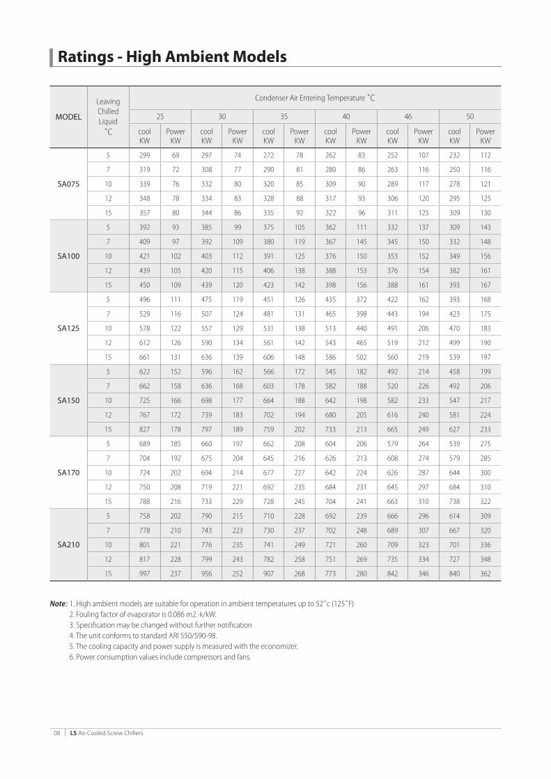

Electrical Data (Continued)
High Ambient Model for 46˚C Nominal Ambient Operation Electricity Supply 380350
Model NoChiller Total Power Input Nominal
Running AmpsMaximum
Running AmpsMaximumStart AmpsNominal Kw Maximum Kw
SA-75 1156 1734 2339 3509 6417
SA-100 1501 2252 2861 4292 7683
SA-125 1935 2903 3672 5508 9816
SA-150 2261 3392 4303 6455 11409
SA-170 2742 4113 5218 7827 6927
SA-210 3021 4532 5722 8583 7683
SA-225 3436 5154 6533 9780 9816
SA-250 3870 5803 7344 11016 9816
SA-270 4274 6411 7626 11439 10239
SA-300 4521 6782 8583 12875 7683
SA-325 4956 7434 9394 14091 9816
SA-350 5426 8139 10172 15258 11409
Note 1 Chiller total power includes all compressors and condenser fans running 2 Nominal Kw and Amps (above) apply when chiller is operating in an ambient temperature of 46˚c with leaving chilled water temperature of 7˚c 3 Max Kw and Amps (above) apply when chiller is operating at extreme limits beyond which safety controls will prevent higher values 4 Max Start Amps occur when the last compressor starts while all other compressors and condenser fans are already running 5 Max running Amps values include compressors and fans
Standard Model for 35˚C Nominal Ambient Operation Electricity Supply 380350
Model NoChiller Total Power Input Nominal
Running AmpsMaximum
Running AmpsMaximumStart AmpsNominal Kw Maximum Kw
SA-75 829 1244 1508 2920 3924
SA-100 1104 1656 2040 3910 8280
SA-125 1451 2177 2624 5010 6672
SA-150 1679 2519 3073 5940 7719
SA-170 1868 2802 3532 7151 4398
SA-210 2208 3312 4080 7841 8280
SA-225 2555 3833 4664 8935 6672
SA-250 2708 4062 4954 10064 6672
SA-270 2902 4353 5248 10451 6672
SA-300 3312 4968 6120 11763 8280
SA-325 3569 5354 6704 12874 6672
SA-350 3896 5844 7084 13940 7719
Note 1 Chiller total power includes all compressors and condenser fans running 2 Nominal Kw and Amps (above) apply when chiller is operating in an ambient temperature of 35˚c with a leaving chilled water temperature of 7˚c 3 Max Kw and Amps (above) apply when chiller is operating at extreme limits beyond which safety controls will prevent higher values 4 Max Start Amps occur when the last compressor starts while all other compressors and condenser fans are already running 5 Max running Amps values include compressors and fans
LS Air-Cooled Screw Chillers 16
Chiller Control
Automatic PLC ControllerModel SA liquid chillers are equipped with PLC controllers which are housed in the low voltage section of the unit Control Center The primary functions of the PLC are
To automatically start and stop the chiller in response to bullldquoCooling Demandrdquo signalsTo start and stop individual compressors and associated bullcondenser fans and to modulate the compressor capacity by unloading the compressor slide valve in response to unit cooling load To activate and control peripheral equipment (ie chilled water bull pumps)To continuously monitor operating temperatures and safety bull controls and display readouts both locally and remotely
Optimization ndash Main Auxiliary UnitFor multi-compressor units an optimization function is bull available to equalize the running time of each compressorcondenser assemblyFor multi chiller installations one unit can be selected as the bull ldquomasterrdquo and its controller will sequence up to 4 ldquoslaverdquo chillers (option)
Automatic and remote control of peripherals
Remote startstop function via cabled connectionbull OnOff of chiller and system peripherals together with bull functional monitoring can be achieved through remote BMS System
Time Table RunningUp to 3 startstop programmes day can be achieved
Soft Loading Function
This ensures that the chiller will operate stably during system start up when large fluctuations in cooling load can occur
Analogue data display functionThis function monitors and displays analog signals of
refrigeration system temperatures and pressures
Network Control FunctionModel SA liquid chillers have interfaces for RS-232 amp RS-485 bull and can work with MODBUS protocolsEach chiller can operate as a ldquoMasterrdquo or ldquoSlaverdquo unit in a group bull control network (option)
LS Air-Cooled Screw Chillers 17
Typical Starter Diagram-1 Compressor
VP
107
D24
ZY
X
WV
U
R11
S11
R2PB
106
D24 T2R2
380V TR
R02
T2220V
700V
A
R01
T01
NFB2
10A
S
2M
1M
S2M
164 2M
161
158
1MS
S0T0
R0
T1S1
R160
0VNF
B1
301
302
303
88 F4 F4
88
U42V
42F3
V41
U41
W42
W41 51
FM4
U31
V31
U32V
32
F188
V21
V22
F1
W11 51
W12
U22
U21
F2W
22
W21 51F288
FM3
FM2
V11
U11
V12
U12 FM
1
W32
W31 51F3
KM1
KM2
KM3
231
230
C2C1R2 G
ITCT
AI3
T2
232
88F1
88F2
88F3
F151F251
F351
R2 T2
171
172
173
233
88F4F451
174
3PH
380V
AC 5
060
HZ
MAI
N PO
WER
SUP
PLY
TO C
ONT
ROL
PANE
L
R02
R02
R02
R2 R2
303
302
301
R223
123
2
KM1
KM3
KM2
230
233
MP
VP
106
107
D24
106
107
D24
E
R2
GAI
3
GAI
3
GAI
3
R2R2
301
301
302
302
303
303
230
230
231
231
232
232
233
233
STAR
TER
PNL
CONT
ROL
PNL
BODY
WIR
ING ST
OP
SGL
EMER
GERN
CYAB
NORM
AL S
GL
MOT
ORamp
POW
ERTR
ANSD
UCER
SGL
CU
RREN
T
CONT
ACTO
R SI
GNAL
COO
LING
FANS
SIG
AL
FRO
M C
ONT
ROL
PANE
LTO
CO
NTRO
L PA
NEL
T2
T2 T2
R2 R2R2
POW
ERCT
RL P
ANEL
3
FRO
MT
O C
ONT
ROL
PANE
L
2
THE
SE PA
RTS
ARE
LOCA
TED
ON
CHIL
LER
BODY
Note
1
T
HESE
PART
S AR
E LO
CATE
D IN
CO
NTRO
L PA
NEL
ELEC
TRIC
AL PA
RT L
IST
11M
2M
SM
AGNE
TIC
CONT
ACTO
R
2NF
B1M
OLDE
D CA
SED
CIR
CUIT
BRE
AKER
3NF
B2NO
FUS
E BR
EAKE
R
4TR
TRAN
SFO
RMER
700V
A
5PB
EMER
GERN
CY S
TOP
SWIT
CH
6M
PM
OTO
R PR
OTEC
T RE
LAY
7VP
POW
ER P
ROTE
CTO
R
8IT
AMPE
RE T
RANS
DUC
ER
9CT
CURR
ENT
TRAN
SFO
RMER
1088
F1-4
MAG
NETI
C CO
NTAC
TOR
1151
F1-4
THER
MAL
REL
AY
12FM
1-4
COO
LING
FAN
13FA
NCO
OLI
NG FA
N
14KM
1-3
AUX
RELA
Y CO
NTAC
TFR
OM C
ONTR
OL P
NL
T11
11 1412L2 L3L1
1 4325 6
CO
MP
MOT
OR
M2
M1 NL
L1
MP
L3L2
FAN
101
102
100
103
105
106
104
107
COM
R21
T21
FSSW
D24
F15
A
EE
R22
223
220
222
221
PU
COM
COM
COM
D24
CHXC
201
200
RS
110
111
COM
D24
OUT
C0Y0
Y1Y2
Y3Y7
Y6Y5
DVP
-16S
P
Y4
SS
X0X1
X2X3
X4X5
X6X7
IN
24V
0V GN
LDVP
PS02
TP04
-+
G0
24RS
-485
HP LP
OL
OP
MP
EKD
VP
FG1
T2R2
HQ
R20
T20
MCC
B10
A
FAN
KM2
340
POW
ER 1
PH 2
20VA
C 50
60H
Z
2
3 4
V3V1
V2V0
NF
T21
R21
EE
E
402
401
403
404
KM2
XC406
405
D24
101
102
D24SW
RS
D24
103
PU
CH
T2
T2 T2
R2 R2
106
MP107
D24
106
107
D24
R2
GAI
3
AI3
G
GAI
3VP
E
1 2 43
ELEC
TRIC
AL PA
RT L
IST
1FS
FLO
W S
WIT
CH
2PU
CHW
PUM
P IN
TERL
OCK
SGL
FRO
M U
SER
3SW
REM
OTE
STAR
TST
OP S
IGNA
LFR
OM
USE
R
4RS
REM
OTE
RESE
T SI
GNAL
FRO
M U
SER
5VP
POW
ER P
ROTE
CT R
ELAY
6M
PM
OTO
R PR
OTEC
T RE
LAY
7HP
HIGH
PER
SSUR
E SW
ITCH
8LP
LOW
PRE
SSUR
E SW
ITCH
9O
LO
IL L
EVEL
SW
ITCH
10O
PO
IL D
IFF
PRES
SURE
SW
ITCH
11TE
01EC
HW TE
MPE
RATU
RE S
ENSO
RPT
100
12TE
02LC
HW TE
MPE
RATU
RE S
ENSO
RPT
100
13TE
03FI
N TE
MPE
RATU
RE S
ENSO
RPT
100
14TE
04SU
CTIO
N TE
MPRE
ATUR
E SEN
SOR
PT10
0
15TE
05EX
HAUS
T TEM
PREA
TURE
SEN
SOR
PT10
0
16EP
EVAP
PRES
SURE
TRA
NSM
ITTER
17CP
COND
PRES
SURE
TRA
NSM
ITTER
18IT
CURR
ENT T
RANS
DUCE
R SIG
NAL
19KM
1-3
AUX
RELA
Y (C
ONT
ACTO
R)
20CH
AUX
RELA
Y (C
HW P
UMP)
21XC
AUX
RELA
Y (F
AULT
)
22PY
SPRA
Y LIQ
UID
SOLE
NOID
VAL
VE
23ET
SE L
ECTR
ONIC
EXPA
NSIO
N
VALV
E
24SV
1SO
LENO
ID V
ALVE
25
25SV
2SO
LENO
ID V
ALVE
75
26SV
3SO
LENO
ID V
ALVE
50
27HQ
OIL
HEA
TER
28FA
NCO
OLI
NG FA
NS
29M
CCB
MOL
DED
CASE
CIRC
UIT
BREA
KER
30N
FNO
ISE
FILT
ER
31F1
-2FU
SE
32V0
-3VA
RIST
ER
33TR
TRAN
SFO
RMER
34EK
DD
RIVE
R M
OD
ULE
-ETS
35EC
ECON
OMIZE
R SOL
ENOI
D VA
LVE
36
PBEM
ERGE
RNCY
STO
P SW
ITCH
120
OUT
C0Y0
Y1Y2
Y3Y7
Y6Y5
DVP
-08S
N
Y4
224
225
226
COM
D24
1C1B
1A
TE01
2C2B
2A
TE02
3C3B
3A4C
4B4A
5C5B
5A
TE05
COM
D24
COM
D24
24V
G
CH1
FGI-
L-
DVP
-04P
T
L+FG
I-L-
L+
L+L-
I-FG
L+L-
I-FG
CH2
CH3
CH4
0V24
V
G
CH1
FGI-
L-
DVP
-04P
T
L+FG
I-L-
L+
L+L-
I-FG
L+L-
I-FG
CH2
CH3
CH4
0V
COM
D24 E
+-EP AI
1
+-CP AI
2
78 AI
3G
IT
AO1
ACO
M
TO E
KD
DVP
-06X
ACH
1
COM
I+V+
0V24
V
GCO
MI+
V+
CH2
COM
I+V+
CH3
COM
I+V+
COM
I+V+
COM
I+V+
CH4
CH5
CH6
D24
COM
302
303 30
330
230
1
R2R2
R2
KM1
KM3
KM2
231
232
23023
123
223
0
231
232
230
-
DVP
-12S
AIN
0V24
V
G
OUT
SS C0
X0X1
X2X3
Y0C1
RS-4
85
+
X4X5
X6X7
Y1C2
Y2Y3
227
KM1
KM2
KM3
ECPY
SV1
SV3
SV2
AC22
024
VTR
R23
T23
R21
T21
F21
A R33
20VA
TO E
LEC
EXPV
ALVE
(ETS
)
501
502
503
504
302
303
301
301
EKD
24VA
C
-
12
56
78
ETS
2122
2425
26+
20
FRO
M P
LC
D24
120
CH
AO1
ACOM
410
TO P
LC
TE03
TE04
230
231
232
233
233
233
233
EE
FOR CHW PUMPSTARTSTOP SGL
FOR COMPRESSOR RUNSTOP INDICATION
FOR FAULTINDICATIONFOR FAULTINDICATION
TO U
SER
S M
CC
FOR CHW PUMPINTERLOCK
FOR REMOTE STARTSTOP SGL
FOR REMOTERESTART SGL
FRO
M U
SER
S M
CC
CONT
ROL
PNL
STAR
TER
PNL
BODY
WIR
ING
POW
ERCT
RL P
ANEL
ABNO
RMAL
SGL
MOT
ORamp
POW
ER TRAN
SDUC
ER S
GLCU
RREN
T
FRO
M S
TART
ER PA
NEL
CONT
ACTO
R SI
GNAL
COO
LING
FANS
RUN
STO
P
TO S
TART
ER PA
NEL
FANS
RUN
SGL
NOTE
SUPP
LIED
BY
USER
S
LOCA
TED
ON
CHIL
LER
BODY
FRO
MT
O S
TART
ER PA
NEL
FRO
MT
O U
SER
S M
CC
R2R0
2R2R0
2
R2R0
2
PB
STO
P SG
LEM
ERGE
RNCY
11 1412L2 L3L1
VP-A
AZAY
AX
AWAV
AU
R2
PB
R2 T2
380VTR
R02
T2
220V
R01
T01
NFB2
10A
S-A
2M-A
1M-A
S-A
2M-A
161 2M
158
1MS
AT1
AS1
AR1
600V
NFB1
-A
301
302
303
-A88
F1
AU1 FM
1
KM1
KM2
KM3
-A
-A-A
-A
-A-A
-A
S-B
2M-B
171 2M
168
1MS
304
305
306
KM1
KM2
KM3
-B-B
-B
-B-B
-B
AU AV AW
106
D24 T2R2
M2
M1 NL
L1
MP-
A
L3L2
BU BV BW
123
D24 T2R2
M2
M1 NL
L1
MP-
B
L3L2
FAN
88F
1-A
230
323
321
51F1
51F3
-A-A
88F
3-A
88F
5-A23
2 326
325
51F5
51F6
-A-A
88F
6-A
88F
1-B
329
327
51F1
51F3
-B-B
88F
3-B
88F
5-B
51F5
51F6
-B-B
88F
6-B
231
233
244
246
245
247
T2
AT0
AS0
AR0
D24
107
ABZ
BYBX
BWBV
BU
S-B
2M-B
1M-B
BT1
BS1
BR1
600V
NFB1
-B
B
BT0
BS0
BR0
VP-B
D24
124
11 1412L2 L3L1
-A51
F1
AV1
AW1
-A88
F2
AU2 FM
2-A
-A51
F2
AV2
AW2
-A88
F3
AU3 FM
3-A
-A51
F3
AV3
AW3
-A88
F4
AU4 FM
4-A
-A51
F4
AV4
AW4
CO
MP
MOT
OR
-B88
F1
BU1 FM
1-B
-B51
F1
BV1
BW1
-B88
F2
BU2 FM
2-B
-B51
F2
BV2
BW2
-B88
F3
BU3 FM
3-B
-B51
F3
BV3
BW3
-B88
F4
BU4 FM
4-B
-B51
F4
BV4
BW4
CO
MP
MOT
OR
T2
T2 T2
R2 R2
302
303
106
302
30330
330
230
1
R2R2
R223
123
2
KM1
KM3
KM2
233
-A-A
-A
MP
301
301
230 23
123
223
323
0
231
232
233
230
-A-AVP
107
D24
106
107
D24
E
R2R0
2
R02
R02
R2 R2
R2AI
G
AIG
AIG
AI5
AI5AI
5
305
306
123
305
30630
630
530
4
R2R2
R224
524
6
KM1
KM3
KM2
247
-B-B
-B
MP
304
304
244 24
524
624
724
4
245
246
247
244
-B-BVP
124
D24
123
124
D24
E
AIG
AIG
AIG
AI6
AI6AI
6
AC2
AC1
R2 G
IT-A
CT-A
AI5
T2
BC2
BC1
R2 G
IT-B
CT-B
AI6
T2
3PH
380V
AC 5
060
HZ
MAI
N PO
WER
SUP
PLY
3PH
380V
AC 5
060
HZ
MAI
N PO
WER
SUP
PLY
TO C
ONT
ROL
PANE
L
3
FRO
MT
O C
ONT
ROL
PANE
L
2
THE
SE PA
RTS
ARE
LOCA
TED
ON
CHIL
LER
BODY
Note
1
T
HESE
PART
S AR
E LO
CATE
D IN
CO
NTRO
L PA
NEL
STAR
TER
PNL
CONT
ROL
PNL
BODY
WIR
ING
STO
P SG
LEM
ERGE
RNCY
ABNO
RMAL
SGL
-AM
OTO
RampPO
WER
TRAN
SDUC
ER S
GL
CURR
ENT-
APO
WER
CTRL
PAN
EL TO C
ONT
ROL
PANE
L
CONT
ACTO
R SI
GNAL
-ACO
OLI
NG FA
NS S
IGAL
-A
FRO
M C
ONT
ROL
PANE
L
STAR
TER
PNL
CONT
ROL
PNL
BODY
WIR
ING AB
NORM
AL S
GL-B
MOT
ORamp
POW
ER TRAN
SDUC
ER S
GL
CURR
ENT-
B
TO C
ONT
ROL
PANE
L
CONT
ACTO
R SI
GNAL
-BCO
OLI
NG FA
NS S
IGAL
-B
FRO
M C
ONT
ROL
PANE
L
ELEC
TRIC
AL PA
RT L
IST
11M
2M
SM
AGNE
TIC
CONT
ACTO
R
2NF
B1M
OLDE
D CA
SED
CIR
CUIT
BRE
AKER
3NF
B2NO
FUS
E BR
EAKE
R
4TR
TRAN
SFO
RMER
700V
A
5PB
EMER
GERN
CY S
TOP
SWIT
CH
6M
PM
OTO
R PR
OTEC
T RE
LAY
7VP
POW
ER P
ROTE
CTO
R
8IT
AMPE
RE T
RANS
DUC
ER
9CT
CURR
ENT
TRAN
SFO
RMER
1088
F1-6
MAG
NETI
C CO
NTAC
TOR
1151
F1-6
THER
MAL
REL
AY
12FM
1-6
COO
LING
FAN
13FA
NCO
OLI
NG FA
N
14KM
1-3
AUX
RELA
Y CO
NTAC
TFR
OM CO
NTRO
L PNL
1 4325 6
1 4325 6
-A88
F5
AU5 FM
5-A
-A51
F5
AV5
AW5
-A88
F6
AU6 FM
6-A
-A51
F6
AV6
AW6
-B88
F5
BU5 FM
5-B
-B51
F5
BV5
BW5
-B88
F6
BU6 FM
6-B
-B51
F6
BV6
BW6
88F
2-A
322
51F2 -A
324
51F4
-A
88F
4-A
328
51F2 -B
88F
2-B
51F4 -B
88F
4-B
330
331
332
LS Air-Cooled Screw Chillers 18
Typical Schematic Diagram-1 Compressor
VP
107
D24
ZY
X
WV
U
R11
S11
R2PB
106
D24 T2R2
380V TR
R02
T2220V
700V
A
R01
T01
NFB2
10A
S
2M
1M
S2M
164 2M
161
158
1MS
S0T0
R0
T1S1
R160
0VNF
B1
301
302
303
88 F4 F4
88
U42V
42F3
V41
U41
W42
W41 51
FM4
U31
V31
U32V
32
F188
V21
V22
F1
W11 51
W12
U22
U21
F2W
22
W21 51F288
FM3
FM2
V11
U11
V12
U12 FM
1
W32
W31 51F3
KM1
KM2
KM3
231
230
C2C1R2 G
ITCT
AI3
T2
232
88F1
88F2
88F3
F151F251
F351
R2 T2
171
172
173
233
88F4F451
174
3PH
380V
AC 5
060
HZ
MAI
N PO
WER
SUP
PLY
TO C
ONT
ROL
PANE
L
R02
R02
R02
R2 R2
303
302
301
R223
123
2
KM1
KM3
KM2
230
233
MP
VP
106
107
D24
106
107
D24
E
R2
GAI
3
GAI
3
GAI
3
R2R2
301
301
302
302
303
303
230
230
231
231
232
232
233
233
STAR
TER
PNL
CONT
ROL
PNL
BODY
WIR
ING ST
OP
SGL
EMER
GERN
CYAB
NORM
AL S
GL
MOT
ORamp
POW
ERTR
ANSD
UCER
SGL
CU
RREN
T
CONT
ACTO
R SI
GNAL
COO
LING
FANS
SIG
AL
FRO
M C
ONT
ROL
PANE
LTO
CO
NTRO
L PA
NEL
T2
T2 T2
R2 R2R2
POW
ERCT
RL P
ANEL
3
FRO
MT
O C
ONT
ROL
PANE
L
2
THE
SE PA
RTS
ARE
LOCA
TED
ON
CHIL
LER
BODY
Note
1
T
HESE
PART
S AR
E LO
CATE
D IN
CO
NTRO
L PA
NEL
ELEC
TRIC
AL PA
RT L
IST
11M
2M
SM
AGNE
TIC
CONT
ACTO
R
2NF
B1M
OLDE
D CA
SED
CIR
CUIT
BRE
AKER
3NF
B2NO
FUS
E BR
EAKE
R
4TR
TRAN
SFO
RMER
700V
A
5PB
EMER
GERN
CY S
TOP
SWIT
CH
6M
PM
OTO
R PR
OTEC
T RE
LAY
7VP
POW
ER P
ROTE
CTO
R
8IT
AMPE
RE T
RANS
DUC
ER
9CT
CURR
ENT
TRAN
SFO
RMER
1088
F1-4
MAG
NETI
C CO
NTAC
TOR
1151
F1-4
THER
MAL
REL
AY
12FM
1-4
COO
LING
FAN
13FA
NCO
OLI
NG FA
N
14KM
1-3
AUX
RELA
Y CO
NTAC
TFR
OM C
ONTR
OL P
NL
T11
11 1412L2 L3L1
1 4325 6
CO
MP
MOT
OR
M2
M1 NL
L1
MP
L3L2
FAN
101
102
100
103
105
106
104
107
COM
R21
T21
FSSW
D24
F15
A
EE
R22
223
220
222
221
PU
COM
COM
COM
D24
CHXC
201
200
RS
110
111
COM
D24
OUT
C0Y0
Y1Y2
Y3Y7
Y6Y5
DVP
-16S
P
Y4
SS
X0X1
X2X3
X4X5
X6X7
IN
24V
0V GN
LDVP
PS02
TP04
-+
G0
24RS
-485
HP LP
OL
OP
MP
EKD
VP
FG1
T2R2
HQ
R20
T20
MCC
B10
A
FAN
KM2
340
POW
ER 1
PH 2
20VA
C 50
60H
Z
2
3 4
V3V1
V2V0
NF
T21
R21
EE
E
402
401
403
404
KM2
XC406
405
D24
101
102
D24SW
RS
D24
103
PU
CH
T2
T2 T2
R2 R2
106
MP107
D24
106
107
D24
R2
GAI
3
AI3
G
GAI
3VP
E
1 2 43
ELEC
TRIC
AL PA
RT L
IST
1FS
FLO
W S
WIT
CH
2PU
CHW
PUM
P IN
TERL
OCK
SGL
FRO
M U
SER
3SW
REM
OTE
STAR
TST
OP S
IGNA
LFR
OM
USE
R
4RS
REM
OTE
RESE
T SI
GNAL
FRO
M U
SER
5VP
POW
ER P
ROTE
CT R
ELAY
6M
PM
OTO
R PR
OTEC
T RE
LAY
7HP
HIGH
PER
SSUR
E SW
ITCH
8LP
LOW
PRE
SSUR
E SW
ITCH
9O
LO
IL L
EVEL
SW
ITCH
10O
PO
IL D
IFF
PRES
SURE
SW
ITCH
11TE
01EC
HW TE
MPE
RATU
RE S
ENSO
RPT
100
12TE
02LC
HW TE
MPE
RATU
RE S
ENSO
RPT
100
13TE
03FI
N TE
MPE
RATU
RE S
ENSO
RPT
100
14TE
04SU
CTIO
N TE
MPRE
ATUR
E SEN
SOR
PT10
0
15TE
05EX
HAUS
T TEM
PREA
TURE
SEN
SOR
PT10
0
16EP
EVAP
PRES
SURE
TRA
NSM
ITTER
17CP
COND
PRES
SURE
TRA
NSM
ITTER
18IT
CURR
ENT T
RANS
DUCE
R SIG
NAL
19KM
1-3
AUX
RELA
Y (C
ONT
ACTO
R)
20CH
AUX
RELA
Y (C
HW P
UMP)
21XC
AUX
RELA
Y (F
AULT
)
22PY
SPRA
Y LIQ
UID
SOLE
NOID
VAL
VE
23ET
SE L
ECTR
ONIC
EXPA
NSIO
N
VALV
E
24SV
1SO
LENO
ID V
ALVE
25
25SV
2SO
LENO
ID V
ALVE
75
26SV
3SO
LENO
ID V
ALVE
50
27HQ
OIL
HEA
TER
28FA
NCO
OLI
NG FA
NS
29M
CCB
MOL
DED
CASE
CIRC
UIT
BREA
KER
30N
FNO
ISE
FILT
ER
31F1
-2FU
SE
32V0
-3VA
RIST
ER
33TR
TRAN
SFO
RMER
34EK
DD
RIVE
R M
OD
ULE
-ETS
35EC
ECON
OMIZE
R SOL
ENOI
D VA
LVE
36
PBEM
ERGE
RNCY
STO
P SW
ITCH
120
OUT
C0Y0
Y1Y2
Y3Y7
Y6Y5
DVP
-08S
N
Y4
224
225
226
COM
D24
1C1B
1A
TE01
2C2B
2A
TE02
3C3B
3A4C
4B4A
5C5B
5A
TE05
COM
D24
COM
D24
24V
G
CH1
FGI-
L-
DVP
-04P
T
L+FG
I-L-
L+
L+L-
I-FG
L+L-
I-FG
CH2
CH3
CH4
0V24
V
G
CH1
FGI-
L-
DVP
-04P
T
L+FG
I-L-
L+
L+L-
I-FG
L+L-
I-FG
CH2
CH3
CH4
0V
COM
D24 E
+-EP AI
1
+-CP AI
2
78 AI
3G
IT
AO1
ACO
M
TO E
KD
DVP
-06X
ACH
1
COM
I+V+
0V24
V
GCO
MI+
V+
CH2
COM
I+V+
CH3
COM
I+V+
COM
I+V+
COM
I+V+
CH4
CH5
CH6
D24
COM
302
303 30
330
230
1
R2R2
R2
KM1
KM3
KM2
231
232
23023
123
223
0
231
232
230
-
DVP
-12S
AIN
0V24
V
G
OUT
SS C0
X0X1
X2X3
Y0C1
RS-4
85
+
X4X5
X6X7
Y1C2
Y2Y3
227
KM1
KM2
KM3
ECPY
SV1
SV3
SV2
AC22
024
VTR
R23
T23
R21
T21
F21
A R33
20VA
TO E
LEC
EXPV
ALVE
(ETS
)
501
502
503
504
302
303
301
301
EKD
24VA
C
-
12
56
78
ETS
2122
2425
26+
20
FRO
M P
LC
D24
120
CH
AO1
ACOM
410
TO P
LC
TE03
TE04
230
231
232
233
233
233
233
EE
FOR CHW PUMPSTARTSTOP SGL
FOR COMPRESSOR RUNSTOP INDICATION
FOR FAULTINDICATIONFOR FAULTINDICATION
TO U
SER
S M
CC
FOR CHW PUMPINTERLOCK
FOR REMOTE STARTSTOP SGL
FOR REMOTERESTART SGL
FRO
M U
SER
S M
CC
CONT
ROL
PNL
STAR
TER
PNL
BODY
WIR
ING
POW
ERCT
RL P
ANEL
ABNO
RMAL
SGL
MOT
ORamp
POW
ER TRAN
SDUC
ER S
GLCU
RREN
T
FRO
M S
TART
ER PA
NEL
CONT
ACTO
R SI
GNAL
COO
LING
FANS
RUN
STO
P
TO S
TART
ER PA
NEL
FANS
RUN
SGL
NOTE
SUPP
LIED
BY
USER
S
LOCA
TED
ON
CHIL
LER
BODY
FRO
MT
O S
TART
ER PA
NEL
FRO
MT
O U
SER
S M
CC
R2R0
2R2R0
2
R2R0
2
PB
STO
P SG
LEM
ERGE
RNCY
11 1412L2 L3L1
VP-A
AZAY
AX
AWAV
AU
R2
PB
R2 T2
380VTR
R02
T2
220V
R01
T01
NFB2
10A
S-A
2M-A
1M-A
S-A
2M-A
161 2M
158
1MS
AT1
AS1
AR1
600V
NFB1
-A
301
302
303
-A88
F1
AU1 FM
1
KM1
KM2
KM3
-A
-A-A
-A
-A-A
-A
S-B
2M-B
171 2M
168
1MS
304
305
306
KM1
KM2
KM3
-B-B
-B
-B-B
-B
AU AV AW
106
D24 T2R2
M2
M1 NL
L1
MP-
A
L3L2
BU BV BW
123
D24 T2R2
M2
M1 NL
L1
MP-
B
L3L2
FAN
88F
1-A
230
323
321
51F1
51F3
-A-A
88F
3-A
88F
5-A23
2 326
325
51F5
51F6
-A-A
88F
6-A
88F
1-B
329
327
51F1
51F3
-B-B
88F
3-B
88F
5-B
51F5
51F6
-B-B
88F
6-B
231
233
244
246
245
247
T2
AT0
AS0
AR0
D24
107
ABZ
BYBX
BWBV
BU
S-B
2M-B
1M-B
BT1
BS1
BR1
600V
NFB1
-B
B
BT0
BS0
BR0
VP-B
D24
124
11 1412L2 L3L1
-A51
F1
AV1
AW1
-A88
F2
AU2 FM
2-A
-A51
F2
AV2
AW2
-A88
F3
AU3 FM
3-A
-A51
F3
AV3
AW3
-A88
F4
AU4 FM
4-A
-A51
F4
AV4
AW4
CO
MP
MOT
OR
-B88
F1
BU1 FM
1-B
-B51
F1
BV1
BW1
-B88
F2
BU2 FM
2-B
-B51
F2
BV2
BW2
-B88
F3
BU3 FM
3-B
-B51
F3
BV3
BW3
-B88
F4
BU4 FM
4-B
-B51
F4
BV4
BW4
CO
MP
MOT
OR
T2
T2 T2
R2 R2
302
303
106
302
30330
330
230
1
R2R2
R223
123
2
KM1
KM3
KM2
233
-A-A
-A
MP
301
301
230 23
123
223
323
0
231
232
233
230
-A-AVP
107
D24
106
107
D24
E
R2R0
2
R02
R02
R2 R2
R2AI
G
AIG
AIG
AI5
AI5AI
5
305
306
123
305
30630
630
530
4
R2R2
R224
524
6
KM1
KM3
KM2
247
-B-B
-B
MP
304
304
244 24
524
624
724
4
245
246
247
244
-B-BVP
124
D24
123
124
D24
E
AIG
AIG
AIG
AI6
AI6AI
6
AC2
AC1
R2 G
IT-A
CT-A
AI5
T2
BC2
BC1
R2 G
IT-B
CT-B
AI6
T2
3PH
380V
AC 5
060
HZ
MAI
N PO
WER
SUP
PLY
3PH
380V
AC 5
060
HZ
MAI
N PO
WER
SUP
PLY
TO C
ONT
ROL
PANE
L
3
FRO
MT
O C
ONT
ROL
PANE
L
2
THE
SE PA
RTS
ARE
LOCA
TED
ON
CHIL
LER
BODY
Note
1
T
HESE
PART
S AR
E LO
CATE
D IN
CO
NTRO
L PA
NEL
STAR
TER
PNL
CONT
ROL
PNL
BODY
WIR
ING
STO
P SG
LEM
ERGE
RNCY
ABNO
RMAL
SGL
-AM
OTO
RampPO
WER
TRAN
SDUC
ER S
GL
CURR
ENT-
APO
WER
CTRL
PAN
EL TO C
ONT
ROL
PANE
L
CONT
ACTO
R SI
GNAL
-ACO
OLI
NG FA
NS S
IGAL
-A
FRO
M C
ONT
ROL
PANE
L
STAR
TER
PNL
CONT
ROL
PNL
BODY
WIR
ING AB
NORM
AL S
GL-B
MOT
ORamp
POW
ER TRAN
SDUC
ER S
GL
CURR
ENT-
B
TO C
ONT
ROL
PANE
L
CONT
ACTO
R SI
GNAL
-BCO
OLI
NG FA
NS S
IGAL
-B
FRO
M C
ONT
ROL
PANE
L
ELEC
TRIC
AL PA
RT L
IST
11M
2M
SM
AGNE
TIC
CONT
ACTO
R
2NF
B1M
OLDE
D CA
SED
CIR
CUIT
BRE
AKER
3NF
B2NO
FUS
E BR
EAKE
R
4TR
TRAN
SFO
RMER
700V
A
5PB
EMER
GERN
CY S
TOP
SWIT
CH
6M
PM
OTO
R PR
OTEC
T RE
LAY
7VP
POW
ER P
ROTE
CTO
R
8IT
AMPE
RE T
RANS
DUC
ER
9CT
CURR
ENT
TRAN
SFO
RMER
1088
F1-6
MAG
NETI
C CO
NTAC
TOR
1151
F1-6
THER
MAL
REL
AY
12FM
1-6
COO
LING
FAN
13FA
NCO
OLI
NG FA
N
14KM
1-3
AUX
RELA
Y CO
NTAC
TFR
OM CO
NTRO
L PNL
1 4325 6
1 4325 6
-A88
F5
AU5 FM
5-A
-A51
F5
AV5
AW5
-A88
F6
AU6 FM
6-A
-A51
F6
AV6
AW6
-B88
F5
BU5 FM
5-B
-B51
F5
BV5
BW5
-B88
F6
BU6 FM
6-B
-B51
F6
BV6
BW6
88F
2-A
322
51F2 -A
324
51F4
-A
88F
4-A
328
51F2 -B
88F
2-B
51F4 -B
88F
4-B
330
331
332
LS Air-Cooled Screw Chillers 19
Typical Starter Diagram-2 Compressor
VP
107
D24
ZY
X
WV
U
R11
S11
R2PB
106
D24 T2R2
380V TR
R02
T2220V
700V
A
R01
T01
NFB2
10A
S
2M
1M
S2M
164 2M
161
158
1MS
S0T0
R0
T1S1
R160
0VNF
B1
301
302
303
88 F4 F4
88
U42V
42F3
V41
U41
W42
W41 51
FM4
U31
V31
U32V
32
F188
V21
V22
F1
W11 51
W12
U22
U21
F2W
22
W21 51F288
FM3
FM2
V11
U11
V12
U12 FM
1
W32
W31 51F3
KM1
KM2
KM3
231
230
C2C1R2 G
ITCT
AI3
T2
232
88F1
88F2
88F3
F151F251
F351
R2 T2
171
172
173
233
88F4F451
174
3PH
380V
AC 5
060
HZ
MAI
N PO
WER
SUP
PLY
TO C
ONT
ROL
PANE
L
R02
R02
R02
R2 R2
303
302
301
R223
123
2
KM1
KM3
KM2
230
233
MP
VP
106
107
D24
106
107
D24
E
R2
GAI
3
GAI
3
GAI
3
R2R2
301
301
302
302
303
303
230
230
231
231
232
232
233
233
STAR
TER
PNL
CONT
ROL
PNL
BODY
WIR
ING ST
OP
SGL
EMER
GERN
CYAB
NORM
AL S
GL
MOT
ORamp
POW
ERTR
ANSD
UCER
SGL
CU
RREN
T
CONT
ACTO
R SI
GNAL
COO
LING
FANS
SIG
AL
FRO
M C
ONT
ROL
PANE
LTO
CO
NTRO
L PA
NEL
T2
T2 T2
R2 R2R2
POW
ERCT
RL P
ANEL
3
FRO
MT
O C
ONT
ROL
PANE
L
2
THE
SE PA
RTS
ARE
LOCA
TED
ON
CHIL
LER
BODY
Note
1
T
HESE
PART
S AR
E LO
CATE
D IN
CO
NTRO
L PA
NEL
ELEC
TRIC
AL PA
RT L
IST
11M
2M
SM
AGNE
TIC
CONT
ACTO
R
2NF
B1M
OLDE
D CA
SED
CIR
CUIT
BRE
AKER
3NF
B2NO
FUS
E BR
EAKE
R
4TR
TRAN
SFO
RMER
700V
A
5PB
EMER
GERN
CY S
TOP
SWIT
CH
6M
PM
OTO
R PR
OTEC
T RE
LAY
7VP
POW
ER P
ROTE
CTO
R
8IT
AMPE
RE T
RANS
DUC
ER
9CT
CURR
ENT
TRAN
SFO
RMER
1088
F1-4
MAG
NETI
C CO
NTAC
TOR
1151
F1-4
THER
MAL
REL
AY
12FM
1-4
COO
LING
FAN
13FA
NCO
OLI
NG FA
N
14KM
1-3
AUX
RELA
Y CO
NTAC
TFR
OM C
ONTR
OL P
NL
T11
11 1412L2 L3L1
1 4325 6
CO
MP
MOT
OR
M2
M1 NL
L1
MP
L3L2
FAN
101
102
100
103
105
106
104
107
COM
R21
T21
FSSW
D24
F15
A
EE
R22
223
220
222
221
PU
COM
COM
COM
D24
CHXC
201
200
RS
110
111
COM
D24
OUT
C0Y0
Y1Y2
Y3Y7
Y6Y5
DVP
-16S
P
Y4
SS
X0X1
X2X3
X4X5
X6X7
IN
24V
0V GN
LDVP
PS02
TP04
-+
G0
24RS
-485
HP LP
OL
OP
MP
EKD
VP
FG1
T2R2
HQ
R20
T20
MCC
B10
A
FAN
KM2
340
POW
ER 1
PH 2
20VA
C 50
60H
Z
2
3 4
V3V1
V2V0
NF
T21
R21
EE
E
402
401
403
404
KM2
XC406
405
D24
101
102
D24SW
RS
D24
103
PU
CH
T2
T2 T2
R2 R2
106
MP107
D24
106
107
D24
R2
GAI
3
AI3
G
GAI
3VP
E
1 2 43
ELEC
TRIC
AL PA
RT L
IST
1FS
FLO
W S
WIT
CH
2PU
CHW
PUM
P IN
TERL
OCK
SGL
FRO
M U
SER
3SW
REM
OTE
STAR
TST
OP S
IGNA
LFR
OM
USE
R
4RS
REM
OTE
RESE
T SI
GNAL
FRO
M U
SER
5VP
POW
ER P
ROTE
CT R
ELAY
6M
PM
OTO
R PR
OTEC
T RE
LAY
7HP
HIGH
PER
SSUR
E SW
ITCH
8LP
LOW
PRE
SSUR
E SW
ITCH
9O
LO
IL L
EVEL
SW
ITCH
10O
PO
IL D
IFF
PRES
SURE
SW
ITCH
11TE
01EC
HW TE
MPE
RATU
RE S
ENSO
RPT
100
12TE
02LC
HW TE
MPE
RATU
RE S
ENSO
RPT
100
13TE
03FI
N TE
MPE
RATU
RE S
ENSO
RPT
100
14TE
04SU
CTIO
N TE
MPRE
ATUR
E SEN
SOR
PT10
0
15TE
05EX
HAUS
T TEM
PREA
TURE
SEN
SOR
PT10
0
16EP
EVAP
PRES
SURE
TRA
NSM
ITTER
17CP
COND
PRES
SURE
TRA
NSM
ITTER
18IT
CURR
ENT T
RANS
DUCE
R SIG
NAL
19KM
1-3
AUX
RELA
Y (C
ONT
ACTO
R)
20CH
AUX
RELA
Y (C
HW P
UMP)
21XC
AUX
RELA
Y (F
AULT
)
22PY
SPRA
Y LIQ
UID
SOLE
NOID
VAL
VE
23ET
SE L
ECTR
ONIC
EXPA
NSIO
N
VALV
E
24SV
1SO
LENO
ID V
ALVE
25
25SV
2SO
LENO
ID V
ALVE
75
26SV
3SO
LENO
ID V
ALVE
50
27HQ
OIL
HEA
TER
28FA
NCO
OLI
NG FA
NS
29M
CCB
MOL
DED
CASE
CIRC
UIT
BREA
KER
30N
FNO
ISE
FILT
ER
31F1
-2FU
SE
32V0
-3VA
RIST
ER
33TR
TRAN
SFO
RMER
34EK
DD
RIVE
R M
OD
ULE
-ETS
35EC
ECON
OMIZE
R SOL
ENOI
D VA
LVE
36
PBEM
ERGE
RNCY
STO
P SW
ITCH
120
OUT
C0Y0
Y1Y2
Y3Y7
Y6Y5
DVP
-08S
N
Y4
224
225
226
COM
D24
1C1B
1A
TE01
2C2B
2A
TE02
3C3B
3A4C
4B4A
5C5B
5A
TE05
COM
D24
COM
D24
24V
G
CH1
FGI-
L-
DVP
-04P
T
L+FG
I-L-
L+
L+L-
I-FG
L+L-
I-FG
CH2
CH3
CH4
0V24
V
G
CH1
FGI-
L-
DVP
-04P
T
L+FG
I-L-
L+
L+L-
I-FG
L+L-
I-FG
CH2
CH3
CH4
0V
COM
D24 E
+-EP AI
1
+-CP AI
2
78 AI
3G
IT
AO1
ACO
M
TO E
KD
DVP
-06X
ACH
1
COM
I+V+
0V24
V
GCO
MI+
V+
CH2
COM
I+V+
CH3
COM
I+V+
COM
I+V+
COM
I+V+
CH4
CH5
CH6
D24
COM
302
303 30
330
230
1
R2R2
R2
KM1
KM3
KM2
231
232
23023
123
223
0
231
232
230
-
DVP
-12S
AIN
0V24
V
G
OUT
SS C0
X0X1
X2X3
Y0C1
RS-4
85
+
X4X5
X6X7
Y1C2
Y2Y3
227
KM1
KM2
KM3
ECPY
SV1
SV3
SV2
AC22
024
VTR
R23
T23
R21
T21
F21
A R33
20VA
TO E
LEC
EXPV
ALVE
(ETS
)
501
502
503
504
302
303
301
301
EKD
24VA
C
-
12
56
78
ETS
2122
2425
26+
20
FRO
M P
LC
D24
120
CH
AO1
ACOM
410
TO P
LC
TE03
TE04
230
231
232
233
233
233
233
EE
FOR CHW PUMPSTARTSTOP SGL
FOR COMPRESSOR RUNSTOP INDICATION
FOR FAULTINDICATIONFOR FAULTINDICATION
TO U
SER
S M
CC
FOR CHW PUMPINTERLOCK
FOR REMOTE STARTSTOP SGL
FOR REMOTERESTART SGL
FRO
M U
SER
S M
CC
CONT
ROL
PNL
STAR
TER
PNL
BODY
WIR
ING
POW
ERCT
RL P
ANEL
ABNO
RMAL
SGL
MOT
ORamp
POW
ER TRAN
SDUC
ER S
GLCU
RREN
T
FRO
M S
TART
ER PA
NEL
CONT
ACTO
R SI
GNAL
COO
LING
FANS
RUN
STO
P
TO S
TART
ER PA
NEL
FANS
RUN
SGL
NOTE
SUPP
LIED
BY
USER
S
LOCA
TED
ON
CHIL
LER
BODY
FRO
MT
O S
TART
ER PA
NEL
FRO
MT
O U
SER
S M
CC
R2R0
2R2R0
2
R2R0
2
PB
STO
P SG
LEM
ERGE
RNCY
11 1412L2 L3L1
VP-A
AZAY
AX
AWAV
AU
R2
PB
R2 T2
380VTR
R02
T2
220V
R01
T01
NFB2
10A
S-A
2M-A
1M-A
S-A
2M-A
161 2M
158
1MS
AT1
AS1
AR1
600V
NFB1
-A
301
302
303
-A88
F1
AU1 FM
1
KM1
KM2
KM3
-A
-A-A
-A
-A-A
-A
S-B
2M-B
171 2M
168
1MS
304
305
306
KM1
KM2
KM3
-B-B
-B
-B-B
-B
AU AV AW
106
D24 T2R2
M2
M1 NL
L1
MP-
A
L3L2
BU BV BW
123
D24 T2R2
M2
M1 NL
L1
MP-
B
L3L2
FAN
88F
1-A
230
323
321
51F1
51F3
-A-A
88F
3-A
88F
5-A23
2 326
325
51F5
51F6
-A-A
88F
6-A
88F
1-B
329
327
51F1
51F3
-B-B
88F
3-B
88F
5-B
51F5
51F6
-B-B
88F
6-B
231
233
244
246
245
247
T2
AT0
AS0
AR0
D24
107
ABZ
BYBX
BWBV
BU
S-B
2M-B
1M-B
BT1
BS1
BR1
600V
NFB1
-B
B
BT0
BS0
BR0
VP-B
D24
124
11 1412L2 L3L1
-A51
F1
AV1
AW1
-A88
F2
AU2 FM
2-A
-A51
F2
AV2
AW2
-A88
F3
AU3 FM
3-A
-A51
F3
AV3
AW3
-A88
F4
AU4 FM
4-A
-A51
F4
AV4
AW4
CO
MP
MOT
OR
-B88
F1
BU1 FM
1-B
-B51
F1
BV1
BW1
-B88
F2
BU2 FM
2-B
-B51
F2
BV2
BW2
-B88
F3
BU3 FM
3-B
-B51
F3
BV3
BW3
-B88
F4
BU4 FM
4-B
-B51
F4
BV4
BW4
CO
MP
MOT
OR
T2
T2 T2
R2 R2
302
303
106
302
30330
330
230
1
R2R2
R223
123
2
KM1
KM3
KM2
233
-A-A
-A
MP
301
301
230 23
123
223
323
0
231
232
233
230
-A-AVP
107
D24
106
107
D24
E
R2R0
2
R02
R02
R2 R2
R2AI
G
AIG
AIG
AI5
AI5AI
5
305
306
123
305
30630
630
530
4
R2R2
R224
524
6
KM1
KM3
KM2
247
-B-B
-B
MP
304
304
244 24
524
624
724
4
245
246
247
244
-B-BVP
124
D24
123
124
D24
E
AIG
AIG
AIG
AI6
AI6AI
6
AC2
AC1
R2 G
IT-A
CT-A
AI5
T2
BC2
BC1
R2 G
IT-B
CT-B
AI6
T2
3PH
380V
AC 5
060
HZ
MAI
N PO
WER
SUP
PLY
3PH
380V
AC 5
060
HZ
MAI
N PO
WER
SUP
PLY
TO C
ONT
ROL
PANE
L
3
FRO
MT
O C
ONT
ROL
PANE
L
2
THE
SE PA
RTS
ARE
LOCA
TED
ON
CHIL
LER
BODY
Note
1
T
HESE
PART
S AR
E LO
CATE
D IN
CO
NTRO
L PA
NEL
STAR
TER
PNL
CONT
ROL
PNL
BODY
WIR
ING
STO
P SG
LEM
ERGE
RNCY
ABNO
RMAL
SGL
-AM
OTO
RampPO
WER
TRAN
SDUC
ER S
GL
CURR
ENT-
APO
WER
CTRL
PAN
EL TO C
ONT
ROL
PANE
L
CONT
ACTO
R SI
GNAL
-ACO
OLI
NG FA
NS S
IGAL
-A
FRO
M C
ONT
ROL
PANE
L
STAR
TER
PNL
CONT
ROL
PNL
BODY
WIR
ING AB
NORM
AL S
GL-B
MOT
ORamp
POW
ER TRAN
SDUC
ER S
GL
CURR
ENT-
B
TO C
ONT
ROL
PANE
L
CONT
ACTO
R SI
GNAL
-BCO
OLI
NG FA
NS S
IGAL
-B
FRO
M C
ONT
ROL
PANE
L
ELEC
TRIC
AL PA
RT L
IST
11M
2M
SM
AGNE
TIC
CONT
ACTO
R
2NF
B1M
OLDE
D CA
SED
CIR
CUIT
BRE
AKER
3NF
B2NO
FUS
E BR
EAKE
R
4TR
TRAN
SFO
RMER
700V
A
5PB
EMER
GERN
CY S
TOP
SWIT
CH
6M
PM
OTO
R PR
OTEC
T RE
LAY
7VP
POW
ER P
ROTE
CTO
R
8IT
AMPE
RE T
RANS
DUC
ER
9CT
CURR
ENT
TRAN
SFO
RMER
1088
F1-6
MAG
NETI
C CO
NTAC
TOR
1151
F1-6
THER
MAL
REL
AY
12FM
1-6
COO
LING
FAN
13FA
NCO
OLI
NG FA
N
14KM
1-3
AUX
RELA
Y CO
NTAC
TFR
OM CO
NTRO
L PNL
1 4325 6
1 4325 6
-A88
F5
AU5 FM
5-A
-A51
F5
AV5
AW5
-A88
F6
AU6 FM
6-A
-A51
F6
AV6
AW6
-B88
F5
BU5 FM
5-B
-B51
F5
BV5
BW5
-B88
F6
BU6 FM
6-B
-B51
F6
BV6
BW6
88F
2-A
322
51F2 -A
324
51F4
-A
88F
4-A
328
51F2 -B
88F
2-B
51F4 -B
88F
4-B
330
331
332
LS Air-Cooled Screw Chillers 20
Typical Schematic Diagram-2 Compressor
101
102
100
103
105
106
104
107
COM
R21
T21
FSSW
D24
F15
A
EE
R22
223
220
222
221
PU
COM
COM
COM
D24
CHXC20
120
0
RS
110
111
COM
D24
OUT
C0Y0
Y1Y2
Y3Y7
Y6Y5
DVP
-16S
P
Y4
SS
X0X1
X2X3
X4X5
X6X7
IN
24V
0V GN
LDVP
PS02
TP04
-+
G0
24RS
-485
HP LP
OL
OP
MP
EKD
VP
121
FG1
T2R2
HQ
R20
T20
MCC
B10
A
FAN
KM2
340
2
3 4
V3V1
V2V0
NF
R21
EE
E
120
OUT
C0Y0
Y1Y2
Y3Y7
Y6Y5
DVP
-08S
N
Y4
224
225
226
COM
D24
1C1B
1A
TE01
2C2B
2A
TE02
3C3B
3A4C
4B4A
5C5B
5A
TE05
6B6A
TE06
COM
D24
COM
D24
24V
G
CH1
FGI-
L-
DVP
-04P
T
L+FG
I-L-
L+
L+L-
I-FG
L+L-
I-FG
CH2
CH3
CH4
0V24
V
G
CH1
FGI-
L-
DVP
-04P
T
L+FG
I-L-
L+
L+L-
I-FG
L+L-
I-FG
CH2
CH3
CH4
0V
COM
D24
E
+-EP
-A AI1
+-CP
-A AI2
78 AI
5AI
G
IT-A
AO1
ACO
M
TO E
XD-A
DVP
-06X
ACH
1
COM
I+V+
0V24
V
GCO
MI+
V+
CH2
COM
I+V+
CH3
COM
I+V+
COM
I+V+
COM
I+V+
CH4
CH5
CH6
D24
COM
6C
-
DVP
-12S
AIN
0V24
V
G
OUT
SS C0
X0X1
X2X3
Y0C1
RS-4
85
+
X4X5
X6X7
Y1C2
Y2Y3
227
-A -A
-A -A
-A-A
-A
122
123
124
112
113
HP LP
OL
OP
MP
VP-B -B
-B -B
-B-B
125
-B
KM1
-AKM
2-A
KM3
-AEC -A
PY -ASV
1-A
SV2
-ASV
3-A
OUT
C0Y0
Y1Y2
Y3Y7
Y6Y5
DVP
-08S
N
Y4
7C7B
7A8C
8B8A
CH1
FGCO
MI+
DVP
-04A
D
V+
CH2
CH3
CH4
0V24
V
G
FGCO
MI+
V+
FGCO
MI+
V+FG
COM
I+V+
78 AI
6AI
G
IT-B
COM
D24
AO2
ACO
M
TO E
XD-B
D24
COM
AI3
AI4
+- EP
-B+
- CP-B
TE03
TE04
TE07
TE08
AC22
024
VTR
R23
T23
R21
T21
F22
A R33
FRO
M P
LC
20VA
EKD
24VA
C
-
12
56
78
ETS
2122
2425
26+
20D2
412
0
-AEK
D24
VAC
-
12
56
78
ETS
2122
2425
26+
20
-B
501
502
503
504
505
506
507
508EK
D
-AHQ
KM2
341 -B
-A-B
402
401
403
404
KM2
KM2
406
405
408
407
-A-B
T2
T2 T2
R2 R2
302
303
106
303
302
301
R2R2
R223
123
2
KM1
KM3
KM2
-A-A-A
-A
MP
301
230
-AVP -A
107
D24
106
107
E
-A
R2
D24
101
102
D24SW
RS
D24
103
PU
XCCH
231
232
230
231
232
230
AIG
AI5
AI5
AIG AI
GAI
5
T21
305
306
123
R2R2
R2
KM1
KM3
KM2
-B-B-B
-B
MP
304
-BVP -B
124
D24
E
-B
AIG
AI6
AI6
AIG AI
GAI
6
123
124
305
306
304
245
244
246
245
244
246
245
244
246
CH
AO1
ACOM
410
TO P
LC
D24
125
CH
AO2
ACOM
411
230
231
232
233
FANS
RUN
SGL
237
234
KM1
KM2
KM3
EC
235
236
-B-B
-B-B
-A
240
241
242
243
PYSV
1SV
3SV
2
244
245
246
247
FANS
RUN
SGL
-B-B
-B-B
-B
233
233
233
247 24
7
247
FAN
FAN
-1-2
-3
R2R0
2R2R0
2
R2R0
2
PB
EE
E
D24
D24
POW
ER 1
PH 2
20VA
C 50
60H
Z
TO E
LEC
EXPV
ALVE
(ETS
-A)
TO E
LEC
EXPV
ALVE
(ETS
-B)
FRO
M P
LCTO
PLC
FOR CHW PUMPSTARTSTOP SGL
FOR COMPRESSOR A RUNSTOP INDICATION
FOR COMPRESSOR BRUNSTOP INDICATION
FOR FAULTINDICATIONFOR FAULTINDICATION
TO U
SER
S M
CC
FOR CHW PUMPINTERLOCK
FOR REMOTE STARTSTOP SGL
FOR REMOTERESTART SGL
FRO
M U
SER
S M
CC
CONT
ROL P
NL
STAR
TER P
NL
BODY
WIR
ING
STOP
SGL
EMER
GERN
CYPO
WER
CTRL
PAN
ELAB
NORM
AL-A
SGL
MOTO
RampPO
WER
TRAN
SDUC
ER SG
LCU
RREN
T-A
FRO
M S
TART
ER PA
NEL
CONT
ACTO
R SIG
NAL
COOL
ING
FANS
RUN
STOP
TO S
TART
ER PA
NEL
ABNO
RMAL
-B SG
LMO
TORamp
POW
ERTR
ANSD
UCER
SGL
CURR
ENT-B
FRO
M S
TART
ER PA
NEL
CONT
ACTO
R SIG
NAL
COOL
ING
FANS
RUN
STOP
TO S
TART
ER PA
NEL
ELEC
TRIC
AL PA
RT L
IST
1FS
FLO
W S
WIT
CH
2PU
CHW
PUM
P IN
TERL
OCK
SGL
FROM
USE
R
FROM
USE
R
FROM
USE
R
3SW
REMO
TE ST
ART
STOP
SIGN
AL
4RS
REM
OTE
RESE
T SI
GNAL
5VP
POW
ER P
ROTE
CT R
ELAY
6M
PM
OTO
R PR
OTEC
T RE
LAY
7HP
HIGH
PER
SSUR
E SW
ITCH
8LP
LOW
PRE
SSUR
E SW
ITCH
9O
LO
IL L
EVEL
SW
ITCH
10O
POI
L DIFF
PRE
SSUR
E SW
ITCH
11TE
01EC
HW TE
MPER
ATUR
E SE
NSOR
PT10
0
12TE
02LC
HW TE
MPER
ATUR
E SEN
SOR
PT10
0
13TE
03FIN
TEMP
ERAT
URE S
ENSO
R A
PT10
0
14TE
04SU
CTIO
N TE
MPRE
ATUR
E SEN
SOR A
PT10
0
15TE
05EX
HAUS
T TEM
PREA
TURE
SENS
OR A
PT10
0
16TE
06FIN
TEMP
ERAT
URE S
ENSO
R B
PT10
0
17TE
07SU
CTIO
N TE
MPRE
ATUR
E SEN
SOR B
PT10
0
18TE
08EX
HAUS
T TEM
PREA
TURE
SEN
SOR B
PT10
0
19EP
EVAP
PRES
SURE
TRA
NSMI
TTER
20CP
COND
PRES
SURE
TRA
NSMI
TTER
21IT
CURR
ENT T
RANS
DUCE
R SIG
NAL
22KM
1-3
AUX
RELA
Y (C
ONT
ACTO
R)
23CH
AUX
RELA
Y (C
HW P
UMP)
24XC
AUX
RELA
Y (F
AULT
)
25PY
SPRA
Y LIQ
UID
SOLE
NOID
VALV
E
26ET
SEL
ECTR
ONIC
EXPA
NSIO
N
VALV
E
27SV
1SO
LENO
ID V
ALVE
25
28SV
2SO
LENO
ID V
ALVE
75
29SV
3SO
LENO
ID V
ALVE
50
30HQ
OIL
HEA
TER
31FA
NCO
OLI
NG FA
NS
32M
CCB
MOLD
ED CA
SE CI
RCUI
T BR
EAKE
R
33N
FNO
ISE
FILT
ER
34F1
-2FU
SE
35V0
-3VA
RIST
ER
36TR
TRAN
SFO
RMER
37EK
DD
RIVE
R M
OD
ULE
-ETS
38EC
ECON
OMIZE
R SOL
ENOI
D VA
LVE
39
PBEM
ERGE
RNCY
STO
P SW
ITCH
1 2 43NOTE
SUPP
LIED
BY U
SERS
LOCA
TED
ON C
HILL
ER B
ODY
FROM
TO
STAR
TER
PANE
L
FROM
TO
USER
S M
CC
302
303
301
305
306
304
11 1412L2 L3L1
VP-A
AZAY
AX
AWAV
AU
R2
PB
R2 T2
380VTR
R02
T2
220V
R01
T01
NFB2
10A
S-A
2M-A
1M-A
S-A
2M-A
161 2M
158
1MS
AT1
AS1
AR1
NFB1
-A
301
302
303
-A88
F1
AU1 FM
1
KM1
KM2
KM3
-A
-A-A
-A
-A-A
-A
S-B
2M-B
171 2M
168
1MS
304
305
306
KM1
KM2
KM3
-B-B
-B
-B-B
-B
AU AV AW
122
D24 T2R2
M2
M1 NL
L1
MP-
A
L3L2
BU BV BW
127
D24 T2R2
M2
M1 NL
L1
MP-
B
L3L2
FAN
88F
1-A
230
323
321
51F1
51F3
-A-A
88F
3-A
88F
5-A23
2
327
325
51F5
51F7
-A-A
88F
7-A
88F
1-B
331
329
51F1
51F3
-B-B
88F
3-B
88F
5-B
51F5
51F6
-B-B
88F
6-B
231
233
244
246
245
247
T2
AT0
AS0
AR0
D24
123
ABZ
BYBX
BWBV
BU
S-B
2M-B
1M-B
BT1
BS1
BR1
NFB1
-B
B
BT0
BS0
BR0
VP-B
D24
130
11 1412L2 L3L1
-A51
F1
AV1
AW1
-A88
F2
AU2 FM
2-A
-A51
F2
AV2
AW2
-A88
F3
AU3 FM
3-A
-A51
F3
AV3
AW3
-A88
F4
AU4 FM
4-A
-A51
F4
AV4
AW4
CO
MP
MOT
OR
-B88
F1
BU1 FM
1-B
-B51
F1
BV1
BW1
-B88
F2
BU2 FM
2-B
-B51
F2
BV2
BW2
-B88
F3
BU3 FM
3-B
-B51
F3
BV3
BW3
-B88
F4
BU4 FM
4-B
-B51
F4
BV4
BW4
CO
MP
MOT
OR
T2
T2 T2
R2 R2
302
303
122
302
30330
330
230
1
R2R2
R223
123
2
KM1
KM3
KM2
233
-A-A
-A
MP
301
301
230 23
123
223
323
0
231
232
233
230
-A-AVP
123
D24
122
123
D24
E
R2R0
2
R02
R02
R2 R2R2AI
G
AIG
AI7
AI7AI
7
305
306
127
305
30630
630
530
4
R2R2
R224
524
6
KM1
KM3
KM2
247
-B-B
-B
MP
304
304
244 24
524
624
724
4
245
246
247
244
-B-BVP
130
D24
127
130
D24
E
AIG
AIG
AIG
AI8
AI8AI
8
AC2
AC1
R2 AIG
IT-A
CT-A
AI7
T2
BC2
BC1
R2 AIG
IT-B
CT-B
AI8
T2
3PH
380V
AC 5
060
HZ
MAI
N PO
WER
SUP
PLY
3PH
380V
AC 5
060
HZ
MAI
N PO
WER
SUP
PLY
TO C
ONT
ROL
PANE
L
3
FRO
MT
O C
ONT
ROL
PANE
L
2
THE
SE PA
RTS
ARE
LOCA
TED
ON
CHIL
LER
BODY
Note
1
T
HESE
PART
S AR
E LO
CATE
D IN
CO
NTRO
L PA
NEL
STAR
TER
PNL
CONT
ROL
PNL
BODY
WIR
ING ST
OP
SGL
EMER
GERN
CYAB
NORM
AL S
GL-A
MOT
ORamp
POW
ERTR
ANSD
UCER
SGL
CU
RREN
T-A
POW
ERCT
RL P
ANEL TO
CO
NTRO
L PA
NEL
CONT
ACTO
R SI
GNAL
-ACO
OLI
NG FA
NS S
IGAL
-A
STAR
TER
PNL
CONT
ROL
PNL
BODY
WIR
ING AB
NORM
AL SG
L-B
MOT
ORampP
OWER
TRAN
SDUC
ER SG
LCU
RREN
T-B
TO C
ONT
ROL
PANE
L
CONT
ACTO
R SIG
NAL-
BCO
OLIN
G FA
NS SI
GAL-
B
1 4325 6
1 4325 6
-A88
F5
AU5 FM
5-A
-A51
F5
AV5
AW5
-A88
F6
AU6 FM
6-A
-A51
F6
AV6
AW6
-B88
F5
BU5 FM
5-B
-B51
F5
BV5
BW5
-B88
F6
BU6 FM
6-B
-B51
F6
BV6
BW6
88F
2-A
322
51F2 -A
324
51F4 -A
88F
4-A
330
51F2 -B
88F
2-B
51F4 -B
88F
4-B
332
333
334
-A88
F7
AU7 FM
7-A
-A51
F7
AV7
AW7
-A88
F8
AU8 FM
8-A
-A51
F8
AW8
AV8
326
51F6 -A
88F
6-A
328
51F8 -A
88F
8-A
S-C
2M-C
181 2M
178
1MS
307
308
309
KM1
KM2
KM3
-C-C
-C
-C-C
-C
88F
1-C
337
335
51F1
51F3
-C-C
88F
3-C
88F
5-C
51F5
51F6
-C-C
88F
6-C
260
262
261
263
336
51F2 -C
88F
2-C
51F4 -C
88F
4-C
338
339
340
CU CV CW
134
D24 T2R2
M2
M1 NL
L1
MP-
C
L3L2
CZCY
CX
CWCV
CU
S-C
2M-C
1M-C
CT1
CS1
CR1
NFB1
-C
C
BT0
BS0
BR0
VP-C
D24
135
11 1412L2 L3L1
-C88
F1
CU1 FM
1-C
-C51
F1
CV1
CW1
-C88
F2
CU2 FM
2-C
-C51
F2
CV2
CW2
-C88
F3
CU3 FM
3-C
-C51
F3
CV3
CW3
-C88
F4
CU4 FM
4-C
-C51
F4
CV4
CW4
CO
MP
MOT
OR
134
308
309
R2R2
R2
KM1
KM3
KM2
-C-C
-C
MP
307
261
262
263
260
-C-CVP
135
D24
134
135
D24
E
AIG3
AIG3
AIG3
AI9
AI9AI
9
CC2
CC1
R2 AIG
IT-C
CT-C
AI9
T2
3PH
380V
AC 5
060
HZM
AIN
POW
ER S
UPPL
YST
ARTE
R PN
L
CONT
ROL
PNL
BODY
WIR
ING AC
NORM
AL S
GL-C
MOT
ORamp
POW
ERTR
ANSD
UCER
SGL
CU
RREN
T-C
TO C
ONT
ROL
PANE
L
CONT
ACTO
R SI
GNAL
-CCO
OLI
NG FA
NS S
IGAL
-C
1 4325 6
-C88
F5
CU5 FM
5-C
-C51
F5
CV5
CW5
-C88
F6
CU6 FM
6-C
-C51
F6
CV6
CW6
261
262
263
260
261
262
263
260
308
309
307
308
309
307 EL
ECTR
ICAL
PART
LIS
T1
1M2
MS
MAG
NETI
C CO
NTAC
TOR
2NF
B1MO
LDED
CASE
D CI
RCUI
T BR
EAKE
R
3NF
B2NO
FUS
E BR
EAKE
R
4TR
TRAN
SFO
RMER
1000
VA
5PB
EMER
GERN
CY S
TOP
SWIT
CH
6M
PM
OTO
R PR
OTEC
T RE
LAY
7VP
POW
ER P
ROTE
CTO
R
8IT
AMPE
RE T
RANS
DUC
ER
9CT
CURR
ENT
TRAN
SFO
RMER
1088
F1-8
MAG
NETI
C CO
NTAC
TOR
1151
F1-8
THER
MAL
REL
AY
12FM
1-8
COO
LING
FAN
13FA
NCO
OLI
NG FA
N
14KM
1-3
AUX
RELA
Y CO
NTAC
TFR
OM CO
NTRO
L PNL
AIG
FRO
M C
ONT
ROL
PANE
LFR
OM
CO
NTRO
L PA
NEL
FRO
M C
ONT
ROL
PANE
L
101
102
100
103
121
122
120
123
COM
R21
T21
FSSW
D24
F15
A
EE
R22
223
220
222
221
PU
COM
COM
COM
D24
CHXC20
120
0RS
110
111
COM
D24
OUT
C0Y0
Y1Y2
Y3Y7
Y6Y5
DVP
-16S
P
Y4
SS
X0X1
X2X3
X4X5
X6X7
IN
24V
0V GN
LDVP
PS02
TP04
-+
G0
24RS
-485
HP LP
OL OP
MP
EKD
VP
125
FG1
T2R2
HQ
R20
T20
MCC
B10
A
FAN
KM2
340
2
3 4
V3V1
V2V0
NF
R21
EE
E
124
224
225
226
COM
D24
1C1B
1A
TE01
2C2B
2A
TE02
3C3B
3A4C
4B4A
5C5B
5A
TE05
6B6A
TE06
COM
D24
COM
D24
24V
G
CH1
FGI-
L-
DVP
-04P
T
L+FG
I-L-
L+
L+L-
I-FG
L+L-
I-FG
CH2
CH3
CH4
0V24
V
G
CH1
FGI-
L-
DVP
-04P
T
L+FG
I-L-
L+
L+L-
I-FG
L+L-
I-FG
CH2
CH3
CH4
0V
COM
D24
E
+-EP
-B AI3
+-CP
-B AI4
AO2
ACO
M
TO E
XD-B
DVP
-06X
ACH
1
COM
I+V+
0V24
V
GCO
MI+
V+
CH2
COM
I+V+
CH3
COM
I+V+
COM
I+V+
COM
I+V+
CH4
CH5
CH6
D24
COM
6C
227
-A -A
-A -A
-A-A
-A
126
127
130
112
113
HP LP
OL OP
MP
VP-B -B
-B -B
-B-B
131
-B
KM1
-AKM
2-A
KM3
-AEC -A
PY -ASV
1-A
SV2
-ASV
3-A
OUT
C0Y0
Y1Y2
Y3Y7
Y6Y5
DVP
-08S
N
Y4
7C7B
7A8C
8B8A
CH1
FGCO
MI+
DVP
-04A
D
V+
CH2
CH3
CH4
0V24
V
G
FGCO
MI+
V+
FGCO
MI+
V+FG
COM
I+V+
78 AI
9AI
G
IT-C
COM
D24
AO3
ACO
M
TO E
XD-C
D24
COM
AI5
AI6
+- EP
-C+
- CP-C
TE03
TE04
TE07
TE08
AC22
024
VTR
R23
T23
R21
T21
F22
A R33
FRO
M P
LC
30VA
EKD
24VA
C
-
12
56
78
ETS
2122
2425
26+
20D2
412
4
-AEK
D24
VAC
-
12
56
78
ETS
2122
2425
26+
20
-B
501
502
503
504
505
506
507
508
EKD
-AHQ
KM2
341 -B
-A-B
401
KM2
KM2
-A-B
T2
T2 T2
R2 R2
302
303
122
303
302
301
R2R2
R223
123
2
KM1
KM3
KM2
-A-A-A
-A
MP
301
230
-AVP -A
123
D24
122
123
E
-A
R2
D24
101
102
D24SW
RS
D24
103
PU
CH
231
232
230
231
232
230
AIG
AI7
AI7
AIG AI
GAI
7
T21
305
306
127
R2R2
R2
KM1
KM3
KM2
-B-B-B
-B
MP
304
-BVP -B
130
D24
E
-B
AIG
AI8
AI8
AIG AI
GAI
8
127
130
305
306
304
245
244
246
245
244
246
245
244
246
CH
AO1
ACOM
410
TO P
LC
D24
131
CH
AO2
ACOM
411
230
231
232
233
FANS
RUN
SGL
237
234
KM1
KM2
KM3
EC
235
236
-B-B
-B-B
-A
240
241
242
243
PYSV
1SV
3SV
2
244
245
246
247
FANS
RUN
SGL
-B-B
-B-B
-B
233
233
233
247 24
7
247
FAN
FAN
-1-2
-3
R2R0
2R2R0
2
R2R0
2
PB
EE
E
D24
D24
POW
ER 1
PH 2
20VA
C 50
60H
Z
TO E
LEC
EXPV
ALVE
(ETS
-A)
TO E
LEC
EXPV
ALVE
(ETS
-B)
FRO
M P
LCTO
PLC
FOR CHW PUMPSTARTSTOP SGL
FOR COMPRESSOR A RUNSTOP INDICATION
FOR COMPRESSOR BRUNSTOP INDICATION
TO U
SER
S M
CC
FOR CHW PUMPINTERLOCK
FOR REMOTE STARTSTOP SGL
FOR REMOTERESTART SGL
FRO
M U
SER
S M
CC
CONT
ROL
PNL
STAR
TER
PNL
BODY
WIR
ING
STOP
SGL
EMER
GERN
CYPO
WER
CTRL
PAN
ELAB
NORM
AL-A
SGL
MOT
ORampP
OWER
TRAN
SDUC
ER SG
LCU
RREN
T-A
FRO
M S
TART
ER PA
NEL
CONT
ACTO
R SIG
NAL
COOL
ING
FANS
RUN
STOP
TO S
TART
ER PA
NEL
ABNO
RMAL
-B SG
LM
OTOR
ampPOW
ERTR
ANSD
UCER
SGL
CURR
ENT-B
FRO
M S
TART
ER PA
NEL
CONT
ACTO
R SIG
NAL
COOL
ING
FANS
RUN
STOP
TO S
TART
ER PA
NEL
302
303
301
305
306
304
OUT
C0Y0
Y1Y2
Y3Y7
Y6Y5
DVP
-08S
N
Y4
OUT
C0Y0
Y1Y2
Y3Y7
Y6Y5
DVP
-08S
N
Y4
9C9B
9A
TE09
10B
10ATE
10
COM
D24
24V
G
CH1
FGI-
L-
DVP
-04P
T
L+FG
I-L-
L+
L+L-
I-FG
L+L-
I-FG
CH2
CH3
CH4
0V
10C
11C
11B
11A TE
11
E
253
250
252
251
254
255
256
257
KM1
-CKM
2-C
KM3
-CEC -C
PY -CSV
1-C
SV2
-CSV
3-C
260
261
262
263
FANS
RUN
SGL
-C
OUT
C0Y0
Y1Y2
Y3Y7
Y6Y5
DVP
-16S
P
Y4
SS
X0X1
X2X3
X4X5
X6X7
IN
132
133
114
115
HP LP
OL OP
-C -C
-C -C
134
135
MP
VP-C
-C
136
-CEKD
COM
-
DVP
-10S
XIN
0V24
V
G
OUT
V0+
I0+
V1+
I1+
C0
X0X1
X2X3
SS
Y0Y1
COM
V0+
I0+
V1+
I1+
DA
AD
RS-4
85
+
+-EP
-A AI1
+-CP
-A AI2
AO1
ACO
M
TO E
XD-A
78 AI
8AI
G
IT-B
78 AI
7AI
G
IT-A
EKD
24VA
C
-
12
56
78
ETS
2122
2425
26+
20
-C
509
510
511
512
D24
136
CH
AO3
ACOM
412
TO E
LEC
EXPV
ALVE
(ETS
-C)
FRO
M P
LCTO
PLC
XC
FOR FAULTINDICATIONFOR FAULTINDICATION
402
403
404
405
406
407
408
409
410
KM2
-C
FOR COMPRESSOR CRUNSTOP INDICATION
HQ
KM2
342 -C
-C
308
309
134
R2R2
R2
KM1
KM3
KM2
-C-C-C
-C
MP
307
-CVP -C
135
D24
E
-C
AIG
AI9
AI9
AIG AI
GAI
9
134
135
308
309
307
261
260
262
261
260
262
261
260
262
263 26
3
263
D24
ABNO
RMAL
-C SG
LM
OTOR
ampPOW
ERTR
ANSD
UCER
SGL
CURR
ENT-
C
FRO
M S
TART
ER PA
NEL
CONT
ACTO
R SIG
NAL
COOL
ING
FANS
RUN
STOP
TO S
TART
ER PA
NEL
308
309
307
ELEC
TRIC
AL PA
RT L
IST
1FS
FLO
W S
WIT
CH
2PU
CHW
PUM
P IN
TERL
OCK
SGL
FRO
M U
SER
3SW
REM
OTE
STAR
TST
OP
SIGN
ALFR
OM
USE
R
4RS
REM
OTE
RESE
T SI
GNAL
FRO
M U
SER
5VP
POW
ER P
ROTE
CT R
ELAY
6M
PM
OTO
R PR
OTEC
T RE
LAY
7HP
HIGH
PER
SSUR
E SW
ITCH
8LP
LOW
PRE
SSUR
E SW
ITCH
9O
LO
IL L
EVEL
SW
ITCH
10O
PO
IL D
IFF
PRES
SURE
SW
ITCH
11TE
01EC
HW T
EMPE
RATU
RE S
ENSO
RPT
100
12TE
02LC
HW T
EMPE
RATU
RE S
ENSO
RPT
100
13TE
03FI
N TE
MPE
RATU
RE S
ENSO
R A
PT10
0
14TE
04SU
CTIO
N TE
MPR
EATU
RE S
ENSO
R A
PT10
0
15TE
05EX
HAUS
T TEM
PREA
TURE
SENS
OR A
PT10
0
16TE
06FI
N TE
MPE
RATU
RE S
ENSO
R B
PT10
0
17TE
07SU
CTIO
N TE
MPR
EATU
RE S
ENSO
R B
PT10
0
18TE
08EX
HAUS
T TEM
PREA
TURE
SEN
SOR
BPT
100
19TE
09FI
N TE
MPE
RATU
RE S
ENSO
R C
PT10
0
20TE
10SU
CTIO
N TE
MPR
EATU
RE SE
NSOR
CPT
100
21TE
11EX
HAUS
T TEM
PREA
TURE
SENS
OR C
PT10
0
22EP
EVAP
PRE
SSUR
E TRA
NSM
ITTE
R
23CP
COND
PRE
SSUR
E TRA
NSM
ITTE
R
24IT
CURR
ENT
TRAN
SDUC
ER S
IGNA
L
25KM
1-3
AUX
RELA
Y (C
ONT
ACTO
R)
26CH
AUX
RELA
Y (C
HW P
UMP)
27XC
AUX
RELA
Y (F
AULT
)
28PY
SPRA
Y LI
QUI
D S
OLE
NOID
VAL
VE
29ET
SEL
ECTR
ONI
C EX
PANS
ION V
ALVE
30SV
1SO
LENO
ID V
ALVE
25
31SV
2SO
LENO
ID V
ALVE
75
32SV
3SO
LENO
ID V
ALVE
50
33HQ
OIL
HEA
TER
34FA
NCO
OLI
NG FA
NS
35M
CCB
MOL
DED
CASE
CIR
CUIT
BRE
AKER
36N
FNO
ISE
FILT
ER
37F1
-2FU
SE
38V0
-3VA
RIST
ER
39TR
TRAN
SFO
RMER
40EK
DD
RIVE
R M
OD
ULE
-ETS
41EC
ECO
NOM
IZER
SO
LENO
ID V
ALVE
42PB
EMER
GERN
CY S
TOP
SWIT
CH
1 2 43NOTE
SUPP
LIED
BY
USER
S
LOCA
TED
ON
CHIL
LER
BODY
FRO
MT
O S
TART
ER PA
NEL
FRO
MT
O U
SER
S M
CC
LS Air-Cooled Screw Chillers 21
Typical Starter Diagram-3 Compressor
101
102
100
103
105
106
104
107
COM
R21
T21
FSSW
D24
F15
A
EE
R22
223
220
222
221
PU
COM
COM
COM
D24
CHXC20
120
0
RS
110
111
COM
D24
OUT
C0Y0
Y1Y2
Y3Y7
Y6Y5
DVP
-16S
P
Y4
SS
X0X1
X2X3
X4X5
X6X7
IN
24V
0V GN
LDVP
PS02
TP04
-+
G0
24RS
-485
HP LP
OL
OP
MP
EKD
VP
121
FG1
T2R2
HQ
R20
T20
MCC
B10
A
FAN
KM2
340
2
3 4
V3V1
V2V0
NF
R21
EE
E
120
OUT
C0Y0
Y1Y2
Y3Y7
Y6Y5
DVP
-08S
N
Y4
224
225
226
COM
D24
1C1B
1A
TE01
2C2B
2A
TE02
3C3B
3A4C
4B4A
5C5B
5A
TE05
6B6A
TE06
COM
D24
COM
D24
24V
G
CH1
FGI-
L-
DVP
-04P
T
L+FG
I-L-
L+
L+L-
I-FG
L+L-
I-FG
CH2
CH3
CH4
0V24
V
G
CH1
FGI-
L-
DVP
-04P
T
L+FG
I-L-
L+
L+L-
I-FG
L+L-
I-FG
CH2
CH3
CH4
0V
COM
D24
E
+-EP
-A AI1
+-CP
-A AI2
78 AI
5AI
G
IT-A
AO1
ACO
M
TO E
XD-A
DVP
-06X
ACH
1
COM
I+V+
0V24
V
GCO
MI+
V+
CH2
COM
I+V+
CH3
COM
I+V+
COM
I+V+
COM
I+V+
CH4
CH5
CH6
D24
COM
6C
-
DVP
-12S
AIN
0V24
V
G
OUT
SS C0
X0X1
X2X3
Y0C1
RS-4
85
+
X4X5
X6X7
Y1C2
Y2Y3
227
-A -A
-A -A
-A-A
-A
122
123
124
112
113
HP LP
OL
OP
MP
VP-B -B
-B -B
-B-B
125
-B
KM1
-AKM
2-A
KM3
-AEC -A
PY -ASV
1-A
SV2
-ASV
3-A
OUT
C0Y0
Y1Y2
Y3Y7
Y6Y5
DVP
-08S
N
Y4
7C7B
7A8C
8B8A
CH1
FGCO
MI+
DVP
-04A
D
V+
CH2
CH3
CH4
0V24
V
G
FGCO
MI+
V+
FGCO
MI+
V+FG
COM
I+V+
78 AI
6AI
G
IT-B
COM
D24
AO2
ACO
M
TO E
XD-B
D24
COM
AI3
AI4
+- EP
-B+
- CP-B
TE03
TE04
TE07
TE08
AC22
024
VTR
R23
T23
R21
T21
F22
A R33
FRO
M P
LC
20VA
EKD
24VA
C
-
12
56
78
ETS
2122
2425
26+
20D2
412
0
-AEK
D24
VAC
-
12
56
78
ETS
2122
2425
26+
20
-B
501
502
503
504
505
506
507
508EK
D
-AHQ
KM2
341 -B
-A-B
402
401
403
404
KM2
KM2
406
405
408
407
-A-B
T2
T2 T2
R2 R2
302
303
106
303
302
301
R2R2
R223
123
2
KM1
KM3
KM2
-A-A-A
-A
MP
301
230
-AVP -A
107
D24
106
107
E
-A
R2
D24
101
102
D24SW
RS
D24
103
PU
XCCH
231
232
230
231
232
230
AIG
AI5
AI5
AIG AI
GAI
5
T21
305
306
123
R2R2
R2
KM1
KM3
KM2
-B-B-B
-B
MP
304
-BVP -B
124
D24
E
-B
AIG
AI6
AI6
AIG AI
GAI
6
123
124
305
306
304
245
244
246
245
244
246
245
244
246
CH
AO1
ACOM
410
TO P
LC
D24
125
CH
AO2
ACOM
411
230
231
232
233
FANS
RUN
SGL
237
234
KM1
KM2
KM3
EC
235
236
-B-B
-B-B
-A
240
241
242
243
PYSV
1SV
3SV
2
244
245
246
247
FANS
RUN
SGL
-B-B
-B-B
-B
233
233
233
247 24
7
247
FAN
FAN
-1-2
-3
R2R0
2R2R0
2
R2R0
2
PB
EE
E
D24
D24
POW
ER 1
PH 2
20VA
C 50
60H
Z
TO E
LEC
EXPV
ALVE
(ETS
-A)
TO E
LEC
EXPV
ALVE
(ETS
-B)
FRO
M P
LCTO
PLC
FOR CHW PUMPSTARTSTOP SGL
FOR COMPRESSOR A RUNSTOP INDICATION
FOR COMPRESSOR BRUNSTOP INDICATION
FOR FAULTINDICATIONFOR FAULTINDICATION
TO U
SER
S M
CC
FOR CHW PUMPINTERLOCK
FOR REMOTE STARTSTOP SGL
FOR REMOTERESTART SGL
FRO
M U
SER
S M
CC
CONT
ROL P
NL
STAR
TER P
NL
BODY
WIR
ING
STOP
SGL
EMER
GERN
CYPO
WER
CTRL
PAN
ELAB
NORM
AL-A
SGL
MOTO
RampPO
WER
TRAN
SDUC
ER SG
LCU
RREN
T-A
FRO
M S
TART
ER PA
NEL
CONT
ACTO
R SIG
NAL
COOL
ING
FANS
RUN
STOP
TO S
TART
ER PA
NEL
ABNO
RMAL
-B SG
LMO
TORamp
POW
ERTR
ANSD
UCER
SGL
CURR
ENT-B
FRO
M S
TART
ER PA
NEL
CONT
ACTO
R SIG
NAL
COOL
ING
FANS
RUN
STOP
TO S
TART
ER PA
NEL
ELEC
TRIC
AL PA
RT L
IST
1FS
FLO
W S
WIT
CH
2PU
CHW
PUM
P IN
TERL
OCK
SGL
FROM
USE
R
FROM
USE
R
FROM
USE
R
3SW
REMO
TE ST
ART
STOP
SIGN
AL
4RS
REM
OTE
RESE
T SI
GNAL
5VP
POW
ER P
ROTE
CT R
ELAY
6M
PM
OTO
R PR
OTEC
T RE
LAY
7HP
HIGH
PER
SSUR
E SW
ITCH
8LP
LOW
PRE
SSUR
E SW
ITCH
9O
LO
IL L
EVEL
SW
ITCH
10O
POI
L DIFF
PRE
SSUR
E SW
ITCH
11TE
01EC
HW TE
MPER
ATUR
E SE
NSOR
PT10
0
12TE
02LC
HW TE
MPER
ATUR
E SEN
SOR
PT10
0
13TE
03FIN
TEMP
ERAT
URE S
ENSO
R A
PT10
0
14TE
04SU
CTIO
N TE
MPRE
ATUR
E SEN
SOR A
PT10
0
15TE
05EX
HAUS
T TEM
PREA
TURE
SENS
OR A
PT10
0
16TE
06FIN
TEMP
ERAT
URE S
ENSO
R B
PT10
0
17TE
07SU
CTIO
N TE
MPRE
ATUR
E SEN
SOR B
PT10
0
18TE
08EX
HAUS
T TEM
PREA
TURE
SEN
SOR B
PT10
0
19EP
EVAP
PRES
SURE
TRA
NSMI
TTER
20CP
COND
PRES
SURE
TRA
NSMI
TTER
21IT
CURR
ENT T
RANS
DUCE
R SIG
NAL
22KM
1-3
AUX
RELA
Y (C
ONT
ACTO
R)
23CH
AUX
RELA
Y (C
HW P
UMP)
24XC
AUX
RELA
Y (F
AULT
)
25PY
SPRA
Y LIQ
UID
SOLE
NOID
VALV
E
26ET
SEL
ECTR
ONIC
EXPA
NSIO
N
VALV
E
27SV
1SO
LENO
ID V
ALVE
25
28SV
2SO
LENO
ID V
ALVE
75
29SV
3SO
LENO
ID V
ALVE
50
30HQ
OIL
HEA
TER
31FA
NCO
OLI
NG FA
NS
32M
CCB
MOLD
ED CA
SE CI
RCUI
T BR
EAKE
R
33N
FNO
ISE
FILT
ER
34F1
-2FU
SE
35V0
-3VA
RIST
ER
36TR
TRAN
SFO
RMER
37EK
DD
RIVE
R M
OD
ULE
-ETS
38EC
ECON
OMIZE
R SOL
ENOI
D VA
LVE
39
PBEM
ERGE
RNCY
STO
P SW
ITCH
1 2 43NOTE
SUPP
LIED
BY U
SERS
LOCA
TED
ON C
HILL
ER B
ODY
FROM
TO
STAR
TER
PANE
L
FROM
TO
USER
S M
CC
302
303
301
305
306
304
11 1412L2 L3L1
VP-A
AZAY
AX
AWAV
AU
R2
PB
R2 T2
380VTR
R02
T2
220V
R01
T01
NFB2
10A
S-A
2M-A
1M-A
S-A
2M-A
161 2M
158
1MS
AT1
AS1
AR1
NFB1
-A
301
302
303
-A88
F1
AU1 FM
1
KM1
KM2
KM3
-A
-A-A
-A
-A-A
-A
S-B
2M-B
171 2M
168
1MS
304
305
306
KM1
KM2
KM3
-B-B
-B
-B-B
-B
AU AV AW
122
D24 T2R2
M2
M1 NL
L1
MP-
A
L3L2
BU BV BW
127
D24 T2R2
M2
M1 NL
L1
MP-
B
L3L2
FAN
88F
1-A
230
323
321
51F1
51F3
-A-A
88F
3-A
88F
5-A23
2
327
325
51F5
51F7
-A-A
88F
7-A
88F
1-B
331
329
51F1
51F3
-B-B
88F
3-B
88F
5-B
51F5
51F6
-B-B
88F
6-B
231
233
244
246
245
247
T2
AT0
AS0
AR0
D24
123
ABZ
BYBX
BWBV
BU
S-B
2M-B
1M-B
BT1
BS1
BR1
NFB1
-B
B
BT0
BS0
BR0
VP-B
D24
130
11 1412L2 L3L1
-A51
F1
AV1
AW1
-A88
F2
AU2 FM
2-A
-A51
F2
AV2
AW2
-A88
F3
AU3 FM
3-A
-A51
F3
AV3
AW3
-A88
F4
AU4 FM
4-A
-A51
F4
AV4
AW4
CO
MP
MOT
OR
-B88
F1
BU1 FM
1-B
-B51
F1
BV1
BW1
-B88
F2
BU2 FM
2-B
-B51
F2
BV2
BW2
-B88
F3
BU3 FM
3-B
-B51
F3
BV3
BW3
-B88
F4
BU4 FM
4-B
-B51
F4
BV4
BW4
CO
MP
MOT
OR
T2
T2 T2
R2 R2
302
303
122
302
30330
330
230
1
R2R2
R223
123
2
KM1
KM3
KM2
233
-A-A
-A
MP
301
301
230 23
123
223
323
0
231
232
233
230
-A-AVP
123
D24
122
123
D24
E
R2R0
2
R02
R02
R2 R2R2AI
G
AIG
AI7
AI7AI
7
305
306
127
305
30630
630
530
4
R2R2
R224
524
6
KM1
KM3
KM2
247
-B-B
-B
MP
304
304
244 24
524
624
724
4
245
246
247
244
-B-BVP
130
D24
127
130
D24
E
AIG
AIG
AIG
AI8
AI8AI
8
AC2
AC1
R2 AIG
IT-A
CT-A
AI7
T2
BC2
BC1
R2 AIG
IT-B
CT-B
AI8
T2
3PH
380V
AC 5
060
HZ
MAI
N PO
WER
SUP
PLY
3PH
380V
AC 5
060
HZ
MAI
N PO
WER
SUP
PLY
TO C
ONT
ROL
PANE
L
3
FRO
MT
O C
ONT
ROL
PANE
L
2
THE
SE PA
RTS
ARE
LOCA
TED
ON
CHIL
LER
BODY
Note
1
T
HESE
PART
S AR
E LO
CATE
D IN
CO
NTRO
L PA
NEL
STAR
TER
PNL
CONT
ROL
PNL
BODY
WIR
ING ST
OP
SGL
EMER
GERN
CYAB
NORM
AL S
GL-A
MOT
ORamp
POW
ERTR
ANSD
UCER
SGL
CU
RREN
T-A
POW
ERCT
RL P
ANEL TO
CO
NTRO
L PA
NEL
CONT
ACTO
R SI
GNAL
-ACO
OLI
NG FA
NS S
IGAL
-A
STAR
TER
PNL
CONT
ROL
PNL
BODY
WIR
ING AB
NORM
AL SG
L-B
MOT
ORampP
OWER
TRAN
SDUC
ER SG
LCU
RREN
T-B
TO C
ONT
ROL
PANE
L
CONT
ACTO
R SIG
NAL-
BCO
OLIN
G FA
NS SI
GAL-
B
1 4325 6
1 4325 6
-A88
F5
AU5 FM
5-A
-A51
F5
AV5
AW5
-A88
F6
AU6 FM
6-A
-A51
F6
AV6
AW6
-B88
F5
BU5 FM
5-B
-B51
F5
BV5
BW5
-B88
F6
BU6 FM
6-B
-B51
F6
BV6
BW6
88F
2-A
322
51F2 -A
324
51F4 -A
88F
4-A
330
51F2 -B
88F
2-B
51F4 -B
88F
4-B
332
333
334
-A88
F7
AU7 FM
7-A
-A51
F7
AV7
AW7
-A88
F8
AU8 FM
8-A
-A51
F8
AW8
AV8
326
51F6 -A
88F
6-A
328
51F8 -A
88F
8-A
S-C
2M-C
181 2M
178
1MS
307
308
309
KM1
KM2
KM3
-C-C
-C
-C-C
-C
88F
1-C
337
335
51F1
51F3
-C-C
88F
3-C
88F
5-C
51F5
51F6
-C-C
88F
6-C
260
262
261
263
336
51F2 -C
88F
2-C
51F4 -C
88F
4-C
338
339
340
CU CV CW
134
D24 T2R2
M2
M1 NL
L1
MP-
C
L3L2
CZCY
CX
CWCV
CU
S-C
2M-C
1M-C
CT1
CS1
CR1
NFB1
-C
C
BT0
BS0
BR0
VP-C
D24
135
11 1412L2 L3L1
-C88
F1
CU1 FM
1-C
-C51
F1
CV1
CW1
-C88
F2
CU2 FM
2-C
-C51
F2
CV2
CW2
-C88
F3
CU3 FM
3-C
-C51
F3
CV3
CW3
-C88
F4
CU4 FM
4-C
-C51
F4
CV4
CW4
CO
MP
MOT
OR
134
308
309
R2R2
R2
KM1
KM3
KM2
-C-C
-C
MP
307
261
262
263
260
-C-CVP
135
D24
134
135
D24
E
AIG3
AIG3
AIG3
AI9
AI9AI
9
CC2
CC1
R2 AIG
IT-C
CT-C
AI9
T2
3PH
380V
AC 5
060
HZM
AIN
POW
ER S
UPPL
YST
ARTE
R PN
L
CONT
ROL
PNL
BODY
WIR
ING AC
NORM
AL S
GL-C
MOT
ORamp
POW
ERTR
ANSD
UCER
SGL
CU
RREN
T-C
TO C
ONT
ROL
PANE
L
CONT
ACTO
R SI
GNAL
-CCO
OLI
NG FA
NS S
IGAL
-C
1 4325 6
-C88
F5
CU5 FM
5-C
-C51
F5
CV5
CW5
-C88
F6
CU6 FM
6-C
-C51
F6
CV6
CW6
261
262
263
260
261
262
263
260
308
309
307
308
309
307 EL
ECTR
ICAL
PART
LIS
T1
1M2
MS
MAG
NETI
C CO
NTAC
TOR
2NF
B1MO
LDED
CASE
D CI
RCUI
T BR
EAKE
R
3NF
B2NO
FUS
E BR
EAKE
R
4TR
TRAN
SFO
RMER
1000
VA
5PB
EMER
GERN
CY S
TOP
SWIT
CH
6M
PM
OTO
R PR
OTEC
T RE
LAY
7VP
POW
ER P
ROTE
CTO
R
8IT
AMPE
RE T
RANS
DUC
ER
9CT
CURR
ENT
TRAN
SFO
RMER
1088
F1-8
MAG
NETI
C CO
NTAC
TOR
1151
F1-8
THER
MAL
REL
AY
12FM
1-8
COO
LING
FAN
13FA
NCO
OLI
NG FA
N
14KM
1-3
AUX
RELA
Y CO
NTAC
TFR
OM CO
NTRO
L PNL
AIG
FRO
M C
ONT
ROL
PANE
LFR
OM
CO
NTRO
L PA
NEL
FRO
M C
ONT
ROL
PANE
L
101
102
100
103
121
122
120
123
COM
R21
T21
FSSW
D24
F15
A
EE
R22
223
220
222
221
PU
COM
COM
COM
D24
CHXC20
120
0RS
110
111
COM
D24
OUT
C0Y0
Y1Y2
Y3Y7
Y6Y5
DVP
-16S
P
Y4
SS
X0X1
X2X3
X4X5
X6X7
IN
24V
0V GN
LDVP
PS02
TP04
-+
G0
24RS
-485
HP LP
OL OP
MP
EKD
VP
125
FG1
T2R2
HQ
R20
T20
MCC
B10
A
FAN
KM2
340
2
3 4
V3V1
V2V0
NF
R21
EE
E
124
224
225
226
COM
D24
1C1B
1A
TE01
2C2B
2A
TE02
3C3B
3A4C
4B4A
5C5B
5A
TE05
6B6A
TE06
COM
D24
COM
D24
24V
G
CH1
FGI-
L-
DVP
-04P
T
L+FG
I-L-
L+
L+L-
I-FG
L+L-
I-FG
CH2
CH3
CH4
0V24
V
G
CH1
FGI-
L-
DVP
-04P
T
L+FG
I-L-
L+
L+L-
I-FG
L+L-
I-FG
CH2
CH3
CH4
0V
COM
D24
E
+-EP
-B AI3
+-CP
-B AI4
AO2
ACO
M
TO E
XD-B
DVP
-06X
ACH
1
COM
I+V+
0V24
V
GCO
MI+
V+
CH2
COM
I+V+
CH3
COM
I+V+
COM
I+V+
COM
I+V+
CH4
CH5
CH6
D24
COM
6C
227
-A -A
-A -A
-A-A
-A
126
127
130
112
113
HP LP
OL OP
MP
VP-B -B
-B -B
-B-B
131
-B
KM1
-AKM
2-A
KM3
-AEC -A
PY -ASV
1-A
SV2
-ASV
3-A
OUT
C0Y0
Y1Y2
Y3Y7
Y6Y5
DVP
-08S
N
Y4
7C7B
7A8C
8B8A
CH1
FGCO
MI+
DVP
-04A
D
V+
CH2
CH3
CH4
0V24
V
G
FGCO
MI+
V+
FGCO
MI+
V+FG
COM
I+V+
78 AI
9AI
G
IT-C
COM
D24
AO3
ACO
M
TO E
XD-C
D24
COM
AI5
AI6
+- EP
-C+
- CP-C
TE03
TE04
TE07
TE08
AC22
024
VTR
R23
T23
R21
T21
F22
A R33
FRO
M P
LC
30VA
EKD
24VA
C
-
12
56
78
ETS
2122
2425
26+
20D2
412
4
-AEK
D24
VAC
-
12
56
78
ETS
2122
2425
26+
20
-B
501
502
503
504
505
506
507
508
EKD
-AHQ
KM2
341 -B
-A-B
401
KM2
KM2
-A-B
T2
T2 T2
R2 R2
302
303
122
303
302
301
R2R2
R223
123
2
KM1
KM3
KM2
-A-A-A
-A
MP
301
230
-AVP -A
123
D24
122
123
E
-A
R2
D24
101
102
D24SW
RS
D24
103
PU
CH
231
232
230
231
232
230
AIG
AI7
AI7
AIG AI
GAI
7
T21
305
306
127
R2R2
R2
KM1
KM3
KM2
-B-B-B
-B
MP
304
-BVP -B
130
D24
E
-B
AIG
AI8
AI8
AIG AI
GAI
8
127
130
305
306
304
245
244
246
245
244
246
245
244
246
CH
AO1
ACOM
410
TO P
LC
D24
131
CH
AO2
ACOM
411
230
231
232
233
FANS
RUN
SGL
237
234
KM1
KM2
KM3
EC
235
236
-B-B
-B-B
-A
240
241
242
243
PYSV
1SV
3SV
2
244
245
246
247
FANS
RUN
SGL
-B-B
-B-B
-B
233
233
233
247 24
7
247
FAN
FAN
-1-2
-3
R2R0
2R2R0
2
R2R0
2
PB
EE
E
D24
D24
POW
ER 1
PH 2
20VA
C 50
60H
Z
TO E
LEC
EXPV
ALVE
(ETS
-A)
TO E
LEC
EXPV
ALVE
(ETS
-B)
FRO
M P
LCTO
PLC
FOR CHW PUMPSTARTSTOP SGL
FOR COMPRESSOR A RUNSTOP INDICATION
FOR COMPRESSOR BRUNSTOP INDICATION
TO U
SER
S M
CC
FOR CHW PUMPINTERLOCK
FOR REMOTE STARTSTOP SGL
FOR REMOTERESTART SGL
FRO
M U
SER
S M
CC
CONT
ROL
PNL
STAR
TER
PNL
BODY
WIR
ING
STOP
SGL
EMER
GERN
CYPO
WER
CTRL
PAN
ELAB
NORM
AL-A
SGL
MOT
ORampP
OWER
TRAN
SDUC
ER SG
LCU
RREN
T-A
FRO
M S
TART
ER PA
NEL
CONT
ACTO
R SIG
NAL
COOL
ING
FANS
RUN
STOP
TO S
TART
ER PA
NEL
ABNO
RMAL
-B SG
LM
OTOR
ampPOW
ERTR
ANSD
UCER
SGL
CURR
ENT-B
FRO
M S
TART
ER PA
NEL
CONT
ACTO
R SIG
NAL
COOL
ING
FANS
RUN
STOP
TO S
TART
ER PA
NEL
302
303
301
305
306
304
OUT
C0Y0
Y1Y2
Y3Y7
Y6Y5
DVP
-08S
N
Y4
OUT
C0Y0
Y1Y2
Y3Y7
Y6Y5
DVP
-08S
N
Y4
9C9B
9A
TE09
10B
10ATE
10
COM
D24
24V
G
CH1
FGI-
L-
DVP
-04P
T
L+FG
I-L-
L+
L+L-
I-FG
L+L-
I-FG
CH2
CH3
CH4
0V
10C
11C
11B
11A TE
11
E
253
250
252
251
254
255
256
257
KM1
-CKM
2-C
KM3
-CEC -C
PY -CSV
1-C
SV2
-CSV
3-C
260
261
262
263
FANS
RUN
SGL
-C
OUT
C0Y0
Y1Y2
Y3Y7
Y6Y5
DVP
-16S
P
Y4
SS
X0X1
X2X3
X4X5
X6X7
IN
132
133
114
115
HP LP
OL OP
-C -C
-C -C
134
135
MP
VP-C
-C
136
-CEKD
COM
-
DVP
-10S
XIN
0V24
V
G
OUT
V0+
I0+
V1+
I1+
C0
X0X1
X2X3
SS
Y0Y1
COM
V0+
I0+
V1+
I1+
DA
AD
RS-4
85
+
+-EP
-A AI1
+-CP
-A AI2
AO1
ACO
M
TO E
XD-A
78 AI
8AI
G
IT-B
78 AI
7AI
G
IT-A
EKD
24VA
C
-
12
56
78
ETS
2122
2425
26+
20
-C
509
510
511
512
D24
136
CH
AO3
ACOM
412
TO E
LEC
EXPV
ALVE
(ETS
-C)
FRO
M P
LCTO
PLC
XC
FOR FAULTINDICATIONFOR FAULTINDICATION
402
403
404
405
406
407
408
409
410
KM2
-C
FOR COMPRESSOR CRUNSTOP INDICATION
HQ
KM2
342 -C
-C
308
309
134
R2R2
R2
KM1
KM3
KM2
-C-C-C
-C
MP
307
-CVP -C
135
D24
E
-C
AIG
AI9
AI9
AIG AI
GAI
9
134
135
308
309
307
261
260
262
261
260
262
261
260
262
263 26
3
263
D24
ABNO
RMAL
-C SG
LM
OTOR
ampPOW
ERTR
ANSD
UCER
SGL
CURR
ENT-
C
FRO
M S
TART
ER PA
NEL
CONT
ACTO
R SIG
NAL
COOL
ING
FANS
RUN
STOP
TO S
TART
ER PA
NEL
308
309
307
ELEC
TRIC
AL PA
RT L
IST
1FS
FLO
W S
WIT
CH
2PU
CHW
PUM
P IN
TERL
OCK
SGL
FRO
M U
SER
3SW
REM
OTE
STAR
TST
OP
SIGN
ALFR
OM
USE
R
4RS
REM
OTE
RESE
T SI
GNAL
FRO
M U
SER
5VP
POW
ER P
ROTE
CT R
ELAY
6M
PM
OTO
R PR
OTEC
T RE
LAY
7HP
HIGH
PER
SSUR
E SW
ITCH
8LP
LOW
PRE
SSUR
E SW
ITCH
9O
LO
IL L
EVEL
SW
ITCH
10O
PO
IL D
IFF
PRES
SURE
SW
ITCH
11TE
01EC
HW T
EMPE
RATU
RE S
ENSO
RPT
100
12TE
02LC
HW T
EMPE
RATU
RE S
ENSO
RPT
100
13TE
03FI
N TE
MPE
RATU
RE S
ENSO
R A
PT10
0
14TE
04SU
CTIO
N TE
MPR
EATU
RE S
ENSO
R A
PT10
0
15TE
05EX
HAUS
T TEM
PREA
TURE
SENS
OR A
PT10
0
16TE
06FI
N TE
MPE
RATU
RE S
ENSO
R B
PT10
0
17TE
07SU
CTIO
N TE
MPR
EATU
RE S
ENSO
R B
PT10
0
18TE
08EX
HAUS
T TEM
PREA
TURE
SEN
SOR
BPT
100
19TE
09FI
N TE
MPE
RATU
RE S
ENSO
R C
PT10
0
20TE
10SU
CTIO
N TE
MPR
EATU
RE SE
NSOR
CPT
100
21TE
11EX
HAUS
T TEM
PREA
TURE
SENS
OR C
PT10
0
22EP
EVAP
PRE
SSUR
E TRA
NSM
ITTE
R
23CP
COND
PRE
SSUR
E TRA
NSM
ITTE
R
24IT
CURR
ENT
TRAN
SDUC
ER S
IGNA
L
25KM
1-3
AUX
RELA
Y (C
ONT
ACTO
R)
26CH
AUX
RELA
Y (C
HW P
UMP)
27XC
AUX
RELA
Y (F
AULT
)
28PY
SPRA
Y LI
QUI
D S
OLE
NOID
VAL
VE
29ET
SEL
ECTR
ONI
C EX
PANS
ION V
ALVE
30SV
1SO
LENO
ID V
ALVE
25
31SV
2SO
LENO
ID V
ALVE
75
32SV
3SO
LENO
ID V
ALVE
50
33HQ
OIL
HEA
TER
34FA
NCO
OLI
NG FA
NS
35M
CCB
MOL
DED
CASE
CIR
CUIT
BRE
AKER
36N
FNO
ISE
FILT
ER
37F1
-2FU
SE
38V0
-3VA
RIST
ER
39TR
TRAN
SFO
RMER
40EK
DD
RIVE
R M
OD
ULE
-ETS
41EC
ECO
NOM
IZER
SO
LENO
ID V
ALVE
42PB
EMER
GERN
CY S
TOP
SWIT
CH
1 2 43NOTE
SUPP
LIED
BY
USER
S
LOCA
TED
ON
CHIL
LER
BODY
FRO
MT
O S
TART
ER PA
NEL
FRO
MT
O U
SER
S M
CC
LS Air-Cooled Screw Chillers 22
Typical Schematic Diagram-3 Compressor
101
102
100
103
105
106
104
107
COM
R21
T21
FSSW
D24
F15
A
EE
R22
223
220
222
221
PU
COM
COM
COM
D24
CHXC20
120
0
RS
110
111
COM
D24
OUT
C0Y0
Y1Y2
Y3Y7
Y6Y5
DVP
-16S
P
Y4
SS
X0X1
X2X3
X4X5
X6X7
IN
24V
0V GN
LDVP
PS02
TP04
-+
G0
24RS
-485
HP LP
OL
OP
MP
EKD
VP
121
FG1
T2R2
HQ
R20
T20
MCC
B10
A
FAN
KM2
340
2
3 4
V3V1
V2V0
NF
R21
EE
E
120
OUT
C0Y0
Y1Y2
Y3Y7
Y6Y5
DVP
-08S
N
Y4
224
225
226
COM
D24
1C1B
1A
TE01
2C2B
2A
TE02
3C3B
3A4C
4B4A
5C5B
5A
TE05
6B6A
TE06
COM
D24
COM
D24
24V
G
CH1
FGI-
L-
DVP
-04P
T
L+FG
I-L-
L+
L+L-
I-FG
L+L-
I-FG
CH2
CH3
CH4
0V24
V
G
CH1
FGI-
L-
DVP
-04P
T
L+FG
I-L-
L+
L+L-
I-FG
L+L-
I-FG
CH2
CH3
CH4
0V
COM
D24
E
+-EP
-A AI1
+-CP
-A AI2
78 AI
5AI
G
IT-A
AO1
ACO
M
TO E
XD-A
DVP
-06X
ACH
1
COM
I+V+
0V24
V
GCO
MI+
V+
CH2
COM
I+V+
CH3
COM
I+V+
COM
I+V+
COM
I+V+
CH4
CH5
CH6
D24
COM
6C
-
DVP
-12S
AIN
0V24
V
G
OUT
SS C0
X0X1
X2X3
Y0C1
RS-4
85
+
X4X5
X6X7
Y1C2
Y2Y3
227
-A -A
-A -A
-A-A
-A
122
123
124
112
113
HP LP
OL
OP
MP
VP-B -B
-B -B
-B-B
125
-B
KM1
-AKM
2-A
KM3
-AEC -A
PY -ASV
1-A
SV2
-ASV
3-A
OUT
C0Y0
Y1Y2
Y3Y7
Y6Y5
DVP
-08S
N
Y4
7C7B
7A8C
8B8A
CH1
FGCO
MI+
DVP
-04A
D
V+
CH2
CH3
CH4
0V24
V
G
FGCO
MI+
V+
FGCO
MI+
V+FG
COM
I+V+
78 AI
6AI
G
IT-B
COM
D24
AO2
ACO
M
TO E
XD-B
D24
COM
AI3
AI4
+- EP
-B+
- CP-B
TE03
TE04
TE07
TE08
AC22
024
VTR
R23
T23
R21
T21
F22
A R33
FRO
M P
LC
20VA
EKD
24VA
C
-
12
56
78
ETS
2122
2425
26+
20D2
412
0
-AEK
D24
VAC
-
12
56
78
ETS
2122
2425
26+
20
-B
501
502
503
504
505
506
507
508EK
D
-AHQ
KM2
341 -B
-A-B
402
401
403
404
KM2
KM2
406
405
408
407
-A-B
T2
T2 T2
R2 R2
302
303
106
303
302
301
R2R2
R223
123
2
KM1
KM3
KM2
-A-A-A
-A
MP
301
230
-AVP -A
107
D24
106
107
E
-A
R2
D24
101
102
D24SW
RS
D24
103
PU
XCCH
231
232
230
231
232
230
AIG
AI5
AI5
AIG AI
GAI
5
T21
305
306
123
R2R2
R2
KM1
KM3
KM2
-B-B-B
-B
MP
304
-BVP -B
124
D24
E
-B
AIG
AI6
AI6
AIG AI
GAI
6
123
124
305
306
304
245
244
246
245
244
246
245
244
246
CH
AO1
ACOM
410
TO P
LC
D24
125
CH
AO2
ACOM
411
230
231
232
233
FANS
RUN
SGL
237
234
KM1
KM2
KM3
EC
235
236
-B-B
-B-B
-A
240
241
242
243
PYSV
1SV
3SV
2
244
245
246
247
FANS
RUN
SGL
-B-B
-B-B
-B
233
233
233
247 24
7
247
FAN
FAN
-1-2
-3
R2R0
2R2R0
2
R2R0
2
PB
EE
E
D24
D24
POW
ER 1
PH 2
20VA
C 50
60H
Z
TO E
LEC
EXPV
ALVE
(ETS
-A)
TO E
LEC
EXPV
ALVE
(ETS
-B)
FRO
M P
LCTO
PLC
FOR CHW PUMPSTARTSTOP SGL
FOR COMPRESSOR A RUNSTOP INDICATION
FOR COMPRESSOR BRUNSTOP INDICATION
FOR FAULTINDICATIONFOR FAULTINDICATION
TO U
SER
S M
CC
FOR CHW PUMPINTERLOCK
FOR REMOTE STARTSTOP SGL
FOR REMOTERESTART SGL
FRO
M U
SER
S M
CC
CONT
ROL P
NL
STAR
TER P
NL
BODY
WIR
ING
STOP
SGL
EMER
GERN
CYPO
WER
CTRL
PAN
ELAB
NORM
AL-A
SGL
MOTO
RampPO
WER
TRAN
SDUC
ER SG
LCU
RREN
T-A
FRO
M S
TART
ER PA
NEL
CONT
ACTO
R SIG
NAL
COOL
ING
FANS
RUN
STOP
TO S
TART
ER PA
NEL
ABNO
RMAL
-B SG
LMO
TORamp
POW
ERTR
ANSD
UCER
SGL
CURR
ENT-B
FRO
M S
TART
ER PA
NEL
CONT
ACTO
R SIG
NAL
COOL
ING
FANS
RUN
STOP
TO S
TART
ER PA
NEL
ELEC
TRIC
AL PA
RT L
IST
1FS
FLO
W S
WIT
CH
2PU
CHW
PUM
P IN
TERL
OCK
SGL
FROM
USE
R
FROM
USE
R
FROM
USE
R
3SW
REMO
TE ST
ART
STOP
SIGN
AL
4RS
REM
OTE
RESE
T SI
GNAL
5VP
POW
ER P
ROTE
CT R
ELAY
6M
PM
OTO
R PR
OTEC
T RE
LAY
7HP
HIGH
PER
SSUR
E SW
ITCH
8LP
LOW
PRE
SSUR
E SW
ITCH
9O
LO
IL L
EVEL
SW
ITCH
10O
POI
L DIFF
PRE
SSUR
E SW
ITCH
11TE
01EC
HW TE
MPER
ATUR
E SE
NSOR
PT10
0
12TE
02LC
HW TE
MPER
ATUR
E SEN
SOR
PT10
0
13TE
03FIN
TEMP
ERAT
URE S
ENSO
R A
PT10
0
14TE
04SU
CTIO
N TE
MPRE
ATUR
E SEN
SOR A
PT10
0
15TE
05EX
HAUS
T TEM
PREA
TURE
SENS
OR A
PT10
0
16TE
06FIN
TEMP
ERAT
URE S
ENSO
R B
PT10
0
17TE
07SU
CTIO
N TE
MPRE
ATUR
E SEN
SOR B
PT10
0
18TE
08EX
HAUS
T TEM
PREA
TURE
SEN
SOR B
PT10
0
19EP
EVAP
PRES
SURE
TRA
NSMI
TTER
20CP
COND
PRES
SURE
TRA
NSMI
TTER
21IT
CURR
ENT T
RANS
DUCE
R SIG
NAL
22KM
1-3
AUX
RELA
Y (C
ONT
ACTO
R)
23CH
AUX
RELA
Y (C
HW P
UMP)
24XC
AUX
RELA
Y (F
AULT
)
25PY
SPRA
Y LIQ
UID
SOLE
NOID
VALV
E
26ET
SEL
ECTR
ONIC
EXPA
NSIO
N
VALV
E
27SV
1SO
LENO
ID V
ALVE
25
28SV
2SO
LENO
ID V
ALVE
75
29SV
3SO
LENO
ID V
ALVE
50
30HQ
OIL
HEA
TER
31FA
NCO
OLI
NG FA
NS
32M
CCB
MOLD
ED CA
SE CI
RCUI
T BR
EAKE
R
33N
FNO
ISE
FILT
ER
34F1
-2FU
SE
35V0
-3VA
RIST
ER
36TR
TRAN
SFO
RMER
37EK
DD
RIVE
R M
OD
ULE
-ETS
38EC
ECON
OMIZE
R SOL
ENOI
D VA
LVE
39
PBEM
ERGE
RNCY
STO
P SW
ITCH
1 2 43NOTE
SUPP
LIED
BY U
SERS
LOCA
TED
ON C
HILL
ER B
ODY
FROM
TO
STAR
TER
PANE
L
FROM
TO
USER
S M
CC
302
303
301
305
306
304
11 1412L2 L3L1
VP-A
AZAY
AX
AWAV
AU
R2
PB
R2 T2
380VTR
R02
T2
220V
R01
T01
NFB2
10A
S-A
2M-A
1M-A
S-A
2M-A
161 2M
158
1MS
AT1
AS1
AR1
NFB1
-A
301
302
303
-A88
F1
AU1 FM
1
KM1
KM2
KM3
-A
-A-A
-A
-A-A
-A
S-B
2M-B
171 2M
168
1MS
304
305
306
KM1
KM2
KM3
-B-B
-B
-B-B
-B
AU AV AW
122
D24 T2R2
M2
M1 NL
L1
MP-
A
L3L2
BU BV BW
127
D24 T2R2
M2
M1 NL
L1
MP-
B
L3L2
FAN
88F
1-A
230
323
321
51F1
51F3
-A-A
88F
3-A
88F
5-A23
2
327
325
51F5
51F7
-A-A
88F
7-A
88F
1-B
331
329
51F1
51F3
-B-B
88F
3-B
88F
5-B
51F5
51F6
-B-B
88F
6-B
231
233
244
246
245
247
T2
AT0
AS0
AR0
D24
123
ABZ
BYBX
BWBV
BU
S-B
2M-B
1M-B
BT1
BS1
BR1
NFB1
-B
B
BT0
BS0
BR0
VP-B
D24
130
11 1412L2 L3L1
-A51
F1
AV1
AW1
-A88
F2
AU2 FM
2-A
-A51
F2
AV2
AW2
-A88
F3
AU3 FM
3-A
-A51
F3
AV3
AW3
-A88
F4
AU4 FM
4-A
-A51
F4
AV4
AW4
CO
MP
MOT
OR
-B88
F1
BU1 FM
1-B
-B51
F1
BV1
BW1
-B88
F2
BU2 FM
2-B
-B51
F2
BV2
BW2
-B88
F3
BU3 FM
3-B
-B51
F3
BV3
BW3
-B88
F4
BU4 FM
4-B
-B51
F4
BV4
BW4
CO
MP
MOT
OR
T2
T2 T2
R2 R2
302
303
122
302
30330
330
230
1
R2R2
R223
123
2
KM1
KM3
KM2
233
-A-A
-A
MP
301
301
230 23
123
223
323
0
231
232
233
230
-A-AVP
123
D24
122
123
D24
E
R2R0
2
R02
R02
R2 R2R2AI
G
AIG
AI7
AI7AI
7
305
306
127
305
30630
630
530
4
R2R2
R224
524
6
KM1
KM3
KM2
247
-B-B
-B
MP
304
304
244 24
524
624
724
4
245
246
247
244
-B-BVP
130
D24
127
130
D24
E
AIG
AIG
AIG
AI8
AI8AI
8
AC2
AC1
R2 AIG
IT-A
CT-A
AI7
T2
BC2
BC1
R2 AIG
IT-B
CT-B
AI8
T2
3PH
380V
AC 5
060
HZ
MAI
N PO
WER
SUP
PLY
3PH
380V
AC 5
060
HZ
MAI
N PO
WER
SUP
PLY
TO C
ONT
ROL
PANE
L
3
FRO
MT
O C
ONT
ROL
PANE
L
2
THE
SE PA
RTS
ARE
LOCA
TED
ON
CHIL
LER
BODY
Note
1
T
HESE
PART
S AR
E LO
CATE
D IN
CO
NTRO
L PA
NEL
STAR
TER
PNL
CONT
ROL
PNL
BODY
WIR
ING ST
OP
SGL
EMER
GERN
CYAB
NORM
AL S
GL-A
MOT
ORamp
POW
ERTR
ANSD
UCER
SGL
CU
RREN
T-A
POW
ERCT
RL P
ANEL TO
CO
NTRO
L PA
NEL
CONT
ACTO
R SI
GNAL
-ACO
OLI
NG FA
NS S
IGAL
-A
STAR
TER
PNL
CONT
ROL
PNL
BODY
WIR
ING AB
NORM
AL SG
L-B
MOT
ORampP
OWER
TRAN
SDUC
ER SG
LCU
RREN
T-B
TO C
ONT
ROL
PANE
L
CONT
ACTO
R SIG
NAL-
BCO
OLIN
G FA
NS SI
GAL-
B
1 4325 6
1 4325 6
-A88
F5
AU5 FM
5-A
-A51
F5
AV5
AW5
-A88
F6
AU6 FM
6-A
-A51
F6
AV6
AW6
-B88
F5
BU5 FM
5-B
-B51
F5
BV5
BW5
-B88
F6
BU6 FM
6-B
-B51
F6
BV6
BW6
88F
2-A
322
51F2 -A
324
51F4 -A
88F
4-A
330
51F2 -B
88F
2-B
51F4 -B
88F
4-B
332
333
334
-A88
F7
AU7 FM
7-A
-A51
F7
AV7
AW7
-A88
F8
AU8 FM
8-A
-A51
F8
AW8
AV8
326
51F6 -A
88F
6-A
328
51F8 -A
88F
8-A
S-C
2M-C
181 2M
178
1MS
307
308
309
KM1
KM2
KM3
-C-C
-C
-C-C
-C
88F
1-C
337
335
51F1
51F3
-C-C
88F
3-C
88F
5-C
51F5
51F6
-C-C
88F
6-C
260
262
261
263
336
51F2 -C
88F
2-C
51F4 -C
88F
4-C
338
339
340
CU CV CW
134
D24 T2R2
M2
M1 NL
L1
MP-
C
L3L2
CZCY
CX
CWCV
CU
S-C
2M-C
1M-C
CT1
CS1
CR1
NFB1
-C
C
BT0
BS0
BR0
VP-C
D24
135
11 1412L2 L3L1
-C88
F1
CU1 FM
1-C
-C51
F1
CV1
CW1
-C88
F2
CU2 FM
2-C
-C51
F2
CV2
CW2
-C88
F3
CU3 FM
3-C
-C51
F3
CV3
CW3
-C88
F4
CU4 FM
4-C
-C51
F4
CV4
CW4
CO
MP
MOT
OR
134
308
309
R2R2
R2
KM1
KM3
KM2
-C-C
-C
MP
307
261
262
263
260
-C-CVP
135
D24
134
135
D24
E
AIG3
AIG3
AIG3
AI9
AI9AI
9
CC2
CC1
R2 AIG
IT-C
CT-C
AI9
T2
3PH
380V
AC 5
060
HZM
AIN
POW
ER S
UPPL
YST
ARTE
R PN
L
CONT
ROL
PNL
BODY
WIR
ING AC
NORM
AL S
GL-C
MOT
ORamp
POW
ERTR
ANSD
UCER
SGL
CU
RREN
T-C
TO C
ONT
ROL
PANE
L
CONT
ACTO
R SI
GNAL
-CCO
OLI
NG FA
NS S
IGAL
-C
1 4325 6
-C88
F5
CU5 FM
5-C
-C51
F5
CV5
CW5
-C88
F6
CU6 FM
6-C
-C51
F6
CV6
CW6
261
262
263
260
261
262
263
260
308
309
307
308
309
307 EL
ECTR
ICAL
PART
LIS
T1
1M2
MS
MAG
NETI
C CO
NTAC
TOR
2NF
B1MO
LDED
CASE
D CI
RCUI
T BR
EAKE
R
3NF
B2NO
FUS
E BR
EAKE
R
4TR
TRAN
SFO
RMER
1000
VA
5PB
EMER
GERN
CY S
TOP
SWIT
CH
6M
PM
OTO
R PR
OTEC
T RE
LAY
7VP
POW
ER P
ROTE
CTO
R
8IT
AMPE
RE T
RANS
DUC
ER
9CT
CURR
ENT
TRAN
SFO
RMER
1088
F1-8
MAG
NETI
C CO
NTAC
TOR
1151
F1-8
THER
MAL
REL
AY
12FM
1-8
COO
LING
FAN
13FA
NCO
OLI
NG FA
N
14KM
1-3
AUX
RELA
Y CO
NTAC
TFR
OM CO
NTRO
L PNL
AIG
FRO
M C
ONT
ROL
PANE
LFR
OM
CO
NTRO
L PA
NEL
FRO
M C
ONT
ROL
PANE
L
101
102
100
103
121
122
120
123
COM
R21
T21
FSSW
D24
F15
A
EE
R22
223
220
222
221
PU
COM
COM
COM
D24
CHXC20
120
0RS
110
111
COM
D24
OUT
C0Y0
Y1Y2
Y3Y7
Y6Y5
DVP
-16S
P
Y4
SS
X0X1
X2X3
X4X5
X6X7
IN
24V
0V GN
LDVP
PS02
TP04
-+
G0
24RS
-485
HP LP
OL OP
MP
EKD
VP
125
FG1
T2R2
HQ
R20
T20
MCC
B10
A
FAN
KM2
340
2
3 4
V3V1
V2V0
NF
R21
EE
E
124
224
225
226
COM
D24
1C1B
1A
TE01
2C2B
2A
TE02
3C3B
3A4C
4B4A
5C5B
5A
TE05
6B6A
TE06
COM
D24
COM
D24
24V
G
CH1
FGI-
L-
DVP
-04P
T
L+FG
I-L-
L+
L+L-
I-FG
L+L-
I-FG
CH2
CH3
CH4
0V24
V
G
CH1
FGI-
L-
DVP
-04P
T
L+FG
I-L-
L+
L+L-
I-FG
L+L-
I-FG
CH2
CH3
CH4
0V
COM
D24
E
+-EP
-B AI3
+-CP
-B AI4
AO2
ACO
M
TO E
XD-B
DVP
-06X
ACH
1
COM
I+V+
0V24
V
GCO
MI+
V+
CH2
COM
I+V+
CH3
COM
I+V+
COM
I+V+
COM
I+V+
CH4
CH5
CH6
D24
COM
6C
227
-A -A
-A -A
-A-A
-A
126
127
130
112
113
HP LP
OL OP
MP
VP-B -B
-B -B
-B-B
131
-B
KM1
-AKM
2-A
KM3
-AEC -A
PY -ASV
1-A
SV2
-ASV
3-A
OUT
C0Y0
Y1Y2
Y3Y7
Y6Y5
DVP
-08S
N
Y4
7C7B
7A8C
8B8A
CH1
FGCO
MI+
DVP
-04A
D
V+
CH2
CH3
CH4
0V24
V
G
FGCO
MI+
V+
FGCO
MI+
V+FG
COM
I+V+
78 AI
9AI
G
IT-C
COM
D24
AO3
ACO
M
TO E
XD-C
D24
COM
AI5
AI6
+- EP
-C+
- CP-C
TE03
TE04
TE07
TE08
AC22
024
VTR
R23
T23
R21
T21
F22
A R33
FRO
M P
LC
30VA
EKD
24VA
C
-
12
56
78
ETS
2122
2425
26+
20D2
412
4
-AEK
D24
VAC
-
12
56
78
ETS
2122
2425
26+
20
-B
501
502
503
504
505
506
507
508
EKD
-AHQ
KM2
341 -B
-A-B
401
KM2
KM2
-A-B
T2
T2 T2
R2 R2
302
303
122
303
302
301
R2R2
R223
123
2
KM1
KM3
KM2
-A-A-A
-A
MP
301
230
-AVP -A
123
D24
122
123
E
-A
R2
D24
101
102
D24SW
RS
D24
103
PU
CH
231
232
230
231
232
230
AIG
AI7
AI7
AIG AI
GAI
7
T21
305
306
127
R2R2
R2
KM1
KM3
KM2
-B-B-B
-B
MP
304
-BVP -B
130
D24
E
-B
AIG
AI8
AI8
AIG AI
GAI
8
127
130
305
306
304
245
244
246
245
244
246
245
244
246
CH
AO1
ACOM
410
TO P
LC
D24
131
CH
AO2
ACOM
411
230
231
232
233
FANS
RUN
SGL
237
234
KM1
KM2
KM3
EC
235
236
-B-B
-B-B
-A
240
241
242
243
PYSV
1SV
3SV
2
244
245
246
247
FANS
RUN
SGL
-B-B
-B-B
-B
233
233
233
247 24
7
247
FAN
FAN
-1-2
-3
R2R0
2R2R0
2
R2R0
2
PB
EE
E
D24
D24
POW
ER 1
PH 2
20VA
C 50
60H
Z
TO E
LEC
EXPV
ALVE
(ETS
-A)
TO E
LEC
EXPV
ALVE
(ETS
-B)
FRO
M P
LCTO
PLC
FOR CHW PUMPSTARTSTOP SGL
FOR COMPRESSOR A RUNSTOP INDICATION
FOR COMPRESSOR BRUNSTOP INDICATION
TO U
SER
S M
CC
FOR CHW PUMPINTERLOCK
FOR REMOTE STARTSTOP SGL
FOR REMOTERESTART SGL
FRO
M U
SER
S M
CC
CONT
ROL
PNL
STAR
TER
PNL
BODY
WIR
ING
STOP
SGL
EMER
GERN
CYPO
WER
CTRL
PAN
ELAB
NORM
AL-A
SGL
MOT
ORampP
OWER
TRAN
SDUC
ER SG
LCU
RREN
T-A
FRO
M S
TART
ER PA
NEL
CONT
ACTO
R SIG
NAL
COOL
ING
FANS
RUN
STOP
TO S
TART
ER PA
NEL
ABNO
RMAL
-B SG
LM
OTOR
ampPOW
ERTR
ANSD
UCER
SGL
CURR
ENT-B
FRO
M S
TART
ER PA
NEL
CONT
ACTO
R SIG
NAL
COOL
ING
FANS
RUN
STOP
TO S
TART
ER PA
NEL
302
303
301
305
306
304
OUT
C0Y0
Y1Y2
Y3Y7
Y6Y5
DVP
-08S
N
Y4
OUT
C0Y0
Y1Y2
Y3Y7
Y6Y5
DVP
-08S
N
Y4
9C9B
9A
TE09
10B
10ATE
10
COM
D24
24V
G
CH1
FGI-
L-
DVP
-04P
T
L+FG
I-L-
L+
L+L-
I-FG
L+L-
I-FG
CH2
CH3
CH4
0V
10C
11C
11B
11A TE
11
E
253
250
252
251
254
255
256
257
KM1
-CKM
2-C
KM3
-CEC -C
PY -CSV
1-C
SV2
-CSV
3-C
260
261
262
263
FANS
RUN
SGL
-C
OUT
C0Y0
Y1Y2
Y3Y7
Y6Y5
DVP
-16S
P
Y4
SS
X0X1
X2X3
X4X5
X6X7
IN
132
133
114
115
HP LP
OL OP
-C -C
-C -C
134
135
MP
VP-C
-C
136
-CEKD
COM
-
DVP
-10S
XIN
0V24
V
G
OUT
V0+
I0+
V1+
I1+
C0
X0X1
X2X3
SS
Y0Y1
COM
V0+
I0+
V1+
I1+
DA
AD
RS-4
85
+
+-EP
-A AI1
+-CP
-A AI2
AO1
ACO
M
TO E
XD-A
78 AI
8AI
G
IT-B
78 AI
7AI
G
IT-A
EKD
24VA
C
-
12
56
78
ETS
2122
2425
26+
20
-C
509
510
511
512
D24
136
CH
AO3
ACOM
412
TO E
LEC
EXPV
ALVE
(ETS
-C)
FRO
M P
LCTO
PLC
XC
FOR FAULTINDICATIONFOR FAULTINDICATION
402
403
404
405
406
407
408
409
410
KM2
-C
FOR COMPRESSOR CRUNSTOP INDICATION
HQ
KM2
342 -C
-C
308
309
134
R2R2
R2
KM1
KM3
KM2
-C-C-C
-C
MP
307
-CVP -C
135
D24
E
-C
AIG
AI9
AI9
AIG AI
GAI
9
134
135
308
309
307
261
260
262
261
260
262
261
260
262
263 26
3
263
D24
ABNO
RMAL
-C SG
LM
OTOR
ampPOW
ERTR
ANSD
UCER
SGL
CURR
ENT-
C
FRO
M S
TART
ER PA
NEL
CONT
ACTO
R SIG
NAL
COOL
ING
FANS
RUN
STOP
TO S
TART
ER PA
NEL
308
309
307
ELEC
TRIC
AL PA
RT L
IST
1FS
FLO
W S
WIT
CH
2PU
CHW
PUM
P IN
TERL
OCK
SGL
FRO
M U
SER
3SW
REM
OTE
STAR
TST
OP
SIGN
ALFR
OM
USE
R
4RS
REM
OTE
RESE
T SI
GNAL
FRO
M U
SER
5VP
POW
ER P
ROTE
CT R
ELAY
6M
PM
OTO
R PR
OTEC
T RE
LAY
7HP
HIGH
PER
SSUR
E SW
ITCH
8LP
LOW
PRE
SSUR
E SW
ITCH
9O
LO
IL L
EVEL
SW
ITCH
10O
PO
IL D
IFF
PRES
SURE
SW
ITCH
11TE
01EC
HW T
EMPE
RATU
RE S
ENSO
RPT
100
12TE
02LC
HW T
EMPE
RATU
RE S
ENSO
RPT
100
13TE
03FI
N TE
MPE
RATU
RE S
ENSO
R A
PT10
0
14TE
04SU
CTIO
N TE
MPR
EATU
RE S
ENSO
R A
PT10
0
15TE
05EX
HAUS
T TEM
PREA
TURE
SENS
OR A
PT10
0
16TE
06FI
N TE
MPE
RATU
RE S
ENSO
R B
PT10
0
17TE
07SU
CTIO
N TE
MPR
EATU
RE S
ENSO
R B
PT10
0
18TE
08EX
HAUS
T TEM
PREA
TURE
SEN
SOR
BPT
100
19TE
09FI
N TE
MPE
RATU
RE S
ENSO
R C
PT10
0
20TE
10SU
CTIO
N TE
MPR
EATU
RE SE
NSOR
CPT
100
21TE
11EX
HAUS
T TEM
PREA
TURE
SENS
OR C
PT10
0
22EP
EVAP
PRE
SSUR
E TRA
NSM
ITTE
R
23CP
COND
PRE
SSUR
E TRA
NSM
ITTE
R
24IT
CURR
ENT
TRAN
SDUC
ER S
IGNA
L
25KM
1-3
AUX
RELA
Y (C
ONT
ACTO
R)
26CH
AUX
RELA
Y (C
HW P
UMP)
27XC
AUX
RELA
Y (F
AULT
)
28PY
SPRA
Y LI
QUI
D S
OLE
NOID
VAL
VE
29ET
SEL
ECTR
ONI
C EX
PANS
ION V
ALVE
30SV
1SO
LENO
ID V
ALVE
25
31SV
2SO
LENO
ID V
ALVE
75
32SV
3SO
LENO
ID V
ALVE
50
33HQ
OIL
HEA
TER
34FA
NCO
OLI
NG FA
NS
35M
CCB
MOL
DED
CASE
CIR
CUIT
BRE
AKER
36N
FNO
ISE
FILT
ER
37F1
-2FU
SE
38V0
-3VA
RIST
ER
39TR
TRAN
SFO
RMER
40EK
DD
RIVE
R M
OD
ULE
-ETS
41EC
ECO
NOM
IZER
SO
LENO
ID V
ALVE
42PB
EMER
GERN
CY S
TOP
SWIT
CH
1 2 43NOTE
SUPP
LIED
BY
USER
S
LOCA
TED
ON
CHIL
LER
BODY
FRO
MT
O S
TART
ER PA
NEL
FRO
MT
O U
SER
S M
CC
LS Air-Cooled Screw Chillers 23
Interface Connection Diagram
Connection between starter panel and motor connection between control panel and starter connection between starter panel and electrical actuator connection between control panel and pressuretemperature transducer have been done in the factory The dotted line box should be supplied by user
1 Compressor
2 Compressor
3 Compressor
101D24
401402
403404
PU
D24 SW
407408
405406
102
103D24 RS
LSS WORKING SCOPE USERS WORK SCOPE
CHILLER CONTROL PANEL USERS AUXEQUIPCONTROL PANEL
FOR CHILLED WATER PUMPNOTE 1)
STARTSTOP SIGNAL
FOR FLAUT INDICATION
RUNSTOP INDICATION
REMOTE RUNSTOP SINGLE
FOR COMPRESSOR-A
REMOTE RESET SINGLE
FOR COMPRESSOR-BRUNSTOP INDICATION
TERMINAL
NOTE 2)
NOTE 3)
NOTE 4)
101D24
401402
403404
PU
D24 SW
407408
102
103D24 RS
LSS WORKING SCOPE USERS WORK SCOPE
CHILLER CONTROL PANEL USERS AUXEQUIPCONTROL PANEL
FOR CHILLED WATER PUMPNOTE 1)
STARTSTOP SIGNAL
FOR FLAUT INDICATION
RUNSTOP INDICATION
REMOTE RUNSTOP SINGLE
FOR COMPRESSOR
REMOTE RESET SINGLE
TERMINAL
NOTE 2)
NOTE 3)
NOTE 4)
101D24
401402
403404
PU
D24 SW
410411
405406
102
103D24 RS
LSS WORKING SCOPE USERS WORK SCOPE
CHILLER CONTROL PANEL USERS AUXEQUIPCONTROL PANEL
FOR CHILLED WATER PUMPNOTE 1)
STARTSTOP SIGNAL
FOR FLAUT INDICATION
RUNSTOP INDICATION
REMOTE RUNSTOP SINGLE
FOR COMPRESSOR-A
REMOTE RESET SINGLE
FOR COMPRESSOR-BRUNSTOP INDICATION
TERMINAL
NOTE 2)
NOTE 3)
NOTE 4)
407408
FOR COMPRESSOR-CRUNSTOP INDICATION
101D24
401402
403404
PU
D24 SW
407408
405406
102
103D24 RS
LSS WORKING SCOPE USERS WORK SCOPE
CHILLER CONTROL PANEL USERS AUXEQUIPCONTROL PANEL
FOR CHILLED WATER PUMPNOTE 1)
STARTSTOP SIGNAL
FOR FLAUT INDICATION
RUNSTOP INDICATION
REMOTE RUNSTOP SINGLE
FOR COMPRESSOR-A
REMOTE RESET SINGLE
FOR COMPRESSOR-BRUNSTOP INDICATION
TERMINAL
NOTE 2)
NOTE 3)
NOTE 4)
101D24
401402
403404
PU
D24 SW
407408
102
103D24 RS
LSS WORKING SCOPE USERS WORK SCOPE
CHILLER CONTROL PANEL USERS AUXEQUIPCONTROL PANEL
FOR CHILLED WATER PUMPNOTE 1)
STARTSTOP SIGNAL
FOR FLAUT INDICATION
RUNSTOP INDICATION
REMOTE RUNSTOP SINGLE
FOR COMPRESSOR
REMOTE RESET SINGLE
TERMINAL
NOTE 2)
NOTE 3)
NOTE 4)
101D24
401402
403404
PU
D24 SW
410411
405406
102
103D24 RS
LSS WORKING SCOPE USERS WORK SCOPE
CHILLER CONTROL PANEL USERS AUXEQUIPCONTROL PANEL
FOR CHILLED WATER PUMPNOTE 1)
STARTSTOP SIGNAL
FOR FLAUT INDICATION
RUNSTOP INDICATION
REMOTE RUNSTOP SINGLE
FOR COMPRESSOR-A
REMOTE RESET SINGLE
FOR COMPRESSOR-BRUNSTOP INDICATION
TERMINAL
NOTE 2)
NOTE 3)
NOTE 4)
407408
FOR COMPRESSOR-CRUNSTOP INDICATION
101D24
401402
403404
PU
D24 SW
407408
405406
102
103D24 RS
LSS WORKING SCOPE USERS WORK SCOPE
CHILLER CONTROL PANEL USERS AUXEQUIPCONTROL PANEL
FOR CHILLED WATER PUMPNOTE 1)
STARTSTOP SIGNAL
FOR FLAUT INDICATION
RUNSTOP INDICATION
REMOTE RUNSTOP SINGLE
FOR COMPRESSOR-A
REMOTE RESET SINGLE
FOR COMPRESSOR-BRUNSTOP INDICATION
TERMINAL
NOTE 2)
NOTE 3)
NOTE 4)
101D24
401402
403404
PU
D24 SW
407408
102
103D24 RS
LSS WORKING SCOPE USERS WORK SCOPE
CHILLER CONTROL PANEL USERS AUXEQUIPCONTROL PANEL
FOR CHILLED WATER PUMPNOTE 1)
STARTSTOP SIGNAL
FOR FLAUT INDICATION
RUNSTOP INDICATION
REMOTE RUNSTOP SINGLE
FOR COMPRESSOR
REMOTE RESET SINGLE
TERMINAL
NOTE 2)
NOTE 3)
NOTE 4)
101D24
401402
403404
PU
D24 SW
410411
405406
102
103D24 RS
LSS WORKING SCOPE USERS WORK SCOPE
CHILLER CONTROL PANEL USERS AUXEQUIPCONTROL PANEL
FOR CHILLED WATER PUMPNOTE 1)
STARTSTOP SIGNAL
FOR FLAUT INDICATION
RUNSTOP INDICATION
REMOTE RUNSTOP SINGLE
FOR COMPRESSOR-A
REMOTE RESET SINGLE
FOR COMPRESSOR-BRUNSTOP INDICATION
TERMINAL
NOTE 2)
NOTE 3)
NOTE 4)
407408
FOR COMPRESSOR-CRUNSTOP INDICATION
Note1 For startstop peripheral equipment - Contact description below 250vac01a2 Indication of chiller operation - Contact description below 250vac01a3 Interlock contacts supplied by user - Contact description no-voltage contact (dry contact) - Allowable contact resistance max 100ohm4 Remote runningrestart conta ct supplied by user - Contact description no-votage contact (dry contact) - Allowable contact resistance max 100ohm5 Symbol definition 52C Interlock of chilled water pump SW Remote runstop switch RS Remote restart switch
LS Air-Cooled Screw Chillers 24
Note1 For startstop peripheral equipment - Contact description below 250vac01a2 Indication of chiller operation - Contact description below 250vac01a3 Interlock contacts supplied by user - Contact description no-voltage contact (dry contact) - Allowable contact resistance max 100ohm4 Remote runningrestart conta ct supplied by user - Contact description no-votage contact (dry contact) - Allowable contact resistance max 100ohm5 Symbol definition 52C Interlock of chilled water pump SW Remote runstop switch RS Remote restart switch
Transportation Handling and Hoisting
Note All SA factory packaged liquid chillers are complete with a full charge of refrigerant and oil and have been tested and inspected before shipment from the factory ldquoShipped Looserdquo factory supplied accessories are packed in cartons and securely strapped to the base of the chiller prior to shipment Immediately upon receiving your new SA chiller please check that no damage has occurred due to transportation and ensure that any ldquoshipped looserdquo accessories are included with the chiller If any discrepancies please notify the local office distributor and annotate the shipping documents accordingly
TransportationTrucks Railcars and High Cube shipping containers can be bullused to transport Model SA liquid chillersFor International deliveries all units are loaded into standard bulllsquohigh cubersquo shipping containers at the LS factory This ensures that the chiller arrives at its port of destination without damageTo unload the chiller from its shipping container the container bullmust be (grounded) placed on a flat hard surface with at least 15 meters of clear space in front of the container doors The chiller can then be lsquopulled outrsquo of the container using 100mm diameter rollers under the base rails Once clear of the container the chiller can be lifted using hooks cables and spreader bars as shown below
Handling and LiftingCare should be taken to avoid rough handling or shock due to bullimpact or dropping the unit Do not push or pull the unit from anything other than the base Never allow any part of the unit to fall during unloading or moving as this may result in serious damageTo lift the unit lifting holes are provided in the base of the bullunit Spreader bars and cables should be arranged to prevent damage to the condenser coils or unit cabinet (see Figure 1) Before moving the unit make sure that the proper lifting bullequipment for the installation of the chillers has been arranged and they can handle the total weight of the unit and accessoriesWhile moving and lifting the chiller must be kept level bull
horizontal
Safety Note While lifting Model SA chillers ensure that all the hooks are securely engaged in their lifting holes Do not stand below units while they are being lifted and do not shake or drop units heavily while positioning
Figure 1
LS Air-Cooled Screw Chillers 25
Outline Dimensional Drawings
SA075 Outline
SA0125 Outline
SA150 Outline
SA170 SA210 Outline
SA100 Outline
LS Air-Cooled Screw Chillers 26
Outline Dimensional Drawings (Continued)
SA225 Outline
SA250 SA270 Outline
SA300 Outline
SA325 SA350 Outline
LS Air-Cooled Screw Chillers 27
Installation Guide
Note Installation and maintenance are to be performed only by qualified personnel who are familiar with local codes and regulations and experienced with this type of equipment
CAUTION Sharp edges and coil surfaces are a potential injury hazard Avoid contact with them
Unit location-Ventilation considerationsCare should be taken in the location of the unit to provide bull proper airflow to the condenser (See Figure 2 for required clearances) Due to the vertical condenser coil design of the LS chillers it bull is recommended that the unit be oriented so that prevailing winds blow parallel to the unit length thus minimizing the wind effect on condensing pressure and performance and wind baffles can be installed as a protection measure against prevailing winds Using smaller clearances than shown in Figure 2 may cause bull hot discharge air recirculation to the condenser and could have a significant and detrimental effect on unit performance
Air-cooled water chiller unit must be installed in the outdoor at ground level or other well-ventilated places When the unit is placed near a wall it is necessary to leave adequate ventilation space as indicated in Figure 2 drawing below
Figure2
To facilitate maintenance and ensure good ventilation the bull minimum clearances between the liquid chiller and any enclosing walls must be provided (Shown in figure 2 above)To ensure adequate ventilation for the air cooled condenser bull the maximum height of any surrounding wall or solid enclosure is 1800 mm If the height is greater than 1800 mm it may be necessary to install wind deflectors or condenser fan discharge ldquochimneysrdquo to avoid re-circulation of hot condenser exhaust airIf possible an extra clearance space should be provided at one bull end of the chiller to facilitate the removal and replacement of cooler tubes in case this repair is ever required The total space required for this operation is approximately half of the overall length of the chiller (including the 2200mm shown in figure 2) Please contact factory for exact clearance dimensions
When 2 or more chillers are placed side by side the distance bull between chillers must be a minimum of 3500mm and the distance between the opposite side of the chiller and the enclosing wall must be increased to 2000mm (See figure 3)Where multi-unit installations are exposed to a prevailing wind bull blowing across (the width of ) the chillers it may be necessary to install wind baffles or fan discharge ldquochimneysrdquo to avoid re-circulation of hot condenser exhaust air In such cases please contact the factory engineering department for advice and guidanceWhere chillers are located on a ground level concrete slab it is bull usual to position the chiller on neoprene anti vibration pads and (if necessary) secure the chillers to the concrete with rag-bolts Foundation location bolt positions for each Model SA chiller are shown in the following pagesWhere chillers are located in areas accessible to the public or bull unauthorized persons they should be enclosed by a security fence to prevent damage to the chiller and injury to personsWhere chillers are positioned on rooftops of hospitals bull auditoriums residential buildings or other noise and vibration sensitive areas it may be necessary to provide special acoustic enclosures and spring type anti-vibration mountings These mountings are available from LS as an accessoryWhen chillers are positioned on rooftops care should be bull taken to avoid any contamination by exhaust air or gasses from adjacent boiler flues or extract fans which may seriously damage the chillerDo not mount electrical conduits switchgear pipe supports bull or any other miscellaneous equipment directly on the chiller or in a position that restricts airflow or access for service technicians
Figure3
LS Air-Cooled Screw Chillers 28
Installation Guide (Continued)
FoundationA drain channel should be provided around the perimeter of the chiller to ensure that rain and wash down water can quickly amp bull completely drain away To reduce noise and vibration transmission chillers should always be mounted on neoprene pads or spring bumper type AVMsbull Where spring type AVMs are used chilled water pipes MUST have flexible connections adjacent to the chillers to prevent vibration bull transmission through the pipes and fatigue cracks developing in the cooler and chilled water piping
Chiller InstallationFoundation bolt holes are provided in the base rails of model SA chillers at the position shown in the accompanying drawings bull However it should be noted that where chillers are rigidly bolted to a supporting structure the incidence of noise and vibration transmission is increasedWhere model SA chillers are positioned on a rigid and level concrete pad the chiller should always be mounted on the neoprene anti-bull vibration pads (supplied loose with the chiller) These pads are usually sufficient to prevent any lateral movement of the chiller on its foundation without the need for anchor bolts These pads will also effectively prevent the transmission of any slight noise or vibration from the chiller to its supporting structureFor installations on roofs or in noise sensitive areas (hospitals studios amp some residential areas) pre-selected spring bumper anti-bull vibration mountings (AVMs) are available as a factory option ndash shipped loose for field installation Some of the foundation bolt holes in the chiller base rails are used to locate the load platform of the AVMs while the base of the AVMs should be rag bolted to the supporting slab
Base for square holes
Base for square holes
Base for square holes
Base for square holes
Base for square holes
Base for square holes
Base for square holes
Base for square holes
Base for square holes
Base for square holes
Base for square holes
Base for square holes
Base for square holes
Base for square holes
Base for square holes
Base for square holes
SA075 Foundation
SA125 Foundation
SA100 Foundation
SA150 Foundation
LS Air-Cooled Screw Chillers 29
Installation Guide (Continued)
Base for square holes
Base for square holes
Base for square holes
Base for square holes
Base for square holes
Base for square holes
Base for square holes
Base for square holes
Base for square holes
Base for square holes
Base for square holes
Base for square holes
Base for square holes
Base for square holes
Base for square holes
Base for square holes
Base for square holes
Base for square holes
Base for square holes
Base for square holes
SA225 Foundation
SA170 SA210 Foundation
SA250 SA270 Foundation
SA300 Foundation
SA325 SA350 Foundation
LS Air-Cooled Screw Chillers 30
Installation Guide (Continued)
Water Piping Design of the chilled water piping system is very important bullThe installation must be made by professionals as any incorrect pipeline design and installation may affect the performance of the liquid chiller or even lead to serious damageFor most air conditioning comfort cooling applications a bullldquoclosed looprdquo chilled water piping system is used The basic components of this system include chilled water pumps isolating valves check valves expansion tank and terminal equipment (Air Handling amp Fan Coil units) The expansion tank should be installed in the return water system and the water level inside this tank should be at least 1 meter higher than all other parts of the system The expansion tank should not be sealed or pressurizedSince Model SA chillers utilize accessible ldquoflooded typerdquo coolers bullthey can also be used in lsquoOPENrsquo type air conditioning system using ldquoair-washersrdquo (instead of conventional AHUs ) as used in textile tobacco and some industrial process factories) In such cases special arrangements should be made to filter out any contaminates in the return water and chemical treatment may be needed to maintain a neutral Ph value in the chilled water circuitInlet and outlet chilled water connections on Model SA chillers bullare clearly marked and must be connected according to the signsShutoff valves must be installed in supply and return water bullpipes adjacent to the chiller to permit isolation of the chiller for maintenance (see figure 4)Flexible connections should be installed in supply and return bullchilled water piping to prevent the transmission of noise and vibration (see figure 4) NB This is a mandatory requirement where the chiller is mounted on spring type AVMs (anti vibration mountings)External pipes and accessories should not be fixed t o the bullchiller unit and must be independently supported to prevent damage to the chillerChilled water strainers must be installed in the supply pipe to bullthe chiller to prevent debris entering blocking and possibly damaging the cooler (see figure 4)All chilled water pipes and accessories should be properly bull
insulated and vapour sealed to prevent atmospheric condensation For installations where ambient temperatures can fall to 0˚c bullor below arrangements must be made to prevent cooler and chilled water piping ldquofreezing uprdquo
Electrical installation The electrical connections for Model SA chillers must be bulldesigned and installed by a professional electricianModels SA chillers are available to operate from a range of bull50 and 60Hz electricity supplies (see page 2 for details) The maximum allowable voltage fluctuation is plusmn 5 Unit power uses 3 phase 4 wire system For the security all bullunits must be connected to the ground (earth)Electric lines and cables should be sized according to locally bullapproved codes and standards Each chiller should have its own independent supply cableWhere chillers are mounted in exposed positions (hilltops bullbuilding rooftops etc) consideration should be given to
installing lightning arrestors
Figure4
LS Air-Cooled Screw Chillers 31
Repair and Maintenance
Unit repair and routine maintenance Regularly remove the dust from the chiller surface and bullvarious exposed pipelines and repair any water refrigerant or oil leakage as soon as the leaks are discovered In corrosive atmospheres (ocean side or industrial locations) particular attention should be paid to corrosion occurring on exposed parts Anti-corrosion paint should be applied if necessaryFrequently check all fasteners and if found loose they should bullbe immediately re-tightened to eliminate vibration and potential leakage caused by vibrationRegularly check that any voltage imbalance between the 3 bullphases is within the acceptable limitsPeriodically check that all electrical connections are tight bullTemperature changes can cause electrical connections to become loose causing overheating and eventual failure of the component Isolate electrical supply before performing these checks Maintain the integrity of thermal insulation on coolers chilled bullwater pipes and low temperature refrigerant pipes This will prevent atmospheric condensation with resulting corrosion and loss of cooling efficiency Regularly smear a little grease on the valve bearings and bullmoving parts and a few drops of lubricating oil on rotating shafts door hinges and lock to avoid corrosion and seizureRegularly monitor and record the principle operating values of bulltemperature pressure voltage and current consumptionIf the chiller is exposed to ambient temperatures of 0˚c or bullbelow electrical trace heaters must be applied to the cooler (available as a factory fitted option) and associated chilled water pipe work to prevent freezing of the chilled water Alternatively the chilled water shut off valves should be closed and all water drained out of the cooler Drain valves are fitted to the bottom of the cooler water boxes for this purpose
The operation and maintenance of components
Compressor MaintenanceSince the compressor is semi-hermetic yearly compressor maintenance is not normally required However vibration is an excellent check for proper mechanical operation Compressor vibration is an indicator of the requirement for maintenance and contributes to a decrease in unit performance and efficiency It is recommended that the compressor be checked with a vibration analyzer at or shortly after start-up and again on an annual basis When performing the test the load should be maintained as closely as possible to the load of the original test
The initial vibration analyzer test provides a benchmark of the compressor and when performed routinely can give a warning of impending problems
Condensers The condensers are air-cooled and constructed of 38rdquo bull(9 52mm) OD internally finned copper tubes bonded in a staggered pattern into louvered aluminum fins No maintenance is ordinarily required except the routine removal of dirt and debris from the outside surface of the fins LS recommend the use of foaming coil cleaners available at most air conditioning supply outlets Use caution when applying such cleaners as they may contain potentially harmful chemicals Care should be taken not to damage the fins during cleaning If the service technician has reason to believe that the bullrefrigerant circuit contains non-condensable purging may be required strictly following Clean Air Act regulations governing refrigerant discharge to the atmosphere The purge valve is located on the vertical coil header on gas bullside of the condenser Purge with the unit off after shutdown of 15 minutes or longer to allow air to collect at the top of the coil Restart and run the unit for a brief period If necessary shut unit off and repeat the procedure Follow accepted environmentally sound practices when removing refrigerant from the unit
Filter-DrierIn order to ensure the best working state of the unit the interior of the cooling system must be clean and free from any moisture (water) To remove all moisture the refrigeration system has been evacuated to a maximum pressure of 005 mbar before changing with refrigerant in the factory When the chiller is operational the Filter-Drier which is installed in the liquid refrigerant pipeline between the liquid shut-off valve amp electronic expansion valve removes any residual moisture and acids and solid particles as small as 10 microns The filter drier core should be replaced during annual maintenance operations amp any time that the moisture indicator sight glass changes colour from GREEN to YELLOW
Attention When charging liquid refrigerant into the condenser the condenser fans and chilled water pump must be kept running to prevent excessive pressure in the
condenser and freezing-up of the evaporator
LS Air-Cooled Screw Chillers 32
Repair and Maintenance (Continued)
Liquid sight glassThe liquid refrigerant sight glass in installed in the liquid refrigerant pipeline between the filter drier and the electronic expansion valve It provides a visual indication of liquid refrigerant flow and also the presence of gas bubbles which indicate low refrigerant charge a system blockage or the presence of non-condensable gasses in the system The presence of moisture (water) in the system is indicated when the green spot in the sightglass changes its colour to yellow
Refrigerant and OilThe correct operating amount of refrigerant R-134a and lubricating oil is charged into the chiller at the LS factory before testing and shipment of the finished chiller Under normal circumstances it will not be necessary to add to or replace this refrigerant and oil during the working life of the chiller If the chiller is damaged allowing refrigerant andor oil to leak out of the chiller then LS professional service technicians should be called in to identify and repair the leak and replace the lost refrigerant and oil
CoolerThe heat exchanger used with Model SA liquid chillers is of the flooded shell and tube type with the chilled water passing through the copper heat exchanger tubes These tubes should be mechanically brush cleaned annually to maintain optimum cooling efficiency and more frequently if the chilled water is contaminated
LS Air-Cooled Screw Chillers 33
Guide Specifications
PART 1 ndash GENERAL
101 SCOPEThe requirements of the General Conditions Supplementary Conditions and Drawings apply to all work herein
102 SYSTEM DESCRIPTIONSFactory packaged air cooled liquid chillers incorporating low noise twin screw compressor(s) and low noise fans
103 QUALITY ASSURANCEUnit shall be rated in accordance with ARI Standard 550590 (USA) bullUnit construction shall comply with ASHRAE 15 Safety Code UL 1995 bulland applicable ASME Codes (USA)Unit shall be manufactured in a facility registered to ISO 90012000 bullManufacturing Quality StandardThe packaged chiller shall be pressure and leak test evacuated and bullfully charged with refrigerant and oil and shall be factory operational run tested at full and part load at specific jobsite design ambient temperatureChiller manufacturer shall have factory trained and supported service bullorganisation local to the chiller installation to provide commissioning and service support throughout the manufacturers warranty periodManufacturer shall warrant all equipment and material of its supply bullagainst defects in workmanship and material for a period of 12 months from initial start-up
104 DELIVERY AND HANDLINGUnit shall be delivered to jobsite fully assembled charged with refrigerant and oil by Manufacturer or Manufacturers authorized agentDuring shipment the chiller will be provided with protective coverings to vulnerable components (condenser coils cooler nozzles control center etc)Unit shall be handled transported and stored in accordance with Manufacturers instructions
PART 2 ndash PRODUCTS
201 GENERAL The equipment shown on the drawings is based on the model SA air cooled liquid chiller as manufactured by the LS MTRON CORP Alternative manufacturers equipment may be acceptable providing this complies with these specifications and the scheduled performance and is approved by project owner and his authorized representative
202 EQUIPMENT DESCRIPTIONSupply and install and commission as shown on the drawings and schedules complete factory assembled charged and operationally tested air cooled screw compressor chiller(s) as specified herein Chiller shall include one or more independent refrigeration circuits semi-hermetic twin screw compressors(s) shell and tube liquid cooler air cooled condense(s) Refrigerant R-134a lubrication system and oil interconnecting piping and wiring and lockable control center housing safety operating and capacity controls necessary for the safe automatic operation of the liquid chiller
203 OPERATING CHARACTERISTICS Unit shall be capable of starting-up and running in outdoor ambient bulltemperatures from -18˚ to 52˚C (0˚ to 125˚F)
Unit should be capable of starting up with fluid entering temperature bullto the cooler of 32˚C (95˚F)
204 UNIT CONSTRUCTION Unit base frame shall be constructed of 100 to 200mm rolled steel channel sections welded and bolted to form rigid load bearing framework to support all major unit components and safe lifting platform Frame shall be shot blasted after welding and finished with corrosion resistant primer and air drying epoxy based enamel Condenser coil frameworks cabinet and control center cabinet shall be of heavy gauge galvanised sheet steel with oven baked powder coating capable of withstanding 500 hour salt spray test in accordance with ASTM (USA) B-117 Standard
205 MOTOR COMPRESSOR ASSEMBLY Shall comprise semi-hermetic rotary twin screw type directly driven by suction gas cooled accessible semi-hermetic motor at 2950 RPM Motor shall have inherent overload protection buried in windings and external current overloads Capacity control to be modulating slide valve factory set to provide 4 capacity steps (per compressor) Compressor housing of precision machined cast iron incorporating discharge muffler oil separator lubricating oil sump with auxiliary oil heater
206 COOLERShall be of the lsquofloodedrsquo shell and tube type with removable heads and mechanically cleanable tubes of seamless copper with internally and externally enhanced surfaces Tubes shall be mechanically expanded into multiple grooves in tube sheets Cooler will incorporate one two or three independent refrigerant circuits with a common chilled liquid multi-pass circuit arrangement Coolers will be factory insulated with 20mm (optional 50) closed cell insulation with all joints vapour sealed and water drain and vent taps in cooler heads
207 AIR COOLED CONDENSER(S)Each refrigerant circuit shall be provided with its own condenser assembly comprising four individual coils arranged in an inverted ldquoMrdquo formation Coil construction is to be of internally enhanced seamless copper tubes mechanically bonded to louvered aluminium alloy fins Fins to have hydrophilic and corrosion resistant surface treatment Low sound condenser fans shall be of pressed and formed aluminium alloy securely fastened to rust less steel hubs with the whole assembly statically and dynamically balanced High efficiency 6 pole 3 phase fan motors with class F insulation and totally enclosed permanently lubricated bearings
208 REFRIGERATION SYSTEM COMPONENTS Shall include replaceable filter drier moisture indicating sight glass electronic expansion valve suction discharge and liquid line service valves and complete operating charge of refrigerant R-134a and lubricating oil Each refrigeration circuit in the cooler shall be fitted with double relief valves with changeover cock
209 CONTROL CENTERShall be mounted on one end of the unit (opposite to that of the cooler connections) and shall comprise an enamelled steel enclosure to IP-54 with separate power (high voltage) section with door interlocked isolators and a control (low voltage) section housing microprocessor LCD display and safety controls All doors to be key lockable Power Section shall contain closed transition star delta starters for each
LS Air-Cooled Screw Chillers 34
Guide Specifications (Continued)
compressor and fan contactors all with thermal and current overloads for each phase For applications in design ambient temperatures above 46˚C (115˚F) the Control Center shall be provided with an independent cooling system to protect the operational and safety controls from excessive temperature rise (sun baking)
210 CONTROLS SAFETIES AND DIAGNOSTICS
2101 CONTROLSChiller controls shall include the following minimum requirements
Microprocessor with permanent memory (battery back up system a not accepted)Separate terminal block and supply for power and controlsb Separate 220 volt supply to serve all controllers relays and control c componentsONOFF control switchd Replaceable solid state controllerse Pressure sensors and transducers to measure suction intermediate f economiser discharge and oil pressures Thermistors to measure cooler entering and leaving fluid temperatures and outside ambient temperatures
2102 CONTROL FUNCTIONSUnit control functions shall include the following
Automatic circuit leadlaga Capacity control based on leaving chilled fluid temperature Limiting b the chilled fluid temperature pull down rate at start-up to an adjustable range of 02˚F to 2˚F (01 to 11˚C) per minute to prevent excessive demand spikes at start-upOne day time schedule c Leaving chiller fluid temperature reset from return fluid and outside d air temperatureChilled water pump start stop controle Chiller control for parallel chiller applications without addition of f hardware modules and control panels (requires thermistors)Timed maintenance scheduling to signal maintenance activities for g strainer maintenance and user-defined maintenance activities Low ambient protection to energize cooler heaters (heaters are h optional)Single step demand limit control activated by remote contact i closure
2103 DIAGNOSTICS
The control panel shall include as standard a display a - Portable hand held display module with a minimum of 4 lines and 20 characters per line in clear English - Display menus shall provide clear language descriptions of all menu items operating modes configuration points and alarm diagnostics
Information included for display shall beb - Compressor lockout - Low fluid flow - Cooler freeze protection(option) - Thermistor and transducer malfunction - Entering and leaving-fluid temperature - Evaporator and condenser pressure - System refrigerant temperatures - Chiller run hours - Compressor run hours - Compressor number of starts
- Compressor current - Time of day
Display module in conjunction with the microprocessor must 1 also be capable of displaying the output (result) of a service test Service test shall verify operation of every switch thermistor fan and compressor before chiller is startedDiagnostics shall include the ability to review a list of the 30 2 most recent alarms with clear language description of the alarm eventThe chiller controller shall include one connection part for 3 communicating with the local equipment network The control system shall allow software upgrade without the 4 need for new hardware modules
2104 SAFETIESUnit shall be equipped with thermistors and all necessary a components in conjunction with the control system to provide the unit with the following protections
- Reverse rotation - Low chilled fluid temperature - Motor over temperature - High pressure - Electrical overload - Loss of phase
Condenser fan motors shall have internal over current protectionb
211 ELECTRICAL REQUIREMENTSUnit primary electrical supply shall enter the unit at a single location a (some chiller voltagesize combinations require 2 power supplies)Primary electrical power supply shall be rated to operate up to 125˚F b (52˚C) ambient temperatureUnit shall operate on 3-phase power at the voltage shown in the c equipment scheduleControl points shall be accessed through terminal blockd Unit shall be shipped with factory control and power wiring installede
212 CHILLED WATER CIRCUITChilled water circuit shall be rated for 150 psig (1034 kPa)a Electronic thermal ldquoproof of flowrdquo switch shall be factory installed b and wired
213 SPECIAL FEATURES
2131 UNIT-MOUNTED NON-FUSED DISCONNECTUnit shall be supplied with factory-installed door interlocked non-fused electrical disconnect for main power supply
2132 CLIMATIX CONTROLUnit shall be supplied with field-installed interface device that allows any controller to read values in system elements connected to the CLIMATIX Communication Bus using its RS-485 connection
2133 MODBUS TRANSLATOR CONTROLUnit shall be supplied field-installed interface between the chiller and a MODBUS Local Area Network
2134 LON TRANSLATOR CONTROLUnit shall be supplied with field-installed interface between the chiller and a Local Operating Network (LON ie LonWorks FT-10A ANSIEIA-7091)
LS Air-Cooled Screw Chillers 35
wwwlsairconditioncom
Overseas Sales Office in KoreaAir conditioning Overseas Business Dept6F Sungji Building 1505-17 Gwanyang-dong Dongan-gu Anyang-si Gyeonggi-do KoreaTel 82-31-450-3531~3538 Fax 82-31-450-3540
Factory in China266109 Yu-Huangling Industrial AreaXiazhuangChengyang District Qingdao ChinaTel 86-532-8096-5648Fax 86-532-8096-5688
Distributed by
Specifications subject to change without prior notice ACOS-01-2000-0901 Printed in Korea

Installation Guide (Continued)
Base for square holes
Base for square holes
Base for square holes
Base for square holes
Base for square holes
Base for square holes
Base for square holes
Base for square holes
Base for square holes
Base for square holes
Base for square holes
Base for square holes
Base for square holes
Base for square holes
Base for square holes
Base for square holes
Base for square holes
Base for square holes
Base for square holes
Base for square holes
SA225 Foundation
SA170 SA210 Foundation
SA250 SA270 Foundation
SA300 Foundation
SA325 SA350 Foundation
LS Air-Cooled Screw Chillers 30
Installation Guide (Continued)
Water Piping Design of the chilled water piping system is very important bullThe installation must be made by professionals as any incorrect pipeline design and installation may affect the performance of the liquid chiller or even lead to serious damageFor most air conditioning comfort cooling applications a bullldquoclosed looprdquo chilled water piping system is used The basic components of this system include chilled water pumps isolating valves check valves expansion tank and terminal equipment (Air Handling amp Fan Coil units) The expansion tank should be installed in the return water system and the water level inside this tank should be at least 1 meter higher than all other parts of the system The expansion tank should not be sealed or pressurizedSince Model SA chillers utilize accessible ldquoflooded typerdquo coolers bullthey can also be used in lsquoOPENrsquo type air conditioning system using ldquoair-washersrdquo (instead of conventional AHUs ) as used in textile tobacco and some industrial process factories) In such cases special arrangements should be made to filter out any contaminates in the return water and chemical treatment may be needed to maintain a neutral Ph value in the chilled water circuitInlet and outlet chilled water connections on Model SA chillers bullare clearly marked and must be connected according to the signsShutoff valves must be installed in supply and return water bullpipes adjacent to the chiller to permit isolation of the chiller for maintenance (see figure 4)Flexible connections should be installed in supply and return bullchilled water piping to prevent the transmission of noise and vibration (see figure 4) NB This is a mandatory requirement where the chiller is mounted on spring type AVMs (anti vibration mountings)External pipes and accessories should not be fixed t o the bullchiller unit and must be independently supported to prevent damage to the chillerChilled water strainers must be installed in the supply pipe to bullthe chiller to prevent debris entering blocking and possibly damaging the cooler (see figure 4)All chilled water pipes and accessories should be properly bull
insulated and vapour sealed to prevent atmospheric condensation For installations where ambient temperatures can fall to 0˚c bullor below arrangements must be made to prevent cooler and chilled water piping ldquofreezing uprdquo
Electrical installation The electrical connections for Model SA chillers must be bulldesigned and installed by a professional electricianModels SA chillers are available to operate from a range of bull50 and 60Hz electricity supplies (see page 2 for details) The maximum allowable voltage fluctuation is plusmn 5 Unit power uses 3 phase 4 wire system For the security all bullunits must be connected to the ground (earth)Electric lines and cables should be sized according to locally bullapproved codes and standards Each chiller should have its own independent supply cableWhere chillers are mounted in exposed positions (hilltops bullbuilding rooftops etc) consideration should be given to
installing lightning arrestors
Figure4
LS Air-Cooled Screw Chillers 31
Repair and Maintenance
Unit repair and routine maintenance Regularly remove the dust from the chiller surface and bullvarious exposed pipelines and repair any water refrigerant or oil leakage as soon as the leaks are discovered In corrosive atmospheres (ocean side or industrial locations) particular attention should be paid to corrosion occurring on exposed parts Anti-corrosion paint should be applied if necessaryFrequently check all fasteners and if found loose they should bullbe immediately re-tightened to eliminate vibration and potential leakage caused by vibrationRegularly check that any voltage imbalance between the 3 bullphases is within the acceptable limitsPeriodically check that all electrical connections are tight bullTemperature changes can cause electrical connections to become loose causing overheating and eventual failure of the component Isolate electrical supply before performing these checks Maintain the integrity of thermal insulation on coolers chilled bullwater pipes and low temperature refrigerant pipes This will prevent atmospheric condensation with resulting corrosion and loss of cooling efficiency Regularly smear a little grease on the valve bearings and bullmoving parts and a few drops of lubricating oil on rotating shafts door hinges and lock to avoid corrosion and seizureRegularly monitor and record the principle operating values of bulltemperature pressure voltage and current consumptionIf the chiller is exposed to ambient temperatures of 0˚c or bullbelow electrical trace heaters must be applied to the cooler (available as a factory fitted option) and associated chilled water pipe work to prevent freezing of the chilled water Alternatively the chilled water shut off valves should be closed and all water drained out of the cooler Drain valves are fitted to the bottom of the cooler water boxes for this purpose
The operation and maintenance of components
Compressor MaintenanceSince the compressor is semi-hermetic yearly compressor maintenance is not normally required However vibration is an excellent check for proper mechanical operation Compressor vibration is an indicator of the requirement for maintenance and contributes to a decrease in unit performance and efficiency It is recommended that the compressor be checked with a vibration analyzer at or shortly after start-up and again on an annual basis When performing the test the load should be maintained as closely as possible to the load of the original test
The initial vibration analyzer test provides a benchmark of the compressor and when performed routinely can give a warning of impending problems
Condensers The condensers are air-cooled and constructed of 38rdquo bull(9 52mm) OD internally finned copper tubes bonded in a staggered pattern into louvered aluminum fins No maintenance is ordinarily required except the routine removal of dirt and debris from the outside surface of the fins LS recommend the use of foaming coil cleaners available at most air conditioning supply outlets Use caution when applying such cleaners as they may contain potentially harmful chemicals Care should be taken not to damage the fins during cleaning If the service technician has reason to believe that the bullrefrigerant circuit contains non-condensable purging may be required strictly following Clean Air Act regulations governing refrigerant discharge to the atmosphere The purge valve is located on the vertical coil header on gas bullside of the condenser Purge with the unit off after shutdown of 15 minutes or longer to allow air to collect at the top of the coil Restart and run the unit for a brief period If necessary shut unit off and repeat the procedure Follow accepted environmentally sound practices when removing refrigerant from the unit
Filter-DrierIn order to ensure the best working state of the unit the interior of the cooling system must be clean and free from any moisture (water) To remove all moisture the refrigeration system has been evacuated to a maximum pressure of 005 mbar before changing with refrigerant in the factory When the chiller is operational the Filter-Drier which is installed in the liquid refrigerant pipeline between the liquid shut-off valve amp electronic expansion valve removes any residual moisture and acids and solid particles as small as 10 microns The filter drier core should be replaced during annual maintenance operations amp any time that the moisture indicator sight glass changes colour from GREEN to YELLOW
Attention When charging liquid refrigerant into the condenser the condenser fans and chilled water pump must be kept running to prevent excessive pressure in the
condenser and freezing-up of the evaporator
LS Air-Cooled Screw Chillers 32
Repair and Maintenance (Continued)
Liquid sight glassThe liquid refrigerant sight glass in installed in the liquid refrigerant pipeline between the filter drier and the electronic expansion valve It provides a visual indication of liquid refrigerant flow and also the presence of gas bubbles which indicate low refrigerant charge a system blockage or the presence of non-condensable gasses in the system The presence of moisture (water) in the system is indicated when the green spot in the sightglass changes its colour to yellow
Refrigerant and OilThe correct operating amount of refrigerant R-134a and lubricating oil is charged into the chiller at the LS factory before testing and shipment of the finished chiller Under normal circumstances it will not be necessary to add to or replace this refrigerant and oil during the working life of the chiller If the chiller is damaged allowing refrigerant andor oil to leak out of the chiller then LS professional service technicians should be called in to identify and repair the leak and replace the lost refrigerant and oil
CoolerThe heat exchanger used with Model SA liquid chillers is of the flooded shell and tube type with the chilled water passing through the copper heat exchanger tubes These tubes should be mechanically brush cleaned annually to maintain optimum cooling efficiency and more frequently if the chilled water is contaminated
LS Air-Cooled Screw Chillers 33
Guide Specifications
PART 1 ndash GENERAL
101 SCOPEThe requirements of the General Conditions Supplementary Conditions and Drawings apply to all work herein
102 SYSTEM DESCRIPTIONSFactory packaged air cooled liquid chillers incorporating low noise twin screw compressor(s) and low noise fans
103 QUALITY ASSURANCEUnit shall be rated in accordance with ARI Standard 550590 (USA) bullUnit construction shall comply with ASHRAE 15 Safety Code UL 1995 bulland applicable ASME Codes (USA)Unit shall be manufactured in a facility registered to ISO 90012000 bullManufacturing Quality StandardThe packaged chiller shall be pressure and leak test evacuated and bullfully charged with refrigerant and oil and shall be factory operational run tested at full and part load at specific jobsite design ambient temperatureChiller manufacturer shall have factory trained and supported service bullorganisation local to the chiller installation to provide commissioning and service support throughout the manufacturers warranty periodManufacturer shall warrant all equipment and material of its supply bullagainst defects in workmanship and material for a period of 12 months from initial start-up
104 DELIVERY AND HANDLINGUnit shall be delivered to jobsite fully assembled charged with refrigerant and oil by Manufacturer or Manufacturers authorized agentDuring shipment the chiller will be provided with protective coverings to vulnerable components (condenser coils cooler nozzles control center etc)Unit shall be handled transported and stored in accordance with Manufacturers instructions
PART 2 ndash PRODUCTS
201 GENERAL The equipment shown on the drawings is based on the model SA air cooled liquid chiller as manufactured by the LS MTRON CORP Alternative manufacturers equipment may be acceptable providing this complies with these specifications and the scheduled performance and is approved by project owner and his authorized representative
202 EQUIPMENT DESCRIPTIONSupply and install and commission as shown on the drawings and schedules complete factory assembled charged and operationally tested air cooled screw compressor chiller(s) as specified herein Chiller shall include one or more independent refrigeration circuits semi-hermetic twin screw compressors(s) shell and tube liquid cooler air cooled condense(s) Refrigerant R-134a lubrication system and oil interconnecting piping and wiring and lockable control center housing safety operating and capacity controls necessary for the safe automatic operation of the liquid chiller
203 OPERATING CHARACTERISTICS Unit shall be capable of starting-up and running in outdoor ambient bulltemperatures from -18˚ to 52˚C (0˚ to 125˚F)
Unit should be capable of starting up with fluid entering temperature bullto the cooler of 32˚C (95˚F)
204 UNIT CONSTRUCTION Unit base frame shall be constructed of 100 to 200mm rolled steel channel sections welded and bolted to form rigid load bearing framework to support all major unit components and safe lifting platform Frame shall be shot blasted after welding and finished with corrosion resistant primer and air drying epoxy based enamel Condenser coil frameworks cabinet and control center cabinet shall be of heavy gauge galvanised sheet steel with oven baked powder coating capable of withstanding 500 hour salt spray test in accordance with ASTM (USA) B-117 Standard
205 MOTOR COMPRESSOR ASSEMBLY Shall comprise semi-hermetic rotary twin screw type directly driven by suction gas cooled accessible semi-hermetic motor at 2950 RPM Motor shall have inherent overload protection buried in windings and external current overloads Capacity control to be modulating slide valve factory set to provide 4 capacity steps (per compressor) Compressor housing of precision machined cast iron incorporating discharge muffler oil separator lubricating oil sump with auxiliary oil heater
206 COOLERShall be of the lsquofloodedrsquo shell and tube type with removable heads and mechanically cleanable tubes of seamless copper with internally and externally enhanced surfaces Tubes shall be mechanically expanded into multiple grooves in tube sheets Cooler will incorporate one two or three independent refrigerant circuits with a common chilled liquid multi-pass circuit arrangement Coolers will be factory insulated with 20mm (optional 50) closed cell insulation with all joints vapour sealed and water drain and vent taps in cooler heads
207 AIR COOLED CONDENSER(S)Each refrigerant circuit shall be provided with its own condenser assembly comprising four individual coils arranged in an inverted ldquoMrdquo formation Coil construction is to be of internally enhanced seamless copper tubes mechanically bonded to louvered aluminium alloy fins Fins to have hydrophilic and corrosion resistant surface treatment Low sound condenser fans shall be of pressed and formed aluminium alloy securely fastened to rust less steel hubs with the whole assembly statically and dynamically balanced High efficiency 6 pole 3 phase fan motors with class F insulation and totally enclosed permanently lubricated bearings
208 REFRIGERATION SYSTEM COMPONENTS Shall include replaceable filter drier moisture indicating sight glass electronic expansion valve suction discharge and liquid line service valves and complete operating charge of refrigerant R-134a and lubricating oil Each refrigeration circuit in the cooler shall be fitted with double relief valves with changeover cock
209 CONTROL CENTERShall be mounted on one end of the unit (opposite to that of the cooler connections) and shall comprise an enamelled steel enclosure to IP-54 with separate power (high voltage) section with door interlocked isolators and a control (low voltage) section housing microprocessor LCD display and safety controls All doors to be key lockable Power Section shall contain closed transition star delta starters for each
LS Air-Cooled Screw Chillers 34
Guide Specifications (Continued)
compressor and fan contactors all with thermal and current overloads for each phase For applications in design ambient temperatures above 46˚C (115˚F) the Control Center shall be provided with an independent cooling system to protect the operational and safety controls from excessive temperature rise (sun baking)
210 CONTROLS SAFETIES AND DIAGNOSTICS
2101 CONTROLSChiller controls shall include the following minimum requirements
Microprocessor with permanent memory (battery back up system a not accepted)Separate terminal block and supply for power and controlsb Separate 220 volt supply to serve all controllers relays and control c componentsONOFF control switchd Replaceable solid state controllerse Pressure sensors and transducers to measure suction intermediate f economiser discharge and oil pressures Thermistors to measure cooler entering and leaving fluid temperatures and outside ambient temperatures
2102 CONTROL FUNCTIONSUnit control functions shall include the following
Automatic circuit leadlaga Capacity control based on leaving chilled fluid temperature Limiting b the chilled fluid temperature pull down rate at start-up to an adjustable range of 02˚F to 2˚F (01 to 11˚C) per minute to prevent excessive demand spikes at start-upOne day time schedule c Leaving chiller fluid temperature reset from return fluid and outside d air temperatureChilled water pump start stop controle Chiller control for parallel chiller applications without addition of f hardware modules and control panels (requires thermistors)Timed maintenance scheduling to signal maintenance activities for g strainer maintenance and user-defined maintenance activities Low ambient protection to energize cooler heaters (heaters are h optional)Single step demand limit control activated by remote contact i closure
2103 DIAGNOSTICS
The control panel shall include as standard a display a - Portable hand held display module with a minimum of 4 lines and 20 characters per line in clear English - Display menus shall provide clear language descriptions of all menu items operating modes configuration points and alarm diagnostics
Information included for display shall beb - Compressor lockout - Low fluid flow - Cooler freeze protection(option) - Thermistor and transducer malfunction - Entering and leaving-fluid temperature - Evaporator and condenser pressure - System refrigerant temperatures - Chiller run hours - Compressor run hours - Compressor number of starts
- Compressor current - Time of day
Display module in conjunction with the microprocessor must 1 also be capable of displaying the output (result) of a service test Service test shall verify operation of every switch thermistor fan and compressor before chiller is startedDiagnostics shall include the ability to review a list of the 30 2 most recent alarms with clear language description of the alarm eventThe chiller controller shall include one connection part for 3 communicating with the local equipment network The control system shall allow software upgrade without the 4 need for new hardware modules
2104 SAFETIESUnit shall be equipped with thermistors and all necessary a components in conjunction with the control system to provide the unit with the following protections
- Reverse rotation - Low chilled fluid temperature - Motor over temperature - High pressure - Electrical overload - Loss of phase
Condenser fan motors shall have internal over current protectionb
211 ELECTRICAL REQUIREMENTSUnit primary electrical supply shall enter the unit at a single location a (some chiller voltagesize combinations require 2 power supplies)Primary electrical power supply shall be rated to operate up to 125˚F b (52˚C) ambient temperatureUnit shall operate on 3-phase power at the voltage shown in the c equipment scheduleControl points shall be accessed through terminal blockd Unit shall be shipped with factory control and power wiring installede
212 CHILLED WATER CIRCUITChilled water circuit shall be rated for 150 psig (1034 kPa)a Electronic thermal ldquoproof of flowrdquo switch shall be factory installed b and wired
213 SPECIAL FEATURES
2131 UNIT-MOUNTED NON-FUSED DISCONNECTUnit shall be supplied with factory-installed door interlocked non-fused electrical disconnect for main power supply
2132 CLIMATIX CONTROLUnit shall be supplied with field-installed interface device that allows any controller to read values in system elements connected to the CLIMATIX Communication Bus using its RS-485 connection
2133 MODBUS TRANSLATOR CONTROLUnit shall be supplied field-installed interface between the chiller and a MODBUS Local Area Network
2134 LON TRANSLATOR CONTROLUnit shall be supplied with field-installed interface between the chiller and a Local Operating Network (LON ie LonWorks FT-10A ANSIEIA-7091)
LS Air-Cooled Screw Chillers 35
wwwlsairconditioncom
Overseas Sales Office in KoreaAir conditioning Overseas Business Dept6F Sungji Building 1505-17 Gwanyang-dong Dongan-gu Anyang-si Gyeonggi-do KoreaTel 82-31-450-3531~3538 Fax 82-31-450-3540
Factory in China266109 Yu-Huangling Industrial AreaXiazhuangChengyang District Qingdao ChinaTel 86-532-8096-5648Fax 86-532-8096-5688
Distributed by
Specifications subject to change without prior notice ACOS-01-2000-0901 Printed in Korea

Installation Guide (Continued)
Water Piping Design of the chilled water piping system is very important bullThe installation must be made by professionals as any incorrect pipeline design and installation may affect the performance of the liquid chiller or even lead to serious damageFor most air conditioning comfort cooling applications a bullldquoclosed looprdquo chilled water piping system is used The basic components of this system include chilled water pumps isolating valves check valves expansion tank and terminal equipment (Air Handling amp Fan Coil units) The expansion tank should be installed in the return water system and the water level inside this tank should be at least 1 meter higher than all other parts of the system The expansion tank should not be sealed or pressurizedSince Model SA chillers utilize accessible ldquoflooded typerdquo coolers bullthey can also be used in lsquoOPENrsquo type air conditioning system using ldquoair-washersrdquo (instead of conventional AHUs ) as used in textile tobacco and some industrial process factories) In such cases special arrangements should be made to filter out any contaminates in the return water and chemical treatment may be needed to maintain a neutral Ph value in the chilled water circuitInlet and outlet chilled water connections on Model SA chillers bullare clearly marked and must be connected according to the signsShutoff valves must be installed in supply and return water bullpipes adjacent to the chiller to permit isolation of the chiller for maintenance (see figure 4)Flexible connections should be installed in supply and return bullchilled water piping to prevent the transmission of noise and vibration (see figure 4) NB This is a mandatory requirement where the chiller is mounted on spring type AVMs (anti vibration mountings)External pipes and accessories should not be fixed t o the bullchiller unit and must be independently supported to prevent damage to the chillerChilled water strainers must be installed in the supply pipe to bullthe chiller to prevent debris entering blocking and possibly damaging the cooler (see figure 4)All chilled water pipes and accessories should be properly bull
insulated and vapour sealed to prevent atmospheric condensation For installations where ambient temperatures can fall to 0˚c bullor below arrangements must be made to prevent cooler and chilled water piping ldquofreezing uprdquo
Electrical installation The electrical connections for Model SA chillers must be bulldesigned and installed by a professional electricianModels SA chillers are available to operate from a range of bull50 and 60Hz electricity supplies (see page 2 for details) The maximum allowable voltage fluctuation is plusmn 5 Unit power uses 3 phase 4 wire system For the security all bullunits must be connected to the ground (earth)Electric lines and cables should be sized according to locally bullapproved codes and standards Each chiller should have its own independent supply cableWhere chillers are mounted in exposed positions (hilltops bullbuilding rooftops etc) consideration should be given to
installing lightning arrestors
Figure4
LS Air-Cooled Screw Chillers 31
Repair and Maintenance
Unit repair and routine maintenance Regularly remove the dust from the chiller surface and bullvarious exposed pipelines and repair any water refrigerant or oil leakage as soon as the leaks are discovered In corrosive atmospheres (ocean side or industrial locations) particular attention should be paid to corrosion occurring on exposed parts Anti-corrosion paint should be applied if necessaryFrequently check all fasteners and if found loose they should bullbe immediately re-tightened to eliminate vibration and potential leakage caused by vibrationRegularly check that any voltage imbalance between the 3 bullphases is within the acceptable limitsPeriodically check that all electrical connections are tight bullTemperature changes can cause electrical connections to become loose causing overheating and eventual failure of the component Isolate electrical supply before performing these checks Maintain the integrity of thermal insulation on coolers chilled bullwater pipes and low temperature refrigerant pipes This will prevent atmospheric condensation with resulting corrosion and loss of cooling efficiency Regularly smear a little grease on the valve bearings and bullmoving parts and a few drops of lubricating oil on rotating shafts door hinges and lock to avoid corrosion and seizureRegularly monitor and record the principle operating values of bulltemperature pressure voltage and current consumptionIf the chiller is exposed to ambient temperatures of 0˚c or bullbelow electrical trace heaters must be applied to the cooler (available as a factory fitted option) and associated chilled water pipe work to prevent freezing of the chilled water Alternatively the chilled water shut off valves should be closed and all water drained out of the cooler Drain valves are fitted to the bottom of the cooler water boxes for this purpose
The operation and maintenance of components
Compressor MaintenanceSince the compressor is semi-hermetic yearly compressor maintenance is not normally required However vibration is an excellent check for proper mechanical operation Compressor vibration is an indicator of the requirement for maintenance and contributes to a decrease in unit performance and efficiency It is recommended that the compressor be checked with a vibration analyzer at or shortly after start-up and again on an annual basis When performing the test the load should be maintained as closely as possible to the load of the original test
The initial vibration analyzer test provides a benchmark of the compressor and when performed routinely can give a warning of impending problems
Condensers The condensers are air-cooled and constructed of 38rdquo bull(9 52mm) OD internally finned copper tubes bonded in a staggered pattern into louvered aluminum fins No maintenance is ordinarily required except the routine removal of dirt and debris from the outside surface of the fins LS recommend the use of foaming coil cleaners available at most air conditioning supply outlets Use caution when applying such cleaners as they may contain potentially harmful chemicals Care should be taken not to damage the fins during cleaning If the service technician has reason to believe that the bullrefrigerant circuit contains non-condensable purging may be required strictly following Clean Air Act regulations governing refrigerant discharge to the atmosphere The purge valve is located on the vertical coil header on gas bullside of the condenser Purge with the unit off after shutdown of 15 minutes or longer to allow air to collect at the top of the coil Restart and run the unit for a brief period If necessary shut unit off and repeat the procedure Follow accepted environmentally sound practices when removing refrigerant from the unit
Filter-DrierIn order to ensure the best working state of the unit the interior of the cooling system must be clean and free from any moisture (water) To remove all moisture the refrigeration system has been evacuated to a maximum pressure of 005 mbar before changing with refrigerant in the factory When the chiller is operational the Filter-Drier which is installed in the liquid refrigerant pipeline between the liquid shut-off valve amp electronic expansion valve removes any residual moisture and acids and solid particles as small as 10 microns The filter drier core should be replaced during annual maintenance operations amp any time that the moisture indicator sight glass changes colour from GREEN to YELLOW
Attention When charging liquid refrigerant into the condenser the condenser fans and chilled water pump must be kept running to prevent excessive pressure in the
condenser and freezing-up of the evaporator
LS Air-Cooled Screw Chillers 32
Repair and Maintenance (Continued)
Liquid sight glassThe liquid refrigerant sight glass in installed in the liquid refrigerant pipeline between the filter drier and the electronic expansion valve It provides a visual indication of liquid refrigerant flow and also the presence of gas bubbles which indicate low refrigerant charge a system blockage or the presence of non-condensable gasses in the system The presence of moisture (water) in the system is indicated when the green spot in the sightglass changes its colour to yellow
Refrigerant and OilThe correct operating amount of refrigerant R-134a and lubricating oil is charged into the chiller at the LS factory before testing and shipment of the finished chiller Under normal circumstances it will not be necessary to add to or replace this refrigerant and oil during the working life of the chiller If the chiller is damaged allowing refrigerant andor oil to leak out of the chiller then LS professional service technicians should be called in to identify and repair the leak and replace the lost refrigerant and oil
CoolerThe heat exchanger used with Model SA liquid chillers is of the flooded shell and tube type with the chilled water passing through the copper heat exchanger tubes These tubes should be mechanically brush cleaned annually to maintain optimum cooling efficiency and more frequently if the chilled water is contaminated
LS Air-Cooled Screw Chillers 33
Guide Specifications
PART 1 ndash GENERAL
101 SCOPEThe requirements of the General Conditions Supplementary Conditions and Drawings apply to all work herein
102 SYSTEM DESCRIPTIONSFactory packaged air cooled liquid chillers incorporating low noise twin screw compressor(s) and low noise fans
103 QUALITY ASSURANCEUnit shall be rated in accordance with ARI Standard 550590 (USA) bullUnit construction shall comply with ASHRAE 15 Safety Code UL 1995 bulland applicable ASME Codes (USA)Unit shall be manufactured in a facility registered to ISO 90012000 bullManufacturing Quality StandardThe packaged chiller shall be pressure and leak test evacuated and bullfully charged with refrigerant and oil and shall be factory operational run tested at full and part load at specific jobsite design ambient temperatureChiller manufacturer shall have factory trained and supported service bullorganisation local to the chiller installation to provide commissioning and service support throughout the manufacturers warranty periodManufacturer shall warrant all equipment and material of its supply bullagainst defects in workmanship and material for a period of 12 months from initial start-up
104 DELIVERY AND HANDLINGUnit shall be delivered to jobsite fully assembled charged with refrigerant and oil by Manufacturer or Manufacturers authorized agentDuring shipment the chiller will be provided with protective coverings to vulnerable components (condenser coils cooler nozzles control center etc)Unit shall be handled transported and stored in accordance with Manufacturers instructions
PART 2 ndash PRODUCTS
201 GENERAL The equipment shown on the drawings is based on the model SA air cooled liquid chiller as manufactured by the LS MTRON CORP Alternative manufacturers equipment may be acceptable providing this complies with these specifications and the scheduled performance and is approved by project owner and his authorized representative
202 EQUIPMENT DESCRIPTIONSupply and install and commission as shown on the drawings and schedules complete factory assembled charged and operationally tested air cooled screw compressor chiller(s) as specified herein Chiller shall include one or more independent refrigeration circuits semi-hermetic twin screw compressors(s) shell and tube liquid cooler air cooled condense(s) Refrigerant R-134a lubrication system and oil interconnecting piping and wiring and lockable control center housing safety operating and capacity controls necessary for the safe automatic operation of the liquid chiller
203 OPERATING CHARACTERISTICS Unit shall be capable of starting-up and running in outdoor ambient bulltemperatures from -18˚ to 52˚C (0˚ to 125˚F)
Unit should be capable of starting up with fluid entering temperature bullto the cooler of 32˚C (95˚F)
204 UNIT CONSTRUCTION Unit base frame shall be constructed of 100 to 200mm rolled steel channel sections welded and bolted to form rigid load bearing framework to support all major unit components and safe lifting platform Frame shall be shot blasted after welding and finished with corrosion resistant primer and air drying epoxy based enamel Condenser coil frameworks cabinet and control center cabinet shall be of heavy gauge galvanised sheet steel with oven baked powder coating capable of withstanding 500 hour salt spray test in accordance with ASTM (USA) B-117 Standard
205 MOTOR COMPRESSOR ASSEMBLY Shall comprise semi-hermetic rotary twin screw type directly driven by suction gas cooled accessible semi-hermetic motor at 2950 RPM Motor shall have inherent overload protection buried in windings and external current overloads Capacity control to be modulating slide valve factory set to provide 4 capacity steps (per compressor) Compressor housing of precision machined cast iron incorporating discharge muffler oil separator lubricating oil sump with auxiliary oil heater
206 COOLERShall be of the lsquofloodedrsquo shell and tube type with removable heads and mechanically cleanable tubes of seamless copper with internally and externally enhanced surfaces Tubes shall be mechanically expanded into multiple grooves in tube sheets Cooler will incorporate one two or three independent refrigerant circuits with a common chilled liquid multi-pass circuit arrangement Coolers will be factory insulated with 20mm (optional 50) closed cell insulation with all joints vapour sealed and water drain and vent taps in cooler heads
207 AIR COOLED CONDENSER(S)Each refrigerant circuit shall be provided with its own condenser assembly comprising four individual coils arranged in an inverted ldquoMrdquo formation Coil construction is to be of internally enhanced seamless copper tubes mechanically bonded to louvered aluminium alloy fins Fins to have hydrophilic and corrosion resistant surface treatment Low sound condenser fans shall be of pressed and formed aluminium alloy securely fastened to rust less steel hubs with the whole assembly statically and dynamically balanced High efficiency 6 pole 3 phase fan motors with class F insulation and totally enclosed permanently lubricated bearings
208 REFRIGERATION SYSTEM COMPONENTS Shall include replaceable filter drier moisture indicating sight glass electronic expansion valve suction discharge and liquid line service valves and complete operating charge of refrigerant R-134a and lubricating oil Each refrigeration circuit in the cooler shall be fitted with double relief valves with changeover cock
209 CONTROL CENTERShall be mounted on one end of the unit (opposite to that of the cooler connections) and shall comprise an enamelled steel enclosure to IP-54 with separate power (high voltage) section with door interlocked isolators and a control (low voltage) section housing microprocessor LCD display and safety controls All doors to be key lockable Power Section shall contain closed transition star delta starters for each
LS Air-Cooled Screw Chillers 34
Guide Specifications (Continued)
compressor and fan contactors all with thermal and current overloads for each phase For applications in design ambient temperatures above 46˚C (115˚F) the Control Center shall be provided with an independent cooling system to protect the operational and safety controls from excessive temperature rise (sun baking)
210 CONTROLS SAFETIES AND DIAGNOSTICS
2101 CONTROLSChiller controls shall include the following minimum requirements
Microprocessor with permanent memory (battery back up system a not accepted)Separate terminal block and supply for power and controlsb Separate 220 volt supply to serve all controllers relays and control c componentsONOFF control switchd Replaceable solid state controllerse Pressure sensors and transducers to measure suction intermediate f economiser discharge and oil pressures Thermistors to measure cooler entering and leaving fluid temperatures and outside ambient temperatures
2102 CONTROL FUNCTIONSUnit control functions shall include the following
Automatic circuit leadlaga Capacity control based on leaving chilled fluid temperature Limiting b the chilled fluid temperature pull down rate at start-up to an adjustable range of 02˚F to 2˚F (01 to 11˚C) per minute to prevent excessive demand spikes at start-upOne day time schedule c Leaving chiller fluid temperature reset from return fluid and outside d air temperatureChilled water pump start stop controle Chiller control for parallel chiller applications without addition of f hardware modules and control panels (requires thermistors)Timed maintenance scheduling to signal maintenance activities for g strainer maintenance and user-defined maintenance activities Low ambient protection to energize cooler heaters (heaters are h optional)Single step demand limit control activated by remote contact i closure
2103 DIAGNOSTICS
The control panel shall include as standard a display a - Portable hand held display module with a minimum of 4 lines and 20 characters per line in clear English - Display menus shall provide clear language descriptions of all menu items operating modes configuration points and alarm diagnostics
Information included for display shall beb - Compressor lockout - Low fluid flow - Cooler freeze protection(option) - Thermistor and transducer malfunction - Entering and leaving-fluid temperature - Evaporator and condenser pressure - System refrigerant temperatures - Chiller run hours - Compressor run hours - Compressor number of starts
- Compressor current - Time of day
Display module in conjunction with the microprocessor must 1 also be capable of displaying the output (result) of a service test Service test shall verify operation of every switch thermistor fan and compressor before chiller is startedDiagnostics shall include the ability to review a list of the 30 2 most recent alarms with clear language description of the alarm eventThe chiller controller shall include one connection part for 3 communicating with the local equipment network The control system shall allow software upgrade without the 4 need for new hardware modules
2104 SAFETIESUnit shall be equipped with thermistors and all necessary a components in conjunction with the control system to provide the unit with the following protections
- Reverse rotation - Low chilled fluid temperature - Motor over temperature - High pressure - Electrical overload - Loss of phase
Condenser fan motors shall have internal over current protectionb
211 ELECTRICAL REQUIREMENTSUnit primary electrical supply shall enter the unit at a single location a (some chiller voltagesize combinations require 2 power supplies)Primary electrical power supply shall be rated to operate up to 125˚F b (52˚C) ambient temperatureUnit shall operate on 3-phase power at the voltage shown in the c equipment scheduleControl points shall be accessed through terminal blockd Unit shall be shipped with factory control and power wiring installede
212 CHILLED WATER CIRCUITChilled water circuit shall be rated for 150 psig (1034 kPa)a Electronic thermal ldquoproof of flowrdquo switch shall be factory installed b and wired
213 SPECIAL FEATURES
2131 UNIT-MOUNTED NON-FUSED DISCONNECTUnit shall be supplied with factory-installed door interlocked non-fused electrical disconnect for main power supply
2132 CLIMATIX CONTROLUnit shall be supplied with field-installed interface device that allows any controller to read values in system elements connected to the CLIMATIX Communication Bus using its RS-485 connection
2133 MODBUS TRANSLATOR CONTROLUnit shall be supplied field-installed interface between the chiller and a MODBUS Local Area Network
2134 LON TRANSLATOR CONTROLUnit shall be supplied with field-installed interface between the chiller and a Local Operating Network (LON ie LonWorks FT-10A ANSIEIA-7091)
LS Air-Cooled Screw Chillers 35
wwwlsairconditioncom
Overseas Sales Office in KoreaAir conditioning Overseas Business Dept6F Sungji Building 1505-17 Gwanyang-dong Dongan-gu Anyang-si Gyeonggi-do KoreaTel 82-31-450-3531~3538 Fax 82-31-450-3540
Factory in China266109 Yu-Huangling Industrial AreaXiazhuangChengyang District Qingdao ChinaTel 86-532-8096-5648Fax 86-532-8096-5688
Distributed by
Specifications subject to change without prior notice ACOS-01-2000-0901 Printed in Korea