air-cooled chillers for global residential - searchbidonequipment.info/s/multi aqua mac120...
TRANSCRIPT

Air-Cooled Chillers for Global Residentialand Light Commercial MicroClimates
MAC120 Air-Cooled Chiller
9
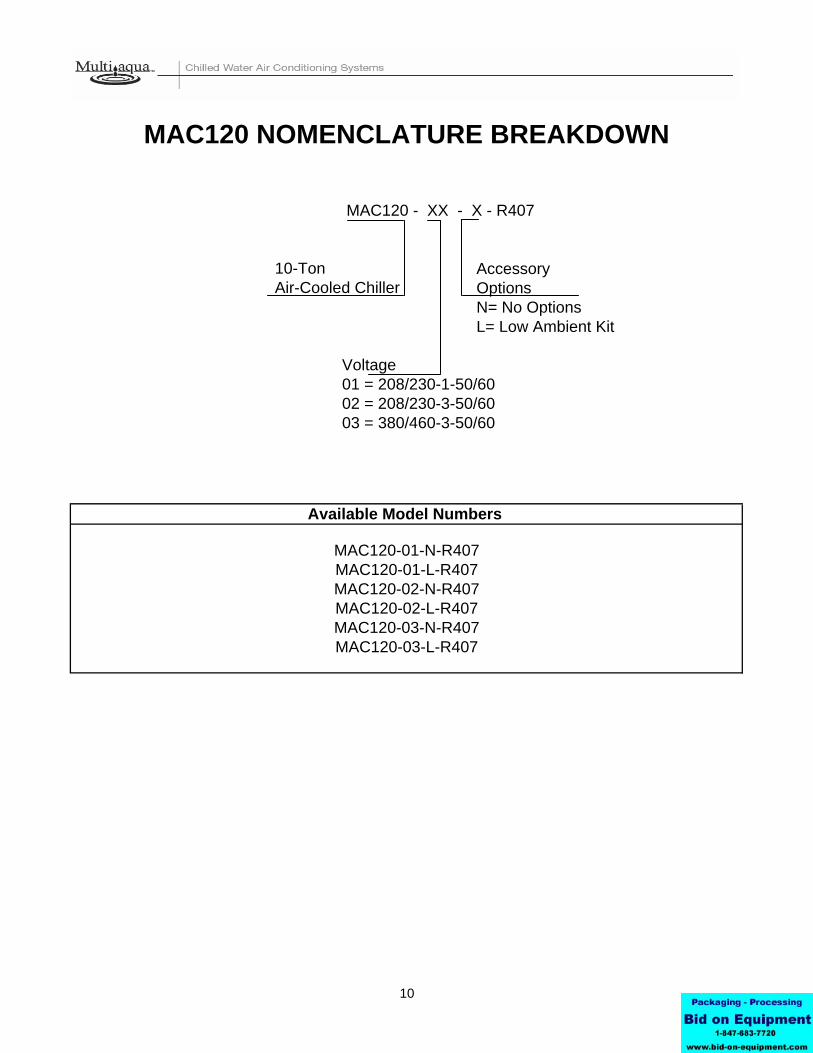
Accessory OptionsN= No OptionsL= Low Ambient Kit
10
01 = 208/230-1-50/6002 = 208/230-3-50/6003 = 380/460-3-50/60
MAC120-02-N-R407MAC120-02-L-R407MAC120-03-N-R407MAC120-03-L-R407
MAC120 NOMENCLATURE BREAKDOWN
MAC120-01-N-R407MAC120-01-L-R407
10-Ton
Voltage
Air-Cooled Chiller
Available Model Numbers
MAC120 - XX - X - R407

HVAC Guide Specifications Air-Cooled Liquid Chiller Nominal Size: 10 Tons Multiaqua Model Number: MAC120-01-N-407, MAC120-01-L-407 MAC120-02-N-407, MAC120-02-L-407 MAC120-03-N-407, MAC120-03-L-407 Part 1-General 1.01 System Description
Multiaqua air-cooled liquid chillers are designed using scroll compressors and low sound condenser fans. 1.02 Quality Assurance
A. Certified in accordance with U.L. Standard 95, latest version (U.S.A.) B. Construction shall comply with ASHRAE 15 Safety Code, NEC and ASME applicable codes. (U.S.A.
Codes) C. Manufactured in a facility registered to ISO 9002, Manufacturing Quality Standard. D. ETL certified. E. Fully load tested at the factory. F. Damage resistant packaging.
1.03 Delivery, Storage and Handling A. Packaged and readied for shipment from the factory. B. Controls shall be capable of withstanding 150°F storage temperatures in the control compartment. C. Stored and handled per manufacturer’s recommendations.
Part 2-Product 2.01 Equipment A. General: 1. Unit shall be a factory assembled and tested air-cooled liquid chiller. 2. Shall be assembled on heavy gauge steel mounting/lifting rails.
3. Contained within the unit cabinet shall be all factory wiring, piping, controls, refrigerant charge (R407c), POE oil and special accessories required prior to start up.
4. Brass body strainer with 20 mesh screen and blow down shall be supplied in cabinet as a field installable accessory.
B. Unit Cabinet: 1. Composed of heavy gauge galvanized steel casing with a baked polyester powder. 2. Capable of withstanding 500-hour salt spray test in accordance with the ASTM (U.S.A.) standard.
C. Condenser Fans: 1. 4-blade, aluminum construction and shall be dynamically balanced and corrosion resistant. 2. Discharge air at a 45° vertical angle. 3. Motors and blades shall be protected by coated steel wire safety guards.
D. Fan Motors: 1. Condenser fan motors shall be single speed, direct drive. 2. Totally enclosed. 3. Permanently lubricated sleeve bearings and Class F insulation. 4. Internal overload protection.
E. Compressors: 1. Unit shall contain two fully hermetic scroll compressors. 2. Direct-drive, 3500 rpm (60Hz) 3. Compressor motor shall be suction gas cooled. 4. Internal motor protection. 5. Externally protected by low and high pressure cutout devices. 6. Individual vibration isolators.
11

F. Pump: 1. Unit shall be capable of incorporating a field installed chilled liquid solution pump. (Space restricted) 2. Unit shall have provisions to allow for chilled liquid solution piping to the exterior of the cabinet.
G. Evaporator: 1. Evaporator shall have two independent refrigerant circuits. 2. Rated for a refrigerant side working pressure of 450 psig and a maximum water side working
pressure of 60 psig. 3. Single pass, ANSI type 316 stainless steel, brazed plate construction. 4. Externally insulated with closed cell, elastomeric foam. (ASTM518)
H. Condenser: 1. Condenser coil shall be air-cooled with integral subcooler. 2. Two independent refrigerant circuits. 3. Constructed of rifled copper tubing mechanically bonded to aluminum fins. 4. Cleaned and dehydrated. 5. Factory leak tested to 450 psig.
I. Refrigerant Circuits: 1. Each circuit shall contain a sight glass, liquid line filter, thermal expansion valve, refrigerant charge of R407c and POE compressor oil.
Part 3-Controls and Safeties 3.01 Controls A. Chiller shall be completely factory wired and tested. B. Capacity control shall be based on leaving chilled liquid solution temperature. 1. Temperature accuracy shall be + - 1.0°F. 2. Controls shall be capable of staging the two compressors. C. Controls shall include the following components. 1. 24vac transformer to serve all controllers relays and control components. 2. Microprocessor based liquid solution temperature controller. 3. Leaving water temperature thermistor. 4. Pump bypass timer. 5. Compressor recycle timer. 6. Optional fan cycling control for low ambient operation. 7. Chilled liquid solution flow switch. 3.02 Safeties A. Unit shall be equipped with thermistors and all necessary components in conjunction with the control system to provide the following protectants.
1. Low refrigerant pressure. 2. High refrigerant pressure. 3. Low chilled liquid solution temperature. 4. Low chilled liquid solution flow. 5. Thermal overload. 6. Short cycling.
Part 4-Operating Characteristics: 4.01 Temperatures
A. Unit shall be capable of starting and running at outdoor temperatures from 55°F to 120°F. B. Optional Low Ambient Kit shall allow starting and running at outdoor temperatures to -20°F. A
field supplied and installed crank case heater must be used when operating at these temperatures. C. Unit shall be capable of starting up with a maximum 80°F and a sustained 70°F entering fluid
solution temperature to the evaporator. D. Minimum 10% Glycol solution is required. For outdoor temperatures below 32°F, reference MAC Glycol Solution Data table.
4.02 Electrical Requirements A. Primary electrical power supply shall enter the unit at a single location. B. Electrical power supply shall be rated to withstand 120°F operating ambient temperature. C. Units shall be available in 1 or 3-phase power at the voltages shown in the equipment electrical data. D. Control points shall be accessed through terminal block.
12

13
MAC120 Product Specifications
Electrical Data Compressor
(Qty 2)
Condenser Fan Motor (Qty 2)
Fuse or HACR Circuit Breaker Model
Number Volts/ Phase/ Hertz
(RLA) (LRA) (RLA) (RPM)
Minimum Amps
Maximum Amps
MAC120-01 208/230-1-50/60 32.1 x 2 169 x 2 2.3 x 2 900 44.73 x 2 “See note 1”
75 x 2 “See note 1”
MAC120-02 208/230-3-50/60 19.3 x 2 137 x 2 2.3 x 2 900 48.03 “See note 2”
65 “See note 2”
MAC120-03 380/415/460-3-50/60 10 x 2 75 x 2 1.6 x 2 900 25.70 “See note 2”
35 “See note 2”
Note: 1. MAC120-01 has two independent line voltage terminations. 2. MAC120-02 & MAC120-03 has one independent line voltage termination.
Multiaqua chillers are designed to operate exclusively with R407c refrigerant in a self-contained, pre-charged refrigerant system. Do not access the closed refrigerant circuit for any reason other than after-sale, after installation component replacement. Routine maintenance and service is to be performed by qualified personnel only.
These specifications are subject to change without notice.
Physical Data Condenser Coil Chiller Weight (lbs)
Model Number Height
(in) Length
(in)
Copper Tubing
Diameter (in)
Coil Rows
Height (in)
Length (in)
Width (in)
Refrigerant R407c Net Shipping
MAC120-01 52.5 48 3/8 3 60 58.25 25.25 104 oz x 2 650 700 MAC120-02 52.5 48 3/8 3 60 58.25 25.25 104 oz x 2 650 700 MAC120-03 52.5 48 3/8 3 60 58.25 25.25 104 oz x 2 650 700
Copper Wire Size (1% Voltage Drop) 200 6 4 4 4 3 3 2 2 150 8 6 6 4 4 4 3 3 100 10 8 8 6 6 6 4 4 50 14 12 10 10 8 8 6 6
15 20 25 30 35 40 45 50 Sup
ply
Wire
Le
ngth
in F
eet
Supply Circuit Ampacity
Compressor Copeland Scroll Refrigerant R407c
Heat Exchanger Brazed Plate Max Flow Rate 28.8 gpm Min Flow Rate 18 gpm
Supply Water Temp 44° Return Water Temp 54°
Minimum System Solution Content 50 Gallons
Expansion Tank Size 3% of Total System Water Connections 1 3/8" OD Supply & Return
Internal Pressure Drop 18 ft of head

14
MAC120 Product Specifications
MAC120 Capacity / Watts / EER*
Outdoor Air °F 82 95 100 105 110
TONS 9.4 9.0 8.8 8.7 8.7 KILOWATTS 10.9 11.5 11.5 12.1 12.4
EER 10.35 9.39 9.18 8.63 8.42
* Refrigerant system performance only, pump data not included.
Example: 30% glycol solution. Maximum Flow Rate = 12gpm x 1.036 System capacity x .98 *Use Propylene Glycol Only Important If the outside temperature is expected to fall below freezing (32°F) in the area the Multiaqua chiller is to be installed; the installer must take the following precautions. Failure to do so will void the warranty. To not engage in cold ambient mitigation will result in the failure of components such as the heat exchanger, piping, circulating pump, etc… and or property damage. • Keep the liquid solution at a minimum of 10% percent Propylene Glycol even in areas where there is no danger of freezing. • The percentage amount of glycol recommended is dependent on the expected ambient temperatures and the solution makeup recommendation of the glycol manufacturer. Refer to the MAC120 Glycol Solution Data table above. • Ensure the system circulating pump is in a constant energized mode to keep a continuous circulation of liquid solution. The Multiaqua chiller is a self-contained air-cooled condenser, coupled with an insulated brazed plate heat exchanger (evaporator). The system utilizes a scroll compressor to circulate refrigerant between the condenser and heat exchanger. The refrigerant is metered into the heat exchanger with a thermal expansion valve. Protecting the system are high and low pressure switches as well as a pump flow switch. Liquid solution (water and Propylene Glycol; minimum 10 % is required) is circulated through the heat exchanger by an externally mounted pump. The liquid solution flows through the heat exchanger to the system supply piping and on to the air handlers. Low ambient kits are available for operating ambient temperatures down to -20 degrees Fahrenheit. A field supplied and installed crankcase heater must be installed when operating at these temperatures. The low ambient kits consist of an ICM 325 (+) ICM (175) for single and three phase 208/230 vac chillers. For the three phase 380/460 vac chillers a pressure activated fan control is used.
These specifications are subject to change without notice.
MAC120 Glycol Solution Data Propylene Glycol % Water
Flow Capacity Min. Ambient Temp GPM Adjustment= 100% Capacity
10% x 1.020 x 0.99 26°F x 1.01 20% x 1.028 x 0.98 18°F x 1.03 30% x 1.036 x 0.98 8°F x 1.07 40% x 1.048 x 0.97 -7°F x 1.11 50% x 1.057 x 0.96 -29°F x 1.16

TONS GPM TONS GPM TONS GPM TONS GPM TONS GPM35 7.9 7.6 7.4 7.3 7.140 8.8 8.4 8.2 8.1 8.142 9.1 8.7 8.5 8.4 8.444 9.4 9.0 8.8 8.7 8.745 9.6 9.2 9.0 8.8 8.846 9.7 9.3 9.1 9.0 9.048 10.1 9.7 9.4 9.3 9.350 10.4 10.0 9.7 9.6 9.655 11.3 10.9 10.5 10.4 10.360 12.3 11.8 11.4 11.2 11.1
TONS GPM TONS GPM TONS GPM TONS GPM TONS GPM35 7.8 7.5 7.3 7.2 7.040 8.7 8.3 8.1 8.0 8.042 9.0 8.6 8.4 8.3 8.344 9.3 8.9 8.7 8.6 8.645 8.5 9.1 8.9 8.7 8.746 9.6 9.2 9.0 8.9 8.948 10.0 9.6 9.3 9.2 9.250 10.3 9.9 9.6 9.5 9.555 11.2 10.7 10.4 10.3 10.260 12.1 11.6 11.2 11.0 10.9
TONS GPM TONS GPM TONS GPM TONS GPM TONS GPM35 7.7 7.4 7.2 7.1 6.940 8.6 8.2 8.0 7.9 7.942 8.9 8.5 8.3 8.2 8.244 9.2 8.8 8.6 8.5 8.545 9.4 9.0 8.8 8.6 8.646 9.5 9.1 8.9 8.8 8.848 9.9 9.5 9.2 9.1 9.150 10.1 9.8 9.5 9.4 9.455 11.1 10.6 10.2 10.1 10.060 12.0 11.5 11.1 10.9 10.8
These specifications are subject to change without notice.
15
28.8
MAC120 CAPACITIES with 0% GlycolENTERING AIR TEMPERATURE (°F)
82 95 100 105 110LWT (°F)
MAC120 Cooling Performance Data
28.8
110
MAC120 CAPACITIES with 10% GlycolENTERING AIR TEMPERATURE (°F)
100 105
28.8 28.8 28.8
28.8 28.8 28.8
LWT (°F)
28.8 28.8
82 95
28.8
MAC120 CAPACITIES with 20% GlycolLWT (°F) ENTERING AIR TEMPERATURE (°F)
82 95 100 105 110
28.8 28.8 28.828.8

TONS GPM TONS GPM TONS GPM TONS GPM TONS GPM35 7.7 7.4 7.2 7.1 6.940 8.5 8.1 8.0 7.9 7.942 8.8 8.4 8.2 8.1 8.144 9.1 8.7 8.5 8.4 8.445 9.3 8.9 8.7 8.5 8.546 9.4 9.0 8.8 8.7 8.748 9.8 9.4 9.1 9.0 9.050 10.1 9.7 9.4 9.3 9.355 11.0 10.6 10.2 10.1 10.060 11.9 11.5 11.1 10.9 10.8
TONS GPM TONS GPM TONS GPM TONS GPM TONS GPM35 7.6 7.3 7.1 7.0 6.840 8.5 8.1 7.9 7.8 7.842 8.8 8.4 8.2 8.1 8.144 9.1 8.7 8.5 8.4 8.445 9.3 8.9 8.7 8.5 8.546 9.4 9.0 8.8 8.7 8.748 9.8 9.4 9.1 9.0 9.050 10.0 9.7 9.4 9.3 9.355 10.9 10.5 10.1 10.0 9.960 11.9 11.4 11.0 10.8 10.7
TONS GPM TONS GPM TONS GPM TONS GPM TONS GPM35 7.5 7.3 7.1 7.0 6.840 8.4 8.0 7.8 7.7 7.742 8.7 8.3 8.1 8.0 8.044 9.0 8.6 8.4 8.3 8.345 9.2 8.8 8.6 8.4 8.446 9.3 8.9 8.7 8.6 8.648 9.7 9.3 9.0 8.9 8.950 9.9 9.6 9.3 9.2 9.255 10.8 10.4 10.0 9.9 9.860 11.8 11.3 10.9 10.7 10.6
These specifications are subject to change without notice.
LWT (°F) ENTERING AIR TEMPERATURE (°F)82 95 100 105 110
28.8 28.8 28.8
MAC120 CAPACITIES with 50% Glycol
95 100 105 110
MAC120 Cooling Performance Data
28.8 28.828.8 28.8 28.8
MAC120 CAPACITIES with 30% GlycolLWT (°F) ENTERING AIR TEMPERATURE (°F)
82
MAC120 CAPACITIES with 40% GlycolLWT (°F)
28.8 28.8
ENTERING AIR TEMPERATURE (°F)82 95 100 105 110
16
28.8 28.828.8 28.8 28.8

17

Page
Introduction 19
System Description & Sequence of Operation 20
Electrical & Physical Data 21
Description of Electrical Controls 23
Chiller Controls Sequence of Operation 25
Refrigeration System Operation 26
Description of Refrigeration Components 26
Piping System Components 28
Layout & Design 29
Banked Chiller Configuration 30
Installation Notes 31
Propylene Glycol Content 32
Expansion Tank 32
Filling the System with Propylene Glycol 33
Air Elimination 33
Table of Contents
18

Multiaqua Chiller Manual The Multiaqua Chiller System is the only air conditioning/refrigeration system of its kind in the world today offering the degree application flexibility described in the following manual. The Multiaqua Chiller System is not only unique in its application flexibility; it is unique in superior quality, rated capacities and rugged durability. When installed in accordance with these instructions the system will deliver years of trouble free service. Proper equipment sizing, piping design and installation are critical to the performance of the chiller. This manual is meant to be a “how to” introduction to piping and installing the Multiaqua Chiller System.
MAC120 Chiller Features
• Copeland Scroll Compressors • Advanced Motor Protection
• Loss of Flow Protection • Control Power Transformer
• Low Ambient Option • Integrated Chilled Solution Pump Control
• Flow Switch • Strainer Connection Kit
• Painted Metal Condenser Protector Grille • Dual Refrigeration Circuits and Single Liquid Solution Circuit
RECOGNIZE THIS SYMBOL AS AN INDICATION OF IMPORTANT SAFETY OR INSTRUCTION RELATED INFORMATION. Web site information addresses are supplied throughout this manual for piping and accessory information. The plumbing industry also has pressure drop information on ferrous and copper piping systems. The following sections will describe each component and how it functions within the system. Installation information is supplied where appropriate. The piping design section will explain the design and layout the piping system from a “how to” perspective. Following the examples provided will enable the installer to determine the correct pipe and accessory sizing, as well as equipment location. It is important to know before installation if the proposed system will operate correctly and by doing a formal layout of a new application or review of an existing piping system will make that determination. Throughout this manual the term “liquid solution” is used in place of water. The chiller circulates a solution of water and Propylene Glycol.
It is essential to operate the system with a minimum of 10% glycol. DO NOT OPERATE THIS SYSTEM USING WATER ALONE. For proper liquid solutions mix ratios, refer to page 14 or the glycol manufacture’s recommended mix ratios.
19

System Description & Sequence of Operation
The Multiaqua Chiller is a self-contained, air-cooled condenser, coupled with an insulated brazed plate heat exchanger (evaporator). The system utilizes scroll compressors to circulate refrigerant between the condenser and heat exchanger. The refrigerant is metered into the heat exchanger with a thermostatic expansion valve. Protecting the system are high and low pressure switches as well as a pump flow switch. Liquid solution (water and Propylene Glycol is circulated through the heat exchanger by a field supplied pump. The liquid solution flows through the heat exchanger to the system supply piping and on to the air handlers. A solenoid-operated, motorized valve or circulator controls the flow of the chilled liquid solution through the air handlers. The valves or circulators can be actuated by a variety of different control schemes. Liquid solution temperature is controlled by a chiller mounted digital electronic controls. A system sequence of operation, individual control description, troubleshooting information and a schematic are included in the controls section.
It must be recognized that ferrous pipe may cause acceleration deterioration of the brazed plate heat exchanger and could void the heat exchanger warranty.
Cooling load Diversity Equipment sizing for a chilled liquid solution system can utilize Cooling Load Diversity. Diversity is described as the actual amount of cooling needed (heat load) by various sections of a structure at a given time. Conventional air conditioning systems are designed for the highest structure heat load. The conventional system determines and selects equipment based on the peak heat load demanded by the structure. A system sized to take advantage of diversity would determine the heat load by the time of day, building exposure and usage. As an example the sections of a structure facing west, demand more cooling in the afternoon, than sections facing east. The opposite of this is true in the morning, where the east section is exposed to a higher heat load requiring more cooling. Utilizing diversity the chiller system would adapt to the needs of each side of the structure during peak demand by delivering more cooling to that area and less to the areas that do not need it. A structure utilizing a conventional DX system, requires 8 tons of cooling at peak load, could utilize a much smaller capacity system (potentially 4 or 5 tons) if the system installed could take advantage of load diversity, which would supply the necessary amount of cooling to the space, as and when needed instead of keeping a larger capacity available at all times. Cooling load diversity can best be determined by referring to ACCA. (Air Conditioning Contractors of America) Manual “J”, Refer to the appendix A-2, Multi-Zone Systems. ACCA’s Internet address is http://www.acca.org/ Because of diversity a Multiaqua Chiller can serve more total air handler tonnage than chiller capacity. A 10-ton chiller may be delivering chilled liquid solution to 15 or more tons of air handler capacity. Because of cooling load diversity, the building does not need equal amounts of cooling in each area at the same time.
20

ELECTRICAL AND PHYSICAL DATA
The information contained in this manual has been prepared to assist in the proper installation, operation and maintenance of the chiller. Improper installation, or installation not made in accordance with these instructions can result in unsatisfactory operation and/or dangerous conditions and can cause the related warranty not to apply. Read this manual and any instructions packaged with separate equipment required to make up the system prior to installation. Retain this manual for future reference.
Separate and independent power supplies and disconnects must be provided. These chillers have separate and discreet power requirements within one cabinet.
All power to the chiller must be turned off prior to opening cabinet and or servicing.
Failure to properly ground chiller can result in death.
Disconnect all power wiring to chiller before maintenance or service work. Failure to do so can cause electrical shock resulting in personal injury or death.
All wiring must be done in accordance with the NEC (National Electric Code) as well as state and local codes, by qualified electricians.
Product warranty does not cover any damages or defect to the chiller caused by the attachment or use of any components, accessories or devices (other than those authorized by the manufacturer) into, onto or in conjunction with the chiller. You should be aware that the use of unauthorized components, accessories or devices may adversely affect the operation of the chiller and may also endanger life and property. The manufacturer disclaims any responsibility for such loss or injury resulting from the use of such unauthorized components, accessories or devices.
Upon receiving the chiller and components, inspect for any shipping damage. Claims for damage, either apparent or concealed should be filed immediately with the shipping company.
No liquid other than the solution of water and Propylene Glycol (mixed in accordance with table 6 page 32) shall be used in the piping system.
Corrosive environments may subject metal parts of the chiller to rust and deteriorate. The oxidation could shorten the chiller’s useful life. Corrosive elements include salt spray, fog or mist in sea coastal areas, sulfur or chlorine from lawn watering systems and various chemical contaminants from industries such as paper mills and petroleum refineries. If the unit is to be installed in an area where contaminates are likely to be a problem, special attention should be given to the equipment location and exposure. • Avoid having lawn sprinklers spray directly on the chiller cabinet. • In coastal areas, locate the chiller on the side of the building away from the water front. • Elevating the chiller off of its slab or base enough to allow air circulation will help avoid holding water in contact with the cabinet base. • Regular maintenance will reduce the build-up of contaminants and help protect the cabinet finish. • In severe locations having the chiller coated with an “epoxy” or other coating formulated for air conditioning systems located in coastal areas may be necessary.
21
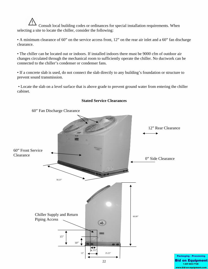
60” Front Service Clearance
15” 10”
13” 4.25”
25.25”
60.00”
60.00” 60.00”
58.25
58.25”
Consult local building codes or ordinances for special installation requirements. When selecting a site to locate the chiller, consider the following: • A minimum clearance of 60” on the service access front, 12” on the rear air inlet and a 60” fan discharge clearance. • The chiller can be located out or indoors. If installed indoors there must be 9000 cfm of outdoor air changes circulated through the mechanical room to sufficiently operate the chiller. No ductwork can be connected to the chiller’s condenser or condenser fans. • If a concrete slab is used, do not connect the slab directly to any building’s foundation or structure to prevent sound transmission. • Locate the slab on a level surface that is above grade to prevent ground water from entering the chiller cabinet.
Stated Service Clearances
22
60” Fan Discharge Clearance
12” Rear Clearance
0” Side Clearance
Chiller Supply and Return Piping Access

Control Transformer: The control transformer is rated at 24 vac, 40 va (1.6 amps @ 24vac)
Pump Bypass Timer: The pump bypass timer is a 24 vac, 3-wire control. When energized the timer will bypass the flow switch for 10 seconds (by creating a circuit to the pump relay), energizing the pump relay, allowing the pump to operate long enough to close the flow switch. In a normally operating system the flow switch will stay closed powering the pump relay in series with
solution control contacts open, the timer delays by opening its contact for 5-minutes before resetting to the closed position.
the low and high- pressure switches. Should the flow switch open, the timer can only be reset by opening and closing the chiller's line voltage disconnect.
Refrigerant System Timer: The refrigerant timer is a 24 vac, 5-minute delay
Description of Electrical Controls
High Pressure Switch: The high-pressure switch is an automatic reset control that senses compressor discharge line pressure. It opens at 400 PSIG and closes at 300 PSIG.
on break, 20wire timer. The normally closed contacts of the timer energizethe compressor contactor through the chilled solution control. When the chilled
23

The low-pressure switch is an automatic reset control
closes at 80 PSIG.
Flow Switch: The flow switch senses liquid solution flow. The paddle of the
that senses compressor suction line pressure. It opens at 40 PSIG and
Description of Electrical Controls (continued)
Low Pressure Switch:
24
switch is inserted through a fitting into the pump discharge line. Liquid solution flow deflects the paddle closing the switch. The flow switch is position sensitive. The arrow ↑ on the switch must point in the direction of liquid solution flow.
Compressor Contactor: The compressor contactor energizes the compressor
control is mounted inside the chiller cabinet.
through the two or three normally open contacts. The contactor coil operates(closes the contacts) when energized by 24 vac.
Liquid Solution Temperature Control: The liquid solution temperature controlis an adjustable microprocessor based temperature control. This control receives temperature information from a thermistor located on the liquid solution supplyline. A liquid crystal display continually indicates liquid solution temperature. The

Chiller Controls Sequence of OperationWhen powered up, the Multiaqua chiller system energizes the control transformer creating 24 vac control voltage.
First the pump bypass timer is energized and temporarily bypasses the flow switch, energizing the pump relay. The
If the liquid solution temperature controller is calling for cooling the control circuit is routed through the short cycle
pump then starts to move liquid solution through the piping system (in a properly filled and air purged system). Themovement of liquid solution from the pump discharge keeps the flow switch closed. After a 10 second delay the pump contact opens, connecting the flow switch in series with the high and low pressure switches. The pump will now run continually unless the power supply is interrupted, or the flow switch opens.
timer and the three safety switches (the flow, high and low pressure switches) to the compressor contactor. This willenergize the compressor(s) and condenser fan motors. The liquid solution controller will open at the user programmedset point, causing the refrigerant short cycle timer to open it's contact for 5 minutes as it delays before resetting to the closed position. This will de-energize the compressor. Power fluctuations will also initiate a 5 minute time delay. The 5 minute delay allows the refrigerant system a period for pressure equalization, protecting the compressor(s) fromshort cycling.
The chiller temperature controller utilizes a thermistor to monitor the liquid solution temperature change. The temperature is then compared to the set point and differential temperatures programmed into the control by the user.The set point is the liquid solution temperature which will cause the control switch to open. For example: The control set point is programmed at 44°F LWT with a 10°F differential, which opens the controller at 44°F LWT and closes at 54°F. The differential temperature is the number of degrees above set point temperature programmed into the controller. If liquid solution temperature falls to the set point, the controller cycles the compressors off.
Chillers are shipped with the control set point adjusted to 44°F LWT and a 10°F differential. Liquid solution temperature set point should not be set below 35°F.
25

technology ensures reliable high performance at a low sound level over a wide range of operating conditions.
interrupted for any reason, the control will open shutting down and locking out the chiller operation. The only exception to this is when power is first applied to the chiller and the pump bypass timer bypasses the flow switch for 10 seconds.
When the system is first filled with liquid solution and the pump is started, expect the system to cycle off
Flow Switch Opening: The flow switch is normally closed during pump operation. Should liquid solution flow be
on the flow switch until all of the air is removed from the piping system. The system will have to be reset by opening and then closing the disconnect switch or circuit breaker powering the chiller.
Low Pressure Switch Opening: Should the compressor suction pressure go low enough (40 PSI) to open the low- pressure switch, the compressor and condenser fan motors will shut down. Check for a refrigerant leak, inoperative thermal expansion valve, low liquid solution control setting, low ambient operation, low liquid solution flow, etc.
High Pressure Switch Opening: Should the compressor discharge pressure go high enough to open the high- pressureswitch the compressor and condenser fan motors will shut down. Check for a dirty condenser coil, inoperable fan motor(s)or the recirculation of condenser air.
Refrigeration System Operation
The refrigeration system is a closed loop consisting of 2 compressors, dual circuit heat exchanger (evaporator), meteringdevices (TXVs) and condenser coil. The refrigerant circulated is R407c. Hot gas is pumped from the compressors to the to the condenser coil where the two condenser fans pull cooler air across the coil condensing and sub cooling the refrigerant.
drops causing the refrigerant to boil at a much lower temperature (34-40°F). The refrigerant leaves the expansion valves andswirls through the plates of the heat exchanger absorbing heat from the circulating liquid solution.
Description Of Refrigerant Components
enough to cause serious injury.
Scroll Compressor: All Multiaqua chillers feature Scroll compressors. Scroll
26
SYSTEM FAULTS:
Caution the top half of the scroll compressor operates at a temperature high
The evaporator or heat exchanger is designed to operate with an 8-10°F superheat. The condenser is designed to condense the refrigerant and sub cool it to 10°F below condensing temperature.
The now liquid refrigerant flows through the liquid line to the thermal expansion valves, where the refrigerant pressure

construction. The coil is protected by a painted metal condenser grille.
Description Of Refrigerant Components (continued)
Brazed Plate Heat Exchanger: The "Heat Exchanger" or evaporator is of abrazed copper and stainless steel design. Refrigerant and liquid solution is channeledthrough narrow openings between plates and flows in opposite directions. The counter flow design and fluid turbulence ensures maximum heat exchange at minimal pressuredrop.
Thermal Expansion Valve: Multiaqua chillers are equipped with Thermal Expansion valves. The valves feature a liquid charged sensing bulb for consistent superheat at
Condenser Coil: The air-cooled condenser coil is of copper tube with aluminum fin
various load conditions.
27

air scoop eliminates air entrance in the liquid solution.
are cycled off.
Part Number: D146M1032- 3/4"
WX202H (42 Gallon)
Expansion Tank and Air Scoop: The Expansion Tank and Air Scoop assembly is used to compensate for the expansion and contraction of liquid in the system. The
Part Number: 1500/1"
Liquid Solution Bypass Valve: The liquid solution bypass valve relieves system pressure from the liquid solution supply to the return as system air handler control
Piping System ComponentsSupply Storage Tank: The supply storage tank must be used in the system with less than 25 gallons of liquid solution. The tank prevents rapid cycling of the compressors and acts as a reserve for chilled liquid solution.
Supply storage tank must be insulated in the field.
Part Number: WX202H (20 Gallon)
D146M1040- 1 1/4"
Motorized Valve: The air handler motorized valve controls the flow of liquid solutionto the systems air handlers. Each air handler in the system should have a motorizedor solenoid valve.
Part Number: MZV524E-T 1/2" 2-Way Zone Valve MZV525E-T 3/4" 2-Way Zone Valve MZV526E-T 1" 2-Way Zone Valve VT3212G13A020 1/2" 3-Way Zone Valve VT3212G13A020 3/4" 3-Way Zone Valve
28

1-2-3-4-5-6-7-
capacities in gallons per minute and pressure drop (feet of head) are listed in table 1.
on capacity and glycol mix percentages.
Table 1
GPMGPM
GallonsGallons
Ft.of HeadGallons
table 1) in GPMs.
29
Chiller Liquid Solution Content
3% of Total1.851.5
MAC-12018
28.850
MAC Series
Composite Piping Layout and DesignUnderstanding the function and friction loss of each part of the piping system is important to the layout and successfulinstallation of a chilled liquid solution system.
Bypass Valve2-Way Liquid Solution Control Valves
Storage TankExpansion TankCoilChillerPump
An adjustable valve must be used to throttle the discharge liquid solution flow rate to appropriate levels based
The circulation pump is the key performer in the piping system. The pump must circulate the liquid solution through the heat exchanger and piping system to the air handlers. Pumps are designed to deliver a flow rate measured in gallonsper minute(GPM). The pump must be able to overcome the resistance to flow (pressure drop) imposed by the chiller components, piping system and air handlers while maintain the necessary flow rates in gallons per minute. Pump
Chiller System Data
Expansion Tank SizeInternal Chiller Pressure Loss
Min. Liquid Solution Flow RateMax.Liquid Flow RateMin. Liquid Solution Content in System
Piping resistance or pressure drop is measured in feet of head. A foot of head is the amount of pressure drop imposedin lifting liquid solution one foot. Pumps in the Multiaqua system are designed to move rated liquid solution flow (see
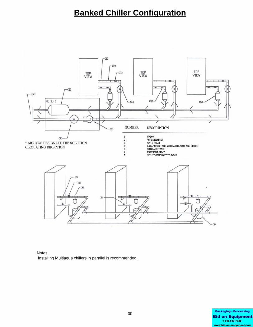
Notes:
Banked Chiller Configuration
Installing Multiaqua chillers in parallel is recommended.
30

In no instance should a Multiaqua chiller be installed with less than 10% Propylene Glycol content in the pipingsystem. Using less than the recommended Propylene Glycol percentage content voids equipment warranty.
Propylene Glycol slightly lessons the temperature exchange in the chiller heat exchanger. However, that is offset by the increased flow of liquid solution through the piping system enabled by the Propylene Glycol. Todetermine the Propylene Glycol content for various ambient temperatures refer to table 6 page 32.
Propylene Glycol must be added to the water used in the system. Propylene helps prevent freeze-ups due to low ambient temperature conditions and low chilled liquid solution temperatures. In comparison to water,
Estimate the system liquid solution content. Should the system have less than 50 gallons of liquid solution content, a chilled liquid solution storage tank must be installed. The tank stores enough chilled liquid solution to prevent frequent chiller compressor cycles at light load and prevents chilled liquid temperature swings athigher load conditions when the chiller compressor is waiting to cycle on the time delay control.
refrigerant compressor in the chiller.
The minimum liquid solution content in the chiller system,(piping, chiller, and air handlers), is 50 U.S. gallons.
solenoid actuated. De-energize the solenoid valve, (at this point no liquid solution will be flowing through the airhandlers.) and adjust the bypass valve to relieve pressure between the supply and return piping.
Bleed ports will be factory installed on all Multiaqua air handlers. Bleed ports are opened to eliminate air trappedin the air handlers after filling the system with liquid solution and Propylene Glycol and before operating the
solution supply pipes at a convenient location to the installation. The bypass valve operates to bypass liquid solutionbetween the supply and return chilled liquid solution lines. In the event air handlers valves should shut down, the bypass valve is set to open up and bypass liquid solution between the supply and return lines, relieving pressureand eliminating the possibility of pump cavitations. To adjust the valve, run the system with one air handler
thermostat or air handler installed digital control operate the valves.
Bypass valves as shown in drawing 1, should be installed between the supply and the return chilled liquid
The air handlers are to be controlled with electrically operated "slow-opening" solenoid valves, circulators ormotorized zone valves as manufactured by Erie controls (www.eriecontrols.com/products/index.htm) A remote
at the chiller and air handler. The factory supplied wye strainer will capture particles of rust and sediment inherent with steel piping and should be checked and cleaned after initial start up and open a regular maintenance
31
during the life of the system.
Any piping used to conduct liquid solution must be insulated in accordance with local and national mechanicalcodes. Information on insulation installation and application can be obtained from Armaflex web site at www.armaflex.com and Owens-Corning site at www.owenscorning.com/mechanical/pipe/. For future servicingof the chiller and air handlers, it is suggested that shutoff valves be installed at the chiller and air handler(s). Ifball valves are used, they can double as balancing valve(s) in the supply piping at each air handler. Chillershutoff valves should be attached at the chiller connections with unions.
Piping such as PEX,steel, copper or PVC can be used with the Multiaqua system. Check local building codes formaterial conformation. Care must be taken when using PVC as the presence of propylene glycol may destroy plastics. Pressure drop data for the selected piping material is readily available and should be used. Should theMultiaqua chiller be installed using existing steel (ferrous metal) piping system, dielectric fittings must be used
Installation Notes:

Table 6
Propylene Water Min. Ambient Glycol % Flow Temperature
10% x 1.020 26°F20% x 1.028 18°F30% x 1.036 8°F40% x 1.048 -7°F50% x 1.057 -29°F
32
Capacity
x .99x .98x .98x .97
family of Glycol-based coolants of food grade Propylene Glycol is suggested. Information on Ambitrol is available from Dow at www.dow.com, search word "Ambitrol".
Expansion Tanks:
Polypropylene Glycol System Content vs.
To not engage in cold ambient mitigation will result in the failure of components, property damage and void warranty.
Minimum Ambient Temperature
x 1.11x 1.16
Ethylene Glycol is environmentally hazardous and not recommended. Inhibited Propylene Glycol ( typical
Percent of Propylene Glycol to Water Content
automotive coolant) is not to be used in a Multiaqua Chiller under any circumstances. Dow Chemical's "Ambitrol"
x .96
GPM Adjustment= 100 % Capacity
x 1.01x 1.03x 1.07
Liquid solution expansion and contraction within the closed system must be compensated for with an expansiontank. The expansion tank used with the Multiaqua system, is a steel tank with a rubber bladder attached to it internally. There is air pressure on one side of the rubber bladder that keeps the bladder pushed against the sides of the tank before the system is filled with liquid solution (illustration above). As the liquid solution heatsup the bladder will be pushed further away from the tank walls, allowing for expansion and contracting as the liquid solution temperature changes. By flexing, the bladder controls the system pressure adjusting to temperature variations of the chilled liquid solution system.
It is critical that the expansion tank's air bladders pressure be less than the system solution pressure. Air pressure can be measured with an automotive tire gauge at the bicycle valve port on the expansion tank. Bleedingair out of the bladder or increasing the pressure with a bicycle pump will adjust pressure.
System must use a liquid solution storage tank if system volume is less than 50 U.S. gallons.

complete air removal. If you continue having air entrapment issues, it will be necessary to install a micro bubble remover device.
(Propylene Glycol)
33
Filling System with Liquid Solution and Coolant
Concentrations of Propylene Glycol in excess of 50% will destroy o-rings in fittings and pump. Water should be added to the system first or a liquid solution diluted Propylene Glycol mix.
System that contains 50 or more U.S. gallons should have a tee fitting with a stopcock installed in the return line close to the chiller. The stopcock can be opened and attached to a hose with a female X female hose fitting. In the open end of the hose section (1 -1.5 feet long) insert a funnel and pour into the system thediluted Propylene Glycol/liquid solution mixture or add water first and then the quantity of Propylene Glycol needed for minimum ambient protection (refer to Table 6). After adding the Propylene Glycol/water mixture, orliquid solution and then coolant proceed to add enough water to the system to achieve a 15 psi gauge pressure. To measure system pressure shut off the stopcock, remove hose and attach a water pressure gauge. Openthe stopcock to read system pressure.
Systems that use the Chilled Liquid Solution Storage Tank should be filled at the tee/stopcock fitting in the outlet fitting of the storage tank. Fill the tanks with 10 gallons of water and with a funnel pour the calculated(refer to Table 6) amount of Propylene Glycol into the tank. The amount of Propylene Glycol added should be calculated to achieve minimum ambient protection. After adding Propylene Glycol, fill the system with enough liquid solution to bring system pressure to approximately 15 psi gauge pressure. To measure system pressure shut off the stopcock and attach a water pressure gauge. Open the stopcock to read system pressure.
Air EliminationSince we have the system filled we must eliminate the air left in the system. Briefly open each bleed valve at the air handlers and allow trapped air to escape. This will eliminate much of the air left in the system.
to get the pump running again. Open and close the power supply switch to the chiller to restart the pump. Continue bleeding air with the pump operating. You may have to start and re-start the pump a few times to
Next we will start the pump and continue bleeding air from the system. Be sure the chiller has line voltage available to it and set the chilled liquid solution control up to 100 °F, which will ensure that only the pump runs at this point. The pump should now start and remain running. Should the pump stop at any time during this
Before filling system with Propylene Glycol and water, pressure test the piping system with compressed air. Testing should be done at a maximum of 50 psi.The system should hold air pressure for a minimum of one hour with no leakage.
Using less than the recommended Propylene Glycol percentage content voids equipment warranty.
All piping systems should have a minimum of 10% Propylene Glycol in the system even in climates with non-freezing ambient temperatures.
process it is an indication that the flow switch had air move across it allowing the circuit to be interrupted. Continue to bleed some air out of the system at the highest locations before resetting the pump bypass timer
valve at the air handlers with the lowest return line chilled liquid solution temperature. Continue this process until each air handler has close to the same return line chilled liquid solution temperature.
Liquid solution control valves (solenoid or motorized valves) should be selected for low pressure drop. If a selectedvalve contributes to pushing your total head calculation to more than 50 feet of head, a larger valve may be needed to bring your total head below the maximum of 50 feet.
Liquid Solution Balancing:Liquid solution balancing will require an accurate digital thermometer to measure return line liquid solution temperature at each air handler. Set the chilled liquid solution temperature control in the chiller at a normal
line chilled liquid solution temperature of each air handler. Begin incrementally closing the supply line balance
operational temperature (44°F) and measure pump discharge temperature with the digital thermometer to checksystem solution temperature. After the chilled liquid solution temperature has lowered to the set point begin the balancing process. The system must be free of air and each air handler set at a temperature low enough to continue cooling operation (and liquid solution flow) during the balancing process. Begin by measuring the return

34
MAC120-3 Ladder Wiring Diagram
380/460-3-50/60

35
MAC120-3 Wiring Diagram
380/460-3-50/60
BKBLBK
BL
BK
BK
BK
BL
BK
BK
BLBL
BLBL
BK
kjg
REFRIGERANT SYSTEM TIMERTM2
COMPRESSOR CONTACTOR
FACTORY WIRING
CONDENSER FAN RELAY
GND
380/460-3-50/60
LEGEND:NOTES:
MULTIAQUA
TITLE
AUTHOR
DATE
REVISION
MAC120-03 380/460-3-50/60
CON1`
CON2
TRAN
SFO
RM
ER
380/4
60-3
24 va
c
DTC 1 DTC 2
REL 2REL 1
TM2
FS
LPS1
HPS1
1
2
3
4
LPS2
HPS2
TIMER1
1
2
3
4
FAN2
FAN1
NOTE 1
1.PUMP STARTER RELAY
L3
L1
L2
NONO C C
COM24 vac COM 24 vac
TM21
2
2
1
FIELD WIRING
DTC DIGITAL TEMPERATURE CONTROLLER09/22/08
0807300029 REV 1
FC1 FC2
FC CONDENSER FAN CONTACTOR
REL
CON
FS FLOW SWITCH
LOW PRESSURE SWITCH
HIGH PRESSURE SWITCHHPS
LPS
PUMP BYPASS TIMERTIMER
BL
YL
YL
BK
RD
WH
RD
WH
BK
WH
WHWH BK
BK
WH
RD
BK
BK BK
BL
BKBK
BK
BK
BK
BL
BL
RD
BK
BKBK
BK
RD
WH
BK
BK
T1COMP
1T2
T3
T3
T2
T1
COMP2
BK

36
MAC120-3-L with Low Ambient Kit Wiring Diagram
380/460/-3-50/60
31
BKBL
BL
BK
BK
BK
BL
BK
BLBL
BK
kjg
REFRIGERANT SYSTEM TIMERTM2
COMPRESSOR CONTACTOR
FACTORY WIRING
CONDENSER FAN RELAY
GND
380/460-3-50/60
LEGEND:NOTES:
MULTIAQUA
TITLE
AUTHOR
DATE
REVISION
MAC120-03 WITH LOW AMBIENT KIT
CON1`
CON2
TRAN
SFO
RM
ER
380/4
60-3
24 vac
DTC 1 DTC 2
REL 2REL 1
TM2
FS
LPS1
HPS1
1
2
3
4
LPS2
HPS2
TIMER1
1
2
3
4
FAN2
FAN1
NOTE 1
1. PUMP STARTER RELAY
L3
L1
L2
NONO C C
COM24 vac COM 24 vac
TM21
2
2
1
FIELD WIRING
DTC DIGITAL TEMPERATURE CONTROLLER
FC1 FC2
FC CONDENSER FAN CONTACTOR
REL
CON
FS FLOW SWITCH
LOW PRESSURE SWITCH
HIGH PRESSURE SWITCHHPS
LPS
PUMP BYPASS TIMERTIMER
BL
YL
YL
BK
RD
WH
RD
WH
BK
BK
BK BK
BL
BKBK
BK
BK
BK
BL
BL
RD
BK
BKBK
BK
RD
WH
BK
BK
T1COMP
1T2
T3
T3
T2
T1
COMP2
BK
FAN CYCLEPRESSURESWITCH
FAN CYCLEPRESSURESWITCH
0608400097 REV 1
1 3
4
2. LOW AMBIENT RELAY #1
NOTE 2
3. LOW AMBIENT RELAY #209/22/08
64 6
NOTE 3

37
MAC120-2 Ladder Wiring Diagram
208/230-3-50/60

38
MAC120-2 Wiring Diagram
208/230-3-50/60

39
MAC120-2-L with Low Ambient Kit Wiring Diagram
208/230-3-50/60

40
MAC120-1 Ladder Wiring Diagram
208/230-1-50/60
41
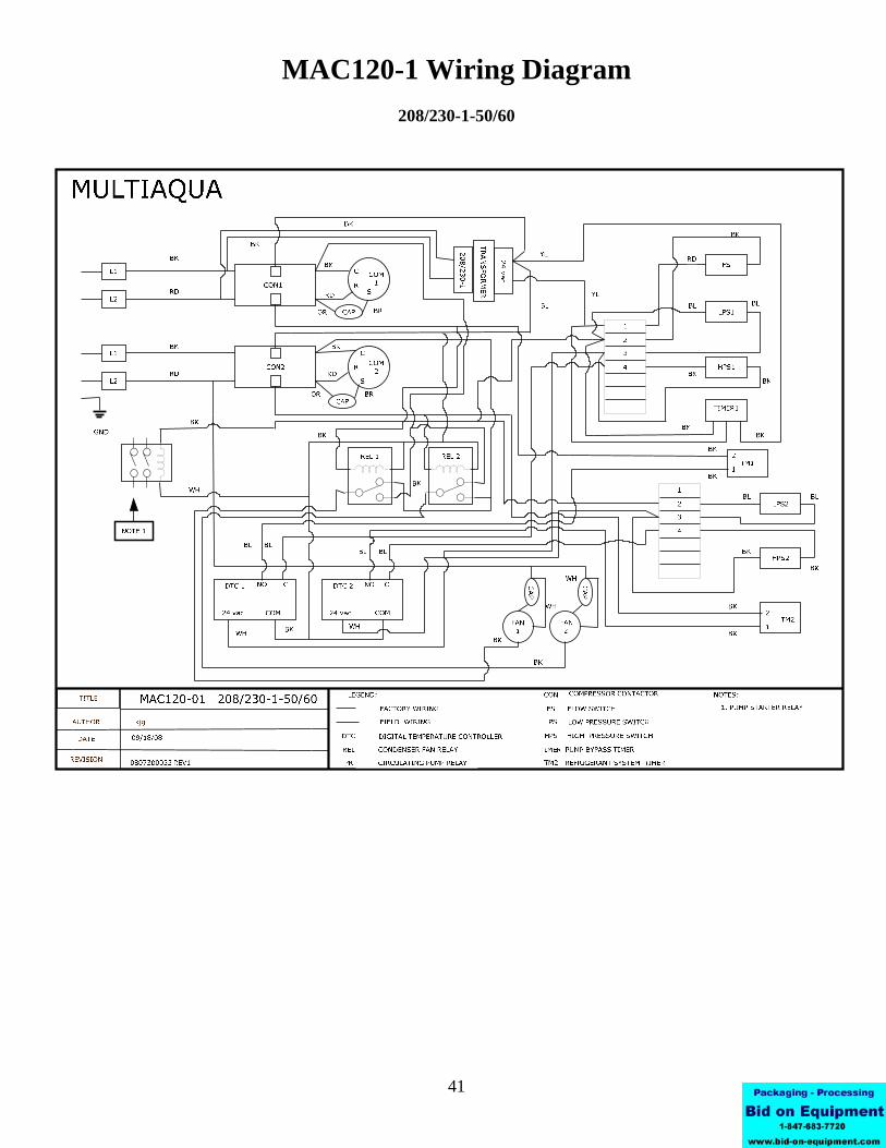
MAC120-1 Wiring Diagram
208/230-1-50/60

42
MAC120-1-L with Low Ambient Kit Wiring Diagram
208/230-1-50/60

MAC120 CERTIFIED DRAWING
43