air-cooled chillers - dunham-bush americas | heating, air · pdf file ·...
TRANSCRIPT
ACDS-B
March 2004Form No. 6009A
○ ○ ○ ○ ○ ○ ○ ○ ○ ○
○
○
○
○
○
○
○
○
○
○
○
○
○
○
○
○
○
○
○
○
○
○
○
○
○
○
○
○
○
○
○
○
○
○
○
○
○
○
○
○
○
○
○
○
○
○
○
○
○
○
○
○
○
○
○
○
○
○
○
○
○
○
○
○
○
○
○ ○ ○ ○ ○ ○ ○ ○ ○ ○
○ ○ ○ ○ ○ ○ ○ ○ ○ ○ ○ ○ ○ ○ ○ ○ ○ ○ ○ ○ ○ ○ ○ ○ ○ ○
○ ○ ○ ○ ○ ○ ○ ○ ○ ○ ○
aaaaa
Air-Cooled Chillers
with Tandem Scroll Compressors14 to 100 Tons
Features• Quiet operation
• Compact footprint
• Rated with HCFC-22
• ETL, MEA unit approval
• New high efficiency design
• Extra Quiet Option Available
• Windows® based PC interface
• Compatible with HFC refrigerants
• microcomputer controller
2
INTRODUCTION ○ ○ ○ ○ ○ ○ ○ ○ ○ ○ ○ ○ ○ ○ ○ ○ ○ ○ ○ ○ ○ ○ ○ ○ ○ ○ ○ ○ ○ ○ ○ ○ ○ ○ ○ ○ ○ ○ ○ ○ ○ ○ ○ ○ ○ ○ ○ ○ ○ ○
The Dunham-Bush Commitment...
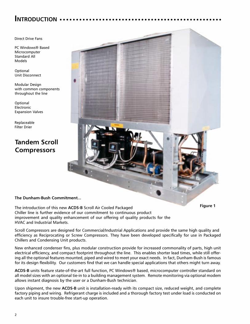
The introduction of this new ACDS-B Scroll Air Cooled PackagedChiller line is further evidence of our commitment to continuous productimprovement and quality enhancement of our offering of quality products for theHVAC and Industrial Markets.
Scroll Compressors are designed for Commercial/Industrial Applications and provide the same high quality andefficiency as Reciprocating or Screw Compressors. They have been developed specifically for use in PackagedChillers and Condensing Unit products.
New enhanced condenser fins, plus modular construction provide for increased commonality of parts, high unitelectrical efficiency, and compact footprint throughout the line. This enables shorter lead times, while still offer-ing all the optional features mounted, piped and wired to meet your exact needs. In fact, Dunham-Bush is famousfor its design flexibility. Our customers find that we can handle special applications that others might turn away.
ACDS-B units feature state-of-the-art full function, PC Windows® based, microcomputer controller standard onall model sizes with an optional tie-in to a building management system. Remote monitoring via optional modemallows instant diagnosis by the user or a Dunham-Bush technician.
Upon shipment, the new ACDS-B unit is installation-ready with its compact size, reduced weight, and completefactory piping and wiring. Refrigerant charge is included and a thorough factory test under load is conducted oneach unit to insure trouble-free start-up operation.
Direct Drive Fans
OptionalUnit Disconnect
Tandem Scroll
Compressors
PC Windows® BasedMicrocomputerStandard AllModels
OptionalElectronicExpansion Valves
ReplaceableFilter Drier
Modular Designwith common componentsthroughout the line
Figure 1

3
TABLE OF CONTENTS
A C D S B 060 D AR Z S
S = Std. 1140 RPM Fans
O = Optional 855 RPM FansAir Cooled Condenser
Z = R22 HCFC Refrigerant
Chiller
Direct Expansion Evaporator CD 208/3/60 Main Power
AN 230/3/60 Main PowerTandem Scroll Compressors AR 460/3/60 Main Power
AS 575/3/60 Main Power
Unit Vintage
Nominal Capacity in Tons
Refrigerant Circuits(S) Single - 015S, 020S, 025S, 027S, 030S
(D) Dual - 025D, 030D, 035D, 040D, 045D
050D, 055D, 057D, 060D, 065D,070D, 080D, 090D, 100D
○ ○ ○ ○ ○ ○ ○ ○ ○ ○ ○ ○ ○ ○ ○ ○ ○ ○ ○ ○ ○ ○ ○ ○ ○ ○ ○ ○ ○ ○ ○ ○ ○ ○ ○ ○ ○ ○ ○ ○ ○ ○ ○ ○
NOMENCLATURE
Page No.Introduction ................................................................................................................................................... 2Nomenclature ....................................................................................................................................................... 3Standard Features and Owner Benefits ....................................................................................................... 4Unit Features:
Compressors ............................................................................................................................................. 5 - 7Package Capacity Control Steps ..................................................................................................................... 8Quiet and Extra Quiet Operation ................................................................................................................... 8Air Cooled Condensers ................................................................................................................................... 9DX Coolers ..................................................................................................................................................... 9
Windows® Based Microcomputer Controller .................................................................. 10 - 12Optional Enclosures and Features ................................................................................................................ 13
Options ................................................................................................................................................... 14 - 15Accessories .......................................................................................................................................................... 16Application Data ......................................................................................................................................... 17 - 20
I. P. Units S.I. UnitsSelection Procedure ................................................................................................................... 21 .................... 22DX Cooler: Water Side Pressure Drop ....................................................................................... 23 .................... 23Performance Data:
R22 - 60 Hz - Standard Unit - 1140 RPM Fans ............................................................... 24 - 25............. 26 - 27Physical Specification:
ACDSB 015S to 030S - Single Circuit Unit ..................................................................................................... 28ACDSB 025D to 045D - Dual Circuit Unit ...................................................................................................... 29ACDSB 050D to 060D - Dual Circuit Unit ...................................................................................................... 30ACDSB 065D to 100D - Dual Circuit Unit ...................................................................................................... 31
Dimensional Data:ACDSB 015S to 030S - Single Circuit Unit ..................................................................................................... 32ACDSB 025D to 055D - Dual Circuit Unit ...................................................................................................... 33ACDSB 057D to 060D - Dual Circuit Unit ...................................................................................................... 34ACDSB 065D to 100D - Dual Circuit Unit ...................................................................................................... 35
Electrical Data:Electrical Data - Unit .............................................................................................................................. 36 - 37Electrical Data - Field Wiring .................................................................................................................. 38 - 39General Electrical Notes ................................................................................................................................ 40Cooler and Crankcase Heater Data .............................................................................................................. 40
Typical Wiring DiagramsPower Wiring Diagram ................................................................................................................................. 41Control Wiring Diagram ........................................................................................................................ 42 - 43
Typical Sequence of Operations ......................................................................................................................... 44Part Load Information ........................................................................................................................................ 45Product Specifications ................................................................................................................................. 46 - 51Installation Clearance ...................................................................................................................... Back Cover

4
STANDARD FEATURES AND OWNER BENEFITS ○ ○ ○ ○ ○ ○ ○ ○ ○ ○ ○ ○ ○ ○ ○ ○ ○ ○ ○ ○ ○ ○
Size Range
• 19 Models from 14 to 100 Tons• High Unit EER at ARI Standard Conditions• Rated with HCFC-22
Quiet Operation
• Standard quiet Scroll operation with 1140 RPM fans• Optional Extra Quiet Operation with Scroll Compressors and Extra Quiet 855
RPM Fans
Compressor
• Reliable Hermetic Tandem Scroll Type at 3500 RPM• (2) Refrigerant Circuits over 25 Tons for Redundancy• Compressor Cycling of 2 compressors on single circuit units up to 30 tons• Compressor Cycling of 4 compressors for dual circuit units from 25 to 100 tons• Manual or automatic compressor lead-lag all models
If automatic lead-lag function is selected and hot gas bypass is required, use dualhot gas bypass on dual circuit models.
Evaporator
• ASME Stamped on all Sizes 015S - 100D• DB High Efficiency Inner-Fin® Design for Compactness and Weight Reduction• 300 PSIG or 200 PSIG Refrigerant Side Design Pressure• 200 PSIG Water Side Design Pressure
Condenser
• Long Life Copper Tubes with Aluminum Fins• Sub-Cooling Circuit for Efficiency• 450 PSIG Test Pressure• Low Noise 30" Diameter Fans - Direct Drive at 1140 RPM• Extra Quiet Option 30” Diameter Fans - direct drive at 855 RPM• All Fan Motors Open Drip Proof with Rain Shield for Safety and Low
Maintenance• Minimum Clearance Required on Sizes 015S to 030S
Electrical/Control
• 115 Volt Control Transformer (supplied standard on all models)• Widest range of optional equipment available• Proactive Full Function PC Windows® Based Microcomputer Controller on all Sizes
015S to 100D for Precise Control• Separate Power and Control Panels for all dual refrigerant circuit models• Separate Power and Control Compartments Sizes 015S to 030S• ETL/CSA Unit Approval (IEC Control Panel Available)• MEA Unit Approval• High Pressure Limiting• Low Pressure Limiting• Load Limiting through Compressor Current Limiting
5
UNIT FEATURES: SCROLL COMPRESSORS
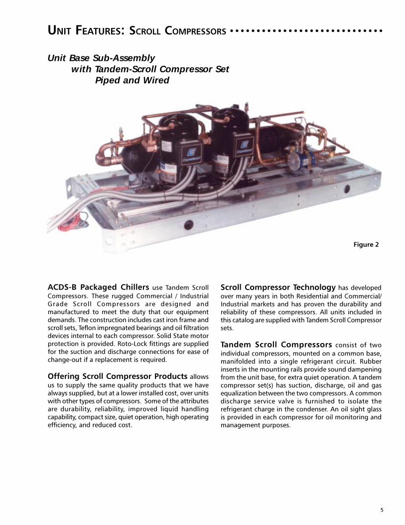
ACDS-B Packaged Chillers use Tandem Scroll
Compressors. These rugged Commercial / IndustrialGrade Scroll Compressors are designed andmanufactured to meet the duty that our equipmentdemands. The construction includes cast iron frame andscroll sets, Teflon impregnated bearings and oil filtrationdevices internal to each compressor. Solid State motorprotection is provided. Roto-Lock fittings are suppliedfor the suction and discharge connections for ease ofchange-out if a replacement is required.
Offering Scroll Compressor Products allows
us to supply the same quality products that we havealways supplied, but at a lower installed cost, over unitswith other types of compressors. Some of the attributesare durability, reliability, improved liquid handlingcapability, compact size, quiet operation, high operatingefficiency, and reduced cost.
○ ○ ○ ○ ○ ○ ○ ○ ○ ○ ○ ○ ○ ○ ○ ○ ○ ○ ○ ○ ○ ○ ○ ○ ○ ○ ○ ○ ○
Unit Base Sub-Assemblywith Tandem-Scroll Compressor Set
Piped and Wired
Scroll Compressor Technology has developed
over many years in both Residential and Commercial/Industrial markets and has proven the durability andreliability of these compressors. All units included inthis catalog are supplied with Tandem Scroll Compressorsets.
Tandem Scroll Compressors consist of two
individual compressors, mounted on a common base,manifolded into a single refrigerant circuit. Rubberinserts in the mounting rails provide sound dampeningfrom the unit base, for extra quiet operation. A tandemcompressor set(s) has suction, discharge, oil and gasequalization between the two compressors. A commondischarge service valve is furnished to isolate therefrigerant charge in the condenser. An oil sight glassis provided in each compressor for oil monitoring andmanagement purposes.
Figure 2

6
UNIT FEATURES: SCROLL COMPRESSORS (CONT.) ○ ○ ○ ○ ○ ○ ○ ○ ○ ○ ○ ○ ○ ○ ○ ○ ○ ○ ○ ○ ○ ○
ScrollNo Valves
PistonSuction & Discharge Valves
No Valve LossesComplete & Continuous
CompressionValve Losses
Re-expansion Volume
Suction Valve Discharge Valve
SuctionPocket
High PressurePocket
IntermediatePocket
Discharge
1 2
3 4
2 Parts
9 Parts Per Cylinder
FixedScroll
OrbitingScroll
PistonRing
SuctionReed
Piston
ValvePlate
DischargeReed
Gasket
Body
Rod
WristPin
High Pressure GasLow Pressure Gas High Pressure Gas
LowPressureGas
Scroll Compressor Design is based around two
identical spirals or scrolls that, when inserted together,form crescent-shaped compression pockets. During acompression cycle, one scroll remains stationary whilethe other orbits around the first. As this motion occurs,gas is drawn into the scrolls and moved in increasinglysmaller pockets toward the center. At this point, thegas, now compressed to a high pressure, is dischargedfrom a port in the center of the fixed scroll to thecondenser.
During each orbit, several pockets of gas are compressedsimultaneously, creating smooth, nearly continuouscompression. Figures 3a, 3b and 3c show thecompression cycle and comparisons to reciprocatingcompressors.
Suction and Compression Cycles occur
simultaneously but only four portions of the continuousCompression Cycle are shown for clarity purposes. (SeeFigure 3a).
• 1. The suction cycle occurs when the suctionpocket opens and enlarges, causing a lowpressure area in the suction pocket, drawingsuction gas into the chamber. The suctionpocket then closes and the compression cyclebegins.
• 2. The Intermediate Compression Cycle iscontinuous as the orbiting scroll moves andcompresses the refrigerant gas.
• 3. The high pressure pocket forces the highpressure gas to the discharge port at the topof the fixed scroll.
• 4. The high pressure gas is forced through thedischarge port and the discharge check valveat the top of the fixed scroll.
Scroll Compressors have few moving parts, as
compared to Reciprocating Compressors. Fewer movingparts, and the smooth continuous rotary scrollcompression cycle, ensures a long, quiet operating,compressor life. (See Figure 3b).
Complete and Continuous CompressionCycle of the Scroll Compressor, with no Valve or Re-
Expansion Volume losses, provide a smooth running,quiet, efficient, compressor. (See Figure 3c).
Figure 3a Scroll Compression Cycle—How AScroll Works
Figure 3b Scroll vs. ReciprocatingFew Moving Parts
Figure 3c Complete and ContinuousCompression Cycle

7
UNIT FEATURES: SCROLL COMPRESSORS (CONT.) ○ ○ ○ ○ ○ ○ ○ ○ ○ ○ ○ ○ ○ ○ ○ ○ ○ ○ ○ ○ ○ ○
Scroll Compressors have much better liquid
refrigerant handling capability than other types ofcompressors due to the nature of scroll design.
Scroll Compressor Durability and Reliabilityas well as Quiet Operation is inherent with the designof the scroll compressor. Scroll compressors have fewmoving parts, oversized Teflon impregnated bearingsand a smooth gas flow compression cycle, to ensuredurability and reliability.
A Large Capacity Built-In Suction Filter is
located between the suction inlet and the motor toprevent abrasive material such as flux, dirt, scale or metalchips from entering the motor cavity. The abrasive actionof this foreign material would crack, chip and wear themotor insulation which could cause premature motorfailure. These same abrasives could also cause bearingseizures and excessive wear of all surfaces.
Compressor Motor Dependability has been
developed with heavy duty motor windings cooled bysuction refrigerant gas. Motor winding insulationsystems exceed Class B requirements and overloadprotection is accomplished by solid state motor modulewith winding temperature thermistor sensor input.
Compressor Lubrication is provided by an integral
centrifugal pumping system through the center of themotor/scroll shaft.
Quiet Operation of Scroll Compressorsensures considerably quieter unit operation, than othertypes of compressors. Heavy construction, few movingparts, small motor horsepower, and smooth gas flowthrough the orbital compression cycle, ensures quietoperation of our ACDS-B Packaged Chillers.
Vibration Free Operation is ensured by smooth
quiet compressor operation plus having thecompressors mounted with rubber grommets to theframe.
Capacity Control Modulation is managed by the
units Microcomputer Controller inresponse to system load requirements. The system loadrequirements are measured by sensing the chiller'sleaving fluid temperature and staging the compressorsaccordingly. The ACDS-B chiller part load efficiency isexcellent due to the staging sequence of thecompressors to meet the required load. If the minimumload requirement is less than the chiller's minimummechanical step capability, hot gas by-pass optionshould be ordered with the unit. See Table 1 for unitcapacity control capabilities.
Capacity Control Modulation with OptionalHot Gas By-Pass, operates by imposing an artificial
load on the evaporator. Discharge gas from thecompressor is introduced to the liquid-vapor mixtureof refrigerant downstream of the expansion valve. Thedischarge gas is cooled by the liquid refrigerant presentin the turbulence of the evaporator so that the finaltemperature of refrigerant gas leaving the evaporatordoes not rise. Hot gas by-pass does not offer any energysavings, but does allow the cooling capacity to theequipment to vary precisely with the load requirements.
8
UNIT FEATURES: SCROLL COMPRESSORS (CONT.) ○ ○ ○ ○ ○ ○ ○ ○ ○ ○ ○ ○ ○ ○ ○ ○ ○ ○ ○ ○ ○ ○
UNIT FEATURES: QUIET AND EXTRA QUIET FAN OPERATION○ ○ ○ ○ ○ ○ ○ ○ ○ ○ ○ ○ ○
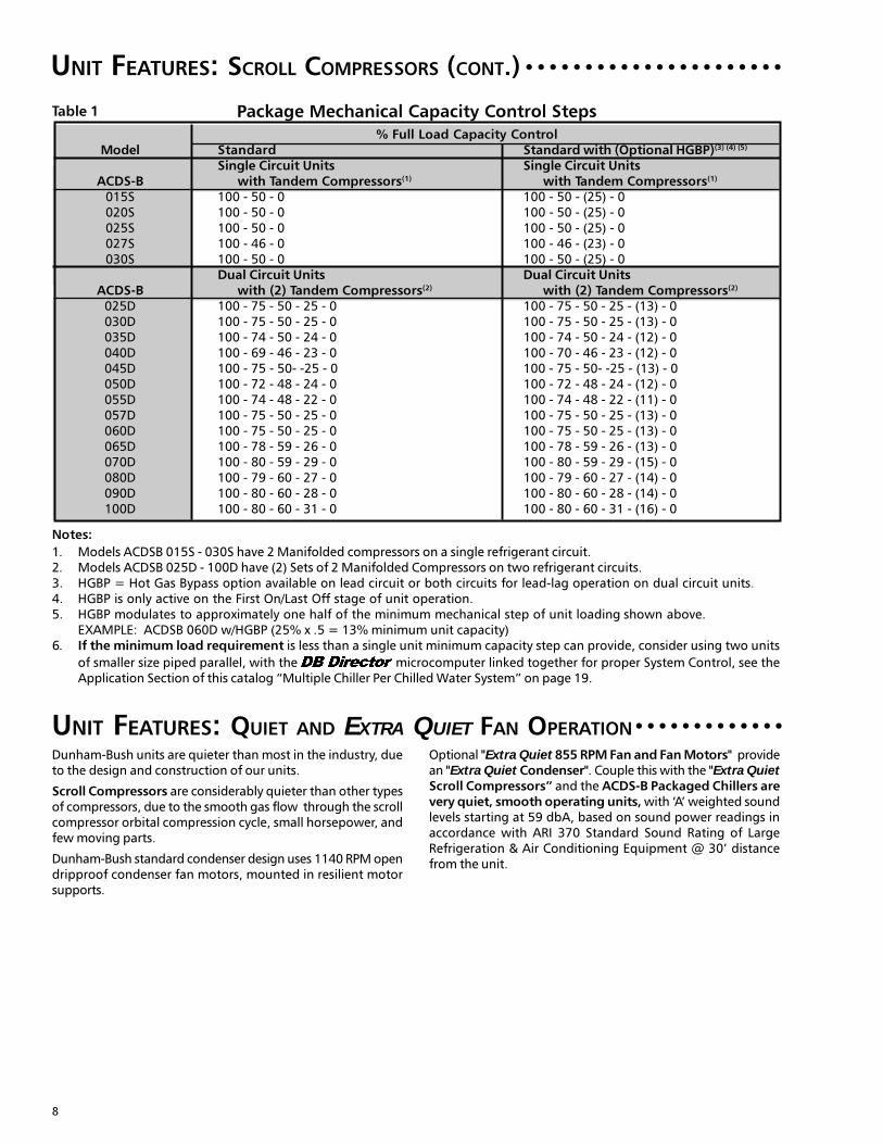
% Full Load Capacity ControlModel Standard Standard with (Optional HGBP)(3) (4) (5)
Single Circuit Units Single Circuit UnitsACDS-B with Tandem Compressors(1) with Tandem Compressors(1)
015S 100 - 50 - 0 100 - 50 - (25) - 0020S 100 - 50 - 0 100 - 50 - (25) - 0025S 100 - 50 - 0 100 - 50 - (25) - 0027S 100 - 46 - 0 100 - 46 - (23) - 0030S 100 - 50 - 0 100 - 50 - (25) - 0
Dual Circuit Units Dual Circuit UnitsACDS-B with (2) Tandem Compressors(2) with (2) Tandem Compressors(2)
025D 100 - 75 - 50 - 25 - 0 100 - 75 - 50 - 25 - (13) - 0030D 100 - 75 - 50 - 25 - 0 100 - 75 - 50 - 25 - (13) - 0035D 100 - 74 - 50 - 24 - 0 100 - 74 - 50 - 24 - (12) - 0040D 100 - 69 - 46 - 23 - 0 100 - 70 - 46 - 23 - (12) - 0045D 100 - 75 - 50- -25 - 0 100 - 75 - 50- -25 - (13) - 0050D 100 - 72 - 48 - 24 - 0 100 - 72 - 48 - 24 - (12) - 0055D 100 - 74 - 48 - 22 - 0 100 - 74 - 48 - 22 - (11) - 0057D 100 - 75 - 50 - 25 - 0 100 - 75 - 50 - 25 - (13) - 0060D 100 - 75 - 50 - 25 - 0 100 - 75 - 50 - 25 - (13) - 0065D 100 - 78 - 59 - 26 - 0 100 - 78 - 59 - 26 - (13) - 0070D 100 - 80 - 59 - 29 - 0 100 - 80 - 59 - 29 - (15) - 0080D 100 - 79 - 60 - 27 - 0 100 - 79 - 60 - 27 - (14) - 0090D 100 - 80 - 60 - 28 - 0 100 - 80 - 60 - 28 - (14) - 0100D 100 - 80 - 60 - 31 - 0 100 - 80 - 60 - 31 - (16) - 0
Table 1 Package Mechanical Capacity Control Steps
Notes:
1. Models ACDSB 015S - 030S have 2 Manifolded compressors on a single refrigerant circuit.2. Models ACDSB 025D - 100D have (2) Sets of 2 Manifolded Compressors on two refrigerant circuits.3. HGBP = Hot Gas Bypass option available on lead circuit or both circuits for lead-lag operation on dual circuit units.4. HGBP is only active on the First On/Last Off stage of unit operation.5. HGBP modulates to approximately one half of the minimum mechanical step of unit loading shown above.
EXAMPLE: ACDSB 060D w/HGBP (25% x .5 = 13% minimum unit capacity)6. If the minimum load requirement is less than a single unit minimum capacity step can provide, consider using two units
of smaller size piped parallel, with the microcomputer linked together for proper System Control, see theApplication Section of this catalog “Multiple Chiller Per Chilled Water System” on page 19.
Dunham-Bush units are quieter than most in the industry, dueto the design and construction of our units.
Scroll Compressors are considerably quieter than other typesof compressors, due to the smooth gas flow through the scrollcompressor orbital compression cycle, small horsepower, andfew moving parts.
Dunham-Bush standard condenser design uses 1140 RPM opendripproof condenser fan motors, mounted in resilient motorsupports.
Optional "Extra Quiet 855 RPM Fan and Fan Motors" providean "Extra Quiet Condenser". Couple this with the "Extra QuietScroll Compressors” and the ACDS-B Packaged Chillers arevery quiet, smooth operating units, with ‘A’ weighted soundlevels starting at 59 dbA, based on sound power readings inaccordance with ARI 370 Standard Sound Rating of LargeRefrigeration & Air Conditioning Equipment @ 30’ distancefrom the unit.
9
UNIT FEATURES:
UNIT FEATURES:
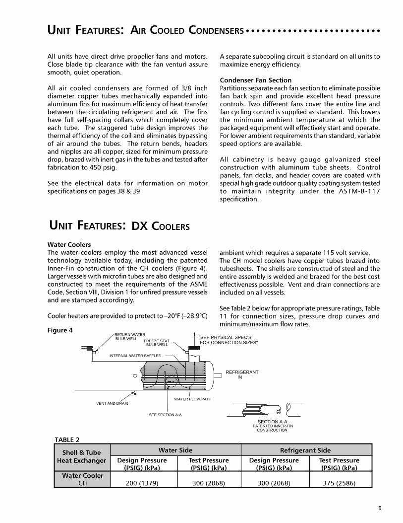
Design Pressure Test Pressure Design Pressure Test Pressure(PSIG) (kPa) (PSIG) (kPa) (PSIG) (kPa) (PSIG) (kPa)
Water CoolerCH 200 (1379) 300 (2068) 300 (2068) 375 (2586)
Shell & TubeHeat Exchanger
Water Side Refrigerant Side
All units have direct drive propeller fans and motors.Close blade tip clearance with the fan venturi assuresmooth, quiet operation.
All air cooled condensers are formed of 3/8 inchdiameter copper tubes mechanically expanded intoaluminum fins for maximum efficiency of heat transferbetween the circulating refrigerant and air. The finshave full self-spacing collars which completely covereach tube. The staggered tube design improves thethermal efficiency of the coil and eliminates bypassingof air around the tubes. The return bends, headersand nipples are all copper, sized for minimum pressuredrop, brazed with inert gas in the tubes and tested afterfabrication to 450 psig.
See the electrical data for information on motorspecifications on pages 38 & 39.
AIR COOLED CONDENSERS ○ ○ ○ ○ ○ ○ ○ ○ ○ ○ ○ ○ ○ ○ ○ ○ ○ ○ ○ ○ ○ ○ ○ ○ ○ ○
A separate subcooling circuit is standard on all units tomaximize energy efficiency.
Condenser Fan SectionPartitions separate each fan section to eliminate possiblefan back spin and provide excellent head pressurecontrols. Two different fans cover the entire line andfan cycling control is supplied as standard. This lowersthe minimum ambient temperature at which thepackaged equipment will effectively start and operate.For lower ambient requirements than standard, variablespeed options are available.
All cabinetry is heavy gauge galvanized steelconstruction with aluminum tube sheets. Controlpanels, fan decks, and header covers are coated withspecial high grade outdoor quality coating system testedto maintain integrity under the ASTM-B-117specification.
Water CoolersThe water coolers employ the most advanced vesseltechnology available today, including the patentedInner-Fin construction of the CH coolers (Figure 4).Larger vessels with microfin tubes are also designed andconstructed to meet the requirements of the ASMECode, Section VIII, Division 1 for unfired pressure vesselsand are stamped accordingly.
Cooler heaters are provided to protect to –20°F (–28.9°C)
DX COOLERS
ambient which requires a separate 115 volt service.The CH model coolers have copper tubes brazed intotubesheets. The shells are constructed of steel and theentire assembly is welded and brazed for the best costeffectiveness possible. Vent and drain connections areincluded on all vessels.
See Table 2 below for appropriate pressure ratings, Table11 for connection sizes, pressure drop curves andminimum/maximum flow rates.
TABLE 2
PATENTED INNER-FINCONSTRUCTION
SECTION A-A
VENT AND DRAINWATER FLOW PATH
FREEZE STATBULB WELL
BULB WELLRETURN WATER
INREFRIGERANT
INTERNAL WATER BAFFLES
"SEE PHYSICAL SPEC'SFOR CONNECTION SIZES"
SEE SECTION A-A
Figure 4
10
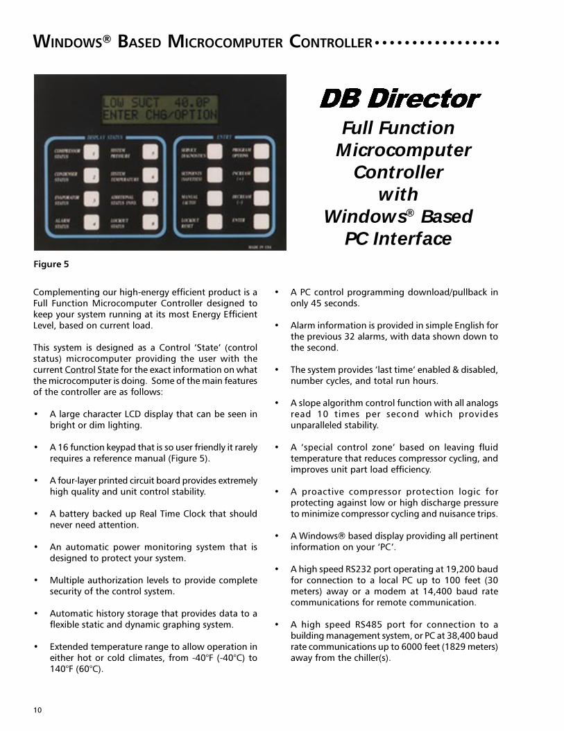
WINDOWS® BASED MICROCOMPUTER CONTROLLER ○ ○ ○ ○ ○ ○ ○ ○ ○ ○ ○ ○ ○ ○ ○ ○ ○
Complementing our high-energy efficient product is aFull Function Microcomputer Controller designed tokeep your system running at its most Energy EfficientLevel, based on current load.
This system is designed as a Control ‘State’ (controlstatus) microcomputer providing the user with thecurrent Control State for the exact information on whatthe microcomputer is doing. Some of the main featuresof the controller are as follows:
• A large character LCD display that can be seen inbright or dim lighting.
• A 16 function keypad that is so user friendly it rarelyrequires a reference manual (Figure 5).
• A four-layer printed circuit board provides extremelyhigh quality and unit control stability.
• A battery backed up Real Time Clock that shouldnever need attention.
• An automatic power monitoring system that isdesigned to protect your system.
• Multiple authorization levels to provide completesecurity of the control system.
• Automatic history storage that provides data to aflexible static and dynamic graphing system.
• Extended temperature range to allow operation ineither hot or cold climates, from -40°F (-40°C) to140°F (60°C).
• A PC control programming download/pullback inonly 45 seconds.
• Alarm information is provided in simple English forthe previous 32 alarms, with data shown down tothe second.
• The system provides ‘last time’ enabled & disabled,number cycles, and total run hours.
• A slope algorithm control function with all analogsread 10 times per second which providesunparalleled stability.
• A ‘special control zone’ based on leaving fluidtemperature that reduces compressor cycling, andimproves unit part load efficiency.
• A proactive compressor protection logic forprotecting against low or high discharge pressureto minimize compressor cycling and nuisance trips.
• A Windows® based display providing all pertinentinformation on your ‘PC’.
• A high speed RS232 port operating at 19,200 baudfor connection to a local PC up to 100 feet (30meters) away or a modem at 14,400 baud ratecommunications for remote communication.
• A high speed RS485 port for connection to abuilding management system, or PC at 38,400 baudrate communications up to 6000 feet (1829 meters)away from the chiller(s).
Full FunctionMicrocomputer
Controllerwith
Windows® BasedPC Interface
Figure 5

11
WINDOWS® BASED MICROCOMPUTER CONTROLLER (CONT.)
Display Information
All information is displayed using common terms thatare easy to understand. It is a simple procedure todetermine the actual status of the system and theindividual circuits, as they are displayed in commonterms that are meaningful. The 2 line by 16 extra largecharacter alphanumeric liquid crystal display (LCD)utilizes easy to understand menu-driven software. TheLCD displays eight character alphanumeric sensornames and twelve character alphanumeric set pointnames enabling the use of meaningful status names.This enables an inexperienced operator to quickly workthrough these menus to obtain the information theyrequire or to modify control parameters. The welldesigned keypad is separated into a DISPLAY STATUSsection and an ENTRY section each consisting of eightkeys that are clearly labeled to identify the informationthat will be displayed. When data is being modified,the second display line contains help information toensure that the desired modification is properly made.Easily accessible measurements include:
• Current capacity status• Current circuit/compressor status• Leaving chilled water temperature• Evaporator pressure of each refrigerant circuit• Condenser pressure of each refrigerant circuit• Compressor elapsed run time, each compressor• Number of compressor starts• Compressor contactor status• Fan on/off status• Remote chilled water reset input (optional)• Water flow switch status• External start/stop command status• Optional low ambient temperature sensor for easier
cold ambient starting• Optional low ambient lockout• Optional entering fluid temperature monitoring• Optional compressor amperage monitoring
Two proactive control features included in themicrocomputer are low suction and high dischargepressure limiting. The second compressor in eachcircuit will shutdown if the discharge pressure exceedsthe high pressure unload setpoint or if suction pressurefrom either refrigerant circuit approaches the low-pressure trip setpoint.
Capacity Control
Control is based upon leaving chilled watertemperature. How fast the temperature is changing iscalculated and capacity decisions are based upon therate, the current temperature, and the controltemperature zone. Capacity is never added if the systemis moving toward the temperature target at anacceptable rate. The unit will monitor all controlfunctions and stage the compressors to maintain therequired operating capacity. Remote adjustment of theleaving chilled water setpoint is accomplished througheither direct connection or a remote keypad to themicrocomputer through the RS485 long distancedifferential communications port, via PC or a modemconnected to the RS232 communication port, or froman external Building Automation System supplying asimple 0 to 5 VDC signal.
System Control
The unit may be enabled or disabled manually, orthrough the use of an external signal from a BuildingAutomation System. In addition, the microcomputermay be programmed with a seven-day optional cycleor other DB control packages may start and stop thesystem through interconnecting wiring.
System Protection
The following system protection controls willautomatically act to insure system reliability:
• Low suction pressure limiting• High discharge pressure limiting• High motor temperature/over current• Freeze protection• Compressor run error• Power loss• Chilled water flow loss• Sensor error• Pump down and pumpout• Anti-recycle• Time delay between stages• Load limiting via compressor current limiting
○ ○ ○ ○ ○ ○ ○ ○ ○ ○

12
2) PCON - PC Connection:
The PC Connection program provides communications for complete operation of the packaged chiller includ-ing graphing information. This option is available through two communications techniques as follows:
a) PCCB (Basic) (Figure 6b)The standard communications for PCCB is via the RS232 connection which may be as far as 100 feet (30meters) away from the packaged chiller. Only one chiller can be accessed
Figure 6b
b) PCCE (Enhanced) (Figure 6c)The enhanced PCCE system allows for communications via the RS485 port and can be located as far as6000 feet from the packaged chiller(s). This option requires the addition of a gateway to convert theRS485 port back to a RS232 port and then may be connected to a modem or directly to a PC. Oneadditional feature is that you may field install a manual AB switch, which allows switching between a localPC and a modem.
Figure 6c
As can be seen, the microcomputer system allows for a variety of remote connection capabilities for almost infiniteflexibility. Utilizing the PC connection program, up to twenty packaged chillers connected via the RS485/RS232 portscan be monitored. The user may then select whichever packaged chiller to review.
Remote Monitoring
The Microcomputer is equipped with a high speed RS232 communications port and two high speed RS485communications ports, to allow for a variety of different remote monitoring operations. The RS232 communicationsport allows for remote communications at distances of up to 100 feet over a 4-wire shielded cable. The RS485communication system allows for remote communications at up to 6000 feet (1829 meters) with a 2-wire shieldedcable connection.
1) RMCT - Remote Mounted Control Terminal (Figure 6a)
This Remote Mounted Control Terminal (RMCT) is a stand alone Control Terminal to communicate and controlthe unit from a remote location up to 6000 feet (1829 meters) away, via the 485 communications port, whenwired with a 2-wire shielded cable. The RMCT will then operate just like the controller in the unit. This enhancedversion of the Remote Mounted Control Terminal with 8 relay outputs and 8 sensor inputs provides remotealarm capabilities and additional sensor inputs as may be required.
Figure 6a
UNITCONTROLLER
REMOTE CONTROLTERMINAL
RS485 — UP TO 6000 FEET (1829 METERS) AWAY
RMCTREMOTE MOUNTEDCONTROL TERMINAL
➙UNIT
CONTROLLER
RS232 — UP TO 100 FEET (30 METERS) AWAY
Local PC withWindows® & PC-CONN
UNITCONTROLLER
RS485
UNITCONTROLLER
UNITCONTROLLER
Local PC with
Windows® & PC-CONN
RS485 MSC 485
GATEWAY
RS485
RS232

13
UNIT FEATURES: OPTIONAL ENCLOSURES AND FEATURES ○ ○ ○ ○ ○ ○ ○ ○ ○ ○ ○ ○
Optional plastic coated wire finguard.Available for upper half of unit (FGT) asshown on page 2, lower half of unit (FGB), orboth.
Optional full length painted aluminumgrilles (GRL) to protect condenser fins andmechanical components. This option alsoincludes sheet metal enclosure panels forthe unit ends.
Optional full length painted steel louvers(LUV) for the maximum protection forcondenser fins and mechanical compo-nents. This option also includes sheet metalenclosure panels for the unit ends.
Standard heavy duty base rails with crossmembers. Optional electronic expansion valves(EEV) shown.
Optional weatherproof alarm bell (BEL2) toindicate a general alarm fault.
Figure 7a
Figure 7b
Figure 7c
Figure 8 Figure 9
14
OPTIONS ○ ○ ○ ○ ○ ○ ○ ○ ○ ○ ○ ○ ○ ○ ○ ○ ○ ○ ○ ○ ○ ○ ○ ○ ○ ○ ○ ○ ○ ○ ○ ○ ○ ○ ○ ○ ○ ○ ○ ○ ○ ○ ○ ○ ○ ○ ○ ○ ○ ○ ○ ○ ○ ○ ○
Options are installed at the factory.
Accessories are shipped unmounted.
Extra Quiet Fan Operation (EQF)—using 855
RPM Fans and Scroll Compressors, provide the quietestoperating refrigeration equipment possible. There is aslight capacity reduction caused by operating the unitwith 855 RPM fans, but the unit efficiency improvementmore than makes up for the loss in capacity.
Copper Fin Condenser (CUF)—Copper fin and
tube condenser.
Poly Fin Condenser (PFC)—The material is a
polyester paint baked onto the aluminum finstock priorto final manufacture, rather than material applied tothe assembly after formation of the coils. The pre-painted fin material has been tested for salt spraycorrosion resistance using ASTM B117 specification.
Oversized Cooler (CH2)—For 42°F (5.5°C) leaving
water temperature applications, 20% and higher glycolapplications will not require oversized coolers.
Oversized Cooler (CH3)—For 40°F (4.5°C) leaving
water temperature applications, 20% and higher glycolapplications will not require oversized coolers.
Convenience Outlet (CON)—dual 3-prong
ground fault receptacle powered from a dedicatedtransformer and fused for 15 amps.
Hot Gas Bypass (HGB1)—for single or dual circuit
units to retain the unit on-line when the load is belowthe minimum unit mechanical capability. This minimizescompressor cycling and extends compressor life, onextra low minimum load conditions (see Table 1 forminimum load capability). HGB1 is supplied for theFirst-On / Last-Off Stage Only, and for units withoutcompressor Lead-Lag control.
Hot Gas Bypass (HGB2)—for dual circuit units to
retain the unit on-line when the minimum load is belowthe unit mechanical capability. This minimizescompressor cycling and extends compressor life, onextra low minimum load conditions (see Table 1 forminimum load capability). HGB2 is supplied for theFirst-On / Last-Off Stage Only, and for units with AutoCompressor Lead-Lag Control.
Low Ambient Control (LAC) TO 0°F (-17.8°C)Minimum Ambient—units use variable speed fans
in conjunction with standard fan cycling.
Extra Low Ambient Control (ELAC) TO -20°F(-29°C) Minimum Ambient—includes LAC and
EEV (Electronic Expansion Valve(s)) options and requiresthe use of 50% glycol and roughly 50% load to ensureextra low ambient starting, with a maximum of 5 MPH(8 KPH) wind. Some limitations apply.
Low Ambient Lock-out (LALO)—uses an
ambient sensor and requires a lock-out set pointentered into the microcomputer controller.
Unit Mounted Disconnect Switch(Non-fused) (UMD1)—for 208 and 230 volt single power source unitsACDSB 015S thru ACDSB 100D - mounted in the controlbox with mechanical interlock through the door.
Unit Mounted Disconnect Switch(Non-Fused) (UMD3)—for 460 and 575 volt single point power source units—mounted in the control box with mechanical interlockthrough the door, all models ACDSB 015S-100D.
Operating and Safety Lights (OSL)—lights
indicating control power to the unit and faults for highdischarge pressure, high motor temperature and alarmstatus.
Gauges (GAG2)—includes suction and discharge
pressure for all unit models. The microcomputerdisplays discharge and suction pressure so thesereadings are redundant.
Louvers (Painted Galvanized Steel) (LUV)—for complete unit enclosure for general mechanicalsecurity and unit aesthetics.
Grill (Aluminum Painted) (GRL)—similar to the
louver option except manufactured of aluminum with3/8" X 3 1/2" slots instead of louvers for security andhail protection and unit aesthetics.
Fin Guard Top (FGT) (1" x 4" Coated Wire)—protects the vertical condenser side coil only.
15
OPTIONS (CONT.)
Fin Guard Bottom (FGB) (1" x 4" CoatedWire)—encloses the bottom compressor, condenser
and cooler section of the unit only. Use FGT and FGBfor full unit protection.
Over and Under Voltage and PhaseProtection Relay (UVR2)—Combined relay
offering protects against high and low incomingvoltage conditions as well as single phasing, phasereversal and phase imbalance by opening the controlcircuit. It is an automatic reset device, but themicrocomputer can be set up for manual reset toprevent unwanted restarts.
Circuit Breakers (CB)—provide additional short
circuit protection for each compressor.
Electrical Panel Door Latch Solenoids (DLS)—to provide the security required by local codes. Mainpower must be disconnected to gain entry to poweror control electrical panel for models ACDSB 015S-030S.On all other models the control panel can be accessedwith a keylock override actuated switch. The powermust be disconnected to gain entry to the high voltagepower panel.
Weather Proof Alarm Bell (BEL2)—mounted
and wired to indicate a common alarm fault.
Unit Ground Fault Detector (GFD)—that takes
the unit off line if a ground fault is detected.
500 Hour Salt Spray Coating (PNT)—special
high-grade outdoor quality coating system tested tomaintain integrity under the ASTM-B-117 specification.
Suction Line Insulation (INS)—suggested for
medium temperature applications or where excessivesweating may occur.
Electronic Expansion Valves (EEV)—for more
precise control over a wide range of operatingconditions such as dual mode air conditioning andthermal storage applications. The EEV option is suppliedas part of the (ELAC) extra low ambient operation downto -20°F (-23.9°C) minimum ambient operation.
Remote Monitoring Modem (MOD1)—for
single chiller long distance communication, allows thesystem to be monitored, retrieve logs, and assist withinvestigating potential problems quickly and in a costeffective manner from a remote source.
Remote Monitoring Modem (MOD2)—for
multiple chiller network long distance communicationwith the same features as MOD1, with the addition ofa gateway to convert the RS485 ports for networkoperation.
ChillerLINK (CHLK)—for communication with
(BMS) building management systems through N2 Bus,BacNet, Modbus or Lonworks. See ChillerLINK DataAcquisition Form SD202-22203.
Chilled Water Pump Control (CWPC)—
provides a contact closure for pump starting prior tostarting the chiller.
Mounted and Wired Water Flow Switch(MWFS)—is mounted, wired and tested at the factory.
The water flow switch is a safety control and if notsupplied mounted and wired must be field mounted
and wired.
Auxiliary Control Module (ACM)—consisting
of RWTM, UDL, LLC and CAM option package of specialcontrol functions.
- RWTM - Return Water (Fluid) TemperatureMonitoring—is used for information only. Unit controlis based on leaving water temperature with a specifictemperature differential (range), so the return watertemperature is for information only.
- UDL-Utility Demand Limiting—requires a remoteanalog input signal that is used to cycle compressorsto limit electrical demand. The demand limiting canbe one or two steps, based on the particular unit model.The required signal is 0 to 5VDC.
- LLC - Load Limiting Control—is based on compressorcurrent limiting rather than return water temperaturecontrol load limiting method. This current limitingmethod is superior to return water temperature controlmethod because it protects the compressor from overcurrent while allowing the unit to run fully loaded whenpossible.
- CAM - Compressor Amp Monitoring—displayscompressor amps for load monitoring and trendlogging.
○ ○ ○ ○ ○ ○ ○ ○ ○ ○ ○ ○ ○ ○ ○ ○ ○ ○ ○ ○ ○ ○ ○ ○ ○ ○ ○ ○ ○ ○ ○ ○ ○ ○ ○ ○ ○ ○ ○ ○ ○ ○ ○ ○ ○ ○ ○ ○

16
ACCESSORIES (SHIPPED LOOSE FOR FIELD MOUNTING)
Water Flow Switch (WFS) - paddle type field
adjustable flow switch. Must be tied into the unit safetycircuit so that the package will remain off until waterflow is proved. Helps prevent cooler freeze up. NEMA3R enclosure, for use on water, ethylene or propyleneglycol circuits.
Spring Isolators (SPG) - designed for 1" deflection,
these housed spring assemblies have a neoprene frictionpad on the bottom to help prevent the passage of noiseand a spring locking leveling bolt at the top. Neopreneinserts prevent contact between the steel upper andlower housings. Suitable for more critical applicationsthan RIS isolators.
Rubber-in-shear Isolators (RIS) - designed for
ease of installation, these rubber, one piece, moldedisolators have skid resistant baseplates. Applicable formost installations.
Weather Proof Bell (BEL1) - is a shipped-loose
bell to be mounted remote of the unit and wired to theALC common alarm contacts in the unit by others.
PC Connection Basic (PCCB) - Provides
communications via the RS232 connection port, forcomplete operation of the packaged chiller, includinggraphing information, up to 100 feet (30 meters) fromthe packaged chiller. The PCONN software will beprovided for use with a remote PC by others. Seeconnection diagram page 12.
PC Connection Enhanced (PCCE) - Provides
communications via the RS485 connection port, forcomplete operation of the packaged chiller includinggraphing, up to 6000 feet (1829 meters) away. Thisoption includes the addition of a gateway to convertthe RS485 port of the to RS232, whichthen may be connected to a modem or directly to a PC.One additional feature is that a field supplied andinstalled AB switch can be added to allow switchingbetween a local PC and a modem. The gateway andPCONN software will be supplied for use with a remotePC by others. See connection diagram page 12.
Remote Monitor-Control Terminal (RMCT) -is a stand alone microcomputer that interfaces withthe microcomputer in the unit which provides all unitcontrol functions, at a remote location.

17
APPLICATION DATA
Cooler Design Data
1. Maximum - Leaving chilled fluid temperature(LCFT) is 60°F (18°C). The unit can start and pulldown with up to 80°F (27°C) entering-watertemperature. For sustained operation, it isrecommended that the entering water temperaturenot exceed 70°F (21°C).
2. Minimum - LCFT is 42°F (5.5°C) for all modelsexcept ACDSB 025D, 030D, 035D and 040D forwater applications with standard coolers. Oversizedcoolers CH2 for 42°F (5.5°C) water on models ACDSB025D, 030D, 035D and 040D and CH3 for 40°F (4.4°C)water for most models are available from thefactory for chilled water applications. Mediumtemperature glycol application selections from 20°F(6.6°C) to 39°F (3.9°C) are available from the factory.
3. Minimum/Maximum Flow Rates and Vessel FluidVolume - refer to Physical Specifications, pages 28-31.
4. Pressure Drop Data - refer to Figure 13 and glycolcorrection factors, Tables 4a and 4b.
5. Wide Range �T - Low Flow Applications
a. Multiple smaller chillers may be applied inseries, each providing a portion of the designtemperature range of roughly 10°F (5.5°C)each.
b. Special cooler baffling may be provided fromthe factory for applications from 12.5°F to 20°F(7°C to 11°C) chiller fluid ranges.
c. Chilled fluid may be recirculated through thecooler as shown below to allow the chiller tooperate with acceptable flow rates andtemperature ranges (Figure 10a).
Figure 10a
The mixed fluid temperature rangethrough the cooler for units with standardcoolers, should not be less than 7.5°F(4.2°C).
6. Narrow Range �T - High Flow Applications
a. Special cooler baffling is available from thefactory for 5°F to 7.5°F (2.7°C to 4.2°C) �Tapplications.
b. For Extra-Narrow Range �T applications apartial cooler bypass piping and valveconfiguration can be used as shown below.This permits a higher �T and lower �P(pressure drop) through the cooler (Figure10b).
Figure 10b
The fluid mixes after the cooler.
SUPPLY
FLUID
COOLER BYPASS
PORTION OF FLOW
C
H
I
L
L
E
R
C
O
O
L
E
R
THERMOSTAT SENSOR T
RETURN
FLUID
Chilled Fluid Loop Volume (CFLV)
Careful consideration needs to be given to the “ChilledFluid Loop Volume” (CFLV) or System / Inertia tomaintain an acceptable leaving fluid temperature.
In close-coupled systems as the compressor starts andstops, the leaving fluid temperature will shift up anddown 2°F to 4°F (1.1°C to 2.2°C) per step of capacitycontrol. The 5-minute anti-recycle timer will preventthe compressor from starting for up to 5 minutes andwill further complicate the leaving fluid temperatureshift.
Air Conditioning ApplicationsThe chilled fluid loop volume must equal or exceed 3gallons per nominal ton of cooling (3.25 L per kW).
Process & Special Air Conditioning ApplicationsWhere leaving fluid temperature is often more critical,the chilled fluid loop volume should be increased to 6to 10 gallons per ton minimum (6.5 to 10.8 L per kW).
○ ○ ○ ○ ○ ○ ○ ○ ○ ○ ○ ○ ○ ○ ○ ○ ○ ○ ○ ○ ○ ○ ○ ○ ○ ○ ○ ○ ○ ○ ○ ○ ○ ○ ○ ○ ○ ○ ○ ○ ○ ○ ○ ○ ○ ○
RETURN
FLUID
SUPPLY
FLUID
RECIRCULATED
PORTION OF FLOW
C
H
I
L
L
E
R
C
O
O
L
E
R
THERMOSTAT SENSOR T
18
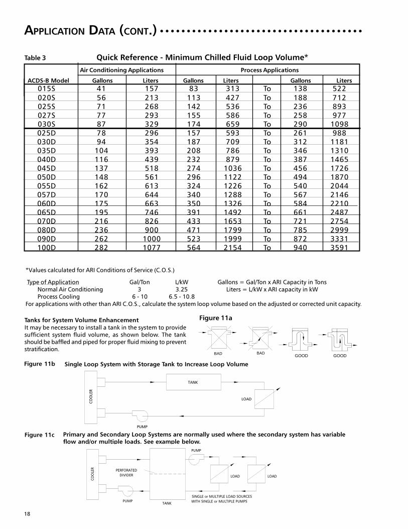
Table 3 Quick Reference - Minimum Chilled Fluid Loop Volume*
Air Conditioning Applications Process Applications
ACDS-B Model Gallons Liters Gallons Liters Gallons Liters
*Values calculated for ARI Conditions of Service (C.O.S.)
Type of Application Gal/Ton L/kW Gallons = Gal/Ton x ARI Capacity in TonsNormal Air Conditioning 3 3.25 Liters = L/kW x ARI capacity in kWProcess Cooling 6 - 10 6.5 - 10.8
For applications with other than ARI C.O.S., calculate the system loop volume based on the adjusted or corrected unit capacity.
Tanks for System Volume EnhancementIt may be necessary to install a tank in the system to providesufficient system fluid volume, as shown below. The tankshould be baffled and piped for proper fluid mixing to preventstratification.
Figure 11b Single Loop System with Storage Tank to Increase Loop Volume
Figure 11c Primary and Secondary Loop Systems are normally used where the secondary system has variableflow and/or multiple loads. See example below.
APPLICATION DATA (CONT.) ○ ○ ○ ○ ○ ○ ○ ○ ○ ○ ○ ○ ○ ○ ○ ○ ○ ○ ○ ○ ○ ○ ○ ○ ○ ○ ○ ○ ○ ○ ○ ○ ○ ○ ○ ○ ○ ○
BAD BADGOOD GOOD
Figure 11a
015S 41 157 83 313 To 138 522
020S 56 213 113 427 To 188 712
025S 71 268 142 536 To 236 893
027S 77 293 155 586 To 258 977
030S 87 329 174 659 To 290 1098
025D 78 296 157 593 To 261 988
030D 94 354 187 709 To 312 1181
035D 104 393 208 786 To 346 1310
040D 116 439 232 879 To 387 1465
045D 137 518 274 1036 To 456 1726
050D 148 561 296 1122 To 494 1870
055D 162 613 324 1226 To 540 2044
057D 170 644 340 1288 To 567 2146
060D 175 663 350 1326 To 584 2210
065D 195 746 391 1492 To 661 2487
070D 216 826 433 1653 To 721 2754
080D 236 900 471 1799 To 785 2999
090D 262 1000 523 1999 To 872 3331
100D 282 1077 564 2154 To 940 3591
COOLER
TANKPUMP
LOAD LOAD
PUMP
PERFORATED
DIVIDER
SINGLE or MULTIPLE LOAD SOURCES
WITH SINGLE or MULTIPLE PUMPS
COOLER
TANK
PUMP
LOAD
19
Oversizing Chillers
Oversizing of chillers more than 5-10% is notrecommended. Oversizing causes energy inefficiencyand shortened compressor life due to excessivecompressor cycling. Larger future load requirementsmay cause temporary oversizing of equipment whichwill require careful unit selection. It may be better toproperly size for the present load and add another unitlater for future expansion. It is also recommended usingmultiple units where operation at minimum load iscritical. Fully loaded equipment operates better andmore efficiently than large equipment running at ornear minimum capacity.
Hot gas bypass should not be a means to allowoversizing of chillers. Hot gas bypass should only beused where the equipment is sized properly for fullload but the load turn down is less than the minimumunloading step available. See Table 1 on Page 8 forestimated hot gas bypass turndown.
Sound and Vibration
ACDS-B compressors are mounted with rubbergrommets to the frame to absorb sound and vibration.The compressors are not mounted on springs becauseextra movement may cause line breakage andrefrigerant leaks. Unit isolation helps prevent anyremaining sound or vibration from entering the buildingstructure, piping or electrical service.
Water (Fluid) Strainers
It is recommended that 40-mesh strainers be installedin the fluid piping as close to unit cooler as possible.
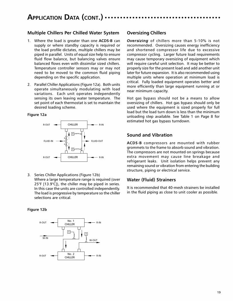
Multiple Chillers Per Chilled Water System
1. Where the load is greater than one ACDS-B cansupply or where standby capacity is required orthe load profile dictates, multiple chillers may bepiped in parallel. Units of equal size help to ensurefluid flow balance, but balancing valves ensurebalanced flows even with dissimilar sized chillers.Temperature controller sensors may or may notneed to be moved to the common fluid pipingdepending on the specific application.
2. Parallel Chiller Applications (Figure 12a). Both unitsoperate simultaneously modulating with loadvariations. Each unit operates independentlysensing its own leaving water temperature. Theset point of each thermostat is set to maintain thedesired loading scheme.
Figure 12a
3. Series Chiller Applications (Figure 12b)Where a large temperature range is required (over25°F [13.9°C]), the chiller may be piped in series.In this case the units are controlled independently.The load is progressive by temperature so the chillerselections are critical.
Figure 12b
R-OUT R-IN
W-IN
W-OUT
R-OUT R-IN
CHILLER
CHILLER
No. 2
No. 1
TT
T
R-OUT R-IN
FLUID-IN FLUID-OUT
R-OUT R-IN
CHILLER
CHILLER
T
APPLICATION DATA (CONT.) ○ ○ ○ ○ ○ ○ ○ ○ ○ ○ ○ ○ ○ ○ ○ ○ ○ ○ ○ ○ ○ ○ ○ ○ ○ ○ ○ ○ ○ ○ ○ ○ ○ ○ ○ ○ ○ ○

20
C1 K1 G1 P1
% E.G. CAPACITY kW FLOW P.D.
°F °C FACTOR FACTOR RATE FACTOR
10 26.2 -3.2 0.995 0.998 1.019 1.050
15 22.4 -5.3 0.991 0.997 1.030 1.083
20 17.8 -7.9 0.988 0.996 1.044 1.121
25 12.6 -10.8 0.984 0.995 1.060 1.170
30 6.7 -14.1 0.981 0.994 1.077 1.219
35 0.0 -17.8 0.977 0.992 1.097 12.75
40 -8.0 -25.8 0.973 0.991 1.116 1.331
45 -17.5 -27.5 0.968 0.990 1.138 1.398
50 -28.9 -33.8 0.964 0.989 1.161 1.466
C2 K2 G2 P2
% P.G. CAPACITY kW FLOW P.D.
°F °C FACTOR FACTOR RATE FACTOR
10 26.1 -3.3 0.988 0.994 1.005 1.019
15 22.8 -5.1 0.984 0.992 1.008 1.031
20 19.1 -7.2 0.978 0.990 1.010 1.051
25 14.5 -9.7 0.970 0.988 1.015 1.081
30 8.9 -12.8 0.962 0.986 1.021 1.120
35 2.1 -16.6 0.952 0.981 1.033 1.163
40 -6.4 -21.3 0.943 0.978 1.043 1.213
45 -16.6 -27.0 0.933 0.975 1.057 1.269
50 -28.9 -33.8 0.924 0.972 1.073 1.326
Glycol Freeze Protection
If the chiller or fluid piping may be exposed totemperatures below freezing, glycol protection isrecommended. The recommended protection is 15°F(8.3°C) below the minimum ambient temperature. Useonly glycol solutions approved for heat exchanger duty.The use of automotive anti-freeze is not recommendedbecause they have short-lived inhibitors and fouling ofthe vessels will occur. If the equipment is exposed tofreezing temperature and not being used, the vesselsand piping should be drained.
Cooler heaters are provided for protection down to-20°F (-29°C) minimum ambient but piping must beprotected. A separate 115V service is required for thisprotection.
If the equipment is being used for operating conditionsbelow the water rated vessel capability, glycol shouldbe used to prevent freeze damage. The freezeprotection level should be 20°F (11°C) lower than theleaving brine temperature. The use of glycol causes aperformance derate as shown below in Table 4a forEthylene Glycol and Table 4b for Propylene Glycol andneeds to be included in the unit selection procedure.
Table 4aEthylene Glycol
Table 4bPropylene Glycol
FREEZE POINT
FREEZE POINT
APPLICATION DATA (CONT.) ○ ○ ○ ○ ○ ○ ○ ○ ○ ○ ○ ○ ○ ○ ○ ○ ○ ○ ○ ○ ○ ○ ○ ○ ○ ○ ○ ○ ○ ○ ○ ○ ○ ○ ○ ○ ○ ○
21
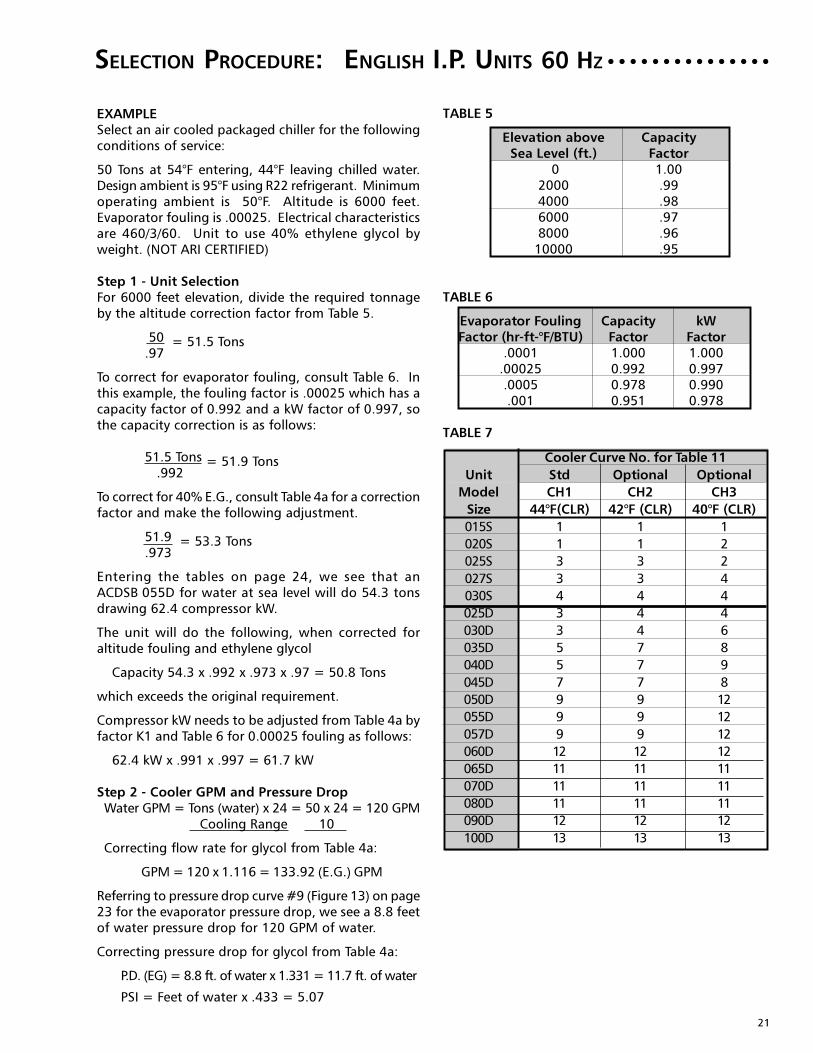
SELECTION PROCEDURE:
TABLE 5
Elevation above CapacitySea Level (ft.) Factor
0 1.002000 .994000 .986000 .978000 .96
10000 .95
TABLE 6
Evaporator Fouling Capacity kWFactor (hr-ft-°F/BTU) Factor Factor
.0001 1.000 1.000.00025 0.992 0.997.0005 0.978 0.990.001 0.951 0.978
TABLE 7
Cooler Curve No. for Table 11
Unit Std Optional Optional
Model CH1 CH2 CH3
Size 44°F(CLR) 42°F (CLR) 40°F (CLR)
015S 1 1 1
020S 1 1 2
025S 3 3 2
027S 3 3 4
030S 4 4 4
025D 3 4 4
030D 3 4 6
035D 5 7 8
040D 5 7 9
045D 7 7 8
050D 9 9 12
055D 9 9 12
057D 9 9 12
060D 12 12 12
065D 11 11 11
070D 11 11 11
080D 11 11 11
090D 12 12 12
100D 13 13 13
EXAMPLESelect an air cooled packaged chiller for the followingconditions of service:
50 Tons at 54°F entering, 44°F leaving chilled water.Design ambient is 95°F using R22 refrigerant. Minimumoperating ambient is 50°F. Altitude is 6000 feet.Evaporator fouling is .00025. Electrical characteristicsare 460/3/60. Unit to use 40% ethylene glycol byweight. (NOT ARI CERTIFIED)
Step 1 - Unit SelectionFor 6000 feet elevation, divide the required tonnageby the altitude correction factor from Table 5.
50 = 51.5 Tons.97
To correct for evaporator fouling, consult Table 6. Inthis example, the fouling factor is .00025 which has acapacity factor of 0.992 and a kW factor of 0.997, sothe capacity correction is as follows:
51.5 Tons = 51.9 Tons .992
To correct for 40% E.G., consult Table 4a for a correctionfactor and make the following adjustment.
51.9 = 53.3 Tons.973
Entering the tables on page 24, we see that anACDSB 055D for water at sea level will do 54.3 tonsdrawing 62.4 compressor kW.
The unit will do the following, when corrected foraltitude fouling and ethylene glycol
Capacity 54.3 x .992 x .973 x .97 = 50.8 Tons
which exceeds the original requirement.
Compressor kW needs to be adjusted from Table 4a byfactor K1 and Table 6 for 0.00025 fouling as follows:
62.4 kW x .991 x .997 = 61.7 kW
Step 2 - Cooler GPM and Pressure DropWater GPM = Tons (water) x 24 = 50 x 24 = 120 GPM
Cooling Range 10
Correcting flow rate for glycol from Table 4a:
GPM = 120 x 1.116 = 133.92 (E.G.) GPM
Referring to pressure drop curve #9 (Figure 13) on page23 for the evaporator pressure drop, we see a 8.8 feetof water pressure drop for 120 GPM of water.
Correcting pressure drop for glycol from Table 4a:
P.D. (EG) = 8.8 ft. of water x 1.331 = 11.7 ft. of water
PSI = Feet of water x .433 = 5.07
ENGLISH I.P. UNITS 60 HZ○ ○ ○ ○ ○ ○ ○ ○ ○ ○ ○ ○ ○ ○ ○

22
SELECTION PROCEDURE:
TABLE 8
Elevation above CapacitySea Level (M) Factor
0 1.00600 .99
1200 .981800 .972400 .963000 .95
TABLE 9
Evaporator Fouling Capacity kWFactor (hr-m2-°C/kW-1) Factor Factor
0.018 1.000 1.0000.044 0.992 0.9970.088 0.978 0.9900.176 0.951 0.978
TABLE 10
Cooler Curve No. for Table 12
Unit Std Optional Optional
Model CH1 CH2 CH3
Size 6.7°C (CLR) 5.5°C (CLR) 4.5°C (CLR)
015S 1 1 1
020S 1 1 2
025S 3 3 2
027S 3 3 4
030S 4 4 4
025D 3 4 4
030D 3 4 6
035D 5 7 8
040D 5 7 9
045D 7 7 8
050D 9 9 12
055D 9 9 12
057D 9 9 12
060D 12 12 12
065D 11 11 11
070D 11 11 11
080D 11 11 11
090D 12 12 12
100D 13 13 13
EXAMPLESelect an air cooled packaged chiller for the followingconditions of service:
175 kWo at 12.5°C entering, 6.5°C leaving chilled water.Design ambient is 35°C. Minimum operating ambientis 10°C. Altitude is 1800 meters. Evaporator fouling is.044. Electrical characteristics are 460/3/60. Unit touse 40% ethylene glycol by weight. (NOT ARI CERTIFIED)
Step 1 - Unit SelectionFor 1800 meters elevation, divide the required capacityby the altitude correction factor from Table 8.
175 = 180.4 kWo.97
To correct for evaporator fouling, consult Table 9. Inthis example, the fouling factor is .044 which has acapacity factor of 0.992 and a kW factor of 0.997, sothe capacity correction is as follows:
180.4 kWo = 181.8 kWo .992
To correct for 40% E.G., consult Table 4a for a correctionfactor and make the following adjustment.
181.8 = 186.8 kWo.973
Entering the tables on page 26, we see that anACDSB 055D for water at sea level will do 189.1 kWodrawing 62.2 compressor kW.
The unit will do the following, when corrected foraltitude and ethylene glycol
Capacity 189.1 x .992 x .973 x .99 =180.7 kWo
which exceeds the original requirement.
Compressor kW needs to be adjusted from Table 4a byfactor K1 and Table 9 for 0.044 fouling as follows:
62.2 kW x .991 x .997 = 61.5 kW
Step 2 - Cooler Flow Rate and Pressure DropWater Flow Rate = kWo(water) = 175 kWo = 6.97 Lit./sec.
4.187 x Range 4.187 x 6
Correcting flow rate for glycol from Table 4a:
Flow Rate = 6.97 x 1.116 = 7.78 (E.G.) Liters/sec.
Referring to pressure drop curve #9 (Figure 13) onpage 23 for the evaporator pressure drop, we see a22.5 kPa pressure drop for 6.97 Liters/sec. of water.
Correcting pressure drop for glycol from Table 4a:
P.D. (EG) = 22.5 kPa x 1.331 = 29.95 kPa
S.I. UNITS 60 HZ○ ○ ○ ○ ○ ○ ○ ○ ○ ○ ○ ○ ○ ○ ○ ○ ○ ○ ○ ○ ○ ○ ○

23
DX COOLER:
ENGLISH I.P. AND S.I. UNITS
TABLE 11 Cooler I.P. Units S.I. Units
Curve Minimum Maximum Min. Max.No. Model *Conn. Size GPM GPM Lit./Sec. Lit./Sec.
1 CHS006601B 3" NPTE 29 97 1.83 6.13
2 CHS007601A 3" NPTE 37 101 2.34 6.39
3 CHS007601B 3" NPTE 50 164 3.16 10.38
4 CHS008601A 3" NPTE 56 168 3.54 10.63
3 CHD007601B 3" NPTE 50 164 3.16 10.38
4 CHD008601A 3" NPTE 56 168 3.54 10.63
5 CHD008601B 3" NPTE 70 227 4.42 14.32
6 CHD010601A 4" NPTE 62 205 3.92 12.97
7 CHD010601B 4" NPTE 78 315 4.93 19.23
8 CHD011601A 4" NPTE 69 206 4.37 13.03
9 CHD011601B 4" NPTE 86 304 5.44 19.23
10 CHD013601B 4" NPTE 101 407 6.39 25.75
11 CXD12090F09 4" NPTE 112 365 6.94 22.63
12 CXD12090B07 4" NPTE 140 380 8.68 23.56
13 CXD12120B07 4" NPTE 188 459 11.65 28.45
*Non-metric compliance
WATER SIDE PRESSURE DROP ○ ○ ○ ○ ○ ○ ○ ○ ○ ○ ○ ○ ○ ○ ○ ○ ○ ○ ○ ○ ○ ○ ○ ○ ○
Figure 13
Single Circuit Coolers
Dual Circuit Coolers

24
R22 - 60 HZ - Standard Unit - 1140 RPM Fans
40
42
ENTERING CONDENSER AIR TEMPERATURE
LWT ACDS-B 85°F 95°F 105°F 115°F
°F MODEL TONS KW EER NPLV TONS KW EER NPLV TONS KW EER NPLV TONS KW EER NPLV
015S 12.6 12.4 10.37 13.58 12.0 13.8 8.96 12.89 11.3 15.5 7.69 12.25 10.6 17.3 6.53 11.62
**020S 17.4 16.9 10.54 13.86 16.5 19.0 9.05 13.16 15.5 21.3 7.72 12.48 14.5 23.8 6.54 11.65
**025S 22.4 22.6 10.55 13.59 21.1 25.1 9.06 12.93 19.8 28.0 7.69 12.28 18.3 31.2 6.45 11.62
**027S 26.9 26.8 10.84 15.46 25.3 29.9 9.26 14.73 23.6 33.2 7.85 14.03 21.9 36.8 6.61 13.32
030S 29.6 30.6 10.61 14.97 27.8 34.0 9.04 14.20 26.0 37.7 7.68 13.66 24.2 41.7 6.51 13.00
**025D 25.2 24.3 10.51 13.79 23.9 27.2 9.08 13.13 22.7 30.5 7.80 12.54 21.3 34.1 6.63 11.93
**030D 31.0 30.7 10.62 14.14 29.3 34.4 9.08 13.43 27.6 38.4 7.73 12.78 25.8 42.9 6.54 11.97
**035D 32.9 32.6 10.68 14.16 31.2 36.5 9.13 13.43 29.3 40.9 7.76 12.76 27.4 45.7 6.56 12.05
**040D 38.0 37.0 10.66 15.48 36.0 41.3 9.15 14.75 33.8 46.2 7.80 14.09 31.5 51.6 6.59 13.08
045D 46.6 45.1 10.99 15.23 44.0 50.2 9.43 14.54 41.1 55.9 8.00 13.76 38.0 62.3 6.71 13.20
**050D 49.7 49.5 10.78 15.18 46.8 55.1 9.22 14.47 43.7 61.3 7.82 13.82 40.4 68.1 6.56 13.15
**055D 55.3 55.5 10.82 15.39 52.0 61.8 9.23 14.65 48.6 68.6 7.83 14.13 45.1 76.0 6.61 13.47
**057D 57.3 55.1 10.77 14.45 54.0 61.6 9.23 14.14 50.6 68.6 7.86 13.52 47.2 76.1 6.67 12.57
060D 57.3 55.7 10.67 14.30 54.0 62.3 9.13 14.00 50.6 69.4 7.78 13.39 47.1 77.0 6.60 12.46
065D 63.7 64.1 10.50 13.96 60.6 71.4 9.08 13.45 57.1 79.3 7.79 12.85 53.4 87.9 6.63 12.09
070D 70.6 72.5 10.43 13.58 67.2 80.4 9.05 12.93 63.3 89.0 7.77 12.12 58.9 98.4 6.60 11.63
080D 76.7 78.9 10.50 13.41 73.1 87.5 9.12 13.17 69.4 97.2 7.86 12.51 65.2 107.8 6.72 11.91
090D 85.0 88.7 10.48 13.53 81.0 98.3 9.09 12.88 77.0 109.2 7.84 12.18 72.8 121.3 6.72 11.66
100D 91.6 90.5 10.77 14.09 87.4 100.1 9.39 13.48 83.0 111.0 8.13 12.96 78.6 123.3 6.99 12.29
015S 13.1 12.4 10.72 14.02 12.4 13.9 9.26 13.31 11.8 15.6 7.95 12.65 11.0 17.4 6.75 11.78
020S 17.8 16.9 10.81 13.95 16.8 18.9 9.27 13.24 15.8 21.1 7.90 12.55 14.8 23.6 6.69 11.73
025S 23.1 22.7 10.83 13.91 21.9 25.3 9.30 13.23 20.5 28.2 7.90 12.56 19.0 31.5 6.63 11.90
027S 27.0 26.9 10.89 15.70 25.5 29.9 9.30 14.97 23.8 33.3 7.89 14.26 22.1 36.9 6.65 13.55
030S 30.7 30.8 10.92 15.34 28.9 34.3 9.31 14.55 27.0 38.1 7.90 14.04 25.1 42.0 6.70 13.36
*025D 25.9 24.3 10.80 14.23 24.6 27.2 9.34 13.55 23.3 30.4 8.02 12.94 21.9 34.1 6.82 11.89
*030D 31.6 30.5 10.88 14.41 29.9 34.1 9.31 13.68 28.1 38.2 7.92 13.02 26.3 42.7 6.70 12.21
*035D 33.8 32.6 10.96 14.34 32.0 36.6 9.37 13.59 30.1 40.9 7.97 12.91 28.1 45.7 6.74 12.20
*040D 39.0 37.0 10.91 15.68 36.9 41.4 9.37 14.93 34.6 46.3 7.98 14.26 32.3 51.7 6.75 13.26
045D 46.5 45.0 10.98 15.36 43.9 50.1 9.43 14.67 41.1 55.9 8.00 13.90 38.0 62.2 6.71 13.33
050D 50.2 49.6 10.87 15.41 47.3 55.2 9.30 14.70 44.2 61.5 7.89 13.97 41.0 68.3 6.63 13.38
055D 55.7 55.6 10.88 15.60 52.4 61.9 9.29 14.85 49.0 68.8 7.89 14.36 45.6 76.2 6.67 13.70
057D 57.7 55.2 10.83 14.62 54.5 61.6 9.29 14.34 51.1 68.7 7.92 13.71 47.6 76.3 6.73 12.76
060D 59.4 56.1 11.01 14.66 56.0 62.6 9.43 14.42 52.5 69.8 8.03 13.79 48.9 77.5 6.81 12.83
065D 66.0 64.6 10.81 14.35 62.8 71.9 9.35 13.85 59.3 79.9 8.03 13.13 55.4 88.6 6.84 12.46
070D 73.1 73.1 10.72 13.95 69.6 81.1 9.31 13.29 65.7 89.8 8.00 12.46 61.1 99.3 6.79 11.96
080D 79.4 79.7 10.77 14.17 75.8 88.4 9.37 13.52 71.9 98.1 8.08 12.85 67.7 108.8 6.91 12.23
090D 88.2 89.8 10.74 13.84 84.1 99.4 9.33 13.17 79.9 110.4 8.05 12.47 75.5 122.6 6.90 11.94
100D 95.1 91.6 11.06 14.44 90.6 101.2 9.65 13.83 86.2 112.2 8.36 13.08 81.6 124.5 7.20 12.63
015S 13.6 12.5 11.08 14.46 12.9 14.0 9.57 13.74 12.2 15.6 8.22 13.06 11.5 17.5 6.98 12.17
020S 18.5 17.0 11.15 14.39 17.5 19.0 9.57 13.65 16.4 21.3 8.15 12.94 15.3 23.7 6.90 12.11
025S 24.0 22.9 11.15 14.31 22.7 25.5 9.58 13.62 21.3 28.4 8.14 12.94 19.7 31.7 6.83 12.27
027S 28.0 27.1 11.20 16.16 26.4 30.2 9.57 15.40 24.7 33.6 8.12 14.67 22.9 37.2 6.84 13.96
030S 31.7 31.1 11.20 15.70 29.9 34.6 9.57 14.90 28.0 38.4 8.13 14.42 26.0 42.4 6.89 13.72
025D 26.3 24.1 11.06 14.31 24.9 26.9 9.56 13.62 23.6 30.1 8.21 13.00 22.2 33.7 6.98 11.94
030D 32.0 29.9 11.18 14.64 30.2 33.5 9.58 13.89 28.5 37.5 8.16 13.22 26.6 41.8 6.90 12.40
035D 34.9 33.1 11.18 14.65 33.0 37.0 9.56 13.89 31.0 41.4 8.13 13.20 29.0 46.2 6.87 12.52
44 040D 39.5 36.6 11.19 15.86 37.4 40.9 9.61 15.10 35.2 45.7 8.19 14.41 32.8 51.0 6.93 13.41
045D 48.2 45.4 11.30 15.80 45.5 50.5 9.70 15.09 42.6 56.3 8.24 14.33 39.5 62.7 6.91 13.74
050D 52.0 50.0 11.19 15.86 49.0 55.6 9.57 15.13 45.9 62.0 8.12 14.33 42.5 68.9 6.83 13.79
055D 57.7 56.0 11.20 16.02 54.3 62.4 9.56 15.26 50.8 69.3 8.12 14.79 47.3 76.8 6.87 14.13
057D 59.8 55.5 11.18 14.97 56.4 62.0 9.58 14.76 53.0 69.1 8.17 14.12 49.4 76.8 6.94 13.14
060D 61.6 56.4 11.35 15.01 58.1 63.0 9.72 14.84 54.4 70.2 8.28 14.19 50.7 78.0 7.02 13.21
065D 68.4 65.1 11.13 14.73 65.1 72.4 9.63 14.26 61.5 80.5 8.27 13.51 57.5 89.3 7.05 12.83
070D 75.7 73.8 11.02 14.33 72.1 81.8 9.56 13.64 68.1 90.6 8.22 12.80 63.4 100.2 6.99 12.29
080D 82.2 80.6 11.06 14.52 78.5 89.3 9.61 13.86 74.5 99.1 8.30 13.09 70.2 109.9 7.10 12.54
090D 91.4 90.9 11.01 14.15 87.2 100.6 9.57 13.47 82.8 111.6 8.26 12.77 78.4 123.9 7.09 12.22
100D 98.6 92.6 11.34 14.79 94.0 102.3 9.90 14.18 89.4 113.3 8.59 13.43 84.7 125.8 7.40 12.97
Table 12a
NOTES: (1) Double asterisk (**) indicates ratings with CH3 oversized evaporator for 40°F LWT(2) Asterisk (*) indicates ratings with CH2 oversized evaporator for 42°F LWT(3) Ratings based on ARI Standard 550/590-98, 10°F water range in evaporator & .0001 fouling factor(4) ARI Standard 550/590-98 “NPLV” (“Non-Standard Part Load Value) has replaced ARI Standard 590-92 “APLV” (Applied Part Load Value) ratings.(5) Interpolation between ratings is permissible but extrapolation is not(6) KW is for compressor only. EER is for entire unit. See Physical Specs for fan kW(7) ARI Standard rating point and IPLV
○ ○ ○ ○ ○ ○ ○ ○ ○ ○ ○ ○ ○ ○ ○ ○ ○ ○ ○ ○ ○ ○ ○ ○ENGLISH I. P. UNITSPERFORMANCE DATA:

25
R22 - 60 HZ - Standard Unit - 1140 RPM Fans
45
46
48
015S 13.8 12.5 11.26 14.69 13.1 14.0 9.73 13.96 12.4 15.7 8.35 13.26 11.7 17.5 7.10 12.37020S 18.8 17.0 11.33 14.61 17.8 19.1 9.72 13.86 16.7 21.3 8.28 13.14 15.6 23.8 7.01 12.30025S 24.4 23.0 11.32 14.52 23.1 25.6 9.72 13.81 21.6 28.5 8.26 13.08 20.1 31.8 6.94 12.45027S 28.5 27.3 11.36 16.38 26.9 30.3 9.71 15.62 25.1 33.7 8.23 14.88 23.3 37.4 6.94 14.16030S 32.2 31.2 11.33 15.88 30.4 34.7 9.68 15.07 28.5 38.6 8.24 14.61 26.5 42.6 6.98 13.90025D 26.7 24.2 11.24 14.53 25.4 27.0 9.72 13.83 24.1 30.2 8.35 13.21 22.6 33.8 7.10 12.14030D 32.5 30.0 11.36 14.86 30.8 33.6 9.73 14.10 29.0 37.6 8.28 13.42 27.1 41.9 7.01 12.60035D 35.5 33.2 11.35 14.87 33.6 37.1 9.71 14.10 31.6 41.5 8.25 13.40 29.5 46.3 6.98 12.73040D 40.2 36.7 11.36 16.10 38.1 41.0 9.76 15.33 35.8 45.8 8.32 14.63 33.4 51.2 7.03 13.62045D 49.1 45.6 11.47 16.03 46.4 50.7 9.84 15.31 43.4 56.5 8.36 14.55 40.2 63.0 7.01 13.95050D 52.9 50.2 11.34 16.08 49.9 55.9 9.71 15.34 46.7 62.2 8.24 14.55 43.3 69.2 6.93 14.00055D 58.7 56.2 11.36 16.22 55.3 62.6 9.70 15.46 51.8 69.6 8.24 15.01 48.1 77.1 6.96 14.34057D 60.8 55.6 11.35 15.15 57.5 62.2 9.73 14.97 53.9 69.3 8.30 14.32 50.3 77.0 7.04 13.33060D 62.7 56.5 11.53 15.19 59.1 63.1 9.87 15.05 55.4 70.4 8.41 14.40 51.6 78.2 7.13 13.40065D 69.7 65.3 11.29 14.92 66.3 72.7 9.77 14.46 62.6 80.8 8.39 13.71 58.6 89.6 7.15 13.01070D 77.1 74.1 11.17 14.52 73.4 82.2 9.69 13.82 69.3 91.0 8.34 12.97 64.6 100.7 7.09 12.45080D 83.7 81.0 11.20 14.70 79.9 89.7 9.74 14.03 75.8 99.6 8.41 13.26 71.4 110.4 7.20 12.70090D 93.1 91.5 11.14 14.31 88.7 101.2 9.69 13.62 84.3 112.2 8.37 12.91 79.8 124.6 7.18 12.36100D 100.3 93.2 11.49 14.93 95.7 102.9 10.04 14.36 91.1 113.9 8.71 13.60 86.3 126.4 7.50 13.14015S 14.1 12.6 11.44 14.92 13.4 14.0 9.89 14.18 12.7 15.7 8.49 13.47 11.9 17.6 7.21 12.57020S 19.1 17.1 11.50 14.83 18.1 19.1 9.87 14.07 17.0 21.4 8.41 13.34 15.9 23.9 7.12 12.49025S 24.9 23.1 11.48 14.73 23.5 25.7 9.86 14.01 22.0 28.6 8.38 13.27 20.5 32.0 7.04 12.64027S 29.1 27.4 11.52 16.61 27.4 30.5 9.84 15.83 25.6 33.9 8.35 15.09 23.7 37.6 7.04 14.37030S 32.7 31.3 11.47 16.06 30.9 34.9 9.80 15.24 28.9 38.7 8.34 14.79 27.0 42.9 7.08 14.08025D 27.2 24.2 11.42 14.76 25.9 27.0 9.88 14.05 24.5 30.2 8.48 13.41 23.0 33.9 7.21 12.33030D 33.1 30.1 11.53 15.08 31.3 33.7 9.88 14.32 29.5 37.7 8.41 13.62 27.5 42.1 7.11 12.80035D 36.2 33.3 11.52 15.10 34.2 37.3 9.86 14.31 32.2 41.7 8.38 13.60 30.0 46.5 7.08 12.93040D 41.0 36.8 11.53 16.34 38.8 41.2 9.90 15.56 36.4 46.0 8.44 14.85 34.0 51.3 7.14 13.84045D 50.0 45.7 11.63 16.25 47.2 50.9 9.98 15.52 44.2 56.7 8.48 14.77 40.9 63.2 7.12 14.16050D 53.9 50.4 11.50 16.31 50.8 56.1 9.85 15.56 47.5 62.5 8.36 14.77 44.1 69.5 7.03 14.21055D 59.8 56.5 11.52 16.43 56.3 62.9 9.83 15.66 52.7 69.9 8.35 15.23 49.0 77.5 7.06 14.56057D 61.9 55.8 11.52 15.33 58.5 62.3 9.88 15.19 54.9 69.5 8.42 14.52 51.2 77.3 7.15 13.52060D 63.8 56.7 11.70 15.36 60.2 63.3 10.02 15.26 56.4 70.6 8.53 14.60 52.6 78.5 7.23 13.59065D 70.9 65.6 11.45 15.12 67.4 73.0 9.91 14.66 63.7 81.1 8.51 13.91 59.7 90.0 7.26 13.20070D 78.4 74.5 11.32 14.70 74.7 82.5 9.82 13.99 70.5 91.4 8.45 13.16 65.8 101.1 7.19 12.62080D 85.1 81.4 11.34 14.88 81.3 90.2 9.86 14.20 77.2 100.0 8.52 13.43 72.7 110.9 7.29 12.86090D 94.6 92.1 11.26 14.46 90.3 101.8 9.80 13.77 85.9 112.9 8.48 13.06 81.3 125.3 7.28 12.50100D 102.1 93.7 11.64 15.12 97.5 103.4 10.17 14.54 92.7 114.5 8.83 13.78 87.9 127.0 7.61 13.31015S 14.6 12.7 11.81 15.38 13.9 14.1 10.21 14.62 13.1 15.8 8.76 13.90 12.3 17.7 7.45 12.98020S 19.8 17.2 11.86 15.28 18.7 19.2 10.17 14.50 17.6 21.5 8.67 13.75 16.5 24.0 7.34 12.89025S 25.8 23.3 11.81 15.14 24.4 25.9 10.15 14.41 22.8 28.9 8.63 13.66 21.2 32.2 7.25 13.01027S 30.1 27.6 11.84 17.06 28.3 30.7 10.11 16.27 26.5 34.2 8.58 15.46 24.6 37.9 7.23 14.78030S 33.8 31.6 11.73 16.41 31.8 35.2 10.03 15.92 29.9 39.1 8.54 15.16 27.9 43.3 7.24 14.44025D 28.2 24.3 11.79 15.21 26.8 27.2 10.20 14.48 25.4 30.4 8.76 13.83 23.8 34.0 7.44 12.73030D 34.3 30.3 11.88 15.53 32.5 33.9 10.18 14.75 30.5 37.9 8.66 14.03 28.5 42.3 7.33 13.21035D 37.5 33.5 11.87 15.54 35.4 37.5 10.15 14.74 33.3 41.9 8.63 14.00 31.1 46.8 7.29 13.34040D 42.4 37.1 11.88 16.83 40.1 41.4 10.20 16.03 37.7 46.3 8.70 15.30 35.2 51.7 7.36 14.28045D 51.7 46.1 11.96 16.70 48.9 51.3 10.27 15.96 45.8 57.2 8.72 15.21 42.4 63.7 7.33 14.59050D 55.8 50.8 11.83 16.76 52.6 56.6 10.13 15.99 49.3 63.0 8.59 15.22 45.7 70.0 7.23 14.63055D 61.8 56.9 11.82 16.85 58.3 63.4 10.10 16.06 54.6 70.5 8.59 15.57 50.8 78.1 7.25 14.99057D 64.1 56.1 11.87 15.67 60.6 62.7 10.18 15.61 56.9 69.9 8.68 14.71 53.1 77.8 7.36 13.89060D 66.1 57.1 12.06 15.71 62.3 63.7 10.33 15.68 58.4 71.1 8.79 14.98 54.4 79.0 7.45 13.97065D 73.4 66.1 11.78 15.50 69.8 73.5 10.19 15.07 66.0 81.8 8.76 14.30 61.9 90.7 7.47 13.58070D 81.2 75.1 11.62 15.08 77.3 83.3 10.09 14.35 73.0 92.2 8.68 13.51 68.2 102.0 7.39 12.93080D 88.0 82.2 11.62 15.24 84.1 91.1 10.12 14.55 79.9 101.0 8.74 13.76 75.3 112.0 7.49 13.18090D 97.6 93.2 11.49 14.75 93.2 103.0 10.01 14.05 88.7 114.2 8.66 13.35 84.0 126.7 7.45 12.75100D 105.8 94.9 11.93 15.49 101.0 104.6 10.43 14.90 96.1 115.8 9.06 14.13 91.2 128.3 7.82 13.63
Table 12b
ENTERING CONDENSER AIR TEMPERATURE
LWT ACDS-B 85°F 95°F 105°F 115°F
°F MODEL TONS KW EER NPLV TONS KW EER NPLV TONS KW EER NPLV TONS KW EER NPLV
○ ○ ○ ○ ○ ○ ○ ○ ○ ○ ○ ○ ○ ○ ○ ○ ○ ○ ○ ○ ○ ○ ○ ○ENGLISH I. P. UNITS
NOTES: (1) Double asterisk (**) indicates ratings with CH3 oversized evaporator for 40°F LWT(2) Asterisk (*) indicates ratings with CH2 oversized evaporator for 42°F LWT(3) Ratings based on ARI Standard 550/590-98, 10°F water range in evaporator & .0001 fouling factor(4) ARI Standard 550/590-98 “NPLV” (“Non-Standard Part Load Value) has replaced ARI Standard 590-92 “APLV” (Applied Part Load Value) ratings.(5) Interpolation between ratings is permissible but extrapolation is not
(6) KW is for compressor only. EER is for entire unit. See Physical Specs for fan kW(7) ARI Standard rating point and IPLV
PERFORMANCE DATA:
26
065D 236.3 65.6 3.18 225.8 72.2 2.79 214.6 79.4 2.43
070D 261.5 74.3 3.15 250.2 81.5 2.77 237.6 89.4 2.42
080D 283.8 81.0 3.16 272.1 88.9 2.79 259.8 97.6 2.44
090D 315.6 91.4 3.15 302.3 100.1 2.78 288.8 110.0 2.43
100D 340.8 93.2 3.25 326.6 101.9 2.88 312.3 111.8 2.53
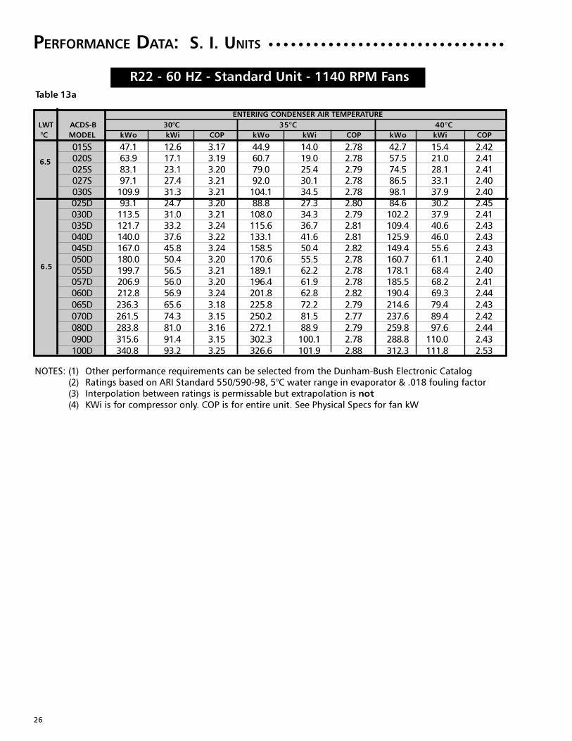
R22 - 60 HZ - Standard Unit - 1140 RPM Fans
6.5
6.5
Table 13a
ENTERING CONDENSER AIR TEMPERATURE
LWT ACDS-B 30°C 35°C 40°C
°C MODEL kWo kWi COP kWo kWi COP kWo kWi COP
015S 47.1 12.6 3.17 44.9 14.0 2.78 42.7 15.4 2.42020S 63.9 17.1 3.19 60.7 19.0 2.78 57.5 21.0 2.41025S 83.1 23.1 3.20 79.0 25.4 2.79 74.5 28.1 2.41027S 97.1 27.4 3.21 92.0 30.1 2.78 86.5 33.1 2.40030S 109.9 31.3 3.21 104.1 34.5 2.78 98.1 37.9 2.40025D 93.1 24.7 3.20 88.8 27.3 2.80 84.6 30.2 2.45030D 113.5 31.0 3.21 108.0 34.3 2.79 102.2 37.9 2.41035D 121.7 33.2 3.24 115.6 36.7 2.81 109.4 40.6 2.43040D 140.0 37.6 3.22 133.1 41.6 2.81 125.9 46.0 2.43045D 167.0 45.8 3.24 158.5 50.4 2.82 149.4 55.6 2.43050D 180.0 50.4 3.20 170.6 55.5 2.78 160.7 61.1 2.40055D 199.7 56.5 3.21 189.1 62.2 2.78 178.1 68.4 2.40057D 206.9 56.0 3.20 196.4 61.9 2.78 185.5 68.2 2.41060D 212.8 56.9 3.24 201.8 62.8 2.82 190.4 69.3 2.44
PERFORMANCE DATA: S. I. UNITS ○ ○ ○ ○ ○ ○ ○ ○ ○ ○ ○ ○ ○ ○ ○ ○ ○ ○ ○ ○ ○ ○ ○ ○ ○ ○ ○ ○ ○ ○ ○ ○
NOTES: (1) Other performance requirements can be selected from the Dunham-Bush Electronic Catalog(2) Ratings based on ARI Standard 550/590-98, 5°C water range in evaporator & .018 fouling factor(3) Interpolation between ratings is permissable but extrapolation is not(4) KWi is for compressor only. COP is for entire unit. See Physical Specs for fan kW

27
R22 - 60 HZ - Standard Unit - 1140 RPM Fans
6.5
6.5
Table 13b
ENTERING CONDENSER AIR TEMPERATURE
LWT ACDS-B 45°C 49°C (See Note 4)
015S 40.4 17.1 2.10 38.4 18.5 1.90
020S 54.1 23.2 2.07 51.3 25.1 1.80
025S 69.7 31.0 2.06 65.6 33.5 1.80
027S 80.9 36.4 2.06 76.2 39.1 1.80
030D 91.9 41.5 2.07 87.0 44.5 1.80
025D 80.0 33.4 2.12 76.0 36.2 1.90
030D 96.2 41.9 2.08 91.2 45.3 1.80
035D 103.0 44.9 2.09 97.7 48.6 1.80
040D 118.3 50.8 2.09 112.0 54.9 1.90
045D 139.5 61.3 2.08 131.1 66.2 1.80
050D 150.2 67.3 2.06 141.4 72.5 1.80
055D 166.8 75.1 2.06 157.6 80.7 1.80
057D 174.3 75.0 2.08 165.1 80.8 1.90
060D 178.7 76.2 2.10 169.2 82.0 1.90
065D 202.4 87.2 2.11 191.9 93.8 1.87
070D 223.4 97.9 2.10 210.7 105.0 1.85
080D 246.5 107.2 2.13 234.9 115.5 1.89
090D 275.0 120.9 2.12 263.5 130.3 1.90
100D 297.7 122.8 2.22 285.7 132.4 1.98
PERFORMANCE DATA: S. I. UNITS ○ ○ ○ ○ ○ ○ ○ ○ ○ ○ ○ ○ ○ ○ ○ ○ ○ ○ ○ ○ ○ ○ ○ ○ ○ ○ ○ ○ ○ ○ ○ ○
NOTES: (1) Other performance requirements can be selected from the Dunham-Bush Electronic Catalog(2) Ratings based on ARI Standard 550/590-98, 5°C water range in evaporator & .018 fouling factor(3) Interpolation between ratings is permissable but extrapolation is not(4) KWi is for compressor only. COP is for entire unit. See Physical Specs for fan kW(5) High Ambient Applications over 48°C may be affected by the unit’s automatic “High Pressure
Limiting” function that unloads the circuit if head pressure reaches limits by allowing only onecompressor per circuit to run.
28
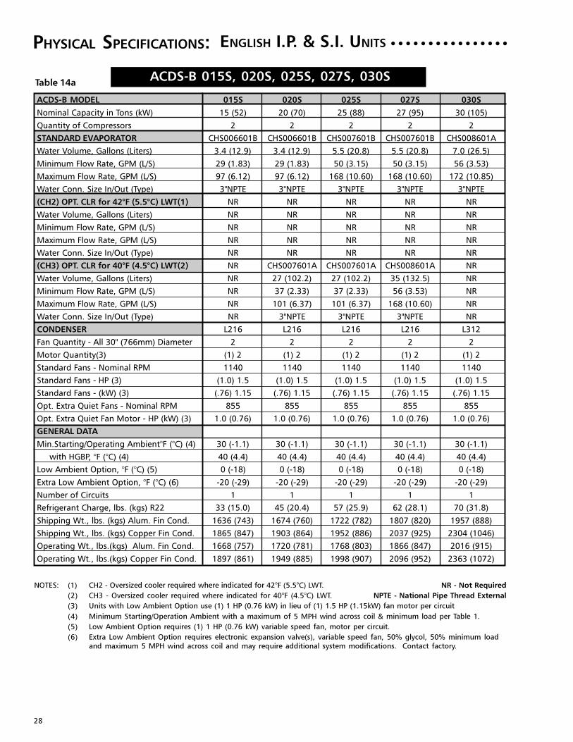
ACDS-B 015S, 020S, 025S, 027S, 030S
PHYSICAL SPECIFICATIONS:
Table 14a
ENGLISH I.P. & S.I. UNITS ○ ○ ○ ○ ○ ○ ○ ○ ○ ○ ○ ○ ○ ○ ○ ○
NOTES: (1) CH2 - Oversized cooler required where indicated for 42°F (5.5°C) LWT. NR - Not Required
(2) CH3 - Oversized cooler required where indicated for 40°F (4.5°C) LWT. NPTE - National Pipe Thread External
(3) Units with Low Ambient Option use (1) 1 HP (0.76 kW) in lieu of (1) 1.5 HP (1.15kW) fan motor per circuit
(4) Minimum Starting/Operation Ambient with a maximum of 5 MPH wind across coil & minimum load per Table 1.
(5) Low Ambient Option requires (1) 1 HP (0.76 kW) variable speed fan, motor per circuit.
(6) Extra Low Ambient Option requires electronic expansion valve(s), variable speed fan, 50% glycol, 50% minimum loadand maximum 5 MPH wind across coil and may require additional system modifications. Contact factory.
ACDS-B MODEL 015S 020S 025S 027S 030S
Nominal Capacity in Tons (kW) 15 (52) 20 (70) 25 (88) 27 (95) 30 (105)
Quantity of Compressors 2 2 2 2 2
STANDARD EVAPORATOR CHS006601B CHS006601B CHS007601B CHS007601B CHS008601A
Water Volume, Gallons (Liters) 3.4 (12.9) 3.4 (12.9) 5.5 (20.8) 5.5 (20.8) 7.0 (26.5)
Minimum Flow Rate, GPM (L/S) 29 (1.83) 29 (1.83) 50 (3.15) 50 (3.15) 56 (3.53)
Maximum Flow Rate, GPM (L/S) 97 (6.12) 97 (6.12) 168 (10.60) 168 (10.60) 172 (10.85)
Water Conn. Size In/Out (Type) 3"NPTE 3"NPTE 3"NPTE 3"NPTE 3"NPTE
(CH2) OPT. CLR for 42°F (5.5°C) LWT(1) NR NR NR NR NR
Water Volume, Gallons (Liters) NR NR NR NR NR
Minimum Flow Rate, GPM (L/S) NR NR NR NR NR
Maximum Flow Rate, GPM (L/S) NR NR NR NR NR
Water Conn. Size In/Out (Type) NR NR NR NR NR
(CH3) OPT. CLR for 40°F (4.5°C) LWT(2) NR CHS007601A CHS007601A CHS008601A NR
Water Volume, Gallons (Liters) NR 27 (102.2) 27 (102.2) 35 (132.5) NR
Minimum Flow Rate, GPM (L/S) NR 37 (2.33) 37 (2.33) 56 (3.53) NR
Maximum Flow Rate, GPM (L/S) NR 101 (6.37) 101 (6.37) 168 (10.60) NR
Water Conn. Size In/Out (Type) NR 3"NPTE 3"NPTE 3"NPTE NR
CONDENSER L216 L216 L216 L216 L312
Fan Quantity - All 30" (766mm) Diameter 2 2 2 2 2
Motor Quantity(3) (1) 2 (1) 2 (1) 2 (1) 2 (1) 2
Standard Fans - Nominal RPM 1140 1140 1140 1140 1140
Standard Fans - HP (3) (1.0) 1.5 (1.0) 1.5 (1.0) 1.5 (1.0) 1.5 (1.0) 1.5
Standard Fans - (kW) (3) (.76) 1.15 (.76) 1.15 (.76) 1.15 (.76) 1.15 (.76) 1.15
Opt. Extra Quiet Fans - Nominal RPM 855 855 855 855 855
Opt. Extra Quiet Fan Motor - HP (kW) (3) 1.0 (0.76) 1.0 (0.76) 1.0 (0.76) 1.0 (0.76) 1.0 (0.76)
GENERAL DATA
Min.Starting/Operating Ambient°F (°C) (4) 30 (-1.1) 30 (-1.1) 30 (-1.1) 30 (-1.1) 30 (-1.1)
with HGBP, °F (°C) (4) 40 (4.4) 40 (4.4) 40 (4.4) 40 (4.4) 40 (4.4)
Low Ambient Option, °F (°C) (5) 0 (-18) 0 (-18) 0 (-18) 0 (-18) 0 (-18)
Extra Low Ambient Option, °F (°C) (6) -20 (-29) -20 (-29) -20 (-29) -20 (-29) -20 (-29)
Number of Circuits 1 1 1 1 1
Refrigerant Charge, lbs. (kgs) R22 33 (15.0) 45 (20.4) 57 (25.9) 62 (28.1) 70 (31.8)
Shipping Wt., lbs. (kgs) Alum. Fin Cond. 1636 (743) 1674 (760) 1722 (782) 1807 (820) 1957 (888)
Shipping Wt., lbs. (kgs) Copper Fin Cond. 1865 (847) 1903 (864) 1952 (886) 2037 (925) 2304 (1046)
Operating Wt., lbs.(kgs) Alum. Fin Cond. 1668 (757) 1720 (781) 1768 (803) 1866 (847) 2016 (915)
Operating Wt., lbs.(kgs) Copper Fin Cond. 1897 (861) 1949 (885) 1998 (907) 2096 (952) 2363 (1072)

29
ACDS-B 025D, 030D, 035D, 040D, 045D
PHYSICAL SPECIFICATIONS:
Table 14b
ENGLISH I.P. & S.I. UNITS ○ ○ ○ ○ ○ ○ ○ ○ ○ ○ ○ ○ ○ ○ ○ ○
NOTES: (1) CH2 - Oversized cooler required where indicated for 42°F (5.5°C) LWT. NR - Not Required
(2) CH3 - Oversized cooler required where indicated for 40°F (4.5°C) LWT. NPTE - National Pipe Thread External
(3) Units with Low Ambient Option use (1) 1 HP (0.76 kW) in lieu of (1) 1.5 HP (1.15kW) fan motor per circuit
(4) Minimum Starting/Operation Ambient with a maximum of 5 MPH wind across coil & minimum load per Table 1.
(5) Low Ambient Option requires (1) 1 HP (0.76 kW) variable speed fan, motor per circuit.
(6) Extra Low Ambient Option requires electronic expansion valve(s), variable speed fan, 50% glycol, 50% minimum loadand maximum 5 MPH wind across coil, and may require additional system modifications. Contact factory.
ACDS-B MODEL 025D 030D 035D 040D 045D
Nominal Capacity in Tons (kW) 25 (88) 30 (105) 35 (120) 40 (140) 45 (150)
Quantity of Compressors 4 4 4 4 4
STANDARD EVAPORATOR CHD007601B CHD007601B CHD008601B CHD008601B CHD010601B
Water Volume, Gallons (Liters) 5.5 (20.8) 5.5 (20.8) 7 (26.5) 7 (26.5) 10.7 (40.5)
Minimum Flow Rate, GPM (L/S) 50 (3.15) 50 (3.15) 70 (4.42) 70 (4.42) 78 (4.93)
Maximum Flow Rate, GPM (L/S) 164 (10.35) 164 (10.35) 227 (14.32) 227 (14.32) 315 (19.23)
Water Conn. Size In/Out (Type) 3" NPTE 3" NPTE 3" NPTE 3" NPTE 4" NPTE
(CH2) OPT. CLR for 42°F (5.5°C) LWT(1) CHD008601A CHD008601A CHD010601B CHD010601B NR
Water Volume, Gallons (Liters) 7.7 (29.1) 7.7 (29.1) 10.7 (40.5) 10.7 (40.5) NR
Minimum Flow Rate, GPM (L/S) 56 (3.53) 56 (3.53) 78 (4.92) 78 (4.92) NR
Maximum Flow Rate, GPM (L/S) 168 (10.60) 168 (10.60) 315 (19.87) 315 (19.87) NR
Water Conn. Size In/Out (Type) 3" NPTE 3" NPTE 4" NPTE 4" NPTE NR
(CH3) OPT. CLR for 40°F (4.5°C) LWT(2) CHD008601A CHD010601A CHD011601A CHD011601B CHD011601A
Water Volume, Gallons (Liters) 7.7 (29.1) 10.7 (40.5) 12.9 (48.8) 12.9 (48.8) 12.9 (48.8)
Minimum Flow Rate, GPM (L/S) 56 (3.53) 62 (3.91) 69 (4.35) 86 (5.42) 69 (4.35)
Maximum Flow Rate, GPM (L/S) 168 (10.60) 205 (12.93) 206 (12.99) 304 (19.18) 206 (12.99)
Water Conn. Size In/Out (Type) 3" NPTE 4" NPTE 4" NPTE 4" NPTE 4" NPTE
CONDENSER L216 L216 L216 L216 L216
Fan Quantity - All 30" (766mm) Diameter 4 4 4 4 4
Motor Quantity(3) (2) 4 (2) 4 (2) 4 (2) 4 (2) 4
Standard Fans - Nominal RPM 1140 1140 1140 1140 1140
Standard Fans - HP (3) 1.0 1.0 1.0 (1.0) 1.5 (1.0) 1.5
Standard Fans - (kW) (3) (.76) 1.15 (.76) 1.15 (.76) 1.15 (.76) 1.15 (.76) 1.15
Opt. Extra Quiet Fans - Nominal RPM 855 855 855 855 855
Opt. Extra Quiet Fan Motor - HP (kW) (3) 1.0 (0.76) 1.0 (0.76) 1.0 (0.76) 1.0 (0.76) 1.0 (0.76)
GENERAL DATA
Min.Starting/Operating Ambient°F (°C) (4) 30 (-1.1) 30 (-1.1) 30 (-1.1) 30 (-1.1) 30 (-1.1)
with HGBP, °F (°C) (4) 40 (4.4) 40 (4.4) 40 (4.4) 40 (4.4) 40 (4.4)
Low Ambient Option, °F (°C) (5) 0 (-18) 0 (-18) 0 (-18) 0 (-18) 0 (-18)
Extra Low Ambient Option, °F (°C) (6) -20 (-29) -20 (-29) -20 (-29) -20 (-29) -20 (-29)
Number of Circuits 2 2 2 2 2
Refrigerant Charge, lbs. (kgs) R22 62 (28.1) 75 (34.0) 83 (37.6) 93 (42.2) 109 (49.4)
Shipping Wt., lbs. (kgs) Alum. Fin Cond. 3424 (1554) 3517 (1597) 3604 (1636) 3629 (1648) 3702 (1681)
Shipping Wt., lbs. (kgs) Copper Fin Cond. 3877 (1760) 3968 (1802) 4057 (1842) 4081 (1853) 4154 (1886)
Operating Wt., lbs.(kgs) Alum. Fin Cond. 3844 (1584) 3606 (1637) 3712 (1685) 3737 (1697) 3810 (1730)
Operating Wt., lbs.(kgs) Copper Fin Cond. 3941 (1789) 4058 (1842) 4165 (1891) 4189 (1902) 4262 (1935)

30
ACDS-B 050D, 055D, 057D, 060D
PHYSICAL SPECIFICATIONS:
Table 14c
ENGLISH I.P. & S.I. UNITS ○ ○ ○ ○ ○ ○ ○ ○ ○ ○ ○ ○ ○ ○ ○ ○
NOTES: (1) CH2 - Oversized cooler required where indicated for 42°F (5.5°C) LWT. NR - Not Required
(2) CH3 - Oversized cooler required where indicated for 40°F (4.5°C) LWT. NPTE - National Pipe Thread External
(3) Units with Low Ambient Option use (1) 1 HP (0.76 kW) in lieu of (1) 1.5 HP (1.15kW) fan motor per circuit
(4) Minimum Starting/Operation Ambient with a maximum of 5 MPH wind across coil & minimum load per Table 1.
(5) Low Ambient Option requires (1) 1 HP (0.76 kW) variable speed fan, motor per circuit.
(6) Extra Low Ambient Option requires electronic expansion valve(s), variable speed fan, 50% glycol, 50% minimum loadand maximum 5 MPH wind across coil and may require additional system modifications. Contact factory.
ACDS-B MODEL 050D 055D 057D 060D
Nominal Capacity in Tons (kW) 50 (175) 55 (190) 57 (200) 60 (210)
Quantity of Compressors 4 4 4 4
STANDARD EVAPORATOR CHD011601B CHD011601B CHD011601B CHD013601B
Water Volume, Gallons (Liters) 12.9 (49.0) 12.9 (49.0) 12.9 (49.0) 18.1 (68.5)
Minimum Flow Rate, GPM (L/S) 86 (5.44) 86 (5.44) 86 (5.44) 101 (6.39)
Maximum Flow Rate, GPM (L/S) 315 (19.23) 315 (19.23) 315 (19.23) 420 (25.76)
Water Conn. Size In/Out (Type) 4" NPTE 4" NPTE 4" NPTE 4" NPTE
(CH2) OPT. CLR for 42°F (5.5°C) LWT(1) NR NR NR NR
Water Volume, Gallons (Liters) NR NR NR NR
Minimum Flow Rate, GPM (L/S) NR NR NR NR
Maximum Flow Rate, GPM (L/S) NR NR NR NR
Water Conn. Size In/Out (Type) NR NR NR NR
(CH3) OPT. CLR for 40°F (4.5°C) LWT(2) CHD013601B CHD013601B CHD013601B NR
Water Volume, Gallons (Liters) 18.1 (68.5) 18.1 (68.5) 18.1 (68.5) NR
Minimum Flow Rate, GPM (L/S) 101 (6.39) 101 (6.39) 101 (6.39) NR
Maximum Flow Rate, GPM (L/S) 420 (25.76) 420 (25.76) 420 (25.76) NR
Water Conn. Size In/Out (Type) 4" NPTE 4" NPTE 4" NPTE NR
CONDENSER L216 L312 L216 L216
Fan Quantity - All 30" (766mm) Diameter 4 4 6 6
Motor Quantity(3) (2) 4 (2) 4 (2) 6 (2) 6
Standard Fans - Nominal RPM 1140 1140 1140 1140
Standard Fans - HP (3) (1.0) 1.5 (1.0) 1.5 (1.0) 1.5 (1.0) 1.5
Standard Fans - (kW) (3) (.76) 1.15 (.76) 1.15 (.76) 1.15 (.76) 1.15
Opt. Extra Quiet Fans - Nominal RPM 855 855 855 855
Opt. Extra Quiet Fan Motor - HP (kW) (3) 1.0 (0.76) 1.0 (0.76) 1.0 (0.76) 1.0 (0.76)
GENERAL DATA
Min.Starting/Operating Ambient°F (°C) (4) 30 (-1.1) 30 (-1.1) 30 (-1.1) 30 (-1.1)
with HGBP, °F (°C) (4) 40 (4.4) 40 (4.4) 40 (4.4) 40 (4.4)
Low Ambient Option, °F (°C) (5) 0 (-18) 0 (-18) 0 (-18) 0 (-18)
Extra Low Ambient Option, °F (°C) (6) -20 (-29) -20 (-29) -20 (-29) -20 (-29)
Number of Circuits 2 2 2 2
Refrigerant Charge, lbs. (kgs) R22 119 (54.0) 130 (59.0) 136 (61.7) 140 (63.5)
Shipping Wt., lbs. (kgs) Alum. Fin Cond. 3910 (1775) 4228 (1920) 4649 (2111) 4649 (2111)
Shipping Wt., lbs. (kgs) Copper Fin Cond. 4362 (1980) 4926 (2236) 5325 (2418) 5325 (2418)
Operating Wt., lbs.(kgs) Alum. Fin Cond. 4061 (1844) 4379 (1988) 4800 (2179) 4800 (2179)
Operating Wt., lbs.(kgs) Copper Fin Cond. 4513 (2049) 5077 (2305) 5476 (2486) 5476 (2486)
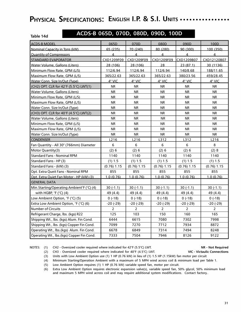
31
ACDS-B 065D, 070D, 080D, 090D, 100D
PHYSICAL SPECIFICATIONS:
Table 14d
ENGLISH I.P. & S.I. UNITS ○ ○ ○ ○ ○ ○ ○ ○ ○ ○ ○ ○ ○ ○ ○ ○
NOTES: (1) CH2 - Oversized cooler required where indicated for 42°F (5.5°C) LWT. NR - Not Required
(2) CH3 - Oversized cooler required where indicated for 40°F (4.5°C) LWT. VIC - Victaulic Connections
(3) Units with Low Ambient Option use (1) 1 HP (0.76 kW) in lieu of (1) 1.5 HP (1.15kW) fan motor per circuit
(4) Minimum Starting/Operation Ambient with a maximum of 5 MPH wind across coil & minimum load per Table 1.
(5) Low Ambient Option requires (1) 1 HP (0.76 kW) variable speed fan, motor per circuit.
(6) Extra Low Ambient Option requires electronic expansion valve(s), variable speed fan, 50% glycol, 50% minimum loadand maximum 5 MPH wind across coil and may require additional system modifications. Contact factory..
ACDS-B MODEL 065D 070D 080D 090D 100D
Nominal Capacity in Tons (kW) 65 (235) 70 (240) 80 (280) 90 (300) 100 (350)
Quantity of Compressors 4 4 4 4 4
STANDARD EVAPORATOR CXD1209F09 CXD1209F09 CXD1209F09 CXD1209B07 CXD12120B07
Water Volume, Gallons (Liters) 28 (106) 28 (106) 28 23 (87.1) 30 (1136)
Minimum Flow Rate, GPM (L/S) 112/6.94 112/6.94 112/6.94 140/8.68 188/11.65
Maximum Flow Rate, GPM (L/S) 365/22.63 365/22.63 365/22.63 380/23.56 459/28.45
Water Conn. Size In/Out (Type) 4" VIC 4" VIC 4" VIC 4" VIC 4" VIC
(CH2) OPT. CLR for 42°F (5.5°C) LWT(1) NR NR NR NR NR
Water Volume, Gallons (Liters) NR NR NR NR NR
Minimum Flow Rate, GPM (L/S) NR NR NR NR NR
Maximum Flow Rate, GPM (L/S) NR NR NR NR NR
Water Conn. Size In/Out (Type) NR NR NR NR NR
(CH3) OPT. CLR for 40°F (4.5°C) LWT(2) NR NR NR NR NR
Water Volume, Gallons (Liters) NR NR NR NR NR
Minimum Flow Rate, GPM (L/S) NR NR NR NR NR
Maximum Flow Rate, GPM (L/S) NR NR NR NR NR
Water Conn. Size In/Out (Type) NR NR NR NR NR
CONDENSER L216 L216 L312 L312 L216
Fan Quantity - All 30" (766mm) Diameter 6 6 6 6 8
Motor Quantity(3) (2) 6 (2) 6 (2) 6 (2) 6 (2) 8
Standard Fans - Nominal RPM 1140 1140 1140 1140 1140
Standard Fans - HP (3) (1) 1.5 (1) 1.5 (1) 1.5 (1) 1.5 (1) 1.5
Standard Fans - (kW) (3) (0.76) 1.15 (0.76) 1.15 (0.76) 1.15 (0.76) 1.15 (0.76) 1.15
Opt. Extra Queit Fans - Nominal RPM 855 855 855 855 855
Opt. Extra Quiet Fan Motor - HP (kW) (3) 1.0 (0.76) 1.0 (0.76) 1.0 (0.76) 1.0 (0.76) 1.0 (0.76)
GENERAL DATA
Min.Starting/Operating Ambient°F (°C) (4) 30 (-1.1) 30 (-1.1) 30 (-1.1) 30 (-1.1) 30 (-1.1)
with HGBP, °F (°C) (4) 49 (4.4) 49 (4.4) 49 (4.4) 49 (4.4) 49 (4.4)
Low Ambient Option, °F (°C) (5) 0 (-18) 0 (-18) 0 (-18) 0 (-18) 0 (-18)
Extra Low Ambient Option, °F (°C) (6) -20 (-29) -20 (-29) -20 (-29) -20 (-29) -20 (-29)
Number of Circuits 2 2 2 2 2
Refrigerant Charge, lbs. (kgs) R22 125 103 150 160 165
Shipping Wt., lbs. (kgs) Alum. Fin Cond. 6444 6615 7080 7302 7998
Shipping Wt., lbs. (kgs) Copper Fin Cond. 7099 7270 7712 7934 8872
Operating Wt., lbs.(kgs) Alum. Fin Cond. 6678 6849 7314 7494 8248
Operating Wt., lbs.(kgs) Copper Fin Cond. 7333 7504 7946 8126 9122

32
Figure 14a
○ ○ ○ ○ ○ ○ ○ ○ ○ ○ ○ ○ ○ ○ ○ ○ ○ ○ ○ ○DIMENSIONAL DATA: ACDS-B 015S TO 030S
022508ABCAT

33
Figure 14b
○ ○ ○ ○ ○ ○ ○ ○ ○ ○ ○ ○ ○ ○ ○ ○ ○ ○ ○DIMENSIONAL DATA: ACDS-B 025D TO 055D
022509ABCAT
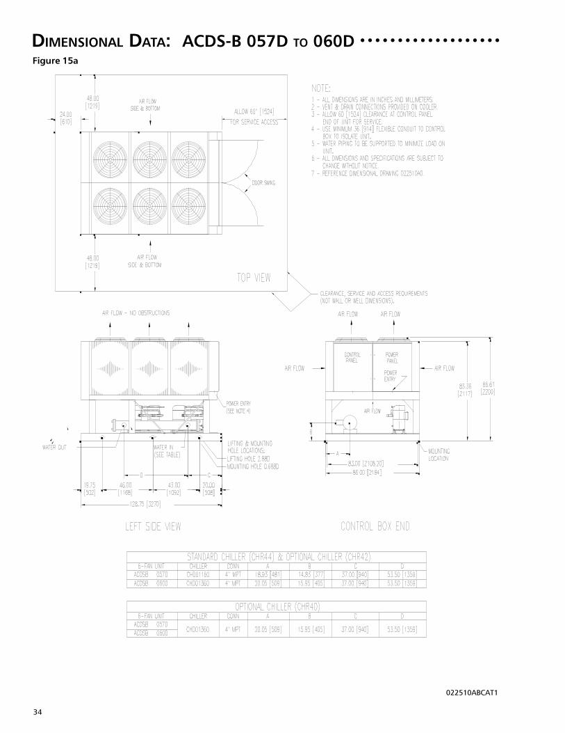
34
Figure 15a
○ ○ ○ ○ ○ ○ ○ ○ ○ ○ ○ ○ ○ ○ ○ ○ ○ ○ ○DIMENSIONAL DATA: ACDS-B 057D TO 060D
022510ABCAT1

35
Figure 15b
DIMENSIONAL DATA: ACDS-B 065D TO 100D
024613AACAT

36
ELECTRICAL DATA:Table 15a
○ ○ ○ ○ ○ ○ ○ ○ ○ ○ ○ ○ ○ ○ ○ ○ ○ ○ ○ ○ ○ ○ ○ ○ ○ ○ ○ ○ ○ ○ ○ ○ ○
NOTES: RLA - Rated Load Amps at ARI Conditions of ServiceMCA - Minimum Circuit AmpacityMFS / HACR - Maximum fuse or HACR breaker size, protective deviceLRA-XL - Locked Rotor Amps Standard Across the Line Starting
*Replace (1) 1.5 HP motor with (1) 1 HP single phase motor per circuit on units with Low Ambient Option
IMPORTANT: See additional notes on page 40.
(60HZ/3PH)
Standard UnitElectrical Data
Each CompressorStandard 1140 RPM
CondenserFan Motors
LRA-XL Qty. HPTotal KW
FLAEach
60 HzNom.Volts
ACDS-B Model RLA MCA
MFS/HACR
Qty./Circuit RLA
AK 208 62 68 90 2 23.8 189 2* 1.5 5.9015S AN 230 62 68 90 2 23.8 189 2* 1.5 2.2 5.9
AR 460 33 36 45 2 12.6 94 2* 1.5 3AS 575 24 26 30 2 9.2 74 2* 1.5 2.1AK 208 82 90 110 2 33.6 278 2* 1.5 5.9
020S AN 230 82 90 110 2 33.6 278 2* 1.5 2.9 5.9AR 460 41 45 60 2 16.5 127 2* 1.5 3AS 575 33 36 45 2 13.7 100 2* 1.5 2.1AK 208 97 107 125 2 41.1 350 2* 1.5 5.9
025S AN 230 97 107 125 2 41.1 350 2* 1.5 2.9 5.9AR 460 51 57 70 2 21.8 158 2* 1.5 3AS 575 40 45 60 2 17.4 125 2* 1.5 2.1AK 208 104 116 150 1/1 41.1/48.1 350/425 2* 1.5 5.9
027S AN 230 104 116 150 1/1 41.1/48.1 350/425 2* 1.5 2.9 5.9AR 460 53 59 80 1/1 21.8/23.8 158/187 2* 1.5 3AS 575 44 49 70 1/1 17.4/21.2 125/148 2* 1.5 2.1AK 208 111 123 150 2 48.1 425 2* 1.5 5.9
030S AN 230 111 123 150 2 48.1 425 2* 1.5 2.9 5.9AR 460 55 61 80 2 23.8 187 2* 1.5 3AS 575 48 53 70 2 21.2 148 2* 1.5 2.1
AK 208 127 133 150 4 25.1 189 4* 1.5 5.9025D AN 230 127 133 150 4 25.1 189 4* 1.5 4.4 5.9
AR 460 68 71 80 4 13.6 94 4* 1.5 3AS 575 50 53 60 4 10.1 74 4* 1.5 2.1AK 208 146 154 175 4 29.9 232 4* 1.5 5.9
030D AN 230 146 153 175 4 29.9 232 4* 1.5 4.4 5.9AR 460 75 79 90 4 15.3 125 4* 1.5 3AS 575 57 60 70 4 11.9 100 4* 1.5 2.1AK 208 158 167 200 2/2 31.1/34.8 232/278 4* 1.5 5.9
035D AN 230 158 167 200 2/2 31.2/34.9 232/278 4* 1.5 4.4 5.9AR 460 80 84 100 2/2 16/17.2 125/127 4* 1.5 3AS 575 63 67 80 2/2 12.3/14.5 100/100 4* 1.5 2.1AK 208 168 179 200 3/1 33.6/41.1 278/350 4* 1.5 5.9
040D AN 230 168 178 200 3/1 33.6/41.1 278/350 4* 1.5 5.8 5.9AR 460 85 90 110 3/1 16.5/21.8 127/158 4* 1.5 3AS 575 69 73 90 3/1 13.8/17.5 100/125 4* 1.5 2.1
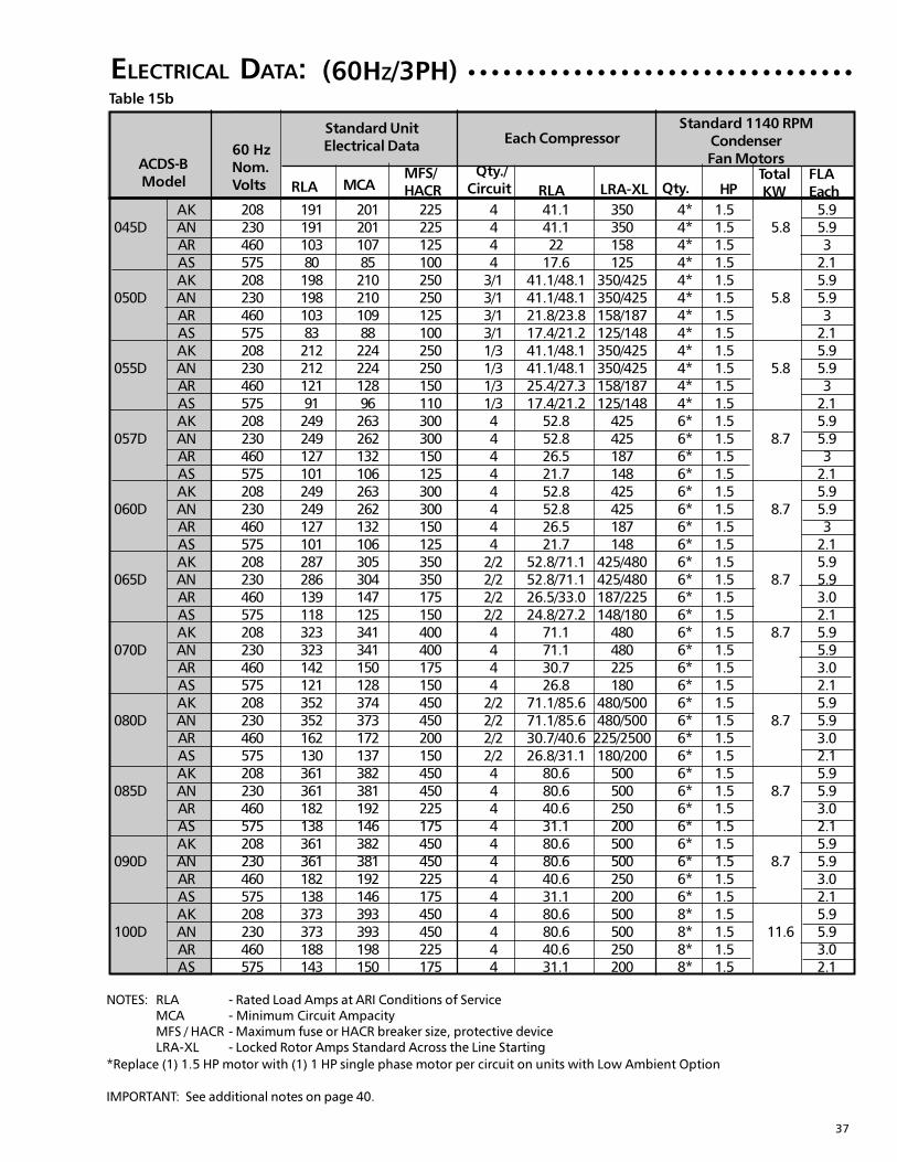
37
ELECTRICAL DATA:Table 15b
○ ○ ○ ○ ○ ○ ○ ○ ○ ○ ○ ○ ○ ○ ○ ○ ○ ○ ○ ○ ○ ○ ○ ○ ○ ○ ○ ○ ○ ○ ○ ○ ○
NOTES: RLA - Rated Load Amps at ARI Conditions of ServiceMCA - Minimum Circuit AmpacityMFS / HACR - Maximum fuse or HACR breaker size, protective deviceLRA-XL - Locked Rotor Amps Standard Across the Line Starting
*Replace (1) 1.5 HP motor with (1) 1 HP single phase motor per circuit on units with Low Ambient Option
IMPORTANT: See additional notes on page 40.
(60HZ/3PH)
Standard UnitElectrical Data
Each CompressorStandard 1140 RPM
CondenserFan Motors
LRA-XL Qty. HPTotal KW
FLAEach
60 HzNom.Volts
ACDS-B Model RLA MCA
MFS/HACR
Qty./Circuit RLA
AK 208 191 201 225 4 41.1 350 4* 1.5 5.9045D AN 230 191 201 225 4 41.1 350 4* 1.5 5.8 5.9
AR 460 103 107 125 4 22 158 4* 1.5 3AS 575 80 85 100 4 17.6 125 4* 1.5 2.1AK 208 198 210 250 3/1 41.1/48.1 350/425 4* 1.5 5.9
050D AN 230 198 210 250 3/1 41.1/48.1 350/425 4* 1.5 5.8 5.9AR 460 103 109 125 3/1 21.8/23.8 158/187 4* 1.5 3AS 575 83 88 100 3/1 17.4/21.2 125/148 4* 1.5 2.1AK 208 212 224 250 1/3 41.1/48.1 350/425 4* 1.5 5.9
055D AN 230 212 224 250 1/3 41.1/48.1 350/425 4* 1.5 5.8 5.9AR 460 121 128 150 1/3 25.4/27.3 158/187 4* 1.5 3AS 575 91 96 110 1/3 17.4/21.2 125/148 4* 1.5 2.1AK 208 249 263 300 4 52.8 425 6* 1.5 5.9
057D AN 230 249 262 300 4 52.8 425 6* 1.5 8.7 5.9AR 460 127 132 150 4 26.5 187 6* 1.5 3AS 575 101 106 125 4 21.7 148 6* 1.5 2.1AK 208 249 263 300 4 52.8 425 6* 1.5 5.9
060D AN 230 249 262 300 4 52.8 425 6* 1.5 8.7 5.9AR 460 127 132 150 4 26.5 187 6* 1.5 3AS 575 101 106 125 4 21.7 148 6* 1.5 2.1AK 208 287 305 350 2/2 52.8/71.1 425/480 6* 1.5 5.9
065D AN 230 286 304 350 2/2 52.8/71.1 425/480 6* 1.5 8.7 5.9AR 460 139 147 175 2/2 26.5/33.0 187/225 6* 1.5 3.0AS 575 118 125 150 2/2 24.8/27.2 148/180 6* 1.5 2.1AK 208 323 341 400 4 71.1 480 6* 1.5 8.7 5.9
070D AN 230 323 341 400 4 71.1 480 6* 1.5 5.9AR 460 142 150 175 4 30.7 225 6* 1.5 3.0AS 575 121 128 150 4 26.8 180 6* 1.5 2.1AK 208 352 374 450 2/2 71.1/85.6 480/500 6* 1.5 5.9
080D AN 230 352 373 450 2/2 71.1/85.6 480/500 6* 1.5 8.7 5.9AR 460 162 172 200 2/2 30.7/40.6 225/2500 6* 1.5 3.0AS 575 130 137 150 2/2 26.8/31.1 180/200 6* 1.5 2.1AK 208 361 382 450 4 80.6 500 6* 1.5 5.9
085D AN 230 361 381 450 4 80.6 500 6* 1.5 8.7 5.9AR 460 182 192 225 4 40.6 250 6* 1.5 3.0AS 575 138 146 175 4 31.1 200 6* 1.5 2.1AK 208 361 382 450 4 80.6 500 6* 1.5 5.9
090D AN 230 361 381 450 4 80.6 500 6* 1.5 8.7 5.9AR 460 182 192 225 4 40.6 250 6* 1.5 3.0AS 575 138 146 175 4 31.1 200 6* 1.5 2.1AK 208 373 393 450 4 80.6 500 8* 1.5 5.9
100D AN 230 373 393 450 4 80.6 500 8* 1.5 11.6 5.9AR 460 188 198 225 4 40.6 250 8* 1.5 3.0AS 575 143 150 175 4 31.1 200 8* 1.5 2.1
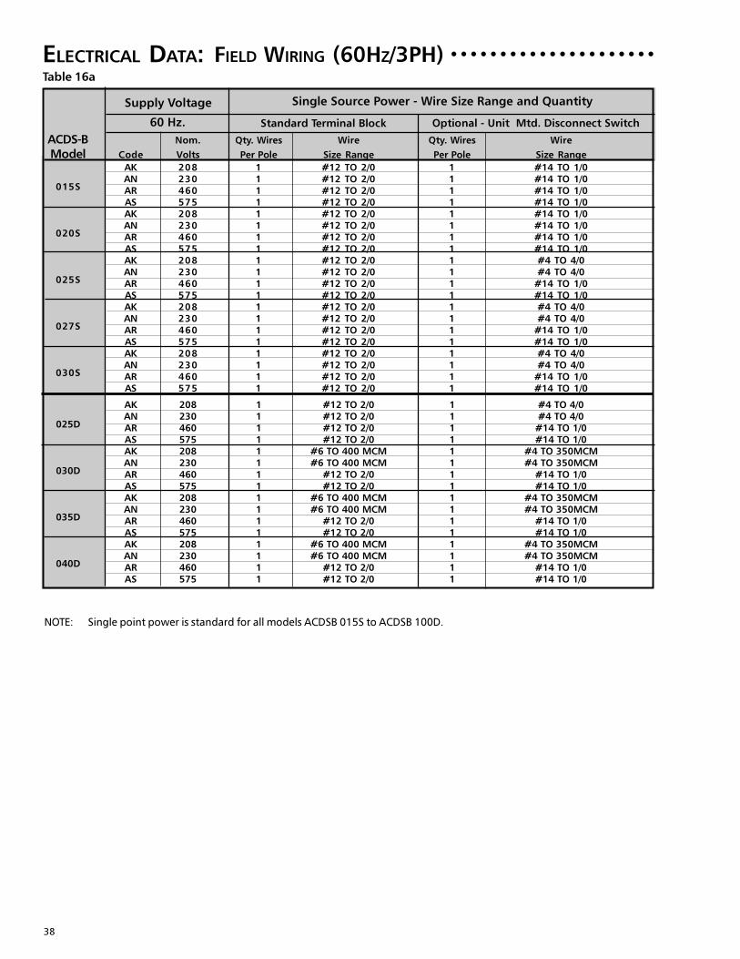
38
ELECTRICAL DATA:
ACDS-B Nom. Qty. Wires Wire Qty. Wires Wire
Model Code Volts Per Pole Size Range Per Pole Size Range
AK 208 1 #12 TO 2/0 1 #14 TO 1/0
015SAN 230 1 #12 TO 2/0 1 #14 TO 1/0AR 460 1 #12 TO 2/0 1 #14 TO 1/0AS 575 1 #12 TO 2/0 1 #14 TO 1/0AK 208 1 #12 TO 2/0 1 #14 TO 1/0
020SAN 230 1 #12 TO 2/0 1 #14 TO 1/0AR 460 1 #12 TO 2/0 1 #14 TO 1/0AS 575 1 #12 TO 2/0 1 #14 TO 1/0AK 208 1 #12 TO 2/0 1 #4 TO 4/0
025SAN 230 1 #12 TO 2/0 1 #4 TO 4/0AR 460 1 #12 TO 2/0 1 #14 TO 1/0AS 575 1 #12 TO 2/0 1 #14 TO 1/0AK 208 1 #12 TO 2/0 1 #4 TO 4/0
027SAN 230 1 #12 TO 2/0 1 #4 TO 4/0AR 460 1 #12 TO 2/0 1 #14 TO 1/0AS 575 1 #12 TO 2/0 1 #14 TO 1/0AK 208 1 #12 TO 2/0 1 #4 TO 4/0
030SAN 230 1 #12 TO 2/0 1 #4 TO 4/0AR 460 1 #12 TO 2/0 1 #14 TO 1/0AS 575 1 #12 TO 2/0 1 #14 TO 1/0
AK 208 1 #12 TO 2/0 1 #4 TO 4/0
025DAN 230 1 #12 TO 2/0 1 #4 TO 4/0AR 460 1 #12 TO 2/0 1 #14 TO 1/0AS 575 1 #12 TO 2/0 1 #14 TO 1/0AK 208 1 #6 TO 400 MCM 1 #4 TO 350MCM
030DAN 230 1 #6 TO 400 MCM 1 #4 TO 350MCMAR 460 1 #12 TO 2/0 1 #14 TO 1/0AS 575 1 #12 TO 2/0 1 #14 TO 1/0AK 208 1 #6 TO 400 MCM 1 #4 TO 350MCM
035DAN 230 1 #6 TO 400 MCM 1 #4 TO 350MCMAR 460 1 #12 TO 2/0 1 #14 TO 1/0AS 575 1 #12 TO 2/0 1 #14 TO 1/0AK 208 1 #6 TO 400 MCM 1 #4 TO 350MCM
040DAN 230 1 #6 TO 400 MCM 1 #4 TO 350MCMAR 460 1 #12 TO 2/0 1 #14 TO 1/0AS 575 1 #12 TO 2/0 1 #14 TO 1/0
○ ○ ○ ○ ○ ○ ○ ○ ○ ○ ○ ○ ○ ○ ○ ○ ○ ○ ○ ○ ○
NOTE: Single point power is standard for all models ACDSB 015S to ACDSB 100D.
FIELD WIRING (60HZ/3PH)
Supply Voltage Single Source Power - Wire Size Range and Quantity
60 Hz. Standard Terminal Block Optional - Unit Mtd. Disconnect Switch
Table 16a
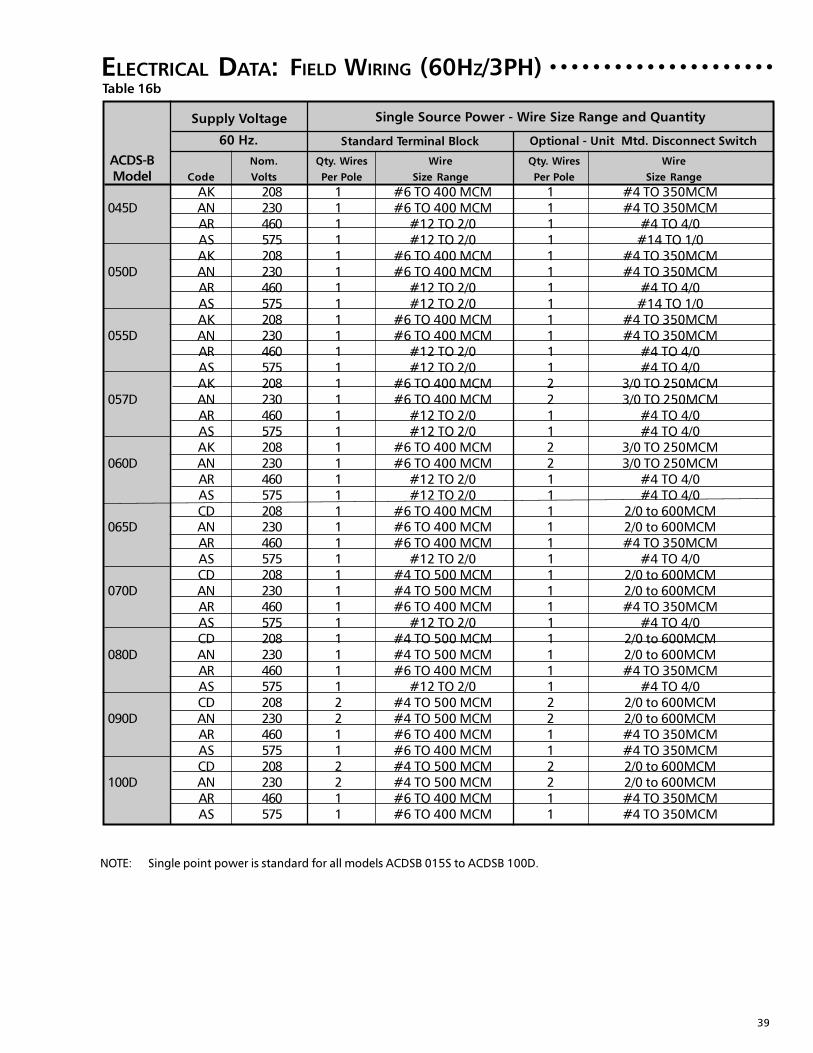
39
ELECTRICAL DATA:
ACDS-B Nom. Qty. Wires Wire Qty. Wires Wire
Model Code Volts Per Pole Size Range Per Pole Size Range
○ ○ ○ ○ ○ ○ ○ ○ ○ ○ ○ ○ ○ ○ ○ ○ ○ ○ ○ ○ ○
NOTE: Single point power is standard for all models ACDSB 015S to ACDSB 100D.
FIELD WIRING (60HZ/3PH)
Supply Voltage Single Source Power - Wire Size Range and Quantity
60 Hz. Standard Terminal Block Optional - Unit Mtd. Disconnect Switch
Table 16b
AK 208 1 #6 TO 400 MCM 1 #4 TO 350MCM045D AN 230 1 #6 TO 400 MCM 1 #4 TO 350MCM
AR 460 1 #12 TO 2/0 1 #4 TO 4/0AS 575 1 #12 TO 2/0 1 #14 TO 1/0AK 208 1 #6 TO 400 MCM 1 #4 TO 350MCM
050D AN 230 1 #6 TO 400 MCM 1 #4 TO 350MCMAR 460 1 #12 TO 2/0 1 #4 TO 4/0AS 575 1 #12 TO 2/0 1 #14 TO 1/0AK 208 1 #6 TO 400 MCM 1 #4 TO 350MCM
055D AN 230 1 #6 TO 400 MCM 1 #4 TO 350MCMAR 460 1 #12 TO 2/0 1 #4 TO 4/0AS 575 1 #12 TO 2/0 1 #4 TO 4/0AK 208 1 #6 TO 400 MCM 2 3/0 TO 250MCM
057D AN 230 1 #6 TO 400 MCM 2 3/0 TO 250MCMAR 460 1 #12 TO 2/0 1 #4 TO 4/0AS 575 1 #12 TO 2/0 1 #4 TO 4/0AK 208 1 #6 TO 400 MCM 2 3/0 TO 250MCM
060D AN 230 1 #6 TO 400 MCM 2 3/0 TO 250MCMAR 460 1 #12 TO 2/0 1 #4 TO 4/0AS 575 1 #12 TO 2/0 1 #4 TO 4/0CD 208 1 #6 TO 400 MCM 1 2/0 to 600MCM
065D AN 230 1 #6 TO 400 MCM 1 2/0 to 600MCMAR 460 1 #6 TO 400 MCM 1 #4 TO 350MCMAS 575 1 #12 TO 2/0 1 #4 TO 4/0CD 208 1 #4 TO 500 MCM 1 2/0 to 600MCM
070D AN 230 1 #4 TO 500 MCM 1 2/0 to 600MCMAR 460 1 #6 TO 400 MCM 1 #4 TO 350MCMAS 575 1 #12 TO 2/0 1 #4 TO 4/0CD 208 1 #4 TO 500 MCM 1 2/0 to 600MCM
080D AN 230 1 #4 TO 500 MCM 1 2/0 to 600MCMAR 460 1 #6 TO 400 MCM 1 #4 TO 350MCMAS 575 1 #12 TO 2/0 1 #4 TO 4/0CD 208 2 #4 TO 500 MCM 2 2/0 to 600MCM
090D AN 230 2 #4 TO 500 MCM 2 2/0 to 600MCMAR 460 1 #6 TO 400 MCM 1 #4 TO 350MCMAS 575 1 #6 TO 400 MCM 1 #4 TO 350MCMCD 208 2 #4 TO 500 MCM 2 2/0 to 600MCM
100D AN 230 2 #4 TO 500 MCM 2 2/0 to 600MCMAR 460 1 #6 TO 400 MCM 1 #4 TO 350MCMAS 575 1 #6 TO 400 MCM 1 #4 TO 350MCM
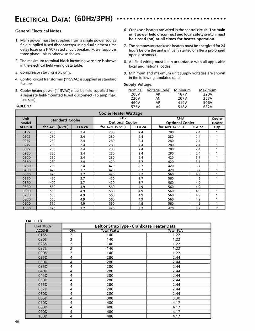
40
ELECTRICAL DATA: ○ ○ ○ ○ ○ ○ ○ ○ ○ ○ ○ ○ ○ ○ ○ ○ ○ ○ ○ ○ ○ ○ ○ ○ ○ ○ ○ ○ ○ ○ ○ ○ ○
General Electrical Notes
1. Main power must be supplied from a single power sourcefield-supplied fused disconnect(s) using dual element timedelay fuses or a HACR rated circuit breaker. Power supply isthree phase unless otherwise shown.
2. The maximum terminal block incoming wire size is shownin the electrical field wiring data table.
3. Compressor starting is XL only.
4. Control circuit transformer (115VAC) is supplied as standardfeature.
5. Cooler heater power (115VAC) must be field-supplied froma separate field-mounted fused disconnect (15 amp max.fuse size).
TABLE 17
(60HZ/3PH)
Nominal Voltage Code Minimum Maximum208V AK 187V 220V230V AN 207V 253V460V AR 414V 506V575V AS 518V 632V
Supply Voltage:
6. Crankcase heaters are wired in the control circuit. The mainunit power field disconnect and local safety switch mustbe closed (on) at all times for heater operation.
7. The compressor crankcase heaters must be energized for 24hours before the unit is initially started or after a prolongedopen disconnect.
8. All field wiring must be in accordance with all applicablelocal and national codes.
9. Minimum and maximum unit supply voltages are shownin the following tabulated data.
TABLE 18
Cooler Heater WattageUnit Cooler
Model HeaterACDS-B for 44°F (6.7°C) FLA ea. for 42°F (5.5°C) FLA ea. for 40°F (4.5°C) FLA ea. Qty.
Standard CoolerCH2
Optional CoolerCH3
Optional Cooler
Unit Model
ACDS-B Qty. Total Watts Total FLABelt or Strap Type - Crankcase Heater Data
015S 2 140 1.22020S 2 140 1.22025S 2 140 1.22027S 2 140 1.22030S 2 140 1.22025D 4 280 2.44030D 4 280 2.44035D 4 280 2.44040D 4 280 2.44045D 4 280 2.44050D 4 280 2.44055D 4 280 2.44057D 4 280 2.44060D 4 280 2.44065D 4 380 3.30070D 4 480 4.17080D 4 480 4.17090D 4 480 4.17100D 4 480 4.17
015S 280 2.4 280 2.4 280 2.4 1
020S 280 2.4 280 2.4 280 2.4 1
025S 280 2.4 280 2.4 280 2.4 1
027S 280 2.4 280 2.4 280 2.4 1
030S 280 2.4 280 2.4 280 2.4 1
025D 280 2.4 280 2.4 280 2.4 1
030D 280 2.4 280 2.4 420 3.7 1
035D 280 2.4 420 3.7 420 3.7 1
040D 280 2.4 420 3.7 420 3.7 1
045D 420 3.7 420 3.7 420 3.7 1
050D 420 3.7 420 3.7 560 4.9 1
055D 420 3.7 420 3.7 560 4.9 1
057D 420 3.7 420 3.7 560 4.9 1
060D 560 4.9 560 4.9 560 4.9 1
065D 560 4.9 560 4.9 560 4.9 1
070D 560 4.9 560 4.9 560 4.9 1
080D 560 4.9 560 4.9 560 4.9 1
090D 560 4.9 560 4.9 560 4.9 1
100D 420 3.7 420 3.7 420 3.7 2
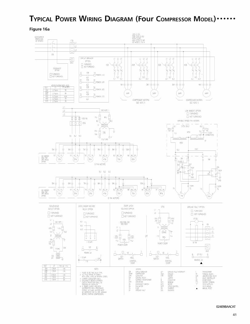
41
Figure 16a
TYPICAL POWER WIRING DIAGRAM (Four COMPRESSOR MODEL) ○ ○ ○ ○ ○ ○
024098AACAT

42
Figure 16b
TYPICAL CONTROL WIRING DIAGRAM (Four COMPRESSOR MODEL) ○ ○ ○ ○
024099ACCAT

43
Figure 16c
TYPICAL CONTROL WIRING DIAGRAM (Four COMPRESSOR MODEL) ○ ○ ○ ○
024099BCCAT
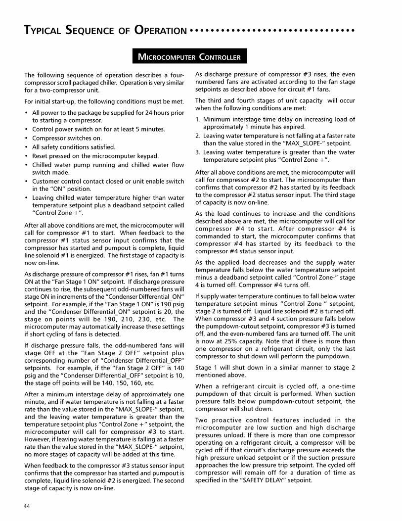
44
TYPICAL SEQUENCE OF OPERATION ○ ○ ○ ○ ○ ○ ○ ○ ○ ○ ○ ○ ○ ○ ○ ○ ○ ○ ○ ○ ○ ○ ○ ○ ○ ○ ○ ○ ○ ○ ○ ○
The following sequence of operation describes a four-compressor scroll packaged chiller. Operation is very similarfor a two-compressor unit.
For initial start-up, the following conditions must be met.
• All power to the package be supplied for 24 hours priorto starting a compressor.
• Control power switch on for at least 5 minutes.
• Compressor switches on.
• All safety conditions satisfied.
• Reset pressed on the microcomputer keypad.
• Chilled water pump running and chilled water flowswitch made.
• Customer control contact closed or unit enable switchin the “ON” position.
• Leaving chilled water temperature higher than watertemperature setpoint plus a deadband setpoint called“Control Zone +”.
After all above conditions are met, the microcomputer willcall for compressor #1 to start. When feedback to thecompressor #1 status sensor input confirms that thecompressor has started and pumpout is complete, liquidline solenoid #1 is energized. The first stage of capacity isnow on-line.
As discharge pressure of compressor #1 rises, fan #1 turnsON at the “Fan Stage 1 ON” setpoint. If discharge pressurecontinues to rise, the subsequent odd-numbered fans willstage ON in increments of the “Condenser Differential_ON”setpoint. For example, if the “Fan Stage 1 ON” is 190 psigand the “Condenser Differential_ON” setpoint is 20, thestage on points will be 190, 210, 230, etc. Themicrocomputer may automatically increase these settingsif short cycling of fans is detected.
If discharge pressure falls, the odd-numbered fans willstage OFF at the “Fan Stage 2 OFF” setpoint pluscorresponding number of “Condenser Differential_OFF”setpoints. For example, if the “Fan Stage 2 OFF” is 140psig and the “Condenser Differential_OFF” setpoint is 10,the stage off points will be 140, 150, 160, etc.
After a minimum interstage delay of approximately oneminute, and if water temperature is not falling at a fasterrate than the value stored in the “MAX_SLOPE-” setpoint,and the leaving water temperature is greater than thetemperature setpoint plus “Control Zone +” setpoint, themicrocomputer will call for compressor #3 to start.However, if leaving water temperature is falling at a fasterrate than the value stored in the “MAX_SLOPE-” setpoint,no more stages of capacity will be added at this time.
When feedback to the compressor #3 status sensor inputconfirms that the compressor has started and pumpout iscomplete, liquid line solenoid #2 is energized. The secondstage of capacity is now on-line.
As discharge pressure of compressor #3 rises, the evennumbered fans are activated according to the fan stagesetpoints as described above for circuit #1 fans.
The third and fourth stages of unit capacity will occurwhen the following conditions are met:
1. Minimum interstage time delay on increasing load ofapproximately 1 minute has expired.
2. Leaving water temperature is not falling at a faster ratethan the value stored in the “MAX_SLOPE-” setpoint.
3. Leaving water temperature is greater than the watertemperature setpoint plus “Control Zone +”.
After all above conditions are met, the microcomputer willcall for compressor #2 to start. The microcomputer thanconfirms that compressor #2 has started by its feedbackto the compressor #2 status sensor input. The third stageof capacity is now on-line.
As the load continues to increase and the conditionsdescribed above are met, the microcomputer will call forcompressor #4 to start. After compressor #4 iscommanded to start, the microcomputer confirms thatcompressor #4 has started by its feedback to thecompressor #4 status sensor input.
As the applied load decreases and the supply watertemperature falls below the water temperature setpointminus a deadband setpoint called “Control Zone-” stage4 is turned off. Compressor #4 turns off.
If supply water temperature continues to fall below watertemperature setpoint minus “Control Zone-” setpoint,stage 2 is turned off. Liquid line solenoid #2 is turned off.When compressor #3 and 4 suction pressure falls belowthe pumpdown-cutout setpoint, compressor #3 is turnedoff, and the even-numbered fans are turned off. The unitis now at 25% capacity. Note that if there is more thanone compressor on a refrigerant circuit, only the lastcompressor to shut down will perform the pumpdown.
Stage 1 will shut down in a similar manner to stage 2mentioned above.
When a refrigerant circuit is cycled off, a one-timepumpdown of that circuit is performed. When suctionpressure falls below pumpdown-cutout setpoint, thecompressor will shut down.
Two proactive control features included in themicrocomputer are low suction and high dischargepressures unload. If there is more than one compressoroperating on a refrigerant circuit, a compressor will becycled off if that circuit’s discharge pressure exceeds thehigh pressure unload setpoint or if the suction pressureapproaches the low pressure trip setpoint. The cycled offcompressor will remain off for a duration of time asspecified in the “SAFETY DELAY” setpoint.
MICROCOMPUTER CONTROLLER
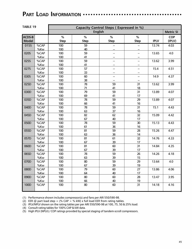
45
PART LOAD INFORMATION ○ ○ ○ ○ ○ ○ ○ ○ ○ ○ ○ ○ ○ ○ ○ ○ ○ ○ ○ ○ ○ ○ ○ ○ ○ ○ ○ ○ ○ ○ ○ ○ ○ ○ ○ ○ ○ ○ ○
TABLE 19
(1) Performance shown includes compressor(s) and fans per ARI 550/590-98.(2) EER @ part load step = (% CAP ÷ % kW) x full load EER from rating tables.(3) IPLV/NPLV shown on the rating tables per per ARI 550/590-98 at 100, 75, 50 & 25% load.(4) Consult rating tables for 100% CAP & kW data.(5) High IPLV (NPLV) / COP ratings provided by special staging of tandem-scroll compressors.
% % % % COPStep Step Step Step IPLV (IPLV)
English Metric SI
Capacity Control Steps ( Expressed in %)
ACDS-B Model
015S %CAP 100 59 -- -- 13.74 4.03
%Kw 100 40 -- --
020S %CAP 100 59 -- -- 13.65 4.0
%Kw 100 41 -- --
025S %CAP 100 59 -- -- 13.62 3.99
%Kw 100 41 -- --
027S %CAP 100 57 -- -- 15.4 4.51
%Kw 100 33 -- --
030S %CAP 100 60 -- -- 14.9 4.37
%Kw 100 38 -- --
025D %CAP 100 78 59 31 13.62 3.99
%Kw 100 71 41 18
030D %CAP 100 79 59 31 13.89 4.07
%Kw 100 69 41 17
035D %CAP 100 78 59 29 13.89 4.07
%Kw 100 66 41 16
040D %CAP 100 78 59 31 15.1 4.43
%Kw 100 63 37 16
045D %CAP 100 82 62 32 15.09 4.42
%Kw 100 67 40 17
050D %CAP 100 78 59 30 15.13 4.43
%Kw 100 61 36 16
055D %CAP 100 81 59 28 15.26 4.47
%Kw 100 63 36 14
057D %CAP 100 81 61 32 14.76 4.33
%Kw 100 67 39 17
060D %CAP 100 81 60 31 14.84 4.35
%Kw 100 67 39 17
065D %CAP 100 78 59 26 14.26 4.18
%Kw 100 63 39 15
070D %CAP 100 80 59 29 13.64 4.0
%Kw 100 67 39 19
080D %CAP 100 79 60 27 13.86 4.06
%Kw 100 64 40 17
090D %CAP 100 80 60 28 13.47 3.95
%Kw 100 66 40 19
100D %CAP 100 80 60 31 14.18 4.16
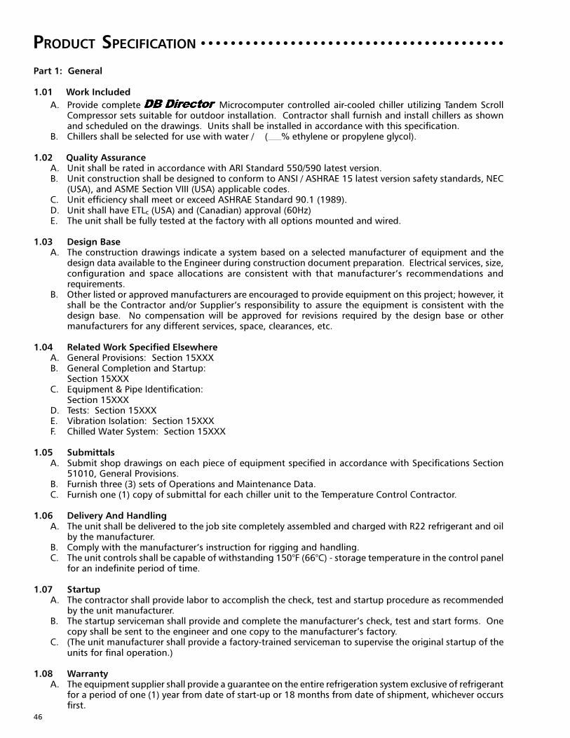
46
PRODUCT SPECIFICATION
Part 1: General
1.01 Work Included
A. Provide complete Microcomputer controlled air-cooled chiller utilizing Tandem ScrollCompressor sets suitable for outdoor installation. Contractor shall furnish and install chillers as shownand scheduled on the drawings. Units shall be installed in accordance with this specification.
B. Chillers shall be selected for use with water / ( % ethylene or propylene glycol).
1.02 Quality AssuranceA. Unit shall be rated in accordance with ARI Standard 550/590 latest version.B. Unit construction shall be designed to conform to ANSI / ASHRAE 15 latest version safety standards, NEC
(USA), and ASME Section VIII (USA) applicable codes.C. Unit efficiency shall meet or exceed ASHRAE Standard 90.1 (1989).D. Unit shall have ETLc (USA) and (Canadian) approval (60Hz)E. The unit shall be fully tested at the factory with all options mounted and wired.
1.03 Design BaseA. The construction drawings indicate a system based on a selected manufacturer of equipment and the
design data available to the Engineer during construction document preparation. Electrical services, size,configuration and space allocations are consistent with that manufacturer’s recommendations andrequirements.
B. Other listed or approved manufacturers are encouraged to provide equipment on this project; however, itshall be the Contractor and/or Supplier’s responsibility to assure the equipment is consistent with thedesign base. No compensation will be approved for revisions required by the design base or othermanufacturers for any different services, space, clearances, etc.
1.04 Related Work Specified ElsewhereA. General Provisions: Section 15XXXB. General Completion and Startup:
Section 15XXXC. Equipment & Pipe Identification:
Section 15XXXD. Tests: Section 15XXXE. Vibration Isolation: Section 15XXXF. Chilled Water System: Section 15XXX
1.05 SubmittalsA. Submit shop drawings on each piece of equipment specified in accordance with Specifications Section
51010, General Provisions.B. Furnish three (3) sets of Operations and Maintenance Data.C. Furnish one (1) copy of submittal for each chiller unit to the Temperature Control Contractor.
1.06 Delivery And HandlingA. The unit shall be delivered to the job site completely assembled and charged with R22 refrigerant and oil
by the manufacturer.B. Comply with the manufacturer’s instruction for rigging and handling.C. The unit controls shall be capable of withstanding 150°F (66°C) - storage temperature in the control panel
for an indefinite period of time.
1.07 StartupA. The contractor shall provide labor to accomplish the check, test and startup procedure as recommended
by the unit manufacturer.B. The startup serviceman shall provide and complete the manufacturer’s check, test and start forms. One
copy shall be sent to the engineer and one copy to the manufacturer’s factory.C. (The unit manufacturer shall provide a factory-trained serviceman to supervise the original startup of the
units for final operation.)
1.08 WarrantyA. The equipment supplier shall provide a guarantee on the entire refrigeration system exclusive of refrigerant
for a period of one (1) year from date of start-up or 18 months from date of shipment, whichever occursfirst.
○ ○ ○ ○ ○ ○ ○ ○ ○ ○ ○ ○ ○ ○ ○ ○ ○ ○ ○ ○ ○ ○ ○ ○ ○ ○ ○ ○ ○ ○ ○ ○ ○ ○ ○ ○ ○ ○ ○ ○ ○

47
B. The start-up date shall be certified by the Mechanical Contractor, and provided to the Manufacturer,Engineer and Owner.
C. (Provide an optional extended four (4)-year warranty on the compressors only, 5 years total).D. (During the warranty period, the equipment supplier shall furnish the services of an authorized service
agency for all labor associated with parts replacement or repair, and start-up of the refrigeration equipmentat the beginning of each cooling season. The equipment supplier shall also furnish the services of anauthorized service agent for one maintenance visit during winter months of operation, such times shall bedesignated by the Owner.)
1.09 MaintenanceMaintenance of the chillers shall be the responsibility of the owner and performed in accordance with themanufacturer’s instructions.
Part 2: Products
2.01 Tandem Scroll Compressor Air Cooled Water Chillers
2.02 Acceptable ManufacturersA. Dunham-Bush, Inc.B. (Approved equal)
2.03 GeneralA. Furnish and install as shown on the plans, air-cooled Tandem Scroll Compressor water chillers. Units shall
be Dunham-Bush Model ACDS-B or equal.B. The units are to be completely factory assembled and wired in a single package complete with Tandem
Scroll Compressors, evaporator, condenser, starting control with safety and operating controls. The unitis to be given a complete factory operating and control sequence test under load conditions and is to beshipped with full operating charge of R-22 and full oil charge.
C. The units shall be built in accordance with all applicable national and local codes including the ANSI safetycode; the National Electrical Code and applicable ASME Code for Unfired Pressure Vessels.
2.04 PerformanceThe units shall be furnished as shown on capacity schedules and drawings. Unit performance shall be in accordancewith ARI Standard 550/590.
2.05 ConstructionThe unit will be designed for maximum corrosion protection being of heavy gauge, UL90 approved galvanizedsteel construction. The base and legs shall be manufactured of 10 gauge galvanized steel channel. Frame membersare constructed of 12 gauge, galvanized steel.
2.06 EvaporatorEvaporator shall be direct expansion, shell and tube type. The shell shall be fabricated from carbon steel, withenhanced inner fin construction inside seamless copper tubes. The tube sheets shall be heavy gauge copper inwelded head vessels. The tubes shall be brazed into the tubesheets. Water control baffles shall be copper. Theheads shall be constructed of carbon steel. Evaporators shall be designed, constructed and inspected to complywith current ASME code for unfired pressure vessels. Shell side (water) design working pressure shall be minimum200 PSIG and tube side (refrigerant) design working pressure shall be minimum 300 PSIG. A thermostaticallycontrolled electric resistance heater cable shall be wrapped around the shell to prevent freezing down to -20°F(-28.9°C) outdoor temperature.
2.07 CondenserThe condenser coil is to be constructed of copper tubes and die formed aluminum fins having self-spacing collars.Fins shall be mechanically bonded to the tubes. An integral sub-cooling loop shall be incorporated into the coil.Condenser divider baffles shall fully separate each condenser fan section to control the airflow to maintain properhead pressure control.
2.08 FansThe fans shall be heavy duty, aluminum blade, direct drive propeller type. Motors shall be three phase (except forlow ambient option lead fan per circuit) with internal overloads and are to be permanently lubricated.
2.09 CompressorA. The compressors shall be Tandem Scroll with suction and discharge manifolded and oil and gas equalization
provided. All compressors shall be 3500 RPM direct drive with an integral two-pole hermetic squirrel cagemotor. A dust-proof terminal box, located in an accessible location on the compressor, shall contain allconnection terminals.

48
B. The compressors shall be fitted with a crankcase heater, large suction filter, oil sight glass, oil strainer andmagnetic crankcase plug. The lubrication system shall be centrifugal forced feed type with external oilequalization.
C. To maximize reliability, the compressors shall utilize across-the-line start and, to limit start-up currentdraw, be limited to a maximum of 15 HP with a time delay between compressor starts.
2.10 Capacity ControlCompressor cycling shall be utilized to match the demand requirement of the system. A Proactive Full Function
Microcomputer Controller shall cycle compressors in response to leaving water temperature andmaintain water temperature within 3.0°F (1.67°C) of setpoint. This system is to provide precise and stable controlof supply water temperature over the complete range of operating conditions. It shall be capable of a systemcapacity range from 100% to % at specified conditions without hot gas bypass.
2.11 Refrigerant CircuitA. (Two compressors) (Four compressors) shall be used with a direct expansion evaporator.B. The packaged chiller shall have no more than two compressors per refrigerant circuit.C. The packaged chiller shall use HCFC-22 refrigerant, a positive pressure refrigerant that will not require a
purge system and is recommended by the Montreal Protocol as an environmentally safe refrigerant.D. Insulate evaporator and other cold surfaces as required to prevent condensation at ambient conditions of
75% humidity of 90°F (32°C) wet bulb with no air movement.E. Each refrigerant circuit shall include expansion valve, sight glass, moisture indicator, solenoid valve,
replaceable core filter-drier, liquid line shut off valves, charging and gauge connections.
2.12 Control CenterA. Control Center shall be fully enclosed in a steel, baked powder coated, control panel with hinged access
doors. Dual compartments, separating safety and operating controls from the power controls, are to beprovided. Controls shall include: 1. Compressor protection, solid state, thermal sensing overloads, with manual reset 2. High refrigerant discharge pressure, manual reset 3. Separate power terminal blocks for main power and 115vAC chiller heater power 4. Compressor starter including current sensing overload protection 5. Proactive Full Function PC Windows® Based Microcomputer Controller with factory installed
sensors including integral anti-recycle protection 6. Complete labeling of all control components 7. Numbered terminal strips and labeled components for easier wire tracing 8. Condenser pressure sensing fan cycling control for start-up and operation down to 30°F (-1.1°C). 9. (Undervoltage and phase failure protection against low voltage, phase imbalance or phase reversal).10. (Operating and safety lights visible from unit exterior including:)
a. Control Power onb. High pressure, high motor temperature and general alarm
11. (Control panel solenoid door latch to prevent door opening before turning off power to the unit).12. (Electronic expansion valves which shall be controlled by the microcomputer.)
B. Control Center’s individual Full Function Microcomputer shall provide compressor stagingbased on leaving water temperature. It shall have two lines of 16 large characters each Alpha-NumericLiquid Crystal display, and the inputs shall be through a 16 single function keypad through the menudriven prompts. The displayed data shall be updated once per second and the microcomputer shall havea Non-Volatile memory used for all control information. The microcomputer shall have an extendedoperating range of -20°F to +158°F (-29°C to +70°C). (It shall be proactive in control and accommodatesystem anomalies such as high condenser pressure and high entering water temperature by controllingloading and refrigerant flow to keep the machine on line but at reduced capacity until the condition iscorrected.)
C. Microcomputer individual chiller controller shall provide as a minimum the following features and options.1. Microcomputer - Unit Control shall provide the following capabilities:
a. Staging of compressors and hot gas bypass to achieve precise control of leaving liquidb. Activating fans of the air-cooled package to control head pressurec. 7 day time clock with schedules for machine controld. Automatic pump down before compressor shuts down and automatic pump out before liquid
line opens on start-up.e. Proactive control of compressor cycling and /or hot gas bypass to help prevent high pressure or
low pressure trips

49
f. Proactive control providing safeties for high pressure, low pressure and freeze protection, toeliminate nuisance trips
g. Proactive compressor staging to eliminate overloading during start-up to reduce compressor cyclingh. Continuous evaluation of sensorsi. (Control of Hot Gas bypass)
2. Microcomputer - Unit Protection shall provide the following:a. Low pressure cutout with Proactive safetyb. High pressure cutout with Proactive safetyc. Automatic re-start from power outage with event postingd. Battery backed-up real time clock and memory with over 10 years life and automatic recharge of
lithium ion battery that requires no service.e. Safeties for temporary shutdown as well as lockout protection that requires manual resetf. Freeze protection on leaving chilled water temperatureg. Anti-recycle timingh. Sensor errori. Pump down - pump out failurej. (Chilled water pump control system)
3. Microcomputer - Readouts shall provide the following:a. Sensor inputsb. Leaving liquid temperaturec. Entering liquid temperatured. Compressor ampere drawe. Suction pressure each circuitf. Discharge pressure each refrigerant circuitg. Unit control contactsh. Water flow switchi. Chilled liquid resetj. Digital Outputsk. Compressor control statusl. Liquid line solenoid control statusm. Condenser fan control statusn. Alarm control statuso. (Hot gas bypass status)p. (Ambient temperature)q. (Utility demand limit)r. (Chilled water pump control)s. (Electronic expansion valve)
4. Microcomputer - Setpoints shall provide the following with proper authorization):a. High discharge pressureb. Low suction pressurec. Freeze protect temperatured. Leaving liquid temperaturee. Control zone settingsf. Fan condenser controlg. Pump down - pump out settingsh. (High & low compressor amperes)i. Low suction circuit limitingj. High discharge circuit limitingk. Anti-recycle delay setting
5. Microcomputer - Alarm History shall provide the following:a. The 32 most recent alarms can be identifiedb. Low suction pressure of all circuitsc. High discharge pressure of all circuitsd. Freeze protection cutoute. Pump down - pump out failure of all circuitsf. External shutdown of each compressorg. Communication failureh. Battery failurei. Time/date invalidj. Memory failurek. Power failure
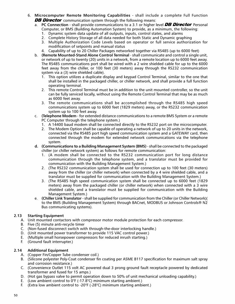
50
6. Microcomputer Remote Monitoring Capabilities - shall include a complete Full Function
communication system through the following means:a. PC Connection - shall provide communications to a 3.1 or higher level Personal
Computer, or BMS (Building Automation System) to provide, as a minimum, the following:1. Dynamic system data update of all outputs, inputs, control states, and alarms2. Complete History Storage of all data needed for both Static and Dynamic graphing3. Multiple Authorization Code Levels based on operator or full service authorization for
modification of setpoints and manual status4. Capability of up to 20 Chiller Packages networked together via RS485 (up to 6000 feet)
b. (Remote Mounted-Stand Alone Control Terminal - shall communicate and control a single unit,or network of up to twenty (20) units in a network, from a remote location up to 6000 feet away.The RS485 communications port shall be wired with a 2 wire shielded cable for up to the 6000feet away from the chiller, or 100 feet (30 meters) away through the RS232 communicationsystem via a (3) wire shielded cable).1. This option utilizes a duplicate display and keypad Control Terminal, similar to the one that
shall be installed in the packaged chiller, or chiller network, and shall provide a full functionoperating terminal.
2. This remote Control Terminal must be in addition to the unit mounted controller, so the unitcan be fully serviced locally, without using the Remote Control Terminal that may be as muchas 6000 feet away.
3. The remote communications shall be accomplished through the RS485 high speedcommunications system up to 6000 feet (1829 meters) away, or the RS232 communicationsystem up to 100 feet away.
c. (Telephone Modem - for extended distance communications to a remote BMS System or a remotePC Computer through the telephone system.)1. A 14400 baud modem shall be connected directly to the RS232 port on the microcomputer.2. The Modem Option shall be capable of operating a network of up to 20 units in the network,
connected via the RS485 port high speed communication system and a GATEWAY card, thenconnected through the modem for extended network communications via the telephonesystem.
d. (Communications to a Building Management System (BMS) - shall be connected to the packagedchiller (or chiller network system) as follows for remote communication:1. (A modem shall be connected to the RS232 communication port for long distance
communication through the telephone system, and a translator must be provided forcommunication with the Building Management System.)
2. (The RS232 communication system shall be used for connection up to 100 feet (30 meters)away from the chiller (or chiller network) when connected by a 4 wire shielded cable, and atranslator must be supplied for communication with the Building Management System.)
3. (The RS485 high speed communication system shall be connected up to 6000 feet (1829meters) away from the packaged chiller (or chiller network) when connected with a 3 wireshielded cable, and a translator must be supplied for communication with the BuildingManagement System.)
e. (Chiller Link Translator - shall be supplied for communication from the Chiller (or Chiller Network)(to the BMS (Building Management System) through BACnet, MODBUS or Johnson Controls® N2Bus communicating systems).
2.13 Starting EquipmentA. Unit mounted contactors with compressor motor module protection for each compressor.B. Five (5) minute anti-recycle timerC. (Non-fused disconnect switch with through-the-door interlocking handle.)D. (Unit mounted power transformer to provide 115 VAC control power.)E. (Multiple small horsepower compressors for reduced inrush starting.)F. (Ground fault interrupter.)
2.14 Additional EquipmentA. (Copper Fin/Copper Tube condenser coil.)B. (Silicone polyester Poly-Coat condenser fin coating per ASME B117 specification for maximum salt spray
and corrosion resistance.)C. (Convenience Outlet 115 volt AC powered dual 3 prong ground fault receptacle powered by dedicated
transformer and fused for 15 amps.)D. (Hot gas bypass valve to permit operation down to 50% of unit mechanical unloading capability.)E. (Low ambient control to 0°F (-17.8°C) minimum starting ambient.)F. (Extra low ambient control to -20°F (-28°C) minimum starting ambient.)

51
G. (Low ambient lock-out control requiring a field setpoint.)H. (Gauges include suction and discharge pressure for each refrigerant circuit in addition to the readings
through the microcomputer.)I. (Steel Painted Louvers for complete unit enclosure for general mechanical security and unit aesthetics.)J. (Aluminum Painted Grills similar to louvers except manufactured or aluminum with 3/8" x 3 1/2" slots
instead of louvers for hail damage protection and unit aesthetics.)K. (Fin Guards Top only (1" x 4" wire mesh) for vertical side condenser coil protection.)L. (Fin Guards Bottom only (1" x 4" wire mesh) for general unit mechanical security for the lower portion of
the unit.)M. (Over and under voltage protection relay protects against high and low incoming voltage conditions as
well as single phasing, phase reversal and phase imbalance.)N. (Circuit Breakers to provide compressor branch circuit protection.)O. (Weatherproof Alarm Bell mounted and wired to indicate a common alarm fault.)P. (Fully Painted Unit meets the requirements for outdoor unit application of 500 Hour Salt Spray Paint
tested in accordance with ASTM-B-117.)Q. (Suction Line Insulation for medium and low temperature applications, or where the relative humidity is
above 75% with ambient temperature of 90°F (32°C) wet bulb.)R. (Chilled Water Pump Control providing a contact closure for pump starting prior to starting the chiller.)S. (Mounted and Wired Water Flow Switch)T. (Auxiliary Control Module providing return water (fluid) temperature monitoring, utility demand limiting
(requires an external 0 to 5 volt DC signal), load limiting by compressor over current protection, andcompressor amperage monitoring/limiting.)
Part 3: Execution
3.01 Installation Work By Mechanical ContractorA. Install on a flat surface level within 1/16 inch and of sufficient strength to support concentrated loading.
Place vibration isolators under the unit.B. Assemble and install all components furnished loose by manufacturer as recommended by the
manufacturer’s literature.C. Complete all water and electrical connections so unit, water circuits and electrical circuits are serviceable.D. Provide and install valves in water piping upstream and downstream of the evaporator to provide means
of isolating shells for maintenance and to balance and trim system.E. Provide soft sound and vibration eliminator connections to the cooler water inlet and outlet as well as
electrical connections to the unit.F. Interlock chillers through a flow switch in the chilled water line to the chilled water pump to ensure the
unit can operate only when water flow is established.G. Furnish and install taps for thermometers and pressure gauges in water piping adjacent to inlet and outlet
connections of the evaporator.H. Provide and install drain valves with capped hose ends to each water box.I. Install vent cocks to each water box.J. Provide a separate 115 volt electrical service to power the cooler heater for winter freeze protection.
3.02 Work By Temperature Control ContractorA. Furnish interlock wiring per manufacturer’s recommendations and install loose control components
furnished by chiller manufacturer.
3.03 Work By Electrical ContractorA. Furnish power wiring to chiller control panel and obtain required code approval.B. Furnish and install approved disconnect switch and short circuit protection and short circuit protection.
END OF SECTION
Specifications subject to change without notice
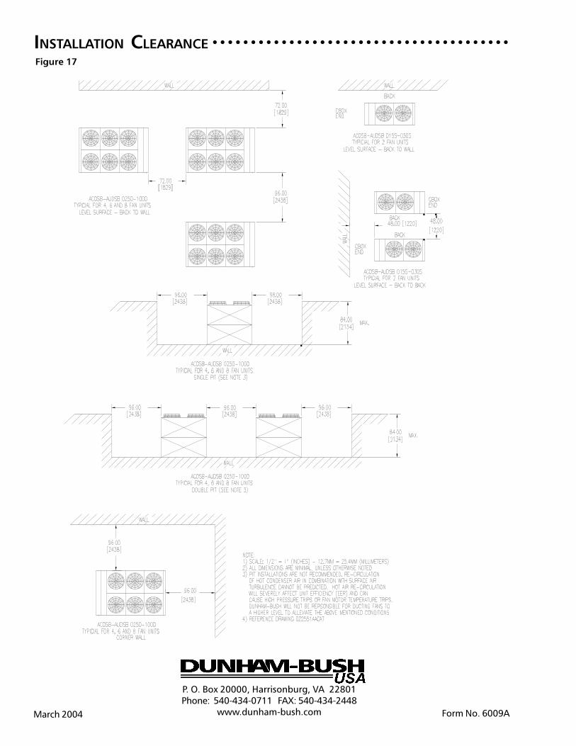
52
INSTALLATION CLEARANCE○ ○ ○ ○ ○ ○ ○ ○ ○ ○ ○ ○ ○ ○ ○ ○ ○ ○ ○ ○ ○ ○ ○ ○ ○ ○ ○ ○ ○ ○ ○ ○ ○ ○ ○ ○ ○ ○ ○
P. O. Box 20000, Harrisonburg, VA 22801Phone: 540-434-0711 FAX: 540-434-2448
www.dunham-bush.com Form No. 6009AMarch 2004
Figure 17