air conditioners lcs13dc -...
TRANSCRIPT

A I R C O N D I T I O N E R S
LCS13DCDRY CHARGE UNITS
Bulletin No. 210636 May 2014
Supersedes March 2012
1.5 to 5 Tons
L C S 13 DC - 036 - 230 - 2
Lennox®
Single Stage
Air Conditioner
Nominal Cooling Capacity 018 = 1.5 tons 024 = 2 tons 030 = 2.5 tons 036 = 3 tons 042 = 3.5 tons 048 = 4 tons 060 = 5 tons
Minor Revision Number
Voltage 230 = 208/230V-1phase-60hz
Nominal SEER
Dry Charge Unit
MODEL NUMBER IDENTIFICATION
P R O D U C T S P E C I F I C AT I O N S

LCS13DC - 1.5 to 5 Ton Air Conditioner / Page 2
EQUIPMENT WARRANTY
Compressor - Limited warranty for five years in residential installations and one year in non-residential installations.
All other covered components - Limited five years in residential installations and one year in non-residential installations.Refer to Lennox Equipment Limited Warranty certificate included with unit for specific details.
APPROVALSAHRI Certified to AHRI Standard 210/240-2008.Sound rated in Lennox reverberant sound test room in Accordance with test conditions included in AHRI Standard 270-2008.Tested in the Lennox Research Laboratory environmental test room.Rated According to U.S. Department of Energy (DOE) test procedures.Units and components within bonded for grounding to meet safety standards for servicing required by UL, NEC and CEC.Units are UL/ULC listed and CSA certified.ISO 9001 Registered Manufacturing Quality System.
APPLICATIONSNitrogen (dry) charged for replacement of R-22 components only.1.5 through 5 ton.Single-phase power supply.Sound levels as low as 76 dB.Vertical air discharge allows concealment behind shrubs at grade level or out of sight on a roof.Units shipped completely factory assembled, piped and wired. Each unit test operated at the factory ensuring proper operation.Installer must set air conditioner, connect refrigerant lines and make electrical connections to complete job.
REFRIGERATION SYSTEMCondenser FanDirect drive fan moves large air volumes uniformly through entire condenser coil for high refrigerant cooling capacity.Vertical air discharge minimizes operating sounds and eliminates damage to lawn and shrubs.Fan motor has sleeve bearings and is inherently protected.Motor totally enclosed for maximum protection from weather, dust and corrosion.Rain shield on motor provides additional protection from moisture.Louvered steel top fan guard furnished as standard.Fan service access accomplished by removal of top panel.
Copper Tube/Enhanced Fin CoilLennox designed and fabricated coil.Ripple-edged aluminum fins.Copper tube construction.Lanced fins provide maximum exposure of fin surface to air stream resulting in excellent heat transfer.Fin collars grip tubing for maximum contact area.Flared shoulder tubing connections/silver soldering construction.Coil is factory tested under high pressure to ensure leakproof construction.Entire coil is accessible for cleaning.
A
B
C
FEATURES
B
C
F
D
G
ECONTENTSDimensions .................................................................. 6Electrical Data.............................................................. 5Features....................................................................... 2Field Wiring .................................................................. 7Installation Clearances ................................................ 7Model Number Identification ........................................ 1Optional Accessories ................................................... 5Sound Data ................................................................. 7Specifications............................................................... 5
LCS13DC - 1.5 to 5 Ton Air Conditioner / Page 3
REFRIGERATION SYSTEM (continued)
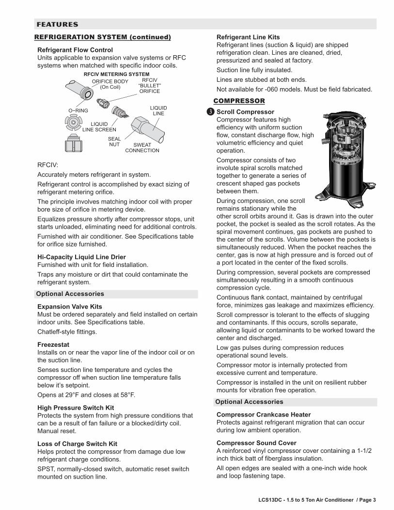
Refrigerant Flow ControlUnits applicable to expansion valve systems or RFC systems when matched with specific indoor coils.
O−RING
RFCIV METERING SYSTEMRFCIV
ORIFICE
ORIFICE BODY(On Coil)
SEALNUT SWEAT
CONNECTION
LIQUIDLINE
LIQUIDLINE SCREEN
RFCIV:Accurately meters refrigerant in system.Refrigerant control is accomplished by exact sizing of refrigerant metering orifice.The principle involves matching indoor coil with proper bore size of orifice in metering device.Equalizes pressure shortly after compressor stops, unit starts unloaded, eliminating need for additional controls.Furnished with air conditioner. See Specifications table for orifice size furnished.
Hi-Capacity Liquid Line DrierFurnished with unit for field installation.Traps any moisture or dirt that could contaminate the refrigerant system.
Optional Accessories
Expansion Valve KitsMust be ordered separately and field installed on certain indoor units. See Specifications table.Chatleff-style fittings.
FreezestatInstalls on or near the vapor line of the indoor coil or on the suction line.Senses suction line temperature and cycles the compressor off when suction line temperature falls below it’s setpoint.Opens at 29°F and closes at 58°F.
High Pressure Switch KitProtects the system from high pressure conditions that can be a result of fan failure or a blocked/dirty coil. Manual reset.
Loss of Charge Switch KitHelps protect the compressor from damage due low refrigerant charge conditions.SPST, normally-closed switch, automatic reset switch mounted on suction line.
Refrigerant Line KitsRefrigerant lines (suction & liquid) are shipped refrigeration clean. Lines are cleaned, dried, pressurized and sealed at factory.Suction line fully insulated.Lines are stubbed at both ends.Not available for -060 models. Must be field fabricated.
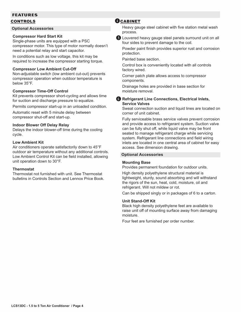
COMPRESSORScroll CompressorCompressor features high efficiency with uniform suction flow, constant discharge flow, high volumetric efficiency and quiet operation.Compressor consists of two involute spiral scrolls matched together to generate a series of crescent shaped gas pockets between them.During compression, one scroll remains stationary while the other scroll orbits around it. Gas is drawn into the outer pocket, the pocket is sealed as the scroll rotates. As the spiral movement continues, gas pockets are pushed to the center of the scrolls. Volume between the pockets is simultaneously reduced. When the pocket reaches the center, gas is now at high pressure and is forced out of a port located in the center of the fixed scrolls.During compression, several pockets are compressed simultaneously resulting in a smooth continuous compression cycle.Continuous flank contact, maintained by centrifugal force, minimizes gas leakage and maximizes efficiency.Scroll compressor is tolerant to the effects of slugging and contaminants. If this occurs, scrolls separate, allowing liquid or contaminants to be worked toward the center and discharged.Low gas pulses during compression reduces operational sound levels.Compressor motor is internally protected from excessive current and temperature.Compressor is installed in the unit on resilient rubber mounts for vibration free operation.
Optional Accessories
Compressor Crankcase HeaterProtects against refrigerant migration that can occur during low ambient operation.
Compressor Sound CoverA reinforced vinyl compressor cover containing a 1-1/2 inch thick batt of fiberglass insulation.All open edges are sealed with a one-inch wide hook and loop fastening tape.
D
FEATURES
LCS13DC - 1.5 to 5 Ton Air Conditioner / Page 4
CONTROLS
Optional Accessories
Compressor Hard Start KitSingle-phase units are equipped with a PSC compressor motor. This type of motor normally doesn’t need a potential relay and start capacitor. In conditions such as low voltage, this kit may be required to increase the compressor starting torque.
Compressor Low Ambient Cut-OffNon-adjustable switch (low ambient cut-out) prevents compressor operation when outdoor temperature is below 35°F.
Compressor Time-Off ControlKit prevents compressor short-cycling and allows time for suction and discharge pressure to equalize.Permits compressor start-up in an unloaded condition.Automatic reset with 5 minute delay between compressor shut-off and start-up.
Indoor Blower Off Delay RelayDelays the indoor blower-off time during the cooling cycle.
Low Ambient KitAir conditioners operate satisfactorily down to 45°F outdoor air temperature without any additional controls. Low Ambient Control Kit can be field installed, allowing unit operation down to 30°F.
ThermostatThermostat not furnished with unit. See Thermostat bulletins in Controls Section and Lennox Price Book.
CABINETHeavy gauge steel cabinet with five station metal wash process.Louvered heavy gauge steel panels surround unit on all four sides to prevent damage to the coil.Powder paint finish provides superior rust and corrosion protection.Painted base section.Control box is conveniently located with all controls factory wired.Corner patch plate allows access to compressor components.Drainage holes are provided in base section for moisture removal.
Refrigerant Line Connections, Electrical Inlets, Service ValvesSweat connection suction and liquid lines are located on corner of unit cabinet.Fully serviceable brass service valves prevent corrosion and provide access to refrigerant system. Suction valve can be fully shut off, while liquid valve may be front seated to manage refrigerant charge while servicing system. Refrigerant line connections and field wiring inlets are located in one central area of cabinet for easy access. See dimension drawing.
Optional Accessories
Mounting BaseProvides permanent foundation for outdoor units.High density polyethylene structural material is lightweight, sturdy, sound absorbing and will withstand the rigors of the sun, heat, cold, moisture, oil and refrigerant. Will not mildew or rot.Can be shipped singly or in packages of 6 to a carton.
Unit Stand-Off KitBlack high density polyethylene feet are available to raise unit off of mounting surface away from damaging moisture.Four feet are furnished per order number.
E
F
G
FEATURES
LCS13DC - 1.5 to 5 Ton Air Conditioner / Page 5
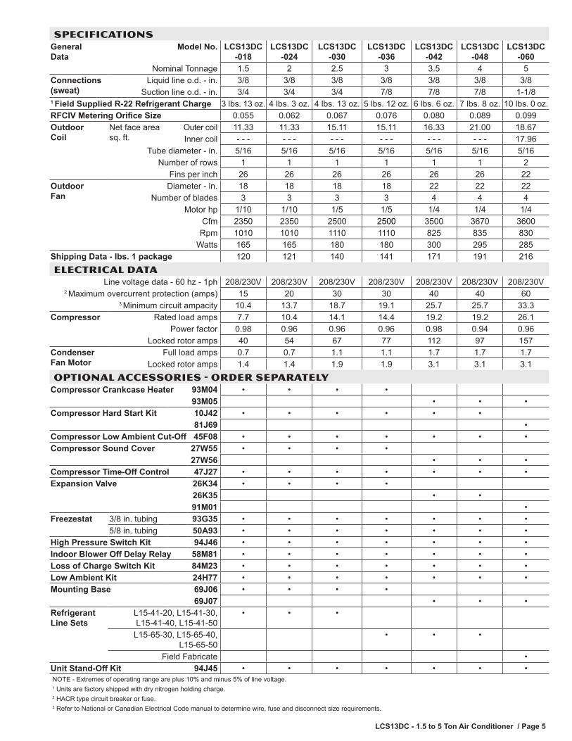
SPECIFICATIONSGeneral Data
Model No. LCS13DC -018
LCS13DC -024
LCS13DC -030
LCS13DC -036
LCS13DC -042
LCS13DC -048
LCS13DC -060
Nominal Tonnage 1.5 2 2.5 3 3.5 4 5Connections (sweat)
Liquid line o.d. - in. 3/8 3/8 3/8 3/8 3/8 3/8 3/8Suction line o.d. - in. 3/4 3/4 3/4 7/8 7/8 7/8 1-1/8
1 Field Supplied R-22 Refrigerant Charge 3 lbs. 13 oz. 4 lbs. 3 oz. 4 lbs. 13 oz. 5 lbs. 12 oz. 6 lbs. 6 oz. 7 lbs. 8 oz. 10 lbs. 0 oz.RFCIV Metering Orifice Size 0.055 0.062 0.067 0.076 0.080 0.089 0.099Outdoor Coil
Net face area sq. ft.
Outer coil 11.33 11.33 15.11 15.11 16.33 21.00 18.67Inner coil - - - - - - - - - - - - - - - - - - 17.96
Tube diameter - in. 5/16 5/16 5/16 5/16 5/16 5/16 5/16Number of rows 1 1 1 1 1 1 2
Fins per inch 26 26 26 26 26 26 22Outdoor Fan
Diameter - in. 18 18 18 18 22 22 22Number of blades 3 3 3 3 4 4 4
Motor hp 1/10 1/10 1/5 1/5 1/4 1/4 1/4Cfm 2350 2350 2500 2500 3500 3670 3600
Rpm 1010 1010 1110 1110 825 835 830Watts 165 165 180 180 300 295 285
Shipping Data - lbs. 1 package 120 121 140 141 171 191 216ELECTRICAL DATA
Line voltage data - 60 hz - 1ph 208/230V 208/230V 208/230V 208/230V 208/230V 208/230V 208/230V2 Maximum overcurrent protection (amps) 15 20 30 30 40 40 60
3 Minimum circuit ampacity 10.4 13.7 18.7 19.1 25.7 25.7 33.3Compressor Rated load amps 7.7 10.4 14.1 14.4 19.2 19.2 26.1
Power factor 0.98 0.96 0.96 0.96 0.98 0.94 0.96Locked rotor amps 40 54 67 77 112 97 157
Condenser Fan Motor
Full load amps 0.7 0.7 1.1 1.1 1.7 1.7 1.7Locked rotor amps 1.4 1.4 1.9 1.9 3.1 3.1 3.1
OPTIONAL ACCESSORIES - ORDER SEPARATELYCompressor Crankcase Heater 93M04 • • • •
93M05 • • •Compressor Hard Start Kit 10J42 • • • • • •
81J69 •Compressor Low Ambient Cut-Off 45F08 • • • • • • •Compressor Sound Cover 27W55 • • • •
27W56 • • •Compressor Time-Off Control 47J27 • • • • • • •Expansion Valve 26K34 • • • •
26K35 • •91M01 •
Freezestat 3/8 in. tubing 93G35 • • • • • • •5/8 in. tubing 50A93 • • • • • • •
High Pressure Switch Kit 94J46 • • • • • • •Indoor Blower Off Delay Relay 58M81 • • • • • • •Loss of Charge Switch Kit 84M23 • • • • • • •Low Ambient Kit 24H77 • • • • • • •Mounting Base 69J06 • • • •
69J07 • • •Refrigerant Line Sets
L15-41-20, L15-41-30, L15-41-40, L15-41-50
• • •
L15-65-30, L15-65-40, L15-65-50
• • •
Field Fabricate •Unit Stand-Off Kit 94J45 • • • • • • •NOTE - Extremes of operating range are plus 10% and minus 5% of line voltage.1 Units are factory shipped with dry nitrogen holding charge.2 HACR type circuit breaker or fuse.3 Refer to National or Canadian Electrical Code manual to determine wire, fuse and disconnect size requirements.
LCS13DC - 1.5 to 5 Ton Air Conditioner / Page 6
SUCTION AND
C
SIDE VIEW
DISCHARGE AIR
SIDE VIEW
A
B
A
LIQUID LINECONNECTION
OUTDOORCOIL FAN
COMPRESSOR
OPTIONAL UNITSTANDOFF KIT (4)(FIELD INSTALLED)
4-3/8
INLET
AIR
INLET
AIR
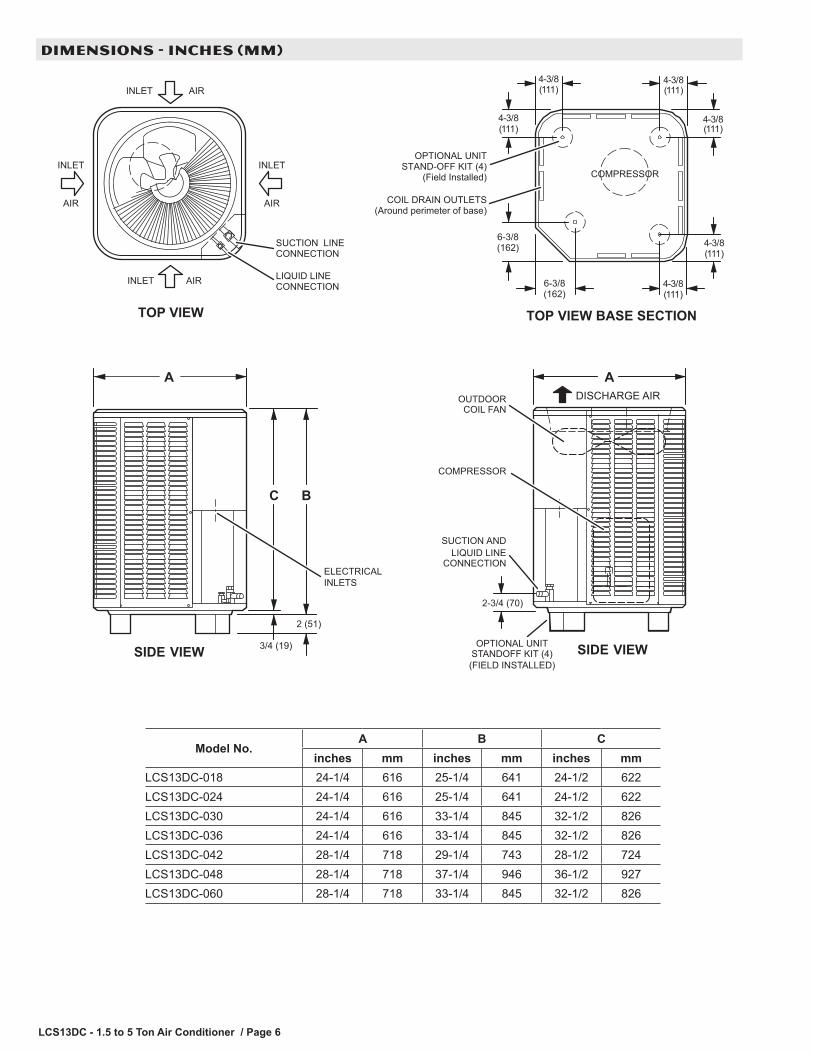
TOP VIEW
INLET AIR
INLET AIR
SUCTION LINECONNECTION
LIQUID LINECONNECTION 6-3/8
(162)
TOP VIEW BASE SECTION
COMPRESSOR
COIL DRAIN OUTLETS(Around perimeter of base)
OPTIONAL UNITSTAND-OFF KIT (4)
(Field Installed)
(111)
4-3/84-3/8
4-3/8 4-3/8
6-3/8(162)
(111) (111)
(111) (111)
4-3/8(111)
2 (51)
3/4 (19)
2-3/4 (70)
ELECTRICALINLETS
Model No.A B C
inches mm inches mm inches mmLCS13DC-018 24-1/4 616 25-1/4 641 24-1/2 622LCS13DC-024 24-1/4 616 25-1/4 641 24-1/2 622LCS13DC-030 24-1/4 616 33-1/4 845 32-1/2 826LCS13DC-036 24-1/4 616 33-1/4 845 32-1/2 826LCS13DC-042 28-1/4 718 29-1/4 743 28-1/2 724LCS13DC-048 28-1/4 718 37-1/4 946 36-1/2 927LCS13DC-060 28-1/4 718 33-1/4 845 32-1/2 826
DIMENSIONS - INCHES (MM)

LCS13DC - 1.5 to 5 Ton Air Conditioner / Page 7
B
DISCONNECTSWITCH
(By Others)
LENNOXAIR
CONDITIONER
LENNOXHEATING UNIT
ORAIR HANDLER
UNIT
DISCONNECTSWITCH
(By Others)THERMOSTAT
(Optional)
C
DA
SeeNOTES
See NOTES
See NOTES
SeeNOTES
CONTROLBOX
A - Two Wire PowerB - Two Wire Power (See Electrical Data)C - Two Wire Low Voltage (18 ga. minimum)D - Four Wire Low Voltage (Electro-Mechanical) 18 ga. mini-
mum. ..... Five Wire Low Voltage (Electronic) 18 ga. minimum
NOTE - Field Wiring Not FurnishedAll wiring must conform to NEC or CEC and local electrical codes.
NOTES:Service clearance of 30 in. (762 mm) must be maintained on
one of the sides adjacent to the control box.Clearance to one of the other three sides must be 36 in. (914
mm)Clearance to one of the remaining two sides may be 12 in. (305
mm) and the final side may be 6 in. (152 mm).A clearance of 24 in. must be maintained between two units.48 in. (1219 mm) clearance required on top of unit.
SOUND DATA 1 Unit
Model No.Octave Band Linear Sound Power Levels dB, re 10-12 WattsCenter Frequency - HZ 1 Sound Rating
Number (dB)125 250 500 1000 2000 4000 8000LCS13DC-018 70.5 70.5 69 68.5 66 60.5 55.5 76LCS13DC-024 71 67 70 69 68.5 61.5 56.5 76LCS13DC-030 68.5 67.5 69 72 68 62 59 76LCS13DC-036 70.5 67.5 69.5 72.5 69.5 63 59 76LCS13DC-042 73.5 73 75 74 72 68 63.5 79LCS13DC-048 73.5 76 76 76.5 72.5 69.5 64.5 79LCS13DC-060 73.5 74.5 77 75 72 69 64.5 79NOTE - the octave sound power data does not include tonal correction.1 Tested according to AHRI Standard 270-2008 test conditions.
FIELD WIRING INSTALLATION CLEARANCES - IN. (MM)
NOTE - Due to Lennox’ ongoing commitment to quality, Specifications, Ratings and Dimensions subject to change without notice and without incurring liability. Improper installation, adjustment, alteration, service or maintenance can cause property damage or personal injury. Installation and service must be performed by a qualified installer and servicing agency. ©2014 Lennox Industries, Inc.
Visit us at www.lennox.com
For the latest technical information, www.lennoxdavenet.com
Contact us at 1-800-4-LENNOX
REVISIONSSections Description of Change
Refrigeration System Filter/Drier now shipped with unit for field installation.