air conditioner - samsunghvac.com...... lightning rod or telephone grounding. ... according to the...
TRANSCRIPT
DVM SAM✴✴✴FXVAF✴ SeriesAM✴✴✴FXVAJ✴ SeriesAM✴✴✴HXVAF✴ SeriesAM✴✴✴HXVAJ✴ SeriesAM✴✴✴KXVTF✴ SeriesAM✴✴✴KXVTJ✴ SeriesAM✴✴✴KXVGJ✴ Series
Air Conditionerinstallation manual
imagine the possibilitiesThank you for purchasing this Samsung product.
2
ContentsSafety precautions . . . . . . . . . . . . . . . . . . . . . . . . . . . . . . . . . . . . . . . . . . . . . . . . . . . . . . . . . . . . . . . . . . . . . . . . . . . . . . . . . . . . . . . . . . . . . . . . . . . . . . . 3Preparing for installation . . . . . . . . . . . . . . . . . . . . . . . . . . . . . . . . . . . . . . . . . . . . . . . . . . . . . . . . . . . . . . . . . . . . . . . . . . . . . . . . . . . . . . . . . . . . . . . . . 6Selecting installation location . . . . . . . . . . . . . . . . . . . . . . . . . . . . . . . . . . . . . . . . . . . . . . . . . . . . . . . . . . . . . . . . . . . . . . . . . . . . . . . . . . . . . . . . . . . 11Space requirement for installation . . . . . . . . . . . . . . . . . . . . . . . . . . . . . . . . . . . . . . . . . . . . . . . . . . . . . . . . . . . . . . . . . . . . . . . . . . . . . . . . . . . . . . 13Accessories . . . . . . . . . . . . . . . . . . . . . . . . . . . . . . . . . . . . . . . . . . . . . . . . . . . . . . . . . . . . . . . . . . . . . . . . . . . . . . . . . . . . . . . . . . . . . . . . . . . . . . . . . . . . . 15Base construction and installation of the outdoor unit . . . . . . . . . . . . . . . . . . . . . . . . . . . . . . . . . . . . . . . . . . . . . . . . . . . . . . . . . . . . . . . . . . . 17Installing the wind/snow prevention duct . . . . . . . . . . . . . . . . . . . . . . . . . . . . . . . . . . . . . . . . . . . . . . . . . . . . . . . . . . . . . . . . . . . . . . . . . . . . . . . 22Refrigerant pipe installation . . . . . . . . . . . . . . . . . . . . . . . . . . . . . . . . . . . . . . . . . . . . . . . . . . . . . . . . . . . . . . . . . . . . . . . . . . . . . . . . . . . . . . . . . . . . . 24Electrical wiring work . . . . . . . . . . . . . . . . . . . . . . . . . . . . . . . . . . . . . . . . . . . . . . . . . . . . . . . . . . . . . . . . . . . . . . . . . . . . . . . . . . . . . . . . . . . . . . . . . . . 56Air tightness test and vacuum drying . . . . . . . . . . . . . . . . . . . . . . . . . . . . . . . . . . . . . . . . . . . . . . . . . . . . . . . . . . . . . . . . . . . . . . . . . . . . . . . . . . . 71Pipe insulation . . . . . . . . . . . . . . . . . . . . . . . . . . . . . . . . . . . . . . . . . . . . . . . . . . . . . . . . . . . . . . . . . . . . . . . . . . . . . . . . . . . . . . . . . . . . . . . . . . . . . . . . . . 73Charging additional refrigerant . . . . . . . . . . . . . . . . . . . . . . . . . . . . . . . . . . . . . . . . . . . . . . . . . . . . . . . . . . . . . . . . . . . . . . . . . . . . . . . . . . . . . . . . . 77Basic segment display . . . . . . . . . . . . . . . . . . . . . . . . . . . . . . . . . . . . . . . . . . . . . . . . . . . . . . . . . . . . . . . . . . . . . . . . . . . . . . . . . . . . . . . . . . . . . . . . . . 79Setting outdoor unit option switch and key function . . . . . . . . . . . . . . . . . . . . . . . . . . . . . . . . . . . . . . . . . . . . . . . . . . . . . . . . . . . . . . . . . . . . 79Things to check after completing the installation . . . . . . . . . . . . . . . . . . . . . . . . . . . . . . . . . . . . . . . . . . . . . . . . . . . . . . . . . . . . . . . . . . . . . . . . 88Inspection and trial operation . . . . . . . . . . . . . . . . . . . . . . . . . . . . . . . . . . . . . . . . . . . . . . . . . . . . . . . . . . . . . . . . . . . . . . . . . . . . . . . . . . . . . . . . . . . 90Automatic refrigerant amount detection function . . . . . . . . . . . . . . . . . . . . . . . . . . . . . . . . . . . . . . . . . . . . . . . . . . . . . . . . . . . . . . . . . . . . . . . 94

3
ENGLISH
Safety precautions WARNING
State of California Proposition 65 Warning (US only)This product contains chemicals known to the State of California to cause cancer and birth defects or other reproductive harm.Please follow the following safety information for safety of the installer and the user.
❋ DVM S air conditioner uses R-410A refrigerant. • When using R-410A, moisture or foreign substances may affect the performance and reliability of the product.
Safety precautions must be obeyed when installing the refrigerant pipe.• The designed maximum pressure of the system is 4.1MPa(594.6 psi) and therefore select appropriate material and
thickness according to the regulations.• R-410A is a quasi-azeotrope of two refrigerants and it has to be charged in liquid phase when filling the refrigerant.
(If you charge vapor refrigerant, it may change the blend of the refrigerant and cause product malfunction.) ❋ You must connect the indoor units for R-410A refrigerant. Refer to product catalog to find out the models names
for connectable indoor units. (If you connect the indoor units that are not designed for R-410A, it cannot operated normally.)
❋ After completing the installation and trial operation, explain to the user how to use and maintain the product. Also, hand over this installation manual so that it can be stored by the user.
❋ Manufacturer is not responsible for the incidents occurred by improper installation. Installer is responsible for any installation related claims from the user occurred by neglecting warnings and cautions stated in this manual. (Installer will be responsible for any service charges that may occur)
❋ Generally, system air conditioners should not be relocated after installation. But when it has to be relocated for inevitable reasons, please contact Samsung’s qualified dealers for system air conditioners.
WARNING • Hazards or unsafe practices that may result in severe personal injury or death.
CAUTION • Hazards or unsafe practices that may result in minor personal injury (to installer/user) or property damage.
SEVERE WARNING SIGNS
Consult qualified installer or dealer for installation.When installation is done by unqualified person, problems such as water leakage, electric shock or fire may occur.
Installation work must be done properly according to this installation manual.When installation is not done properly, it may cause water leakage, electric shock or fire.
When installing the unit in a small room, take measure to keep the refrigerant concentration from exceeding allowable safety limits in case of refrigerant leakage. Consult the dealer for precautionary measure before the installation.
When refrigerant leaks and exceed dangerous concentration level, it may cause suffocation accidents.
If any gas or impurities, except R-410A refrigerant, come into the refrigerant pipe, serious problem may occur and it may cause injury.
Use the supplied accessories, specified components and tools for the installation.Do not use the pipe and the installation product used for the R-22 refrigerant.Failure to use the specified components can cause product fall down, water leakage, electrical shock, and fire. (The pipe and flare components used for R-22 refrigerant must not be used)
Install the outdoor unit on a hard and even place that can support its weight.If the place cannot support its weight, the outdoor unit may fall down and it may cause injury.
4
Safety precautionsCheck the following before installation and service work.
Before welding, remove dangerous and inflammable things that may cause an explosion and fire around the work.Before welding, remove the refrigerant from inside the pipe or the product. - If you perform welding while refrigerant is in the pipe, it may increase the pressure of the refrigerant and cause the pipe
to burst. If the pipe bursts or explodes, it may cause severe injury to the installer. When welding, use the nitrogen gas to eliminate oxidation inside the pipe.
Do not modify the product on your own.Potential risk of electric shock, fire, product failure or injury.
Fix the outdoor unit securely on foundation to resist strong wind or earthquake.If the outdoor unit is not properly fixed, it turns over and accidents may occur.
Electric work must be done by qualified persons, complying the national wiring regulations and installed according to the instruction stated in the installation manual with leased circuit.
Capacity shortage on the leased circuit and improper installation may cause electric shock or fire.
Make sure to perform grounding work.Do not connect the ground wire to a gas pipe, water pipe, lightning rod or telephone grounding. Improper grounding could cause electric shock.
Wiring must be connected with the designated wires and it must be fixed securely so that it does not apply any external force to the connection part of the terminals.
If connection for fixation is not properly done, it may cause heat generation or fire.
Neatly arrange the wires in the electrical parts to make sure that electrical cover is closed securely without any gaps.If the cover is not properly closed, heat may generate on the electrical terminal and cause electric shock or fire.
Exclusive circuit breaker (MCCB, ELB) must be installed to the power supply.When overcurrent or current leakage occurs with no circuit breaker installed, power will not be cut-off and it may cause electric shock or fire.Do not use damaged parts. It may cause fire or electric shock.
You must cut-off the power before you work on, or adjust any power supply part for product installation, maintenance, repair or any other services.
There is risk of electric shock. Even when the power is off, it is dangerous when you come in contact with inverter PCB, fan PCB since high pressure DC voltage is charged to those parts.When replacing/repairing the PCB, cut-off the power and wait until the DC voltage is discharged before replacing/repairing them. (Wait for more than 15 minutes to allow it to discharge naturally.)
If the refrigerant gas leaks during the installation, you should ventilate the room.When the refrigerant gas gets in contact with flammable substance, it may generate toxic gas.
Gas leakage must be checked after installation is completed.When the refrigerant gas gets in contact with flammable substance, it may generate toxic gas.
You can get a frostbite if you get in contact with the leaked refrigerant gas.
Supply power to the product during winter time since the product will operate in protection mode itself when the temperature decrease below 0°C(32°F).
If you cut-off the power, compressor protection mode cannot be operated and may cause damage to the product.
5
ENGLISH
CAUTION SIGNS
Do not install the drain pipe directly to the bottom part of the outdoor unit and built a proper drainage so that water drains out smoothly. If not, pipe may freeze or bursts during winter time and cause damage to the product or water leakage.
When the draining work is not done properly, water leak may occur and cause property damage.
Install the power cable and communication cable of the indoor and outdoor unit at least 1.5m(4.92ft) away from the electric appliances and install it at least 2m(6.56ft) away from the lightning conductor.
Noise may be generated from the electronic devices, depending on the status of the electric wave.
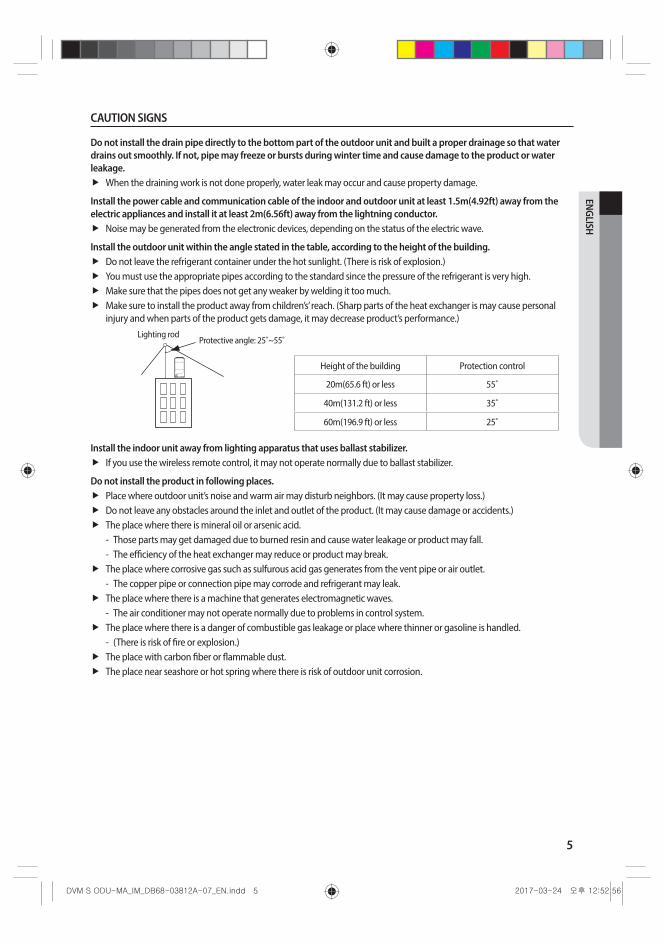
Install the outdoor unit within the angle stated in the table, according to the height of the building.Do not leave the refrigerant container under the hot sunlight. (There is risk of explosion.)You must use the appropriate pipes according to the standard since the pressure of the refrigerant is very high.Make sure that the pipes does not get any weaker by welding it too much.Make sure to install the product away from children’s’ reach. (Sharp parts of the heat exchanger is may cause personal injury and when parts of the product gets damage, it may decrease product’s performance.)
Lighting rodProtective angle: 25˚~55˚
Height of the building Protection control
20m(65.6 ft) or less 55˚
40m(131.2 ft) or less 35˚
60m(196.9 ft) or less 25˚
Install the indoor unit away from lighting apparatus that uses ballast stabilizer.If you use the wireless remote control, it may not operate normally due to ballast stabilizer.
Do not install the product in following places.Place where outdoor unit’s noise and warm air may disturb neighbors. (It may cause property loss.)Do not leave any obstacles around the inlet and outlet of the product. (It may cause damage or accidents.)The place where there is mineral oil or arsenic acid. - Those parts may get damaged due to burned resin and cause water leakage or product may fall. - The efficiency of the heat exchanger may reduce or product may break.
The place where corrosive gas such as sulfurous acid gas generates from the vent pipe or air outlet. - The copper pipe or connection pipe may corrode and refrigerant may leak.
The place where there is a machine that generates electromagnetic waves. - The air conditioner may not operate normally due to problems in control system.
The place where there is a danger of combustible gas leakage or place where thinner or gasoline is handled. - (There is risk of fire or explosion.)
The place with carbon fiber or flammable dust.The place near seashore or hot spring where there is risk of outdoor unit corrosion.

6
Safety precautionsChanges in DVM S (inverter) compare to conventional models that has to noted when installing
For optimal distribution of the refrigerant, you must use Y-joint as branch joint for connecting outdoor units. (Do not use T-joint)You cannot operate normally if you do not complete the trial operation through outdoor unit key mode. You must use KEY MODE to run trial operation.DVM S air conditioner uses R-410A refrigerant.Check the compatibility of other products such as indoor unit, EEV kits etc. which will be connected to DVM S.Make sure to note that outdoor unit combination is different from DVM PLUS III and IV.The length of maximum piping, level difference, the quantity of connectable indoor units, the installation at the outdoor joints and the outdoor unit combinations are different from the conventional models.If the pipe length is over 2m(6.56ft) between outdoor units, make traps to prevent oil stagnation. Oil stagnation may occur when outdoor unit at the end of module stops while other outdoor units are still in operation.
Preparing for installation
Outdoor unit classification
Classification Small type Large A type Large B type
Appearance
Models
AM✴✴✴F✴ Series AM072✴✴✴ AM096/120/144✴✴✴
AM✴✴✴H✴ Series AM168/192✴✴✴
AM✴✴✴K✴ Series AM072/096✴✴✴ AM216KXVGJH
Packaging material disposition• Safely store or dispose the packaging materials.
- Sharp metals such as nails or wooden material packaging that may break into pieces become a cause for personal injury.
- Make sure to store or dispose the vinyl type packaging material to keep it out of reach of children. Children may put them over their face, which is very dangerous since it may lead them to suffocation.
CAUTION

7
ENGLISH
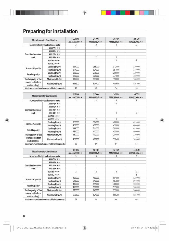
Preparing for installation
Outdoor unit combinationMake sure to use an indoor unit that is compatible with DVM S.Indoor units can be connected within the range indicated in following table.If the total capacity of the connected indoor units exceeds the indicated maximum capacity, cooling and heating capacity of the indoor unit may decrease.Total capacity of the connected indoor units can be allowed from 50% to 130% of the total outdoor unit capacity. 0.5 × Σ(Outdoor unit capacity) ≤ Total capacity of the connected indoor units ≤ 1.3 × Σ(Outdoor unit capacity)
❋ You can connect maximum 64 indoor units to the outdoor unit. Maximum quantity of connectable indoor unit is set to 64 since outdoor unit only support up to 64 communication address. Indoor unit address can be assigned from 0~63. If the indoor unit address was assigned from 64~79, E201 error will occur.
❋ Maximum 32 Wall-mount type indoor units with EEV (AM✴✴✴HNQDC✴) can be connected.
• Use the following table to determine the size and number of outdoor units needed to achieve the capacity requirements.CAUTION
Module combination for AM✴✴✴F✴ Series, AM✴✴✴H✴ Series
Model name for Combination6TON 8TON 10TON 12TON
AM072FXVA✴✴ AM096FXVA✴✴ AM120FXVA✴✴ AM144FXVA✴✴
Number of individual outdoor units 1 1 1 1
Combined outdoor unit
AM072✴✴✴ 1AM096✴✴✴ 1AM120✴✴✴ 1AM144✴✴✴ 1AM168✴✴✴
AM192✴✴✴
Nominal CapacityCooling(btu/h) 72000 96000 120000 144000Heating(btu/h) 81000 108000 135000 162000
Rated CapacityCooling(btu/h) 69000 92000 114000 138000Heating(btu/h) 77000 103000 129000 154000
Total capacity of the connected indoor units
(cooling)
Minimum(btu/h) 36000 48000 60000 72000
Maximum(btu/h) 93600 124800 156000 187200
Maximum number of connectable indoor units 12 16 20 25
Model name for Combination14TON 16TON 18TON 20TON
AM168HXVA✴✴ AM192HXVA✴✴ AM216JXVA✴✴ AM240JXVA✴✴
Number of individual outdoor units 1 1 2 2
Combined outdoor unit
AM072✴✴✴ 1 1AM096✴✴✴
AM120✴✴✴
AM144✴✴✴ 1AM168✴✴✴ 1 1AM192✴✴✴ 1
Nominal CapacityCooling(btu/h) 168000 192000 216000 240000Heating(btu/h) 189000 216000 243000 270000
Rated CapacityCooling(btu/h) 160000 184000 206000 228000Heating(btu/h) 180000 206000 230000 258000
Total capacity of the connected indoor
units(cooling)
Minimum(btu/h) 84000 96000 108000 120000
Maximum(btu/h) 218400 249600 280800 312000
Maximum number of connectable indoor units 29 33 37 41
8
Preparing for installationModel name for Combination
22TON 24TON 26TON 28TONAM264JXVA✴✴ AM288JXVA✴✴ AM312JXVA✴✴ AM336JXVA✴✴
Number of individual outdoor units 2 2 2 2
Combined outdoor unit
AM072✴✴✴ 1AM096✴✴✴
AM120✴✴✴
AM144✴✴✴ 2 1AM168✴✴✴ 1 2AM192✴✴✴ 1
Nominal CapacityCooling(btu/h) 264000 288000 312000 336000Heating(btu/h) 297000 324000 351000 378000
Rated CapacityCooling(btu/h) 252000 276000 298000 320000Heating(btu/h) 282000 308000 334000 360000
Total capacity of the connected indoor
units(cooling)
Minimum(btu/h) 132000 144000 156000 168000
Maximum(btu/h) 343200 374400 405600 436800
Maximum number of connectable indoor units 45 49 54 58
Model name for Combination30TON 32TON 34TON 36TON
AM360JXVA✴✴ AM384JXVA✴✴ AM408JXVA✴✴ AM432JXVA✴✴
Number of individual outdoor units 2 2 3 3
Combined outdoor unit
AM072✴✴✴ 1AM096✴✴✴
AM120✴✴✴
AM144✴✴✴ 1 3AM168✴✴✴ 1AM192✴✴✴ 1 2 1
Nominal CapacityCooling(btu/h) 360000 384000 408000 432000Heating(btu/h) 405000 432000 459000 486000
Rated CapacityCooling(btu/h) 344000 366000 390000 415000Heating(btu/h) 386000 410000 435000 460000
Total capacity of the connected indoor
units(cooling)
Minimum(btu/h) 180000 192000 204000 216000
Maximum(btu/h) 468000 499200 530400 561600
Maximum number of connectable indoor units 62 64 64 64
Model name for Combination38 TON 40 TON 42 TON 44 TON
AM456JXVA✴✴ AM480JXVA✴✴ AM504JXVA✴✴ AM528JXVA✴✴
Number of individual outdoor units 3 3 3 3
Combined outdoor unit
AM072✴✴✴
AM096✴✴✴
AM120✴✴✴ 1AM144✴✴✴ 1AM168✴✴✴ 2 2 3 2AM192✴✴✴ 1
Nominal CapacityCooling(btu/h) 456000 480000 504000 528000Heating(btu/h) 513000 540000 567000 594000
Rated CapacityCooling(btu/h) 435000 455000 480000 500000Heating(btu/h) 490000 510000 535000 560000
Total capacity of the connected indoor
units(cooling)
Minimum(btu/h) 228000 240000 252000 264000
Maximum(btu/h) 592800 624000 655200 686400
Maximum number of connectable indoor units 64 64 64 64
9
ENGLISH
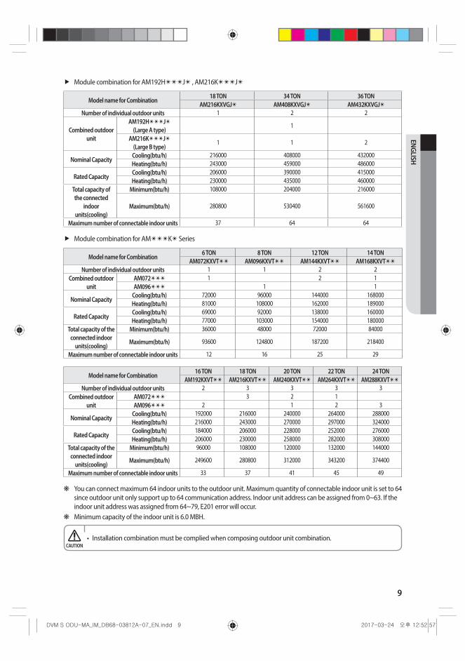
Module combination for AM192H✴✴✴J✴ , AM216K✴✴✴J✴
Model name for Combination18 TON 34 TON 36 TON
AM216KXVGJ✴ AM408KXVGJ✴ AM432KXVGJ✴Number of individual outdoor units 1 2 2
Combined outdoor unit
AM192H✴✴✴J✴ (Large A type)
1
AM216K✴✴✴J✴ (Large B type)
1 1 2
Nominal CapacityCooling(btu/h) 216000 408000 432000Heating(btu/h) 243000 459000 486000
Rated CapacityCooling(btu/h) 206000 390000 415000Heating(btu/h) 230000 435000 460000
Total capacity of the connected
indoor units(cooling)
Minimum(btu/h) 108000 204000 216000
Maximum(btu/h) 280800 530400 561600
Maximum number of connectable indoor units 37 64 64
Module combination for AM✴✴✴K✴ Series
Model name for Combination6 TON 8 TON 12 TON 14 TON
AM072KXVT✴✴ AM096KXVT✴✴ AM144KXVT✴✴ AM168KXVT✴✴
Number of individual outdoor units 1 1 2 2Combined outdoor
unitAM072✴✴✴ 1 2 1AM096✴✴✴ 1 1
Nominal CapacityCooling(btu/h) 72000 96000 144000 168000Heating(btu/h) 81000 108000 162000 189000
Rated CapacityCooling(btu/h) 69000 92000 138000 160000Heating(btu/h) 77000 103000 154000 180000
Total capacity of the connected indoor
units(cooling)
Minimum(btu/h) 36000 48000 72000 84000
Maximum(btu/h) 93600 124800 187200 218400
Maximum number of connectable indoor units 12 16 25 29
Model name for Combination16 TON 18 TON 20 TON 22 TON 24 TON
AM192KXVT✴✴ AM216KXVT✴✴ AM240KXVT✴✴ AM264KXVT✴✴ AM288KXVT✴✴
Number of individual outdoor units 2 3 3 3 3Combined outdoor
unitAM072✴✴✴ 3 2 1AM096✴✴✴ 2 1 2 3
Nominal CapacityCooling(btu/h) 192000 216000 240000 264000 288000Heating(btu/h) 216000 243000 270000 297000 324000
Rated CapacityCooling(btu/h) 184000 206000 228000 252000 276000Heating(btu/h) 206000 230000 258000 282000 308000
Total capacity of the connected indoor
units(cooling)
Minimum(btu/h) 96000 108000 120000 132000 144000
Maximum(btu/h) 249600 280800 312000 343200 374400
Maximum number of connectable indoor units 33 37 41 45 49
❋ You can connect maximum 64 indoor units to the outdoor unit. Maximum quantity of connectable indoor unit is set to 64 since outdoor unit only support up to 64 communication address. Indoor unit address can be assigned from 0~63. If the indoor unit address was assigned from 64~79, E201 error will occur.
❋ Minimum capacity of the indoor unit is 6.0 MBH.
• Installation combination must be complied when composing outdoor unit combination. CAUTION

10
Preparing for installation
Moving the outdoor unitSelect the moving path in advance.Be sure that moving path can support weight of the outdoor unit.Do not slant the product more than 30˚ when carrying it. (Do not lay the product down in sideways.)Surface of the heat exchanger is sharp. Be careful not to get injured while moving the product.
• You must use certain part of the product when moving the product.CAUTION
When moving with a crane
Fasten the wire rope as shown in the figure.To protect damage or scratches, insert a piece of cloth between the outdoor unit and the wire rope.
Wire rope
Holes for wire rope to go through
When moving with a forklift
Carefully insert the forklift forks into the forklift holes at the bottom of the outdoor unit.Be careful with the forklift from damaging the product.
Forklift
Forklift holes
Holes for forklift forks to go through
When moving the product without wooden pallet and the crane is not available for use
Connect a wire rope to the outdoor unit as you would move it with a crane.Hang the wire rope to the forklift fork to move the outdoor unit.
Wire ropeForklift
11
ENGLISH
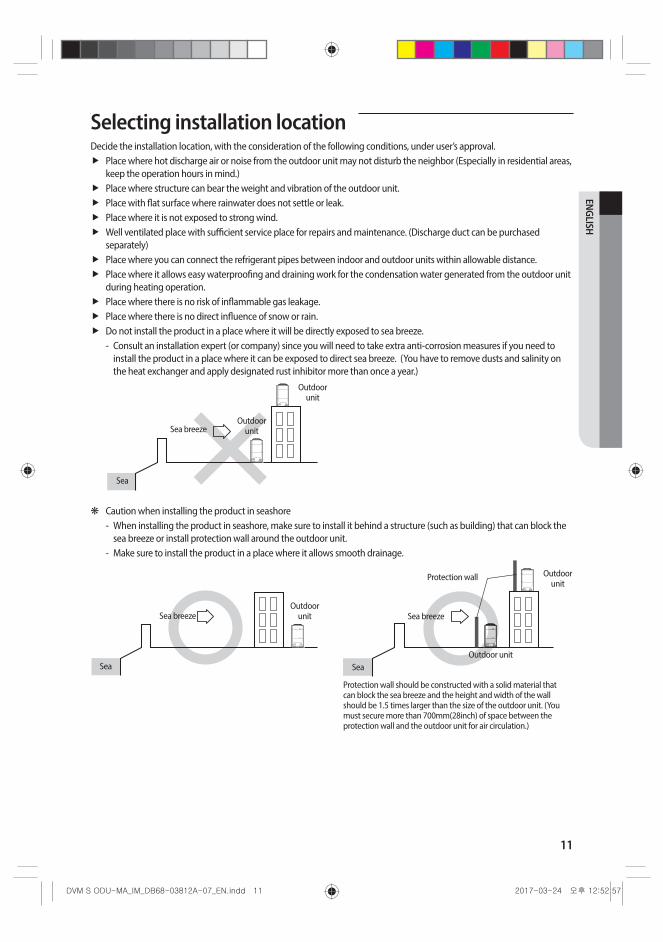
Selecting installation locationDecide the installation location, with the consideration of the following conditions, under user’s approval.
Place where hot discharge air or noise from the outdoor unit may not disturb the neighbor (Especially in residential areas, keep the operation hours in mind.)Place where structure can bear the weight and vibration of the outdoor unit.Place with flat surface where rainwater does not settle or leak.Place where it is not exposed to strong wind.Well ventilated place with sufficient service place for repairs and maintenance. (Discharge duct can be purchased separately)Place where you can connect the refrigerant pipes between indoor and outdoor units within allowable distance.Place where it allows easy waterproofing and draining work for the condensation water generated from the outdoor unit during heating operation. Place where there is no risk of inflammable gas leakage.Place where there is no direct influence of snow or rain.Do not install the product in a place where it will be directly exposed to sea breeze. - Consult an installation expert (or company) since you will need to take extra anti-corrosion measures if you need to
install the product in a place where it can be exposed to direct sea breeze. (You have to remove dusts and salinity on the heat exchanger and apply designated rust inhibitor more than once a year.)
Sea
Sea breeze
Outdoor unit
Outdoor unit
❋ Caution when installing the product in seashore - When installing the product in seashore, make sure to install it behind a structure (such as building) that can block the
sea breeze or install protection wall around the outdoor unit. - Make sure to install the product in a place where it allows smooth drainage.
Protection wall should be constructed with a solid material that can block the sea breeze and the height and width of the wall should be 1.5 times larger than the size of the outdoor unit. (You must secure more than 700mm(28inch) of space between the protection wall and the outdoor unit for air circulation.)
Sea
Sea breeze
Outdoor unit
Protection wall
Outdoor unitSea
Sea breezeOutdoor
unit
12
Selecting installation location• System air conditioner may cause static noise when listening to AM stations. Therefore, select an installation
location for indoor unit where electrical wiring can be done while keeping certain distance from a radio, computer and stereo equipment. - Especially, keep the unit at least 3m(9.84inch) away from the electrical equipment in an area with weak
electromagnetic waves and put the main power cable and communication cables in a separately installed protection tube.
- Make sure that there is no equipment that generates electromagnetic waves. If not electromagnetic waves may cause problem to the control systems which may lead to air conditioner malfunction. (Example: Remote control sensor of the indoor unit may not receive the signal very well, due to ballast stabilizer of the lighting equipment.)
• In regions with heavy snowfall, make sure to install the outdoor unit where there is no concerns of direct snowfall on the outdoor unit. Also, build higher base support so that accumulated snow does not block the air inlet or the heat exchanger.
• R-410A refrigerant is a safe, nontoxic and nonflammable refrigerant. However, if the place holds any concerns for exceeding dangerous level of refrigerant concentration in case of refrigerant leakage, extra ventilation system is required.
• When you install the outdoor unit in a high places such as roof, install fence or guardrail around it. When there is no fence or guardrail, service person could fall.
• Do not install the product in places where corrosive gases such as sulfur oxides, ammonia, and sulfurous gas are produced. (e.g. Toilet outlet, ventilation opening, sewage works, dyeing complex, cattle shed, sulfuric hot spring, nuclear power plant, ship etc.) When installing the product in those places, contact an installation specialty store as the copper pipe and brazing part will need additional corrosion proof or anti-rust additive to prevent corrosion.
• Make sure to keep away inflammable materials (such as wooden materials, oil etc.) around the outdoor unit. When there's fire, those inflammable material will easily catch the fire and may pass it on to the product.
• Depending on the condition of power supply, unstable power or voltage any cause malfunction of the parts or control system. (At the ship or places using power supply from electric generator...etc)
• Make sure to install MCU when using HR products.• When you select the location to install MCU, the location is far away from indoor rooms because the refrigerant
running of MCU may create noise.
CAUTION
13
ENGLISH
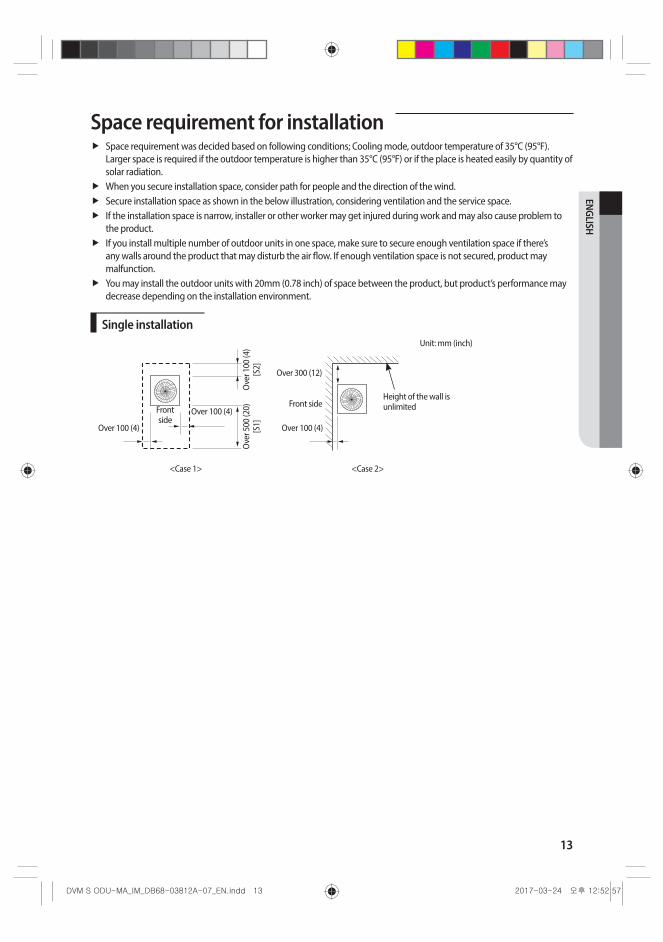
Space requirement for installationSpace requirement was decided based on following conditions; Cooling mode, outdoor temperature of 35°C (95°F). Larger space is required if the outdoor temperature is higher than 35°C (95°F) or if the place is heated easily by quantity of solar radiation.When you secure installation space, consider path for people and the direction of the wind.Secure installation space as shown in the below illustration, considering ventilation and the service space. If the installation space is narrow, installer or other worker may get injured during work and may also cause problem to the product. If you install multiple number of outdoor units in one space, make sure to secure enough ventilation space if there’s any walls around the product that may disturb the air flow. If enough ventilation space is not secured, product may malfunction.You may install the outdoor units with 20mm (0.78 inch) of space between the product, but product’s performance may decrease depending on the installation environment.
Single installationUnit: mm (inch)
Height of the wall is unlimited
Ove
r 100
(4)
[S2]
Ove
r 500
(20)
[S
1]Over 100 (4) Over 100 (4)
Front side
Over 100 (4)
Over 300 (12)
<Case 1> <Case 2>
Front side

14
Space requirement for installation
Module installation
<Case 3>
Ove
r 500
(2
0)O
ver 5
00
(20)
Ove
r 600
(2
4)
Over 100 (4) Over 100 (4) Over 100 (4)Over 100 (4)
Over 100 (4) Over 100 (4) Over 100 (4) Over 100 (4)
Front side
Front side
<Case 1> <Case 2>
Ove
r 200
(8)
Ove
r 100
(4) O
ver 3
00 (1
2)
[S2]
Ove
r 500
(S
1)
Over 100 (4)Over 100 (4)
Over 100 (4)
Over 300 (12)
Over 400 (16)
Over 400 (16)
Height of the wall is unlimited
Front side
Front side
❋ For <Case 1> or <Case 3> • Height of the wall on the front side should not be higher than 1500mm (60 inch). • Height of the wall on the air inlet side should not be higher than 500mm (20 inch). • Height of the wall on the side is not limited. • If the height of the wall exceeds by certain value (h1, h2), additional clearance [(h1)/2, (h2)/2 : Half of the exceeded
distance] should be added to the service space (S1, S2).
1500
(60)
h1
500
(20)
h2
Front side
Air inlet side
Unit: mm (inch)
S1+h1/2 S2+h2/2
15
ENGLISH
Accessories
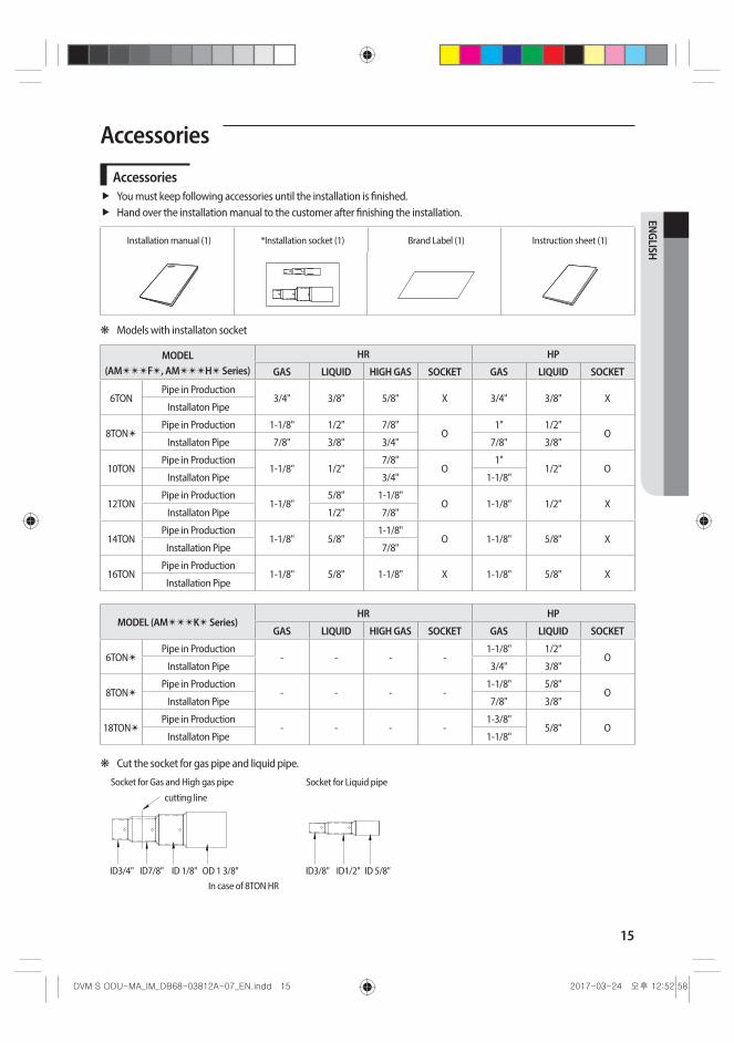
AccessoriesYou must keep following accessories until the installation is finished.Hand over the installation manual to the customer after finishing the installation.
Installation manual (1) *Installation socket (1) Brand Label (1) Instruction sheet (1)
❋ Models with installaton socket
MODEL (AM✴✴✴F✴, AM✴✴✴H✴ Series)
HR HP
GAS LIQUID HIGH GAS SOCKET GAS LIQUID SOCKET
6TONPipe in Production
3/4" 3/8" 5/8" X 3/4" 3/8" XInstallaton Pipe
8TON✴Pipe in Production 1-1/8" 1/2" 7/8"
O1" 1/2"
OInstallaton Pipe 7/8" 3/8" 3/4" 7/8" 3/8"
10TONPipe in Production
1-1/8" 1/2"7/8"
O1"
1/2" OInstallaton Pipe 3/4" 1-1/8"
12TONPipe in Production
1-1/8"5/8" 1-1/8"
O 1-1/8" 1/2" XInstallaton Pipe 1/2" 7/8"
14TONPipe in Production
1-1/8" 5/8"1-1/8"
O 1-1/8" 5/8" XInstallation Pipe 7/8"
16TONPipe in Production
1-1/8" 5/8" 1-1/8" X 1-1/8" 5/8" XInstallation Pipe
MODEL (AM✴✴✴K✴ Series)HR HP
GAS LIQUID HIGH GAS SOCKET GAS LIQUID SOCKET
6TON✴Pipe in Production
- - - -1-1/8" 1/2"
OInstallaton Pipe 3/4" 3/8"
8TON✴Pipe in Production
- - - -1-1/8" 5/8"
OInstallaton Pipe 7/8" 3/8"
18TON✴Pipe in Production
- - - -1-3/8"
5/8" OInstallaton Pipe 1-1/8"
❋ Cut the socket for gas pipe and liquid pipe.
ID3/4" ID7/8" ID 1/8" OD 1 3/8"
cutting line
Socket for Gas and High gas pipe
ID3/8" ID1/2" ID 5/8"
Socket for Liquid pipe
In case of 8TON HR
16
Accessories
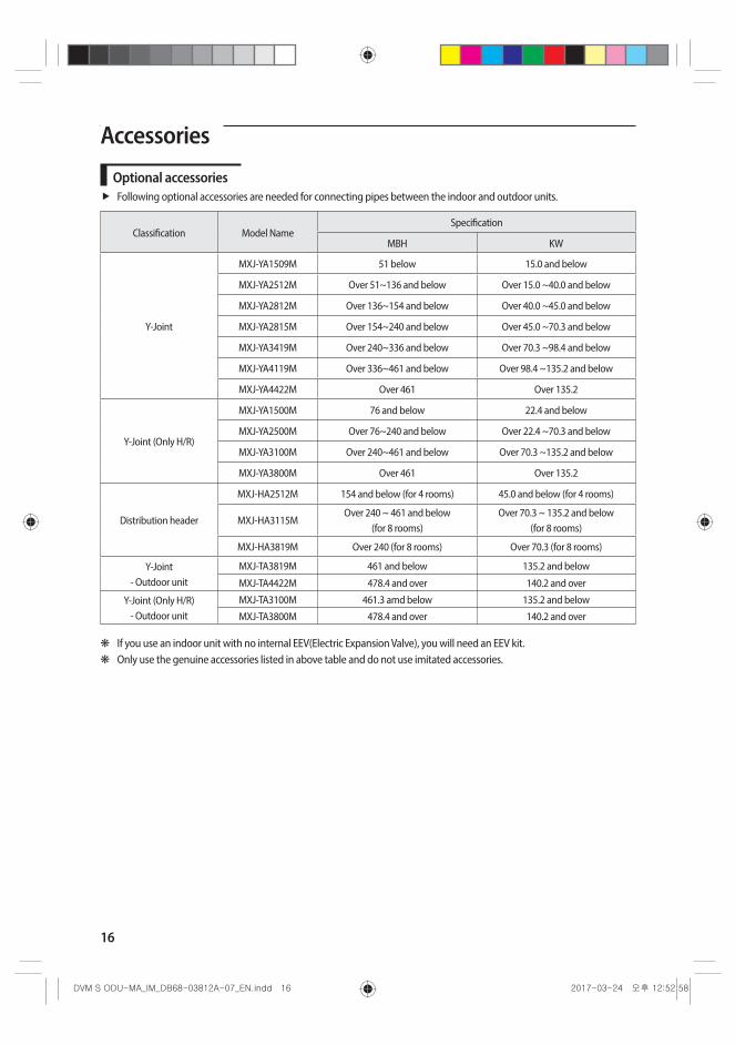
Optional accessoriesFollowing optional accessories are needed for connecting pipes between the indoor and outdoor units.
Classification Model NameSpecification
MBH KW
Y-Joint
MXJ-YA1509M 51 below 15.0 and below
MXJ-YA2512M Over 51~136 and below Over 15.0 ~40.0 and below
MXJ-YA2812M Over 136~154 and below Over 40.0 ~45.0 and below
MXJ-YA2815M Over 154~240 and below Over 45.0 ~70.3 and below
MXJ-YA3419M Over 240~336 and below Over 70.3 ~98.4 and below
MXJ-YA4119M Over 336~461 and below Over 98.4 ~135.2 and below
MXJ-YA4422M Over 461 Over 135.2
Y-Joint (Only H/R)
MXJ-YA1500M 76 and below 22.4 and below
MXJ-YA2500M Over 76~240 and below Over 22.4 ~70.3 and below
MXJ-YA3100M Over 240~461 and below Over 70.3 ~135.2 and below
MXJ-YA3800M Over 461 Over 135.2
Distribution header
MXJ-HA2512M 154 and below (for 4 rooms) 45.0 and below (for 4 rooms)
MXJ-HA3115MOver 240 ~ 461 and below
(for 8 rooms)Over 70.3 ~ 135.2 and below
(for 8 rooms)
MXJ-HA3819M Over 240 (for 8 rooms) Over 70.3 (for 8 rooms)
Y-Joint- Outdoor unit
MXJ-TA3819M 461 and below 135.2 and below
MXJ-TA4422M 478.4 and over 140.2 and over
Y-Joint (Only H/R)- Outdoor unit
MXJ-TA3100M 461.3 amd below 135.2 and below
MXJ-TA3800M 478.4 and over 140.2 and over
❋ If you use an indoor unit with no internal EEV(Electric Expansion Valve), you will need an EEV kit. ❋ Only use the genuine accessories listed in above table and do not use imitated accessories.

17
ENGLISH
Base construction and installation of the outdoor unit• Make sure to remove the wooden pallet before installing the outdoor unit. If you do not remove the wooden
pallet, there is risk of fire during welding the pipes. If the outdoor unit is installed with wooden pallet on, and it was used for long period time, wooden palette may break and cause electrical hazard or high pressure may damage the pipes.
WARNING
❋ Fix an outdoor unit firmly on the base ground with anchor bolts. ❋ Manufacturer is not responsible for the damage occurred by not following the installation standards.
1. Make sure that the height of the base ground is 200mm or higher to protect the outdoor unit from rain water or other external conditions. Also, install a draining pit around the base ground and connect the drain pipe to the drainage.
2. Considering the vibration and weight of the outdoor unit, strength of the base ground must be strong to prevent noise and the top surface of it should be flat.
3. Base ground should be 1.5 times larger than the bottom of the outdoor unit.4. Outdoor unit must be fixed firmly so that it can withstand the wind speed of 30m/s. If you cannot fix the outdoor unit on
the base ground, fix it by side or use extra structure.5. In heating operation, defrost water may form so you must really care about the drainage and waterproofing the floor. To
prevent defrost water from stagnating or freezing, construct a drainage with over 1/50 slope. (Ice may form on the floor in winter time.)
6. It is necessary to add wire mesh or steel bar during concrete construction for the base ground to prevent damages or cracks.
7. When installing multiple outdoor units at the same place, construct a H beam or an anti-vibration frame on the base ground to install the outdoor unit.
8. After installing a H beam or an anti-vibration frame, apply corrosion protection and other necessary coating.9. When concrete construction for outdoor unit installation is completed, install an anti-vibration pad (t=20mm/0.78 inch or
more) or an anti-vibration frame to prevent vibration of the outdoor unit from transferring to the base ground.10. Place the outdoor unit on a H beam or an anti-vibration frame and fix it with the bolt, nut and washer. (The bearing force
has to be over 3.5kN)
Base ground construction
<When installing on the ground>
Draining pit Over 200mm (8inch)
<When installing on the roof>
Bottom surface of the base ground must be horizontally leveled
Over 200mm (8inch)
Ove
r 200
mm
(8in
ch)
18
Base construction and installation of the outdoor unit
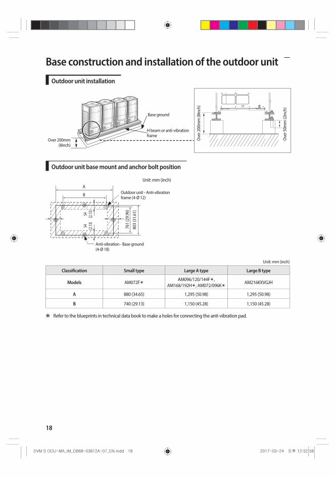
Outdoor unit installation
Ove
r 200
mm
(8in
ch)
Ove
r 50m
m (2
inch
)
Base ground
H beam or anti-vibration frame
Over 200mm (8inch)
Outdoor unit base mount and anchor bolt position Unit: mm (inch)
A
B
54
(2.13
)
761
(29.
96)
803
(31.
61)
54
(2.13
)
Outdoor unit - Anti-vibration frame (4-Ø 12)
Anti-vibration - Base ground (4-Ø 18)
Unit: mm (inch)
Classification Small type Large A type Large B type
Models AM072F✴AM096/120/144F✴,
AM168/192H✴, AM072/096K✴AM216KXVGJH
A 880 (34.65) 1,295 (50.98) 1,295 (50.98)
B 740 (29.13) 1,150 (45.28) 1,150 (45.28)
❋ Refer to the blueprints in technical data book to make a holes for connecting the anti-vibration pad.
19
ENGLISH
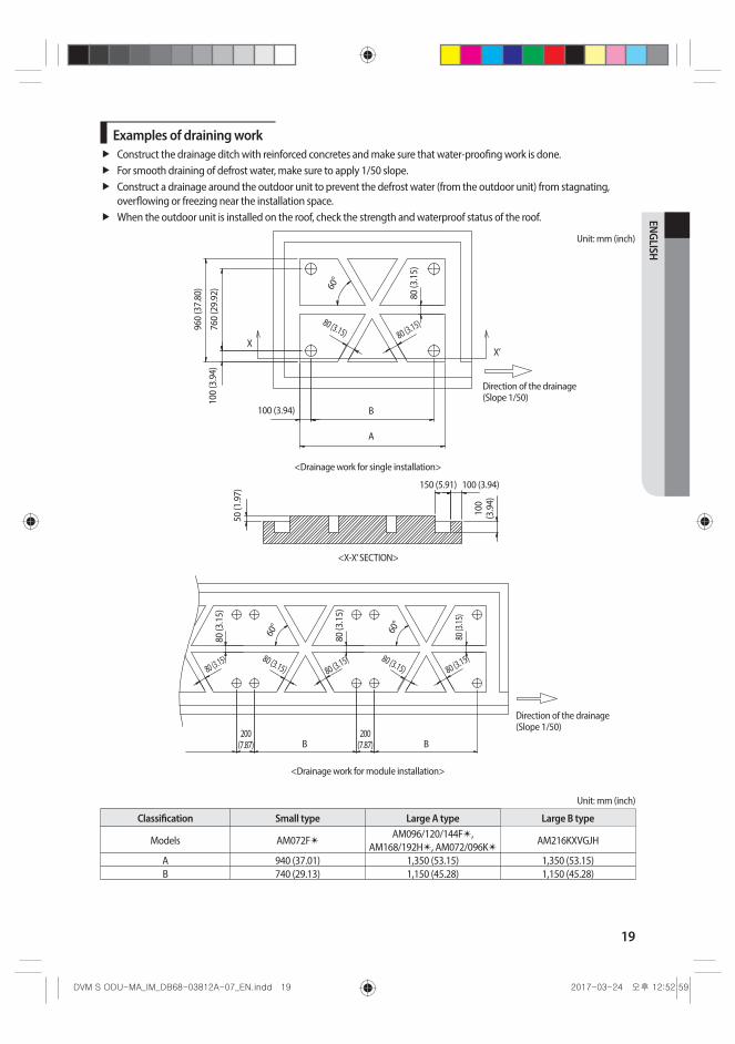
Examples of draining workConstruct the drainage ditch with reinforced concretes and make sure that water-proofing work is done.For smooth draining of defrost water, make sure to apply 1/50 slope.Construct a drainage around the outdoor unit to prevent the defrost water (from the outdoor unit) from stagnating, overflowing or freezing near the installation space. When the outdoor unit is installed on the roof, check the strength and waterproof status of the roof.
Unit: mm (inch)
960
(37.
80)
760
(29.
92)
100
(3.9
4)
80 (3
.15)
80 (3.15)80 (3.15)60
°
100 (3.94)
XX’
Direction of the drainage (Slope 1/50)
<Drainage work for single installation>
B
A
50 (1
.97)
100
(3.9
4)150 (5.91) 100 (3.94)
<X-X’ SECTION>
80 (3
.15)
80 (3
.15)
80 (3
.15)
80 (3.15) 80 (3.15)
80 (3.15) 80 (3.15) 80 (3.15)
60° 60°
200 (7.87) B B
200 (7.87)
Direction of the drainage (Slope 1/50)
<Drainage work for module installation>
Unit: mm (inch)
Classification Small type Large A type Large B type
Models AM072F✴AM096/120/144F✴,
AM168/192H✴, AM072/096K✴AM216KXVGJH
A 940 (37.01) 1,350 (53.15) 1,350 (53.15)B 740 (29.13) 1,150 (45.28) 1,150 (45.28)
20
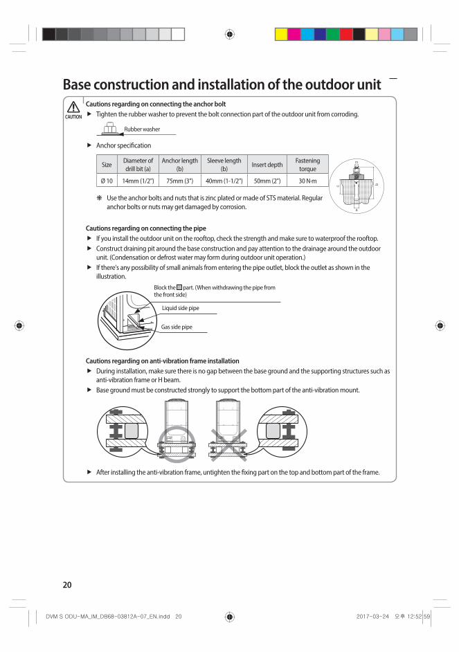
Base construction and installation of the outdoor unitCautions regarding on connecting the anchor bolt
Tighten the rubber washer to prevent the bolt connection part of the outdoor unit from corroding.
Rubber washer
Anchor specification
SizeDiameter of drill bit (a)
Anchor length (b)
Sleeve length (b)
Insert depthFastening
torque
Ø 10 14mm (1/2") 75mm (3") 40mm (1-1/2") 50mm (2") 30 N·m
❋ Use the anchor bolts and nuts that is zinc plated or made of STS material. Regular anchor bolts or nuts may get damaged by corrosion.
Cautions regarding on connecting the pipeIf you install the outdoor unit on the rooftop, check the strength and make sure to waterproof the rooftop.Construct draining pit around the base construction and pay attention to the drainage around the outdoor unit. (Condensation or defrost water may form during outdoor unit operation.)If there's any possibility of small animals from entering the pipe outlet, block the outlet as shown in the illustration.
Liquid side pipe
Gas side pipe
Block the part. (When withdrawing the pipe from the front side)
Cautions regarding on anti-vibration frame installationDuring installation, make sure there is no gap between the base ground and the supporting structures such as anti-vibration frame or H beam.Base ground must be constructed strongly to support the bottom part of the anti-vibration mount.
After installing the anti-vibration frame, untighten the fixing part on the top and bottom part of the frame.
CAUTION
21
ENGLISH
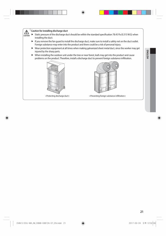
Caution for installing discharge ductStatic pressure of the discharge duct should be within the standard specification 78.45 Pa (0.315 W.G) when installing the duct.If you remove the fan guard to install the discharge duct, make sure to install a safety net on the duct outlet. Foreign substance may enter into the product and there could be a risk of personal injury.Wear protection equipment at all times when making galvanized sheet metal duct, since the worker may get injured by the sharp parts. When installing the outdoor unit under the tree or near forest, leafs may get into the product and cause problems on the product. Therefore, install a discharge duct to prevent foreign substance infiltration.
<Protecting discharge duct> <Preventing foreign substance infiltration>
CAUTION
22
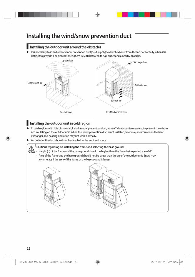
Installing the wind/snow prevention duct
Installing the outdoor unit around the obstaclesIt is necessary to install a wind/snow prevention duct(field supply) to direct exhaust from the fan horizontally, when it is difficult to provide a minimum space of 2m (6.56ft) between the air outlet and a nearby obstacle.
Discharged air
Grille/louver
Suction air
Upper floor
Discharged air
Ex.) Balcony Ex.) Mechanical room
Installing the outdoor unit in cold regionIn cold regions with lots of snowfall, install a snow prevention duct, as a sufficient countermeasure, to prevent snow from accumulating on the outdoor unit. When the snow prevention duct is not installed, frost may accumulate on the heat exchanger and heating operation may not work normally.Air outlet of the duct should not be directed to the enclosed space.
Cautions regarding on installing the frame and selecting the base ground• Height (h) of the frame and the base ground should be higher than the "heaviest expected snowfall". • Area of the frame and the base ground should not be larger than the are of the outdoor unit. Snow may
accumulate if the area of the frame or the base ground is larger.
CAUTION
23
ENGLISH
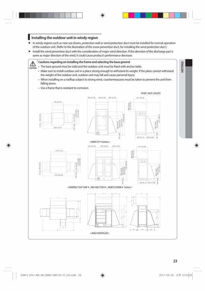
Installing the outdoor unit in windy regionIn windy regions such as near sea shores, protection wall or wind protection duct must be installed for normal operation of the outdoor unit. (Refer to the illustration of the snow prevention duct, for installing the wind protection duct.)Install the wind prevention duct with the consideration of major wind direction. If the direction of the discharge part is same as major direction of the wind, it could cause product’s performance decrease.
Cautions regarding on installing the frame and selecting the base ground• The base ground must be solid and the outdoor unit must be fixed with anchor bolts.• Make sure to install outdoor unit in a place strong enough to withstand its weight. If the place cannot withstand
the weight of the outdoor unit, outdoor unit may fall and cause personal injury.• When installing on a rooftop subject to strong wind, countermeasures must be taken to prevent the unit from
falling down.• Use a frame that is resistant to corrosion.
782 (30.79)
560 (22.05) 880 (34.05) 560 (22.05) 871 (34.29)
765 (30.12) 550 (21.65)
2300
(90.
55)
668
(26.
30)
532
(20.
94)
2271
(89.
41)
1134
(44.
65)
965
(37.
99)
180
(7.0
9)
1632
(64.
25)
1150
(45.
28)
980
(38.
58)
180
(7.0
9)
2000 (78.74)127
(5)
593
(23.
35)
1318
(51.
89)
1210
(47.
64)
612
(24.
09)
108
(4.2
5)
1197 (47.13)
2415 (95.08)
560 (22.05) 560 (22.05)1295 (50.98)
593
(23.
35)
127
(5)
1318
(51.
89)
1210
(47.
64)
612
(24.
09)
108
(4.2
5)
2300
(90.
55)
1632
(64.
25)
1150
(45.
28)
980
(38.
58)
180
(7.0
9)
871 (34.29)
765 (30.12) 550 (21.65)
668
(26.
30)
532
(20.
94)
2271
(89.
41)
1134
(44.
65)
965
(37.
99)
180
(7.0
9)
<AM072F✴Series>
<AM096/120/144F✴, AM168/192H✴, AM072/096K✴ Series>
<AM216KXVGJH>
Unit: mm (inch)
406
550
640
1252
1315
552
1192
1080
180
1255 1732
1080 12
55180
2371
2400
CAUTION

24
Refrigerant pipe installation• When installing, make sure there is no leakage. When collecting the refrigerant, stop the compressor first before
removing the connection pipe. If the refrigerant pipe is not properly connected and the compressor works with the service valve open, the pipe inhales the air and it makes the pressure inside of the refrigerant cycle abnormally high which may lead to explosion and injury.
WARNING
Refrigerant pipe workThe length of refrigerant pipe should be as short as possible and the height difference between an indoor and outdoor unit should be minimized.Piping work must be done within allowable piping length, height difference, and the allowable length after branching.The pressure of the R-410A is high. Use only certified refrigerant pipe and follow the installation method.After installing the pipes, calculate the total length of the pipe to check if additional refrigerant is needed. When you need to charge the additional refrigerant, make sure to use R-410A refrigerant.Use clean refrigerant pipe and there shouldn’t be any harmful ion, oxide, dust, iron content or moisture inside pipe.Use tools and accessories that fit on R-410A only.
Tool Installation process/purpose Compatibility with conventional tool
Pipe cutter
Refrigerant pipe installation
Pipe cuttingCompatible
Flaring tool Pipe flaring
Refrigerant machine oil
Apply refrigerant oil on flared part
Exclusive ether oil, ester oil, alkali benzene oil or synthetic oil
Torque wrenchConnect flare nut
with pipe
CompatiblePipe bender Pipe bending
Nitrogen gasAir tightness test
Prevent oxidation within the pipe
Welder Pipe welding
Manifold gage Air tightness test ~ additional
refrigerant charging
Vacuuming, charging
refrigerant and checking
operation
Need exclusive one to prevent mixture of R-22 refrigerant oil use and also the measurement is not available due to high pressure
Refrigerant charging hose
Need exclusive one since there is risk of refrigerant leakage or inflow of impurities
Vacuum pump Pipe dryingCompatible (Use products which contain the check valve to prevent
the oil from flowing backward into the outdoor unit.) Use the one that can be vacuumed up to -100.7kpa(5Torr).
Scale for refrigerant charging
Charging refrigerant Compatible
Gas leak detector Gas leak testNeed exclusive one
(Ones used for R-134a is compatible)
Flare nutMust use the flare nut equipped with the product. Refrigerant leakage may occur when the conventional flare
nut for R-22 is used.
25
ENGLISH
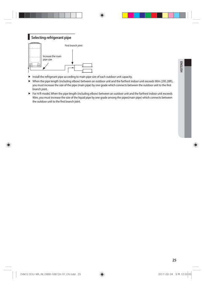
Selecting refrigerant pipe
First branch joint
Increase the main pipe size
Install the refrigerant pipe according to main pipe size of each outdoor unit capacity. When the pipe length (including elbow) between an outdoor unit and the farthest indoor unit exceeds 90m (295.28ft), you must increase the size of the pipe (main pipe) by one grade which connects between the outdoor unit to the first branch joint.For H/R model, When the pipe length (including elbow) between an outdoor unit and the farthest indoor unit exceeds 90m, you must increase the size of the liquid pipe by one grade among the pipes(main pipe) which connects between the outdoor unit to the first branch joint.
26
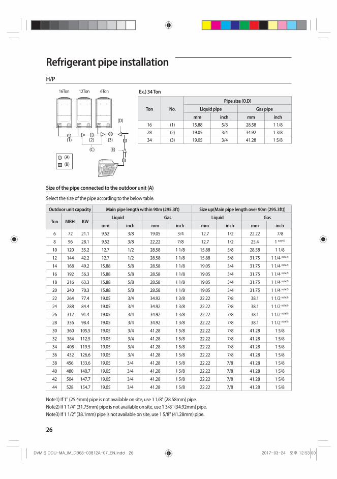
Refrigerant pipe installationH/P
16Ton 12Ton
(D)
(E)(C)(A)(B)
(3)(2)(1)
6Ton Ex.) 34 Ton
Ton No.
Pipe size (O.D)
Liquid pipe Gas pipe
mm inch mm inch16 (1) 15.88 5/8 28.58 1 1/8
28 (2) 19.05 3/4 34.92 1 3/8
34 (3) 19.05 3/4 41.28 1 5/8
Size of the pipe connected to the outdoor unit (A)
Select the size of the pipe according to the below table.
Outdoor unit capacity Main pipe length within 90m (295.3ft) Size up(Main pipe length over 90m (295.3ft))
Ton MBH KWLiquid Gas Liquid Gas
mm inch mm inch mm inch mm inch
6 72 21.1 9.52 3/8 19.05 3/4 12.7 1/2 22.22 7/8
8 96 28.1 9.52 3/8 22.22 7/8 12.7 1/2 25.4 1 note1)
10 120 35.2 12.7 1/2 28.58 1 1/8 15.88 5/8 28.58 1 1/8
12 144 42.2 12.7 1/2 28.58 1 1/8 15.88 5/8 31.75 1 1/4 note2)
14 168 49.2 15.88 5/8 28.58 1 1/8 19.05 3/4 31.75 1 1/4 note2)
16 192 56.3 15.88 5/8 28.58 1 1/8 19.05 3/4 31.75 1 1/4 note2)
18 216 63.3 15.88 5/8 28.58 1 1/8 19.05 3/4 31.75 1 1/4 note2)
20 240 70.3 15.88 5/8 28.58 1 1/8 19.05 3/4 31.75 1 1/4 note2)
22 264 77.4 19.05 3/4 34.92 1 3/8 22.22 7/8 38.1 1 1/2 note3)
24 288 84.4 19.05 3/4 34.92 1 3/8 22.22 7/8 38.1 1 1/2 note3)
26 312 91.4 19.05 3/4 34.92 1 3/8 22.22 7/8 38.1 1 1/2 note3)
28 336 98.4 19.05 3/4 34.92 1 3/8 22.22 7/8 38.1 1 1/2 note3)
30 360 105.5 19.05 3/4 41.28 1 5/8 22.22 7/8 41.28 1 5/8
32 384 112.5 19.05 3/4 41.28 1 5/8 22.22 7/8 41.28 1 5/8
34 408 119.5 19.05 3/4 41.28 1 5/8 22.22 7/8 41.28 1 5/8
36 432 126.6 19.05 3/4 41.28 1 5/8 22.22 7/8 41.28 1 5/8
38 456 133.6 19.05 3/4 41.28 1 5/8 22.22 7/8 41.28 1 5/8
40 480 140.7 19.05 3/4 41.28 1 5/8 22.22 7/8 41.28 1 5/8
42 504 147.7 19.05 3/4 41.28 1 5/8 22.22 7/8 41.28 1 5/8
44 528 154.7 19.05 3/4 41.28 1 5/8 22.22 7/8 41.28 1 5/8
Note1) If 1" (25.4mm) pipe is not available on site, use 1 1/8" (28.58mm) pipe.Note2) If 1 1/4" (31.75mm) pipe is not available on site, use 1 3/8" (34.92mm) pipe.Note3) If 1 1/2" (38.1mm) pipe is not available on site, use 1 5/8" (41.28mm) pipe.
27
ENGLISH
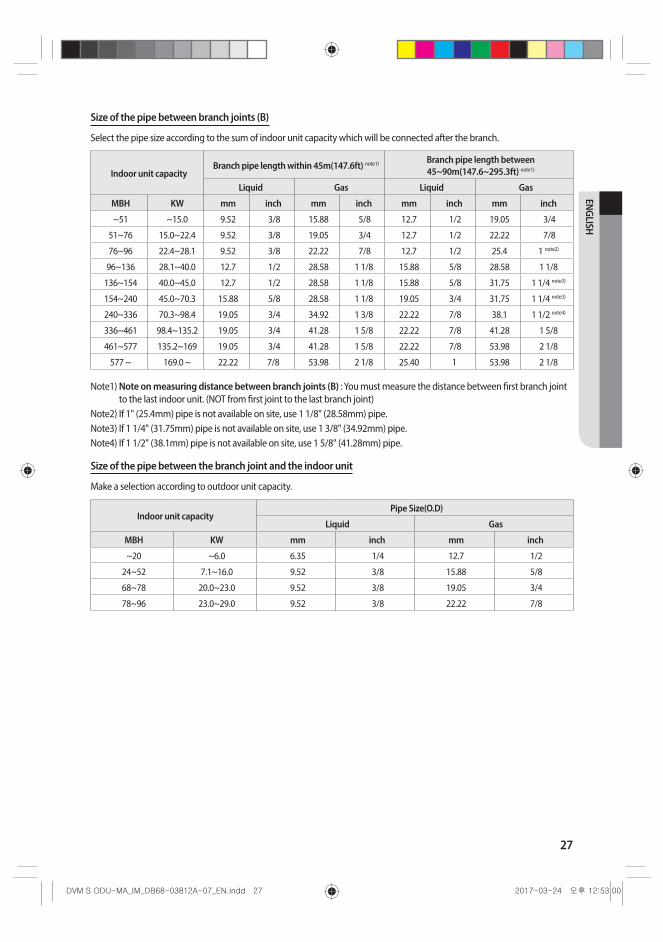
Size of the pipe between branch joints (B)
Select the pipe size according to the sum of indoor unit capacity which will be connected after the branch.
Indoor unit capacityBranch pipe length within 45m(147.6ft) note1) Branch pipe length between
45~90m(147.6~295.3ft) note1)
Liquid Gas Liquid Gas
MBH KW mm inch mm inch mm inch mm inch
~51 ~15.0 9.52 3/8 15.88 5/8 12.7 1/2 19.05 3/4
51~76 15.0~22.4 9.52 3/8 19.05 3/4 12.7 1/2 22.22 7/8
76~96 22.4~28.1 9.52 3/8 22.22 7/8 12.7 1/2 25.4 1 note2)
96~136 28.1~40.0 12.7 1/2 28.58 1 1/8 15.88 5/8 28.58 1 1/8
136~154 40.0~45.0 12.7 1/2 28.58 1 1/8 15.88 5/8 31.75 1 1/4 note3)
154~240 45.0~70.3 15.88 5/8 28.58 1 1/8 19.05 3/4 31.75 1 1/4 note3)
240~336 70.3~98.4 19.05 3/4 34.92 1 3/8 22.22 7/8 38.1 1 1/2 note4)
336~461 98.4~135.2 19.05 3/4 41.28 1 5/8 22.22 7/8 41.28 1 5/8
461~577 135.2~169 19.05 3/4 41.28 1 5/8 22.22 7/8 53.98 2 1/8
577 ~ 169.0 ~ 22.22 7/8 53.98 2 1/8 25.40 1 53.98 2 1/8
Note1) Note on measuring distance between branch joints (B) : You must measure the distance between first branch joint to the last indoor unit. (NOT from first joint to the last branch joint)
Note2) If 1" (25.4mm) pipe is not available on site, use 1 1/8" (28.58mm) pipe.Note3) If 1 1/4" (31.75mm) pipe is not available on site, use 1 3/8" (34.92mm) pipe.Note4) If 1 1/2" (38.1mm) pipe is not available on site, use 1 5/8" (41.28mm) pipe.
Size of the pipe between the branch joint and the indoor unit
Make a selection according to outdoor unit capacity.
Indoor unit capacityPipe Size(O.D)
Liquid Gas
MBH KW mm inch mm inch
~20 ~6.0 6.35 1/4 12.7 1/2
24~52 7.1~16.0 9.52 3/8 15.88 5/8
68~78 20.0~23.0 9.52 3/8 19.05 3/4
78~96 23.0~29.0 9.52 3/8 22.22 7/8
28
Refrigerant pipe installation16Ton 12Ton
(D)
(E)(C)(A)(B)
(3)(2)(1)
6Ton
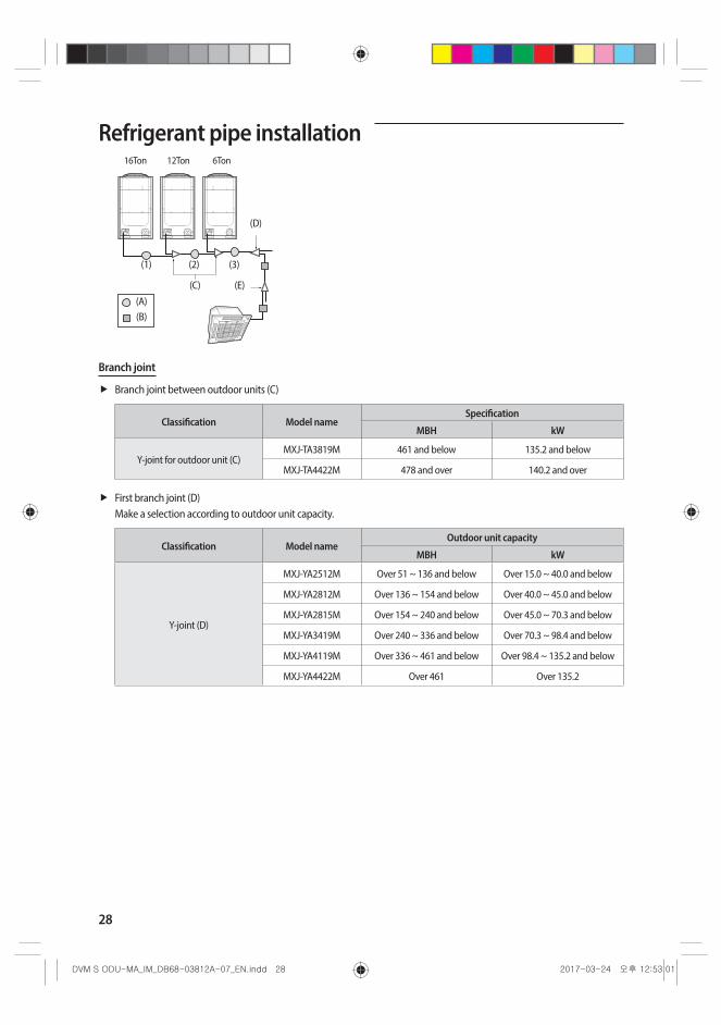
Branch joint
Branch joint between outdoor units (C)
Classification Model nameSpecification
MBH kW
Y-joint for outdoor unit (C)MXJ-TA3819M 461 and below 135.2 and below
MXJ-TA4422M 478 and over 140.2 and over
First branch joint (D)Make a selection according to outdoor unit capacity.
Classification Model nameOutdoor unit capacity
MBH kW
Y-joint (D)
MXJ-YA2512M Over 51 ~ 136 and below Over 15.0 ~ 40.0 and below
MXJ-YA2812M Over 136 ~ 154 and below Over 40.0 ~ 45.0 and below
MXJ-YA2815M Over 154 ~ 240 and below Over 45.0 ~ 70.3 and below
MXJ-YA3419M Over 240 ~ 336 and below Over 70.3 ~ 98.4 and below
MXJ-YA4119M Over 336 ~ 461 and below Over 98.4 ~ 135.2 and below
MXJ-YA4422M Over 461 Over 135.2
29
ENGLISH
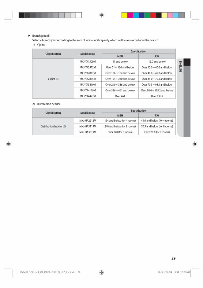
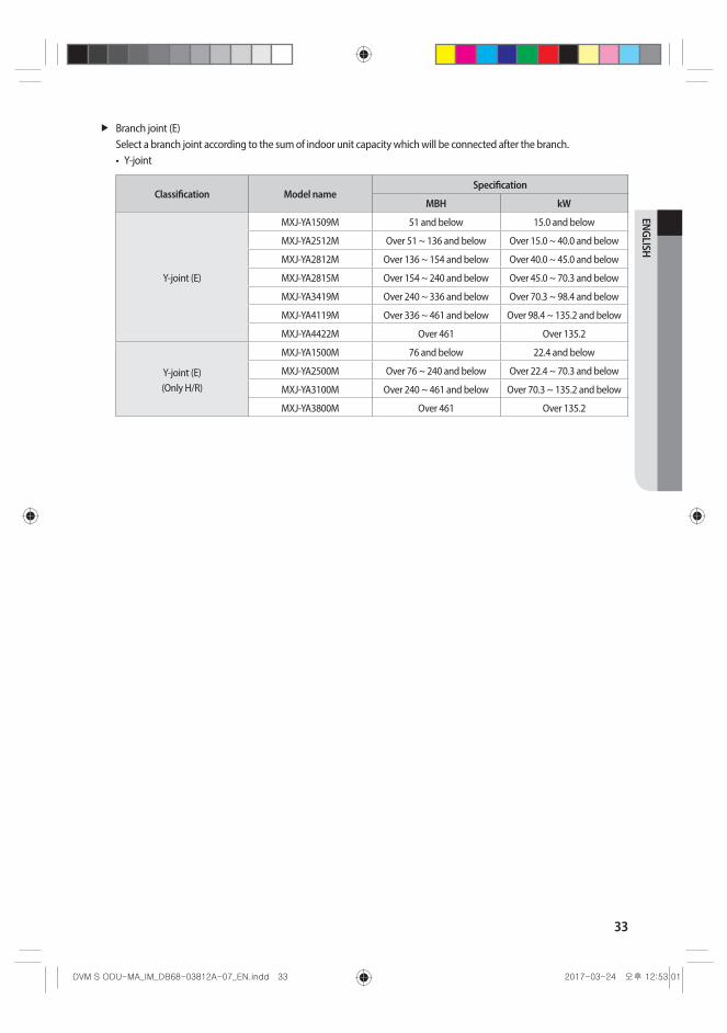
Branch joint (E)Select a branch joint according to the sum of indoor unit capacity which will be connected after the branch.1) Y-joint
Classification Model nameSpecification
MBH kW
Y-joint (E)
MXJ-YA1509M 51 and below 15.0 and below
MXJ-YA2512M Over 51 ~ 136 and below Over 15.0 ~ 40.0 and below
MXJ-YA2812M Over 136 ~ 154 and below Over 40.0 ~ 45.0 and below
MXJ-YA2815M Over 154 ~ 240 and below Over 45.0 ~ 70.3 and below
MXJ-YA3419M Over 240 ~ 336 and below Over 70.3 ~ 98.4 and below
MXJ-YA4119M Over 336 ~ 461 and below Over 98.4 ~ 135.2 and below
MXJ-YA4422M Over 461 Over 135.2
2) Distribution header
Classification Model nameSpecification
MBH kW
Distribution header (E)
MXJ-HA2512M 154 and below (for 4 rooms) 45.0 and below (for 4 rooms)
MXJ-HA3115M 240 and below (for 8 rooms) 70.3 and below (for 8 rooms)
MXJ-HA3819M Over 240 (for 8 rooms) Over 70.3 (for 8 rooms)
30
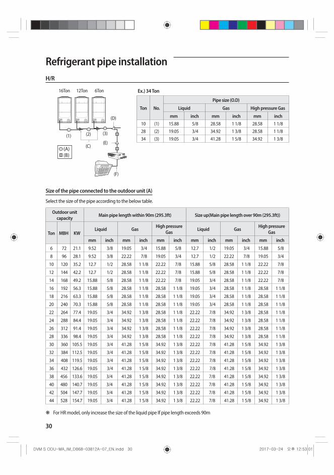
Refrigerant pipe installationH/R
(A) (B)
16Ton 12Ton
(D)
(E)
(F)
(C)
(3)(2)(1)
6Ton Ex.) 34 Ton
Ton No.
Pipe size (O.D)
Liquid Gas High pressure Gas
mm inch mm inch mm inch10 (1) 15.88 5/8 28.58 1 1/8 28.58 1 1/8
28 (2) 19.05 3/4 34.92 1 3/8 28.58 1 1/8
34 (3) 19.05 3/4 41.28 1 5/8 34.92 1 3/8
Size of the pipe connected to the outdoor unit (A)
Select the size of the pipe according to the below table.
Outdoor unit capacity Main pipe length within 90m (295.3ft) Size up(Main pipe length over 90m (295.3ft))
Ton MBH KWLiquid Gas High pressure
Gas Liquid Gas High pressure Gas
mm inch mm inch mm inch mm inch mm inch mm inch
6 72 21.1 9.52 3/8 19.05 3/4 15.88 5/8 12.7 1/2 19.05 3/4 15.88 5/8
8 96 28.1 9.52 3/8 22.22 7/8 19.05 3/4 12.7 1/2 22.22 7/8 19.05 3/4
10 120 35.2 12.7 1/2 28.58 1 1/8 22.22 7/8 15.88 5/8 28.58 1 1/8 22.22 7/8
12 144 42.2 12.7 1/2 28.58 1 1/8 22.22 7/8 15.88 5/8 28.58 1 1/8 22.22 7/8
14 168 49.2 15.88 5/8 28.58 1 1/8 22.22 7/8 19.05 3/4 28.58 1 1/8 22.22 7/8
16 192 56.3 15.88 5/8 28.58 1 1/8 28.58 1 1/8 19.05 3/4 28.58 1 1/8 28.58 1 1/8
18 216 63.3 15.88 5/8 28.58 1 1/8 28.58 1 1/8 19.05 3/4 28.58 1 1/8 28.58 1 1/8
20 240 70.3 15.88 5/8 28.58 1 1/8 28.58 1 1/8 19.05 3/4 28.58 1 1/8 28.58 1 1/8
22 264 77.4 19.05 3/4 34.92 1 3/8 28.58 1 1/8 22.22 7/8 34.92 1 3/8 28.58 1 1/8
24 288 84.4 19.05 3/4 34.92 1 3/8 28.58 1 1/8 22.22 7/8 34.92 1 3/8 28.58 1 1/8
26 312 91.4 19.05 3/4 34.92 1 3/8 28.58 1 1/8 22.22 7/8 34.92 1 3/8 28.58 1 1/8
28 336 98.4 19.05 3/4 34.92 1 3/8 28.58 1 1/8 22.22 7/8 34.92 1 3/8 28.58 1 1/8
30 360 105.5 19.05 3/4 41.28 1 5/8 34.92 1 3/8 22.22 7/8 41.28 1 5/8 34.92 1 3/8
32 384 112.5 19.05 3/4 41.28 1 5/8 34.92 1 3/8 22.22 7/8 41.28 1 5/8 34.92 1 3/8
34 408 119.5 19.05 3/4 41.28 1 5/8 34.92 1 3/8 22.22 7/8 41.28 1 5/8 34.92 1 3/8
36 432 126.6 19.05 3/4 41.28 1 5/8 34.92 1 3/8 22.22 7/8 41.28 1 5/8 34.92 1 3/8
38 456 133.6 19.05 3/4 41.28 1 5/8 34.92 1 3/8 22.22 7/8 41.28 1 5/8 34.92 1 3/8
40 480 140.7 19.05 3/4 41.28 1 5/8 34.92 1 3/8 22.22 7/8 41.28 1 5/8 34.92 1 3/8
42 504 147.7 19.05 3/4 41.28 1 5/8 34.92 1 3/8 22.22 7/8 41.28 1 5/8 34.92 1 3/8
44 528 154.7 19.05 3/4 41.28 1 5/8 34.92 1 3/8 22.22 7/8 41.28 1 5/8 34.92 1 3/8
❋ For HR model, only increase the size of the liquid pipe If pipe length exceeds 90m
31
ENGLISH
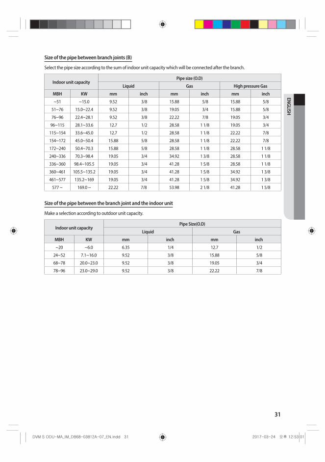
Size of the pipe between branch joints (B)
Select the pipe size according to the sum of indoor unit capacity which will be connected after the branch.
Indoor unit capacityPipe size (O.D)
Liquid Gas High pressure Gas
MBH KW mm inch mm inch mm inch
~51 ~15.0 9.52 3/8 15.88 5/8 15.88 5/8
51~76 15.0~22.4 9.52 3/8 19.05 3/4 15.88 5/8
76~96 22.4~28.1 9.52 3/8 22.22 7/8 19.05 3/4
96~115 28.1~33.6 12.7 1/2 28.58 1 1/8 19.05 3/4
115~154 33.6~45.0 12.7 1/2 28.58 1 1/8 22.22 7/8
154~172 45.0~50.4 15.88 5/8 28.58 1 1/8 22.22 7/8
172~240 50.4~70.3 15.88 5/8 28.58 1 1/8 28.58 1 1/8
240~336 70.3~98.4 19.05 3/4 34.92 1 3/8 28.58 1 1/8
336~360 98.4~105.5 19.05 3/4 41.28 1 5/8 28.58 1 1/8
360~461 105.5~135.2 19.05 3/4 41.28 1 5/8 34.92 1 3/8
461~577 135.2~169 19.05 3/4 41.28 1 5/8 34.92 1 3/8
577 ~ 169.0 ~ 22.22 7/8 53.98 2 1/8 41.28 1 5/8
Size of the pipe between the branch joint and the indoor unit
Make a selection according to outdoor unit capacity.
Indoor unit capacityPipe Size(O.D)
Liquid Gas
MBH KW mm inch mm inch
~20 ~6.0 6.35 1/4 12.7 1/2
24~52 7.1~16.0 9.52 3/8 15.88 5/8
68~78 20.0~23.0 9.52 3/8 19.05 3/4
78~96 23.0~29.0 9.52 3/8 22.22 7/8

32
Refrigerant pipe installation
(A) (B)
16Ton 12Ton
(D)
(E)
(F)
(C)
(3)(2)(1)
6Ton
Branch joint
Branch joint between outdoor units (C)
Classification Model nameSpecification
MBH kW
Liquid/Low pressure Y-joint (C)MXJ-TA3819M 461 and below 135.2 and below
MXJ-TA4422M 478 and over 140.2 and over
High pressure Y-joint (C)MXJ-TA3100M 461 and below 135.2 and below
MXJ-TA3800M 478 and over 140.2 and over
First branch joint (D)Make a selection according to outdoor unit capacity.
Classification Model nameOutdoor unit capacity
MBH kW
Liquid/Low pressure Y-joint (D)
MXJ-YA2512M Over 51 ~ 136 and below Over 15.0 ~ 40.0 and below
MXJ-YA2812M Over 136 ~ 154 and below Over 40.0 ~ 45.0 and below
MXJ-YA2815M Over 154 ~ 240 and below Over 45.0 ~ 70.3 and below
MXJ-YA3419M Over 240 ~ 336 and below Over 70.3 ~ 98.4 and below
MXJ-YA4119M Over 336 ~ 461 and below Over 98.4 ~ 135.2 and below
MXJ-YA4422M Over 461 Over 135.2
High pressure Y-joint (D)
MXJ-YA1500M 76 and below 22.4 and below
MXJ-YA2500M Over 76 ~ 240 and below Over 22.4 ~ 70.3 and below
MXJ-YA3100M Over 240 ~ 461 and below Over 70.3 ~ 135.2 and below
MXJ-YA3800M Over 461 Over 135.2
33
ENGLISH
Branch joint (E)Select a branch joint according to the sum of indoor unit capacity which will be connected after the branch.• Y-joint
Classification Model nameSpecification
MBH kW
Y-joint (E)
MXJ-YA1509M 51 and below 15.0 and below
MXJ-YA2512M Over 51 ~ 136 and below Over 15.0 ~ 40.0 and below
MXJ-YA2812M Over 136 ~ 154 and below Over 40.0 ~ 45.0 and below
MXJ-YA2815M Over 154 ~ 240 and below Over 45.0 ~ 70.3 and below
MXJ-YA3419M Over 240 ~ 336 and below Over 70.3 ~ 98.4 and below
MXJ-YA4119M Over 336 ~ 461 and below Over 98.4 ~ 135.2 and below
MXJ-YA4422M Over 461 Over 135.2
Y-joint (E) (Only H/R)
MXJ-YA1500M 76 and below 22.4 and below
MXJ-YA2500M Over 76 ~ 240 and below Over 22.4 ~ 70.3 and below
MXJ-YA3100M Over 240 ~ 461 and below Over 70.3 ~ 135.2 and below
MXJ-YA3800M Over 461 Over 135.2

34
Refrigerant pipe installationBasic type - additional refrigerant
H/P H/R
1/2" (5m/16.4')
1/2" (5m/16.4')
1/2" (5m/16.4')
1/4" (5m/16.4')
1/4" (10m/32.8')
1/4" (15m/49.2')
3/8" (10m/32.8')
3/8" (10m/32.8')
3/8" (10m/32.8')
3/8" (10m/32.8')
1/4" (5m/16.4')
3/8" (10m/32.8')
144MBH (12Ton)
12MBH
24MBH
24MBH
18MBH18MBH
18MBH
18MBH
12MBH
3/8" (1m/3.3')
1/2" (5m/16.4')
5/8" (10m/32.8')
1/2" (10m/32.8')
3/8" (15m/49.2')
3/8" (10m/32.8')
1/2" (10m/32.8')
3/8" (18m/59.1')
3/8" (18m/59.1')
3/8" (25m/82.0')
3/8" (15m/49.2')
3/8" (10m/32.8')
MCU MCU
1/4" (2m/6.6')
12MBH
24MBH
36MBH
36MBH
36MBH
24MBH
24MBH
24MBH
1/4" (15m/49.2')
216MBH (18Ton)(144MBH + 72MBH)
Branch joint
Basic amount of refrigerant within the outdoor unit - Amount of additional refrigerant has to be calculated based on the sum of all liquid pipe length.
Classification AM072F✴ AM096F✴ AM120F✴ AM144F✴ AM168H✴ AM192H✴
Basic type [kg (lb)] 5.5 (12.1) 7.4 (16.3) 7.4 (16.3) 8.7 (19.2) 11.0 (24.3) 11.0 (24.3)
Classification AM072K✴ AM096K✴ AM216KXVGJHBasic type [kg (lb)] 8.4 (18.5) 8.4 (18.5) 12.5 (27.6)
Amount of additional refrigerant depending on the pipe size (ⓐ) - Amount of additional refrigerant has to be calculated based on the sum of all liquid pipe length.
Size of liquid pipe [mm (inch)]
Ø6.35 (Ø1/4)
Ø9.52 (Ø3/8)
Ø12.70 (Ø1/2)
Ø15.88 (Ø5/8)
Ø19.05 (Ø3/4)
Ø22.23 (Ø7/8)
Ø25.40 (Ø1)
Additional amount [kg/m (Ib/ft)]
0.02 (0.013)
0.06 (0.040)
0.125 (0.084)
0.18 (0.121)
0.27 (0.181)
0.35 (0.235)
0.53 (0.356)
- For the indoor unit already connected to EEV kit, the additional refrigerant charging is 0.0067lb per feet regardless of the pipe size.
35
ENGLISH
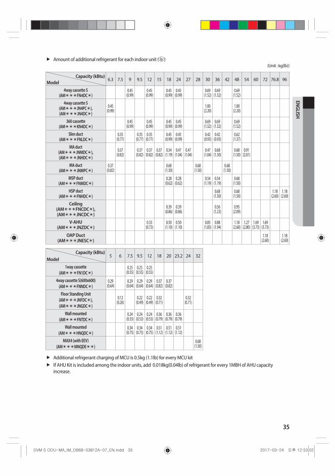
Amount of additional refrigerant for each indoor unit (ⓑ)(Unit : kg(lb))
Capacity (kBtu)Model
6.3 7.5 9 9.5 12 15 18 24 27 28 30 36 42 48 54 60 72 76.8 96
4way cassette S (AM✴✴✴FN4DC✴)
0.45 (0.99)
0.45 (0.99)
0.45 (0.99)
0.45 (0.99)
0.69 (1.52)
0.69 (1.52)
0.69 (1.52)
4way cassette S (AM✴✴✴JN4PC✴), (AM✴✴✴JN4DC✴)
0.45 (0.99)
1.00 (2.20)
1.00 (2.20)
360 cassette (AM✴✴✴KN4DC✴)
0.45 (0.99)
0.45 (0.99)
0.45 (0.99)
0.45 (0.99)
0.69 (1.52)
0.69 (1.52)
0.69 (1.52)
Slim duct (AM✴✴✴FNLDC✴)
0.35 (0.77)
0.35 (0.77)
0.35 (0.77)
0.45 (0.99)
0.45 (0.99)
0.42 (0.93)
0.42 (0.93)
0.62 (1.37)
MA duct (AM✴✴✴JNMDC✴), (AM✴✴✴JNHDC✴)
0.37 (0.82)
0.37 (0.82)
0.37 (0.82)
0.37 (0.82)
0.54 (1.19)
0.47 (1.04)
0.47 (1.04)
0.47 (1.04)
0.68 (1.50)
0.68 (1.50)
0.91 (2.01)
MA duct (AM✴✴✴JNMPC✴)
0.37 (0.82)
0.68 (1.50)
0.68 (1.50)
0.68 (1.50)
MSP duct (AM✴✴✴FNMDC✴)
0.28 (0.62)
0.28 (0.62)
0.54 (1.19)
0.54 (1.19)
0.68 (1.50)
HSP duct (AM✴✴✴FNHDC✴)
0.68 (1.50)
0.68 (1.50)
1.18 (2.60)
1.18 (2.60)
Ceiling (AM✴✴✴FNCDC✴), (AM✴✴✴JNCDC✴)
0.39 (0.86)
0.39 (0.86)
0.56 (1.23)
0.95 (2.09)
V-AHU (AM✴✴✴JNZDC✴)
0.33 (0.73)
0.50 (1.10)
0.50 (1.10)
0.83 (1.83)
0.88 (1.94)
1.18 (2.60)
1.27 (2.80)
1.69 (3.73)
1.69 (3.73)
OAP Duct (AM✴✴✴JNESC✴)
1.18 (2.60)
1.18 (2.60)
Capacity (kBtu)Model
5 6 7.5 9.5 12 18 20 23.2 24 32
1way cassette (AM✴✴✴FN1DC✴)
0.25 (0.55)
0.25 (0.55)
0.25 (0.55)
4way cassette S(600x600) (AM✴✴✴FNNDC✴)
0.29 (0.64)
0.29 (0.64)
0.29 (0.64)
0.29 (0.64)
0.37 (0.82)
0.37 (0.82)
Floor Standing Unit (AM✴✴✴JNFDC✴), (AM✴✴✴JNGDC✴)
0.12 (0.26)
0.22 (0.49)
0.22 (0.49)
0.32 (0.71)
0.32 (0.71)
Wall mounted (AM✴✴✴FNTDC✴)
0.24 (0.53)
0.24 (0.53)
0.24 (0.53)
0.36 (0.79)
0.36 (0.79)
0.36 (0.79)
Wall mounted (AM✴✴✴HNQDC✴)
0.34 (0.75)
0.34 (0.75)
0.34 (0.75)
0.51 (1.12)
0.51 (1.12)
0.51 (1.12)
MAX4 (with EEV) (AM✴✴✴MNQDE✴✴)
0.68 (1.50)
Additional refrigerant charging of MCU is 0.5kg (1.1lb) for every MCU kitIf AHU Kit is included among the indoor units, add 0.018kg(0.04lb) of refrigerant for every 1MBH of AHU capacity increase.
36
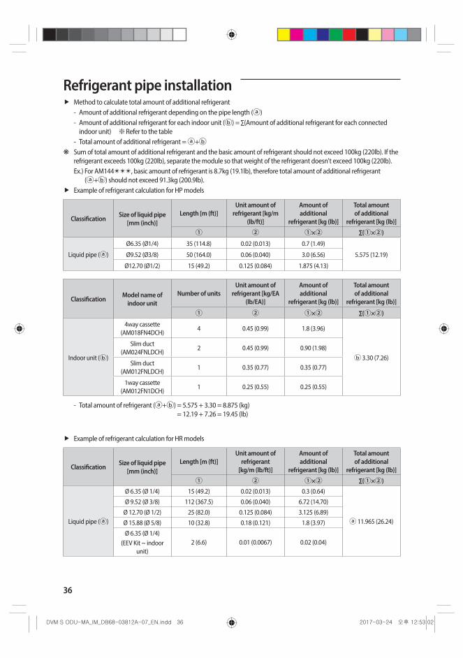
Refrigerant pipe installationMethod to calculate total amount of additional refrigerant - Amount of additional refrigerant depending on the pipe length (ⓐ) - Amount of additional refrigerant for each indoor unit (ⓑ) = ∑(Amount of additional refrigerant for each connected
indoor unit) ❇ Refer to the table - Total amount of additional refrigerant = ⓐ+ⓑ
❋ Sum of total amount of additional refrigerant and the basic amount of refrigerant should not exceed 100kg (220lb). If the refrigerant exceeds 100kg (220lb), separate the module so that weight of the refrigerant doesn't exceed 100kg (220lb).Ex.) For AM144✴✴✴, basic amount of refrigerant is 8.7kg (19.1lb), therefore total amount of additional refrigerant
(ⓐ+ⓑ) should not exceed 91.3kg (200.9lb).Example of refrigerant calculation for HP models
Classification Size of liquid pipe [mm (inch)]
Length [m (ft)]Unit amount of
refrigerant [kg/m (lb/ft)]
Amount of additional
refrigerant [kg (lb)]
Total amount of additional
refrigerant [kg (lb)]
① ② ①×② ∑(①×②)
Liquid pipe (ⓐ)
Ø6.35 (Ø1/4) 35 (114.8) 0.02 (0.013) 0.7 (1.49)
5.575 (12.19)Ø9.52 (Ø3/8) 50 (164.0) 0.06 (0.040) 3.0 (6.56)
Ø12.70 (Ø1/2) 15 (49.2) 0.125 (0.084) 1.875 (4.13)
Classification Model name of indoor unit
Number of unitsUnit amount of
refrigerant [kg/EA (lb/EA)]
Amount of additional
refrigerant [kg (lb)]
Total amount of additional
refrigerant [kg (lb)]
① ② ①×② ∑(①×②)
Indoor unit (ⓑ)
4way cassette (AM018FN4DCH)
4 0.45 (0.99) 1.8 (3.96)
ⓑ 3.30 (7.26)
Slim duct (AM024FNLDCH)
2 0.45 (0.99) 0.90 (1.98)
Slim duct (AM012FNLDCH)
1 0.35 (0.77) 0.35 (0.77)
1way cassette (AM012FN1DCH)
1 0.25 (0.55) 0.25 (0.55)
- Total amount of refrigerant (ⓐ+ⓑ) = 5.575 + 3.30 = 8.875 (kg) = 12.19 + 7.26 = 19.45 (lb)
Example of refrigerant calculation for HR models
Classification Size of liquid pipe [mm (inch)]
Length [m (ft)]Unit amount of
refrigerant [kg/m (lb/ft)]
Amount of additional
refrigerant [kg (lb)]
Total amount of additional
refrigerant [kg (lb)]
① ② ①×② ∑(①×②)
Liquid pipe (ⓐ)
Ø 6.35 (Ø 1/4) 15 (49.2) 0.02 (0.013) 0.3 (0.64)
ⓐ 11.965 (26.24)
Ø 9.52 (Ø 3/8) 112 (367.5) 0.06 (0.040) 6.72 (14.70)
Ø 12.70 (Ø 1/2) 25 (82.0) 0.125 (0.084) 3.125 (6.89)
Ø 15.88 (Ø 5/8) 10 (32.8) 0.18 (0.121) 1.8 (3.97)
Ø 6.35 (Ø 1/4)(EEV Kit ~ indoor
unit)2 (6.6) 0.01 (0.0067) 0.02 (0.04)
37
ENGLISH
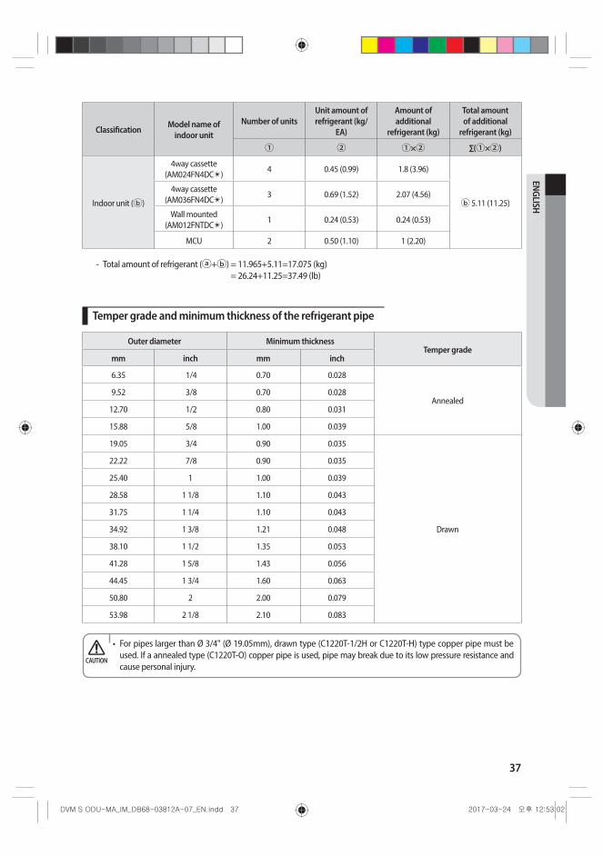
Classification Model name of indoor unit
Number of unitsUnit amount of refrigerant (kg/
EA)
Amount of additional
refrigerant (kg)
Total amount of additional
refrigerant (kg)
① ② ①×② ∑(①×②)
Indoor unit (ⓑ)
4way cassette (AM024FN4DC✴)
4 0.45 (0.99) 1.8 (3.96)
ⓑ 5.11 (11.25)
4way cassette (AM036FN4DC✴)
3 0.69 (1.52) 2.07 (4.56)
Wall mounted (AM012FNTDC✴)
1 0.24 (0.53) 0.24 (0.53)
MCU 2 0.50 (1.10) 1 (2.20)
- Total amount of refrigerant (ⓐ+ⓑ) = 11.965+5.11=17.075 (kg) = 26.24+11.25=37.49 (lb)
Temper grade and minimum thickness of the refrigerant pipe
Outer diameter Minimum thicknessTemper grade
mm inch mm inch
6.35 1/4 0.70 0.028
Annealed9.52 3/8 0.70 0.028
12.70 1/2 0.80 0.031
15.88 5/8 1.00 0.039
19.05 3/4 0.90 0.035
Drawn
22.22 7/8 0.90 0.035
25.40 1 1.00 0.039
28.58 1 1/8 1.10 0.043
31.75 1 1/4 1.10 0.043
34.92 1 3/8 1.21 0.048
38.10 1 1/2 1.35 0.053
41.28 1 5/8 1.43 0.056
44.45 1 3/4 1.60 0.063
50.80 2 2.00 0.079
53.98 2 1/8 2.10 0.083
• For pipes larger than Ø 3/4" (Ø 19.05mm), drawn type (C1220T-1/2H or C1220T-H) type copper pipe must be used. If a annealed type (C1220T-O) copper pipe is used, pipe may break due to its low pressure resistance and cause personal injury.
CAUTION

38
Refrigerant pipe installation
Keeping refrigerant pipeTo prevent foreign materials or water from entering the pipe, storing method and sealing method (especially during installation)is very important. Apply correct sealing method depending on the environment.
Exposure place Exposure time Sealing type
OutdoorLonger than one month Pipe pinch
Shorter than one month Taping
Indoor - Taping
Refrigerant pipe welding and safety information
Important information for refrigerant pipe work• Make sure there is no moisture inside the pipe.• Make sure there are no foreign substances and impurities in the pipe.• Make sure there is no leakage.• Make sure to follow the instruction when welding or storing the pipe.
CAUTION
Nitrogen flushing welding
When welding the refrigerant pipes, flush them with nitrogen gas as shown in the picture.If you do not perform nitrogen flushing when welding the pipes, oxide may form inside the pipe. It can cause the damage of the important parts such as compressor and valves etc.Adjust the flow rate of the nitrogen flushing with a pressure regulator to maintain 0.05m2/h(0.54ft2/h) or less.
Welding part
Nitrogen gas
Ø 6.35 (1/4") copper pipe
Stop valve
Taping
High pressure hose
Pressure regulator
Nitrogen gas
Flowmeter
Direction of the pipe when welding
Direction of the pipe should be headed downward or in a sideways when welding.Avoid welding the pipe with pipe direction heading upward.
• When you test gas leakage after welding the pipes, use a designated solution for gas leakage detection. If you use the detection solution that includes sulfuric ingredient, it may cause corrosion to the pipes. CAUTION
39
ENGLISH
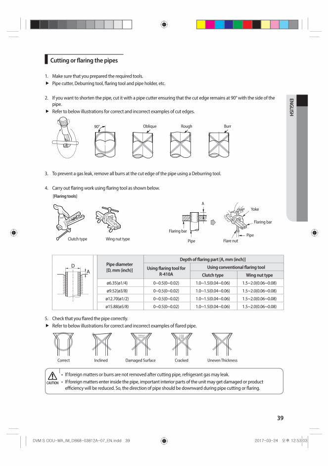
Cutting or flaring the pipes
1. Make sure that you prepared the required tools.Pipe cutter, Deburring tool, flaring tool and pipe holder, etc.
2. If you want to shorten the pipe, cut it with a pipe cutter ensuring that the cut edge remains at 90° with the side of the pipe. Refer to below illustrations for correct and incorrect examples of cut edges.
90° Oblique Rough Burr
3. To prevent a gas leak, remove all burrs at the cut edge of the pipe using a Deburring tool.
4. Carry out flaring work using flaring tool as shown below.
A
Flaring bar
Pipe
Yoke
Flaring bar
PipeFlare nutClutch type Wing nut type
[Flaring tools]
Pipe diameter [D, mm (inch)]
Depth of flaring part [A, mm (inch)]
Using flaring tool for R-410A
Using conventional flaring tool
Clutch type Wing nut type
ø6.35(ø1/4) 0~0.5(0~0.02) 1.0~1.5(0.04~0.06) 1.5~2.0(0.06~0.08)
ø9.52(ø3/8) 0~0.5(0~0.02) 1.0~1.5(0.04~0.06) 1.5~2.0(0.06~0.08)
ø12.70(ø1/2) 0~0.5(0~0.02) 1.0~1.5(0.04~0.06) 1.5~2.0(0.06~0.08)
ø15.88(ø5/8) 0~0.5(0~0.02) 1.0~1.5(0.04~0.06) 1.5~2.0(0.06~0.08)
5. Check that you flared the pipe correctly. Refer to below illustrations for correct and incorrect examples of flared pipe.
Uneven ThicknessCrackedDamaged SurfaceInclinedCorrect
• If foreign matters or burrs are not removed after cutting pipe, refrigerant gas may leak.• If foreign matters enter inside the pipe, important interior parts of the unit may get damaged or product
efficiency will be reduced. So, the direction of pipe should be downward during pipe cutting or flaring.CAUTION

40
Refrigerant pipe installation
Connecting the flared pipesCheck if the flaring is properly done according to the standard size.Align the center of the piping and tighten the flare nut with your hands. Then, tighten the flare nut with torque wrench in a direction of the arrow indicated in below illustration.Make sure to use ester oil to coat the flare connection section.
Flare connection section Flare nut
Pipe
Monkey wrench
Torque wrench
Outer diameter (D) Torque Flare dimension (L)Flare shape [mm(inch)]
mm inch N·m lbf·ft mm inch
6.35 1/4 14 ~ 18 10.3 ~ 13.3 8.7 ~ 9.1 0.34 ~ 0.36
DL90° ±
2°
45° ±
2°
R 0.4~0.8 (0.016~0.032)
9.52 3/8 34 ~ 42 25.1 ~ 31.0 12.8 ~ 13.2 0.50 ~ 0.52
12.7 1/2 49 ~ 61 36.1 ~ 45.0 16.2 ~ 16.6 0.64 ~ 0.65
15.88 5/8 68 ~ 82 50.2 ~ 60.5 19.3 ~ 19.7 0.76 ~ 0.78
• Blowing Nitrogen gas should be done when welding the pipe.• Make sure to use the provided flare nut.• Make sure that there are no cracks or twisted part when you need to bend the pipe.• Do not fasten the flare nut with excessive strength.• R-410A is a high pressure refrigerant and there is a risk of refrigerant leakage if the flare connection is not coated
with ester oil. Therefore, apply ester oil to coat the flare connection area.
CAUTION
41
ENGLISH
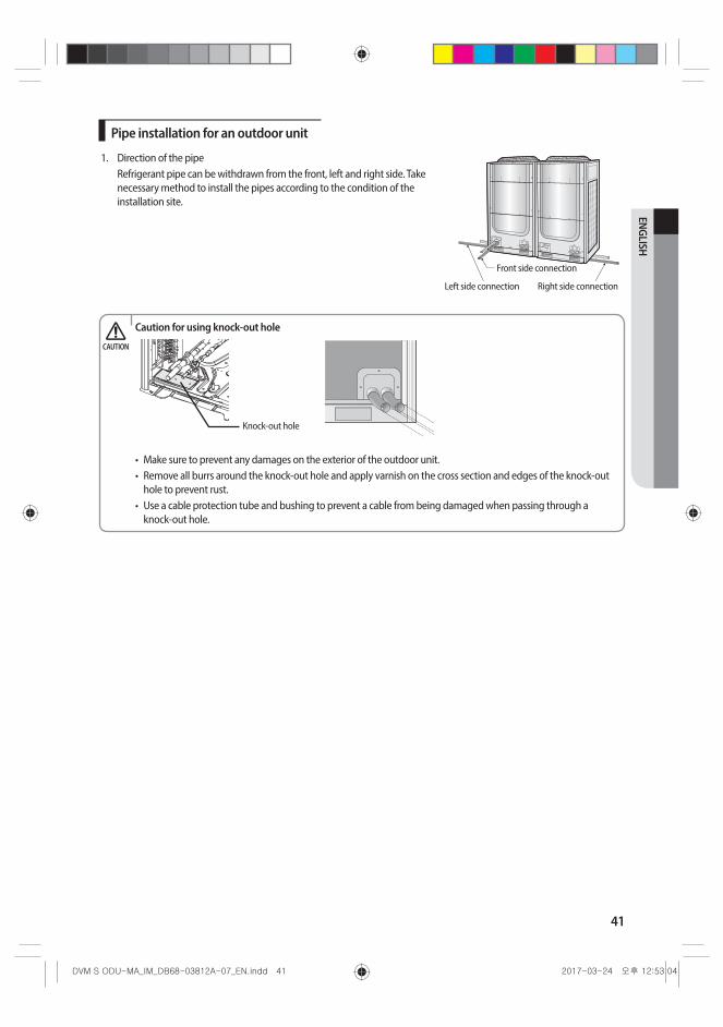
Pipe installation for an outdoor unit
1. Direction of the pipeRefrigerant pipe can be withdrawn from the front, left and right side. Take necessary method to install the pipes according to the condition of the installation site.
Front side connection
Right side connectionLeft side connection
Caution for using knock-out hole
Knock-out hole
• Make sure to prevent any damages on the exterior of the outdoor unit.• Remove all burrs around the knock-out hole and apply varnish on the cross section and edges of the knock-out
hole to prevent rust.• Use a cable protection tube and bushing to prevent a cable from being damaged when passing through a
knock-out hole.
CAUTION
42
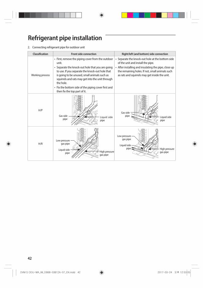
2. Connecting refrigerant pipe for outdoor unit
Classification Front side connection Right/left (and bottom) side connection
Working process
• First, remove the piping cover from the outdoor unit.
• Separate the knock-out hole that you are going to use. If you separate the knock-out hole that is going to be unused, small animals such as squirrels and rats may get into the unit through the hole.
• Fix the bottom side of the piping cover first and then fix the top part of it.
• Separate the knock-out hole at the bottom side of the unit and install the pipe.
• After installing and insulating the pipe, close up the remaining holes. If not, small animals such as rats and squirrels may get inside the unit.
H/P
Liquid side pipe
Gas side pipe
Gas side pipe Liquid side
pipe
H/R
High pressure gas pipe
Liquid side pipe
Low pressure gas pipe Liquid side
pipe
Low pressure gas pipe
High pressure gas pipe
Refrigerant pipe installation
43
ENGLISH
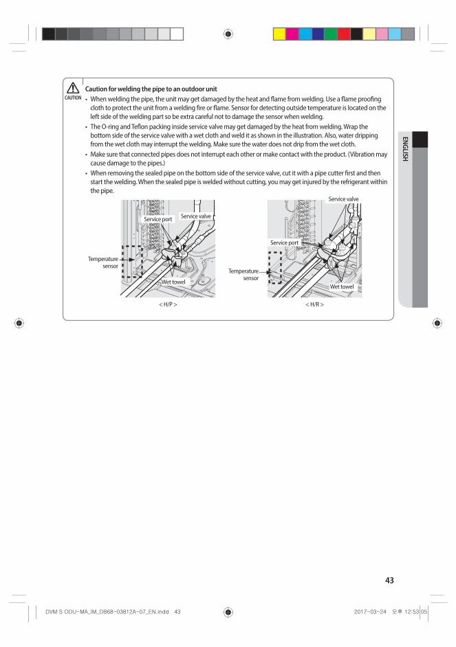
Caution for welding the pipe to an outdoor unit• When welding the pipe, the unit may get damaged by the heat and flame from welding. Use a flame proofing
cloth to protect the unit from a welding fire or flame. Sensor for detecting outside temperature is located on the left side of the welding part so be extra careful not to damage the sensor when welding.
• The O-ring and Teflon packing inside service valve may get damaged by the heat from welding. Wrap the bottom side of the service valve with a wet cloth and weld it as shown in the illustration. Also, water dripping from the wet cloth may interrupt the welding. Make sure the water does not drip from the wet cloth.
• Make sure that connected pipes does not interrupt each other or make contact with the product. (Vibration may cause damage to the pipes.)
• When removing the sealed pipe on the bottom side of the service valve, cut it with a pipe cutter first and then start the welding. When the sealed pipe is welded without cutting, you may get injured by the refrigerant within the pipe.
Temperature sensor
Wet towel
Service port
Service valve
< H/R >< H/P >
Temperature sensor
Wet towel
Service port Service valve
CAUTION
44
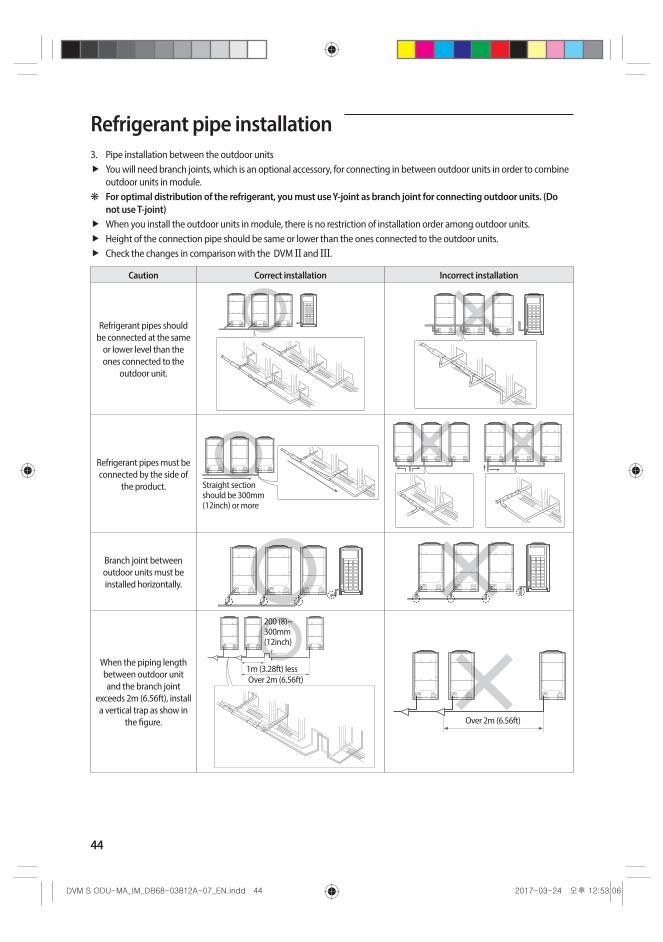
3. Pipe installation between the outdoor unitsYou will need branch joints, which is an optional accessory, for connecting in between outdoor units in order to combine outdoor units in module.
❋ For optimal distribution of the refrigerant, you must use Y-joint as branch joint for connecting outdoor units. (Do not use T-joint) When you install the outdoor units in module, there is no restriction of installation order among outdoor units.Height of the connection pipe should be same or lower than the ones connected to the outdoor units.Check the changes in comparison with the DVM II and III.
Caution Correct installation Incorrect installation
Refrigerant pipes should be connected at the same
or lower level than the ones connected to the
outdoor unit.
Refrigerant pipes must be connected by the side of
the product. Straight section should be 300mm (12inch) or more
Branch joint between outdoor units must be installed horizontally.
When the piping length between outdoor unit and the branch joint
exceeds 2m (6.56ft), install a vertical trap as show in
the figure.
1m (3.28ft) less
200 (8)~ 300mm (12inch)
Over 2m (6.56ft)
Over 2m (6.56ft)
Refrigerant pipe installation
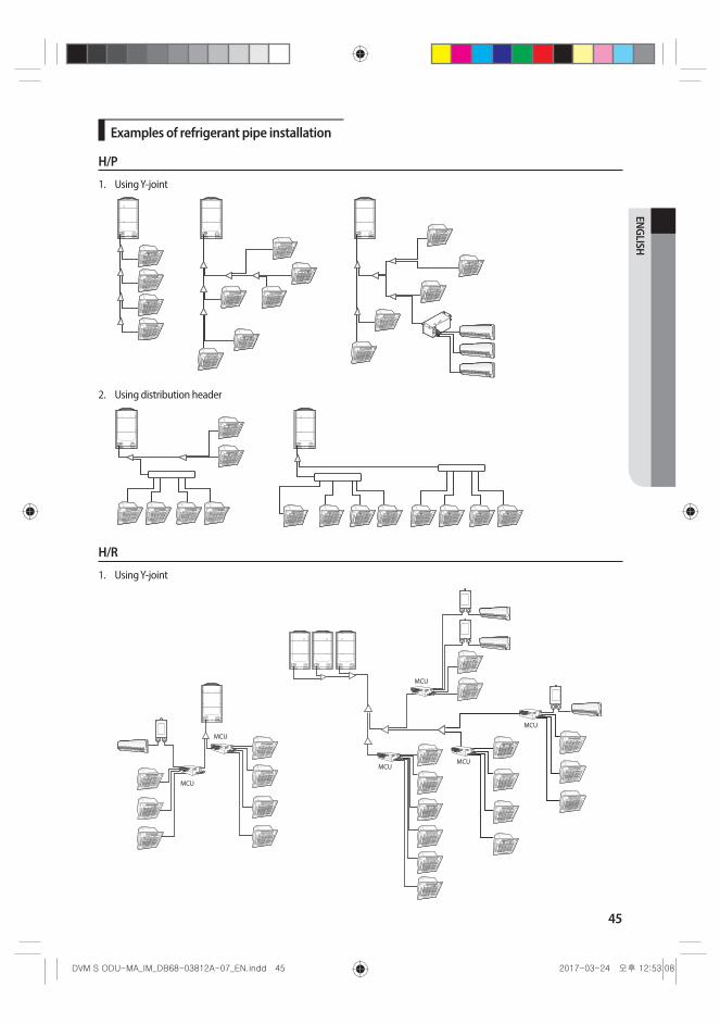
45
ENGLISH
Examples of refrigerant pipe installation
H/P
1. Using Y-joint
2. Using distribution header
H/R
1. Using Y-joint
MCU
MCU
MCU
MCU
MCU
MCU
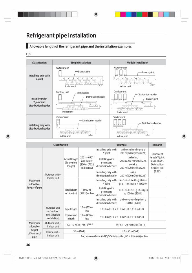
46
Refrigerant pipe installation
Allowable length of the refrigerant pipe and the installation examples
H/P
Classification Single Installation Module installation
Installing only with Y-joint
Branch jointOutdoor unit
Indoor unit
Branch joint
Outdoor unit
Indoor unit
Installing with Y-joint and
distribution header
Branch jointDistribution header
Outdoor unit
Indoor unit
Outdoor unit
Indoor unit
Distribution header
Branch joint
Installing only with distribution header
Outdoor unit
Indoor unit
Distribution header Outdoor unit
Indoor unit
Distribution header
Classification Example Remarks
Maximum allowable
length of pipe
Outdoor unit ~ Indoor unit
Actual length (Equivalent
length)
200 m (656') and below
[220 m (722') and below]
Installing only with Y-joint
a+b+c+d+e+f+g+p ≤ 200 m(220 m)/656'(722') Equivalent
length Y-joint: 0.5 m (1.64'), Distribution header: 1 m
(3.28')
Installing with Y-joint and
distribution header
a+b+h ≤ 200 m(220 m)/656'(722'),
a+i+k ≤ 200 m(220 m)/656'(722')
Installing only with distribution header
a+i ≤ 200 m(220 m)/656'(722')
Total length of pipe (m)
1000 m (3281') or less
Installing only with Y-joint
a+b+c+d+e+f+g+h+i+ j+k+l+m+n+p ≤ 1000 m
Installing with Y-joint and
distribution header
a+b+c+d+e+f+g+h+i+j+k ≤ 1000 m (3281')
Installing only with distribution header
a+b+c+d+e+f+g+h+i ≤ 1000 m (3281')
Outdoor unit ~ Outdoor
unit (Module installation)
Pipe length10 m (33') or
lessr ≤ 10 m (33'), s ≤ 10 m (33'), t ≤ 10 m (33')
Equivalent length
13 m (43') or less
r ≤ 13 m (43'), s ≤ 13 m (43'), t ≤ 13 m (43')
Maximum allowable
height difference of
pipe
Outdoor unit ~ Indoor unit
110/110 m(361'/361') Note 2) H1 ≤ 110/110 m(361'/361')
Indoor unit ~ Indoor unit
50 m (164') H2 ≤ 50 m (164')
But, when AM✴✴✴HNQDC✴ is installed, H2 is 15 m(49') or less.
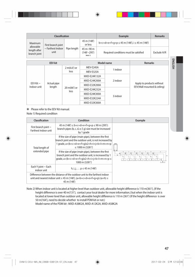
47
ENGLISH
Classification Example Remarks
Maximum allowable
length after branch joint
First branch joint ~ Farthest Indoor
unitPipe length
45 m (148') or less
b+c+d+e+f+g+p ≤ 45 m (148'), i ≤ 45 m (148')
45 m~90 m (148'~295')
Note 1)Required conditions must be satisfied Exclude H/R
EEV kit Model name Remarks
EEV Kit ~ Indoor unit
Actual pipe length
2 m(6.6') or less
MEV-E24SA1 indoor
Apply to products without EEV(Wall mounted & ceiling)
MEV-E32SA
20 m(66') or less
MXD-E24K132A
2 indoorMXD-E24K200A
MXD-E32K200A
MXD-E24K232A
3 indoorMXD-E24K300A
MXD-E32K224A
MXD-E32K300A
❋ Please refer to the EEV Kit manual.Note 1) Required condition
Classification Condition Example
First branch joint ~ Farthest Indoor unit
45 m (148') ≤ b+c+d+e+f+g+p ≤ 90 m (295'): branch pipes (b, c, d, e, f, g) size must be increased
by 1 grade
Total length of extended pipe
If the size of pipe (main pipe), between the first branch joint and the outdoor unit, is not increased by 1 grade, a+(b+c+d+e+f+g)x2+h+i+j+k+l+m+n+p
≤ 1000 m (3281')
If the size of pipe (main pipe), between the first branch joint and the outdoor unit, is increased by 1
grade, a+(b+c+d+e+f+g)x2+h+i+j+k+l+m+n+p ≤ 1000 m (3281')
Each Y-joint ~ Each indoor unit
h, i, j, … p ≤ 45 m (148')
Difference between the distance of the outdoor unit to the farthest indoor unit and nearest indoor unit ≤ 45 m (148'), (a+b+c+d+e+f+g+p)-(a+h) ≤
45 m (148')
Note 2) When indoor unit is located at higher level than outdoor unit, allowable height difference is 110 m(361'), (If the height difference is over 40 m(131'), contact your local dealer for more information.) but when the indoor unit is located at lower level than outdoor unit, allowable height difference is 110 m (361') (If the height difference is over 50 m(164'), need to decide whether to install PDM kit or not.) Model name of the PDM kit : MXD-A38K2A, MXD-A12K2A, MXD-A58K2A
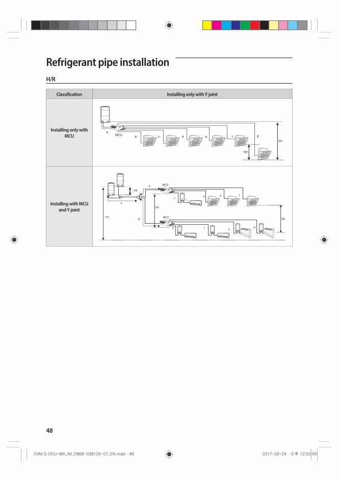
48
Refrigerant pipe installationH/R
Classification Installing only with Y-joint
Installing only with MCU
Installing with MCU and Y-joint
MCU
MCU
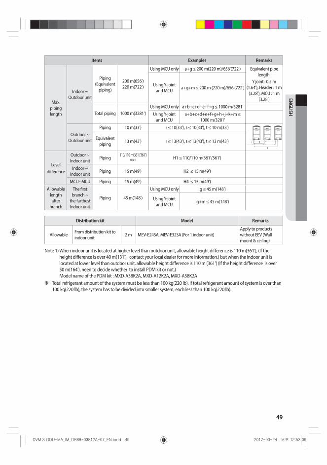
49
ENGLISH
Items Examples Remarks
Max. piping length
Indoor ~ Outdoor unit
Piping (Equivalent
piping)
200 m(656') 220 m(722')
Using MCU only a+g ≤ 200 m(220 m)/656'(722') Equivalent pipe length.
Y joint : 0.5 m (1.64'), Header : 1 m
(3.28'), MCU : 1 m (3.28')
Using Y-joint and MCU
a+g+m ≤ 200 m (220 m)/656'(722')
Total piping 1000 m(3281')Using MCU only a+b+c+d+e+f+g ≤ 1000 m/3281'
Using Y-joint and MCU
a+b+c+d+e+f+g+h+j+k+m ≤ 1000 m/3281'
Outdoor ~ Outdoor unit
Piping 10 m(33') r ≤ 10(33'), s ≤ 10(33'), t ≤ 10 m(33')
Equivalent piping
13 m(43') r ≤ 13(43'), s ≤ 13(43'), t ≤ 13 m(43')
Leveldifference
Outdoor ~ Indoor unit
Piping110/110 m(361'/361')
Note 1) H1 ≤ 110/110 m(361'/361')
Indoor ~ Indoor unit
Piping 15 m(49') H2 ≤ 15 m(49')
MCU~MCU Piping 15 m(49') H4 ≤ 15 m(49')
Allowable length after
branch
The first branch ~
the farthest Indoor unit
Piping 45 m(148')
Using MCU only g ≤ 45 m(148')
Using Y-joint and MCU
g+m ≤ 45 m(148')
Distribution kit Model Remarks
AllowableFrom distribution kit to indoor unit
2 m MEV-E24SA, MEV-E32SA (For 1 indoor unit)Apply to products without EEV (Wall mount & ceiling)
Note 1) When indoor unit is located at higher level than outdoor unit, allowable height difference is 110 m(361'), (If the height difference is over 40 m(131'), contact your local dealer for more information.) but when the indoor unit is located at lower level than outdoor unit, allowable height difference is 110 m (361') (If the height difference is over 50 m(164'), need to decide whether to install PDM kit or not.) Model name of the PDM kit : MXD-A38K2A, MXD-A12K2A, MXD-A58K2A
❋ Total refrigerant amount of the system must be less than 100 kg(220 lb). If total refrigerant amount of system is over than 100 kg(220 lb), the system has to be divided into smaller system, each less than 100 kg(220 lb).
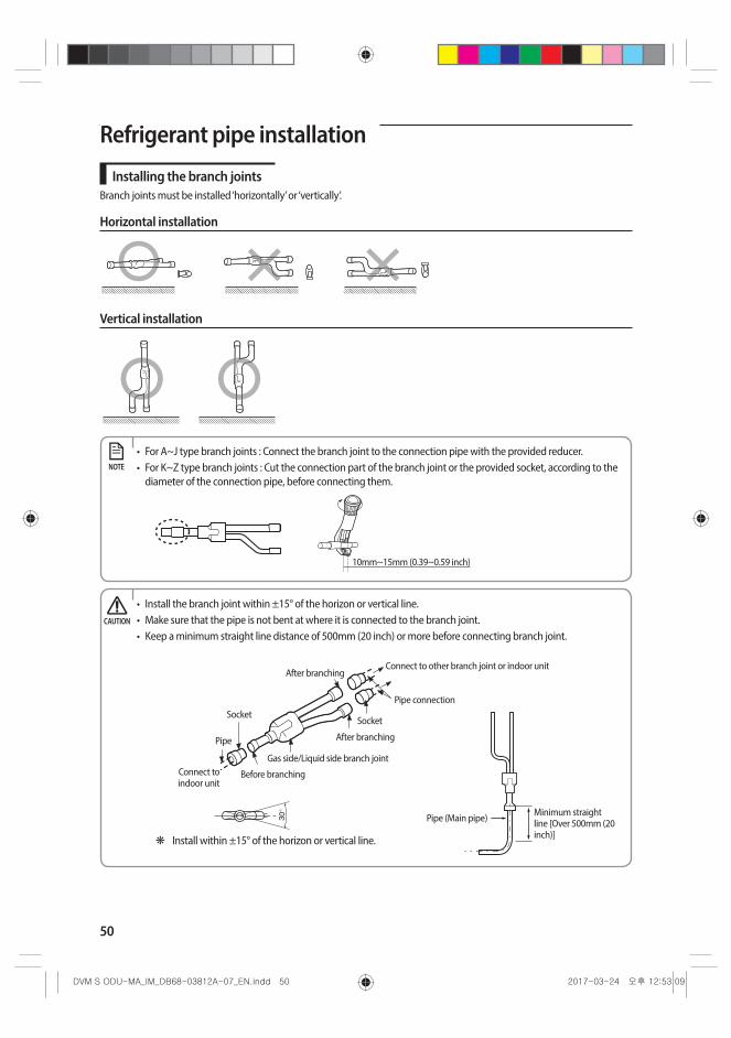
50
Refrigerant pipe installation
Installing the branch jointsBranch joints must be installed ‘horizontally’ or ‘vertically’.
Horizontal installation
Vertical installation
• For A~J type branch joints : Connect the branch joint to the connection pipe with the provided reducer.• For K~Z type branch joints : Cut the connection part of the branch joint or the provided socket, according to the
diameter of the connection pipe, before connecting them.
10mm~15mm (0.39~0.59 inch)
NOTE
• Install the branch joint within ±15° of the horizon or vertical line.• Make sure that the pipe is not bent at where it is connected to the branch joint.• Keep a minimum straight line distance of 500mm (20 inch) or more before connecting branch joint.
❋ Install within ±15° of the horizon or vertical line.
Minimum straight line [Over 500mm (20 inch)]
Pipe (Main pipe)
Connect to indoor unit
Pipe
Before branching
After branching
After branching
Gas side/Liquid side branch joint
Pipe connection
Socket
Connect to other branch joint or indoor unit
Socket
CAUTION
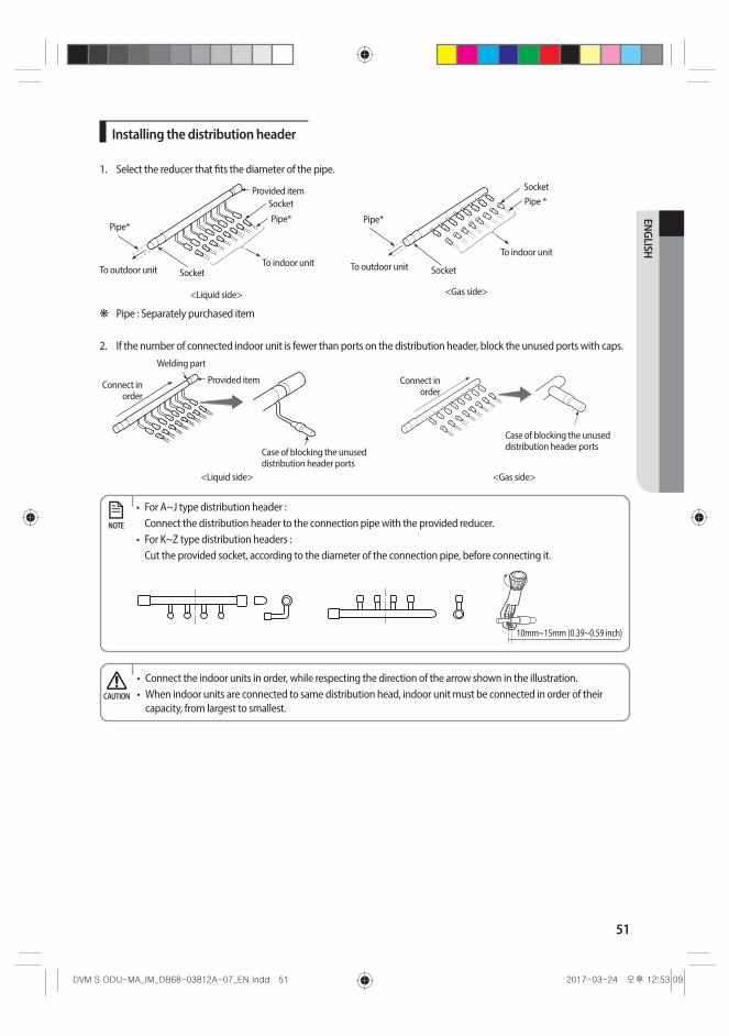
51
ENGLISH
Installing the distribution header
1. Select the reducer that fits the diameter of the pipe.
<Gas side>
SocketPipe *
To indoor unit
Pipe*
SocketTo outdoor unit
<Liquid side>
SocketPipe*
To indoor unit
Pipe*
SocketTo outdoor unit
Provided item
❋ Pipe : Separately purchased item
2. If the number of connected indoor unit is fewer than ports on the distribution header, block the unused ports with caps.
<Liquid side>
Case of blocking the unused distribution header ports
Connect in order
Welding part
Provided item
<Gas side>
Case of blocking the unused distribution header ports
Connect in order
• For A~J type distribution header : Connect the distribution header to the connection pipe with the provided reducer.
• For K~Z type distribution headers : Cut the provided socket, according to the diameter of the connection pipe, before connecting it.
10mm~15mm (0.39~0.59 inch)
NOTE
• Connect the indoor units in order, while respecting the direction of the arrow shown in the illustration. • When indoor units are connected to same distribution head, indoor unit must be connected in order of their
capacity, from largest to smallest.CAUTION

52
3. Install the distribution header horizontally.Install the distribution header horizontally so that its ports does not face down.
Below ±10°
Horizon line
Socket Distribution header
Pipe (Separately purchased item)
Below ±15°Horizon line
Horizon line
< Liquid side >
Below ±15°Horizon line
Below ±10°
Horizon line
< Gas side >
Installing the branch joint between outdoor units
Installation of outdoor joints
Do not install the outdoor joint in this direction.
Liquid pipe
High pressure gas pipe
Gas pipe
❋ High pressure gas pipe only applies to the H/R product.
Refrigerant pipe installation

53
ENGLISH
<Liquid side>
❋ Use the attached reducer according to the selected pipe size.
Pipe
Reducer
ReducerPipe
To other outdoor unit
To other outdoor joint or Y-joint of the main pipe
To other outdoor joint or outdoor unit
<Gas side>
❋ Use the attached reducer according to the selected pipe size.
Pipe
Reducer
Reducer
Pipe
To other outdoor unit
To other outdoor joint or Y-joint of the main pipe
To other outdoor joint or outdoor unit
❋ Use the attached reducer according to the selected pipe size.Pipe
ReducerReducer
Pipe
To other outdoor unit
To other outdoor joint or Y-joint of the main pipe
<High pressure gas side>
To other outdoor joint or outdoor unit
• Connect the Outdoor joint to the pipe by cutting the outlet of the Outdoor joint or provided reducer properly.
10mm~15mm (0.39~0.59 inch) or more
NOTE
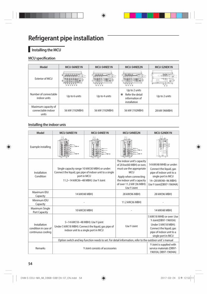
54
Refrigerant pipe installation
Installing the MCU
MCU specification
Model MCU-S6NEE1N MCU-S4NEE1N MCU-S4NEE2N MCU-S2NEK1N
Exterior of MCU
Number of connectable indoor units
Up to 6 units Up to 4 units
Up to 2 units ❋ Refer the detail
information of installation
Up to 2 units
Maximum capacity of connectable indoor
units56 kW (192MBH) 56 kW (192MBH) 56 kW (192MBH) 28 kW (96MBH)
Installing the indoor unis
Model MCU-S6NEE1N MCU-S4NEE1N MCU-S4NEE2N MCU-S2NEK1N
Example installing
Installation Condition
Single capacity range 10 kW(30 MBH) or under: Connect the liquid, gas pipe of indoor unit to a single
port in MCU 11.2~14 kW(36~48 MBH): Use Y-Joint
The indoor unit's capacity of 20 kw(60 MBH) or over, must use the appropriate
MCUApply when connecting
the indoor unit's capacity of over 11.2 kW (36 MBH):
Use Y-Joint
14 kW(48 MHB) or under:Connect the liquid, gas pipe of indoor unit to a
single port in MCU14~28 kW(48~96 MBH):
Use Y-Joint(DB97-19694A)
Maximum IDU Capacity
14 kW(48 MBH) 28 kW(96 MBH) 28 kW(96 MBH)
Minimum IDU Capacity
- 11.2 kW(36 MBH) -
Maximum Single Port Capacity
10 kW(30 MBH) - 14 kW(48 MBH)
Installation condition in case of continuous cooling
5~14 kW(18~48 MBH): Use Y-jointUnder 5 kW(18 MBH): Connect the liquid, gas pipe of
indoor unit to a single port in MCUUse Y-Joint
5 kW(18 MHB) or over: Use Y-Joint(DB97-19693A)Under 5 kW(18 MBH):
Connect the liquid, gas pipe of indoor unit to a
single port in MCUOption switch and key function needs to set. For detail information, refer to the outdoor unit`s manual
Remarks Y-Joint consists of accessoriesY-Joint is supplied with
service materials (DB97-19693A, DB97-19694A)

55
ENGLISH
How to connect the pipes
Low pressure gas pipe conection (welding)
High pressure gas pipe connection (welding)
Liquid pipe connection (Flare)
Pipe connection from outdoor unit
Pipe connection to indoor unit
Gas pipe (Flare)Liquid pipe (Flare)
Protect with wet towel when welding
70mm (2.75 inch)
70mm (2.75 inch)
❋ When installing MCU, use the pattern sheet for installation that is provided with the product. ❋ When welding the high/low pressure gas pipe, protect the product with the flame-proof sheet.
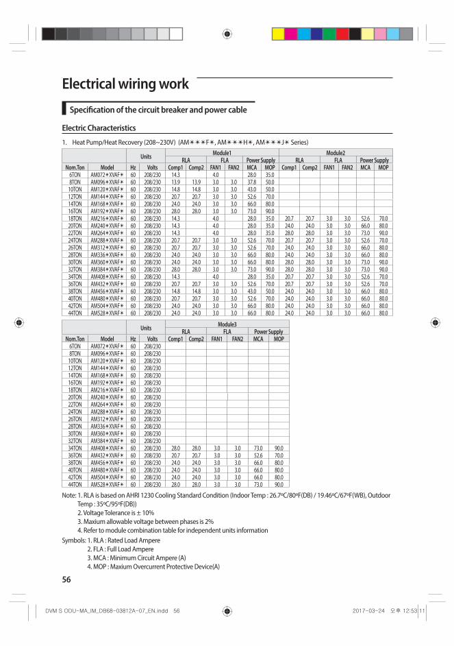
56
Electrical wiring work
Specification of the circuit breaker and power cable
Electric Characteristics
1. Heat Pump/Heat Recovery (208~230V) (AM✴✴✴F✴, AM✴✴✴H✴, AM✴✴✴J✴ Series)
Units Module1 Module2RLA FLA Power Supply RLA FLA Power Supply
Nom.Ton Model Hz Volts Comp1 Comp2 FAN1 FAN2 MCA MOP Comp1 Comp2 FAN1 FAN2 MCA MOP6TON AM072✴XVAF✴ 60 208/230 14.3 4.0 28.0 35.08TON AM096✴XVAF✴ 60 208/230 13.9 13.9 3.0 3.0 37.8 50.0
10TON AM120✴XVAF✴ 60 208/230 14.8 14.8 3.0 3.0 43.0 50.012TON AM144✴XVAF✴ 60 208/230 20.7 20.7 3.0 3.0 52.6 70.014TON AM168✴XVAF✴ 60 208/230 24.0 24.0 3.0 3.0 66.0 80.016TON AM192✴XVAF✴ 60 208/230 28.0 28.0 3.0 3.0 73.0 90.018TON AM216✴XVAF✴ 60 208/230 14.3 4.0 28.0 35.0 20.7 20.7 3.0 3.0 52.6 70.020TON AM240✴XVAF✴ 60 208/230 14.3 4.0 28.0 35.0 24.0 24.0 3.0 3.0 66.0 80.022TON AM264✴XVAF✴ 60 208/230 14.3 4.0 28.0 35.0 28.0 28.0 3.0 3.0 73.0 90.024TON AM288✴XVAF✴ 60 208/230 20.7 20.7 3.0 3.0 52.6 70.0 20.7 20.7 3.0 3.0 52.6 70.026TON AM312✴XVAF✴ 60 208/230 20.7 20.7 3.0 3.0 52.6 70.0 24.0 24.0 3.0 3.0 66.0 80.028TON AM336✴XVAF✴ 60 208/230 24.0 24.0 3.0 3.0 66.0 80.0 24.0 24.0 3.0 3.0 66.0 80.030TON AM360✴XVAF✴ 60 208/230 24.0 24.0 3.0 3.0 66.0 80.0 28.0 28.0 3.0 3.0 73.0 90.032TON AM384✴XVAF✴ 60 208/230 28.0 28.0 3.0 3.0 73.0 90.0 28.0 28.0 3.0 3.0 73.0 90.034TON AM408✴XVAF✴ 60 208/230 14.3 4.0 28.0 35.0 20.7 20.7 3.0 3.0 52.6 70.036TON AM432✴XVAF✴ 60 208/230 20.7 20.7 3.0 3.0 52.6 70.0 20.7 20.7 3.0 3.0 52.6 70.038TON AM456✴XVAF✴ 60 208/230 14.8 14.8 3.0 3.0 43.0 50.0 24.0 24.0 3.0 3.0 66.0 80.040TON AM480✴XVAF✴ 60 208/230 20.7 20.7 3.0 3.0 52.6 70.0 24.0 24.0 3.0 3.0 66.0 80.042TON AM504✴XVAF✴ 60 208/230 24.0 24.0 3.0 3.0 66.0 80.0 24.0 24.0 3.0 3.0 66.0 80.044TON AM528✴XVAF✴ 60 208/230 24.0 24.0 3.0 3.0 66.0 80.0 24.0 24.0 3.0 3.0 66.0 80.0
Units Module3RLA FLA Power Supply
Nom.Ton Model Hz Volts Comp1 Comp2 FAN1 FAN2 MCA MOP6TON AM072✴XVAF✴ 60 208/2308TON AM096✴XVAF✴ 60 208/230
10TON AM120✴XVAF✴ 60 208/23012TON AM144✴XVAF✴ 60 208/23014TON AM168✴XVAF✴ 60 208/23016TON AM192✴XVAF✴ 60 208/23018TON AM216✴XVAF✴ 60 208/23020TON AM240✴XVAF✴ 60 208/23022TON AM264✴XVAF✴ 60 208/23024TON AM288✴XVAF✴ 60 208/23026TON AM312✴XVAF✴ 60 208/23028TON AM336✴XVAF✴ 60 208/23030TON AM360✴XVAF✴ 60 208/23032TON AM384✴XVAF✴ 60 208/23034TON AM408✴XVAF✴ 60 208/230 28.0 28.0 3.0 3.0 73.0 90.036TON AM432✴XVAF✴ 60 208/230 20.7 20.7 3.0 3.0 52.6 70.038TON AM456✴XVAF✴ 60 208/230 24.0 24.0 3.0 3.0 66.0 80.040TON AM480✴XVAF✴ 60 208/230 24.0 24.0 3.0 3.0 66.0 80.042TON AM504✴XVAF✴ 60 208/230 24.0 24.0 3.0 3.0 66.0 80.044TON AM528✴XVAF✴ 60 208/230 28.0 28.0 3.0 3.0 73.0 90.0
Note: 1. RLA is based on AHRI 1230 Cooling Standard Condition (Indoor Temp : 26.7ºC/80ºF(DB) / 19.46ºC/67ºF(WB), Outdoor Temp : 35ºC/95ºF(DB)) 2. Voltage Tolerance is ± 10% 3. Maxium allowable voltage between phases is 2% 4. Refer to module combination table for independent units information
Symbols: 1. RLA : Rated Load Ampere 2. FLA : Full Load Ampere 3. MCA : Minimum Circuit Ampere (A) 4. MOP : Maxium Overcurrent Protective Device(A)

57
ENGLISH
2. Heat Pump/Heat Recovery (460V) (AM✴✴✴F✴, AM✴✴✴H✴, AM✴✴✴J✴ Series)
UnitsModule1 Module2
RLA FLA Power Supply RLA FLA Power SupplyNom.Ton Model Hz Volts Comp1 Comp2 FAN1 FAN2 MCA MOP Comp1 Comp2 FAN1 FAN2 MCA MOP
6TON AM072✴XVAJ✴ 60 460 9.5 2.0 16.4 20.08TON AM096✴XVAJ✴ 60 460 11.5 1.5 1.5 19.0 25.0
10TON AM120✴XVAJ✴ 60 460 14.0 1.5 1.5 21.7 30.012TON AM144✴XVAJ✴ 60 460 11.4 11.4 1.5 1.5 28.7 40.014TON AM168✴XVAJ✴ 60 460 12.0 12.0 1.5 1.5 33.0 40.016TON AM192✴XVAJ✴ 60 460 14.5 14.5 1.5 1.5 37.0 50.018TON AM216✴XVAJ✴ 60 460 9.5 2.0 16.4 20.0 11.4 11.4 1.5 1.5 28.7 40.020TON AM240✴XVAJ✴ 60 460 9.5 2.0 16.4 20.0 12.0 12.0 1.5 1.5 33.0 40.022TON AM264✴XVAJ✴ 60 460 9.5 2.0 16.4 20.0 14.5 14.5 1.5 1.5 37.0 50.024TON AM288✴XVAJ✴ 60 460 11.4 11.4 1.5 1.5 28.7 40.0 11.4 11.4 1.5 1.5 28.7 40.026TON AM312✴XVAJ✴ 60 460 11.4 11.4 1.5 1.5 28.7 40.0 12.0 12.0 1.5 1.5 33.0 40.028TON AM336✴XVAJ✴ 60 460 12.0 12.0 1.5 1.5 33.0 40.0 12.0 12.0 1.5 1.5 33.0 40.030TON AM360✴XVAJ✴ 60 460 12.0 12.0 1.5 1.5 33.0 40.0 14.5 14.5 1.5 1.5 37.0 50.032TON AM384✴XVAJ✴ 60 460 14.5 14.5 1.5 1.5 37.0 50.0 14.5 14.5 1.5 1.5 37.0 50.034TON AM408✴XVAJ✴ 60 460 9.5 2.0 16.4 20.0 11.4 11.4 1.5 1.5 28.7 40.036TON AM432✴XVAJ✴ 60 460 11.4 11.4 1.5 1.5 28.7 40.0 11.4 11.4 1.5 1.5 28.7 40.038TON AM456✴XVAJ✴ 60 460 14.0 1.5 1.5 21.7 30.0 12.0 12.0 1.5 1.5 33.0 40.040TON AM480✴XVAJ✴ 60 460 11.4 11.4 1.5 1.5 28.7 40.0 12.0 12.0 1.5 1.5 33.0 40.042TON AM504✴XVAJ✴ 60 460 12.0 12.0 1.5 1.5 33.0 40.0 12.0 12.0 1.5 1.5 33.0 40.044TON AM528✴XVAJ✴ 60 460 12.0 12.0 1.5 1.5 33.0 40.0 12.0 12.0 1.5 1.5 33.0 40.0
Units Module3RLA FLA Power Supply
Nom.Ton Model Hz Volts Comp1 Comp2 FAN1 FAN2 MCA MOP6TON AM072✴XVAJ✴ 60 4608TON AM096✴XVAJ✴ 60 460
10TON AM120✴XVAJ✴ 60 46012TON AM144✴XVAJ✴ 60 46014TON AM168✴XVAJ✴ 60 46016TON AM192✴XVAJ✴ 60 46018TON AM216✴XVAJ✴ 60 46020TON AM240✴XVAJ✴ 60 46022TON AM264✴XVAJ✴ 60 46024TON AM288✴XVAJ✴ 60 46026TON AM312✴XVAJ✴ 60 46028TON AM336✴XVAJ✴ 60 46030TON AM360✴XVAJ✴ 60 46032TON AM384✴XVAJ✴ 60 46034TON AM408✴XVAJ✴ 60 460 14.5 14.5 1.5 1.5 37.0 50.036TON AM432✴XVAJ✴ 60 460 11.4 11.4 1.5 1.5 28.7 40.038TON AM456✴XVAJ✴ 60 460 12.0 12.0 1.5 1.5 33.0 40.040TON AM480✴XVAJ✴ 60 460 12.0 12.0 1.5 1.5 33.0 40.042TON AM504✴XVAJ✴ 60 460 12.0 12.0 1.5 1.5 33.0 40.044TON AM528✴XVAJ✴ 60 460 14.5 14.5 1.5 1.5 37.0 50.0
Note: 1. RLA is based on AHRI 1230 Cooling Standard Condition (Indoor Temp : 26.7ºC/80ºF(DB) / 19.46ºC/67ºF(WB), Outdoor Temp : 35ºC/95ºF(DB)) 2. Voltage Tolerance is ± 10% 3. Maxium allowable voltage between phases is 2% 4. Refer to module combination table for independent units information
Symbols: 1. RLA : Rated Load Ampere 2. FLA : Full Load Ampere 3. MCA : Minimum Circuit Ampere (A) 4. MOP : Maxium Overcurrent Protective Device(A)
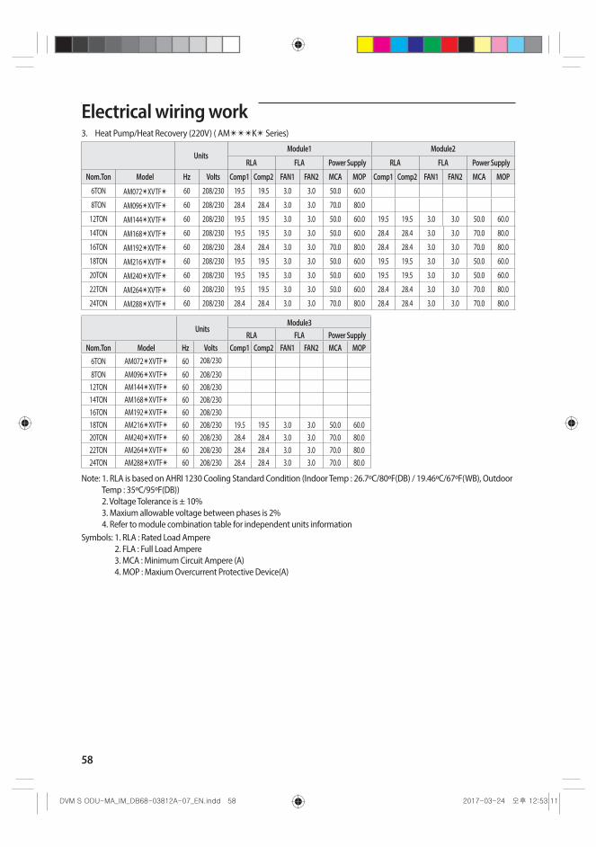
58
Electrical wiring work3. Heat Pump/Heat Recovery (220V) ( AM✴✴✴K✴ Series)
UnitsModule1 Module2
RLA FLA Power Supply RLA FLA Power Supply
Nom.Ton Model Hz Volts Comp1 Comp2 FAN1 FAN2 MCA MOP Comp1 Comp2 FAN1 FAN2 MCA MOP
6TON AM072✴XVTF✴ 60 208/230 19.5 19.5 3.0 3.0 50.0 60.0
8TON AM096✴XVTF✴ 60 208/230 28.4 28.4 3.0 3.0 70.0 80.0
12TON AM144✴XVTF✴ 60 208/230 19.5 19.5 3.0 3.0 50.0 60.0 19.5 19.5 3.0 3.0 50.0 60.0
14TON AM168✴XVTF✴ 60 208/230 19.5 19.5 3.0 3.0 50.0 60.0 28.4 28.4 3.0 3.0 70.0 80.0
16TON AM192✴XVTF✴ 60 208/230 28.4 28.4 3.0 3.0 70.0 80.0 28.4 28.4 3.0 3.0 70.0 80.0
18TON AM216✴XVTF✴ 60 208/230 19.5 19.5 3.0 3.0 50.0 60.0 19.5 19.5 3.0 3.0 50.0 60.0
20TON AM240✴XVTF✴ 60 208/230 19.5 19.5 3.0 3.0 50.0 60.0 19.5 19.5 3.0 3.0 50.0 60.0
22TON AM264✴XVTF✴ 60 208/230 19.5 19.5 3.0 3.0 50.0 60.0 28.4 28.4 3.0 3.0 70.0 80.0
24TON AM288✴XVTF✴ 60 208/230 28.4 28.4 3.0 3.0 70.0 80.0 28.4 28.4 3.0 3.0 70.0 80.0
UnitsModule3
RLA FLA Power SupplyNom.Ton Model Hz Volts Comp1 Comp2 FAN1 FAN2 MCA MOP
6TON AM072✴XVTF✴ 60 208/230
8TON AM096✴XVTF✴ 60 208/23012TON AM144✴XVTF✴ 60 208/23014TON AM168✴XVTF✴ 60 208/23016TON AM192✴XVTF✴ 60 208/23018TON AM216✴XVTF✴ 60 208/230 19.5 19.5 3.0 3.0 50.0 60.020TON AM240✴XVTF✴ 60 208/230 28.4 28.4 3.0 3.0 70.0 80.022TON AM264✴XVTF✴ 60 208/230 28.4 28.4 3.0 3.0 70.0 80.024TON AM288✴XVTF✴ 60 208/230 28.4 28.4 3.0 3.0 70.0 80.0
Note: 1. RLA is based on AHRI 1230 Cooling Standard Condition (Indoor Temp : 26.7ºC/80ºF(DB) / 19.46ºC/67ºF(WB), Outdoor Temp : 35ºC/95ºF(DB)) 2. Voltage Tolerance is ± 10% 3. Maxium allowable voltage between phases is 2% 4. Refer to module combination table for independent units information
Symbols: 1. RLA : Rated Load Ampere 2. FLA : Full Load Ampere 3. MCA : Minimum Circuit Ampere (A) 4. MOP : Maxium Overcurrent Protective Device(A)
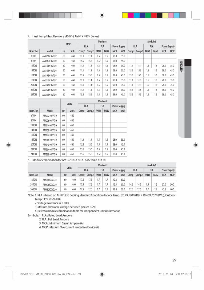
59
ENGLISH
4. Heat Pump/Heat Recovery (460V) ( AM✴✴✴K✴ Series)
UnitsModule1 Module2
RLA FLA Power Supply RLA FLA Power Supply
Nom.Ton Model Hz Volts Comp1 Comp2 FAN1 FAN2 MCA MOP Comp1 Comp2 FAN1 FAN2 MCA MOP
6TON AM072✴XVTJ✴ 60 460 11.1 11.1 1.5 1.5 28.0 35.0
8TON AM096✴XVTJ✴ 60 460 15.5 15.5 1.5 1.5 38.0 45.0
12TON AM144✴XVTJ✴ 60 460 11.1 11.1 1.5 1.5 28.0 35.0 11.1 11.1 1.5 1.5 28.0 35.0
14TON AM168✴XVTJ✴ 60 460 11.1 11.1 1.5 1.5 28.0 35.0 15.5 15.5 1.5 1.5 38.0 45.0
16TON AM192✴XVTJ✴ 60 460 15.5 15.5 1.5 1.5 38.0 45.0 15.5 15.5 1.5 1.5 38.0 45.0
18TON AM216✴XVTJ✴ 60 460 11.1 11.1 1.5 1.5 28.0 35.0 11.1 11.1 1.5 1.5 28.0 35.0
20TON AM240✴XVTJ✴ 60 460 11.1 11.1 1.5 1.5 28.0 35.0 11.1 11.1 1.5 1.5 28.0 35.0
22TON AM264✴XVTJ✴ 60 460 11.1 11.1 1.5 1.5 28.0 35.0 15.5 15.5 1.5 1.5 38.0 45.0
24TON AM288✴XVTJ✴ 60 460 15.5 15.5 1.5 1.5 38.0 45.0 15.5 15.5 1.5 1.5 38.0 45.0
UnitsModule3
RLA FLA Power Supply
Nom.Ton Model Hz Volts Comp1 Comp2 FAN1 FAN2 MCA MOP
6TON AM072✴XVTJ✴ 60 460
8TON AM096✴XVTJ✴ 60 460
12TON AM144✴XVTJ✴ 60 460
14TON AM168✴XVTJ✴ 60 460
16TON AM192✴XVTJ✴ 60 460
18TON AM216✴XVTJ✴ 60 460 11.1 11.1 1.5 1.5 28.0 35.0
20TON AM240✴XVTJ✴ 60 460 15.5 15.5 1.5 1.5 38.0 45.0
22TON AM264✴XVTJ✴ 60 460 15.5 15.5 1.5 1.5 38.0 45.0
24TON AM288✴XVTJ✴ 60 460 15.5 15.5 1.5 1.5 38.0 45.0
5. Module combination for AM192H✴✴✴J✴, AM216K✴✴✴J✴
UnitsModule1 Module2
RLA FLA Power Supply RLA FLA Power Supply
Nom.Ton Model Hz Volts Comp1 Comp2 FAN1 FAN2 MCA MOP Comp1 Comp2 FAN1 FAN2 MCA MOP
18 TON AM216KXVGJ✴ 60 460 17.5 17.5 1.7 1.7 42.8 60.0
34 TON AM408KXVGJ✴ 60 460 17.5 17.5 1.7 1.7 42.8 60.0 14.5 14.5 1.5 1.5 37.0 50.0
36 TON AM432KXVGJ✴ 60 460 17.5 17.5 1.7 1.7 42.8 60.0 17.5 17.5 1.7 1.7 42.8 60.0
Note: 1. RLA is based on AHRI 1230 Cooling Standard Condition (Indoor Temp : 26.7ºC/80ºF(DB) / 19.46ºC/67ºF(WB), Outdoor Temp : 35ºC/95ºF(DB)) 2. Voltage Tolerance is ± 10% 3. Maxium allowable voltage between phases is 2% 4. Refer to module combination table for independent units information
Symbols: 1. RLA : Rated Load Ampere 2. FLA : Full Load Ampere 3. MCA : Minimum Circuit Ampere (A) 4. MOP : Maxium Overcurrent Protective Device(A)

60
Electrical wiring workCaution for electrical work• You must install ELCB or MCCB + ELB
- ELCB: Earth leakage breaker - MCCB: Molded case circuit breaker - ELB: Earth leakage breaker
• Do not operate the outdoor unit before completing the refrigerant pipe work.• Do not disconnect or change the cable inside the product. It may cause damage to the product.• Specification of the power cable is selected based on following installation condition; culvert installation/
ambient temperature 30ºC(86ºF) / single multi conductor cables. If the condition is different from the ones stated, please consult an electrical installation expert and re-select the power cable. - If the length of power cable exceed 50m (164.04ft), re-select the power cable considering the voltage drop.
• Use a power cable made out of incombustible material for the insulator (inner cover) and the sheath (outer cover).
• Do not use the power cable with the core wire exposed due to insulator damage occurred during removal of the sheath. When the core wire is exposed, it may cause fire.
Insulator (inner cover)Exposed wire core
<The example of exposed core wire>
Sheath (outer cover)
CAUTION
Power and communication cable configuration Main power and the ground cable must be withdrawn through the knock-out hole on the bottom-right or right side of the cabinet.Withdraw the communication cable from the designated knock-out hole on the bottom-right side of the front part. Install the power and communication cable using separate cable protection tube.Fix a protection tube to the knock-out hole on the outdoor unit by using a CD connector or bushing. Make sure to use insulating bushing.
Main unit Sub unit Sub unit
Ground cable Ground cableGround cableCommunication cablePower • ground cable Power cable Power cablePower cable
Communication cable between outdoor units
Communication cable between outdoor units
Protection tube
ELCB
MCCB+ ELB
orELCB
MCCB+ ELB
orELCB
MCCB+ ELB
or
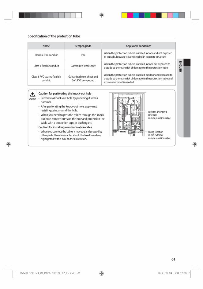
61
ENGLISH
Specification of the protection tube
Name Temper grade Applicable conditions
Flexible PVC conduit PVCWhen the protection tube is installed indoor and not exposed to outside, because it is embedded in concrete structure
Class 1 flexible conduit Galvanized steel sheetWhen the protection tube is installed indoor but exposed to outside so there are risk of damage to the protection tube
Class 1 PVC coated flexible conduit
Galvanized steel sheet and Soft PVC compound
When the protection tube is installed outdoor and exposed to outside so there are risk of damage to the protection tube and extra waterproof is needed
Caution for perforating the knock-out hole• Perforate a knock-out hole by punching it with a
hammer. • After perforating the knock-out hole, apply rust
resisting paint around the hole. • When you need to pass the cables through the knock-
out hole, remove burrs on the hole and protection the cable with a protection tape or bushing etc.
Caution for installing communication cable• When you connect the cable, it may sag and pressed by
other parts. Therefore cables should be fixed to a clamp highlighted with a box on the illustration.
Path for arranging external communication cable
Fixing location of the external communication cable
CAUTION
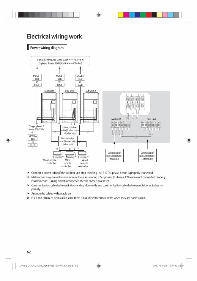
62
Electrical wiring work
Power wiring diagram
3 phase 3wires 208-230V [AM✴✴✴✴XV✴F✴]3 phase 3wires 460V [AM✴✴✴✴XV✴J✴]
Main unit Sub unit
Communication cable (Outdoor unit ~
Outdoor unit)
Main unit Sub unit 1 Sub unit 2
Single phase 2 wires 208-230V
Communication cable (Outdoor unit ~
Indoor unit)
Grounding Grounding GroundingWired remote
controllerWired
remote controller
Wired remote
controller
orELCB
MCCB+ ELB
orELCB
MCCB+ ELB
orELCB
MCCB+ ELB
MCCB + ELBor
ELCB
Communication cable (Outdoor unit ~
Indoor unit)
Communication cable (Outdoor unit ~
Outdoor unit)
Connect a power cable of the outdoor unit after checking that R-S-T (3 phase 3 wire) is properly connected. Malfunction may occur if one or more of the wires among R-S-T phases (3 Phases-3 Wires) are not connected properly. (*Malfunction: Turning on/off, occurrence of error, consecutive reset)Communication cable between indoor and outdoor units and communication cable between outdoor units has no polarity.Arrange the cables with a cable tie.
❋ ELCB and ELB must be installed since there is risk of electric shock or fire when they are not installed.

63
ENGLISH
Selecting solderless ring terminalSelect a solderless ring terminal for a power cable according to the nominal dimensions for cable.Apply insulation coating to the connection part of the solderless ring terminal and the power cable.
Silver solder
Nominal dimensions for cable [mm2 (inch2)] 4/6 (0.006/0.009) 10 (0.01) 16 (0.02) 25 (0.03) 35 (0.05) 50 (0.07) 70 (0.10)
Nominal dimensions for screw [mm (inch)] 4 (3/8) 8 (3/16) 8 (3/16) 8 (3/16) 8 (3/16) 8 (3/16) 8 (3/16) 8 (3/16) 8 (3/16) 8 (3/16)
B
Standard dimension [mm (inch)]
9.5 (3/8) 15 (9/16) 15 (9/16) 16 (10/16) 12 (1/2)16.5
(10/16)16
(10/16)22 (7/8) 22 (7/8) 24 (1)
Allowance [mm (inch)] ±0.2 (±0.007)
±0.2 (±0.007)
±0.2 (±0.007)
±0.3 (±0.011) ±0.3 (±0.011)±0.3
(±0.011)±0.4
(±0.015)
D
Standard dimension [mm (inch)]
5.6 (1/4) 7.1 (1/4) 9 (3/8) 11.5 (7/16) 13.3 (1/2) 13.5 (1/2) 17.5 (1/2)
Allowance [mm (inch)]
+0.3 (+0.011) -0.2 (-0.007)
+0.3 (+0.011)
-0.2 (-0.007)
+0.3 (+0.011)
-0.2 (-0.007)
+0.5 (+0.019) -0.2 (-0.007)
+0.5 (+0.019) -0.2 (-0.007)
+0.5 (+0.019)
-0.2 (-0.007)
+0.5 (+0.019)
-0.4 (-0.015)
d1
Standard dimension [mm (inch)]
3.4 (1/8) 4.5 (3/16) 5.8 (1/4) 7.7 (5/16) 9.4 (3/8)11.4
(7/16)13.3 (1/2)
Allowance [mm (inch)]
±0.2 (±0.007)
±0.2 (±0.007)
±0.2 (±0.007)
±0.2 (±0.007)
±0.2 (±0.007)
±0.3 (±0.011)
±0.4 (±0.015)
E Min. [mm (inch)] 6 (1/4)
7.9 (5/16)
9.5 (5/16)
11 (3/8)
12.5 (1/2)
17.5 (11/16)
18.5 (3/4)
F Min. [mm (inch)] 5 (3/16)
9 (3/8)
9 (3/8)
13 (1/2)
15 (5/8)
13 (1/2)
13 (1/2)
13 (1/2)
14 (9/16)
20 (3/4)
L Max. [mm (inch)] 20 (3/4)
28.5 (1-1/8)
30 (1-3/16)
33 (1-5/16)
34 (1-3/8)
38 (1-1/2)
43 (1-
11/16)
50 (2)
51 (2)
d2
Standard dimension [mm (inch)]
4.3 (3/16)
8.4 (1-3/16)
8.4 (1-3/16)
8.4 (1-3/16)
8.4 (1-3/16)
8.4 (1-3/16)
8.4 (1-3/16)
8.4 (1-3/16)
8.4 (1-3/16)
8.4 (1-3/16)
Allowance [mm (inch)]
+ 0.2 (+0.007)
0 (0)
+ 0.4 (+0.015)
0 (0)
+ 0.4 (+0.015)
0 (0)
+ 0.4 (+0.015)
0 (0)
+ 0.4 (+0.015) 0 (0)
+ 0.4 (+0.015) 0 (0)
+ 0.4 (+0.015)
0 (0)
+ 0.4 (+0.015)
0 (0)
t Min. [mm (inch)] 0.9 (0.03)
1.15 (0.04)
1.45 (0.05)
1.7 (0.06)
1.8 (0.07)
1.8 (0.07)
2.0 (0.078)
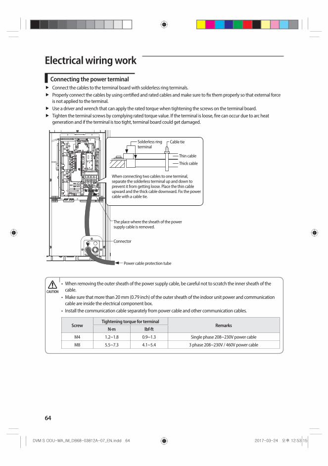
64
Electrical wiring work
Connecting the power terminalConnect the cables to the terminal board with solderless ring terminals.Properly connect the cables by using certified and rated cables and make sure to fix them properly so that external force is not applied to the terminal.Use a driver and wrench that can apply the rated torque when tightening the screws on the terminal board.Tighten the terminal screws by complying rated torque value. If the terminal is loose, fire can occur due to arc heat generation and if the terminal is too tight, terminal board could get damaged.
Power cable protection tube
The place where the sheath of the power supply cable is removed.
Connector
Solderless ring terminal
Thin cable
Thick cable
Cable tie
When connecting two cables to one terminal, separate the solderless terminal up and down to prevent it from getting loose. Place the thin cable upward and the thick cable downward. Fix the power cable with a cable tie.
• When removing the outer sheath of the power supply cable, be careful not to scratch the inner sheath of the cable.
• Make sure that more than 20 mm (0.79 inch) of the outer sheath of the indoor unit power and communication cable are inside the electrical component box.
• Install the communication cable separately from power cable and other communication cables.
ScrewTightening torque for terminal
RemarksN·m lbf·ft
M4 1.2~1.8 0.9~1.3 Single phase 208~230V power cable
M8 5.5~7.3 4.1~5.4 3 phase 208~230V / 460V power cable
CAUTION
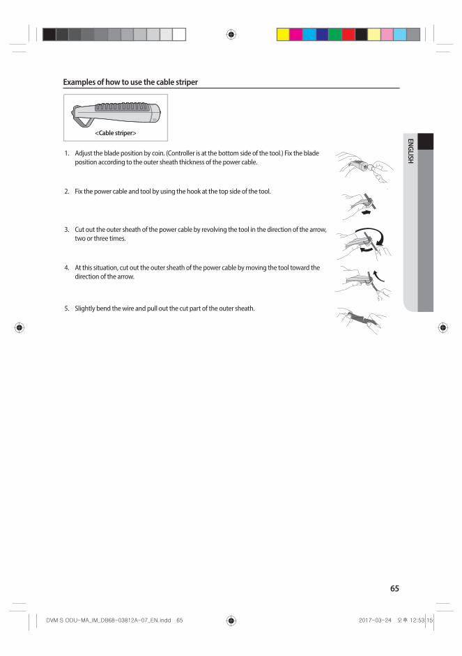
65
ENGLISH
Examples of how to use the cable striper
<Cable striper>
1. Adjust the blade position by coin. (Controller is at the bottom side of the tool.) Fix the blade position according to the outer sheath thickness of the power cable.
2. Fix the power cable and tool by using the hook at the top side of the tool.
3. Cut out the outer sheath of the power cable by revolving the tool in the direction of the arrow, two or three times.
4. At this situation, cut out the outer sheath of the power cable by moving the tool toward the direction of the arrow.
5. Slightly bend the wire and pull out the cut part of the outer sheath.
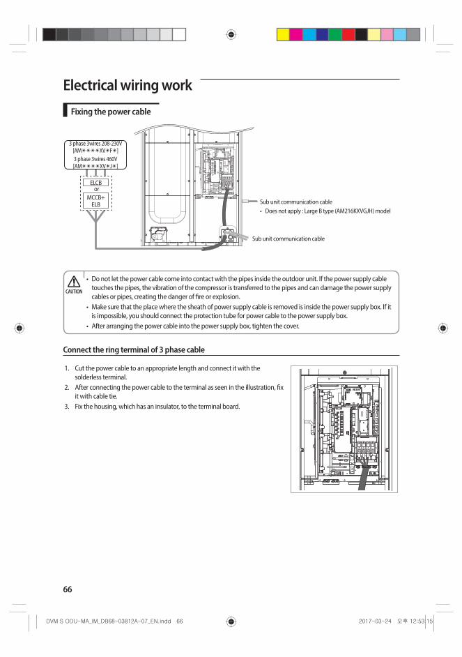
66
Electrical wiring work
Fixing the power cable
3 phase 3wires 208-230V [AM✴✴✴✴XV✴F✴]3 phase 3wires 460V [AM✴✴✴✴XV✴J✴]
Sub unit communication cable• Does not apply : Large B type (AM216KXVGJH) model
ELCB
MCCB+ ELB
or
Sub unit communication cable
• Do not let the power cable come into contact with the pipes inside the outdoor unit. If the power supply cable touches the pipes, the vibration of the compressor is transferred to the pipes and can damage the power supply cables or pipes, creating the danger of fire or explosion.
• Make sure that the place where the sheath of power supply cable is removed is inside the power supply box. If it is impossible, you should connect the protection tube for power cable to the power supply box.
• After arranging the power cable into the power supply box, tighten the cover.
CAUTION
Connect the ring terminal of 3 phase cable
1. Cut the power cable to an appropriate length and connect it with the solderless terminal.
2. After connecting the power cable to the terminal as seen in the illustration, fix it with cable tie.
3. Fix the housing, which has an insulator, to the terminal board.
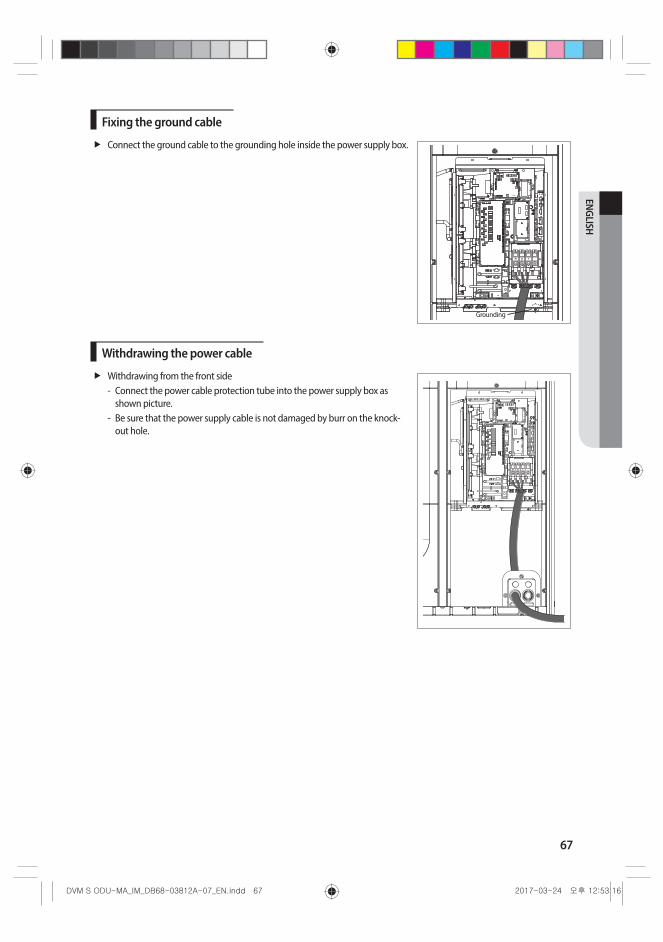
67
ENGLISH
Fixing the ground cable
Connect the ground cable to the grounding hole inside the power supply box.
Grounding
Withdrawing the power cable
Withdrawing from the front side - Connect the power cable protection tube into the power supply box as
shown picture. - Be sure that the power supply cable is not damaged by burr on the knock-
out hole.

68
Electrical wiring work
Installing the Solution deviceWhen the number of indoor units installed with the outdoor unit is 16 or less
F1F2
OF1
OF2
R1R2
F1 Terminal block with indoor unitF2
OF1 Terminal block with outdoor unit sub moduleOF2
R1 Terminal block with solution deviceR2

69
ENGLISH
Connecting the MCU
Example 1
Indoor unit Outdoor unit
Indoor unit
ELB
MCCB
208-230 V~
Example 2
Indoor unit Outdoor unit
ELB
MCCB
208-230 V~
Indoor unit Indoor unit
Power must be supplied to the MCU separately from the outdoor unit. Connect the communication cable of the outdoor unit (F1, F2) to the communication cable of the MCU (F1, F2)
• Power cable connection should be done with the solderless ring terminal.
Indoor unit
Indoor unit
Indoor unit
Indoor unit
Indoor unit
Indoor unit
MCU
MCU
Indoor unit
Indoor unit
Indoor unit
Indoor unit
Indoor unit
Indoor unit
MCU
MCU
• When installing the MCU, communication cable can be connected as shown above.
CAUTION

70
Electrical wiring work
Grounding workGrounding must be done by a qualified installer for your safety.
Grounding the power cable
The standard of grounding may vary according to the rated voltage and installation place of the air conditioner.Ground the power cable according to the following table.
Power conditionInstallation place
Voltage to ground is lower than 150V Voltage to ground is over 150V
High humidityMust perform the grounding work 3. Note 1)
(Including the case where earth leakage breaker is installed)
Average humidity Perform grounding work 3. Note 1) Must perform the grounding work 3. Note 1)
(Including the case where earth leakage breaker is installed)Low humidity Perform grounding work 3, if possible, for
your safety. Note 2)
Note 1) About grounding work 3.• Grounding work must be done by an expert (with qualification).• Check if the grounding resistance is lower than 100Ω. When installing a earth leakage breaker (that can cut the electric
circuit within 0.5 second in case of a short circuit), allowable grounding resistance should be 30~500Ω.Note 2) Grounding at dry place• The grounding resistance should be lower than 100Ω. Even in worst case, grounding resistance should be lower than
250Ω.
Performing the grounding work
Use a rated grounding cable by referring to the specification of the electric cable for the outdoor unit.
❋ When using the exclusive grounding terminal (When the grounding terminal is already built on the house)
❋ When using grounding of the switch board
Exclusive grounding terminal Distributing board
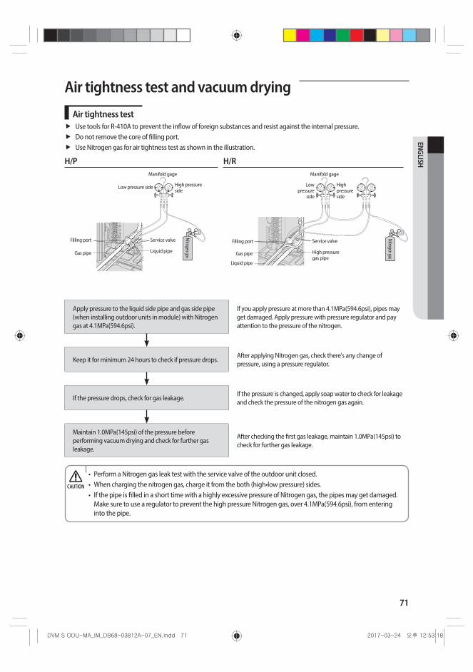
71
ENGLISH
Air tightness test and vacuum drying
Air tightness testUse tools for R-410A to prevent the inflow of foreign substances and resist against the internal pressure.Do not remove the core of filling port.Use Nitrogen gas for air tightness test as shown in the illustration.
H/P H/RManifold gage
High pressure side
Low pressure side
Filling port
Gas pipe Liquid pipe
Nitrogen gas
Service valve
Manifold gage
High pressure side
Low pressure
side
Filling port
Gas pipe
Liquid pipe
High pressure gas pipe
Nitrogen gas
Service valve
Apply pressure to the liquid side pipe and gas side pipe (when installing outdoor units in module) with Nitrogen gas at 4.1MPa(594.6psi).
If you apply pressure at more than 4.1MPa(594.6psi), pipes may get damaged. Apply pressure with pressure regulator and pay attention to the pressure of the nitrogen.
Keep it for minimum 24 hours to check if pressure drops.After applying Nitrogen gas, check there's any change of pressure, using a pressure regulator.
If the pressure drops, check for gas leakage.If the pressure is changed, apply soap water to check for leakage and check the pressure of the nitrogen gas again.
Maintain 1.0MPa(145psi) of the pressure before performing vacuum drying and check for further gas leakage.
After checking the first gas leakage, maintain 1.0MPa(145psi) to check for further gas leakage.
• Perform a Nitrogen gas leak test with the service valve of the outdoor unit closed.• When charging the nitrogen gas, charge it from the both (high•low pressure) sides.• If the pipe is filled in a short time with a highly excessive pressure of Nitrogen gas, the pipes may get damaged.
Make sure to use a regulator to prevent the high pressure Nitrogen gas, over 4.1MPa(594.6psi), from entering into the pipe.
CAUTION
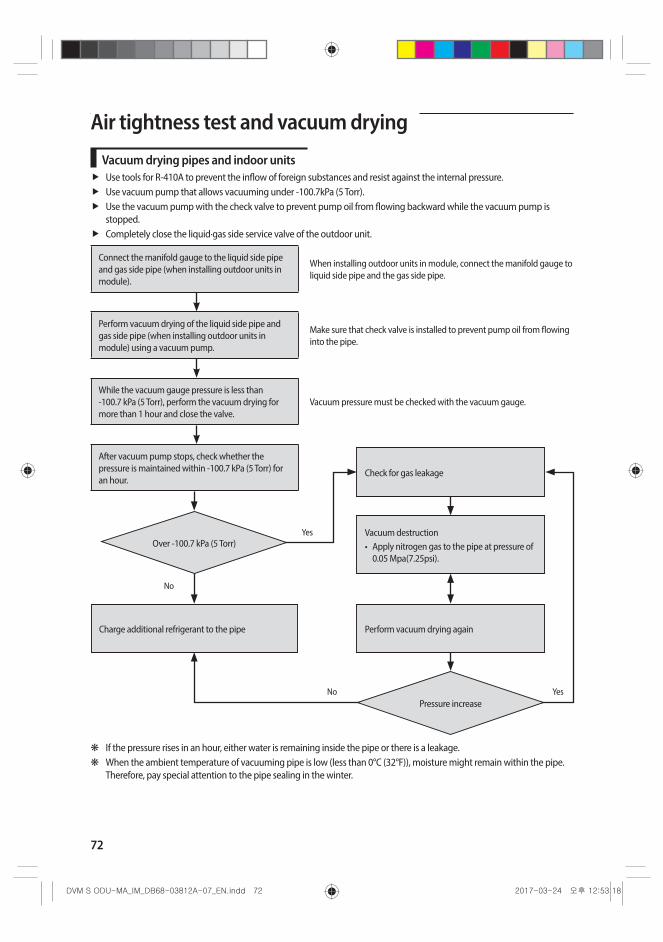
72
Air tightness test and vacuum drying
Vacuum drying pipes and indoor unitsUse tools for R-410A to prevent the inflow of foreign substances and resist against the internal pressure.Use vacuum pump that allows vacuuming under -100.7kPa (5 Torr).Use the vacuum pump with the check valve to prevent pump oil from flowing backward while the vacuum pump is stopped.Completely close the liquid·gas side service valve of the outdoor unit.
Connect the manifold gauge to the liquid side pipe and gas side pipe (when installing outdoor units in module).
When installing outdoor units in module, connect the manifold gauge to liquid side pipe and the gas side pipe.
Perform vacuum drying of the liquid side pipe and gas side pipe (when installing outdoor units in module) using a vacuum pump.
Make sure that check valve is installed to prevent pump oil from flowing into the pipe.
While the vacuum gauge pressure is less than -100.7 kPa (5 Torr), perform the vacuum drying for more than 1 hour and close the valve.
Vacuum pressure must be checked with the vacuum gauge.
After vacuum pump stops, check whether the pressure is maintained within -100.7 kPa (5 Torr) for an hour.
Charge additional refrigerant to the pipe
No
Yes
Perform vacuum drying again
Check for gas leakage
Vacuum destruction• Apply nitrogen gas to the pipe at pressure of
0.05 Mpa(7.25psi).
YesNo
Over -100.7 kPa (5 Torr)
Pressure increase
❋ If the pressure rises in an hour, either water is remaining inside the pipe or there is a leakage. ❋ When the ambient temperature of vacuuming pipe is low (less than 0°C (32°F)), moisture might remain within the pipe.
Therefore, pay special attention to the pipe sealing in the winter.
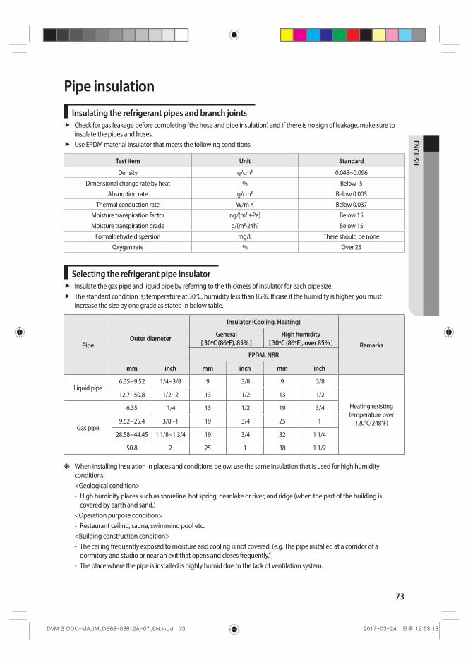
73
ENGLISH
Pipe insulation
Insulating the refrigerant pipes and branch jointsCheck for gas leakage before completing (the hose and pipe insulation) and if there is no sign of leakage, make sure to insulate the pipes and hoses.Use EPDM material insulator that meets the following conditions.
Test item Unit Standard
Density g/cm3 0.048~0.096
Dimensional change rate by heat % Below -5
Absorption rate g/cm3 Below 0.005
Thermal conduction rate W/m·K Below 0.037
Moisture transpiration factor ng/(m2·s·Pa) Below 15
Moisture transpiration grade g/(m2·24h) Below 15
Formaldehyde dispersion mg/L There should be none
Oxygen rate % Over 25
Selecting the refrigerant pipe insulatorInsulate the gas pipe and liquid pipe by referring to the thickness of insulator for each pipe size.The standard condition is; temperature at 30°C, humidity less than 85%. If case if the humidity is higher, you must increase the size by one grade as stated in below table.
PipeOuter diameter
Insulator (Cooling, Heating)
Remarks
General [ 30ºC (86ºF), 85% ]
High humidity [ 30ºC (86ºF), over 85% ]
EPDM, NBR
mm inch mm inch mm inch
Liquid pipe6.35~9.52 1/4~3/8 9 3/8 9 3/8
Heating resisting temperature over
120°C(248°F)
12.7~50.8 1/2~2 13 1/2 13 1/2
Gas pipe
6.35 1/4 13 1/2 19 3/4
9.52~25.4 3/8~1 19 3/4 25 1
28.58~44.45 1 1/8~1 3/4 19 3/4 32 1 1/4
50.8 2 25 1 38 1 1/2
❋ When installing insulation in places and conditions below, use the same insulation that is used for high humidity conditions.<Geological condition> - High humidity places such as shoreline, hot spring, near lake or river, and ridge (when the part of the building is
covered by earth and sand.) <Operation purpose condition> - Restaurant ceiling, sauna, swimming pool etc.
<Building construction condition> - The ceiling frequently exposed to moisture and cooling is not covered. (e.g. The pipe installed at a corridor of a
dormitory and studio or near an exit that opens and closes frequently.”) - The place where the pipe is installed is highly humid due to the lack of ventilation system.
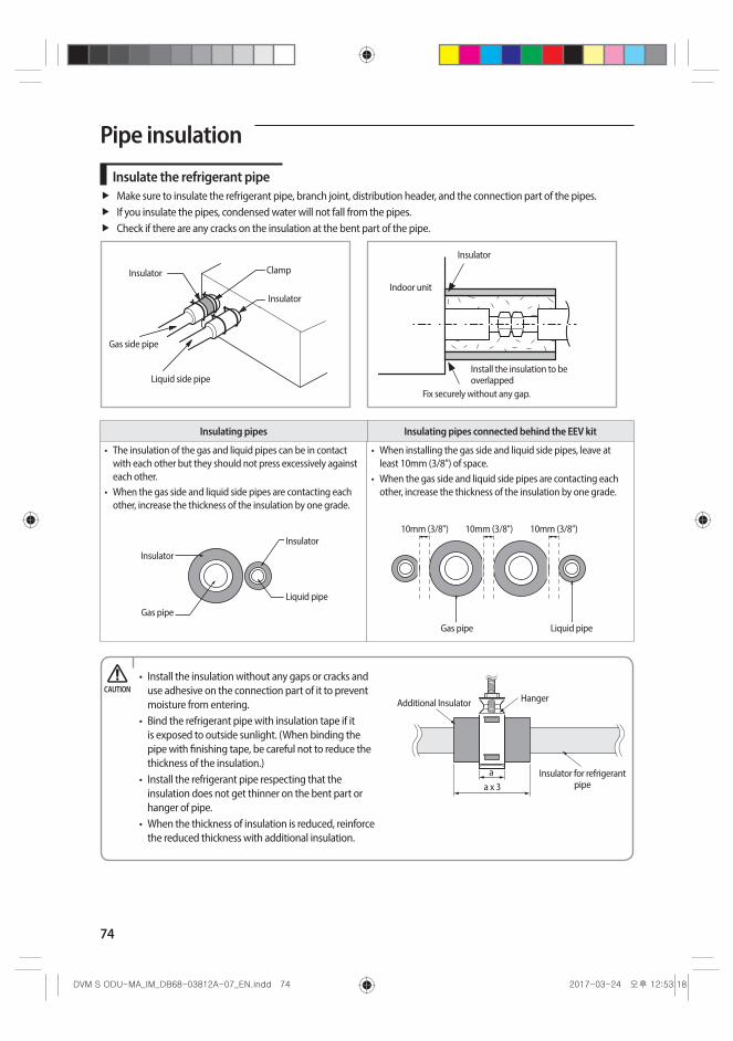
74
Pipe insulation
Insulate the refrigerant pipeMake sure to insulate the refrigerant pipe, branch joint, distribution header, and the connection part of the pipes.If you insulate the pipes, condensed water will not fall from the pipes. Check if there are any cracks on the insulation at the bent part of the pipe.
Fix securely without any gap.
Install the insulation to be overlapped
Indoor unit
Insulator
Insulator Clamp
Liquid side pipe
Gas side pipe
Insulator
Insulating pipes Insulating pipes connected behind the EEV kit
• The insulation of the gas and liquid pipes can be in contact with each other but they should not press excessively against each other.
• When the gas side and liquid side pipes are contacting each other, increase the thickness of the insulation by one grade.
• When installing the gas side and liquid side pipes, leave at least 10mm (3/8") of space.
• When the gas side and liquid side pipes are contacting each other, increase the thickness of the insulation by one grade.
Gas pipe
Liquid pipe
Insulator Insulator
Gas pipe
10mm (3/8")10mm (3/8") 10mm (3/8")
Liquid pipe
• Install the insulation without any gaps or cracks and use adhesive on the connection part of it to prevent moisture from entering.
• Bind the refrigerant pipe with insulation tape if it is exposed to outside sunlight. (When binding the pipe with finishing tape, be careful not to reduce the thickness of the insulation.)
• Install the refrigerant pipe respecting that the insulation does not get thinner on the bent part or hanger of pipe.
• When the thickness of insulation is reduced, reinforce the reduced thickness with additional insulation.
Insulator for refrigerant pipea x 3
HangerAdditional Insulator
a
CAUTION
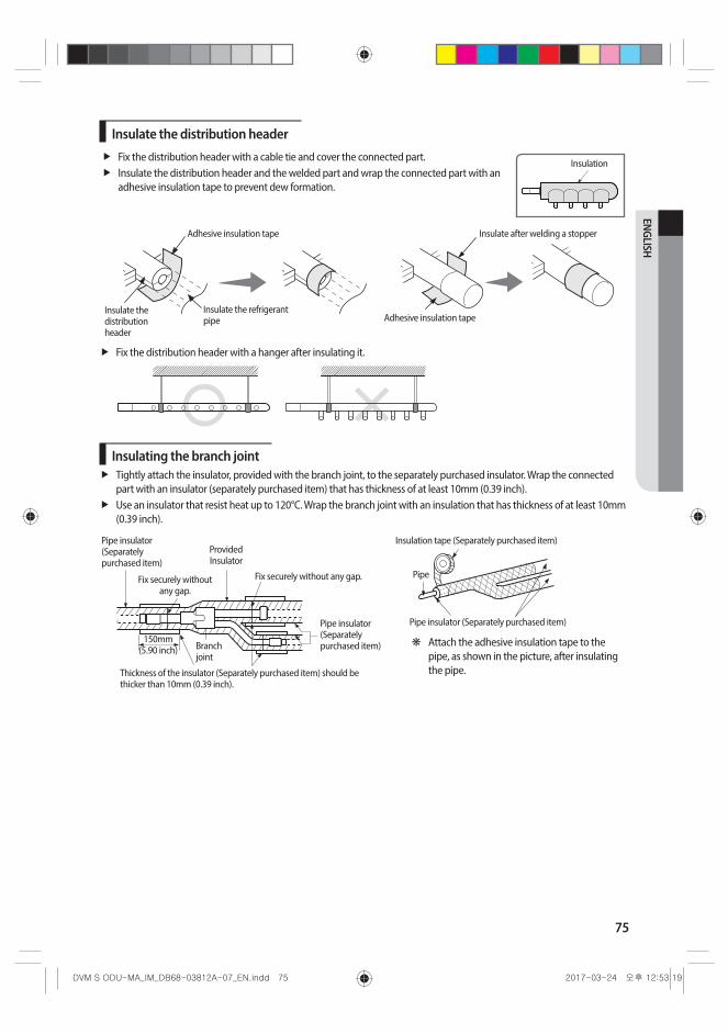
75
ENGLISH
Insulate the distribution headerFix the distribution header with a cable tie and cover the connected part.Insulate the distribution header and the welded part and wrap the connected part with an adhesive insulation tape to prevent dew formation.
Insulation
Adhesive insulation tape
Insulate the refrigerant pipe
Insulate the distribution header
Insulate after welding a stopper
Adhesive insulation tape
Fix the distribution header with a hanger after insulating it.
Insulating the branch jointTightly attach the insulator, provided with the branch joint, to the separately purchased insulator. Wrap the connected part with an insulator (separately purchased item) that has thickness of at least 10mm (0.39 inch).Use an insulator that resist heat up to 120°C. Wrap the branch joint with an insulation that has thickness of at least 10mm (0.39 inch).
Fix securely without any gap.
Provided Insulator
Fix securely without any gap.
Pipe insulator (Separately purchased item)
Pipe insulator (Separately purchased item)
150mm (5.90 inch) Branch
joint
Thickness of the insulator (Separately purchased item) should be thicker than 10mm (0.39 inch).
Insulation tape (Separately purchased item)
Pipe insulator (Separately purchased item)
Pipe
❋ Attach the adhesive insulation tape to the pipe, as shown in the picture, after insulating the pipe.
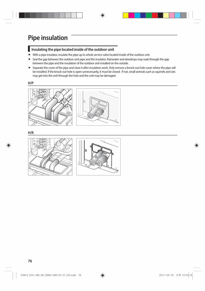
76
Pipe insulation
Insulating the pipe located inside of the outdoor unitWith a pipe insulator, insulate the pipe up to whole service valve located inside of the outdoor unit.Seal the gap between the outdoor unit pipe and the insulator. Rainwater and dewdrops may soak through the gap between the pipe and the insulation of the outdoor unit installed on the outside.Separate the cover of the pipe and close it after insulation work. Only remove a knock-out hole cover where the pipe will be installed. If the knock-out hole is open unnecessarily, it must be closed. If not, small animals such as squirrels and rats may get into the unit through the hole and the unit may be damaged.
H/P
H/R
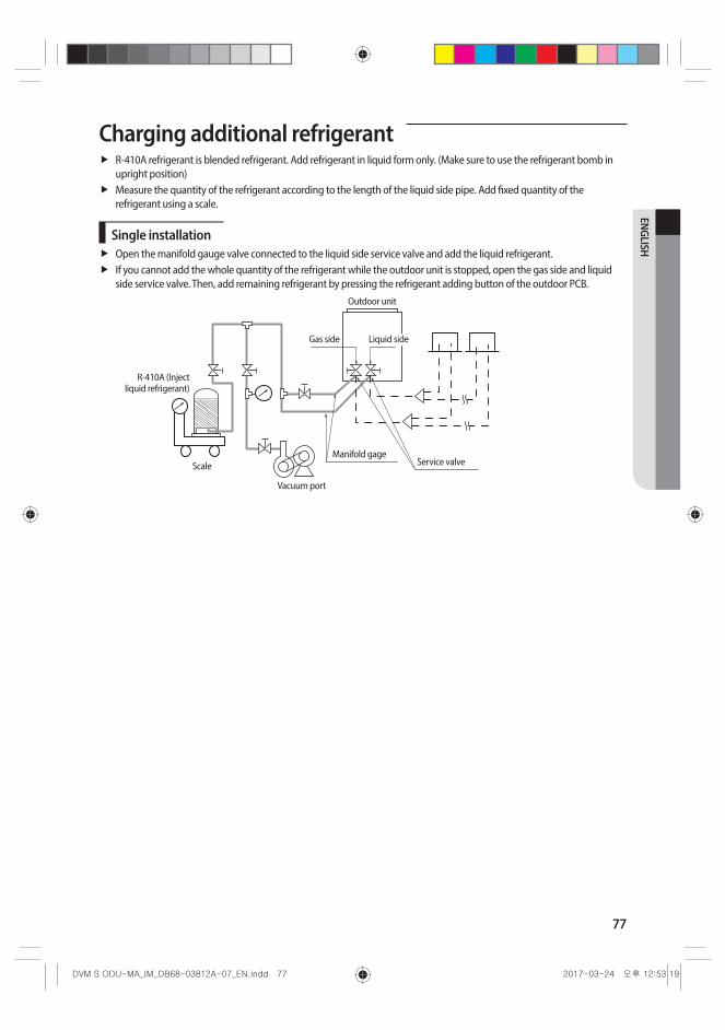
77
ENGLISH
Charging additional refrigerantR-410A refrigerant is blended refrigerant. Add refrigerant in liquid form only. (Make sure to use the refrigerant bomb in upright position)Measure the quantity of the refrigerant according to the length of the liquid side pipe. Add fixed quantity of the refrigerant using a scale.
Single installationOpen the manifold gauge valve connected to the liquid side service valve and add the liquid refrigerant.If you cannot add the whole quantity of the refrigerant while the outdoor unit is stopped, open the gas side and liquid side service valve. Then, add remaining refrigerant by pressing the refrigerant adding button of the outdoor PCB.
Gas side
Scale
R-410A (Inject liquid refrigerant)
Liquid side
Vacuum port
Manifold gage Service valve
Outdoor unit

78
Charging additional refrigerant
Module installationOpen the manifold gauge valve connected to the liquid side service valve and add the liquid refrigerant.If you cannot add the whole quantity of the refrigerant while the outdoor unit is stopped, open the gas side and liquid side service valve. Then, add remaining refrigerant by pressing the refrigerant adding button of the outdoor PCB.If you use the refrigerant charging function from the PCB, outdoor unit will operate and charge the refrigerant. At this time, you must use gas side manifold gauge for cooling operation and use charging port for heating at the manifold gauge for heating operation.
Gas side
Scale
R-410A (Inject liquid refrigerant)
Liquid side
Vacuum port
Liquid side pipe Service valve
Outdoor unit Outdoor unitManifold gage
• Open the gas side and liquid side service valve completely after charging the refrigerant. (If you operate the air conditioner with the service valve closed, the important parts may be damaged.)
• Put on safety equipment when charging refrigerant.• Do not charge the refrigerant when you adjust or control other product such as indoor units or EEV kits.• If you charge the refrigerant with the front cabinet open, be very careful with the fan on the top of the product
to prevent personal injury.• When the ambient temperature is low in winter time, do not heat the refrigerant container to speed up the
charging process. There is risk of explosion.• Beware for possibility of refrigerant leakage when you connect the manifold gauge to the charging port for
heating. • Close the valve of the refrigerant container immediately after charging the refrigerant. If not, there might be a
change in entire amount of refrigerant.
CAUTION
Using service valve for gas
After charging the refrigerant, close all caps as shown in the illustration.Tightening torque for the cap of refrigerant charging port 10~12N·m (7.4 ~ 8.9 lbf·ft)Tightening torque for the cap of control part 20~25N·m (14.8 ~ 18.4 lbf·ft)Opening/closing torque for the valve - Over Ø19.05mm (Ø3/4inch) : 10 N·m (7.4 lbf·ft)
Cap for the control part
Cap for the refrigerant charging port
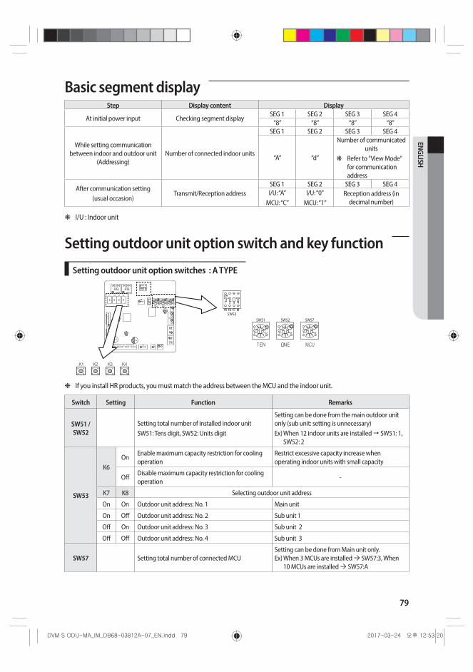
79
ENGLISH
Basic segment displayStep Display content Display
At initial power input Checking segment displaySEG 1 SEG 2 SEG 3 SEG 4
“8” “8” “8” “8”
While setting communication between indoor and outdoor unit
(Addressing)Number of connected indoor units
SEG 1 SEG 2 SEG 3 SEG 4
“A” “d”
Number of communicated units
❋ Refer to "View Mode" for communication address
After communication setting(usual occasion)
Transmit/Reception addressSEG 1 SEG 2 SEG 3 SEG 4I/U: “A”
MCU: “C”I/U: “0”
MCU: “1”Reception address (in
decimal number)
❋ I/U : Indoor unit
Setting outdoor unit option switch and key function
Setting outdoor unit option switches : A TYPE
❋ If you install HR products, you must match the address between the MCU and the indoor unit.
Switch Setting Function Remarks
SW51 / SW52
Setting total number of installed indoor unitSW51: Tens digit, SW52: Units digit
Setting can be done from the main outdoor unit only (sub unit: setting is unnecessary)Ex) When 12 indoor units are installed SW51: 1,
SW52: 2
SW53
K6On
Enable maximum capacity restriction for cooling operation
Restrict excessive capacity increase when operating indoor units with small capacity
OffDisable maximum capacity restriction for cooling operation
-
K7 K8 Selecting outdoor unit address
On On Outdoor unit address: No. 1 Main unit
On Off Outdoor unit address: No. 2 Sub unit 1
Off On Outdoor unit address: No. 3 Sub unit 2
Off Off Outdoor unit address: No. 4 Sub unit 3
SW57 Setting total number of connected MCUSetting can be done from Main unit only. Ex) When 3 MCUs are installed SW57:3, When
10 MCUs are installed SW57:A
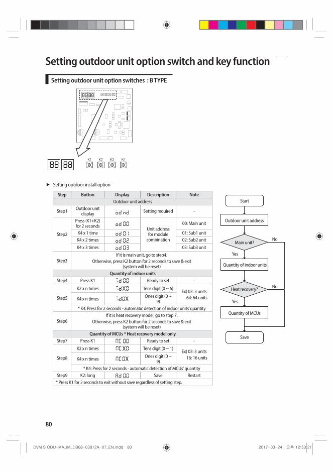
80
Setting outdoor unit option switch and key function
Setting outdoor unit option switches : B TYPE
Setting outdoor install option
Step Button Display Description NoteStart
Outdoor unit address
Quantity of indoor units
Main unit?No
No
Yes
Yes
Save
Heat recovery?
Quantity of MCUs
Outdoor unit address
Step1 Outdoor unit display Setting required -
Step2
Press (K1+K2) for 2 seconds Unit address
for module combination
00: Main unit
K4 x 1 time 01: Sub1 unitK4 x 2 times 02: Sub2 unit
K4 x 3 times 03: Sub3 unit
Step3If it is main unit, go to step4.
Otherwise, press K2 button for 2 seconds to save & exit (system will be reset)
Quantity of indoor unitsStep4 Press K1 Ready to set -
Step5
K2 x n times X Tens digit (0 ~ 6) Ex) 03: 3 units 64: 64 unitsK4 x n times X Ones digit (0 ~
9)* K4: Press for 2 seconds - automatic detection of indoor units’ quantity
Step6If it is heat recovery model, go to step 7.
Otherwise, press K2 button for 2 seconds to save & exit (system will be reset)
Quantity of MCUs * Heat recovery model onlyStep7 Press K1 Ready to set -
Step8
K2 x n times X Tens digit (0 ~ 1) Ex) 03: 3 units 16: 16 unitsK4 x n times X Ones digit (0 ~
9)* K4: Press for 2 seconds - automatic detection of MCUs' quantity
Step9 K2: long Save Restart* Press K1 for 2 seconds to exit without save regardless of setting step.

81
ENGLISH
Installing and setting the option with tact switch and explanation of the functions
Setting the option
1. Press and hold K2 to enter the option setting. (Only available when the operation is stopped) - If you enter the option setting, display will show the following. (If you have set the 'Emergency operation for
compressor malfunction', 1 or 2 will be displayed on Seg 4.)
- Seg 1 and Seg 2 will display the number for selected option. - Seg 3 and Seg 4 will display the number for set value of the selected option.
2. If you have entered option setting, you can shortly press the K1 switch to adjust the value of the Seg 1, Seg 2 and select the desired option. (Refer to pages 81~83 for the Seg number of the function for each option)
Example)
3. If you have selected desired option, you can shortly press the K2 switch to adjust the value of the Seg 3, Seg 4 and change the function for the selected option. (Refer to pages 81~83 for the Seg number of the function for each option)
Example)
4. After selecting the function for options, press and hold the K2 switch for 2 seconds. Edited value of the option will be saved when entire segments blinks and tracking mode begins.
• Edited option will not be saved if you do not end the option setting as explained in above instruction.CAUTION
❋ While you are setting the option, you may press and hold the K1 button to reset the value to previous setting. ❋ If you want to restore the setting to factory default, press and hold the K4 button while you are in the option setting
mode. - If you press and hold the K4 button, setting will be restored to factory default but it doesn't mean that restored setting
is saved. Press and hold the K2 button. When the segments shows that tracking mode is in progress, setting will be saved.
Optional item Input unit SEG1 SEG2 SEG3 SEG4 Function of the option Remarks
Emergency operation for compressor malfunction
Individual 0 0
0 0 Disabled (Factory default)E560 will occur when all the compressors are set as malfunction state.
0 1Set compressor 1 as malfunction state
0 2Set compressor 2 as malfunction state

82
Optional item Input unit SEG1 SEG2 SEG3 SEG4 Function of the option Remarks
Cooling capacity correction
Main 0 1
0 07-9 (Factory default in case of
A type PBA)
Targeted evaporation temperature [°C].(When low temperature value is set, discharged air temperature of the indoor unit will decrease)
0 15-7 (Factory default in case of
B type PBA)0 2 9-11
0 3 10-12
0 4 11-13
0 5 12-14
0 6 13-15
Capcity correction for heating
Main 0 2
0 0 3.0 (Factory default)
Targeted high pressure [MPa].(When low pressure value is set, discharged air temperature of the indoor unit will decrease)
0 1 2.5
0 2 2.6
0 3 2.7
0 4 2.8
0 5 2.9
0 6 3.1
0 7 3.2
0 8 3.3
Current restriction rate
Individual 0 3
0 0 100% (Factory default)
When restriction option is set, cooling and heating performance may decrease.
0 1 95 %
0 2 90 %
0 3 85 %
0 4 80 %
0 5 75 %
0 6 70 %
0 7 65 %
0 8 60 %
0 9 55 %
1 0 50 %
1 1 No restriction
Oil collection interval
Main 0 40 0 Factory default
0 1 Shorten the interval by 1/2
Temperature to trigger defrost
operationMain 0 5
0 0 Factory default
0 1
Apply setting when the product is being installed in
humid area such as near river or lake
Fan speed correction for outdoor unit
Individual 0 60 0 Factory default
0 1 Increase fan speedIncrease the outdoor unit's fan speed to maximum value
Setting outdoor unit option switch and key function
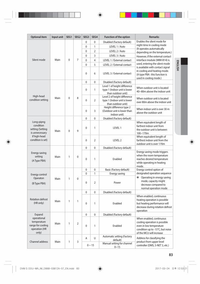
83
ENGLISH
Optional item Input unit SEG1 SEG2 SEG3 SEG4 Function of the option Remarks
Silent mode Main 0 7
0 0 Disabled (Factory default) Enables the silent mode for night-time in cooling mode (It operates automatically depending on the temperature.) However, if the external contact interface module (MIM-B14) is used, entering the silent mode is available with contact signal in cooling and heating mode. (A type PBA : this function is used in cooling mode.)
0 1 LEVEL 1 / Auto
0 2 LEVEL 2 / Auto
0 3 LEVEL 3 / Auto
0 4 LEVEL 1 / External contact
0 5 LEVEL 2 / External contact
0 6 LEVEL 3 / External contact
High-head condition setting
Main 0 8
0 0 Disabled (Factory default)
0 1Level 1 of height difference type 1 (Indoor unit is lower
than outdoor unit)
When outdoor unit is located 40~80m above the indoor unit
0 2Level 2 of height difference type 1 (Indoor unit is lower
than outdoor unit)
When outdoor unit is located over 80m above the indoor unit
0 3Height difference type 2
(Outdoor unit is lower than indoor unit)
When indoor unit is over 30 m above the outdoor unit
Long-pipng condition
setting (Setting is unnecessary
if high-head condition is set)
Main 0 9
0 0 Disabled (Factory default)
0 1 LEVEL 1
When equivalent length of farthest indoor unit from the outdoor unit is between 100~170m
0 2 LEVEL 2When equivalent length of farthest indoor unit from the outdoor unit is over 170m
Energy saving setting
(A Type PBA)Main 1 0
0 0 Disabled (Factory default)
0 1 Enabled
Energy saving mode triggers when the room temperature reaches desired temperature while operating in heating mode.
Energy control Operaton
(B Type PBA)
Main 1 0
0 0 Basic (Factory default) Energy control option of designated operation sequence
❋ Operating in energy saving mode, capacity might decrease compared to normal operation mode
0 1 Energy saving
0 2 Power
Rotation defrost (HR only)
Main 1 1
0 0 Disabled (Factory default)
0 1 Enabled
When enabled, continuous heating operation is possible but heating performance will decrease during rotation defrost operation
Expand operational
temperature range for cooling
operation (HR only)
Main 1 2
0 0 Disabled (Factory default)
0 1 Enabled
When enabled, continuous cooling operation is possible even in low temperature condition up to -15°C, but noise of the MCU will increase
Channel address Main 1 3A U
Automatic setting (Factory default)
Address for classifying the product from upper level controller (DMS, S-NET 3, etc.)0 ~ 15
Manual setting for channel 0~15
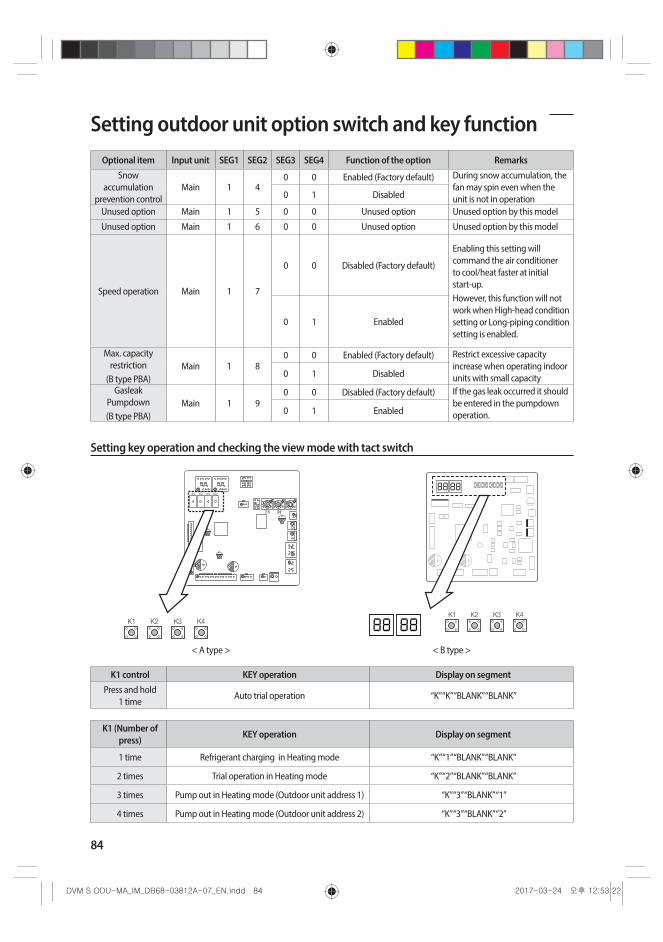
84
Optional item Input unit SEG1 SEG2 SEG3 SEG4 Function of the option RemarksSnow
accumulation prevention control
Main 1 40 0 Enabled (Factory default) During snow accumulation, the
fan may spin even when the unit is not in operation0 1 Disabled
Unused option Main 1 5 0 0 Unused option Unused option by this model
Unused option Main 1 6 0 0 Unused option Unused option by this model
Speed operation Main 1 7
0 0 Disabled (Factory default)
Enabling this setting will command the air conditioner to cool/heat faster at initial start-up. However, this function will not work when High-head condition setting or Long-piping condition setting is enabled.
0 1 Enabled
Max. capacity restriction
(B type PBA) Main 1 8
0 0 Enabled (Factory default) Restrict excessive capacity increase when operating indoor units with small capacity 0 1 Disabled
Gasleak Pumpdown (B type PBA)
Main 1 90 0 Disabled (Factory default) If the gas leak occurred it should
be entered in the pumpdown operation. 0 1 Enabled
Setting key operation and checking the view mode with tact switch
K1 K2 K3 K4
< A type > < B type >
K1 control KEY operation Display on segmentPress and hold
1 timeAuto trial operation “K” “K” “BLANK” “BLANK”
K1 (Number of press) KEY operation Display on segment
1 time Refrigerant charging in Heating mode “K” “1” “BLANK” “BLANK”
2 times Trial operation in Heating mode “K” “2” “BLANK” “BLANK”
3 times Pump out in Heating mode (Outdoor unit address 1) “K” “3” “BLANK” “1”
4 times Pump out in Heating mode (Outdoor unit address 2) “K” “3” “BLANK” “2”
Setting outdoor unit option switch and key function
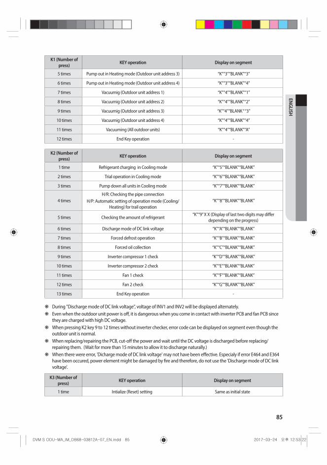
85
ENGLISH
K1 (Number of press) KEY operation Display on segment
5 times Pump out in Heating mode (Outdoor unit address 3) “K” “3” “BLANK” “3”
6 times Pump out in Heating mode (Outdoor unit address 4) “K” “3” “BLANK” “4”
7 times Vacuumig (Outdoor unit address 1) “K” “4” “BLANK” “1”
8 times Vacuumig (Outdoor unit address 2) “K” “4” “BLANK” “2”
9 times Vacuumig (Outdoor unit address 3) “K” “4” “BLANK “ “3”
10 times Vacuumig (Outdoor unit address 4) “K” “4” “BLANK” “4”
11 times Vacuuming (All outdoor units) “K” “4” “BLANK” “A”
12 times End Key operation -
K2 (Number of press) KEY operation Display on segment
1 time Refrigerant charging in Cooling mode “K” “5” “BLANK” “BLANK”
2 times Trial operation in Cooling mode “K” “6” “BLANK” “BLANK”
3 times Pump down all units in Cooling mode “K” “7” “BLANK” “BLANK”
4 timesH/R: Checking the pipe connection
H/P: Automatic setting of operation mode (Cooling/Heating) for trail operation
“K” “8” “BLANK” “BLANK”
5 times Checking the amount of refrigerant“K” “9” X X (Display of last two digits may differ
depending on the progress)
6 times Discharge mode of DC link voltage “K” “A” “BLANK” “BLANK”
7 times Forced defrost operation “K” “B” “BLANK” “BLANK”
8 times Forced oil collection “K” “C” “BLANK” “BLANK”
9 times Inverter compressor 1 check “K” “D” “BLANK” “BLANK”
10 times Inverter compressor 2 check “K” “E” “BLANK” “BLANK”
11 times Fan 1 check “K” “F” “BLANK” “BLANK”
12 times Fan 2 check “K” “G” “BLANK” “BLANK”
13 times End Key operation -
❋ During "Discharge mode of DC link voltage", voltage of INV1 and INV2 will be displayed alternately. ❋ Even when the outdoor unit power is off, it is dangerous when you come in contact with inverter PCB and fan PCB since
they are charged with high DC voltage. ❋ When pressing K2 key 9 to 12 times without inverter checker, error code can be displayed on segment even though the
outdoor unit is normal. ❋ When replacing/repairing the PCB, cut-off the power and wait until the DC voltage is discharged before replacing/
repairing them. (Wait for more than 15 minutes to allow it to discharge naturally.) ❋ When there were error, 'Dicharge mode of DC link voltage' may not have been effective. Especialy if error E464 and E364
have been occured, power element might be damaged by fire and therefore, do not use the 'Discharge mode of DC link voltage'.
K3 (Number of press) KEY operation Display on segment
1 time Intialize (Reset) setting Same as initial state

86
Setting outdoor unit option switch and key function
K1 K2 K3 K4
< A type > < B type >
K4 (Number of press) KEY operation
Display on segmentSEG 1 SEG2, 3, 4
1 time Outdoor unit model 1 (a) Capacity Off, 1, 4
2 times Order frequency of the compressor 1 2 120 Hz 1, 2, 0
3 times Order frequency of the compressor 2 3 120 Hz 1, 2, 0
4 times High pressure (MPa) 4 1.52 MPa 1, 5, 2
5 times Low pressure (MPa) 5 0.43 MPa 0, 4, 3
6 times Discharge temperature (Compressor 1) 6 87 °C 0, 8, 7
7 times Discharge temperature (Compressor 2) 7 87 °C 0, 8, 7
8 times IPM temperature (Compressor 1) 8 87 °C 0, 8, 7
9 times IPM temperature (Compressor 2) 9 87 °C 0, 8, 7
10 times CT sensor value (Compressor 1) A 2 A 0, 2, 0
11 times CT sensor value (Compressor 2) B 2 A 0, 2, 0
12 times Suction temperature C -42 °C -, 4, 2
13 times COND OUT temperautre D -42 °C -, 4, 2
14 times Temperature of liquid pipe E -42 °C -, 4, 2
15 times TOP temperature (Compressor 1) F -42 °C -, 4, 2
16 times TOP temperature (Compressor 2) G -42 °C -, 4, 2
17 times Outdoor temperature H -42 °C -, 4, 2
18 times EVI inlet temperature I -42 °C -, 4, 2
19 times EVI outlet temperature J -42 °C -, 4, 2
20 times Main EEV1 step K 2000 steps 2, 0, 0
21 times Main EEV2 step L 2000 steps 2, 0, 0
22 times EVI EEV step M 300 steps 3, 0, 0
23 times HR EEV step N 300 steps 3, 0, 0
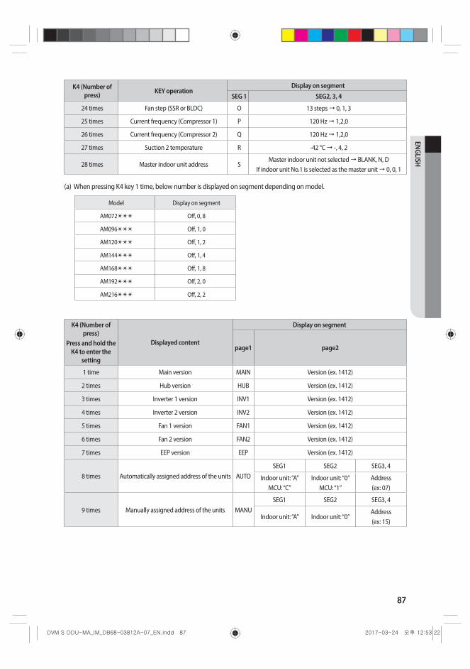
87
ENGLISH
K4 (Number of press) KEY operation
Display on segmentSEG 1 SEG2, 3, 4
24 times Fan step (SSR or BLDC) O 13 steps 0, 1, 3
25 times Current frequency (Compressor 1) P 120 Hz 1,2,0
26 times Current frequency (Compressor 2) Q 120 Hz 1,2,0
27 times Suction 2 temperature R -42 °C -, 4, 2
28 times Master indoor unit address SMaster indoor unit not selected BLANK, N, D
If indoor unit No.1 is selected as the master unit 0, 0, 1
(a) When pressing K4 key 1 time, below number is displayed on segment depending on model.
Model Display on segment
AM072✴✴✴ Off, 0, 8
AM096✴✴✴ Off, 1, 0
AM120✴✴✴ Off, 1, 2
AM144✴✴✴ Off, 1, 4
AM168✴✴✴ Off, 1, 8
AM192✴✴✴ Off, 2, 0
AM216✴✴✴ Off, 2, 2
K4 (Number of press)
Press and hold the K4 to enter the
setting
Displayed content
Display on segment
page1 page2
1 time Main version MAIN Version (ex. 1412)
2 times Hub version HUB Version (ex. 1412)
3 times Inverter 1 version INV1 Version (ex. 1412)
4 times Inverter 2 version INV2 Version (ex. 1412)
5 times Fan 1 version FAN1 Version (ex. 1412)
6 times Fan 2 version FAN2 Version (ex. 1412)
7 times EEP version EEP Version (ex. 1412)
8 times Automatically assigned address of the units AUTOSEG1 SEG2 SEG3, 4
Indoor unit: “A”MCU: “C”
Indoor unit: “0”MCU: “1”
Address (ex: 07)
9 times Manually assigned address of the units MANUSEG1 SEG2 SEG3, 4
Indoor unit: “A” Indoor unit: “0”Address (ex: 15)
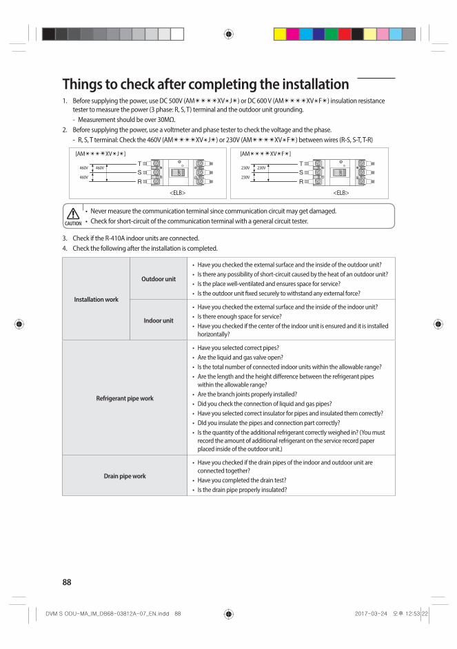
88
Things to check after completing the installation1. Before supplying the power, use DC 500V (AM✴✴✴✴XV✴J✴) or DC 600 V (AM✴✴✴✴XV✴F✴) insulation resistance
tester to measure the power (3 phase: R, S, T) terminal and the outdoor unit grounding. - Measurement should be over 30MΩ.
2. Before supplying the power, use a voltmeter and phase tester to check the voltage and the phase. - R, S, T terminal: Check the 460V (AM✴✴✴✴XV✴J✴) or 230V (AM✴✴✴✴XV✴F✴) between wires (R-S, S-T, T-R)
T S
R
T S
R
<ELB>
[AM✴✴✴✴XV✴J✴] [AM✴✴✴✴XV✴F✴]
<ELB>
460V 230V460V 230V
460V 230V
• Never measure the communication terminal since communication circuit may get damaged.• Check for short-circuit of the communication terminal with a general circuit tester.CAUTION
3. Check if the R-410A indoor units are connected.4. Check the following after the installation is completed.
Installation work
Outdoor unit
• Have you checked the external surface and the inside of the outdoor unit?• Is there any possibility of short-circuit caused by the heat of an outdoor unit?• Is the place well-ventilated and ensures space for service?• Is the outdoor unit fixed securely to withstand any external force?
Indoor unit
• Have you checked the external surface and the inside of the indoor unit?• Is there enough space for service?• Have you checked if the center of the indoor unit is ensured and it is installed
horizontally?
Refrigerant pipe work
• Have you selected correct pipes?• Are the liquid and gas valve open?• Is the total number of connected indoor units within the allowable range?• Are the length and the height difference between the refrigerant pipes
within the allowable range?• Are the branch joints properly installed?• Did you check the connection of liquid and gas pipes?• Have you selected correct insulator for pipes and insulated them correctly?• DId you insulate the pipes and connection part correctly?• Is the quantity of the additional refrigerant correctly weighed in? (You must
record the amount of additional refrigerant on the service record paper placed inside of the outdoor unit.)
Drain pipe work
• Have you checked if the drain pipes of the indoor and outdoor unit are connected together?
• Have you completed the drain test?• Is the drain pipe properly insulated?
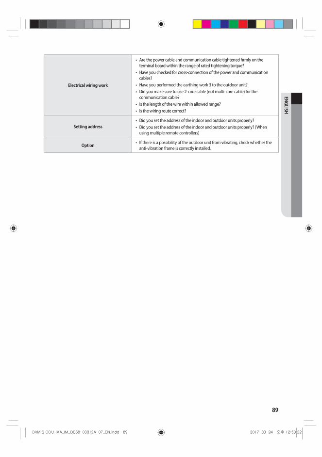
89
ENGLISH
Electrical wiring work
• Are the power cable and communication cable tightened firmly on the terminal board within the range of rated tightening torque?
• Have you checked for cross-connection of the power and communication cables?
• Have you performed the earthing work 3 to the outdoor unit?• Did you make sure to use 2-core cable (not multi-core cable) for the
communication cable?• Is the length of the wire within allowed range?• Is the wiring route correct?
Setting address• Did you set the address of the indoor and outdoor units properly?• Did you set the address of the indoor and outdoor units properly? (When
using multiple remote controllers)
Option • If there is a possibility of the outdoor unit from vibrating, check whether the anti-vibration frame is correctly installed.

90
Inspection and trial operationPrecautions before test operation• When the outdoor temperature is low, turn on the main power 6 hours before beginning the operation.
- If you start the operation immediately after turning on the main power, it may cause serious damage to the part within the product.
• Do not touch the refrigerant pipe during or right after the operation. - Refrigerant pipe may be hot or cold during or right after the operation depending on the status of the
refrigerant which flows through the refrigerant pipe, compressor and other parts of the refrigerant cycle.• Do not operate the product with its panel or protection nets off.
- There is risk of personal injury from the parts that rotates, heated or with the high voltage.• Do not turn off the main power immediately after stopping the operation.
- Wait for at least 5 minutes before turning off the main power. If not, water leakage or other problems may occur.
• Connect all the indoor units and the power supply for the outdoor unit and run auto address setting. Run auto address setting even after changing the indoor unit PCB.
CAUTION
Checklist before auto trial operation1. Check the power cable and communication cable of the indoor and outdoor unit.2. Supply power to the outdoor unit 6 hours before trial operation to pre-heat the crank case heater.3. Before supplying the power, use a voltmeter and phase tester to check the voltage and the phase.
- R,S,T terminal: check the 460V between wires (R-S, S-T, T-R) (AM✴✴✴✴XV✴J✴ Model only) / 230V between wires (R-S, S-T, T-R) (AM✴✴✴✴XV✴F✴ Model only).
4. When the power is supplied, outdoor unit will execute tracking to check the indoor unit connection and other optional functions.
5. Write down the installation report on the service history report paper attached on the front part of the control box.
• Supply power to the outdoor unit 6 hours before auto trial operation to pre-heat the crank case heater.CAUTION
6. Guaranteed range of auto trial operationFor precise judgment, you must perform auto trial operation in below indoor/outdoor temperature condition.
50 (122)
40 (104)
30 (86)
20 (68)
10 (50)
0 (32)
-10 (14)
-20 (-4)5 (41) 10 (50) 15 (59) 20 (68) 25 (77) 30 (86) 35 (95) 40 (104) 45 (113)
Indoor temperature [°C (°F)]
CoolingHeating
Outd
oor t
empe
ratu
re [°
C (°F
)]
- In Auto trial operation, product will automatically select either cooling or heating mode and operate in selected mode. - In the temperature range marked with slashed pattern, system protection control may trigger during operation. (If the
system protection control is enabled, it can be hard to get the precise judgment after the auto trial operation.) - When the temperature is outside of guaranteed range, accuracy of judgment on auto trial operation may decrease near
boarder line area.
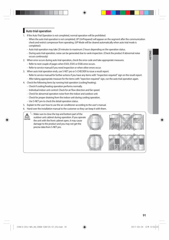
91
ENGLISH
Auto trial operation1. If the Auto Trial Operation is not completed, normal operation will be prohibited.
- When the auto trial operation is not completed, UP (UnPrepared) will appear on the segment after the communication check and restrict compressor from operating. (UP Mode will be cleared automatically when auto trial mode is completed.)
- Auto trial operation may take 20 minutes to maximum 2 hours depending on the operation status. - During auto trial operation, noise can be generated due to vavle inspection. (Check the product if abnormal noise
occurs continously)2. When error occurs during auto trial operation, check the error code and take appropriate measures.
- Refer to next couple of pages when E503, E505 or E506 error occurs. - Refer to service manual if you need inspection or when other errors occur.
3. When auto trial operation ends, use S-NET pro or S-CHECKER to issue a result report. - Refer to service manual for further actions if you have any items with "inspection required" sign on the result report. - After taking appropriate measure for the items with "inpection required" sign, run the auto trial operation again.
4. Check the following items by running trial operation (cooling/heating). - Check if cooling/heating operation performs normally. - Individual indoor unit control: Check for air flow direction and fan speed. - Check for abnormal operation noise from the indoor and outdoor unit. - Check for proper draining from the indoor unit during cooling operation. - Use S-NET pro to check the detail operation status.
5. Explain to the user how to use the air conditioner according to the user's manual.6. Hand over the installation manual to the customer so they can keep it with them.
CAUTION
• Make sure to close the top and bottom part of the outdoor unit cabinet during operation. If you operate the unit with the front cabinet open, it may cause damage to the product and you may not get the precise data from S-NET pro.
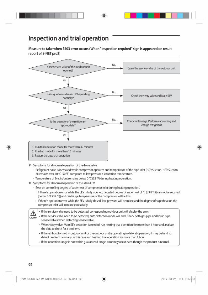
92
Inspection and trial operationMeasure to take when E503 error occurs (When "inspection required" sign is appeared on result report of S-NET pro2)
1. Run trial operation mode for more than 30 minutes2. Run Fan mode for more than 10 minutes3. Restart the auto trial operation
Yes
Yes
Yes
Open the service valve of the outdoor unitNo.
Is the service valve of the outdoor unit opened?
Check the 4way valve and Main EEVNo.
Is 4way valve and main EEV operating normally?
Check for leakage. Perform vacuuming and charge refrigerant
No.Is the quantity of the refrigerant
appropriate?
❋ Symptoms for abnormal operation of the 4way valve - Refrigerant noise is increased while compressor operates and temperature of the pipe inlet (H/P: Suction, H/R: Suction
2) remains over 10 °C (50 °F) compared to low pressure's saturation temperature. - Temperature of Eva. in/out remains below 0 °C (32 °F) during heating operation.
❋ Symptoms for abnormal operation of the Main EEV - Error on controlling degree of superheat of compressor inlet during heating operation.
: If there's operation error while the EEV is fully opened, targeted degree of superheat [1 °C (33.8 °F)] cannot be secured [below 0 °C (32 °F)] and discharge temperature of the compressor will be low.
: If there's operation error while the EEV is fully closed, low pressure will decrease and the degree of superheat on the compressor inlet will increase excessively.
• If the service valve need to be detected, corresponding outdoor unit will display the error.• If the service valve need to be detected, auto detection mode will end. Check both gas pipe and liquid pipe
service valves when detecting service valve.• When 4way valve, Main EEV detection is needed, run heating trial operation for more than 1 hour and analyze
the data to check for a problem.• If there's frost formed in outdoor unit or the outdoor unit is operating in deforst operation, it may be hard to
detect problem normally. In this case, run heating trial operation for more than 1 hour.• If the opreation range is not within guaranteed range, error may occur even though the product is normal.
CAUTION
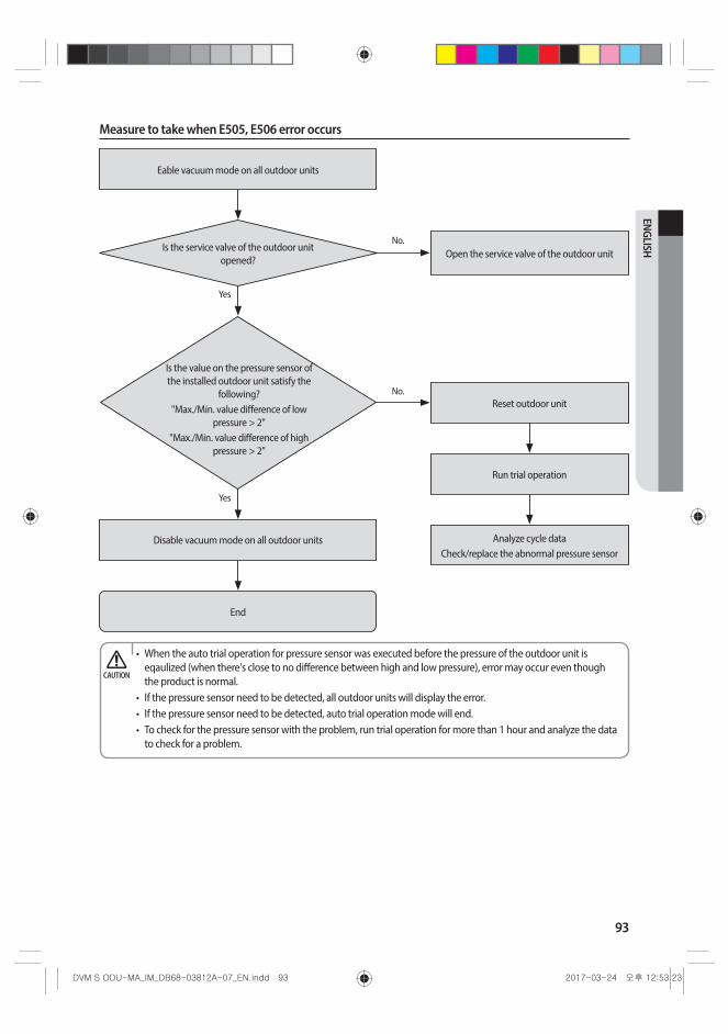
93
ENGLISH
Measure to take when E505, E506 error occurs
End
Yes
Yes
Eable vacuum mode on all outdoor units
Disable vacuum mode on all outdoor units
No.Is the service valve of the outdoor unit
opened?Open the service valve of the outdoor unit
No.
Is the value on the pressure sensor of the installed outdoor unit satisfy the
following?"Max./Min. value difference of low
pressure > 2" "Max./Min. value difference of high
pressure > 2"
Reset outdoor unit
Run trial operation
Analyze cycle dataCheck/replace the abnormal pressure sensor
• When the auto trial operation for pressure sensor was executed before the pressure of the outdoor unit is eqaulized (when there's close to no difference between high and low pressure), error may occur even though the product is normal.
• If the pressure sensor need to be detected, all outdoor units will display the error.• If the pressure sensor need to be detected, auto trial operation mode will end.• To check for the pressure sensor with the problem, run trial operation for more than 1 hour and analyze the data
to check for a problem.
CAUTION
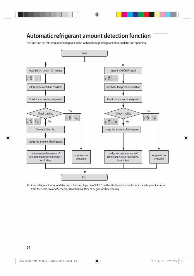
94
Automatic refrigerant amount detection functionThis function detects amount of refrigerant in the system through refrigerant amount detection operation
Start
Press the Tact switch "K2" 5 times
Check the amount of refrigerant
Judge the amount of refrigerant
Judgment on the amount of refrigerant: Normal / Excessive /
Insufficient
Judgment not available
Judgment not available
Connect S-Net Pro Judge the amount of refrigerant
Judgment on the amount of refrigerant: Normal / Excessive /
Insufficient
Satisfy the temperature condition Satisfy the temperature condition
Check the amount of refrigerant
Input S-CHECKER signal
Check stability Check stability
End
Yes
No No
Yes
❋ After refrigerant amount detection is finished, if you see “K9 Ed” on the display and cannot check the refrigerant amount from the S-net pro and S-checker, it means insufficient degree of supercooling.
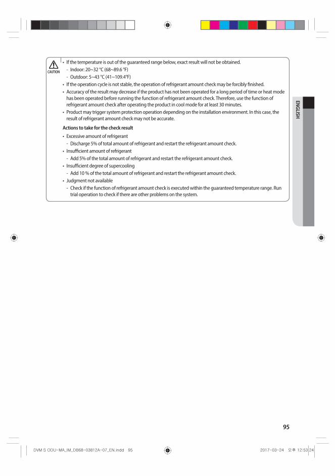
95
ENGLISH
• If the temperature is out of the guaranteed range below, exact result will not be obtained. - Indoor: 20~32 °C (68~89.6 °F) - Outdoor: 5~43 °C (41~109.4°F)
• If the operation cycle is not stable, the operation of refrigerant amount check may be forcibly finished.• Accuracy of the result may decrease if the product has not been operated for a long period of time or heat mode
has been operated before running the function of refrigerant amount check. Therefore, use the function of refrigerant amount check after operating the product in cool mode for at least 30 minutes.
• Product may trigger system protection operation depending on the installation environment. In this case, the result of refrigerant amount check may not be accurate.
Actions to take for the check result
• Excessive amount of refrigerant - Discharge 5% of total amount of refrigerant and restart the refrigerant amount check.
• Insufficient amount of refrigerant - Add 5% of the total amount of refrigerant and restart the refrigerant amount check.
• Insufficient degree of supercooling - Add 10 % of the total amount of refrigerant and restart the refrigerant amount check.
• Judgment not available - Check if the function of refrigerant amount check is executed within the guaranteed temperature range. Run
trial operation to check if there are other problems on the system.
CAUTION

DB68-03812A-07