air conditioner instruction models: 10, 12 and … · the control panel and compressor compartments...
TRANSCRIPT
OUTDOOR SPLIT-SYSTEMAIR CONDITIONER
MODELS: 10, 12 AND 14 SEER
1.5 TO 5 TONS
035-15776-003 REV. C (800)
INSTALLATION INSTRUCTION
TABLE OF CONTENTS
GENERAL INFORMATION . . . . . . . . . . . . . . . . . . . 2
INSPECTION . . . . . . . . . . . . . . . . . . . . . . . . . . . . . . 2
REFERENCE . . . . . . . . . . . . . . . . . . . . . . . . . . . . . . 2
LIMITATIONS . . . . . . . . . . . . . . . . . . . . . . . . . . . . . . 2
INSTALLATION . . . . . . . . . . . . . . . . . . . . . . . . . . . 4
OUTDOOR UNIT . . . . . . . . . . . . . . . . . . . . . . . . . . . 4
INDOOR UNITS . . . . . . . . . . . . . . . . . . . . . . . . . . . . 4
REFRIGERANT LINE (SWEAT FIT) . . . . . . . . . . . . 4
INSULATION OF VAPOR LINE . . . . . . . . . . . . . . . . 4
RE-ASSEMBLING, BRAZING AND CLEANING OF JOINT CONNECTIONS . . . . . . . . . . . . . . . . . . . . . . 4
REFRIGERANT LINE SUPPORT . . . . . . . . . . . . . . 5
CHARGING AND LEAK TESTING . . . . . . . . . . . . . . 5
TOTAL LINE LENGTH . . . . . . . . . . . . . . . . . . . . . . . 5
ORIFICE SELECTION (ON SWEAT FIT COILS) . . . 5
REFRIGERANT VALVE OPERATION . . . . . . . . . . 5
REFRIGERANT LINE (QUICK CONNECT UNITS) . 6
OIL TRAPPING . . . . . . . . . . . . . . . . . . . . . . . . . . . . 8
CHECKOUT PROCEDURE . . . . . . . . . . . . . . . . . . 11
SYSTEM OPERATION CHECKOUT . . . . . . . . . . . 11
CAUTION: READ ALL SAFETY GUIDES BEFORE YOU START TO INSTALL YOUR FURNACE.
SAVE THIS MANUAL
035-15776-003 REV. C (800)
2 Unitary Products Group
GENERAL INFORMATION
These outdoor condensing units are designed to be con-nected to a matching UPG indoor coil. They are equippedwith a filter-drier located in the liquid line. One of two types ofconnection lines are required, depending on the model:
� Units with sweat-fit base valve connections are factory charged with refrigerant for a matching UPG indoor coil, plus 15 feet of field supplied line.
� Units with quick-connect coupling connections are fac-tory charged with refrigerant to be matched with the appropriate precharged line set, and UPG indoor coil.
The outdoor unit is designed to be placed near the perimeterof the home, typically alongside or at the back of the home,remote from the indoor coil. The outdoor unit has been fac-tory run-tested and all components of the system are readyfor easy, immediate installation.
INSPECTION
Check the unit thoroughly for shipping damage, Unusuallyrough handling during shipment may loosen fan motors, com-pressors, or other components. Be sure that the unit is readyto operate before installing it. If there is damage, file a claimwith the shipper.
REFERENCE
Use this instruction in conjunction with the instructions for theappropriate indoor unit, air moving system and accessories.
Installer should pay particular attention to the words NOTE,CAUTION and WARNING.
NOTES are intended to clarify or make the installation easier.
CAUTIONS identify procedures which, if not followed care-fully, could result in personal injury, property damage orequipment damage.
WARNINGS are given to alert the installer that severe per-sonal injury, death or equipment damage may result if instal-lation procedures are not followed properly.
LIMITATIONS
The unit should be installed in accordance with all nationaland local codes and regulations which govern the installationof this type of equipment. In lieu of local codes, the equip-ment should be installed in accordance with National ElectricCode, and in accordance with the recommendations made bythe National Board of Fire Underwriters.
Limitations for the indoor unit, coil and appropriate accesso-ries must also be observed.
The outdoor unit must not be installed with any duct work inthe air stream. The outdoor fan is the propeller type and is notdesigned to operate against any additional external staticpressure.
The maximum and minimum conditions for operation must beobserved to assure a system that will give maximum perfor-mance with minimum service.
Check Electrical Power Supply
The electrical power should be checked to determine if ade-quate power is available, and near constant voltage can be maintained. If there is any question concerning the power supply, contact the local power company for corrections; oth-erwise, unsatisfactory performance may result.
Selecting the Best Heat Pump Location
Several important factors must be considered before select-ing the site for the outdoor unit:
� Distance to indoor coil
� Proximity to the structure
� Proximity to vents and exhaust systems
� Ability to service
� Sound transmission
� Air circulation
� Wind direction
� Relationship between structure, sun, and unit
� Distance from power source
� Water drainage
� Local codes
Locate the outdoor unit near enough to the indoor coil vicinityto eliminate lengthy refrigerant line runs. Do not locate theoutdoor unit so it discharges air under eaves or gutters. Rainor snow melt-off should not be able to run off a roof and downupon the unit. Be sure vents are not located upwind from theoutdoor unit.
The manufacturer is not responsible for the perfor-mance of a mismatched system. The outdoor unitmust be installed with a compatible indoor unit asdesignated in the specification data or in the Direc-tory of Certified Unitary Heat Pumps published bythe Air Conditioning and Refrigeration Institute.Using unmatched components may not only affectthe performance of the system, but may also voidthe warranty of the equipment.
Do not install any coil in a furnace which is to beoperated during the heating season without attach-ing the refrigerant lines to the coil. Allowing the coilcharge to enter the refrigerant lines prevents exces-sive refrigerant pressure build-up and possible coildamage.
Table 1: APPLICATION LIMITATIONS
Ambient Air Temperature on Outdoor Coil
Air Temperature onIndoor Coil
Min. °DB Max. °DB Min. Max.
50 120 57 72
035-15776-003 REV. C (800)
Unitary Products Group 3
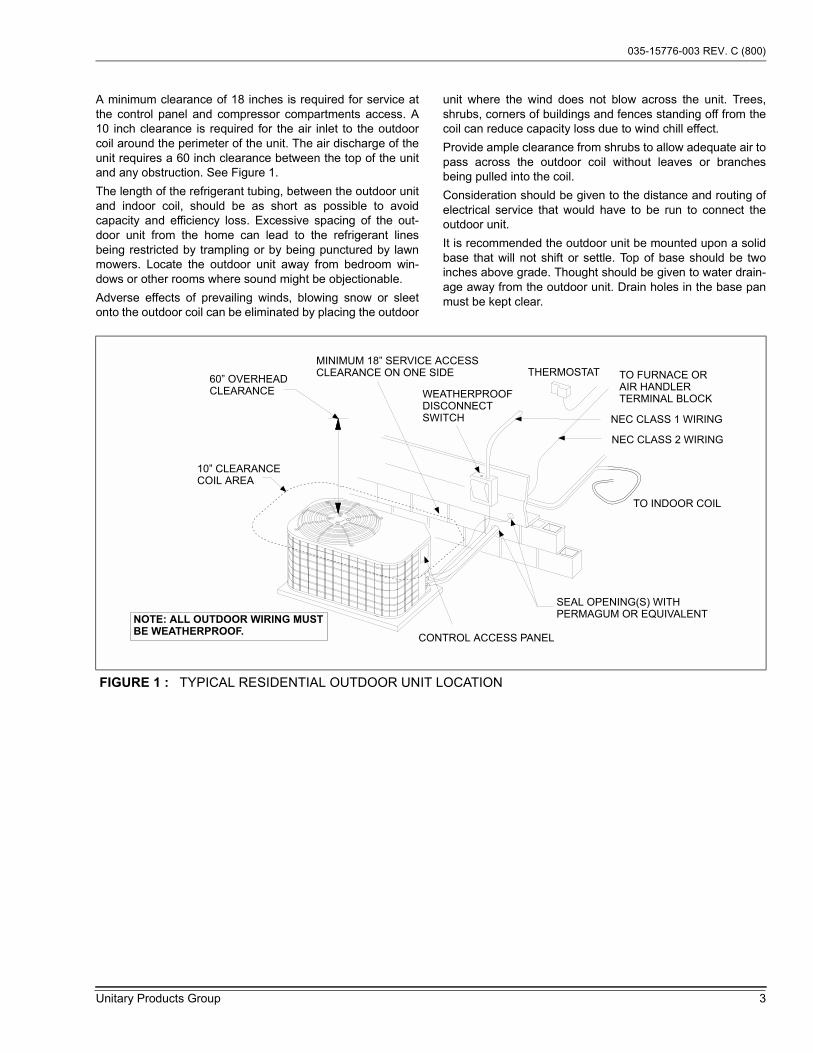
A minimum clearance of 18 inches is required for service atthe control panel and compressor compartments access. A10 inch clearance is required for the air inlet to the outdoorcoil around the perimeter of the unit. The air discharge of theunit requires a 60 inch clearance between the top of the unitand any obstruction. See Figure 1.
The length of the refrigerant tubing, between the outdoor unitand indoor coil, should be as short as possible to avoidcapacity and efficiency loss. Excessive spacing of the out-door unit from the home can lead to the refrigerant linesbeing restricted by trampling or by being punctured by lawnmowers. Locate the outdoor unit away from bedroom win-dows or other rooms where sound might be objectionable.
Adverse effects of prevailing winds, blowing snow or sleetonto the outdoor coil can be eliminated by placing the outdoor
unit where the wind does not blow across the unit. Trees,shrubs, corners of buildings and fences standing off from thecoil can reduce capacity loss due to wind chill effect.
Provide ample clearance from shrubs to allow adequate air topass across the outdoor coil without leaves or branchesbeing pulled into the coil.
Consideration should be given to the distance and routing ofelectrical service that would have to be run to connect theoutdoor unit.
It is recommended the outdoor unit be mounted upon a solidbase that will not shift or settle. Top of base should be twoinches above grade. Thought should be given to water drain-age away from the outdoor unit. Drain holes in the base panmust be kept clear.
FIGURE 1 : TYPICAL RESIDENTIAL OUTDOOR UNIT LOCATION
MINIMUM 18” SERVICE ACCESSCLEARANCE ON ONE SIDE
60” OVERHEADCLEARANCE
10” CLEARANCECOIL AREA
WEATHERPROOFDISCONNECTSWITCH
THERMOSTAT TO FURNACE ORAIR HANDLERTERMINAL BLOCK
NEC CLASS 1 WIRING
NEC CLASS 2 WIRING
TO INDOOR COIL
SEAL OPENING(S) WITHPERMAGUM OR EQUIVALENT
CONTROL ACCESS PANEL
NOTE: ALL OUTDOOR WIRING MUST
BE WEATHERPROOF.
035-15776-003 REV. C (800)
4 Unitary Products Group
INSTALLATION
OUTDOOR UNIT
After the site has been selected, a solid base pad that will notshift or settle should be provided. The base pad should notcome in contact with the foundation or side of the structurebecause sound may be transmitted to the residence. The padshould be located far enough away from the structure so theoutdoor unit is not closer than its minimum distances. SeeFigure 1. Set the outdoor unit upon the pad with care to avoiddamage..
INDOOR UNITS
Install the indoor coil in the furnace or air handler accordingto the installation instructions packed with each component.
REFRIGERANT LINE (SWEAT FIT)
The following steps are very important when setting up arefrigeration system and need to be followed completely toinsure that a strong, flexible and leak tight system is obtained.
The installation of the copper refrigerant tubing must be donewith care to obtain reliable, trouble-free operation.
1. Selection of proper refrigerant tubing grade and size.
2. Refrigerant line routing, cutting and fitting.
3. Insulating the vapor line.
4. Connecting the refrigerant lines to the indoor coil and outdoor unit.
5. Proper preparation of joint connections.
6. Reassembling, cleaning and brazing the joint connec-tions.
7. Pressure leak test all joints.
8. Evacuate refrigerant lines and indoor coil.
9. Charging refrigeration system (See Tabular Data Sheet if the line length is other than 15 feet).
Use only ACR grade copper tubing and keep ends sealeduntil joints are made.
The correct diameters of the refrigerant lines are listed in theTabular Data Sheet.
For best performance, select routing of refrigerant lines forminimum distance and fewest number of bends.
Determine the path that the refrigerant lines will follow.
Starting at either the indoor coil or the outdoor unit refrigerantline connections, carefully measure, cut, de-burr and fit cop-per refrigerant lines along the path previously determined.
NOTE: If it is necessary for bends to be formed in the vaporline, the radius should not be less than 12 inches.
Cut ends of the copper tubing square.
Remove all burrs from tubing with a reamer, file or de-burringtool.
When the indoor coil is above the outdoor unit, the vapor lineshould be sloped toward the outdoor unit with a fall of at least1/4 inch per 5 feet.
INSULATION OF VAPOR LINE
Insulate vapor line with 3/8" (or that required by local code)closed cell insulation.
Slide tubing insulation onto the vapor line so that it is coveredcompletely from the indoor coil to the outdoor unit. Be surethat the tubing is capped before sliding on insulation.
It is not necessary to insulate the liquid line.
NOTE: In areas of extreme temperatures and humidity,additional insulation may be required to preventexcessive condensation and loss of capacity.
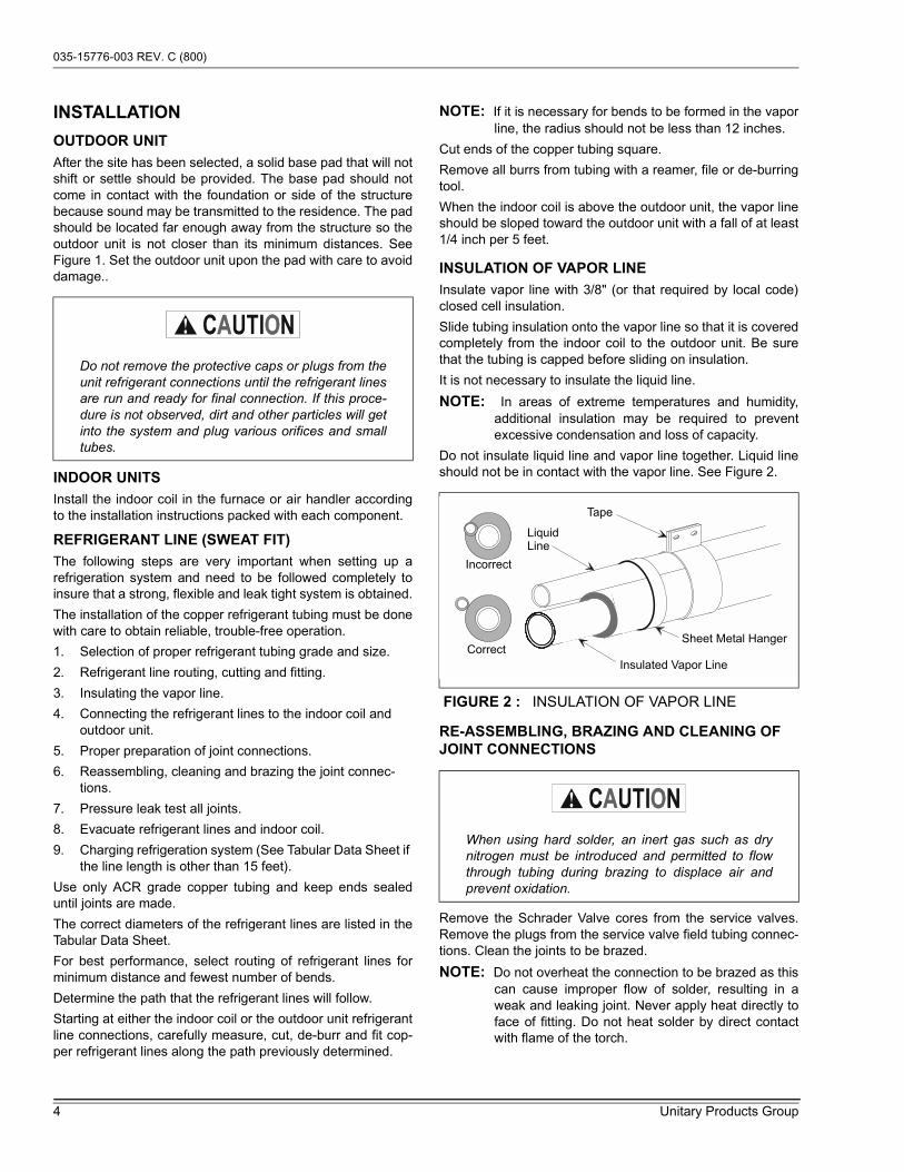
Do not insulate liquid line and vapor line together. Liquid lineshould not be in contact with the vapor line. See Figure 2.
RE-ASSEMBLING, BRAZING AND CLEANING OF JOINT CONNECTIONS
Remove the Schrader Valve cores from the service valves.Remove the plugs from the service valve field tubing connec-tions. Clean the joints to be brazed.
NOTE: Do not overheat the connection to be brazed as thiscan cause improper flow of solder, resulting in aweak and leaking joint. Never apply heat directly toface of fitting. Do not heat solder by direct contactwith flame of the torch.
Do not remove the protective caps or plugs from theunit refrigerant connections until the refrigerant linesare run and ready for final connection. If this proce-dure is not observed, dirt and other particles will getinto the system and plug various orifices and smalltubes.
FIGURE 2 : INSULATION OF VAPOR LINE
When using hard solder, an inert gas such as drynitrogen must be introduced and permitted to flowthrough tubing during brazing to displace air andprevent oxidation.
LiquidLine
Incorrect
Correct
Tape
Sheet Metal Hanger
Insulated Vapor Line
035-15776-003 REV. C (800)
Unitary Products Group 5
When brazing copper tubing it is very important to preheatthe entire joint before applying the solder. This is done bysweeping the flame steadily and evenly around the fitting, tobring both fitting and tubing up to equal temperature beforeapplying the solder.
Reassemble groups of tubing and fittings, brazing severaljoints instead of one joint at a time. This reduces the chancefor error in the alignment of the assembly. Replace SchraderValve cores. DO NOT OPEN SERVICE VALVES AT THISTIME.
Clean joint connection immediately after brazing with wet rag.
REFRIGERANT LINE SUPPORT
Refrigerant lines should be supported in a way that no dips orsags occur. We recommend four feet between supports. Ifrefrigerant lines are to be attached to the home structure,care should be taken to eliminate the transmission of vibra-tions. Attach the refrigerant lines to the indoor coil first.Remove plugs from the indoor coil, then clean joints to bebrazed. Braze refrigerant lines to the indoor coil. Attachrefrigerant lines to the outdoor unit.
CHARGING AND LEAK TESTING
On systems with or without service valves the refrigerantshould be recovered or recycled in accordance with EPA reg-ulations. In some cases this may require putting piercingvalves on both the high and low sides of the system.
When recovering refrigerant from a system, with a burnout,follow a safe procedure due to possible contamination.
Contaminated refrigerant must be recovered and returned tothe local refrigeration supply house for proper disposition.
TOTAL LINE LENGTH
Units should be installed only with approved system combi-nation (indoor/outdoor) as specified in the Technical Guide.
For systems with total line length exceeding 50 feet, seeAPPLICATION DATA and work sheet "General Piping Rec-ommendations and Refrigerant Line Length" for vapor andliquid line sizing, calibration of liquid line pressure loss orgain, determination of vapor line velocity, elevation limita-tions, orifice connections, system charging, traps, etc.
Systems with liquid line pressure loss or gain greater than 11psi must be provided with corrected orifice size as noted in.APPLICATION DATA.
ORIFICE SELECTION (ON SWEAT FIT COILS)
NOTE: The proper orifice must be installed in the indoor coilliquid line connection prior to the connection of therefrigerant lines.
The orifice shipped with the outdoor unit is based on the�most sold� combination, but it may be changed, dependingon the capacity and efficiency of the outdoor unit, elevationdifferences, and/or long total line lengths. An additional ori-fice(s) is shipped with most outdoor units for the most com-monly required replacement combinations. Other sizes mustbe ordered from Source 1 Parts if required.
See the appropriate Tabular Data Sheet for the correct orificesize and charge adder. If the orifice size matches, nothing fur-ther is required and the refrigerant lines may be connectedper the outdoor unit instruction. However, if another orificeshould be used, see the coil instruction for details to changethe orifice in the coil.
REFRIGERANT VALVE OPERATION
All models in this series have brass service valves. Thesevalves are not back seating. Opening or closing valve doesnot close service port. Service ports have Schrader valves forgauge connections. Use back-up wrench on valve body whenremoving cap to open or close the valve. To open, insert hexwrench into stem and back out counter clockwise until stem
just touches retaining ring.
DO NOT vent refrigerant to the outdoors.
Avoid getting the refrigerant in the eyes or on theskin.
Coil is under 30 to 35 psig (inert gas) pressure.
Each coil has an orifice installed in the fittingbetween the liquid line connection and distributor.The orifice is identified on a label next to the liquidline connection.
All outdoor units are shipped with the service valvesin the closed position. After installation of the refrig-erant and proper evacuation, make sure that allvalves are in the open position and that the caps aresecurely tightened before turning ON the electricalpower to the outdoor unit.
If the valve stem is backed out beyond the retainingring, system pressure could force the stem out of thevalve body and possibly cause personal injury. Inthe event that the retaining ring is missing do notattempt to open the valve.
035-15776-003 REV. C (800)
6 Unitary Products Group
Some units may have factory installed 1-1/8" ball valves. Toopen the valve, remove the brass valve stem cap, located onthe side of the valve, with an adjustable wrench. Next, turnthe valve stem 1/4 turn CCW (away from unit).
All caps must be replaced to prevent leaks.
Replace valve cap finger tight, then tighten an additional 1/6of a turn with a wrench, using a back-up wrench on the valvebody.
REFRIGERANT LINE (QUICK CONNECT UNITS)
IMPORTANT - Do not remove protective caps from cou-plings until precharged lines are routed and ready for finalconnection. Protective caps prevent dirt from entering cou-plings and contaminating system when connected together.
1. Check size and length of precharged refrigerant lines before installing.
a. Check the size of the precharged refrigerant lines toinsure that they are correct for the model beinginstalled.
b. Check the final routing of the tubing, and insure tub-ing will be of adequate length, with allowance forconnection at the coil and outdoor unit.
2. Copper tubing will work-harden.
a. The precharged tubing should be handled carefully.
b. Do not bend or work the tubing any more than nec-essary. (The larger size tubing 3/4" for example, willwork-harden rapidly as it is formed. As the tubingbecomes harder, it is more susceptible to kinkingand damage).
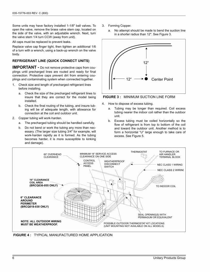
3. Forming Copper.
a. No attempt should be made to bend the suction linein a shorter radius than 12". See Figure 3.
4. How to dispose of excess tubing.
a. Tubing may be longer than required. Coil excesstubing nearer the indoor coil rather than the outdoorunit.
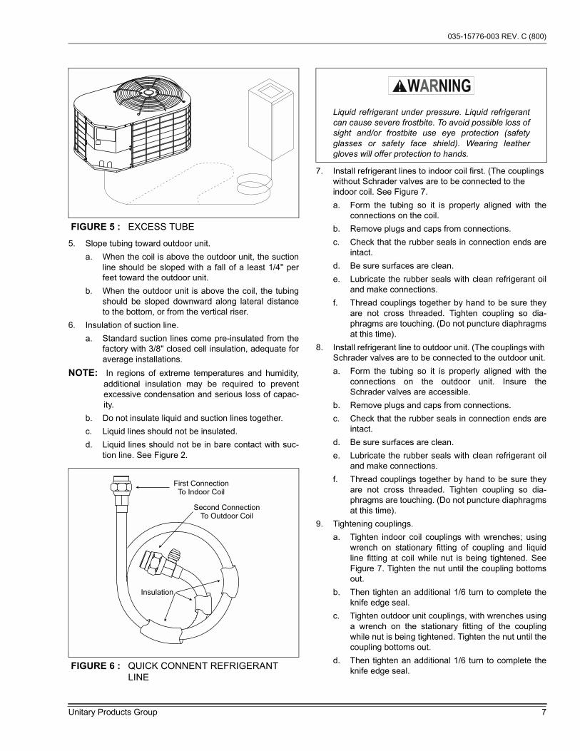
b. Excess tubing must be coiled horizontally so theflow of refrigerant is from top to bottom of the coiland toward the outdoor unit. Another method is toform a horizontal �U� large enough to take care ofexcess. See Figure 5.
FIGURE 3 : MINIMUM SUCTION LINE FORM
12“
12“ Center Point
FIGURE 4 : TYPICAL MANUFACTURED HOME APPLICATION
MINIMUM 18” SERVICE ACCESSCLEARANCE ON ONE SIDE
60” OVERHEADCLEARANCE
10” CLEARANCE
COIL AREA
(BRCQ036-055 ONLY)
WEATHERPROOFDISCONNECTSWITCH
THERMOSTAT TO FURNACE ORAIR HANDLERTERMINAL BLOCK
NEC CLASS 1 WIRING
NEC CLASS 2 WIRING
TO INDOOR COIL
SEAL OPENING(S) WITHPERMAGUM OR EQUIVALENT
CONTROLACCESSPANEL
NOTE: ALL OUTDOOR WIRING
MUST BE WEATHERPROOF.POSSIBLE OUTDOOR THERMOSTAT KIT LOCATIONS(UNIT MOUNTING NOT AVAILABLE ON ALL MODELS)
6” CLEARANCE
AROUND
PERIMETER
(BRCQ018-030 ONLY)
035-15776-003 REV. C (800)
Unitary Products Group 7
5. Slope tubing toward outdoor unit.
a. When the coil is above the outdoor unit, the suctionline should be sloped with a fall of a least 1/4" perfeet toward the outdoor unit.
b. When the outdoor unit is above the coil, the tubingshould be sloped downward along lateral distanceto the bottom, or from the vertical riser.
6. Insulation of suction line.
a. Standard suction lines come pre-insulated from thefactory with 3/8" closed cell insulation, adequate foraverage installations.
NOTE: In regions of extreme temperatures and humidity,additional insulation may be required to preventexcessive condensation and serious loss of capac-ity.
b. Do not insulate liquid and suction lines together.
c. Liquid lines should not be insulated.
d. Liquid lines should not be in bare contact with suc-tion line. See Figure 2.
7. Install refrigerant lines to indoor coil first. (The couplings without Schrader valves are to be connected to the indoor coil. See Figure 7.
a. Form the tubing so it is properly aligned with theconnections on the coil.
b. Remove plugs and caps from connections.
c. Check that the rubber seals in connection ends areintact.
d. Be sure surfaces are clean.
e. Lubricate the rubber seals with clean refrigerant oiland make connections.
f. Thread couplings together by hand to be sure theyare not cross threaded. Tighten coupling so dia-phragms are touching. (Do not puncture diaphragmsat this time).
8. Install refrigerant line to outdoor unit. (The couplings with Schrader valves are to be connected to the outdoor unit.
a. Form the tubing so it is properly aligned with theconnections on the outdoor unit. Insure theSchrader valves are accessible.
b. Remove plugs and caps from connections.
c. Check that the rubber seals in connection ends areintact.
d. Be sure surfaces are clean.
e. Lubricate the rubber seals with clean refrigerant oiland make connections.
f. Thread couplings together by hand to be sure theyare not cross threaded. Tighten coupling so dia-phragms are touching. (Do not puncture diaphragmsat this time).
9. Tightening couplings.
a. Tighten indoor coil couplings with wrenches; usingwrench on stationary fitting of coupling and liquidline fitting at coil while nut is being tightened. SeeFigure 7. Tighten the nut until the coupling bottomsout.
b. Then tighten an additional 1/6 turn to complete theknife edge seal.
c. Tighten outdoor unit couplings, with wrenches usinga wrench on the stationary fitting of the couplingwhile nut is being tightened. Tighten the nut until thecoupling bottoms out.
d. Then tighten an additional 1/6 turn to complete theknife edge seal.
FIGURE 5 : EXCESS TUBE
FIGURE 6 : QUICK CONNENT REFRIGERANT LINE
First ConnectionTo Indoor Coil
Second ConnectionTo Outdoor Coil
Insulation
Liquid refrigerant under pressure. Liquid refrigerantcan cause severe frostbite. To avoid possible loss ofsight and/or frostbite use eye protection (safetyglasses or safety face shield). Wearing leathergloves will offer protection to hands.

035-15776-003 REV. C (800)
8 Unitary Products Group
10. Check for leaks.
a. After the line set connections have been made theyshould be checked for leaks.
b. If the valves were kept clean and lubricated perinstruction no leaks should be found.
c. Use leak detect solution or soap solution for leaktesting. An electronic leak detector is recom-mended.
OIL TRAPPING
When the outdoor unit is above the indoor coil oil trapping isnecessary. An oil trap should be provided for every 20 feet ofrise..
Check the system for correct charge after all components ofthe system have been installed, connected and wired cor-rectly.
Connect service gauges to low pressure port and dischargeservice ports.
Allow unit to operate until system pressures and tempera-tures have stabilized, making sure that the pressure and tem-perature align with unit service data. If not, check systemcharge and adjust if necessary.
ELECTRICAL WIRING
POWER SUPPLY
All wiring must comply with N.E.C. and local codes. See rat-ing plate and product data sheet for volts, frequency, phase,maximum fuse size and minimum branch circuit ampacity.
Refer to the wiring diagram inside the unit control box coverbefore connecting to power supply.
1. The 208/230 volt single phase line voltage service wiring for the outdoor unit must include a disconnect switch located within sight of the outdoor unit.
2. Use the correct size fuse or circuit breaker as listed on the unit rating plate and data sheet. If using nonmetallic-sheathed cable (NM or NM-B) ampacities shall be that of 60° C conductors per N.E.C 336-26.
3. Wiring connections. - Two are provided in the control box:
a. One for low voltage wiring.
b. One entrance for high voltage L1 and L2.
The adjustable High Voltage Conduit Plate is factory installedfor 1/2" conduit connections. For 3/4" conduit, remove thescrew holding the plate in place and adjust the location of theholes. For 1" conduit, remove the conduit plate and discard.Re-install screw to maintain the integrity of the unit structure,regardless of the conduit being used. See Figures 9, 10 & 11.
4. Power connection to the unit is facilitated by screw termi-nals, L1 and L2 on the outdoor unit contactor. See Fig-ures 9, 10 & 11.
5. Ground the outdoor unit using the ground lug provided. Unless the outdoor unit is grounded through proper wir-ing to the service entrance ground, a suitable separate ground should be provided at the outdoor unit.
6. Use copper conductors only.
FIGURE 7 : QUICK CONNECT COUPLING
FIGURE 8 : OIL TRAP
TIGHTEN
BACK UP
BACK UP
TIGHTEN
INDOORCOIL
OUTDOOR COIL
20 Ft.
20 Ft.
10 In.
6 In.
To prevent electrical shock, open remote disconnectso electrical supply to outdoor unit is shut off. Con-tactor does not open both sides of the 208/230 voltelectrical circuit.
Casing or cabinet must be permanently grounded inaccordance with National Electric Code or otherapplicable local codes.
035-15776-003 REV. C (800)
Unitary Products Group 9
LOW VOLTAGE
Control wiring may vary depending upon the type of thermo-stat and furnace being connected.
Low voltage wiring diagrams can be found with the furnace orair conditioning blower package installation instructions.
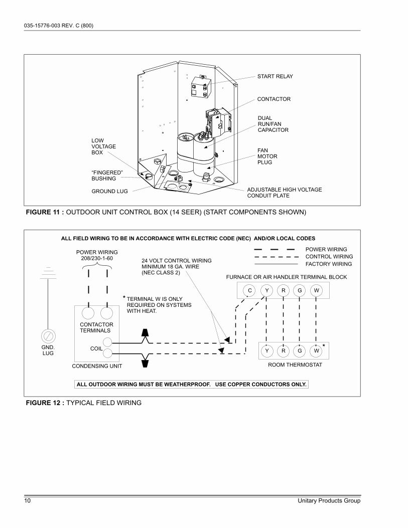
Pig-tail connector wires (2 blue or 1 blue, 1 brown) are pro-vided from the low voltage pull-in coil on the contactor to asection of the control box (See Figure 12). A �Fingered� bush-ing is provided in the low voltage knockout hole. If 1/2" con-duit is used for the low voltage wiring, the bushing is to beremoved.
1. Route the low voltage cable through the fingered bush-ing in the low voltage junction box. See Figures 9, 10 & 11.
2. Using wire nuts, connect the low voltage wiring within the low voltage box.
3. A minimum of 19 AWG wire must be used in connecting the low voltage control wiring between the outdoor unit, air handler thermostat, and outdoor thermostat.
Connect thermostat and control package wiring as shown inFigure 12 and per the instructions packed with those pieces.
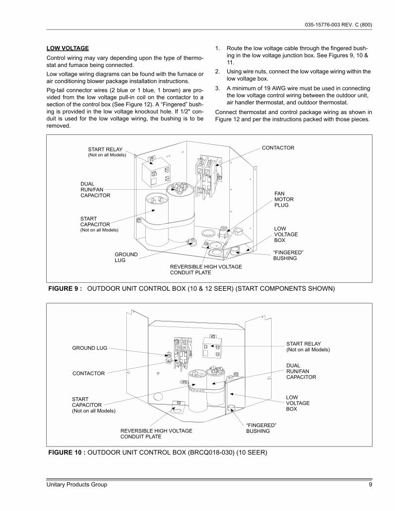
FIGURE 9 : OUTDOOR UNIT CONTROL BOX (10 & 12 SEER) (START COMPONENTS SHOWN)
START RELAY(Not on all Models)
STARTCAPACITOR(Not on all Models)
DUALRUN/FANCAPACITOR
CONTACTOR
FANMOTORPLUG
“FINGERED”BUSHING
LOWVOLTAGEBOX
REVERSIBLE HIGH VOLTAGECONDUIT PLATE
GROUNDLUG
FIGURE 10 : OUTDOOR UNIT CONTROL BOX (BRCQ018-030) (10 SEER)
START RELAY(Not on all Models)
STARTCAPACITOR(Not on all Models)
DUALRUN/FANCAPACITOR
CONTACTOR
“FINGERED”BUSHING
LOWVOLTAGEBOX
REVERSIBLE HIGH VOLTAGECONDUIT PLATE
GROUND LUG
035-15776-003 REV. C (800)
10 Unitary Products Group
FIGURE 11 : OUTDOOR UNIT CONTROL BOX (14 SEER) (START COMPONENTS SHOWN)
DUALRUN/FANCAPACITOR
GROUND LUG
CONTACTOR
FANMOTORPLUG
“FINGERED”BUSHING
ADJUSTABLE HIGH VOLTAGECONDUIT PLATE
LOWVOLTAGEBOX
START RELAY
FIGURE 12 : TYPICAL FIELD WIRING
ALL FIELD WIRING TO BE IN ACCORDANCE WITH ELECTRIC CODE (NEC) AND/OR LOCAL CODES
POWER WIRING208/230-1-60
CONTACTORTERMINALS
COILGND.LUG
C Y R G W
Y R G W
POWER WIRING
CONTROL WIRING
FACTORY WIRING24 VOLT CONTROL WIRINGMINIMUM 18 GA. WIRE(NEC CLASS 2)
FURNACE OR AIR HANDLER TERMINAL BLOCK
ROOM THERMOSTATCONDENSING UNIT
ALL OUTDOOR WIRING MUST BE WEATHERPROOF. USE COPPER CONDUCTORS ONLY.
TERMINAL W IS ONLYREQUIRED ON SYSTEMSWITH HEAT.
*
*

035-15776-003 REV. C (800)
Unitary Products Group 11
CHECKOUT PROCEDURE
Use the following list to see that nothing was over looked:
1. Have all braze joints on refrigerant lines been leak checked? (Sweat Fit Units)
2. Line set fittings leak checked? (Quick Connect Units)
3. Have base valves been opened? (Sweat Fit Units only)
4. Have all refrigerant lines been secured and isolated properly?
5. Is the indoor coil drain hooked up and draining freely? Pour water in drain pan.
6. Is air filter installed and clean?
IMPORTANT - Installer should place unit data sheet andinstallation instructions in customer packet and give to homeowner after installation is complete.
SYSTEM OPERATION CHECKOUT
1. With thermostat set to the OFF position, close discon-nect switch or switches to complete circuits to condens-ing unit and furnace. Set thermostat to call for cooling.
2. After the system starts, check the voltage and amperage at the condensing unit contactor.
3. If voltage is not within 10% of rated voltage, or amperage greatly exceeds nameplate amperage, shut down the system and contact the local power company for correc-tions; otherwise unsatisfactory performance may result.
4. With the system in operation, check the condensing unit for unusual noise and undue vibration.
5. Allow the system to operate until it is balanced or stabi-lized (approximately 30 minutes), before making further checks.
6. Remove manifold gages hoses, and install cap on Schrader valves.

Subject to change without notice. Printed in U.S.A. 035-15776-003 REV. C (800)Copyright © by York International Corp. 2000. All rights reserved. Supersedes: 035-15776-003 REV. B (0700)
Unitary 5005 NormanProduct York OKGroup Drive 73069
NOTES