air bearing upgrade for split-hopkinson pressure bar (shpb) experiment donald hayes ii, joseph...
TRANSCRIPT

Air Bearing Upgrade for Split-Hopkinson Pressure Bar (SHPB) Experiment
Donald Hayes II, Joseph Chason, Sarah Napier, Zachary Johnson Department of Mechanical Engineering
Sponsor Dr. Joel House
Eglin Air Force Base Research Laboratory
AdvisorErica Cosmutto
FAMU/FSU College of Engineering
April 12, 2012

Overview Introduction Concept Generation & Selection Final Concept Components Functional Diagram Results & Discussion Project Budget Safety Concerns Conclusion Acknowledgements Questions
2

Introduction: SHPB Basics
StrikerMechanism
Incident Bar / Strain Gauges / Bushings
Transmitter Bar / Strain Gauges / Bushings
MaterialSample
Momentum Trap
Initial Strain Pulse
Reflected Pulse Transmitted Pulse
3

Introduction: SHPB Basics
StrikerMechanism
Strain Gauges Strain GaugesMaterialSample
Momentum Trap
Data
Data Acquisition System
4

Introduction: Needs Assessment Research air bearings for existing 5/8 inch
diameter journal bearing system Develop:
Bar alignment method System upgrade from journal bearings to air bearings
Determine efficiency of air bearings over journal bearings
5
Introduction: Objectives Analyze SHPB design based on use of air bearings Analyze:
Hardware cost Interface requirements Installation procedures Impact on bar geometry
Assess strain gauge technology Develop procedure to align bars Design a working prototype to show knowledge of
system Remain within $2500 budget
6

Generating Concepts: Methodology
Break system into base components Treat components as individual systems Generate multiple solutions per system Determine most suitable components Combine and implement into design
7

Generating Concepts: Components & Concerns
SHPB Components Base Structure Striker Mechanism Incident & Transmission Bars Strain Gauges Air Bushings Momentum Trap Air Supply System
Concerns Bar Alignment Method Data Acquisition
8

Generating Concepts: Criteria
Cost Weight Size Simplicity Durability
Portability Scalability Accuracy Data Quality Ease of Use
9

Selecting Concepts
10

Selecting Concepts
11
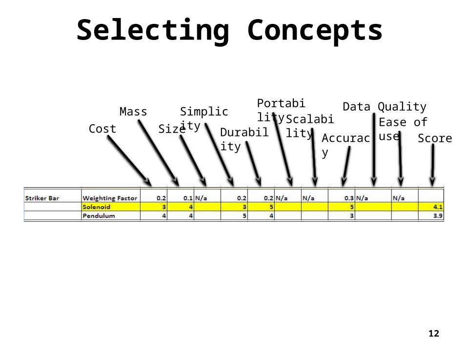
Selecting Concepts
Cost
Mass
Size
Simplicity
Durability
PortabilityScalability
Accuracy
Data Quality Ease of use
Score
12

Final Concept Component Final SelectionBase Structure T-Slotted Framing
Striker Mechanism Electric Solenoid
Incident, Transmission & Striker Bars 0.75” dia. 1566 Steel
Strain Gauges Foil Type (Vishay Co.)
Air Bushings 0.75” ID (New Way Air Bearing Co.)
Momentum Trap Custom
Gas Supply Compressed Argon
Data Acquisition NI Hardware & Software (LabView)
Bushing Alignment Method Laser Insert
13
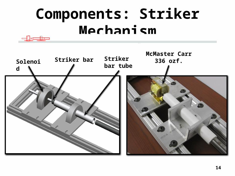
Components: Striker Mechanism
Solenoid Striker barMcMaster Carr
336 ozf.
14
Striker bar tube

Components: Air Bushings
Air lineBushing block
housingAir bushing
New Way Air Bearings0.75” Inner Diameter30 lb. Radial Load
15

Components: Strain Gauges and Material Sample
Strain gauges
16

Components: Strain Gauges and Material Sample
Strain gauges
Vishay MicromeasurementsGauge factor ≈ 2Resistance = 120 ΩLocated 6” from sample
17
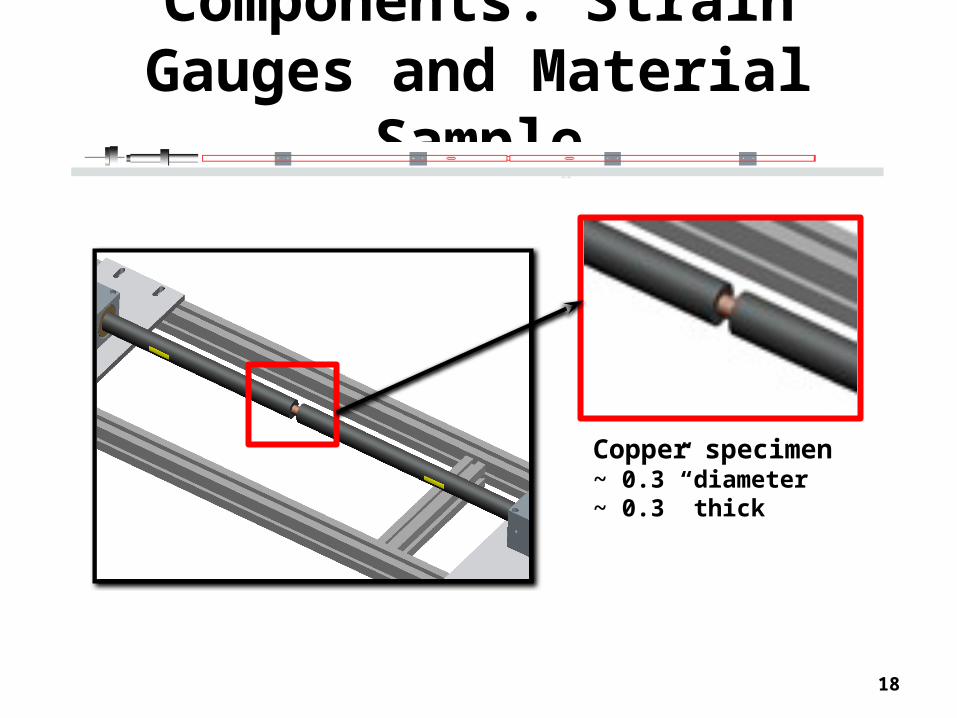
Components: Strain Gauges and Material Sample
Copper specimen ~ 0.3” diameter~ 0.3” thick
18

Components: Momentum Trap (bar stopper)
19

Final Concept
Incident bar
Copper specimen
Momentum trap
Transmitter bar
Strain gauges
Air bushing
Striker bar mechanism
Length = 8 ft.Width = 7 in.Height = 3.5 in.
20
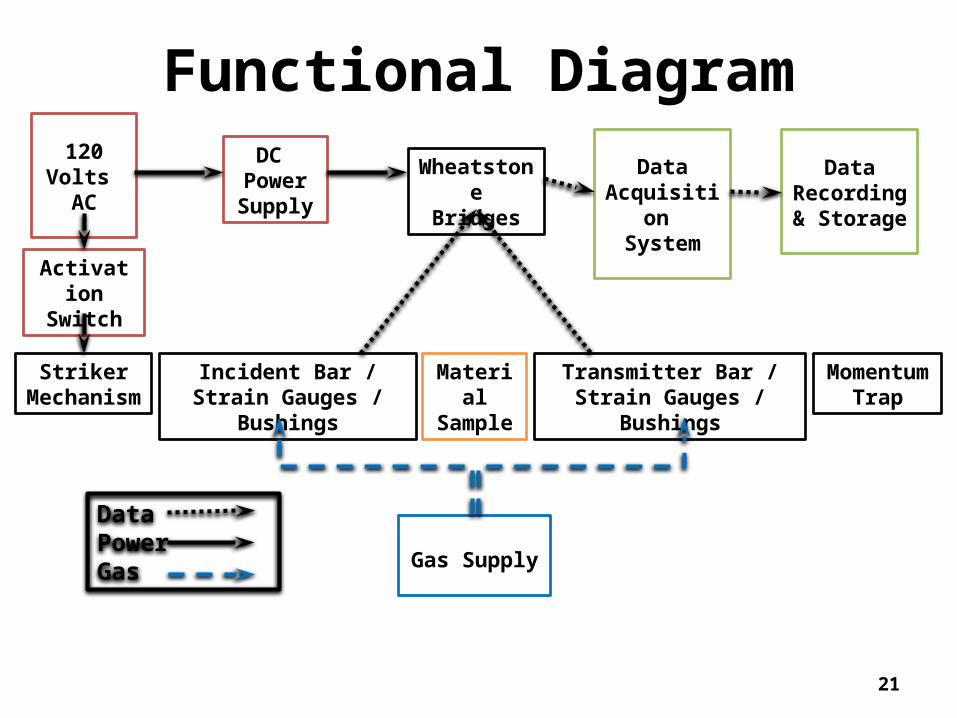
Functional Diagram
Activation Switch
StrikerMechanism
Incident Bar / Strain Gauges / Bushings
Transmitter Bar / Strain Gauges / Bushings
MaterialSample
Momentum Trap
WheatstoneBridges
Gas Supply
DC PowerSupply
Data Acquisition
System
DataPowerGas
120 Volts AC Data
Recording & Storage
21

Strain Pulse: VisualizationVisualizing the Sample
CopperSample
SteelIncident Bar
SteelTransmitter Bar
22

Strain Pulse: VisualizationReduced Sample Area Increases Applied Stress
Dsteel DCopper 0.75 in 0.31 in
23
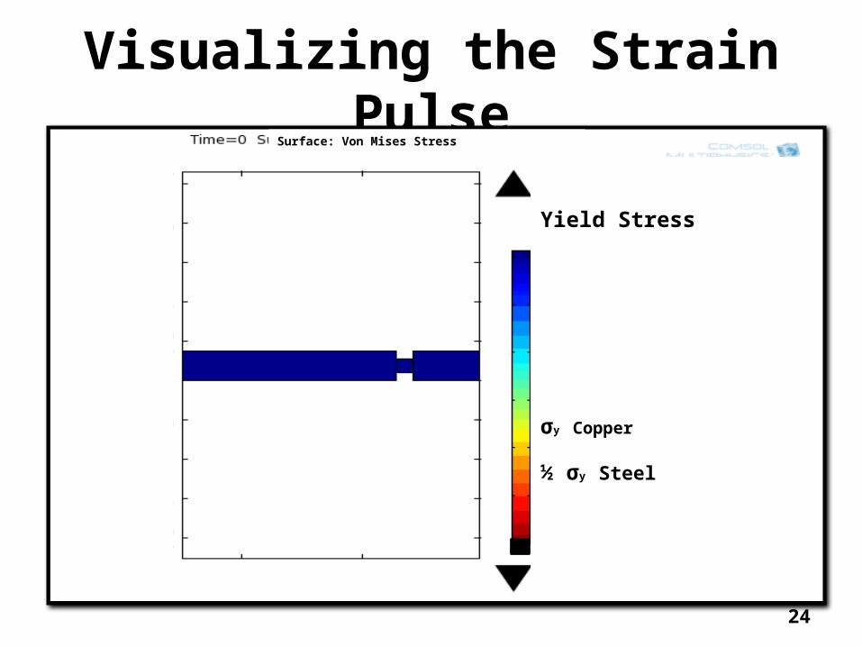
Visualizing the Strain PulseSurface: Von Mises Stress
Yield Stress
σy Copper
½ σy Steel
24

Geometric Definitions + Boundary Conditions
Material Description
Strain Waves Strain Energy
Analyzing Data LabView hardware & software 250 kHz Sampling rate
Measured Voltage Calculated Strain
25

Data Acquired
26
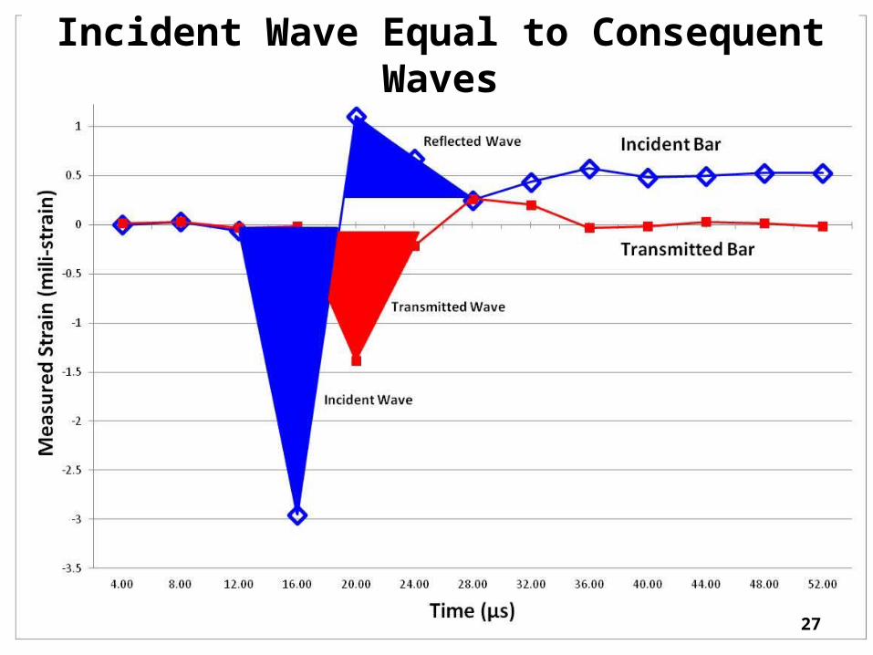
Incident Wave Equal to Consequent Waves
27

Elastic Impulse Wave Area
Incident Reflected Transmitted "Absorbed"
Strain-Seconds 1.15 x 10⁻⁸ 4.47 x 10⁻⁹ 5.46 x 10⁻⁹
% of Initial Pulse 100 % 38.7 % 47.3 % 14 %
Low sampling rate error
∫dε*dt (s)
28

Discussion Potential improvements in system
Use of stainless steel bars Potential improvements in testing
Annealed copper specimen Higher data rates
Used 250 kHz Recommend 1 MHz
Implement friction imitation method to evaluate efficiencies between air bushings and journal bearings
29

Project Budget Within budget Total budget
$2,500 Total expenditures
$2117 Percentage under budget
15%
30
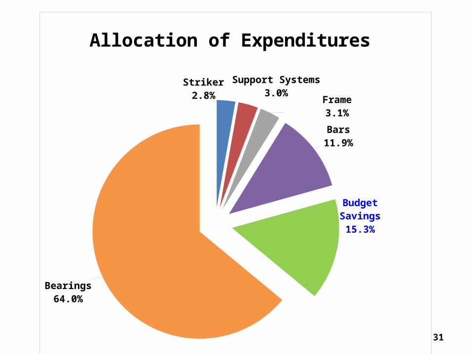
Striker2.8%
Support Systems3.0%
Frame3.1%
Bars11.9%
Budget Savings15.3%
Bearings64.0%
Allocation of Expenditures
31

Safety Concerns
Pinching/crushing fingers
Flying Fragments
Electrocution
32

Review
Analyzed: SHPB design based on use of air bushings Interface requirements Installation procedures
Designed alignment tool Impact on bar geometry
33
Review Assessed strain gauge technology
Foil gauges sufficient Semiconductor gauges if high accuracy required
Designed a working prototype that shows knowledge of system
Remained within $2500 budget Total expenditures ≈ $2100
34

Conclusion Accomplished major requirements! Critical Factors
Segmented design Ease of manufacture Team cooperation Excellent support
35

AcknowledgementsWe would like to thank the following people for their help and support which
made this project a success…
Dr. House – Eglin AFRLDr. Shih – FAMU/FSU COEDr. Kosaraju – FAMU/FSU COE, CAPSDr. Dalban-Canassy – FAMU/FSU COE, ASCDr. Hovsapian - CAPSMr. Bob Walsh - NHMFLMr. Dustin McRae – FAMU/FSU COE, NHMFLDr. Solomon – FAMU/FSU COEMr. Ryan Jantzen – FAMU/FSU COE, HPMIMr. Bill Starch - ASCDr. Hellstrom – FAMU/FSU COE, ASC
THANK YOU!
36

Questions?
Comments?

Quantity Unit Cost Total CostSolenoid 1 69.94 $69.94T-slot Framing 1 1/2 inch (96 inch length) 2 48.15 $96.30Incident & Transmission Bar: 1566 Steel Bar 0.75 inch (36inch length) 2 29.42 $58.84
T-slot Framing 1 1/2 inch (4 foot length for 6 inch braces) 1 25.15 $25.15Air Manifold (72 inches) 1 16.34 $16.34Striker Bar: 1566 Steel Bar 0.75 inch (6inch length) 2 5.17 $10.34Right Angle Fastener 16 4.06 $64.96Fasteners (Packs of 4) 16 2.71 $43.36Strain Gauges (Pack of 10) 3 20 $60.00Air Bushings 0.75 inch 4 265 $1,060.00Bushing Block 0.75 ID 4 135 $540.000.25”x3”x72” Aluminum Sheet 1 40.35 $40.35
0.75” Diameter x 12” Long High Tolerance Aluminum Bar 1 12.1 $12.1012” Aluminum U-Channel 1 14.19 $14.190.75” diameter x 6” Long High Tolerance Steel Bar 1 5.26 $5.26Total $2,117.13
Detailed Budget
38

Velocity CalculationsThe velocity of the striker bar is neededThe only requirement is that the specimen plasticaly deform while the incident and transmitter bars are only loaded elasticalyThe following equations show the process
yc 70MPa Yield stress of copper
Areac .4
2in
2
0.126in2 Area of the copper
F yc Areac 5.675kN Force Required to reach Yield
Next the mass of the steel bar is computed
7.85gm
cm3
Density of steel
v 0.75
2
2
in2
6 in 2.651in3 Volume of the 3/4 inch diameter, 6 inch
striker bar
mass v 0.341kg Mass of the striker bar39

Velocity CalculationsNext the amount of time the striker bar will impact the incident bar
c 6100m
s Speed of wave propogation in steel
Length of Striker barL 6in
Pressure wave propogating down the strikerbar and returning = 2 x length/speed
t 2L
c 4.997 10
5 s
t 49.967s Duration of impact
Finaly the minimum velocity of the striker bar needed to plasticaly deform the specimen
VF
masst 0.832
m
s
Minimum velocity of striker barneeded to plasticaly deform the copper specimen
V 1.86mi
hr
40

Velocity CalculationsAcc
130ozf
mass105.993
m
s2
Acceleration available from the chosen solenoid
Lsol 1in Length of piston with given force
D Do Vo t .5A t2 Generic dynamic position equation
timesol
Lsol
0.5 Acc
.5
0.022s Derived time, from previous equation
Vstkr Acc timesol 5.191mi
hr Calculated velocity from given solenoid
41

Plastic Energy Derivation
• Stress σ = F/A
• Strain ε = (Li – Lo) / Lo
• Gauge Factor GF = [ (Ri - Ro) / Ro] / ε
• Data Strain ε (Ri) = [ (Ri - Ro) / Ro] / GF
42

Plastic Energy Derivation
• Strain in Specimen:
dεavg / dt = ( cb / Ls ) * (εI – εR – εT)
• Integration:
εs = (Cb / Ls) * ∫0t [(εI – εR – εT) *dt]
Strain through the specimen
43

Plastic Energy Derivation
• Strain energy for each wave
Kinetic energy = 0.5 * m * v2
• Initial EI = 0.5* AB * CB * EB * T *εI2
• Reflected Er = 0.5* AB * CB * EB * T *εR2
• Transmitted Et = 0.5* AB * CB * EB * T *εT2
44

Plastic Energy Derivation
• Strain energy
δSE = EI – ER – ET
• Plastic Energy absorbed by specimen
Es = 2 * δSE45

Solenoid Optimization
0 10 20 30 40 50 60 70 80 90 1000
500
1000
1500
2000
Cost ($)
App
lied
Forc
e (o
z F)
Unacceptable Region
Acceptable Region
Unacceptable Region
Unacceptable Region
46

Weak Formulation for FEA
A2
tTd
d
2
xE A
xud
d
d
d f x t( ) 0
x t( )w A2
tTd
d
2 w
xE A
xud
d
d
d w f x t( )
d 0
x t( ) A( )twd
d
tTd
d
w f x t( )
d w A tTd
d
0
47

Weak Formulation for FEA
48