ai miei genitori e a mio fratello. vi porto sempre nel cuore. · tensile test on soft tissue...
TRANSCRIPT

Ai miei genitori e a mio fratello.
Vi porto sempre nel cuore.

2

Abstract
Aorta is the large arterial trunk carrying oxygenated blood from the heart to all the
parts of the body through the systemic circulation. Aorta is usually divided in several
anatomical districts with different specific arterial functions; in fact the composition of
the aortic wall layers and the corresponding arrangement of elastin and collagen fibers
vary along the vascular districts, leading to a different mechanical response.
A number of cardiovascular diseases can impair the aortic wall structure leading to
aneurysm or dissection. The assessment of the mechanical response of the aortic wall
with respect to its anatomical districts, both in healthy and diseased conditions, could
provided useful information for clinical research or vascular prosthesis design.
The present study is collocated within this scenario since it aims at investigating
the mechanical response of the aortic wall through uniaxial tensile tests. In particular,
we developed a testing protocol based on literature, evaluating two main mechanical
parameters: i) the maximum elastic modulus (MEM) and ii) the physiological elastic
modulus (PM). MEM corresponds to the mechanical behavior for ultimate conditions
before failure, while PM resembles the elastic response of the aortic tissue within phys-
iological ranges of pressure (i.e., 130/80 mmHg).
In the first part of the study we have set-up a testing protocol to perform uniaxial
tensile test on soft tissue samples exploiting a MTS Insight 10 kN machine. A prelim-
inary performance of such tests and the related tuning have been performed on aortic
samples derived from freshly slaughtered pigs.
Subsequently we have characterized the mechanical response of human aortic sam-
ples derived from several districs and related to different pathologies; in particular we
analyzed the following cases: i) aneurysmal ascending aorta, ii) aneurysmal ascending
aorta with Bicuspid Aortic Valve (BAV), iii) dissected descending aorta, iv) dissected
descending aorta with Loeys-Dietz Syndrome (LDS)
Wide knowledge about the ascending aorta is available in literature, while articles
related to the other segments are rare, especially referring to pathological states. For
3

this reason, the experimental data obtained from the ascending aorta are compared with
previous works found in literature, while the analysis of descending aorta is reported
as new data feeding.
The results obtained from pigs, on one hand, support the reliability of the adopted
testing protocol, on the other do not confirm the indications available in literature,
since we have not found the anisotropic response of the aortic wall. The experiments
achieved on human samples excised from ascending aorta, globally agree with previous
studies, proving the anisotropy of the tissue. The circumferential direction, in fact, is
stiffer than the longitudinal in the last part of the curves (17.13 MPa versus 10.87 MPa
in the aneurysmal ascending aorta; 6.1 MPa versus 2.4 MPa for aneurysmal ascending
aorta with BAV). Even the results on descending aorta are in line with this trend, with
the circumferential orientation stiffer than the longitudinal.
All the stress-strain relationships obtained in this work can provide new data in
the assessment of the mechanism in which diseases effect the mechanical behavior.
Such results can, finally, be exploited to calibrate ad-hoc constitutive models of aortic
tissue for computational analysis, dedicated to wall failure investigation of aneurysm
or dissection.

Sommario
L’aorta è il lungo tronco arterioso responsabile del trasporto di sangue ossigenato a
partire dal cuore fino a tutte le parti dell’organismo attraverso la circolazione sistemica.
Tipicamente l’aorta si distingue in diversi distretti anatomici con specifiche funzioni;
infatti, la composizione strutturale degli strati della parete aortica ed il corrispondente
arrangiamento delle fibre di elastina e collagene variano lungo i segmenti vascolari,
comportando una risposta meccanica diversa.
Esistono delle patologie cardiovascolari in grado di alterare la struttura della parete
del vaso, portando ad aneurisma e dissezione. La definizione della risposta meccanica
del tessuto rispetto ai distretti anatomici, sia in condizioni fisiologiche che patologiche,
potrebbe fornire informazioni utili per la ricerca clinica e la progettazione di protesi
vascolari.
La presente attività si inserisce all’interno di questo scenario, dal momento che mira
allo studio della risposta meccanica della parete aortica attraverso prove di trazione
monoassiali. In particolare abbiamo sviluppato un protocollo di test basato sulla let-
teratura, valutando due parametri principali: i)il massimo modulo elastico (MEM) e
ii) il modulo elastico fisiologico (PM). Il MEM corrisponde al comportamento mecca-
nico in condizioni di massima trazione prima della rottura, mentre il PM rappresenta
la risposta elastica del tessuto aortico per range fisiologici di pressione (i.e., 80-130
mmHg). Nella prima parte del lavoro abbiamo settato un protocollo per effettuare le
prove di trazione monoassiale su campioni di tessuti soft, utilizzando la macchina di
prova MTS Insight 10 kN. Una verifica preliminare su questo tipo di test ed il relativo
perfezionamento sono stati fatti su campioni di aorta provenienti da maiali macellati
in giornata.
In seguito abbiamo caratterizzato la risposta meccanicaaorte umane in diverse con-
dizioni patologiche e diversi segmenti. In particolare abbiamo concentrato l’attenzione
sui seguenti casi: i) aneursima dell’aorta ascendente, ii)aneursima dell’aorta ascendente
affetta da Valvola Aortica Bicuspide, iii) dissezione dell’aorta discendente, iv) dissezione
5

dell’aorta discendente affetta da sindrome di Loeys-Dietz.
I risultati ottenuti dai maiali confermano, da un lato, la validità del protocollo di test
adottato, mentre dall’altro, non coincidono con le indicazioni riportate in letteratura,
infatti non si evidenzia la risposta anisotropa della parete aortica.
Gli esperimenti condotti su campioni umani estratti da aorta ascendente, concor-
dano globalmente con studi pecedenti, dimostrando l’anisotropia del tessuto. La di-
rezione circonferenziale, infatti, risulta più rigida di quella longitudinale nell’ ultima
parte delle curve (17.13 MPa versus 10.87 MPa nell’aorta ascendente aneurismatica;
6.1 MPa versus 2.4 MPa nell’aorta ascendente aneurismatica con valvola bicuspide).
Anche gli esperimenti sull’aorta discendente sono in linea con questa tendenza, con la
direzione circonferenziale più rigida di quella longitudinale.
Tutte le relazioni di stress-strain ricavate possono fornire nuovi dati per la definizione
del meccanismo in cui le patologie influenzano le proprietà meccaniche. Questi risultati
possono, infine, essere impiegati nella calibrazione di modelli costitutivi ad-hoc del tes-
suto aortico, utili per le analisi computazionali, improntati all’ indagine della rottura
della parete per aneurisma e dissezione.

Acknowledgements
Eccoci ai ringraziamenti! Il primo e più sincero pensiero va a mamma e papà.
Grazie per tutto l’amore e sostegno che mi avete sempre dato senza mai nulla chiedere
in cambio. Siete speciali, come so io di esserlo per voi. Grazie al mio spettacolare
fratello Fabrizio, quante risate mi fai fare?? Ma sai anche fare l’ometto e farmi sentire
al sicuro. Grazie ai miei nonni Faustina e Peppe che, ognuno a modo loro, mi hanno
sempre incoraggiata e compresa. Grazie anche alla torta di mele di zia Maria, con un
pezzo di quella ripartire per Pavia era meno amaro d’inverno!
Grazie a tutti quegli amici che hanno saputo smuovere il meglio di me, una scossa
ci voleva! A tutti coloro che nel bene e nel male mi hanno fatto crescere.
Grazie ai miei collegiali, a quelli validi, s’intende! A chi mi ha dato una mano
quando ne avevo bisogno, a chi mi ha aiutato a spostare il frigo, a chi mi ha offerto
una tisana calda a mezzanotte e mi ha fatto compagnia a distanza anche solo tramite
internet dall’altro capo d’europa.
Grazie poi ai ragazzi del lab, sono stati una famiglia! L’asse del male con Beppe,
il napoletano di Simo, il pure sardo Mauro...tra caffè e risate me la sono passata bene.
In particolare devo ringraziare però Anna, mi hai sostenuto nei momenti di diffcoltà
fino all’ultimo, e Michele, mi hai insegnato ad andare alla ’ciccia’ delle cose ...grazie!
Il ringraziamento va anche al Prof. Auricchio che con il suo entusiasmo coinvolgente ti
fa sentire parte di una squadra!
Penso di avere finito...grazie anche a me!
7

8

Table of Contents
1 Introduction 11
2 Aorta biomechanics 15
2.1 Aortic wall anatomy . . . . . . . . . . . . . . . . . . . . . . . . . . . . . 15
2.2 Aortic diseases . . . . . . . . . . . . . . . . . . . . . . . . . . . . . . . . 18
2.3 Aortic biomechanical behavior . . . . . . . . . . . . . . . . . . . . . . . . 19
2.3.1 Regional variations of material and mechanical properties . . . . 21
2.3.2 Mechanical properties in pathological state . . . . . . . . . . . . 22
3 Materials and methods 23
3.1 Testing protocol . . . . . . . . . . . . . . . . . . . . . . . . . . . . . . . . 23
3.1.1 Testing system . . . . . . . . . . . . . . . . . . . . . . . . . . . . 23
3.1.2 Samples . . . . . . . . . . . . . . . . . . . . . . . . . . . . . . . . 25
3.1.3 Uniaxial Tensile Testing . . . . . . . . . . . . . . . . . . . . . . . 27
3.2 Data analysis . . . . . . . . . . . . . . . . . . . . . . . . . . . . . . . . . 28
3.2.1 Stress-strain response . . . . . . . . . . . . . . . . . . . . . . . . 29
3.2.2 Material elastic parameters . . . . . . . . . . . . . . . . . . . . . 30
4 Experimental results 33
4.1 Results on porcine aorta . . . . . . . . . . . . . . . . . . . . . . . . . . . 33
4.2 Results on human aorta . . . . . . . . . . . . . . . . . . . . . . . . . . . 34
4.2.1 Results on ascending aorta . . . . . . . . . . . . . . . . . . . . . 35
4.2.2 Results on descending aorta . . . . . . . . . . . . . . . . . . . . . 38
5 Conclusions 41
9

10 TABLE OF CONTENTS

Chapter 1
Introduction
Aorta, which is the largest artery of the cardiovascular system, arises from the left
ventricle of the heart and, forming an arch, it extends down to the abdomen where it
branches off into two smaller arteries. The main function of the aorta is to carry and
distribute oxygenated blood to all arteries. Aorta experiences a complex mechanical
loading due to the pulsatile blood flow ejected by the left ventriculum, thus, an ap-
propriate mechanical response is required to accomplish the physiological task of this
important vascular district.
The interest for the aortic mechanics has fascinated researchers since 1800 (Roy,
1880) as it may be confirmed by the large number of publications available in the
literature (Carew et al., 1968; Halloran et al., 1995; Holzapfel, 2006; Duprey, 2008;
Choudhury et al., 2009; Guinea et al., 2010; Khanafer et al., 2011).
The knowledge of aortic mechanical properties is of the outermost importance to
better understand the mechanical behavior in healthy condition as well as to predict
the mechanical behavior in pathological states.
In fact, severe pathologies connected to genetics and cardiovascular diseases can
affect the aortic wall leading to a micro-structural degeneration of its layers and, con-
sequently, impairing its mechanical response. It appears evident that dysfunction of
the vessel can induce negative effect on all the system.
The underlying aortic composition, mechanical properties as well as the mechanisms
responsible for age-related changes and vascular disease are however largely unknown.
In order to identify mechanically the aortic wall components of healthy and diseased
11

12 CHAPTER 1. INTRODUCTION
aorta, in vivo and ex vivo experimental tests may be carried out.
In vivo tests through imaging techniques, such as computed tomography, magnetic
resonance imaging and echocardiography, give the possibility to evaluate the relative
change in vessel cross-sectional area occurring during the cardiac cycle as well as to
detect aneurysm formation. Together with simultaneous pressure registrations, stress-
diameter curves can be obtained by inflation tests (Koullias et al., 2005). Nevertheless,
in vivo examinations do not contribute in tissue analysis and, more importantly, in
assessing potential rupture of the aortic wall.
With respect to ex vivo experiments, typical tests are the uniaxial and biaxial tensile
tests. In particular, uniaxial tensile tests are conducted to determine one dimensional
elastic properties such as the elastic modulus (Duprey, 2008), tensile strength (Guinea
et al., 2010) and failure point (Mohan and Melvin, 1982).
Moreover, uniaxial tensile tests can highlight the differences between healthy and
pathological vessels, as it has been presented in the recent study of Khanafer et al.
(2011). However, although unidirectional tests are easier to perform and control, they
are not able to evidence the anisotropic properties of soft tissues. In order to overcome
this limitation, it is common practice to test strips excised at different orientations,
circumferential and longitudinal in relation to the vessel, or to consider biaxial tests.
If, on the one hand, biaxial tests are more appropriate for anisotropic tissues, on the
other hand, they may be difficult to perform and to control due to the small size of
aortic wall specimens (Nielsen et al., 1991).
The aim of this study is to analyze the mechanical response of the human aorta
specimens undergoing external excitement and, thus, to investigate its mechanical prop-
erties. Particular emphasis is given to the changes of the elastic properties in relation
to pathological conditions as well as to the aortic district from which the sample is
extracted.
For this purpose, uniaxial tensile tests have been performed on pathological sam-
ples of patients underwent to surgical repair at Policlinico of San Donato, Milan, for
aneurysm or dissection. The pathologies evidenced are: i) Bicuspid Aortic Valve (BAV)
and ii) Loeys-Dietz Syndrome.
Each tensile tests is carried out following standard protocols as described in the lit-
erature by using the uniaxial testing device of the Department of Structural Mechanics,
University of Pavia. The procedure has been validated on porcine samples. It is worth
noting that testing soft tissue is not a trivial task since it is necessary to maintain the
original mechanical properties before the test.

13
The experimental data have been post-processed in order to investigate the elasticity
of the aortic wall in relation to two main conditions: (i) ultimate failure condition and
(ii) normal situation.
In particular, the elastic modulus has been evaluated: i) in the region of strain
preceding the failure, highlighting the behavior in critical conditions, and ii) in the the
physiological range of blood pressure (130/80 mmHg), underlying the importance of
understanding how aorta acts in normal conditions.
First of all, it is necessary to own a deep knowledge of the arterial tissue, in partic-
ular of the aortic wall, since it slightly differs from the common arterial structure. For
this reason, in the Chapter 2, the material and mechanical properties of the aorta will
be presented, taking into account the variation of its typical behavior along the vessel
and for connective tissue disorders.
The Chapter 3, indeed, will focus on the materials and methods adopted to ac-
complish a uniaxial tensile test. Specifically, it is attempted to define a new protocol,
as long as no standards on mechanical tests for the biological tissues are assessed in
literature. Many challenges will be there faced, due to the nature of the samples above
all, involving preservation, sizing and the eventual damaging of the aortic tissue. On
that account peculiar tools and methods in data acquisition will be described.
Finally, the Chapter 4 will report the results of the unaxial experiments performed,
at first, on porcine samples, so that the procedure assessed could be validated, and
then on human pathological tissues. This part of the work work will provide new
data about aneurysmal ascending aorta and dissected descending aorta, increasing the
understanding of the mechanisms involving the degeneration of these districts.
Experimental tests performed on the other segments, instead, are briefly described
in Appendix since no effective data are extracted. The results here achieved on ascending
aorta are compared to other works, while the ones related to descending aorta are
just commented since no study, to our knowledge, concerned that district dissected .
However taking new experimental data into this domain has a great value, as not many
samples are available to improve the knowledge about the changes in the mechanical
properties of the aortic wall in relation to the location and the pathologies correlated.

14 CHAPTER 1. INTRODUCTION

Chapter 2
Aorta biomechanics
Biomechanics is broadly defined as mechanics applied to biology and provides the
physical and analytical tools to understand problems in physiology with mathematical
accuracy (Kassab, 2006).
In the present work, we focus on the biomechanics of the aorta. Initially the anatomy
of the aortic wall is described, taking into account the structure and composition of
the three different layers in which the vessel is subdivided. Afterward, aneurysm and
dissection, are described since they are the main diseases that affect the aortic wall.
The mechanical behavior of aorta, strictly related to the wall microstructure, is then
presented, paying attention to the variations of material and mechanical properties
with regard to the location along the trunk and pathological states.
2.1 Aortic wall anatomy
The arterial system consists of a branching network of elastic conduits and high
resistance terminals, which transforms the intermittent discrete cardiac output into
capillary flow with moderate pulse (Sokolis, 2007).
According to dimensions and location, arteries can be subdivided into two groups:
elastic arteries and muscular arteries. Elastic arteries, which include the aorta, pul-
monary artery, common carotids, and common iliacs, are closer to the heart and have
relatively large diameters (25-20 mm) (Redaelli and Montevecchi, 2007).
On the contrary, muscular arteries, which include coronaries, cerebrals, femorals,
and renals, have smaller dimensions and in general are located at the periphery (except
15

16 CHAPTER 2. AORTA BIOMECHANICS
(a)
Ascendingaorta
Innominateartery
Aortic archLeft common carotidartery
Left subclavianartery
Diaphragm
Abdominalaorta
Commoniliac artery
Descendingaorta
(b)
Figure 2.1: (a) Trunk of aorta located into the human body and (b) aortic districts
for the coronary arteries).
In this work, we focus on the aorta which is the largest artery of the human body.
Aorta has not only to conduct the blood to the different organs, but to act, also, as the
major player of the circulatory biomechanics.
Aorta originates from the left ventricle of the heart and extends through the ab-
domen where it splits in the common iliacs (see Fig. 2.1(a)).
With respect to its position on the human body, four segments may be identified
along the aorta: i) ascending aorta – first 5-7 cm out of the heart, ii) aortic arch –
from the second sterno costal joint to the 4th thoracic vertebrae, iii) descending aorta
– till the diaphragm, iv) abdominal aorta – below the diaphragm till the common iliac
arteries (see Fig. 2.1(b)).
At microscopic level the arterial wall appears as a layered structure, composed of
three concentric zones (tunica intima, tunica media, and tunica adventitia) separated by
elastic membranes and containing primarily elastin, collagen fibers, fibroblast, endothe-
lial and smooth muscle cells, embedded in an amorphous, gel-like, ground substance
consisting mostly of water.
It is worth noting that the histology of each arterial segment changes with location
according to the own physiological function in the circulatory system. However, no
abrupt variations are evidenced between large and small vessels and some arteries can
exhibit both types of morphological structures. In the following, we describe briefly

2.1. AORTIC WALL ANATOMY 17
(a) (b)
Figure 2.2: Photomicrographs at low magnification showing the layers of (a) elastic arteries;(b) muscular arteries
each arterial layer (tunica intima, media, and adventitia) from the histological point of
view (see Fig. 2.2).
Tunica intima is the innermost layer of the artery made of a single layer of endothe-
lial cells embedded in extracellular matrix and of an underlying thin basal lamina. In
the aorta, the tunica intima may also contain a subendothelial layer of connective tissue
and axially oriented smooth muscle cells. The intima is responsible for the transition
of nutritional substances and chemical signals through the conduct, as it is in direct
contact with the blood flow. Despite the great functional importance of aorta, its me-
chanical contribution in healthy young human arteries is neglected due to its small
thickness. With aging and atherosclerosis –the most common disease of arterial wall-
the intima becomes thicker and stiffer developing a more complex and heterogeneous
structure (Holzapfel, 2006).
Tunica media is the middle and thickest layer of the artery, made of smooth muscle
cells, elastin and collagen immersed into an aqueous ground substance (matrix) con-
taining proteoglycans. In elastic arteries as the aorta, these constituents are arranged
in repetitive lamellar units, forming concentric medial layers. The lamellae, in average
5-15 µm thick, are separated by thin (3 µm) fenestrated sheets of elastin.
The number of such units decrease as the distance from the heart increases. In fact,
the thoracic aorta contains 50-60 lamellar units divided into vascular and avascular
zones, while the entirely avascular abdominal aortic media typically contains 28-32
units (Ruddy et al., 2008). This laminated structure confers high strength to the
media and explains how the medial layer determines the mechanical properties of the

18 CHAPTER 2. AORTA BIOMECHANICS
whole vessel. Unfortunately, this organization is prone to split, creating a cleavage
between lamellae (dissection). In the media, collagen fibers are aligned along the the
circumferential direction with a very little dispersion. This structural arrangement
gives the media the ability to carry loads in the circumferential direction (Gasser et al.,
2006).
Tunica adventitia is the outermost layer of the artery, mainly composed of fibroblast
and collagen bundles undulated at physiological pressures. Histological evidence proves
that collagen fibers tend to maintain an axial orientation with dispersion. Collagen
fibers remain slack at low pressures but, as the pressure increases, they straighten,
reinforcing the arterial wall and preventing the over-stretching and the rupture of the
artery (Holzapfel, 2008). Adventita is involved in mechanics only for extreme pressure
values, when collagen straighten, reinforcing the arterial wall and preventing the over-
stretching and the rupture of the artery. Collagen fibers, which tend to maintain an
axial orientation, remain slack at low pressures (Gasser et al., 2006).
2.2 Aortic diseases
Cardiovascular disease is the leading cause of death in developed countries and it is
projected to become the leading cause of death worldwide in the near future. Several
genetic and cardiovascular diseases affect the aorta wall, leading to a microstructural
degeneration of its layers and, consequently, impairing its mechanical response. The
most common types of aortic diseases are the dissection and the aneurysm (see Fig 2.3)
where generally the former arises as a consequence of the latter (Hebballi, 2009).
Aortic dissection is an intramedial splitting caused by a radial tear of the intima
and of a portion of the underlying media. The blood entering in the media through
the tear creates a false lumen with variable extension. Moreover, blood can even re-
enter the true lumen at any point, thus making a communicating dissection. The
primary biological mechanisms in aortic dissection are decreased strength of the inner
layer, increased blood pressure and augmented diameter coupled to thickness reduction.
Intima tears when the inner layer is no more able to bear the stress (Okamoto et al.,
2002).
Dissection may occur spontaneously during accident or as a complication of bal-
loon angioplasty. The risk of dissection increase in patients with hypertension, many
connective tissue disorders such as Marfan, Loeys-Dietz, Ehlers-Danlos syndromes and
congenital heart diseases as Bicuspid Aortic Valve (BAV).

2.3. AORTIC BIOMECHANICAL BEHAVIOR 19
Figure 2.3: Different types of dissection and aneurysm
Aneurysm is the progressive balloon-like dilation of the artery in correspondence to
a weaker portion of the vessel wall, that in worst cases leads to rupture of the tissue
and death of the patient. Aneurysm rupture occurs when the mechanical forces acting
on the aneurysm exceed the strength of the degenerated wall (Vorp, 2007). Such forces
are directly related to the local diameter of the aorta.
Despite the increase in diagnose of aortic aneurysm over these last 30 years, thanks
to advances in imaging techniques and screening programs, aortic aneurysm represents
the 13th largest cause of death in USA. For the aorta, the most common forms are
the abdominal aortic aneurysm and the thoracic aortic aneurysm . Abdominal aor-
tic aneurysm affects approximately 3-5% of the population beyond 50 years of age in
Western countries (Ruddy et al., 2008) . Approximately 150,000 new cases are diag-
nosed each year, and the incidence is increasing. Thoracic aortic aneurysm is relatively
rare; each year, only 0.0059% of a given population is diagnosed with this condition.
Thoracic aortic aneurysms are often caused by some form of genetic syndrome, involv-
ing connective tissue disorder and by the congenital deformation of the bicuspid aortic
valve.
2.3 Aortic biomechanical behavior
The mechanical behavior of each single arterial layer and, therefore, the overall
artery behavior, is strongly influenced by the concentration and the structural arrange-
ment of its constituents (Holzapfel, 2000).
In experimental and theoretical studies, under physiological conditions, arteries are
regarded as nearly incompressible solids (Carew et al. (1968), Chuong and Fung (1984)).
The physiological range of the stresses in arterial tissue is assumed to be in the order
of 50 – 100 kPa under the mean blood pressure (100 mmHg) and the in situ axial
20 CHAPTER 2. AORTA BIOMECHANICS
IIIII
stre
ss
strain
III
(a)
stre
ss
strain
(b)
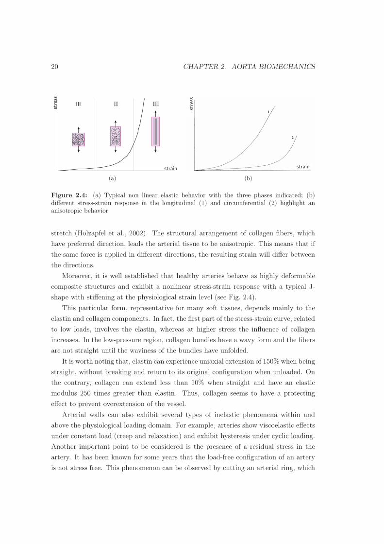
Figure 2.4: (a) Typical non linear elastic behavior with the three phases indicated; (b)different stress-strain response in the longitudinal (1) and circumferential (2) highlight ananisotropic behavior
stretch (Holzapfel et al., 2002). The structural arrangement of collagen fibers, which
have preferred direction, leads the arterial tissue to be anisotropic. This means that if
the same force is applied in different directions, the resulting strain will differ between
the directions.
Moreover, it is well established that healthy arteries behave as highly deformable
composite structures and exhibit a nonlinear stress-strain response with a typical J-
shape with stiffening at the physiological strain level (see Fig. 2.4).
This particular form, representative for many soft tissues, depends mainly to the
elastin and collagen components. In fact, the first part of the stress-strain curve, related
to low loads, involves the elastin, whereas at higher stress the influence of collagen
increases. In the low-pressure region, collagen bundles have a wavy form and the fibers
are not straight until the waviness of the bundles have unfolded.
It is worth noting that, elastin can experience uniaxial extension of 150% when being
straight, without breaking and return to its original configuration when unloaded. On
the contrary, collagen can extend less than 10% when straight and have an elastic
modulus 250 times greater than elastin. Thus, collagen seems to have a protecting
effect to prevent overextension of the vessel.
Arterial walls can also exhibit several types of inelastic phenomena within and
above the physiological loading domain. For example, arteries show viscoelastic effects
under constant load (creep and relaxation) and exhibit hysteresis under cyclic loading.
Another important point to be considered is the presence of a residual stress in the
artery. It has been known for some years that the load-free configuration of an artery
is not stress free. This phenomenon can be observed by cutting an arterial ring, which

2.3. AORTIC BIOMECHANICAL BEHAVIOR 21
assumes the shape of an open sector by a springing effect. In general the cut open
sector is also not stress free, since the opening angles of the separate layers are different
(Okamoto et al., 2003).
2.3.1 Regional variations of material and mechanical properties
It is well appreciated today that the aorta not only serves a conduit function but
it has an important role in modulating the left ventricular function, the myocardial
perfusion and the arterial system (Sokolis et al., 2008).
Microstructural changes of the tissue and consequently variations of the elastic
properties along the trunk, are the main responsible for the management of the whole
cardiovascular system through all the body. Recent studies reported that aortic biome-
chanical and microstructure are affected by location.
Haskett et al. (2010), used the SALS technique, combined with biaxial planar tests,
to approach the precise mechanism for these changes and progression along the axial
length of the aorta as well as with age. Fiber directionality through the thickness of
the aorta was found to be primarily in the circumferential direction, which was also the
direction of highest compliance. Afterward, the degree of fiber alignment was found to
decrease along the length of the aorta.
Moreover, circumferential and axial stiffening occurs with age and increases from
proximal to distal aorta. In particular, abdominal region displays the highest stiffness.
Inherent differences in the organization and content of the major vascular structural
proteins contribute, furthermore, to the regional variation in mechanical properties.
The content of collagen and elastin relative to lumenal surface area, progressively di-
minishes with increasing distance from the heart (Halloran et al., 1995).
The elastin decrease is associated to the reduction of the amount of elastic lamellae,
balanced by the commensurate collagen content till the suprarenal aorta, level below
which the proportion is altered for a major percentage of collagen. Since the arterial
pressure is essentially constant through all the length of aorta and the elastin component
varies along the trunk, the stiffness of the segments increases in the distal part, in the
abdominal region above all (Ruddy et al., 2008). Finally, it is reasonable to agree with
the tensile tests data of Sommer (2008), where the failure properties obtained suggest
that the tensile strength of aorta decreases with increasing distance from the heart.

22 CHAPTER 2. AORTA BIOMECHANICS
2.3.2 Mechanical properties in pathological state
Changes in biomechanical properties of aortic wall are strictly related to pathologies
formation. Connective tissue disorders, involving the rearrangement or degradation of
the proteins structures, deeply influence the elastic properties of the aorta.
Genetic diseases, such as Loeys-Dietz and Marfan Syndromes, raised from the mu-
tation of genes responsible for synthesis of tissue constituents, weaken the aortic wall,
while cardiovascular malformations, like Bicuspid Aortic Valve (BAV), changes the
hemodinamics on the tissue, both remodeling the intrinsic structure of the wall.
Aneurysm and dissection, are generally considered side effects of the diseases men-
tioned above, but they can even occur in apparently healthy, elder people, till the
occurrence of a critical event.
Thubrikar et al. (2001), found the global stiffening of the tissue, with higher value
in the circumferential direction than in the longitudinal. They focused even on the
variation of mechanical properties in relation to the regions of the aneurysm, feature
taken into account even by Ravaghan et al. (1996) in their work. They agreed that the
change in characteristic is strictly related to the variation in wall thickness.
Experimental data obtained by Vorp et al. (2003), showed that aneurysmal ascend-
ing aorta was significantly weaker than control, having tensile strength lower for both
circumferential and longitudinal orientations. The same trend was found for stiffness
values, greater in pathological tissues than in healthy patients for both directions (4.67
MPa versus 3.25 MPa in the circumferential direction; 4.48 MPa versus 2.61 MPa in
the longitudinal direction). No significant mechanical differences were displayed con-
sidering the two orientations.
Iliopoulos et al. (2009) sustains that the reason why aneurysmal and dissected, from
ascending to abdominal, aorta stiffens, is related to reduction in tissue extensibility and
especially in elastin content. In particular, as medial thickness decreases, the intimal
layer increases, keeping constant the wall dimensions; in this way a no more elastic
tissue hardly withstands the physiologic hemodinamic forces.
A recent work of Khanafer et al. (2011), reveals that the circumferential orientation
is significantly higher (9.19 MPa) than the longitudinal (3.13 MPa). Analog results
were obtained in the previous work (Duprey, 2008), for the same region and disease,
underlying the significant difference in stiffness for circumferential and longitudinal
orientation, that suggests that aortic wall with aneurysm is anisotropic.

Chapter 3
Materials and methods
In this chapter, we present the standard protocol used for testing specimens of
porcine and human aortic tissue. In particular, we describe the tensile testing system,
the method for preserving living tissue and the data analysis. Emphasis will be reserved
to the definition of parameters to investigate the elasticity of the wall.
3.1 Testing protocol
3.1.1 Testing system
The uniaxial tensile tests are executed by using the MTS Insight 10 kN (MTS Sys-
tem Corporation) machine recently acquired by the Structural Mechanics Department
of the University of Pavia. The MTS Insight material testing system consists of: i) a
load frame, ii) an electronic frame controller, and iii) a TestWorks R© software. In the
following, a brief description of each testing system component is presented.
The load frame includes a base unit and two vertical columns with an upper trans-
verse member (see Fig. 3.1). The moving crosshead is driven by precision ball screws
with high-strength, precision ball nuts and rides on the ball bearings. This configura-
tion is very efficient in minimizing friction and wear. The ball screws are anti-backlash.
This feature removes the backlash so that position can be measured with increased
accuracy over non preloaded ball screws. The screws are driven by a series of pulleys
and belts which in turn are driven by a precision dc servo motor. The ball screw is
connected to an optical encoder for precise position and velocity control.
23

24 CHAPTER 3. MATERIALS AND METHODS
Figure 3.1: MTS Insight 10 kN testing machine
The forces applied during the test are detected by a load cell (see Fig. 3.2 ) plugged to
the moving crosshead. By using a specific algorithm, the load cell transforms resistance
variations measured by a Wheatstone bridge into force values. The maximum load
supported by the system is 10 kN. However, the forces involved in the biological domain
are significantly lower, so that a load cell of 250 N with an accuracy of 0.01 N may be
adequate for our tests.
Other important components of the testing system are the grips which allow the
fixation and the consequent extension of the specimen. Wedge jaws are furnished with
the MTS Insight 10 kN, but they are usually used for hard materials. On the contrary,
pneumatic grips are suitable for soft tissues since they are able to keep constant the
pressure during the testing execution (see Fig 3.3). In order to measure correctly tissue
deformations, a video extensometer has been used which can read the original as well
as the variation of the distance between two targets.
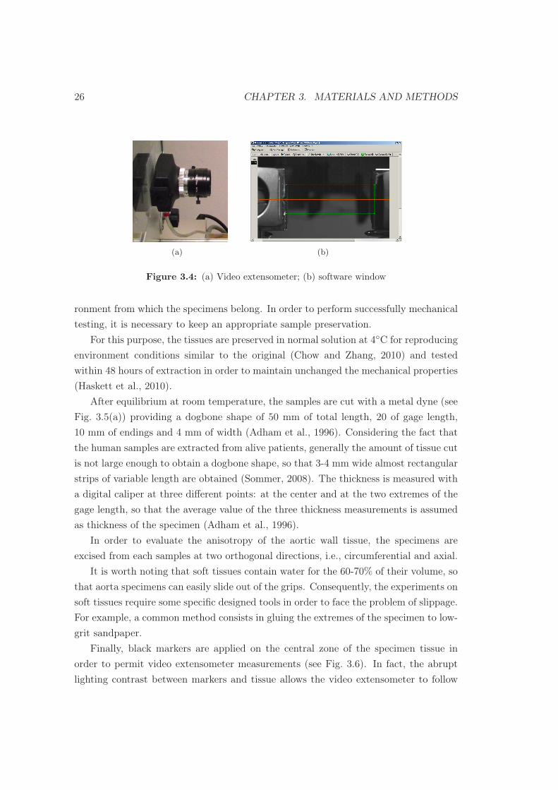
Finally, the software program TestWorks4 (TWS4) is responsible of the full machine
control, data acquisition, management, and advanced data analysis. The program,

3.1. TESTING PROTOCOL 25
(a) (b)
Figure 3.2: Load cells furnished with the MTS Insight 10 kN device: (a) load cell of 10 kNand (b) load cell of 250 N
(a) (b)
Figure 3.3: Grips furnished with the MTS Insight 10 kN device: (a) wedge grip and (a)pneumatic grip
offering a host of features, makes the material testing process fast and easy to use.
The software has various method templates available, providing a starting point in the
configuration of specific test methods. The user can define new variables, formulas
and routines, depending on the needs, and follow the test easily during execution (see
Fig. 3.4).
3.1.2 Samples
The samples investigated during the experiments belong to porcine and human
species. Pig aortas which are harvested from a local slaughter (Rovescala, Pavia) are
used only to verify the reliability of the testing method. The human aortic samples are
obtained from patients undergoing to surgical repair at Policlinico San Donato, Milano.
It is worth noting that samples of soft biological tissues are very difficult to analyze
through mechanical devices since experiments are done in a completely different envi-
26 CHAPTER 3. MATERIALS AND METHODS
(a) (b)
Figure 3.4: (a) Video extensometer; (b) software window
ronment from which the specimens belong. In order to perform successfully mechanical
testing, it is necessary to keep an appropriate sample preservation.
For this purpose, the tissues are preserved in normal solution at 4◦C for reproducing
environment conditions similar to the original (Chow and Zhang, 2010) and tested
within 48 hours of extraction in order to maintain unchanged the mechanical properties
(Haskett et al., 2010).
After equilibrium at room temperature, the samples are cut with a metal dyne (see
Fig. 3.5(a)) providing a dogbone shape of 50 mm of total length, 20 of gage length,
10 mm of endings and 4 mm of width (Adham et al., 1996). Considering the fact that
the human samples are extracted from alive patients, generally the amount of tissue cut
is not large enough to obtain a dogbone shape, so that 3-4 mm wide almost rectangular
strips of variable length are obtained (Sommer, 2008). The thickness is measured with
a digital caliper at three different points: at the center and at the two extremes of the
gage length, so that the average value of the three thickness measurements is assumed
as thickness of the specimen (Adham et al., 1996).
In order to evaluate the anisotropy of the aortic wall tissue, the specimens are
excised from each samples at two orthogonal directions, i.e., circumferential and axial.
It is worth noting that soft tissues contain water for the 60-70% of their volume, so
that aorta specimens can easily slide out of the grips. Consequently, the experiments on
soft tissues require some specific designed tools in order to face the problem of slippage.
For example, a common method consists in gluing the extremes of the specimen to low-
grit sandpaper.
Finally, black markers are applied on the central zone of the specimen tissue in
order to permit video extensometer measurements (see Fig. 3.6). In fact, the abrupt
lighting contrast between markers and tissue allows the video extensometer to follow

3.1. TESTING PROTOCOL 27
(a)
20
10 10
4
(b)
Figure 3.5: (a) Metal dyne which provides the dogbone shape; (b) schematic representationof the dogbone specimen with dimensions;
Figure 3.6: Rectangular specimen ready to be tested with markers applied on the centralzone and grit sandpaper at extremes
the black markers during the test.
3.1.3 Uniaxial Tensile Testing
The uniaxial tensile procedure is performed into two steps: i) preconditioning and
ii) tensile testing. The former step is applied to make repeatable the test procedure.
Preconditioning. Aortic tissue as each soft tissue shows a viscoelastic behavior un-
der particular loading condition. For example, difference in the stress-strain response
are evidenced during cycles of loading and unloading, i.e., the hysteresis phenomenon.
The area delimited by the two loading-unloading curves corresponds to energy dissi-
pated as heat during the load cycle.
However, it has been noted that after a proper number of subsequent cycles, the
loading-unloading response becomes repeatable with less energy dissipation. In the
literature, this technique is called preconditioning (Sokolis et al., 2006).
Moreover, the preconditioning is also used to reproduce the homeostasis of the living
tissue. In this work, each specimen is preconditioned for 10 cycles with a triangular
wave ranging from 0.1 to 0.49 N at a constant speed of 10 mm/s of the crosshead (see.
Fig. 3.7).

28 CHAPTER 3. MATERIALS AND METHODS
(a) (b)
Figure 3.7: (a) Hysteresis cycles observed as the triangular function applied; (b) stress-strainrelationship on the software
Tensile test. After the preliminary phase of preconditioning, the uniaxial tensile
test takes place. During the tensile test, the applied force and the extension between
the two markers are continuously recorded (10Hz) at the same speed of 10 mm/s (see.
Fig. 3.8). The test runs until the failure of the tissue specimen, detected by the software
as a drop of 0.1 N between two following data points.
By using the directly measured values of loads F and extensions ∆L, the program
can calculate the indirect measures of engineering stress, σE , and engineering strain,
εE , rispectively:
σE =F
A0
, εE =∆L
L0
, (3.1)
with L0 and A0 the initial length and initial cross-sectional area of the specimen,
respectively.
Fig. 3.8(b) shows the plot of the quantities directly measured by the testing machine,
i.e., loads and displacement, whereas Fig. 3.8(b) shows the stress and strain quantities
computed by the software using the relations (3.1).
According to the size of the variations in the cross-sectional area, this choice may
be questionable, so that true strain definitions for studying the mechanics of aortas
have been introduced (Duprey, 2008; Khanafer et al., 2011).
3.2 Data analysis
The stress and strain data provided by MTS software have been post processed
by Matlab software (The Mathworks Inc., Natick, MA, USA) in order to compute the

3.2. DATA ANALYSIS 29
(a) (b) (c)
Figure 3.8: (a)Tensile test in execution; (b) output in terms of loads and extensions directlymeasured by the device; (c) output in terms of stress and strain calculated by the software
true stress and the true strain (Khanafer et al., 2011). Then, the true-stress versus
true-strain curves are derived.
The passive mechanical behavior of the aorta has been investigated through the
analysis of curve slopes in the physiological and supra physiological ranges of blood
pressure. The physiological blood pressure in adults should be 130/80 mmHg. The top
number (130 mmHg) is the systolic pressure whereas the bottom number (80 mmHg)
is the diastolic pressure. Over the range 130/80 mmHg, we have considered the failure
zone wherein the specimen breaks.
3.2.1 Stress-strain response
The stress and strain values obtained from the cross-head have been transformed
into the corresponding true stress and true strain by using the relations:
σT =F
A, δεT =
δL
L, (3.2)
with A the current cross-sectional area, L the current length of the specimen and δL
the instantaneous extension.
In order to correlate true with engineering quantities, we assume the arterial tissue
to be incompressibility, i.e., no volume changing. The relationship between the current
and the initial cross-sectional area is A = A0L0/L.
Consequently, the true stress is given by:
σT =F
A= F
L
A0L0
= σE
L
L0
= σE(1 + εE), (3.3)

30 CHAPTER 3. MATERIALS AND METHODS
where the relations (3.1) and the position L = L0 + ∆L have been used.
On the contrary, the true strain is obtained as as the sum of all current engineering
strains:
εT =
∫δε =
∫L
L0
δL
L= ln
L
L0
= lnL0 + ∆L
L0
= ln(1 + εE). (3.4)
3.2.2 Material elastic parameters
With the aim to describe more efficiently the elastic properties of an artery, some
material parameters are considered: i) the ultimate strain and ultimate stress at the
breaking point, and ii) elastic modulus.
According to classical elastic theories, an elastic and isotropic material shows a
constant proportionality (within their elastic limits) between stress and strain. This
proportionality is expressed by the familiar Young modulus (E):
E =force per unit area
force per unit length. (3.5)
However, since aortic tissue is largely extensible and show a nonlinear stress-strain
response, a single value of elastic modulus does not represent the continuously varying
response of the tissue.
In order to take into account the variation of the elastic modulus, the incremental
elastic modulus, which is defined as the differentiation of the stress-strain relationship
(δσ/δε) in generally used in literature (Sokolis et al., 2008).
With respect to the two investigated range of blood pressure, i.e., physiological
and failure regions , two elastic moduli, i.e., physiological elastic modulus (PM), and
maximum elastic modulus (MEM), are defined in a different manner.
Since the stress–strain curve is nearly linear within each investigated range, the
elastic moduli are computed as the slope of the fitted line in the corresponding range.
In order to apply this method, we define the failure region and the physiological
region as follows: (i) failure region: part of the stress-strain curve between the two
points related to the ultimate strain, εmax, and the 70% of εmax (see, Fig. 3.9(a)); (ii)
physiological region: part of the stress-strain curve between the two points related to
the stress values σ80 and σ120 corresponding to a blood pressure of 80 and 130 mmHg,
respectively (see, Fig. 3.9(b)).
Following Duprey (2008), the stress values σ80 and σ130 are computed by using the

3.2. DATA ANALYSIS 31
0
strain
stre
ss
σmax
εmaxεmax70%εmax
(a)
0
str
ess
strain
130/80 mmHg
(b)
Figure 3.9: Graphical represantation of elastic modulus on an experimental curve: (a) max-imum elastic modulus (MEM); (b) phisiological elastic modulus (PM)
Laplace law for thin-thickness tube:
σP =Pd
2t, with t/d < 0.10, (3.6)
with p the inner pressure, d the inner diameter and t the thickness of the thin vessel.
The adoption of the Laplace law is widely spread in the mechanics assessment of
aorta (Vorp, 2007), nevertheless the assumption of thin-thickness should be always
validated. The samples under investigation in this study had an average thickness of
3 mm and a related diameter of 30 mm. For some samples this assumption would not
be valid, especially in dissection occurrence, where the blood coagulation in the false
lumen leads to a large increase in the wall thickness.

32 CHAPTER 3. MATERIALS AND METHODS

Chapter 4
Experimental results
The testing protocol described in the previous chapter has been adopted on samples
of porcine and human aorta.
Although in the literature porcine data have been widely assumed as a good approx-
imation of human, in this work porcine data are only used to validate the testing pro-
cedure. However, some recent studies as the work of Martin et al. (2011) demonstrated
that significant differences exist between pig and human aortas, and this motivates our
assumption.
The human aortic samples are excised from patient undergoing to surgical repair
(aneurysm or dissection) at Policlinico of San Donato, Milano. The samples provided
belongs to different aortic districts, such as ascending aorta, aortic arch, descending
aorta and abdominal aorta. Based on information from pre- and post-operative exams,
the aortic samples are classified according to the aortic district and the cardiovascular
risk factor.
4.1 Results on porcine aorta
Two aortas freshly harvested are taken from a local slaughter (see Fig. 4.1(a)).
Six specimens, three in both circumferential and longitudinal direction, are cut from
ascending and descending aorta with the metal dyne, obtaining the typical dog-bone
shape. Tensile tests are carried out without video extensometer strain acquisition, since
it was not yet available.
The Fig. 4.1(b) shows the typical stress-strain response for circumferential and
33

34 CHAPTER 4. EXPERIMENTAL RESULTS
(a)
0 0.2 0.4 0.6 0.80
0.5
1
1.5
2
Strain [mm/mm]
Str
ess
[MP
a]
CircLong
(b)
Figure 4.1: (a) Picture of the two pig aortas investigated; (b) two representative stress-straincurves obtained from the tensile tests
longitudinal directions. The curves display the common non linear elastic behavior of
the aortic wall. All the longitudinal specimens fail at lower tensile strength than the
circumferential. The responses in both tensile directions do not evidence anisotropy, in
contrast with the work of Gundiah et al. (2008). The curve in that article, however,
do not strongly display this kind of behavior that, probably, as Sokolis (2007) found,
increases in the aorta distally, where circumferential direction becomes progressively
stiffer.
In order to assess the validity of the method through which the highest stiffness
is calculated, the MEM defined in this work is applied to another curve described
in literature (Sokolis et al., 2008) and the value obtained is then compared to the
corresponding result of the authors. A typical stress-strain relationship of a strip from
a porcine aortic arch, undergone to uniaxial tensile test, is analyzed. Sokolis et al.
(2008) defined the maximal stiffness as the peak of the incremental elastic modulus,
leading to 0.78 MPa for this curve. The linear regression approach provides the same
result, showing the legitimacy of the method.
4.2 Results on human aorta
The samples of human aortic are excised from five patients still alive undergoing to
surgical repair at Policlinico San Donato. From the donors, eight samples are freshly
obtained.
As shown in Tab. 4.1, the samples are correspond to the different aortic districts,
i.e., ascending, descending and abdominal as well as the arch. With regard to the

4.2. RESULTS ON HUMAN AORTA 35
Table 4.1: Donor informations
Sex Age Reason of surgery Correlatedpathologies
Aortic district
CT-1945 M 66 Aneurysm –Ascending aortaAortic Arch
TA-1963 M 48 Aneurysm BAV Ascending aorta
ZA-1956 M 65 Aneurysm –Suprarenal aortaSubrenal aorta
MA-1938 M 73 Dissection – Descending aorta
TC-1975 F 36 Dissection LDSAscending aortaDescending aorta
reason of surgery it is possible to distinguish the aneurysm and the dissection.
Unfortunately, we made to investigate the elastic mechanical properties only in the
ascending and descending aorta districts, so that the results obtained testing only the
ascending and descending aorta samples are reported in this chapter.
In fact, the abdominal aorta samples and the ascending aorta tissue with Loeys-
Dietz syndrome were heavily damaged, so that poor data have been obtained. On the
contrary, the samples of aortic arch have been disregarded due to the little interest in
literature and then to the paucity of experimental data for comparison. However, our
experimental data concerning aortic arch , LDS ascending aorta and the abdominal
aorta are summarized in Appendix.
Finally, our results are compared with experimental data available in the literature.
It is worth noting that ascending aorta aneurysm is a wide spread topic of the literature
domain, so that many works may be found. On the contrary, experimental data on
descending aorta are few since, only recently, the brand-new medical breakthrough
(endografts) demands an increasing knowledge about this segment of the aorta.
4.2.1 Results on ascending aorta
Ascending aorta, CT-1945
With respect to ascending aorta, here, we refer to the sample labeled CT-1945, see
Tab. 4.1. From this sample, three specimens are obtained: one in the circumferential
direction and two in the longitudinal one, as indicated in Fig.4.2(a).
The obtained elastic moduli, MEM and PM, are reported in Tab.4.2, whereas the
stress-strain curves are plotted in Fig.4.2(b). As shown in Tab.4.2, the values of elastic

36 CHAPTER 4. EXPERIMENTAL RESULTS
(a)
0 0.05 0.1 0.15 0.2 0.250
0.2
0.4
0.6
0.8
1
1.2
Strain [mm/mm]
Str
ess
[MP
a]
CircLong
(b)
Figure 4.2: (a) Visual inspection of ascending aorta with specimens indication; (b) represen-tative curves for circumferential and longitudinal direction
modulus are different in the circumferential and longitudinal direction. This evidences
an anisotropy in the tissue. Moreover, we have also found that both MEM and PM
moduli are higher in the circumferential direction than the longitudinal one.
Table 4.2: Elastic moduli in the circumferential and longitudinal direction for CT–1945 sample
Direction MEM [MPa] PM [MPa]
CT–1945Circumferential 17.13 3.14Longitudinal 10.87 2.35
In the literature, Vorp et al. (2003), reported no significant difference in MEM be-
tween circumferential and longitudinal specimens (4.46 MPa versus 4.48 MPa). How-
ever Iliopoulos et al. (2009), and Khanafer et al. (2011) more recently, reported sig-
nificant differences in MEM between circumferential and longitudinal orientations for
ascending aorta aneurysms (7.15 MPa versus 4.6 MPa).
Ascending aorta with BAV, TA-1963
The sample TA-1963, resembles the patient with BAV (see Tab.4.1). This car-
diovascular deformation is regarded as a risk factor for aneurysm occurrence, since it
impairs the hemodiamic forces acting on the wall.
As long as the sample is a complete ring (see Fig.4.3(a)), we decide to cut it sagitally
(see Fig.4.3(b)), in order to investigate the greater and lesser curvature of the ascending
aorta. Four strips are cut from the greater curvature (GC), two for both directions (see
Fig.4.3(c)); six specimens instead are obtained from the lesser curvature (LC), three in

4.2. RESULTS ON HUMAN AORTA 37
(a) (b)
(c) (d)
Figure 4.3: (a) Visual inspection of the whole ring of the ascending aorta sample; (b) sagittalcut of the ascending aorta; (c) greater curvature with specimens indication; (d) lesser curvaturewith specimens indication.
the circumferential orientation and three in the longitudinal one (see Fig.4.3(d)).
The elastic moduli, shown in Tab.4.3, display a different trend among curvature
and direction. If on one hand the MEM is stiffer in the circumferential region for both
the regions with higher value for the GC, the longitudinal direction appears as stiffer
in the LC. The PM values instead show no large differences.
In a previous work, Choudhury et al. (2009) studied the mechanical properties of GC
and LC in BAV ascending aortic aneurysm with equibiaxial tests. The stiffness of the
greater curvature was underlined but no significant differences proved the anisotropy
of the tissue. On the contrary, Duprey et al. (2010), performing uniaxial tensile tests,
reported values close to ours: 9.37 MPa versus 4.39 MPa in GC and 9.96 MPa versus
2.78 MPa, confirming the anisotropic behavior.

38 CHAPTER 4. EXPERIMENTAL RESULTS
Table 4.3: Elastic moduli circumferential and longitudinal orientation in relation to GC andLC, for TA-1963
Curvature Direction MEM [MPa] PM [MPa]
TA-1963Greater
Circumferential 8.57 0.60Longitudinal 2.70 0.65
LesserCircumferential 6.51 1.05Longitudinal 4.73 0.68
(a)
0 0.05 0.1 0.15 0.20
0.2
0.4
0.6
0.8
Strain [mm/mm]
Str
ess
[MP
a]
CircLong
(b)
Figure 4.4: (a) Visual inspection of a fragment of descending aorta with specimens indication;(b) representative curves for circumferential and longitudinal direction
Finally, the same work (Duprey et al., 2010) analyzed the elastic modulus in the
physiological range (120/80 mmHg), sustaining that the circumferential orientation is
stiffer than the longitudinal one.
4.2.2 Results on descending aorta
The experiments following described have no reference in previous studies, hence
all data extracted will just be commented on the knowledge acquired in this work of
thesis.
Dissected descending aorta, MA-1938
In relation to the dissected descending aorta, the first sample investigated is MA-
1938 (see Tab.4.1). Three natural regions were obtained, differentially damaged. Eight
strips were cut, but, since during preconditioning some failed, only five were actually
tested: two in the circumferential direction and three in the longitudinal one (see
Fig.4.4(a)).

4.2. RESULTS ON HUMAN AORTA 39
Table 4.4: Elastic moduli in the circumferential and longitudinal direction for MA-1938
Direction MEM [MPa] PM [MPa]
MA-1938Circumferential 8.4 3.27Longitudinal 5.58 2.27
(a)
0 0.05 0.1 0.15 0.20
0.2
0.4
0.6
0.8
1
1.2
1.4
Strain [mm/mm]
Str
ess
[MP
a]
CircLong
(b)
Figure 4.5: (a) Visual inspection of descending aorta (LDS) with specimens indication; (b)representative curves for circumferential and longitudinal direction
The value of the elastic parameters calculated are reported in Tab.4.4, whereas two
representative stress-strain relationship are depicted in Fig.4.4(b). The longitudinal
stiffness is lower than the circumferential one for both maximum and physiological
modulus.
Dissected descending aorta with Loeys-Dietz Syndrome
The last sample under our investigation, belongs to the young patient labeled with
TC-1975. The LDS is an autosomal dominant syndrome related to the mutation of
the genes encoding the transforming growth factors TGBR1 and TGBR2. Such a
mutation impair the microstructural interactions of the cardiovascular vessels. From the
sample four strips were obtained: two in the circumferential and two in the longitudinal
direction (see Fig.4.5(a)).
Table 4.5: Elastic moduli in the circumferential and longitudinal direction for TC-1975 sample
Direction MEM [MPa] PM [MPa]
TC–1975Circumferential 24.62 2.80Longitudinal 4.45 1.91
40 CHAPTER 4. EXPERIMENTAL RESULTS
The Tab.4.5 reports the the elastic values obtained from the tensile test. The
high stiffness calculated for MEM in the circumferential direction, is even appreciable
in the curves depicted in Fig.4.5(b), where the longitudinal direction reaches higher
deformations but fails at lower loads.

Chapter 5
Conclusions
The study carried out in this work of thesis consists in the investigation of the
mechanical properties of the aortic tissue wall, in relation to the regional variation and
pathologies involved, through uniaxial tensile tests. The biomechanics of main artery of
the body, in fact, is deeply influenced by the microstructural changes of the components
of the aortic wall and it is widely interesting to understand how the behavior is thus
altered.
Actually, it was firstly assessed a new protocol for testing soft tissues, since no
standars are defined, digging the knowledge out of previous works available in literature.
Many challenges, such as the brittleness, the preservation and the manual management
of the living tissues, made the task not trivial. Specific techniques and tools were
adopted, indeed. The uniaxial tests, were achieved by the tensile test machine MTS
Insight, controlled with the TWS4 software that let the user to acquire data according
to his needs. Owing a video extensometer for evaluating the samples deformation, it
was possible to reduce the errors in data acquisition with respect to the traditional way
of measurement (i.e., crosshead).
The elastic non linear behavior of the aortic wall, was analyzed, then, through
the stress-strain relationship provided by the tensile system. In particular two elastic
parameters of main interest were defined: i) maximum elastic modulus (MEM) and ii)
41

physiological modulus (PM). As long as the changes in the modulus of elasticity let
understand how the tissue deforms under stress application, the investigation of it, in
the failure and physiological region of pressures, would help in assessing the mechanical
response of pathological tissues.
The first experiments were performed on porcine samples, in order to check the
validity of the protocol in relation to the results of the literature. The anisotropy of
the tissue was not confirmed, but the shape of the curves and the method applied for
calculating the elastic parameters found good correspondences.
The last part of the study involved human samples testing. Several tissues were
provided by the hospital of San Donato, Milano, but the unsteady nature of surgical
repair, not always allowed meaningful tensile tests. With regard to the feasibility of
the tests, two districts are analyzed in this work: i) ascending aorta and ii) descending
aorta though the MEM and PM. If on one hand the results are globally in line with the
indications found in literature, such as the stiffening of the circumferential orientation,
on the other the small amount of specimens available do not allow to define a significant
trend.
The new experimental data here obtained, however, encourage the understanding
of the effects of rare diseases on the mechanics of aorta, for which little knowledge is
still available. Moreover, specific constitutive models can be assessed in order to foresee
the evolution of aneurysmal and dissected aortic tissue. Recently the clinical practice
strongly requires such tools, with the aim of developing patient-specific treatment and
endograft design.

Appendix
This appendix enclose some data with regard to the samples just mentioned during
the discussion for the poor informations extracted.
43

44 CHAPTER 5. CONCLUSIONS
(a)
0 0.05 0.1 0.15 0.20
0.1
0.2
0.3
0.4
0.5
0.6
0.7
Strain [mm/mm]
Str
ess
[MP
a]
CircLong
(b)
Figure 5.1: (a) Visual inspection of the sample with specimens indication; (b) two represen-tative stress-strain curves obtained from the tensile tests.
Aortic arch, CT-1945 In literature no studies, to our knowledge, are available on
aneurysmal aortic arch. Moreover, the restricted number of specimens that were feasi-
ble to cut, lead us to insert the analysis in this part of the thesis. It is worth noting
that samples availability is bare, hence these values need to be recorded.
The tissue provided three specimen: two in the circumferential orientation and one
in the longitudinal (see Fig.5.1(a)). The stress-strain relationship of the main direction
are reported in Fig.5.1(b).
Table 5.1: Elastic moduli in the circumferential and longitudinal direction for aortic archCT–1945 sample
Direction MEM [MPa] PM [MPa]
CT–1945Circumferential 18.29 1.21Longitudinal 6.09 3.65
The sample under investigation showed the circumferential orientation stiffer than
the longitudinal one with regard to the MEM, whereas the PM displays a higher value
in the longitudinal direction.
45
(a) (b)
(c) (d)
Figure 5.2: (a) Visual inspection of the ascending aorta sample with specimens indication;(b) false lumen; (c) suprarenal abdominal aorta; (d) subrenal abdominal aorta.
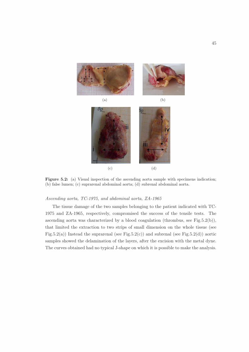
Ascending aorta, TC-1975, and abdominal aorta, ZA-1965
The tissue damage of the two samples belonging to the patient indicated with TC-
1975 and ZA-1965, respectively, compromised the success of the tensile tests. The
ascending aorta was characterized by a blood coagulation (thrombus, see Fig.5.2(b)),
that limited the extraction to two strips of small dimension on the whole tissue (see
Fig.5.2(a)) Instead the suprarenal (see Fig.5.2(c)) and subrenal (see Fig.5.2(d)) aortic
samples showed the delamination of the layers, after the excision with the metal dyne.
The curves obtained had no typical J-shape on which it is possible to make the analysis.

46 CHAPTER 5. CONCLUSIONS

Bibliography
M. Adham, J. Gournier, J. Favre, E. De La Roche, C. Ducerf, J. Bauliuex, X. Barral, and
M. Pouyet. Mechanical characteristics of fresh and frozen human descending thoracic aorta.
Journal of surgical research, 64:32–34, 1996.
T. E. Carew, R. N. Vaishnav, and D.i J. Patel. Compressibility of the arterial wall. Circulation
Research, 23:61–68, 1968.
N. Choudhury, O. Bouchot, L. Rouleau, D. Tremblay, R. Cartier, J. Butany, R. Mongrainb,
and R. L. Leaska. Local mechanical and structural properties of healthy and diseased human
ascending aorta tissue. Cardiovascular Pathology, 18:83–91, 2009.
M. Chow and Y. Zhang. Changes in the mechanical and biochemical properties of aortic tissue
due to cold storage. Article in press, 2010.
C. J. Chuong and Y. C. Fung. Compressibility and constitutive equation of arterial wall in
radial compression experiments. Journal of Biomechanics, 17:35–40, 1984.
A. Duprey, K. Khanafer, M. Schlicht, s. Avril, D.M. Williams, and R.Berguer. In vitro char-
acterisation of physiologicla and maximum elastic modulus of ascending thoracic aortic
aneurysms unsing uniaxial tensile testing. European Journal of Vascular and Endovascular
Surgery, 36:700–707, 2010.
Ambroise Duprey. Mechanical properties of the aorta. Technical report, Vascular mechanics
laboratory University of Michigan, 2008.
T.C. Gasser, R.W.Ogden, and G.A. Holzapfel. Hyperelastic modelling of arterial layers with
distributed collagen fiber orientations. Journal of the Royal Society Interface, 3:15–35, 2006.
G. V Guinea, J. Atienza, F.Rojo, C.Herrera, L. Yiqun, E. Claes, J. Goicolea, C. Montero,
R. L Burgos, F. J. Goicolea, and M. Elices. Factors influencing the mechanical behaviour of
healthy human descending thoracic aorta. Physiological measurement, 31:1553–1565, 2010.
N. Gundiah, P.B. Matthews, R. K., A. Azadani, J. Guccione, T. Sloane Guy, D. Saloner, and
E. E. Tseng. Significant material property differences between the porcine ascending aorta
and aortic sinuses. The Journal of Heart Valve Disease, 17:606–613, 2008.
47

48 BIBLIOGRAPHY
B. Halloran, V. Davis, B. McManus, T. Lynch, and T. Baxter. Localization of aortic disease
is associated with intrinsic differences in aortic strucuture. Journal of surgical research, 59:
17–22, 1995.
D. Haskett, G. Johnson, A. Zhou, U. Utzinger, and J. Vande Geest. Microstructural and
biomechanical alterations of the human aorta as a function of age and location. Biomechanics
and modeling in mechanobiology,, 9:725–736, 2010.
R. Hebballi. Diagnosis and management of aortic dissection. Continuing Education in Anaes-
thesia, Critical Care & Pain, 9:14–18, 2009.
G. A. Holzapfel, Stadler M., and C. A. J. Schulze-Bauer. A layer-specific 3d model for the simu-
lation of balloon angioplasty using mr imaging and mechanical testing. Annals of Biomedical
Engineering, 30:753–767, 2002.
G.A. Holzapfel. Collagen in ArterialWalls: Biomechanical Aspects, chapter 11, pages 285–324.
Springer Science, 2008.
Gerhard A. Holzapfel. Biomechanics of soft tissue. Lemaitre handbook of materials behavior
models, 10.:1057–1072, 2000.
Gerhard A. Holzapfel. Determination of material models for arterial walls from uniaxial ex-
tension tests and histological structure. Journal of Theoretical Biology, 238:290–302, 2006.
D. C. Iliopoulos, E. P. Kritharis, A. T. Giagini, S.A. Papadodima, and D. P. Sokolis. Ascending
thoracic aortic aneurysms are associated with compositional remodeling and vessel stiffening
but not weakening in age-matched subjects. The Journal of Thoracic and Cardiovascular
Surgery, 137:101–109, 2009.
Ghassan S. Kassab. Biomechanics of the cardiovascular system: the aorta as an illustratory
example. Journal of the Royal Society Interface, 3:719–740, 2006.
K. Khanafer, A. Duprey, M. Zainal, M. Schlicht, D. Williams, and R. Berguer. Determination
of the elastic modulus of ascending thoracic aortic aneurysm at different ranges of pressure
using uniaxial tensile testing. The Journal of Thoracic and Cardiovascular Surgery, 142:
682–686, 2011.
G. Koullias, R.Modak, M. Tranquilli, D. P. Korkolis, P. Bara, and J. A. Elefteriades. Mechan-
ical deterioration underlies malignant behavior of aneurysmal human ascending aorta. The
Journal of Thoracic and Cardiovascular Surgery, 130:677–, 2005.
C. Martin, T.Pham, and W. Sun. Significant differences in the material properties between
aged human and porcine aortic tissues. European Journal of Cardio-thoracic Surgery, 40:
28–34, 2011.

BIBLIOGRAPHY 49
D. H. Mohan and J. W. Melvin. Failure properties of passive human aortic tissue i uniaxial
tension tests. Journal of Biomechanics, 15:887–902, 1982.
P. M. F. Nielsen, P. J. Hunter, and B. H. Smaill. Biaxial testing of membrane biomaterials:
testing equipment and procedures. Journal of Bioengineering, 113:295–300, 1991.
R. J. Okamoto, J. E. Wagenseil, W. R. Delong, S. J. Peterson, N. T. Kouchoukos, and
T. M.Sundt. Mechanical properties of dilated human ascending aorta. Annals of Biomedical
Engineering, 30:624–635, 2002.
R. J. Okamoto, H. Xu, N. T. Kouchoukos, M. R. Moon, and T. M. Sundt. The influence of
mechanical properties on wall stress and distensibility of the dilated ascending aorta. The
Journal of Thoracic and Cardiovascular Surgery, 126:842–850, 2003.
M. L. Ravaghan, M. W. Webster, and D. A .Vorp. Ex vivo biomechanical behavior of abdom-
inal aortic aneurysm: assessment using a new mathematical model. Annals of Biomedical
Engineering, 24:573–582, 1996.
A. Redaelli and F. Montevecchi. Biomeccanica. Analisi multiscala di tessuti biologici. Patron,
2007.
C.S. Roy. The elastic properties of the arterial wall. Jounal of Physiology, 3:125–159, 1880.
J. Ruddy, J. A. Jones, F. G. Spinale, and J. S. Ikonomidis. Regional heterogeneity within the
aorta: Relevance to aneurysm disease. The Journal of Thoracic and Cardiovascular Surgery,
136:1123–1130, 2008.
D. P. Sokolis, E. M. Kefaloyannis, M. Kouloukouss, E. Marinos, H. Boudoulasc, and P. E.
Karayannacos. A structural basis for the aortic stress strain relation in uniaxial tension.
Journal of Biomechanics, 39:1651–1662, 2006.
D. P. Sokolis, H. Boudoulas, and P. E. Karayannacos. Segmental differences of aortic function
and composition: Clinical implications. Hellenic Journal of Cardiology, 49:145–154, 2008.
Dimitrios P. Sokolis. Passive mechanical properties and structure of the aorta:segmental anal-
ysis. Acta Physiologica, 190:277–289, 2007.
G. Sommer. Mechanical Properties of Healthy and Diseased Human Arteries Insights into
Human Arterial Biomechanics and Related Material Modeling. PhD thesis, Graz University
of Technology, 2008.
M. J. Thubrikar, M. Labrosse, F. Robicsek, J. Al-Soudi, and B. Fowler. Mechanical properties
of abdominal aortic aneurysm wall. Journal of Medical Engineering & Technology, 25:133–
142, 2001.

50 BIBLIOGRAPHY
D. A. Vorp, Br. J. Schiro, M.P. Ehrlich, T. S. Juvonen, M. A. Ergin, , and B.P. Griffith. Effect
of aneurysm on the tensile strength and biomechanical behavior of the ascending thoracic
aorta. The annals of thoracic surgery, 75:1210–1214, 2003.
David A. Vorp. Biomechanics of abdominal aortic aneurysm. Journal of Biomechanics, 40:
887–1902, 2007.