~~ai;?~;-~{!i· -~i...maintenance manual for ir-20iry coaches -date of issue 05/1 i/97 -by...
TRANSCRIPT

CMJ-990J
GOVERNMENT OF INDIAMINISTRY OF RAILWAYS _
'\~~Ai;?~;-~{!i· -~IL~ .....---F- ,'i 1\1
.. -' .
--. . ,
PROCEDURE FOR I.O.H. OF
BROAD GAUGE (1676mm) IRY COACHES
HAVING 1R-20 BOGIES
SEPTEMBER 1999
RESEARCH DESIGNS AND STANDARDS ORGANISATIONMANAK NAGAR, LUCKNOW - 22601 I.
•
PREFACE
The IR Y coach having JR-20 bogics were introduced inservice between New Delhi & Amritsar as Swam ShatabdiExpress on 15th August J998. The coaches have alreadyserved more than one year and need intermediate overhauling.This report deals with the procedure to he followed for lOR ofthese coaches. Instructions detailed in the report needs to beupdated in light of data collected and experience gainedduring tllC lOH of these coaches.
This report should be referred along with the followingdocuments:
•
I.
2.
Maintenance Manual for IR-20 IRY coaches - Date ofissue 05/1 I/97 - by RCF/Kapurthala.
CMI-9801 - Maintenance Instructions for IRY coachesfitted with IR-20 bogies - Issued in June 1998 - byRDSOlLucknow.

,
•
CONTENTS
Item Descriotion Pa••I INTRODUCTION 0 I2 OBJECnVE I
PART - I (BOGIE)
I INSPECTION 22 BEARINGS 3J BRAKES J4 WHEEL AJ\JD AXLE 35 SECONDARY SPRINGS 46 PRIMARY SPRINGS 47 INSPECTION OF HYDRAULIC DAMPERS 5
" INSPECTION OF RUBBER COMPONENTS 69 INSPECTION OF BUSHES 710 ANCHOR LI NKS 7II TRANSVERSE BEAM 712 A,"ITI-ROLL BAR 713 STUDS AND WBDGES IN CONTROL ARM "14 BOGIE-BODY CONNECTION 815 WHEEL SLIP PROTECTOR (WSP) 816 BOGIE ROTATION STOPS 817 STEPS TO ACHIEVE BUFFER HEIGIIT 818 CRITICAL COMPONENTS TO BE OBSERVED DURING 10H 819 SPECIAL FACILITIES REQUIRED III21l PAINTING I I21 TRATNlNG OF OFFICERS AND STAFF II
PART - II (SHELL AND SUB-ASSEMBLY)
I WINDOWS 122 DRAW GEAR & SCREW COUPLING 123 BUFF GEAR 134 UNDERFRAME 135 PASSENGER COMPARTMENT 136 ROOF 147 PANTRY 148 BODY SIDE DOORS 149 VESTIBULE SLIDING DOORS 1410 UIC VESTIBULE 14II LAVATORY AND LAVATORY FITTINGS 1512 INTERIOR pM'ELLING 1513 PAINTING 15
ANNEXURE I STANDARD PROCEDURE FOR RUNNING OUT IR-20 BOGIES 16ANNEXUREIl INSPECl'ION SHEET FOR SEC. SPRINGS FOR AC CHAIR CAR 17ANNEXURE III INSPECTION SHEET FOR SEC. SPRINGS FOR HIGH CAP. POWER CAR 18ANNEXURES DETERMINATION OF LATERAL STIFFNESS OF COlL SPRINGS 11}-20
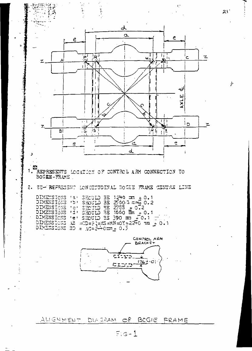
IV(a) & (b)FIG.I ALIGNMENT DIAGRAM OF BOGIE FRAME 21FIG.2 BOGIE GENERAL ARRANGEMENT 22
LIST OF SUPPORTING DOCUMENTS REQUIRED FOR LO.H 23

•
,
•
I.
2.
•
•
fROCEDUREFOR I.O.H. OFBROAD GAUGE (1676mm) IRY COACHES
HAVING IR·20 BOGIES
INTRODUCTION
The IR Y coaches on 10.25t axle load IR-20 bogies weremanufactured by RCF, Kapurthala and after successful oscillationtrials two such coaches were put in commercial service in New Delhi Dehradun Shatabdi Express for .assessment of in-service behaviour.One rake of IRY coaches having IR-20 bogies comprising of twopower cars, one Executive Class AC Chair Car and six AC Chair Carswere put in regular operation on Swam Shatabdi Express betweenNew Oelhi and Amritsar on IS August 1998. During one year ofservice, these coaches have earned approx. 2.5 lac kilometers and arerequired to undergo IOH for the first time. As the new generation IR20 bogies are having soft riding characteristics and robust in design,the schedule of JOH and POH requirements are .proposed to be basedupon 12 months and 24 months respectively or kilometer earning of2.5 lac and 5.0 lac respectively whichever is less. The 1R-20 bogiesbeing similar to the FIAT version, some guidelines have been takenfrom the Schedule of IOH requirements for FIAT bogies, besides, .nonnal procedures adopted for the proven ICF design, suitable forIndian environment and also the experience gained during servicetrials. As the bogies shall be undergoing IOH for the first time, someadditiopaJ checks may .be required to he done to gain confidencewhich can be subsequently amended.
QBJECTIVE
To provide necessary guidelines and procedures to the shop,undertaking the work ofIOH on IRY coaches having TR-20 bogies.To apprise the shop, undertaking the work of lOH, about criticalproblel]lS experienced during service .trials on IRY coaches having JR20 bogies and to implement the necessary and suggestedmodifications, during IOH on a remedial measure.
•
•
J
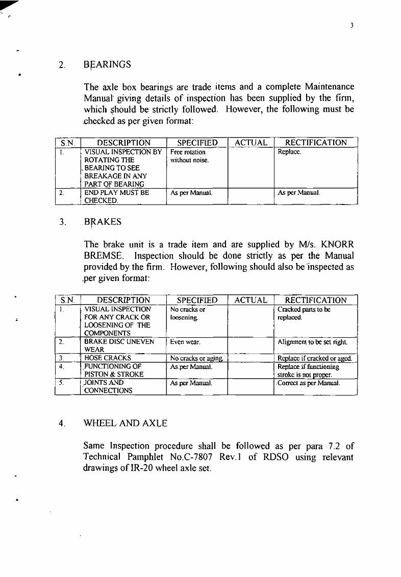
2. BpARINGS
The axle box bearings are trade items and a complete MaintenanceManual giving details of inspection has been supplied by the finn,which ~hould be strictly followed. However, the following must be.checked as per given format:
S.N. DESCRIPTION SPECIFIED ACTUAL RECTIFICATIONI. VISUAL INSPECTION BV Free rolation Replace.
ROTATING THE \\ithout noise._BEARlNG TO SEEBREAKAGE IN ANYPART OF BEARING
2. END PLAY MUST BE As per Manual. As per Manwl.CHECKED.
3. Bf<AKES
The brake unit is a trade item and are supplied by MIs. KNORRBREMSE. Inspection should be done strictly as per the Manualprovided by the firm. However, following should also be ·inspected as.per given format:
S.N. DESCRIPTION SPECIFIED ACTUAL RECTIFICATIONI. VISUAL INSPECTION No cracks or Cracked parts to be
FOR ANY CRACK OR loosening.. replaced.LOOSENING OF THECOMPONENTS
2. BRAKE DISC UNEVEN Even wear. Alignmcm to be set right.WEAR
J. HOSE CRACKS No cracks or alrinl!.. Renlace ifcracked or a 'cd.4 FUNCT10NlNG OF Aspcr Manual. Replace iffunctioning
PISTON & STROKE stroke is n01 Droner.5. )OlNTSAND .As per Manual .Corrcclas per MnnuaI .
CONNECTIONS
4. WHEEL AND AXLE
Same Inspection procedure shall be followed as per para 7.2 ofTechnical Pamphlet No.C-7807 Rev. I of ROSa using relevautdrawings of IR-20 wheel axle set.

•
5.
51
4
SECONDARY SPRINGS
The secondary springs are flexicoil springs. It is necessary to checkthese springs for cracks, dent marks and measure their free height andout of squareness to ensure that they meet the desired requirements asper relevant ROSO drawings. All springs should be SCRAG testedupto home height unless otherwise specified in the drawing. Thespring should also be subjected to varying vertical and lateral loads todeteI11Jine the load versus deflection characteristics in vertical andlateral modes. The spring stiffness in vertical mode shall not be morethan ±3% at nominal working load and +6 , -4% at other loads ofdesigned values. Free height and out of squareness should berestricted as perRDSO Spec. WD-HLS-O I.
Secondary Spring for AC Chair Car:
The secondary springs for AC chair car should be inspected as perROSO drawing no.sK-YC-OIO. The fonnat and specified values forouter and inner springs are given in Annexure-II.
5.2 Secondary Spring for Power Car:
The secondary springs for power car should be inspected as perROSO drawing nO.SK. YC-091. The fonnat and specified values forouter, middle and inner springs are given in Annexure-Ill.
6. PRIMARY SPRINGS
The secondary springs are flexicoil springs. It is necessary to checkthese springs for cracks, dent marks and measure their free height andout of squareness to ensure that they meet the desired requirements asper RO.sOdrawings. All springs should be SCRAG tested .uptohome height unless otherwise specified in the drawing. The springshould also be subjected to varying vertical and lateral loads todetermine the load versus deflection characteristics in vertical mode.The spring stiffness in vertical and lateral modes shall not be morethan ±3% at nominal working load and +6 , -4% at other loads ofdesigned values. Free height and out of squareness should berestricted as perRDSO Spec. WD-HLS-OI.
•
5
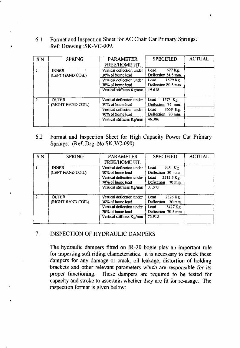
6.1 Fonnat and Inspection Sheet for AC Chair Car Primary Springs:Ref: Drawing :SK-VC-009.
S.N. SPRING PARAMETER SPECIFIED ACTUALFREEfHOME HT.
I. INNER • Vertical deflection under load 677 Kg.
(LEFT HAND COIL) 30% of home load Deflection 34.5 nun.Vertical deflection under load 1579 Kg.70% of home load Deflection 80.5 rom.Vertical stiffuess Kg/om! 19.618
2. OUTER Vertical de11ection under Load 1573 Kg.(RlGHT HAND COIL) 3lJ'/o of home load Deflection 34 nun.
Vertical deflection under load 3669 Kg.7OU/" of home load Deflection 70 mmVertical stiffhcss Kg/mm 46.386
6.2 Fonnat and Inspection Sheet for High Capacity Power Car PrimarySprings: (Ref: Drg. No.sK.VC-090)
S.N. SPRING PARAMETER SPECIFIED ACTUALFREEiHOMEHT.
I. INNER Vertical deflection under Load 948 Kg.(LEFT HAND COIL) 30% of home load Deflection 30 rom.
Vertical deflection under Load 2212.5 Kg.70% of home load Deflection 70mm..Vertical stiffness Kg/nun 31.575
2. OUTER Vertical deflection under Load 2326 Kg.(RIGHT HAND COIL) 30% of home load Deflection 30mm.
Vertical deflection under load 5427 Kg.70% of home load Deflection 70.5 mmVertical stiffness Kglmm 76.912
7. INSPECTION OF HYDRAULIC DAMPERS
The hydraulic dampers fitted on IR-20 bogie play an important rolefor imparting soft riding characteristics. it is necessary to check thesedampers for any damage or crack, oil leakage, distortion of holdingbrackets and other relevant parameters which are responsible for itsproper functioning. These dampers are required to be tested forcapacity and stroke to ascertain whether they are fit for re-usage. Theinspection fonnat is given below:

•
G
S.N. SPRING PARAMETER SPECIFIED ACTUALI. ,PJUMARY VERTICAL r"~,c;tv lOOK !J/lOcmIsec
DAMPER Stroke 60mm(Ex1.),IlOmm (Como.)
Ref: ReF Drawing Qilleaka·c No leakapc....ND.M,lOOV500 Condition ofEnd Sound.
attachmentsBushes -- Replace the
existing one withcollared bushes.
2. SECONDARY VERTICAL Caoacitv 400Kl!!IOcm/sec, -DMtfPER Stroke 4funm(ex1),92nun
(Comn.)-Ref:RCFdrawing OillcakaQ.c No leakaQ.c.NO.MIOOO489 Condition of End Sound
attachmentsBushes -- Rcnlace.
3. SECONDARY LATERAL Capacity IOOKgllOcmlsecDAMPER (cq
Stroke 85mm(Ext.) 70mmRef: ReF drawing I (Como.) (Cc)NO.IOOO490 Oillcakal!c No leakaQc.
Condition of End SoundattachmentsBushes -- Renlace.
4. YAW DAMPER Capacity I :,100KgI lOem/sec.CCI
Ref: ReF drawing Stroke ±85mmNo.MIOOO507 Oil1eakavc No leakavc.
Condition of End Sound.attachmentsBushes -- Renlace.
8. Il)lSPECTlON OF RUBBER COMPONENTS
Following are the rubber components in 1R-20 bogie which arerequired to be checked:a) ):llastic connection of control arm pin.b) ;r:opand bottom rubberring ofsecondary spring.c) Centre pivot rubber bush.d) Centre pivot lateral rubber stoppers.e) Teflon coated bogie rotation rubber stops.f) Anchor link rubber bushes.g) Damper end attachment rubber bushes.h) Anti-roll bar silent block rubber bushes.i) !tubber pads between body-bogie connection.j) FJexiblehoses used in brake system.

•
9.
9.1
7
All the {llbber components are required to be replaced with a new one.As the ,elastic connection of control ann pin is the prime contributingfactor of the vehicle riding, it must also be replaced during IOH with anew and tested piece, irrespective of its condition.
INSPECTION OF BUSHES
Nylon!Acetal Bushes:
Bogie brake gear bushes which were initially supplied byM/s.KNORR BREMSE, Gennany and for which wear limits havealready been indicated by them, shall be inspected and replaced as permaintenance limits suggested by them. At all other locations, bushesshall be replaced irrespective of their condition with a new ones.
,
9.2 Metallic Bushes:
Bogie brake gear bushes which were initially supplied byM/s.KNORR BREMSE, Gennany and for which wear limits havealready been indicated by them shall be inspected and replaced as permaintenance limits suggested by them. At all other locations bushesshall be replaced if radial clearance between pin and bush exceeds0.50mm.
10. ANCHOR LINKS
Check for any weld failure or crack in the vicinity of end support andbrackets.
11. TRANSVERSE BEAM
Check for crack, if any and rectify. Check conditions for all brackets,for example, for shock absorbers and Anti-roll bar.
12. ANTI-ROLL BAR
Check for loosening of fork from roll bar. Silent block used should bechecked and replaced, if required. Bushes used between anti-roll barand bracket should be checked and replaced, if required.

8
, 13 STUD AND WEDGES IN CONTROL ARM
,14.
Wedges & studs should be removed & examined. Replace, if required.
BOGIE-BODY CONNECTION
Weld crack and any damage to be checked and rectified. Looseningof bolt, if any, should be noted and reported to ROSO.
15. WHEEL SLIP PROTECTOR
Speed sensor and cable condition/damage both should be checked.Speed sensor gap should be recorded.
16. BOGlE ROTATION STOPS
Thickness of liner used to be checked if it is to be condemned or maywork for another one year.
17. STEPS TO ACHIEVE BUFFER HEIGHT
The prescribed value of coupler height is 1104 +0, - IOmm under tarecondition. The sequence of steps to achieve this height is given below:
17.1 CRs to the drawing NO.YF-05157 to be provided at locations markedas * in Fig.2 to achieve the secondary spring height of 372±4 asindicated as 'M' under tare condition.
17.2 CR to the drawing No.YF-05152, Max. ~ 40mm to be provided atlocations marked as # in Fig. I to achieve the body bolster height fromrail level of 11 0 I±3mm as indicated as 'P' under tare condition.
17.3 The detailed guidelines for achieving the prescribed buffer height maybe obtained by following the latest revision of RCF drawing No. YF90001. All the above drawings may be obtained from ReF.
18. CRITICAL COMPONENTS TO BE OBSERVED DURING LO.H.
Based upon the experience during the service trials of IR-20 bogies,following are the critical areas which needs special attention.

•
9
18.1 Accumulation ofwater in Lower Spring Seat Well:
Water gets accumulated in the lower spring seat well which slowlycorrodes the bogie frame as well as spring. There are three possiblesolutions which are given below:]) Eliminate spring well by re-designing the spring; OR2) Cover the existing system with proper rubber bellow; OR3) Provide an effective water drainage system.
18.2 Wear in Control Ann Bracket & Pin:
Excessive wear has been observed in the control arm bracket and pinduring service trials. This has been compensated by introducingwedge type arrangement which is also not a permanent solution to theproblem. ROSO has approved the proposal for the replacement ofcontrol arm bracket as per FIAT design. FIAT design may beobtained from RDSO or RCF.
18.3 Elastic Connection:
Switch over to tight pin arrangement. Refer ROSO drawing no.SKYC-OIl alt. NIL.
18.4 Bogie Rotation Stop Bracket on Bogie Frame:
Lower the top level to avoid infringement with car body underdynamic augmentation.
18.5 Anti-roll Bar:
The interference level to be made at par with the FlAT design whichis approximately 180J.!M (1 O.Oe-6 M).
18.6 Secondary Lateral and Yaw Damper Brackets:
Initially 'Escorts' make dampers were fitted in the bogie for lateral andyaw modes. It was observed during service trials that these dampersstarted leaking after some time. The performance of KONI damperswere more suitable. So it is now proposed that the 'Escort' make
,,
10
damper sbould be replaced by KONI dampers. The existing dampersbracket which was suitable for Escorts should now be modifiedaccordingly to suit KONI dampers of same capacity.
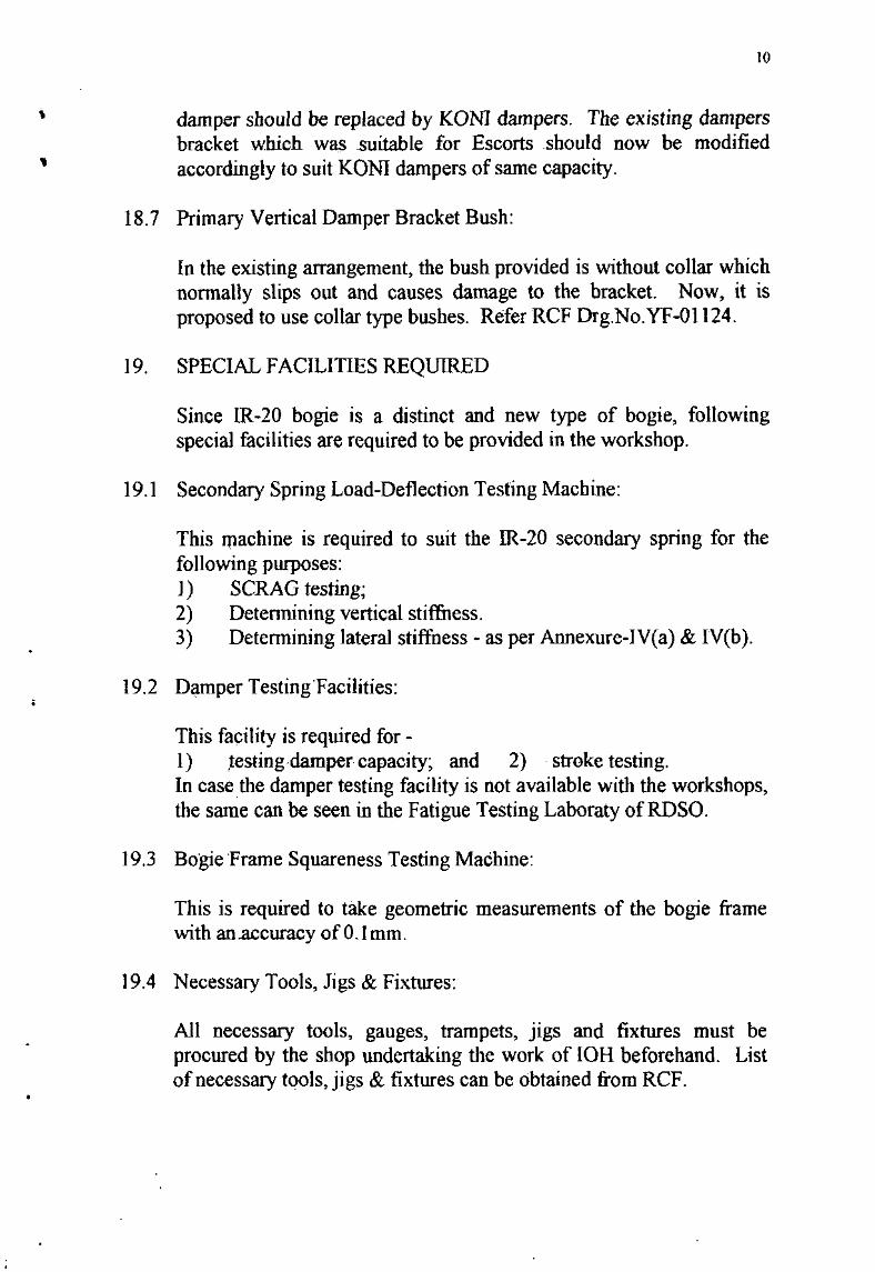
18.7 Primary Vertical Damper Bracket Bush:
In the existing arrangement, the bush provided is without collar whichnormally slips out and causes damage to the bracket. Now, it isproposed to use collar type bushes. Refer RCF Drg.No.YF-OI124.
19. SPECIAL FACILITIES REQUIRED
Since 1R-20 bogie is a distinct and new type of bogie, followingspecial facilities are required to be provided in the workshop.
19.1 Secondary Spring Load-Deflection Testing Machine:
This J1lachine is required to suit the 1R-20 secondary spring for thefollowing purposes:J) SCRAG testing;2) Detennining vertical stiffness.3) Detennining lateral stiffness - as per Annexure-IV(a) & IV(b).
19.2 Damper Testing Facilities:
This facility is required for -I) ,testing damper capacity; and 2)· stroke testing,In case the damper testing facility is not available with the workshops,the same can be seen in the Fatigue Testing Laboraty ofROSO.
19.3 Bogie Frame Squareness Testing Machine:
This is required to take geometric measurements of the bogie framewith an.accuracy ofO.lmm.
19.4 Necessary Tools, Jigs & Fixtures:
All necessary tools, gauges, trampets, jigs and fixtures must beprocured by the shop undertaking the work of IOH beforehand. Listofnecessary tools, jigs & fixtures can be obtained from RCF.
•
11
20. PAINTING
Standard procedure as adopted for ICF bogies may be adopted. Nopainting is required to be done on Trade items viz. Disc brake systemand its accessories.
21. TRAINING OF OFFICERS & STAFF
It is necessary to form a core group comprising of officers, staff,skilled artisans by the workshop undertaking the job of IOH on IR-20bogies. Wide exposure about the bogie and role of components mustbe given to the CORE group for better understanding. The Coregroup should also be given a training in class room as well as on theshop floor jointly by ROSa and RCF for the better adaptability totechnology transfer.

,
•
\.
L2
Part-II
(SHELL & SUB-ASSEMBLY)
'Yindows:
Windows of the air-conditioned compartments shall be double glasssealed windows with suitable fixing arrangement as shov.'I1 in RCF'sdrawingNo. HE 54103.
During IOH the coach shall be inspected from inside to check foringress of water. If tell tale marks of ingress of water is noticed thenthe window unit shall be removed and inspected thoroughly.Defective components shall be changed. Rubber beading shall beinvariably changed whenever the window unit is dismantled. Cracked!damaged window glasses shall also be changed.
2. Dvaw Gear & Screw Coupling:
UIC type draw gear arrangement as per Sk. 93027-U with enhancedcapacity screw coupling to Sk. 79067 have been provided on theunderframe. Alternatively, the screw coupling arrangement shall beto Sk. 9900 I.
During IOH, screw couplings shall be maintained as per theinstructions contained in RDSO's CM] 990 I - Enhanced Draw Gear.
2.1 Dvaw Gear:
The draw gear arrangement shall be thoroughly inspected from thebottom side for any damage to the rubber spring elements and othercomponents. The nuts shall be checked for slackness and, if slack, thesame ~hall be tightened. The nut shall be replaced, if the threads aredamaged or the nut is not engaging properly on the screw. The splitpin shall be checked for soundness and replaced, if found unsuitable.The lOCking plate should be checked whether the tabs are bent overthe screw or not. Ifnot, the locking plate assembly shallbe .changed.

r1
3.
4.
13
Buff Gear:,
The buffers on IRY coaches are to the standard design as being usedon ICF and RCF coaches. The buffer assembly shall be particularlychecked for drooping. Coaches with drooping buffers shall be bookedto workshops for rectification / repairs.. Buffer faceplates shall bechecked for abnormal wear and smeared with used grease. Fordetailed maintenance procedure, 'Maintenance Manual for BOCoaches' issued by CAMTECH may be referred.
Ullderframe:
The maintenance procedure for the underffame and associated partsshall be as indicated in the table below:
S.No. Part I Location Inspection Remedial Action4.1 Sole bar, body bolster, cross To be checked for weld Coach booked to
members and other defects and corrosion W/S for repairsframework
4.2 Trough floor To be checked for weld Coach booked todefects and corrosion WIS for repairs
4.3 Underslung equipments To be checked for Nuts to be tightenedI orooer clamoino orooerlv
4.4 Lavatory chutes To be checked for Replace wherevercracks bends etc. necessarv
5. Passenger Compartment:
The attention to be given in maintenance ofpassenger compartment isas given below:
S.No. Part I Location Inspection Remedial Action5.1 AC compartment To check for any Replace, wherever
doors damage to rubber parts necessary.and broken olass
5.2 Door closer To check for proper Replace whereverfunetioniml. necessarY.
5.3 Seats To be checked for Replace upholsteryproper upholstery - wherever necessary.fadina or tom
5.4 Reclining Mechanism To be checked for Replace partsproper functioning, ease wherever necessary.of movement
,I
14
5.5 Magazine Bag Broken or torn Replace.
5.6 Snack Table FRP panel damaged or Replace assembly.drooping
5.7 Window Curtain Tom, dirty or improper Replace.movement
5.8 Floor Damaged PVC or ply Coach booked to WISwood and welding ioints for repairs.
6. Roof:
The roof shall be checked for mild rusting and leakage of water. Rustshall be removed by use of suitable emery and a matching coat ofpaint applied. Any accumulated waste matter should be removedfrpm the corrugations.
7. Pantry:
The mounting of pantry equipments shall be sound. The drains shallbe checked for any blockage. Necessary remedial action, in thisregard, J1lay be taken.
8. Body side Doors:
The body side doors shall be checked for ease of operation. Rubberdust excluding device shall be checked for soundness and replacedwherever necessary. Door handles shall afford ease of operation.Bottol)l door panel shall be checked for any signs of corrosion andcoach shall be booked to workshop for repairs, if corrosion is noticed.
9. Vestibule Sliding Doors:
The top guide rail shall be checked for straightness. It should also bechecked and ensured that the roller moves in the top 'V' groovesmoothly. 'V' grooves shall be cleaned of any muck, dust, etc.
10. we Vestibule:
Securio$ of UIC vestibule on the steel frame shall be checked andscrews tightened, if found loose. In the event of perished rubberelement of the UIC vestibule, the coach shall be booked to workshopsfor replacement, if facility does not exist during IOH.

,
15
11 . Lavatory and Lavatory Fittings:
The lavatory pans shall be firm without any movement. Fittings suchas pus" cocks, flushing valves, etc. shall be in good working conditionand replaced, wherever necessary. Wash-hand basins shall be free ofslain. Wall protector, if made of FRP, shall be specifically checked forcracks. Lavatory flooring shall be finn and without bulge. Lavatoryiqlays shall be checked for cracks.
12. Interior Panelling:
The compartment panelling shall be without cracks, free of bulge, etc.Necessary replacements shall be carried out.
13. P~inting:
The coach shall be inspected from exterior and interior for any sib'llSof scratches, etc. on the painted surfaces. Necessary touching withpaint shall be carried out.
*.***
IOH-1R-20
•
•
16
Annexure-l
STANDARD PROCEDURE FOR RUNNING OUT IR-20 BOGIES
Following procedure should be adopted for lifting and running out thebogies:
I. Unscrew and remove the four bolts provided between the body bolsterand transverse beam.
2. Remove all the hydraulic dampers by unscrewing the holding bolts(yaw, lateral, secondary and primary vertical).
3. Remove the holding plate of centre pivot plate.
4. Remove speed sensor cables from WSP.
5. Remove flexihle brake pipe connections.
6. Remove roll links of anti-roll bar arrangement.
7. Disconnect the safety wire rope connection between body and bogie.
8. Place four electromechanical lifting jacks (lOt. capacity each) byputting them at the marked position under the coach body. Lift thecoach body approx. 2m high till the coach body components clears theinfringements against bogie frame and secondary springs.
9. After assuring no infringement, roll out the two bogies.
10. Now dismantle all the connections from the transverse beam VIZ.
reckoner arm, minor frame, control arm bracket, brake system,primary and secondary springs etc. for further inspection.

••
•
17
Annexure-II
fNSPECTION SHEET FOR SECONDARY SPRINGS FORAlC CHAIR CAR
(Ref. Drawing - SK-VC-OIO)
S. Spring Parameter Specified ActualNo. Value ValueI. INNER SPRING FREE HEIGHT 771 ±4
Vertical Deflection under Load - 1750 kg.30% of Home load Deflection = 126mm.Vertical Deflection under Load 4075 kg.70% of Home load Deflection = 293mm.Lateral Force under vertical Tare load 2026 Kg.tare load for 20mm lateral Lat force '" 90.4 Kg.deflectionLateral force under vertical Gross load - 2529.4Kg.gross load'for 20nun lateral -Lateral force :: 83.4 kg.deflectionVertical Stiffness KeJrnm 13.896Lateral Stiffness Kglmm 4.5214.17Tare/gross.
2. OUTER SPRING FREE HEIGHT 877±4Vertical Deflection under Load 2906 kg.30% of Home load Deflection = 141mm.Vertical Deflection under Load 6780 kg.70% afHome load Deflection = 329mm.Lateral Force under vertical Tore load - 5194 Kg.tare load for 20mm lateral Lat. force = 197.8 kg.deflectionLateral force under vertical Gross load 5940 kg.gross load for 20mm lateral Lat. force = 195.8 kg.deflectionVenical Stiffness KWmm 20.611Lateral Stiffness Kg/nun 9.89/9.79Tarell!I'Oss.

,
•
18
Annexure-III
INSPECTION SHEET FOR SECONDARY SPRINGS FORHIGH CAPACITY POWER CAR
(Ref. Drawing - SK-VC-091)
S Spring Parameter Specified ActualNo. Value ValueI. INNER SPRING FREE HEIGHT 65Omm.
(RlGHTHAND Vertical Deflection under Loarl - 1066 Kg.'COIL) 3Qllio ofHome load Deflection = 92mm.
Vertical Deflection under Load - 2486 kg.700!o of Home load Deflection = 214mm.
Lateral force under tare Tare load - 1403.2 kgload for 20mm deflection. Lat load =32.8 k..Lateral force under gross Gross load - 1577 kg.load for.20mm deflection. Lal load =17.4 ko..Vertical Stiffness Kelmm 11.642
. ..LatemJ Stiffness Kglmm 1.64/0.87Tarell!TOSS.
2. MIDDLE FREE HEIGHT 81Omm.SPRING Vertical Deflection under Load - 2309 kg.(LEFT HAND )0% ofHome load Deflection = 107mm.COlL) Vertical Deflection under Load - 5399 kg.
700/0 ofHome load Deflection = 250nun.Lateral force under tare Ver.load 3894.7 kg.load fOT 20mm deflection lal force = 73.4 k£.Lateral force under gross Vcr.load-4217kg.load for 20mm deflection Lat. force = 64.8 kg.Vertical Stiffness Kelmm 21572'Lateml Stiffness Kg/nun 3.67/3.24Tarell!TOSS.
3. ,0UTER SPRING FREE HEIGHT 810'(RiGHT HAND Vertical Deflection under Load - 4276kg..<'OlL) 30%ofHomc'load Deflection = 115mm
Vertical Deflection under Load - 9977 kg.70'% of Home load Deflection = 269mmLateral force under tare load Tare load 6701.7 kg.for"20mm deflection. .Lat. force "" 467.6~Lateral force under gross Gross load'" 7255.9 kg.load for 20mm deflection Lac force 467.6 kg.Vertical Stiffness Kg/mm 37.118Lateral Stiffness Kg/mm 23.381231J8TareilITOss.
•
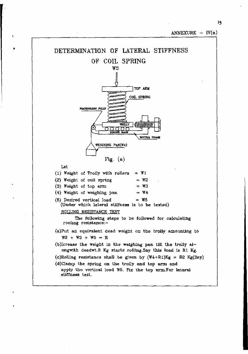
ANNEXURE - IV(a)
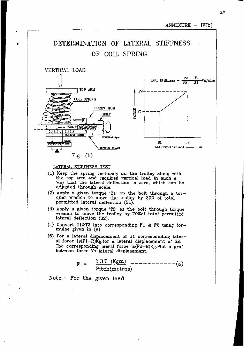
DETERMINATION OF LATERAL STIFFNESS
OF COIL SPRINGW5
r--.JL----, TOP Aft"
con. SPRING
•
WEIGHD'{G PAN(W4)
Fig. (alLet
(1) Weight of Trolly with rollers == Wi
(2) Weight of coil SjlriIlg - W2(3) Weight of top arm = 11'3
(4) Weight of weighing pan - 11'4
(6) DesIre<! vertical load = 11'6(Under which lateral :!ltillness is to be te:!lted)
ROrJJNG RSSlSTANCE TESTThe following :JlepB to be followed for calculating
rooling resistance:-
(a)Put an equiva.J.ent dead weight on the trolly amount.ing toW2+W3+W5-R
{b)IcreB.:!le the weight in the weighing pan till the trolly 8.1ongwith deel.dwt.R Kg starts rolling.Say this load. 1s Rl Kg.
(c)Rt>lling resi3tane. shflll be g:iven by (W4.+Rl)Kg ~ R2 Kg(Say)
(d)Clamp the spring on t.he trolly and lop arm andapply the vertical toad Woo Fix the top 1U'D:l.For lateralsti!tness te 9t.
•
•
ANNEXURE - IV(b)
DETERMINATION OF LATERAL STIFFNESS
OF COIL SPRING
VERTICAL LOAD
r--..:L----, TOP mil
l~~COIL SPRJNG
i;:. SCREW HUB
. BOLT
J
Fig. (b)
1
F2 - FlL",t. stiffneaa = sz _ 31 Ki:/mm
I91 82
La.LDlsplacs:lD.snt __~rr
LATERAL SnFFNESS TEST(1) Keep the spring vertically on the trolley along with
the top arm and required vertical load in such away that the lateral deflection is zero, which can beadjusted through scale.
(2) Apply a. given torque 'Tl' on the bolt through a torquer wrench tc move the trolley by 30% ot totalpermitted lateral deflection (81).
(3) Apply a given torque 'T2' as the bolt through torquewrench to move the trolley by 70%of total permittedlateral deflection (32).
(4) Convert TI&TZ Into oorresponding FI & F2 using rormula.e given in (a).
(5) For a lateral displacement of 31 corresponding lateral loroe Is(FI-R)Kg,ror a lateral displacement ot S2.The corresponding laeral lerce Is(F2-R)Kg.Plet • grarbetween force Va lateral displasement.
F = 211 T (Kgm) -----------(a)Pitch(metre.)
Note: - For the given load
.Lr
.. '.,
C.cMr!lOL. A~l\4
&~AC.IC.~"T"'
c.d.
,.;,,
,I c.. :'t.-~_--L __! 17Et::"O\I __~"":"'J.....!r=~-C!I.:C::J~'-=-~:::':j~\"- I
- - J..-1 0-
~lee - -
I,
I~\
, J ,- I I,, .
-
\ " " -, - l-J "'1 ~'1 -,-, -, ~ ,,_i'-'
,. :
....
J
o
{..\tI,,
·1-r•·-,·~
I 1,,I ,
,

•
LIST OF SUPPORTING I>OCUMENTS REQUIRED FOR 1.0.H.
S Document No. Type of Document Subject Source ofNo SUDDlv
1. -- Maine Manual Axle box bearings Mis TataTimken orRCF.
2. -- Installation and Disc brake assembly MIs. KnorrMaintenance Manual Bremse or
RCF.
3. C-7807 Technical Pamphlet On Wheel and Axle RDSOlLko.
4 WD-HLS-OI RDSO Specification On Coil springs. RDSO/Lko.
5 SK-YC-OIO Drawing Sec.Spring (Chair car) RDSOlLko.
6 SK-YC-09J Drawing Sec. Spring (power car) RDSOlLko.
7 SK-YC-009 Drawing Pri.Spring (Chair car) RDSOlLko.
8 SK-YC-090 Drawing Pri.Spring (Power car) RDSO/Lko.
9 YFOl124 Drawing Privert damper bracket RCFcollored bushes.
10 MIOO0500 Drawing Primary vertical damper RCF
1I MI000489 Drawing Secondary vertical damper RCF
12 MI000490 Drawing Secondary lateral damper RCF
13 MJOO0507 Drawing Yaw damper RCF.
14 YF05157 Drawing Compensating rings. RCF.
15 YF05152 Drawing Compensating rings. RCF
16 YF90001 Drawing Coupler height. RCf
17 1272005 Drawing (FIAT) FIAT version of Control RCfArm Bracket.