ahrti report no. 9009 leak detection of a2l … results... · ahrti report no. 9009 leak detection...
TRANSCRIPT
AHRTI Report No. 9009
LEAK DETECTION OF A2L REFRIGERANTS IN HVACR EQUIPMENT
Final Report
Revised on August 4, 2017
Mark Wagner and Rebecca Ferenchiak
ICF
1725 Eye Street NW
Suite 1000
Washington, DC 20006
Prepared for
AIR-CONDITIONING, HEATING AND REFRIGERATION TECHNOLOGY
INSTITUTE, INC
2111 Wilson Boulevard, Suite 500, Arlington, Virginia 22201-3001
©2017 AHRTI

2
DISCLAIMER
This report was prepared as an account of work sponsored by the Air-Conditioning, Heating and
Refrigeration Technology Institute, Inc. (AHRTI). Neither AHRTI, its research program financial
supporters, or any agency thereof, nor any of their employees, contractors, subcontractors or
employees thereof - makes any warranty, expressed or implied; assumes any legal liability or
responsibility for the accuracy, completeness, any third party’s use of, or the results of such use of
any information, apparatus, product, or process disclosed in this report; or represents that its use
would not infringe privately owned rights. Reference herein to any specific commercial product,
process, or service by trade name, trademark, manufacturer, or otherwise, does not necessarily
constitute nor imply its endorsement, recommendation, or favoring by AHRTI, its sponsors, or any
agency thereof or their contractors or subcontractors. The views and opinions of authors expressed
herein do not necessarily state or reflect those of AHRTI, its program sponsors, or any agency
thereof.
Funding for this project was provided by (listed alphabetically):
- Air-Conditioning, Heating and Refrigeration Institute (AHRI)
3
Table of Contents
List of Acronyms ................................................................................................................................................. 4
Executive Summary ............................................................................................................................................ 5
Introduction ......................................................................................................................................................... 7
Evaluation of Refrigerant Sensor Technologies ............................................................................................... 8
1. A2L Sensor Requirements ........................................................................................................................ 10
2. Available Sensor Technologies ................................................................................................................ 14
2.1 Infrared Sensors ............................................................................................................................. 16
2.1.1 Overview of Technology ........................................................................................................... 16
2.1.2 Comparison of Evaluation Criteria............................................................................................ 17
2.2 Electrochemical Cell (EC) ............................................................................................................. 20
2.2.1 Overview of Technology ........................................................................................................... 20
2.2.2 Comparison of Evaluation Criteria............................................................................................ 21
2.3 Metal Oxide Semiconductor (MOS) .............................................................................................. 22
2.3.1 Overview of Technology ........................................................................................................... 22
2.3.2 Comparison of Evaluation Criteria............................................................................................ 22
2.4 Catalytic-type (Pellistor) ................................................................................................................ 24
2.4.1 Overview of Technology ........................................................................................................... 24
2.4.2 Comparison of Evaluation Criteria............................................................................................ 25
2.5 Heated Diode ................................................................................................................................. 26
2.5.1 Overview of Technology ........................................................................................................... 26
2.5.1 Comparison of Evaluation Criteria............................................................................................ 26
3. Alternative Sensor Technologies .............................................................................................................. 28
3.1 Open Source Infrared ..................................................................................................................... 28
3.2 Virtual Refrigerant Charge Sensor ................................................................................................. 28
Review of Failure Modes .................................................................................................................................. 29
4. Ranking of Key Failure Modes................................................................................................................. 29
5. Recommended Reliability Testing Procedure .......................................................................................... 32
Summary of Findings ....................................................................................................................................... 35
6. Limitations and Uncertainties ................................................................................................................... 35
7. Summary of Findings ............................................................................................................................... 36
References .......................................................................................................................................................... 38

4
List of Acronyms
AC Air-Conditioning
ASHRAE American Society of Heating, Refrigerating and Air-Conditioning Engineers
CFC Chlorofluorocarbon
CO Carbon Monoxide
EC Electrochemical Cell
GWP Global Warming Potential
HART Signal Highway Addressable Remote Transducer signal
H2S Hydrogen Sulfide
HC Hydrocarbon
HCFC Hydrochlorofluorocarbon
HFC Hydrofluorocarbon
HFO Hydrofluoroolefin
HVACR Heating, Ventilation, Air-Conditioning, and Refrigeration
IEC International Electrotechnical Commission
IPCC AR4 Fourth Assessment Report of the Intergovernmental Panel on Climate Change
IR Infrared
ISO International Organization for Standardization
LEL Lower Explosive Limit
LFL Lower Flammability Limit
MOS Metal Oxide Semiconductor
NDIR Non-Dispersive Infrared
NH3 Ammonia
NO2 Nitrogen Dioxide
O2 Oxygen
ODS Ozone Depleting Substance
OEL Occupational Exposure Limit
PIR Photo-acoustic Infrared
ppm Parts per Million, volume basis [as used throughout this document]
SO2 Sulphur Dioxide
TLV-TWA Threshold Limit Value - Time Weighted Average
VDC Voltage Direct Current
5
Executive Summary
Over the past several years, climate-friendly alternatives, such as lower-GWP HFCs and HFOs,
have been developed to replace the current suite of HFCs in use. Several of these proposed
refrigerants fall into the ASHRAE safety category created in ASHRAE Standard 34-2010:
Designation and Safety Classification of Refrigerants, A2L, which are a sub-class of A2 (i.e.,
lower flammability) refrigerants.
Current international and U.S. standards for HVACR systems are anticipated to be updated with
new or revised requirements specific for A2L refrigerants, including refrigerant sensor
requirements, such as response time and measurement ranges:
• International Standard IEC 60335-2-40: Household and similar electrical appliances –
Particular requirements for electrical heat pumps, air conditioners, and dehumidifiers
(Edition 5.1, April 2016)
• ASHRAE Standard 15-2016: Safety Standard for Refrigeration Systems
• International Organization for Standardization (ISO) 5149-3:2014 Refrigerating systems
and heat pumps – Safety and environmental requirements
According to the proposed requirements, HVACR systems containing an A2L refrigerant would
be required to include one or more refrigerant sensor/detection systems that previously did not
have refrigerant sensor requirements, such as for certain smaller commercial/industrial and
residential applications. Large industrial and commercial applications (e.g., machine and cold
rooms) are already required to have refrigerant detection systems.
Currently available technologies including IR, EC, MOS, catalytic, and heated diode sensors
were reviewed to determine whether they can meet the proposed sensor requirements under
standards ASHRAE 15, IEC 60335-2-40, and ISO 5149-3. These sensors were reviewed and
evaluated against certain criteria to determine the applications and equipment types the
technology could be installed in and whether they would be appropriate for detecting A2L
refrigerants (e.g., HFC-32, HFO-1234yf, HFO-1234ze(E), and blends thereof). In addition, due
to the flammability of A2L refrigerants, potential failure modes of the sensors (i.e., how the
sensor can fail) were evaluated and a reliability testing procedure was developed to address these
failure modes. The evaluation of sensor technologies and potential failure modes was based on a
review of product literature and discussions with sensor manufactures; actual testing of
refrigerant sensors was not performed for this analysis.
Based on research of available refrigerant sensor technologies and discussions with sensor
manufacturers, both IR and MOS sensors were found to be the most promising sensor
technologies that could be used for A2L refrigerant detection and meet the proposed
requirements in residential and commercial/industrial settings. These sensor technologies were
both found to be least susceptible to the effects of potential failure modes in
commercial/industrial and residential settings. Sensor models using IR and MOS technology
currently exist that detect A2L refrigerants; however, most sensors that are currently available or
are coming available this year cannot measure A2L refrigerants up to the specified detection

6
ranges and have additional concerns for adaptation, particularly in residential settings, including
relatively short lifetimes, maintenance requirements, and costs. However, sensor manufacturers
are becoming aware of the proposed requirements for A2L refrigerant sensors and it is expected
that manufacturers will focus research and development efforts to ensure that appropriate sensors
are available to meet the updated standards, although the timeline for development is still
uncertain.

7
Introduction
In light of global efforts to phase out ODS (i.e., CFCs and HCFCs), HFCs are now the most
commonly used refrigerant in a variety of air conditioning (AC) and refrigeration applications.
HFCs used in these applications have low toxicity and are non-flammable; however, these
commonly used HFCs typically have GWP100 values that range from 1,430 to 3,985 per IPCC
AR4. Recognizing the harmful impact these chemicals have on the climate, as well as anticipated
regulatory restrictions on their use, industry is in the process of transitioning to less harmful,
lower-GWP alternatives.
Over the past several years, climate-friendly alternatives, such as lower-GWP HFCs and HFOs,
have been developed to replace the current suite of HFCs in use. Several of these proposed
refrigerants fall into an ASHRAE safety category created in ASHRAE Standard 34-2010:
Designation and Safety Classification of Refrigerants, A2L.1 A2L refrigerants are a sub-class of
A2 (i.e., lower flammability) refrigerants that have a burning velocity of ≤10 cm/sec when tested
at 23°C and 101.3 kPa. Common A2L refrigerant alternatives include HFC-32, HFO-1234yf,
HFO-1234ze(E), and other refrigerant blends containing HFOs.
As a result of the flammability of these refrigerants, codes and standards will require the use of
sensors to detect a refrigerant leak for both commercial/industrial and residential applications to
mitigate the potential for a combustible event. Currently, refrigerant detectors are only required
in restricted-access machine rooms that contain HVACR equipment with several hundred (or
thousand) pounds of refrigerant charge. These detectors use a set point value to trigger an alarm
and mechanical ventilation to prevent the refrigerant concentration in the room from exceeding
the occupational exposure limit, as well as to prevent exceeding flammability, toxicity, and
oxygen deprivation limits in the case of a large leak or accidental release. The proposed
requirement for sensors in human comfort applications is dictated by the charge quantity of the
refrigerant, which takes into account the room size where the equipment is installed and the LFL
for that refrigerant.
Current international and U.S. standards for HVACR systems are anticipated to be updated with
new or revised requirements specific for A2L refrigerants, including refrigerant sensor
requirements, such as response time and measurement ranges:
• International Standard IEC 60335-2-40: Household and similar electrical appliances –
Particular requirements for electrical heat pumps, air conditioners, and dehumidifiers
(Edition 5.1, April 2016)
• ASHRAE Standard 15-2016: Safety Standard for Refrigeration Systems
• International Organization for Standardization (ISO) 5149-3:2014 Refrigerating systems
and heat pumps – Safety and environmental requirements
1 A2L refrigerants were first introduced in Addendum ak to ASHRAE Standard 34-2007. A2L refrigerants were
later incorporated into the ASHRAE Standard 34-2010 edition.
8
If switched to an A2L refrigerant, some HVACR systems would be required to include one or
more refrigerant sensor/detection systems that previously did not have refrigerant sensor
requirements, such as for certain residential applications. Industrial and commercial equipment
in machine rooms per ASHRAE Standard 15 are already required to have refrigerant detection
systems. Currently available sensor technologies may not necessarily meet the proposed
requirements and be able to be integrated into HVACR equipment across all applications. In
addition, due to the flammability of A2L refrigerants, an important consideration for selecting a
suitable sensor technology are the potential failure modes of the sensor (i.e., how the sensor can
fail).
The most recent summaries of refrigerant detector technologies that discuss the ability to
measure halocarbon refrigerants in residential and commercial settings are from the 1990s (e.g.,
McClure et. al., (1990) and USACERL (1996)); therefore, this analysis reviews currently
available sensor technologies and evaluates whether these sensors can be incorporated into
HVACR equipment for both commercial/industrial and residential applications and meet the
proposed requirements for detecting A2L refrigerants. In addition, key known failure modes
were also identified for available sensor technologies and suitable reliability testing procedures
to address these potential failure modes were developed to allow industry to best evaluate the
current market of refrigerant sensors and inform decisions regarding the use of A2L refrigerants.
The evaluation of sensor technologies and potential failure modes was based on a review of
product literature and discussions with sensor manufactures; actual testing of refrigerant sensors
was not performed for this analysis.
Evaluation of Refrigerant Sensor Technologies
Currently, refrigerant detectors are required in machine rooms that contain HVACR equipment.
Detectors must be located in an area where refrigerant from a leak will concentrate and activate
an alarm and mechanical ventilation upon detection of a concentration equal to the
corresponding TLV-TWA of the refrigerant, a type of occupational exposure limit based on
intermittent exposure not exceeding 8 hours per day and 40 hours per week. As such, there are
multiple refrigerant sensor technologies available and in use in the market today for fluorinated
refrigerants (e.g., HCFCs and HFCs) in large commercial HVACR equipment. All commonly
known Class A2L refrigerants (e.g., HFC-32, HFO-1234yf, and HFO-1234ze(E)) are also
fluorinated gases, and therefore, commercially available sensor technologies may be appropriate
for these new refrigerants; however there may be additional requirements for Class A2L
refrigerant sensors that available sensor technologies are not capable of meeting.Table 1 lists the
A2L refrigerants and blends currently defined by ASHRAE Standard 34-2016 and published
addenda to date. Additional refrigerant designations are in process and will be added in future
editions of the standard.
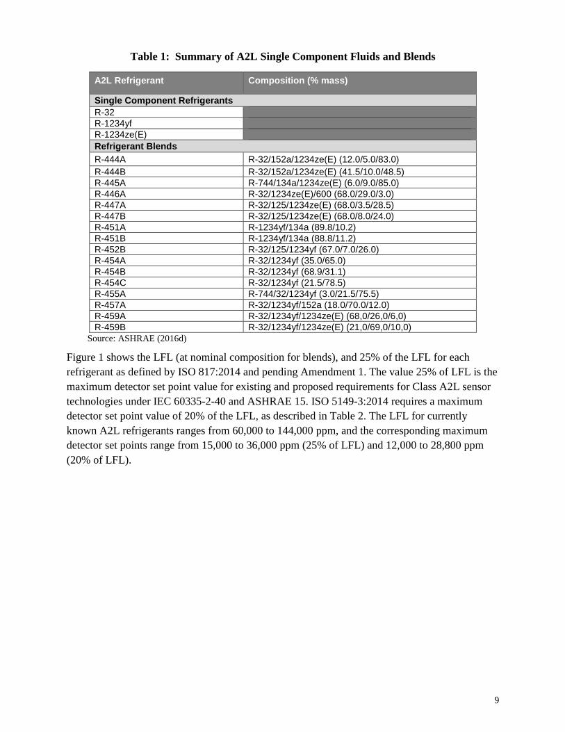
9
Table 1: Summary of A2L Single Component Fluids and Blends
A2L Refrigerant Composition (% mass)
Single Component Refrigerants
R-32
R-1234yf
R-1234ze(E)
Refrigerant Blends
R-444A R-32/152a/1234ze(E) (12.0/5.0/83.0)
R-444B R-32/152a/1234ze(E) (41.5/10.0/48.5)
R-445A R-744/134a/1234ze(E) (6.0/9.0/85.0)
R-446A R-32/1234ze(E)/600 (68.0/29.0/3.0)
R-447A R-32/125/1234ze(E) (68.0/3.5/28.5)
R-447B R-32/125/1234ze(E) (68.0/8.0/24.0)
R-451A R-1234yf/134a (89.8/10.2)
R-451B R-1234yf/134a (88.8/11.2)
R-452B R-32/125/1234yf (67.0/7.0/26.0)
R-454A R-32/1234yf (35.0/65.0)
R-454B R-32/1234yf (68.9/31.1)
R-454C R-32/1234yf (21.5/78.5)
R-455A R-744/32/1234yf (3.0/21.5/75.5)
R-457A R-32/1234yf/152a (18.0/70.0/12.0)
R-459A R-32/1234yf/1234ze(E) (68,0/26,0/6,0)
R-459B R-32/1234yf/1234ze(E) (21,0/69,0/10,0)
Source: ASHRAE (2016d)
Figure 1 shows the LFL (at nominal composition for blends), and 25% of the LFL for each
refrigerant as defined by ISO 817:2014 and pending Amendment 1. The value 25% of LFL is the
maximum detector set point value for existing and proposed requirements for Class A2L sensor
technologies under IEC 60335-2-40 and ASHRAE 15. ISO 5149-3:2014 requires a maximum
detector set point value of 20% of the LFL, as described in Table 2. The LFL for currently
known A2L refrigerants ranges from 60,000 to 144,000 ppm, and the corresponding maximum
detector set points range from 15,000 to 36,000 ppm (25% of LFL) and 12,000 to 28,800 ppm
(20% of LFL).

10
Figure 1: LFLs of Select A2L Refrigerants
The remainder of this section reviews the existing and proposed requirements for Class A2L
sensor technologies under IEC 60335-2-40, ASHRAE 15, and ISO 5149-3:2014 and evaluates
existing and new sensor technologies against these requirements.
1. A2L Sensor Requirements
A new draft of IEC 60335-2-40 (for future edition 6) and several addenda to ASHRAE Standard
15-2016 are expected in the next few years. Both standards are anticipated to be updated with
specific requirements for A2L refrigerants, including refrigerant sensor requirements.
Additionally, ISO 5149-3:2014 specifies the detector requirements for all classes of refrigerant,
including A2L. ISO 5149-3:2014 allows the use of an oxygen deprivation sensor in lieu of a
refrigerant detector; however those sensor types are outside the scope of this study. Table 2
summarizes the existing and proposed sensor requirements for Class A2L refrigeration systems.
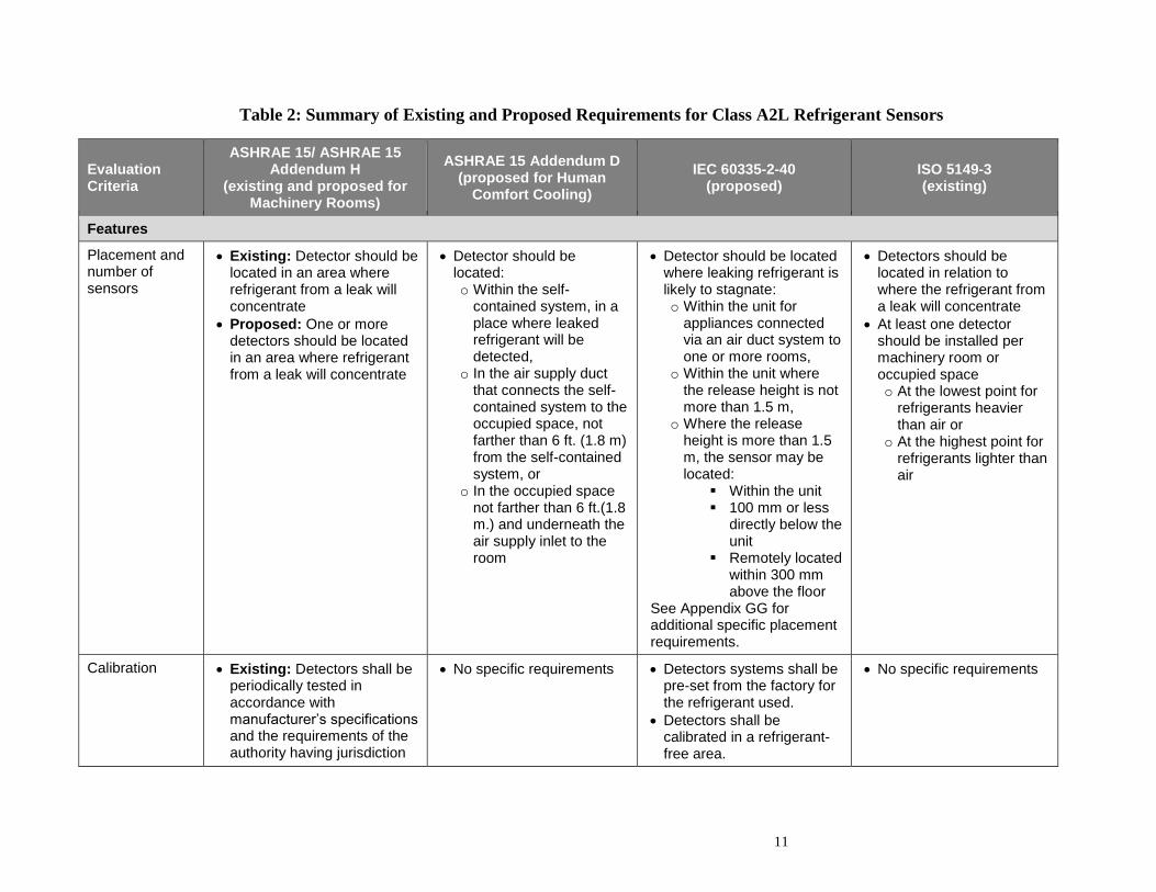
11
Table 2: Summary of Existing and Proposed Requirements for Class A2L Refrigerant Sensors
Evaluation Criteria
ASHRAE 15/ ASHRAE 15 Addendum H
(existing and proposed for Machinery Rooms)
ASHRAE 15 Addendum D (proposed for Human
Comfort Cooling)
IEC 60335-2-40 (proposed)
ISO 5149-3 (existing)
Features
Placement and number of sensors
• Existing: Detector should be located in an area where refrigerant from a leak will concentrate
• Proposed: One or more detectors should be located in an area where refrigerant from a leak will concentrate
• Detector should be located: o Within the self-
contained system, in a place where leaked refrigerant will be detected,
o In the air supply duct that connects the self-contained system to the occupied space, not farther than 6 ft. (1.8 m) from the self-contained system, or
o In the occupied space not farther than 6 ft.(1.8 m.) and underneath the air supply inlet to the room
• Detector should be located where leaking refrigerant is likely to stagnate: o Within the unit for
appliances connected via an air duct system to one or more rooms,
o Within the unit where the release height is not more than 1.5 m,
o Where the release height is more than 1.5 m, the sensor may be located:
▪ Within the unit ▪ 100 mm or less
directly below the unit
▪ Remotely located within 300 mm above the floor
See Appendix GG for additional specific placement requirements.
• Detectors should be located in relation to where the refrigerant from a leak will concentrate
• At least one detector should be installed per machinery room or occupied space o At the lowest point for
refrigerants heavier than air or
o At the highest point for refrigerants lighter than air
Calibration • Existing: Detectors shall be periodically tested in accordance with manufacturer’s specifications and the requirements of the authority having jurisdiction
• No specific requirements • Detectors systems shall be pre-set from the factory for the refrigerant used.
• Detectors shall be calibrated in a refrigerant-free area.
• No specific requirements
12
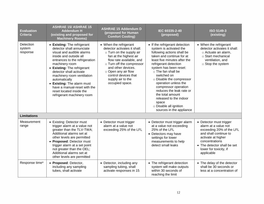
Evaluation Criteria
ASHRAE 15/ ASHRAE 15 Addendum H
(existing and proposed for Machinery Rooms)
ASHRAE 15 Addendum D (proposed for Human
Comfort Cooling)
IEC 60335-2-40 (proposed)
ISO 5149-3 (existing)
Detection system response
• Existing: The refrigerant detector shall annunciate visual and audible alarms inside and outside all entrances to the refrigeration machinery room
• Existing: The refrigerant detector shall activate machinery room ventilation automatically
• Existing: The alarm must have a manual-reset with the reset located inside the refrigerant machinery room
• When the refrigerant detector activates it shall: o Turn on the supply air
fan at the highest air flow rate available, and
o Turn off the compressor and other devices.
o Open any air flow control devices that supply air to the occupied space.
• If the refrigerant detection system is activated the following actions shall be taken and continue for at least five minutes after the refrigerant detection system has been reset: o The fan shall be
switched on o Disable the compressor
operation unless the compressor operation reduces the leak rate or the total amount released to the indoor space
o Disable all ignition sources in the appliance
• When the refrigerant detector activates it shall: o Actuate an alarm, o Start mechanical
ventilation, and o Stop the system
Limitations
Measurement range
• Existing: Detector must trigger alarm at a value not greater than the TLV-TWA; Additional alarms set at other levels are permitted
• Proposed: Detector must trigger alarm at a set point not greater than the OEL; Additional alarms set at other levels are permitted
• Detector must trigger alarm at a value not exceeding 25% of the LFL
• Detector must trigger alarm at a value not exceeding 25% of the LFL
• Detectors may have settings for lower measurements to help detect small leaks
• Detector must trigger alarm at a value not exceeding 20% of the LFL and shall continue to activate at higher concentrations
• The detector shall be set lower for toxicity, if applicable
Response timea • Proposed: Detector, including any sampling tubes, shall activate
• Detector, including any sampling tubing, shall activate responses in 15
• The refrigerant detection system will make outputs within 30 seconds of reaching the limit
• The delay of the detector shall be 30 seconds or less at a concentration of
13
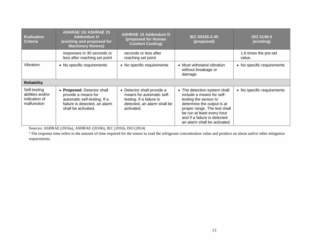
Evaluation Criteria
ASHRAE 15/ ASHRAE 15 Addendum H
(existing and proposed for Machinery Rooms)
ASHRAE 15 Addendum D (proposed for Human
Comfort Cooling)
IEC 60335-2-40 (proposed)
ISO 5149-3 (existing)
responses in 30 seconds or less after reaching set point
seconds or less after reaching set point
1.6 times the pre-set value.
Vibration • No specific requirements • No specific requirements • Must withstand vibration without breakage or damage
• No specific requirements
Reliability
Self-testing abilities and/or indication of malfunction
• Proposed: Detector shall provide a means for automatic self-testing. If a failure is detected, an alarm shall be activated.
• Detector shall provide a means for automatic self-testing. If a failure is detected, an alarm shall be activated.
• The detection system shall include a means for self-testing the sensor to determine the output is at proper range. The test shall be run at least every hour and if a failure is detected an alarm shall be activated.
• No specific requirements
Sources: ASHRAE (2016a), ASHRAE (2016b), IEC (2016), ISO (2014) a The response time refers to the amount of time required for the sensor to read the refrigerant concentration value and produce an alarm and/or other mitigation
requirements.
14
2. Available Sensor Technologies
There are a number of sensor technologies currently employed for detection of refrigerants in the
HVACR sector, including photoacoustic infrared, nondispersive infrared, electrochemical cells,
metal oxide semiconductors, catalytic beads, and heated diode sensors. The fundamental process
used to measure concentration varies between the technologies. Infrared technologies utilize light
absorption; electrochemical cells and metal oxide semiconductors utilize oxidation/reduction
reactions; and catalytic bead and heated diode sensors utilize ionization.
These sensors were reviewed and evaluated against certain criteria to determine the applications
and equipment types the technology could be installed in and whether they would be appropriate
for detecting A2L refrigerants. The sensors that were reviewed are appropriate for detecting
refrigerant gases. Although within the refrigerant circuit for HVACR equipment refrigerant may
take the form of a liquefied gas, the sensors are not anticipated to come into contact with the
refrigerant in liquid form. Throughout this section, instances where other liquids (e.g., water) can
damage or interfere with sensor technologies are noted.
Certain sensor requirements summarized in Table 2 are anticipated to be met by all existing
sensor technologies. For example, proposed sensor requirements indicate sensors must activate
the alarm within 15 to 30 seconds of reading the set point concentration. Several sensor
manufacturers indicated that once the sensor reads the concentration and produces an output
signal, the alarm and/or other mitigation steps (e.g., turning on ventilation) would be almost
instantaneous (Genesis 2017). Therefore it is anticipated that all current sensor technologies
would be able to meet the response time requirements. In addition, all reviewed stationary sensor
models produce standard output signals (e.g., 4-20 mA analog output or HART signals) that can
be connected to an alarm system that could trigger the necessary emergency responses (e.g., turn
off compressor, turn on ventilation).
Conversely, there are sensor requirements summarized in Table 2 that will need to be addressed
across all technologies. For example, sensors may require the use of batteries (or a battery back-
up) in order to continue operating even if the system is not currently powered or in use (e.g., in
case of a power outage or if a unit is stored in a closet during the winter months). Such issues
could be discussed by the safety standards committees. Sensor manufactures would need to
consider how long sensor batteries would last and whether consumers would have access to the
sensor in order to replace the batteries. Proposed requirements also indicate that sensors should
have self-testing abilities in order to alert the user of malfunction. Some currently available
monitoring devices do incorporate self-testing capabilities, such as active diagnostics, to indicate
whether the sensor is operating properly. While electrical components can be tested for proper
function through automated diagnostics, the only certain way of knowing that a gas sensor is
functioning properly is to test the sensor with a measured quantity of gas (i.e., a bump test) (EHS
Today 2014). Some sensor manufacturers are producing additional modules that attach to sensors
and periodically test sensors through bump testing (Sensidyne 2017); however, it is unclear

15
whether these modules would be practical in a residential setting and at what additional cost for
installation and maintenance.
In addition to reviewing whether the sensor could meet the proposed requirements for A2L
refrigerant sensors, as summarized in Table 2, additional features of the sensor technology and
detector apparatus were taken into account, such as operating conditions and limitations, cost,
size, and power requirements. Some of these criteria are dependent on the number of zones,
desired precision, and the required robustness of the sensor model. The evaluation criteria are
summarized in Table 3.
Table 3: Summary of Evaluation Criteria for Refrigerant Sensor Technologies
Evaluation Criteria
Features Definition
Cost range Indicates the range of costs. Costs are designated as those for handheld devices, stationary elements, and/or costs for individual sensing elements, as applicable
Size The dimensions of the complete system and/or the weight of the sensor
Power requirements Indicates the supply voltage or power consumption required to operate the sensor
Refrigerant types The specific types of refrigerant that can be detected by the sensor. If sensor models have been identified that can detect specific A2L refrigerants, those refrigerants will be identified.
Calibration Indicates whether and how often the sensor requires recalibration or re-zeroing
Detection system response The response of the system when high levels of refrigerant are detected
Limitations
Measurement range The refrigerant concentration range that the sensor can detect, specified in ppm
Response time Indicates the amount of time for the sensor to sample and read the refrigerant concentration. The response time is generally measured as the amount of time to reach T90, which represents the amount of time needed from introduction of a sample to when a sensor indicates 90% of the real concentration.
Operating Temperature Indicates temperatures at which sensor can operate.
Humidity Indicates humidity levels at which sensor can operate
Vibration Indicates whether the sensor can withstand vibration
False-triggering chemicals Identifies chemicals that could falsely trigger the sensor
Interfering Chemicals Identifies chemicals that could interfere or block the sensor from identifying or accurately measuring the refrigerant concentration
Reliability
Lifetime Indicates the average number of years a refrigerant sensor is expected to last (assuming regular maintenance)
Repairable Indicates whether components of the sensor can be replaced or repaired
Self-testing abilities and/or indication of malfunction
Indicates whether the sensor features the ability to self-test or indicate to the user that it is malfunctioning
16
The evaluation criteria in the sections below are summarized from a range of models using the
class of sensor technology in order to provide a complete overview of the technology based on a
review of product literature from multiple manufactures and technical reports. In addition,
multiple sensor manufacturers were contacted to discuss the current state of sensor technologies,
the potential challenges associated with using these sensors to detect A2L refrigerants, and
sensor technologies currently under development that could be used to detect A2L refrigerants.
Feedback from manufacturers is incorporated throughout the analysis; however, some
information regarding development and sensors that are not commercially available are
discussed, but not attributed to a specific manufacturer in order to protect confidential business
information.
This summary does not necessarily provide an exhaustive review of all the models available
from manufacturers, but the approach provides a representative review of all technologies on the
market.
2.1 Infrared Sensors
Infrared detection technology relies on a beam of light in the infrared range (between 700 nm
and 1 mm) that is used to measure the concentration of gases in sampled air. The two most
widely used infrared technologies in refrigerant sensors are photo-acoustic infrared (PIR) and
non-dispersive infrared (NDIR). Although the detection method differs between these two
technologies, most of the operating conditions, costs and potential uses are the same, and
therefore these sensors are likely to provide similar potential benefits and disadvantages for use
in detecting A2L refrigerants.
2.1.1 Overview of Technology
PIR technology is a fixed point infrared technology in which gas molecules are exposed to a
specific wavelength of infrared light and the response is measured. When using a PIR
instrument, a gas sample is introduced into the monitor’s measurement chamber and then
exposed to a specific wavelength of infrared light. The infrared light passes through an optical
sensor and is absorbed by the gas molecule of interest. As the molecules absorb the infrared
light, an audible pulse is created and measured by a microphone in the measurement chamber.
The magnitude of the pulse is used to determine the concentration of the desired gas within the
sample (MSA 2014).
NDIR technology is a fixed point infrared technology in which a detector measures the infrared
light that is passed through a gas sample while an inert gas sample (e.g., nitrogen) is
simultaneously present in a separate measurement chamber that serves as a reference. Using an
inert gas ensures that no absorption takes place and that all infrared light passes through the
chamber, which provides an accurate baseline. The detector compares the amount of light
transmitted through the sample and reference cells. The sensor determines the concentration of
the desired gas in the sample by comparing the ratio of light that is transmitted through the two
chambers (MSA 2014). Since the measurement is comparative, there is no need to periodically
recalibrate the detector; rather it must be “re-zeroed.” Some detectors in the market require

17
manual re-zeroing, while other, more expensive and robust detectors do it automatically. One
sensor manufacturer indicated that the re-zeroing process for certain IR sensors requires an
equipment owner or technician to push a button at which point, the sensor takes a sample of air
and re- calibrates itself for the new baseline sample (Genesis 2017). Another manufacturer
indicated that sensors are recalibrated by exposing the sensor to air or nitrogen gas in order to
zero the sensor and then the sensor is exposed to up to 50% of the target concentration and tested
for accuracy (Draeger 2017b).
Infrared technology is commonly used across a wide range of HVACR applications including
equipment rooms, cold rooms, supermarket refrigeration, and refrigerant handling centers. It is
also used in petrochemical plants and off-shore platforms, mainly for sensors detecting HC gases
(but in these cases not for detecting refrigerants) (Draeger 2016). Models are available on the
market for single-zone detection, multi-zone detection, and handheld devices. Both single-zone
and multi-zone detection models have a centralized PIR sensor. The multi-zone detection models
also contain a pump that brings in air from multiple intakes, but only measures concentration
from one intake at a time (though in some installations individual intake ports may in turn use
splitters in the sample tubing). The use of sampling pumps could introduce additional concerns
due to the limited lifetime of the electrical motor and additional potential for electrical failure.
Handheld IR devices currently on the market have a similar detection range to the stationary
devices; however, their precision and sensitivity are lower.
The infrared systems that are commonly available target two primary classes of refrigerants
fluorinated refrigerants (i.e., CFCs, HCFCs, HFCs, and HFOs) or HCs. The sensor technology
itself is capable of detecting any gases within the infrared spectrum, with the exception of
hydrogen, which does not absorb infrared light. In addition, acetylene is difficult for PIR sensors
to detect due to the triple bond, which cannot be measured at certain wavelengths, causing it to
act as a blocking gas (ISHN 2014). The presence of a blocking gas can lead to incorrect
measurements when in the presence of the compound being monitored; however it is not
expected to falsely trigger the alarm system. Furthermore, refrigeration system installations using
detectors where acetylene would be routinely present are uncommon, but this may be a short
term concern during building construction, renovation, or maintenance activities. IR sensors can
detect blends; however adjusting the absorption band to encompass all chemicals within a blend
is expensive. Typically, sensors are calibrated to detect either the most prevalent compound
within the blend or the most sensitive (Draeger 2017b).
2.1.2 Comparison of Evaluation Criteria
This section presents a summary of key features and evaluation criteria for infrared detectors
based on the proposed A2L refrigerant sensor requirements presented in Table 2.

18
Table 4: Summary of Evaluation Criteria for PIR & NDIR Infrared Sensor Technology
Evaluation Criteria
Features
Cost range Handheld $300-$400; Stationary $1,000-$12,000; Sensing element NA
Size 6.3 in x 3.5 in (diameter) (sensor without display) 11 in x 5.9 in x 5.1 in (including docking station) 1 to 20 lbs.
Power requirements 13-30 VDC, 4-5 Watts (Power requirements largely dependent on number of zones and the distance from the sensor as it influences the power required by the sampling pump).
Refrigerant types All types (HFCs, HFOs, HCs, CFCs, HCFCs)
Calibration PIR: Required every 6 months (and when a change in gas measurement is required) NDIR: Calibration is not required. Re-zeroing is required every 0.5ºC internal temperature change or every year
Detection system response Produces either a 4-20 mA or HART signal; connects to alarm system
Limitations
Measurement range 0-10,000 ppm
Response time Single-Zone: 5-30 seconds; Multi-Zone: 5-300 seconds
Operating Temperature -40 to 167ºF (-40 to 75ºC)
Humidity 0-100% (some sensors require non-condensing environment)
Vibration Depends on application (the sensor can be placed inside a strong structure that protects it from harm)
False-triggering chemicals None
Interfering Chemicals Acetylene; overexposure of refrigerant gas
Reliability
Lifetime Handheld: 5 years; Stationary: 10-15 years; Sampling pumps have limited electrical motor life expectancy
Repairable Replace air filters every year to prevent particles from entering the cell and contaminating sensor
Self-testing abilities and/or indication of malfunction
Certain monitoring devices incorporate active diagnostics that continuously monitor the system for proper operation
Sources: MSA (2011), Det-tronics (2015), Honeywell (2014a), Honeywell (2016), Thermal Gas Systems (2006),
Draeger (2015), Trane (1998), Asada (2016), Bacharach (2011), Danfoss (2016a), Enmet Gas Detection (2014),
Javac (2015), Sensidyne (2016), Genesis (2014), TQ Environmental (2015), Draeger (2017b), Genesis (2017)
Infrared technology is currently used within a wide range of applications and is capable of
detecting HFC and HFO refrigerants across the infrared spectrum, including models that are
marketed for use detecting HFO-1234yf (Honeywell 2016, Bacharach 2011). Sensors, intake
filters, and docking system are relatively small, allowing them to be placed close to any potential
leaks; some currently available IR sensors might be considered too large for integration within
19
smaller residential equipment; however one sensor manufacturer indicated that IR sensor sizes
could be significantly reduced (i.e., 3 in. x 3 in. x 1in.). Furthermore, certain types of monitoring
devices are equipped with self-testing abilities, such as active diagnostics that indicate whether
the system is operating properly (Bacharach 2011).
The sensor detection range of 0-10,000 ppm would likely be sufficient for the measurement
range requirements proposed for A2L sensors (as presented in Table 2) for certain A2L
refrigerants and blends, such as HFO-1234yf or HFO-1234ze(E) where 20 to 25% of the LFL for
those gases is close to 10,000 ppm; however, for systems using HFC-32 or other blends with
higher LFLs, sensor detection ranges will need to be increased. Sensor manufacturers indicated
that detection ranges for sensors could be increased.
Potential areas for concern regarding these sensors would be cost, as currently available small,
stationary units ranged in price from $1,000 to $2,000, while larger units with multiple intakes
can range from $4,000 to $12,000. Handheld refrigerant detectors using PIR technology are
available for as low as $400 and could potentially be adapted for integration into smaller
HVACR equipment; however, there could be sacrifices in lifetime of the system (e.g., 5-8 years),
as the sensing element for a handheld IR sensor is not designed for continuous operation
(Draeger 2017b). One sensor manufacturer indicated that IR sensor costs could be further
reduced to the $30-50 range, because reduction in detection accuracy reduces costs (Honeywell
2017); this could be a considerable additional cost for certain types of air conditioners, although
very small systems below a certain refrigerant charge quantity will not require refrigerant
sensors.
Lifetimes for currently available sensors (i.e., 5-10 years) could also present a concern for
incorporation into household HVACR equipment with longer lifetimes. IR sensors that utilize
sampling pumps could also affect the longevity of the sensing device or could require additional
maintenance and repair, although it is unlikely that household HVACR equipment would be
large enough to need this type of IR sensor.
Another area of concern for use inside self-contained systems, particularly in residential
applications, is the need for bi-annual recalibration (for PIR sensors) or re-zeroing (for NDIR
sensors) and the need to replace air filters annually to protect the sensors and cells from
contamination. It is expected that users in these applications would not know how, or potentially
forget, to perform routine maintenance on the detectors or the equipment owner could
inadvertently recalibrate the system while refrigerant or other interfering gases are present, thus
setting the sensor’s baseline to a sample that isn’t necessarily clean, which could affect future
readings if a catastrophic leak does occur (Genesis 2017).
Sensor manufacturers are aware of these concerns and have indicated that sensors are currently
being developed that do not require annual recalibration or zeroing. One NDIR model researched
indicated that the system is capable of automatically re-zeroing, thus eliminating the need for
technicians or skilled users to be present (Bacharach 2011). This model re-zeroes every 5
minutes or on a 0.5 ºC internal temperature change, and the process can take up to 30 seconds
during which the detector cannot measure concentration. The re-zeroing time could be a potential

20
issue, because the proposed standard requirements presented in Table 2 require a response time
of no more than 30 seconds in certain applications.
The presence of acetylene is not expected to be a concern for PIR or NDIR detectors, particularly
in residential applications, however it could cause a problem in commercial or industrial settings
if welding was occurring nearby. If the IR sensor is exposed to large concentrations of refrigerant
gas, it can fail; however, sensors are typically designed to fail-safe and would alarm if they were
exposed to too much refrigerant (Genesis 2017); however, it is unclear whether permanent
damage to the sensor would occur from overexposure. Other IR sensors are immune to sudden
changes in temperature, humidity, and over-exposure (Bacharach 2017).
2.2 Electrochemical Cell (EC)
2.2.1 Overview of Technology
In electrochemical cell (EC) technology, a detector measures the electric current passing between
electrodes within an electrolyte medium, one of which is exposed to a gas sample. A typical
electrochemical cell sensor consists of three electrodes; sensing, counter, and reference. The gas
sample enters the detector and passes through a hydrophobic membrane. The gas then reacts with
the sensing electrode involving either an oxidation or reduction mechanism. The reactions are
catalyzed by the electrode materials specifically developed for the gas of interest. With a resistor
across the electrodes, a current flows between the anode and the cathode. The magnitude of the
current is measured by the detector and is proportional to the concentration. The reference
electrode is required for sensors that require an external driving voltage (Anderson 1999).
EC technology is commonly used in small or portable instruments in confined space applications
with human traffic (e.g. homes, workshops). EC detectors are popular in these applications
because the power requirement is the lowest of comparable detection technologies. Models are
available for single-zone detection and as part of a detection system using multiple sensors. An
example of multiple sensor technologies within a detection system is a household fire alarm;
which contains an EC sensor for carbon monoxide (CO) monitoring and an optical smoke sensor
for particulate matter.
EC sensors are commonly used to detect toxic and/or combustible gases: CO, H2S, O2, NO2,
NH3, and SO2. The only refrigerant that is commonly measured with EC detectors is NH3
(R-717), classified as a B2L refrigerant. No models were identified that had the capability of
detecting A2L refrigerants; however one sensor manufacturer indicated that EC detectors could
utilize a highly customized electrolyte (e.g., containing chlorine) in order to detect a fluorinated
refrigerant, but this is not considered to be practical (Honeywell 2017). EC detectors are also
vulnerable to poisoning mechanisms, and it is not recommended to use sensors in environments
that are exposed to organic solvent vapors, high humidity, or high temperatures. Sensors in these
environments are more likely to have issues with the electrolyte medium, which would shorten
the lifetime of the sensor and compromise the detecting ability of the sensor.

21
2.2.2 Comparison of Evaluation Criteria
This section presents a summary of key features and evaluation criteria based for electrochemical
cell detectors on the proposed A2L refrigerant sensor requirements presented in Table 2.
Table 5: Summary of Evaluation Criteria for EC Sensor Technology
Evaluation Criteria
Features
Cost range Handheld NA; Stationary $250-$1,600; Sensing element $100-$200
Size 8 x 6 in 0.5 to 4 lbs. (can include the weight of the entire system)
Power requirements 12-30 VDC, 4-10 Watts
Refrigerant types NH3
Calibration Required every 12 months
Detection System Response Detector connects to alarm system
Limitations
Measurement range 0-1000 ppm
Response time <90 seconds to T90
Operating Temperature -4 to 122ºF (-20 to 50ºC)
Humidity 15-90%
Vibration Sensor can be placed inside a protective structure
False-triggering chemicals Organic solvents (e.g., alcohols, acetone); some sensors subject to cross-sensitivity with other gases
Interfering Chemicals None
Reliability
Lifetime 1-3 years (varies based on exposure to target gas)
Repairable Electrochemical sensor cell can be replaced
Self-testing abilities and/or indication of malfunction
Certain monitoring devices incorporate active diagnostics that continuously monitor the system for proper operation
Sources: Anderson (1999), Baldigowski (2011), Critical Environment Technologies (2016), Danfoss (2016b),
Danfoss (2016c), Delphian (Undated), Honeywell (2014b)
Electrochemical cell technology is currently used to measure toxic gases in small or portable
instruments for confined space applications. The only refrigerant that can currently be measured
by the technology is NH3; however, Honeywell (2017) indicates that it is feasible to adapt an EC
sensor to detect fluorinated refrigerants, but it is not practical. The sensor requirements identified
in Table 2 apply to A2L refrigerants, none of which are measured by EC detectors. The response
time is higher than is accepted by the standards, and the current detection range would likely be
unable to detect up to 20 to 25% of the LFL of most A2L refrigerants.
The primary benefit to electrochemical cell technology is cost. While small stationary IR units
regularly cost over $1,000, similarly sized EC units cost as little as $250. In addition, the units

22
have the lowest power requirements of commonly used detection technologies. In these
situations, the limited lifetime and calibration schedule of the sensor are potential areas of
concern, as HVACR appliances would outlast the limited lifetime (1-3 years) of EC detectors.
In addition, the sensor requires annual calibration, which involves changing the air currents
drastically inside the sensing chamber and requires users to follow a multi-step procedure in
which the user connects the calibration gas canister to the inlet valve and sets an artificial zero by
running N2/O2 gas through the sensor. Once a zero level is established, the user runs the
measured refrigerant gas through the sensor. This process could be a concern for residential uses
as it is anticipated that users in these applications would not know how, or forget, to recalibrate
the detectors.
Ultimately, given that this technology cannot currently detect fluorinated compounds (nor is it
practical to adapt EC cell sensors to detect fluorinated refrigerants), the short sensor lifetimes,
and the intensive recalibration requirements, this technology is not likely to be appropriate for
use in HVACR systems containing A2L refrigerants.
2.3 Metal Oxide Semiconductor (MOS)
2.3.1 Overview of Technology
Metal Oxide Semiconductor (MOS) sensors are activated by changes in resistance caused by
presence of gases. In P-type semiconductor sensors, positive holes are the majority charge
carriers, so the conductivity increases in the presence of oxidizing gases. N-type semiconductors,
in which the majority charge carriers are electrons, are used for the detection of combustible
(reducing) gases. In clean air, oxygen is adsorbed onto the metal oxide, attracting free electrons
and preventing electrical flow in the sensor. In the presence of a reducing gas, oxidation on the
metal oxide surface lowers the concentration of adsorbed oxygen and lowers the potential
barrier, allowing electricity to flow in the sensor (Fine 2010). The empirical relationship between
combustible gas concentration and MOS sensor resistance is well-described (Siegel 1990).
2.3.2 Comparison of Evaluation Criteria
This section presents a summary of key features and evaluation criteria for metal oxide
semiconductor detectors based on the proposed A2L refrigerant sensor requirements presented in
Table 2.
23
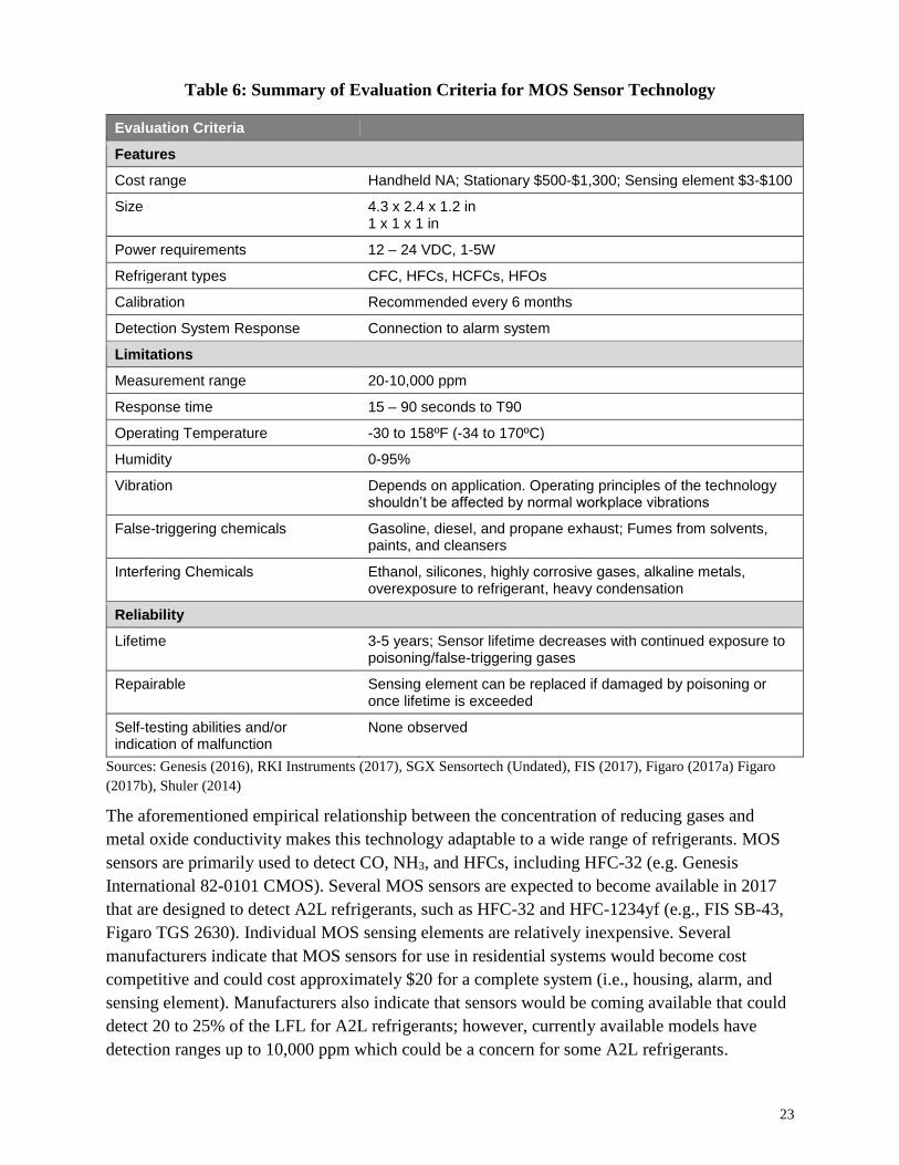
Table 6: Summary of Evaluation Criteria for MOS Sensor Technology
Evaluation Criteria
Features
Cost range Handheld NA; Stationary $500-$1,300; Sensing element $3-$100
Size 4.3 x 2.4 x 1.2 in 1 x 1 x 1 in
Power requirements 12 – 24 VDC, 1-5W
Refrigerant types CFC, HFCs, HCFCs, HFOs
Calibration Recommended every 6 months
Detection System Response Connection to alarm system
Limitations
Measurement range 20-10,000 ppm
Response time 15 – 90 seconds to T90
Operating Temperature -30 to 158ºF (-34 to 170ºC)
Humidity 0-95%
Vibration Depends on application. Operating principles of the technology shouldn’t be affected by normal workplace vibrations
False-triggering chemicals Gasoline, diesel, and propane exhaust; Fumes from solvents, paints, and cleansers
Interfering Chemicals Ethanol, silicones, highly corrosive gases, alkaline metals, overexposure to refrigerant, heavy condensation
Reliability
Lifetime 3-5 years; Sensor lifetime decreases with continued exposure to poisoning/false-triggering gases
Repairable Sensing element can be replaced if damaged by poisoning or once lifetime is exceeded
Self-testing abilities and/or indication of malfunction
None observed
Sources: Genesis (2016), RKI Instruments (2017), SGX Sensortech (Undated), FIS (2017), Figaro (2017a) Figaro
(2017b), Shuler (2014)
The aforementioned empirical relationship between the concentration of reducing gases and
metal oxide conductivity makes this technology adaptable to a wide range of refrigerants. MOS
sensors are primarily used to detect CO, NH3, and HFCs, including HFC-32 (e.g. Genesis
International 82-0101 CMOS). Several MOS sensors are expected to become available in 2017
that are designed to detect A2L refrigerants, such as HFC-32 and HFC-1234yf (e.g., FIS SB-43,
Figaro TGS 2630). Individual MOS sensing elements are relatively inexpensive. Several
manufacturers indicate that MOS sensors for use in residential systems would become cost
competitive and could cost approximately $20 for a complete system (i.e., housing, alarm, and
sensing element). Manufacturers also indicate that sensors would be coming available that could
detect 20 to 25% of the LFL for A2L refrigerants; however, currently available models have
detection ranges up to 10,000 ppm which could be a concern for some A2L refrigerants.
24
A potential area of concern for MOS sensors would be installation in environments where the
presence of gases such as exhaust from gasoline, diesel, and propane, solvents, or highly
corrosive gases could potentially cause false triggering or poisoning of the sensors, although the
typical concentrations of these gases in residential and commercial settings is variable and
difficult to quantify. This could impact residential systems in which HVACR systems and
sensors are located near a garage and could falsely trigger the alarm system and other protective
measures (e.g., turn off compressor, turn on ventilation) even though there was no refrigerant
leak. MOS sensor characteristics may also be temporarily affected by soaking or splashing with
water, heavy condensation, or salt water (Figaro 2017a). If sensors are exposed to a small
amount of interfering gases or condensate, they can recover without permanent damage
occurring; otherwise, the sensing element would need to be replaced (FiS 2017). Some sensors
are being manufactured with a filter that would prevent poisoning of the sensor from certain
interfering or poisoning gases, such as ethanol and silicones. In addition to sensitivity to a variety
of different gases, MOS sensor requirements for periodic calibration and a relatively short
lifetime (3-5 years) could also be concerns in residential applications. There was also limited
information available regarding whether self-testing capabilities are or could be incorporated into
currently available sensors.
2.4 Catalytic-type (Pellistor)
2.4.1 Overview of Technology
Similar to MOS sensors, catalytic-type (also known as pellistor) sensors are triggered by
resistance changes in the presence of flammable gases. Flammable gases are oxidized or burned
on a catalytic surface, releasing heat and increasing the electrical resistance of the circuit to
which the catalyzed sensing element is connected (Sensitron 2010). The resultant voltage
increase has a direct linear relationship to the concentration of flammable gas present. Some
systems measure the resistance of a catalytic bead directly, while others measure the voltage in a
Wheatstone bridge circuit formed with the detector (catalyzed) element and a compensator
element. Because catalytic sensors use oxidation to detect gases, oxygen must be present for the
sensor to work. In addition, some catalytic sensors are prone to be poisoned by certain
compounds, such as sulfur- phosphor-, lead-, or silicone-compounds; however, some catalytic
sensors are manufactured to be resistant to these poisons (Draeger 2009). In situations where a
high gas concentration is present, the combustion process may be incomplete which can leave a
layer of soot on the active bead and either partially or completely impair performance of the
sensor (Crowcon 2015).
Catalytic sensors are sold almost exclusively to detect HCs and NH3, but some sensors (e.g.,
NET NP-17) are reported to measure the presence of any flammable gas. These general-purpose
catalytic gas sensors are indicated to detect flammable gases from 0-100% LEL2 but only have
2 The LFL is sometimes referred to as the lower explosive limit (LEL). These limits, while similar and somewhat
interchangeable, are calculated using different methods.
25
effective linearity up to 60% LEL. The non-linearity refers to a slight deviation of the sensors’
output from the ideal input/output relationship to which the sensor is calibrated. However,
catalytic sensors are not recommended to detect fluorinated refrigerants, because the combustion
products of fluorinated gases (i.e., HF) can poison the catalytic sensor as it is simultaneously
measuring the concentration of the fluorinated refrigerant (Draeger 2017b).
2.4.2 Comparison of Evaluation Criteria
This section presents a summary of key features and evaluation criteria for catalytic-type
detectors based on the proposed A2L refrigerant sensor requirements presented in Table 2.
Table 7: Summary of Evaluation Criteria for Catalytic-type Sensor Technology
Evaluation Criteria
Features
Cost range Handheld NA; Stationary $700-$1,500; Sensing element $50-$100
Size Sensing element: 2 x 1.1 x 1 in. Stationary detector: 8.3 x 8.9 x 3.4 in. 2-3.5 lbs.
Power requirements 12 – 24 VDC, 1-10W
Refrigerant types HCs, NH3, other flammable gases
Calibration Calibrated to response rates of individual gases prior to installation; required every 3-6 months depending on environment where used
Detection System Response Connection to alarm system
Limitations
Measurement range 0-1,000 ppm, 0-100% LEL
Response time 5-10 seconds to T50, 20-30 seconds to T90
Operating Temperature -40 to 300ºF (40 to 150ºC)
Humidity 0-95%
Vibration Typically not impactful – Sensors are mounted on a single header and protected by a metal mesh enclosure and a metal or plastic external enclosure
False-triggering chemicals None
Interfering Chemicals Substances containing silicone or sulfur (e.g., hydrogen sulfide, hexamethyldisiloxane), heavy metals, halogenated hydrocarbons, overexposure of refrigerant gas; Once sensor is used, it is more susceptible to poisoning.
Reliability
Lifetime 2-5 years
Repairable Sensing element can be replaced if damaged by poisoning or once lifetime is exceeded
Self-testing abilities and/or indication of malfunction
Compensator element acts as a constant control mechanism
26
Sources: NET (2016), Draeger (2017a), Draeger (2017b)
Catalytic-type sensors are compatible with a wide range of commercially available gas detection
systems and remote flammable gas detection beads. Catalytic sensors maintain precision well,
with maximum long term drifts (i.e., sensitivity loss) of ±0.5 mV/month and maximum
temperature and humidity drifts of ±2% LEL, however they have relatively short lifetimes (i.e.,
2-5 years). There are also concerns with the sensor performing correctly when a high
concentration of gas is present and the combustion process cannot be completed. The presence of
poisoning gases is less of a concern in residential settings and could be addressed in
industrial/commercial settings through the use of poison-resistant sensors. The catalytic sensor
technology, however, is well developed, and there is a range of options in terms of cost and uses.
Ultimately, given that this technology is susceptible to poisoning from the combustion products
of fluorinated compounds, the short sensor lifetimes, and the frequent recalibration requirements,
this technology is not considered to be appropriate for use in HVACR systems containing A2L
refrigerants.
2.5 Heated Diode
2.5.1 Overview of Technology
Heated diode technology is currently well established in the handheld portable refrigerant
detector market due to its ability to quickly and effectively locate leaks of different refrigerants
without the need for recalibration for each gas. The technology is capable of identifying the
presence of halogenated compounds and several models are available that are capable of
detecting HFC-32 and HFO-1234yf. These sensors do not measure the presence of a specific
compound, but rather heat the refrigerant, thus breaking the molecules apart and measuring the
concentration of the newly created positively charged chlorine or fluorine ions (Siegel 2003).
2.5.1 Comparison of Evaluation Criteria
This section presents a summary of key features and evaluation criteria for heated diode
detectors based on the proposed A2L refrigerant sensor requirements presented in Table 2.
Because heated diode sensors are currently only used in handheld detectors, some features or
operating conditions are not known or are not applicable.

27
Table 8: Summary of Evaluation Criteria for Heated Diode Sensor Technology
Evaluation Criteria
Features
Cost range $100-$500
Size n/a (handheld system)
Power requirements Battery-operated (alkaline, Li, NiMH, AC adapter)
Refrigerant types HFCs, HFOs, and blends
Calibration Automatic or manual zeroing
Detection System Response Alarm (audio/visual)
Limitations
Measurement range 6.6oz/yr to <0.1oz/yr, High/low sensitivity range,
Response time 0.5-1 seconds (30 second warm-up time, ~9 second recovery
time)
Operating Temperature -4 to 122 °F (-20 to 50 °C)
Humidity Unknown, but can be affected by moisture
Vibration n/a
False-triggering chemicals Moisture, oils, other fluorinated refrigerants (sensor cannot
selectively detect refrigerants)
Interfering Chemicals Moisture, oils, overexposure to refrigerant gas
Reliability
Lifetime 2-3 years, up to 5 years
Repairable Sensing element and filters can be replaced
Self-testing abilities and/or
indication of malfunction
n/a
Sources: Fieldpiece (2017a), Fieldpiece (2017b), Siegel (2003), Inficon (2015a), Inficon (2015b)
Heated diode technology is currently only employed in handheld devices used by service
technicians to detect the source of refrigerant leaks. Heated diode sensors have fast response
times, but it is not clear whether sensors could detect refrigerant at the required refrigerant
concentrations. Potential concerns with heated diode technology in stationary equipment are the
relatively short lifetimes and susceptibility to the presence of moisture or oils. In addition,
because the detectors do not selectively detect a particular refrigerant, there could be concerns
with use in environments where multiple halogenated compounds are in use, though they could
be appropriate for use in areas where only one halogenated refrigerant is present. There is also
limited information available regarding whether currently available handheld sensors incorporate
any form of self-testing, such as whether the sensor has been damaged from overexposure or

28
moisture. The user would likely need to introduce the refrigerant gas to the sensor in order to
verify detection.
It is unclear whether heated diode technology is a viable option for use detecting A2L
refrigerants in stationary applications and meeting the proposed standard requirements outlined
in Table 2. Furthermore, sensor manufacturers are not aware of ongoing efforts to develop heated
diode technology for stationary refrigerant sensors (Fieldpiece 2017c).
3. Alternative Sensor Technologies
The following section identifies alternative technologies with varied uses that cannot be used in
standard refrigerant monitoring. Although the sensors could detect A2L refrigerants, these
technologies are disqualified from widespread use for several reasons.
3.1 Open Source Infrared
Open source infrared detectors are primarily used for monitoring of large areas where leaks are
most likely to concentrate along a straight line. The most common use of this technology is with
flammable gases (e.g., HCs) across pipelines in petrochemical plants. The detector can be set up
to measure concentration along the length of a pipeline, reaching up to several hundred feet.
Open source infrared sensors work by sending infrared light in a straight beam between the
source and receiver units and detecting gas anywhere along the path. The quantity of gas
intercepted by the beam is measured by the receiver. The measurement has a natural bias towards
the total size of a gas release, rather than the concentration at any one point (General Monitors
2009).
The open source IR technology does not meet the requirements of the ASHRAE, IEC, and ISO
standards, because the unit measures concentration over a certain distance, and therefore the
sensor cannot differentiate between a dense gas cloud in a small location and a dispersed gas
cloud and properly measure the LFL concentration required by safety standards.
3.2 Virtual Refrigerant Charge Sensor
Virtual refrigerant charge sensors use an algorithm that employs non-invasive measurements to
estimate refrigerant charge level for HVACR systems. The algorithm uses surface mounted
temperature measurements to estimate charge level. These sensors can be embedded within a
portable device for a technician’s use or permanently installed on units. The sensor does not
measure refrigerant that is present in the air, and cannot determine concentration; however it
could be used to check for leaks by monitoring the change in charge over time (Kim 2010).
Additional information on the response time, detection range, and operating parameters of the
sensors were not available.
29
Review of Failure Modes
The following sections present a cumulative review of the sensor technologies discussed in
Section II.2. The sensors are ranked based on the impact that common failure modes have on the
ability to detect refrigerants. Based on the failure mode analysis, and the performance of
detectors in other categories, recommendations are made for suitable sensors for A2L
refrigerants in commercial/industrial and residential applications. A reliability testing procedure
is proposed to ensure that sensor technologies are suitable for commercial/industrial and
residential applications where the user is unfamiliar with detector operation and maintenance.
4. Ranking of Key Failure Modes
Failure modes are the specific manner or way by which a failure occurs in terms of failure of the
item (part or [sub] system) function. For purposes of this analysis, a failure of the refrigerant
detector includes false-positive readings, failure to detect a positive reading, poisoning of the
system, or other damage to the sensor or its electrical components. Section I.2 identified the
conditions that cause failure modes across the evaluated sensor technologies (i.e., the sensing
element and any electrical components) including: operating conditions (e.g., humidity,
temperature, vibration), contaminants (e.g., false triggering gases, air contaminants), and
refrigerant over-exposure. Table 11 and Table 12 present a ranked matrix approach to analyze
the individual sensor failure modes based on the likelihood and severity of the failure event
occurring.
Every sensor technology is assigned a score for a failure mode based on the combined likelihood
and severity of the event occurring. The likelihood of an event occurring in the
commercial/industrial or residential sectors is scored on a scale of 1-4 with the following
categories: Unlikely, Moderately Unlikely, Moderately Likely, and Likely. The severity of the
event can affect the ability of the sensor to detect refrigerant and is scored on a scale of 1-4 with
the following categories: Low, Moderately Low, Moderately High, and High. Failure modes that
are not applicable to a given sensor technology are given a score of 0.
Table 9: Description of Severity and Likelihood Rankings for Failure Modes
Lik
eli
ho
od
Severity
Low (L) Moderately Low (ML) Moderately High (MH) High (H)
Unlikely (U) The failure mode is not expected to occur
in the lifetime of the sensor and is expected
to result in a minor loss of detection
accuracy in the sensor.
The failure mode is not expected to occur
in the lifetime of the sensor and is likely to
damage the integrity and/or detection
abilities of the sensor.
Moderately
Unlikely (MU)
Moderately
Likely (ML)
The failure mode is expected to occur at
least once in the lifetime of the sensor and
is expected to result in a minor loss of
detection accuracy in the sensor.
The failure mode is expected to occur at
least once in the lifetime of the sensor and
is likely to damage the integrity and/or
detection abilities of the sensor Likely (L)
Note: Failure modes that are not applicable or do not occur with a particular sensor technology are designated as “not
applicable (NA)”

30
In this analysis, the likelihood and severity scores are added to provide an impact score for each
failure mode, as shown in Table 10. The scores from all the failure modes of a certain technology
are summed to provide a total ranking failure ranking score for each sensor technology. The
lower the score, the smaller the impact and likelihood that failure modes have on the safe
operation of the detector.
Table 10: Failure Mode Ranking
Lik
elih
oo
d
Severity
Not Applicable
(NA)
Low
(L)
Moderately
Low (ML)
Moderately
High (MH)
High
(H)
Not Applicable
(NA) 0 - - - -
Unlikely (U) - 2 3 4 5
Moderately
Unlikely (MU) - 3 4 5 6
Moderately
Likely (ML) - 4 5 6 7
Likely (L) - 5 6 7 8
Two separate rankings are provided to facilitate sensor evaluation across both
commercial/industrial and residential applications, as the likelihood and severity of failure modes
to the sensing element or its electrical components, including sampling pumps, may be different
depending on the application (e.g. presence of false-triggering gases in an industrial setting).
These rankings are intended to be used for comparing the applicability of sensor technologies in
conjunction with the operating parameters and features (e.g. cost, size and detection range)
discussed in Section I.2.
There were certain failure modes that could not be quantified or ranked, due to a wide range of
likelihood and severity of occurrence, such as vibration, power outages, or extreme events (e.g.,
flood, fire). The likelihood and severity of vibration, for example, is highly dependent on the
type of system and setting in which the refrigerant sensor is installed and the magnitude of the
vibration.

31
Table 11: Failure Mode Ranking for Commercial/Industrial Applications
Failure Mode IR EC MOS Catalytic Heated Diode
Humidity Likelihood U
3 MU
5 U
4 U
2 L
7 Severity ML MH MH L MH
Temperature Likelihood U
3 U
3 MU
4 MU
3 U
2 Severity ML ML ML L L
False
Triggering
Gases
Likelihood NA
0
ML
6
ML
5
NA
0
ML
5 Severity NA MH ML NA ML
Poisoning or
Blocking
Gases
Likelihood ML
4
ML
6
U
2
ML
5
NA
0 Severity L MH L ML NA
Overexposure Likelihood U
2 L
6 ML
5 ML
5 ML
5 Severity L ML ML ML ML
Air
Contaminants
Likelihood U 3
U 2
MU 3
MU 3
U 2
Severity ML L L L L
Total 15 28 23 18 21
As shown in Table 11, infrared sensors have the best (i.e., lowest) ranking in the failure mode
assessment for commercial and industrial applications, as these sensors operate across a wide
range of operating conditions (i.e., humidity and temperature) and are not affected by false-
triggering gases, over-exposure, or air contaminants (due to the presence of an air filter).
Furthermore, these types of refrigerant sensors are already in use in HVACR equipment within
different commercial and industrial applications. Electrochemical cells are the most susceptible
to the effects from common failure modes in refrigerant detection, mainly due to the likelihood
of over-exposure and moderately high impacts of false-triggering gases.
32
Table 12: Failure Mode Ranking for Residential Applications
Failure Mode IR EC MOS Catalytic Heated Diode
Humidity Likelihood U
3 U
4 U
4 U
2 U
4 Severity ML MH MH L MH
Temperature Likelihood U
3 U
3 U
3 U
2 U
2 Severity ML ML ML L L
False
Triggering
Gases
Likelihood NA
0
MU
5
U
3
NA
0
MU
4 Severity NA MH ML NA ML
Poisoning or
Blocking
Gases
Likelihood MU
3
ML
6
U
2
ML
5
NA
0 Severity L MH L ML NA
Overexposure Likelihood U
2 U
3 U
3 U
2 U
3 Severity L L L L ML
Air
Contaminants
Likelihood U 3
U 2
MU 3
MU 3
U 2
Severity ML L L L L
Total 14 23 18 14 15
For residential applications, both infrared and catalytic sensors have the best (i.e., lowest)
ranking in the failure mode assessment, as shown in Table 12. Infrared sensors are anticipated to
have the same likelihood and severity of failure modes in residential applications as for
commercial and industrial applications, except in the likelihood of blocking gases. In a
residential setting, catalytic sensors have an overall lower failure ranking than for industrial and
commercial settings, because it is less likely that the sensor would come in contact with gases
that could poison the sensor. Electrochemical cells are anticipated to be the most susceptible to
the effects from common failure modes in refrigerant detection in residential settings. Heated
diode sensors are anticipated to have lower likelihood and severity of most failure modes in
residential applications than for commercial and industrial applications; however, if these sensors
are adapted for use in stationary systems, the susceptibility or likelihood to failure modes in both
applications should be reexamined.
5. Recommended Reliability Testing Procedure
As discussed in Section I.4, all available refrigerant sensor technologies are susceptible to failure
modes with varying degrees of severity and likelihood. To address these failure modes, sensors
should be tested for reliability while under stress, as well as the full range of possible operating
environments to ensure that the refrigerant detector functions according to the proposed
requirements outlined in ASHRAE, IEC and ISO standards.
33
Table 13 summarizes testing procedures to specifically address the failure modes. These
reliability testing procedures are based on numerous sources, including:
JRA 4068T Requirements of refrigerant leak detector and alarm for air conditioning and
refrigeration equipment
UL 2075 Gas and vapor detectors and sensors
All testing procedures (with the exception of temperature and humidity/condensation testing)
should be conducted between 68-77°F (20-25°C) and approximately 65% relative humidity.
Following each test, the detector should be inspected for damage and an accuracy test should be
performed. During and/or after each reliability test takes place, the sensor should be tested. The
sensor readout can be verified by either introducing a known quantity of refrigerant gas or using
a backup or handheld sensor to check the accuracy of the sensor readout.
Table 13: Recommended Reliability Testing Procedure
Failure Modes Testing Parameters
Accuracy • Detection component is exposed to test gas at specified concentration
within the detection range of the sensor.
Temperature
• Tests should be performed at the highest and lowest ambient conditions
defined in the operation manual, or each of the two conditions below:
o 120 °F, relative humidity 40 ±10%
o 32 °F, relative humidity 15 ±5%
o Oxygen concentration = 20.9 ±1%
• Expose sensor to refrigerant samples at the maximum and minimum
sensitivity levels of the sensor (or single level, if the sensor if the
sensitivity is non-adjustable), maintained at both ambient temperatures
for at least 3 hours. Measure samples before and during the test.
• For sensors intended for permanent installation in unconditioned areas,
two samples (one at maximum sensitivity and one at minimum
sensitivity) should be independently maintained at the following ambient
temperatures for 14 days:
o 150 °F, relative humidity 40 ±10%
o -40 °F, relative humidity 0%
Humidity (non-
condensing)
• High Humidity: Two detectors or sensors (one at the maximum and one
at the minimum sensitivity level) shall operate for their intended signaling
performance when exposed for 168 hours to air having a relative
humidity of 95 ±4% at a temperature of 125 ±5°F (52 ±3°C).
• Low Humidity: Two detectors or sensors (one at the maximum and one
at the minimum sensitivity level) shall operate for their intended signaling
performance when exposed for 168 hours to air having a relative
humidity of 7.5 ±0.5% at a temperature of 72 ±5°F (22 ±3°C).
34
Failure Modes Testing Parameters
Condensation
Resistance
• With the power on, the detector is placed into an isothermal chamber at
its lower limit temperature.
• Once it reaches the temperature, the detector is removed and placed
into an environment with a temperature of 25 °C or higher and 60%
relative humidity until condensation occurs.
• Repeat 36 times (if sensor is waterproof) or 1000 times
• Remove moisture and perform accuracy test
Durability Tests
• Spray the detection component with 10,000 ppm of methane gas (at a
rate of 100 mL/min) for 30 seconds, then pause for 1 minute.
• Repeat 1000 times.
• Let detector stand for 1 hour.
• Introduce refrigerant sample and examine difference between specified
concentration value and concentration at output.
Overexposure
• Expose sensing element to a step-change in gas concentration from 0-
100% by volume.
o For manually aspirated devices, connect sample inlet to a
gas concentration of 100% by volume.
• Expose sensing element to a step-change in liquid concentration from 0-
100% by volume.
• Expose sensing element to a step-change in two-phase (liquid and gas)
concentration from 0-100% by volume
Resistance to other
Gases
• Expose sensing element to 1,000 ppm concentration of ethyl alcohol for
1 minute. Confirm no signal or alarm initiation.
• After removing ethyl alcohol sample and keeping detector under test
conditions for 1 hour, expose sensing element to 500 ppm of hydrogen.
Confirm no signal or alarm initiation. Note, depending upon the
application, the user may, in addition, decide to test the effect of
additional gases than mentioned here.
Vibration
• Two sensors (at maximum and minimum sensitivity range) shall be
secured in their intended mounting position and securely fastened to a
variable speed vibration test machine having an amplitude and
frequency as follows:
o - 10 Hz to 30 Hz, with 1.0 mm total excursion and
o - 31 Hz to 150 Hz, with 2 g acceleration peak
• The sensors shall be vibrated over the specified frequency range,
displacement and acceleration for a period of 1 hour in each of the three
mutually perpendicular planes. The frequency rate of the change shall
not exceed 10 Hz/min.
Sources: JRAIA (2016a), JRAIA (2016b), UL (2013)
Additional failure modes, such as the presence of certain compounds that can either poison,
interfere, block, or falsely trigger the sensor should be noted by the sensor manufacturer so that
equipment owners are aware of installation requirements. Moreover, the user should consider
combining certain tests cited above to more realistically mimic real conditions.
This reliability testing procedure is intended to provide parameters for testing sensors against
common failure modes that could result in a failure of the detector, including false-positive
35
readings, failure to detect a positive reading, poisoning of the system, or other damage to the
sensor or its electrical components. It is anticipated that refrigerant sensors sold on the market or
incorporated into HVACR equipment are manufactured in accordance with relevant safety and
manufacturing standards (e.g., UL 2075 Standard for Gas and Vapor Detectors and Sensors and
UL 61010-1 Safety Requirements for Electrical Equipment for Measurement, Control, and
Laboratory Use) and will follow required testing procedures. Furthermore, it is anticipated that
manufacturers would provide guidance to equipment owners regarding installation parameters to
ensure that the sensor is not located in an area with conditions outside its operating limits.
Summary of Findings
Refrigerant sensor technologies are considered appropriate residential and commercial/industrial
applications for A2L refrigerant detection if they can detect the desired A2L refrigerants (e.g.
HFC-32, HFO-1234yf, HFO-1234ze, and refrigerant blends thereof) and if they can conform to
the requirements proposed in HVACR equipment safety standards set by ASHRAE, IEC, UL
and ISO. In addition, a low unit cost for the refrigerant sensor is important to the viability of
refrigerant monitoring, particularly for residential applications where costs could be passed-
down to the consumer.
The remainder of this section discusses limitations and uncertainties of the analysis and next
steps for the analysis.
6. Limitations and Uncertainties
Conducting a full evaluation of the refrigerant detection market presented several challenges.
Product literature of available sensor models were reviewed to determine the range of operating
parameters, lifetime, and cost. These models were reviewed across various manufacturers and
vendors; however conducting an exhaustive review of all sensor models across all manufacturers
was not possible. In addition, information on new sensor technologies was not readily available,
as the information is generally considered proprietary by the manufacturers. An extensive library
search of technical reports, scientific journals, and academic databases also did not identify any
new technologies or technological improvements to existing sensor technologies in the
developmental pipeline. Furthermore, based on discussions with a variety of refrigerant sensor
manufacturers, some manufacturers are actively pursuing the adaption of current sensor
technologies to detect A2L refrigerants and meet proposed requirements, while others are within
preliminary research stages.
The full range of costs for refrigerant sensors, in particular high-end robust systems, was difficult
to establish based on the variety of factors that can affect the value. Many of the detectors are
manufactured by one company and sold by a retailer with various warranties and supplementary
parts or accessories. Robust systems with multiple detection points require installation by a
trained technician. These additional costs may be included in the cost ranges presented in Section
I.2, although they are not directly tied to a particular product.
36
The scope of this report in residential and commercial/industrial A2L refrigerant detection is
different from what many of the detectors in the market are designed to monitor. Most
technologies reviewed were capable of monitoring gasses on the single-digit ppm range, while
the detection limits for A2L refrigerants is in the thousands of ppm. It is unclear to what degree
manufacturers could simplify their products to minimize cost and size.
Furthermore, many of the operating parameter data collected for the evaluation of the sensor
technologies are dependent on the specifications of individual models, in addition to the
underlying technology. For example, the operating ranges, such as humidity and temperature
limits varied significantly within sensor technologies based on the design of the model. The
summary information presented in Section I.2 provides ranges across all models reviewed and do
not necessarily represent the operating range of one particular model.
7. Summary of Findings
Based on current research of available refrigerant sensor technologies, there are a number of
promising sensor technologies that could be used for A2L refrigerant detection in residential and
commercial/industrial settings.
Infrared technology (both PIR and NDIR) are widely used in industrial and commercial settings
and satisfy many of the proposed required criteria for A2L sensors. Although systems are not
currently on the market with high enough detection ranges to measure 20 to 25% of the LFL for
certain A2L refrigerants, existing sensors would have detection ranges high enough to alarm at
lower levels (e.g., 10% of the LFL) without falsely-triggering on typical pollutants present in
residential or commercial environments. IR sensors are not anticipated to be susceptible to many
failure modes in both residential and commercial/industrial applications; however cost is likely
to be a major inhibitor to use in residential systems. Discussions with IR sensor manufacturers
indicate that it is possible that IR sensors could be adapted for use in residential systems at a
lower price point and fewer calibration requirements while meeting the proposed detection
requirements, potentially through the adaption of IR sensors currently used in portable systems
for stationary use.
MOS sensor technology also satisfies many of the proposed requirements for A2L sensors and
performs fairly well in the failure mode ranking. The primary risks associated with MOS sensors
are cross-sensitivity with multiple chemicals, including exhaust from gasoline, diesel, and
propane, solvents, and ethanol, which could be problematic in an industrial or residential
environment. MOS sensors also experience drift from over exposure to refrigerant, which is
unlikely to happen in a residential environment. Individual sensing units are inexpensive and
small, which allow them to be placed in as many locations as necessary or be integrated into
smaller appliances.
Although catalytic bead sensors are considered the least susceptible to failure modes in both
residential and commercial settings, they are not considered a viable option for detection of A2L
refrigerants because the byproducts formed during the measurement (which is conducted via
combustion) of fluorinated compounds would poison the sensor. EC sensors are anticipated to be
37
the most susceptible to the effects from common failure modes in refrigerant detection in
commercial and residential settings and, although EC sensor technology could be used to detect
fluorinated refrigerants, industry does not consider it to be practical; therefore, these sensors are
not considered viable for A2L refrigerant detection. Heated diode technology could potentially
be adapted for use detecting A2L refrigerants in stationary systems; however sensor
manufacturers were unaware of ongoing efforts to do so. Furthermore, the effects of failure
modes on heated diode systems are relatively high in commercial/industrial settings given the
sensitivity to moisture, oils, and other refrigerant gases (i.e., refrigerants used in nearby systems,
because heated diode sensors cannot selectively detect refrigerants). Although the effects of
failure modes on these handheld sensors are anticipated to be much lower in residential settings,
the rankings could be different if these sensors are adapted for stationary use.
Within the commercial/industrial sector, IR sensors are likely to be the most practical option,
assuming the detection range can be increased. These sensors are already widely used in
commercial/industrial settings and are considered to be less susceptible to potential failure modes
in commercial/industrial settings. The requirements for IR sensors regarding recalibration/re-
zeroing and other maintenance would be less of a concern in commercial/industrial settings,
because equipment and sensors are already regularly serviced and maintained by trained
technicians. MOS sensors could also be viable for use with commercial/industrial HVACR
equipment if installed in a clean environment, as MOS sensors are susceptible to poisoning or
interference from a number of gases.
In residential settings, MOS sensors are anticipated to be the most practical option, assuming the
detection range can be increased. These sensors are not susceptible to many failure modes within
residential settings considered to be less susceptible to potential failure modes in
commercial/industrial settings and are already commercially available at lower price points than
other sensors; however, the burden of annual maintenance is an issue for small systems.
Furthermore, current availability of monitoring devices with self-testing abilities for MOS
sensors is limited.
In conclusion, sensor models using IR and MOS technology currently exist that are capable of
detecting A2L refrigerants, in particular in Japan, where the use of HFC-32 is well established;
however, most sensors that are currently available or are coming available this year cannot
measure all A2L refrigerants at 20 to 25% of the LFL and there are other uncertainties regarding
whether these sensors can fully meet the proposed self-testing requirements. However, sensor
manufacturers are becoming aware of the proposed requirements in ASHRAE 15, IEC 60335-2-
40, and ISO 5149-3 for A2L refrigerant sensors and it is expected that manufacturers will focus
research and development efforts to ensure that appropriate sensors are available to meet the
updated standards, although the timeline for development is still uncertain.

38
References
Anderson, G; Hadden, D. 1999. The Gas Monitoring Handbook. Avocet Press INC.
Asada Corporation. 2017. Personal communication between ICF and Tomokazu Nagata, Asada.
March 8, 2017.
Asada Corporation. 2016. Refrigerant Leak Monitor “Mihari” corresponding JRA 4068.
Presented by Masahide Sumi at the International Symposium on New Refrigerants and
Environmental Technology in Japan.
ASHRAE. 2016a. BSR/ASHRAE Addendum d to ANSI/ASHRAE Standard 15-2013: Safety
Standard for Refrigeration Systems. First Public Review Draft. August 2016.
ASHRAE. 2016b. BSR/ASHRAE Addendum h to ANSI/ASHRAE Standard 15-2013: Safety
Standard for Refrigeration Systems. First Public Review Draft. August 2016.
ASHRAE. 2016c. ANSI/ASHRAE Standard 15-2016: Safety Standard for Refrigeration
Systems. December 2016.
ASHRAE. 2016d. ANSI/ASHRAE Standard 34-2016: Designation and Safety Classification of
Refrigerants. December 2016.
Bacharach. 2017. PGM-IR. Available online at: https://www.mybacharach.com/product-
view/pgm-ir/.
Bacharach. 2011. Multi-Zone Gas Leak Monitor HGM-MZ, AGM-MZ, CO2-MZ. Available
online at: https://www.instrumart.com/assets/Bacharach-multizone-datasheet.pdf
Baldigowski, M. September 2011. The pros and cons of electrochemical sensors. Safety and
Health Magazine. Available online at: http://www.safetyandhealthmagazine.com/articles/the-
pros-and-cons-of-electrochemical-sensors-2
California Analytics. 2017. Personal communication between ICF and Jason Midyett, California
Analytics. February 21, 2017.
Critical Environment Technologies. 2016. Self-Contained Controllers – Gas Detection
Datasheet. Available online at:
http://www.dodtec.com/site/files/843/162303/533928/762859/SCC_Product_Data_Sheet.pdf
Crowncon. 2015. Pellistor Sensors – How They Work. Available online at:
https://www.crowcon.com/blog/pellistor-sensors-how-they-work/.
Danfoss. 2016a. Portable Area Gas Monitor with Infrared Sensor for Halogen. Available online
at: http://files.danfoss.com/technicalinfo/dila/01/PGM-
IR_DKRCC.PS.S1.B1.02_520H10880.pdf
Danfoss 2016b. GD gas detection sensors, standard basic (IP30) 148H5000. Available online at:
http://products.danfoss.com/productdetail/refrigeration/electronic-controls-sensors-

39
transmitters/gd-dgs-gas-detection-sensors/gd-gas-detection-sensor-standard-basic-ip-
30/148h5000/#/
Danfoss. 2016c.GD gas detection sensors, standard basic (IP30) 148H5010. Available online at:
http://products.danfoss.com/productdetail/refrigeration/electronic-controls-sensors-
transmitters/gd-dgs-gas-detection-sensors/gd-gas-detection-sensor-standard-basic-ip-
30/148h5010/
Delphian. Undated. 770 System. Available online at:
http://www.cbrnetechindex.com/Print/3131/Delphian-Corporation/770-System
Det-tronics. 2015. PointWatchTM Infrared Hydrocarbon Gas Detector Model PIR9400. Available
online at: http://www.det-tronics.com/ProductCatalog/GasDetection/Documents/90-1074-5.2-
PIR9400.pdf
Draeger. 2017a. Draeger CatEx sensors. Available online at:
http://www.etapii.com/brochures/Draeger/Draeger%20Catalytic%20Bead%20Sensors.lit.ETA.0
315.pdf
Draeger. 2017b. Personal communication between ICF and Steve Slavutsky of Draeger, Inc.
March 9, 2017.
Draeger. 2015. Draeger PIR 7000. Available online at:
http://www.draeger.com/sites/assets/PublishingImages/Products/gds_pir_7000/global-
blueprint/pir-7000-pi-9046393-en-gb.pdf
Draeger. 2009. Explosion Protection: Gas Detection Systems. Available online at:
https://www.draeger.com/library/content/explosion_protection_br_9046262_en.pdf.
EHS Today. 2014. It Pays to be Redundant. Available online at: http://ehstoday.com/industrial-
hygiene/it-pays-be-redundant.
Enmet Gas Detection. 2014. Infrared HCFC & Ammonia (NH3) Refrigerant Sensor User
Manual. Available online at: http://www.skitternet.com/Manuals/IR-
200%20HCFC&NH3_All%20RefSensorum2.2.pdf
Fieldpiece. 2017a. Heated Diode Refrigerant Leak Detector Model: SRL8. Available online at:
http://www.fieldpiece.com/media/manuals/Opman-SRL8-web.pdf
Fieldpiece. 2017b. Premium Refrigerant Leak Detectors. Available online at:
http://site.jjstech.com/pdf/Fieldpiece/SRL2-SRL8v08.pdf
Fieldpiece. 2017c. Personal communication between ICF and Ken Brown, Fieldpiece. February
10, 2017.
Figaro. 2017a. Metal Oxide Semiconductor Type Sensors Operating Principle. Available online
at: http://www.figaro.co.jp/en/technicalinfo/principle/mos-type.html.
Figaro. 2017b. Personal communication between ICF and Yuki Fujimori, Figaro Sensors. March
1 and 3, 2017.
40
Figaro. 2016. TGS 2630 – for the detection of Refrigerant Gases.
Figaro. Undated. Operating principle – catalytic type. Available online at:
http://www.figaro.co.jp/en/technicalinfo/principle/catalytic-type.html
Fine, University College of London Department of Chemistry. 2010. Metal Oxide Semi-
Conductor Gas Sensors in Environmental Monitoring. Available online at:
http://www.mdpi.com/1424-8220/10/6/5469
FIS. 2017. Personal communication between ICF and Val Di Giovanni, FIS. February 9, 2017.
General Monitors. 2009. Safety Manual IR5000 Open Path Hydrocarbon Gas Monitoring
System. Available online at:
http://www.gmsystemsgroup.com/downloads/manuals/combustible/IR5000_SAFETY_MAN.PD
F
Genesis International, Inc. 2017. Personal communications between ICF and Ken Sampson,
Genesis International. February 8 and 10, 2017.
Genesis International, Inc. 2016. Sherlock Solid-State Sensor. Available online at:
http://www.genesis-international.com/products/sensors/CMOS_cut_sheet.pdf
Genesis International, Inc. 2014. SherlockTM Infra-red Refrgierant Gas Sensor. Available online
at: http://www.genesis-international.com/products/sensors/IR_Sensor_Cut_Sheet_NEMA3R.pdf
Honeywell Analytics. 2017. Personal conversation between ICF, Lucy Smith, and Steve
Gautieri, Honeywell. February 21, 2017.
Honeywell Analytics. 2016. Manning AirScan™ IRF9 sensor/transmitter. Available online at:
http://www.honeywellanalytics.com/~/media/honeywell-analytics/products/manning-airscan-
ir/documents/irf9_brochure_flr_07_12_2016.pdf?la=en.
Honeywell Analytics. 2014a. Infrared Refrigerant Gas Detector IR-F9 Series. March 2014.
Available online at: http://www.kele.com/Catalog/08%20Gas_Specialty_Sensors/PDFs/IR-
F9%20Series%20Catalog%20Page.pdf
Honeywell Analytics. 2014b. Electrochemical Ammonia (NH3) Leak Detector EC-FX-NH3.
June 2014. Available online at: http://www.honeywellanalytics.com/~/media/honeywell-
analytics/products/ec_fx_nh3/documents/english/ecfxnh3-manual-1998m0872-en-
rev1.pdf?la=en
Industrial Safety & Hygiene News (ISHN). 2014. How Infrared Sensors Measure LEL
Combustible Gas. Available online at: http://www.ishn.com/articles/99428-how-infrared-
sensors-measure-lel-combustible-gas
Inficon. 2015a. Compass® Refrigerant Leak Detector. Available online at:
http://products.inficon.com/en-us/Product/Detail/Compass-Refrigerant-Leak-
Detector?path=Products%2Fpg-ServiceToolsforHVAC-R

41
Inficon. 2015b. TEK-Mate® Refrigerant Leak Detector. Available online at:
http://products.inficon.com/en-us/nav-products/Product/Detail/TEK-Mate-Refrigerant-Leak-
Detector?path=Products%2Fpg-ServiceToolsforHVAC-R
International Electrotechnical Commission (IEC). 2016. Discussion between ICF and AHRTI
PMS Committee regarding potential revisions to Standard IEC 60335-2-40: Household and
similar electrical appliances – Particular requirements for electrical heat pumps, air conditioners,
and dehumidifiers (Edition 5.1, April 2016).
International Organization for Standardization (ISO). 2014a. ISO 5149-1:2014: Refrigeration
systems and heat pumps – Safety and environmental requirements.
International Organization for Standardization (ISO). 2014b. ISO 817-1:2014: Refrigerants –
Designation and safety classification.
Japan Refrigeration and Air Conditioning Industry Association (JRAIA). 2016a JRA 4068T:
2016R: Requirements of refrigerant leak detector and alarm for air conditioning and refrigeration
equipment. https://www.jraia.or.jp/pdf/JRA4068T_2016R.pdf
Japan Refrigeration and Air Conditioning Industry Association (JRAIA). 2016b. Standards of
Refrigerant Leak Detector and Alarm for Air Conditioning and Refrigeration Equipment. Koji
Yamashita. JRAIA2016KOBE-0403.
Javac. 2015. iSense, The Industry’s only 4 Gas ready Infrared Intelligent Refrigerant Leak
Detection. Available online at: http://www.javac.co.uk/wp-content/uploads/2015/03/Javac-
iSense-data-sheet-new.pdf
Kim, W; Braun, J. 2010. Evaluation of a Virtual Refrigerant Charge Sensor. International
Refrigeration and Air Conditioning Conference. Available online at:
http://docs.lib.purdue.edu/iracc/1121
McClure D., and Anderson. 1990. A Comparison of Refrigerant Constant Monitoring Leak Detectors. International
Refrigeration and Air Conditioning Conference. Paper 115. Available online at:
http://docs.lib.purdue.edu/cgi/viewcontent.cgi?article=1114&context=iracc
MSA The Safety Company. 2011. Chillgard® LS Photoacoustic Infrared Refrigerant Monitor.
Available online at:
http://s7d9.scene7.com/is/content/minesafetyappliances/Chillgard%20LS%20Bulletin%20-
%20EN
MSA The Safety Company. 2014. Photoacoustic Infrared Detection (PAIR) versus Non-
Dispersive Infrared Detection (NDIR). Available online at:
http://s7d9.scene7.com/is/content/minesafetyappliances/0700-58-
MC%20PAIR%20vs%20NDIR%20-%20EN
Nano-environmental Technology (NET). 2016. Catalytic pellistor gas sensors. Available online
at: http://www.nenvitech.com/catalytic-sensor/
RKI Instruments. 2017. SGU-8521-R32 Unit. Available online at: http://www.jjstech.com/sgu-
8521-r32-9k.html
42
Sensidyne. 2017. Gas Sensor Test-on-Demand (ToD™) Delivers Reliability – Low Maintenance.
Available online at: http://www.sensidynegasdetection.com/Support%20Library/gas-
detection/SensAlert%20Plus/Test-on-Demand%20Tech%20Sheet%20821-0204-02%20821-
0204-06.pdf
Sensidyne. 2016. Point Infrared Gas Detector for Hydrocarbon Gas Detection. Available online
at: http://www.sensidynegasdetection.com/products/industrial-point-gas-detection-
products/point-hydrocarbons-ir-gas-detector/
Sensitron. 2010. Catalytic sensors. Available online at: http://www.sensitron.it/wp-
content/uploads/2010/07/CatalyticSensors.pdf
Siegel, J. 2003. Pros and Cons of Leak Detection Methods. Available online at:
http://www.achrnews.com/articles/90932-pros-and-cons-of-leak-detection-methods
Siegel, M.W. 1990. Olfaction Metal Oxide Semiconductor Gas Sensors and Neural Networks.
Carnegie Mellon University. Available online at:
http://citeseerx.ist.psu.edu/viewdoc/download?doi=10.1.1.71.3355&rep=rep1&type=pdf
SGX Sensortech Limited. Undated, MiCS. Available online at:
https://sgx.cdistore.com/ProductDetail/MICS5524-SGX-Sensortech-Limited/333420/
Thermal Gas Systems. 2006. HaloguardTM III Multi-Point, Multi-Gas Monitor Instruction
Manual. Available online at: http://www.thermalgas.com/files/Haloguard%20III-
IR%20Product%20Manual.pdf
TQ Environmental. 2015. GD231 Single Point Infra-red Refrigerant Leak Detector. Available
online at: http://www.tqplc.com/gd231/
Trane. 1998. TruSenseTM MG Refrigerant Monitor. Available online at:
http://surplusgroup.com/literature-library/trane-rmwe-trusense-mg-refrigerant-monitor-
installation-operation-and-maintenance-1998/
Underwriters Laboratory (UL). 2013. UL 2075: Gas and Vapor Detectors and Sensors. Second
edition. March 5, 2013.
United States Army Corps of Engineering Research Laboratories (USACERL). 1996.
Halocarbon Refrigerant Detection Methods. January 1996. Available online at:
http://www.dtic.mil/dtic/tr/fulltext/u2/a304992.pdf