ahlstar process pumps
TRANSCRIPT

AHLSTAR™ Process Pumps

Sulzer Pumps –Striving to Serve You Better!
Sulzer Pumps has earned its reputa-
tion for providing advanced pumping
solutions that meet the critical de-
mands of our customers and busi-
ness partners. Attention to detail and
an insistence on quality are para-
mount to all phases of our operations.
A Reputation for Excellence
For over 135 years Sulzer Pumps has
been providing innovative pumping
solutions for a number of different
industry segments. Today we are a
leading global supplier of pumps to
these targeted markets.
Through our commitment to under-
standing the customers' process and
specific needs, we have consistently
been at the leading edge of technical
developments in providing pumping
solutions. We strive to meet your ap-
plication requirements through the use
of state-of-the-art technology and ad-
vanced research & development facil-
ities. In addition we offer the pump
industry's most extensive network of
Customer Service Centers to support
and service our products.
Through having our own foundries,
we are able to ensure optimum pump
material selection for each particular
application. Our 14 manufacturing
plants are strategically located
throughout the world, and our produc-
tion processes are ISO 9002 and ISO
14001 certified. Each and every pump
is rigorously tested before shipment,
and regardless of where in the world
our pumps are made, the commit-
ment to quality is unrelenting.

Lifetime Service Solutions for theAHLSTAR™ PumpHigh pumping performance comes as
a result of the availability, reliability
and the quality of the right pump.
Genuine spare parts and proper main-
tenance ensure the high performance
of AHLSTAR™ process pumps in com-
plex production operations.
We support our customers with an
extensive range of pumping services,
from spare parts to remote monitor-
ing.
Additionally we offer various types of
service agreements in which spare
parts and service solutions can be
combined.
PumpsOnlineCustomers can benefit from our new
eBusiness solution, Pumps Online.
This enables instant online access to
product documentation, electronic or-
dering of spare parts and installed
pump base at the mill.
Spare Part SolutionsWe offer an exchange unit service
and newly developed service kits for
all AHLSTAR™ process pumps. This
enables fast and easy servicing and
reduces downtime.
Service SolutionsTo maintain and improve the high
performance of AHLSTAR™ process
pumps, customers can select from a
wide range of available service solu-
tions. All service work is carried out
by qualified, experienced technicians
using state-of-the-art equipment.
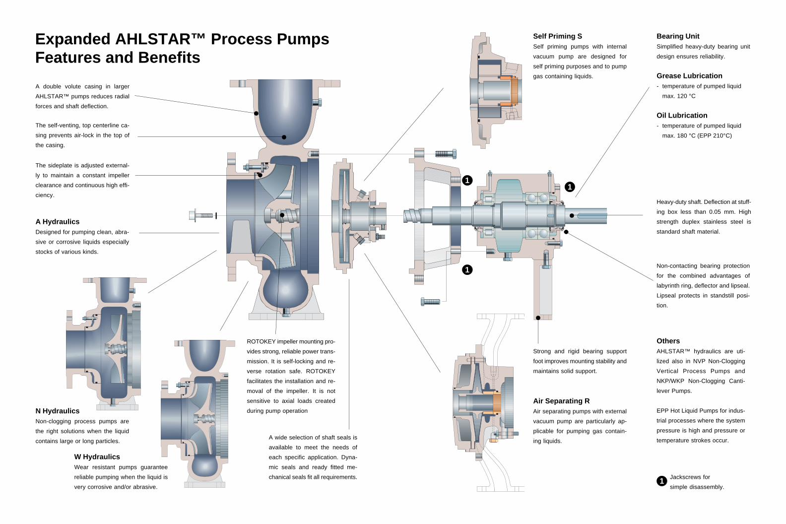
Self Priming SSelf priming pumps with internal
vacuum pump are designed for
self priming purposes and to pump
gas containing liquids.
Air Separating RAir separating pumps with external
vacuum pump are particularly ap-
plicable for pumping gas contain-
ing liquids.
Bearing UnitSimplified heavy-duty bearing unit
design ensures reliability.
Grease Lubrication- temperature of pumped liquid
max. 120 °C
Oil Lubrication- temperature of pumped liquid
max. 180 °C (EPP 210°C)
Non-contacting bearing protection
for the combined advantages of
labyrinth ring, deflector and lipseal.
Lipseal protects in standstill posi-
tion.
Heavy-duty shaft. Deflection at stuff-
ing box less than 0.05 mm. High
strength duplex stainless steel is
standard shaft material.
Strong and rigid bearing support
foot improves mounting stability and
maintains solid support.
1
1
1
1
Jackscrews for
simple disassembly.1
OthersAHLSTAR™ hydraulics are uti-
lized also in NVP Non-Clogging
Vertical Process Pumps and
NKP/WKP Non-Clogging Canti-
lever Pumps.
EPP Hot Liquid Pumps for indus-
trial processes where the system
pressure is high and pressure or
temperature strokes occur.
Expanded AHLSTAR™ Process PumpsFeatures and Benefits
N HydraulicsNon-clogging process pumps are
the right solutions when the liquid
contains large or long particles.
W HydraulicsWear resistant pumps guarantee
reliable pumping when the liquid is
very corrosive and/or abrasive.
A double volute casing in larger
AHLSTAR™ pumps reduces radial
forces and shaft deflection.
The self-venting, top centerline ca-
sing prevents air-lock in the top of
the casing.
The sideplate is adjusted external-
ly to maintain a constant impeller
clearance and continuous high effi-
ciency.
ROTOKEY impeller mounting pro-
vides strong, reliable power trans-
mission. It is self-locking and re-
verse rotation safe. ROTOKEY
facilitates the installation and re-
moval of the impeller. It is not
sensitive to axial loads created
during pump operation
A HydraulicsDesigned for pumping clean, abra-
sive or corrosive liquids especially
stocks of various kinds.
A wide selection of shaft seals is
available to meet the needs of
each specific application. Dyna-
mic seals and ready fitted me-
chanical seals fit all requirements.

APP
Hydraulic Design
The AHLSTAR™ product line offers a
wide range of hydraulic sizes to guar-
antee minimum power consumption.
Pump hydraulics, casings and impel-
lers are designed to optimize fluid
handling capabilities. Stocks are
pumped like water. Particles in slud-
ges do not accumulate in the pump,
or slurries are effectively channelled
so as not to cause wear.
The impeller hub design ensures a
smooth flow and helps to avoid spin-
ning and plugging.
The reverse sides of same size im-
pellers on the APP, NPP and WPP
pumps are of equal dimensions. It is
possible, therefore, to use the same
casing covers for all impellers. This
reduces the number of spare parts
required.
The back vanes of the impeller keep
the area between the impeller and
the casing cover clean, and reduce
the axial load on the bearings.
Balance holes in the impeller are used
to stabilize the pressure in the seal
chamber. The balance holes can be
plugged to optimize the shaft seal
environment, should the application
demand it.
Standardization
AHLSTAR™Interchangeabilityof main parts
Volutecasing
Impeller Casingcover
Adapter Bearingunit
ARP
ASP
EPP
NPP
NRP
NSP
WPP
WRP
WSP
All AHLSTAR™ pumps have the same
basic design using the same compo-
nents.
• 246 pumps
• 80 casing covers
• 6 common bearing units
• 6 common shaft seal sizes
• common sealing water equipment
• common coupling and coupling guard
• common baseplates
Common parts
shown in columns.
_ _ P
P metric dimensioning
P basic horizontal pump,
S self priming and R air
separating construction
A, N, W and E indicate the
basic hydraulics

Wear Resistant OpenImpelleris suitable for liquids with bigger solid
particles and long fibers, abrasive liq-
uids or stock up to 8% consistency.
WPP
WRP
WSP
WPP
WRP
WSP
Low Pulse Impelleris designed and manufactured to mi-
nimize pressure pulsations.
APP
Special Open Impelleris suitable for liquids containing big-
ger solid particles and long fibers,
abrasive liquids or stock up to 8 %
consistency.
APP
ARP
ASP
Open Impelleris designed for liquids containing so-
lid particles, abrasive liquids or stock
up to 8 % consistency.
APP
ARP
ASP
EPP
Vortex Impelleris suitable for liquids containing big or
long solid particles or abrasive li-
quids.
NPP
NRP
NSP
WPP
WRP
WSP
Closed Impelleris used for pumping clean liquids or
liquids containing some impurities.
APP
EPP
Non-clogging ClosedImpelleris used for sludges or slurries con-
taining big solid particles.
NPP
NRP
NSP
Wear Resistant ClosedImpelleris used for pumping both erosive and
corrosive liquids or slurries contain-
ing solid particles.
An Impeller Tailored to Each Liquid

Gas Handling Systems
The Effect of Weakly BoundGas Content in theAHLSTAR™ Gas RemovalPump
• Pump operation is stable.
• For weakly bound gases, the
absolute maximum value is 40 %.
For strongly bound gases it is up to
70%.
The Effect of Gas Content inConventional CentrifugalPumps
• Almost all impeller types can
operate with a gas content below
4%. However, the capacity and
head will be reduced.
• At gas content level above 4% , the
duty point remains approximately
10 ... 100% from BEP (Best
Efficiency Point).
Pumping is unstable since the duty
point varies heavily and excessive
over-dimensioning of the pump
becomes necessary.
AHLSTAR™ Gas RemovalPumps for VariousApplicationsThe patented AHLSTAR ™ Self Prim-
ing gas removal pumps are designed
to pump liquids containing gas, and
for use where the inlet pipe is empty.
These are situations where conven-
tional centrifugal pumps fail.
With standard centrifugal pumps, gas
bubbles formed in the impeller eye
impair pumping. With the AHLSTAR™
pump, these gas bubbles are removed
by an internal or external vacuum
pump, or through sufficient inlet pres-
sure. By removing the gas bubbles
form the impeller, the operation of the
pump system is stabilized and effi-
ciency is greatly increased.
Conventional pump has unstable
operation with gas content 0...4%
AHLSTAR™ Gas Removal Pump
has stable operation with gas
content 0...40%.
Self priming application. Gas containing liquid pumping. Water separator application.
HEAD
CAPACITY
4%3% 2% 1%
0%
HEAD
CAPACITY
30%
40%
10%20%
BEP
0%

Mechanical SealsVarious mechanical seal configura-
tions are available. For difficult appli-
cations “ready-fitted” seals are espe-
cially recommended. For extremely
corrosive applications, a ready-fitted
seal can be selected with the same
exact construction material as the
pump casing itself.
Gland PackingsA gland packing with external flush-
ing prevents the pumped liquid from
precipitating into the sealing housing.
The flushing liquid is mixed with the
pumped liquid. Alternatively the ex-
ternal flushing has an outlet connec-
tion.
Dynamic SealDynamic Seal is specially designed
for fibrous liquids such as paper stock
and other difficult liquids. The Dyna-
mic Seal requires no external sealing
water. It is essentially maintenance-
free and offers outstanding reliability.
Shaft Sealing
The well proven and highly successful Dynamic Seal has been given a new
generation of additional properties. With the latest construction, we are able to
enlarge its operational limits, and low or occasionally high liquid level pump
suction and even light vacuums, can now be handled. This new development
permits pumping liquid temperatures in excess of boiling point.
New Options for the Dynamic Seal

Standard Material Combinations
Materials
Duplex SS ASTM A890 Grade 3A 41 0.06 24.0-27.0 4.0-6.0 1.75-2.50 - 0.15-0.25
ASTM A890 Grade 1B 4L 0.04 24.5-26.5 4.75-6.00 1.75-2.25 2.75-3.25 -
ASTM A890 Grade 5A 4T 0.03 24.0-26.0 6.0-8.0 4.0-5.0 - 0.10-0.30
Austenitic SS ASTM A743 Grade CG-3M 4G 0.03 18.0-21.0 9.0-13.0 3.0-4.0 - -
ASTM A743 Grade CN-7M 43 0.07 19.0-22.0 27.5-30.5 2.0-3.0 3.0-4.0 -
AVESTA 654 SMO1) 4U 0.025 23.0-25.0 21.0-23.0 7.1-7.5 0.3-0.7 0.45-0.55
Martensitic SS ASTM A747 Grade CB7Cu-2 4E 0.07 14.0-15.5 4.5-5.5 - 2.5-3.2 -
Gasket material Klinger SIL C-4430 83 Used in temperature range -40...+160 °C and pH 2-12
PTFE/Glass 84 Used in temperature range -190...+240 °C and pH 0-14
O-ring material EPDM 92 Used in temperature range -50...+150 °C
FKM 96 Used in temperature range -20...+210 °C
Other corrosion resistant cast steels available on special request.1) AVESTA 654SMO is a trademark owned by AVESTA Sheffield which has granted Sulzer Pumps licence to produce this material.
*) For W-construction
Corrosion Resistant Thinking
To ensure maximum reliability against
corrosion we offer material selection
options from our own steel foundries.
• All parts in contact with the pumped
liquid can be produced from the
same construction material as the
pump casing.
Materials available for this option
are 41, 4L, 4T, 4G, 43, 4U and 4J
• All stainless steel structure for ex-
tremely corrosive situations.
All parts including the adapter and
bearing unit are made of stainless
steel.
• Additionally, stainless steel can be
selected for the bearing unit
auxiliary equipment to give longer
operating life in corrosive
environments.
Stainless Steel Design Nominal Chemical Composition %
C max. Cr Ni Mo Cu N
Nickel Alloy A494CW-6M 4J 0.07 17.0-20.0 balance 17.0-20.0 - -
Other Design C max. Cr Ni Mo Cu N
Cast Iron ASTM A48 CL 35 B 53 3.1-3.4 - - - 0.5-1.0 1.5-2.1
Chromium Iron*) A532 IIIA 5B 2.0-3.3 23.0-30.0 2.5 max. 3.0 max. 1.2 max. 1.5 max.
Cast Iron Design C Cr Ni Mo Cu Si
Material alternatives for other parts
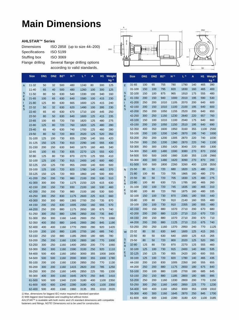
AHLSTAR™ Series
Dimensions ISO 2858 (up to size 44–200)Specifications ISO 5199
Stuffing box ISO 3069Flange drilling Several flange drilling options
according to valid standards.
Size DN1 DN2 B21) H 1) L 1) A H1 Weightkg 2)
Main Dimensions
Size DN1 DN2 B21) H 1) L 1) A H1 Weightkg 2)
E
SERIES
A
SERIES
11-32 50 32 500 480 1240 80 300 125
11-40 65 40 500 480 1260 100 300 125
11-50 80 50 630 540 1330 100 340 160
21-65 100 65 630 640 1580 100 415 230
21-80 125 80 630 665 1600 125 415 240
22-32 50 32 630 620 1490 100 395 230
22-40 65 40 630 670 1710 100 445 250
22-50 80 50 630 640 1600 125 415 235
22-65 100 65 720 730 1820 125 480 275
22-80 125 80 720 760 1820 125 480 280
23-40 65 40 630 740 1700 125 460 280
23-50 80 50 720 800 2020 125 520 350
31-100 125 100 730 835 2290 140 555 420
31-125 150 125 730 910 2290 140 555 430
31-150 200 150 630 840 1670 160 465 340
32-65 100 65 730 835 2270 125 555 420
32-80 125 80 730 870 2270 125 555 410
32-100 125 100 730 915 2400 140 600 480
32-125 150 125 730 955 2400 140 600 500
33-100 125 100 720 820 1780 140 465 370
33-125 150 125 720 900 1860 140 500 400
41-200 250 200 730 980 2100 200 530 510
41-300 300 300 730 1175 2150 225 615 630
42-150 200 150 730 930 2100 160 530 460
42-200 250 200 730 980 2100 180 530 500
43-250 300 250 830 1175 2600 225 615 660
43-300 350 300 880 1365 2700 250 735 870
44-150 200 150 830 1005 2350 160 555 570
44-200 250 200 880 1175 2650 180 675 740
51-250 300 250 880 1295 2850 200 735 840
51-300 350 300 1160 1440 2900 250 770 1060
52-350 400 350 880 1645 2900 280 845 1190
52-400 400 400 1160 1770 2900 280 920 1420
53-100 200 100 880 1185 2700 180 685 740
53-150 250 150 880 1185 2800 180 685 780
53-200 250 200 1160 1330 2800 180 770 1000
53-250 300 250 1160 1400 2850 200 770 1060
53-300 350 300 1160 1590 3100 250 920 1110
54-400 500 400 1160 1850 3000 355 1000 1600
54-500 500 500 1160 2000 3000 355 1000 1780
55-100 200 100 1160 1330 2850 250 770 1130
55-200 300 200 1160 1415 2820 200 785 1250
55-250 300 250 1160 1495 2850 225 785 1330
55-300 400 300 1160 1645 2870 250 845 1410
61-500 500 500 1340 2100 3180 400 1100 2350
61-600 600 600 1340 2280 3180 420 1100 2350
62-400 500 400 1340 1960 3135 355 1010 2020
1) Max. dimensions for biggest IEC-motor required in standard operation2) With biggest steel baseplate and coupling but without motor.AHLSTAR™ is available with both metric and US standard dimensions with compatiblefasteners and fittings. NOTE! Dimensions not to be used for construction.
31-65 100 65 755 780 1790 140 465 390
31-100 150 100 795 820 1830 160 465 400
32-100 150 100 875 965 1910 175 555 480
41-150 200 150 940 1000 2010 195 590 530
41-200 250 200 1010 1105 2070 200 640 600
42-150 200 150 1010 1100 2100 195 640 600
42-200 250 200 1050 1155 2520 200 640 650
42-250 300 250 1150 1230 2640 220 657 760
43-100 150 100 1010 1100 2040 175 640 660
43-150 200 150 1050 1150 2510 195 640 690
52-350 400 350 1600 1950 3160 355 1100 2560
53-100 200 100 1200 1240 2870 195 740 1000
53-200 250 200 1200 1305 2870 220 740 1030
53-250 300 250 1200 1360 2870 220 740 1100
53-300 350 300 1350 1420 3040 220 800 1300
54-300 350 400 1480 1590 3080 270 870 1550
54-500 500 500 1600 1980 3180 355 1100 2960
55-300 400 300 1480 1620 3090 270 870 200
61-500 500 500 1800 2260 3260 400 1200 3550
N
SERIES
21-50 80 50 720 680 1820 125 480 260
21-80 100 80 720 705 1865 160 480 270
22-50 80 50 720 705 1830 125 480 275
22-80 100 80 630 715 1785 160 465 260
31-100 150 100 720 745 1835 180 465 310
32-80 100 80 720 760 1875 160 480 335
32-100 150 100 730 870 2365 180 555 440
33-80 100 80 730 910 2140 160 555 480
33-100 150 100 730 910 2355 180 555 480
42-150 200 150 880 1070 2710 200 670 680
42-200 200 200 880 1120 2710 210 670 720
44-150 200 150 880 1070 2710 200 670 710
44-200 200 200 880 1125 2710 210 675 740
53-250 250 250 1160 1370 2950 240 770 1125
W
SERIES
22-32 80 50 630 640 1600 125 415 265
22-50 80 50 630 640 1600 125 415 265
23-50 80 50 720 800 2020 125 520 390
32-80 125 80 730 870 2270 125 555 460
32-100 125 100 730 915 2400 140 600 535
32-125 150 125 730 955 2420 160 600 555
33-100 125 100 720 820 1780 140 465 435
44-150 200 150 830 1005 2350 160 555 655
44-200 250 200 880 1175 2650 180 675 840
53-100 200 100 880 1185 2700 180 685 845
53-150 250 150 880 1185 2800 180 685 895
53-200 250 200 1160 1330 2800 200 770 1150
53-250 300 250 1160 1400 2850 225 770 1230
54-400 500 400 1160 1850 3000 355 1000 1910
55-300 400 300 1160 1645 2870 250 845 1700
61-600 600 600 1340 2280 3180 420 1100 3185

Foundation Screws
A smaller pump and motor can be
installed with adjustable support feet.
WeldedGrouted
Design Featuresand Installation Advantage
Back pull–out design facilitates fast
and easy access when servicing.
RIGBASE baseplates are steel or con-
crete with 3–point fastening. Distor-
tion-free and easy to install.
EPP centerline mounted.
Removable adjusting screws permit
fast and simple alignment of the
coupling.
Riser blocks allow the installation of
the next frame size of motor.
Safety coupling-guard is designed
according to stringent safety
regulations.
Flexible coupling with
spacer for quick service.
Various options are available for paint-
ing the pump.
Grinding of the pump interior and
special cleaning offered for specific
applications where surface quality or
cleanliness is essential.

Sealing Water Equipment
The concept for sealing water equip-
ment meets all the requirements de-
manded by the pumped liquid or the
shaft seal. All general pumping solu-
tions can be covered by just four
different options. Special materials to
take into account corrosive environ-
ments ensure reliable operation in
extreme circumstances.
Non Pressurized
Fluid in/out
PressurizedFluid in
Flowing PressurizedFluid in/out
A
FI
A
FI
API
FI
API
FI
Non Flowing Pressurized
Fluid in (out)
Steel baseplate
A steel baseplate for pump and motor
grouted at site. A short baseplate is
also available.
Concrete baseplate
The concrete baseplate can be mount-
ed on rubber sheeting, various mount-
ing beams, vibration dampers, etc.
Baseplates
Belt Drive
Belt drive construction is also avail-
able.
Wide Hydraulic Coverage
A PerformanceHead up to 160 m.
Temperature max. 180 °C.
Capacity up to 2000 l/s.
Operating frequencies 50 or 60 Hz.
Pressure up to 1.6 MPa,
depending on material and size.
Head H (m)
100
150
200
80
60
20
40
108
6
4
2100 200 400 6008001000 2000
Capacity Q (l/s)
806040201086421
E PerformanceHead up to 140 m.
Temperature max. 210 °C.
Capacity up to 1700 l/s.
Operating frequencies 50 or 60 Hz.
Pressure up to 2.5 MPa.
Head H (m)
100
150
200
80
60
20
40
108
6
4
2
100 200 400 600 8001000 2000
Capacity Q (l/s)
80604020108642

W PerformanceHead up to 110 m.
Temperature max. 180 °C.
Capacity up to 2000 l/s.
Operating frequencies 50 or 60 Hz.
Pressure up to 1.6 MPa,
depending on material and size.
N PerformanceHead up to 90 m.
Temperature max. 180 °C.
Capacity up to 550 l/s.
Operating frequencies 50 or 60 Hz.
Pressure up to 1.6 MPa,
depending on material and size.
Head H (m)
100
150
200
80
60
20
40
108
6
4
2
11
100 200 400 6008001000 2000
Capacity Q (l/s)
80604020106 862

E00545 en 1.2002 (7000), Copyright © Sulzer Pumps Finland Oy
This brochure is a general presentation. It does not provide any warranty or guarantee of any kind. Please, contact us for a description of the warranties and guarantees offered with ourproducts. Directions for use and safety will be given separately. All information herein is subject to change without notice.
Check our worldwide offices atwww.sulzerpumps.com