agriculture commandsandlogs referencemanual · 2020-05-01 ·...
TRANSCRIPT

AgricultureCommands and LogsReference Manual
Agriculture Comands and Logs Reference Manual v7C June 2020

Agriculture Comands and Logs Reference Manual v7C 2
Agriculture Comands and Logs Reference ManualPublication Number: OM-20000183
Revision Level: v7C
Revision Date: June 2020
Firmware Versions:
l 7.06.03 / OA7CR0603RN0000
Proprietary NoticeInformation in this document is subject to change without notice and does not represent a commitment on thepart of NovAtel Inc. The information contained within this manual is believed to be true and correct at the time ofpublication.
NovAtel, ALIGN, GLIDE, GrafNav/GrafNet, Inertial Explorer, NovAtel CORRECT, OEM7, PwrPak7, RELAY,SPAN, STEADYLINE, VEXXIS andWaypoint are registered trademarks of NovAtel Inc.
NovAtel Connect, OEM719, OEM729, OEM7500, OEM7600, OEM7700, OEM7720, SMART7, SMART2,RELAY7 and RTK ASSIST are trademarks of NovAtel Inc.
All other brand names are trademarks of their respective holders.
© Copyright 2020 NovAtel Inc. All rights reserved. Unpublished rights reserved under International copyrightlaws.

Agriculture Comands and Logs Reference Manual v7C 3
Table of Contents
Figures
Tables
Customer Support
Foreword
Chapter 1 Messages1.1 ASCII 271.2 Abbreviated ASCII 291.3 Binary 291.4 Description of ASCII and Binary Logs with Short Headers 401.5 Message Responses 41
1.5.1 Abbreviated ASCII Response 411.5.2 ASCII Response 411.5.3 Binary Response 41
1.6 GLONASS Slot and Frequency Numbers 431.6.1 PRN Numbers 44
1.7 GPS Reference Time Status 441.8 Message Time Stamps 451.9 Decoding of the GPS ReferenceWeek Number 451.10 32-Bit CRC 46
Chapter 2 Agriculture GNSS Commands2.1 Command Formats 49
2.1.1 Optional Parameters 492.2 Command Settings 492.3 CommandDefaults 502.4 ALIGNAUTOMATION 512.5 ASSIGN 532.6 ASSIGNALL 562.7 ASSIGNLBANDBEAM 582.8 AUTH 602.9 AUTOSURVEY 632.10 BASEANTENNAPCO 652.11 BASEANTENNAPCV 672.12 BASEANTENNATYPE 682.13 BDSECUTOFF 792.14 BESTVELTYPE 802.15 BLUETOOTHCONTROL 812.16 CANCONFIG 82

Agriculture Comands and Logs Reference Manual v7C 4
2.17 CCOMCONFIG 842.18 CLOCKCALIBRATE 862.19 COMCONTROL 882.20 CONFIGCODE 912.21 DATUM 932.22 DATUMTRANSFORMATION 952.23 DGPSTXID 982.24 DNSCONFIG 992.25 DYNAMICS 1002.26 ECHO 1022.27 ECUTOFF 1052.28 ELEVATIONCUTOFF 1072.29 ETHCONFIG 1092.30 EVENTINCONTROL 1112.31 EVENTOUTCONTROL 1132.32 FIX 1152.33 FRESET 1182.34 GALECUTOFF 1212.35 GENERATEALIGNCORRECTIONS 1222.36 GENERATEDIFFCORRECTIONS 1232.37 GENERATERTKCORRECTIONS 1242.38 GEODETICDATUM 1262.39 GGAQUALITY 1282.40 GLIDEINITIALIZATIONPERIOD 1302.41 GLOECUTOFF 1312.42 HDTOUTTHRESHOLD 1322.43 HEADINGOFFSET 1332.44 ICOMCONFIG 1342.45 INTERFACEMODE 136
2.45.1 SPAN Systems 1362.46 IPCONFIG 1412.47 IPSERVICE 1422.48 ITBANDPASSCONFIG 1442.49 ITDETECTCONFIG 1452.50 ITFRONTENDMODE 1462.51 ITPROGFILTCONFIG 1482.52 ITSPECTRALANALYSIS 1502.53 J1939CONFIG 1542.54 LOCKOUT 1562.55 LOCKOUTSYSTEM 1572.56 LOG 158
2.56.1 Binary 1592.56.2 ASCII 162
2.57 LOGIN 163

Agriculture Comands and Logs Reference Manual v7C 5
2.58 LOGOUT 1652.59 LUA 1662.60 MAGVAR 1682.61 MODEL 1712.62 MOVINGBASESTATION 1722.63 NAVICECUTOFF 1742.64 NMEAFORMAT 1752.65 NMEATALKER 1782.66 NMEAVERSION 1802.67 NTRIPCONFIG 1812.68 NTRIPSOURCETABLE 1832.69 NVMRESTORE 1842.70 NVMUSERDATA 1852.71 OUTPUTDATUM 1862.72 PDPFILTER 188
2.72.1 GLIDE Position Filter 1882.73 PDPMODE 1902.74 $PMDT 1912.75 POSAVE 1932.76 POSTIMEOUT 1952.77 PPPBASICCONVERGEDCRITERIA 1962.78 PPPCONVERGEDCRITERIA 1972.79 PPPDYNAMICS 1982.80 PPPRESET 1992.81 PPPSEED 2002.82 PPPSOURCE 2022.83 PPPTIMEOUT 2032.84 PPSCONTROL 2042.85 PSRDIFFSOURCE 2062.86 PSRDIFFSOURCETIMEOUT 2082.87 PSRDIFFTIMEOUT 2092.88 QZSSECUTOFF 2102.89 RADARCONFIG 2112.90 REFERENCESTATIONTIMEOUT 2132.91 RESET 2142.92 RTKASSIST 2152.93 RTKASSISTTIMEOUT 2162.94 RTKDYNAMICS 2172.95 RTKINTEGERCRITERIA 2182.96 RTKNETWORK 2192.97 RTKPORTMODE 2212.98 RTKRESET 2232.99 RTKSOURCE 2242.100 RTKSOURCETIMEOUT 226

Agriculture Comands and Logs Reference Manual v7C 6
2.101 RTKSVENTRIES 2272.102 RTKTIMEOUT 2282.103 SATEL4CONFIG 2292.104 SATEL9CONFIG 2332.105 SATEL9CONFIGL 2352.106 SATEL9CONFIGN 2372.107 SATELCONTROL 2392.108 SATELDETECT 2402.109 SATELSTARTUPDETECT 2412.110 SAVECONFIG 2422.111 SAVEETHERNETDATA 2432.112 SBASCONTROL 2452.113 SBASECUTOFF 2472.114 SBASTIMEOUT 2482.115 SELECTCHANCONFIG 2492.116 SEND 2532.117 SERIALCONFIG 2552.118 SERIALPROTOCOL 2582.119 SETADMINPASSWORD 2602.120 SETAPPROXPOS 2612.121 SETAPPROXTIME 2622.122 SETBESTPOSCRITERIA 2642.123 SETIONOTYPE 2652.124 SETROVERID 2662.125 SETUTCLEAPSECONDS 2672.126 SOFTLOADCOMMIT 2682.127 SOFTLOADDATA 2692.128 SOFTLOADRESET 2702.129 SOFTLOADSETUP 2712.130 SOFTLOADSREC 2732.131 STEADYLINE 2742.132 STEADYLINEDIFFERENTIALTIMEOUT 2762.133 SURVEYPOSITION 2772.134 TECTONICSCOMPENSATIONSOURCE 2792.135 TERRASTARAUTOCHANCONFIG 2802.136 THISANTENNAPCO 2812.137 THISANTENNAPCV 2822.138 THISANTENNATYPE 2832.139 TILTCOMPENSATIONCONTROL 2842.140 TILTFILTER 2852.141 TILTZERO 2862.142 TRACKSV 2872.143 TUNNELESCAPE 2892.144 UALCONTROL 291

Agriculture Comands and Logs Reference Manual v7C 7
2.145 UNASSIGN 2932.146 UNASSIGNALL 2952.147 UNDULATION 2962.148 UNLOCKOUT 2982.149 UNLOCKOUTALL 2992.150 UNLOCKOUTSYSTEM 3002.151 UNLOG 301
2.151.1 Binary 3012.151.2 ASCII 302
2.152 UNLOGALL 3032.153 USERDATUM 3042.154 USEREXPDATUM 3062.155 USERI2CREAD 3092.156 USERI2CWRITE 3112.157 WIFIALIGNAUTOMATION 3132.158 WIFIAPCHANNEL 3152.159 WIFIAPIPCONFIG 3162.160 WIFIAPPASSKEY 3172.161 WIFIAPSSID 3182.162 WIFIMODE 3192.163 WIFINETCONFIG 320
Chapter 3 Logs3.1 Log Types 322
3.1.1 Log Type Examples 3223.2 ALIGNBSLNENU 3243.3 ALIGNBSLNXYZ 3263.4 ALIGNDOP 3283.5 ALMANAC 3293.6 AUTHCODES 3313.7 AVEPOS 3333.8 BDSALMANAC 3353.9 BDSCLOCK 3373.10 BDSEPHEMERIS 3393.11 BDSIONO 3413.12 BDSRAWNAVSUBFRAME 3423.13 BESTDATUMINFO 3433.14 BESTGNSSDATUMINFO 3453.15 BESTPOS 3463.16 BESTSATS 3543.17 BESTUTM 3583.18 BESTVEL 3603.19 BESTXYZ 3633.20 BSLNXYZ 366

Agriculture Comands and Logs Reference Manual v7C 8
3.21 CHANCONFIGLIST 3683.22 CLOCKMODEL 3723.23 CLOCKSTEERING 3743.24 DATUMTRANSFORMATIONS 3773.25 ETHSTATUS 3793.26 GALALMANAC 3803.27 GALCLOCK 3823.28 GALCNAVRAWPAGE 3843.29 GALFNAVEPHEMERIS 3853.30 GALFNAVRAWPAGE 3873.31 GALINAVEPHEMERIS 3883.32 GALINAVRAWWORD 3913.33 GALIONO 3933.34 GEODETICDATUMS 3943.35 GLMLA 3963.36 GLOALMANAC 3993.37 GLOCLOCK 4023.38 GLOEPHEMERIS 4043.39 GLORAWALM 4083.40 GLORAWEPHEM 4103.41 GLORAWFRAME 4123.42 GLORAWSTRING 4143.43 GPALM 4153.44 GPGGA 4173.45 GPGGALONG 4203.46 GPGLL 4223.47 GPGRS 4243.48 GPGSA 4263.49 GPGST 4283.50 GPGSV 4303.51 GPHDT 4323.52 GPRMC 4333.53 GPSEPHEM 4353.54 GPVTG 4393.55 GPZDA 4413.56 HEADING2 4423.57 HEADINGEXT 4453.58 HEADINGEXT2 4463.59 HEADINGRATE 4473.60 HEADINGSATS 4493.61 HWMONITOR 4513.62 IONUTC 4543.63 IPSTATS 4563.64 IPSTATUS 457
Agriculture Comands and Logs Reference Manual v7C 9
3.65 ITBANDPASSBANK 4593.66 ITDETECTSTATUS 4613.67 ITFILTTABLE 4633.68 ITPROGFILTBANK 4673.69 ITPSDFINAL 4693.70 J1939STATUS 4723.71 LBANDBEAMTABLE 4743.72 LBANDTRACKSTAT 4763.73 LOGLIST 479
3.73.1 Binary 4793.73.2 ASCII 480
3.74 LUAFILELIST 4823.75 LUAFILESYSTEMSTATUS 4833.76 LUAOUTPUT 4843.77 LUASTATUS 4853.78 MARKPOS, MARK2POS, MARK3POS andMARK4POS 4863.79 MARK1TIME, MARK2TIME, MARK3TIME andMARK4TIME 4893.80 MASTERPOS 4913.81 MATCHEDPOS 4933.82 MATCHEDSATS 4963.83 MATCHEDXYZ 4983.84 MODELFEATURES 5003.85 NAVICALMANAC 5033.86 NAVICEPHEMERIS 5053.87 NAVICIONO 5083.88 NAVICRAWSUBFRAME 5103.89 NAVICSYSCLOCK 5113.90 NMEA Standard Logs 5133.91 NOVATELXOBS 5153.92 NOVATELXREF 5163.93 OCEANIXINFO 5173.94 OCEANIXSTATUS 5193.95 PASSCOM, PASSAUX, PASSUSB, PASSETH1, PASSICOM, PASSNCOM 5213.96 PASSTHROUGH 5263.97 PDPDOP 5273.98 PDPDOP2 5293.99 PDPPOS 5313.100 PDPSATS 5333.101 PDPVEL 5353.102 PDPXYZ 5363.103 PORTSTATS 5383.104 PPPDATUMINFO 5403.105 PPPPOS 5413.106 PPPSATS 543

Agriculture Comands and Logs Reference Manual v7C 10
3.107 PPPSEEDAPPLICATIONSTATUS 5453.108 PPPSEEDSTORESTATUS 5473.109 PROFILEINFO 5483.110 PSRDOP 5503.111 PSRDOP2 5523.112 PSRPOS 5543.113 PSRSATS 5563.114 PSRVEL 5583.115 PSRXYZ 5603.116 QZSSALMANAC 5633.117 QZSSEPHEMERIS 5653.118 QZSSIONUTC 5683.119 QZSSRAWALMANAC 5703.120 QZSSRAWCNAVMESSAGE 5723.121 QZSSRAWEPHEM 5733.122 QZSSRAWSUBFRAME 5743.123 RADARSTATUS 5753.124 RAIMSTATUS 5773.125 RANGE 5803.126 RANGECMP 5883.127 RANGECMP2 5923.128 RANGECMP4 6003.129 RANGEGPSL1 6123.130 RAWALM 6143.131 RAWCNAVFRAME 6163.132 RAWEPHEM 6173.133 RAWGPSSUBFRAME 6193.134 RAWGPSWORD 6213.135 RAWSBASFRAME 6223.136 RAWSBASFRAME2 6243.137 REFSTATION 6263.138 REFSTATIONINFO 6283.139 ROVERPOS 6303.140 RTCMV3 Standard Logs 632
3.140.1 Legacy Observable Messages 6323.140.2 MSMObservable Messages 6333.140.3 Station and AntennaMessages 6343.140.4 Ephemeris Messages 635
3.141 RTKASSISTSTATUS 6373.142 RTKDOP 6393.143 RTKDOP2 6413.144 RTKPOS 6433.145 RTKSATS 6463.146 RTKVEL 648

Agriculture Comands and Logs Reference Manual v7C 11
3.147 RTKXYZ 6503.148 RXCONFIG 6533.149 RXSTATUS 6553.150 RXSTATUSEVENT 6683.151 SAFEMODESTATUS 6703.152 SATEL4INFO 6733.153 SATEL9INFO 6753.154 SATELSTATUS 6773.155 SATVIS2 6793.156 SATXYZ2 6823.157 SAVEDSURVEYPOSITIONS 6853.158 SBAS0 6873.159 SBAS1 6883.160 SBAS2 6893.161 SBAS3 6923.162 SBAS4 6943.163 SBAS5 6963.164 SBAS6 6983.165 SBAS7 7013.166 SBAS9 7043.167 SBAS10 7063.168 SBAS12 7083.169 SBAS17 7103.170 SBAS18 7123.171 SBAS24 7133.172 SBAS25 7163.173 SBAS26 7193.174 SBAS27 7213.175 SBASALMANAC 7233.176 SOFTLOADSTATUS 7253.177 SOURCETABLE 7283.178 TECTONICSCOMPENSATION 7313.179 TERRASTARINFO 7333.180 TERRASTARSTATUS 7363.181 TIME 7383.182 TIMESYNC 7403.183 TRACKSTAT 7413.184 TRANSFERPORTSTATUS 7433.185 UPTIME 7453.186 USERI2CRESPONSE 7463.187 VALIDMODELS 7493.188 VERSION 7513.189 WIFIAPSETTINGS 7563.190 WIFINETLIST 759

Agriculture Comands and Logs Reference Manual v7C 12
3.191 WIFISTATUS 760
Chapter 4 Agriculture SPAN Commands4.1 ALIGNMENTMODE 7654.2 CONNECTIMU 7674.3 EXTERNALPVAS 7694.4 INSALIGNCONFIG 7734.5 INSCALIBRATE 7764.6 INSCOMMAND 7784.7 INSSEED 7794.8 INSTHRESHOLDS 7804.9 RELINSAUTOMATION 7814.10 RELINSCONFIG 7834.11 SETALIGNMENTVEL 7854.12 SETINITAZIMUTH 7864.13 SETINSPROFILE 7874.14 SETINSROTATION 7884.15 SETINSTRANSLATION 7904.16 SETINSUPDATE 7934.17 SETRELINSOUTPUTFRAME 794
Chapter 5 SPAN Logs5.1 Logs with INS or GNSS Data 7965.2 BESTGNSSPOS 7975.3 BESTGNSSVEL 7995.4 CORRIMUDATA 8015.5 CORRIMUDATAS 8035.6 GIMBALLEDPVA 8045.7 IMURATECORRIMUS 8065.8 IMURATEPVA 8085.9 IMURATEPVAS 8105.10 INSATT 8125.11 INSATTQS 8145.12 INSATTS 8165.13 INSATTX 8175.14 INSCALSTATUS 8215.15 INSCONFIG 8235.16 INSPOS 8265.17 INSPOSS 8275.18 INSPOSX 8285.19 INSPVA 8305.20 INSPVACMP 8325.21 INSPVAS 8345.22 INSPVASDCMP 836

Agriculture Comands and Logs Reference Manual v7C 13
5.23 INSPVAX 8385.24 INSSEEDSTATUS 8405.25 INSSPD 8425.26 INSSPDS 8435.27 INSSTDEV 8445.28 INSSTDEVS 8465.29 INSUPDATESTATUS 8485.30 INSVEL 8525.31 INSVELS 8535.32 INSVELX 8545.33 RAWIMU 8565.34 RAWIMUS 8755.35 RAWIMUSX 8795.36 RAWIMUX 8835.37 RELINSPVA 8875.38 SYNCRELINSPVA 8905.39 TSS1 8935.40 VARIABLELEVERARM 895
Chapter 6 Responses
APPENDIX A Example of Bit Parsing a RANGECMP4 LogA.1 Reference Log Decoding 905
A.1.1 Reference Header 905A.1.2 Reference Satellite and Signal Block: GPS 905A.1.3 ReferenceMeasurement Block Header: GPS 907A.1.4 ReferenceMeasurement Block: GPS 907A.1.5 Reference Primary Signal Measurement Block: GPS PRN 10 – L1CA 908A.1.6 Reference Secondary Signals Measurement Block: GPS PRN 10 – L2Y 910A.1.7 Reference Third Signals Measurement Block: GPS PRN 10 – L5Q 911A.1.8 Reference Satellite and Signal Block: GLONASS 914A.1.9 ReferenceMeasurement Block Header: GLONASS PRN 38 915A.1.10 Reference Primary Signal Measurement Block: GLONASS PRN 38 – L1CA 916
A.2 Differential Log Decoding 918A.2.1 Differential Header 918A.2.2 Differential Satellite and Signal Block 919A.2.3 Differential Measurement Block Header 920A.2.4 Differential Measurement Block 921A.2.5 Differential Primary Signal Measurement Block GPS PRN 10 – L1CA 922A.2.6 Differential Secondary Signals Measurement Block GPS PRN 10 – L2Y 924A.2.7 Differential Third Signals Measurement Block GPS PRN 10 – L5Q 925

Agriculture Comands and Logs Reference Manual v7C 14
Figures
Figure 1: Byte Arrangements 27
Figure 2: HEADINGOFFSET Example 133
Figure 3: Illustration of Magnetic Variation and Correction 169
Figure 4: Moving Base Station ‘Daisy Chain’ Effect 173
Figure 5: Using the SEND Command 254
Figure 6: Illustration of Undulation 296
Figure 7: TheWGS84 ECEF Coordinate System 365
Figure 8: Pass Through Log Data 524
Figure 9: Channel Tracking Example 583

Agriculture Comands and Logs Reference Manual v7C 15
Tables
Table 1: Field Type 26
Table 2: ASCII Message Header Structure 28
Table 3: Binary Message Header Structure 30
Table 4: Detailed Port Identifier 32
Table 5: Available Port Types 40
Table 6: Short ASCII Message Header Structure 40
Table 7: Short Binary Message Header Structure 41
Table 8: Binary Message Response Structure 42
Table 9: Binary Message Sequence 43
Table 10: PRN Numbers for Commands and Logs 44
Table 11: GPS Reference Time Status 44
Table 12: Channel State 55
Table 13: Satellite System 57
Table 14: L-Band Assignment Option 59
Table 15: AUTH Command State 61
Table 16: Frequency Type 65
Table 17: Antenna Type 69
Table 18: Radome Type 77
Table 19: Velocity Types 80
Table 20: CAN Port Speed 82
Table 21: CAN Protocol 85
Table 22: Tx, DTR and RTS Availability 90
Table 23: Configuration Actions 92
Table 24: User Dynamics 100
Table 25: Communications Port Identifiers 103
Table 26: FIX Parameters 116
Table 27: Fix Types 117
Table 28: FRESET Target 119
Table 29: Datum Anchors 127
Table 30: Serial Port InterfaceModes 138
Table 31: RF Path Selection 145
Table 32: Frequency Bands 146
Table 33: Mode 147
Table 34: Programmable Filter ID 149
Table 35: Programmable Filter Mode 149

Tables
Agriculture Comands and Logs Reference Manual v7C 16
Table 36: Data Sources for PSD Samples 151
Table 37: Frequency Types 152
Table 38: FFT Sizes 152
Table 39: NMEA Talkers 179
Table 40: EpochOptions 187
Table 41: PSRDIFFSOURCE Type 207
Table 42: ResponseModes 212
Table 43: Network RTK Mode 219
Table 44: RTK Source Type 224
Table 45: Radio Behavior 230
Table 46: Compatibility Mode 231
Table 47: Base Type 231
Table 48: Turn Radio On, Off or Factory Reset 239
Table 49: System Types 246
Table 50: SBAS TimeOut Mode 248
Table 51: COM Port Identifiers 256
Table 52: Parity 257
Table 53: Handshaking 257
Table 54: Ports Supporting RS-422 258
Table 55: Selection Type 264
Table 56: Ionospheric CorrectionModels 265
Table 57: Available Set Up Commands 272
Table 58: STEADYLINE Mode 275
Table 59: TRACKSV CommandCondition 288
Table 60: User Accuracy Level Supplemental Position Types and NMEA Equivalents 291
Table 61: Log Type Triggers 322
Table 62: Position Averaging Status 334
Table 63: Data Source 342
Table 64: Transformation Status 343
Table 65: Solution Status 349
Table 66: Position or Velocity Type 350
Table 67: GPS andGLONASS Signal-UsedMask 352
Table 68: Galileo and BeiDou Signal-UsedMask 352
Table 69: Extended Solution Status 353
Table 70: Supplemental Position Types and NMEA Equivalents 353
Table 71: Observation Statuses 355

Tables
Agriculture Comands and Logs Reference Manual v7C 17
Table 72: GPS Signal Mask 356
Table 73: GLONASS Signal Mask 356
Table 74: Galileo Signal Mask 357
Table 75: BeiDou Signal Mask 357
Table 76: QZSS Signal Mask 357
Table 77: NavIC Signal Mask 357
Table 78: Definitions 365
Table 79: CHANCONFIGLIST Signal Type 369
Table 80: Clock Model Status 373
Table 81: Clock Source 375
Table 82: Steering State 375
Table 83: Signal Type 391
Table 84: Kp UTC Leap Second Descriptions 403
Table 85: GLONASS Ephemeris Flags Coding 407
Table 86: P1 Flag Range Values 407
Table 87: GPS Quality Indicators 418
Table 88: Position Precision of NMEA Logs 421
Table 89: Position Precision of NMEA Logs 423
Table 90: NMEA Positioning SystemMode Indicator 423
Table 91: NMEA Positioning SystemMode Indicator 434
Table 92: URA Variance 437
Table 93: NMEA Positioning SystemMode Indicator 440
Table 94: Solution Source 444
Table 95: Satellite System 450
Table 96: HWMONITOR Status Table 452
Table 97: DDC Filter Type 464
Table 98: ITFILTTable Status Word 465
Table 99: Filter Switches 466
Table 100: Spectral Analysis Status Word 470
Table 101: Node Status 472
Table 102: L-Band Signal Tracking Status 477
Table 103: File System Status 483
Table 104: Lua Data Source 484
Table 105: Script Status 485
Table 106: Feature Status 501
Table 107: Feature Type 502
Tables
Agriculture Comands and Logs Reference Manual v7C 18
Table 108: GNSS Time Scales 512
Table 109: Oceanix Subscription Type 518
Table 110: Oceanix Subscription Details Mask 518
Table 111: Oceanix Region Restriction 518
Table 112: Decoder Data Synchronization State 519
Table 113: Region Restriction Status 520
Table 114: System Used for Timing 530
Table 115: Position Type 542
Table 116: PPP Seed Application Status 546
Table 117: Status Word 549
Table 118: System Used for Timing 553
Table 119: Emulated Radar Status 576
Table 120: RAIMMode Types 578
Table 121: Integrity Status 578
Table 122: Protection Level Status 579
Table 123: Channel Tracking Status 583
Table 124: Tracking State 585
Table 125: Correlator Type 585
Table 126: RINEX Mappings 586
Table 127: Range Record Format (RANGECMP only) 589
Table 128: StdDev-PSR Values 591
Table 129: Satellite Block of the Range Record Format (RANGECMP2 only) 593
Table 130: Signal Block of the Range Record Format (RANGECMP2 only) 594
Table 131: Std Dev PSR Scaling 595
Table 132: Std Dev ADR Scaling 596
Table 133: L1/E1/B1 Scaling 596
Table 134: Signal Type (only in RANGECMP2) 598
Table 135: Header 602
Table 136: Satellite and Signal Block 602
Table 137: Measurement Block Header 603
Table 138: Primary Reference Signal Measurement Block 604
Table 139: Secondary Reference Signals Measurement Block 605
Table 140: Primary Differential Signal Measurement Block 606
Table 141: Secondary Differential Signals Measurement Block 607
Table 142: Signal Bit Mask 609
Table 143: Lock Time 609

Tables
Agriculture Comands and Logs Reference Manual v7C 19
Table 144: ADR Std Dev 610
Table 145: Pseudorange Std Dev 611
Table 146: Base Station Status 627
Table 147: Base Station Type 627
Table 148: Legacy Observable Messages 632
Table 149: MSM Type Descriptions 633
Table 150: MSM LogNames 634
Table 151: MSMMessage IDs 634
Table 152: Station and AntennaMessages 635
Table 153: Ephemeris Messages 635
Table 154: System Used for Timing 642
Table 155: Receiver Error 657
Table 156: Receiver Status 658
Table 157: Version Bits 660
Table 158: Auxiliary 1 Status 661
Table 159: Auxiliary 2 Status 662
Table 160: Auxiliary 3 Status 664
Table 161: AntennaGain State 665
Table 162: Auxiliary 4 Status 666
Table 163: Status Word 669
Table 164: Event Type 669
Table 165: SafeMode States 671
Table 166: Compatibility Mode 674
Table 167: ASCII and Binary Values 676
Table 168: Radio State 678
Table 169: Error Types 678
Table 170: Evaluation of UDREI 691
Table 171: SBAS Subsystem Types 724
Table 172: SoftLoad Status Type 725
Table 173: Tectonics Compensation Status 731
Table 174: TerraStar Subscription Type 734
Table 175: TerraStar Subscription Details Mask 734
Table 176: TerraStar Region Restriction 735
Table 177: Decoder Data Synchronization State 736
Table 178: TerraStar Local Area Status 737
Table 179: TerraStar Geogating Status 737

Tables
Agriculture Comands and Logs Reference Manual v7C 20
Table 180: USB Detection Type 743
Table 181: USB Mode 744
Table 182: Error Code 747
Table 183: OperationMode Code 747
Table 184: Component Types 753
Table 185: Firmware and Boot Version Field Formats 754
Table 186: Wi-Fi Band 757
Table 187: Wi-Fi Security Protocol 757
Table 188: Wi-Fi Encryption Type 757
Table 189: Regulatory Region 758
Table 190: Wi-Fi Security Type 759
Table 191: Wi-Fi Status 761
Table 192: IMU Type 768
Table 193: EXTERNALPVAS Updates Mask 771
Table 194: EXTERNALPVAS Options Mask 772
Table 195: COM Ports 784
Table 196: Rotational Offset Types 789
Table 197: Translation Offset Types 791
Table 198: Translation Input Frame 792
Table 199: Inertial Solution Status 813
Table 200: Extended Solution Status 818
Table 201: Alignment Indication 820
Table 202: NVM Seed Indication 820
Table 203: Offset Type 822
Table 204: Source Status 822
Table 205: Injection Status 841
Table 206: Validity Status 841
Table 207: DMI Update Status 849
Table 208: Heading Update Values 849
Table 209: INS Update Values 850
Table 210: iIMU-FSAS IMU Status 858
Table 211: HG1700 IMU Status 859
Table 212: LN200 IMU Status 861
Table 213: ISA-100C IMU Status 862
Table 214: IMU-CPT IMU Status 863
Table 215: IMU-KVH1750 IMU Status 865
Tables
Agriculture Comands and Logs Reference Manual v7C 21
Table 216: HG1900 and HG1930 IMU Status 866
Table 217: HG4930 IMU Status 868
Table 218: ADIS16488 and IMU-IGM-A1 IMU Status 869
Table 219: STIM300 and IMU-IGM-S1 IMU Status 870
Table 220: µIMU IMU Status 872
Table 221: G320N andG370N IMU Status 873
Table 222: Raw IMU Scale Factors 877
Table 223: ResponseMessages 896

Agriculture Comands and Logs Reference Manual v7C 22
Customer Support
NovAtel Knowledge BaseIf you have a technical issue, visit the NovAtel Support page at novatel.com/support. Through theSupport page,you can contact Customer Support, find papers and tutorials or download current manuals and the latest firm-ware.
Before Contacting Customer SupportBefore contacting NovAtel Customer Support about a software problem, perform the following steps:
If logging data over an RS-232 serial cable, ensure that the configured baud rate can support the databandwidth (seeSERIALCONFIG command). NovAtel recommends aminimum suggested baud rate of230400 bps.
1. Log the following data to a file on your computer for 15minutes:
LOG RXSTATUSB onchangedLOG ALMANACB onchangedLOG RAWEPHEMB onchangedLOG GLORAWEPHEMB onchangedLOG TRACKSTATB ontime 1LOG SATVIS2B ontime 60LOG BESTPOSB ontime 1LOG RANGEB ontime 1LOG RXCONFIGA onceLOG ITDETECTSTATUSB onchangedLOG VERSIONA onceLOG PORTSTATSB ontime 10
For SPAN systems, add the following logs to the above list in the file created on your computer:
LOG RAWIMUSXB onnewLOG INSUPDATESTATUSB onnewLOG INSPVAXB ontime 1LOG INSCONFIGA onchanged
For issues with tracking L-Band or TerraStar (PPP) convergence, add the following logs to the above list inthe file created on your computer:
LOG IONUTCB onchangedLOG GLOCLOCKB onchangedLOG PPPPOSB ontime 1LOG PPPSATSB ontime 1LOG LBANDTRACKSTATB ontime 1LOG TERRASTARINFOA onchangedLOG TERRASTARSTATUSA onchangedLOG LBANDBEAMTABLEA onchanged
2. Send the data file to NovAtel Customer Support: [email protected]
3. You can also issue a FRESET command to the receiver to clear any unknown settings.

Customer Support
Agriculture Comands and Logs Reference Manual v7C 23
The FRESET commandwill erase all user settings. You should know your configuration (by requestingthe RXCONFIGA log) and be able to reconfigure the receiver before you send the FRESET command.
If you are having a hardware problem, send a list of the troubleshooting steps taken and the results.
Contact InformationLog a support request with NovAtel Customer Support using one of the followingmethods:
Log a Case and Search Knowledge:
Website: novatel.com/support
Log a Case, Search Knowledge and View Your Case History: (login access required)
Web Portal: https://novatelsupport.force.com/community/login
E-mail:
Telephone:
U.S. and Canada: 1-800-NOVATEL (1-800-668-2835)
International: +1-403-295-4900

Agriculture Comands and Logs Reference Manual v7C 24
Foreword
This manual describes each command and log the OEM7 receivers and SMART2 receiver are capable of accept-ing or generating. Sufficient detail is provided so you can understand the purpose, syntax and structure of eachcommand or log. You will also be able to communicate with the receiver, enabling you to effectively use andwrite custom interfacing software for specific applications.
Related Documents and InformationOEM7 and SMART2 products include the following:
l Support for all current and upcomingGNSS constellations
l Real-Time Kinematic (RTK) available onOEM7 receivers only
l L-Band capability including TerraStar licensed based corrections
l Satellite Based Augmentation System (SBAS) signal functionality
l Differential Global Positioning System (DGPS)
l National Marine Electronics Association (NMEA) standards, a protocol used by GNSS receivers to transmitdata
For more information on these components, refer the Support page on our website at novatel.com/support. Forintroductory information onGNSS technology, refer toAn Introduction to GNSS available on our website at nova-tel.com/contactus/an-introduction-to-gnss.
This manual does not address any of the receiver hardware attributes or installation information. Consult theproduct specific Installation andOperation User Manuals for information about these topics (doc-s.novatel.com/OEM7). Furthermore, should you encounter any functional, operational or interfacing difficultieswith the receiver, refer to the NovAtel web site for warranty and support information.
PrerequisitesAs this referencemanual is focused on theOEM7 family commands and logging protocol, it is necessary toensure the receiver has been properly installed and powered up according to the instructions outlined in the com-panion product specific user manuals (docs.novatel.com/OEM7).
Logs and Commands Defaults and Structurel The factory defaults for commands and logs are shown after the syntax but before the example in the com-mand or log description.
l The letter H in the Binary Byte or Binary Offset columns of the commands and logs tables represents theheader length for that command or log, seeBinary on page 29.
l The number following 0x is a hexadecimal number.l Default values shown in command tables indicate the assumed values when optional parameters have beenomitted. Default values do not imply the factory default settings.
l Parameters surrounded by [ and ] are optional in a command or are required for only some instances of thecommand depending on the values of other parameters.
l Text displayed between < and > indicates the entry of a keystroke in the case of the command or an auto-matic entry in the case of carriage return <CR> and line feed <LF> in data output.
l In tables where no values are given they are assumed to be reserved for future use.

Foreword
Agriculture Comands and Logs Reference Manual v7C 25
l Status words in ASCII logs are output as hexadecimal numbers andmust be converted to binary format (andin some cases then also to decimal) to parse the fields because they are not fixed in 4-bits boundary. For anexample of this type of conversion, see the RANGE log, Table 123: Channel Tracking Status on page 583.
l Conversions and their binary or decimal results are always read from right to left. For a complete list of hexa-decimal, binary and decimal equivalents, refer to the Unit Conversions information available on our websiteat novatel.com/support.
l ASCII log examples may be split over several lines for readability. In reality, only a single [CR][LF] pair istransmitted at the end of an ASCII log.
You can download themost up-to-date version of this manual from theOEM7Documentation Portal (doc-s.novatel.com/OEM7).

Agriculture Comands and Logs Reference Manual v7C 26
Chapter 1 MessagesThe receiver handles incoming and outgoing NovAtel data in three different message formats: AbbreviatedASCII, ASCII and Binary. This allows for a great deal of versatility in the way theOEM7 and SMART2 receiverscan be used. All NovAtel commands and logs can be entered, transmitted, output or received in any of the threeformats. The receiver also supports RTCMV3, NOVATELX and NMEA format messaging.
When entering an ASCII or abbreviated ASCII command to request an output log, themessage type is indicatedby the character appended to the end of themessage name. ‘A’ indicates themessage is ASCII and ‘B’ indicatesbinary. No character means themessage is Abbreviated ASCII. When issuing binary commands, the outputmessage type is dependent on the bit format in themessage’s binary header (refer toBinary on page 29).
Table 1: Field Type below below, describes the field types used in the description of messages.
TypeBinarySize(bytes)
Description
Char 1The char type is an 8-bit integer in the range -128 to +127. As a binary value, a two'scompliment format is used. This integer valuemay be the ASCII code corresponding to thespecified character. In ASCII or Abbreviated ASCII this comes out as an actual character.
UChar 1 The uchar type is an 8-bit unsigned integer. Values are in the range from +0 to +255. In ASCII orAbbreviated ASCII this comes out as a number.
Short 2 The short type is 16-bit integer in the range -32768 to +32767. As a binary value, a two'scompliment format is used.
UShort 2 The same as short except it is not signed. Values are in the range from +0 to +65535.
Long 4 The long type is 32-bit integer in the range -2147483648 to +2147483647. As a binary value, atwo's compliment format is used.
ULong 4 The same as long except it is not signed. Values are in the range from +0 to +4294967295.
Double 8 The double type contains 64-bits: 1 for sign, 11 for the exponent and 52 for themantissa. Itsrange is ±1.7E308 with at least 15 digits of precision. This is IEEE 754.
Float 4 The float type contains 32-bits: 1 for the sign, 8 for the exponent and 23 for themantissa. Itsrange is ±3.4E38 with at least 7 digits of precision. This is IEEE 754.
Enum 4 A 4-byte enumerated type beginning at zero (an unsigned long). In binary, the enumerated valueis output. In ASCII or Abbreviated ASCII, the enumeration label is spelled out.
GPSec 4This type has two separate formats dependent on whether you requested a binary or an ASCIIformat output. For binary, the output is in milliseconds and is a long type. For ASCII, the outputis in seconds and is a float type.
Hex n Hex is a packed, fixed length (n) array of bytes in binary but in ASCII or Abbreviated ASCII isconverted into 2 character hexadecimal pairs.
HexUlong 4 An unsigned, 32-bit integer in hexadecimal format. Values are in the range from +0 to
+4294967295.
Table 1: Field Type

Chapter 1 Messages
Agriculture Comands and Logs Reference Manual v7C 27
TypeBinarySize(bytes)
Description
String nString is a variable length array of bytes that is null-terminated in the binary case and additionalbytes of padding are added tomaintain 4-byte alignment. Themaximum byte length for eachString field is shown in the row in the log or command tables.
Figure 1: Byte Arrangements
Byte Arrangements above shows the arrangement of bytes, within each field type, when used by IBMPC computers. All data sent to or from theOEM7 and SMART2 receivers is ordered least significant bit(LSB) first (little-endian). This is opposite to themost significant bit first (big-endian) ordering that isshown inByte Arrangements above. Data is then stored in the receiver LSB first. For example, in chartype data, the LSB is bit 0 and themost significant bit (MSB) is bit 7. See Table 123: Channel TrackingStatus on page 583 for amore detailed example.
1.1 ASCIIASCII messages are readable by both the user and a computer. The structures of all ASCII messages follow thegeneral conventions as noted here:
1. The lead code identifier for each record is '#'.
2. Each log or command is of variable length depending on amount of data and formats.
3. All data fields are delimited by a comma ',' with two exceptions:
l The first exception is the last header field which is followed by a ‘;’ to denote the start of the datames-sage.
l The second exception is the last data field, which is followed by a * to indicate end of message data.

Chapter 1 Messages
Agriculture Comands and Logs Reference Manual v7C 28
4. Each log ends with a hexadecimal number preceded by an asterisk and followed by a line termination usingthe carriage return and line feed characters.For example:*1234ABCD[CR][LF]. This value is a 32-bit CRC of all bytes in the log, excluding the '#' identifier and theasterisk preceding the eight CRC digits.See 32-Bit CRC on page 46 for the algorithm used to generate the CRC.
5. The receiver only accepts the following ASCII characters.
l characters between space (ASCII value 32) and '~' (ASCII value 126) inclusive,
l vertical tab (ASCII value 9)
l line feed (ASCII value 10)
l horizontal tab (ASCII value 11)
l carriage return (ASCII value 13)
Other values are discarded and can lead to unexpected results.
6. An ASCII string is one field and is surrounded by double quotationmarks.For example:“ASCII string”. If separators are surrounded by quotationmarks then the string is still one field and the sep-arator will be ignored (example, “xxx,xxx” is one field). Double quotationmarks within a string are notallowed.
7. If the receiver detects an error parsing an input message, it returns an error responsemessage. SeeResponses on page 896 for a list of responsemessages from the receiver.
Message Structure:
header; data field..., data field..., data field... *xxxxxxxx [CR][LF]
The ASCII message header structure is described in Table 2: ASCII Message Header Structure below.
Field FieldName
FieldType Description
IgnoredonInput
1 Sync Char Sync character. The ASCII message is always preceded by a single ‘#’symbol N
2 Message Char The ASCII name of the log or command N
3 Port Char
The name of the port from which the log was generated. The string ismade up of the port name followed by an _x where x is a number from 1 to31 denoting the virtual address of the port. If no virtual address isindicated, it is assumed to be address 0
Y
4 Sequence# Long
Used for multiple related logs. It is a number that counts down from N-1to 0, where 0means it is the last one of the set. Most logs only come outone at a time in which case this number is 0
N
5 % IdleTime Float Theminimum percentage of time the processor is idle, calculated once
per second Y
Table 2: ASCII Message Header Structure

Chapter 1 Messages
Agriculture Comands and Logs Reference Manual v7C 29
Field FieldName
FieldType Description
IgnoredonInput
6 TimeStatus Enum The value indicates the quality of the GPS reference time (see Table 11:
GPS Reference Time Status on page 44) Y
7 Week Ulong GPS reference week number Y
8 Seconds GPSec Seconds from the beginning of the GPS reference week; accurate to themillisecond level Y
9 ReceiverStatus Ulong
An eight digit hexadecimal number representing the status of varioushardware and software components of the receiver (see Table 156:Receiver Status on page 658)
Y
10 Reserved Ulong Reserved for internal use Y
11ReceiverS/WVersion
Ulong A value (0 - 65535) representing the receiver software build number Y
12 ; Char The character indicates the end of the header N
Example Log:#RAWEPHEMA,COM1,0,55.5,SATTIME,2072,133140.000,02000000,58ba,15761;32,2072,136800,8b00602b57a606100004389101eefa4e0eeed24e012f216600007608cd27,8b00602b58282f02373454d33b986d01bd01a76ba710a2a10d008e21667f,8b00602b58ae003384abe701001226ff6c6c1c9999f3c99fffa77c2f05c8*d3806ea3
1.2 Abbreviated ASCIIThis message format is designed tomake entering and viewing commands and logs simple. The data is rep-resented as simple ASCII characters, separated by spaces or commas and arranged in an easy to understandformat. There is no 32-bit CRC for error detection because it is meant for viewing by the user.
Example Command:log com1 loglist
Resultant Log:<LOGLIST COM1 0 69.0 FINE 0 0.000 00240000 206d 0< 4< COM1 RXSTATUSEVENTA ONNEW 0.000000 0.000000 NOHOLD< COM2 RXSTATUSEVENTA ONNEW 0.000000 0.000000 NOHOLD< COM3 RXSTATUSEVENTA ONNEW 0.000000 0.000000 NOHOLD< COM1 LOGLIST ONCE 0.000000 0.000000 NOHOLD
The array of 4 entries are offset from the left hand side and start with ‘<’.
1.3 BinaryBinary messages are strictly machine readable format. They are ideal for applications where the amount of datatransmitted is fairly high. Due to the inherent compactness of binary as opposed to ASCII data, messages are

Chapter 1 Messages
Agriculture Comands and Logs Reference Manual v7C 30
much smaller. The smaller message size allows a larger amount of data to be transmitted and received by thereceiver’s communication ports. The structure of all binary messages follows the general conventions as notedhere:
1. Basic format of:
l Header: 3 Sync bytes plus 25-bytes of header information. The header length is variable as fields maybe appended in the future. Always check the header length.
l CRC: 4 bytesl Data: variable
2. The 3 Sync bytes will always be:
Byte Hex Decimal
First AA 170
Second 44 68
Third 12 18
3. The CRC is a 32-bit CRC (see 32-Bit CRC on page 46 for the CRC algorithm) performed on all data includ-ing the header.
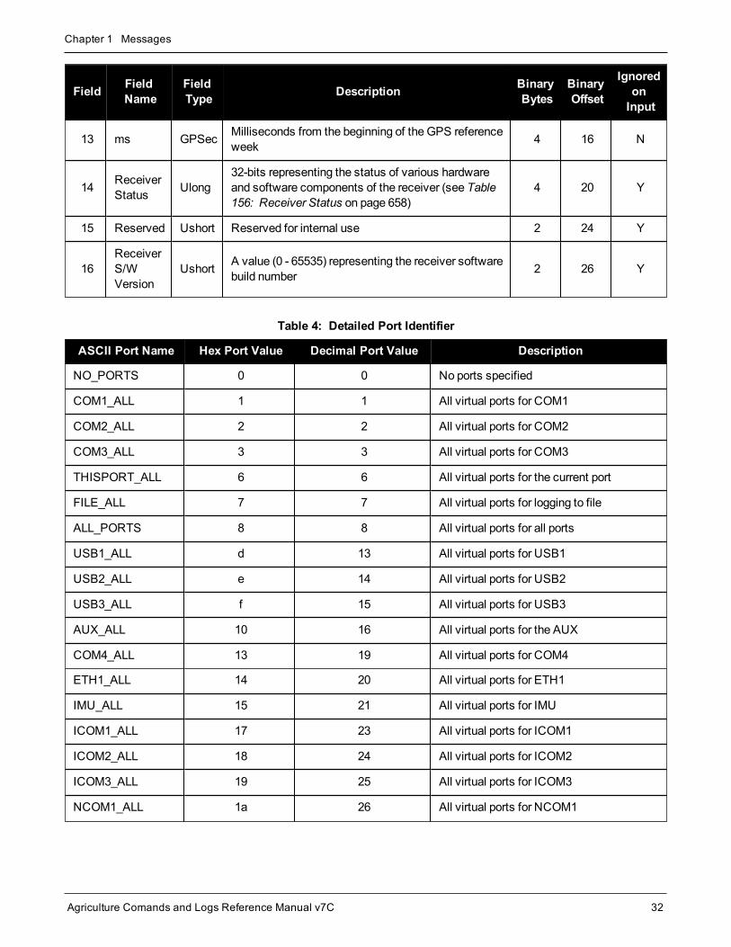
4. The header is in the format shown in Table 3: Binary Message Header Structure below.
Field FieldName
FieldType Description Binary
BytesBinaryOffset
IgnoredonInput
1 Sync Uchar Hexadecimal 0xAA 1 0 N
2 Sync Uchar Hexadecimal 0x44 1 1 N
3 Sync Uchar Hexadecimal 0x12 1 2 N
4 HeaderLength Uchar Length of the header 1 3 N
5 MessageID Ushort
This is theMessage ID number of the log (see thecommand or log descriptions for theMessage IDvalues of individual commands or logs)
2 4 N
Table 3: Binary Message Header Structure

Chapter 1 Messages
Agriculture Comands and Logs Reference Manual v7C 31
Field FieldName
FieldType Description Binary
BytesBinaryOffset
IgnoredonInput
6 MessageType Char
Bits 0-4 = Measurement source1
Bits 5-6 = Format
00 = Binary
01 = ASCII
10 = Abbreviated ASCII, NMEA
11 = Reserved
Bit 7 = Response bit (seeMessage Responses onpage 41)
0 = Original Message
1 = ResponseMessage
1 6 N
7 PortAddress Uchar
See Table 4: Detailed Port Identifier on the next page(decimal values >=32may be used) (lower 8-bitsonly) 2
1 7 N 3
8 MessageLength Ushort The length in bytes of the body of themessage, not
including the header nor the CRC 2 8 N
9 Sequence Ushort
Used for multiple related logs. It is a number thatcounts down from N-1 to 0 where N is the number ofrelated logs and 0means it is the last one of the set.Most logs only come out one at a time in which casethis number is 0
2 10 N
10 Idle Time Uchar
Time the processor is idle, calculated once persecond. Take the time (0 – 200) and divide by two togive the percentage of time (0 – 100%). 0% indicatesthe processor is fully occupied. Other values indicatethe availability of the processor to take on tasks.
1 12 Y
11 TimeStatus Enum Indicates the quality of the GPS reference time (see
Table 11: GPS Reference Time Status on page 44). 1 4 13 N 5
12 Week Ushort GPS reference week number 2 14 N
1Bits 0-4 are used to indicate the measurement source. For dual antenna receivers, if bit 0 is set, the log is from thesecondary antenna.2The 8-bit size means you will only see 0xA0 to 0xBF when the top bits are dropped from a port value greater than 8-bits. Forexample, ASCII port USB1 will be seen as 0xA0 in the binary output.3Recommended value is THISPORT (decimal 192).4This ENUM is not 4-bytes long but, as indicated in the table, is only 1-byte.5Fields 12 and 13 (Week and ms) are ignored if Field 11 (Time Status) is invalid. In this case, the current receiver time isused. The recommended values for the three time fields are 0, 0, 0.
Chapter 1 Messages
Agriculture Comands and Logs Reference Manual v7C 32
Field FieldName
FieldType Description Binary
BytesBinaryOffset
IgnoredonInput
13 ms GPSec Milliseconds from the beginning of the GPS referenceweek 4 16 N
14 ReceiverStatus Ulong
32-bits representing the status of various hardwareand software components of the receiver (see Table156: Receiver Status on page 658)
4 20 Y
15 Reserved Ushort Reserved for internal use 2 24 Y
16ReceiverS/WVersion
Ushort A value (0 - 65535) representing the receiver softwarebuild number 2 26 Y
ASCII Port Name Hex Port Value Decimal Port Value Description
NO_PORTS 0 0 No ports specified
COM1_ALL 1 1 All virtual ports for COM1
COM2_ALL 2 2 All virtual ports for COM2
COM3_ALL 3 3 All virtual ports for COM3
THISPORT_ALL 6 6 All virtual ports for the current port
FILE_ALL 7 7 All virtual ports for logging to file
ALL_PORTS 8 8 All virtual ports for all ports
USB1_ALL d 13 All virtual ports for USB1
USB2_ALL e 14 All virtual ports for USB2
USB3_ALL f 15 All virtual ports for USB3
AUX_ALL 10 16 All virtual ports for the AUX
COM4_ALL 13 19 All virtual ports for COM4
ETH1_ALL 14 20 All virtual ports for ETH1
IMU_ALL 15 21 All virtual ports for IMU
ICOM1_ALL 17 23 All virtual ports for ICOM1
ICOM2_ALL 18 24 All virtual ports for ICOM2
ICOM3_ALL 19 25 All virtual ports for ICOM3
NCOM1_ALL 1a 26 All virtual ports for NCOM1
Table 4: Detailed Port Identifier

Chapter 1 Messages
Agriculture Comands and Logs Reference Manual v7C 33
ASCII Port Name Hex Port Value Decimal Port Value Description
NCOM2_ALL 1b 27 All virtual ports for NCOM2
NCOM3_ALL 1c 28 All virtual ports for NCOM3
ICOM4_ALL 1d 29 All virtual ports for ICOM4
WCOM1_ALL 1e 30 All virtual ports forWCOM1
COM1 20 32 COM1, virtual port 0
COM1_1 21 33 COM1, virtual port 1
. . .
COM1_31 3f 63 COM1, virtual port 31
COM2 40 64 COM2, virtual port 0
COM2_1 41 65 COM1, virtual port 1
. . .
COM2_31 5f 95 COM2, virtual port 31
COM3 60 96 COM3, virtual port 0
COM3_1 61 97 COM3, virtual port 1
. . .
COM3_31 7f 127 COM3, virtual port 31
SPECIAL a0 160 Unknown port, virtual port 0
SPECIAL_1 a1 161 Unknown port, virtual port1
. . .
SPECIAL_31 bf 191 Unknown port, virtual port 31
THISPORT c0 192 Current COM port, virtual port 0
THISPORT_1 c1 193 Current COM port, virtual port 1
. . .
THISPORT_31 df 223 Current COM port, virtual port 31
FILE e0 224 Virtual port 0 for logging to file
FILE_1 e1 225 Virtual port 1 for logging to file
. . .
FILE_31 ff 255 Virtual port 31 for logging to file

Chapter 1 Messages
Agriculture Comands and Logs Reference Manual v7C 34
ASCII Port Name Hex Port Value Decimal Port Value Description
USB1 5a0 1440 USB1, virtual port 0
USB1_1 5a1 1441 USB1, virtual port 1
. . .
USB1_31 5bf 1471 USB1, virtual port 31
USB2 6a0 1696 USB2, virtual port 0
USB2_1 6a1 1967 USB2, virtual port 1
. . .
USB2_31 6bf 1727 USB2, virtual port 31
USB3 7a0 1952 USB3, virtual port 0
USB3_1 7a1 1953 USB3, virtual port 1
. . .
USB3_31 7bf 1983 USB port 3, virtual port 31
AUX 8a0 2208 AUX port, virtual port 0
AUX_1 8a1 2209 AUX port, virtual port 1
. . .
AUX_31 8bf 2239 AUX port, virtual port 31
COM4 ba0 2976 COM4, virtual port 0
COM4_1 ba1 2977 COM4, virtual port 1
. . .
COM4_31 bbf 3007 COM4, virtual port 31
ETH1 ca0 3232 ETH1, virtual port 0
ETH1_1 ca1 3233 ETH1, virtual port 1
. . .
ETH1_31 cbf 3263 ETH1, virtual port 31
IMU da0 3488 IMU, virtual port 0
IMU_1 da1 3489 IMU, virtual port 1
. . .
IMU_31 dbf 3519 IMU, virtual port 31

Chapter 1 Messages
Agriculture Comands and Logs Reference Manual v7C 35
ASCII Port Name Hex Port Value Decimal Port Value Description
ICOM1 fa0 4000 ICOM1, virtual port 0
ICOM1_1 fa1 4001 ICOM1, virtual port 1
. . .
ICOM1_31 fbf 4031 ICOM1, virtual port 31
ICOM2 10a0 4256 ICOM2, virtual port 0
ICOM2_1 10a1 4257 ICOM2, virtual port 1
. . .
ICOM2_31 10bf 4287 ICOM2, virtual port 31
ICOM3 11a0 4512 ICOM3, virtual port 0
ICOM3_1 11a1 4513 ICOM3, virtual port 1
. . .
ICOM3_31 11bf 4543 ICOM3, virtual port 31
NCOM1 12a0 4768 NCOM1, virtual port 0
NCOM1_1 12a1 4769 NCOM1, virtual port 1
. . .
NCOM1_31 12bf 4799 NCOM1, virtual port 31
NCOM2 13a0 5024 NCOM2, virtual port 0
NCOM2_1 13a1 5025 NCOM2, virtual port 1
. . .
NCOM2_31 13bf 5055 NCOM2, virtual port 31
NCOM3 14a0 5280 NCOM3, virtual port 0
NCOM3_1 14a1 5281 NCOM3, virtual port 1
. . .
NCOM3_31 14bf 5311 NCOM3, virtual port 31
ICOM4 15a0 5536 ICOM4, virtual port 0
ICOM4_1 15a1 5537 ICOM4, virtual port 1
. . .
ICOM4_31 15bf 5567 ICOM4, virtual port 31

Chapter 1 Messages
Agriculture Comands and Logs Reference Manual v7C 36
ASCII Port Name Hex Port Value Decimal Port Value Description
WCOM1 16a0 5792 WCOM1, virtual port 0
WCOM1_1 16a1 5793 WCOM1, virtual port 1
. . .
WCOM1_31 16bf 5823 WCOM1, virtual port 31
COM5_ALL 16c0 5824 All virtual ports for COM5
COM6_ALL 16c1 5825 All virtual ports for COM6
BT1_ALL 16c2 5826 All virtual ports for the Bluetooth device
COM7_ALL 16c3 5827 All virtual ports for COM7
COM8_ALL 16c4 5828 All virtual ports for COM8
COM9_ALL 16c5 5829 All virtual ports for COM9
COM10_ALL 16c6 5830 All virtual ports for COM10
CCOM1_ALL 16c7 5831 All virtual ports for CCOM1
CCOM2_ALL 16c8 5832 All virtual ports for CCOM2
CCOM3_ALL 16c9 5833 All virtual ports for CCOM3
CCOM4_ALL 16ca 5834 All virtual ports for CCOM4
CCOM5_ALL 16cb 5835 All virtual ports for CCOM5
CCOM6_ALL 16cc 5836 All virtual ports for CCOM6
ICOM5_ALL 16cf 5839 All virtual ports for ICOM5
ICOM6_ALL 16d0 5840 All virtual ports for ICOM6
ICOM7_ALL 16d1 5841 All virtual ports for ICOM7
SCOM1_ALL 16d2 5842 All virtual ports for SCOM1
SCOM2_ALL 16d3 5843 All virtual ports for SCOM2
SCOM3_ALL 16d4 5844 All virtual ports for SCOM3
SCOM4_ALL 16d5 5845 All virtual ports for SCOM4
COM5 17a0 6048 COM5, virtual port 0
COM5_1 17a1 6049 COM5, virtual port 1
. . .
COM5_31 17bf 6079 COM5, virtual port 31

Chapter 1 Messages
Agriculture Comands and Logs Reference Manual v7C 37
ASCII Port Name Hex Port Value Decimal Port Value Description
COM6 18a0 6304 COM6, virtual port 0
COM6_1 18a1 6305 COM6, virtual port 1
. . .
COM6_31 18bf 6335 COM6, virtual port 31
BT1 19a0 6560 Bluetooth device, virtual port 0
BT1_1 19a1 6561 Bluetooth device, virtual port 1
. . .
BT1_31 19bf 6591 Bluetooth device, virtual port 31
COM7 1aa0 6816 COM7, virtual port 0
COM7_1 1aa1 6817 COM7, virtual port 1
. . .
COM7_31 1abf 6847 COM7, virtual port 31
COM8 1ba0 7072 COM8, virtual port 0
COM8_1 1ba1 7073 COM8, virtual port 1
. . .
COM8_31 1bbf 7103 COM8, virtual port 31
COM9 1ca0 7328 COM9, virtual port 0
COM9_1 1ca1 7329 COM9, virtual port 1
. . .
COM9_31 1cbf 7359 COM9, virtual port 31
COM10 1da0 7584 COM10, virtual port 0
COM10_1 1da1 7585 COM10, virtual port 1
. . .
COM10_31 1dbf 7615 COM10, virtual port 31
CCOM1 1ea0 7840 CAN COM1, virtual port 0
CCOM1_1 1ea1 7841 CAN COM1, virtual port 1
. . .
CCOM1_31 1ebf 7871 CAN COM1, virtual port 31

Chapter 1 Messages
Agriculture Comands and Logs Reference Manual v7C 38
ASCII Port Name Hex Port Value Decimal Port Value Description
CCOM2 1fa0 8096 CAN COM2, virtual port 0
CCOM2_1 1fa1 8097 CAN COM2, virtual port 1
. . .
CCOM2_31 1fbf 8127 CAN COM2, virtual port 31
CCOM3 20a0 8352 CAN COM3, virtual port 0
CCOM3_1 20a1 8353 CAN COM3, virtual port 1
. . .
CCOM3_31 20bf 8383 CAN COM3, virtual port 31
CCOM4 21a0 8608 CAN COM4, virtual port 0
CCOM4_1 21a1 8609 CAN COM4, virtual port 1
. . .
CCOM4_31 21bf 8639 CAN COM4, virtual port 31
CCOM5 22a0 8864 CAN COM5, virtual port 0
CCOM5_1 22a1 8865 CAN COM5, virtual port 1
. . .
CCOM5_31 22bf 8895 CAN COM5, virtual port 31
CCOM6 23a0 9120 CAN COM6, virtual port 0
CCOM6_1 23a1 9121 CAN COM6, virtual port 1
. . .
CCOM6_31 23bf 9151 CAN COM6, virtual port 31
ICOM5 26a0 9888 ICOM5, virtual port 0
ICOM5_1 26a1 9889 ICOM5, virtual port 1
. . .
ICOM5_31 26bf 9919 ICOM5, virtual port 31
ICOM6 27a0 10144 ICOM6, virtual port 0
ICOM6_1 27a1 10145 ICOM6, virtual port 1
. . .
ICOM6_31 27bf 10175 ICOM6, virtual port 31

Chapter 1 Messages
Agriculture Comands and Logs Reference Manual v7C 39
ASCII Port Name Hex Port Value Decimal Port Value Description
ICOM7 28a0 10400 ICOM7, virtual port 0
ICOM7_1 28a1 10401 ICOM7, virtual port 1
. . .
ICOM7_31 28bf 10431 ICOM7, virtual port 31
SCOM1 29a0 10656 SCOM1, virtual port 0
SCOM1_1 29a1 10657 SCOM1, virtual port 1
. . .
SCOM1-31 29bf 10687 SCOM1, virtual port 31
SCOM2 2aa0 10912 SCOM2, virtual port 0
SCOM2_1 2aa1 10913 SCOM2, virtual port 1
. . .
SCOM2_31 2abf 10943 SCOM2, virtual port 31
SCOM3 2ba0 11168 SCOM3, virtual port 0
SCOM3_1 2ba1 11169 SCOM3, virtual port 1
. . .
SCOM3_31 2bbf 11199 SCOM3, virtual port 31
SCOM4 2ca0 11424 SCOM4, virtual port 0
SCOM4_1 2ca1 11425 SCOM4, virtual port 1
. . .
SCOM4_31 2cbf 11455 SCOM4, virtual port 31
COM1_ALL, COM2_ALL, COM3_ALL, COM4_ALL, COM5_ALL, THISPORT_ALL, FILE_ALL, ALL_PORTS, USB1_ALL, USB2_ALL, USB3_ALL, AUX_ALL, ETH1_ALL, ICOM1_ALL, ICOM2_ALL,ICOM3_ALL, ICOM4_ALL, ICOM5_ALL, ICOM6_ALL, ICOM7_ALL, CCOM1_ALL, CCOM2_ALL,CCOM3_ALL, CCOM4_ALL, CCOM5_ALL, CCOM6_ALL, NCOM1_ALL, NCOM2_ALL, NCOM3_ALL, SCOM1_ALL, SCOM2_ALL, SCOM3_ALL, SCOM4_ALL andWCOM1_ALL are only valid for theUNLOGALL command.
The ports available vary based on the receiver.
Table 5: Available Port Types on the next page provides examples of where each port typemight be used.

Chapter 1 Messages
Agriculture Comands and Logs Reference Manual v7C 40
PortType Description Example of where it might be used
AUX Auxiliary "serial"ports An additional UART serial port available only on certain platforms
BTx Bluetooth ports These ports are used to connect over Bluetooth devices, when the receiver isequipped with a BT device
COMx Serial Port UART serial ports. Used when there is a physical RS-232 or RS-422 connection tothe receiver
ICOMx Internet ports These ports are used when establishing TCP or UDP connections to the receiverover a network
NCOMx NTRIP ports These ports are used when establishing NTRIP connections to the receiver over anetwork
SCOMx Script ports Ports used by the Scripted User Interface (i.e. Lua)
USBx USB "serial"ports
When the receiver is connected to an external host through USB, these ports areavailable
WCOMx Web Server port Ports used by Web Server applications, for receivers equipped with a web server
Table 5: Available Port Types
1.4 Description of ASCII and Binary Logs with Short HeadersOne difference from the standard OEM7 logs is there are two possible headers for the ASCII and binary versionsof the INS logs. Which header is used for a given log is described in the log definitions in theSPAN Logs onpage 795 chapter. The reason for the alternate short headers is that the normal OEM7 binary header is quite longat 28 bytes. This is nearly as long as the data portion of many of the INS logs and creates excess storage andbaud rate requirements.
These logs are set up in the sameway as normal ASCII or binary logs except a normal ASCII or binary header isreplaced with a short header (see Table 6: Short ASCII Message Header Structure below and Table 7: Short Bin-ary Message Header Structure on the next page).
Field Field Name Field Type Description
1 % Char % symbol
2 Message Char This is the name of the log
3 Week Number Ushort GNSS week number
4 Seconds GPSec Seconds from the beginning of the GNSS week(Same byte arrangement as a Float type)
Table 6: Short ASCII Message Header Structure

Chapter 1 Messages
Agriculture Comands and Logs Reference Manual v7C 41
Field Field Name FieldType Description Binary
BytesBinaryOffset
1 Synch Char Hex 0xAA 1 0
2 Synch Char Hex 0x44 1 1
3 Synch Char Hex 0x13 1 2
4 MessageLength Uchar Message length, not including header or CRC 1 3
5 Message ID Ushort Message ID number 2 4
6 Week Number Ushort GNSS week number 2 6
7 Milliseconds GPSecMilliseconds from the beginning of the GNSSweek(Same byte arrangement as a Long type)
4 8
Table 7: Short Binary Message Header Structure
1.5 Message ResponsesBy default, if you input amessage you get back a response. If desired, the INTERFACEMODE command (seepage 136) can be used to disable responsemessages. The response will be in the exact format you entered themessage (that is, binary input = binary response).
1.5.1 Abbreviated ASCII ResponseThe response is just the leading '<' followed by the response string, for example: <OK.
1.5.2 ASCII ResponseThe response is the full header with themessage name being identical except ending in an 'R' (for response).The body of themessage consists of a 40 character string for the response string. For example:
#BESTPOSR,COM1,0,67.0,FINE,1028,422060.400,02000000,a31b,0;"OK" *b867caad
1.5.3 Binary ResponseThe response is similar to an ASCII response except that it follows the binary protocols, see Table 8: BinaryMessage Response Structure on the next page.
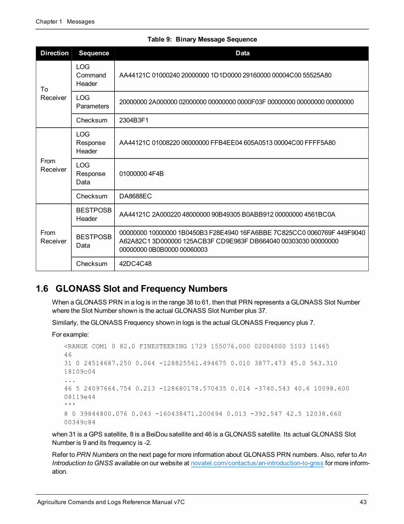
Table 9: Binary Message Sequence on page 43 is an example of the sequence for requesting and then receivingBESTPOSB. The example is in hex format. When you enter a hex command, youmay need to add a ‘\x’ or ‘0x’before each hex pair, depending on your code. For example:
0xAA0x440x120x1C0x010x000x02 and so on.

Chapter 1 Messages
Agriculture Comands and Logs Reference Manual v7C 42
Field FieldName
FieldType Description Binary
BytesBinaryOffset
BINARY
HEADER
1 Sync Char Hexadecimal 0xAA 1 0
2 Sync Char Hexadecimal 0x44 1 1
3 Sync Char Hexadecimal 0x12 1 2
4 HeaderLength Uchar Length of the header 1 3
5 MessageID Ushort Message ID number 2 4
6 MessageType Char
Response Bit
1 = ResponseMessage1 6
7 PortAddress Uchar See Table 4: Detailed Port Identifier on page 32 1 7
8 MessageLength Ushort The length in bytes of the body of themessage (not
including the CRC) 2 8
9 Sequence Ushort Normally 0 2 10
10 Idle Time Uchar Idle time 1 12
11 TimeStatus Enum Table 11: GPS Reference Time Status on page 44 1 1 13
12 Week Ushort GPS reference week number 2 14
13 ms GPSec Milliseconds into GPS reference week 4 16
14 ReceiverStatus Ulong Table 156: Receiver Status on page 658 4 20
15 Reserved Ushort Reserved 2 24
16ReceiverS/WVersion
Ushort Receiver software build number 2 26
ID 17 Response
ID Enum The enumeration value corresponding to themessageresponse (Table 223: ResponseMessages on page 896) 4 28
HEX
18 Response Hex String containing the ASCII response in hex coding tomatch the ID above (for example, 0x4F4B = OK) variable 32
Table 8: Binary Message Response Structure
1This ENUM is not 4-bytes long but as indicated in the table is only 1 byte.
Chapter 1 Messages
Agriculture Comands and Logs Reference Manual v7C 43
Direction Sequence Data
ToReceiver
LOGCommandHeader
AA44121C 01000240 20000000 1D1D0000 29160000 00004C00 55525A80
LOGParameters 20000000 2A000000 02000000 00000000 0000F03F 00000000 00000000 00000000
Checksum 2304B3F1
FromReceiver
LOGResponseHeader
AA44121C 01008220 06000000 FFB4EE04 605A0513 00004C00 FFFF5A80
LOGResponseData
01000000 4F4B
Checksum DA8688EC
FromReceiver
BESTPOSBHeader AA44121C 2A000220 48000000 90B49305 B0ABB912 00000000 4561BC0A
BESTPOSBData
00000000 10000000 1B0450B3 F28E4940 16FA6BBE 7C825CC0 0060769F 449F9040A62A82C1 3D000000 125ACB3F CD9E983F DB664040 00303030 0000000000000000 0B0B0000 00060003
Checksum 42DC4C48
Table 9: Binary Message Sequence
1.6 GLONASS Slot and Frequency NumbersWhen aGLONASS PRN in a log is in the range 38 to 61, then that PRN represents a GLONASS Slot Numberwhere the Slot Number shown is the actual GLONASS Slot Number plus 37.
Similarly, the GLONASS Frequency shown in logs is the actual GLONASS Frequency plus 7.
For example:
<RANGE COM1 0 82.0 FINESTEERING 1729 155076.000 02004000 5103 114654631 0 24514687.250 0.064 -128825561.494675 0.010 3877.473 45.0 563.31018109c04...46 5 24097664.754 0.213 -128680178.570435 0.014 -3740.543 40.6 10098.60008119e44'''8 0 39844800.076 0.043 -160438471.200694 0.013 -392.547 42.5 12038.66000349c84
when 31 is a GPS satellite, 8 is a BeiDou satellite and 46 is a GLONASS satellite. Its actual GLONASS SlotNumber is 9 and its frequency is -2.
Refer toPRN Numbers on the next page for more information about GLONASS PRN numbers. Also, refer toAnIntroduction to GNSS available on our website at novatel.com/contactus/an-introduction-to-gnss for more inform-ation.

Chapter 1 Messages
Agriculture Comands and Logs Reference Manual v7C 44
1.6.1 PRN NumbersThe PRN and SVID ranges for the logs and commands that use them are shown in the following table.
Command/Log GPSPRN
SBASPRN
SBASQZSSL1SPRN
GLONASSSlot
GalileoSVID
QZSSPRN
BDSPRN
NavICPRN
ASSIGN 1-32 120-158 183-192 38-61 1-36 193-202 1-30 1-7
ASSIGNALL 1-32 120-158 183-192 38-61 1-36 193-202 1-30 1-7
LOCKOUT 1-32 120-158 183-192 38-61 - 193-202 - 1-7
SBASCONTROL - 120-158 183-192 - - - - -
TRACKSV 1-32 120-158 183-192 38-61 1-36 193-202 1-30 1-7
UNLOCKOUT 1-32 120-158 183-192 38-61 - 193-202 - 1-7
RANGE 1-32 120-158 183-192 38-61 1-36 193-202 1-30 1-7
RANGECMP 1-32 120-158 183-192 38-61 1-36 193-202 1-30 1-7
RANGECMP2 1-32 120-158 183-192 1-24 1-36 193-202 1-30 1-7
RANGECMP4 1-32 120-158 183-192 1-24 1-36 193-202 1-30 1-7
RANGEGPSL1 1-32 - - - - - - -
SATVIS2 1-32 120-158 183-192 1-24 1-36 193-202 1-30 1-7
TRACKSTAT 1-32 120-158 183-192 38-61 1-36 193-202 1-30 1-7
Table 10: PRN Numbers for Commands and Logs
1.7 GPS Reference Time StatusAll reported receiver times are subject to a qualifying time status. The status indicates how well a time is known(see Table 11: GPS Reference Time Status below).
GPS Reference TimeStatus (Decimal)
GPS Reference TimeStatus(ASCII)
Description
20 UNKNOWN Time validity is unknown
60 APPROXIMATE Time is set approximately
80 COARSEADJUSTING Time is approaching coarse precision
100 COARSE This time is valid to coarse precision
120 COARSESTEERING Time is coarse set and is being steered
Table 11: GPS Reference Time Status

Chapter 1 Messages
Agriculture Comands and Logs Reference Manual v7C 45
GPS Reference TimeStatus (Decimal)
GPS Reference TimeStatus(ASCII)
Description
130 FREEWHEELING Position is lost and the range bias cannot be calculated
140 FINEADJUSTING Time is adjusting to fine precision
160 FINE Time has fine precision
170 FINEBACKUPSTEERING Time is fine set and is being steered by the backupsystem
180 FINESTEERING Time is fine set and is being steered
200 SATTIME Time from satellite. Only used in logs containing satellitedata such as ephemeris and almanac
If time is input to the receiver using theSETAPPROXTIME command (see page 262), the time status will beAPPROXIMATE.
1.8 Message Time StampsAll NovAtel format messages generated by the OEM7 and SMART2 receivers have aGPS reference time stampin their header. GPS reference time is referenced to UTC with zero point defined as midnight on the night of Janu-ary 5, 1980. The time stamp consists of the number of weeks since that zero point and the number of secondssince the last week number change (0 to 604,799). GPS reference time differs from UTC time since leapseconds are occasionally inserted into UTC andGPS reference time is continuous. In addition, a small error(less than 1microsecond) can exist in synchronization between UTC andGPS reference time. The TIME logreports both GNSS and UTC time and the offset between the two.
The data in synchronous logs (for example, RANGE, BESTPOS, TIME) are based on a periodic measurement ofsatellite pseudoranges. The time stamp on these logs is the receiver estimate of GPS reference time at the timeof themeasurement.
Other log types (asynchronous and polled) are triggered by an external event and the time in the header may notbe synchronized to the current GPS reference time. Logs that contain satellite broadcast data (for example,ALMANAC, GPSEPHEM) have the transmit time of their last subframe in the header. In the header of differentialtimematched logs (for example, MATCHEDPOS) is the time of thematched reference and local observationthat they are based on. Logs triggered by amark event (for example, MARKPOS, MARK1TIME) have the estim-ated GPS reference time of themark event in their header. In the header of polled logs (for example, LOGLIST,PORTSTATS, VERSION) is the approximate GPS reference time when their data was generated. However,when asynchronous logs are triggeredONTIME, the time stampwill represent the time the log was generatedand not the time given in the data.
For more information about log types, see Log Types on page 322.
1.9 Decoding of the GPS Reference Week NumberTheGPS reference week number provided in the raw satellite data is the 10 least significant bits (or 8 least sig-nificant bits in the case of the almanac data) of the full week number. When the receiver processes the satellitedata, the week number is decoded in the context of the current era and therefore is computed as the full weeknumber starting from week 0 or January 6, 1980. Therefore, in all log headers and decoded week number fields,the full week number is given. Only in raw data, such as the data field of theRAWALM log (see page 614) or the

Chapter 1 Messages
Agriculture Comands and Logs Reference Manual v7C 46
subframe field of theRAWEPHEM log (see page 617), will the week number remain as the 10 (or 8) least sig-nificant bits.
1.10 32-Bit CRCThe ASCII and Binary OEM7 family and SMART2message formats all contain a 32-bit CRC for data veri-fication. This allows the user to ensure the data received (or transmitted) is valid with a high level of certainty.
The C functions below may be implemented to generate the CRC of a block of data.
#define CRC32_POLYNOMIAL 0xEDB88320L/* --------------------------------------------------------------------------Calculate a CRC value to be used by CRC calculation functions.-------------------------------------------------------------------------- */unsigned long CRC32Value(int i) {
int j;unsigned long ulCRC;
ulCRC = i;for ( j = 8 ; j > 0; j-- ) {
if ( ulCRC & 1 ) ulCRC = ( ulCRC >> 1 ) ^ CRC32_POLYNOMIAL;
else ulCRC >>= 1;
}return ulCRC;
}
/* --------------------------------------------------------------------------Calculates the CRC-32 of a block of data all at onceulCount - Number of bytes in the data blockucBuffer - Data block-------------------------------------------------------------------------- */unsigned long CalculateBlockCRC32( unsigned long ulCount, unsigned char*ucBuffer ) {
unsigned long ulTemp1;unsigned long ulTemp2;unsigned long ulCRC = 0;while ( ulCount-- != 0 ) {
ulTemp1 = ( ulCRC >> 8 ) & 0x00FFFFFFL; ulTemp2 = CRC32Value( ((int) ulCRC ^ *ucBuffer++ ) & 0xFF ); ulCRC = ulTemp1 ^ ulTemp2;
}return( ulCRC );
}
The NMEA checksum is an XOR of all the bytes (including delimiters such as ',' but excluding the * and$) in themessage output. It is therefore an 8-bit and not a 32-bit checksum.
Not all logs may be available. Every effort is made to ensure examples are correct, however, a checksummaybe created for promptness in publication. In this case it will appear as ‘9999’.
Example:
Chapter 1 Messages
Agriculture Comands and Logs Reference Manual v7C 47
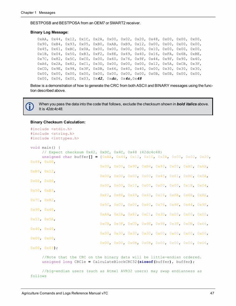
BESTPOSB and BESTPOSA from anOEM7 or SMART2 receiver.
Binary Log Message:0xAA, 0x44, 0x12, 0x1C, 0x2A, 0x00, 0x02, 0x20, 0x48, 0x00, 0x00, 0x00,0x90, 0xB4, 0x93, 0x05, 0xB0, 0xAB, 0xB9, 0x12, 0x00, 0x00, 0x00, 0x00,0x45, 0x61, 0xBC, 0x0A, 0x00, 0x00, 0x00, 0x00, 0x10, 0x00, 0x00, 0x00,0x1B, 0x04, 0x50, 0xB3, 0xF2, 0x8E, 0x49, 0x40, 0x16, 0xFA, 0x6B, 0xBE,0x7C, 0x82, 0x5C, 0xC0, 0x00, 0x60, 0x76, 0x9F, 0x44, 0x9F, 0x90, 0x40,0xA6, 0x2A, 0x82, 0xC1, 0x3D, 0x00, 0x00, 0x00, 0x12, 0x5A, 0xCB, 0x3F,0xCD, 0x9E, 0x98, 0x3F, 0xDB, 0x66, 0x40, 0x40, 0x00, 0x30, 0x30, 0x30,0x00, 0x00, 0x00, 0x00, 0x00, 0x00, 0x00, 0x00, 0x0B, 0x0B, 0x00, 0x00,0x00, 0x06, 0x00, 0x03, 0x42, 0xdc, 0x4c,0x48
Below is a demonstration of how to generate the CRC from both ASCII and BINARY messages using the func-tion described above.
When you pass the data into the code that follows, exclude the checksum shown in bold italics above.It is 42dc4c48.
Binary Checksum Calculation:#include <stdio.h>#include <string.h>#include <inttypes.h>
void main() {// Expect checksum 0x42, 0xDC, 0x4C, 0x48 (42dc4c48)unsigned char buffer[] = {0xAA, 0x44, 0x12, 0x1C, 0x2A, 0x00, 0x02, 0x20,
0x48, 0x00,0x00, 0x00, 0x90, 0xB4, 0x93, 0x05, 0xB0, 0xAB,
0xB9, 0x12,0x00, 0x00, 0x00, 0x00, 0x45, 0x61, 0xBC, 0x0A,
0x00, 0x00,0x00, 0x00, 0x10, 0x00, 0x00, 0x00, 0x1B, 0x04,
0x50, 0xB3,0xF2, 0x8E, 0x49, 0x40, 0x16, 0xFA, 0x6B, 0xBE,
0x7C, 0x82,0x5C, 0xC0, 0x00, 0x60, 0x76, 0x9F, 0x44, 0x9F,
0x90, 0x40,0xA6, 0x2A, 0x82, 0xC1, 0x3D, 0x00, 0x00, 0x00,
0x12, 0x5A,0xCB, 0x3F, 0xCD, 0x9E, 0x98, 0x3F, 0xDB, 0x66,
0x40, 0x40,0x00, 0x30, 0x30, 0x30, 0x00, 0x00, 0x00, 0x00,
0x00, 0x00,0x00, 0x00, 0x0B, 0x0B, 0x00, 0x00, 0x00, 0x06,
0x00, 0x03};
//Note that the CRC on the binary data will be little-endian ordered.unsigned long CRCle = CalculateBlockCRC32(sizeof(buffer), buffer);
//big-endian users (such as Atmel AVR32 users) may swap endianness asfollows

Chapter 1 Messages
Agriculture Comands and Logs Reference Manual v7C 48
unsigned long CRCbe = __builtin_bswap32(CRCle);
printf("\n\n%s %lx \n", "Computed binary checksum (little-endian): ",CRCle); printf("%s %" PRIx32 "\n", "Computed binary checksum (big-endian): ",CRCbe);
}
Note that the above checksum function (CalculateBlockCRC32) must also be included to execute this code.
ASCII Log Message:#BESTPOSA,COM1,0,78.0,FINESTEERING,1427,325298.000,00000000,6145,2748;SOL_COMPUTED,SINGLE,51.11678928753,-114.03886216575,1064.3470,-16.2708,WGS84,2.3434,1.3043,4.7300,"",0.000,0.000,7,7,0,0,0,06,0,03*9c9a92bb
The checksum for this log is given above, it is 9c9a92bb.
ASCII:#include <stdio.h>#include <string.h>
void main() {//Remember to escape " characters as \"char *msgBlock =
"BESTPOSA,COM1,0,78.0,FINESTEERING,1427,325298.000,00000000,\6145,2748;SOL_COMPUTED,SINGLE,51.11678928753,-114.03886216575,\1064.3470,-16.2708,WGS84,2.3434,1.3043,4.7300,\"\",0.000,0.000,7,7,0,0,0,06,0,03";
unsigned long CRC = CalculateBlockCRC32(strlen(msgBlock), (unsignedchar*)msgBlock);
printf("\n%s %s\n", "Demonstrating CRC computed for the block:",msgBlock); printf("\n\n%s %lu\n", "CRC32 in Decimal is: ", CRC); printf("%s %lx\n", "CRC32 in Hex is: ", CRC);}
Note that the above checksum function (CalculateBlockCRC32) must also be included to execute this code.

Agriculture Comands and Logs Reference Manual v7C 49
Chapter 2 Agriculture GNSS CommandsThe commands used to configure the receiver andGNSS functions are described in the following sections.
For information about SPAN specific commands, refer to theAgriculture SPAN Commands on page 764.
2.1 Command FormatsThe receiver accepts commands in 3 formats as described inMessages on page 26:
l Abbreviated ASCII
l ASCII
l Binary
Abbreviated ASCII is the easiest to use for your input. The other two formats include a CRC for error checkingand are intended for use when interfacing with other electronic equipment.
The following are examples of the same command in each format:
Abbreviated ASCII Example:LOG COM1 BESTPOSB ONTIME 1[CR]
ASCII Example:#LOGA,THISPORT,0,0,UNKNOWN,0,0.0,0,0,0;COM1,BESTPOSB,ONTIME,1.000000,0.000000,NOHOLD*ec9ce601[CR]
Binary Example:AA44121C 010000C0 20000000 00FF0000 00000000 00000000 00000000 200000002A000000 02000000 00000000 0000F03F 00000000 00000000 00000000 34D32DC1
2.1.1 Optional ParametersMany commands have nested optional parameters where an optional parameter requires the optional parameterbefore it to be present. This is noted in the Abbreviated ASCII Syntax as:
Command [OPT_1 [OPT_2 [OPT_3]]]
In this syntax example, OPT_1 andOPT_2must be provided if you want to provide a value for OPT_3. Theseleading two options are required even if you want to use the defaults for OPT_1 andOPT_2.
2.2 Command SettingsThere are several ways to determine the current command settings of the receiver:
1. Request anRXCONFIG log (see page 653). This log provides a listing of all commands issued to thereceiver and their parameter settings. It also provides themost complete information.
2. For some specific commands, logs are available to indicate all their parameter settings. The LOGLIST log(see page 479) shows all active logs in the receiver beginning with the LOG command (see page 158).
3. Request a log of the specific command of interest to show the parameters last entered for that command.The format of the log produced is exactly the same as the format of the specific commandwith updatedheader information.
Chapter 2 Agriculture GNSS Commands
Agriculture Comands and Logs Reference Manual v7C 50
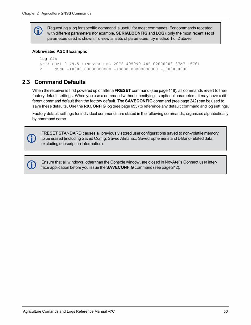
Requesting a log for specific command is useful for most commands. For commands repeatedwith different parameters (for example, SERIALCONFIG and LOG), only themost recent set ofparameters used is shown. To view all sets of parameters, try method 1 or 2 above.
Abbreviated ASCII Example:log fix<FIX COM1 0 49.5 FINESTEERING 2072 405099.446 02000008 37d7 15761< NONE -10000.00000000000 -10000.00000000000 -10000.0000
2.3 Command DefaultsWhen the receiver is first powered up or after a FRESET command (see page 118), all commands revert to theirfactory default settings. When you use a commandwithout specifying its optional parameters, it may have a dif-ferent command default than the factory default. TheSAVECONFIG command (see page 242) can be used tosave these defaults. Use theRXCONFIG log (see page 653) to reference any default command and log settings.
Factory default settings for individual commands are stated in the following commands, organized alphabeticallyby command name.
FRESET STANDARD causes all previously stored user configurations saved to non-volatile memoryto be erased (including Saved Config, Saved Almanac, Saved Ephemeris and L-Band-related data,excluding subscription information).
Ensure that all windows, other than the Console window, are closed in NovAtel’s Connect user inter-face application before you issue theSAVECONFIG command (see page 242).

Chapter 2 Agriculture GNSS Commands
Agriculture Comands and Logs Reference Manual v7C 51
2.4 ALIGNAUTOMATIONConfigures ALIGN plug-and-play feature
Platform: OEM719, OEM729, OEM7500, OEM7600, OEM7700, OEM7720, PwrPak7, SPAN CPT7,SMART7, SMART2
This command configures the ALIGN plug and play feature. Use this command to enable/disable the plug andplay feature, to set the rover COM port to whichmaster is connected, to set the baud rate for communication, toset the intended operation rate using this command and to enable/disable sending theHEADINGEXTB/HEADINGEXT2B back to theMaster receiver. Refer to the NovAtel application note APN-048: ALIGN Family of Heading Solutions for details on HEADINGEXT (available on our website at nova-tel.com/support/support-materials/application-notes).
On issuing this command at the ALIGN Rover, the Rover will automatically sync with theMaster and configure itto send corrections at the specified baud rate and specified data rate.
This command should only be issued at ALIGN Rover.
Message ID: 1323
Abbreviated ASCII Syntax:ALIGNAUTOMATION option [comport] [baudrate] [datarate] [headingextboption][interfacemode]
Factory Default:ALIGNAUTOMATION disable
Example:ALIGNAUTOMATION enable com2 230400 10 ON
Field Field Type ASCIIValue
BinaryValue Description Format Binary
BytesBinaryOffset
1ALIGNAUTOMATIONheader
- -Command header. SeeMessages on page 26 formore information.
- H 0
2 optionENABLE 1 Enable or disable the plug-
and-play feature Enum 4 HDISABLE 0
3 comport COM1, COM2 orCOM3
Rover COM port to whichmaster is connected (Table51: COM Port Identifiers onpage 256)(default=COM2)
Enum 4 H+4
4 baudrate9600, 19200, 38400,57600, 115200,230400 or 460800
Intended baud rate for datatransmission(default=230400)
Ulong 4 H+8

Chapter 2 Agriculture GNSS Commands
Agriculture Comands and Logs Reference Manual v7C 52
Field Field Type ASCIIValue
BinaryValue Description Format Binary
BytesBinaryOffset
5 datarate 1, 2, 4, 5, 10 or20
Rate (in Hz) at whichheading output is required(default=10 Hz)
Ulong 4 H+12
6 headingextboption
OFF 0 Enable or disable sendingHEADINGEXTB/HEADINGEXT2B back totheMaster (default=ON)
Enum 4 H+16ON 1
7 interfacemodeSee Table 30: SerialPort InterfaceModes on page 138
Serial port interfacemode(default=None) Enum 4 H+20

Chapter 2 Agriculture GNSS Commands
Agriculture Comands and Logs Reference Manual v7C 53
2.5 ASSIGNAssigns a channel to a PRN
Platform: OEM719, OEM729, OEM7500, OEM7600, OEM7700, OEM7720, PwrPak7, SPAN CPT7,SMART7, SMART2
TheASSIGN command should only be used by advanced users.
1. Assigning SV channel sets the forced assignment bit in the channel tracking status field which isreported in the RANGE and TRACKSTAT logs.
2. Assigning a PRN to a SV channel does not remove the PRN from the search space of the automaticsearcher; only the SV channel is removed (that is, the searcher may search and lock onto the samePRN on another channel). See Table 10: PRN Numbers for Commands and Logs on page 44 for thePRN available for theASSIGN command.
3. GLONASS SVs cannot be assigned if there is no information onGLONASS frequencies andmatch-ing slot numbers.
4. OEM7 cards have 4 channels available for SBAS. They automatically use the healthy GEO satelliteswith the highest elevations. Use theASSIGN command to enter a GEOPRN manually.
5. TheASSIGN andUNASSIGN commands are not accepted for L-Band channels. TheASSIGNLBANDBEAM command (see page 58) should be used for L-Band channels.
6. Manually assigned satellites are not reported in theRANGECMP4 log (see page 600).
This commandmay be used to aid in the initial acquisition of a satellite by manually overriding the automaticsatellite/channel assignment and reacquisition processes. The command specifies that the indicated trackingchannel search for:
l a specified satellite
l at a specified Doppler frequency
l within a specified Doppler window
The instruction remains in effect for the specified SV channel and PRN, even if the assigned satellite is belowthe elevation cutoff. If the satellite Doppler offset of the assigned SV channel exceeds that specified by the win-dow parameter of theASSIGN command, the satellite may never be acquired or reacquired. If a channel hasbeenmanually assigned, and the channel is changed to AUTO tracking, then the channel is idled immediatelyand returns to automatic mode.
To cancel the effects of ASSIGN, issue one of the following:
l TheASSIGN commandwith the state set to AUTO
l TheUNASSIGN command (see page 293)
l TheUNASSIGNALL command (see page 295)
These immediately return SV channel control to the automatic search engine
Message ID: 27
Abbreviated ASCII Syntax:ASSIGN channel [state] [prn [Doppler [Doppler window]]]

Chapter 2 Agriculture GNSS Commands
Agriculture Comands and Logs Reference Manual v7C 54
ASCII Example 1:ASSIGN 0 ACTIVE 29 0 2000
In example 1, the first SV channel is searching for satellite PRN 29 in a range from -2000 Hz to 2000 Hz until thesatellite signal is detected.
ASCII Example 2:ASSIGN 11 28 -250 0
SV channel 11 is searching for satellite PRN 28 at an offset of -250 Hz only.
ASCII Example 3:ASSIGN 11 IDLE
SV channel 11 is idled and does not attempt to search for satellites.
For dual antenna receivers:
l On the primary antenna, the SV channel is from 0 to N-1, where N is the number of channels in theprimary antenna channel configuration.
l On the secondary antenna, the SV channel count is from at N to N+(M-1), whereM is the numberof channels in the secondary antenna SV channel configuration.
l Even though L-Band channels cannot be configured with theASSIGN command, they are includedwhen determining N.
Field FieldType
ASCIIValue
BinaryValue Description Format Binary
BytesBinaryOffset
1 ASSIGNheader - - Command header. SeeMessages
on page 26 for more information. - H 0
2 channel
0 to n-1, where n is themaximum number ofGNSS channels in thecurrent channelconfiguration
Desired SV channel number wherechannel 0 is the first SV channel.The last channel depends on themodel configuration.
Ulong 4 H
3 stateRefer to Table 12:Channel State on thenext page
Set the SV channel state. If a valueis not given, the default of ACTIVE isused when the additional optionalparameters are entered.
Enum 4 H+4
4 prn Refer toPRN Numberson page 44
Optional satellite PRN number. Avaluemust be entered unless thestate parameter is IDLE or AUTO.
Ulong 4 H+8

Chapter 2 Agriculture GNSS Commands
Agriculture Comands and Logs Reference Manual v7C 55
Field FieldType
ASCIIValue
BinaryValue Description Format Binary
BytesBinaryOffset
5 Doppler-100 000 to
100 000 Hz
Current Doppler offset of thesatellite.(default=0)
Note: Satellite motion, receiverantennamotion and receiver clockfrequency error must be included inthe calculation of Doppler frequency.
Long 4 H+12
6 Dopplerwindow 0 to 10 000 Hz
Error or uncertainty in the Dopplerestimate above.(default=4500)
Note: This is a ± value.Example: 500 for ± 500 Hz
Ulong 4 H+16
Binary ASCII Description
0 IDLE Set the SV channel to not track any satellites
1 ACTIVE1 Set the SV channel active (default)
2 AUTO Tell the receiver to automatically assign PRN numbers to channels
Table 12: Channel State
1A PRN number is required when using the ACTIVE channel state in this command.

Chapter 2 Agriculture GNSS Commands
Agriculture Comands and Logs Reference Manual v7C 56
2.6 ASSIGNALLAssigns all channels of a satellite system
Platform: OEM719, OEM729, OEM7500, OEM7600, OEM7700, OEM7720, PwrPak7, SPAN CPT7,SMART7, SMART2
TheASSIGNALL command should only be used by advanced users.
This command is used to override the automatic satellite channel algorithms with manual instructions for all chan-nels in a satellite system.
Message ID: 28
Abbreviated ASCII Syntax:ASSIGNALL [system][state][prn [Doppler [Doppler window]]]
ASCII Example 1:ASSIGNALL GLONASS IDLE
In example 1, all GLONASS channels are idled, essentially stopping the receiver from tracking GLONASS.
ASCII Example 2:ASSIGNALL GLONASS AUTO
In example 2, all GLONASS channels are enabled in automode. This enables the receiver to automaticallyassign channels to track the available GLONASS satellites.
This command is the same as ASSIGN except that it affects all SV channels of the specified satellitesystem.
These command examples are only applicable to specific receiver models.
If the system field is used with this command and the receiver has no channels configured with thatsatellite system, the command is rejected.
Field FieldType
ASCIIValue
BinaryValue Description Format Binary
BytesBinaryOffset
1ASSIGN-ALLheader
- - Command header. SeeMessages onpage 26 for more information. - H 0
2 systemSee Table 13:Satellite Systemon the next page
Satellite system to assign. If no value isspecified, the value defaults to ALL. Enum 4 H

Chapter 2 Agriculture GNSS Commands
Agriculture Comands and Logs Reference Manual v7C 57
Field FieldType
ASCIIValue
BinaryValue Description Format Binary
BytesBinaryOffset
3 state
Refer to Table12: ChannelState onpage 55)
Set the SV channel state. Enum 4 H+4
4 prnRefer toPRNNumbers onpage 44
Optional satellite PRN code. A valuemustbe entered if the state parameter is neitherIDLE or AUTO.
Ulong 4 H+8
5 Doppler-100 000 to
100 000 Hz
Current Doppler offset of the satellite.(default=0)
Note: Satellite motion, receiver antennamotion and receiver clock frequency errormust be included in the calculation ofDoppler frequency.
Long 4 H+12
6 Dopplerwindow 0 to 10 000 Hz
Error or uncertainty in the Doppler estimateabove.(default=4500)
Note: This is a ± valueExample, 500 for ± 500 Hz
Ulong 4 H+16
Binary ASCII Description
3 ALL All systems
99 GPS GPS system
100 SBAS SBAS system
101 GLONASS GLONASS system
102 GALILEO GALILEO system
103 BeiDou BeiDou system
104 QZSS QZSS system
105 NAVIC NavIC system
Table 13: Satellite System
GLONASS SVs cannot be assigned if there is no information onGLONASS frequencies andmatchingslot numbers.

Chapter 2 Agriculture GNSS Commands
Agriculture Comands and Logs Reference Manual v7C 58
2.7 ASSIGNLBANDBEAMConfigure L-Band tracking
Platform: OEM719, OEM729, OEM7500, OEM7600, OEM7700, OEM7720, PwrPak7, SPAN CPT7,SMART7, SMART2
This command assigns TerraStar or Veripos beams to the L-Band channels based on the defined L-Band assign-ment option.
Logging theASSIGNLBANDBEAM commandmay not display the correct values. To access theactual beam name, frequency and baud rate values, log the LBANDTRACKSTAT log (see page 476)or if the beam name is known, log the LBANDBEAMTABLE log (see page 474) and find the asso-ciated frequency and baud rate.
Message ID: 1733
Abbreviated ASCII Syntax:ASSIGNLBANDBEAM [option] [name] [frequency] [baudrate] [Dopplerwindow]
Factory Default:ASSIGNLBANDBEAM idle
ASCII Examples:ASSIGNLBANDBEAM auto
ASSIGNLBANDBEAM 98W
ASSIGNLBANDBEAM manual 98w 1545865000 1200
Field Field Type Description Format BinaryBytes
BinaryOffset
1 ASSIGNLBANDBEAM header
Command header. SeeMessages on page 26 for moreinformation. - H 0
2 Option Assignment option (see Table 14: L-Band AssignmentOption on the next page) (manual=default) Enum 4 H
3 Name Beam name (empty string=default) Char[8] 8 H+4
4 Frequency Beam frequency in Hz (0=default) Ulong 4 H+12
5 Baud rate Data baud rate (0=default) Ulong 4 H+16
6 Doppler window Doppler window to search (6000=default) Ulong 4 H+20

Chapter 2 Agriculture GNSS Commands
Agriculture Comands and Logs Reference Manual v7C 59
ASCII Binary Description
IDLE 0 Idle all L-Band channels
AUTO 1
The receiver searches for multiple L-Band beams on the L-Band channels based on AUTOselection criteria.
If the receiver position is known, the AUTO selection criteria is a ranking of granted access L-Band beams by descending elevation angle.
If the receiver position is not known, the AUTO selection criteria is a ranking of grantedaccess L-Band beams in the order they appear in the stored beam table (see theLBANDBEAMTABLE log on page 474).
MANUAL 2 The receiver assigns the specified beam on the first L-BAND channel andmakes the other L-BAND channels IDLE.
Table 14: L-Band Assignment Option

Chapter 2 Agriculture GNSS Commands
Agriculture Comands and Logs Reference Manual v7C 60
2.8 AUTHAuthorization code for different model
Platform: OEM719, OEM729, OEM7500, OEM7600, OEM7700, OEM7720, PwrPak7, SPAN CPT7,SMART7, SMART2
This command is used to add or remove authorization codes from the receiver. Authorization codes are used toauthorizemodels of software for a receiver. Models control the functionality the receiver provides. The receiveris capable of keeping track of 24 authorization codes at one time. TheMODEL command (see page 171) canthen be used to switch between authorizedmodels. TheVALIDMODELS command (see page 749) lists the cur-rent available models in the receiver. TheAUTHCODES log (see page 331) lists all authorization codes enteredinto the receiver. This simplifies the use of multiple softwaremodels on the same receiver.
If there is more than one valid model in the receiver, the receiver either uses themodel of the last auth codeentered via theAUTH command or themodel that was selected by theMODEL command, whichever was donelast. Adding an authorization code or using theMODEL command causes an automatic reset of the receiver.Removing an authorization code does not cause a reset.
Removing an authorization code will cause the receiver to permanently lose this information.
Message ID: 49
Abbreviated ASCII Syntax:AUTH [state] part1 part2 part3 part4 part5 model [date]
Input Example:AUTH add T48JF2,W25DBM,JH46BJ,2WGHMJ,8JW5TW,G2SR0RCCR,101114
AUTH erase_table PW5W2B,WW5TM9,WW2PCZ,WW3M4H,WW4HPG,ERASE_AUTH
When you are ready to upgrade from onemodel to another, call 1-800-NOVATEL to speak with ourCustomer Support/Sales Personnel, who can provide the authorization code that unlocks the additionalfeatures of your GNSS receiver. This procedure can be performed at your work site and takes only a fewminutes.
Receiver models can also be downgraded. This is a two step handshaking process and is bestperformed in a location with e-mail access.
Field FieldType
ASCIIValue
BinaryValue Description Format Binary Bytes Binary
Offset
1 AUTHheader - -
Command header. SeeMessages on page 26 formore information.
- H 0
2 stateSee Table 15: AUTHCommand State on thenext page
Authorization code function toperform Enum 4 H

Chapter 2 Agriculture GNSS Commands
Agriculture Comands and Logs Reference Manual v7C 61
Field FieldType
ASCIIValue
BinaryValue Description Format Binary Bytes Binary
Offset
3 part1 6 character ASCII string Authorization code section 1 String[max. 16] Variable1 H+4
4 part2 6 character ASCII string Authorization code section 2 String[max. 16]
Variable1 H+20
5 part3 6 character ASCII string Authorization code section 3 String[max. 16]
Variable1 H+36
6 part4 6 character ASCII string Authorization code section 4 String[max. 16]
Variable1 H+52
7 part5 6 character ASCII string Authorization code section 5 String[max. 16]
Variable1 H+68
8 model Alphanumeric
Nullterminated Model name of the receiver String
[max. 16]Variable1 H+84
9 date Numeric Nullterminated
Expiry date entered asyymmdd in decimal
String[max 7]
Variable1 Variable
ASCII Binary Description
REMOVE 0
Remove the authorization code from the system
For this parameter, the Part1-Part5 fields can be entered as 0 0 0 0 0, andonly themodel name entered.
ADD 1 Add the authorization code to the system (default)
ADD_DOWNLOAD 4 Add the authorization code to the system (Deprecated: Use ADD instead)
ERASE_TABLE 7
Erase all authorization codes from the system. Requires a special authorization code toprevent against accidental erasing.
The special authorization code required for this option is:PW5W2B,WW5TM9,WW2PCZ,WW3M4H,WW4HPG,ERASE_AUTH
Table 15: AUTH Command State
1In the binary case, each string field needs to be NULL terminated and additional bytes of padding added to maintain 4-bytealignment, up to the maximum defined by the string size. The next defined field starts immediately at the next 4-bytealignment following the NULL.

Chapter 2 Agriculture GNSS Commands
Agriculture Comands and Logs Reference Manual v7C 62
ASCII Binary Description
CLEAN_TABLE 8
Remove all invalidated authorization codes from the system.
When an authorization code is removed, it is simply invalidated and so it still uses one ofthe 24 spaces reserved for authorization codes in the receiver. Use the CLEAN_TABLEoption to free up the spaces from removed authorization codes.
The special authorization code required for this option is:4DR69H,G369W8,34MNJJ,5NHXCJ,GW7C75,CLEAN_AUTH

Chapter 2 Agriculture GNSS Commands
Agriculture Comands and Logs Reference Manual v7C 63
2.9 AUTOSURVEYSurvey for accurate position
Platform: OEM719, OEM729, OEM7500, OEM7600, OEM7700, OEM7720, PwrPak7, SPAN CPT7,SMART7
TheAUTOSURVEY command uses position averaging to automatically determine the position for a base sta-tion.
When theAUTOSURVEY command is sent, the receiver starts position averaging. The position averaging con-tinues until a specified accuracy level is met or until the specified survey time expires. When position averagingis complete, the calculated position is saved as the fix position for the base station. This calculated position isthen used when transmitting differential corrections to the rover.
TheAUTOSURVEY command computes the base position inWGS84.
If the FIX command is entered by a user, theSAVECONFIG commandmust then be issued to save toNVM. If the FIX command is issued by the AUTOSURVEY feature, theSAVECONFIG commanddoes not need to be issued, because it is automatically saved to NVM.
On subsequent power ups or resets, an AUTOSURVEY runs to determine if the base station has moved. As theAUTOSURVEY runs, the average position calculated is compared to the saved fix position. If the average pos-ition is within the AUTOSURVEY tolerance setting, the receiver assumes it has not moved and uses the pre-viously saved fix position. If the average position is outside of the AUTOSURVEY tolerance setting, the receiverassumes it has moved and will continue calculating a position average until the accuracy level is met or until thespecified survey time expires.
The surveyed positions saved using theAUTOSURVEY command can be viewed using theSAVEDSURVEYPOSITIONS log on page 685. Surveyed positions can be added or deleted using theSURVEYPOSITION command on page 277.
Message ID: 1795
Abbreviated ASCII Syntax:AUTOSURVEY control [time] [accuracy] [tolerance] [save_nvm] [position_id]
Input Example:
In the following example, the receiver is set up to survey its position for up to 24 hours or until the averaged pos-ition accuracy is 10 cm. On subsequent power ups at the same location, the survey will terminate as soon as thereceiver determines the position is within 4m of its surveyed position. Once the receiver has fixed its position, itwill transmit RTCMV3 corrections over COM2.
SERIALCONFIG COM2 115200 N 8 1 N ON
INTERFACEMODE COM2 NONE RTCMV3 OFF
LOG COM2 RTCM1004 ONTIME 1
LOG COM2 RTCM1012 ONTIME 1
LOG COM2 RTCM1006 ONTIME 10
LOG COM2 RTCM1033 ONTIME 10

Chapter 2 Agriculture GNSS Commands
Agriculture Comands and Logs Reference Manual v7C 64
LOG COM2 RTCM1019 ONTIME 120
AUTOSURVEY ENABLE 1440 .1 4
SAVECONFIG
Field Field Type ASCIIValue
BinaryValue Description Format Binary
BytesBinaryOffset
1 AUTOSURVEYheader - - Command header. SeeMessages on
page 26 for more information. - H 0
2 controldisable 0
Disables the self-survey feature andhalts any self-survey related activity(default = disable) Enum 4 H
enable 1 Enables the self-survey feature
3 time 1 - 6000minutesMaximum amount of time to performself-survey(default = 1440minutes)
Ulong 4 H+4
4 accuracy 0 - 100meters Desired horizontal standard deviation(default = 0.1meters) Float 4 H+8
5 tolerance 3 - 100meters
Maximum distance betweencalculated position and savedposition. During the self-survey, if thedistance between the calculatedposition and the previously surveyedposition is less than this value, theprevious position is used.(default = 10meters)
Float 4 H+12
6 save_nvmOFF 0 Do not save position in NVM
Enum 4 H+16ON 1 Save position in NVM
(default = ON)
7 position_id 4 characterstring
ID for the saved position. If the ID isnot specified or if the ID is entered as"AUTO", receiver automaticallygenerates a unique ID for the position.
Note: This ID is the ID for thesurveyed position, not the station IDset using theDGPSTXID commandon page 98.
String[5] 51 H+20
1In the binary case, each string field needs to be NULL terminated and additional bytes of padding added to maintain 4-bytealignment, up to the maximum defined by the string size. The next defined field starts immediately at the next 4-bytealignment following the NULL.

Chapter 2 Agriculture GNSS Commands
Agriculture Comands and Logs Reference Manual v7C 65
2.10 BASEANTENNAPCOSets the PCOmodel of the base receiver
Platform: OEM719, OEM729, OEM7500, OEM7600, OEM7700, OEM7720, PwrPak7, SPAN CPT7,SMART7
Use theBASEANTENNAPCO command to set the Phase Center Offsets (PCO) for a given frequency on theremote base receiver from which this receiver is receiving corrections. TheOffsets are defined as North, Eastand Up from the Antenna Reference Point to the Frequency Phase Center in millimeters.
Message ID: 1415
Abbreviated ASCII Syntax:BASEANTENNAPCO Frequency NorthOffset EastOffset UpOffset [CorrectionType[StationId]]
ASCII Example:BASEANTENNAPCO GPSL1 0.61 1.99 65.64
Field Field Type ASCIIValue
BinaryValue Description Format Binary
BytesBinaryOffset
1 BASEANTENNAPCOheader - -
Command header. SeeMessages on page 26 formore information.
- H 0
2 FrequencySee Table 16:Frequency Typebelow
The frequency that thephase center offsets arevalid for.
Enum 4 H
3 NorthOffset NGS standard Phase CenterNorth Offset in millimeters. Double 8 H+4
4 EastOffset NGS standard Phase CenterEast Offset in millimeters. Double 8 H+12
5 UpOffset NGS standard Phase CenterUpOffset in millimeters. Double 8 H+20
6 CorrectionTypeSee Table 44: RTKSource Type onpage 224
Correction type
(default = AUTO)Enum 4 H+28
7 StationID Char [8] or ANYID string for the base station
(default = ANY)Char 8 H+32
Value Name Description
0 GPSL1 GPS L1 frequency
Table 16: Frequency Type

Chapter 2 Agriculture GNSS Commands
Agriculture Comands and Logs Reference Manual v7C 66
Value Name Description
1 GPSL2 GPS L2 frequency
2 GLONASSL1 GLONASS L1 frequency
3 GLONASSL2 GLONASS L2 frequency
5 GPSL5 GPS L5 frequency
7 GALILEOE1 Galileo E1 frequency
8 GALILEOE5A Galileo E5a frequency
9 GALILEOE5B Galileo E5b frequency
10 GALILEOALTBOC Galileo AltBOC frequency
11 BEIDOUB1 BeiDou B1 frequency
12 BEIDOUB2 BeiDou B2 frequency
13 QZSSL1 QZSS L1 frequency
14 QZSSL2 QZSS L2 frequency
15 QZSSL5 QZSS L5 frequency

Chapter 2 Agriculture GNSS Commands
Agriculture Comands and Logs Reference Manual v7C 67
2.11 BASEANTENNAPCVSets the PCV model of the base receiver
Platform: OEM719, OEM729, OEM7500, OEM7600, OEM7700, OEM7720, PwrPak7, SPAN CPT7,SMART7
Use theBASEANTENNAPCV command to set the Phase Center Variation (PCV) for a given frequency on theremote base receiver from which this receiver is receiving corrections. The Phase Center Variation entries followthe NGS standard and correspond to the phase elevation at 5 degree increments starting at 90 degrees anddecreasing to 0.
Message ID: 1416
Abbreviated ASCII Syntax:BASEANTENNAPCV Frequency [PCVArray [CorrectionType [StationId]]]
ASCII Example:BASEANTENNAPCV GPSL1 0.00 -0.020 -0.07 -0.15 -0.24 -0.34 -0.43 -0.51 -0.56 -0.61 -0.65 -0.69 -0.69 -0.62 -0.44 -0.13 0.28 0.70 1.02
Field Field Type ASCIIValue
BinaryValue Description Format Binary
BytesBinaryOffset
1 BASEANTENNAPCVheader - -
Command header. SeeMessages on page 26 for moreinformation.
- H 0
2 FrequencySee Table 16:Frequency Typeon page 65
The frequency for which thephase center variations arevalid.
Enum 4 H
3 PCVArray
NGS standard 19 element arrayof phase center variations, inmillimeters, in 5 degree elevationincrements from 90 to 0.Defaults to zero for all elevationincrements.
Double[19] 152 H+4
4 CorrectionType
See Table 44:RTK SourceType onpage 224
Correction type(default = AUTO) Enum 4 H+156
5 StationID Char [8] or ANY ID string(default = ANY) Char 8 H+160

Chapter 2 Agriculture GNSS Commands
Agriculture Comands and Logs Reference Manual v7C 68
2.12 BASEANTENNATYPESets the antenna type of the base receiver
Platform: OEM719, OEM729, OEM7500, OEM7600, OEM7700, OEM7720, PwrPak7, SPAN CPT7,SMART7
Use theBASEANTENNATYPE command to set the type of antenna type connected to the base receiver fromwhich this receiver is receiving RTK corrections. The Antenna Type and Radome Type are the NGS names forthe antenna.
When the antenna type is set using this command, the receiver will look up and use the Phase CenterVariations and Phase Center Offsets from an internal table.
Message ID: 1419
Abbreviated ASCII Syntax:BASEANTENNATYPE AntennaType [RadomeType] [CorrectionType] [StationId]
ASCII Examples:BASEANTENNATYPE NOV702
BASEANTENNATYPE USER_ANTENNA_1
Field Field Type ASCIIValue
BinaryValue Description Format Binary
BytesBinaryOffset
1 BASEANTENNATYPEheader - -
Command header. SeeMessages on page 26 formore information.
- H 0
2 AntennaTypeSee Table 17:Antenna Type onthe next page
Antenna type Enum 4 H
3 RadomeTypeSee Table 18:Radome Type onpage 77
Radome type(default = NONE) Enum 4 H+4
4 CorrectionTypeSee Table 44: RTKSource Type onpage 224
Correction type(default = AUTO) Enum 4 H+8
5 StationID Char [8] or ANY Base station ID(default = ANY) Char 8 H+12
The latest information can be obtained from the National Geodetic Survey (NGS) site www.ng-s.noaa.gov/ANTCAL.

Chapter 2 Agriculture GNSS Commands
Agriculture Comands and Logs Reference Manual v7C 69
Value Name Description
0 NONE No antennamodel
2 AUTO Determine the antennamodel from the RTK corrections(Not valid for THISANTENNATYPE)
3 AERAT2775_43
4 AOAD_M_B
5 AOAD_M_T AOAD/M_T
6 AOAD_M_TA_NGS AOAD/M_TA_NGS
7 APSAPS-3
8 ASH700228A
9 ASH700228B
10 ASH700228C
11 ASH700228D
12 ASH700228E
13 ASH700699.L1
14 ASH700700.A
15 ASH700700.B
16 ASH700700.C
17 ASH700718A
18 ASH700718B
19 ASH700829.2
20 ASH700829.3
21 ASH700829.A
22 ASH700829.A1
23 ASH700936A_M
24 ASH700936B_M
25 ASH700936C_M
26 ASH700936D_M
27 ASH700936E
Table 17: Antenna Type

Chapter 2 Agriculture GNSS Commands
Agriculture Comands and Logs Reference Manual v7C 70
Value Name Description
28 ASH700936E_C
29 ASH700936F_C
30 ASH701008.01B
31 ASH701073.1
32 ASH701073.3
33 ASH701933A_M
34 ASH701933B_M
35 ASH701933C_M
36 ASH701941.1
37 ASH701941.2
38 ASH701941.A
39 ASH701941.B
40 ASH701945B_M
41 ASH701945C_M
42 ASH701945D_M
43 ASH701945E_M
44 ASH701945G_M
45 ASH701946.2
46 ASH701946.3
47 ASH701975.01A
48 ASH701975.01AGP
49 JAV_GRANT-G3T
50 JAV_RINGANT_G3T
51 JAVRINGANT_DM
52 JNSMARANT_GGD
53 JPLD/M_R
54 JPLD/M_RA_SOP
55 JPSLEGANT_E

Chapter 2 Agriculture GNSS Commands
Agriculture Comands and Logs Reference Manual v7C 71
Value Name Description
56 JPSODYSSEY_I
57 JPSREGANT_DD_E
58 JPSREGANT_SD_E
59 LEIAR10
60 LEIAR25
61 LEIAR25.R3
62 LEIAR25.R4
63 LEIAS05
64 LEIAX1202GG
65 LEIAS10
66 LEIAX1203+GNSS
67 LEIAT202+GP
68 LEIAT202-GP
69 LEIAT302+GP
70 LEIAT302-GP
71 LEIAT303
72 LEIAT502
73 LEIAT503
74 LEIAT504
75 LEIAT504GG
76 LEIATX1230
77 LEIATX1230+GNSS
78 LEIATX1230GG
79 LEIAX1202
80 LEIGG02PLUS
81 LEIGS08
82 LEIGS09
83 LEIGS12

Chapter 2 Agriculture GNSS Commands
Agriculture Comands and Logs Reference Manual v7C 72
Value Name Description
84 3S-02-TSADM
85 3S-02-TSATE
86 LEIGS15
87 LEIMNA950GG
88 LEISR299_INT
89 LEISR399_INT
90 LEISR399_INTA
91 MAC4647942
92 MPL_WAAS_2224NW
93 MPL_WAAS_2225NW
94 MPLL1_L2_SURV
95 NAVAN2004T
96 NAVAN2008T
97 NAX3G+C
98 NOV_WAAS_600
99 NOV501
100 NOV501+CR
101 NOV502
102 NOV502+CR
103 NOV503+CR
104 NOV531
105 NOV531+CR
106 NOV600
107 NOV702
108 NOV702GG
109 NOV750.R4
110 SEN67157596+CR
111 SOK_RADIAN_IS

Chapter 2 Agriculture GNSS Commands
Agriculture Comands and Logs Reference Manual v7C 73
Value Name Description
112 SOK502
113 SOK600
114 SOK702
115 SPP571212238+GP
116 STXS9SA7224V3.0
117 TOP700779A
118 TOP72110
119 TPSCR.G3
120 TPSCR3_GGD
121 TPSCR4
122 TPSG3_A1
123 TPSHIPER_GD
124 TPSHIPER_GGD
125 TPSHIPER_LITE
126 TPSHIPER_PLUS
127 TPSLEGANT_G
128 TPSLEGANT2
129 TPSLEGANT3_UHF
130 TPSODYSSEY_I
131 TPSPG_A1
132 TPSPG_A1+GP
133 TRM14177.00
134 TRM14532.00
135 TRM14532.10
136 TRM22020.00+GP
137 TRM22020.00-GP
138 TRM23903.00
139 TRM27947.00+GP

Chapter 2 Agriculture GNSS Commands
Agriculture Comands and Logs Reference Manual v7C 74
Value Name Description
140 TRM27947.00-GP
141 TRM29659.00
142 TRM33429.00+GP
143 TRM33429.00-GP
144 TRM33429.20+GP
145 TRM39105.00
146 TRM41249.00
147 TRM41249USCG
148 TRM4800
149 TRM55971.00
150 TRM57970.00
151 TRM57971.00
152 TRM5800
153 TRM59800.00
154 TRM59800.80
155 TRM59900.00
156 TRMR8_GNSS
157 TRMR8_GNSS3
158 ASH701023.A
159 CHCC220GR
160 CHCC220GR2
161 CHCX91+S
162 GMXZENITH10
163 GMXZENITH20
164 GMXZENITH25
165 GMXZENITH25PRO
166 GMXZENITH35
167 JAVRINGANT_G5T

Chapter 2 Agriculture GNSS Commands
Agriculture Comands and Logs Reference Manual v7C 75
Value Name Description
168 JAVTRIUMPH_1M
169 JAVTRIUMPH_1MR
170 JAVTRIUMPH_2A
171 JAVTRIUMPH_LSA
172 JNSCR_C146-22-1
173 JPSREGANT_DD_E1
174 JPSREGANT_DD_E2
175 JPSREGANT_SD_E1
176 JPSREGANT_SD_E2
177 LEIAR20
178 LEIGG03
179 LEIGS08PLUS
180 LEIGS14
181 LEIICG60
182 NOV533+CR
183 NOV703GGG.R2 Note: This valuemay also be used for theGPS-713-GGG-N andGPS-713-GGGL-N antennas.
184 NOV750.R5
185 RNG80971.00
186 SEPCHOKE_B3E6
187 SEPCHOKE_MC
188 STXS10SX017A
189 STXS8PX003A
190 STXS9PX001A
191 TIAPENG2100B
192 TIAPENG2100R
193 TIAPENG3100R1
194 TIAPENG3100R2
195 TPSCR.G5

Chapter 2 Agriculture GNSS Commands
Agriculture Comands and Logs Reference Manual v7C 76
Value Name Description
196 TPSG5_A1
197 TPSPN.A5
198 TRM55970.00
199 TRMR10
200 TRMR4-3
201 TRMR6-4
202 TRMR8-4
203 TRMR8S
204 TRMSPS985
205 AERAT1675_120
206 ITT3750323
207 NOV702GGL
208 NOV704WB
209 ARFAS1FS
210 CHAPS9017
211 CHCI80
212 GMXZENITH15
213 HXCCGX601A
214 IGAIG8
215 LEICGA60
216 LEIGS15.R2
217 LEIGS16
218 MVEGA152GNSSA
219 SEPALTUS_NR3
220 SJTTL111
221 SOKGCX3
222 SOKSA500
223 STHCR3-G3

Chapter 2 Agriculture GNSS Commands
Agriculture Comands and Logs Reference Manual v7C 77
Value Name Description
224 STXS9I
225 TPSCR.G5C
226 TPSHIPER_HR
227 TPSHIPER_HR+PS
228 TRM105000.10
229 TRM115000.00
230 TRM115000.10
231 TRMR2
232 TWIVP6000
233 TWIVP6050_CONE
234 JAVTRIUMPH_2A+G
235 JAVTRIUMPH_2A+P
236 LEIGS18
237 LEIGG04PLUS
238 STXS800
239 STXS800A
240 NOV850 Note: This valuemay also be used for the GNSS-802,GNSS-802L, GNSS-804 andGNSS-804L antennas.
241 TRM159800.00
242 TRM159900.00
Value Name
0 NONE
1 SPKE
2 SNOW
3 SCIS
4 SCIT
5 OLGA
6 PFAN
Table 18: Radome Type

Chapter 2 Agriculture GNSS Commands
Agriculture Comands and Logs Reference Manual v7C 78
Value Name
7 JVDM
8 LEIT
9 LEIC
10 LEIS
11 MMAC
12 NOVS
13 TPSH
14 CONE
15 TPSD
16 TCWD
17 UNAV
18 TZGD
19 CHCD
20 JAVC
21 LEIM
22 NOVC
23 ARFC
24 HXCS
25 JVGR
26 STHC
27 DUTD

Chapter 2 Agriculture GNSS Commands
Agriculture Comands and Logs Reference Manual v7C 79
2.13 BDSECUTOFFSets elevation cut-off angle for BeiDou satellites
Platform: OEM719, OEM729, OEM7500, OEM7600, OEM7700, OEM7720, PwrPak7, SPAN CPT7,SMART7, SMART2
This command is used to set the elevation cut-off angle for tracked BeiDou satellites. The receiver does not startautomatically searching for a BeiDou satellite until it rises above the cut-off angle (when satellite position isknown). Tracked satellites that fall below the cut-off angle are no longer tracked unless they aremanuallyassigned (see theASSIGN command on page 53).
In either case, satellites below the BDSECUTOFF angle are eliminated from the internal position and clock off-set solution computations.
This command permits a negative cut-off angle; it could be used in these situations:
l The antenna is at a high altitude, and thus can look below the local horizon
l Satellites are visible below the horizon due to atmospheric refraction
Caremust be taken when usingBDSECUTOFF command because the signals from lower elevationsatellites are traveling throughmore atmosphere and are therefore degraded. Use of satellites below 5degrees is not recommended.
Use theELEVATIONCUTOFF command on page 107 to set the cut-off angle for all other systems.
For dual antenna receivers, this command applies to both the primary and secondary antennas.
Message ID: 1582
Abbreviated ASCII Syntax:BDSECUTOFF angle
Factory Default:BDSECUTOFF 5.0
ASCII Example:BDSECUTOFF 10.0
Field Field Type ASCIIValue
BinaryValue Description Format Binary
BytesBinaryOffset
1 BDSECUTOFFheader - - Command header. SeeMessages on
page 26 for more information. - H 0
2 angle ±90.0 degrees Elevation cut-off angle relative tohorizon Float 4 H

Chapter 2 Agriculture GNSS Commands
Agriculture Comands and Logs Reference Manual v7C 80
2.14 BESTVELTYPESets the velocity used in the BESTVEL and GPVTG logs
Platform: OEM719, OEM729, OEM7500, OEM7600, OEM7700, OEM7720, PwrPak7, SPAN CPT7,SMART7, SMART2
This command configures the source of the velocity that is output in the BESTVEL andGPVTG logs. Set thetype to something other than BESTPOS when an unchanging velocity source with specific characteristics isneeded.
The Doppler velocity is the highest-availability, lowest-latency velocity available from the receiver. Due to its lowlatency, it is also the noisiest velocity.
Message ID: 1678
Abbreviated ASCII Syntax:BESTVELTYPE mode
Factory Default:BESTVELTYPE bestpos
ASCII Example:BESTVELTYPE doppler
Field Field Type Description Format BinaryBytes
BinaryOffset
1 BESTVELTYPEheader
Command header. SeeMessages on page 26 formore information. - H 0
2 mode Velocity type (see Table 19: Velocity Typesbelow) Enum 4 H
ASCII Binary Description
BESTPOS 1 Use the velocity from the same positioning filter that is being used to fill BESTPOS andGPGGA
DOPPLER 2 Always fill BESTVEL andGPVTG using Doppler-derived velocities
Table 19: Velocity Types

Chapter 2 Agriculture GNSS Commands
Agriculture Comands and Logs Reference Manual v7C 81
2.15 BLUETOOTHCONTROLConfigure Bluetooth on the receiver
Platform: SMART2-B, SMART2-TB
The BLUETOOTHCONTROL command is used to set the Bluetooth operatingmode.
Bluetooth support for Apple products requires that a custom application be developed.
Message ID: 2265
Abbreviated ASCII Syntax:BLUETOOTH switch
Factory Default:BLUETOOTHCONTROL ENABLE
Examples:BLUETOOTHCONTROL ENABLE
BLUETOOTHCONTROL DISABLE
Field Field Type ASCIIValue
BinaryValue Description Format Binary
BytesBinaryOffset
1BLUETOOTHCONTROLheader
- - Command header. SeeMessages onpage 26 for more information. - H 0
2 Switch
DISABLE 0 Power off Bluetoothmodule
Enum 4 H+4ENABLE 1Power on Bluetoothmodule andconfigure to support Bluetooth SerialPort Profile
LOAD 2 Load the Bluetooth firmware1
1The LOAD switch should not normally be necessary. In rare situations, it might be possible for the Bluetooth modulefirmware to become corrupt. The LOAD switch can be used to force the Bluetooth image to be reloaded onto the module tocorrect the situation. Once the firmware is loaded onto the module, Bluetooth functionality is enabled automatically.

Chapter 2 Agriculture GNSS Commands
Agriculture Comands and Logs Reference Manual v7C 82
2.16 CANCONFIGConfigure CAN ports
Platform: OEM719, OEM729, OEM7500, OEM7600, OEM7700, OEM7720, PwrPak7, SPAN CPT7,SMART7, SMART2
Use the CANCONFIG command to configure the hardware parameters of the CAN ports.
Message ID: 884
Abbreviated ASCII Syntax:CANCONFIG port switch [speed]
Factory Default:CANCONFIG CAN1 OFF 250K
CANCONFIG CAN2 OFF 250K
ASCII Example:CANCONFIG CAN1 OFF 500K
Field Field Type ASCIIValue
BinaryValue Description Format Binary
BytesBinaryOffset
1 CANCONFIGheader - - Command header. SeeMessages
on page 26 for more information. - H 0
2 port
CAN1 1Physical CAN port ID
Note: TheOEM7500 supports theCAN2 port only.
Note: SMART2 does not supportthe CAN2 port
Enum 4 H
CAN2 2
3 switchON 1 Sets the port to beOn or Off the
CAN bus Enum 4 H+4OFF 0
4 speed See Table 20: CANPort Speed below
Physical CAN port speed (bits persecond)(default = 250K
Enum 4 H+8
The CAN port must be set to OFF (using CANCONFIG <port> OFF) before the port speed can bechanged.
ASCII Value Binary Value
10K 0
Table 20: CAN Port Speed

Chapter 2 Agriculture GNSS Commands
Agriculture Comands and Logs Reference Manual v7C 83
ASCII Value Binary Value
20K 1
50K 2
100K 3
125K 4
250K 5
500K 6
1M 7

Chapter 2 Agriculture GNSS Commands
Agriculture Comands and Logs Reference Manual v7C 84
2.17 CCOMCONFIGConfigure the CAN COM port
Platform: OEM719, OEM729, OEM7500, OEM7600, OEM7700, OEM7720, PwrPak7, SPAN CPT7,SMART7
Bind a CAN communication port to a J1939 node (see J1939CONFIG command on page 154) and specify theCAN protocol, PGN, priority and address for messages transmitted and received over the CCOM port.
This command is not supported on the SMART2.
Message ID: 1902
Abbreviated ASCII Syntax:CCOMCONFIG port node protocol [pgn [priority [address]]]
Factory Default:CCOMCONFIG ccom1 node1 J1939 61184 7 fe
CCOMCONFIG ccom2 node2 J1939 61184 7 fe
CCOMCONFIG ccom3 node1 J1939 126720 7 fe
CCOMCONFIG ccom4 none none 0 0 0
CCOMCONFIG ccom5 none none 0 0 0
CCOMCONFIG ccom6 none none 0 0 0
ASCII Example :ccomconfig ccom1 node1 j1939 1792 6 1b
Field Field Type ASCIIValue
BinaryValue Description Format Binary
BytesBinaryOffset
1 CCOMCONFIGHeader - - Command header. SeeMessages on
page 26 for more information. - H 0
2 port
CCOM1 38
Name of CCOM port. Enum 4 H
CCOM2 39
CCOM3 40
CCOM4 41
CCOM5 42
CCOM6 43
3 nodeNODE1 1 The J1939 node to use. This binds a
CCOM port to the CANNAME/address associated with thenode.
Enum 4 H+4NODE2 2

Chapter 2 Agriculture GNSS Commands
Agriculture Comands and Logs Reference Manual v7C 85
Field Field Type ASCIIValue
BinaryValue Description Format Binary
BytesBinaryOffset
4 protocolSee Table 21:CAN Protocolbelow
CAN transport protocol to use. Enum 4 H+8
5 pgn 0 - 131071
Any valid PGN as defined by theJ1939 protocol.
All messages transmitted over thisCCOM port will contain this PGNvalue.
Only messages with this PGN will bereceived on this CCOM port.
Note: This value is ignored if theprotocol is NMEA2000.
Ulong 4 H+12
6 priority 0-7
Default CAN message priority fortransmittedmessages. (Priority 0 isthe highest priority)
Note: This value is ignored if theprotocol is NMEA2000.
Uchar 1 H+16
7 address 00 – FF
00 – FD:Transmit and receivemessagesto/from this address only.
FE:Transmit and receivemessageto/from the address of the firstmessage received.
FF:Broadcast messages and receivemessages from all addresses.
Note: This value is ignored if theprotocol is NMEA2000.
Hex 1 H+17
Binary ASCII Description
2 J1939 J1939 single packet
3 NMEA2000 NMEA2000 (single packet, multi-packet, fast packet)
5 ISO11783 ISO 11783 transport protocol
Table 21: CAN Protocol

Chapter 2 Agriculture GNSS Commands
Agriculture Comands and Logs Reference Manual v7C 86
2.18 CLOCKCALIBRATEAdjusts clock steering parameters
Platform: OEM719, OEM729, OEM7500, OEM7600, OEM7700, OEM7720, PwrPak7, SPAN CPT7,SMART7, SMART2
This command is used to adjust the control parameters of the clock steering loop.
The current values used by the clock steering process are listed in theCLOCKSTEERING command (see page374).
The values entered using theCLOCKCALIBRATE command are saved to non-volatile memory(NVM). To restore the values to their defaults, the FRESET CLKCALIBRATION commandmust beused. Issuing FRESET without the CLKCALIBRATION parameter will not clear the values (seeFRESET command on page 118 for more details).
Message ID: 430
Abbreviated ASCII Syntax:CLOCKCALIBRATE [mode] [period] [pulsewidth] [slope] [bandwidth]
ASCII Example:CLOCKCALIBRATE AUTO
Field Field Type ASCIIValue
BinaryValue Description Format Binary
BytesBinaryOffset
1CLOCKCALIBRATEheader
- - Command header. SeeMessages onpage 26 for more information. - H 0
2 mode
SET 0
Sets the period, pulsewidth, slope andbandwidth values into NVM for thecurrently selected steered oscillator.(INTERNAL or EXTERNAL)
Enum 4 HAUTO 1
Forces the receiver to do a clock steeringcalibration tomeasure the slope (changein clock drift rate with a 1 bit change inpulse width) and required pulsewidth tozero the clock drift rate. After thecalibration, these values along with theperiod and bandwidth are entered intoNVM and are then used from this pointforward on the selected oscillator.
OFF 2 Terminates a calibration process currentlyunderway. (default)

Chapter 2 Agriculture GNSS Commands
Agriculture Comands and Logs Reference Manual v7C 87
Field Field Type ASCIIValue
BinaryValue Description Format Binary
BytesBinaryOffset
3 period 0 to 262144Signal period in 10 ns steps.
Frequency Output = 100,000,000 / Period(default=11000)
Ulong 4 H+4
4 pulsewidth
The valid rangefor thisparameter is10% to 90% ofthe period
Sets the initial pulse width that shouldprovide a near zero drift rate from theselected oscillator being steered. Thevalid range for this parameter is 10% to90% of the period. If this value is notknown, (in the case of a new externaloscillator) then it should be set to ½ theperiod and themode should be set toAUTO to force a calibration.(default=6600)
Ulong 4 H+8
5 slope
This value should correspond to howmuch the clock drift changes with a 1 bitchange in the pulsewidthm/s/bit. Thedefault values for the slope used for theINTERNAL and EXTERNAL clocks is -2.0 and -0.01 respectively. If this value isnot known, then its value should be set to1.0 and themode should be set to AUTOto force a calibration. Once the calibrationprocess is complete and using a slopevalue of 1.0, the receiver should berecalibrated using themeasured slope andpulsewidth values (see theCLOCKSTEERING log on page 374).This process should be repeated until themeasured slope value remains constant(less than a 5% change).(default=0.774)
Float 4 H+12
6 bandwidth
This is the value used to control thesmoothness of the clock steeringprocess. Smaller values result in slowerand smoother changes to the receiverclock. Larger values result in fasterresponses to changes in oscillatorfrequency and faster start up clock pull in.The default values are 0.03 and 0.001 Hzrespectively for the INTERNAL andEXTERNAL clocks.(default=0.03)
Float 4 H+16

Chapter 2 Agriculture GNSS Commands
Agriculture Comands and Logs Reference Manual v7C 88
2.19 COMCONTROLControls the serial port hardware control lines
Platform: OEM719, OEM729, OEM7500, OEM7600, OEM7700, OEM7720
This command is used to control the hardware control lines of the serial communication (COM) ports. TheTOGGLEPPS mode of this command is typically used to supply a timing signal to a host PC computer by usingthe RTS and DTR lines. The accuracy of controlling the COM control signals is better than 900 µs. The othermodes are typically used to control custom peripheral devices.
1. If handshaking is disabled, any of thesemodes can be used without affecting regular serial com-munications through the selected COM port. However, if handshaking is enabled, it may conflict withhandshaking of the selected COM port, causing unexpected results.
2. The PULSEPPSLOW control type cannot be issued for a TX signal.
3. Only PULSEPPSHIGH, FORCEHIGH and FORCELOW control types can be used for a TX signal.
4. To use the COM2 flow control signals, COM5must be disabled. SeeOEM7600, OEM7700 andOEM7720Multiplexed Port in the OEM7 Installation andOperation User Manual for more information.
Message ID: 431
Abbreviated ASCII Syntax:COMCONTROL [port] [signal] [control]
Factory Default:COMCONTROL COM1 RTS DEFAULTCOMCONTROL COM2 RTS DEFAULTCOMCONTROL COM3 RTS DEFAULTCOMCONTROL COM4 RTS DEFAULTCOMCONTROL COM5 RTS DEFAULT
ASCII Example 1:
SERIALCONFIG COM1 9600 N 8 1 N (to disable handshaking)COMCONTROL COM1 RTS FORCELOW
ASCII Example 2:COMCONTROL COM1 RTS TOGGLEPPSCOMCONTROL COM2 RTS TOGGLEPPS
ASCII Example 3:
To set a break condition on COM1:
COMCONTROL COM1 TX FORCELOW
A break condition remains in effect until it is cleared. To clear a break condition on COM1:
COMCONTROL COM1 TX DEFAULT
or
COMCONTROL COM1 TX FORCEHIGH

Chapter 2 Agriculture GNSS Commands
Agriculture Comands and Logs Reference Manual v7C 89
Field Field Type ASCII Value BinaryValue Description Format Binary
BytesBinaryOffset
1COMCONTROLheader
- -Command header. SeeMessages on page 26 for moreinformation.
- H 0
2 port
COM1 1
Serial port to control. Enum 4 H
COM2 2
COM3 3
COM4 19
COM5 31
3 signal
RTS 0 COM signal to control. Thecontrollable COM signals areRTS, DTR and TX. (Default =RTS)
See also Table 22: Tx, DTRand RTS Availability on the nextpage
Enum 4 H+4DTR 1
TX 2
4 control
DEFAULT 0Disables this command andreturns the COM signal to itsdefault state (Default)
Enum 4 H+8
FORCEHIGH 1 Immediately forces the signalhigh
FORCELOW 2 Immediately forces the signallow
TOGGLE 3 Immediately toggles the currentstate of the signal
TOGGLEPPS 4
Toggles the state of theselected signal within 900 μsafter each 1PPS event. Thestate change of the signal lagsthe 1PPS by an average valueof 450 μs. The delay of eachpulse varies by a uniformlyrandom amount less than 900μs
PULSEPPSLOW 5Pulses the line low at a 1PPSevent and to high 1ms after it.Not for TX
PULSEPPSHIGH 6 Pulses the line high for 1ms atthe time of a 1PPS event

Chapter 2 Agriculture GNSS Commands
Agriculture Comands and Logs Reference Manual v7C 90
Tx Available On DTR Available On RTS Available On
OEM719 COM1, COM2, COM3 N/A N/A
OEM729 COM1, COM2, COM3 N/A COM1 and COM2
OEM7600 COM1, COM2, COM3, COM4, COM5 N/A COM1 and COM2
OEM7700 COM1, COM2, COM3, COM4, COM5 N/A COM1 and COM2
OEM7720 COM1, COM2, COM3, COM4, COM5 N/A COM1 and COM2
Table 22: Tx, DTR and RTS Availability

Chapter 2 Agriculture GNSS Commands
Agriculture Comands and Logs Reference Manual v7C 91
2.20 CONFIGCODEConfiguration Code
Platform: OEM719, OEM729, OEM7500, OEM7600, OEM7700, OEM7720, PwrPak7, SPAN CPT7,SMART7, SMART2
Configuration Codes can be used tomake permanent changes to a receiver. These are configurations that per-sist even after non-volatile memory is cleared.
A configuration code is different from an auth code, which controls the functionality the receiver firm-ware provides.
This commandwrites to and reads from non-volatile memory. Therefore, it is required that the receivermaintain power throughout the execution of this command. Loss of power during this critical step couldresult in an unrecoverable error.
Message ID: 1041
Abbreviated ASCII Syntax:CONFIGCODE [action] data1 data2 data3 data4 data5 description
Input Example:CONFIGCODE ERASE_TABLE WJ4HDW,GM5Z99,T2M7DP,KG2T8T,KF7GKR,TABLECLEAR
Field Field Type ASCIIValue
BinaryValue Description Format Binary
BytesBinaryOffset
1 CONFIGCODEheader – –
Command header. SeeMessages on page 26 formore information.
– H 0
2 actionSee Table 23:Configuration Actions onthe next page
Configuration action
Default = ADDEnum 4 H
3 data1 First data block String[15]
Max.16 H+4
4 data2 Second data block String[15]
Max.16 Variable
5 data3 Third data block String[15]
Max.16 Variable
6 data4 Fourth data block String[15]
Max.16 Variable
7 data5 Fifth data block String[15]
Max.16 Variable

Chapter 2 Agriculture GNSS Commands
Agriculture Comands and Logs Reference Manual v7C 92
Field Field Type ASCIIValue
BinaryValue Description Format Binary
BytesBinaryOffset
8 description Description of the configcode
String[15]
Max.16 Variable
In the binary case, each string field needs to be NULL terminated and additional bytes of padding addedtomaintain 4-byte alignment, up to themaximum defined by the string size. The next defined field startsimmediately at the next 4-byte alignment following the NULL.
Binary Value ASCII Value Description
0 REMOVE Invalidate the specified configuration code.
1 ADD Add the specified configuration code. (default)
3 ADD_NO_RESET Add the specified configuration code without resetting the receiver.
7 ERASE_TABLEErase the entire configuration code table.
This will only work with config codeWJ4HDW,GM5Z99,T2M7DP,KG2T8T,KF7GKR,TABLECLEAR
8 CLEAN_TABLEClear the table of invalid configuration codes.
This will only work with config code:6296CN,W27KNX,W2MD4H,W5JBKG,W3BFPN,CLEAN_CONFIG.
Table 23: Configuration Actions

Chapter 2 Agriculture GNSS Commands
Agriculture Comands and Logs Reference Manual v7C 93
2.21 DATUMSelect a datum transformation
Platform: OEM719, OEM729, OEM7500, OEM7600, OEM7700, OEM7720, PwrPak7, SPAN CPT7,SMART7, SMART2
This command is used to select the ellipsoid used for converting Cartesian co-ordinates to geodetic (latitude, lon-gitude and height) and the transformation applied to positions calculated by the receiver before they are output.
The datum transformation selected by this commandwill be applied to all solutions calculated by the receiver.Solutions based on corrections, like RTK or pseudorange differential, will naturally be in the datum of the cor-rections; for example, RTK networks in North America will transmit corrections that position users in NAD83.Uncorrected solutions, meanwhile, will be inWGS84 or a datum closely-aligned to it. If different solutions are indifferent datums then a single transformation will not work in all cases. Caremust therefore be taken when usingthis command.
With RTK, it is normally intended to position in the datum of the base station. A transformation applied to the nat-ural solution will shift the solution out of the base station datum. Consequently, this command is generally notsuitable for use with RTK.
Use of the factory default datum of WGS84will result in no transformation being applied to any solution. Userdefined datums can also be used, after being created using theUSERDATUM command (see page 304) orUSEREXPDATUM command (see page 306).
Datum transformations matter mostly for precise solutions like PPP and RTK, where the difference betweendatums is large relative to the solution accuracy. As already outlined, RTK solutions are, typically, already in thedesired datum. Therefore, in most cases only PPP solutions will need transforming. To transform only the PPPsolution, use theOUTPUTDATUM command on page 186.
Do not mix theDATUM USER andOUTPUTDATUM commands.
Message ID: 160
Abbreviated ASCII Syntax:DATUM datum
Factory Default:DATUM WGS84
ASCII Example:DATUM USER
Field FieldType
ASCIIValue
BinaryValue Description Format Binary
BytesBinaryOffset
1 DATUMheader - - Command header. SeeMessages on
page 26 for more information. - H 0

Chapter 2 Agriculture GNSS Commands
Agriculture Comands and Logs Reference Manual v7C 94
Field FieldType
ASCIIValue
BinaryValue Description Format Binary
BytesBinaryOffset
2 datum
WGS84 61 World Geodetic System 84
Enum 4 HUSER 63
User defined datum set by theUSERDATUM command (see page 304) andUSEREXPDATUM command (see page306).

Chapter 2 Agriculture GNSS Commands
Agriculture Comands and Logs Reference Manual v7C 95
2.22 DATUMTRANSFORMATIONSet user-defined datum transformation parameters
Platform: OEM719, OEM729, OEM7500, OEM7600, OEM7700, OEM7720, PwrPak7, SPAN CPT7,SMART7, SMART2
Use this command to add or remove user-defined datum transformations. Each entry converts from one geodeticdatum in theGEODETICDATUMS list to another. Generally, “From” is the native service datum for one of theposition types, such as ITRF2014 for TerraStar or Veripos, and “To” is a desired output datum. Entries areindexed by the pair “From” “To”.
TheOUTPUTDATUM command (see page 186) must be sent for any user-defined transformations totake effect.
The receiver firmware includes a default set of datum transformations. These default transformations cannot bedeleted, but can be overwritten with user-defined parameters. A default transformation that has been overwrittencan be reverted to the default parameters by deleting the transformation. User-defined transformations will per-sist a factory reset; all user-defined transformations can be removed by sending FRESET USER_DATUM_TRANSFORMATION (see the FRESET command on page 118).
The transformation used by this command is the 7 parameter Helmert transformation:
Where:
X, Y, Z are the coordinates in the input datum
Xs, Ys, Zs are the coordinates in the output datum
Tx, Ty, Tz are the translation parameters corrected for translation rate (meters)
Rx, Ry, Rz are the rotation parameters corrected for rotation rate (radians)
s is the scale difference corrected for scale rate (unitless)
A given parameter P is corrected for rate:
P(t)=P(tr)+ Ṕ(tr) (t-tr)
Where:
tr is the reference epoch of the parameters
t is the current epoch
P(tr) is the parameter at the reference epoch
Ṕ(tr) is the rate of the parameter at the reference epoch
The entry contains the reference epoch, value of each parameter at the reference epoch and rate of each para-meter at the reference epoch. Both the user-defined and default transformations are reported by theDATUMTRANSFORMATIONS log (see page 377).
Message ID: 2297

Chapter 2 Agriculture GNSS Commands
Agriculture Comands and Logs Reference Manual v7C 96
Abbreviated ASCII Syntax:DATUMTRANSFORMATION switch from to [epoch [tx [ty [tz [rx [ry [rz [scale[tx_vel [ty_vel [tz_vel [rx_vel [ry_vel [rz_vel [scale_vel]]]]]]]]]]]]]]]
ASCII Examples:
Save a new transformation to NVM:
DATUMTRANSFORMATION save ITRF2008 NAD83(MA11) 1997.0 0.908 -2.0161 -0.565328.971 10.42 8.928 1.1 0.0001 0.0001 -0.0018 -0.02 0.105 -0.347 0.08
Delete an existing transformation from NVM:
DATUMTRANSFORMATION delete ITRF2008 NAD83(MA11)
Field Field Type ASCIIValue
BinaryValue Description Format Binary
BytesBinaryOffset
1DATUMTRANSFORMATIONheader
– – Command header. SeeMessageson page 26 for more information. – H 0
2 switchSAVE 1 Save the datum transformation
defined by this command. Enum 4 HDELETE 2 Delete the datum transformation.
3 fromName of the From datum in theGEODETICDATUMS log (seepage 394).
Char[32] Variable H+4
4 toName of the To datum in theGEODETICDATUMS log (seepage 394).
Char[32] Variable Variable
5 epoch 1900.000 –3000.000
Reference epoch of theparameters (decimal year)
Examples:
2011.00 = Jan 1, 2011
2011.19 = Mar 11, 2011
Double 8 Variable
6 txTranslations at the referenceepoch (meters)
Float 4 Variable
7 ty Float 4 Variable
8 tz Float 4 Variable
9 rxRotations at the reference epoch(milliarcseconds)
Float 4 Variable
10 ry Float 4 Variable
11 rz Float 4 Variable
12 scale Scale difference at the referenceepoch (parts per billion) Float 4 Variable

Chapter 2 Agriculture GNSS Commands
Agriculture Comands and Logs Reference Manual v7C 97
Field Field Type ASCIIValue
BinaryValue Description Format Binary
BytesBinaryOffset
13 tx_vel
Translation rates (meters/year)
Float 4 Variable
14 ty_vel Float 4 Variable
15 tz_vel Float 4 Variable
16 rx_velRotation rates(milliarcsecond/year)
Float 4 Variable
17 ry_vel Float 4 Variable
18 rz_vel Float 4 Variable
19 scale_vel Scale difference rate (parts perbillion/year) Float 4 Variable

Chapter 2 Agriculture GNSS Commands
Agriculture Comands and Logs Reference Manual v7C 98
2.23 DGPSTXIDSets DGPS station ID
Platform: OEM719, OEM729, OEM7500, OEM7600, OEM7700, OEM7720, PwrPak7, SPAN CPT7,SMART7, SMART2
This command is used to set the station ID value for the receiver when it is transmitting corrections. This allowsfor the easy identification of which base station was the source of the data.
For example, if you want to compare RTCM andRTCMV3 corrections, you would be easily able to identify theirbase stations by first setting their respective DGPSTXID values.
If DGPSTXID AUTO is sent, the Base Station ID String (field 3) is mandatory, but any ID entered isalways replaced by ANY.
Message ID: 144
Abbreviated ASCII Syntax:DGPSTXID type ID
Factory Default:DGPSTXID auto ANY
ASCII Examples:
DGPSTXID RTCM 2 - using an RTCM type and ID
DGPSTXID CMR 30 - using a CMR type and ID
DGPSTXID CMR ANY - using the default CMR ID
DGPSTXID RTCA d36d - using an RTCA type and ID
DGPSTXID RTCMV3 2050 - using an RTCMV3 type and ID
Field Field Type ASCIIValue
BinaryValue Description Format Binary
BytesBinaryOffset
1 DGPSTXIDheader - - Command header. SeeMessages
on page 26 for more information. - H 0
2 type
RTCM 0
See Table 44: RTK Source Type onpage 224 Enum 4 H
RTCA 1
CMR 2
AUTO 10
RTCMV3 13
NOVATELX 14
3 ID Char[5] Base Station ID String or ANY Char[5] 8 H+4

Chapter 2 Agriculture GNSS Commands
Agriculture Comands and Logs Reference Manual v7C 99
2.24 DNSCONFIGManually configures Ethernet DNS servers
Platform: OEM729, OEM7600, OEM7700, OEM7720, PwrPak7, SPAN CPT7, SMART7-I, SMART7-SI
This command is part of the Ethernet set up. It is used to configure the Domain Name Servers (DNS) so thathost names can be used instead of IP addresses.
TheDNSCONFIG command configures a DNS server for the Ethernet interface, ETHA.
TheDNSCONFIG commandwill fail if the IP address for the Ethernet interface, ETHA, is configured touse DHCP. Ensure the IP address for the Ethernet interface is configured to use a static IP addressbefore entering theDNSCONFIG command.
When using DHCP, the DNS server received using DHCP is used and the DNS server configured byDNSCONFIG is ignored.
Message ID: 1244
Abbreviated ASCII Syntax:DNSCONFIG NumDNSSservers IP
Factory Default:DNSCONFIG 0
ASCII Example:DNSCONFIG 1 192.168.1.5
Field Field Type ASCIIValue
BinaryValue Data Description Format Binary
BytesBinaryOffset
1 DNSCONFIGHeader - - Command header. SeeMessages
on page 26 for more information. - H 0
2 NumDNSServers0 0 Number of DNS servers
If this field is set to 0, anIP address is not required.
Enum 4 H1 1
3 IP ddd.ddd.ddd.ddd IP address of primary DNS server String
[16]variable1 H+4
1In the binary case, each string field needs to be NULL terminated and additional bytes of padding added to maintain 4-bytealignment, up to the maximum defined by the string size. The next defined field starts immediately at the next 4-bytealignment following the NULL.
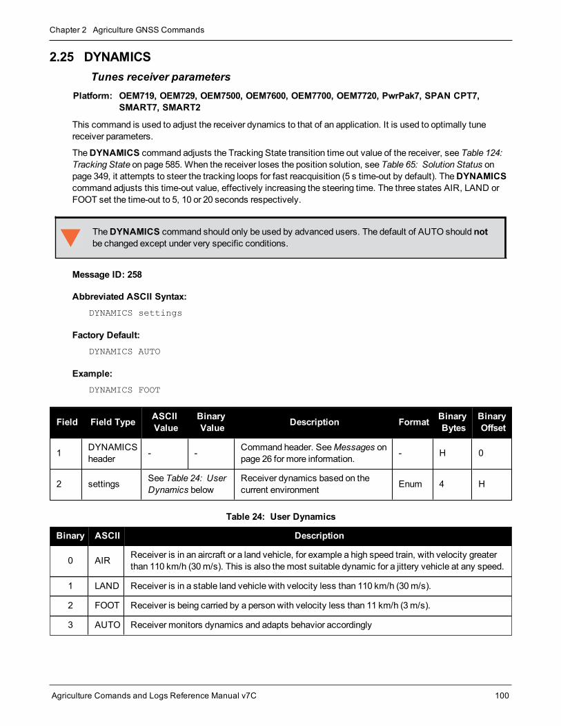
Chapter 2 Agriculture GNSS Commands
Agriculture Comands and Logs Reference Manual v7C 100
2.25 DYNAMICSTunes receiver parameters
Platform: OEM719, OEM729, OEM7500, OEM7600, OEM7700, OEM7720, PwrPak7, SPAN CPT7,SMART7, SMART2
This command is used to adjust the receiver dynamics to that of an application. It is used to optimally tunereceiver parameters.
TheDYNAMICS command adjusts the Tracking State transition time out value of the receiver, see Table 124:Tracking State on page 585. When the receiver loses the position solution, see Table 65: Solution Status onpage 349, it attempts to steer the tracking loops for fast reacquisition (5 s time-out by default). TheDYNAMICScommand adjusts this time-out value, effectively increasing the steering time. The three states AIR, LAND orFOOT set the time-out to 5, 10 or 20 seconds respectively.
TheDYNAMICS command should only be used by advanced users. The default of AUTO should notbe changed except under very specific conditions.
Message ID: 258
Abbreviated ASCII Syntax:DYNAMICS settings
Factory Default:DYNAMICS AUTO
Example:DYNAMICS FOOT
Field Field Type ASCIIValue
BinaryValue Description Format Binary
BytesBinaryOffset
1 DYNAMICSheader - - Command header. SeeMessages on
page 26 for more information. - H 0
2 settings See Table 24: UserDynamics below
Receiver dynamics based on thecurrent environment Enum 4 H
Binary ASCII Description
0 AIR Receiver is in an aircraft or a land vehicle, for example a high speed train, with velocity greaterthan 110 km/h (30m/s). This is also themost suitable dynamic for a jittery vehicle at any speed.
1 LAND Receiver is in a stable land vehicle with velocity less than 110 km/h (30m/s).
2 FOOT Receiver is being carried by a person with velocity less than 11 km/h (3m/s).
3 AUTO Receiver monitors dynamics and adapts behavior accordingly
Table 24: User Dynamics

Chapter 2 Agriculture GNSS Commands
Agriculture Comands and Logs Reference Manual v7C 101
Qualifying North American Solar Challenge cars annually weave their way through 1000’s of milesbetween the US and Canada. GNSS keeps them on track throughmany intersections on secondaryhighways and gives the Calgary team constant intelligence on the competition’s every move. In thiscase, with average speeds of 46miles/hour and at times a jittery vehicle, AIR is themost suitabledynamic.

Chapter 2 Agriculture GNSS Commands
Agriculture Comands and Logs Reference Manual v7C 102
2.26 ECHOSets port echo
Platform: OEM719, OEM729, OEM7500, OEM7600, OEM7700, OEM7720, PwrPak7, SPAN CPT7,SMART7, SMART2
This command is used to set a port to echo.
Message ID: 1247
Abbreviated ASCII Syntax:ECHO [port] echo
Factory Default:ECHO COM1 OFF
ECHO COM2 OFF
ECHO COM3 OFF (not supported onOEM719)
ECHO COM4 OFF (OEM7600, OEM7700 andOEM7720 only)
ECHO COM5 OFF (OEM7600, OEM7700 andOEM7720 only)
ECHO USB1 OFF
ECHO USB2 OFF
ECHO USB3 OFF
ECHO ICOM1 OFF (not supported onOEM719)
ECHO ICOM2 OFF (not supported onOEM719)
ECHO ICOM3 OFF (not supported onOEM719)
ECHO ICOM4 OFF (not supported onOEM719)
ECHO ICOM5 OFF (not supported onOEM719)
ECHO ICOM6 OFF (not supported onOEM719)
ECHO ICOM7 OFF (not supported onOEM719)
ECHO SCOM1 OFF
ECHO SCOM2 OFF
ECHO SCOM3 OFF
ECHO SCOM4 OFF
ASCII Example:ECHO COM1 ON
ECHO ON

Chapter 2 Agriculture GNSS Commands
Agriculture Comands and Logs Reference Manual v7C 103
Field FieldType
ASCIIValue
BinaryValue Description Format Binary
BytesBinaryOffset
1 ECHOHeader - - Command header. SeeMessages
on page 26 for more information. - H 0
2 portSee Table 25:Communications PortIdentifiers below
Port to configure(default = THISPORT) Enum 4 H
3 echoOFF 0 Sets port echo to off
Enum 4 H+4ON 1 Sets port echo to on
ASCII Port Name Binary Value
ALL 8
BT1 33
CCOM1 38
CCOM2 39
CCOM3 40
CCOM4 41
CCOM5 42
CCOM6 43
COM1 1
COM2 2
COM3 3
COM4 19
COM5 31
COM6 32
COM7 34
COM8 35
COM9 36
COM10 37
Table 25: Communications PortIdentifiers

Chapter 2 Agriculture GNSS Commands
Agriculture Comands and Logs Reference Manual v7C 104
ASCII Port Name Binary Value
ETH1 20
FILE 7
ICOM1 23
ICOM2 24
ICOM3 25
ICOM4 29
ICOM5 46
ICOM6 47
ICOM7 48
IMU 21
NCOM1 26
NCOM2 27
NCOM3 28
NOPORT 0
SCOM1 49
SCOM2 50
SCOM3 51
SCOM4 52
THISPORT 6
USB1 13
USB2 14
USB3 15
WCOM1 30

Chapter 2 Agriculture GNSS Commands
Agriculture Comands and Logs Reference Manual v7C 105
2.27 ECUTOFFSets satellite elevation cut-off for GPS Satellites
Platform: OEM719, OEM729, OEM7500, OEM7600, OEM7700, OEM7720, PwrPak7, SPAN CPT7,SMART7, SMART2
This command is used to set the elevation cut-off angle for trackedGPS satellites. The receiver does not startautomatically searching for a GPS satellite until it rises above the cut-off angle (when satellite position isknown). Tracked satellites that fall below the cut-off angle are no longer tracked unless they aremanuallyassigned (see theASSIGN command on page 53).
In either case, satellites below the ECUTOFF angle are eliminated from the internal position and clock offsetsolution computations.
This command permits a negative cut-off angle; it could be used in these situations:
l The antenna is at a high altitude, and thus can look below the local horizon
l Satellites are visible below the horizon due to atmospheric refraction
Caremust be taken when usingECUTOFF command because the signals from lower elevation satel-lites are traveling throughmore atmosphere and are therefore degraded. Use of satellites below 5degrees is not recommended.
Use theELEVATIONCUTOFF command (see page 107) to set the cut-off angle for any system.
For dual antenna receivers, this command applies to both the primary and secondary antennas.
A low elevation satellite is a satellite the receiver tracks just above the horizon. Generally, a satellite isconsidered low elevation if it is between 0 and 15 degrees above the horizon.
There is no difference between the data transmitted from a low elevation satellite and that transmittedfrom a higher elevation satellite. However, differences in the signal path of a low elevation satellite maketheir use less desirable. Low elevation satellite signals havemore error due to the increased amount ofatmosphere they must travel through. In addition, signals from low elevation satellites don't fit theassumption that a signal travels in air nearly the same as in a vacuum. As such, using low elevationsatellites in the solution results in greater position inaccuracies.
The elevation cut-off angle is specified withECUTOFF to ensure that noisy, low elevation satellite databelow the cut-off is not used in computing a position. If post-processing data, it is still best to collect alldata (even that below the cut-off angle). Experimenting with different cut-off angles can then be done toprovide the best results. In cases where there are not enough satellites visible, a low elevation satellitemay actually help in providing a useful solution.
Message ID: 50
Abbreviated ASCII Syntax:ECUTOFF angle
Factory Default:

Chapter 2 Agriculture GNSS Commands
Agriculture Comands and Logs Reference Manual v7C 106
ECUTOFF 5.0
ASCII Example:ECUTOFF 10.0
Field FieldType
ASCIIValue
BinaryValue Description Format Binary
BytesBinaryOffset
1 ECUTOFFheader - - Command header. SeeMessages on
page 26 for more information. - H 0
2 angle ±90.0 degrees Elevation cut-off angle relative to horizon Float 4 H

Chapter 2 Agriculture GNSS Commands
Agriculture Comands and Logs Reference Manual v7C 107
2.28 ELEVATIONCUTOFFSets the elevation cut-off angle for tracked satellites
Platform: OEM719, OEM729, OEM7500, OEM7600, OEM7700, OEM7720, PwrPak7, SPAN CPT7,SMART7, SMART2
TheELEVATIONCUTOFF command is used to set the elevation cut-off angle for tracked satellites. Thereceiver does not start automatically searching for a satellite until it rises above the cut-off angle (when the satel-lite position is known). Tracked satellites that fall below the cut-off angle are no longer tracked unless they aremanually assigned (refer to theASSIGN command on page 53).
In either case, satellites below the elevation cut-off angle are eliminated from the internal position and clock off-set solution computations.
This command permits a negative cut-off angle and can be used in the following situations:
l The antenna is at a high altitude and thus can look below the local horizon
l Satellites are visible below the horizon due to atmospheric refraction
Caremust be taken when usingELEVATIONCUTOFF command because the signals from lower elev-ation satellites are traveling throughmore atmosphere and are therefore degraded. Use of satellitesbelow 5 degrees is not recommended.
This command combines the following commands into one convenient command: ECUTOFF,GLOECUTOFF, GALECUTOFF, QZSSECUTOFF, SBASECUTOFF, BDSECUTOFF andNAVICECUTOFF.
For dual antenna receivers, this command applies to both the primary and secondary antennas.
A low elevation satellite is a satellite the receiver tracks just above the horizon. Generally, a satellite isconsidered low elevation if it is between 0 and 15 degrees above the horizon.
There is no difference between the data transmitted from a low elevation satellite and that transmitted froma higher elevation satellite. However, differences in the signal path of a low elevation satellite make theiruse less desirable. Low elevation satellite signals havemore error due to the increased amount ofatmosphere they must travel through. In addition, signals from low elevation satellites don't fit theassumption that a signal travels in air nearly the same as in a vacuum. As such, using low elevationsatellites in the solution results in greater position inaccuracies.
The elevation cut-off angle is specified with theELEVATIONCUTOFF command to ensure that noisy, lowelevation satellite data below the cut-off is not used in computing a position. If post-processing data, it isstill best to collect all data (even that below the cutoff angle). Experimenting with different cut-off anglescan then be done to provide the best results. In cases where there are not enough satellites visible, a lowelevation satellite may actually help in providing a useful solution.
Message ID: 1735
Abbreviated ASCII Syntax:ELEVATIONCUTOFF Constellation Angle [Reserved]

Chapter 2 Agriculture GNSS Commands
Agriculture Comands and Logs Reference Manual v7C 108
Factory default:ELEVATIONCUTOFF ALL 5.0 0
ASCII Example:ELEVATIONCUTOFF GPS 5
ELEVATIONCUTOFF ALL 5
Field Field Type ASCIIValue
BinaryValue Description Format Binary
BytesBinaryOffset
1ELEVATIONCUTOFFheader
- - Command header. SeeMessageson page 26 for more information. - H 0
2 Constellation
GPS 0 Sets the cut-off angle for GPSConstellation satellites only.
Enum 4 H
GLONASS 1 Sets the cut-off angle for GLONASSconstellation satellites only.
SBAS 2 Sets the cut-off angle for SBASconstellation satellites only.
GALILEO 5 Sets the cut-off angle for Galileoconstellation satellites only.
BEIDOU 6 Sets the cut-off angle for BeiDouconstellation satellites only.
QZSS 7 Sets the cut-off angle for QZSSconstellation satellites only.
NAVIC 9 Sets the cut-off angle for NavICconstellation satellites only.
ALL 32Sets the cut-off angle for allsatellites regardless of theconstellation.
3 Angle ±90.0 degrees Elevation cut-off angle relative to thehorizon. Float 4 H+4
4 Reserved 0 Reserved Field (optional) Ulong 4 H+8

Chapter 2 Agriculture GNSS Commands
Agriculture Comands and Logs Reference Manual v7C 109
2.29 ETHCONFIGConfigures Ethernet physical layer
Platform: OEM729, OEM7600, OEM7700, OEM7720, PwrPak7, SPAN CPT7, SMART7-I, SMART7-SI
This command is used to configure the Ethernet physical layer.
Message ID: 1245
Abbreviated ASCII Syntax:ETHCONFIG interface_name [speed] [duplex] [crossover] [power_mode]
Factory Default:
ETHCONFIG etha auto auto auto powerdown (OEM7 receiver cards)
ETHCONFIG etha auto auto auto auto (PwrPak7)
ASCII Example:ETHCONFIG etha 100 full mdix normal
Field Field Type ASCII Value BinaryValue Description Format Binary
BytesBinaryOffset
1 ETHCONFIGHeader - -
Command header. SeeMessages on page 26 for moreinformation.
- H 0
2 interface_name ETHA 2 Name of the Ethernet interface Enum 4 H
3 speed
AUTO 1
Auto-negotiate speed (default)
AUTO is the recommendedvalue for the speed parameter.
If setting speed to AUTO,duplex must be set to AUTO atthe same time otherwise a“parameter 3 out of range” erroroccurs.
Enum 4 H+4
10 2 Force 10BaseT
100 3 Force 100BaseT
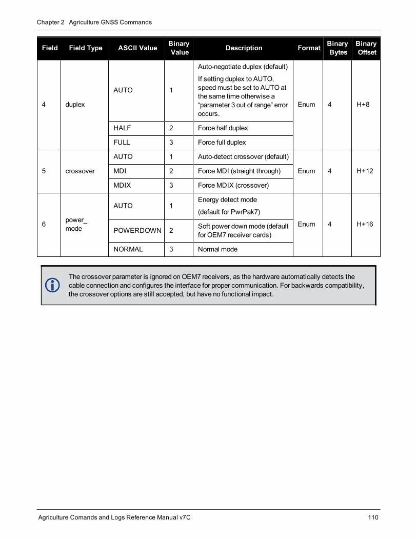
Chapter 2 Agriculture GNSS Commands
Agriculture Comands and Logs Reference Manual v7C 110
Field Field Type ASCII Value BinaryValue Description Format Binary
BytesBinaryOffset
4 duplex
AUTO 1
Auto-negotiate duplex (default)
If setting duplex to AUTO,speedmust be set to AUTO atthe same time otherwise a“parameter 3 out of range” erroroccurs.
Enum 4 H+8
HALF 2 Force half duplex
FULL 3 Force full duplex
5 crossover
AUTO 1 Auto-detect crossover (default)
Enum 4 H+12MDI 2 ForceMDI (straight through)
MDIX 3 ForceMDIX (crossover)
6 power_mode
AUTO 1Energy detect mode
(default for PwrPak7)
Enum 4 H+16POWERDOWN 2 Soft power downmode (default
for OEM7 receiver cards)
NORMAL 3 Normal mode
The crossover parameter is ignored onOEM7 receivers, as the hardware automatically detects thecable connection and configures the interface for proper communication. For backwards compatibility,the crossover options are still accepted, but have no functional impact.

Chapter 2 Agriculture GNSS Commands
Agriculture Comands and Logs Reference Manual v7C 111
2.30 EVENTINCONTROLControls Event-In input triggers
Platform: OEM719, OEM729, OEM7500, OEM7600, OEM7700, OEM7720, PwrPak7, SPAN CPT7,SMART7, SMART2
This command controls up to four Event-In input triggers. Each input can be used as an event strobe.
When used as an event strobe, an accurate GPS time or position is applied to the rising or falling edge of theinput event pulse (refer to theMARK1TIME, MARK2TIME, MARK3TIME and MARK4TIME log on page 489orMARKPOS, MARK2POS, MARK3POS and MARK4POS log on page 486). Each input strobe is usuallyassociated with a separate device, therefore different solution output lever arm offsets can be applied to eachstrobe. When used as an Event Input Trigger, it is possible to overwhelm the receiver with a very high rate ofinput events that impacts the performance of the receiver. For this reason, the receiver internally throttles therate at which it responds to input events. The limit is 200 Hz.
Message ID: 1637
Abbreviated ASCII Syntax:EVENTINCONTROL mark switch [polarity] [t_bias] [t_guard]
ASCII Example:EVENTINCONTROL MARK1 ENABLE
Field Field Type ASCIIValue
BinaryValue Description Format Binary
BytesBinaryOffset
1EVENTINCONTROLheader
- - Command header. SeeMessages onpage 26 for more information. - H 0
2 mark
MARK1 0 Choose which Event-In Mark tochange. This valuemust be specified.
Note: MARK3 andMARK4 areavailable only onOEM7600,OEM7700 andOEM7720 receivers.
Enum 4 HMARK2 1
MARK3 2
MARK4 3
3 switch
DISABLE 0 Disables Event Input
Enum 4 H+4EVENT 1 Enables Event Input
ENABLE 3 A synonym for the EVENT option (forcompatibility with previous releases)
4 polarityNEGATIVE 0 Negative polarity (default)
Enum 4 H+8POSITIVE 1 Positive polarity

Chapter 2 Agriculture GNSS Commands
Agriculture Comands and Logs Reference Manual v7C 112
Field Field Type ASCIIValue
BinaryValue Description Format Binary
BytesBinaryOffset
5 t_bias
default: 0minimum: -999,999,999maximum:999,999,999
A constant time bias in nanosecondscan be applied to each event pulse.Typically this is used to account for atransmission delay.
This field is not used if the switch fieldis set to COUNT.
Long 4 H+12
6 t_guarddefault: 4minimum: 2maximum: 3,599,999
The time guard specifies theminimumnumber of milliseconds betweenpulses. This is used to coarsely filterthe input pulses.
If Field 3 is COUNT, this field is notused.
Ulong 4 H+16

Chapter 2 Agriculture GNSS Commands
Agriculture Comands and Logs Reference Manual v7C 113
2.31 EVENTOUTCONTROLControl Event-Out properties
Platform: OEM719, OEM729, OEM7500, OEM7600, OEM7700, OEM7720, PwrPak7, SPAN CPT7
This command configures up to seven Event-Out output strobes. The event strobes toggle between 3.3 V and 0V. The pulse consists of two periods: one active period followed by a not active period. The start of the activeperiod is synchronized with the top of the GNSS time second and the signal polarity determines whether the act-ive level is 3.3 V or 0 V. The not active period immediately follows the active period and has the alternatevoltage.
The outputs that are available vary according to the platform.
A 100MHz clock is used internally to create these output signals. As a result, all period values are lim-ited to 10 ns steps.
The EVENTOUT outputs cannot synchronize with GPS time until the receiver reachesFINESTEERING time status. As the receiver transitions to GPS time, theremay be additional, unex-pected pulses on the EVENTOUT signals.
Message ID: 1636
Abbreviated ASCII Syntax:EVENTOUTCONTROL mark switch [polarity] [active_period] [non_active_period]
ASCII Example:EVENTOUTCONTROL MARK3 ENABLE
Field Field Type ASCIIValue
BinaryValue Description Format Binary
BytesBinaryOffset
1EVENTOUTCONTROLheader
- - Command header. SeeMessages onpage 26 for more information. - H 0
2 mark
MARK1 0Choose which Event-Out Mark tochange. This valuemust bespecified.
Note: OnOEM719 andOEM729receivers, only MARK1 is available.
Note: OnOEM7600, OEM7700 andOEM7720 receivers, only MARK1throughMARK4 are available.
Enum 4 H
MARK2 1
MARK3 2
MARK4 3
MARK5 4
MARK6 5
MARK7 6

Chapter 2 Agriculture GNSS Commands
Agriculture Comands and Logs Reference Manual v7C 114
Field Field Type ASCIIValue
BinaryValue Description Format Binary
BytesBinaryOffset
3 switchDISABLE 0 Disables the Event output
Enum 4 H+4ENABLE 1 Enables the Event output
4 polarityNEGATIVE 0 Negative polarity (active = 0V)
(default) Enum 4 H+8POSITIVE 1 Positive polarity (active = 3.3V)
5 active_period
default: 500,000,000minimum: 10maximum:999,999,990
Active period of the Event Out signalin nanoseconds.
10 ns steps must be used.
Note: If the value entered is not amultiple of 10, it will be rounded downto the nearest 10 ns.
Ulong 4 H+12
6 non_active_period
default: 500,000,000minimum: 10maximum:999,999,990
Non-active period of the Event Outsignal in nanoseconds.
10 ns steps must be used.
Note: If the value entered is not amultiple of 10, it will be rounded downto the nearest 10 ns.
Ulong 4 H+16
The sum of the active period and inactive period should total 1,000,000,000 ns. If the totalexceeds one full second, the active period duration will be as given and the inactive period will bethe remainder of the second.
Alternately, the sum of the active and inactive periods may be less than 1,000,000,000 ns, butshould divide evenly into 1,000,000,000 ns. For example, if the active period is 150,000,000 andthe inactive period is 50,000,000, the sum of the periods is 200,000,000 ns which divides evenlyinto one full second.
If the sum is less than one full second and not an evenmultiple, the last active or inactive periodis stretched or truncated to equal one full second.
A 100MHz clock is used internally to create these output signals. As a result, all period valuesare limited to 10 ns steps.

Chapter 2 Agriculture GNSS Commands
Agriculture Comands and Logs Reference Manual v7C 115
2.32 FIXConstrains to fixed height or position
Platform: OEM719, OEM729, OEM7500, OEM7600, OEM7700, OEM7720, PwrPak7, SPAN CPT7,SMART7, SMART2
This command is used to fix height or position to the input values. For various applications, fixing these valuescan assist in improving acquisition times and accuracy of position or corrections. For example, fixing the positionis a requirement for differential base stations as it provides the reference position to base the differential cor-rections from.
1. It is strongly recommended that the FIX POSITION entered be accurate to within a few meters. Thislevel of accuracy can be obtained from a receiver using single point positioning once 5 or 6 satellitesare being tracked.
2. FIX POSITION should only be used for base station receivers. Applying FIX POSITION to a roverswitches it from RTK mode to a fixed positionmode. Applying FIX POSITION to the rover does notspeed up ambiguity resolution.
3. Any setting other than FIX POSITION disables output of differential corrections unless theMOVINGBASESTATION command (see page 172) is set to ENABLE.
4. You can fix the position of the receiver using latitude, longitude and height in Mean Sea Level (MSL)or ellipsoidal parameters depending on the UNDULATION setting. The factory default for theUNDULATION command (see page 296) setting is EGM96, where the height entered in the FIX com-mand is set as MSL height. If you change the UNDULATION setting to USER 0, the height enteredin the FIX command is set as ellipsoidal height (refer to Table 26: FIX Parameters on the next page).
Error checking is performed on the entered fixed position by the integrity monitor. Depending on the result of thischeck, the position can be flagged with the following statuses.
l SOL_COMPUTED: The entered position has been confirmed by measurement.
l PENDING: Insufficient measurements are available to confirm the entered position.
l INTEGRITY_WARNING: First level of error when an incorrect position has been entered. The fixed positionis off by approximately 25-50meters.
l INVALID_FIX: Second level of error when an inaccurate position has been entered. The fixed position is offby a gross amount.
An incorrectly entered fixed position will be flagged either INTEGRITY_WARNING or INVALID_FIX.This will stop output of differential corrections or RTK measurements and can affect the clock steeringand satellite signal search.
Message ID: 44
Abbreviated ASCII Syntax:FIX type [param1 [param2 [param3]]]
Factory Default:FIX none
ASCII Example:

Chapter 2 Agriculture GNSS Commands
Agriculture Comands and Logs Reference Manual v7C 116
FIX none
FIX HEIGHT 4.567
FIX position 51.116 -114.038 1065.0
In order to maximize the absolute accuracy of RTK rover positions, the base station coordinates mustbe fixed to their known position using the FIX POSITION [lat][lon][hgt] command.
Field FieldType
ASCIIValue
BinaryValue Description Format Binary
BytesBinaryOffset
1 FIXheader - - Command header. SeeMessages on
page 26 for more information. - H 0
2 type See Table 27: FixTypes on the next page Fix type Enum 4 H
3 param1See Table 26: FIXParameters below
Parameter 1 Double 8 H + 4
4 param2 Parameter 2 Double 8 H + 12
5 param3 Parameter 3 Double 8 H + 20
ASCIITypeName
Parameter 1 Parameter 2 Parameter 3
AUTO Not used Not used Not used
HEIGHTDefault MSL height 1
(-1000 to 20000000m)Not used Not used
NONE Not used Not used Not used
POSITIONLat (-90 to 90 degrees) where a ‘-’sign denotes south and a ‘+’ signdenotes north
Lon (-360 to 360 degrees) where a ‘-’sign denotes west and a ‘+’ signdenotes east
Default MSL height 1
(-1000 to 20000000 m)
Table 26: FIX Parameters
For a discussion on height, refer toAn Introduction to GNSS available on our website at nova-tel.com/contactus/an-introduction-to-gnss.
1See also Note #4 above.

Chapter 2 Agriculture GNSS Commands
Agriculture Comands and Logs Reference Manual v7C 117
ASCIIName
BinaryValue Description
NONE 0 Unfix. Clears any previous FIX commands
AUTO 1Configures the receiver to fix the height at the last calculated value if the number ofsatellites available is insufficient for a 3-D solution. This provides a 2-D solution. Heightcalculation resumes when the number of satellites available allows a 3-D solution
HEIGHT 2
Configures the receiver in 2-D mode with its height constrained to a given value. Thiscommand is usedmainly in marine applications where height in relation tomean sea levelmay be considered to be approximately constant. The height entered using this command isreferenced to themean sea level, see theBESTPOS log on page 346 (is in meters). Thereceiver is capable of receiving and applying differential corrections from a base stationwhile fix height is in effect. The fix height command overrides any previous FIX HEIGHT orFIX POSITION command.
Note: This command only affects pseudorange corrections and solutions.
POSITION 3
Configures the receiver with its position fixed. This command is used when it is necessaryto generate differential corrections.
For both pseudorange and differential corrections, this commandmust be properly initializedbefore the receiver can operate as aGNSS base station. Once initialized, the receivercomputes differential corrections for each satellite being tracked. The computed differentialcorrections can then be output to rover stations using the RTCMV3 differential correctionsdata log format. See the SMART7 Installation andOperation User Manual for informationabout using the receiver for differential applications.
The values entered into the fix position command should reflect the precise position of thebase station antenna phase center. Any errors in the fix position coordinates directly biasthe corrections calculated by the base receiver.
The receiver performs all internal computations based onWGS84 and theDATUMcommand (see page 93) is defaulted as such. The datum in which you choose to operate (bychanging theDATUM command (see page 93)) is internally converted to and fromWGS84.Therefore, all differential corrections are based onWGS84, regardless of your operatingdatum.
The FIX POSITION command overrides any previous FIX HEIGHT or FIX POSITIONcommand settings.
Table 27: Fix Types

Chapter 2 Agriculture GNSS Commands
Agriculture Comands and Logs Reference Manual v7C 118
2.33 FRESETClears selected data from NVM and reset
Platform: OEM719, OEM729, OEM7500, OEM7600, OEM7700, OEM7720, PwrPak7, SPAN CPT7,SMART7, SMART2
This command is used to clear data which is stored in non-volatile memory. Such data includes the almanac,ephemeris, and any user specific configurations. The commands, ephemeris, almanac, and L-Band related data,excluding the subscription information, can be cleared by using the STANDARD target. The receiver is forced toreset.
FRESET STANDARD (which is also the default) causes most commands, ephemeris, GNSS andalmanac data previously saved to NVM to be erased.
The FRESET STANDARD commandwill erase all user settings. You should know your configuration(by requesting theRXCONFIG log on page 653) and be able to reconfigure the receiver before you sendthe FRESET command.
Message ID: 20
Abbreviated ASCII Syntax:FRESET [target]
Input Example:FRESET COMMAND
Field FieldType
ASCIIValue
BinaryValue Description Format Binary
BytesBinaryOffset
1 FRESETheader - - Command header. SeeMessages
on page 26 for more information. - H 0
2 target See Table 28: FRESETTarget on the next page
What data is to be reset by thereceiver (default = STANDARD) Enum 4 H
If you are receiving no data or random data from your receiver, try the following before contactingNovAtel:
l Verify that the receiver is tracking satellites by logging the TRACKSTAT log (see page 741) andchecking that the receiver is tracking at least four satellites.
l Check the integrity and connectivity of power, antenna and data cables
l Verify the baud rate settings of the receiver and terminal device (your PC, data logger or laptop)
l Switch COM ports
l Issue the FRESET command.

Chapter 2 Agriculture GNSS Commands
Agriculture Comands and Logs Reference Manual v7C 119
Binary ASCII Description
0 STANDARD
Resets commands (except CLOCKCALIBRATION andMODEL).
Resets the stored ephemeris and almanac from all satellite systems.
Resets all L-Band related data except for the subscription information.
Does not reset the Ethernet settings or stored Profile configurations.
(default)
1 COMMAND Resets the stored commands (saved configuration)
2 GPSALMANAC Resets the stored GPS almanac
3 GPSEPHEM Resets the stored GPS ephemeris
4 GLOEPHEM Resets the stored GLONASS ephemeris
5 MODEL Resets the currently selectedmodel
10 USERDATA Resets the user data saved using theNVMUSERDATA command (seepage 185)
11 CLKCALIBRATION Resets the parameters entered using theCLOCKCALIBRATE command(see page 86)
20 SBASALMANAC Resets the stored SBAS almanac
21 LAST_POSITION Resets the position using the last stored position
31 GLOALMANAC Resets the stored GLONASS almanac
39 GALFNAV_EPH Resets the stored GALFNAV ephemeris
40 GALINAV_EPH Resets the stored GALINAV ephemeris
45 GALFNAV_ALM Resets the stored GALFNAV almanac
46 GALINAV_ALM Resets the stored GALINAV almanac
52 PROFILEINFO Resets the stored profile configurations
54 QZSSALMANAC Resets the QZSS almanac
55 QZSSEPHEMERIS Resets the QZSS ephemeris
57 BDSALMANAC Resets the BeiDou almanac
58 BDSEPHEMERIS Resets the BeiDou ephemeris
60 USER_ACCOUNTS Resets the admin password to the default (the receiver PSN)
64 ETHERNET Resets the stored Ethernet settings
85 SRTK_SUBSCRIPTIONS Resets the Secure RTK Subscription data stored on the rover receiver
Table 28: FRESET Target

Chapter 2 Agriculture GNSS Commands
Agriculture Comands and Logs Reference Manual v7C 120
Binary ASCII Description
87 NAVICEPHEMERIS Resets the NavIC ephemeris
88 NAVICALMANAC Resets the NavIC almanac
93 USER_DATUM Resets the user datums (see theGEODETICDATUM command onpage 126)
94 USER_DATUM_TRANSFORMATION
Resets the user datums transformations (see theDATUMTRANSFORMATION command on page 95)

Chapter 2 Agriculture GNSS Commands
Agriculture Comands and Logs Reference Manual v7C 121
2.34 GALECUTOFFSets elevation cut-off angle for Galileo satellites
Platform: OEM719, OEM729, OEM7500, OEM7600, OEM7700, OEM7720, PwrPak7, SPAN CPT7,SMART7, SMART2
This command is used to set the elevation cut-off angle for trackedGalileo satellites. The receiver does not startautomatically searching for a satellite until it rises above the cut-off angle (when satellite position is known).Tracked satellites that fall below the cut-off angle are no longer tracked unless they weremanually assigned (seetheASSIGN command on page 53).
In either case, satellites below theGALECUTOFF angle are eliminated from the internal position and clock off-set solution computations.
This command permits a negative cut-off angle and can be used in the following situations:
l The antenna is at a high altitude and thus look below the local horizon
l Satellites are visible below the horizon due to atmospheric refraction
Caremust be taken when usingGALECUTOFF because the signals from lower elevation satellites aretraveling throughmore atmosphere and are therefore degraded. Use of satellites below 5 degrees is notrecommended.
Use theELEVATIONCUTOFF command (see page 107) to set the cut-off angle for any system.
For dual antenna receivers, this command applies to both the primary and secondary antennas.
Message ID: 1114
Abbreviated ASCII Syntax:GALECUTOFF angle
Factory Default:GALECUTOFF 5.0
ASCII Example:GALECUTOFF 10.0
Field Field Type ASCIIValue
BinaryValue Description Format Binary
BytesBinaryOffset
1 GALECUTOFFheader - - Command header. SeeMessages on
page 26 for more information. - H 0
2 angle ±90.0 degrees Elevation cut-off angle relative tohorizon Float 4 H

Chapter 2 Agriculture GNSS Commands
Agriculture Comands and Logs Reference Manual v7C 122
2.35 GENERATEALIGNCORRECTIONSConfigure ALIGN Master
Platform: OEM719, OEM729, OEM7500, OEM7600, OEM7700, OEM7720, PwrPak7, SPAN CPT7,SMART7
This command is used to configure the ALIGN Master and starts sending out ALIGN corrections through the spe-cified port. This command is like sending the following commands to theMaster, assuming the use of a serialport and default ALIGN corrections:
unlogall [port]fix nonemovingbasestation enableinterfacemode [port] novatel rtcaserialconfig [port] [baud] N 8 1 N ONlog [port] rtcaobs3 ontime [rate = 1/ obsreqrate]log [port] rtcarefext ontime [rate = 1/ refextreqrate]
Message ID: 1349
Abbreviated ASCII Syntax:GENERATEALIGNCORRECTIONS port [baud] [obsreqrate] [refextreqrate][interfacemode]
ASCII Example:GENERATEALIGNCORRECTIONS COM2 230400 10 10
Field Field Type ASCIIValue
BinaryValue Description Format Binary
BytesBinaryOffset
1GENERATEALIGNCORRECTIONSheader
- -Command header. SeeMessages on page 26 formore information.
- H 0
2 portSee Table 25:Communications PortIdentifiers on page 103
Port identifier(default = THISPORT) Enum 4 H
3 baud9600, 19200, 38400,57600, 115200, 230400 or460800
Communication baudrate (bps)(default = 9600)
Ulong 4 H+4
4 obsreqrate 1, 2, 4, 5, 10, 20, 50 or 100RTCAOBS3 data rate inHz(default = 1)
Ulong 4 H+8
5 refextreqrate 0, 1, 2, 4, 5, 10, 20, 50 or100
RTCAREFEXT data ratein Hz(default = 1)
Ulong 4 H+12
6 interfacemodeRTCA 3 Correction interface
mode(default = RTCA)
Enum 4 H+16NOVATELX 35

Chapter 2 Agriculture GNSS Commands
Agriculture Comands and Logs Reference Manual v7C 123
2.36 GENERATEDIFFCORRECTIONSSends a preconfigured set of differential corrections
Platform: OEM719, OEM729, OEM7500, OEM7600, OEM7700, OEM7720, PwrPak7, SPAN CPT7,SMART7, SMART2
This command is used to configure the receiver to send a preconfigured set of differential pseudorange cor-rections.
Message ID: 1296
Abbreviated ASCII Syntax:GENERATEDIFFCORRECTIONS mode port
ASCII Example:GENERATEDIFFCORRECTIONS rtcm com2
Preconfigured set of differential corrections sent when RTCM:
RTCM1 ontime 1RTCM31 ontime 1RTCM3 ontime 10
Preconfigured set of differential corrections sent when RTCA:
RTCA1 ontime 1RTCAREF ontime 10
Field Field Type ASCIIValue
BinaryValue Description Format Binary
BytesBinaryOffset
1GENERATEDIFFCORRECTIONSheader
- - Command header. SeeMessageson page 26 for more information. - H 0
2 modeRTCM 2 Serial port interfacemode
identifier. See Table 30: SerialPort InterfaceModes on page 138
Enum 4 HRTCA 3
3 port
See Table 51:COM PortIdentifiers onpage 256
Port to configure Enum 4 H+4

Chapter 2 Agriculture GNSS Commands
Agriculture Comands and Logs Reference Manual v7C 124
2.37 GENERATERTKCORRECTIONSSends a preconfigured set of RTK corrections
Platform: OEM719, OEM729, OEM7500, OEM7600, OEM7700, OEM7720, PwrPak7, SPAN CPT7,SMART7
This command is used to configure the receiver to send a preconfigured set of RTK (carrier phase) corrections.
Message ID: 1260
Abbreviated ASCII Syntax:GENERATERTKCORRECTIONS mode port
ASCII Example:GENERATERTKCORRECTIONS rtcmv3 com2
Preconfigured set of differential corrections sent when RTCM:
RTCM1819 ontime 1
RTCM3 ontime 10
RTCM22 ontime 10
RTCM23 ontime 60
RTCM24 ontime 60
Preconfigured set of differential corrections sent when RTCMV3:
RTCM1004 ontime 1RTCM1012 ontime 1RTCM1006 ontime 10RTCM1008 ontime 10RTCM1033 ontime 10
Preconfigured set of differential corrections sent when RTCA:
RTCAOBS2 ontime 1
RTCAREF ontime 10
Preconfigured set of differential corrections sent when CMR:
CMROBS ontime 1
CMRGLOOBS ontime 1
CMRREF ontime 10
Preconfigured set of differential corrections sent when NOVATELX:
NOVATELXOBS ontime 1
Field Field Type ASCIIValue
BinaryValue Description Format Binary
BytesBinaryOffset
1GENERATERTKCORRECTIONSheader
- -Command header. SeeMessages on page 26 for moreinformation.
- H 0

Chapter 2 Agriculture GNSS Commands
Agriculture Comands and Logs Reference Manual v7C 125
Field Field Type ASCIIValue
BinaryValue Description Format Binary
BytesBinaryOffset
2 mode
RTCM 2
Serial port interfacemodeidentifier. For more information,see Table 30: Serial PortInterfaceModes on page 138
Enum 4 H
RTCA 3
CMR 4
RTCMV3 14
NOVATELX 35
3 portSee Table 51: COMPort Identifiers onpage 256
Port to configure Enum 4 H+4
For information about the RTCM, RTCA and CMR messages, refer to the official standards documentfor thosemessages.

Chapter 2 Agriculture GNSS Commands
Agriculture Comands and Logs Reference Manual v7C 126
2.38 GEODETICDATUMSet user-defined datum parameters
Platform: OEM719, OEM729, OEM7500, OEM7600, OEM7700, OEM7720, PwrPak7, SPAN CPT7,SMART7, SMART2
Use this command to add or remove user-defined datums. These are used by theOUTPUTDATUM command(see page 186) to select an entry from theDATUMTRANSFORMATIONS log (see page 377). They also definethe parameters to convert between geodetic and Cartesian coordinates.
TheOUTPUTDATUM command (see page 186) must be sent for any user-defined datums to be out-put.
The receiver firmware includes a default set of datums. These default datums cannot be deleted, but can be over-written with user-defined parameters. A default datum that has been overwritten can be reverted to the defaultparameters by deleting the datum. User-defined datums will persist a factory reset; all user-defined datums canbe removed by sending FRESET USER_DATUM (see the FRESET command on page 118). Both the user-defined and default datums are reported by theGEODETICDATUMS log (see page 394).
Datum entries are indexed by name, whichmust be unique. The name “USER” is reserved for theUSEREXPDATUM entry. “ECEF” is reserved as a generic Earth-Centered Earth-Fixed datum. “UNKNOWN” isalso reserved.
The EPSGGeodetic Parameter Dataset (www.epsg-registry.org/) is a commonly-referenced database ofcoordinate reference systems and coordinate transformations. The EPSG code in this log is intended to cor-respond to the “GeodeticDatum” data type within that database. If you are using a custom datum, the ESPGcode should be 0.
Message ID: 2295
Abbreviated ASCII Syntax:GEODETICDATUM switch name epsg_code anchor semimajor_axis flattening
Factory Default:GEODETICDATUM none
ASCII Example:
Save a new geodetic datum to NVM:
GEODETICDATUM save NAD83(MA11) 1118 EARTH_FIXED 6378137.0 298.257222101
Delete an existing geodetic datum from NVM:
GEODETICDATUM delete NAD83(MA11)
Field Field Type ASCIIValue
BinaryValue Description Format Binary
BytesBinaryOffset
1 GEODETICDATUMheader – –
Command header. SeeMessages on page 26 formore information.
– H 0

Chapter 2 Agriculture GNSS Commands
Agriculture Comands and Logs Reference Manual v7C 127
Field Field Type ASCIIValue
BinaryValue Description Format Binary
BytesBinaryOffset
2 switchSAVE 1 Save the datum.
Enum 4 HDELETE 2 Delete the datum.
3 name Name of the datum. Char[32] variable H+4
4 epsg_code The EPSG code. Ulong 4 variable
5 anchorSee Table 29:Datum Anchorsbelow
The datum type. Enum 4 variable
6 semimajor_axis 6300000.000 –6400000.000
Semi-major axis of thedatum's ellipsoid (meters) Double 8 variable
7 flattening 290.000 – 305.000 Inverse flattening of thedatum's ellipsoid (unitless) Double 8 variable
Binary ASCII Description
0 UNKNOWN The anchor is unknown.
1 EARTH_FIXED The datum is not anchored to a specific tectonic plate (e.g., ITRF2005, WGS84).
2 PLATE_FIXED The datum is anchored to a tectonic plate (e.g., NAD83, ETRF89).
Table 29: Datum Anchors

Chapter 2 Agriculture GNSS Commands
Agriculture Comands and Logs Reference Manual v7C 128
2.39 GGAQUALITYCustomizes the GPGGA GPS quality indicator
Platform: OEM719, OEM729, OEM7500, OEM7600, OEM7700, OEM7720, PwrPak7, SPAN CPT7,SMART7, SMART2
This command is used to customize the NMEA GPGGA GPS quality indicator. See also theGPGGA log onpage 417.
This command also changes the GPS quality indicator in the NMEA2000 CAN logs.
Message ID: 691
Abbreviated ASCII Syntax:GGAQUALITY #entries pos_type quality
Input Example 1:GGAQUALITY 1 waas 2
Makes theWAAS solution type show 2 as the quality indicator.
Input Example 2:GGAQUALITY 2 waas 2 NARROW_FLOAT 3
Makes theWAAS solution type show 2 and the NARROW_FLOAT solution type show 3, as their quality indic-ators.
Input Example 3:GGAQUALITY 0
Sets all the quality indicators back to the default.
Some solution types, see Table 66: Position or Velocity Type on page 350, share a quality indicator.For example, converged PPP and NARROW_FLOAT all share an indicator of 5. This command can beused to customize an application to have unique indicators for each solution type. Sets all the qualityindicators back to the default. Refer to Table 87: GPS Quality Indicators on page 418.
Field Field Type ASCIIValue
BinaryValue Description Format Binary
BytesBinaryOffset
1 GGAQUALITYheader - - Command header. SeeMessages
on page 26 for more information. - H 0
2 #entries 0-20 The number of position types thatare being remapped (20max) Ulong 4 H
3 pos_typeSee Table 66:Position or VelocityType on page 350
The position type that is beingremapped Enum 4 H+4

Chapter 2 Agriculture GNSS Commands
Agriculture Comands and Logs Reference Manual v7C 129
Field Field Type ASCIIValue
BinaryValue Description Format Binary
BytesBinaryOffset
4 qualitySee Table 87: GPSQuality Indicators onpage 418
The remapped quality indicatorvalue that will appear in theGPGGA log for this position type
Ulong 4 H+8
... Next solution type and quality indicator set, if applicable Variable

Chapter 2 Agriculture GNSS Commands
Agriculture Comands and Logs Reference Manual v7C 130
2.40 GLIDEINITIALIZATIONPERIODConfigures the GLIDE initialization period
Platform: OEM719, OEM729, OEM7500, OEM7600, OEM7700, OEM7720, PwrPak7, SPAN CPT7,SMART7, SMART2
This command sets the initialization period for Relative PDP (GLIDE) when pseudorangemeasurements areusedmore heavily. During the initialization period, the PDP output position is not as smooth as during full GLIDEoperation, but it helps to get better absolute accuracy at the start. The longer this period is, the better the abso-lute accuracy that can be attained. Themaximum period that can be set throughGLIDEINITIALIZATIONPERIOD is 1200 seconds.
Message ID: 1760
Abbreviated ASCII Syntax:GLIDEINITIALIZATIONPERIOD initialization
Factory Default:GLIDEINITIALIZATIONPERIOD 300
ASCII Example:GLIDEINITIALIZATIONPERIOD 100
Field Field Type ASCIIValue
BinaryValue Description Binary
FormatBinaryBytes
BinaryOffset
1 GLIDEINITIALIZATIONPERIOD header - -
Command header. SeeMessages on page 26 for moreinformation.
- H 0
2 initialization 0 -1200 s Initialization period for GLIDEin seconds Double 8 H

Chapter 2 Agriculture GNSS Commands
Agriculture Comands and Logs Reference Manual v7C 131
2.41 GLOECUTOFFSets GLONASS satellite elevation cut-off
Platform: OEM719, OEM729, OEM7500, OEM7600, OEM7700, OEM7720, PwrPak7, SPAN CPT7,SMART7, SMART2
This command is used to set the elevation cut-off angle for trackedGLONASS satellites. The receiver does notstart automatically searching for a satellite until it rises above the cut-off angle (when satellite position is known).Tracked satellites that fall below the cut-off angle are no longer tracked unless they weremanually assigned (seetheASSIGN command on page 53).
In either case, satellites below theGLOECUTOFF angle are eliminated from the internal position and clock off-set solution computations.
This command permits a negative cut-off angle and can be used in the following situations:
l The antenna is at a high altitude and can look below the local horizon
l Satellites are visible below the horizon due to atmospheric refraction
l However, for GLONASS it is not recommended to use negative values because a receiver should not trackboth antipodal satellites that are broadcasting on the same frequency.
Caremust be taken when usingGLOECUTOFF because the signals from lower elevation satellites aretraveling throughmore atmosphere and are therefore degraded. Use of satellites below 5 degrees is notrecommended.
Use theELEVATIONCUTOFF command (see page 107) to set the cut-off angle for any system.
For dual antenna receivers, this command applies to both the primary and secondary antennas.
Message ID: 735
Abbreviated ASCII Syntax:GLOECUTOFF angle
Factory Default:GLOECUTOFF 5.0
ASCII Example:GLOECUTOFF 0
Field Field Type ASCIIValue
BinaryValue Description Format Binary
BytesBinaryOffset
1 GLOECUTOFFheader - - Command header. SeeMessages on
page 26 for more information. - H 0
2 angle ±90.0 degrees Elevation cut-off angle relative tohorizon Float 4 H

Chapter 2 Agriculture GNSS Commands
Agriculture Comands and Logs Reference Manual v7C 132
2.42 HDTOUTTHRESHOLDControls GPHDT log output
Platform: OEM719, OEM729, OEM7500, OEM7600, OEM7700, OEM7720, PwrPak7, SPAN CPT7,SMART7
This command is used to control the output of the NMEA GPHDT log (see page 432). It sets a heading standarddeviation threshold. Only heading information with a standard deviation less than this threshold can be outputinto a GPHDTmessage.
Message ID: 1062
Abbreviated ASCII Syntax:HDTOUTTHRESHOLD thresh
Factory Default:HDTOUTTHRESHOLD 2.0
ASCII Example:HDTOUTTHRESHOLD 12.0
Field Field Type ASCIIValue
BinaryValue Description Format Binary
BytesBinaryOffset
1 HDTOUTTHRESHOLDheader - -
Command header. SeeMessages on page 26 for moreinformation.
- H 0
2 thresh 0.0 - 180.0 Heading standard deviationthreshold (degrees) Float 4 H

Chapter 2 Agriculture GNSS Commands
Agriculture Comands and Logs Reference Manual v7C 133
2.43 HEADINGOFFSETAdds heading and pitch offset values
Platform: OEM719, OEM729, OEM7500, OEM7600, OEM7700, OEM7720, PwrPak7, SPAN CPT7,SMART7
This command is used to add an offset in the heading and pitch values of theHEADING2 log (see page 442) andGPHDT log (see page 432).
The unmodified heading value represents the angle from True North of the base to rover vector in a clockwise dir-ection. In some installations, it may not be possible to place the rover antenna in the desired location, forinstance tomatch the forward-facing direction of the vehicle.
Figure 2: HEADINGOFFSET Example
In the example above, the rover antenna (in brown) is offset from the forward direction of travel and the providedheading will look as if the land vehicle is "slipping". A Heading offset can help to account for that differencebetween heading output and actual course over ground. It is up to the user to accurately determine the offset tobe applied to suit their scenario.
Message ID: 1082
Abbreviated ASCII Syntax:HEADINGOFFSET headingoffsetindeg [pitchoffsetindeg]
Factory Default:HEADINGOFFSET 0 0
ASCII Example:HEADINGOFFSET 2 -1
Field Field Type ASCIIValue
BinaryValue Description Format Binary
BytesBinaryOffset
1 HEADINGOFFSETheader - - Command header. SeeMessages
on page 26 for more information. - H 0
2 headingoffsetindeg -180.0 - 180.0 Offset added to heading output(degrees). Default=0 Float 4 H
3 pitchoffsetindeg -90.0 - 90.0 Offset added to pitch output(degrees). Default=0 Float 4 H+4

Chapter 2 Agriculture GNSS Commands
Agriculture Comands and Logs Reference Manual v7C 134
2.44 ICOMCONFIGConfigures IP virtual COM port
Platform: OEM729, OEM7600, OEM7700, OEM7720, PwrPak7, SPAN CPT7, SMART7-I, SMART7-SI
This command is used for Ethernet set up and to configure the transport/application layer of the configuration.
Access to the ICOM ports can be restricted by turning on ICOM security using the IPSERVICE com-mand (see page 142).
Message ID: 1248
Abbreviated ASCII Syntax:ICOMCONFIG [port] protocol [endpoint [bindinterface]]
Factory Default:ICOMCONFIG ICOM1 TCP :3001
ICOMCONFIG ICOM2 TCP :3002
ICOMCONFIG ICOM3 TCP :3003
ICOMCONFIG ICOM4 TCP :3004
ICOMCONFIG ICOM5 TCP :3005
ICOMCONFIG ICOM6 TCP :3006
ICOMCONFIG ICOM7 TCP :3007
ASCII Example:ICOMCONFIG ICOM1 TCP :2000 All
Due to security concerns, configuring and enabling ICOM ports should only be done to receivers on aclosed system, that is, board-to-board. NovAtel is not liable for any security breaches that may occur ifnot used on a closed system.
Field Field Type ASCIIValue
BinaryValue Data Description Format Binary
BytesBinaryOffset
1 ICOMCONFIGHeader - -
Command header. SeeMessages on page 26 for moreinformation.
- H 0
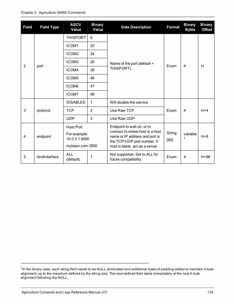
Chapter 2 Agriculture GNSS Commands
Agriculture Comands and Logs Reference Manual v7C 135
Field Field Type ASCIIValue
BinaryValue Data Description Format Binary
BytesBinaryOffset
2 port
THISPORT 6
Name of the port (default =THISPORT). Enum 4 H
ICOM1 23
ICOM2 24
ICOM3 25
ICOM4 29
ICOM5 46
ICOM6 47
ICOM7 48
3 protocol
DISABLED 1 Will disable the service
Enum 4 H+4TCP 2 Use Raw TCP
UDP 3 Use Raw UDP
4 endpoint
Host:Port
For example:10.0.3.1:8000
mybase.com:3000
Endpoint to wait on, or toconnect to where host is a hostname or IP address and port isthe TCP/UDP port number. Ifhost is blank, act as a server.
String
[80]variable1 H+8
5 bindInterface ALL(default) 1 Not supported. Set toALL for
future compatibility. Enum 4 H+88
1In the binary case, each string field needs to be NULL terminated and additional bytes of padding added to maintain 4-bytealignment, up to the maximum defined by the string size. The next defined field starts immediately at the next 4-bytealignment following the NULL.

Chapter 2 Agriculture GNSS Commands
Agriculture Comands and Logs Reference Manual v7C 136
2.45 INTERFACEMODESets receive or transmit modes for ports
Platform: OEM719, OEM729, OEM7500, OEM7600, OEM7700, OEM7720, PwrPak7, SPAN CPT7,SMART7, SMART2
This command is used to specify what type of data a particular port on the receiver can transmit and receive. Thereceive type tells the receiver what type of data to accept on the specified port. The transmit type tells thereceiver what kind of data it can generate. For example, to accept RTCMV3 differential corrections, set thereceive type on the port to RTCMV3.
It is also possible to disable or enable the generation or transmission of command responses for a particular port.Disabling of responses is important for applications where data is required in a specific form and the introductionof extra bytes may cause problems, i.e., RTCA, RTCM, RTCMV3 or CMR. Disabling a port prompt is also use-ful when the port is connected to amodem or other device that responds with data the RECEIVER does notrecognize.
For applications running in specific interfacemodes, see Table 30: Serial Port InterfaceModes onpage 138, please set the appropriate interfacemodes before sending or receiving corrections. It isimportant that the port interfacemodematches the data being received on that port. Mismatchesbetween the interfacemode and received data can result in CPU overloads.
When INTERFACEMODE port NONE NONE OFF is set, the specified port is disabled from interpreting anyinput or output data. Therefore, no commands or differential corrections are decoded by the specified port. WhenGENERIC is set for a port, it is also disabled but data can be passed through the disabled port and be outputfrom an alternative port using the pass-through logs PASSCOM, PASSAUX and PASSUSB. SeePASSCOM,PASSAUX, PASSUSB, PASSETH1, PASSICOM, PASSNCOM on page 521 for details on these logs alongwith the Operation chapter in the OEM7 Installation andOperation User Manual for information about pass-through logging. See also theSERIALCONFIG command on page 255.If you intend to use theSERIALCONFIG command (see page 255), ensure you do so before the INTERFACEMODE command oneach port. TheSERIALCONFIG command (see page 255) can remove the INTERFACEMODE command set-ting if the baud rate is changed after the interfacemode is set. You should also turn break detection off using theSERIALCONFIG command (see page 255) to stop the port from resetting because it is interpreting incomingbits as a break command. If such a reset happens, the Interfacemode will be set back to the default NOVATELmode for both input and output.
2.45.1 SPAN SystemsThe INTERFACEMODE of the receiver is also configured for the serial port dedicated to the IMU. This modechanges automatically upon sending aCONNECTIMU command (see page 767) and the change is reflectedwhen logging this command. This is normal operation.
When theCONNECTIMU command (see page 767) is used to configure the IMU connected to thereceiver, the correct interfacemode for the IMU port is automatically set. The IMU port should not bealtered using the INTERFACEMODE command in normal operation. Doing somay result in the loss ofIMU communication.
Message ID: 3
Abbreviated ASCII Syntax:

Chapter 2 Agriculture GNSS Commands
Agriculture Comands and Logs Reference Manual v7C 137
INTERFACEMODE [port] rxtype txtype [responses]
Factory Default:INTERFACEMODE COM1 NOVATEL NOVATEL ON
INTERFACEMODE COM2 NOVATEL NOVATEL ON
INTERFACEMODE COM3 NOVATEL NOVATEL ON
INTERFACEMODE AUX NOVATEL NOVATEL ON
INTERFACEMODE USB1 NOVATEL NOVATEL ON
INTERFACEMODE USB2 NOVATEL NOVATEL ON
INTERFACEMODE USB3 NOVATEL NOVATEL ON
INTERFACEMODE ICOM1 NOVATEL NOVATEL ON
INTERFACEMODE ICOM2 NOVATEL NOVATEL ON
INTERFACEMODE ICOM3 NOVATEL NOVATEL ON
INTERFACEMODE ICOM4 NOVATEL NOVATEL ON
INTERFACEMODE ICOM5 NOVATEL NOVATEL ON
INTERFACEMODE ICOM6 NOVATEL NOVATEL ON
INTERFACEMODE ICOM7 NOVATEL NOVATEL ON
INTERFACEMODE NCOM1 RTCMV3 NONE OFF
INTERFACEMODE NCOM2 RTCMV3 NONE OFF
INTERFACEMODE NCOM3 RTCMV3 NONE OFF
INTERFACEMODE CCOM1 NOVATELBINARY NOVATELBINARY ON
INTERFACEMODE CCOM2 NOVATELBINARY NOVATELBINARY ON
INTERFACEMODE CCOM3 AUTO NOVATEL OFF
INTERFACEMODE CCOM4 AUTO NOVATEL OFF
INTERFACEMODE CCOM5 AUTO NOVATEL OFF
INTERFACEMODE CCOM6 AUTO NOVATEL OFF
INTERFACEMODE SCOM1 NOVATEL NOVATEL ON
INTERFACEMODE SCOM2 NOVATEL NOVATEL ON
INTERFACEMODE SCOM3 NOVATEL NOVATEL ON
INTERFACEMODE SCOM4 NOVATEL NOVATEL ON
ASCII Example 1:INTERFACEMODE COM1 RTCMV3 NOVATEL ON
ASCII Example 2:INTERFACEMODE COM2 MRTCA NONE

Chapter 2 Agriculture GNSS Commands
Agriculture Comands and Logs Reference Manual v7C 138
Are NovAtel receivers compatible with others on themarket?
All GNSS receivers output two solutions: position and time. Themanner in which they output themmakes each receiver unique. Most geodetic and survey grade receivers output the position in electronicform (typically RS-232), whichmakes them compatible with most computers and data loggers. AllNovAtel receivers have this ability. However, eachmanufacturer has a unique way of formatting themessages. A NovAtel receiver is not directly compatible with a Trimble or Ashtech receiver (which arealso incompatible with each other) unless everyone uses a standard data format.
However, there are several standard data formats available. For position and navigation output there isthe NMEA format. Real-time differential corrections use RTCM or RTCA format. For receiver code andphase data RINEX format is often used. NovAtel and all other major manufacturers support theseformats and can work together using them. The NovAtel format measurement logs can be converted toRINEX using the utilities provided in NovAtel Connect.
Field Field Type ASCIIValue
BinaryValue Description Format Binary
BytesBinaryOffset
1 INTERFACEMODEheader - -
Command header. SeeMessages on page 26 formore information.
- H 0
2 port
See Table 25:CommunicationsPort Identifiers onpage 103
Serial port identifier
(default = THISPORT)
Note: On the SMART2, theINTERFACEMODEcommand cannot be usedwith CCOM ports.
Enum 4 H
3 rxtypeSee Table 30: SerialPort InterfaceModes below
Receive interfacemode Enum 4 H+4
4 txtypeSee Table 30: SerialPort InterfaceModes below
Transmit interfacemode Enum 4 H+8
5 responsesOFF 0 Turn response generation off
Enum 4 H+12ON 1 Turn response generation on
(default)
BinaryValue ASCII Value Description
0 NONE The port accepts/generates nothing. The port is disabled.
1 NOVATEL The port accepts/generates NovAtel commands and logs.
2 RTCM The port accepts/generates RTCM corrections.
Table 30: Serial Port Interface Modes

Chapter 2 Agriculture GNSS Commands
Agriculture Comands and Logs Reference Manual v7C 139
BinaryValue ASCII Value Description
3 RTCA The port accepts/generates RTCA corrections.
4 CMR The port accepts/generates CMR corrections.
5 Reserved
6 Reserved
7 IMU This port supports communication with a NovAtel supported IMU.
8 RTCMNOCR
WhenRTCMNOCR is used as the txtype, the port generates RTCMcorrections without the CR/LF appended.
When RTCMNOCR is used as the rxtype, the port accepts RTCM correctionswith or without the CR/LF appended.
9 Reserved
10 TCOM1INTERFACEMODE tunnel modes. To configure a full duplex tunnel, configurethe baud rate on each port. Once a tunnel is established, the baud rate does notchange. Special characters, such as a BREAK condition, do not route acrossthe tunnel transparently and the serial port is altered, see theSERIALCONFIGcommand on page 255. Only serial ports may be in a tunnel configuration:COM1, COM2, COM3 or AUX may be used.
For example, configure a tunnel at 115200 bps between COM1 and AUX:
SERIALCONFIG AUX 115200
SERIALCONFIG COM1 115200
INTERFACEMODE AUX TCOM1 NONE OFF
INTERFACEMODE COM1 TAUX NONE OFF
The tunnel is fully configured to receive/transmit at a baud rate of 115200 bps.
11 TCOM2
12 TCOM3
13 TAUX 1
14 RTCMV3 The port accepts/generates RTCM Version 3.0 corrections.
15 NOVATELBINARY
The port only accepts/generates binary messages. If an ASCII command isentered when themode is set to binary only, the command is ignored. Onlyproperly formatted binary messages are responded to and the response is abinary message.
16-17 Reserved
18 GENERIC
The port accepts/generates nothing. TheSEND command (see page 253) fromanother port generate data on this port. Any incoming data on this port can beseen with PASSCOM logs on another port, seePASSCOM, PASSAUX,PASSUSB, PASSETH1, PASSICOM, PASSNCOM log on page 521.
19 IMARIMU This port supports communication with an iMAR IMU.
1Only available on specific models.

Chapter 2 Agriculture GNSS Commands
Agriculture Comands and Logs Reference Manual v7C 140
BinaryValue ASCII Value Description
20 MRTCA The port accepts/generates Modified Radio Technical Commission forAeronautics (MRTCA) corrections.
21-22 Reserved
23 KVHIMU This port supports communication with a KVH CG5100 IMU.
24-26 Reserved
27 AUTO
For auto-detecting different RTK correction formats and incoming baud rate(over serial ports).
The change of baud rate will not appear whenSERIALCONFIG is logged asthis shows the saved baud rate for that port.
28-34 Reserved
35 NOVATELX The port accepts/generates NOVATELX corrections.
36-40 Reserved
41 KVH1750IMU This port supports communication with a KVH 17xx series IMU.
42-45 Reserved
46 TCCOM1 CCOM1 Tunnel
47 TCCOM2 CCOM2 Tunnel
48 TCCOM3 CCOM3 Tunnel
49 NOVATELMINBINARY NovAtel binary message with aminimal header.Only available for CCOM ports.
50 TCCOM4 CCOM4 Tunnel
51 TCCOM5 CCOM5 Tunnel
52 TCCOM6 CCOM6 Tunnel
53-57 Reserved
60 TSCOM1 SCOM1 Tunnel
61 TSCOM2 SCOM2 Tunnel
62 TSCOM3 SCOM3 Tunnel
63 TSCOM4 SCOM4 Tunnel
64 LUALua stdin/stdout/stderr.
Use the LUA PROMPT command to set this InterfaceMode.

Chapter 2 Agriculture GNSS Commands
Agriculture Comands and Logs Reference Manual v7C 141
2.46 IPCONFIGConfigures network IP settings
Platform: OEM729, OEM7600, OEM7700, OEM7720, PwrPak7, SPAN CPT7, SMART7-I, SMART7-SI
This command is used to configure static/dynamic TCP/IP properties for the Ethernet connection.
In addition to configuring an IP address and netmask for the interface, this command also includes agateway address.
Message ID: 1243
Abbreviated ASCII Syntax:IPCONFIG [interface_name] address_mode [IP_address [netmask [gateway]]]
Factory Default:IPCONFIG ETHA DHCP
ASCII Examples:IPCONFIG ETHA STATIC 192.168.74.10 255.255.255.0 192.168.74.1
Field Field Type ASCIIValue
BinaryValue Description Format Binary
BytesBinaryOffset
1 IPCONFIGHeader - - Command header. SeeMessages on
page 26 for more information. - H 0
2 interfacename ETHA 2 Name of the Ethernet interface
(default = ETHA) Enum 4 H
3 addressmode
DHCP 1 Use Dynamic IP addressEnum 4 H+4
STATIC 2 Use Static IP address
4 IP addressddd.ddd.ddd.ddd(For example:10.0.0.2)
IP Address-decimal dot notation String[16]
variable1 H+8
5 netmaskddd.ddd.ddd.ddd(For example:255.255.255.0)
Netmask-decimal dot notation String[16]
variable1 H+24
6 gatewayddd.ddd.ddd.ddd(For example:10.0.0.1)
Gateway-decimal dot notation String[16]
variable1 H+40
1In the binary case, each string field needs to be NULL terminated and additional bytes of padding added to maintain 4-byte alignment, up to the maximum defined by the string size. The next defined field starts immediately at the next 4-bytealignment following the NULL.

Chapter 2 Agriculture GNSS Commands
Agriculture Comands and Logs Reference Manual v7C 142
2.47 IPSERVICEConfigure availability of networks ports/services
Platform: OEM729, OEM7600, OEM7700, OEM7720, PwrPak7, SPAN CPT7, SMART7-I, SMART7-SI
Use the IPSERVICE command to configure the availability of specific network ports/services. When disabled,the service does not accept incoming connections.
Onmost OEM7 receivers, the FTP Server is disabled by default. The exception is the PwrPak7 whichhas FTP enabled by default.
We have found two problems in theMicrosoft® FTP clients contained within the Internet Explorer® andEdge browsers whichmake them unsuitable for retrieving files from aNovAtel receiver. When using aWindows® computer to transfer files off a NovAtel receiver, we suggest using a 3rd party FTP client.
Message ID: 1575
Abbreviated ASCII Syntax:IPSERVICE IPService switch
Factory Default:
IPSERVICE WEB_SERVER DISABLE (OEM719 andOEM7500)
IPSERVICE WEB_SERVER ENABLE (OEM729, OEM7600OEM7700 andOEM7720)
IPSERVICE SECURE_ICOM DISABLE
ASCII Example:IPSERVICE FTP_SERVER ENABLE
Field Field Type ASCIIValue
BinaryValue Description Format Binary
BytesBinaryOffset
1 IPSERVICEheader - - Command header. SeeMessages on
page 26 for more information. - H 0

Chapter 2 Agriculture GNSS Commands
Agriculture Comands and Logs Reference Manual v7C 143
Field Field Type ASCIIValue
BinaryValue Description Format Binary
BytesBinaryOffset
2 ipservice
NO_PORT 0 No port
Enum 4 H
FTP_SERVER 1
FTP server port.For most OEM7 receivers the default= DISABLE.For the PwrPak7 the default =ENABLE.
WEB_SERVER 2
Web server portFor most OEM7 receivers the default= ENABLE.For the OEM7500 andOEM719 thedefault = DISABLE.
SECURE_ICOM 3
Enables or disables security on ICOMports.
When security is enabled, a login isrequired as part of the connectionprocess (see the LOGIN commandon page 163).
Default = DISABLE
Note: Security in this sensemeansusers must supply a name andpassword before being allowed toenter commands on the ICOM ports.It does not mean there is dataencryption
3 switchDISABLE 0 Disable the IP service specified.
Enum 4 H+4ENABLE 1 Enable the IP service specified.

Chapter 2 Agriculture GNSS Commands
Agriculture Comands and Logs Reference Manual v7C 144
2.48 ITBANDPASSCONFIGEnable and configure bandpass filter on receiver
Platform: OEM719, OEM729, OEM7500, OEM7600, OEM7700, OEM7720, PwrPak7, SPAN CPT7,SMART7
Use this command to apply a bandpass filter at a certain frequency tomitigate interference in the pass band ofGNSS signals. The ITBANDPASSBANK log (see page 459) provides information on the allowable con-figuration settings for each frequency band. The bandpass filter is symmetrical in nature, whichmeans that spe-cifying one cutoff frequency will apply a cutoff on both the low side and high side of the signal's center frequency.Only one filter can be applied for each signal.
OnOEM7720, PwrPak7D, PwrPak7D-E1, PwrPak7D-E2 and SPAN CPT7 receivers, any filterenabled for GPS L2 or GLONASS L2 on the secondary antenna will be applied to both GPS L2 andGLONASS L2. For this reason, caremust be taken to avoid attenuating the signals with a bandpass fil-ter that is too narrow in bandwidth. The recommendedmaximum lower cutoff frequency is 1221MHz.The recommendedminimum upper cutoff frequency is 1254MHz.
Message ID: 1999
Abbreviated ASCII Syntax:ITBANDPASSCONFIG frequency switch [cutofffrequency]
ASCII Example:ITBANDPASSCONFIG gpsl5 enable 1165.975
Field Field Type ASCIIValue
BinaryValue Description Format Binary
BytesBinaryOffset
1ITBANDPASSCONFIGheader
- -Command header. SeeMessages on page 26 for moreinformation.
- H 0
2 frequencySee Table 37:Frequency Types onpage 152
Set the frequency band on whichto apply the filter Enum 4 H
3 switchDISABLE 0 Disable filter
Enum 4 H+4ENABLE 1 Enable filter
4 cutofffrequency
Cut off frequency for band passfilter (MHz).(default = 0)
Refer to ITBANDPASSBANKlog (see page 459) for theallowable values.
Float 4 H+8

Chapter 2 Agriculture GNSS Commands
Agriculture Comands and Logs Reference Manual v7C 145
2.49 ITDETECTCONFIGEnable interference detection on receiver
Platform: OEM719, OEM729, OEM7500, OEM7600, OEM7700, OEM7720, PwrPak7, SPAN CPT7,SMART7
This command is used to enable or disable interference detection on the receiver. It is applicable to both SpectralAnalysis Detection and Statistical Analysis Detection at the same time. Detection can be enabled on all RFpaths, only one RF path (L1, L2, or L5), or no RF paths. By default, only the RF paths connecting to the firstantenna are enabled.
Message ID: 2143
Abbreviated ASCII Syntax:ITDETECTCONFIG RFPath [reserved1] [reserved2] [reserved3]
Factory Default:ITDETECTCONFIG all
ASCII Example:ITDETECTCONFIG L1
ITDETECTCONFIG none
Field Field Type ASCIIValue
BinaryValue Description Format Binary
BytesBinaryOffset
1 ITDETECTCONFIGheader - - Command header. SeeMessages
on page 26 for more information. - H 0
2 RFPathSee Table 31:RF PathSelection below
RF path selected for detection. Bydefault, all paths are turned on.The receiver will cycle through allactive paths.
Enum 4 H
3 reserved1 0 Reserved parameter Ulong 4 H+4
4 reserved2 0 Reserved parameter Ulong 4 H+8
5 reserved3 0 Reserved parameter Ulong 4 H+12
ASCII Value Binary Value Description
NONE 0 Turn off detection on all paths
ALL 1 Turn on detection on all paths (cycle through all active paths)
L1 2 Turn on detection only on L1 path
L2 3 Turn on detection only on L2 path
L5 4 Turn on detection only on L5 path
Table 31: RF Path Selection

Chapter 2 Agriculture GNSS Commands
Agriculture Comands and Logs Reference Manual v7C 146
2.50 ITFRONTENDMODEConfigure the front end mode settings
Platform: OEM719, OEM729, OEM7500, OEM7600, OEM7700, OEM7720, PwrPak7, SPAN CPT7,SMART7
Use this command to configure the front endmode for the L1, L2 and L5 RF paths to use the default third-orderCIC mode or HDR (High Dynamic Range) mode. The HDR mode is used in an interference environment toobtain best interference rejection in general. However, the power consumption will increase in this mode.
Message ID: 2039
Abbreviated ASCII Syntax:ITFRONTENDMODE frequency mode
Factory DefaultITFRONTENDMODE L1 cic3
ITFRONTENDMODE L2 cic3
ITFRONTENDMODE LBAND cic3
ITFRONTENDMODE L5 cic3
ASCII Example:ITFRONTENDMODE L1 hdr
On theOEM7500, the default mode for all frequency bands is HDR.
Field Field Type ASCIIValue
BinaryValue Description Format Binary
BytesBinaryOffset
1 ITFRONTENDMODEheader - -
Command header. SeeMessages on page 26 formore information.
- H 0
2 frequencySee Table 32:Frequency Bandsbelow
Set the frequency band foradjustment Enum 4 H
3 modeSee Table 33:Mode on the nextpage
Select the desiredmode Enum 4 H+4
Binary Value ASCII Value Description
2 L1 Selects the L1 frequency
3 L2 Selects the L2 frequency
Table 32: Frequency Bands

Chapter 2 Agriculture GNSS Commands
Agriculture Comands and Logs Reference Manual v7C 147
Binary Value ASCII Value Description
4 LBAND Selects the L-Band frequency
5 L5 Selects the L5 frequency
Binary Value ASCII Value Description
0 CIC3 3rd order CIC (CIC3) mode (default)
1 HDR High Dynamic Range (HDR)mode
Table 33: Mode

Chapter 2 Agriculture GNSS Commands
Agriculture Comands and Logs Reference Manual v7C 148
2.51 ITPROGFILTCONFIGEnable and configure filtering on the receiver
Platform: OEM719, OEM729, OEM7500, OEM7600, OEM7700, OEM7720, PwrPak7, SPAN CPT7,SMART7
Use this command to set the programmable filter to be either a notch filter or a bandpass filter to mitigate inter-ference in the pass band of GNSS signals. The notch filter is used to attenuate a very narrow band of fre-quencies (specified by the notch width) around the configured center frequency.
The bandpass filter is symmetrical in nature, whichmeans that specifying one cutoff frequency will apply acutoff on both the low side and high side of the spectrum center frequency.
The ITPROGFILTBANK log (see page 467) provides information on the allowable configuration settings for theprogrammable filter (i.e. the allowable settings for the notch filter and bandpass filter) for each frequency band.Only one filter can be applied for each frequency.
Message ID: 2000
Abbreviated ASCII Syntax:ITPROGFILTCONFIG frequency filterid switch [filtermode] [cutofffreq][notchwidth]
ASCII Example:ITPROGFILTCONFIG gpsl1 pf0 enable notchfilter 1580 1
Field Field Type ASCIIValue
BinaryValue Description Format Binary
BytesBinaryOffset
1ITPROGFILTCONFIGheader
- -Command header. SeeMessages on page 26 for moreinformation.
- H 0
2 frequency See Table 37: FrequencyTypes on page 152
Set the frequency band onwhich to apply the filter Enum 4 H
3 filteridSee Table 34:Programmable Filter IDon the next page
Select the filter ID to use Enum 4 H+4
4 switchDISABLE 0 Disable the filter
Enum 4 H+8ENABLE 1 Enable the filter
5 filtermodeSee Table 35:Programmable FilterMode on the next page
Configure the type of filter to use(default = NONE) Enum 4 H+12

Chapter 2 Agriculture GNSS Commands
Agriculture Comands and Logs Reference Manual v7C 149
Field Field Type ASCIIValue
BinaryValue Description Format Binary
BytesBinaryOffset
6 cutofffreq
Center frequency for notch filteror cut off frequency forbandpass filter (MHz).
Refer to ITPROGFILTBANKlog (see page 467) for theallowable values.
(default = 0)
Float 4 H+16
7 notchwidth
Notch width (MHz).
Refer to ITPROGFILTBANKlog (see page 467) for theallowable values.
(default = 0)
Float 4 H+20
Binary Value ASCII Value Description
0 PF0 Programmable Filter 0
1 PF1 Programmable Filter 1
Table 34: Programmable Filter ID
BinaryValue ASCII Value Description
0 NOTCHFILTER Configure the filter as a notch filter
1 BANDPASSFILTER Configure the filter as a bandpass filter
2 NONETurn off filter
If the switch parameter is set to ENABLED while the filtermode parameter is setto NONE, the system will return a parameter out of rangemessage.
Table 35: Programmable Filter Mode

Chapter 2 Agriculture GNSS Commands
Agriculture Comands and Logs Reference Manual v7C 150
2.52 ITSPECTRALANALYSISEnable and configure spectral analysis on receiver
Platform: OEM719, OEM729, OEM7500, OEM7600, OEM7700, OEM7720, PwrPak7, SPAN CPT7,SMART7
Use this command to view the spectrum in a range of frequencies. The ITSPECTRALANALYSIS commandenables and configures the spectral analysis. The spectrum is viewed by plotting the PSD samples in theITPSDFINAL log (see page 469).
Decreasing the update period or increasing the FFT size will impact receiver idle time. The idle timeshould bemonitored to prevent adverse effects on receiver performance.
Message ID: 1967
Abbreviated ASCII Syntax:ITSPECTRALANALYSIS mode [frequency] [updateperiod] [FFTsize] [timeavg][integration_window]
Factory Default:ITSPECTRALANALYSIS off
ASCII Example:ITSPECTRALANALYSIS predecimation gpsl1 500 1K 20 1
Field Field Type ASCIIValue
BinaryValue Description Format Binary
BytesBinaryOffset
1ITSPECTRALANALYSISheader
- - Command header. SeeMessages onpage 26 for more information. - H 0
2 mode
See Table 36:Data Sources forPSD Samples onthe next page
Set the view mode. Enum 4 H
3 frequencySee Table 37:Frequency Typeson page 152
Set the frequency band to view. Enum 4 H+4

Chapter 2 Agriculture GNSS Commands
Agriculture Comands and Logs Reference Manual v7C 151
Field Field Type ASCIIValue
BinaryValue Description Format Binary
BytesBinaryOffset
4 updateperiod 50 to 100000
The spectrum update rate inmilliseconds.
The update period is limited by theFFT size chosen. For 32k theminimum update period is 100ms andfor 64k theminimum update period is200ms.
(default = 1000)
Ulong 4 H+8
5 FFTsizeSee Table 38: FFTSizes on the nextpage
The frequency resolution of thespectrum.
(default = 1k)Enum 4 H+12
6 timeavg 0 to 50Time averaging window in seconds. 0means no time averaging.
(default = 10)Ulong 4 H+16
7 integrationwindow 1 to 1024
The integration window size of FFTsamples. 1means no integration.
(default = 5)Ulong 4 H+20
BinaryValue ASCII Value Description
0 OFF Disable spectral analysis
1 PREDECIMATIONPerform spectrum analysis on the pre-decimated spectrum.
This can be used to see a wide view of the spectrum for an RF path (L1, L2 orL5).
2 POSTDECIMATIONPerform spectrum analysis on the post-decimated spectrum.
This is narrower than predecimation and is used to see the spectrum for a givensignal.
3 POSTFILTERPerform spectrum analysis on the post-filtered spectrum.
This can be used when either bandpass or notch filters have been enabled tosee the spectrum after the filters are applied.
Table 36: Data Sources for PSD Samples
The post-filter spectrum is not available for the Galileo AltBOC frequency. Only the pre-decimation andpost-decimation spectrums are available for Galileo AltBOC.

Chapter 2 Agriculture GNSS Commands
Agriculture Comands and Logs Reference Manual v7C 152
Binary Value ASCII Value Description
0 GPSL1 GPS L1 frequency
1 GPSL2 GPS L2 frequency
2 GLONASSL1 GLONASS L1 frequency
3 GLONASSL2 GLONASS L2 frequency
4 Reserved
5 GPSL5 GPS L5 frequency
61 LBAND Inmarsat L-Band frequency
7 GALILEOE1 Galileo E1 frequency
8 GALILEOE5A Galileo E5A frequency
9 GALILEOE5B Galileo E5B frequency
10 GALILEOALTBOC Galileo AltBOC frequency
11 BEIDOUB1 BeiDou B1 frequency
12 BEIDOUB2 BeiDou B2 frequency
13 QZSSL1 QZSS L1 frequency
14 QZSSL2 QZSS L2 frequency
15 QZSSL5 QZSS L5 frequency
16 QZSSL6 QZSS L6 frequency
17 GALILEOE6 Galileo E6 frequency
18 BEIDOUB3 BeiDou B3 frequency
19 GLONASSL3 GLONASS L3 frequency
20 NAVICL5 NavIC L5 frequency
21 BEIDOUB1C BeiDou B1C frequency
22 BEIDOUB2A BeiDou B2a frequency
Table 37: Frequency Types
Binary Value ASCII Value Description
0 1K 1K FFT, 1024 samples
Table 38: FFT Sizes
1Must first enable L-Band using the ASSIGNLBANDBEAM command.

Chapter 2 Agriculture GNSS Commands
Agriculture Comands and Logs Reference Manual v7C 153
Binary Value ASCII Value Description
1 2K 2K FFT, 2048 samples
2 4K 4K FFT, 4096 samples
3 8K 8K FFT, 8192 samples
4 16K 16K FFT, 16384 samples
5 32K 32K FFT, 32768 samples
6 64K 64K FFT, 65536 samples
The 64k FFT is not available in post-decimation or post-filter modes.

Chapter 2 Agriculture GNSS Commands
Agriculture Comands and Logs Reference Manual v7C 154
2.53 J1939CONFIGConfigure CAN network-level parameters
Platform: OEM719, OEM729, OEM7500, OEM7600, OEM7700, OEM7720, PwrPak7, SPAN CPT7,SMART7, SMART2
Use this command to configure the CAN J1939 network-level parameters (NAME, etc).
Issuing this commandmay initiate a CAN 'Address Claim' procedure. The status of the node and address claimare reported in the J1939STATUS log (see page 472).
Once a "node" is configured using J1939CONFIG, and the "port" is configured to ON using CANCONFIG "port"ON, J1939CONFIG "node" cannot be entered again until the "port" is configured to "OFF" using CANCONFIG"port" OFF. (See theCANCONFIG command on page 82
Message ID: 1903
Abbreviated ASCII Syntax:J1939CONFIG node port [pref_addr [alt_addr_range_start] [alt_addr_range_end][mfgcode] [industry] [devclass] [devinstance] [func] [funcinstance][ECUinstance]]
Factory Default:J1939CONFIG NODE1 CAN1 1C 0 FD 305 2 0 0 23 0 0
J1939CONFIG NODE2 CAN2 1C 0 FD 305 2 0 0 23 0 0
ASCII Example :J1939CONFIG NODE1 CAN1 AA 0 FD 305 2 0 0 23 0 0
Field Field Type ASCIIValue
BinaryValue Description Format Binary
BytesBinaryOffset
1 J1939CONFIGheader - - Command header. SeeMessages on
page 26 for more information. - H 0
2 nodeNODE1 1 Identifies the J1939 Node (i.e., CAN
NAME)
Note: SMART2 does not supportNODE2.
Enum 4 HNODE2 2
3 portCAN1 1 Physical CAN port to use
Note: SMART2 does not support theCAN2 port.
Enum 4 H+4CAN2 2
4 pref_addr 0x0 - 0xFDPreferred CAN address. The receiverattempts to claim this address
(default = 0x0)Ulong 4 H+8

Chapter 2 Agriculture GNSS Commands
Agriculture Comands and Logs Reference Manual v7C 155
Field Field Type ASCIIValue
BinaryValue Description Format Binary
BytesBinaryOffset
5 alt_addr_range_start 0x0 - 0xFD
When the pref_addr cannot beclaimed, the receiver attempts toclaim an address from this range.
(default: 0x0)
Ulong 4 H+12
6 alt_addr_range_end 0x0 - 0xFD
End of alternative address range.
(default: 0xFD)Ulong 4 H+16
7 mfgcode 0-2047NAME: Manufacturer Code. Refer toISO 11783-5.
(default: 0)Ulong 4 H+20
8 industry 0 - 7NAME: Industry Group
(default: 2)Ulong 4 H+24
9 devclass 0 - 127NAME: Device Class
(default: 0)Ulong 4 H+28
10 devinstance 0 - 15NAME: Device Class Instance
(default: 0)Ulong 4 H+32
11 func 0 - 255NAME: Function
(default: 23)Ulong 4 H+36
12 funcinstance 0 - 31NAME: Function instance
(default: 0)Ulong 4 H+40
13 ECUinstance 0 - 7NAME: ECU Instance
(default: 0)Ulong 4 H+44
Due to current limitations in the CAN stack, NODE1 can only be associated with CAN1 and NODE2can only be associated with CAN2. A mismatch combination results in an 'invalid parameter' error.
Node statistics are reported in the J1939STATUS log (see page 472).

Chapter 2 Agriculture GNSS Commands
Agriculture Comands and Logs Reference Manual v7C 156
2.54 LOCKOUTPrevents the receiver from using a satellite
Platform: OEM719, OEM729, OEM7500, OEM7600, OEM7700, OEM7720, PwrPak7, SPAN CPT7,SMART7, SMART2
This command is used to prevent the receiver from using a satellite in the solution computations.
The LOCKOUT command does not prevent the receiver from tracking an undesirable satellite.
LOCKOUT command andUNLOCKOUT command (see page 298) can be used with GPS, GLONASS,SBAS andQZSS PRNs.
This commandmust be repeated for each satellite to be locked out. See also theUNLOCKOUT command onpage 298 andUNLOCKOUTALL command on page 299.
Message ID: 137
Abbreviated ASCII Syntax:LOCKOUT prn
Input Example:LOCKOUT 8
The LOCKOUT command removes one or more satellites from the solution while leaving other satel-lites available.
Field FieldType
ASCIIValue
BinaryValue Description Format Binary
BytesBinaryOffset
1 LOCKOUTheader - - Command header. SeeMessages on
page 26 for more information. - H 0
2 prnRefer toPRNNumbers onpage 44
Unique identifier for the satellite beinglocked out Ulong 4 H

Chapter 2 Agriculture GNSS Commands
Agriculture Comands and Logs Reference Manual v7C 157
2.55 LOCKOUTSYSTEMPrevents the receiver from using a system
Platform: OEM719, OEM729, OEM7500, OEM7600, OEM7700, OEM7720, PwrPak7, SPAN CPT7,SMART7, SMART2
This command is used to prevent the receiver from using all satellites in a system in the solution computations.
The LOCKOUTSYSTEM command does not prevent the receiver from tracking an undesirable satel-lite.
This commandmust be repeated for each system to be locked out. See also theUNLOCKOUTSYSTEM com-mand on page 300 andUNLOCKOUTALL command on page 299.
Message ID: 871
Abbreviated ASCII Syntax:LOCKOUTSYSTEM system
Factory Defaults:LOCKOUTSYSTEM sbas
LOCKOUTSYSTEM navic
The LOCKOUTSYSTEM command removes one or more systems from the solution while leavingother systems available.
Field Field Type ASCIIValue
BinaryValue Description Format Binary
BytesBinaryOffset
1 LOCKOUTSYSTEMheader - -
Command header. SeeMessages on page 26 formore information.
- H 0
2 systemSee Table 95:Satellite System onpage 450
A single satellite system to belocked out Enum 4 H

Chapter 2 Agriculture GNSS Commands
Agriculture Comands and Logs Reference Manual v7C 158
2.56 LOGRequests logs from the receiver
Platform: OEM719, OEM729, OEM7500, OEM7600, OEM7700, OEM7720, PwrPak7, SPAN CPT7,SMART7, SMART2
Many different types of data can be logged using different methods of triggering the log events. Every log ele-ment can be directed to any combination of the receiver’s ports. The ontime trigger option requires the addition ofthe period parameter. See Logs on page 322 for further information and a complete list of data log structures. TheLOG command tables in this section show the binary format followed by the ASCII command format.
The optional parameter [hold] prevents a log from being removed when theUNLOGALL command (see page303), with its defaults, is issued. To remove a log which was invoked using the [hold] parameter requires the spe-cific use of theUNLOG command (see page 301). To remove all logs that have the [hold] parameter, use theUNLOGALL command (see page 303) with the held field set to 1.
The [port] parameter is optional. If [port] is not specified, [port] is defaulted to the port that the commandwasreceived on.
1. TheOEM7 family of receivers can handle 80 simultaneous log requests. If an attempt is made to logmore than 80 logs at a time, the receiver responds with an Insufficient Resources error. Note thatRXSTATUSEVENTA logs are requested onmost ports by default and these logs count against the80.
2. The user is cautioned that each log requested requires additional CPU time andmemory bufferspace. Toomany logs may result in lost data and low CPU idle time. Receiver overload can bemon-itored using the idle-time field and buffer overload bits of the Receiver Status in any log header.
3. Only theMARKPOS, MARK2POS, MARK3POS and MARK4POS log (see page 486),MARK1TIME, MARK2TIME, MARK3TIME and MARK4TIME log (see page 489) and ‘polled’ logtypes are generated, on the fly, at the exact time of themark. Synchronous and asynchronous logsoutput themost recently available data.
4. Use theONNEW trigger with theMARKPOS, MARK2POS, MARK3POS and MARK4POS log(see page 486) andMARK1TIME, MARK2TIME, MARK3TIME and MARK4TIME log (see page489).
5. Polled log types do not all allow fractional offsets.
6. If ONTIME trigger is used with asynchronous logs, the time stamp in the log does not necessarily rep-resent the time the data was generated but rather the time when the log is transmitted.
7. Published logs are not placed in a queue if there is no physical or virtual connection when the log isgenerated. Thus, a log requested ONNEW orONCHANGED that is in SAVECONFIGmay not bereceived if it is published before connections aremade. This can happen if there's no cable connectedor if the communication protocol has not been established yet (e.g. CAN, Ethernet, USB, etc).
8. PwrPak7M variants do not support the FILE port.
Message ID: 1
Abbreviated ASCII Syntax:LOG [port] message ONNEWLOG [port] message ONCHANGEDLOG [port] message ONTIME period [offset [hold]]LOG [port] message ONNEXT

Chapter 2 Agriculture GNSS Commands
Agriculture Comands and Logs Reference Manual v7C 159
LOG [port] message ONCELOG [port] message ONMARK
Factory Default:LOG COM1 RXSTATUSEVENTA ONNEW 0 0 HOLDLOG COM2 RXSTATUSEVENTA ONNEW 0 0 HOLDLOG COM3 RXSTATUSEVENTA ONNEW 0 0 HOLDLOG USB1 RXSTATUSEVENTA ONNEW 0 0 HOLDLOG USB2 RXSTATUSEVENTA ONNEW 0 0 HOLDLOG USB3 RXSTATUSEVENTA ONNEW 0 0 HOLDLOG ICOM1 RXSTATUSEVENTA ONNEW 0 0 HOLDLOG ICOM2 RXSTATUSEVENTA ONNEW 0 0 HOLDLOG ICOM3 RXSTATUSEVENTA ONNEW 0 0 HOLDLOG ICOM4 RXSTATUSEVENTA ONNEW 0 0 HOLDLOG ICOM5 RXSTATUSEVENTA ONNEW 0 0 HOLDLOG ICOM6 RXSTATUSEVENTA ONNEW 0 0 HOLDLOG ICOM7 RXSTATUSEVENTA ONNEW 0 0 HOLD
Abbreviated ASCII Example 1:LOG COM1 BESTPOS ONTIME 7 0.5 HOLD
The above example shows BESTPOS logging to com port 1 at 7 second intervals and offset by 0.5 seconds (out-put at 0.5, 7.5, 14.5 seconds and so on). The [hold] parameter is set so that logging is not disrupted by theUNLOGALL command (see page 303).
To send a log once, the trigger option can be omitted.
Abbreviated ASCII Example 2:LOG COM1 BESTPOS ONCE
Using the NovAtel Connect utility there are two ways to initiate data logging from the receiver's serialports. Either enter the LOG command in theConsolewindow or use the interface provided in the Log-ging Control window. Ensure the Power Settings on the computer are not set to go into Hibernate orStandby modes. Data is lost if one of thesemodes occurs during a logging session.
2.56.1 Binary
Field FieldType Binary Value Description Format Binary
BytesBinaryOffset
1LOG(binary)header
See Table 3: BinaryMessage HeaderStructure on page 30
This field contains themessage header - H 0
2 portSee Table 4: DetailedPort Identifier onpage 32
Output port Enum 4 H
3 message Any valid message ID Message ID of the log to output Ushort 2 H+4

Chapter 2 Agriculture GNSS Commands
Agriculture Comands and Logs Reference Manual v7C 160
Field FieldType Binary Value Description Format Binary
BytesBinaryOffset
4 messagetype
Bits 0-4 =Measurement source1
Bits 5-6 = Format
00 = Binary
01 = ASCII
10 = AbbreviatedASCII, NMEA
11 = Reserved
Bit 7 = Response Bit(Message Responseson page 41)
0 = Original Message
1 = ResponseMessage
Message type of log Char 1 H+6
5 Reserved Char 1 H+7
6 trigger
0 = ONNEWDoes not output current message butoutputs when themessage is updated(not necessarily changed)
Enum 4 H+8
1 = ONCHANGEDOutputs the current message and thencontinues to output when themessageis changed
2 = ONTIME Output on a time interval
3 = ONNEXT Output only the next message
4 = ONCE
Output only the current message(default). If nomessage is currentlypresent, the next message is outputwhen available.
1Bits 0-4 are used to indicate the measurement source. For dual antenna receivers, if bit 0 is set, the log is from thesecondary antenna.

Chapter 2 Agriculture GNSS Commands
Agriculture Comands and Logs Reference Manual v7C 161
Field FieldType Binary Value Description Format Binary
BytesBinaryOffset
5 = ONMARK Output when a pulse is detected on themark 1 input, MK1I 1 2
7 period
Valid values for thehigh rate logging are0.01, 0.02, 0.05, 0.1,0.2, 0.25 and 0.5. Forlogging slower than 1Hz any integer valueis accepted
Log period (for ONTIME trigger) inseconds
If the value entered is lower than theminimummeasurement period, thecommandwill be rejected. See theSMART7 Installation andOperationUser Manual for themaximum rawmeasurement rate to calculate theminimum period.
Double 8 H+12
8 offsetOffset for period(ONTIME trigger) inseconds.
A valid value is any integer (wholenumber) smaller than the period.
For example, to log data at 1 second,after every minute, set the period to 60and the offset to 1.
These decimal values, on their own, arealso valid: 0.1, 0.2, 0.25 or 0.5, as wellas any multiple of themaximum loggingrate defined by the receiver model. Theoffset cannot be smaller than theminimummeasurement periodsupported by themodel.
Double 8 H+20
9 hold
0 = NOHOLD Allow log to be removed by theUNLOGALL command (see page 303)
Enum 4 H+28
1 = HOLDPrevent log from being removed by thedefault UNLOGALL command (seepage 303)
1Refer to the SMART7 Installation and Operation User Manual for more details on the MK1I pin. ONMARK only applies toMK1I. Events on MK2I (if available) do not trigger logs when ONMARK is used. Use the ONNEW trigger with the MARKTIME,MARK2TIME, MARKPOS or MARK2POS logs.2Once the 1PPS signal has hit a rising edge, for both MARKPOS and MARKTIME logs, a resolution of both measurements is10 ns. As for the ONMARK trigger for other logs that measure latency, for example RANGE and POSITION logs such asBESTPOS, it takes typically 20-30 ms (50 ms maximum) for the logs to output information from the 1PPS signal. Latency isthe time between the reception of the 1PPS pulse and the first byte of the associated log. See also the MARKPOS,MARK2POS, MARK3POS and MARK4POS log on page 486 and the MARK1TIME, MARK2TIME, MARK3TIME andMARK4TIME log on page 489.

Chapter 2 Agriculture GNSS Commands
Agriculture Comands and Logs Reference Manual v7C 162
2.56.2 ASCII
Field FieldName ASCII Value Description Format
1LOG(ASCII)header
-This field contains the command name or themessageheader depending on whether the command is abbreviatedASCII or ASCII respectively
-
2 portTable 4: DetailedPort Identifier onpage 32
Output port
(default = THISPORT)Enum
3 messageAny valid messagename, with anoptional A or B suffix
Message name of log to output Char [ ]
4 trigger
ONNEW Output when themessage is updated (not necessarilychanged)
Enum
ONCHANGED Output when themessage is changed
ONTIME Output on a time interval
ONNEXT Output only the next message
ONCE Output only the current message (default)
ONMARK Output when a pulse is detected on themark 1 input, MK1I 2,3
5 period
Any positive doublevalue larger than thereceiver’s minimumraw measurementperiod
Log period (for ONTIME trigger) in seconds (default = 0)
If the value entered is lower than theminimummeasurementperiod, the commandwill be rejected. See the SMART7Installation andOperation User Manual for themaximum rawmeasurement rate to calculate theminimum period.
Double
6 offsetAny positive doublevalue smaller thanthe period
Offset for period (ONTIME trigger) in seconds (default = 0)
For example, if you want to log data, at 1 second after everyminute, set the period to 60 and the offset to 1.
Double
7 holdNOHOLD To be removed by theUNLOGALL command (see page
303) (default)Enum
HOLD Prevent log from being removed by the default UNLOGALLcommand (see page 303)

Chapter 2 Agriculture GNSS Commands
Agriculture Comands and Logs Reference Manual v7C 163
2.57 LOGINStart a secure ICOM/SCOM connection to the receiver
Platform: OEM729, OEM7600, OEM7700, OEM7720, PwrPak7, SPAN CPT7, SMART7-I, SMART7-SI
When ICOM/SCOM ports have security enabled (see the IPSERVICE command on page 142), a session to theICOM/SCOM port can be established but commands are refused until a valid LOGIN command is issued. Boththe UserName and Password are required. The LOGIN command checks the supplied credentials againstknownUserNames/Passwords and determines if the login is successful or not. A successful login permits thesecured ICOM/SCOM command interpreter to accept further commands and returns OK. An unsuccessful logindoes not release the secured ICOM/SCOM command interpreter and returns Login Failed.
Entering a LOGIN command on any command port other than the ICOM/SCOM port has no effect, regardless ofwhether the UserName/Password is correct. In this case, the appropriate response (OK or Login Failed) isreturned, but there is no effect on the command interpreter.
When security is enabled, access to the port is restricted unless a valid name and password are sup-plied. It does not mean there is data encryption enabled. Username is case-insensitive and password iscase-sensitive.
Message ID: 1671
Abbreviated ASCII Syntax:LOGIN [commport] UserName Password
ASCII Example:LOGIN ADMIN ADMINPASSWORD
Field FieldType
ASCIIValue
BinaryValue Description Format Binary
BytesBinaryOffset
1 LOGINheader - - Command header. SeeMessages on
page 26 for more information. - H 0

Chapter 2 Agriculture GNSS Commands
Agriculture Comands and Logs Reference Manual v7C 164
Field FieldType
ASCIIValue
BinaryValue Description Format Binary
BytesBinaryOffset
2 commport
ICOM1 23
The ICOM or SCOM port to log into.
This is an optional parameter.
If no value is entered, logs in to the ICOMport currently being used.(default=THISPORT)
Enum 4 H
ICOM2 24
ICOM3 25
ICOM4 29
ICOM5 46
ICOM6 47
ICOM7 48
SCOM1 49
SCOM2 50
SCOM3 51
SCOM4 52
3 usernameProvide the user name for the logincommand.
The user name is not case sensitive.
String
[32]variable1 H+4
4 passwordProvide the password for the user name.
The password is case sensitive.
String
[28]variable1 variable
1In the binary case, each string field needs to be NULL terminated and additional bytes of padding added to maintain 4-byte alignment, up to the maximum defined by the string size. The next defined field starts immediately at the next 4-bytealignment following the NULL.

Chapter 2 Agriculture GNSS Commands
Agriculture Comands and Logs Reference Manual v7C 165
2.58 LOGOUTEnd a secure ICOM/SCOM session started using the LOGIN command
Platform: OEM729, OEM7600, OEM7700, OEM7720, PwrPak7, SPAN CPT7, SMART7-I, SMART7-SI
Use the LOGOUT command to sign out of an ICOM/SCOM connection after a user has successfully logged inusing the LOGIN command. After the sending the LOGOUT command, the ICOM/SCOM connection will notaccept further commands, other than a new LOGIN command. The session itself is not ended. This only appliesto ICOM/SCOM ports that have had security enabled (see the IPSERVICE command on page 142).
Message ID: 1672
Abbreviated ASCII Syntax:LOGOUT [commport]
ASCII Example:LOGOUT
Field FieldType
ASCIIValue
BinaryValue Description Format Binary
BytesBinaryOffset
1 LOGOUTheader - - Command header. SeeMessages on
page 26 for more information. - H 0
2 commport
ICOM1 23
The ICOM or SCOM port from which to logout. This is an optional parameter. If novalue is entered, logs out from theICOM/SCOM port currently being used.
Enum 4 H
ICOM2 24
ICOM3 25
ICOM4 29
ICOM5 46
ICOM6 47
ICOM7 48
SCOM1 49
SCOM2 50
SCOM3 51
SCOM4 52

Chapter 2 Agriculture GNSS Commands
Agriculture Comands and Logs Reference Manual v7C 166
2.59 LUAConfigure Lua Interpreter
Platform: OEM719, OEM729, OEM7500, OEM7600, OEM7700, OEM7720, PwrPak7, SPAN CPT7,SMART7
Use this command to configure the execution of the Lua interpreter on the receiver. Scripts that appear within theLUAFILELIST log (see page 482) can be executed by the Lua interpreter.
Message ID: 2049
Abbreviated ASCII Syntax:LUA option [LuaInterpreterArguments]
Abbreviated ASCII Example:lua start "printarguments.lua 1 2 3 4 5"
Field Field Type ASCIIValue
BinaryValue Description Format Binary
BytesBinaryOffset
1 Lua header - - Command header. SeeMessagesfor more information. - H 0
2 option
START 1
Start the Lua interpreter in thebackground. The file descriptorsstdout, stdin and stderr will not beaccessible outside the receiver.
Enum 4 H
PROMPT 2
Start the Lua interpreter in interactivemode and connect stdout, stdio andstderr to the port on which thecommandwas entered. TheINTERFACEMODE of that port willbe changed to LUA for both RX andTX.
3 LuaInterpreterArguments STRING
String containing Lua interpreteroptions including the name of thescript file to run and arguments topass to the script.
This stringmust be enclosed inquotes if it contains any spaces.
String arguments within the fieldmust be enclosed by single quotes.
String[400] Variable H+4

Chapter 2 Agriculture GNSS Commands
Agriculture Comands and Logs Reference Manual v7C 167
The format of the Lua Interpreter Arguments is as follows as adapted from the standard Lua 5.3 interpreter:
[options] [script [args]]Available options are: -e stat execute string 'stat' -i enter interactive mode after executing 'script'.
(This is added to the arguments when using the PROMPT option of the LUA command) -l name require library 'name'

Chapter 2 Agriculture GNSS Commands
Agriculture Comands and Logs Reference Manual v7C 168
2.60 MAGVARSets a magnetic variation correction
Platform: OEM719, OEM729, OEM7500, OEM7600, OEM7700, OEM7720, PwrPak7, SPAN CPT7,SMART7, SMART2
The receiver computes directions referenced to True North (also known as geodetic north). TheMagnetic Vari-ation Correction command (MAGVAR) is used to navigate in agreement with magnetic compass bearings. Thecorrection value entered here causes the "bearing" field of the navigate log to report bearing in degrees Magnetic.The receiver computes themagnetic variation correction when using the auto option. See Figure 3: Illustration ofMagnetic Variation and Correction on the next page.
The receiver calculates values of magnetic variation for given values of latitude, longitude and time using theInternational Geomagnetic Reference Field (IGRF) 2015 spherical harmonic coefficients and IGRF time cor-rections to the harmonic coefficients. (IGRF-2015 is also referred to as IGRF-12.) Themodel is intended for useup to the year 2020, however due to accelerated drift of the earth’s magnetic north pole starting in 2018, the accur-acy of themodel will degrade sooner than the intended date. Furthermore, the receiver will compute for years bey-ond 2020, but accuracy may be further reduced depending on the behavior of themagnetic pole.
Message ID: 180
Abbreviated ASCII Syntax:MAGVAR type [correction [std dev]]
Factory Default:MAGVAR correction 0 0
ASCII Example 1:MAGVAR AUTO
ASCII Example 2:MAGVAR CORRECTION 15 0

Chapter 2 Agriculture GNSS Commands
Agriculture Comands and Logs Reference Manual v7C 169
Figure 3: Illustration of Magnetic Variation and Correction
How does GNSS determine what Magnetic North is? Do the satellites transmit a database or some kindof look up chart to determine the declination for your given latitude and longitude? How accurate is it?
Magnetic North refers to the location of the Earth's Magnetic North Pole. Its position is constantlychanging in various cycles over centuries, years and days. These rates of change vary and are not wellunderstood. However, we are able tomonitor the changes.
True North refers to the earth's spin axis, that is, at 90° north latitude or the location where the lines oflongitude converge. The position of the spin axis does not vary with respect to the Earth.
The locations of these two poles do not coincide. Thus, a relationship is required between these twovalues for users to relate GNSS bearings to their compass bearings. This value is called themagneticvariation correction or declination.
GNSS does not determine whereMagnetic North is nor do the satellites providemagnetic correction ordeclination values. However, OEM7 receivers store this information internally in look up tables so thatwhen you specify that you want to navigate with respect to Magnetic North, this internal information isused. These values are also available from various information sources such as the United StatesGeological Survey (USGS). The USGS produces maps and has software which enables thedetermination of these correction values. By identifying your location (latitude and longitude), you canobtain the correction value. Refer toAn Introduction to GNSS available on our website atnovatel.com/contactus/an-introduction-to-gnss.
Field FieldType ASCII Value Binary
Value Description Format BinaryBytes
BinaryOffset
1 MAGVARheader - - Command header. SeeMessages
on page 26 for more information. - H 0

Chapter 2 Agriculture GNSS Commands
Agriculture Comands and Logs Reference Manual v7C 170
Field FieldType ASCII Value Binary
Value Description Format BinaryBytes
BinaryOffset
2 typeAUTO 0 Use IGRF corrections
Enum 4 HCORRECTION 1 Use the correction supplied
3 correction ± 180.0 degreesMagnitude of correction
(Required field if type = Correction)Float 4 H+4
4 std_dev ± 180.0 degreesStandard deviation of correction
(default = 0)Float 4 H+8

Chapter 2 Agriculture GNSS Commands
Agriculture Comands and Logs Reference Manual v7C 171
2.61 MODELSwitches to a previously authorized model
Platform: OEM719, OEM729, OEM7500, OEM7600, OEM7700, OEM7720, PwrPak7, SPAN CPT7,SMART7, SMART2
This command is used to switch the receiver betweenmodels previously added with theAUTH command (seepage 60). When theMODEL command is issued, the receiver saves the specifiedmodel as the activemodel.The activemodel is now used on every subsequent start up. TheMODEL command causes an automatic reset.
Use theVALIDMODELS log (see page 749) to output a list of available models on the receiver. Use theVERSION log (see page 751) to output the activemodel. Use theAUTHCODES log (see page 331) to output alist of the auth codes present on the receiver.
If theMODEL command is used to switch to an expiredmodel, the receiver will reset and enter into anerror state. Switch to a valid model to continue.
Message ID: 22
Abbreviated ASCII Syntax:MODEL model
Input Example:MODEL DDNRNNTBN
NovAtel uses the termmodels to refer to and control different levels of functionality in the receiver firm-ware. For example, a receiver may be purchased with an L1 only capability and be easily upgraded at alater time to amore feature intensivemodel, like L1/L2 dual-frequency. All that is required to upgrade isan authorization code for the higher model and theAUTH command (see page 60). Reloading the firm-ware or returning the receiver for service to upgrade themodel is not required. Upgrades are availablefrom novatel.com/support.
Field FieldType
ASCIIValue
BinaryValue Description Format Binary
BytesBinaryOffset
1 MODELheader - -
Command header. SeeMessages on page 26 for moreinformation.
- H 0
2 modelMax 16 character null-terminated string (includingthe null)
Model nameString
[max16]
Variable1 H
1In the binary case, each string field needs to be NULL terminated and additional bytes of padding added to maintain 4-bytealignment, up to the maximum defined by the string size. The next defined field starts immediately at the next 4-bytealignment following the NULL.

Chapter 2 Agriculture GNSS Commands
Agriculture Comands and Logs Reference Manual v7C 172
2.62 MOVINGBASESTATIONEnables the use of a moving base station
Platform: OEM719, OEM729, OEM7500, OEM7600, OEM7700, OEM7720, PwrPak7, SPAN CPT7,SMART7, SMART2
This command is used to enable or disable a receiver from transmitting corrections without a fixed position.
Themoving base function allows you to obtain a centimeter level xyz baseline estimate when the base stationand possibly the rover aremoving. It is very similar to normal RTK, with one stationary base station and amov-ing rover (refer to Transmitting and Receiving Corrections in the SMART7 Installation andOperation UserManual). The BSLNXYZ log is an asynchronous ‘matched’ log that can be logged with the onchanged trigger toprovide an accurate baseline between the base and rover.
Due to the latency of the reference station positionmessages, the following logs are not recommended to beused when inmoving baselinemode: BESTXYZ, GPGST, MARKPOS, MARK2POS, MATCHEDPOS,MATCHEDEYZ, RTKPOS and RTKXYZ. The position error of these logs could exceed 100m, depending on thelatency of the reference station positionmessage. If a rover position is required duringmoving basestationmode,then PSRPOS is recommended.
TheMOVINGBASESTATION commandmust be used to allow the base to transmit messages without a fixedposition.
1. Use the PSRPOS position log at the rover. It provides the best accuracy and standard deviationswhen theMOVINGBASESTATION mode is enabled.
2. This command supports RTCM V3 operation.
3. RTCM V3 support includes GPS + GLONASS operation.
Message ID: 763
Abbreviated ASCII Syntax:MOVINGBASESTATION switch
Factory Default:MOVINGBASESTATION disable
ASCII Example:MOVINGBASESTATION ENABLE

Chapter 2 Agriculture GNSS Commands
Agriculture Comands and Logs Reference Manual v7C 173
Consider the case where there is a fixed base, an airplane flying with amoving base station near its frontand a rover station at its tail end.Corrections can be sent between the receivers in a ‘daisy chain’ effect, where the fixed base stationsends corrections to themoving base station, which in turn can send corrections to the rover.
Figure 4: Moving Base Station ‘Daisy Chain’ Effect
When using this method, the position type is only checked at the fixed base station. Mov-ing base stations will continue to operate under any conditions.
This command is useful for moving base stations doing RTK positioning at sea. A rover station is usedtomap out local areas (for marking shipping lanes, hydrographic surveying and so on), while the basestation resides on the control ship. The control ship may not movemuch (parked at sea), but there is acertain amount of movement due to the fact that it is floating in the ocean. By using theMOVINGBASESTATION command, the control ship is able to use RTK positioning andmove to newsurvey sites.
Field Field Type ASCIIValue
BinaryValue Description Format Binary
BytesBinaryOffset
1MOVINGBASESTATIONheader
- - Command header. SeeMessageson page 26 for more information. - H 0
2 switchDISABLE 0 Do not transmit corrections
without a fixed position.Enum 4 H
ENABLE 1 Transmit corrections without afixed position.

Chapter 2 Agriculture GNSS Commands
Agriculture Comands and Logs Reference Manual v7C 174
2.63 NAVICECUTOFFSets elevation cut-off angle for NavIC satellites
Platform: OEM719, OEM729, OEM7500, OEM7600, OEM7700, OEM7720, PwrPak7, SPAN CPT7,SMART7
This command is used to set the elevation cut-off angle for tracked NavIC satellites. The receiver does not startautomatically searching for a NavIC satellite until it rises above the cut-off angle (when satellite position isknown). Tracked satellites that fall below the cut-off angle are no longer tracked unless they aremanuallyassigned (see theASSIGN command on page 53).
In either case, satellites below the NAVICECUTOFF angle are eliminated from the internal position and clock off-set solution computations.
This command permits a negative cut-off angle; it could be used in these situations:
l The antenna is at a high altitude, and thus can look below the local horizon
l Satellites are visible below the horizon due to atmospheric refraction
Caremust be taken when usingNAVICECUTOFF command because the signals from lower elevationsatellites are traveling throughmore atmosphere and are therefore degraded. Use of satellites below 5degrees is not recommended.
Use theELEVATIONCUTOFF command on page 107 to set the cut-off angle for all other systems.
For dual antenna receivers, this command applies to both the primary and secondary antennas.
Message ID: 2134
Abbreviated ASCII Syntax:NAVICECUTOFF angle
Factory Default:NAVICECUTOFF 5.0
ASCII Example:NAVICECUTOFF 10.0
Field Field Type ASCIIValue
BinaryValue Description Format Binary
BytesBinaryOffset
1 NAVICECUTOFFheader - - Command header. SeeMessages
on page 26 for more information. - H 0
2 angle ±90.0 degrees Elevation cut-off angle relative tohorizon Float 4 H

Chapter 2 Agriculture GNSS Commands
Agriculture Comands and Logs Reference Manual v7C 175
2.64 NMEAFORMATCustomize NMEA output
Platform: OEM719, OEM729, OEM7500, OEM7600, OEM7700, OEM7720, PwrPak7, SPAN CPT7,SMART7, SMART2
Use the NMEAFORMAT command to customize the NMEA GPGGA andGPGGALONG output.
Modifying the NMEA output will make it not compliant with the NMEA standard.
Message ID: 1861
Abbreviated ASCII Syntax:NMEAFORMAT field format
Factory Default:NMEAFORMAT GGA_LATITUDE 9.4
NMEAFORMAT GGA_LONGITUDE 10.4
NMEAFORMAT GGA_ALTITUDE .2
NMEAFORMAT GGALONG_LATITUDE 12.7
NMEAFORMAT GGALONG_LONGITUDE 13.7
NMEAFORMAT GGALONG_ALTITUDE .3
Example:
The following settings increase the precision of the GPGGA latitude and longitude fields:
NMEAFORMAT GGA_LATITUDE 11.6
NMEAFORMAT GGA_LONGITUDE 12.6
The following settings decrease the precision of the GPGGALONG latitude and longitude fields:
NMEAFORMAT GGALONG_LATITUDE 11.6
NMEAFORMAT GGALONG_LONGITUDE 12.6
The following setting stops the undulation fields of the GPGGALONG log being filled, making a log like theGPGGARTK log that was in NovAtel's OEM6 firmware:
NMEAFORMAT GGALONG_UNDULATION !0
Field FieldType ASCII Value Binary
Value Description Format BinaryBytes
BinaryOffset
1NMEAFORMATHeader
- - Command header. SeeMessageson page 26 for more information. - H 0

Chapter 2 Agriculture GNSS Commands
Agriculture Comands and Logs Reference Manual v7C 176
Field FieldType ASCII Value Binary
Value Description Format BinaryBytes
BinaryOffset
2 Field
GGA_LATITUDE 0 GPGGA latitude field
Enum 4 H
GGA_LONGITUDE 1 GPGGA longitude field
GGA_ALTITUDE 2 GPGGA altitude (height) field
GGA_UNDULATION 3 GPGGA undulation field
GGALONG_LATITUDE 10 GPGGALONG latitude field
GGALONG_LONGITUDE 11 GPGGALONG longitude field
GGALONG_ALTITUDE 12 GPGGALONG altitude (height) field
GGALONG_UNDULATION 13 GPGGALONG undulation field
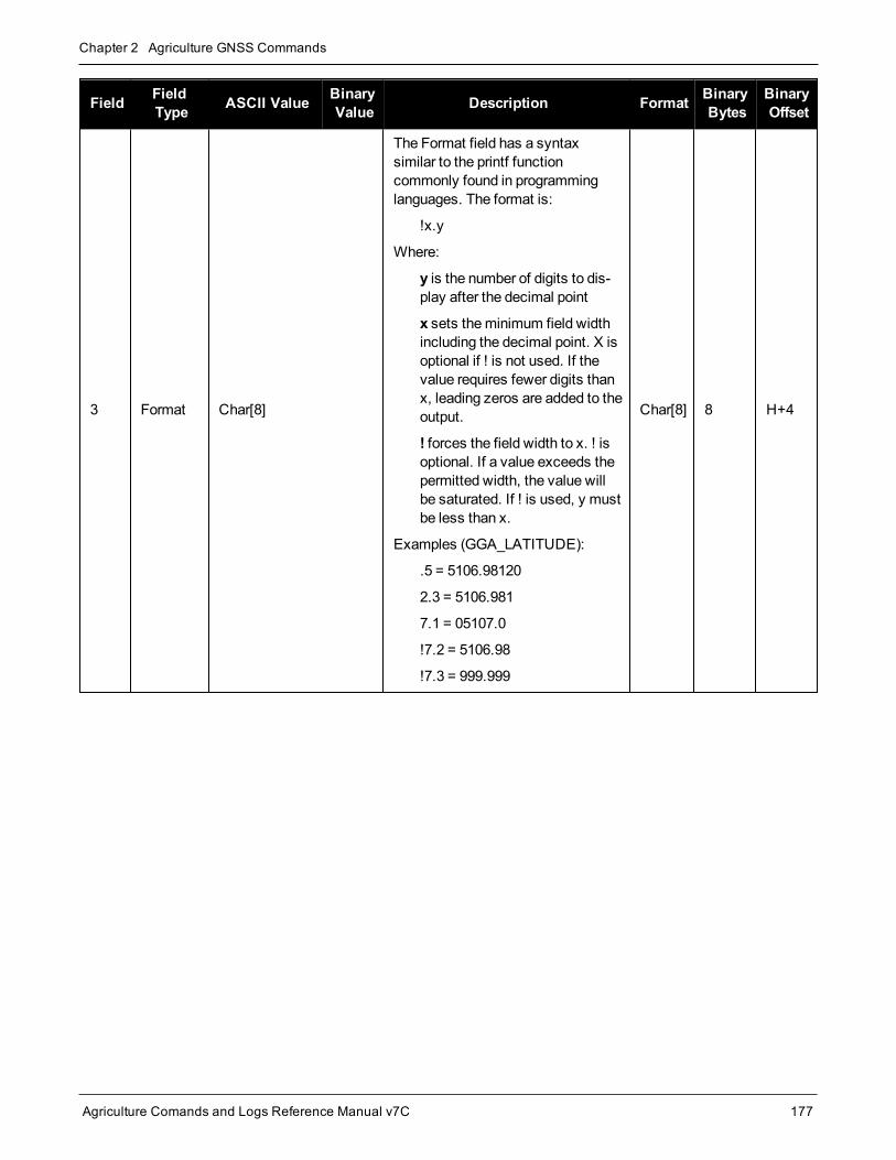
Chapter 2 Agriculture GNSS Commands
Agriculture Comands and Logs Reference Manual v7C 177
Field FieldType ASCII Value Binary
Value Description Format BinaryBytes
BinaryOffset
3 Format Char[8]
The Format field has a syntaxsimilar to the printf functioncommonly found in programminglanguages. The format is:
!x.y
Where:
y is the number of digits to dis-play after the decimal point
x sets theminimum field widthincluding the decimal point. X isoptional if ! is not used. If thevalue requires fewer digits thanx, leading zeros are added to theoutput.
! forces the field width to x. ! isoptional. If a value exceeds thepermitted width, the value willbe saturated. If ! is used, y mustbe less than x.
Examples (GGA_LATITUDE):
.5 = 5106.98120
2.3 = 5106.981
7.1 = 05107.0
!7.2 = 5106.98
!7.3 = 999.999
Char[8] 8 H+4

Chapter 2 Agriculture GNSS Commands
Agriculture Comands and Logs Reference Manual v7C 178
2.65 NMEATALKERSets the NMEA talker ID
Platform: OEM719, OEM729, OEM7500, OEM7600, OEM7700, OEM7720, PwrPak7, SPAN CPT7,SMART7, SMART2
This command is used to alter the behavior of the NMEA talker ID. The talker is the first 2 characters after the $ sign in the log header of the GPGLL, GPGRS, GPGSA, GPGST, GPGSV, GPRMB, GPRMC, GPVTG andGPZDA log outputs. The other NMEA logs are not affected by the NMEATALKER command.
On SPAN systems, the GPGGA position is always based on the position solution from the BESTPOSlog which incorporate GNSS + INS solutions as well.
The default GPS NMEA messages (NMEATALKER GP) include specific information about only the GPS satel-lites that have a 'GP' talker solution, even whenGLONASS satellites are present. As well, the default GPSNMEA message outputs GP as the talker ID regardless of the position type given in position logs such asBESTPOS. TheNMEATALKER AUTO command changes this behavior so that the NMEA messages includeall satellites in the solution and the talker ID changes according to those satellites.
If NMEATALKER is set to auto and there are systems other thanGPS in the solution, there will bemulitple sen-tences with different talker IDs.
For instance, if both GPS andGLONASS satellites are in the solution, two sentences with the GN talker ID areoutput. The first sentence contains information about the GPS and the second sentence contains the GLONASSsatellites in the solution. In another example, if NMEATALKER is set to auto and there are only GLONASSsatellites in the solution, the talker ID of this message is GL.
If the solution comes from SPAN, the talker ID is IN.
Message ID: 861
Abbreviated ASCII Syntax:NMEATALKER id
Factory Default:NMEATALKER gp
ASCII Example:NMEATALKER auto
Field Field Type ASCIIValue
BinaryValue Description Format Binary
BytesBinaryOffset
1 NMEATALKERheader - - Command header. SeeMessages on
page 26 for more information. - H 0
2 IDGP 0 GPS (GP) only
Enum 4 HAUTO 1 GPS, Inertial (IN) and/or GLONASS

Chapter 2 Agriculture GNSS Commands
Agriculture Comands and Logs Reference Manual v7C 179
The NMEATALKER command only affects NMEA logs that are capable of a GPS output. For example,GLMLA is a GLONASS-only log and the output will always use the GL talker. Table 39: NMEA Talkersbelow shows the NMEA logs and whether they useGPS (GP), GLONASS (GL), Galileo (GA), or com-bined (GN) talkers with NMEATALKER AUTO.
Log Talker IDs
GLMLA GL
GPALM GP
GPGGA GP
GPGLL GA or GL or GN or GP
GPGRS GA or GL or GN or GP
GPGSA GA or GL or GN or GP
GPGST GA or GL or GN or GP
GPGSV GA or GL or GP
GPRMB GA or GL or GN or GP
GPRMC GA or GL or GN or GP
GPVTG GA or GL or GN or GP
GPZDA GP
Table 39: NMEA Talkers

Chapter 2 Agriculture GNSS Commands
Agriculture Comands and Logs Reference Manual v7C 180
2.66 NMEAVERSIONSets the NMEA Version for Output
Platform: OEM719, OEM729, OEM7500, OEM7600, OEM7700, OEM7720, PwrPak7, SPAN CPT7,SMART7, SMART2
Use this command to set the output version of NMEA messages.
Message ID: 1574
Abbreviated ASCII Syntax:NMEAVERSION Version
Factory Defaults:NMEAVERSION V31
ASCII Example:NMEAVERSION V41
Field Field Type ASCIIValue
BinaryValue Description Format Binary
BytesBinaryOffset
1 NMEAVERSIONheader - - Command header. SeeMessages
on page 26 for more information. - H 0
2 VersionV31 0 NMEA messages will be output in
NMEA version 3.10 format.Enum 4 H
V41 1 NMEA messages will be output inNMEA version 4.10 format.
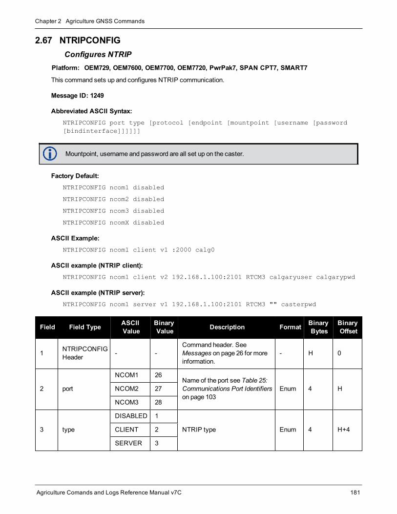
Chapter 2 Agriculture GNSS Commands
Agriculture Comands and Logs Reference Manual v7C 181
2.67 NTRIPCONFIGConfigures NTRIP
Platform: OEM729, OEM7600, OEM7700, OEM7720, PwrPak7, SPAN CPT7, SMART7
This command sets up and configures NTRIP communication.
Message ID: 1249
Abbreviated ASCII Syntax:NTRIPCONFIG port type [protocol [endpoint [mountpoint [username [password[bindinterface]]]]]]
Mountpoint, username and password are all set up on the caster.
Factory Default:NTRIPCONFIG ncom1 disabled
NTRIPCONFIG ncom2 disabled
NTRIPCONFIG ncom3 disabled
NTRIPCONFIG ncomX disabled
ASCII Example:NTRIPCONFIG ncom1 client v1 :2000 calg0
ASCII example (NTRIP client):NTRIPCONFIG ncom1 client v2 192.168.1.100:2101 RTCM3 calgaryuser calgarypwd
ASCII example (NTRIP server):NTRIPCONFIG ncom1 server v1 192.168.1.100:2101 RTCM3 "" casterpwd
Field Field Type ASCIIValue
BinaryValue Description Format Binary
BytesBinaryOffset
1 NTRIPCONFIGHeader - -
Command header. SeeMessages on page 26 for moreinformation.
- H 0
2 port
NCOM1 26Name of the port see Table 25:Communications Port Identifierson page 103
Enum 4 HNCOM2 27
NCOM3 28
3 type
DISABLED 1
NTRIP type Enum 4 H+4CLIENT 2
SERVER 3

Chapter 2 Agriculture GNSS Commands
Agriculture Comands and Logs Reference Manual v7C 182
Field Field Type ASCIIValue
BinaryValue Description Format Binary
BytesBinaryOffset
4 protocol
DISABLED 1
Protocol (default V1) Enum 4 H+8V1 2
V2 3
5 endpoint Max 80 characterstring
Endpoint to wait on or toconnect to where host is ahostname or IP address and portis the TCP/UDP port number(default = 80)
String[80]
variable1 H+12
6 mountpoint Max 80 characterstring Whichmount point to use String
[80]variable1 variable
7 user name Max 30 characterstring Login user name String
[30]variable1 variable
8 password Max 30 characterstring Password String
[30]variable1 variable
9 bindInterface ALL(default) 1 Not supported. Set toALL for
future compatibility. Enum 4 variable
1In the binary case, each string field needs to be NULL terminated and additional bytes of padding added to maintain 4-bytealignment, up to the maximum defined by the string size. The next defined field starts immediately at the next 4-bytealignment following the NULL.

Chapter 2 Agriculture GNSS Commands
Agriculture Comands and Logs Reference Manual v7C 183
2.68 NTRIPSOURCETABLESet NTRIP caster endpoints
Platform: OEM729, OEM7600, OEM7700, OEM7720, PwrPak7, SPAN CPT7, SMART7
This command is used to set the NTRIP caster endpoints to be used for theSOURCETABLE log (see page728).
Message ID: 1343
Abbreviated ASCII Syntax:NTRIPSOURCETABLE endpoint [reserved1] [reserved2]
Factory Default:NTRIPSOURCETABLE none
ASCII Example:NTRIPSOURCETABLE base.station.novatel.ca:1001
NTRIPSOURCETABLE 192.168.1.100:1001
Field Field Type ASCIIValue
BinaryValue Description Format Binary
BytesBinaryOffset
1NTRIPSOURCETABLEheader
- Command header. SeeMessageson page 26 for more information. - H 0
2 Endpoint Max 80character string
Endpoint, in format of host:port, toconnect to where the host is ahostname or IP address and port isthe TCP/IP port number
String[80]
variable1 H
3 Reserved1 Reserved Reserved Ulong 4 variable
4 Reserved2 Reserved Reserved Ulong 4 variable
1In the binary case, each string field needs to be NULL terminated and additional bytes of padding added to maintain 4-bytealignment, up to the maximum defined by the string size. The next defined field starts immediately at the next 4-bytealignment following the NULL.

Chapter 2 Agriculture GNSS Commands
Agriculture Comands and Logs Reference Manual v7C 184
2.69 NVMRESTORERestores NVM data after an NVM failure
Platform: OEM719, OEM729, OEM7500, OEM7600, OEM7700, OEM7720, PwrPak7, SPAN CPT7,SMART7, SMART2
This command is used to restore Non-Volatile Memory (NVM) data after a NVM Fail error. This failure is indic-ated by bit 15 of the receiver error word being set (see alsoRXSTATUS command on page 655 andRXSTATUSEVENT command on page 668). If corrupt NVM data is detected, the receiver remains in the errorstate and continues to flash an error code on the Status LED until theNVMRESTORE command is issued (referto Built-In Status Tests in the SMART7 Installation andOperation User Manual for further explanation).
After entering theNVMRESTORE command and resetting the receiver, the communications link may have to bereestablished at a different baud rate from the previous connection.
Message ID: 197
Abbreviated ASCII Syntax:NVMRESTORE
The possibility of NVM failure is extremely remote, however, if it should occur it is likely that only asmall part of the data is corrupt. This command is used to remove the corrupt data and restore thereceiver to an operational state. The data lost could be the user configuration, almanac, model or otherreserved information.

Chapter 2 Agriculture GNSS Commands
Agriculture Comands and Logs Reference Manual v7C 185
2.70 NVMUSERDATAWrite User Data to NVM
Platform: OEM719, OEM729, OEM7500, OEM7600, OEM7700, OEM7720, PwrPak7, SPAN CPT7,SMART7, SMART2
This commandwrites the data provided in the data array to NVM. This data can be retrieved by issuing the com-mand LOG NVMUSERDATA.
The user data is maintained through power cycles and a standard FRESET command (see page 118). To clearthe user data, use the FRESET USERDATA command.
The user datamay be deleted if theNVMRESTORE command (see page 184) is sent. NVMRESTOREshould be used with caution and is meant for use only in the event of a NVM receiver error.
Message ID: 1970
Abbreviated ASCII Syntax:NVMUSERDATA #bytes data
Field Field Type BinaryValue Description Binary
FormatBinaryBytes
BinaryOffset
1 NVMUSERDATAheader - Command header. SeeMessages on page 26
for more information. - H 0
2 #bytes - Number of bytes of data to follow Ulong 4 H
3 data -
User input data up to amaximum of 2000bytes.
Data is entered in hexadecimal values with noseparators between the values. For example,1a2b3c4e
Uchar 2000 H+4

Chapter 2 Agriculture GNSS Commands
Agriculture Comands and Logs Reference Manual v7C 186
2.71 OUTPUTDATUMChoose the datum to output PPP solutions in
Platform: OEM719, OEM729, OEM7500, OEM7600, OEM7700, OEM7720, PwrPak7, SPAN CPT7,SMART7, SMART2
This command is used to select the geodetic datum and co-ordinate epoch in which PPP solutions are output. Ifnot set, the factory default value is the service datum and epoch of the PPP corrections. For TerraStar and Veri-pos, this is ITRF2014 and the current epoch.
For either a plate-fixed or earth-fixed output datum, using a fixed epoch will compensate for plate motion suchthat you get repeatable co-ordinates over time for a location. Compensation is controlled using theTECTONICSCOMPENSATIONSOURCE command on page 279 and reported by theTECTONICSCOMPENSATION log (see page 731). The TECTONICSCOMPENSATION log will warn whenoperating in a region where tectonics compensationmay be imprecise.
In order for solutions to be transformed to the requested datum, the datum selectedmust be in the list of datumsshown in theGEODETICDATUMS log (see page 394).
To view the current datum, use theBESTDATUMINFO log (see page 343).
Note, in future firmware versions OUTPUTDATUM will transform the coordinates from other solution types.
Message ID: 1144
Abbreviated ASCII Syntax:OUTPUTDATUM name epoch_option epoch
Factory Default:OUTPUTDATUM SERVICE SERVICE_EPOCH 0
ASCII Example:
To output co-ordinates in NAD83(CSRS), 2018:
OUTPUTDATUM NAD83(CSRS) FIXED_EPOCH 2018.000
To output co-ordinates in ITRF2014, 2010.00:
OUTPUTDATUM ITRF2014 FIXED_EPOCH 2010.000
TheOUTPUTDATUM command only accepts a non-zero epoch if the FIXED_EPOCH option is spe-cified. The earliest fixed epoch is 1900.
Do not mix theOUTPUTDATUM command and theDATUM USER commands.
Field Field Type ASCIIValue
BinaryValue Description Format Binary
BytesBinaryOffset
1 OUTPUTDATUMheader – –
Command header. SeeMessages on page 26 for moreinformation.
– H 0

Chapter 2 Agriculture GNSS Commands
Agriculture Comands and Logs Reference Manual v7C 187
Field Field Type ASCIIValue
BinaryValue Description Format Binary
BytesBinaryOffset
2 name The datum output. Char[32] variable H
3 epoch_optionSee Table 40:EpochOptionsbelow
Epoch type to enter coordinatesin. Enum 4 variable
4 epochEpoch to output coordinates in.
(default = 0)Double 8 variable
Binary ASCII Description
0 SERVICE_EPOCH Output coordinates in the epoch of the corrections (default)
1 FIXED_EPOCH Output coordinates in the specified epoch
2 CURRENT_EPOCH Output coordinates in the current epoch
Table 40: Epoch Options

Chapter 2 Agriculture GNSS Commands
Agriculture Comands and Logs Reference Manual v7C 188
2.72 PDPFILTEREnables, disables or resets the PDP filter
Platform: OEM719, OEM729, OEM7500, OEM7600, OEM7700, OEM7720, PwrPak7, SPAN CPT7,SMART7, SMART2
This command is used to enable, disable or reset the Pseudorange/Delta-Phase (PDP) filter. Themain advant-ages of the PDP implementation are:
l Smooths a jumpy position
l Bridges outages in satellite coverage (the solution is degraded from normal but there is at least a reasonablesolution without gaps)
Enable the PDP filter to output the PDP solution in theBESTPOS log (see page 346),BESTVEL log (see page 360) andNMEA Standard Logs on page 513.
Refer to PDP andGLIDE Configurations in the SMART7 Installation andOperationUser Manual for information on configuring your receiver for PDP or GLIDE® operation.
2.72.1 GLIDE Position FilterGLIDE is amode of the PDP1 filter that optimizes the position for consistency over time rather than absoluteaccuracy. This is ideal in clear sky conditions where the user needs a tight, smooth and consistent output. TheGLIDE filter works best with SBAS. The PDP filter is smoother than a least squares solution but is still noisy inplaces. TheGLIDE filter produces a very smooth solution with relative rather than absolute position accuracy.There should typically be less than 1 centimeter difference in error from epoch to epoch. GLIDE also works insingle point and DGPS modes. See also thePDPMODE command on page 190 and thePDPPOS log onpage 531, PDPVEL log on page 535 andPDPXYZ log on page 536.
Message ID: 424
Abbreviated ASCII Syntax:PDPFILTER switch
Factory Default:PDPFILTER disable
ASCII Example:PDPFILTER enable
Field Field Type ASCIIValue
BinaryValue Description Format Binary
BytesBinaryOffset
1 PDPFILTERheader - - Command header. SeeMessages on
page 26 for more information. - H 0
1Refer also to the application note APN-038: Pseudorange/Delta-Phase (PDP) and GLIDE Filters, available at nova-tel.com/support/support-materials/application-notes.

Chapter 2 Agriculture GNSS Commands
Agriculture Comands and Logs Reference Manual v7C 189
Field Field Type ASCIIValue
BinaryValue Description Format Binary
BytesBinaryOffset
2 switch
DISABLE 0 Disable the PDP filter.
Enum 4 HENABLE 1 Enable the PDP filter.
RESET 2Reset the PDP filter. A reset clears thefilter memory so that the PDP filter canstart over.

Chapter 2 Agriculture GNSS Commands
Agriculture Comands and Logs Reference Manual v7C 190
2.73 PDPMODESelects the PDP mode and dynamics
Platform: OEM719, OEM729, OEM7500, OEM7600, OEM7700, OEM7720, PwrPak7, SPAN CPT7,SMART7, SMART2
This command is used to select themode and dynamics of the PDP filter.
ThePDPFILTER ENABLE command (see thePDPFILTER command on page 188) must be enteredbefore thePDPMODE command.
It is recommended that the ionotype be left at AUTOwhen using either normal mode PDP or GLIDE.See also theSETIONOTYPE command on page 265.
Message ID: 970
Abbreviated ASCII Syntax:PDPMODE mode dynamics
Factory Default:PDPMODE normal auto
ASCII Example:PDPMODE relative dynamic
Field Field Type ASCIIValue
BinaryValue Description Format Binary
BytesBinaryOffset
1 PDPMODEheader - - Command header. SeeMessages on
page 26 for more information. - H 0
2 mode
NORMAL 0In RELATIVE or GLIDE mode, GLIDEperformance is optimized to obtain aconsistent error in latitude andlongitude over time periods of 15minutes or less, rather than to obtainthe smallest absolute position error.See alsoGLIDE Position Filter onpage 188 for GLIDE mode additionalinformation.
GLIDE mode is the same asRELATIVE mode.
Enum 4 HRELATIVE 1
GLIDE 3
3 dynamics
AUTO 0 Auto detect dynamics mode
Enum 4 H+4STATIC 1 Static mode
DYNAMIC 2 Dynamic mode

Chapter 2 Agriculture GNSS Commands
Agriculture Comands and Logs Reference Manual v7C 191
2.74 $PMDTConfigure Terrain Compensation
Platform: SMART7, SMART7-I, SMART7-W, SMART2-TB
Use this NMEA style command to configure the Terrain Compensation feature. The Terrain Compensation filtermust be enabled using the TILTCOMPENSATIONCONTROL command (see page 284) for the Terrain Com-pensation feature to function.
Themaximum antenna height allowed is 500 inches (12.7meters).
The TILTFILTER command (see page 285) and TILTZERO command (see page 286) can also be usedto configure the Terrain Compensation filter.
Message ID: 2308
Syntax$PMDT,a,x,x,x,x.x*hh[CR][LF]
ASCII Example:$PMDT,u,,1,1*78
Field Structure Description Format Symbol Example
1 $PMDT Command header. SeeMessages on page 26 for moreinformation. – $PMDT $PMDT
2 function
The function to perform, where:
l = Set level state
u = Set/Get antenna height
x = Save level and height values
r = Clear the saved level and height values
Required field.
Char a ,u
3 reserved Reserved field, leave empty. – x ,
4 antenna heightfeet
Antenna height in feet. Will be combined with theantenna height inches field.
Cannot be combined with the antennaheight meters field.
Integer x ,1

Chapter 2 Agriculture GNSS Commands
Agriculture Comands and Logs Reference Manual v7C 192
Field Structure Description Format Symbol Example
5 antenna heightinches
Antenna height in inches. Will be combined with theantenna height feet field.
Cannot be combined with the antennaheight meters field.
Integer x ,1
6 antenna heightmeters
Antenna height in meters.
Cannot be combined with the antennaheight feet and antenna height inchesfields.
Float x.x ,2.2
7 *hh NMEA check sum. *hh *78
8 [CR][LF] Sentence terminator. [CR][LF]
For more information about configuring the Terrain Compensation feature using the $PMDT command,see Configuring Terrain Compensation using NMEA Command in the SMART7 Installation andOper-ation User Manual.

Chapter 2 Agriculture GNSS Commands
Agriculture Comands and Logs Reference Manual v7C 193
2.75 POSAVEImplements base station position averaging
Platform: OEM719, OEM729, OEM7500, OEM7600, OEM7700, OEM7720, PwrPak7, SPAN CPT7,SMART7, SMART2
This command implements position averaging for base stations. Position averaging continues for a specifiednumber of hours or until the estimated averaged position error is within specified accuracy limits. Averagingstops when the time limit or the horizontal standard deviation limit or the vertical standard deviation limit isachieved. When averaging is complete, the FIX POSITION command is automatically invoked. See the FIXcommand on page 115.
If differential logging is initiated, then issue thePOSAVE command followed by theSAVECONFIG command(see page 242). The receiver averages positions after every power on or reset. It then invokes the FIXPOSITION command to enable it to send differential corrections.
Message ID: 173
Abbreviated ASCII Syntax:POSAVE state [maxtime [maxhstd [maxvstd]]]
Factory Default:POSAVE off
ASCII Example 1:POSAVE on 24 1 2
ASCII Example 2:POSAVE OFF
Field FieldType
ASCIIValue
BinaryValue Description Format Binary
BytesBinaryOffset
1 POSAVEheader - - Command header. SeeMessages on
page 26 for more information. - H 0
2 stateON 1 Enable position averaging
Enum 4 HOFF 0 Disable position averaging
3 maxtime 0.01 - 100 hours Maximum amount of time that positions areto be averaged (default=0.01) Float 4 H+4
4 maxhstd 0 - 100m Desired horizontal standard deviation(default = 0.0) Float 4 H+8
5 maxvstd 0 - 100m Desired vertical standard deviation(default = 0.0) Float 4 H+12

Chapter 2 Agriculture GNSS Commands
Agriculture Comands and Logs Reference Manual v7C 194
ThePOSAVE command can be used to establish a new base station, in any form of survey or RTKdata collection, by occupying a site and averaging the position until either a certain amount of time haspassed or position accuracy has reached a user-specified level. User-specified requirements can bebased on time or horizontal or vertical quality of precision.

Chapter 2 Agriculture GNSS Commands
Agriculture Comands and Logs Reference Manual v7C 195
2.76 POSTIMEOUTSets the position time out
Platform: OEM719, OEM729, OEM7500, OEM7600, OEM7700, OEM7720, PwrPak7, SPAN CPT7,SMART7, SMART2
This command is used to set the time out value for the position calculation in seconds.
In position logs, for exampleBESTPOS log (see page 346) orPSRPOS log (see page 554), when the positiontime out expires, the Position Type field is set to NONE. Other field values in these logs remain populated withthe last available position data. Also, the position is no longer used in conjunction with the almanac to determinewhat satellites are visible.
Message ID: 612
Abbreviated ASCII Syntax:POSTIMEOUT sec
Factory Default:POSTIMEOUT 600
ASCII Example:POSTIMEOUT 1200
When performing data collection in a highly dynamic environment (for example, urban canyons or inhigh speed operations), you can usePOSTIMEOUT to prevent the receiver from outputting calculatedpositions that are too old. UsePOSTIMEOUT to force the receiver position type to NONE. Thisensures that the position information being used in theBESTPOS log (see page 346) orPSRPOS log(see page 554) is based on a recent calculation. All position calculations are then recalculated using themost recent satellite information.
Field Field Type ASCIIValue
BinaryValue Description Format Binary
BytesBinaryOffset
1 POSTIMEOUTheader - - Command header. SeeMessages on
page 26 for more information. - H 0
2 sec 0-86400 Time out in seconds Ulong 4 H

Chapter 2 Agriculture GNSS Commands
Agriculture Comands and Logs Reference Manual v7C 196
2.77 PPPBASICCONVERGEDCRITERIAConfigures decision for PPP Basic convergence
Platform: OEM719, OEM729, OEM7500, OEM7600, OEM7700, OEM7720, PwrPak7, SPAN CPT7,SMART7, SMART2
ThePPPBASICCONVERGEDCRITERIA command sets the threshold that determines if the solution has con-verged for lower accuracy PPP solutions. These are the PPP solutions reported with the PPP_BASIC and PPP_BASIC_CONVERGING position types.
The convergence threshold for high-accuracy PPP solutions (reported with PPP and PPP_CONVERGING position types) is set using thePPPCONVERGEDCRITERIA command (see page197).
Relaxing the convergence threshold shortens the time before a PPP solution is reported as converged.However, it does not alter solution behavior. During the initial PPP solution period, the positions canhave decimeter error variation. Only relax the convergence threshold if the application can toleratehigher solution variability.
Message ID: 1949
Abbreviated ASCII Syntax:PPPBASICCONVERGEDCRITERIA criteria tolerance
Factory Default:PPPBASICCONVERGEDCRITERIA horizontal_stddev 0.60
ASCII Example:PPPBASICCONVERGEDCRITERIA total_stddev 0.45
Field Field Type ASCII Value BinaryValue Description Format Binary
BytesBinaryOffset
1
PPPBASICCONVERGEDCRITERIAheader
- -Command header. SeeMessages on page 26 formore information.
- H 0
2 Criteria
TOTAL_STDDEV 1 Use the total, 3D, standard
deviationEnum 4 H
HORIZONTAL_STDDEV 2 Use the horizontal, 2D,
standard deviation
3 Tolerance Tolerance (m) Float 4 H+4

Chapter 2 Agriculture GNSS Commands
Agriculture Comands and Logs Reference Manual v7C 197
2.78 PPPCONVERGEDCRITERIAConfigures decision for PPP convergence
Platform: OEM719, OEM729, OEM7500, OEM7600, OEM7700, OEM7720, PwrPak7, SPAN CPT7,SMART7, SMART2
ThePPPCONVERGEDCRITERIA command sets the threshold that determines if the solution has convergedfor high-accuracy PPP solutions. These are the PPP solutions reported with the PPP and PPP_CONVERGINGposition types.
The convergence threshold for lower accuracy PPP solutions (reported with PPP_BASIC and PPP_BASIC_CONVERGING position types) is set using thePPPBASICCONVERGEDCRITERIA com-mand (see page 196).
Relaxing the convergence threshold shortens the time before a PPP solution is reported as converged.However, it does not alter solution behavior. During the initial PPP solution period, the positions canhave decimeter error variation. Only relax the convergence threshold if the application can toleratehigher solution variability.
Message ID: 1566
Abbreviated ASCII Syntax:PPPCONVERGEDCRITERIA criteria tolerance
Factory Default:PPPCONVERGEDCRITERIA horizontal_stddev 0.32
ASCII Example:PPPCONVERGEDCRITERIA total_stddev 0.15
Field Field Type ASCII Value BinaryValue Description Format Binary
BytesBinaryOffset
1
PPPCONVERGEDCRITERIAheader
- -Command header. SeeMessages on page 26 formore information.
- H 0
2 Criteria
TOTAL_STDDEV 1 Use the total, 3D, standard
deviationEnum 4 H
HORIZONTAL_STDDEV 2 Use the horizontal, 2D,
standard deviation
3 Tolerance Tolerance (m) Float 4 H+4

Chapter 2 Agriculture GNSS Commands
Agriculture Comands and Logs Reference Manual v7C 198
2.79 PPPDYNAMICSSets the PPP dynamics mode
Platform: OEM719, OEM729, OEM7500, OEM7600, OEM7700, OEM7720, PwrPak7, SPAN CPT7,SMART7, SMART2
This command configures the dynamics assumed by the PPP filter. AUTO detects the antenna dynamics andadapts filter operation accordingly.
The automatic dynamics detectionmay be fooled by very slow, “creeping” motion, where the antennaconsistently moves less than 2 cm/s. In such cases, themode should explicitly be set to DYNAMIC.
Message ID: 1551
Abbreviated ASCII Syntax:PPPDYNAMICS mode
Factory Default:PPPDYNAMICS dynamic
ASCII Example:PPPDYNAMICS auto
Field Field Type ASCIIValue
BinaryValue Description Format Binary
BytesBinaryOffset
1 PPPDYNAMICSheader - -
Command header. SeeMessages on page 26 for moreinformation.
- H 0
2 Mode
AUTO 0 Automatically determinesdynamics mode
Enum 4 HSTATIC 1 Static mode
DYNAMIC 2 Dynamic mode

Chapter 2 Agriculture GNSS Commands
Agriculture Comands and Logs Reference Manual v7C 199
2.80 PPPRESETReset the PPP filter
Platform: OEM719, OEM729, OEM7500, OEM7600, OEM7700, OEM7720, PwrPak7, SPAN CPT7,SMART7, SMART2
This command resets the PPP filter. After a reset, the PPP filter is restored to its initial state and PPP con-vergence will start over.
If deletion of the NVM-saved PPP seed information is also required, then aPPPSEED CLEAR com-mandmust be applied before the PPPRESET command. See thePPPSEED command on the nextpage.
Message ID: 1542
Abbreviated ASCII Syntax:PPPRESET [Option]
ASCII Example :PPPRESET
Field Field Type ASCIIValue
BinaryValue Description Binary
BytesBinaryFormat
BinaryOffset
1 PPPRESETheader - - Command header. SeeMessages on
page 26 for more information. - H 0
2 OptionFILTER 1
Reset the PPP filter.
(default = FILTER) 4 Enum H
ALL 10 Reset the PPP filter and Corrections

Chapter 2 Agriculture GNSS Commands
Agriculture Comands and Logs Reference Manual v7C 200
2.81 PPPSEEDControl the seeding of the PPP filter
Platform: OEM719, OEM729, OEM7500, OEM7600, OEM7700, OEM7720, PwrPak7, SPAN CPT7,SMART7, SMART2
ThePPPSEED command controls the seeding of the PPP filter. Accurate position seeding can accelerate PPPconvergence.
PPPSEED SET is used to explicitly specify a seed position. The seed positionmust be in a datum consistentwith the PPP corrections that will be used. For TerraStar corrections, this is ITRF2014. ThePPPSEED SETcommand can only be used to give seed positions for stationary platforms.
Cautionmust be exercised when usingPPPSEED SET. While a good seed position can accelerateconvergence, a bad seed position hurts performance. In some cases, a bad seed can prevent a solutionfrom ever converging to a correct position. In other cases, a bad seedmight be rejected immediately. Instill other cases, the filter might operate with it for a time period only to reject it later. In this case, the fil-ter position is partially reset, with a corresponding discontinuity in the PPP position.
PPPSEED STORE andRESTORE are intended to simplify seeding in operations where the antenna does notmove between power-down and power-up. For example, in agricultural operations a tractor might be stopped in afield at the end of a day and then re-started the next day in the same position. Before the receiver is powered-down, the current PPP position could be saved to NVM using thePPPSEED STORE command, and then thatposition applied as a seed after power-up usingPPPSEED RESTORE.
PPPSEED AUTO automates the STORE and RESTORE process. When this option is used, the PPP filter auto-matically starts using the stopping position of the previous day. Additionally, in order for the receiver to recall thesaved seed, thePPPSEED AUTO command should be saved to NVM using theSAVECONFIG command (seepage 242).
Message ID: 1544
Abbreviated ASCII Syntax:PPPSEED option [latitude] [longitude] [height] [northing_std._dev.][easting_std._dev.] [height_std._dev.]
ASCII Example:PPPSEED set 51.11635322441 -114.03819311672 1064.5458 0.05 0.05 0.05
Field FieldType
ASCIIValue
BinaryValue Description Format Binary
BytesBinaryOffset
1 PPPSEEDheader - - Command header. SeeMessages on
page 26 for more information. - H 0

Chapter 2 Agriculture GNSS Commands
Agriculture Comands and Logs Reference Manual v7C 201
Field FieldType
ASCIIValue
BinaryValue Description Format Binary
BytesBinaryOffset
2 option
CLEAR 0 Resets the stored seed, and preventsany auto seeding from occurring.
Enum 4 H
SET 1 Immediately apply the specified co-ordinates as a seed position.
STORE 2 Store the current PPP position in NVMfor use as a future seed.
RESTORE 3Retrieve and apply a seed position thatwas previously saved in NVM via theSTORE or AUTO options.
AUTO 4 Automatically store and restore PPPseed positions.
3 latitude ±90 Latitude (degrees) Double 8 H+4
4 longitude ±180 Longitude (degrees) Double 8 H+12
5 height > -2000.0 Ellipsoidal height (meters) Double 8 H+20
6 northingstd. dev. Northing standard deviation (meters) Float 4 H+28
7 eastingstd. dev. Easting standard deviation (meters) Float 4 H+32
8 height std.dev.
Ellipsoidal height standard deviation(meters) Float 4 H+36
9 Reserved Float 4 H+40
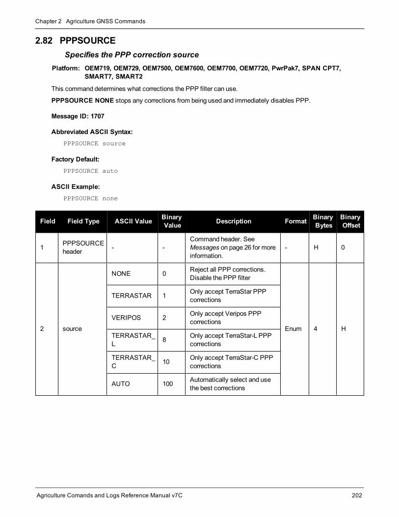
Chapter 2 Agriculture GNSS Commands
Agriculture Comands and Logs Reference Manual v7C 202
2.82 PPPSOURCESpecifies the PPP correction source
Platform: OEM719, OEM729, OEM7500, OEM7600, OEM7700, OEM7720, PwrPak7, SPAN CPT7,SMART7, SMART2
This command determines what corrections the PPP filter can use.
PPPSOURCE NONE stops any corrections from being used and immediately disables PPP.
Message ID: 1707
Abbreviated ASCII Syntax:PPPSOURCE source
Factory Default:PPPSOURCE auto
ASCII Example:PPPSOURCE none
Field Field Type ASCII Value BinaryValue Description Format Binary
BytesBinaryOffset
1 PPPSOURCEheader - -
Command header. SeeMessages on page 26 for moreinformation.
- H 0
2 source
NONE 0 Reject all PPP corrections.Disable the PPP filter
Enum 4 H
TERRASTAR 1 Only accept TerraStar PPPcorrections
VERIPOS 2 Only accept Veripos PPPcorrections
TERRASTAR_L 8 Only accept TerraStar-L PPP
corrections
TERRASTAR_C 10 Only accept TerraStar-C PPP
corrections
AUTO 100 Automatically select and usethe best corrections

Chapter 2 Agriculture GNSS Commands
Agriculture Comands and Logs Reference Manual v7C 203
2.83 PPPTIMEOUTSets the maximum age of the PPP corrections
Platform: OEM719, OEM729, OEM7500, OEM7600, OEM7700, OEM7720, PwrPak7, SPAN CPT7,SMART7, SMART2
This command sets themaximum age of the corrections that can be used to generate a PPP solution.
By default, the delay is 360 seconds. If the received corrections are older than the delay time set, the receiverwill not produce a PPP solution.
For example, if L-Band tracking (which is providing us the PPP corrections) is lost for some reason, the receiverwill continue generating a PPP solution using last available corrections until the age of corrections is older thanthe delay time. Note that using older corrections degrades the PPP solution quality.
Message ID: 1560
Abbreviated ASCII Syntax:PPPTIMEOUT delay
Factory Default:PPPTIMEOUT 360
ASCII Example:PPPTIMEOUT 120
Field Field Type ASCIIValue
BinaryValue Description Format Binary
BytesBinaryOffset
1 PPPTIMEOUTheader - - Command header. SeeMessages on
page 26 for more information. - H 0
2 delay 5 to 900 s Maximum corrections age Ulong 4 H

Chapter 2 Agriculture GNSS Commands
Agriculture Comands and Logs Reference Manual v7C 204
2.84 PPSCONTROLControls the PPS output
Platform: OEM719, OEM729, OEM7500, OEM7600, OEM7700, OEM7720, PwrPak7, SPAN CPT7,SMART7, SMART2
This command provides amethod for controlling the polarity, period and pulse width of the PPS output on theOEM7. The PPS output can also be disabled using this command.
This command is used to setup the PPS signal coming from the receiver. For example, to takemeas-urements such as temperature or pressure, in synch with your GNSS data, the PPS signal can be usedto trigger measurements in other devices.
The leading edge of the 1 PPS pulse is always the trigger/reference. For example:
PPSCONTROL ENABLE NEGATIVE
generates a normally high, active low pulse with the falling edge as the reference, while:
PPSCONTROL ENABLE POSITIVE
generates a normally low, active high pulse with the rising edge as the reference.
The pulse width is user-adjustable. The adjustable pulse width feature supports triggers/systems that needlonger, or shorter, pulse widths than the default to register the pulse enabling a type of GPIO line for manipulationof external hardware control lines.
The switch states allow more control over disabling/enabling the PPS. The ENABLE_FINETIME switch pre-vents the PPS from being enabled until FINE or FINESTEERING time status has been reached. The ENABLE_FINETIME_MINUTEALIGN switch is similar to ENABLE_FINETIME with caveat that the PPS will still not beenabled until the start of the next 60 seconds (a 1minutemodulus) after FINE or FINESTEERING time statushas been reached.
If the value of a field shared with PPSCONTROL2 is changed in PPSCONTROL, the value of that fieldis also changed in PPSCONTROL2. For example, if the polarity is changed using the PPSCONTROLcommand, the polarity is also changed in PPSCONTROL2 command.
Message ID: 613
Abbreviated ASCII Syntax:PPSCONTROL [switch [polarity [period [pulsewidth]]]]
Factory Default:PPSCONTROL enable negative 1.0 1000
ASCII Example:PPSCONTROL enable positive 0.5 2000

Chapter 2 Agriculture GNSS Commands
Agriculture Comands and Logs Reference Manual v7C 205
Field Field Type ASCII Value BinaryValue Description Format Binary
BytesBinaryOffset
1 PPSCONTROLheader - -
Command header. SeeMessages on page 26 formore information.
- H 0
2 switch
DISABLE 0 Disable the PPS
Enum 4 H
ENABLE 1 Enable the PPS (default)
ENABLE_FINETIME 2
Enable the PPS only whenFINE or FINESTEERINGtime status has been reached
ENABLE_FINETIME_MINUTEALIGN
3
Enable the PPS only whenFINE or FINESTEERINGtime status has been reachedAND the start of the next 60seconds (1minutemodulus)has occurred
3 polarityNEGATIVE 0 Optional field to specify the
polarity of the pulse to begenerated on the PPS output.(default= NEGATIVE)
Enum 4 H+4POSITIVE 1
4 period 0.05, 0.1, 0.2, 0.25, 0.5,1.0, 2.0, 3.0,...20.0
Optional field to specify theperiod of the pulse, inseconds (default=1.0)
Double 8 H+8
5 pulsewidthAny positive value lessthan or equal to half theperiod
Optional field to specify thepulse width of the PPS signalin microseconds. This valueshould always be less than orequal to half the period.(default=1000)
Ulong 4 H+16

Chapter 2 Agriculture GNSS Commands
Agriculture Comands and Logs Reference Manual v7C 206
2.85 PSRDIFFSOURCESets the pseudorange differential correction source
Platform: OEM719, OEM729, OEM7500, OEM7600, OEM7700, OEM7720, PwrPak7, SPAN CPT7,SMART7, SMART2
This command determines what differential corrections the PSR and PDP (GLIDE) filters can use.
Differential corrections can be generated from RTK corrections. PSRDIFFSOURCE RTK enables this, allowingthe PSR and PDP solutions to benefit from RTK corrections. An RTK-capablemodel is not required for this cap-ability.
PSRDIFFSOURCE NONE stops any corrections from being used; the PSR and PDP solutions will revert tobeing uncorrected.
All types except NONE may revert to SBAS (if enabled) or SINGLE position types.
Message ID: 493
Abbreviated ASCII Syntax:PSRDIFFSOURCE type [id]
Factory Default:PSRDIFFSOURCE AUTO ANY
ASCII Examples:
1. Enable only SBAS:
PSRDIFFSOURCE SBASSBASCONTROL ENABLE AUTO
2. Enable differential from RTCM, with a fall-back to SBAS:
PSRDIFFSOURCE RTCM ANYSBASCONTROL ENABLE AUTO
3. Disable all corrections:
PSRDIFFSOURCE NONE
Field Field Type ASCIIValue
BinaryValue Description Format Binary
BytesBinaryOffset
1 PSRDIFFSOURCEheader - -
Command header. SeeMessages on page 26 formore information.
- H 0
2 typeSee Table 41:PSRDIFFSOURCEType on the next page
Correction type Enum 4 H
3 id Char[4] or ANYBase station ID
(default = ANY)Char[4] 8 H+4

Chapter 2 Agriculture GNSS Commands
Agriculture Comands and Logs Reference Manual v7C 207
Binary ASCII Description
0 RTCMUseRTCM version 2 corrections from the given ID if available or SBAS otherwise.
RTCM ID: 0 ≤ RTCM ID ≤ 1023 or ANY to accept all IDs.
1 RTCAUseRTCA corrections from the given ID if available or SBAS otherwise.
RTCA ID: A four-character string containing only alpha (a-z) or numeric characters (0-9) or ANYto accept all IDs.
5 SBAS
Use SBAS corrections such as WAAS, EGNOS andMSAS in the region they are available andapplicable to. There are regions that are not covered by any SBAS satellite and so the solutionwill revert to uncorrected.
The ID is ignored for this correction type.
6 RTK
Use differential corrections that are generated from RTK corrections if available or SBASotherwise.
The correction type used is determined by the setting of theRTKSOURCE command (see page224).
10 AUTO Use any available correction source. If both differential and SBAS sources are available,differential will be preferred.
11 NONE Disables all differential correction types. Solution will revert to uncorrected.
Table 41: PSRDIFFSOURCE Type

Chapter 2 Agriculture GNSS Commands
Agriculture Comands and Logs Reference Manual v7C 208
2.86 PSRDIFFSOURCETIMEOUTSets pseudorange differential correction source timeout
Platform: OEM719, OEM729, OEM7500, OEM7600, OEM7700, OEM7720, PwrPak7, SPAN CPT7,SMART7, SMART2
Whenmultiple differential correction sources are available, this command allows the user to set a time inseconds, that the receiver will wait before switching to another differential source, if corrections from the originalsource are lost.
Message ID: 1449
Abbreviated ASCII Syntax:PSRDIFFSOURCETIMEOUT option [timeout]
Factory Default:PSRDIFFSOURCETIMEOUT AUTO
ASCII Example:PSRDIFFSOURCETIMEOUT auto
PSRDIFFSOURCETIMEOUT set 180
Field Field Type ASCIIValue
BinaryValue Description Format Binary
BytesBinaryOffset
1 PSRDIFFSOURCETIMEOUT header - - Command header. SeeMessages
on page 26 for more information. - H 0
2 optionAUTO 1
Use AUTO or SET to set the time Enum 4 HSET 2
3 timeout 0 to 3600 sec Specify the timeout(default=0) Ulong 4 H+4

Chapter 2 Agriculture GNSS Commands
Agriculture Comands and Logs Reference Manual v7C 209
2.87 PSRDIFFTIMEOUTSets maximum age of pseudorange differential data
Platform: OEM719, OEM729, OEM7500, OEM7600, OEM7700, OEM7720, PwrPak7, SPAN CPT7,SMART7, SMART2
This command is used to set themaximum age of pseudorange differential correction data to use when operatingas a rover station. Received pseudorange differential correction data, older than the specified time, is ignored.This time out period also applies to differential corrections generated from RTK corrections.
The RTCA Standard for scat-i stipulates that themaximum age of differential correctionmessages can-not be greater than 22 seconds. Therefore, for RTCA rover users, the recommended PSRDIFF delaysetting is 22.
Message ID: 1450
Abbreviated ASCII Syntax:PSRDIFFTIMEOUT delay
Factory Default:PSRDIFFTIMEOUT 300
ASCII Example:PSRDIFFTIMEOUT 60
Field FieldType
ASCIIValue
BinaryValue Description Format Binary
BytesBinaryOffset
1PRSDIFFTIMEOUTheader
- - Command header. SeeMessages onpage 26 for more information. - H 0
2 delay 2 to 1000 s Maximum pseudorange differential age Ulong 4 H

Chapter 2 Agriculture GNSS Commands
Agriculture Comands and Logs Reference Manual v7C 210
2.88 QZSSECUTOFFSets QZSS satellite elevation cutoff
Platform: OEM719, OEM729, OEM7500, OEM7600, OEM7700, OEM7720, PwrPak7, SPAN CPT7,SMART7, SMART2
This command is used to set the elevation cut-off angle for trackedQZSS satellites. The receiver does not startautomatically searching for a QZSS satellite until it rises above the cut-off angle (when satellite position isknown). Tracked satellites that fall below the cut-off angle are no longer tracked unless they aremanuallyassigned (see theASSIGN command on page 53).
In either case, satellites below theQZSSECUTOFF angle are eliminated from the internal position and clock off-set solution computations.
This command permits a negative cut-off angle; it could be used in these situations:
l The antenna is at a high altitude, and thus can look below the local horizon
l Satellites are visible below the horizon due to atmospheric refraction
Caremust be taken when usingQZSSECUTOFF command because the signals from lower elevationsatellites are traveling throughmore atmosphere and are therefore degraded. Use of satellites below 5degrees is not recommended.
Use theELEVATIONCUTOFF command (see page 107) to set the cut-off angle for any system.
For dual antenna receivers, this command applies to both the primary and secondary antennas.
Message ID: 1350
Abbreviated ASCII Syntax:QZSSECUTOFF angle
Factory Default:QZSSECUTOFF 5.0
ASCII ExampleQZSSECUTOFF 10.0
Field Field Type ASCIIValue
BinaryValue Description Format Binary
BytesBinaryOffset
1 QZSSECUTOFFheader - - Command header. SeeMessages
on page 26 for more information. - H 0
2 angle ±90 degrees Elevation cutoff angle relative to thehorizon Float 4 H

Chapter 2 Agriculture GNSS Commands
Agriculture Comands and Logs Reference Manual v7C 211
2.89 RADARCONFIGConfigure the Emulated Radar Output
Platform: OEM719, OEM729, OEM7500, OEM7600, OEM7700, OEM7720, PwrPak7, SPAN CPT7,SMART7, SMART2
Use this command to configure the Emulated Radar (ER) output.
The ER signal is output on theVARF orEVENT_OUT1 pin of the receiver.
Message ID: 1878
Abbreviated ASCII Syntax:RADARCONFIG switch [frequency_step [update_rate [response_mode[threshold]]]]
Factory Default:radarconfig disable
ASCII Example:radarconfig enable 26.11 5hz 2 3.5
Field Field Type ASCIIValue
BinaryValue Description Format Binary
BytesBinaryOffset
1 RADARCONFIGheader - -
Command header. SeeMessages on page 26 for moreinformation.
- H 0
2 switchDISABLE 0 Disables radar emulation
Enum 4 HENABLE 1 Enables radar emulation
3 freq_step
10.06
16.32
26.11
28.12
34.80
36.11
Frequency step per kilometer perhour.
(default = 36.11 Hz/kph)Double 8 H+4

Chapter 2 Agriculture GNSS Commands
Agriculture Comands and Logs Reference Manual v7C 212
Field Field Type ASCIIValue
BinaryValue Description Format Binary
BytesBinaryOffset
4 update_rate
1HZ 1
Rate at which the outputfrequency is adjusted
(default = 10HZ)1Enum 4 H+12
2HZ 2
5HZ 5
10HZ 10
20HZ 20
5 resp_modeSee Table 42:ResponseModesbelow
Specify how responsive radaremulation is to changes invelocity
(Default = 500)1
Integer 4 H+16
6 threshold 2 to 50 kph
The speed threshold at which toswitch between responsemode1000 and responsemode 500.
The threshold is only applicablewhen the responsemode is set to2.
(default = 5 kph)
Double 8 H+20
Mode Description
1 Immediate. This results in the lowest latency at the cost of higher noise.
2 Automatically switch between 1000 and 500 depending on speed. When speed is below the Thresholdparameter, use ResponseMode 500. Otherwise, use ResponseMode 1000.
500 Signal is minimally smoothed resulting in low latency but increased noise.
1000 Output signal is smoothed over a smaller window resulting in less latency than 2000 and less noise than500.
2000 Output signal is smoothed to reduce noise at the cost of higher latency.
Table 42: Response Modes
1The number of samples used for smoothing depends on both the update_rate and resp_mode parameters. For instance, ifthe update_rate is 5 Hz and the resp_mode is 2000 ms, the number of samples used will be 10.

Chapter 2 Agriculture GNSS Commands
Agriculture Comands and Logs Reference Manual v7C 213
2.90 REFERENCESTATIONTIMEOUTSets timeout for removing previously stored base stations
Platform: OEM719, OEM729, OEM7500, OEM7600, OEM7700, OEM7720, PwrPak7, SPAN CPT7,SMART7
This command sets how long the receiver will retain RTK base station co-ordinates. Shorter durations might berequired if the receiver is operating in a VRS RTK network that recycles base station IDs quickly.
Message ID: 2033
Abbreviated ASCII Syntax:REFERENCESTATIONTIMEOUT option [timeout]
Factory Default:REFERENCESTATIONTIMEOUT AUTO
ASCII Example:REFERENCESTATIONTIMEOUT SET 90
Field Field Type ASCIIValue
BinaryValue Description Format Binary
BytesBinaryOffset
1 REFERENCESTATIONTIMEOUT header - -
Command header. SeeMessages on page 26 formore information.
- H 0
2 option
AUTO 1
Sets the Timeout to 90seconds1
The Timeout field is optionalfor AUTO and has no effect
Enum 4 H
SET 2
Must set the timeout valueusing the Timeout field
0 is not accepted when usingthe SET option
3 timeout 1 to 3600 s Specify the time Ulong 4 H+4
1This behavior is subject to change.

Chapter 2 Agriculture GNSS Commands
Agriculture Comands and Logs Reference Manual v7C 214
2.91 RESETPerforms a hardware reset
Platform: OEM719, OEM729, OEM7500, OEM7600, OEM7700, OEM7720, PwrPak7, SPAN CPT7,SMART7, SMART2
This command performs a hardware reset. The receiver configuration reverts either to the factory default, if nouser configuration was saved or the last SAVECONFIG settings. Refer to the FRESET command on page 118andSAVECONFIG command on page 242.
The optional delay field is used to set the number of seconds the receiver is to wait before resetting.
Message ID: 18
Abbreviated ASCII Syntax:RESET [delay]
Input ExampleRESET 30
TheRESET command can be used to erase any unsaved changes to the receiver configuration.
Unlike the FRESET command on page 118, theRESET command does not erase data stored in theNVM, such as Almanac and Ephemeris data.
Field FieldType
ASCIIValue
BinaryValue Description Format Binary
BytesBinaryOffset
1 RESETheader - - Command header. SeeMessages on
page 26 for more information. - H 0
2 delay (0-60)
Seconds to wait before resetting (default =0) Ulong 4 H

Chapter 2 Agriculture GNSS Commands
Agriculture Comands and Logs Reference Manual v7C 215
2.92 RTKASSISTEnable or disable RTK ASSIST
Platform: OEM719, OEM729, OEM7500, OEM7600, OEM7700, OEM7720, PwrPak7, SPAN CPT7,SMART7
This command enables or disables RTK ASSIST.
RTK ASSIST uses L-Band-delivered corrections to enable RTK operation to continue for extended durations ifRTK corrections are lost. In order to use RTK ASSIST, a receiver with L-Band tracking capability and RTKASSIST capability is needed. The duration of RTK ASSIST operation can be limited using theRTKASSISTTIMEOUT command (see page 216).
When active, RTK ASSIST is shown in the RTKPOS and BESTPOS extended solution status field (see Table69: Extended Solution Status on page 353). The active status and further details on the RTK ASSIST status areavailable through theRTKASSISTSTATUS log on page 637.
For reliable RTK ASSIST performance, the RTK base station positionmust be within 1meter of its trueWGS84 position.
Message ID: 1985
Abbreviated ASCII Syntax:RTKASSIST switch
Factory Default:RTKASSIST enable
ASCII Example:RTKASSIST disable
Field Field Type ASCIIValue
BinaryValue Description Format Binary
BytesBinaryOffset
1 RTKASSISTheader - - Command header. SeeMessages on
page 26 for more information. - H 0
2 switchDISABLE 0 Disable RTK ASSIST
Enum 4 HENABLE 1 Enable RTK ASSIST

Chapter 2 Agriculture GNSS Commands
Agriculture Comands and Logs Reference Manual v7C 216
2.93 RTKASSISTTIMEOUTSet the maximum RTK ASSIST duration
Platform: OEM719, OEM729, OEM7500, OEM7600, OEM7700, OEM7720, PwrPak7, SPAN CPT7,SMART7
This command sets how long the receiver will report an RTK solution when RTK is beingmaintained by RTKASSIST. Themaximum permitted duration of RTK ASSIST operation is determined by the subscription andreceiver model. Values less than the subscription limit can be set using theRTKASSISTTIMEOUT command.
When RTK ASSIST is active, theRTKTIMEOUT command is disregarded. Themaximum time thatRTK will continue past an RTK corrections outage is controlled by RTKASSISTTIMEOUT.
Message ID: 2003
Abbreviated ASCII Syntax:RTKASSISTTIMEOUT limit_type [limit_value]
Factory Default:RTKASSISTTIMEOUT SUBSCRIPTION_LIMIT
ASCII Example:RTKASSISTTIMEOUT USER_LIMIT 900
Field Field Type ASCII Value BinaryValue Description Format Binary
BytesBinaryOffset
1RTKASSISTTIMEOUTheader
- -Command header. SeeMessages on page 26 for moreinformation.
- H 0
2 limit_type
SUBSCRIPTION_LIMIT 0 Usemaximum permitted
duration limit.
Enum 4 HUSER_LIMIT 1
Themaximum RTK ASSISTduration is user set, up to thelimit permitted by thesubscription andmodel.
3 limit_valueTime out value in seconds.
Only valid for the USER_LIMIT Limit Type.
Ulong 4 H+4

Chapter 2 Agriculture GNSS Commands
Agriculture Comands and Logs Reference Manual v7C 217
2.94 RTKDYNAMICSSets the RTK dynamics mode
Platform: OEM719, OEM729, OEM7500, OEM7600, OEM7700, OEM7720, PwrPak7, SPAN CPT7,SMART7
This command is used to specify how the receiver looks at the data. There are threemodes: STATIC,DYNAMIC and AUTO. The STATIC mode forces the RTK software to treat the rover station as though it werestationary.
DYNAMIC mode forces the software to treat the rover as though it were in motion. If the receiver is undergoingvery slow, steady motion (<2.5 cm/s for more than 5 seconds), use DYNAMIC mode (as opposed to AUTO) toprevent inaccurate results and possible resets.
For reliable performance, the antenna should not movemore than 1-2 cm when in STATIC mode.
Message ID: 183
Abbreviated ASCII Syntax:RTKDYNAMICS mode
Factory Default:RTKDYNAMICS dynamic
ASCII Example:RTKDYNAMICS static
Use the STATIC option to decrease the time required to fix ambiguities and reduce the amount of noisein the position solution. If STATIC mode is used when the antenna is not static, the receiver will haveerroneous solutions and unnecessary RTK resets.
Field Field Type ASCIIValue
BinaryValue Description Format Binary
BytesBinaryOffset
1 RTKDYNAMICSheader - -
Command header. SeeMessages on page 26 for moreinformation.
- H 0
2 mode
AUTO 0 Automatically determinesdynamics mode
Enum 4 HSTATIC 1 Static mode
DYNAMIC 2 Dynamic mode
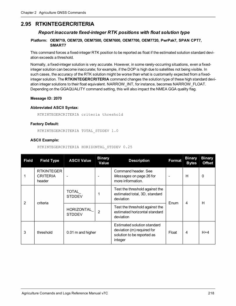
Chapter 2 Agriculture GNSS Commands
Agriculture Comands and Logs Reference Manual v7C 218
2.95 RTKINTEGERCRITERIAReport inaccurate fixed-integer RTK positions with float solution type
Platform: OEM719, OEM729, OEM7500, OEM7600, OEM7700, OEM7720, PwrPak7, SPAN CPT7,SMART7
This command forces a fixed-integer RTK position to be reported as float if the estimated solution standard devi-ation exceeds a threshold.
Normally, a fixed-integer solution is very accurate. However, in some rarely-occurring situations, even a fixed-integer solution can become inaccurate; for example, if the DOP is high due to satellites not being visible. Insuch cases, the accuracy of the RTK solutionmight be worse than what is customarily expected from a fixed-integer solution. TheRTKINTEGERCRITERIA command changes the solution type of these high standard devi-ation integer solutions to their float equivalent. NARROW_INT, for instance, becomes NARROW_FLOAT.Depending on theGGAQUALITY command setting, this will also impact the NMEA GGA quality flag.
Message ID: 2070
Abbreviated ASCII Syntax:RTKINTEGERCRITERIA criteria threshold
Factory Default:RTKINTEGERCRITERIA TOTAL_STDDEV 1.0
ASCII Example:RTKINTEGERCRITERIA HORIZONTAL_STDDEV 0.25
Field Field Type ASCII Value BinaryValue Description Format Binary
BytesBinaryOffset
1RTKINTEGERCRITERIAheader
- -Command header. SeeMessages on page 26 formore information.
- H 0
2 criteria
TOTAL_STDDEV 1
Test the threshold against theestimated total, 3D, standarddeviation
Enum 4 HHORIZONTAL_STDDEV 2
Test the threshold against theestimated horizontal standarddeviation
3 threshold 0.01m and higher
Estimated solution standarddeviation (m) required forsolution to be reported asinteger
Float 4 H+4

Chapter 2 Agriculture GNSS Commands
Agriculture Comands and Logs Reference Manual v7C 219
2.96 RTKNETWORKSpecifies the RTK network mode
Platform: OEM719, OEM729, OEM7500, OEM7600, OEM7700, OEM7720, PwrPak7, SPAN CPT7,SMART7
Network RTK uses permanent base station installations, allowing kinematic GNSS users to achieve centimeteraccuracies, without the need of setting up aGNSS base station, at a known site. This command sets the RTKnetwork mode for a specific network. For more details on Network RTK, refer to the application note APN-041Network RTK.
Message ID: 951
Abbreviated ASCII Syntax:RTKNETWORK mode [network#]
Factory Default:RTKNETWORK AUTO
Input Example:RTKNETWORK imax
Field Field Type ASCIIValue
BinaryValue Description Format Binary
BytesBinaryOffset
1 RTKNETWORKheader - - Command header. SeeMessages on
page 26 for more information. - H 0
2 modeTable 43:Network RTKMode below
RTK network mode. The factorydefault is auto where the receiverswitches to the first available networkRTK source
Enum 4 H
3 network# 0 to4294967295
Specify a number for the network
(default = 0)Ulong 4 H+4
Binary ASCII Description
0 DISABLE Single reference station RTK mode. All received network RTK corrections are ignored.
1-4 Reserved
Table 43: Network RTK Mode

Chapter 2 Agriculture GNSS Commands
Agriculture Comands and Logs Reference Manual v7C 220
Binary ASCII Description
5 VRS
The Virtual Reference Station (VRS) or Virtual Base Station (VBS) idea introduced byTrimble, is that a base station is artificially created in the vicinity of a rover receiver. Allbaseline length dependent errors, such as abnormal troposphere variation, ionosphericdisturbances and orbital errors, are reduced for this VRS. The rover receiving VRSinformation has a lower level of these errors than a distant base station. The VRS iscalculated for a position, supplied by the rover during communication start up, withnetworking software. The VRS position can change if the rover is far away from the initialpoint. The format for sending the rover’s position is standard NMEA format. Most roversreceive VRS data, for a calculated base station, within a couple of meters away.
The VRS approach requires bi-directional communication for supplying the rover’s position tothe networking software.
6 IMAX
The iMAX idea, introduced by Leica Geosystems, is that networking software corrections,based on the rover’s position, are calculated as with VRS. However, instead of calculatingthe base station observations for the provided position or another position closer to the basestation, original observation information is corrected with the calculated corrections andbroadcast. VRS works so that although the rover is unaware of the errors the VRS is takingcare of, there still might be ionospheric remains in the base station observations. iMAXprovides actual base station position information. The rover may assume the base station isat a distance and open its settings for estimation of the remaining ionospheric residuals. TheiMAX methodmay trigger the rover to open its settings further than required, since thenetworking software removes at least part of the ionospheric disturbances. However,compared to VRS above, this approach is safer since it notifies the rover when theremight bebaseline length dependent errors in the observation information. iMAX requires bi-directionalcommunication to the networking software for supplying the base station observationinformation.
7 FKP
The FKP method delivers the information from a base station network to the rover. Noprecise knowledge of the rover’s position is required for providing the correct information. Thecorrections are deployed as gradients to be used for interpolating to the rover’s actualposition.
8 MAX
The basic principle of themaster-auxiliary concept is to provide, in compact form, as much ofthe information from the network and the errors it is observing to the rover as possible. Withmore information about the state and distribution of the dispersive and non-dispersive errorsacross the network, the rover is able to usemore intelligent algorithms in the determination ofits position solution. Each supplier of reference station software will have their ownproprietary algorithms for modeling or estimating these error sources. The rover system candecide to use or to neglect the network RTK information, depending on its own firmwarealgorithm performance.
9 Reserved
10 AUTO
Default value, assume single base. If network RTK corrections are detected then thereceiver will switch to the appropriate mode. iMAX and VRS can only be detected usingRTCMV3, however, it is not possible to distinguish between iMAX or VRS. If iMAX or VRS isdetected, then iMAX will be assumed.

Chapter 2 Agriculture GNSS Commands
Agriculture Comands and Logs Reference Manual v7C 221
2.97 RTKPORTMODEAssigns the port for RTK and ALIGN messages
Platform: OEM719, OEM729, OEM7500, OEM7600, OEM7700, OEM7720, PwrPak7, SPAN CPT7,SMART7
This command only applies to receivers with both RTK and ALIGN enabled.
A rover receiver with RTK and ALIGN enabled can receive RTK and ALIGN corrections at the same time.However, the two different sources (RTK and ALIGN)must be sent to different ports.
Use the RTKPORTMODE command to route correction feeds to different ports. RTK and ALIGN can be routedto any user specified ports.
Failing to specify themode for the incoming source could cause unexpected behavior of RTK or ALIGN.
Ports configured using the RTKPORTMODE commandmust also be configured using theINTERFACEMODE command (see page 136).
Message ID: 1936
Abbreviated ASCII Syntax:RTKPORTMODE [port] mode
Factory Default:RTKPORTMODE COM1 RTK
RTKPORTMODE COM2 RTK
RTKPORTMODE COM3 RTK
RTKPORTMODE COM4 RTK
RTKPORTMODE COM5 RTK
RTKPORTMODE COM6 RTK
RTKPORTMODE ICOM1 RTK
RTKPORTMODE ICOM2 RTK
RTKPORTMODE ICOM3 RTK
RTKPORTMODE ICOM4 RTK
RTKPORTMODE ICOM5 RTK
RTKPORTMODE ICOM6 RTK
RTKPORTMODE ICOM7 RTK
RTKPORTMODE NCOM1 RTK
RTKPORTMODE NCOM2 RTK
RTKPORTMODE NCOM3 RTK
RTKPORTMODE USB1 RTK

Chapter 2 Agriculture GNSS Commands
Agriculture Comands and Logs Reference Manual v7C 222
RTKPORTMODE USB2 RTK
RTKPORTMODE USB3 RTK
RTKPORTMODE WCOM1 RTK
RTKPORTMODE BT1 RTK
RTKPORTMODE AUX RTK
RTKPORTMODE CCOM1 RTK
RTKPORTMODE CCOM2 RTK
RTKPORTMODE CCOM3 RTK
RTKPORTMODE CCOM4 RTK
RTKPORTMODE CCOM5 ALIGN
RTKPORTMODE CCOM6 RTK
ASCII Example:RTKPORTMODE COM2 RTK
RTKPORTMODE COM3 ALIGN
Field Field Type ASCIIValue
BinaryValue Description Format Binary
BytesBinaryOffset
1 RTKPORTMODEheader - -
Command header. SeeMessages on page 26 formore information.
- H 0
2 PortSee Table 25:Communications PortIdentifiers on page 103
Port identifier(default = THISPORT) Enum 4 H
3 ModeRTK 0
Mode for this port Enum 4 H+4ALIGN 1

Chapter 2 Agriculture GNSS Commands
Agriculture Comands and Logs Reference Manual v7C 223
2.98 RTKRESETReset the RTK filter
Platform: OEM719, OEM729, OEM7500, OEM7600, OEM7700, OEM7720, PwrPak7, SPAN CPT7,SMART7
This command resets the RTK filter and causes the AdVanceRTK filter to undergo a complete reset, forcing thesystem to restart the ambiguity resolution calculations.
Message ID: 2082
Abbreviated ASCII Syntax:RTKRESET [Switch]
Example :RTKRESET
Field Field Type ASCIIValue
BinaryValue Description Format Binary
ByteBinaryOffset
1 RTKRESETheader - - Command header. SeeMessages on
page 26 for more information. - H 0
2 Switch FILTER 1Reset the RTK filter.
This is an optional parameterEnum 4 H

Chapter 2 Agriculture GNSS Commands
Agriculture Comands and Logs Reference Manual v7C 224
2.99 RTKSOURCESets the RTK correction source
Platform: OEM719, OEM729, OEM7500, OEM7600, OEM7700, OEM7720, PwrPak7, SPAN CPT7,SMART7
This command determines what corrections the RTK filter can use. This is useful when the receiver is receivingcorrections frommultiple base stations.
RTKSOURCE NONE stops any corrections from being used and immediately disables RTK and RTK-ASSIST.
Message ID: 494
Abbreviated ASCII Syntax:RTKSOURCE type [id]
Factory Default:RTKSOURCE AUTO ANY
ASCII Examples:
1. Use a specific format:
RTKSOURCE RTCMV3
2. Use a specific format and base station:
RTKSOURCE RTCMV3 1234
3. Disable RTK:
RTKSOURCE NONE
Field Field Type ASCIIValue
BinaryValue Description Format Binary
BytesBinaryOffset
1 RTKSOURCEheader - - Command header. SeeMessages
on page 26 for more information. - H 0
2 type See Table 44: RTKSource Type below Correction type Enum 4 H
3 id Char[4] or ANYBase station ID
(default = ANY)Char[4] 8 H+4
Binary ASCII Description
0 RTCMUse only RTCM version 2 corrections from the given ID.
ID: 0 ≤ RTCM ID ≤ 1023 or ANY to accept all IDs
Table 44: RTK Source Type

Chapter 2 Agriculture GNSS Commands
Agriculture Comands and Logs Reference Manual v7C 225
Binary ASCII Description
1 RTCAUse only RTCA corrections from the given ID.
ID: A four-character string containing only alpha (a-z) or numeric characters (0-9) or ANYto accept all IDs
2 CMRUse only CMR corrections from the given ID.
ID: 0 ≤ CMR ID ≤ 31 or ANY to accept all IDs
10 AUTO Use any correction type received. If multiple types are received, the first one received isused. If entered, the ID must be ANY.
11 NONE Disable RTK
13 RTCMV3Use only RTCM version 3 corrections from the given ID.
ID: 0 ≤ RTCMV3 ID ≤ 4095 or ANY to accept all IDs.
14 NOVATELXUse only NovAtel proprietary corrections from the given ID.
ID: A four-character string containing alpha (a-z) or numeric characters (0-9) or ANY toaccept all IDs.

Chapter 2 Agriculture GNSS Commands
Agriculture Comands and Logs Reference Manual v7C 226
2.100 RTKSOURCETIMEOUTSets RTK correction source timeout
Platform: OEM719, OEM729, OEM7500, OEM7600, OEM7700, OEM7720, PwrPak7, SPAN CPT7,SMART7
Whenmultiple RTK correction sources are available, this command allows the user to set a time, in seconds,that the receiver will wait before switching to another RTK correction source if corrections from the originalsource are lost.
Message ID: 1445
Abbreviated ASCII Syntax:RTKSOURCETIMEOUT option [timeout]
Factory Default:RTKSOURCETIMEOUT AUTO
ASCII Example:RTKSOURCETIMEOUT auto
RTKSOURCETIMEOUT set 180
Field Field Type ASCIIValue
BinaryValue Description Format Binary
BytesBinaryOffset
1RTKSOURCETIMEOUTheader
- - Command header. SeeMessages onpage 26 for more information. - H 0
2 optionAUTO 1
Sets the timeout according to networktype or other self-detected conditions.
Timeout field is optional for AUTO andhas no effect Enum 4 H
SET 2 Sets the timeout to the value entered inthe timeout field.
3 timeout 1 to 3600 s(maximum)
Specify the time
0 is not accepted if SET is entered inthe option field
(default=0 for the AUTO option)
Ulong 4 H+4

Chapter 2 Agriculture GNSS Commands
Agriculture Comands and Logs Reference Manual v7C 227
2.101 RTKSVENTRIESSets number of satellites in corrections
Platform: OEM719, OEM729, OEM7500, OEM7600, OEM7700, OEM7720, PwrPak7, SPAN CPT7,SMART7
This command sets the number of satellites (at the highest elevation) that are transmitted in the RTK correctionsfrom a base station receiver. This is useful when the amount of bandwidth available for transmitting correctionsis limited.
Message ID: 92
Abbreviated ASCII Syntax:RTKSVENTRIES number
Factory Default:RTKSVENTRIES 24
ASCII Example:RTKSVENTRIES 7
GPS devices have enabledmany transit and fleet authorities to provide Automatic Vehicle Location(AVL). AVL systems track the position of individual vehicles and relay that data back to a remotedispatch location that can store or better utilize the information. Consider the implementation of an AVLsystem within a police department, to automatically log and keep track of the location of each cruiser.Typically a fleet uses a 9600 bps connection where AVL data is relayed back to headquarters. Thelimited bandwidth of the radio must be shared amongst the AVL and other systems inmultiple cruisers.
When operating with a low baud rate radio transmitter (9600 or lower), especially over a long distance,the AVL system could limit the number of satellites for which corrections are sent using theRTKSVENTRIES command.
Field Field Type ASCIIValue
BinaryValue Description Format Binary
BytesBinaryOffset
1 RTKSVENTRIESheader - - Command header. SeeMessages
on page 26 for more information. - H 0
2 number 4-24 The number of SVs to betransmitted in correctionmessages Ulong 4 H

Chapter 2 Agriculture GNSS Commands
Agriculture Comands and Logs Reference Manual v7C 228
2.102 RTKTIMEOUTSets maximum age of RTK data
Platform: OEM719, OEM729, OEM7500, OEM7600, OEM7700, OEM7720, PwrPak7, SPAN CPT7,SMART7
This command is used to set themaximum age of RTK data to use when operating as a rover station. RTK datareceived that is older than the specified time is ignored.
When RTK ASSIST is active, theRTKTIMEOUT command is disregarded. Themaximum time thatRTK will continue past an RTK corrections outage is controlled by the settings in theRTKASSISTTIMEOUT command (see page 216).
Message ID: 910
Abbreviated ASCII Syntax:RTKTIMEOUT delay
Factory Default:RTKTIMEOUT 60
ASCII Example (rover):RTKTIMEOUT 20
Field Field Type ASCIIValue
BinaryValue Description Format Binary
BytesBinaryOffset
1 RTKTIMEOUTheader - - Command header. SeeMessages on
page 26 for more information. - H 0
2 delay 5 to 60 s Maximum RTK data age Ulong 4 H

Chapter 2 Agriculture GNSS Commands
Agriculture Comands and Logs Reference Manual v7C 229
2.103 SATEL4CONFIGConfigures the Satel 400 MHz radio
Platform: SMART7 with RELAY7
Refer to the Satel Radio user documentation for complete and detailed instructions regarding the cor-rect operation of the radio.
This command is used to configure the Satel 400MHz radio. Settings in this command are stored directly on theradio and not saved through theSAVECONFIG command on page 242.
The receiver responds to the command immediately, but the radio settings will take some time to be applied. LogSATELSTATUS onchanged to receive a notification that configuration is complete. See theSATELSTATUSlog on page 677.
l Not all compatibility modes are available on every radio.
l The radio_behavior setting determines whether the receive or transmit frequency willbe changed.
l If the TRIMTALK protocol is used, the base transmitter type (TRIMBLE or PACCREST)must be specified.
l If the tx_power value entered does not correspond to one of the power levels supported bythe radiomodule, the output power is set to the nearest possible value.
Do not interrupt power while the radio is being configured.
Message ID: 2215
Abbreviated ASCII Syntax:SATEL4CONFIG <radio_behavior> <tx_power> <freq> <compatibility> <base_type>
ASCII Example:SATEL4CONFIG RX 0 438000000 7 TRIMBLE
Field Field Type ASCII Value BinaryValue Description Format Binary
BytesBinaryOffset
1 SATEL4CONFIGheader - -
Command header. SeeMessages on page 26 formore information.
- H 0
2 radio_behavior Refer to Table 45: RadioBehavior on the next page Radio behavior ENUM 4 H
3 tx_power 0 - 35000 Transmit power (mW) UINT 4 H+4
4 frequency 403000000 - 473000000 Frequency (Hz) UINT 4 H+8

Chapter 2 Agriculture GNSS Commands
Agriculture Comands and Logs Reference Manual v7C 230
Field Field Type ASCII Value BinaryValue Description Format Binary
BytesBinaryOffset
5 compatibilitymode
1-20 Refer to Table 46:Compatibility Mode on thenext page
Radio compatibility mode UINT 4 H+12
6 base type0-5 Refer to Table 47:Base Type on the nextpage
Base transmitter type(required for TRIMTALKprotocol only)
ENUM 4 H+16
7 crc 32-bit CRC (ASCII andBinary only) Hex 4 H+20
Binary ASCII Description
0 RX Configure for receive
1 TX Configure for transmit
Table 45: Radio Behavior

Chapter 2 Agriculture GNSS Commands
Agriculture Comands and Logs Reference Manual v7C 231
Binary Protocol Modulation Link Rate (bps) /Channel Spacing (kHz) FEC
1 Pacific Crest compatible GMSK 4800 / 12.5 ON
2 Pacific Crest compatible GMSK 4800 / 12.5 OFF1
3 Pacific Crest compatible 4FSK 9600 / 12.5 ON
4 Pacific Crest compatible 4FSK 9600 / 12.5 OFF1
5 Pacific Crest FST compatible 4FSK 9600 / 12.5 ON
6 Pacific Crest FST compatible 4FSK 9600 / 12.5 OFF1
7 Trimtalk compatible GMSK 4800 / 12.5
8 Trimtalk compatible GMSK 80002
9 Satel 3AS 4FSK 9600 / 12.5 ON
10 Satel 3AS 4FSK 9600 / 12.5 OFF
11 Pacific Crest compatible GMSK 9600 / 25.0 ON
12 Pacific Crest compatible GMSK 9600 / 25.0 OFF1
13 Pacific Crest compatible 4FSK 19200 / 25.0 ON
14 Pacific Crest compatible 4FSK 19200 / 25.0 OFF1
15 Pacific Crest FST compatible 4FSK 19200 / 25.0 ON
16 Pacific Crest FST compatible 4FSK 19200 / 25.0 OFF1
17 Trimtalk compatible GMSK 9600/ 25.0
18 Trimtalk compatible GMSK 160002
19 Satel 3AS 4FSK 19200 / 25.0 ON
20 Satel 3AS 4FSK 19200 / 25.0 OFF
Table 46: Compatibility Mode
Binary ASCII Description
0 PACCREST PacCrest transmitter
4 TRIMBLE Trimble transmitter
9 NONE Unspecified base type
Table 47: Base Type
1The Satel M3-R4 and EASy radio modules do not support disabling FEC for compatibility modes.2The Satel M3-R4 and EASy radio modules do not support Trimtalk 8000 and 16000 link rates.
Chapter 2 Agriculture GNSS Commands
Agriculture Comands and Logs Reference Manual v7C 232
Base Type is only required for receiving TRIMTALK protocol.
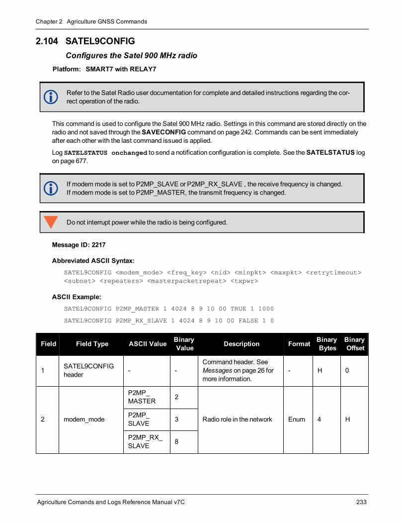
Chapter 2 Agriculture GNSS Commands
Agriculture Comands and Logs Reference Manual v7C 233
2.104 SATEL9CONFIGConfigures the Satel 900 MHz radio
Platform: SMART7 with RELAY7
Refer to the Satel Radio user documentation for complete and detailed instructions regarding the cor-rect operation of the radio.
This command is used to configure the Satel 900MHz radio. Settings in this command are stored directly on theradio and not saved through theSAVECONFIG command on page 242. Commands can be sent immediatelyafter each other with the last command issued is applied.
Log SATELSTATUS onchanged to send a notification configuration is complete. See theSATELSTATUS logon page 677.
If modemmode is set to P2MP_SLAVE or P2MP_RX_SLAVE , the receive frequency is changed.If modemmode is set to P2MP_MASTER, the transmit frequency is changed.
Do not interrupt power while the radio is being configured.
Message ID: 2217
Abbreviated ASCII Syntax:SATEL9CONFIG <modem_mode> <freq_key> <nid> <minpkt> <maxpkt> <retrytimeout><subnet> <repeaters> <masterpacketrepeat> <txpwr>
ASCII Example:SATEL9CONFIG P2MP_MASTER 1 4024 8 9 10 00 TRUE 1 1000
SATEL9CONFIG P2MP_RX_SLAVE 1 4024 8 9 10 00 FALSE 1 0
Field Field Type ASCII Value BinaryValue Description Format Binary
BytesBinaryOffset
1 SATEL9CONFIGheader - -
Command header. SeeMessages on page 26 formore information.
- H 0
2 modem_mode
P2MP_MASTER 2
Radio role in the network Enum 4 HP2MP_SLAVE 3
P2MP_RX_SLAVE 8

Chapter 2 Agriculture GNSS Commands
Agriculture Comands and Logs Reference Manual v7C 234
Field Field Type ASCII Value BinaryValue Description Format Binary
BytesBinaryOffset
3 freq_key 0-14 Frequency key for hop table Uint 4 H+4
4 nid 0-4095 Network ID Uint 4 H+8
5 minpkt 0-9 Minimum packet size Uint 4 H+12
6 maxpkt 0-9 Maximum packet size Enum 4 H+16
7 retrytimeout 8-255Number of failed attemptsto receive packets beforeconnection drops
Uint 4 H+20
8 subnet 0x00, 0xFFMulti-point subnet0x00=Roaming0xFF=Disabled
Uint 4 H+24
9 repeatersFALSE 0 Boolean to specify if
repeaters are present in thenetwork
Bool 4 H+28TRUE 1
10 masterpacketrepeat 0-9 Number of times themaster repeats packets Uint 4 H+32
11 txpwr 0-1000 Transmitter output power(mW) Uint 4 H+36
12 crc 32-bit CRC (ASCII andBinary only) Hex 4 H+40

Chapter 2 Agriculture GNSS Commands
Agriculture Comands and Logs Reference Manual v7C 235
2.105 SATEL9CONFIGLConfigures the 900 MHz radio network
Platform: SMART7 with RELAY7
The SATEL9CONFIGL command is used to configure the Satel 900MHz radio network settings using a sim-plified Leica channel identifier.
Message ID: 2218
Abbreviated ASCII Syntax:SATEL9CONFIGL <modem_mode> <channel> <retrytimeout> <subnet> <repeaters><masterpacketrepeat> <txpwr>
ASCII Example:SATEL9CONFIGL P2MP_MASTER 2 10 00 TRUE 1 1000
SATEL9CONFIGL P2MP_RX_SLAVE 4 10 FF FALSE 0 0
Field Field Type ASCIIValue
BinaryValue Description Format Binary
BytesBinaryOffset
1 SATEL9CONFIGLheader - -
Command header.SeeMessages onpage 26 for moreinformation.
- H 0
2 modem_mode
P2MP_MASTER 2
Radio roll in network Enum 4 HP2MP_SLAVE 3
P2MP_RX_SLAVE 8
3 channel 1-9 Virtual channel Uint 4 H+4
4 retrytimeout 8-255
Number of failedattempts to receivepackets beforeconnection is dropped
Uint 4 H+8
5 subnet 0x00, 0xFFMulti-point subnet0x00=Roaming,0xFF=Disabled
Uint 4 H+12
6 repeatersFALSE 0 Boolean to specify if
repeaters are presentin the network
Bool 4 H+16TRUE 1

Chapter 2 Agriculture GNSS Commands
Agriculture Comands and Logs Reference Manual v7C 236
Field Field Type ASCIIValue
BinaryValue Description Format Binary
BytesBinaryOffset
7 masterpacketrepeat 0-9Number of timesmaster repeatspackets
Uint 4 H+20
8 txpwr 0-1000 Transmitter outputpower (mW) Uint 4 H+24
9 crc 32-bit CRC (ASCIIand Binary only) Hex 4 H+28

Chapter 2 Agriculture GNSS Commands
Agriculture Comands and Logs Reference Manual v7C 237
2.106 SATEL9CONFIGNConfigures the 900 MHz radio network
Platform: SMART7 with RELAY7
The SATEL9CONFIGN command is used to configure the Satel 900MHz radio network settings using a sim-plified Novariant channel identifier.
Message ID: 2219
Abbreviated ASCII Syntax:SATEL9CONFIGN <modem_mode> <channel> <retrytimeout> <subnet> <repeaters><masterpacketrepeat> <txpwr>
ASCII Example:SATEL9CONFIGN P2MP_MASTER 32 10 00 TRUE 1 1000
SATEL9CONFIGN P2MP_RX_SLAVE 32 10 00 FALSE 0 0
Field Field Type ASCIIValue
BinaryValue Description Format Binary
BytesBinaryOffset
1 SATEL9CONFIGNheader - -
Command header.SeeMessages onpage 26 for moreinformation.
- H 0
2 modem_mode
P2MP_MASTER 2
Radio roll in network Enum 4 HP2MP_SLAVE 3
P2MP_RX_SLAVE 8
3 channel 1-3824 Virtual channel Uint 4 H+4
4 retrytimeout 8-255
Number of failedattempts to receivepackets beforeconnection is dropped
Uint 4 H+8
5 subnet 0x00, 0xFFMulti-point subnet0x00=Roaming,0xFF=Disabled
Uint 4 H+12
6 repeatersFALSE 0 Boolean to specify if
repeaters are presentin the network
Bool 4 H+16TRUE 1

Chapter 2 Agriculture GNSS Commands
Agriculture Comands and Logs Reference Manual v7C 238
Field Field Type ASCIIValue
BinaryValue Description Format Binary
BytesBinaryOffset
7 masterpacketrepeat 0-9Number of timesmaster repeatspackets
Uint 4 H+20
8 txpwr 0-1000 Transmitter outputpower (mW) Uint 4 H+24
9 crc 32-bit CRC (ASCIIand Binary only) Hex 4 H+28

Chapter 2 Agriculture GNSS Commands
Agriculture Comands and Logs Reference Manual v7C 239
2.107 SATELCONTROLControls radio operations
Platform: SMART7 with RELAY7
The SATELCONTROL command is used to control the SATEL radio.
Message ID: 2203
Abbreviated ASCII Syntax:SATELCONTROL <Action> <Value>
ASCII Example:SATELCONTROL POWER ON
Field Field Type ASCIIValue
BinaryValue Description Format Binary
BytesBinaryOffset
1SATELCONTROLheader
- -Command header. SeeMessages on page 26 for moreinformation.
- H 0
2action Refer to Table 48: Turn
Radio On, Off or FactoryReset below
Action to perform Enum 4 H
value Corresponding value for action String[24]1 24 H+4
3 crc 32-bit CRC (ASCII and Binaryonly) Hex 4 H+28
Action Value Description
POWERON
Toggles radio power (if available)OFF
FRESET - Resets the radio to factory default settings
Table 48: Turn Radio On, Off or Factory Reset
1Refer to Table 1: Field Type on page 26 for detailed explanation of string variable length.

Chapter 2 Agriculture GNSS Commands
Agriculture Comands and Logs Reference Manual v7C 240
2.108 SATELDETECTDetects the connected Satel radio
Platform: SMART7 with RELAY7
This command is used to detect the Satel radio connected to the serial port. Detection is only required to con-figure the radio settings. If previously configured, the radio can provide RTK corrections without issuing theSATELDETECT command.
LoggingSATELSTATUS command on page 677 onchanged provides a notification of the completion of detec-tion. If no radio is detected at the default baud rate of 38400, the RIL will attempt at additional baud rates(115200, 9600). If a radio is detected, the baud rate of the radio will be changed to 38400. Upon detection, theradio identity (version block) and settings (SATEL4INFO command on page 673 andSATEL9INFO commandon page 675) will be queried. Regardless of the presence of a radio, the final state of the given serial port will bebaud rate=38400, data bits=8, parity bits=N, stop bits=1. Interfacemode will be returned to its setting beforeSATELDETECT was issued.
Message ID: 2204
Abbreviated ASCII Syntax:SATELDETECT COMPort
ASCII Example:SATELDETECT COM3
Field Field Type ASCIIValue
BinaryValue Description Format Binary
BytesBinaryOffset
1 SATELDETECTheader - -
Command header. SeeMessages on page 26 for moreinformation.
- H 0
2 portSee Table 51: COMPort Identifiers onpage 256
Port to attempt detection(default=COM3) Enum 4 H

Chapter 2 Agriculture GNSS Commands
Agriculture Comands and Logs Reference Manual v7C 241
2.109 SATELSTARTUPDETECTDetects the Satel radio on the COM port during startup
Platform: SMART7 with RELAY7
This command is used to detect the Satel radio connected to the COM port during system startup. Detectionfunctions the same as if theSATELDETECT command on the previous page was issued. SATELDECT auto-matically begins at the next startup when theSATELSTARTUPDETECT command is used.
TheSAVECONFIG command on the next pagemust be issued to set this command parameters.
Message ID: 2221
Abbreviated ASCII Syntax:SATELSTARTUPDETECT Switch COMPort
ASCII Example:SATELSTARTUPDETECT Enable COM3
Field Field Type ASCII Value BinaryValue Description Format Binary
BytesBinaryOffset
1 SATELSTARTUPDETECT header - -
Command header. SeeMessages on page 26 formore information.
- H 0
2 switchEnable - Switch to enable detection
(default=Disable) Enum 4 HDisable -
3 portSee Table 51: COMPort Identifiers onpage 256
Port to attempt detection(default=COM3) Enum 4 H+4

Chapter 2 Agriculture GNSS Commands
Agriculture Comands and Logs Reference Manual v7C 242
2.110 SAVECONFIGSave current configuration in NVM
Platform: OEM719, OEM729, OEM7500, OEM7600, OEM7700, OEM7720, PwrPak7, SPAN CPT7,SMART7, SMART2
SAVECONFIG saves commands that were entered by a user to establish the desired receiver configuration onstart up. This configuration is saved in Non-Volatile Memory (NVM) and is executed every time the receiverstarts, whether by power-up or theRESET command on page 214. The commands that are saved as part of aconfiguration are typically LOG requests, SERIALCONFIG commands, ICOMCONFIG commands, a FIX com-mand and others. Note that not all the commands can be saved usingSAVECONFIG. All of the commands thatset a configuration, including default commands for the receiver, are listed in theRXCONFIG log (see page 653).To clear the commands saved by SAVECONFIG and reset the receiver to the factory-set configuration, theFRESET command on page 118 can be used.
If using theSAVECONFIG command in NovAtel Connect, ensure that you have all windows other thanthe Console window closed. Otherwise, log requests used for the various windows are saved as well.This will result in unnecessary data being logged.
Message ID: 19
Abbreviated ASCII Syntax:SAVECONFIG
Field Field Type ASCIIValue
BinaryValue Description Format Binary
BytesBinaryOffset
1 SAVECONFIGheader - - Command header. SeeMessages on
page 26 for more information. - H 0

Chapter 2 Agriculture GNSS Commands
Agriculture Comands and Logs Reference Manual v7C 243
2.111 SAVEETHERNETDATASave the configuration data associated with an Ethernet interface
Platform: OEM729, OEM7600, OEM7700, OEM7720, PwrPak7, SPAN CPT7, SMART7-I, SMART7-SI
Saving the configuration data for an Ethernet interface allows the interface to start automatically at boot time andbe configured with either a static IP address or to obtain an address using DHCP. TheSAVEETHERNETDATAcommand saves the configuration for the interface previously entered using theETHCONFIG command (seepage 109), IPCONFIG command (see page 141) andDNSCONFIG command (see page 99). The configurationdata that is saved will survive aRESET command (see page 214) and FRESET command (see page 118). Toclear the Ethernet interface configuration data, the FRESET ETHERNET command is used. It is not necessaryto issue theSAVECONFIG command (see page 242) to save the Ethernet interface configuration data. In fact, ifSAVECONFIG is used to save theETHCONFIG, IPCONFIG andDNSCONFIG commands, the configurationsaved by SAVEETHERNETDATA will take precedence over theSAVECONFIG configuration.
Message ID: 1679
Abbreviated ASCII Syntax:SAVEETHERNETDATA [Interface]
ASCII Example:ETHCONFIG ETHA AUTO AUTO AUTO AUTO
IPCONFIG ETHA STATIC 192.168.8.11 255.255.255.0 192.168.8.1
DNSCONFIG 1 192.168.4.200
SAVEETHERNETDATA ETHA
Field Field Type ASCIIValue
BinaryValue Description Format Binary
BytesBinaryOffset
1 SAVEETHERNETDATA header - - Command header. SeeMessages
on page 26 for more information. - H 0
2 Interface ETHA 2The Ethernet interface to save theconfiguration data for. The default isETHA.
Enum 4 H
Note that the configurations set using the ICOMCONFIG command (see page 134) andNTRIPCONFIG com-mand (see page 181) are not saved by theSAVEETHERDATA command. The following factory default ICOMconfigurations can be used if Ethernet access to the receiver is required immediately after the receiver is RESETor FRESET.
ICOMCONFIG ICOM1 TCP :3001ICOMCONFIG ICOM2 TCP :3002ICOMCONFIG ICOM3 TCP :3003ICOMCONFIG ICOM4 TCP :3004ICOMCONFIG ICOM5 TCP :3005ICOMCONFIG ICOM6 TCP :3006ICOMCONFIG ICOM7 TCP :3007
See also the following commands:

Chapter 2 Agriculture GNSS Commands
Agriculture Comands and Logs Reference Manual v7C 244
l ETHCONFIG command on page 109
l IPCONFIG command on page 141
l DNSCONFIG command on page 99
l FRESET command on page 118

Chapter 2 Agriculture GNSS Commands
Agriculture Comands and Logs Reference Manual v7C 245
2.112 SBASCONTROLSets SBAS test mode and PRN
Platform: OEM719, OEM729, OEM7500, OEM7600, OEM7700, OEM7720, PwrPak7, SPAN CPT7,SMART7, SMART2
This command is used to dictate how the receiver tracks and uses correction data from Satellite Based Aug-mentation Systems (SBAS).
To enable the position solution corrections, issue theSBASCONTROL ENABLE command. The receiver doesnot, by default, attempt to track or use any SBAS signals satellites unless told to do so by theSBASCONTROLcommand. When in AUTOmode, if the receiver is outside the defined satellite system’s corrections grid, itreverts to ANY mode and chooses a system based on other criteria.
The “testmode” parameter in the example provides amethod to use a particular satellite even if it is currently oper-ating in test mode. The recommended setting for tracking satellites operating in test mode is ZEROTOTWO. Ona simulator, youmay want to leave this parameter off or specify NONE explicitly.
When using theSBASCONTROL command to direct the receiver to use a specific correction type, the receiverbegins to search for and track the relevant GEOPRNs for that correction type only.
The receiver can be forced to track a specific PRN using theASSIGN command (see page 53). The receiver canalso be forced to use the corrections from a specific SBAS PRN using theSBASCONTROL command.
Disable stops the corrections from being used.
Message ID: 652
Abbreviated ASCII Syntax:SBASCONTROL switch [system] [prn] [testmode]
Factory Default:SBASCONTROL disable
ASCII Example:SBASCONTROL enable waas
Field Field Type ASCII Value BinaryValue Description Format Binary
BytesBinaryOffset
1 SBASCONTROLheader - -
Command header. SeeMessages on page 26 formore information.
- H 0
2 switchDISABLE 0
Receiver does not use theSBAS corrections itreceives (default) Enum 4 H
ENABLE 1 Receiver uses the SBAScorrections it receives
3 system See Table 49: SystemTypes on the next page
Choose the SBAS thereceiver will use Enum 4 H+4

Chapter 2 Agriculture GNSS Commands
Agriculture Comands and Logs Reference Manual v7C 246
Field Field Type ASCII Value BinaryValue Description Format Binary
BytesBinaryOffset
4 prn
0 Receiver uses any PRN(default)
Ulong 4 H+8120-158 and 183-187
Receiver uses SBAScorrections only from thisPRN
5 testmode
NONE 0
Receiver interprets Type 0messages as they areintended (as do not use)(default)
Enum 4 H+12ZEROTOTWO 1Receiver interprets Type 0messages as Type 2messages
IGNOREZERO 2
Receiver ignores the usualinterpretation of Type 0messages (as do not use)and continues
ASCII Binary Description
NONE 0Does not use any SBAS satellites
(Default for SBASCONTROLDISABLE)
AUTO 1Automatically determines satellite system to use and prevents the receiver from usingsatellites outside of the service area
(Default for SBASCONTROLENABLE)
ANY 2 Uses any and all SBAS satellites found
WAAS 3 Uses only WAAS satellites
EGNOS 4 Uses only EGNOS satellites
MSAS 5 Uses only MSAS satellites
GAGAN 6 Uses only GAGAN satellites
QZSS 7 Uses only QZSS L1S signals
Table 49: System Types

Chapter 2 Agriculture GNSS Commands
Agriculture Comands and Logs Reference Manual v7C 247
2.113 SBASECUTOFFSets SBAS satellite elevation cut-off
Platform: OEM719, OEM729, OEM7500, OEM7600, OEM7700, OEM7720, PwrPak7, SPAN CPT7,SMART7, SMART2
This command sets the elevation cut-off angle for tracked SBAS satellites. The receiver does not start auto-matically searching for an SBAS satellite until it rises above the cut-off angle (when satellite position is known).Tracked SBAS satellites that fall below the cut-off angle are no longer tracked unless they aremanuallyassigned (see theASSIGN command on page 53).
This command permits a negative cut-off angle and can be used in the following situations:
l The antenna is at a high altitude and can look below the local horizon
l Satellites are visible below the horizon due to atmospheric refraction
Use theELEVATIONCUTOFF command (see page 107) to set the cut-off angle for any system.
Message ID: 1000
Abbreviated ASCII Syntax:SBASECUTOFF angle
Factory Default:SBASECUTOFF -5.0
ASCII Example:SBASECUTOFF 10.0
Field Field Type ASCIIValue
BinaryValue Description Format Binary
BytesBinaryOffset
1 SBASECUTOFFheader - - Command header. SeeMessages
on page 26 for more information. - H 0
2 angle ±90.0 degrees Elevation cut-off angle relative tohorizon Float 4 H

Chapter 2 Agriculture GNSS Commands
Agriculture Comands and Logs Reference Manual v7C 248
2.114 SBASTIMEOUTSets the SBAS position time out
Platform: OEM719, OEM729, OEM7500, OEM7600, OEM7700, OEM7720, PwrPak7, SPAN CPT7,SMART7, SMART2
This command is used to set the amount of time the receiver remains in an SBAS position if it stops receivingSBAS corrections.
Message ID: 1001
Abbreviated ASCII Syntax:SBASTIMEOUT mode [delay]
Factory Default:SBASTIMEOUT auto
ASCII Example:SBASTIMEOUT set 100
When the time out mode is AUTO, the time out delay is 180 s.
Field Field Type ASCIIValue
BinaryValue Description Format Binary
BytesBinaryOffset
1 SBASTIMEOUTheader - -
Command header. SeeMessages on page 26 for moreinformation.
- H 0
2 modeSee Table 50: SBASTimeOut Modebelow
Time out mode Enum 4 H
3 delay 2 to 1000 s Maximum SBAS position age(default=180) Double 8 H+4
4 Reserved Double 8 H+12
Binary ASCII Description
0 Reserved
1 AUTO Set the default value (180 s)
2 SET Set the delay in seconds
Table 50: SBAS Time Out Mode

Chapter 2 Agriculture GNSS Commands
Agriculture Comands and Logs Reference Manual v7C 249
2.115 SELECTCHANCONFIGSets the channel configuration
Platform: OEM719, OEM729, OEM7500, OEM7600, OEM7700, OEM7720, PwrPak7, SPAN CPT7,SMART7, SMART2
Some softwaremodels comewith support for more than one channel configuration, which can be verified by log-gingCHANCONFIGLIST log (see page 368). TheSELECTCHANCONFIG command is used to pick a differentchannel configuration. If a different channel configuration is selected via theSELECTCHANCONFIG com-mand, the receiver resets and starts up with the new configuration. The Set in Use number in theCHANCONFIGLIST log (see page 368) changes as a result.
After a FRESET, the channel configuration is reset to the factory default value. For receivers with a pos-itioningmodel bit of R, B or P, the default channel configuration is 3. For all other positioningmodels,the default is 1.
Message ID: 1149
Abbreviated ASCII Syntax:SELECTCHANCONFIG chanconfigsetting
Factory Default:
SELECTCHANCONFIG 3 (if the positioningmodel bit is R, B or P)
SELECTCHANCONFIG 1 (for all other positioningmodels)
ASCII Example:SELECTCHANCONFIG 2
Field Field Type ASCIIValue
BinaryValue Description Format Binary
BytesBinaryOffset
1 SELECTCHANCONFIGheader - -
Commandheader. SeeMessages onpage 26 for moreinformation.
- H 0
2 chanconfigsetting
1 to n
where n is the number ofchannel configurations intheCHANCONFIGLISTlog (see page 368)
Channelconfiguration touse
Ulong 4 H
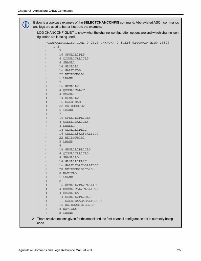
Chapter 2 Agriculture GNSS Commands
Agriculture Comands and Logs Reference Manual v7C 250
Below is a use case example of theSELECTCHANCONFIG command. Abbreviated ASCII commandsand logs are used to better illustrate the example.
1. LOGCHANCONFIGLIST to show what the channel configuration options are and which channel con-figuration set is being used.
<CHANCONFIGLIST COM1 0 25.5 UNKNOWN 0 8.226 02440020 d1c0 15823< 1 5< 7< 16 GPSL1L2PL5< 4 QZSSL1CAL2CL5< 4 SBASL1< 14 GLOL1L2< 16 GALE1E5B< 22 BEIDOUB1B2< 5 LBAND< 7< 16 GPSL1L2< 4 QZSSL1CAL2C< 4 SBASL1< 14 GLOL1L2< 16 GALE1E5B< 22 BEIDOUB1B2< 5 LBAND< 7< 16 GPSL1L2PL2CL5< 4 QZSSL1CAL2CL5< 4 SBASL1< 14 GLOL1L2PL2C< 16 GALE1E5AE5BALTBOC< 22 BEIDOUB1B2< 5 LBAND< 8< 16 GPSL1L2PL2CL5< 4 QZSSL1CAL2CL5< 4 SBASL1L5< 14 GLOL1L2PL2C< 16 GALE1E5AE5BALTBOC< 20 BEIDOUB1B1CB2B3< 8 NAVICL5< 5 LBAND< 8< 16 GPSL1L2PL2CL5L1C< 4 QZSSL1CAL2CL5L1CL6< 4 SBASL1L5< 14 GLOL1L2PL2CL3< 11 GALE1E5AE5BALTBOCE6< 16 BEIDOUB1B1CB2B3< 8 NAVICL5< 5 LBAND
2. There are five options given for themodel and the first channel configuration set is currently beingused.

Chapter 2 Agriculture GNSS Commands
Agriculture Comands and Logs Reference Manual v7C 251
3. If the user would like to use the third channel configuration set enter, SELECTCHANCONFIG 3 com-mand.
4. The receiver receives the command and resets. At startup, the third channel configuration set is con-figured.
5. To verify that setting has changed, enter LOGCHANCONFIGLIST.
<CHANCONFIGLIST COM1 0 74.5 FINESTEERING 2073 154125.980 02400020d1c0 15823< 3 5< 7< 16 GPSL1L2PL5< 4 QZSSL1CAL2CL5< 4 SBASL1< 14 GLOL1L2< 16 GALE1E5B< 22 BEIDOUB1B2< 5 LBAND< 7< 16 GPSL1L2< 4 QZSSL1CAL2C< 4 SBASL1< 14 GLOL1L2< 16 GALE1E5B< 22 BEIDOUB1B2< 5 LBAND< 7< 16 GPSL1L2PL2CL5< 4 QZSSL1CAL2CL5< 4 SBASL1< 14 GLOL1L2PL2C< 16 GALE1E5AE5BALTBOC< 22 BEIDOUB1B2< 5 LBAND< 8< 16 GPSL1L2PL2CL5< 4 QZSSL1CAL2CL5< 4 SBASL1L5< 14 GLOL1L2PL2C< 16 GALE1E5AE5BALTBOC< 20 BEIDOUB1B1CB2B3< 8 NAVICL5< 5 LBAND< 8< 16 GPSL1L2PL2CL5L1C< 4 QZSSL1CAL2CL5L1CL6< 4 SBASL1L5< 14 GLOL1L2PL2CL3< 11 GALE1E5AE5BALTBOCE6< 16 BEIDOUB1B1CB2B3< 8 NAVICL5< 5 LBAND

Chapter 2 Agriculture GNSS Commands
Agriculture Comands and Logs Reference Manual v7C 252
6. This log shows that the third set is selected. To further verify, enter LOG TRACKSTAT to show allthe configured channels.

Chapter 2 Agriculture GNSS Commands
Agriculture Comands and Logs Reference Manual v7C 253
2.116 SENDSends an ASCII message to a COM port
Platform: OEM719, OEM729, OEM7500, OEM7600, OEM7700, OEM7720, PwrPak7, SPAN CPT7,SMART7, SMART2
This command is used to send ASCII printable data from any of the COM or USB ports to a specified com-munications port. This is a one time command, therefore the datamessagemust be preceded by theSEND com-mand and followed by <CR> each time data is sent. If the data string contains delimiters (that is, spaces,commas, tabs and so on), the entire stringmust be contained within double quotationmarks. Carriage return andline feed characters (for example, 0x0D, 0x0A) are appended to the sent ASCII data.
Message ID: 177
Abbreviated ASCII Syntax:SEND [port] data
ASCII ExampleSEND com1 “log com1 rtcaobs ontime 5”
Scenario: Assume you are operating receivers as base and rover stations. It could also be assumedthat the base station is unattended but operational and you wish to control it from the rover station.From the rover station, you could establish the data link and command the base station receiver to senddifferential corrections.

Chapter 2 Agriculture GNSS Commands
Agriculture Comands and Logs Reference Manual v7C 254
Figure 5: Using the SEND Command
Field FieldType ASCII Value Binary Value Description Format Binary
BytesBinaryOffset
1 SENDheader - -
Command header. SeeMessages on page 26for more information.
- H 0
2 port See Table 4: Detailed Port Identifieron page 32
Output port(default=THISPORT) Enum 4 H
3 messageMax 100 character string (99 typedvisible chars and a null char addedby the firmware automatically)
ASCII data to sendString[max100]
Variable1 H+4
1In the binary case, each string field needs to be NULL terminated and additional bytes of padding added to maintain 4-bytealignment, up to the maximum defined by the string size. The next defined field starts immediately at the next 4-bytealignment following the NULL.
Chapter 2 Agriculture GNSS Commands
Agriculture Comands and Logs Reference Manual v7C 255
2.117 SERIALCONFIGConfigures serial port settings
Platform: OEM719, OEM729, OEM7500, OEM7600, OEM7700, OEM7720, PwrPak7, SPAN CPT7,SMART7, SMART2
This command is used to configure the receiver’s asynchronous serial port communications drivers.
1. Also refer to theECHO command on page 102.
2. TheSERIALCONFIG command can be used as a log to confirm settings.
3. The entire content of the current log is sent before pausing due to the receipt of the XOFF character.
The current SERIALCONFIG port configuration can be reset to its default state by sending it two hardware breaksignals of 250milliseconds each, spaced by fifteen hundredmilliseconds (1.5 seconds) with a pause of at least250milliseconds following the second break. This will:
l Stop the logging of data on the current port (see theUNLOGALL command on page 303)
l Clear the transmit and receive buffers on the current port
l Return the current port to its default settings (seeCommandDefaults on page 50 for details)
l Set the interfacemode to NovAtel for both input and output (see the INTERFACEMODE command onpage 136)
This break detection can be disabled using theSERIALCONFIG command.
1. TheCOMCONTROL command (see page 88) may conflict with handshaking of the selected COMport. If handshaking is enabled, then unexpected results may occur.
2. Baud rates higher than 115,200 bps are not supported by standard PC hardware. Special PC hard-waremay be required for higher rates, including 230400 bps and 460800 bps. Avoid having COMports of two receivers connected together using baud rates that do not match. Data transmittedthrough a port operating at a slower baud ratemay bemisinterpreted as break signals by the receivingport if it is operating at a higher baud rate because data transmitted at the lower baud rate is stretchedrelative to the higher baud rate. In this case, configure the receiving port to break detection disabledusing theSERIALCONFIG command.
Use theSERIALCONFIG command before using the INTERFACEMODE command on each port. Turnbreak detection off using theSERIALCONFIG command to stop the port from resetting because it isinterpreting incoming bits as a break command.
Message ID: 1246
Abbreviated ASCII Syntax:SERIALCONFIG [port] baud [parity[databits[stopbits[handshaking[break]]]]]
Factory Defaults:SERIALCONFIG COM1 9600 N 8 1 N ONSERIALCONFIG COM2 9600 N 8 1 N ONSERIALCONFIG COM3 9600 N 8 1 N ON

Chapter 2 Agriculture GNSS Commands
Agriculture Comands and Logs Reference Manual v7C 256
SERIALCONFIG COM4 9600 N 8 1 N ONSERIALCONFIG COM5 9600 N 8 1 N ON
ASCII Example:SERIALCONFIG com1 9600 n 8 1 n off
Field Field Type ASCIIValue
BinaryValue Description Format Binary
BytesBinaryOffset
1 SERIALCONFIGHeader - -
Command header. SeeMessages on page 26 formore information.
- H 0
2 port See Table 51: COM PortIdentifiers below
Port to configure(default = THISPORT) Enum 4 H
3 bps/baud2400, 4800, 9600, 19200,38400, 57600, 115200,230400 and 460800
Communication baud rate(bps). Ulong 4 H+4
4 parity See Table 52: Parity on thenext page Parity Enum 4 H+8
5 databits 7 or 8 Number of data bits(default = 8) Ulong 4 H+12
6 stopbits 1 or 2 Number of stop bits(default = 1) Ulong 4 H+16
7 handshake1See Table 53:Handshaking on the nextpage
Handshaking Enum 4 H+20
8 breakOFF 0 Disable break detection
Enum 4 H+24ON 1 Enable break detection
(default)
Binary ASCII Description Applicable Receiver
1 COM1 COM port 1 OEM719, OEM729, OEM7600, OEM7700, OEM7720, PwrPak7,SPAN CPT7, SMART7
2 COM2 COM port 2 OEM719, OEM729, OEM7600, OEM7700, OEM7720, PwrPak7,SPAN CPT7, SMART7
3 COM3 COM port 3 OEM729, OEM7600, OEM7700, OEM7720, PwrPak7, SMART7
Table 51: COM Port Identifiers
1The OEM719, SPAN CPT7 and SMART7 do not support hardware handshaking. Only transmit and receive lines exist forthe OEM719, SPAN CPT7 and SMART7 ports.

Chapter 2 Agriculture GNSS Commands
Agriculture Comands and Logs Reference Manual v7C 257
Binary ASCII Description Applicable Receiver
6 THISPORT The currentCOM port
OEM719, OEM729, OEM7600, OEM7700, OEM7720, PwrPak7,SPAN CPT7
19 COM4 COM port 4 OEM7700, OEM7600, OEM7720
21 IMU IMU COM port dependent on hardware configuration
31 COM5 COM port 5 OEM7700, OEM7600, OEM7720
32 COM6 COM port 6
33 BT1 Bluetooth COMport dependent on hardware configuration
34 COM7 COM port 7
35 COM8 COM port 8
36 COM9 COM port 9
37 COM10 COM port 10
Binary ASCII Description
0 N No parity (default)
1 E Even parity
2 O Odd parity
Table 52: Parity
Binary ASCII Description
0 N No handshaking (default)
1 XON XON/XOFF software handshaking
2 CTS CTS/RTS hardware handshaking
Table 53: Handshaking
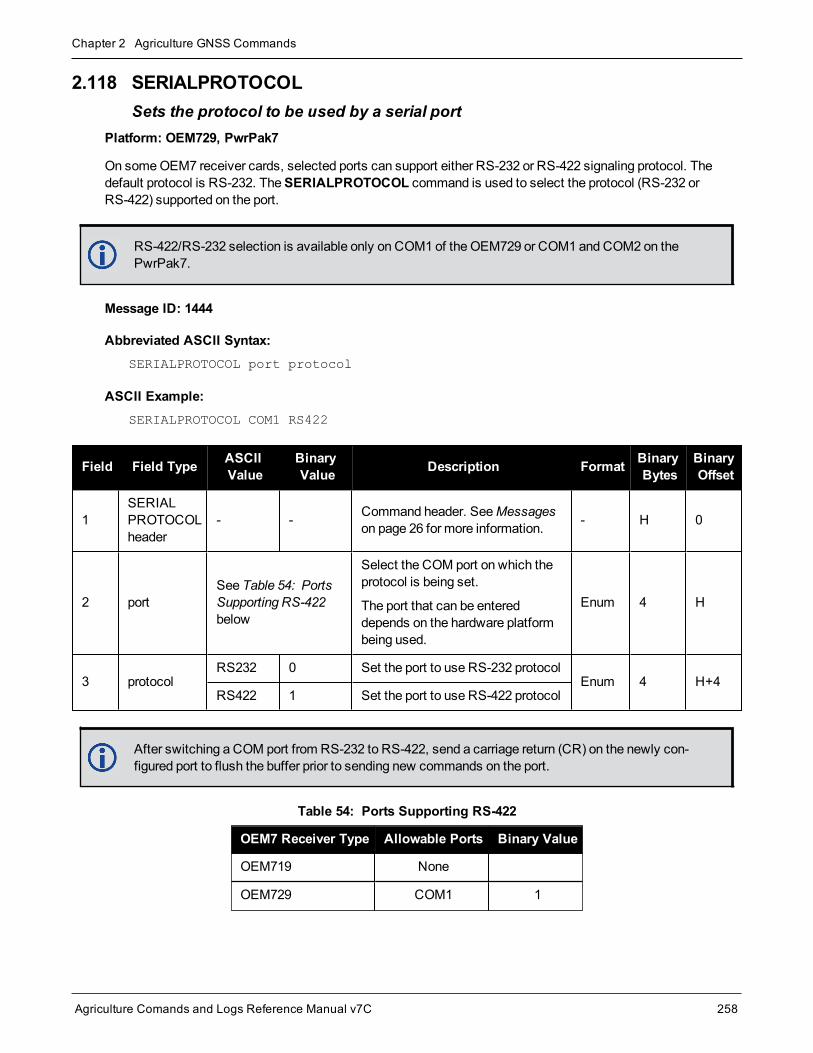
Chapter 2 Agriculture GNSS Commands
Agriculture Comands and Logs Reference Manual v7C 258
2.118 SERIALPROTOCOLSets the protocol to be used by a serial port
Platform: OEM729, PwrPak7
On someOEM7 receiver cards, selected ports can support either RS-232 or RS-422 signaling protocol. Thedefault protocol is RS-232. TheSERIALPROTOCOL command is used to select the protocol (RS-232 orRS-422) supported on the port.
RS-422/RS-232 selection is available only on COM1 of the OEM729 or COM1 and COM2 on thePwrPak7.
Message ID: 1444
Abbreviated ASCII Syntax:SERIALPROTOCOL port protocol
ASCII Example:SERIALPROTOCOL COM1 RS422
Field Field Type ASCIIValue
BinaryValue Description Format Binary
BytesBinaryOffset
1SERIALPROTOCOLheader
- - Command header. SeeMessageson page 26 for more information. - H 0
2 portSee Table 54: PortsSupporting RS-422below
Select the COM port on which theprotocol is being set.
The port that can be entereddepends on the hardware platformbeing used.
Enum 4 H
3 protocolRS232 0 Set the port to use RS-232 protocol
Enum 4 H+4RS422 1 Set the port to use RS-422 protocol
After switching a COM port from RS-232 to RS-422, send a carriage return (CR) on the newly con-figured port to flush the buffer prior to sending new commands on the port.
OEM7 Receiver Type Allowable Ports Binary Value
OEM719 None
OEM729 COM1 1
Table 54: Ports Supporting RS-422

Chapter 2 Agriculture GNSS Commands
Agriculture Comands and Logs Reference Manual v7C 259
OEM7 Receiver Type Allowable Ports Binary Value
OEM7600 None
OEM7700 None
OEM7720 None
PwrPak7COM1 1
COM2 2

Chapter 2 Agriculture GNSS Commands
Agriculture Comands and Logs Reference Manual v7C 260
2.119 SETADMINPASSWORDSets the administration password
Platform: OEM729, OEM7600, OEM7700, OEM7720, PwrPak7, SPAN CPT7, SMART7-I, SMART7-SI
This command sets the administration password used to log into various web services.
l The administration password is required for Secure ICOM access.
The default admin password is the receiver‘s PSN. For OEM7 enclosures, such as the PwrPak7, the defaultpassword is the enclosure PSN. The enclosure PSN is shown on the label on the bottom of the enclosure and inthe ENCLOSURE line in theVERSION log (see page 751). The default password should be changed before con-necting the receiver to a network.
Message ID: 1579
Abbreviated ASCII Syntax:SETADMINPASSWORD oldpassword newpassword
Input exampleSETADMINPASSWORD ABC123 XYZ789
Field Field Type ASCIIValue
BinaryValue Description Format Binary Bytes Binary
Offset
1SETADMINPASSWORDheader
- -Command header. SeeMessages on page 26 for moreinformation.
- H 0
2 OldPassword Maximum 28character string Previous password. String
[28] variable1 H
3 NewPassword Maximum 28character string New password. String
[28]variable1 variable
This password can be restored to default (the receiver‘s PSN) by issuing the FRESET USER_ACCOUNTS command (see FRESET on page 118).
1In the binary case, each string field needs to be NULL terminated and additional bytes of padding added to maintain 4-bytealignment, up to the maximum defined by the string size. The next defined field starts immediately at the next 4-bytealignment following the NULL.

Chapter 2 Agriculture GNSS Commands
Agriculture Comands and Logs Reference Manual v7C 261
2.120 SETAPPROXPOSSets an approximate position
Platform: OEM719, OEM729, OEM7500, OEM7600, OEM7700, OEM7720, PwrPak7, SPAN CPT7,SMART7, SMART2
This command sets an approximate latitude, longitude and height in the receiver. Estimating these parameters,when used in conjunction with an approximate time (see theSETAPPROXTIME command on the next page),can improve satellite acquisition times and Time To First Fix (TTFF). For more information about TTFF and Satel-lite Acquisition, refer toAn Introduction to GNSS available on our website at novatel.com/contactus/an-intro-duction-to-gnss.
The horizontal position entered should be within 200 km of the actual receiver position. The approximate height isnot critical and can normally be entered as zero. By default , if the receiver cannot calculate a valid positionwithin 2.5minutes of entering an approximate position, the approximate position is ignored.
The approximate position is not visible in any position logs. It can be seen by issuing a SETAPPROXPOS log.
Message ID: 377
Abbreviated ASCII Syntax:SETAPPROXPOS lat lon height
Input Example:SETAPPROXPOS 51.116 -114.038 0
For an example on the use of this command, refer to theSETAPPROXTIME command on the nextpage.
Field Field Type ASCIIValue
BinaryValue Description Format Binary
BytesBinaryOffset
1 SETAPPROXPOSheader - - Command header. SeeMessages
on page 26 for more information. - H 0
2 Lat ± 90 degrees Approximate latitude Double 8 H
3 Lon ± 180 degrees Approximate longitude Double 8 H+8
4 Height -1000 to+20000000m Approximate height Double 8 H+16

Chapter 2 Agriculture GNSS Commands
Agriculture Comands and Logs Reference Manual v7C 262
2.121 SETAPPROXTIMESets an approximate GPS reference time
Platform: OEM719, OEM729, OEM7500, OEM7600, OEM7700, OEM7720, PwrPak7, SPAN CPT7,SMART7, SMART2
This command sets an approximate time in the receiver. The receiver uses this time as system time until acoarse time can be acquired. This can be used in conjunction with an approximate position (see theSETAPPROXPOS command on the previous page) to improve Time To First Fix (TTFF). For more informationTTFF and Satellite Acquisition, refer toAn Introduction to GNSS available on our website at nova-tel.com/contactus/an-introduction-to-gnss.
The time entered should be within 10minutes of the actual GPS reference time. If the week numberentered does not match the broadcast week number, the receiver resets once it is tracking.
Message ID: 102
Abbreviated ASCII Syntax:SETAPPROXTIME week sec
Input Example:SETAPPROXTIME 1930 501232
Upon power up, the receiver does not know its position or time and therefore cannot use almanacinformation to aid satellite acquisition. You can set an approximate GPS reference time using theSETAPPROXPOS command (see page 261).
Approximate time and positionmay be used in conjunction with a current almanac to aid satelliteacquisition. See the table below for a summary of the OEM7 family commands used to inject anapproximated time or position into the receiver:
Approximate Command
Time SETAPPROXTIME
Position SETAPPROXPOS
Base station aiding can help in these environments. A set of ephemerides can be injected into a roverstation by broadcasting the RTCAEPHEMmessage from a base station. This is also useful inenvironments where there is frequent loss of lock. GPS ephemeris is three frames long within asequence of five frames. Each frame requires 6 s of continuous lock to collect the ephemeris data. Thisgives aminimum of 18 s and amaximum of 36 s continuous lock time or when no recent ephemerides(new or stored) are available.

Chapter 2 Agriculture GNSS Commands
Agriculture Comands and Logs Reference Manual v7C 263
Field Field Type ASCIIValue
BinaryValue Description Format Binary
BytesBinaryOffset
1 SETAPPROXTIMEheader - - Command header. SeeMessages
on page 26 for more information. - H 0
2 week 0-9999 GPS reference week number Ulong 4 H
3 sec 0-604800 Number of seconds into GPSreference week Double 8 H+4

Chapter 2 Agriculture GNSS Commands
Agriculture Comands and Logs Reference Manual v7C 264
2.122 SETBESTPOSCRITERIASets selection criteria for BESTPOS
Platform: OEM719, OEM729, OEM7500, OEM7600, OEM7700, OEM7720, PwrPak7, SPAN CPT7,SMART7, SMART2
Use this command to set the criteria for theBESTPOS log (see page 346) and choose between 2D and 3D stand-ard deviation to obtain the best position from theBESTPOS log (see page 346). It also allows you to specify thenumber of seconds to wait before changing the position type. This delay provides a single transition that ensuresposition types do not skip back and forth.
TheSETBESTPOSCRITERIA command is also used as the basis for theUALCONTROL command(see page 291) standard deviations.
Message ID: 839
Abbreviated ASCII Syntax:SETBESTPOSCRITERIA type [delay]
Factory Default:SETBESTPOSCRITERIA pos3d 0
Input Example:SETBESTPOSCRITERIA pos2d 5
Field Field Type ASCIIValue
BinaryValue Description Format Binary
BytesBinaryOffset
1SETBESTPOSCRITERIAheader
- - Command header. SeeMessages onpage 26 for more information. - H 0
2 typeSee Table 55:Selection Typebelow
Select a 2D or 3D standard deviationtype to obtain the best position fromthe BESTPOS log
Enum 4 H
3 delay 0 to 100 sSet the number of seconds to waitbefore changing the position type.Default=0
Ulong 4 H+4
ASCII Binary Description
POS3D 0 3D standard deviation
POS2D 1 2D standard deviation
Table 55: Selection Type

Chapter 2 Agriculture GNSS Commands
Agriculture Comands and Logs Reference Manual v7C 265
2.123 SETIONOTYPEEnables ionospheric models
Platform: OEM719, OEM729, OEM7500, OEM7600, OEM7700, OEM7720, PwrPak7, SPAN CPT7,SMART7, SMART2
Use this command to set which ionospheric corrections model the receiver should use. If the selectedmodel isnot available, the receiver reverts to AUTO.
L1 only models automatically use SBAS ionospheric grid corrections, if available.
Message ID: 711
Abbreviated ASCII Syntax:SETIONOTYPE model
Factory Default:SETIONOTYPE auto
ASCII Example:SETIONOTYPE Klobuchar
An ionotype of AUTO is recommended for PDP andGLIDE.
Field Field Type ASCIIValue
BinaryValue Description Format Binary
BytesBinaryOffset
1SETIONOTYPE
header- -
Command header. SeeMessages on page 26 for moreinformation.
- H 0
2 modelSee Table 56:Ionospheric CorrectionModels below
Choose an ionosphericcorrections model Enum 4 H
ASCII Binary Description
NONE 0 Don’t use ionospheremodeling
KLOBUCHAR 1 Use the Klobuchar model broadcast by GPS
GRID 2 Use the SBAS grid model
L1L2 3 Multi-frequency computed
AUTO 4 Automatically determine the ionospheric model to use
Table 56: Ionospheric Correction Models

Chapter 2 Agriculture GNSS Commands
Agriculture Comands and Logs Reference Manual v7C 266
2.124 SETROVERIDSet ID for ALIGN rovers
Platform: OEM719, OEM729, OEM7500, OEM7600, OEM7700, OEM7720, PwrPak7, SPAN CPT7,SMART7
This command sets the Rover ID output in theROVERPOS log (see page 630), HEADING2 log (see page 442),ALIGNBSLNXYZ log (see page 326) andALIGNBSLNENU log (see page 324).
The default value for the ID is set using the last six characters of the receiver PSN Number. For example, if thereceiver PSN number is DAB07170027, ID is set as R027, i.e., 17 is represented as R and last three charactersare filled in as is. The fourth last character is ignored.
It is not guaranteed that each receiver will have a unique auto-generated ID. Use this command to setthe ID in case the auto-generated ID overlaps with other rovers. It is the user’s responsibility to ensureeach receiver ID is unique (if they ownmultiple receivers). If the ID overlaps, use this command to setthe ID.
Message ID: 1135
Abbreviated ASCII Syntax:SETROVERID rovid
Factory Default:
If the receiver PSN is: DAB07170027
SETROVERID R027
Input ExampleSETROVERID rov1
Field Field Type ASCIIValue
BinaryValue Description Format Binary
BytesBinaryOffset
1 SETROVERIDheader - - Command header. SeeMessages on
page 26 for more information. - H 0
2 ID4 CharacterString e.g.,ROV1
ID String (maximum 4 characters plusNULL)
String[5] 51 H
1In the binary case, each string field needs to be NULL terminated and additional bytes of padding added to maintain 4-byte alignment, up to the maximum defined by the string size. The next defined field starts immediately at the next 4-bytealignment following the NULL.

Chapter 2 Agriculture GNSS Commands
Agriculture Comands and Logs Reference Manual v7C 267
2.125 SETUTCLEAPSECONDSSets future leap seconds
Platform: OEM719, OEM729, OEM7500, OEM7600, OEM7700, OEM7720, PwrPak7, SPAN CPT7,SMART7, SMART2
This command allows the user to force the UTC offset to be updated according to the input date.
Leap seconds will occur at the end of the UTC day specified. The receiver will use the leap second set by thiscommand until a leap second can be obtained over the air.
Message ID: 1150
Abbreviated ASCII Syntax:SETUTCLEAPSECONDS seconds [futureweeknumber [futuredaynumber[futureseconds]]]
Input Example:SETUTCLEAPSECONDS 18 1929 7 18
Field Field Type ASCIIValue
BinaryValue Description Format Binary
BytesBinaryOffset
1SETUTCLEAPSECONDSheader
- - Command header. SeeMessages onpage 26 for more information. - H 0
2 Seconds1 0 – 4294967295 Current UTC leap second Ulong 4 H
3 Futureweeknumber 0 – 10000 GPSWeek when future leap seconds
will take effect Ulong 4 H+4
4 Futuredaynumber 1 – 7 Day of the week when future leap
seconds will take effect Ulong 4 H+8
5 Futureseconds 0 – 4294967295Future leap second offset that will takeeffect at the end of the futuredaynumberof the futureweeknumber
Ulong 4 H+12
1This value will only be applied if the UTC status in the TIME log is not Valid.

Chapter 2 Agriculture GNSS Commands
Agriculture Comands and Logs Reference Manual v7C 268
2.126 SOFTLOADCOMMITCompletes the SoftLoad process
Platform: OEM719, OEM729, OEM7500, OEM7600, OEM7700, OEM7720, PwrPak7, SPAN CPT7,SMART7, SMART2
This command completes the SoftLoad process by verifying the downloaded image and activating it. Refer toUpdating Using SoftLoad Commands in the SMART7 Installation andOperation User Manual for more inform-ation about the SoftLoad process.
This command can only be sent to the receiver when theSOFTLOADSTATUS log (see page 725) reportsREADY_FOR_DATA.
After issuing theSOFTLOADCOMMIT command the user must wait for the OK or ERROR command responsebefore proceeding. This response is guaranteed to be output from the receiver within 300 seconds from the timethe commandwas received by the receiver. If an error response is returned, consult theSOFTLOADSTATUSlog on page 725 for more detail.
Message ID: 475
Abbreviated ASCII Syntax:SOFTLOADCOMMIT
Input Example:SOFTLOADCOMMIT
Field Field Type ASCIIValue
BinaryValue Description Format Binary
BytesBinaryOffset
1 SOFTLOADCOMMITheader - -
Command header. SeeMessages on page 26 for moreinformation.
- H 0
2 Reserved - Reserved. Set to 1 in the binarycase Enum 4 H

Chapter 2 Agriculture GNSS Commands
Agriculture Comands and Logs Reference Manual v7C 269
2.127 SOFTLOADDATASends firmware image data to the receiver for the SoftLoad process
Platform: OEM719, OEM729, OEM7500, OEM7600, OEM7700, OEM7720, PwrPak7, SPAN CPT7,SMART7, SMART2
This command is only valid in binary mode.
This command is used to upload data to the receiver for the SoftLoad process. Refer to Updating Using SoftLoadCommands in the SMART7 Installation andOperation User Manual for more information about the SoftLoad pro-cess.
After eachSOFTLOADDATA command, the user must wait for the OK or ERROR command response beforeproceeding. This response is guaranteed to be output from the receiver within 15 seconds from the time the com-mand was received by the receiver. If an error response is returned, consult theSOFTLOADSTATUS log onpage 725 for more detail.
This command can only be sent to the receiver after theSOFTLOADSREC command (see page 273) orSOFTLOADSETUP command (see page 271) have sent the content of the S0 records from the start of a firm-ware *.shex file. In these cases, theSOFTLOADSTATUS log (see page 725) reports READY_FOR_SETUP orREADY_FOR_DATA.
Message ID: 1218
Abbreviated ASCII Syntax:
Not applicable
Field Field Type BinaryValue Description Format Binary
BytesBinaryOffset
1 SOFTLOADDATAheader - NovAtel binary message header - H 0
2 offset - Offset of the data within the downloadedimage Ulong 4 H
3 data length -Number of bytes of data. This must match thenumber of bytes contained within the “data”field
Ulong 4 H+4
4 data - Incoming data up to amaximum of 4096bytes Uchar 4096 H+8

Chapter 2 Agriculture GNSS Commands
Agriculture Comands and Logs Reference Manual v7C 270
2.128 SOFTLOADRESETInitiates a new SoftLoad process
Platform: OEM719, OEM729, OEM7500, OEM7600, OEM7700, OEM7720, PwrPak7, SPAN CPT7,SMART7, SMART2
This command restarts the SoftLoad process. Refer to Updating Using SoftLoad Commands in the SMART7Installation andOperation User Manual for more information about the SoftLoad process.
The command does not affect the flash and does not reset the receiver.
TheSOFTLOADRESET command can be issued at any time. If it is issued while a SoftLoad process is cur-rently in progress then that process is terminated and a new one is started. After theSOFTLOADRESET com-mand is processed the SOFTLOADSTATUS log will report a status of READY_FOR_SETUP.
After issuing theSOFTLOADRESET command the user must wait for the OK or ERROR command responsebefore proceeding. This response is guaranteed to be output from the receiver within 300 seconds from the timethe commandwas received by the receiver. If an error response is returned, consult theSOFTLOADSTATUSlog on page 725 for more detail.
Message ID: 476
Abbreviated ASCII Syntax:SOFTLOADRESET
Input Example:SOFTLOADRESET
Field Field Type ASCIIValue
BinaryValue Description Format Binary
BytesBinaryOffset
1 SOFTLOADRESETheader - - Command header. SeeMessages
on page 26 for more information. - H 0
2 Reserved - - Reserved. Set to 1 in the binarycase Enum 4 H

Chapter 2 Agriculture GNSS Commands
Agriculture Comands and Logs Reference Manual v7C 271
2.129 SOFTLOADSETUPSends configuration information to the receiver for the SoftLoad process
Platform: OEM719, OEM729, OEM7500, OEM7600, OEM7700, OEM7720, PwrPak7, SPAN CPT7,SMART7, SMART2
TheSOFTLOADSETUP command can be used in place of theSOFTLOADSREC commandwhen sending S0Records. This command is meant to be used if the user requires that the entire SoftLoad process be performed inbinary, but can also be used in ASCII or abbreviated ASCII. The examples below are given in abbreviated ASCIIfor simplicity.
Refer to Updating Using SoftLoad Commands in the SMART7 Installation andOperation User Manual for moreinformation about the SoftLoad process.
This command can only be sent to the receiver when the SOFTLOADSTATUS log reports READY_FOR_SETUP.
After eachSOFTLOADSETUP command, the user must wait for the OK or ERROR command response beforeproceeding. This response is guaranteed to be output from the receiver within 15 seconds from the time the com-mand was received by the receiver. If an error response is returned, consult theSOFTLOADSTATUS log onpage 725 for more detail.
NovAtel S0 records use the following format: S0~X~<<DATA>>, whereX is the Setup Type and <<DATA>> isa NULL terminated string. To convert from S0 record to the SOFTLOADSETUP command, convert the SetupType to the appropriate Setup type enumeration, as described in Table 57: Available Set Up Commands on thenext page, and copy the <<DATA>> string in to the Setup data string.
Message ID: 1219
Abbreviated ASCII Syntax:SOFTLOADSETUP setuptype setupdata
Input Example:SOFTLOADSETUP datatype "APP"
Field Field Type ASCIIValue
BinaryValue Description Format Binary
BytesBinaryOffset
1SOFTLOADSETUPheader
- - Command header. SeeMessages onpage 26 for more information. - H 0
2 Setup type
See Table 57:Available SetUp Commandson the nextpage
The type of setup command Enum 4 H

Chapter 2 Agriculture GNSS Commands
Agriculture Comands and Logs Reference Manual v7C 272
Field Field Type ASCIIValue
BinaryValue Description Format Binary
BytesBinaryOffset
3 Setup data - -
ASCII setup data string. See Table 57:Available Set Up Commands below fordetails on this data. This data can bepulled from the S0 records of the hex filebeing loaded onto the receiver. If theASCII form of this command is used, thisstringmust be enclosed in double quotes(“ “)
String
[512]variable1 H+4
Binary ASCII Description
1 PlatformComma separated list of platforms supported by the data to be uploaded. This corresponds toS0~P~. For example, the S-Record S0~P~OEM729,OEM7700,OEM719, translates toSOFTLOADSETUP PLATFORM "OEM729,OEM7700,OEM719"
2 VersionVersion of the data to be uploaded. This corresponds to S0~V~. For example, the S-RecordS0~V~OMP070400RN0000, translates to SOFTLOADSETUP VERSION"OMP070400RN0000"
3 Datatype Intended data block for the data to be uploaded. This corresponds to S0~T~. For example, theS-Record S0~T~APP, translates to SOFTLOADSETUP DATATYPE "APP"
4 Authcode
PSN and AUTH code for the data to be uploaded. The format is: PSN:AuthCode.Note thatsince there are commas within the AuthCode, double quotes must surround thePSN:AuthCode string. For example:
SOFTLOADSETUP AUTHCODE "BFN10260115:T48JF2,W25DBM,JH46BJ,2WGHMJ,8JW5TW,G2SR0RCCR,101114"
Table 57: Available Set Up Commands
1In the binary case, each string field needs to be NULL terminated and additional bytes of padding added to maintain 4-bytealignment, up to the maximum defined by the string size. The next defined field starts immediately at the next 4-bytealignment following the NULL.

Chapter 2 Agriculture GNSS Commands
Agriculture Comands and Logs Reference Manual v7C 273
2.130 SOFTLOADSRECSends an S-Record to the receiver for the SoftLoad process
Platform: OEM719, OEM729, OEM7500, OEM7600, OEM7700, OEM7720, PwrPak7, SPAN CPT7,SMART7, SMART2
Use this command to send S-Records to the receiver for the SoftLoad process. Refer to Updating UsingSoftLoad Commands in the SMART7 Installation andOperation User Manual for more information about theSoftLoad process.
After eachSOFTLOADDATA command, the user must wait for the OK or ERROR command response beforeproceeding. This response is guaranteed to be output from the receiver within 15 seconds from the time the com-mand was received by the receiver. If an error response is returned, consult theSOFTLOADSTATUS log onpage 725 for more detail.
This command can only be sent to the receiver when the SOFTLOADSTATUS log reports READY_FOR_SETUP or READY_FOR_DATA.
Message ID: 477
Abbreviated ASCII Syntax:SOFTLOADSREC s-record
Input Example:SOFTLOADSREC “S30900283C10FAA9F000EF”
Field Field Type ASCIIValue
BinaryValue Description Format Binary
BytesBinaryOffset
1 SOFTLOADSRECheader - - Command header. SeeMessages
on page 26 for more information. - H 0
2 SREC - ASCII S-Record string copitesfrom firmware *.shex file
String
[515]variable1 H
3 Reserved - 1 Reserved. Set to 1 in the binarycase Ulong 4 variable
1In the binary case, each string field needs to be NULL terminated and additional bytes of padding added to maintain 4-bytealignment, up to the maximum defined by the string size. The next defined field starts immediately at the next 4-bytealignment following the NULL.

Chapter 2 Agriculture GNSS Commands
Agriculture Comands and Logs Reference Manual v7C 274
2.131 STEADYLINEConfigures position mode matching
Platform: OEM719, OEM729, OEM7500, OEM7600, OEM7700, OEM7720, PwrPak7, SPAN CPT7,SMART7
The STEADYLINE® functionality helps mitigate the discontinuities that often occur when aGNSS receiverchanges positioningmodes. The effect is especially evident when a receiver transitions from anRTK positionmode solution to a lower accuracy “fall back” solution, such as DGPS, WAAS+GLIDE or even autonomousGLIDE. Smooth transitions are particularly important for agricultural steering applications where sudden jumpsmay be problematic.
The STEADYLINE internally monitors the position offsets between all the positioningmodes present in thereceiver. When the receiver experiences a position transition, the corresponding offset is applied to the outputposition to limit a potential real position jump. When the original accurate position type returns, theSTEADYLINE algorithm will slowly transition back to the new accurate position at a default rate of 0.005m/s.This creates a smoother pass-to-pass relative accuracy at the expense of a possible degradation of absoluteaccuracy.
For example, a receiver can be configured to do both RTK andGLIDE. If this receiver has a fixed RTK positionand experiences a loss of correction data causing the loss of the RTK solution it will immediately apply the offsetbetween the two positionmodes and uses the GLIDE position stability to maintain the previous trajectory. Overtime theGLIDE (or non-RTK) position will experience some drift. Once the RTK position is achieved again thereceiver will start using the RTK positions for position stability and will slowly transition back to the RTK pos-itions at a default rate of 0.005m/s.
Message ID: 1452
Abbreviated ASCII Syntax:STEADYLINE mode [transition_time]
Factory Default:STEADYLINE disable
ASCII Example:STEADYLINE prefer_accuracy 100
Field Field Type ASCIIValue
BinaryValue Description Format Binary
BytesBinaryOffset
1 STEADYLINEheader - - Command header. SeeMessages on
page 26 for more information. - H 0
2 mode
See Table 58:STEADYLINEMode on the nextpage
STEADYLINE mode Enum 4 H
3 Transitiontime
Time over which solutions willtransition in seconds. Theminimumrate of change is 0.005m/sregardless of this parameter.
Ulong 4 H+4

Chapter 2 Agriculture GNSS Commands
Agriculture Comands and Logs Reference Manual v7C 275
ASCII Binary Description
DISABLE 0 Disable STEADYLINE (default)
RESET 3 Reset the offsets, jump immediately to the current position and continue in the currentmode.
PREFER_ACCURACY 4
Slowly transition to the new reference position when changing from less accuratereference positioning type tomore accurate reference positioning type. Maintains theposition offset calculated when changing frommore accurate reference positioning typeto a less accurate reference positioning type.
Table 58: STEADYLINE Mode

Chapter 2 Agriculture GNSS Commands
Agriculture Comands and Logs Reference Manual v7C 276
2.132 STEADYLINEDIFFERENTIALTIMEOUTSets how long the receiver will report RTK/PPP after corrections are lost
Platform: OEM719, OEM729, OEM7500, OEM7600, OEM7700, OEM7720, PwrPak7, SPAN CPT7,SMART7
Use this command to set how long STEADYLINE will report RTK or PPP solutions after a loss of corrections. Ifable, STEADYLINE will report an RTK or PPP solution until this timeout expires or until the RTK/PPP timeoutexpires, whichever is higher.
For example:
l If theRTKTIMEOUT is 60 seconds and theSTEADYLINEDIFFERENTIALTIMEOUT is 300 seconds,STEADYLINE will report an RTK solution for 300 seconds.
l If theRTKTIMEOUT is 60 seconds and theSTEADYLINEDIFFERENTIALTIMEOUT is 30 seconds,STEADYLINE will report an RTK solution for 60 seconds.
Message ID: 2002
Abbreviated ASCII Syntax:STEADYLINEDIFFERENTIALTIMEOUT timeout
Factory Default:STEADYLINEDIFFERENTIALTIMEOUT 60
ASCII Example:STEADYLINEDIFFERENTIALTIMEOUT 300
Field Field Type ASCIIValue
BinaryValue Description Format Binary
BytesBinaryOffset
1STEADYLINEDIFFERENTIALTIMEOUTheader
- -Command header. SeeMessages on page 26 formore information.
- H 0
2 timeout 5 to 1200 Timeout period in seconds Float 4 H

Chapter 2 Agriculture GNSS Commands
Agriculture Comands and Logs Reference Manual v7C 277
2.133 SURVEYPOSITIONSaves or deletes a surveyed position
Platform: OEM719, OEM729, OEM7500, OEM7600, OEM7700, OEM7720, PwrPak7, SPAN CPT7,SMART7
Use this command to add or delete a surveyed position saved in the receiver NVM.
The surveyed positions added or deleted with this command are used in conjunction with theAUTOSURVEYcommand on page 63.
Message ID: 1952
Abbreviated ASCII Syntax:SURVEYPOSITION option id [latitude] [longitude] [height] [tolerance]
ASCII Examples:SURVEYPOSITION save auto 51.116 -114.038 1065.0 10.0
SURVEYPOSITION delete cal2
Field FieldType
ASCIIValue
BinaryValue Description Format Binary
BytesBinaryOffset
1SURVEYPOSITIONheader
- - Command header. SeeMessages onpage 26 for more information. - H 0
2 optionSAVE 1 Save the surveyed position in the
receiver NVMEnum 4 H
DELETE 2 Delete the surveyed position from thereceiver NVM
3 id 4 character string
ID for the saved position
When saving a position, "AUTO" can beentered and the receiver willautomatically generate a unique ID for theposition."AUTO" cannot be used when deleting aposition.
To determine the ID for a saved position,use theSAVEDSURVEYPOSITIONSlog on page 685.
Note: In the Binary case, the ID stringmust be null terminated and additionalbytes of paddingmust be added tomakethe total length of the field 8 bytes.
String[5] 8 H+4

Chapter 2 Agriculture GNSS Commands
Agriculture Comands and Logs Reference Manual v7C 278
Field FieldType
ASCIIValue
BinaryValue Description Format Binary
BytesBinaryOffset
4 latitude -90 to 90
Latitude of the position in degrees(default=0.0)
A "-" sign denotes south and a "+" signdenotes north
Double 8 H+12
5 longitude -360 to 360
Longitude of the position in degrees(default=0)
A "-" sign denotes west and a "+" signdenotes east
Double 8 H+20
6 height -1000 to 20000000Mean Sea Level height of the position inmeters(default=0.0)
Double 8 H+28
7 tolerance 3 - 100
Position tolerance inmeters(default=10.0)
Themaximum distance between theposition calculated during an self-surveyand the saved position. During the self-survey, if the distance between thecalculated position and the previouslysurveyed position is less than this value,the previous position is used.
Double 8 H+36

Chapter 2 Agriculture GNSS Commands
Agriculture Comands and Logs Reference Manual v7C 279
2.134 TECTONICSCOMPENSATIONSOURCEChooses the model to use for tectonics compensation
Platform: OEM719, OEM729, OEM7500, OEM7600, OEM7700, OEM7720, PwrPak7, SPAN CPT7,SMART7, SMART2
Use this command to enable tectonics (plate motion) compensation.
Message ID: 2290
Abbreviated ASCII Syntax:TECTONICSCOMPENSATIONSOURCE model
Factory Default:TECTONICSCOMPENSATIONSOURCE plate_motion_model
ASCII Example:TECTONICSCOMPENSATIONSOURCE none
Field Field Type ASCIIValue
BinaryValue Description Format Binary
BytesBinaryOffset
1TECTONICSCOMPENSATIONSOURCE header
– –Command header. SeeMessages on page 26 for moreinformation.
– H 0
2 model
NONE 0 Do not use a tectonics model.
Enum 4 HPLATE_MOTION_MODEL
1
Automatically determine theplate the receiver is on and usethe plate motionmodel of thatplate.
3 reserved Char[32] variable H+4

Chapter 2 Agriculture GNSS Commands
Agriculture Comands and Logs Reference Manual v7C 280
2.135 TERRASTARAUTOCHANCONFIGEnable channel configurations granted by eligible TerraStar subscriptions
Platform: OEM719, OEM729, OEM7500, OEM7600, OEM7700, OEM7720, PwrPak7, SPAN CPT7,SMART7
This command allows the receiver to use amulti-constellation, multi-frequency channel configuration while aTerraStar-X, TerraStar-C PRO or RTK ASSIST PRO subscription is active. This allows the receiver to make thebest use of the TerraStar subscription while computing PPP position solutions. Multi-constellation, multi-fre-quency channel configurations give better accuracy and faster convergence time compared to a dual-con-stellation, dual-frequency channel configuration.
To enable this feature, issue the TERRASTARAUTOCHANCONFIG ENABLE command, followed by aSAVECONFIG command (see page 242). If a TerraStar-X, TerraStar-C PRO or RTK ASSIST PRO subscriptionis active, as reflected in the TERRASTARINFO log (see page 733), the channel configuration (seeCHANCONFIGLIST log on page 368) will bemodified on the next reboot.
Message ID: 2284
Abbreviated ASCII Syntax:TERRASTARAUTOCHANCONFIG switch
Factory Default:TERRASTARAUTOCHANCONFIG ENABLE
ASCII Example:TERRASTARAUTOCHANCONFIG ENABLE
Field Field Type ASCIIValue
BinaryValue Description Format Binary
BytesBinaryOffset
1TERRASTARAUTOCHANCONFIGheader
– –Command header. SeeMessages on page 26 for moreinformation.
– H 0
2 switch
DISABLE 0The receiver does not use thechannel configuration grantedby the TerraStar subscription.
Enum 4 H
ENABLE 1The receiver uses the channelconfiguration granted by theTerraStar subscription.

Chapter 2 Agriculture GNSS Commands
Agriculture Comands and Logs Reference Manual v7C 281
2.136 THISANTENNAPCOSets the PCOmodel of this receiver
Platform: OEM719, OEM729, OEM7500, OEM7600, OEM7700, OEM7720, PwrPak7, SPAN CPT7
Use the THISANTENNAPCO command to set the Phase Center Offsets (PCO) for the given frequency of thisreceiver. TheOffsets are defined as North, East and Up from the Antenna Reference Point to the FrequencyPhase Center in mm.
Message ID: 1417
Abbreviated ASCII Syntax:THISANTENNAPCO Frequency[NorthOffset][EastOffset][UpOffset]
ASCII Example:THISANTENNAPCO GPSL1 0.61 1.99 65.64
Field Field Type ASCIIValue
BinaryValue Description Format Binary
BytesBinaryOffset
1 THISANTENNAPCOheader - -
Command header. SeeMessages on page 26 formore information.
- H 0
2 FrequencySee Table 16:Frequency Type onpage 65
The frequency for which thephase center offsets are valid. Enum 4 H
3 North Offset NGS standard Phase CenterNorth Offset (millimeters).1 Double 8 H+4
4 East Offset NGS standard Phase CenterEast Offset (millimeters).1 Double 8 H+12
5 UpOffset NGS standard Phase CenterUpOffset (millimeters).1 Double 8 H+20
1Enter values as per the NGS standards and tables to define which direction is plus or minus.

Chapter 2 Agriculture GNSS Commands
Agriculture Comands and Logs Reference Manual v7C 282
2.137 THISANTENNAPCVSets the PCV model of this receiver
Platform: OEM719, OEM729, OEM7500, OEM7600, OEM7700, OEM7720, PwrPak7, SPAN CPT7
Use the THISANTENNAPCV command to set the Phase Center Variation (PVC) for the given frequency of thisreceiver. The Phase Center Variation entries follow the NGS standard and correspond to the phase elevation at 5degree increments starting at 90 degrees and decreasing to 0.
Message ID: 1418
Abbreviated ASCII Syntax:THISANTENNAPCV Frequency[PCVArray]
ASCII Example:THISANTENNAPCV GPSL1 0.00 -0.020 -0.07 -0.15 -0.24 -0.34 -0.43 -0.51 -0.56 -0.61 -0.65 -0.69 -0.69 -0.62 -0.44 -0.13 0.28 0.70 1.02
Field Field Type ASCIIValue
BinaryValue Description Format Binary
BytesBinaryOffset
1 THISANTENNAPCVheader - -
Command header. SeeMessages on page 26 for moreinformation.
- H 0
2 FrequencySee Table 16:Frequency Typeon page 65
The frequency for which thephase center variations is valid. Enum 4 H
3 PCV Array
NGS standard 19 Element arrayof Phase Center Variations forphase variation for 5 degreeelevation increments starting at90 degrees and decreasing to 0.The variances are entered inmillimeters.
DoubleArray
[19]152 H+4

Chapter 2 Agriculture GNSS Commands
Agriculture Comands and Logs Reference Manual v7C 283
2.138 THISANTENNATYPESets the antenna type of this receiver
Platform: OEM719, OEM729, OEM7500, OEM7600, OEM7700, OEM7720, PwrPak7, SPAN CPT7
Use the THISANTENNATYPE command to set the type of antenna being used with the receiver. The antennatype and radome type are the NGS names for the antenna.
When antenna type is set using this command, the receiver will look up and use the Phase Center Vari-ations and Phase Center Offsets from an internal table.
Message ID: 1420
Abbreviated ASCII Syntax:THISANTENNATYPE AntennaType [RadomeType]
ASCII Examples:THISANTENNATYPE NOV702
THISANTENNATYPE USER_ANTENNA_1
Field Field Type ASCIIValue
BinaryValue Description Format Binary
BytesBinaryOffset
1 THISANTENNATYPEheader - -
Command header. SeeMessages on page 26 formore information.
- H 0
2 AntennaTypeSee Table 17:Antenna Type onpage 69
Antenna type Enum 4 H
3 RadomeTypeSee Table 18:Radome Type onpage 77
Radome type(default = NONE) Enum 4 H+4

Chapter 2 Agriculture GNSS Commands
Agriculture Comands and Logs Reference Manual v7C 284
2.139 TILTCOMPENSATIONCONTROLControl the application of position corrections for vehicle roll and pitch
Platform: SMART7, SMART7-I, SMART7-W, SMART2-TB
Use this command to enable or disable the application of position corrections computed by the Terrain Com-pensation filter to output positions. If disabled, the Terrain Compensation filter will continue to run in the back-ground but the reported position will be the antenna position.
The TILTFILTER command on the next page and TILTZERO command on page 286, or the $PMDTcommand on page 191, are used to configure the Terrain Compensation feature.
Message ID: 2309
Abbreviated ASCII Syntax:TILTCOMPENSATIONCONTROL switch
Abbreviated ASCII Example:TILTCOMPENSATIONCONTROL ENABLE
Field Field Type ASCIIValue
BinaryValue Description Format Binary
BytesBinaryOffset
1 TILTCOMPENSATIONCONTROL header – –
Command header. SeeMessages on page 26 formore information.
– H 0
2 switch
DISABLE 0Disable TerrainCompensation (Tilt)corrections.
Enum 4 H
ENABLE 1Enable TerrainCompensation (Tilt)corrections.

Chapter 2 Agriculture GNSS Commands
Agriculture Comands and Logs Reference Manual v7C 285
2.140 TILTFILTERConfigure the Terrain Compensation filter
Platform: SMART7, SMART7-I, SMART7-W, SMART2-TB
Use this command to enable or disable estimation of the system pitch and roll by the Terrain Compensation filterand to set the height of the GNSS antenna above the vehicle control point. The Terrain Compensation filter mustbe enabled for the Terrain Compensation feature to function.
The $PMDT command (see page 191) can also be used to enable and configure the Terrain Com-pensation filter.
Message ID: 1221
Abbreviated ASCII Syntax:TILTFILTER switch antennaheight
Abbreviated ASCII Example:TILTFILTER ENABLE 3.5
Field Field Type ASCIIValue
BinaryValue Description Format Binary
BytesBinaryOffset
1 TILTFILTERheader – – Command header. SeeMessages on
page 26 for more information. – H 0
2 switchDISABLE 0 Disable the Tilt filter.
Enum 4 HENABLE 1 Enable the Tilt filter.
3 antennaheight 0.0 – 12.7
Height of the GNSS antenna abovethe vehicle control point (meters).(default = 0.0)
Refer to Terrain Compensation in theSMART7 Installation andOperationUser Manual for information aboutmounting the SMART antenna andmeasuring the antenna height.
Float 4 H+4
4 Reserved Ulong 4 H+8
5 Reserved Ulong 4 H+12

Chapter 2 Agriculture GNSS Commands
Agriculture Comands and Logs Reference Manual v7C 286
2.141 TILTZEROSet the zero level and save Terrain Compensation settings to NVM
Platform: SMART7, SMART7-I, SMART7-W, SMART2-TB
Use this command to set the internal zero level for Terrain Compensation and to save the settings (includingantenna height which is configured with the TILTFILTER command on the previous page) to NVM.
Sending this commandwith the ZERO option will set the current roll and pitch as the zero level. Setting the zerolevel allows the Terrain Compensation filter to account for any mounting offset between the receiver and thevehicle or any inherent tilt of the vehicle. It will also observe the internal sensor biases to allow for better per-formance of the filter. Zeroingmust be conducted while the vehicle is stationary on a flat surface.
Sending this commandwith theSAVE option will save the zero level and antenna height settings to NVM.Theses settings will be automatically used on following startups.
Sending this commandwith theRESTORE option will clear the saved settings from NVM and restore the factorydefaults.
The $PMDT command (see page 191) can also be used to zero the filter and save the settings to NVM.
Message ID: 1222
Abbreviated ASCII Syntax:TILTZERO action
ASCII Example:TILTZERO zero
Field FieldType
ASCIIValue
BinaryValue Description Format Binary
BytesBinaryOffset
1 TILTZEROheader – – Command header. SeeMessages on
page 26 for more information. – H 0
2 action
ZERO 0 Set the current orientation as zero(level).
Enum 4 HSAVE 1 Saves the current level setting andantenna height to NVM.
RESTORE 2Clear the current Tilt filter settingssaved in NVM and restore the factorydefaults.

Chapter 2 Agriculture GNSS Commands
Agriculture Comands and Logs Reference Manual v7C 287
2.142 TRACKSVOverrides automatic satellite assignment criteria
Platform: OEM719, OEM729, OEM7500, OEM7600, OEM7700, OEM7720, PwrPak7, SPAN CPT7,SMART7, SMART2
This command is used to override the automatic satellite/channel assignment for all satellites with manualinstructions.
Message ID: 1326
Abbreviated ASCII Syntax:TRACKSV system SVID condition
Factory Default:GPS, GLONASS, GALILEO, QZSS, BeiDou and NavIC default = GOODHEALTHSBAS default = ANYHEALTH
TRACKSV QZSS 198 NEVER
TRACKSV QZSS 202 NEVER
QZSS 198 andQZSS 202 are excluded because they are defined as test PRNs in the QZSS ICD.
Input Example:TRACKSV GALILEO 0 ANYHEALTH
For dual antenna receivers, this command applies to both the primary and secondary antennas.
Field FieldType ASCII Value Binary
Value Description Format BinaryBytes
BinaryOffset
1 TRACKSVheader - -
Command header. SeeMessages on page 26 for moreinformation.
- H 0
2 System See Table 95: SatelliteSystem on page 450
System that the SVID belongsto Enum 4 H
3 SVID Refer toPRN Numbers onpage 44
Satellite SVID number
"0" is allowed and applies to allSVIDs for the specifiedsystem type
Ulong 4 H+4
4 ConditionSee Table 59: TRACKSVCommandCondition on thenext page
Tracking condition Enum 4 H+8
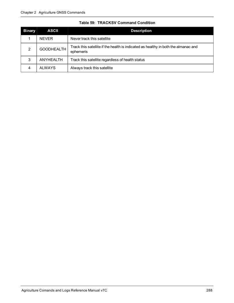
Chapter 2 Agriculture GNSS Commands
Agriculture Comands and Logs Reference Manual v7C 288
Binary ASCII Description
1 NEVER Never track this satellite
2 GOODHEALTH Track this satellite if the health is indicated as healthy in both the almanac andephemeris
3 ANYHEALTH Track this satellite regardless of health status
4 ALWAYS Always track this satellite
Table 59: TRACKSV Command Condition

Chapter 2 Agriculture GNSS Commands
Agriculture Comands and Logs Reference Manual v7C 289
2.143 TUNNELESCAPEBreaks out of an established tunnel
Platform: OEM719, OEM729, OEM7500, OEM7600, OEM7700, OEM7720, PwrPak7, SPAN CPT7,SMART7, SMART2
The tunnel escape sequence feature allows you to break out of a tunnel between two ports by sending a pre-defined sequence of bytes through the tunnel in-line with the data stream.
Use the TUNNELESCAPE command to specify the tunnel escape sequence. The escape sequence is appliedindependently to all active tunnels. Use theSAVECONFIG command (see page 242) to save the escapesequence in case of a power cycle.
This command is used to define an escape sequence that, when detected in a byte stream between any twoCOM (or AUX) ports, resets the interfacemode toNOVATEL NOVATEL on those ports. The baud rate andother port parameters remain unaffected.
The TUNNELESCAPE command accepts three parameters. The first is the switch parameter withENABLE orDISABLE options. The second is the length parameter. It is a number from 1 to 8 andmust be present if theswitch parameter is set to ENABLE. The third parameter, esc seq, consists of a series of pairs of digits rep-resenting hexadecimal numbers, where the number of pairs are equal to the value entered for the second para-meter. The series of hexadecimal pairs of digits represent the escape sequence. The receiver detects asequence in a tunnel exactly as it was entered.
For example, the command TUNNELESCAPE ENABLE 4 61626364 searches for the bytes representing“abcd” in a tunnel stream. TUNNELESCAPE ENABLE 3 AA4412 searches for the NovAtel binary log syncbytes.
Youmust first set up a tunnel. For example, create a tunnel between COM1 and COM2 by enteringINTERFACEMODE COM1 TCOM2 NONE OFF. The commands can be entered in any order.
1. All bytes, leading up to and including the escape sequence, pass through the tunnel before it is reset.Therefore, the escape sequence is the last sequence of bytes that passes through the tunnel. Con-figure the receiver to detect and interpret the escape sequence. For example, use this information toreset equipment or perform a shutdown process.
2. The receiver detects the escape sequence in all active tunnels in any direction.
3. Create tunnels using the INTERFACEMODE command (see page 136).
Message ID: 962
Abbreviated ASCII Syntax:TUNNELESCAPE switch length escseq
Factory Default:TUNNELESCAPE disable 0
ASCII Example:TUNNELESCAPE enable 1 aa

Chapter 2 Agriculture GNSS Commands
Agriculture Comands and Logs Reference Manual v7C 290
Field Field Type ASCIIValue
BinaryValue Description Format Binary
BytesBinaryOffset
1 TUNNELESCAPEheader - -
Command header. SeeMessages on page 26 for moreinformation.
H 0 -
2 switchDISABLE 0 Enable or disable the tunnel
escapemode Enum 4 HENABLE 1
3 length 1 to 8 Specifies the number of hexbytes to follow Ulong 4 H+4
4 escseqEscape sequence where Hexpairs are entered withoutspaces, for example, AA4412
Uchar[8] 8 H+8
If using theSAVECONFIG command (see page 242) in NovAtel Connect, ensure all windows otherthan theConsolewindow are closed. If open, NovAtel Connect also saves log commands used for itsvarious windows. This results in unnecessary data being logged.

Chapter 2 Agriculture GNSS Commands
Agriculture Comands and Logs Reference Manual v7C 291
2.144 UALCONTROLSetup User Accuracy levels
Platform: OEM719, OEM729, OEM7500, OEM7600, OEM7700, OEM7720, PwrPak7, SPAN CPT7,SMART7, SMART2
TheUALCONTROL command is used to define User Accuracy Levels. User accuracy levels are user definedstandard deviations thresholds, used to determine solution acceptability. Issuing theUALCONTROL commandcauses the BESTPOS andGPGGA solution types to be controlled via the specified thresholds, rather than bythe solution source or mode. The new solution types are described in the table below.
Value BESTPOS Position Type1 NMEA Equivalent2
70 OPERATIONAL 4
71 WARNING 5
72 OUT_OF_BOUNDS 1
1. As reported in the BESTPOS log (see page 346).
2. Refers to the GPGGA quality indicator (see the GPGGA log on page 417 fordetails).
Table 60: User Accuracy Level Supplemental Position Types and NMEA Equi-valents
TheSETBESTPOSCRITERIA command (see page 264) determines which standard deviations are comparedagainst the provided thresholds.
UAL is useful for applications that rely upon specific solutions types being present in the BESTPOS orGPGGA logs. For example, if an agricultural steering system commonly requires an RTK fixedGPGGAsolution type (4) to operate, and interruptions in RTK conventionally cause the GPGGA to switch toanother solution type. This causes the steering system to disengage.
Message ID: 1627
Abbreviated ASCII Syntax:UALCONTROL Action [Operational_limit] [Warning_limit]
Factory Default:UALCONTROL disable
ASCII Example:UALCONTROL enable 0.10 0.20

Chapter 2 Agriculture GNSS Commands
Agriculture Comands and Logs Reference Manual v7C 292
Field Field Type ASCIIValue
BinaryValue Description Format Binary
BytesBinaryOffset
1 UALCONTROLheader - - Command header. SeeMessages
on page 26 for more information. - H 0
2 Action
DISABLE 0 Disables this feature
Enum 4 HENABLE 1
Replace BESTPOS andGPGGAposition types withOPERATIONAL, WARNING orOUT_OF_BOUNDS based on theentered standard deviations (refer toTable 60: User Accuracy LevelSupplemental Position Types andNMEA Equivalents on the previouspage)
CLEAR 2 Disable this feature and reset theentered standard deviations.
3 OperationalLimit
Standard deviation in meters toreport OPERATIONAL Double 8 H+4
4 Warning Limit
Standard deviation in meters toreport WARNING
Note: OUT_OF_BOUND reportswhen the standard deviationexceeds this value
Double 8 H+12

Chapter 2 Agriculture GNSS Commands
Agriculture Comands and Logs Reference Manual v7C 293
2.145 UNASSIGNUnassigns a previously assigned channel
Platform: OEM719, OEM729, OEM7500, OEM7600, OEM7700, OEM7720, PwrPak7, SPAN CPT7,SMART7, SMART2
This command cancels a previously issuedASSIGN command (see page 53) and the SV channel reverts toautomatic control (the same as ASSIGN AUTO).
Message ID: 29
Abbreviated ASCII Syntax:UNASSIGN channel [state]
Input Example:UNASSIGN 11
Issuing theUNASSIGN command to a channel that was not previously assigned by theASSIGN com-mand (see page 53) has no effect.
For dual antenna receivers:
l On the primary antenna, the SV channel is from 0 to N-1, where N is the number of channels in theprimary antenna channel configuration.
l On the secondary antenna, the SV channel count is from at N to N+(M-1), whereM is the numberof channels in the secondary antenna SV channel configuration.
l Even though L-Band channels cannot be configured withASSIGN orUNASSIGN, they areincluded when determining N.
TheASSIGN andUNASSIGN commands are not accepted for L-Band channels. TheASSIGNLBANDBEAM command (see page 58) should be used for L-Band channels.
Field Field Type ASCII Value Binary Value Description Format BinaryBytes
BinaryOffset
1 UNASSIGNheader - -
Command header.SeeMessages onpage 26 for moreinformation.
- H 0
2 channel0 to N-1, where N is the number of thelast GNSS channel in the currentchannel configuration
Channel numberreset to automaticsearch andacquisitionmode
Ulong 4 H

Chapter 2 Agriculture GNSS Commands
Agriculture Comands and Logs Reference Manual v7C 294
Field Field Type ASCII Value Binary Value Description Format BinaryBytes
BinaryOffset
3 state
These return SV channel control tothe automatic search engineimmediately (see Table 12: ChannelState on page 55)
Set the SV channelstate (currentlyignored)
Enum 4 H+4

Chapter 2 Agriculture GNSS Commands
Agriculture Comands and Logs Reference Manual v7C 295
2.146 UNASSIGNALLUnassigns all previously assigned channels
Platform: OEM719, OEM729, OEM7500, OEM7600, OEM7700, OEM7720, PwrPak7, SPAN CPT7,SMART7, SMART2
This command cancels all previously issuedASSIGN orASSIGNALL commands for all SV channels for a satel-lite system (same as ASSIGNALL AUTO). Tracking and control for each SV channel reverts to automaticmode.
Message ID: 30
Abbreviated ASCII Syntax:UNASSIGNALL [system]
Input Example:UNASSIGNALL GPS
Issuing theUNASSIGNALL command has no effect on channels that were not previously assignedusing theASSIGN command (see page 53) orASSIGNALL command (see page 56).
Field Field Type ASCIIValue
BinaryValue Description Format Binary
BytesBinaryOffset
1 UNASSIGNALLheader - - Command header. SeeMessages
on page 26 for more information. - H 0
2 systemSee Table 13:Satellite System onpage 57
System that will be affected by theUNASSIGNALL command(default = ALL)
Enum 4 H

Chapter 2 Agriculture GNSS Commands
Agriculture Comands and Logs Reference Manual v7C 296
2.147 UNDULATIONChooses undulation
Platform: OEM719, OEM729, OEM7500, OEM7600, OEM7700, OEM7720, PwrPak7, SPAN CPT7,SMART7, SMART2
This command permits you to enter a specific geoidal undulation value. In the option field, the EGM96 tableprovides ellipsoid heights at a 0.5° by 0.5° spacing while the OSU89B is implemented at a 2° by 3° spacing. Inareas of rapidly changing elevation, you could be operating somewhere within the 2° by 3° grid with an erroneousheight. EGM96 provides amore accuratemodel of the ellipsoid which results in a denser grid of heights. It is alsomore accurate because the accuracy of the grid points themselves has also improved from OSU89B to EGM96.For example, the default grid (EGM96) is useful where there are underwater canyons, steep drop-offs or moun-tains.
The undulation values reported in the position logs are in reference to the ellipsoid of the chosen datum.
Refer to the application note APN-006: Geoid Issue, available at novatel.com/support/support-mater-ials/application-notes, for a description of the relationships in Figure 6: Illustration of Undulation below.
Figure 6: Illustration of Undulation
Message ID: 214
Abbreviated ASCII Syntax:UNDULATION option [separation]
Factory Default:UNDULATION egm96 0.0000
ASCII Example 1:UNDULATION osu89b
ASCII Example 2:UNDULATION USER -5.599999905

Chapter 2 Agriculture GNSS Commands
Agriculture Comands and Logs Reference Manual v7C 297
Field Field Type ASCIIValue
BinaryValue Description Format Binary
BytesBinaryOffset
1 UNDULATIONheader - - Command header. SeeMessages
on page 26 for more information. - H 0
2 option
USER 1 Use the user specified undulationvalue
Enum 4 HOSU89B 2 Use theOSU89B undulation table
EGM96 3 Use global geoidal height modelEGM96 table
3 separation ±1000.0m The undulation value (required for theUSER option) (default = 0.000) Float 4 H+4

Chapter 2 Agriculture GNSS Commands
Agriculture Comands and Logs Reference Manual v7C 298
2.148 UNLOCKOUTReinstates a satellite in the solution
Platform: OEM719, OEM729, OEM7500, OEM7600, OEM7700, OEM7720, PwrPak7, SPAN CPT7,SMART7, SMART2
This command allows a satellite which has been previously locked out (LOCKOUT command on page 156) to bereinstated in the solution computation. If more than one satellite is to be reinstated, this commandmust be reis-sued for each satellite reinstatement.
Message ID: 138
Abbreviated ASCII Syntax:UNLOCKOUT prn
Input Example:UNLOCKOUT 8
TheUNLOCKOUT command is used to reinstate a satellite while leaving other locked out satellitesunchanged.
This command can be used for GPS, GLONASS, SBAS andQZSS.
Field Field Type ASCIIValue
BinaryValue Description Format Binary
BytesBinaryOffset
1 UNLOCKOUTheader - - Command header. SeeMessages on
page 26 for more information. - H 0
2 prnRefer toPRNNumbers onpage 44
A single satellite PRN number to bereinstated Ulong 4 H

Chapter 2 Agriculture GNSS Commands
Agriculture Comands and Logs Reference Manual v7C 299
2.149 UNLOCKOUTALLReinstates all previously locked out satellites
Platform: OEM719, OEM729, OEM7500, OEM7600, OEM7700, OEM7720, PwrPak7, SPAN CPT7,SMART7, SMART2
This command allows all satellites or systems which have been previously locked out (LOCKOUT command onpage 156 or LOCKOUTSYSTEM command on page 157) to be reinstated in the solution computation.
Message ID: 139
Abbreviated ASCII Syntax:UNLOCKOUTALL
Input Example:UNLOCKOUTALL
Field Field Type ASCIIValue
BinaryValue Description Format Binary
BytesBinaryOffset
1 UNLOCKOUTALLheader - - Command header. SeeMessages
on page 26 for more information. - H 0

Chapter 2 Agriculture GNSS Commands
Agriculture Comands and Logs Reference Manual v7C 300
2.150 UNLOCKOUTSYSTEMReinstates previously locked out system
Platform: OEM719, OEM729, OEM7500, OEM7600, OEM7700, OEM7720, PwrPak7, SPAN CPT7,SMART7, SMART2
This command allows a system which has been previously locked out (refer to the LOCKOUTSYSTEM com-mand on page 157) to be reinstated in the solution computation.
If more than one system is to be reinstated, this commandmust be reissued for each system rein-statement.
Message ID: 908
Abbreviated ASCII Syntax:UNLOCKOUTSYSTEM system
Input Example:UNLOCKOUTSYSTEM glonass
TheUNLOCKOUTSYSTEM command is used to reinstate a system while leaving other locked outsystems unchanged.
Field Field Type ASCIIValue
BinaryValue Description Format Binary
BytesBinaryOffset
1UNLOCKOUTSYSTEMheader
- - Command header. SeeMessageson page 26 for more information. - H 0
2 systemSee Table 95:Satellite System onpage 450
A single satellite system to bereinstated Enum 4 H

Chapter 2 Agriculture GNSS Commands
Agriculture Comands and Logs Reference Manual v7C 301
2.151 UNLOGRemoves a log from logging control
Platform: OEM719, OEM729, OEM7500, OEM7600, OEM7700, OEM7720, PwrPak7, SPAN CPT7,SMART7, SMART2
This command is used to remove a specific log request from the system.
Message ID: 36
Abbreviated ASCII Syntax:UNLOG [port] message
Input Example:UNLOG com1 bestposa
UNLOG bestposa
TheUNLOG command is used to remove one or more logs while leaving other logs unchanged.
2.151.1 Binary
Field FieldName Binary Value Description Format Binary
BytesBinaryOffset
1UNLOG(binary)header
(See Table 3: Binary Message HeaderStructure on page 30)
This fieldcontains themessage header
- H 0
2 portSee Table 4: Detailed Port Identifier onpage 32 (decimal port values greater than 16may be used)
Port to which logis being sent Enum 4 H
3 message Any valid message ID Message ID oflog to output Ushort 2 H+4
4 messagetype
Bits 0-4 = Reserved
Bits 5-6 = Format
00 = Binary
01 = ASCII
10 = Abbreviated ASCII, NMEA
11 = Reserved
Bit 7 = Response Bit (Message Responseson page 41)
0 = Original Message
1 = ResponseMessage
Message type oflog Char 1 H+6
5 Reserved Char 1 H+7

Chapter 2 Agriculture GNSS Commands
Agriculture Comands and Logs Reference Manual v7C 302
2.151.2 ASCII
Field FieldType
ASCIIValue
BinaryValue Description Format Binary
BytesBinaryOffset
1UNLOG(ASCII)header
- -
This field contains the commandname or themessage headerdepending on whether the commandis abbreviated ASCII or ASCII,respectively
- H 0
2 port
See Table 4: DetailedPort Identifier on page 32(decimal port valuesgreater than 16may beused)
Port to which log is being sent
(default = THISPORT)Enum 4 H
3 message MessageName N/A Message Name of log to be disabled Ulong 4 H+4

Chapter 2 Agriculture GNSS Commands
Agriculture Comands and Logs Reference Manual v7C 303
2.152 UNLOGALLRemoves all logs from logging control
Platform: OEM719, OEM729, OEM7500, OEM7600, OEM7700, OEM7720, PwrPak7, SPAN CPT7,SMART7, SMART2
If [port] is specified, this command disables all logs on the specified port only. All other ports are unaffected. If[port] is not specified this command defaults to the ALL_PORTS setting.
Message ID: 38
Abbreviated ASCII Syntax:UNLOGALL [port] [held]
Input Example:UNLOGALL com2_15
UNLOGALL true
TheUNLOGALL command is used to remove all log requests currently in use.
Field Field Type ASCII Value Binary Value Description Format BinaryBytes
BinaryOffset
1 UNLOGALLheader - -
Command header. SeeMessages on page 26for more information.
- H 0
2 port
See Table 4: Detailed PortIdentifier on page 32 (decimalvalues greater than 16may beused)
Port to clear
(default = ALL_PORTS)Enum 4 H
3 held
FALSE 0Does not remove logswith the HOLDparameter (default)
Bool 4 H+4
TRUE 1
Removes previouslyheld logs, even thosewith the HOLDparameter

Chapter 2 Agriculture GNSS Commands
Agriculture Comands and Logs Reference Manual v7C 304
2.153 USERDATUMSets user customized ellipsoid and datum transformation
Platform: OEM719, OEM729, OEM7500, OEM7600, OEM7700, OEM7720, PwrPak7, SPAN CPT7,SMART7, SMART2
This command is like theUSEREXPDATUM command but without parameter rates. See theUSEREXPDATUM command on page 306 for details on command usage and parameter meaning.
When theUSERDATUM command is entered, theUSEREXPDATUM command on page 306 is issued intern-ally with theUSERDATUM command values. It is theUSEREXPDATUM command on page 306 that appearsin theRXCONFIG log (see page 653). Only a single set of USEREXPDATUM orUSERDATUM entered para-meters is valid at one time. Newer parameters entered by either commandwill overwrite previously entered para-meters.
See theDATUM command on page 93 for important guidance and details on datum operation.
Message ID: 78
Abbreviated ASCII Syntax:USERDATUM semi_major_axis flattening dx dy dz rx ry rz scale
Factory Default:USERDATUM 6378137.0 298.2572235628 0.0 0.0 0.0 0.0 0.0 0.0 0.0
ASCII Example:USERDATUM 6378206.400 294.97869820000 -12.0000 147.0000 192.0000 0.00000.0000 0.0000 0.000000000
Field Field Type ASCIIValue
BinaryValue Description Format Binary
BytesBinaryOffset
1 USERDATUMheader - - Command header. SeeMessages on
page 26 for more information. - H 0
2 semi_major_axis
6300000.0 -6400000.0 Datum semi-major axis (a) (meters) Double 8 H
3 flattening 290.0 - 305.0 Reciprocal Flattening,1/f = a/(a-b) Double 8 H+8
4 dx ± 2000.0
Translation values (meters)
Double 8 H+16
5 dy ± 2000.0 Double 8 H+24
6 dz ± 2000.0 Double 8 H+32

Chapter 2 Agriculture GNSS Commands
Agriculture Comands and Logs Reference Manual v7C 305
Field Field Type ASCIIValue
BinaryValue Description Format Binary
BytesBinaryOffset
7 rx ± 10.0 radians Datum rotation angles
A positive sign is for counter clockwiserotation and a negative sign is forclockwise rotation
Double 8 H+40
8 ry ± 10.0 radians Double 8 H+48
9 rz ± 10.0 radians Double 8 H+56
10 scale ± 10.0 ppm Scale value is the difference in ppm Double 8 H+64
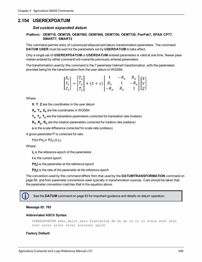
Chapter 2 Agriculture GNSS Commands
Agriculture Comands and Logs Reference Manual v7C 306
2.154 USEREXPDATUMSet custom expanded datum
Platform: OEM719, OEM729, OEM7500, OEM7600, OEM7700, OEM7720, PwrPak7, SPAN CPT7,SMART7, SMART2
This command permits entry of customized ellipsoid and datum transformation parameters. The commandDATUM USER must be sent for the parameters set by USERDATUM to take effect.
Only a single set of USEREXPDATUM orUSERDATUM entered parameters is valid at one time. Newer para-meters entered by either commandwill overwrite previously entered parameters.
The transformation used by this command is the 7 parameter Helmert transformation, with the parametersprovided being for the transformation from the user datum toWGS84:
Where:
X, Y, Z are the coordinates in the user datum
Xs, Ys, Zs are the coordinates inWGS84
Tx, Ty, Tz are the translation parameters corrected for translation rate (meters)
Rx, Ry, Rz are the rotation parameters corrected for rotation rate (radians)
s is the scale difference corrected for scale rate (unitless)
A given parameter P is corrected for rate:
P(t)=P(tr)+ Ṕ(tr) (t-tr)
Where:
tr is the reference epoch of the parameters
t is the current epoch
P(tr) is the parameter at the reference epoch
Ṕ(tr) is the rate of the parameter at the reference epoch
The convention used by this command differs from that used by theDATUMTRANSFORMATION command onpage 95, and from parameter conventions seen typically in transformation sources. Care should be taken thatthe parameter conventionmatches that in the equation above.
See theDATUM command on page 93 for important guidance and details on datum operation.
Message ID: 783
Abbreviated ASCII Syntax:USEREXPDATUM semi_major_axis flattening dx dy dz rx ry rz scale xvel yvelzvel xrvel yrvel zrvel scalevel epoch
Factory Default:

Chapter 2 Agriculture GNSS Commands
Agriculture Comands and Logs Reference Manual v7C 307
USEREXPDATUM 6378137.0 298.25722356280 0.0 0.0 0.0 0.0 0.0 0.0 0.0 0.0 0.00.0 0.0 0.0 0.0 0.0 0.0
ASCII Example:USEREXPDATUM 6378137.000 298.25722356280 0.000000000 0.000000000 0.0000000000.00000000 0.000000000 0.000000000 0.000000000 0.000000000 0.0000000000.000000000 0.0000 0.000000000 0.000000000 0.000000000 0.000000000
Use theUSEREXPDATUM command in a survey to fix the position with values from another knowndatum so that the GPS calculated positions are reported in the known datum rather thanWGS84. Forexample, it is useful for places like Australia, where the continent is moving several centimeters a yearrelative toWGS84. WithUSEREXPDATUM, you can also input the velocity of themovement toaccount for drift over the years.
Field Field Type ASCIIValue
BinaryValue Description Format Binary
BytesBinaryOffset
1 USEREXPDATUMheader - - Command header. SeeMessages
on page 26 for more information. - H 0
2 semi_major_axis 6300000.0 -6400000.0m Datum semi-major axis (a) (meters) Double 8 H
3 flattening 290.0 - 305.0 Reciprocal Flattening,1/f = a/(a-b) Double 8 H+8
4 dx ± 2000.0m
Translation values (meters)
Double 8 H+16
5 dy ± 2000.0m Double 8 H+24
6 dz ± 2000.0m Double 8 H+32
7 rx ± 10.0 radians Datum rotation angles
A positive sign is for counterclockwise rotation and a negativesign is for clockwise rotation
Double 8 H+40
8 ry ± 10.0 radians Double 8 H+48
9 rz ± 10.0 radians Double 8 H+56
10 scale ± 10.0 ppm Scale value is the difference in ppm Double 8 H+64
11 xvel ± 2000.0m/yr Velocity vector along X-axis Double 8 H+72
12 yvel ± 2000.0m/yr Velocity vector along Y-axis Double 8 H+80
13 zvel ± 2000.0m/yr Velocity vector along Z-axis Double 8 H+88
14 xrvel ± 10.0radians/yr
Change in the rotation about X overtime Double 8 H+96
15 yrvel ± 10.0radians/yr
Change in the rotation about Y overtime Double 8 H+104
16 zrvel ± 10.0radians/yr
Change in the rotation about Z overtime Double 8 H+112

Chapter 2 Agriculture GNSS Commands
Agriculture Comands and Logs Reference Manual v7C 308
Field Field Type ASCIIValue
BinaryValue Description Format Binary
BytesBinaryOffset
17 scalevel ± 10.0 ppm/yr Change in scale fromWGS84 overtime Double 8 H+120
18 epoch 0.0 year
Reference epoch of parameters(decimal year)
Example:
2011.00 = Jan 1, 2011
2011.19 = Mar 11, 2011
Double 8 H+128

Chapter 2 Agriculture GNSS Commands
Agriculture Comands and Logs Reference Manual v7C 309
2.155 USERI2CREADRead data from devices on the I2C bus
Platform: OEM7600, OEM7700, OEM7720
Use this command to read data from devices on the I2C bus.
This command only applies to OEM7 receivers that have I2C signals available on the interface con-nector. The compatible receivers are listed in thePlatform section above.
TheUSERI2CRESPONSE log (see page 746) can be used to check the completion or status of the read oper-ation. An optional user defined Transaction ID can be provided to help synchronize requests with responses intheUSERI2CRESPONSE log (see page 746). This command is primarily intended to be used by Lua applic-ations that need to interact with external devices.
Reading from an I2C device requires a device address, to distinguish which physical device is to be accessed, aregister within the device, and the expected number of bytes to be read. Depending on the type of I2C device,register addresses can be 1 to 4 bytes in length, so the actual number of bytes for the register address must bespecified.
For some I2C devices there are no registers within the device. In this case, the Register Address Length is 0 andno bytes are supplied for the Register Address.
TheUSERI2CREAD command is flexible to handle all of these situations.
Message ID: 2232
Abbreviated ASCII Syntax:USERI2CREAD DeviceAddress RegisterAddressLen RegisterAddress RequestReadLen[TransactionID]
Examples:USERI2CREAD 70 1 AB 12 1234
USERI2CREAD 74 3 ABCDEF 234 5678
USERI2CREAD 74 0 234 5678
Field Field Type Description Format BinaryBytes
BinaryOffset
1 USERI2CREADheader
Command header. SeeMessages for moreinformation. - H 0
2 DeviceAddress
The 7 bit address of the I2C device. Valid values are 0through 127.
For ASCII and Abbreviated commands, this field is ahexadecimal string of two digits. There is no 0x prefixand spaces are not allowed in the string.
Uchar 11 H
1In the binary case, additional bytes of padding are added after this field to maintain 4-byte alignment for the fields thatfollow.

Chapter 2 Agriculture GNSS Commands
Agriculture Comands and Logs Reference Manual v7C 310
Field Field Type Description Format BinaryBytes
BinaryOffset
3 RegisterAddressLen The length of the register address that follows. Validvalues are 0 through 4. Ulong 4 H+4
4 RegisterAddress
The actual address of the register to be read. Thenumber of bytes heremust match theRegisterAddressLen. In particular, whenRegisterAddressLen is 0, this field is empty (even fora binary command)
For ASCII and Abbreviated commands, this field is ahexadecimal string of two digits for each byte in theregister address. There is no 0x prefix and spaces arenot allowed in the string.
UcharArray
X1 H+8
5 RequestReadLen The length of data expected to be retrieved from thedevice. Valid values are 1 through 256. Ulong 4 H+121
6 TransactionID
An optional user provided ID for this transaction.Default = 0.
This transaction ID will be copied to theUSERI2CRESPONSE log (see page 746) created forthis read operation.
Ulong 4 H+162
1H+8 if X=02H+12 if X=0

Chapter 2 Agriculture GNSS Commands
Agriculture Comands and Logs Reference Manual v7C 311
2.156 USERI2CWRITEWrite data to device on I2C bus
Platform: OEM7600, OEM7700, OEM7720
Use this command to write data to devices on the I2C bus.
This command only applies to OEM7 receivers that have I2C signals available on the interface con-nector. The compatible receivers are listed in thePlatform section above.
TheUSERI2CRESPONSE log (see page 746) can be used to check the completion or status of the write oper-ation. An optional user defined Transaction ID can be provided to help synchronize requests with responses intheUSERI2CRESPONSE log (see page 746). This command is primarily intended to be used by Lua applic-ations that need to interact with external devices.
Writing to an I2C device requires a device address, to distinguish which physical device is to be accessed, aregister within the device and the data. Depending on the type of I2C device, register addresses can be 1 to 4bytes in length, and so the actual number of bytes for the register address must be specified.
For some I2C devices there are no registers within the device. In this case, the Register Address Length is 0,and no bytes are supplied for the Register Address.
For some other I2C devices, write operations are done in two stages:
1. The first stage sends a write commandwith a register address, but no data. This is a dummy write to set theregister within the device for write operations that follow.
2. The second stage sends a write commandwith no register address, but does send a stream of data.
TheUSERI2CWRITE command is flexible to handle all of these situations.
Message ID: 2233
Abbreviated ASCII Syntax:USERI2CWRITE DeviceAddress RegisterAddressLen RegisterAddressWriteDataLength WriteData [TransactionID]
Examples:USERI2CWRITE 70 1 AB 12 3132333435363738393A3B3C 1234
USERI2CWRITE 74 3 ABCDED 5 1234567890 1234
USERI2CWRITE 40 0 5 1234567890 1234
USERI2CWRITE 40 2 AABB 0 1234 (a dummy write)
Field Field Type Description Format BinaryBytes
BinaryOffset
1 USERI2CWRITEheader
Command header. SeeMessages for moreinformation. - H 0

Chapter 2 Agriculture GNSS Commands
Agriculture Comands and Logs Reference Manual v7C 312
Field Field Type Description Format BinaryBytes
BinaryOffset
2 DeviceAddress
The 7 bit address of the I2C device. Validvalues 0 through 127.
For ASCII and Abbreviated commands, thisfield is a hexadecimal string of two digits. Thereis no 0x prefix and spaces are not allowed in thestring.
Uchar 11 H
3 RegisterAddressLen The length of the register address that follows.Valid values are 0 through 4. Ulong 4 H+4
4 RegisterAddress
The actual address of the register to be written.The number of bytes heremust match theRegisterAddressLen. In particular, whenRegisterAddressLen is 0, this field is empty(even for a binary command)
For ASCII and Abbreviated commands, thisfield is a hexadecimal string of two digits foreach byte in the register address. There is no 0xprefix and spaces are not allowed in the string.
UcharArray
X1 H+8
5 WriteDataLength The length of data to be written in bytes. Validvalues are 0 through 256. Ulong 4 H+122
6 WriteData
The data to be written. The number of bytes inthis data block must match theWriteDataLength. In particular, whenWriteDataLength is 0, this field is empty.
For ASCII and Abbreviated commands, thisfield is a hexadecimal string of two digits foreach byte in the data block. There is no 0xprefix and spaces are not allowed in the string.
Data is streamed to the device as a series ofbytes in the order provided.
UcharArray Y3 H+164
7 TransactionID
An optional user provided ID for thistransaction. Default = 0.
This transaction ID will be copied to theUSERI2CRESPONSE log (see page 746)created for this write operation.
Ulong 4 H+16+4*INT((Y+3)/4)5
1In the binary case, additional bytes of padding are added after this field to maintain 4-byte alignment for the fields thatfollow.2H+8 if X=03In the binary case, additional bytes of padding are added after this field to maintain 4-byte alignment for the fields thatfollow.4H+12 if X=05H+12+4*INT((Y+3)/4) if X=0

Chapter 2 Agriculture GNSS Commands
Agriculture Comands and Logs Reference Manual v7C 313
2.157 WIFIALIGNAUTOMATIONConfigure the ALIGN plug-and-play feature over Wi-Fi
Platform: PwrPak7, SMART7-I, SMART7-SI, SMART7-W
PwrPak7M variants do not support this command.
Use this command to simplify the configuration of a pair of receivers; one acting as an ALIGN Master and theother acting as an ALIGN Rover.
Similar to theALIGNAUTOMATION command (see page 51) the ALIGN Rover, acting as aWi-Fi Client, con-nects to the specifiedWi-Fi Access Point and configures it as an ALIGN Master.
The IP address of the ALIGN Rover and ALIGN Master must be different. Since all NovAtel receiversare delivered with the same default IP address, it is highly recommended to use theWIFIAPIPCONFIGcommand (see page 316) to change the IP address of the ALIGN Rover to a non-default value such as192.168.20.1 prior to entering theWIFIALIGNAUTOMATION command. Failure to do somay result inloss of wireless communication to the ALIGN Rover.
Message ID: 2214
Abbreviated ASCII Syntax:WIFIALIGNAUTOMATION option [master_networkid] [corrections_port] [datarate][headingextboption] [interfacemode]
Factory Default:WIFIALIGNAUTOMATION DISABLE
Example:WIFIALIGNAUTOMATION enable 1 icom1 10 on novatelx
Field Field Type ASCII Value BinaryValue Description Format Binary
BytesBinaryOffset
1WIFIALIGNAUTOMATIONheader
- -Command header. SeeMessages on page 26 formore information.
- H 0
2 optionENABLE 1 Enable or disable the plug-
and-play feature. Enum 4 HDISABLE 0
3 master_network 1-4
Network id of AlignMasterAccess Point as defined intheWIFINETCONFIGcommand (see page 320).
Ulong 4 H+4
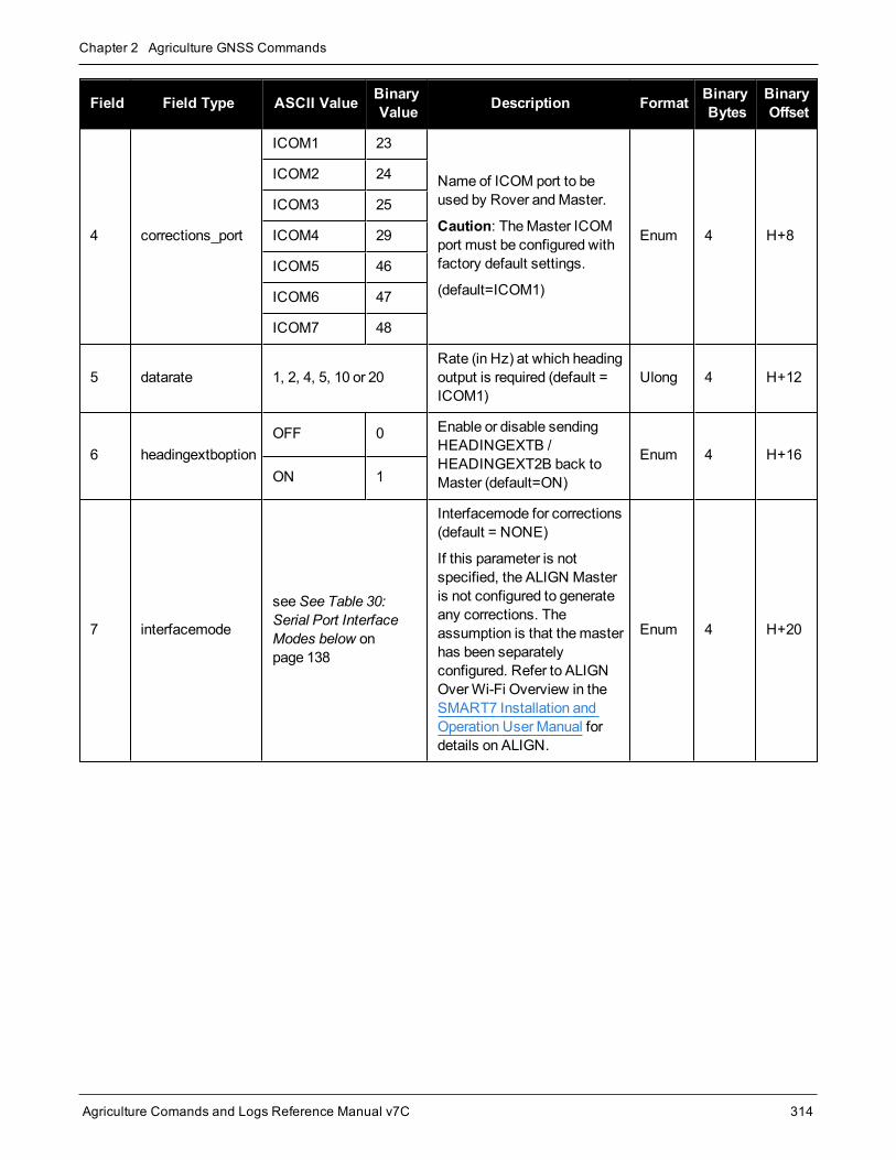
Chapter 2 Agriculture GNSS Commands
Agriculture Comands and Logs Reference Manual v7C 314
Field Field Type ASCII Value BinaryValue Description Format Binary
BytesBinaryOffset
4 corrections_port
ICOM1 23
Name of ICOM port to beused by Rover andMaster.
Caution: TheMaster ICOMport must be configured withfactory default settings.
(default=ICOM1)
Enum 4 H+8
ICOM2 24
ICOM3 25
ICOM4 29
ICOM5 46
ICOM6 47
ICOM7 48
5 datarate 1, 2, 4, 5, 10 or 20Rate (in Hz) at which headingoutput is required (default =ICOM1)
Ulong 4 H+12
6 headingextboptionOFF 0 Enable or disable sending
HEADINGEXTB /HEADINGEXT2B back toMaster (default=ON)
Enum 4 H+16ON 1
7 interfacemode
seeSee Table 30:Serial Port InterfaceModes below onpage 138
Interfacemode for corrections(default = NONE)
If this parameter is notspecified, the ALIGN Masteris not configured to generateany corrections. Theassumption is that themasterhas been separatelyconfigured. Refer to ALIGNOverWi-Fi Overview in theSMART7 Installation andOperation User Manual fordetails on ALIGN.
Enum 4 H+20

Chapter 2 Agriculture GNSS Commands
Agriculture Comands and Logs Reference Manual v7C 315
2.158 WIFIAPCHANNELSet the channel for the Wi-Fi access point
Platform: PwrPak7, SMART7-I, SMART7-SI, SMART7-W
PwrPak7M variants do not support this command.
Use this command to set the operating channel for theWi-Fi module when operating as an access point. Thenew channel will be used the next time theWIFIMODE AP orWIFIMODE CONCURRENT command isreceived.
Message ID: 2091
Abbreviated ASCII Syntax:WIFIAPCHANNEL channel
Factory Default:WIFIAPCHANNEL 11
Example:WIFIAPCHANNEL 6
Field Field Type ASCIIValue
BinaryValue Description Format Binary
ValueBinaryOffset
1 WIFIAPCHANNELheader - - Command header. SeeMessages
on page 26 for more information. - H 0
2 channel 1-14 802.11 channel Long 4 H
For best performance, choose one of the non-overlapping channels: 1, 6, or 11.

Chapter 2 Agriculture GNSS Commands
Agriculture Comands and Logs Reference Manual v7C 316
2.159 WIFIAPIPCONFIGSet the IP address and netmask for the Wi-Fi access point
Platform: PwrPak7, SMART7-I, SMART7-SI, SMART7-W
PwrPak7M variants do not support this command.
Use this command to set theWi-Fi IP address and netmask forWi-Fi module when operating as an accesspoint. The new network configuration takes effect the next time theWIFIMODE AP orWIFIMODECONCURRENT command is received.
Message ID: 2096
Abbreviated ASCII Syntax:WIFIAPIPCONFIG ip_address ip_netmask
Factory Default:WIFIAPIPCONFIG 192.168.19.1 255.255.255.0
Example:WIFIAPIPCONFIG 192.162.55.20 255.255.0.0
Field Field Type ASCIIValue
BinaryValue Description Format Binary
BytesBinaryOffset
1 WIFIAPIPCONFIGheader - -
Command header. SeeMessages on page 26 for moreinformation.
- H 0
2 ip_address Null-terminatedASCII string IP address, dot decimal format String
[16] Variable H
3 ip_netmask Null-terminatedASCII string
IP netmask, dot decimal format(optional)
Default =255.255.255.0
String[16] Variable Variable
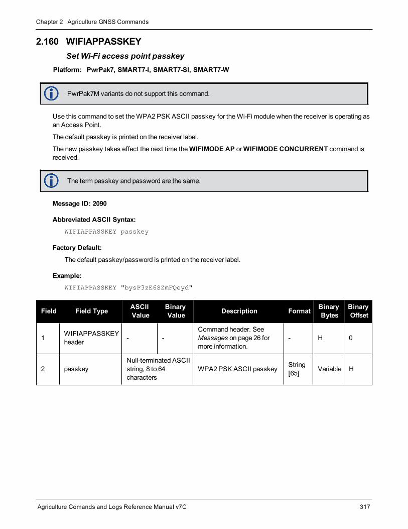
Chapter 2 Agriculture GNSS Commands
Agriculture Comands and Logs Reference Manual v7C 317
2.160 WIFIAPPASSKEYSet Wi-Fi access point passkey
Platform: PwrPak7, SMART7-I, SMART7-SI, SMART7-W
PwrPak7M variants do not support this command.
Use this command to set theWPA2 PSK ASCII passkey for theWi-Fi module when the receiver is operating asan Access Point.
The default passkey is printed on the receiver label.
The new passkey takes effect the next time theWIFIMODE AP orWIFIMODE CONCURRENT command isreceived.
The term passkey and password are the same.
Message ID: 2090
Abbreviated ASCII Syntax:WIFIAPPASSKEY passkey
Factory Default:
The default passkey/password is printed on the receiver label.
Example:WIFIAPPASSKEY "bysP3zE6SZmFQeyd"
Field Field Type ASCIIValue
BinaryValue Description Format Binary
BytesBinaryOffset
1 WIFIAPPASSKEYheader - -
Command header. SeeMessages on page 26 formore information.
- H 0
2 passkeyNull-terminated ASCIIstring, 8 to 64characters
WPA2 PSK ASCII passkey String[65] Variable H

Chapter 2 Agriculture GNSS Commands
Agriculture Comands and Logs Reference Manual v7C 318
2.161 WIFIAPSSIDSet the SSID for the Wi-Fi access point
Platform: PwrPak7, SMART7-I, SMART7-SI, SMART7-W
PwrPak7M variants do not support this command.
Use this command to explicitly set the SSID of the Access Point when the receiver is configured to operate ineither AP or CONCURRENT mode (refer to theWIFIMODE command on the next page for details regarding theWi-Fi configurationmodes).
Message ID: 2206
Abbreviated ASCII Syntax:WIFIAPSSID ssid
Factory Default:<platform-dependent prefix>-<Enclosure PSN>
Example:PwrPak7-NMND17190003B
SM7i-NMPX17500010L
Example:WIFIAPSSID SomeSSIDName
WIFIAPSSID “SSID with spaces”
Field Field Type ASCIIValue
BinaryValue Description Format Binary
BytesBinaryOffset
1 WIFIAPSSIDheader - - Command header. SeeMessages on
page 26 for more information. - H 0
2 SSID Null-terminatedASCII string SSID to be broadcast by access point String
[33] Variable H

Chapter 2 Agriculture GNSS Commands
Agriculture Comands and Logs Reference Manual v7C 319
2.162 WIFIMODEConfigure the receiver Wi-Fi mode
Platform: PwrPak7, SMART7-I, SMART7-SI, SMART7-W
PwrPak7M variants do not support this command.
Use this command to enable, disable or set the operatingmode of Wi-Fi on the receiver. This command is alsoapplies any Wi-Fi configuration changes specified by otherWi-Fi commands such asWIFIAPCHANNEL.
Message ID: 2144
Abbreviated ASCII Syntax:WIFIMODE mode
Factory Default:WIFIMODE AP
Example:WIFIMODE CLIENT
WIFIMODE OFF
Field Field Type ASCII Value BinaryValue Description Format Binary
BytesBinaryOffset
1 WIFIMODEheader - -
Command header. SeeMessages on page 26 for moreinformation.
- H 0
2 mode
OFF 0 Power off theWi-Fi module
Enum 4 H
AP 1 Configure theWi-Fi module asan Access Point (AP)
CLIENT 2 Configure theWi-Fi module as aClient/Station
ON 3 Supply power to theWi-Fimodule, but do not configure it.
CONCURRENT 4
Configure theWi-Fi module asboth an access point andClient/Station simultaneously.When configured in this mode itis possible to connect thereceiver to an access point andfor Clients/Stations to connectto the receiver simultaneously.

Chapter 2 Agriculture GNSS Commands
Agriculture Comands and Logs Reference Manual v7C 320
2.163 WIFINETCONFIGSet the connection parameters of Wi-Fi to which the Wi-Fi client can connect
Platform: PwrPak7, SMART7-I, SMART7-SI, SMART7-W
PwrPak7M variants do not support this command.
Use this command to specify Access Points (AP) to which the Client/Station will automatically connect whenthe receiver's Wi-Fi Client/Station functionality is enabled (refer to theWIFIMODE command (see page 319) fordetails regarding theWi-Fi configurationmodes).
If theWi-Fi Client/Station is already connected to an access point (defined using this command), theconnection remains in effect even when amore preferred access point comes into range (preferred asindicated by network_id).
If Wi-Fi ALIGN automation is enabled, the Client only connects to the Access Point specified in theWIFIALIGNAUTOMATION command (see page 313).
The term passkey and password are the same.
Message ID: 2213
Abbreviated ASCII Syntax:WIFINETCONFIG network_id switch [ssid [passkey [address_mode [IP_address]netmask [gateway [dns]]]]]]]
Factory Default:WIFINETCONFIG 1 DISABLE
WIFINETCONFIG 2 DISABLE
WIFINETCONFIG 3 DISABLE
WIFINETCONFIG 4 DISABLE
Example:WIFINETCONFIG 1 ENABLE SomeSSID 12345678
WIFINETCONFIG 2 ENABLE AnotherSSID 1A2b3C4d STATIC 192.168.19.1

Chapter 2 Agriculture GNSS Commands
Agriculture Comands and Logs Reference Manual v7C 321
Field Field Type ASCIIValue
BinaryValue Description Format Binary
BytesBinaryOffset
1 WIFINETCONFIGheader - -
Command header. SeeMessages on page 26 for moreinformation.
- H 0
2 network_id 1, 2, 3, 4
The Network identifier value isused to prioritize networkconnections whenmore thanone network is in range of theclient. The access point withthe lowest network_id ischosen.
Ulong 4 H
3 switch
DISABLE 0When set to Disable, the clientwill not connect to an accesspoint with this SSID.
Enum 4 H+4
ENABLE 1
When set to Enable, the clientconnects to an access pointwith this SSID if there are noother APs with a lowernetwork_id in range.
4 ssid Null-terminatedASCII string
Access Points with non-ASCIISSIDs are not supported.
Required if switch is set toENABLE.
String[33] Variable
5 passkeyNull-terminatedASCII string, 8 to 64characters
Passkey required to connectto access point identified by“ssid” parameter.(default = “”)
String[65] Variable
6 address_modeDHCP 1 Use dynamic IP address
(default = DHCP) Enum 4STATIC 2 Use static IP address
7 ip_address ddd.ddd.ddd.ddd
IP Address - decimal dotnotation
The IP address is mandatorywhen the address mode isSTATIC.
String[16] Variable
8 netmask ddd.ddd.ddd.dddNetmask – decimal dotnotation (default =255.255.255.0)
String[16] Variable
9 gateway ddd.ddd.ddd.ddd Gateway – decimal dotnotation (default = 0.0.0.0)
String[16] Variable
10 dns ddd.ddd.ddd.ddd DNS server – decimal dotnotation (default = 0.0.0.0)
String[16] Variable

Agriculture Comands and Logs Reference Manual v7C 322
Chapter 3 Logs
3.1 Log TypesSee the LOG command on page 158, for details about requesting logs.
The receiver is capable of generating three type of logs: synchronous, asynchronous and polled. The data for syn-chronous logs is generated on a regular schedule. In order to output themost current data as soon as it is avail-able, asynchronous data is generated at irregular intervals. The data in polled logs is generated on demand. Thefollowing table outlines the log types and the valid triggers to use:
Type Recommended Trigger Illegal Trigger
Synch ONTIME ONNEW, ONCHANGED
Asynch ONCHANGED or ONCE -
Polled ONCE or ONTIME 1 ONNEW, ONCHANGED
Table 61: Log Type Triggers
SeeMessage Time Stamps on page 45 for information about how themessage time stamp is set for each typeof log.
1. TheOEM7 family of receivers can handle 80 logs at a time. If an attempt is made to logmore than 80logs at a time, the receiver responds with an Insufficient Resources error.
2. Asynchronous logs, such as MATCHEDPOS, should only be loggedONCHANGED. Otherwise, themost current data is not output when it is available. This is especially true of the ONTIME trigger,whichmay result in inaccurate time tags.
3. Use theONNEW trigger with theMARKxTIME orMARKxPOS logs.
4. Before the output of fields for logs, there is a header. SeeASCII on page 27, Abbreviated ASCII onpage 29 andBinary on page 29.
3.1.1 Log Type ExamplesFor polled logs, the receiver only supports an offset that is:
l smaller than the logging period
l decimal values that are amultiple of themaximum logging rate defined by the receiver model. For moreinformation see the LOG command on page 158.
The following are valid examples for a polled log:
log portstats ontime 4 2
log version once
For polled logs, the following examples are invalid:
log serialconfig ontime 1 2 [offset is larger than the logging period]
log serialconfig ontime 4 1.5 [offset is not an integer]
1Polled log types do not allow fractional offsets and cannot do ontime rates faster than 1 Hz.

Chapter 3 Logs
Agriculture Comands and Logs Reference Manual v7C 323
For synchronous and asynchronous logs, the receiver supports any offset that is both:
l smaller than the logging period
l amultiple of theminimum logging period
For example, if the receiver supports 20 Hz logging, theminimum logging period is 1/20 Hz or 0.05 s. The fol-lowing are valid examples for a synchronous or asynchronous log, on a receiver that can log at rates up to 20 Hz:
log bestpos ontime 1 [1 Hz]
log bestpos ontime 1 0.1
log bestpos ontime 1 0.90
log avepos ontime 1 0.95
log avepos ontime 2 [0.5 Hz]
log avepos ontime 2 1.35
log avepos ontime 2 1.75
For synchronous and asynchronous logs, the following examples are invalid:
log bestpos ontime 1 0.08 [offset is not amultiple of theminimum logging period]
log bestpos ontime 1 1.05 [offset is larger than the logging period]

Chapter 3 Logs
Agriculture Comands and Logs Reference Manual v7C 324
3.2 ALIGNBSLNENUENU baselines using ALIGN
Platform: OEM719, OEM729, OEM7500, OEM7600, OEM7700, OEM7720, PwrPak7, SPAN CPT7,SMART7
This log outputs the RTK quality ENU baselines from ALIGN. The XYZ baselines (output in theALIGNBSLNXYZ log on page 326) are rotated relative tomaster position (output in MASTERPOS) to computeENU baselines.
On dual antenna receivers, the baseline vector from the primary to the secondary antenna is provided.Additionally, with an ALIGN Relative Positioningmodel, the baseline vector from an external base sta-tion to the primary antenna is also available. The baseline vector from an external base station to thesecondary antenna is not available.
Message ID: 1315
Log Type: Asynch
Recommended Input:log alignbslnenua onnew
ASCII Example:#ALIGNBSLNENUA,COM1,0,29.0,FINESTEERING,1629,259250.000,02040000,100b,39448;SOL_COMPUTED,NARROW_INT,4.1586,-1.9197,-0.0037,0.0047,0.0050,0.0062,"0092","AAAA",22,16,16,16,0,01,0,33*11e1d4c0
Field Field type Description Format BinaryBytes
BinaryOffset
1 ALIGNBSLNENUheader
Log header. SeeMessages on page 26 for moreinformation. H 0
2 sol stat Solution status, see Table 65: Solution Status onpage 349
Enum 4 H
3 pos type Position type, see Table 66: Position or Velocity Typeon page 350 Enum 4 H+4
4 East East Baseline (relative tomaster position) in meters Double 8 H+8
5 North North Baseline (relative tomaster position) in meters Double 8 H+16
6 Up Up Baseline (relative tomaster position) in meters Double 8 H+24
7 East σ East Baseline standard deviation in meters Float 4 H+32
8 North σ North Baseline standard deviation in meters Float 4 H+36
9 Up σ Up Baseline standard deviation in meters Float 4 H+40

Chapter 3 Logs
Agriculture Comands and Logs Reference Manual v7C 325
Field Field type Description Format BinaryBytes
BinaryOffset
10 Rover id
Rover Receiver IDSet using theSETROVERID command (see page 266)on the Rover
e.g., setroverid RRRR
Char[4] 4 H+44
11 Master id
Master Receiver IDSet using theDGPSTXID command (see page 98) ontheMaster
Default: AAAA
Char[4] 4 H+48
12 #SVs Number of satellites tracked Uchar 1 H+52
13 #solnSVs Number of satellites used in solution Uchar 1 H+53
14 #obs Number of satellites above elevationmask angle Uchar 1 H+54
15 #multi Number of satellites with multi-frequency signals abovethemask angle Uchar 1 H+55
16 Reserved Hex 1 H+56
17 ext sol stat Extended solution status, see Table 69: ExtendedSolution Status on page 353 Hex 1 H+57
18 Galileo andBeiDou sigmask
Galileo and BeiDou signals usedmask (see Table 68:Galileo and BeiDou Signal-UsedMask on page 352) Hex 1 H+58
19GPS andGLONASS sigmask
GPS andGLONASS signals usedmask (see Table 67:GPS andGLONASS Signal-UsedMask on page 352) Hex 1 H+59
20 xxxx 32-bit CRC (ASCII and Binary only) Hex 4 H+60
21 [CR][LF] Sentence Terminator (ASCII only) - - -

Chapter 3 Logs
Agriculture Comands and Logs Reference Manual v7C 326
3.3 ALIGNBSLNXYZXYZ baselines using ALIGN
Platform: OEM719, OEM729, OEM7500, OEM7600, OEM7700, OEM7720, PwrPak7, SPAN CPT7,SMART7
This log outputs the RTK quality XYZ baselines from ALIGN.
On dual antenna receivers, the baseline vector from the primary to the secondary antenna is provided.Additionally, with an ALIGN Relative Positioningmodel, the baseline vector from an external base sta-tion to the primary antenna is also available. The baseline vector from an external base station to thesecondary antenna is not available.
Message ID: 1314
Log Type: Asynch
Recommended Input:log alignbslnxyza onnew
ASCII Example:#ALIGNBSLNXYZA,COM1,0,29.0,FINESTEERING,1629,259250.000,02040000,9d28,39448;SOL_COMPUTED,NARROW_INT,3.1901,-3.0566,1.2079,0.0050,0.0054,0.0056,"0092","AAAA",22,16,16,16,0,01,0,33*ac372198
Field Field type Description Format BinaryBytes
BinaryOffset
1 ALIGNBSLNXYZheader
Log header. SeeMessages on page 26 for moreinformation. H 0
2 sol stat Solution status, see Table 65: Solution Status onpage 349 Enum 4 H
3 pos type Position type, see Table 66: Position or Velocity Typeon page 350 Enum 4 H+4
4 dX X Baseline in meters Double 8 H+8
5 dY Y Baseline in meters Double 8 H+16
6 dZ Z Baseline in meters Double 8 H+24
7 dX σ X Baseline standard deviation in meters Float 4 H+32
8 dY σ Y Baseline standard deviation in meters Float 4 H+36
9 dZ σ Z Baseline standard deviation in meters Float 4 H+40

Chapter 3 Logs
Agriculture Comands and Logs Reference Manual v7C 327
Field Field type Description Format BinaryBytes
BinaryOffset
10 Rover id
Rover Receiver ID
Set usingSETROVERID command (see page 266) onthe Rover
e.g. SETROVERID RRRR
Uchar[4] 4 H+44
11 Master id
Master Receiver Id
Set using theDGPSTXID command (see page 98) ontheMaster
Default: AAAA
Uchar[4] 4 H+48
12 #SVs Number of satellites tracked Uchar 1 H+52
13 #solnSVs Number of satellites used in solution Uchar 1 H+53
14 #obs Number of satellites above elevationmask angle Uchar 1 H+54
15 #multi Number of satellites with multi-frequency signals abovethemask angle Uchar 1 H+55
16 Reserved Hex 1 H+56
17 ext sol stat Extended solution status, see Table 69: ExtendedSolution Status on page 353 Hex 1 H+57
18 Galileo andBeiDou sigmask
Galileo and BeiDou signals usedmask (see Table 68:Galileo and BeiDou Signal-UsedMask on page 352) Hex 1 H+58
19GPS andGLONASS sigmask
GPS andGLONASS signals usedmask (see Table 67:GPS andGLONASS Signal-UsedMask on page 352) Hex 1 H+59
20 xxxx 32-bit CRC (ASCII and Binary only) Hex 4 H+60
21 [CR][LF] Sentence Terminator (ASCII only) - - -
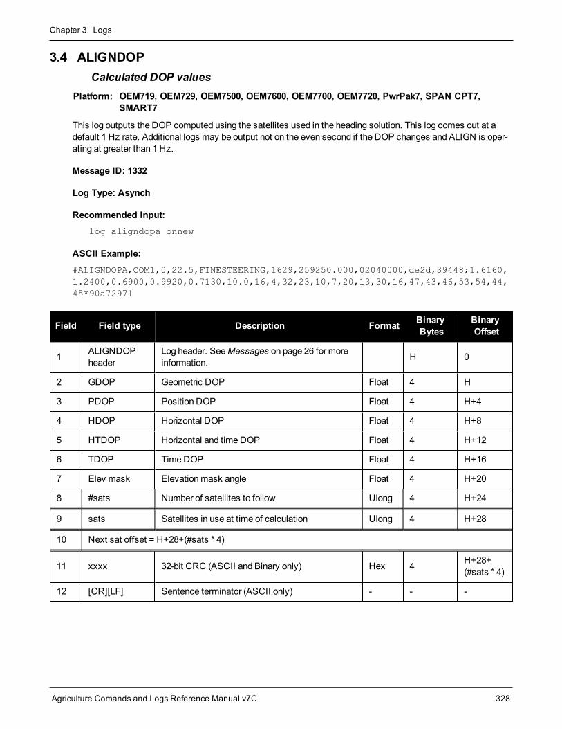
Chapter 3 Logs
Agriculture Comands and Logs Reference Manual v7C 328
3.4 ALIGNDOPCalculated DOP values
Platform: OEM719, OEM729, OEM7500, OEM7600, OEM7700, OEM7720, PwrPak7, SPAN CPT7,SMART7
This log outputs the DOP computed using the satellites used in the heading solution. This log comes out at adefault 1 Hz rate. Additional logs may be output not on the even second if the DOP changes and ALIGN is oper-ating at greater than 1 Hz.
Message ID: 1332
Log Type: Asynch
Recommended Input:log aligndopa onnew
ASCII Example:#ALIGNDOPA,COM1,0,22.5,FINESTEERING,1629,259250.000,02040000,de2d,39448;1.6160,1.2400,0.6900,0.9920,0.7130,10.0,16,4,32,23,10,7,20,13,30,16,47,43,46,53,54,44,45*90a72971
Field Field type Description Format BinaryBytes
BinaryOffset
1 ALIGNDOPheader
Log header. SeeMessages on page 26 for moreinformation. H 0
2 GDOP Geometric DOP Float 4 H
3 PDOP Position DOP Float 4 H+4
4 HDOP Horizontal DOP Float 4 H+8
5 HTDOP Horizontal and time DOP Float 4 H+12
6 TDOP TimeDOP Float 4 H+16
7 Elev mask Elevationmask angle Float 4 H+20
8 #sats Number of satellites to follow Ulong 4 H+24
9 sats Satellites in use at time of calculation Ulong 4 H+28
10 Next sat offset = H+28+(#sats * 4)
11 xxxx 32-bit CRC (ASCII and Binary only) Hex 4 H+28+(#sats * 4)
12 [CR][LF] Sentence terminator (ASCII only) - - -

Chapter 3 Logs
Agriculture Comands and Logs Reference Manual v7C 329
3.5 ALMANACDecoded GPS L1 C/A Almanac
Platform: OEM719, OEM729, OEM7500, OEM7600, OEM7700, OEM7720, PwrPak7, SPAN CPT7,SMART7, SMART2
This log contains the decodedGPS almanac parameters from L1C/A subframes four and five, as received fromthe satellite, with the parity information removed and appropriate scaling applied. For more information aboutalmanac data, refer to the GPS SPS Signal Specification.
TheOEM7 family of receivers automatically save almanacs in their Non-Volatile Memory (NVM), so creating analmanac boot file is not necessary.
Message ID: 73
Log Type: Asynch
Recommended Input:log almanaca onchanged
ASCII Example:#ALMANACA,COM1,0,81.5,SATTIME,2061,161544.000,02000020,06de,15340;
31,
1,2061,319488.0,9.024620e-03,-7.72603611e-09,2.5520875e+00,7.32573573e-01,1.0417636e+00,-6.38961792e-05,-1.09139364e-11,1.45859650e-04,2.6559659e+07,3.39033723e-02,3,0,0,TRUE,
2,2061,319488.0,1.892567e-02,-7.92032991e-09,2.4824476e+00,-1.7306367e+00,1.3164810e+00,-2.57492065e-04,-7.27595761e-12,1.45852146e-04,2.6560570e+07,1.29609392e-02,1,0,0,TRUE,
3,2061,319488.0,2.330303e-03,-7.98890420e-09,-2.6893473e+00,6.35680740e-01,4.78796000e-02,1.82151794e-04,-3.63797881e-12,1.45852022e-04,2.6560585e+07,2.09664015e-02,3,0,0,TRUE,
...
30,2061,319488.0,4.143715e-03,-8.06890753e-09,-5.53781670e-01,-2.9358273e+00,4.13367750e-01,-1.40190125e-04,-7.27595761e-12,1.45849120e-04,2.6560938e+07,-1.79763374e-03,3,0,0,TRUE,
31,2061,319488.0,9.235382e-03,-7.88604277e-09,-5.67069929e-01,9.71920640e-03,1.02299965e-01,2.47955322e-05,-3.63797881e-12,1.45860314e-04,2.6559579e+07,1.72872444e-02,2,0,0,TRUE,
32,2061,319488.0,3.180504e-03,-7.85175563e-09,-1.6503499e+00,-2.4786853e+00,-2.4002616e+00,-8.58306885e-06,1.45519152e-11,1.45864294e-04,2.6559096e+07,1.38717403e-02,3,0,0,TRUE*80c86a68
The speed at which the receiver locates and locks onto new satellites is improved if the receiverhas approximate time and position(SETAPPROXTIME andSETAPPROXPOS), as well as analmanac. This allows the receiver to compute the elevation of each satellite so it can tell whichsatellites are visible and their Doppler offsets, improving Time to First Fix (TTFF).
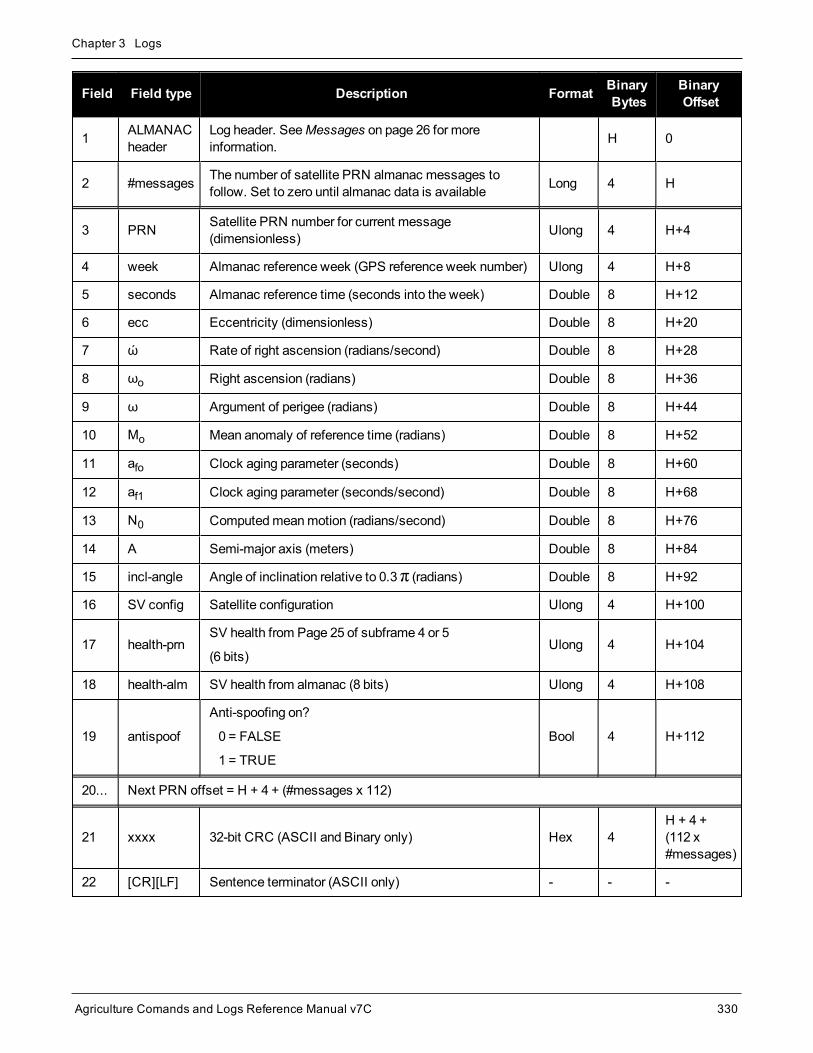
Chapter 3 Logs
Agriculture Comands and Logs Reference Manual v7C 330
Field Field type Description Format BinaryBytes
BinaryOffset
1 ALMANACheader
Log header. SeeMessages on page 26 for moreinformation. H 0
2 #messages The number of satellite PRN almanac messages tofollow. Set to zero until almanac data is available Long 4 H
3 PRN Satellite PRN number for current message(dimensionless) Ulong 4 H+4
4 week Almanac reference week (GPS reference week number) Ulong 4 H+8
5 seconds Almanac reference time (seconds into the week) Double 8 H+12
6 ecc Eccentricity (dimensionless) Double 8 H+20
7 ώ Rate of right ascension (radians/second) Double 8 H+28
8 ωo Right ascension (radians) Double 8 H+36
9 ω Argument of perigee (radians) Double 8 H+44
10 Mo Mean anomaly of reference time (radians) Double 8 H+52
11 afo Clock aging parameter (seconds) Double 8 H+60
12 af1 Clock aging parameter (seconds/second) Double 8 H+68
13 N0 Computedmeanmotion (radians/second) Double 8 H+76
14 A Semi-major axis (meters) Double 8 H+84
15 incl-angle Angle of inclination relative to 0.3π (radians) Double 8 H+92
16 SV config Satellite configuration Ulong 4 H+100
17 health-prnSV health from Page 25 of subframe 4 or 5
(6 bits)Ulong 4 H+104
18 health-alm SV health from almanac (8 bits) Ulong 4 H+108
19 antispoof
Anti-spoofing on?
0 = FALSE
1 = TRUE
Bool 4 H+112
20... Next PRN offset = H + 4 + (#messages x 112)
21 xxxx 32-bit CRC (ASCII and Binary only) Hex 4H + 4 +(112 x#messages)
22 [CR][LF] Sentence terminator (ASCII only) - - -

Chapter 3 Logs
Agriculture Comands and Logs Reference Manual v7C 331
3.6 AUTHCODESList of authorization codes
Platform: OEM719, OEM729, OEM7500, OEM7600, OEM7700, OEM7720, PwrPak7, SPAN CPT7,SMART7, SMART2
This log contains all authorization codes (auth codes) entered into the system since the last complete firmwarereload. Signature authorization codes will bemaintained through a SoftLoad. The log also indicates the status ofthe firmware signature. For more information about firmware signatures see the “Upgrading Using the AUTHCommand” section of the OEM7 Installation andOperation User Manual.
The following situations will cause an authorization code to bemarked invalid:
l Authorization Code is for a different receiver
l Authorization Code has expired
l Authorization Code was entered incorrectly
If you require new authorization codes, contact NovAtel Customer Service.
Message ID: 1348
Log Type: Polled
Recommended Input:log authcodesa once
ASCII Example:#AUTHCODESA,COM1,0,80.5,UNKNOWN,0,10.775,024c0000,2ad2,12143;VALID,2,SIGNATURE,TRUE,"63F3K8,MX43GD,T4BJ2X,924RRB,BZRWBT,D2SB0G550",STANDARD,TRUE,"CJ43M9,2RNDBH,F3PDK8,N88F44,8JMKK9,D2SB0G550"*6f778e32
Field Field type Description Format BinaryBytes Binary Offset
1 AUTHCODESheader
Log header. SeeMessages on page 26for more information. H 0
2 AUTHCODESSignature Status
Status of the Firmware Signature
1 = NONE
2 = INVALID
3 = VALID
4 = RESERVED
5 = HIGH_SPEED
Enum 4 H
3 Number of AuthCodes
# of Auth Codes to follow(max is 24) Ulong 4 H+4

Chapter 3 Logs
Agriculture Comands and Logs Reference Manual v7C 332
Field Field type Description Format BinaryBytes Binary Offset
4 Auth code type
1=STANDARD
2=SIGNATURE
3=EMBEDDED
Enum 4 H+8
5 Valid TRUE if the Auth Code has been verified Bool 4 H+12
6 Auth Code String ASCII String of the Auth Code String[max 80] variable1 H+16
7... Next AuthCode = H+8+ (#AuthCodes*variable)
8 xxxx 32-bit CRC (ASCII and Binary only) Hex 4H+8+(#AuthCodes*variable)
9 [CR][LF] Sentence terminator (ASCII only) - - -
1In the binary case, each string field needs to be NULL terminated and additional bytes of padding added to maintain 4-bytealignment, up to the maximum defined by the string size. The next defined field starts immediately at the next 4-bytealignment following the NULL.
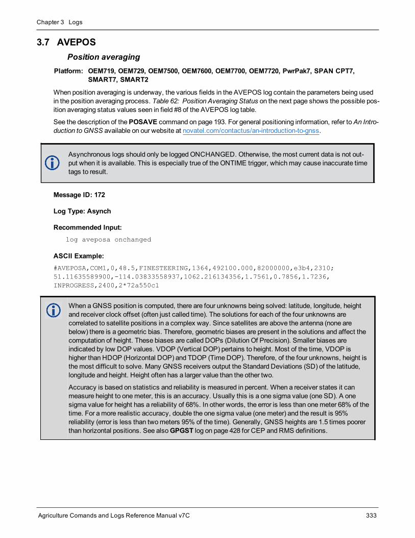
Chapter 3 Logs
Agriculture Comands and Logs Reference Manual v7C 333
3.7 AVEPOSPosition averaging
Platform: OEM719, OEM729, OEM7500, OEM7600, OEM7700, OEM7720, PwrPak7, SPAN CPT7,SMART7, SMART2
When position averaging is underway, the various fields in the AVEPOS log contain the parameters being usedin the position averaging process. Table 62: Position Averaging Status on the next page shows the possible pos-ition averaging status values seen in field #8 of the AVEPOS log table.
See the description of thePOSAVE command on page 193. For general positioning information, refer toAn Intro-duction to GNSS available on our website at novatel.com/contactus/an-introduction-to-gnss.
Asynchronous logs should only be loggedONCHANGED. Otherwise, themost current data is not out-put when it is available. This is especially true of the ONTIME trigger, whichmay cause inaccurate timetags to result.
Message ID: 172
Log Type: Asynch
Recommended Input:log aveposa onchanged
ASCII Example:#AVEPOSA,COM1,0,48.5,FINESTEERING,1364,492100.000,82000000,e3b4,2310;51.11635589900,-114.03833558937,1062.216134356,1.7561,0.7856,1.7236,INPROGRESS,2400,2*72a550c1
When aGNSS position is computed, there are four unknowns being solved: latitude, longitude, heightand receiver clock offset (often just called time). The solutions for each of the four unknowns arecorrelated to satellite positions in a complex way. Since satellites are above the antenna (none arebelow) there is a geometric bias. Therefore, geometric biases are present in the solutions and affect thecomputation of height. These biases are called DOPs (Dilution Of Precision). Smaller biases areindicated by low DOP values. VDOP (Vertical DOP) pertains to height. Most of the time, VDOP ishigher than HDOP (Horizontal DOP) and TDOP (TimeDOP). Therefore, of the four unknowns, height isthemost difficult to solve. Many GNSS receivers output the Standard Deviations (SD) of the latitude,longitude and height. Height often has a larger value than the other two.
Accuracy is based on statistics and reliability is measured in percent. When a receiver states it canmeasure height to onemeter, this is an accuracy. Usually this is a one sigma value (one SD). A onesigma value for height has a reliability of 68%. In other words, the error is less than onemeter 68% of thetime. For amore realistic accuracy, double the one sigma value (onemeter) and the result is 95%reliability (error is less than twometers 95% of the time). Generally, GNSS heights are 1.5 times poorerthan horizontal positions. See alsoGPGST log on page 428 for CEP and RMS definitions.
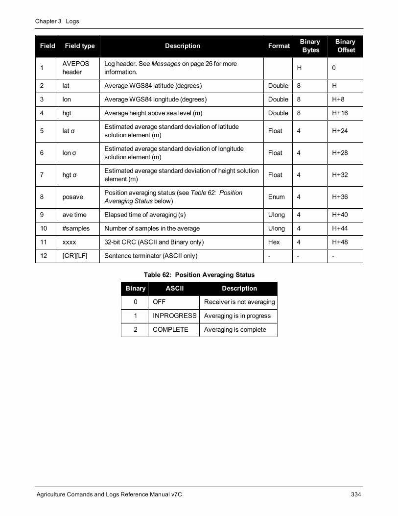
Chapter 3 Logs
Agriculture Comands and Logs Reference Manual v7C 334
Field Field type Description Format BinaryBytes
BinaryOffset
1 AVEPOSheader
Log header. SeeMessages on page 26 for moreinformation. H 0
2 lat AverageWGS84 latitude (degrees) Double 8 H
3 lon AverageWGS84 longitude (degrees) Double 8 H+8
4 hgt Average height above sea level (m) Double 8 H+16
5 lat σ Estimated average standard deviation of latitudesolution element (m) Float 4 H+24
6 lon σ Estimated average standard deviation of longitudesolution element (m) Float 4 H+28
7 hgt σ Estimated average standard deviation of height solutionelement (m) Float 4 H+32
8 posave Position averaging status (see Table 62: PositionAveraging Status below) Enum 4 H+36
9 ave time Elapsed time of averaging (s) Ulong 4 H+40
10 #samples Number of samples in the average Ulong 4 H+44
11 xxxx 32-bit CRC (ASCII and Binary only) Hex 4 H+48
12 [CR][LF] Sentence terminator (ASCII only) - - -
Binary ASCII Description
0 OFF Receiver is not averaging
1 INPROGRESS Averaging is in progress
2 COMPLETE Averaging is complete
Table 62: Position Averaging Status

Chapter 3 Logs
Agriculture Comands and Logs Reference Manual v7C 335
3.8 BDSALMANACDecoded BDS Almanac
Platform: OEM719, OEM729, OEM7500, OEM7600, OEM7700, OEM7720, PwrPak7, SPAN CPT7,SMART7, SMART2
This log contains the decoded BeiDou B1I almanac parameters, with the parity information removed and appro-priate scaling applied. Multiple messages are transmitted, one for each SV almanac collected. For more inform-ation about almanac data, refer to the BDS Signal Specification.
TheOEM7 family of receivers automatically save almanacs in their Non-Volatile Memory (NVM), so creating analmanac boot file is not necessary.
Message ID: 1584
Log Type: Asynch
Recommended Input:log bdsalmanaca onchanged
ASCII Example:#BDSALMANACA,COM1,13,88.5,SATTIME,1727,518438.000,02000000,24ad,44226;1,371,245760,6493.394531,2.9134750366e-04,-2.289514637,-0.021819903,-2.456844003,1.30291141e-09,2.7785425443e-02,-1.096725e-04,2.18279e-11,0*77017e1b
...
#BDSALMANACA,COM1,0,88.5,SATTIME,1727,518108.000,02000000,24ad,44226;14,371,217088,5282.558105,1.4486312866e-03,-2.970093901,2.846651891,1.512957087,-6.91457373e-09,1.7820542434e-02,7.438660e-05,0.00000,d8*ce944672
Field Field Type Description Format BinaryBytes
BinaryOffset
1 BDSALMANACheader
Log header. SeeMessages on page 26 for moreinformation. H 0
2 satellite ID Satellite ID/ranging code Ulong 4 H
3 week BeiDou week number Ulong 4 H+4
4 toa Time of almanac (s) Ulong 4 H+8
5 RootA Square root of semi-major axis (sqrt(m)) Double 8 H+12
6 ecc Eccentricity (dimensionless) Double 8 H+20
7 ω Argument of perigee (radians) Double 8 H+28
8 M0 Mean anomaly at reference time (radians) Double 8 H+36
9 Ω Longitude of ascending node of orbital of plane computedaccording to reference time (radians) Double 8 H+44
10 Rate of right ascension (radians/s) Double 8 H+52

Chapter 3 Logs
Agriculture Comands and Logs Reference Manual v7C 336
Field Field Type Description Format BinaryBytes
BinaryOffset
11 δiCorrection of orbit reference inclination at reference time(radians) Double 8 H+60
12 a0 Constant term of clock correction polynomial (s) Double 8 H+68
13 a1 Linear term of clock correction polynomial (s/s) Double 8 H+76
14 health Satellite health information Ulong 4 H+84
15 xxxx 32-bit CRC (ASCII and Binary only) Hex 4 H+88
16 [CR][LF] Sentence terminator (ASCII only) - - -

Chapter 3 Logs
Agriculture Comands and Logs Reference Manual v7C 337
3.9 BDSCLOCKBeiDou time parameters
Platform: OEM719, OEM729, OEM7500, OEM7600, OEM7700, OEM7720, PwrPak7, SPAN CPT7,SMART7, SMART2
This log contains time parameters transmitted by the BeiDou satellites. These parameters can be used to cal-culated the offset between BeiDou time (BDT) and other time frames.
Message ID: 1607
Log Type: Asynch
Recommended Input:log bdsclocka onchanged
ASCII Example:#BDSCLOCKA,COM1,0,80.0,SATTIME,1730,193994.000,02000000,3b16,44290;-9.313225746154785e-010,-8.881784197001252e-016,2,6,0,2,0.000000000000000e+000,0.000000000000000e+000,0.000000000000000e+000,0.000000000000000e+000,0.000000000000000e+000,0.000000000000000e+000*84820676
Field Field Type Description Format BinaryBytes
BinaryOffset
1 BDSCLOCKheader
Log header. SeeMessages on page 26 for moreinformation. H 0
2 A0UTC BDT clock bias relative to UTC (s) Double 8 H
3 A1UTC BDT clock rate relative to UTC (s/s) Double 8 H+8
4 ΔTLSDelta time due to leap seconds before the new leapsecond is effective (s) Short 2 H+16
5 WNLSF Week number of the new leap second Ushort 2 H+18
6 DN Day number of week of the new leap second Ushort 2 H+20
7 ΔTLSFDelta time due to leap seconds after the new leapsecond effective Short 2 H+22
8 A0GPS BDT clock bias relative to GPS time (s) Double 8 H+24
9 A1GPS BDT clock rate relative to GPS time (s/s) Double 8 H+32
10 A0Gal BDT clock bias relative to Galileo time (s) Double 8 H+40
11 A1Gal BDT clock rate relative to Galileo time (s/s) Double 8 H+48
12 A0GLO BDT clock bias relative to GLONASS time (s) Double 8 H+56
13 A1GLO BDT clock rate relative to GLONASS time (s/s) Double 8 H+64

Chapter 3 Logs
Agriculture Comands and Logs Reference Manual v7C 338
Field Field Type Description Format BinaryBytes
BinaryOffset
14 xxxx 32-bit CRC (ASCII and Binary only) Ulong 4 H+72
15 [CR][LF] Sentence terminator (ASCII only) - - -

Chapter 3 Logs
Agriculture Comands and Logs Reference Manual v7C 339
3.10 BDSEPHEMERISDecoded BDS ephemeris
Platform: OEM719, OEM729, OEM7500, OEM7600, OEM7700, OEM7720, PwrPak7, SPAN CPT7,SMART7, SMART2
This log contains a single set of BDS B1I ephemeris parameters with appropriate scaling applied. Multiple mes-sages are transmitted, one for each SV ephemeris collected.
Message ID: 1696
Log Type: Asynch
Recommended Input:log bdsephemerisa onchanged
ASCII Example:#BDSEPHEMERISA,COM1,0,82.5,SATTIME,1774,162464.000,02000000,2626,45436;13,418,2.00,1,8.20e-09,3.10e-09,11,162000,2.33372441e-04,5.73052716e-12,8.53809211e-19,12,162000,5282.609060,2.3558507673e-03,3.122599126,4.1744595973e-09,-0.654635278,1.950232658e+00,-6.98564812e-09,9.5674299203e-01,3.164417525e-10,4.325527698e-06,8.850824088e-06,179.3593750,87.5312500,7.171183825e-08,1.024454832e-08*d8b97536
Field Field Type Description Format BinaryBytes
BinaryOffset
1 BDSEPHEMERISheader
Log header. SeeMessages on page 26 for moreinformation. H 0
2 satellite ID ID/ranging code Ulong 4 H
3 Week BeiDou week number Ulong 4 H+4
4 URA User range accuracy (m). This is the evaluatedURAI/URA lookup-table value. Double 8 H+8
5 health 1 Autonomous satellite health flag. 0meansbroadcasting satellite is good and 1means not. Ulong 4 H+16
6 tgd1 Equipment group delay differential for the B1 signal (s) Double 8 H+20
7 tgd2 Equipment group delay differential for the B2 signal (s) Double 8 H+28
8 AODC Age of data, clock Ulong 4 H+36
9 toc Reference time of clock parameters (s) Ulong 4 H+40
10 a0 Constant term of clock correction polynomial (s) Double 8 H+44
11 a1 Linear term of clock correction polynomial (s/s) Double 8 H+52
12 a2 Quadratic term of clock correction polynomial (s/s^2) Double 8 H+60

Chapter 3 Logs
Agriculture Comands and Logs Reference Manual v7C 340
Field Field Type Description Format BinaryBytes
BinaryOffset
13 AODE Age of data, ephemeris Ulong 4 H+68
14 toe Reference time of ephemeris parameters (s) Ulong 4 H+72
15 RootA Square root of semi-major axis (sqrt(m)) Double 8 H+76
16 ecc Eccentricity (dimensionless) Double 8 H+84
17 ω Argument of perigee (radians) Double 8 H+92
18 ΔN Meanmotion difference from computed value(radians/s) Double 8 H+100
19 M0 Mean anomaly at reference time (radians) Double 8 H+108
20 Ω0Longitude of ascending node of orbital of planecomputed according to reference time (radians) Double 8 H+116
21 Rate of right ascension (radians/s) Double 8 H+124
22 i0 Inclination angle at reference time (radians) Double 8 H+132
23 IDOT Rate of inclination angle (radians/second) Double 8 H+140
24 cucAmplitude of cosine harmonic correction term to theargument of latitude (radians) Double 8 H+148
25 cusAmplitude of sine harmonic correction term to theargument of latitude (radians) Double 8 H+156
26 crcAmplitude of cosine harmonic correction term to theorbit radius (m) Double 8 H+164
27 crsAmplitude of sine harmonic correction term to the orbitradius (m) Double 8 H+172
28 cicAmplitude of cosine harmonic correction term to theangle of inclination (radians) Double 8 H+180
29 cisAmplitude of sine harmonic correction term to the angleof inclination (radians) Double 8 H+188
30 xxxx 32-bit CRC (ASCII and Binary only) Ulong 4 H+196
31 [CR][LF] Sentence terminator (ASCII only) - - -

Chapter 3 Logs
Agriculture Comands and Logs Reference Manual v7C 341
3.11 BDSIONOBeiDou Klobuchar ionosphere delay model
Platform: OEM719, OEM729, OEM7500, OEM7600, OEM7700, OEM7720, PwrPak7, SPAN CPT7,SMART7, SMART2
This log contains the Klobuchar ionospheremodel parameters transmitted by the BeiDou satellites.
Message ID: 1590
Log Type: Asynch
Recommended Input:log bdsionoa onchanged
ASCII Example:#BDSIONOA,COM1,0,80.0,SATTIME,1734,58094.000,02080000,1956,44836;6,2.607703208923340e-008,4.097819328308105e-007,-3.695487976074218e-006,7.212162017822263e-006,69632.0,360448.0,-524288.0,-327680.0*69c2a6c6
Field Field Type Description Format BinaryBytes
BinaryOffset
1 BDSIONOHeader
Log header. SeeMessages on page 26 for moreinformation. H 0
2 ID Transmitting satellite ID Ulong 4 H
3 α0 Alpha parameter constant term Double 8 H+4
4 α1 Alpha parameter 1st order term Double 8 H+12
5 α2 Alpha parameter 2nd order term Double 8 H+20
6 α3 Alpha parameter 3rd order term Double 8 H+28
7 β0 Beta parameter constant term Double 8 H+36
8 β1 Beta parameter 1st order term Double 8 H+44
9 β2 Beta parameter 2nd order term Double 8 H+52
10 β3 Beta parameter 3rd order term Double 8 H+60
11 xxxx 32-bit CRC (ASCII and Binary only) Ulong 4 H+68
12 [CR][LF] Sentence terminator (ASCII only) - - -

Chapter 3 Logs
Agriculture Comands and Logs Reference Manual v7C 342
3.12 BDSRAWNAVSUBFRAMERaw BeiDou subframe data
Platform: OEM719, OEM729, OEM7500, OEM7600, OEM7700, OEM7720, PwrPak7, SPAN CPT7,SMART7, SMART2
This log contains the raw BeiDou subframe data with parity bits removed. Only subframes that have passed theparity check are output.
Message ID: 1695
Log Type: Asynch
Recommended Input:log bdsrawnavsubframea onchanged
ASCII Example:#BDSRAWNAVSUBFRAMEA,COM1,0,85.5,SATTIME,1774,162554.000,02000000,88f3,45436;84,13,B1D1,1,e24049ebb2b00d113c685207c4d0ee9fd1bf364e41f8f4b57003268c*6b1f478b
Field Field Type Description Format BinaryBytes
BinaryOffset
1 BDSRAWNAVSUBFRAMEheader
Log header. SeeMessages on page 26 formore information. H 0
2 signal channel Signal channel number Ulong 4 H
3 satellite ID Satellite ID Ulong 4 H+4
4 data source Source of data (refer to Table 63: DataSource below) Enum 4 H+8
5 subframe ID Subframe identifier Ulong 4 H+12
6 raw subframe data Framed raw navigation bits Hex[28] 28 H+16
7 xxxx 32-bit CRC (ASCII and Binary only) Hex 4 H+44
8 [CR][LF] Sentence terminator (ASCII only) - - -
ASCII Binary Description
B1D1 0 Data is from a B1I/D1 signal
B1D2 1 Data is from a B1I/D2 signal
B2D1 65536 Data is from a B2I/D1 signal
B2D2 65537 Data is from a B2I/D2 signal
Table 63: Data Source

Chapter 3 Logs
Agriculture Comands and Logs Reference Manual v7C 343
3.13 BESTDATUMINFODatum information for best position
Platform: OEM719, OEM729, OEM7500, OEM7600, OEM7700, OEM7720, PwrPak7, SPAN CPT7,SMART7, SMART2
This log reports the datum and co-ordinate epoch of the solution in theBESTPOS log (see page 346). For dif-ferential solutions, such as RTK or PSRDIFF, where the base station datum is not known, “UNKNOWN” isreported with an ESPG code of 0. Single-point and SBAS report “ECEF” and code 0.
Message ID: 2305
Log Type: Asynch
Recommended Input:log bestdatuminfoa onchanged
ASCII Example:#BESTDATUMINFOA,COM1,0,62.5,FINESTEERING,2044,508765.000,02000020,0c2b,15427;"ITRF2014",1165,2019.202,GOOD*3db57b92
Field Field Type Description Format BinaryBytes
BinaryOffset
1 BESTDATUMINFOheader
Log header. SeeMessages on page 26 formore information. – H 0
2 datum Datum of the position being output by theBESTPOS log.
Char[32] variable H
3 epsg_code EPSG code of the datum. Ulong 4 variable
4 epoch
Co-ordinate epoch (decimal year).
Example:
2011.00 = Jan 1, 2011
2011.19 = Mar 11, 2011
Double 8 variable
5 statusTransformation status.
See Table 64: Transformation Status below.Enum 4 variable
6 xxxx 32-bit CRC (ASCII and Binary only) Hex 4 variable
7 [CR][LF] Sentence terminator (ASCII only) – – –
Binary ASCII Description
0 GOOD An exact transformation was found and used.
Table 64: Transformation Status

Chapter 3 Logs
Agriculture Comands and Logs Reference Manual v7C 344
Binary ASCII Description
1 ECEF_EQUIVALENCY An exact transformation could not be found, but a similar transformationinvolving another Earth-fixed transformation was found and used.
2 SERVICE_DETAILS_UNKNOWN
The datum of the input solution was not known and therefore atransformation could not take place.
3REQUESTED_TRANSFORMATION_UNAVAILABLE
No transformation could be found to transform the solution into therequested datum.

Chapter 3 Logs
Agriculture Comands and Logs Reference Manual v7C 345
3.14 BESTGNSSDATUMINFODatum information for BESTGNSS position
Platform: OEM719, OEM729, OEM7500, OEM7600, OEM7700, OEM7720, PwrPak7, SPAN CPT7,SMART7, SMART2
This log reports the datum and co-ordinate epoch of the solution in theBESTGNSSPOS log (see page 797). Fordifferential solutions, such as RTK or PSRDIFF, where the base station datum is not known, “UNKNOWN” isreported with an ESPG code of 0. Single-point and SBAS report “ECEF” and code 0.
Message ID: 2302
Log Type: Asynch
Recommended Input:log bestgnssdatuminfoa onchanged
ASCII Example:#BESTGNSSDATUMINFOA,COM1,0,75.0,FINESTEERING,2044,509700.000,02000020,1790,15427;"ITRF2014",1165,2019.202,GOOD*a34f668f
Field Field Type Description Format BinaryBytes
BinaryOffset
1 BESTGNSSDATUMINFOheader
Log header. SeeMessages on page 26 formore information. – H 0
2 datum Datum of position being output by theBESTGNSSPOS log.
Char[32] variable
3 epsg_code EPSG code of the datum. Ulong 4 variable
4 epoch
Co-ordinate epoch (decimal year).
Example:
2011.00 = Jan 1, 2011
2011.19 = Mar 11, 2011
Double 8 variable
5 statusTransformation Status.
See Table 64: Transformation Status onpage 343.
Enum 4 variable
6 xxxx 32-bit CRC (ASCII and Binary only) Hex 4 variable
7 [CR][LF] Sentence terminator (ASCII only) – – –

Chapter 3 Logs
Agriculture Comands and Logs Reference Manual v7C 346
3.15 BESTPOSBest position
Platform: OEM719, OEM729, OEM7500, OEM7600, OEM7700, OEM7720, PwrPak7, SPAN CPT7,SMART7, SMART2
When positioning with GNSS, there are four parameters being solved for: latitude, longitude, height and receiverclock offset from GPS time. The quality of the solution for all four parameters depends on the geometry of wherethe satellites are with respect to the antenna (and receiver). The strength of the positioning geometry is indicatedby Dilution of Precision (DOP) values, with lower DOP numbers indicating better geometry. Because all theGNSS satellites are above terrestrial receivers, the VDOP (vertical DOP) is the largest DOP value. This is whythe reported standard deviation for height is usually larger than for latitude or longitude.
Accuracy is based on statistics and reliability is measured in percentages. When a receiver states it canmeas-ure height to onemeter, this is an accuracy measure. Usually this is a one sigma value (one SD). A one sigmavalue for height has a reliability of 68%. In other words, the error is less than onemeter 68% of the time. For amore realistic accuracy, double the one sigma value (onemeter) and the result is 95% reliability (error is lessthan twometers 95% of the time). Generally, GNSS heights are 1.5 times poorer than horizontal positions. Seealso the note in theGPGST log on page 428 for CEP and RMS definitions.
This log contains the best position computed by the receiver. In addition, it reports several status indicators,including differential age, which is useful in predicting anomalous behavior brought about by outages in dif-ferential corrections. A differential age of 0 indicates that no differential correction was used.
SPAN SystemsOn systems with SPAN enabled, this log contains the best available combinedGNSS and Inertial Nav-igation System (INS - if available) position computed by the receiver.
With the system operating in an RTK mode, BESTPOS reflects the latest low-latency solution for up to 60seconds after reception of the last base station observation. After this 60 second period, the position reverts tothe best solution available and the degradation in accuracy is reflected in the standard deviation fields. If the sys-tem is not operating in RTK mode, pseudorange differential solutions continue for the time specified in thePSRDIFFTIMEOUT command (see page 209). If the receiver is SPAN enabled, the GNSS+INS combined solu-tion is also a candidate for BESTPOS output.

Chapter 3 Logs
Agriculture Comands and Logs Reference Manual v7C 347
The RTK system in the receiver provides two kinds of position solutions. TheMatched RTK position iscomputed with buffered observations, so there is no error due to the extrapolation of base stationmeasurements. This provides the highest accuracy solution possible at the expense of some latencywhich is affected primarily by the speed of the differential data link. TheMATCHEDPOS log (see page493) contains thematched RTK solution and can be generated for each processed set of base stationobservations.
The Low-Latency RTK position is computed from the latest local observations and extrapolated basestation observations. This supplies a valid RTK position with the lowest latency possible at the expenseof some accuracy. The degradation in accuracy is reflected in the standard deviation and is summarizedinAn Introduction to GNSS available on our website at novatel.com/contactus/an-introduction-to-gnss.The amount of time that the base station observations are extrapolated is in the "differential age" field ofthe position log. The Low-Latency RTK system extrapolates for 60 seconds. TheRTKPOS log (seepage 643) contains the Low-Latency RTK position when valid, and an "invalid" status when a Low-Latency RTK solution could not be computed. TheBESTPOS log contains either the low-latency RTK,PPP or pseudorange-based position, whichever has the smallest standard deviation.
RTK positioning uses the carrier phase observations from the receiver. The carrier phases are precisebut ambiguous: themeasurement includes an unknown integer number of cycles known as the“ambiguities”. Determining these ambiguities is the key to unlocking the highest-accuracy GNSSpositions. This determination is known as ambiguity resolution. Before the integer ambiguities can beresolved they are first estimated as real-numbered values, “floats” in computing parlance. After someperiod that depends on RTK baseline length, ionosphere activity, and other observing conditions, theambiguities can be resolved into integers, making centimeter or even sub-centimeter positioningpossible.
Different positioningmodes have different maximum logging rates, which are also controlled by modeloption. Themaximum rates are: 100 Hz for RTK, 100 Hz for pseudorange based positioning, 20 Hz forGLIDE (PDP) and 20 Hz for PPP.
On SMART antennas, the position in theBESTPOS logmay be corrected for antenna height. If so thiswill be indicated in the Extended Solution Status. See Terrain Compensation in the SMART7 InstallationandOperation User Manual for details.
Message ID: 42
Log Type: Synch
Recommended Input:log bestposa ontime 1
ASCII Example 1:#BESTPOSA,COM1,0,90.5,FINESTEERING,1949,403742.000,02000000,b1f6,32768;SOL_COMPUTED,SINGLE,51.11636937989,-114.03825348307,1064.533,-16.9000,WGS84,1.3610,1.0236,2.4745,"",0.000,0.000,19,19,19,19,00,06,00,33*6e08fa22
ASCII Example 2:#BESTPOSA,COM1,0,78.5,FINESTEERING,1419,336208.000,02000040,6145,2724;SOL_COMPUTED,NARROW_INT,51.11635910984,-114.03833105168,1063.8416,-16.2712,WGS84,0.0135,0.0084,0.0172,"AAAA",1.000,0.000,8,8,8,8,0,01,0,03*3d9fbd48

Chapter 3 Logs
Agriculture Comands and Logs Reference Manual v7C 348
Field Field type Description Format BinaryBytes
BinaryOffset
1 BESTPOSheader
Log header. SeeMessages on page 26 for moreinformation. H 0
2 sol stat Solution status, see Table 65: Solution Status on the nextpage Enum 4 H
3 pos type Position type, see Table 66: Position or Velocity Type onpage 350 Enum 4 H+4
4 lat Latitude (degrees) Double 8 H+8
5 lon Longitude (degrees) Double 8 H+16
6 hgt Height abovemean sea level (meters) Double 8 H+24
7 undulation
Undulation - the relationship between the geoid and theellipsoid (m) of the chosen datum
When using a datum other thanWGS84, theundulation value also includes the verticalshift due to differences between the datum inuse andWGS84.
Float 4 H+32
8 datum id#
Datum ID number
61 = WGS84
63 = USER
Enum 4 H+36
9 lat σ Latitude standard deviation (m) Float 4 H+40
10 lon σ Longitude standard deviation (m) Float 4 H+44
11 hgt σ Height standard deviation (m) Float 4 H+48
12 stn id Base station ID Char[4] 4 H+52
13 diff_age Differential age in seconds Float 4 H+56
14 sol_age Solution age in seconds Float 4 H+60
15 #SVs Number of satellites tracked Uchar 1 H+64
16 #solnSVs Number of satellites used in solution Uchar 1 H+65
17 #solnL1SVs Number of satellites with L1/E1/B1 signals used in solution Uchar 1 H+66
18 #solnMultiSVs Number of satellites with multi-frequency signals used insolution Uchar 1 H+67
19 Reserved Hex 1 H+68

Chapter 3 Logs
Agriculture Comands and Logs Reference Manual v7C 349
Field Field type Description Format BinaryBytes
BinaryOffset
20 ext sol stat Extended solution status (see Table 69: Extended SolutionStatus on page 353) Hex 1 H+69
21Galileo andBeiDou sigmask
Galileo and BeiDou signals usedmask (see Table 68:Galileo and BeiDou Signal-UsedMask on page 352) Hex 1 H+70
22GPS andGLONASS sigmask
GPS andGLONASS signals usedmask (see Table 67:GPS andGLONASS Signal-UsedMask on page 352) Hex 1 H+71
23 xxxx 32-bit CRC (ASCII and Binary only) Hex 4 H+72
24 [CR][LF] Sentence terminator (ASCII only) - - -
Binary ASCII Description
0 SOL_COMPUTED Solution computed
1 INSUFFICIENT_OBS Insufficient observations
2 NO_CONVERGENCE No convergence
3 SINGULARITY Singularity at parameters matrix
4 COV_TRACE Covariance trace exceeds maximum (trace > 1000m)
5 TEST_DIST Test distance exceeded (maximum of 3 rejections if distance >10 km)
6 COLD_START Not yet converged from cold start
7 V_H_LIMIT Height or velocity limits exceeded (in accordance with export licensing restrictions)
8 VARIANCE Variance exceeds limits
9 RESIDUALS Residuals are too large
10-12 Reserved
13 INTEGRITY_WARNING Large residuals make position unreliable
14-17 Reserved
Table 65: Solution Status

Chapter 3 Logs
Agriculture Comands and Logs Reference Manual v7C 350
Binary ASCII Description
18 PENDING
When a FIX position command is entered, the receiver computes its own positionand determines if the fixed position is valid
PENDING implies there are not enough satellites currently tracked toverify if the FIX POSITION entered into the receiver is valid. Undernormal conditions, you should only see PENDING for a few secondson power up before the GNSS receiver has locked onto its first fewsatellites. If your antenna is obstructed (or not plugged in) and youhave entered a FIX POSITION command, then youmay seePENDING indefinitely.
19 INVALID_FIX The fixed position, entered using the FIX position command, is not valid
20 UNAUTHORIZED Position type is unauthorized
21 Reserved
22 INVALID_RATE The selected logging rate is not supported for this solution type.
Binary ASCII Description
0 NONE No solution
1 FIXEDPOS Position has been fixed by the FIX position command or by position averaging.
2 FIXEDHEIGHT Position has been fixed by the FIX height or FIX auto command or by positionaveraging
3-7 Reserved
8 DOPPLER_VELOCITY Velocity computed using instantaneous Doppler
9-15 Reserved
16 SINGLE Solution calculated using only data supplied by the GNSS satellites
17 PSRDIFF Solution calculated using pseudorange differential (DGPS, DGNSS) corrections
18 WAAS Solution calculated using corrections from an SBAS satellite
19 PROPAGATED Propagated by a Kalman filter without new observations
20-31 Reserved
32 L1_FLOAT Single-frequency RTK solution with unresolved, float carrier phase ambiguities
33 Reserved
Table 66: Position or Velocity Type
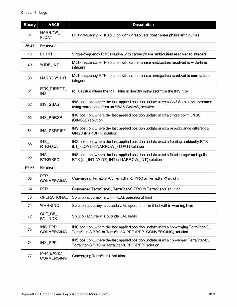
Chapter 3 Logs
Agriculture Comands and Logs Reference Manual v7C 351
Binary ASCII Description
34 NARROW_FLOAT Multi-frequency RTK solution with unresolved, float carrier phase ambiguities
35-47 Reserved
48 L1_INT Single-frequency RTK solution with carrier phase ambiguities resolved to integers
49 WIDE_INT Multi-frequency RTK solution with carrier phase ambiguities resolved to wide-laneintegers
50 NARROW_INT Multi-frequency RTK solution with carrier phase ambiguities resolved to narrow-laneintegers
51 RTK_DIRECT_INS RTK status where the RTK filter is directly initialized from the INS filter
52 INS_SBAS INS position, where the last applied position update used aGNSS solution computedusing corrections from an SBAS (WAAS) solution
53 INS_PSRSP INS position, where the last applied position update used a single point GNSS(SINGLE) solution
54 INS_PSRDIFF INS position, where the last applied position update used a pseudorange differentialGNSS (PSRDIFF) solution
55 INS_RTKFLOAT
INS position, where the last applied position update used a floating ambiguity RTK(L1_FLOAT or NARROW_FLOAT) solution
56 INS_RTKFIXED
INS position, where the last applied position update used a fixed integer ambiguityRTK (L1_INT, WIDE_INT or NARROW_INT) solution
57-67 Reserved
68 PPP_CONVERGING Converging TerraStar-C, TerraStar-C PRO or TerraStar-X solution
69 PPP Converged TerraStar-C, TerraStar-C PRO or TerraStar-X solution
70 OPERATIONAL Solution accuracy is within UAL operational limit
71 WARNING Solution accuracy is outside UAL operational limit but within warning limit
72 OUT_OF_BOUNDS Solution accuracy is outside UAL limits
73 INS_PPP_CONVERGING
INS position, where the last applied position update used a converging TerraStar-C,TerraStar-C PRO or TerraStar-X PPP (PPP_CONVERGING) solution
74 INS_PPP INS position, where the last applied position update used a converged TerraStar-C,TerraStar-C PRO or TerraStar-X PPP (PPP) solution
77 PPP_BASIC_CONVERGING Converging TerraStar-L solution

Chapter 3 Logs
Agriculture Comands and Logs Reference Manual v7C 352
Binary ASCII Description
78 PPP_BASIC Converged TerraStar-L solution
79
INS_PPP_BASIC_CONVERGING
INS position, where the last applied position update used a converging TerraStar-LPPP (PPP_BASIC) solution
80 INS_PPP_BASIC
INS position, where the last applied position update used a converged TerraStar-LPPP (PPP_BASIC) solution
PPP requires access to a suitable correction stream, delivered either through L-Band or the Internet.For L-Band delivered TerraStar or Veripos service, an L-Band capable receiver and softwaremodel isrequired, along with a subscription to the desired service. Contact NovAtel for TerraStar and Veripossubscription details.
Bit Mask Description
0 0x01 GPS L1 used in Solution
1 0x02 GPS L2 used in Solution
2 0x04 GPS L5 used in Solution
3 0x08 Reserved
4 0x10 GLONASS L1 used in Solution
5 0x20 GLONASS L2 used in Solution
6 0x40 GLONASS L3 used in Solution
7 0x80 Reserved
Table 67: GPS and GLONASS Signal-Used Mask
Bit Mask Description
0 0x01 Galileo E1 used in Solution
1 0x02 Galileo E5A used in Solution
2 0x04 Galileo E5B used in Solution
3 0x08 Galileo ALTBOC used in Solution
4 0x10 BeiDou B1 used in Solution
5 0x20 BeiDou B2 used in Solution
6 0x40 BeiDou B3 used in Solution
7 0x80 Reserved
Table 68: Galileo and BeiDou Signal-Used Mask

Chapter 3 Logs
Agriculture Comands and Logs Reference Manual v7C 353
Bit Mask Description
0 0x01
If an RTK solution: an RTK solution has been verified
If a PDP solution: solution is GLIDE
Otherwise: Reserved
1-3 0x0E
Pseudorange Iono Correction
0 = Unknown or default Klobuchar model
1 = Klobuchar Broadcast
2 = SBAS Broadcast
3 = Multi-frequency Computed
4 = PSRDiff Correction
5 = NovAtel Blended Iono Value
4 0x10 RTK ASSIST active
5 0x200 = No antenna warning
1 = Antenna information is missing
6 0x40 Reserved
7 0x800 = Terrain Compensation corrections are not used
1 = Position includes Terrain Compensation corrections
Table 69: Extended Solution Status
Value Documented Enum Name NMEA Equivalent
68 PPP_CONVERGING 2
69 PPP 5
70 OPERATIONAL 4
71 WARNING 5
72 OUT_OF_BOUNDS 1
77 PPP_BASIC_CONVERGING 1
78 PPP_BASIC 2
Table 70: Supplemental Position Types and NMEA Equi-valents

Chapter 3 Logs
Agriculture Comands and Logs Reference Manual v7C 354
3.16 BESTSATSSatellites used in BESTPOS
Platform: OEM719, OEM729, OEM7500, OEM7600, OEM7700, OEM7720, PwrPak7, SPAN CPT7,SMART7, SMART2
This log lists the used and unused satellites for the corresponding BESTPOS solution. It also describes the sig-nals of the used satellites or reasons for exclusions.
Message ID: 1194
Log Type: Synch
Recommended Input:log bestsats ontime 1
Abbreviated ASCII Example:<BESTSATS COM1 0 57.5 FINESTEERING 1729 12132.000 02000000 95e7 11487< 26< GPS 3 GOOD 00000003< GPS 5 GOOD 00000003...< GPS 26 GOOD 00000003< GPS 28 GOOD 00000003< GLONASS 3+5 GOOD 00000003< GLONASS 4+6 GOOD 00000003...< GLONASS 23+3 GOOD 00000003< GLONASS 24+2 GOOD 00000003< BEIDOU 6 GOOD 00000003< BEIDOU 9 GOOD 00000003...< BEIDOU 12 GOOD 00000003< BEIDOU 13 GOOD 00000003
Field Field type Description Format BinaryBytes
BinaryOffset
1 BESTSATSheader Log header. SeeMessages on page 26 for more information. H 0
2 #entries Number of records to follow Ulong 4 H
3 System See Table 95: Satellite System on page 450 Enum 4 H+4

Chapter 3 Logs
Agriculture Comands and Logs Reference Manual v7C 355
Field Field type Description Format BinaryBytes
BinaryOffset
4 Satellite ID
In binary logs, the satellite ID field is 4 bytes. The 2 lowest-order bytes, interpreted as a USHORT, are the systemidentifier: for instance, the PRN for GPS, Galileo, BeiDou,NavIC andQZSS, or the slot for GLONASS. The 2 highest-order bytes are the frequency channel for GLONASS,interpreted as a SHORT and zero for all other systems.
In ASCII and abbreviated ASCII logs, the satellite ID field isthe system identifier. If the system is GLONASS and thefrequency channel is not zero, then the signed channel isappended to the system identifier. For example, slot 13,frequency channel -2 is output as 13-2.
Ulong 4 H+8
5 Status Satellite status. See Table 71: Observation Statuses below Enum 4 H+12
6 Signalmask
See Table 72: GPS Signal Mask on the next page, Table 73:GLONASS Signal Mask on the next page, Table 74: GalileoSignal Mask on page 357, Table 75: BeiDou Signal Mask onpage 357, Table 76: QZSS Signal Mask on page 357 andTable 77: NavIC Signal Mask on page 357
Hex 4 H+16
7 Next satellite offset = H + 4 + (#entries x 16)
8 xxxx 32-bit CRC (ASCII and Binary only) Hex 4H+4(#entriesx 16)
9 [CR][LF] Sentence terminator (ASCII only) - - -
Value Name Description
0 GOOD Observation is good
1 BADHEALTH Satellite is flagged as bad health in ephemeris or almanac
2 OLDEPHEMERIS Ephemeris >3 hours old
6 ELEVATIONERROR Satellite was below the elevation cutoff
7 MISCLOSURE Observation was too far from predicted value
8 NODIFFCORR No differential correction available
9 NOEPHEMERIS No ephemeris available
10 INVALIDIODE IODE used is invalid
11 LOCKEDOUT Satellite has been locked out
12 LOWPOWER Satellite has low signal power
Table 71: Observation Statuses

Chapter 3 Logs
Agriculture Comands and Logs Reference Manual v7C 356
Value Name Description
13 OBSL2 An L2 observation not directly used in the solution
15 UNKNOWN Observation was not used because it was of an unknown type
16 NOIONOCORR No ionosphere delay correction was available
17 NOTUSED Observation was not used in the solution
18 OBSL1 An L1 observation not directly used in the solution
19 OBSE1 An E1 observation not directly used in the solution
20 OBSL5 An L5 observation not directly used in the solution
21 OBSE5 An E5 observation not directly used in the solution
22 OBSB2 A B2 observation not directly used in the solution
23 OBSB1 A B1 observation not directly used in the solution
24 OBSB3 A B3 observation not directly used in the solution
25 NOSIGNALMATCH Signal type does not match
26 SUPPLEMENTARY Observation contributes supplemental information to the solution
99 NA No observation available
100 BAD_INTEGRITY Observation was an outlier and was eliminated from the solution
101 LOSSOFLOCK Lock was broken on this signal
102 NOAMBIGUITY NoRTK ambiguity type resolved
Bit Mask Description
0 0x01 GPS L1 used in Solution
1 0x02 GPS L2 used in Solution
2 0x04 GPS L5 used in Solution
Table 72: GPS Signal Mask
Bit Mask Description
0 0x01 GLONASS L1 used in Solution
1 0x02 GLONASS L2 used in Solution
2 0x04 GLONASS L3 used in Solution
Table 73: GLONASS Signal Mask

Chapter 3 Logs
Agriculture Comands and Logs Reference Manual v7C 357
Bit Mask Description
0 0x01 Galileo E1 used in Solution
1 0x02 Galileo E5A used in Solution
2 0x04 Galileo E5B used in Solution
3 0x08 Galileo ALTBOC used in Solution
4 0x10 Galileo E6 used in Solution
Table 74: Galileo Signal Mask
Bit Mask Description
0 0x01 BeiDou B1 used in Solution
1 0x02 BeiDou B2 used in Solution
2 0X04 BeiDou B3 used in Solution
Table 75: BeiDou Signal Mask
Bit Mask Description
0 0x01 QZSS L1 used in Solution
1 0x02 QZSS L2 used in Solution
2 0x04 QZSS L5 used in Solution
4 0x08 QZSS L6 used in Solution
Table 76: QZSS Signal Mask
Bit Mask Description
2 0x04 NavIC L5 used in Solution
Table 77: NavIC Signal Mask

Chapter 3 Logs
Agriculture Comands and Logs Reference Manual v7C 358
3.17 BESTUTMBest available UTM data
Platform: OEM719, OEM729, OEM7500, OEM7600, OEM7700, OEM7720, PwrPak7, SPAN CPT7,SMART7, SMART2
This log contains the best available position computed by the receiver in UTM coordinates.
See also theBESTPOS log on page 346.
The latitude limits of the UTM System are 80°S to 84°N. If your position is outside this range, theBESTUTM log outputs a northing, easting and height of 0.0, along with a zone letter of ‘*’and a zonenumber of 0, to indicate that the data in the log is unusable.
Message ID: 726
Log Type: Synch
Recommended Input:log bestutma ontime 1
ASCII Example:#BESTUTMA,COM1,0,73.0,FINESTEERING,1419,336209.000,02000040,eb16,2724;SOL_COMPUTED,NARROW_INT,11,U,5666936.4417,707279.3875,1063.8401,-16.2712,WGS84,0.0135,0.0084,0.0173,"AAAA",1.000,0.000,8,8,8,8,0,01,0,03*a6d06321
Field Field type Description Format BinaryBytes
BinaryOffset
1 BESTUTMheader Log header. SeeMessages on page 26 for more information. H 0
2 sol status Solution status, see Table 65: Solution Status on page 349 Enum 4 H
3 pos type Position type, see Table 66: Position or Velocity Type onpage 350 Enum 4 H+4
4 z# Longitudinal zone number Ulong 4 H+8
5 zletter Latitudinal zone letter Ulong 4 H+12
6 northing
Northing (m) where the origin is defined as the equator in thenorthern hemisphere and as a point 10,000,000meters southof the equator in the southern hemisphere (that is, a ‘falsenorthing’ of 10,000,000m)
Double 8 H+16
7 eastingEasting (m) where the origin is 500,000m west of the centralmeridian of each longitudinal zone (that is, a ‘false easting’ of500,000m)
Double 8 H+24
8 hgt Height abovemean sea level (m) Double 8 H+32
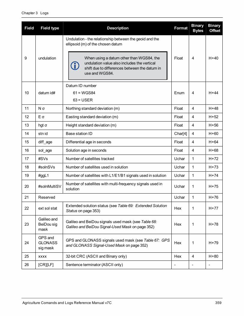
Chapter 3 Logs
Agriculture Comands and Logs Reference Manual v7C 359
Field Field type Description Format BinaryBytes
BinaryOffset
9 undulation
Undulation - the relationship between the geoid and theellipsoid (m) of the chosen datum
When using a datum other thanWGS84, theundulation value also includes the verticalshift due to differences between the datum inuse andWGS84.
Float 4 H+40
10 datum id#
Datum ID number
61 = WGS84
63 = USER
Enum 4 H+44
11 N σ Northing standard deviation (m) Float 4 H+48
12 E σ Easting standard deviation (m) Float 4 H+52
13 hgt σ Height standard deviation (m) Float 4 H+56
14 stn id Base station ID Char[4] 4 H+60
15 diff_age Differential age in seconds Float 4 H+64
16 sol_age Solution age in seconds Float 4 H+68
17 #SVs Number of satellites tracked Uchar 1 H+72
18 #solnSVs Number of satellites used in solution Uchar 1 H+73
19 #ggL1 Number of satellites with L1/E1/B1 signals used in solution Uchar 1 H+74
20 #solnMultiSV Number of satellites with multi-frequency signals used insolution Uchar 1 H+75
21 Reserved Uchar 1 H+76
22 ext sol stat Extended solution status (see Table 69: Extended SolutionStatus on page 353) Hex 1 H+77
23Galileo andBeiDou sigmask
Galileo and BeiDou signals usedmask (see Table 68:Galileo and BeiDou Signal-UsedMask on page 352) Hex 1 H+78
24GPS andGLONASSsigmask
GPS andGLONASS signals usedmask (see Table 67: GPSandGLONASS Signal-UsedMask on page 352) Hex 1 H+79
25 xxxx 32-bit CRC (ASCII and Binary only) Hex 4 H+80
26 [CR][LF] Sentence terminator (ASCII only) - - -

Chapter 3 Logs
Agriculture Comands and Logs Reference Manual v7C 360
3.18 BESTVELBest available velocity data
Platform: OEM719, OEM729, OEM7500, OEM7600, OEM7700, OEM7720, PwrPak7, SPAN CPT7,SMART7, SMART2
This log contains the best available velocity information computed by the receiver. In addition, it reports a velo-city status indicator, which is needed to determine whether or not the corresponding data is valid. The velocitiescalculated by the receiver can have a latency associated with them. When present, the velocity time of validityis the time tag in the logminus the latency value.
The velocity is typically from the same source used in the BESTPOS solution. For example, if theBESTPOS is from the pseudorange filter, then the BESTVEL velocity type is the same as for PSRVEL.However, a specific velocity source can be chosen. See theBESTVELTYPE command on page 80.
In a BESTVEL log, the actual speed and direction of the receiver antenna over ground is provided. Thereceiver does not determine the direction a vessel, craft or vehicle is pointed (heading) but rather the dir-ection of motion of the GNSS antenna relative to ground.
The RTK, PDP and PPP velocities are computed from the average change in position over the time intervalbetween consecutive solutions. As such, they are an average velocity based on the time difference between suc-cessive position computations and not an instantaneous velocity at the BESTVEL time tag. The velocity latencyto be subtracted from the time tag is normally half the time between filter updates. Under default operation, thepositioning filters are updated at a rate of 2 Hz. This average velocity translates into a velocity latency of 0.25seconds. To reduce the latency, increase the update rate of the positioning filter being used by requesting theBESTVEL or BESTPOS messages at a rate higher than 2 Hz. For example, a logging rate of 10 Hz would reducethe velocity latency to 0.05 seconds.
If the velocity in the BESTVEL log comes from the pseudorange filter, it has been computed from instantaneousDoppler measurements. You know that you have an instantaneous Doppler derived velocity solution when thevelocity type is PSRDIFF, WAAS or DOPPLER_VELOCITY. The instantaneous Doppler derived velocity haslow latency and is not position change dependent. If you change your velocity quickly, you can see this in theDOPPLER_VELOCITY solution. Under typically seen dynamics with minimal jerk, the velocity latency is zero.Under extreme, high-jerk dynamics, the latency cannot be well represented: it will still be reported as being zero,but may be as high as 0.15 seconds. Such dynamics are typically only seen in simulated trajectories.
Message ID: 99
Log Type: Synch
Recommended Input:log bestvela ontime 1
ASCII Example:#BESTVELA,COM1,0,61.0,FINESTEERING,1337,334167.000,02000000,827b,1984;SOL_COMPUTED,PSRDIFF,0.250,4.000,0.0206,227.712486,0.0493,0.0*0e68bf05

Chapter 3 Logs
Agriculture Comands and Logs Reference Manual v7C 361
Field FieldType Description Format Binary
BytesBinaryOffset
1 BESTVELheader Log header. SeeMessages on page 26 for more information. H 0
2 sol status Solution status, see Table 65: Solution Status on page 349 Enum 4 H
3 vel type Velocity type, see Table 66: Position or Velocity Type onpage 350 Enum 4 H+4
4 latency A measure of the latency in the velocity time tag in seconds. Itshould be subtracted from the time to give improved results (s) Float 4 H+8
5 age Differential age in seconds Float 4 H+12
6 hor spd Horizontal speed over ground, in meters per second Double 8 H+16
7 trk gnd Actual direction of motion over ground (track over ground) withrespect to True North, in degrees Double 8 H+24
8 vert spdVertical speed, in meters per second, where positive valuesindicate increasing altitude (up) and negative values indicatedecreasing altitude (down)
Double 8 H+32
9 Reserved Float 4 H+40
10 xxxx 32-bit CRC (ASCII and Binary only) Hex 4 H+44
11 [CR][LF] Sentence terminator (ASCII only) - - -

Chapter 3 Logs
Agriculture Comands and Logs Reference Manual v7C 362
Velocity (speed and direction) calculations are computed from either Doppler or carrier phasemeasurements rather than from pseudorangemeasurements. Typical speed accuracies are around0.03m/s (0.07mph, 0.06 knots).
Direction accuracy is derived as a function of the vehicle speed. A simple approach would be to assumeaworst case 0.03m/s cross-track velocity that would yield a direction error function something like:
d (speed) = tan-1(0.03/speed)
For example, if you are flying in an airplane at a speed of 120 knots or 62m/s, the approximatedirectional error will be:
tan-1 (0.03/62) = 0.03 degrees
Consider another example applicable to hiking at an average walking speed of 3 knots or 1.5m/s. Usingthe same error function yields a direction error of about 1.15 degrees.
You can see from both examples that a faster vehicle speed allows for amore accurate headingindication. As the vehicle slows down, the velocity information becomes less and less accurate. If thevehicle is stopped, a GNSS receiver still outputs some kind of movement at speeds between 0 and 0.5m/s in random and changing directions. This represents the noise and error of the static position.
In a navigation capacity, the velocity information provided by your GNSS receiver is as, or more,accurate than that indicated by conventional instruments as long as the vehicle is moving at areasonable rate of speed. It is important to set the GNSS measurement rate fast enough to keep up withall major changes of the vehicle's speed and direction. It is important to keep inmind that although thevelocity vector is quite accurate in terms of heading and speed, the actual track of the vehicle might beskewed or offset from the true track by plus or minus 0 to 1.8meters as per the standard positionalerrors.

Chapter 3 Logs
Agriculture Comands and Logs Reference Manual v7C 363
3.19 BESTXYZBest available cartesian position and velocity
Platform: OEM719, OEM729, OEM7500, OEM7600, OEM7700, OEM7720, PwrPak7, SPAN CPT7,SMART7, SMART2
This log contains the receiver’s best available position and velocity in ECEF coordinates. The position and velo-city status fields indicate whether or not the corresponding data is valid. See Figure 7: TheWGS84 ECEFCoordinate System on page 365, for a definition of the ECEF coordinates.
See also theBESTPOS log on page 346 andBESTVEL log on page 360.
These quantities are always referenced to theWGS84 ellipsoid, regardless of the use of theDATUMcommand (see page 93) orUSERDATUM command (see page 304).
Message ID: 241
Log Type: Synch
Recommended Input:log bestxyza ontime 1
ASCII Example:#BESTXYZA,COM1,0,55.0,FINESTEERING,1419,340033.000,02000040,d821,2724;SOL_COMPUTED,NARROW_INT,-1634531.5683,-3664618.0326,4942496.3270,0.0099,0.0219,0.0115,SOL_COMPUTED,NARROW_INT,0.0011,-0.0049,-0.0001,0.0199,0.0439,0.0230,"AAAA",0.250,1.000,0.000,12,11,11,11,0,01,0,33*e9eafeca
Field Field type Description Format BinaryBytes
BinaryOffset
1 BESTXYZheader
Log header. SeeMessages on page 26 for moreinformation. H 0
2 P-sol status Solution status, see Table 65: Solution Status on page 349 Enum 4 H
3 pos type Position type, see Table 66: Position or Velocity Type onpage 350 Enum 4 H+4
4 P-X Position X-coordinate (m) Double 8 H+8
5 P-Y Position Y-coordinate (m) Double 8 H+16
6 P-Z Position Z-coordinate (m) Double 8 H+24
7 P-X σ Standard deviation of P-X (m) Float 4 H+32
8 P-Y σ Standard deviation of P-Y (m) Float 4 H+36
9 P-Z σ Standard deviation of P-Z (m) Float 4 H+40
10 V-sol status Solution status, see Table 65: Solution Status on page 349 Enum 4 H+44

Chapter 3 Logs
Agriculture Comands and Logs Reference Manual v7C 364
Field Field type Description Format BinaryBytes
BinaryOffset
11 vel type Velocity type, see Table 66: Position or Velocity Type onpage 350 Enum 4 H+48
12 V-X Velocity vector along X-axis (m/s) Double 8 H+52
13 V-Y Velocity vector along Y-axis (m/s) Double 8 H+60
14 V-Z Velocity vector along Z-axis (m/s) Double 8 H+68
15 V-X σ Standard deviation of V-X (m/s) Float 4 H+76
16 V-Y σ Standard deviation of V-Y (m/s) Float 4 H+80
17 V-Z σ Standard deviation of V-Z (m/s) Float 4 H+84
18 stn ID Base station identification Char[4] 4 H+88
19 V-latencyA measure of the latency in the velocity time tag inseconds. It should be subtracted from the time to giveimproved results
Float 4 H+92
20 diff_age Differential age in seconds Float 4 H+96
21 sol_age Solution age in seconds Float 4 H+100
22 #SVs Number of satellites tracked Uchar 1 H+104
23 #solnSVs Number of satellites used in solution Uchar 1 H+105
24 #ggL1 Number of satellites with L1/E1/B1 signals used in solution Uchar 1 H+106
25 #solnMultiSVs Number of satellites with multi-frequency signals used insolution Uchar 1 H+107
26 Reserved Char 1 H+108
27 ext sol stat Extended solution status (see Table 69: ExtendedSolution Status on page 353) Hex 1 H+109
28Galileo andBeiDou sigmask
Galileo and BeiDou signals usedmask (see Table 68:Galileo and BeiDou Signal-UsedMask on page 352) Hex 1 H+110
29GPS andGLONASS sigmask
GPS andGLONASS signals usedmask (see Table 67:GPS andGLONASS Signal-UsedMask on page 352) Hex 1 H+111
30 xxxx 32-bit CRC (ASCII and Binary only) Hex 4 H+112
31 [CR][LF] Sentence terminator (ASCII only) - - -

Chapter 3 Logs
Agriculture Comands and Logs Reference Manual v7C 365
Figure 7: The WGS84 ECEF Coordinate System
Origin = Earth's center of massZ-Axis = Parallel to the direction of the Conventional Terrestrial Pole (CTP) for polar motion, as defined by the
Bureau International de l'Heure (BIH) on the basis of the coordinates adopted for the BIH stations.X-Axis=
Intersection of theWGS 84ReferenceMeridian Plane and the plane of the CTP's Equator, the ReferenceMeridian being parallel to the ZeroMeridian defined by the BIH on the basis of the coordinates adopted forthe BIH stations.
Y-Axis=
Completes a right-handed, earth-centered, earth-fixed (ECEF) orthogonal coordinate system, measured inthe plane of the CTP Equator, 90° East of the X-Axis.
Table 78: Definitions
These definitions are analogous to the BIH Defined Conventional Terrestrial System (CTS), or BTS,1984.0.

Chapter 3 Logs
Agriculture Comands and Logs Reference Manual v7C 366
3.20 BSLNXYZRTK XYZ baseline
Platform: OEM719, OEM729, OEM7500, OEM7600, OEM7700, OEM7720, PwrPak7, SPAN CPT7,SMART7, SMART2
This log contains the receiver’s RTK baseline in ECEF coordinates. The position status field indicates whetheror not the corresponding data is valid. See Figure 7: TheWGS84 ECEF Coordinate System on the previous pagefor a definition of the ECEF coordinates.
The BSLNXYZ log comes from time-matched base and rover observations such as in theMATCHEDXYZ log onpage 498.
Asynchronous logs, such as BSLNXYZ, should only be loggedONCHANGED. Otherwise, themostcurrent data is not output when it is available. This is especially true of the ONTIME trigger, whichmaycause inaccurate time tags to result.
Message ID: 686
Log Type: Asynch
Recommended Input:log bslnxyza onchanged
ASCII Example:#BSLNXYZA,COM1,0,59.5,FINESTEERING,1419,340033.000,02000040,5b48,2724;SOL_COMPUTED,NARROW_INT,0.0012,0.0002,-0.0004,0.0080,0.0160,0.0153,"AAAA",12,12,12,12,0,01,0,33*1a8a1b65
Field Field type Data Description Format BinaryBytes
BinaryOffset
1 BSLNXYZheader
Log header. SeeMessages on page 26 for moreinformation. H 0
2 sol status Solution status, see Table 65: Solution Status onpage 349 Enum 4 H
3 bsln type Baseline type, see Table 66: Position or Velocity Type onpage 350 Enum 4 H+4
4 B-X X Baseline (m) Double 8 H+8
5 B-Y Y Baseline (m) Double 8 H+16
6 B-Z Z Baseline (m) Double 8 H+24
7 B-X σ Standard deviation of B-X (m) Float 4 H+32
8 B-Y σ Standard deviation of B-Y (m) Float 4 H+36
9 B-Z σ Standard deviation of B-Z (m) Float 4 H+40

Chapter 3 Logs
Agriculture Comands and Logs Reference Manual v7C 367
Field Field type Data Description Format BinaryBytes
BinaryOffset
10 stn ID Base station identification Char[4] 4 H+44
11 #SVs Number of satellites tracked Uchar 1 H+48
12 #solnSVs Number of satellites used in solution Uchar 1 H+49
13 #ggL1 Number of satellites with L1/E1/B1 signals used insolution Uchar 1 H+50
14 #solnMultiSVs Number of satellites with multi-frequency signals used insolution Uchar 1 H+51
15 Reserved Uchar 1 H+52
16 ext sol stat Extended solution status (see Table 69: ExtendedSolution Status on page 353) Hex 1 H+53
17Galileo andBeiDou sigmask
Galileo and BeiDou signals usedmask (see Table 68:Galileo and BeiDou Signal-UsedMask on page 352) Hex 1 H+54
18GPS andGLONASS sigmask
GPS andGLONASS signals usedmask (see Table 67:GPS andGLONASS Signal-UsedMask on page 352) Hex 1 H+55
19 xxxx 32-bit CRC (ASCII and Binary only) Hex 4 H+56
20 [CR][LF] Sentence terminator (ASCII only) - - -

Chapter 3 Logs
Agriculture Comands and Logs Reference Manual v7C 368
3.21 CHANCONFIGLISTChannel configuration list
Platform: OEM719, OEM729, OEM7500, OEM7600, OEM7700, OEM7720, PwrPak7, SPAN CPT7,SMART7, SMART2
This log provides the channel configuration list including the number of channels and signal types. If more thanone channel configuration is available, then it can be switched using theSELECTCHANCONFIG command(see page 249).
Message ID: 1148
Log Type: Polled
Recommended Input:log chanconfiglist once
Abbreviated ASCII Example:<CHANCONFIGLIST COM1 0 73.0 FINESTEERING 2046 491998.494 02000008 d1c0 327685 5 7 16 GPSL1L2PL5 4 QZSSL1CAL2CL5 4 SBASL1 14 GLOL1L2 16 GALE1E5B 22 BEIDOUB1B2 5 LBAND 7 16 GPSL1L2 4 QZSSL1CAL2C 4 SBASL1 14 GLOL1L2 16 GALE1E5B 22 BEIDOUB1B2 5 LBAND 7 16 GPSL1L2PL2CL5 4 QZSSL1CAL2CL5 4 SBASL1 14 GLOL1L2PL2C 16 GALE1E5AE5BALTBOC 22 BEIDOUB1B2 5 LBAND 8 16 GPSL1L2PL2CL5 4 QZSSL1CAL2CL5 4 SBASL1L5 14 GLOL1L2PL2C 16 GALE1E5AE5BALTBOC 20 BEIDOUB1B1CB2B3 8 NAVICL5 5 LBAND 8

Chapter 3 Logs
Agriculture Comands and Logs Reference Manual v7C 369
16 GPSL1L2PL2CL5L1C 4 QZSSL1CAL2CL5L1CL6 4 SBASL1L5 14 GLOL1L2PL2CL3 11 GALE1E5AE5BALTBOCE6 16 BEIDOUB1B1CB2B3 8 NAVICL5 5 LBAND
Field Field type Description Format BinaryBytes
BinaryOffset
1 CHANCONFIGLISTheader
Log header. SeeMessages on page 26 for moreinformation. H 0
2 SetInUse
Current channel configuration being used. Forexample, if SetInUse is 2 then the second channelconfiguration listed in this log is the current channelconfiguration
Ulong 4 H
3 #chanconfigs Number of channel configurations to follow Ulong 4 H+4
4 #signaltypes Total number of signal types in this channelconfiguration Ulong 4 H+8
5 NumChans Number of channels for individual signal type Ulong 4 H+12
6 SignalType See Table 79: CHANCONFIGLIST Signal Typebelow Ulong 4 H+16
7 Next chanconfig offset = H + 8+ (#chanconfigs * (4 + (#signaltypes * 8)))
8 xxxx 32-bit CRC (ASCII and Binary only) Hex 4 variable
9 [CR][LF] Sentence terminator (ASCII only) - - -
Value Name Description
0 GPSL1 GPS L1C/A
1 GPSL1L2 GPS L1C/A and L2P(Y)
4 SBASL1 SBAS L1C/A
5 GPSL5 GPS L5
6 GPSL1L2C GPS L1C/A and L2C
7 GPSL1L2AUTO GPS L1C/A and L2 P(Y) or L2C
8 GLOL1L2 GLONASS L1C/A and L2P
9 LBAND L-Band
Table 79: CHANCONFIGLIST Signal Type

Chapter 3 Logs
Agriculture Comands and Logs Reference Manual v7C 370
Value Name Description
10 GLOL1 GLONASS L1C/A
11 GALE1 Galileo E1
12 GALE5A Galileo E5a
13 GALE5B Galileo E5b
14 GALALTBOC Galileo E5 AltBOC
15 BEIDOUB1 BeiDou B1
16 GPSL1L2PL2C GPS L1C/A, L2 P(Y), and L2C
17 GPSL1L5 GPS L1C/A and L5
18 SBASL1L5 SBAS L1C/A and L5
19 GPSL1L2PL2CL5 GPS L1C/A, L2 P(Y), L2C, and L5
20 GPSL1L2PL5 GPS L1C/A, L2 P(Y), and L5
21 GALE1E5AE5B Galileo E1, E5a, and E5b
22 GALE1E5AE5BALTBOC Galileo E1, E5a, E5b, and E5 AltBOC
23 GALE1E5A Galileo E1 and E5a
24 GLOL1L2C GLONASS L1C/A and L2C
25 GLOL1L2PL2C GLONASS L1C/A, L2 P, and L2C
26 QZSSL1CA QZSS L1C/A
27 QZSSL1CAL2C QZSS L1C/A and L2C
28 QZSSL1CAL2CL5 QZSS L1C/A, L2C, and L5
29 QZSSL1CAL5 QZSS L1C/A and L5
30 BEIDOUB1B2 BeiDou B1 and B2I/B2a
31 GALE1E5B Galileo E1 and E5b
32 BEIDOUB1B3 BeidDou B1, B3
33 BEIDOUB3 BeiDou B3
34 BEIDOUB1B2B3 BeiDou B1, B2I/B2a and B3
35 GALE1E5AE5BALTBOCE6 Galileo E1, E5A, E5B, AltBOC, E6
36 GPSL1L2PL2CL5L1C GPS L1CA, L2P, L2C, L5, L1C
37 QZSSL1CAL2CL5L1C QZSS L1CA, L2C, L5, L1C

Chapter 3 Logs
Agriculture Comands and Logs Reference Manual v7C 371
Value Name Description
38 QZSSL1CAL2CL5L1CL6 QZSS L1CA, L2C, L5, L1C, L6
39 GLOL1L3 GLONASS L1CA, L3
40 GLOL3 GLONASS L3
41 GLOL1L2PL2CL3 GLONASS L1CA, L2P, L2CA, L3
42 GPSL1L2PL2CL1C GPS L1CA, L2P, L2C, L1C
43 QZSSL1CAL2CL1C QZSS L1CA, L2C, L1C
44 NAVICL5 NavIC L5
45 BEIDOUB1C BeiDou B1C
46 BEIDOUB1B1C BeiDou B1I, B1C
47 BEIDOUB1B1CB2B3 BeiDou B1I, B1C, B2I/B2a, B3
48 BEIDOUB1B1CB2 BeiDou B1I, B1C, B2I/B2a
Configurations with BeiDou B2will track either the B2I or B2a signal provided that the receiver RF sup-ports both frequencies. Phase 2 BDS satellites transmit B2I but not B2a, while phase 3 satellites trans-mit B2a but not B2I.

Chapter 3 Logs
Agriculture Comands and Logs Reference Manual v7C 372
3.22 CLOCKMODELCurrent clock model status
Platform: OEM719, OEM729, OEM7500, OEM7600, OEM7700, OEM7720, PwrPak7, SPAN CPT7,SMART7, SMART2
The CLOCKMODEL log contains a filtered representation of the receiver's clock bias relative to GPS systemtime.
Message ID: 16
Log Type: Synch
Recommended Input:log clockmodela ontime 1
ASCII Example:#CLOCKMODELA,USB1,0,76.5,FINESTEERING,2032,240222.000,02000020,98f9,32768;VALID,0,240222.000,240222.000,-9.477561087e-02,-4.830560778e-02,0.000000000,4.862723266e-02,1.117247043e-03,0.000000000,1.117247043e-03,4.002808929e-03,0.000000000,0.000000000,0.000000000,0.000000000,-0.030,-5.532940561e-02,FALSE*71e347cc
The CLOCKMODEL log can be used tomonitor the clock drift of an internal oscillator once theCLOCKADJUSTmode has been disabled. Watch the CLOCKMODEL log to see the drift rate andadjust the oscillator until the drift stops.
Field Field type Description Format BinaryBytes
BinaryOffset
1 CLOCKMODELheader
Log header. SeeMessages on page 26 for moreinformation. H 0
2 status Clock model status. See Table 80: Clock ModelStatus on the next page Enum 4 H
3 reject_count Number of rejected instantaneous clock errors Ulong 4 H+4
4 propagation_time Time of last propagation GPSec 4 H+8
5 update_time Time of last update GPSec 4 H+12
6 bias Receiver clock bias (m) Double 8 H+16
7 rate Receiver clock bias rate (m/s) Double 8 H+24
8 Reserved Double 8 H+32
9 bias_variance Receiver clock bias variance (m2) Double 8 H+40

Chapter 3 Logs
Agriculture Comands and Logs Reference Manual v7C 373
Field Field type Description Format BinaryBytes
BinaryOffset
10 covariance Receiver clock bias/bias rate covariance (m2/s) Double 8 H+48
11 Reserved Double 8 H+56
12 Reserved Double 8 H+64
13 rate_variance Receiver clock bias rate variance (m2/s2) Double 8 H+72
14 Reserved Double 8 H+80
15 Reserved Double 8 H+88
16 Reserved Double 8 H+96
17 Reserved Double 8 H+104
18 instantaneous_bias Last instantaneous receiver clock bias (m) Double 8 H+112
19 instantaneous_rate Last instantaneous receiver clock bias rate (m/s) Double 8 H+120
20 Reserved Bool 4 H+128
21 xxxx 32-bit CRC (ASCII and Binary only) Hex 4 H+132
22 [CR][LF] Sentence terminator (ASCII only) - - -
Clock Status (Binary) Clock Status (ASCII) Description
0 VALID The clock model is valid
1 CONVERGING The clock model is near validity
2 ITERATING The clock model is iterating towards validity
3 INVALID The clock model is not valid
Table 80: Clock Model Status

Chapter 3 Logs
Agriculture Comands and Logs Reference Manual v7C 374
3.23 CLOCKSTEERINGClock steering status
Platform: OEM719, OEM729, OEM7500, OEM7600, OEM7700, OEM7720, PwrPak7, SPAN CPT7,SMART7, SMART2
The CLOCKSTEERING log is used tomonitor the current state of the clock steering process. All oscillatorshave some inherent drift. By default the receiver attempts to steer the receiver clock to accurately match GPSreference time.
Message ID: 26
Log Type: Asynch
Recommended Input:log clocksteeringa onchanged
ASCII Example:#CLOCKSTEERINGA,COM1,0,56.5,FINESTEERING,1337,394857.051,02000000,0f61,1984;INTERNAL,SECOND_ORDER,4400,1707.554687500,0.029999999,-2.000000000,-0.224,0.060*0e218bbc
Field Field type Description Format BinaryBytes
BinaryOffset
1 CLOCKSTEERINGheader
Log header. SeeMessages on page 26 for moreinformation. H 0
2 source Clock source, see Table 81: Clock Source on thenext page Enum 4 H
3 steering state Steering state, see Table 82: Steering State on thenext page Enum 4 H+4
4 periodPeriod of the pulse widthmodulated signal used tocontrol the oscillator. This value is set using theCLOCKCALIBRATE command (see page 86).
Ulong 4 H+8
5 pulse width
Current pulse width of the pulse widthmodulatedsignal used to control the oscillator. The starting pointfor this value is set using theCLOCKCALIBRATEcommand (see page 86). The clock steering loopcontinuously adjusts this value in an attempt to drivethe receiver clock offset and drift terms to zero.
Double 8 H+12
6 bandwidthThe current band width of the clock steering trackingloop in Hz. This value is set using theCLOCKCALIBRATE command (see page 86).
Double 8 H+20
7 slopeThe current clock drift change inm/s/bit for a 1 LSBpulse width. This value is set using theCLOCKCALIBRATE command (see page 86).
Float 4 H+28

Chapter 3 Logs
Agriculture Comands and Logs Reference Manual v7C 375
Field Field type Description Format BinaryBytes
BinaryOffset
8 offsetThe last valid receiver clock offset computed (m). It isthe same as Field # 18 of theCLOCKMODEL log(see page 372).
Double 8 H+32
9 drift rateThe last valid receiver clock drift rate received (m/s). Itis the same as Field # 19 of theCLOCKMODEL log(see page 372).
Double 8 H+40
10 xxxx 32-bit CRC (ASCII and Binary only) Hex 4 H+48
11 [CR][LF] Sentence terminator (ASCII only) - - -
Binary ASCII Description
0 INTERNAL The receiver is currently steering its internal VCTCXO using an internal VARF signal
1 EXTERNAL The receiver is currently steering an external oscillator using the external VARF signal
Table 81: Clock Source
Binary ASCII Description
0 FIRST_ORDER
Upon start-up, the clock steering task adjusts the VARF pulse width to reduce thereceiver clock drift rate to below 1ms using a 1st order control loop. This is the normalstart-up state of the clock steering loop.
1 SECOND_ORDER
Once the receiver has reduced the clock drift to below 1m/s, it enters a second ordercontrol loop and attempts to reduce the receiver clock offset to zero. This is the normalruntime state of the clock steering process.
2 CALIBRATE_HIGH
This state corresponds to when the calibration process is measuring at the "High" pulsewidth setting.
The CALIBRATE_HIGH state is only seen if you force the receiver to do a clock steeringcalibration using theCLOCKCALIBRATE command (see page 86). With theCLOCKCALIBRATE command (see page 86), you can force the receiver to calibratethe slope and center pulse width of the currently selected oscillator, to steer. Thereceiver measures the drift rate at several "High" and "Low" pulse width settings.
3 CALIBRATE_LOW
This state corresponds to when the calibration process is measuring at the "Low" pulsewidth setting.
The CALIBRATE_LOW state is only seen if you force the receiver to do a clock steeringcalibration using theCLOCKCALIBRATE command (see page 86). With theCLOCKCALIBRATE command (see page 86), you can force the receiver to calibratethe slope and center pulse width of the currently selected oscillator, to steer. Thereceiver measures the drift rate at several "High" and "Low" pulse width settings.
Table 82: Steering State

Chapter 3 Logs
Agriculture Comands and Logs Reference Manual v7C 376
Binary ASCII Description
4 CALIBRATE_CENTER
This state corresponds to the "Center" calibration process. Once the center has beenfound, themodulus pulse width, center pulse width, loop bandwidth andmeasured slopevalues are saved in NVM and are used from now on for the currently selected oscillator(INTERNAL or EXTERNAL).
After the receiver has measured the "High" and "Low" pulse width setting, the calibrationprocess enters a "Center calibration" process where it attempts to find the pulse widthrequired to zero the clock drift rate.

Chapter 3 Logs
Agriculture Comands and Logs Reference Manual v7C 377
3.24 DATUMTRANSFORMATIONSAvailable datum transformations
Platform: OEM719, OEM729, OEM7500, OEM7600, OEM7700, OEM7720, PwrPak7, SPAN CPT7,SMART7, SMART2
This log reports the datum transformations known to the receiver. This includes the default transformationsincluded in the firmware, plus user-defined transformations entered using theDATUMTRANSFORMATIONcommand (see page 95).
The entry “USER” to “WGS84” transformation in this log is the datum transformation set by theUSERDATUMcommand (see page 304) or theUSEREXPDATUM command (see page 306). The parameters in this entry willdiffer from those entered via the user datum commands due to differences in units and convention.
Message ID: 2298
Log Type: Asynch
Recommended Input:log datumtransformations
Abbreviated ASCII Example:<DATUMTRANSFORMATIONS COM1 0 75.5 UNKNOWN 0 0.799 02440020 f957 32768< 10< "ITRF2014" "ITRF2005" 2010.000 0.0026 0.0010 -0.0023 0.0< "ITRF2014" "ITRF2008" 2010.000 0.0016 0.0019 0.0024 0.00< "ITRF2014" "ETRF2000" 2010.000 0.0547 0.0522 -0.0741 1.7< "ITRF2014" "ETRF2005" 1989.000 0.0523 0.0490 -0.0372 0.0< "ITRF2014" "ETRF2014" 2010.000 0.0000 0.0000 0.0000 1.78< "ITRF2014" "NAD83(NSRS2011)" 1997.000 0.9950 -1.9014 -0< "ITRF2014" "NAD83(CSRS)" 1997.000 0.9950 -1.9014 -0.5228< "ITRF2014" "GDA94" 1994.000 -0.0831 -0.0175 0.0360 0.425< "ITRF2014" "GDA2020" 2020.000 0.0000 0.0000 0.0000 0.000< "USER" "WGS84" 0.000 0.0000 0.0000 0.0000 0.0000 0.0000
Field Field Type Description Format BinaryBytes
BinaryOffset
1DATUMTRANSFORMATIONSheader
Log header. SeeMessages on page 26 formore information. – H 0
2 # transformations Number of transformations to follow Ulong 4 H
3 from Name of from datum Char[32] variable H+4
4 to Name of to datum Char[32] variable variable

Chapter 3 Logs
Agriculture Comands and Logs Reference Manual v7C 378
Field Field Type Description Format BinaryBytes
BinaryOffset
5 epoch
Reference epoch of parameters (decimal year)
Examples:2011.00 = Jan 1, 2011,2011.19 = Mar 11, 2011
Double 8 variable
6 tx
Translations at reference epoch (meters)
Float 4 variable
7 ty Float 4 variable
8 tz Float 4 variable
9 rx
Rotations at reference epoch (milliarcseconds)
Float 4 variable
10 ry Float 4 variable
11 rz Float 4 variable
12 scale Scale difference at reference epoch (parts perbillion) Float 4 variable
13 tx_vel
Translation rates (meters/year)
Float 4 variable
14 ty_vel Float 4 variable
15 tz_vel Float 4 variable
16 rx_vel
Rotation rates (milliarcseconds/year)
Float 4 variable
17 ry_vel Float 4 variable
18 rz_vel Float 4 variable
19 scale_vel Scale difference rate (parts per billion/year) Float 4 variable
21… Next transformation offset = variable
variable xxxx 32-bit CRC (ASCII and Binary only) Ulong 4 variable
variable [CR][LF] Sentence terminator (ASCII only) – – –

Chapter 3 Logs
Agriculture Comands and Logs Reference Manual v7C 379
3.25 ETHSTATUSCurrent Ethernet status
Platform: OEM729, OEM7600, OEM7700, OEM7720, PwrPak7, SPAN CPT7, SMART7-I, SMART7-SI
This log provides the current status of the Ethernet ports.
Message ID: 1288
Log Type: Polled
Recommended Input:log ethstatusa once
ASCII Example:#ETHSTATUSA,COM1,0,89.5,FINESTEERING,1609,500138.174,02000000,e89d,6259;1,ETHA,"00-21-66-00-05-A2",100_FULL*98d86b04
Field Field Type Description Format BinaryBytes Binary Offset
1 ETHSTATUSheader
Log header. SeeMessages on page 26 for moreinformation. - H 0
2 #of interfaces Number of records to follow Ulong 4 H
3 interface Name of the Ethernet interface (e.g., ETHA) Enum 4 H+4
4 MAC address An identifier assigned to the network adapters ornetwork interface card
String[18]
variable1 H+8
5 interfaceconfiguration
Current connectivity, speed and duplex settingsof the Ethernet interface Enum 4 H+26
6... Next interface = H+4+(# of interfaces * 26)
7 xxxx 32-bit CRC (ASCII and Binary only) Hex 4 H+4+(# ofinterfaces * 26)
8 [CR][LF] Sentence terminator (ASCII only) - - -
Refer to theETHCONFIG command (see page 109) for enum values.
1In the binary case, each string field needs to be NULL terminated and additional bytes of padding added to maintain 4-byte alignment, up to the maximum defined by the string size. The next defined field starts immediately at the next 4-bytealignment following the NULL.

Chapter 3 Logs
Agriculture Comands and Logs Reference Manual v7C 380
3.26 GALALMANACDecoded Galileo Almanac
Platform: OEM719, OEM729, OEM7500, OEM7600, OEM7700, OEM7720, PwrPak7, SPAN CPT7,SMART7, SMART2
This log contains the decodedGalileo almanac parameters from Galileo navigationmessages. Multiple mes-sages are transmitted, one for each satellite ID with data. TheGalileo almanac can come from any of the E1,E5a or E5b signals.
TheOEM7 family of receivers automatically save almanacs in their Non-Volatile Memory (NVM), so creating analmanac boot file is not necessary.
Message ID: 1120
Log Type: Asynch
Recommended Input:log galalmanaca onchanged
ASCII Example:#GALALMANACA,COM1,3,83.5,SATTIME,1769,333371.000,02000020,131f,45362;19,FALSE,TRUE,0,0,0,0,10,745,332400.000,1.221e-04,-5.486e-09,2.757e+00,2.038e+00,-1.226e+00,-1.1444e-05,0.000,2.539e-02,-1.457e-02*5c77f44b
#GALALMANACA,COM1,2,83.5,SATTIME,1769,333399.000,02000020,131f,45362;20,FALSE,TRUE,0,0,0,0,10,745,332400.000,1.831e-04,-5.486e-09,2.757e+00,1.542e+00,-3.1734e-02,4.8084e-03,9.495e-10,2.539e-02,-1.457e-02*3530e391
#GALALMANACA,COM1,1,83.5,SATTIME,1769,333939.000,02000020,131f,45362;11,FALSE,TRUE,0,0,0,0,11,745,333000.000,6.104e-05,-5.120e-09,6.6412e-01,2.396e+00,-1.032e+00,5.1498e-05,1.091e-11,3.125e-02,-1.764e-02*afa0f631
#GALALMANACA,COM1,0,83.5,SATTIME,1769,333941.000,02000020,131f,45362;12,FALSE,TRUE,0,0,0,0,11,745,333000.000,1.526e-04,-5.120e-09,6.6412e-01,-2.392e+00,-1.818e+00,6.4850e-05,1.091e-11,3.516e-02,-1.764e-02*ef41e1b2
The speed at which the receiver locates and locks onto new satellites is improved if the receiverhas approximate time and position(SETAPPROXTIME andSETAPPROXPOS), as well as analmanac. This allows the receiver to compute the elevation of each satellite so it can tell whichsatellites are visible and their Doppler offsets, improving Time to First Fix (TTFF).
Field Field Type Description Format BinaryBytes
BinaryOffset
1 GALALMANACheader
Log header. SeeMessages on page 26 for moreinformation. H 0
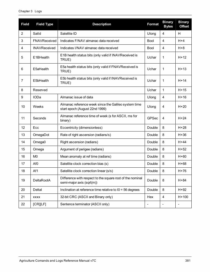
Chapter 3 Logs
Agriculture Comands and Logs Reference Manual v7C 381
Field Field Type Description Format BinaryBytes
BinaryOffset
2 SatId Satellite ID Ulong 4 H
3 FNAVReceived Indicates F/NAV almanac data received Bool 4 H+4
4 INAVReceived Indicates I/NAV almanac data received Bool 4 H+8
5 E1BHealth E1B health status bits (only valid if INAVReceived isTRUE) Uchar 1 H+12
6 E5aHealth E5a health status bits (only valid if FNAVReceived isTRUE) Uchar 1 H+13
7 E5bHealth E5b health status bits (only valid if INAVReceived isTRUE) Uchar 1 H+14
8 Reserved Uchar 1 H+15
9 IODa Almanac issue of data Ulong 4 H+16
10 Weeks Almanac reference week since the Galileo system timestart epoch (August 22nd 1999) Ulong 4 H+20
11 Seconds Almanac reference time of week (s for ASCII, ms forbinary) GPSec 4 H+24
12 Ecc Eccentricity (dimensionless) Double 8 H+28
13 OmegaDot Rate of right ascension (radians/s) Double 8 H+36
14 Omega0 Right ascension (radians) Double 8 H+44
15 Omega Argument of perigee (radians) Double 8 H+52
16 M0 Mean anomaly at ref time (radians) Double 8 H+60
17 Af0 Satellite clock correction bias (s) Double 8 H+68
18 Af1 Satellite clock correction linear (s/s) Double 8 H+76
19 DeltaRootA Difference with respect to the square root of the nominalsemi-major axis (sqrt(m)) Double 8 H+84
20 DeltaI Inclination at reference time relative to I0 = 56 degrees Double 8 H+92
21 xxxx 32-bit CRC (ASCII and Binary only) Hex 4 H+100
22 [CR][LF] Sentence terminator (ASCII only) - - -

Chapter 3 Logs
Agriculture Comands and Logs Reference Manual v7C 382
3.27 GALCLOCKGalileo clock information
Platform: OEM719, OEM729, OEM7500, OEM7600, OEM7700, OEM7720, PwrPak7, SPAN CPT7,SMART7, SMART2
This log contains the Galileo time information.
This log is populated from both the I/NAV and F/NAV messages from any of the E1, E5a or E5b sig-nals. Depending on the data source, it is possible that the time in the header of the log is earlier than thetime in a previous log. This is expected behavior.
Message ID: 1121
Log Type: Asynch
Recommended Input:log galclocka onchanged
ASCII Example:#GALCLOCKA,COM1,0,84.5,SATTIME,1769,336845.000,02000020,c6cf,45362;8.381903172e-09,-3.5527137e-15,16,259200,233,28,7,16,-3.5216e-09,-1.776e-14,345600,41*186e9085
Field Field Type Description Format BinaryBytes
BinaryOffset
1 GALCLOCKheader
Log header. SeeMessages on page 26 for moreinformation. H 0
2 A0 Constant term of polynomial (s) Double 8 H
3 A1 1st order term of polynomial (s/s) Double 8 H+8
4 DeltaTls Leap second count before leap second adjustment Long 4 H+16
5 Tot UTC data reference time of week (s) Ulong 4 H+20
6 WNt UTC data reference week number Ulong 4 H+24
7 WNlsf Week number of leap second adjustment Ulong 4 H+28
8 DN Day number at the end of which a leap second adjustmentbecomes effective Ulong 4 H+32
9 DeltaTlsf Leap second count after leap second adjustment Long 4 H+36
10 A0g Constant term of the polynomial describing the differencebetweenGalileo andGPS time (s) Double 8 H+40
11 A1g Rate of change of offset the offset betweenGalileo andGPS time (s/s) Double 8 H+48

Chapter 3 Logs
Agriculture Comands and Logs Reference Manual v7C 383
Field Field Type Description Format BinaryBytes
BinaryOffset
12 T0g Reference time for GGTO data (s) Ulong 4 H+56
13 WN0g Week number of GGTO reference Ulong 4 H+60
14 xxxx 32-bit CRC (ASCII and Binary only) Hex 4 H+64
15 [CR][LF] Sentence terminator (ASCII only) - - -

Chapter 3 Logs
Agriculture Comands and Logs Reference Manual v7C 384
3.28 GALCNAVRAWPAGEGalileo raw CNAV page
Platform: OEM719, OEM729, OEM7500, OEM7700, OEM7720, PwrPak7, SPAN CPT7, SMART7,SMART7-I, SMART7-S, SMART7-SI, SMART7-W
This log provides Galileo raw C/NAV page data from Galileo E6 signals.
Message ID: 2239
Log Type: Asynch
Recommended Input:log galcnavrawpage onnew
Abbreviated ASCII Example:<GALCNAVRAWPAGE USB1 0 49.5 SATTIME 1997 145162.000 02040020 ab53 32768< 319 30 2761 2b26bcef0c04f6711bf86137086a12c14f87c07b4c6aa4de04bceb8612c34c691bfabceceb86bced4f851bfb0c074c68613604bff48448d33487
Field Field Type Description Format BinaryBytes
BinaryOffset
1 GALCNAVRAWPAGEheader
Log header. SeeMessages on page 26 formore information. - H 0
2 signal channel Signal channel providing the bits Ulong 4 H
3 PRN Satellite PRN number Ulong 4 H+4
4 Page ID The page ID Ulong 4 H+8
5 data Raw CNAV page data HEX[58] 58 H+12
6 xxxx 32-bit CRC (ASCII and Binary only) Hex 4 h+70
7 [CR][LF] Sentence terminator (ASCII only) - - -

Chapter 3 Logs
Agriculture Comands and Logs Reference Manual v7C 385
3.29 GALFNAVEPHEMERISDecoded Galileo FNAV Ephemeris
Platform: OEM719, OEM729, OEM7500, OEM7600, OEM7700, OEM7720, PwrPak7, SPAN CPT7,SMART7, SMART2
TheGALFNAVEPHEMERIS log contains the Galileo F/NAV ephemeris information. Multiple messages aretransmitted, one for each satellite ID. The F/NAV messages are only transmitted on E5a.
Message ID: 1310
Log Type: Asynch
Recommended Input:log galfnavephemerisa onchanged
ASCII Example:#GALFNAVEPHEMERISA,COM2,0,82.5,SATTIME,1874,148850.000,02400000,02cd,32768;22,0,0,0,0,118,122,0,147600,147600,-6.101167919e-01,3.1687e-09,4.478077171e-04,5.44059147e+03,9.639218456e-01,6.4610e-10,2.329679501e-01,2.55827293e+00,-5.5577315e-09,1.0207e-06,8.2552e-06,1.611e+02,2.313e+01,4.0978e-08,-1.8626e-09,1.335504232e-03,1.768257e-10,0.0,2.561e-09*d02e28ca
Field Field Type Description Format BinaryBytes
BinaryOffset
1 GALFNAVEPHEMERISheader
Log header. SeeMessages on page 26 for moreinformation. H 0
2 SatId Satellite identifier Ulong 4 H
3 E5aHealth E5a health status bits Uchar 1 H+4
4 E5aDVS E5a data validity status Uchar 1 H+5
5 Reserved Uchar 1 H+6
6 Reserved Uchar 1 H+7
7 IODnav Issue of data ephemeris Ushort 2 H+8
8 SISA Index Signal in space accuracy (unitless) Uchar 1 H+10
9 Reserved Uchar 1 H+11
10 T0e Ephemeris reference time (s) Ulong 4 H+12
11 T0c Clock correction data reference time of weekfrom the F/NAV message (s) Ulong 4 H+16
12 M0 Mean anomaly at ref time (radians) Double 8 H+20
13 DeltaN Meanmotion difference (radians/s) Double 8 H+28

Chapter 3 Logs
Agriculture Comands and Logs Reference Manual v7C 386
Field Field Type Description Format BinaryBytes
BinaryOffset
14 Ecc Eccentricity (unitless) Double 8 H+36
15 RootA Square root of semi-major axis Double 8 H+44
16 I0 Inclination angle at ref time (radians) Double 8 H+52
17 IDot Rate of inclination angle (radians/s) Double 8 H+60
18 Omega0 Longitude of ascending node of orbital plane atweekly epoch (radians) Double 8 H+68
19 Omega Argument of perigee (radians) Double 8 H+76
20 OmegaDot Rate of right ascension (radians/s) Double 8 H+84
21 Cuc Amplitude of the cosine harmonic correction termto the argument of latitude (radians) Double 8 H+92
22 Cus Amplitude of the sine harmonic correction term tothe argument of latitude (radians) Double 8 H+100
23 Crc Amplitude of the cosine harmonic correction termto the orbit radius (m) Double 8 H+108
24 Crs Amplitude of the sine harmonic correction term tothe orbit radius (m) Double 8 H+116
25 Cic Amplitude of the cosine harmonic correction termto the angle of inclination (radians) Double 8 H+124
26 Cis Amplitude of the sine harmonic correction term tothe angle of inclination (radians) Double 8 H+132
27 Af0 SV clock bias correction coefficient from theF/NAV message (s) Double 8 H+140
28 Af1 SV clock drift correction coefficient from theF/NAV message (s/s) Double 8 H+148
29 Af2 SV clock drift rate correction coefficient from theF/NAV message (s/s^2) Double 8 H+156
30 E1E5aBGD E1, E5a broadcast group delay Double 8 H+164
31 xxxx 32-bit CRC (ASCII and Binary only) Hex 4 H+172
32 [CR][LF] Sentence terminator (ASCII only) - - -

Chapter 3 Logs
Agriculture Comands and Logs Reference Manual v7C 387
3.30 GALFNAVRAWPAGERaw Galileo FNAV page data
Platform: OEM719, OEM729, OEM7500, OEM7600, OEM7700, OEM7720, PwrPak7, SPAN CPT7,SMART7, SMART2
This log contains the raw Galileo F/NAV page data.The F/NAV messages are only transmitted on E5a.
Log Type: Asynch
Recommended Input:log galfnavrawpagea onchanged
ASCII Example:#GALFNAVRAWPAGEA,USB3,0,85.0,SATTIME,1680,434410.000,02000008,d4fb,43274;56,11,0b818df50ad5ffc151001baffdaa04d5dae655e17affc8a41a83aa*5955b14d
Field Field Type Description Format BinaryBytes
BinaryOffset
1 GALFNAVRAWPAGEheader
Log header. SeeMessages on page 26 formore information. H 0
2 signal channel Signal channel providing the data Ulong 4 H
3 SVID SVID of transmitting satellite Ulong 4 H+4
4 raw frame data Raw F/NAV page (214 bits). Does not includeCRC or Tail bits.
Hex[27] 27 H+8
5 xxxx 32-bit CRC (ASCII and Binary only) Hex 4 H+35
6 [CR][LF] Sentence terminator (ASCII only) - - -

Chapter 3 Logs
Agriculture Comands and Logs Reference Manual v7C 388
3.31 GALINAVEPHEMERISDecoded Galileo INAV Ephemeris
Platform: OEM719, OEM729, OEM7500, OEM7600, OEM7700, OEM7720, PwrPak7, SPAN CPT7,SMART7, SMART2
TheGALINAVEPHEMERIS log contains the Galileo I/NAV ephemeris information. Multiple messages are trans-mitted, one for each SVID with date. The I/NAV messages are only transmitted on E1 and E5b.
Message ID: 1309
Log Type: Asynch
Recommended Input:log galinavephemerisa onchanged
ASCII Example:#GALINAVEPHEMERISA,COM1,10,82.0,SATTIME,1930,494134.000,02000020,dbe9,32768;1,0,0,0,0,0,0,0,0,54,107,1,493200,493200,2.98962614e+00,2.7990e-09,1.763084438e-04,5.44061901e+03,9.996620695e-01,-2.8608e-10,-2.52251354e+00,-1.37786826e+00,-5.7041662e-09,-3.7253e-09,3.8184e-06,2.773e+02,4.6875e-01,-7.0781e-08,4.6566e-08,3.960891627e-05,-9.904966e-12,0.0,-6.752e-09,-7.683e-09*b575a8b9
#GALINAVEPHEMERISA,COM1,9,82.0,SATTIME,1930,511405.000,02000020,dbe9,32768;2,0,0,0,0,0,0,0,0,81,107,3,509400,509400,1.23345967e+00,2.9637e-09,2.852674806e-04,5.44061650e+03,9.996659901e-01,-2.3537e-10,-2.52264339e+00,-7.551901559e-01,-5.8113135e-09,5.2713e-07,2.4810e-06,3.021e+02,1.034e+01,-1.3039e-08,1.8626e-09,-2.745073289e-07,1.705303e-13,0.0,-8.149e-09,-9.546e-09*6df98c07
#GALINAVEPHEMERISA,COM1,8,82.0,SATTIME,1930,511384.000,02000020,dbe9,32768;8,0,0,0,0,0,0,0,0,83,107,3,510600,510600,1.19121266e+00,3.0755e-09,1.157049555e-04,5.44062434e+03,9.581430032e-01,-2.9858e-10,1.66547803e+00,7.075104782e-01,-5.5223729e-09,-1.5851e-06,1.2502e-05,6.706e+01,-3.447e+01,5.5879e-09,-5.7742e-08,4.641003208e-03,3.982876e-10,0.0,-1.048e-08,-1.211e-08*99c692a8
...
#GALINAVEPHEMERISA,COM1,1,82.0,SATTIME,1930,511405.000,02000020,dbe9,32768;26,0,0,0,0,0,0,0,0,83,107,1,510600,510600,-1.25500637e+00,2.9951e-09,2.602027962e-04,5.44060480e+03,9.688215634e-01,3.7894e-10,-4.223768063e-01,-2.61686286e+00,-5.6309488e-09,-4.0233e-07,8.1658e-06,1.711e+02,-8.500e+00,-1.3039e-08,-3.1665e-08,5.767530005e-03,4.148148e-10,0.0,-6.985e-10,-9.313e-10*0e6670f3
#GALINAVEPHEMERISA,COM1,0,82.0,SATTIME,1930,511405.000,02000020,dbe9,32768;30,0,0,0,0,0,0,0,0,83,107,1,510600,510600,-2.836817871e-01,2.9558e-09,2.358634956e-04,5.44061465e+03,9.972253278e-01,-1.9894e-10,-2.51793093e+00,1.101770916e-01,-5.7991701e-09,7.0594e-07,2.4680e-06,3.045e+02,1.675e+01,-1.8626e-08,5.0291e-08,4.957979254e-03,3.988703e-10,0.0,-4.889e-09,-5.821e-09*4513b897
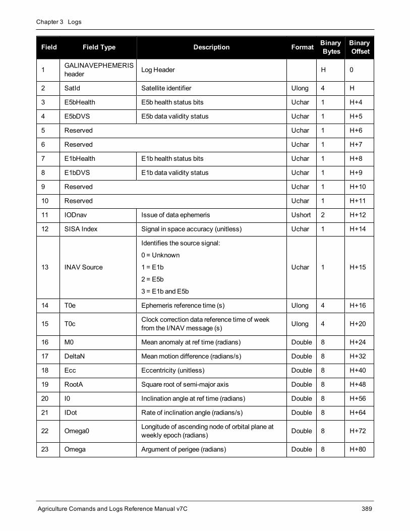
Chapter 3 Logs
Agriculture Comands and Logs Reference Manual v7C 389
Field Field Type Description Format BinaryBytes
BinaryOffset
1 GALINAVEPHEMERISheader Log Header H 0
2 SatId Satellite identifier Ulong 4 H
3 E5bHealth E5b health status bits Uchar 1 H+4
4 E5bDVS E5b data validity status Uchar 1 H+5
5 Reserved Uchar 1 H+6
6 Reserved Uchar 1 H+7
7 E1bHealth E1b health status bits Uchar 1 H+8
8 E1bDVS E1b data validity status Uchar 1 H+9
9 Reserved Uchar 1 H+10
10 Reserved Uchar 1 H+11
11 IODnav Issue of data ephemeris Ushort 2 H+12
12 SISA Index Signal in space accuracy (unitless) Uchar 1 H+14
13 INAV Source
Identifies the source signal:
0 = Unknown
1 = E1b
2 = E5b
3 = E1b and E5b
Uchar 1 H+15
14 T0e Ephemeris reference time (s) Ulong 4 H+16
15 T0c Clock correction data reference time of weekfrom the I/NAV message (s) Ulong 4 H+20
16 M0 Mean anomaly at ref time (radians) Double 8 H+24
17 DeltaN Meanmotion difference (radians/s) Double 8 H+32
18 Ecc Eccentricity (unitless) Double 8 H+40
19 RootA Square root of semi-major axis Double 8 H+48
20 I0 Inclination angle at ref time (radians) Double 8 H+56
21 IDot Rate of inclination angle (radians/s) Double 8 H+64
22 Omega0 Longitude of ascending node of orbital plane atweekly epoch (radians) Double 8 H+72
23 Omega Argument of perigee (radians) Double 8 H+80

Chapter 3 Logs
Agriculture Comands and Logs Reference Manual v7C 390
Field Field Type Description Format BinaryBytes
BinaryOffset
24 OmegaDot Rate of right ascension (radians/s) Double 8 H+88
25 Cuc Amplitude of the cosine harmonic correction termto the argument of latitude (radians) Double 8 H+96
26 Cus Amplitude of the sine harmonic correction term tothe argument of latitude (radians) Double 8 H+104
27 Crc Amplitude of the cosine harmonic correction termto the orbit radius (m) Double 8 H+112
28 Crs Amplitude of the sine harmonic correction term tothe orbit radius (m) Double 8 H+120
29 Cic Amplitude of the cosine harmonic correction termto the angle of inclination (radians) Double 8 H+128
30 Cis Amplitude of the sine harmonic correction term tothe angle of inclination (radians) Double 8 H+136
31 Af0 SV clock bias correction coefficient from theI/NAV message (s) Double 8 H+144
32 Af1 SV clock drift correction coefficient from theI/NAV message (s/s) Double 8 H+152
33 Af2 SV clock drift rate correction coefficient from theI/NAV message (s/s^2) Double 8 H+160
34 E1E5aBGD E1, E5a broadcast group delay Double 8 H+168
35 E1E5bBGD E1, E5b broadcast group delay Double 8 H+176
36 xxxx 32-bit CRC (ASCII and Binary only) Hex 4 H+184
37 [CR][LF] Sentence terminator (ASCII only) - - -

Chapter 3 Logs
Agriculture Comands and Logs Reference Manual v7C 391
3.32 GALINAVRAWWORDRaw Galileo INAV word data
Platform: OEM719, OEM729, OEM7500, OEM7600, OEM7700, OEM7720, PwrPak7, SPAN CPT7,SMART7, SMART2
This log contains the raw Galileo I/NAV word data. The I/NAV messages are only transmitted on E1 and E5b.
Message ID: 1414
Log Type: Asynch
Recommended Input:log galinavrawworda onchanged
ASCII Example:#GALINAVRAWWORDA,USB3,0,84.5,SATTIME,1680,434401.000,02000008,884b,43274;55,11,GALE1,0b81e655e17a26eb5237d7d20088ffc9*dcb4bedb
Field Field Type Description Format BinaryBytes
BinaryOffset
1 GALINAVRAWWORDheader
Log header. SeeMessages on page 26 formore information. H 0
2 signal channel Signal channel providing data Ulong 4 H
3 SVID Space Vehicle ID (SVID) of transmittingsatellite Ulong 4 H+4
4 signal type Signal Type as defined in Table 83: SignalType below Enum 4 H+8
5 raw frame data Raw I/NAV word (128 bits) Hex[16] 16 H+12
6 xxxx 32-bit CRC (ASCII and binary only) Hex 4 H+28
7 [CR][LF] Sentence terminator (ASCII only) - - -
Value (Binary) Signal (ASCII) Description
33 GPSL1CA GPS L1C/A-code
47 GPSL1CP GPS L1C P-code
68 GPSL2Y GPS L2 P(Y)-code
69 GPSL2C GPS L2C/A-code
70 GPSL2P GPS L2 P-code
Table 83: Signal Type

Chapter 3 Logs
Agriculture Comands and Logs Reference Manual v7C 392
Value (Binary) Signal (ASCII) Description
103 GPSL5 GPS L5
2177 GLOL1CA GLONASS L1C/A-code
2211 GLOL2CA GLONASS L2C/A-code
2212 GLOL2P GLONASS L2 P-code
2662 GLOL3 GLONASS L3
4129 SBASL1 SBAS L1
4194 SBASL5 SBAS L5
10433 GALE1 Galileo E1
10466 GALE5A Galileo E5A
10499 GALE5B Galileo E5B
10532 GALALTBOC Galileo ALT-BOC
10565 GALE6C Galileo E6C
10572 GALE6B Galileo E6B
12673 BDSB1D1 BeiDou B1with D1 navigation data
12674 BDSB1D2 BeiDou B1with D2 navigation data
12803 BDSB2D1 BeiDou B2with D1 navigation data
12804 BDSB2D2 BeiDou B2with D2 navigation data
12877 BDSB3D1 BeiDou B3with D1 navigation data
12880 BDSB3D2 BeiDou B3with D2 navigation data
12979 BDSB1C BeiDou B1C
13012 BDSB2A BeiDou B2a
14753 QZSSL1CA QZSS L1C/A-code
14760 QZSSL1CP QZSS L1C P-code
14787 QZSSL2CM QZSS L2C/A-code
14820 QZSSL5 QZSS L5
14891 QZSSL6P QZSS L6P
19073 NAVICL5SPS NavIC L5 SPS

Chapter 3 Logs
Agriculture Comands and Logs Reference Manual v7C 393
3.33 GALIONODecoded Galileo ionospheric corrections
Platform: OEM719, OEM729, OEM7500, OEM7600, OEM7700, OEM7720, PwrPak7, SPAN CPT7,SMART7, SMART2
This log contains the decodedGalileo ionospheric corrections.
Message ID: 1127
Log Type: Asynch
Recommended Input:log galionoa onchanged
ASCII Example:#GALIONOA,COM1,0,81.5,SATTIME,1930,512134.000,02000020,d22e,32768;6.03e+01,-2.344e-02,-3.9368e-03,0,0,0,0,0*f50fae69
Field Field Type Description Format BinaryBytes
BinaryOffset
1 GALIONOheader
Log header. SeeMessages on page 26 for moreinformation. H 0
2 Ai0 Effective ionization level 1st order parameter (sfu) Double 8 H
3 Ai1 Effective ionization level 2st order parameter(sfu/degree) Double 8 H+8
4 Ai2 Effective ionization level 3st order parameter(sfu/degree2) Double 8 H+16
5 SF1 Ionospheric disturbance flag for region 1 Uchar 1 H+24
6 SF2 Ionospheric disturbance flag for region 2 Uchar 1 H+25
7 SF3 Ionospheric disturbance flag for region 3 Uchar 1 H+26
8 SF4 Ionospheric disturbance for flag region 4 Uchar 1 H+27
9 SF5 Ionospheric disturbance for flag region 5 Uchar 1 H+28
10 xxxx 32-bit CRC (ASCII and Binary only) Hex 4 H+29
11 [CR][LF] Sentence terminator (ASCII only) - - -

Chapter 3 Logs
Agriculture Comands and Logs Reference Manual v7C 394
3.34 GEODETICDATUMSAvailable datums
Platform: OEM719, OEM729, OEM7500, OEM7600, OEM7700, OEM7720, PwrPak7, SPAN CPT7,SMART7, SMART2
This log shows a list of available datums. User-defined datums can be added using theGEODETICDATUMcommand (see page 126).
The "USER" entry in the this log is the datum set by theUSERDATUM command (see page 304) or theUSEREXPDATUM command (see page 306).
Message ID: 2296
Log Type: Asynch
Recommended Input:log geodeticdatums
Abbreviated ASCII Example:<GEODETICDATUMS COM1 0 75.0 UNKNOWN 0 1.591 02000020 e7f2 15427
< 12
< "WGS84" 6326 EARTH_FIXED 6378137.00 298.2572235630
< "ITRF2005" 6896 EARTH_FIXED 6378137.00 298.2572221010
< "ITRF2008" 1061 EARTH_FIXED 6378137.00 298.2572221010
< "ITRF2014" 1165 EARTH_FIXED 6378137.00 298.2572221010
< "ETRF2000" 1186 PLATE_FIXED 6378137.00 298.2572221010
< "ETRF2005" 1204 PLATE_FIXED 6378137.00 298.2572221010
< "ETRF2014" 1206 PLATE_FIXED 6378137.00 298.2572221010
< "NAD83(NSRS2011)" 1116 PLATE_FIXED 6378137.00 298.2572221010
< "NAD83(CSRS)" 6140 PLATE_FIXED 6378137.00 298.2572221010
< "GDA94" 6283 PLATE_FIXED 6378137.00 298.2572221010
< "GDA2020" 1168 PLATE_FIXED 6378137.00 298.2572221010
< "USER" 0 UNKNOWN 6378137.00 298.2572235628
Field Field Type Description Format BinaryBytes
BinaryOffset
1 GEODETICDATUMSheader
Log header. SeeMessages on page 26 formore information. – H 0
2 # datums Number of datums to follow Ulong 4 H
3 name Name of datum Char[32] variable H+4

Chapter 3 Logs
Agriculture Comands and Logs Reference Manual v7C 395
Field Field Type Description Format BinaryBytes
BinaryOffset
4 epsg_code EPSG code of datum Ulong 4 variable
5 anchorThe datum’s anchor.
See Table 29: Datum Anchors on page 127.Enum 4 variable
6 semimajor_axis Semi-major axis of datum’s ellipsoid (m) Double 8 variable
7 flattening Inverse flattening of datum’s ellipsoid(unitless) Double 8 variable
8… Next datum offset = variable
variable xxxx 32-bit CRC (ASCII and Binary only) Ulong 4 variable
variable [CR][LF] Sentence terminator (ASCII only) – – –

Chapter 3 Logs
Agriculture Comands and Logs Reference Manual v7C 396
3.35 GLMLANMEA GLONASS Almanac data
Platform: OEM719, OEM729, OEM7500, OEM7600, OEM7700, OEM7720, PwrPak7, SPAN CPT7,SMART7, SMART2
This log outputs almanac data for GLONASS satellites. Multiple sentences are transmitted, one for each satel-lite.
The following relationships enable translation between the NMEA GLONASS satellite IDs, the NovAtelGLONASS PRN IDs, and the GLONASS slot numbers:
NMEA GLONASS satellite ID = GLONASS slot number + 64NovAtel GLONASS PRN ID = GLONASS slot number + 37
= NMEA GLONASS satellite ID - 27
Message ID: 859
Log Type: Asynch
Recommended Input:log glmlaa onchanged
ASCII Example:$GLMLA,16,01,65,1176,07,0496,4c,5ff2,8000,34c05e,0e93e8,04b029,001fa2,099,213*68
$GLMLA,16,02,66,1176,01,12e3,4c,42cc,8000,34c08e,10fae9,02f48c,00224e,099,003*64
$GLMLA,16,03,67,1176,8c,08f6,4a,ef4d,8000,34c051,13897b,00d063,001b09,099,000*63
$GLMLA,16,04,68,1176,06,116b,48,3a00,8000,34c09d,02151f,0e49e8,00226e,099,222*63
$GLMLA,16,05,70,1176,01,140f,49,45c4,8000,34c0bc,076637,0a3e40,002214,099,036*37
$GLMLA,16,06,71,1176,05,0306,4c,5133,8000,34c025,09bda7,085d84,001f83,099,21d*6E
$GLMLA,16,07,72,1176,06,01b1,4c,4c19,8000,34c021,0c35a0,067db8,001fca,099,047*3D
$GLMLA,16,08,74,1176,84,076b,45,7995,8000,34c07b,104b6d,0e1557,002a38,099,040*35
$GLMLA,16,09,78,1176,84,066c,46,78cf,8000,34c07b,0663f0,1a6239,0029df,099,030*38
$GLMLA,16,10,79,1176,80,0afc,45,8506,8000,34c057,08de48,1c44ca,0029d7,099,000*6B
$GLMLA,16,11,82,1176,8a,12d3,0f,e75d,8000,34be85,10aea6,1781b7,00235a,099,207*6E

Chapter 3 Logs
Agriculture Comands and Logs Reference Manual v7C 397
$GLMLA,16,12,83,1176,03,0866,0f,6c08,8000,34c009,11f32e,18839d,002b22,099,214*36
$GLMLA,16,13,85,1176,88,01a6,0d,9dc9,8000,34bff8,031887,02da1e,002838,099,242*6D
$GLMLA,16,14,86,1176,8a,00e1,0e,4b15,8000,34c016,058181,010433,0027f0,099,227*6F
$GLMLA,16,15,87,1176,03,0383,0f,824c,8000,34bfda,081864,1104ea,002b04,099,00c*60
$GLMLA,16,16,88,1176,02,0821,0f,8ac8,8000,34c05b,0a8510,12dcb6,002b6f,099,020*3F
Refer to the GLONASS section of An Introduction to GNSS available on our website at nova-tel.com/contactus/an-introduction-to-gnss.
Field Structure Description Symbol Example
1 $GLMLA Log header. SeeMessages on page 26 for more information. $GLMLA
2 #alm Number of NMEA almanac messages in the set x.x 16
3 alm# Current message number x.x 13
4 slot
Slot number for satellite (65-96)
The NMEA GLONASS PRN numbers are 64 plus the GLONASS slotnumber. Current slot numbers are 1 to 24 which give the range 65 to 88.PRN numbers 89 to 96 are available if slot numbers above 24 areallocated to on-orbit spares.
xx 85
5 N Calendar day count within the four year period from the last leap year x.x 1176
6 hlth &freq
Health and frequency for satellite
Health and carrier frequency numbers are represented in this 2-character Hex field as:
hh 88
7 ecc Eccentricity 1 hhhh 01a6
8 ΔTdot Rate of change of orbital period (s/orbital period2) 1 hh 0d
9 w Argument of perigee (PZ-90.02) (radians)1 hhhh 9dc9
1The LSB of the Hex data field corresponds to the LSB of the word indicated in the Table 4.3 of the GLONASS InterfaceControl Document, 1995. If the number of available bits in the Hex field is greater than the word, the MSB (upper bits) areunused and filled with zeroes.
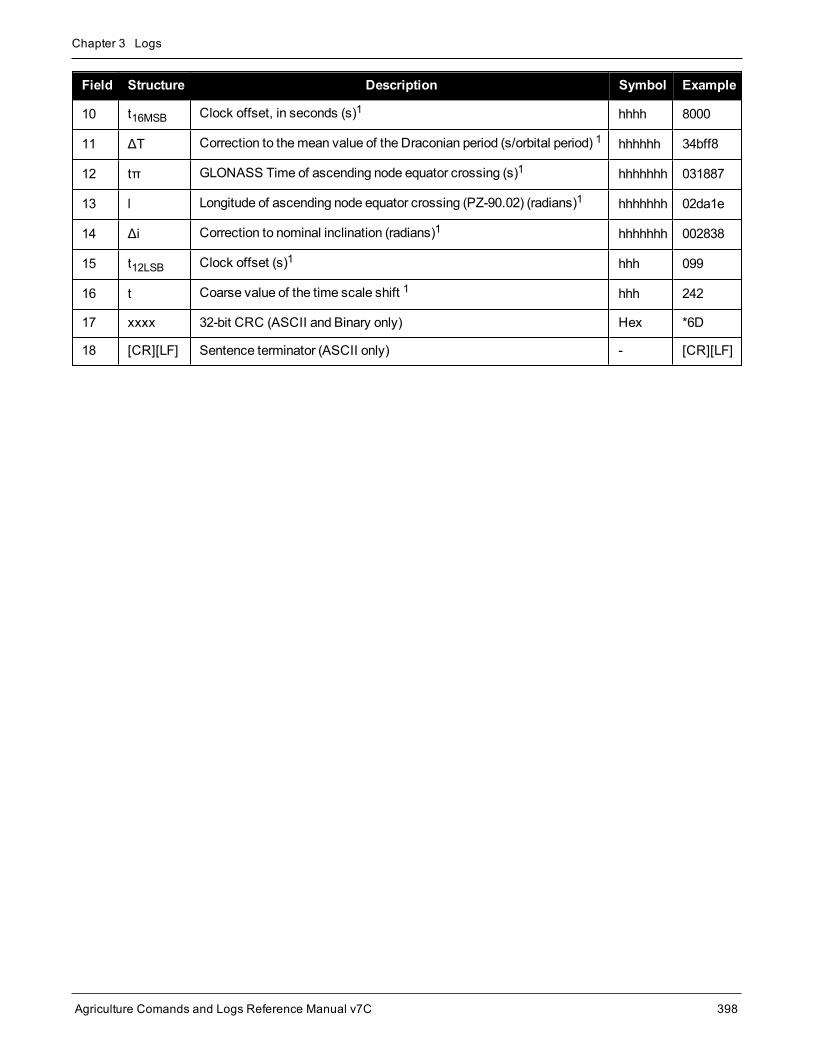
Chapter 3 Logs
Agriculture Comands and Logs Reference Manual v7C 398
Field Structure Description Symbol Example
10 t16MSB Clock offset, in seconds (s)1 hhhh 8000
11 ΔT Correction to themean value of the Draconian period (s/orbital period) 1 hhhhhh 34bff8
12 tπ GLONASS Time of ascending node equator crossing (s)1 hhhhhhh 031887
13 l Longitude of ascending node equator crossing (PZ-90.02) (radians)1 hhhhhhh 02da1e
14 Δi Correction to nominal inclination (radians)1 hhhhhhh 002838
15 t12LSB Clock offset (s)1 hhh 099
16 t Coarse value of the time scale shift 1 hhh 242
17 xxxx 32-bit CRC (ASCII and Binary only) Hex *6D
18 [CR][LF] Sentence terminator (ASCII only) - [CR][LF]

Chapter 3 Logs
Agriculture Comands and Logs Reference Manual v7C 399
3.36 GLOALMANACDecoded GLONASS Almanac
Platform: OEM719, OEM729, OEM7500, OEM7600, OEM7700, OEM7720, PwrPak7, SPAN CPT7,SMART7, SMART2
TheGLONASS almanac reference time and week are in GPS reference time coordinates. GLONASS ephemerisinformation is available through theGLOEPHEMERIS command (see page 404).
Nominal orbit parameters of the GLONASS satellites are as follows:
l Draconian period - 11 hours 15minutes 44 seconds (see fields 14 and 15 in the following table)
l Orbit altitude - 19100 km
l Inclination - 64.8 (see field 11)
l Eccentricity - 0 (see field 12)
TheOEM7 family of receivers automatically save almanacs in their Non-Volatile Memory (NVM), so creating analmanac boot file is not necessary.
The speed at which the receiver locates and locks onto new satellites is improved if the receiverhas approximate time and position(SETAPPROXTIME andSETAPPROXPOS), as well as analmanac. This allows the receiver to compute the elevation of each satellite so it can tell whichsatellites are visible and their Doppler offsets, improving Time to First Fix (TTFF).
Message ID: 718
Log Type: Asynch
Recommended Input:log gloalmanaca onchanged
ASCII Example:#GLOALMANACA,COM1,0,52.5,SATTIME,1364,410744.000,02000000,ba83,2310;
24,
1364,336832.625,1,2,0,0,2018.625000000,-2.775537500,0.028834045,0.001000404,2.355427500,-2656.076171875,0.000000000,0.000091553,
1364,341828.437,2,1,0,0,7014.437500000,-3.122226146,0.030814438,0.004598618,1.650371580,-2656.160156250,0.000061035,0.000095367,
1364,347002.500,3,12,0,0,12188.500000000,2.747629236,0.025376596,0.002099991,-2.659059822,-2656.076171875,-0.000061035,-0.000198364,
1364,351887.125,4,6,0,0,17073.125000000,2.427596502,0.030895332,0.004215240,1.438586358,-2656.167968750,-0.000061035,0.000007629,
.
.
.
1364,364031.187,23,11,0,1,29217.187500000,0.564055522,0.030242192,0.001178741,2.505278248,-2655.957031250,0.000366211,0.000019073,

Chapter 3 Logs
Agriculture Comands and Logs Reference Manual v7C 400
1364,334814.000,24,3,0,1,0.000000000,0.000000000,0.000000000,0.000000000,0.000000000,0.000000000,0.000000000,0.000000000*4dc981c7
Field Field type Description Format BinaryBytes
BinaryOffset
1 GLOALMANACheader
Log header. SeeMessages on page 26 for moreinformation. H 0
2 #recs The number of GLONASS almanac records to follow. Setto zero until almanac data is available Long 4 H
3 week GPS reference week, in weeks Ulong 4 H+4
4 time GPS reference time, in milliseconds (binary data) orseconds (ASCII data) GPSec 4 H+8
5 slot Slot number for satellite, ordinal Uchar 1 H+12
6 frequency Frequency for satellite, ordinal (frequency channels are inthe range -7 to +6) Char 1 H+13
7 sat type
Satellite type where
0 = GLO_SAT
1 = GLO_SAT_M (M type)
2 = GLO_SAT_K (K type)
Uchar 1 H+14
8 health
Satellite status where
0 = OPERATIONAL
1 = MALFUNCTION
Uchar 1 H+15
9 TlambdaN GLONASS Time of ascending node equator crossing (s) Double 8 H+16
10 lambdaN Longitude of ascending node equator crossing(PZ-90.02) (radians) Double 8 H+24
11 deltaI Correction to nominal inclination (radians) Double 8 H+32
12 ecc Eccentricity Double 8 H+40
13 ArgPerig Argument of perigee (PZ-90.02) (radians) Double 8 H+48
14 deltaT Correction to themean value of the Draconian period(s/orbital period) Double 8 H+56
15 deltaTD Rate of change of orbital period (s/orbital period2) Double 8 H+64
16 tau Clock offset (s) Double 8 H+72
17 Next message offset = H + 4 + (#recs x 76)

Chapter 3 Logs
Agriculture Comands and Logs Reference Manual v7C 401
Field Field type Description Format BinaryBytes
BinaryOffset
18 xxxx 32-bit CRC (ASCII and Binary only) Ulong 4H+4+(76 x#recs)
19 [CR][LF] Sentence terminator (ASCII only) - - -

Chapter 3 Logs
Agriculture Comands and Logs Reference Manual v7C 402
3.37 GLOCLOCKGLONASS clock information
Platform: OEM719, OEM729, OEM7500, OEM7600, OEM7700, OEM7720, PwrPak7, SPAN CPT7,SMART7, SMART2
This log contains the time difference information betweenGPS andGLONASS time as well as status flags. Thestatus flags are used to indicate the type of time processing used in the least squares adjustment. GPS andGLONASS time are both based on the Universal Time Coordinated (UTC) time scale with some adjustments.GPS reference time is continuous and does not include any of the leap second adjustments to UTC appliedsince 1980. The result is that GPS reference time currently leads UTC time by 15 seconds.
GLONASS time applies leap seconds but is also three hours ahead to represent Moscow time. The nominal off-set betweenGPS andGLONASS time is therefore due to the three hour offset minus the leap second offset. Aswell as the nominal offset, there is a residual offset on the order of nanoseconds whichmust be estimated in theleast squares adjustment. TheGLONASS-M satellites broadcasts this difference in the navigationmessage.
This log also contains information from theGLONASS navigation data relating GLONASS time to UTC.
Message ID: 719
Log Type: Asynch
Recommended Input:log gloclocka onchanged
ASCII Example:#GLOCLOCKA,COM1,0,54.5,SATTIME,1364,411884.000,02000000,1d44,2310;0,0.000000000,0.000000000,0,0,-0.000000275,792,-0.000001207,0.000000000,0.000000000,0*437e9afaf
Field Field type Description Format BinaryBytes
BinaryOffset
1 GLOCLOCKheader Log header. SeeMessages on page 26 for more information. H 0
2
Reserved
Ulong 4 H
3 Double 8 H+4
4 Double 8 H+12
5 sat type
Satellite type where
0 = GLO_SAT
1 = GLO_SAT_M (M type)
2 = GLO_SAT_K (K type)
Uchar 1 H+20
6 N4 Four-year interval number starting from 1996 Uchar 1 1 H+21
1In the binary log case, additional bytes of padding are added to maintain 4-byte alignment.

Chapter 3 Logs
Agriculture Comands and Logs Reference Manual v7C 403
Field Field type Description Format BinaryBytes
BinaryOffset
7 τGPS Correction to GPS time relative to GLONASS time Double 8 H+24
8 NA GLONASS calendar day number within a four year periodbeginning since the leap year, in days Ushort 2 1 H+32
9 τCGLONASS time scale correction to UTC(SU) given atbeginning of day N4 (s) Double 8 H+36
10 b1 Beta parameter 1st order term Double 8 H+44
11 b2 Beta parameter 2nd order term Double 8 H+52
12 KpKp provides notification of the next expected leap second. Formore information, see Table 84: Kp UTC Leap SecondDescriptions below
Uchar 1 H+60
13 xxxx 32-bit CRC (ASCII and Binary only) Ulong 4 H+61
14 [CR][LF] Sentence terminator (ASCII only) - - -
Kp Information on UTC Leap Second1
00 NoUTC update for this quarter
01 UTC update of plus 1 second at the end of current quarter
11 UTC update of minus 1 second at end of current quarter
Table 84: Kp UTC Leap Second Descriptions
1Based on GLONASS ICD version 5.1, 2008.

Chapter 3 Logs
Agriculture Comands and Logs Reference Manual v7C 404
3.38 GLOEPHEMERISDecoded GLONASS ephemeris
Platform: OEM719, OEM729, OEM7500, OEM7600, OEM7700, OEM7720, PwrPak7, SPAN CPT7,SMART7, SMART2
This log contains GLONASS ephemeris information. GLONASS ephemerides are referenced to the PZ90.02 geo-detic datum. No adjustment between theGPS andGLONASS reference frames aremade for positioning. Mul-tiple messages are transmitted, one for each SVID with data.
Message ID: 723
Log Type: Asynch
Recommended Input:log gloephemerisa onchanged
Example:#GLOEPHEMERISA,COM1,3,49.0,SATTIME,1364,413624.000,02000000,6b64,2310;43,8,1,0,1364,413114000,10786,792,0,0,87,0,9.0260864257812500e+06,-6.1145468750000000e+06,2.2926090820312500e+07,1.4208841323852539e+03,2.8421249389648438e+03,1.9398689270019531e+02,0.00000000000000000,-2.79396772384643555e-06,-2.79396772384643555e-06,2.12404876947402954e-04,-1.396983862e-08,-3.63797880709171295e-12,78810,3,15,0,12*a02ce18b
#GLOEPHEMERISA,COM1,2,49.0,SATTIME,1364,413626.000,02000000,6b64,2310;44,11,1,0,1364,413116000,10784,792,0,0,87,13,-1.2882617187500000e+06,-1.9318657714843750e+07,1.6598909179687500e+07,9.5813846588134766e+02,2.0675134658813477e+03,2.4769935607910156e+03,2.79396772384643555e-06,-3.72529029846191406e-06,-1.86264514923095703e-06,6.48368149995803833e-05,-4.656612873e-09,3.63797880709171295e-12,78810,3,15,3,28*e2d5ef15
#GLOEPHEMERISA,COM1,1,49.0,SATTIME,1364,413624.000,02000000,6b64,2310;45,13,0,0,1364,413114000,10786,0,0,0,87,0,-1.1672664062500000e+07,-2.2678505371093750e+07,4.8702343750000000e+05,-1.1733341217041016e+02,1.3844585418701172e+02,3.5714883804321289e+03,2.79396772384643555e-06,-2.79396772384643555e-06,0.00000000000000000,-4.53162938356399536e-05,5.587935448e-09,-2.36468622460961342e-11,78810,0,0,0,8*c15abfeb
#GLOEPHEMERISA,COM1,0,49.0,SATTIME,1364,413624.000,02000000,6b64,2310;59,17,0,0,1364,413114000,10786,0,0,0,87,0,-2.3824853515625000e+05,-1.6590188964843750e+07,1.9363733398437500e+07,1.3517074584960938e+03,-2.2859592437744141e+03,-1.9414072036743164e+03,1.86264514923095703e-06,-3.72529029846191406e-06,-1.86264514923095703e-06,7.92574137449264526e-05,4.656612873e-09,2.72848410531878471e-12,78810,0,0,0,12*ed7675f5
Field Field type Description Format BinaryBytes
BinaryOffset
1 GLOEPHEMERISheader
Log header. SeeMessages on page 26 for moreinformation. H 0

Chapter 3 Logs
Agriculture Comands and Logs Reference Manual v7C 405
Field Field type Description Format BinaryBytes
BinaryOffset
2 slotoSlot information offset - PRN identification
(Slot + 37). This is also called SLOTO in ConnectUshort 2 H
3 freqo Frequency channel offset for satellite in the range 0 to20 Ushort 2 H+2
4 sat type
Satellite type where
0 = GLO_SAT
1 = GLO_SAT_M (M type)
2 = GLO_SAT_K (K type)
Uchar 1 H+4
5 Reserved 1 H+5
6 e week Reference week of ephemeris (GPS reference time) Ushort 2 H+6
7 e time Reference time of ephemeris (GPS reference time)(ms) Ulong 4 H+8
8 t offsetInteger seconds betweenGPS andGLONASS time. Apositive value implies GLONASS is ahead of GPSreference time.
Ulong 4 H+12
9 Nt Calendar number of day within 4 year interval starting atJan 1 of a leap year Ushort 2 H+16
10Reserved
1 H+18
11 1 H+19
12 issue 15minute interval number corresponding to ephemerisreference time Ulong 4 H+20
13 health1Ephemeris health where
0-3 = GOOD
4-15 = BAD
Ulong 4 H+24
14 pos x X coordinate for satellite at reference time (PZ-90.02)(m) Double 8 H+28
15 pos y Y coordinate for satellite at reference time (PZ-90.02)(m) Double 8 H+36
1The last four bits of this field are used to describe the health.Bit 0-2: BnBit 3: InAll other bits are reserved and set to 0.

Chapter 3 Logs
Agriculture Comands and Logs Reference Manual v7C 406
Field Field type Description Format BinaryBytes
BinaryOffset
16 pos z Z coordinate for satellite at reference time (PZ-90.02)(m) Double 8 H+44
17 vel x X coordinate for satellite velocity at reference time (PZ-90.02) (m/s) Double 8 H+52
18 vel y Y coordinate for satellite velocity at reference time (PZ-90.02) (m/s) Double 8 H+60
19 vel z Z coordinate for satellite velocity at reference time (PZ-90.02), (m/s) Double 8 H+68
20 LS acc x X coordinate for lunisolar acceleration at reference time(PZ-90.02), (m/s/s) Double 8 H+76
21 LS acc y Y coordinate for lunisolar acceleration at reference time(PZ-90.02) (m/s/s) Double 8 H+84
22 LS acc z Z coordinate for lunisolar acceleration at reference time(PZ-90.02) (m/s/s) Double 8 H+92
23 tau_n Correction to the nth satellite time t_n relative toGLONASS time t_c (s) Double 8 H+100
24 delta_tau_nTime difference between navigation RF signaltransmitted in L2 sub-band and navigation RF signaltransmitted in L1 sub-band by nth satellite (s)
Double 8 H+108
25 gamma Frequency correction (s/s) Double 8 H+116
26 Tk Time of frame start (since start of GLONASS day) (s) Ulong 4 H+124
27 P Technological parameter Ulong 4 H+128
28 Ft User range Ulong 4 H+132
29 age Age of data (days) Ulong 4 H+136
30 Flags Information flags, see Table 85: GLONASS EphemerisFlags Coding on the next page Ulong 4 H+140
31 xxxx 32-bit CRC (ASCII and Binary only) Ulong 4 H+144
32 [CR][LF] Sentence terminator (ASCII only) - - -

Chapter 3 Logs
Agriculture Comands and Logs Reference Manual v7C 407
NibbleNumber Bit Description Range Values Hex
Value
N0
0 P1 Flag - Time interval between adjacent iISSUE(fb) values
See Table 86: P1 FlagRange Values below
00000001
1 00000002
2 P2 Flag - Oddness or Evenness of iISSUE (fb) value0 = even
1 = odd00000004
3 P3 Flag - Number of satellites with almanacinformation within current subframe
0 = four
1 = five00000008
N-1throughN-7
4...31
Reserved
Table 85: GLONASS Ephemeris Flags Coding
State Description
00 0minutes
01 30minutes
10 45minutes
11 60minutes
Table 86: P1 FlagRange Values

Chapter 3 Logs
Agriculture Comands and Logs Reference Manual v7C 408
3.39 GLORAWALMRaw GLONASS Almanac data
Platform: OEM719, OEM729, OEM7500, OEM7600, OEM7700, OEM7720, PwrPak7, SPAN CPT7,SMART7, SMART2
This log contains the raw almanac subframes as received from theGLONASS satellite.
Message ID: 720
Log Type: Asynch
Recommended Input:log glorawalma onchanged
Example:#GLORAWALMA,COM1,0,44.5,SATTIME,1364,419924.000,02000000,77bb,2310;1364,419954.069,54,0563100000a4000000006f,0,0681063c457a12cc0419be,0,075ff807e2a69804e0040b,0,0882067fcd80141692d6f2,0,09433e1b6676980a40429b,0,0a838d1bfcb4108b089a8c,0,0bec572f9c869804f05882,0,...06950201e02e13d3819564,0,07939a4a16fe97fe814ad0,0,08960561cecc13b0014613,0,09469a5d70c69802819466,0,0a170165bed413b704d416,0,0b661372213697fd41965a,0,0c18000000000000000006,0,0d00000000000000000652,0,0e000000000000000000d0,0*b516623b
Field Field type Description Format BinaryBytes
BinaryOffset
1 GLORAWALMheader
Log header. SeeMessages on page 26 for moreinformation. H 0
2 week GPS reference week, in weeks Ulong 4 H
3 time GPS reference time, in milliseconds (binary data) orseconds (ASCII data) GPSec 4 H+4
4 #recs Number of records to follow Ulong 4 H+8
5 string GLONASS data string String[11] 11 H+12

Chapter 3 Logs
Agriculture Comands and Logs Reference Manual v7C 409
Field Field type Description Format BinaryBytes
BinaryOffset
6 Reserved Uchar 1 H+23
7 Next record offset = H+8+(#recs x 12)
8 xxxx 32-bit CRC (ASCII and Binary only) Ulong 4 H+12+(#recsx12)
9 [CR][LF] Sentence terminator (ASCII only) - - -

Chapter 3 Logs
Agriculture Comands and Logs Reference Manual v7C 410
3.40 GLORAWEPHEMRaw GLONASS Ephemeris data
Platform: OEM719, OEM729, OEM7500, OEM7600, OEM7700, OEM7720, PwrPak7, SPAN CPT7,SMART7, SMART2
This log contains the raw ephemeris frame data as received from theGLONASS satellite.
Message ID: 792
Log Type: Asynch
Recommended Input:log glorawephema onchanged
Example:#GLORAWEPHEMA,COM1,3,47.0,SATTIME,1340,398653.000,02000000,332d,2020;38,9,0,1340,398653.080,4,0148d88460fc115dbdaf78,0,0218e0033667aec83af2a5,0,038000b9031e14439c75ee,0,0404f22660000000000065,0*17f3dd17
…
#GLORAWEPHEMA,COM1,0,47.0,SATTIME,1340,398653.000,02000000,332d,2020;41,13,0,1340,398653.078,4,0108d812532805bfa1cd2c,0,0208e0a36e8e0952b111da,0,03c02023b68c9a32410958,0,0401fda44000000000002a,0*0b237405
Field Field type Description Format BinaryBytes
BinaryOffset
1 GLORAWEPHEMheader
Log header. SeeMessages on page 26 for moreinformation. H 0
2 slotoSlot information offset - PRN identification (Slot +37). Ephemeris relates to this slot and is also calledSLOTO in NovAtel Connect
Ushort 2 H
3 freqo Frequency channel offset in the range 0 to 20 Ushort 2 H+2
4 sigchan Signal channel number Ulong 4 H+4
5 week GPS reference week, in weeks Ulong 4 H+8
6 time GPS reference time, in milliseconds (binary data) orseconds (ASCII data) GPSec 4 H+12
7 #recs Number of records to follow Ulong 4 H+16
8 string GLONASS data string String[11] 11 H+20
9 Reserved Uchar 1 H+31
10 Next record offset = H+20+(#recs x 12)

Chapter 3 Logs
Agriculture Comands and Logs Reference Manual v7C 411
Field Field type Description Format BinaryBytes
BinaryOffset
11 xxxx 32-bit CRC (ASCII and Binary only) Ulong 4 H+20+(#recsx12)
12 [CR][LF] Sentence terminator (ASCII only) - - -

Chapter 3 Logs
Agriculture Comands and Logs Reference Manual v7C 412
3.41 GLORAWFRAMERaw GLONASS frame data
Platform: OEM719, OEM729, OEM7500, OEM7600, OEM7700, OEM7720, PwrPak7, SPAN CPT7,SMART7, SMART2
This log contains the raw GLONASS frame data as received from theGLONASS satellite. Multiple messagesare transmitted, one for each SVID with data.
Message ID: 721
Log Type: Asynch
Recommended Input:log glorawframea onchanged
Example:#GLORAWFRAMEA,COM1,19,53.0,SATTIME,1340,398773.000,02000000,8792,2020;3,39,8,1340,398773.067,44,44,15,0148dc0b67e9184664cb35,0,0218e09dc8a3ae8c6ba18d,0,…0f00000000000000000000,0*11169f9e
…
#GLORAWFRAMEA,COM1,0,53.0,SATTIME,1340,398713.000,02000000,8792,2020;1,41,13,1340,398713.077,36,36,15,0108da12532805bfa1cded,0,0208e0a36e8e0952b111da,0,03c02023b68c9a32410958,0,…0f6efb59474697fd72c4e2,0*0a6267c8
Field Field type Description Format BinaryBytes
BinaryOffset
1 GLORAWFRAMEheader
Log header. SeeMessages on page 26 for moreinformation. H 0
2 frame# Frame number Ulong 4 H
3 slotoSlot information offset - PRN identification (Slot + 37).Ephemeris relates to this slot and is also called SLOTOin NovAtel Connect.
Ushort 2 H+4
4 freqo Frequency channel offset in the range 0 to 20 Ushort 2 H+6
5 week GPSWeek, in weeks Ulong 4 H+8
6 time GPS Time, in milliseconds (binary data) or seconds(ASCII data) GPSec 4 H+12
7 frame decode Frame decoder number Ulong 4 H+16
8 sigchan Signal channel number Ulong 4 H+20
9 #recs Number of records to follow Ulong 4 H+24

Chapter 3 Logs
Agriculture Comands and Logs Reference Manual v7C 413
Field Field type Description Format BinaryBytes
BinaryOffset
10 string GLONASS data string String[11] 11 H+28
11 Reserved Uchar 1 H+39
12 Next record offset = H+28+ (#recs x 12)
13 xxxx 32-bit CRC (ASCII and Binary only) Ulong 4H +28+(#recsx 12)
14 [CR][LF] Sentence terminator (ASCII only) - - -
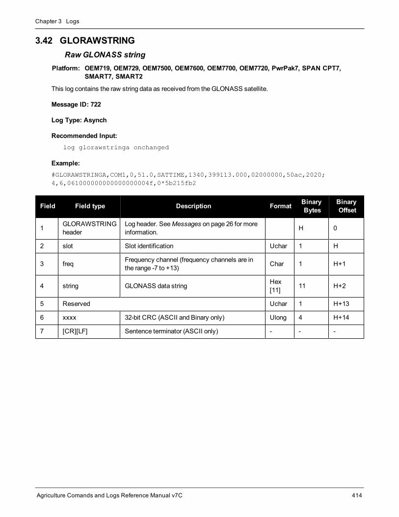
Chapter 3 Logs
Agriculture Comands and Logs Reference Manual v7C 414
3.42 GLORAWSTRINGRaw GLONASS string
Platform: OEM719, OEM729, OEM7500, OEM7600, OEM7700, OEM7720, PwrPak7, SPAN CPT7,SMART7, SMART2
This log contains the raw string data as received from theGLONASS satellite.
Message ID: 722
Log Type: Asynch
Recommended Input:log glorawstringa onchanged
Example:#GLORAWSTRINGA,COM1,0,51.0,SATTIME,1340,399113.000,02000000,50ac,2020;4,6,061000000000000000004f,0*5b215fb2
Field Field type Description Format BinaryBytes
BinaryOffset
1 GLORAWSTRINGheader
Log header. SeeMessages on page 26 for moreinformation. H 0
2 slot Slot identification Uchar 1 H
3 freq Frequency channel (frequency channels are inthe range -7 to +13) Char 1 H+1
4 string GLONASS data string Hex[11] 11 H+2
5 Reserved Uchar 1 H+13
6 xxxx 32-bit CRC (ASCII and Binary only) Ulong 4 H+14
7 [CR][LF] Sentence terminator (ASCII only) - - -

Chapter 3 Logs
Agriculture Comands and Logs Reference Manual v7C 415
3.43 GPALMAlmanac data
Platform: OEM719, OEM729, OEM7500, OEM7600, OEM7700, OEM7720, PwrPak7, SPAN CPT7,SMART7, SMART2
This log outputs raw almanac data for eachGPS satellite PRN contained in the broadcast message. A separaterecord is logged for each PRN, up to amaximum of 32 records. GPALM outputs thesemessages without waitingfor a valid almanac. Instead, it uses a UTC time, calculated with default parameters. In this case, the UTC timestatus (see the TIME log on page 738) is set toWARNING since it may not be one hundred percent accurate.When a valid almanac is available, the receiver uses the real parameters. UTC time is then set to VALID. Ittakes aminimum of 12.5minutes to collect a complete almanac following receiver boot-up. In the case of aGLONASS capable receiver, the UTC offset can be determined once theGLONASS ephemeris is decoded,which takes about 50 seconds. If an almanac was stored in NVM, the stored values are reported in the GPALMlog once time is set on the receiver.
To obtain copies of ICD-GPS-200, refer to https://www.gps.gov/technical/icwg/.
Message ID: 217
Log Type: Asynch
Recommended Input:log gpalm onchanged
Example:$GPALM,28,01,01,1337,00,305a,90,1b9d,fd5b,a10ce9,ba0a5e,2f48f1,cccb76,006,001*27
$GPALM,28,02,02,1337,00,4aa6,90,0720,fd50,a10c5a,4dc146,d89bab,0790b6,fe4,000*70
.
.
.
$GPALM,28,24,26,1337,00,878c,90,1d32,fd5c,a10c90,1db6b6,2eb7f5,ce95c8,00d,000*23
$GPALM,28,25,27,1337,00,9cde,90,07f2,fd54,a10da5,adc097,562da3,6488dd,00e,000*2F
$GPALM,28,26,28,1337,00,5509,90,0b7c,fd59,a10cc4,a1d262,83e2c0,3003bd,02d,000*78
$GPALM,28,27,29,1337,00,47f7,90,1b20,fd58,a10ce0,d40a0b,2d570e,221641,122,006*7D
$GPALM,28,28,30,1337,00,4490,90,0112,fd4a,a10cc1,33d10a,81dfc5,3bdb0f,178,004*28

Chapter 3 Logs
Agriculture Comands and Logs Reference Manual v7C 416
See the The NMEA (National Marine Electronics Association) has defined standards that specify howelectronic equipment for marine users communicate. GNSS receivers are part of this standard and theNMEA has defined the format for several GNSS data logs otherwise known as 'sentences'. on the nextpage that applies to all NMEA logs.
Field Structure Description Symbol Example
1 $GPALM Log header. SeeMessages on page 26 for more information. $GPALM
2 #msg Total number of messages logged. Set to zero until almanac data isavailable x.x 17
3 msg # Current message number1 x.x 17
4 PRNSatellite PRN number:
GPS = 1 to 32xx 28
5 GPS wk GPS reference week number x.x 653
6 SV hlth SV health, bits 17-24 of each almanac page2 hh 00
7 ecc e, eccentricity3 hhhh 3EAF
8 alm ref time to a almanac reference time 3 hh 87
9 incl angle (sigma)i, inclination angle 3 hhhh OD68
10 omegadot OMEGADOT, rate of right ascension 3 hhhh FD30
11 rt axis (A)1/2, root of semi-major axis 3 hhhhhh A10CAB
12 omega omega, argument of perigee 3 hhhhhh 6EE732
13 long ascnode
(OMEGA)°, longitude of ascension node 3 hhhhhh 525880
14 Mo Mo, mean anomaly 3 hhhhhh 6DC5A8
15 af0 af0, clock parameter 3 hhh 009
16 af1 af1, clock parameter 3 hhh 005
17 *xx Check sum *hh *37
18 [CR][LF] Sentence terminator [CR][LF]
1Variable length integer, 4-digits maximum from (2) most significant binary bits of Subframe 1, Word 3 reference Table 20-I,IS-GPS-200J, and (8) least significant bits from subframe 5, page 25, word 3 reference Table 20-I.2Reference paragraph 20.3.3.5.1.3, Table 20-VII and Table 20-VIII, IS-GPS-200J.3Reference Table 20-VI, IS-GPS-200J for scaling factors and units.

Chapter 3 Logs
Agriculture Comands and Logs Reference Manual v7C 417
3.44 GPGGAGPS fix data and undulation
Platform: OEM719, OEM729, OEM7500, OEM7600, OEM7700, OEM7720, PwrPak7, SPAN CPT7,SMART7, SMART2
This log contains time, position and fix related data of the GNSS receiver. See also Table 89: Position Precisionof NMEA Logs on page 423.
TheGPGGA log outputs thesemessages without waiting for a valid almanac. Instead, it uses a UTC time, cal-culated with default parameters. In this case, the UTC time status (see the TIME log on page 738) is set toWARNING since it may not be one hundred percent accurate. When a valid almanac is available, the receiveruses the real parameters. Then the UTC time status is set to VALID.
TheGPGGA log can be customized using theNMEAFORMAT command (see page 175).
The position for theGPGGA log is reported in the user selected datum. See theDATUM command onpage 93 for more details.
Message ID: 218
Log Type: Synch
Recommended Input:log gpgga ontime 1
Example:$GPGGA,134658.00,5106.9792,N,11402.3003,W,2,09,1.0,1048.47,M,-16.27,M,08,AAAA*60
The NMEA (National Marine Electronics Association) has defined standards that specify how electronicequipment for marine users communicate. GNSS receivers are part of this standard and the NMEA hasdefined the format for several GNSS data logs otherwise known as 'sentences'.
Each NMEA sentence begins with a '$' followed by a two-letter prefix identifying the type of sendingdevice (for example 'GP', 'GL' or ‘GN’), followed by a sequence of letters that define the type ofinformation contained in the sentence. Data contained within the sentence is separated by commas andthe sentence is terminated with a two digit checksum followed by a carriage return/line feed. Here is anexample of a NMEA sentence describing time, position and fix related data:
$GPGGA,134658.00,5106.9792,N,11402.3003,W,2,09,1.0,1048.47,M,-16.27,M,08,AAAA*60
TheGPGGA sentence shown above and other NMEA logs are output the same nomatter what GNSSreceiver is used, providing a standard way to communicate and process GNSS information. For moreinformation about NMEA, see theNMEATALKER command on page 178.
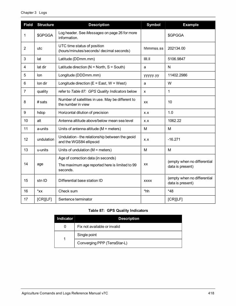
Chapter 3 Logs
Agriculture Comands and Logs Reference Manual v7C 418
Field Structure Description Symbol Example
1 $GPGGA Log header. SeeMessages on page 26 for moreinformation. $GPGGA
2 utc UTC time status of position(hours/minutes/seconds/ decimal seconds) hhmmss.ss 202134.00
3 lat Latitude (DDmm.mm) llll.ll 5106.9847
4 lat dir Latitude direction (N = North, S = South) a N
5 lon Longitude (DDDmm.mm) yyyyy.yy 11402.2986
6 lon dir Longitude direction (E = East, W = West) a W
7 quality refer to Table 87: GPS Quality Indicators below x 1
8 # sats Number of satellites in use. May be different tothe number in view xx 10
9 hdop Horizontal dilution of precision x.x 1.0
10 alt Antenna altitude above/below mean sea level x.x 1062.22
11 a-units Units of antenna altitude (M = meters) M M
12 undulation Undulation - the relationship between the geoidand theWGS84 ellipsoid x.x -16.271
13 u-units Units of undulation (M = meters) M M
14 ageAge of correction data (in seconds)
Themaximum age reported here is limited to 99seconds.
xx (empty when no differentialdata is present)
15 stn ID Differential base station ID xxxx (empty when no differentialdata is present)
16 *xx Check sum *hh *48
17 [CR][LF] Sentence terminator [CR][LF]
Indicator Description
0 Fix not available or invalid
1Single point
Converging PPP (TerraStar-L)
Table 87: GPS Quality Indicators

Chapter 3 Logs
Agriculture Comands and Logs Reference Manual v7C 419
Indicator Description
2
Pseudorange differential
Converged PPP (TerraStar-L)
Converging PPP (TerraStar-C, TerraStar-C PRO, TerraStar-X)
4 RTK fixed ambiguity solution
5RTK floating ambiguity solution
Converged PPP (TerraStar-C, TerraStar-C PRO, TerraStar-X)
6 Dead reckoningmode
7 Manual input mode (fixed position)
8 Simulator mode
9 WAAS (SBAS)1
Refer to theBESTPOS log (see page 346) and Table 70: Supplemental Position Types and NMEAEquivalents on page 353.
1An indicator of 9 has been temporarily set for SBAS (NMEA standard for SBAS not decided yet). This indicator can becustomized using the GGAQUALITY command.

Chapter 3 Logs
Agriculture Comands and Logs Reference Manual v7C 420
3.45 GPGGALONGFix data, extra precision and undulation
Platform: OEM719, OEM729, OEM7500, OEM7600, OEM7700, OEM7720, PwrPak7, SPAN CPT7,SMART7, SMART2
This log contains, time, position, undulation and fix related data of the GNSS receiver. This is output as aGPGGA log but the GPGGALONG log differs from the normal GPGGA log by its extra precision. See also Table89: Position Precision of NMEA Logs on page 423.
TheGPGGALONG log outputs thesemessages without waiting for a valid almanac. Instead, it uses a UTCtime, calculated with default parameters. In this case, the UTC time status is set toWARNING since it may notbe one hundred percent accurate. When a valid almanac is available, the receiver uses the real parameters.Then the UTC time status is set to VALID.
TheGPGGALONG log can be customized using theNMEAFORMAT command (see page 175).
Message ID: 521
Log Type: Synch
Recommended Input:log gpggalong ontime 1
Example 1:$GPGGA,181126.00,5106.9802863,N,11402.3037304,W,7,11,0.9,1048.234,M,-16.27,M,,*51
Example 2:$GPGGA,134658.00,5106.9802863,N,11402.3037304,W,2,09,1.0,1048.234,M,-16.27,M,08,AAAA
See the Note in theGPGGA log (see page 417) that applies to all NMEA logs.
Field Structure Description Symbol Example
1 $GPGGALONG Log header $GPGGA
2 utc UTC time status of position(hours/minutes/seconds/ decimal seconds) hhmmss.ss 202126.00
3 lat Latitude (DDmm.mm) llll.ll 5106.9847029
4 lat dir Latitude direction (N = North, S = South) a N
5 lon Longitude (DDDmm.mm) yyyyy.yy 11402.2986286
6 lon dir Longitude direction (E = East, W = West) a W
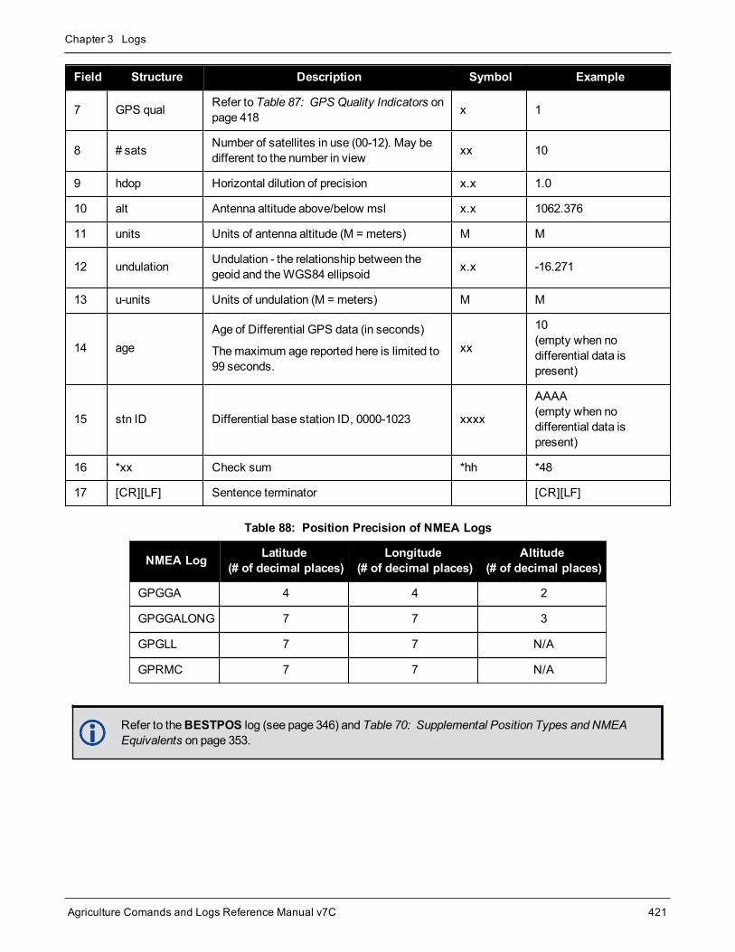
Chapter 3 Logs
Agriculture Comands and Logs Reference Manual v7C 421
Field Structure Description Symbol Example
7 GPS qual Refer to Table 87: GPS Quality Indicators onpage 418 x 1
8 # sats Number of satellites in use (00-12). May bedifferent to the number in view xx 10
9 hdop Horizontal dilution of precision x.x 1.0
10 alt Antenna altitude above/below msl x.x 1062.376
11 units Units of antenna altitude (M = meters) M M
12 undulation Undulation - the relationship between thegeoid and theWGS84 ellipsoid x.x -16.271
13 u-units Units of undulation (M = meters) M M
14 ageAge of Differential GPS data (in seconds)
Themaximum age reported here is limited to99 seconds.
xx
10(empty when nodifferential data ispresent)
15 stn ID Differential base station ID, 0000-1023 xxxx
AAAA(empty when nodifferential data ispresent)
16 *xx Check sum *hh *48
17 [CR][LF] Sentence terminator [CR][LF]
NMEA Log Latitude(# of decimal places)
Longitude(# of decimal places)
Altitude(# of decimal places)
GPGGA 4 4 2
GPGGALONG 7 7 3
GPGLL 7 7 N/A
GPRMC 7 7 N/A
Table 88: Position Precision of NMEA Logs
Refer to theBESTPOS log (see page 346) and Table 70: Supplemental Position Types and NMEAEquivalents on page 353.
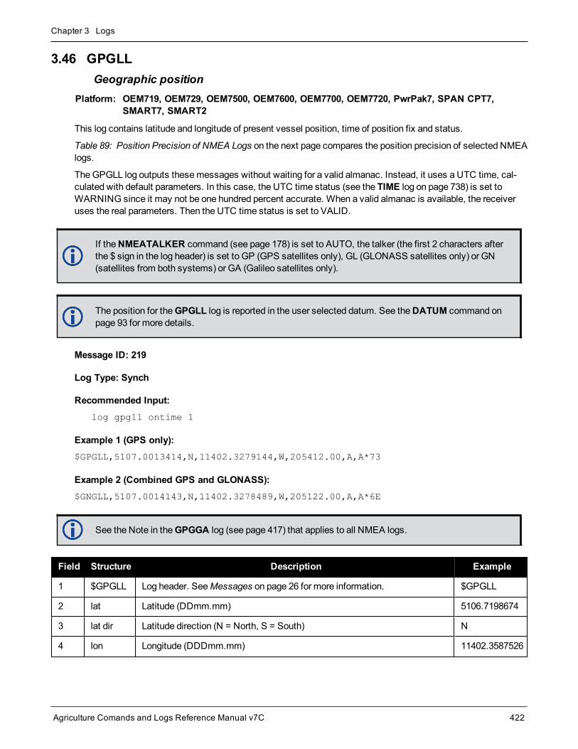
Chapter 3 Logs
Agriculture Comands and Logs Reference Manual v7C 422
3.46 GPGLLGeographic position
Platform: OEM719, OEM729, OEM7500, OEM7600, OEM7700, OEM7720, PwrPak7, SPAN CPT7,SMART7, SMART2
This log contains latitude and longitude of present vessel position, time of position fix and status.
Table 89: Position Precision of NMEA Logs on the next page compares the position precision of selected NMEAlogs.
TheGPGLL log outputs thesemessages without waiting for a valid almanac. Instead, it uses a UTC time, cal-culated with default parameters. In this case, the UTC time status (see the TIME log on page 738) is set toWARNING since it may not be one hundred percent accurate. When a valid almanac is available, the receiveruses the real parameters. Then the UTC time status is set to VALID.
If theNMEATALKER command (see page 178) is set to AUTO, the talker (the first 2 characters afterthe $ sign in the log header) is set to GP (GPS satellites only), GL (GLONASS satellites only) or GN(satellites from both systems) or GA (Galileo satellites only).
The position for theGPGLL log is reported in the user selected datum. See theDATUM command onpage 93 for more details.
Message ID: 219
Log Type: Synch
Recommended Input:log gpgll ontime 1
Example 1 (GPS only):$GPGLL,5107.0013414,N,11402.3279144,W,205412.00,A,A*73
Example 2 (Combined GPS and GLONASS):$GNGLL,5107.0014143,N,11402.3278489,W,205122.00,A,A*6E
See the Note in theGPGGA log (see page 417) that applies to all NMEA logs.
Field Structure Description Example
1 $GPGLL Log header. SeeMessages on page 26 for more information. $GPGLL
2 lat Latitude (DDmm.mm) 5106.7198674
3 lat dir Latitude direction (N = North, S = South) N
4 lon Longitude (DDDmm.mm) 11402.3587526

Chapter 3 Logs
Agriculture Comands and Logs Reference Manual v7C 423
Field Structure Description Example
5 lon dir Longitude direction (E = East, W = West) W
6 utc UTC time status of position (hours/minutes/seconds/decimal seconds) 220152.50
7 datastatus Data status: A = Data valid, V = Data invalid A
8 mode ind Positioning systemmode indicator, see Table 90: NMEA PositioningSystemMode Indicator below A
9 *xx Check sum *1B
10 [CR][LF] Sentence terminator [CR][LF]
NMEA Log Latitude(# of decimal places)
Longitude(# of decimal places)
Altitude(# of decimal places)
GPGGA 4 4 2
GPGGALONG 7 7 3
GPGLL 7 7 N/A
GPRMC 7 7 N/A
Table 89: Position Precision of NMEA Logs
Mode Indicator
A Autonomous
D Differential
E Estimated (dead reckoning) mode
M Manual input
N Data not valid
Table 90: NMEA Positioning SystemMode Indicator

Chapter 3 Logs
Agriculture Comands and Logs Reference Manual v7C 424
3.47 GPGRSGPS range residuals for each satellite
Platform: OEM719, OEM729, OEM7500, OEM7600, OEM7700, OEM7720, PwrPak7, SPAN CPT7,SMART7, SMART2
Range residuals can be computed in two ways, and this log reports those residuals. Under mode 0, residuals out-put in this log are used to update the position solution output in the GPGGA message. Under mode 1, the resid-uals are recomputed after the position solution in the GPGGA message is computed. The receiver computesrange residuals in mode 1. An integrity process using GPGRS would also require GPGGA (for position fix data),GPGSA (for DOP figures) andGPGSV (for PRN numbers) for comparative purposes.
TheGPGRS log outputs thesemessages without waiting for a valid almanac. Instead, it uses a UTC time, cal-culated with default parameters. In this case, the UTC time status (see the TIME log on page 738) is set toWARNING since it may not be one hundred percent accurate. When a valid almanac is available, the receiveruses the real parameters. Then the UTC time status is set to VALID.
1. If the range residual exceeds ± 99.9, then the decimal part is dropped. Maximum value for this field is± 999. The sign of the range residual is determined by the order of parameters used in the calculationas follows:
range residual = calculated range - measured range
2. If theNMEATALKER command (see page 178) is set to AUTO, the talker (the first 2 characters afterthe $ sign in the log header) is set to GP (GPS satellites only), GL (GLONASS satellites only), GN(GPS andGLONASS satellites) or GA (Galileo satellites only).
The position for theGPRMC log is reported in the user selected datum. See theDATUM command onpage 93 for more details.
Message ID: 220
Log Type: Synch
Recommended Input:log gpgrs ontime 1
Example 1 (GPS only):$GPGRS,142406.00,1,-1.1,-0.1,1.7,1.2,-2.0,-0.5,1.2,-1.2,-0.1,,,*67
Example 2 (Combined GPS and GLONASS):$GNGRS,143209.00,1,-0.2,-0.5,2.2,1.3,-2.0,-1.3,1.3,-0.4,-1.2,-0.2,,*72
$GNGRS,143209.00,1,1.3,-6.7,,,,,,,,,,*73
See the Note in theGPGGA log (see page 417) that applies to all NMEA logs.

Chapter 3 Logs
Agriculture Comands and Logs Reference Manual v7C 425
Field Structure Description Symbol Example
1 $GPGRS Log header. SeeMessages on page 26 for more information. $GPGRS
2 utc UTC time status of position (hours/minutes/seconds/decimalseconds) hhmmss.ss 192911.0
3 mode
Mode 0= residuals were used to calculate the position given inthematching GGA line (apriori) (not used by OEM7 receivers)
Mode 1= residuals were recomputed after the GGA position wascomputed (preferredmode)
x 1
4 - 15 res Range residuals for satellites used in the navigation solution.Order matches order of PRN numbers in GPGSA x.x,x.x,.....
-13.8,-1.9,11.4,-33.6,0.9,6.9,-12.6,0.3,0.6,-22.3
16 *xx Check sum *hh *65
17 [CR][LF] Sentence terminator [CR][LF]

Chapter 3 Logs
Agriculture Comands and Logs Reference Manual v7C 426
3.48 GPGSAGPS DOP and active satellites
Platform: OEM719, OEM729, OEM7500, OEM7600, OEM7700, OEM7720, PwrPak7, SPAN CPT7,SMART7, SMART2
This log contains GNSS receiver operatingmode, satellites used for navigation and DOP values.
TheGPGSA log outputs thesemessages without waiting for a valid almanac. Instead, it uses a UTC time, cal-culated with default parameters. In this case, the UTC time status (see the TIME log on page 738) is set toWARNING since it may not be one hundred percent accurate. When a valid almanac is available, the receiveruses the real parameters. Then the UTC time status is set to VALID.
If theNMEATALKER command (see page 178) is set to AUTO, the talker (the first 2 characters afterthe $ sign in the log header) is set to GP (GPS satellites only), GL (GLONASS satellites only), or GN(satellites from both systems) or GA (Galileo satellites only).
Message ID: 221
Log Type: Synch
Recommended Input:log gpgsa ontime 1
Example 1 (GPS only):$GPGSA,M,3,17,02,30,04,05,10,09,06,31,12,,,1.2,0.8,0.9*35
Example 2 (Combined GPS and GLONASS):$GNGSA,M,3,17,02,30,04,05,10,09,06,31,12,,,1.2,0.8,0.9*2B
$GNGSA,M,3,87,70,,,,,,,,,,,1.2,0.8,0.9*2A
The DOPs provide a simple characterization of the user satellite geometry. DOP is related to thevolume formed by the intersection points of the user satellite vectors, with the unit sphere centered onthe user. Larger volumes give smaller DOPs. Lower DOP values generally represent better positionaccuracy. The role of DOP in GNSS positioning is oftenmisunderstood. A lower DOP value does notautomatically mean a low position error. The quality of a GNSS derived position estimate depends uponboth themeasurement geometry as represented by DOP values and range errors caused by signalstrength, ionospheric effects, multipath and so on.
See the Note in theGPGGA log (see page 417) that applies to all NMEA logs.
Field Structure Description Symbol Example
1 $GPGSA Log header. SeeMessages on page 26 for more information. $GPGSA

Chapter 3 Logs
Agriculture Comands and Logs Reference Manual v7C 427
Field Structure Description Symbol Example
2 modeMAA = Automatic 2D/3D
M = Manual, forced to operate in 2D or 3DM M
3 mode 123 Mode: 1 = Fix not available; 2 = 2D; 3 = 3D x 3
4 - 15 prn
PRN numbers of satellites used in solution (null for unused fields),total of 12 fields
GPS = 1 to 32
SBAS = 33 to 64 (add 87 for PRN number)
GLO = 65 to 96 1
xx,xx,.....
18,03,13,
25,16,
24,12,
20,,,,
16 pdop Position dilution of precision x.x 1.5
17 hdop Horizontal dilution of precision x.x 0.9
18 vdop Vertical dilution of precision x.x 1.2
19 *xx Check sum *hh *3F
20 [CR][LF] Sentence terminator [CR][LF]
1The NMEA GLONASS PRN numbers are 64 plus the GLONASS slot number. Current slot numbers are 1 to 24 which givethe range 65 to 88. PRN numbers 89 to 96 are available if slot numbers above 24 are allocated to on-orbit spares.

Chapter 3 Logs
Agriculture Comands and Logs Reference Manual v7C 428
3.49 GPGSTEstimated error in position solution
Platform: OEM719, OEM729, OEM7500, OEM7600, OEM7700, OEM7720, PwrPak7, SPAN CPT7,SMART7, SMART2
This log contains pseudorangemeasurement noise statistics are translated in the position domain in order togive statistical measures of the quality of the position solution.
This log reflects the accuracy of the solution type used in theBESTPOS log (see page 346) andGPGGA log(see page 417), except for the RMS field. The RMS field, since it specifically relates to pseudorange inputs,does not represent carrier-phase based positions. Instead, it reflects the accuracy of the pseudorange positionwhich is given in thePSRPOS log (see page 554).
TheGPGST log outputs thesemessages without waiting for a valid almanac. Instead, it uses a UTC time, cal-culated with default parameters. In this case, the UTC time status (see the TIME log on page 738) is set toWARNING since it may not be one hundred percent accurate. When a valid almanac is available, the receiveruses the real parameters. Then the UTC time status is set to VALID.
If theNMEATALKER command (see page 178) is set to AUTO, the talker (the first 2 characters afterthe $ sign in the log header) is set to GP (GPS satellites only), GL (GLONASS satellites only) or GN(satellites from both systems) or GA (Galileo satellites only).
Message ID: 222
Log Type: Synch
Recommended Input:log gpgst ontime 1
Example 1 (GPS only):$GPGST,141451.00,1.18,0.00,0.00,0.0000,0.00,0.00,0.00*6B
Example 2 (Combined GPS and GLONASS):$GNGST,143333.00,7.38,1.49,1.30,68.1409,1.47,1.33,2.07*4A
1. See the Note in theGPGGA log (see page 417) that applies to all NMEA logs.
2. Accuracy is based on statistics, reliability is measured in percent. When a receiver canmeasureheight to onemeter, this is an accuracy. Usually this is a one sigma value (one SD). A one sigmavalue for height has a reliability of 68%, that is, the error is less than onemeter 68% of the time. For amore realistic accuracy, double the one sigma value (1m) and the result is 95% reliability (error isless than 2m 95% of the time). Generally, GNSS heights are 1.5 times poorer than horizontal pos-itions.
As examples of statistics, the GPGSTmessage and NovAtel performance specifications use RootMean Square (RMS). Specifications may be quoted in CEP:
l RMS - root mean square (a probability level of 68%)
l CEP - circular error probable (the radius of a circle such that 50% of a set of events occur insidethe boundary)

Chapter 3 Logs
Agriculture Comands and Logs Reference Manual v7C 429
Field Structure Description Symbol Example
1 $GPGST Log header. SeeMessages on page 26 for more information. $GPGST
2 utc UTC time status of position(hours/minutes/seconds/ decimal seconds) hhmmss.ss 173653.00
3 rmsRMS value of the standard deviation of the range inputs to thenavigation process. Range inputs include pseudoranges andDGPS corrections
x.x 2.73
4 smjr std Standard deviation of semi-major axis of error ellipse (m) x.x 2.55
5 smnr std Standard deviation of semi-minor axis of error ellipse (m) x.x 1.88
6 orient Orientation of semi-major axis of error ellipse (degrees from truenorth) x.x 15.2525
7 lat std Standard deviation of latitude error (m) x.x 2.51
8 lon std Standard deviation of longitude error (m) x.x 1.94
9 alt std Standard deviation of altitude error (m) x.x 4.30
10 *xx Check sum *hh *6E
11 [CR][LF] Sentence terminator [CR][LF]

Chapter 3 Logs
Agriculture Comands and Logs Reference Manual v7C 430
3.50 GPGSVGPS satellites in view
Platform: OEM719, OEM729, OEM7500, OEM7600, OEM7700, OEM7720, PwrPak7, SPAN CPT7,SMART7, SMART2
This log contains the number of GPS SVs in view, PRN numbers, elevation, azimuth and SNR value. Eachmes-sage includes up to four satellites. If there aremore than four satellites in view, additional messages are trans-mitted. The total number of messages and themessage number are included in eachmessage.
TheGPGSV log outputs thesemessages without waiting for a valid almanac. Instead, it uses a UTC time, cal-culated with default parameters. In this case, the UTC time status (see the TIME log on page 738) is set toWARNING since it may not be one hundred percent accurate. When a valid almanac is available, the receiveruses the real parameters. Then the UTC time status is set to VALID.
1. Satellite informationmay require the transmission of multiple messages. The first field specifies thetotal number of messages, minimum value 1. The second field identifies the order of this message(message number), minimum value 1.
2. If theNMEATALKER command (see page 178) is set to AUTO, the talker (the first 2 characters afterthe $ sign in the log header) is set to GP (GPS satellites only) or GL (GLONASS satellites only) or GN(satellites from both systems) or GA (Galileo satellites only). Each system is output in a separatemessage.
3. The ID setting in theNMEATALKER command (see page 178) controls the satellites reported in thislog. If the NMEATALKER ID is set to GP, only GPS satellites are reported in this log. If theNMEATALKER ID is set to AUTO, all satellites in view are reported.
4. A variable number of 'PRN-Elevation-Azimuth-SNR' sets are allowed up to amaximum of four setsper message. Null fields are not required for unused sets when less than four sets are transmitted.
Message ID: 223
Log Type: Synch
Recommended Input:log gpgsv ontime 1
Example (Including GPS and GLONASS sentences):$GPGSV,3,1,11,18,87,050,48,22,56,250,49,21,55,122,49,03,40,284,47*78
$GPGSV,3,2,11,19,25,314,42,26,24,044,42,24,16,118,43,29,15,039,42*7E
$GPGSV,3,3,11,09,15,107,44,14,11,196,41,07,03,173,*4D
$GLGSV,2,1,06,65,64,037,41,66,53,269,43,88,39,200,44,74,25,051,*64
$GLGSV,2,2,06,72,16,063,35,67,01,253,*66
TheGPGSV log can be used to determine which GPS satellites are currently available to the receiver.Comparing the information from this log to that in the GPGSA log shows if the receiver is tracking allavailable satellites.

Chapter 3 Logs
Agriculture Comands and Logs Reference Manual v7C 431
See also the Note in theGPGGA log (see page 417) that applies to all NMEA logs.
Field Structure Description Symbol Example
1 $GPGSV Log header. SeeMessages on page 26 for more information. $GPGSV
2 #msgs Total number of messages (1-9) x 3
3 msg # Message number (1-9) x 1
4 # sats Total number of satellites in view. May be different than the numberof satellites in use (see also theGPGGA log on page 417) xx 09
5 prn
Satellite PRN number
GPS = 1 to 32
SBAS = 33 to 64 (add 87 for PRN#s)
GLO = 65 to 96 1
xx 03
6 elev Elevation, degrees, 90maximum xx 51
7 azimuth Azimuth, degrees True, 000 to 359 xxx 140
8 SNR SNR (C/No) 00-99 dB, null when not tracking xx 42
...
...
...
...
...
...
Next satellite PRN number, elev, azimuth, SNR,
...
Last satellite PRN number, elev, azimuth, SNR,
variable *xx Check sum *hh *72
variable [CR][LF] Sentence terminator [CR][LF]
1The NMEA GLONASS PRN numbers are 64 plus the GLONASS slot number. Current slot numbers are 1 to 24 which givethe range 65 to 88. PRN numbers 89 to 96 are available if slot numbers above 24 are allocated to on-orbit spares.

Chapter 3 Logs
Agriculture Comands and Logs Reference Manual v7C 432
3.51 GPHDTNMEA heading log
Platform: OEM719, OEM729, OEM7500, OEM7600, OEM7700, OEM7720, PwrPak7, SPAN CPT7,SMART7
This log contains actual vessel heading in degrees True (from True North). See also a description of heading intheHEADING2 log on page 442. You can also set a standard deviation threshold for this log, see theHDTOUTTHRESHOLD command on page 132.
Youmust have an ALIGN capable receiver to use this log.
TheGPHDT log can only be logged using the ONCHANGED trigger. Other triggers, such as ONTIMEare not accepted.
If theNMEATALKER command (see page 178) is set to AUTO, the talker (the first 2 characters afterthe $ sign in the log header) is set to GP (GPS satellites only), GL (GLONASS satellites only) or GN(satellites from both systems) or GA (Galileo satellites only).
Message ID: 1045
Log Type: Asynch
Recommended Input:log gphdt onchanged
Example 1 (GPS only):$GPHDT,75.5664,T*36
Example 2 (Combined GPS and GLONASS):$GNHDT,75.5554,T*45
Field Structure Description Symbol Example
1 $GPHDT Log header. SeeMessages on page 26 for more information. $GPHDT
2 heading Heading in degrees x.x 75.5554
3 True Degrees True T T
4 *xx Check sum *hh *36
5 [CR][LF] Sentence terminator [CR][LF]

Chapter 3 Logs
Agriculture Comands and Logs Reference Manual v7C 433
3.52 GPRMCGPS specific information
Platform: OEM719, OEM729, OEM7500, OEM7600, OEM7700, OEM7720, PwrPak7, SPAN CPT7,SMART7, SMART2
This log contains time, date, position, track made good and speed data provided by the GPS navigation receiver.RMC andRMB are the recommendedminimum navigation data to be provided by aGNSS receiver.
A comparison of the position precision between this log and other selected NMEA logs can be seen in Table 89:Position Precision of NMEA Logs on page 423.
TheGPRMC log outputs thesemessages without waiting for a valid almanac. Instead, it uses a UTC time, cal-culated with default parameters. In this case, the UTC time status (see the TIME log on page 738) is set toWARNING since it may not be one hundred percent accurate. When a valid almanac is available, the receiveruses the real parameters. Then the UTC time status is set to VALID.
If theNMEATALKER command (see page 178) is set to AUTO, the talker (the first 2 characters afterthe $ sign in the log header) is set to GP (GPS satellites only), GL (GLONASS satellites only) or GN(satellites from both systems) or GA (Galileo satellites only).
The position for theGPRMC log is reported in the user selected datum. See theDATUM command onpage 93 for more details.
Message ID: 225
Log Type: Synch
Recommended Input:log gprmc ontime 1
Example 1 (GPS):$GPRMC,144326.00,A,5107.0017737,N,11402.3291611,W,0.080,323.3,210307,0.0,E,A*20
Example 2 (Combined GPS and GLONASS):$GNRMC,143909.00,A,5107.0020216,N,11402.3294835,W,0.036,348.3,210307,0.0,E,A*31
See the Note in theGPGGA log (see page 417) that applies to all NMEA logs.
Field Structure Field Description Symbol Example
1 $GPRMC Log header. SeeMessages on page 26 for more information. $GPRMC
2 utc UTC of position hhmmss.ss 144326.00
3 posstatus Position status (A = data valid, V = data invalid) A A

Chapter 3 Logs
Agriculture Comands and Logs Reference Manual v7C 434
Field Structure Field Description Symbol Example
4 lat Latitude (DDmm.mm) llll.ll 5107.0017737
5 lat dir Latitude direction: (N = North, S = South) a N
6 lon Longitude (DDDmm.mm) yyyyy.yy 11402.3291611
7 lon dir Longitude direction: (E = East, W = West) a W
8 speed Kn Speed over ground, knots x.x 0.080
9 track true Track made good, degrees True x.x 323.3
10 date Date: dd/mm/yy xxxxxx 210307
11 mag var
Magnetic variation, degrees
Note that this field is the actual magnetic variation and willalways be positive. The direction of themagnetic variation isalways positive.
x.x 0.0
12 var dirMagnetic variation direction E/W
Easterly variation (E) subtracts from True course.Westerly variation (W) adds to True course.
a E
13 mode ind Positioning systemmode indicator, see Table 91: NMEAPositioning SystemMode Indicator below a A
14 *xx Check sum *hh *20
15 [CR][LF] Sentence terminator [CR][LF]
Mode Indicator
A Autonomous
D Differential
E Estimated (dead reckoning) mode
M Manual input
N Data not valid
Table 91: NMEA Positioning SystemMode Indicator

Chapter 3 Logs
Agriculture Comands and Logs Reference Manual v7C 435
3.53 GPSEPHEMDecoded GPS L1 C/A ephemerides
Platform: OEM719, OEM729, OEM7500, OEM7600, OEM7700, OEM7720, PwrPak7, SPAN CPT7,SMART7, SMART2
This log contains a single set of GPS ephemeris parameters.
Message ID: 7
Log Type: Asynch
Recommended Input:log gpsephema onchanged
ASCII Example:#GPSEPHEMA,COM1,12,59.0,SATTIME,1337,397560.000,02000000,9145,1984;3,397560.0,0,99,99,1337,1337,403184.0,2.656004220e+07,4.971635660e-09,-2.752651501e+00,7.1111434372e-03,6.0071892571e-01,2.428889275e-06,1.024827361e-05,1.64250000e+02,4.81562500e+01,1.117587090e-08,-7.078051567e-08,9.2668266314e-01,-1.385772009e-10,-2.098534041e+00,-8.08319384e-09,99,403184.0,-4.190951586e-09,2.88095e-05,3.06954e-12,0.00000,TRUE,1.458614684e-04,4.00000000e+00*0f875b12
#GPSEPHEMA,COM1,11,59.0,SATTIME,1337,397560.000,02000000,9145,1984;25,397560.0,0,184,184,1337,1337,403200.0,2.656128681e+07,4.897346851e-09,1.905797220e+00,1.1981436634e-02,-1.440195331e+00,-1.084059477e-06,6.748363376e-06,2.37812500e+02,-1.74687500e+01,1.825392246e-07,-1.210719347e-07,9.5008501632e-01,2.171519024e-10,2.086083072e+00,-8.06140722e-09,184,403200.0,-7.450580597e-09,1.01652e-04,9.09495e-13,0.00000,TRUE,1.458511425e-04,4.00000000e+00*18080b24
...
#GPSEPHEMA,COM1,0,59.0,SATTIME,1337,397560.000,02000000,9145,1984;1,397560.0,0,224,224,1337,1337,403200.0,2.656022490e+07,3.881233098e-09,2.938005195e+00,5.8911956148e-03,-1.716723741e+00,-2.723187208e-06,9.417533875e-06,2.08687500e+02,-5.25625000e+01,9.126961231e-08,-7.636845112e-08,9.8482911735e-01,1.325055194e-10,1.162012787e+00,-7.64138972e-09,480,403200.0,-3.259629011e-09,5.06872e-06,2.04636e-12,0.00000,TRUE,1.458588731e-04,4.00000000e+00*97058299
TheGPSEPHEM log can be used tomonitor changes in the orbits of GPS satellites.
To obtain copies of IS-GPS-200, refer to the GPS website(https://www.gps.gov/technical/icwg/).

Chapter 3 Logs
Agriculture Comands and Logs Reference Manual v7C 436
Field Field type Description Format BinaryBytes
BinaryOffset
1 GPSEPHEMheader Log header. SeeMessages on page 26 for more information. H 0
2 PRN Satellite PRN number Ulong 4 H
3 tow Time stamp of subframe 1 (s) Double 8 H+4
4 health Health status - a 6-bit health code as defined in IS-GPS-200 Ulong 4 H+12
5 IODE1 Issue of ephemeris data 1 Ulong 4 H+16
6 IODE2 Issue of ephemeris data 2 Ulong 4 H+20
7 week toe week number (computed from Z count week) Ulong 4 H+24
8 z weekZ count week number. This is the week number fromsubframe 1 of the ephemeris. The ‘toe week’ (field #7) isderived from this to account for rollover
Ulong 4 H+28
9 toe Reference time for ephemeris (s) Double 8 H+32
10 A Semi-major axis (m) Double 8 H+40
11 ΔN Meanmotion difference (radians/s) Double 8 H+48
12 M0 Mean anomaly of reference time (radians) Double 8 H+56
13 ecc Eccentricity, dimensionless Double 8 H+64
14 ω Argument of perigee (radians) Double 8 H+72
15 cuc Amplitude of cosine harmonic correction term to theargument of latitude (radians) Double 8 H+80
16 cus Amplitude of sine harmonic correction term to the argumentof latitude (radians) Double 8 H+88
17 crc Amplitude of cosine harmonic correction term to the orbitradius (m) Double 8 H+96
18 crs Amplitude of sine harmonic correction term to the orbit radius(m) Double 8 H+104
19 cic Amplitude of cosine harmonic correction term to the angle ofinclination (radians) Double 8 H+112
20 cis Amplitude of sine harmonic correction term to the angle ofinclination (radians) Double 8 H+120
21 I0 Inclination angle at reference time (radians) Double 8 H+128
22 I0 Rate of inclination angle (radians/s) Double 8 H+136
23 ωo Right ascension (radians) Double 8 H+144

Chapter 3 Logs
Agriculture Comands and Logs Reference Manual v7C 437
Field Field type Description Format BinaryBytes
BinaryOffset
24 ώ Rate of right ascension (radians/s) Double 8 H+152
25 iodc Issue of data clock Ulong 4 H+160
26 toc SV clock correction term (s) Double 8 H+164
27 tgd Estimated group delay difference (s) Double 8 H+172
28 af0 Clock aging parameter (s) Double 8 H+180
29 af1 Clock aging parameter (s/s) Double 8 H+188
30 af2 Clock aging parameter (s/s/s) Double 8 H+196
31 ASAnti-spoofing on:0 = FALSE1 = TRUE
Bool 4 H+204
32 N
Correctedmeanmotion (radians/s)
This field is computed by the receiver.Double 8 H+208
33 URA
User Range Accuracy variance (m)2
The ICD specifies that the URA index transmitted in theephemerides can be converted to a nominal standarddeviation value using an algorithm listed there. We publishthe square of the nominal value (variance). Thecorrespondence between the original URA index and thevalue output is shown in Table 92: URA Variance below
Double 8 H+216
34 xxxx 32-bit CRC (ASCII and Binary only) Ulong 4 H+224
35 [CR][LF] Sentence terminator (ASCII only) - - -
Index Value (m) A: Standard Deviations (m) Variance: A2 (m2)
0 2.0 4
1 2.8 7.84
2 4.0 16
3 5.7 32.49
4 8 64
5 11.3 127.69
6 16.0 256
Table 92: URA Variance

Chapter 3 Logs
Agriculture Comands and Logs Reference Manual v7C 438
Index Value (m) A: Standard Deviations (m) Variance: A2 (m2)
7 32.0 1024
8 64.0 4096
9 128.0 16384
10 256.0 65536
11 512.0 262144
12 1024.0 1048576
13 2048.0 4194304
14 4096.0 16777216
15 8192.0 67108864

Chapter 3 Logs
Agriculture Comands and Logs Reference Manual v7C 439
3.54 GPVTGTrack made good and ground speed
Platform: OEM719, OEM729, OEM7500, OEM7600, OEM7700, OEM7720, PwrPak7, SPAN CPT7,SMART7, SMART2
This log contains the track made good and speed relative to the ground.
TheGPVTG log outputs thesemessages without waiting for a valid almanac. Instead, it uses a UTC time, cal-culated with default parameters. In this case, the UTC time status (see the TIME log on page 738) is set toWARNING since it may not be one hundred percent accurate. When a valid almanac is available, the receiveruses the real parameters. Then the UTC time status is set to VALID.
Message ID: 226
Log Type: Synch
Recommended Input:log gpvtg ontime 1
Example 1 (GPS only):$GPVTG,172.516,T,155.295,M,0.049,N,0.090,K,D*2B
Example 2 (Combined GPS and GLONASS):$GNVTG,134.395,T,134.395,M,0.019,N,0.035,K,A*33
If theNMEATALKER command (see page 178) is set to AUTO, the talker (the first 2 characters afterthe $ sign in the log header) is set to GP (GPS satellites only), GL (GLONASS satellites only) or GN(satellites from both systems).
See the Note in theGPGGA log (see page 417) that applies to all NMEA logs.
Field Structure Description Symbol Example
1 $GPVTG Log header. SeeMessages on page 26 for more information. $GPVTG
2 track true Track made good, degrees True x.x 24.168
3 T True track indicator T T
4 track mag
Track made good, degrees Magnetic;
Track mag = Track true + (MAGVAR correction)
See theMAGVAR command on page 168
x.x 24.168
5 M Magnetic track indicator M M
6 speed Kn Speed over ground, knots x.x 0.4220347
7 N Nautical speed indicator (N = Knots) N N

Chapter 3 Logs
Agriculture Comands and Logs Reference Manual v7C 440
Field Structure Description Symbol Example
8 speedKm Speed, kilometers/hour x.x 0.781608
9 K Speed indicator (K = km/hr) K K
10 mode ind Positioning systemmode indicator, see Table 93: NMEA PositioningSystemMode Indicator below a A
11 *xx Check sum *hh *7A
12 [CR][LF] Sentence terminator [CR][LF]
Mode Indicator
A Autonomous
D Differential
E Estimated (dead reckoning) mode
M Manual input
N Data not valid
Table 93: NMEA Positioning SystemMode Indicator

Chapter 3 Logs
Agriculture Comands and Logs Reference Manual v7C 441
3.55 GPZDAUTC time and date
Platform: OEM719, OEM729, OEM7500, OEM7600, OEM7700, OEM7720, PwrPak7, SPAN CPT7,SMART7, SMART2
TheGPZDA log outputs the UTC date and time. If no valid almanac is stored in the receiver, a default UTC off-set is used to generate the time until a new almanac is downloaded. If the offset is not up-to-date, this initial UTCtimemay be incorrect until the new almanac is present.
Message ID: 227
Log Type: Synch
Recommended Input:log gpzda ontime 1
Example:$GPZDA,143042.00,25,08,2005,,*6E
See the Note in theGPGGA log (see page 417) that applies to all NMEA logs.
Field Structure Description Symbol Example
1 $GPZDA Log header. SeeMessages on page 26 for moreinformation. $GPZDA
2 utc UTC time status hhmmss.ss 220238.00
3 day Day, 01 to 31 xx 15
4 month Month, 01 to 12 xx 07
5 year Year xxxx 1992
6 null
Local zone description—not available
Local time zones are not supportedby OEM7 family receivers.Fields 6 and 7 are always null.
xx (empty when no data ispresent)
7 null Local zoneminutes description—not available xx (empty when no data ispresent)
8 *xx Check sum *hh *6F
9 [CR][LF] Sentence terminator [CR][LF]

Chapter 3 Logs
Agriculture Comands and Logs Reference Manual v7C 442
3.56 HEADING2Heading information with multiple rovers
Platform: OEM719, OEM729, OEM7500, OEM7600, OEM7700, OEM7720, PwrPak7, SPAN CPT7,SMART7, SMART2
The heading is the angle from True North of the base to rover vector in a clockwise direction. This log can be out-put at bothMaster and Rover ends.
An ALIGN capable receiver is required to use this log.
Asynchronous logs, such as HEADING2, should only be loggedONCHANGED or ONNEW otherwisethemost current data is not available or included in the output. An example of this occurrence is in theONTIME trigger. If this trigger is not loggedONNEW orONCHANGED, it may cause inaccurate timetags.
The HEADING2 log is dictated by the output frequency of themaster receiver sending out RTCAOBS2,RTCAOBS3 or NOVATELXOBS messages. HEADING2 supports 20 Hz output rate. Ensure sufficientradio bandwidth is available between the ALIGN Master and the ALIGN Rover.
Message ID: 1335
Log Type: Asynch
Recommended Input:log heading2a onnew
ASCII Example:#HEADING2A,COM1,0,39.5,FINESTEERING,1622,422892.200,02040000,f9bf,6521;SOL_COMPUTED,NARROW_INT,0.927607417,178.347869873,-1.3037414550.0,0.261901051,0.391376048,"R222","AAAA",18,17,17,16,0,01,0,33*7be836f6
Field Field type Description BinaryFormat
BinaryBytes
BinaryOffset
1 HEADING2header Log header. SeeMessages on page 26 for more information. H 0
2 sol stat Solution status, see Table 65: Solution Status on page 349 Enum 4 H
3 pos type Position type, see Table 66: Position or Velocity Type onpage 350 Enum 4 H+4

Chapter 3 Logs
Agriculture Comands and Logs Reference Manual v7C 443
Field Field type Description BinaryFormat
BinaryBytes
BinaryOffset
4 length
Baseline length in meters
For ALIGN Headingmodels with position access, this field is-1.
For ALIGN Headingmodels without position access, this fieldis only the decimal portion of the baseline in meters.
For ALIGN Relative Positioningmodels receiving correctionsfrom amaster with a fixed position, this field is -1.
For ALIGN Relative Positioningmodels receiving correctionsfrom amaster in moving baselinemode, this field is thecomplete baseline length in meters.
Float 4 H+8
5 heading Heading in degrees (0° to 359.999°) Float 4 H+12
6 pitch Pitch (±90 degrees) Float 4 H+16
7 Reserved Float 4 H+20
8 hdg std dev Heading standard deviation in degrees Float 4 H+24
9 ptch std dev Pitch standard deviation in degrees Float 4 H+28
10 rover stn ID
Rover Receiver ID
Set using theSETROVERID command (see page 266) on theRover
e.g. setroverid RRRR
Char[4] 4 H+32
11 Master stnID
Master Receiver ID
Set using theDGPSTXID command (see page 98) on theMaster
Default: AAAA
Char[4] 4 H+36
12 #SVs Number of satellites tracked Uchar 1 H+40
13 #solnSVs Number of satellites used in solution Uchar 1 H+41
14 #obs Number of satellites above the elevationmask angle Uchar 1 H+42
15 #multi Number of satellites with multi-frequency signals above themask angle Uchar 1 H+43
16 sol source Solution source (see Table 94: Solution Source on the nextpage) Hex 1 H+44
17 ext sol stat Extended solution status (see Table 69: Extended SolutionStatus on page 353) Uchar 1 H+45

Chapter 3 Logs
Agriculture Comands and Logs Reference Manual v7C 444
Field Field type Description BinaryFormat
BinaryBytes
BinaryOffset
18Galileo andBeiDou sigmask
Galileo and BeiDou signals usedmask (see Table 68: Galileoand BeiDou Signal-UsedMask on page 352) Hex 1 H+46
19GPS andGLONASSsigmask
GPS andGLONASS signals usedmask (see Table 67: GPSandGLONASS Signal-UsedMask on page 352) Hex 1 H+47
20 xxxx 32-bit CRC (ASCII and Binary only) Hex 4 H+48
21 [CR][LF] Sentence terminator (ASCII only) - - -
Bit Mask Description
0-1 0x03 Reserved
2-3 0x0C
Source antenna
0 = Primary antenna
1 = Secondary antenna
4-7 0xF0 Reserved
Table 94: Solution Source

Chapter 3 Logs
Agriculture Comands and Logs Reference Manual v7C 445
3.57 HEADINGEXTExtended heading log
Platform: OEM719, OEM729, OEM7500, OEM7600, OEM7700, OEM7720, PwrPak7, SPAN CPT7,SMART7
HEADINGEXT is a proprietary message sent from the rover receiver to themaster receiver in an ALIGN or Rel-ative INS configuration. This message provides the position information from the rover receiver that themasterreceiver requires to produce an ALIGN or Relative INS solution.
Message ID: 1132
Log Type: Asynch
Recommended Input:log com2 headingextb onnew

Chapter 3 Logs
Agriculture Comands and Logs Reference Manual v7C 446
3.58 HEADINGEXT2Extended heading log in variable array form
Platform: OEM719, OEM729, OEM7500, OEM7600, OEM7700, OEM7720, PwrPak7, SPAN CPT7,SMART7
HEADINGEXT2 is a proprietary message sent from the rover receiver to themaster receiver in an ALIGN or Rel-ative INS configuration. This message provides the position information from the rover receiver that themasterreceiver requires to produce an ALIGN or Relative INS solution.
Message ID: 1661
Log Type: Asynch
Recommended Input:log com2 headingext2b onnew

Chapter 3 Logs
Agriculture Comands and Logs Reference Manual v7C 447
3.59 HEADINGRATEHeading rate information
Platform: OEM719, OEM729, OEM7500, OEM7600, OEM7700, OEM7720, PwrPak7, SPAN CPT7,SMART7
This log provides rate of change for the heading parameters. The heading is the angle from True North of thebase to rover vector in a clockwise direction.
Youmust have an ALIGN capable receiver to use this log.
Message ID: 1698
Log Type: Asynch
Recommended Input:log headingratea onchanged
ASCII Example:#HEADINGRATEA,UNKNOWN,0,60.0,FINESTEERING,1873,411044.700,02040008,c53a,32768;SOL_COMPUTED,NARROW_INT,0.025000000,0.000000000,-0.308837891,0.575313330,0.000000000,1.264251590,1.663657904,0.0,"748M","725U",00,0,0,0*66f97b96
Field Field type Description Format BinaryBytes
BinaryOffset
1 HEADINGRATEheader
Log header. SeeMessages on page 26 for moreinformation. H 0
2 sol stat Solution status, see Table 65: Solution Status onpage 349 Enum 4 H
3 pos type Position type, see Table 66: Position or Velocity Type onpage 350 Enum 4 H+4
4 latencyA measure of the latency in the velocity time tag inseconds. It should be subtracted from the time to giveimproved results.
Float 4 H+8
5 length rateRate of change of the baseline length in m/s.
For Z ALIGN rovers, this field outputs the decimal portionof the baseline rate.
Float 4 H+12
6 heading rate Rate of change of the heading in degrees/s Float 4 H+16
7 pitch rate Rate of change of the pitch in degrees/s Float 4 H+20
8 length rate stddev Baseline rate standard deviation in m/s Float 4 H+24
9 heading rate stddev Heading rate standard deviation in degrees/s Float 4 H+28

Chapter 3 Logs
Agriculture Comands and Logs Reference Manual v7C 448
Field Field type Description Format BinaryBytes
BinaryOffset
10 pitch rate std dev Pitch rate standard deviation in degrees/s Float 4 H+32
11 Reserved Float 4 H+36
12 rover stn IDRover Receiver ID
Set using theSETROVERID command (see page 266)on the Rover receiver. For example, setroverid RRRR.
Uchar 4 H+40
13 master stn IDMaster Receiver ID
Set using theDGPSTXID command (see page 98) on theMaster receiver. Default: AAAA
Uchar 4 H+44
14 sol source Solution source (see Table 94: Solution Source onpage 444) Hex 1 H+48
15 Reserved Uchar 1 H+49
16 Reserved Uchar 1 H+50
17 Reserved Uchar 1 H+51
18 xxxx 32-bit CRC (ASCII and Binary only) Hex 4 H+52
19 [CR][LF] Sentence terminator (ASCII only) - - -

Chapter 3 Logs
Agriculture Comands and Logs Reference Manual v7C 449
3.60 HEADINGSATSSatellite used in heading solution
Platform: OEM719, OEM729, OEM7500, OEM7600, OEM7700, OEM7720, PwrPak7, SPAN CPT7,SMART7
This log provides information on the satellites that are used in a heading solution.
The HEADINGSATS log can only be used from the ALIGN rover.
Message ID: 1316
Log Type: Asynch
Recommended Input:log headingsatsa onnew
ASCII Example:<HEADINGSATS COM1 0 86.5 FINESTEERING 2075 411685.000 02000020 f5b0 32768< 17< GPS 10 GOOD 00000003< GPS 24 GOOD 00000003< GPS 15 GOOD 00000003< GPS 27 GOOD 00000003< GPS 20 GOOD 00000003< GPS 8 GOOD 00000003< GPS 21 GOOD 00000003< GPS 16 GOOD 00000003< GPS 13 GOOD 00000003< GLONASS 14-7 NODIFFCORR 00000000< GLONASS 6-4 GOOD 00000001< GLONASS 22-3 GOOD 00000003< GLONASS 15 GOOD 00000003< GLONASS 23+3 GOOD 00000003< GLONASS 21+4 GOOD 00000003< GLONASS 7+5 GOOD 00000003< GLONASS 8+6 GOOD 00000003
Field Field type Description Format BinaryBytes
BinaryOffset
1 HEADINGSATS Log header. SeeMessages on page 26 for moreinformation. H 0
2 #entries Number of records to follow Ulong 4 H
3 System Refer to Table 95: Satellite System on the next page. Enum 4 H+4

Chapter 3 Logs
Agriculture Comands and Logs Reference Manual v7C 450
Field Field type Description Format BinaryBytes
BinaryOffset
4 Satellite ID
In binary logs, the satellite ID field is 4 bytes. The 2lowest-order bytes, interpreted as a USHORT, are thesystem identifier: for instance, the PRN for GPS, or theslot for GLONASS. The 2 highest-order bytes are thefrequency channel for GLONASS, interpreted as aSHORT and zero for all other systems.
In ASCII and abbreviated ASCII logs, the satellite IDfield is the system identifier. If the system isGLONASS and the frequency channel is not zero, thenthe signed channel is appended to the systemidentifier. For example, slot 13, frequency channel -2 isoutput as 13-2
Ulong 4 H+8
5 Status See Table 71: Observation Statuses on page 355 Enum 4 H+12
6 Signal Mask
See Table 72: GPS Signal Mask on page 356, Table73: GLONASS Signal Mask on page 356, Table 74:Galileo Signal Mask on page 357, Table 75: BeiDouSignal Mask on page 357, QZSS Signal Mask onpage 357 andNavIC Signal Mask on page 357
Hex 4 H+16
7 Next satellite offset = H + 4 + (#sat x 16)
8 xxxx 32-bit CRC (ASCII and Binary only) Hex 4 H+4+(#satx16)
9 [CR][LF] Sentence Terminator (ASCII only) - - -
Binary Value ASCII Mode Name
0 GPS
1 GLONASS
2 SBAS
5 Galileo
6 BeiDou
7 QZSS
9 NAVIC
Table 95: Satellite System

Chapter 3 Logs
Agriculture Comands and Logs Reference Manual v7C 451
3.61 HWMONITORMonitor hardware levels
Platform: OEM719, OEM729, OEM7500, OEM7600, OEM7700, OEM7720, PwrPak7, SPAN CPT7,SMART7, SMART2
This log allows the user to monitor temperature, antenna current and voltages.
Message ID: 963
Log Type: Polled
Recommended Input:log hwmonitora ontime 10
ASCII Example:#HWMONITORA,COM1,0,90.5,FINESTEERING,1928,153778.000,02000020,52db,32768;7,43.284492493,100,0.000000000,200,5.094994068,700,1.195970654,800,3.279609442,f00,1.811965823,1100,44.017093658,1600*52beac4b
Field Field Type Description Format BinaryBytes Binary Offset
1 HWMONITORheader
Log header. SeeMessages on page 26 formore information. H 0
2 #measurements Number of measurements to follow Ulong 4 H
3 reading
Temperature, antenna current or voltagereading
Units:
l Degree Celsius for Temperature
l Amps for Antenna Current
l Volts for Voltage
Float 4 H+4
4 status See Table 96: HWMONITOR Status Tableon the next page HexUlong 4 H+8
5... Next reading offset = H + 4 + (#measurements x 8)
6 xxxx 32-bit CRC (ASCII and Binary only) Hex 4
H+4+(#measurementsx 8)
7 [CR][LF] Sentence Terminator (ASCII only) - - -
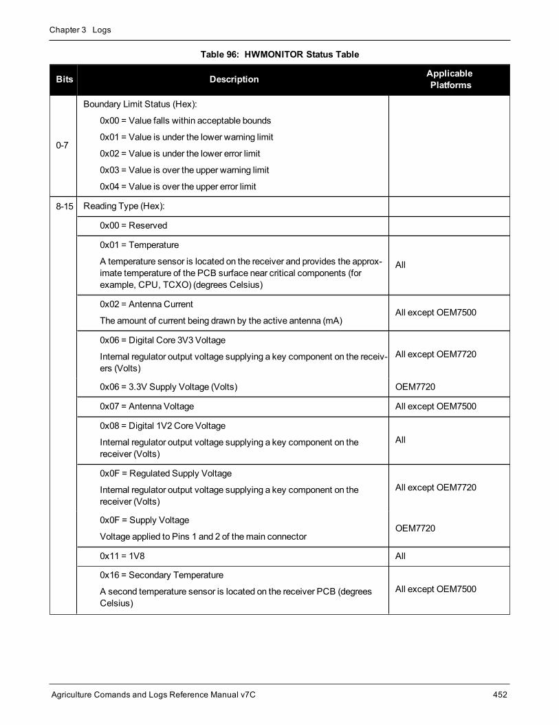
Chapter 3 Logs
Agriculture Comands and Logs Reference Manual v7C 452
Bits Description ApplicablePlatforms
0-7
Boundary Limit Status (Hex):
0x00 = Value falls within acceptable bounds
0x01 = Value is under the lower warning limit
0x02 = Value is under the lower error limit
0x03 = Value is over the upper warning limit
0x04 = Value is over the upper error limit
8-15 Reading Type (Hex):
0x00 = Reserved
0x01 = Temperature
A temperature sensor is located on the receiver and provides the approx-imate temperature of the PCB surface near critical components (forexample, CPU, TCXO) (degrees Celsius)
All
0x02 = Antenna Current
The amount of current being drawn by the active antenna (mA)All except OEM7500
0x06 = Digital Core 3V3 Voltage
Internal regulator output voltage supplying a key component on the receiv-ers (Volts)
All except OEM7720
0x06 = 3.3V Supply Voltage (Volts) OEM7720
0x07 = Antenna Voltage All except OEM7500
0x08 = Digital 1V2 Core Voltage
Internal regulator output voltage supplying a key component on thereceiver (Volts)
All
0x0F = Regulated Supply Voltage
Internal regulator output voltage supplying a key component on thereceiver (Volts)
All except OEM7720
0x0F = Supply Voltage
Voltage applied to Pins 1 and 2 of themain connectorOEM7720
0x11 = 1V8 All
0x16 = Secondary Temperature
A second temperature sensor is located on the receiver PCB (degreesCelsius)
All except OEM7500
Table 96: HWMONITOR Status Table
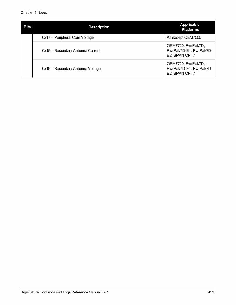
Chapter 3 Logs
Agriculture Comands and Logs Reference Manual v7C 453
Bits Description ApplicablePlatforms
0x17 = Peripheral Core Voltage All except OEM7500
0x18 = Secondary Antenna CurrentOEM7720, PwrPak7D,PwrPak7D-E1, PwrPak7D-E2, SPAN CPT7
0x19 = Secondary Antenna VoltageOEM7720, PwrPak7D,PwrPak7D-E1, PwrPak7D-E2, SPAN CPT7

Chapter 3 Logs
Agriculture Comands and Logs Reference Manual v7C 454
3.62 IONUTCIonospheric and UTC data
Platform: OEM719, OEM729, OEM7500, OEM7600, OEM7700, OEM7720, PwrPak7, SPAN CPT7,SMART7, SMART2
This log contains the Ionospheric Model parameters (ION) and the Universal Time Coordinated parameters(UTC).
Message ID: 8
Log Type: Asynch
Recommended Input:log ionutca onchanged
ASCII Example:#IONUTCA,COM1,0,58.5,FINESTEERING,1337,397740.107,02000000,ec21,1984;1.210719347000122e-08,2.235174179077148e-08,-5.960464477539062e-08,-1.192092895507812e-07,1.003520000000000e+05,1.146880000000000e+05,-6.553600000000000e+04,-3.276800000000000e+05,1337,589824,-1.2107193470001221e-08,-3.907985047e-14,1355,7,13,14,0*c1dfd456
The Receiver-Independent Exchange (RINEX11) format is a broadly accepted, receiver independentformat for storing GPS data. It features a non-proprietary ASCII file format that can be used to combineor process data generated by receivers made by different manufacturers.
Use the NovAtel’s Convert utility to produce RINEX files from NovAtel receiver data files.
Field Field type Description Format BinaryBytes
BinaryOffset
1 IONUTCheader
Log header. SeeMessages on page 26 for moreinformation. H 0
2 a0 Alpha parameter constant term Double 8 H
3 a1 Alpha parameter 1st order term Double 8 H+8
4 a2 Alpha parameter 2nd order term Double 8 H+16
5 a3 Alpha parameter 3rd order term Double 8 H+24
6 b0 Beta parameter constant term Double 8 H+32
7 b1 Beta parameter 1st order term Double 8 H+40
8 b2 Beta parameter 2nd order term Double 8 H+48
9 b3 Beta parameter 3rd order term Double 8 H+56
1Refer to the U.S. National Geodetic Survey website at: www.ngs.noaa.gov/CORS/data.shtml.

Chapter 3 Logs
Agriculture Comands and Logs Reference Manual v7C 455
Field Field type Description Format BinaryBytes
BinaryOffset
10 utc wn UTC reference week number Ulong 4 H+64
11 tot Reference time of UTC parameters (s) Ulong 4 H+68
12 A0 UTC constant term of polynomial (s) Double 8 H+72
13 A1 UTC 1st order term of polynomial (s) Double 8 H+80
14 wn lsf Future week number Ulong 4 H+88
15 dn Day number (the range is 1 to 7 where Sunday = 1 andSaturday = 7) Ulong 4 H+92
16 deltat ls Delta time due to leap seconds Long 4 H+96
17 deltat lsf Future delta time due to leap seconds Long 4 H+100
18 Reserved 4 H+104
19 xxxx 32-bit CRC (ASCII and Binary only) Hex 4 H+108
20 [CR][LF] Sentence terminator (ASCII only) - - -

Chapter 3 Logs
Agriculture Comands and Logs Reference Manual v7C 456
3.63 IPSTATSIP statistics
Platform: OEM729, OEM7600, OEM7700, OEM7720, PwrPak7, SPAN CPT7, SMART7-I, SMART7-SI
This log contains the current IP interface statistics.
Message ID: 1669
Log Type: Polled
Recommended Input:log ipstatsa
ASCII Example:#IPSTATSA,COM1,0,70.5,FINESTEERING,1749,328376.337,02000020,0d94,45068;1,CELL,0,526,526*01c4847c
Field Field Type Description Format BinaryBytes Binary Offset
1 IPSTATSheader
Log header. SeeMessages on page 26 formore information. H 0
2 #Interface Number of records to follow. Ulong 4 H
3 PhysicalInterface
IP Interface Type
1 = ALL
2 = ETHA
Enum 4 H+4
4 Reserved Ulong 4 H+8
5 ReceiveBytes Total number of bytes received Ulong 4 H+12
6 TransmitBytes Total number of bytes transmitted Ulong 4 H+16
7 Next reading offset = H+4+(#Interface * 16)
8 xxxx 32-bit CRC (ASCII and Binary only) Hex 4 H+4+(#Interface* 16)
9 [CR][LF] Sentence terminator (ASCII only) - - -

Chapter 3 Logs
Agriculture Comands and Logs Reference Manual v7C 457
3.64 IPSTATUSCurrent network configuration status
Platform: OEM729, OEM7600, OEM7700, OEM7720, PwrPak7, SPAN CPT7, SMART7-I, SMART7-SI
This log provides the configuration of IP address, netmask, gateway and a list of DNS servers currently in use.
Message ID: 1289
Log Type: Polled
Recommended Input:log ipstatusa once
ASCII Example:#IPSTATUSA,COM1,0,90.5,FINESTEERING,1609,500464.121,02000000,7fe2,6259;1,ETHA,"10.4.44.131","255.255.255.0","10.4.44.1",1,"198.161.72.85"*ec22236c
Field Field Type Description Format BinaryBytes
BinaryOffset
1 IPSTATUSHeader
Log header. SeeMessages on page 26 for moreinformation. - H 0
2 #IPrec Number of records to follow Ulong 4 H
3 interfaceName of the network interface
2 = ETHAEnum 4 H+4
4 IP address IP Address-decimal dot notation String[16] variable1 H+8
5 netmask Netmask-decimal dot notation String[16]
variable1 H+24
6 gatewayGateway-decimal dot notation
This is the default gateway that is currently in useby the receiver.
String[16]
variable1 H+40
7... Next reading offset = H+4+(#IPrec * 52)
8 #dnsserver Number of DNS Servers to follow Ulong 4 H+4+(#IPrec x 52)
9 server IPaddress IP address-decimal dot notation String
[16]variable1
H+4+(#IPrec x52)+4
1In the binary case, each string field needs to be NULL terminated and additional bytes of padding added to maintain 4-bytealignment, up to the maximum defined by the string size. The next defined field starts immediately at the next 4-bytealignment following the NULL.

Chapter 3 Logs
Agriculture Comands and Logs Reference Manual v7C 458
Field Field Type Description Format BinaryBytes
BinaryOffset
10... Next reading offset = H+4+(#IPrec * 52)+4+(#dnsserver * 16)
11 xxxx 32-bit CRC (ASCII and Binary only) Hex 4
H+4+(#IPrec x52)+4+(#dnsserverx 16)
12 [CR][LF] Sentence terminator (ASCII only) - - -
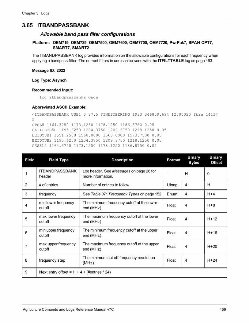
Chapter 3 Logs
Agriculture Comands and Logs Reference Manual v7C 459
3.65 ITBANDPASSBANKAllowable band pass filter configurations
Platform: OEM719, OEM729, OEM7500, OEM7600, OEM7700, OEM7720, PwrPak7, SPAN CPT7,SMART7, SMART2
The ITBANDPASSBANK log provides information on the allowable configurations for each frequency whenapplying a bandpass filter. The current filters in use can be seen with the ITFILTTABLE log on page 463.
Message ID: 2022
Log Type: Asynch
Recommended Input:log itbandpassbanka once
Abbreviated ASCII Example:<ITBANDPASSBANK USB1 0 87.5 FINESTEERING 1933 346809.694 12000020 fb2e 141375GPSL5 1164.3750 1173.1250 1178.1250 1186.8750 0.05GALILEOE5B 1195.6250 1204.3750 1209.3750 1218.1250 0.05BEIDOUB1 1551.2500 1560.0000 1565.0000 1573.7500 0.05BEIDOUB2 1195.6250 1204.3750 1209.3750 1218.1250 0.05QZSSL5 1164.3750 1173.1250 1178.1250 1186.8750 0.05
Field Field Type Description Format BinaryBytes
BinaryOffset
1 ITBANDPASSBANKheader
Log header. SeeMessages on page 26 formore information. - H 0
2 # of entries Number of entries to follow Ulong 4 H
3 frequency See Table 37: Frequency Types on page 152 Enum 4 H+4
4 min lower frequencycutoff
Theminimum frequency cutoff at the lowerend (MHz) Float 4 H+8
5 max lower frequencycutoff
Themaximum frequency cutoff at the lowerend (MHz) Float 4 H+12
6 min upper frequencycutoff
Theminimum frequency cutoff at the upperend (MHz) Float 4 H+16
7 max upper frequencycutoff
Themaximum frequency cutoff at the upperend (MHz) Float 4 H+20
8 frequency step Theminimum cut off frequency resolution(MHz) Float 4 H+24
9 Next entry offset = H + 4 + (#entries * 24)

Chapter 3 Logs
Agriculture Comands and Logs Reference Manual v7C 460
Field Field Type Description Format BinaryBytes
BinaryOffset
10 xxxx 32-bit CRC (ASCII and Binary only) Ulong 4H+4+(#entries *24)
11 [CR][LF] Sentence terminator (ASCII only) - - -

Chapter 3 Logs
Agriculture Comands and Logs Reference Manual v7C 461
3.66 ITDETECTSTATUSInterference detection status
Platform: OEM719, OEM729, OEM7500, OEM7600, OEM7700, OEM7720, PwrPak7, SPAN CPT7,SMART7, SMART2
This log lists all of the detected interferences from all active paths where interference detection is enabled.
This log should be used with the onchanged trigger only.
Message ID: 2065
Log Type: Asynch
Recommended Input:log itdetectstatusa onchanged
ASCII Example#ITDETECTSTATUSA,USB2,0,74.0,FINESTEERING,1982,430605.267,0200c000,7fdb,32768;3,L1,STATISTICANALYSIS,-0.718,29.167,0.126,12.797,00000000,00000000,00000000,L2,SPECTRUMANALYSIS,1249.961,71.191,-56.769,-132.907,00000000,00000000,00000000,L2,SPECTRUMANALYSIS,1289.512,1.978,-75.967,-138.493,00000000,00000000,00000000*5e83b175
Field Field Type Description Format BinaryBytes
BinaryOffset
1 ITDETECTSTATUSheader
Log header. SeeMessages on page 26 for moreinformation. - H 0
2 # of entries Number of interferences to follow Ulong 4 H
3 RF Path
RF path for this entry.
2 = L1
3 = L2
5 = L5
Enum 4 H+4
4 Interferencedetection type
Interference detection type for this entry.
0 = SPECTRALANALYSIS
1 = STATISTICALANALYSIS
Enum 4 H+8
5 Parameter 1
The first parameter of the interference.
For SPECTRALANALYSIS type, this is the centerfrequency in MHz.
For STATISTICALANALYSIS type, this isreserved.
Float 4 H+12

Chapter 3 Logs
Agriculture Comands and Logs Reference Manual v7C 462
Field Field Type Description Format BinaryBytes
BinaryOffset
6 Parameter 2
The second parameter of the interference.
For SPECTRALANALYSIS type, this is thebandwidth in MHz.
For STATISTICALANALYSIS type, this isreserved.
Float 4 H+16
7 Parameter 3
The third parameter of the interference.
For SPECTRALANALYSIS type, this is theestimated power in dBm of the interference.
For STATISTICALANALYSIS type, this isreserved.
Float 4 H+20
8 Parameter 4
The fourth parameter of the interference.
For SPECTRALANALYSIS type, this is the highestestimated power spectrum density in dBmHz of theinterference.
For STATISTICALANALYSIS type this is reserved.
Float 4 H+24
9 Reserved 1 Reserved Ulong 4 H+28
10 Reserved 2 Reserved Ulong 4 H+32
11 Reserved 3 Reserved Ulong 4 H+36
12 Next interference signal offset = H + 4 + (#entries * 36)
13 xxxx 32-bit CRC (ASCII and Binary only) Ulong 4H=4+(#entries* 36)
14 [CR][LF] Sentence terminator (ASCII only) - - -

Chapter 3 Logs
Agriculture Comands and Logs Reference Manual v7C 463
3.67 ITFILTTABLEFilter configuration for each frequency
Platform: OEM719, OEM729, OEM7500, OEM7600, OEM7700, OEM7720, PwrPak7, SPAN CPT7,SMART7, SMART2
The ITFILTTABLE log contains the filter configuration summary for each frequency. It lists which bandpass ornotch filters are enabled and how each is configured.
Message ID: 1991
Log Type: Asynch
Recommended Input:log itfilttablea once
ASCII Example:#ITFILTTABLEA,USB2,0,80.5,FINESTEERING,1923,232588.825,12000000,35d0,32768;13,GPSL1,8,CIC3,00000001,DISABLE,0.0000,0.0000,1,ENABLE,PF0,NOTCHFILTER,1572.2500,1577.7500,1.000,GPSL2,4,CIC3,00000000,DISABLE,0.0000,0.0000,0,GLONASSL1,9,CIC3,00000000,DISABLE,0.0000,0.0000,0,GLONASSL2,5,CIC3,00000000,DISABLE,0.0000,0.0000,0,GPSL5,0,CIC3,00000000,DISABLE,0.0000,0.0000,0,…QZSSL1,8,CIC3,00000001,DISABLE,0.0000,0.0000,1,ENABLE,PF0,NOTCHFILTER,1572.2500,1577.7500,1.000,QZSSL2,4,CIC3,00000000,DISABLE,0.0000,0.0000,0,QZSSL5,0,CIC3,00000000,DISABLE,0.0000,0.0000,0*3ca84167
Field Field Type Description Format BinaryBytes
BinaryOffset
1 ITFILTTABLEheader
Log header. SeeMessages on page 26 for moreinformation. - H 0
2 # entries Number of records with information to follow Ulong 4 H
3 frequency The frequency at which the filter is applied. See Table 37:Frequency Types on page 152 Enum 4 H+4
4 Encoder ID ID of the digital path used by this frequency Ulong 4 H+8
5 DDC filtertype
The DDC filter type (see Table 97: DDC Filter Type on thenext page) Enum 4 H+12
6 status word
Filter warning limit status. Raise a warning flag if the filter isplaced too close to the center frequency of the GNSSsignal (see Table 98: ITFILTTable Status Word onpage 465)
Ulong 4 H+16

Chapter 3 Logs
Agriculture Comands and Logs Reference Manual v7C 464
Field Field Type Description Format BinaryBytes
BinaryOffset
7 switch Filter is enabled or disabled (see Table 99: Filter Switcheson page 466) Enum 4 H+20
8 lower cut offfrequency Cut off frequency at the lower end (MHz) Float 4 H+24
9 upper cut offfrequency Cut off frequency at the upper end (MHz) Float 4 H+28
10 # prog filters Number of programmable filters applied Ulong 4 H+32
11 switch Filter is enabled or disabled (see Table 99: Filter Switcheson page 466) Enum 4 H+36
12 prog filter ID The programmable filter ID (see Table 34: ProgrammableFilter ID on page 149) Enum 4 H+40
13 mode Programmable filter mode (notch filter or bandpass) (seeTable 35: Programmable Filter Mode on page 149) Enum 4 H+44
14 lower cut offfrequency Cut off frequency at the lower end (MHz) Float 4 H+48
15 upper cut offfrequency Cut off frequency at the upper end (MHz) Float 4 H+52
16 notch width Width of notch filter (MHz) Float 4 H+56
17 Next programmable filter – variable binary offset
18 Next frequency – variable binary offset
19 xxxx 32-bit CRC (ASCII and Binary only) Ulong 4 variable
20 [CR][LF] Sentence terminator (ASCII only) - - -
Binary ASCII
0 PASSTHROUGH
1 CIC1
2 CIC2
3 CIC3
4 HALFBAND
Table 97: DDC Filter Type

Chapter 3 Logs
Agriculture Comands and Logs Reference Manual v7C 465
Nibble Bit Mask Description Range Value
N0
0 0x00000001
First enabled filter0 = Within acceptable limit
1 = Warning
1 0x00000002
2 0x00000004
3 0x00000008
N1
4 0x00000010
5 0x00000020
6 0x00000040
7 0x00000080
N2
8 0x00000100
Second enabled filter0 = Within acceptable limit
1 = Warning
9 0x00000200
10 0x00000400
11 0x00000800
N3
12 0x00001000
13 0x00002000
14 0x00004000
15 0x00008000
N4
16 0x00010000
Third enabled filter0 = Within acceptable limit
1 = Warning
17 0x00020000
18 0x00040000
19 0x00080000
N5
20 0x00100000
21 0x00200000
22 0x00400000
23 0x00800000
Table 98: ITFILTTable Status Word

Chapter 3 Logs
Agriculture Comands and Logs Reference Manual v7C 466
Nibble Bit Mask Description Range Value
N6
24 0x01000000
Fourth enabled filter0 = Within acceptable limit
1 = Warning
25 0x02000000
26 0x04000000
27 0x08000000
N7
28 0x10000000
29 0x20000000
30 0x40000000
31 0x80000000
Binary Value ASCII Value Description
0 DISABLE Filter disabled
1 ENABLE Filter enabled
Table 99: Filter Switches

Chapter 3 Logs
Agriculture Comands and Logs Reference Manual v7C 467
3.68 ITPROGFILTBANKAllowable filter configurations
Platform: OEM719, OEM729, OEM7500, OEM7600, OEM7700, OEM7720, PwrPak7, SPAN CPT7,SMART7, SMART2
The ITPROGFILTBANK log provides information on the allowable configurations for the programmable filter foreach frequency when applying either a notch filter or bandpass filter. The current filters in use can be seen withthe ITFILTTABLE log on page 463.
Message ID: 2023
Log Type: Asynch
Recommended Input:log itprogfiltbanka once
Abbreviated ASCII Example:<ITPROGFILTBANK USB1 0 88.0 FINESTEERING 1933 346362.985 12000020 3696 1413712
GPSL1 5NOTCHFILTER 1563.0000 1574.0000 1576.0000 1587.0000 0.05 0.15NOTCHFILTER 1563.7500 1573.6000 1576.4000 1586.2500 0.05 0.50NOTCHFILTER 1564.0500 1573.3000 1576.7000 1585.9500 0.05 1.00NOTCHFILTER 1565.7500 1571.7000 1578.3000 1584.2500 0.05 2.50BANDPASSFILTER 1563.7500 1572.5000 1577.5000 1586.2500 0.05 0.00
GPSL2 5NOTCHFILTER 1215.5000 1226.5000 1228.5000 1239.5000 0.05 0.15NOTCHFILTER 1216.2500 1226.1000 1228.9000 1238.7500 0.05 0.50NOTCHFILTER 1216.5500 1225.8000 1229.2000 1238.4500 0.05 1.00NOTCHFILTER 1218.2500 1224.2000 1230.8000 1236.7500 0.05 2.50BANDPASSFILTER 1216.2500 1225.0000 1230.0000 1238.7500 0.05 0.00
GLONASSL1 5NOTCHFILTER 1589.5625 1600.5625 1602.5625 1613.5625 0.05 0.15NOTCHFILTER 1590.3125 1600.1625 1602.9625 1612.8125 0.05 0.50NOTCHFILTER 1590.6125 1599.8625 1603.2625 1612.5125 0.05 1.00NOTCHFILTER 1592.3125 1598.2625 1604.8625 1610.8125 0.05 2.50BANDPASSFILTER 1590.3125 1599.0625 1604.0625 1612.8125 0.05 0.00
...
Field Field Type Description Format BinaryBytes
BinaryOffset
1 ITPROGFILTBANKheader
Log header. SeeMessages on page 26 for moreinformation. - H 0
2 # entries Number of entries to follow Ulong 4 H
3 frequency See Table 37: Frequency Types on page 152 Enum 4 H+4

Chapter 3 Logs
Agriculture Comands and Logs Reference Manual v7C 468
Field Field Type Description Format BinaryBytes
BinaryOffset
4 # prog filters Number of programmable filters applied withinformation to follow Ulong 4 H+8
5 mode
Programmable filter mode (notch filter orbandpass)
(see Table 35: Programmable Filter Mode onpage 149)
Enum 4 H+12
6 min lower frequencycutoff
Theminimum frequency cutoff at the lower end(MHz) Float 4 H+16
7 max lowerfrequency cutoff
Themaximum frequency cutoff at the lower end(MHz) Float 4 H+20
8 min upper frequencycutoff
Theminimum frequency cutoff at the upper end(MHz) Float 4 H+24
9 max upperfrequency cutoff
Themaximum frequency cutoff at the upper end(MHz) Float 4 H+28
10 frequency step Theminimum cut off frequency resolution(MHz) Float 4 H+32
11 notch width Width of notch filter (MHz) Float 4 H+36
12 Next programmable filter – variable binary offset
13 Next frequency – variable binary offset
14 xxxx 32-bit CRC (ASCII and Binary only) Ulong 4 variable
15 [CR][LF] Sentence terminator (ASCII only)
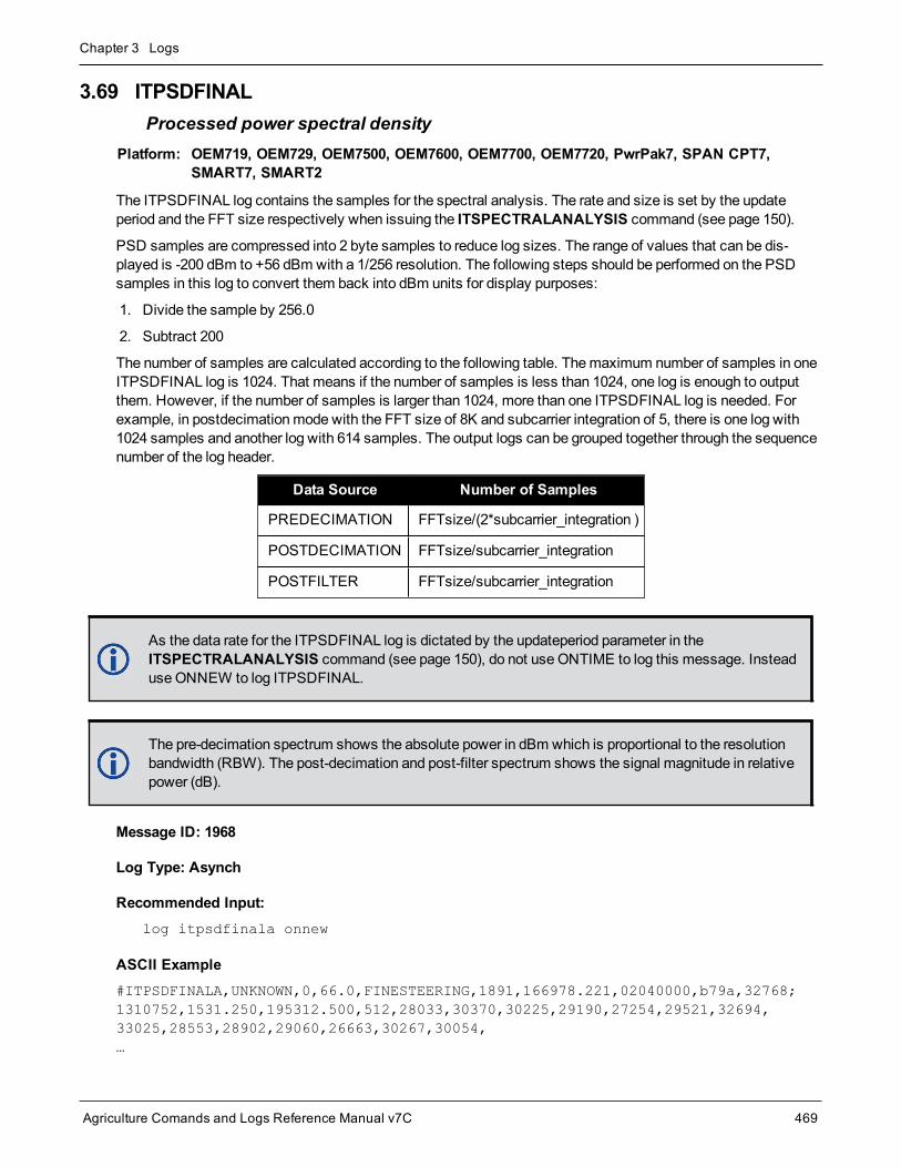
Chapter 3 Logs
Agriculture Comands and Logs Reference Manual v7C 469
3.69 ITPSDFINALProcessed power spectral density
Platform: OEM719, OEM729, OEM7500, OEM7600, OEM7700, OEM7720, PwrPak7, SPAN CPT7,SMART7, SMART2
The ITPSDFINAL log contains the samples for the spectral analysis. The rate and size is set by the updateperiod and the FFT size respectively when issuing the ITSPECTRALANALYSIS command (see page 150).
PSD samples are compressed into 2 byte samples to reduce log sizes. The range of values that can be dis-played is -200 dBm to +56 dBm with a 1/256 resolution. The following steps should be performed on the PSDsamples in this log to convert them back into dBm units for display purposes:
1. Divide the sample by 256.0
2. Subtract 200
The number of samples are calculated according to the following table. Themaximum number of samples in oneITPSDFINAL log is 1024. That means if the number of samples is less than 1024, one log is enough to outputthem. However, if the number of samples is larger than 1024, more than one ITPSDFINAL log is needed. Forexample, in postdecimationmode with the FFT size of 8K and subcarrier integration of 5, there is one log with1024 samples and another log with 614 samples. The output logs can be grouped together through the sequencenumber of the log header.
Data Source Number of Samples
PREDECIMATION FFTsize/(2*subcarrier_integration )
POSTDECIMATION FFTsize/subcarrier_integration
POSTFILTER FFTsize/subcarrier_integration
As the data rate for the ITPSDFINAL log is dictated by the updateperiod parameter in theITSPECTRALANALYSIS command (see page 150), do not useONTIME to log this message. InsteaduseONNEW to log ITPSDFINAL.
The pre-decimation spectrum shows the absolute power in dBm which is proportional to the resolutionbandwidth (RBW). The post-decimation and post-filter spectrum shows the signal magnitude in relativepower (dB).
Message ID: 1968
Log Type: Asynch
Recommended Input:log itpsdfinala onnew
ASCII Example#ITPSDFINALA,UNKNOWN,0,66.0,FINESTEERING,1891,166978.221,02040000,b79a,32768;1310752,1531.250,195312.500,512,28033,30370,30225,29190,27254,29521,32694,33025,28553,28902,29060,26663,30267,30054,…

Chapter 3 Logs
Agriculture Comands and Logs Reference Manual v7C 470
34027,38038,31082,29418,28805,27373,27869,28847,28331,31901,30251,33625,33625*000b928d
Field Field Type Description Format BinaryBytes
BinaryOffset
1 ITPSDFINALheader
Log header. SeeMessages on page 26 for moreinformation. - H 0
2 status wordStatus word containing information about the configurationof the spectral analysis (see Table 100: Spectral AnalysisStatus Word below)
Ulong 4 H
3 frequencystart Frequency represented by first data sample (MHz) Float 4 H+4
4 resolutionbandwidth The resolution bandwidth (Hz) Float 4 H+8
5 # samples Number of spectral density samples Ulong 4 H+12
6 sample Power spectral density sample Ushort 2 H+16
7 Next sample = H+16+(2*#samples)
8 xxxx 32-bit CRC (ASCII and Binary only) Ulong 4H+16+(2*#samples)
9 [CR][LF] Sentence terminator (ASCII only) - - -
Nibble Bit Mask Description Range Value
N0
0 0x00000001
Frequency0 – 20
See Table 37: Frequency Types on page 152
1 0x00000002
2 0x00000004
3 0x00000008
N1
4 0x00000010
5 0x00000020
Data Source0 – 3
See Table 36: Data Sources for PSD Samples onpage 151
6 0x00000040
7 0x00000080
Table 100: Spectral Analysis Status Word

Chapter 3 Logs
Agriculture Comands and Logs Reference Manual v7C 471
Nibble Bit Mask Description Range Value
N2
8 0x00000100
FFT Size0 – 6
See Table 38: FFT Sizes on page 1529 0x00000200
10 0x00000400
11 0x00000800
IntegrationWindow 1 – 1024 samplesN3
12 0x00001000
13 0x00002000
14 0x00004000
15 0x00008000
N4
16 0x00010000
17 0x00020000
Time AverageWindow 0 – 100 seconds
18 0x00040000
19 0x00080000
N5
20 0x00100000
21 0x00200000
22 0x00400000
23 0x00800000
N6
24 0x01000000
25 0x02000000
Reserved26 0x04000000
27 0x08000000
N7
28 0x10000000
Reserved29 0x20000000
30 0x40000000
31 0x80000000

Chapter 3 Logs
Agriculture Comands and Logs Reference Manual v7C 472
3.70 J1939STATUSStatus of CAN J1939 Node
Platform: OEM719, OEM729, OEM7500, OEM7600, OEM7700, OEM7720, PwrPak7, SPAN CPT7,SMART7, SMART2
This logs reports the status of J1939 node, specifically J1939 Address Claim function (initiated using theJ1939CONFIG command (see page 154)).
This log displays the status only for nodes that have been set.
Message ID: 1907
Log Type: Asynch
Recommended Input:LOG J1939STATUSA ONCHANGED
ASCII Examples:#J1939STATUSA,COM1,1,81.0,UNKNOWN,0,0.000,02004020,e9ce,32768;NODE1,DISABLED,0,FE*637c7f
#J1939STATUSA,COM1,0,81.0,UNKNOWN,0,0.000,02004020,e9ce,32768;NODE2,DISABLED,0,FE*c41af5ee
Field Field Type Description Format BinaryBytes
BinaryOffset
1 J1939STATUSheader
Log header. SeeMessages on page 26 for moreinformation. - H 0
2 node J1939 Node. The node can be either NODE1 or NODE2. Enum 4 H
3 status Node status. See Table 101: Node Status below Enum 4 H+4
4 countNumber of attempts that weremade to claim address.
This will be 1 when the preferred address is used andmaybemore if the alternate range is used.
Ulong 4 H+8
5 addressClaimed CAN Address.
0xFE (NULL address) if the address could not benegotiated.
Uchar 1 H+12
6 xxxx 32-bit CRC (ASCII and Binary only) Hex 4 H+13
7 [CR][LF] Sentence Terminator (ASCII only) - - -
Value ASCII Description
1 DISABLED Address claim activity is not taking place. The node does not have J1939 enabled.
Table 101: Node Status
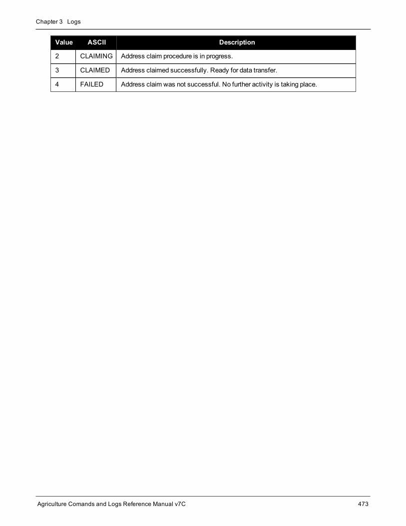
Chapter 3 Logs
Agriculture Comands and Logs Reference Manual v7C 473
Value ASCII Description
2 CLAIMING Address claim procedure is in progress.
3 CLAIMED Address claimed successfully. Ready for data transfer.
4 FAILED Address claim was not successful. No further activity is taking place.

Chapter 3 Logs
Agriculture Comands and Logs Reference Manual v7C 474
3.71 LBANDBEAMTABLEList of L-Band beams
Platform: OEM719, OEM729, OEM7500, OEM7600, OEM7700, OEM7720, PwrPak7, SPAN CPT7,SMART7, SMART2
This log lists the TerraStar and Veripos L-Band beams known to the receiver.
Message ID: 1718
Log Type: Asynch
Recommended Input:log lbandbeamtablea onchanged
Abbreviated ASCII Example:<LBANDBEAMTABLE COM1 0 69.0 UNKNOWN 0 1.283 02044008 19b8 32768< 8< "AORE" "A" 1545855000 1200 -15.50 1< "AORW" "B" 1545845000 1200 -54.00 1< "IOR" "C" 1545865000 1200 64.50 1< "POR" "D" 1545905000 1200 178.00 1< "25E" "E" 1545825000 1200 25.00 1< "143.5E" "F" 1545835000 1200 143.50 1< "98W" "G" 1545865000 1200 -98.00 1< "SP98W1" "SP98W1" 1545885000 1200 -98.00 1
Field Field type Description Format BinaryBytes
BinaryOffset
1 LBANDBEAMTABLEheader
Log header. SeeMessages on page 26 for moreinformation. H 0
2 #entries Number of records to follow Ulong 4 H
3 Name Beam/transmitting satellite name Char[8] 8 H+4
4 Reserved Char[8] 8 H+12
5 Frequency Frequency (Hz) Ulong 4 H+20
6 Baud Baud rate (bps) Ulong 4 H+24
7 Longitude Transmitting satellite longitude (degrees) Float 4 H+28
8 Access
Beam service availability flag
0 = Denied
1 = Granted
Ulong 4 H+32
9 Next beam offset = H + 4 + (#entries * 32)

Chapter 3 Logs
Agriculture Comands and Logs Reference Manual v7C 475
Field Field type Description Format BinaryBytes
BinaryOffset
10 xxxx 32-bit CRC (ASCII and Binary only) Ulong 4H+4+(#entries *32)
11 [CR][LF] Sentence terminator (ASCII only) - - -

Chapter 3 Logs
Agriculture Comands and Logs Reference Manual v7C 476
3.72 LBANDTRACKSTATL-Band Beams status
Platform: OEM719, OEM729, OEM7500, OEM7600, OEM7700, OEM7720, PwrPak7, SPAN CPT7,SMART7, SMART2
This log reports the L-Band tracking and Viterbi decoding status for the tracked L-Band beams.
Themaximum logging rate for LBANDTRACKSTAT is 2 Hz.
Message ID: 1201
Log Type: Synch
Recommended Input:log lbandtrackstata ontime 1
ASCII Example:#LBANDTRACKSTATA,COM2,0,82.5,FINESTEERING,2054,406100.000,02004000,29e3,15526;5,"98W",1545865000,1200,974c,00c2,0,-141.268,40.765,3.2063,7333.552,139648,0,0,17874944,34,0.0000,"AORW",1545845000,1200,974c,00c2,0,-170.379,43.710,3.5375,7331.935,139584,1,1,17866752,27,0.0000,"POR",1545905000,1200,974c,0000,0,-160.064,0.000,0.0000,0.000,0,0,0,0,0,0.0000,"",0,0,0000,0003,0,0.000,0.000,0.0000,0.000,0,0,0,0,0,0.0000,"",0,0,0000,0003,0,0.000,0.000,0.0000,0.000,0,0,0,0,0,0.0000*d5311c69
Field Field type Description Format BinaryBytes
BinaryOffset
1 LBANDTRACKSTATheader
Log header. SeeMessages on page 26 for moreinformation. H 0
2 #entries Number of records to follow Ulong 4 H
3 Name Beam/transmitting satellite name Char[8] 8 H+4
4 Frequency Frequency assigned to this L-Band beam (Hz) Ulong 4 H+12
5 Baud rate Baud rate of assigned beam Ushort 2 H+16
6 ID Service ID of the assigned beam Ushort 2 H+18
7 Status Tracking status word. See Table 102: L-BandSignal Tracking Status on the next page Ushort 2 H+20
8 Reserved Reserved Ushort 2 H+22
9 Doppler Signal Doppler (Hz) Float 4 H+24
10 C/No Carrier to noise density ratio (dB-Hz) Float 4 H+28

Chapter 3 Logs
Agriculture Comands and Logs Reference Manual v7C 477
Field Field type Description Format BinaryBytes
BinaryOffset
11 Phase std. dev. Phase error standard deviation (cycles) Float 4 H+32
12 Lock time Lock time (s) Float 4 H+36
13 Unique word bits Total unique word bits Ulong 4 H+40
14 Bad unique word bits Bad unique word bits Ulong 4 H+44
15 Bad unique words Bad unique words Ulong 4 H+48
16 Viterbi symbols Total Viterbi symbols Ulong 4 H+52
17 Corrected Viterbi Corrected Viterbi symbols Ulong 4 H+56
18 Bit error rate Estimated pre-Viterbi Bit Error Rate (BER) Float 4 H+60
19 Next entry offset = H + 4 + (#entries x 60)
20 xxxx 32-bit CRC (ASCII and Binary only) Hex 4H+4+(#entriesx 60)
21 [CR][LF] Sentence terminator (ASCII only) - - -
Nibble Bit Mask Description Range Value
0 0x0001Tracking State
0 = Searching,1 = Pull-in,2 = Tracking,3 = IdleN0 1 0x0002
2 0x0004
Reserved3 0x0008
N1
4 0x0010
5 0x0020
6 0x0040 Bit Timing Lock 0 = Not Locked,1 = Locked
7 0x0080 Phase Locked 0 = Not Locked,1 = Locked
Table 102: L-Band Signal Tracking Status
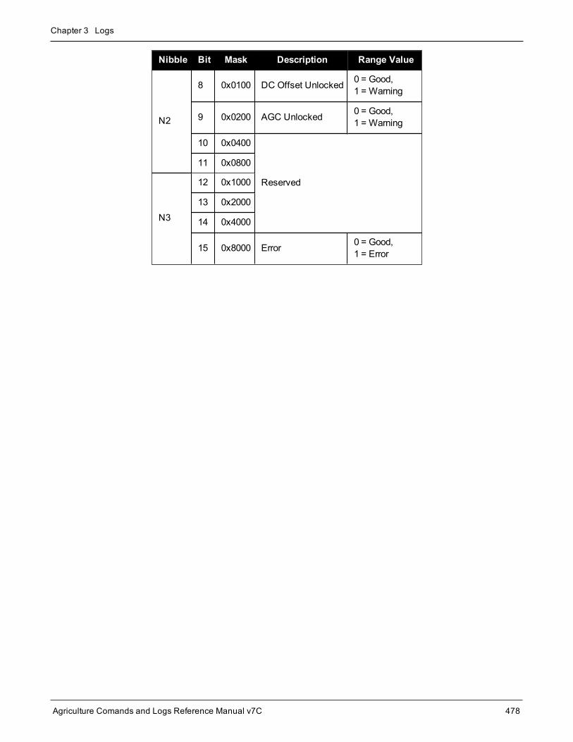
Chapter 3 Logs
Agriculture Comands and Logs Reference Manual v7C 478
Nibble Bit Mask Description Range Value
N2
8 0x0100 DC Offset Unlocked 0 = Good,1 = Warning
9 0x0200 AGC Unlocked 0 = Good,1 = Warning
10 0x0400
Reserved
11 0x0800
N3
12 0x1000
13 0x2000
14 0x4000
15 0x8000 Error 0 = Good,1 = Error

Chapter 3 Logs
Agriculture Comands and Logs Reference Manual v7C 479
3.73 LOGLISTList of system logs
Platform: OEM719, OEM729, OEM7500, OEM7600, OEM7700, OEM7720, PwrPak7, SPAN CPT7,SMART7, SMART2
This log lists whichmessages are currently being logged to each port and when. The following tables show thebinary and ASCII output. See also theRXCONFIG log on page 653 for a list of current command settings.
Message ID: 5
Log Type: Polled
Recommended Input:log loglista once
ASCII Example:#LOGLISTA,COM1,0,60.5,FINESTEERING,1337,398279.996,02000000,c00c,1984; 8,COM1,RXSTATUSEVENTA,ONNEW,0.000000,0.000000,HOLD,COM2,RXSTATUSEVENTA,ONNEW,0.000000,0.000000,HOLD,COM3,RXSTATUSEVENTA,ONNEW,0.000000,0.000000,HOLD,USB1,RXSTATUSEVENTA,ONNEW,0.000000,0.000000,HOLD,USB2,RXSTATUSEVENTA,ONNEW,0.000000,0.000000,HOLD,USB3,RXSTATUSEVENTA,ONNEW,0.000000,0.000000,HOLD,COM1,BESTPOSA,ONTIME,10.000000,0.000000,NOHOLD,COM1,LOGLISTA,ONCE,0.000000,0.000000,NOHOLD*5b29eed3
Do not use undocumented logs or commands. Doing somay produce errors and void your warranty.
3.73.1 Binary
Field Field type Description Format BinaryBytes
BinaryOffset
1 LOGLIST (binary)header
Log header. SeeMessages on page 26 formore information. H 0
2 #logs Number of messages to follow, maximum =80 Ulong 4 H
3 port Output port, see Table 4: Detailed PortIdentifier on page 32 Enum 4 H+4
4 message Message ID of the log Ushort 2 H+8

Chapter 3 Logs
Agriculture Comands and Logs Reference Manual v7C 480
Field Field type Description Format BinaryBytes
BinaryOffset
5 message type
Bits 0-4 = Reserved
Bits 5-6 = Format 00 = Binary 01 = ASCII 10 = Abbreviated ASCII, NMEA 11 = Reserved
Bit 7 = Response Bit (seeMessageResponses on page 41) 0 = Original Message 1 = ResponseMessage
Char 1 H+10
6 Reserved Char 1 H+11
7 trigger
0 = ONNEW1 = ONCHANGED2 = ONTIME3 = ONNEXT4 = ONCE5 = ONMARK
Enum 4 H+12
8 period Log period for ONTIME Double 8 H+16
9 offset Offset for period (ONTIME trigger) Double 8 H+24
10 hold 0 = NOHOLD1 = HOLD Enum 4 H+32
11... Next log offset = H + 4 + (#logs x 32)
variable xxxx 32-bit CRC Hex 4 H+4+ (#logsx 32)
3.73.2 ASCII
Field Field type Description Format
1 LOGLIST(ASCII) header Log header. SeeMessages on page 26 for more information.
2 #port Number of messages to follow, maximum = 80 Long
3 port Output port, see Table 4: Detailed Port Identifier on page 32 Enum
4 message Message name of log with no suffix for abbreviated ASCII, an A suffix forASCII and a B suffix for binary Char [ ]

Chapter 3 Logs
Agriculture Comands and Logs Reference Manual v7C 481
Field Field type Description Format
5 trigger
ONNEWONCHANGEDONTIMEONNEXTONCEONMARK
Enum
6 period Log period for ONTIME Double
7 offset Offset for period (ONTIME trigger) Double
8 hold NOHOLDHOLD Enum
9... Next port
variable xxxx 32-bit CRC Hex
variable [CR][LF] Sentence terminator -

Chapter 3 Logs
Agriculture Comands and Logs Reference Manual v7C 482
3.74 LUAFILELISTList available Lua scripts
Platform: OEM719, OEM729, OEM7500, OEM7600, OEM7700, OEM7720, PwrPak7, SPAN CPT7,SMART7
This sequenced log informs the user of the available scripts, obtained from the ISO loaded onto the receiver. Thesize of the file, last change date in yyyymmdd format, last change time in hhmmss format, and path to the filesare printed as well.
Message ID: 2151
Log Type: Polled
Recommended Input:LOG LUAFILELIST
Abbreviated ASCII Example:[COM1]<LUAFILELIST COM1 6 89.5 UNKNOWN 0 4.000 02444020 b447 14635< 0 20180202 151403 "/lua/uppercase.lua"<LUAFILELIST COM1 5 90.5 UNKNOWN 0 4.000 02444020 b447 14635< 2706 20180129 152042 "/lua/debugloop.lua"<LUAFILELIST COM1 4 90.5 UNKNOWN 0 4.000 02444020 b447 14635< 4692 20180202 110107 "/lua/parsetime.lua"<LUAFILELIST COM1 3 90.5 UNKNOWN 0 4.000 02444020 b447 14635< 4764 20180205 105415 "/lua/scom_rx.lua"<LUAFILELIST COM1 2 90.5 UNKNOWN 0 4.000 02444020 b447 14635< 3728 20180202 104830 "/lua/scomtunnel.lua"<LUAFILELIST COM1 1 90.5 UNKNOWN 0 4.000 02444020 b447 14635< 3044 20180201 144849 "/lua/scriptargs.lua"<LUAFILELIST COM1 0 90.5 UNKNOWN 0 4.000 02444020 b447 14635< 2337 20180129 155140 "/lua/sendtocom2.lua"
Field Field Type Description Format BinaryBytes
BinaryOffset
1 LUAFILELISTheader Log header. SeeMessages for more information. - H 0
2 Size File size (in Bytes) Ulong 4 H
3 Date
Last change date
When viewed as a string, the date is of the formYYYYMMDD. So, numerically, the date is (Year * 10000) +(Month * 100) + (Day).
Ulong 4 H+4
4 Time
Last change time
When viewed as a string, the time is HHMMSS. So,numerically, the time is (Hour * 10000) + (Minute * 100) +(Second).
Ulong 4 H+8
5 PathThe path to the Lua script
Themaximum length of this string is 256 bytes.String Variable H+12

Chapter 3 Logs
Agriculture Comands and Logs Reference Manual v7C 483
3.75 LUAFILESYSTEMSTATUSQuery mount status of Lua scripts
Platform: OEM719, OEM729, OEM7500, OEM7600, OEM7700, OEM7720, PwrPak7, SPAN CPT7,SMART7
Use this log to query themount status of the ISO image that contains the Lua scripts loaded on to the receiver.
Message ID: 2150
Log Type: Asynch
Recommended Input:LOG LUAFILESYSTEMSTATUS
Abbreviated ASCII Example:<LUAFILESYSTEMSTATUS COM1 0 90.0 UNKNOWN 0 0.204 02444020 b8f8 14635< MOUNTED ""
Field Field Type Description Format BinaryBytes
BinaryOffset
1 LUAFILESYSTEMSTATUSheader
Log header. SeeMessages for moreinformation. H 0
2 Status The status of the file system. See Table103: File System Status below. Enum 4 H
3 Error
String that indicates the error message ifmounting fails
Themaximum length of this string is 52bytes.
String Variable H+4
Value Description
1 UNMOUNTED
2 MOUNTED
3 BUSY
4 ERROR
5 UNMOUNTING
6 MOUNTING
Table 103: File SystemStatus

Chapter 3 Logs
Agriculture Comands and Logs Reference Manual v7C 484
3.76 LUAOUTPUTOutput stderr and stdout from the Lua interpreter
Platform: OEM719, OEM729, OEM7500, OEM7600, OEM7700, OEM7720, PwrPak7, SPAN CPT7,SMART7
Use this log to output stderr and stdoutmessages from the Lua interpreter.
Message ID: 2240
Log Type: Asynch
Recommended Input:LOG LUAOUTPUT ONNEW
Abbreviated ASCII Example:<LUAOUTPUT 0 346044.929< 1 0 STDOUT "Lua 5.3.4 Copyright (C) 1994-2017 Lua.org, PUC-Rio"<LUAOUTPUT 0 346044.987< 2 0 STDOUT "> "
Field Field Type Description Format BinaryBytes
BinaryOffset
1 LUAOUTPUTheader Log header. SeeMessages for more information. - H 0
2 SequenceNumber
Running number of each LUAOUTPUT log produced by thesystem Ulong 4 H
3 ExecutorNumber Lua Executor Number that produced the data Ulong 4 H+4
4 Data Source See Table 104: Lua Data Source below Enum 4 H+8
5 Data
NULL-terminated string containing a single line of data fromstderr or stdout. This string is not terminated with a carriagereturn or line feed.
This string contains only printable characters.
Themaximum length of this string is 128 bytes.
String Variable H+12
Binary ASCII Description
0 STDOUT Data is from stdout
1 STDERR Data is from stderr
Table 104: Lua Data Source

Chapter 3 Logs
Agriculture Comands and Logs Reference Manual v7C 485
3.77 LUASTATUSDisplay status of Lua scripts
Platform: OEM719, OEM729, OEM7500, OEM7600, OEM7700, OEM7720, PwrPak7, SPAN CPT7,SMART7
Use this log to determine which scripts are running on the receiver and whether the scripts have exited orencountered errors.
Message ID: 2181
Log Type: Collection
Recommended Input:LOG LUASTATUS
Abbreviated ASCII Example:[COM1]<LUASTATUS COM1 1 84.5 FINESTEERING 1963 402110.866 02400000 2e18 32768< 0 "icom_rx.lua 127.0.0.1 3001" EXECUTING<LUASTATUS COM1 0 84.5 FINESTEERING 1963 402110.866 02400000 2e18 32768< 1 "" NOT_STARTED
The example above is for the projected log output for two executors.
Field Field Type Description Format BinaryBytes
BinaryFormat
1 LUASTATUSheader
Log header. SeeMessages for moreinformation. H 0
2 Number Executor number Ulong 4 H
3 Script Script and arguments String[256] Variable H+4
4 Status Script status. See Table 105: Script Statusbelow. Enum 4 Variable
Binary ASCII Description
0 NOT_STARTED There is no script running on the executor
1 EXECUTING The script is running
2 COMPLETED The script completed successfully
3 SCRIPT_ERROR The script exited with an error
4 EXECUTOR_ERROR The script executor encountered an error while attempting to run the script
Table 105: Script Status

Chapter 3 Logs
Agriculture Comands and Logs Reference Manual v7C 486
3.78 MARKPOS, MARK2POS, MARK3POS and MARK4POSPosition at time of mark input event
Platform: OEM719, OEM729, OEM7500, OEM7600, OEM7700, OEM7720, PwrPak7, SPAN CPT7,SMART2
This log contains the estimated position of the antenna when a pulse is detected at amark input.
l MARKPOS is generated when a pulse occurs on theMK1I (EVENT_IN1) input.
l MARK2POS is generated when a pulse occurs on theMK2I (EVENT_IN2) input.
l MARK3POS is generated when a pulse occurs on theMK3I (EVENT_IN3) input (OEM7600, OEM7700 andOEM7720 only).
l MARK4POS is generated when a pulse occurs on theMK4I (EVENT_IN4) input (OEM7600, OEM7700 andOEM7720 only).
The position at themark input pulse is extrapolated using the last valid position and velocities. The latched timeof mark impulse is in GPS reference weeks and seconds into the week. The resolution of the latched time is 10ns. See also the notes onMARKPOS in theMARK1TIME, MARK2TIME, MARK3TIME and MARK4TIME logon page 489.
The position for theMARKPOS,MARK2POS,MARK3POS andMARK4POS logs are reported in theuser selected datum. See theDATUM command on page 93 for more details.
Message ID: 181 (MARKPOS)615 (MARK2POS)1738 (MARK3POS)1739 (MARK4POS)
Log Type: Asynch
Recommended Input:log markposa onnew
1. Use theONNEW trigger with theMARKxTIME orMARKxPOS logs.
2. ONMARK only applies toMK1I. Events onMK2I (if available) do not trigger logs whenONMARK isused. Use theONNEW trigger with theMARK1TIME, MARK2TIME, MARKPOS orMARK2POSlogs.
3. Once the 1PPS signal has hit a rising edge, for bothMARKxPOS andMARKxTIME logs, a resolutionof bothmeasurements is 10 ns. As for the ONMARK trigger for other logs that measure latency, forexample RANGE and POSITION logs such as BESTPOS, it takes typically 20-30ms (50ms max-imum) for the logs to output information from the 1PPS signal. Latency is the time between the recep-tion of the 1PPS pulse and the first byte of the associated log. See also theMARK1TIME,MARK2TIME, MARK3TIME and MARK4TIME log on page 489.
Abbreviated ASCII Example:

Chapter 3 Logs
Agriculture Comands and Logs Reference Manual v7C 487
<MARKPOS COM1 0 89.0 FINESTEERING 1670 413138.000 02000020 c223 42770SOL_COMPUTED SINGLE 51.11289233689 -114.02932170726 1018.9653 1049.4915 BUKIT1.9372 1.1981 4.0909 "" 0.000 0.000 19 18 18 18 0 06 0 33
Consider the case where you have a user pointdevice such as video equipment. Connect thedevice to the receiver’s I/O port using a cablethat is compatible to both the receiver and thedevice. Refer to your device’s documentation forinformation about connectors and cables. Thearrow along the cable in the figure belowindicates aMARKIN pulse, from the user deviceon the right to the receiver I/O port.
Field Field type Description Format BinaryBytes
BinaryOffset
1
MARKPOS/MARK2POS/MARK3POS/MARK4POSheader
Log header. SeeMessages on page 26 for moreinformation. H 0
2 sol status Solution status (see Table 65: Solution Status on page 349) Enum 4 H
3 pos type Position type (see Table 66: Position or Velocity Type onpage 350) Enum 4 H+4
4 lat Latitude (degrees) Double 8 H+8
5 lon Longitude (degrees) Double 8 H+16
6 hgt Height abovemean sea level (m) Double 8 H+24
7 undulation
Undulation - the relationship between the geoid and theWGS84 ellipsoid (m)
When using a datum other thanWGS84, theundulation value also includes the verticalshift due to differences between the datum inuse andWGS84.
Float 4 H+32
8 datum id#
Datum ID number
61 = WGS84
63 = USER
Enum 4 H+36
9 lat σ Latitude standard deviation (m) Float 4 H+40
10 lon σ Longitude standard deviation (m) Float 4 H+44

Chapter 3 Logs
Agriculture Comands and Logs Reference Manual v7C 488
Field Field type Description Format BinaryBytes
BinaryOffset
11 hgt σ Height standard deviation (m) Float 4 H+48
12 stn id Base station ID Char[4] 4 H+52
13 diff_age Differential age in seconds Float 4 H+56
14 sol_age Solution age in seconds Float 4 H+60
15 #SVs Number of satellites tracked Uchar 1 H+64
16 #solnSVs Number of satellites used in solution Uchar 1 H+65
17 #ggL1 Number of satellites with L1/E1/B1 signals used in solution Uchar 1 H+66
18 #solnMultiSVs Number of satellites with multi-frequency signals used insolution Uchar 1 H+67
19 Reserved Uchar 1 H+68
20 ext sol stat Extended solution status (see Table 69: Extended SolutionStatus on page 353) Hex 1 H+69
21Galileo andBeiDou sigmask
Galileo and BeiDou signals usedmask (see Table 68:Galileo and BeiDou Signal-UsedMask on page 352) Hex 1 H+70
22GPS andGLONASS sigmask
GPS andGLONASS signals usedmask (see Table 67:GPS andGLONASS Signal-UsedMask on page 352) Hex 1 H+71
23 xxxx 32-bit CRC (ASCII and Binary only) Hex 4 H+72
24 [CR][LF] Sentence terminator (ASCII only) - - -

Chapter 3 Logs
Agriculture Comands and Logs Reference Manual v7C 489
3.79 MARK1TIME, MARK2TIME, MARK3TIME and MARK4TIMETime of mark input event
Platform: OEM719, OEM729, OEM7500, OEM7600, OEM7700, OEM7720, PwrPak7, SPAN CPT7,SMART2
This log contains the time of the leading edge of the detectedmark input pulse.
l MARK1TIME is generated when a pulse occurs on aMK1I (EVENT_IN1) input
l MARK2TIME is generated when a pulse occurs on aMK2I (EVENT_IN2) input
l MARK3TIME is generated when a pulse occurs on aMK3I (EVENT_IN3) input (OEM7600, OEM7700 andOEM7720 only)
l MARK4TIME is generated when a pulse occurs on aMK4I (EVENT_IN4) input (OEM7600, OEM7700 andOEM7720 only)
TheMARKTIME log (message ID 231) is deprecated. Use theMARK1TIME log as a replacement.
The resolution of this measurement is 10 ns.
1. Use theONNEW trigger with theMARKxTIME or theMARKxPOS logs.
2. Only theMARKxPOS logs, MARKxTIME logs and ‘polled’ log types are generated ‘on the fly’ at theexact time of themark. Synchronous and asynchronous logs output themost recently available data.
3. ONMARK only applies toMK1I. Events onMK2I (if available) do not trigger logs whenONMARK isused. Use theONNEW trigger with theMARK1TIME, MARK2TIME, MARKPOS orMARK2POSlogs.
4. Once the 1PPS signal has hit a rising edge, for bothMARKxPOS andMARKxTIME logs, a resolutionof bothmeasurements is 10 ns. As for the ONMARK trigger for other logs that measure latency, forexample RANGE and POSITION logs such as BESTPOS, it takes typically 20-30ms (50ms max-imum) for the logs to output information from the 1PPS signal. Latency is the time between the recep-tion of the 1PPS pulse and the first byte of the associated log. See also theMARKPOS,MARK2POS, MARK3POS and MARK4POS log on page 486.
Message ID: 1130 (MARK1TIME)616 (MARK2TIME)1075 (MARK3TIME)1076 (MARK4TIME)
Log Type: Asynch
Recommended Input:log mark1timea onnew
ASCII Example:#MARK1TIMEA,COM1,0,77.5,FINESTEERING,1358,422621.000,02000000,292e,2214;1358,422621.000000500,-1.398163614e-08,7.812745577e-08,-14.000000002,VALID*d8502226

Chapter 3 Logs
Agriculture Comands and Logs Reference Manual v7C 490
GPS reference time is the receiver’s estimate of the true GPS system time. GPS reference time can befound in the header of the log. The relationship betweenGPS reference time and true GPS system timeis:GPS system time = GPS reference time - offset
Field Field type Description Format BinaryBytes
BinaryOffset
1
MARK1TIME/MARK2TIME/MARK3TIME/MARK4TIMEheader
Log header. SeeMessages on page 26 for moreinformation. H 0
2 week GPS reference week number Long 4 H
3 secondsSeconds into the week as measured from the receiverclock, coincident with the time of electrical closure ontheMark Input port
Double 8 H+4
4 offset
Receiver clock offset, in seconds. A positive offsetimplies that the receiver clock is ahead of GPS systemtime. To derive GPS system time, use the followingformula:
GPS system time = GPS reference time - (offset)
Where GPS reference time can be obtained from the logheader
Double 8 H+12
5 offset std Standard deviation of receiver clock offset (s) Double 8 H+20
6 utc offset
This field represents the offset of GPS system time fromUTC time (s), computed using almanac parameters.UTC time is GPS reference time plus the current UTCoffset minus the receiver clock offset.
UTC time = GPS reference time - offset + UTC offset
0 indicates that UTC time is unknownbecause there is no almanac available inorder to acquire the UTC offset.
Double 8 H+28
7 status Clock model status, see Table 80: Clock Model Statuson page 373 Enum 4 H+36
8 xxxx 32-bit CRC (ASCII and Binary only) Ulong 4 H+40
9 [CR][LF] Sentence terminator (ASCII only) - - -

Chapter 3 Logs
Agriculture Comands and Logs Reference Manual v7C 491
3.80 MASTERPOSMaster Position using ALIGN
Platform: OEM719, OEM729, OEM7500, OEM7600, OEM7700, OEM7720, PwrPak7, SPAN CPT7,SMART7
ALIGN generates distance and bearing information between aMaster and Rover receiver. This log outputs theposition information of themaster when using the ALIGN feature. This log can be output from both Y and ZALIGN models and can be output at bothMaster and Rover ends.
Youmust have an ALIGN capable receiver to use this log.
1. ALIGN is useful for obtaining the relative directional heading of a vessel/body, separation headingbetween two vessels/bodies or heading information with moving base and pointing applications.
2. The log can be output at both Y and Z model Rover if it is receiving the RTCAREFEXT orNovAtelXRef message from theMaster. The log can be output at any Master if theMaster is receiv-ing HEADINGEXTB or HEADINGEXT2B from the Rover. Refer to the NovAtel application noteAPN-048: ALIGN Family of Heading Solutions for details on HEADINGEXT (available on our websiteat novatel.com/support/support-materials/application-notes).
3. MASTERPOS logging is dictated by the output frequency of the RTCAREFEXT or NovAtelXRef out-put frequency.
Message ID: 1051
Log Type: Asynch
Recommended Input:log masterposa onchanged
ASCII Example:#MASTERPOSA,COM1,0,21.5,FINESTEERING,1544,340322.000,02000008,5009,4655;SOL_COMPUTED,NARROW_INT,51.11604599076,-114.03855412002,1055.7756,16.9000,WGS84,0.0090,0.0086,0.0143,"AAAA",0.0,0.0,13,13,13,12,0,0,0,0*a72e8d3f
Asynchronous logs, such as MASTERPOS, should only be loggedONCHANGED or ONNEW oth-erwise, themost current data is not output when it is available. This is especially true of the ONTIMEtrigger, whichmay cause inaccurate time tags to result.
Field Field Type Description Format BinaryBytes
BinaryOffset
1 MASTERPOSheader
Log header. SeeMessages on page 26 for moreinformation. H 0

Chapter 3 Logs
Agriculture Comands and Logs Reference Manual v7C 492
Field Field Type Description Format BinaryBytes
BinaryOffset
2 sol stat Solution Status, see Table 65: Solution Status onpage 349 Enum 4 H
3 pos type Position Type see Table 66: Position or VelocityType on page 350 Enum 4 H+4
4 lat MasterWGS84 Latitude in degrees Double 8 H+8
5 long MasterWGS84 Longitude in degrees Double 8 H+16
6 hgt Master MSLHeight in meters Double 8 H+24
7 undulation Undulation in meters Float 4 H+32
8 datum id#
Datum ID number
61 = WGS84
63 = USER
(default = WGS84)
Enum 4 H+36
9 lat σ Latitude standard deviation in meters Float 4 H+40
10 long σ Longitude standard deviation in meters Float 4 H+44
11 hgt σ Height standard deviation in meters Float 4 H+48
12 stn id Receiver ID can be set using theDGPSTXIDcommand (see page 98) Char[4] 4 H+52
13Reserved
Float 4 H+56
14 Float 4 H+60
15 #SVs Number of satellites tracked Uchar 1 H+64
16 #solnSVs Number of satellites used in solution Uchar 1 H+65
17 #obs Number of satellites with L1/E1/B1 signals used insolution Uchar 1 H+66
18 #multi Number of satellites with multi-frequency signalsused in solution Uchar 1 H+67
19 sol source Solution source (see Table 94: Solution Source onpage 444) Hex 1 H+68
20
Reserved
Uchar 1 H+69
21 Uchar 1 H+70
22 Uchar 1 H+71
23 xxxx 32-bit CRC (ASCII and Binary only) HEX 1 H+72
24 [CR][LF] Sentence Terminator (ASCII only) - - -

Chapter 3 Logs
Agriculture Comands and Logs Reference Manual v7C 493
3.81 MATCHEDPOSMatched RTK position
Platform: OEM719, OEM729, OEM7500, OEM7600, OEM7700, OEM7720, PwrPak7, SPAN CPT7,SMART7
This log represents positions that have been computed from timematched base and rover observations. There isno base extrapolation error on these positions because they are based on bufferedmeasurements, that is, theylag real time by some amount depending on the latency of the data link. If the rover receiver has not been enabledto accept RTK differential data or is not actually receiving data leading to a valid solution, this is shown in fields#2 (sol status) and #3 (pos type).
This log provides the best accuracy in static operation. For lower latency in kinematic operation, see theRTKPOS log (see page 643) orBESTPOS log (see page 346). The data in the logs changes only when a baseobservation (RTCMv3) changes.
A goodmessage trigger for this log is onchanged. Then, only positions related to unique base stationmessagesare produced and the existence of this log indicates a successful link to the base.
Asynchronous logs, such as MATCHEDPOS, should only be loggedONCHANGED otherwise themost current data is not output when it is available. This is especially true of the ONTIME trigger, whichmay cause inaccurate time tags to result.
The RTK system in the receiver provides two kinds of position solutions. TheMatched RTK position iscomputed with buffered observations, so there is no error due to the extrapolation of base stationmeasurements. This provides the highest accuracy solution possible at the expense of some latencywhich is affected primarily by the speed of the differential data link. TheMATCHEDPOS log containsthematched RTK solution and can be generated for each processed set of base station observations.
The Low-Latency RTK position is computed from the latest local observations and extrapolated basestation observations. This supplies a valid RTK position with the lowest latency possible at the expenseof some accuracy. The degradation in accuracy is reflected in the standard deviation and is summarizedinAn Introduction to GNSS available on our website at novatel.com/contactus/an-introduction-to-gnss.The amount of time that the base station observations are extrapolated is in the "differential age" field ofthe position log. The Low-Latency RTK system extrapolates for 60 seconds. TheRTKPOS log (seepage 643) contains the Low-Latency RTK position when valid, and an "invalid" status when a Low-Latency RTK solution could not be computed. TheBESTPOS log (see page 346) contains either thelow-latency RTK, PPP or pseudorange-based position, whichever has the smallest standard deviation.
Message ID: 96
Log Type: Asynch
Recommended Input:log matchedposa onchanged
ASCII Example:#MATCHEDPOSA,COM1,0,63.0,FINESTEERING,1419,340034.000,02000040,2f06,2724;SOL_COMPUTED,NARROW_INT,51.11635908660,-114.03833102484,1063.8400,-16.2712,WGS84,0.0140,0.0075,0.0174,"AAAA",0.000,0.000,12,12,12,12,0,01,0,33*feac3a3a

Chapter 3 Logs
Agriculture Comands and Logs Reference Manual v7C 494
Measurement precision is different from the position computation precision. Measurement precision isa value that shows how accurately the actual code or carrier phase is measured by the GNSS receiver.Position precision is a value that shows the accuracy of the position computationmade from the codeand/or carrier phasemeasurements. The P-code L2measurement precision is not as good as the C/Ameasurement precision because the NovAtel GNSS receiver is a civilian gradeGPS device and doesnot have direct access to the decryptedmilitary L2 P(Y) code. This means that NovAtel’s semi-code-less P-code L2measurements are noisier than the civilian band C/A codemeasurements. Refer to theSMART7 Installation andOperation User Manual for the technical specification of the OEM7 card.
Field Field type Description Format BinaryBytes
BinaryOffset
1 MATCHEDPOSheader
Log header. SeeMessages on page 26 for moreinformation. H 0
2 sol status Solution status (see Table 65: Solution Status onpage 349) Enum 4 H
3 pos type Position type (see Table 66: Position or Velocity Type onpage 350) Enum 4 H+4
4 lat Latitude (degrees) Double 8 H+8
5 lon Longitude (degrees) Double 8 H+16
6 hgt Height abovemean sea level (m) Double 8 H+24
7 undulation
Undulation - the relationship between the geoid and theWGS84 ellipsoid (m)
When using a datum other thanWGS84,the undulation value also includes the ver-tical shift due to differences between thedatum in use andWGS84.
Float 4 H+32
8 datum id#
Datum ID number
61 = WGS84
63 = USER
Enum 4 H+36
9 lat σ Latitude standard deviation (m) Float 4 H+40
10 lon σ Longitude standard deviation (m) Float 4 H+44
11 hgt σ Height standard deviation (m) Float 4 H+48
12 stn id Base station ID Char[4] 4 H+52
13Reserved
Float 4 H+56
14 Float 4 H+60

Chapter 3 Logs
Agriculture Comands and Logs Reference Manual v7C 495
Field Field type Description Format BinaryBytes
BinaryOffset
15 #SVs Number of satellites tracked Uchar 1 H+64
16 #solnSVs Number of satellites used in solution Uchar 1 H+65
17 #ggL1 Number of satellites with L1/E1/B1 signals used insolution Uchar 1 H+66
18 #solnMultiSVs Number of satellites with multi-frequency signals used insolution Uchar 1 H+67
19 Reserved Hex 1 H+68
20 ext sol stat Extended solution status (see Table 69: ExtendedSolution Status on page 353) Hex 1 H+69
21Galileo andBeiDou sigmask
Galileo and BeiDou signals usedmask (see Table 68:Galileo and BeiDou Signal-UsedMask on page 352) Hex 1 H+70
22GPS andGLONASS sigmask
GPS andGLONASS signals usedmask (see Table 67:GPS andGLONASS Signal-UsedMask on page 352) Hex 1 H+71
23 xxxx 32-bit CRC (ASCII and Binary only) Hex 4 H+72
24 [CR][LF] Sentence terminator (ASCII only) - - -

Chapter 3 Logs
Agriculture Comands and Logs Reference Manual v7C 496
3.82 MATCHEDSATSSatellites used in MATCHEDPOS solution
Platform: OEM719, OEM729, OEM7500, OEM7600, OEM7700, OEM7720, PwrPak7, SPAN CPT7,SMART7
This log lists the used and unused satellites for the correspondingMATCHEDPOS solution. It also describes thesignals of the used satellites and reasons for exclusions.
Message ID: 1176
Log Type: Asynch
Recommended Input:log matchedsats onchanged
Abbreviated ASCII Example:<MATCHEDSATS COM1 0 60.5 FINESTEERING 1728 524924.000 02000000 b555 11487
< 24< GPS 3 GOOD 00000003< GPS 5 GOOD 00000003...< GPS 23 GOOD 00000003< GPS 30 GOOD 00000003< GLONASS 1+1 GOOD 00000003< GLONASS 2-4 GOOD 00000003...< GLONASS 21+4 GOOD 00000003< BEIDOU 6 GOOD 00000003< BEIDOU 11 GOOD 00000003...< BEIDOU 12 GOOD 00000003< BEIDOU 13 GOOD 00000003
Field Field type Description Format BinaryBytes
BinaryOffset
1 MATCHEDSATSheader
Log header. SeeMessages on page 26 for moreinformation. H 0
2 #entries Number of records to follow Ulong 4 H
3 system See Table 95: Satellite System on page 450 Enum 4 H+4
4 Satellite ID Satellite identifier Ulong 4 H+8
5 Status Satellite status (Table 71: Observation Statuses onpage 355) Enum 4 H+12

Chapter 3 Logs
Agriculture Comands and Logs Reference Manual v7C 497
Field Field type Description Format BinaryBytes
BinaryOffset
6 Signal mask
See Table 72: GPS Signal Mask on page 356, Table 73:GLONASS Signal Mask on page 356, Table 74: GalileoSignal Mask on page 357, Table 75: BeiDou SignalMask on page 357, Table 76: QZSS Signal Mask onpage 357 and Table 77: NavIC Signal Mask on page 357
Hex 4 H+16
7 Next satellite offset = H + 4 + (#sat x 16)
8 xxxx 32-bit CRC (ASCII and Binary only) Hex 1H+4+(#sat x16)
9 [CR][LF] Sentence terminator (ASCII only) - - -

Chapter 3 Logs
Agriculture Comands and Logs Reference Manual v7C 498
3.83 MATCHEDXYZMatched RTK Cartesian position
Platform: OEM719, OEM729, OEM7500, OEM7600, OEM7700, OEM7720, PwrPak7, SPAN CPT7,SMART7
This log contains the receiver’s matched position in ECEF coordinates. It represents positions that have beencomputed from timematched base and rover observations. There is no base station extrapolation error on thesepositions because they are based on bufferedmeasurements, that is, they lag real time, by some amount,depending on the latency of the data link. If the rover receiver has not been enabled to accept RTK differentialdata or is not actually receiving data leading to a valid solution, this is reflected by the code shown in field #2(solution status) and #3 (position type). See Figure 7: TheWGS84 ECEF Coordinate System on page 365 for adefinition of the ECEF coordinates.
This log provides the best accuracy in static operation. For lower latency in kinematic operation, see theBESTXYZ log (see page 363) orRTKXYZ log (see page 650). The data in the logs changes only when a baseobservation (RTCMv3) changes.
The time stamp in the header is the time of thematched observations that the computed position is based on andnot the current time.
Message ID: 242
Log Type: Asynch
Recommended Input:log matchedxyza onchanged
Asynchronous logs, such as MATCHEDXYZ, should only be loggedONCHANGED otherwise themost current data is not output when it is available. This is especially true of the ONTIME trigger, whichmay cause inaccurate time tags to result.
ASCII Example:#MATCHEDXYZA,COM1,0,62.5,FINESTEERING,1419,340035.000,02000040,b8ed,2724;SOL_COMPUTED,NARROW_INT,-1634531.5703,-3664618.0321,4942496.3280,0.0080,0.0159,0.0154,"AAAA",12,12,12,12,0,01,0,33*e4b84015
Field Field type Description Format BinaryBytes
BinaryOffset
1 MATCHEDXYZheader
Log header. SeeMessages on page 26 for moreinformation. H 0
2 P-sol status Solution status, see Table 65: Solution Status onpage 349 Enum 4 H
3 pos type Position type, see Table 66: Position or Velocity Type onpage 350 Enum 4 H+4
4 P-X Position X-coordinate (m) Double 8 H+8

Chapter 3 Logs
Agriculture Comands and Logs Reference Manual v7C 499
Field Field type Description Format BinaryBytes
BinaryOffset
5 P-Y Position Y-coordinate (m) Double 8 H+16
6 P-Z Position Z-coordinate (m) Double 8 H+24
7 P-X σ Standard deviation of P-X (m) Float 4 H+32
8 P-Y σ Standard deviation of P-Y (m) Float 4 H+36
9 P-Z σ Standard deviation of P-Z (m) Float 4 H+40
10 stn ID Base station ID Char[4] 4 H+44
11 #SVs Number of satellites tracked Uchar 1 H+48
12 #solnSVs Number of satellites used in solution Uchar 1 H+49
13 #ggL1 Number of satellites with L1/E1/B1 signals used insolution Uchar 1 H+50
14 #solnMultiSVs Number of satellites with multi-frequency signals used insolution Uchar 1 H+51
15 Reserved Char 1 H+52
16 ext sol stat Extended solution status (see Table 69: ExtendedSolution Status on page 353) Hex 1 H+53
17Galileo andBeiDou sigmask
Galileo and BeiDou signals usedmask (see Table 68:Galileo and BeiDou Signal-UsedMask on page 352) Hex 1 H+54
18GPS andGLONASS sigmask
GPS andGLONASS signals usedmask (see Table 67:GPS andGLONASS Signal-UsedMask on page 352) Hex 1 H+55
19 xxxx 32-bit CRC (ASCII and Binary only) Hex 4 H+56
20 [CR][LF] Sentence terminator (ASCII only) - - -

Chapter 3 Logs
Agriculture Comands and Logs Reference Manual v7C 500
3.84 MODELFEATURESStates features available for current loaded model
Platform: OEM719, OEM729, OEM7500, OEM7600, OEM7700, OEM7720, PwrPak7, SPAN CPT7,SMART7, SMART2
TheMODELFEATURES log states the features available for the current loadedmodel.
To see which satellite systems are available for the current model, use theCHANCONFIGLIST log (see page368).
Most features have a boolean state: authorized or unauthorized. However, some havemore complex licensedstates with varying degrees of capability.
This log is best viewed in Abbreviated ASCII.
Message ID: 1329
Log Type: Polled
Recommended Input:log modelfeatures once
Abbreviated ASCII Example:<MODELFEATURES COM1 0 92.5 COARSESTEERING 2007 237316.648 02400000 141a 14898
< 20< 1HZ MAX_MSR_RATE< 0HZ MAX_POS_RATE< SINGLE ANTENNA< AUTHORIZED NTRIP< UNAUTHORIZED IMU< UNAUTHORIZED INS< UNAUTHORIZED MEAS_OUTPUT< UNAUTHORIZED DGPS_TX< UNAUTHORIZED RTK_TX< UNAUTHORIZED RTK_FLOAT< UNAUTHORIZED RTK_FIXED< UNAUTHORIZED PPP< UNAUTHORIZED LOW_END_POSITIONING< UNAUTHORIZED RAIM< UNAUTHORIZED ALIGN_HEADING< UNAUTHORIZED ALIGN_RELATIVE_POS< UNAUTHORIZED API< UNAUTHORIZED INTERFERENCE_MITIGATION< UNAUTHORIZED RTKASSIST< UNAUTHORIZED SCINTILLATION

Chapter 3 Logs
Agriculture Comands and Logs Reference Manual v7C 501
Field Field type Description Format BinaryBytes Binary Offset
1 MODELFEATURESheader
Log header. SeeMessages on page 26 formore information. - H 0
2 # Feature Number of features in list Ulong 4 H
3 Feature StatusLicensing status of feature
See Table 106: Feature Status belowEnum 4 H+4
4 Feature TypeType of feature
See Table 107: Feature Type on the nextpage
Enum 4 H+8
5... Next feature = H+4+(# Feature x 8)
6 xxxx 32-bit CRC (ASCII and Binary only) Ulong 4 H+4+(#Feature x 8)
7 [CR][LF] Sentence terminator (ASCII only) - - -
Value Name Description
0 AUTHORIZED The feature is authorized
1 UNAUTHORIZED The feature is unauthorized
2 0Hz Disables output of POS logs
6 20Hz Maximum logging rate for POS orMSR logs is 20 Hz
8 100Hz Maximum logging rate for POS orMSR logs is 100 Hz
9 RATE_INVALID Option bits don't correspond to a valid rate
15 STANDARD SPAN StandardModel
20 COMMERCIAL_MEMS IMU Grade-Commercial MEMS
21 TACTICAL IMU Grade-Tactical
22 HIGH_GRADE_TACTICAL IMU Grade-High Grade Tactical
23 NAVIGATION IMU Grade-Navigation
25 SINGLE Single antenna
26 DUAL Dual antenna
30 LITE SPAN Lite Model
33 CONSUMER_MEMS IMU Grade-ConsumerMEMS
Table 106: Feature Status

Chapter 3 Logs
Agriculture Comands and Logs Reference Manual v7C 502
Value Name Description
0 MAX_MSR_RATE Maximummeasurement logging rate
1 MAX_POS_RATE Maximum position logging rate
3 MEAS_OUTPUT Output of raw measurements (phase and pseudorange)
4 DGPS_TX Transmission of DGPS (non RTK) corrections
5 RTK_TX Transmission of RTK corrections
6 RTK_FLOAT RTK float positioning
7 RTK_FIXED RTK fixed positioning
8 RAIM Extended RAIM
9 LOW_END_POSITIONING GLIDE and TerraStar-L positioning
10 ALIGN_HEADING Heading
11 ALIGN_RELATIVE_POS Heading and Relative Positioning
12 API Lua Scripted User Interface (formerly User Application API)
15 NTRIP NTRIP Server/Client
19 PPP TerraStar-C, TerraStar-C PRO, or TerraStar-X positioning
20 SCINTILLATION Scintillation
22 INS Inertial (SPAN)
23 IMU IMU Grade
26FEATURE_INTERFERENCE_MITIGATION
InterferenceMitigation
28 ANTENNA Number of antenna enabled on the receiver
29 GENERIC_IMU SPAN Generic IMU Interface
30 INS_PLUS_PROFILES SPAN Plus Profiles
31 HEAVE SPAN HeaveOption
32 RELATIVE_INS SPAN Relative INS
999 MODEL_INVALID If a badmodel is loaded, MODELFEATURES will contain one entry:MODEL_INVALID STATUS_INVALID
Table 107: Feature Type

Chapter 3 Logs
Agriculture Comands and Logs Reference Manual v7C 503
3.85 NAVICALMANACDecoded NavIC Almanac
Platform: OEM719, OEM729, OEM7500, OEM7600, OEM7700, OEM7720, PwrPak7, SPAN CPT7,SMART7
This log contains the decoded NavIC almanac parameters from NavIC navigationmessages. Multiple mes-sages are transmitted, one for each satellite ID with data.
TheOEM7 family of receivers automatically save almanacs in their Non-Volatile Memory (NVM), so creating analmanac boot file is not necessary.
Message ID: 2122
Log Type: Asynch
Recommended Input:log navicalmanaca onchanged
ASCII Example:#NAVICALMANACA,COM1,4,69.5,SATTIME,1943,158160.000,02000020,fb6e,32768;919,0.001982212,86400,0.075264303,8.457495146e-10,6493.383789062,1.327344662,2.996060720,2.542881375,-0.000580788,7.275957614e-12,6,0,0,5*05cfbc62
#NAVICALMANACA,COM1,3,69.5,SATTIME,1943,156276.000,02000020,fb6e,32768;919,0.001962662,0,0.509411950,2.742971399e-10,6493.538574219,1.844826864,3.107479183,-3.001633760,-0.000161171,-5.093170330e-11,4,0,0,7*8fbd9e3a
#NAVICALMANACA,COM1,2,69.5,SATTIME,1943,158148.000,02000020,fb6e,32768;919,0.001979351,86400,0.499982612,2.400099974e-10,6493.359375000,-1.300198895,-3.061969089,0.047002130,0.000025749,-3.637978807e-12,5,0,0,5*be12ffa2
#NAVICALMANACA,COM1,1,69.5,SATTIME,1943,157620.000,02000020,fb6e,32768;919,0.001854897,86400,0.509561753,1.371485699e-10,6493.388671875,1.842267109,3.032190537,2.385950946,0.000114441,-5.456968211e-11,2,0,0,5*b64cf69c
#NAVICALMANACA,COM1,0,69.5,SATTIME,1943,156804.000,02000020,fb6e,32768;919,0.000161171,86400,0.076541746,1.142904749e-09,6493.613281250,1.349937548,0.783248119,0.142653098,0.000204086,-8.003553376e-11,7,0,0,7*495808b9
The speed at which the receiver locates and locks onto new satellites is improved if the receiverhas approximate time and position(SETAPPROXTIME andSETAPPROXPOS), as well as analmanac. This allows the receiver to compute the elevation of each satellite so it can tell whichsatellites are visible and their Doppler offsets, improving Time to First Fix (TTFF).
Field Field Type Description Format BinaryBytes
BinaryOffset
1 NAVICALMANACheader
Log header. SeeMessages on page 26 for moreinformation. - H 0
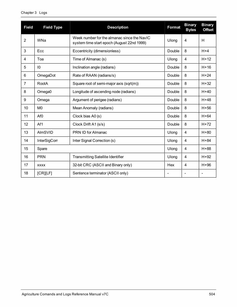
Chapter 3 Logs
Agriculture Comands and Logs Reference Manual v7C 504
Field Field Type Description Format BinaryBytes
BinaryOffset
2 WNa Week number for the almanac since the NavICsystem time start epoch (August 22nd 1999) Ulong 4 H
3 Ecc Eccentricity (dimensionless) Double 8 H+4
4 Toa Time of Almanac (s) Ulong 4 H+12
5 I0 Inclination angle (radians) Double 8 H+16
6 OmegaDot Rate of RAAN (radians/s) Double 8 H+24
7 RootA Square root of semi-major axis (sqrt(m)) Double 8 H+32
8 Omega0 Longitude of ascending node (radians) Double 8 H+40
9 Omega Argument of perigee (radians) Double 8 H+48
10 M0 Mean Anomaly (radians) Double 8 H+56
11 Af0 Clock bias A0 (s) Double 8 H+64
12 Af1 Clock Drift A1 (s/s) Double 8 H+72
13 AlmSVID PRN ID for Almanac Ulong 4 H+80
14 InterSigCorr Inter Signal Correction (s) Ulong 4 H+84
15 Spare Ulong 4 H+88
16 PRN Transmitting Satellite Identifier Ulong 4 H+92
17 xxxx 32-bit CRC (ASCII and Binary only) Hex 4 H+96
18 [CR][LF] Sentence terminator (ASCII only) - - -

Chapter 3 Logs
Agriculture Comands and Logs Reference Manual v7C 505
3.86 NAVICEPHEMERISDecoded NavIC Ephemeris
Platform: OEM719, OEM729, OEM7500, OEM7600, OEM7700, OEM7720, PwrPak7, SPAN CPT7,SMART7
This log contains NavIC ephemeris parameters with the appropriate scaling applied. Multiple messages aretransmitted, one for each SV ephemeris collected.
Message ID: 2123
Log Type: Asynch
Recommended Input:log navicephemerisa onchanged
ASCII Example:#NAVICEPHEMERISA,COM1,5,74.0,SATTIME,1943,255984.000,02000020,01fa,32768;2,919,1.05838757e-04,-5.63886715e-11,0.00000000,0,252000,-1.86e-09,3.2829938927e-09,11,0,0,0,1.922249794e-06,1.032650471e-05,2.011656761e-07,4.097819328e-08,-230.9375000,66.1250000,-5.239503961e-10,0,1.900019163,252000,1.8492219970e-03,6493.385761,1.842761896e+00,3.027013584,-2.94012247e-09,5.0965660552e-01,0,0,0*d2f4c9a5
#NAVICEPHEMERISA,COM1,4,74.0,SATTIME,1943,255984.000,02000020,01fa,32768;6,919,-5.79587650e-04,1.02318154e-11,0.00000000,1,252000,-1.86e-09,8.5817860373e-09,11,0,0,0,-1.282989979e-05,2.417713404e-06,1.974403858e-07,2.644956112e-07,-83.3125000,-395.3125000,-5.535944880e-10,0,2.050709297,252000,1.9699299010e-03,6493.408867,1.328589850e+00,2.996532035,-7.66746224e-09,7.5298187077e-02,0,0,0*50cdb388
...
#NAVICEPHEMERISA,COM1,0,74.0,SATTIME,1943,255984.000,02000020,01fa,32768;7,919,1.90386083e-04,-8.28777047e-11,0.00000000,1,255024,-1.40e-09,6.3988379659e-09,252,0,0,0,-8.992850780e-06,-1.732259989e-06,-9.313225746e-08,-2.235174179e-08,60.1250000,-266.1875000,-3.928735076e-10,0,-0.445949980,255024,2.4348858278e-04,6493.269802,1.351327715e+00,1.099632488,-5.54308803e-09,7.6573741924e-02,0,0,0*01bf330e
Field Field Type Description Format BinaryBytes
BinaryOffset
1 NAVICEPHEMERISheader
Log header. SeeMessages on page 26 for moreinformation. - H 0
2 PRN Satellite Identifier Ulong 4 H
3 WN Week number since the NavIC system time startepoch (August 22nd 1999) Ulong 4 H+4
4 Af0 Clock bias (s) Double 8 H+8

Chapter 3 Logs
Agriculture Comands and Logs Reference Manual v7C 506
Field Field Type Description Format BinaryBytes
BinaryOffset
5 Af1 Clock drift (s/s) Double 8 H+16
6 Af2 Clock drift rate (s/s2) Double 8 H+24
7 URA SV Accuracy Ulong 4 H+32
8 toc Reference time for the satellite clock corrections (s) Ulong 4 H+36
9 TGD Total group delay (s) Double 8 H+40
10 DeltaN Meanmotion difference (radian/s) Double 8 H+48
11 IODEC Issue of data ephemeris and clock Ulong 4 H+56
12 Reserved Ulong 4 H+60
13 L5 HealthHealth status of navigation data on L5 SPS signal
0=OK; 1=badUlong 4 H+64
14 S HealthHealth status of navigation data on S SPS signal
0=OK; 1=badUlong 4 H+68
15 Cuc Amplitude of the cosine harmonic correction term tothe argument of latitude (radians) Double 8 H+72
16 Cus Amplitude of the sine harmonic correction term to theargument of latitude (radians) Double 8 H+80
17 Cic Amplitude of the cosine harmonic correction term tothe angle of inclination (radians) Double 8 H+88
18 Cis Amplitude of the sine harmonic correction term to theangle of inclination (radians) Double 8 H+96
19 Crc Amplitude of the cosine harmonic correction term tothe orbit radius (m) Double 8 H+104
20 Crs Amplitude of the sine harmonic correction term to theorbit radius (m) Double 8 H+112
21 IDOT Rate of inclination angle (radians/s) Double 8 H+120
22 Spare Ulong 4 H+128
23 M0 Mean anomaly (radians) Double 8 H+132
24 toe Time of ephemeris (s) Ulong 4 H+140
25 Ecc Eccentricity (dimensionless) Double 8 H+144
26 RootA Square root of semi-major axis (sqrt(m)) Double 8 H+152
27 Omega0 Longitude of ascending node (radians) Double 8 H+160

Chapter 3 Logs
Agriculture Comands and Logs Reference Manual v7C 507
Field Field Type Description Format BinaryBytes
BinaryOffset
28 Omega Argument of perigee (radians) Double 8 H+168
29 OmegaDot Rate of RAAN (radians/s) Double 8 H+176
30 I0 Inclination angle (radians) Double 8 H+184
31 Spare Ulong 4 H+192
32 Alert flagThe utilization of navigation data shall be at theusers’ own risk.
1=Alert; 0=OKUlong 4 H+196
33 AutoNav flag
When set to 1, satellite is in AutoNav mode.Satellite broadcasts primary navigation parametersfrom AutoNav data sets with no uplink from groundfor maximum of 7 days
Ulong 4 H+200
34 xxxx 32-bit CRC (ASCII and Binary only) Hex 4 H+204
35 [CR][LF] Sentence terminator (ASCII only) - - -

Chapter 3 Logs
Agriculture Comands and Logs Reference Manual v7C 508
3.87 NAVICIONONavIC ionospheric coefficients parameters
Platform: OEM719, OEM729, OEM7500, OEM7600, OEM7700, OEM7720, PwrPak7, SPAN CPT7,SMART7
This log contains NavIC ionospheric coefficients parameters. Ionospheric error correction for single frequency(L5) users of the NavIC are provided through a set of eight coefficients. The correction coefficients are:
l 4 Alpha Coefficients (αn; n=0,1,2,3)
These are the coefficients of the cubic polynomial representing the amplitude of the positive cosine curve inthe cosinemodel approximation of ionospheric delay.
l 4 Beta Coefficients (βn; n=0,1,2,3)
These are the coefficients of the cubic polynomial representing the period of the positive cosine curve in thecosinemodel approximation of ionospheric delay.
Message ID: 2124
Log Type: Asynch
Recommended Input:log navicionoa onchanged
ASCII Example:#NAVICIONOA,COM1,0,92.5,SATTIME,1944,166272.000,02000020,56c0,32768;5,2.980232238769531e-08,3.874301910400390e-07,-2.562999725341796e-06,-7.510185241699216e-06,558.0,168.0,-2286.0,2286.0,0*2b250bbd
Field Field Type Description Format BinaryBytes
BinaryOffset
1 NAVICIONOheader
Log header. SeeMessages on page 26 for moreinformation. - H 0
2 PRN Satellite Identifier of the transmitting NavIC SV Ulong 4 H
3 Alpha 0 Alpha parameter constant term Double 8 H+4
4 Alpha 1 Alpha parameter 1st order term Double 8 H+12
5 Alpha 2 Alpha parameter 2nd order term Double 8 H+20
6 Alpha 3 Alpha parameter 3rd order term Double 8 H+28
7 Beta 0 Beta parameter constant term Double 8 H+36
8 Beta 1 Beta parameter 1st order term Double 8 H+44
9 Beta 2 Beta parameter 2nd order term Double 8 H+52
10 Beta 3 Beta parameter 3rd order term Double 8 H+60
11 Spare Ulong 4 H+68

Chapter 3 Logs
Agriculture Comands and Logs Reference Manual v7C 509
Field Field Type Description Format BinaryBytes
BinaryOffset
12 xxxx 32-bit CRC (ASCII and Binary only) Hex 4 H+72
13 [CR][LF] Sentence terminator (ASCII only) - - -

Chapter 3 Logs
Agriculture Comands and Logs Reference Manual v7C 510
3.88 NAVICRAWSUBFRAMERaw NavIC subframe data
Platform: OEM719, OEM729, OEM7500, OEM7600, OEM7700, OEM7720, PwrPak7, SPAN CPT7,SMART7
This log contains the raw NavIC subframe data with parity bits removed. Only subframes that have passed theparity check are output.
Message ID: 2105
Log Type: Asynch
Recommended Input:log navicrawsubframea onchanged
ASCII Example:#NAVICRAWSUBFRAMEA,COM1,0,72.5,SATTIME,1943,159168.000,02000020,76af,32768;182,7,1,8b19e883971a005bf4880009ab3f400eac0af84f7541befff78018e6d7e1dfacd1*88c2ba19
#NAVICRAWSUBFRAMEA,COM1,0,72.5,SATTIME,1943,159168.000,02000020,76af,32768;177,2,1,8b19e883970e8fc3f8500009ab3f00087f0af8415e4232800f7fd9eb8650b7b630*c7e27e82
#NAVICRAWSUBFRAMEA,COM1,0,72.5,SATTIME,1943,159168.000,02000020,76af,32768;181,6,1,8b19e88397b3e73401600009ab3f0012370af84f550327c032800ad1d9da339260*0bb7b256
#NAVICRAWSUBFRAMEA,COM1,0,72.5,SATTIME,1943,159168.000,02000020,76af,32768;180,5,1,8b19e88397036703ff1c0049ab3fc009b10af84fe7e3773ffd7fd6d8f5fddc4181*f42f59ab
Field Field Type Description Format BinaryBytes
BinaryOffset
1 NAVICRAWSUBFRAMEheader
Log header. SeeMessages on page 26 formore information. - H 0
2 Signal channel Signal channel providing the data Ulong 4 H
3 PRN Satellite Identifier of transmitting NavICSV Ulong 4 H+4
4 Subframe Id Subframe ID Ulong 4 H+8
5 Raw subframe dataRaw subframe data (262 bits).
Does not include CRC or Tail bitsHex[33] 33 H+12
6 xxxx 32-bit CRC (ASCII and Binary only) Hex 4 H+45
7 [CR][LF] Sentence terminator (ASCII only) - - -

Chapter 3 Logs
Agriculture Comands and Logs Reference Manual v7C 511
3.89 NAVICSYSCLOCKNavIC clock parameters
Platform: OEM719, OEM729, OEM7500, OEM7600, OEM7700, OEM7720, PwrPak7, SPAN CPT7,SMART7
This log provides the NavIC system time offset with respect to UTC, UTC (NPLI) and other GNSS times suchas GPS, GALILEO, GLONASS.
Message ID: 2125
Log Type: Asynch
Recommended Input:log navicsysclocka onchanged
ASCII Example:#NAVICSYSCLOCKA,COM1,0,93.0,SATTIME,1944,166320.000,02000020,3dfd,32768;7,-7.625203579664230e-09,-1.598721155460225e-14,0.000000000000000e+00,18,32508,920,905,7,18,2,2.149608917534351e-07,-5.151434834260726e-14,-1.998997755520149e-19,32508,920,0*f6617e67
Field Field Type Description Format BinaryBytes
BinaryOffset
1 NAVICSYSCLOCKheader
Log header. SeeMessages on page 26 for moreinformation. H 0
2 PRN Satellite Identifier of the transmitting NavIC SV Ulong 4 H
3 A0utcBias coefficient of the NavIC time scale relative to theUTC time scale (s) Double 8 H+4
4 A1utcDrift coefficient of the NavIC time scale relative to theUTC time scale (s/s) Double 8 H+12
5 A2utcDrift rate coefficient of the NavIC time scale relativeto the UTC time scale (s/s2) Double 8 H+20
6 ΔtLS Current or past leap second count (s) Long 4 H+28
7 Toutc Time data reference time of week (s) Ulong 4 H+32
8 WNoutc Time data reference week number Ulong 4 H+36
9 WNLSF Leap second reference week number Ulong 4 H+40
10 DN Leap second reference day number Ulong 4 H+44
11 ΔtLSF Current or future leap second count (s) Long 4 H+48
12 GNSSID Timescale for the time offsets with respect to NavIC(Table 108: GNSS Time Scales on the next page) Ulong 4 H+52

Chapter 3 Logs
Agriculture Comands and Logs Reference Manual v7C 512
Field Field Type Description Format BinaryBytes
BinaryOffset
13 A0 Bias coefficient of the NavIC time scale relative to theGNSS time scale (s) Double 8 H+56
14 A1 Drift coefficient of the NavIC time scale relative to theGNSS time scale (s/s) Double 8 H+64
15 A2 Drift rate correction coefficient of the NavIC timescale relative to the GNSS time scale (s/s2) Double 8 H+72
16 Tot Time data reference time of week (s) Ulong 4 H+80
17 WNot Time data reference week number Ulong 4 H+84
18 Spare Ulong 4 H+88
19 xxxx 32-bit CRC (ASCII and Binary only) Hex 4 H+92
20 [CR][LF] Sentence terminator (ASCII only) - - -
GNSS ID Time Scale
0 GPS
1 GALILEO
2 GLONASS
3-6 Reserved
7 UTC (NPLI)
Table 108: GNSS TimeScales

Chapter 3 Logs
Agriculture Comands and Logs Reference Manual v7C 513
3.90 NMEA Standard LogsPlatform: OEM719, OEM729, OEM7500, OEM7600, OEM7700, OEM7720, PwrPak7, SPAN CPT7,
SMART7, SMART2
This log contains NMEA logs.
GLMLA GLONASS Almanac DataGPALM Almanac DataGPGGA Global Position System Fix Data and UndulationGPGGALONG GPS Fix Data, Extra Precision and UndulationGPGLL Geographic PositionGPGRS GPS Range Residuals for Each SatelliteGPGSA GPS DOP on Active SatellitesGPGST Estimated Error in Position SolutionGPGSV GPS Satellites in ViewGPHDT NMEA Heading Log (ALIGN)GPRMB Navigation InformationGPRMC GPS Specific InformationGPVTG Track Made Good and Ground SpeedGPZDA UTC Time and Date
The NMEA log structures follow format standards as adopted by the National Marine Electronics Association.The reference document used is "Standard For InterfacingMarine Electronic Devices NMEA 0183 Version3.01". For further information, refer to www.nmea.org. The following table contains excerpts from Table 6 of theNMEA Standard which defines the variables for the NMEA logs. The actual format for each parameter is indic-ated after the description.
See the Note in theGPGGA log (see page 417) that applies to all NMEA logs.
1. Spaces may only be used in variable text fields.
2. A negative sign "-" (HEX 2D) is the first character in a Field if the value is negative. The sign is omit-ted if the value is positive.
3. All data fields are delimited by a comma (,).
4. Null fields are indicated by no data between two commas (,,). Null fields indicate invalid data or nodata available.
5. The NMEA Standard requires that message length be limited to 82 characters.
Field Type Symbol Definition
Special Format Fields

Chapter 3 Logs
Agriculture Comands and Logs Reference Manual v7C 514
Field Type Symbol Definition
Status A
Single character field:
A = Yes, Data Valid, Warning Flag Clear
V = No, Data Invalid, Warning Flag Set
Latitude llll.ll
Fixed/Variable length field:
degrees|minutes.decimal - 2 fixed digits of degrees, 2 fixed digits of mins and avariable number of digits for decimal-fraction of minutes. Leading zeros alwaysincluded for degrees andminutes tomaintain fixed length. The decimal point andassociated decimal-fraction are optional if full resolution is not required
Longitude yyyyy.yy
Fixed/Variable length field:
degrees|minutes.decimal - 3 fixed digits of degrees, 2 fixed digits of minutes and avariable number of digits for decimal-fraction of minutes. Leading zeros alwaysincluded for degrees andminutes tomaintain fixed length. The decimal point andassociated decimal-fraction are optional if full resolution is not required
Time hhmmss.ss
Fixed/Variable length field:
hours|minutes|seconds.decimal - 2 fixed digits of hours, 2 fixed digits of minutes, 2fixed digits of seconds and variable number of digits for decimal-fraction of seconds.Leading zeros always included for hours, minutes and seconds tomaintain fixedlength. The decimal point and associated decimal-fraction are optional if full resolutionis not required.
Defined field
Some fields are specified to contain predefined constants, most often alphacharacters. Such a field is indicated in this standard by the presence of one or morevalid characters. Excluded from the list of allowable characters are the followingwhich are used to indicate field types within this standard:
"A", "a", "c", "hh", "hhmmss.ss", "llll.ll", "x", "yyyyy.yy"
Numeric Value Fields
Variablenumbers x.x
Variable length integer or floating numeric field. Optional leading and trailing zeros.The decimal point and associated decimal-fraction are optional if full resolution is notrequired(example: 73.10 = 73.1 = 073.1 = 73)
Fixed HEXfield hh___ Fixed length HEX numbers only, MSB on the left
Information Fields
Variable text c--c Variable length valid character field
Fixed alphafield aa___ Fixed length field of uppercase or lowercase alpha characters
Fixednumber field xx___ Fixed length field of numeric characters
Fixed textfield cc___ Fixed length field of valid characters

Chapter 3 Logs
Agriculture Comands and Logs Reference Manual v7C 515
3.91 NOVATELXOBSNovAtel proprietary RTK correction
Platform: OEM719, OEM729, OEM7500, OEM7600, OEM7700, OEM7720, PwrPak7, SPAN CPT7,SMART7
NOVATELX is a combined observation and reference stationmessage used to transmit RTK corrections. This isa proprietary message and supports sending data for all systems.
Message ID: 1618
Log Type: Synch
Recommended Input:log com2 novatelxobs ontime 1
To calculate the size of the NOVATELXOBS messages, use the following formula.
Size = 168 + s * (6 + p * (54 + f*33) )
where:
s = number of systems (maximum 8)
p = number of PRN per system (maximum 64)
f = number of signals data per PRN – 1 (maximum 10 signals possible)
Example size calculations:
l For 2 systems (GPS andGLONASS), 12 PRN per system, and 2 signals per satellite (L1CA, L2PY)
Size = 168 + 2 * (6 + 12 * (54 + 33))= 2268 bits per second= 284 bytes + NovAtelXHeader (8 bytes)
l For 3 systems (GPS, BEIDOU andGLONASS), 12 PRN per system, and 2 signals per satellite (L1CA,L2PY)
Size = 168 + 3 * (6 + 12 * (54 + 33))= 3318 bits per second= 415 bytes + NovAtelXHeader (8 bytes)
l For 3 systems (GPS, BEIDOU andGLONASS), 12 PRN per system, and 3 signals per satellite (L1CA,L2PY, L2C)
Size = 168 + 3 * (6 + 12 * (54 + 2*33))= 4506 bits per second= 564 bytes + NovAtelXHeader (8 bytes)

Chapter 3 Logs
Agriculture Comands and Logs Reference Manual v7C 516
3.92 NOVATELXREFNovAtel proprietary reference station message for use in ALIGN
Platform: OEM719, OEM729, OEM7500, OEM7600, OEM7700, OEM7720, PwrPak7, SPAN CPT7,SMART7
NOVATELXREF is a proprietary extended reference stationmessage for use in ALIGN configurations only. Thismessage enables the output of theMASTERPOS log (see page 491), ROVERPOS log (see page 630) andALIGNBSLNENU log (see page 324) on the rover.
Message ID: 1620
Log Type: Synch
Recommended Input:log com2 novatelxref ontime 1

Chapter 3 Logs
Agriculture Comands and Logs Reference Manual v7C 517
3.93 OCEANIXINFOOceanix subscription information
Platform: OEM719, OEM729, OEM7500, OEM7600, OEM7700, OEM7720, PwrPak7, SPAN CPT7,SMART7
This log contains details on the Oceanix subscription.
Message ID: 2159
Log Type: Asynch
Recommended Input:log oceanixinfoa onchanged
ASCII Example:#OCEANIXINFOA,COM1,0,83.0,FINESTEERING,1987,253328.270,02040020,9ce8,14635;"QU242:3004:3631",TERM,80001803,44,2018,0,NEARSHORE*de2b56e3
Field Field Type Description Format BinaryBytes
BinaryOffset
1 OCEANIXINFOheader
Log header. SeeMessages on page 26 for moreinformation. H 0
2 PAC Product activation code Char[16] 16 H
3 Type Subscription type (see Table 109: Oceanix SubscriptionType on the next page) Enum 4 H+16
4 Subscriptionpermissions
Services permitted by the subscription (see Table 110:Oceanix Subscription Details Mask on the next page)
Note: Bits in the Reserved areas of this field may be set,but the Reserved bits should be ignored.
Hex 4 H+20
5 Service EndDay
Last day of the year for which service is available. Serviceexpires at the end of this UTC day.
For example, if the Service End Year and Day are 2019and 15, respectively, then the service will expire onJanuary 15, 2019 at 24:00 UTC.
Ulong 4 H+24
6 Service EndYear Year that the subscription ends. Ulong 4 H+28
7 Reserved Ulong 4 H+32
8 Regionrestriction
For region restricted subscriptions, the type of regionrestriction (see Table 111: Oceanix Region Restriction onthe next page)
Enum 4 H+36
9 xxxx 32-bit CRC (ASCII and Binary only) Ulong 4 H+40
10 [CR][LF] Sentence terminator (ASCII only) - - -

Chapter 3 Logs
Agriculture Comands and Logs Reference Manual v7C 518
ASCII Binary Description
UNASSIGNED 0 Decoder has not had an assigned operatingmode
TERM 1 Term subscription
MODEL 5 Reserved
BUBBLE 100 Receiver is operating in anOceanix-permitted subscription-freebubble
INCOMPATIBLE_SUBSCRIPTION 104 Subscription is incompatible with this version of firmware
Table 109: Oceanix Subscription Type
Bit Mask Description
0 0x00000001 Reserved
1 0x00000002 Oceanix - H service
2-31 0xFFFFFFFC Reserved
Table 110: Oceanix Subscription DetailsMask
ASCII Binary Description
NONE 0 Oceanix operation has no region restrictions
GEOGATED 1 Oceanix operation is limited to land regions. GEOGATED is also the default valuereported if there is no subscription
NEARSHORE 3 Oceanix operation is limited to land and near shore (coastal) regions
Table 111: Oceanix Region Restriction

Chapter 3 Logs
Agriculture Comands and Logs Reference Manual v7C 519
3.94 OCEANIXSTATUSOceanix decoder and subscription status
Platform: OEM719, OEM729, OEM7500, OEM7600, OEM7700, OEM7720, PwrPak7, SPAN CPT7,SMART7
This log contains status information for the Oceanix decoder and subscription.
Message ID: 2160
Log Type: Asynch
Recommended Input:log oceanixstatusa onchanged
ASCII Example:#OCEANIXSTATUSA,COM1,0,89.0,FINESTEERING,1982,315542.430,03000020,049a,32768;ENABLE,LOCKED,IN_REGION*954083ea
Field Field Type Description Format BinaryBytes
BinaryOffset
1 OCEANIXSTATUSheader
Log header. SeeMessages on page 26 for moreinformation. H 0
2 Access
Access status.
ENABLE (1) if the subscription is valid.
DISABLE (0) otherwise
Enum 4 H
3 Sync state Decoder data synchronization state (see Table 112:Decoder Data Synchronization State below) Enum 4 H+4
4 Region restrictionstatus
Region restriction status (see Table 113: RegionRestriction Status on the next page) Enum 4 H+8
5 xxxx 32-bit CRC (ASCII and Binary only) Ulong 4 H+12
6 [CR][LF] Sentence terminator (ASCII only) - - -
ASCII Binary Description
NO_SIGNAL 0 None of the decoders have received data in the last 30 seconds
SEARCH 1 At least one decoder is receiving data and is searching for the format
LOCKED 2 At lease one decoder has locked onto the format
Table 112: Decoder Data Synchronization State

Chapter 3 Logs
Agriculture Comands and Logs Reference Manual v7C 520
ASCII Binary Description
UNKNOWN 0 Region restriction status cannot be determined
IN_REGION 1 Receiver is within the permitted region
OUT_OF_REGION 2 Receiver is outside the permitted region
Table 113: Region Restriction Status

Chapter 3 Logs
Agriculture Comands and Logs Reference Manual v7C 521
3.95 PASSCOM, PASSAUX, PASSUSB, PASSETH1, PASSICOM, PASSNCOMRedirects data
Platform: OEM719, OEM729, OEM7500, OEM7600, OEM7700, OEM7720, PwrPak7, SPAN CPT7,SMART7, SMART2
The pass-through logging feature enables the receiver to redirect any ASCII or binary data, input at a specifiedport, to any specified receiver port. It allows the receiver to perform bi-directional communications with otherdevices such as amodem, terminal or another receiver. See also the INTERFACEMODE command onpage 136.
There aremany pass through logs: PASSCOM1, PASSCOM2, PASSCOM3, PASSCOM4, PASSCOM5,PASSCOM6, PASSAUX, PASSETH1, PASSICOM1, PASSICOM2, PASSICOM3, PASSICOM4,PASSICOM5, PASSICOM6, PASSICOM7, PASSNCOM1, PASSNCOM2, PASSNCOM3 allow for redirectionof data that is arriving at COM1, COM2, COM3, virtual COM1, virtual COM2 or AUX. PASSCOM4 andPASSCOM5 are only available onOEM7600, OEM7700 andOEM7720 receivers. The AUX port is available onsome products. PASSUSB1, PASSUSB2, PASSUSB3 are used to redirect data from USB1, USB2 or USB3.PASSETH1 is only available on receivers supporting Ethernet and can be used to redirect data from ETH1.
A pass through log is initiated the same as any other log, that is, log [to-port] [data-type] [trigger]. However,pass-through can bemore clearly specified as: log [to-port] [from-port-AB] [onchanged]. Now, the [from-port-AB]field designates the port which accepts data (that is, COM1, COM2, COM3, COM4, COM5, COM6, AUX,USB1, USB2 or USB3) as well as the format in which the data is logged by the [to-port] (A for ASCII or B for Bin-ary).
To pass through data arriving on all ports, use thePASSTHROUGH log (see page 526).
When the [from-port-AB] field is suffixed with an [A], all data received by that port is redirected to the [to-port] inASCII format and logs according to standard NovAtel ASCII format. Therefore, all incoming ASCII data is redir-ected and output as ASCII data. However, any binary data received is converted to a form of ASCII hexadecimalbefore it is logged.
When the [from-port-AB] field is suffixed with a [B], all data received by that port is redirected to the [to-port]exactly as it is received. The log header and time tag adhere to standard NovAtel Binary format followed by thepass through data as it was received (ASCII or binary).
Pass through logs are best utilized by setting the [trigger] field as onchanged or onnew.
If the data being injected is ASCII, then the data is grouped together with the following rules:
l blocks of 80 characters
l any block of characters ending in a <CR>
l any block of characters ending in a <LF>
l any block remaining in the receiver code when a timeout occurs (100ms)
If the data being injected is binary or the port INTERFACEMODE mode is set to GENERIC, then the data isgrouped as follows:
l blocks of 80 bytes
l any block remaining in the receiver code when a timeout occurs (100ms)
If a binary value is encountered in an ASCII output, then the byte is output as a hexadecimal byte preceded by abackslash and an x. For example 0A is output as \x0A. An actual ‘\’ in the data is output as \\. The output countsas one pass through byte although it is four characters.

Chapter 3 Logs
Agriculture Comands and Logs Reference Manual v7C 522
The first character of each pass-through record is time tagged in GPS reference weeks and seconds.
PASSAUX Message ID: 690PASSCCOM1 Message ID: 1893PASSCCOM2 Message ID: 1894PASSCCOM3 Message ID: 1895PASSCCOM4 Message ID: 1930PASSCCOM5 Message ID: 1937PASSCCOM6 Message ID: 1938PASSCOM1 Message ID: 233PASSCOM2 Message ID: 234PASSCOM3 Message ID: 235PASSCOM4 Message ID: 1384PASSCOM5 Message ID: 1576PASSCOM6 Message ID: 1577PASSCOM7 Message ID: 1701PASSCOM8 Message ID: 1702PASSCOM9 Message ID: 1703PASSCOM10 Message ID: 1704PASSETH1 Message ID: 1209PASSICOM1 Message ID: 1250PASSICOM2 Message ID: 1251PASSICOM3 Message ID: 1252PASSICOM4 Message ID: 1385PASSICOM5 Message ID: 2119PASSICOM6 Message ID: 2120PASSICOM7 Message ID: 2121PASSNCOM1 Message ID: 1253PASSNCOM2 Message ID: 1254PASSNCOM3 Message ID: 1255PASSUSB1 Message ID: 607PASSUSB2 Message ID: 608PASSUSB3 Message ID: 609
Log Type: Asynch
Recommended Input:log passcom1a onchanged
Asynchronous logs should only be loggedONCHANGED otherwise themost current data is not outputwhen it is available. This is especially true of the ONTIME trigger, whichmay cause inaccurate timetags to result.
ASCII Example 1:#PASSCOM2A,COM1,0,59.5,FINESTEERING,1337,400920.135,02000000,2b46,1984;80,#BESTPOSA,COM3,0,80.0,FINESTEERING,1337,400920.000,02000000,4ca6,1899;

Chapter 3 Logs
Agriculture Comands and Logs Reference Manual v7C 523
SOL_COMPUT*f9dfab46#PASSCOM2A,COM1,0,64.0,FINESTEERING,1337,400920.201,02000000,2b46,1984;80,ED,SINGLE,51.11636326036,-114.03824210485,1062.6015,-16.2713,WGS84,1.8963,1.0674*807fd3ca#PASSCOM2A,COM1,0,53.5,FINESTEERING,1337,400920.856,02000000,2b46,1984;49,,2.2862,"",0.000,0.000,9,9,0,0,0,0,0,0*20b24878\x0d\x0a*3eef4220#PASSCOM1A,COM1,0,53.5,FINESTEERING,1337,400922.463,02000000,13ff,1984;17,unlog passcom2a\x0d\x0a*ef8d2508
ASCII Example 2:#PASSCOM2A,COM1,0,53.0,FINESTEERING,1337,400040.151,02000000,2b46,1984;80,\x99A\x10\x04\x07yN&\xc6\xea\xf10\x00\x01\xde\x00\x00\x10\xfe\xbf\xfe1\xfe\x9c\xf4\x03\xe2\xef\x9f\x1f\xf3\xff\xd6\xff\xc3_A~z\xaa\xfe\xbf\xf9\xd3\xf8\xd4\xf4-\xe8kHo\xe2\x00>\xe0QOC>\xc3\x9c\x11\xff\x7f\xf4\xa1\xf3t\xf4'\xf4xvo\xe6\x00\x9d*dcd2e989
In the example, note that ‘~’ is a printable character.
For example, you could connect twoOEM7 family receivers together via their COM1 ports such as inthe Figure 8: Pass Through Log Data on the next page (a rover station to base station scenario). If therover station is logging BESTPOSA data to the base station, it is possible to use the pass through logsto pass through the received BESTPOSA data to a disk file (let's call it diskfile.log) at the base stationhost PC hard disk.

Chapter 3 Logs
Agriculture Comands and Logs Reference Manual v7C 524
Figure 8: Pass Through Log Data
Under default conditions, the two receivers "chatter" back and forth with the Invalid CommandOptionmessage(due to the command interpreter in each receiver not recognizing the command prompts of the other receiver).The chattering in turn causes the accepting receiver to transmit new pass through logs with the response datafrom the other receiver. To avoid the chattering problem, use the INTERFACEMODE command (see page 136)on the accepting port to disable error reporting from the receiving port command interpreter.
If the accepting port's error reporting is disabled by INTERFACEMODE, the BESTPOSA data record passesthrough and creates two records.
The reason that two records are logged from the accepting receiver is the first record was initiated by receipt ofthe BESTPOSA first terminator <CR>. The second record followed in response to the BESTPOSA second ter-minator <LF>.
Note the time interval between the first character received and the terminating <LF> can be calculated by dif-ferencing the twoGPS reference time tags. This pass through feature is useful for time tagging the arrival ofexternal messages. Thesemessages can be any user related data. When using this feature for tagging externalevents, it is recommended that the rover receiver be disabled from interpreting commands so the receiver doesnot respond to themessages, using the INTERFACEMODE command (see page 136).
If the BESTPOSB binary log data is input to the accepting port (log com2 passcom1a onchanged), theBESTPOSB binary data at the accepting port is converted to a variation of ASCII hexadecimal before it ispassed through to com2 port for logging.

Chapter 3 Logs
Agriculture Comands and Logs Reference Manual v7C 525
Field Field Type Description Format BinaryBytes
BinaryOffset
1 PASSCOMheader
Log header. SeeMessages on page 26 for moreinformation. H 0
2 #bytes Number of bytes to follow Ulong 4 H
3 data Message data Char[80] 80 H+4
4 xxxx 32-bit CRC (ASCII and Binary only) Ulong 4 H+4+(#bytes)
5 [CR][LF] Sentence terminator (ASCII only) - - -

Chapter 3 Logs
Agriculture Comands and Logs Reference Manual v7C 526
3.96 PASSTHROUGHRedirected data from all ports
Platform: OEM719, OEM729, OEM7500, OEM7600, OEM7700, OEM7720, PwrPak7, SPAN CPT7,SMART7, SMART2
This log outputs pass through data from all receiver ports. The behavior is the same as the port specific passthough logs described inPASSCOM, PASSAUX, PASSUSB, PASSETH1, PASSICOM, PASSNCOM onpage 521.
Message ID: 1342
Log Type: Asynch
Recommended Input:log passthrougha onchanged
ASCII Example:#PASSTHROUGHA,COM1,0,73.0,FINESTEERING,1625,165965.067,02040008,5fa3,39275;USB1,80,i\xd3\x00\x87>\xb0\x00'\x91\xb3"\xa0D?\xaa\xb2\x00\x07op\x18@\x05\xe9\xd4\x08\xe7\x03\x7f\xfd\x18{\x80w\xff\xf2N_cy\x11\x80\x0bC\xdc\x01@\x00\xdfr\xb1`\x873\xff\x81]\x7f\xe3\xff\xea\x83v\x08M\xd8?\xfcr\xf7\x01\x18\x00\x17\x1d2\xd1\xd1b\x00*5cb8bd9a
Field Field type Description Format BinaryBytes
BinaryOffset
1 PASSTHROUGHheader
Log header. SeeMessages on page 26 formore information. H 0
2 Port See Table 51: COM Port Identifiers onpage 256 Enum 4 H
3 #bytes Number of bytes to follow Ulong 4 H+4
4 data Message data Char[80] 80 H+8
5 xxxx 32-bit CRC (ASCII and Binary only) Ulong 4 H+8+#bytes
6 [CR][LF] Sentence terminator (ASCII only) - - -
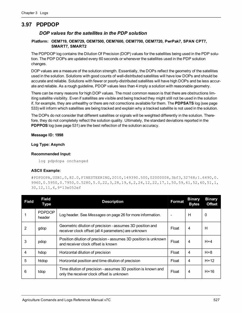
Chapter 3 Logs
Agriculture Comands and Logs Reference Manual v7C 527
3.97 PDPDOPDOP values for the satellites in the PDP solution
Platform: OEM719, OEM729, OEM7500, OEM7600, OEM7700, OEM7720, PwrPak7, SPAN CPT7,SMART7, SMART2
The PDPDOP log contains the Dilution Of Precision (DOP) values for the satellites being used in the PDP solu-tion. The PDP DOPs are updated every 60 seconds or whenever the satellites used in the PDP solutionchanges.
DOP values are ameasure of the solution strength. Essentially, the DOPs reflect the geometry of the satellitesused in the solution. Solutions with good counts of well-distributed satellites will have low DOPs and should beaccurate and reliable. Solutions with fewer or poorly-distributed satellites will have high DOPs and be less accur-ate and reliable. As a rough guideline, PDOP values less than 4 imply a solution with reasonable geometry.
There can bemany reasons for high DOP values. Themost common reason is that there are obstructions lim-iting satellite visibility. Even if satellites are visible and being tracked they might still not be used in the solutionif, for example, they are unhealthy or there are not corrections available for them. ThePDPSATS log (see page533) will inform which satellites are being tracked and explain why a tracked satellite is not used in the solution.
The DOPs do not consider that different satellites or signals will be weighted differently in the solution. There-fore, they do not completely reflect the solution quality. Ultimately, the standard deviations reported in thePDPPOS log (see page 531) are the best reflection of the solution accuracy.
Message ID: 1998
Log Type: Asynch
Recommended Input:log pdpdopa onchanged
ASCII Example:#PDPDOPA,USB1,0,82.0,FINESTEERING,2010,149390.500,02000008,3bf3,32768;1.6490,0.9960,0.5950,0.7950,0.5280,5.0,22,3,28,19,6,2,24,12,22,17,1,50,59,61,52,60,51,1,30,12,11,6,9*13e052ef
Field FieldType Description Format Binary
BytesBinaryOffset
1 PDPDOPheader Log header. SeeMessages on page 26 for more information. - H 0
2 gdop Geometric dilution of precision - assumes 3D position andreceiver clock offset (all 4 parameters) are unknown Float 4 H
3 pdop Position dilution of precision - assumes 3D position is unknownand receiver clock offset is known Float 4 H+4
4 hdop Horizontal dilution of precision Float 4 H+8
5 htdop Horizontal position and time dilution of precision Float 4 H+12
6 tdop Time dilution of precision - assumes 3D position is known andonly the receiver clock offset is unknown Float 4 H+16

Chapter 3 Logs
Agriculture Comands and Logs Reference Manual v7C 528
Field FieldType Description Format Binary
BytesBinaryOffset
7 cutoff GPS elevation cut-off angle Float 4 H+20
8 #PRN Number of satellites PRNs to follow Long 4 H+24
9 PRN PRN of a satellite used in the position solution Ulong 4 H+28
10 Next PRN offset = H+28+(#prn x 4)
11 xxxx 32-bit CRC (ASCII and Binary only) Ulong 4H+28+(#prn x4)
12 [CR][LF] Sentence terminator (ASCII only) - - -

Chapter 3 Logs
Agriculture Comands and Logs Reference Manual v7C 529
3.98 PDPDOP2DOP values for the satellites used in the PDP solution
Platform: OEM719, OEM729, OEM7500, OEM7600, OEM7700, OEM7720, PwrPak7, SPAN CPT7,SMART7, SMART2
The PDPDOP2 log contains the Dilution Of Precision (DOP) values for the satellites being used in the PDP solu-tion. This log is similar to thePDPDOP log (see page 527) but contains the per-system TDOPs; see thePDPDOP log on page 527 for more information on the DOPs.
Message ID: 1995
Log Type: Asynch
Recommended Input:log pdpdop2a onchanged
ASCII Example:#PDPDOP2A,USB1,0,82.0,FINESTEERING,2010,149390.500,02000008,2488,32768;1.6490,0.9960,0.5950,0.7990,4,GPS,0.5280,GLONASS,0.6880,GALILEO,0.7200,BEIDOU,0.6750*25f8324a
Field Field type Description Format BinaryBytes
BinaryOffset
1 PDPDOP2header
Log header. SeeMessages on page 26 for moreinformation. H 0
2 GDOP Geometric dilution of precision - assumes 3D position andreceiver clock offset (all 4 parameters) are unknown Float 4 H
3 PDOP Position dilution of precision - assumes 3D position isunknown and receiver clock offset is known Float 4 H+4
4 HDOP Horizontal dilution of precision Float 4 H+8
5 VDOP Vertical dilution of precision Float 4 H+12
6 #systems Number of systems Ulong 4 H+16
7 system See Table 114: System Used for Timing on the next page Enum 4 H+20
8 TDOP Time dilution of precision Float 4 H+24
9 Next system offset = H+20+(#systems x 8)
10 xxxx 32-bit CRC (ASCII and Binary only) Hex 4H+20+(#systemsx 8)
11 [CR][LF] Sentence terminator (ASCII only) - - -

Chapter 3 Logs
Agriculture Comands and Logs Reference Manual v7C 530
Binary ASCII
0 GPS1
1 GLONASS
2 GALILEO
3 BEIDOU
4 NAVIC
99 AUTO2
Table 114: System Used for Timing
1GPS setting includes QZSS satellites.2AUTO is used only as a backup system (not available for primary system field).

Chapter 3 Logs
Agriculture Comands and Logs Reference Manual v7C 531
3.99 PDPPOSPDP filter position
Platform: OEM719, OEM729, OEM7500, OEM7600, OEM7700, OEM7720, PwrPak7, SPAN CPT7,SMART7, SMART2
The PDPPOS log contains the receiver position computed by the receiver with the PDP filter enabled. See alsothePDPFILTER command on page 188.
Message ID: 469
Log Type: Synch
Recommended Input:log pdpposa ontime 1
ASCII Example:#PDPPOSA,COM1,0,75.5,FINESTEERING,1431,494991.000,02040000,a210,35548;SOL_COMPUTED,SINGLE,51.11635010310,-114.03832575772,1065.5019,-16.9000,WGS84,4.7976,2.0897,5.3062,"",0.000,0.000,8,8,0,0,0,0,0,0*3cbfa646
Field Field type Description Format BinaryBytes
BinaryOffset
1 PDPPOSheader Log header. SeeMessages on page 26 for more information. H 0
2 sol status Solution status (refer to Table 65: Solution Status onpage 349) Enum 4 H
3 pos type Position type (refer to Table 66: Position or Velocity Type onpage 350) Enum 4 H+4
4 lat Latitude (degrees) Double 8 H+8
5 lon Longitude (degrees) Double 8 H+16
6 hgt Height abovemean sea level (m) Double 8 H+24
7 undulation
Undulation - the relationship between the geoid and theWGS84 ellipsoid (m)
When using a datum other thanWGS84, theundulation value also includes the vertical shiftdue to differences between the datum in useandWGS84.
Float 4 H+32
8 datum id#
Datum ID number
61 = WGS84
63 = USER
Enum 4 H+36
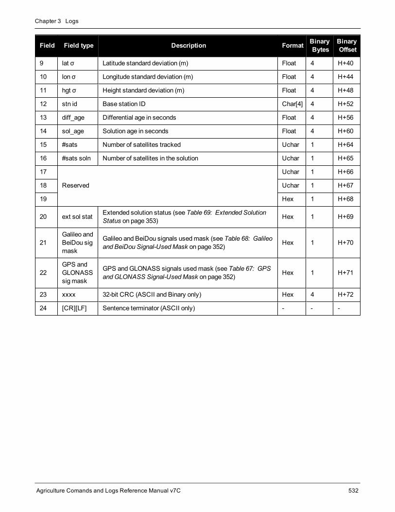
Chapter 3 Logs
Agriculture Comands and Logs Reference Manual v7C 532
Field Field type Description Format BinaryBytes
BinaryOffset
9 lat σ Latitude standard deviation (m) Float 4 H+40
10 lon σ Longitude standard deviation (m) Float 4 H+44
11 hgt σ Height standard deviation (m) Float 4 H+48
12 stn id Base station ID Char[4] 4 H+52
13 diff_age Differential age in seconds Float 4 H+56
14 sol_age Solution age in seconds Float 4 H+60
15 #sats Number of satellites tracked Uchar 1 H+64
16 #sats soln Number of satellites in the solution Uchar 1 H+65
17
Reserved
Uchar 1 H+66
18 Uchar 1 H+67
19 Hex 1 H+68
20 ext sol stat Extended solution status (see Table 69: Extended SolutionStatus on page 353) Hex 1 H+69
21Galileo andBeiDou sigmask
Galileo and BeiDou signals usedmask (see Table 68: Galileoand BeiDou Signal-UsedMask on page 352) Hex 1 H+70
22GPS andGLONASSsigmask
GPS andGLONASS signals usedmask (see Table 67: GPSandGLONASS Signal-UsedMask on page 352) Hex 1 H+71
23 xxxx 32-bit CRC (ASCII and Binary only) Hex 4 H+72
24 [CR][LF] Sentence terminator (ASCII only) - - -

Chapter 3 Logs
Agriculture Comands and Logs Reference Manual v7C 533
3.100 PDPSATSSatellites used in PDPPOS solution
Platform: OEM719, OEM729, OEM7500, OEM7600, OEM7700, OEM7720, PwrPak7, SPAN CPT7,SMART7, SMART2
This log lists the used and unused satellites for the corresponding PDPPOS solution. It also describes the sig-nals of the used satellites and reasons for exclusions.
Message ID: 1234
Log Type: Synch
Recommended Input:log pdpsatsa ontime 1
Abbreviated ASCII Example:<PDPSATS COM1 0 80.0 FINESTEERING 1690 603073.000 02000008 be33 43488< 21< GPS 11 GOOD 00000001< GPS 27 GOOD 00000001...< GPS 1 GOOD 00000001< GPS 7 GOOD 00000001< SBAS 133 NOTUSED 00000000< SBAS 138 NOTUSED 00000000< SBAS 135 NOTUSED 00000000< GLONASS 10-7 GOOD 00000001< GLONASS 21+4 GOOD 00000001...< GLONASS 12-1 GOOD 00000001< GLONASS 11 GOOD 00000001
Field Field type Description Format BinaryBytes
BinaryOffset
1 PDPSATSheader Log header. SeeMessages on page 26 for more information. H 0
2 #entries Number of records to follow Ulong 4 H
3 system See Table 95: Satellite System on page 450 Enum 4 H+4
4 SatelliteID Satellite identifier Ulong 4 H+8
5 Status Satellite status (see Table 71: Observation Statuses onpage 355) Enum 4 H+12

Chapter 3 Logs
Agriculture Comands and Logs Reference Manual v7C 534
Field Field type Description Format BinaryBytes
BinaryOffset
6 Statusmask
See Table 72: GPS Signal Mask on page 356, Table 73:GLONASS Signal Mask on page 356, Table 74: Galileo SignalMask on page 357, Table 75: BeiDou Signal Mask onpage 357, Table 76: QZSS Signal Mask on page 357 and Table77: NavIC Signal Mask on page 357
Hex 4 H+16
7 Next satellite offset = H+4+(#sat x 16)
8 xxxx 32-bit CRC (ASCII and Binary only) Ulong 4H+4+(#sat x16)
9 [CR][LF] Sentence terminator (ASCII only) - - -

Chapter 3 Logs
Agriculture Comands and Logs Reference Manual v7C 535
3.101 PDPVELPDP filter velocity
Platform: OEM719, OEM729, OEM7500, OEM7600, OEM7700, OEM7720, PwrPak7, SPAN CPT7,SMART7, SMART2
The PDPVEL log contains the pseudorange velocity computed by the receiver with the PDP filter enabled. Seealso thePDPFILTER command on page 188.
Message ID: 470
Log Type: Synch
Recommended Input:log pdpvela ontime 1
ASCII Example:#PDPVELA,COM1,0,75.0,FINESTEERING,1430,505990.000,02000000,b886,2859;SOL_COMPUTED,SINGLE,0.150,0.000,27.4126,179.424617,-0.5521,0.0*7746b0fe
Field Fieldtype Description Format Binary
BytesBinaryOffset
1 PDPVELheader Log header. SeeMessages on page 26 for more information. H 0
2 solstatus Solution status (refer to Table 65: Solution Status on page 349) Enum 4 H
3 vel type Velocity type (refer to Table 66: Position or Velocity Type onpage 350) Enum 4 H+4
4 latency A measure of the latency in the velocity time tag in seconds. Itshould be subtracted from the time to give improved results Float 4 H+8
5 age Differential age in seconds Float 4 H+12
6 hor spd Horizontal speed over ground, in meters per second Double 8 H+16
7 trk gnd Actual direction of motion over ground (track over ground) withrespect to True North, in degrees Double 8 H+24
8 heightHeight in meters where positive values indicate increasingaltitude (up) and negative values indicate decreasing altitude(down)
Double 8 H+32
9 Reserved Float 4 H+40
10 xxxx 32-bit CRC (ASCII and Binary only) Ulong 4 H+44
11 [CR][LF] Sentence terminator (ASCII only) - - -

Chapter 3 Logs
Agriculture Comands and Logs Reference Manual v7C 536
3.102 PDPXYZPDP filter Cartesian position and velocity
Platform: OEM719, OEM729, OEM7500, OEM7600, OEM7700, OEM7720, PwrPak7, SPAN CPT7,SMART7, SMART2
The PDPXYZ log contains the Cartesian position in X, Y and Z coordinates as computed by the receiver with thePDP filter enabled. See also thePDPFILTER command on page 188.
Message ID: 471
Log Type: Synch
Recommended Input:log pdpxyza ontime 1
ASCII Example:#PDPXYZA,COM1,0,75.5,FINESTEERING,1431,494991.000,02040000,33ce,35548;SOL_COMPUTED,SINGLE,-1634531.8128,-3664619.4862,4942496.5025,2.9036,6.1657,3.0153,SOL_COMPUTED,SINGLE,-2.5588e-308,-3.1719e-308,3.9151e-308,0.0100,0.0100,0.0100,"",0.150,0.000,0.000,8,8,0,0,0,0,0,0*a20dbd4f
Field Field type Description Format BinaryBytes
BinaryOffset
1 PDPXYZheader Log header. SeeMessages on page 26 for more information. H 0
2 P-sol status Solution status (refer to Table 65: Solution Status onpage 349) Enum 4 H
3 pos type Position type (refer to Table 66: Position or Velocity Typeon page 350) Enum 4 H+4
4 P-X Position X-coordinate (m) Double 8 H+8
5 P-Y Position Y-coordinate (m) Double 8 H+16
6 P-Z Position Z-coordinate (m) Double 8 H+24
7 P-X σ Standard deviation of P-X (m) Float 4 H+32
8 P- Y σ Standard deviation of P-Y (m) Float 4 H+36
9 P-Z σ Standard deviation of P-Z (m) Float 4 H+40
10 V-sol status Solution status (refer to Table 65: Solution Status onpage 349) Enum 4 H+44
11 vel type Velocity type (refer to Table 66: Position or Velocity Typeon page 350) Enum 4 H+48
12 V-X Velocity vector along X-axis (m) Double 8 H+52

Chapter 3 Logs
Agriculture Comands and Logs Reference Manual v7C 537
Field Field type Description Format BinaryBytes
BinaryOffset
13 V-Y Velocity vector along Y-axis (m) Double 8 H+60
14 V-Z Velocity vector along Z-axis (m) Double 8 H+68
15 V-X σ Standard deviation of V-X (m) Float 4 H+76
16 V-Y σ Standard deviation of V-Y (m) Float 4 H+80
17 V-Z σ Standard deviation of V-Z (m) Float 4 H+84
18 stn ID Base station ID Char[4] 4 H+88
19 V-latencyA measure of the latency in the velocity time tag in seconds.It should be subtracted from the time to give improvedresults
Float 4 H+92
20 diff_age Differential age in seconds Float 4 H+96
21 sol_age Solution age in seconds Float 4 H+100
22 #sats Number of satellite vehicles tracked Uchar 1 H+104
23 #sats soln Number of satellite vehicles used in solution Uchar 1 H+105
24
Reserved
Uchar 1 H+106
25 Uchar 1 H+107
26 Uchar 1 H+108
27 ext sol stat Extended solution status (see Table 69: Extended SolutionStatus on page 353) Hex 1 H+109
28Galileo andBeiDou sigmask
Galileo and BeiDou signals usedmask (see Table 68:Galileo and BeiDou Signal-UsedMask on page 352) Hex 1 H+110
29GPS andGLONASSsigmask
GPS andGLONASS signals usedmask (see Table 67:GPS andGLONASS Signal-UsedMask on page 352) Hex 1 H+111
30 xxxx 32-bit CRC (ASCII and Binary only) Hex 4 H+112
31 [CR][LF] Sentence terminator (ASCII only) - - -

Chapter 3 Logs
Agriculture Comands and Logs Reference Manual v7C 538
3.103 PORTSTATSPort statistics
Platform: OEM719, OEM729, OEM7500, OEM7600, OEM7700, OEM7720, PwrPak7, SPAN CPT7,SMART7, SMART2
This log conveys various status parameters of the receiver’s communication ports. The receiver maintains a run-ning count of a variety of status indicators of the data link. This log outputs a report of those indicators.
Message ID: 72
Log Type: Polled
Recommended Input:log portstatsa once
ASCII example:#PORTSTATSA,USB1,0,69.5,FINESTEERING,1971,489026.000,02004020,a872,14434;29,COM1,0,3109742555,0,0,435636653,0,0,0,0,COM2,0,207,0,0,32,0,0,0,0,COM3,0,207,0,0,32,0,0,0,0,FILE,0,0,0,0,0,0,0,0,0,USB1,175513,21321491,175513,0,0,0,0,0,0,USB2,0,0,0,0,0,0,0,0,0,USB3,0,0,0,0,0,0,0,0,0,COM4,139542424,189379232,139542424,0,69771230,0,0,0,0,ICOM1,0,0,0,0,0,0,0,0,0,ICOM2,0,0,0,0,0,0,0,0,0,ICOM3,0,0,0,0,0,0,0,0,0,NCOM1,0,0,0,0,0,0,0,0,0,NCOM2,0,0,0,0,0,0,0,0,0,NCOM3,0,0,0,0,0,0,0,0,0,ICOM4,0,0,0,0,0,0,0,0,0,WCOM1,0,394864554,0,0,0,0,0,0,0,COM5,0,6,0,0,4,0,0,0,0,CCOM1,0,0,0,0,0,0,0,0,0,CCOM2,0,0,0,0,0,0,0,0,0,CCOM3,0,0,0,0,0,0,0,0,0,CCOM4,0,0,0,0,0,0,0,0,0,CCOM5,0,0,0,0,0,0,0,0,0,CCOM6,0,0,0,0,0,0,0,0,0,ICOM5,0,0,0,0,0,0,0,0,0,ICOM6,0,0,0,0,0,0,0,0,0,ICOM7,0,0,0,0,0,0,0,0,0*b9c28761
Parity and framing errors occur for COM ports if poor transmission lines are encountered or if there is anincompatibility in the data protocol. If errors occur, youmay need to confirm the bit rate, number of databits, number of stop bits and parity of both the transmit and receiving ends. Characters may be droppedwhen the CPU is overloaded.
Field Field type Description Format BinaryBytes
BinaryOffset
1 PORTSTATSheader
Log header. SeeMessages on page 26 for moreinformation. H 0
2 #port Number of ports with information to follow Long 4 H
3 port Refer to Table 25: Communications PortIdentifiers on page 103 Enum 4 H+4
4 rx chars Total number of characters received through thisport Ulong 4 H+8
5 tx chars Total number of characters transmitted throughthis port Ulong 4 H+12

Chapter 3 Logs
Agriculture Comands and Logs Reference Manual v7C 539
Field Field type Description Format BinaryBytes
BinaryOffset
6 acc rx chars Total number of accepted characters receivedthrough this port Ulong 4 H+16
7 dropped rx chars Number of software overruns in receive Ulong 4 H+20
8 interrupts Number of interrupts on this port Ulong 4 H+24
9 breaks Number of breaks (only for serial ports) Ulong 4 H+28
10 par err Number of parity errors (only for serial ports) Ulong 4 H+32
11 frame err Number of framing errors (only for serial ports) Ulong 4 H+36
12 rx overruns Number of hardware overruns in receive Ulong 4 H+40
13 Next port offset = H+4+(#port x 40)
14 xxxx 32-bit CRC (ASCII and Binary only) Ulong 4H+4+(#port x40)
15 [CR][LF] Sentence terminator (ASCII only) - - -

Chapter 3 Logs
Agriculture Comands and Logs Reference Manual v7C 540
3.104 PPPDATUMINFODatum information for the PPP position
Platform: OEM719, OEM729, OEM7500, OEM7600, OEM7700, OEM7720, PwrPak7, SPAN CPT7,SMART7, SMART2
This log reports the datum and co-ordinate epoch of the solution in thePPPPOS log (see page 541).
Message ID: 2293
Log Type: Asynch
Recommended Input:log pppdatuminfoa onchanged
ASCII Example:#PPPDATUMINFOA,COM1,0,75.5,FINESTEERING,2044,510000.000,02000020,ea8d,15427;"ITRF2014",1165,2019.202,GOOD*2f28701e
Field Field Type Description Format BinaryBytes
BinaryOffset
1 PPPDATUMINFOheader
Log header. SeeMessages on page 26 formore information. – H 0
2 datum Datum of the position being output by thePPPPOS log.
Char[32] variable H
3 epsg_code EPSG code of datum. Ulong 4 variable
4 epoch
Co-ordinate epoch (decimal year)
Example:
2011.00 = Jan 1, 2011
2011.19 = Mar 11, 2011
Double 8 variable
5 statusTransformation Status.
See Table 64: Transformation Status onpage 343.
Enum 4 variable
6 xxxx 32-bit CRC (ASCII and Binary only) Hex 4 variable
7 [CR][LF] Sentence terminator (ASCII only) – – –
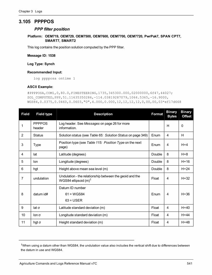
Chapter 3 Logs
Agriculture Comands and Logs Reference Manual v7C 541
3.105 PPPPOSPPP filter position
Platform: OEM719, OEM729, OEM7500, OEM7600, OEM7700, OEM7720, PwrPak7, SPAN CPT7,SMART7, SMART2
This log contains the position solution computed by the PPP filter.
Message ID: 1538
Log Type: Synch
Recommended Input:log pppposa ontime 1
ASCII Example:#PPPPOSA,COM1,0,80.0,FINESTEERING,1735,345300.000,02000000,6f47,44027;SOL_COMPUTED,PPP,51.11635350286,-114.03819287079,1064.5365,-16.9000,WGS84,0.0375,0.0460,0.0603,"0",4.000,0.000,12,12,12,12,0,00,00,03*ef17d668
Field Field type Description Format BinaryBytes
BinaryOffset
1 PPPPOSheader
Log header. SeeMessages on page 26 for moreinformation. H 0
2 Status Solution status (see Table 65: Solution Status on page 349) Enum 4 H
3 Type Position type (see Table 115: Position Type on the nextpage) Enum 4 H+4
4 lat Latitude (degrees) Double 8 H+8
5 lon Longitude (degrees) Double 8 H+16
6 hgt Height abovemean sea level (m) Double 8 H+24
7 undulation Undulation - the relationship between the geoid and theWGS84 ellipsoid (m)1 Float 4 H+32
8 datum id#
Datum ID number
61 = WGS84
63 = USER
Enum 4 H+36
9 lat σ Latitude standard deviation (m) Float 4 H+40
10 lon σ Longitude standard deviation (m) Float 4 H+44
11 hgt σ Height standard deviation (m) Float 4 H+48
1When using a datum other than WGS84, the undulation value also includes the vertical shift due to differences betweenthe datum in use and WGS84.

Chapter 3 Logs
Agriculture Comands and Logs Reference Manual v7C 542
Field Field type Description Format BinaryBytes
BinaryOffset
12 stn id Base station ID Char[4] 4 H+52
13 diff_age Differential age in seconds Float 4 H+56
14 sol_age Solution age in seconds Float 4 H+60
15 #SVs Number of satellites tracked Uchar 1 H+64
16 #solnSVs Number of satellites used in solution Uchar 1 H+65
17 #ggL1 Number of satellites with L1/E1/B1 signals used in solution Uchar 1 H+66
18 #solnMultiSVs Number of satellites with multi-frequency signals used insolution Uchar 1 H+67
19 Reserved Hex 1 H+68
20 ext sol stat Extended solution status (see Table 69: Extended SolutionStatus on page 353) Hex 1 H+69
21 Reserved Hex 1 H+70
22GPS andGLONASS sigmask
GPS andGLONASS signals usedmask (see Table 67:GPS andGLONASS Signal-UsedMask on page 352 orTable 68: Galileo and BeiDou Signal-UsedMask onpage 352)
Hex 1 H+71
23 xxxx 32-bit CRC (ASCII and Binary only) Ulong 4 H+72
24 [CR][LF] Sentence terminator (ASCII only) - - -
ASCII Binary Description
NONE 0 No solution
PPP_CONVERGING 68 Converging TerraStar-C, TerraStar-C PRO, TerraStar-X solution
PPP 69 Converged TerraStar-C, TerraStar-C PRO, TerraStar-X solution
PPP_BASIC_CONVERGING 77 Converging TerraStar-L solution
PPP_BASIC 78 Converged TerraStar-L solution
Table 115: Position Type

Chapter 3 Logs
Agriculture Comands and Logs Reference Manual v7C 543
3.106 PPPSATSSatellites used in the PPPPOS solution
Platform: OEM719, OEM729, OEM7500, OEM7600, OEM7700, OEM7720, PwrPak7, SPAN CPT7,SMART7, SMART2
This log lists the used and unused satellites for the corresponding PPPPOS solution. It also describes the sig-nals of the used satellites and reasons for exclusions.
Message ID: 1541
Log Type: Synch
Recommended Input:log pppsatsa ontime 1
Abbreviated ASCII Example:<PPPSATS COM1 0 80.0 FINESTEERING 1735 345300.000 02000000 ce3f 44027< 12< GPS 3 GOOD 00000003< GPS 5 GOOD 00000003< GPS 6 GOOD 00000003< GPS 7 GOOD 00000003< GPS 8 GOOD 00000003< GPS 10 GOOD 00000003< GPS 13 GOOD 00000003< GPS 16 GOOD 00000003< GPS 19 GOOD 00000003< GPS 23 GOOD 00000003< GPS 26 GOOD 00000003< GPS 28 GOOD 00000003
Field Field type Description Format BinaryBytes
BinaryOffset
1 PPPSATSheader Log header. SeeMessages on page 26 for more information. H 0
2 #entries Number of records to follow Ulong 4 H
3 System Satellite system (see Table 95: Satellite System onpage 450) Enum 4 H+4

Chapter 3 Logs
Agriculture Comands and Logs Reference Manual v7C 544
Field Field type Description Format BinaryBytes
BinaryOffset
4 SatelliteID
In binary logs, the satellite ID field is 4 bytes. The 2 lowest-order bytes, interpreted as a USHORT, are the systemidentifier: for instance, the PRN for GPS, or the slot forGLONASS. The 2 highest-order bytes are the frequencychannel for GLONASS, interpreted as a SHORT and zero forall other systems.
In ASCII and abbreviated ASCII logs, the satellite ID field isthe system identifier. If the system is GLONASS and thefrequency channel is not zero, then the signed channel isappended to the system identifier. For example, slot 13,frequency channel -2 is output as 13-2.
Ulong 4 H+8
5 Status Satellite status (see Table 71: Observation Statuses onpage 355) Enum 4 H+12
6 SignalMask
Signals used in the solution (see Table 72: GPS Signal Maskon page 356, Table 73: GLONASS Signal Mask on page 356,Table 74: Galileo Signal Mask on page 357, Table 75:BeiDou Signal Mask on page 357, Table 76: QZSS SignalMask on page 357 and Table 77: NavIC Signal Mask onpage 357)
Hex 4 H+16
7 Next satellite offset = H + 4 + (#entries x 16)
8 xxxx 32-bit CRC (ASCII and Binary only) Ulong 4H+4+(#entriesx 16)
9 [CR][LF] Sentence terminator (ASCII only) - - -

Chapter 3 Logs
Agriculture Comands and Logs Reference Manual v7C 545
3.107 PPPSEEDAPPLICATIONSTATUSStatus of the last-applied PPP seed
Platform: OEM719, OEM729, OEM7500, OEM7600, OEM7700, OEM7720, PwrPak7, SPAN CPT7,SMART7, SMART2
This log is used tomonitor the status of the last-applied static PPP seed. For a static seed to shorten the PPPconvergence time, the receiver must remain stationary until the seed is applied and confirmed. A status ofAPPLIED means that a seed was successfully applied andmovement can start. Movement before seed con-firmation will result in the seed being discarded and a full convergence taking place.
ThePPPSEED command (see page 200) is used to control the application of seeds. Seeds can bemanuallyapplied by PPPSEED SET orRESTORE, or automatically by PPPSEED AUTO.
ThePPPPOS log (see page 541) will also report a solution status of PENDING if a static seed has been appliedbut has not yet been confirmed.
Message ID 2250
Log type: Asynch
Recommended Inputlog pppseedapplicationstatusa onchanged
ASCII Example#PPPSEEDAPPLICATIONSTATUSA,COM1,0,77.5,FINESTEERING,2017,505640.391,02000000,f8c2,32768;PENDING,51.11637026243,-114.03825414820,1047.6422,0.0534,0.0523,0.0824*3a5e7250
#PPPSEEDAPPLICATIONSTATUSA,COM1,0,75.0,FINESTEERING,2017,505680.000,02000000,f8c2,32768;APPLIED,51.11637026243,-114.03825414820,1047.6422,0.0534,0.0523,0.0824*390a7178
Field Field Type Description Format BinaryBytes
BinaryOffset
1 PPPSEEDAPPLICATIONSTATUS header
Log header. SeeMessages on page 26 formore information. H 0
2 Status See Table 116: PPP Seed ApplicationStatus on the next page. Enum 4 H
3 LatitudeLatitude
Range: ±90 (degrees)Double 8 H+4
4 LongitudeLongitude
Range: ±180 (degrees)Double 8 H+12
5 HeightEllipsoidal height
Range: > -2000 (m)Double 8 H+20
6 Latitude std. dev. Latitude standard deviation (m) Float 4 H+28

Chapter 3 Logs
Agriculture Comands and Logs Reference Manual v7C 546
Field Field Type Description Format BinaryBytes
BinaryOffset
7 Longitude std. dev. Longitude standard deviation (m Float 4 H+32
8 Height std. dev. Longitude standard deviation (m) Float 4 H+36
9 xxxx 32-bit CRC (ASCII and Binary only) Hex 4 H+40
10 [CR][LF] Sentence terminator (ASCII only) – – –
Binary ASCII Description
0 UNAVAILABLE No seed was retrieved from NVM at startup
1 AVAILABLE A seed was retrieved from NVM at startup and is available for application
2 PENDING A seed was applied but is awaiting confirmation
3 APPLIED The seed was successfully applied
10REJECTED_MOTION_DETECTED
The seed was rejected becausemotion was detected or explicitly set viaPPPDYNAMICS DYNAMIC (seePPPDYNAMICS command on page 198)
11 REJECTED_BAD_POSITION
The seed was rejected because the seed position was inconsistent with the currentreceiver position
Table 116: PPP Seed Application Status

Chapter 3 Logs
Agriculture Comands and Logs Reference Manual v7C 547
3.108 PPPSEEDSTORESTATUSStatus of the NVM-stored PPP seed
Platform: OEM719, OEM729, OEM7500, OEM7600, OEM7700, OEM7720, PwrPak7, SPAN CPT7,SMART7, SMART2
This log reports the availability of the PPP seed stored in NVM. When the status is AVAILABLE, a seed hasbeen stored in NVM and is available for recall.
Seed storing and recall is controlled by thePPPSEED command (see page 200).
Message ID 2251
Log type: Asynch
Recommended Inputlog pppseedstorestatusa onchanged
ASCII Example#PPPSEEDSTORESTATUSA,COM1,0,76.0,FINESTEERING,2017,502402.000,02000000,edad,32768;AVAILABLE,0.071*bb8a343c
Field Field Type Description Format BinaryBytes
BinaryOffset
1 PPPSEEDSTORESTATUSheader
Log header. SeeMessages on page 26for more information. H 0
2 Status
Status of the stored PPP seed:
0 = UNAVAILABLE
1 = AVAILABLE
Enum 4 H
3 Horizontal std. dev. Horizontal standard deviation (meters) Float 4 H+4
4 xxxx 32-bit CRC (ASCII and Binary only) Hex 4 H+8
5 [CR][LF] Sentence terminator (ASCII only) – – –

Chapter 3 Logs
Agriculture Comands and Logs Reference Manual v7C 548
3.109 PROFILEINFOProfile information in NVM
Platform: OEM719, OEM729, OEM7500, OEM7600, OEM7700, OEM7720, PwrPak7, SPAN CPT7,SMART7, SMART2
This log outputs a list of Profiles in the system.
A list may consist of a maximum of 20 profiles.
Message ID: 1412
Log Type: Polled
Recommended Input:log profileinfoa onchanged
ASCII Examples:#PROFILEINFOA,COM1,0,84.0,UNKNOWN,0,17539.339,024c0020,ae3a,10526;"BASE",0,2,"LOG VERSION","SERIALCONFIG COM2 230400"*0ad5cda5
Field Field Type Description Format BinaryBytes
BinaryOffset
1 PROFILEINFOheader
Log header. SeeMessages on page 26 formore information. - H 0
2 Name Profile Name String [Max20] variable1 H
3 Status Word Refer toTable 117: Status Word on the nextpage Ulong 4 variable
4 # of Commands Number of commands assigned to the Profile Ulong 4 variable
5 Command Profile command String [Max150]
variable1 variable
6 Next command offset = variable
7 xxxx 32-bit CRC (ASCII and Binary only) Ulong 4 variable
8 [CR][LF] Sentence terminator (ASCII only) - - -
1In the binary case, each string field needs to be NULL terminated and additional bytes of padding added to maintain 4-bytealignment, up to the maximum defined by the string size. The next defined field starts immediately at the next 4-bytealignment following the NULL.

Chapter 3 Logs
Agriculture Comands and Logs Reference Manual v7C 549
Bit # Mask Description
0 0x00000001 Activate Flag(0 – Deactivate (default), 1 –Activate)
1 – 3 0x0000000E Reserved
4 0x00000010 Command 1 validation Flag(0 – Valid (default), 1 – Invalid)
5 0x00000020 Command 2 validation Flag
6 0x00000040 Command 3 validation Flag
7 0x00000080 Command 4 validation Flag
8 0x00000100 Command 5 validation Flag
9 0x00000200 Command 6 validation Flag
10 0x00000400 Command 7 validation Flag
11 0x00000800 Command 8 validation Flag
12 0x00001000 Command 9 validation Flag
13 0x00002000 Command 10 validation Flag
14 0x00004000 Command 11 validation Flag
15 0x00008000 Command 12 validation Flag
16 0x00010000 Command 13 validation Flag
17 0x00020000 Command 14 validation Flag
18 0x00040000 Command 15 validation Flag
19 0x00080000 Command 16 validation Flag
20 0x00100000 Command 17 validation Flag
21 0x00200000 Command 18 validation Flag
22 0x00400000 Command 19 validation Flag
23 0x00800000 Command 20 validation Flag
24 - 31 0xFF000000 Reserved
Table 117: Status Word

Chapter 3 Logs
Agriculture Comands and Logs Reference Manual v7C 550
3.110 PSRDOPDOP values for the satellites used in the PSR solution
Platform: OEM719, OEM729, OEM7500, OEM7600, OEM7700, OEM7720, PwrPak7, SPAN CPT7,SMART7, SMART2
The PSRDOP log contains the Dilution Of Precision (DOP) values for the satellites being used in the PSR solu-tion. The PSR DOPs are updated every 60 seconds or whenever the satellites used in the PSR solutionchanges.
DOP values are ameasure of the solution strength. Essentially, the DOPs reflect the geometry of the satellitesused in the solution. Solutions with good counts of well-distributed satellites will have low DOPs and should beaccurate and reliable. Solutions with fewer or poorly-distributed satellites will have high DOPs and be less accur-ate and reliable. As a rough guideline, PDOP values less than 4 imply a solution with reasonable geometry.
There can bemany reasons for high DOP values. Themost common reason is that there are obstructions lim-iting satellite visibility. Even if satellites are visible and being tracked they might still not be used in the solutionif, for example, they are unhealthy or there are not corrections available for them. ThePSRSATS log (see page556) will inform which satellites are being tracked and explain why a tracked satellite is not used in the solution.
The DOPs do not consider that different satellites or signals will be weighted differently in the solution. There-fore, they do not completely reflect the solution quality. Ultimately, the standard deviations reported in thePSRPOS log (see page 554) are the best reflection of the solution accuracy.
1. If a satellite is locked out using the LOCKOUT command (see page 156), it will still show in the prnlist but it will be significantly deweighted in the dop calculation.
2. The vertical dilution of precision can be calculated by:vdop = √ pdop2 - hdop2
3. If the DOP is not yet calculated, a default value of 9999.0 is displayed.
Message ID: 174
Log Type: Asynch
Recommended Input:log psrdopa onchanged
ASCII Example:#PSRDOPA,COM1,0,56.5,FINESTEERING,1337,403100.000,02000000,768f,1984;1.9695,1.7613,1.0630,1.3808,0.8812,5.0,10,14,22,25,1,24,11,5,20,30,7*106de10a
Field Fieldtype Format Binary
BytesBinaryOffset
1 PSRDOPheader Log header. SeeMessages on page 26 for more information. H 0
2 gdop Geometric dilution of precision - assumes 3D position andreceiver clock offset (all 4 parameters) are unknown Float 4 H

Chapter 3 Logs
Agriculture Comands and Logs Reference Manual v7C 551
Field Fieldtype Format Binary
BytesBinaryOffset
3 pdop Position dilution of precision - assumes 3D position is unknownand receiver clock offset is known Float 4 H+4
4 hdop Horizontal dilution of precision. Float 4 H+8
5 htdop Horizontal position and time dilution of precision. Float 4 H+12
6 tdop Time dilution of precision - assumes 3D position is known andonly the receiver clock offset is unknown Float 4 H+16
7 cutoff GPS elevation cut-off angle Float 4 H+20
8 #PRN Number of satellites PRNs to follow Long 4 H+24
9 PRN PRN of SV PRN tracking, null field until position solutionavailable Ulong 4 H+28
10... Next PRN offset = H+28+(#prn x 4)
11 xxxx 32-bit CRC (ASCII and Binary only) Ulong 4H+28+(#prn x4)
12 [CR][LF] Sentence terminator (ASCII only) - - -
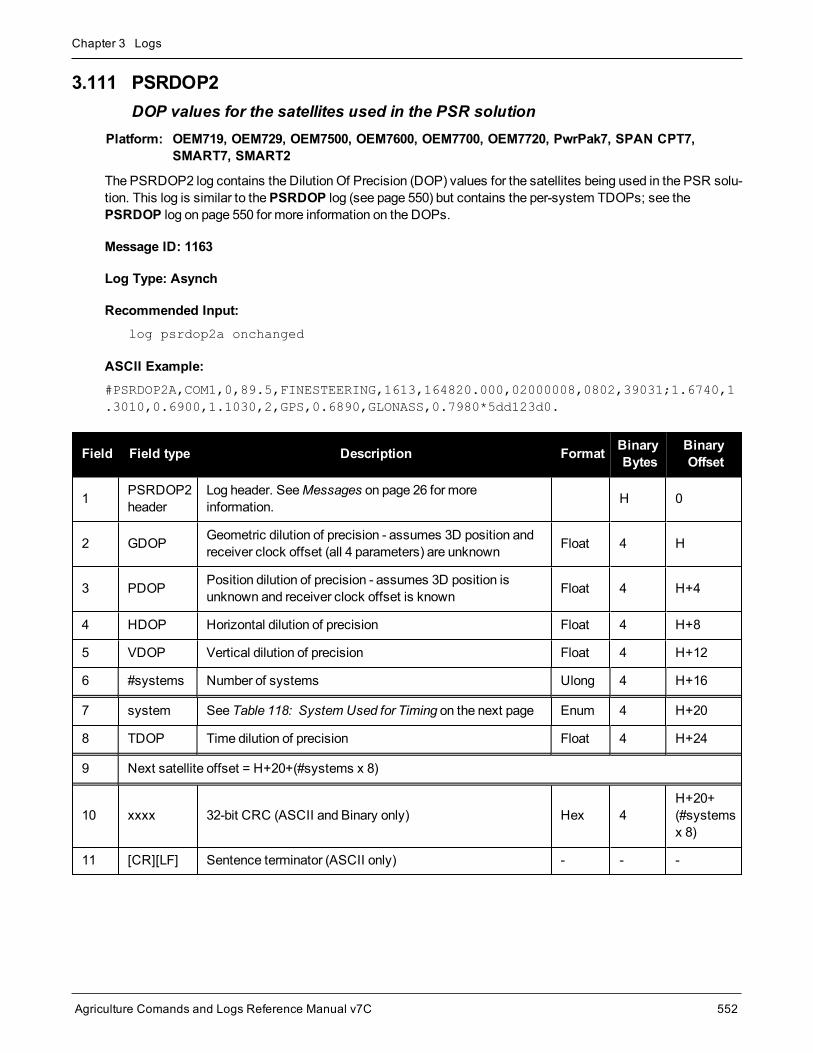
Chapter 3 Logs
Agriculture Comands and Logs Reference Manual v7C 552
3.111 PSRDOP2DOP values for the satellites used in the PSR solution
Platform: OEM719, OEM729, OEM7500, OEM7600, OEM7700, OEM7720, PwrPak7, SPAN CPT7,SMART7, SMART2
The PSRDOP2 log contains the Dilution Of Precision (DOP) values for the satellites being used in the PSR solu-tion. This log is similar to thePSRDOP log (see page 550) but contains the per-system TDOPs; see thePSRDOP log on page 550 for more information on the DOPs.
Message ID: 1163
Log Type: Asynch
Recommended Input:log psrdop2a onchanged
ASCII Example:#PSRDOP2A,COM1,0,89.5,FINESTEERING,1613,164820.000,02000008,0802,39031;1.6740,1.3010,0.6900,1.1030,2,GPS,0.6890,GLONASS,0.7980*5dd123d0.
Field Field type Description Format BinaryBytes
BinaryOffset
1 PSRDOP2header
Log header. SeeMessages on page 26 for moreinformation. H 0
2 GDOP Geometric dilution of precision - assumes 3D position andreceiver clock offset (all 4 parameters) are unknown Float 4 H
3 PDOP Position dilution of precision - assumes 3D position isunknown and receiver clock offset is known Float 4 H+4
4 HDOP Horizontal dilution of precision Float 4 H+8
5 VDOP Vertical dilution of precision Float 4 H+12
6 #systems Number of systems Ulong 4 H+16
7 system See Table 118: System Used for Timing on the next page Enum 4 H+20
8 TDOP Time dilution of precision Float 4 H+24
9 Next satellite offset = H+20+(#systems x 8)
10 xxxx 32-bit CRC (ASCII and Binary only) Hex 4H+20+(#systemsx 8)
11 [CR][LF] Sentence terminator (ASCII only) - - -

Chapter 3 Logs
Agriculture Comands and Logs Reference Manual v7C 553
Binary ASCII
0 GPS1
1 GLONASS
2 GALILEO
3 BEIDOU
4 NAVIC
99 AUTO2
Table 118: System Used for Timing
1GPS setting includes QZSS satellites.2AUTO is used only as a backup system (not available for primary system field).

Chapter 3 Logs
Agriculture Comands and Logs Reference Manual v7C 554
3.112 PSRPOSPseudorange position
Platform: OEM719, OEM729, OEM7500, OEM7600, OEM7700, OEM7720, PwrPak7, SPAN CPT7,SMART7, SMART2
This log contains the position computed by the receiver, along with three status flags. In addition, it reports otherstatus indicators, including differential age, which is useful in predicting anomalous behavior brought about byoutages in differential corrections.
Message ID: 47
Log Type: Synch
Recommended Input:log psrposa ontime 1
ASCII Example:#PSRPOSA,COM1,0,58.5,FINESTEERING,1419,340037.000,02000040,6326,2724;SOL_COMPUTED,SINGLE,51.11636177893,-114.03832396506,1062.5470,-16.2712,WGS84,1.8532,1.4199,3.3168,"",0.000,0.000,12,12,0,0,0,06,0,33*d200a78c
There are DGPS use cases in which the base receiver is not maintained or controlled by the positioninguser. For example, the US Coast Guard operates a differential correction service which broadcastsGPS differential corrections over marine radio beacons. As a user, all you need is amarine beaconreceiver and aGNSS receiver to achieve positioning accuracy of less than 1meter. In this case, theCoast Guard owns and operates the base receiver at known coordinates. Other examples of usersappearing to use only oneGNSS receiver include FM radio station correction services, privately ownedradio transmitters and corrections carried by communication satellites. Some of the radio receivers havebuilt-in GNSS receivers and combined antennas, so they even appear to look as one self-contained unit.
Themajor factors degrading GPS signals which can be removed or reduced with differential methodsare the atmosphere, ionosphere, satellite orbit errors, and satellite clock errors. Some errors which arenot removed include receiver noise andmultipath.
Field Field type Description Format BinaryBytes
BinaryOffset
1 PSRPOSheader
Log header. SeeMessages on page 26 for moreinformation. H 0
2 sol status Solution status (see Table 65: Solution Status onpage 349) Enum 4 H
3 pos type Position type (see Table 66: Position or Velocity Type onpage 350) Enum 4 H+4
4 lat Latitude (degrees) Double 8 H+8
5 lon Longitude (degrees) Double 8 H+16

Chapter 3 Logs
Agriculture Comands and Logs Reference Manual v7C 555
Field Field type Description Format BinaryBytes
BinaryOffset
6 hgt Height abovemean sea level (m) Double 8 H+24
7 undulation Undulation - the relationship between the geoid and theWGS84 ellipsoid (m) 1 Float 4 H+32
8 datum id#
Datum ID number
61 = WGS84
63 = USER
Enum 4 H+36
9 lat σ Latitude standard deviation (m) Float 4 H+40
10 lon σ Longitude standard deviation (m) Float 4 H+44
11 hgt σ Height standard deviation (m) Float 4 H+48
12 stn id Base station ID Char[4] 4 H+52
13 diff_age Differential age in seconds Float 4 H+56
14 sol_age Solution age in seconds Float 4 H+60
15 #SVs Number of satellites tracked Uchar 1 H+64
16 #solnSVs Number of satellites used in solution Uchar 1 H+65
17
Reserved
Uchar 1 H+66
18 Uchar 1 H+67
19 Hex 1 H+68
20 ext sol stat Extended solution status (see Table 69: ExtendedSolution Status on page 353) Hex 1 H+69
21Galileo andBeiDou sigmask
Galileo and BeiDou signals usedmask (see Table 68:Galileo and BeiDou Signal-UsedMask on page 352) Hex 1 H+70
22GPS andGLONASS sigmask
GPS andGLONASS signals usedmask (see Table 67:GPS andGLONASS Signal-UsedMask on page 352) Hex 1 H+71
23 xxxx 32-bit CRC (ASCII and Binary only) Hex 4 H+72
24 [CR][LF] Sentence terminator (ASCII only) - - -
1When using a datum other than WGS84, the undulation value also includes the vertical shift due to differences betweenthe datum in use and WGS84.

Chapter 3 Logs
Agriculture Comands and Logs Reference Manual v7C 556
3.113 PSRSATSSatellites used in PSRPOS solution
Platform: OEM719, OEM729, OEM7500, OEM7600, OEM7700, OEM7720, PwrPak7, SPAN CPT7,SMART7, SMART2
This log lists the used and unused satellites for the corresponding PSRPOS solution. It also describes the sig-nals of the used satellites and reasons for exclusions.
Message ID: 1162
Log Type: Synch
Recommended Input:log psrsats ontime 1
Abbreviated ASCII Example:<PSRSATS COM1 0 80.0 FINESTEERING 1729 154910.000 02004000 fea4 11465< 20< GPS 31 GOOD 00000003< GPS 14 GOOD 00000003< GPS 22 GOOD 00000003< GPS 11 GOOD 00000003< GPS 1 GOOD 00000003< GPS 32 GOOD 00000003< GPS 18 GOOD 00000003< GPS 24 GOOD 00000003< GPS 19 GOOD 00000003< GLONASS 24+2 GOOD 00000003< GLONASS 10-7 GOOD 00000003< GLONASS 9-2 GOOD 00000003< GLONASS 2-4 GOOD 00000003< GLONASS 1+1 GOOD 00000003< GLONASS 11 GOOD 00000003< GLONASS 17+4 GOOD 00000003< GLONASS 18-3 GOOD 00000003< GALILEO 12 LOCKEDOUT 00000000< GALILEO 11 LOCKEDOUT 00000000< BEIDOU 8 GOOD 00000003
Field Field type Description Format BinaryBytes
BinaryOffset
1 PSRSATSheader Log header. SeeMessages on page 26 for more information. H 0
2 #entries Number of records to follow Ulong 4 H
3 system See Table 95: Satellite System on page 450 Enum 4 H+4

Chapter 3 Logs
Agriculture Comands and Logs Reference Manual v7C 557
Field Field type Description Format BinaryBytes
BinaryOffset
4 SatelliteID Satellite identifier Ulong 4 H+8
5 Status Satellite status (see Table 71: Observation Statuses onpage 355) Enum 4 H+12
6 Signalmask
See Table 72: GPS Signal Mask on page 356, Table 73:GLONASS Signal Mask on page 356, Table 74: Galileo SignalMask on page 357, Table 75: BeiDou Signal Mask onpage 357, Table 76: QZSS Signal Mask on page 357 and Table77: NavIC Signal Mask on page 357
Hex 4 H+16
7 Next satellite offset = H+4+(#sat x 16)
8 xxxx 32-bit CRC (ASCII and Binary only) Hex 4H+4+(#sat x16)
9 [CR][LF] Sentence terminator (ASCII only) - - -

Chapter 3 Logs
Agriculture Comands and Logs Reference Manual v7C 558
3.114 PSRVELPseudorange velocity
Platform: OEM719, OEM729, OEM7500, OEM7600, OEM7700, OEM7720, PwrPak7, SPAN CPT7,SMART7, SMART2
In the PSRVEL log, the actual speed and direction of the receiver antenna over ground is provided. The velocitymeasurements sometimes have a latency associated with them. The time of validity is the time tag in the logminus the latency value.
In a PSRVEL log, the actual speed and direction of the receiver antenna over ground is provided. Thereceiver does not determine the direction a vessel, craft or vehicle is pointed (heading) but rather the dir-ection of motion of the GNSS antenna relative to ground.
The velocity in the PSRVEL log is determined by the pseudorange filter. Velocities from the pseudorange filterare calculated from the Doppler.
The velocity status indicates varying degrees of velocity quality. To ensure healthy velocity, the velocity sol-status must also be checked. If the sol-status is non-zero, the velocity is likely invalid. It should be noted that thereceiver does not determine the direction a vessel, craft, or vehicle is pointed (heading), but rather the direction ofthemotion of the GPS antenna relative to the ground.
The latency of the instantaneous Doppler velocity is always 0.15 seconds. The latency represents an estimateof the delay caused by the tracking loops under acceleration of approximately 1 G. For most users, the latencycan be assumed to be zero (instantaneous velocity).
Message ID: 100
Log Type: Synch
Recommended Input:log psrvela ontime 1
ASCII Example:#PSRVELA,COM1,0,52.5,FINESTEERING,1337,403362.000,02000000,658b,1984;SOL_COMPUTED,PSRDIFF,0.250,9.000,0.0698,26.582692,0.0172,0.0*a94e5d48
Consider the case where vehicles are leaving a control center. The control center’s coordinates areknown but the vehicles are on themove. Using the control center’s position as a reference, the vehiclesare able to report where they are with PSRPOS and their speed and direction with PSRVEL at any time.
Field Fieldtype Description Format Binary
BytesBinaryOffset
1 PSRVELheader Log header. SeeMessages on page 26 for more information. H 0
2 solstatus Solution status, see Table 65: Solution Status on page 349 Enum 4 H

Chapter 3 Logs
Agriculture Comands and Logs Reference Manual v7C 559
Field Fieldtype Description Format Binary
BytesBinaryOffset
3 vel type Velocity type, see Table 66: Position or Velocity Type onpage 350 Enum 4 H+4
4 latency A measure of the latency in the velocity time tag in seconds. Itshould be subtracted from the time to give improved results Float 4 H+8
5 age Differential age in seconds Float 4 H+12
6 hor spd Horizontal speed over ground, in meters per second Double 8 H+16
7 trk gnd Actual direction of motion over ground (track over ground) withrespect to True North, in degrees Double 8 H+24
8 vert spdVertical speed, in meters per second, where positive valuesindicate increasing altitude (up) and negative values indicatedecreasing altitude (down)
Double 8 H+32
9 Reserved Float 4 H+40
10 xxxx 32-bit CRC (ASCII and Binary only) Ulong 4 H+44
11 [CR][LF] Sentence terminator (ASCII only) - - -

Chapter 3 Logs
Agriculture Comands and Logs Reference Manual v7C 560
3.115 PSRXYZPseudorange Cartesian position and velocity
Platform: OEM719, OEM729, OEM7500, OEM7600, OEM7700, OEM7720, PwrPak7, SPAN CPT7,SMART7, SMART2
This log contains the receiver’s pseudorange position and velocity in ECEF coordinates. The position and velo-city status field’s indicate whether or not the corresponding data is valid. See Figure 7: TheWGS84 ECEFCoordinate System on page 365 for a definition of the ECEF coordinates.
The velocity status indicates varying degrees of velocity quality. To ensure healthy velocity, the velocity sol-status must also be checked. If the sol-status is non-zero, the velocity is likely invalid. It should be noted that thereceiver does not determine the direction a vessel, craft or vehicle is pointed (heading) but rather the direction ofthemotion of the GNSS antenna relative to the ground.
The latency of the instantaneous Doppler velocity is always 0.15 seconds. The latency represents an estimateof the delay caused by the tracking loops under acceleration of approximately 1 G. For most users, the latencycan be assumed to be zero (instantaneous velocity).
Message ID: 243
Log Type: Synch
Recommended Input:log psrxyza ontime 1
ASCII Example:#PSRXYZA,COM1,0,58.5,FINESTEERING,1419,340038.000,02000040,4a28,2724;SOL_COMPUTED,SINGLE,-1634530.7002,-3664617.2823,4942495.5175,1.7971,2.3694,2.7582,SOL_COMPUTED,DOPPLER_VELOCITY,0.0028,0.0231,-0.0120,0.2148,0.2832,0.3297,"",0.150,0.000,0.000,12,12,0,0,0,06,0,33*4fdbcdb1
The instantaneous Doppler is themeasured Doppler frequency which consists of the satellite's motionrelative to the receiver (Satellite Doppler + User Doppler) and the clock (local oscillator) drift.
Field Field type Description Format BinaryBytes
BinaryOffset
1 PSRXYZheader Log header. SeeMessages on page 26 for more information. H 0
2 P-sol status Solution status, see Table 65: Solution Status on page 349 Enum 4 H
3 pos type Position type, see Table 66: Position or Velocity Type onpage 350 Enum 4 H+4
4 P-X Position X-coordinate (m) Double 8 H+8
5 P-Y Position Y-coordinate (m) Double 8 H+16
6 P-Z Position Z-coordinate (m) Double 8 H+24

Chapter 3 Logs
Agriculture Comands and Logs Reference Manual v7C 561
Field Field type Description Format BinaryBytes
BinaryOffset
7 P-X σ Standard deviation of P-X (m) Float 4 H+32
8 P-Y σ Standard deviation of P-Y (m) Float 4 H+36
9 P-Z σ Standard deviation of P-Z (m) Float 4 H+40
10 V-sol status Solution status, see Table 65: Solution Status on page 349 Enum 4 H+44
11 vel type Velocity type, see Table 66: Position or Velocity Type onpage 350 Enum 4 H+48
12 V-X Velocity vector along X-axis (m/s) Double 8 H+52
13 V-Y Velocity vector along Y-axis (m/s) Double 8 H+60
14 V-Z Velocity vector along Z-axis (m/s) Double 8 H+68
15 V-X σ Standard deviation of V-X (m/s) Float 4 H+76
16 V-Y σ Standard deviation of V-Y (m/s) Float 4 H+80
17 V-Z σ Standard deviation of V-Z (m/s) Float 4 H+84
18 stn ID Base station ID Char[4] 4 H+88
19 V-latencyA measure of the latency in the velocity time tag in seconds.It should be subtracted from the time to give improvedresults
Float 4 H+92
20 diff_age Differential age in seconds Float 4 H+96
21 sol_age Solution age in seconds Float 4 H+100
22 #SVs Number of satellites tracked Uchar 1 H+104
23 #solnSVs Number of satellites used in solution Uchar 1 H+105
24
Reserved
Char 1 H+106
25 Char 1 H+107
26 Char 1 H+108
27 ext sol stat Extended solution status (see Table 69: Extended SolutionStatus on page 353) Hex 1 H+109
28Galileo andBeiDou sigmask
Galileo and BeiDou signals usedmask (see Table 68:Galileo and BeiDou Signal-UsedMask on page 352) Hex 1 H+110
29GPS andGLONASSsigmask
GPS andGLONASS signals usedmask (see Table 67:GPS andGLONASS Signal-UsedMask on page 352) Hex 1 H+111

Chapter 3 Logs
Agriculture Comands and Logs Reference Manual v7C 562
Field Field type Description Format BinaryBytes
BinaryOffset
30 xxxx 32-bit CRC (ASCII and Binary only) Hex 4 H+112
31 [CR][LF] Sentence terminator (ASCII only) - - -

Chapter 3 Logs
Agriculture Comands and Logs Reference Manual v7C 563
3.116 QZSSALMANACDecoded QZSS Almanac parameters
Platform: OEM719, OEM729, OEM7500, OEM7600, OEM7700, OEM7720, PwrPak7, SPAN CPT7,SMART7, SMART2
This log contains the decoded L1 C/A almanac parameters as received from the satellite with the parity inform-ation removed and appropriate scaling applied.
TheOEM7 family of receivers automatically save almanacs in their Non-Volatile Memory (NVM), so creating analmanac boot file is not necessary.
For more information about QZSS almanac data, refer to the Interface Specifications for QZSS athttp://qzss.go.jp/en/technical/ps-is-qzss/ps-is-qzss.html.
Message ID: 1346
Log Type: Asynch
Recommended Input:log qzssalmanaca onchanged
ASCII Example:#QZSSALMANACA,COM1,0,89.5,SATTIME,1642,148584.000,02000008,67d2,39655;1,193,1642,208896.0,7.587582e-02,-2.94869425e-09,-1.4441238e+00,-1.5737385e+00,1.7932513e+00,0.00000000,0.00000000,7.29336435e-05,4.2159360e+07,7.11809030e-01,7,7*fb648921
The speed at which the receiver locates and locks onto new satellites is improved if the receiverhas approximate time and position(SETAPPROXTIME andSETAPPROXPOS), as well as analmanac. This allows the receiver to compute the elevation of each satellite so it can tell whichsatellites are visible and their Doppler offsets, improving Time to First Fix (TTFF).
Field Field Type Description Format BinaryBytes
BinaryOffset
1 QZSSALMANACHeader
Log header. SeeMessages on page 26 for moreinformation. H 0
2 #messages Number of satellite PRN almanac messages tofollow. Set to zero until almanac data is available Ulong 4 H
3 PRN Satellite PRN number for current message(dimensionless) Ulong 4 H+4
4 week Almanac reference week Ulong 4 H+8
5 seconds Almanac reference time (s) Double 8 H+12
6 ecc Eccentricity (dimensionless) Double 8 H+20

Chapter 3 Logs
Agriculture Comands and Logs Reference Manual v7C 564
Field Field Type Description Format BinaryBytes
BinaryOffset
7 ώ Rate of right ascension (radians/s) Double 8 H+28
8 ω0 Right, ascension (radians) Double 8 H+36
9 ω Argument of perigee (radians) Double 8 H+44
10 M0 Mean anomaly of reference time (radians) Double 8 H+52
11 af0 Clock aging parameter (s) Double 8 H+60
12 af1 Clock aging parameter (s/s) Double 8 H+68
13 N Correctedmeanmotion (radians/s) Double 8 H+76
14 A Semi-major axis (m) Double 8 H+84
15 inclination angle Angle of inclination Double 8 H+92
16 health-prn SV health from Page 25 of subframe 4 or 5 (6 bits) Ulong 4 H+100
17 health-alm SV health from almanac (8 bits) Ulong 4 H+104
18 Next PRN offset = H+4+(#messages x 104)
19 xxxx 32-bit CRC (ASCII and Binary only) Ulong 4H+4+(#messagesx 104)
20 [CR][LF] Sentence terminator (ASCII only) - - -
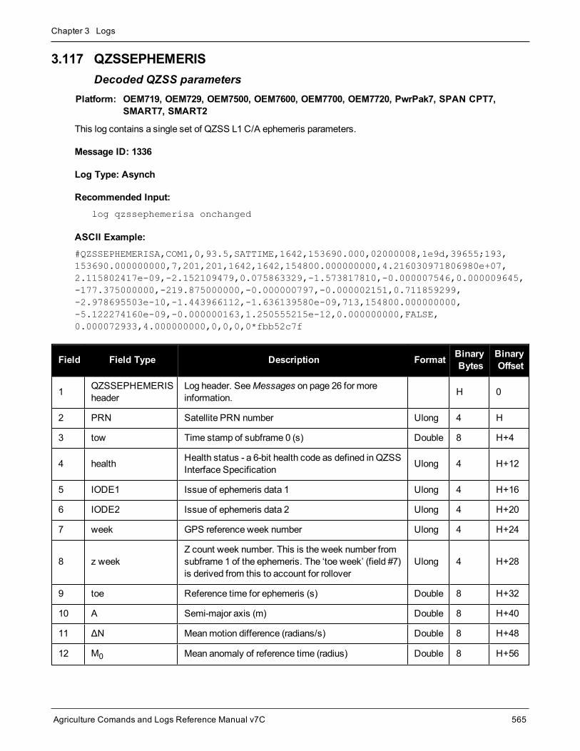
Chapter 3 Logs
Agriculture Comands and Logs Reference Manual v7C 565
3.117 QZSSEPHEMERISDecoded QZSS parameters
Platform: OEM719, OEM729, OEM7500, OEM7600, OEM7700, OEM7720, PwrPak7, SPAN CPT7,SMART7, SMART2
This log contains a single set of QZSS L1C/A ephemeris parameters.
Message ID: 1336
Log Type: Asynch
Recommended Input:log qzssephemerisa onchanged
ASCII Example:#QZSSEPHEMERISA,COM1,0,93.5,SATTIME,1642,153690.000,02000008,1e9d,39655;193,153690.000000000,7,201,201,1642,1642,154800.000000000,4.216030971806980e+07,2.115802417e-09,-2.152109479,0.075863329,-1.573817810,-0.000007546,0.000009645,-177.375000000,-219.875000000,-0.000000797,-0.000002151,0.711859299,-2.978695503e-10,-1.443966112,-1.636139580e-09,713,154800.000000000,-5.122274160e-09,-0.000000163,1.250555215e-12,0.000000000,FALSE,0.000072933,4.000000000,0,0,0,0*fbb52c7f
Field Field Type Description Format BinaryBytes
BinaryOffset
1 QZSSEPHEMERISheader
Log header. SeeMessages on page 26 for moreinformation. H 0
2 PRN Satellite PRN number Ulong 4 H
3 tow Time stamp of subframe 0 (s) Double 8 H+4
4 health Health status - a 6-bit health code as defined in QZSSInterface Specification Ulong 4 H+12
5 IODE1 Issue of ephemeris data 1 Ulong 4 H+16
6 IODE2 Issue of ephemeris data 2 Ulong 4 H+20
7 week GPS reference week number Ulong 4 H+24
8 z weekZ count week number. This is the week number fromsubframe 1 of the ephemeris. The ‘toe week’ (field #7)is derived from this to account for rollover
Ulong 4 H+28
9 toe Reference time for ephemeris (s) Double 8 H+32
10 A Semi-major axis (m) Double 8 H+40
11 ΔN Meanmotion difference (radians/s) Double 8 H+48
12 M0 Mean anomaly of reference time (radius) Double 8 H+56

Chapter 3 Logs
Agriculture Comands and Logs Reference Manual v7C 566
Field Field Type Description Format BinaryBytes
BinaryOffset
13 ecc Eccentricity (dimensionless) Double 8 H+64
14 ω Argument of perigee (radians) Double 8 H+72
15 cuc Amplitude of cosine harmonic correction term to theargument of latitude (radians) Double 8 H+80
16 cus Amplitude of sine harmonic correction term to theargument of latitude (radians) Double 8 H+88
17 crc Amplitude of cosine harmonic correction term to theorbit radius (m) Double 8 H+96
18 crs Amplitude of sine harmonic correction term to the orbitradius (m) Double 8 H+104
19 cic Amplitude of cosine harmonic correction term to theangle of inclination (radians) Double 8 H+112
20 cis Amplitude of sine harmonic correction term to theangle of inclination (radians) Double 8 H+120
21 I0 Inclination angle at reference time (radians) Double 8 H+128
22 İ Rate of inclination angle (radians/s) Double 8 H+136
23 ω0 Right ascension (radians) Double 8 H+144
24 ώ Rate of right ascension (radians/s) Double 8 H+152
25 iodc Issue of data clock Ulong 4 H+160
26 toc SV clock correction term (s) Double 8 H+164
27 tgd Estimated group delay difference (s) Double 8 H+172
28 afo Clock aging parameter (s) Double 8 H+180
29 af1 Clock aging parameter (s/s) Double 8 H+188
30 af2 Clock aging parameter (s/s/s) Double 8 H+196
31 ASAnti-spoofing on:0= FALSE1=TRUE
Enum 4 H+204
32 N Correctedmeanmotion (radians/s) Double 8 H+208

Chapter 3 Logs
Agriculture Comands and Logs Reference Manual v7C 567
Field Field Type Description Format BinaryBytes
BinaryOffset
33 URA
User Range Accuracy variance, m2.
The ICD specifies that the URA index transmitted inthe ephemerides can be converted to a nominalstandard deviation value using an algorithm listedthere. We publish the square of the nominal value(variance)
Double 8 H+216
34 Fit Interval
Curve fit interval:
0 = Ephemeris data are effective for 2 hours
1 = Ephemeris data are effective for more than 2 hours
Uchar 1 H+224
35 Reserved Uchar 1 H+225
36 Reserved Uchar 1 H+226
37 Reserved Uchar 1 H+227
38 xxxx 32-bit CRC (ASCII and Binary only) Ulong 4 H+228
39 [CR][LF] Sentence terminator (ASCII only) - - -

Chapter 3 Logs
Agriculture Comands and Logs Reference Manual v7C 568
3.118 QZSSIONUTCQZSS ionospheric and time information
Platform: OEM719, OEM729, OEM7500, OEM7600, OEM7700, OEM7720, PwrPak7, SPAN CPT7,SMART7, SMART2
This log contains the Ionospheric Model parameters (ION) and the Universal Time Coordinated parameters(UTC) for QZSS.
Message ID: 1347
Log Type: Asynch
Recommended Input:log qzssionutca onchanged
ASCII Example:#QZSSIONUTCA,COM1,0,94.0,FINESTEERING,1642,153300.565,02480008,158b,39655;1.396983861923218e-08,-6.705522537231444e-8,0.000000000000000e+000,1.788139343261719e-07,8.396800000000000e+04,7.536640000000000e+05,-7.864320000000000e+05,-6.946816000000000e+06,1642,307200,-5.5879354476928711e-09,5.329070518e-15,1768,4,15,15,0*0204eec1
Field Field Type Description Format BinaryBytes
BinaryOffset
1 QZSSIONUTCHeader
Log header. SeeMessages on page 26 for moreinformation. H 0
2 a0 Alpha parameter constant term Double 8 H
3 a1 Alpha parameter 1st order term Double 8 H+8
4 a2 Alpha parameter 2nd order term Double 8 H+16
5 a3 Alpha parameter 3rd order term Double 8 H+24
6 b0 Beta parameter constant term Double 8 H+32
7 b1 Beta parameter 1st order term Double 8 H+40
8 b2 Beta parameter 2nd order term Double 8 H+48
9 b3 Beta parameter 3rd order term Double 8 H+56
10 utc wn UTC reference week number Ulong 4 H+64
11 tot Reference time of UTC parameters (s) Ulong 4 H+68
12 A0 UTC constant term of polynomial (s) Double 8 H+72
13 A1 UTC 1st order term of polynomial (s/s) Double 8 H+80
14 wn lsf Future week number Ulong 4 H+88
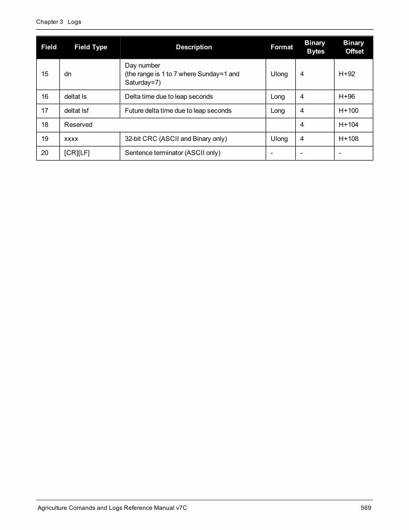
Chapter 3 Logs
Agriculture Comands and Logs Reference Manual v7C 569
Field Field Type Description Format BinaryBytes
BinaryOffset
15 dnDay number(the range is 1 to 7 where Sunday=1 andSaturday=7)
Ulong 4 H+92
16 deltat ls Delta time due to leap seconds Long 4 H+96
17 deltat lsf Future delta time due to leap seconds Long 4 H+100
18 Reserved 4 H+104
19 xxxx 32-bit CRC (ASCII and Binary only) Ulong 4 H+108
20 [CR][LF] Sentence terminator (ASCII only) - - -

Chapter 3 Logs
Agriculture Comands and Logs Reference Manual v7C 570
3.119 QZSSRAWALMANACRaw QZSS almanac data
Platform: OEM719, OEM729, OEM7500, OEM7600, OEM7700, OEM7720, PwrPak7, SPAN CPT7,SMART7, SMART2
This log contains the undecoded L1 C/A almanac subframes as received from theQZSS satellite.
Message ID: 1345
Log Type: Asynch
Recommended Input:log qzssrawalmanaca onchanged
ASCII Example:#QZSSRAWALMANACA,COM1,0,93.5,SATTIME,1642,153300.000,02480008,64c4,39655;1642,208896.000,7,1,8b000031c390c1820e33d007fefe07cae831c5293ebfe15049104a000001,51,8b000031c613f3336a1fffffffffffffffffffffffffffffffffff000000,49,8b000031cd90f14e6a7cf3cf1cf1cf3cf3c73cf1cf1cf3cf3cf3cf000002,50,8b000031ce14f24e6a0cf3cf1df1cfffffffffffffffffffffffff000002,56,8b000031d511f80ff70003292ef496000006fffffffa4b6a0fe8040f0002,52,8b000031e692f4a00a0fff83f060f2080180082082082082082002080381,53,8b000031e717f58082082082082082082082082082082082082082082080*ca4596f9ŀ
TheOEM7 family of receivers automatically saves almanacs in their Non-Volatile Memory (NVM),therefore creating an almanac boot file is not necessary.
Field Field Type Description Format BinaryBytes
BinaryOffset
1QZSSRAWALMANACheader
Log header. SeeMessages on page 26 for moreinformation. H 0
2 ref week Almanac reference week number Ulong 4 H
3 ref secs Almanac reference time, in milliseconds (binary data) orseconds (ASCII data) GPSec 4 H+4
4 #subframes Number of subframes to follow Ulong 4 H+8
5 svid
SV ID (satellite vehicle ID)
SV ID 1 to 10 corresponds to QZSS PRN 193 to 202.Any other values indicate the page ID. Refer to QZSSInterface Specification for more details.
Hex 2 H+12
6 data Subframe page data Hex 30 H+14

Chapter 3 Logs
Agriculture Comands and Logs Reference Manual v7C 571
Field Field Type Description Format BinaryBytes
BinaryOffset
7 Next subframe offset = H+12+(#subframe x 32)
8 xxxx 32-bit CRC (ASCII and Binary only) Hex 4H+12+(#subframesx 32)
9 [CR][LF] Sentence terminator (ASCII only) - - -

Chapter 3 Logs
Agriculture Comands and Logs Reference Manual v7C 572
3.120 QZSSRAWCNAVMESSAGERaw QZSS L2C and L5 CNAV message
Platform: OEM719, OEM729, OEM7500, OEM7600, OEM7700, OEM7720, PwrPak7, SPAN CPT7,SMART7, SMART2
This log provides the raw QZSS L2C and L5 CNAV message.
Message ID: 1530
Log Type: Collection
Recommended Input:log qzssrawcnavmessage onnew
ASCII Example:#QZSSRAWCNAVMESSAGEA,COM1,0,66.5,SATTIME,1902,405696.000,02000020,20f7,13677;40,193,10,8b04a84110edc2a346a97d311c3ff854620220004eba94f1313134f005530056c9da0ccc2300*1f2abac5
Field Field type Description Format BinaryBytes
BinaryOffset
1 QZSSRAWCNAVMESSAGEheader
Log header. SeeMessages on page 26for more information. - H 0
2 signal channel Signal channel providing the bits Ulong 4 H
3 PRN QZSS satellite PRN number Ulong 4 H+4
4 message ID CNAV message ID Ulong 4 H+8
5 data CNAV raw message data Hex[38] 38 H+12
6 xxxx 32-bit CRC (ASCII and Binary only) Hex 4 H+50
7 [CR][LF] Sentence terminator (ASCII only) - - -

Chapter 3 Logs
Agriculture Comands and Logs Reference Manual v7C 573
3.121 QZSSRAWEPHEMQZSS Raw ephemeris information
Platform: OEM719, OEM729, OEM7500, OEM7600, OEM7700, OEM7720, PwrPak7, SPAN CPT7,SMART7, SMART2
This log contains the raw binary information for subframes one, two and three from the satellite with the parityinformation removed. Each subframe is 240 bits long (10 words - 24 bits each) and the log contains a total 720bits (90 bytes) of information (240 bits x 3 subframes). This information is preceded by the PRN number of thesatellite from which it originated. This message is not generated unless all 10 words from all 3 frames havepassed parity.
Message ID: 1331
Log Type: Asynch
Recommended Input:log qzssrawephema onnew
ASCII Example:#QZSSRAWEPHEMA,COM1,0,84.5,SATTIME,1642,230580.000,02000008,2f9e,39655;193,1642,234000,8b00004b0f879aa01c8000000000000000000000f6df3921fe0005fffdbd,8b00004b1009dfd2bb1ec493a98277e8fd26d924d5062dcae8f5b739210e,8b00004b108ffe5bc52864ae00591d003b8b02b6bfe13f3affe2afdff1e7*d2bd151e
Field Field Type Description Format BinaryBytes
BinaryOffset
1 QZSSRAWEPHEMheader
Log header. SeeMessages on page 26 formore information. H 0
2 prn Satellite PRN number Ulong 4 H
3 ref week Ephemeris reference week number Ulong 4 H+4
4 ref secs Ephemeris reference time (s) Ulong 4 H+8
5 subframe1 Subframe 1 data Hex 30 H+12
6 subframe2 Subframe 2 data Hex 30 H+42
7 subframe3 Subframe 3 data Hex 30 H+72
8 xxxx 32-bit CRC (ASCII and Binary only) Ulong 4 H+102
9 [CR][LF] Sentence terminator (ASCII only) - - -

Chapter 3 Logs
Agriculture Comands and Logs Reference Manual v7C 574
3.122 QZSSRAWSUBFRAMERaw QZSS subframe data
Platform: OEM719, OEM729, OEM7500, OEM7600, OEM7700, OEM7720, PwrPak7, SPAN CPT7,SMART7, SMART2
This log contains the raw QZSS subframe data.
A raw QZSS subframe is 300 bits in total, 10 words of 30 bits each. This includes the parity 6 bits at the end ofeach word, for a total of 60 parity bits. Note that in Field #4, the ‘data’ field below, the 60 parity bits are strippedout and only the raw subframe data remains, for a total of 240 bits. There are two bytes added onto the end of this30 byte packed binary array to pad out the entire data structure to 32 bytes in order to maintain 4 byte alignment.
Message ID: 1330
Log Type: Asynch
Recommended Input:log qzssrawsubframea onnew
ASCII Example:#QZSSRAWSUBFRAMEA,COM1,0,85.5,SATTIME,1642,230604.000,02000008,e56b,39655;193,5,8b00004b11970637984efbf7fd4d0fa10ca49631ace140740a08fe0dfd43,65*6a7b9123
Field Field Type Description Format BinaryBytes
BinaryOffset
1QZSSRAWSUBFRAMEheader
Log header. SeeMessages on page 26 for moreinformation. H 0
2 PRN Satellite PRN number Ulong 4 H
3 subframe ID Subframe ID Ulong 4 H+4
4 data Raw subframe data Hex[30] 321 H+8
5 chan Signal channel number that the framewasdecoded on Ulong 4 H+40
6 xxxx 32-bit CRC (ASCII and Binary only) Ulong 4 H+44
7 [CR][LF] Sentence terminator - - -
1In the binary log case, an additional 2 bytes of padding are added to maintain 4-byte alignment.

Chapter 3 Logs
Agriculture Comands and Logs Reference Manual v7C 575
3.123 RADARSTATUSEmulated Radar Signal Information
Platform: OEM719, OEM729, OEM7500, OEM7600, OEM7700, OEM7720, PwrPak7, SPAN CPT7,SMART7, SMART2
This log provides information on the velocity and Emulated Radar (ER) signal.
Message ID: 1877
Log Type: Synch
Recommended Input:log radarstatusa ontime 1
ASCII Example:#RADARSTATUSA,COM1,0,39.0,FINESTEERING,3189,201903.000,00040020,3a93,32768;0000000F,SOL_COMPUTED,DOPPLER_VELOCITY,5.5924,5.1682,671.842775*9a017aff
Field Field Type Description Format BinaryBytes
BinaryOffset
1 RADARSTATUSHeader
Log header. SeeMessages on page 26 for moreinformation. - H 0
2 Emulated radarstatus
Bit field representing current state of radar emulationTable 119: Emulated Radar Status on the next page Hex 4 H
3 Solution status Solution status as reported inBESTVEL log on page 360 Enum 4 H+4
4 Velocity type Velocity type as reported inBESTVEL log on page 360 Enum 4 H+8
5 Hor speed Horizontal speed over ground (m/sec) Double 8 H+12
6 Smooth horspeed Smoother horizontal speed over ground (m/sec) Enum 4 H+20
7 Frequency Output frequency (Hz) Double 8 H+28

Chapter 3 Logs
Agriculture Comands and Logs Reference Manual v7C 576
Bit Mask Description
0 0x01 Feature enabled
1 0x02 Velocity type good
2 0x04 Velocity >1 kph
3-4 0x18
Current responsemode being applied will equal theRADARCONFIG command on page 211responsemode parameter unless it is 2. If responsemode is set to 2 in theRADARCONFIGcommand , this will be either 500 or 1000, depending on speed.
Mapped as follows:
- 00: Responsemode 1 (no smoothing)
- 01: Responsemode 500 (500ms smoothing)
- 10: Responsemode 1000 (1000ms smoothing)
- 11: Responsemode 2000 (2000ms smoothing)
5-31 0xFFFFE700 Reserved
Table 119: Emulated Radar Status

Chapter 3 Logs
Agriculture Comands and Logs Reference Manual v7C 577
3.124 RAIMSTATUSRAIM status
Platform: OEM719, OEM729, OEM7500, OEM7600, OEM7700, OEM7720, PwrPak7, SPAN CPT7,SMART7, SMART2
This log provides information on Receiver Autonomous Integrity Monitoring (RAIM) status.
Message ID: 1286
Log Type: Synch
Recommended Input:log raimstatusa ontime 1
ASCII Example:#RAIMSTATUSA,COM1,0,88.5,FINESTEERING,1837,268443.500,02040008,bf2d,32768;DEFAULT,PASS,NOT_AVAILABLE,0.000,NOT_AVAILABLE,0.000,1,GLONASS,10-7*6504be7b
Field Field Type Description Format BinaryBytes
BinaryOffset
1 RAIMSTATUSHeader
Log header. SeeMessages on page 26 for moreinformation. - H 0
2 RAIMMode RAIMmode (refer to Table 120: RAIMMode Types on thenext page) Enum 4 H
3 Integrity status Integrity Status (see Table 121: Integrity Status on thenext page) Enum 4 H+4
4 HPL status Horizontal protection level status (see Table 122:Protection Level Status on page 579) Enum 4 H+8
5 HPL Horizontal protection level (m) Double 8 H+12
6 VPL status Vertical protection level status (see Table 122: ProtectionLevel Status on page 579) Enum 4 H+20
7 VPL Vertical protection level (m) Double 8 H+24
8 #SVs Number of excluded satellites Ulong 4 H+32
9 System Satellite system (see Table 95: Satellite System onpage 450) Enum 4 H+36

Chapter 3 Logs
Agriculture Comands and Logs Reference Manual v7C 578
Field Field Type Description Format BinaryBytes
BinaryOffset
10 Satellite ID
In binary logs, the satellite ID field is 4 bytes. The 2 lowestorder bytes, interpreted as a USHORT, are the systemidentifier. For instance, the PRN for GPS or the slot forGLONASS. The 2 highest-order bytes are the frequencychannel for GLONASS, interpreted as a SHORT and zerofor all other systems.
In ASCII and abbreviated ASCII logs, the satellite ID fieldis the system identifier. If the system is GLONASS and thefrequency channel is not zero, then the signed channel isappended to the system identifier. For example, slot 13,frequency channel -2 is output as 13-2.
Ulong 4 H+40
11 Next offset field = H+36+(#SVs * 8)
12 xxxx 32-bit CRC (ASCII and Binary only) Ulong 4
H+36+(#SVs* 8)
13 [CR][LF] Sentence terminator (ASCII only)
Binary ASCII Description
0 DISABLE Do not do integrity monitoring of least squares solution
1 USER User will specify alert limits and probability of false alert
2 DEFAULT Use NovAtel RAIM (default)
3 APPROACH Default numbers for non-precision approach navigationmodes are used - HAL = 556m(0.3 nm), VAL = 50m for LNAV/VNAV
4 TERMINAL Default numbers for terminal navigationmode are used - HAL = 1 nm, no VAL requirement
5 ENROUTE Default numbers for enroute navigationmode are used - HAL = 2 nm, no VAL requirement
Table 120: RAIM Mode Types
Binary ASCII Description
0 NOT_AVAILABLE
RAIM is unavailable because either there is no solution or because the solution is unique,that is, there is no redundancy
1 PASS RAIM succeeded. Either there were no bad observations or the bad observations weresuccessfully removed from the solution
2 FAIL RAIM detected a failure and was unable to isolate the bad observations
Table 121: Integrity Status

Chapter 3 Logs
Agriculture Comands and Logs Reference Manual v7C 579
Binary ASCII Description
0 NOT_AVAILABLE
WhenRAIM is not available. For example, immediately after issuing a FRESET command(see page 118) or when there are not enough satellites tracked to have the requiredredundant observations.
1 PASS
Current protection levels are below alert limits, meaning positioning accuracyrequirements are fulfilled.
HPL < HAL
VPL < VAL
2 ALERT
Current protection levels are above alert limits, meaning required positioning accuracycannot be guaranteed by RAIM algorithm.
HPL ≥ HAL
VPL ≥ VAL
Table 122: Protection Level Status

Chapter 3 Logs
Agriculture Comands and Logs Reference Manual v7C 580
3.125 RANGESatellite range information
Platform: OEM719, OEM729, OEM7500, OEM7600, OEM7700, OEM7720, PwrPak7, SPAN CPT7,SMART7, SMART2
The RANGE log contains the channel measurements for the currently tracked satellites. When using this log,please keep inmind the constraints noted along with the description.
It is important to ensure that the receiver clock has been set. This can bemonitored by the bits in the ReceiverStatus field of the log header. Large jumps in pseudorange as well as Accumulated Doppler Range (ADR) occuras the clock is being adjusted. If the ADR measurement is being used in precise phase processing, it is import-ant not to use the ADR if the "parity known" flag, in the ch-tr-status field, is not set as theremay exist a half (1/2)cycle ambiguity on themeasurement. The tracking error estimate of the pseudorange and carrier phase (ADR) isthe thermal noise of the receiver tracking loops only. It does not account for possible multipath errors or atmo-spheric delays.
If multiple signals are being tracked for a given PRN, an entry for each signal, with the same PRN, appears inthe RANGE logs. As shown in Table 123: Channel Tracking Status on page 583, these entries can be dif-ferentiated by bits 21-25, which indicate the signal type of the observation.
For dual antenna receivers, a RANGE_1 log can be requested to get RANGE data from the secondantenna. As described in Table 3: Binary Message Header Structure on page 30, themessage typeindicates the log is from the second antenna. To request an ASCII log enter RANGEA_1, and for a bin-ary log enter RANGEB_1.
Message ID: 43
Log Type: Synch
Recommended Input:log rangea ontime 30
Abbreviated ASCII Example:<RANGE COM1 0 82.0 FINESTEERING 1729 155076.000 02004000 5103 114654631 0 24514687.250 0.064 -128825561.494675 0.010 3877.473 45.0 563.310 18109c0431 0 24514688.765 0.096 -100383546.734328 0.010 3021.415 39.8 558.900 02309c0b14 0 20345286.178 0.047 -106915249.491005 0.008 90.799 47.6 10283.130 08109c2414 0 20345282.367 0.130 -83310588.842026 0.008 70.753 44.0 10276.900 01303c2b22 0 20789170.556 0.038 -109247823.573628 0.007 -1421.169 49.4 15829.45018109c4422 0 20789164.279 0.138 -85128150.759123 0.007 -1107.404 43.6 15822.40011303c4b11 0 21977065.699 0.057 -115490261.964920 0.009 1235.428 46.0 5831.400 18109c6411 0 21977062.220 0.201 -89992401.903056 0.011 962.671 40.3 5823.900 11303c6b1 0 23109644.678 0.073 -121441999.794897 0.011 2971.250 43.8 3239.620 18109ca41 0 23109646.769 0.073 -94630142.467139 0.011 2315.261 42.1 3233.420 02309cab1 0 23109647.385 0.009 -90687226.778371 0.009 2218.538 48.9 3237.080 01d03ca432 0 23839782.353 0.133 -125278916.608912 0.022 3033.561 38.7 2193.280 18109cc432 0 23839781.295 0.363 -97619939.025504 0.026 2363.815 35.1 2184.900 11303ccb18 0 22923322.792 0.062 -120462840.747702 0.009 -2710.945 45.3 20493.260

Chapter 3 Logs
Agriculture Comands and Logs Reference Manual v7C 581
18109d0418 0 22923320.071 0.350 -93867119.471860 0.012 -2112.426 35.5 20484.40011303d0b24 0 23708761.188 0.111 -124590391.778428 0.015 -2376.459 40.2 10643.82008109d2424 0 23708763.572 0.065 -97083440.180816 0.015 -1851.788 43.1 10639.42002309d2b24 0 23708765.724 0.009 -93038305.697497 0.008 -1774.807 49.1 10641.68001d03d2419 0 23739234.067 0.078 -124750470.392697 0.013 -2778.561 43.3 12263.18008109d6419 0 23739230.131 0.250 -97208136.646475 0.014 -2165.115 38.4 12255.40001303d6b61 9 22189063.544 0.155 -118654856.801346 0.011 -3985.235 43.3 13310.88208119e0461 9 22189063.246 0.055 -92287085.024614 0.011 -3099.631 37.6 13303.96400b13e0b47 0 21209673.567 0.147 -113059527.680842 0.011 -804.710 43.8 7342.680 08119e2447 0 21209679.575 0.043 -87935228.320976 0.011 -625.886 39.7 7334.968 00b13e2b46 5 24097664.754 0.213 -128680178.570435 0.014 -3740.543 40.6 10098.60008119e4446 5 24097669.137 0.048 -100084595.729257 0.015 -2909.311 38.8 10082.83810b13e4b39 3 21484445.079 0.161 -114645140.076744 0.012 2864.162 43.0 4463.150 18119e6439 3 21484447.532 0.046 -89168467.325722 0.013 2227.683 39.1 4453.468 10b13e6b38 8 19445896.471 0.101 -103949483.524466 0.008 -389.973 47.1 11640.26018119e8438 8 19445897.101 0.048 -80849619.556577 0.009 -303.312 38.8 11632.974 00b13e8b48 7 21301665.694 0.166 -113829687.684616 0.011 3143.656 42.8 3778.910 08119ea448 7 21301667.294 0.054 -88534230.502244 0.012 2445.068 37.8 3770.968 10b13eab54 11 20899591.029 0.131 -111837944.708346 0.009 -401.734 44.8 7155.19018119ec454 11 20899589.241 0.024 -86985062.942139 0.009 -312.461 44.8 7146.970 10b13ecb55 4 23127316.661 0.318 -123455195.443877 0.020 3067.787 37.1 1588.420 18119ee455 4 23127321.850 0.032 -96020732.562183 0.021 2386.060 42.3 1580.442 00b13eeb12 0 26239080.161 0.048 -137887256.553732 0.015 -2696.802 47.6 11527.71048539c2412 0 26239085.285 0.012 -102967750.707625 0.013 -2013.883 46.8 11523.77041933c2412 0 26239083.219 0.011 -105653860.401460 0.013 -2066.457 47.3 11523.71242333c2412 0 26239094.196 0.019 -104310841.607718 0.014 -2040.204 42.7 11522.97042933c2411 0 25589806.061 0.045 -134475330.397885 0.013 -729.686 48.0 4974.653 48539c6411 0 25589809.285 0.010 -100419891.315177 0.012 -545.179 47.8 4969.770 41933c6411 0 25589806.124 0.010 -103039536.069621 0.011 -559.405 48.0 4969.734 42333c6411 0 25589818.004 0.017 -101729751.744395 0.013 -552.305 43.7 4967.060 42933c648 0 39844800.850 0.077 -207482308.002186 0.018 -507.335 37.4 12048.980 18149c848 0 39844800.076 0.043 -160438471.200694 0.013 -392.547 42.5 12038.660 00349c84
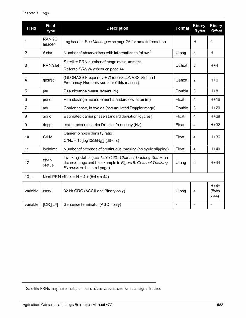
Chapter 3 Logs
Agriculture Comands and Logs Reference Manual v7C 582
Field Fieldtype Description Format Binary
BytesBinaryOffset
1 RANGEheader Log header. SeeMessages on page 26 for more information. H 0
2 # obs Number of observations with information to follow 1 Ulong 4 H
3 PRN/slotSatellite PRN number of rangemeasurement
Refer toPRN Numbers on page 44Ushort 2 H+4
4 glofreq (GLONASS Frequency + 7) (seeGLONASS Slot andFrequency Numbers section of this manual) Ushort 2 H+6
5 psr Pseudorangemeasurement (m) Double 8 H+8
6 psr σ Pseudorangemeasurement standard deviation (m) Float 4 H+16
7 adr Carrier phase, in cycles (accumulated Doppler range) Double 8 H+20
8 adr σ Estimated carrier phase standard deviation (cycles) Float 4 H+28
9 dopp Instantaneous carrier Doppler frequency (Hz) Float 4 H+32
10 C/NoCarrier to noise density ratio
C/No = 10[log10(S/N0)] (dB-Hz)Float 4 H+36
11 locktime Number of seconds of continuous tracking (no cycle slipping) Float 4 H+40
12 ch-tr-status
Tracking status (see Table 123: Channel Tracking Status onthe next page and the example in Figure 9: Channel TrackingExample on the next page)
Ulong 4 H+44
13... Next PRN offset = H + 4 + (#obs x 44)
variable xxxx 32-bit CRC (ASCII and Binary only) Ulong 4H+4+(#obsx 44)
variable [CR][LF] Sentence terminator (ASCII only) - - -
1Satellite PRNs may have multiple lines of observations, one for each signal tracked.
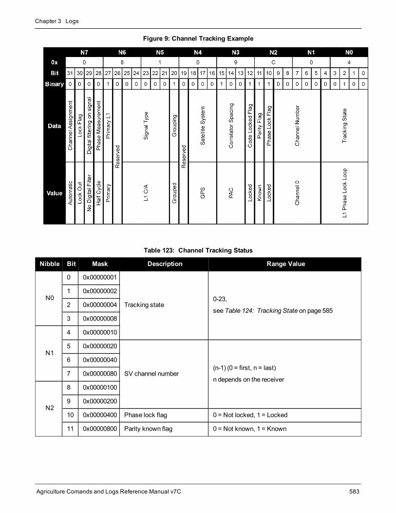
Chapter 3 Logs
Agriculture Comands and Logs Reference Manual v7C 583
Figure 9: Channel Tracking Example
Nibble Bit Mask Description Range Value
N0
0 0x00000001
Tracking state0-23,
see Table 124: Tracking State on page 585
1 0x00000002
2 0x00000004
3 0x00000008
N1
4 0x00000010
5 0x00000020
SV channel number(n-1) (0 = first, n = last)
n depends on the receiver
6 0x00000040
7 0x00000080
N2
8 0x00000100
9 0x00000200
10 0x00000400 Phase lock flag 0 = Not locked, 1 = Locked
11 0x00000800 Parity known flag 0 = Not known, 1 = Known
Table 123: Channel Tracking Status

Chapter 3 Logs
Agriculture Comands and Logs Reference Manual v7C 584
Nibble Bit Mask Description Range Value
N3
12 0x00001000 Code locked flag 0 = Not locked, 1 = Locked
13 0x00002000
Correlator type0-7,
see Table 125: Correlator Type on the next page14 0x00004000
15 0x00008000
N4
16 0x00010000
Satellite system
0 = GPS1 = GLONASS2 = SBAS3 = Galileo
4 = BeiDou5 = QZSS6 = NavIC7 = Other
17 0x00020000
18 0x00040000
19 0x00080000 Reserved
20 0x00100000 Grouping 0 = Not grouped, 1 = Grouped
21 0x00200000
Signal type
(Dependent on satellitesystem above)
GPS:0 = L1C/A5 = L2P9 = L2P (Y), semi-codeless14 = L5 (Q)16 = L1C (P)17 = L2C (M)
GLONASS:0 = L1C/A1 = L2C/A5 = L2P6 = L3 (Q)
BeiDou:0 = B1 (I) with D1 data1 = B2 (I) with D1 data2 = B3 (I) with D1 data4 = B1 (I) with D2 data5 = B2 (I) with D2 data6 = B3 (I) with D2 data7 = B1C (P)9 = B2a (P)
Galileo:2 = E1 (C)6 = E6B7 = E6C12 = E5a (Q)17 = E5b (Q)20 = E5AltBOC (Q)
QZSS:0 = L1C/A14 = L5 (Q)16 = L1C (P)17 = L2C (M)27 = L6P
SBAS:0 = L1C/A6 = L5 (I)
NavIC:0 = L5 SPS
Other:19 = L-Band
N5 22 0x00400000
23 0x00800000
24 0x01000000
N6 25 0x02000000
26 0x04000000 Reserved
27 0x08000000 Primary L1 channel 0 = Not primary, 1 = Primary
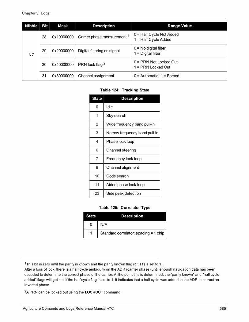
Chapter 3 Logs
Agriculture Comands and Logs Reference Manual v7C 585
Nibble Bit Mask Description Range Value
N7
28 0x10000000 Carrier phasemeasurement 1 0 = Half Cycle Not Added1 = Half Cycle Added
29 0x20000000 Digital filtering on signal 0 = No digital filter1 = Digital filter
30 0x40000000 PRN lock flag 2 0 = PRN Not LockedOut1 = PRN LockedOut
31 0x80000000 Channel assignment 0 = Automatic, 1 = Forced
State Description
0 Idle
1 Sky search
2 Wide frequency band pull-in
3 Narrow frequency band pull-in
4 Phase lock loop
6 Channel steering
7 Frequency lock loop
9 Channel alignment
10 Code search
11 Aided phase lock loop
23 Side peak detection
Table 124: Tracking State
State Description
0 N/A
1 Standard correlator: spacing = 1 chip
Table 125: Correlator Type
1This bit is zero until the parity is known and the parity known flag (bit 11) is set to 1.After a loss of lock, there is a half cycle ambiguity on the ADR (carrier phase) until enough navigation data has beendecoded to determine the correct phase of the carrier. At the point this is determined, the "parity known" and "half cycleadded" flags will get set. If the half cycle flag is set to 1, it indicates that a half cycle was added to the ADR to correct aninverted phase.
2A PRN can be locked out using the LOCKOUT command.

Chapter 3 Logs
Agriculture Comands and Logs Reference Manual v7C 586
State Description
2 Narrow correlator: spacing < 1 chip
3 Reserved
4 Pulse Aperture Correlator (PAC)
5 Narrow PAC
6 Reserved
GNSSSystem
FrequencyBand Frequency
Observation Codes
SignalType
PseudoRange
CarrierPhase Doppler Signal
Strength
GPS
L1 1575.42L1CA C1C L1C D1C S1C
L1C(P) C1L L1L D1L S1L
L2 1227.6
L2C(M) C2S L2S D2S S2S
L2P L2P C2P D2P S2P
L2P(Y) C2W L2W D2W S2W
L5 1176.45 L5(Q) C5Q L5Q D5Q S5Q
GLONASS
G1 1598.0625-1609.3125 L1CA C1C L1C D1C S1C
G2 1242.9375-1251.6875
L2CA C2C L2C D2C S2C
L2P C2P L2P D2P S2P
G3 1202.025 L3(Q) C3Q L3Q D3Q S3Q
Galileo
E1 1575.42 E1C C1C L1C D1C S1C
E5a 1176.45 E5a(Q) C5Q L5Q D5Q S5Q
E5b 1207.14 E5b(Q) C7Q L7Q D7Q S7Q
E5(E5a+E5b) 1191.795 E5AltBOC
(Q) C8Q L8Q D8Q S8Q
E6 1278.75 E6C C6C L6C D6C S6C
SBASL1 1575.42 L1CA C1C L1C D1C S1C
L5 1176.45 L5(I) C5I L5I D5I S5I
Table 126: RINEX Mappings

Chapter 3 Logs
Agriculture Comands and Logs Reference Manual v7C 587
GNSSSystem
FrequencyBand Frequency
Observation Codes
SignalType
PseudoRange
CarrierPhase Doppler Signal
Strength
QZSS
L1 1575.42L1CA C1C L1C D1C S1C
L1C(P) C1L L1L D1L S1L
L2 1227.6 L2C(M) C2S L2S D2S S2S
L5 1176.45 L5(Q) C5Q L5Q D5Q S5Q
L6 1278.75 L6(P) C6L L6L D6L S6L
BeiDou
B1 1561.098 B1(I) C2I L2I D2I S2I
B1C 1575.42 B1C(P) C1P L1P D1P S1P
B2 1207.14 B2(I) C7I L7I D7I S7I
B2a 1176.45 B2a(P) C5P L5P D5P S5P
B3 1268.52 B3(I) C6I L6I D6I S6I
NavIC L5 1176.45 L5SPS C5A L5A D5A S5A

Chapter 3 Logs
Agriculture Comands and Logs Reference Manual v7C 588
3.126 RANGECMPCompressed version of the RANGE log
Platform: OEM719, OEM729, OEM7500, OEM7600, OEM7700, OEM7720, PwrPak7, SPAN CPT7,SMART7, SMART2
This log contains the RANGE data in a compressed format.
For dual antenna receivers, a RANGECMP_1 log can be requested to get RANGECMP data from thesecond antenna. As described in Table 3: Binary Message Header Structure on page 30, themessagetype indicates the log is from the second antenna. To request an ASCII log enter RANGECMPA_1, andfor a binary log enter RANGECMPB_1.
Message ID: 140
Log Type: Synch
Recommended Input:log rangecmpa ontime 10
ASCII Example:#RANGECMPA,COM1,0,63.5,FINESTEERING, 1429,226780.000,02000000,9691,2748;26,049c10081857f2df1f4a130ba2888eb9600603a709030000,0b9c3001225bf58f334a130bb1e2bed473062fa609020000,449c1008340400e0aaa9a109a7535bac2015cf71c6030000,4b9c300145030010a6a9a10959c2f09120151f7166030000,...0b9d301113c8ffefc284000c6ea051dbf3089da1a0010000,249d1018c6b7f67fa228820af2e5e39830180ae1a8030000,2b9d301165c4f8ffb228820a500a089f31185fe0a8020000,449d1018be18f41f2aacad0a1a934efc40074ecf88030000,4b9d301182b9f69f38acad0a3e3ac28841079fcb88020000,849d101817a1f95f16d7af0a69fbe1fa401d3fd064030000,8b9d30112909fb2f20d7af0a9f24a687521ddece64020000,249e1118af4e0470f66d4309a0a631cd642cf5b821320000,2b9eb110a55903502f6e4309ee28d1ad032c7cb7e1320000,849e1118b878f54f4ed2aa098c35558a532bde1765220000,8b9eb110abcff71f5ed2aa09cb6ad0f9032b9d16c5220000*0eeead18
Field Field Type Description Format BinaryBytes
BinaryOffset
1 RANGECMPheader
Log header. SeeMessages on page 26 for moreinformation. H 0
2 #obs Number of satellite observations with information to follow Ulong 4 H

Chapter 3 Logs
Agriculture Comands and Logs Reference Manual v7C 589
Field Field Type Description Format BinaryBytes
BinaryOffset
3 1st rangerecord
Compressed range log in format of Table 127: RangeRecord Format (RANGECMP only) below Hex 24 H+4
4 Next rangecmp offset = H+4 (#obs x 24)
5 xxxx 32-bit CRC (ASCII and Binary only) Ulong 4H+4+(#obs x24)
6 [CR][LF] Sentence terminator (ASCII only) - - -
Data DescriptionBitsfirst tolast
Length(bits)
ScaleFactor Units
ChannelTrackingStatus
Channel tracking status word 0-31 32
see Table123:ChannelTrackingStatus onpage 583
-
DopplerFrequency Instantaneous carrier Doppler frequency 32-59 28 1/256 Hz
Pseudorange (PSR) Pseudorangemeasurement 60-95 36 1/128 m
Table 127: Range Record Format (RANGECMP only)
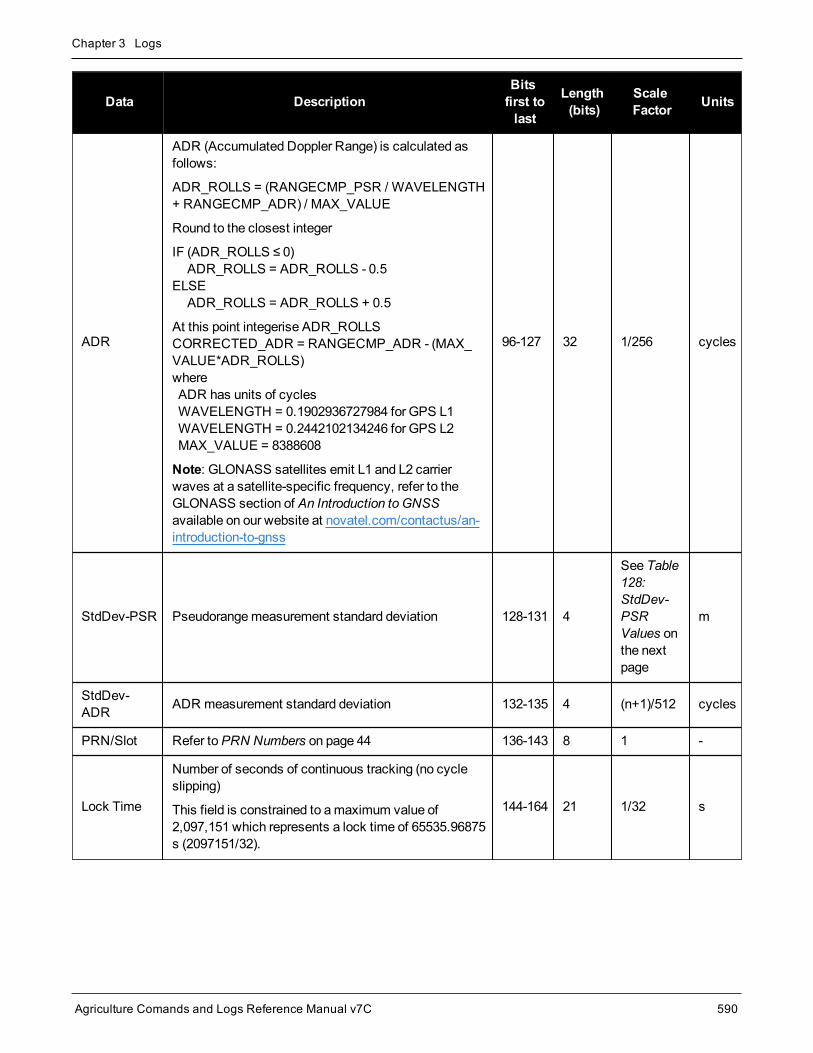
Chapter 3 Logs
Agriculture Comands and Logs Reference Manual v7C 590
Data DescriptionBitsfirst tolast
Length(bits)
ScaleFactor Units
ADR
ADR (Accumulated Doppler Range) is calculated asfollows:
ADR_ROLLS = (RANGECMP_PSR / WAVELENGTH+ RANGECMP_ADR) / MAX_VALUE
Round to the closest integer
IF (ADR_ROLLS ≤ 0) ADR_ROLLS = ADR_ROLLS - 0.5ELSE ADR_ROLLS = ADR_ROLLS + 0.5
At this point integerise ADR_ROLLSCORRECTED_ADR = RANGECMP_ADR - (MAX_VALUE*ADR_ROLLS)where ADR has units of cycles WAVELENGTH = 0.1902936727984 for GPS L1 WAVELENGTH = 0.2442102134246 for GPS L2 MAX_VALUE = 8388608
Note: GLONASS satellites emit L1 and L2 carrierwaves at a satellite-specific frequency, refer to theGLONASS section of An Introduction to GNSSavailable on our website at novatel.com/contactus/an-introduction-to-gnss
96-127 32 1/256 cycles
StdDev-PSR Pseudorangemeasurement standard deviation 128-131 4
See Table128:StdDev-PSRValues onthe nextpage
m
StdDev-ADR ADR measurement standard deviation 132-135 4 (n+1)/512 cycles
PRN/Slot Refer toPRN Numbers on page 44 136-143 8 1 -
Lock Time
Number of seconds of continuous tracking (no cycleslipping)
This field is constrained to amaximum value of2,097,151 which represents a lock time of 65535.96875s (2097151/32).
144-164 21 1/32 s

Chapter 3 Logs
Agriculture Comands and Logs Reference Manual v7C 591
Data DescriptionBitsfirst tolast
Length(bits)
ScaleFactor Units
C/No
Carrier to noise density ratio
The C/No is constrained to a value between 20-51 dB-Hz. Thus, if it is reported that C/No = 20 dB-Hz, theactual value could be less. Likewise, if it is reportedthat C/No = 51, the true value could be greater.
165-169 5 (20+n) dB-Hz
GLONASSFrequencynumber
GLONASS Frequency number 170-175 n+7 1
Reserved 176-191 16
Code StdDev-PSR (m)
0 0.050
1 0.075
2 0.113
3 0.169
4 0.253
5 0.380
6 0.570
7 0.854
8 1.281
9 2.375
10 4.750
11 9.500
12 19.000
13 38.000
14 76.000
15 152.000
Table 128: StdDev-PSR Values

Chapter 3 Logs
Agriculture Comands and Logs Reference Manual v7C 592
3.127 RANGECMP2Compressed version of the RANGE log
Platform: OEM719, OEM729, OEM7500, OEM7600, OEM7700, OEM7720, PwrPak7, SPAN CPT7,SMART7, SMART2
This log contains the RANGE data in a compressed format to handlemore channels and different channel typesthan the RANGECMP log.
For dual antenna receivers, a RANGECMP2_1 log can be requested to get RANGECMP2 data fromthe second antenna. As described in Table 3: Binary Message Header Structure on page 30, themes-sage type indicates the log is from the second antenna. To request an ASCII log enterRANGECMP2A_1, and for a binary log enter RANGECMP2B_1.
Message ID: 1273
Log Type: Synch
Recommended Input:log rangecmp2a ontime 10
Example:#RANGECMP2A,COM1,0,84.5,FINESTEERING,1681,163457.000,02000020,1fe3,10526;634,000d00f4fddf05920620e1ffff2979e806e81301c8ffe4ffff03106b5a50a902c8ff01100054f6bd05410720e1ffff2996ea0e90fb01e2ffe4ffff030e0d65681603e3ff020400acdcd605c40320e1ffff697b080e9859801300e4ffff4310c94fb8c70114000317002c554685260520e1ffff295f4412b0ad03c4ffe4ffff03d5a60d18c705c4ff0401008452b08583f92fe1ffff2998ac65302c800000e4ffff03f32edf784b0000000520000c8500056cfd2fe1ffff295fa40dd04a822300e4ffff03b8242a58f8022300061f00c0081385effb2fe1ffff295fc408a83884f8ffe4ffff03b8861608c286f8ff081e008cb25105970520e1ffff295c2604989483ceffe4ffff03f2862f489006cfff0914003027e204930020e1ffff695e4407188602ddffe4ffff43b8241480c903ddff0a0e0050e3e305d3f92fe1ffff2979c89c506d800700e4ffff030f4bdd603a8006000b1900d8f3cc8543fb2fe1ffff297a280950f2002500e4ffff03f1286880e8022500140118341c0f0581f92fe1ffff299d4404d02401f2ffe4ffff03920c2f900d82faff160d158cfa6b85400820e1ffff69baa600b83d02d9ffe4ffff03734a4380ea04ceff170b178874ef0409fa2fe1ffff299d6409d01904e6ffe4ffff0374ea31304d87daff180213c8039884fd0020e1ffff697fe401007082d4ffe4ffff033b0616688084c4ff19131a5cdc9585f9fe2fe1ffff69b8c80e08e5800200e4ffff0357c830a8d001ebff1b0c16a45ca384c80220e1ffff697f6401888a04efffe4ffff033a463d605e8802001c031c905434051d0720e1ffff299cc60b18e881f3ffe4ffff0339462d38e182fbff231050f05e6406b9fd1fe6ffff6998080f1013801300*61b80516
Field Field Type Description Format BinaryBytes
BinaryOffset
1 RANGECMP2header
Log header. SeeMessages on page 26 for moreinformation. H 0

Chapter 3 Logs
Agriculture Comands and Logs Reference Manual v7C 593
Field Field Type Description Format BinaryBytes
BinaryOffset
2 # bytes Number of bytes in the compressed binary range data1 Uchar 4 H
3 RangeData
Compressed binary range data in the format of Table 129:Satellite Block of the Range Record Format(RANGECMP2 only) below and Table 130: Signal Block ofthe Range Record Format (RANGECMP2 only) on the nextpage 2
Uchar #bytes H+4
4 xxxx 32-bit CRC (ASCII and binary only) Hex 4H+4+(#bytes)
5 [CR][LF] Sentence terminator (ASCII only) - - -
Data Description
Bitsfirsttolast
Length(bits)
ScaleFactor Units
SV ChannelNumber Receiver SV channel number 0-7 8 - -
SatelliteIdentifier
Satellite identifier specific to the satellite system
Refer toPRN Numbers on page 448-15 8 - -
GLONASSFrequencyIdentifier
GLONASS frequency channel offset by +7 16-19 4 (7+Ch#) -
SatelliteSystemIdentifier
Defined in Table 95: Satellite System on page 450 20-24 5 - Enum
Reserved 25 1 - -
PseudorangeBase
Pseudorange base value to be combined with PSR Diff andPhaserange Diff in each following Signal Block 26-54 29 1 m
DopplerBase
Doppler base value to be combined with the Scaled DopplerDiff value in each following Signal Block 55-75 21 1 Hz
Number ofSignalBlocks
The number of Signal Blocks to follow this Satellite Block.See Table 130: Signal Block of the Range Record Format(RANGECMP2 only) below for Signal Block definition
76-79 4 - -
Table 129: Satellite Block of the Range Record Format (RANGECMP2 only)
1Maximum is 2880 bytes for 120 channels; maximum 5760 for 240 channels.
2The compressed binary range data is organized into satellite blocks, one for each satellite. Each satellite block isfollowed by a variable number of signal blocks corresponding to the same satellite. For example, a Satellite Block for GPSPRN 17 may be followed by two Signal Blocks for the L1 C/A and L2C signals.

Chapter 3 Logs
Agriculture Comands and Logs Reference Manual v7C 594
Data DescriptionBitsfirstto last
Length(bits) Scale Factor Units
Signal Type Defined in Table 134: Signal Type (only inRANGECMP2) on page 598 0-4 5 - Enum
Phase Lock Phase Lock: 0 = Not locked, 1 = Locked 5 1 - Bool
Parity Known Parity Known: 0 = Not known, 1 = Known 6 1 - Bool
Code Lock Code Lock: 0 = Not locked, 1 = Locked 7 1 - Bool
LocktimeTime of continuous tracking with no cycle slips.The locktime value saturates at amaximum of131071ms
8-24 17 1 ms
CorrelatorType
Correlator type: (see Table 125: Correlator Typeon page 585) 25-28 4 - Enum
PrimarySignal
Primary signal: 0 = Not primary,1 = Primary 29 1 - Bool
Carrier PhaseMeasurement
Carrier phasemeasurement:0 = Half cycle not added, 1 = Half cycle added 30 1 - Bool
Reserved 31 1 - -
C/No Carrier to Noise density ratio 32-36 5 (20 + n) dB-Hz
StdDev PSR Pseudorange Standard Deviation (defined Table131: Std Dev PSR Scaling on the next page) 37-40 4
Bit Field inTable 131:Std Dev PSRScaling on thenext page
-
StdDev ADR Carrier-Phase Standard Deviation (defined Table132: Std Dev ADR Scaling on page 596) 41-44 4
Bit Field inTable 132:Std Dev ADRScaling onpage 596
-
PSR DiffPseudorange Diff to be combined withPseudorange base i.e.,PSR = PSRBase + PSRDiff/128
45-58 14 1/128 m(unsigned)
PhaserangeDiff
Phaserange Diff to be combined withPseudorange Base i.e.,ADR = PSRBase + PhaserangeDiff/2048
59-78 20 1/2048 m(unsigned)
Table 130: Signal Block of the Range Record Format (RANGECMP2 only)

Chapter 3 Logs
Agriculture Comands and Logs Reference Manual v7C 595
Data DescriptionBitsfirstto last
Length(bits) Scale Factor Units
ScaledDoppler Diff1
Doppler Diff to be combined with Doppler Base.Note that all Doppler values are scaled to theL1/E1 equivalent value. (refer to Table 133:L1/E1/B1 Scaling on the next page) i.e.,Doppler = (DopplerBase +ScaledDopplerDiff/256)/L1ScaleFactor
79-95 17 1/256 Hz(signed)
PSR Std Dev Bit Field Value Represented Std Dev (m)
0 0.02
1 0.03
2 0.045
3 0.066
4 0.099
5 0.148
6 0.22
7 0.329
8 0.491
9 0.732
10 1.092
11 1.629
12 2.43
13 3.625
14 5.409
15 >5.409
Table 131: Std Dev PSR Scaling
1The Scaled Doppler Diff field is the only field in the RANGECMP2 that should be parsed as Two's Complement. Themost significant byte (MSB) determines whether the number will be positive (< 0x7) or negative (> 0x7). Two'scomplement should be applied prior to AND, right bit shift computations.

Chapter 3 Logs
Agriculture Comands and Logs Reference Manual v7C 596
ADR Std Dev Bit Field Value Represented Std Dev (cycles)
0 0.00391
1 0.00521
2 0.00696
3 0.00929
4 0.01239
5 0.01654
6 0.02208
7 0.02947
8 0.03933
9 0.05249
10 0.07006
11 0.09350
12 0.12480
13 0.16656
14 0.22230
15 >0.22230
Table 132: Std Dev ADR Scaling
Satellite System Signal Type L1/E1/B1 Scale Factor
GPS
L1CA 1.0
L2Y 154/120
L2C 154/120
L5Q 154/115
GLONASS
L1CA 1.0
L2CA 9/7
L2P 9/7
SBASL1CA 1.0
L5I 154/115
Table 133: L1/E1/B1 Scaling

Chapter 3 Logs
Agriculture Comands and Logs Reference Manual v7C 597
Satellite System Signal Type L1/E1/B1 Scale Factor
Galileo
E1 1.0
E5A 154/115
E5B 154/118
AltBOC 154/116.5
E6C 154/125
E6B 154/125
QZSS
L1CA 1.0
L2C 154/120
L5Q 154/115
L6P 154/125
LBAND LBAND 1.0
BDS
B1 1.0
B1C 1526/1540
B2 1526/1180
B2a 1526/1150
B3 1526/1240
NAVIC L5SPS 1.0
Satellite System Signal Type Value
GPS
L1CA 1
L2Y 4
L2CM 5
L5Q 7
L1C 15
GLONASS
L1CA 1
L2CA 3
L2P 4
L3Q 6
Table 134: Signal Type (only in RANGECMP2)

Chapter 3 Logs
Agriculture Comands and Logs Reference Manual v7C 598
Satellite System Signal Type Value
SBASL1CA 1
L5I 2
Galileo
E1C 1
E5AQ 2
E5BQ 3
AltBOCQ 4
E6C 5
E6B 12
QZSS
L1CA 1
L2CM 3
L5Q 4
L1C 8
L6P 11
LBAND LBAND 1
BDS
B1D1I 1
B1D2I 2
B2D1I 3
B2D2I 4
B3D1I 13
B3D2I 14
B1CP 19
B2AP 20
NAVIC L5SPS 1

Chapter 3 Logs
Agriculture Comands and Logs Reference Manual v7C 599
3.128 RANGECMP4Highly compressed version of the RANGE log
Platform: OEM719, OEM729, OEM7500, OEM7600, OEM7700, OEM7720, PwrPak7, SPAN CPT7,SMART7, SMART2
This log contains the RANGE data in amore heavily compressed format compared to the RANGECMP2 log.
For dual antenna receivers, a RANGECMP4_1 log can be requested to get RANGECMP4 data fromthe second antenna. As described in Table 3: Binary Message Header Structure on page 30, themes-sage type indicates the log is from the second antenna. To request an ASCII log enterRANGECMP4A_1, and for a binary log enter RANGECMP4B_1.
1. Channels that have beenmanually assigned to a PRN withASSIGN orASSIGNALL are not repor-ted in theRANGECMP4 log.
2. L-Band channels are not reported in theRANGECMP4 log.
3. RANGECMP4 is a complex log. For more information about decoding theRANGECMP4 log, refer toExample of Bit Parsing a RANGECMP4 Log on page 903.
Message ID: 2050
Log Type: Synch
Recommended Input:log rangecmp4a ontime 10
Example:#RANGECMP4A,COM1,0,81.5,FINESTEERING,1921,228459.000,00000020,fb0e,32768;627,630032090851000000009200dbbf7d8306f822d0a3b2bc897f0010d350428cf31228ea9f7300040050ff5e641cb7c7463d2a00b6a4644f6e5ee2a0fe530a00fe1f829dcfe4cf30d52abaf37f94e01621cd8d8c04a0bafcaf00e43b0761690064e7bfe90f11ce8710a4eb2b573202607403fc28e647c6fe9f550118007a9d839c2680ebfedff6876be81150411adbc972feef4686c483f30a09f01773ff0b0050d8b8a843f41576b94100440e1e4f59ace54fffca2700fc1f62e14720f4facba64affbf9c52ff39ce4b3eef9f14fd0f00244387d00d80fefabfeb0fb3cf456ae97542d410fc9ffab7f601e73580e5efdaff0f00a0b33991fc072ccbaa99ff134efa9fd0dc684bfc61f0fffeff60b020000000008004c0ff3fa0b2f724f7e1eee889e9fb9f3977c0437391ab135877fe0b00301edf93f4bd63c62850fdbf8527e6e5cd438e3a208400e0ff43bb6f5fc2101c75b058daff375c5ea4378f51940022eeffff0fe1c97dcda81887c83a63007c9d5a7ed65ce6f901427bffff3f9c04f735db1d55294a3bfc5f35ccc66df318c412181400140060eedbd7285feaf6a653f9bf9fc7fe27cd653633c0b5fcffff03197b4f8228d4e59d0cfbffa731b2f73b07e9b68078f47f0000a9be7dcdcc51898da269fe839b6191ab9cc67701f21000fc3f0001a1000000008002c03fb4362793b9bfeb657dfcffe6badabb9a4375b77f5bff1fed87bce64454a98ae16c14ff4fec6f7a48f3206b03e8040138fbd0023d225492cd7679a4ffa5623b08810e42bf05fce17fa41f9a9ccfc8e2626231edf2ff208a1225ce6150204067febfef030100000000000028000ca9cc8728bb3306e68af97f921cfce3e632f0d1cf8300c8f701*6de99eb7

Chapter 3 Logs
Agriculture Comands and Logs Reference Manual v7C 600
Field Field Type Description Format BinaryBytes
BinaryOffset
1 RANGECMP4header
Log header. SeeMessages on page 26 for moreinformation. - H 0
2 # bytes Number of bytes in the compressed binary Range Data. Uchar 4 H
3 Range Data
The compressed binary range data is organized intosatellite system blocks which break down intomeasurement blocks for each active signal within eachsystem. Refer to the following tables for more details aboutthis format:
Table 135: Header on the next page (sent once)
Table 136: Satellite and Signal Block on the next page(sent once per satellite system bit set to 1 in the GNSSField found in Table 135: Header on the next page)
Table 137: Measurement Block Header on page 603 (sentonce for each bit set to 1 in the Satellites Field found inTable 136: Satellite and Signal Block on the next page)
Table 138: Primary Reference Signal Measurement Blockon page 604 and Table 139: Secondary Reference SignalsMeasurement Block on page 605, or Table 140: PrimaryDifferential Signal Measurement Block on page 606 andTable 141: Secondary Differential Signals MeasurementBlock on page 607, Measurement Block (sent for each bitset to 1 in the Included Signals Field for a given satellitefound in Table 136: Satellite and Signal Block on the nextpage)
The byte data is receivedMSB first so eachgroup of bytes (as defined by the number ofneeded bits) must be swapped prior to pro-cessing.
Uchar #bytes H+4
4 xxxx 32-bit CRC (ASCII only) Hex 4H+4+(#bytes)
5 [CR][LF] Sentence terminator (ASCII only) - - -

Chapter 3 Logs
Agriculture Comands and Logs Reference Manual v7C 601
DataName Description Bits Scale
Factor
GNSS
Indicates which satellite system data is encoded and in what order. When the bit is setthe satellite data is included. Data for each system is encoded sequentially:
Bit 0 = GPS
Bit 1 = GLONASS
Bit 2 = SBAS
Bit 5 = Galileo
Bit 6 = BeiDou
Bit 7 = QZSS
Bit 9 = NavIC
16 1
Bit Sum: 16
This block is sent once per message
Table 135: Header
DataName Range Description Bits Scale
Factor
Satellites 0…1.84467E+19
Indicates which satellites are present for this system and their order inthemessage. Each PRN is represented by a bit. (Bit 0 = PRN 1, Bit 1= PRN 2, …)
Notes:
l GLONASS Satellite: This value represents the Slot ID of thesatellite (range of 1 to 24 where Bit 0 = Slot ID 1). In the event theSlot ID is between 43 and 63, the actual GLONASS Slot ID hasnot yet been determined and has been replaced with a temporarySlot ID calculated using the GLONASS Frequency Number. SeetheGLONASS Frequency Number field in Table 137: Meas-urement Block Header on the next page for more details.
l SBAS Satellite PRNs 120 to 158 are offset by 120. (Bit 0 = PRN120, Bit 1 = 121, …)
l SBAS Satellite PRNs 183 to 191 are offset by 130
l QZSS Satellite PRNs are offset by 193
64 1
Signals 0… 65535Indicates which signals are present for this system and their order inthemessage. Each signal is represented by a bit as defined in Table142: Signal Bit Mask on page 609.
16 1
Table 136: Satellite and Signal Block

Chapter 3 Logs
Agriculture Comands and Logs Reference Manual v7C 602
DataName Range Description Bits Scale
Factor
IncludedSignals 0…mxn
A two dimensional field to tell the decoder which signals are present foreach of the satellites.
m = The number of rows equals the number of bits set to 1 found in theSatellites field. (Maximum number of PRNs in the satellite system)
n = The number of columns equals the number of bits set to 1 found inthe Signals field. (Maximum number of Signals in the satellite system)
mxn
Bit Sum: 80 + mxn
This block is sent once for each bit set to 1 in the GNSS field found in Table 135: Header on the pre-vious page.
DataName Range Description Bits Scale
Factor
DataFormatFlag
0… 1
Identifies what type of Measurement Block will be used:
0 = Reference(Table 138: Primary Reference Signal Measurement Block on the nextpage and Table 139: Secondary Reference Signals Measurement Blockon page 605)
1 = Differential(Table 140: Primary Differential Signal Measurement Block on page 606and Table 141: Secondary Differential Signals Measurement Block onpage 607)
1 1
Ref DataBlock ID 0… 7
This ID identifies to which reference data the Differential Data is linked.This value is incremented by 1 each time a new ReferenceMeasurementBlock is used.
3 1
Table 137: Measurement Block Header

Chapter 3 Logs
Agriculture Comands and Logs Reference Manual v7C 603
DataName Range Description Bits Scale
Factor
GLONASSFrequencyNumber
0… 20(-7 to+13)
These bits are only present for GLONASS satellites in the ReferenceData. This represents the GLONASS Frequency Number which identifiesthe frequency offset of the carrier frequency. The value will appear as anumber between 0 and 20 which directly translates into a frequency offsetnumber between -7 to +13.
If the GLONASS Slot ID is unknown, a temporary Slot ID for this satellitewill be set between 43 and 63 based on theGLONASS FrequencyNumber:
PRN = 63 –GLONASS Frequency Number
TheGLONASS Frequency Number used in this cal-culation is the 0 to 20 value, not the adjusted -7 to +13value.
5 1
Bit Sum:4 (Non-GLONASS)
9 (GLONASS)
This block is sent once for each bit set to 1 in the Satellites field found in Table 136: Satellite and Sig-nal Block on page 602.
Data Name Range Description Bits ScaleFactor
Parity Flag 0… 10 = Parity Unknown
1 = Parity Known1 1
½ Cycle Flag 0… 10 = Half Cycle Not Added
1 = Half Cycle Added1 1
C/No 0…63.95 C/No 11 0.05 dBHz
Lock Time 0…15 The Lock Time – See Table 143: Lock Time onpage 609 4 1
Pseudorange StdDev 0… 15 The Pseudorange Standard Deviation (m) – See
Table 145: Pseudorange Std Dev on page 611 4
ADR Std Dev 0… 15 The ADR Standard Deviation (cycles) – See Table144: ADR Std Dev on page 610 4
Table 138: Primary Reference Signal Measurement Block

Chapter 3 Logs
Agriculture Comands and Logs Reference Manual v7C 604
Data Name Range Description Bits ScaleFactor
PrimaryPseudorange
0…68719476.74
The Pseudo Range of the 1st signal (Signals fieldin Table 136: Satellite and Signal Block onpage 602).
If this value equals (237-1) = 137438953471, itrepresents a signal that is not locked.
37 0.0005m
PhaseRange –PrimaryPseudorange
±419.4303(2’s Complement)If this value equals –(223-1) = -4194304, itrepresents the signal is not locked.
23 0.0001m
Primary Doppler ±3355.4431(2’s Complement)If this value equals –(226-1) = -33554432, itrepresents an invalid Doppler.
26 0.0001m/s
Bit Sum: 111
This block is sent once for the first bit set to 1 in the Included Signals field found in Table 136: Satel-lite and Signal Block on page 602.For any bits set to 1 after the first bit set to 1, refer to Table 139: Secondary Reference Signals Meas-urement Block below.
This table is for Reference blocks only, as indicated by the Data Format Flag (see Table 137: Meas-urement Block Header on page 603).
Data Name Range Description Bits ScaleFactor
Parity Flag 0… 10 = Parity Unknown
1 = Parity Known1 1
½ Cycle Flag 0… 10 = Half Cycle Not Added
1 = Half Cycle Added1 1
C/No Indicator 0… 63.95 C/No 11 0.05 dBHz
Lock Time 0…15 The Lock Time – See Table 143: Lock Timeon page 609 4 1
Pseudorange StdDev 0… 15
The Pseudorange Standard Deviation (m) –See Table 145: Pseudorange Std Dev onpage 611
4
Table 139: Secondary Reference Signals Measurement Block

Chapter 3 Logs
Agriculture Comands and Logs Reference Manual v7C 605
Data Name Range Description Bits ScaleFactor
ADR Std Dev 0… 15 The ADR Standard Deviation (cycles) – SeeTable 144: ADR Std Dev on page 610 4
Pseudorange –Primary SignalPseudorange
±262.1435(2’s Complement)If this value equals –(220-1) = -524288, itindicates the signal is not locked.
20 0.0005m
Phaserange –Pseudorange ±419.4303
(2’s Complement)If this value equals –(223-1) = -4194304, itindicates the signal is not locked.
23 0.0001m
Doppler – PrimaryDoppler ±0.8191
(2’s Complement)If this value equals –(214-1) = -8192, itindicates an invalid Doppler.
14 0.0001m/s
Bit Sum: 82
This block is sent once for each bit set to 1 after the first bit set to 1 in the Included Signals fieldfound in Table 136: Satellite and Signal Block on page 602.
This table is for Reference blocks only, as indicated by the Data Format Flag (see Table 137: Meas-urement Block Header on page 603).
Data Name Range Description Bits ScaleFactor
Parity Flag 0… 10 = Parity Unknown
1 = Parity Known1 1
½ Cycle Flag 0… 10 = Half Cycle Not Added
1 = Half Cycle Added1 1
C/No 0…63.95 C/No 11 0.05dBHz
Lock Time 0…15 The Lock Time – See Table 143: Lock Time on page 609 4 1
PseudorangeStd Dev 0… 15 The Pseudorange Standard Deviation (m) – See Table 145:
Pseudorange Std Dev on page 611 4
ADR StdDev 0… 15 The ADR Standard Deviation (cycles) – See Table 144: ADR Std
Dev on page 610 4
Table 140: Primary Differential Signal Measurement Block

Chapter 3 Logs
Agriculture Comands and Logs Reference Manual v7C 606
Data Name Range Description Bits ScaleFactor
Pseudorange– PredictedPseudorange
±131.0715
(2’s Complement)If this value equals –(219-1) = -262144, it indicates a signal that is notlocked.
The Predicted Pseudorange = reference pseudorange plus (thereference doppler x time difference between the reference log and thedifferential log). The Reference log and Differential logs usedmustcontain matching Ref Data Block ID references (Table 137:Measurement Block Header on page 603).
19 0.0005m
Phaserange– PredictedPhaserange
±3.2767
(2’s Complement)If this value equals –(216-1) = -32768, it indicates the signal is notlocked.
The Predicted Phaserange = reference phaserange plus (thereference doppler x time difference between the reference log and thedifferential log). The Reference log and Differential logs usedmustcontain matching Ref Data Block ID references (Table 137:Measurement Block Header on page 603).
16 0.0001m
Doppler –ReferenceDoppler
±13.1071
(2’s Complement)If this value equals –(218-1) = -131072, it indicates an invalid Doppler.
The Reference Doppler is the Doppler for that PRN and for that signalfrom the Reference log. The Reference log and Differential logs usedmust contain matching Ref Data Block ID references (Table 137:Measurement Block Header on page 603).
18 0.0001m/s
Bit Sum: 78
This block is sent once for each bit set to 1 after the first bit set to 1 in the Included Signals fieldfound in Table 136: Satellite and Signal Block on page 602.For any bits set to 1 after the first bit set to 1, refer to Table 141: Secondary Differential SignalsMeasurement Block below.
This table is for Differential blocks only, as indicated by the Data Format Flag (see Table 137: Meas-urement Block Header on page 603).
Data Name Range Description Bits ScaleFactor
Parity Flag 0… 10 = Parity Unknown
1 = Parity Known1 1
Table 141: Secondary Differential Signals Measurement Block

Chapter 3 Logs
Agriculture Comands and Logs Reference Manual v7C 607
Data Name Range Description Bits ScaleFactor
½Cycle Flag 0… 10 = Half Cycle Not Added
1 = Half Cycle Added1 1
C/No 0…63.95 C/No 11 0.05dBHz
Lock Time 0…15 The Lock Time – See Table 143: Lock Time on the next page 4 1
PseudorangeStd Dev 0… 15 The Pseudorange Standard Deviation (m) – See Table 145:
Pseudorange Std Dev on page 611 4 1
ADR StdDev 0… 15 The ADR Std Dev (cycles)– See Table 144: ADR Std Dev on
page 610 4 1
Pseudorange– PredictedPseudorange
±131.0715
(2’s Complement)If this value equals –(219-1) = -262144, it indicates the signal is notlocked.
The Predicted Pseudorange = reference pseudorange plus (thereference doppler x time difference between the reference log and thedifferential log). The Reference log and Differential logs usedmustcontain matching Ref Data Block ID references (Table 137:Measurement Block Header on page 603).
19 0.0005m
Phaserange– PredictedPhaserange
±3.2767
(2’s Complement)If this value equals –(216-1) = -32768, it indicates the signal is notlocked.
The Predicted Phaserange = reference phaserange plus (thereference doppler x time difference between the reference log and thedifferential log). The Reference log and Differential logs usedmustcontain matching Ref Data Block ID references (Table 137:Measurement Block Header on page 603).
16 0.0001m
Doppler –ReferenceDoppler
±13.1071
(2’s Complement)If this value equals –(214-1) = -8192, it indicates an invalid Doppler.
The Reference Doppler is the Doppler for that PRN and for that signalfrom the Reference log. The Reference log and Differential logs usedmust contain matching Ref Data Block ID references (Table 137:Measurement Block Header on page 603).
14 0.0001m/s
Bit Sum: 74
This block is sent once for each bit set to 1 after the first bit set to 1 in the Included Signals fieldfound in Table 136: Satellite and Signal Block on page 602.
This table is for Differential blocks only, as indicated by the Data Format Flag (see Table 137: Meas-urement Block Header on page 603).
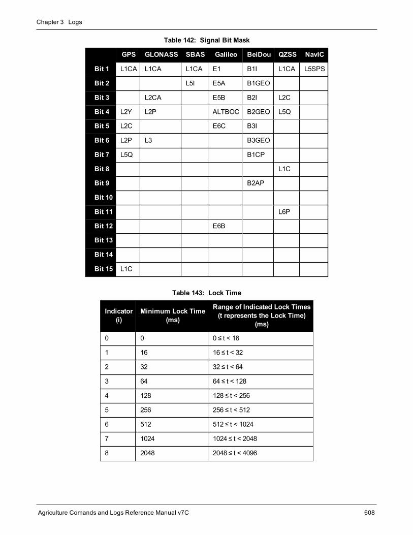
Chapter 3 Logs
Agriculture Comands and Logs Reference Manual v7C 608
GPS GLONASS SBAS Galileo BeiDou QZSS NavIC
Bit 1 L1CA L1CA L1CA E1 B1I L1CA L5SPS
Bit 2 L5I E5A B1GEO
Bit 3 L2CA E5B B2I L2C
Bit 4 L2Y L2P ALTBOC B2GEO L5Q
Bit 5 L2C E6C B3I
Bit 6 L2P L3 B3GEO
Bit 7 L5Q B1CP
Bit 8 L1C
Bit 9 B2AP
Bit 10
Bit 11 L6P
Bit 12 E6B
Bit 13
Bit 14
Bit 15 L1C
Table 142: Signal Bit Mask
Indicator(i)
Minimum Lock Time(ms)
Range of Indicated Lock Times(t represents the Lock Time)
(ms)
0 0 0 ≤ t < 16
1 16 16 ≤ t < 32
2 32 32 ≤ t < 64
3 64 64 ≤ t < 128
4 128 128 ≤ t < 256
5 256 256 ≤ t < 512
6 512 512 ≤ t < 1024
7 1024 1024 ≤ t < 2048
8 2048 2048 ≤ t < 4096
Table 143: Lock Time

Chapter 3 Logs
Agriculture Comands and Logs Reference Manual v7C 609
Indicator(i)
Minimum Lock Time(ms)
Range of Indicated Lock Times(t represents the Lock Time)
(ms)
9 4096 4096 ≤ t < 8192
10 8192 8192 ≤ t < 16384
11 16384 16384 ≤ t < 32768
12 32768 32768 ≤ t < 65536
13 65536 65536 ≤ t < 131072
14 131072 131072 ≤ t < 262144
15 262144 262144 ≤ t
ADR Std Dev (cycles)
0 ≤ 0.0039
1 ≤ 0.0052
2 ≤ 0.0070
3 ≤ 0.0093
4 ≤ 0.0124
5 ≤ 0.0165
6 ≤ 0.0221
7 ≤ 0.0295
8 ≤ 0.0393
9 ≤ 0.0525
10 ≤ 0.0701
11 ≤ 0.0935
12 ≤ 0.1248
13 ≤ 0.1666
14 ≤ 0.2223
15 > 0.2223
Table 144: ADR Std Dev

Chapter 3 Logs
Agriculture Comands and Logs Reference Manual v7C 610
Pseudorange Std Dev (m)
0 ≤ 0.020
1 ≤ 0.030
2 ≤ 0.045
3 ≤ 0.066
4 ≤ 0.099
5 ≤ 0.148
6 ≤ 0.220
7 ≤ 0.329
8 ≤ 0.491
9 ≤ 0.732
10 ≤ 1.092
11 ≤ 1.629
12 ≤ 2.430
13 ≤ 3.625
14 ≤ 5.409
15 > 5.409
Table 145: Pseudorange Std Dev

Chapter 3 Logs
Agriculture Comands and Logs Reference Manual v7C 611
3.129 RANGEGPSL1L1 version of the RANGE log
Platform: OEM719, OEM729, OEM7500, OEM7600, OEM7700, OEM7720, PwrPak7, SPAN CPT7,SMART7, SMART2
This log is identical to theRANGE log (see page 580) except that it only includes GPS L1C/A observations.
Message ID: 631
Log Type: Synch
Recommended Input:log rangegpsl1a ontime 30
ASCII Example:#RANGEGPSL1A,COM1,0,57.0,FINESTEERING,1337,404766.000,02000000,5862,1984;
10,
14,0,21773427.400,0.037,-114420590.433332,0.006,2408.171,49.9,14963.280,18109c04,
22,0,24822942.668,0.045,-130445851.055756,0.009,-3440.031,48.0,22312.971,08109c24,
25,0,20831000.299,0.033,-109468139.214586,0.006,1096.876,50.7,7887.840,08109c44,
1,0,20401022.863,0.032,-107208568.887106,0.006,-429.690,51.1,10791.500,18109c64,
24,0,23988223.932,0.074,-126058964.619453,0.013,2519.418,43.8,493.550,18109c84,
11,0,22154466.593,0.043,-116423014.826717,0.007,-1661.273,48.4,11020.952,08109ca4,
5,0,24322401.516,0.067,-127815012.260616,0.012,-1363.596,44.6,6360.282,18109cc4,
20,0,22294469.347,0.043,-117158267.467388,0.008,2896.813,48.5,4635.968,08109ce4,
30,0,23267589.649,0.051,-122271969.418761,0.009,822.194,47.0,4542.270,08109d04,
23,0,24975654.673,0.058,-131247903.805678,0.009,3395.097,45.9,406.762,18109d24*be4b7d70
Since the RANGEGPSL1 log includes only GPS L1C/A observations, it is smaller in size thanthe RANGE log which contains entries for multiple systems and signals. Use the RANGEGPSL1log when data throughput is limited and you are only interested in GPS L1C/A range data. ForGPS L1 only models, RANGE and RANGEGPSL1 logs are identical.
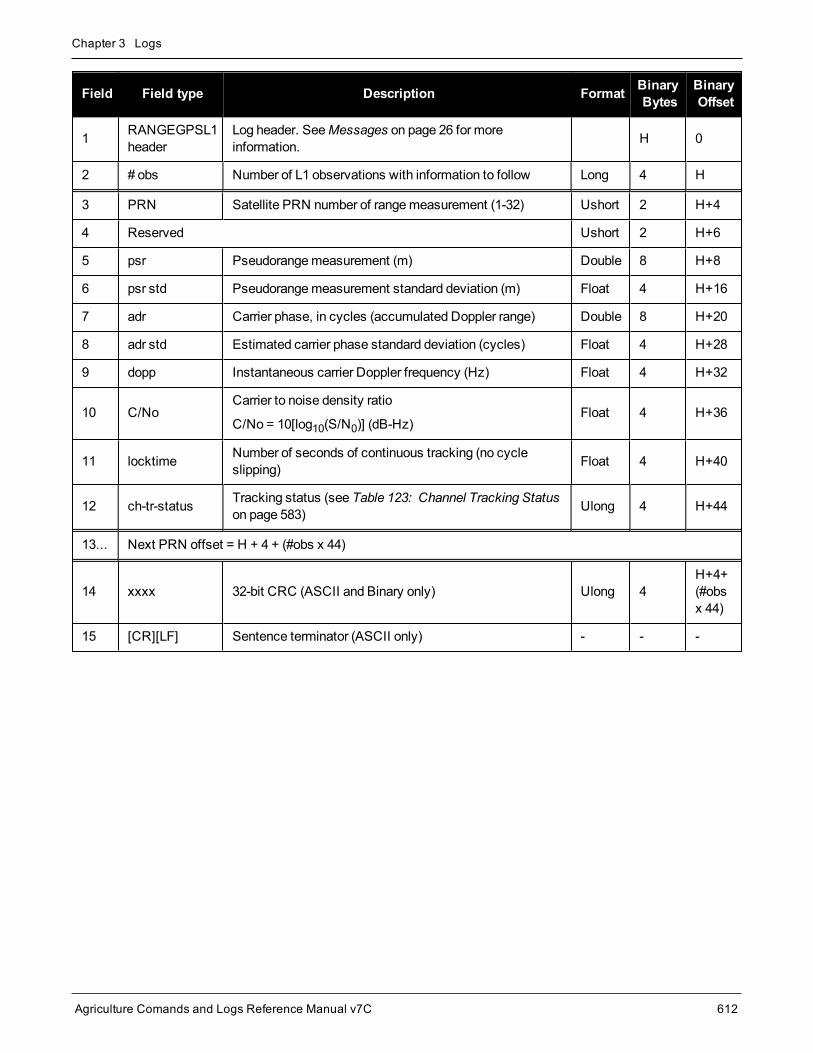
Chapter 3 Logs
Agriculture Comands and Logs Reference Manual v7C 612
Field Field type Description Format BinaryBytes
BinaryOffset
1 RANGEGPSL1header
Log header. SeeMessages on page 26 for moreinformation. H 0
2 # obs Number of L1 observations with information to follow Long 4 H
3 PRN Satellite PRN number of rangemeasurement (1-32) Ushort 2 H+4
4 Reserved Ushort 2 H+6
5 psr Pseudorangemeasurement (m) Double 8 H+8
6 psr std Pseudorangemeasurement standard deviation (m) Float 4 H+16
7 adr Carrier phase, in cycles (accumulated Doppler range) Double 8 H+20
8 adr std Estimated carrier phase standard deviation (cycles) Float 4 H+28
9 dopp Instantaneous carrier Doppler frequency (Hz) Float 4 H+32
10 C/NoCarrier to noise density ratio
C/No = 10[log10(S/N0)] (dB-Hz)Float 4 H+36
11 locktime Number of seconds of continuous tracking (no cycleslipping) Float 4 H+40
12 ch-tr-status Tracking status (see Table 123: Channel Tracking Statuson page 583) Ulong 4 H+44
13... Next PRN offset = H + 4 + (#obs x 44)
14 xxxx 32-bit CRC (ASCII and Binary only) Ulong 4H+4+(#obsx 44)
15 [CR][LF] Sentence terminator (ASCII only) - - -

Chapter 3 Logs
Agriculture Comands and Logs Reference Manual v7C 613
3.130 RAWALMRaw GPS L1 C/A Almanac data
Platform: OEM719, OEM729, OEM7500, OEM7600, OEM7700, OEM7720, PwrPak7, SPAN CPT7,SMART7, SMART2
This log contains the undecodedGPS almanac subframes as received from the satellite. For more informationabout Almanac data, refer toAn Introduction to GNSS available on our website at novatel.com/contactus/an-introduction-to-gnss.
Message ID: 74
Log Type: Asynch
Recommended Input:log rawalma onchanged
ASCII Example:#RAWALMA,COM1,0,56.0,SATTIME,1337,405078.000,02000000,cc1b,1984;1337,589824.000,43,3,8b04e4839f35433a5590f5aefd3900a10c9aaa6f40187925e50b9f03003f,27,8b04e483a1325b9cde9007f2fd5300a10da5562da3adc0966488dd01001a,4,8b04e483a1b44439979006e2fd4f00a10d15d96b3b021e6c6c5f23feff3c,28,8b04e483a3b05c5509900b7cfd5800a10cc483e2bfa1d2613003bd050017,5,8b04e483a43745351c90fcb0fd4500a10d8a800f0328067e5df8b6100031,57,8b04e483a6337964e036d74017509f38e13112df8dd92d040605eeaaaaaa,6,8b04e483a6b54633e390fa8bfd3f00a10d4facbc80b322528f62146800ba,29,8b04e483a8b05d47f7901b20fd5700a10ce02d570ed40a0a2216412400cb,7,8b04e483a935476dee90fb94fd4300a10d93aba327b7794ae853c02700ba,...1,8b04e483d8b641305a901b9dfd5a00a10ce92f48f1ba0a5dcccb7500003b,25,8b04e483dab25962259004fcfd4c00a10dc154eee5c555d7a2a5010d000d,2,8b04e483db37424aa6900720fd4f00a10c5ad89baa4dc1460790b6fc000f,26,8b04e483dd305a878c901d32fd5b00a10c902eb7f51db6b6ce95c701fff4*83cae97a
TheOEM7 family of receivers automatically saves almanacs in their Non-Volatile Memory (NVM),therefore creating an almanac boot file is not necessary.
Field Field type Description Format BinaryBytes
BinaryOffset
1 RAWALMheader
Log header. SeeMessages on page 26 for moreinformation. H 0
2 ref week Almanac reference week number Ulong 4 H
3 ref secs Almanac reference time (ms) GPSec 4 H+4
4 #subframes Number of subframes to follow Ulong 4 H+8

Chapter 3 Logs
Agriculture Comands and Logs Reference Manual v7C 614
Field Field type Description Format BinaryBytes
BinaryOffset
5 svid
SV ID (satellite vehicle ID)
A value between 1 and 32 for the SV ID indicates thePRN of the satellite. Any other values indicate the pageID.
See section 20.3.3.5.1.1, Data ID and SVID, of IS-GPS-200J for more details. Toobtain copies of IS-GPS-200, refer to theGPS website (http://www.g-ps.gov/technical/icwg/).
Ushort 2 H+12
6 data Subframe page data Hex 30 H+14
7... Next subframe offset = H+12+(#subframe x 32)
8 xxxx 32-bit CRC (ASCII and Binary only) Hex 4H+12+(#subframesx 32)
9 [CR][LF] Sentence terminator (ASCII only) - - -

Chapter 3 Logs
Agriculture Comands and Logs Reference Manual v7C 615
3.131 RAWCNAVFRAMERaw GPS CNAV frame data
Platform: OEM719, OEM729, OEM7500, OEM7600, OEM7700, OEM7720, PwrPak7, SPAN CPT7,SMART7, SMART2
This log provides raw frame data from signals which contain the CNAV message (L2C, L5).
Message ID: 1066
Log Type: Asynch
Recommended Input:log rawcnavframea onnew
ASCII Example:#RAWCNAVFRAMEA,COM1,0,63.0,SATTIME,1902,431718.000,02000020,ee56,13677;17,6,11,8b18b8c892cd499a403d89d3a5bfc05f500a1fff6007dff412e017a3c029ccff5d6001fc9a70*0dddab32
Field Field type Description Format BinaryBytes
BinaryOffset
1 RAWCNAVFRAMEheader
Log header. SeeMessages on page 26 formore information. H 0
2 signal channel Signal channel providing the bits Ulong 4 H
3 PRN Satellite PRN number Ulong 4 H+4
4 frame ID frame ID Ulong 4 H+8
5 data Raw frame data Hex[38] 38 H+12
6 xxxx 32-bit CRC (ASCII and Binary only) Hex 4 H+50
7 [CR][LF] Sentence terminator (ASCII only) - - -

Chapter 3 Logs
Agriculture Comands and Logs Reference Manual v7C 616
3.132 RAWEPHEMRaw GPS L1 C/A ephemeris
Platform: OEM719, OEM729, OEM7500, OEM7600, OEM7700, OEM7720, PwrPak7, SPAN CPT7,SMART7, SMART2
This log contains the raw binary information for subframes one, two and three from theGPS satellite L1 C/A sig-nal with the parity information removed. Each subframe is 240 bits long (10 words - 24 bits each) and the log con-tains a total 720 bits (90 bytes) of information (240 bits x 3 subframes). This information is preceded by the PRNnumber of the satellite from which it originated. This message is not generated unless all 10 words from all 3frames have passed parity.
Ephemeris data whose Time of Ephemeris (TOE) is older than six hours is not shown. Multiple logs are output,one for eachGPS satellite with collected ephemeris information.
Message ID: 41
Log Type: Asynch
Recommended Input:log rawephema onnew
ASCII Example:#RAWEPHEMA,COM1,30,48.0,SATTIME,2017,215910.000,02000008,58ba,14968;8,2017,215984,8b0f84464926f8500023bc389922867c68cea8010b0d34bb00fff5f10fbe,8b0f844649ab0dfac632fe6b077ab8fbc101cbf3970702a10cf7c334bb16,8b0f84464a2fffd51d287903005b2781e24627e6ef75369dffa4920dfe27*e26b8cb9
...
#RAWEPHEMA,COM1,29,48.0,SATTIME,2017,217440.000,02000008,58ba,14968;10,2017,223200,8b0f8446c8a7f8500012fcc99922867c68cea801045e367e00ffef1817c6,8b0f8446c9295efea1313adc677649fe7a01ea37a913e4a10d5206367e7e,8b0f8446c9af003072eca2d5fff527313d1619108e3984d6ffa8df5e08ba*85ccfe5a
A way to use only one receiver and achieve better than 1meter accuracy is to use precise orbit andclock files. Three types of GPS ephemeris, clock and earth orientation solutions are compiled by anelaborate network of GNSS receivers around the world all monitoring the satellite characteristics. IGSrapid orbit data is processed to produce files that correct the satellite clock and orbit parameters. Sincethere is extensive processing involved, these files are available on a delayed schedule from the USNational Geodetic Survey at: www.ngs.noaa.gov/orbits
Precise ephemeris files are available today to correct GPS data which was collected a few days ago. Allyou need is oneGNSS receiver and a computer to process on. Replace the ephemeris data with theprecise ephemeris data and post-process to correct range values.

Chapter 3 Logs
Agriculture Comands and Logs Reference Manual v7C 617
Field Field type Description Format BinaryBytes
BinaryOffset
1 RAWEPHEMheader
Log header. SeeMessages on page 26 for moreinformation. H 0
2 PRN Satellite PRN number Ulong 4 H
3 ref week Ephemeris reference week number Ulong 4 H+4
4 ref secs Ephemeris reference time (s) Ulong 4 H+8
5 subframe1 Subframe 1 data Hex[30] 30 H+12
6 subframe2 Subframe 2 data Hex[30] 30 H+42
7 subframe3 Subframe 3 data Hex[30] 30 H+72
8 xxxx 32-bit CRC (ASCII and Binary only) Hex 4 H+102
9 [CR][LF] Sentence terminator (ASCII only) - - -

Chapter 3 Logs
Agriculture Comands and Logs Reference Manual v7C 618
3.133 RAWGPSSUBFRAMERaw GPS L1 C/A subframe data
Platform: OEM719, OEM729, OEM7500, OEM7600, OEM7700, OEM7720, PwrPak7, SPAN CPT7,SMART7, SMART2
This log contains the raw GPS L1C/A subframe data.
A raw GPS L1C/A subframe is 300 bits in total. This includes the parity bits which are interspersed with the rawdata ten times in six bit chunks, for a total of 60 parity bits. Note Field #5, below, has these 60 parity bits strippedout and only the raw subframe data remains, for a total of 240 bits.
Message ID: 25
Log Type: Asynch
Recommended Input:log rawgpssubframea onnew
ASCII Example:#RAWGPSSUBFRAMEA,COM1,59,62.5,SATTIME,1337,405348.000,02000000,f690,1984;2,22,4,8b04e483f3b17ee037a3732fe0fc8ccf074303ebdf2f6505f5aaaaaaaaa9,2*41e768e4...#RAWGPSSUBFRAMEA,COM1,35,62.5,SATTIME,1337,405576.000,02000000,f690,1984;4,25,2,8b04e48406a8b9fe8b364d786ee827ff2f062258840ea4a10e20b964327e,4*52d460a7...#RAWGPSSUBFRAMEA,COM1,0,62.5,SATTIME,1337,400632.000,02000000,f690,1984;20,9,3,8b04e4826aadff3557257871000a26fc34a31d7a300bede5ffa3de7e06af,20*55d16a4a
The RAWGPSSUBFRAME log can be used to receive the data bits with the parity bits stripped out.Alternately, you can use theRAWGPSWORD log (see page 621) to receive the parity bits in addition tothe data bits.
Field Field type Description Format BinaryBytes
BinaryOffset
1 RAWGPSSUBFRAMEheader
Log header. SeeMessages on page 26 formore information. H 0
2 decode # Frame decoder number Long 4 H
3 PRN Satellite PRN number Ulong 4 H+4
4 subframe id Subframe ID Ulong 4 H+8
5 data Raw subframe data Hex[30] 321 H+12
1In the binary log case, an additional 2 bytes of padding are added to maintain 4-byte alignment.

Chapter 3 Logs
Agriculture Comands and Logs Reference Manual v7C 619
Field Field type Description Format BinaryBytes
BinaryOffset
6 signal channel Signal channel number that the framewasdecoded on Ulong 4 H+44
7 xxxx 32-bit CRC (ASCII and Binary only) Ulong 4 H+48
8 [CR][LF] Sentence terminator (ASCII only) - - -

Chapter 3 Logs
Agriculture Comands and Logs Reference Manual v7C 620
3.134 RAWGPSWORDRaw GPS L1 C/A navigation word
Platform: OEM719, OEM729, OEM7500, OEM7600, OEM7700, OEM7720, PwrPak7, SPAN CPT7,SMART7, SMART2
This message contains the framedGPS L1C/A raw navigation words. Each log contains a new 30 bit navigationword (in the least significant 30 bits), plus the last 2 bits of the previous word (in themost significant 2 bits). The30 bit navigation word contains 24 bits of data plus 6 bits of parity. TheGPS reference time stamp in the logheader is the time the first bit of the 30 bit navigation word was received. Only navigation data that has passedparity checking appears in this log. One log appears for each PRN being tracked every 0.6 seconds if loggedONNEW orONCHANGED.
Message ID: 407
Log Type: Asynch
Recommended Input:log rawgpsworda onnew
ASCII Example:#RAWGPSWORDA,COM1,0,58.5,FINESTEERING,1337,405704.473,02000000,9b16,1984;14,7ff9f5dc*8e7b8721...#RAWGPSWORDA,COM1,0,57.0,FINESTEERING,1337,405783.068,02000000,9b16,1984;1,93feff8a*6dd62c81...#RAWGPSWORDA,COM1,0,55.5,FINESTEERING,1337,405784.882,02000000,9b16,1984;5,fffff8ce*a948b4de
The RAWGPSWORD log can be used to receive the parity bits in addition to the data bits. Alternately,you can use the RAWGPSSUBFRAME log which already has the parity bits stripped out
Field Field type Description Format BinaryBytes
BinaryOffset
1 RAWGPSWORDheader
Log header. SeeMessages on page 26 for moreinformation. H 0
2 PRN Satellite PRN number Ulong 4 H
3 nav word Raw navigation word Hex[4] 4 H+4
4 xxxx 32-bit CRC (ASCII and Binary only) Ulong 4 H+8
5 [CR][LF] Sentence terminator (ASCII only) - - -

Chapter 3 Logs
Agriculture Comands and Logs Reference Manual v7C 621
3.135 RAWSBASFRAMERaw SBAS frame data
Platform: OEM719, OEM729, OEM7500, OEM7600, OEM7700, OEM7720, PwrPak7, SPAN CPT7,SMART7, SMART2
This log contains the raw SBAS frame data of 226 bits (8-bit preamble, 6-bit message type and 212 bits of databut without a 24-bit CRC). Only frame data with a valid preamble and CRC are reported.
Message ID: 973
Log Type: Asynch
Recommended Input:log rawsbasframea onnew
ASCII Example:#RAWSBASFRAMEA,COM1,0,91.0,SATTIME,1610,341534.000,02000000,58e4,38637;32,133,4,c6115ffc00000c009ffc07004c089ffdffdffdffdfff957bbb6bffffc0,32*5afc5f95
#RAWSBASFRAMEA,COM1,0,91.0,SATTIME,1610,341535.000,02000000,58e4,38637;32,133,2,53084007ff9fffffc03002c0000f0009ffc004005ffd6b961e39b9fb80,32*db5dfa62
#RAWSBASFRAMEA,COM1,0,91.0,SATTIME,1610,341535.000,02000000,58e4,38637;35,135,2,53084007ff9fffffc03002c0000f0009ffc004005ffd6b961e39b9fb80,35*b72ff2a0
...
#RAWSBASFRAMEA,COM1,0,90.0,SATTIME,1610,341539.000,02000000,58e4,38637;34,138,3,9a0c4000009ffc009ffdffc007fb9ffdffc0000040315b9bb96fb95680,34*cb050361
The RAWSBASFRAME log output contains all the raw data required for an application to compute itsown SBAS correction parameters.
Field Field type Description Format BinaryBytes
BinaryOffset
1 RAWSBASFRAMEheader
Log header. SeeMessages on page 26 for moreinformation. H 0
2 decode # Frame decoder number Ulong 4 H
3 PRN SBAS satellite PRN number Ulong 4 H+4
4 SBAS frame ID SBAS frame ID Ulong 4 H+8
5 raw frame data Raw SBAS frame data. There are 226 bits of dataand 6 bits of padding.
Hex[29] 321 H+12
1In the binary log case, an additional 3 bytes of padding are added to maintain 4-byte alignment.

Chapter 3 Logs
Agriculture Comands and Logs Reference Manual v7C 622
Field Field type Description Format BinaryBytes
BinaryOffset
6 signal channel Signal channel number that the framewasdecoded on. Ulong 4 H+44
7 xxxx 32-bit CRC (ASCII and Binary only) Ulong 4 H+48
8 [CR][LF] Sentence terminator (ASCII only) - - -

Chapter 3 Logs
Agriculture Comands and Logs Reference Manual v7C 623
3.136 RAWSBASFRAME2Raw SBAS frame data 2
Platform: OEM719, OEM729, OEM7500, OEM7600, OEM7700, OEM7720, PwrPak7, SPAN CPT7,SMART7, SMART2
This log contains the raw SBAS frame data of 226 bits (8-bit preamble, 6-bit message type and 212 bits of databut without a 24-bit CRC). It also contains the transmitted frequency. Only frame data with a valid preamble andCRC are reported.
Message ID: 2185
Log Type: Asynch
Recommended Input:log rawsbasframe2a onnew
ASCII Example:#RAWSBASFRAME2A,COM1,0,77.5,SATTIME,1977,514394.000,02000020,b39f,32768;135,209,2,1,0,3,c60d4009ffc018001ffc005ffdfffffbff9ffc00bfed79db9bb95b9540*9a75ce69
#RAWSBASFRAME2A,COM1,0,77.5,SATTIME,1977,514394.000,02000020,b39f,32768;138,207,2,1,0,4,c6125ffdffc005ffffffffbfe3fb9ffdffdffdffdfffba3956abffffc0*9324a574
#RAWSBASFRAME2A,COM1,0,77.5,SATTIME,1977,514395.000,02000020,b39f,32768;135,208,1,0,0,4,53125ffdffc011ffc000007fe3fb5ffdffdffdffdfffba3956abffffc0*69490ac5
#RAWSBASFRAME2A,COM1,0,78.5,SATTIME,1977,514395.000,02000020,b39f,32768;138,206,1,0,0,3,530c7ff9ffc017ff9fffff9ffdfffffbfedffc003fe579db9bb95b9540*c7ca1531
TheRAWSBASFRAME2 log output contains all the raw data required for an application to compute itsown SBAS correction parameters.
Field Field Type Description Format BinaryBytes
BinaryOffset
1 RAWSBASFRAME2header
Log header. SeeMessages on page 26 for moreinformation. H 0
2 PRN SBAS satellite PRN number Ulong 4 H
3 signal channel Signal channel number that the framewasdecoded on Ulong 4 H+4
4 SBAS Signal Source
Identifies the source of the SBAS signal:
1 – SBASL1CA
2 – SBASL5I
Uchar 1 H+8

Chapter 3 Logs
Agriculture Comands and Logs Reference Manual v7C 624
Field Field Type Description Format BinaryBytes
BinaryOffset
5 SBAS PreambleType
Identifies what preamble was used whentracking the SBAS signal:
0 – SBASL1CA 8-bit Preamble
1 – SBASL5I 8-bit Preamble
Uchar 1 H+9
6 Reserved Ushort 2 H+10
7 SBAS frame ID SBAS frame ID Ulong 4 H+12
8 data Raw SBAS frame data. There are 226 bits ofdata and 6 bits of padding.
Hex[29] 321 H+16
9 xxxx 32-bit CRC (ASCII and Binary only) Ulong 4 H+48
10 [CR][LF] Sentence terminator (ASCII only) - - -
1In the binary log case, an additional 3 bytes of padding are added to maintain 4-byte alignment.

Chapter 3 Logs
Agriculture Comands and Logs Reference Manual v7C 625
3.137 REFSTATIONBase station position and health
Platform: OEM719, OEM729, OEM7500, OEM7600, OEM7700, OEM7720, PwrPak7, SPAN CPT7,SMART7
This log contains the ECEF Cartesian position of the base station as received through the RTCMV3message. Italso features a time tag, the health status of the base station and the station ID. This information is set at thebase station using the FIX command (see page 115) and theDGPSTXID command (see page 98). See Figure 7:TheWGS84 ECEF Coordinate System on page 365 for a definition of the ECEF coordinates.
The base station health, Field #6, may be one of 8 values (0 to 7). Values 0 through 5 indicate the scale factorthat is multiplied with the satellite UDRE one-sigma differential error values. Below are values 0 to 5 and their cor-responding UDRE scale factors:
0: 1 (Health OK) 0.75 2: 0.5 3: 0.3 4: 0.2 5: 0.1
The base station health field only applies to RTCM base stations. A value of 6means the base station trans-mission is not monitored and a value of 7means that the base station is not working.
Message ID: 175
Log Type: Asynch
Recommended Input:log refstationa onchanged
ASCII Example:#REFSTATIONA,COM1,0,66.5,FINESTEERING,1364,490401.124,82000000,4e46,2310;00000000,-1634532.443,-3664608.907,4942482.713,0,RTCMV3,"AAAA"*1e2a0508
Field Field type Description Format BinaryBytes
BinaryOffset
1 REFSTATIONheader
Log header. SeeMessages on page 26 for moreinformation. H 0
2 status Status of the base station information (see Table 146:Base Station Status on the next page) Ulong 4 H
3 x ECEF X value (m) Double 8 H+4
4 y ECEF Y value (m) Double 8 H+12
5 z ECEF Z value (m) Double 8 H+20
6 health Base station health, see the description at the start of thissection Ulong 4 H+28
7 stn type Station type (see Table 147: Base Station Type on thenext page) Enum 4 H+32

Chapter 3 Logs
Agriculture Comands and Logs Reference Manual v7C 626
Field Field type Description Format BinaryBytes
BinaryOffset
8 stn ID Base station ID Char[5] 81 H+36
9 xxxx 32-bit CRC (ASCII and Binary only) Ulong 4 H+44
10 [CR][LF] Sentence terminator (ASCII only) - - -
Bit # Mask Description Bit = 0 Bit = 1
0 0x00000001 Validity of the base station Valid Invalid
Table 146: Base Station Status
Binary ASCII Description
0 NONE Base station is not used
1 - 3 Reserved
4 RTCMV3 Base station is RTCMV3
Table 147: Base Station Type
The REFSTATION log can be used for checking the operational status of a remotely located base sta-tion. You can verify that the base station is operating properly without traveling to it. This is especiallyuseful for RTK work on long baselines.
1In the binary log case, an additional 3 bytes of padding are added to maintain 4-byte alignment.

Chapter 3 Logs
Agriculture Comands and Logs Reference Manual v7C 627
3.138 REFSTATIONINFOBase Station position information
Platform: OEM719, OEM729, OEM7500, OEM7600, OEM7700, OEM7720, PwrPak7, SPAN CPT7,SMART7
This is an extended version of the REFSTATION log with latitude, longitude and ellipsoidal height of the base sta-tion inWGS84. In addition to the base station position, ARP height, antennamodel name and antenna serial num-ber are available if provided by the base station only through RTCMV3.
Message ID: 1325
Log Type: Asynch
Recommended Input:log refstationinfoa onchanged
ASCII Example:#REFSTATIONINFOA,USB1,0,89.5,EXACT,0,0.000,02000040,d38f,6782;51.116375174,-114.038254922,1048.502830628,WGS84,1.234,0,RTCMV3,"0","702GG","NVH05410007"*bedf8ece
Field Field type Description Format BinaryBytes
BinaryOffset
1 REFSTATIONINFOheader
Log header. SeeMessages on page 26 for moreinformation. H 0
2 latitude Latitude (degrees) Double 8 H
3 longitude Longitude (degrees) Double 8 H+8
4 height Ellipsoidal Height (m) Double 8 H+16
5 datum
Datum ID number
61 = WGS84
63 = USER
(default = WGS84)
Enum 4 H+24
6 ARP height Base Antenna ARP (m) Float 4 H+28
7 health Base Station Health, see Table 146: Base StationStatus on the previous page Ulong 4 H+32
8 Ref Stn Type Base Station Type, see (Table 147: Base StationType on the previous page) Enum 4 H+36
9 stn ID Base Station ID Char[5] 81 H+40
1In the binary log case, an additional 3 bytes of padding are added to maintain 4-byte alignment.

Chapter 3 Logs
Agriculture Comands and Logs Reference Manual v7C 628
Field Field type Description Format BinaryBytes
BinaryOffset
10 Ant Model Base AntennaModel Name Char[32] 32 H+48
11 Ant Serial Base Antenna Serial Number Char[32] 32 H+80
12 xxxx 32-bit CRC (ASCII and Binary only) Ulong 4 H+112
13 [CR][LF] Sentence terminator (ASCII only) - - -

Chapter 3 Logs
Agriculture Comands and Logs Reference Manual v7C 629
3.139 ROVERPOSPosition using ALIGN
Platform: OEM719, OEM729, OEM7500, OEM7600, OEM7700, OEM7720, PwrPak7, SPAN CPT7,SMART7
ALIGN generates distance and bearing information between amaster and rover receiver. This log outputs theposition information of the rover when using the ALIGN feature. This log can only be output from a Y ALIGNmodel and can be output at bothMaster and Rover ends.
Youmust have an ALIGN capable receiver to use this log.
l ALIGN is useful for obtaining the relative directional heading of a vessel/body, separation headingbetween two vessels/bodies, or heading information with moving base and pointing applications.
l The log can be output at the Y model Rover only if it is receiving the RTCAREFEXTmessage fromtheMaster. The log can be output at any Master if theMaster is receiving HEADINGEXTB fromthe Rover. Refer to the NovAtel application note APN-048: ALIGN Family of Heading Solutions fordetails on HEADINGEXT (available at novatel.com/support/support-materials/application-notes).
l ROVERPOS is dependent on the output frequency of the RTCAREFEXTmessage from themas-ter to the rover.
l On dual antenna receivers, theROVERPOS log outputs the position for the secondary antennainput.
Message ID: 1052
Log Type: Asynch
Recommended Input:log roverposa onchanged
ASCII Example:#ROVERPOSA,COM1,0,21.5,FINESTEERING,1544,340322.000,02000008,7453,4655;SOL_COMPUTED,NARROW_INT,51.11605565964,-114.03854655975,1055.8559,-16.9000,WGS84,0.0130,0.0122,0.0206,"RRRR",0.0,0.0,13,12,12,11,0,0,0,0*635b3a1c
Asynchronous logs, such as ROVERPOS, should only be loggedONCHANGED or ONNEW oth-erwise themost current data is not output when it is available. This is especially true of the ONTIMEtrigger, whichmay cause inaccurate time tags to result.
Field Field Type Description Format BinaryBytes
BinaryOffset
1 ROVERPOSheader
Log header. SeeMessages on page 26 for moreinformation. H 0

Chapter 3 Logs
Agriculture Comands and Logs Reference Manual v7C 630
Field Field Type Description Format BinaryBytes
BinaryOffset
2 sol stat Solution Status, see Table 65: Solution Status onpage 349 Enum 4 H
3 pos type Position Type see Table 66: Position or Velocity Typeon page 350 Enum 4 H+4
4 lat RoverWGS84 latitude (degrees) Double 8 H+8
5 long RoverWGS84 longitude (degrees) Double 8 H+16
6 hgt Rover MSLHeight (m) Double 8 H+24
7 undulation Undulation (m) Float 4 H+32
8 datum id#
Datum ID number
61 = WGS84
63 = USER
(default = WGS84)
Enum 4 H+36
9 lat σ Latitude standard deviation (m) Float 4 H+40
10 long σ Longitude standard deviation (m) Float 4 H+44
11 hgt σ Height standard deviation (m) Float 4 H+48
12 stn id Rover ID (default = “RRRR”) Char[4] 4 H+52
13 Reserved Float 4 H+56
14 Reserved Float 4 H+60
15 #SVs Number of satellites tracked Uchar 1 H+64
16 #solnSVs Number of satellites used in solution Uchar 1 H+65
17 #obs Number of satellites above elevationmask angle Uchar 1 H+66
18 #multi Number of satellites with multi-frequency signals aboveelevationmask angle Uchar 1 H+67
19
Reserved
Hex 1 H+68
20 Uchar 1 H+69
21 Uchar 1 H+70
22 Uchar 1 H+71
23 xxxx 32-bit CRC (ASCII and Binary only) Hex 1 H+72
24 [CR][LF] Sentence Terminator (ASCII only) - - -

Chapter 3 Logs
Agriculture Comands and Logs Reference Manual v7C 631
3.140 RTCMV3 Standard LogsPlatform: OEM719, OEM729, OEM7500, OEM7600, OEM7700, OEM7720, PwrPak7, SPAN CPT7,
SMART7
NovAtel’s RTCMv3 logs are implementations of themessages described by the RTCM SC-104 committee’s“Differential GNSS (Global Navigation Satellite Systems) Services – Version 3” standard. Thesemessages areprimarily intended to support RTK operations. They are also an alternative raw data format to NovAtel’s pro-prietary messages.
The RTCMv3 logs can be divided into several categories that are described below. An RTK base stationmustminimally transmit one or more observable message, together with one or more station and antennamessage.TheGENERATERTKCORRECTIONS command on page 124 illustrates an appropriate set of messages and isan easy way to configure logging.
Example Input:interfacemode com2 none RTCMV3
fix position 51.1136 -114.0435 1059.4
thisantennatype NOV702
log com2 rtcm1006 ontime 10
log com2 rtcm1033 ontime 10 2
log com2 rtcm1004 ontime 1
log com2 rtcm1012 ontime 1
Example Input using MSM4 messages:interfacemode com1 none rtcmv3 off
thisantennatype nov850
fix position 51.1136 -114.0435 1059.4
log com1 rtcm1006 ontime 10
log com1 rtcm1033 ontime 10 2
log com1 rtcm1074 ontime 1
log com1 rtcm1084 ontime 1
log com1 rtcm1094 ontime 1
log com1 rtcm1124 ontime 1
3.140.1 Legacy Observable MessagesThe legacy observable messages contain GPS andGLONASS code and phase observables. The extendedmes-sages additionally contain the C/N0.
Log Name Message ID Description
RTCM1001 772 GPS L1-only observables, basic
Table 148: Legacy Observable Messages

Chapter 3 Logs
Agriculture Comands and Logs Reference Manual v7C 632
Log Name Message ID Description
RTCM1002 774 GPS L1-only observables, extended
RTCM1003 776 GPS L1/L2 basic observables, basic
RTCM1004 770 GPS L1/L2 basic observables, extended
RTCM1009 885 GLONASS L1-only observables, basic
RTCM1010 887 GLONASS L1-only observables, extended
RTCM1011 889 GLONASS L1/L2 basic observables, basic
RTCM1012 891 GLONASS L1/L2 basic observables, extended
3.140.2 MSM Observable MessagesTheMultiple Signal Messages (MSM) are observable messages for all current GNSS systems. They provide astandardized framework for message content and are designed to support future systems and signals.
Sending legacy (1001-1004 and 1009-1012) andMSMmessages in the same stream can cause prob-lems for remote RTK users and is not recommended.
EachGNSS system has a set of sevenMSM types numbered from 1 to 7. TheMSM type for eachGNSS sys-tem provides the same generic information. Generally, as theMSM number increases, more information is avail-able in themessages. For example, MSM1 for eachGNSS system provides the codemeasurements for thesystem, while MSM3 provides both the code and phase.
The information encoded in eachMSM variant is described in Table 149: MSM Type Descriptions below for thedescriptions of each of the sevenMSM types. For RTK operations, MSM3 is minimally recommended.
Message Description
MSM1 Provides the codemeasurements.
MSM2 Provides the phasemeasurements.
MSM3 Provides the data fromMSM1 (code) andMSM2 (phase) in a single message.
MSM4 Provides all the data fromMSM3 (code and phase) and adds the CNR measurements.
MSM5 Provides all the data fromMSM4 (code, phase and CNR) and adds the doppler measurements.
MSM6 Provides the same information as MSM4, but has extended resolution on themeasurements.
MSM7 Provides the same information as MSM5, but has extended resolution on themeasurements.
Table 149: MSM Type Descriptions
Table 150: MSM LogNames on the next page lists theMSMmessage name and Table 151: MSMMessageIDs on the next page lists themessage IDs.
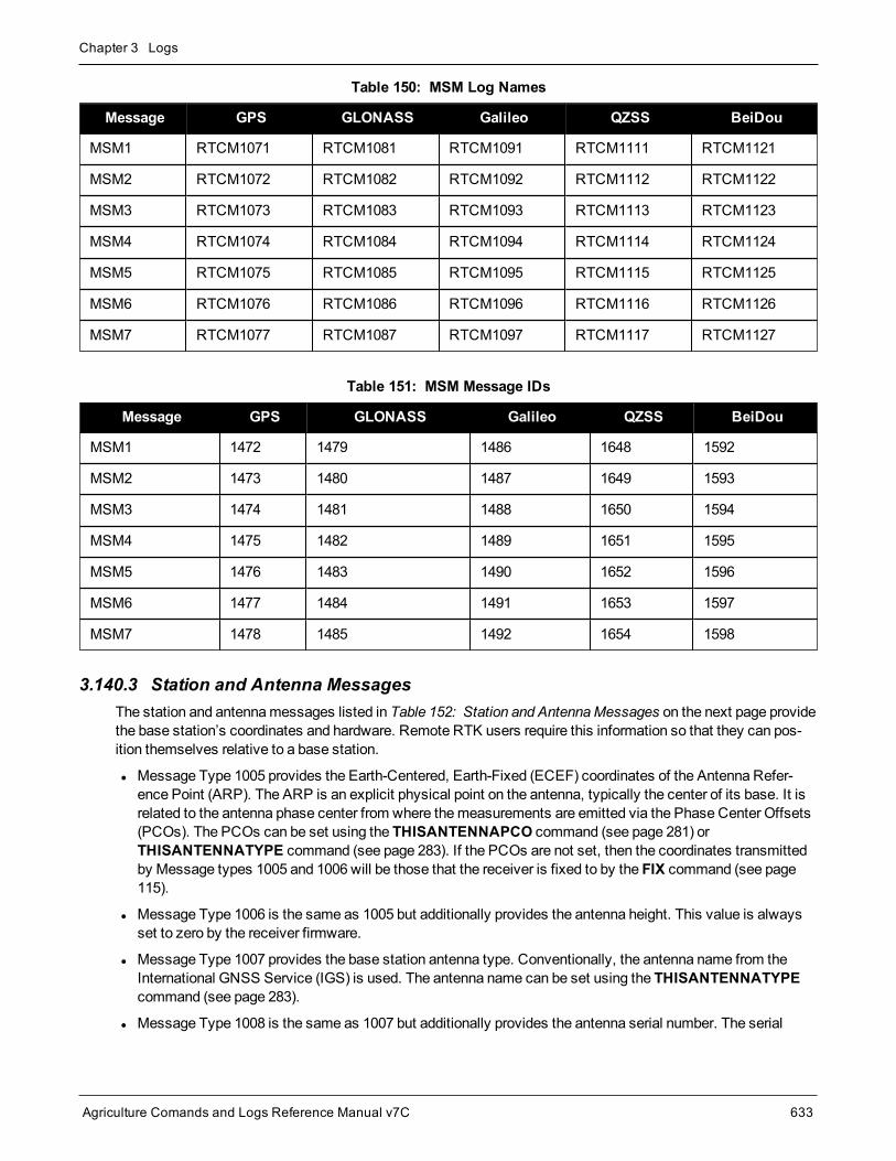
Chapter 3 Logs
Agriculture Comands and Logs Reference Manual v7C 633
Message GPS GLONASS Galileo QZSS BeiDou
MSM1 RTCM1071 RTCM1081 RTCM1091 RTCM1111 RTCM1121
MSM2 RTCM1072 RTCM1082 RTCM1092 RTCM1112 RTCM1122
MSM3 RTCM1073 RTCM1083 RTCM1093 RTCM1113 RTCM1123
MSM4 RTCM1074 RTCM1084 RTCM1094 RTCM1114 RTCM1124
MSM5 RTCM1075 RTCM1085 RTCM1095 RTCM1115 RTCM1125
MSM6 RTCM1076 RTCM1086 RTCM1096 RTCM1116 RTCM1126
MSM7 RTCM1077 RTCM1087 RTCM1097 RTCM1117 RTCM1127
Table 150: MSM Log Names
Message GPS GLONASS Galileo QZSS BeiDou
MSM1 1472 1479 1486 1648 1592
MSM2 1473 1480 1487 1649 1593
MSM3 1474 1481 1488 1650 1594
MSM4 1475 1482 1489 1651 1595
MSM5 1476 1483 1490 1652 1596
MSM6 1477 1484 1491 1653 1597
MSM7 1478 1485 1492 1654 1598
Table 151: MSM Message IDs
3.140.3 Station and Antenna MessagesThe station and antennamessages listed in Table 152: Station and AntennaMessages on the next page providethe base station’s coordinates and hardware. Remote RTK users require this information so that they can pos-ition themselves relative to a base station.
l Message Type 1005 provides the Earth-Centered, Earth-Fixed (ECEF) coordinates of the Antenna Refer-ence Point (ARP). The ARP is an explicit physical point on the antenna, typically the center of its base. It isrelated to the antenna phase center from where themeasurements are emitted via the Phase Center Offsets(PCOs). The PCOs can be set using the THISANTENNAPCO command (see page 281) orTHISANTENNATYPE command (see page 283). If the PCOs are not set, then the coordinates transmittedby Message types 1005 and 1006 will be those that the receiver is fixed to by the FIX command (see page115).
l Message Type 1006 is the same as 1005 but additionally provides the antenna height. This value is alwaysset to zero by the receiver firmware.
l Message Type 1007 provides the base station antenna type. Conventionally, the antenna name from theInternational GNSS Service (IGS) is used. The antenna name can be set using the THISANTENNATYPEcommand (see page 283).
l Message Type 1008 is the same as 1007 but additionally provides the antenna serial number. The serial

Chapter 3 Logs
Agriculture Comands and Logs Reference Manual v7C 634
number is always set to null by the receiver firmware.
l Message Type 1033, likemessage types 1007 and 1008, also provides the antenna information. Messagetype 1033 additionally provides the receiver type and firmware version. The primary use of this information isto more-easily enable RTK rovers to fix their GLONASS ambiguities. This information is filled automaticallyand appropriately by the receiver firmware.
For a receiver operating as an RTK base station, the recommendedmessages to transmit are 1006 and 1033.With thesemessages remote RTK users have all the information describing the base station.
Log Name MessageID
RTCM MessageType Description
RTCM1005 765 1005 Stationary RTK Base Station Antenna Reference Point (ARP)
RTCM1006 768 1006 Stationary RTK Base Station ARP with Antenna Height
RTCM1007 852 1007 Extended Antenna Descriptor and Setup Information
RTCM1008 854 1008 Extended Antenna Reference Station Description and SerialNumber
RTCM1033 1097 1033 Receiver and antenna descriptors
Table 152: Station and Antenna Messages
3.140.4 Ephemeris MessagesThe ephemeris messages listed in Table 153: Ephemeris Messages below provide the satellite ephemerides.For RTK operations this information is optional, as RTK rovers will be downloading their own ephemerides dir-ectly from the satellites.
There are twomessages for each ephemeris type. For themessages loggedONTIME (e.g. LOGRTCM1019ONTIME 10) a single satellite’s ephemeris is output at eachONTIME interval. The ephemerides will be cycledthrough in numerical order. For themessages loggedONCHANGED (e.g., LOGRTCM1019ASYNCONCHANGED), new or changed ephemerides will be output as soon as they are available.
Log Name MessageID
RTCM MessageType Description
RTCM1019 893 1019 GPS Ephemerides, loggedONTIME
RTCM1019ASYNC 2088 1019 GPS Ephemerides, loggedONCHANGED
RTCM1020 895 1020 GLONASS Ephemerides, loggedONTIME
RTCM1020ASYNC 2089 1020 GLONASS Ephemerides, loggedONCHANGED
RTCM1042 2171 1042 BeiDou Ephemerides, loggedONTIME
RTCM1042ASYNC 2170 1042 BeiDou Ephemerides, loggedONCHANGED
RTCM1044 2177 1044 QZSS Ephemerides, loggedONTIME
RTCM1044ASYNC 2176 1044 QZSS Ephemerides, loggedONCHANGED
Table 153: Ephemeris Messages

Chapter 3 Logs
Agriculture Comands and Logs Reference Manual v7C 635
Log Name MessageID
RTCM MessageType Description
RTCM1045 2173 1045 Galileo F/NAV Ephemerides, loggedONTIME
RTCM1045ASYNC 2172 1045 Galileo F/NAV Ephemerides, loggedONCHANGED
RTCM1046 2175 1046 Galileo I/NAV Ephemerides, loggedONTIME
RTCM1046ASYNC 2174 1046 Galileo I/NAV Ephemerides, loggedONCHANGED

Chapter 3 Logs
Agriculture Comands and Logs Reference Manual v7C 636
3.141 RTKASSISTSTATUSRTK ASSIST status
Platform: OEM719, OEM729, OEM7500, OEM7600, OEM7700, OEM7720, PwrPak7, SPAN CPT7,SMART7
This log provides information on the state of RTK ASSIST.
RTK ASSIST operates in twomodes: coast and full assist. The RTKASSISTSTATUS log reports whichmode iscurrently available. Coast mode is available as soon as the RTK ASSIST corrections are received from the L-Band satellite, while full assist mode requires a convergence period. In coast mode, position error growth duringRTK correction outages is slightly worse than in full assist mode and RTK will not resume following a full signaloutage until after RTK corrections are restored. Full assist gives the lowest position error growth during RTK cor-rection outages, andmakes it possible for RTK to resume even if there are complete GNSS signal outages dur-ing the RTK ASSIST period.
The RTK ASSIST ACTIVE state reported in the RTKASSISTSTATUS log is also reported in the RTKPOS andBESTPOS extended solution status field. See Table 69: Extended Solution Status on page 353.
The RTKASSISTSTATUS log reports the time remaining in the RTK ASSIST ACTIVE state. Once RTKASSIST becomes active, the remaining time will count down from the time out set by theRTKASSISTTIMEOUT command (see page 216) .
The corrections age reported in the RTKASSISTSTATUS log should typically be below 30 seconds. If the ageexceeds this value, then L-Band tracking is likely degraded. Themost likely cause of degraded L-Band trackingare obstructions between the antenna and the L-Band satellite.
Message ID: 2048
Log Type: Synch
Recommended Input:log rtkassiststatusa ontime 5
ASCII Example:#RTKASSISTSTATUSA,COM1,0,80.0,FINESTEERING,1932,491359.000,02000020,80fe,46672;ACTIVE,ASSIST,969.0,14.0*26e32616
Field Field type Description Format BinaryBytes
BinaryOffset
1 RTKASSISTSTATUSheader
Log header. SeeMessages on page 26 for moreinformation. H 0
2 State
State:
INACTIVE (0)
ACTIVE (1)
Enum 4 H

Chapter 3 Logs
Agriculture Comands and Logs Reference Manual v7C 637
Field Field type Description Format BinaryBytes
BinaryOffset
3 Mode
Mode:
UNAVAILABLE (0)
COAST (1)
ASSIST (2)
Enum 4 H+4
4 Remaining time Time remaining in seconds Float 4 H+8
5 Corrections age Age of the RTK ASSIST corrections in seconds.Maximum value of 120 seconds. Float 4 H+12
6 xxxx 32-bit CRC (ASCII and Binary only) Hex 4 H+16
7 [CR][LF] Sentence terminator (ASCII only) - - -
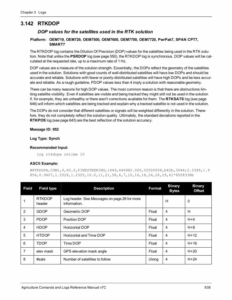
Chapter 3 Logs
Agriculture Comands and Logs Reference Manual v7C 638
3.142 RTKDOPDOP values for the satellites used in the RTK solution
Platform: OEM719, OEM729, OEM7500, OEM7600, OEM7700, OEM7720, PwrPak7, SPAN CPT7,SMART7
The RTKDOP log contains the Dilution Of Precision (DOP) values for the satellites being used in the RTK solu-tion. Note that unlike thePSRDOP log (see page 550), the RTKDOP log is synchronous. DOP values will be cal-culated at the requested rate, up to amaximum rate of 1 Hz.
DOP values are ameasure of the solution strength. Essentially, the DOPs reflect the geometry of the satellitesused in the solution. Solutions with good counts of well-distributed satellites will have low DOPs and should beaccurate and reliable. Solutions with fewer or poorly-distributed satellites will have high DOPs and be less accur-ate and reliable. As a rough guideline, PDOP values less than 4 imply a solution with reasonable geometry.
There can bemany reasons for high DOP values. Themost common reason is that there are obstructions lim-iting satellite visibility. Even if satellites are visible and being tracked they might still not be used in the solutionif, for example, they are unhealthy or there aren't corrections available for them. TheRTKSATS log (see page646) will inform which satellites are being tracked and explain why a tracked satellite is not used in the solution.
The DOPs do not consider that different satellites or signals will be weighted differently in the solution. There-fore, they do not completely reflect the solution quality. Ultimately, the standard deviations reported in theRTKPOS log (see page 643) are the best reflection of the solution accuracy.
Message ID: 952
Log Type: Synch
Recommended Input:log rtkdopa ontime 10
ASCII Example:#RTKDOPA,COM1,0,60.0,FINESTEERING,1449,446982.000,02000008,b42b,3044;2.3386,1.9856,0.9407,1.5528,1.2355,10.0,11,21,58,6,7,10,16,18,24,26,29,41*85f8338b
Field Field type Description Format BinaryBytes
BinaryOffset
1 RTKDOPheader
Log header. SeeMessages on page 26 for moreinformation. H 0
2 GDOP Geometric DOP Float 4 H
3 PDOP Position DOP Float 4 H+4
4 HDOP Horizontal DOP Float 4 H+8
5 HTDOP Horizontal and TimeDOP Float 4 H+12
6 TDOP TimeDOP Float 4 H+16
7 elev mask GPS elevationmask angle Float 4 H+20
8 #sats Number of satellites to follow Ulong 4 H+24
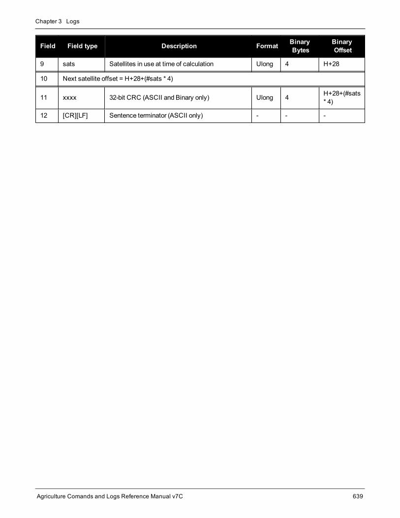
Chapter 3 Logs
Agriculture Comands and Logs Reference Manual v7C 639
Field Field type Description Format BinaryBytes
BinaryOffset
9 sats Satellites in use at time of calculation Ulong 4 H+28
10 Next satellite offset = H+28+(#sats * 4)
11 xxxx 32-bit CRC (ASCII and Binary only) Ulong 4 H+28+(#sats* 4)
12 [CR][LF] Sentence terminator (ASCII only) - - -
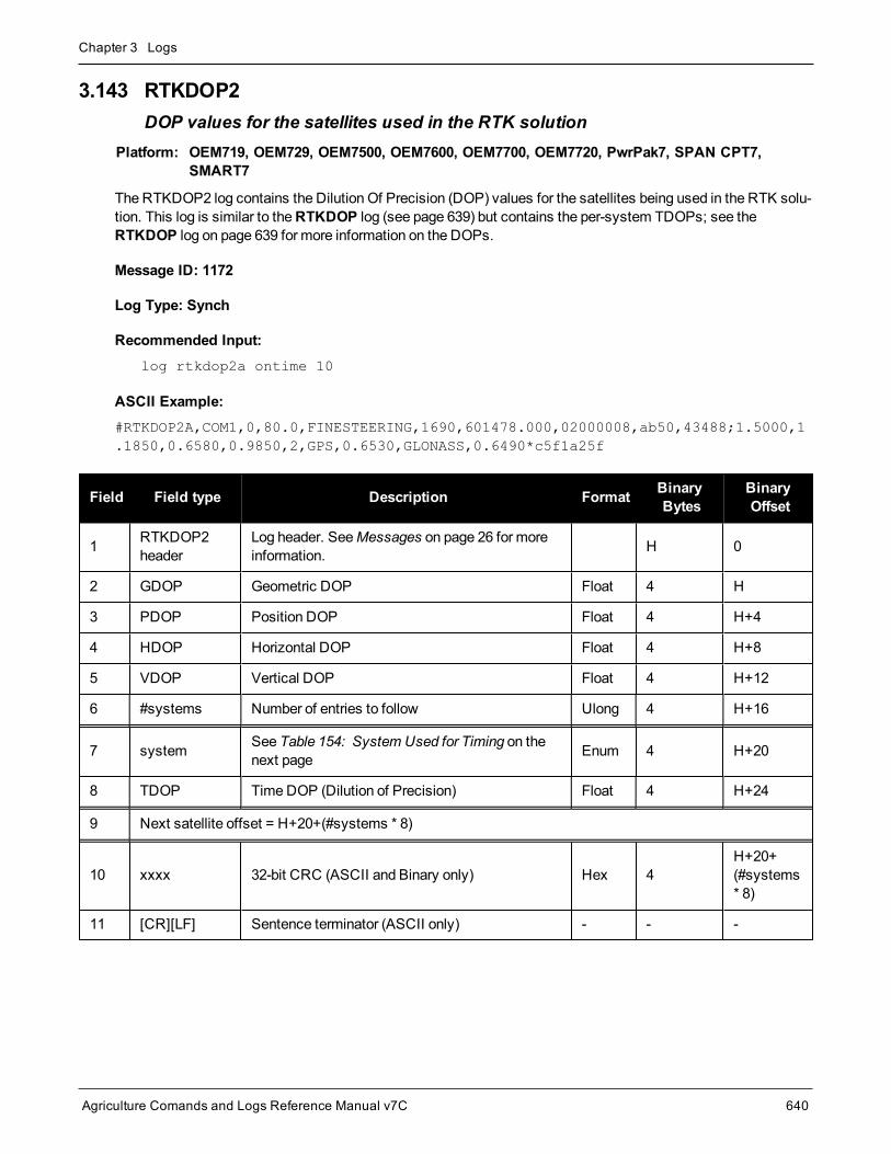
Chapter 3 Logs
Agriculture Comands and Logs Reference Manual v7C 640
3.143 RTKDOP2DOP values for the satellites used in the RTK solution
Platform: OEM719, OEM729, OEM7500, OEM7600, OEM7700, OEM7720, PwrPak7, SPAN CPT7,SMART7
The RTKDOP2 log contains the Dilution Of Precision (DOP) values for the satellites being used in the RTK solu-tion. This log is similar to theRTKDOP log (see page 639) but contains the per-system TDOPs; see theRTKDOP log on page 639 for more information on the DOPs.
Message ID: 1172
Log Type: Synch
Recommended Input:log rtkdop2a ontime 10
ASCII Example:#RTKDOP2A,COM1,0,80.0,FINESTEERING,1690,601478.000,02000008,ab50,43488;1.5000,1.1850,0.6580,0.9850,2,GPS,0.6530,GLONASS,0.6490*c5f1a25f
Field Field type Description Format BinaryBytes
BinaryOffset
1 RTKDOP2header
Log header. SeeMessages on page 26 for moreinformation. H 0
2 GDOP Geometric DOP Float 4 H
3 PDOP Position DOP Float 4 H+4
4 HDOP Horizontal DOP Float 4 H+8
5 VDOP Vertical DOP Float 4 H+12
6 #systems Number of entries to follow Ulong 4 H+16
7 system See Table 154: System Used for Timing on thenext page Enum 4 H+20
8 TDOP TimeDOP (Dilution of Precision) Float 4 H+24
9 Next satellite offset = H+20+(#systems * 8)
10 xxxx 32-bit CRC (ASCII and Binary only) Hex 4H+20+(#systems* 8)
11 [CR][LF] Sentence terminator (ASCII only) - - -
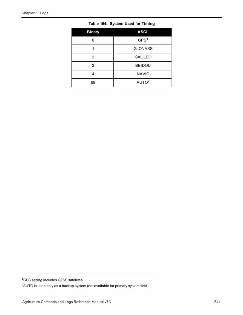
Chapter 3 Logs
Agriculture Comands and Logs Reference Manual v7C 641
Binary ASCII
0 GPS1
1 GLONASS
2 GALILEO
3 BEIDOU
4 NAVIC
99 AUTO2
Table 154: System Used for Timing
1GPS setting includes QZSS satellites.2AUTO is used only as a backup system (not available for primary system field).

Chapter 3 Logs
Agriculture Comands and Logs Reference Manual v7C 642
3.144 RTKPOSRTK low latency position data
Platform: OEM719, OEM729, OEM7500, OEM7600, OEM7700, OEM7720, PwrPak7, SPAN CPT7,SMART7
This log contains the low latency RTK position computed by the receiver, along with two status flags. In addi-tion, it reports other status indicators, including differential age, which is useful in predicting anomalous behaviorbrought about by outages in differential corrections. This log is recommended for kinematic operation. Betteraccuracy can be obtained in static operation with theMATCHEDPOS log (see page 493).
With the system operating in an RTK mode, this log reflects if the solution is a good RTK low latency solution(from extrapolated base stationmeasurements) or invalid. A valid RTK low latency solution is computed for up to60 seconds after reception of the last base station observation. The degradation in accuracy, due to differentialage, is reflected in the standard deviation fields. See also theDGPSTXID command (see page 98).
The RTK system in the receiver provides two kinds of position solutions. TheMatched RTK position iscomputed with buffered observations, so there is no error due to the extrapolation of base stationmeasurements. This provides the highest accuracy solution possible at the expense of some latencywhich is affected primarily by the speed of the differential data link. TheMATCHEDPOS log (see page493) contains thematched RTK solution and can be generated for each processed set of base stationobservations.
The Low-Latency RTK position is computed from the latest local observations and extrapolated basestation observations. This supplies a valid RTK position with the lowest latency possible at the expenseof some accuracy. The degradation in accuracy is reflected in the standard deviation. The amount oftime that the base station observations are extrapolated is in the "differential age" field of the positionlog. The Low-Latency RTK system extrapolates for 60 seconds. TheRTKPOS log contains the Low-Latency RTK position when valid, and an "invalid" status when a Low-Latency RTK solution could notbe computed. TheBESTPOS log (see page 346) contains either the low-latency RTK, PPP orpseudorange-based position, whichever has the smallest standard deviation.
Message ID: 141
Log Type: Synch
Recommended Input:log rtkposa ontime 1
ASCII Example:#RTKPOSA,COM1,0,54.5,FINESTEERING,1419,340040.000,02000040,176e,2724;SOL_COMPUTED,NARROW_INT,51.11635911294,-114.03833103654,1063.8336,-16.2712,WGS84,0.0179,0.0096,0.0174,"AAAA",1.000,0.000,12,11,11,11,0,01,0,33*0adb3e47

Chapter 3 Logs
Agriculture Comands and Logs Reference Manual v7C 643
Consider the case of a racing car, on a closed circuit, requiring RTK operation. In this situation, youwould have to send live data to the pits using a radio link.
RTK operation enables live centimeter level position accuracy. When answers are required in the field,the base stationmust transmit information to the rover in real-time. For RTK operation, extra equipmentsuch as radios are required to transmit and receive this information. The base station has acorresponding base radio and the rover station has a corresponding rover radio.
Post-processing can provide post-mission position and velocity data using raw GNSS data collectedfrom the car. The logs necessary for post-processing include:
RANGECMPB ONTIME 1RAWEPHEMB ONNEW
These are examples of data collection for post-processing, and real-time operation. OEM7-based outputis compatible with post-processing software from the NovAtel’s Waypoint Products Group or refer to ourwebsite at novatel.com/products/waypoint-software for more details.
Field Field type Description Format BinaryBytes
BinaryOffset
1 RTKPOSheader
Log header. SeeMessages on page 26 for moreinformation. H 0
2 sol status Solution status (see Table 65: Solution Status on page 349) Enum 4 H
3 pos type Position type (see Table 66: Position or Velocity Type onpage 350) Enum 4 H+4
4 lat Latitude (degrees) Double 8 H+8
5 lon Longitude (degrees) Double 8 H+16
6 hgt Height abovemean sea level (m) Double 8 H+24
7 undulation
Undulation - the relationship between the geoid and theWGS84 ellipsoid (m)
When using a datum other thanWGS84, theundulation value also includes the verticalshift due to differences between the datum inuse andWGS84.
Float 4 H+32
8 datum id#
Datum ID number
61 = WGS84
63 = USER
Enum 4 H+36
9 lat σ Latitude standard deviation (m) Float 4 H+40
10 lon σ Longitude standard deviation (m) Float 4 H+44
11 hgt σ Height standard deviation (m) Float 4 H+48

Chapter 3 Logs
Agriculture Comands and Logs Reference Manual v7C 644
Field Field type Description Format BinaryBytes
BinaryOffset
12 stn id Base station ID Char[4] 4 H+52
13 diff_age Differential age in seconds Float 4 H+56
14 sol_age Solution age in seconds Float 4 H+60
15 #SVs Number of satellites tracked Uchar 1 H+64
16 #solnSVs Number of satellites used in solution Uchar 1 H+65
17 #ggL1 Number of satellites with L1/E1/B1 signals used in solution Uchar 1 H+66
18 #solnMultiSVs Number of satellites with multi-frequency signals used insolution Uchar 1 H+67
19 Reserved Hex 1 H+68
20 ext sol stat Extended solution status (see Table 69: Extended SolutionStatus on page 353) Hex 1 H+69
21Galileo andBeiDou sigmask
Galileo and BeiDou signals usedmask (see Table 68:Galileo and BeiDou Signal-UsedMask on page 352) Hex 1 H+70
22GPS andGLONASS sigmask
GPS andGLONASS signals usedmask (see Table 67:GPS andGLONASS Signal-UsedMask on page 352) Hex 1 H+71
23 xxxx 32-bit CRC (ASCII and Binary only) Hex 4 H+72
24 [CR][LF] Sentence terminator (ASCII only) - - -

Chapter 3 Logs
Agriculture Comands and Logs Reference Manual v7C 645
3.145 RTKSATSSatellites used in RTKPOS solution
Platform: OEM719, OEM729, OEM7500, OEM7600, OEM7700, OEM7720, PwrPak7, SPAN CPT7,SMART7
This log lists the used and unused satellites for the corresponding RTKPOS solution. It also describes the sig-nals of the used satellites and reasons for exclusions.
Message ID: 1174
Log Type: Synch
Recommended Input:log rtksats ontime 1
Abbreviated ASCII Example:<RTKSATS COM1 0 60.5 FINESTEERING 1728 524924.000 02000000 95e7 11487< 24< GPS 3 GOOD 00000003< GPS 5 GOOD 00000003...< GPS 23 GOOD 00000003< GPS 30 GOOD 00000003< GLONASS 1+1 GOOD 00000003< GLONASS 2-4 GOOD 00000003...< GLONASS 20+2 GOOD 00000003< GLONASS 21+4 GOOD 00000003< BEIDOU 6 GOOD 00000003< BEIDOU 11 GOOD 00000003...< BEIDOU 12 GOOD 00000003< BEIDOU 13 GOOD 00000003
Field Field type Description Format BinaryBytes
BinaryOffset
1 RTKSATSheader Log header. SeeMessages on page 26 for more information. H 0
2 #entries Number of records to follow Ulong 4 H
3 system Satellite system (refer to Table 95: Satellite System onpage 450) Enum 4 H+4
4 SatelliteID Satellite identifiers Ulong 4 H+8
5 Status Satellite status. See Table 71: Observation Statuses onpage 355 Enum 4 H+12

Chapter 3 Logs
Agriculture Comands and Logs Reference Manual v7C 646
Field Field type Description Format BinaryBytes
BinaryOffset
6 Signalmask
See Table 72: GPS Signal Mask on page 356, Table 73:GLONASS Signal Mask on page 356, Table 74: Galileo SignalMask on page 357, Table 75: BeiDou Signal Mask onpage 357, Table 76: QZSS Signal Mask on page 357 and Table77: NavIC Signal Mask on page 357
Hex 4 H+16
7 Next satellite offset = H+4+(#sat x 16)
8 xxxx 32-bit CRC (ASCII and Binary only) Hex 4H+4+(#sat x16)
9 [CR][LF] Sentence terminator (ASCII only) - - -

Chapter 3 Logs
Agriculture Comands and Logs Reference Manual v7C 647
3.146 RTKVELRTK velocity
Platform: OEM719, OEM729, OEM7500, OEM7600, OEM7700, OEM7720, PwrPak7, SPAN CPT7,SMART7
This log contains the RTK velocity information computed by the receiver. In addition, it reports a velocity statusindicator that is useful in indicating whether or not the corresponding data is valid and differential age is useful inpredicting anomalous behavior brought about by outages in differential corrections. The velocity measurementssometimes have a latency associated with them. The time of validity is the time tag in the logminus the latencyvalue.
Velocities from the RTK filter are calculated from the delta-position. In RTKVEL, the velocity type is thesame as the position type.
In an RTKVEL log, the actual speed and direction of the receiver antenna over ground is provided. Thereceiver does not determine the direction a vessel, craft or vehicle is pointed (heading) but rather the dir-ection of motion of the GNSS antenna relative to ground.
With the system operating in an RTK mode, this log reflects if the solution is a good RTK low latency solution(from extrapolated base stationmeasurements) or invalid. A valid RTK low latency solution is computed for up to60 seconds after reception of the last base station observation.
The velocity is computed from consecutive RTK low latency updates. As such, it is an average velocity basedon the time difference between successive position computations and not an instantaneous velocity at theRTKVEL time tag. The velocity latency to be subtracted from the time tag is normally half the time between filterupdates. Under default operation, the RTK low latency filter is updated at a rate of 2 Hz. This translates into avelocity latency of 0.25 seconds. The latency can be reduced by increasing the update rate of the RTK lowlatency filter by requesting the BESTVEL, RTKVEL, BESTPOS or RTKPOS messages at a rate higher than 2Hz. For example, a logging rate of 10 Hz would reduce the velocity latency to 0.05 seconds. For integration pur-poses, the velocity latency should be applied to the record time tag.
Message ID: 216
Log Type: Synch
Recommended Input:log rtkvela ontime 1
ASCII Example:#RTKVELA,COM1,0,43.5,FINESTEERING,1364,496137.000,02100000,71e2,2310;SOL_COMPUTED,NARROW_INT,0.250,1.000,0.0027,207.645811,0.0104,0.0*f551cc42
Consider the case of an unmanned aircraft. A base stationmust send differential correction data to theremote aircraft. In this type of application, the aircraft’s radio may pass the differential solution, forexample RTKVEL, to the positioning system so it can process it and generate precise position inform-ation for the flight controls.
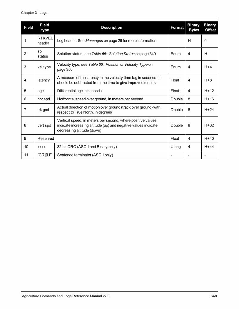
Chapter 3 Logs
Agriculture Comands and Logs Reference Manual v7C 648
Field Fieldtype Description Format Binary
BytesBinaryOffset
1 RTKVELheader Log header. SeeMessages on page 26 for more information. H 0
2 solstatus Solution status, see Table 65: Solution Status on page 349 Enum 4 H
3 vel type Velocity type, see Table 66: Position or Velocity Type onpage 350 Enum 4 H+4
4 latency A measure of the latency in the velocity time tag in seconds. Itshould be subtracted from the time to give improved results Float 4 H+8
5 age Differential age in seconds Float 4 H+12
6 hor spd Horizontal speed over ground, in meters per second Double 8 H+16
7 trk gnd Actual direction of motion over ground (track over ground) withrespect to True North, in degrees Double 8 H+24
8 vert spdVertical speed, in meters per second, where positive valuesindicate increasing altitude (up) and negative values indicatedecreasing altitude (down)
Double 8 H+32
9 Reserved Float 4 H+40
10 xxxx 32-bit CRC (ASCII and Binary only) Ulong 4 H+44
11 [CR][LF] Sentence terminator (ASCII only) - - -

Chapter 3 Logs
Agriculture Comands and Logs Reference Manual v7C 649
3.147 RTKXYZRTK Cartesian position and velocity
Platform: OEM719, OEM729, OEM7500, OEM7600, OEM7700, OEM7720, PwrPak7, SPAN CPT7,SMART7
This log contains the receiver’s low latency position and velocity in ECEF coordinates. The position and velocitystatus fields indicate whether or not the corresponding data is valid. See Figure 7: TheWGS84 ECEF Coordin-ate System on page 365 for a definition of the ECEF coordinates.
The velocity measurements have a latency associated with them. The time of validity is the time tag in the logminus the latency value.
With the system operating in an RTK mode, this log reflects if the solution is a good RTK low latency solution(from extrapolated base stationmeasurements) or invalid. A valid RTK low latency solution is computed for up to60 seconds after reception of the last base station observation. The degradation in accuracy due to differentialage is reflected in the standard deviation fields. See also theDGPSTXID command (see page 98).
The velocity is computed from consecutive RTK low latency updates. As such, it is an average velocity basedon the time difference between successive position computations and not an instantaneous velocity at theRTKVEL time tag. The velocity latency to be subtracted from the time tag is normally half the time between filterupdates. Under default operation, the RTK low latency filter is updated at a rate of 2 Hz. This translates into avelocity latency of 0.25 seconds. The latency can be reduced by increasing the update rate of the RTK lowlatency filter by requesting the BESTXYZmessage at a rate higher than 2 Hz. For example, a logging rate of 10Hz would reduce the velocity latency to 0.05 seconds. For integration purposes, the velocity latency should beapplied to the record time tag.
See also theBESTXYZ log on page 363 andMATCHEDXYZ log on page 498.
Message ID: 244
Log Type: Synch
Recommended Input:log rtkxyza ontime 1
ASCII Example:#RTKXYZA,COM1,0,56.0,FINESTEERING,1419,340041.000,02000040,3d88,2724;SOL_COMPUTED,NARROW_INT,-1634531.5666,-3664618.0291,4942496.3230,0.0099,0.0219,0.0115,SOL_COMPUTED,NARROW_INT,0.0030,0.0003,-0.0016,0.0198,0.0438,0.0230,"AAAA",0.250,1.000,0.000,12,11,11,11,0,01,0,33*0497d146
Field Field type Description Format BinaryBytes
BinaryOffset
1 RTKXYZheader
Log header. SeeMessages on page 26 for moreinformation. H 0
2 P-sol status Solution status, see Table 65: Solution Status on page 349 Enum 4 H
3 pos type Position type, see Table 66: Position or Velocity Type onpage 350 Enum 4 H+4

Chapter 3 Logs
Agriculture Comands and Logs Reference Manual v7C 650
Field Field type Description Format BinaryBytes
BinaryOffset
4 P-X Position X-coordinate (m) Double 8 H+8
5 P-Y Position Y-coordinate (m) Double 8 H+16
6 P-Z Position Z-coordinate (m) Double 8 H+24
7 P-X σ Standard deviation of P-X (m) Float 4 H+32
8 P-Y σ Standard deviation of P-Y (m) Float 4 H+36
9 P-Z σ Standard deviation of P-Z (m) Float 4 H+40
10 V-sol status Solution status, see Table 65: Solution Status on page 349 Enum 4 H+44
11 vel type Velocity type, see Table 66: Position or Velocity Type onpage 350 Enum 4 H+48
12 V-X Velocity vector along X-axis (m) Double 8 H+52
13 V-Y Velocity vector along Y-axis (m) Double 8 H+60
14 V-Z Velocity vector along Z-axis (m) Double 8 H+68
15 V-X σ Standard deviation of V-X (m) Float 4 H+76
16 V-Y σ Standard deviation of V-Y (m) Float 4 H+80
17 V-Z σ Standard deviation of V-Z (m) Float 4 H+84
18 stn ID Base station identification Char[4] 4 H+88
19 V-latencyA measure of the latency in the velocity time tag inseconds. It should be subtracted from the time to giveimproved results.
Float 4 H+92
20 diff_age Differential age in seconds Float 4 H+96
21 sol_age Solution age in seconds Float 4 H+100
22 #SVs Number of satellites tracked Uchar 1 H+104
23 #solnSVs Number of satellites used in solution Uchar 1 H+105
24 #ggL1 Number of satellites with L1/E1/B1 signals used in solution Uchar 1 H+106
25 #solnMultiSVs Number of satellites with multi-frequency signals used insolution Uchar 1 H+107
26 Reserved Char 1 H+108
27 ext sol stat Extended solution status (see Table 69: ExtendedSolution Status on page 353) Hex 1 H+109

Chapter 3 Logs
Agriculture Comands and Logs Reference Manual v7C 651
Field Field type Description Format BinaryBytes
BinaryOffset
28Galileo andBeiDou sigmask
Galileo and BeiDou signals usedmask (see Table 68:Galileo and BeiDou Signal-UsedMask on page 352) Hex 1 H+110
29GPS andGLONASS sigmask
GPS andGLONASS signals usedmask (see Table 67:GPS andGLONASS Signal-UsedMask on page 352) Hex 1 H+111
30 xxxx 32-bit CRC (ASCII and Binary only) Ulong 4 H+112
31 [CR][LF] Sentence terminator (ASCII only) - - -

Chapter 3 Logs
Agriculture Comands and Logs Reference Manual v7C 652
3.148 RXCONFIGReceiver configuration
Platform: OEM719, OEM729, OEM7500, OEM7600, OEM7700, OEM7720, PwrPak7, SPAN CPT7,SMART7, SMART2
This log is used to output a list of all current command settings. When requested, an RXCONFIG log is outputfor each setting. See also the LOGLIST log on page 479 for a list of currently active logs. One log is output foreach current command.
Message ID: 128
Log Type: Collection
Recommended Input:log rxconfiga once
ASCII Example:#RXCONFIGA,COM1,71,47.5,APPROXIMATE,1337,333963.260,02000000,f702,1984;
#ADJUST1PPSA,COM1,71,47.5,APPROXIMATE,1337,333963.260,02000000,f702,1984;OFF,ONCE,0*ba85a20b*91f89b07
#RXCONFIGA,COM1,70,47.5,APPROXIMATE,1337,333963.398,02000000,f702,1984;
#ANTENNAPOWERA,COM1,70,47.5,APPROXIMATE,1337,333963.398,02000000,f702,1984;ON*d12f6135*8f8741be
#RXCONFIGA,COM1,69,47.5,APPROXIMATE,1337,333963.455,02000000,f702,1984;
#CLOCKADJUSTA,COM1,69,47.5,APPROXIMATE,1337,333963.455,02000000,f702,1984;ENABLE*0af36d92*b13280f2
...
#RXCONFIGA,COM1,7,47.5,APPROXIMATE,1337,333966.781,02000000,f702,1984;
#STATUSCONFIGA,COM1,7,47.5,APPROXIMATE,1337,333966.781,02000000,f702,1984;CLEAR,AUX2,0*a6141e28*d0bba9f2
#RXCONFIGA,COM1,2,47.5,APPROXIMATE,1337,333967.002,02000000,f702,1984;
#SBASECUTOFFA,COM1,2,47.5,APPROXIMATE,1337,333967.002,02000000,f702,1984;-5.000000000*b9b11096*2e8b77cf
#RXCONFIGA,COM1,1,47.5,FINESTEERING,1337,398382.787,02000000,f702,1984;
#LOGA,COM1,1,47.5,FINESTEERING,1337,398382.787,02000000,f702,1984;COM1,MARKPOSA,ONNEW,0.000000,0.000000,NOHOLD*a739272d*6692c084
#RXCONFIGA,COM1,0,47.5,FINESTEERING,1337,400416.370,02000000,f702,1984;
#LOGA,COM1,0,47.5,FINESTEERING,1337,400416.370,02000000,f702,1984;COM2,PASSCOM2A,ONCHANGED,0.000000,0.000000,NOHOLD*55fc0c62*17086d18

Chapter 3 Logs
Agriculture Comands and Logs Reference Manual v7C 653
The embedded CRCs are flipped tomake the embeddedmessages recognizable to the receiver. Forexample, consider the first embeddedmessage above.
91f89b07: 10010001111110001001101100000111 11100000110110010001111110001001:e0d91f89
The CRC is really e0d91f89.
Do not use undocumented commands or logs! Doing somay produce errors and void your warranty.
The RXCONFIG log can be used to ensure your receiver is correctly setup for your application.
Field Field type Description Format BinaryBytes
BinaryOffset
1 RXCONFIGheader
Log header. SeeMessages on page 26 for moreinformation. - H 0
2 e header Embedded header - h H
3 emsg Embeddedmessage Varied a H+h
4 e xxxx
Embedded (inverted) 32-bit CRC (ASCII and Binary only).The embedded CRC is inverted so that the receiver doesnot recognize the embeddedmessages as messages to beoutput but continues with the RXCONFIGmessage. If youwish to use themessages output from the RXCONFIG log,simply flip the embedded CRC around for individualmessages
Ulong 4 H+h+a
5 xxxx 32-bit CRC (ASCII and Binary only) Hex 4 H+h+a+4
6 [CR][LF] Sentence terminator (ASCII only) - - -
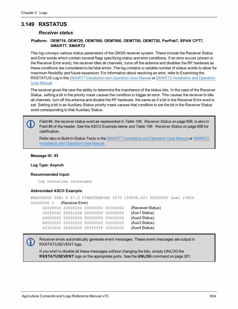
Chapter 3 Logs
Agriculture Comands and Logs Reference Manual v7C 654
3.149 RXSTATUSReceiver status
Platform: OEM719, OEM729, OEM7500, OEM7600, OEM7700, OEM7720, PwrPak7, SPAN CPT7,SMART7, SMART2
This log conveys various status parameters of the GNSS receiver system. These include the Receiver Statusand Error words which contain several flags specifying status and error conditions. If an error occurs (shown inthe Receiver Error word), the receiver idles all channels, turns off the antenna and disables the RF hardware asthese conditions are considered to be fatal errors. The log contains a variable number of status words to allow formaximum flexibility and future expansion. For information about resolving an error, refer to Examining theRXSTATUS Log in the SMART7 Installation andOperation User Manual or SMART2 Installation andOperationUser Manual.
The receiver gives the user the ability to determine the importance of the status bits. In the case of the ReceiverStatus, setting a bit in the priority mask causes the condition to trigger an error. This causes the receiver to idleall channels, turn off the antenna and disable the RF hardware, the same as if a bit in the Receiver Error word isset. Setting a bit in an Auxiliary Status priority mask causes that condition to set the bit in the Receiver Statusword corresponding to that Auxiliary Status.
Field #4, the receiver status word as represented in Table 156: Receiver Status on page 658, is also inField #8 of the header. See the ASCII Example below and Table 156: Receiver Status on page 658 forclarification.
Refer also to Built-In Status Tests in the SMART7 Installation andOperation User Manual or SMART2Installation andOperation User Manual.
Message ID: 93
Log Type: Asynch
Recommended Input:log rxstatusa onchanged
Abbreviated ASCII Example:#RXSTATUS USB1 0 67.0 FINESTEERING 2070 159546.023 02000000 2ae1 1582400000000 5 (Receiver Error) 02000000 00000000 00000000 00000000 (Receiver Status) 00040000 00001008 00000000 00000000 (Aux1 Status) 00000000 00000000 80000000 00000000 (Aux2 Status) 80000000 00000000 00000000 00000000 (Aux3 Status) 0030c000 00000000 ffffffff 00000000 (Aux4 Status)
Receiver errors automatically generate event messages. These event messages are output inRXSTATUSEVENT logs.
If you wish to disable all thesemessages without changing the bits, simply UNLOG theRXSTATUSEVENT logs on the appropriate ports. See theUNLOG command on page 301.

Chapter 3 Logs
Agriculture Comands and Logs Reference Manual v7C 655
Field Field type Description Format BinaryBytes
BinaryOffset
1 RXSTATUSheader Log header. SeeMessages on page 26 for more information. H 0
2 error Receiver error (see Table 155: Receiver Error on the nextpage). A value of zero indicates no errors Ulong 4 H
3 # stats
Number of status codes (including Receiver Status). Eachstatus code consists of 4 fields, the status, priority mask,event set mask and event clear mask. Each set is repeatedfor each status type.
Note that for clarity, the Receiver Status, Auxiliary 1 Status,Auxiliary 2 Status, Auxiliary 3 Status and Auxiliary 4 statusare listed separately in this message
Ulong 4 H+4
4 rxstat Receiver status word (see Table 156: Receiver Status onpage 658) Ulong 4 H+8
5 rxstat pri Receiver status priority mask Ulong 4 H+12
6 rxstat set Receiver status event set mask Ulong 4 H+16
7 rxstat clear Receiver status event clear mask Ulong 4 H+20
8 aux1stat Auxiliary 1 status word (see Table 158: Auxiliary 1 Status onpage 661) Ulong 4 H+24
9 aux1stat pri Auxiliary 1 status priority mask Ulong 4 H+28
10 aux1stat set Auxiliary 1 status event set mask Ulong 4 H+32
11 aux1statclear Auxiliary 1 status event clear mask Ulong 4 H+36
12 aux2stat Auxiliary 2 status word (see Table 159: Auxiliary 2 Status onpage 662) Ulong 4 H+40
13 aux2stat pri Auxiliary 2 status priority mask Ulong 4 H+44
14 aux2stat set Auxiliary 2 status event set mask Ulong 4 H+48
15 aux2statclear Auxiliary 2 status event clear mask Ulong 4 H+52
16 aux3stat Auxiliary 3 status word (see Table 160: Auxiliary 3 Status onpage 664) Ulong 4 H+56
17 aux3stat pri Auxiliary 3 status priority mask Ulong 4 H+60
18 aux3stat set Auxiliary 3 status event set mask Ulong 4 H+64
19 aux3statclear Auxiliary 3 status event clear mask Ulong 4 H+68

Chapter 3 Logs
Agriculture Comands and Logs Reference Manual v7C 656
Field Field type Description Format BinaryBytes
BinaryOffset
20 aux4stat Auxiliary 4 status word (see Table 162: Auxiliary 4 Status onpage 666) Ulong 4 H+72
21 aux4stat pri Auxiliary 4 status priority mask Ulong 4 H+76
22 aux4stat set Auxiliary 4 status event set mask Ulong 4 H+80
23 aux4statclear Auxiliary 4 status event clear mask Ulong 4 H+84
24 xxxx 32-bit CRC (ASCII and Binary only) Ulong 4 H+88
25 [CR][LF] Sentence terminator (ASCII only) - - -
Nibble Bit Mask Description Bit = 0 Bit = 1
N0
0 0x00000001Dynamic Random Access Memory (DRAM) status
RAM failure on anOEM7 cardmay also be indicated by aflashing red LED.
OK Error
1 0x00000002 Invalid firmware OK Error
2 0x00000004 ROM status OK Error
3 0x00000008 Reserved
N1
4 0x00000010 Electronic Serial Number (ESN) access status OK Error
5 0x00000020 Authorization code status OK Error
6 0x00000040 Reserved
7 0x00000080 Supply voltage status OK Error
N2
8 0x00000100 Reserved
9 0x00000200 Temperature status (as compared against acceptable limits) OK Error
10 0x00000400 MINOS status OK Error
11 0x00000800PLL RF status. Error with an RF PLL. See AUX2 status bits(Table 159: Auxiliary 2 Status on page 662) for individualPLL status
OK Error
N3
12 0x00001000
Reserved13 0x00002000
14 0x00004000
15 0x00008000 NVM status OK Error
Table 155: Receiver Error
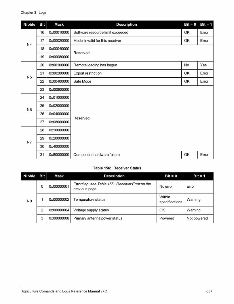
Chapter 3 Logs
Agriculture Comands and Logs Reference Manual v7C 657
Nibble Bit Mask Description Bit = 0 Bit = 1
N4
16 0x00010000 Software resource limit exceeded OK Error
17 0x00020000 Model invalid for this receiver OK Error
18 0x00040000Reserved
19 0x00080000
N5
20 0x00100000 Remote loading has begun No Yes
21 0x00200000 Export restriction OK Error
22 0x00400000 SafeMode OK Error
23 0x00800000
Reserved
N6
24 0x01000000
25 0x02000000
26 0x04000000
27 0x08000000
N7
28 0x10000000
29 0x20000000
30 0x40000000
31 0x80000000 Component hardware failure OK Error
Nibble Bit Mask Description Bit = 0 Bit = 1
N0
0 0x00000001 Error flag, see Table 155: Receiver Error on theprevious page No error Error
1 0x00000002 Temperature status Withinspecifications Warning
2 0x00000004 Voltage supply status OK Warning
3 0x00000008 Primary antenna power status Powered Not powered
Table 156: Receiver Status

Chapter 3 Logs
Agriculture Comands and Logs Reference Manual v7C 658
Nibble Bit Mask Description Bit = 0 Bit = 1
N1
4 0x00000010 LNA Failure OK Failure
5 0x00000020Primary antenna open circuit flag
This flag is only available on certain products.OK Open, antenna
disconnected
6 0x00000040Primary antenna short circuit flag
This flag is only available on certain products.OK Short circuit
detected
7 0x00000080CPU overload flag
This flag is only available on certain products.No overload Overload
N2
8 0x00000100
COM port transmit buffer overrun.See AUX2 status bits (Table 159: Auxiliary 2Status on page 662) for individual COM portstatus
OK COM bufferoverrun
9 0x00000200Reserved
10 0x00000400
11 0x00000800
Link overrun flag
This flag indicates if any of the USB, ICOM,CCOM, NCOM or File ports are overrun. SeeAUX1, AUX2 and AUX3 status bits (Table 158:Auxiliary 1 Status on page 661, Table 159:Auxiliary 2 Status on page 662 or Table 160:Auxiliary 3 Status on page 664) for the specificport for which the buffer is overrun.
No overrun Overrun
N3
12 0x00001000
Input overrun flag
This flag is set if any of the receiver ports (COM,USB, ICOM or NCOM) experience an inputoverrun.
No overrun Overrun
13 0x00002000 Aux transmit overrun flag No overrun Overrun
14 0x00004000Antenna gain state
See the AUX3 status bits (Table 160: Auxiliary 3Status on page 664) for the antenna gain status.
OK Out of range
15 0x00008000Jammer Detected
See the AUX1 status bits (Table 158: Auxiliary 1Status on page 661) for individual RF status
OK JammerDetected

Chapter 3 Logs
Agriculture Comands and Logs Reference Manual v7C 659
Nibble Bit Mask Description Bit = 0 Bit = 1
N4
16 0x00010000 INS reset flag No INS reset INS reset
17 0x00020000 IMU communication failure No error No IMUcommunication
18 0x00040000 GPS almanac flag/UTC known Valid Invalid
19 0x00080000 Position solution flag Valid Invalid
N5
20 0x00100000 Position fixed flag, see the FIX command onpage 115 Not fixed Fixed
21 0x00200000 Clock steering status Enabled Disabled
22 0x00400000 Clock model flag Valid Invalid
23 0x00800000 External oscillator locked flag Unlocked Locked
N6
24 0x01000000 Software resource OK Warning
250x06000000
Version bit 0 See Table 157: Version Bitsbelow
26 Version bit 1 See Table 157: Version Bitsbelow
27 0x08000000 Trackingmode Normaltracking HDR tracking
N7
28 0x10000000 Digital Filtering Enabled Disabled Enabled
29 0x20000000 Auxiliary 3 status event flag No event Event
30 0x40000000 Auxiliary 2 status event flag No event Event
31 0x80000000 Auxiliary 1 status event flag No event Event
Bit 25 Bit 26 Description
0 0 Interpret Status/Error Bits as OEM6 or earlier format
1 0 Interpret Status/Error Bits as OEM7 format
0 1 Reserved for a future version
1 1 Reserved for a future version
Table 157: Version Bits
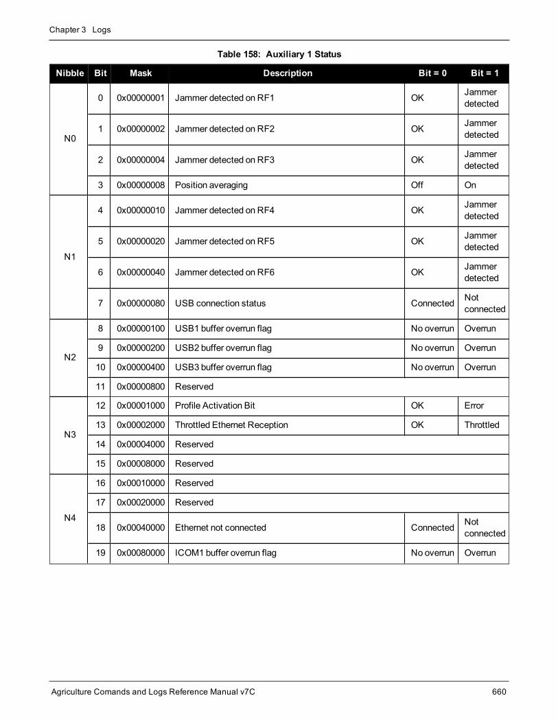
Chapter 3 Logs
Agriculture Comands and Logs Reference Manual v7C 660
Nibble Bit Mask Description Bit = 0 Bit = 1
N0
0 0x00000001 Jammer detected on RF1 OK Jammerdetected
1 0x00000002 Jammer detected on RF2 OK Jammerdetected
2 0x00000004 Jammer detected on RF3 OK Jammerdetected
3 0x00000008 Position averaging Off On
N1
4 0x00000010 Jammer detected on RF4 OK Jammerdetected
5 0x00000020 Jammer detected on RF5 OK Jammerdetected
6 0x00000040 Jammer detected on RF6 OK Jammerdetected
7 0x00000080 USB connection status Connected Notconnected
N2
8 0x00000100 USB1 buffer overrun flag No overrun Overrun
9 0x00000200 USB2 buffer overrun flag No overrun Overrun
10 0x00000400 USB3 buffer overrun flag No overrun Overrun
11 0x00000800 Reserved
N3
12 0x00001000 Profile Activation Bit OK Error
13 0x00002000 Throttled Ethernet Reception OK Throttled
14 0x00004000 Reserved
15 0x00008000 Reserved
N4
16 0x00010000 Reserved
17 0x00020000 Reserved
18 0x00040000 Ethernet not connected Connected Notconnected
19 0x00080000 ICOM1 buffer overrun flag No overrun Overrun
Table 158: Auxiliary 1 Status

Chapter 3 Logs
Agriculture Comands and Logs Reference Manual v7C 661
Nibble Bit Mask Description Bit = 0 Bit = 1
N5
20 0x00100000 ICOM2 buffer overrun flag No overrun Overrun
21 0x00200000 ICOM3 buffer overrun flag No overrun Overrun
22 0x00400000 NCOM1 buffer overrun flag No overrun Overrun
23 0x00800000 NCOM2 buffer overrun flag No overrun Overrun
N6
24 0x01000000 NCOM3 buffer overrun flag No overrun Overrun
25 0x02000000 Reserved
26 0x04000000 Reserved
27 0x08000000 Reserved
N7
28 0x10000000 Reserved
29 0x20000000 Reserved
30 0x40000000 Status error reported by the IMU. May be treated as anotice unless the issue persists. OK
StatusErrorReported
31 0x80000000
IMU measurement outlier detected. Indicates when theSPAN system has detected an outlier in theIMU performance. May be treated as a notice unless theissue persists.
OK Outlierdetected
Nibble Bit Mask Description Bit = 0 Bit = 1
N0
0 0x00000001 SPI Communication Failure OK Error
1 0x00000002 I2C Communication Failure OK Error
2 0x00000004 COM4 buffer overrun flag Nooverrun Buffer Overrun
3 0x00000008 COM5 buffer overrun flag Nooverrun Buffer Overrun
N1
4 0x00000010 Reserved
5 0x00000020 Reserved
6 0x00000040 Reserved
7 0x00000080 Reserved
Table 159: Auxiliary 2 Status

Chapter 3 Logs
Agriculture Comands and Logs Reference Manual v7C 662
Nibble Bit Mask Description Bit = 0 Bit = 1
N2
8 0x00000100 Reserved
9 0x00000200 COM1 buffer overrun flag OK Buffer Overrun
10 0x00000400 COM2 buffer overrun flag OK Buffer Overrun
11 0x00000800 COM3 buffer overrun flag OK Buffer Overrun
N3
12 0x00001000 PLL RF1 unlock flag OK PLLUnlock
13 0x00002000 PLL RF2 unlock flag OK PLLUnlock
14 0x00004000 PLL RF3 unlock flag OK PLLUnlock
15 0x00008000 PLL RF4 unlock flag OK PLLUnlock
N4
16 0x00010000 PLL RF5 unlock flag OK PLLUnlock
17 0x00020000 PLL RF6 unlock flag OK PLLUnlock
18 0x00040000 CCOM1 buffer overrun OK Buffer Overrun
19 0x00080000 CCOM2 buffer overrun OK Buffer Overrun
N5
20 0x00100000 CCOM3 buffer overrun OK Buffer Overrun
21 0x00200000 CCOM4 buffer overrun OK Buffer Overrun
22 0x00400000 CCOM5 buffer overrun OK Buffer Overrun
23 0x00800000 CCOM6 buffer overrun OK Buffer Overrun
N6
24 0x01000000 ICOM4 buffer overrun OK Buffer Overrun
25 0x02000000 ICOM5 buffer overrun OK Buffer Overrun
26 0x04000000 ICOM6 buffer overrun OK Buffer Overrun
27 0x08000000 ICOM7 buffer overrun OK Buffer Overrun
N7
28 0x10000000 Secondary antenna power status Powered Not Powered
29 0x20000000Secondary antenna open circuitThis flag is only available on certainproducts
OK Open, antennadisconnected
30 0x40000000Secondary antenna short circuitThis flag is only available on certainproducts
OK Short circuit detected
31 0x80000000 Reset loop detected OK Reset Detected

Chapter 3 Logs
Agriculture Comands and Logs Reference Manual v7C 663
Nibble Bit Mask Description Bit = 0 Bit = 1
N0
0 0x00000001SCOM buffer overrun flag.This flag is set if any of the SCOM ports(SCOM1 – SCOM4) experience overrun.
No overrun Overrun
1 0x00000002 WCOM1 buffer overrun flag No overrun Overrun
2 0x00000004 FILE buffer overrun flag No overrun Overrun
3 0x00000008 Reserved
N1
4 0x00000010Antenna 1Gain State Table 161: AntennaGain State
on the next page5 0x00000020
6 0x00000040Antenna 2Gain State Table 161: AntennaGain State
on the next page7 0x00000080
N2
8 0x00000100
Reserved9 0x00000200
10 0x00000400
11 0x00000800
N3
12 0x00001000
Reserved13 0x00002000
14 0x00004000
15 0x00008000
N4
16 0x00010000
Reserved17 0x00020000
18 0x00040000
19 0x00080000
N5
20 0x00100000
Reserved21 0x00200000
22 0x00400000
23 0x00800000
Table 160: Auxiliary 3 Status

Chapter 3 Logs
Agriculture Comands and Logs Reference Manual v7C 664
Nibble Bit Mask Description Bit = 0 Bit = 1
N6
24 0x01000000
Reserved25 0x02000000
26 0x04000000
27 0x08000000
N7
28 0x10000000 Reserved
29 0x20000000 Web content is corrupt or does not exist Content isOK
Error withcontent
30 0x40000000 RF Calibration Data is present and in error Data is OK Data has an error
31 0x80000000 RF Calibration Data is present No datafound
Data exists andhas no errors
Bits 4-5or
Bits 6-7Description
00 AntennaGain in range
01
AntennaGain Low
This state indicates that the input signal is very weak (under -160 dBm/Hz). It can indicate the antenna isnot operating correctly, the antenna is not suitable for NovAtel receivers, or there is no antennaconnected.
10AntennaGain High.
This state indicates that the input signal is very strong (above -120 dBm/Hz). This can be caused by astrong in-band interference or by toomuch signal gain or toomany LNAs cascaded in the path.
11AntennaGain Anomaly.
This state indicates that an anomaly has been detected for the input signal. It can be caused by strong in-band or out-of-band interference, or by the antenna being disconnected/changed during operation.
Table 161: Antenna Gain State

Chapter 3 Logs
Agriculture Comands and Logs Reference Manual v7C 665
Nibble Bit Mask Description Bit = 1
N0
0 0x00000001
GNSS Tracked Status
<60% of availablesatellites are trackedwell
1 0x00000002<15% of availablesatellites are trackedwell
2 0x00000004Reserved
3 0x00000008
N1
4 0x00000010
Reserved5 0x00000020
6 0x00000040
7 0x00000080
N2
8 0x00000100
Reserved9 0x00000200
10 0x00000400
11 0x00000800
N3
12 0x00001000 Clock freewheeling due to bad position integrity Clock freewheeling
13 0x00002000 Reserved
14 0x00004000 Usable RTK Corrections
Percentage of expectedmeasurements which havetimely RTK corrections (latency <20 seconds)
<60% of expectedcorrections available
15 0x00008000 <15% of expectedcorrections available
N4
16 0x00010000 Bad RTK Geometry PDOP >5.0
17 0x00020000Reserved
18 0x00040000
19 0x00080000 Long RTK Baseline Baseline >50 km
Table 162: Auxiliary 4 Status

Chapter 3 Logs
Agriculture Comands and Logs Reference Manual v7C 666
Nibble Bit Mask Description Bit = 1
N5
20 0x00100000 Poor RTK COM Link (poor correction quality) Corrections quality≤60%
21 0x00200000 Poor ALIGN COM Link (poor correction quality) Corrections quality≤60%
22 0x00400000 GLIDE Not Active GLIDE not active
23 0x00800000 Bad PDP Geometry PDOP >5.0
N6
24 0x01000000 No TerraStar Subscription No subscription
25 0x02000000
Reserved26 0x04000000
27 0x08000000
N7
28 0x10000000 Bad PPP Geometry PDOP >5.0
29 0x20000000 Reserved
30 0x40000000 No INS Alignment No alignment
31 0x80000000 INS not converged Not converged
Only GPS andGLONASS are considered in the Auxiliary 4 status word states.
For bits relating to RTK, ALIGN or INS, the bits will only be set if the receiver has that type of pos-itioning is enabled via Auth Code.

Chapter 3 Logs
Agriculture Comands and Logs Reference Manual v7C 667
3.150 RXSTATUSEVENTStatus event indicator
Platform: OEM719, OEM729, OEM7500, OEM7600, OEM7700, OEM7720, PwrPak7, SPAN CPT7,SMART7, SMART2
This log is used to output event messages as indicated in theRXSTATUS log (see page 655). An event mes-sage is automatically generated for all receiver errors, which are indicated in the receiver error word.
On start-up, the receiver is set to logRXSTATUSEVENTA ONNEW HOLD on all ports. You can remove thismessage using theUNLOG command (see page 301). To remove this log using anUNLOGALL command (seepage 303), youmust use the True option. LoggingRXSTATUSEVENT on all ports is a factory default setting. Ifit is unlogged, theRXSTATUSEVENT log will not be collected until the next start-up. After a start-up, loggingRXSTATUSEVENT on all ports will start again.
See also Built-In Status Tests in the SMART7 Installation andOperation User Manual.
Message ID: 94
Log Type: Asynch
Recommended Input:log rxstatuseventa onchanged
ASCII Example 1:#RXSTATUSEVENTA,COM1,0,17.0,FREEWHEELING,1337,408334.510,02480000,b967,1984;STATUS,19,SET,"No Valid Position Calculated"*6de945ad
ASCII Example 2:#RXSTATUSEVENTA,COM1,0,41.0,FINESTEERING,1337,408832.031,03000400,b967,1984;STATUS,10,SET,"COM3 Transmit Buffer Overrun"*5b5682a9
When a fatal event occurs (for example, in the event of a receiver hardware failure), a bit is set in thereceiver error word, part of theRXSTATUS log (see page 655) to indicate the cause of the problem. Bit0 is set in the receiver status word to show that an error occurred, the error strobe is driven high and theLED flashes red and yellow showing an error code. An RXSTATUSEVENT log is generated on all portsto show the cause of the error. Receiver tracking is disabled at this point but command and log pro-cessing continues to allow you to diagnose the error. Even if the source of the error is corrected at thispoint, the receiver must be reset to resume normal operation.
Field Field type Description Format BinaryBytes
BinaryOffset
1 RXSTATUSEVENTheader
Log header. SeeMessages on page 26 for moreinformation. H 0
2 word The status word that generated the event message(see Table 163: Status Word on the next page) Enum 4 H

Chapter 3 Logs
Agriculture Comands and Logs Reference Manual v7C 668
Field Field type Description Format BinaryBytes
BinaryOffset
3 bit position
Location of the bit in the status word (see Table 156:Receiver Status on page 658, Table 158: Auxiliary 1Status on page 661, Table 159: Auxiliary 2 Status onpage 662, Table 160: Auxiliary 3 Status on page 664or Table 162: Auxiliary 4 Status on page 666
Ulong 4 H+4
4 event Event type (see Table 164: Event Type below) Enum 4 H+8
5 description This is a text description of the event or error Char[32] 32 H+12
6 xxxx 32-bit CRC (ASCII and Binary only) Ulong 4 H+44
7 [CR][LF] Sentence terminator (ASCII only) - - -
Binary ASCII Description
0 ERRORReceiver Error word,
see Table 155: Receiver Error on page 657
1 STATUSReceiver Status word,
see Table 156: Receiver Status on page 658
2 AUX1Auxiliary 1 Status word,
see Table 158: Auxiliary 1 Status on page 661
3 AUX2Auxiliary 2 Status word
see Table 159: Auxiliary 2 Status on page 662
4 AUX3Auxiliary 3 Status word
see Table 160: Auxiliary 3 Status on page 664
5 AUX4Auxiliary 4 Status word
see Table 162: Auxiliary 4 Status on page 666
Table 163: Status Word
Binary ASCII Description
0 CLEAR Bit was cleared
1 SET Bit was set
Table 164: Event Type

Chapter 3 Logs
Agriculture Comands and Logs Reference Manual v7C 669
3.151 SAFEMODESTATUSSafe Mode Status
Platform: OEM719, OEM729, OEM7500, OEM7600, OEM7700, OEM7720, PwrPak7, SPAN CPT7,SMART7, SMART2
This log provides additional information about the state of the receiver in the event that theSafeMode error bitand/orReset Loop Detected status bit are set in theRXSTATUS log (see page 655).
The data within this log is set at receiver start up and will not change over time.
For information about SafeMode, see SafeMode in the SMART7 Installation andOperation User Manual orSMART2 Installation andOperation User Manual.
Message ID: 2060
Log Type: Asynch
Recommended Input:log SAFEMODESTATUSA once
Abbreviated ASCII Example:#SAFEMODESTATUSA,COM1,0,89.0,UNKNOWN,0,0.000,024c0020,8e55,32768;SAFE_MODE_OK,0,"Normal Operation."*29c7d28a
Field Field Type Description BinaryFormat
BinaryBytes
BinaryOffset
1 SAFEMODESTATUSheader
Log header. SeeMessages on page 26 formore information. - H 0
2 Status SafeMode State. See Table 165: SafeModeStates on the next page Enum 4 H
3 Reset Count Number of resets since power up or asuccessful boot Ulong 4 H+4
4 Description String for additional information about the SafeMode State String 80 H+8
5 xxxx 32-bit CRC (ASCII and Binary only) Ulong 4 H+88
6 [CR][LF] Sentence terminator (ASCII only) - - -

Chapter 3 Logs
Agriculture Comands and Logs Reference Manual v7C 670
Value State
SafeModeErrorBit
ResetLoop
DetectedBit
Notes Recovery Steps
0 SAFE_MODE_OK 0 0 Normal Operation. No reset loopdetected. No action required
1 SAFE_MODE_WARNING 0 1 An unexpected reset was detected.
The receiver will operate as normal No action required
2SAFE_MODE_DISABLE_SATELLITE_DATA
0 1
Satellite Navigation Data previouslysaved to NVM is ignored in thisstate. As the receiver continues totrack GNSS satellites, new data willbe downloaded. Theremay be somedelay in initial satellite acquisitionas this will effectively be a ColdStart, but the receiver will otherwiseoperate as normal.
No action required
3
SAFE_MODE_DISABLE_NON_COMMUNICATION_NVM
1 1
All data previously saved to NVMthat is not related to communicationis ignored in this state.
Communication ports (COM, USB,ICOM, etc.) will remain in theconfiguration previously saved bySAVECONFIG allowing the user totake corrective action.
Depending on whatNVM data is causingthe problem, aFRESET may resolvethe issue.
If a standard FRESETdoes not resolve theissue, see theFRESET commandon page 118 for otherNVM targets that maybe causing the issueand could beremoved.
4SAFE_MODE_DISABLE_ALL_NVM
1 1 All data previously saved to NVM isignored in this state.
See recovery stepsfor SAFE_MODE_DISABLE_NON_COMMUNICATION_NVM.
Table 165: Safe Mode States

Chapter 3 Logs
Agriculture Comands and Logs Reference Manual v7C 671
Value State
SafeModeErrorBit
ResetLoop
DetectedBit
Notes Recovery Steps
5SAFE_MODE_DISABLE_AUTH
1 1All data previously saved to NVMand all Auth Codes are ignored inthis state.
Use theAUTHREMOVE commandto remove theoffending Auth Code.TheAUTHCODESlog (see page 331) canbe used to determinewhat Auth Codes arecurrently loaded.
6 SAFE_MODE_FAILED 1 1
All data previously saved to NVMand all Auth Codes are ignored inthis state.
This state isunexpected. Therecovery steps forother states mayapply.
7SAFE_MODE_UNEXPECTED_MAIN_FIRMWARE
1 0 or 1 An error related tomain firmwareloading occurred.
Reload themainfirmware.

Chapter 3 Logs
Agriculture Comands and Logs Reference Manual v7C 672
3.152 SATEL4INFODisplays the Satel 400 MHz radio configuration settings
Platform: SMART7 with RELAY7
Use this log to display the configuration settings of the Satel 400MHz radio.
Message ID: 2216
Log Type: Async
Recommended Input:log SATEL400INFO
ASCII Example:#SATEL4INFOA,COM1,0,78.0,FINESTEERING,1997,507154.039,02004000,7499,32768;TRIMTALK450S_T,438000000,438000000,12500,1000,TRUE*bf15bfb0
Field Field Type Description Format BinaryBytes
BinaryOffset
1 SATEL4INFOheader
Log header. SeeMessages on page 26 for moreinformation. - H 0
2 protocol Refer to Table 166: Compatibility Mode on thenext page ENUM 4 H
3 Freqtx Transmit frequency in Hz UINT 4 H+4
4 Freqrx Receive frequency in Hz UNIT 4 H+8
5 spacing Channel spacing in Hz UNIT 4 H+12
6 txpwr Maximum transmit power in mW UNIT 4 H+16
7 Fec
Forward correction error
0 = FALSE
1 = TRUE
ENUM 4 H+20
8 xxxx 32-bit CRC (ASCII or Binary only) Hex 4 Variable
9 [CR][LF] Sentence terminator (ASCII only) - - -

Chapter 3 Logs
Agriculture Comands and Logs Reference Manual v7C 673
Value Enum Mode
0 SATELLINE_3AS Satelline-3AS
1 PACCREST_4FSK PacCrest-4FSK
2 PACCREST_GMSK PacCrest-GMSK
3 TRIMTALK450S_P TrimTalk450s (PacCrest transmitter)
4 TRIMTALK450S_T TrimTalk450s (Trimble transmitter)
5 PACCREST_FST PacCrest-FST
Table 166: Compatibility Mode

Chapter 3 Logs
Agriculture Comands and Logs Reference Manual v7C 674
3.153 SATEL9INFODisplays the Satel UHF radio configuration settings
Platform: SMART7 with RELAY7
Use this log to display the configuration settings of the Satel UHF radio.
Message ID: 2220
Log Type: Async
Recommended Input:log SATEL9INFO
ASCII Example:#SATEL9INFOA,COM1,0,78.5,FINESTEERING,1997,507405.578,02004000,9dd6,32768;P2MP_RX_SLAVE,4,-1,4,534,1,9,10,FF,FALSE,0,0,0,"1111111111111111"*2d430ec2
Field Field Type Description Format BinaryBytes
BinaryOffset
1 SATEL9INFOheader
Log header. SeeMessages on page 26 for moreinformation. - H 0
2 modemmode Radio role in network ENUM 4 H
3 Leicachannel Leica virtual channel1 INT 4 H+4
4 novchannel Novarient virtual channel2 INT 4 H+8
5 freqkey Frequency key UINT 4 H+12
6 nid Network ID UINT 4 H+16
7 minpktsize Minimum packet size UINT 4 H+20
8 maxpktsize Maximum packet size UINT 4 H+24
9 retrytimeout Number of failed attempts to receive packetsbefore the connection is dropped UINT 4 H+28
10 subnetMultipoint subnet:00=RoamingFF=Disabled
UINT 4 H+32
11 repeaters Boolean to specify if repeaters are present inthe network BOOL 4 H+36
12 masterpacketrepeat How many timemaster will repeat packets UINT 4 H+40
13 txpower The transmitter output power (mW) UINT 4 H+44
1If the current configuration does not translate to a valid Leica virtual channel, the reported value will be -1.2If the current configuration does not translate to a valid Novariant virtual channel, the reported value will be -1.

Chapter 3 Logs
Agriculture Comands and Logs Reference Manual v7C 675
Field Field Type Description Format BinaryBytes
BinaryOffset
14 hoptablever Hop table version UINT 4 H+48
15 freqzone Frequency zone FixedUChaArray 16 H+52
16 xxxx 32-bit CRC (ASCII or Binary only) Hex 4 Variable
17 [CR][LF] Sentence terminator (ASCII only) - - -
Type ASCII Binary Description
SATEL9INFOheader - - Log header. SeeMessages on page 26 for more information.
modemmode
P2MP_MASTER 2
Role in radio networkP2MP_SLAVE 3
P2MP_RX_SLAVE 8
leicachannel 1-9, -1 Leica virtual channel
novchannel 1-3824, -1 Novariant virtual channel
freqkey 0-14 Frequency key
nid 0-4095 Network ID
minpktsize 0-9 Minimum packet size
maxpktsize 0-9 Maximum packet size
retrytimeout 8-255 Number of failed attempts to receive packets beforeconnection drops off
subnet 0x00, 0xFFMultipoint subnet:00=RoamingFF=Disabled
repeatersFALSE 0
Boolean to specify if repeaters are present in the networkTRUE 1
masterpacketrepeat 0-9 Number of times master will repeat packets
txpower 0-1000 The transmitter output power (mW)
hoptablever 0-6 Hop table version
freqzone "1111111111111111" Frequency zone
Table 167: ASCII and Binary Values

Chapter 3 Logs
Agriculture Comands and Logs Reference Manual v7C 676
3.154 SATELSTATUSDelivers status updates for any asynchronous radio operations
Platform: SMART7 with RELAY7
Use this log to display the status of the last operation attempted on the RELAY7 radio. Settings are saved on theradio so it is not necessary to configure the radio for each session. The SATELSTATUS log reportsUNDETECTED until the radio is used. If hardware power control is available, OFF may also be reported.
There is no statemonitoring, so a radio can be detached after being configured and the status would notupdate until a radio command is issued.
Message ID: 2205
Log Type: Async
Recommended Input:log SATELSTATUS onchanged
ASCII Example:#SATELSTATUSA,COM1,0,68.5,FINESTEERING,1883,338273.235,03040040,ea7e,32768;UNDETECTED,OK,""*8b80bd71
#SATELSTATUSA,COM1,0,68.5,FINESTEERING,1883,338273.235,03040040,ea7e,32768;READY,OK,""*8b80bd71
#SATELSTATUSA,COM1,0,68.5,FINESTEERING,1883,338273.235,03040040,ea7e,32768;ERROR,TIMEOUT,""*8b80bd71
#SATELSTATUSA,COM1,0,68.5,FINESTEERING,1883,338273.235,03040040,ea7e,32768;ERROR,COMMAND_FAILED,"SL&FR=900.0000"*8b80bd71
Field Field Type Description Format BinaryBytes
BinaryOffset
1 SATELSTATUSheader
Log header. SeeMessages on page 26 for moreinformation. - H 0
2 state State of the radio. See Table 168: Radio Stateon the next page. ENUM 4 H
3 error Error type. See Table 169: Error Types on thenext page. UINT 4 H+4
4 error_source Last SATEL radio command issued String Variable H+8
5 xxxx 32-bit CRC (ASCII or Binary only) Hex 4 Variable
6 [CR][LF] Sentence terminator (ASCII only) - - -

Chapter 3 Logs
Agriculture Comands and Logs Reference Manual v7C 677
ASCII Binary Description
OFF 0 The radio power is configured OFF
DETECTING 1 The radio is being queried for identity and current configuration
UNDETECTED 2 The radiomay be operating but it must be detected before responding to configurationcommands
READY 3 The radio is operating and ready to respond to configuration commands
BUSY 4 The radio is being configured. Datamay be interrupted
ERROR 5 The radio is in an error state
Table 168: Radio State
ASCII Binary Description
NONE 0
Error typeCOMMAND_FAILED 1
TIMEOUT 2
Table 169: Error Types

Chapter 3 Logs
Agriculture Comands and Logs Reference Manual v7C 678
3.155 SATVIS2Satellite visibility
Platform: OEM719, OEM729, OEM7500, OEM7600, OEM7700, OEM7720, PwrPak7, SPAN CPT7,SMART7, SMART2
This log contains satellite visibility data for all available systems with additional satellite and satellite systeminformation. One log is output for each available satellite system.
1. The SATVIS2 log is meant to provide a brief overview. The satellite positions and velocities used inthe computation of this log are based on Almanac orbital parameters, not the higher precisionEphemeris parameters. BeiDou is an exception, it uses ephemeris only.
2. In the SATVIS2 log output, theremay be double satellite number entries. These are GLONASS anti-podal satellites in the same orbit plane separated by 180 degrees latitude. Refer to the GLONASSsection of An Introduction to GNSS available on our website at novatel.com/contactus/an-intro-duction-to-gnss.
3. The SATVIS2 log is generated every 10 seconds. If the log is requested at a faster rate than ontime10, it will be output at the requested rate, but will only be updated every 10 seconds.
Message ID: 1043
Log Type: Asynch
Recommended Input:log satvis2a onchanged
Abbreviated ASCII Example:<SATVIS2 COM1 6 49.0 FINESTEERING 2073 326280.000 02000000 a867 15761< GPS TRUE TRUE 31< 21 0 85.7 308.7 251.181 251.142< 20 0 57.7 238.7 1991.844 1991.805...< 3 0 -73.4 245.4 1009.468 1009.429< 17 0 -75.6 51.5 232.697 232.658
<SATVIS2 COM1 5 49.0 FINESTEERING 2073 326280.000 02000000 a867 15761< GLONASS TRUE TRUE 24< 23+3 0 70.8 325.6 1413.800 1413.760< 8+6 0 67.3 185.7 1741.148 1741.109...< 4+6 1 -74.6 8.9 -1209.114 -1209.153< 19+3 0 -87.2 239.5 -3.311 -3.351
<SATVIS2 COM1 4 49.0 FINESTEERING 2073 326280.000 02000000 a867 15761< SBAS TRUE FALSE 3< 131 0 31.6 183.8 0.009 -0.030< 138 0 31.3 171.3 0.011 -0.028< 133 0 29.9 199.2 0.005 -0.034
<SATVIS2 COM1 3 49.0 FINESTEERING 2073 326280.000 02000000 a867 15761< GALILEO TRUE TRUE 22< 13 0 66.2 123.9 -1154.174 -1154.213
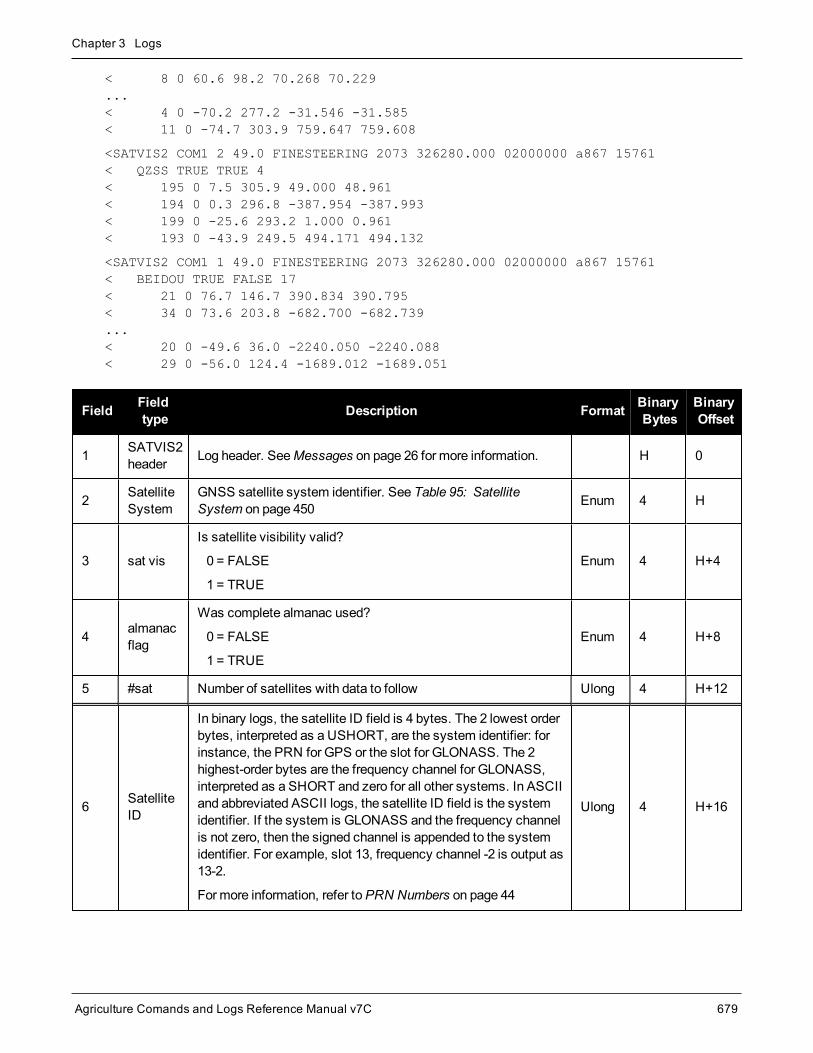
Chapter 3 Logs
Agriculture Comands and Logs Reference Manual v7C 679
< 8 0 60.6 98.2 70.268 70.229...< 4 0 -70.2 277.2 -31.546 -31.585< 11 0 -74.7 303.9 759.647 759.608
<SATVIS2 COM1 2 49.0 FINESTEERING 2073 326280.000 02000000 a867 15761< QZSS TRUE TRUE 4< 195 0 7.5 305.9 49.000 48.961< 194 0 0.3 296.8 -387.954 -387.993< 199 0 -25.6 293.2 1.000 0.961< 193 0 -43.9 249.5 494.171 494.132
<SATVIS2 COM1 1 49.0 FINESTEERING 2073 326280.000 02000000 a867 15761< BEIDOU TRUE FALSE 17< 21 0 76.7 146.7 390.834 390.795< 34 0 73.6 203.8 -682.700 -682.739...< 20 0 -49.6 36.0 -2240.050 -2240.088< 29 0 -56.0 124.4 -1689.012 -1689.051
Field Fieldtype Description Format Binary
BytesBinaryOffset
1 SATVIS2header Log header. SeeMessages on page 26 for more information. H 0
2 SatelliteSystem
GNSS satellite system identifier. See Table 95: SatelliteSystem on page 450 Enum 4 H
3 sat vis
Is satellite visibility valid?
0 = FALSE
1 = TRUE
Enum 4 H+4
4 almanacflag
Was complete almanac used?
0 = FALSE
1 = TRUE
Enum 4 H+8
5 #sat Number of satellites with data to follow Ulong 4 H+12
6 SatelliteID
In binary logs, the satellite ID field is 4 bytes. The 2 lowest orderbytes, interpreted as a USHORT, are the system identifier: forinstance, the PRN for GPS or the slot for GLONASS. The 2highest-order bytes are the frequency channel for GLONASS,interpreted as a SHORT and zero for all other systems. In ASCIIand abbreviated ASCII logs, the satellite ID field is the systemidentifier. If the system is GLONASS and the frequency channelis not zero, then the signed channel is appended to the systemidentifier. For example, slot 13, frequency channel -2 is output as13-2.
For more information, refer toPRN Numbers on page 44
Ulong 4 H+16

Chapter 3 Logs
Agriculture Comands and Logs Reference Manual v7C 680
Field Fieldtype Description Format Binary
BytesBinaryOffset
7 health
Satellite health
Satellite health values may be found in the applic-able Interface Control Document for each sys-tem.
Ulong 4 H+20
8 elev Elevation (degrees) Double 8 H+24
9 az Azimuth (degrees) Double 8 H+32
10 trueDoppler
Theoretical Doppler of satellite - the expected Doppler frequencybased on a satellite's motion relative to the receiver. It iscomputed using the satellite's coordinates and velocity alongwith the receiver's coordinates and velocity (Hz).
Double 8 H+40
11 apparentDoppler
Apparent Doppler for this receiver - the same as TheoreticalDoppler above but with clock drift correction added (Hz). Double 8 H+48
12 Next satellite offset = H + 16 + (#sat x 40)
13 xxxx 32-bit CRC (ASCII and Binary only) Ulong 4H+16+(#sat x40)
14 [CR][LF] Sentence terminator (ASCII only) - - -

Chapter 3 Logs
Agriculture Comands and Logs Reference Manual v7C 681
3.156 SATXYZ2Satellite positions in ECEF Cartesian coordinates
Platform: OEM719, OEM729, OEM7500, OEM7600, OEM7700, OEM7720, PwrPak7, SPAN CPT7,SMART7, SMART2
When combined with a RANGE log, this data set contains the decoded satellite information necessary to com-pute the solution: satellite coordinates (ECEFWGS84), satellite clock correction, ionospheric corrections andtropospheric corrections. See the calculation examples in the usage box below. Only those satellites used in thecorresponding PSRPOS solution are reported here. See also Figure 7: TheWGS84 ECEF Coordinate Systemon page 365.
Message ID: 1451
Log Type: Synch
Recommended Input:log satxyz2 ontime 1
Abbreviated ASCII Example:<SATXYZ2 COM1 0 43.0 FINESTEERING 2073 326597.000 02000000 7513 15761< 31< GPS 13 13292381.0861 -9204057.4856 20943772.2872 -12315.672 1.730 4.0400.0 0.0< GPS 26 -26171343.8441 -3995818.7265 3158269.4974 15742.110 3.276 10.0400.0 0.0< GPS 10 -22871286.2136 -11539483.0577 7490020.1157 -23362.172 2.518 4.0490.0 0.0...< QZSS 195 -26852309.2176 25168047.7930 25627104.8820 -943.845 3.588 14.3920.0 0.0< GLONASS 23+3 -7728588.2303 -9923997.7486 22179613.4745 77256.655 4.5352.209 0.0 0.0< GLONASS 22-3 2062133.9271 -23859927.8705 8944205.1074 -53417.457 5.7143.233 0.0 0.0< GLONASS 15 -1568588.2687 11620631.2286 22680731.2560 31246.746 4.928 9.5750.0 0.0...< GALILEO 26 -15009834.0035 -6744628.6348 24605291.2086 1211027.652 3.7642.482 0.0 0.0< GALILEO 13 -1405515.6484 -23638629.2714 17758202.4136 118018.035 3.8972.360 0.0 0.0< GALILEO 7 -12398598.1739 -26308725.3107 5470967.1516 -82852.430 4.5133.301 0.0 0.0...< BEIDOU 11 -13808280.9446 -10084397.5362 22092795.5021 23811.128 -0.9692.316 0.0 0.0< BEIDOU 10 -1132944.7407 26163154.0839 33245955.0163 -69500.475 0.92516.645 0.0 0.0< BEIDOU 14 -24527716.7042 -12609403.1954 -4035069.5018 153346.639 1.49713.392 0.0 0.0...

Chapter 3 Logs
Agriculture Comands and Logs Reference Manual v7C 682
TheOEM7 family defines ionospheric and tropospheric corrections positively whichmeans thationospheric and tropospheric corrections are added to the geometric ranges or subtracted from themeasured pseudoranges. A positive clock offset indicates the clock is running ahead of the referencetime. For example:
P = p + pd + c(dT - dt) + d(ion) + d(trop) + Ep
is equivalent to
P - c(dT - dt) - d(ion) - d(trop) = p + pd + Ep
where
P = measured pseudorangep = geometric rangepd = orbit errordt = satellite clock offsetdT = receiver clock offsetd (ion) = ionospheric delayd (trop) = tropospheric delayc = speed of lightEp = noise andmultipath
Note that when dual frequency ionosphere corrections are used, the corrections include receiverbiases. Consequently, the correction does not provide ameasure of the ionosphere delay in an absolutesense.
Field Field Type Description Format BinaryBytes
BinaryOffset
1 SATXYZ2header
Log header. SeeMessages on page 26 for moreinformation. - H 0
2 #sat Number of satellites to follow Ulong 4 H
3 System Satellite system (refer to Table 95: SatelliteSystem on page 450) Enum 4 H+4
4 Satellite ID Satellite ID Ulong 4 H+8
5 X Satellite X co-ordinates (ECEF,m) Double 8 H+12
6 Y Satellite Y co-ordinates (ECEF,m) Double 8 H+20
7 Z Satellite Z co-ordinates (ECEF,m) Double 8 H+28
8 clk corr Satellite clock correction (m) Double 8 H+36
9 iono delay Ionosphere delay (m) Double 8 H+44
10 tropo delay Troposphere delay (m) Double 8 H+52
11 Reserved1 Double 8 H+60

Chapter 3 Logs
Agriculture Comands and Logs Reference Manual v7C 683
Field Field Type Description Format BinaryBytes
BinaryOffset
12 Reserved2 Double 8 H+68
13 Next satellite offset = H+4+(#sat x 72)
14 xxxx 32-bit CRC (ASCII and Binary only) Ulong 4 H+4+(#satx 72)
15 [CR][LF] Sentence terminator (ASCII only)

Chapter 3 Logs
Agriculture Comands and Logs Reference Manual v7C 684
3.157 SAVEDSURVEYPOSITIONSSaved surveyed positions
Platform: OEM719, OEM729, OEM7500, OEM7600, OEM7700, OEM7720, PwrPak7, SPAN CPT7,SMART7
This log lists the surveyed positions saved on the receiver.
A surveyed position is saved using theAUTOSURVEY command (see page 63) orSURVEYPOSITION com-mand (see page 277).
Message ID: 1951
Log Type: Polled
Recommended Input:log savedsurveypositions once
Abbreviated ASCII Example:<SAVEDSURVEYPOSITIONS COM1 0 82.5 FINESTEERING 2003 313938.731 02000008 ddf232768< 3< "MN01" 51.00000000000 100.00000000000 150.0000< "TST1" 90.00000000000 90.00000000000 90.0000< "MON1" 45.00000000000 45.00000000000 45.0000
Field Field Type Description Format BinaryBytes
BinaryOffset
1SAVEDSURVEYPOSITIONSheader
Log header. SeeMessages on page 26 for moreinformation. H 0
2 #Positions Number of records to follow. Ulong 4 H
3 Position ID
ID for the saved position.
Note: In the Binary case, the ID stringmust be nullterminated and additional bytes of paddingmust beadded tomake the total length of the field 8 bytes.
String 8 H+4
4 LatitudeLatitude of the position
(-90 to 90 degrees) where a ‘-’ sign denotes southand a ‘+’ sign denotes north
Double 8 H+12
5 LongitudeLongitude of the position
(-360 to 360 degrees) where a ‘-’ sign denotes westand a ‘+’ sign denotes east
Double 8 H+20
6 Height Mean Sea Level height of the position in meters Double 8 H+28
7 Next reading offset = H+4+(#Positions * 32)

Chapter 3 Logs
Agriculture Comands and Logs Reference Manual v7C 685
Field Field Type Description Format BinaryBytes
BinaryOffset
8 xxxx 32-bit CRC (ASCII and Binary only) Hex 4H+4+(#Positions* 32)
9 [CR][LF] Sentence terminator (ASCII only) - - -

Chapter 3 Logs
Agriculture Comands and Logs Reference Manual v7C 686
3.158 SBAS0Do not use for safety applications
Platform: OEM719, OEM729, OEM7500, OEM7600, OEM7700, OEM7720, PwrPak7, SPAN CPT7,SMART7, SMART2
This message specifies the PRN if GEO transmitting SBAS corrections is operating in test mode, and shouldnot be used for safety applications for a period of time outlined in the SBAS signal specification.
TheGEO transmitting SBAS corrections is operating in test mode, and should not be used for safety-of-life applications.
See how the SBAS0message relates to the SBAS testingmodes in theSBASCONTROL command onpage 245.
Message ID: 976
Log Type: Asynch
Recommended Input:log SBAS0a onchanged
ASCII Example:#SBAS0A,COM1,0,72.5,SATTIME,2073,327283.000,1a000000,5a84,15761;130*8390deb3
Although the SBAS was designed for aviation users, it supports a wide variety of non-aviation usesincluding agriculture, surveying, recreation, and surface transportation.
Field Field type Description Format BinaryBytes
BinaryOffset
1 SBAS0header
Log header. SeeMessages on page 26 for moreinformation. H 0
2 prn Source PRN message - also PRN not to use Ulong 4 H
3 xxxx 32-bit CRC (ASCII and Binary only) Ulong 4 H+4
4 [CR][LF] Sentence terminator (ASCII only) - - -

Chapter 3 Logs
Agriculture Comands and Logs Reference Manual v7C 687
3.159 SBAS1PRN mask assignments
Platform: OEM719, OEM729, OEM7500, OEM7600, OEM7700, OEM7720, PwrPak7, SPAN CPT7,SMART7, SMART2
The PRN mask is given in SBAS1. The transition of the PRN mask to a new one (which will be infrequent) is con-trolled with the 2-bit IODP, which sequences to a number between 0 and 3. The same IODP appears in theapplicable SBAS2, SBAS3, SBAS4, SBAS5, SBAS7, SBAS24 and SBAS25messages (SBAS32, SBAS33,SBAS34, SBAS35 and SBAS45). This transition would probably only occur when a new satellite is launched orwhen a satellite fails and is taken out of service permanently. A degraded satellite may be flagged as a “do notuse” satellite temporarily.
Message ID: 977
Log Type: Asynch
Recommended Input:log SBAS1a onchanged
ASCII Example:#SBAS1A,COM1,0,24.5,SATTIME,1337,415802.000,02000000,5955,1984;134,ffeffffe0000000000000000000000400400000000000000000000,2*3633cf7b
Each raw SBAS frame gives data for a specific frame decoder number. The SBAS1message can belogged to view the data breakdown of SBAS frame 1which contains information about the PRN maskassignment.
Field Field type Description Format BinaryBytes
BinaryOffset
1 SBAS1header
Log header. SeeMessages on page 26 for moreinformation. H 0
2 prn Source PRN of message Ulong 4 H
3 mask PRN bit mask Uchar[27] 28 1 H+4
4 iodp Issue of PRN mask data Ulong 4 H+32
5 xxxx 32-bit CRC (ASCII and Binary only) Ulong 4 H+36
6 [CR][LF] Sentence terminator (ASCII only) - - -
1In the binary log case, an additional 1 byte of padding is added to maintain 4-byte alignment.

Chapter 3 Logs
Agriculture Comands and Logs Reference Manual v7C 688
3.160 SBAS2Fast correction slots 0-12
Platform: OEM719, OEM729, OEM7500, OEM7600, OEM7700, OEM7720, PwrPak7, SPAN CPT7,SMART7, SMART2
SBAS2 are fast corrections for slots 0-12 in themask of SBAS1. This messagemay or may not comewhenSBAS is in testingmode (see theSBASCONTROL command on page 245 for details).
Message ID: 982
Log Type: Asynch
Recommended Input:log SBAS2a onchanged
ASCII Example:#SBAS2A,COM1,0,29.0,SATTIME,1337,415925.000,02000000,e194,1984;134,2,2,3,-3,5,1,2047,-2,2047,2047,2047,2047,2047,-3,2,5,11,7,8,14,8,14,14,14,14,14,6,12*8d8d2e1c
Each raw SBAS frame gives data for a specific frame decoder number. The SBAS2message can belogged to view the data breakdown of SBAS frame 2which contains information about fast correctionslots 0-12.
Field Field type Description Format BinaryBytes
BinaryOffset
1 SBAS2header
Log header. SeeMessages on page 26 for moreinformation. H 0
2 prn Source PRN of message Ulong 4 H
3 iodf Issue of fast corrections data Ulong 4 H+4
4 iodp Issue of PRN mask data Ulong 4 H+8

Chapter 3 Logs
Agriculture Comands and Logs Reference Manual v7C 689
Field Field type Description Format BinaryBytes
BinaryOffset
5 prc0
prc(i):
Fast corrections
(-2048 to +2047) for the PRN in slot i (i = 0-12)
Long 4 H+12
6 prc1 Long 4 H+16
7 prc2 Long 4 H+20
8 prc3 Long 4 H+24
9 prc4 Long 4 H+28
10 prc5 Long 4 H+32
11 prc6 Long 4 H+36
12 prc7 Long 4 H+40
13 prc8 Long 4 H+44
14 prc9 Long 4 H+48
15 prc10 Long 4 H+52
16 prc11 Long 4 H+56
17 prc12 Long 4 H+60
18 udre0
udre(i):
User differential range error indicator for the PRN in slot i (i= 0-12)
See Table 170: Evaluation of UDREI on the next page forscaling information.
Ulong 4 H+64
19 udre1 Ulong 4 H+68
20 udre2 Ulong 4 H+72
21 udre3 Ulong 4 H+76
22 udre4 Ulong 4 H+80
23 udre5 Ulong 4 H+84
24 udre6 Ulong 4 H+88
25 udre7 Ulong 4 H+92
26 udre8 Ulong 4 H+96
27 udre9 Ulong 4 H+100
28 udre10 Ulong 4 H+104
29 udre11 Ulong 4 H+108
30 udre12 Ulong 4 H+112
31 xxxx 32-bit CRC (ASCII and Binary only) Ulong 4 H+116
32 [CR][LF] Sentence terminator (ASCII only) - - -

Chapter 3 Logs
Agriculture Comands and Logs Reference Manual v7C 690
UDREI 1 UDRE meters σ2 i.udre meters2
0 0.75 0.0520
1 1.0 0.0924
2 1.25 0.1444
3 1.75 0.2830
4 2.25 0.4678
5 3.0 0.8315
6 3.75 1.2992
7 4.5 1.8709
8 5.25 2.5465
9 6.0 3.3260
10 7.5 5.1968
11 15.0 20.7870
12 50.0 230.9661
13 150.0 2078.695
14 Not Monitored Not Monitored
15 DoNot Use DoNot Use
Table 170: Evaluation of UDREI
1The s2UDRE broadcast in SBAS2, SBAS3, SBAS4, SBAS5, SBAS6 and SBAS24 applies at a time prior to or at the time ofapplicability of the associated corrections.

Chapter 3 Logs
Agriculture Comands and Logs Reference Manual v7C 691
3.161 SBAS3Fast corrections slots 13-25
Platform: OEM719, OEM729, OEM7500, OEM7600, OEM7700, OEM7720, PwrPak7, SPAN CPT7,SMART7, SMART2
SBAS3 are fast corrections for slots 13-25 in themask of SBAS1.
Message ID: 987
Log Type: Asynch
Recommended Input:log SBAS3a onchanged
ASCII Example:#SBAS3A,COM1,0,17.0,SATTIME,1337,415990.000,02000000,bff5,1984;134,1,2,2047,0,2047,2047,-21,-4,2047,2047,-1,0,2,2047,6,14,5,14,14,11,5,14,14,5,7,5,14,8*a25aebc5
Each raw SBAS frame gives data for a specific frame decoder number. The SBAS3message can belogged to view the data breakdown of SBAS frame 3which contains information about fast correctionslots 13-25.
Field Field type Description Format BinaryBytes
BinaryOffset
1 SBAS3header
Log header. SeeMessages on page 26 for moreinformation. H 0
2 prn Source PRN of message Ulong 4 H
3 iodf Issue of fast corrections data Ulong 4 H+4
4 iodp Issue of PRN mask data Ulong 4 H+8

Chapter 3 Logs
Agriculture Comands and Logs Reference Manual v7C 692
Field Field type Description Format BinaryBytes
BinaryOffset
5 prc13
prc(i):
Fast corrections (-2048 to +2047) for the PRN in slot i (i =13-25)
Long 4 H+12
6 prc14 Long 4 H+16
7 prc15 Long 4 H+20
8 prc16 Long 4 H+24
9 prc17 Long 4 H+28
10 prc18 Long 4 H+32
11 prc19 Long 4 H+36
12 prc20 Long 4 H+40
13 prc21 Long 4 H+44
14 prc22 Long 4 H+48
15 prc23 Long 4 H+52
16 prc24 Long 4 H+56
17 prc25 Long 4 H+60
18 udre13
udre(i):
User differential range error indicator for the PRN in slot i(i = 13-25)
See Table 170: Evaluation of UDREI on page 691 forscaling information.
Ulong 4 H+64
19 udre14 Ulong 4 H+68
20 udre15 Ulong 4 H+72
21 udre16 Ulong 4 H+76
22 udre17 Ulong 4 H+80
23 udre18 Ulong 4 H+84
24 udre19 Ulong 4 H+88
25 udre20 Ulong 4 H+92
26 udre21 Ulong 4 H+96
27 udre22 Ulong 4 H+100
28 udre23 Ulong 4 H+104
29 udre24 Ulong 4 H+108
30 udre25 Ulong 4 H+112
31 xxxx 32-bit CRC (ASCII and Binary only) Ulong 4 H+116
32 [CR][LF] Sentence terminator (ASCII only) - - -

Chapter 3 Logs
Agriculture Comands and Logs Reference Manual v7C 693
3.162 SBAS4Fast correction slots 26-38
Platform: OEM719, OEM729, OEM7500, OEM7600, OEM7700, OEM7720, PwrPak7, SPAN CPT7,SMART7, SMART2
SBAS4 are fast corrections for slots 26-38 in themask of SBAS1.
Message ID: 992
Log Type: Asynch
Recommended Input:log SBAS4a onchanged
ASCII Example:#SBAS4A,COM1,0,58.0,SATTIME,1093,163399.000,02000020,b4b0,209;122,0,3,2047,3,-1,2047,2047,2047,-3,-1,5,3,3,2047,2,14,3,3,14,14,14,6,3,4,5,4,14,3*2e0894b1
Each raw SBAS frame gives data for a specific frame decoder number. The SBAS4message can belogged to view the data breakdown of SBAS frame 4which contains information about fast correctionslots 26-38.
Field Field type Description Format BinaryBytes
BinaryOffset
1 SBAS4header
Log header. SeeMessages on page 26 for moreinformation. H 0
2 prn Source PRN of message Ulong 4 H
3 iodf Issue of fast corrections data Ulong 4 H+4
4 iodp Issue of PRN mask data Ulong 4 H+8

Chapter 3 Logs
Agriculture Comands and Logs Reference Manual v7C 694
Field Field type Description Format BinaryBytes
BinaryOffset
5 prc26
prc(i):
Fast corrections (-2048 to +2047) for the PRN in slot i (i =26-38)
Long 4 H+12
6 prc27 Long 4 H+16
7 prc28 Long 4 H+20
8 prc29 Long 4 H+24
9 prc30 Long 4 H+28
10 prc31 Long 4 H+32
11 prc32 Long 4 H+36
12 prc33 Long 4 H+40
13 prc34 Long 4 H+44
14 prc35 Long 4 H+48
15 prc36 Long 4 H+52
16 prc37 Long 4 H+56
17 prc38 Long 4 H+60
18 udre26
udre(i):
User differential range error indicator for the PRN in slot i(i = 26-38)
See Table 170: Evaluation of UDREI on page 691 forscaling information.
Ulong 4 H+64
19 udre27 Ulong 4 H+68
20 udre28 Ulong 4 H+72
21 udre29 Ulong 4 H+76
22 udre30 Ulong 4 H+80
23 udre31 Ulong 4 H+84
24 udre32 Ulong 4 H+88
25 udre33 Ulong 4 H+92
26 udre34 Ulong 4 H+96
27 udre35 Ulong 4 H+100
28 udre36 Ulong 4 H+104
29 udre37 Ulong 4 H+108
30 udre38 Ulong 4 H+112
31 xxxx 32-bit CRC (ASCII and Binary only) Ulong 4 H+116
32 [CR][LF] Sentence terminator (ASCII only) - - -

Chapter 3 Logs
Agriculture Comands and Logs Reference Manual v7C 695
3.163 SBAS5Fast correction slots 39-50
Platform: OEM719, OEM729, OEM7500, OEM7600, OEM7700, OEM7720, PwrPak7, SPAN CPT7,SMART7, SMART2
SBAS5 are fast corrections for slots 39-50 in themask of SBAS1.
Message ID: 994
Log Type: Asynch
Recommended Input:log SBAS5a onchanged
ASCII Example:#SBAS5A,COM1,0,72.5,SATTIME,1093,161480.000,02040020,31d4,209;122,1,3,-7,2047,2047,2047,-4,2047,2047,2047,9,2047,2047,-3,-2,11,14,14,14,4,14,14,14,5,14,14,4,2*2bf0109b
Each raw SBAS frame gives data for a specific frame decoder number. The SBAS5message can belogged to view the data breakdown of SBAS frame 5which contains information about fast correctionslots 39-50.
Field Field type Description Format BinaryBytes
BinaryOffset
1 SBAS5header
Log header. SeeMessages on page 26 for moreinformation. H 0
2 prn Source PRN of message Ulong 4 H
3 iodf Issue of fast corrections data Ulong 4 H+4
4 iodp Issue of PRN mask data Ulong 4 H+8
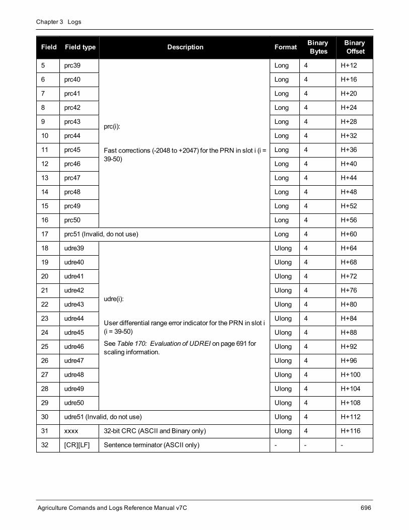
Chapter 3 Logs
Agriculture Comands and Logs Reference Manual v7C 696
Field Field type Description Format BinaryBytes
BinaryOffset
5 prc39
prc(i):
Fast corrections (-2048 to +2047) for the PRN in slot i (i =39-50)
Long 4 H+12
6 prc40 Long 4 H+16
7 prc41 Long 4 H+20
8 prc42 Long 4 H+24
9 prc43 Long 4 H+28
10 prc44 Long 4 H+32
11 prc45 Long 4 H+36
12 prc46 Long 4 H+40
13 prc47 Long 4 H+44
14 prc48 Long 4 H+48
15 prc49 Long 4 H+52
16 prc50 Long 4 H+56
17 prc51 (Invalid, do not use) Long 4 H+60
18 udre39
udre(i):
User differential range error indicator for the PRN in slot i(i = 39-50)
See Table 170: Evaluation of UDREI on page 691 forscaling information.
Ulong 4 H+64
19 udre40 Ulong 4 H+68
20 udre41 Ulong 4 H+72
21 udre42 Ulong 4 H+76
22 udre43 Ulong 4 H+80
23 udre44 Ulong 4 H+84
24 udre45 Ulong 4 H+88
25 udre46 Ulong 4 H+92
26 udre47 Ulong 4 H+96
27 udre48 Ulong 4 H+100
28 udre49 Ulong 4 H+104
29 udre50 Ulong 4 H+108
30 udre51 (Invalid, do not use) Ulong 4 H+112
31 xxxx 32-bit CRC (ASCII and Binary only) Ulong 4 H+116
32 [CR][LF] Sentence terminator (ASCII only) - - -

Chapter 3 Logs
Agriculture Comands and Logs Reference Manual v7C 697
3.164 SBAS6Integrity message
Platform: OEM719, OEM729, OEM7500, OEM7600, OEM7700, OEM7720, PwrPak7, SPAN CPT7,SMART7, SMART2
SBAS6 is the integrity informationmessage. Eachmessage includes an IODF for each fast corrections mes-sage. The σ2UDRE information for each block of satellites applies to the fast corrections with the correspondingIODF.
Message ID: 995
Log Type: Asynch
Recommended Input:log SBAS6a onchanged
ASCII Example:#SBAS6A,COM1,0,57.5,SATTIME,1093,273317.000,02000020,526a,209;122,3,3,3,3,9,14,14,2,3,10,2,14,14,3,14,14,5,14,14,7,14,14,14,14,14,14,3,3,14,14,14,14,3,15,11,11,15,0,0,0,0,0,0,0,0,0,0,0,0,0,0,0,0,0,0*925a2a9b
Each raw SBAS frame gives data for a specific frame decoder number. The SBAS6message can belogged to view the data breakdown of SBAS frame 6which contains information about the integrity mes-sage.
Field Field type Description Format BinaryBytes
BinaryOffset
1 SBAS6header
Log header. SeeMessages on page 26 for moreinformation. H 0
2 prn Source PRN of message Ulong 4 H
3 iodf2 Issue of fast corrections data Ulong 4 H+4
4 iodf3 Issue of fast corrections data Ulong 4 H+8
5 iodf4 Issue of fast corrections data Ulong 4 H+12
6 iodf5 Issue of fast corrections data Ulong 4 H+16
7 udre0
udre(i):
User differential range error indicator for the PRN in slot i(i = 0-50)
See Table 170: Evaluation of UDREI on page 691 forscaling information.
Ulong 4 H+20
8 udre1 Ulong 4 H+24
9 udre2 Ulong 4 H+28

Chapter 3 Logs
Agriculture Comands and Logs Reference Manual v7C 698
Field Field type Description Format BinaryBytes
BinaryOffset
10 udre3 Ulong 4 H+32
11 udre4 Ulong 4 H+36
12 udre5 Ulong 4 H+40
13 udre6 Ulong 4 H+44
14 udre7 Ulong 4 H+48
15 udre8 Ulong 4 H+52
16 udre9 Ulong 4 H+56
17 udre10 Ulong 4 H+60
18 udre11 Ulong 4 H+64
19 udre12 Ulong 4 H+68
20 udre13 Ulong 4 H+72
21 udre14 Ulong 4 H+76
22 udre15 Ulong 4 H+80
23 udre16 Ulong 4 H+84
24 udre17 Ulong 4 H+88
25 udre18 Ulong 4 H+92
26 udre19 Ulong 4 H+96
27 udre20 Ulong 4 H+100
28 udre21 Ulong 4 H+104
29 udre22 Ulong 4 H+108
30 udre23 Ulong 4 H+112
31 udre24 Ulong 4 H+116
32 udre25 Ulong 4 H+120
33 udre26 Ulong 4 H+124
34 udre27 Ulong 4 H+128
35 udre28 Ulong 4 H+132
36 udre29 Ulong 4 H+136
37 udre30 Ulong 4 H+140

Chapter 3 Logs
Agriculture Comands and Logs Reference Manual v7C 699
Field Field type Description Format BinaryBytes
BinaryOffset
38 udre31 Ulong 4 H+144
39 udre32 Ulong 4 H+148
40 udre33 Ulong 4 H+152
41 udre34 Ulong 4 H+156
42 udre35 Ulong 4 H+160
43 udre36 Ulong 4 H+164
44 udre37 Ulong 4 H+168
45 udre38 Ulong 4 H+172
46 udre39 Ulong 4 H+176
47 udre40 Ulong 4 H+180
48 udre41 Ulong 4 H+184
49 udre42 Ulong 4 H+188
50 udre43 Ulong 4 H+192
51 udre44 Ulong 4 H+196
52 udre45 Ulong 4 H+200
53 udre46 Ulong 4 H+204
54 udre47 Ulong 4 H+208
55 udre48 Ulong 4 H+212
56 udre49 Ulong 4 H+216
58 udre50 Ulong 4 H+220
58 udre51 (Invalid, do not use) Ulong 4 H+224
59 xxxx 32-bit CRC (ASCII and Binary only) Ulong 4 H+228
60 [CR][LF] Sentence terminator (ASCII only) - - -

Chapter 3 Logs
Agriculture Comands and Logs Reference Manual v7C 700
3.165 SBAS7Fast correction degradation
Platform: OEM719, OEM729, OEM7500, OEM7600, OEM7700, OEM7720, PwrPak7, SPAN CPT7,SMART7, SMART2
The SBAS7message specifies the applicable IODP, system latency time and fast degradation factor indicatorfor computing the degradation of fast and long term corrections.
Message ID: 996
Log Type: Asynch
Recommended Input:log SBAS7a onchanged
ASCII Example:#SBAS7A,COM1,0,36.5,SATTIME,1337,416367.000,02000000,12e3,1984;122,1,2,0,15,15,15,15,15,15,15,15,15,15,15,15,15,15,15,15,15,15,15,15,15,15,15,15,15,15,15,15,15,15,15,15,0,0,0,0,0,0,0,0,0,0,0,0,0,0,0,0,0,0,0*827a7364
Each raw SBAS frame gives data for a specific frame decoder number. The SBAS7message can belogged to view the data breakdown of SBAS frame 7which contains information about fast correctiondegradation.
Field Field type Description Format BinaryBytes
BinaryOffset
1 SBAS7header
Log header. SeeMessages on page 26 for moreinformation. H 0
2 prn Source PRN of message Ulong 4 H
3 latency System latency (s) Ulong 4 H+4
4 iodp Issue of PRN mask data Ulong 4 H+8
5 spare bits Unused spare bits Ulong 4 H+12
6 aI(0)aI(i):
Degradation factor indicator for the PRN in slot i (i =0-50)
Ulong 4 H+16
7 aI(1) Ulong 4 H+20
8 aI(2) Ulong 4 H+24
9 aI(3) Ulong 4 H+28
10 aI(4) Ulong 4 H+32
11 aI(5) Ulong 4 H+36

Chapter 3 Logs
Agriculture Comands and Logs Reference Manual v7C 701
Field Field type Description Format BinaryBytes
BinaryOffset
12 aI(6) Ulong 4 H+40
13 aI(7) Ulong 4 H+44
14 aI(8) Ulong 4 H+48
15 aI(9) Ulong 4 H+52
16 aI(10) Ulong 4 H+56
17 aI(11) Ulong 4 H+60
18 aI(12) Ulong 4 H+64
19 aI(13) Ulong 4 H+68
20 aI(14) Ulong 4 H+72
21 aI(15) Ulong 4 H+76
22 aI(16) Ulong 4 H+80
23 aI(17) Ulong 4 H+84
24 aI(18) Ulong 4 H+88
25 aI(19) Ulong 4 H+92
26 aI(20) Ulong 4 H+96
27 aI(21) Ulong 4 H+100
28 aI(22) Ulong 4 H+104
29 aI(23) Ulong 4 H+108
30 aI(24) Ulong 4 H+112
31 aI(25) Ulong 4 H+116
32 aI(26) Ulong 4 H+120
33 aI(27) Ulong 4 H+124
34 aI(28) Ulong 4 H+128
35 aI(29) Ulong 4 H+132
36 aI(30) Ulong 4 H+136
37 aI(31) Ulong 4 H+140
38 aI(32) Ulong 4 H+144
39 aI(33) Ulong 4 H+148

Chapter 3 Logs
Agriculture Comands and Logs Reference Manual v7C 702
Field Field type Description Format BinaryBytes
BinaryOffset
40 aI(34) Ulong 4 H+152
41 aI(35) Ulong 4 H+156
42 aI(36) Ulong 4 H+160
43 aI(37) Ulong 4 H+164
44 aI(38) Ulong 4 H+168
45 aI(39) Ulong 4 H+172
46 aI(40) Ulong 4 H+176
47 aI(41) Ulong 4 H+180
48 aI(42) Ulong 4 H+184
49 aI(43) Ulong 4 H+188
50 aI(44) Ulong 4 H+192
51 aI(45) Ulong 4 H+196
52 aI(46) Ulong 4 H+200
53 aI(47) Ulong 4 H+204
54 aI(48) Ulong 4 H+208
55 aI(49) Ulong 4 H+212
56 aI(50) Ulong 4 H+216
57 aI(51) (Invalid, do not use) Ulong 4 H+220
58 xxxx 32-bit CRC (ASCII and Binary only) Ulong 4 H+224
59 [CR][LF] Sentence terminator (ASCII only) - - -

Chapter 3 Logs
Agriculture Comands and Logs Reference Manual v7C 703
3.166 SBAS9GEO navigation message
Platform: OEM719, OEM729, OEM7500, OEM7600, OEM7700, OEM7720, PwrPak7, SPAN CPT7,SMART7, SMART2
SBAS9 provides the GEO navigationmessage representing the position, velocity and acceleration of the geo-stationary satellite, in ECEF coordinates and its apparent clock time and frequency offsets.
Also included is the time of applicability, an Issue of Data (IOD) and an accuracy exponent (URA) representingthe estimated accuracy of themessage. The time offset and time drift are with respect to SBAS Network Time.Their combined effect is added to the estimate of the satellite’s transmit time.
Message ID: 997
Log Type: Asynch
Recommended Input:log SBAS9a onchanged
ASCII Example:#SBAS9A,COM1,0,38.0,SATTIME,1337,416426.000,02000000,b580,1984;122,175,70848,2,24802064.1600,-34087313.9200,-33823.2000,1.591250000,0.107500000,0.6080000,-0.0000750,-0.0001125,0.000187500,-2.235174179e-08,9.094947018e-12*636051d2
Each raw SBAS frame gives data for a specific frame decoder number. The SBAS9message can belogged to view the data breakdown of SBAS frame 9which contains the GEO navigationmessage.
Field Field type Description Format BinaryBytes
BinaryOffset
1 SBAS9header
Log header. SeeMessages on page 26 for moreinformation. H 0
2 prn Source PRN of message Ulong 4 H
3 iodn Issue of GEO navigation data Ulong 4 H+4
4 t0 Time of applicability Ulong 4 H+8
5 ura URA value Ulong 4 H+12
6 x ECEF x coordinate (m) Double 8 H+16
7 y ECEF y coordinate (m) Double 8 H+24
8 z ECEF z coordinate (m) Double 8 H+32
9 xvel X rate of change (m/s) Double 8 H+40
10 yvel Y rate of change (m/s) Double 8 H+48
11 zvel Z rate of change (m/s) Double 8 H+56

Chapter 3 Logs
Agriculture Comands and Logs Reference Manual v7C 704
Field Field type Description Format BinaryBytes
BinaryOffset
12 xaccel X rate of rate change (m/s2) Double 8 H+64
13 yaccel Y rate of rate change (m/s2) Double 8 H+72
14 zaccel Z rate of rate change (m/s2) Double 8 H+80
15 af0 Time offset (s) Double 8 H+88
16 af1 Time drift (s) Double 8 H+96
17 xxxx 32-bit CRC (ASCII and Binary only) Ulong 4 H+104
18 [CR][LF] Sentence terminator (ASCII only) - - -

Chapter 3 Logs
Agriculture Comands and Logs Reference Manual v7C 705
3.167 SBAS10Degradation factor
Platform: OEM719, OEM729, OEM7500, OEM7600, OEM7700, OEM7720, PwrPak7, SPAN CPT7,SMART7, SMART2
The fast corrections, long term corrections and ionospheric corrections are all provided in the SBAS10message.
Message ID: 978
Log Type: Asynch
Recommended Input:log SBAS10a onchanged
ASCII Example:#SBAS10A,COM1,0,35.5,SATTIME,1337,416469.000,02000000,c305,1984;122,54,38,76,256,152,100,311,83,256,6,0,300,292,0,1,0000000000000000000000*8884d248
Each raw SBAS frame gives data for a specific frame decoder number. The SBAS10message can belogged to view the data breakdown of SBAS frame 10 which contains information about degradationfactors.
Field Fieldtype Description Format Binary
BytesBinaryOffset Scaling
1 SBAS10header
Log header. SeeMessages on page 26 for moreinformation. H 0 -
2 prn Source PRN of message Ulong 4 H -
3 brcc Estimated noise and round off error parameter Ulong 4 H+4 0.002
4 cltc_lsbMaximum round off due to the least significant bit(lsb) of the orbital clock Ulong 4 H+8 0.002
5 cltc_vl Velocity error bound Ulong 4 H+12 0.00005
6 iltc_vl Update interval for v=1 long term Ulong 4 H+16 -
7 cltc_v0 Bound on update delta Ulong 4 H+20 0.002
8 iltc_v1 Minimum update interval v = 0 Ulong 4 H+24 -
9 cgeo_lsbMaximum round off due to the lsb of the orbitalclock Ulong 4 H+28 0.0005
10 cgeo_v Velocity error bound Ulong 4 H+32 0.00005
11 igeo Update interval for GEO navigationmessage Ulong 4 H+36 -
12 cer Degradation parameter Ulong 4 H+40 0.5

Chapter 3 Logs
Agriculture Comands and Logs Reference Manual v7C 706
Field Fieldtype Description Format Binary
BytesBinaryOffset Scaling
13 ciono_step Bound on ionospheric grid delay difference Ulong 4 H+44 0.001
14 iiono Minimum ionospheric update interval Ulong 4 H+48 -
15 ciono_ramp Rate of ionospheric corrections change Ulong 4 H+52 0.000005
16 rssudre User differential range error flag Ulong 4 H+56 -
17 rssiono Root sum square flag Ulong 4 H+60 -
18 spare bits Spare 88 bits, possibly GLONASS Hex[11] 11 H+64 -
19 xxxx 32-bit CRC (ASCII and Binary only) Ulong 4 H+75 -
20 [CR][LF] Sentence terminator (ASCII only) - - - -

Chapter 3 Logs
Agriculture Comands and Logs Reference Manual v7C 707
3.168 SBAS12SBAS network time and UTC
Platform: OEM719, OEM729, OEM7500, OEM7600, OEM7700, OEM7720, PwrPak7, SPAN CPT7,SMART7, SMART2
SBAS12 contains information bits for the UTC parameters and UTC time standard from which an offset isdetermined. The UTC parameters correlate UTC time with the SBAS network time rather than with GPS ref-erence time.
Message ID: 979
Log Type: Asynch
Recommended Input:log SBAS12a onchanged
Each raw SBAS frame gives data for a specific frame decoder number. The SBAS12message can belogged to view the data breakdown of SBAS frame 12 which contains information about time para-meters.
Field Field type Description Format BinaryBytes
BinaryOffset
1 SBAS12header
Log header. SeeMessages on page 26 for moreinformation. H 0
2 prn Source PRN of message Ulong 4 H
3 A1 Time drift (s/s) Double 8 H+4
4 A0 Time offset (s) Double 8 H+12
5 seconds Seconds into the week (s) Ulong 4 H+20
6 week Week number Ushort 2 H+24
7 dtls Delta time due to leap seconds Short 2 H+26
8 wnlsf Week number, leap second future Ushort 2 H+28
9 dn Day of the week (the range is 1 to 7 where Sunday = 1and Saturday = 7) Ushort 2 H+30
10 dtlsf Delta time, leap second future Ushort 2 H+32
11 utc id UTC type identifier Ushort 2 H+34
12 gpstow GPS reference time of the week Ulong 4 H+36
13 gpswn GPS de-modulo week number Ulong 4 H+40

Chapter 3 Logs
Agriculture Comands and Logs Reference Manual v7C 708
Field Field type Description Format BinaryBytes
BinaryOffset
14 glo indicator
Is GLONASS information present?
0 = FALSE
1 = TRUE
Enum 4 H+44
15 Reserved array of hexabytes for GLONASS Char[10] 121 H+48
16 xxxx 32-bit CRC (ASCII and Binary only) Ulong 4 H+60
17 [CR][LF] Sentence terminator (ASCII only) - - -
1In the binary log case, an additional 2 bytes of padding are added to maintain 4-byte alignment.
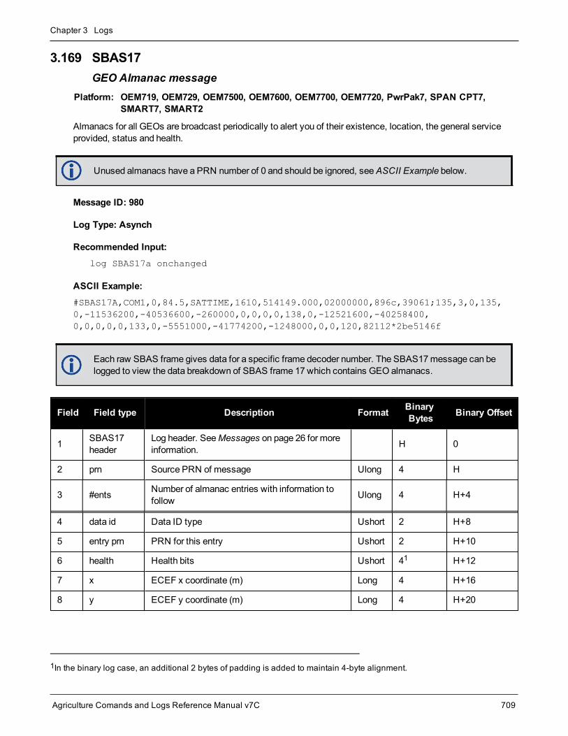
Chapter 3 Logs
Agriculture Comands and Logs Reference Manual v7C 709
3.169 SBAS17GEO Almanac message
Platform: OEM719, OEM729, OEM7500, OEM7600, OEM7700, OEM7720, PwrPak7, SPAN CPT7,SMART7, SMART2
Almanacs for all GEOs are broadcast periodically to alert you of their existence, location, the general serviceprovided, status and health.
Unused almanacs have a PRN number of 0 and should be ignored, seeASCII Example below.
Message ID: 980
Log Type: Asynch
Recommended Input:log SBAS17a onchanged
ASCII Example:#SBAS17A,COM1,0,84.5,SATTIME,1610,514149.000,02000000,896c,39061;135,3,0,135,0,-11536200,-40536600,-260000,0,0,0,0,138,0,-12521600,-40258400,0,0,0,0,0,133,0,-5551000,-41774200,-1248000,0,0,120,82112*2be5146f
Each raw SBAS frame gives data for a specific frame decoder number. The SBAS17message can belogged to view the data breakdown of SBAS frame 17 which contains GEO almanacs.
Field Field type Description Format BinaryBytes Binary Offset
1 SBAS17header
Log header. SeeMessages on page 26 for moreinformation. H 0
2 prn Source PRN of message Ulong 4 H
3 #ents Number of almanac entries with information tofollow Ulong 4 H+4
4 data id Data ID type Ushort 2 H+8
5 entry prn PRN for this entry Ushort 2 H+10
6 health Health bits Ushort 41 H+12
7 x ECEF x coordinate (m) Long 4 H+16
8 y ECEF y coordinate (m) Long 4 H+20
1In the binary log case, an additional 2 bytes of padding is added to maintain 4-byte alignment.

Chapter 3 Logs
Agriculture Comands and Logs Reference Manual v7C 710
Field Field type Description Format BinaryBytes Binary Offset
9 z ECEF z coordinate (m) Long 4 H+24
10 x vel X rate of change (m/s) Long 4 H+28
11 y vel Y rate of change (m/s) Long 4 H+32
12 z vel Z rate of change (m/s) Long 4 H+36
13... Next entry = H+8+(#ents x 32)
14 t0Time of day in seconds (0 to 86336)
Scaling = 64Ulong 4 H+8+ (#ents x
32)
15 xxxx 32-bit CRC (ASCII and Binary only) Ulong 4 H+12+ (#entsx 32)
16 [CR][LF] Sentence terminator (ASCII only) - - -

Chapter 3 Logs
Agriculture Comands and Logs Reference Manual v7C 711
3.170 SBAS18IGP mask
Platform: OEM719, OEM729, OEM7500, OEM7600, OEM7700, OEM7720, PwrPak7, SPAN CPT7,SMART7, SMART2
The ionospheric delay corrections are broadcast as vertical delay estimates, at specified ionospheric grid points(IGPs), applicable to a signal on L1. The predefined IGPs are contained in 11 bands (numbered 0 to 10). Bands 0-8 are vertical bands on aMercator projectionmap and bands 9-10 are horizontal bands on aMercator projectionmap. Since it is impossible to broadcast IGP delays for all possible locations, amask is broadcast to define theIGP locations providing themost efficient model of the ionosphere at the time.
Message ID: 981
Log Type: Asynch
Recommended Input:log SBAS18a onchanged
ASCII Example:#SBAS18A,COM1,0,33.0,SATTIME,1337,417074.000,02000000,f2c0,1984;122,4,2,2,0000ffc0007fc0003ff0000ff80007fe0007fe0003ff0000ff80,0*b1ed353e
Each raw SBAS frame gives data for a specific frame decoder number. The SBAS18message can belogged to view the data breakdown of SBAS frame 18 which contains information about ionospheric gridpoints.
Field Field type Description Format BinaryBytes
BinaryOffset
1 SBAS18header
Log header. SeeMessages on page 26 for moreinformation. H 0
2 prn Source PRN of message Ulong 4 H
3 #bands Number of bands broadcast Ulong 4 H+4
4 band num Specific band number that identifies which of the 11 IGPbands the data belongs to Ulong 4 H+8
5 iodi Issue of ionospheric data Ulong 4 H+12
6 igpmask IGP mask Uchar[26] 281 H+16
7 spare bit One spare bit Ulong 4 H+44
8 xxxx 32-bit CRC (ASCII and Binary only) Ulong 4 H+48
9 [CR][LF] Sentence terminator (ASCII only) - - -
1In the binary log case, an additional 2 bytes of padding are added to maintain 4-byte alignment.

Chapter 3 Logs
Agriculture Comands and Logs Reference Manual v7C 712
3.171 SBAS24Mixed fast/slow corrections
Platform: OEM719, OEM729, OEM7500, OEM7600, OEM7700, OEM7720, PwrPak7, SPAN CPT7,SMART7, SMART2
If there are 6 or fewer satellites in a block, they may be placed in this mixed correctionmessage. There is a fastdata set for each satellite and a UDRE indicator. Eachmessage also contains an IODP indicating the asso-ciated PRN mask.
The fast correction (PRC) has a valid range of -2048 to +2047. If the range is exceeded, a don’t use indication isinserted into the user differential range error indicator (UDREI) field, see Table 170: Evaluation of UDREI onpage 691. You should ignore extra data sets not represented in the PRN mask.
The time of applicability (T0) of the PRC is the start of the epoch of theWNT second that is coincident with thetransmission at the GEO satellite of the first bit of themessage block.
Message ID: 983
Log Type: Asynch
Recommended Input:log SBAS24a onchanged
ASCII Example:#SBAS24A,COM1,0,34.0,SATTIME,1337,417108.000,02000000,0a33,1984;134,2047,2047,2047,2047,-1,-2,14,14,14,14,11,14,2,2,0,0,1,0,0,0,0,0,0,0,0,0,0,0,0,0,0,0*76ff954b
Each raw SBAS frame gives data for a specific frame decoder number. The SBAS24message can belogged to view the data breakdown of SBAS frame 24 which contains mixed fast/slow corrections.
Field Fieldtype Description Format Binary
BytesBinaryOffset Scaling
1 SBAS24header
Log header. SeeMessages onpage 26 for more information. H 0 -
2 prn Source PRN of message Ulong 4 H -
3 prc0
prc(i):
Fast corrections (-2048 to +2047)for the PRN in slot i
(i = 0-5)
Long 4 H+4 -
4 prc1 Long 4 H+8 -
5 prc2 Long 4 H+12 -
6 prc3 Long 4 H+16 -
7 prc4 Long 4 H+20 -
8 prc5 Long 4 H+24 -

Chapter 3 Logs
Agriculture Comands and Logs Reference Manual v7C 713
Field Fieldtype Description Format Binary
BytesBinaryOffset Scaling
9 udre0
udre(i):
User differential range errorindicator for the PRN in slot i
(i = 0-5)
Ulong 4 H+28
See Table 170: Evaluationof UDREI on page 691
10 udre1 Ulong 4 H+32
11 udre2 Ulong 4 H+36
12 udre3 Ulong 4 H+40
13 udre4 Ulong 4 H+44
14 udre5 Ulong 4 H+48
15 iodp Issue of PRN mask data Ulong 4 H+52 -
16 block id Associatedmessage type Ulong 4 H+56
17 iodf Issue of fast corrections data Ulong 4 H+60 -
18 spare Spare value Ulong 4 H+64 -
19 vel Velocity code flag Ulong 4 H+68 -
20 mask1 Index into PRN mask (Type 1) Ulong 4 H+72 -
21 iode1 Issue of ephemeris data Ulong 4 H+76 -
22 dx1 Delta x (ECEF) Long 4 H+80 0.125
23 dy1 Delta y (ECEF) Long 4 H+84 0.125
24 dz1 Delta z (ECEF) Long 4 H+88 0.125
25 daf0 Delta af0 clock offset Long 4 H+92 2-31
26 mask2 Second index into PRN mask(Type 1) Ulong 4 H+96 -
27 iode2 Second issue of ephemeris data Ulong 4 H+100 -
28 ddx Delta delta x (ECEF) Long 4 H+104 2-11
29 ddy Delta delta y (ECEF) Long 4 H+108 2-11
30 ddz Delta delta z (ECEF) Long 4 H+112 2-11
31 daf1 Delta af1 clock offset Long 4 H+116 2-39
32 t0 Applicable time of day Ulong 4 H+120 16
33 iodp Issue of PRN mask data Ulong 4 H+124 -
34 corrspare
Spare value when velocity code isequal to 0 Ulong 4 H+128 -

Chapter 3 Logs
Agriculture Comands and Logs Reference Manual v7C 714
Field Fieldtype Description Format Binary
BytesBinaryOffset Scaling
35 xxxx 32-bit CRC (ASCII and Binaryonly) Ulong 4 H+132 -
36 [CR][LF] Sentence terminator (ASCII only) - - - -

Chapter 3 Logs
Agriculture Comands and Logs Reference Manual v7C 715
3.172 SBAS25Long term slow satellite corrections
Platform: OEM719, OEM729, OEM7500, OEM7600, OEM7700, OEM7720, PwrPak7, SPAN CPT7,SMART7, SMART2
SBAS25 provides error estimates for slow varying satellite ephemeris and clock errors with respect toWGS-84ECEF coordinates.
Message ID: 984
Log Type: Asynch
Recommended Input:log SBAS25a onchanged
ASCII Example:#SBAS25A,COM1,0,37.5,SATTIME,1337,417193.000,02000000,b8ff,1984;134,1,19,25,-1,-3,0,-15,0,0,0,1,-1,-2,4465,2,0,1,0,0,0,0,0,0,0,0,0,0,0,0,0,0,0*81685317
Each raw SBAS frame gives data for a specific frame decoder number. The SBAS25message can belogged to view the data breakdown of SBAS frame 25 which contains long term slow satellite cor-rections.
Field Field type Description Format BinaryBytes
BinaryOffset Scaling
1 SBAS25header
Log header. SeeMessages on page 26 formore information. H 0 -
2 prn Source PRN of message Ulong 4 H -
3 1st half vel Velocity code flag (0 or 1) Ulong 4 H+4 -
4 1st halfmask1 Index into PRN mask (Type 1) Ulong 4 H+8 -
5 1st half iode1 Issue of ephemeris data Ulong 4 H+12 -
6 1st half dx1 Delta x (ECEF) Long 4 H+16 0.125
7 1st half dy1 Delta y (ECEF) Long 4 H+20 0.125
8 1st half dz1 Delta z (ECEF) Long 4 H+24 0.125
9 1st half af0 Delta af0 clock offset Long 4 H+28 2-31
10 1st halfmask2
Second index into PRN mask (Type 1)Dummy value when velocity code = 1 Ulong 4 H+32 -
11 1st half iode2 Second issue of ephemeris dataDummy value when velocity code = 1 Ulong 4 H+36 -

Chapter 3 Logs
Agriculture Comands and Logs Reference Manual v7C 716
Field Field type Description Format BinaryBytes
BinaryOffset Scaling
12 1st half ddx Delta delta x (ECEF) when velocity code = 1Delta x (dx) when velocity code = 0 Long 4 H+40 2-11
13 1st half ddy Delta delta y (ECEF) when velocity code = 1Delta y (dy) when velocity code = 0 Long 4 H+44 2-11
14 1st half ddz Delta delta z (ECEF) when velocity code = 1Delta z (dz) when velocity code = 0 Long 4 H+48 2-11
15 1st half af1Delta af1 clock offset when velocity code = 1Delta af0 clock offset when velocity code = 0
Long 4 H+52 2-39
16 1st half t0Applicable time of dayDummy value when velocity code = 0 Ulong 4 H+56 16
17 1st half iodp Issue of PRN mask data Ulong 4 H+60 -
18 1st half corrspare
Spare value when velocity code = 0Dummy value when velocity code = 1 Ulong 4 H+64 -
19 2nd half vel Velocity code flag (0 or 1) Ulong 4 H+68 -
20 2nd halfmask1 Index into PRN mask (Type 1) Ulong 4 H+72 -
21 2nd halfiode1 Issue of ephemeris data Ulong 4 H+76 -
22 2nd half dx1 Delta x (ECEF) Long 4 H+80 0.125
23 2nd half dy1 Delta y (ECEF) Long 4 H+84 0.125
24 2nd half dz1 Delta z (ECEF) Long 4 H+88 0.125
25 2nd half af0 Delta af0 clock offset Long 4 H+92 2-31
26 2nd halfmask2
Second index into PRN mask (Type 1)Dummy value when velocity code = 1 Ulong 4 H+96 -
27 2nd halfiode2
Second issue of ephemeris dataDummy value when velocity code = 1 Ulong 4 H+100 -
28 2nd half ddx Delta delta x (ECEF) when velocity code = 1Delta x (dx) when velocity code = 0 Long 4 H+104 2-11
29 2nd half ddy Delta delta y (ECEF) when velocity code = 1Delta y (dy) when velocity code = 0 Long 4 H+108 2-11
30 2nd half ddz Delta delta z (ECEF) when velocity code = 1Delta z (dz) when velocity code = 0 Long 4 H+112 2-11
31 2nd half af1Delta af1 clock offset when velocity code = 1Delta af0 clock offset when velocity code = 0
Long 4 H+116 2-39

Chapter 3 Logs
Agriculture Comands and Logs Reference Manual v7C 717
Field Field type Description Format BinaryBytes
BinaryOffset Scaling
32 2nd half t0Applicable time of day
Dummy value when velocity code = 0Ulong 4 H+120 16
33 2nd half iodp Issue of PRN mask data Ulong 4 H+124 -
34 2nd half corrspare
Spare value when velocity code = 0Dummy value when velocity code = 1 Ulong 4 H+128 -
35 xxxx 32-bit CRC (ASCII and Binary only) Ulong 4 H+132 -
36 [CR][LF] Sentence terminator (ASCII only) - - - -

Chapter 3 Logs
Agriculture Comands and Logs Reference Manual v7C 718
3.173 SBAS26Ionospheric delay corrections
Platform: OEM719, OEM729, OEM7500, OEM7600, OEM7700, OEM7720, PwrPak7, SPAN CPT7,SMART7, SMART2
SBAS26 provides vertical delays (relative to an L1 signal) and their accuracy at geographically defined IGPs iden-tified by the BAND NUMBER and IGP number. Eachmessage contains a band number and a block ID, whichindicates the location of the IGPs in the respective bandmask.
Message ID: 985
Log Type: Asynch
Recommended Input:log SBAS26a onchanged
ASCII Example:#SBAS26A,COM1,0,38.0,SATTIME,1337,417243.000,02000000,ec70,1984;134,1,2,15,27,11,25,11,23,11,19,11,16,11,16,12,15,13,16,13,29,14,30,13,27,11,27,11,24,11,19,11,16,12,2,0*3b6d6806
Each raw SBAS frame gives data for a specific frame decoder number. The SBAS26message can belogged to view the data breakdown of SBAS frame 26 which contains ionospheric delay corrections
Field Field type Description Format BinaryBytes
BinaryOffset
1 SBAS26header
Log header. SeeMessages on page 26 for moreinformation. H 0
2 prn Source PRN of message Ulong 4 H
3 band num Band number Ulong 4 H+4
4 block id Block ID Ulong 4 H+8
5 #pts Number of grid points with information to follow Ulong 4 H+12
6 igpvdeIGP vertical delay estimates
Scaling = 0.125Ulong 4 H+16
7 givei Grid ionospheric vertical error indicator Ulong 4 H+20
8... Next #pts entry = H + 16 + (#pts x 8)
9 iodi Issue of data - ionosphere Ulong 4 H+16+ (#ptsx 8)

Chapter 3 Logs
Agriculture Comands and Logs Reference Manual v7C 719
Field Field type Description Format BinaryBytes
BinaryOffset
10 spare 7 spare bits Ulong 41 H+20+ (#ptsx 8)
11 xxxx 32-bit CRC (ASCII and Binary only) Ulong 4 H+24+ (#ptsx 8)
12 [CR][LF] Sentence terminator (ASCII only) - - -
1In the binary case, additional bytes of padding are added after this field to maintain 4-byte alignment for the fields thatfollow.

Chapter 3 Logs
Agriculture Comands and Logs Reference Manual v7C 720
3.174 SBAS27SBAS service message
Platform: OEM719, OEM729, OEM7500, OEM7600, OEM7700, OEM7720, PwrPak7, SPAN CPT7,SMART7, SMART2
SBAS27messages apply only to the service provider transmitting themessage. The number of servicemes-sages indicates the total number of unique SBAS27messages for the current IODS. Each uniquemessage forthat IODS includes a sequential message number. The IODS is incremented in all messages, each time that anyparameter in any SBAS27message is changed.
Message ID: 986
Log Type: Asynch
Recommended Input:log SBAS27a onchanged
Each raw SBAS frame gives data for a specific frame decoder number. The SBAS27message can belogged to view the data breakdown of SBAS frame 27 which contains information about SBAS servicemessages.
Field Field type Description Format BinaryBytes
BinaryOffset
1 SBAS27header
Log header. SeeMessages on page 26 for moreinformation. H 0
2 prn Source PRN of message Ulong 4 H
3 iods Issue of slow corrections data Ulong 4 H+4
4 #messages Low-by-one count of messages Ulong 4 H+8
5 messagenum Low-by-onemessage number Ulong 4 H+12
6 priority code Priority code Ulong 4 H+16
7 dudre inside Delta user differential range error – inside Ulong 4 H+20
8 dudre outside Delta user differential range error – outside Ulong 4 H+24
9... #reg Number of regions with information to follow Ulong 4 H+28
10 lat1 Coordinate 1 latitude Long 4 H+32
11 lon1 Coordinate 1 longitude Long 4 H+36
12 lat2 Coordinate 2 latitude Long 4 H+40
13 lon2 Coordinate 2 longitude Long 4 H+44

Chapter 3 Logs
Agriculture Comands and Logs Reference Manual v7C 721
Field Field type Description Format BinaryBytes
BinaryOffset
14 shape Shape where: 0 = triangle, 1 = square Ulong 4 H+48
15 Next #reg entry = H+32+(#reg x 20)
16 Reserved Ulong 4 H+32+(#reg x 20)
17 xxxx 32-bit CRC (ASCII and Binary only) Ulong 4 H+36+(#reg x 20)
18 [CR][LF] Sentence terminator (ASCII only) - - -

Chapter 3 Logs
Agriculture Comands and Logs Reference Manual v7C 722
3.175 SBASALMANACSBAS Almanac collection
Platform: OEM719, OEM729, OEM7500, OEM7600, OEM7700, OEM7720, PwrPak7, SPAN CPT7,SMART7, SMART2
This log contains a collection of all current SBAS almanacs that have been decoded by the receiver andmay con-tain almanac data for multiple PRNs. The SBASALMANAC log is populated by the GEOAlmanac MessageType 17 which is available in theSBAS17 log (see page 710). These PRNs are broken out into individual SBASalmanac entries for this message and output individually. If multiple SBAS subsystems (e.g., WAAS, EGNOS,GAGAN, MSAS) are tracked, this message will include almanac data collected from each with the subsystemidentified in eachmessage entry. The almanac data contains all of the information required to compute the satel-lite position as well as health and status information.
TheOEM7 family of receivers automatically save almanacs in their Non-Volatile Memory (NVM), so creating analmanac boot file is not necessary.
Message ID: 1425
Log Type: Asynch
Recommended Input:Log SBASALMANACA onchanged
ASCII Example:#SBASALMANACA,COM1,2,80.0,SATTIME,1672,411186.000,02000020,84d8,43119;133,WAAS,65600,0,0,-5571800,-41758600,-1456000,0,0,120*22da17e8
#SBASALMANACA,COM1,1,80.0,SATTIME,1672,411186.000,02000020,84d8,43119;135,WAAS,65600,0,0,-28758600,-30825600,0,0,0,0*dd122ca1
#SBASALMANACA,COM1,0,80.0,SATTIME,1672,411186.000,02000020,84d8,43119;138,WAAS,65600,0,0,-12547600,-40248000,0,0,0,0*89c6c51c
Field Field Type Description Format BinaryBytes
BinaryOffset
1 SBASALMANACHeader
Log header. SeeMessages on page 26 for moreinformation. H 0
2 Satellite ID Satellite ID Ulong 4 H
3 Variant System variant (refer to Table 171: SBASSubsystem Types on the next page) Enum 4 H + 4
4 Time Time of day (s) Ulong 4 H + 8
5 Data ID Data identification Ushort 2 H + 12
6 Health Satellite health Ushort 2 H + 14
7 X ECEF X coordinate (m) Long 4 H + 16
8 Y ECEF Y coordinate (m) Long 4 H + 20
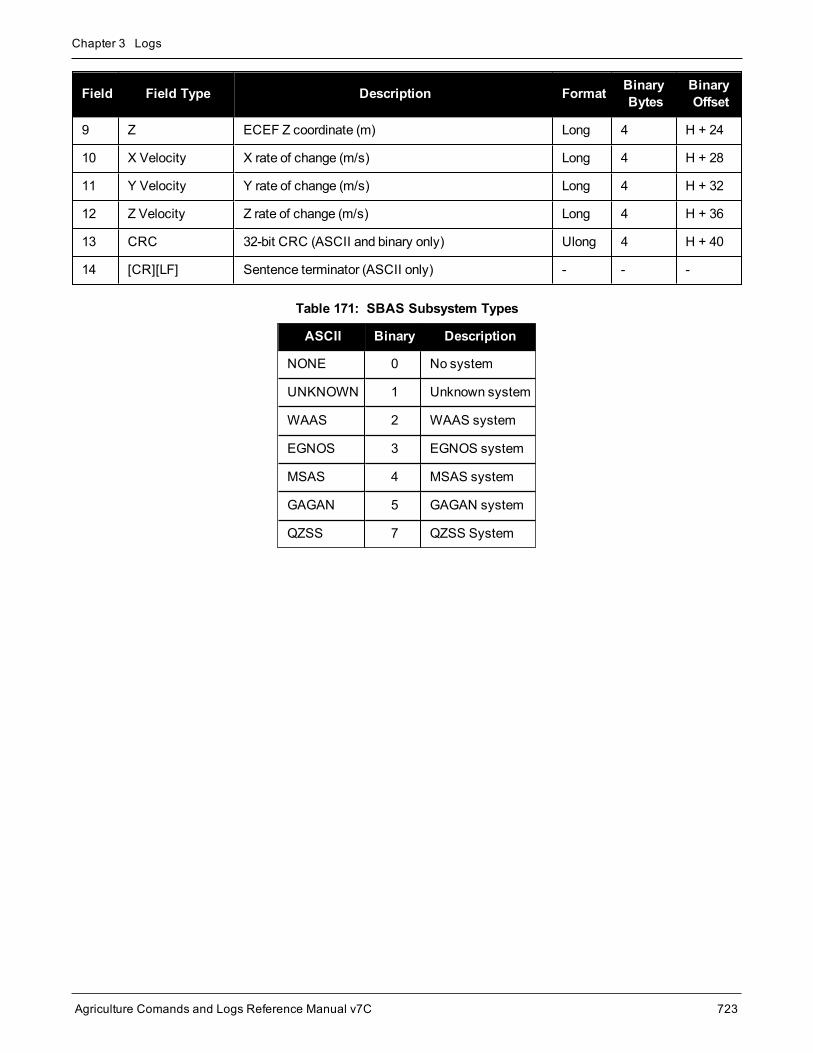
Chapter 3 Logs
Agriculture Comands and Logs Reference Manual v7C 723
Field Field Type Description Format BinaryBytes
BinaryOffset
9 Z ECEF Z coordinate (m) Long 4 H + 24
10 X Velocity X rate of change (m/s) Long 4 H + 28
11 Y Velocity Y rate of change (m/s) Long 4 H + 32
12 Z Velocity Z rate of change (m/s) Long 4 H + 36
13 CRC 32-bit CRC (ASCII and binary only) Ulong 4 H + 40
14 [CR][LF] Sentence terminator (ASCII only) - - -
ASCII Binary Description
NONE 0 No system
UNKNOWN 1 Unknown system
WAAS 2 WAAS system
EGNOS 3 EGNOS system
MSAS 4 MSAS system
GAGAN 5 GAGAN system
QZSS 7 QZSS System
Table 171: SBAS Subsystem Types

Chapter 3 Logs
Agriculture Comands and Logs Reference Manual v7C 724
3.176 SOFTLOADSTATUSDescribes the status of the SoftLoad process
Platform: OEM719, OEM729, OEM7500, OEM7600, OEM7700, OEM7720, PwrPak7, SPAN CPT7,SMART7, SMART2
This log describes the status of the SoftLoad process.
Status values >= 16 (ERROR) indicate that an error has occurred during the loading process. Status <16 (ERROR) are part of normal SoftLoad operation.
Message ID: 1235
Log Type: Asynch
Recommended Input:log softloadstatusa onchanged
ASCII Example:#SOFTLOADSTATUSA,COM1,0,97.5,UNKNOWN,0,0.113,024c0001,2d64,10481;NOT_STARTED*827fdc04
Field Field Type Description Format BinaryBytes
BinaryOffset
1 SOFTLOADSTATUSheader
Log header. SeeMessages on page 26 for moreinformation. - H 0
2 status Status of the SoftLoad process see Table 172:SoftLoad Status Type below Enum 4 H
3 xxxx 32-bit CRC (ASCII and Binary only) Ulong 4 H+4
4 [CR][LF] Sentence terminator (ASCII only) - - -
Value Name Description
1 NOT_STARTED SoftLoad process has not begun.
2 READY_FOR_SETUP
SoftLoad process is ready to receive setup information in the form of theSOFTLOADSETUP command orSOFTLOADSREC commandwith S0 records.Once sufficient setup data has been sent, the process is also ready for theSOFTLOADDATA command.
3 READY_FOR_DATA
SoftLoad process is ready to receive data in the form of theSOFTLOADDATAcommand orSOFTLOADSREC commandwith S3 records. Once all data has beensent, send theSOFTLOADCOMMIT command.
Table 172: SoftLoad Status Type

Chapter 3 Logs
Agriculture Comands and Logs Reference Manual v7C 725
Value Name Description
4 DATA_VERIFIED SoftLoad data has passed CRC. This status occurs after aSOFTLOADCOMMITcommand.
5 WRITING_FLASH
SoftLoad data is being written to flash. This status occurs after aSOFTLOADCOMMIT command. During a firmware upload, the receiver may remainin this state for 300 seconds or longer.
6 WROTE_FLASH SoftLoad data has been written to flash.
7 WROTE_AUTHCODE The embedded AuthCode was successfully written.
8 COMPLETE SoftLoad process has completed. The next step is to send theRESET command toreset the receiver.
9 VERIFYING_DATA SoftLoad is verifying the downloaded image.
10COPIED_SIGNATURE_AUTH
Signature AuthCodes have been copied from the current firmware to the downloadedfirmware.
11WROTE_TRANSACTION_TABLE
The downloaded firmware has been activated and will be executed if the receiver isreset. This status is effectively identical to COMPLETE.
16 ERROR Indicates an internal error in the SoftLoad process. This error is not expected tooccur. Contact NovAtel Customer Support for assistance.
17 RESET_ERROR Error resetting SoftLoad. Reset the receiver and restart the SoftLoad process.
18 BAD_SRECORD A bad S Record was received. Ensure that S Records are enclosed in double quoteswithin theSOFTLOADSREC command.
19 BAD_PLATFORM This data cannot be loaded onto this platform. Ensure that the correct *.shex file forthe platform is being used.
20 BAD_MODULE This module cannot be loaded with SoftLoad. This file must be loaded usingWinLoador a similar loader.
21 BAD_AUTHCODE Bad AuthCode received for this PSN.
22 NOT_READY_FOR_SETUP
A SOFTLOADSETUP commandwas entered before aSOFTLOADRESETcommand or after aSOFTLOADDATA command.
23 NO_MODULENo data type was entered before aSOFTLOADDATA commandwas received. Setthe data type using theSOFTLOADSETUP command orSOFTLOADSRECcommandwith an "S0~T~" S Record.

Chapter 3 Logs
Agriculture Comands and Logs Reference Manual v7C 726
Value Name Description
24 NO_PLATFORMNo platform was entered before aSOFTLOADDATA commandwas received. Setthe platform using theSOFTLOADSETUP command orSOFTLOADSRECcommandwith an "S0~P~" S Record.
25 NOT_READY_FOR_DATA A SOFTLOADDATA commandwas received but the receiver was not ready for it.
26 MODULE_MISMATCH
The SoftLoad datamodule was changed in themiddle of loading. Restart theSoftLoad process using theSOFTLOADRESET command.
27 OUT_OF_MEMORY
SoftLoad has run out of RAM to store the incoming data. Reset the receiver andrestart the SoftLoad process.
28 DATA_OVERLAP SoftLoad data has overlapped. Ensure that the correct address and length is set intheSOFTLOADDATA command orSOFTLOADSREC command.
29 BAD_IMAGE_CRC
CRC of the downloaded image has failed. Ensure that all content from the *.shex filehas been successfully downloaded.
30 IMAGE_OVERSIZE The downloaded image is too big for the intended datamodule.
31 AUTHCODE_WRITE_ERROR An error occurred when writing the embedded AuthCode to flash.
32 BAD_FLASH_ERASE Erasing of the flash failed. This could indicate a failure in the flash hardware.
33 BAD_FLASH_WRITE Writing to the flash failed. This could indicate a failure in the flash hardware.
34 TIMEOUT SoftLoad time out has occurred.
35 INCOMPATIBLE_FLASH Application image that does not support the onboard flash rejected.

Chapter 3 Logs
Agriculture Comands and Logs Reference Manual v7C 727
3.177 SOURCETABLENTRIP source table entries
Platform: OEM729, OEM7600, OEM7700, OEM7720, PwrPak7, SPAN CPT7, SMART7-W, SMART7-I
This log outputs the NTRIP source table entries from the NTRIP caster set by theNTRIPSOURCETABLE com-mand (see page 183). The entry data field in the first entry is always the header of the retrievedSOURCETABLE. The entry data field in the last entry is always a string “ENDSOURCETABLE” which indic-ates the end of the source table. Entries in between these fields are the real SOURCETABLE entries.
Message ID: 1344
Log Type: Polled
Recommended Input:log sourcetablea once
ASCII Example:#SOURCETABLEA,COM1,17,84.0,COARSESTEERING,1933,497547.000,02400020,71dd,32768;"hera.novatel.com:2101",0,0,"HTTP/1.1 200 OK;Ntrip-Version: Ntrip/2.0;Ntrip-Flags: st_filter,st_auth,st_match,st_strict,rtsp,plain_rtp;Server: NTRIPCaster/2.0.15;Date: Fri, 27 Jan 2017 18:12:01 GMT;Connection: close;Content-Type: gnss/sourcetable;Content-Length: 2057"*87a7d39d
#SOURCETABLEA,COM1,16,84.0,COARSESTEERING,1933,497547.000,02400020,71dd,32768;"hera.novatel.com:2101",0,0,"CAS;hera.novatel.ca;80,2101;NovAtel;NovAtel;0;CAN;51;-115;http://www.novatel.com"*e3ec11a0
#SOURCETABLEA,COM1,15,84.0,COARSESTEERING,1933,497547.000,02400020,71dd,32768;"hera.novatel.com:2101",0,0,"NET;GREF;NovAtel;B;N;http://novatel.com;none;novatel.com;none"*2a6b50eb
#SOURCETABLEA,COM1,14,84.0,COARSESTEERING,1933,497547.000,02400020,71dd,32768;"hera.novatel.com:2101",0,0,"STR;novatel_rtcmv3;Office Roof DL1L2;RTCM 3.0;1033(10),1005(10),1019(60),1020(60),1003(1),1011(1);2;GPS+GLO;NovAtel;CAN;51;-115;0;0;NovAtel OEM628;none;B;N;9600;Test"*8a7c760f
#SOURCETABLEA,COM1,13,84.0,COARSESTEERING,1933,497547.000,02400020,71dd,32768;"hera.novatel.com:2101",0,0,"STR;novatel_rtcm;Office Roof DL1L2;RTCM 2.3;1(1),3(10),31(1),32(10);0;GPS+GLO;NovAtel;CAN;51;-115;0;0;NovAtel OEM628;none;B;N;9600;Test"*08c57cb7
#SOURCETABLEA,COM1,12,84.0,COARSESTEERING,1933,497547.000,02400020,71dd,32768;"hera.novatel.com:2101",0,0,"STR;novatel_rtca;Office Roof DL1L2;RTCA;RTCAREF(10),RTCA1(1),RTCAEPHEM(60);0;GPS;NovAtel;CAN;51;-115;0;0;NovAtel OEM628;none;B;N;9600;Test"*006997bc
#SOURCETABLEA,COM1,11,84.0,COARSESTEERING,1933,497547.000,02400020,71dd,32768;"hera.novatel.com:2101",0,0,"STR;novatel_cmr;Office Roof DL1L2;CMR;CMRREF(10),CMROBS(1),CMRGLOOBS(1);2;GPS+GLO;NovAtel;CAN;51;-115;0;0;NovAtel OEM628;none;B;N;9600;Test"*0955ccb7
#SOURCETABLEA,COM1,10,84.0,COARSESTEERING,1933,497547.000,02400020,71dd,32768;"hera.novatel.com:2101",0,0,"STR;novatel_rtcaobs2;Office Roof DL1L2;RTCA;rtcaref(10),rtcaobs2(1),rtcaephem(60);2;GPS+GLO;NovAtel;CAN;51;-115;0;0;NovAtelOEM628;none;B;N;9600;Test"*426e39a5

Chapter 3 Logs
Agriculture Comands and Logs Reference Manual v7C 728
#SOURCETABLEA,COM1,9,84.0,COARSESTEERING,1933,497547.000,02400020,71dd,32768;"hera.novatel.com:2101",0,0,"STR;novatel_cmrplus;Office Roof DL1L2;CMR+;cmrplus(1),cmrobs(1),cmrgloobs(1);2;GPS+GLO;NovAtel;CAN;51;-115;0;0;NovAtel OEM628;none;B;N;9600;Test"*2d5ba56e
#SOURCETABLEA,COM1,8,84.0,COARSESTEERING,1933,497547.000,02400020,71dd,32768;"hera.novatel.com:2101",0,0,"STR;novatel_rtcm2021;Office Roof DL1L2;RTCM 2.3;3(10),2021(1);2;GPS+GLO;NovAtel;CAN;51;-115;0;0;NovAtelOEM628;none;B;N;9600;Test"*d82df5de
#SOURCETABLEA,COM1,7,84.0,COARSESTEERING,1933,497547.000,02400020,71dd,32768;"hera.novatel.com:2101",0,0,"STR;novatel_1819;Office Roof DL1L2;RTCM 2.3;3(10),22(10),23(60),24(60),1819(1);2;GPS+GLO;NovAtel;CAN;51;-115;0;0;NovAtel OEM628;none;B;N;9600;Test"*7aead153
#SOURCETABLEA,COM1,6,84.0,COARSESTEERING,1933,497547.000,02400020,71dd,32768;"hera.novatel.com:2101",0,0,"STR;novatel_rtcaobs;Office Roof DL1L2;RTCA;rtcaref(10),rtcaobs(1),rtcaephem(60);2;GPS+GLO;NovAtel;CAN;51;-115;0;0;NovAtelOEM628;none;B;N;9600;Test"*530a51c4
#SOURCETABLEA,COM1,5,84.0,COARSESTEERING,1933,497547.000,02400020,71dd,32768;"hera.novatel.com:2101",0,0,"STR;novatel_novatelx;Office Roof;NovatelX;novatelobs;2;GPS+GLO;NovAel;CAN;51;-114;0;0;NovAtel OEM628;none;B;N;9600;Test"*4438c2e2
#SOURCETABLEA,COM1,4,84.0,COARSESTEERING,1933,497547.000,02400020,71dd,32768;"hera.novatel.com:2101",0,0,"STR;Hyderabad1;hyderabad test1;unknown;unknown;2;GPS+GLO;NovAtel;INDIA;17;78;0;0;NovAtel OEM628;none;B;N;9600;Test"*de6c19f0
#SOURCETABLEA,COM1,3,84.0,COARSESTEERING,1933,497547.000,02400020,71dd,32768;"hera.novatel.com:2101",0,0,"STR;Hyderabad2;hyderabadtest1;unknown;unknown;2;GPS+GLO;NovAtel;INDIA;17;78;0;0;NovAtelOEM628;none;B;N;9600;Test"*27e9eee1
#SOURCETABLEA,COM1,2,84.0,COARSESTEERING,1933,497547.000,02400020,71dd,32768;"hera.novatel.com:2101",0,0,"STR;Hyderabad3;hyderabad test1;unknown;unknown;2;GPS+GLO;NovAtel;INDIA;17;78;0;0;NovAtel OEM628;none;B;N;9600;Test"*3ed5941b
#SOURCETABLEA,COM1,1,84.0,COARSESTEERING,1933,497547.000,02400020,71dd,32768;"hera.novatel.com:2101",0,0,"STR;Hyderabad4;hyderabad test1;unknown;unknown;2;GPS+GLO;NovAtel;INDIA;17;78;0;0;NovAtel OEM628;none;B;N;9600;Test"*a3a188e2
#SOURCETABLEA,COM1,0,84.0,COARSESTEERING,1933,497547.000,02400020,71dd,32768;"hera.novatel.com:2101",0,0,"ENDSOURCETABLE"*7758fba9
Field Field Type Description Format BinaryBytes
BinaryOffset
1 SOURCETABLEheader
Log header. SeeMessages onpage 26 for more information. H 0

Chapter 3 Logs
Agriculture Comands and Logs Reference Manual v7C 729
Field Field Type Description Format BinaryBytes
BinaryOffset
2 endpoint NTRIPCASTER Endpoint String with varied lengthup to 80 bytes a1 H
3 Reserved1 reserved Ulong 4 H+a
4 Reserved2 reserved Ulong 4 H+a+4
5 Entry data Source table entry data String with varied lengthup to 512 bytes
b1 H+a+8
6 xxxx 32-bit CRC (ASCII and binary only) Ulong 4 H+a+b+8
7 [CR][LF] Sentence terminator (ASCII only) - - -
1In the binary case, each string field needs to be NULL terminated and additional bytes of padding added to maintain 4-bytealignment, up to the maximum defined by the string size. The next defined field starts immediately at the next 4-bytealignment following the NULL.

Chapter 3 Logs
Agriculture Comands and Logs Reference Manual v7C 730
3.178 TECTONICSCOMPENSATIONTectonics Compensation status
Platform: OEM719, OEM729, OEM7500, OEM7600, OEM7700, OEM7720, PwrPak7, SPAN CPT7,SMART7, SMART2
This log shows the status of the tectonics compensation.
Message ID: 2291
Log Type: Asynch
Recommended Input:log tectonicscompensationa onchanged
ASCII Example:#TECTONICSCOMPENSATIONA,COM1,0,74.0,FINESTEERING,2044,511461.010,02000020,3af4,15427;AVAILABLE,"North America",-0.018,-0.000,-0.006*e85af7bf
Field Field Type Description Format BinaryBytes
BinaryOffset
1TECTONICSCOMPENSATIONheader
Log header. SeeMessages on page 26 for moreinformation. – H 0
2 statusStatus of plate tectonics compensation.
See Table 173: Tectonics Compensation Statusbelow.
Enum 4 H
3 name Name of the plate that is being used fordetermining station velocities.
Char(32) Variable H+4
4 xvelStation velocities for the location of the receiver(meters/year)
Float 4 Variable
5 yvel Float 4 Variable
6 zvel Float 4 Variable
7 xxxx 32-bit CRC (ASCII and Binary only) Ulong 4 Variable
8 [CR][LF] Sentence terminator (ASCII only) – – –
Binary ASCII Description
0 UNAVAILABLE Tectonics compensation is not available.
1 AVAILABLE Tectonics compensation is available.
2 WARNING The receiver is either close to a plate boundary or inside a region where the tectonicscompensation is not well modeled.
Table 173: Tectonics Compensation Status

Chapter 3 Logs
Agriculture Comands and Logs Reference Manual v7C 731
Binary ASCII Description
4 OFF_PLATE The receiver has moved from the plate that was initially selected. The receiver will notchange the plate to avoid discontinuities in the positions.

Chapter 3 Logs
Agriculture Comands and Logs Reference Manual v7C 732
3.179 TERRASTARINFOTerraStar subscription information
Platform: OEM719, OEM729, OEM7500, OEM7600, OEM7700, OEM7720, PwrPak7, SPAN CPT7,SMART7, SMART2
This log contains details on the TerraStar subscription.
Message ID: 1719
Log Type: Asynch
Recommended Input:log terrastarinfoa onchanged
ASCII Example:#TERRASTARINFOA,COM1,0,78.0,FINESTEERING,2050,426971.997,02000000,91ea,14517;"QW503:1904:5936",TERM,00000700,120,2019,0,NEARSHORE,0.00000,0.00000,0*c930f2bd
Field Field type Description Format BinaryBytes
BinaryOffset
1 TERRASTARINFO header Log header. SeeMessages on page 26 for more information. H 0
2 PAC Product activation code Char[16] 16 H
3 Type Subscription type (see Table 174: TerraStar SubscriptionType on the next page) Enum 4 H+16
4 Subscriptionpermissions
Services permitted by the subscription (see Table 175:TerraStar Subscription Details Mask on the next page)
Note: Bits in the Reserved areas of this field may be set,but the Reserved bits should be ignored. A receiver canhave only one active subscription at a time but asubscription can enablemultiple services or bits. Forexample, “00000700” indicates the receiver has a TerraStar-C subscription though TerraStar-L is also allowed.
Hex 4 H+20
5 Service EndDay
Last day of the year for which service is available. Serviceexpires at the end of this UTC day.
For example, if the Service End Year and Day are 2019 and15, respectively, then the service will expire on January 15,2019 at 24:00 UTC.
Ulong 4 H+24
6 Service EndYear Year that subscription ends Ulong 4 H+28
7 Reserved Ulong 4 H+32

Chapter 3 Logs
Agriculture Comands and Logs Reference Manual v7C 733
Field Field type Description Format BinaryBytes
BinaryOffset
8 Regionrestriction
For region restricted subscriptions, the type of regionrestriction (see Table 176: TerraStar Region Restriction onthe next page)
Enum 4 H+36
9 Center pointlatitude
For local area subscriptions, the center point latitude(degrees) Float 4 H+40
10 Center pointlongitude
For local area subscriptions, the center point longitude(degrees) Float 4 H+44
11 Radius For local area subscriptions, themaximum permitteddistance from center point (kilometers) Ulong 4 H+48
12 xxxx 32-bit CRC (ASCII and Binary only) Ulong 4 H+52
13 [CR][LF] Sentence terminator (ASCII only) - - -
ASCII Binary Description
UNASSIGNED 0 Decoder has not had an assigned operatingmode
TERM 1 Term subscription
MODEL 5 Receiver is operating with an RTK assist enabledmodel and there is not anactive TerraStar subscription installed
BUBBLE 100 Receiver is operating in a TerraStar-permitted subscription-free bubble
INCOMPATIBLE_SUBSCRIPTION 104 Subscription is incompatible with this version of firmware
Table 174: TerraStar Subscription Type
Bit Mask Description
0-8 0x000001FF Reserved
9 0x00000200 TerraStar-C service
10 0x00000400 TerraStar-L service
11 0x00000800 RTK ASSIST service
12 0x00001000 RTK ASSIST PRO service
13 0x00002000 TerraStar-C PRO service
14 0x00004000 TerraStar-X service
15-31 0xFFFF8000 Reserved
Table 175: TerraStar Subscription Details Mask

Chapter 3 Logs
Agriculture Comands and Logs Reference Manual v7C 734
ASCII Binary Description
NONE 0 TerraStar operation has no region restrictions.
GEOGATED 1TerraStar operation limited to on-land
GEOGATED is also the default value reported if there is no subscription
LOCAL_AREA 2 TerraStar operation limited to radius from local area center point
NEARSHORE 3 TerraStar operation limited to on land and near shore (coastal) regions
Table 176: TerraStar Region Restriction

Chapter 3 Logs
Agriculture Comands and Logs Reference Manual v7C 735
3.180 TERRASTARSTATUSTerraStar decoder and subscription status
Platform: OEM719, OEM729, OEM7500, OEM7600, OEM7700, OEM7720, PwrPak7, SPAN CPT7,SMART7, SMART2
This log contains status information for the TerraStar decoder and subscription.
Message ID: 1729
Log Type: Asynch
Recommended Input:log terrastarstatusa onchanged
ASCII Example:#TERRASTARSTATUSA,COM1,0,49.5,FINESTEERING,1769,332336.443,02000000,fdc1,12602;ENABLE,LOCKED,0,DISABLED,ONSHORE*555155a5
Field Field type Description Format BinaryBytes
BinaryOffset
1TERRASTARSTATUSheader
Log header. SeeMessages on page 26 for more information. H 0
2 Access Access status. ENABLE (1) if the subscription is valid;DISABLE (0) otherwise Enum 4 H
3 Sync state Decoder data synchronization state (see Table 177:Decoder Data Synchronization State below) Enum 4 H+4
4 Reserved Ulong 4 H+8
5 Local areastatus
For local-area subscriptions, indicates if the receiver iswithin the permitted area (see Table 178: TerraStar LocalArea Status on the next page)
Enum 4 H+12
6 Geogatingstatus
Geogating status (see Table 179: TerraStar GeogatingStatus on the next page) Enum 4 H+16
7 xxxx 32-bit CRC (ASCII and Binary only) Ulong 4 H+20
8 [CR][LF] Sentence terminator (ASCII only) - - -
ASCII Binary Description
NO_SIGNAL 0 None of the decoders have received data in the last 30 seconds
SEARCH 1 At least one decoder is receiving data and is searching for the format
LOCKED 2 At lease one decoder has locked onto the format
Table 177: Decoder Data Synchronization State

Chapter 3 Logs
Agriculture Comands and Logs Reference Manual v7C 736
ASCII Binary Description
DISABLED 0The subscription is not restricted to a local area.
This is also the value when there is no subscription.
WAITING_FOR_POSITION 1 Waiting for a position
RANGE_CHECK 16 Checking position against local area region restriction
IN_RANGE 129 Receiver is within the permitted local area
OUT_OF_RANGE 130 Receiver is outside the permitted local area
POSITION_TOO_OLD 255 Position is too old
Table 178: TerraStar Local Area Status
ASCII Binary Description
DISABLED 0The subscription is restricted to a local area or there is no regionrestriction.
This is also the value when there is no subscription.
WAITING_FOR_POSITION 1 Waiting for a position
ONSHORE 129 Receiver is over land
OFFSHORE 130 Receiver is over water
POSITION_TOO_OLD 255 Position is too old
PROCESSING 1000 Geogater is determining status
Table 179: TerraStar Geogating Status

Chapter 3 Logs
Agriculture Comands and Logs Reference Manual v7C 737
3.181 TIMETime data
Platform: OEM719, OEM729, OEM7500, OEM7600, OEM7700, OEM7720, PwrPak7, SPAN CPT7,SMART7, SMART2
This log provides several time related pieces of information including receiver clock offset and UTC time and off-set. It can also be used to determine any offset in the PPS signal relative to GPS reference time.
To find any offset in the PPS signal, log the TIME log 'ontime' at the same rate as the PPS output. For example,if the PPS output is configured to output at a rate of 0.5 seconds (see thePPSCONTROL command onpage 204) log the TIME log 'ontime 0.5' as follows:
log time ontime 0.5
The TIME log offset field can then be used to determine any offset in PPS output relative to GPS reference time.
GPS reference time is the receiver’s estimate of the true GPS system time. GPS reference time can befound in the header of the TIME log. The relationship betweenGPS reference time and true GPS sys-tem time is:GPS system time = GPS reference time - offset
Message ID: 101
Log Type: Synch
Recommended Input:log timea ontime 1
ASCII Example:#TIMEA,COM1,0,86.5,FINESTEERING,1930,428348.000,02000020,9924,32768;VALID,1.667187222e-10,9.641617960e-10,-18.00000000000,2017,1,5,22,58,50000,VALID*2a066e78
Field Fieldtype Description Format Binary
BytesBinaryOffset
1 TIMEheader Log header. SeeMessages on page 26 for more information. H 0
2 clockstatus
Clock model status (not including current measurement data),see Table 80: Clock Model Status on page 373 Enum 4 H
3 offset
Receiver clock offset in seconds from GPS system time. Apositive offset implies that the receiver clock is ahead of GPSsystem time. To derive GPS system time, use the followingformula:
GPS system time = GPS reference time - offset.
TheGPS reference time can be obtained from the log header.
Double 8 H+4
4 offset std Receiver clock offset standard deviation (s) Double 8 H+12

Chapter 3 Logs
Agriculture Comands and Logs Reference Manual v7C 738
Field Fieldtype Description Format Binary
BytesBinaryOffset
5 utc offset
The offset of GPS system time from UTC time, computed usingalmanac parameters. UTC time is GPS reference time plus thecurrent UTC offset minus the receiver clock offset:
UTC time = GPS reference time - offset + UTC offset
Double 8 H+20
6 utc year UTC year Ulong 4 H+28
7 utc monthUTC month (0-12)
If UTC time is unknown, the value for month is 0.Uchar 1 H+32
8 utc dayUTC day (0-31)
If UTC time is unknown, the value for day is 0.Uchar 1 H+33
9 utc hour UTC hour (0-23) Uchar 1 H+34
10 utc min UTC minute (0-59) Uchar 1 H+35
11 utc msUTC millisecond (0-60999)
Maximum of 60999 when leap second is applied.Ulong 4 H+36
12 utc status
UTC status
0 = Invalid
1 = Valid
2 = Warning1
Enum 4 H+40
13 xxxx 32-bit CRC (ASCII and Binary only) Ulong 4 H+44
14 [CR][LF] Sentence terminator (ASCII only) - - -
1Indicates that the leap second value is used as a default due to the lack of an almanac.

Chapter 3 Logs
Agriculture Comands and Logs Reference Manual v7C 739
3.182 TIMESYNCSynchronize time between GNSS receivers
Platform: OEM719, OEM729, OEM7500, OEM7600, OEM7700, OEM7720, PwrPak7, SPAN CPT7,SMART7, SMART2
The TIMESYNC log is used to synchronize the time betweenGNSS receivers.
Message ID: 492
Log Type: Synch
Recommended Input:log timesynca ontime 1
ASCII Example:#TIMESYNCA,COM1,0,46.0,FINESTEERING,1337,410095.000,02000000,bd3f,1984;1337,410095000,FINESTEERING*aa2025db
Field Field type Description Format BinaryBytes
BinaryOffset
1 TIMESYNCheader
Log header. SeeMessages on page 26 for moreinformation. H 0
2 week GPS reference week number Ulong 4 H
3 ms Number of milliseconds into the GPS reference week Ulong 4 H+4
4 time status GPS reference time Status, see Table 11: GPSReference Time Status on page 44 Enum 4 H+8
5 xxxx 32-bit CRC (ASCII and Binary only) Ulong 4 H+12
6 [CR][LF] Sentence terminator (ASCII only) - - -

Chapter 3 Logs
Agriculture Comands and Logs Reference Manual v7C 740
3.183 TRACKSTATTracking status
Platform: OEM719, OEM729, OEM7500, OEM7600, OEM7700, OEM7720, PwrPak7, SPAN CPT7,SMART7, SMART2
The TRACKSTAT log contains an entry for each channel. If there aremultiple signal channels for one satellite(for example L1, L2 P(Y), L2C, and L5 for GPS), then there will bemultiple entries for that satellite.
As shown in Table 123: Channel Tracking Status on page 583 these entries can be differentiated by bit 20,which is set if there aremultiple observables for a given satellite, and bits 21-25, which denote the signal type forthe observation.
A zero in the PRN/slot of the TRACKSTAT log indicates the channel should be considered idle with the excep-tion of those for GLONASS. A GLONASS channel should only be considered idle if the tracking state is 0 in thechannel tracking status word.
For dual antenna receivers, a TRACKSTAT_1 log can be requested to get TRACKSTAT data from thesecond antenna. As described in Table 3: Binary Message Header Structure on page 30, themessagetype indicates the log is from the second antenna. To request an ASCII log enter TRACKSTATA_1 andfor a binary log enter TRACKSTATB_1.
Message ID: 83
Log Type: Synch
Recommended Input:log trackstata ontime 1
ASCII Example:#TRACKSTATA,COM1,0,49.5,FINESTEERING,1337,410139.000,02000000,457c,1984;SOL_COMPUTED,PSRDIFF,5.0,30,1,0,18109c04,21836080.582,-2241.711,50.087,1158.652,0.722,GOOD,0.973,1,0,11309c0b,21836083.168,-1746.788,42.616,1141.780,0.000,OBSL2,0.000,30,0,18109c24,24248449.644,-2588.133,45.237,939.380,-0.493,GOOD,0.519,30,0,11309c2b,24248452.842,-2016.730,38.934,939.370,0.000,OBSL2,0.000,...14,0,18109da4,24747286.206,-3236.906,46.650,1121.760,-0.609,GOOD,0.514,14,0,11309dab,24747288.764,-2522.270,35.557,1116.380,0.000,OBSL2,0.000,0,0,0c0221c0,0.000,0.000,0.047,0.000,0.000,NA,0.000,0,0,0c0221e0,0.000,0.000,0.047,0.000,0.000,NA,0.000*255a732e
Field Field Type Description Format BinaryBytes
BinaryOffset
1 TRACKSTATheader
Log header. SeeMessages on page 26 for moreinformation. H 0
2 sol status Solution status (see Table 65: Solution Status onpage 349) Enum 4 H

Chapter 3 Logs
Agriculture Comands and Logs Reference Manual v7C 741
Field Field Type Description Format BinaryBytes
BinaryOffset
3 pos type Position type (see Table 66: Position or Velocity Type onpage 350) Enum 4 H+4
4 cutoff GPS tracking elevation cut-off angle Float 4 H+8
5 # chans Number of hardware channels with information to follow Ulong 4 H+12
6 PRN/slotSatellite PRN number of rangemeasurement
Refer toPRN Numbers on page 44Short 2 H+16
7 glofreq (GLONASS Frequency + 7), seeGLONASS Slot andFrequency Numbers on page 43 Short 2 H+18
8 ch-tr-status Channel tracking status (see Table 123: Channel TrackingStatus on page 583) Ulong 4 H+20
9 psr
Pseudorange (m) - if this field is zero but the channeltracking status in the previous field indicates that the cardis phase locked and code locked, the pseudorange has notbeen calculated yet
Double 8 H+24
10 Doppler Doppler frequency (Hz) Float 4 H+32
11 C/No Carrier to noise density ratio (dB-Hz) Float 4 H+36
12 locktime Number of seconds of continuous tracking (no cycle slips) Float 4 H+40
13 psr res Pseudorange residual from pseudorange position filter (m) Float 4 H+44
14 reject Range reject code from pseudorange position filter (seeTable 71: Observation Statuses on page 355) Enum 4 H+48
15 psr weight Pseudorange filter weighting Float 4 H+52
16... Next PRN offset = H+16+(#chans x 40)
17 xxxx 32-bit CRC (ASCII and Binary only) Ulong 4H+16(#chansx 40)
18 [CR][LF] Sentence terminator (ASCII only) - - -

Chapter 3 Logs
Agriculture Comands and Logs Reference Manual v7C 742
3.184 TRANSFERPORTSTATUSDisplay the state of the USB transfer port
Platform: PwrPak7
PwrPak7M variants do not support this log.
This log displays the current state of the USB transfer port.
Message ID: 2114
Log Type: Asynch
Recommended Input:log transferportstatusa onchanged
ASCII Example:#TRANSFERPORTSTATUSA,COM1,0,86.5,UNKNOWN,0,10.551,02100000,4b3f,32768;USBSTICK,HOST*9f7ad7be
Field Field Type Description Format BinaryBytes
BinaryOffset
1 TRANSFERPORTSTATUSheader
Log header. SeeMessages on page 26for more information. - H 0
2 USB Detection TypeType of connection detectedSee Table 180: USB Detection Typebelow
Enum 4 H
3 USB ModeCurrent USB operationmodeSee Table 181: USB Mode on the nextpage
Enum 4 H+4
4 xxxx 32-bit CRC (ASCII and Binary only) Hex 4 H+8
5 [CR][LF] Sentence terminator (ASCII only) - - -
Binary ASCII Description
0 NONE Nothing is detected
1 USBSTICK A flash drive is detected
2 PC A computer is detected
3 ERROR This is an error state
Table 180: USB Detection Type

Chapter 3 Logs
Agriculture Comands and Logs Reference Manual v7C 743
Binary ASCII Description
0 DEVICE The USB port is in devicemode
1 HOST The USB port is in host mode
2 OTG TheUSB port is in OTGmode
3 INVALID The USB port is in an invalid mode
4 NONE TheUSB port is not in an operationmode
5 TRANSITION TheUSB port operationmode is transitioning
Table 181: USB Mode

Chapter 3 Logs
Agriculture Comands and Logs Reference Manual v7C 744
3.185 UPTIMEReport the running time of the receiver
Platform: OEM719, OEM729, OEM7500, OEM7600, OEM7700, OEM7720, PwrPak7, SPAN CPT7,SMART7, SMART2
This log reports the number of seconds the receiver's firmware has been running, after the application of power orafter the completion of a reset.
Message ID: 1777
Log Type: Polled
Recommended Input:log uptimea once
ASCII Example:#UPTIMEA,COM1,0,80.0,FINESTEERING,1928,495123.000,02000020,27d2,32768;151639*013e11a7
In this example, 151639 seconds since power-on = 42.1 hours.
Field Field Type Description Format BinaryBytes
BinaryOffset
1 UPTIMEheader Log header. SeeMessages on page 26 for more information. - H 0
2 Uptime The number of seconds the receiver has been running after apower up or reset. Ulong 4 H
3 xxxx 32-bit CRC (ASCII and Binary only) Hex 4 H+4
4 [CR][LF] Sentence terminator (ASCII only) - - -

Chapter 3 Logs
Agriculture Comands and Logs Reference Manual v7C 745
3.186 USERI2CRESPONSEStatus of USERI2CREAD or USERI2CWRITE Command
Platform: OEM7600, OEM7700, OEM7720
This log reports the status of a previously executedUSERI2CREAD orUSERI2CWRITE command. There isone log emitted for each command that is executed.
For theUSERI2CREAD command (see page 309), this log outputs the data read from the device on the I2C busand the status of the read operation.
For theUSERI2CWRITE command (see page 311), the status of the write operation is reported and the datafield will always be 0.
Message ID: 2234
Recommended Input:log USERI2CRESPONSE onnew
Abbreviated ASCII Example 1:USERI2CREAD 70 4 aabbccdd 12 6789
<USERI2CRESPONSE COM1 0 84.0 FINESTEERING 1994 257885.895 02000000 e3f6 32768< 70 aabbccdd OK READ 6789 12 000102030405060708090a0b
Abbreviated ASCII Example 2:USERI2CWRITE 70 3 aabbcc 8 0001020304050607 12345
<USERI2CRESPONSE COM1 0 84.0 FINESTEERING 1994 257885.895 02000000 e3f6 32768< 70 aabbcc OK WRITE 12345 0
Field Field Type Description Format BinaryBytes
BinaryOffset
1 USERI2CRESPONSEheader
Log header. SeeMessages for moreinformation. - H 0
2 DeviceAddress
The 7 bit address of the I2C device. Validvalues are 0 through 127.
For ASCII and Abbreviated commands, thisfield is a hexadecimal string of two digits. Thereis no 0x prefix and spaces are not allowed in thestring.
Uchar 11 H
3 RegisterAddressThe actual register address used for theoperation. This is a ULONG value inhexadecimal format (without 0x prefix).
Ulong 4 H+4
1In the binary case, additional bytes of padding are added after this field to maintain 4-byte alignment for the fields thatfollow.

Chapter 3 Logs
Agriculture Comands and Logs Reference Manual v7C 746
Field Field Type Description Format BinaryBytes
BinaryOffset
4 ErrorCode Error code for the operation. See Table 182:Error Code below. Enum 4 H+8
5 OperationMode Operationmode code. See Table 183:OperationMode Code below. Enum 4 H+12
6 TransactionID This is the copy of Transaction ID provided tothe command. Ulong 4 H+16
7 ReadDataLengthFor a Read operation, this is the actual numberof bytes read from the I2C device.
For aWrite operation, this value is always zero.Ulong 4 H+20
8 ReadData
For a Read operation, this is the data read fromthe device. For ASCII logs this field isdisplayed as a string of hexadecimal digits,with two digits per byte. The first byte retrievedfrom the I2C device is the first byte displayedand so on.
Themaximum size of this field is 256 bytes.
When ReadDataLength is zero, this field will beempty.
HEXBYTEARRAY Y H+24
Binary ASCII Description
0 OK I2C transaction is successful
1 IN_PROGRESS I2C transaction is currently in progress
2 DATA_TRUNCATION I2C transaction read data was truncated
3 BUS_BUSY I2C bus is busy
4 NO_DEVICE_REPLY No device replied to the I2C transaction request
5 BUS_ERROR I2C bus error or bus arbitration lost
6 TIMEOUT I2C transaction has timed out
7 UNKNOWN_FAILURE I2C transaction has an unexplained failure
Table 182: Error Code
Binary ASCII Description
0 NONE NoOperation
1 READ ReadOperation
Table 183: Operation Mode Code
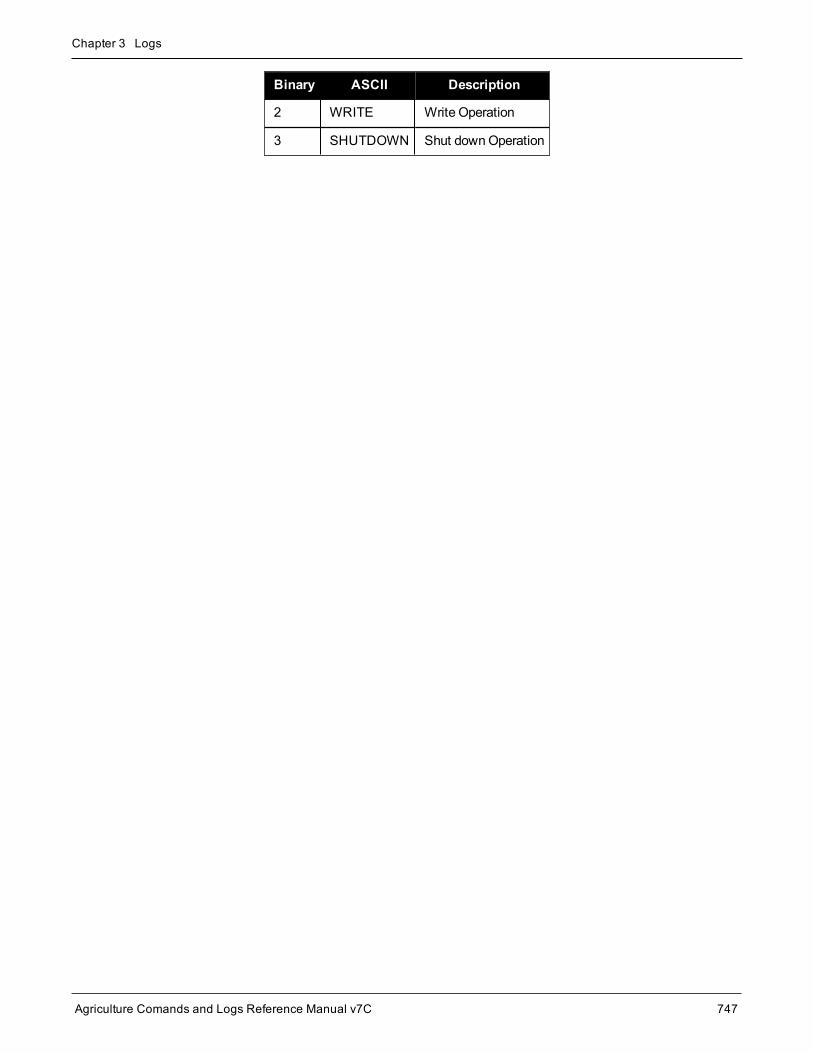
Chapter 3 Logs
Agriculture Comands and Logs Reference Manual v7C 747
Binary ASCII Description
2 WRITE Write Operation
3 SHUTDOWN Shut downOperation

Chapter 3 Logs
Agriculture Comands and Logs Reference Manual v7C 748
3.187 VALIDMODELSValid model information
Platform: OEM719, OEM729, OEM7500, OEM7600, OEM7700, OEM7720, PwrPak7, SPAN CPT7,SMART7, SMART2
This log gives a list of valid authorizedmodels available and expiry date information.
If a model has no expiry date, it reports the year, month and day fields as 0s.
Message ID: 206
Log Type: Asynch
Recommended Input:log validmodelsa once
ASCII Example:#VALIDMODELSA,COM1,0,92.0,FINESTEERING,1610,499139.682,02000000,342f,6293;1,"D2LR0RCCR",0,0,0*d0580c1b
Use the VALIDMODELS log to output a list of available models for the receiver. Use theAUTH com-mand (see page 60), to add amodel and theMODEL command (see page 171) to change the currentlyactivemodel. See theVERSION log on page 751 for the currently activemodel
Field Field type Description Format BinaryBytes Binary Offset
1 VALIDMODELSheader
Log header. SeeMessages on page 26 formore information. H 0
2 #mod Number of models with information tofollow Ulong 4 H
3 model Model name String[Max16] Variable1 H+4
4 expyear Expiry year Ulong 4 VariableMax: H+20
5 expmonth Expiry month Ulong 4 VariableMax: H+24
6 expday Expiry day Ulong 4 Variable:Max: H+28
7... Next model offset = H+4+(#mod x variable [max:28])
1In the binary case, each string field needs to be NULL terminated and additional bytes of padding added to maintain 4-bytealignment, up to the maximum defined by the string size. The next defined field starts immediately at the next 4-bytealignment following the NULL.

Chapter 3 Logs
Agriculture Comands and Logs Reference Manual v7C 749
Field Field type Description Format BinaryBytes Binary Offset
8 xxxx 32-bit CRC (ASCII and Binary only) Ulong 4H+4+(#mod x variable[max:28])
9 [CR][LF] Sentence terminator (ASCII only) - - -

Chapter 3 Logs
Agriculture Comands and Logs Reference Manual v7C 750
3.188 VERSIONVersion information
Platform: OEM719, OEM729, OEM7500, OEM7600, OEM7700, OEM7720, PwrPak7, SPAN CPT7,SMART7, SMART2
This log contains the version information for all components of a system. A component may be hardware (forexample, a receiver or data collector) or firmware in the form of applications or data (for example, data blocks forheight models or user applications). See Table 185: Firmware and Boot Version Field Formats on page 754 fordetails on the format of key fields.
See also theVALIDMODELS log on page 749.
Message ID: 37
Log Type: Polled
Recommended Input:log versiona once
Abbreviated ASCII Example:<VERSION USB1 0 72.0 FINESTEERING 2025 247123.828 02000020 3681 14970< 11< GPSCARD "FFNRNNCBES1" "BMHR17090005E" "OEM7700-1.00" "OM7CR0500RN0000""OM7BR0001RB0000" "2018/Jul/10" "14:37:01"< OEM7FPGA "" "" "" "OMV070001RN0000" "" "" ""< WHEELSENSOR "" "" "" "SWS000101RN0000" "" "2018/Jul/10" "14:37:28"< WIFI "RS9113" "" "" "1.6.8" "" "2018/Jul/10" "14:37:32"< APPLICATION "" "" "" "EP7AR0500RN0000" "" "2018/Jul/10" "14:37:13"< DEFAULT_CONFIG "" "" "" "EP7CR0500RN0000" "" "2018/Jul/10" "14:37:23"< PACKAGE "" "" "" "EP7PR0500RN0000" "" "2018/Jul/10" "14:37:18"< DB_WWWISO "WWWISO" "0" "" "WMC010201AN0004" "" "2017/Sep/20" "21:00:04"< ENCLOSURE "" "NMNE17200009B" "" "" "" "" ""< REGULATORY "US" "" "" "" "" "" ""< IMUCARD "Epson G320N" "" "" "" "" "" ""
The VERSION log is a useful log as a first communication with your receiver. Once connected, usingNovAtel Connect or a terminal emulator program, log VERSION and check that the output makessense. Also, ensure that you have the receiver components you expected.
Field Field type Description Format BinaryBytes
BinaryOffset
1 VERSIONheader Log header. SeeMessages on page 26 for more information. H 0
2 # comp Number of components (cards, and so on) Long 4 H
3 type Component type (see Table 184: Component Types onpage 753) Enum 4 H+4

Chapter 3 Logs
Agriculture Comands and Logs Reference Manual v7C 751
Field Field type Description Format BinaryBytes
BinaryOffset
4 model
OEM7 firmwaremodel numbere.g., CFNPNNTVN indicates the receiver’s current modelfunctionality
When the component type is ENCLOSURE, themodelspecifies the enclosure type.
Char[16] 16 H+8
5 psn Product serial number Char[16] 16 H+24
6 hw version
Hardware version in the format:
P-R
Where
P = hardware platformR = hardware revision
Example: OEM7700-1.00
Char[16] 16 H+40
7 sw version Firmware version, see Table 185: Firmware and BootVersion Field Formats on page 754
Char[16] 16 H+56
8 bootversion
Boot code version, see Table 185: Firmware and BootVersion Field Formats on page 754
Char[16] 16 H+72
9 comp date
Firmware compile date in the format:
YYYY/Mmm/DD
Where
YYYY = yearMmm = monthDD = day (1-31)
Example: 2018/Jul/10
Char[12] 12 H+88
10 comp time
Firmware compile time in the format:
HH:MM:SS
Where:
HH = hoursMM = minutesSS = seconds
Example: 14:37:01
Char[12] 12 H+100
11... Next component offset = H + 4 + (#comp x 108)
12 xxxx 32-bit CRC (ASCII and Binary only) Ulong 4H+4+(#compx 108)
13 [CR][LF] Sentence terminator (ASCII only) - - -

Chapter 3 Logs
Agriculture Comands and Logs Reference Manual v7C 752
Binary ASCII Description
0 UNKNOWN Unknown component
1 GPSCARDOEM7 family receiver
In an enclosure product this is thereceiver card in the enclosure.
2 CONTROLLER Reserved
3 ENCLOSURE OEM card enclosure
4-6 Reserved
7 IMUCARD IMU integrated in the enclosure
8 USERINFO Application specific information
12-14 Reserved
15 WIFI Wi-Fi radio firmware
16-17 Reserved
18 RADIO UHF radio component
19 WWW_CONTENT Web Server content
20 Regulatory Regulatory configuration
21 OEM7FPGA OEM7 FPGA version
22 APPLICATION Embedded application
23 Package Package
24 Reserved
25 DEFAULT_CONFIG Default configuration data
26 WHEELSENSOR Wheel sensor in the enclosure
27 EMBEDDED_AUTH Embedded Auth Code data
981073920 (0x3A7A0000) DB_HEIGHTMODEL Height/track model data
981073928 (0x3A7A0008) DB_WWWISO WebUI ISO Image
981073930 (0x3A7A000A) DB_LUA_SCRIPTS Lua Script ISO Image
Table 184: Component Types

Chapter 3 Logs
Agriculture Comands and Logs Reference Manual v7C 753
Field Format (ASCII) Description Example
NWXYZFFMMRN0000
N = Family Name
The Family Name can be:
O = OEM
Software Version:OM7CR0500RN0000
Boot Version:OM7BR0001RB0000
In both examples, the FamilyName is O.
WX = Product
The Product can be:
M7: OEM7 product
A7: Agriculture optimizedOEM7 product
In both examples, the Productis M7.
Y = Image Type
The Image Type can be:
B: boot code
M: main firmware application
C: combinedmain firmwareapplication and userapplication
In the Software Versionexample, the Image Type is C.
In the Boot Version example,the Image Type is B.
Z = Signature
The Signature can be:
R: Officially signed
H: High Speed signed
In both examples the Signatureis R.
FF = Feature ReleaseNumber
In the Software Versionexample, the Feature ReleaseNumber is 05.
In the Boot Version example,the Feature Release Number is00.
MM = Maintenance ReleaseNumber
In both examples, theMaintenance Release Numberis 00.
Table 185: Firmware and Boot Version Field Formats

Chapter 3 Logs
Agriculture Comands and Logs Reference Manual v7C 754
Field Format (ASCII) Description Example
R = Release Type
The Release Type can be:
A: Alpha
B: Beta
R: Release
S: Special
E: Engineering Special
C: Customer ApprovedSpecial
In both examples, the ReleaseType is R.
N = Distribution Permit
The Distribution Permit canbe:
N: No restrictions
B: Boot Code
H: High Speed Build(Requires a permit to use)
In the Software Versionexample, the DistributionPermit is N.
In the Boot Version example,the Distribution Permit is B.
0000 = Minor ReleaseIndicator
In both examples, theMinorRelease Indicator is 0000.
The firmware version of a receiver is also presented in a short version (e.g. 7.05.04). The short versionis the product number, feature release number andmaintenance release number separated by dots. Forexample, the firmware version OM7MR0504RN0000 has a short version of 7.05.04.

Chapter 3 Logs
Agriculture Comands and Logs Reference Manual v7C 755
3.189 WIFIAPSETTINGSDisplay the Wi-Fi access point configuration
Platform: PwrPak7, SMART7-I, SMART7-SI, SMART7-W
PwrPak7M variants do not support this log.
Use this log to display theWi-Fi access point configuration. If the access point is not currently operational, thelog reports the access point configuration to be applied the next time theWIFIMODE AP orWIFIMODECONCURRENT command is received.
The term passkey and password are the same.
Message ID: 2093
Log Type: Polled
Recommended Input:LOG WIFIAPSETTINGS
ASCII Example:#WIFIAPSETTINGSA,COM1,0,77.5,FINESTEERING,2007,167962.000,02000000,fc0e,14693;"PwrPak7-NMNE16470005M","12345678",2P4GHZ,WPA2,CCMP,US,11,"2d:43:5a:63:79:6f"*546c6f08
Field Field Type Description Format BinaryBytes
BinaryOffset
1 WIFIAPSETTINGSheader
Log header. SeeMessages on page 26 for moreinformation. - H 0
2 SSID SSID of the APString[Max33]
Variable H
3 passkey Passkey of the APString[Max65]
Variable Variable
4 band Wi-Fi operating band. See Table 186: Wi-Fi Bandon the next page. Enum 4 Variable
5 security protocol Wireless security protocol. See Table 187: Wi-FiSecurity Protocol on the next page. Enum 4 Variable
6 encryption Wireless encryption type. See Table 188: Wi-FiEncryption Type on the next page. Enum 4 Variable

Chapter 3 Logs
Agriculture Comands and Logs Reference Manual v7C 756
Field Field Type Description Format BinaryBytes
BinaryOffset
7 region Regulatory region. See Table 189: RegulatoryRegion on the next page. Enum 4 Variable
8 channel Wireless channel used by access point tocommunicate with connected clients. Int 4 Variable
9 BSSID BSSID of the AP (MAC of theWi-Fi interface)String[Max18]
Variable Variable
10 xxxx 32-bit CRC (ASCII or Binary only) Hex 4 Variable
11 [CR][LF] Sentence terminator (ASCII only) - - -
Binary ASCII Description
1 2P4GHZ 2.4 GHz
Table 186: Wi-Fi Band
Binary ASCII Description
1 OPEN Open network (No security)
2 WPA Wi-Fi Protected Access
3 WPA2 Wi-Fi Protected Access version 2
Table 187: Wi-Fi Security Protocol
NovAtel Wi-Fi access points only support theWPA2 security protocol. As a result, theWIFIAPSETTINGS log will only reportWPA2.
Novatel Wi-Fi Clients support OPEN, WPA, andWPA2 security protocols.
Binary ASCII Description
1 OPEN Open (no encryption)
2 TKIP Temporal Key Integrity Protocol (used withWPA)
3 CCMP AES-based CCMP (Cipher ChainingMessage Authentication) used withWPA2
Table 188: Wi-Fi Encryption Type
NovAtel Wi-Fi access points only support theWPA2 security protocol. As a result, theWIFIAPSETTINGS log will only report CCMP.

Chapter 3 Logs
Agriculture Comands and Logs Reference Manual v7C 757
Binary ASCII Description
0 None Receiver has not been configured to comply with any regional regulatory requirements. Wirelesscomponents (e.g. Wi-Fi) will not operate. Contact NovAtel Customer Support.
1 US United States
2 EU Europe
3 AU Australia
4 JP Japan
5 NZ New Zealand
6 BR Brazil
Table 189: Regulatory Region

Chapter 3 Logs
Agriculture Comands and Logs Reference Manual v7C 758
3.190 WIFINETLISTDisplay a list of Wi-Fi networks in range of client
Platform: PwrPak7, SMART7-I, SMART7-SI, SMART7-W
PwrPak7M variants do not support this log.
Use this log to display information about Wi-Fi access points detected by the receiver when configured in eitherClient or Concurrent mode.
Message ID: 2210
Log Type: Asynch
Recommended input:log wifinetlist onchanged
ASCII Example:#WIFINETLISTA,COM1,0,73.0,FINESTEERING,1989,422765.530,02000000,9906,32768;1,"SM7-i NMRT00000001M",-20,7,"aa:bb:cc:dd:ee:01",WPA2*0727340b
Field Field Type Description Format BinaryBytes
BinaryOffset
1 WIFINETLISTheader
Log header. SeeMessages on page 26 for moreinformation. - H 0
2 num_networks Number of network records to follow Ulong 4 H
3 SSID SSID of scanned access point. String[Max 33] variable H+4
4 RSSI Absolute value of RSSI (dBm) Int 4 variable
5 channel RF channel to use Ulong 4 variable
6 BSSID MAC address of the access point. String[Max 18] variable variable
7 security Security mode of access point. Table 190: Wi-FiSecurity Type below Enum 4 variable
Binary ASCII Description
1 OPEN Open network (no security)
2 WPA Wi-Fi protected access
3 WPA2 Wi-Fi protected access II
Table 190: Wi-Fi Security Type

Chapter 3 Logs
Agriculture Comands and Logs Reference Manual v7C 759
3.191 WIFISTATUSDisplay status information of receiver Wi-Fi
Platform: PwrPak7, SMART7-I, SMART7-SI, SMART7-W
PwrPak7M variants do not support this log.
Use this log to display the current status of aWi-Fi Client and or Access Point in addition to information aboutany connected Access Point and or Clients.
Message ID: 2207
Log Type: Asynch
Recommended input:log wifistatus onchanged
ASCII Example:#WIFISTATUSA,COM1,0,63.5,UNKNOWN,0,31.682,02440000,c017,32768;CONCURRENT_OPERATIONAL," PwrPak7-NMND17130002Z",-20,11,"00:21:66:01:47:BB",WPA2,1,"D4:6E:0E:05:B1:F6"*faee8ed9
Field Field Type Description Format BinaryBytes
BinaryOffset
1 WIFISTATUSheader
Log header. SeeMessages on page 26 for moreinformation. - H 0
2 status Wi-Fi operational status. Refer to Table 191: Wi-Fi Statuson the next page.
String[Max33]
Variable H
3 AP SSID SSID of connected access point. This field is blank if theclient is not connected to an access point.
String[Max33]
Variable
4 AP RSSIValue of RSSI (dBm) of connection to access point. Thisfield is zero if the client is not connected to an accesspoint.
Ulong 4
5 AP channel Channel use to connect to access point. This field is zero ifthe client is not connected to an access point. Ulong 4
6 AP BSSID MAC address of connected access point. This field isblank if the client is not connected to an access point. Ulong 4
7 AP security
Security mode of connected access point. See Table 190:Wi-Fi Security Type on the previous page in theWIFINETLIST command (see page 759). The value of thisfield is only valid if the AP SSID field is not blank.
Enum 4

Chapter 3 Logs
Agriculture Comands and Logs Reference Manual v7C 760
Field Field Type Description Format BinaryBytes
BinaryOffset
8 #clients Number of clients connected to an access point to follow. Ulong 4
9 BSSID MAC address of connected client.String[Max18]
Variable
10... Next Client
Binary ASCII Description
0 STARTUP
1 OFF Wi-Fi hardware is powered off
2 ON Wi-Fi hardware is powered on but not configured
3 CONFIGURING_ACCESSPOINT Wi-Fi hardware is being configured as an access point
4 ACCESSPOINT_OPERATIONAL
Wi-Fi hardware is operating as an access point and is ready to acceptclient connections
5 CONFIGURING_CLIENT Wi-Fi hardware is being configured as a client station
6 CLIENT_OPERATIONAL Wi-Fi hardware is operating as a client but is not connected to an accesspoint
7 BOOTING_UP Wi-Fi hardware is booting up
8 BOOTUP_COMPLETE Wi-Fi hardware has booted up
9 UPGRADE_REQUIRED Wi-Fi firmware version does not match required version
10 UPGRADING_FIRMWARE Wi-Fi firmware is being upgraded
11 UPGRADING_FIRMWARE_10 Wi-Fi firmware update is 10% complete
12 UPGRADING_FIRMWARE_20 Wi-Fi firmware update is 20% complete
13 UPGRADING_FIRMWARE_30 Wi-Fi firmware update is 30% complete
14 UPGRADING_FIRMWARE_40 Wi-Fi firmware update is 40% complete
15 UPGRADING_FIRMWARE_50 Wi-Fi firmware update is 50% complete
Table 191: Wi-Fi Status

Chapter 3 Logs
Agriculture Comands and Logs Reference Manual v7C 761
Binary ASCII Description
16 UPGRADING_FIRMWARE_60 Wi-Fi firmware update is 60% complete
17 UPGRADING_FIRMWARE_70 Wi-Fi firmware update is 70% complete
18 UPGRADING_FIRMWARE_80 Wi-Fi firmware update is 80% complete
19 UPGRADING_FIRMWARE_90 Wi-Fi firmware update is 90% complete
20 UPGRADING_FIRMWARE_COMPLETE Wi-Fi firmware update is 100% complete
21 ERROR An error has occurred
22 CONFIGURING_CONCURRENT
Wi-Fi hardware is being configured to operate as both an access point andclient concurrently
23 CONCURRENT_OPERATIONAL
Wi-Fi hardware is operating as both an access point and client. The clientis not connected to an access point.
24 CONNECTING_TO_AP Wi-Fi hardware is attempting to connect to an access point
25 CONNECTED_TO_AP Wi-Fi hardware has successfully connected to an access point
26 CONNECTION_FAILUREWi-Fi client failed to connect to an access point. Possible causes includeinvalid password provided in theWIFINETCONFIG command (see page320)
27CONFIGURING_NETWORK_PARAMETERS
Wi-Fi client is configuring its network parameters based on activeconnection to an access point
28 CONNECTION_REFUSED
Wi-Fi client failed on initial attempt to connect to an access point due tothe connection being actively refused by the access point
Possible causes include invalid configuration settings in theWIFINETCONFIG command on page 320
29PREFERRED_NETWORK_MISCONFIGURED
Wi-Fi client cannot connect to preferred access point due to amisconfiguration of network parameters in theWIFINETCONFIGcommand on page 320
30 CONCURRENT_CONNECTING_TO_AP
Wi-Fi concurrent client is configuring its network parameters based onactive connection to an access point
31CONCURRENT_CONFIGURING_NETWORK_PARAMS
Wi-Fi concurrent client is configuring its network parameters based onactive connection to an access point

Chapter 3 Logs
Agriculture Comands and Logs Reference Manual v7C 762
Binary ASCII Description
32 CONCURRENT_CONNECTED_TO_AP Wi-Fi concurrent client has successfully connected to an access point
33 DISCONNECTING_FROM_AP Wi-Fi client is disconnecting from an access point
34CONCURRENT_DISCONNECTING_FROM_AP
Wi-Fi concurrent is disconnecting from an access point
35 BOOTUP_CONNECTING_TO_WIFI_MODULE
36 BOOTUP_ERROR
Agriculture Comands and Logs Reference Manual v7C 764
Chapter 4 Agriculture SPAN CommandsThe commands used to configure GNSS+INS functions are described in the following sections.
For information about other available commands, refer toAgriculture GNSS Commands on page 49.
Synchronous Position, Attitude and Navigation (SPAN) technology brings together two different but com-plementary technologies: Global Navigation Satellite System (GNSS) positioning and inertial navigation. Theabsolute accuracy of GNSS positioning and the stability of Inertial Measurement Unit (IMU) gyro and accel-erometer measurements are tightly coupled to provide an exceptional 3D navigation solution that is stable andcontinuously available, even through periods when satellite signals are blocked.

Chapter 4 Agriculture SPAN Commands
Agriculture Comands and Logs Reference Manual v7C 765
4.1 ALIGNMENTMODESet the Alignment Mode
Platform: OEM719, OEM729, OEM7500, OEM7600, OEM7700, OEM7720, PwrPak7, SPAN CPT7,SMART7-S, SMART7-SI
Use this command to set the alignment method used to initialize the SPAN system.
The default ALIGNMENTMODE is AUTOMATIC. In this mode, the first available method to align is used.
Sending the ALIGNMENTMODE commandmanually overrides the AUTOMATIC setting and changes theoptions available to complete an alignment.
Message ID: 1214
Abbreviated ASCII Syntax:ALIGNMENTMODE mode
Abbreviated ASCII Example:ALIGNMENTMODE AIDED_TRANSFER
Field Field Type ASCII Value BinaryValue Description Binary
FormatBinaryBytes
BinaryOffset
1 ALIGNMENTMODEheader - -
Command header. SeeMessages on page 26 formore information.
- H 0
2 mode
UNAIDED 0Static coarse alignment orkinematic alignmentmethods are available.
Enum 4 H
AIDED_TRANSFER 2
Seed the initial azimuthestimate from the ALIGNsolution.
AUTOMATIC 3
Seed the full attitude fromthe ALIGN solution,perform a regular staticcoarse alignment orperform a kinematicalignment, whichever ispossible first.
STATIC 4 Static coarse alignmentmethod only.
KINEMATIC 5 Kinematic alignmentmethod only.

Chapter 4 Agriculture SPAN Commands
Agriculture Comands and Logs Reference Manual v7C 766
If theALIGNMENTMODE selected can use a kinematic alignment (UNAIDED, KINEMATIC orAUTOMATIC), theSETINSROTATION RBV commandmust be sent to the receiver regardless of sys-tem configuration and IMU orientation.
NVM Seed injected (see the INSSEED command on page 779) and commanded (seeSETINITAZIMUTH command on page 786) alignments are valid for all alignment modes and will super-sede all other options if valid and available.

Chapter 4 Agriculture SPAN Commands
Agriculture Comands and Logs Reference Manual v7C 767
4.2 CONNECTIMUConnects an IMU to a Port
Platform: OEM719, OEM729, OEM7500, OEM7600, OEM7700, OEM7720, PwrPak7
Use this command to specify the type of IMU connected to the receiver and the receiver port used by the IMU.
Message ID: 1428
Abbreviated ASCII Syntax:CONNECTIMU IMUPort IMUType
Abbreviated ASCII Example:CONNECTIMU COM2 LN200
Field Field Type ASCIIValue
BinaryValue Description Binary
FormatBinaryBytes
BinaryOffset
1 CONNECTIMUheader - -
Command header. SeeMessages on page 26 for moreinformation.
- H 0
2 IMUPort
COM1 1 IMU Port is COM port 1
Enum 4 H
COM2 2 IMU Port is COM port 2
COM3 3 IMU Port is COM port 3
SPI 7 IMU Port is the SPI port
COM4 19 IMU Port is COM port 4
COM5 31 IMU Port is COM port 5
3 IMUTypeSee Table 192: IMUType on the nextpage
IMU Type Enum 4 H+4
SPI is available only on the OEM7500, OEM7600, OEM7700, andOEM7720.
COM4 and COM5 are available only on the OEM7600, OEM7700 andOEM7720.
The IMU-ISA-100C, IMU-FSAS, IMU-HG1900, IMU-LN200, IMU-µIMU, IMU-CPT and IMU-KVH1750use RS-422 protocol andmust be connected to a receiver port that is configured to use RS-422. Referto for information about which receiver ports support RS-422 and instructions for enabling RS-422.

Chapter 4 Agriculture SPAN Commands
Agriculture Comands and Logs Reference Manual v7C 768
Binary ASCII Description
0 UNKNOWN Unknown IMU type (default)
1 HG1700_AG11 Honeywell HG1700 AG11
4 HG1700_AG17 Honeywell HG1700 AG17
5 HG1900_CA29 Honeywell HG1900 CA29
8 LN200 Northrop Grumman LN200/LN200C
11 HG1700_AG58 Honeywell HG1700 AG58
12 HG1700_AG62 Honeywell HG1700 AG62
13 IMAR_FSAS iMAR iIMU-FSAS
16 KVH_COTS KVH CPT IMU
20 HG1930_AA99 Honeywell HG1930 AA99
26 ISA100C Northrop Grumman Litef ISA-100C
27 HG1900_CA50 Honeywell HG1900 CA50
28 HG1930_CA50 Honeywell HG1930 CA50
31 ADIS16488 Analog Devices ADIS16488
32 STIM300 Sensonor STIM300
33 KVH_1750 KVH1750 IMU
41 EPSON_G320 EpsonG320N
52 LITEF_MICROIMU Northrop Grumman Litef µIMU-IC
56 STIM300D Sensonor STIM300, Direct Connection
58 HG4930_AN01 Honeywell HG4930 AN01
61 EPSON_G370 EpsonG370N
62 EPSON_G320_200HZ EpsonG320N – 200 Hz
Table 192: IMU Type
The IMU Type field also supports the legacy ASCII values that contain the "IMU_" prefix. For example,LN200 or IMU_LN200.IMUs recently added as SPAN supported devices, such as the LITEF_MICROIMU and STIM300D, donot support the "IMU_" prefix.
Values not shown in this table are reserved.

Chapter 4 Agriculture SPAN Commands
Agriculture Comands and Logs Reference Manual v7C 769
4.3 EXTERNALPVASEnter PVA Update
Platform: OEM719, OEM729, OEM7500, OEM7600, OEM7700, OEM7720, PwrPak7, SPAN CPT7,SMART7-S, SMART7-SI
This command should only be used by advanced users of GNSS+INS.
The standard deviations entered using this commandmust be representative of actual input error.
TheEXTERNALPVAS command uses a short header if the command is entered in ASCII or Binary.
This command allows the user to provide their own update for INS in full position, velocity, attitude and otherupdates, and in any combination. The user can also provide height or attitude only updates, along with Zero Velo-city Updates (ZUPTs). The position and velocity updates can be entered in local level or ECEF.
TheEXTERNALPVAS command is designed to provide amethod for additional sensor information to be inputinto the SPAN filter, specifically during GNSS denied environments. This will provide amethod to constrain theerror growth that is typical in an Inertial Kalman Filter whenGNSS observations are unavailable (environmentssuch as: urban canyon, tunnels, jamming etc.). It is important to ensure that the external update and its cor-responding standard deviations are accurate and input with minimal latency to provide optimal effectiveness.Entering an external update or its standard deviation inappropriately may have an adverse effect on the SPANsolution.
The default input frame is ECEF. Updates are entered in ECEF unless Local Level is specified usingthe OptionsMask parameter.
Message ID: 1463
Abbreviated ASCII Syntax:EXTERNALPVAS Position1 Position2 Position3 Velocity1 Velocity2 Velocity3Attitude1 Attitude2 Attitude3 PosStdDev1 PosStdDev2 PosStdDev3 VelStdDev1VelStdDev2 VelStdDev3 AttStdDev1 AttStdDev2 AttStdDev3 UpdateMaskOptionsMask
Abbreviated ASCII Example: (Local Level Velocity Update)EXTERNALPVAS 0.0 0.0 0.0 0.4502 10.54 -0.09598 0.0 0.0 0.0 0.0 0.0 0.0 0.010.01 0.01 0.0 0.0 0.0 4000 10
Full ASCII Example: (Local Level Velocity Update)%EXTERNALPVASA,2051,493713.000;0.00000000000,0.00000000000,0.00000000000,0.1333,17.1424,-0.3311,0.000000000,0.000000000,0.000000000,0.0000,0.0000,0.0000,0.0119,0.0096,0.0132,0.0000,0.0000,0.0000,00004000,00000010*edced535

Chapter 4 Agriculture SPAN Commands
Agriculture Comands and Logs Reference Manual v7C 770
Field Field Type ASCIIValue
BinaryValue Description Binary
FormatBinaryBytes
BinaryOffset
1 EXTERNALPVASheader - - Command header. SeeMessages
on page 26 for more information. - H 0
2 Position1Latitude (degrees), ECEF X-coordinate (m) or X relativecoordinate (m)
Double 8 H
3 Position2Longitude (degrees), ECEF Y-coordinate (m) or Y relativecoordinate (m)
Double 8 H+8
4 Position3 Height, ECEF Z-coordinate or Zrelative coordinate (m) Double 8 H+16
5 Velocity1 North velocity or velocity along theX-axis (m/s) Float 4 H+24
6 Velocity2 East velocity or velocity along the Y-axis (m/s) Float 4 H+28
7 Velocity3 Up velocity or velocity along the Z-axis (m/s) Float 4 H+32
8 Attitude1Pitch – Local Level to SPAN UserOutput Frame or relative delta fromSPAN User Output Frame (degrees)
Float 4 H+36
9 Attitude2Roll – Local Level to SPAN UserOutput Frame or relative delta fromSPAN User Output Frame (degrees)
Float 4 H+40
10 Attitude3
Azimuth – Local Level to SPANUser Output Frame or relative deltafrom SPAN User Output Frame(degrees)
Float 4 H+44
11 PosStdDev1 Position1 standard deviation (m) Float 4 H+48
12 PosStdDev2 Position2 standard deviation (m) Float 4 H+52
13 PosStdDev3 Position3 standard deviation (m) Float 4 H+56
14 VelStdDev1 Velocity1 standard deviation (m/s) Float 4 H+60
15 VelStdDev2 Velocity2 standard deviation (m/s) Float 4 H+64
16 VelStdDev3 Velocity3 standard deviation (m/s) Float 4 H+68
17 AttStdDev1 Attitude1 standard deviation(degrees) Float 4 H+72

Chapter 4 Agriculture SPAN Commands
Agriculture Comands and Logs Reference Manual v7C 771
Field Field Type ASCIIValue
BinaryValue Description Binary
FormatBinaryBytes
BinaryOffset
18 AttStdDev2 Attitude2 standard deviation(degrees) Float 4 H+76
19 AttStdDev3 Attitude3 standard deviation(degrees) Float 4 H+80
20 UpdateMask
This mask selects which updatesare applied. Setting a bit applies theupdate. More than one update canbe applied at one time.
See Table 193: EXTERNALPVASUpdates Mask below for the externalupdate bits that can be used.
HEXUlong 4 H+84
21 OptionsMask
This mask selects the updateoptions for various updates, such asusing an ECEF or Local Levelsystem for the position updates.
See Table 194: EXTERNALPVASOptions Mask on the next page fordetails.
HEXUlong 4 H+88
Bit Mask Description
0 0x00001 Reserved
1 0x00002 Reserved
2 0x00004 ZUPT Update. No fields are required in theEXTERNALPVAS command for this update.
3 0x00008 Reserved
4 0x00010 Reserved
5 0x00020 External Position Update.This update is entered using Position1 to Position3 in theEXTERNALPVAS command.
6 0x00040 Reserved
7 0x00080 Reserved
8 0x00100 Reserved
9 0x00200 Reserved
10 0x00400 Reserved
11 0x00800 Reserved
12 0x01000 Reserved
Table 193: EXTERNALPVAS Updates Mask

Chapter 4 Agriculture SPAN Commands
Agriculture Comands and Logs Reference Manual v7C 772
Bit Mask Description
13 0x02000 Reserved
14 0x04000 External Velocity Update.This update is entered using Velocity1 to Velocity3 in theEXTERNALPVAS command.
15 0x08000 External Attitude Update.This update is entered using Attitude1 to Attitude3 in theEXTERNALPVAS command.
16 0x10000 External Heading Update.This update is entered using Attitude3 in theEXTERNALPVAS command.
17 0x20000 External Height Update.This update is entered using Position3 in theEXTERNALPVAS command.
If both the External Position Update and External Height Update bits are set, only the External PositionUpdate will be applied.
If both the External Attitude Update and External Heading Update bits are set, only the External AttitudeUpdate will be applied.
Bit Mask Description Range Value
0 0x00000001 Reserved
1 0x00000002 Reserved
2–3 0x0000000C Position Input Frame00 – ECEF
01 – LLH
4–5 0x00000030 Velocity Input Frame00 – ECEF
01 – LLH
6 0x00000040 Position Update Type0 – Absolute
1 – Relative
7 0x00000080 Attitude Update Type0 – Absolute
1 – Relative
Table 194: EXTERNALPVAS Options Mask

Chapter 4 Agriculture SPAN Commands
Agriculture Comands and Logs Reference Manual v7C 773
4.4 INSALIGNCONFIGConfigure ALIGN Parameters for SPAN Receiver
Platform: OEM719, OEM729, OEM7500, OEM7600, OEM7700, OEM7720, PwrPak7, SPAN CPT7,SMART7-S, SMART7-SI
Use the INSALIGNCONFIG command to configure ALIGN for a SPAN master receiver to a secondary roverreceiver. The commandwill configure the port on themaster and rover and setup corrections at the desired rate.It also attempts to re-establish these corrections should they stop.
Important
l This commandmust be used to define the ALIGN communication between the receiversthat SPAN is to configure.
l When using ICOM ports, the Ethernet settings on the SPAN master and rover receiver mustbemanually configured.
l Themaster and rover ports must be the same interface type (i.e. Serial to Serial or Ethernetto Ethernet).
l The INSALIGNCONFIG command can be used to set the output rate for dual antennareceivers (e.g. OEM7720). In these cases, the port configuration fields are ignored.
Message ID: 2163
Abbreviated ASCII Syntax:INSALIGNCONFIG masterport [roverport] [baudrate] [outputrate]
Abbreviated ASCII Example:INSALIGNCONFIG COM1 COM2 230400 5
Field Field Type ASCIIValue
BinaryValue Description Format Binary
BytesBinaryOffset
1 INSALIGNCONFIGheader - -
Command header. SeeMessages on page 26 for moreinformation.
- H 0

Chapter 4 Agriculture SPAN Commands
Agriculture Comands and Logs Reference Manual v7C 774
Field Field Type ASCIIValue
BinaryValue Description Format Binary
BytesBinaryOffset
2 masterport
NOPORT 0
Specify which COM port on themaster receiver to use tocommunicate with an externalALIGN capable receiver.
Selecting NOPORT disablesautomatic dual antennaconfiguration.
Enum 4 H
COM1 1
COM2 2
COM3 3
COM4 19
COM5 31
ICOM1 23
ICOM2 24
ICOM3 25
ICOM4 29
ICOM5 46
ICOM6 47
ICOM7 48
3 roverport
COM1 1
Specify which rover COM portis connected to themasterreceiver
(Default = COM2)
Enum 4 H+4
COM2 2
COM3 3
COM4 19
COM5 31
ICOM1 23
ICOM2 24
ICOM3 25
ICOM4 29
ICOM5 46
ICOM6 47
ICOM7 48
4 baudrate 57600, 115200,230400, or 460800
Baud rate for communication
(Default = 230400)Ulong 4 H+8

Chapter 4 Agriculture SPAN Commands
Agriculture Comands and Logs Reference Manual v7C 775
Field Field Type ASCIIValue
BinaryValue Description Format Binary
BytesBinaryOffset
5 outputrate 1, 2, 4, 5, 10The data rate, in Hz, in whichALIGN will be output
(Default = 1 Hz)Ulong 4 H+12
6 Reserved – Reserved Ulong 4 H+16
The SPAN filter only requires ALIGN updates at 1 Hz. Increasing the output rate (using the outputratefield) does not increase performance, it only provides ALIGN logs at higher rates.

Chapter 4 Agriculture SPAN Commands
Agriculture Comands and Logs Reference Manual v7C 776
4.5 INSCALIBRATEInitiate calibration of the INS offsets
Platform: OEM719, OEM729, OEM7500, OEM7600, OEM7700, OEM7720, PwrPak7, SPAN CPT7,SMART7-S, SMART7-SI
Use this command to initiate the calibration of INS offsets.
The RBV calibration requires a valid RBV estimate to be entered prior to initializing the calibration. SeetheSETINSROTATION command on page 788 for details on entering a RBV estimate.
For optimal SPAN performance when using Dual Antenna with SPAN, an ALIGN offset calibration isrequired for each unique installation. This calibration refines the IMU to antenna baseline angular offsetfrom the initial estimate derived from the input lever arms.
Message ID: 1882
Abbreviated ASCII Syntax:INSCALIBRATE Offset [Trigger] [SDThreshold]
Abbreviated ASCII Example:INSCALIBRATE RBV NEW 1.0
Field Field Type ASCIIValue
BinaryValue Description Binary
FormatBinaryBytes
BinaryOffset
1 INSCALIBRATEheader - - Command header. SeeMessages
on page 26 for more information. - H 0
2 Offset
ANT1 1
Use this option to set the INScalibration offset from the IMU to theprimary GNSS antenna
Note: The ANT1 option is availableonly on IMU Grade 2 or higher IMUs.SeeModels and Features in theOEM7SPAN Installation andOperation User Manual. Enum 4 H
ALIGN 8Use this option to set the INScalibration offset from the IMU Bodyframe to ALIGN frame rotation.
RBV 11Use this option to set the INScalibration offset from the IMU Bodyframe to Vehicle frame rotation.

Chapter 4 Agriculture SPAN Commands
Agriculture Comands and Logs Reference Manual v7C 777
Field Field Type ASCIIValue
BinaryValue Description Binary
FormatBinaryBytes
BinaryOffset
3 Trigger
STOP 0Ends the INS calibration and usesthe current estimate for the RBVoffsets
Enum 4 H+4
NEW 1Begins a new single line calibration,overwriting any previous input orcumulative average offset values
ADD 2Adds a new path.Only valid for multi-path RBVcalibrations
RESET 3Resets the calibration process andrestores the RBV offsets to previoususer input values
4 SDThreshold
Standard Deviation Threshold
(default for lever arm calibration =0.10m)(default for RBV calibration = 0.5degrees)
Float 4 H+8

Chapter 4 Agriculture SPAN Commands
Agriculture Comands and Logs Reference Manual v7C 778
4.6 INSCOMMANDINS Control Command
Platform: OEM719, OEM729, OEM7500, OEM7600, OEM7700, OEM7720, PwrPak7, SPAN CPT7,SMART7-S, SMART7-SI
Use this command to enable or disable INS. When INS is disabled, no INS position, velocity or attitude is output(however IMU data is still available). Also, INS aiding of tracking reacquisition is disabled. If the command isused to disable INS and then re-enable it, the INS system has to go through its alignment procedure (equivalentto issuing aRESET command). See the relevant SPAN UserManual for information about the SPAN alignmentprocedures.
Message ID: 379
Abbreviated ASCII Syntax:INSCOMMAND action
Abbreviated ASCII Example:INSCOMMAND ENABLE
Field Field Type ASCIIValue
BinaryValue Description Binary
FormatBinaryBytes
BinaryOffset
1INSCOMMANDheader
- - Command header. SeeMessages onpage 26 for more information. - H 0
2 Action
RESET 0 Resets the GNSS/INS alignmentwithout clearing the INS biases.
Enum 4 H
DISABLE 1 Disables INS navigation.
ENABLE 2
Enables INS navigation wherealignment initialization starts again ifthe Action parameter was previouslyset to DISABLE.
START_NO_TIME 3
Raw IMU data will begin to flow uponsystem startup. IMU data collectioncan begin before the receiver has aGNSS solution. (default)
START_FINE_TIME
4RAWIMU data will only be output afterthe system reachesFINESTEERING.
RESTART 5 Resets the GNSS/INS alignment andclears the INS biases.

Chapter 4 Agriculture SPAN Commands
Agriculture Comands and Logs Reference Manual v7C 779
4.7 INSSEEDINS Seed Configuration
Platform: OEM719, OEM729, OEM7500, OEM7600, OEM7700, OEM7720, PwrPak7, SPAN CPT7,SMART7-S, SMART7-SI
This command enables or disables the saving and restoration of the last known SPAN solution from NVM.
Message ID: 1906
Abbreviated ASCII Syntax:INSSEED Command [Validation]
Abbreviated ASCII Example:INSSEED ENABLE
Field FieldType
ASCIIValue
BinaryValue Description Binary
FormatBinaryBytes
BinaryOffset
1 INSSEEDHeader - - Command header. SeeMessages on
page 26 for more information. - H 0
2 Command
DISABLE 0 Disable the INS seed functionality
Enum 4 HENABLE 1 Enable the INS seed functionality
CLEAR 2 Clear the currently saved seed value soit will not be used until re-saved
3 Validation
VALIDATE 0 Validate INS Seed data using GNSSsolution before injecting (default)
Enum 4 H+4INJECT 1
Force an NVM seed value (if available)to be used, without any validation.
Using this option to forcethe seed to be used canresult in an unstable INSsolution if the vehiclehas moved. Foradvanced users only.
4 Reserved Ulong 4 H+8
5 Reserved Ulong 4 H+12

Chapter 4 Agriculture SPAN Commands
Agriculture Comands and Logs Reference Manual v7C 780
4.8 INSTHRESHOLDSChange the INS_HIGH_VARIANCE Threshold
Platform: OEM719, OEM729, OEM7500, OEM7600, OEM7700, OEM7720, PwrPak7, SPAN CPT7,SMART7-S, SMART7-SI
This command should only be used by advanced users of GNSS+INS.
The INSTHRESHOLDS command allows you to customize the criteria by which the system reports the inertialsolution status. This criteria is used to determine whether the solution status is reported as INS_SOLUTION_GOOD or INS_HIGH_VARIANCE.
This command is useful in situations where system dynamics are known to be challenging.
Message ID: 1448
Abbreviated ASCII Syntax:INSTHRESHOLDS ThresholdConfiguration
Abbreviated ASCII Example:INSTHRESHOLDS DEFAULT
Field Field Type ASCIIValue
BinaryValue Description Binary
FormatBinaryBytes
BinaryOffset
1 INSTHRESHOLDSheader - -
Command header. SeeMessages on page 26 for moreinformation.
- H 0
2 ThresholdConfiguration
DEFAULT 0 Standard INS status thresholdsettings
Enum 4 HLOW 1
Low INS status thresholdsettings (only checks theAttitude standard deviation)
3 Reserved Double 8 H+4
4 Reserved Double 8 H+12
5 Reserved Double 8 H+20
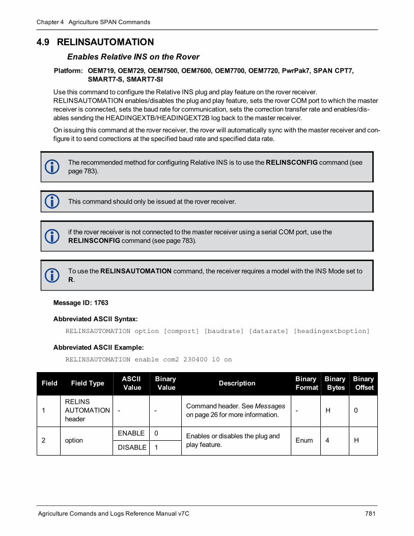
Chapter 4 Agriculture SPAN Commands
Agriculture Comands and Logs Reference Manual v7C 781
4.9 RELINSAUTOMATIONEnables Relative INS on the Rover
Platform: OEM719, OEM729, OEM7500, OEM7600, OEM7700, OEM7720, PwrPak7, SPAN CPT7,SMART7-S, SMART7-SI
Use this command to configure the Relative INS plug and play feature on the rover receiver.RELINSAUTOMATION enables/disables the plug and play feature, sets the rover COM port to which themasterreceiver is connected, sets the baud rate for communication, sets the correction transfer rate and enables/dis-ables sending the HEADINGEXTB/HEADINGEXT2B log back to themaster receiver.
On issuing this command at the rover receiver, the rover will automatically sync with themaster receiver and con-figure it to send corrections at the specified baud rate and specified data rate.
The recommendedmethod for configuring Relative INS is to use theRELINSCONFIG command (seepage 783).
This command should only be issued at the rover receiver.
if the rover receiver is not connected to themaster receiver using a serial COM port, use theRELINSCONFIG command (see page 783).
To use theRELINSAUTOMATION command, the receiver requires amodel with the INS Mode set toR.
Message ID: 1763
Abbreviated ASCII Syntax:RELINSAUTOMATION option [comport] [baudrate] [datarate] [headingextboption]
Abbreviated ASCII Example:RELINSAUTOMATION enable com2 230400 10 on
Field Field Type ASCIIValue
BinaryValue Description Binary
FormatBinaryBytes
BinaryOffset
1RELINSAUTOMATIONheader
- - Command header. SeeMessageson page 26 for more information. - H 0
2 optionENABLE 0 Enables or disables the plug and
play feature. Enum 4 HDISABLE 1

Chapter 4 Agriculture SPAN Commands
Agriculture Comands and Logs Reference Manual v7C 782
Field Field Type ASCIIValue
BinaryValue Description Binary
FormatBinaryBytes
BinaryOffset
3 comport
COM1 1 The COM port on the rover receiverto which themaster receiver isconnected.(default = COM2)
Enum 4 H+4COM2 2
COM3 3
4 baudrate9600, 19200, 38400,57600, 115200,230400, 460800
The baud rate used forcommunication between themaster and rover receivers.
Ulong 4 H+8
5 datarate 1, 2, 4, 5, 10 or20 Hz
The rate at which corrections aretransferred between the receivers.(default =10 Hz)
Ulong 4 H+12
6 headingextboption
ONOFF
Enables or disables sending theHEADINGEXTB/HEADINGEXT2B log back to themaster receiver.(default = ON)
Enum 4 H+16

Chapter 4 Agriculture SPAN Commands
Agriculture Comands and Logs Reference Manual v7C 783
4.10 RELINSCONFIGConfigure Relative INS
Platform: OEM719, OEM729, OEM7500, OEM7600, OEM7700, OEM7720, PwrPak7, SPAN CPT7,SMART7-S, SMART7-SI
Use this command to configure Relative INS on this receiver.
To use theRELINSCONFIG command, the receiver requires amodel with the INS Mode set toR.
Message ID: 1797
Abbreviated ASCII Syntax:RELINSCONFIG enable rxtype [port] [baud] [rateinhz]
Abbreviated ASCII Example:RELINSCONFIG ENABLE ROVER COM2 230400 10
Field FieldType
ASCIIValue
BinaryValue Description Binary
FormatBinaryBytes
BinaryOffset
1RELINSCONFIGheader
- - Command header. SeeMessages onpage 26 for more information. - H 0
2 enableDISABLE 0 Enables or disables the Relative INS
functionality. Enum 4 HENABLE 1
3 rxtypeROVER 1 Defines the receiver as themaster or
rover in a Relative INS configuration. Enum 4 H+4MASTER 2
4 port See Table 195: COMPorts on the next page
Communication port used tocommunicate with the other receiver.(default = COM2)
Enum 4 H+8
5 baud9600, 19200, 38400,57600, 115200, 230400,460800
The baud rate used for communicationbetween themaster and roverreceivers.(default = 230400)
Ulong 4 H+12
6 rateinhz 1, 2, 4, 5, 10 or 20 HzThe rate at which corrections aretransferred between the receivers.(default =10 Hz)
Ulong 4 H+16

Chapter 4 Agriculture SPAN Commands
Agriculture Comands and Logs Reference Manual v7C 784
Decimal ASCII Description
1 COM1 COM port 1
2 COM2 COM port 2
3 COM3 COM port 3
13 USB1 USB port 1
14 USB2 USB port 2
15 USB3 USB port 3
19 COM4 COM port 4
23 ICOM1 IP virtual COM port 1
24 ICOM2 IP virtual COM port 2
25 ICOM3 IP virtual COM port 3
29 ICOM4 IP virtual COM port 4
31 COM5 COM port 5
46 ICOM5 IP virtual COM port 5
47 ICOM6 IP virtual COM port 6
48 ICOM7 IP virtual COM port 7
49 SCOM1 Scripted application COM port 1
50 SCOM2 Scripted application COM port 2
51 SCOM3 Scripted application COM port 3
52 SCOM4 Scripted application COM port 4
Table 195: COM Ports

Chapter 4 Agriculture SPAN Commands
Agriculture Comands and Logs Reference Manual v7C 785
4.11 SETALIGNMENTVELSet the Minimum Kinematic Alignment Velocity
Platform: OEM719, OEM729, OEM7500, OEM7600, OEM7700, OEM7720, PwrPak7, SPAN CPT7,SMART7-S, SMART7-SI
Use theSETALIGNMENTVEL command to adjust theminimum required velocity for a kinematic alignment.
Useful in cases, such as helicopters, where alignment velocity should be increased to prevent a poor alignmentbefore the vehicle/aircraft is able to flight straight and level.
Message ID: 1397
Abbreviated ASCII Syntax:SETALIGNMENTVEL velocity
Abbreviated ASCII ExampleSETALIGNMENTVEL 5.0
Field Field Type ASCIIValue
BinaryValue Description Binary
FormatBinaryBytes
BinaryOffset
1 SETALIGNMENTVELheader - -
Command header. SeeMessages on page 26 formore information.
- H 0
2 Velocity
Minimum:0.2m/s(Defaultis 5m/s)
Theminimum velocity, inm/s, required tokinematically align.
Double 8 H

Chapter 4 Agriculture SPAN Commands
Agriculture Comands and Logs Reference Manual v7C 786
4.12 SETINITAZIMUTHSet Initial Azimuth and Standard Deviation
Platform: OEM719, OEM729, OEM7500, OEM7600, OEM7700, OEM7720, PwrPak7, SPAN CPT7,SMART7-S, SMART7-SI
Use this command to start SPAN operation with a previously known azimuth. Azimuth is the weakest com-ponent of a coarse alignment and is also the easiest to know from an external source (i.e., like the azimuth ofroadway). When using this command, SPAN operation through alignment will appear the same as with a usualcoarse alignment. Roll and pitch is determined using averaged gyro and accelerometer measurements. The inputazimuth is used rather than what is computed by the normal coarse alignment routine.
l Input azimuth values must be accurate for good system performance.
l SendingSETINITAZIMUTH resets the SPAN filter. Following realignment, vehicle dynamics are required forthe filter to re-converge. Bridging performance is poor before filter convergence.
l The entered azimuth angle is with respect to the configured output frame. This is generally the vehicle frameunless a User Frame offset has been configured using theSETINSROTATION command (see page 788). Alloffsets should be entered before entering theSETINITAZIMUTH command.
l This command is not save configurable andmust be re-entered after each start-up. The command can beentered at any time and will be used automatically when the system is ready to begin alignment.
Azimuth is positive in a clockwise direction when looking towards the z-axis origin.
Message ID: 863
Abbreviated ASCII Syntax:SETINITAZIMUTH azimuth azSTD
Abbreviated ASCII Example:SETINITAZIMUTH 90 5
Field FieldType
ASCIIValue
BinaryValue Description Binary
FormatBinaryBytes
BinaryOffset
1SETINITAZIMUTHheader
- - Command header. SeeMessages onpage 26 for more information. - H 0
2 azimuth 0 to 360 Input azimuth angle (degrees) Double 8 H
3 azSTD 1 to 25 Input azimuth standard deviation angle(degrees) Float 4 H+8

Chapter 4 Agriculture SPAN Commands
Agriculture Comands and Logs Reference Manual v7C 787
4.13 SETINSPROFILESets filter behavior depending on system environment
Platform: OEM719, OEM729, OEM7500, OEM7600, OEM7700, OEM7720, PwrPak7, SPAN CPT7,SMART7-S, SMART7-SI
This command sets specific filter behavior depending on the environment the system is installed in. TheDEFAULT profile is the legacy setting from earlier SPAN products. The other profiles make changes specific tothat environment.
See theOEM7SPAN Installation andOperation User Manual for a detailed description of each profile's effect.
Message ID: 1944
Abbreviated ASCII Syntax:SETINSPROFILE profile
Abbreviated ASCII Example:SETINSPROFILE LAND
Field FieldType ASCII Value Binary
Value Description BinaryFormat
BinaryBytes
BinaryOffset
1SETINSPROFILEHeader
- - Command header. SeeMessageson page 26 for more information. - H 0
2 Profile
Default 0 Default INS profile with standardSPAN behavior.
Enum 4 H
LAND 1 INS profile for land vehicles
MARINE 2 INS profile for marine vehicles
FIXEDWING 3 INS profile for fixed wing aircraft
FOOT 4 INS profiles for walking/backpackapplications
VTOL 5INS profile for vertical takeoff andlanding vehicles (UAVs,helicopters, etc.)
RAIL 6 INS profile for trains
AGRICULTURE 7 INS profile for agricultureapplications

Chapter 4 Agriculture SPAN Commands
Agriculture Comands and Logs Reference Manual v7C 788
4.14 SETINSROTATIONSpecifies rotational offsets between the IMU frame and other reference frames
Platform: OEM719, OEM729, OEM7500, OEM7600, OEM7700, OEM7720, PwrPak7, SPAN CPT7,SMART7-S, SMART7-SI
Use theSETINSROTATION command to specify rotational offsets between the IMU frame and other referenceframes, such as the vehicle frame or an ALIGN baseline. Offsets must be entered as the rotation from the IMUbody frame, to the frame of interest. The order of rotations is Z, X, Y. All rotations are right handed.
It is very important to follow the order of rotations (Z, X, Y) when determining the rotations from IMUbody frame to frame of interest.
To specify translational offsets between frames, see theSETINSTRANSLATION command onpage 790.
Message ID: 1921
Abbreviated ASCII Syntax:SETINSROTATION INSRotation XRotation YRotation ZRotation [XRotationSD][YRotationSD] [ZRotationSD]
Abbreviated ASCII Example:SETINSROTATION RBV 0 0 90 3.0 3.0 3.0
Field Field Type ASCIIValue
BinaryValue Description Binary
FormatBinaryBytes
BinaryOffset
1 SETINSROTATIONHeader - -
Command header. SeeMessages on page 26 formore information.
- H 0
2 INS RotationTable 196: RotationalOffset Types on thenext page
Rotational offset to be set. Enum 4 H
3 XRotation ±180 X rotation offset from IMUorigin (degrees) Float 4 H+4
4 YRotation ±180 Y rotation offset from IMUorigin (degrees) Float 4 H+8
5 ZRotation ±180 Z rotation offset from IMUorigin (degrees) Float 4 H+12
6 XRotationSD 0 to 45Optional X rotation offsetstandard deviation (degrees)Default: 0.0
Float 4 H+16

Chapter 4 Agriculture SPAN Commands
Agriculture Comands and Logs Reference Manual v7C 789
Field Field Type ASCIIValue
BinaryValue Description Binary
FormatBinaryBytes
BinaryOffset
7 YRotationSD 0 to 45Optional Y translation offsetstandard deviation (degrees)Default: 0.0
Float 4 H+20
8 ZRotationSD 0 to 45Optional Z translation offsetstandard deviation (degrees)Default: 0.0
Float 4 H+24
9 Reserved Long 4 H+28
ASCIIValue
BinaryValue Description
USER 4Rotation from the IMU body frame to the user output frame.
This offset shifts the attitude information in the INSPVA, INSPOS, INSVEL, INSATT, andINSSPD logs, along with their short header and extended versions.
MARK1 5Rotation from the IMU body frame to the desired output for MARK1.
This offset rotates the attitude information in theMARK1PVA log.
MARK2 6Rotation from the IMU body frame to the desired output for MARK2.
This offset rotates the attitude information in theMARK2PVA log.
ALIGN 8
Rotation from the IMU body frame to an ALIGN dual antenna solution.
When using a dual antenna ALIGN solution with SPAN, this offset will be cal-culated automatically if translational offsets to both the primary and secondaryGNSS antennas are provided using theSETINSTRANSLATION command onthe next page.
MARK3 9Rotation from the IMU body frame to the desired output for MARK3.
This offset rotates the attitude information in theMARK3PVA log.
MARK4 10Rotation from the IMU body frame to the desired output for MARK4.
This offset rotates the attitude information in theMARK4PVA log.
RBV 11 Rotation from the IMU body frame to the vehicle frame.
RBM 12 Rotation from the IMU body frame to the gimbal mount body frame.
Table 196: Rotational Offset Types

Chapter 4 Agriculture SPAN Commands
Agriculture Comands and Logs Reference Manual v7C 790
4.15 SETINSTRANSLATIONSpecifies translational offsets between the IMU frame and other reference frames
Platform: OEM719, OEM729, OEM7500, OEM7600, OEM7700, OEM7720, PwrPak7, SPAN CPT7,SMART7-S, SMART7-SI
Use theSETINSTRANSLATION command to specify translational offsets between the IMU frame and otherreference frames, including GNSS antennas or the desired output frame. Offsets must be entered as the vectorfrom the IMU, to the frame or position of interest. Offsets can be entered either in the IMU body frame, or thevehicle frame; offsets in the vehicle framewill be automatically rotated into the IMU body frame using the bestavailable IMU Body to Vehicle Rotation (RBV).
For details on entering the RBV rotation or other angular offsets, see theSETINSROTATION command onpage 788.
Message ID: 1920
Abbreviated ASCII Syntax:SETINSTRANSLATION INSTranslation XTranslation YTranslation ZTranslation[XTranslationSD] [YTranslationSD] [ZTranslationSD] [InputFrame]
Abbreviated ASCII Example:SETINSTRANSLATION USER 1.0 2.0 3.0 0.05 0.05 0.05 VEHICLE
Field Field Type ASCIIValue
BinaryValue Description Binary
FormatBinaryBytes
BinaryOffset
1SETINSTRANSLATIONHeader
- -Command header. SeeMessages on page 26 formore information.
- H 0
2 InsTranslationSee Table 197:Translation Offset Typeson the next page
Translation offset to be set Enum 4 H
3 XTranslation ±100 X translation offset from IMUorigin (m) Float 4 H+4
4 YTranslation ±100 Y translation offset from IMUorigin (m) Float 4 H+8
5 ZTranslation ±100 Z translation offset from IMUorigin (m) Float 4 H+12
6 XTranslationSD 0 to 10 Optional X translation offsetstandard deviation (m) Float 4 H+16
7 YTranslationSD 0 to 10 Optional Y translation offsetstandard deviation (m) Float 4 H+20
8 ZTranslationSD 0 to 10 Optional Z translation offsetstandard deviation (m) Float 4 H+24

Chapter 4 Agriculture SPAN Commands
Agriculture Comands and Logs Reference Manual v7C 791
Field Field Type ASCIIValue
BinaryValue Description Binary
FormatBinaryBytes
BinaryOffset
9 InputFrameTable 198: TranslationInput Frame on the nextpage
Optional input frame fortranslation offset values Enum 4 H+48
For the ANT1, ANT2, EXTERNAL andGIMBAL translations, the standard deviation defaults are set to10% of the translation value (up to amax of 10meters).
Large standard deviations can lead to an inaccurate position solution. Therefore, it is highly recom-mended tomeasure translation offsets as accurately as possible and tomanually enter translation off-set standard deviations that reflect that accuracy.
ASCIIValue
BinaryValue Description
ANT1 1 Offset from the IMU center of navigation to the phase center of the primary GNSSantenna.
ANT2 2 Offset from the IMU center of navigation to the phase center of the secondary GNSSantenna.
EXTERNAL 3Offset from the IMU center of navigation to the external position source location.
This offset type is for use with theEXTERNALPVAS command (see page 769).
USER 4Translation from the IMU center of navigation to the user output location.
This offset shifts the position and velocity information in the INSPVA, INSPOS, INSVEL,INSATT, and INSSPD logs, along with their short header and extended versions.
MARK1 5Translation from the IMU center of navigation to theMARK1 output location.
This offset shifts the position and velocity information in theMARK1PVA log.
MARK2 6Translation from the IMU center of navigation to theMARK2 output location.
This offset shifts the position and velocity information in theMARK2PVA log.
GIMBAL 7 Translation from the IMU center of navigation to the gimbal mount center of rotation.
MARK3 9Translation from the IMU center of navigation to theMARK3 output location.
This offset shifts the position and velocity information in theMARK3PVA log.
MARK4 10Translation from the IMU center of navigation to theMARK4 output location.
This offset shifts the position and velocity information in theMARK4PVA log.
Table 197: Translation Offset Types

Chapter 4 Agriculture SPAN Commands
Agriculture Comands and Logs Reference Manual v7C 792
ASCIIValue
BinaryValue Description
IMUBODY 0Offset is provided in the IMU enclosure frame.
Default: IMUBODY
VEHICLE 1
Offset is provided in the vehicle frame.
Offsets entered in the vehicle framewill be automatically rotated into the IMU frame usingthe best available RBV (rotation from IMU Body to Vehicle) information when required.
Vehicle frame offsets should only be used if the RBV is known accurately, either thoughuser measurement or calibration.
The order of entry for vehicle frame offsets and the RBV rotation does not matter.
Table 198: Translation Input Frame

Chapter 4 Agriculture SPAN Commands
Agriculture Comands and Logs Reference Manual v7C 793
4.16 SETINSUPDATEEnable/Disable INS Filter Updates
Platform: OEM719, OEM729, OEM7500, OEM7600, OEM7700, OEM7720, PwrPak7, SPAN CPT7,SMART7-S, SMART7-SI
This command should only be used by advanced users of GNSS+INS.
Use this command to enable or disable the available INS filter updates.
Message ID: 1821
Abbreviated ASCII Syntax:SETINSUPDATE INSUpdate Trigger
Abbreviated ASCII Example:SETINSUPDATE ZUPT DISABLE
Field Field Type ASCIIValue
BinaryValue Description Binary
FormatBinaryBytes
BinaryOffset
1 SETINSUPDATEheader - -
Command header. SeeMessages on page 26 for moreinformation.
- H 0
2 INSUpdate
POS 0 Position updates
Enum 4 H
ZUPT 1 Zero velocity updates
PSR 2 Pseudorange updates
ADR 3 Carrier phase updates
DOPPLER 4 Doppler updates
ALIGN 5 Heading updates
DMI 6 Distancemeasuring instrument(wheel sensor) updates
3 TriggerDISABLE 0 Disable the INS update
specified in the INSUpdate field.Enum 4 H+4
ENABLE 1 Enable the INS update specifiedin the INSUpdate field.

Chapter 4 Agriculture SPAN Commands
Agriculture Comands and Logs Reference Manual v7C 794
4.17 SETRELINSOUTPUTFRAMESets the Relative INS Output Frame
Platform: OEM719, OEM729, OEM7500, OEM7600, OEM7700, OEM7720, PwrPak7, SPAN CPT7,SMART7-S, SMART7-SI
Use this command to change the frame of the output solution provided in the RELINSPVA andSYNCRELINSPVA logs. SeeRELINSPVA log on page 887 andSYNCRELINSPVA log on page 890 for inform-ation about these logs.
See in the OEM7SPAN Installation andOperation User Manual for information about the Relative INS func-tionality.
Message ID: 1775
Abbreviated ASCII Syntax:SETRELINSOUTPUTFRAME OutputFrame [DiffCriteria]
Abbreviated ASCII Example:SETRELINSOUTPUTFRAME ECEF TRUE
Field Field Type ASCII Value BinaryValue Description Binary
FormatBinaryBytes
BinaryOffset
1SETRELINSOUTPUTFRAMEheader
- -Command header. SeeMessages on page 26 formore information.
- H 0
2 OutputFrame
ROVER 1Frame of the output solutionin the RELINSPVA andSYNCRELINSPVA logs.
ROVER – the output frameof the rover INS solution
MASTER – the output frameof themaster INS solution
ECEF – Earth CenteredEarth Fixed
LOCALLEVEL – Local level
The default is the ROVER.
Enum 4 H
MASTER 2
ECEF 3
LOCALLEVEL 4
3 DiffCriteria
FALSE 0The delta solution iscomputed as Rover minusMaster. (default)
Bool 1 H+4
TRUE 1The delta solution iscomputed as Master minusRover.

Agriculture Comands and Logs Reference Manual v7C 795
Chapter 5 SPAN LogsThe SPAN specific logs follow the same general logging scheme as normal OEM7 Family logs. They are avail-able in ASCII or binary formats and are defined as being either synchronous or asynchronous. All the logs in thischapter are used only with the SPAN system.
For information on other available logs and output logging, refer to Logs on page 322.
One difference from the standard OEM7 Family logs is there are two possible headers for the ASCII and binaryversions of the logs. Which header is used for a given log is described in the log definitions in this chapter. Thereason for the alternate short headers is that the normal OEM7 binary header is quite long at 28 bytes. This isnearly as long as the data portion of many of the INS logs and creates excess storage and baud rate require-ments. Note that the INS related logs contain a time tag within the data block in addition to the time tag in theheader. The time tag in the data block should be considered the exact time of applicability of the data. All INSPosition, Velocity and Attitude logs can be obtained at a rate of up to 200 Hz. The standard deviation and updatelogs are available once per second.
Each ASCII log ends with a hexadecimal number preceded by an asterisk and followed by a linetermination using the carriage return and line feed characters, for example, *1234ABCD[CR][LF]. This value is a 32-bit CRC of all bytes in the log, excluding the '#’ or ‘%’ identifier and theasterisk preceding the four checksum digits. See alsoDescription of ASCII and Binary Logs withShort Headers on page 40.
Table 199: Inertial Solution Status on page 813 shows the status values included in the INS position, velocityand attitude output logs. If the IMU is connected properly and a good status value is not being received, checkthe hardware setup to ensure it is properly connected. This situation can be recognized in the RAWIMU data byobserving accelerometer and gyro values which are not changing with time.
Logging Restriction Important Notice
Logging excessive amounts of high rate data can overload the system. When configuring theoutput for SPAN, NovAtel recommends that only one high rate (>50Hz) message be configuredfor output at a time. It is possible to logmore than onemessage at high rates, but doing so couldhave negative impacts on the system. Also, if logging 100/125/200Hz data, always use thebinary format and, if possible, the short header binary format (available onmost INS logs).
For optimal performance, log only one high rate output at a time. These logs could be:
l Raw data for post processingRAWIMUXSB ONNEW (100, 125 or 200 Hz depending on IMU)
l RAWIMU logs are not valid with the ONTIME trigger. The raw IMU observations con-tained in these logs are sequential changes in velocity and rotation. As such, you canonly use them for navigation if they are logged at their full rate.
l Real time INS solutionIMURATEPVA ONNEW or IMURATEPVAS ONNEW
Other possible INS solution logs available at high rates are: INSPVASB, INSPOSSB,INSVELSB, INSATTSB
The periods available when using the ONTIME trigger are 0.005 (200 Hz), 0.01 (100 Hz), 0.02 (50Hz), 0.05, 0.1, 0.2, 0.25, 0.5, 1, and any integer number of seconds.
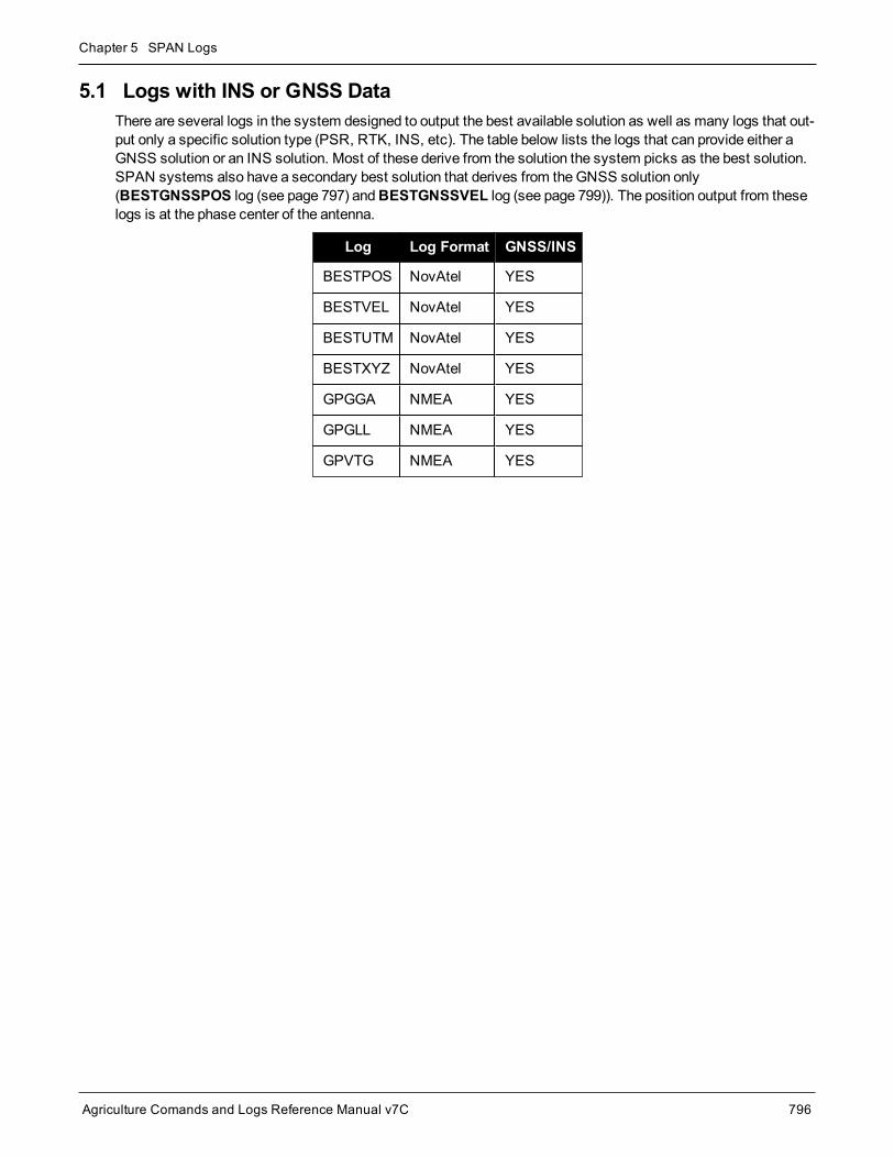
Chapter 5 SPAN Logs
Agriculture Comands and Logs Reference Manual v7C 796
5.1 Logs with INS or GNSS DataThere are several logs in the system designed to output the best available solution as well as many logs that out-put only a specific solution type (PSR, RTK, INS, etc). The table below lists the logs that can provide either aGNSS solution or an INS solution. Most of these derive from the solution the system picks as the best solution.SPAN systems also have a secondary best solution that derives from theGNSS solution only(BESTGNSSPOS log (see page 797) andBESTGNSSVEL log (see page 799)). The position output from theselogs is at the phase center of the antenna.
Log Log Format GNSS/INS
BESTPOS NovAtel YES
BESTVEL NovAtel YES
BESTUTM NovAtel YES
BESTXYZ NovAtel YES
GPGGA NMEA YES
GPGLL NMEA YES
GPVTG NMEA YES

Chapter 5 SPAN Logs
Agriculture Comands and Logs Reference Manual v7C 797
5.2 BESTGNSSPOSBest GNSS Position
Platform: OEM719, OEM729, OEM7500, OEM7600, OEM7700, OEM7720, PwrPak7, SPAN CPT7,SMART7-S, SMART7-SI
This log contains the best available GNSS position (without INS) computed by the receiver. In addition, it reportsseveral status indicators, including differential age, which is useful in predicting anomalous behavior broughtabout by outages in differential corrections. A differential age of 0 indicates that no differential correction wasused.
With the system operating in an RTK mode, this log reflects the latest low latency solution for up to 60 secondsafter reception of the last base station observations. After this 60 second period, the position reverts to the bestsolution available and the degradation in accuracy is reflected in the standard deviation fields. If the system isnot operating in an RTK mode, pseudorange differential solutions continue for the time specified in thePSRDIFFTIMEOUT command (see page 209).
BESTGNSSPOS always outputs positions at the antenna phase center.
Message ID: 1429
Log Type: Synch
Recommended Input:log bestgnssposa ontime 1
ASCII Example:#BESTGNSSPOSA,COM1,0,92.5,FINESTEERING,1692,332119.000,02000000,8505,43521;SOL_COMPUTED,SINGLE,51.11635530655,-114.03819448382,1064.6283,-16.9000,WGS84,1.2612,0.9535,2.7421,"",0.000,0.000,11,11,11,11,0,06,00,03*52d3f7c0
Field Field type Data Description Format BinaryBytes
BinaryOffset
1 BESTGNSSPOSHeader
Log header. SeeMessages on page 26 for moreinformation. - H 0
2 Sol Status Solution status, see Table 65: Solution Status onpage 349 Enum 4 H
3 Pos Type Position type, see Table 66: Position or Velocity Typeon page 350 Enum 4 H+4
4 Lat Latitude (degrees) Double 8 H+8
5 Lon Longitude (degrees) Double 8 H+16
6 Hgt Height abovemean sea level (meters) Double 8 H+24

Chapter 5 SPAN Logs
Agriculture Comands and Logs Reference Manual v7C 798
Field Field type Data Description Format BinaryBytes
BinaryOffset
7 Undulation
Undulation - the relationship between the geoid and theellipsoid (m) of the chosen datum
When using a datum other thanWGS84,the undulation value also includes the ver-tical shift due to differences between thedatum in use andWGS84.
Float 4 H+32
8 Datum ID
Datum ID
61 = WGS84
63 = USER
Enum 4 H+36
9 Lat σ Latitude standard deviation (meters) Float 4 H+40
10 Lon σ Longitude standard deviation (meters) Float 4 H+44
11 Hgt σ Height standard deviation (meters) Float 4 H+48
12 Stn ID Base station ID Char[4] 4 H+52
13 Diff_age Differential age in seconds Float 4 H+56
14 Sol_age Solution age in seconds Float 4 H+60
15 #SVs Number of satellites tracked Uchar 1 H+64
16 #solnSVs Number of satellite solutions used in solution Uchar 1 H+65
17 #solnL1SVs Number of satellites with L1/E1/B1 signals used insolution Uchar 1 H+66
18 #solnMultiSVs Number of satellites with multi-frequency signals used insolution Uchar 1 H+67
19 Reserved Uchar 1 H+68
20 ext sol stat Extended solution status (see Table 69: ExtendedSolution Status on page 353) Hex 1 H+69
21 Galileo andBeiDou sigmask
Galileo and BeiDou signals usedmask (see Table 68:Galileo and BeiDou Signal-UsedMask on page 352) Hex 1 H+70
22GPS andGLONASS sigmask
GPS andGLONASS signals usedmask (see Table 67:GPS andGLONASS Signal-UsedMask on page 352) Hex 1 H+71
23 xxxx 32-bit CRC (ASCII and Binary only) Hex 4 H+72
24 [CR][LF] Sentence terminator (ASCII only) - - -

Chapter 5 SPAN Logs
Agriculture Comands and Logs Reference Manual v7C 799
5.3 BESTGNSSVELBest Available GNSS Velocity Data
Platform: OEM719, OEM729, OEM7500, OEM7600, OEM7700, OEM7720, PwrPak7, SPAN CPT7,SMART7-S, SMART7-SI
This log contains the best available GNSS velocity information (without INS) computed by the receiver. In addi-tion, it reports a velocity status indicator, which is useful to indicate whether or not the corresponding data isvalid. The velocity measurements sometimes have a latency associated with them. The time of validity is thetime tag in the logminus the latency value.
The velocity is typically computed from the average change in pseudorange over the time interval or the RTKLow Latency filter. As such, it is an average velocity based on the time difference between successive positioncomputations and not an instantaneous velocity at the BESTGNSSVEL time tag. The velocity latency to be sub-tracted from the time tag is normally half the time between filter updates. Under default operation, the positioningfilters are updated at a rate of 2 Hz. This translates into a velocity latency of 0.25 seconds. The latency isreduced by increasing the update rate of the positioning filter used by requesting the BESTGNSSVEL orBESTGNSSPOS messages at a rate higher than 2 Hz. For example, a logging rate of 10 Hz reduces the velocitylatency to 0.005 seconds. For integration purposes, the velocity latency should be applied to the record time tag.
A valid solution with a latency of 0.0 indicates the instantaneous Doppler measurement was used to calculatevelocity.
Message ID: 1430
Log Type: Synch
Recommended Input:log bestgnssvela ontime 1
ASCII Example:#BESTGNSSVELA,COM1,0,91.5,FINESTEERING,1692,332217.000,02000000,00b0,43521;SOL_COMPUTED,DOPPLER_VELOCITY,0.150,0.000,0.0168,323.193320,0.0232,0.0*159c13ad
Field Field type Data Description Format BinaryBytes
BinaryOffset
1 BESTGNSSVELHeader
Log header. SeeMessages on page 26 for moreinformation. - H 0
2 Sol Status Solution status, see Table 65: Solution Status onpage 349 Enum 4 H
3 Vel Type Velocity type, see Table 66: Position or Velocity Type onpage 350 Enum 4 H+4
4 LatencyA measure of the latency in the velocity time tag inseconds. It should be subtracted from the time to giveimproved results.
Float 4 H+8
5 Age Differential age Float 4 H+12
6 Hor Spd Horizontal speed over ground, in meters per second Double 8 H+16

Chapter 5 SPAN Logs
Agriculture Comands and Logs Reference Manual v7C 800
Field Field type Data Description Format BinaryBytes
BinaryOffset
7 Trk Gnd Actual direction of motion over ground (track over ground)with respect to True North, in degrees Double 8 H+24
8 Vert SpdVertical speed, in meters per second, where positivevalues indicate increasing altitude (up) and negativevalues indicate decreasing altitude (down)
Double 8 H+32
9 Reserved Float 4 H+40
10 xxxx 32-bit CRC (ASCII and Binary only) Hex 4 H+44
11 [CR][LF] Sentence terminator (ASCII only) - - -
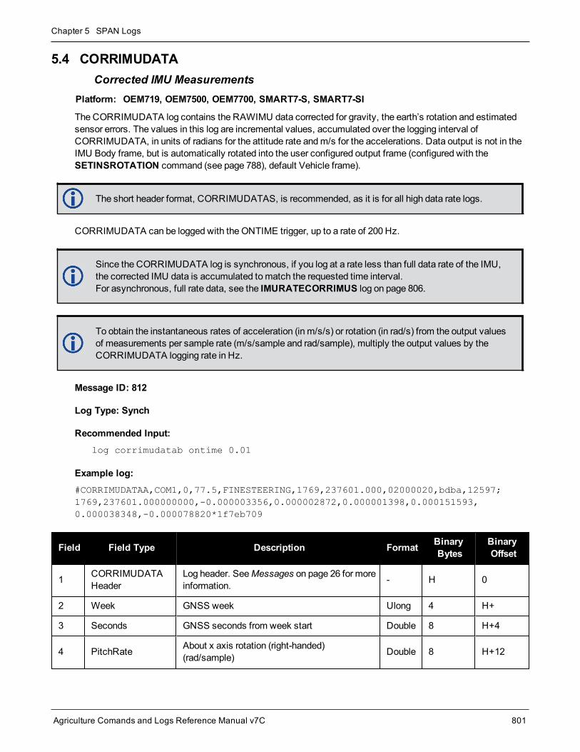
Chapter 5 SPAN Logs
Agriculture Comands and Logs Reference Manual v7C 801
5.4 CORRIMUDATACorrected IMU Measurements
Platform: OEM719, OEM7500, OEM7700, SMART7-S, SMART7-SI
The CORRIMUDATA log contains the RAWIMU data corrected for gravity, the earth’s rotation and estimatedsensor errors. The values in this log are incremental values, accumulated over the logging interval ofCORRIMUDATA, in units of radians for the attitude rate andm/s for the accelerations. Data output is not in theIMU Body frame, but is automatically rotated into the user configured output frame (configured with theSETINSROTATION command (see page 788), default Vehicle frame).
The short header format, CORRIMUDATAS, is recommended, as it is for all high data rate logs.
CORRIMUDATA can be logged with the ONTIME trigger, up to a rate of 200 Hz.
Since the CORRIMUDATA log is synchronous, if you log at a rate less than full data rate of the IMU,the corrected IMU data is accumulated tomatch the requested time interval.For asynchronous, full rate data, see the IMURATECORRIMUS log on page 806.
To obtain the instantaneous rates of acceleration (in m/s/s) or rotation (in rad/s) from the output valuesof measurements per sample rate (m/s/sample and rad/sample), multiply the output values by theCORRIMUDATA logging rate in Hz.
Message ID: 812
Log Type: Synch
Recommended Input:log corrimudatab ontime 0.01
Example log:#CORRIMUDATAA,COM1,0,77.5,FINESTEERING,1769,237601.000,02000020,bdba,12597;1769,237601.000000000,-0.000003356,0.000002872,0.000001398,0.000151593,0.000038348,-0.000078820*1f7eb709
Field Field Type Description Format BinaryBytes
BinaryOffset
1 CORRIMUDATAHeader
Log header. SeeMessages on page 26 for moreinformation. - H 0
2 Week GNSS week Ulong 4 H+
3 Seconds GNSS seconds from week start Double 8 H+4
4 PitchRate About x axis rotation (right-handed)(rad/sample) Double 8 H+12

Chapter 5 SPAN Logs
Agriculture Comands and Logs Reference Manual v7C 802
Field Field Type Description Format BinaryBytes
BinaryOffset
5 RollRate About y axis rotation (right-handed)(rad/sample) Double 8 H+20
6 YawRate About z axis rotation (right-handed)(rad/sample) Double 8 H+28
7 LateralAcc INS Lateral Acceleration (along x axis)(m/s/sample) Double 8 H+36
8 LongitudinalAcc INS Longitudinal Acceleration (along y axis)(m/s/sample) Double 8 H+44
9 VerticalAcc INS Vertical Acceleration (along z axis)(m/s/sample) Double 8 H+52
10 xxxx 32-bit CRC Hex 4 H+56
11 [CR][LF] Sentence Terminator (ASCII only) - - -

Chapter 5 SPAN Logs
Agriculture Comands and Logs Reference Manual v7C 803
5.5 CORRIMUDATASShort Corrected IMU Measurements
Platform: OEM719, OEM7500, OEM7700, SMART7-S, SMART7-SI
This log is the short header version of theCORRIMUDATA log (see page 801).
To obtain the instantaneous rates of acceleration (in m/s/s) or rotation (in rad/s) from the output valuesof measurements per sample rate (m/s/sample and rad/sample), multiply the output values by theCORRIMUDATAS logging rate in Hz.
Message ID: 813
Log Type: Synch
Recommended Input:log corrimudatasb ontime 0.01
Example log:%CORRIMUDATASA,1581,341553.000;1581,341552.997500000,-0.000000690,-0.000001549,0.000001654,0.000061579,-0.000012645,-0.000029988*770c6232
Field Field Type Description Format BinaryBytes
BinaryOffset
1 CORRIMUDATASHeader
Log header. SeeMessages on page 26 formore information. - H 0
2 Week GNSS week Ulong 4 H+
3 Seconds GNSS seconds from week start Double 8 H+4
4 PitchRate About x-axis rotation (right-handed)(rad/sample) Double 8 H+12
5 RollRate About y-axis rotation (right-handed)(rad/sample) Double 8 H+20
6 YawRate About z-axis rotation (right-handed)(rad/sample) Double 8 H+28
7 LateralAcc INS Lateral Acceleration (along x-axis)(m/s/sample) Double 8 H+36
8 LongitudinalAcc INS Longitudinal Acceleration (along y-axis)(m/s/sample) Double 8 H+44
9 VerticalAcc INS Vertical Acceleration (along z-axis)(m/s/sample) Double 8 H+52
10 xxxx 32-bit CRC Hex 4 H+56
11 [CR][LF] Sentence Terminator (ASCII only) - - -

Chapter 5 SPAN Logs
Agriculture Comands and Logs Reference Manual v7C 804
5.6 GIMBALLEDPVADisplay Gimballed Position
Platform: OEM719, OEM729, OEM7500, OEM7600, OEM7700, OEM7720, PwrPak7, SPAN CPT7,SMART7-S, SMART7-SI
Use theGIMBALLEDPVA log to view the re-calculated position, velocity and attitude of the gimbal null position.
This log should only be requested with the ONCHANGED or ONTIME trigger.
Message ID: 1321
Log Type: Asynch
Recommended Input:log gimballedpvaa onnew
ASCII Example:#GIMBALLEDPVAA,COM1,0,93.5,FINESTEERING,1635,320568.514,02000000,0000,407;1635,320568.514000000,51.116376614,-114.038259915,1046.112025828,-0.000291756,-0.000578067,0.030324466,-0.243093917,-0.127718304,19.495023227,INS_ALIGNMENT_COMPLETE*32fbb61b
Field Field Type Description Format BinaryBytes
BinaryOffset
1 GIMBALLEDPVAHeader
Log header. SeeMessages on page 26 for moreinformation. - H 0
2 Week GPS week Ulong 4 H
3 Seconds Seconds from week start Double 8 H+4
4 Latitude WGS84 latitude in degrees Double 8 H+12
5 Longitude WGS84 longitude in degrees Double 8 H+20
6 Height WGS84 ellipsoidal height Double 8 H+28
7 North Velocity Velocity in a northerly direction Double 8 H+36
8 East Velocity Velocity in an easterly direction Double 8 H+44
9 Up Velocity Velocity in an upward direction Double 8 H+52
10 Roll Right-handed rotation from local level around they-axis in degrees Double 8 H+60
11 Pitch Right-handed rotation from local level around thex-axis in degrees Double 8 H+68

Chapter 5 SPAN Logs
Agriculture Comands and Logs Reference Manual v7C 805
Field Field Type Description Format BinaryBytes
BinaryOffset
12 Azimuth Right-handed rotation from local level around thez-axis in degrees Double 8 H+76
13 Status INS status, see Table 199: Inertial SolutionStatus on page 813 Enum 4 H+84
14 xxxx 32-bit CRC Hex 4 H+88
15 [CR][LF] Sentence Terminator (ASCII only) - - -

Chapter 5 SPAN Logs
Agriculture Comands and Logs Reference Manual v7C 806
5.7 IMURATECORRIMUSAsynchronous Corrected IMU Data
Platform: OEM719, OEM729, OEM7500, OEM7600, OEM7700, OEM7720, PwrPak7, SPAN CPT7,SMART7-S, SMART7-SI
This log provides the same information as theCORRIMUDATAS log (see page 803), but is available asyn-chronously at the full rate of the IMU.
Using this log consumes significant system resources and should only be used by experienced users.
However, using this log consumes less resources than logging the synchronous CORRIMUDATAS logat the same rate.
To obtain the instantaneous rates of acceleration (in m/s/s) or rotation (in rad/s) from the output valuesof measurements per sample rate (m/s/sample and rad/sample), multiply the output values by the IMUdata rate in Hz.
This log should only be requested with the ONNEW trigger.
Message ID: 1362
Log Type: Asynch
Recommended Input:log imuratecorrimusb onnew
Example log:%IMURATECORRIMUSA,1581,341553.000;1581,341552.997500000,-0.000000690,-0.000001549,0.000001654,0.000061579,-0.000012645,-0.000029988*770c6232
Field Field Type Description Format BinaryBytes
BinaryOffset
1 IMURATECORRIMUSHeader
Log header. SeeMessages on page 26 formore information. - H 0
2 Week GNSS week Ulong 4 H+
3 Seconds GNSS seconds from week start Double 8 H+4
4 PitchRate About x axis rotation (rad/sample) Double 8 H+12
5 RollRate About y axis rotation (rad/sample) Double 8 H+20
6 YawRate About z axis rotation (right-handed)(rad/sample) Double 8 H+28

Chapter 5 SPAN Logs
Agriculture Comands and Logs Reference Manual v7C 807
Field Field Type Description Format BinaryBytes
BinaryOffset
7 LateralAcc INS Lateral Acceleration (along x-axis)(m/s/sample) Double 8 H+36
8 LongitudinalAcc INS Longitudinal Acceleration (along y-axis)(m/s/sample) Double 8 H+44
9 VerticalAcc INS Vertical Acceleration (along z-axis)(m/s/sample) Double 8 H+52
10 xxxx 32-bit CRC Hex 4 H+56
11 [CR][LF] Sentence Terminator (ASCII only) - - -

Chapter 5 SPAN Logs
Agriculture Comands and Logs Reference Manual v7C 808
5.8 IMURATEPVAAsynchronous INS Position, Velocity and Attitude
Platform: OEM719, OEM729, OEM7500, OEM7600, OEM7700, OEM7720, PwrPak7, SPAN CPT7,SMART7-S, SMART7-SI
This log provides the same information as the INSPVA log (see page 830), but is available asynchronously atthe full rate of the IMU.
Using this log consumes significant system resources and should only be used by experienced users.
However, using this log consumes less resources than logging the synchronous INSPVA log at thesame rate.
This log should only be requested with the ONNEW trigger.
Message ID: 1778
Log Type: Asynch
Recommended Input:log imuratepvaa onnew
ASCII Example:#IMURATEPVAA,COM1,0,57.0,FINESTEERING,1802,320345.180,02000000,9b1f,12987;1802,320345.180000030,51.11695246671,-114.03897779953,1047.6905,-0.2284,0.0076,0.2227,0.160588332,-0.039823409,269.988184416,INS_ALIGNMENT_COMPLETE*f60016a6
Field Field Type Description Format BinaryBytes
BinaryOffset
1 IMURATEPVAHeader
Log header. SeeMessages on page 26 for moreinformation. - H 0
2 Week GNSSWeek Ulong 4 H
3 Seconds Seconds from week start Double 8 H+4
4 Latitude Latitude (WGS84) [degrees] Double 8 H+12
5 Longitude Longitude (WGS84) [degrees] Double 8 H+20
6 Height Ellipsoidal Height (WGS84) [m] Double 8 H+28
7 North Velocity Velocity in a northerly direction (a -ve value impliesa southerly direction) [m/s] Double 8 H+36
8 East Velocity Velocity in an easterly direction (a -ve value impliesa westerly direction) [m/s] Double 8 H+44
9 Up Velocity Velocity in an up direction [m/s] Double 8 H+52

Chapter 5 SPAN Logs
Agriculture Comands and Logs Reference Manual v7C 809
Field Field Type Description Format BinaryBytes
BinaryOffset
10 Roll Right-handed rotation from local level around y-axisin degrees Double 8 H+60
11 Pitch Right-handed rotation from local level around x-axisin degrees Double 8 H+68
12 Azimuth
Left-handed rotation around z-axis in degreesclockwise from North
This is the inertial azimuth calculated from the IMUgyros and the SPAN filters.
Double 8 H+76
13 Status INS Status, see Table 199: Inertial Solution Statuson page 813 Enum 4 H+84
14 xxxx 32-bit CRC Hex 4 H+88
15 [CR][LF] Sentence Terminator (ASCII only) - - -

Chapter 5 SPAN Logs
Agriculture Comands and Logs Reference Manual v7C 810
5.9 IMURATEPVASAsynchronous INS Position, Velocity and Attitude
Platform: OEM719, OEM729, OEM7500, OEM7600, OEM7700, OEM7720, PwrPak7, SPAN CPT7,SMART7-S, SMART7-SI
This log provides the same information as the INSPVAS log (see page 834), but is available asynchronously atthe full rate of the IMU.
Using this log consumes significant system resources and should only be used by experienced users.
However, using this log consumes less resources than logging the synchronous INSPVAS log at thesame rate.
This log should only be requested with the ONCHANGED or ONTIME trigger.
Message ID: 1305
Log Type: Asynch
Recommended Input:log imuratepvas
ASCII Example:%IMURATEPVASA,1264,144059.000;1264,144059.002135700,51.116680071,-114.037929194,515.286704183,277.896368884,84.915188605,-8.488207941,0.759619515,-2.892414901,6.179554750,INS_ALIGNMENT_COMPLETE*855d6f76
Field Field Type Description Format BinaryBytes
BinaryOffset
1 IMURATEPVASHeader
Log header. SeeMessages on page 26 for moreinformation. - H 0
2 Week GNSSWeek Ulong 4 H
3 Seconds Seconds from week start Double 8 H+4
4 Latitude Latitude (WGS84) Double 8 H+12
5 Longitude Longitude (WGS84) Double 8 H+20
6 Height Ellipsoidal Height (WGS84) [m] Double 8 H+28
7 North Velocity Velocity in a northerly direction (a -ve value implies asoutherly direction) [m/s] Double 8 H+36
8 East Velocity Velocity in an easterly direction (a -ve value implies awesterly direction) [m/s] Double 8 H+44
9 Up Velocity Velocity in an up direction [m/s] Double 8 H+52

Chapter 5 SPAN Logs
Agriculture Comands and Logs Reference Manual v7C 811
Field Field Type Description Format BinaryBytes
BinaryOffset
10 Roll Right-handed rotation from local level around y-axisin degrees Double 8 H+60
11 Pitch Right-handed rotation from local level around x-axisin degrees Double 8 H+68
12 Azimuth Left-handed rotation around z-axis in degreesclockwise from North Double 8 H+76
13 Status INS Status, see Table 199: Inertial Solution Statuson page 813 Enum 4 H+84
14 xxxx 32-bit CRC Hex 4 H+88
15 [CR][LF] Sentence Terminator (ASCII only) - - -

Chapter 5 SPAN Logs
Agriculture Comands and Logs Reference Manual v7C 812
5.10 INSATTINS Attitude
Platform: OEM719, OEM729, OEM7500, OEM7600, OEM7700, OEM7720, PwrPak7, SPAN CPT7,SMART7-S, SMART7-SI
This log contains themost recent attitudemeasurements computed by the SPAN filter. This attitude definitionmay not correspond to other definitions of the terms pitch, roll and azimuth. By default, the output attitude is withrespect to the vehicle frame. If the attitude output is desired with respect to another frame of reference, use theSETINSROTATION USER command (see theSETINSROTATION command on page 788) to configure theuser output frame offset rotation.
Message ID: 263
Log Type: Synch
Recommended Input:log insatta ontime 1
ASCII Example:#INSATTA,USB2,0,14.5,FINESTEERING,1541,487970.000,02040000,5b35,37343;1541,487970.000549050,1.876133508,-4.053672765,328.401460897,INS_SOLUTION_GOOD*ce4ac533
Field Field Type Description Format BinaryBytes
BinaryOffset
1 INSATTHeader
Log header. SeeMessages on page 26 for moreinformation. - H 0
2 Week GNSSWeek Ulong 4 H
3 Seconds intoWeek Seconds from week start Double 8 H+4
4 Roll Right-handed rotation from local level around y-axis indegrees. Double 8 H+12
5 Pitch Right-handed rotation from local level around x-axis indegrees. Double 8 H+20
6 Azimuth
Left-handed rotation around z-axis in degrees clockwisefrom North.
This is the inertial azimuth calculated from the IMUgyros and the SPAN filters.
Double 8 H+28
7 Status INS status, see Table 199: Inertial Solution Status onthe next page. Enum H+36
8 xxxx 32-bit CRC (ASCII, Binary and Short Binary only) Hex H+40
9 [CR][LF] Sentence terminator (ASCII only) - - -

Chapter 5 SPAN Logs
Agriculture Comands and Logs Reference Manual v7C 813
Binary ASCII Description
0 INS_INACTIVE IMU logs are present, but the alignment routine has not started; INS is inactive.
1 INS_ALIGNING INS is in alignment mode.
2 INS_HIGH_VARIANCE
The INS solution is in navigationmode but the azimuth solution uncertainty hasexceeded the threshold. The default threshold is 2 degrees for most IMUs. Thesolution is still valid but you shouldmonitor the solution uncertainty in the INSSTDEVlog (see page 844). Youmay encounter this state during times when theGNSS, usedto aid the INS, is absent.
The INS solution uncertainty contains outliers and the solutionmay be outsidespecifications.1 The solution is still valid but you shouldmonitor the solutionuncertainty in the INSSTDEV log (see page 844). It may be encountered during timeswhenGNSS is absent or poor.
3INS_SOLUTION_GOOD
The INS filter is in navigationmode and the INS solution is good.
6INS_SOLUTION_FREE
The INS filter is in navigationmode and theGNSS solution is suspected to be inerror.
This may be due tomultipath or limited satellite visibility. The inertial filter hasrejected the GNSS position and is waiting for the solution quality to improve.
7INS_ALIGNMENT_COMPLETE
The INS filter is in navigationmode, but not enough vehicle dynamics have beenexperienced for the system to be within specifications.
8 DETERMINING_ORIENTATION INS is determining the IMU axis aligned with gravity.
9 WAITING_INITIALPOS
The INS filter has determined the IMU orientation and is awaiting an initial positionestimate to begin the alignment process.
10 WAITING_AZIMUTH
The INS filer has orientation, initial biases, initial position and valid roll/pitchestimated. Will not proceed until initial azimuth is entered.
11 INITIALIZING_BIASES
The INS filter is estimating initial biases during the first 10 seconds of stationarydata.
12 MOTION_DETECT The INS filter has not completely aligned, but has detectedmotion.
Table 199: Inertial Solution Status
1The solution uncertainty threshold levels can be adjusted using the INSTHRESHOLDS command on page 780.

Chapter 5 SPAN Logs
Agriculture Comands and Logs Reference Manual v7C 814
5.11 INSATTQSShort INS Quaternion Attitude
Platform: OEM719, OEM729, OEM7500, OEM7600, OEM7700, OEM7720, PwrPak7, SPAN CPT7,SMART7-S, SMART7-SI
This log contains the attitude from the INSATT log, but the rotation from local level is given as aQuaternionrather than Euler Angles. The quaternion takes the form:
The element w is the rotational component, defining themagnitude of the rotation to be performed. The elementsx, y, and z are the vector portion of the rotation, which define the axis about which the rotation is to be performed.
If θ is the rotational angle, and the axis of rotation is defined by the vector , then the elementsof the quaternion can be written as:
Message ID: 2118
Log Type: Synch
Recommended Input:log insattqsa ontime 1
ASCII Example:%INSATTQSA,1943,425090.000;1943,425090.000000000,0.706276782,0.001974400,-0.001083571,-0.707932225,INS_ALIGNMENT_COMPLETE*552d93f0
Field Field Type Description Format BinaryBytes
BinaryOffset
1 INSATTQSHeader
Log header. SeeMessages on page 26 for moreinformation. - H 0
2 Week GNSSWeek Ulong 4 H
3 Seconds intoWeek Seconds from week start Double 8 H+4
4 Quaternion w Quaternion rotation from local level, w component Double 8 H+12
5 Quaternion x Quaternion rotation from local level, x component Double 8 H+20
6 Quaternion y Quaternion rotation from local level, y component Double 8 H+28

Chapter 5 SPAN Logs
Agriculture Comands and Logs Reference Manual v7C 815
Field Field Type Description Format BinaryBytes
BinaryOffset
7 Quaternion z Quaternion rotation from local level, z component Double 8 H+36
8 Status INS status, see Table 199: Inertial Solution Statuson page 813 Enum 4 H+44
9 xxxx 32-bit CRC (ASCII, Binary and Short Binary only) Hex 4 H+48
10 [CR][LF] Sentence Terminator (ASCII only) - - -

Chapter 5 SPAN Logs
Agriculture Comands and Logs Reference Manual v7C 816
5.12 INSATTSShort INS Attitude
Platform: OEM719, OEM729, OEM7500, OEM7600, OEM7700, OEM7720, PwrPak7, SPAN CPT7,SMART7-S, SMART7-SI
This log is the short header version of the INSATT log (see page 812).
Message ID: 319
Log Type: Synch
Recommended Input:log insattsa ontime 1
ASCII Example:%INSATTSA,1541,487975.000;1541,487975.000549050,2.755452422,-4.127365126,323.289778434,INS_SOLUTION_GOOD*ba08754f
Field Field Type Description Format BinaryBytes
BinaryOffset
1 INSATTSHeader
Log header. SeeMessages on page 26 for moreinformation. - H 0
2 Week GNSSWeek Ulong 4 H
3 Seconds intoWeek Seconds from week start Double 8 H+4
4 Roll Right-handed rotation from local level around y-axis indegrees Double 8 H+12
5 Pitch Right-handed rotation from local level around x-axis indegrees Double 8 H+20
6 Azimuth
Left-handed rotation around z-axis in degrees clockwisefrom North
This is the inertial azimuth calculated from the IMUgyros and the SPAN filters.
Double 8 H+28
7 Status INS status, see Table 199: Inertial Solution Status onpage 813 Enum 4 H+36
8 xxxx 32-bit CRC (ASCII, Binary and Short Binary only) Hex 4 H+40
9 [CR][LF] Sentence terminator (ASCII only) - - -

Chapter 5 SPAN Logs
Agriculture Comands and Logs Reference Manual v7C 817
5.13 INSATTXInertial Attitude – Extended
Platform: OEM719, OEM729, OEM7500, OEM7600, OEM7700, OEM7720, PwrPak7, SPAN CPT7,SMART7-S, SMART7-SI
This log includes the information from the INSATT log (see page 812), as well as information about the attitudestandard deviation. The position type and solution status fields indicate whether or not the corresponding data isvalid.
The INSATTX log is a large log and is not recommend for high rate logging.
If you want to use high rate logging, log the INSATTS log at a high rate and the INSSTDEVS log ontime1.
Message ID: 1457
Log Type: Synch
Recommended Input:log insattxa ontime 1
ASCII Example:#INSATTXA,COM4,0,48.5,FINESTEERING,2088,169973.000,02004020,5d25,15823;INS_SOLUTION_GOOD,INS_PSRSP,-0.064981993,0.506340505,90.280586875,0.5448,0.5359,0.0834,13000044,0*15aeac66
Field Field Type Description Format BinaryBytes
BinaryOffset
1 INSATTXHeader
Log header. SeeMessages on page 26 for moreinformation. H 0
2 INS Status Solution statusSee Table 199: Inertial Solution Status on page 813 Enum 4 H
3 Pos Type Position typeSee Table 66: Position or Velocity Type on page 350 Enum 4 H+4
4 Roll Roll in Local Level (degrees) Double 8 H+8
5 Pitch Pitch in Local Level (degrees) Double 8 H+16
6 AzimuthAzimuth in Local Level (degrees)
This is the inertial azimuth calculated from the IMUgyros and the SPAN filters.
Double 8 H+24
7 Roll σ Roll standard deviation (degrees) Float 4 H+32
8 Pitch σ Pitch standard deviation (degrees) Float 4 H+36
9 Azimuth σ Azimuth standard deviation (degrees) Float 4 H+40

Chapter 5 SPAN Logs
Agriculture Comands and Logs Reference Manual v7C 818
Field Field Type Description Format BinaryBytes
BinaryOffset
10 Ext sol stat Extended solution statusSee Table 200: Extended Solution Status below Hex 4 H+44
11 Time SinceUpdate
Elapsed time since the last ZUPT or position update(seconds) Ushort 2 H+48
12 xxxx 32-bit CRC (ASCII and Binary only) Hex 4 H+50
13 [CR][LF] Sentence terminator (ASCII only) - - -
Nibble Bit Mask Description Range Value
N0
0 0x00000001 Position update 0 = Unused1 = Used
1 0x00000002 Phase update 0 = Unused1 = Used
2 0x00000004 Zero velocity update 0 = Unused1 = Used
3 0x00000008 Wheel sensor update 0 = Unused1 = Used
N1
4 0x00000010 ALIGN (heading) update 0 = Unused1 = Used
5 0x00000020 External position update 0 = Unused1 = Used
6 0x00000040 INS solution convergenceflag
0 = Not converged1 = Converged
7 0x00000080 Doppler update 0 = Unused1 = Used
N2
8 0x00000100 Pseudorange update 0 = Unused1 = Used
9 0x00000200 Velocity update 0 = Unused1 = Used
10 0x00000400 Reserved
11 0x00000800 Dead reckoning update 0 = Unused1 = Used
Table 200: Extended Solution Status

Chapter 5 SPAN Logs
Agriculture Comands and Logs Reference Manual v7C 819
Nibble Bit Mask Description Range Value
N3
12 0x00001000 Phase wind up update 0 = Unused1 = Used
13 0x00002000 Course over ground update 0 = Unused1 = Used
14 0x00004000 External velocity update 0 = Unused1 = Used
15 0x00008000 External attitude update 0 = Unused1 = Used
N4
16 0x00010000 External heading update 0 = Unused1 = Used
17 0x00020000 External height update 0 = Unused1 = Used
18 0x00040000 Reserved
19 0x00080000 Reserved
N5
20 0x00100000 Rover position update 0 = Unused1 = Used
21 0x00200000 Rover position update type 0 = Non-RTK update1 = RTK integer update
22 0x00400000 Reserved
23 0x00800000 Reserved
N6
24 0x01000000 Turn on biases estimated0 = Static turn-on biases not estimated (starting fromzero)1 = Static turn-on biases estimated
25 0x02000000 Alignment direction verified 0 = Not verified1 = Verified
26 0x04000000 Alignment Indication 10 = Not set, 1 = SetRefer to Table 201: Alignment Indication on the nextpage
27 0x08000000 Alignment Indication 20 = Not set, 1 = SetRefer to Table 201: Alignment Indication on the nextpage

Chapter 5 SPAN Logs
Agriculture Comands and Logs Reference Manual v7C 820
Nibble Bit Mask Description Range Value
N7
28 0x10000000 Alignment Indication 3 0 = Not set, 1 = SetRefer to Table 201: Alignment Indication below
29 0x20000000 NVM Seed Indication 1 0 = Not set, 1 = SetRefer to Table 202: NVM Seed Indication below
30 0x40000000 NVM Seed Indication 2 0 = Not set, 1 = SetRefer to Table 202: NVM Seed Indication below
31 0x80000000 NVM Seed Indication 3 0 = Not set, 1 = SetRefer to Table 202: NVM Seed Indication below
Bits 26-28 Values Hex Value Completed Alignment Type
000 0x00 Incomplete Alignment
001 0x01 Static
010 0x02 Kinematic
011 0x03 Dual Antenna
100 0x04 User Command
101 0x05 NVM Seed
Table 201: Alignment Indication
Bit 29-31Values Hex Value NVM Seed Type
000 0x00 NVM Seed Inactive
001 0x01 Seed stored in NVM is invalid
010 0x02 NVM Seed failed validation check
011 0x03 NVM Seed is pending validation (awaiting GNSS)
100 0x04 NVM Seed Injected (includes error model data)
101 0x05 NVM Seed data ignored due to a user-commanded filter reset or configuration change
110 0x06 NVM Seed error model data injected
Table 202: NVM Seed Indication

Chapter 5 SPAN Logs
Agriculture Comands and Logs Reference Manual v7C 821
5.14 INSCALSTATUSOffset calibration status
Platform: OEM719, OEM729, OEM7500, OEM7600, OEM7700, OEM7720, PwrPak7, SPAN CPT7,SMART7-S, SMART7-SI
This log reports the status and estimated values of the currently running offset calibration.
Message ID: 1961
Log Type: Asynch
Abbreviated ASCII Syntax:log inscalstatus onchanged
ASCII Example:#INSCALSTATUSA,COM1,0,80.0,FINESTEERING,1880,317815.012,02000000,a4f2,32768;RBV,0.0000,-180.0000,-90.0000,45.0000,45.0000,45.0000,INS_CONVERGING,1*e0b3152d
Field Field Type Description BinaryFormat
BinaryBytes
BinaryOffset
1 INSCALSTATUSheader
Log header. SeeMessages on page 26 for moreinformation. - H 0
2 Offset Type Type of offset (see Table 203: Offset Type on the nextpage). Enum 4 H
3 X axis offset IMU body frame X-axis offset (m/degrees). Float 4 H+4
4 Y axis offset IMU body frame Y-axis offset (m/degrees). Float 4 H+8
5 Z axis offset IMU body frame Z-axis offset (m/degrees). Float 4 H+12
6 X uncertainty IMU body frame X-axis offset uncertainty (m/degrees). Float 4 H+16
7 Y uncertainty IMU body frame Y-axis offset uncertainty (m/degrees). Float 4 H+20
8 Z uncertainty IMU body frame Z-axis offset uncertainty (m/degrees). Float 4 H+24
9 Source Status Source from which offset values originate (see Table204: Source Status on the next page). Enum 4 H+28
10 Multi-lineCalibration Count
Counter for number of completed calibrationscumulatively averaged. Ulong 4 H+32
11 xxxx 32-bit CRC (ASCII and Binary only). Hex 4 H+36
12 [CR][LF] Sentence terminator (ASCII only). - - -
Units for the axis offset and uncertainty values (fields 3-8) are in meters for translational offset com-ponents and degrees for rotational offset components.

Chapter 5 SPAN Logs
Agriculture Comands and Logs Reference Manual v7C 822
Binary ASCII Description
1 ANT1 Primary IMU to antenna lever arm
8 ALIGN Align offset
11 RBV IMU body to vehicle offset
Table 203: Offset Type
Binary ASCII Description
1 FROM_NVM Offset values originate from saved parameters in NVM
2 CALIBRATING Offset values originate from a currently running calibration process
3 CALIBRATED Offset values originate from a completed calibration process
4 FROM_COMMAND Offset values originate from a user command
5 RESET Offset values originate from a system reset
6 FROM_DUAL_ANT Offset values originate from a dual antenna Align solution
7 INS_CONVERGING
Offset values originate from initial input values. Calibration process on hold until INSsolution is converged.
8 INSUFFICIENT_SPEED
Offset values originate from a currently running calibration process. Furtherestimation on hold due to insufficient speed.
9 HIGH_ROTATION
Offset values originate from a currently running calibration process. Furtherestimation on hold due to high vehicle rotations.
Table 204: Source Status

Chapter 5 SPAN Logs
Agriculture Comands and Logs Reference Manual v7C 823
5.15 INSCONFIGDetermine required settings for post-processing or system analysis
Platform: OEM719, OEM729, OEM7500, OEM7600, OEM7700, OEM7720, PwrPak7, SPAN CPT7,SMART7-S, SMART7-SI
This log is the single message required to determine all required settings for post-processing or system analysis.This log is asynchronous and published for any change to the included fields. It is intended to be recorded occa-sionally though it could be updated frequently at system startup.
Message ID: 1945
Log Type: Polled
Recommended Input:log insconfig onchanged
ASCII Example:#INSCONFIGA,COM1,0,71.0,COARSESTEERING,1931,517331.006,02400000,6d7a,32768;EPSON_G320,6,50,20,DEFAULT,00ffd1bf,AUTOMATIC,ROVER,FALSE,00000000,0,0,0,0,0,0,0,0,0,1,ANT1,IMUBODY,0.0540,0.0699,-0.0346,0.0200,0.0200,0.0200,FROM_NVM,1,RBV,IMUBODY,180.0000,0.0000,90.0000,5.0000,5.0000,5.0000,FROM_COMMAND*b1233ac4
Field Field Type Description BinaryFormat
BinaryBytes
BinaryOffset
1 INSCONFIGHeader
Command header. SeeMessages on page 26 for moreinformation. - H 0
2 IMU Type IMU type. See Table 192: IMU Type on page 768. Enum 4 H
3 Mapping Mapping / Orientation Uchar 1 H+4
4InitialAlignmentVelocity
Minimum Alignment Velocity entered by the user (see theSETALIGNMENTVEL command on page 785).
Note: Velocity (m/s) is scaled by 10 for 10cm/s precisionUchar 1 H+5
5 HeaveWindow Length of the heave window in seconds Ushort 2 H+6
6 Profile Profile setting (see theSETINSPROFILE command onpage 787) Enum 4 H+8
7 INS EnabledUpdates
Enabled INS updates (see Table 209: INS UpdateValues on page 850) Hex 4 H+12
8 AlignmentMode
Alignment mode configured on the system (see theALIGNMENTMODE command on page 765) Enum 4 H+16

Chapter 5 SPAN Logs
Agriculture Comands and Logs Reference Manual v7C 824
Field Field Type Description BinaryFormat
BinaryBytes
BinaryOffset
9 Relative INSOutput Frame
The user specified output frame of the Relative INSVector (seeSETRELINSOUTPUTFRAME command onpage 794)
If not specified, the default value appears.
Enum 4 H+20
10Relative INSOutputDirection
The User specified Output direction of the Relative INSVector (From or ToMaster-Rover) (see theSETRELINSOUTPUTFRAME command on page 794).
If not specified, the default value appears. TRUE if FromMaster, FALSE (Default) if From Rover
Bool 4 H+24
11 INS ReceiverStatus
Lower byte- INS Reset. Corresponds numerically to theINS Reset as described by the INSResetEnum
Second byte-= 0x01 if an IMU Communication Error (Receiver statusbit 17).= 0x00 otherwise.Other values are reserved for future use.
Upper 2 bytes - reserved.
Hex 4 H+28
12 INS SeedEnabled
INS Seed Enable setting(see the INSSEED command on page 779)Enabled = 1, Disabled = 0
Uchar 1 H+32
13 INS SeedValidation
INS Seed Validation setting(see the INSSEED command on page 779) Uchar 1 H+33
14 Reserved 1 N/A 2 H+34
15 Reserved 2 N/A 4 H+36
16 Reserved 3 N/A 4 H+40
17 Reserved 4 N/A 4 H+44
18 Reserved 5 N/A 4 H+48
19 Reserved 6 N/A 4 H+52
20 Reserved 7 N/A 4 H+56
21 Number ofTranslations Number of translation entries to follow Ulong 4 H+60
22 Translation Translation to follow (see Table 197: Translation OffsetTypes on page 791) Enum 4 variable
23 Frame Frame of translation (IMUBODY or VEHICLE) Enum 4 variable
24 X Offset X Offset Float 4 variable

Chapter 5 SPAN Logs
Agriculture Comands and Logs Reference Manual v7C 825
Field Field Type Description BinaryFormat
BinaryBytes
BinaryOffset
25 Y Offset Y Offset Float 4 variable
26 Z Offset Z Offset Float 4 variable
27 X Uncertainty X Uncertainty Float 4 variable
28 Y Uncertainty Y Uncertainty Float 4 variable
29 Z Uncertainty Z Uncertainty Float 4 variable
30 TranslationSource
Source of translation (see Table 204: Source Status onpage 822) Enum 4 variable
Next Translation
variable Number ofRotations Number of rotation entries to follow Ulong 4 variable
variable Rotation Rotation to follow (see Table 196: Rotational OffsetTypes on page 789) Enum 4 variable
variable Frame Frame of rotation (IMUBODY or VEHICLE) Enum 4 variable
variable X Rotation X Rotation Float 4 variable
variable Y Rotation Y Rotation Float 4 variable
variable Z Rotation Z Rotation Float 4 variable
variable X RotationStd Dev X Rotation offset standard deviation (degrees) Float 4 variable
variable Y RotationSTD Dev Y Rotation offset standard deviation (degrees) Float 4 variable
variable Z RotationSTD Dev Z Rotation offset standard deviation (degrees) Float 4 variable
variable RotationSource
Source of rotation (see Table 204: Source Status onpage 822) Enum 4 variable
Next Rotation
variable xxxx 32-bit CRC (ASCII and Binary only) Hex 4 variable
[CR][LF] Sentence terminator (ASCII only) - - -

Chapter 5 SPAN Logs
Agriculture Comands and Logs Reference Manual v7C 826
5.16 INSPOSINS Position
Platform: OEM719, OEM729, OEM7500, OEM7600, OEM7700, OEM7720, PwrPak7, SPAN CPT7,SMART7-S, SMART7-SI
This log contains themost recent positionmeasurements inWGS84 coordinates and includes an INS statusindicator. The log reports the position at the IMU center, unless theSETINSTRANSLATION USER commandwas issued. See theSETINSTRANSLATION command on page 790.
This log provides the position information inWGS84.
Message ID: 265
Log Type: Synch
Recommended Input:log insposa ontime 1
ASCII Example:#INSPOSA,USB2,0,18.0,FINESTEERING,1541,487977.000,02040000,17cd,37343;1541,487977.000549050,51.121315135,-114.042311349,1038.660737046,INS_SOLUTION_GOOD*2fffd557
Field Field Type Description Format BinaryBytes
BinaryOffset
1 INSPOSHeader
Log header. SeeMessages on page 26 for moreinformation. - H 0
2 Week GNSSWeek Ulong 4 H
3 Seconds intoWeek Seconds from week start Double 8 H+4
4 Latitude Latitude (WGS84) Double 8 H+12
5 Longitude Longitude (WGS84) Double 8 H+20
6 Height Ellipsoidal Height (WGS84) [m] Double 8 H+28
7 Status INS status, see Table 199: Inertial Solution Statuson page 813 Enum 4 H+36
8 xxxx 32-bit CRC (ASCII, Binary and Short Binary only) Hex 4 H+40
9 [CR][LF] Sentence terminator (ASCII only) - - -

Chapter 5 SPAN Logs
Agriculture Comands and Logs Reference Manual v7C 827
5.17 INSPOSSShort INS Position
Platform: OEM719, OEM729, OEM7500, OEM7600, OEM7700, OEM7720, PwrPak7, SPAN CPT7,SMART7-S, SMART7-SI
This log is the short header version of the INSPOS log (see page 826).
This log provides the position information inWGS84.
Message ID: 321
Log Type: Synch
Recommended Input:log inspossa ontime 1
ASCII Example:%INSPOSSA,1541,487916.000;1541,487916.000549050,51.115797277,-114.037811065,1039.030700122,INS_SOLUTION_GOOD*5ca30894
Field Field Type Description Format BinaryBytes
BinaryOffset
1 INSPOSSHeader
Log header. SeeMessages on page 26 for moreinformation. - H 0
2 Week GNSSWeek Ulong 4 H
3 Seconds intoWeek Seconds from week start Double 8 H+4
4 Latitude Latitude (WGS84) Double 8 H+12
5 Longitude Longitude (WGS84) Double 8 H+20
6 Height Ellipsoidal Height (WGS84) [m] Double 8 H+28
7 Status INS status, see Table 199: Inertial Solution Statuson page 813 Enum 4 H+36
8 xxxx 32-bit CRC (ASCII, Binary and Short Binary only) Hex 4 H+40
9 [CR][LF] Sentence terminator (ASCII only) - - -

Chapter 5 SPAN Logs
Agriculture Comands and Logs Reference Manual v7C 828
5.18 INSPOSXInertial Position – Extended
Platform: OEM719, OEM729, OEM7500, OEM7600, OEM7700, OEM7720, PwrPak7, SPAN CPT7,SMART7-S, SMART7-SI
This log includes the information from the INSPOS log, as well as information about the position standard devi-ation. The position type and solution status fields indicate whether or not the corresponding data is valid.
The INSPOSX log is a large log and is not recommend for high rate logging.
If you want to use high rate logging, log the INSPOSS log at a high rate and the INSSTDEVS log ontime1.
This log provides the position information in the user datum.
To determine the datum being used, log theBESTPOS log.
Message ID: 1459
Log Type: Synch
Recommended Input:log insposxa ontime 1
ASCII example:#INSPOSXA,COM4,0,46.0,FINESTEERING,2088,169976.000,02004020,1e1d,15823;INS_SOLUTION_GOOD,INS_PSRSP,51.15036800018,-114.03064199432,1097.3581,-17.0000,5.2758,5.1921,5.9453,13000044,0*1aaf8eac
Field Field Type Description Format BinaryBytes
BinaryOffset
1 INSPOSXHeader
Log header. SeeMessages on page 26 for moreinformation. H 0
2 INS StatusSolution statusSee Table 199: Inertial Solution Status onpage 813
Enum 4 H
3 Pos TypePosition typeSee Table 66: Position or Velocity Type onpage 350
Enum 4 H+4
4 Lat Latitude Double 8 H+8
5 Long Longitude Double 8 H+16
6 Height Height above sea level (m) Double 8 H+24
7 Undulation Undulation (m) Float 4 H+32

Chapter 5 SPAN Logs
Agriculture Comands and Logs Reference Manual v7C 829
Field Field Type Description Format BinaryBytes
BinaryOffset
8 Lat σ Latitude standard deviation Float 4 H+36
9 Long σ Longitude standard deviation Float 4 H+34
10 Height σ Height standard deviation Float 4 H+44
11 Ext sol statExtended solution statusSee Table 200: Extended Solution Status onpage 818
Hex 4 H+48
11 Time SinceUpdate
Elapsed time since the last ZUPT or positionupdate (seconds) Ushort 2 H+52
12 xxxx 32-bit CRC (ASCII and Binary only) Hex 4 H+54
13 [CR][LF] Sentence terminator (ASCII only) - - -
The INS covariance and standard deviation values reported by the SPAN filter are an estimate of theInertial filter solution quality. In lower accuracy GNSS positionmodes, such as SINGLE orWAAS (seeTable 66: Position or Velocity Type on page 350), the position covariance and standard deviation val-ues can appear to become optimistic compared with the absolute GNSS accuracy. This is due to theINS filter’s ability to smooth short term noise in the GNSS solution, although the overall position errorenvelope still reflects the GNSS accuracy. Therefore, if the desired application requires absoluteGNSS position accuracy, it is recommended to alsomonitor GNSS positionmessages such asBESTGNSSPOS (seeBESTGNSSPOS log on page 797).

Chapter 5 SPAN Logs
Agriculture Comands and Logs Reference Manual v7C 830
5.19 INSPVAINS Position, Velocity and Attitude
Platform: OEM719, OEM729, OEM7500, OEM7600, OEM7700, OEM7720, PwrPak7, SPAN CPT7,SMART7-S, SMART7-SI
This log allows INS position, velocity and attitude, with respect to the SPAN frame, to be collected in one log,instead of using three separate logs. Refer to the INSATT log (see page 812) for an explanation of how theSPAN framemay differ from the IMU enclosure frame.
This log provides the position information inWGS84.
Message ID: 507
Log Type: Synch
Recommended Input:log inspvaa ontime 1
ASCII Example:#INSPVAA,COM1,0,31.0,FINESTEERING,1264,144088.000,02040000,5615,1541;1264,144088.002284950,51.116827527,-114.037738908,401.191547167,354.846489850,108.429407241,-10.837482850,1.116219952,-3.476059035,7.372686190,INS_ALIGNMENT_COMPLETE*af719fd9
Field Field Type Description Format BinaryBytes
BinaryOffset
1 INSPVAHeader
Log header. SeeMessages on page 26 for moreinformation. - H 0
2 Week GNSSWeek Ulong 4 H
3 Seconds Seconds from week start Double 8 H+4
4 Latitude Latitude (WGS84) [degrees] Double 8 H+12
5 Longitude Longitude (WGS84) [degrees] Double 8 H+20
6 Height Ellipsoidal Height (WGS84) [m] Double 8 H+28
7 NorthVelocity
Velocity in a northerly direction (a -ve value implies asoutherly direction) [m/s] Double 8 H+36
8 EastVelocity
Velocity in an easterly direction (a -ve value implies awesterly direction) [m/s] Double 8 H+44
9 Up Velocity Velocity in an up direction [m/s] Double 8 H+52
10 Roll Right-handed rotation from local level around y-axis indegrees Double 8 H+60

Chapter 5 SPAN Logs
Agriculture Comands and Logs Reference Manual v7C 831
Field Field Type Description Format BinaryBytes
BinaryOffset
11 Pitch Right-handed rotation from local level around x-axis indegrees Double 8 H+68
12 Azimuth
Left-handed rotation around z-axis in degrees clockwisefrom North
This is the inertial azimuth calculated from the IMU gyrosand the SPAN filters.
Double 8 H+76
13 Status INS Status, see Table 199: Inertial Solution Status onpage 813 Enum 4 H+84
14 xxxx 32-bit CRC Hex 4 H+88
15 [CR][LF] Sentence Terminator (ASCII only) - - -

Chapter 5 SPAN Logs
Agriculture Comands and Logs Reference Manual v7C 832
5.20 INSPVACMPCompressed version of the INSPVA log for CAN
Platform: OEM719, OEM729, OEM7500, OEM7600, OEM7700, OEM7720, PwrPak7, SPAN CPT7,SMART7-S, SMART7-SI
This log contains the INSPVA log (see page 830) information compressed as a NMEA 2000 fast packet mes-sage for CAN output. The information in the table below is the data portion of the INSPVACMP NMEA 2000mes-sage. Refer to theNATIONALMARINE ELECTRONICS ASSOCIATION (NMEA) NMEA2000(r) rev 2.0 -January/2013 document for full details on this message output and the NMEA 2000 fast packet protocol.
Message ID: 1889
Log Type: Synch
Abbreviated ASCII Syntax:LOG CCOM1 INSPVACMP ONTIME 1
Field Field Type Description Format BinaryBytes Units Scale
Factor
1 MessageTime Seconds from week start Ulong 4 seconds 0.001
2 INS Status INS solution status (see Table 199: InertialSolution Status on page 813) UChar 1 N/A N/A
3GNSSPositionType
GNSS position type (see Table 66: Position orVelocity Type on page 350) UChar 1 N/A N/A
4 Latitude Latitude (WGS84) 5 byteLong 5 degrees 180/2
39
5 Longitude Longitude (WGS84) 5 byteLong 5 degrees 180/2
39
6 Height Ellipsoidal Height (WGS84) Long 4 meters 0.0001
7 NorthVelocity
Velocity in a northerly direction (a -ve valueimplies a southerly direction) Short 2 m/s 0.002
8 EastVelocity
Velocity in an easterly direction (a -ve valueimplies a westerly direction) Short 2 m/s 0.002
9 Up Velocity Velocity in an up direction Short 2 m/s 0.002
10 Roll Right-handed rotation from local level around yaxis Short 2 degrees 0.01
11 Pitch Right-handed rotation from local level around xaxis Short 2 degrees 0.01

Chapter 5 SPAN Logs
Agriculture Comands and Logs Reference Manual v7C 833
Field Field Type Description Format BinaryBytes Units Scale
Factor
12 Azimuth
Left-handed rotation around z-axis clockwisefrom North
This is the inertial azimuth calculated from theIMU gyros and the SPAN filters.
Ushort 2 degrees 0.01
13 AzimuthRate Rate of change of the Azimuth Short 2 degrees/s 0.01

Chapter 5 SPAN Logs
Agriculture Comands and Logs Reference Manual v7C 834
5.21 INSPVASShort INS Position, Velocity and Attitude
Platform: OEM719, OEM729, OEM7500, OEM7600, OEM7700, OEM7720, PwrPak7, SPAN CPT7,SMART7-S, SMART7-SI
This log is the short header version of the INSPVA log (see page 830).
This log provides the position information inWGS84.
Message ID: 508
Log Type: Synch
Recommended Input:log inspvasa ontime 1
ASCII Example:%INSPVASA,1264,144059.000;1264,144059.002135700,51.116680071,-114.037929194,515.286704183,277.896368884,84.915188605,-8.488207941,0.759619515,-2.892414901,6.179554750,INS_ALIGNMENT_COMPLETE*855d6f76
Field Field Type Description Format BinaryBytes
BinaryOffset
1 INSPVASHeader
Log header. SeeMessages on page 26 for moreinformation. - H 0
2 Week GNSSWeek Ulong 4 H
3 Seconds Seconds from week start Double 8 H+4
4 Latitude Latitude (WGS84) [degrees] Double 8 H+12
5 Longitude Longitude (WGS84) [degrees] Double 8 H+20
6 Height Ellipsoidal Height (WGS84) [m] Double 8 H+28
7 NorthVelocity
Velocity in a northerly direction (a -ve value implies asoutherly direction) [m/s] Double 8 H+36
8 EastVelocity
Velocity in an easterly direction (a -ve value implies awesterly direction) [m/s] Double 8 H+44
9 Up Velocity Velocity in an up direction [m/s] Double 8 H+52
10 Roll Right-handed rotation from local level around y-axis indegrees Double 8 H+60
11 Pitch Right-handed rotation from local level around x-axis indegrees Double 8 H+68

Chapter 5 SPAN Logs
Agriculture Comands and Logs Reference Manual v7C 835
Field Field Type Description Format BinaryBytes
BinaryOffset
12 Azimuth
Left-handed rotation around z-axis in degrees clockwisefrom north
This is the inertial azimuth calculated from the IMU gyrosand the SPAN filters.
Double 8 H+76
13 Status INS Status, see Table 199: Inertial Solution Status onpage 813 Enum 4 H+84
14 xxxx 32-bit CRC Hex 4 H+88
15 [CR][LF] Sentence Terminator (ASCII only) - - -
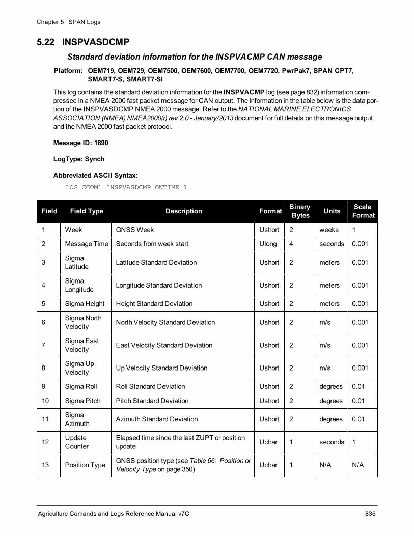
Chapter 5 SPAN Logs
Agriculture Comands and Logs Reference Manual v7C 836
5.22 INSPVASDCMPStandard deviation information for the INSPVACMP CAN message
Platform: OEM719, OEM729, OEM7500, OEM7600, OEM7700, OEM7720, PwrPak7, SPAN CPT7,SMART7-S, SMART7-SI
This log contains the standard deviation information for the INSPVACMP log (see page 832) information com-pressed in a NMEA 2000 fast packet message for CAN output. The information in the table below is the data por-tion of the INSPVASDCMP NMEA 2000message. Refer to theNATIONALMARINE ELECTRONICSASSOCIATION (NMEA) NMEA2000(r) rev 2.0 - January/2013 document for full details on this message outputand the NMEA 2000 fast packet protocol.
Message ID: 1890
LogType: Synch
Abbreviated ASCII Syntax:LOG CCOM1 INSPVASDCMP ONTIME 1
Field Field Type Description Format BinaryBytes Units Scale
Format
1 Week GNSSWeek Ushort 2 weeks 1
2 Message Time Seconds from week start Ulong 4 seconds 0.001
3 SigmaLatitude Latitude Standard Deviation Ushort 2 meters 0.001
4 SigmaLongitude Longitude Standard Deviation Ushort 2 meters 0.001
5 SigmaHeight Height Standard Deviation Ushort 2 meters 0.001
6 SigmaNorthVelocity North Velocity Standard Deviation Ushort 2 m/s 0.001
7 Sigma EastVelocity East Velocity Standard Deviation Ushort 2 m/s 0.001
8 SigmaUpVelocity Up Velocity Standard Deviation Ushort 2 m/s 0.001
9 SigmaRoll Roll Standard Deviation Ushort 2 degrees 0.01
10 Sigma Pitch Pitch Standard Deviation Ushort 2 degrees 0.01
11 SigmaAzimuth Azimuth Standard Deviation Ushort 2 degrees 0.01
12 UpdateCounter
Elapsed time since the last ZUPT or positionupdate Uchar 1 seconds 1
13 Position Type GNSS position type (see Table 66: Position orVelocity Type on page 350) Uchar 1 N/A N/A

Chapter 5 SPAN Logs
Agriculture Comands and Logs Reference Manual v7C 837
Field Field Type Description Format BinaryBytes Units Scale
Format
14ExtendedSolutionStatus
Extended Solution Status (see Table 200:Extended Solution Status on page 818) Hex 4 N/A N/A
15 ALIGN Age Elapsed time since a valid ROVERPOSsolution was available Uchar 1 seconds 1

Chapter 5 SPAN Logs
Agriculture Comands and Logs Reference Manual v7C 838
5.23 INSPVAXInertial PVA – Extended
Platform: OEM719, OEM729, OEM7500, OEM7600, OEM7700, OEM7720, PwrPak7, SPAN CPT7,SMART7-S, SMART7-SI
This log includes the information from the INSPVA log, as well as information about the position standard devi-ation. The position type and solution status fields indicate whether or not the corresponding data is valid.
The INSPVAX log is a large log and is not recommend for high rate logging.
If you want to use high rate logging, log the INSPVAS log (see page 834) at a high rate and theINSSTDEV log on page 844 ontime 1.
This log provides the position information in the user datum.
To determine the datum being used, log theBESTPOS log.
Message ID: 1465
Log Type: Synch
Recommended Input:log inspvaxa ontime 1
ASCII example:#INSPVAXA,COM4,0,48.0,FINESTEERING,2088,169979.000,02004020,471d,15823;INS_SOLUTION_GOOD,INS_PSRSP,51.15036795488,-114.03064190575,1097.3582,-17.0000,0.0007,-0.0027,0.0006,-0.056479668,0.504066737,90.285883014,5.2756,5.1919,5.9401,0.0014,0.0014,0.0011,0.5442,0.5345,0.0833,13000044,0*2813a8d7
Field Field Type Data Description Format BinaryBytes
BinaryOffset
1 INSPVAXHeader
Log header. SeeMessages on page 26 for moreinformation. H 0
2 INS Status Solution statusSee Table 199: Inertial Solution Status on page 813 Enum 4 H
3 Pos Type Position typeSee Table 66: Position or Velocity Type on page 350 Enum 4 H+4
4 Lat Latitude (degrees) Double 8 H+8
5 Long Longitude (degrees) Double 8 H+16
6 Height Height abovemean sea level (m) Double 8 H+24
7 Undulation Undulation (m) Float 4 H+32
8 North Vel North velocity (m/s) Double 8 H+36

Chapter 5 SPAN Logs
Agriculture Comands and Logs Reference Manual v7C 839
Field Field Type Data Description Format BinaryBytes
BinaryOffset
9 East Vel East velocity (m/s) Double 8 H+44
10 Up Vel Up velocity (m/s) Double 8 H+52
11 Roll Roll in Local Level (degrees) Double 8 H+60
12 Pitch Pitch in Local Level (degrees) Double 8 H+68
13 AzimuthAzimuth in Local Level (degrees)
This is the inertial azimuth calculated from the IMUgyros and the SPAN filters.
Double 8 H+76
14 Lat σ Latitude standard deviation (m) Float 4 H+84
15 Long σ Longitude standard deviation (m) Float 4 H+88
16 Height σ Height standard deviation (m) Float 4 H+92
17 North Vel σ North velocity standard deviation (m/s) Float 4 H+96
18 East Vel σ East velocity standard deviation (m/s) Float 4 H+100
19 Up Vel σ Up velocity standard deviation (m/s) Float 4 H+104
20 Roll σ Roll standard deviation (degrees) Float 4 H+108
21 Pitch σ Pitch standard deviation (degrees) Float 4 H+112
22 Azimuth σ Azimuth standard deviation (degrees) Float 4 H+116
23 Ext sol stat Extended solution statusSee Table 200: Extended Solution Status on page 818 Hex 4 H+120
24 Time SinceUpdate
Elapsed time since the last ZUPT or position update(seconds) Ushort 2 H+124
25 xxxx 32-bit CRC (ASCII and Binary only) Hex 4 H+126
26 [CR][LF] Sentence terminator (ASCII only) - - -
The INS covariance and standard deviation values reported by the SPAN filter are an estimate of theInertial filter solution quality. In lower accuracy GNSS positionmodes, such as SINGLE orWAAS (seeTable 66: Position or Velocity Type on page 350), the position covariance and standard deviation val-ues can appear to become optimistic compared with the absolute GNSS accuracy. This is due to theINS filter’s ability to smooth short term noise in the GNSS solution, although the overall position errorenvelope still reflects the GNSS accuracy. Therefore, if the desired application requires absoluteGNSS position accuracy, it is recommended to alsomonitor GNSS positionmessages such asBESTGNSSPOS (seeBESTGNSSPOS log on page 797).

Chapter 5 SPAN Logs
Agriculture Comands and Logs Reference Manual v7C 840
5.24 INSSEEDSTATUSStatus of INS Seed
Platform: OEM719, OEM729, OEM7500, OEM7600, OEM7700, OEM7720, PwrPak7, SPAN CPT7,SMART7-S, SMART7-SI
This log reports the current status of the INS Seed. See theOEM7SPAN Installation andOperation UserManual for more information about an INS Seed.
Message ID: 2129
Log Type: Asynch
Abbreviated ASCII Syntax:log insseedstatusa onnew
Example:#INSSEEDSTATUSA,COM3,0,66.0,FINESTEERING,1945,315811.009,02040020,9fd0,32768;INJECTED,ALLVALID,-0.098151498,0.298816800,95.888587952,-1634544.0523482216522098,-3664556.8064546003006399,4942534.6315599447116256,-16.9000,0,0,0,0*f353470c
Field Field Type Description Format BinaryBytes
BinaryOffset
1 INSSEEDSTATUSheader
Command header. SeeMessages on page 26 for moreinformation. - H 0
2 Injection Status Status of the INS Seed being injected into the solution.See Table 205: Injection Status on the next page Enum 4 H
3 Validity Status Flag to indicate if current seed data in NVM is valid.See Table 206: Validity Status on the next page Bool 4 H+4
4 Pitch IMU frame pitch angle (degrees) Float 4 H+8
5 Roll IMU frame roll angle (degrees) Float 4 H+12
6 Azimuth IMU frame azimuth angle (degrees) Float 4 H+16
7 PositionX ECEF-based x-coordinate Double 8 H+20
8 PositionY ECEF-based y-coordinate Double 8 H+28
9 PositionZ ECEF-based z-coordinate Double 8 H+36
10 Undulation Geoid undulation Float 4 H+44
11 Reserved Ulong 4 H+48
12 Reserved Ulong 4 H+52
13 Reserved Ulong 4 H+56
14 Reserved Ulong 4 H+60

Chapter 5 SPAN Logs
Agriculture Comands and Logs Reference Manual v7C 841
Field Field Type Description Format BinaryBytes
BinaryOffset
15 xxxx 32-bit CRC (ASCII and Binary only) Hex 4 H+64
16 [CR][LF] Sentence Terminator (ASCII only) - - -
Binary ASCII Description
0 NOT_INITIALIZED INS Seed has not been injected into the solution
1 INVALID Valid INS Seed was not found in non-volatile memory
2 FAILED INS Seed has failed validation and has been discarded
3 PENDING INS Seed is awaiting validation
4 INJECTED INS Seed alignment data has successfully been injected (including errormodel data)
5 IGNORED INS Seed was pending, but has been ignored due to a user commandedfilter reset or configuration change
6 ERRORMODELINJECTED INS Seed error model data has successfully been injected
Table 205: Injection Status
Binary ASCII Description
0 INVALID INS Seed in NVM is not valid
1 ALLVALID INS Seed in NVM is valid
2 ERRORMODELVALID INS Seed error model in NVM is valid (alignment data is not valid)
Table 206: Validity Status

Chapter 5 SPAN Logs
Agriculture Comands and Logs Reference Manual v7C 842
5.25 INSSPDINS Speed
Platform: OEM719, OEM729, OEM7500, OEM7600, OEM7700, OEM7720, PwrPak7, SPAN CPT7,SMART7-S, SMART7-SI
This log contains themost recent speedmeasurements in the horizontal and vertical directions and includes anINS status indicator.
Message ID: 266
Log Type: Synch
Recommended Input:log insspda ontime 1
ASCII Example:#INSSPDA,USB2,0,20.0,FINESTEERING,1541,487969.000,02040000,7832,37343;1541,487969.000549050,329.621116190,14.182070674,-0.126606551,INS_SOLUTION_GOOD*c274fff2
Field FieldType Description Format Binary
BytesBinaryOffset
1 INSSPDHeader Log header. SeeMessages on page 26 for more information. - H 0
2 Week GNSSWeek Ulong 4 H
3 SecondsintoWeek Seconds from week start Double 8 H+4
4 Trk gnd
Actual direction of motion over ground (track over ground) withrespect to True North, in degrees
The track over ground is determined by comparing the currentposition determined from theGNSS/INS solution with thepreviously determined position.
Track over ground is best used when the vehicle is moving.When the vehicle is stationary, position error canmake thedirection of motion appear to change randomly.
Double 8 H+12
5 HorizontalSpeed Magnitude of horizontal speed inm/s. Double 8 H+20
6 VerticalSpeed
Magnitude of vertical speed inm/s where a positive valueindicates speed upward and a negative value indicates speeddownward.
Double 8 H+28
7 Status INS status, see Table 199: Inertial Solution Status on page 813 Enum 4 H+36
8 xxxx 32-bit CRC (ASCII, Binary and Short Binary only) Hex 4 H+40
9 [CR][LF] Sentence terminator (ASCII only) - - -

Chapter 5 SPAN Logs
Agriculture Comands and Logs Reference Manual v7C 843
5.26 INSSPDSShort INS Speed
Platform: OEM719, OEM729, OEM7500, OEM7600, OEM7700, OEM7720, PwrPak7, SPAN CPT7,SMART7-S, SMART7-SI
This log is the short header version of the INSSPD log (see page 842).
Message ID: 323
Log Type: Synch
Recommended Input:log insspdsa ontime 1
ASCII Example:%INSSPDSA,1541,487975.000;1541,487975.000549050,323.101450813,9.787233999,-0.038980077,INS_SOLUTION_GOOD*105ba028
Field FieldType Description Format Binary
BytesBinaryOffset
1 INSSPDSHeader Log header. SeeMessages on page 26 for more information. - H 0
2 Week GNSSWeek Ulong 4 H
3 SecondsintoWeek Seconds from week start Double 8 H+4
4 Trk gnd
Actual direction of motion over ground (track over ground) withrespect to True North, in degrees.
The track over ground is determined by comparing the currentposition determined from theGNSS/INS solution with thepreviously determined position.
Track over ground is best used when the vehicle is moving.When the vehicle is stationary, position error canmake thedirection of motion appear to change randomly.
Double 8 H+12
5 HorizontalSpeed Magnitude of horizontal speed inm/s. Double 8 H+20
6 VerticalSpeed
Magnitude of vertical speed inm/s where a positive valueindicates speed upward and a negative value indicates speeddownward.
Double 8 H+28
7 Status INS status, see Table 199: Inertial Solution Status on page 813 Enum 4 H+36
8 xxxx 32-bit CRC (ASCII, Binary and Short Binary only) Hex 4 H+40
9 [CR][LF] Sentence terminator (ASCII only) - - -

Chapter 5 SPAN Logs
Agriculture Comands and Logs Reference Manual v7C 844
5.27 INSSTDEVINS PVA standard deviations
Platform: OEM719, OEM729, OEM7500, OEM7600, OEM7700, OEM7720, PwrPak7, SPAN CPT7,SMART7-S, SMART7-SI
This log displays the INS PVA standard deviations.
Message ID: 2051
Log Type: Synch
Abbreviated ASCII Syntax:log insstdev ontime 1
ASCII Example:#INSSTDEVA,COM1,0,78.0,FINESTEERING,1907,233990.000,02000020,3e6d,32768;0.4372,0.3139,0.7547,0.0015,0.0015,0.0014,3.7503,3.7534,5.1857,26000005,0,0,01ffd1bf,0*3deca7d2
Field Field Type Description BinaryFormat
BinaryBytes
BinaryOffset
1 INSSTDEVHeader
Log header. SeeMessages on page 26 formore information. - H 0
2 Latitude σ Latitude standard deviation (m) Float 4 H
3 Longitude σ Longitude standard deviation (m) Float 4 H+4
4 Height σ Height standard deviation (m) Float 4 H+8
5 North Velocityσ North velocity standard deviation (m/s) Float 4 H+12
6 East Velocityσ East velocity standard deviation (m/s) Float 4 H+16
7 Up Velocity σ Up velocity standard deviation (m/s) Float 4 H+20
8 Roll σ Roll standard deviation (degrees) Float 4 H+24
9 Pitch σ Pitch standard deviation (degrees) Float 4 H+28
10 Azimuth σ Azimuth standard deviation (degrees) Float 4 H+32
11 Ext sol statExtended solution status
See Table 200: Extended Solution Status onpage 818
Ulong 4 H+36
12 Time SinceUpdate
Elapsed time since the last ZUPT or positionupdate (seconds) Ushort 2 H+40
13 Reserved Ushort 2 H+42
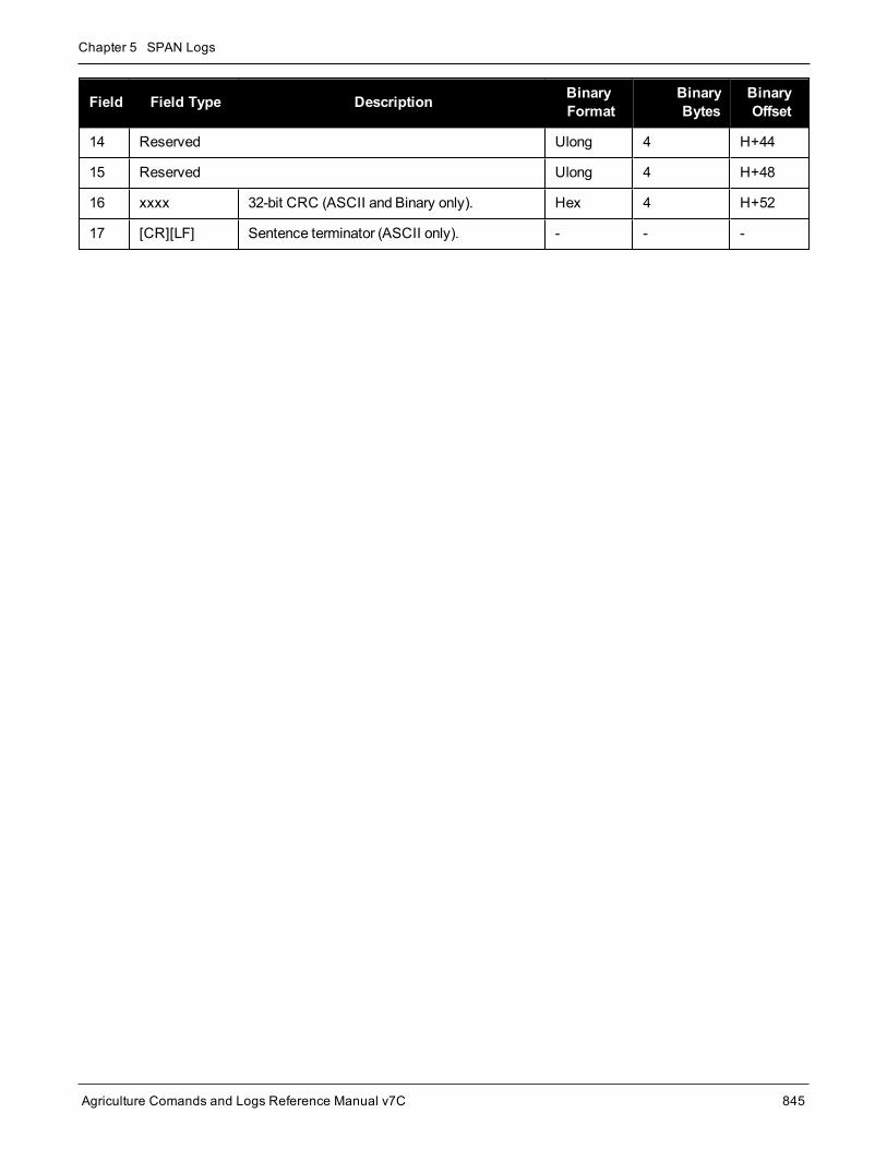
Chapter 5 SPAN Logs
Agriculture Comands and Logs Reference Manual v7C 845
Field Field Type Description BinaryFormat
BinaryBytes
BinaryOffset
14 Reserved Ulong 4 H+44
15 Reserved Ulong 4 H+48
16 xxxx 32-bit CRC (ASCII and Binary only). Hex 4 H+52
17 [CR][LF] Sentence terminator (ASCII only). - - -

Chapter 5 SPAN Logs
Agriculture Comands and Logs Reference Manual v7C 846
5.28 INSSTDEVSShort INS PVA standard deviations
Platform: OEM719, OEM729, OEM7500, OEM7600, OEM7700, OEM7720, PwrPak7, SPAN CPT7,SMART7-S, SMART7-SI
This log is the short header version of the INSSTDEV log (see page 844).
Message ID: 2052
Log Type: Synch
Abbreviated ASCII Syntax:log insstdevs ontime 1
ASCII Example:%INSSTDEVSA,1907,233990.000;0.4372,0.3139,0.7547,0.0015,0.0015,0.0014,3.7503,3.7534,5.1857,26000005,0,0,01ffd1bf,0*2c967ced
Field Field Type Description BinaryFormat
BinaryBytes
BinaryOffset
1 INSSTDEVHeader
Log header. SeeMessages on page 26 formore information. - H 0
2 Latitude σ Latitude standard deviation (m) Float 4 H
3 Longitude σ Longitude standard deviation (m) Float 4 H+4
4 Height σ Height standard deviation (m) Float 4 H+8
5 North Velocityσ North velocity standard deviation (m/s) Float 4 H+12
6 East Velocityσ East velocity standard deviation (m/s) Float 4 H+16
7 Up Velocity σ Up velocity standard deviation (m/s) Float 4 H+20
8 Roll σ Roll standard deviation (degrees) Float 4 H+24
9 Pitch σ Pitch standard deviation (degrees) Float 4 H+28
10 Azimuth σ Azimuth standard deviation (degrees) Float 4 H+32
11 Ext sol statExtended solution status
See Table 200: Extended Solution Status onpage 818
Ulong 4 H+36
12 Time SinceUpdate
Elapsed time since the last ZUPT or positionupdate (seconds) Ushort 2 H+40
13 Reserved Ushort 2 H+42

Chapter 5 SPAN Logs
Agriculture Comands and Logs Reference Manual v7C 847
Field Field Type Description BinaryFormat
BinaryBytes
BinaryOffset
14 Reserved Ulong 4 H+44
15 Reserved Ulong 4 H+48
16 xxxx 32-bit CRC (ASCII and Binary only). Hex 4 H+52
17 [CR][LF] Sentence terminator (ASCII only). - - -

Chapter 5 SPAN Logs
Agriculture Comands and Logs Reference Manual v7C 848
5.29 INSUPDATESTATUSINS Update Status
Platform: OEM719, OEM729, OEM7500, OEM7600, OEM7700, OEM7720, PwrPak7, SPAN CPT7,SMART7-S, SMART7-SI
This log provides themost recent INS update information. It provides information about what updates were per-formed in the INS filter at the last update epoch and a wheel sensor status indicator.
Message ID: 1825
Log Type: Asynch
Recommended Input:log insupdatestatus onchanged
ASCII Example:#INSUPDATESTATUSA,COM2,0,76.0,FINESTEERING,1934,149288.000,02000000,78f1,32768;SINGLE,0,0,0,INACTIVE,INACTIVE,00000005,00ffd1bf,0,0*d6b7ee02
Field Field Type Description Format BinaryBytes
BinaryOffset
1INSUPDATESTATUSHeader
Log header. SeeMessages on page 26 for moreinformation. - H 0
2 PosTypeType of GNSS solution used for the last INS filterupdate.See Table 66: Position or Velocity Type on page 350
Enum 4 H
3 NumPSR Number of raw pseudorange observations used in thelast INS filter update. Integer 4 H+4
4 NumADR Number of raw phase observations used in the lastINS filter update. Integer 4 H+8
5 NumDOP Number of raw doppler observations used in the lastINS filter update. Integer 4 H+12
6 DMI UpdateStatus
Distancemeasurement instrument (wheel sensor)status.See Table 207: DMI Update Status on the next page.
Enum 4 H+16
7 Heading UpdateStatus
Status of the heading update during the last INS filterupdate.See Table 208: Heading Update Values on the nextpage
Enum 4 H+20
8 Ext sol statExtended solution statusSee Table 200: Extended Solution Status onpage 818
Hex 4 H+24

Chapter 5 SPAN Logs
Agriculture Comands and Logs Reference Manual v7C 849
Field Field Type Description Format BinaryBytes
BinaryOffset
9 INS EnabledUpdates
Enabled INS updates.See Table 209: INS Update Values on the next page Hex 4 H+28
10 Reserved Ulong 4 H+32
11 Reserved Ulong 4 H+36
12 xxxx 32-bit CRC (ASCII, Binary and Short Binary only) Hex 4 H+40
13 [CR][LF] Sentence terminator (ASCII only) - - -
Binary ASCII Description
0 INACTIVE The DMI sensor is not connected.
1 ACTIVE The DMI sensor is connected but not used.
2 USED TheDMI sensor is connected and used in the INS solution.
3 RESERVED Reserved
4 BAD_MISC Themeasurement of the DMI sensor resulted in badmisclosure and was rejected.
5 HIGH_ROTATION
Themeasurement of the DMI sensor was not used because the system is undergoinghigh rotation.
6 DISABLED DMI updates are disabled.
7 ZUPT The DMI update reported zero velocity.
Table 207: DMI Update Status
Binary ASCII Description
0 INACTIVE A heading update was not available.
1 ACTIVEHeading updates are running, but the epoch is not used as an update. When all otherrejection criteria pass, a heading update will still only be applied once every 5 seconds(20 seconds when stationary).
2 USED The update for that epoch was taken.
5HEADING_UPDATE_BAD_MISC
Heading updates are running, but was not performed this epoch due to a large dis-agreement with filter estimates.
Table 208: Heading Update Values

Chapter 5 SPAN Logs
Agriculture Comands and Logs Reference Manual v7C 850
Nibble Bit Mask Description Range Value
N0
0 0x00000001 Position update 0 = Disabled1 = Enabled
1 0x00000002 Phase update 0 = Disabled1 = Enabled
2 0x00000004 Zero velocity update 0 = Disabled1 = Enabled
3 0x00000008 Wheel sensor update 0 = Disabled1 = Enabled
N1
4 0x00000010 ALIGN (heading) update 0 = Disabled1 = Enabled
5 0x00000020 External position update 0 = Disabled1 = Enabled
6 0x00000040 Reserved
7 0x00000080 Doppler update 0 = Disabled1 = Enabled
N2
8 0x00000100 Pseudorange update 0 = Disabled1 = Enabled
9 0x00000200 Velocity update 0 = Disabled1 = Enabled
10 0x00000400 Reserved
11 0x00000800 Dead reckoning update 0 = Disabled1 = Enabled
N3
12 0x00001000 Phase wind up update 0 = Disabled1 = Enabled
13 0x00002000 Course over ground update 0 = Disabled1 = Enabled
14 0x00004000 External velocity update 0 = Disabled1 = Enabled
15 0x00008000 External attitude update 0 = Disabled1 = Enabled
Table 209: INS Update Values

Chapter 5 SPAN Logs
Agriculture Comands and Logs Reference Manual v7C 851
Nibble Bit Mask Description Range Value
N4
16 0x00010000 External heading update 0 = Disabled1 = Enabled
17 0x00020000 External height update 0 = Disabled1 = Enabled
18 0x00040000 Reserved
19 0x00080000 Reserved

Chapter 5 SPAN Logs
Agriculture Comands and Logs Reference Manual v7C 852
5.30 INSVELINS Velocity
Platform: OEM719, OEM729, OEM7500, OEM7600, OEM7700, OEM7720, PwrPak7, SPAN CPT7,SMART7-S, SMART7-SI
This log contains themost recent North, East and Up velocity vector values, with respect to the local level frameand also includes an INS status indicator.
Message ID: 267
Log Type: Synch
Recommended Input:log insvela ontime 1
ASCII Example:#INSVELA,USB1,0,19.0,FINESTEERING,1543,236173.000,02000000,9c95,37343;1543,236173.002500000,14.139471871,-0.070354464,-0.044204369,INS_SOLUTION_GOOD*3c37c0fc
Field Field Type Description Format BinaryBytes
BinaryOffset
1 INSVELHeader
Log header. SeeMessages on page 26 for moreinformation. - H 0
2 Week GNSSWeek Ulong 4 H
3 Seconds intoWeek Seconds from week start Double 8 H+4
4 North Velocity Velocity North in m/s Double 8 H+12
5 East Velocity Velocity East in m/s Double 8 H+20
6 Up Velocity Velocity Up inm/s Double 8 H+28
7 Status INS status, see Table 199: Inertial Solution Statuson page 813 Enum 4 H+36
8 xxxx 32-bit CRC (ASCII, Binary and Short Binary only) Hex 4 H+40
9 [CR][LF] Sentence terminator (ASCII only) - - -

Chapter 5 SPAN Logs
Agriculture Comands and Logs Reference Manual v7C 853
5.31 INSVELSShort INS Velocity
Platform: OEM719, OEM729, OEM7500, OEM7600, OEM7700, OEM7720, PwrPak7, SPAN CPT7,SMART7-S, SMART7-SI
This log is the short header version of the INSVEL log (see page 852).
Message ID: 324
Log Type: Synch
Recommended Input:log insvelsa ontime 1
ASCII Example:%INSVELSA,1921,152855.200;1921,152855.200000000,0.1077,-9.8326,-0.1504,INS_SOLUTION_GOOD*efd71f65
Field Field Type Description Format BinaryBytes
BinaryOffset
1 INSVELSHeader
Log header. SeeMessages on page 26 for moreinformation. - H 0
2 Week GNSSWeek Ulong 4 H
3 Seconds intoWeek Seconds from week start Double 8 H+4
4 North Velocity Velocity North m/s Double 8 H+12
5 East Velocity Velocity East m/s Double 8 H+20
6 Up Velocity Velocity Upm/s Double 8 H+28
7 Status INS status, see Table 199: Inertial Solution Statuson page 813 Enum 4 H+36
8 xxxx 32-bit CRC (ASCII, Binary and Short Binary only) Hex 4 H+40
9 [CR][LF] Sentence terminator (ASCII only) - - -

Chapter 5 SPAN Logs
Agriculture Comands and Logs Reference Manual v7C 854
5.32 INSVELXInertial Velocity – Extended
Platform: OEM719, OEM729, OEM7500, OEM7600, OEM7700, OEM7720, PwrPak7, SPAN CPT7,SMART7-S, SMART7-SI
This log includes the information from the INSVEL log, as well as information about the velocity standard devi-ation. The position type and solution status fields indicate whether or not the corresponding data is valid.
The INSVELX log is a large log and is not recommend for high rate logging.
If you want to use high rate logging, log the INSVELS log at a high rate and the INSSTDEVS log ontime1.
Message ID: 1458
Log Type: Synch
Recommended Input:log insvelxa ontime 1
ASCII example:#INSVELXA,COM4,0,46.5,FINESTEERING,2088,169982.000,02004020,1a1f,15823;INS_SOLUTION_GOOD,INS_PSRSP,0.0003,0.0002,-0.0009,0.0014,0.0014,0.0011,13000044,0*3f7881dc
Field Field Type Description Format BinaryBytes
BinaryOffset
1 INSVELXHeader
Log header. SeeMessages on page 26 for moreinformation. H 0
2 INS StatusSolution statusSee Table 199: Inertial Solution Status onpage 813
Enum 4 H
3 Pos TypePosition typeSee Table 66: Position or Velocity Type onpage 350
Enum 4 H+4
4 North Vel North velocity (m/s) Double 8 H+8
5 East Vel East velocity (m/s) Double 8 H+16
6 Up Vel Up velocity (m/s) Double 8 H+24
7 North Vel σ North velocity standard deviation (m/s) Float 4 H+32
8 East Vel σ East velocity standard deviation (m/s) Float 4 H+36
9 Up Vel σ Up velocity standard deviation (m/s) Float 4 H+40

Chapter 5 SPAN Logs
Agriculture Comands and Logs Reference Manual v7C 855
Field Field Type Description Format BinaryBytes
BinaryOffset
10 Ext sol statExtended solution statusSee Table 200: Extended Solution Status onpage 818
Hex 4 H+44
11 Time SinceUpdate
Elapsed time since the last ZUPT or positionupdate (seconds) Ushort 2 H+48
11 xxxx 32-bit CRC (ASCII and Binary only) Hex 4 H+50
12 [CR][LF] Sentence terminator (ASCII only) - - -

Chapter 5 SPAN Logs
Agriculture Comands and Logs Reference Manual v7C 856
5.33 RAWIMURaw IMU Data
Platform: OEM719, OEM729, OEM7500, OEM7600, OEM7700, OEM7720, PwrPak7, SPAN CPT7,SMART7-S, SMART7-SI
This log contains an IMU status indicator and themeasurements from the accelerometers and gyros withrespect to the IMU enclosure frame. If logging this data, consider theRAWIMUS log (see page 875) to reducethe amount of data.
The change in velocity (acceleration) and angle (rotation rate) scale factors for each IMU type can befound in Table 222: Raw IMU Scale Factors on page 877. Multiply the appropriate scale factor by thecount value for the velocity (field 5-7) and angle (field 8-10) increments.
To obtain acceleration in m/s/s or rotation rate in rad/s, multiply the velocity/rotation increments by theoutput rate of the IMU:
l 100 Hz for HG1700, HG1900, HG1930 and HG4930
l 125 Hz for STIM300, G320N, PwrPak7-E1, PwrPak7D-E1 and SMART7-S
l 200 Hz for ISA-100C, iMAR-FSAS, LN200, KVH1750, ADIS16488, G370N, G320N_200Hz,PwrPak7-E2 and PwrPak7D-E2
The units of acceleration and rotation rate will depend on the IMU Scale Factors.
This log is output in the IMU Body frame.
Logging Restriction Important Notice
Logging excessive amounts of high rate data can overload the system. When configuring theoutput for SPAN, NovAtel recommends that only one high rate (>50Hz) message be configuredfor output at a time. It is possible to logmore than onemessage at high rates, but doing so couldhave negative impacts on the system. Also, if logging 100/125/200Hz data, always use thebinary format and, if possible, the short header binary format (available onmost INS logs).
For optimal performance, log only one high rate output at a time. These logs could be:
l Raw data for post processingRAWIMUXSB ONNEW (100, 125 or 200 Hz depending on IMU)
l RAWIMU logs are not valid with the ONTIME trigger. The raw IMU observations con-tained in these logs are sequential changes in velocity and rotation. As such, you canonly use them for navigation if they are logged at their full rate.
l Real time INS solutionIMURATEPVA ONNEW or IMURATEPVAS ONNEW
Other possible INS solution logs available at high rates are: INSPVASB, INSPOSSB,INSVELSB, INSATTSB
Message ID: 268

Chapter 5 SPAN Logs
Agriculture Comands and Logs Reference Manual v7C 857
Log Type: Asynch
Recommended Input:log rawimua onnew
ASCII Example:#RAWIMUA,COM1,0,68.5,FINESTEERING,1724,219418.009,024c0040,6125,30019;1724,219418.008755000,00000077,64732,56,298,8,28,-3*7378486f
Field FieldType Description Format Binary
BytesBinaryOffset
1 RAWIMUHeader Log header. SeeMessages on page 26 for more information. - H 0
2 Week GNSSWeek Ulong 4 H
3SecondsintoWeek
Seconds from week start Double 8 H+4
4 IMUStatus
The status of the IMU. This field is given in a fixed length (n)array of bytes in binary but in ASCII or Abbreviated ASCII isconverted into 2 character hexadecimal pairs.
For the raw IMU status, see one of the following tables:
l Table 210: iIMU-FSAS IMU Status on the next page
l Table 211: HG1700 IMU Status on page 859
l Table 212: LN200 IMU Status on page 861
l Table 213: ISA-100C IMU Status on page 862
l Table 214: IMU-CPT IMU Status on page 863
l Table 215: IMU-KVH1750 IMU Status on page 865
l Table 216: HG1900 and HG1930 IMU Status on page 866
l Table 217: HG4930 IMU Status on page 868
l Table 218: ADIS16488 and IMU-IGM-A1 IMU Status onpage 869
l Table 219: STIM300 and IMU-IGM-S1 IMU Status onpage 870
l Table 220: µIMU IMU Status on page 872
l Table 221: G320N andG370N IMU Status on page 873
Also refer to Interface Control Documentation as provided byHoneywell or Northrop Grumman.
HexUlong 4 H+12
5 Z AccelOutput Change in velocity count along z axis Long 4 H+16

Chapter 5 SPAN Logs
Agriculture Comands and Logs Reference Manual v7C 858
Field FieldType Description Format Binary
BytesBinaryOffset
6 - (Y AccelOutput)
- (Change in velocity count along y axis)
A negative value implies the output is along the positive y-axismarked on the IMU. A positive value implies the change is in thedirection opposite to that of the y-axis marked on the IMU.
Long 4 H+20
7 X AccelOutput Change in velocity count along x axis Long 4 H+24
8 Z GyroOutput
Change in angle count around z axis.Right-handed Long 4 H+28
9 - (Y GyroOutput)
- (Change in angle count around y axis).Right-handed
A negative value implies the output is along the positive y-axismarked on the IMU. A positive value implies the change is in thedirection opposite to that of the y-axis marked on the IMU.
Long 4 H+32
10 X GyroOutput
Change in angle count around x axis.Right-handed Long 4 H+36
11 xxxx 32-bit CRC (ASCII, Binary and Short Binary only) Hex 4 H+40
12 [CR][LF] Sentence terminator (ASCII only) - - -
Nibble Bit Mask Description Range Value
N0
0 0x00000001
Reserved1 0x00000002
2 0x00000004
3 0x00000008
N1
4 0x00000010 Gyro warm-up 0 = Passed, 1 = Failed
5 0x00000020 Gyro self-test active 0 = Passed, 1 = Failed
6 0x00000040 Gyro status bit set 0 = Passed, 1 = Failed
7 0x00000080 Gyro time-out command interface 0 = Passed, 1 = Failed
N2
8 0x00000100 Power-up built-in test (PBIT) 0 = Passed, 1 = Failed
9 0x00000200 Reserved
10 0x00000400 Interrupt 0 = Passed, 1 = Failed
11 0x00000800 Reserved
Table 210: iIMU-FSAS IMU Status

Chapter 5 SPAN Logs
Agriculture Comands and Logs Reference Manual v7C 859
Nibble Bit Mask Description Range Value
N3
12 0x00001000 Warm-up 0 = Passed, 1 = Failed
13 0x00002000Reserved
14 0x00004000
15 0x00008000 Initiated built-in test (IBIT) 0 = Passed, 1 = Failed
N4
16 0x00010000Reserved
17 0x00020000
18 0x00040000 Accelerometer 0 = Passed, 1 = Failed
19 0x00080000 Accelerometer time-out 0 = Passed, 1 = Failed
N5
20 0x00100000 Reserved
21 0x00200000 Gyro initiated BIT 0 = Passed, 1 = Failed
22 0x00400000 Gyro self-test 0 = Passed, 1 = Failed
23 0x00800000 Gyro time-out 0 = Passed, 1 = Failed
N6
24 0x01000000 Analog-to-Digital (AD) 0 = Passed, 1 = Failed
25 0x02000000 Test mode 0 = Passed, 1 = Failed
26 0x04000000 Software 0 = Passed, 1 = Failed
27 0x08000000 RAM/ROM 0 = Passed, 1 = Failed
N7
28 0x10000000 Reserved
29 0x20000000 Operational 0 = Passed, 1 = Failed
30 0x40000000 Interface 0 = Passed, 1 = Failed
31 0x80000000 Interface time-out 0 = Passed, 1 = Failed
Nibble Bit Mask Description Range Value
N0
0 0x00000001 Reserved
1 0x00000002 Reserved
2 0x00000004 Reserved
3 0x00000008 Reserved
Table 211: HG1700 IMU Status

Chapter 5 SPAN Logs
Agriculture Comands and Logs Reference Manual v7C 860
Nibble Bit Mask Description Range Value
N1
4 0x00000010 IMU Status 0 = Passed, 1 = Failed
5 0x00000020 IMU Status 0 = Passed, 1 = Failed
6 0x00000040 IMU Status 0 = Passed, 1 = Failed
7 0x00000080 IMU Status 0 = Passed, 1 = Failed
N2
8 0x00000100 Reserved
9 0x00000200 Reserved
10 0x00000400 Reserved
11 0x00000800 Reserved
N3
12 0x00001000 Reserved
13 0x00002000 Reserved
14 0x00004000 Reserved
15 0x00008000 Reserved
N4
16 0x00010000 Reserved
17 0x00020000 Reserved
18 0x00040000 Reserved
19 0x00080000 Reserved
N5
20 0x00100000 Reserved
21 0x00200000 Reserved
22 0x00400000 Reserved
23 0x00800000 Reserved
N6
24 0x01000000 Reserved
25 0x02000000 Reserved
26 0x04000000 Reserved
27 0x08000000 IMU Status 0 = Passed, 1= Failed
N7
28 0x10000000 IMU Status 0 = Passed, 1 = Failed
29 0x20000000 IMU Status 0 = Passed, 1 = Failed
30 0x40000000 IMU Status 0 = Passed, 1 = Failed
31 0x80000000 IMU Status 0 = Passed, 1 = Failed

Chapter 5 SPAN Logs
Agriculture Comands and Logs Reference Manual v7C 861
Nibble Bit Mask Description Range Value
N0
0 0x00000001 IMU Status 0 = Passed, 1 = Failed
1 0x00000002 IMU Status 0 = Passed, 1 = Failed
2 0x00000004 IMU Status 0 = Passed, 1 = Failed
3 0x00000008 IMU Status 0 = Passed, 1 = Failed
N1
4 0x00000010 IMU Status 0 = Passed, 1 = Failed
5 0x00000020 IMU Status 0 = Passed, 1 = Failed
6 0x00000040 IMU Status 0 = Passed, 1 = Failed
7 0x00000080 IMU Status 0 = Passed, 1 = Failed
N2
8 0x00000100 IMU Status 0 = Passed, 1 = Failed
9 0x00000200 IMU Status 0 = Passed, 1 = Failed
10 0x00000400 IMU Status 0 = Passed, 1 = Failed
11 0x00000800 IMU Status 0 = Passed, 1 = Failed
N3
12 0x00001000 IMU Status 0 = Passed, 1 = Failed
13 0x00002000 IMU Status 0 = Passed, 1 = Failed
14 0x00004000 IMU Status 0 = Passed, 1 = Failed
15 0x00008000 Reserved
N4
16 0x00010000 Reserved
17 0x00020000 Reserved
18 0x00040000 Reserved
19 0x00080000 Reserved
N5
20 0x00100000 Reserved
21 0x00200000 Reserved
22 0x00400000 Reserved
23 0x00800000 Reserved
N6
24 0x01000000 IMU Status 0 = Passed, 1 = Failed
25 0x02000000 IMU Status 0 = Passed, 1 = Failed
26 0x04000000 IMU Status 0 = Passed, 1 = Failed
27 0x08000000 IMU Status 0 = Passed, 1 = Failed
Table 212: LN200 IMU Status

Chapter 5 SPAN Logs
Agriculture Comands and Logs Reference Manual v7C 862
Nibble Bit Mask Description Range Value
N7
28 0x10000000 IMU Status 0 = Passed, 1 = Failed
29 0x20000000 Reserved
30 0x40000000 IMU Status 0 = Passed, 1 = Failed
31 0x80000000 Reserved
Nibble Bit Mask Description Range Value
N0
0 0x00000001 Maintenance Indication 0 = Normal,1 = SystemMaintenance Indicator
1 0x00000002 Accelerometers Invalid 0 = Normal, 1 = Invalid
2 0x00000004 Accelerometer X Warning 0 = Normal, 1 = Warning
3 0x00000008 Accelerometer Y Warning 0 = Normal, 1 = Warning
N1
4 0x00000010 Accelerometer ZWarning 0 = Normal, 1 = Warning
5 0x00000020 Accelerometer X NOGO 0 = Normal, 1 = NOGO
6 0x00000040 Accelerometer Y NOGO 0 = Normal, 1 = NOGO
7 0x00000080 Accelerometer Z NOGO 0 = Normal, 1 = NOGO
N2
8 0x00000100 Reset Occurred 0 = Normal,1 = First Message after ISA-100C Reset
9 0x00000200 Gyroscopes Invalid 0 = Normal, 1 = Invalid
10 0x00000400 Gyroscope X Warning 0 = Normal, 1 = Warning
11 0x00000800 Gyroscope Y Warning 0 = Normal, 1 = Warning
N3
12 0x00001000 Gyroscope ZWarning 0 = Normal, 1 = Warning
13 0x00002000 Gyroscope X NOGO 0 = Normal, 1 = NOGO
14 0x00004000 Gyroscope Y NOGO 0 = Normal, 1 = NOGO
15 0x00008000 Gyroscope Z NOGO 0 = Normal, 1 = NOGO
Table 213: ISA-100C IMU Status

Chapter 5 SPAN Logs
Agriculture Comands and Logs Reference Manual v7C 863
Nibble Bit Mask Description Range Value
N4
16 0x00010000
IMU temperature reading as follows:
Signed 2-byte value (SHORT)
1 LSB = 3.90625e-3Celsius
Temperature Range +/- 128 Celsius
17 0x00020000
18 0x00040000
19 0x00080000
N5
20 0x00100000
21 0x00200000
22 0x00400000
23 0x00800000
N6
24 0x01000000
25 0x02000000
26 0x04000000
27 0x08000000
N7
28 0x10000000
29 0x20000000
30 0x40000000
31 0x80000000
Nibble Bit Mask Description Range Value
N0
0 0x00000001 Gyro X Status 1 = Valid, 0 = Invalid
1 0x00000002 Gyro Y Status 1 = Valid, 0 = Invalid
2 0x00000004 Gyro Z Status 1 = Valid, 0 = Invalid
3 0x00000008 Unused Set to 0
N1
4 0x00000010 Accelerometer X Status 1 = Valid, 0 = Invalid
5 0x00000020 Accelerometer Y Status 1 = Valid, 0 = Invalid
6 0x00000040 Accelerometer Z Status 1 = Valid, 0 = Invalid
7 0x00000080 Unused Set to 0
Table 214: IMU-CPT IMU Status

Chapter 5 SPAN Logs
Agriculture Comands and Logs Reference Manual v7C 864
Nibble Bit Mask Description Range Value
N2
8 0x00000100
IMU Data Sequence Counter read in a Ushort.
Note: Increments for eachmessage and resets to 0 after 127.
9 0x00000200
10 0x00000400
11 0x00000800
N3
12 0x00001000
13 0x00002000
14 0x00004000
15 0x00008000
N4
16 0x00010000
Unused
17 0x00020000
18 0x00040000
19 0x00080000
N5
20 0x00100000
21 0x00200000
22 0x00400000
23 0x00800000
N6
24 0x01000000
25 0x02000000
26 0x04000000
27 0x08000000
N7
28 0x10000000
29 0x20000000
30 0x40000000
31 0x80000000

Chapter 5 SPAN Logs
Agriculture Comands and Logs Reference Manual v7C 865
Nibble Bit Mask Description Range Value
N0
0 0x00000001 Gyro X Status 1 = Valid, 0 = Invalid
1 0x00000002 Gyro Y Status 1 = Valid, 0 = Invalid
2 0x00000004 Gyro Z Status 1 = Valid, 0 = Invalid
3 0x00000008 Unused Set to 0
N1
4 0x00000010 Accelerometer X Status 1 = Valid, 0 = Invalid
5 0x00000020 Accelerometer Y Status 1 = Valid, 0 = Invalid
6 0x00000040 Accelerometer Z Status 1 = Valid, 0 = Invalid
7 0x00000080 Unused Set to 0
N2
8 0x00000100
IMU Data Sequence Counter read in a Ushort.
Note: Increments for eachmessage and resets to 0 after 127.
9 0x00000200
10 0x00000400
11 0x00000800
N3
12 0x00001000
13 0x00002000
14 0x00004000
15 0x00008000
Table 215: IMU-KVH1750 IMU Status

Chapter 5 SPAN Logs
Agriculture Comands and Logs Reference Manual v7C 866
Nibble Bit Mask Description Range Value
N4
16 0x00010000
IMU temperature reading as follows:
Signed 2-byte value (SHORT)
Rounded to the nearest degree
Example:
<RAWIMU COM1 0 75.0 FINESTEERING 1813 514207.000 00000020 fa9a 458361813 514207.000000000 00260077 32164 -47 -305 1 -10 0
IMU status = 00260077
Temperatures bytes = 0026
Decimal value = 38 degrees C
17 0x00020000
18 0x00040000
19 0x00080000
N5
20 0x00100000
21 0x00200000
22 0x00400000
23 0x00800000
N6
24 0x01000000
25 0x02000000
26 0x04000000
27 0x08000000
N7
28 0x10000000
29 0x20000000
30 0x40000000
31 0x80000000
Nibble Bit Mask Description Range Value
N0
0 0x00000001
Reserved1 0x00000002
2 0x00000004
3 0x00000008
N1
4 0x00000010 IMU Status 0 = Passed, 1 = Failed
5 0x00000020 IMU Status 0 = Passed, 1 = Failed
6 0x00000040 IMU Status 0 = Passed, 1 = Failed
7 0x00000080 IMU Status 0 = Passed, 1 = Failed
Table 216: HG1900 and HG1930 IMU Status

Chapter 5 SPAN Logs
Agriculture Comands and Logs Reference Manual v7C 867
Nibble Bit Mask Description Range Value
N2
8 0x00000100
Reserved9 0x00000200
10 0x00000400
11 0x00000800
N3
12 0x00001000
Reserved13 0x00002000
14 0x00004000
15 0x00008000
N4
16 0x00010000
Reserved17 0x00020000
18 0x00040000
19 0x00080000
N5
20 0x00100000
Reserved21 0x00200000
22 0x00400000
23 0x00800000
N6
24 0x01000000 IMU Status 0 = Passed, 1 = Failed
25 0x02000000 Reserved
26 0x04000000 IMU Status 0 = Passed, 1 = Failed
27 0x08000000 IMU Status 0 = Passed, 1 = Failed
N7
28 0x10000000 IMU Status 0 = Passed, 1 = Failed
29 0x20000000 IMU Status 0 = Passed, 1 = Failed
30 0x40000000 IMU Status 0 = Passed, 1 = Failed
31 0x80000000 Reserved

Chapter 5 SPAN Logs
Agriculture Comands and Logs Reference Manual v7C 868
Nibble Bit Mask Description Range Value
N0
0 0x00000001 IMU Status 0 = Passed, 1 = Failed
1 0x00000002Reserved
2 0x00000004
3 0x00000008 Gyro Status 0 = Passed, 1 = Failed
N1
4 0x00000010 Accelerometer Status 0 = Passed, 1 = Failed
5 0x00000020 Reserved
6 0x00000040 IMU Status 0 = Passed, 1 = Failed
7 0x00000080 Reserved
N2
8 0x00000100
Reserved9 0x00000200
10 0x00000400
11 0x00000800
N3
12 0x00001000
Reserved13 0x00002000
14 0x00004000
15 0x00008000
N4
16 0x00010000
Reserved17 0x00020000
18 0x00040000
19 0x00080000
N5
20 0x00100000
Reserved21 0x00200000
22 0x00400000
23 0x00800000
N6
24 0x01000000
Reserved25 0x02000000
26 0x04000000
27 0x08000000
Table 217: HG4930 IMU Status

Chapter 5 SPAN Logs
Agriculture Comands and Logs Reference Manual v7C 869
Nibble Bit Mask Description Range Value
N7
28 0x10000000
Reserved29 0x20000000
30 0x40000000
31 0x80000000
Nibble Bit Mask Description Range Value
N0
0 0x00000001 Alarm Status Flag
1 0x00000002Reserved
2 0x00000004
3 0x00000008 SPI Communication Error 0 = Passed, 1 = Failed
N1
4 0x00000010 Sensor Over-Range 0 = Passed,1 = One of more sensors over-ranged
5 0x00000020 Initial Self Test Failure 0 = Passed, 1= Failed
6 0x00000040 FlashMemory Failure 0 = Passed, 1 = Failed
7 0x00000080 Processing Overrun 0 = Passed, 1 = Failed
N2
8 0x00000100 Self Test Failure – X-axis gyro 0 = Passed, 1 = Failed
9 0x00000200 Self Test Failure – Y-axis gyro 0 = Passed, 1 = Failed
10 0x00000400 Self Test Failure – Z-axis gyro 0 = Passed, 1 = Failed
11 0x00000800 Self Test Failure – X-axis accelerometer 0 = Passed, 1 = Failed
N3
12 0x00001000 Self Test Failure – Y-axis accelerometer 0 = Passed, 1 = Failed
13 0x00002000 Self Test Failure – Z-axis 0 = Passed, 1 = Failed
14 0x00004000Reserved
15 0x00008000
Table 218: ADIS16488 and IMU-IGM-A1 IMU Status
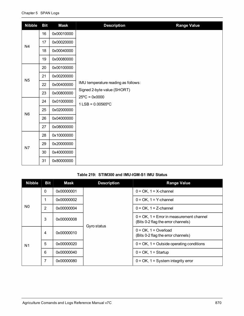
Chapter 5 SPAN Logs
Agriculture Comands and Logs Reference Manual v7C 870
Nibble Bit Mask Description Range Value
N4
16 0x00010000
IMU temperature reading as follows:
Signed 2-byte value (SHORT)
25ºC = 0x0000
1 LSB = 0.00565ºC
17 0x00020000
18 0x00040000
19 0x00080000
N5
20 0x00100000
21 0x00200000
22 0x00400000
23 0x00800000
N6
24 0x01000000
25 0x02000000
26 0x04000000
27 0x08000000
N7
28 0x10000000
29 0x20000000
30 0x40000000
31 0x80000000
Nibble Bit Mask Description Range Value
N0
0 0x00000001
Gyro status
0 = OK, 1 = X-channel
1 0x00000002 0 = OK, 1 = Y-channel
2 0x00000004 0 = OK, 1 = Z-channel
3 0x00000008 0 = OK, 1 = Error in measurement channel(Bits 0-2 flag the error channels)
N1
4 0x00000010 0 = OK, 1 = Overload(Bits 0-2 flag the error channels)
5 0x00000020 0 = OK, 1 = Outside operating conditions
6 0x00000040 0 = OK, 1 = Startup
7 0x00000080 0 = OK, 1 = System integrity error
Table 219: STIM300 and IMU-IGM-S1 IMU Status

Chapter 5 SPAN Logs
Agriculture Comands and Logs Reference Manual v7C 871
Nibble Bit Mask Description Range Value
N2
8 0x00000100
Accelerometer Status
0 = OK, 1 = X-channel
9 0x00000200 0 = OK, 1 = Y-channel
10 0x00000400 0 = OK, 1 = Z-channel
11 0x00000800 0 = OK, 1 = Error in measurement channel(Bits 0-2 flag the error channels)
N3
12 0x00001000 0 = OK, 1 = Overload(Bits 0-2 flag the error channels)
13 0x00002000 0 = OK, 1 = Outside operating conditions
14 0x00004000 0 = OK, 1 = Startup
15 0x00008000 0 = OK, 1 = System integrity error
N4
16 0x00010000
Temperature of the X gyro sensor
0ºC = 0x0000
1 LSB = 2-8 ºC
17 0x00020000
18 0x00040000
19 0x00080000
N5
20 0x00100000
21 0x00200000
22 0x00400000
23 0x00800000
N6
24 0x01000000
25 0x02000000
26 0x04000000
27 0x08000000
N7
28 0x10000000
29 0x20000000
30 0x40000000
31 0x80000000

Chapter 5 SPAN Logs
Agriculture Comands and Logs Reference Manual v7C 872
Nibble Bit Mask Description Range Value
N0
0 0x00000001 Reset Acknowledged 0 = Normal, 1 = Reset
1 0x00000002 Gyros Not Initialized 0 = Normal, 1 = Not Initialized
2 0x00000004 Gyro X Warning 0 = Normal, 1 = Warning
3 0x00000008 Gyro Y Warning 0 = Normal, 1 = Warning
N1
4 0x00000010 Gyro ZWarning 0 = Normal, 1 = Warning
5 0x00000020 Gyro X NOGO 0 = Normal, 1 = NOGO
6 0x00000040 Gyro Y NOGO 0 = Normal, 1 = NOGO
7 0x00000080 Gyro Z NOGO 0 = Normal, 1 = NOGO
N2
8 0x00000100 Reserved
9 0x00000200 Accels Not Initialized 0 = Normal, 1 = Not Initialized
10 0x00000400 Accel X Warning 0 = Normal, 1 = Warning
11 0x00000800 Accel Y Warning 0 = Normal, 1 = Warning
N3
12 0x00001000 Accel ZWarning 0 = Normal, 1 = Warning
13 0x00002000 Accel X NOGO 0 = Normal, 1 = NOGO
14 0x00004000 Accel Y NOGO 0 = Normal, 1 = NOGO
15 0x00008000 Accel Z NOGO 0 = Normal, 1 = NOGO
Table 220: µIMU IMU Status

Chapter 5 SPAN Logs
Agriculture Comands and Logs Reference Manual v7C 873
Nibble Bit Mask Description Range Value
N4
16 0x00010000
IMU temperature reading as follows:
Signed 2-byte value (SHORT)
1 LSB = 3.90625e^-3 ºC
Temperature Range +/- 128 ºC
17 0x00020000
18 0x00040000
19 0x00080000
N5
20 0x00100000
21 0x00200000
22 0x00400000
23 0x00800000
N6
24 0x01000000
25 0x02000000
26 0x04000000
27 0x08000000
N7
28 0x10000000
29 0x20000000
30 0x40000000
31 0x80000000
Nibble Bit Mask Description Range Value
N0
0 0x00000001 Error All 0 = Normal, 1 = Sensor Failure
1 0x00000002
Reserved
2 0x00000004
3 0x00000008
N1
4 0x00000010
5 0x00000020
6 0x00000040
7 0x00000080
Table 221: G320N and G370N IMU Status

Chapter 5 SPAN Logs
Agriculture Comands and Logs Reference Manual v7C 874
Nibble Bit Mask Description Range Value
N2
8 0x00000100
9 0x00000200 Accel Z - New Data New Data = 1, No Data = 0
10 0x00000400 Accel Y - New Data New Data = 1, No Data = 0
11 0x00000800 Accel X - New Data New Data = 1, No Data = 0
N3
12 0x00001000 Gyro Z - New Data New Data = 1, No Data = 0
13 0x00002000 Gyro Y - New Data New Data = 1, No Data = 0
14 0x00004000 Gyro X - New Data New Data = 1, No Data = 0
15 0x00008000 Temperature - New Data New Data = 1, No Data = 0
N4
16 0x00010000
IMU Temperature reading as follows:
Temperature = [(-0.0037918 * (A - 2634)) + 25] Celsius
A: Temperature Sensor output data (decimal)
17 0x00020000
18 0x00040000
19 0x00080000
N5
20 0x00100000
21 0x00200000
22 0x00400000
23 0x00800000
N6
24 0x01000000
25 0x02000000
26 0x04000000
27 0x08000000
N7
28 0x10000000
29 0x20000000
30 0x40000000
31 0x80000000
The values in Table 221: G320N andG370N IMU Status on the previous page also apply to thePwrPak7-E1, PwrPak7D-E1, PwrPak7-E2, PwrPak7D-E2 and SMART7-S.

Chapter 5 SPAN Logs
Agriculture Comands and Logs Reference Manual v7C 875
5.34 RAWIMUSShort Raw IMU Data
Platform: OEM719, OEM729, OEM7500, OEM7600, OEM7700, OEM7720, PwrPak7, SPAN CPT7,SMART7-S, SMART7-SI
This log is the short header version of theRAWIMU log (see page 856).
The change in velocity (acceleration) and angle (rotation rate) scale factors for each IMU type can befound in Table 222: Raw IMU Scale Factors on page 877. Multiply the appropriate scale factor by thecount value for the velocity (field 5-7) and angle (field 8-10) increments.
To obtain acceleration in m/s/s or rotation rate in rad/s, multiply the velocity/rotation increments by theoutput rate of the IMU:
l 100 Hz for HG1700, HG1900, HG1930 and HG4930
l 125 Hz for STIM300, G320N, PwrPak7-E1, PwrPak7D-E1 and SMART7-S
l 200 Hz for ISA-100C, iMAR-FSAS, LN200, KVH1750, ADIS16488, G370N, PwrPak7-E2 andPwrPak7D-E2
The units of acceleration and rotation rate will depend on the IMU Scale Factors.
This log is output in the IMU Body frame.
Logging Restriction Important Notice
Logging excessive amounts of high rate data can overload the system. When configuring theoutput for SPAN, NovAtel recommends that only one high rate (>50Hz) message be configuredfor output at a time. It is possible to logmore than onemessage at high rates, but doing so couldhave negative impacts on the system. Also, if logging 100/125/200Hz data, always use thebinary format and, if possible, the short header binary format (available onmost INS logs).
For optimal performance, log only one high rate output at a time. These logs could be:
l Raw data for post processingRAWIMUXSB ONNEW (100, 125 or 200 Hz depending on IMU)
l RAWIMU logs are not valid with the ONTIME trigger. The raw IMU observations con-tained in these logs are sequential changes in velocity and rotation. As such, you canonly use them for navigation if they are logged at their full rate.
l Real time INS solutionIMURATEPVA ONNEW or IMURATEPVAS ONNEW
Other possible INS solution logs available at high rates are: INSPVASB, INSPOSSB,INSVELSB, INSATTSB
Message ID: 325
Log Type: Asynch

Chapter 5 SPAN Logs
Agriculture Comands and Logs Reference Manual v7C 876
Recommended Input:log rawimusa onnew
ASCII Example:%RAWIMUSA,1105,425384.180;1105,425384.156166800,111607,43088060,430312,-3033352,-132863,186983,823*5aa97065
Field Field Type Description Format BinaryBytes
BinaryOffset
1 RAWIMUSHeader Log header. SeeMessages on page 26 for more information. - H 0
2 Week GNSSWeek Ulong 4 H
3 SecondsintoWeek Seconds from week start Double 8 H+4
4 IMU Status
The status of the IMU. This field is given in a fixed length (n)array of bytes in binary but in ASCII or Abbreviated ASCII isconverted into 2 character hexadecimal pairs.
For the raw IMU status, see one of the following tables:
l Table 210: iIMU-FSAS IMU Status on page 858
l Table 211: HG1700 IMU Status on page 859
l Table 212: LN200 IMU Status on page 861
l Table 213: ISA-100C IMU Status on page 862
l Table 214: IMU-CPT IMU Status on page 863
l Table 215: IMU-KVH1750 IMU Status on page 865
l Table 216: HG1900 and HG1930 IMU Status onpage 866
l Table 217: HG4930 IMU Status on page 868
l Table 218: ADIS16488 and IMU-IGM-A1 IMU Status onpage 869
l Table 219: STIM300 and IMU-IGM-S1 IMU Status onpage 870
l Table 220: µIMU IMU Status on page 872
l Table 221: G320N andG370N IMU Status on page 873
Also refer to Interface Control Documentation as provided byHoneywell or Northrop Grumman.
HexUlong 4 H+12
5 Z AccelOutput Change in velocity count along z axis Long 4 H+16
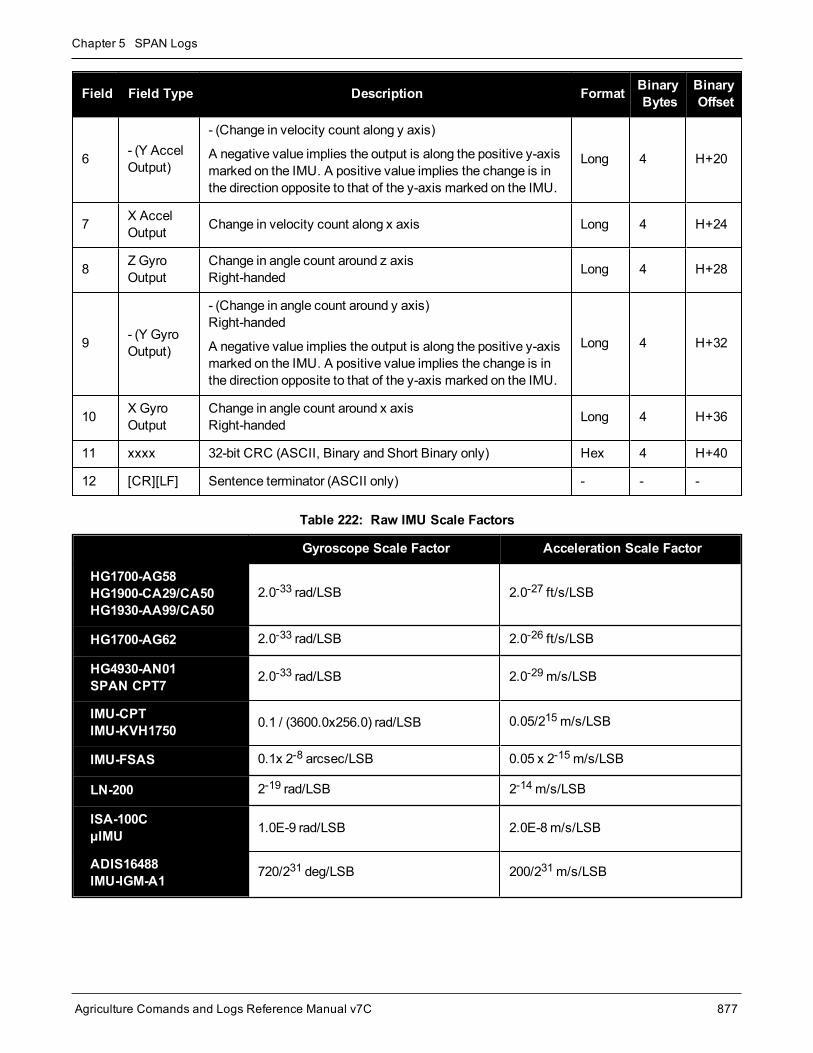
Chapter 5 SPAN Logs
Agriculture Comands and Logs Reference Manual v7C 877
Field Field Type Description Format BinaryBytes
BinaryOffset
6 - (Y AccelOutput)
- (Change in velocity count along y axis)
A negative value implies the output is along the positive y-axismarked on the IMU. A positive value implies the change is inthe direction opposite to that of the y-axis marked on the IMU.
Long 4 H+20
7 X AccelOutput Change in velocity count along x axis Long 4 H+24
8 Z GyroOutput
Change in angle count around z axisRight-handed Long 4 H+28
9 - (Y GyroOutput)
- (Change in angle count around y axis)Right-handed
A negative value implies the output is along the positive y-axismarked on the IMU. A positive value implies the change is inthe direction opposite to that of the y-axis marked on the IMU.
Long 4 H+32
10 X GyroOutput
Change in angle count around x axisRight-handed Long 4 H+36
11 xxxx 32-bit CRC (ASCII, Binary and Short Binary only) Hex 4 H+40
12 [CR][LF] Sentence terminator (ASCII only) - - -
Gyroscope Scale Factor Acceleration Scale Factor
HG1700-AG58HG1900-CA29/CA50HG1930-AA99/CA50
2.0-33 rad/LSB 2.0-27 ft/s/LSB
HG1700-AG62 2.0-33 rad/LSB 2.0-26 ft/s/LSB
HG4930-AN01SPAN CPT7 2.0-33 rad/LSB 2.0-29m/s/LSB
IMU-CPTIMU-KVH1750 0.1 / (3600.0x256.0) rad/LSB 0.05/215m/s/LSB
IMU-FSAS 0.1x 2-8 arcsec/LSB 0.05 x 2-15m/s/LSB
LN-200 2-19 rad/LSB 2-14m/s/LSB
ISA-100CµIMU 1.0E-9 rad/LSB 2.0E-8m/s/LSB
ADIS16488IMU-IGM-A1 720/231 deg/LSB 200/231m/s/LSB
Table 222: Raw IMU Scale Factors

Chapter 5 SPAN Logs
Agriculture Comands and Logs Reference Manual v7C 878
Gyroscope Scale Factor Acceleration Scale Factor
STIM300IMU-IGM-S1 2-21 deg/LSB 2-22m/s/LSB
G320NPwrPak7-E1PwrPak7D-E1SMART7-S
(0.008/65536)/125 deg/LSB (0.200/65536)/125mG/s/LSB 1
G370NPwrPak7-E2PwrPak7D-E2
(0.0151515/65536)/200 deg/LSB (0.400/65536)/200mG/s/LSB1
LSB = Least Significant Bit
11 G = 9.80665 m/s/s

Chapter 5 SPAN Logs
Agriculture Comands and Logs Reference Manual v7C 879
5.35 RAWIMUSXIMU Data Extended
Platform: OEM719, OEM729, OEM7500, OEM7600, OEM7700, OEM7720, PwrPak7, SPAN CPT7,SMART7-S, SMART7-SI
This is the short header version of the extended RAWIMUX log intended for use with post-processing. The exten-ded version includes IMU information that is used by the NovAtel Inertial Explorer post-processing software.
The change in velocity (acceleration) and angle (rotation rate) scale factors for each IMU type can befound in Table 222: Raw IMU Scale Factors on page 877. Multiply the appropriate scale factor by thecount value for the velocity (field 7-9) and angle (field 10-12) increments.
To obtain acceleration in m/s/s or rotation rate in rad/s, multiply the velocity/rotation increments by theoutput rate of the IMU:
l 100 Hz for HG1700, HG1900, HG1930 and HG4930
l 125 Hz for STIM300, G320N, PwrPak7-E1, PwrPak7D-E1 and SMART7-S
l 200 Hz for ISA-100C, iMAR-FSAS, LN200, KVH1750, ADIS16488, G370N, PwrPak7-E2 andPwrPak7D-E2
The units of acceleration and rotation rate will depend on the IMU Scale Factors.
This log is output in the IMU Body frame.
Logging Restriction Important Notice
Logging excessive amounts of high rate data can overload the system. When configuring theoutput for SPAN, NovAtel recommends that only one high rate (>50Hz) message be configuredfor output at a time. It is possible to logmore than onemessage at high rates, but doing so couldhave negative impacts on the system. Also, if logging 100/125/200Hz data, always use thebinary format and, if possible, the short header binary format (available onmost INS logs).
For optimal performance, log only one high rate output at a time. These logs could be:
l Raw data for post processingRAWIMUXSB ONNEW (100, 125 or 200 Hz depending on IMU)
l RAWIMU logs are not valid with the ONTIME trigger. The raw IMU observations con-tained in these logs are sequential changes in velocity and rotation. As such, you canonly use them for navigation if they are logged at their full rate.
l Real time INS solutionIMURATEPVA ONNEW or IMURATEPVAS ONNEW
Other possible INS solution logs available at high rates are: INSPVASB, INSPOSSB,INSVELSB, INSATTSB
Message ID: 1462
Log Type: Asynch

Chapter 5 SPAN Logs
Agriculture Comands and Logs Reference Manual v7C 880
Recommended Input:log rawimusxb onnew
ASCII example:%RAWIMUSXA,1692,484620.664;00,11,1692,484620.664389000,00801503,43110635,-817242,-202184,-215194,-41188,-9895*a5db8c7b
Field Field Type Description Format BinaryBytes
BinaryOffset
1 RAWIMUSXHeader
Log header. SeeMessages on page 26 for more information.(short) - H 0
2 IMU Info
IMU Info Bits
Bit 0: If set, an IMU error was detected. Check the IMUStatus field for details.
Bit 1: If set, the IMU data is encrypted and should not beused.
Bits 2 to 7: Reserved
HexUchar 1 H
3 IMU Type IMU Type identifier.See Table 192: IMU Type on page 768. Uchar 1 H+1
4 GNSSWeek GNSSWeek Ushort 2 H+2
5 GNSSWeekSeconds Seconds from week start Double 8 H+4

Chapter 5 SPAN Logs
Agriculture Comands and Logs Reference Manual v7C 881
Field Field Type Description Format BinaryBytes
BinaryOffset
6 IMU Status
The status of the IMU. This field is given in a fixed length (n)array of bytes in binary but in ASCII or Abbreviated ASCII isconverted into 2 character hexadecimal pairs.
For the raw IMU status, see one of the following tables:
l Table 210: iIMU-FSAS IMU Status on page 858
l Table 211: HG1700 IMU Status on page 859
l Table 212: LN200 IMU Status on page 861
l Table 213: ISA-100C IMU Status on page 862
l Table 214: IMU-CPT IMU Status on page 863
l Table 215: IMU-KVH1750 IMU Status on page 865
l Table 216: HG1900 and HG1930 IMU Status onpage 866
l Table 217: HG4930 IMU Status on page 868
l Table 218: ADIS16488 and IMU-IGM-A1 IMU Statuson page 869
l Table 219: STIM300 and IMU-IGM-S1 IMU Status onpage 870
l Table 220: µIMU IMU Status on page 872
l Table 221: G320N andG370N IMU Status on page 873
Also refer to Interface Control Documentation as provided byHoneywell or Northrop Grumman.
HexUlong 4 H+12
7 Z Accel Change in velocity count along Z-axis. Long 4 H+16
8 -(Y Accel)
- (Change in velocity count along y-axis.)
A negative value implies the output is along the positive y-axis marked on the IMU. A positive value implies the changeis in the direction opposite to that of the y-axis marked on theIMU.
Long 4 H+20
9 X Accel Change in velocity count along x axis. Long 4 H+24
10 Z Gyro Change in angle count around z axis.Right-handed Long 4 H+28
11 -(Y Gyro)
- (Change in angle count around y axis.)Right-handed
A negative value implies the output is along the positive y-axis marked on the IMU. A positive value implies the changeis in the direction opposite to that of the y-axis marked on theIMU.
Long 4 H+32

Chapter 5 SPAN Logs
Agriculture Comands and Logs Reference Manual v7C 882
Field Field Type Description Format BinaryBytes
BinaryOffset
12 X Gyro Change in angle count around x axis.Right-handed Long 4 H+36
13 XXXX 32-bit CRC (ASCII, Binary, and Short Binary only) Hex 4 H+40
14 [CR][LF] Sentence terminator (ASCII only) - - -

Chapter 5 SPAN Logs
Agriculture Comands and Logs Reference Manual v7C 883
5.36 RAWIMUXIMU Data Extended
Platform: OEM719, OEM729, OEM7500, OEM7600, OEM7700, OEM7720, PwrPak7, SPAN CPT7,SMART7-S, SMART7-SI
This log is an extended version of the RAWIMU log intended for use with post-processing. The extended versionincludes IMU information that is used by the NovAtel Inertial Explorer post-processing software.
The change in velocity (acceleration) and angle (rotation rate) scale factors for each IMU type can befound in Table 222: Raw IMU Scale Factors on page 877. Multiply the appropriate scale factor by thecount value for the velocity (field 7-9) and angle (field 10-12) increments.
To obtain acceleration in m/s/s or rotation rate in rad/s, multiply the velocity/rotation increments by theoutput rate of the IMU:
l 100 Hz for HG1700, HG1900, HG1930 and HG4930
l 125 Hz for STIM300, G320N, PwrPak7-E1, PwrPak7D-E1 and SMART7-S
l 200 Hz for ISA-100C, iMAR-FSAS, LN200, KVH1750, ADIS16488, G370N, PwrPak7-E2 andPwrPak7D-E2
The units of acceleration and rotation rate will depend on the IMU Scale Factors.
This log is output in the IMU Body frame.
Logging Restriction Important Notice
Logging excessive amounts of high rate data can overload the system. When configuring theoutput for SPAN, NovAtel recommends that only one high rate (>50Hz) message be configuredfor output at a time. It is possible to logmore than onemessage at high rates, but doing so couldhave negative impacts on the system. Also, if logging 100/125/200Hz data, always use thebinary format and, if possible, the short header binary format (available onmost INS logs).
For optimal performance, log only one high rate output at a time. These logs could be:
l Raw data for post processingRAWIMUXSB ONNEW (100, 125 or 200 Hz depending on IMU)
l RAWIMU logs are not valid with the ONTIME trigger. The raw IMU observations con-tained in these logs are sequential changes in velocity and rotation. As such, you canonly use them for navigation if they are logged at their full rate.
l Real time INS solutionIMURATEPVA ONNEW or IMURATEPVAS ONNEW
Other possible INS solution logs available at high rates are: INSPVASB, INSPOSSB,INSVELSB, INSATTSB
Message ID: 1461
Log Type: Asynch

Chapter 5 SPAN Logs
Agriculture Comands and Logs Reference Manual v7C 884
Recommended Input:log rawimuxb onnew
ASCII example:#RAWIMUXA,COM1,0,81.5,FINESTEERING,1691,410338.819,024c0020,3fd1,43495;00,5,1691,410338.818721000,00170705,-113836,-464281,43146813,89,11346,181*01cd06bf
Field Field Type Description Format BinaryBytes
BinaryOffset
1 RAWIMUXHeader Log header. SeeMessages on page 26 for more information. - H 0
2 IMU Info
IMU Info Bits
Bit 0: If set, an IMU error was detected. Check the IMU Statusfield for details.
Bit 1: If set, the IMU data is encrypted and should not be used.
Bits 2 to 7: Reserved
HexUchar 1 H
3 IMU TypeIMU Type identifier.
See Table 192: IMU Type on page 768.Uchar 1 H+1
4 GNSSWeek GNSSWeek Ushort 2 H+2
5GNSSWeekSeconds
Seconds from week start Double 8 H+4

Chapter 5 SPAN Logs
Agriculture Comands and Logs Reference Manual v7C 885
Field Field Type Description Format BinaryBytes
BinaryOffset
6 IMU Status
The status of the IMU. This field is given in a fixed length (n)array of bytes in binary but in ASCII or Abbreviated ASCII isconverted into 2 character hexadecimal pairs.
For the raw IMU status, see one of the following tables:
l Table 210: iIMU-FSAS IMU Status on page 858
l Table 211: HG1700 IMU Status on page 859
l Table 212: LN200 IMU Status on page 861
l Table 213: ISA-100C IMU Status on page 862
l Table 214: IMU-CPT IMU Status on page 863
l Table 215: IMU-KVH1750 IMU Status on page 865
l Table 216: HG1900 and HG1930 IMU Status onpage 866
l Table 217: HG4930 IMU Status on page 868
l Table 218: ADIS16488 and IMU-IGM-A1 IMU Status onpage 869
l Table 219: STIM300 and IMU-IGM-S1 IMU Status onpage 870
l Table 220: µIMU IMU Status on page 872
l Table 221: G320N andG370N IMU Status on page 873
Also refer to Interface Control Documentation as provided byHoneywell or Northrop Grumman.
HexUlong 4 H+12
7 Z Accel Change in velocity count along Z-axis. Long 4 H+16
8 -(Y Accel)
- (Change in velocity count along y-axis.)
A negative value implies the output is along the positive y-axismarked on the IMU. A positive value implies the change is inthe direction opposite to that of the y-axis marked on the IMU.
Long 4 H+20
9 X Accel Change in velocity count along x axis. Long 4 H+24
10 Z Gyro Change in angle count around z axis.Right-handed Long 4 H+28
11 -(Y Gyro)
- (Change in angle count around y axis.)Right-handed
A negative value implies the output is along the positive y-axismarked on the IMU. A positive value implies the change is inthe direction opposite to that of the y-axis marked on the IMU.
Long 4 H+32
12 X Gyro Change in angle count around x axis.Right-handed Long 4 H+36

Chapter 5 SPAN Logs
Agriculture Comands and Logs Reference Manual v7C 886
Field Field Type Description Format BinaryBytes
BinaryOffset
13 XXXX 32-bit CRC (ASCII, Binary, and Short Binary only) Hex 4 H+40
14 [CR][LF] Sentence terminator (ASCII only) - - -

Chapter 5 SPAN Logs
Agriculture Comands and Logs Reference Manual v7C 887
5.37 RELINSPVARelative INSPVA log
Platform: OEM719, OEM729, OEM7500, OEM7600, OEM7700, OEM7720, PwrPak7, SPAN CPT7,SMART7-S, SMART7-SI
This log provides the relative offset between theMaster and Rover Inertial Solutions. The output solutionprovides the offset of where the local station is with respect to the other station.
This log should only be requested with the ONNEW trigger.
To use theRELINSPVA log, the receiver requires amodel with the INS Mode set toR.
Message ID: 1446
Log Type: Asynch
Recommended Input:LOG RELINSPVAA ONNEW
ASCII example:#RELINSPVAA,COM1,0,61.0,FINESTEERING,1805,245074.000,02000000,2338,45757;BODY,9.285958662,-0.755483058,0.079229338,0.001739020,-0.000126304,0.001525848,0.321033045,0.669367786,4.466250181,0.000000000,"b81V",INS_ALIGNMENT_COMPLETE,"B20C",INS_ALIGNMENT_COMPLETE,NARROW_INT,00000000*a114ce3c
Field Field Type Description Format BinaryBytes
BinaryOffset
1 RELINSPVAHeader
Log header. SeeMessages on page 26 for moreinformation. - H 0
2 Output Frame
The current output frame (IMU body, ECEF or local levelframe).
The output frame is specified using theSETRELINSOUTPUTFRAME command (see page 794)
Enum 4 H
3 DeltaPosX
Difference in the position between the two receivers (m).The position difference is relative to the output frame:
BODY = along the X-axisECEF = along the X-axisLocal level = Northing
Double 8 H+4

Chapter 5 SPAN Logs
Agriculture Comands and Logs Reference Manual v7C 888
Field Field Type Description Format BinaryBytes
BinaryOffset
4 DeltaPosY
Difference in the position between the two receivers (m).The position difference is relative to the output frame:
BODY = along the Y-axisECEF = along the Y-axisLocal level = Easting
Double 8 H+12
5 DeltaPosZ
Difference in the position between the two receivers (m).The position difference is relative to the output frame:
BODY = along the Z-axisECEF = along the Z-axisLocal level = Up
Double 8 H+20
6 DeltaVelX
Difference in velocity between the two receivers (m/s).The position difference is relative to the output frame:
BODY = along the X-axisECEF = along the X-axisLocal level = Northing
Double 8 H+28
7 DeltaVelY
Difference in velocity between two receivers (m/s).The position difference is relative to the output frame:
BODY = along the Y-axisECEF = along the Y-axisLocal level = Easting
Double 8 H+36
8 DeltaVelZ
Difference in velocity between the two receivers (m/s).The position difference is relative to the output frame:
BODY = along the Z-axisECEF = along the Z-axisLocal level = Up
Double 8 H+44
9 DeltaRoll Difference in roll between the two receivers (degrees). Double 8 H+52
10 DeltaPitch Difference in pitch between the two receivers (degrees). Double 8 H+60
11 DeltaHeading Difference in heading between the two receivers (degrees). Double 8 H+68
12 Diff Age Differential age in seconds. Float 4 H+76
13 Rover ID Rover receiver ID string. Char[4] 4 H+80
14 RoverINSStatus
INS status of the rover receiver.See Table 199: Inertial Solution Status on page 813 Enum 4 H+84
15 Master ID Master receiver ID string. Char[4] 4 H+88
16 MasterINSStatus
INS status of themaster receiver.See Table 199: Inertial Solution Status on page 813 Enum 4 H+92

Chapter 5 SPAN Logs
Agriculture Comands and Logs Reference Manual v7C 889
Field Field Type Description Format BinaryBytes
BinaryOffset
17 RTK Status Status of the current RTK vector betweenmaster and rover.See Table 66: Position or Velocity Type on page 350 Enum 4 H+96
18 ExtStatus Extended solution status. See Table 200: ExtendedSolution Status on page 818 Hex 4 H+100
20 xxxx 32-bit CRC (ASCII and Binary only) Hex 4 H+104
21 [CR][LF] Sentence terminator (ASCII only) - - -

Chapter 5 SPAN Logs
Agriculture Comands and Logs Reference Manual v7C 890
5.38 SYNCRELINSPVASynchronous Relative INSPVA log
Platform: OEM719, OEM729, OEM7500, OEM7600, OEM7700, OEM7720, PwrPak7, SPAN CPT7,SMART7-S, SMART7-SI
This log provides the relative offset between themaster and rover inertial solutions. The output solution providesthe offset of where the local station is with respect to the other station.
To use theSYNCRELINSPVA log, the receiver requires amodel with the INS Mode set toR.
This log is designed to provide synchronous, relative Position, Velocity and Attitude information,propagating the information betweenmatched corrections between themaster and remote solutions. Itis highly recommended that the highest rate of corrections be used at all times for themost precise androbust performance.
Message ID: 1743
Log Type: Synch
Recommended Input:LOG SYNCRELINSPVAA ONTIME 1
ASCII example:#SYNCRELINSPVAA,COM1,0,72.5,FINESTEERING,1805,247243.000,02000000,e9c7,13005;BODY,8.141080733,-2.779177478,2.045421773,-0.001464009,-0.001038329,0.002323548,0.409467974,0.715633909,-6.204731538,0.000000000,"B81V",INS_ALIGNMENT_COMPLETE,"B20C",INS_ALIGNMENT_COMPLETE,INS_PSRSP,00000000*e270f5c8
Field Field Type Description Format BinaryBytes
BinaryOffset
1 SYNCRELINSPVAHeader
Log header. SeeMessages on page 26 for moreinformation. - H 0
2 Output Frame
The current output frame (IMU body, ECEF or locallevel frame).
The output frame is specified using theSETRELINSOUTPUTFRAME command (see page794)
Enum 4 H
3 DeltaPosX
Difference in the position between the two receivers(m).The position difference is relative to the output frame:
BODY = along the X-axisECEF = along the X-axisLocal level = Northing
Double 8 H+4

Chapter 5 SPAN Logs
Agriculture Comands and Logs Reference Manual v7C 891
Field Field Type Description Format BinaryBytes
BinaryOffset
4 DeltaPosY
Difference in the position between the two receivers(m).The position difference is relative to the output frame:
BODY = along the Y-axisECEF = along the Y-axisLocal level = Easting
Double 8 H+12
5 DeltaPosZ
Difference in the position between the two receivers(m).The position difference is relative to the output frame:
BODY = along the Z-axisECEF = along the Z-axisLocal level = Up
Double 8 H+20
6 DeltaVelX
Difference in velocity between the two receivers(m/s).The position difference is relative to the output frame:
BODY = along the X-axisECEF = along the X-axisLocal level = Northing
Double 8 H+28
7 DeltaVelY
Difference in velocity between two receivers (m/s).The position difference is relative to the output frame:
BODY = along the Y-axisECEF = along the Y-axisLocal level = Easting
Double 8 H+36
8 DeltaVelZ
Difference in velocity between the two receivers(m/s).The position difference is relative to the output frame:
BODY = along the Z-axisECEF = along the Z-axisLocal level = Up
Double 8 H+44
9 DeltaRoll Difference in roll between the two receivers (degrees). Double 8 H+52
10 DeltaPitch Difference in pitch between the two receivers(degrees). Double 8 H+60
11 DeltaHeading Difference in heading between the two receivers(degrees). Double 8 H+68
12 Diff Age Differential age in seconds. Float 4 H+76
13 Rover ID Rover receiver ID string. Char[4] 4 H+80
14 Rover INSStatus INS status of the rover receiver.See Table 199: Inertial Solution Status on page 813 Enum 4 H+84

Chapter 5 SPAN Logs
Agriculture Comands and Logs Reference Manual v7C 892
Field Field Type Description Format BinaryBytes
BinaryOffset
15 Master ID Master receiver ID string. Char[4] 4 H+88
16 Master INSStatus INS status of themaster receiver.See Table 199: Inertial Solution Status on page 813 Enum 4 H+92
17 RTK StatusStatus of the current RTK vector betweenmaster androver.See Table 66: Position or Velocity Type on page 350
Enum 4 H+96
18 ExtStatusExtended solution status.See Table 200: Extended Solution Status onpage 818
Hex 4 H+100
20 xxxx 32-bit CRC (ASCII and Binary only) Hex 4 H+104
21 [CR][LF] Sentence terminator (ASCII only) - - -

Chapter 5 SPAN Logs
Agriculture Comands and Logs Reference Manual v7C 893
5.39 TSS1TSS1 Protocol for Heave, Roll and Pitch
Platform: OEM719, OEM729, OEM7500, OEM7600, OEM7700, OEM7720, PwrPak7, SPAN CPT7,SMART7-S, SMART7-SI
This log provides heave, roll and pitch information in TSS1 protocol.
This message is in a different format than any other log output by the SPAN system.
Message ID: 1456
Log Type: Synch
Recommended Input:log tss1a ontime 1
Message Format::XXAAAASMHHHHQMRRRRSMPPPP<CR><LF>
ASCII Example::00FFCA -0003F-0325 0319
Field Field Type Description Symbol Example
1 TSS1Header Log header. SeeMessages on page 26 for more information. : :
2 HorizontalAcceleration
Horizontal acceleration from 0 to 9.81m/s2.
Shown as a one byte unsigned hex number where the leastsignificant bit = 3.83 cm/s2.
XX 00
3 VerticalAcceleration
Vertical acceleration from -20.48 to +20.48m/s2.
Shown as a two byte hex number where the least significantbit = 0.0625 cm/s2.
AAAA FFCA
4 SpaceCharacter A space delimiter. S
5 Heave PolaritySpace if positive.
Minus sign (-) if negative.M -
6 HeaveHeave value from -99.99 to +99.99m.
Shown as a four digit integer where the least significant bit =0.01m.
HHHH 0003
7 Status FlagF if INS Active.
H if INS has not completed an alignment.Q F

Chapter 5 SPAN Logs
Agriculture Comands and Logs Reference Manual v7C 894
Field Field Type Description Symbol Example
8 Roll PolaritySpace if positive.
Minus sign (-) if negative.M -
9 RollRoll value from -99.99 to +99.99 degrees.
Shown as a four digit integer where the least significant bit =0.01 degrees.
RRRR 0325
10 SpaceCharacter A space delimiter. S
11 Pitch PolaritySpace if positive.
Minus sign (-) if negative.M
12 PitchPitch value from -99.99 to +99.99 degrees.
Shown as a four digit integer where the least significant bit =0.01 degrees.
PPPP 0319
13 [CR][LF] Sentence terminator <CR><LF>

Chapter 5 SPAN Logs
Agriculture Comands and Logs Reference Manual v7C 895
5.40 VARIABLELEVERARMDisplay Variable Lever Arm Details
Platform: OEM719, OEM729, OEM7500, OEM7600, OEM7700, OEM7720, PwrPak7, SPAN CPT7,SMART7-S, SMART7-SI
Use this log to redisplay the re-calculated variable lever arm whenever a new INPUTGIMBALANGLE commandis received. This message is output in the IMU body frame.
TheVARIABLELEVERARM log will not be published or used internally unless aSETINSROTATIONRBM command is sent. See theSETINSROTATION command on page 788.
This log should only be requested with the ONCHANGED or ONTIME trigger.
Message ID: 1320
Log Type: Asynch
Recommended Input:log variableleverarma onnew
ASCII Example:#VARIABLELEVERARMA,SPECIAL,0,81.5,FINESTEERING,1614,495820.512,42040000,0000,320;-0.0959421909646755,0.1226971902356540,1.1319295452903300,0.0100057787272846,0.0122604827412661,0.1131929545290330*9611d3c6
Field Field Type Description Format BinaryBytes
BinaryOffset
1 VARIABLELEVERARMHeader
Log header. SeeMessages on page 26 formore information. - H 0
2 XOffset IMU body frame x-axis offset Double 8 H
3 YOffset IMU body frame y-axis offset Double 8 H+8
4 ZOffset IMU body frame z-axis offset Double 8 H+16
5 XUncert X-axis uncertainty in meters Double 8 H+24
6 YUncert Y-axis uncertainty in meters Double 8 H+32
7 ZUncert Z-axis uncertainty in meters Double 8 H+40
8 xxxx 32-bit CRC (ASCII, Binary and Short Binaryonly) Hex 4 H+48
9 [CR][LF] Sentence terminator (ASCII only) - - -

Agriculture Comands and Logs Reference Manual v7C 896
Chapter 6 ResponsesThe receiver is capable of outputting several responses for various conditions. Most responses are error mes-sages to indicate when something is not correct.
The output format of themessages is dependent on the format of the input command. If the command is input asabbreviated ASCII, the output will be abbreviated ASCII. The same rule applies for both ASCII and binaryformats.
ASCII MessageBinaryMessage
IDMeaning
OK 1 Commandwas received correctly
Requested log does notexist 2 The log requested does not exist
Not enough resources insystem 3 The request has exceeded a limit (for example, themaximum
number of logs are being generated)
Data packet doesn’tverify 4 Data packet is not verified
Command failed onreceiver 5 Command did not succeed in accomplishing requested task
Invalid Message ID 6 The input message ID is not valid
Invalid Message. Field =x 7 Field x of the input message is not correct
Invalid Checksum 8 The checksum of the input message is not correct. Only appliesto ASCII and binary format messages.
Message missing field 9 A field is missing from the input message
Array size for field xexceeds max 10 Field x contains more array elements than allowed
parameter x is out ofrange 11 Field x of the input message is outside the acceptable limits
Message Id already existsin system 12 Message Id already exists in system
Debug token unknown 13 Debug token unknown
Trigger x not valid forthis log 14 Trigger type x is not valid for this type of log
Authcode table full -Reload Software 15 Toomany authcodes are stored in the receiver. The receiver
firmwaremust be reloaded
Table 223: Response Messages

Chapter 6 Responses
Agriculture Comands and Logs Reference Manual v7C 897
ASCII MessageBinaryMessage
IDMeaning
Invalid date format 16 This error is related to the inputting of authcodes. Indicates thedate attached to the code is not valid
Invalid Authcode entered 17 The authcode entered is not valid
No matching model toremove 18 Themodel requested for removal does not exist
Not valid Auth code forthat Model 19 Themodel attached to the authcode is not valid
Channel is invalid 20 The selected channel is invalid
Requested rate is invalid 21 The requested rate is invalid
Word has no mask for thistype 22 The word has nomask for this type of log
Channels locked due toerror 23 Channels are locked due to error (the receiver must be reset or
power cycled to track satellites again)
Injected time invalid 24 Injected time is invalid
Com port not supported 25 The COM or USB port is not supported
Message is incorrect 26 Themessage is invalid
Invalid PRN 27 The PRN is invalid
PRN not locked out 28 The PRN is not locked out
PRN lockout list is full 29 PRN lockout list is full
PRN already locked out 30 The PRN is already locked out
Message timed out 31 Message timed out
Unknown COM portrequested 33 UnknownCOM or USB port requested
Hex string not formattedcorrectly 34 Hex string not formatted correctly
Invalid baud rate 35 The baud rate is invalid
Message is invalid forthis model 36 Message is invalid for this model of receiver
Could Not SaveConfiguration 38 Could Not Save Configuration
Too Many ConfigurationItems 39 TooMany Configuration Items

Chapter 6 Responses
Agriculture Comands and Logs Reference Manual v7C 898
ASCII MessageBinaryMessage
IDMeaning
Command only valid if inNVM Fail mode 40 Command is only valid if NVM is in fail mode
Invalid offset 41 The offset is invalid
File conflict 43 File conflict
File not found 44 File not found
File open 45 File open
File not open 46 File not open
Invalid DOS FileName 47 Invalid DOS File name
File channel in use 48 File channel in use
File close fail 50 File close fail
Disk not present 51 Disk not present
Disk error 52 Disk error
Disk full 53 Disk full
NVM Write Fail 74 NVMWrite Fail
NVM Read Fail 75 NVMRead Fail
Not allowed for input 77 Not allowed for input
Maximum number of usermessages reached 78 Maximum number of user messages has been reached
User message decryptionfailed 79 User message decryption failed
GPS precise time isalready known 84 GPS precise time is already known
The message could not becreated 87 Themessage could not be created
Not enough memory tostart application 113 Not enoughmemory to start application
No data available 114 No data available
Invalid handshaking 117 Invalid handshaking
Message name alreadyexists 118 Message name already exists
Invalid message name 119 Invalid message name

Chapter 6 Responses
Agriculture Comands and Logs Reference Manual v7C 899
ASCII MessageBinaryMessage
IDMeaning
The datatype is invalid 120 The data type is invalid
Message ID is reserved 121 Message ID is reserved
Message size too large 122 Message size too large
Invalid Security Key 126 Invalid security key
Hardware not available 127 Hardware not available
Requested pulse width isinvalid 131 Requested pulse width is invalid
Coarse time is notachieved yet 133 Coarse time is not achieved yet
Invalid Config Code 134 Invalid Config Code
ConfigCode table full -Reload Software 135 Config Code table is full. Reload the software.
Unknown Object Type 136 Unknown object type
This operation is notvalid at this time 137 This operation is not valid at this time
User VARF in use 140 User VARF in use
Disk busy 142 Disk busy
Invalid Word InputArgument 143 InvalidWord Input Argument
Parameter %d is not validfor this model 148 The parameter specified is not valid for this model
IMU SPECS LOCKED FOR THISIMU TYPE 150
SPAN allows the default specifications for a select few IMUs tobemodified to support different variants. However, most IMUspecifications are not allowed to change.
Invalid interface mode.Parameter %d 151 The specified Interfacemode parameter is not valid.
COMMAND INVALID FOR THISIMU 154
The entered command cannot be used with the configured IMU.For example, the INSCALIBRATE ANT1 command is not validfor lower quality IMUs.
IMU protocol is lockedfor this IMU type 155 IMU protocol is locked for this IMU type
IMU TYPE IS NOT SUPPORTEDWITH CURRENT MODEL 157 A firmwaremodel upgrade is required to use the requested IMU
(CONNECTIMU command on page 767).

Chapter 6 Responses
Agriculture Comands and Logs Reference Manual v7C 900
ASCII MessageBinaryMessage
IDMeaning
Trigger start time isinvalid 159 Trigger start time is invalid
Sensor is not initialized 160 Sensor is not initialized
Board has not achievedfinesteering 162 The receiver has not achieved finesteering
Invalid Profile Name 165 Invalid Profile Name
Maximum Number ProfilesExceeded 166 Themaximum number of profiles is exceeded
Failed To Delete Profile 167 Failed to delete the profile
Profile Name AlreadyExists 168 Profile name already exists
Total Profile CommandsSize Over Limit 169 Total Profile commands size over limit
Cannot Change ProfileWhen Activated 170 Cannot change a Profile when it is activated
Signature Authcode CopyFail 171 Signature Authcode copy fail
Profile Active, Could NotSave Configuration 173 Profile active, could not save configuration
Current PPP position hasbad status and cannot beused for seeding
178 Current PPP position has bad status and cannot be used forseeding
PPP seed position failedintegrity check 179 PPP seed position failed integrity check
Invalid password 180 Invalid password
Too many files 181 Toomany files
Encryption key output isnot allowed 186 Encryption key output is not allowed
Secure port requireslogin 187 Secure port requires login
NMEA2000/J1939 stack isalready running on theCAN port
188 NMEA2000/J1939 stack is already running on the CAN port

Chapter 6 Responses
Agriculture Comands and Logs Reference Manual v7C 901
ASCII MessageBinaryMessage
IDMeaning
No saved PPP seedposition 191 No saved PPP seed position
System type is invalidfor this model 192 System type is invalid for this model
Command is not supportedfor this model 193 Command is not supported for this model
Position Averaging NotStarted 194 Position averaging not started
Not in GLIDE mode 200 Not in GLIDE mode
PPP seeding invalid inforced dynamics mode 201 PPP seeding invalid in forced dynamics mode
Wrong combination ofparameters 202 Wrong combination of parameters
Invalid CalibrationRequest 203 Invalid calibration request
Active Gimbal Detected 204 Active gimbal detected
Authcode table full - Useauth erase_table 205
Authcode table full. An authcodemust be removed beforeanother authcode can be added.
Refer to theAUTH command (see page 60) for instructions onremoving authcodes and cleaning up the authcode table.
Profile Not Running -Profile should beactivated
206 Profile not running - Profile should be activated
ID provided is already inuse 208 ID provided is already in use
ID provided does notexist 209 ID provided does not exist
Calibration already inprogress 210 Calibration already in progress
Filter cannot be enableddue to channel speedsettings
211 Filter cannot be enabled due to channel speed settings
Notch Filter andFrequency are mismatching 212 Notch filter and frequency aremismatching
Filter can not cascade 213 Filter can not cascade

Chapter 6 Responses
Agriculture Comands and Logs Reference Manual v7C 902
ASCII MessageBinaryMessage
IDMeaning
There is no RF filterapplied 214 There is no RF filter applied
ID provided should be 4character long 215 ID provided should be 4 characters long
Invalid subscription code 216 Invalid subscription code
Subscription table full 217 Subscription table full
Network id does not matchsubscription code 218 Network ID does not match the subscription code
Subscription not found 219 Subscription not found
Subscription not active 220 Subscription not active
Cannot activate expiredsubscription 221 Cannot activate expired subscription
Maximum number of logsexceeded. No new logadded.
222 Maximum number of logs exceeded. No new log added.
Seed is too far in thepast 223 Seed is too far in the past
Final log request mustuse the ONCE trigger 224 Final log request must use the ONCE trigger
Channel invalid forregion x 225 Channel invalid for region x
Region not set 226 Region not set
Estimated RBV must beentered first 227 Initial RBV estimate is required before RBV calibration
Command failed becauseWIFIALIGNAUTOMATION isenabled
240Command failed becauseWIFIALIGNAUTOMATION isenabled. See theWIFIALIGNAUTOMATION command onpage 313.
Specified network notenabled withWIFINETCONFIG command
241 Specified network not enabled withWIFINETCONFIGcommand. See theWIFINETCONFIG command on page 320.

Agriculture Comands and Logs Reference Manual v7C 903
APPENDIX A Example of Bit Parsing a RANGECMP4 Log
The following takes a sample RANGECMP4 log and breaks it down into its raw components.
Data was captured in both RANGE and in RANGECMP4 logs which are shown here for reference. These logswere captured at a rate of 4 Hz such that the Reference and Differential parts of the RANGECMP4 could beexplained.
Some of the RANGECMP4 values will have some very slight differences (at themillicycle level) com-pared to the equivalent RANGE log data due to truncating the double values into integers.
Here are two RANGE logs to reference against once the RANGECMP4 logs have been determined:
RANGE COM1 0 88.5 FINESTEERING 1919 507977.000 02000020 5103 32768 22 27 0 21761200.335 0.036 -114355879.993103 0.006 1121.758 50.0 876.78518109c04 27 0 21761202.795 0.128 -89108485.029683 0.007 874.097 44.2 862.386 11303c0b 27 0 21761200.306 0.007 -85395622.838987 0.004 837.685 51.7 865.845 01d03c04 21 0 21214757.684 0.027 -111484302.588995 0.005 -1107.624 52.6 888.96808109c24 21 0 21214757.049 0.122 -86870882.607297 0.006 -863.084 44.6 874.389 01303c2b 10 0 21540290.811 0.027 -113194996.162910 0.005 2288.688 52.6 889.90508109c44 10 0 21540293.632 0.110 -88203904.731314 0.006 1783.394 45.6 868.725 01303c4b 10 0 21540289.869 0.006 -84528728.138216 0.004 1709.022 53.0 872.386 01d03c44 15 0 21776375.653 0.032 -114435625.391762 0.007 -1814.485 50.9 879.58618109c64 15 0 21776376.038 0.129 -89170616.457446 0.007 -1413.886 44.1 862.70611303c6b 18 0 20493192.703 0.031 -107692454.149639 0.007 212.747 51.1 891.550 08109c84 18 0 20493191.933 0.105 -83916195.494946 0.007 165.777 45.9 874.710 01303c8b 61 9 20375330.794 0.104 -108956045.737322 0.006 -3039.481 46.8 891.93108119ca4 61 9 20375332.806 0.083 -84743599.055547 0.007 -2364.042 34.0 876.81300b13cab 55 4 22748433.080 0.146 -121432681.638722 0.009 4061.119 43.9 416.03218119cc4 55 4 22748438.602 0.021 -94447660.068923 0.009 3158.651 46.0 415.562 00b13ccb 38 8 19781617.845 0.058 -105744080.698106 0.004 -2024.611 51.8 893.56318119ce4 38 8 19781623.453 0.032 -82245418.313339 0.005 -1574.698 42.2 878.83300b13ceb 39 3 19968976.955 0.055 -106558290.405759 0.004 2248.713 52.3 875.21008119d04 39 3 19968980.676 0.019 -82878686.553631 0.005 1749.000 46.9 870.890 00b13d0b 54 11 19507573.213 0.059 -104388964.028915 0.005 1289.410 51.8 894.61308119d24 54 11 19507576.477 0.017 -81191427.275619 0.004 1002.874 48.0 878.83210b13d2b

APPENDIX A Example of Bit Parsing a RANGECMP4 Log
Agriculture Comands and Logs Reference Manual v7C 904
RANGE COM1 0 88.5 FINESTEERING 1919 507977.250 02000020 5103 32768 22 27 0 21761146.982 0.036 -114355599.642256 0.006 1121.140 49.9 877.03518109c04 27 0 21761149.447 0.122 -89108266.573995 0.007 873.616 44.6 862.636 11303c0b 27 0 21761146.957 0.007 -85395413.484293 0.004 837.294 51.8 866.095 01d03c04 21 0 21214810.390 0.027 -111484579.560955 0.005 -1108.100 52.6 889.21808109c24 21 0 21214809.754 0.120 -86871098.429369 0.005 -863.454 44.8 874.639 01303c2b 10 0 21540181.949 0.027 -113194424.080322 0.005 2288.176 52.6 890.15508109c44 10 0 21540184.767 0.111 -88203458.952394 0.006 1782.995 45.4 868.975 01303c4b 10 0 21540181.003 0.006 -84528300.928648 0.004 1708.751 53.0 872.636 01d03c44 15 0 21776461.990 0.032 -114436079.084785 0.006 -1814.956 50.9 879.83618109c64 15 0 21776462.375 0.129 -89170969.984233 0.007 -1414.253 44.1 862.95611303c6b 18 0 20493182.598 0.031 -107692401.054068 0.007 212.183 51.2 891.800 08109c84 18 0 20493181.833 0.110 -83916154.122137 0.007 165.338 45.6 874.960 01303c8b 61 9 20375472.914 0.104 -108956805.696703 0.006 -3040.142 46.9 892.18108119ca4 61 9 20375474.924 0.084 -84744190.134355 0.007 -2364.555 33.9 877.06300b13cab 55 4 22748242.897 0.150 -121431666.427728 0.009 4060.804 43.7 416.28218119cc4 55 4 22748248.421 0.021 -94446870.460803 0.009 3158.405 46.0 415.812 00b13ccb 38 8 19781712.549 0.059 -105744586.938646 0.004 -2025.149 51.8 893.81318119ce4 38 8 19781718.158 0.032 -82245812.055601 0.005 -1575.117 42.3 879.08300b13ceb 39 3 19968871.615 0.055 -106557728.318448 0.004 2248.162 52.3 875.46008119d04 39 3 19968875.343 0.019 -82878249.374953 0.005 1748.571 46.8 871.140 00b13d0b 54 11 19507512.994 0.059 -104388641.780659 0.005 1288.778 51.7 894.86308119d24 54 11 19507516.256 0.016 -81191176.637999 0.005 1002.383 48.1 879.08210b13d2b
Here are the equivalent RANGECMP4 logs which will be broken down into their individual components:
#RANGECMP4A,COM1,0,88.5,FINESTEERING,1919,507977.000,02000020,fb0e,32768;295,030000421204000000009200df7688831f611fd87ca0b03a00638bbdf7b82f49b080fd0ec0ff1f091f8214ff4d4d00a1009cbf1751f6911f5141f87fd9571a96dbd7040c8090f87f0080fcf722fe9bfa8a49a8ff4f299d7f96fb9afefc771800fcffd0063f02cde01f3c7dd3ffb75240886f5fa2b0ff91f57f00003edf8b78868c882878014065dbf7d3ed6b722680d5fc0f00a4c08730fe7fecf8bffa3f003008000000002001f03fa019f8136a11273649b8fcefab9c434c7b89e71560dbfe070030b2e04fd841f33125320b80b0ecefa5ee21243ac0bb03e0ffc36a813fb13bbe5791a0f5ff9e3bdbffbb87f0cb8064f03f0000e4b67dd15bc5f4a50a3a006ca72fdee53ec86405b2c0fffa3fa450f725d5bfed7c49b1fb0fb16b45a87a9adb0740cbfe0700*7DD8F893
#RANGECMP4A,COM1,0,88.5,FINESTEERING,1919,507977.250,02000020,fb0e,32768;239,030000421204000000009200dff688831f6102005500e70162dc977c004015c07988840f6101803a805921cedf8b80002011207080e5f6351f003804081c2200be0808005c01620808725f93028057801822dae0476000a00f207180fef6251700e803401c62f3bdc8060052013009986f5f22020054004ca2053ec408005401ca8701804100000000000980ff6306fec408004801de07c8692f5102805180f721b2e04f600040152081804ef7102500600540202205fe040a0086013a0938780f610200618

APPENDIX A Example of Bit Parsing a RANGECMP4 Log
Agriculture Comands and Logs Reference Manual v7C 905
04e224edbdb68002010c0498030f7411d0018047812a2d47d090a004c01a609c8544f62028052006a02*48E189A2
A.1 Reference Log DecodingThe RANGECMP4 log at time 507977.0 will be decoded first:
#RANGECMP4A,COM1,0,88.5,FINESTEERING,1919,507977.000,02000020,fb0e,32768;295,030000421204000000009200df7688831f611fd87ca0b03a00638bbdf7b82f49b080fd0ec0ff1f091f8214ff4d4d00a1009cbf1751f6911f5141f87fd9571a96dbd7040c8090f87f0080fcf722fe9bfa8a49a8ff4f299d7f96fb9afefc771800fcffd0063f02cde01f3c7dd3ffb75240886f5fa2b0ff91f57f00003edf8b78868c882878014065dbf7d3ed6b722680d5fc0f00a4c08730fe7fecf8bffa3f003008000000002001f03fa019f8136a11273649b8fcefab9c434c7b89e71560dbfe070030b2e04fd841f33125320b80b0ecefa5ee21243ac0bb03e0ffc36a813fb13bbe5791a0f5ff9e3bdbffbb87f0cb8064f03f0000e4b67dd15bc5f4a50a3a006ca72fdee53ec86405b2c0fffa3fa450f725d5bfed7c49b1fb0fb16b45a87a9adb0740cbfe0700*7DD8F893
Since this log falls on a whole second (507977.000), it is a Reference log.
At the start of the RANGECMP4 log is the identifier for how many bytes are in the log. In this case, there are 295bytes. The rest of themessage is compressed binary data and is transmitted as LSB first so the bytes must beswapped before processing.
A.1.1 Reference HeaderThe Reference Header is sent once per message. See Table 135: Header on page 602 in the RANGECMP4 logsection.
Decoding the bits starting with the first bytes:
GNSS Field (16 bits)
l Grab the first 2 bytes (16 bits) = 0x0300
l Swap the bytes = 0x0003
l 0x0003 in binary form = 0000 0000 0000 0011
In this example the receiver was configured to track only GPS andGLONASS systems. If other sys-tems had been in the configuration and tracked, they would have shown here.
A.1.2 Reference Satellite and Signal Block: GPSThis block is sent once for each bit set to 1 in the GNSS field (See Table 135: Header on page 602). As identifiedby the aboveGNSS field, the first system (right to left) is the GPS System. Use Table 136: Satellite and SignalBlock on page 602 to determine what satellites and signals data are contained in this GPS system:
GPS Satellites field (64 bits)
l Grab the next 8 bytes (64 bits) = 0x0042120400000000
l Swap the bytes = 0x0000000004124200
l 0x0000000004124200 in binary form =

APPENDIX A Example of Bit Parsing a RANGECMP4 Log
Agriculture Comands and Logs Reference Manual v7C 906
l The 1’s above identify that there are 5 tracking GPS PRNs.
GPS Signals field (16 bits)
l Grab the next 2 bytes (16 bits) = 0x9200
l Swap the bytes = 0x0092
l 0x0092 in binary form =
l The 1’s above identify that there are 3 tracking GPS signals: L1CA, L2Y, and L5Q.
GPS Included Signals field (5 PRNs x 3 Signals = 15 bits – Therefore need 2 bytes)
l Up to the point of processing the Included Signals field, the bytes are aligned such that the bits start and endwithin each batch of bytes. After processing this step, it is quite common for the Included Signals Field (mxnmatrix) to not be divisible by 8 so bytes not processed will need to be carried over to the next section depend-ing on the size of thematrix.
l Grab the next 2 bytes (16 bits) = 0xdf76
l Swap the bytes = 0x76df
l 0x76df in binary form = 0111011011011111
l Only need 15 of the 16 bits = X111011011011111
l This bit string breaks down into 5 rows (PRNs) and 3 columns (signals) as specified by themxn (PRN x sig-nals) parameters. Take the bit string and break it up into sets of 3 starting at theMSB. This will result with thelowest PRN being at the bottom row of the stack and the first signal (L1CA) being the far right column.
111011011011111
l This stack can be further broken apart to identify the PRNs vs. their Signals:
PRN L5Q L2Y L1CA27 1 1 121 0 1 118 0 1 115 0 1 110 1 1 1

APPENDIX A Example of Bit Parsing a RANGECMP4 Log
Agriculture Comands and Logs Reference Manual v7C 907
A.1.3 Reference Measurement Block Header: GPSThis block is sent once for each bit set to 1 in the Satellites field found in Table 136: Satellite and Signal Blockon page 602. Now that the PRN’s signals have been determined, the next step is to determine the specifics ofthe first PRN (10) and its list of signals (L1CA, L2Y, L5Q). Working from bottom right to upper left of the PRN/Sig-nal chart above, each 1 represents a signal for a PRN. Use Table 137: Measurement Block Header on page 603to determine the contents of each field:
GPS PRN 10 (first PRN found in the Satellites field)
Wewill grab enough bytes to process the wholeMeasurement Block Header. If this was aGLONASS System, atotal of 9 bits would be required for this step (1 bit for the Data Format Flag, 3 bits for the Ref Data Block ID, plus5 bits for the GLONASS Frequency Number). Since this is a GPS system, only 4 bits in total are required (1 bitfor the Data Format Flag and 3 bits for the Ref Data Block ID).
There was 1 bit not processed in the last byte so that byte will be carried forward. Only 4 bits need to be looked atfor this step so grab the next byte as well:
l Use the last byte (0x76) plus the next byte (0x88)= 0x7688
l Swap the bytes = 0x8876
l 0x8876 in binary form = 1000100001110110
l Ignore the 7 processed bits from the last step = 100010000XXXXXXX
l Ignore the 5MSB bits leaving 4 bits for processing =
The Data Format Flag identifies that this batch of data is Reference (0) data.The Ref Data Block ID is 0x000.
The 5MSBs have not been processed so this byte will be carried forward.
The Data Format Flag identifies if the upcoming data is Reference or Differential data. By default every log thatwas published on a whole second will always be Reference logs. Logs between seconds will be Differential logsbut could be Reference logs depending on the compression calculations. If a discontinuity occurred that made itimpossible for a Differential calculation to fit within the Differential Constraints, it will revert to a Reference log.
A.1.4 Reference Measurement Block: GPSThis block is sent once for each bit set to 1 in the Included Signals Field found in Table 136: Satellite and SignalBlock on page 602. Use Table 138: Primary Reference Signal Measurement Block on page 604 and Table 139:Secondary Reference Signals Measurement Block on page 605 to determine the contents of each field:
A Measurement Block for a single PRN will look like the following:
Primary Parity Flag
Primary ½ Cycle Slip Flag
Primary C/No
Primary Lock Time
Primary Pseudorange Std Deviation
Primary Phaserange Std Deviation

APPENDIX A Example of Bit Parsing a RANGECMP4 Log
Agriculture Comands and Logs Reference Manual v7C 908
Primary Pseudorange
Primary Phaserange - Primary Pseudorange (determines the Phaserange for the 1st Signal)
Primary Doppler
2nd Parity Flag
2nd½Cycle Slip Flag
2ndC/No
2nd Lock Time
2nd Pseudorange Std Deviation
2nd Phaserange Std Deviation
2nd Pseudorange - Primary Pseudorange (determines the Pseudorange for the 2nd Signal
2nd Phaserange - 2nd Pseudorange (determines the Phaserange for the 2nd Signal)
2ndDoppler - Primary Doppler (determines the Doppler for the 2nd Signal)
3rd Parity Flag
3rd½Cycle Slip Flag
3rdC/No
3rd Lock Time
3rd Pseudorange Std Deviation
3rd Phaserange Std Deviation
3rd Pseudorange - Primary Pseudorange (determines the Pseudorange for the 3rd Signal
3rd Phaserange - 3rd Pseudorange (determines the Phaserange for the 3rd Signal)
3rdDoppler - Primary Doppler (determines the Doppler for the 3rd Signal)
…
A.1.5 Reference Primary Signal Measurement Block: GPS PRN 10 – L1CAThe next bytes collected will be for the GPS PRN 10 - L1CA signal data. This is the primary signal of the PRNsince it is the first signal. As a result, its Measurement Block consists of 111 bits as listed in Table 138: PrimaryReference Signal Measurement Block on page 604. Since 111 bits takes up a lot of space, these bits will be splitinto two groups from Table 138: Primary Reference Signal Measurement Block on page 604: the top 25 bits forsignal info followed by the bottom 86 bits for signal data.
The signal info section (top 25 bits) is processed as follows:
l With 5 bits left unprocessed from the previous byte, we calculate 25 – 5 = 20 bits which rounds up to 3 bytes.Therefore the previous last byte (0x88) plus the next 3 bytes will be needed.
l Use the last byte (0x88) plus grab 3 bytes (x831f61) = 0x88831f61
l Swap the bytes = 0x611f8388

APPENDIX A Example of Bit Parsing a RANGECMP4 Log
Agriculture Comands and Logs Reference Manual v7C 909
l 0x611f8388 in binary form = 01100001000111111000001110001000
l The previous step used the 3 LSBs = 01100001000111111000001110001XXX
l 25 bits are needed so ignore the 4MSBs =
l Parity flag is a 1 (Parity Known)
l ½Cycle Slip flag is a 0 (Cycle Slip Not Present)
l C/No is:0x10000011100b = 1052 x Scaling Factor of 0.05= 52.60 dBHz
l The Lock Time value is:0x1111b = 15 whichmeans that this signal has been locked for 262144ms ormore.
l The Pseudorange Std Deviation value is:0x0001b = 1 whichmeans: 0.020m < PSR Std Dev <= 0.030m using Table 145: Pseudorange Std Dev onpage 611.
l The ADR Std Deviation value is:0x0001b = 1 whichmeans: 0.0039 < ADR Std Dev <= 0.0052 cycles using Table 144: ADR Std Dev onpage 610.
The signal data section (bottom 86 bits) is processed as follows:
l With 4 bits unprocessed from the previous byte, we calculate 86 – 4 = 82 bits = 11 bytes (2 bits will not be pro-cessed in the last byte).
l Use the last byte (0x61) plus grab 11 bytes (0x1fd87ca0b03a00638bbdf7)= 0x611fd87ca0b03a00638bbdf7
l Swap the bytes = 0xf7bd8b63003ab0a07cd81f61
l 0xf7bd8b63003ab0a07cd81f61 in binary form =111 0111 1011 1101 1000 1011 0110 0011 0000 0000 0011 1010 1011 0000 1010 0000 0111 1100 11011000 0001 1111 0110 0001
l Only need 86 bits. Ignore last 4 LSBs and first 6 MSBs =
l Use Table 138: Primary Reference Signal Measurement Block on page 604 to identify if a 2’s ComplementConversion is needed as well as what Scale Factor should be used before these binary numbers are used inthe following calculations.
l The 1st (Primary) Pseudorange is processed by:
1st Pseudorange = 0x0101000000111110011011000000111110110b x Scaling Factor1st Pseudorange = 43080581622 x 0.0005L1CA Pseudorange for PRN 10= 21540290.811m

APPENDIX A Example of Bit Parsing a RANGECMP4 Log
Agriculture Comands and Logs Reference Manual v7C 910
l The 1st (Primary) Phaserange is a 2’s Complement number (as identified by the Range column in Table 138:Primary Reference Signal Measurement Block on page 604) so it is processed in the followingmanner:
1st Phaserange – 1st Pseudorange = 2’s Complement(0x00000000001110101011000b) * Scaling Factor1st Phaserange – 21540290.811m = 7512 * 0.0001L1CA Phaserange = 21540291.5622m
l Convert this to ADR to check against the original RANGE log:
ADR = 1st Phaserange * Frequency * (-1)/SpeedOf LightADR = 21540291.5622m * 1575420000 Hz * (-1)/299792458m/sL1CA ADR for PRN 10 = -113194996.1627158 cycles
In the range logs, PSR and ADR have opposite signs.
l The 1st (Primary) Doppler is a 2’s Complement number (as identified by the Range column in Table 138:Primary Reference Signal Measurement Block on page 604) so it is processed in the followingmanner:
1st Doppler(m/s) = 2’s Complement(0x11101111011000101101100011b) x Scaling Factor1st Doppler(m/s) = -4,355,229 x 0.0001L1CA Doppler(m/s) = -435.5229m/s
Convert the Doppler to Hz:
1st Doppler(Hz) = 1st Doppler(m/s) x Frequency * (-1)/SpeedOf LightL1CA Doppler(Hz) for PRN 10 = 2288.6883 Hz1st Doppler(Hz) = -435.5229m/s x 1575420000 Hz * (-1)/299792458m/s
A.1.6 Reference Secondary Signals Measurement Block: GPS PRN 10 – L2YSignal L1CA was the 1st signal (Primary Signal) of the three PRN 10 signals found in this RANGECMP4 logdata. L1CA’s data is now used to determine the L2Y’s signals data. Since this is the second signal block of thisPRN, its data will be processed by using Table 139: Secondary Reference Signals Measurement Block onpage 605.
With 6 bits left unprocessed from the previous byte, we will require 82 – 6 = 76 bits which rounds up to 10 bytes.
l Use the last byte (0xf7) plus grab the next 10 bytes (0xb82f49b080fd0ec0ff1f)= 0xf7b82f49b080fd0ec0ff1f
l Swap the bytes = 0x1fffc00efd80b0492fb8f7
l 0x1fffc00efd80b0492fb8f7 in binary form =0001 1111 1111 1111 1100 0000 0000 1110 1111 1101 1000 0000 1011 0000 0100 1001 0010 1111 1011 10001111 0111
l Only need 78 bits. The 2 LSBs are ignored as they were already processed above and the 4MSBs areignored so there is a total of 82 bits to process
Use Table 139: Secondary Reference Signals Measurement Block on page 605 to identify if a 2’s ComplementConversion is needed as well as what Scale Factor should be used before these binary numbers are used in thefollowing calculations.

APPENDIX A Example of Bit Parsing a RANGECMP4 Log
Agriculture Comands and Logs Reference Manual v7C 911
l Parity flag is a 1 (Parity Known)
l ½Cycle Slip flag is a 0 (Cycle Slip Not Present)
l C/No is:0x01110001111b = 911 x Scaling factor of 0.05= 45.55 dBHz
l The Lock Time value is:0x1111b = 15 whichmeans that this signal has been locked for 262144ms ormore.
l The Pseudorange Std Deviation value is:0x0101b = 5 whichmeans: 0.099m < PSR Std Dev <= 0.148m using Table 145: Pseudorange Std Dev onpage 611.
l The ADR Std Deviation value is:0x0010b = 2 whichmeans: 0.0052 < ADR Std Dev <= 0.0070 cycles using Table 144: ADR Std Dev onpage 610.
l The L2Y Pseudorange is a 2’s Complement number (as identified by the Range column in Table 139: Sec-ondary Reference Signals Measurement Block on page 605) so it is processed in the followingmanner:
Pseudorange – 1st Pseudorange = 2’s Complement(0x00000001011000001001b) x Scaling FactorPseudorange – 21540290.811m = 5641 x 0.00052Y Pseudorange = 21540293.6315m
l The L2Y Phaserange is a 2’s Complement number (as identified by the Range column in Table 139: Sec-ondary Reference Signals Measurement Block on page 605) so it is calculated in the followingmanner:
Phaserange – Pseudorange = 2’s Complement(0x00000000001110111111011b) * Scaling FactorPhaserange – 21540293.6315m = 7675 * 0.0001L2Y Phaserange = 21540294.399m
l Convert this to ADR to check against the original RANGE log:
ADR = Phaserange * Frequency * (-1)/SpeedOf LightADR = 21540294.399m * 1227600000 Hz * (-1)/299792458m/sL2Y ADR for PRN 10 = -88203904.73002626 cycles
In the range logs, PSR and ADR have opposite signs.
l The L2Y Doppler is a 2’s Complement number (as identified by the Range Column in Table 139: SecondaryReference Signals Measurement Block on page 605) so it is calculated in the followingmanner:
Doppler(m/s) – 1st Doppler(m/s) = 2’s Complement(0x11111111111111b) x Scaling FactorDoppler(m/s) – (-435.5229m/s) = (-1) x 0.0001L2Y Doppler(m/s) = -435.5228m/s
Convert the Doppler to Hz:
Doppler(Hz) = Doppler(m/s) x Frequency * (-1)/SpeedOf LightDoppler(Hz) = -435.5228m/s x 1227600000 Hz * (-1)/299792458m/sL2Y Doppler(Hz) for PRN 10 = 1783.3938 Hz
A.1.7 Reference Third Signals Measurement Block: GPS PRN 10 – L5QSignal L1CA was the 1st signal (Primary Signal) of the three PRN 10 signals found in this RANGECMP4 logdata. L1CA’s data is now used to determine the L5Q’s signals data. Since this is the third signal block of this

APPENDIX A Example of Bit Parsing a RANGECMP4 Log
Agriculture Comands and Logs Reference Manual v7C 912
PRN, its data will be processed using Table 139: Secondary Reference Signals Measurement Block onpage 605.
With 4 bits left unprocessed from the previous byte, we will require 82 – 4 = 78 bits which rounds up to 10 bytes.
l Use the last byte (0x1f) plus grab the next 10 bytes (0x091f8214ff4d4d00a100)= 0x1f091f8214ff4d4d00a100
l Swap the bytes = 0x00a1004d4dff14821f091f
l 0x00a1004d4dff14821f091f in binary form =0000 0000 1010 0001 0000 0000 0100 1101 0100 1101 1111 1111 0001 0100 1000 0010 0001 1111 0000 10010001 1111
l Only need 78 bits. The 4 LSBs are ignored as they were already processed above and the 2MSBs areignored so there is a total of 82 bits to process
Use Table 139: Secondary Reference Signals Measurement Block on page 605 to identify if a 2’s ComplementConversion is needed as well as what Scale Factor should be used before these binary numbers are used in thefollowing calculations.
l Parity flag is a 1 (Parity Known)
l ½Cycle Slip flag is a 0 (Cycle Slip Not Present)
l C/No is:0x10000100100b = 1060 x Scaling Factor of 0.05= 53.00 dBHz
l The Lock Time value is:0x1111b = 15 whichmeans that this signal has been locked for 262144ms ormore.
l The Pseudorange Std Deviation value is:0x0000b = 0 whichmeans: PSR Std Dev <= 0.020m using Table 145: Pseudorange Std Dev on page 611.
l The ADR Std Deviation value is:0x0001b = 1 whichmeans: 0.0039 < ADR Std Dev <= 0.0052 cycles using Table 144: ADR Std Dev onpage 610.
l The L5QPseudorange is a 2’s Complement number (as identified by Range column in Table 139: SecondaryReference Signals Measurement Block on page 605) so it is processed in the followingmanner:
Pseudorange – 1st Pseudorange = 2’s Complement(0x11111111100010100100b) x Scaling FactorPseudorange – 21540290.811m = (-1884) x 0.0005L5QPseudorange = 21540289.869m
l The L5QPhaserange is a 2’s Complement number (as identified by the Range column in Table 139: Sec-ondary Reference Signals Measurement Block on page 605) so it is calculated in the followingmanner:
Phaserange – Pseudorange = 2’s Complement(0x00000000010011010100110b) * Scaling FactorPhaserange – 21540289.869m = 9894 * 0.0001L5QPhaserange = 21540290.8584m
l Convert this to ADR to check against the original RANGE log:

APPENDIX A Example of Bit Parsing a RANGECMP4 Log
Agriculture Comands and Logs Reference Manual v7C 913
ADR = Phaserange * Frequency * (-1)/SpeedOf LightADR = 21540290.8584m * 1176450000 Hz * (-1)/299792458m/sL5QADR for PRN 10 = -84528728.13886692 cycles
In the range logs, PSR and ADR have opposite signs.
l The L5QDoppler is a 2’s Complement number (as identified by the Range column Table 139: SecondaryReference Signals Measurement Block on page 605) so it is calculated in the followingmanner:
Doppler(m/s) – 1st Doppler(m/s) = 2’s Complement(0x00000010100001b) x Scaling FactorDoppler(m/s) – (-435.5229m/s) = 80 x 0.0001L5QDoppler(m/s) = -435.5149m/s
Convert the Doppler to Hz:
Doppler(Hz) = Doppler(m/s) x Frequency * (-1)/SpeedOf LightDoppler(Hz) = -435.5149m/s x 1176450000 Hz * (-1)/299792458m/sL5QDoppler(Hz) for PRN 10 = 1709.054 Hz
This concludes the processing of the signals present for PRN 10.
The next PRN as identified in the GPS Included Signals Field is PRN 15with 2 signals. Processing of this datawould be handled as described above, starting with the 4 bit Measurement Block followed by the individual sig-nals. This would be followed by PRN 18, 21, and 27. Processing these remaining PRNs and their signals woulduse up the next 870 bits as shown below:
Bits required for remaining GPS PRNs and Signals:
PRN 15
l 4 bits Measurement Block header
l 111 bits - 1st Signal
l 82 bits - 2nd Signal
PRN 18
l 4 bits Measurement Block header
l 111 bits - 1st Signal
l 82 bits - 2nd Signal
PRN 21
l 4 bits Measurement Block header
l 111 bits - 1st Signal
l 82 bits - 2nd Signal
PRN 27
l 4 bits Measurement Block header
l 111 bits - 1st Signal
l 82 bits - 2nd Signal
l 82 bits - 3rd Signal
Total = 870 bits

APPENDIX A Example of Bit Parsing a RANGECMP4 Log
Agriculture Comands and Logs Reference Manual v7C 914
There are 2 bits left unprocessed from the last byte of PRN 10’s processing so 868more bits (109 bytes) arerequired. After processing the remaining GPS data, there will be 4 bits left from the last byte to start off the nextsystem (GLONASS as identified by the GNSS field in the Header).
After the last GPS bit, the GLONASS system will then be processed since it was identified as the next systemby theGNSS field in the Header.
A.1.8 Reference Satellite and Signal Block: GLONASSThis block is sent once for each bit set to 1 in the GNSS field found in Table 135: Header on page 602. As iden-tified by the aboveGNSS field, the second system (right to left) is the GLONASS System. Use Table 136: Satel-lite and Signal Block on page 602 to determine what satellites slots and signals data are contained in thisGLONASS System:
GLONASS Satellites field (64 bits)
l Grab the next 8 bytes (64 bits) = 0x3f0030080000000020
l Swap the bytes = 0x20000000000830003f
l 0x20000000000830003f in binary form =001000000000000000000000000000000000000000001000001100000000000000111111
l Mask out the used 4 LSBs =00100000000000000000000000000000000000000000100000110000000000000011XXXX
l Determine the required 64 bits =
l The 1’s above identify that there are 5 tracking GLONASS Slots.
l The present GLONASS satellite PRNs/Slot ID’s (when between 1 to 24) are therefore (37 + Slot ID):
Slot 1 = PRN 38
Slot 2 = PRN 39
Slot 17 = PRN 54
Slot 18 = PRN 55
Slot 24 = PRN 61
If the GLONASS Slot ID was between 43 and 64, this would represent a GLONASS satellitethat has an unknown Slot ID and is instead assigned a temporary one based upon 64minusthe unadjusted GLONASS Frequency Number (0 to 20). This Slot ID will be updated once theactual PRN/Slot ID has been determined.
GLONASS Signals field (16 bits)
l Append the next 2 bytes (0x01f0) to the last byte (0x20) = 0x2001f0
l Swap the bytes = 0x0f0120
l 0x0f0120 in binary form = 11110000000100100000

APPENDIX A Example of Bit Parsing a RANGECMP4 Log
Agriculture Comands and Logs Reference Manual v7C 915
l Ignore the processed bits = 1111000000010010XXXX
l Determine the required 16 bits =
l The 1’s above identify that there are 2 tracking GLONASS signals: L1CA and L2P.
GLONASS Included Signals field (5 Slot ID’s x 2 Signals = 10 bits)
l Append the next byte (0x3f) to the last byte (0xf0) = 0xf03f
l Swap the bytes = 0x3ff0
l 0x3ff0in binary form = 0011111111110000
l Ignore the processed bits = 001111111111XXXX
l Determine the required 10 bits = XX1111111111XXXX
l This bit string breaks down into 5 rows (Slots) and 2 columns (signals) as specified by themxn (Slot IDs x sig-nals) parameters. Take the bit string and break it up into sets of 2 starting at theMSB. This will result with thelowest Slot ID being at the bottom row of the stack and the first signal (L1CA) being the far right column.
11
11
11
11
11
l This stack can be further broken apart to identify the Slot ID’s vs. their Signals:
SLOT L2P L1CA24 1 118 1 117 1 1 2 1 1 1 1 1
A.1.9 Reference Measurement Block Header: GLONASS PRN 38(Slot 1 which was the first Slot found in the Satellites Field)
Wewill grab enough bytes to process the wholeMeasurement Block Header. Since this is a GLONASS Sys-tem, a total of 9 bits will be required for this step (1 bit for the Data Format Flag, 3 bits for the Ref Data Block ID,plus 5 bits for the GLONASS Frequency Number).
With 2 bits left unprocessed from the previous byte, we will require 9 – 2 = 7 bits which rounds up to 1 byte:
l Use the last byte (0x3f) plus the next byte (0xa0)= 0x3fa0
l Swap the bytes = 0xa03f
l 0xa03f in binary form = 1010000000111111
l Ignore the 6 processed bits from the last step = 1010000000XXXXXX

APPENDIX A Example of Bit Parsing a RANGECMP4 Log
Agriculture Comands and Logs Reference Manual v7C 916
l Ignore the 1MSB bits leaving 9 bits for processing =
The Data Format Flag identifies that this batch of data is Reference (0) data.
The Ref Data Block ID is 0x000.
TheGLONASS Frequency Number is 8 (adjusted to 1). When calculating the GLONASS Carrier frequency, thisvalue (0 to 20) will be adjusted to its -7 to +13 value and thenmultiplied by that frequencies delta. Note that thisfield only appears in the Reference data and will not be found in the Differential data.
Special Case: When the Slot ID is between 43 and 63, the Slot ID of the GLONASS satellite isunknown. In order to keep track of which satellite it is for these calculations, the Frequency Number isused to assign this GLONASS Satellite a temporary Slot ID based on theGLONASS Frequency Num-bers binary value of 0 to 20.
A.1.10 Reference Primary Signal Measurement Block: GLONASS PRN 38 – L1CAThe next bytes collected will be for the GLONASS PRN 38 - L1CA signal data. This is the primary signal of thesatellite since it is the first signal. As a result, its Measurement Block consists of 111 bits as listed in Table 138:Primary Reference Signal Measurement Block on page 604. Since 111 bits takes up a lot of space, these bitswill be split into two groups from Table 138: Primary Reference Signal Measurement Block on page 604: the top25 bits for signal info followed by the bottom 86 bits for signal data.
The signal info section (top 25 bits) is processed as follows:
l With 1 bit left unprocessed from the previous byte, we calculate 25 – 1 = 24 bits which equals 3 bytes. There-fore the previous last byte (0xa0) plus the next 3 bytes will be needed.
l Use the last byte (0xa0) plus grab 3 bytes (x19f813) = 0xa019f813
l Swap the bytes = 0x13f819a0
l 0x13f819a0 in binary form = 00010011111110000001100110100000
l The previous step used the 7 LSBs = 0001001111111000000110011XXXXXXX
l Need 25 bits which is exactly what is left over:
l Parity flag is a 1 (Parity Known)
l ½Cycle Slip flag is a 1 (Cycle Slip Present)
l C/No is:0x10000001100b = 1036 x Scaling factor of 0.05= 51.80 dBHz
l The Lock Time value is:

APPENDIX A Example of Bit Parsing a RANGECMP4 Log
Agriculture Comands and Logs Reference Manual v7C 917
0x1111b = 15 whichmeans that this signal has been locked for 262144ms ormore.
l The Pseudorange Std Deviation value is:0x0011b = 3 whichmeans: 0.045m < PSR Std Dev <= 0.066m using Table 145: Pseudorange Std Dev onpage 611.
l The ADR Std Deviation value is:0x0001b = 1 whichmeans: 0.0039 < ADR Std Dev <= 0.0052 cycles using Table 144: ADR Std Dev onpage 610.
The signal data section (bottom 86 bits) is processed as follows:
l With no unprocessed bits from the previous byte, we need 86 bits which rounds up to 11 bytes.
l Grab 11 bytes = 0x6a11273649b8fcefab9c43
l Swap the bytes = 0x439cabeffcb8493627116a
l 0x439cabeffcb8493627116a in binary form =
0100 0011 1001 1100 1010 1011 1110 1111 1111 1100 1011 1000 0100 1001 0011 0110 0010 0111 00010001 0110 1010
l Only need 86 bits. Ignore first 2 MSBs =
l Use Table 138: Primary Reference Signal Measurement Block on page 604 to identify if a 2’s ComplementConversion is needed as well as what Scale Factor should be used before these binary numbers are used inthe following calculations.
l The 1st (Primary) Pseudorange is processed by:
1st Pseudorange = 0x0100100110110001001110001000101101010b x Scaling Factor1st Pseudorange = 39563235690 x 0.0005L1CA Pseudorange for PRN 38 = 19781617.845m
l The 1st (Primary) Phaserange is a 2’s Complement number (as identified by the Range column in Table 138:Primary Reference Signal Measurement Block on page 604) so it is processed in the followingmanner:
1st Phaserange – 1st Pseudorange = 2’s Complement(0x11111111110010111000010b) * Scaling Factor1st Phaserange – 19781617.845m = -6718 * 0.0001L1CA Phaserange = 19781617.1732m
l Convert this to ADR to check against the original RANGE log:
ADR = 1st Phaserange * (Carrier Frequency + Frequency Number * 562500 Hz) * (-1)/SpeedOf LightADR = 19781617.1732m * (1602000000 Hz + 1 * 562500 Hz) * (-1)/299792458m/sADR = 19781617.1732m * 1602562500 Hz * (-1)/299792458m/sL1CA ADR for PRN 38 = -105744080.6970745 cycles
In the range logs, PSR and ADR have opposite signs.
l The 1st (Primary) Doppler is a 2’s Complement number (as identified by the Range column in Table 138:Primary Reference Signal Measurement Block on page 604) so it is processed in the followingmanner:

APPENDIX A Example of Bit Parsing a RANGECMP4 Log
Agriculture Comands and Logs Reference Manual v7C 918
1st Doppler(m/s) = 2’s Complement(0x00001110011100101010111110b) x Scaling Factor1st Doppler(m/s) = 3787454m/s x 0.0001L1CA Doppler(m/s) = 378.7454m/s
Convert the Doppler to Hz:
1st Doppler(Hz) = 1st Doppler(m/s) x (Carrier Frequency + Frequency Number * 562500 Hz) * (-1)/SpeedOfLight1st Doppler(Hz) = 378.7454m/s x (1602000000 Hz + 1 * 562500 Hz) * (-1)/299792458m/s1st Doppler(Hz) = 378.7454m/s x 1602562500 Hz * (-1)/299792458m/sL1CA Doppler(Hz) for PRN 38 = -2024.6112 Hz
The rest of the GLONASS Reference Signals are handled in a similar manner as described in the aboveGPSsection.
A.2 Differential Log DecodingLogs not falling on a whole second aremost likely Differential logs which are processed differently than the Refer-ence logs. It is possible for a sub-second RANGECMP4 log to be a Reference log if the data contained within itdid not fit the tight Differential Compression requirements.
Differential logs use the reference data of the same signal unlike reference logs which uses the first signal todefine the other signals.
The next RANGECMP4 log is at time 507977.250:
#RANGECMP4A,COM1,0,88.5,FINESTEERING,1919,507977.250,02000020,fb0e,32768;239,030000421204000000009200dff688831f6102005500e70162dc977c004015c07988840f6101803a805921cedf8b80002011207080e5f6351f003804081c2200be0808005c01620808725f93028057801822dae0476000a00f207180fef6251700e803401c62f3bdc8060052013009986f5f22020054004ca2053ec408005401ca8701804100000000000980ff6306fec408004801de07c8692f5102805180f721b2e04f600040152081804ef7102500600540202205fe040a0086013a0938780f61020061804e224edbdb68002010c0498030f7411d0018047812a2d47d090a004c01a609c8544f62028052006a02*48E189A2
At the start of the RANGECMP4 log is the identifier for how many bytes are in the log. In this case, there are 239bytes (just under 20% less than a Reference Log). The rest of themessage is compressed binary data and istransmitted as LSB first so the bytes must be swapped before processing.
A.2.1 Differential HeaderThe Differential Header is sent once per message (See Table 135: Header on page 602).
Decoding the bits starting with the first bytes:
GNSS field (16 bits)
l Grab the first 2 bytes (16 bits) = 0x0300
l Swap the bytes = 0x0003
l 0x0003 in binary form =

APPENDIX A Example of Bit Parsing a RANGECMP4 Log
Agriculture Comands and Logs Reference Manual v7C 919
In this example the receiver was configured to track only GPS andGLONASS systems. If other sys-tems had been in the configuration and tracked, they would have shown here.
A.2.2 Differential Satellite and Signal BlockThis block is sent once for each bit set to 1 in the GNSS field found in Table 135: Header on page 602. As iden-tified by the aboveGNSS field, the first system (right to left) is the GPS System. Use Table 136: Satellite andSignal Block on page 602 to determine what satellites and signals data are contained in this GPS System:
GPS Satellites field (64 bits)
l Grab the next 8 bytes (64 bits) = 0x0042120400000000
l Swap the bytes = 0x…0000000004124200
l 0x0000000004124200 in binary form =
l The 1’s above identify that there are 5 tracking GPS PRNs.
GPS Signals field (16 bits)
l Grab the next 2 bytes (16 bits) = 0x9200
l Swap the bytes = 0x0092
l 0x0092 in binary form =
l The 1’s above identify that there are 3 tracking GPS signals: L1CA, L2Y, and L5Q.
GPS Included Signals field (5 PRNs x 3 Signals = 15 bits – therefore need 2 bytes)
Up to the point of processing the Included Signals field, the bytes are aligned such that the bits start and endwithin each batch of bytes. After processing this step, it is quite common for the Included Signals field (mxnmat-rix) to not be divisible by 8 so bytes not processed will need to be carried over to the next section depending onthe size of thematrix.
l Grab the next 2 bytes (16 bits) = 0xdff6
l Swap the bytes = 0xf6df
l 0xf6df in binary form = 1111011011011111
l Only need 15 of the 16 bits = X111011011011111
l This bit string breaks down into 5 rows (PRNs) and 3 columns (signals) as specified by themxn (PRN x sig-nals) parameters. Take the bit string and break it up into sets of 3 starting at theMSB. This will result with thelowest PRN being at the bottom row of the stack and the first signal (L1CA) being the far right column.

APPENDIX A Example of Bit Parsing a RANGECMP4 Log
Agriculture Comands and Logs Reference Manual v7C 920
111011011011111
l This stack can be further broken apart to identify the PRNs vs. their Signals:
PRN L5Q L2Y L1CA27 1 1 121 0 1 118 0 1 115 0 1 110 1 1 1
A.2.3 Differential Measurement Block HeaderThis block is sent once for each bit set to 1 in the Satellites field found in Table 136: Satellite and Signal Blockon page 602. Now that the PRN’s signals have been determined, the next step is to determine the specifics ofthe first PRN (10) and its list of signals (L1CA, L2Y, L5Q). Working from bottom right to upper left of the PRN/Sig-nal chart above, each 1 represents a signal for a PRN. Use Table 137: Measurement Block Header on page 603to determine the contents of each field:
GPS PRN 10 (first PRN found in the Satellites field)
Wewill grab enough bytes to process the wholeMeasurement Block Header. If this was aGLONASS system, atotal of 9 bits would be required at this step (1 bit for the Data Format Flag, 3 bits for the Ref Data Block ID, plus5 bits for the GLONASS Frequency Number). Since this is a GPS system, only 4 bits in total are required (1 bitfor the Data Format Flag and 3 bits for the Ref Data Block ID).
There was 1 bit not processed in the last byte so that byte will be carried forward. Only 4 bits need to be looked atfor this step so grab the next byte as well:
l Use the last byte (0xf6) plus the next byte (0x88)= 0xf688
l Swap the bytes = 0x88f6
l 0x88f6 in binary form = 1000 1000 1111 0110
l Ignore the processed bits from the last step = 1000 1000 1XXX XXXX
l Ignore the 5MSB bits leaving 4 bits for processing =
The Data Format Flag identifies that this batch of data is Differential (1) data.
The Ref Data Block ID is 0x000. The Ref Data Block ID here identifies that this differential data will be cal-culated from the Reference data that had a Ref Data Block ID equaling 000 (which was determined in theRANGECMP4 log at time 507977.00 seconds).
The 5MSBs have not been processed so this byte will be carried forward.
Logs between seconds will be Differential logs but could be Reference logs depending on the compression cal-culations. If a discontinuity occurred that made it impossible for a Differential calculation to fit within the Dif-ferential Constraints, it will revert to a Reference log.
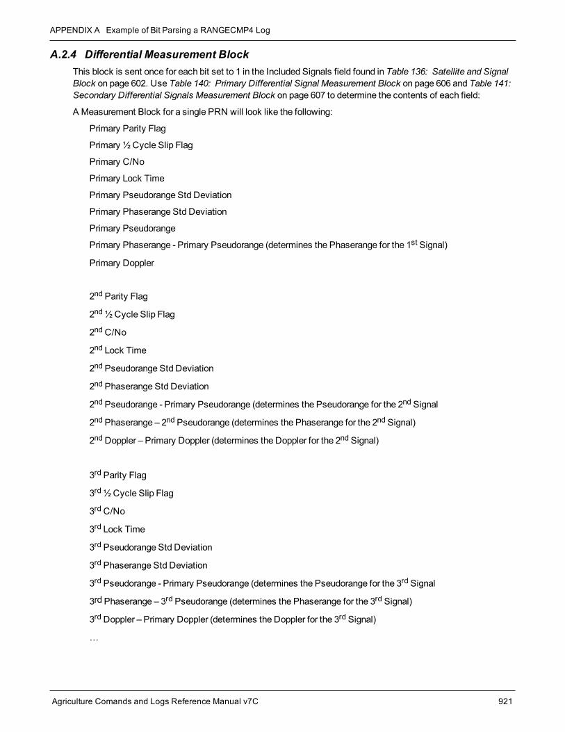
APPENDIX A Example of Bit Parsing a RANGECMP4 Log
Agriculture Comands and Logs Reference Manual v7C 921
A.2.4 Differential Measurement BlockThis block is sent once for each bit set to 1 in the Included Signals field found in Table 136: Satellite and SignalBlock on page 602. Use Table 140: Primary Differential Signal Measurement Block on page 606 and Table 141:Secondary Differential Signals Measurement Block on page 607 to determine the contents of each field:
A Measurement Block for a single PRN will look like the following:
Primary Parity Flag
Primary ½ Cycle Slip Flag
Primary C/No
Primary Lock Time
Primary Pseudorange Std Deviation
Primary Phaserange Std Deviation
Primary Pseudorange
Primary Phaserange - Primary Pseudorange (determines the Phaserange for the 1st Signal)
Primary Doppler
2nd Parity Flag
2nd½Cycle Slip Flag
2ndC/No
2nd Lock Time
2nd Pseudorange Std Deviation
2nd Phaserange Std Deviation
2nd Pseudorange - Primary Pseudorange (determines the Pseudorange for the 2nd Signal
2nd Phaserange – 2nd Pseudorange (determines the Phaserange for the 2nd Signal)
2ndDoppler – Primary Doppler (determines the Doppler for the 2nd Signal)
3rd Parity Flag
3rd½Cycle Slip Flag
3rdC/No
3rd Lock Time
3rd Pseudorange Std Deviation
3rd Phaserange Std Deviation
3rd Pseudorange - Primary Pseudorange (determines the Pseudorange for the 3rd Signal
3rd Phaserange – 3rd Pseudorange (determines the Phaserange for the 3rd Signal)
3rdDoppler – Primary Doppler (determines the Doppler for the 3rd Signal)
…

APPENDIX A Example of Bit Parsing a RANGECMP4 Log
Agriculture Comands and Logs Reference Manual v7C 922
A.2.5 Differential Primary Signal Measurement Block GPS PRN 10 – L1CAThe next bytes collected will be for the GPS PRN 10 - L1CA signal data. Since this is the primary signal of thePRN, its Measurement Block consists of 78 bits as listed in Table 140: Primary Differential Signal Meas-urement Block on page 606.
The signal info section (top 25 bits) is processed as follows:
l With 5 bits left from the previous byte, we calculate 25 – 5 = 20 bits which rounds up to 3 bytes. Therefore theprevious last byte (0x88) plus the next 3 bytes will be needed.
l Use the last byte (0x88) plus grab 3 bytes (x831f61) = 0x88831f61
l Swap the bytes = 0x611f8388
l 0x611f8388 in binary form
= 0110 0001 0001 1111 1000 0011 1000 1000
l Only need 25 bits. The last byte uses the 5MSBs and the first byte ignores the 4MSBs
l Parity flag is a 1 (Parity Known)
l ½Cycle Slip flag is a 0 (Cycle Slip Not Present)
l C/No is:0x10000011100b = 1052 x Scaling factor of 0.05= 52.60 dBHz
l The Lock Time value is:0x1111b = 15 whichmeans that this signal has been locked for 262144ms ormore.
l The Pseudorange Std Deviation value is:0x0001b = 1 whichmeans: 0.020m < PSR Std Dev <= 0.030m using Table 145: Pseudorange Std Dev onpage 611.
l The ADR Std Deviation value is:0x0001b = 1 whichmeans: 0.0039 < ADR Std Dev <= 0.0052 cycles using Table 144: ADR Std Dev onpage 610Table 10.
l For the following calculations, the time difference between the Differential Log and the Reference log is 0.25seconds as shown below:TimeDifference = Current Log Time – Reference log Time= 507977.250 - 507977.000= 0.250 seconds
The signal data section (bottom 53 bits) is processed as follows:
l With 4 bits unprocessed from the previous byte, we calculate 53 – 4 = 49 bits = 7 bytes (7 bits will not be pro-cessed in the last byte).

APPENDIX A Example of Bit Parsing a RANGECMP4 Log
Agriculture Comands and Logs Reference Manual v7C 923
l Use the last byte (0x61) plus grab 7 bytes (0x02005500e70162)= 0x6102005500e70162
l Swap the bytes = 0x6201e70055000261
l 0x6201e70055000261 in binary form =
0110 0010 0000 0001 1110 0111 0000 0000 0101 0101 0000 0000 0000 0010 0110 0001
l Only need 53 bits. Ignore last 4 LSBs and first 7 MSBs =
l Use Table 140: Primary Differential Signal Measurement Block on page 606 to identify if a 2’s ComplementConversion is needed as well as what Scale Factor should be used before these binary numbers are used inthe following calculations.
l The 1st (Primary) Differential Pseudorange is processed by:
Predicted Pseudorange = Reference 1st Pseudorange + (1st Doppler x TimeDifference)= 21540181.930275m= 21540290.811m + ((-435.5229m/s) x 0.250 s)
1st DiffPseudorange – Predicted Pseudorange = 0x0000000000000100110b x Scaling Factor1st DiffPseudorange – 21540181.930275m = 38 x 0.0005L1CA Pseudorange for PRN 10 = 21540181.949275m
l The 1st (Primary) Differential Phaserange is a 2’s Complement number (as identified by the Range column inTable 140: Primary Differential Signal Measurement Block on page 606) so it is processed in the followingmanner:
Predicted Phaserange = Reference 1st DiffPhaserange + (1st Doppler x TimeDifference)= 21540291.5622m + ((-435.5229m/s) x 0.250 s)= 21540182.681475m
1st DiffPhaserange – Predicted Phaserange = 2’s Complement(0x0000000010101010b) * Scaling Factor1st DiffPhaserange – 21540182.681475m = 170 * 0.0001L1CA Phaserange = 21540182.698475m
l Convert this to ADR to check against the original RANGE log:
ADR = 1st DifPhaserange * Frequency * (-1)/SpeedOf LightADR = 21540182.698475m * 1575420000 Hz * (-1)/299792458m/sL1CA ADR for PRN 10 = -113194424.0799796 cycles
In the range logs, PSR and ADR have opposite signs.
l The 1st (Primary) Differential Doppler is a 2’s Complement number (as identified by the Range column inTable 140: Primary Differential Signal Measurement Block on page 606) so it is processed in the followingmanner:
1st DiffDoppler(m/s)- Reference 1st Doppler = 2’s Complement(0x000000001111001110b) x Scaling Factor1st DiffDoppler(m/s) – (-435.5229m/s) = 974 x 0.0001L1CA Doppler(m/s) = -435.4255m/s
Convert the Doppler to Hz:

APPENDIX A Example of Bit Parsing a RANGECMP4 Log
Agriculture Comands and Logs Reference Manual v7C 924
1st DiffDoppler(Hz) = 1st DiffDoppler(m/s) x Frequency * (-1)/SpeedOf Light1st DiffDoppler(Hz) = -435.4255m/s x 1575420000 Hz * (-1)/299792458m/sL1CA Doppler(Hz) for PRN 10 = 2288.1764464 Hz
A.2.6 Differential Secondary Signals Measurement Block GPS PRN 10 – L2YUnlike Reference logs which always reflect back to the initial signal for their computations, Differential logs usesthe last Reference log data of the same signal for its calculations.
l With 7 bits unprocessed from the previous byte, we will require 74 – 7 = 67 bits which rounds up to 9 bytes.
l Use the last byte (0x62) plus grab the next 9 bytes (0xdc977c004015c07988)= 0x62dc977c004015c07988
l Swap the bytes = 0x8879c01540007c97dc62
l 0x8879c01540007c97dc62 in binary form =1000 1000 0111 1001 1100 0000 0001 0101 0100 0000 0000 0000 0111 1100 1001 0111 1101 1100 01100010
l Only need 74 bits. The 1 LSB is ignored as it was already processed above and the 5MSBs are ignoredso there is a total of 74 bits to process
l Parity flag is a 1 (Parity Known)
l ½Cycle Slip flag is a 0 (Cycle Slip Not Present)
l C/No is:0x01110001100b = 908 x Scaling Factor of 0.05= 45.4 dBHz
l The Lock Time value is:0x1111b = 15 whichmeans that this signal has been locked for 262144ms ormore.
l The Pseudorange Std Deviation value is:0x0101b = 5 whichmeans: 0.099m < PSR Std Dev <= 0.148m using Table 145: Pseudorange Std Dev onpage 611.
l The ADR Std Deviation value is:0x0010b = 2 whichmeans: 0.0052 < ADR Std Dev <= 0.0070 cycles using Table 144: ADR Std Dev onpage 610.
l The L2Y Pseudorange is a 2’s Complement number (as identified by the Range column in Table 141: Sec-ondary Differential Signals Measurement Block on page 607) so it is processed in the followingmanner:
Predicted Pseudorange = Reference 2nd Pseudorange + (2nd Doppler x TimeDifference)= 21540293.6315m + ((-435.523m/s) x 0.250 s)= 21540184.75075m
DiffPseudorange – Predicted Pseudorange = 2’s Complement(0x0000000000000011111b) x Scaling FactorDiffPseudorange – 21540184.75075m = 31 x 0.0005L2Y Pseudorange = 21540184.76625m
l The L2Y Phaserange is a 2’s Complement number (as identified by the Range column in Table 141:

APPENDIX A Example of Bit Parsing a RANGECMP4 Log
Agriculture Comands and Logs Reference Manual v7C 925
Secondary Differential Signals Measurement Block on page 607) so it is calculated in the followingmanner:
Predicted Phaserange = Reference 2nd DiffPhaserange + (2nd Doppler x TimeDifference)= 21540294.399m + ((-435.523m/s) x 0.250 s)= 21540185.51825m
DiffPhaserange – Predicted Phaserange = 2’s Complement(0x0000000010101010b) * Scaling FactorDiffPhaserange – 21540185.51825m = 170 * 0.0001L2Y Phaserange = 21540185.53525m
l Convert this to ADR to check against the original RANGE log:
ADR = Phaserange * Frequency * (-1)/SpeedOf LightADR = 21540185.53525m * 1227600000 Hz * (-1)/299792458m/sL2Y ADR for PRN 10 = -88203458.95116848 cycles
In the range logs, PSR and ADR have opposite signs.
l The L2Y Doppler is a 2’s Complement number (as identified by the Range column in Table 141: SecondaryDifferential Signals Measurement Block on page 607) so it is calculated in the followingmanner:
DiffDoppler(m/s) – Ref 2nd Doppler(m/s) = 2’s Complement(0x00001111001110b) x Scaling FactorDiffDoppler(m/s) – (-435.5229m/s) = (974) x 0.0001L2Y Doppler(m/s) = -435.4255m/s
Convert the Doppler to Hz:
Doppler(Hz) = Doppler(m/s) x Frequency * (-1)/SpeedOf LightDoppler(Hz) = -435.4255m/s x 1227600000 Hz * (-1)/299792458m/sL2Y Doppler(Hz) for PRN 10 = 1782.994633 Hz
A.2.7 Differential Third Signals Measurement Block GPS PRN 10 – L5QUnlike Reference logs which always reflect back to the initial signal for their computations, Differential logs usesthe last Reference log data of the same signal for its calculations.
l With 3 bits unprocessed from the previous byte, we will require 74 – 3 = 71 bits which rounds up to 9 bytes.
l Use the last byte (0x88) plus grab the next 9 bytes (0x 840f6101803a805921)= 0x88840f6101803a805921
l Swap the bytes = 0x2159803a8001610f8488
l 0x2159803a8001610f8488 in binary form =0010 0001 0101 1001 1000 0000 0011 1010 1000 0000 0000 0001 0110 0001 0000 1111 1000 0100 10001000
l Only need 74 bits. The 3 LSBs are ignored as they were already processed and the 3MSBs are ignoredso there is a total of 74 bits to process.
l Parity flag is a 1 (Parity Known)

APPENDIX A Example of Bit Parsing a RANGECMP4 Log
Agriculture Comands and Logs Reference Manual v7C 926
l ½Cycle Slip flag is a 0 (Cycle Slip Not Present)
l C/No is:0x10000100100b = 1060 x Scaling factor of 0.05= 53.0 dBHz
l The Lock Time value is:0x1111b = 15 whichmeans that this signal has been locked for 262144ms ormore.
l The Pseudorange Std Deviation value is:0x0000b = 0 whichmeans: PSR Std Dev <= 0.020m using Table 145: Pseudorange Std Dev on page 611.
l The ADR Std Deviation value is:0x0001b = 1 whichmeans: 0.0039 < ADR Std Dev <= 0.0052 cycles using Table 144: ADR Std Dev onpage 610.
l The L5QPseudorange is a 2’s Complement number (as identified by the Range column in Table 141: Sec-ondary Differential Signals Measurement Block on page 607) so it is processed in the followingmanner:
Predicted Pseudorange = Reference 3rd Pseudorange + (3rd Doppler x TimeDifference)= 21540289.869m + ((-435.5149m/s) x 0.250 s)= 21540180.990275m
DiffPseudorange – Predicted Pseudorange = 2’s Complement(0x000 0000 0000 0001 0110b) x ScalingFactorDiffPseudorange – 21540180.990275m = 22 x 0.0005L5QPseudorange = 21540181.001275m
l The L5QPhaserange is a 2’s Complement number (as identified by the Range column in Table 141: Sec-ondary Differential Signals Measurement Block on page 607) so it is calculated in the followingmanner:
Predicted Phaserange = Reference 3rd DiffPhaserange + (3rd Doppler x TimeDifference)= 21540290.8584m + ((-435.5149m/s) x 0.250 s)= 21540181.979675m
DiffPhaserange – Predicted Phaserange = 2’s Complement(0x0000000001110101b) * Scaling FactorDiffPhaserange – 21540181.979675m = 117 * 0.0001L5QPhaserange = 21540181.991375m
l Convert this to ADR to check against the original RANGE log:
ADR = Phaserange * Frequency * (-1)/SpeedOf LightADR = 21540181.991375m * 1176450000 Hz * (-1)/299792458m/sL5QADR for PRN 10 = -84528300.92127641 cycles
In the range logs, PSR and ADR have opposite signs.
l The L5QDoppler is a 2’s Complement number (as identified by the Range column in Table 141: SecondaryDifferential Signals Measurement Block on page 607) so it is calculated in the followingmanner:
DiffDoppler(m/s) – Ref 3rd Doppler(m/s) = 2’s Complement(0x00001010110011b) x Scaling FactorDiffDoppler(m/s) – (-435.5149m/s) = 691 x 0.0001L5QDoppler(m/s) = -435.4458m/s
Convert this to Hz:
Doppler(Hz) = Doppler(m/s) x Frequency * (-1)/SpeedOf LightDoppler(Hz) = -435.4458m/s x 1176450000 Hz * (-1)/299792458m/sL5QDoppler(Hz) for PRN 10 = 1708.78285 Hz

APPENDIX A Example of Bit Parsing a RANGECMP4 Log
Agriculture Comands and Logs Reference Manual v7C 927
This concludes the decoding of the Differential Log for PRN 10 (signals L1CA, L2Y, and L5Q). The rest of thedecoding for the other PRNs and systems are handled in the samemanner.

Agriculture Comands and Logs Reference Manual v7C 928