agricultural track service guide -...
TRANSCRIPT

Agricultural Track Service Guide Removal, Installation, Inspection and Alignment
Caterpillar Challenger 65, 70, 75, 85, 95
CPB-0317 3.0 10/04
1 CPB-0317 R3 (10/04)
Table of Contents Introduction........................................................................................................................................... 1
Track Terminology ........................................................................................................................... 1 Tooling Required .............................................................................................................................. 2 Time Estimates - Removal, Installation and Alignment................................................................... 2
Tractor Preparation ............................................................................................................................... 2 Track Removal...................................................................................................................................... 3 Undercarriage Inspection ...................................................................................................................... 8 Track Installation ................................................................................................................................ 11 Alignment ........................................................................................................................................... 12
Check Alignment ............................................................................................................................ 12 Adjusting Track Alignment ............................................................................................................ 13
Product Information ............................................................................................................................ 16 Summary ............................................................................................................................................. 17
Introduction This service guide is intended for use for distributors and dealers, and provides the basic information needed for track installation and service. This guide is for use with the Challenger Legacy Tillage tractor only. Whenever tracks are changed or replaced, they also must be aligned in order to maximize overall track life and prevent early guide lug failure.
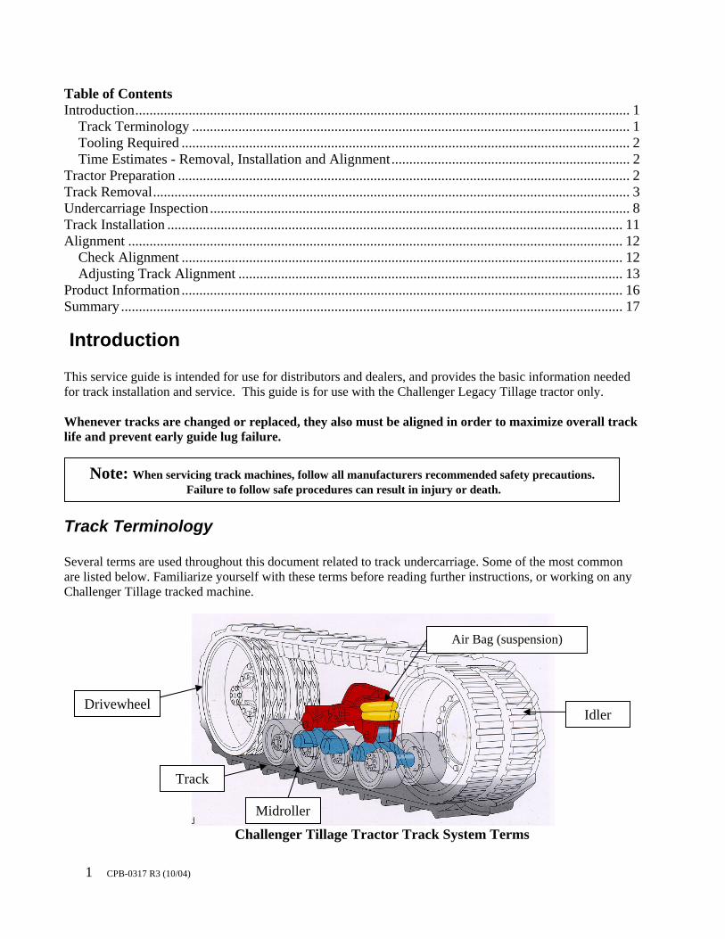
Track Terminology Several terms are used throughout this document related to track undercarriage. Some of the most common are listed below. Familiarize yourself with these terms before reading further instructions, or working on any Challenger Tillage tracked machine.
Challenger Tillage Tractor Track System Terms
Note: When servicing track machines, follow all manufacturers recommended safety precautions. Failure to follow safe procedures can result in injury or death.
Track
Midroller
Drivewheel Idler
Air Bag (suspension)
2 CPB-0317 R3 (10/04)
Tooling Required Table 1 lists the required tooling for the installation and alignment of Camoplast track on a Challenger Tillage tractor. Items in bold are available from Camoplast. Refer to Camoplast literature number CPB-0330 “Agricultural Track Technical Literature and Tooling List “for a complete list of tools available from Camoplast which are specific to tracked machines. Safety Glasses & Steel Toed Shoes Camoplast CST- 0200 Detensioning Kit Pilot Pins (for idler installation) Air Impact Socket Set (up to 1 ½”) 1 3/8” Combination Wrench Small / Large small pry bars Infrared Thermometer Gun Torque Wrench (850 ft-lb capacity) Penetrating Oil
(4) [15 Ton Minimum] Support Stands 1” Air Impact Wrench (with min.450 ft-lb capacity) Several large wood blocks (2) Lifting Eyes Air / Hydraulic Jack (min 10 Ton Capacity and 12” stroke) Optional – Soap solution (Track installation) Oil Suction Gun Compressed Air Thread Lock 5 gallon oil catch pail
Table 1. Tooling List
Time Estimates - Removal, Installation and Alignment The time to change a track depends to a great degree on the skill of the technician and the tools available. Table 2 lists average times for removal, installation, and alignment. These times assume a technician of average skills, with the correct tools, and working on firm and level ground. The process of changing alignment shims requires more time than other Ag track machines. As experience is gained, less time will be required to arrive at a correct shim pack. The assumptions below are that the alignment will take at least 1 iteration to obtain the correct alignment on each side. Note: If inspection reveals parts that must be replaced, total time will be significantly longer than shown.
Track Removal, Inspection, and
Installation Track Alignment Total
Tractor Series Per track (man-hrs)
Machine (man-hrs)
Per track (man-hrs)
Machine (man-hrs)
Total time (man-hrs)
1986-1993 (1 pc Shims) 2.5 5 3 6 11 Late 1993-up (Split Shims) 2 4 1.5 3 7
Table 2. Estimated man-hours required
Tractor Preparation 1. If possible, always move the tractor to a flat, firm surface. The machine can be raised easier and will be more stable if the track removal and installation occurs on a stable surface. A hard surface also makes it easier to slide the track out from under the machine, and allows use of a forklift if available.
2. Make sure that any implements are disconnected from the hitch or drawbar. Never work on a tractor with an implement attached or in the air, as this is an unstable condition.
3 CPB-0317 R3 (10/04)
3. Always clean the tractor before working on it. Dirt and debris makes access to bolts difficult and work unpleasant.
Important Record new track serial numbers in the operators guide in the tractor, on the warranty certificate, in
the product registration card, and for your records. Guide lugs or edge strips can be damaged!
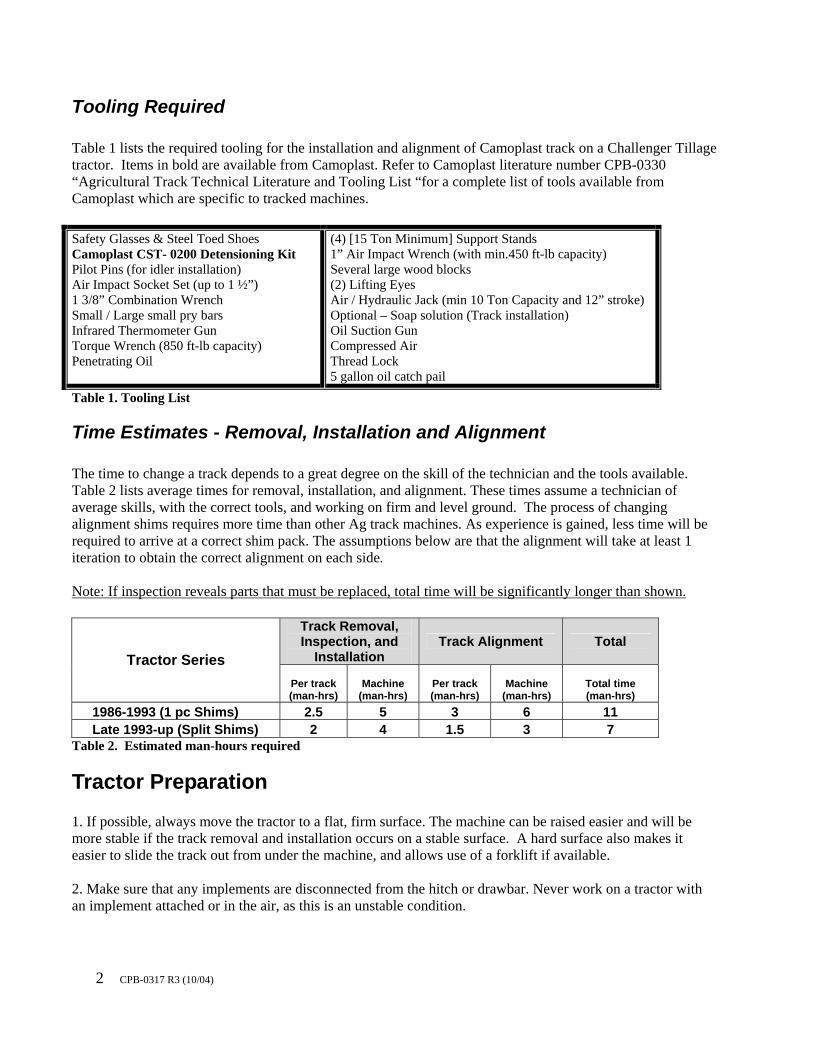
Track Removal Raise the Tractor
Step 1 and 2. Raising and supporting the rear of the machine
1. Using the hydraulic jack, position it at the rear of the machine under the drawbar support or at the base of the hitch arms. Raise the tractor at least 8” above the ground in order to provide clearance for the guide lugs to slide out from under the midrollers.
2. Position 2 jack stands as far apart as possible (for stability) on the drawbar support or hitch arms.
Step 3 and 4. Raising the front of the tractor
3. Using a long stroke hydraulic jack, also raise up the front end approximately 8”. 4. Place 2 tall jack stands under the frame rails to firmly stabilize the tractor. Then slightly lower the
jack to allow the stands to fully support the machine.

4 CPB-0317 R3 (10/04)
Detension the Track Remove from the toolbox and inspect the CST-0200 Camoplast Detensioning Hose Kit. This detensioning hose kit connects to the 2 tension cylinders through the implement valve and uses the tractor hydraulics to detension the tracks.
Tension Cylinders with External Hoses (65,65B (S/N 7YCXXXX), 75(S/N 4CJXXXX)) Early model machines do not have a breather in the location shown in the photo below. Rather, a small hydraulic hose connects both ends of the cylinder to allow for air equalization and lubrication via residual oil. There may be some residual air pressure in the tensioning system. Only disconnect the FRONT of the hose. Vent any trapped air in the system by SLOWLY loosening the fittings and allowing any pressure to dissipate. Failure to use care during this step can cause injury. Make sure to have a 5 gallon bucket handy to catch any residual oil that may run out when the hose is disconnected. Once the oil is drained, leave the REAR section of the hose connected to the tensioner and leave in the oil bucket, as some oil may come out of it during the detensioning process. Then jump to Step 7. Tension Systems with Front Breather (C series, D Series, E Series)
Step 5. Removal of breather guard Step 6. Removal of breather
Quick Coupler Adapter – installed in RH tensioner
Reducers – 1 set is used on early (spring only) tensioners, and one set is used for the later (nitrogen charged) cylinders
Hydraulic Hoses – short one connects 2 tension cylinders. Long one connects T adapter to the implement hydraulic valve
“T”Adapter - install in LH tensioner
5 CPB-0317 R3 (10/04)
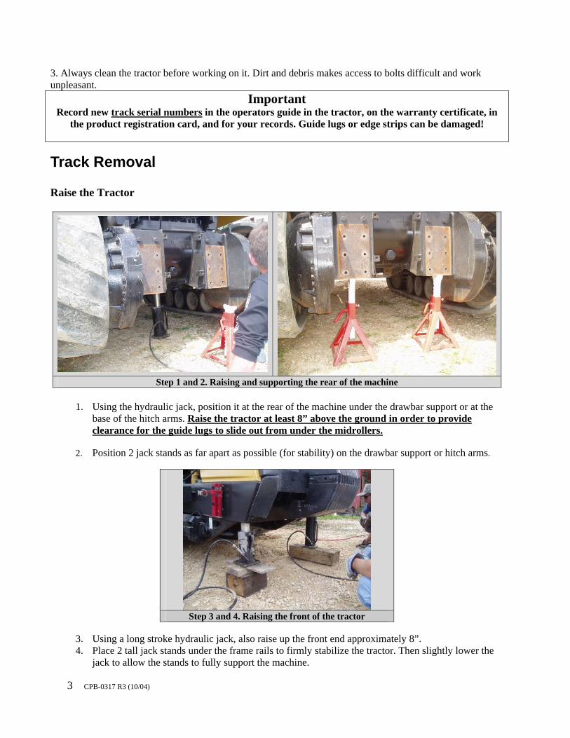
5. Locate and remove the (2) tension cylinder breather guard bolts (LH and RH side) using a 9/16” socket.
6. (Slowly!) Remove the 2 breathers using a 1 3/8” open end wrench. If breather is plugged, some
minimal air pressure may exist inside the tensioner, so use care and unscrew slowly to allow pressure to bleed off.
Step 7 and Step 8. Detensioning Adapter + Fittings
LH Side Step 7 and Step 8. Detensioning adapter + Fittings
RH Side
7. Install the detensioning hose (part of Camoplast CST-0200 Detensioning Kit). First install the correct adapter in the breather location (Note: on early machines this is the port in the FRONT of the tensioner). The detensioning kit has 2 different size adapters (1 for early tractors and one for later tractors) – select the correct one needed for the machine.
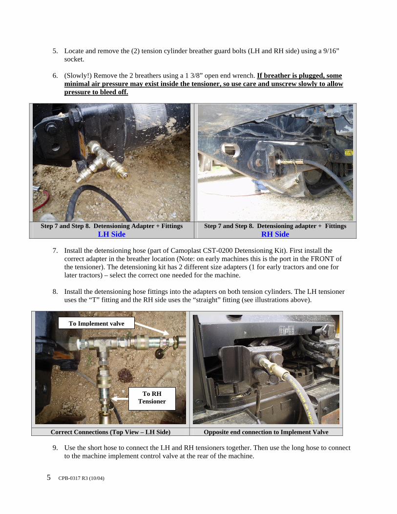
8. Install the detensioning hose fittings into the adapters on both tension cylinders. The LH tensioner
uses the “T” fitting and the RH side uses the “straight” fitting (see illustrations above).
Correct Connections (Top View – LH Side) Opposite end connection to Implement Valve
9. Use the short hose to connect the LH and RH tensioners together. Then use the long hose to connect
to the machine implement control valve at the rear of the machine.
To RH Tensioner
To Implement valve

6 CPB-0317 R3 (10/04)
10. Check front axle area (both front and rear) for material, rocks, or debris. Then lubricate the back
side of the front axle pin with oil.
Lubricate Front Axle Pin
Extension of the tension cylinder
(causing track to slacken) Track appearance after full extension of the
tensioner 11. Making sure the tractor is out of gear and in neutral, start the machine and run at idle. Move the
correct implement valve lever to extend the tension cylinders. The tension cylinders should extend and the front axle should move back. Make sure that both sides extend all the way back.
NOTE: If detensioning an early model machine with a crossover hose on the cylinder, make sure the rear section of the hose is in an oil bucket during detensioning to allow for catching of any residual oil.
IMPORTANT Make sure the front axle pin is free of debris, and is lubricated before attempting to detention track
Failure to clean and lubricate pin may cause damage to the axle, pin, or saddle.

7 CPB-0317 R3 (10/04)
Step 15. Method to gain additional guide lug
clearance Step 15. Removal of track – note guide lug
clearance needed under midrollers
12. Once full extension is reached, move the implement control lever to the hold position and then stop the engine.
13. Remove the outside front idler bolts and spacer plates (1 ½” socket).
14. Remove the outside front idler.
15. Using a boom truck or forklift, carefully slide the track off the inner front idler, out from
underneath the midrollers (see above illustration), and then out of the drivewheel groove and off the machine. Note: By letting the air out of the air suspension bag and using a come-along, additional clearance with the guide lugs can be made which can simplify the track removal.
16. Remove the 2 smaller bolts holding the inner idler, and then remove the inner idler wheel.
8 CPB-0317 R3 (10/04)
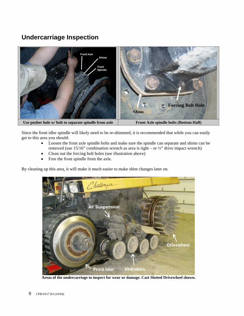
Undercarriage Inspection
Use pusher hole w/ bolt to separate spindle from axle Front Axle spindle bolts (Bottom Half)
Since the front idler spindle will likely need to be re-shimmed, it is recommended that while you can easily get to this area you should:
• Loosen the front axle spindle bolts and make sure the spindle can separate and shims can be removed (use 15/16” combination wrench as area is tight – or ½” drive impact wrench)
• Clean out the forcing bolt holes (see illustration above) • Free the front spindle from the axle.
By cleaning up this area, it will make it much easier to make shim changes later on.
Areas of the undercarriage to inspect for wear or damage. Cast Slotted Drivewheel shown.
ShimForcing Bolt Hole
9 CPB-0317 R3 (10/04)
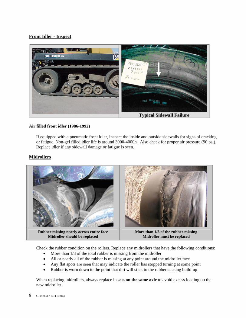
Front Idler - Inspect
Typical Sidewall Failure Air filled front idler (1986-1992)
If equipped with a pneumatic front idler, inspect the inside and outside sidewalls for signs of cracking or fatigue. Non-gel filled idler life is around 3000-4000h. Also check for proper air pressure (90 psi). Replace idler if any sidewall damage or fatigue is seen.
Midrollers
Rubber missing nearly across entire face
Midroller should be replaced More than 1/3 of the rubber missing
Midroller must be replaced
Check the rubber condition on the rollers. Replace any midrollers that have the following conditions:
• More than 1/3 of the total rubber is missing from the midroller • All or nearly all of the rubber is missing at any point around the midroller face • Any flat spots are seen that may indicate the roller has stopped turning at some point • Rubber is worn down to the point that dirt will stick to the rubber causing build-up
When replacing midrollers, always replace in sets on the same axle to avoid excess loading on the new midroller.
10 CPB-0317 R3 (10/04)
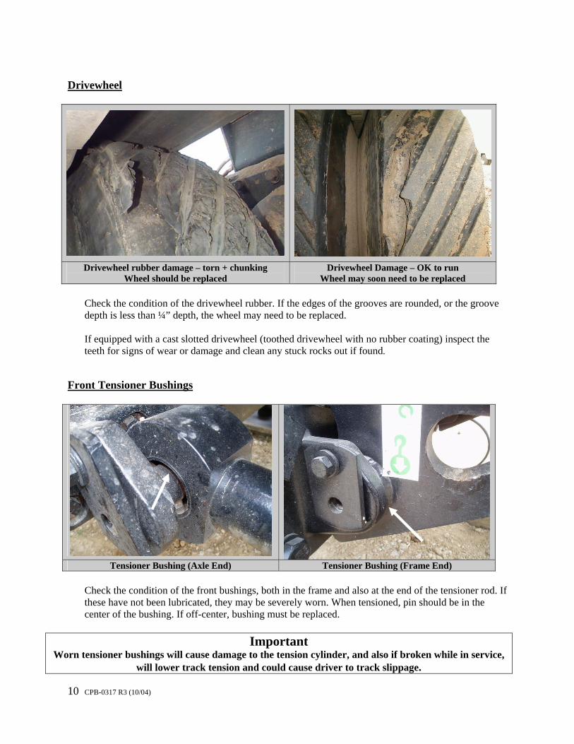
Drivewheel
Drivewheel rubber damage – torn + chunking
Wheel should be replaced Drivewheel Damage – OK to run
Wheel may soon need to be replaced
Check the condition of the drivewheel rubber. If the edges of the grooves are rounded, or the groove depth is less than ¼” depth, the wheel may need to be replaced. If equipped with a cast slotted drivewheel (toothed drivewheel with no rubber coating) inspect the teeth for signs of wear or damage and clean any stuck rocks out if found.
Front Tensioner Bushings
Tensioner Bushing (Axle End) Tensioner Bushing (Frame End)
Check the condition of the front bushings, both in the frame and also at the end of the tensioner rod. If these have not been lubricated, they may be severely worn. When tensioned, pin should be in the center of the bushing. If off-center, bushing must be replaced.
Important Worn tensioner bushings will cause damage to the tension cylinder, and also if broken while in service,
will lower track tension and could cause driver to track slippage.
11 CPB-0317 R3 (10/04)
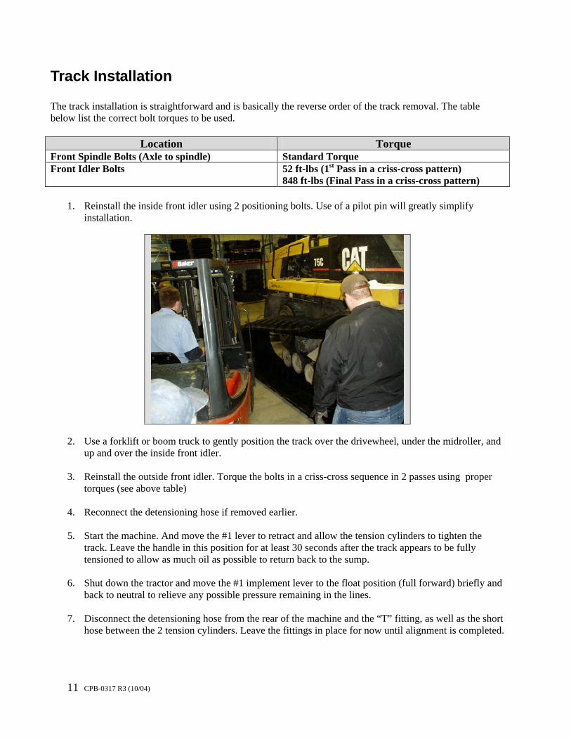
Track Installation The track installation is straightforward and is basically the reverse order of the track removal. The table below list the correct bolt torques to be used.
Location Torque Front Spindle Bolts (Axle to spindle) Standard Torque Front Idler Bolts 52 ft-lbs (1st Pass in a criss-cross pattern)
848 ft-lbs (Final Pass in a criss-cross pattern)
1. Reinstall the inside front idler using 2 positioning bolts. Use of a pilot pin will greatly simplify installation.
2. Use a forklift or boom truck to gently position the track over the drivewheel, under the midroller, and
up and over the inside front idler. 3. Reinstall the outside front idler. Torque the bolts in a criss-cross sequence in 2 passes using proper
torques (see above table) 4. Reconnect the detensioning hose if removed earlier. 5. Start the machine. And move the #1 lever to retract and allow the tension cylinders to tighten the
track. Leave the handle in this position for at least 30 seconds after the track appears to be fully tensioned to allow as much oil as possible to return back to the sump.
6. Shut down the tractor and move the #1 implement lever to the float position (full forward) briefly and
back to neutral to relieve any possible pressure remaining in the lines. 7. Disconnect the detensioning hose from the rear of the machine and the “T” fitting, as well as the short
hose between the 2 tension cylinders. Leave the fittings in place for now until alignment is completed.
12 CPB-0317 R3 (10/04)
NOTE : At this point, you should now skip to the “Alignment” Section, as you may need to detension and install shims during the alignment process. Once the alignment of both tracks is correct, then return her and then proceed to Step 8. Once Alignment is Correct
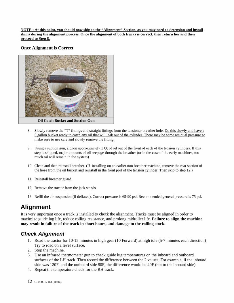
Oil Catch Bucket and Suction Gun
8. Slowly remove the “T” fittings and straight fittings from the tensioner breather hole. Do this slowly and have a
5 gallon bucket ready to catch any oil that will leak out of the cylinder. There may be some residual pressure so make sure to use care and slowly remove the fitting
9. Using a suction gun, siphon approximately 1 Qt of oil out of the front of each of the tension cylinders. If this
step is skipped, major amounts of oil seepage through the breather (or in the case of the early machines, too much oil will remain in the system).
10. Clean and then reinstall breather. (If installing on an earlier non breather machine, remove the rear section of
the hose from the oil bucket and reinstall in the front port of the tension cylinder. Then skip to step 12.)
11. Reinstall breather guard.
12. Remove the tractor from the jack stands
13. Refill the air suspension (if deflated). Correct pressure is 65-90 psi. Recommended general pressure is 75 psi.
Alignment It is very important once a track is installed to check the alignment. Tracks must be aligned in order to maximize guide lug life, reduce rolling resistance, and prolong midroller life. Failure to align the machine may result in failure of the track in short hours, and damage to the rolling stock.
Check Alignment 1. Road the tractor for 10-15 minutes in high gear (10 Forward) at high idle (5-7 minutes each direction)
Try to road on a level surface. 2. Stop the machine. 3. Use an infrared thermometer gun to check guide lug temperatures on the inboard and outboard
surfaces of the LH track. Then record the difference between the 2 values. For example, if the inboard side was 120F, and the outboard side 80F, the difference would be 40F (hot to the inboard side)
4. Repeat the temperature check for the RH track.
13 CPB-0317 R3 (10/04)
Important A track requires alignment if the temperature difference is greater than approximately 15-
20F. Failure to align a misaligned track will result in rapid guide lug wear and damage to the midrollers, drivewheels, and idlers
Adjusting Track Alignment
The Challenger Tillage tractor requires significant amounts of time to adjust the alignment. The track tension must be released, the machine jacked up, the front spindled loosened or removed, old shims removed and new shims installed, and then a recheck of the alignment. Step 1 – Detension the Track Please refer to the earlier sections for the correct procedure to detension tracks. Step 2 – Remove shims and determine existing shim angles
Challenger 65,65B(7YC), 65C (4KK1-499), 75 (4CJ), 75C(4KK1-499)
The earlier Challenger Tillage tractors listed above are equipped with single piece shims. In order to get the correct alignment, you will need a selection of these shims to choose from. For a pre-assembled kit of a selection of shims needed, order Camoplast Shim Kit CST-0400.
Shim removal is laborious with the earlier non split shim models, and requires the following steps:
a. Removal of track b. Removal of inside and outside front idlers c. Removal of front spindle
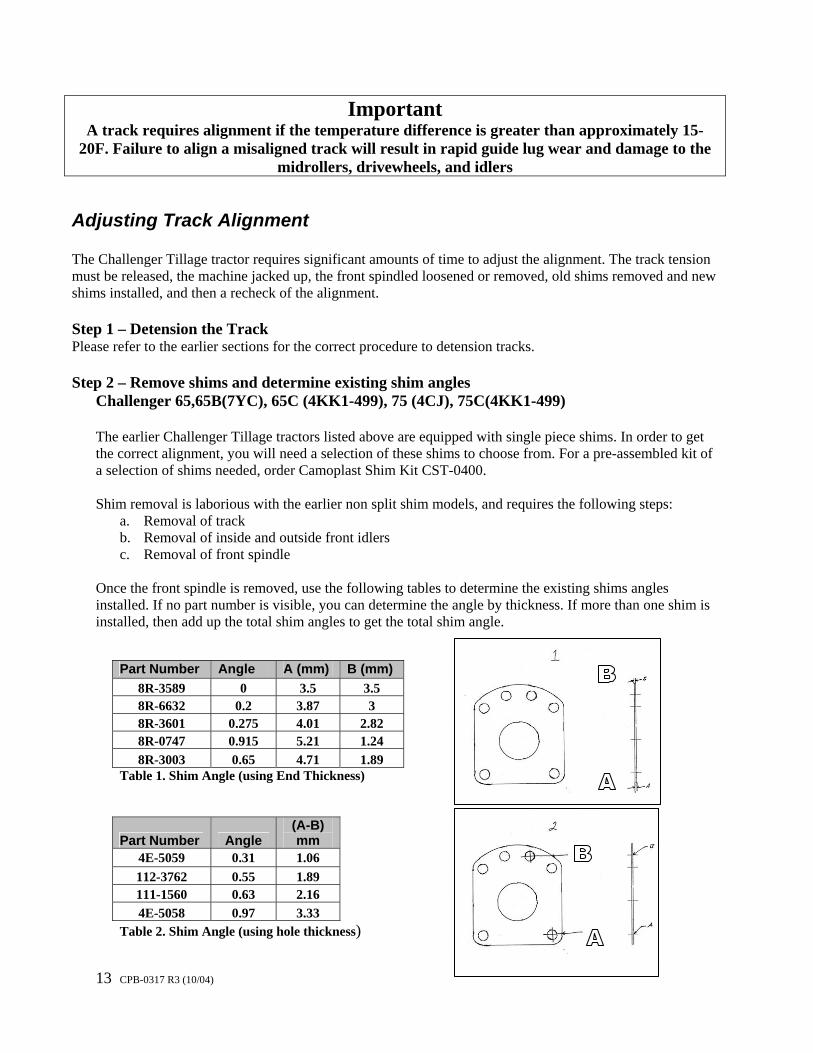
Once the front spindle is removed, use the following tables to determine the existing shims angles installed. If no part number is visible, you can determine the angle by thickness. If more than one shim is installed, then add up the total shim angles to get the total shim angle.
Part Number Angle A (mm) B (mm) 8R-3589 0 3.5 3.5 8R-6632 0.2 3.87 3 8R-3601 0.275 4.01 2.82 8R-0747 0.915 5.21 1.24 8R-3003 0.65 4.71 1.89
Table 1. Shim Angle (using End Thickness)
Part Number Angle (A-B) mm
4E-5059 0.31 1.06 112-3762 0.55 1.89 111-1560 0.63 2.16 4E-5058 0.97 3.33
Table 2. Shim Angle (using hole thickness)
14 CPB-0317 R3 (10/04)
Challenger 65C (4KK500-up), 70C, 75C(4KK500-up), 85C, All D Series , All E Series
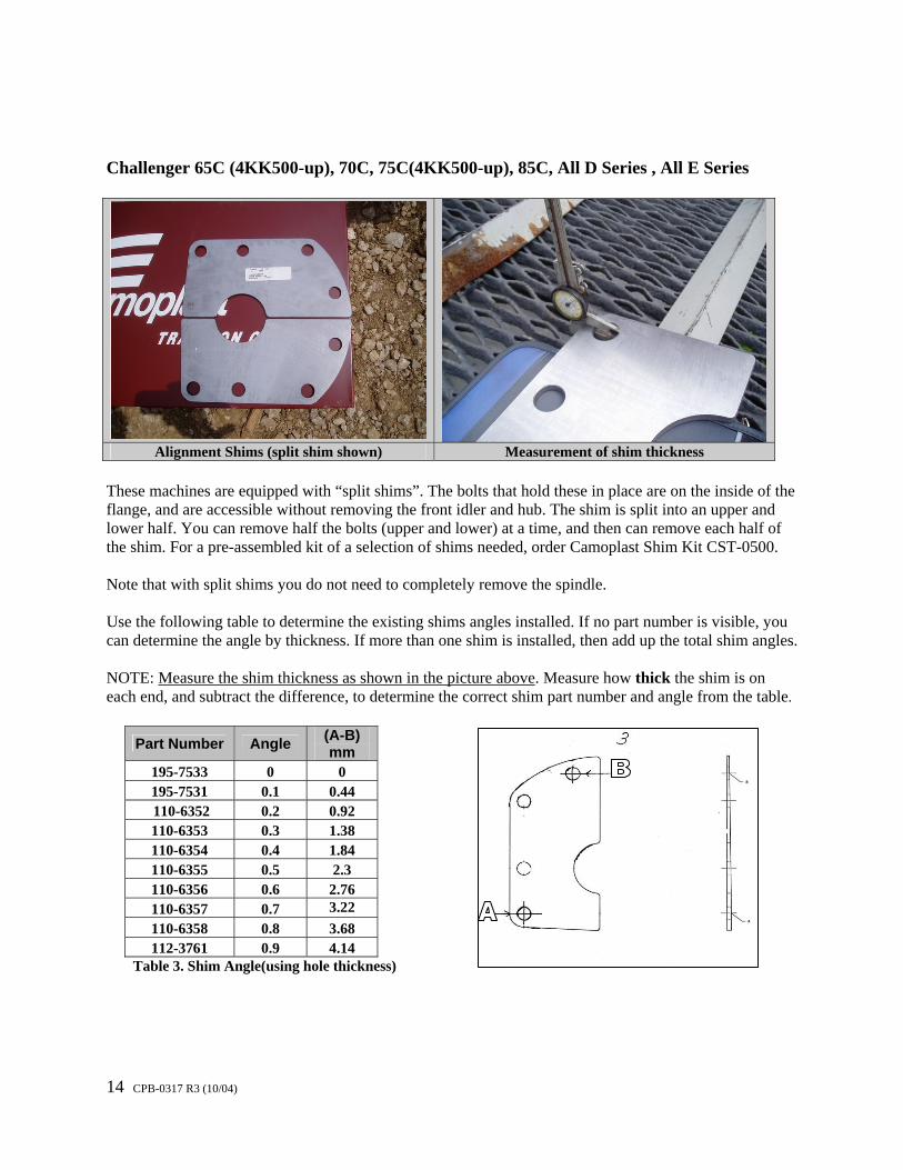
Alignment Shims (split shim shown) Measurement of shim thickness
These machines are equipped with “split shims”. The bolts that hold these in place are on the inside of the flange, and are accessible without removing the front idler and hub. The shim is split into an upper and lower half. You can remove half the bolts (upper and lower) at a time, and then can remove each half of the shim. For a pre-assembled kit of a selection of shims needed, order Camoplast Shim Kit CST-0500.
Note that with split shims you do not need to completely remove the spindle.
Use the following table to determine the existing shims angles installed. If no part number is visible, you can determine the angle by thickness. If more than one shim is installed, then add up the total shim angles.
NOTE: Measure the shim thickness as shown in the picture above. Measure how thick the shim is on each end, and subtract the difference, to determine the correct shim part number and angle from the table.
Part Number Angle (A-B)
mm 195-7533 0 0 195-7531 0.1 0.44 110-6352 0.2 0.92 110-6353 0.3 1.38 110-6354 0.4 1.84 110-6355 0.5 2.3 110-6356 0.6 2.76 110-6357 0.7 3.22 110-6358 0.8 3.68 112-3761 0.9 4.14
Table 3. Shim Angle(using hole thickness)
15 CPB-0317 R3 (10/04)
Step 3 – Calculate new shim angle needed
Using the temperature differentials recorded earlier during the alignment check, you now can calculate what shim angle will be needed to achieve better alignment. Use the following table to estimate first the amount of CHANGE that will be needed depending on the temperature differential.
Left Side Right Side Outer Idler Hottest Inner Idler Hottest Outer Idler Hottest Inner Idler Hottest
Temp Difference
Increase Angle
Temp Difference
Decrease Angle
Temp Difference
Increase Angle
Temp Difference
Decrease Angle
10F 0.05 10F 0.05 10F 0.07 10F 0.05 20F 0.1 20F 0.1 20F 0.13 20F 0.1 40F 0.17 40F 0.17 40F 0.23 40F 0.17 60F 0.25 60F 0.25 60F 0.33 60F 0.25 80F 0.31 80F 0.31 80F 0.44 80F 0.31
100F 0.36 100F 0.36 100F 0.54 100F 0.36 120F 0.41 120F 0.41 120F 0.63 120F 0.41 140F 0.45 140F 0.45 140F 0.73 140F 0.45
Table 4. Estimated change in shim angle from current setting The final shim angle will be:
New Shim Angle = Current shim angle +/- Change needed in shim angle . The following example will illustrate how to use the above tables to calculate the correct angle. Example: A Challenger 75E with new tracks is rubbing the guide lugs hard to the outside on the RH track. After 15 minutes of roading, the temperature measured on the inside of the drivewheel or guide lug was 100F, and on the outside of drivewheel or guide lug it was 160F. Upon disassembly, the shim was removed and since there was no part number found, it was measured at the front and the rear holes and was found to have measurements be 8.6mm and 6 mm. Solution: The difference in measurements A and B is (8.6-6), or 2.6mm. Looking at Table 3, the closest (A-B) dimension is 2.76, so we must have a 0.6 degree shim (110-6356). Now, using Table 4, we know we have the RH track with the outer idler hottest by (160-100) = 60F temperature differential. This would indicate we need to increase the angle by 0.33 degrees. We could just add a 0.3 deg shim to the current shim, but stacking shims is not usually recommended, so we should instead calculate the new shim angle. The new angle needed is 0.6+0.33= 0.93 degrees. The closest shim angle to try would be 0.9 degrees (112-3761). This new split shim should be installed in place of the earlier 110-6356 split shim. Make sure to then recheck alignment. Important Shim Installation Rules 1. Do not stack shims unless necessary. It is preferable to use the correct shim rather than
stacking 2 smaller angle shims to achieve best results. 2. Never stack more than 2 shims on top of each other.
16 CPB-0317 R3 (10/04)
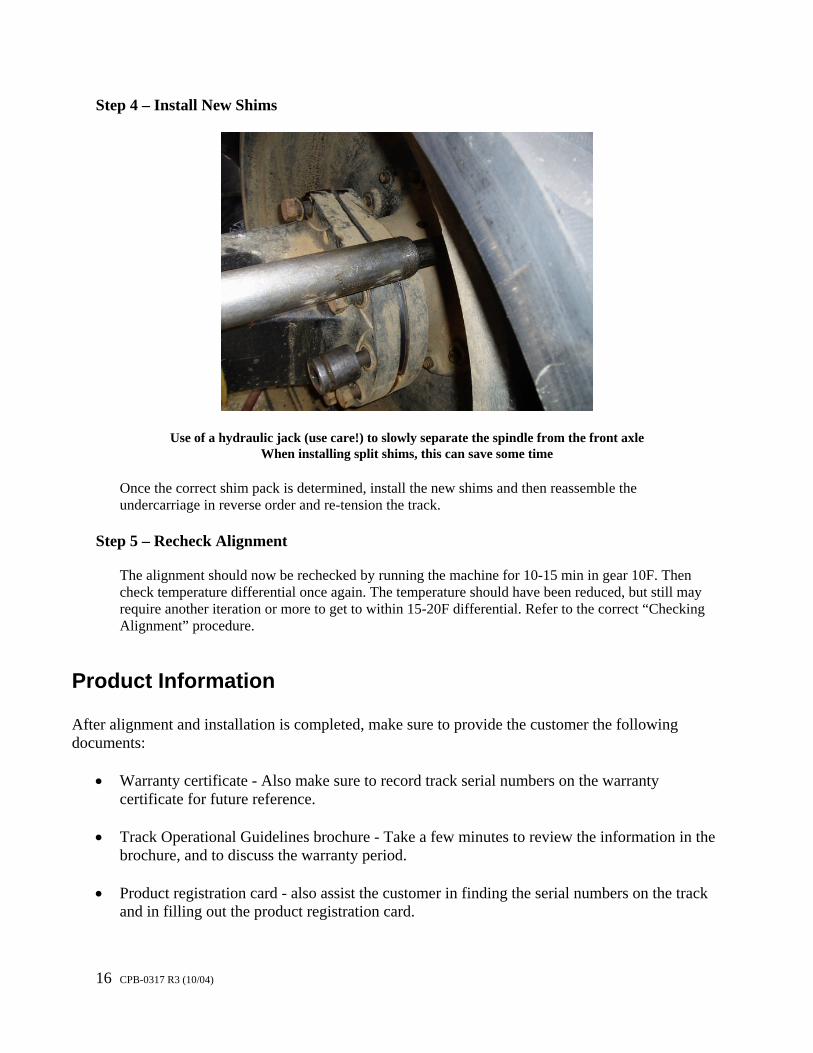
Step 4 – Install New Shims
Use of a hydraulic jack (use care!) to slowly separate the spindle from the front axle
When installing split shims, this can save some time
Once the correct shim pack is determined, install the new shims and then reassemble the undercarriage in reverse order and re-tension the track.
Step 5 – Recheck Alignment
The alignment should now be rechecked by running the machine for 10-15 min in gear 10F. Then check temperature differential once again. The temperature should have been reduced, but still may require another iteration or more to get to within 15-20F differential. Refer to the correct “Checking Alignment” procedure.
Product Information
After alignment and installation is completed, make sure to provide the customer the following documents:
• Warranty certificate - Also make sure to record track serial numbers on the warranty
certificate for future reference. • Track Operational Guidelines brochure - Take a few minutes to review the information in the
brochure, and to discuss the warranty period.
• Product registration card - also assist the customer in finding the serial numbers on the track and in filling out the product registration card.

17 CPB-0317 R3 (10/04)
Summary Installation and adjustment of tracks is straightforward and not complicated once you know the proper procedures. As you gain experience, you will find more efficient ways to accomplish the work in a shorter period of time. For additional information on the maintenance of the undercarriage, and on the extended procedures for servicing and rebuilding these areas, refer to the OEM service manual (available from the local OEM dealer or from Camoplast)
Title OEM Part Number Cat 65/75/85/95 Disassembly & Assembly Manual
SENR1789
Note: OEM manuals are available in a complete set (including all machines Camoplast manufactures tracks for) by ordering the “OEM Track Installation Literature Kit“(P/N CPB-0300) from Camoplast. Email any suggestions for improvements, clarifications, or errors, to [email protected].
Revision History Rev 3 10/04 : Added details on proper disconnection and reconnection of early Challenger tension cylinders with crossover vent hoses between front and back of cylinder. Rev 2 5/04 : Rewrote separate manual for Tillage tractor. Added detail photos of entire procedure. Inlcuded latest detensioning kit photos and information.