agricultural research service • u.s. department of
TRANSCRIPT

Agricultural Research Service • U.S. Department of Agriculture • Agriculture Handbook No.438

RECREATIONAL BUILDINGS AND FACILITIES
Agriculture Handbook No. 438
Prepared by Agricultural Research Service
United States Department of Agriculture
Washington, D.C. ^ issued September 1972
For sale by the Superintendent of Documents, U.S. Government Printing Office Washington, D.C. 20402 - Price 70 cents
Stock Number 0100-02663

CONTENTS
2
Plan No. Page Introduction 1 Cabins
Vacation cabin for two 5184 2 Three-room cabin 5185 3 Vacation cabin for four 5I86 4 Cabin 5928 5 Cabin, masonry construction 5968 6 Cabin with dormitory loft 6013 9 A-frame cabins 5954 11
5965 11 A-frame cabin 6003 15 Log cabin 55O6 17 Log cabin 5507 I8 Log cabin 7013 18 Pole-frame cabin 6002 20 Pole-frame cabin 6004 22 Vacation house, frame construction 5997 24 Tenant house 7010 27 Farm cottage 7137 28 Adirondack-type shelter 5998 30
Barns and Equipment for Horses 32 Expansible barn for riding horses 5838 32 Two-horse trailer 5943 33 Saddle horse barn 5994 35 Eight-stall horse barn 6010 36 Seventeen-stall horse barn 6011 38 One-and-a-half-story horse barn 6024 40 Portable stable for a horse 6082 42 Horse equipment 6014 44 Horse show rings 6015 46
Greenhouses 48 Plastic-covered greenhouse 594I 48 Plastic-covered greenhouse 5946 50 Greenhouse framing for plastic covering 6029 52 Hotbed and propagating frame 597I 54 Mini-hotbed and propagating frame 6080 57
Recreation Facilities 59 Outdoor fireplace 5188 59 Boat landing 5975 51 Picnic shelter of wood construction 5995 62 Concrete block incinerator 5996 64 Sheltered barbeque pits 6020 66
6022 66 Recreational pavilion with kitchen 6079 68 Comfort station for campgrounds 6083 70 Storage sheds 6086 72
6093 72 Utility sheds 6100 73

RECREATIONAL BUILDINGS AND FACILITIES
Agricultural Research Service
INTRODUCTION
This illustrated list of currently available building plans was compiled by the Cooperative Farm Building
Plan Exchange. The plans were developed by the cooperative effort of Extension Service (USDA). State Extension Service, State Experiment Stations, Cooperative State Research Service (USDA), and Agricultural Engineering Research Division, Agricultural Research Service (USDA).
The building plans, their purpose, and some of the construction details are shown in the illustrations and are described in the brief text for each plan.
Economy of material and labor has been given particular emphasis. The structures are efficient and useful for the purposes intended.
Complete working drawings of the plans may be obtained from the extension agricultural engineer at your State university. There may be a small charge to cover cost of printing. If you do not know the location
of your State university, send your request to Agricultural Engineer, Extension Service, U.S. Department of Agriculture, Washington, D.C. 20250. He will forward your request to the correct university.
CABINS
VACATION CABIN FOR TWO, PLAN NO. 5184
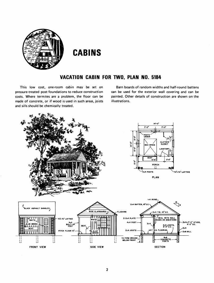
This low cost, one-room cabin may be set on pressure-treated post foundations to reduce construction costs. Where termites are a problem, the floor can be made of concrete, or if wood is used in such areas, joists and sills should be chemically treated.
Barn boards of random widths and half-round battens can be used for the exterior wall covering and can be painted. Other details of construction are shown on the illustrations.
-■1
I4'~0-
=1^1
7Î-0"
-POSTS UNDER
7^
SEAT 10-6'
CLOTHES^ CLOSET
LAVATORY«v
3-6"
PORCH
^ 4x4 POSTS
PLAN
Vt"iy«" LATTICE
2x4 RAFTER,
2-2x4 PLATE
TO FIRM GROUND BELOW FROST
2x4x7-0" STUDS, 4'-0" O.e.
FRONT VIEW SIDE VIEW SECTION

THREE-ROOM CABIN, PLAN NO. 5185
This cabin is suitable for camping or could be Utilized permanent farmhouse was being built. The cookstove as a bunkhouse during the harvest season. It could also would furnish heat. In cold climates the cabin should be serve temporarily as living quarters for a family while a insulated.
.... *«'I«'V ^..j^.
m

VACATION CABIN FOR FOUR, PLAN NO. 5186
This economical building provides for Pullman-type berths. If a central heat source is not practical, a chimney should be added to provide for a heater. Space
is also provided for a toilet as shown on the plan. The sill is steel-strapped to concrete posts that extend
below frost line. Floor joists are framed into the sill and securely
anchored with metal fasteners.
Both floor joists and sill should be protected from
termite attack. This building is frame construction with the exterior
surface covered with rough-sawn, random width boards
and 1%-inch, half-round, wood battens. Interior has tongue-and-groove flooring, with walls
and ceiling covered with building board or sheathing.
PLAN FRONT VIEW tx6 RIDGE
WIDE CLAPBOARDS
2x4 RAFTERS 2'-0" O.e.
TWO 2x4 PLATES ^
T a G FLOORING IzZTl
BELOW FROST FIRM GROUND
t^^^^^. "^8x8 CONCRETE
POST
2x4 TIES, 2'-0" 0.C
^^2x4
^2x4 STUDS 4'or ac.
/^2x4 PLATE 2x3
f-Z^6x8 SILL
SIDE VIEW SECTION

CABIN, PLAN NO. 5928
The basic floor plan for this frame cabin is 24 by 24 feet, slab-on-grade construction. The exterior shell can be built and the plumbing roughed in at a reasonably low cost. Interior finish, storage walls, and an addition can be added later.
The simple interior arrangement is flexible and can be adapted to many uses-a beach house, lake or mountain
cabin; a low-cost permanent home with one, two, or three bedrooms; or a temporary home. The outside may be rustic or of the finest modern siding. The inside may have rough framing and concrete floor exposed, or it may be highly finished. Thus, the design fits a wide variety of needs.
SCALE IN FEET

Alternate floor plans
The alternate plans of this cabin can be utilized for additional income from a developed recreational area. The basic building can be arranged in several ways, depending on the type of facility and on
accommodations needed by vacationers. For example, a screened porch, a bunk room, or two additional
bedrooms can be added. The working drawings show construction details for
storage walls—2 feet wide, 4 feet long, and 8 feet
high—which may be built from standard 4- by 8-foot sheets of material. The roof trusses eliminate any need for interior load-bearing walls, so the walls may be located wherever desired. If built lower than ceiling
height, they can be moved easily. If the cabin is to be used as a permanent dwelling,
storage space is needed outside. The space should be large enough to accommodate paints, hand and garden tools, lawn mower, outboard motor, gasoline, and similar equipment and supplies. Also, the shed should be large enough to permit handyman activities.
Careful consideration should be given to the heating system. If expansion is planned, the system must be capable of heating the larger unit.
The alternate plan shows one arrangement that is possible for expansion. It has more living, sleeping, and storage space than the basic plan, but it also requires outdoor storage for a permanent type home. The working drawings show only the expanded building with
storage walls. The roof trusses used in the design are simple
lap-nailed construction and have been load tested. The truss members can be nailed together and trimmed later to eliminate precision marking and cutting. If the details of the working drawings are followed, a reliable roof
support can be easily and quickly constructed.
CABIN, MASONRY CONSTRUCTION, PLAN NO. 5968
Concrete masonry construction is suggested for this modern cabin because concrete is low cost, durable, easy
to maintain, and attractive. Complete kitchen facilities in the cabin combine with
the living-dining area to form a unified activities center for the family. Though the basic plan calls for one bedroom, the activities center is large enough for a family that would need three bedrooms. The two extra bedrooms may be added at the rear, as suggested in the working drawings, without alteration of the present
rooms or equipment. A bath with shower, a space for a washer, and good storage facilities contribute to pleasant
and convenient living in this cabin. Suggestions for block selection, insulation, finishing
materials, and paint are given below. These ideas, along with personal preference for trim and for paint color combinations, can be used to give warmth and character to the cabin. Further help and suggestions are available from the Portland Cement Association, which
cooperated in the development of this plan.

■^>>
SCALE IN FEET
Block selection
The working drawings show 4- by 8- by 16-inch concrete block units, which give horizontal mortar lines at 4-inch intervals. These relatively close-spaced nnortar joints have a pleasing appearance, but the finished cost is increased by one-third as compared with that of standard 8- by 8- by 16-inch units.
Properly tooled joints are very important for watertight walls and for overall good appearance.
Concave or "v" joints are recommended. When mortar in joints is "thumb print" hard, it
should be firmly pressed into the concave or "v"
formation with a tooling device that is wider than the joint and 24 to 36 inches long. This long tooling device
makes straight, uniform horizontal joints.
CONCAVE II y.I
476-018 O - 72 - 2

Insulation
Insulation above the ceiling is recommended for
cabins built in any climate and for use in any season.
Either loose fill or batt-type insulation may be used.
Vermiculite fill in the cores of the blocks and foamed semirigid insulation about the perimeter of the floor slab
are necessary for winter comfort. Lightweight-aggregate blocks are recommended because insulation is easier to
apply to them than to the denser concrete blocks with sand and gravel aggregate. Lightweight blocks are also easier to handle, and nails can be driven into them.
Finishing material
Interior-wall, ceiling, and floor finishes can be applied
before partitions are erected. This saves cutting and fitting labor. Ceiling tiles made of insulating board are popular for this type of building because no further
finishing is required. Low-cost asphalt tiles serve well over a concrete floor slab.
A latex paint is recommended for the interior walls.
Besides being economical and easy to apply, it is well
suited for masonry and the other inside materials. The exterior masonry walls should have a base coat of
Portland cement paint (a special cement powder to be
mixed with water) for watertightness. Apply this with a stiff-bristle scrub brush to fill the pores of the block.
The second exterior coat should be an acrylic resin,
outside latex paint.
Interior partitions The clear span of the roof trusses permits free
placement of interior partitions. If the partitions are not
hindered by wiring or plumbing, they can be easily
moved for remodeling. Partitions should be slightly less
than ceiling height and wedged at the bottom to press them against the ceiling.
The working drawings show construction details of
the storage room wall that separates the living area from
the bedroom. Built from standard 4- by 8-foot sheets of
material, the wall is 2 feet deep by 8 feet high.
Perforated hardboard is suggested for closet doors and backs, for ventilation as well as for its decorative quality. Brackets and hooks can be placed in the perforated board to make the storage space more usable.
Construction of the heater enclosure will depend on the type of heating unit to be installed.

CABIN WITH DORMITORY LOFT, PLAN NO. 6013
/ ST FLOOR . . 22' X 24'
LOFT .12' X 24'
1.0 FEÎ
This one-and-a-half-story cabin has two bedrooms and a loft sleeping area. The loft is over the first floor bedrooms and has clearanœs of 7 feet at the ridge beam and 3 feet at the outside wall.
An open-type ceiling gives a feeling of spaciousness to the kitchen and living area and cuts construction costs. A prefabricated fireplace is suggested on the plan.
Pole framing helps to make construction easy for the less-experienced builder and eliminates the need for expensive masonry foundations. A woodframe floor is used in the structure shown and is most suitable for a
sloping site. A concrete floor would be more economical when the house is built on a well-drained, level site. A pole-supported deck is suggested for more indoor-outdoor relaxation space.
Rough-sawn native material is used wherever possible. The choice of interior finishing material is left to the builder. Slight changes in the wall framing could be made if insulation and interior finish are to be added.

details
BEARING BLOCK
FOR A MORE ATTRACTIVE
ROOFLINE, INCREASE OVERHANG TO 2'-0" AT THE RIDGE.
s'-xe-Vie'-o" 3-0" o.e.
END-WALL FRAMING
iiiiillr CEiiraHof „srroicnœf
10

A-FRAME CABINS, PLANS NO. 5964 AND NO. 5965
These two cabins (24-foot and 36-foot A-frames) are
designed for recreational purposes in mountain areas or
at a beach. They can be built by three or four people
who have reasonable ability in the use of tools. Someone
with a knowledge of concrete work may be required to
place the footings. The frame itself should present no
problems; nor should erection of the end walls, roof, and
interior partitions. It is assumed that electricity will be
available at the site to permit the use of power tools and
to provide for lighting, heating, and cooking. Each cabin is provided with a modern kitchen that
contains a refrigerator, range, sink, and adequate cabinet space. Provision is made for a water heater under one corner of the floor cabinet arrangement. The bathroom
contains a lavatory, toilet, and shower. A storage locker for linens is provided in the bathroom. The water supply would probably come from a well or spring; and the
piping, where exposed to the outside air should be
properly insulated and provided with drain valves so that all water can be drained from the system when the cabin
is not occupied during winter weather.
'\,^ - y' I '*
A CUTAWAY VIEW
11

Plan No. 5965
The 36-foot cabin contains three bedrooms, one on the first floor and two on the second floor. The front bedroom on the second floor is a balcony that overlooks
the two-story living room. If sleeping space for more than six persons is required, cots can be placed in the living room.
B ffl B 53 B 5B H H. H H_
^—m—gg—gg g g g H H 05 ffl B 36-0 '_n//
>- z 8 —1
S 1
1
—1
■
l
r —0 - 11 w
UPKR
m mm mm
O BEDROOM
L— BEDROOM
ClOSET II A Í
36'-0'' 2^ FLOOR PLAN NO. 5B6S
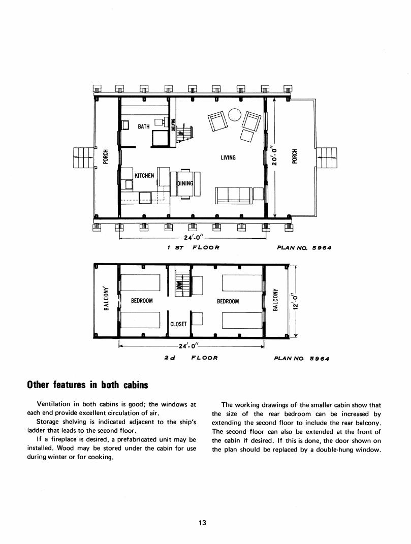
Plan No. 5964
The 24-foot cabin contains two bedrooms, both on the second floor. The living-dining area is smaller than
that in the 36-foot cabin. The living room is only one story high.
12
H 5¡ H H_ _H 53 B
o oc £
ii w 1
o g
CM ^
"g 01 g" 24'-0"-
H
/ ST FLOOR PLAN NO. S964
1 1
BA
LCO
NY
\ 1 ""■" —n 1
1 = 1 z
O o
1 CO
BEDROOM BE DROOM
■ 1
CLOSET
■ ■ 1 II,
4 -2 4'. o''- *
o "CM
2ci FLOOR PLAN NO. S 9 64
Other features in both cabins
Ventilation in both cabins is good; the windows at each end provide excellent circulation of air.
Storage shelving is indicated adjacent to the ship's ladder that leads to the second floor.
If a fireplace is desired, a prefabricated unit may be installed. Wood may be stored under the cabin for use during winter or for cooking.
The working drawings of the smaller cabin show that the size of the rear bedroom can be increased by extending the second floor to include the rear balcony. The second floor can also be extended at the front of the cabin if desired. If this is done, the door shown on the plan should be replaced by a double-hung window.
13

View of section
This section gives some ideas for constructing the
A-frame. After the footings have been placed, the lower
half of the frame may be erected and the rough flooring
nailed in place at the first- and second-floor levels. The
second floor can be used as a work platform while the
upper half of the frame is put in place. The roof
sheathing should then be put on, followed by the
finished roofing. The end walls may then be framed and
completed and, finally, the interior partitions.
For added protection in cold climates the space
under the first floor and in the end walls should be
insulated. Additional insulation may be installed on the
underside of the roof sheathing between the frames if
the climate requires.
ROOF DECKING
SHELVES
LADDER TO
2d FLOOR
SECTION VIEW FROM LIVING ROOM TOWARD THE REAR
14
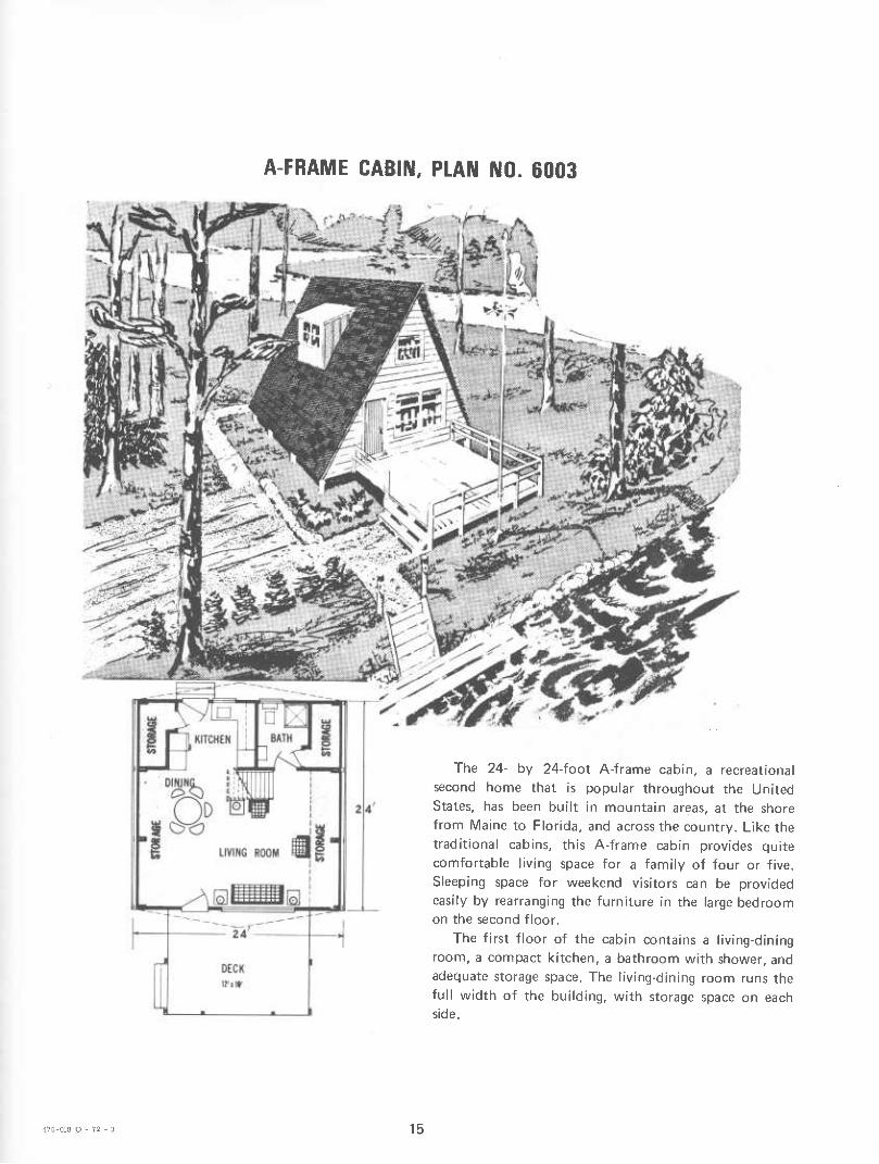
A-FRAME CABIN, PLAN NO. 6003
The 24- by 24-foot A-frame cabin, a recreational
second home that is popular throughout the United States, has been built in mountain areas, at the shore
from Maine to Florida, and across the country. Like the
traditional cabins, this A-frame cabin provides quite comfortable living space for a family of four or five. Sleeping space for weekend visitors can be provided easily by rearranging the furniture in the large bedroom on the second floor.
The first floor of the cabin contains a living-dining room, a compact kitchen, a bathroom with shower, and
adequate storage space. The living-dining room runs the
full width of the building, with storage space on each side.
476-018 O - 72 - 3 15

The locale and climatic conditions are major factors for the builder to consider when deciding if a heating
system and insulation are needed. The kitchen at the rear of the cabin contains space
for a sink, a refrigerator, a range, and base and wall cabinets. A ship's ladder stairway leads to the second floor, and a dormer-type window extension in the roof
adds light and ventilation to this area. With some knowledge of carpentry and the ability to
use ordinary hand tools, three or four men should have
no serious problems building this cabin. Care should be
taken in locating and setting the pressure-treated posts.
The A-frames should be assembled flat on the ground, raised into position, and braced until the flooring is put in place. The roof sheathing should be placed, the ends cut to the shape of the overhang, then the roofing applied. The end walls and partitions may easily be installed and the kitchen and bathroom fixtures placed. Redwood or cypress lumber siding will take on a weathered finish and eliminate the need for periodic painting.
DOUBLE C RAFTER
CONSTRUCTION NOTES- Use rough lumber for all structural framing. Lap
rough, I-inch boards for end-wall siding. Other ma- terials or methods may be substituted.
Rafters and floor beams are 24-feet long to fa- cilitate construction of the A-frame on the ground. If some saving in intial cost is necessary, add the deck in the front later. Interior finish is left to builder's choice.
1¿ FLOOR
FRAMING DIAGRAM
REAR ELEVATION
2-2X10 RAFTERS
16

LOG CABIN, PLAN NO. 5506
This five-room cabin, designed principally for entrance down a stairway from the back proch. Loft camping, would make a fairly comfortable house for a space could be reached from an open stair in the living small family. A basement could be provided, with the room.
4¿'cr
17

LOG CABIN, PLAN NO. 5507
3Q'-Q"
This three-room log cabin would be especially appropriate for a camp in the woods or on the lakeshore. The back of the fireplace in the living room gives heat to the bedrooms. The large porch is especially desirable if the house is to be used as a summer home. Porch posts of peeled logs are appropriate for this cabin.
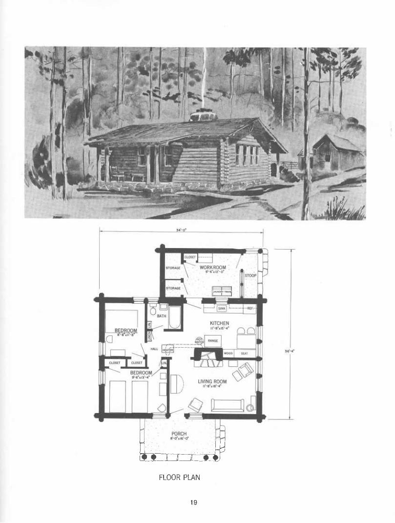
LOG CABIN. PLAN NO. 7013
In a well-wooded region, this rustic log cabin would be suitable for a small family starting farm life. Or, it
might be used as a tenant house or a summer cottage. The grouping of doors and windows reduces the work that usually goes into log construction and provides
good cross ventilation. The single, main bearing partition
and other partitions are easily framed. A circulator heater, large living-room fireplace, and the wood or coal kitchen range furnish heat.
18
aoE îi) \V
FLOOR PLAN
19

POLE-FRAME CABIN, PLAN NO. 6002
24' X 24'
SC/«l.r /N FCCT
This one-bedroom structure, simply designed for comfort and economy, can be used as a vacation retreat or campsite. It features low-cost pole-frame construc-
tion, design simplicity, and flexibility of arrangement. The use of poles permits rapid erection, minimum
site preparation, and decreased foundation expenses. The poles also serve as the wall framework to which other members are fastened. The life expectancy of a pole-frame structure, with the commercial preservative- treating processes in use today, can be as long as 75 years. The structure can be made very attractive both inside and out, depending on materials available, taste,
and cost. Rough-sawn, native lumber is used in the board-
and-batten siding. Several kinds of material are available for use as coverings.
Location and type of window treatment is flexible. With a kitchen and bath suggested, the interior is
efficiently arranged for pleasant living. A prefabricated fireplace could be installed, if necessary.
20

WINDOW OPENING TO SUIT
3"l8" PLATE; NOTCH INTO POLE l"
6" SPIKES EACH I'tfT TOPOLE
^ »j^rw- 2"« 12" .2--0- XTs^
2"ilO' TREAD
STRINGER
¿ J4'-0" MIN. EMBEDMENT J^6-.6-PRESSURE-TREATED POLE ^ *^^B'nt'nl%' CONG.
¿.^ ['^►—6" THICK POLE FOOTING ¿}]
II '-' Il - "il
[Z3 [Z31Z3
BOARD ANO BATTEN SIDING
sxo
S'KS'P.T. POST-
FRONT ELEVATION
SECTION A-A
-2"«8" FALSE RAFTER
LAPPED GABLE SIDING. 10*TO WEATHER
_f ^ _._. . .,,
LI IIII ^
,. . . . ., 1=, J—'^ 1 6-.Í- PT. POLE ' <h
ROOF OVERHANG PROJECTION ZERO AT EAVE. I'-O' AT RiDGE
SIDE ELEVATION
PLAN
^NOTCHED POLE FACE
.SEPARATE NAILS AS WIDELY
LEGEND •-4" NAIL-USE 4 INNER 2"ie" TO POLE 'fos^^ •-6" SPIKE-USE 4 OUTER 2"ie"T0 POLE >x1e<^ ♦-4" NAIL-USE NUMBERS AS SHOWN "
PLATE NAILING DETAIL PLATE POLE DETAIL
WINDOW SCHEDULE
WINDOW •UNIT SIZE
NO. OF UNITS
A r-8"i2-e- 1 B 1-8"X 2-8" 1 C l'-8"«4'-l" 1 D l'-8"x4'-r' 2 E r-8"x4'-r 6 F l'-8"»4*-l" 1 G l'-8"x 2'-8" 1 H r-8-x4--i" 1
« ALL AWNING WINDOW UNIT SIZES ARE APPROXIMATE. OTHER WINQOW SIZES AND/OR STYLES SUBSTITUTED AS DESIRED.
' DESIGN BASED ON ROUGH-SAWN EASTERN HEMLOCK.
DESIGN ROOF LOAD-40 PS.F.
DESIGN FLOOR LOAD-3S PS.F'
ALL FRAMING NAILS SHOULD BE OF HARDENED THREADED TYPE.
FLOOR-AND ROOF-DECKING JOINTS SHOULD BE WELL STAGGERED.
ROUGH r BOARDS ARE SUGGESTED FOR SIDING.
INTERIOR FINISH IS LEFT TO BUILDERS DISCRETION.
BASED ON UNIV. OF MASS. PLAN MC-4613
21

POLE-FRAME CABIN, PLAN NO. 6004
This structure was designed for builders having limited finances, time, and construction skills. Besides being used as campsite living quarters, it can be an auxiliary structure for such other uses as a concession stand or a storage shelter.
The use of pole framing is in keeping with the objectives of design simplicity, low cost, and flexibility
of arrangement. Pole framing is not necessarily unattractive from either the exterior or the interior.
Several kinds of covering materials can be used, depending on cost, desired appearance, and availability of the material. This plan suggests using rough-sawn board-and-batten siding with 10- to 12-inch-wide boards and 2- to 3-inch-wide battens over cracks between the boards. Such siding is economical, attractive, and easily applied.
Though a wood-framed floor structure on a level site is shown here, this type of construction is also adaptable to a sloping site. A concrete floor slab could be substituted on a well-drained, level site.
The window treatment is quite flexible as to type and location.
THE FLOOR PLAN IS 16 FEET BY 20 FEET WITH SIDE-WALL POLES SPACED 10 FEET ON CENTER. THE STRUCTURE CAN BE EXTENDED TO 30 FEET THEREBY ALLOWING ONE END TOBE PARTITIONED INTO SLEEPING AREAS.
.■^~^
1)^.
ft Í • ^^J^ MVv»^
,-".^¿,H-^
,>;/!>•/
22

2x6xir-2" RAFTER 2*-6'O.e.
-2x8 RIDGE BOARD
^r TSG SHEATHING
4x4 PRESSURE- TREATED POLE
PLAN
lU FRAMING ISOMETRIC
THIS DESIGN IS BASED ON THE USE OF ROUGH-SAWN EASTERN HEMLOCK. DESIGN ROOF LOAD 40 LBS. PER SO. FT DESIGN FLOOR LOAD 40 LBS. PER SO FT. LENGTHS OF POLES ARE DEPENDENT ON SLOPE OF BUILDING SITE. ALL FRAMING NAILS SHOULD BE HARDENED AND THREADED. ALL WOOD IN CONTACT WITH EARTH SHOULD BE PRESSURE »TREATED WITH A PRESERVATIVE. ROUGH-SAWN BOARD AND BATTEN SIDING WITH 10" TO I'-O" WIDE BOARDS AND 2" TO 3" WIDE BATTENS ON THE BETWEEN-BOARD CRACKS IS ATTRACTIVE. OTHER SIDING MATERIALS MAY BE USED IF DESIRED INTERIOR FINISH IS LEFT TO THE BUILDERS DISCRETION.
ROOF AS DESIRED^
LAP SIDING 10" TO WEATHER
BOARD«AND- BATTEN SIDING
WINDOW SCHEDULE UNIT SIZE*|NQ OF UNITS 28"x28"
^JJ iJS
END ELEVATION
» ALL WINDOW UNIT SIZES APPROX- IMATE. UNITS ARE INSWINGING AND ARE HINGED AT THE TOP. OTHER STYLES OR SIZES MAY BE SUBSTITUTED
4x4 PRESSURE-N
TREATED POLE -^ FRONT ELEVATION
476-018 O - 72 - 4 23

VACATION HOUSE. FRAME CONSTRUCTION, PLAN NO. 5997
-%.
Comfort, convenience, safety, and economy were designed into this house by agricultural engineers at Beltsville, Md. The heating system uniformly distributes heat from any type of heater-wood, coal, gas, or oil- fired. The standards of convenience and sanitation that are found in the most expensive home are maintained in this low-cost house. The framing timber is used efficiently so that cost of material is reduced without the loss of the framing strength. Wall panels, trusses, and floor systems were load-tested to prove the strength. This method of construction, described in Miscellaneous
Publication 1020,* is recommended because it is low cost, and the simplified building techniques allow the
home owner to do some of the work himself. The outstanding features of this house are the post-
and-girt construction and a free-floating floor that promotes central heating without ductwork—that is, perimeter distribution of warmed air. Besides these improvements in construction methods, the house plan embodies the usual cost-saving features-multiple use of
space, minimum traffic lanes, and omission of
unnecessary trim or doors.
LIVING ROOM
mini SCALE IN FEET
Post-and-girt construction
Pressure treated 4- by 6-inch posts, set 8 feet 4 inches on center, serve as foundation members; as the columnar support for the airtight, insulated, skirt wall around the aawl space; and as the columnar supports for the curtain-wall sides and roof. The built-up plate and lintel system is continuous around the entire periphery of the
* Newman, J.O. A House-Framing System for Low-Cost Construct/on, U.S. Dept. Agr. Misc. Pub. No. 1020, 18 pp.
1966.
24

•2"x8"PLATE
2"x4" LINTEL
TILE ON 5/4 PLYWOOD SUBFLOOR
TWO 2"x8" GIRDER
3 2"x 4" TREATED POSTS
6 MIL POLYETHYLENE
CIRCULATION PLENUM LOW-TEMPERATURE AIR
FOOTING
ASBESTOS CEMENT BOARD
4x6 PRESSURE] TREATED POSTS
ASPHALT IMPREGNATED INSULATION BOARD
FOOTING
ISOMETRIC OF WALL a FLOOR
ASSEMBLY
25

AIR DIFFUSION SYSTEM USING UNDER-FLOOR PLENUM WITH PERIMETER SLOT
house. No further lintels are needed over the doors and windows. The full 8-inch wide top plate member and the 8-inch deep lintel form an excellent foundation for fastening the roof trusses. A building with this continuous tie from the foundation through the trusses is more resistant to wind damage than a building with conventional platform framing.
Horizontal nail ties, 2 feet on center, are notched onto the posts for precision spacing and alinement—a help in speedy erection. The curtain wall sides are continuous on the interior, but are placed between the posts on the exterior. The skirt wall beneath the floor is a little over 2 inches thick and is installed on the inside of the posts. Because of its continuity, the skirt can easily be made airtight. No ventilators are installed in the aawl space of this house.
Continuous cantilevered joists and girders support the floor and carry the interior loads independently of the exterior loads and shrinkage. This improvement in construction technique prevents doors and windows from being pulled out of line and sticking. In conventional construction, floor settlement creates problems in the walls. With post-and-girt construction, the floor can be installed after the roof and walls are
placed, and interior partitions can be installed after the floor and ceiling are in place.
Superior heating at low cost
The perimeter-slot heating system used in this house provides draft-free comfort and a uniform temperature. A fan draws warm air from a centrally located intake near the ceiling and delivers it into the crawl space beneath the floor. Since air pressure in the crawl space is a little higher than that inside the house, air flows through the %-inch-wide slot around the entire periphery of the house. This air warms the floor and walls, and the result is draft-free uniform temperatures in the house.
The best uniformity of temperature distribution is maintained with continuous operation of the circulating fan. Temperature uniformity was somewhat better when the air was heated with a down-draft type of hot air furance than when it was heated with a space heater in one corner of the living room. However, tests of the heating systems show that while both of the above systems were superior to the perimeter loop type, the perimeter-slot heating system gave the best heat distribution at lower cost than the other systems.
26

TENANT HOUSE, PLAN NO. 7010
24-0
TO DRIVE ANO FARM BUILDINGS
■ CLOSET\
ifl BEDROOM " / .^^? Q'-C"» Q'-Q" /CLOSET 8-9 ¡
BEDROOM 8'-6"x8'-9" ""i"'"
BEDROOM 8'-9"xl2'-6"
PLAN No. 7010
This minimum house is suitable for use as a tenant
house or for the first home of a young married couple.
For economy and good use of space, the living room,
dining room, and kitchen are combined into one large
room. Folding screens may be used to separate the kitchen area from the main living room if desired.
A ventilated storage cabinet for food is provided, next to the refrigerator.
A double-deck bed could be used in the smaller of the two bedrooms. A deep, roll-rim sink in the bathroom
serves as washbowl and laundry tray. There is space in the bathroom for a washing machine. In such a small house, the bathroom is a better place for doing the laundry than the cooking and living quarters.
A circulator heater or floor furnace can be installed in the back hall. The hall also contains work clothes and general utility closets.
The pipes for all plumbing fixtures are in one
partition-which means that they can be installed with the greatest economy.
With the gable roof, the house can be expanded or
the interior rearranged later at minimum expense. The
roof is trussed, so there are no interior bearing partitions.
With the flat roof, the center partition of the house is
a bearing partition, but other partitions can easily be
moved. This style is usually a little cheaper to build than the gabled style.
27

FARM COTTAGE. PLAN NO. 7137
This small frame cottage represents a practical minimum of both space and cost. It is intended primarily for a young couple starting out on a farm. Later, when the farm business is further developed, it can be used as a tenant house.
The cottage is also adequate for a retired couple who do not wish to maintain a large house.
Special space-saving features include an under-the- counter water heater, a pullout bed, a wall-type heater with a prefabricated metal or asbestos-cement chimney, a wall desk, and accordion-type closet doors.
With large porches and generous window areas, the cottage is particularly suitable for warm climates.
SCALE IN recT Living area Porch and storage area
28

Interior
The view of the sleeping area shows the convertible bed in the pulled-out position. The bed becomes a comfortable couch for daytime use when pushed partly under the storage cabinet and provided with cushions for a back rest.
KM i liltH
I,
Farmstead layout
The cottage should be located at least 100 feet from the highway and about the same distance from the farm court, to keep out odors and dust from the livestock area.
If a second dwelling is built, it may be located at the left of this arrangement, with a separate driveway from
the highway.
29

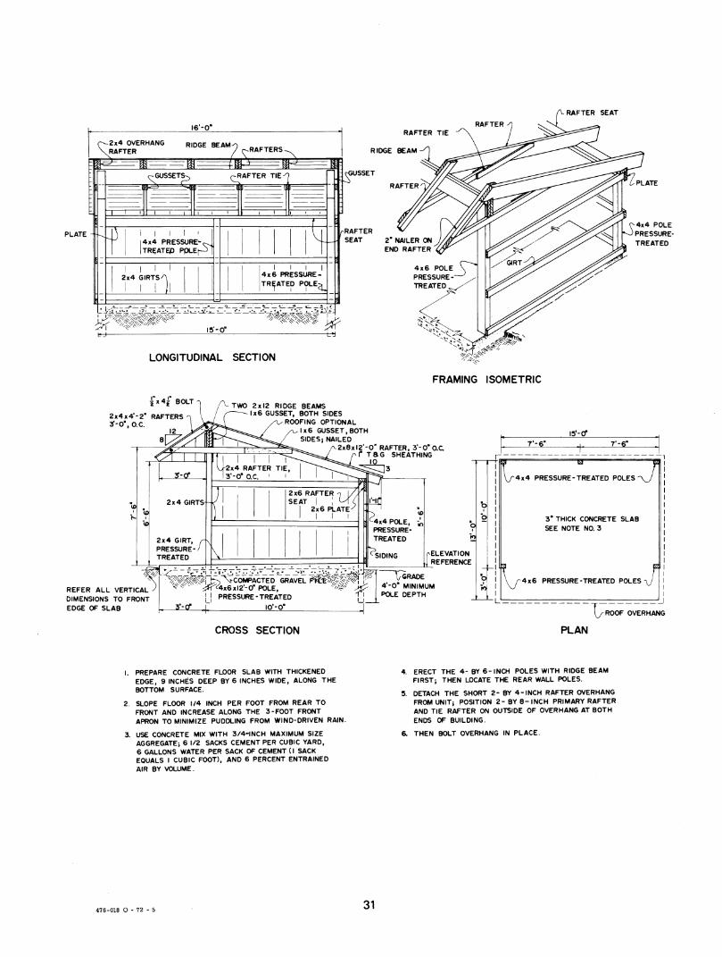
ADIRONDACK-TYPE SHELTER, PLAN NO. 5998
The Adirondack-type shelter fills the recreational
needs for scout camps, hunting shelters, and overnight accommodations on the foot trail. It also may be used on a suburban lot as a playhouse or storage place for
garden tools and recreational equipment. Some shelters have been used as market stands for fresh farm produce. In Massachusetts, where the shelter was developed, it has many uses and is in popular demand.
The pole-type construction, designed to fit the skill of beginning carpenters, is economical and easy to erect. When properly treated with preservatives, the poles will last from 30 to 75 years.
The rafters are trussed units, prefabricated on the ground in a jig for bolt location. The roof is designed to carry a load of 30 pounds per square foot.
The builder has a wide choice of materials for the floor, sidewalls, and roof. The floor can be of concrete, but tamped earth or gravel may be substituted. Sidewalls are rough-sawn, 1- by 10-inch eastern hemlock boards that are battened with 2- to 3-inch strips; the tongue- and-groove roof can be covered with a waterproofing surface, such as cedar or asphalt shingles, composition roll roofing, steel, aluminum, or terne.
A carefully selected building site can mean the
difference between success and failure of the shelter. The back of the shelter should face the wind, and the front should $lope forward to keep storm water off the floor. If the shelter is to be used in winter, it should be protected from direct winds to keep snow from drifting in the front. An open-front shelter should face south. The front can be closed in for protection against weather
and for storage.
30
RAFTER SEAT
l6'-0' RAFTER
PLATE i I I I I 14x4 PRESSURE-;;^ ITRÇATEP PpLE^ [
I I I I 2x4 GIRTS^
I I
4x6 PRESSURE TREATED POLE •^
RAFTER TIE
RIDGE BEAM
RAFTER
SEAT
LONGITUDINAL SECTION
PLATE
^4x4 POLE O PRESSURE-
TREATED
FRAMING ISOMETRIC
2x4x4'-2" RAFTERS 3'-0", O.e.
12 er
REFER ALL VERTICAL DIMENSIONS TO FRONT EDGE OF SLAB
TWO 2x12 RIDGE BEAMS 1x6 GUSSET, BOTH SIDES
ROOFING OPTIONAL x6 GUSSET,BOTH
SIDES; NAILED 2x8xl2'-0'' RAFTER, 3*-0"0.C
f TaG SHEATHING
2x4 RAFTER TIE, ^^^...J^*=5^^¿^3 3'-O" OC. I I I I I
15'-or 7'-6" T'-g"
^COMPACTED GRAVEL f^:^)P}¥
SIDING ^ ELEVATION REFERENCE
../ .. .- GRADE '^S^^^^^lrb I ^'-O' MINIMUM
ri POLE DEPTH
^4x4 PRESSURE-TREATED POLES
3" THICK CONCRETE SLAB SEE NOTE NO. 3
4x6 PRESSURE-TREATED POLES J
CROSS SECTION "T; ROOF OVERHANG
PLAN
1. PREPARE CONCRETE FLOOR SLAB WITH THICKENED EDGE, 9 INCHES DEEP BY 6 INCHES WIDE, ALONG THE BOTTOM SURFACE.
2. SLOPE FLOOR 1/4 INCH PER FOOT FROM REAR TO FRONT AND INCREASE ALONG THE 3-FOOT FRONT APRON TO MINIMIZE PUDDLING FROM WIND-DRIVEN RAIN.
3. USE CONCRETE MIX WITH 3/4-INCH MAXIMUM SIZE AGGREGATE-, 6 1/2 SACKS CEMENT PER CUBIC YARD, 6 GALLONS WATER PER SACK OF CEMENT (I SACK EQUALS I CUBIC FOOT), AND 6 PERCENT ENTRAINED AIR BY VOLUME.
ERECT THE 4- BY 6-INCH POLES WITH RIDGE BEAM FIRST; THEN LOCATE THE REAR WALL POLES.
DETACH THE SHORT 2- BY 4-INCH RAFTER OVERHANG FROM UNIT; POSITION 2-BY 8-INCH PRIMARY RAFTER AND TIE RAFTER ON OUTSIDE OF OVERHANG AT BOTH ENDS OF BUILDING.
THEN BOLT OVERHANG IN PLACE.
476-018 O - 72 - 5 31

BARNS AND EQUIPMENT FOR HORSES
FEED ROOM
8'-0" X l2'-0"
■ ■ PARTITION
\
BOX STALL ^ BOX STALL I2'.0" X 12'.0" " I2'-0"X l2*-0"
**TER BUCKET "7
r^-
EXPANSIBLE BARN FOR RIDING HORSES, PLAN NO. 5838
This small barn was designed for use in hot, moderate, or cold climates. In very cold or hot climates, the low-pitched roof should be insulated.
The construction is frame. Floors in the feed and tack rooms are concrete; stall floors are clay. The two 12- by 12-foot box stalls are separated by a plank partition open at the top. Built-up roofing surfaced with
white stone chips (mineral granules) to reflect heat is suggested.
Length of the building may be increased as desired to provide additional stalls or feed storage.
The structure is designed to withstand snow loads up to 20 pounds per square foot or winds that do not exceed 75 m.p.h. If the girder size and rafter spacing are changed as noted on the working plans, the barn is suitable for use in areas subject to 30-pound snow loads or winds of hurricane force.
Working plans show an alternate, more steeply pitched roof. This is for use where the appearance of the building must conform to that of adjacent buildings or where additional mow space for hay and bedding storage is desired. If he selects the alternate plan, the owner may prefer to use the tack room as a feed room and the present feed room as a combination tack and bunk room.
=-n
>CDUTCH DOORS -''
COVERED WAY
E _
I TACK • ' ROOM 7;-0"X8'-6|'
^
PLAN
1 WipSfffS rar*
REAR ELEVATION RICH! END ELEVATION
32
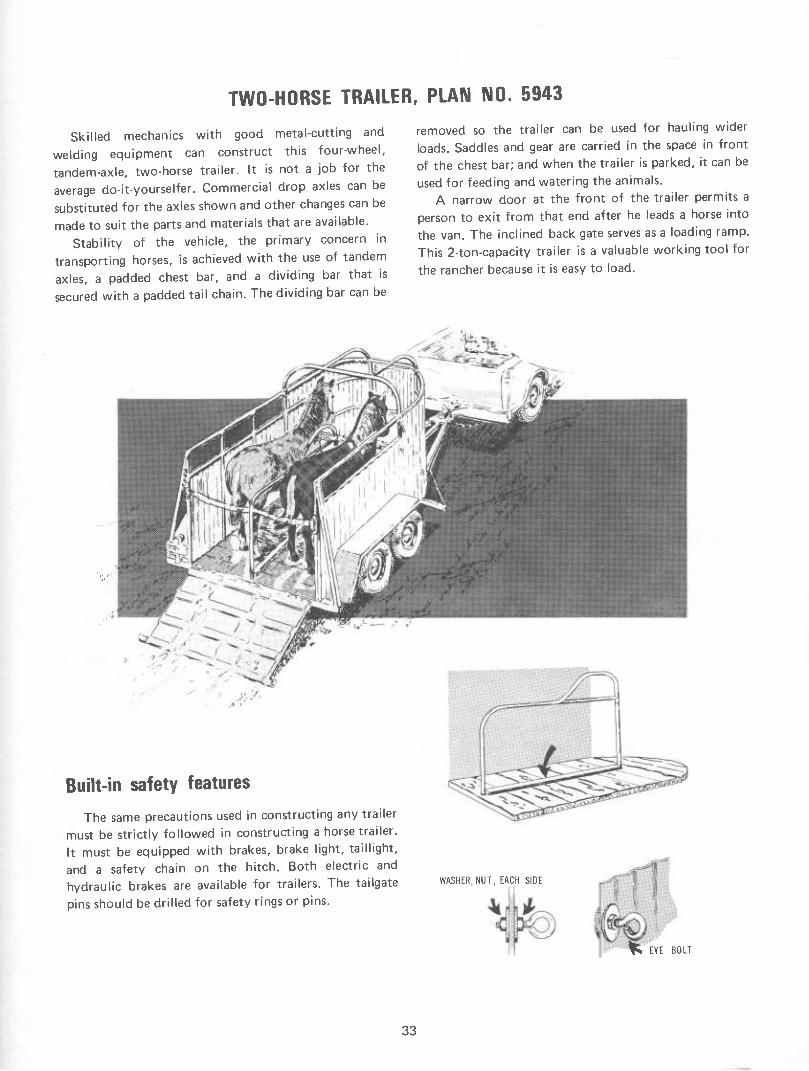
TWO-HORSE TRAILER, PLAN NO. 5943
Skilled mechanics with good metal-cutting and
welding equipment can construct this four-wheel,
tandem-axle, two-horse trailer. It is not a job for the
average do-it-yourselfer. Commercial drop axles can be
substituted for the axles shown and other changes can be
made to suit the parts and materials that are available.
Stability of the vehicle, the primary concern in
transporting horses, is achieved with the use of tandem
axles, a padded chest bar, and a dividing bar that is
secured with a padded tail chain. The dividing bar can be
removed so the trailer can be used for hauling wider
loads. Saddles and gear are carried in the space in front of the chest bar; and when the trailer is parked, it can be
used for feeding and watering the animals. A narrow door at the front of the trailer permits a
person to exit from that end after he leads a horse into
the van. The inclined back gate serves as a loading ramp. This 2-ton-capacity trailer is a valuable working tool for
the rancher because it is easy to load.
Built-in safety features
The same precautions used in constructing any trailer must be strictly followed in constructing a horse trailer. It must be equipped with brakes, brake light, taillight,
and a safety chain on the hitch. Both electric and hydraulic brakes are available for trailers. The tailgate
pins should be drilled for safety rings or pins.
WASHER, NUT, EACH SIDE
1* EYE BOLT
33

Tandem axles have advantages and disadvantages
The advantages of tandem axles outweigh the dis- advantages. Tandenn-axle trailers are safer, have less sway, and put smaller loads on the towing vehicle than do single axle trailers.
A disadvantage of the tandem axle is that the hitch is seldom at the proper height for maximum stability of the trailer. To build the hitch height as nearly right as possible, the towing vehicle should be set on a level site. As shown in the schematic sketch, when the towing point is too high, the front tires of the trailer tend to leave the ground; and when the towing point is too low, the rear tires of the trailer tend to leave the ground.
Proper hitch height is more important for a trailer without springs than it is for a trailer with spring action that permits the axles to ride at different heights.
Antirattle construction
This trailer is prone to rattle unless precautions are taken in fastening it together. Neoprene washers should be inserted between the covering and the frame whenever a self-tapping screw is used to fasten the cover. Corrugated gasket strips installed between covering metal and frame helps prevent rattles. Also, some covering materials are inherently less noisy than sheet steel.
Horses that are being transported should be carefully protected from injury. For instance, the chest bar must be padded to prevent localized injury or galling. Burlap sacking, wrapped and tied around the bar, makes good padding. A rough and uneven floor surface keeps the horses' feet from sliding. A floor of rough-sawn oak boards, which usually vary in thickness, provides the desirable uneven surface. A smooth floor should be covered with heavy matting material that will not become slick. Matting with interwoven wire should be
avoided. A 2 by 4 fastened beneath the center divider, as shown in the illustration, will prevent the horses from slipping sideways.
Protection is also needed to keep the horses free from drafts, especially when the animals are hot and sweaty. The front wall of the trailer will provide this protection if it is high enough to cut direct wind from the animals. Seventy-two inches is high enough for quarter horses, but thoroughbreds and hunters may require a wall height of as much as 85 inches. A well-fitted canvas cover for the canopy frame will also provide protection. Ordinary double-nutted eyebolts (see illustration) with large washers can be installed in the trailer front and will serve to hold the lashing for the cover.
Other safety features used will depend somewhat on the horses being carried. Nervous or frightened animals may need a solid, center divider between them. Some- times the sides of the van and the divider bars are padded to prevent bruising or abrasion of the horses.
34

SADDLE HORSE BARN, PLAN NO. 5994
This barn for saddle horses is easy to build, pleasing in appearance, and designed for long life and low-cost maintenance because it is a well-anchored, pole-type construction. Treated posts are set in concrete, the girder is steel-strapped to posts, and rafters are anchored to girder and are lapped and bolted at the ridge. Strong construction at these four places nnakes a wind-resistive building. After the 2-inch kickboards are placed to aline the building, concrete should be used to backfill around
the posts.
The recommended dimensions of the barn minimize waste of construction material.
Translucent panels in the front wall admit a pleasing amount of diffused light into the stable. The upper half of the weather protected dutch doors at stall entrances can be opened in mild weather to provide cross ventilation from the rear window. These doors provide air movement in the upper part of the stalls and draft- free ventilation in summer and winter.
Some details of construction for various parts of the building are shown on the illustration.
-,,Äv^4iy —*'
.v-»v:rff
■ /"■
i'h,(^
35
COMMERCIAL CONTINUOUS RIDGE VENT
'/a" MACHINE BOLTS WITH WASHERS
/FIRE-RESISTIVE ROOFING APPLIED OVER I" T a G WOOD SHEATHING
2"K6"XI4'-0" RAFTERS SPACED 2-0" O.e.
l" SLOT FOR VENTILATION
TWO 2"x8" GIRDER WITH 2x6* CAR SPLICE OVER POSTS WITH 2"x8" iBLOCKING 3-0" LONG
4"x 4" CORNER POST
2"x6" GIRT
2"x6" FILLER
CALK V-JOINiS
2"x4" NAILER, FULL HEIGHT OF WALL
'/e"x 3"x 16" STEEL PLATE AT EACH POST. DRILL FOR TWELVE 20d NAILS
CORNER PARTITION
TYPICAL DETAILS
POST AND GIRDER
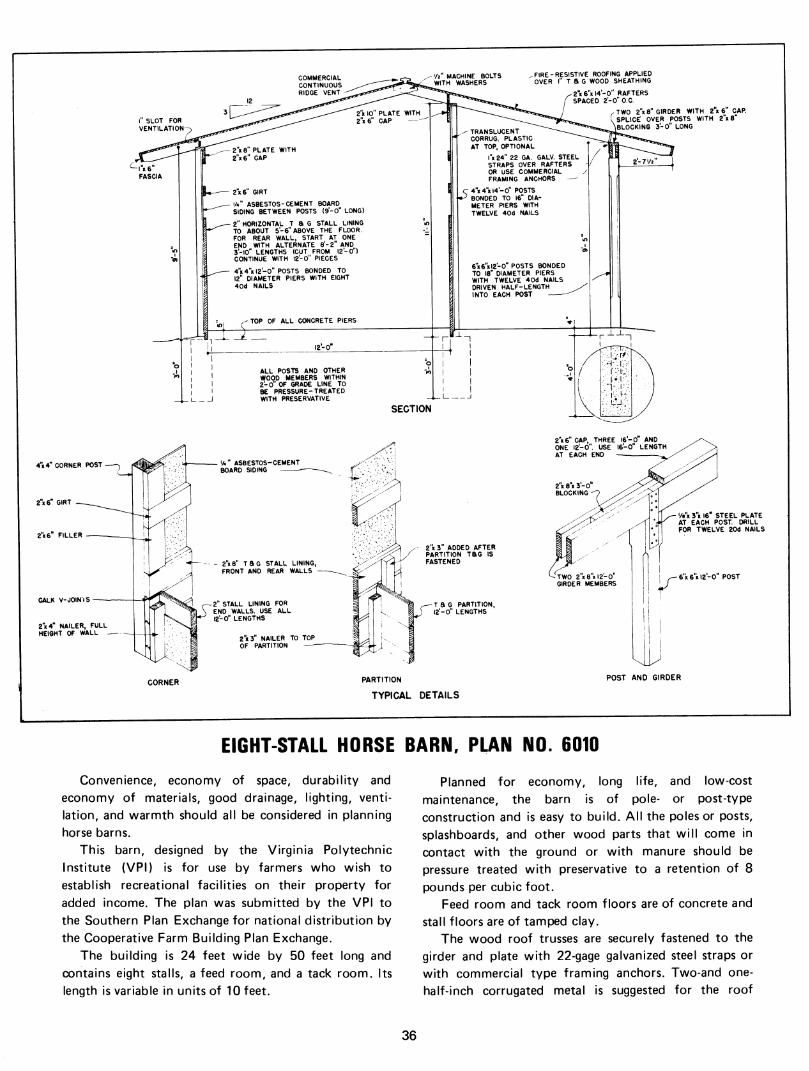
EIGHT-STALL HORSE BARN, PLAN NO. 6010
Convenience, economy of space, durability and economy of materials, good drainage, lighting, venti- lation, and warmth should all be considered in planning horse barns.
This barn, designed by the Virginia Polytechnic Institute (VPI) is for use by farmers who wish to establish recreational facilities on their property for added income. The plan was submitted by the VPI to the Southern Plan Exchange for national distribution by the Cooperative Farm Building Plan Exchange.
The building is 24 feet wide by 50 feet long and contains eight stalls, a feed room, and a tack room. Its length is variable in units of 10 feet.
Planned for economy, long life, and low-cost maintenance, the barn is of pole- or post-type construction and is easy to build. All the poles or posts, splashboards, and other wood parts that will come in contact with the ground or with manure should be pressure treated with preservative to a retention of 8
pounds per cubic foot. Feed room and tack room floors are of concrete and
stall floors are of tamped clay. The wood roof trusses are securely fastened to the
girder and plate with 22-gage galvanized steel straps or with commercial type framing anchors. Two-and one- half-inch corrugated metal is suggested for the roof
36

jh^^t
SADDLE RACK
œvering. A 4-foot overhang, built into the roof design,
provides partial shelter along the building sides.
The box stalls, approxinnately 10 by 12 feet, are
constructed of 2-inch lumber. The dutch doors on the
exterior walls of the stalls open outward to a paddock or
pasture. The lower 2 feet of the stall walls should be
treated with a preservative that is noninjurious to the
animals.
liiiÄiiil^^
CROSS SECTION
Wood or metal siding is suitable for the exterior
walls. If metal siding is used, it is essential that a kicker
panel of 2-inch lumber be constructed on the interior
surface of the exterior framing.
The two cupolas shown on the working drawings can
be purchased preconstructed from a lumber and mill-
work dealer. The bridle and saddle racks shown on the
drawings are easily constructed.
The saddle racks in the tack room should be spaced
24 to 30 inches apart. The lower and upper racks should
be 36 inches and 60 inches, respectively, above the floor.
37

SEVENTEEN-STALL HORSE BARN, PLAN NO. 6011
Horseback riding has become popular throughout most of the United States. Numerous private and public riding clubs and academies are available to those who enjoy the sport of horsemanship. Some State and National parks also offer riding horses for hire. The farmer who wishes to supplement his income may establish such a recreational facility on his property.
This barn plan, designed by the Virginia Polytechnic Institute, is for the farmer who is interested in operating a horseback riding facility as a money-making sideline. The barn is designed for economy, long life, and low- cost maintenance. It is of pole-type construction and is easy to build. The dimensions are 36 by 100 feet, and the length of the building is variable in 10-foot units. All poles, splashboards, and other wood parts that come in
contact with the ground or manure should be pressure- treated with preservative to a retention of 8 pounds per cubic foot.
A center alley separates the two rows of stalls and is wide enough for the chore of saddling horses. A tack room and a feed room are located in the back end of the building. Above the center alley is a hay mow or storage loft. Hay can be dropped from the loft directly into the stalls, thereby eliminating some of the traffic between the feed room and the stalls.
Floors are concrete in the feed room and in the tack room, clay in the stalls and in the center alley, and wood in the loft. The loft floor is designed to withstand a load not to exceed 75 pounds per square foot.
'""•^ ^ K"-
xioo'
10 20 30 —I 1 I
FEET
FLOOR PLAN
38

The wood roof framing is securely fastened to wood beams with 22-gage steel straps or with commercial framing anchors. A covering of 2y2-inch corrugated metal
is suggested for the roof exterior.
The 10- by 12-foot box stalls are constructed with 2-inch lumber. For the protection of the animals, the lower 2 feet of the walls should be treated with a nontoxic preservative. The working plans show alternate
stall details and an alternate roof design using trusses.
CROSS SECTION
STALL
DETAIL
39

ONE-AND-A-HALF-STORY HORSE BARN, PLAN NO. 6024
Labor saving devices developed by science and technology have made it possible for farm families to use their leisure time to increase their income by establishing recreational facilities on their farm property. One such facility may be a riding academy.
This r/2-story, gambrel-roofed barn for horses is well suited to many farmsteads and has a pleasingly traditional appearance. It was designed at Rutgers University, New Brunswick, N.J., and was submitted to the Northeast Plan Exchange for national distribution through the Cooperative Farm Building Plan Exchange.
The barn is particularly well suited for use in the colder parts of the United States. The alleyway along the front of the stall row and the hay and bedding storage space overhead are enclosed. The feed and tack rooms are on the ground level.
Floors of tamped clay in the stalls and of concrete in the other first floor areas are recommended.
The building, 24 feet wide by 48 feet long, contains three 12- by 12-foot stalls and a 12- by 36-foot working alley, convenient for grooming the horses and for doing other chores. The concrete foundation walls are 1 foot above ground level and, with the concrete footings, they extend below the frostline.
PLAN
The building is frame construction throughout with 2- by 4-inch studs 2 feet on centers and with fire- stopping materials midway between the sill and the upper plate.
Although the exterior walls indicate the use of horizontal siding, larger sheet materials, such as exterior plywood, may be used. The interior walls of the stalls are covered with 2-inch planking up to the firestop level, and all interior surfaces of the exterior walls are covered with 1-inch sheathing.
The stable ceiling is covered with plywood, a vapor barrier, and insulating material.
40

For a fire-resistant mow floor, gypsum wallboard is
inserted between the subfloor and the finished floor. The gambrel-shaped roof framing is secured to the
upper plate by metal commercial framing anchors. A chaff strip (or wall) of 1- by 6-inch, tongue-and-groove lumber extends 2 feet 6 inches above the mow floor on
the interior surface. Tongue-and-groove sheathing (1 by 6 inches), roofing
paper, and asphalt shingles cover the outside of the roof
framing. A 30-inch-square louver at each end and a screened
slot at the eaves provide sufficient ventilation in the mow on the upper level. Also, a 4- by 6-foot sliding door at one end facilitates the storing of hay and bedding
material.
CUTAWAY VtEVi OF STALLS
41

PORTABLE STABLE FOR A HORSE, PLAN NO. 6082
This portable, one-horse stable was designed at
Rutgers University, New Brunswick, N.J., with emphasis
on the economical use of materials. The openings between the rafters at front and rear of
the building, two hinged panels that open in the rear
wall, and a dutch door provide ventilation. The windows
in the sidewalls are optional. The plan for the stable does not show a floor
covering. However, well-tamped clay makes a very good floor for a horse stable and is preferable to a wood floor.
The clay should be built up enough so that the floor will be several inches above the outside ground level. The
walls can then be tilted up and secured to the pressure-
treated timber base. The exterior-type plywood siding
stiffens the walls, eliminating the need for let-in braces.
The roofing is corrugated metal and translucent plastic.
No interior wall lining is shown on the working
drawings but may be desirable, depending on the
temperament of the horse and the preference of the horseman.
In areas subject to high winds, the stable should be
securely anchored in place.
CAUTION: Do not use paint containing lead on any
part of buildings, fences, or equipment that is accessible
to livestock.
% A-0'
'*t^,yáJjU'. Wdi"
42

2x4x14'-o'
12'-O" SHEETS OF CORRUGATED 2'-O" QC ALUM. OR'GALV STEEL ROOFING WITH CENTER SECTION TRANSLUCENT PLASTIC PANELS
^ -2x8xl2'-0" RAFTERS, 4'-0" O.C.
IX10 FASCIA BOARDS FRONT AND REAR
^c;:;: ;6xl2-0" PRESSURE TREATED
SIDES
;;
z
1 II II ill II 11; II I- - . 1
I'-O",
-WINDOW GUARD SEE DETAIL (§)
lO'-O"
1
1
,r-o",
= o
r'- \
^2x4 STUDS-^
tí, i; \ii II \ii
»! 1 \ UJ -J CD
1/1
LL O
t-
O û:
: /
ll: 1 II II >ll II III II 1- - .:
PLAN
^2x8 RAFTERS- ) 4'-0" O.C
ROUGH DOOR
OPENING—\
2x4 STUDS-
'^4x6xl2'-0" PRESSURE TREATED
FRONT
r<D 2x^ STUDS
2x4 SILL-
REAR "^^
^IxlO FASCIA BOARD SHOWN DOTTED
6xl2'-0" PRESSURE TREATED
MATERIAL LIST 6-ALUM. OR GALV STEEL ROOFING SHEETS (26'x 144") I-TRANSLUCENT ROOF SHEET
LUMBER 7-2x4x14-0' 4-2x4x12-0" 12-2x4x10-0"
36-2x4x8'-0" 4-2x8xl2'-0" 2-4x6xi2'-0" PT 2-4x6xl2'-0" PT 2- lxl0xl4'-0" 2- lxl0xl2'-0" 5-1x3x10-0" 8-1x4x10-0' 3-|x4x8'-0"
MISCELLANEOUS 8-COMMERCIAL CONNECTORS I -D00R(MAT'L AS REOt)) 4-HEAVY DUTY T-HINGES
4-3" HINGES FOR REAR OPNG'S
2-LATCHES FOR REAR OPNG'S
2-l6"x32" 3 LITE WINDOWS OPTI
NAILS, LAG SCREWS, ETC. AS REO'D
FRAMING DETAILS
43

HORSE EQUIPMENT, PLAN NO. 6014
The growing interest in the production and training of horses for field events—in the show ring and for hunting-is providing a profitable side line for many farmers.
The horse that will be used for cross-country hunting should be trained to jump so it will be able to clear the many obstacles it will encounter in the hunt. The same training can be used to good advantage for show horses.
The wood obstacles illustrated here are of the type used in training horses for show and for hunting.
The wood that will come in contact with the ground or that will be exposed to the weather should be treated with preservative for longer life of the equipment. A nonstaining preservative should be used so that the
equipment can be painted. Rustproof fastenings are also recommended.
Construction details are shown in the four sheets of working drawings.
44

4x4x4-6"-
2x6x2'-0V
WHITE-RAIL JUMP
2x6
2x6x2-0"
BRUSH JUMP
COOP JUMP
4x4 OR 5" DIA. X 4-6'
POST
3"-4" LOCUST, CEDAR OR OTHER NATURAL POLES
NATURAL-RAIL (HUNTER'S) JUMP
COOP
^1x2 1/2x2-6" PICKETS, 5 1/2" O.C.^
Ixe^^ r-
-9-10
FRONT
PICKET JUMP
7"
Jz:-3"
45

1x21/2x4-6" PICKETS, 5 1/2" O.e.
2x4
2x4x5-0" 1x6 = \
I^T -41/8"
IP
2x6
Mx6x2-6" FRONT
PLANK
STRIP ADDED TO ACHIEVE 7" FULL 4 1/8" WIDTH
4 l/8'MZ
WING
- lO'-O"-
1x4
z 1x4x3-6"
HORSE SHOW RINGS, PLAN NO. 6015
FRONT
GATE
^
46

The plan for these indoor and outdoor show rings was developed at the Virginia Polytechnic Institute because of growing interest and dennand for riding horses. "Raising this type horse has now become a
profitable business. The show ring is considered an ideal place to exhibit
horses for their performance, presence, quality, manners, all-around excellence, body conformation, and for gait- such as walk, trot, and canter. The use of the horse show ring benefits both the prospective buyer and the
salesman. The construction of the show rings is fairly simple.
The boards, natural-rail, and movable fence should be
treated with a nontoxic preservative for longer life of these parts. Noncorrosive fastenings should be used
throughout the structures. A section of movable fence, a gate, or removable rails
can provide entrance to the ring. The ring sizes shown in the illustration were recommended by the National Horse Show Association, 307 West 49th Street, New
York, N.Y. 10019. The business of training horses for field events
requires the use of special equipment such as that featured in Plan No. 6014, page 44. Construction details are shown in the plan for various types of jumps and
related equipment.
60'-0' RADIUS
240'-0*
^^
9'-0- s'-o"
lx6xl6'-0' BOARDS
r4" TOP DIA. OR 4x4 --^ SAWED POSTS ^
>7/)'~^/^>;^y^'/:^7>^yw
FRONT VIEW
BOARD FENCE DETAIL OUTDOORS
8'-0* TO lO'-O"
55'-0" RADIUS
ZZQ'-O"
INDOORS
HORSE SHOW RINGS
3" NATURAL RAILS>^
'OP
a'-o''TOio'-o''
^^^g^
-6" TO 8" V|p> POSTS fm |i(i i
R ,.^'^^'*
SECTION
1x6'$
.J
ALTERNATE SECTION
3—TO w !j>^^te
-<Nll
FRONT VIEW
NATURAL RAIL FENCE DETAIL
SECTION
n'-o"
"a
JJ ^,
4x4x4'-0" SAWED POSTS
/T.jxexia'-O" LAPPED XZi 6" AT POSTS
.l-vT- xT" BOLTS
jLs? PLYWOOD BRACE
¡rix2''x2'-0'' ROD I Vlx6x3-0 ¡ ' STAND
FRONT VIEW
/^Ix6'8 LAPPED ^ AT POSTS
^5 PLYWOOD BRACE
24x4x2'-0'' STAND
SECTION
47

GREENHOUSES
PLASTIC-COVERED GREENHOUSE, PLAN NO. 5941 This plastic-covered greenhouse features a removable
upper unit that can be used as a coldframe in which plants may be given a headstart on the frost-free season.
A heating cable can be installed in the assembled lower unit for germinating seeds and growing starter plants. When the plants are about 3 inches high, they should be moved to a coldframe located in a corner of
the garden. The upper part of the greenhouse can then be placed over the plants to protect them from the night frost.
The wooden parts of the greenhouse frame should be pressure treated to prevent rotting. All hardware, including nails, should be galvanized.
The greenhouse should be anchored to the ground with steel rods.
!ii';''iiiiil''lï'i|'/'ii'ii'ii''''''''''ii"'i''//,,
....*'• — ' «*." —-* ,',1*'' iiW.»'" ,•
48

7
■^'^^
^^ ^^
' {2« o^ 1 CD O o.«
• < 5 ^ OD
1 (E oc » o o 1 < - * X
1 -^5 1> <
\
.»/«
1 -H^rc ' -♦/,«: ^
I- .e:i
♦^/r¿
,*rc .♦/,6r^
49

PLASTIC-COVERED GREENHOUSE, PLAN NO. 5946
This greenhouse is easily constructed, inexpensive,
and portable. Its roof slope approximates that of a
gothic arch that extends from the ground to the ridge.
The slope is steep enough to shed snow, water, and
debris. However, a large accumulation of snow may pile
up against the sides and cause lateral pressure to the
plastic film. The structure resists wind very well. A low-cost
polyethylene cover will last from 3 to 8 months. More
expensive films last from 2y2 to 3 years or even longer.
The film must be securely fastened to the frame, and the
house must be staked down to resist strong winds. In late summer, the plastic film can be replaced by a
lath-type snow fence, and the house can be used as a
propagating frame. Two small ventilators at the top of the door provide
limited ventilation. When more air is needed on hot
Construction features The base of the greenhouse is 12 feet long, 8 feet 6
inches wide, and 16 inches deep. Door frames are
attached at each end and are tied together at the top
days, the doors can be opened, or the house can be raised off the ground.
The width of the greenhouse (872 feet) allows space for a walkway with a row of flats on each side, and the
height (7 feet) allows head room for most people. With
doors in each end, several units of this greenhouse can be placed in a series, and tools can be moved from section to section.
When the structure is finished, two men can move it
short distances, and three or four men can lift it above
their heads. It can also be placed on a flat-bed truck and
moved to the desired location. Construction is rather
simple, requiring only a little experience with common
tools. The most complicated job—forming the ridge
beam—is easy if a table saw with an adjustable table or
blade is available to rip the board.
with a beam which forms the center ridge of the green- house.
50
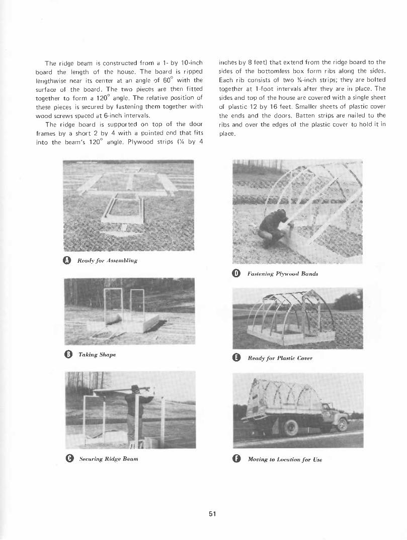
The ridge beam is constructed from a 1- by 10-inch
board the length of the house. The board is ripped lengthwise near its center at an angle of 60 with the
surface of the board. The two pieces are then fitted together to form a 120° angle. The relative position of
these pieces is secured by fastening them together with
wood screws spaced at 6-inch intervals. The ridge board is supported on top of the door
frames by a short 2 by 4 with a pointed end that fits
into the beam's 120° angle. Plywood strips (% by 4
inches by 8 feet) that extend from the ridge board to the sides of the bottomless box form ribs along the sides.
Each rib consists of two %-inch strips; they are bolted
together at 1-foot intervals after they are in place. The
sides and top of the house are covered with a single sheet
of plastic 12 by 16 feet. Smaller sheets of plastic cover
the ends and the doors. Batten strips are nailed to the
ribs and over the edges of the plastic cover to hold it in
place.
^¿J Ready for Assembling
\f Taking Shape
\
^¡ß Fastening Plywood Band»
'-- 'fr:,,..ii-^-^'iii. »a; 'cCrfi-
%^ Ready for Plastic Cover
r la
%y Securing Ridge Beam %^ Moving to I Atea I i on for Use
51

GREENHOUSE FRAMING FOR PLASTIC COVERING, PLAN NO. 6029
This building is of wooden, rigid-frame construction with nailed plywood gussets. It is about 23 feet yvide and the length nnay be varied as desired. If it is to be covered with plastic film, 48- or 96-foot building lengths are suggested so that unbroken lengths of the film can be applied with a minimum of waste. Access is through 7-foot-square doorways at each end of the building.
The rigid frames are erected on a foundation consisting of short poles set in the ground to support a built-up wood sill assembly. The poles and sill planks should be pressure treated with a nontoxic preservative. Do not use a preservative that may be toxic to plants.
Careful workmanship in cutting and assembling will produce a sturdy frame. As with other light structures, the framing should be securely anchored to the foundation to reduce possible wind damage. For this same reason, the legs of each rigid frame should be
fastened to the sill plate with commercial metal framing anchors. All wood above grade should be painted white to reflect a maximum of light.
The initial cost can be reduced by covering the house with plastic film for a season or two and later applying rigid plastic panels for a longer lasting covering. In either case, it is important to follow the manufacturer's directions for installing the plastic.
Exhaust fans installed at one end of the building and air-intake louvers at the other end provide ventilation. Specific ventilation recommendations depend on the size of greenhouse, the type of covering, and the climate of the area in which the house is to be built. Consult your county agricultural agent or State extension agricultural engineer. The air-intake louvers should provide a
minimum of 1 square foot of free area for every 1,000 cubic feet per minute of the required fan capacity.
.."** *%?
*^
>W-#l¿!'íi,-''^*-''-
52

2"x4' RIOGE
FRAME FOR LOUVERS
END ELEVATION
SIDE ELEVATION
53

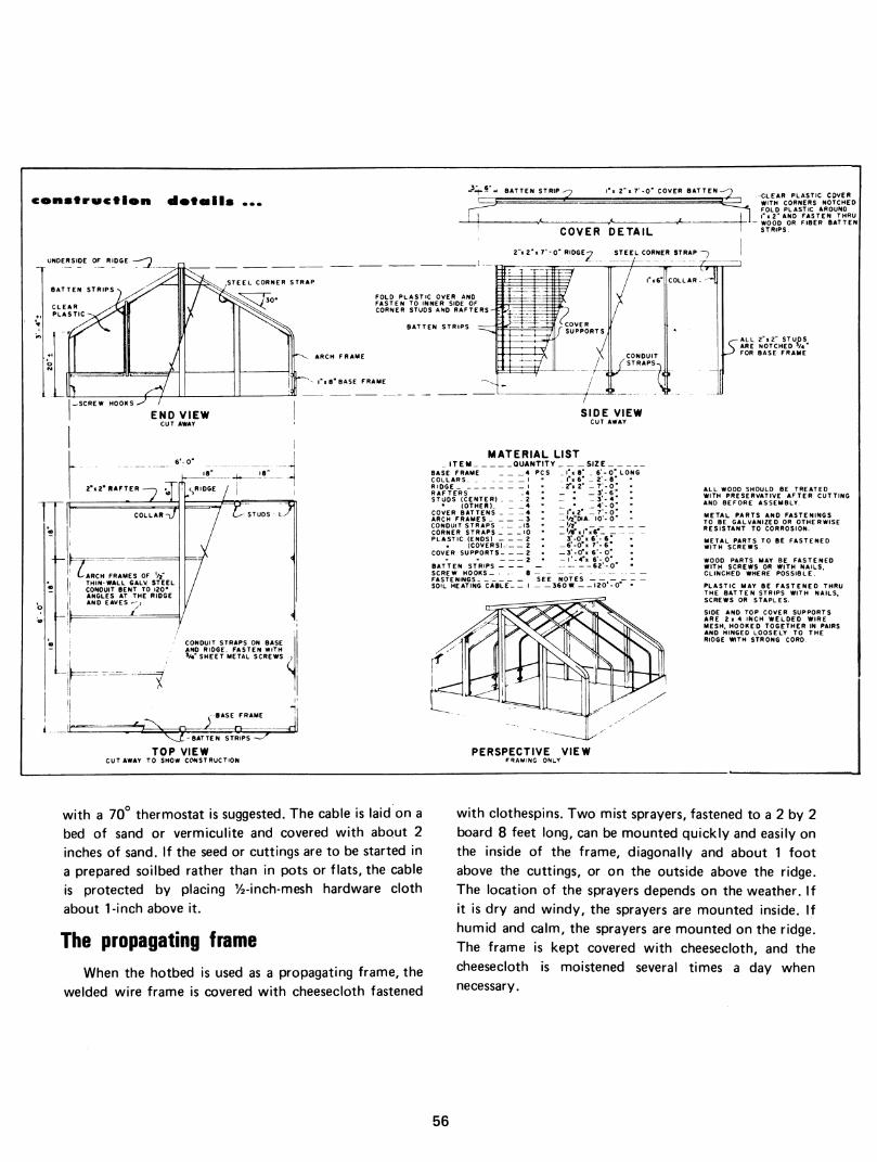
HOTBED AND PROPAGATING FRAME, PLAN NO. 5971
This plastic-covered hotbed, which can also be used
as a propagating frame, is inexpensive and easy to build.
The hotbed has welded wire frames with removable
covers of 4-mil polyethylene plastic film on each side of
the ridge. The covers may be rolled down from the ridge
or up from the sides to provide almost unlimited
adjustment for ventilation. The covers are secured in the
desired position with light ropes that pass over the sides and down to the base at each end of the frame. Rubber tubing can be attached at one end of each rope to
provide tension. When the spring season is over, the
covers can be rolled up and stored out of sunlight to prevent deterioration from ultra-violet radiation. The
plastic film that covers the end sections of the structure is not removable, so a long-lasting plastic such as 4-mil vinyl or 3-mil type W polyester film is recommended. Details for making the removable covers are given in the
working drawings.
The hotbed is made of wood. It has three arch frames of thin-wall electrical conduit. The frames may be easily
bent to shape with a hand conduit bender. The wooden
parts should be treated with a preservative after they
have been cut. A thorough soaking in a 5-percent solution of pentachlorophenol is suggested.
A soaking trough for treating the wood can be
improvised by lining a small trench with polyethylene
film. Weight the boards to be sure they are completely
immersed in the liquid. Place thin spacers between the
boards so the preservative will flow completely around each piece.
Precaution: Keep children and animals away from the
soaking trough. Follow directions given on the label for use of the preservative.
The hotbed should be located on well-drained soil. Some locations may require a 3-inch layer of gravel under the prepared soil mixture or flats. For supple-
mentary heating, a 360-watt electric soil-heating cable
54

HOTBED & PROPAGATING FRAME
55
construe flou dota i Is BATTEN STRIP 2"K 7'-0" COVER BATTEN -
UNDERSIDE OF RIDGE
rOLD PLASTIC OVER AND -'■ FASTEN TO INNER SIDE OF CORNER STUDS AND RAFTERS
BATTEN STRIPS
.SCREW HOOKS
END VIEW CUT AWAY
FTER —, rrri ^ RI
L^ STUDS ly
te ARCH FRAMES OF V THIN-WALL 6ALV STEEL CONDUIT BENT TO 120* ANGLES AT THE RIDGE AND EAVES ^,
ih CONDUIT STRAPS ON BASE AND RIDGE. FASTEN WITH >/•" SHEET METAL SCREWS ,
i.^._.it Cx-.:.-! BASE FRAME
^3 BATTEN STRIPS -
TOP VIEW CUTAWAY TO SHOW CONSTRUCTION
-CLEAR PLASTIC COVER WITH CORNERS NOTCHED FOLD PLASTIC AROUND I" I 2" AND FASTEN THRU
- WOOD OR FIBER BATTEN STRIPS
SIDE VIEW CUT AWAY
MATERIAL LIST ITEM QUANTITY SIZE.
BASE FRAME 4 PCS _ C» 8" _ 6'-O" LONG COLLARS„ RIDGE I RAFTERS -4 STUDS (CENTER) _ _ - 2
(OTHER). 4 COVER BATTENS 4 ARCH FRAMES 3 CONDUIT STRAPS . _ -15 CORNER STRAPS 10 PLASTIC (ENDS) 2
(COVERS). 2 COVER SUPPORTS 2
„ x6" _ _ . -2"«2" _ 7-0" - " - 3' - 6 " _ - _3-4" _ • _4'-0" _ I"« 2" _7'-0" _'/2"DíA. 10'-0" _ '/î" _'/r«|-«6-
3'-0"K6'-6' _6'-0 « 7-6 -3'-0"K 6'-0" - l'-4"i 6'- 0" 62'-0 BATTEN STRIPS
SCREW HOOKS- 8 - - FASTENINGS SEE NOTES ,-- SOIL HEATING CABLE I 360 W. 120-0
PERSPECTIVE VIEW FRAMING ONLY
ALL 2"x2" STUDS ..^ALL 2x2 STUDS \ ARE NOTCHED V4 ' ^ FOR BASE FRAME
ALL WOOD SHOULD BE TREATED WITH PRESERVATIVE AFTER CUTTING AND BEFORE ASSEMBLY.
METAL PARTS AND FASTENINGS TO BE GALVANIZED OR OTHERWISE RESISTANT TO CORROSION.
WOOD PARTS MAY BE FASTENED WITH SCREWS OR WITH NAILS. CLINCHED WHERE POSSIBLE.
PLASTIC MAY BE FASTENED THRU THE BATTEN STRIPS WITH NAILS. SCREWS OR STAPLES.
SIDE AND TOP COVER SUPPORTS ARE 2x4 INCH WELDED WIRE MESH. HOOKED TOGETHER IN PAIRS AND HINGED LOOSELY TO THE RIDGE WITH STRONG CORD.
with a 70° thermostat is suggested. The cable is laid on a bed of sand or vermiculite and covered with about 2 inches of sand. If the seed or cuttings are to be started in a prepared soilbed rather than in pots or flats, the cable is protected by placing y2-inch-mesh hardware cloth
about 1-inch above it.
The propagating frame
When the hotbed is used as a propagating frame, the welded wire frame is covered with cheesecloth fastened
with clothespins. Two mist sprayers, fastened to a 2 by 2 board 8 feet long, can be mounted quickly and easily on the inside of the frame, diagonally and about 1 foot above the cuttings, or on the outside above the ridge. The location of the sprayers depends on the weather. If it is dry and windy, the sprayers are mounted inside. If humid and calm, the sprayers are mounted on the ridge. The frame is kept covered with cheesecloth, and the
cheesecloth is moistened several times a day when necessary.
56

MINI-HOTBED AND PROPAGATING FRAME, PLAN N0.6080
This plastic-covered hotbed is inexpensive and easy to
construct. It is portable and suitable for use in the honne
backyard. A 160-watt soil heating cable, thermostatically
controlled to shut off at 70° F. is used to heat the
structure.
Two pieces of plastic filnn that cover the frame overlap at the top and are held taut with snap clothes- pins. Plastic webbing permits closing up the hotbed at
night. Ventilation is achieved during the day by pulling
down the plastic film from the top and fastening it with clothespins.
57

58

RECREATIONAL FACILITIES
OUTDOOR FIREPLACE, PLAN NO. 5188
In recent years, structures that can be used either as a small barbeque pit or simply for outdoor cooking have become quite popular. Therefore, the trend in barbeque pits is for a structure somewhat like the one illustrated.
The fireplace and grill shown are large enough for cooking meals for 10 to 20 persons; it can also be used
as a trash burner. Consult your local authorities on environmental
control before starting construction of this fireplace.
59

Construction details
CEMENT CAP
BARS, 21" aC.
i 1
I'-y"
FLUE
L__
lO
PLAN
CEMENT CAP
FLUE LINING, 4¿"xl'-|"
ix2-xl'-6", STRAP IRON
SECTION
3'-5i
FORM UNDERCUT DRIP WITH •!•" 1/4 ROUND.
7-5x5 BARS, !" r ^
4" CONCRETE SLAB
FRONT VIEW
60

BOAT LANDING, PLAN NO. 5975
Summer is a good time to build a boat landing. This all-weather dock for a small boat is designed for use in a sound where waves do not exceed 3 feet and the tide is normally 2 to 3 feet. Although it is built to withstand winds of hurricane force, the dock is not suitable for a river or lake where massive ice floes can cause structural
damage. Any location on an open stretch of water is subjected
to higher winds than an inland site. Therefore, build this shelter extra strong to resist wind forces. Fasten the roof down well. Drive at least four deformed-shank, 9-gage
(diameter, 0.144 inch), galvanized roofing nails, 2 inches long, into each sheet at each purlin (the 2- by 8-inch members that support the roof lengthwise). At least 4 pounds of nails this size are required to anchor the roof. Spike the purlins securely to 2- by 8-inch purlin ties and, in turn, spike the purlin ties to both 2- by 8-inch rafters.
Bolt the rafters to the pilings. Well-anchored pilings are necessary to keep the
building intact. In most areas the pilings can be set with- out special equipment. A water jet will penetrate
ordinary clays. Pressure and volume of water required for jetting a pile hole vary with the depth of waterhead above the jet and with the density and tightness of the clay. An ordinary garden hose, equipped with a nozzle and fed from a domestic water system (shallow well pump, driven by a y2-horsepower electrical motor) has
been used successfully for pile setting. Jetting a pilot hole about 3 or 4 inches in diameter is
done by fastening the garden hose and nozzle to a steel bar (crowbar) about 6 feet long, and approximately 1 inch square. The end of the bar should be chisel- or diamond-pointed and tempered to hold the point. Fasten the nozzle of the hose 2 inches above the point, to deliver a jet stream to the point. Drive a hole in the bottom by plunging the steel bar and hose up and down. Do not be disturbed if the pilot hole fills with sand when you remove the jet; the hole serves as a soft spot to guide the piling in a vertical position. Insert a pointed piling in the top of the pilot hole; with the garden hose on either a stick or a steel bar, continue jetting beneath the pile by plunging the jet nozzle down and up.
12' 1
so'
^ ■ !';!!
14'
61

Moving the jet up and down produces a drawing action on the pile; the pile may also be slightly Ijfted and dropped to increase the movement of slush to the soil material under the pile.
Set the pile at least 5 feet deep to give good bottom anchorage to the boathouse. Piles for the wharf may be set shallower-3 to 4 feet. The greatest force exerted on a wharf comes from driving waves. A low wharf is more convenient than a high wharf, but driving waves will knock the decking from a low wharf unless the decking has better anchorage than that provided by nails through the deck into the stringers.
The design shows a 2 by 4 toe guard along the outside edges on top of the decking. This guard is fastened by an eyebolt (5/16 inch in diameter and 8 inches long) through the toe guard and the deck. The
eye of the bolt lies beside the 2- by 8-inch stringer. A bolt, 5/16 inch in diameter, with large washers ties the
eyebolt to the stringer; the stringer is securely bolted to the piling with a bolt Vï inch in diameter.
The gangplank between the wharf and the shoreline should not be rigidly fastened to the wharf because the free-moving piles of the structure adjust their positions to resist water and wind (one secret of piling strength). The gangplank can be rigidly fastened on the shore and can rest freely on the wharf.
When left in the landing shed unattended, the boat should be raised out of the water. A steel cable (1/8 inch to 3/16 inch in diameter) attached to winches on the piles at each end of the boathouse can be attached to a block hung from the rafters. If the .cable passing through the block is strung between the lower rafter ties on the pathway to the fall, the wind and waves cannot swing the boat enough for it to strike the piles. Fore and aft slings made of webbing can be looped under the boat. Spreader sticks, made from 2- by 3-inch clear lumber, may be placed in the slings above the gunwales to prevent the slings from pulling the gunwales inward.
Spreader sticks will not be needed on well-built boats. The fore sling can be dropped over the bow, but the aft sling may have to be placed beneath the boat in front of the propeller if an outboard motor is used. If the sling has to go beneath instead of looping over the stern, the task can be made easier by installing a quick-acting snap in the sling and by stiffening the sling with a piece of
material cut from an old automobile tire. The stiffened sling can be more easily inserted beneath the boat.
A locker and seat, installed on the landing dock, may be used to keep oars, gasoline, skis, fishing tackle, life preservers, and similar equipment needed for your safe enjoyment of the water.
PICNIC SHELTER OF WOOD CONSTRUCTION, PLAN NO. 5995
Economy of construction and distinctive archi- tectural design make this picnic shelter a unique attraction and landmark for a recreational area.
The roof is especially stable because its long, projecting overhang at the three points of a triangle provides a counterbalance for the high crown. This counterbalancing force eliminates much of the horizontal thrust on the top of the posts. Because thrust is rather negligible, the posts have no tension ties but, instead, are stabilized by concrete collars at the ground surface.
The shelter is designed as a roof, consisting of three doubly warped surfaces supported by three wooden
posts, 20 feet apart. The roof covers an equilateral triangular area of 693 square feet. Each side is 40 feet long. These doubly warped surfaces are known as hyperbolic paraboloids.
Each of the three surfaces is made by two sets of crossing straight lines that join two opposite edge
members (see 1-unit plan view). In construction, these
lines are actually formed by two layers of !4- by 12-inch hardboard strips that cross each other and are nailed at
62

^, )■.- ,•» -ill -J''
their ends to 2- by 8-inch edge members. To achieve warping without sagging of the strips, temporary 2- by 4-inch rafters are fastened at quarter points on two
opposite edge members. Before the second layer of strips is laid, the first layer
is covered with fiberglass fabric to bridge the gap between strips. After the fabric is in place, the two layers of strips are then bolted together with at least two 5/16-inch carriage bolts at each intersection. When bolting is finished, the strips are end trimmed, ridges are covered with roll material, and the overhang is bound with formed angle of sheet metal. The surface thus formed is ready to be weatherproofed by mopping two coats of stabilized asphalt with a three-knot roofing brush. Additional fiberglass fabric is used to bridge gaps wherever needed. This procedure applies to all roof surfaces. Rafters and scaffolding can be used again.
The asphalt roof coating provides weather protection for about 2 years. At the end of this time, the roof should be remopped to prevent the occurrence of pin holes between the intersections of the hardboard strips.
As shown below in the plan view of a 6-unit layout, additional triangular roof units can be joined to provide a larger shelter. The technique of joining triangular units is made practical by using a 5-inch pipe column instead of a wooden post for interior support. This pipe column then becomes a storm drain through which one-third of
the roof water flows to a disposal line installed under the building. Six of these roof units can be joined together to form a hexagonal type of building supported by six wooden posts and six pipe columns, which serve as storm drains for two-thirds of roof water. Since this is a new type of fabrication to which workmen are not accustomed, the cost of fabrication will be higher than
the cost of material.
1. 4^T^?;;^a9^¿^¿^teá
6-UNIT PLAN VIEW
63

CONCRETE BLOCK INCINERATOR, PLAN NO. 5996
Engineers at the University of Connecticut designed this oil-fired incinerator. It is capable of burning a variety of material—trash, garbage, dead poultry, or any other combustible refuse that is small enough to be placed in the incinerator basket. Incineration of dead birds and similar material may cause a bad odor. This can be alleviated by heating the firebrick in the com- bustion chamber before placing the material to be burned in it. This helps the burning of the volatile gases and eliminates most of the odor.
Garbage should be drained and wrapped in paper before placing it in the steel basket for burning. The steel basket can be taken from the incinerator so that tin cans and other incombustible material mixed with the
garbage can be removed. Heat of incineration destroys all distase organisms, making this method of trash disposal desirable and relatively inexpensive.
The incinerator should be operated only when it can be attended and supervised by a responsible person. An attendant is needed to see that incineration consumes all the combustible material, that the area is kept sanitary, and that sparks do not cause unwanted fire.
Incineration is one method of disposing of garbage accumulated in picnic areas. This can be done during inspections when tables are scrubbed and litter and garbage are removed.
Consult State and local authorities to insure compliance with health and building requirements and to avoid possible environmental pollution.
^ .^^^"í^'
64

f^ -Pt ^L CVi _j o.
Yi s5^^
"28 g ç5x •f) fi. K
rfi z **- ¿
IJ "j ^ t
U¿M¿:^ (S3SHnOD t) „0.2
{S3S8nOD 9) .,0->
(5358003 9) ..0->
«»v<*rvj*0*oVôl«
ic I |g i ^
Il 5
2z o: * u
I§
1.
w
uj ui G 3 o í* z _
(C UJ Z
Z 4 Z
iril -j o <o _
s Hf i^ ; s
g ^ «- " oe <¿ M M w tai ^ IM S e
¡•''Il £ < s a. a.
65

SHELTERED BARBEQUE PITS, PLANS NO. 6020 AND NO. 6022
/Via #oiNc^
In many areas, barbeques pits are very popular and can be used to cook large quantities of meat at one time when necessary. These plans for building sheltered barbeque pits were developed in response to requests from many organizations such as cattlemen's asso- ciations, poultrymen's associations, and other farm groups.
The pit described here can be built in increments of 5 feet so that a pit from 5 to 30 feet can be easily constructed.
Metal doors at either end of the pit give convenient access to the firebox.
Because some meats should be cooked slowly and others more rapidly, the plans include an adjustable grill.
In Plan 6022, the end- and sidewalls of the shelter are screened to keep out insects. A screen door at each end of the structure provides convenient access to the pit. The concrete slab and the roof extend past both ends of the pit to permit free movement around the entire pit.
66

-0-6 .0-« a
j. . .o-,¿\o-,t • J
.o-> : "i^-":^!'"
-"-> ^^^^ -zi
.o->
is
0«
O «
< Q.
O o
B-
>. i&-
\ .2-«I
G
2
.o-> .o->
o O
Ó
<
ce
8
67

RECREATIONAL PAVILION WITH KITCHEN, PLAN NO. 6079
This recreational pavilion with kitchen was designed
at Cornell University to meet an increasing need in parks
and other recreational areas in New York State. It could
be used in any part of the United States except in areas
where snow accunnulations may be extremely heavy. The pavilion has facilities for preparing and serving food and
may be easily enclosed for all-year, all-weather use. The
working drawings include an alternate floor plan for
extending the kitchen the full width of the pavilion and for adding a fireplace.
For sanitation, the floor in the kitchen is of concrete,
and the designers suggest that some type of paving also
be used on the rest of the covered area. According to the effect desired, this paving could be brick, flagstone,
treated woodblock, or other durable and reasonably flat
material. The paving should extend an additional 3 feet on all sides of the pavilion.
The building may be lengthened in 12-foot units. The siding may be applied either horizontally or vertically
and stained or painted to harmonize or contrast with the surroundings.
The pavilion is of pole construction, with clear span trusses supporting the roof. The working drawings
include details for building these trusses, which are
designed to support roof loads up to 30 pounds per
square foot. If desired, commercially fabricated trusses
could be substituted, with the result of a reduction in cost of onsite labor.
NOTE: As a protection for clothing, the poles should
be pressure treated with a nonstaining preservative.
68

KITCHEN ' CUTAWAY VIEW
CROSS SECTION
69

COMFORT STATION FOR CAMPGROUNDS, PLAN NO. 6083
The design for this comfort station was developed at Rutgers University, New Brunswick, N.J., and is based on the operators' code of the New Jersey Private Camp- ground Association. The comfort station is intended to serve 50 campsites-or about 200 people.
To reduce maintenance, the building has no windows. Instead, natural light is admitted through translucent plastic panels that cover the top 2 feet of all four walls. As an alternate, the panels could be installed as skylights
in a corrugated metal roof, but it should be noted that in open, unshaded locations, skylights can contribute to an undesirable buildup of heat within the building.
Positive ventilation is provided by a two-speed exhaust fan mounted in one gable end of the building and several screened, floor-level intake vents in the walls.
Consult State and local authorities to insure compliance with health and building requirements and to avoid possible environmental pollution.
ALTEmNATE CONSTRUCTION
70
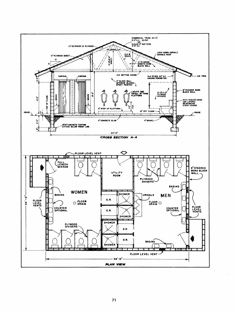
'/»• EXTERIOR ce PLYWOOD
COMMERCIAL TRUSS 24-0. 2-0" O.e.. 50 PSF
OR 2i6<i6'-0' RAFTERS 2-0" OC.
'/•"PLYWOOD SHEET
12
LOCK-DOWN ASPHALT SHINGLE ROOF
•"STACKED tOND •LOCK WALL
WITH STACKED BOND USE LATERAL REINFORCING EVERY COURSE
CROSS SECTION A-A
TTT
o I
FLOOR LEVEL h VENTS
8 STACKED BONO BLOCK WALL
36-0
FUkM vmw
71

STORAGE SHEDS, PLANS NO. 6086 AND NO. 6093
These two plans offer a choice of five different designs for small sheds which are suitable for a variety of uses, such as:
(1) The storage of lawn and garden tools, equipment.
and supplies, patio furniture, sports equipment, bicycles and toys.
(2) A workshop or house for hobbies.
(3) A playhouse or poolside cabana. (4) A shelter for a small pony.
Plan No. 6093 was developed at Virginia Polytechnic
Institute in the style of a traditional gambrel-roofed
barn, with the battens painted to contrast with the color
of the vertical board siding, such as white over red barn
stain.
Plan No. 6086 was developed at Clemson University,
Clemson, S.C. The plan shows details of construction for
four sheds of more contemporary styling.
All five sheds are of light frame construction, erected
on 4-inch thick reinforced concrete floor slabs with
thickened edges.
Many exterior materials and finishes may be used,
such as real or simulated board-and-batten, textured
plywood, and horizontal or vertical siding.
In some localities, building permits are required for structures such as these. Consult authorities before starting construction.
72
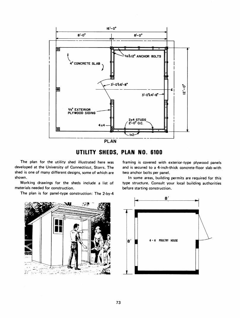
ir
1
ÜL
l6'-0"
I 4- CONCRETE SLAB
3/8" EXTERIOR PLYWOOD SIDING
M ^ n s a: Ve1(l2" ANCHOR BOLTS
3'-0'5t4'-6"-
4x4 —
2x4 STUDS /2'-0"0.C. -X
i J Ï
O I
I £! -í|
PLAN
UTILITY SHEDS, PLAN NO. 6100
The plan for the utility shed illustrated here was developed at the University of Connecticut, Storrs. The shed is one of many different designs, some of which are shown.
Working drawings for the sheds include a list of materials needed for construction.
The plan is for panel-type construction: The 2-by-4
framing is covered with exterior-type plywood panels and is secured to a 4-inch-thick concrete-floor slab with two anchor bolts per panel.
In some areas, building permits are required for this type structure. Consult your local building authorities before starting construction.
8'
8' I 4-H POULTRY HOUSE
73
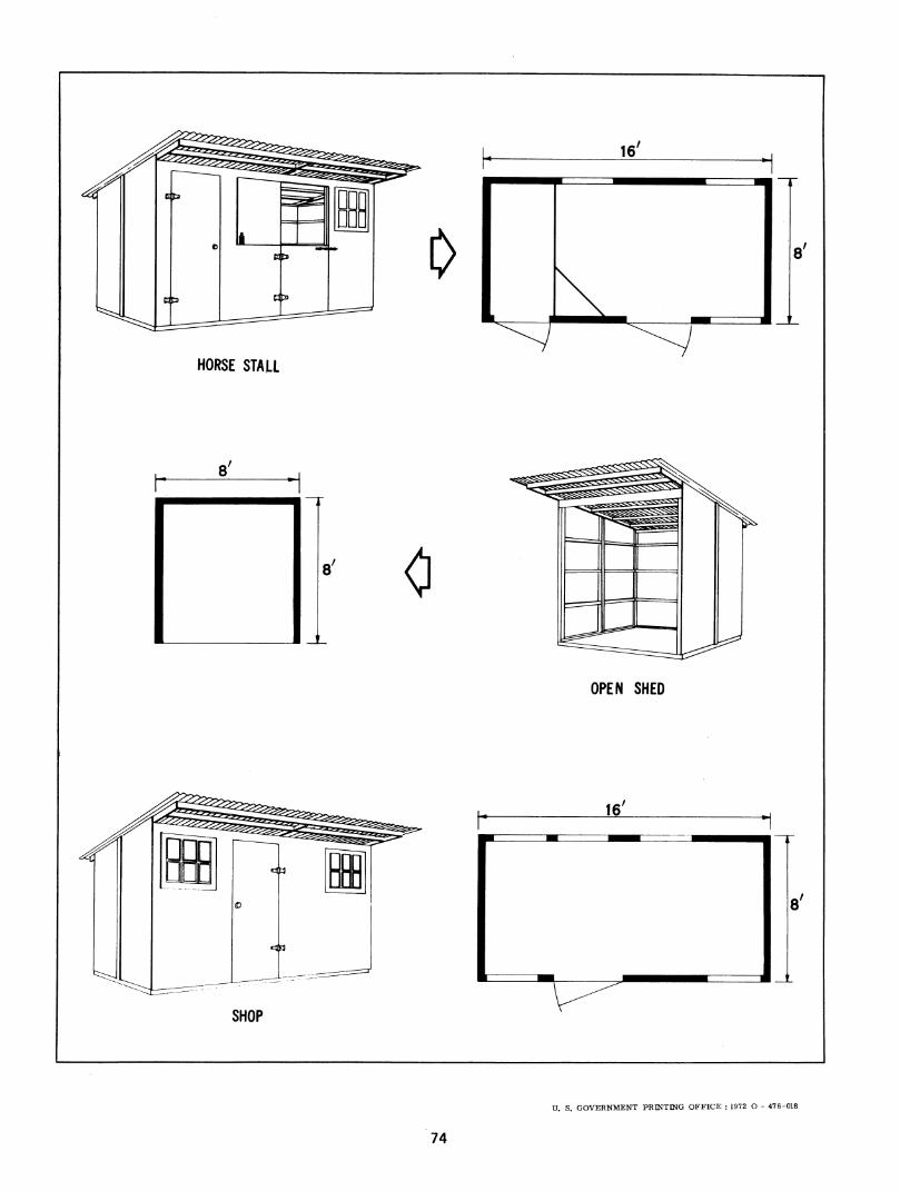
i
8'
HORSE STALL
8' O
OPEN SHED
16'
SHOP
U. S. GOVERNMENT PRINTING OFFICE : 1972 O - 476-018
74

ir3^

/ /