agenda technical committee on lightning protection first
TRANSCRIPT

Agenda Technical Committee on Lightning Protection
First Draft Meeting Fort Collins, CO
October 17 - 20, 2017 Item No. Subject 17-10-1 Call to order 17-10-2 Roll call and introductions 17-10-3 Approval of meeting agenda 17-10-4 Approval of meeting minutes 17-10-5 Chair remarks 17-10-6 BSR/AWEA 61400-24-201x, Lightning Protection 17-10-7 Review of regulations and committee actions 17-10-8 Processing of public inputs 17-10-9 Old business 17-10-10 New business 17-10-11 Review dates and times for future meetings/conference calls 17-10-12 Closing remarks and adjournment
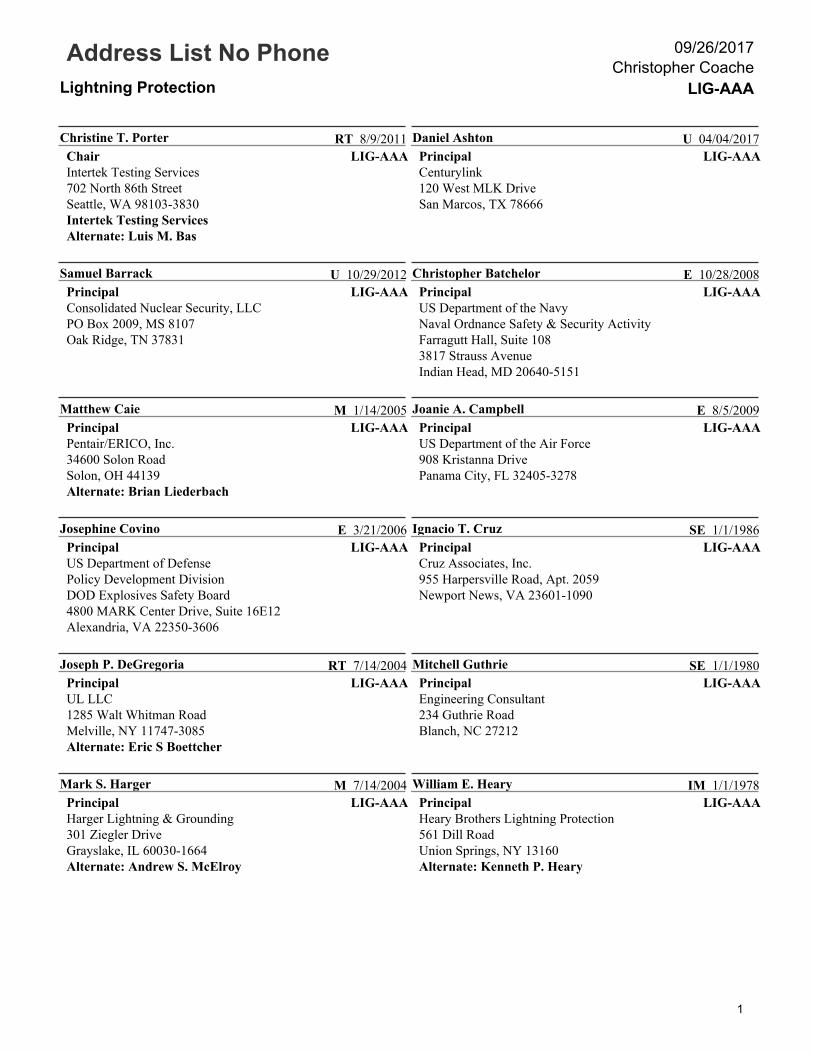
Address List No PhoneLightning Protection LIG-AAA
Christopher Coache09/26/2017
LIG-AAAChristine T. PorterChairIntertek Testing Services702 North 86th StreetSeattle, WA 98103-3830Intertek Testing ServicesAlternate: Luis M. Bas
RT 8/9/2011LIG-AAA
Daniel AshtonPrincipalCenturylink120 West MLK DriveSan Marcos, TX 78666
U 04/04/2017
LIG-AAASamuel BarrackPrincipalConsolidated Nuclear Security, LLCPO Box 2009, MS 8107Oak Ridge, TN 37831
U 10/29/2012LIG-AAA
Christopher BatchelorPrincipalUS Department of the NavyNaval Ordnance Safety & Security ActivityFarragutt Hall, Suite 1083817 Strauss AvenueIndian Head, MD 20640-5151
E 10/28/2008
LIG-AAAMatthew CaiePrincipalPentair/ERICO, Inc.34600 Solon RoadSolon, OH 44139 Alternate: Brian Liederbach
M 1/14/2005LIG-AAA
Joanie A. CampbellPrincipalUS Department of the Air Force908 Kristanna DrivePanama City, FL 32405-3278
E 8/5/2009
LIG-AAAJosephine CovinoPrincipalUS Department of DefensePolicy Development DivisionDOD Explosives Safety Board4800 MARK Center Drive, Suite 16E12Alexandria, VA 22350-3606
E 3/21/2006LIG-AAA
Ignacio T. CruzPrincipalCruz Associates, Inc.955 Harpersville Road, Apt. 2059Newport News, VA 23601-1090
SE 1/1/1986
LIG-AAAJoseph P. DeGregoriaPrincipalUL LLC1285 Walt Whitman RoadMelville, NY 11747-3085Alternate: Eric S Boettcher
RT 7/14/2004LIG-AAA
Mitchell GuthriePrincipalEngineering Consultant234 Guthrie RoadBlanch, NC 27212
SE 1/1/1980
LIG-AAAMark S. HargerPrincipalHarger Lightning & Grounding301 Ziegler DriveGrayslake, IL 60030-1664Alternate: Andrew S. McElroy
M 7/14/2004LIG-AAA
William E. HearyPrincipalHeary Brothers Lightning Protection561 Dill RoadUnion Springs, NY 13160Alternate: Kenneth P. Heary
IM 1/1/1978
1

Address List No PhoneLightning Protection LIG-AAA
Christopher Coache09/26/2017
LIG-AAAStephen HumeniukPrincipalWarren Lightning Rod Company2 Richey AvenueCollingswood, NJ 08107United Lightning Protection Association, Inc.Alternate: George Portfleet
IM 4/17/2002LIG-AAA
Mark E. JohnsonPrincipalThomas and Betts815 T&B BoulevardMemphis, TN 38125National Electrical Manufacturers Association
M 08/17/2017
LIG-AAACarl S. Johnson IIPrincipalAVCON, Inc.5555 East Michigan Street, Suite 200Orlando, FL 32822
U 3/1/2011LIG-AAA
Bruce A. KaiserPrincipalLightning Master CorporationPO Box 6017Clearwater, FL 33758-6017Alternate: Morris Kline
M 1/1/1990
LIG-AAASimon C. LarterPrincipalDobbyn Lightning Protection#123 11769 - 40th Street SECalgary, AB T2Z 4M8 Canada
IM 10/28/2014LIG-AAA
David E. McAfeePrincipalLightning & Fire Protection Consultant325 E. Washington StreetBelding, MI 48809
SE 4/1/1994
LIG-AAARobley B. Melton, Jr.PrincipalCSI Telecommunications5165 South Trimble Road, NEAtlanta, GA 30342-2124 Alliance for Telecommunications Industry SolutionsAlternate: Ernest J. Gallo
U 1/1/1989LIG-AAA
Mark P. MorganPrincipalEast Coast Lightning Equipment, Inc.24 Lanson DriveWinsted, CT 06098Alternate: Charles H. Ackerman
M 9/30/2004
LIG-AAALuke PettrossPrincipalLightning Eliminators & Consultants Inc.6687 Arapahoe RoadBoulder, CO 80303Alternate: Joseph A. Lanzoni
M 8/9/2011LIG-AAA
Robert W. RappPrincipalNational Lightning Protection Corporation 13550 Smith Road, Suite 150Aurora, CO 80011Alternate: Paul R. Svendsen
M 1/1/1996
LIG-AAALon D. SantisPrincipalExplosives Risk Managers, LLC11104 Innsbrook WayIjamsville, MD 21754-9058
SE 01/15/1999LIG-AAA
Ronald ThomasPrincipalInstitute of Makers of Explosives15 West Oak DriveWoodland Hills, UT 84653-2034Institute of Makers of Explosives
U 03/03/2014
LIG-AAAEwen ThomsonPrincipalMarine Lightning Protection Inc.3215 NW 17th StreetGainesville, FL 32605-2511
SE 03/03/2014LIG-AAA
John M. TobiasPrincipalUS Department of the ArmyCECOM, Attn: Amsel-SFS-I3200 Raritan AvenueAberdeen Proving Grounds, MD 21005
U 4/1/1995
2

Address List No PhoneLightning Protection LIG-AAA
Christopher Coache09/26/2017
LIG-AAAHarold VanSickle, IIIPrincipalLightning Protection Institute25475 Magnolia DrivePO Box 99Maryville, MO 64468Alternate: Philip E. Youtsey
IM 1/1/1988LIG-AAA
Allan P. SteffesVoting AlternateThompson Lightning Protection Inc.901 Sibley HighwaySt. Paul, MN 55118-1792
M 1/1/1985
LIG-AAALeah TietjenVoting AlternateLos Alamos National LaboratoryPO Box 1663Los Alamos, NM 87545
U 03/07/2013LIG-AAA
Charles H. AckermanAlternateEast Coast Lightning Equipment Inc.24 Lanson Drive, RFD 4 Winsted, CT 06098Principal: Mark P. Morgan
M 4/1/1993
LIG-AAALuis M. BasAlternateIntertek Testing Services5522 Antler TrailLakeland, FL 33811Intertek Testing ServicesPrincipal: Christine T. Porter
RT 04/04/2017LIG-AAA
Eric S BoettcherAlternateUL LLC9535 Butternut CourtNew Port Richey, FL 34654UL LLCPrincipal: Joseph P. DeGregoria
RT 08/17/2017
LIG-AAAErnest J. GalloAlternateTelcordia Technologies (Ericsson)444 Hoes LanePiscataway, NJ 08854-4157Alliance for Telecommunications Industry SolutionsPrincipal: Robley B. Melton, Jr.
U 08/17/2017LIG-AAA
Kenneth P. HearyAlternateHeary Brothers Lightning Protection11291 Moore RoadSpringville, NY 14141Principal: William E. Heary
IM 1/1/1978
LIG-AAAMorris KlineAlternateLightning Master Corporation1770 Calumet StreetClearwater, FL 33765-1137Principal: Bruce A. Kaiser
M 03/05/2012LIG-AAA
Joseph A. LanzoniAlternateLightning Eliminators & Consultants Inc.6687 Arapahoe RoadBoulder, CO 80303-1453Principal: Luke Pettross
M 1/16/2003
LIG-AAABrian LiederbachAlternatePentair/ERICO, Inc.34600 Solon RoadSolon, OH 44139Principal: Matthew Caie
M 10/29/2012LIG-AAA
Andrew S. McElroyAlternateHarger Lightning & Grounding301 Ziegler DriveGrayslake, IL 60030Principal: Mark S. Harger
M 04/05/2016
3
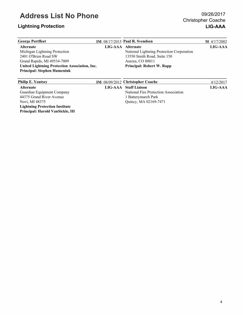
Address List No PhoneLightning Protection LIG-AAA
Christopher Coache09/26/2017
LIG-AAAGeorge PortfleetAlternateMichigan Lightning Protection2401 O'Brien Road SWGrand Rapids , MI 49534-7009United Lightning Protection Association, Inc.Principal: Stephen Humeniuk
IM 08/17/2015LIG-AAA
Paul R. SvendsenAlternateNational Lightning Protection Corporation13550 Smith Road, Suite 150Aurora, CO 80011Principal: Robert W. Rapp
M 4/17/2002
LIG-AAAPhilip E. YoutseyAlternateGuardian Equipment Company44375 Grand River AvenueNovi, MI 48375Lightning Protection InstitutePrincipal: Harold VanSickle, III
IM 08/09/2012LIG-AAA
Christopher CoacheStaff LiaisonNational Fire Protection Association1 Batterymarch ParkQuincy, MA 02169-7471
4/12/2017
4

NFPA 780 SECOND DRAFT MEETING MINUTES Technical Committee on Standard for the
Installation of Lightning Protection Systems July 27 – 30, 2015
DoubleTree Hotel Charlotte Airport Charlotte, NC
Attendance: See attached for both members and guests present.
Item 15-7-1 Call to Order The Technical Committee meeting was called to order at 8:05 am by Chair John Tobias. John provided opening comments and welcomed members and guests.
Item 15-7-2 Roll Call and Introductions All TC members and guests were asked to sign in and verify their affiliation. New committee members were introduced.
Item 15-7-3 Approval of Meeting Agenda The meeting agenda was approved.
Item 15-7-4 Approval of Meeting Minutes The meeting minutes of September 22 - 26, 2014 were approved.
Item 15-7-5 Staff/Chair Remarks and Using the New Process The Chair thanked all for their attendance and participation. The Chair made opening remarks and outlined the plan for addressing Public Comments (PCs) by task group. NFPA Staff reviewed the Second Draft process and operation of the TerraView system for processing items. Everyone was in awe of the committee liason’s PowerPoint.
Item 15-7-6 Task Group Reports Task Groups reported on their assigned comments. As task groups were operating for approximately six weeks to formulate recommendations on resolution of PCs to the full TC, their work was integrated into item 15-7-7.
The following represents the NFPA 780 Task Groups:
Airfield Lighting - Carl J.
Bridges/Piers - Mitch G.
Editorial - Steve H.
Explosives - Jo. C.
Fabric Structures – Doug F.
Grounding & Bonding - Mitch G.
Personal Safety – Steve H.
References – Mark M.
Risk Assessment – Mitch G./Dave M.
Smart Structures – John T.
Solar Panel – Matt C.
Strike Terminations/Tall Structures – Tom H.
Surge Protection – Mitch G.
Tanks – Bruce K.
Watercraft – Ewen T.
Wind Turbine – Matt C.

Item 15-7-7 Public Comments and Second Revisions
PC s were grouped into areas of responsibilities assigned to the task groups (see item 15-7-6). 104 PCs were processed resulting in 48 SRs.
Item 15-7-8 Old Business None.
Item 15-7-9 New Business All task groups were dissolved with the thanks of NFPA and the Chair.
Item 15-7-10 Review Dates and Times for Future Meetings/Conference Calls
No conference calls are scheduled. There are no future meetings scheduled. Ballots for actions taken at the meeting will be circulated. Item 15-7-11 Adjournment and Closing Remarks The meeting adjourned at 6:00 pm on July 29. The Chair thanked staff and members for their past and continued efforts on NFPA 780.
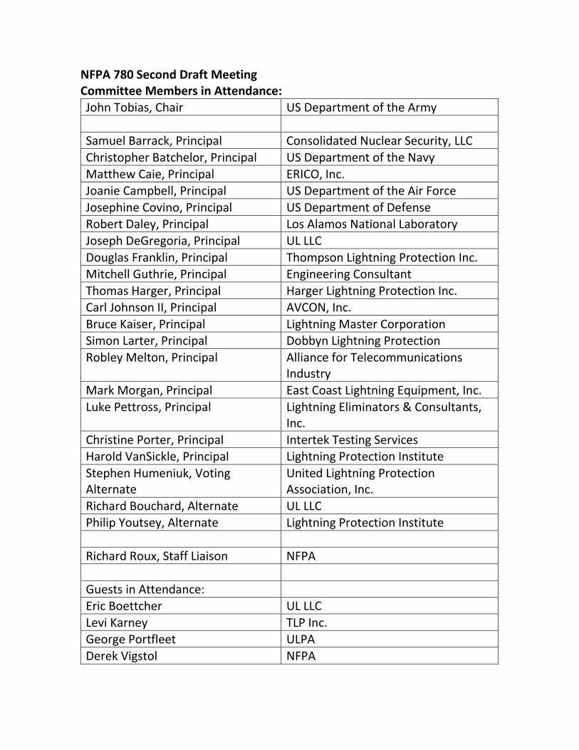
NFPA 780 Second Draft Meeting Committee Members in Attendance: John Tobias, Chair US Department of the Army
Samuel Barrack, Principal Consolidated Nuclear Security, LLC
Christopher Batchelor, Principal US Department of the Navy
Matthew Caie, Principal ERICO, Inc. Joanie Campbell, Principal US Department of the Air Force
Josephine Covino, Principal US Department of Defense Robert Daley, Principal Los Alamos National Laboratory
Joseph DeGregoria, Principal UL LLC
Douglas Franklin, Principal Thompson Lightning Protection Inc. Mitchell Guthrie, Principal Engineering Consultant
Thomas Harger, Principal Harger Lightning Protection Inc. Carl Johnson II, Principal AVCON, Inc.
Bruce Kaiser, Principal Lightning Master Corporation Simon Larter, Principal Dobbyn Lightning Protection
Robley Melton, Principal Alliance for Telecommunications Industry
Mark Morgan, Principal East Coast Lightning Equipment, Inc.
Luke Pettross, Principal Lightning Eliminators & Consultants, Inc.
Christine Porter, Principal Intertek Testing Services Harold VanSickle, Principal Lightning Protection Institute
Stephen Humeniuk, Voting Alternate
United Lightning Protection Association, Inc.
Richard Bouchard, Alternate UL LLC Philip Youtsey, Alternate Lightning Protection Institute
Richard Roux, Staff Liaison NFPA
Guests in Attendance: Eric Boettcher UL LLC
Levi Karney TLP Inc. George Portfleet ULPA
Derek Vigstol NFPA

Public Input No. 241-NFPA 780-2017 [ Global Input ]
Globally change "3 ft (0.9 m)" to "3 ft (1 m)" in the following clauses for consistency with A.4.13.8.3.1:
4.7.11.4, 4.9.6.1, 4.9.12, 4.10, 4.13.8.1.4, 8.4.3.2, G.1.1.3, and J.6.1.1.4.
Statement of Problem and Substantiation for Public Input
While 0.9 m is the most accurate value relating to 3 feet, the general rule of thumb for those using the metric system is a yard is equivalent to a meter. Changing 3 feet to 1 meter will be less than 10% difference. Even for fasteners, I am not so sure an additional 3.37 inches will make a difference; especially considering the 3 feet value is the specified rule.
Submitter Information Verification
Submitter Full Name: Mitchell Guthrie
Organization: Engineering Consultant
Street Address:
City:
State:
Zip:
Submittal Date: Mon Jun 26 17:34:41 EDT 2017
National Fire Protection Association Report http://submittals.nfpa.org/TerraViewWeb/ContentFetcher?commentPara...
1 of 302 9/22/2017, 11:03 AM

Public Input No. 242-NFPA 780-2017 [ Global Input ]
Globally change "In" to "In" in Clauses 12.4.2.2 and 12.4.3.2.
Statement of Problem and Substantiation for Public Input
This change would be consistent with IEC 62305-4 and IEC 61643 as well as clauses 3.3.9.2, 4.20.3.1.2 and A.4.20.3.1.
Submitter Information Verification
Submitter Full Name: Mitchell Guthrie
Organization: Engineering Consultant
Street Address:
City:
State:
Zip:
Submittal Date: Mon Jun 26 18:05:26 EDT 2017
National Fire Protection Association Report http://submittals.nfpa.org/TerraViewWeb/ContentFetcher?commentPara...
2 of 302 9/22/2017, 11:03 AM

Public Input No. 265-NFPA 780-2017 [ Chapter 1 [Title Only] ]
Administration
1.1.1 This document shall cover traditional lightning protection system installation requirements for the following:
Statement of Problem and Substantiation for Public Input
Delete the word “traditional” from 1.1.1, first sentence. The effect of this word is to inappropriately limit competition. (See rationale for 1.1.3.)
Submitter Information Verification
Submitter Full Name: Bruce Kaiser
Organization: Lightning Master Corporation
Street Address:
City:
State:
Zip:
Submittal Date: Tue Jun 27 15:56:43 EDT 2017
National Fire Protection Association Report http://submittals.nfpa.org/TerraViewWeb/ContentFetcher?commentPara...
3 of 302 9/22/2017, 11:03 AM

Public Input No. 194-NFPA 780-2017 [ Section No. 1.1.1 ]
1.1.1
This document shall cover traditional lightning protection system installation requirements for the following:
(1) Ordinary structures
(2) Miscellaneous structures and special occupancies
(3) Heavy-duty stacks
(4) Structures containing flammable vapors, flammable gases, or liquids that can give off flammable vapors
(5) Structures housing explosive materials
(6) Wind turbines
(7) Watercraft
(8) Airfield lighting circuits
(9) Solar arrays
Statement of Problem and Substantiation for Public Input
Delete ‘traditional from “Traditional lightning protection system”; the international standard of IEC covers the entire LPS and NFPA does, too. Therefore, the term ‘traditional’ has no meaning
Submitter Information Verification
Submitter Full Name: Youngki Chung
Organization: Omni Lps
Street Address:
City:
State:
Zip:
Submittal Date: Mon Jun 26 04:26:53 EDT 2017
National Fire Protection Association Report http://submittals.nfpa.org/TerraViewWeb/ContentFetcher?commentPara...
4 of 302 9/22/2017, 11:03 AM

Public Input No. 195-NFPA 780-2017 [ Section No. 1.1.3 ]
1.1.3
This document shall not cover lightning protection system installation requirements for early streamer emission systems or chargedissipation systems.
Additional Proposed Changes
File Name Description Approved
Reference_1.docx
Statement of Problem and Substantiation for Public Input
There have been various types of air terminals with different features produced and sold in market. Having gathered the opinions from members of the committee, IEC amended the relevant standards in 2010, in which it is allowed to install all air terminals regardless of types as far as it is designed and installed in accordance with IEC62305 series as seen in Ref.1. Since the standards for lightning system in IEC and NFPA are fundamentally based on the same principles, here I suggest that NFPA1.3 be amended as follows.
Related Public Inputs for This Document
Related Input Relationship
Public Input No. 209-NFPA 780-2017 [Section No. 4.6.2]
Submitter Information Verification
Submitter Full Name: Youngki Chung
Organization: Omni Lps
Street Address:
City:
State:
Zip:
Submittal Date: Mon Jun 26 04:31:38 EDT 2017
National Fire Protection Association Report http://submittals.nfpa.org/TerraViewWeb/ContentFetcher?commentPara...
5 of 302 9/22/2017, 11:03 AM

Public Input No. 76-NFPA 780-2017 [ Section No. 1.1.3 ]
1.1.3
This document shall not cover lightning protection system installation requirements for early streamer emission systems or charge , charge dissipation systems or any other none in the Scientific Community as NON-Conventional Systems .
Statement of Problem and Substantiation for Public Input
There are in the market many different gadgets that fool customers, by taking advantage of the use of the single Mast Type lightning protection, to validate their "technology". The term Conventional Lightning protection is a must in the Standard.
Submitter Information Verification
Submitter Full Name: Lizardo Lopez
Organization: Pro Lightning Prot Inc
Street Address:
City:
State:
Zip:
Submittal Date: Fri May 19 20:44:30 EDT 2017
National Fire Protection Association Report http://submittals.nfpa.org/TerraViewWeb/ContentFetcher?commentPara...
6 of 302 9/22/2017, 11:03 AM

Public Input No. 77-NFPA 780-2017 [ Section No. 1.1.3 ]
1.1.3 1.1.3 This document shall not cover lightning protection system installation requirements for early streamer emissionsystems or charge dissipation systems.
Statement of Problem and Substantiation for Public Input
This is a dimension-based standard, specifying physical dimension of components and layout, not a performance-based standard. A component either meets the requirements of the standard or it does not. As long as a system or component, any system or component, meets the requirements of this standard, it should be allowed. If an air terminal or other system component employs appurtenances to achieve additional or alternative performance, but otherwise meets the requirements of this standard, it should be accepted. Dimensions may be easily measured and ascertained in the field. In light of abuses by listing agencies, it is apparent that this section has been used to limit competition. The negatives of such limitation of competition outweigh any dubious benefits of this section.
These changes were recommended by the NFPA’s own Report of the Third Party Independent Evaluation Panel on the Early Streamer Emission Lightning Protection Technology (aka the Bryan Report) submitted to the Standards Council September 1, 1999. Section C. 4. recommends that, “The current provision in the NFPA 780 document scope as follows: “except those concepts utilizing early streamer emission air terminals.” Should be removed. The restructured 780 Committee should include representatives from the total lightning protection community.” This recommendation naturally includes eliminating the restriction on all technologies.
NFPA 780 is generally accepted as THE US lightning protection standard. It is unlikely that any other lightning protection standard will be approved by NFPA. Think back on the outrageous and shameless lobbying of the conventional Franklin lightning rod crowd at the Phoenix meeting to prevent the acceptance of NFPA 781.
It is further unlikely that any other standard will be accepted and adopted based upon the unequal requirement that any alternative technology provide what would amount to irrefutable scientific proof of its efficacy when no such proof was required of the existing, conventional Franklin lightning rod technology. Such proof does not exist, as was pointed out in section C, NFPA Lightning Protection Documents, “… It appears to the panel the NFPA 780 document does not meet the NFPA criteria for a standard since the recommended lightning protection system has never been scientifically or technically validated and the Franklin rod air terminals have not been validated in field tests under thunderstorm conditions…The current NFPA 780 document appears to have been recognized by historical precedent rather than by experimental and scientific validation.”
The only justification for excluding technologies that otherwise meet 780 is to limit competition. Since there will be no other standards, it is incumbent on NFPA to delete the restrictions in the scope of 780 to allow the use of alternative technologies that otherwise meet the standard.
Submitter Information Verification
Submitter Full Name: Bruce Kaiser
Organization: Lightning Master Corporation
Street Address:
City:
State:
Zip:
Submittal Date: Tue May 23 11:11:33 EDT 2017
National Fire Protection Association Report http://submittals.nfpa.org/TerraViewWeb/ContentFetcher?commentPara...
7 of 302 9/22/2017, 11:03 AM

Public Input No. 152-NFPA 780-2017 [ New Section after 1.3 ]
1.3.1
Materials that comply with the requirements of sections 4.1 and 4.2 and comply with charts 4.1.1.1.1 or 4.1.1.1.2 also comply withthis standard. Such components are approved for use and shall be permitted to be used in system installations complying with thisstandard without a listing or label.
Statement of Problem and Substantiation for Public Input
Structural elements of 3/16 inch thickness are acceptable, but simple metal conductors of the appropriate size for their class of use must be listed or labeled. The Charts are self explanatory and can easily be field verified. Stripping in particular has been employed for the purposes of bonding for half a century. Listing and label these materials restricts free trade and adds undue cost without benefit.
Submitter Information Verification
Submitter Full Name: Stephen Humeniuk
Organization: Warren Lightning Rod Company
Affilliation: ULPA
Street Address:
City:
State:
Zip:
Submittal Date: Thu Jun 22 16:58:08 EDT 2017
National Fire Protection Association Report http://submittals.nfpa.org/TerraViewWeb/ContentFetcher?commentPara...
8 of 302 9/22/2017, 11:03 AM
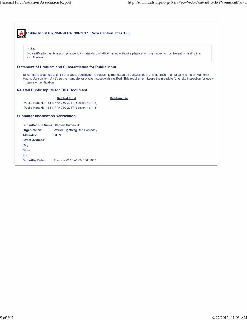
Public Input No. 150-NFPA 780-2017 [ New Section after 1.5 ]
1.5.4
No certification verifying compliance to this standard shall be issued without a physical on site inspection by the entity issuing thatcertification.
Statement of Problem and Substantiation for Public Input
Since this is a standard, and not a code, certification is frequently mandated by a Specifier. In this instance, their usually is not an Authority Having Jurisdiction (AHJ), so the mandate for onsite inspection is nullified. This requirement keeps the mandate for onsite inspection for every instance of certification.
Related Public Inputs for This Document
Related Input Relationship
Public Input No. 151-NFPA 780-2017 [Section No. 1.5]
Public Input No. 151-NFPA 780-2017 [Section No. 1.5]
Submitter Information Verification
Submitter Full Name: Stephen Humeniuk
Organization: Warren Lightning Rod Company
Affilliation: ULPA
Street Address:
City:
State:
Zip:
Submittal Date: Thu Jun 22 16:46:55 EDT 2017
National Fire Protection Association Report http://submittals.nfpa.org/TerraViewWeb/ContentFetcher?commentPara...
9 of 302 9/22/2017, 11:03 AM

Public Input No. 151-NFPA 780-2017 [ Section No. 1.5 ]
1.5 Mechanical Execution of Work.
1.5.1
Lightning protection systems shall be installed in a neat and workmanlike manner.
1.5.2 *
The individual(s) responsible for the installation shall be certified for fitness on the requirements of this standard by the authorityhaving jurisdiction.
1.5.3
Where required by the authority having jurisdiction, compliance of the completed installation with the requirements of this standardshall be certified through a physical on-site inspection by a qualified and impartial organization acceptable to the authority havingjurisdiction.
Statement of Problem and Substantiation for Public Input
This text is deleted and expanded in the new section1.5.4
Related Public Inputs for This Document
Related Input Relationship
Public Input No. 150-NFPA 780-2017 [New Section after 1.5]
Public Input No. 150-NFPA 780-2017 [New Section after 1.5]
Submitter Information Verification
Submitter Full Name: Stephen Humeniuk
Organization: Warren Lightning Rod Company
Affilliation: ULPA
Street Address:
City:
State:
Zip:
Submittal Date: Thu Jun 22 16:55:59 EDT 2017
National Fire Protection Association Report http://submittals.nfpa.org/TerraViewWeb/ContentFetcher?commentPara...
10 of 302 9/22/2017, 11:03 AM
Public Input No. 337-NFPA 780-2017 [ Section No. 1.6.1 ]
1.6.1 * Periodic Inspection.
Periodic inspections or testing for compliance to this standard shall be done at intervals determined by the authority havingjurisdiction.
Statement of Problem and Substantiation for Public Input
The Existing Structures Task Group references new annex material.
Related Public Inputs for This Document
Related Input Relationship
Public Input No. 338-NFPA 780-2017 [New Section after A.1.6]
Submitter Information Verification
Submitter Full Name: Stephen Humeniuk
Organization: Warren Lightning Rod Company
Affilliation: ULPA, The Existing Structures Task Group
Street Address:
City:
State:
Zip:
Submittal Date: Wed Jun 28 15:55:25 EDT 2017
National Fire Protection Association Report http://submittals.nfpa.org/TerraViewWeb/ContentFetcher?commentPara...
11 of 302 9/22/2017, 11:03 AM
Public Input No. 263-NFPA 780-2017 [ Section No. 1.7 ]
1.7 Units of Measurement.
1.7.1
The values stated shall be minimum value. A standard deviation is not permitted in this standard
1.7.2
Measurements shall be presented in inch-pound units followed by the equivalent value presented in SI units in parentheses.
1.7. 2 3
A given equivalent value shall be approximate.
1.7.4
When the approximation of the SI value is less restrictive than the Inch Pound requirement, the SI equivalent shall be equal to ormore restrictive than the exact equivalent of the Inch Pound unit expressed in the requirement.
Statement of Problem and Substantiation for Public Input
Text is added to clarify that approximate SI values are not the standard requirement. In some cases the approximate value may reflect a more lenient value which is not the intention of the standard. Where the Value is more lenient the Inch pound value must be used or a value equal to or more stringent than the exact SI equivalent of that value.
Submitter Information Verification
Submitter Full Name: Stephen Humeniuk
Organization: Warren Lightning Rod Company
Affilliation: ULPA
Street Address:
City:
State:
Zip:
Submittal Date: Tue Jun 27 15:37:50 EDT 2017
National Fire Protection Association Report http://submittals.nfpa.org/TerraViewWeb/ContentFetcher?commentPara...
12 of 302 9/22/2017, 11:03 AM

Public Input No. 266-NFPA 780-2017 [ Section No. 2.2 ]
2.2 NFPA Publications.
National Fire Protection Association, 1 Batterymarch Park, Quincy, MA 02169-7471.
NFPA 61, Standard for the Prevention of Fires and Dust Explosions in Agricultural and Food Processing Facilities, 2013 edition.
NFPA 70®, National Electrical Code®, 2014 edition.
NFPA 77, Recommended Practice on Static Electricity.
NFPA 122, Standard for Fire Prevention and Control in Metal/Nonmetal Mining and Metal Mineral Processing Facilities, 2015 edition.
NFPA 664, Standard for the Prevention of Fires and Explosions in Wood Processing and Woodworking Facilities, 2012 edition.
Statement of Problem and Substantiation for Public Input
Chapter 7 proposed revisions will reference NFPA 77.
Submitter Information Verification
Submitter Full Name: Bruce Kaiser
Organization: Lightning Master Corporation
Street Address:
City:
State:
Zip:
Submittal Date: Tue Jun 27 16:00:02 EDT 2017
National Fire Protection Association Report http://submittals.nfpa.org/TerraViewWeb/ContentFetcher?commentPara...
13 of 302 9/22/2017, 11:03 AM

Public Input No. 196-NFPA 780-2017 [ Section No. 2.3.1 ]
2.3.1 IEC Publications.
International Electrotechnical Commission, 3, rue de Varembé, P.O. Box 131, CH-1211 Geneva 20, Switzerland.
IEC 62305-2, Protection Against Lightning—Part 2: Risk Management, Edition 2, 2010.
IEC 62305-1, Protection Against Lightning—Part 1: General Principle , Edition 2, 2010.
IEC 62305-3, Protection Against Lightning — Part 3: Physical Damage to Structures and Life Hazard , Edition 2, 2010.
IEC 61643-11, Low-Voltage Surge Protective Devices — Part 11: Surge Protective Devices Connected to Low-Voltage PowerDistribution Systems — Requirements and Test Methods , 2011.
IEC 61643-12, Low-Voltage Surge Protective Devices — Part 12: Surge Protective Devices Connected to Low-Voltage PowerDistribution Systems — Selection and Application Principles , 2008.
IEC 61643-21, Low Voltage Surge Protective Devices — Part 21: Surge Protective Devices Connected to Telecommunications andSignalling Networks—Performance Requirements and Testing Methods , Edition 1.1, 2009.
IEC 62561-1, Lightning protection system components (LPSC) - Part 1: Requirements for connection components, 2012.
IEC 62561-2, Lightning protection system components (LPSC) - Part 2: Requirements for conductors and earth electrodes, 2012.
IEC 62561-4, Lightning protection system components (LPSC) – Part 4: Requirements for conductor fasteners, 2012.
Statement of Problem and Substantiation for Public Input
As more and more countries sign international agreements such as WTO/TBT and FTA, it is necessary to harmonize NFPA with other international standards in order to avoid technical disputes. Thus, partly accepting the related international standard of IEC, NFPA 780; 2017 new edition was revised.
Submitter Information Verification
Submitter Full Name: Youngki Chung
Organization: Omni Lps
Street Address:
City:
State:
Zip:
Submittal Date: Mon Jun 26 04:37:53 EDT 2017
National Fire Protection Association Report http://submittals.nfpa.org/TerraViewWeb/ContentFetcher?commentPara...
14 of 302 9/22/2017, 11:03 AM
Public Input No. 148-NFPA 780-2017 [ Section No. 2.3.3 ]
2.3.3 UL Publications.
Underwriters Laboratories Inc., 333 Pfingsten Road, Northbrook, IL 60062-2096.
ANSI/UL 1449, Standard for Safety for Surge Protective Devices, 4th edition, August 20, 2014 Revised 2016 .
Statement of Problem and Substantiation for Public Input
Update Standards
Related Public Inputs for This Document
Related Input Relationship
Public Input No. 149-NFPA 780-2017 [Section No. O.1.2.7]
Submitter Information Verification
Submitter Full Name: Kelly Nicolello
Organization: UL LLC
Street Address:
City:
State:
Zip:
Submittal Date: Thu Jun 22 15:30:53 EDT 2017
National Fire Protection Association Report http://submittals.nfpa.org/TerraViewWeb/ContentFetcher?commentPara...
15 of 302 9/22/2017, 11:03 AM

Public Input No. 339-NFPA 780-2017 [ Section No. 2.3.3 ]
2.3.3 UL Publications.
Underwriters Laboratories Inc., 333 Pfingsten Road, Northbrook, IL 60062-2096.
ANSI/UL 1449, Standard for Safety for Surge Protective Devices, 4th edition, August 20 February 5 , 2014 2016 .
Statement of Problem and Substantiation for Public Input
Updating the reference to the most recent revision. Note to NFPA Staff: This document is also listed in O.1.2.7.
Submitter Information Verification
Submitter Full Name: Mitchell Guthrie
Organization: Engineering Consultant
Street Address:
City:
State:
Zip:
Submittal Date: Wed Jun 28 16:31:34 EDT 2017
National Fire Protection Association Report http://submittals.nfpa.org/TerraViewWeb/ContentFetcher?commentPara...
16 of 302 9/22/2017, 11:03 AM

Public Input No. 340-NFPA 780-2017 [ Section No. 2.4 ]
2.4 References for Extracts in Mandatory Sections.
NFPA 70®, National Electrical Code®, 2014 edition.
NFPA 115, Standard for Laser Fire Protection, 2016 edition.
Statement of Problem and Substantiation for Public Input
The only place I could find this mentioned was in Clause 2.4 where it is mentioned as a reference for an abstract. Delete?
Submitter Information Verification
Submitter Full Name: Mitchell Guthrie
Organization: Engineering Consultant
Street Address:
City:
State:
Zip:
Submittal Date: Wed Jun 28 16:39:30 EDT 2017
National Fire Protection Association Report http://submittals.nfpa.org/TerraViewWeb/ContentFetcher?commentPara...
17 of 302 9/22/2017, 11:03 AM
Public Input No. 198-NFPA 780-2017 [ New Section after 3.3.1 ]
3.3.1.1 Conventional Air Terminal
A metal rod amounted on a structure as part of the external LPS.
Statement of Problem and Substantiation for Public Input
Add the definition for the term of ‘Conventional air terminal’
Submitter Information Verification
Submitter Full Name: Youngki Chung
Organization: Omni Lps
Street Address:
City:
State:
Zip:
Submittal Date: Mon Jun 26 04:48:25 EDT 2017
National Fire Protection Association Report http://submittals.nfpa.org/TerraViewWeb/ContentFetcher?commentPara...
18 of 302 9/22/2017, 11:03 AM
Public Input No. 199-NFPA 780-2017 [ New Section after 3.3.1 ]
3.3.1.2 Bipolar Conventional Air Terminal (BCAT)
Conventional Air Terminal with a floating conductor for a bipolar function.
Additional Proposed Changes
File Name Description Approved
_4_1._ExperimentandAnalysisforEffectofFloatingConductoronElectricDischargeCharacteristic.pdf
_6_2._Finite_Element_Analysis_of_Corona_Discharge.pdf
_8_3._Local_Electric_Field_Analysis_for_Evaluation_of_Charge_Transfer_System_Using_Sequential_Subwindow_Technique.pdf
Statement of Problem and Substantiation for Public Input
Add the definition for BCAT(Bipolar Conventional Air Terminal)
Related Public Inputs for This Document
Related Input Relationship
Public Input No. 202-NFPA 780-2017 [New Section after 3.3.9]
Public Input No. 225-NFPA 780-2017 [New Section after O.3]
Submitter Information Verification
Submitter Full Name: Youngki Chung
Organization: Omni Lps
Street Address:
City:
State:
Zip:
Submittal Date: Mon Jun 26 04:50:09 EDT 2017
National Fire Protection Association Report http://submittals.nfpa.org/TerraViewWeb/ContentFetcher?commentPara...
19 of 302 9/22/2017, 11:03 AM

Public Input No. 197-NFPA 780-2017 [ Section No. 3.3.1 ]
3.3.1* Air Terminal.
A strike termination device part of an external LPS that is a receptor for attachment of flashes to the lightning protection systemand is listed for the purpose composed of listed items, such as metallic elements including rods, mesh conductors or catenarywires intended to intercept lightning strikes .
Additional Proposed Changes
File Name Description Approved
Reference_2.docx
Statement of Problem and Substantiation for Public Input
Modify the definition of “Air Terminal” to reflect IEC standards.
Submitter Information Verification
Submitter Full Name: Youngki Chung
Organization: Omni Lps
Street Address:
City:
State:
Zip:
Submittal Date: Mon Jun 26 04:41:52 EDT 2017
National Fire Protection Association Report http://submittals.nfpa.org/TerraViewWeb/ContentFetcher?commentPara...
20 of 302 9/22/2017, 11:03 AM

Public Input No. 285-NFPA 780-2017 [ New Section after 3.3.2 ]
Add new definition 3.3.X* Inherently Bonded.
Electrically continuous connection between grounded and ungrounded metal bodies and building framework or the lightningprotection grounding system which are permanently or semi-permanently joined through construction or other physical contact withconductive material capable of conducting partial lightning current.
Statement of Problem and Substantiation for Public Input
The term is used several times in the standard with no definition. This definition provides clarification as to what constitutes an acceptable inherent bond.
Submitter Information Verification
Submitter Full Name: Mitchell Guthrie
Organization: Engineering Consultant
Affilliation: NFPA 780 Grounding and Bonding Task Group
Street Address:
City:
State:
Zip:
Submittal Date: Tue Jun 27 17:02:43 EDT 2017
National Fire Protection Association Report http://submittals.nfpa.org/TerraViewWeb/ContentFetcher?commentPara...
21 of 302 9/22/2017, 11:03 AM

Public Input No. 297-NFPA 780-2017 [ Section No. 3.3.7.4 ]
3.3.7.4* Ground Loop Conductor.
A main-size loop conductor installed within 12 ft (3.6 m) vertically of the base of the structure to provide a common ground potential.
Statement of Problem and Substantiation for Public Input
An asterisk is added to indicate annex material is added in Annex A.
Related Public Inputs for This Document
Related Input Relationship
Public Input No. 298-NFPA 780-2017 [New Section after A.3.3.7.6]
Submitter Information Verification
Submitter Full Name: Mitchell Guthrie
Organization: Engineering Consultant
Street Address:
City:
State:
Zip:
Submittal Date: Tue Jun 27 23:25:03 EDT 2017
National Fire Protection Association Report http://submittals.nfpa.org/TerraViewWeb/ContentFetcher?commentPara...
22 of 302 9/22/2017, 11:03 AM
Public Input No. 201-NFPA 780-2017 [ New Section after 3.3.9 ]
3.3.9.3 Impulse Discharge Current ( I imp )
It is defined by three parameters, a current peak value Ipiak, a charge Q and a specific energy W/R. Its waveform is 10/350microsecond, which is for testing SPD mounted outside the structure and air terminal connection components.
Additional Proposed Changes
File Name Description Approved
Reference_5.docx
Statement of Problem and Substantiation for Public Input
Add the definition for 10/350 ㎲ Impulse Current for Class I SPD Test and connection components of LPS
Related Public Inputs for This Document
Related Input Relationship
Public Input No. 221-NFPA 780-2017 [Section No. 4.20.3.1]
Submitter Information Verification
Submitter Full Name: Youngki Chung
Organization: Omni Lps
Street Address:
City:
State:
Zip:
Submittal Date: Mon Jun 26 05:24:17 EDT 2017
National Fire Protection Association Report http://submittals.nfpa.org/TerraViewWeb/ContentFetcher?commentPara...
23 of 302 9/22/2017, 11:03 AM

Public Input No. 202-NFPA 780-2017 [ New Section after 3.3.9 ]
3.3.9.4 Corona Discharge Current
Current from Corona discharge occurred at the air terminal in advance of direct lightning strikes caused by intense electric field incase a thunder cloud approaches
Statement of Problem and Substantiation for Public Input
Add the definition for ‘Corona Discharge Current’
Related Public Inputs for This Document
Related Input Relationship
Public Input No. 199-NFPA 780-2017 [New Section after 3.3.1]
Submitter Information Verification
Submitter Full Name: Youngki Chung
Organization: Omni Lps
Street Address:
City:
State:
Zip:
Submittal Date: Mon Jun 26 05:32:50 EDT 2017
National Fire Protection Association Report http://submittals.nfpa.org/TerraViewWeb/ContentFetcher?commentPara...
24 of 302 9/22/2017, 11:03 AM

Public Input No. 203-NFPA 780-2017 [ Section No. 3.3.10 ]
3.3.10 Fastener and connecting component .
3.3.10.1 Fastener
An attachment device used to secure the conductor to the structure.
3.3.10.2 connecting component.
Part of an LPS which is used for the connection of conductors to each other or to metallic installations.
Additional Proposed Changes
File Name Description Approved
Reference_6.docx
Statement of Problem and Substantiation for Public Input
Add clauses for connecting components
Related Public Inputs for This Document
Related Input Relationship
Public Input No. 207-NFPA 780-2017 [New Section after 4.3.3]
Submitter Information Verification
Submitter Full Name: Youngki Chung
Organization: Omni Lps
Street Address:
City:
State:
Zip:
Submittal Date: Mon Jun 26 05:40:20 EDT 2017
National Fire Protection Association Report http://submittals.nfpa.org/TerraViewWeb/ContentFetcher?commentPara...
25 of 302 9/22/2017, 11:03 AM

Public Input No. 290-NFPA 780-2017 [ Section No. 3.3.13 ]
3.3.13
Flammable Vapors.
A concentration of constituents in air that exceeds
10 percent
10 25 percent of its lower flammable limit (LFL).
[ 115, 2016]
Statement of Problem and Substantiation for Public Input
Changes this section to agree with NFPA 115, 2016.
Submitter Information Verification
Submitter Full Name: Bruce Kaiser
Organization: Lightning Master Corporation
Affilliation: Chapter 7 task group
Street Address:
City:
State:
Zip:
Submittal Date: Tue Jun 27 17:17:36 EDT 2017
National Fire Protection Association Report http://submittals.nfpa.org/TerraViewWeb/ContentFetcher?commentPara...
26 of 302 9/22/2017, 11:03 AM

Public Input No. 200-NFPA 780-2017 [ New Section after 3.3.17 ]
3.3.17.1 Perlite Carbon Ground Module
A grounding electrode combined with multiple units of modules composed of graphite, perlite and expanded vermiculite.
Additional Proposed Changes
File Name Description Approved
japan-conference_paper_perlite_module.pdf
Statement of Problem and Substantiation for Public Input
Add definition about perlite carbon ground module(PCGM)
Related Public Inputs for This Document
Related Input Relationship
Public Input No. 215-NFPA 780-2017 [Section No. 4.13.1.6]
Public Input No. 216-NFPA 780-2017 [Section No. 4.13.2.1]
Public Input No. 218-NFPA 780-2017 [Section No. 4.13.2.3.1]
Public Input No. 219-NFPA 780-2017 [Section No. 4.13.4 [Excluding any Sub-Sections]]
Public Input No. 220-NFPA 780-2017 [New Section after 4.13.6]
Submitter Information Verification
Submitter Full Name: Youngki Chung
Organization: Omni Lps
Street Address:
City:
State:
Zip:
Submittal Date: Mon Jun 26 04:58:21 EDT 2017
National Fire Protection Association Report http://submittals.nfpa.org/TerraViewWeb/ContentFetcher?commentPara...
27 of 302 9/22/2017, 11:03 AM

1
Aging Characteristics and Performance of Perlite Carbon Ground Module
Kangsoo Lee, Youngki Chung (OMNI LPS), Sungcheol Park(Seoul city), Bokhee Lee (Inha Univ.)
Keyword : Perlite carbon ground module, Carbon ground module, corrsion protction, ground resistance, water absorption
I. INTRODUCTION Copper, as a material of grounding, has been used for
over 100 years in order to protect facilities and human life from electric shock in construction of buildings and structures.
It is well known that copper gets corroded from the moment when it is laid underground. Its rate of progress depends totally on ground condition, such as electrical condition and humidity, temperature and acidity. For the influence of these conditions, a metallic material of copper for electrode, soil corrosion and electrolytic corrosion develop fast on it, so it fail to lower ground resistance, which leads to safety problems on facilities and human life. [1][2] In order to solve this problem, IEEE recommends using stainless steel in case of installation in areas prone to corrosion. [3]
As a solution for the problem of corrosion on the grounding electrode, for 10 years OMNI LPS has been producing and installing Carbon Ground Module (CGM) which adopts a stainless center pole resistant to corrosion and compressed mixture of graphite and hardener around the center pole. CGM is highly resistant to corrosion as it consists of a stainless steel center pole and coating material with corrosion free natural mineral. CGM is verified that it is highly effective in lowering ground resistance and resistant to seasonal aging changes.
However, during the process of production, storage, delivery and installation, there appeared some problems with CGM. First, for its weight of minimum 50kg, it is not easy to deliver, store and install it. Second, due to the characteristics of graphite, it easily cracks and breaks A much more effective in lowering ground resistance to compare with copper electrodes, its aging characteristics remained the same without much improvement.
Therefore, OMNI LPS developed Perlite Carbon Ground Module(PCGM) which is easy to install and improved aging characteristics while retaining its performance of lowering ground resistance. In order to increase the performance of lowering ground resistance and reduce its weight, PCGM contains expanded vermiculite and expanded Perlite which is porous mineral of excellent absorption and electrolyte is added to improve soil resistance.
This paper verifies the basic performance and aging characteristics of PCGM which was developed to solve
problems CGM has. For verification of aging characteristics, an actual testing field was established and copper electrodes, CGM and PGCM were installed there for measurement and comparison of ground resistance every week for over 1 year. In addition, absorption of PCGM was verified by measuring the weight of the 3 electrodes before and after water absorption. For verification of improved soil resistance, changes of resistance of CGM and PCGM in separate chambers filled with sand were measured.
II. EXPERIMENTAL SCHEME AND METHOD
A. Aging Change Test As shown in Figure 1, PGCM was laid underground in
the testing field to verify its aging change. Fall of potential method (tripartite observation method) was applied with a digital measurement for ground resistance (CA6470 series).
Figure 1. Plan for Grounding Electrode Laying and Ground Resistance
Meausrement
Figure 2 and Table 1 shows the types of test samples and their specification.
Figure 3 shows a test tank which was made big enough to accommodate PCGM. It is used for verification of absorption and performance of lowering resistance of a ground electrode.

2
(a) copper grounding electrode
(b) Carbon ground module
(c) Perlite carbon ground module
Figure 2. Test Samples of Grounding Electrode
Table 1. Specification of grounding electrdoes
(a) Diameter 18 mm, Length 1.4 m Copper coating steel
(b) Main body; Diameter 260 mm, Length 1 m Center rod; diameter 22 mm, length 1.3 m Total weight; above 50 kg
(c) Main body; Diameter 260 mm, Length 1 m Center rod; diameter 22 mm, length 1.3 m Total weight; 35 kg ±10%
Figure 3. Test tank(Wooden box 1.6L X 0.5W X 0.6D m)
III. RESULTS AND DISCUSSION
A. Field test
Figure 4. Measurement of Ground Resitance
For verification of performance of lowering ground resistance and seasonal aging changes of PCGM, CGM and a copper electrode were laid underground on November in 2013 and on March in 2015 PGCM were laid underground. Since then, ground resistance was measured every once a week. Figure 4 shows the results of ground resistance graph. Figure 5 indicates the maximum, minimum and average values of ground resistance for each grounding electrode.
Figure 5. Max., Min., Ave. Value of Ground Resistanace
As indicated in the graph above, ground resistance of PCGM was measured the lowest and its average value was also the lowest. In changes of ground resistance by season, difference between the maximum and minimum value of PGCM was the lowest, which means PGCM is not affected by seasonal changes so that it is expected to show stable performance in facility operation.
B. Absorption of PGCM Expanded Vermiculite and expanded Perlite, Main
materials of PCGM, are very light and porous mineral materials which are instantaneously expanded in high temperature, for which it is most commonly used as construction material mixed with soil that in areas requiring certain humidity. PCGM is made of mixture of these materials with graphite of high conductivity so that it can easily conduct electric current. PCGM is in a hyper-mesh network to absorb water circumjacent so that it can lower ground resistance. It is expected to secure low resistance especially in mountain areas and bedrock areas where it is difficult to get low ground resistance for dryness of the soil.
Figure 6. Photo of Immersion Test

3
Figure 6 is the photo of immersion test that CGM and PCGM are immersed in a test tank filled with tap water. Table 2 is the data record of the weight of each electrode before and after immersion.
Table 2. Weight Measurement before and after immersion
Ground rod Before After Carbon ground
module 60.1 kg 62.85 kg
Perlite carbon ground module 35.9 kg 46.74 kg
As shown in Table 2, by comparing the results from the immersion test, it is verified that the weight of CGM increased by 4.5 % after immersion and that of PCGM increased by 30.2 %.
C. Ground Resistance Reduction Effect As seen in the structure of PCGM, it is a grounding
electrode which contains electrolyte within the electrode. It is also a ground electrode which combines all performances of CGM and electrolyte electrodes, but it solved the problem of electrolyte electrodes that they emit electrolyte into ground so that ground resistance rises from 2~3 years after installation.
PCGM has the structure that sheds electrolyte very slowly by surrounding the electrolyte in the middle with absorptive and porous Perlite and expanded vermiculite.
Figure 7 shows each electrode laid in the test tank filled with sand. Changes of resistance of the sane were measure by lapse of time to show in Figure 8.
d) PCGM
d) CGM
Figure 7. PCGM and CGM laid in a sand tank
As shown in Figure 8, resistance of the sand laid PCGM in constantly decreases by time while that of the sand laid CGM in does not change much. This test shows PCGM is expected to reduce resistance of circumjacent soil by shedding electrolyte into ground. Further tests and observation are required to verify better analysis on this effect.
The test results indicate that PCGM has merits of both CGM and an electrolyte electrode while it requires further tests to verify its performance more evidently and test standards and specification of PCGM for it to be more widely utilized as a ground electrode.
Figure 8. Resistance changes by time
IV. CONCLUSIONS
Conclusions drawn from the results of tests to verify characteristics of ground resistance change are as follows.
(1) In the test of seasonal changes, PCGM has the least resistance dynamic range, which implies that it consistently secures low resistance to establish and maintain stable grounding system for the safe of human life and facilities.
(2) In the absorption test, the weight of Perlite increased by 35% after absorbing water, which implies that PCGM can keep low resistance easily.
(3) PCGM contains electrolyte to effectively reduce ground resistance of circumjacent area so that it can be used in areas where ground resistance is particularly high.
(4) The tests in this paper were conducted on purpose of evaluation of the product of PCGM within certain period of time. However, it is still necessary to proceed with further research and test for performance verification of this product to develop appropriate test standards and specification for it.
REFERENCES [1] S. Visacro, “A comprehensive approach the grounding response
lightning currents” , IEEE Transactions on Power Delivery, Vol.22 No.1, pp381~386, 2007.
[2] Bok-Hee Lee, Jong-Ho Kim and Jong-Hyuk Choi,“Analysis for the Grounding Impedance of Vertical Grounding Electrodes using the Distributed Parameter Circuit Model” , T. KIEE, Vol.59, No 6, pp.1103-1108, 2010.
[3] IEEE Std. 142-2007, “ IEEE Recommended Practice for Grounding of Industrial and Commercial Power Systems ” , pp.181, 2007.
Public Input No. 236-NFPA 780-2017 [ Section No. 3.3.27.1 ]
3.3.27.1 Earth-Covered Magazine (ECM).
An aboveground, earth-covered structure with a minimum of 2 ft (0.6 m 24 in. (600 mm ) soil cover depth and a slope of 2 horizontaland 1 vertical.
Statement of Problem and Substantiation for Public Input
The Editorial Task Group changes from feet to inches for accuracy and consistency.
Submitter Information Verification
Submitter Full Name: Stephen Humeniuk
Organization: Warren Lightning Rod Company
Affilliation: ULPA, The Editorial Task Group
Street Address:
City:
State:
Zip:
Submittal Date: Mon Jun 26 13:07:41 EDT 2017
National Fire Protection Association Report http://submittals.nfpa.org/TerraViewWeb/ContentFetcher?commentPara...
28 of 302 9/22/2017, 11:03 AM

Public Input No. 342-NFPA 780-2017 [ New Section after 3.3.41.2 ]
3.3.41.3 Adjoined Structure
A structure physically attached to those in close proximity, but designed, built, and is considered to be distinctly separate.
Statement of Problem and Substantiation for Public Input
The intention of the standard is to protect entire structures. Often Structures are attached even though they are technically and legally separate. Adding this definition makes a provision for accommodating them with a compliant installation.
Related Public Inputs for This Document
Related Input Relationship
Public Input No. 343-NFPA 780-2017 [New Section after 4.1.1.3]
Submitter Information Verification
Submitter Full Name: Stephen Humeniuk
Organization: Warren Lightning Rod Company
Affilliation: ULPA
Street Address:
City:
State:
Zip:
Submittal Date: Wed Jun 28 17:00:13 EDT 2017
National Fire Protection Association Report http://submittals.nfpa.org/TerraViewWeb/ContentFetcher?commentPara...
29 of 302 9/22/2017, 11:03 AM

Public Input No. 293-NFPA 780-2017 [ Section No. 3.3.47.6 ]
3.3.47.6 Rated Impulse Withstand Voltage Level (Withstand Voltage) (U W).
Impulse withstand voltage assigned by the manufacturer to wiring and equipment, or to a part of it, characterizing the specifiedwithstand capability of its insulation against (transient) overvoltages.
Statement of Problem and Substantiation for Public Input
Editorial. U should be italics.
Submitter Information Verification
Submitter Full Name: Mitchell Guthrie
Organization: Engineering Consultant
Street Address:
City:
State:
Zip:
Submittal Date: Tue Jun 27 20:20:51 EDT 2017
National Fire Protection Association Report http://submittals.nfpa.org/TerraViewWeb/ContentFetcher?commentPara...
30 of 302 9/22/2017, 11:03 AM

Public Input No. 204-NFPA 780-2017 [ New Section after 3.3.50 ]
3.3.51 Cable-Stayed Bridge
A bridge with one or more towers (or pylons), from which cables support the bridge deck. A distinctive feature is the cables which rundirectly from the tower to the deck.
Additional Proposed Changes
File Name Description Approved
Preemptive_actions_needed-INSIDE_Korea_JoongAng_Daily-seohae-bridge20151204.pdf
Statement of Problem and Substantiation for Public Input
Add the definition for ‘cable-stayed-bridge’ It is necessary to have protection measures for cable-stayed-bridges.
Related Public Inputs for This Document
Related Input Relationship
Public Input No. 224-NFPA 780-2017 [New Section after 12.5.2.5]
Submitter Information Verification
Submitter Full Name: Youngki Chung
Organization: Omni Lps
Street Address:
City:
State:
Zip:
Submittal Date: Mon Jun 26 05:44:48 EDT 2017
National Fire Protection Association Report http://submittals.nfpa.org/TerraViewWeb/ContentFetcher?commentPara...
31 of 302 9/22/2017, 11:03 AM

Public Input No. 327-NFPA 780-2017 [ New Section after 4.1.1 ]
4.1.1
The entire structure, building, or contiguous facility, shall be protected in accordance with this standard for that structure to beconsider in compliance with this standard.
4.1.2
Lightning protection on additions to buildings shall be designed and installed as part of a complete lightning protection system thatincludes the existing structure for the lightning protection system to comply with this standard.
Statement of Problem and Substantiation for Public Input
The Existing StructuresTask Group adds language to emphasize the standards intent to install complete systems.
Related Public Inputs for This Document
Related Input Relationship
Public Input No. 330-NFPA 780-2017 [Section No. 4.1.1]
Public Input No. 330-NFPA 780-2017 [Section No. 4.1.1]
Public Input No. 343-NFPA 780-2017 [New Section after 4.1.1.3]
Submitter Information Verification
Submitter Full Name: Stephen Humeniuk
Organization: Warren Lightning Rod Company
Affilliation: ULPA, The Existing Structures Task Group
Street Address:
City:
State:
Zip:
Submittal Date: Wed Jun 28 15:08:56 EDT 2017
National Fire Protection Association Report http://submittals.nfpa.org/TerraViewWeb/ContentFetcher?commentPara...
32 of 302 9/22/2017, 11:03 AM
Public Input No. 330-NFPA 780-2017 [ Section No. 4.1.1 ]
4.1. 1 3 Material Class Requirements.
4.1. 1 3 .1 *
Structures shall be protected according to 4.1.1 3 .1.1 or 4.1.1 3 .1.2.
National Fire Protection Association Report http://submittals.nfpa.org/TerraViewWeb/ContentFetcher?commentPara...
33 of 302 9/22/2017, 11:03 AM

4.1. 1 3 .1.1
Structures not exceeding 75 ft (23 m) in height shall be protected with Class I materials as shown in Table 4.1.1 3 .1.1.
Table 4.1.1 3 .1.1 Minimum Class I Material Requirements
Copper
Aluminum
Type of Conductor Parameter U.S. SI
U.S. SI
Air terminal, solid Diameter 3 ⁄ 8 in. 9.5 mm
1 ⁄ 2 in. 12.7 mm
Air terminal, tubular Diameter 5 ⁄ 8 in. 15.9 mm
5 ⁄ 8 in. 15.9 mm
Wall thickness 0.033 in. 0.8 mm
0.064 in. 1.63 mm
Main conductor, cable Size each strand 17 AWG 1.04 mm 2
14 AWG 2.08 mm 2
Weight per length 187 lb/1000 ft 278 g/m
95 lb/1000 ft 141 g/m
Cross-section area 57,400 cir. mils 29 mm 2
98,600 cir. mils 50 mm 2
Bonding conductor, cable (solid or stranded) Size each strand 17 AWG 1.04 mm 2
14 AWG 2.08 mm 2
Cross-section area 26,240 cir. mils 13.3 mm 2
41,100 cir. mils 20.8 mm 2
Bonding conductor, solid strip Thickness 0.051 in. 1.30 mm
0.064 in. 1.63 mm
Width 1 ⁄ 2 in. 12.7 mm
1 ⁄ 2 in. 12.7 mm
Main conductor, solid strip Thickness 0.051 in. 1.30 mm
0.064 in. 1.63 mm
Cross-section area 57,400 cir. mils 29 mm 2
98,600 cir. mils 50 mm 2
National Fire Protection Association Report http://submittals.nfpa.org/TerraViewWeb/ContentFetcher?commentPara...
34 of 302 9/22/2017, 11:03 AM

4.1. 1 3 .1.2
Structures exceeding 75 ft (23 m) in height shall be protected with Class II materials as shown in Table 4.1.1 3 .1.2.
Table 4.1.1 3 .1.2 Minimum Class II Material Requirements
Copper
Aluminum
Type of Conductor Parameter U.S. SI
U.S. SI
Air terminal, solid Diameter 1 ⁄ 2 in. 12.7 mm
5 ⁄ 8 in. 15.9 mm
Main conductor, cable Size each strand 15 AWG 1.65 mm 2
13 AWG 2.62 mm 2
Weight per length 375 lb/1000 ft 558 g/m
190 lb/1000 ft 283 g/m
Cross-section area 115,000 cir. mils 58 mm 2
192,000 cir. mils 97 mm 2
Bonding conductor, cable (solid or stranded) Size each strand 17 AWG 1.04 mm 2
14 AWG 2.08 mm 2
Cross-section area 26,240 cir. mils 13.2 mm 2
41,100 cir. mils 20.8 mm 2
Bonding conductor, solid strip Thickness 0.051 in. 1.30 mm
0.064 in. 1.63 mm
Width 1 ⁄ 2 in. 12.7 mm
1 ⁄ 2 in. 12.7 mm
Main conductor, solid strip Thickness 0.064 in. 1.63 mm
0.1026 in. 2.61 mm
Cross-section area 115,000 cir. mils 58 mm 2
192,000 cir. mils 97 mm 2
4.1. 1 3 .2
If part of a structure exceeds 75 ft (23 m) in height (e.g., a steeple) and the remaining portion does not exceed 75 ft (23 m) in height,the requirements for Class II air terminals and conductors shall apply only to that portion exceeding 75 ft (23 m) in height.
4.1. 1 3 .3
Class II conductors from the higher portion shall be extended to ground and shall be interconnected with the balance of the system.
Statement of Problem and Substantiation for Public Input
This proposal is made by the existing structures task group to renumber the section accordingly, along with all sections referencing the old numbers, if the new sections 4.1.1 and 4.1.2 are accepted.
Related Public Inputs for This Document
National Fire Protection Association Report http://submittals.nfpa.org/TerraViewWeb/ContentFetcher?commentPara...
35 of 302 9/22/2017, 11:03 AM
Related Input Relationship
Public Input No. 327-NFPA 780-2017 [New Section after 4.1.1]
Public Input No. 327-NFPA 780-2017 [New Section after 4.1.1]
Public Input No. 331-NFPA 780-2017 [Section No. A.4.1.1.1]
Submitter Information Verification
Submitter Full Name: Stephen Humeniuk
Organization: Warren Lightning Rod Company
Affilliation: ULPA, The Existing Structures Task Group
Street Address:
City:
State:
Zip:
Submittal Date: Wed Jun 28 15:22:17 EDT 2017
National Fire Protection Association Report http://submittals.nfpa.org/TerraViewWeb/ContentFetcher?commentPara...
36 of 302 9/22/2017, 11:03 AM

Public Input No. 205-NFPA 780-2017 [ Section No. 4.1.1.1 ]
4.1.1.1*
Structures shall be protected according to 4.1.1.1.1 or 4.1.1.1.2.
4.1.1.1.1
Structures not exceeding 75 ft (23 m) in height shall be protected with Class I materials as shown in Table 4.1.1.1.1.
Table 4.1.1.1.1 Minimum Class I Material Requirements
Copper Aluminum
Type of Conductor Parameter U.S. SI U.S. SI
Air terminal, solid Diameter 3⁄8 in. 9.5 mm 1⁄2 in. 12.7 mm
Air terminal, tubularDiameter 5⁄8 in. 15.9 mm 5⁄8 in. 15.9 mm
Wall thickness 0.033 in. 0.8 mm 0.064 in. 1.63 mm
Main conductor, cable
Size each strand 17 AWG 1.04 mm2 14 AWG 2.08 mm2
Weight per length 187 lb/1000 ft 278 g/m 95 lb/1000 ft 141 g/m
Cross-section area 57,400 cir. mils 29 mm2 98,600 cir. mils 50 mm2
Bonding conductor, cable (solid or stranded)Size each strand 17 AWG 1.04 mm2 14 AWG 2.08 mm2
Cross-section area 26,240 cir. mils 13.3 mm2 41,100 cir. mils 20.8 mm2
Bonding conductor, solid stripThickness 0.051 in. 1.30 mm 0.064 in. 1.63 mm
Width 1⁄2 in. 12.7 mm 1⁄2 in. 12.7 mm
Main conductor, solid stripThickness 0.051 in. 1.30 mm 0.064 in. 1.63 mm
Cross-section area 57,400 cir. mils 29 mm2 98,600 cir. mils 50 mm2
4.1.1.1.2
Structures exceeding 75 ft (23 m) in height shall be protected with Class II materials as shown in Table 4.1.1.1.2.
Table 4.1.1.1.2 Minimum Class II Material Requirements
Copper Aluminum
Type of Conductor Parameter U.S. SI U.S. SI
Air terminal, solid Diameter 1⁄2 in. 12.7 mm 5⁄8 in. 15.9 mm
Main conductor, cable
Size each strand 15 AWG 1.65 mm2 13 AWG 2.62 mm2
Weight per length 375 lb/1000 ft 558 g/m 190 lb/1000 ft 283 g/m
Cross-section area 115,000 cir. mils 58 mm2 192,000 cir. mils 97 mm2
Bonding conductor, cable (solid or stranded)Size each strand 17 AWG 1.04 mm2 14 AWG 2.08 mm2
Cross-section area 26,240 cir. mils 13.2 mm2 41,100 cir. mils 20.8 mm2
Bonding conductor, solid stripThickness 0.051 in. 1.30 mm 0.064 in. 1.63 mm
Width 1⁄2 in. 12.7 mm 1⁄2 in. 12.7 mm
Main conductor, solid stripThickness 0.064 in. 1.63 mm 0.1026 in. 2.61 mm
Cross-section area 115,000 cir. mils 58 mm2 192,000 cir. mils 97 mm2
Additional Proposed Changes
File Name Description Approved
Reference_8.docx
Statement of Problem and Substantiation for Public Input
Add Stainless steel in table 4.1.1.1.1 and 4.1.1.1.2
Related Public Inputs for This Document
Related Input Relationship
Public Input No. 206-NFPA 780-2017 [New Section after 4.2.2]
National Fire Protection Association Report http://submittals.nfpa.org/TerraViewWeb/ContentFetcher?commentPara...
37 of 302 9/22/2017, 11:03 AM

Submitter Information Verification
Submitter Full Name: Youngki Chung
Organization: Omni Lps
Street Address:
City:
State:
Zip:
Submittal Date: Mon Jun 26 05:50:23 EDT 2017
National Fire Protection Association Report http://submittals.nfpa.org/TerraViewWeb/ContentFetcher?commentPara...
38 of 302 9/22/2017, 11:03 AM

Public Input No. 343-NFPA 780-2017 [ New Section after 4.1.1.3 ]
4.1.1
An entire structure, building, contiguous facility or adjoined structure shall be protected in accordance with this standard to beconsidered in compliance with this standard.
Statement of Problem and Substantiation for Public Input
The proposal is made to include language allowing systems to be installed on buildings that adjoin but are distinctly separate
Related Public Inputs for This Document
Related Input Relationship
Public Input No. 342-NFPA 780-2017 [New Section after 3.3.41.2]
Public Input No. 327-NFPA 780-2017 [New Section after 4.1.1]
Submitter Information Verification
Submitter Full Name: Stephen Humeniuk
Organization: Warren Lightning Rod Company
Affilliation: ULPA
Street Address:
City:
State:
Zip:
Submittal Date: Wed Jun 28 17:26:03 EDT 2017
National Fire Protection Association Report http://submittals.nfpa.org/TerraViewWeb/ContentFetcher?commentPara...
39 of 302 9/22/2017, 11:03 AM

Public Input No. 133-NFPA 780-2017 [ Section No. 4.2 ]
4.2 Materials.
Protection systems shall be made of materials that are resistant to corrosion or protected against corrosion.
4.2.1
Combinations of materials that form electrolytic couples of such a nature that, in the presence of moisture, corrosion is acceleratedshall not be used.
4.2.2
One or more of the materials in 4.2.2 1 .1 through 4.2.2 1 .3 4 shall be used.
4.2.2 1 .1 Copper.
Copper shall be of the grade required for commercial electrical work and shall be of 95 percent conductivity when annealed.
4.2.2 1 .2 Copper Alloys.
Copper alloy shall be as resistant to corrosion as is copper.
4.2.2 1 .3 Aluminum.
4.2.2 1 .3.1
Conductors shall be of electrical-grade aluminum with a minimum chemical composition of 99 percent aluminum.
4.2.1.3.2
Aluminum shall not be used where contact with the earth is possible or where rapid deterioration is possible.
4.2. 1.3.3 Aluminum materials shall not be used within 18 in. (450 mm) of the point where the lightning protection system conductorcomes into contact with the earth.
4. 2. 1. 3.
2
Conductors shall be of electrical-grade aluminum with a minimum chemical composition of 99 percent aluminum.
3.1 Fittings used for the connection of aluminum down conductors to copper or copper-clad grounding equipment shall be of thebimetallic type.
4.2.1.3.3.2 The bimetallic connectors shall be installed not less than 18 in. (450 mm) above earth level.
4.2.1.3.4* An aluminum conductor shall not be attached to a surface coated with alkaline-base paint, embedded in concrete ormasonry, or installed in a location subject to excessive moisture.
A.2.1.3.4 The prohibition of aluminum in locations subject to excessive moisture requires that aluminum materials not be installedon roof areas that may be subject to ponding, such as near roof drains, at low points near scuppers, and similar locations.
4.2.1.4 Other Materials.
4.2.1.4.1 Lightning protection masts shall be permitted to be galvanized or plain steel, in accordance with 4.6.3.
4.2.1.4.2 Overhead ground wires shall be permitted to be constructed of stainless steel, galvanized steel, or protected steel such ascopper-clad, aluminum-clad, or aluminum conductor steel reinforced (ACSR), in accordance with 4.6.4
4.2.
3
2
Combinations of materials that form electrolytic couples of such a nature that, in the presence of moisture, corrosion is acceleratedshall not be used.
4.2.2.1
Copper lightning protection materials shall not be installed on or in contact with aluminum roofing, aluminum siding, or other aluminumsurfaces , nor on galvanized or painted steel surfaces where corrosion protection measures have not been implemented .
4.2.
4
2.2
Aluminum lightning protection materials shall not be installed on or in direct contact with copper roofing materials or other coppersurfaces , or where exposed to runoff from copper surfaces .
Statement of Problem and Substantiation for Public Input
National Fire Protection Association Report http://submittals.nfpa.org/TerraViewWeb/ContentFetcher?commentPara...
40 of 302 9/22/2017, 11:03 AM

This consolidates all of the material requirements into one locations, instead of having the aluminum requirements randomly broken out several sections later, and having exceptions farther down the line for masts and overhead wires.
Also, see section 4.6.4.5 where we disallow connections between galvanized steel and copper, but make no mention of this back in the main materials section. I'm trying to remedy that situation.
Related Public Inputs for This Document
Related Input Relationship
Public Input No. 134-NFPA 780-2017 [Section No. 4.5] Tight.
Public Input No. 135-NFPA 780-2017 [Section No. 4.6.4.2] Tight.
Public Input No. 134-NFPA 780-2017 [Section No. 4.5]
Public Input No. 135-NFPA 780-2017 [Section No. 4.6.4.2]
Submitter Information Verification
Submitter Full Name: Simon Larter
Organization: Dobbyn Lightning Protection
Street Address:
City:
State:
Zip:
Submittal Date: Wed Jun 21 10:48:00 EDT 2017
National Fire Protection Association Report http://submittals.nfpa.org/TerraViewWeb/ContentFetcher?commentPara...
41 of 302 9/22/2017, 11:03 AM
Public Input No. 206-NFPA 780-2017 [ New Section after 4.2.2 ]
4.2.2.4 Stainless Steel
4.2.2.4.1 Stainless steel shall be used where corrosion protection is needed.
4.2.2.4.2 Conductors shall be of electrical-grade stainless steel.
Additional Proposed Changes
File Name Description Approved
Reference_9.docx
Statement of Problem and Substantiation for Public Input
Add contents about stainless steel
Related Public Inputs for This Document
Related Input Relationship
Public Input No. 205-NFPA 780-2017 [Section No. 4.1.1.1]
Submitter Information Verification
Submitter Full Name: Youngki Chung
Organization: Omni Lps
Street Address:
City:
State:
Zip:
Submittal Date: Mon Jun 26 05:53:59 EDT 2017
National Fire Protection Association Report http://submittals.nfpa.org/TerraViewWeb/ContentFetcher?commentPara...
42 of 302 9/22/2017, 11:03 AM

Public Input No. 207-NFPA 780-2017 [ New Section after 4.3.3 ]
4.3.3.3
Connecting components and fixing components shall satisfy the requirements in IEC 62561-1( Lightning protection systemcomponents (LPSC) – Part 1: Requirements for connection components ) and IEC 62561-4( Lightning protection system components(LPSC) – Part 4: Requirements for conductor fasteners )
Additional Proposed Changes
File Name Description Approved
Reference_10.docx
Statement of Problem and Substantiation for Public Input
Add contents about test method for connectors and fittings. In IEC standard(IEC 62561 series), LPS components shell be tested environments tests and electrical and mechanical performance tests.
Related Public Inputs for This Document
Related Input Relationship
Public Input No. 203-NFPA 780-2017 [Section No. 3.3.10]
Submitter Information Verification
Submitter Full Name: Youngki Chung
Organization: Omni Lps
Street Address:
City:
State:
Zip:
Submittal Date: Mon Jun 26 05:57:22 EDT 2017
National Fire Protection Association Report http://submittals.nfpa.org/TerraViewWeb/ContentFetcher?commentPara...
43 of 302 9/22/2017, 11:03 AM

Public Input No. 137-NFPA 780-2017 [ Section No. 4.4.1 ]
4.4.1*
Any part of a lightning protection system that is subject to mechanical damage or displacement shall be protected with a protectivemolding or covering.
Statement of Problem and Substantiation for Public Input
Adds the asterisk that will be required with the addition of PI 138.
Related Public Inputs for This Document
Related Input Relationship
Public Input No. 138-NFPA 780-2017 [New Section after A.4.1.1.1] Super close. Almost awkward, even.
Public Input No. 138-NFPA 780-2017 [New Section after A.4.1.1.1]
Submitter Information Verification
Submitter Full Name: Simon Larter
Organization: Dobbyn Lightning Protection
Street Address:
City:
State:
Zip:
Submittal Date: Wed Jun 21 11:15:30 EDT 2017
National Fire Protection Association Report http://submittals.nfpa.org/TerraViewWeb/ContentFetcher?commentPara...
44 of 302 9/22/2017, 11:03 AM

Public Input No. 134-NFPA 780-2017 [ Section No. 4.5 ]
4.5 Use of Aluminum.
Aluminum systems shall be installed in accordance with other applicable sections and 4.5.1 through 4.5.3 .
4.5.1
Aluminum lightning protection equipment shall not be installed on or in direct contact with copper roofing materials or other coppersurfaces, or where exposed to runoff from copper surfaces.
4.5.2
Aluminum materials shall not be used within 18 in. (450 mm) of the point where the lightning protection system conductor comes intocontact with the earth.
4.5.2.1
Fittings used for the connection of aluminum down conductors to copper or copper-clad grounding equipment shall be of thebimetallic type.
4.5.2.2
Bimetallic connectors shall be installed not less than 18 in. (450 mm) above earth level.
4.5.3
An aluminum conductor shall not be attached to a surface coated with alkaline-base paint, embedded in concrete or masonry, orinstalled in a location subject to excessive moisture.
Statement of Problem and Substantiation for Public Input
See PI 133, for consolidation of materials requirements.
Related Public Inputs for This Document
Related Input Relationship
Public Input No. 133-NFPA 780-2017 [Section No. 4.2] Really close. Like, almost incestuous, but without the taboo.
Public Input No. 133-NFPA 780-2017 [Section No. 4.2]
Submitter Information Verification
Submitter Full Name: Simon Larter
Organization: Dobbyn Lightning Protection
Street Address:
City:
State:
Zip:
Submittal Date: Wed Jun 21 11:08:53 EDT 2017
National Fire Protection Association Report http://submittals.nfpa.org/TerraViewWeb/ContentFetcher?commentPara...
45 of 302 9/22/2017, 11:03 AM
Public Input No. 139-NFPA 780-2017 [ New Section after 4.6.1.4 ]
4.6.1.4.1
Metal handrails or guardrails outside a zone of protection , including metal cables, that are 1/8 in (3.2 mm) thick or more shall notrequire air terminals when the installation of the air terminals may result in a risk of injury to persons accessing the protected area.
Statement of Problem and Substantiation for Public Input
This harmonizes 780's requirements with those of UL 96A, section 8.8.1. There's no real reason why we can't relax the 4.8 mm requirement for handrails. See also IEC 62305-3, Table 3, where the requirement for metal thickness where hotspots or small punctures aren't an issue is a maximum of 2 mm (for lead). I'd argue that hotspots and tiny punctures are not an issue for the structural integrity of handrails. And we already allow rooftop metallic objects to act as a full conductor of lightning current with a thickness of 1.63 mm or greater, so all we're doing is reducing the strike termination requirement specifically for handrails.
Submitter Information Verification
Submitter Full Name: Simon Larter
Organization: Dobbyn Lightning Protection
Street Address:
City:
State:
Zip:
Submittal Date: Wed Jun 21 11:27:27 EDT 2017
National Fire Protection Association Report http://submittals.nfpa.org/TerraViewWeb/ContentFetcher?commentPara...
46 of 302 9/22/2017, 11:03 AM

Public Input No. 305-NFPA 780-2017 [ Section No. 4.6.1.5 ]
4.6.1.5
Strike termination devices shall not be required devices are not required for those parts of a structure located within a zone ofprotection.
Statement of Problem and Substantiation for Public Input
The standard should not state that strike termination devices “shall not be required” for any application so as to allow the LPS designer or AHJ the option to add air terminals to increase the protection efficiency. The standard identifies a minimum acceptable standard which is allowed to be exceeded.
Submitter Information Verification
Submitter Full Name: Mitchell Guthrie
Organization: Engineering Consultant
Street Address:
City:
State:
Zip:
Submittal Date: Wed Jun 28 10:39:20 EDT 2017
National Fire Protection Association Report http://submittals.nfpa.org/TerraViewWeb/ContentFetcher?commentPara...
47 of 302 9/22/2017, 11:03 AM

Public Input No. 209-NFPA 780-2017 [ Section No. 4.6.2 ]
4.6.2 Air Terminals.
4.6.2.1*
The tip of an air terminal shall be not less than 10 in. (254 mm) above the object or area it is to protect, as shown in Figure 4.6.2.1.
Figure 4.6.2.1 Air Terminal Height.
Note 2: The user may select the type of air terminals depending on the conditions of the site. However, the LPS shall be designedand installed in accordance with NFPA 780
4.6.2.2 Air Terminal Support.
4.6.2.2.1
Air terminals shall be secured against overturning or displacement by one of the following methods:
(1) Attachment to the object to be protected
(2) Braces that are permanently and rigidly attached to the structure
National Fire Protection Association Report http://submittals.nfpa.org/TerraViewWeb/ContentFetcher?commentPara...
48 of 302 9/22/2017, 11:03 AM
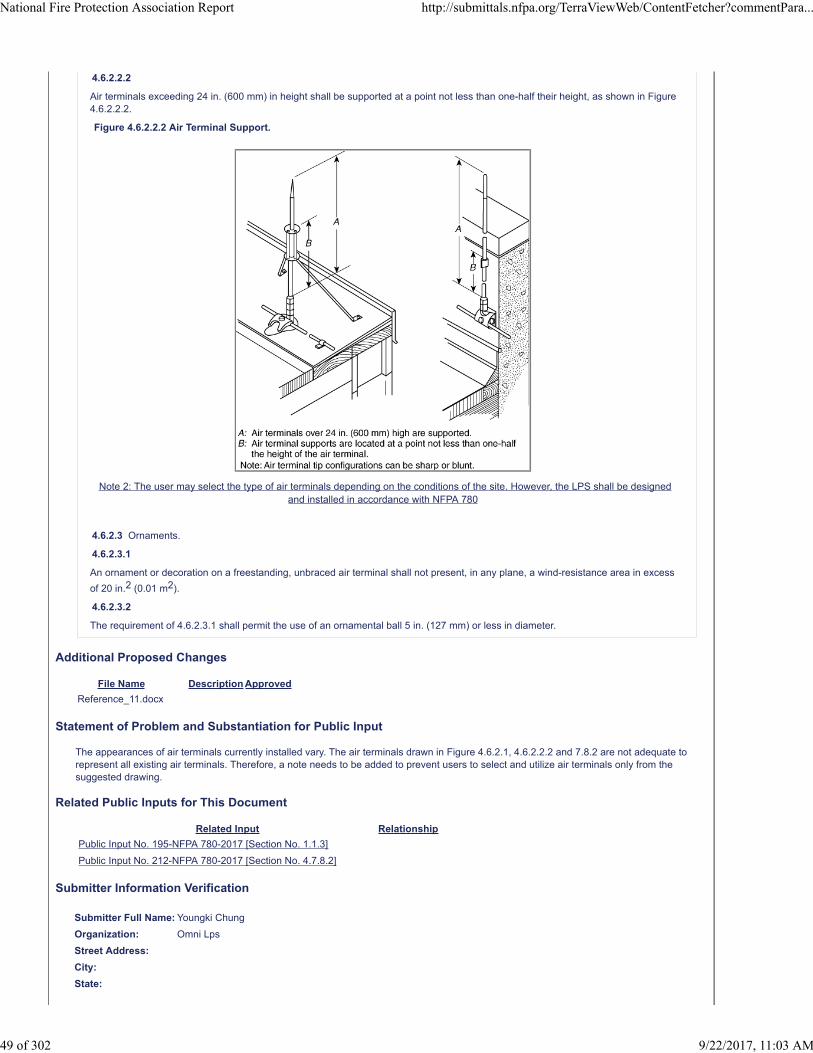
4.6.2.2.2
Air terminals exceeding 24 in. (600 mm) in height shall be supported at a point not less than one-half their height, as shown in Figure4.6.2.2.2.
Figure 4.6.2.2.2 Air Terminal Support.
Note 2: The user may select the type of air terminals depending on the conditions of the site. However, the LPS shall be designedand installed in accordance with NFPA 780
4.6.2.3 Ornaments.
4.6.2.3.1
An ornament or decoration on a freestanding, unbraced air terminal shall not present, in any plane, a wind-resistance area in excess
of 20 in.2 (0.01 m2).
4.6.2.3.2
The requirement of 4.6.2.3.1 shall permit the use of an ornamental ball 5 in. (127 mm) or less in diameter.
Additional Proposed Changes
File Name Description Approved
Reference_11.docx
Statement of Problem and Substantiation for Public Input
The appearances of air terminals currently installed vary. The air terminals drawn in Figure 4.6.2.1, 4.6.2.2.2 and 7.8.2 are not adequate to represent all existing air terminals. Therefore, a note needs to be added to prevent users to select and utilize air terminals only from the suggested drawing.
Related Public Inputs for This Document
Related Input Relationship
Public Input No. 195-NFPA 780-2017 [Section No. 1.1.3]
Public Input No. 212-NFPA 780-2017 [Section No. 4.7.8.2]
Submitter Information Verification
Submitter Full Name: Youngki Chung
Organization: Omni Lps
Street Address:
City:
State:
National Fire Protection Association Report http://submittals.nfpa.org/TerraViewWeb/ContentFetcher?commentPara...
49 of 302 9/22/2017, 11:03 AM

Zip:
Submittal Date: Mon Jun 26 06:04:31 EDT 2017
National Fire Protection Association Report http://submittals.nfpa.org/TerraViewWeb/ContentFetcher?commentPara...
50 of 302 9/22/2017, 11:03 AM

Public Input No. 267-NFPA 780-2017 [ Section No. 4.6.2.2 ]
4.6.2.2 Air Terminal Support.
4.6.2.2.1
Air terminals shall be secured against overturning or displacement by one of the following methods:
(1) Attachment to the object to be protected
(2) Braces that are permanently and rigidly attached to the structure
4.6.2.2.2 Air terminals exceeding 24 in. (
600 mm
600 mm ) in height shall be supported at a point not less than one-half their height, as shown in Figure 4.6.2.2.2 . ,except that an airterminal and base combination shall not require side bracing if it is installed on structural steel or concrete, and is capable ofwithstanding a tipping force of 2.2 lbs (0.9979032 kg) per foot (0.3048 m) of un-braced elevation conductor length at its tip oralternately able to withstand a wind of 156 mph (0.3048 m/second).
4.6.2.2.3 An air terminal over 24 in in length shall be secured at a minimum of two elevations along its length.
4.6.2.2.4 An anchored, threaded base shall be considered as one location.
Figure 4.6.2.2.2 Air Terminal Support.
Statement of Problem and Substantiation for Public Input
Allow an un-braced air terminal on a structure if it and its mounting base, as installed, is capable of withstanding a tipping force of 2.2 lbs (0.9979032 kg) per foot (0.3048 m) of unbraced elevation conductor length at its tip or alternately able to withstand a wind of 156 mph (0.3048 m/second) (category 5 hurricane). Most air terminals in these applications are installed on structural steel where the bracing requirement is downright comical. Add .2 and .3 to agree with the intent of 6.3.4.2 and 6.3.4.3.
Submitter Information Verification
Submitter Full Name: Bruce Kaiser
Organization: Lightning Master Corporation
Street Address:
City:
State:
Zip:
Submittal Date: Tue Jun 27 16:02:12 EDT 2017
National Fire Protection Association Report http://submittals.nfpa.org/TerraViewWeb/ContentFetcher?commentPara...
51 of 302 9/22/2017, 11:03 AM

Public Input No. 136-NFPA 780-2017 [ Section No. 4.6.2.2.1 ]
4.6.2.2.1
Air terminals shall be secured against overturning or displacement by one or both of the following methods:
(1) Attachment to the object to be protected
(2) Braces that are permanently and rigidly attached to the structure
Statement of Problem and Substantiation for Public Input
Just clarifying that both methods can be used, and they're not exclusive.
Submitter Information Verification
Submitter Full Name: Simon Larter
Organization: Dobbyn Lightning Protection
Street Address:
City:
State:
Zip:
Submittal Date: Wed Jun 21 11:14:12 EDT 2017
National Fire Protection Association Report http://submittals.nfpa.org/TerraViewWeb/ContentFetcher?commentPara...
52 of 302 9/22/2017, 11:03 AM

Public Input No. 208-NFPA 780-2017 [ Section No. 4.6.2.3 ]
4.6.2.3 Ornaments.
4.6.2.3.1
An ornament or decoration on a freestanding, unbraced air terminal shall not present, in any plane, a wind-resistance area in excess
of 20 in.2 (0.01 m2).
4.6.2.3.2
The requirement of 4.6.2.3.1 shall permit the use of an ornamental ball 5 in. (127 mm) or less in diameter.
Note. An exception to the limitation is where the component’s size is over the wind-resistance area of 20in 2 (0.01m 2 ) used to meetthe characteristic function of the air terminal. However, in this case of an air terminal with such a characteristic function, its shaft andbase supporting components shall be mechanically strong enough to endure strong wind of more than 60m/s and the air terminalshall be installed to endure strong wind of more than 60m/s.
Statement of Problem and Substantiation for Public Input
Add noteAs the types of air terminals vary, there is no limit for the size and diameter of the air terminal. For the suggestion clause 1.1.3, clause 4.6.2.3 which is related to the components of air terminals should be amended as right.
Submitter Information Verification
Submitter Full Name: Youngki Chung
Organization: Omni Lps
Street Address:
City:
State:
Zip:
Submittal Date: Mon Jun 26 06:02:35 EDT 2017
National Fire Protection Association Report http://submittals.nfpa.org/TerraViewWeb/ContentFetcher?commentPara...
53 of 302 9/22/2017, 11:03 AM

Public Input No. 135-NFPA 780-2017 [ Section No. 4.6.4.2 ]
4.6.4.2
Overhead ground wire material shall be constructed of aluminum, copper, stainless steel, galvanized steel, or protected steel such ascopper-clad, aluminum-clad, or aluminum conductor steel reinforced (ACSR).
Statement of Problem and Substantiation for Public Input
See PI 133 for consolidation of materials requirements.
Related Public Inputs for This Document
Related Input Relationship
Public Input No. 133-NFPA 780-2017 [Section No. 4.2] Pretty much as close as PI 134.
Public Input No. 133-NFPA 780-2017 [Section No. 4.2]
Submitter Information Verification
Submitter Full Name: Simon Larter
Organization: Dobbyn Lightning Protection
Street Address:
City:
State:
Zip:
Submittal Date: Wed Jun 21 11:11:38 EDT 2017
National Fire Protection Association Report http://submittals.nfpa.org/TerraViewWeb/ContentFetcher?commentPara...
54 of 302 9/22/2017, 11:03 AM

Public Input No. 210-NFPA 780-2017 [ Section No. 4.7.1.4 ]
4.7.1.4
Protection for typical roof types shall be as illustrated in Figure 4.7.1.4.
Figure 4.7.1.4 Protection Measures for Various Roof Types. (Drawings are top and end views of each roof type.)
Additional Proposed Changes
File Name Description Approved
Reference_12.docx revised figure 4.7.1.4
Statement of Problem and Substantiation for Public Input
According to IEC 62305-3, the number of down conductor is decided by the protection level. Since NFPA 780 applies the same level (Rolling Sphere radius 45m) as IEC 62305 protection level III, it is reasonable to apply the same for the interval between down conductors. Basically, down conductors shall be mounted on the corners or edges of the structure.
Related Public Inputs for This Document
Related Input Relationship
Public Input No. 211-NFPA 780-2017 [Section No. 4.7.2.1]
Public Input No. 225-NFPA 780-2017 [New Section after O.3]
Submitter Information Verification
Submitter Full Name: Youngki Chung
Organization: Omni Lps
Street Address:
City:
State:
Zip:
Submittal Date: Mon Jun 26 06:11:51 EDT 2017
National Fire Protection Association Report http://submittals.nfpa.org/TerraViewWeb/ContentFetcher?commentPara...
55 of 302 9/22/2017, 11:03 AM

Public Input No. 163-NFPA 780-2017 [ Section No. 4.7.2.1 ]
4.7.2.1 *
As shown in Figure 4.7.2.1, the distance from strike termination devices to ridge ends on pitched roofs or to edges and outsidecorners of flat or gently sloping roofs shall not exceed 2 ft (0.6 m 24 in. (600 mm ).
Figure 4.7.2.1 Air Terminals on a Pitched Roof.
Note to NFPA Staff: Please change the vales expressed in Figure 4.7.2.1 B: to 24 in. (600mm)
Statement of Problem and Substantiation for Public Input
This Editorial Task Group Proposal changes the values from feet to inches to maintain accuracy to keep consistency throughout the standard.
Submitter Information Verification
Submitter Full Name: Stephen Humeniuk
Organization: Warren Lightning Rod Company
Affilliation: ULPS, The Editorial Task Group
Street Address:
City:
State:
Zip:
Submittal Date: Fri Jun 23 17:13:54 EDT 2017
National Fire Protection Association Report http://submittals.nfpa.org/TerraViewWeb/ContentFetcher?commentPara...
56 of 302 9/22/2017, 11:03 AM
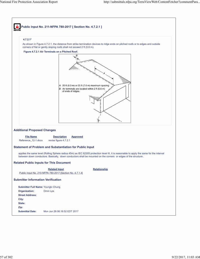
Public Input No. 211-NFPA 780-2017 [ Section No. 4.7.2.1 ]
4.7.2.1*
As shown in Figure 4.7.2.1, the distance from strike termination devices to ridge ends on pitched roofs or to edges and outsidecorners of flat or gently sloping roofs shall not exceed 2 ft (0.6 m).
Figure 4.7.2.1 Air Terminals on a Pitched Roof.
Additional Proposed Changes
File Name Description Approved
Reference_12-1.docx revise figure 4.7.2.1
Statement of Problem and Substantiation for Public Input
applies the same level (Rolling Sphere radius 45m) as IEC 62305 protection level III, it is reasonable to apply the same for the interval between down conductors. Basically, down conductors shall be mounted on the corners or edges of the structure..
Related Public Inputs for This Document
Related Input Relationship
Public Input No. 210-NFPA 780-2017 [Section No. 4.7.1.4]
Submitter Information Verification
Submitter Full Name: Youngki Chung
Organization: Omni Lps
Street Address:
City:
State:
Zip:
Submittal Date: Mon Jun 26 06:16:52 EDT 2017
National Fire Protection Association Report http://submittals.nfpa.org/TerraViewWeb/ContentFetcher?commentPara...
57 of 302 9/22/2017, 11:03 AM
Public Input No. 164-NFPA 780-2017 [ Section No. 4.7.2.3 ]
4.7.2.3
Strike termination devices 2 ft (0.6 m 24 in. (600 mm ) or more above the object or area to be protected shall be permitted to beplaced at intervals not exceeding 25 ft (7.6 m).
Statement of Problem and Substantiation for Public Input
The Editorial Task Group makes this change from feet to inches to for accuracy and to maintain consistency throughout the standard.
Submitter Information Verification
Submitter Full Name: Stephen Humeniuk
Organization: Warren Lightning Rod Company
Affilliation: ULPS< The Editorial Task Group
Street Address:
City:
State:
Zip:
Submittal Date: Fri Jun 23 17:23:50 EDT 2017
National Fire Protection Association Report http://submittals.nfpa.org/TerraViewWeb/ContentFetcher?commentPara...
58 of 302 9/22/2017, 11:03 AM

Public Input No. 79-NFPA 780-2017 [ Section No. 4.7.3.2 [Excluding any Sub-Sections] ]
For pitched roofs with a span of 100 ft (30 m) or less and eave heights greater than or equal to 50 ft (15 m) but less than 150 ft (45 m)above grade, it shall be permitted to omit strike termination devices at the eaves if the slope of that roof is equal to or steeperthan the tangent of the arc at the eave elevation of a rolling sphere having a 150 ft (45 m) radius. (See Figure 4.7.3.2.)
Figure 4.7.3.2 Illustration of Tangent of Rolling Sphere Method.
Statement of Problem and Substantiation for Public Input
Bold or highlighted text needs to be explained in a better way. The comparison is too vague, or add an example to explain the concept.
Submitter Information Verification
Submitter Full Name: Lizardo Lopez
Organization: Pro Lightning Prot Inc
Street Address:
City:
State:
Zip:
Submittal Date: Mon May 29 10:38:39 EDT 2017
National Fire Protection Association Report http://submittals.nfpa.org/TerraViewWeb/ContentFetcher?commentPara...
59 of 302 9/22/2017, 11:03 AM

Public Input No. 83-NFPA 780-2017 [ Section No. 4.7.3.2.3 ]
4.7.3.2.3*
The tangent of the rolling sphere arc shall be considered as a vertical line over 150 ft (45 m) above grade, except as permitted by4 . 8.2.4.
Statement of Problem and Substantiation for Public Input
The reference is incorrect. This section refers to the rolling sphere arc tangent at 45 m above grade, but section 4.8.2.4 deals only with structures that do not exceed 15 m above earth. And yes, I'm using metric and not fps, because I'm civilised, thank you very much.
Submitter Information Verification
Submitter Full Name: Simon Larter
Organization: Dobbyn Lightning Protection
Street Address:
City:
State:
Zip:
Submittal Date: Mon Jun 12 15:48:54 EDT 2017
National Fire Protection Association Report http://submittals.nfpa.org/TerraViewWeb/ContentFetcher?commentPara...
60 of 302 9/22/2017, 11:03 AM

Public Input No. 80-NFPA 780-2017 [ Section No. 4.7.5.1 ]
4.7.5.1
Flat or gently sloping roofs that exceed 50 ft (15 m) in width or length shall have additional strike termination devices located atintervals not to exceed 50 ft (15 m) on the flat or gently sloping areas, as shown in Figure 4.7.5.1(a) and Figure 4.7.5.1(b).
Figure 4.7.5.1(a) Air Terminals on a Flat Roof.
Figure 4.7.5.1(b) Air Terminals on a Gently Sloping Roof.
Statement of Problem and Substantiation for Public Input
If the description of figure 4.7.5.1 (a) is correct, than the width of the building is 160 feet instead of 150 feet. (20 x 8 ea. (C spaces). Therefore the flat roof should have three cross runs instead of two like the picture.Needs to be corrected.
Submitter Information Verification
Submitter Full Name: Lizardo Lopez
Organization: Pro Lightning Prot Inc
Street Address:
City:
State:
National Fire Protection Association Report http://submittals.nfpa.org/TerraViewWeb/ContentFetcher?commentPara...
61 of 302 9/22/2017, 11:03 AM

Zip:
Submittal Date: Mon May 29 22:02:32 EDT 2017
National Fire Protection Association Report http://submittals.nfpa.org/TerraViewWeb/ContentFetcher?commentPara...
62 of 302 9/22/2017, 11:03 AM

Public Input No. 165-NFPA 780-2017 [ Section No. 4.7.6.2 ]
4.7.6.2
In all cases, strike termination devices shall be located in accordance with Section 4.7, as shown in Figure 4.7.6.2.
Figure 4.7.6.2 Flat or Gently Sloping Roof with an Irregular Perimeter.
Note to NFPA Staff: Please change the values in Figure 4.7.6.2 A: to 4 in. (600mm)
Statement of Problem and Substantiation for Public Input
The Editorial Task Group makes this change form feet to inches for accuracy and to maintain consistency throughout the standard
Submitter Information Verification
Submitter Full Name: Stephen Humeniuk
Organization: Warren Lightning Rod Company
Affilliation: ULPA, The Editorial Task Group
Street Address:
City:
State:
Zip:
Submittal Date: Fri Jun 23 17:28:23 EDT 2017
National Fire Protection Association Report http://submittals.nfpa.org/TerraViewWeb/ContentFetcher?commentPara...
63 of 302 9/22/2017, 11:03 AM
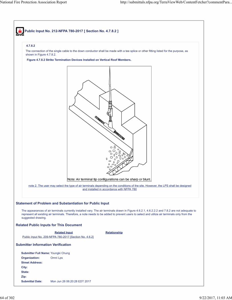
Public Input No. 212-NFPA 780-2017 [ Section No. 4.7.8.2 ]
4.7.8.2
The connection of the single cable to the down conductor shall be made with a tee splice or other fitting listed for the purpose, asshown in Figure 4.7.8.2.
Figure 4.7.8.2 Strike Termination Devices Installed on Vertical Roof Members.
note 2. The user may select the type of air terminals depending on the conditions of the site. However, the LPS shall be designedand installed in accordance with NFPA 780
Statement of Problem and Substantiation for Public Input
The appearances of air terminals currently installed vary. The air terminals drawn in Figure 4.6.2.1, 4.6.2.2.2 and 7.8.2 are not adequate to represent all existing air terminals. Therefore, a note needs to be added to prevent users to select and utilize air terminals only from the suggested drawing.
Related Public Inputs for This Document
Related Input Relationship
Public Input No. 209-NFPA 780-2017 [Section No. 4.6.2]
Submitter Information Verification
Submitter Full Name: Youngki Chung
Organization: Omni Lps
Street Address:
City:
State:
Zip:
Submittal Date: Mon Jun 26 06:20:28 EDT 2017
National Fire Protection Association Report http://submittals.nfpa.org/TerraViewWeb/ContentFetcher?commentPara...
64 of 302 9/22/2017, 11:03 AM

Public Input No. 127-NFPA 780-2017 [ Section No. 4.7.9 ]
4.7.9 Open Areas in Flat Roofs.
The perimeter of open areas, such as light or mechanical wells, shall be protected if the open area perimeter exceeds 300 ft(92 m 90 m ), provided both rectangular dimensions exceed 50 ft (15 m).
Statement of Problem and Substantiation for Public Input
The editorial Task Group changes the SI dimension to be consistent with the rest of the document. This measurement is also more stringent requirement in this application
Submitter Information Verification
Submitter Full Name: Stephen Humeniuk
Organization: Warren Lightning Rod Company
Affilliation: ULPA, The Editorial Task Ggroup.
Street Address:
City:
State:
Zip:
Submittal Date: Mon Jun 19 17:17:41 EDT 2017
National Fire Protection Association Report http://submittals.nfpa.org/TerraViewWeb/ContentFetcher?commentPara...
65 of 302 9/22/2017, 11:03 AM
Public Input No. 189-NFPA 780-2017 [ Section No. 4.7.9 ]
4.7.9 Open Areas in Flat Roofs.
The perimeter of open areas, such as light or mechanical wells, shall be protected if the open area perimeter exceeds 300 ft(92 m 90 m ), provided both rectangular dimensions exceed 50 ft (15 m).
Statement of Problem and Substantiation for Public Input
The change will make the conversion equivalent to other sections where 300 feet appears and consistent with the 50 foot conversion later in the sentence.
Related Public Inputs for This Document
Related Input Relationship
Public Input No. 188-NFPA 780-2017 [Section No. H.2.2] Same change
Submitter Information Verification
Submitter Full Name: Mitchell Guthrie
Organization: Engineering Consultant
Street Address:
City:
State:
Zip:
Submittal Date: Sun Jun 25 16:40:08 EDT 2017
National Fire Protection Association Report http://submittals.nfpa.org/TerraViewWeb/ContentFetcher?commentPara...
66 of 302 9/22/2017, 11:03 AM

Public Input No. 166-NFPA 780-2017 [ Section No. 4.7.11.2 ]
4.7.11.2 *
Required strike termination devices shall be installed on objects, as shown in Figure 4.7.11.2, so that the distance from a striketermination device to an outside corner or the distance perpendicular to an outside edge is not greater than 2 ft (0.6 m 24 in. (600mm ).
Figure 4.7.11.2 Air Terminals on a Chimney.
Note to NFPA Staff: Change the Value in Figure 4.7.11.2 A: to 24 in. (600 mm)
Statement of Problem and Substantiation for Public Input
The Editorial Task Group makes the change from feet to inches for accuracy and to maintain consistency throughout the standard
Submitter Information Verification
Submitter Full Name: Stephen Humeniuk
Organization: Warren Lightning Rod Company
Affilliation: ULPA. The Editorial Task Group
Street Address:
City:
State:
Zip:
Submittal Date: Fri Jun 23 17:33:54 EDT 2017
National Fire Protection Association Report http://submittals.nfpa.org/TerraViewWeb/ContentFetcher?commentPara...
67 of 302 9/22/2017, 11:03 AM

Public Input No. 85-NFPA 780-2017 [ Section No. 4.7.11.3 ]
4.7.11.3
Where only one strike termination device is required on an object, at least one main-size conductor shall connect the striketermination device to a main conductor at or near the location where the object meets the roof surface and provides two or morepaths to ground from that location in accordance with Section 4.9 and 4.9.2.
Statement of Problem and Substantiation for Public Input
This allows a little flexibility in the location of the main conductor relative to the protected object. Often the main conductor is located a short distance away from the actual point where the object meets the roof.
Submitter Information Verification
Submitter Full Name: Simon Larter
Organization: Dobbyn Lightning Protection
Street Address:
City:
State:
Zip:
Submittal Date: Mon Jun 12 15:56:03 EDT 2017
National Fire Protection Association Report http://submittals.nfpa.org/TerraViewWeb/ContentFetcher?commentPara...
68 of 302 9/22/2017, 11:03 AM

Public Input No. 179-NFPA 780-2017 [ Section No. 4.7.11.4 ]
4.7.11.4
Objects on roofs that are less than 10 in. (254 mm) above the surface of the roof shall not require strike termination devices unlessthey are located within 3 ft (0.9 m 36 in. (900 mm ) of the ridge or roof edge.
Statement of Problem and Substantiation for Public Input
The Editorial Task Group changes from feet to inches for accuracy and to maintain consistency throughout the standard
Submitter Information Verification
Submitter Full Name: Stephen Humeniuk
Organization: Warren Lightning Rod Company
Affilliation: ULPA, The Editorial Task Group
Street Address:
City:
State:
Zip:
Submittal Date: Fri Jun 23 18:26:01 EDT 2017
National Fire Protection Association Report http://submittals.nfpa.org/TerraViewWeb/ContentFetcher?commentPara...
69 of 302 9/22/2017, 11:03 AM
Public Input No. 84-NFPA 780-2017 [ Section No. 4.7.12.3 [Excluding any Sub-Sections] ]
Where the air terminal is mounted in accordance with 4.7.12.2(2) or 4.7.12.2(3) the unit's metal housing shall be permitted to be usedas a main conductors conductor where the housing minimum thickness is 0.064 in. (1.63 mm) and is electrically continuous.
Statement of Problem and Substantiation for Public Input
Inappropriate plural.
Submitter Information Verification
Submitter Full Name: Simon Larter
Organization: Dobbyn Lightning Protection
Street Address:
City:
State:
Zip:
Submittal Date: Mon Jun 12 15:54:51 EDT 2017
National Fire Protection Association Report http://submittals.nfpa.org/TerraViewWeb/ContentFetcher?commentPara...
70 of 302 9/22/2017, 11:03 AM

Public Input No. 311-NFPA 780-2017 [ Sections 4.7.12.3.1, 4.7.12.3.2, 4.7.12.3.3 ]
Sections 4.7.12.3.1, 4.7.12.3.2, 4.7.12.3.3
4.7.12.3.1
At least two main-size conductors shall be installed to connect the unit to the lightning protection system.
4.7.12.3.2
The connection shall be made to bare metal at the base or lower edges of the unit using main-size lightning conductors and bonding
devices that have a surface contact area of not less than 3 in. 2 (1940 mm 2 ) and shall provide two or more paths to ground, as isrequired for strike termination devices.
4.7.12.3.3
The two main bonding plates shall be located as far apart as practicable at the base or lower edges of the unit's electricallycontinuous metal housing and connected to the lightning protection system.
Statement of Problem and Substantiation for Public Input
This exact text is then replicated in section 4.7.12.4. There's no need for us to have it twice, unless we like redundancy, which we may, because redundancy.
Submitter Information Verification
Submitter Full Name: Simon Larter
Organization: Dobbyn Lightning Protection
Street Address:
City:
State:
Zip:
Submittal Date: Wed Jun 28 13:32:47 EDT 2017
National Fire Protection Association Report http://submittals.nfpa.org/TerraViewWeb/ContentFetcher?commentPara...
71 of 302 9/22/2017, 11:03 AM

Public Input No. 147-NFPA 780-2017 [ Section No. 4.7.12.4 ]
4.7.12.4
At least two main-size conductors shall be installed to connect the unit to the lightning protection system.
4.7.12.4.1
The connection shall be made to bare metal at the base or lower edges of the unit using main-size lightning conductors and bonding
devices that have a surface contact area of not less than 3 in. 2 (1940 mm 2 ) and shall provide two or more paths to ground, as isrequired for strike termination devices.
4.7.12.4.2
The two main bonding plates shall be located as far apart as practicable at the base or lower edges of the unit's electricallycontinuous metal housing and connected to the lightning protection system.
Statement of Problem and Substantiation for Public Input
Paragraphs 4.7.12.4, 4.7.12.4.1, 4.7.12.4.2 appear to be duplicate of 4.7.12.3.1, 4.7.12.3.2, and 4.7.12.3.3.
Submitter Information Verification
Submitter Full Name: Chris Carlson
Organization: Harger Lightning & Grounding
Street Address:
City:
State:
Zip:
Submittal Date: Thu Jun 22 11:05:16 EDT 2017
National Fire Protection Association Report http://submittals.nfpa.org/TerraViewWeb/ContentFetcher?commentPara...
72 of 302 9/22/2017, 11:03 AM

Public Input No. 74-NFPA 780-2017 [ New Section after 4.8.2.3 ]
TITLE OF NEW CONTENT
NOTE: If 4.8.2.2 is TRUE that: "The zone of protection shall be permitted o be "delineated" as a cone, "with the apex located " at thehigh point of the: STRIKING TERMINATION DEVICE" than the figures 4.8.2..3 (b) and 4.8.2.4 (b) are wrong. From any angle it lookslike the protection is given by the eave of a roof instead of an air terminal. Needs to be corected.Unlessit has a main size conductorrunning along the eave that could represent a guy wire or as the IEC 62305 its a mesh system.
Additional Proposed Changes
File Name Description Approved
NFPA_4-8-2-3-b.jpg
NFPA_4-8-2-4-b.jpg
Statement of Problem and Substantiation for Public Input
As is it stated in 4.8.2.2…Based on the height “OF THE STRIKE TERMINATION DEVICE” ABOVE THE GROUND AND NOT …THAT BASED ON A: Structure …shall be considered to protect lower portions…
Submitter Information Verification
Submitter Full Name: Lizardo Lopez
Organization: Pro Lightning Prot Inc
Street Address:
City:
State:
Zip:
Submittal Date: Fri May 19 19:57:47 EDT 2017
National Fire Protection Association Report http://submittals.nfpa.org/TerraViewWeb/ContentFetcher?commentPara...
73 of 302 9/22/2017, 11:03 AM
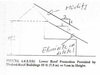


Public Input No. 153-NFPA 780-2017 [ Section No. 4.9.1 ]
4.9.1 One-Way Path.
A one way path shall be permitted under the following circumstances:
(1) Strike termination devices on a lower roof level that are interconnected by a conductor run from a higher roof level shall requireonly one horizontal or downward path to ground, provided the lower level roof conductor run does not exceed 40 ft (12 m).
(2) On a pitched roof, where the down hill side of the conductor run terminates to a horizontal run at the eave with at least 2 downleads attached to ground electrodes spaced within 100 ft. (30m) horizontally of each other as show in Figure 4.9.1 (2). INSERT NEWFIGURE
(3) On a pitched roofs where the down hill side terminates to a ground electrode within 16 ft.(5m) horizontally from were theconductor meets the eave as shown in Figue 4.9.1 (3).INSERT NEW FIGURE
(4) On a pitched roofs where the down hill side of conductor run is connected to another down conductor with in 40 ft. (12 m)horizontally from where the conductor meets the eave as shown Figure 4.9.1 (4). INSERT NEW FIGURE
(5) On a pitched roof were the down hill side terminates directly to a ground electrode as shown in Figure 4.9.1 (5) INSERT NEWFIGURE
Additional Proposed Changes
File Name Description Approved
NFPA_780_4_9_1Substantiation_for_Change_-_.pdf Substantiation for changes
NFPA_780_4_9_1.pdf Figure 4.9.1(2), Figure 4.9.1(3), Figure 4.9.1(4), Figure 4.9.1(5)
Statement of Problem and Substantiation for Public Input
This allows for multiple roof top units to be tied to the same conductor. The current language would require additional cross runs horizontally across full pitched roofs, after every unit that is connected to it. This is not the intention of the standard. It has never been its intention but is being interpreted this way.In regions subject to snow loading running cable perpendicular to the standing seams of metal roofs will result on the cable being torn off, or if the cable is secured against removal, the metal roof itself being ripped. Running parallel to the standing seams prevents this problem and is a preferential method. Cross runs are typically not needed because buildings with pitched roofs are seldom wider than 300 ft. See attached illustrations.
Submitter Information Verification
Submitter Full Name: Stephen Humeniuk
Organization: Warren Lightning Rod Company
Affilliation: ULPA
Street Address:
City:
State:
Zip:
Submittal Date: Thu Jun 22 17:32:01 EDT 2017
National Fire Protection Association Report http://submittals.nfpa.org/TerraViewWeb/ContentFetcher?commentPara...
74 of 302 9/22/2017, 11:03 AM


Public Input No. 310-NFPA 780-2017 [ Section No. 4.9.1 ]
4.9.1 One-Way Path.
Strike termination devices on a lower roof level that are interconnected by a conductor run from a higher roof level shall require onlyone horizontal or downward path to ground, provided the lower level roof conductor run does not exceed 40 ft (12 m), as shown inFigure 4 .9.1.
Additional Proposed Changes
File Name Description Approved
Fig_4.9.1.pdf New figure 4.9.1, taken from LPI 175 (2011) figure 21.
Statement of Problem and Substantiation for Public Input
Clarifies the paragraph by adding a figure to explain the text.
Submitter Information Verification
Submitter Full Name: Simon Larter
Organization: Dobbyn Lightning Protection
Street Address:
City:
State:
Zip:
Submittal Date: Wed Jun 28 13:27:09 EDT 2017
National Fire Protection Association Report http://submittals.nfpa.org/TerraViewWeb/ContentFetcher?commentPara...
75 of 302 9/22/2017, 11:03 AM
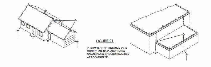
FIGURE 21
IF LOWER ROOF DISTANCE (A) IS MORE THAN 40'~·. ADDmDNAL OOVVNLEAD & GROUND REQUIRED AT LOCATION "X".

Public Input No. 312-NFPA 780-2017 [ New Section after 4.9.4.2 ]
4.9.4.3
Conductors shall be permitted to be routed in an upward coursing for a vertical distance of no greater than 8" (200 mm) at through-roof or through-wall connections only, in order to mitigate tripping hazards, provided that the coursing complies with 4.9.5.
Statement of Problem and Substantiation for Public Input
Where through-roof connections are required near the perimeter of a flat roof, the requirement that the conductor run uphill at no more than a 1 in 4 rise can create several feet of conductor suspended between the through-roof rod cap and the nearest roof fastener, creating a potential tripping hazard. Standard industry practice before this was to allow no more than an 8" rise in the conductor at through-roof rods. I'd like to see this reinstated.
Submitter Information Verification
Submitter Full Name: Simon Larter
Organization: Dobbyn Lightning Protection
Street Address:
City:
State:
Zip:
Submittal Date: Wed Jun 28 13:38:48 EDT 2017
National Fire Protection Association Report http://submittals.nfpa.org/TerraViewWeb/ContentFetcher?commentPara...
76 of 302 9/22/2017, 11:03 AM
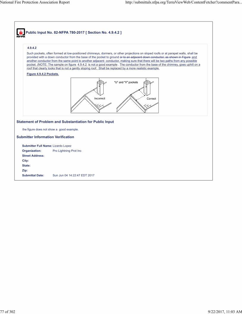
Public Input No. 82-NFPA 780-2017 [ Section No. 4.9.4.2 ]
4.9.4.2
Such pockets, often formed at low-positioned chimneys, dormers, or other projections on sloped roofs or at parapet walls, shall beprovided with a down conductor from the base of the pocket to ground or to an adjacent down conductor, as shown in Figure andanother conductor from the same point to another adjacent conductor, making sure that there will be two paths from any possiblepocket. (NOTE: The sample on figure 4.9.4.2 is not a good example . The conductor from the base of the chimney, goes uphill on aroof that clearly looks that is not a gently sloping roof. Shall be replaced by a more realistic example.
Figure 4.9.4.2 Pockets.
Statement of Problem and Substantiation for Public Input
the figure does not show a good example.
Submitter Information Verification
Submitter Full Name: Lizardo Lopez
Organization: Pro Lightning Prot Inc
Street Address:
City:
State:
Zip:
Submittal Date: Sun Jun 04 14:22:47 EDT 2017
National Fire Protection Association Report http://submittals.nfpa.org/TerraViewWeb/ContentFetcher?commentPara...
77 of 302 9/22/2017, 11:03 AM

Public Input No. 180-NFPA 780-2017 [ Section No. 4.9.6.1 ]
4.9.6.1
Conductors shall be permitted to be coursed through air without support for a distance of 3 ft (0.9 m 36 in. (900 mm ) or less.
Statement of Problem and Substantiation for Public Input
The Editorial Task Group changes from feet to inches for accuracy and to maintain consistency throughout the standard.
Submitter Information Verification
Submitter Full Name: Stephen Humeniuk
Organization: Warren Lightning Rod Company
Affilliation: ULPA, The Editorial Task Group
Street Address:
City:
State:
Zip:
Submittal Date: Fri Jun 23 18:28:44 EDT 2017
National Fire Protection Association Report http://submittals.nfpa.org/TerraViewWeb/ContentFetcher?commentPara...
78 of 302 9/22/2017, 11:03 AM

Public Input No. 314-NFPA 780-2017 [ Section No. 4.9.7.2 ]
4.9.7.2
Conductors shall be coursed through or around obstructions (e.g., cupolas and ventilators) in a horizontal plane with the mainconductor, as shown in Figure 4 .9.7.2.
Additional Proposed Changes
File Name Description Approved
Fig._4.9.7.2.pdf Figure 4.9.7.2 (proposed)
Statement of Problem and Substantiation for Public Input
Adds a bit more clarity to the text. Why not?
Submitter Information Verification
Submitter Full Name: Simon Larter
Organization: Dobbyn Lightning Protection
Street Address:
City:
State:
Zip:
Submittal Date: Wed Jun 28 13:51:12 EDT 2017
National Fire Protection Association Report http://submittals.nfpa.org/TerraViewWeb/ContentFetcher?commentPara...
79 of 302 9/22/2017, 11:03 AM
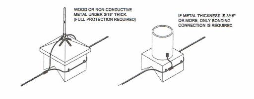
22) Fasteners shall not be su bject to breakage and shall be of the same material as the conductor or of a material equally resistant to corrosion as that of the conductor.
23) Fasteners may include attachment to the structure by nails, screws, bolts , adhesives, masonry anchors as necessary with no combination of materials used that will form an electrolytic couple in the presence of moisture for the fastener, attachment device, or structure.
24) Masonry anchors used to attach lightn ing protection components shall have a minimum outside diameter of%" (6.4 mm). The fit shall be tight against moisture reducing the possibil ity of damage due to freezing.
STRIKE TERMINATION DEVICES
25) Strike termination devices include air terminals , metal masts, permanent metal parts of structures and overhead ground wires . Combinations of these devices shall be permitted for a total protection system. Strike termination devices shall protect all roofs and roof projections of a building subject to a direct lightning strike. Strike termination devices shall be provided where required by the following sections of this standard . Those parts of a structure determined to be in a zone of protection according to this standard do not require additional strike termination devices.
26) Metal parts of a structure that are exposed to direct lightning fl ashes and that have a metal thickness of 3/16 in . (4 .8mm ) or greater serve as strike termination devices and shall require on ly connection to the lightning protection system. Such connection shall provide a minimum of two paths to ground (subject to "dead-end" exceptions as stated below). The metal needs to be connected to the lightn ing protection system using main size conductor and a bonding device having a minimum 3 in. 2 (1 940 mm2
) of contact. Provisions shall be made to guard against the corrosive effect introduced by dissimilar metals at points of bonding . Connection points shall generally be bare metal to bare metal with required corrosion protection applied after bonding (SEE FIGURE 3).
WOOD OR NON-CONDUCTIVE METAL UNDER 3/18" THICK (FULL PROTECTION REQUIRED)
FIGURE 3
0 IF METAl TliiCKNESS IS 3/18" OR MORE, ONLY BONDING CONNECTION IS REQUIRED.
27) Air terminals are designed to serve as strike termination devices. All air terminals used for LPI Certified Systems shall be subjected to factory inspection or certification by an independent testing agency to Standard UL 96 requirements. Air terminals on Class I structures (75 feet (23m) high or less ) and Class II structures (over 75 feet (23m)) shall be sized according to the materials table below (See Table 1).
10

Public Input No. 159-NFPA 780-2017 [ Section No. 4.9.8.1 ]
4.9.8.1
For example, roofs from 50 ft to 100 ft (15 m to 30 m) in width shall require one cross-run conductor, roofs 100 ft to 150 ft (30 m to45 m) in width shall require two cross-run conductors, and so on.
Statement of Problem and Substantiation for Public Input
4.9.8.1 is explanatory material, thus belongs in the annex.
Related Public Inputs for This Document
Related Input Relationship
Public Input No. 161-NFPA 780-2017 [New Section after A.4.13.1]
Submitter Information Verification
Submitter Full Name: Mark Harger
Organization: Harger Lightning Grounding
Street Address:
City:
State:
Zip:
Submittal Date: Fri Jun 23 14:21:18 EDT 2017
National Fire Protection Association Report http://submittals.nfpa.org/TerraViewWeb/ContentFetcher?commentPara...
80 of 302 9/22/2017, 11:03 AM
Public Input No. 75-NFPA 780-2017 [ Section No. 4.9.8.2 ]
4.9.8.2
Cross-run conductors shall be connected to the main perimeter cable OR TO AN ADJACENT CROSSRUN .... at intervals notexceeding 150 ft (45 m), as shown in Figure 4.7.5.1(a).
Statement of Problem and Substantiation for Public Input
There are cases were a roof can have more than two parallel cross-runs and it’s obvious that a connection to an adjacent cross run will connect it to the perimeter...using the one closest to the perimeter...
Submitter Information Verification
Submitter Full Name: Lizardo Lopez
Organization: Pro Lightning Protection Inc
Street Address:
City:
State:
Zip:
Submittal Date: Fri May 19 20:35:46 EDT 2017
National Fire Protection Association Report http://submittals.nfpa.org/TerraViewWeb/ContentFetcher?commentPara...
81 of 302 9/22/2017, 11:03 AM
Public Input No. 213-NFPA 780-2017 [ Section No. 4.9.10 [Excluding any Sub-Sections] ]
At least two down conductors shall be provided on any kind of structure, including steeples All kind of structures shall have a downconductor positioned every 15m .
Additional Proposed Changes
File Name Description Approved
Reference_13.docx
Statement of Problem and Substantiation for Public Input
Changes to reflect the IEC standard 62305-3 5.3.3 table 4
Related Public Inputs for This Document
Related Input Relationship
Public Input No. 214-NFPA 780-2017 [Section No. 4.9.10.5]
Submitter Information Verification
Submitter Full Name: Youngki Chung
Organization: Omni Lps
Street Address:
City:
State:
Zip:
Submittal Date: Mon Jun 26 06:22:21 EDT 2017
National Fire Protection Association Report http://submittals.nfpa.org/TerraViewWeb/ContentFetcher?commentPara...
82 of 302 9/22/2017, 11:03 AM

Public Input No. 214-NFPA 780-2017 [ Section No. 4.9.10.5 ]
4.9.10.5
When determining the perimeter of a pitched roof structure, the horizontal projection (footprint) of the protected roof shall bemeasured as shown in Figure 4.9.10.5.
Figure 4.9.10.5 Quantity of Down Conductors.
Statement of Problem and Substantiation for Public Input
Modify the picture referring IEC standard. Intervals of down conductor; 15m
Related Public Inputs for This Document
Related Input Relationship
Public Input No. 213-NFPA 780-2017 [Section No. 4.9.10 [Excluding any Sub-Sections]]
Submitter Information Verification
Submitter Full Name: Youngki Chung
Organization: Omni Lps
Street Address:
City:
State:
Zip:
Submittal Date: Mon Jun 26 06:25:02 EDT 2017
National Fire Protection Association Report http://submittals.nfpa.org/TerraViewWeb/ContentFetcher?commentPara...
83 of 302 9/22/2017, 11:03 AM

Public Input No. 181-NFPA 780-2017 [ Section No. 4.9.12 ]
4.9.12 Down Conductors Entering Corrosive Soil.
Down conductors entering corrosive soil shall be protected against corrosion by a protective covering beginning at a point 3 ft(0.9 m 36 in. (900 mm ) above grade level and extending for their entire length below grade.
Statement of Problem and Substantiation for Public Input
The Editorial Task Group changes values from feet to inches for accuracy and to maintain consistency throughout the standard
Submitter Information Verification
Submitter Full Name: Stephen Humeniuk
Organization: Warren Lightning Rod Company
Affilliation: ULPA, The Editorial Task Group
Street Address:
City:
State:
Zip:
Submittal Date: Fri Jun 23 18:31:17 EDT 2017
National Fire Protection Association Report http://submittals.nfpa.org/TerraViewWeb/ContentFetcher?commentPara...
84 of 302 9/22/2017, 11:03 AM
Public Input No. 249-NFPA 780-2017 [ New Section after 4.9.13.3 ]
4.9.13.4
Steel reinforcing bars shall be permitted to be used as down leads when bars no less than 1/2 in. (12.7 m) in diameter have beeneffectively bonded together by welding, structural mechanical coupling, or overlapping 20 diameters and wire tied.
Statement of Problem and Substantiation for Public Input
This allows for steel reinforcement to be used as down conductors when it meets the same criteria previously established for steel reinforcing to be used as ground electrodes
Related Public Inputs for This Document
Related Input Relationship
Public Input No. 246-NFPA 780-2017 [New Section after 4.15.3.2]
Submitter Information Verification
Submitter Full Name: Stephen Humeniuk
Organization: Warren Lightning Rod Company
Affilliation: ULPA
Street Address:
City:
State:
Zip:
Submittal Date: Mon Jun 26 20:07:47 EDT 2017
National Fire Protection Association Report http://submittals.nfpa.org/TerraViewWeb/ContentFetcher?commentPara...
85 of 302 9/22/2017, 11:03 AM

Public Input No. 182-NFPA 780-2017 [ Section No. 4.10 [Excluding any Sub-Sections] ]
Conductors shall be fastened to the structure upon which they are placed at intervals not exceeding 3 ft (0.9 m 36 in. (900 mm ).
Statement of Problem and Substantiation for Public Input
The Editorial Task Group changes values from feet to inches for accuracy and to maintain consistency throughout the standard
Submitter Information Verification
Submitter Full Name: Stephen Humeniuk
Organization: Warren Lightning Rod Company
Affilliation: ULPA, The Editorial Task Group
Street Address:
City:
State:
Zip:
Submittal Date: Fri Jun 23 18:33:57 EDT 2017
National Fire Protection Association Report http://submittals.nfpa.org/TerraViewWeb/ContentFetcher?commentPara...
86 of 302 9/22/2017, 11:03 AM

Public Input No. 317-NFPA 780-2017 [ Section No. 4.10.2 ]
4.10.2
The fasteners shall not be subject resistant to breakage.
Statement of Problem and Substantiation for Public Input
What, are we going to make the fasteners out of titanium alloy? Everything is subject to breakage under the right conditions (see cast aluminum and cold weather). The current language is unenforceable.
Submitter Information Verification
Submitter Full Name: Simon Larter
Organization: Dobbyn Lightning Protection
Street Address:
City:
State:
Zip:
Submittal Date: Wed Jun 28 13:56:13 EDT 2017
National Fire Protection Association Report http://submittals.nfpa.org/TerraViewWeb/ContentFetcher?commentPara...
87 of 302 9/22/2017, 11:03 AM

Public Input No. 316-NFPA 780-2017 [ Section No. 4.10.5 ]
4.10.5
No combination of materials shall be used that will form an electrolytic couple of such a nature that, in the presence of moisture,corrosion will be accelerated.
Statement of Problem and Substantiation for Public Input
This simply repeats what was said in 4.2.1, and is not necessary.
Submitter Information Verification
Submitter Full Name: Simon Larter
Organization: Dobbyn Lightning Protection
Street Address:
City:
State:
Zip:
Submittal Date: Wed Jun 28 13:54:59 EDT 2017
National Fire Protection Association Report http://submittals.nfpa.org/TerraViewWeb/ContentFetcher?commentPara...
88 of 302 9/22/2017, 11:03 AM

Public Input No. 146-NFPA 780-2017 [ Section No. 4.13.1.5 ]
4.13.1.5
Grounding Where practicable, grounding electrodes shall be installed below the frost line where possible (excluding shallow topsoilconditions).
Statement of Problem and Substantiation for Public Input
Editorial fix, the usage of “possible” in this manner is not consistent with the remainder of the standard.
Submitter Information Verification
Submitter Full Name: Chris Carlson
Organization: Harger Lightning and Grounding
Street Address:
City:
State:
Zip:
Submittal Date: Thu Jun 22 08:31:59 EDT 2017
National Fire Protection Association Report http://submittals.nfpa.org/TerraViewWeb/ContentFetcher?commentPara...
89 of 302 9/22/2017, 11:03 AM

Public Input No. 215-NFPA 780-2017 [ Section No. 4.13.1.6 ]
4.13.1.6*
In corrosive environments, the use of stainless steel alloy grounding electrodes and perlite carbon ground module shall be permitted.
Statement of Problem and Substantiation for Public Input
Add contents about perlite carbon ground module in corrosive environment.
Related Public Inputs for This Document
Related Input Relationship
Public Input No. 200-NFPA 780-2017 [New Section after 3.3.17]
Public Input No. 216-NFPA 780-2017 [Section No. 4.13.2.1]
Submitter Information Verification
Submitter Full Name: Youngki Chung
Organization: Omni Lps
Street Address:
City:
State:
Zip:
Submittal Date: Mon Jun 26 06:26:52 EDT 2017
National Fire Protection Association Report http://submittals.nfpa.org/TerraViewWeb/ContentFetcher?commentPara...
90 of 302 9/22/2017, 11:03 AM
Public Input No. 216-NFPA 780-2017 [ Section No. 4.13.2.1 ]
4.13.2.1
Ground rods shall be not less than 1⁄2 in. (12.7 mm) in diameter and 8 ft (2.4 m) long. The exception occurs when using perlite carbonground module with a stainless steel surface in corrosive environments. The diameter of PCGM shall be greater than 26 cm, itslengths shall be 1~1.5 m, and the stainless steel shall have material quality not less than STS 304.
Statement of Problem and Substantiation for Public Input
Need to add exception contents.
Related Public Inputs for This Document
Related Input Relationship
Public Input No. 200-NFPA 780-2017 [New Section after 3.3.17]
Public Input No. 215-NFPA 780-2017 [Section No. 4.13.1.6]
Public Input No. 218-NFPA 780-2017 [Section No. 4.13.2.3.1]
Public Input No. 219-NFPA 780-2017 [Section No. 4.13.4 [Excluding any Sub-Sections]]
Public Input No. 220-NFPA 780-2017 [New Section after 4.13.6]
Submitter Information Verification
Submitter Full Name: Youngki Chung
Organization: Omni Lps
Street Address:
City:
State:
Zip:
Submittal Date: Mon Jun 26 06:29:19 EDT 2017
National Fire Protection Association Report http://submittals.nfpa.org/TerraViewWeb/ContentFetcher?commentPara...
91 of 302 9/22/2017, 11:03 AM
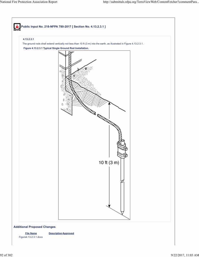
Public Input No. 218-NFPA 780-2017 [ Section No. 4.13.2.3.1 ]
4.13.2.3.1
The ground rods shall extend vertically not less than 10 ft (3 m) into the earth, as illustrated in Figure 4.13.2.3.1.
Figure 4.13.2.3.1 Typical Single Ground Rod Installation.
Additional Proposed Changes
File Name Description Approved
Figure4.13.2.3.1.docx
National Fire Protection Association Report http://submittals.nfpa.org/TerraViewWeb/ContentFetcher?commentPara...
92 of 302 9/22/2017, 11:03 AM

Statement of Problem and Substantiation for Public Input
Add new picture about perlite carbon ground module
Related Public Inputs for This Document
Related Input Relationship
Public Input No. 200-NFPA 780-2017 [New Section after 3.3.17]
Public Input No. 216-NFPA 780-2017 [Section No. 4.13.2.1]
Public Input No. 219-NFPA 780-2017 [Section No. 4.13.4 [Excluding any Sub-Sections]]
Submitter Information Verification
Submitter Full Name: Youngki Chung
Organization: Omni Lps
Street Address:
City:
State:
Zip:
Submittal Date: Mon Jun 26 06:36:03 EDT 2017
National Fire Protection Association Report http://submittals.nfpa.org/TerraViewWeb/ContentFetcher?commentPara...
93 of 302 9/22/2017, 11:03 AM

Public Input No. 294-NFPA 780-2017 [ Section No. 4.13.3.3 ]
4.13.3.3
A test or connection point shall be provided on each provided at each location a down conductor is terminated into a concrete-encased electrode to enable periodic maintenance and testing of the ground system . (See Figure 4.13.3.3.)
Figure 4.13.3.3 Typical Concrete-Encased Electrode Test and Disconnect Point.
Statement of Problem and Substantiation for Public Input
The existing wording requires a test or connection point for each concreate-encased electrode for the purpose of maintenance and inspection, regardless of whether it is to be used as a test point or whether it is used to terminate a down conductor. This appears to be excessive and is not consistent with the requirements for other grounding electrodes. On the other hand, for a foundation earth electrode, it only requires one access point regardless of the size of the foundation. The proposal suggests that the number and location of the access points be tied to down conductor termination locations.
Submitter Information Verification
Submitter Full Name: Mitchell Guthrie
Organization: Engineering Consultant
Affilliation: NFPA 780 Grounding and Bonding Task Group
Street Address:
City:
State:
Zip:
Submittal Date: Tue Jun 27 22:48:06 EDT 2017
National Fire Protection Association Report http://submittals.nfpa.org/TerraViewWeb/ContentFetcher?commentPara...
94 of 302 9/22/2017, 11:03 AM

Public Input No. 219-NFPA 780-2017 [ Section No. 4.13.4 [Excluding any Sub-Sections] ]
A ground ring electrode encircling a structure shall be as shown in Figure 4.13.4.
Figure 4.13.4 Typical Ground Ring Electrode Installation.
Note: The diameter of PCGM shall be greater than 26 cm, its lengths shall be 1~1.5 m, and the stainless steel shall have materialquality better than STS 304.
Additional Proposed Changes
File Name Description Approved
Figure4.13.4.docx
Statement of Problem and Substantiation for Public Input
Modify figure referring perlite carbon ground module.
Related Public Inputs for This Document
Related Input Relationship
Public Input No. 200-NFPA 780-2017 [New Section after 3.3.17]
Public Input No. 216-NFPA 780-2017 [Section No. 4.13.2.1]
Public Input No. 218-NFPA 780-2017 [Section No. 4.13.2.3.1]
Submitter Information Verification
Submitter Full Name: Youngki Chung
Organization: Omni Lps
Street Address:
City:
State:
Zip:
Submittal Date: Mon Jun 26 06:39:30 EDT 2017
National Fire Protection Association Report http://submittals.nfpa.org/TerraViewWeb/ContentFetcher?commentPara...
95 of 302 9/22/2017, 11:03 AM

Add new figure after Figure 4.13.2.3.1
Vertical or horizontal installation
Note: The diameter of PCGM shall be greater than 26 cm, its lengths shall be 1~1.5 m, and the stainless steel shall have material quality better than STS 304. b) Perlite carbon ground module

Public Input No. 140-NFPA 780-2017 [ Section No. 4.13.4.1 ]
4.13.4.1
The ground ring electrode shall be in direct contact with earth at a depth of not less than 18 in. (450 mm than 30 inches (750 mm )or encased in a concrete footing in accordance with 4.13.3.
Statement of Problem and Substantiation for Public Input
Rational: Changing all references to 18 inch ground ring/ conductor/ electrode depth to 30 in. (750mm) better aligns this document with NFPA 70 Section 250.53 (F). In areas with frost, this will reduce or eliminate frost heaving of ground plate or plate electrodes, ground ring and grounding conductors. In areas prone to dry / drought conditions, 30 inch depth would be far less prone to loss of ground moisture. (Also recommend including section 8.5.7, figure 8.5.7, and section 8.8.3.2)
Related Public Inputs for This Document
Related Input Relationship
Public Input No. 141-NFPA 780-2017 [Section No. 4.13.5.3]
Public Input No. 142-NFPA 780-2017 [Section No. 4.13.6.2]
Public Input No. 143-NFPA 780-2017 [Section No. 4.13.8.1.1]
Public Input No. 141-NFPA 780-2017 [Section No. 4.13.5.3]
Public Input No. 142-NFPA 780-2017 [Section No. 4.13.6.2]
Public Input No. 143-NFPA 780-2017 [Section No. 4.13.8.1.1]
Submitter Information Verification
Submitter Full Name: Daniel Ashton
Organization: Centurylink
Street Address:
City:
State:
Zip:
Submittal Date: Wed Jun 21 12:19:25 EDT 2017
National Fire Protection Association Report http://submittals.nfpa.org/TerraViewWeb/ContentFetcher?commentPara...
96 of 302 9/22/2017, 11:03 AM

Public Input No. 318-NFPA 780-2017 [ Section No. 4.13.4.1 ]
4.13.4.1
The ground ring electrode shall be in direct contact with earth at a depth of not less than 18 in. (450 mm) or encased in a concretefooting in accordance with 4.13.3.
Statement of Problem and Substantiation for Public Input
4.13.3 allows the electrode to be encased in a concrete footing OR FOUNDATION, allowing for the conductor to be poured into slab-on-grade type foundations. the current wording of 4.13.4.1 allows a ground ring only to be installed in a footing, with no allowance for the slab foundation construction.
Submitter Information Verification
Submitter Full Name: Simon Larter
Organization: Dobbyn Lightning Protection
Street Address:
City:
State:
Zip:
Submittal Date: Wed Jun 28 14:03:16 EDT 2017
National Fire Protection Association Report http://submittals.nfpa.org/TerraViewWeb/ContentFetcher?commentPara...
97 of 302 9/22/2017, 11:03 AM

Public Input No. 156-NFPA 780-2017 [ New Section after 4.13.4.2 ]
4.13.4.3
Steel reinforcing bars in the perimeter footing shall be acceptable as a ground ring electrode when installed in accordance withsection 4.13.3
Statement of Problem and Substantiation for Public Input
This new section follows the logic of the acceptability of allowing concrete encased electrodes and the reality of reinforcing steel as being an integral part of the grounding electrode system.
Submitter Information Verification
Submitter Full Name: Stephen Humeniuk
Organization: Warren Lightning Rod Company
Affilliation: ULPA
Street Address:
City:
State:
Zip:
Submittal Date: Fri Jun 23 13:46:35 EDT 2017
National Fire Protection Association Report http://submittals.nfpa.org/TerraViewWeb/ContentFetcher?commentPara...
98 of 302 9/22/2017, 11:03 AM

Public Input No. 141-NFPA 780-2017 [ Section No. 4.13.5.3 ]
4.13.5.3
The radial electrode shall be buried not less than 18 in. (450 mm than 30 inches 750 mm ) below grade.
Statement of Problem and Substantiation for Public Input
Rational: Changing all references to 18 inch ground ring/ conductor/ electrode depth to 30 in. (750mm) better aligns this document with NFPA 70 Section 250.53 (F). In areas with frost, this will reduce or eliminate frost heaving of ground plate or plate electrodes, ground ring and grounding conductors. In areas prone to dry / drought conditions, 30 inch depth would be far less prone to loss of ground moisture. (Also recommend including section 8.5.7, figure 8.5.7, and section 8.8.3.2)
Related Public Inputs for This Document
Related Input Relationship
Public Input No. 140-NFPA 780-2017 [Section No. 4.13.4.1]
Public Input No. 142-NFPA 780-2017 [Section No. 4.13.6.2]
Public Input No. 143-NFPA 780-2017 [Section No. 4.13.8.1.1]
Public Input No. 140-NFPA 780-2017 [Section No. 4.13.4.1]
Public Input No. 142-NFPA 780-2017 [Section No. 4.13.6.2]
Public Input No. 143-NFPA 780-2017 [Section No. 4.13.8.1.1]
Submitter Information Verification
Submitter Full Name: Daniel Ashton
Organization: Centurylink
Street Address:
City:
State:
Zip:
Submittal Date: Wed Jun 21 12:30:17 EDT 2017
National Fire Protection Association Report http://submittals.nfpa.org/TerraViewWeb/ContentFetcher?commentPara...
99 of 302 9/22/2017, 11:03 AM

Public Input No. 220-NFPA 780-2017 [ New Section after 4.13.6 ]
4.13.6a Perlite Carbon Ground Module .
4.13.6a.1 The stainless steel encased part of the Perlite carbon ground module shall be at least 1m long. Its external diameter shallbe more than 26cm; the stainless steel shall have material quality better than STS 304.
4.13.6a.2 The Perlite carbon ground module shall be buried 75cm under the ground, buried vertically or horizontally.
Statement of Problem and Substantiation for Public Input
In case of acid or sodic soil, there emerge problems of ground resistance rise or electrode disappearance because of outflow of copper from corrosion of electrodes.Therefore, since it is essential to install strong anti-corrosive electrodes in areas with acid or sodic soil, Perlite carbon ground module should be installed. (IEEE Std. 142)
Related Public Inputs for This Document
Related Input Relationship
Public Input No. 200-NFPA 780-2017 [New Section after 3.3.17]
Public Input No. 216-NFPA 780-2017 [Section No. 4.13.2.1]
Submitter Information Verification
Submitter Full Name: Youngki Chung
Organization: Omni Lps
Street Address:
City:
State:
Zip:
Submittal Date: Mon Jun 26 06:43:00 EDT 2017
National Fire Protection Association Report http://submittals.nfpa.org/TerraViewWeb/ContentFetcher?commentPara...
100 of 302 9/22/2017, 11:03 AM

Public Input No. 142-NFPA 780-2017 [ Section No. 4.13.6.2 ]
4.13.6.2
The ground plate electrode shall be buried not less than 18 in. (450 mm than 30 inches (750 MM ) below grade.
Statement of Problem and Substantiation for Public Input
Rational: Changing all references to 18 inch ground ring/ conductor/ electrode depth to 30 in. (750mm) better aligns this document with NFPA 70 Section 250.53 (F). In areas with frost, this will reduce or eliminate frost heaving of ground plate or plate electrodes, ground ring and grounding conductors. In areas prone to dry / drought conditions, 30 inch depth would be far less prone to loss of ground moisture. (Also recommend including section 8.5.7, figure 8.5.7, and section 8.8.3.2)
Related Public Inputs for This Document
Related Input Relationship
Public Input No. 140-NFPA 780-2017 [Section No. 4.13.4.1] same change in text
Public Input No. 141-NFPA 780-2017 [Section No. 4.13.5.3] same change in text
Public Input No. 143-NFPA 780-2017 [Section No. 4.13.8.1.1]
Public Input No. 140-NFPA 780-2017 [Section No. 4.13.4.1]
Public Input No. 141-NFPA 780-2017 [Section No. 4.13.5.3]
Public Input No. 143-NFPA 780-2017 [Section No. 4.13.8.1.1]
Submitter Information Verification
Submitter Full Name: Daniel Ashton
Organization: Centurylink
Street Address:
City:
State:
Zip:
Submittal Date: Wed Jun 21 12:32:07 EDT 2017
National Fire Protection Association Report http://submittals.nfpa.org/TerraViewWeb/ContentFetcher?commentPara...
101 of 302 9/22/2017, 11:03 AM
Public Input No. 143-NFPA 780-2017 [ Section No. 4.13.8.1.1 ]
4.13.8.1.1
Where topsoil depth is less than 18 in. (450 mm than 30 inchs (75 mm ) , it shall be permitted to provide a ground ring electrode,radials, and/or ground plate electrodes buried at the maximum depth of topsoil available.
Statement of Problem and Substantiation for Public Input
Rational: Changing all references to 18 inch ground ring/ conductor/ electrode depth to 30 in. (750mm) better aligns this document with NFPA 70 Section 250.53 (F). In areas with frost, this will reduce or eliminate frost heaving of ground plate or plate electrodes, ground ring and grounding conductors. In areas prone to dry / drought conditions, 30 inch depth would be far less prone to loss of ground moisture. (Also recommend including section 8.5.7, figure 8.5.7, and section 8.8.3.2)
Related Public Inputs for This Document
Related Input Relationship
Public Input No. 140-NFPA 780-2017 [Section No. 4.13.4.1] same change in text
Public Input No. 141-NFPA 780-2017 [Section No. 4.13.5.3] same change in text
Public Input No. 142-NFPA 780-2017 [Section No. 4.13.6.2] same change in text
Public Input No. 140-NFPA 780-2017 [Section No. 4.13.4.1]
Public Input No. 141-NFPA 780-2017 [Section No. 4.13.5.3]
Public Input No. 142-NFPA 780-2017 [Section No. 4.13.6.2]
Submitter Information Verification
Submitter Full Name: Daniel Ashton
Organization: Centurylink
Street Address:
City:
State:
Zip:
Submittal Date: Wed Jun 21 12:36:44 EDT 2017
National Fire Protection Association Report http://submittals.nfpa.org/TerraViewWeb/ContentFetcher?commentPara...
102 of 302 9/22/2017, 11:03 AM

Public Input No. 167-NFPA 780-2017 [ Section No. 4.13.8.1.2 ]
4.13.8.1.2 *
The grounding electrode for shallow topsoil shall be one or more of the following, buried to the maximum depth of topsoil available:
(1) A ground ring electrode, in accordance with 4.13.4, a minimum distance of 2 ft (0.6 m 24 in. (600 mm ) from the foundation orexterior footing
(2) Radial(s) in accordance with 4.13.5
(3) A plate electrode in accordance with 4.13.6, a minimum distance of 2 ft (0.6 m 24 in. (600 mm ) from the foundation or exteriorfooting
Statement of Problem and Substantiation for Public Input
The Editorial Task Group changes the values from feet to inches for accuracy and to maintain consistency throughout the standard.
Submitter Information Verification
Submitter Full Name: Stephen Humeniuk
Organization: Warren Lightning Rod Company
Affilliation: ULPA, The Editorial Task Group
Street Address:
City:
State:
Zip:
Submittal Date: Fri Jun 23 17:40:03 EDT 2017
National Fire Protection Association Report http://submittals.nfpa.org/TerraViewWeb/ContentFetcher?commentPara...
103 of 302 9/22/2017, 11:03 AM

Public Input No. 168-NFPA 780-2017 [ Section No. 4.13.8.1.3 ]
4.13.8.1.3
Where a method of 4.13.8.1.2 is impossible, radial(s) shall be permitted to be laid directly on bedrock a minimum distance of 12 ft(3.6 m) from the foundation or exterior footing. A ground ring electrode encircling the structure shall be permitted to be laid directly onbedrock a minimum distance of 2 ft (0.6 m 24 in. (600 mm ) from the foundation or exterior footing.
Statement of Problem and Substantiation for Public Input
The Editorial Task Group Changes the values from feet to inches for accuracy and to maintain consistency throughout the standard.
Submitter Information Verification
Submitter Full Name: Stephen Humeniuk
Organization: Warren Lightning Rod Company
Affilliation: ULPA, The Editorial Task Group
Street Address:
City:
State:
Zip:
Submittal Date: Fri Jun 23 17:44:08 EDT 2017
National Fire Protection Association Report http://submittals.nfpa.org/TerraViewWeb/ContentFetcher?commentPara...
104 of 302 9/22/2017, 11:03 AM

Public Input No. 144-NFPA 780-2017 [ Section No. 4.13.8.1.4 ]
4.13.8.1.4
In those cases where the grounding conductor is laid directly on bedrock, the conductor shall be secured to the bedrock every 3 ft(0.9 m) by nailing, conductive cement, or a conductive adhesive to ensure electrical contact and protect against movement ordamage .
Statement of Problem and Substantiation for Public Input
Rational: protection from damage of the exposed grounding conductor should also be considered
Submitter Information Verification
Submitter Full Name: Daniel Ashton
Organization: Centurylink
Street Address:
City:
State:
Zip:
Submittal Date: Wed Jun 21 12:39:56 EDT 2017
National Fire Protection Association Report http://submittals.nfpa.org/TerraViewWeb/ContentFetcher?commentPara...
105 of 302 9/22/2017, 11:03 AM

Public Input No. 183-NFPA 780-2017 [ Section No. 4.13.8.1.4 ]
4.13.8.1.4
In those cases where the grounding conductor is laid directly on bedrock, the conductor shall be secured to the bedrock every 3 ft(0.9 m 36 in. (900 mm ) by nailing, conductive cement, or a conductive adhesive to ensure electrical contact and protect againstmovement.
Statement of Problem and Substantiation for Public Input
The Editorial Task Group changes values from feet to inches for accuracy and to maintain consistency throughout the standard
Submitter Information Verification
Submitter Full Name: Stephen Humeniuk
Organization: Warren Lightning Rod Company
Affilliation: ULPA, The Editorial Task Group
Street Address:
City:
State:
Zip:
Submittal Date: Fri Jun 23 18:36:29 EDT 2017
National Fire Protection Association Report http://submittals.nfpa.org/TerraViewWeb/ContentFetcher?commentPara...
106 of 302 9/22/2017, 11:03 AM

Public Input No. 302-NFPA 780-2017 [ Section No. 4.14.1 ]
4.14.1* General.
All grounded media and buried metallic conductors that can assist in providing a path for lightning currents in or on a structure shall(including underground metallic piping systems) shall be interconnected to the lightning protection system within 12 ft vertically(3.6 m vertically) of the base of the structure to provide a common ground potential.
Statement of Problem and Substantiation for Public Input
The asterisk indicates that new annex text is proposed for this clause. The addition of ... (including underground metallic piping systems) ... is added to provide a link between this clause and 4.14.4.
Submitter Information Verification
Submitter Full Name: Mitchell Guthrie
Organization: Engineering Consultant
Affilliation: NFPA 780 Grounding and Bonding Task Group
Street Address:
City:
State:
Zip:
Submittal Date: Wed Jun 28 08:04:38 EDT 2017
National Fire Protection Association Report http://submittals.nfpa.org/TerraViewWeb/ContentFetcher?commentPara...
107 of 302 9/22/2017, 11:03 AM

Public Input No. 157-NFPA 780-2017 [ New Section after 4.14.2 ]
4.14.2.1
Steel reinforcement in the perimeter footing shall be acceptable as the ground loop conductor when bonded to all ground media andinstalled in accordance with section 4.13.3
Statement of Problem and Substantiation for Public Input
This statement recognizes the reality of steel reinforcement as part of the ground electrode system when appropriately tie to it. The steel reinforcement is suitable to serve as a means of equalizing electrical potential.
Submitter Information Verification
Submitter Full Name: Stephen Humeniuk
Organization: Warren Lightning Rod Company
Affilliation: ULPA
Street Address:
City:
State:
Zip:
Submittal Date: Fri Jun 23 13:59:46 EDT 2017
National Fire Protection Association Report http://submittals.nfpa.org/TerraViewWeb/ContentFetcher?commentPara...
108 of 302 9/22/2017, 11:03 AM

Public Input No. 155-NFPA 780-2017 [ Section No. 4.14.4 ]
4.14.4 *
Interconnection of underground metallic piping systems shall include water service, well casings located within 25 ft (7.6 m) of thestructure, gas piping, underground conduits, underground liquefied petroleum gas piping systems, and so on. If the water pipe is notelectrically continuous due to the use of plastic pipe sections or other reasons, the nonconductive sections shall be bridged withmain-size conductors, or the connection shall be made at a point where electrical continuity is ensured.
Statement of Problem and Substantiation for Public Input
Denotes the addition of annex material submitted under a separate proposal.
Related Public Inputs for This Document
Related Input Relationship
Public Input No. 154-NFPA 780-2017 [New Section after A.4.14.3]
Submitter Information Verification
Submitter Full Name: Stephen Humeniuk
Organization: Warren Lightning Rod Company
Affilliation: ULPA
Street Address:
City:
State:
Zip:
Submittal Date: Fri Jun 23 13:39:31 EDT 2017
National Fire Protection Association Report http://submittals.nfpa.org/TerraViewWeb/ContentFetcher?commentPara...
109 of 302 9/22/2017, 11:03 AM
Public Input No. 301-NFPA 780-2017 [ Section No. 4.14.4 ]
4.14.4
Interconnection of underground metallic piping systems shall include water service, well casings located within 25 ft (7.6 m) of thestructure, gas piping, underground conduits, underground liquefied petroleum gas piping systems, and so on . If the water pipe is notelectrically continuous due to the use of plastic pipe sections or other reasons, the nonconductive sections shall be bridged withmain-size conductors, or the connection shall be made at a point where electrical the required electrical continuity is ensured.
Statement of Problem and Substantiation for Public Input
The deletion of "and so on" is editorial. The sentence begins with ... shall include ... so the list is not intended to be restrictive. "Required" is inserted to clarify that the piping must be conductive in the section that is required to perform the function of common bonding of grounding systems.
Related Public Inputs for This Document
Related Input Relationship
Public Input No. 315-NFPA 780-2017 [New Section after A.4.13.8.3.1]
Submitter Information Verification
Submitter Full Name: Mitchell Guthrie
Organization: Engineering Consultant
Street Address:
City:
State:
Zip:
Submittal Date: Wed Jun 28 07:37:50 EDT 2017
National Fire Protection Association Report http://submittals.nfpa.org/TerraViewWeb/ContentFetcher?commentPara...
110 of 302 9/22/2017, 11:03 AM

Public Input No. 259-NFPA 780-2017 [ Section No. 4.14.6 ]
4.14.6
Where bonding of the lightning protection grounding system, grounded media, and buried metallic conductors has not beenaccomplished at a common point, interconnection shall be provided according to the following:
(1) Grounded media and buried metallic conductors shall be bonded to the lightning protection grounding system below a height12 ft (3.6 m) vertically above the base of the structure.
(2) * Grounded media and buried metallic conductors inherently bonded through construction to the lightning protection groundingsystem shall system do not require further bonding.
(3) The continuous metal framework of a structure shall be connected to the lightning protection system (see 4.9.13 andSection 4.19).
(4) Main-size lightning conductors shall be used for direct connection of grounded media and buried metallic conductors to thelightning protection system.
(5)
(6) A
ground bar designed for interconnection of building grounded systems shall have one connection to the lightning protectionsystem.
(7) A continuous metal water pipe system designed for interconnection of building grounded systems shall be connected to thelightning protection system.
(8)
(9)
Statement of Problem and Substantiation for Public Input
An asterisk is added to (2) to indicate that annex text is proposed to provide a recommended criteria to determine whether an item is inherently bonded. "Shall" is replaced by "do" to indicate that an additional bond is not required for the inherently bonded item but also not to restrict an additional bond if the additional bond is determined to provide an additional level of protection.(5) is deleted because the requirement is previously addressed in 4.14.5.
Related Public Inputs for This Document
Related Input Relationship
Public Input No. 260-NFPA 780-2017 [New Section after A.4.14.5]
Submitter Information Verification
Submitter Full Name: Mitchell Guthrie
Organization: Engineering Consultant
Affilliation: NFPA 780 Grounding and Bonding Task Group
Street Address:
City:
State:
Zip:
Submittal Date: Tue Jun 27 11:29:30 EDT 2017
* Interconnection to a gas line shall be made on the customer’s side of the meter.
* Where galvanic corrosion is a concern or where a direct bond is prohibited by local code, an isolating spark gap shall bepermitted.
National Fire Protection Association Report http://submittals.nfpa.org/TerraViewWeb/ContentFetcher?commentPara...
111 of 302 9/22/2017, 11:03 AM

Public Input No. 319-NFPA 780-2017 [ Section No. 4.14.6 ]
4.14.6
Where bonding of the lightning protection grounding system, grounded media, and buried metallic conductors has not beenaccomplished at a common point, interconnection shall be provided according to the following:
(1) Grounded media and buried metallic conductors shall be bonded to the lightning protection grounding system below a height12 ft (3.6 m) vertically above the base of the structure.
(2) Grounded media and buried metallic conductors inherently bonded through construction to the lightning protection groundingsystem shall not require further bonding.
(3) The continuous metal framework of a structure shall be connected to the lightning protection system (see 4.9.13 andSection 4.19).
(4) Main-size lightning conductors shall be used for direct connection of grounded media and buried metallic conductors to thelightning protection system.
(5) A ground bar designed for interconnection of building grounded systems shall have one connection to the lightning protectionsystem.
(6) A continuous metal water pipe system designed for interconnection of that is permitted to serve as an interconnection point forbuilding grounded systems shall be connected to the lightning protection system.
(7)
(8)
Statement of Problem and Substantiation for Public Input
The water pipe isn't designed as a ground interconnection point. It's designed to carry water. Hence the name. Just trying to clarify things a bit, y'all.
Submitter Information Verification
Submitter Full Name: Simon Larter
Organization: Dobbyn Lightning Protection
Street Address:
City:
State:
Zip:
Submittal Date: Wed Jun 28 14:09:11 EDT 2017
* Interconnection to a gas line shall be made on the customer’s side of the meter.
* Where galvanic corrosion is a concern or where a direct bond is prohibited by local code, an isolating spark gap shall bepermitted.
National Fire Protection Association Report http://submittals.nfpa.org/TerraViewWeb/ContentFetcher?commentPara...
112 of 302 9/22/2017, 11:03 AM

Public Input No. 321-NFPA 780-2017 [ New Section after 4.15.1 ]
4.15.1.1
Existing structures shall not be required to accomplish ground-level potential equalization with a loop conductor when all of the underthe following conditions are met:
(1) The structure is bonded in accordance with 4.14.1.
(2) A loop conductor is installed around the perimeter of the roof.
(3) The down conductors are installed on the exterior of the building minimizing the risk of side flash of building system within thestructure.
(4) The risk of not having a ground level potential equalizing loop is acceptable to the AHJ.
Additional Proposed Changes
File Name Description Approved
NFPA_2020_Substantiation_Existing_Structures.docx
Statement of Problem and Substantiation for Public Input
This exception needs to be allowed in order to proliferate the use of lightning protection on existing structure. The number of facilities this requirement actually applies to represents a small percent of actual existing buildings. Additional substantiation is attached.
Submitter Information Verification
Submitter Full Name: Stephen Humeniuk
Organization: Warren Lightning Rod Company
Affilliation: ULPA
Street Address:
City:
State:
Zip:
Submittal Date: Wed Jun 28 14:31:48 EDT 2017
National Fire Protection Association Report http://submittals.nfpa.org/TerraViewWeb/ContentFetcher?commentPara...
113 of 302 9/22/2017, 11:03 AM
Substantiation
Most buildings of over 60 feet tall are structural steel, and meet the requirements of this section inherently through construction. Few buildings over 60 feet are constructed of pour concrete without rebar, if any.
The remaining buildings over 60 feet are typically steel reinforced concrete. High rise buildings typically run building systems through the center of the structure, radiating them outward as needed. Code requirements, ( i.e., the length of electric wire due to resistance, the slope of sewer and drain pipes) construction practices, and economics, keep building system supplies close to the core of the building. Since the exterior of the building is structurally poured-in-place reinforced concrete, it cannot be cut or cored without compromising the structural integrity of the building. Due to this, grounded metal bodies are not usually run in or near the exterior walls. Based upon the side flash calculations 4.16.2.5 a building that is 55 X 100x 800 feet which is a very tall building with a very small foot print would require 4 down leads. If the down conductors were place equidistant from each other they would be placed 77.5 feet apart. Using the formula no all down leads are within 100 feet so the side flash would be calculated as 600 divided by 24 times .5 which equals 12.5 feet bonding distance. If a 6 foot corridor were placed down the center of the building, the average apartment on either side would be 24.5 wide. With building systems placed on the interior third of the apartment, all grounded metal bodies would still be 3.83 feet away from the required bonding distance.

Public Input No. 160-NFPA 780-2017 [ New Section after 4.15.3.2 ]
4.15.3.2.1
Where metal pan decking is used in conjunction with steel reinforcement in concrete columns, the metal pan decking shall bepermitted to be used as the intermediate-level potential equalization under the following conditions:
(1) All down leads are tied to the pan decking.
(2) The pan decking is electrically continuous or is made so.
Statement of Problem and Substantiation for Public Input
This section is written to introduce a practical way proliferate the use intermediate-level bonding to equalize potential
Submitter Information Verification
Submitter Full Name: Stephen Humeniuk
Organization: Warren Lightning Rod Company
Affilliation: ULPA
Street Address:
City:
State:
Zip:
Submittal Date: Fri Jun 23 14:22:00 EDT 2017
National Fire Protection Association Report http://submittals.nfpa.org/TerraViewWeb/ContentFetcher?commentPara...
114 of 302 9/22/2017, 11:03 AM

Public Input No. 246-NFPA 780-2017 [ New Section after 4.15.3.2 ]
4.15.3.2.2
The steel reinforcing bars in concrete beams shall be permitted to be used as the intermediate level-potential equalization loop when:
(1) The steel reinforcing bars are utilized as the down conductors in the concrete columns.
(2) The bars are not less than 1/2 in. (12.7 mm) in. diameter, and have been effectively bonded together by welding, structuralmechanical coupling, or are overlapping 20 diameters and are wire tied.
Statement of Problem and Substantiation for Public Input
Makes the same allowance as was previously made for steel reinforcing bars to be used as grounding electrodes.
Related Public Inputs for This Document
Related Input Relationship
Public Input No. 249-NFPA 780-2017 [New Section after 4.9.14]
Public Input No. 249-NFPA 780-2017 [New Section after 4.9.13.3]
Submitter Information Verification
Submitter Full Name: Stephen Humeniuk
Organization: Warren Lightning Rod Company
Affilliation: ULPA
Street Address:
City:
State:
Zip:
Submittal Date: Mon Jun 26 19:25:42 EDT 2017
National Fire Protection Association Report http://submittals.nfpa.org/TerraViewWeb/ContentFetcher?commentPara...
115 of 302 9/22/2017, 11:03 AM
Public Input No. 324-NFPA 780-2017 [ New Section after 4.15.3.3 ]
4.15.3.4
Existing structures shall not be required to install an intermediate-level potential equalizing loop conductor when the followingconditions are met:
(1) The structure is bonded in accordance with 4.14.1.
(2) A loop conductor is installed around the perimeter of the roof.
(3) The down conductors are installed on the exterior of the building to minimize side flash to building systems within the structure.
(4) The risk of not having an intermediate-level potential equalizing loop is acceptable to the AHJ.
Additional Proposed Changes
File Name Description Approved
NFPA_2020_Substantiation_Existing_Structures.docx
Statement of Problem and Substantiation for Public Input
This change is need to proliferate the use of lightning protection on existing structures. The existing requirements apply to a very limited number of building. Additional substantiation for this change is attached.
Submitter Information Verification
Submitter Full Name: Stephen Humeniuk
Organization: Warren Lightning Rod Company
Affilliation: ULPA
Street Address:
City:
State:
Zip:
Submittal Date: Wed Jun 28 14:48:16 EDT 2017
National Fire Protection Association Report http://submittals.nfpa.org/TerraViewWeb/ContentFetcher?commentPara...
116 of 302 9/22/2017, 11:03 AM

Substantiation
Most buildings of over 60 feet tall are structural steel, and meet the requirements of this section inherently through construction. Few buildings over 60 feet are constructed of pour concrete without rebar, if any.
The remaining buildings over 60 feet are typically steel reinforced concrete. High rise buildings typically run building systems through the center of the structure, radiating them outward as needed. Code requirements, ( i.e., the length of electric wire due to resistance, the slope of sewer and drain pipes) construction practices, and economics, keep building system supplies close to the core of the building. Since the exterior of the building is structurally poured-in-place reinforced concrete, it cannot be cut or cored without compromising the structural integrity of the building. Due to this, grounded metal bodies are not usually run in or near the exterior walls. Based upon the side flash calculations 4.16.2.5 a building that is 55 X 100x 800 feet which is a very tall building with a very small foot print would require 4 down leads. If the down conductors were place equidistant from each other they would be placed 77.5 feet apart. Using the formula no all down leads are within 100 feet so the side flash would be calculated as 600 divided by 24 times .5 which equals 12.5 feet bonding distance. If a 6 foot corridor were placed down the center of the building, the average apartment on either side would be 24.5 wide. With building systems placed on the interior third of the apartment, all grounded metal bodies would still be 3.83 feet away from the required bonding distance.

Public Input No. 264-NFPA 780-2017 [ Section No. 4.16.1.2 ]
4.16.1.2 Reinforced Concrete Structures Where the Reinforcement Is Interconnected and Grounded in Accordance with 4 .18.3.
Grounded and ungrounded metal bodies exceeding 60 ft (18 m) in vertical length shall located in reinforced concrete structureswhere the reinforcement is interconnected and grounded in accordance with 4.18.3 shall be bonded to the lightning protectionsystem as near as practicable to their extremities unless inherently bonded through construction at those locations.
Statement of Problem and Substantiation for Public Input
Editorial. The existing title was 1/3 the length of the text. The title was shortened by moving the requirements out of the title and into the body.
Submitter Information Verification
Submitter Full Name: Mitchell Guthrie
Organization: Engineering Consultant
Street Address:
City:
State:
Zip:
Submittal Date: Tue Jun 27 15:38:21 EDT 2017
National Fire Protection Association Report http://submittals.nfpa.org/TerraViewWeb/ContentFetcher?commentPara...
117 of 302 9/22/2017, 11:03 AM

Public Input No. 292-NFPA 780-2017 [ Section No. 4.16.2.3 ]
4.16.2.3
Where such bonding has been accomplished either inherently through construction or by physical contact between electricallyconductive materials, no additional bonding connection shall be required Grounded metal bodies do not require additional bonding ifthe measured DC resistance between the inherently bonded electrically conductive materials and nearest lightning protectioncomponent is less than 200 milliohms .
Statement of Problem and Substantiation for Public Input
The term inherently bonded through construction is subjective and is open to different interpretations. Physical contact may not be enough to provide equal potential or prevent flashover. The proposal forwards a recommended criteria.
Submitter Information Verification
Submitter Full Name: Mitchell Guthrie
Organization: Engineering Consultant
Affilliation: NFPA 780 Grounding and Bonding Task Group
Street Address:
City:
State:
Zip:
Submittal Date: Tue Jun 27 17:47:03 EDT 2017
National Fire Protection Association Report http://submittals.nfpa.org/TerraViewWeb/ContentFetcher?commentPara...
118 of 302 9/22/2017, 11:03 AM
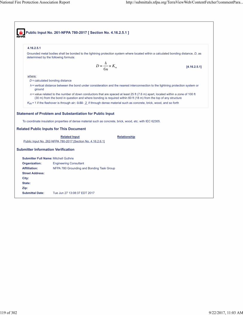
Public Input No. 261-NFPA 780-2017 [ Section No. 4.16.2.5.1 ]
4.16.2.5.1
Grounded metal bodies shall be bonded to the lightning protection system where located within a calculated bonding distance, D, asdetermined by the following formula:
[4.16.2.5.1]
where:
D = calculated bonding distance
h = vertical distance between the bond under consideration and the nearest interconnection to the lightning protection system orground
n = value related to the number of down conductors that are spaced at least 25 ft (7.6 m) apart, located within a zone of 100 ft(30 m) from the bond in question and where bonding is required within 60 ft (18 m) from the top of any structure
Km = 1 if the flashover is through air; 0.50 2 if through dense material such as concrete, brick, wood, and so forth
Statement of Problem and Substantiation for Public Input
To coordinate insulation properties of dense material such as concrete, brick, wood, etc. with IEC 62305.
Related Public Inputs for This Document
Related Input Relationship
Public Input No. 262-NFPA 780-2017 [Section No. 4.16.2.6.1]
Submitter Information Verification
Submitter Full Name: Mitchell Guthrie
Organization: Engineering Consultant
Affilliation: NFPA 780 Grounding and Bonding Task Group
Street Address:
City:
State:
Zip:
Submittal Date: Tue Jun 27 13:08:37 EDT 2017
National Fire Protection Association Report http://submittals.nfpa.org/TerraViewWeb/ContentFetcher?commentPara...
119 of 302 9/22/2017, 11:03 AM

Public Input No. 262-NFPA 780-2017 [ Section No. 4.16.2.6.1 ]
4.16.2.6.1
Grounded metal bodies shall be bonded to the lightning protection system where located within a calculated bonding distance, D, asdetermined by the following formula:
[4.16.2.6.1]
where:
D = calculated bonding distance
h = either the height of the building or the vertical distance from the nearest bonding connection from the grounded metal body tothe lightning protection system and the point on the down conductor where the bonding connection is being considered
n = value related to the number of down conductors that are spaced at least 25 ft (7.6 m) apart and located within a zone of 100 ft(30 m) from the bond in question
Km = 1 if the flashover is through air; 0.50 2 if through dense material such as concrete, brick, wood, and so forth
Statement of Problem and Substantiation for Public Input
To coordinate insulation properties of dense material such as concrete, brick, wood, etc. with IEC 62305.
Related Public Inputs for This Document
Related Input Relationship
Public Input No. 261-NFPA 780-2017 [Section No. 4.16.2.5.1] Identical change
Submitter Information Verification
Submitter Full Name: Mitchell Guthrie
Organization: Engineering Consultant
Affilliation: NFPA 780 Grounding and Bonding Task Group
Street Address:
City:
State:
Zip:
Submittal Date: Tue Jun 27 13:15:27 EDT 2017
National Fire Protection Association Report http://submittals.nfpa.org/TerraViewWeb/ContentFetcher?commentPara...
120 of 302 9/22/2017, 11:03 AM

Public Input No. 320-NFPA 780-2017 [ Section No. 4.18.3.1 ]
4.18.3.1
Concealed down conductors shall be connected to the vertical reinforcing steel in accordance with 4.9.13 . by use of boltedconnectors, welding, or brazing.
Statement of Problem and Substantiation for Public Input
You can't get 8 square inch bonding plates on reinforcing steel bars. The reference to 4.19.3 is inappropriate.
Submitter Information Verification
Submitter Full Name: Simon Larter
Organization: Dobbyn Lightning Protection
Street Address:
City:
State:
Zip:
Submittal Date: Wed Jun 28 14:22:30 EDT 2017
National Fire Protection Association Report http://submittals.nfpa.org/TerraViewWeb/ContentFetcher?commentPara...
121 of 302 9/22/2017, 11:03 AM

Public Input No. 268-NFPA 780-2017 [ Section No. 4.19.1 ]
4.19.1
General.
The metal framework of a structure shall be permitted to be utilized as the main conductor and down conductor of a lightningprotection system if it is equal to or greater than 3
⁄
? 16 in. (4.
8 mm
8 mm ) 0.064 in (1.63 mm) in thickness and is electrically continuous, or it is made electrically continuous by methods specified in4.19.3 .
Statement of Problem and Substantiation for Public Input
Change to agree with 4.9.3.2 and 4.6.3.5.
Submitter Information Verification
Submitter Full Name: Bruce Kaiser
Organization: Lightning Master Corporation
Street Address:
City:
State:
Zip:
Submittal Date: Tue Jun 27 16:05:44 EDT 2017
National Fire Protection Association Report http://submittals.nfpa.org/TerraViewWeb/ContentFetcher?commentPara...
122 of 302 9/22/2017, 11:03 AM

Public Input No. 61-NFPA 780-2017 [ Section No. 4.19.1 ]
4.19.1 General.
The metal framework of a structure shall be permitted to be utilized as the main conductor of a lightning protection system if it isequal to or greater than 3⁄16 in. (4.8 mm) in thickness and is electrically continuous, or it is made electrically continuous by methodsspecified in 4.19.3.
If the intent of paragraph 4.19.1 of NFPA 780 is to eliminate the requirement for both the main conductor and the air terminals of thelightning protection system, then I believe that Paagraph 4.19.1 should read as follows:
419.1 General. The metal roof structural members of a structure shall be permitted to function as the main conductor and airterminals of the lightning protection system if each metal roof structure member of a structure is equal to or greater than 3/16 inches(4.8 mm) in thickness and is electrically continuous. Or the metal roof structural members noted above in this paragraph (4.19.1) aremade electrically continuous by the methods specified in 4.19.3.
Statement of Problem and Substantiation for Public Input
This change would eliminate the need for main conductors and air terminals having to be installed on roofs which have metal structural roof members.
Submitter Information Verification
Submitter Full Name: Al Ondic
Organization: 96 CEG CEN
Street Address:
City:
State:
Zip:
Submittal Date: Tue Apr 11 13:45:58 EDT 2017
National Fire Protection Association Report http://submittals.nfpa.org/TerraViewWeb/ContentFetcher?commentPara...
123 of 302 9/22/2017, 11:03 AM
Public Input No. 270-NFPA 780-2017 [ New Section after 4.19.2.2 ]
TITLE OF NEW CONTENT
4.19.2.3 A n air terminal and base combination shall not require side bracing if it is installed on structural steel or concrete, and iscapable of withstanding a tipping force of 2.2 lbs (0.9979032 kg) per foot (0.3048 m) of un-braced elevation conductor length at its tipor alternately able to withstand a wind of 156 mph (0.3048 m/second).
Statement of Problem and Substantiation for Public Input
Change to allow use of unbraced air terminals where side bracing is not required.
Submitter Information Verification
Submitter Full Name: Bruce Kaiser
Organization: Lightning Master Corporation
Street Address:
City:
State:
Zip:
Submittal Date: Tue Jun 27 16:11:56 EDT 2017
National Fire Protection Association Report http://submittals.nfpa.org/TerraViewWeb/ContentFetcher?commentPara...
124 of 302 9/22/2017, 11:03 AM

Public Input No. 269-NFPA 780-2017 [ Section No. 4.19.3 ]
4.19.3
Connections to Framework.
Conductors shall be connected to areas of the structural metal framework that have been cleaned to base metal, by use of bondingplates having a surface contact area of not less than
8 in8 in . 2 (
5200 mm 2 )
5200 mm2) 3 in. 2 (1940 mm 2 ) or by welding or brazing.
4.19.3.1
Drilling and tapping the metal framework to accept a threaded connector also shall be permitted.
4.19.3.2
The threaded device shall be installed with at least five threads fully engaged and secured with a jam nut or equivalent.
4.19.3.3
The threaded portion of the connector shall be not less than 1⁄2 in. (12.7 mm) in diameter.
4.19.3.4
Bonding plates shall have bolt-pressure cable connectors and shall be bolted, welded, or brazed to the structural metal framework soas to maintain electrical continuity.
4.19.3.5*
Where corrosion-protective paint or coatings are removed, the completed electrical connection shall have corrosion protectionequivalent to the original coating.
Statement of Problem and Substantiation for Public Input
Change to agree with 4.7.11.1.(3), 4.7.12.2 (2), 4.7.12.3.2, and 4.7.12.4.1
Submitter Information Verification
Submitter Full Name: Bruce Kaiser
Organization: Lightning Master Corporation
Street Address:
City:
State:
Zip:
Submittal Date: Tue Jun 27 16:07:39 EDT 2017
National Fire Protection Association Report http://submittals.nfpa.org/TerraViewWeb/ContentFetcher?commentPara...
125 of 302 9/22/2017, 11:03 AM

Public Input No. 322-NFPA 780-2017 [ Section No. 4.19.3 ]
4.19.3 Connections to Framework.
Conductors shall be connected to areas of the structural metal framework that have been cleaned to base metal, by use of bondingone of the following methods:
(1) Bonding plates having a surface contact area of not less than 8 in.2 (5200 mm2) or by welding or brazing
(2) Welding
(3) Brazing
(4) Drilling and tapping .
4.19.3.1
Drilling and tapping the metal framework to accept a threaded connector also shall be permitted Bonding plates shall have bolt-pressure cable connectors and shall be bolted, welded, or brazed to the structural metal framework so as to maintain electricalcontinuity .
4.19.3.2
The threaded device A threaded connector drilled and tapped into the metal framework shall be installed with at least five threadsfully engaged and secured with a jam nut or equivalent.
4.19.3.3
The threaded portion of the connector shall be not less than 1⁄ ? 2 in. (12.7 mm) in diameter.
4.19.3.4
Bonding plates shall have bolt-pressure cable connectors and shall be bolted, welded, or brazed to the structural metal framework soas to maintain electrical continuity.
4.19.3.5 *
Where corrosion-protective paint or coatings are removed as part of the bonding process , the completed electrical connection shallhave corrosion protection equivalent to the original coating.
Statement of Problem and Substantiation for Public Input
Reworks the section for clarity and flow.
Related Public Inputs for This Document
Related Input Relationship
Public Input No. 323-NFPA 780-2017 [Section No. A.4.19.3.5] They're like golfing partners, but with the occasional awkward hug.
Public Input No. 323-NFPA 780-2017 [Section No. A.4.19.3.5]
Submitter Information Verification
Submitter Full Name: Simon Larter
Organization: Dobbyn Lightning Protection
Street Address:
City:
State:
Zip:
Submittal Date: Wed Jun 28 14:38:54 EDT 2017
National Fire Protection Association Report http://submittals.nfpa.org/TerraViewWeb/ContentFetcher?commentPara...
126 of 302 9/22/2017, 11:03 AM
Public Input No. 271-NFPA 780-2017 [ Section No. 4.19.4.1 ]
4.19.4.1
Grounding electrodes shall be connected to the structural metal framework at intervals around the perimeter averaging not morethan
60 ft
60 ft (
18 m)
18 m) 100 ft (30 m) .
Statement of Problem and Substantiation for Public Input
Change to agree with section 4.9.10, down conductor spacing.
Submitter Information Verification
Submitter Full Name: Bruce Kaiser
Organization: Lightning Master Corporation
Street Address:
City:
State:
Zip:
Submittal Date: Tue Jun 27 16:13:19 EDT 2017
National Fire Protection Association Report http://submittals.nfpa.org/TerraViewWeb/ContentFetcher?commentPara...
127 of 302 9/22/2017, 11:03 AM

Public Input No. 306-NFPA 780-2017 [ Section No. 4.20.2.1 ]
4.20.2.1
SPDs shall be installed at all power service entrances (see 4 .20.3.1, 4.20.4 and 4.20.5 for selection criteria).
Statement of Problem and Substantiation for Public Input
The addition provides the user with information on where to find selection criteria and addresses questions often asked of NFPA staff..
Submitter Information Verification
Submitter Full Name: Mitchell Guthrie
Organization: Engineering Consultant
Street Address:
City:
State:
Zip:
Submittal Date: Wed Jun 28 10:46:52 EDT 2017
National Fire Protection Association Report http://submittals.nfpa.org/TerraViewWeb/ContentFetcher?commentPara...
128 of 302 9/22/2017, 11:03 AM
Public Input No. 58-NFPA 780-2017 [ Section No. 4.20.2.3 ]
4.20.2.3
SPDs shall be installed at all points where an electrical or electronic system conductor leaves a structure to supply another structureif unless the conductors or cables are run over 100 ft (30 m) structures are located entirely within a zone of protection .
Statement of Problem and Substantiation for Public Input
We have had systems damaged where the structures were less than 100 feet apart. Adding surge protection would help prevent lightning damage.
Submitter Information Verification
Submitter Full Name: Carl Johnson II
Organization: Avcon Inc
Affilliation: none
Street Address:
City:
State:
Zip:
Submittal Date: Mon Apr 03 11:35:24 EDT 2017
National Fire Protection Association Report http://submittals.nfpa.org/TerraViewWeb/ContentFetcher?commentPara...
129 of 302 9/22/2017, 11:03 AM

Public Input No. 332-NFPA 780-2017 [ New Section after 4.20.2.4 ]
4.20.2.5
If an existing structure has separate power or conductive telecommunications system service entrances building additions, eachservice entrance shall have a suitable SPD installed.
Statement of Problem and Substantiation for Public Input
The Existing Structures Task Group makes the proposal because building additions often have services that supply only the addition, and do not come from the existing structure.
Related Public Inputs for This Document
Related Input Relationship
Public Input No. 333-NFPA 780-2017 [Section No. 4.20.2.5]
Public Input No. 333-NFPA 780-2017 [Section No. 4.20.2.5]
Submitter Information Verification
Submitter Full Name: Stephen Humeniuk
Organization: Warren Lightning Rod Company
Affilliation: ULPA, The Existing Structures Task Group
Street Address:
City:
State:
Zip:
Submittal Date: Wed Jun 28 15:41:05 EDT 2017
National Fire Protection Association Report http://submittals.nfpa.org/TerraViewWeb/ContentFetcher?commentPara...
130 of 302 9/22/2017, 11:03 AM
Public Input No. 333-NFPA 780-2017 [ Section No. 4.20.2.5 ]
4.20.2. 5 6 *
SPDs shall not be required where, under engineering supervision, it is determined that surge threat is negligible or the lines areequivalently protected or where installation compromises safety.
Statement of Problem and Substantiation for Public Input
The Existing Structures Task Group renumbers this section if the new section 4.20.2.5 is accepted
Related Public Inputs for This Document
Related Input Relationship
Public Input No. 332-NFPA 780-2017 [New Section after 4.20.2.4]
Public Input No. 332-NFPA 780-2017 [New Section after 4.20.2.4]
Public Input No. 335-NFPA 780-2017 [Section No. A.4.20.2.5]
Submitter Information Verification
Submitter Full Name: Stephen Humeniuk
Organization: Warren Lightning Rod Company
Affilliation: ULPA, The Existing Structures Task Group
Street Address:
City:
State:
Zip:
Submittal Date: Wed Jun 28 15:47:13 EDT 2017
National Fire Protection Association Report http://submittals.nfpa.org/TerraViewWeb/ContentFetcher?commentPara...
131 of 302 9/22/2017, 11:03 AM

Public Input No. 221-NFPA 780-2017 [ Section No. 4.20.3.1 ]
4.20.3.1* Electrical Power Circuits.
4.20.3.1.1
The SPD shall protect against surges produced by a 1.2/50 µs and 8/20 µs combination waveform generator.
4.20.3.1.2
SPDs at the service entrance shall have a nominal discharge current (In) rating of at least 20 kA 8/20 µs per phase.
4.20.3.1.3
The rated impulse current ( I imp ) for SPDs installed at power supply of outdoor electrical facilities shall be minimum 12.5 kA
10/350 µs .
4.20.3.1.4
The material for the Power SPD shall be metallic.
Statement of Problem and Substantiation for Public Input
Add the requirements and installation location for Class I SPDs according to IEC 61643-11
Related Public Inputs for This Document
Related Input Relationship
Public Input No. 201-NFPA 780-2017 [New Section after 3.3.9]
Submitter Information Verification
Submitter Full Name: Youngki Chung
Organization: Omni Lps
Street Address:
City:
State:
Zip:
Submittal Date: Mon Jun 26 06:45:16 EDT 2017
National Fire Protection Association Report http://submittals.nfpa.org/TerraViewWeb/ContentFetcher?commentPara...
132 of 302 9/22/2017, 11:03 AM

Public Input No. 57-NFPA 780-2017 [ Section No. 4.20.4 ]
4.20.4 * Measured Limiting Voltage of an SPD.
The published voltage protection rating (VPR) for each mode of protection shall be selected to be no greater than those given inTable 4.20.4 for the different power distribution systems to which they can be connected.
Table 4.20.4 Maximum Allowed Voltage Protection Rating per Mode of Protection Provided for Different Power Distribution Systemsto Which the SPD Can Be Connected
Power Distribution System
Line-to-
Neutral
Line-to-
Ground
Neutral-to-
Ground
Line-to-
Line
120 2W + ground 700 700 700 —
240 2W + ground 1000 1000 1000 —
120/240 3W + ground 700 700 700 1200
120/208 WYE 4W + ground 700 700 700 1200
277/480 WYE 4W + ground 1200 1200 1200 1800
277/480 WYE 4W + HRG (high-resistance ground) 1200
1200
1800 1200 1800
347/600 WYE 4W + ground 1800 1800 1800 4000
240 DELTA 3W + ground
(corner grounded)
— 1000 — 1000
240 DELTA 3W (ungrounded) — 1000 — 1000
480 DELTA 3W + ground
(corner grounded)
— 1800 — 1800
480 DELTA 3W (ungrounded) — 1800 — 1800
Statement of Problem and Substantiation for Public Input
There is also a fundamental hiccup in the 277/480 Wye HRG ratings. Table 4.20.4 suggests that these have the same ratings as Grounded Wye systems (next row higher). In reality, HRG power systems ‘move’ with respect to ground similar to ungrounded Delta power systems. Consequently SPDs for HRG systems must be configured like 480V Ungrounded Deltas having higher L-G ratings.
Worded differently: a 1200V VPR is generally what you get using MOVs having 320Vrms rating. 320's are typically used on 277V legs. During a ground fault in an HRG system, L-G voltage on the non-faulted phases can go up to 480V. A 320V MOV will fail when exposed to 480V. Consequently, SPD mfgs use 550Vrms MOVs, which allow sufficient headroom. Unfortunately, 550V MOVs will never achieve 1200V VPRs, rather more like 1800V or 2000V.
(Use two sheets of paper to visualize this: Draw a Wye on sheet one. Draw a horizontal ground line on sheet two. Place sheet one over sheet two, and align Neutral on sheet one with ground on sheet two. L-N voltage is 277V, So is L-G. Now, ground fault the 'lower' phase by moving it 'up' and align it with the ground on sheet two. Look at L-G voltage of the ungrounded phases: It is 480V. The 320Vrms MOVs will fail and the SPD needs higher voltage MOVs, which will increase VPRs to at least 1800V.)
Submitter Information Verification
Submitter Full Name: Lou Farquhar
Organization: ASCO Power Technologies (727-450-2702)
Street Address:
City:
State:
Zip:
Submittal Date: Fri Feb 24 10:42:35 EST 2017
National Fire Protection Association Report http://submittals.nfpa.org/TerraViewWeb/ContentFetcher?commentPara...
133 of 302 9/22/2017, 11:03 AM

Public Input No. 222-NFPA 780-2017 [ Section No. 4.20.5.3 ]
4.20.5.3
The protection of service entrances shall use Type 1 or Type 2 SPDs, in compliance with applicable standards such asANSI/UL 1449, Standard for Safety for Surge Protective Devices or or IEC 61643-11, Low-Voltage Surge Protective Devices —Part 11: Surge Protective Devices Connected to Low-Voltage Power Distribution Systems — Requirements and Test Methods ,2011 .
Statement of Problem and Substantiation for Public Input
Modify the contents referring the IEC standard(IEC 61643-11)
Submitter Information Verification
Submitter Full Name: Youngki Chung
Organization: Omni Lps
Street Address:
City:
State:
Zip:
Submittal Date: Mon Jun 26 06:48:57 EDT 2017
National Fire Protection Association Report http://submittals.nfpa.org/TerraViewWeb/ContentFetcher?commentPara...
134 of 302 9/22/2017, 11:03 AM

Public Input No. 7-NFPA 780-2016 [ Section No. 4.20.6.4 [Excluding any Sub-Sections] ]
SPDs protecting communications systems shall be grounded, unless the SPD is listed as not requiring to be grounded such asisolation type SPDs .
Statement of Problem and Substantiation for Public Input
There are standards for communications type SPDs that contain isolation transformers. Newly published IEEE Standard for the Surge Parameters of Isolating Transformers Used in Networking Devices and Equipment C62.69-2016 and others like ITU-T K.96 and IEEE C62.36-2016 and the soon coming C62.43 (out for re-circulation) all point to linear suppression technology in the use of isolation transformers as suppression components. When these components are coupled with traditional non-linear suppression components on the line or input side, the combination makes for a very effective surge protective device also providing substantial electrical noise reduction on the signal line. The NFPA-780 should not limit this clause to only traditional suppression type products when more effective technology is also available. When isolation transformers are used a ground connection is not required for effective protective function.
Submitter Information Verification
Submitter Full Name: Frank Basciano
Organization: [ Not Specified ]
Street Address:
City:
State:
Zip:
Submittal Date: Thu Dec 22 14:28:00 EST 2016
National Fire Protection Association Report http://submittals.nfpa.org/TerraViewWeb/ContentFetcher?commentPara...
135 of 302 9/22/2017, 11:03 AM

Public Input No. 8-NFPA 780-2016 [ Section No. 4.20.6.4.1 ]
4.20.6.4.1*
SPDs protecting communications systems shall be grounded in accordance with NFPA 70, Chapter 8, unless the SPD is an isolatingtype not requiring a ground for effective protective function .
Statement of Problem and Substantiation for Public Input
There are standards for communications type SPDs that contain isolation transformers. Newly published IEEE Standard for the Surge Parameters of Isolating Transformers Used in Networking Devices and Equipment C62.69-2016 and others like ITU-T K.96 and IEEE C62.36-2016 and the soon coming C62.43 all point to linear suppression technology in the use of isolation transformers as suppression components. When these components are coupled with traditional non-linear suppression components on the line or input side, the combination makes for a very effective surge protective device also providing substantial electrical noise reduction on the signal line. The NFPA-780 should not limit this clause to only traditional suppression type products when more effective technology is also available. When isolation transformers are used a ground connection is not required for effective protective function.
Submitter Information Verification
Submitter Full Name: Frank Basciano
Organization: [ Not Specified ]
Street Address:
City:
State:
Zip:
Submittal Date: Thu Dec 22 14:47:17 EST 2016
National Fire Protection Association Report http://submittals.nfpa.org/TerraViewWeb/ContentFetcher?commentPara...
136 of 302 9/22/2017, 11:03 AM

Public Input No. 9-NFPA 780-2016 [ Section No. 4.20.6.4.4 ]
4.20.6.4.4*
SPDs for data and signal line protection shall provide common mode protection, unless the SPD is an isolating type not requiring aground connection for effective protective function .
Statement of Problem and Substantiation for Public Input
There are standards for communications type SPDs that contain isolation transformers. Newly published IEEE Standard for the Surge Parameters of Isolating Transformers Used in Networking Devices and Equipment C62.69-2016 and others like ITU-T K.96 and IEEE C62.36-2016 and the soon coming C62.43 all point to linear suppression technology in the use of isolation transformers as suppression components. When these components are coupled with traditional non-linear suppression components on the line or input side, the combination makes for a very effective surge protective device also providing substantial electrical noise reduction on the signal line. The NFPA-780 should not limit this clause to only traditional suppression type products when more effective technology is also available. When isolation transformers are used a ground connection is not required for effective protective function.
Submitter Information Verification
Submitter Full Name: Frank Basciano
Organization: [ Not Specified ]
Street Address:
City:
State:
Zip:
Submittal Date: Thu Dec 22 14:48:51 EST 2016
National Fire Protection Association Report http://submittals.nfpa.org/TerraViewWeb/ContentFetcher?commentPara...
137 of 302 9/22/2017, 11:03 AM
Public Input No. 223-NFPA 780-2017 [ Section No. 4.20.7.1 ]
4.20.7.1
Installation of surge suppression hardware shall conform to the requirements of NFPA 70 NFPA 70 or IEC 61643-12, Low-VoltageSurge Protective Devices — Part 12: Surge Protective Devices Connected to Low-Voltage Power Distribution Systems —Selectionand Application Principles , 2008 .
Statement of Problem and Substantiation for Public Input
Modify the contents referring the IEC standard(IEC 61643-12)
Submitter Information Verification
Submitter Full Name: Youngki Chung
Organization: Omni Lps
Street Address:
City:
State:
Zip:
Submittal Date: Mon Jun 26 06:50:33 EDT 2017
National Fire Protection Association Report http://submittals.nfpa.org/TerraViewWeb/ContentFetcher?commentPara...
138 of 302 9/22/2017, 11:03 AM

Public Input No. 145-NFPA 780-2017 [ Section No. 4.20.7.2 ]
4.20.7.2 *
SPDs shall be located and installed so as to minimize lead length. Interconnecting leads shall be routed so as to avoid sharp bendsor , coils or kinks.
Statement of Problem and Substantiation for Public Input
Rational: Even though much is covered about minimize lead length, field experience has shown excessive leads are often left coiled for storage.
Submitter Information Verification
Submitter Full Name: Daniel Ashton
Organization: Centurylink
Street Address:
City:
State:
Zip:
Submittal Date: Wed Jun 21 12:42:24 EDT 2017
National Fire Protection Association Report http://submittals.nfpa.org/TerraViewWeb/ContentFetcher?commentPara...
139 of 302 9/22/2017, 11:03 AM
Public Input No. 353-NFPA 780-2017 [ Section No. 5.9.4.2 ]
5.9.4.2 *
A ground grid shall be installed under fabric structures with an earth or fabric floor.
Statement of Problem and Substantiation for Public Input
This is an onerous requirement that would prevent the use of any lightning protection on this type of structure which are the ones that need it most.
Submitter Information Verification
Submitter Full Name: Stephen Humeniuk
Organization: Warren Lightning Rod Company
Affilliation: ULPA
Street Address:
City:
State:
Zip:
Submittal Date: Wed Jun 28 17:57:16 EDT 2017
National Fire Protection Association Report http://submittals.nfpa.org/TerraViewWeb/ContentFetcher?commentPara...
140 of 302 9/22/2017, 11:03 AM

Public Input No. 169-NFPA 780-2017 [ Section No. 6.5.5 ]
6.5.5
Horizontal conductors shall be fastened at intervals not exceeding 2 ft (0.6 m 24 in. (600 mm ).
Statement of Problem and Substantiation for Public Input
The Editorial Task Group Changes the values from feet to inches for accuracy and to maintain consistency throughout the standard
Submitter Information Verification
Submitter Full Name: Stephen Humeniuk
Organization: Warren Lightning Rod Company
Affilliation: ULPA, The Editorial Task Group
Street Address:
City:
State:
Zip:
Submittal Date: Fri Jun 23 17:46:57 EDT 2017
National Fire Protection Association Report http://submittals.nfpa.org/TerraViewWeb/ContentFetcher?commentPara...
141 of 302 9/22/2017, 11:03 AM

Public Input No. 336-NFPA 780-2017 [ Section No. 7.1.1 ]
7.1.1
This chapter shall apply to the protection of structures containing flammable vapors, flammable gases, or liquids that give offflammable vapors; including both operating facilities and storage facilities .
7.1.1.1
General requirements as well as specific requirements for operating and processing facilities are given in 7.2 and 7.3.
7.1.1.2
Specific requirements relating to storage tanks are given in 7.4.
Statement of Problem and Substantiation for Public Input
The additional text clarifies the scope of the chapter and identifies the purpose of each of the primary clauses.
Submitter Information Verification
Submitter Full Name: Mitchell Guthrie
Organization: Engineering Consultant
Affilliation: NFPA 780 Flammables Task Group
Street Address:
City:
State:
Zip:
Submittal Date: Wed Jun 28 15:52:24 EDT 2017
National Fire Protection Association Report http://submittals.nfpa.org/TerraViewWeb/ContentFetcher?commentPara...
142 of 302 9/22/2017, 11:03 AM
Public Input No. 334-NFPA 780-2017 [ Section No. 7.2.3 ]
7.2.3 Lightning Protection System.
Structures not meeting the requirements of 7.2.2 shall be provided with protection in accordance with the requirements of Section 7.3except as modified for specific types of structures (see Section 7.4).
Statement of Problem and Substantiation for Public Input
Editorial. Added space between of and 7.2.2.
Submitter Information Verification
Submitter Full Name: Mitchell Guthrie
Organization: Engineering Consultant
Street Address:
City:
State:
Zip:
Submittal Date: Wed Jun 28 15:49:36 EDT 2017
National Fire Protection Association Report http://submittals.nfpa.org/TerraViewWeb/ContentFetcher?commentPara...
143 of 302 9/22/2017, 11:03 AM

Public Input No. 272-NFPA 780-2017 [ Section No. 7.3.3.1 ]
7.3.3.1
7.3.3.1 Strike termination devices shall be in accordance with
Section Section 4.6 . , except that an air terminal and base combination shall not require side bracing if it is installed onstructural steel or concrete, and is capable of withstanding a tipping force of 2.2 lbs (0.9979032 kg) per foot (0.3048 m)of unbraced elevation conductor length at its tip or alternately able to withstand a wind of 156 mph (0.3048 m/second).
7.3.3.2 An air terminal over 36 in (0.9144 m) in length shall be secured at a minimum of two locations along its length.
7.3.3.3 An anchored, threaded base shall be considered as one location.
Statement of Problem and Substantiation for Public Input
1. Modify 7.3.3.1 regarding its reference to 4.6.2.2.2 to allow an un-braced air terminal on a structure if it and its mounting base, as installed, is capable of withstanding a tipping force of 2.2 lbs (0.9979032 kg) per foot (0.3048 m) of unbraced elevation conductor length at its tip or alternately able to withstand a wind of 156 mph (0.3048 m/second) (category 5 hurricane). Most air terminals in these applications are installed on structural steel where the bracing requirement is downright comical. Add .2 and .3 to agree with the intent of 6.3.4.2 and 6.3.4.3.
Submitter Information Verification
Submitter Full Name: Bruce Kaiser
Organization: Lightning Master Corporation
Affilliation: Chapter 7 task group
Street Address:
City:
State:
Zip:
Submittal Date: Tue Jun 27 16:15:08 EDT 2017
National Fire Protection Association Report http://submittals.nfpa.org/TerraViewWeb/ContentFetcher?commentPara...
144 of 302 9/22/2017, 11:03 AM

Public Input No. 273-NFPA 780-2017 [ New Section after 7.3.4.3 ]
TITLE OF NEW CONTENT
7.3.4.4 A structure and metal components of a site shall be permitted to be used as main and down conductors if they areelectrically contiguous and greater than .064 in (0.0016256 m) thick.
Statement of Problem and Substantiation for Public Input
Provides an exception to 4.19.1 to allow the use as a main or down conductor a metallic structure less than 3/16” (0.0047625 m) thick, but greater than 0.064 in (0.0016256 m) to agree with 4.9.3.2 and 4.6.3.5.
Submitter Information Verification
Submitter Full Name: Bruce Kaiser
Organization: Lightning Master Corporation
Affilliation: Chapter 7 task group
Street Address:
City:
State:
Zip:
Submittal Date: Tue Jun 27 16:18:26 EDT 2017
National Fire Protection Association Report http://submittals.nfpa.org/TerraViewWeb/ContentFetcher?commentPara...
145 of 302 9/22/2017, 11:03 AM
Public Input No. 274-NFPA 780-2017 [ New Section after 7.3.5 ]
TITLE OF NEW CONTENT
7.3.5.1 Small metal items, such as isolated metal bolts, shall not require bonding.
Statement of Problem and Substantiation for Public Input
3. This change addresses the requirement for bonding of small metallic items such as bolts holding a man-way hatch. These should not require bonding. This is also allowed in 8.5.3.1.
Submitter Information Verification
Submitter Full Name: Bruce Kaiser
Organization: Lightning Master Corporation
Affilliation: Chapter 7 task group
Street Address:
City:
State:
Zip:
Submittal Date: Tue Jun 27 16:24:32 EDT 2017
National Fire Protection Association Report http://submittals.nfpa.org/TerraViewWeb/ContentFetcher?commentPara...
146 of 302 9/22/2017, 11:03 AM

Public Input No. 275-NFPA 780-2017 [ Section No. 7.3.7.1 ]
7.3.7.1
Except as specified in 7.3.7.2, a A ground ring electrode or ground loop conductor supplemented by groundingelectrodes as identified in 4.13.2 through 4.13.7 shall be provided for structures containing flammable vapors,flammable gases, or liquids that can give off flammable vapors.
Statement of Problem and Substantiation for Public Input
4. Provides clarification.
Submitter Information Verification
Submitter Full Name: Bruce Kaiser
Organization: Lightning Master Corporation
Affilliation: Chapter 7 task group
Street Address:
City:
State:
Zip:
Submittal Date: Tue Jun 27 16:28:30 EDT 2017
National Fire Protection Association Report http://submittals.nfpa.org/TerraViewWeb/ContentFetcher?commentPara...
147 of 302 9/22/2017, 11:03 AM

Public Input No. 325-NFPA 780-2017 [ Section No. 7.3.7.1 ]
7.3.7.1
A ground ring electrode or ground loop conductor supplemented by grounding electrodes as identified in 4.13.2 through 4.13.7 shallbe provided for structures containing flammable vapors, flammable gases, or liquids that can give off flammable vapors except asidentified in 7 .3.7.2 and 7.3.7.3.
Statement of Problem and Substantiation for Public Input
Proposed change clarifies that 7.3.7.2 is an exception to 7.3.7.1 and introduces a new clause to provide perimeter size for structures below which a ground loop conductor is not required.
Submitter Information Verification
Submitter Full Name: Mitchell Guthrie
Organization: Engineering Consultant
Affilliation: NFPA 780 Flammables Task Group
Street Address:
City:
State:
Zip:
Submittal Date: Wed Jun 28 14:57:13 EDT 2017
National Fire Protection Association Report http://submittals.nfpa.org/TerraViewWeb/ContentFetcher?commentPara...
148 of 302 9/22/2017, 11:03 AM

Public Input No. 276-NFPA 780-2017 [ New Section after 7.3.7.2 ]
TITLE OF NEW CONTENT
(2) A piping system shall be considered grounded if it is buried and in contact with earth for at least 8 linear ft (2.4384 m).
Statement of Problem and Substantiation for Public Input
Provides a description of “grounded metallic piping system” in 7.3.7.2 (1).
Submitter Information Verification
Submitter Full Name: Bruce Kaiser
Organization: Lightning Master Corporation
Affilliation: Chapter 7 task group
Street Address:
City:
State:
Zip:
Submittal Date: Tue Jun 27 16:30:35 EDT 2017
National Fire Protection Association Report http://submittals.nfpa.org/TerraViewWeb/ContentFetcher?commentPara...
149 of 302 9/22/2017, 11:03 AM
Public Input No. 326-NFPA 780-2017 [ New Section after 7.3.7.2 ]
7.3.7.3
A ground ring electrode or ground loop conductor is not required for structures with a perimeter projection of 200 feet total or less.
Statement of Problem and Substantiation for Public Input
The proposed change identifies a structure perimeter size for which a ground ring electrode or ground loop conductor would not be required. It is the intent that this minimum size requirement would also minimize the probability of requiring a ground ring electrode for covered gas pumps.
Submitter Information Verification
Submitter Full Name: Mitchell Guthrie
Organization: Engineering Consultant
Street Address:
City:
State:
Zip:
Submittal Date: Wed Jun 28 15:06:28 EDT 2017
National Fire Protection Association Report http://submittals.nfpa.org/TerraViewWeb/ContentFetcher?commentPara...
150 of 302 9/22/2017, 11:03 AM

Public Input No. 277-NFPA 780-2017 [ Section No. 7.3.7.2 ]
7.3.7.2
A metal tank shall be grounded by one of the following methods:
(1) A tank shall be connected without insulated joints to a grounded metallic piping system.
(2)7.3.7.2 (2) A vertical cylindrical tank shall rest on earth or concrete and shall be at least
20 ft20 ft (
6 m6 m ) in diameter, or shall rest on bituminous pavement and shall be at least
50 ft50 ft (
15 m15 m ) in diameter.
A flat bottom metal tank resting on earth, concrete, or pavement and at least 10 ft (3 m) in diameter shall beconsidered inherently self-grounding. Tanks and other structures installed in a battery with inherently self-groundingtanks shall be considered to be grounded if electrically bonded to an inherently self-grounding tank.
(3) A tank shall be grounded through a minimum of two grounding electrodes, as described in Section 4.13, at maximum 100 ft(30 m) intervals along the perimeter of the tank.
(4) A tank installation using an insulating membrane beneath for environmental or other reasons shall be grounded as in 7.3.7.2(3).
Statement of Problem and Substantiation for Public Input
Accepts the inherent self-grounding of any vertical, metallic flat-bottom tank, per API 545. Change 20 ft minimum diameter to 10 ft. API has no diameter requirement (API 545, A.2.2 and API 2003, 5.4.1), and most production tanks subject to this requirement are 10+ ft in diameter.
Submitter Information Verification
Submitter Full Name: Bruce Kaiser
Organization: Lightning Master Corporation
Affilliation: Chapter 7 task group
Street Address:
City:
State:
Zip:
Submittal Date: Tue Jun 27 16:32:19 EDT 2017
National Fire Protection Association Report http://submittals.nfpa.org/TerraViewWeb/ContentFetcher?commentPara...
151 of 302 9/22/2017, 11:03 AM

Public Input No. 278-NFPA 780-2017 [ Section No. 7.3.7.2 ]
7.3.7.2
A metal tank shall be grounded by one of the following methods:
(1) A tank shall be connected without insulated joints to a grounded metallic piping system.
(2) A vertical cylindrical tank shall rest on earth or concrete and shall be at least 20 ft (6 m) in diameter, or shall rest on bituminouspavement and shall be at least 50 ft (15 m) in diameter.
(3) A tank shall be grounded through a minimum of two grounding electrodes, as described in Section 4.13, at maximum 100 ft(30 m) intervals along the perimeter of the tank.
A
(4) (4) A tank installation using an insulating membrane beneath for environmental or other reasons shall be grounded as in7.3.7.2(3) . ?
Statement of Problem and Substantiation for Public Input
This will bring chapter 7 into conformance with API 545, (A.3) and with industry practices.
Submitter Information Verification
Submitter Full Name: Bruce Kaiser
Organization: Lightning Master Corporation
Affilliation: Chapter 7 task group
Street Address:
City:
State:
Zip:
Submittal Date: Tue Jun 27 16:34:59 EDT 2017
National Fire Protection Association Report http://submittals.nfpa.org/TerraViewWeb/ContentFetcher?commentPara...
152 of 302 9/22/2017, 11:03 AM

Public Input No. 178-NFPA 780-2017 [ Section No. 7.4.3.2.1.2 ]
7.4.3.2.1.2 *
If nonconductive primary seals are installed, shunts shall be installed as follows:
(1) The shunts shall consist of a flexible stainless steel conductor of at least 0.031 in.2 (20 mm2) cross-sectional area or of othermaterial conductors of equivalent current-carrying capacity and corrosion resistance.
(2) The minimum width of the shunt shall be 2 in. (50 mm).
(3) The shunts shall be spaced at intervals no greater than 10 ft (3 m) around the perimeter of the floating roof.
(4) The shunt shall have as short and direct a path as possible from the conductive floating roof to the tank shell.
(5) The shunts shall be of the minimum length necessary to permit the function of the floating roof assembly.
(6) The shunts shall be of the minimum length necessary to remain in contact with the shell during the full horizontal and verticaldesign movement of the floating roof.
(7)
(8) The shunt-to-shell contact point shall be submerged at least 1 ft (0.3 m 12 in. (300 mm ) below the surface of the liquid product.
(9) Above-deck shunts shall be removed when retrofitting existing tanks with submerged shunts.
Statement of Problem and Substantiation for Public Input
The Editorial Task Group changes from feet to inches for accuracy and to maintain consistency throughout the standard
Submitter Information Verification
Submitter Full Name: Stephen Humeniuk
Organization: Warren Lightning Rod Company
Affilliation: ULPA< The Editorial Task Group
Street Address:
City:
State:
Zip:
Submittal Date: Fri Jun 23 18:22:29 EDT 2017
* The shunts and terminations shall be of sufficient flexibility, cross-sectional area, and corrosion resistance to maximize servicelife.
National Fire Protection Association Report http://submittals.nfpa.org/TerraViewWeb/ContentFetcher?commentPara...
153 of 302 9/22/2017, 11:03 AM

Public Input No. 280-NFPA 780-2017 [ Section No. 7.4.3.2.1.2 ]
7.4.3.2.1.2*
If nonconductive primary seals are installed, shunts shall be installed as follows:
(1) The shunts shall consist of a flexible stainless steel conductor of at least 0.031 in.2 (20 mm2) cross-sectional area or of othermaterial conductors of equivalent current-carrying capacity and corrosion resistance.
(2) The minimum width of the shunt shall be 2 in. (50 mm).
(3) The shunts shall be spaced at intervals no greater than 10 ft (3 m) around the perimeter of the floating roof.
(4) The shunt shall have as short and direct a path as possible from the conductive floating roof to the tank shell.
(5) The shunts shall be of the minimum length necessary to permit the function of the floating roof assembly.
(6) The shunts shall be of the minimum length necessary to remain in contact with the shell during the full horizontal and verticaldesign movement of the floating roof.
(7)
The
(8) If submerged shunts are installed, T t he shunt-to-shell contact point shall be submerged at least
1 ft
(9) 1 ft (0.
3 m
(10) 3 m ) below the surface of the liquid product.
(11) Above-deck shunts shall be removed when if retrofitting existing tanks with submerged shunts.
Statement of Problem and Substantiation for Public Input
Makes submerged shunts permissible, not mandatory. This is an extremely important change, as submerged shunts may cause ignitions in a tank in the drain dry position.
Submitter Information Verification
Submitter Full Name: Bruce Kaiser
Organization: Lightning Master Corporation
Affilliation: Chapter 7 task group
Street Address:
City:
State:
Zip:
Submittal Date: Tue Jun 27 16:44:01 EDT 2017
* The shunts and terminations shall be of sufficient flexibility, cross-sectional area, and corrosion resistance to maximize servicelife.
National Fire Protection Association Report http://submittals.nfpa.org/TerraViewWeb/ContentFetcher?commentPara...
154 of 302 9/22/2017, 11:03 AM

Public Input No. 279-NFPA 780-2017 [ Section No. 7.4.3.2.2.2 ]
7.4.3.2.2.2
Each bypass conductor, including connections connectors , shall have a maximum end-to-end electrical resistanceof 0.
03 ohm
03 ohm .
Statement of Problem and Substantiation for Public Input
Change “connections” to “connectors”. This requirement allows operators to determine if bypass conductor supplied by a manufacturer meets end-to-end resistance requirement. Resistance including connections cannot be readily determined by the manufacturer or in the field.
Submitter Information Verification
Submitter Full Name: Bruce Kaiser
Organization: Lightning Master Corporation
Affilliation: Chapter 7 task group
Street Address:
City:
State:
Zip:
Submittal Date: Tue Jun 27 16:37:56 EDT 2017
National Fire Protection Association Report http://submittals.nfpa.org/TerraViewWeb/ContentFetcher?commentPara...
155 of 302 9/22/2017, 11:03 AM
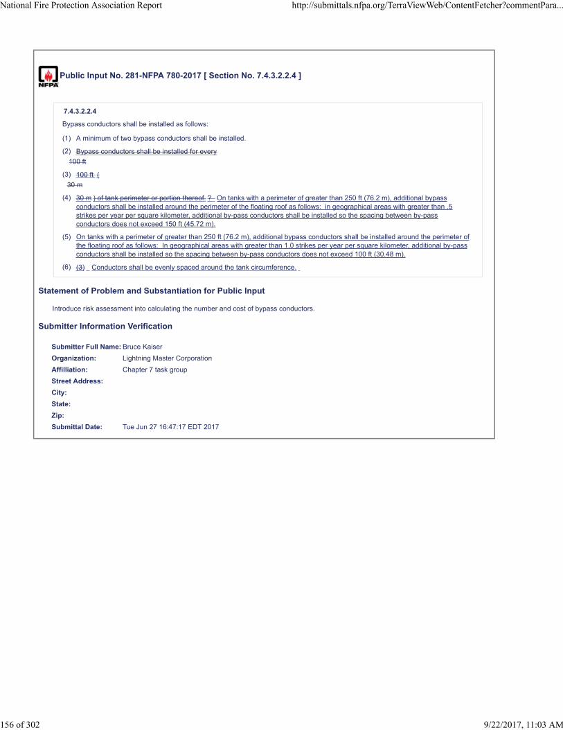
Public Input No. 281-NFPA 780-2017 [ Section No. 7.4.3.2.2.4 ]
7.4.3.2.2.4
Bypass conductors shall be installed as follows:
(1) A minimum of two bypass conductors shall be installed.
(2) Bypass conductors shall be installed for every
100 ft
(3) 100 ft (
30 m
(4) 30 m ) of tank perimeter or portion thereof. ? On tanks with a perimeter of greater than 250 ft (76.2 m), additional bypassconductors shall be installed around the perimeter of the floating roof as follows: in geographical areas with greater than .5strikes per year per square kilometer, additional by-pass conductors shall be installed so the spacing between by-passconductors does not exceed 150 ft (45.72 m).
(5) On tanks with a perimeter of greater than 250 ft (76.2 m), additional bypass conductors shall be installed around the perimeter ofthe floating roof as follows: In geographical areas with greater than 1.0 strikes per year per square kilometer, additional by-passconductors shall be installed so the spacing between by-pass conductors does not exceed 100 ft (30.48 m).
(6) (3) Conductors shall be evenly spaced around the tank circumference.
Statement of Problem and Substantiation for Public Input
Introduce risk assessment into calculating the number and cost of bypass conductors.
Submitter Information Verification
Submitter Full Name: Bruce Kaiser
Organization: Lightning Master Corporation
Affilliation: Chapter 7 task group
Street Address:
City:
State:
Zip:
Submittal Date: Tue Jun 27 16:47:17 EDT 2017
National Fire Protection Association Report http://submittals.nfpa.org/TerraViewWeb/ContentFetcher?commentPara...
156 of 302 9/22/2017, 11:03 AM

Public Input No. 345-NFPA 780-2017 [ Section No. 7.4.3.2.2.4 ]
7.4.3.2.2.4
Bypass conductors shall be installed as follows:
(1) A minimum of two one bypass conductors shall be installed.
(2) Bypass conductors If additional bypass conductors are used, these shall be installed for every 100 ft (30 m) of tank perimeter orportion thereof.
(3) Conductors shall be evenly spaced around the tank circumference.
Statement of Problem and Substantiation for Public Input
API minimum requirement is for a single bypass conductor, which is supported by API Research
Submitter Information Verification
Submitter Full Name: George Morovich
Organization: TETI
Street Address:
City:
State:
Zip:
Submittal Date: Wed Jun 28 17:33:19 EDT 2017
National Fire Protection Association Report http://submittals.nfpa.org/TerraViewWeb/ContentFetcher?commentPara...
157 of 302 9/22/2017, 11:03 AM
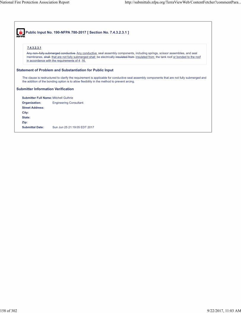
Public Input No. 190-NFPA 780-2017 [ Section No. 7.4.3.2.3.1 ]
7.4.3.2.3.1
Any non–fully submerged conductive Any conductive seal assembly components, including springs, scissor assemblies, and sealmembranes, shall that are not fully submerged shall be electrically insulated from insulated from the tank roof or bonded to the roofin accordance with the requirements of 4 .16.
Statement of Problem and Substantiation for Public Input
The clause is restructured to clarify the requirement is applicable for conductive seal assembly components that are not fully submerged and the addition of the bonding option is to allow flexibility in the method to prevent arcing.
Submitter Information Verification
Submitter Full Name: Mitchell Guthrie
Organization: Engineering Consultant
Street Address:
City:
State:
Zip:
Submittal Date: Sun Jun 25 21:19:05 EDT 2017
National Fire Protection Association Report http://submittals.nfpa.org/TerraViewWeb/ContentFetcher?commentPara...
158 of 302 9/22/2017, 11:03 AM

Public Input No. 282-NFPA 780-2017 [ Section No. 7.4.3.2.3.1 ]
7.4.3.2.3.1
Any non–fully submerged conductive seal assembly components, including springs, scissor assemblies, and sealmembranes, shall be electrically bonded to, or insulated from the tank roof.
Statement of Problem and Substantiation for Public Input
11. Change these sections to allow bonding or insulation. Insulation tends to be difficult to properly install, and to break down over time.
Submitter Information Verification
Submitter Full Name: Bruce Kaiser
Organization: Lightning Master Corporation
Affilliation: Chapter 7 task group
Street Address:
City:
State:
Zip:
Submittal Date: Tue Jun 27 16:58:36 EDT 2017
National Fire Protection Association Report http://submittals.nfpa.org/TerraViewWeb/ContentFetcher?commentPara...
159 of 302 9/22/2017, 11:03 AM

Public Input No. 287-NFPA 780-2017 [ Section No. 7.4.3.2.3.2 ]
7.4.3.2.3.2
The
If insulated from, t T he insulation level shall be rated 1 kV or greater.
Statement of Problem and Substantiation for Public Input
Allow bonding or insulation. Insulation tends to be difficult to properly install, and to break down over time.
Submitter Information Verification
Submitter Full Name: Bruce Kaiser
Organization: Lightning Master Corporation
Affilliation: Chapter 7 task group
Street Address:
City:
State:
Zip:
Submittal Date: Tue Jun 27 17:05:02 EDT 2017
National Fire Protection Association Report http://submittals.nfpa.org/TerraViewWeb/ContentFetcher?commentPara...
160 of 302 9/22/2017, 11:03 AM
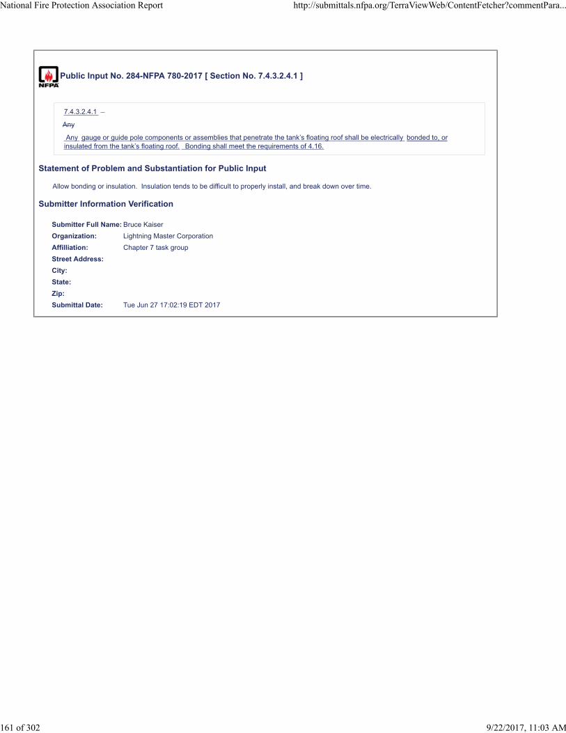
Public Input No. 284-NFPA 780-2017 [ Section No. 7.4.3.2.4.1 ]
7.4.3.2.4.1
Any
Any gauge or guide pole components or assemblies that penetrate the tank’s floating roof shall be electrically bonded to, orinsulated from the tank’s floating roof. Bonding shall meet the requirements of 4.16.
Statement of Problem and Substantiation for Public Input
Allow bonding or insulation. Insulation tends to be difficult to properly install, and break down over time.
Submitter Information Verification
Submitter Full Name: Bruce Kaiser
Organization: Lightning Master Corporation
Affilliation: Chapter 7 task group
Street Address:
City:
State:
Zip:
Submittal Date: Tue Jun 27 17:02:19 EDT 2017
National Fire Protection Association Report http://submittals.nfpa.org/TerraViewWeb/ContentFetcher?commentPara...
161 of 302 9/22/2017, 11:03 AM

Public Input No. 286-NFPA 780-2017 [ Section No. 7.4.3.2.4.2 ]
7.4.3.2.4.2
The
If insulated from, t T he insulation level shall be rated 1 kV or greater.
Statement of Problem and Substantiation for Public Input
Allow bonding or insulation. Insulation tends to be difficult to properly install, and break down over time.
Submitter Information Verification
Submitter Full Name: Bruce Kaiser
Organization: Lightning Master Corporation
Affilliation: Chapter 7 task group
Street Address:
City:
State:
Zip:
Submittal Date: Tue Jun 27 17:03:35 EDT 2017
National Fire Protection Association Report http://submittals.nfpa.org/TerraViewWeb/ContentFetcher?commentPara...
162 of 302 9/22/2017, 11:03 AM

Public Input No. 347-NFPA 780-2017 [ Section No. 7.4.3.3.1 ]
7.4.3.3.1
Such tanks or tank facilities shall be provided with strike termination devices, or catenary type devices (as defined elsewhere inNFPA 780) used to protect the tank or battery of tanks .
Statement of Problem and Substantiation for Public Input
Tanks need not have air terminal mounted on them, some are towers mounted beside the tank, but more commonly a catentary system is used to protect a tank of battery of tanks. Air terminals should not be installed at locations where combustible gases are anticipated.
Submitter Information Verification
Submitter Full Name: George Morovich
Organization: TETI
Street Address:
City:
State:
Zip:
Submittal Date: Wed Jun 28 17:37:10 EDT 2017
National Fire Protection Association Report http://submittals.nfpa.org/TerraViewWeb/ContentFetcher?commentPara...
163 of 302 9/22/2017, 11:03 AM
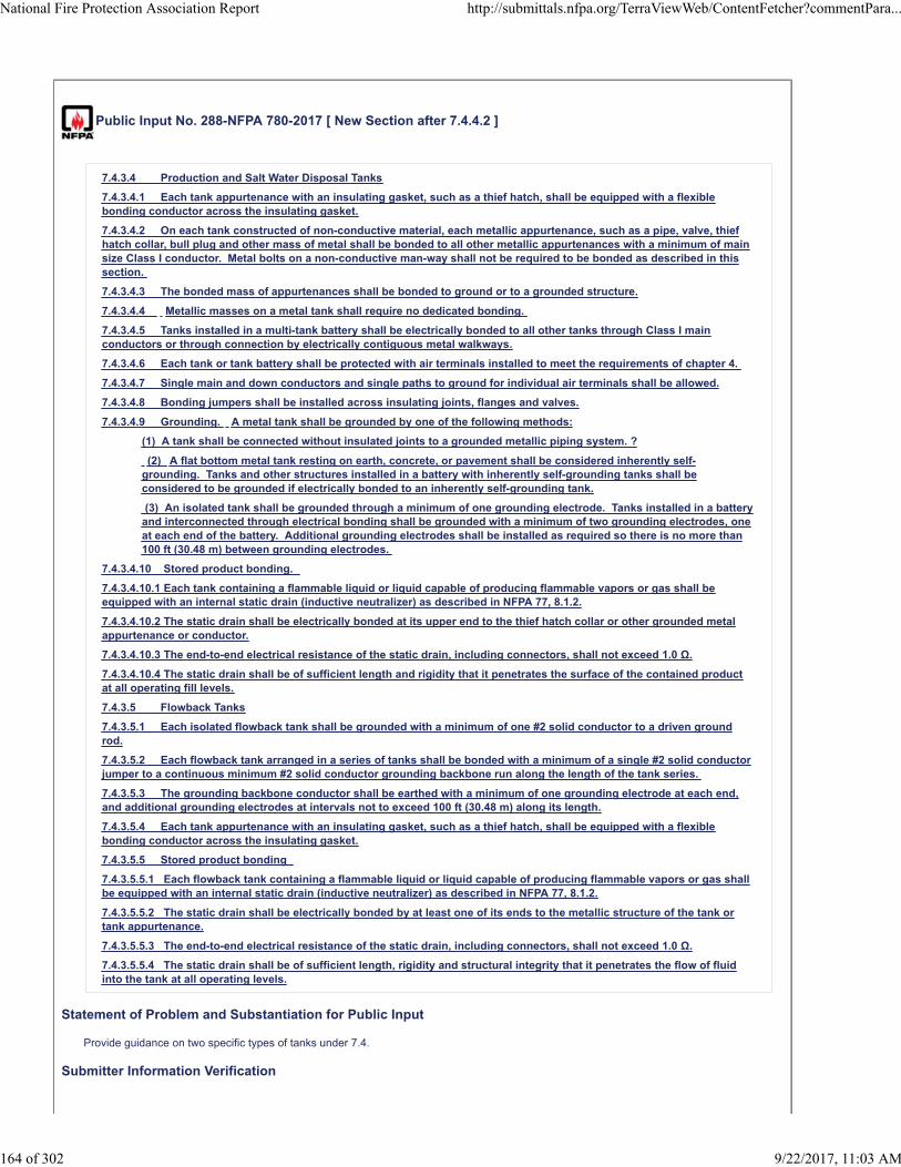
Public Input No. 288-NFPA 780-2017 [ New Section after 7.4.4.2 ]
7.4.3.4 Production and Salt Water Disposal Tanks
7.4.3.4.1 Each tank appurtenance with an insulating gasket, such as a thief hatch, shall be equipped with a flexiblebonding conductor across the insulating gasket.
7.4.3.4.2 On each tank constructed of non-conductive material, each metallic appurtenance, such as a pipe, valve, thiefhatch collar, bull plug and other mass of metal shall be bonded to all other metallic appurtenances with a minimum of mainsize Class I conductor. Metal bolts on a non-conductive man-way shall not be required to be bonded as described in thissection.
7.4.3.4.3 The bonded mass of appurtenances shall be bonded to ground or to a grounded structure.
7.4.3.4.4 Metallic masses on a metal tank shall require no dedicated bonding.
7.4.3.4.5 Tanks installed in a multi-tank battery shall be electrically bonded to all other tanks through Class I mainconductors or through connection by electrically contiguous metal walkways.
7.4.3.4.6 Each tank or tank battery shall be protected with air terminals installed to meet the requirements of chapter 4.
7.4.3.4.7 Single main and down conductors and single paths to ground for individual air terminals shall be allowed.
7.4.3.4.8 Bonding jumpers shall be installed across insulating joints, flanges and valves.
7.4.3.4.9 Grounding. A metal tank shall be grounded by one of the following methods:
(1) A tank shall be connected without insulated joints to a grounded metallic piping system. ?
(2) A flat bottom metal tank resting on earth, concrete, or pavement shall be considered inherently self-grounding. Tanks and other structures installed in a battery with inherently self-grounding tanks shall beconsidered to be grounded if electrically bonded to an inherently self-grounding tank.
(3) An isolated tank shall be grounded through a minimum of one grounding electrode. Tanks installed in a batteryand interconnected through electrical bonding shall be grounded with a minimum of two grounding electrodes, oneat each end of the battery. Additional grounding electrodes shall be installed as required so there is no more than100 ft (30.48 m) between grounding electrodes.
7.4.3.4.10 Stored product bonding.
7.4.3.4.10.1 Each tank containing a flammable liquid or liquid capable of producing flammable vapors or gas shall beequipped with an internal static drain (inductive neutralizer) as described in NFPA 77, 8.1.2.
7.4.3.4.10.2 The static drain shall be electrically bonded at its upper end to the thief hatch collar or other grounded metalappurtenance or conductor.
7.4.3.4.10.3 The end-to-end electrical resistance of the static drain, including connectors, shall not exceed 1.0 Ω.
7.4.3.4.10.4 The static drain shall be of sufficient length and rigidity that it penetrates the surface of the contained productat all operating fill levels.
7.4.3.5 Flowback Tanks
7.4.3.5.1 Each isolated flowback tank shall be grounded with a minimum of one #2 solid conductor to a driven groundrod.
7.4.3.5.2 Each flowback tank arranged in a series of tanks shall be bonded with a minimum of a single #2 solid conductorjumper to a continuous minimum #2 solid conductor grounding backbone run along the length of the tank series.
7.4.3.5.3 The grounding backbone conductor shall be earthed with a minimum of one grounding electrode at each end,and additional grounding electrodes at intervals not to exceed 100 ft (30.48 m) along its length.
7.4.3.5.4 Each tank appurtenance with an insulating gasket, such as a thief hatch, shall be equipped with a flexiblebonding conductor across the insulating gasket.
7.4.3.5.5 Stored product bonding
7.4.3.5.5.1 Each flowback tank containing a flammable liquid or liquid capable of producing flammable vapors or gas shallbe equipped with an internal static drain (inductive neutralizer) as described in NFPA 77, 8.1.2.
7.4.3.5.5.2 The static drain shall be electrically bonded by at least one of its ends to the metallic structure of the tank ortank appurtenance.
7.4.3.5.5.3 The end-to-end electrical resistance of the static drain, including connectors, shall not exceed 1.0 Ω.
7.4.3.5.5.4 The static drain shall be of sufficient length, rigidity and structural integrity that it penetrates the flow of fluidinto the tank at all operating levels.
Statement of Problem and Substantiation for Public Input
Provide guidance on two specific types of tanks under 7.4.
Submitter Information Verification
National Fire Protection Association Report http://submittals.nfpa.org/TerraViewWeb/ContentFetcher?commentPara...
164 of 302 9/22/2017, 11:03 AM

Submitter Full Name: Bruce Kaiser
Organization: Lightning Master Corporation
Affilliation: Chapter 7 task group
Street Address:
City:
State:
Zip:
Submittal Date: Tue Jun 27 17:07:33 EDT 2017
National Fire Protection Association Report http://submittals.nfpa.org/TerraViewWeb/ContentFetcher?commentPara...
165 of 302 9/22/2017, 11:03 AM

Public Input No. 350-NFPA 780-2017 [ Section No. 7.4.4.2 ]
7.4.4.2
Aboveground nonmetallic tanks shall be protected as described in Section 7.3 .
Statement of Problem and Substantiation for Public Input
Non-conductive tanks are covered elsewhere within Section 7
Submitter Information Verification
Submitter Full Name: George Morovich
Organization: TETI
Street Address:
City:
State:
Zip:
Submittal Date: Wed Jun 28 17:45:15 EDT 2017
National Fire Protection Association Report http://submittals.nfpa.org/TerraViewWeb/ContentFetcher?commentPara...
166 of 302 9/22/2017, 11:03 AM
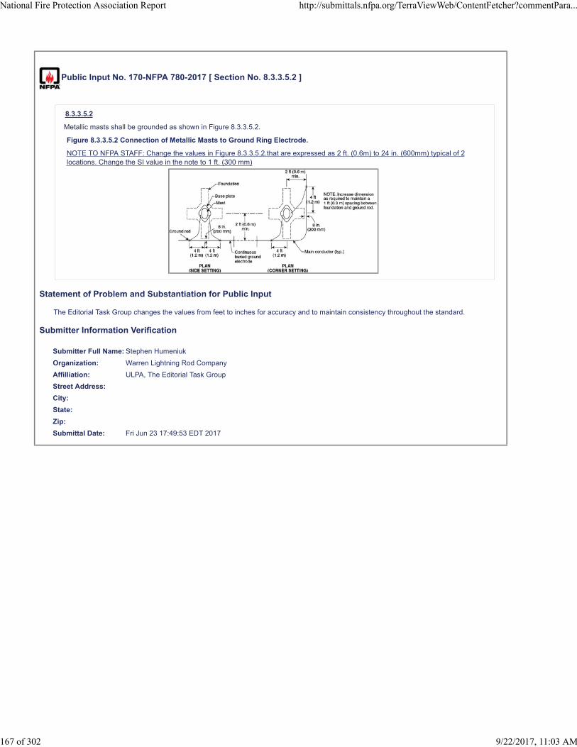
Public Input No. 170-NFPA 780-2017 [ Section No. 8.3.3.5.2 ]
8.3.3.5.2
Metallic masts shall be grounded as shown in Figure 8.3.3.5.2.
Figure 8.3.3.5.2 Connection of Metallic Masts to Ground Ring Electrode.
NOTE TO NFPA STAFF: Change the values in Figure 8.3.3.5.2.that are expressed as 2 ft. (0.6m) to 24 in. (600mm) typical of 2locations. Change the SI value in the note to 1 ft. (300 mm)
Statement of Problem and Substantiation for Public Input
The Editorial Task Group changes the values from feet to inches for accuracy and to maintain consistency throughout the standard.
Submitter Information Verification
Submitter Full Name: Stephen Humeniuk
Organization: Warren Lightning Rod Company
Affilliation: ULPA, The Editorial Task Group
Street Address:
City:
State:
Zip:
Submittal Date: Fri Jun 23 17:49:53 EDT 2017
National Fire Protection Association Report http://submittals.nfpa.org/TerraViewWeb/ContentFetcher?commentPara...
167 of 302 9/22/2017, 11:03 AM

Public Input No. 184-NFPA 780-2017 [ Section No. 8.4.3.2 ]
8.4.3.2
The ground ring electrode shall be installed no less than 3 ft (0.9 m 36 in. (900 mm ) from the structure foundation or footing.
Statement of Problem and Substantiation for Public Input
The Editorial Task Group changes values form feet to inches for accuracy and to maintain consistency throughout the standard
Submitter Information Verification
Submitter Full Name: Stephen Humeniuk
Organization: Warren Lightning Rod Company
Affilliation: ULPA, The Editorial Task Group
Street Address:
City:
State:
Zip:
Submittal Date: Fri Jun 23 18:39:00 EDT 2017
National Fire Protection Association Report http://submittals.nfpa.org/TerraViewWeb/ContentFetcher?commentPara...
168 of 302 9/22/2017, 11:03 AM

Public Input No. 56-NFPA 780-2017 [ Sections 8.7.1.1, 8.7.1.2 ]
Sections 8.7.1.1, 8.7.1.2
8.7.1.1
Air terminals Strike termination devices shall be placed on to cover the headwall, any ventilator, or other metal bodies as requiredto provide a zone of protection in accordance with 8.2.1.
8.7.1.2
Air terminals shall be permitted but are not required for portions Portions of the magazine where a minimum earth cover of 2 ft(0.6 m) is maintained shall be permitted, but are not required to be in a zone of protection .
Statement of Problem and Substantiation for Public Input
The current wording of these sections appear to only allow air terminals to protect earth covered magazines, but then says air terminals are not required on the portions covered under 2 feet of earth. It is not clear that the intent of the wording is that portions of the earth covered magazine under 2 feet of earth do not need to be protected.
The proposed revision to section 8.7.1.1 would allow for alternatives to air terminals to protect the exposed portions of the magazines, such as a mast or catenary system. Equivalently, this section could be deleted.
The proposed revision to section 8.7.1.2 is an attempt to clarify the recent (2017) revision to this section. If air terminals are not required on portions of the magazine covered under 2 feet of earth, then are those portions required to be in a zone of protection at all?
Submitter Information Verification
Submitter Full Name: David Carulli
Organization: Government
Street Address:
City:
State:
Zip:
Submittal Date: Wed Feb 15 19:26:32 EST 2017
National Fire Protection Association Report http://submittals.nfpa.org/TerraViewWeb/ContentFetcher?commentPara...
169 of 302 9/22/2017, 11:03 AM

Public Input No. 171-NFPA 780-2017 [ Section No. 8.7.1.2 ]
8.7.1.2
Air terminals shall be permitted but are not required for portions of the magazine where a minimum earth cover of 2 ft (0.6 m 24 in.(600 mm ) is maintained.
Statement of Problem and Substantiation for Public Input
The Editorial Task Group changes the values from feet to inches for accuracy and to maintain consistency throughout the standard.
Submitter Information Verification
Submitter Full Name: Stephen Humeniuk
Organization: Warren Lightning Rod Company
Affilliation: ULPA, The Editorial Task Group
Street Address:
City:
State:
Zip:
Submittal Date: Fri Jun 23 17:56:19 EDT 2017
National Fire Protection Association Report http://submittals.nfpa.org/TerraViewWeb/ContentFetcher?commentPara...
170 of 302 9/22/2017, 11:03 AM

Public Input No. 300-NFPA 780-2017 [ Section No. 8.9 ]
8.9* Maintenance and Inspection Plan .
A maintenance and inspection plan shall be developed for all protection systems used to protect structures housing explosives.
Statement of Problem and Substantiation for Public Input
The proposal is primarily editorial in nature, The purpose is to clarify the difference between Clause 8.9 Maintenance and Inspection and Clause 8.10 Inspection, Testing, and Maintenance. 8.9 discusses the Plan and 8.10 provides details on implementation of the plan.
Submitter Information Verification
Submitter Full Name: Mitchell Guthrie
Organization: Engineering Consultant
Street Address:
City:
State:
Zip:
Submittal Date: Wed Jun 28 06:58:46 EDT 2017
National Fire Protection Association Report http://submittals.nfpa.org/TerraViewWeb/ContentFetcher?commentPara...
171 of 302 9/22/2017, 11:03 AM

Public Input No. 299-NFPA 780-2017 [ Section No. 8.10.7.1 ]
8.10.7.1
The dc resistance of any single object bonded to the lightning protection system shall not exceed 1 ohm 200 milliohms .
Statement of Problem and Substantiation for Public Input
A bonding resistance of 1 ohm is unnecessarily excessive for a bond to a lightning protection system for an explosives facility, especially in those cases where internal arcing can cause significant consequences. This proposal will bring NFPA 780 in line with the normative requirements of IEC 62305-3, Edition 2 for electrical testing of the bonding resistance for structures with risk of explosion, which includes structures containing solid explosives material and structures containing hazardous (classified) locations.
Submitter Information Verification
Submitter Full Name: Mitchell Guthrie
Organization: Engineering Consultant
Street Address:
City:
State:
Zip:
Submittal Date: Wed Jun 28 06:23:34 EDT 2017
National Fire Protection Association Report http://submittals.nfpa.org/TerraViewWeb/ContentFetcher?commentPara...
172 of 302 9/22/2017, 11:03 AM

Public Input No. 2-NFPA 780-2016 [ Section No. 10.4.1.3 ]
10.4.1.3 *
A conducting fitting constructed of metal other than copper or aluminum that neither contains electrical wiring nor connectsconductors containing electrical wiring shall be permitted to be used as a main conductor if it has at least the cross-sectional areagiven by one of the following formulas:
[10.4.1.3a]
where:
A = cross-sectional area (in.2)
? = resistivity (O in.)
Cp = specific heat capacity (BTU/lbm°F)
D = density (lbm/in.2) Units of measurement should be (lb m /in. 3 )
MP = melting point (°F)
[10.4.1.3b]
where:
A = cross-sectional area (mm2)
? = resistivity (O m)
Cp = specific heat capacity (J kg-1 K-1)
D = density (kg m-3)
MP = melting point (K)
Statement of Problem and Substantiation for Public Input
Density is measured as [mass / volume]
Submitter Information Verification
Submitter Full Name: Eduardo Mariani
Organization: CIMA Ingenieria S.R.L
Street Address:
City:
State:
Zip:
Submittal Date: Wed Oct 26 07:55:37 EDT 2016
National Fire Protection Association Report http://submittals.nfpa.org/TerraViewWeb/ContentFetcher?commentPara...
173 of 302 9/22/2017, 11:03 AM
Public Input No. 53-NFPA 780-2017 [ Section No. 10.4.1.8 ]
10.4.1.8
An air gap shall be permitted to break the path of a main conductor, subject to the conditions in 10.5.5 .
Statement of Problem and Substantiation for Public Input
The air gap specified in section 10.4.1.8 is likely to result in the lightning current flowing to ground through alternate paths and/or 600 volt to 15,000 volts potentials on other grounding buses
NFPA 780 paragraph 10.4.2.7 require large metallic masses to be connected to the main conductor, paragraph10.4.28 requires stays and shrouds to be connected, and paragraph 10.4.4.7 requires that AC and DC grounding buses be connected. Therefore, parallel paths to ground which would bypass the 600 volt to 15,000 volt air gap include shore power system dockside ground connection, DC and AC electronic equipment grounding plate connections, main engine propeller shafts, cathodic bonding system, and through personnel making contact with stays, shrouds or large metal masses, particularly if thruhull fittings or large metal masses are nearby..
Additionally, many vessels are designed with negative ground battery systems (battery negative connected to the engine blocks and cathodic bonding systems. Therefore, the air gap would be bypassed by the battery negative bus, effectively converting the battery negative distribution system, main engine, and bonding system into the lightning down conductor..
Submitter Information Verification
Submitter Full Name: James Coté
Organization: Coté Marine LLC
Affilliation: None
Street Address:
City:
State:
Zip:
Submittal Date: Sun Feb 05 22:42:27 EST 2017
National Fire Protection Association Report http://submittals.nfpa.org/TerraViewWeb/ContentFetcher?commentPara...
174 of 302 9/22/2017, 11:03 AM

Public Input No. 3-NFPA 780-2016 [ Section No. 10.4.2.3 ]
10.4.2.3 *
A conducting fitting constructed of metal other than copper or aluminum that neither contains electrical wiring nor connectsconductors containing electrical wiring shall be permitted to be used as a bonding conductor if it meets the minimum cross-sectionalarea given by one of the following formulas:
[10.4.2.3a]
where:
A = cross-sectional area (in.2)
? = resistivity (O in.)
Cp = specific heat capacity (BTU/lbm°F)
D = density (lbm/in.2) Units of measurement shoul be (lb m /in. 2 )
MP = melting point (°F)
[10.4.2.3b]
where:
A = cross-sectional area (mm2)
? = resistivity (O m)
Cp = specific heat capacity (J kg-1 K-1)
D = density (kg m-3)
MP = melting point (K)
Statement of Problem and Substantiation for Public Input
Correct the units of density en section 10.4.1.3a, formula [10.4.1.3a] and section 10.4.2.3a , formula [10.4.2.3a].. Density is measured as [ mass / volume ]
Submitter Information Verification
Submitter Full Name: Eduardo Mariani
Organization: CIMA Ingenieria S.R.L
Street Address:
City:
State:
Zip:
Submittal Date: Wed Oct 26 08:08:21 EDT 2016
National Fire Protection Association Report http://submittals.nfpa.org/TerraViewWeb/ContentFetcher?commentPara...
175 of 302 9/22/2017, 11:03 AM

Public Input No. 55-NFPA 780-2017 [ Section No. 10.4.3.2 ]
10.4.3.2
The loop conductor shall be connected to at least one main conductor by means of a main conductor. , except for loop conductorswith perimeters exceeding 76 m (250 ft); where a down conductor shall be connected every 30 m (100 ft) of the perimeter or fractionthereof
Statement of Problem and Substantiation for Public Input
This change protects from side flashes and provides harmony with NFPA 780 paragraph 4.9.10.1
Submitter Information Verification
Submitter Full Name: James Coté
Organization: Coté Marine LLC
Street Address:
City:
State:
Zip:
Submittal Date: Sun Feb 05 23:31:36 EST 2017
National Fire Protection Association Report http://submittals.nfpa.org/TerraViewWeb/ContentFetcher?commentPara...
176 of 302 9/22/2017, 11:03 AM
Public Input No. 172-NFPA 780-2017 [ Section No. 10.4.6.2 ]
10.4.6.2 *
Connecting fittings made of metals other than aluminum or copper shall meet either of the following criteria:
(1) Have the same resistance per unit length as the corresponding type of conductor (that is, main or bonding)
(2) Have a cross-sectional area at least as large as that given in 10.4.1.3 for a main conductor or 10.4.2.3 for a bonding conductor,and have a resistance that is not more than the resistance of 2 ft (0.6 m 24 in. (600 mm ) of the corresponding copper conductor
Statement of Problem and Substantiation for Public Input
The Editorial Task Group changes the values from feet to inches for accuracy and to maintain consistency throughout the standard
Submitter Information Verification
Submitter Full Name: Stephen Humeniuk
Organization: Warren Lightning Rod Company
Affilliation: ULPA, The Editorial Task Group
Street Address:
City:
State:
Zip:
Submittal Date: Fri Jun 23 17:59:07 EDT 2017
National Fire Protection Association Report http://submittals.nfpa.org/TerraViewWeb/ContentFetcher?commentPara...
177 of 302 9/22/2017, 11:03 AM

Public Input No. 101-NFPA 780-2017 [ Section No. 11.1.1 ]
11.1.1 *
This chapter shall provide the minimum requirements for the installation of a lightning protection system installation requirements forairfield lighting systems and components.
Statement of Problem and Substantiation for Public Input
The existing language was verbose. The recommended language is more precise and easily understood.
Submitter Information Verification
Submitter Full Name: Carl Johnson II
Organization: AVCON Inc
Affilliation: NFPA 780 Airfield Lighting Task Group
Street Address:
City:
State:
Zip:
Submittal Date: Sat Jun 17 15:57:10 EDT 2017
National Fire Protection Association Report http://submittals.nfpa.org/TerraViewWeb/ContentFetcher?commentPara...
178 of 302 9/22/2017, 11:03 AM
Public Input No. 102-NFPA 780-2017 [ Section No. 11.1.2 ]
11.1.2 *
Lightning protection Installation of lightning protection systems for airfield lighting shall be installed entirely be entirely undergroundin accordance with the provisions of this chapter.
Statement of Problem and Substantiation for Public Input
Partial reading of the text could be interpreted to require installation -"Lightning protection systems for airfield lighting shall be installed...". The recommended language is more precise and easily understood.
Submitter Information Verification
Submitter Full Name: Carl Johnson II
Organization: AVCON Inc
Affilliation: NFPA 780 Airfield Lighting Task Group
Street Address:
City:
State:
Zip:
Submittal Date: Sat Jun 17 16:13:56 EDT 2017
National Fire Protection Association Report http://submittals.nfpa.org/TerraViewWeb/ContentFetcher?commentPara...
179 of 302 9/22/2017, 11:03 AM

Public Input No. 103-NFPA 780-2017 [ Section No. 11.2.4 ]
11.2.4
All requirements of Section 4.2, Section 4.3, Section 4.4, 4.9.5, Section 4.13, and Section 4.14 shall , as determined by theAHJ, shall apply, except as modified by this chapter.
Additional Proposed Changes
File Name Description Approved
PI_No._103_NFPA_780-2017_Airfield_Sign_Structure.pdf manufacturer's literature providing an example of sign construction
Statement of Problem and Substantiation for Public Input
For example: paragraph 4.2.2.3.2 requires aluminum conductors to be electrical-grade aluminum. Airfield signs are constructed using aluminum. The aluminum shell/frame is effectively used as a strike termination device and down conductor until connected to the copper counterpoise. The airfield signs are not constructed from electrical-grade aluminum. The task group is attempting to more precisely identify the applicability of the sections with out creating a massive list of chapters, sections, subsections, paragraphs, and subparagraphs.Please see attached Figure 20 from manufacturer's literature for an example of airfield sign construction.
Submitter Information Verification
Submitter Full Name: Carl Johnson II
Organization: AVCON Inc
Affilliation: NFPA 780 Airfield Lighting Task Group
Street Address:
City:
State:
Zip:
Submittal Date: Sat Jun 17 16:21:21 EDT 2017
National Fire Protection Association Report http://submittals.nfpa.org/TerraViewWeb/ContentFetcher?commentPara...
180 of 302 9/22/2017, 11:03 AM
Public Input No. 104-NFPA 780-2017 [ Section No. 11.4.1.2 ]
11.4.1.2 *
In locations where bare copper counterpoise conductors are adversely conductors will be adversely affected by the environment,corrosion-resistant materials (e.g., tinned copper, stainless steel, etc.) as permitted by the AHJ shall be utilized.
Statement of Problem and Substantiation for Public Input
Tense of verb was incorrect. The requirement should be implemented prior to installation.
Submitter Information Verification
Submitter Full Name: Carl Johnson II
Organization: AVCON Inc
Affilliation: NFPA 780 Airfield Lighting Task Group
Street Address:
City:
State:
Zip:
Submittal Date: Sat Jun 17 16:54:47 EDT 2017
National Fire Protection Association Report http://submittals.nfpa.org/TerraViewWeb/ContentFetcher?commentPara...
181 of 302 9/22/2017, 11:03 AM

Public Input No. 105-NFPA 780-2017 [ Section No. 11.4.2.1 ]
11.4.2.1 *
The counterpoise conductor shall be bonded to grounding electrodes at intervals not exceeding 500 ft (150 m exceeding 2,000 ft(600 m ).
Statement of Problem and Substantiation for Public Input
The section sets the maximum spacing interval requirement. The Air Force and Army are in the process of changing their maximum recommended spacing to 2000 feet. Annex A material was added to address the requirements of other AHJs.
Related Public Inputs for This Document
Related Input Relationship
Public Input No. 106-NFPA 780-2017 [New Section after A.11.4.2.4] corresponding annex a material
Public Input No. 106-NFPA 780-2017 [New Section after A.11.4.2.4]
Submitter Information Verification
Submitter Full Name: Carl Johnson II
Organization: AVCON Inc
Affilliation: NFPA 780 Airfield Lighting Task Group
Street Address:
City:
State:
Zip:
Submittal Date: Sat Jun 17 17:02:08 EDT 2017
National Fire Protection Association Report http://submittals.nfpa.org/TerraViewWeb/ContentFetcher?commentPara...
182 of 302 9/22/2017, 11:03 AM

Public Input No. 107-NFPA 780-2017 [ Section No. 11.4.2.6.1 ]
11.4.2.6.1 *
The counterpoise conductor shall be installed either centered installed centered over the raceway or cable to be protected asdescribed in 11.4.2.6.1 and as shown in Figure .1 thrugh 11.4.2.6.1 or in accordance with .8 and as shown in Figure 11.4.2.6.2 1 .
Figure 11.4.2.6.1 Counterpoise Centered Over Raceway or Cable to Be Protected.
11.4.2.6.1.1
The counterpoise conductor shall be installed no less than 8 in. (200 mm) above the raceway or cable to be protected, except aspermitted in 11.4.2.6.1.2 and 11.4.2.6.1.3.
11.4.2.6.1.2 *
The minimum counterpoise or maximum counterpoise conductor height above the raceway or cable to be protected shall bepermitted to be adjusted subject to coordination with the airfield lighting and pavement designs.
11.4.2.6.1.3 *
Where the raceway is installed by the directional bore, jack and bore, or other drilling method, the counterpoise conductor shall bepermitted to be installed concurrently with the directional bore, jack and bore, or other drilling method raceway, external to theraceway or sleeve.
11.4.2.6.1.4
The counterpoise conductor shall be installed no more than 12 in. (300 mm) above the raceway or cable to be protected.
11.4.2.6.1.5
The counterpoise conductor height above the protected raceway(s) or cable(s) shall be calculated to ensure that the raceway orcable is within a 45-degree area of protection.
11.4.2.6.1.6 *
The area of protection shall be determined only by the 45-degree triangular prism area of protection method. prism method asdepicted in Figure11.4.2.6.1.6.
11.4.2.6.1.7
The counterpoise conductor shall be bonded to each metallic light base, mounting stake, and metallic airfield lighting component.
11.4.2.6.1.8 *
All metallic airfield lighting components in the field circuit on the output side of the constant current regulator (CCR) or other powersource shall be bonded to the airfield lighting counterpoise system.
Additional Proposed Changes
File Name Description Approved
Fig_11.4.2.6.1.6_Area_of_Prot_-_Triangular_Prism.jpg New Figure 11.4.2.6.1.6
Statement of Problem and Substantiation for Public Input
Both counterpoise methods were discussed in section 11.4.2.6.1. The change clarified the requirements of the two methods. The new annex material attached to 11.4.2.6 clarified that order of appearance in the standard does not imply a preference.
National Fire Protection Association Report http://submittals.nfpa.org/TerraViewWeb/ContentFetcher?commentPara...
183 of 302 9/22/2017, 11:03 AM

Related Public Inputs for This Document
Related Input Relationship
Public Input No. 108-NFPA 780-2017 [New Section after A.11.4.2.4]
Public Input No. 108-NFPA 780-2017 [New Section after A.11.4.2.4]
Public Input No. 110-NFPA 780-2017 [Section No. 11.4.3.1.2]
Submitter Information Verification
Submitter Full Name: Carl Johnson II
Organization: AVCON Inc
Affilliation: NFPA 780 Airfield Lighting Task Group
Street Address:
City:
State:
Zip:
Submittal Date: Sat Jun 17 17:29:33 EDT 2017
National Fire Protection Association Report http://submittals.nfpa.org/TerraViewWeb/ContentFetcher?commentPara...
184 of 302 9/22/2017, 11:03 AM

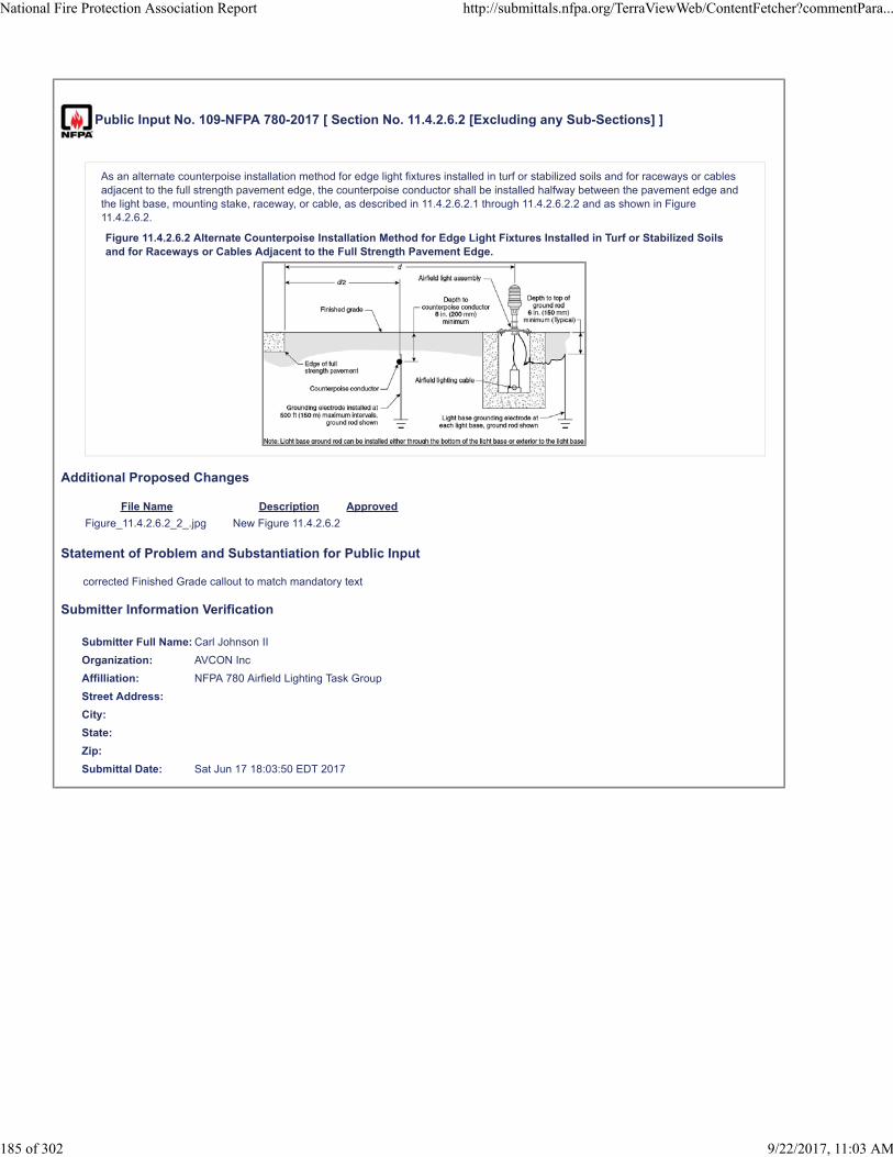
Public Input No. 109-NFPA 780-2017 [ Section No. 11.4.2.6.2 [Excluding any Sub-Sections] ]
As an alternate counterpoise installation method for edge light fixtures installed in turf or stabilized soils and for raceways or cablesadjacent to the full strength pavement edge, the counterpoise conductor shall be installed halfway between the pavement edge andthe light base, mounting stake, raceway, or cable, as described in 11.4.2.6.2.1 through 11.4.2.6.2.2 and as shown in Figure11.4.2.6.2.
Figure 11.4.2.6.2 Alternate Counterpoise Installation Method for Edge Light Fixtures Installed in Turf or Stabilized Soilsand for Raceways or Cables Adjacent to the Full Strength Pavement Edge.
Additional Proposed Changes
File Name Description Approved
Figure_11.4.2.6.2_2_.jpg New Figure 11.4.2.6.2
Statement of Problem and Substantiation for Public Input
corrected Finished Grade callout to match mandatory text
Submitter Information Verification
Submitter Full Name: Carl Johnson II
Organization: AVCON Inc
Affilliation: NFPA 780 Airfield Lighting Task Group
Street Address:
City:
State:
Zip:
Submittal Date: Sat Jun 17 18:03:50 EDT 2017
National Fire Protection Association Report http://submittals.nfpa.org/TerraViewWeb/ContentFetcher?commentPara...
185 of 302 9/22/2017, 11:03 AM


Public Input No. 66-NFPA 780-2017 [ Section No. 11.4.2.6.2 [Excluding any Sub-Sections] ]
As an alternate counterpoise installation method for elevated edge light fixtures installed in turf or stabilized soils and for raceways orcables adjacent to the full strength pavement edge, the counterpoise conductor shall be installed halfway between the pavement edgeand the light base, mounting stake, raceway, or cable, as described in 11.4.2.6.2.1 through 11.4.2.6.2.2 and as shown in Figure11.4.2.6.2.
Figure 11.4.2.6.2 Alternate Counterpoise Installation Method for Elevated Edge Light Fixtures Installed in Turf or StabilizedSoils and for Raceways or Cables Adjacent to the Full Strength Pavement Edge.
Statement of Problem and Substantiation for Public Input
Figure 11.4.2.6.2 shows an elevated edge fixture. Fixtures installed in a turf or stabilized soil area would typically be an elevated edge light fixture.Revised text matches figure and typical installation practices.
Related Public Inputs for This Document
Related Input Relationship
Public Input No. 67-NFPA 780-2017 [Section No. A.11.1.1] added term "elevated"
Public Input No. 67-NFPA 780-2017 [Section No. A.11.1.1]
Submitter Information Verification
Submitter Full Name: Carl Johnson II
Organization: AVCON, Inc.
Street Address:
City:
State:
Zip:
Submittal Date: Tue Apr 25 10:41:32 EDT 2017
National Fire Protection Association Report http://submittals.nfpa.org/TerraViewWeb/ContentFetcher?commentPara...
186 of 302 9/22/2017, 11:03 AM

Public Input No. 110-NFPA 780-2017 [ Section No. 11.4.3.1.2 ]
11.4.3.1.2
The 45-degree area of protection shall be maintained in accordance with 11.4.2.6.1. 6.
Statement of Problem and Substantiation for Public Input
Corrects subsection reference in accordance with PI No. 107.
Related Public Inputs for This Document
Related Input Relationship
Public Input No. 107-NFPA 780-2017 [Section No. 11.4.2.6.1]
Submitter Information Verification
Submitter Full Name: Carl Johnson II
Organization: AVCON Inc
Affilliation: NFPA 780 Airfield Lighting Task Group
Street Address:
City:
State:
Zip:
Submittal Date: Sat Jun 17 18:12:03 EDT 2017
National Fire Protection Association Report http://submittals.nfpa.org/TerraViewWeb/ContentFetcher?commentPara...
187 of 302 9/22/2017, 11:03 AM

Public Input No. 111-NFPA 780-2017 [ Section No. 11.4.3.1.3 ]
11.4.3.1.3
The maximum width of the area of protection shall separation between counterpoise conductors shall be twice the height of thecounterpoise conductor above the protected raceway or cable.
Statement of Problem and Substantiation for Public Input
Clarification that the text and figure refer to the distance between the conductors, not the area of protection.
Submitter Information Verification
Submitter Full Name: Carl Johnson II
Organization: AVCON Inc
Affilliation: NFPA 780 Airfield Lighting Task Group
Street Address:
City:
State:
Zip:
Submittal Date: Sat Jun 17 18:16:43 EDT 2017
National Fire Protection Association Report http://submittals.nfpa.org/TerraViewWeb/ContentFetcher?commentPara...
188 of 302 9/22/2017, 11:03 AM
Public Input No. 112-NFPA 780-2017 [ Section No. 11.4.4.1 ]
11.4.4.1
Where raceways or cables cross, the intersecting counterpoise conductors shall be interconnected by bondng .
Statement of Problem and Substantiation for Public Input
The existing language was not specific. The recommended language is more precise and easily understood.
Submitter Information Verification
Submitter Full Name: Carl Johnson II
Organization: AVCON Inc
Affilliation: NFPA 780 Airfield Lighting Task Group
Street Address:
City:
State:
Zip:
Submittal Date: Sat Jun 17 18:26:31 EDT 2017
National Fire Protection Association Report http://submittals.nfpa.org/TerraViewWeb/ContentFetcher?commentPara...
189 of 302 9/22/2017, 11:03 AM

Public Input No. 113-NFPA 780-2017 [ Section No. 11.4.5.2 ]
11.4.5.2 *
Grounding electrodes shall comply with all requirements of 4.13.2, 4.13.5, 4.13.6, 4.13.7, and 4.13.8, except as modified by thischapter and as determined by the AHJ .
Statement of Problem and Substantiation for Public Input
Not all references may be specifically applicable to airfield lighting. The task group is attempting to more precisely identify the applicability of the sections with out creating a massive list of chapters, sections, subsections, paragraphs, and subparagraphs.
Submitter Information Verification
Submitter Full Name: Carl Johnson II
Organization: AVCON Inc
Affilliation: NFPA 780 Airfield Lighting Task Group
Street Address:
City:
State:
Zip:
Submittal Date: Sat Jun 17 18:29:40 EDT 2017
National Fire Protection Association Report http://submittals.nfpa.org/TerraViewWeb/ContentFetcher?commentPara...
190 of 302 9/22/2017, 11:03 AM
Public Input No. 114-NFPA 780-2017 [ Section No. 11.4.7.2 ]
11.4.7.2
For existing During new installations, when existing metallic light bases without ground straps are encountered , the installation ofground straps shall not interfere with the structural integrity of the light base.
Statement of Problem and Substantiation for Public Input
The original text could have been interpreted to require global retrofitting existing light bases. The recommended language is more precise and easily understood.
Submitter Information Verification
Submitter Full Name: Carl Johnson II
Organization: AVCON Inc
Affilliation: NFPA 780 Airfield Lighting Task Group
Street Address:
City:
State:
Zip:
Submittal Date: Sat Jun 17 18:38:41 EDT 2017
National Fire Protection Association Report http://submittals.nfpa.org/TerraViewWeb/ContentFetcher?commentPara...
191 of 302 9/22/2017, 11:03 AM

Public Input No. 115-NFPA 780-2017 [ Section No. 11.4.8.1 ]
11.4.8.1 *
All counterpoise conductor connectors, grounding connectors, and bonding connectors shall be listed with relevant standards utilizedfor the purpose intended by listing agencies .
Statement of Problem and Substantiation for Public Input
The existing language was verbose. The recommended language is more precise and easily understood.
Submitter Information Verification
Submitter Full Name: Carl Johnson II
Organization: AVCON Inc
Affilliation: NFPA 780 Airfield Lighting Task Group
Street Address:
City:
State:
Zip:
Submittal Date: Sat Jun 17 18:43:08 EDT 2017
National Fire Protection Association Report http://submittals.nfpa.org/TerraViewWeb/ContentFetcher?commentPara...
192 of 302 9/22/2017, 11:03 AM
Public Input No. 116-NFPA 780-2017 [ Section No. 11.4.8.5 ]
11.4.8.5 *
The metallic light base ground strap with ground clamp shall be used for connection of the counterpoise conductor to or groundingelectrode to the light base.
Statement of Problem and Substantiation for Public Input
The original text, as written, was applicable to the equipotential method only. The revised text makes the statement applicable to both the equipotential method and isolation method, as originally intended.
Submitter Information Verification
Submitter Full Name: Carl Johnson II
Organization: AVCON Inc
Affilliation: NFPA 780 Airfield Lighting Task Group
Street Address:
City:
State:
Zip:
Submittal Date: Sat Jun 17 18:46:37 EDT 2017
National Fire Protection Association Report http://submittals.nfpa.org/TerraViewWeb/ContentFetcher?commentPara...
193 of 302 9/22/2017, 11:03 AM

Public Input No. 63-NFPA 780-2017 [ Chapter 12 [Title Only] ]
Protection for Solar Photovoltaic Arrays
Statement of Problem and Substantiation for Public Input
the term "solar arrays" includes solar thermal, solar hot water and concentrating solar thermal collectors as well as solar photovoltaic (i.e. solar electric) arrays. Photovoltaic or 'PV' is the term used in the industry to distinguish this specific technology from other solar technologies, and would be the commonly used search term for finding relevant standards and requirements. PV arrays have distinct susceptibilities to lightning hazards in contrast to solar heating technologies.
c.f. https://energy.gov/eere/sunshot/solar-energy-glossary#photovoltaic
Submitter Information Verification
Submitter Full Name: Brian Quinn
Organization: M+W Energy Inc.
Street Address:
City:
State:
Zip:
Submittal Date: Fri Apr 21 18:32:48 EDT 2017
National Fire Protection Association Report http://submittals.nfpa.org/TerraViewWeb/ContentFetcher?commentPara...
194 of 302 9/22/2017, 11:03 AM

Public Input No. 173-NFPA 780-2017 [ Section No. 12.3.2.1 ]
12.3.2.1
Sloped solar panels or arrays having a horizontal distance (run) of 40 ft (12 m) or less and a slope of 1⁄8 or greater and solar panels orarrays having a horizontal distance (run) of more than 40 ft (12 m) and a slope of 1⁄4 or greater shall have strike termination deviceslocated as follows:
(1) Strike termination devices shall be located such that they extend a minimum of 10 in. (254 mm) vertically above the uppermostedge of the solar panel or array.
(2) Strike termination devices shall be located such that they are within 2 ft (0.6 m 24 in. (600 mm ) of the ends of the apex of thesolar panel or array.
(3) Strike termination devices shall be located within 2 ft (0.6 m 24 in. (600 mm ) of the apex of the solar panel or array.
(4) Strike termination devices shall be located at intervals not exceeding 20 ft (6 m) along the apex of the solar panel or array.
(5) Strike termination devices that extend 2 ft (0.6 m 24 in. (600 mm ) or more above the apex of the solar panel or array shall bepermitted to be placed at intervals not exceeding 25 ft (7.6 m) along the uppermost edge of the solar panel or array.
Statement of Problem and Substantiation for Public Input
The Editorial Task Group changes the values from feet to inches for accuracy and to maintain consistency throughout the standard
Submitter Information Verification
Submitter Full Name: Stephen Humeniuk
Organization: Warren Lightning Rod Company
Affilliation: ULPA, The Editorial Task Group
Street Address:
City:
State:
Zip:
Submittal Date: Fri Jun 23 18:01:44 EDT 2017
National Fire Protection Association Report http://submittals.nfpa.org/TerraViewWeb/ContentFetcher?commentPara...
195 of 302 9/22/2017, 11:03 AM

Public Input No. 64-NFPA 780-2017 [ Section No. 12.3.2.1 ]
12.3.2.1
Sloped solar panels or arrays having a horizontal distance (run) of 40 ft (12 m) or less and a slope of 1 ⁄ 8 7.5 degrees or greater
and solar panels or arrays having a horizontal distance (run) of more than 40 ft (12 m) and a slope of 1 ⁄ 4 15 degrees or greatershall have strike termination devices located as follows:
(1) Strike termination devices shall be located such that they extend a minimum of 10 in. (254 mm 0.25 m ) vertically above theuppermost edge of the solar panel or array.
(2) Strike termination devices shall be located such that they are within 2 ft (0.6 m) of the ends of the apex of the solar panel orarray.
(3) Strike termination devices shall be located within 2 ft (0.6 m) of the apex of the solar panel or array.
(4) Strike termination devices shall be located at intervals not exceeding 20 ft (6 m) along the apex of the solar panel or array.
(5) Strike termination devices that extend 2 ft (0.6 m) or more above the apex of the solar panel or array shall be permitted to beplaced at intervals not exceeding 25 ft (7.6 m) along the uppermost edge of the solar panel or array.
Statement of Problem and Substantiation for Public Input
In the solar industry, solar (PV) panel elevation (or tilt) angles are invariably given in degrees from horizontal, not as ratios or percentage slopes. 10 and 15 degrees are common angles for low tilt systems and/or at low latitudes, and the minimum tilt angle is generally 5 degrees (to avoid accumulation of dirt along the lower edge of module frames). Use of angles in degrees rather than fractional slopes makes for easy comprehension without risk of conversion errors.
Regarding the suggested change from 254 mm to 0.25 m, soft conversions to SI units appear to have been used in the document, e.g. 2 ft » 0.6 m rather than 610 mm. In the interest of consistency, conversion of 10 in as 0.25 m seems more elegant and appropriate. Alternatively, all dimensions of less than one metre/meter could be rendered as "mm", rounded to 10 mm or 50 mm as appropriate, except where the context calls for 3-digit precision.
Submitter Information Verification
Submitter Full Name: Brian Quinn
Organization: [ Not Specified ]
Street Address:
City:
State:
Zip:
Submittal Date: Fri Apr 21 18:48:45 EDT 2017
National Fire Protection Association Report http://submittals.nfpa.org/TerraViewWeb/ContentFetcher?commentPara...
196 of 302 9/22/2017, 11:03 AM
Public Input No. 174-NFPA 780-2017 [ Section No. 12.3.2.2 ]
12.3.2.2
Solar panels or arrays that have a slope of less than ¼ and the distance from the uppermost edge to the lowermost edge along theface of the panel or array exceeds 20 ft (6 m) shall have strike termination devices located as follows:
(1) Strike termination devices shall be located within 2 ft (0.6 m 24 in. (600 mm ) of the outermost corners of the solar panel or arrayunless those corners are within a zone of protection.
(2) Strike termination devices shall be located at intervals not exceeding 20 ft 20 ft. (6 m) along all edges of the solar panel or arrayunless those edges are within a zone of protection.
(3) Strike termination devices that extend 2 ft (0.6 m 24 in (600 mm ) or more above the edges of the solar panel or array shall bepermitted to be placed at intervals not exceeding 25 ft (7.6 m) along the edges of the solar panel or array.
Statement of Problem and Substantiation for Public Input
The Editorial Task Group changes the values from feet to inches for accuracy and to maintain consistency throughout the standard
Submitter Information Verification
Submitter Full Name: Stephen Humeniuk
Organization: Warren Lightning Rod Company
Affilliation: ULPA, The Editorial Task Group
Street Address:
City:
State:
Zip:
Submittal Date: Fri Jun 23 18:06:10 EDT 2017
National Fire Protection Association Report http://submittals.nfpa.org/TerraViewWeb/ContentFetcher?commentPara...
197 of 302 9/22/2017, 11:03 AM
Public Input No. 123-NFPA 780-2017 [ Section No. 12.4.2.2 ]
12.4.2.2
PV surge protective devices shall have a nominal discharge current rating (In ) of 20kA 8/20 µs per mode.
Statement of Problem and Substantiation for Public Input
The Editorial Task Group make this change to keep this reference consistent through out the standard
Submitter Information Verification
Submitter Full Name: Stephen Humeniuk
Organization: Warren Lightning Rod Company
Affilliation: ULPA, Editorial Task Group
Street Address:
City:
State:
Zip:
Submittal Date: Mon Jun 19 16:29:20 EDT 2017
National Fire Protection Association Report http://submittals.nfpa.org/TerraViewWeb/ContentFetcher?commentPara...
198 of 302 9/22/2017, 11:03 AM

Public Input No. 124-NFPA 780-2017 [ Section No. 12.4.3.2 ]
12.4.3.2
Surge protective devices shall have a nominal discharge current rating (In ) of 20kA 8/20 µs per mode.
Statement of Problem and Substantiation for Public Input
The Editorial Task Group makes this change to keep this reference consistent through out the standard.
Submitter Information Verification
Submitter Full Name: Stephen Humeniuk
Organization: Warren Lightning Rod Company
Affilliation: ULPA. Editorial Task Group
Street Address:
City:
State:
Zip:
Submittal Date: Mon Jun 19 16:32:50 EDT 2017
National Fire Protection Association Report http://submittals.nfpa.org/TerraViewWeb/ContentFetcher?commentPara...
199 of 302 9/22/2017, 11:03 AM
Public Input No. 224-NFPA 780-2017 [ New Section after 12.5.2.5 ]
Chapter 13. Protection for Bridge
Statement of Problem and Substantiation for Public Input
Add new chapter “Protection for Bridge”
Related Public Inputs for This Document
Related Input Relationship
Public Input No. 204-NFPA 780-2017 [New Section after 3.3.50]
Submitter Information Verification
Submitter Full Name: Youngki Chung
Organization: Omni Lps
Street Address:
City:
State:
Zip:
Submittal Date: Mon Jun 26 06:52:30 EDT 2017
National Fire Protection Association Report http://submittals.nfpa.org/TerraViewWeb/ContentFetcher?commentPara...
200 of 302 9/22/2017, 11:03 AM

Public Input No. 338-NFPA 780-2017 [ New Section after A.1.6 ]
A.1.6.1
See the attached text adding recommendation for existing structures with obsolete systems or systems in disrepair
Additional Proposed Changes
File Name Description Approved
NFPA_A.1.6.1.docx
Statement of Problem and Substantiation for Public Input
Many existing structures with existing lightning protection have systems that are either obsolete or in substantial disrepair. The Existing Structures Task Group Make the proposal to provide suggestions for those systems.
Related Public Inputs for This Document
Related Input Relationship
Public Input No. 337-NFPA 780-2017 [Section No. 1.6.1]
Submitter Information Verification
Submitter Full Name: Stephen Humeniuk
Organization: Warren Lightning Rod Company
Affilliation: ULPA, The Existing Strucutres Task Group
Street Address:
City:
State:
Zip:
Submittal Date: Wed Jun 28 15:58:02 EDT 2017
National Fire Protection Association Report http://submittals.nfpa.org/TerraViewWeb/ContentFetcher?commentPara...
201 of 302 9/22/2017, 11:03 AM

A.1.6.1 Keeping the lightning protection system up to date with current standards is the best practice. However, periodic inspection and maintenance is often neglected. Facilities with lightning protection systems older than twenty years, that have undergone additions, or have had alterations, should be brought into compliance with the current standards. When a lightning protection system is upgrade, As-built drawings are recommended so the AHJ has record of the modifications. These drawing should include testing point locations, if installed. Where required by the AHJ, test records of the new configured system shall be provided to establish a new baseline for future test measurements. If no modifications have occurred since construction, do a visual inspection at a minimum. Re-evaluate the need to improve the lightning protection system, based on the current use and contents of the facility. If the system, as previously installed, provides adequate coverage, no additional changes are required. The AHJ is advised to maintain the applicable drawings and test records. If the system is in disrepair, and is no longer deemed necessary by the AHJ based upon the structures use, occupancy and content, the facility would be better off with the lightning protection system removed, than to have a nonfunctional system.

Public Input No. 291-NFPA 780-2017 [ New Section after A.3.3.1 ]
Add new A.3.3.X Inherently Bonded.
A method to determine whether grounded media and buried metallic conductors are inherently bonded through construction is toperform a bonding test using test equipment suitable for the purpose. The bonding resistance value should typically be in the tens ofmilliohms but should not exceed 200 milliohms.
Statement of Problem and Substantiation for Public Input
Provide a suggested criteria to determine whether a connection meets the requirements of being inherently bonded.
Submitter Information Verification
Submitter Full Name: Mitchell Guthrie
Organization: Engineering Consultant
Affilliation: NFPA 780 Grounding and Bonding Task Group
Street Address:
City:
State:
Zip:
Submittal Date: Tue Jun 27 17:29:58 EDT 2017
National Fire Protection Association Report http://submittals.nfpa.org/TerraViewWeb/ContentFetcher?commentPara...
202 of 302 9/22/2017, 11:03 AM

Public Input No. 298-NFPA 780-2017 [ New Section after A.3.3.7.6 ]
Add new A.3.3.7.4 Ground Loop Conductor.
A ground ring electrode is a buried ground loop conductor.
Statement of Problem and Substantiation for Public Input
The proposed text makes it clear that a ground ring electrode is a buried ground loop conductor.
Related Public Inputs for This Document
Related Input Relationship
Public Input No. 297-NFPA 780-2017 [Section No. 3.3.7.4] Identifies annex material is available
Submitter Information Verification
Submitter Full Name: Mitchell Guthrie
Organization: Engineering Consultant
Street Address:
City:
State:
Zip:
Submittal Date: Tue Jun 27 23:29:53 EDT 2017
National Fire Protection Association Report http://submittals.nfpa.org/TerraViewWeb/ContentFetcher?commentPara...
203 of 302 9/22/2017, 11:03 AM

Public Input No. 72-NFPA 780-2017 [ Section No. A.3.3.23 ]
A.3.3.23 Light Base.
The light base is cylindrically shaped with a closed bottom and a top flange to mate with an airfield fixture or cover. Currentlyavailable light bases have provisions for cable or conduit entry and exit and provisions for bonding.
Type L-867 light bases and extensions are used for applications subject to occasional light vehicular loading but no aircraft or otherheavy vehicular loading. Type L-868 light bases and extensions are used for applications subject to aircraft and other heavy vehicularloading. Light bases, which can be fabricated from metallic or nonmetallic materials, serve as a connection point for the raceway andhousing for mounting the light fixture. Light bases are subject to direct earth burial with or without concrete backfill. Drainconnections, load rings, and other options are available for the light base.
Additional information can be found in FAA Advisory Circular 150/5345-42F 42H , Specification for Airport Light Bases, TransformerHousings, Junction Boxes, and Accessories.
Statement of Problem and Substantiation for Public Input
Advisory circular reference was not current.Proposed text updates to current AC edition.
Submitter Information Verification
Submitter Full Name: Carl Johnson II
Organization: AVCON, Inc.
Street Address:
City:
State:
Zip:
Submittal Date: Tue Apr 25 12:15:43 EDT 2017
National Fire Protection Association Report http://submittals.nfpa.org/TerraViewWeb/ContentFetcher?commentPara...
204 of 302 9/22/2017, 11:03 AM

Public Input No. 138-NFPA 780-2017 [ New Section after A.4.1.1.1 ]
A.4.4.1
The requirement to protect conductors from mechanical damage does not preclude the running of exposed wiring at roofingperimeters, on roof surfaces, or other similar locations where incidental foot traffic or manual disturbance of the conductor is possible.This paragraph is not intended to require the concealment of all exposed lightning protection components in conduit or similar.
Statement of Problem and Substantiation for Public Input
We recently ran across a situation where a QA/QC inspector thought our exposed conductor should have been in conduit, when it was installed at the base of a kickplate, in a location where any disturbance to the wiring would have to have been deliberate. This annex clarifies the situation so that installers can't be told that their exposed wiring is unacceptable because some random hypothetical clumsy person might trip over it or stumble against it at some point in the future.
Seriously, if we don't clarify it, people will find a way to misinterpret it.
Related Public Inputs for This Document
Related Input Relationship
Public Input No. 137-NFPA 780-2017 [Section No. 4.4.1] Annex and asterisk. They go together like carrots and peas.
Public Input No. 137-NFPA 780-2017 [Section No. 4.4.1]
Submitter Information Verification
Submitter Full Name: Simon Larter
Organization: Dobbyn Lightning Protection
Street Address:
City:
State:
Zip:
Submittal Date: Wed Jun 21 11:19:24 EDT 2017
National Fire Protection Association Report http://submittals.nfpa.org/TerraViewWeb/ContentFetcher?commentPara...
205 of 302 9/22/2017, 11:03 AM

Public Input No. 125-NFPA 780-2017 [ Section No. A.4.1.1.1 ]
A.4.1.1.1
Main-size lightning conductors are not manufactured to standard American Wire Gauge (AWG) sizes. Bare AWG conductors are nottypically “listed for the purpose” for lightning protection by any listing authority. Table A.4.1.1.1 provides comparisons betweenlightning protection conductors and the closest AWG sizes from Table 8 in Chapter 9 ofNFPA 70.
Table A.4.1.1.1 Lightning Protection Conductors
Lightning Conductor Area
A.
Class I main-size copper lightning conductor 57,400 cir. mils
#2 AWG 66,360 cir. mils
#3 AWG 52,620 cir. mils
B.
Class I main-size aluminum lightning conductor 98,600 cir. mils
#1 AWG 83,690 cir. mils
#1/0 AWG 105,600 cir. mils
C.
Class II main-size copper lightning conductor 115,000 cir. mils
#1/0 AWG 105,600 cir. mils
#2/0 AWG 133,100 cir. mils
D.
Class II main-size aluminum lightning conductor 192,000 cir. mils
#3/0 AWG 167,800 cir. mils
#4/0 AWG211,600 cir. mils
Lightning bonding conductor
Copper 26,240 cir. mils
#6 AWG
.
26,240 cir. mils
Lightning bonding conductor
Aluminum 41,100 cir. mils
#4 AWG 41,740 cir. mils
Statement of Problem and Substantiation for Public Input
The Editorial committee removes the Capitol letter references from the titles. They serve no purpose. The titles are sufficient. Also, add a single line between copper and aluminum in the bottom cell. TERRA WILL NOT ALLOW THIS CHANGE SO IT MUST BE DONE BY NFPA STAFF. This is for consistency. It also separates, and differentiate between the materials
Submitter Information Verification
Submitter Full Name: Stephen Humeniuk
Organization: Warren Lightning Rod Company
Affilliation: ULPA, The Editorial Task Group
Street Address:
City:
State:
Zip:
National Fire Protection Association Report http://submittals.nfpa.org/TerraViewWeb/ContentFetcher?commentPara...
206 of 302 9/22/2017, 11:03 AM

Submittal Date: Mon Jun 19 16:39:34 EDT 2017
National Fire Protection Association Report http://submittals.nfpa.org/TerraViewWeb/ContentFetcher?commentPara...
207 of 302 9/22/2017, 11:03 AM
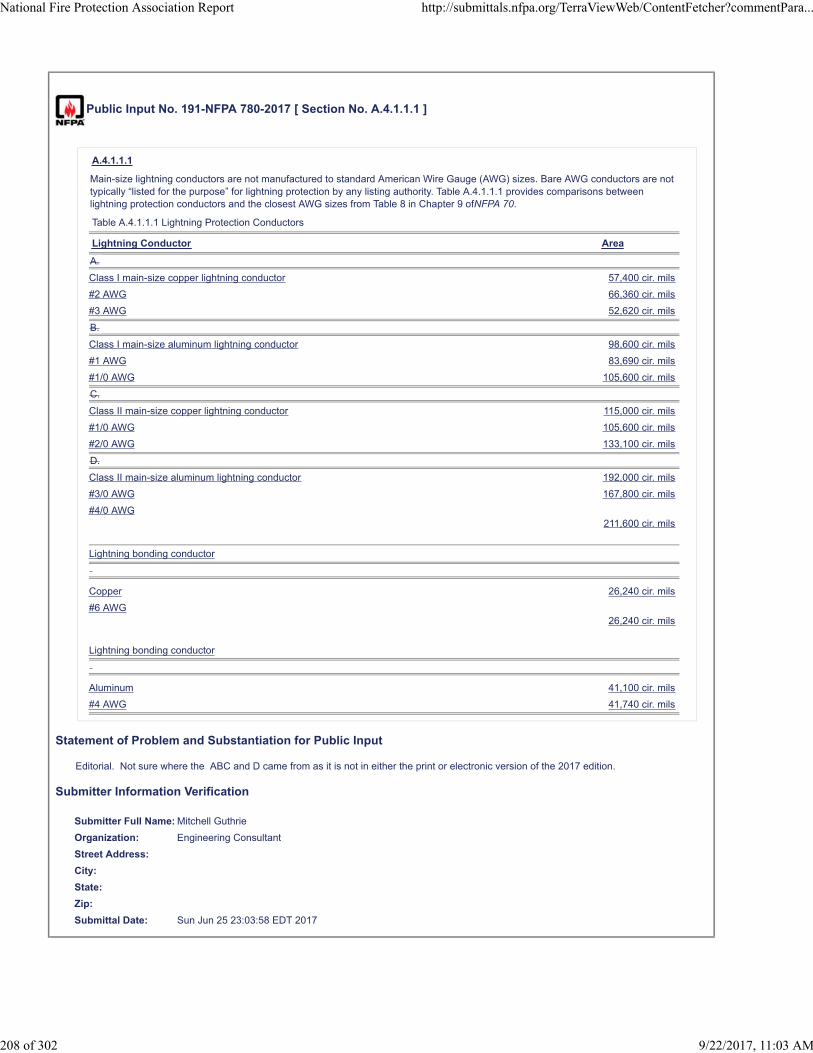
Public Input No. 191-NFPA 780-2017 [ Section No. A.4.1.1.1 ]
A.4.1.1.1
Main-size lightning conductors are not manufactured to standard American Wire Gauge (AWG) sizes. Bare AWG conductors are nottypically “listed for the purpose” for lightning protection by any listing authority. Table A.4.1.1.1 provides comparisons betweenlightning protection conductors and the closest AWG sizes from Table 8 in Chapter 9 ofNFPA 70.
Table A.4.1.1.1 Lightning Protection Conductors
Lightning Conductor Area
A.
Class I main-size copper lightning conductor 57,400 cir. mils
#2 AWG 66,360 cir. mils
#3 AWG 52,620 cir. mils
B.
Class I main-size aluminum lightning conductor 98,600 cir. mils
#1 AWG 83,690 cir. mils
#1/0 AWG 105,600 cir. mils
C.
Class II main-size copper lightning conductor 115,000 cir. mils
#1/0 AWG 105,600 cir. mils
#2/0 AWG 133,100 cir. mils
D.
Class II main-size aluminum lightning conductor 192,000 cir. mils
#3/0 AWG 167,800 cir. mils
#4/0 AWG211,600 cir. mils
Lightning bonding conductor
Copper 26,240 cir. mils
#6 AWG26,240 cir. mils
Lightning bonding conductor
Aluminum 41,100 cir. mils
#4 AWG 41,740 cir. mils
Statement of Problem and Substantiation for Public Input
Editorial. Not sure where the ABC and D came from as it is not in either the print or electronic version of the 2017 edition.
Submitter Information Verification
Submitter Full Name: Mitchell Guthrie
Organization: Engineering Consultant
Street Address:
City:
State:
Zip:
Submittal Date: Sun Jun 25 23:03:58 EDT 2017
National Fire Protection Association Report http://submittals.nfpa.org/TerraViewWeb/ContentFetcher?commentPara...
208 of 302 9/22/2017, 11:03 AM
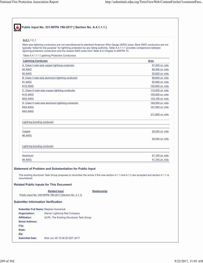
Public Input No. 331-NFPA 780-2017 [ Section No. A.4.1.1.1 ]
A.4.1. 1 3 .1
Main-size lightning conductors are not manufactured to standard American Wire Gauge (AWG) sizes. Bare AWG conductors are nottypically “listed for the purpose” for lightning protection by any listing authority. Table A.4.1.1.1 provides comparisons betweenlightning protection conductors and the closest AWG sizes from Table 8 in Chapter 9 ofNFPA 70.
Table A.4.1.1.1 Lightning Protection Conductors
Lightning Conductor Area
A. Class I main-size copper lightning conductor 57,400 cir. mils
#2 AWG 66,360 cir. mils
#3 AWG 52,620 cir. mils
B. Class I main-size aluminum lightning conductor 98,600 cir. mils
#1 AWG 83,690 cir. mils
#1/0 AWG 105,600 cir. mils
C. Class II main-size copper lightning conductor 115,000 cir. mils
#1/0 AWG 105,600 cir. mils
#2/0 AWG 133,100 cir. mils
D. Class II main-size aluminum lightning conductor 192,000 cir. mils
#3/0 AWG 167,800 cir. mils
#4/0 AWG211,600 cir. mils
Lightning bonding conductor
Copper 26,240 cir. mils
#6 AWG26,240 cir. mils
Lightning bonding conductor
Aluminum 41,100 cir. mils
#4 AWG 41,740 cir. mils
Statement of Problem and Substantiation for Public Input
The existing structures Task Group proposes to renumber the annex if the new section 4.1.1 and 4.1.2 are accepted and section 4.1.1 is renumbered
Related Public Inputs for This Document
Related Input Relationship
Public Input No. 330-NFPA 780-2017 [Section No. 4.1.1]
Submitter Information Verification
Submitter Full Name: Stephen Humeniuk
Organization: Warren Lightning Rod Company
Affilliation: ULPA, The Existing Structures Task Group
Street Address:
City:
State:
Zip:
Submittal Date: Wed Jun 28 15:36:35 EDT 2017
National Fire Protection Association Report http://submittals.nfpa.org/TerraViewWeb/ContentFetcher?commentPara...
209 of 302 9/22/2017, 11:03 AM

Public Input No. 304-NFPA 780-2017 [ Section No. A.4.8.3.1 ]
A.4.8.3.1
Figure A.4.8.3.1 depicts the 150 ft (45 m) rolling sphere method for structures of selected heights up to 150 ft (45 m). Based on theheight of the strike termination device for a protected structure being 25 ft (7.6 m), 50 ft (15 m), 75 ft (23 m), 100 ft (30 m), or 150 ft(45 m) aboveground, reference to the appropriate curve shows the anticipated zone of protection for objects and roofs at lowerelevations.
ATTENTION NFPA STAFF: Remove identification of the arcs from the body of the graph in Figure A.4.8.3.1 and change 46 in 2places at the upper right hand corner to 45 in each of the cases.
Figure A.4.8.3.1 Zone of Protection Utilizing Rolling Sphere Method.
Statement of Problem and Substantiation for Public Input
The text identifying the arcs blocks the graphs in the most significant part of the graph, that area with 25 feet of the height projection. The value of this text is minimal as it only states the obvious; the arc that starts at a "height protected" of 150 feet is the 150 foot arc, etc. The metric equivalents are given on the right side Y axis.If it is felt this information is required, it is suggested that it be inserted between the left side Y axis label and the graph.
Submitter Information Verification
Submitter Full Name: Mitchell Guthrie
Organization: Engineering Consultant
Street Address:
City:
State:
Zip:
Submittal Date: Wed Jun 28 10:18:52 EDT 2017
National Fire Protection Association Report http://submittals.nfpa.org/TerraViewWeb/ContentFetcher?commentPara...
210 of 302 9/22/2017, 11:03 AM

Public Input No. 161-NFPA 780-2017 [ New Section after A.4.13.1 ]
A.4.9.8
For example, roofs from 50 ft to 100 ft (15 m to 30 m) in width shall require one cross-run conductor, roofs 100 ft to 150 ft(30 m to 45 m) in width shall require two cross-run conductors, and so on.
Statement of Problem and Substantiation for Public Input
4..9.8.1 resembles annex material, thus should be moved to Annex A.
Related Public Inputs for This Document
Related Input Relationship
Public Input No. 159-NFPA 780-2017 [Section No. 4.9.8.1]
Submitter Information Verification
Submitter Full Name: Mark Harger
Organization: Harger Lightning Grounding
Street Address:
City:
State:
Zip:
Submittal Date: Fri Jun 23 14:24:19 EDT 2017
National Fire Protection Association Report http://submittals.nfpa.org/TerraViewWeb/ContentFetcher?commentPara...
211 of 302 9/22/2017, 11:03 AM

Public Input No. 240-NFPA 780-2017 [ New Section after A.4.13.2.4 ]
TITLE OF NEW CONTENT
A.4.13.3.2 Field experience has demonstrated that a copper conductor could experience accelerated corrosion at the pointwhere the copper conductor exits the concrete. Concrete and soil composition could have a direct impact on the amount of corrosion,if any. Investigation of existing installations at the proposed site or chemical analysis of the concrete and soil composition wouldprovide a basis to determine if additional corrosion protection is warranted. Each installation should be evaluated to determine theneed for any additional corrosion protection. Tinned copper conductors or installation of a non-metallic sleeve over the conductorwhere the conductor exits the concrete are two methods that could mitigate corrosion. The non-metallic sleeve should extend 6 in.(150 mm) on each side of the transition from concrete to soil. See clauses 4.2 and 4.3 for additional requirements .
Statement of Problem and Substantiation for Public Input
In some cases bare copper wire has exhibited additional corrosion at the point where the bare copper conductor exits the concrete. The annex material will make the user aware that this condition is possible, will provide a method to determine if the condition exists and possible mitigation solutions.
Submitter Information Verification
Submitter Full Name: Carl Johnson II
Organization: AVCON Inc
Affilliation: NFPA 780 Grounding and Bonding Task Group
Street Address:
City:
State:
Zip:
Submittal Date: Mon Jun 26 16:42:30 EDT 2017
National Fire Protection Association Report http://submittals.nfpa.org/TerraViewWeb/ContentFetcher?commentPara...
212 of 302 9/22/2017, 11:03 AM

Public Input No. 315-NFPA 780-2017 [ New Section after A.4.13.8.3.1 ]
ADD NEW A.4.14.1
The interconnection of incoming services to the lightning protection system should be performed as near the service entry asreasonable and not meander greatly through the structure before its interconnection. For larger structures with services entering thestructure at different locations, multiple equipotential ground bus bars (EGB) should be considered. In these cases, theinterconnection of the multiple EGBs is best accomplished through interconnection with a ground ring electrode.
Statement of Problem and Substantiation for Public Input
Existing requirements put no restrictions on the length an incoming metallic service can meander in the structure before being interconnected with the LPS as long as it does not exceed 12 foot in the vertical dimension. The proposed annex text provides recommendations for limiting the extent of the horizontal dimension for incoming services.
Related Public Inputs for This Document
Related Input Relationship
Public Input No. 301-NFPA 780-2017 [Section No. 4.14.4] anchoring text for annex material
Submitter Information Verification
Submitter Full Name: Mitchell Guthrie
Organization: Engineering Consultant
Street Address:
City:
State:
Zip:
Submittal Date: Wed Jun 28 13:54:45 EDT 2017
National Fire Protection Association Report http://submittals.nfpa.org/TerraViewWeb/ContentFetcher?commentPara...
213 of 302 9/22/2017, 11:03 AM

Public Input No. 175-NFPA 780-2017 [ Section No. A.4.13.8.3.1 ]
A.4.13.8.3.1
It is preferable that grounding electrodes be located no closer than 2 ft (0.6 m 24 in. (600 mm ) from foundation walls to minimize theprobability of damage to the foundation, although this is not always practicable for all applications. For reference, IEC 62305-3,Protection Against Lightning, requires that ring earth electrodes be buried at a depth of at least 18 in. (450 mm) and a distance ofapproximately 3 ft 36 in. (1 m 1000 mm ) around external walls. Note: The metric equivalent values given in this paragraph are thevalues cited in the IEC standard.
Statement of Problem and Substantiation for Public Input
The Editorial Task Group changes values from feet to inches for accuracy and to maintain consistency throughout the standard
Submitter Information Verification
Submitter Full Name: Stephen Humeniuk
Organization: Warren Lightning Rod Company
Affilliation: ULPA, The Editorial Task Group
Street Address:
City:
State:
Zip:
Submittal Date: Fri Jun 23 18:10:27 EDT 2017
National Fire Protection Association Report http://submittals.nfpa.org/TerraViewWeb/ContentFetcher?commentPara...
214 of 302 9/22/2017, 11:03 AM

Public Input No. 154-NFPA 780-2017 [ New Section after A.4.14.3 ]
A.4.14.4
If Corrugated Stainless Steel Tubing (CSST) is used for gas piping, the requirements of this standard may not be adequate to protectthe CSST. When injected with the electrical energy of a direct or near direct lightning strike, CSST has been known to perforate, withan auto ignition of the gas carried within it sometimes occurring. Fires, even explosions, are known to have resulted. This hasbeen observed in structures with Certified Lightning Protection Systems. Until the electrical characteristic of CSST subjected to highvoltage, high frequency energy are known and understood, the redundant bonding of CSST is recommended. As best guess practice,bonding should be done as close to the service entrance as possible, at every device the CSST supplies gas to, and intermittently inbetween. Since CSST is a thin walled product, bonding must take place at a manifold, or the bonding connector may crush the tubing.For this reason, intermittent bonding should be done where feasible. These recommendations are based on experience and representthe best practice until a verifiable remedy is available.
Statement of Problem and Substantiation for Public Input
CSST is a problem with known failures. NFPA 54 only make provisions for protection against indirect lightning current and does nothing to provide for protection against direct or near direct lightning strikes. To my knowledge, a scientific solution using data and research from a disinterested, peer reviewed source has not been established. However, we have an obligation to raise awareness to the end users of lightning protection that this is a real threat. The recommendations made are based on experience, and represent the best practice until a verifiable remedy is available.
Related Public Inputs for This Document
Related Input Relationship
Public Input No. 155-NFPA 780-2017 [Section No. 4.14.4]
Submitter Information Verification
Submitter Full Name: Stephen Humeniuk
Organization: Warren Lightning Rod Company
Affilliation: ULPA
Street Address:
City:
State:
Zip:
Submittal Date: Fri Jun 23 12:44:29 EDT 2017
National Fire Protection Association Report http://submittals.nfpa.org/TerraViewWeb/ContentFetcher?commentPara...
215 of 302 9/22/2017, 11:03 AM

Public Input No. 192-NFPA 780-2017 [ Section No. A.4.14.3 ]
A.4.14.3
Definitions in NFPA 70(NEC), and in this standard for bonded (bonding), grounded, grounding, and grounding electrode are similar.The actual sections in the NEC and in this standard that define what constitutes these various items point to differences inapplication, equipment, and requirements.
Section 250.50 of the NEC requires that all electrodes present at each building or structure be bonded together to form the groundingelectrode system, which coordinates with the requirements of Section 4.14. The differences occur in Section 250.52 of the NEC,which describes grounding electrode devices not shown in Section 4.13. Grounding electrode devices described in Section 250.52 ofthe NEC but not referenced in this document include the following:
(1) 250.52(A)(1): 10 ft (3 m) of metallic underground water pipe extending from the structure in contact with earth.
(2) 250.52(A)(2)(1): The metal frame of the structure in contact with earth.
(3) 250.52(A)(3)(2): The concrete-encased electrode described as #4 AWG would need to be a main-size conductor per 4.13.3.2.
(4) 250.52(A)(4): The ground ring electrode not smaller than 2 AWG is acceptable for Class I but would not be acceptable forClass II (see Table 4.1.1.1.2).
(5) 250.52(A)(5): Pipe electrodes described in item (a) are not included. Rod electrodes described in item (b) as zinc-coated steelare not covered (4.13.2.5).
(6) 250.52(A)(6): Other listed electrodes would need to comply with the various sections of Section 4.13.
(7) 250.52(A)(7): Plate electrodes would need to comply with 4.13.6.
(8) 250.52(A)(8): “Other local metal underground systems or structures” are not referenced as grounding electrodes in this standard.
The lightning protection system designer must be familiar with these differences to be able to coordinate interconnection with otherbuilding grounding electrodes or the structural grounding electrode system as required by 4.14.3.
Where separate but adjacent buildings or facilities are interconnected directly (not through a utility) by electric, CATV, CCTV, data, orcommunications wiring, the grounding systems of those buildings should be directly interconnected to each other with a main-sizeconductor. The need for this interconnection can be eliminated by the use of fiber optic cable, shielded wire, wire run in groundedmetallic conduit, or redundant surge protection (SPDs installed at the entrance(s) and exit(s) of both buildings or facilities).
Statement of Problem and Substantiation for Public Input
Editorial. Added the metric equivalence.
Submitter Information Verification
Submitter Full Name: Mitchell Guthrie
Organization: Engineering Consultant
Street Address:
City:
State:
Zip:
Submittal Date: Sun Jun 25 23:18:05 EDT 2017
National Fire Protection Association Report http://submittals.nfpa.org/TerraViewWeb/ContentFetcher?commentPara...
216 of 302 9/22/2017, 11:03 AM

Public Input No. 238-NFPA 780-2017 [ Section No. A.4.14.3 ]
A.4.14.3
Definitions in NFPA 70(NEC), and in this standard for bonded (bonding), grounded, grounding, and grounding electrode are similar.The actual sections in the NEC and in this standard that define what constitutes these various items point to differences inapplication, equipment, and requirements.
Section 250.50 of the NEC requires that all electrodes present at each building or structure be bonded together to form the groundingelectrode system, which coordinates with the requirements of Section 4.14. The differences occur in Section 250.52 of the NEC,which describes grounding electrode devices not shown in Section 4.13. Grounding electrode devices described in Section 250.52 ofthe NEC but not referenced in this document include the following:
(1) 250.52(A)(1): 10 ft of (3 m) of metallic underground water pipe extending from the structure in contact with earth.
(2) 250.52(A)(2)(1): The metal frame of the structure in contact with earth.
(3) 250.52(A)(3)(2): The concrete-encased electrode described as #4 AWG would need to be a main-size conductor per 4.13.3.2.
(4) 250.52(A)(4): The ground ring electrode not smaller than 2 AWG is acceptable for Class I but would not be acceptable forClass II (see Table 4.1.1.1.2).
(5) 250.52(A)(5): Pipe electrodes described in item (a) are not included. Rod electrodes described in item (b) as zinc-coated steelare not covered (4.13.2.5).
(6) 250.52(A)(6): Other listed electrodes would need to comply with the various sections of Section 4.13.
(7) 250.52(A)(7): Plate electrodes would need to comply with 4.13.6.
(8) 250.52(A)(8): “Other local metal underground systems or structures” are not referenced as grounding electrodes in this standard.
The lightning protection system designer must be familiar with these differences to be able to coordinate interconnection with otherbuilding grounding electrodes or the structural grounding electrode system as required by 4.14.3.
Where separate but adjacent buildings or facilities are interconnected directly (not through a utility) by electric, CATV, CCTV, data, orcommunications wiring, the grounding systems of those buildings should be directly interconnected to each other with a main-sizeconductor. The need for this interconnection can be eliminated by the use of fiber optic cable, shielded wire, wire run in groundedmetallic conduit, or redundant surge protection (SPDs installed at the entrance(s) and exit(s) of both buildings or facilities).
Statement of Problem and Substantiation for Public Input
The Editorial Task Group adds the SI value to Comply with the Manual of Style
Submitter Information Verification
Submitter Full Name: Stephen Humeniuk
Organization: Warren Lightning Rod Company
Affilliation: ULPA, The Editorial Task Group
Street Address:
City:
State:
Zip:
Submittal Date: Mon Jun 26 14:27:27 EDT 2017
National Fire Protection Association Report http://submittals.nfpa.org/TerraViewWeb/ContentFetcher?commentPara...
217 of 302 9/22/2017, 11:03 AM

Public Input No. 260-NFPA 780-2017 [ New Section after A.4.14.5 ]
New A.4.14.6(2)
A method to determine whether grounded media and buried metallic conductors are inherently bonded through construction is toperform a bonding test using test equipment suitable for the purpose. The measured bonding resistance for inherently bondedconductors should typically be in the range of tens of milliohms but should not exceed 200 milliohms.
Statement of Problem and Substantiation for Public Input
The proposed text provides a suggested method to quantify when grounded media and buried metallic conductors could be considered to be bonded to the lightning protection grounding system.
Related Public Inputs for This Document
Related Input Relationship
Public Input No. 259-NFPA 780-2017 [Section No. 4.14.6] Text providing requirements
Submitter Information Verification
Submitter Full Name: Mitchell Guthrie
Organization: Engineering Consultant
Affilliation: Grounding and Bonding Task Group
Street Address:
City:
State:
Zip:
Submittal Date: Tue Jun 27 12:48:14 EDT 2017
National Fire Protection Association Report http://submittals.nfpa.org/TerraViewWeb/ContentFetcher?commentPara...
218 of 302 9/22/2017, 11:03 AM
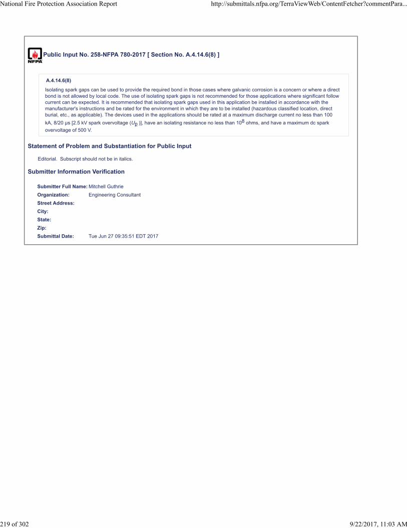
Public Input No. 258-NFPA 780-2017 [ Section No. A.4.14.6(8) ]
A.4.14.6(8)
Isolating spark gaps can be used to provide the required bond in those cases where galvanic corrosion is a concern or where a directbond is not allowed by local code. The use of isolating spark gaps is not recommended for those applications where significant followcurrent can be expected. It is recommended that isolating spark gaps used in this application be installed in accordance with themanufacturer's instructions and be rated for the environment in which they are to be installed (hazardous classified location, directburial, etc., as applicable). The devices used in the applications should be rated at a maximum discharge current no less than 100
kA, 8/20 µs [2.5 kV spark overvoltage (Up )], have an isolating resistance no less than 108 ohms, and have a maximum dc spark
overvoltage of 500 V.
Statement of Problem and Substantiation for Public Input
Editorial. Subscript should not be in italics.
Submitter Information Verification
Submitter Full Name: Mitchell Guthrie
Organization: Engineering Consultant
Street Address:
City:
State:
Zip:
Submittal Date: Tue Jun 27 09:35:51 EDT 2017
National Fire Protection Association Report http://submittals.nfpa.org/TerraViewWeb/ContentFetcher?commentPara...
219 of 302 9/22/2017, 11:03 AM

Public Input No. 78-NFPA 780-2017 [ Section No. A.4.16.4 ]
A.4.16.4
An ungrounded metallic body, such as a metal window frame in a nonconducting medium, that is located close to a lightningconductor and to a grounded metal body will influence bonding requirements only if the total of the distances between the lightningconductor and the ungrounded metal body and between the ungrounded metal body and the grounded metal body is equal to or lessthan the calculated bonding distance Isolated metal bodies that show no conductance to ground shall not require bonding. Onlygrounded metal bodies that are within the first (6 or 7 feet - 1.8 m) of the main conductor shall be bonded .
Statement of Problem and Substantiation for Public Input
Proposal extracted form UL 96A, Item 11.tSupported as well with LPI-175: Number 163Based ALSO on MULTIPLE AND POSSIBLE calculation using formula from number 165 and table 166, from LPI-175.Therefore for simplicity. Just conclude that isolated metal bodies at more than 7 feet, to be don’t need a bonding connection and supported by number 167 (LPI-175)
Submitter Information Verification
Submitter Full Name: Lizardo Lopez
Organization: Pro Lightning Prot Inc
Street Address:
City:
State:
Zip:
Submittal Date: Mon May 29 10:18:17 EDT 2017
National Fire Protection Association Report http://submittals.nfpa.org/TerraViewWeb/ContentFetcher?commentPara...
220 of 302 9/22/2017, 11:03 AM

Public Input No. 323-NFPA 780-2017 [ Section No. A.4.19.3.5 ]
A.4.19.3.5 4
Protecting the base metal with a conductive, corrosion-inhibiting coating, coating the entire bond with a corrosion-inhibiting coating, orother equivalent methods can be utilized.
Statement of Problem and Substantiation for Public Input
Numbering changed to conform to the changes in PI 322.
Related Public Inputs for This Document
Related Input Relationship
Public Input No. 322-NFPA 780-2017 [Section No. 4.19.3] Best buds.
Public Input No. 322-NFPA 780-2017 [Section No. 4.19.3]
Submitter Information Verification
Submitter Full Name: Simon Larter
Organization: Dobbyn Lightning Protection
Street Address:
City:
State:
Zip:
Submittal Date: Wed Jun 28 14:43:00 EDT 2017
National Fire Protection Association Report http://submittals.nfpa.org/TerraViewWeb/ContentFetcher?commentPara...
221 of 302 9/22/2017, 11:03 AM
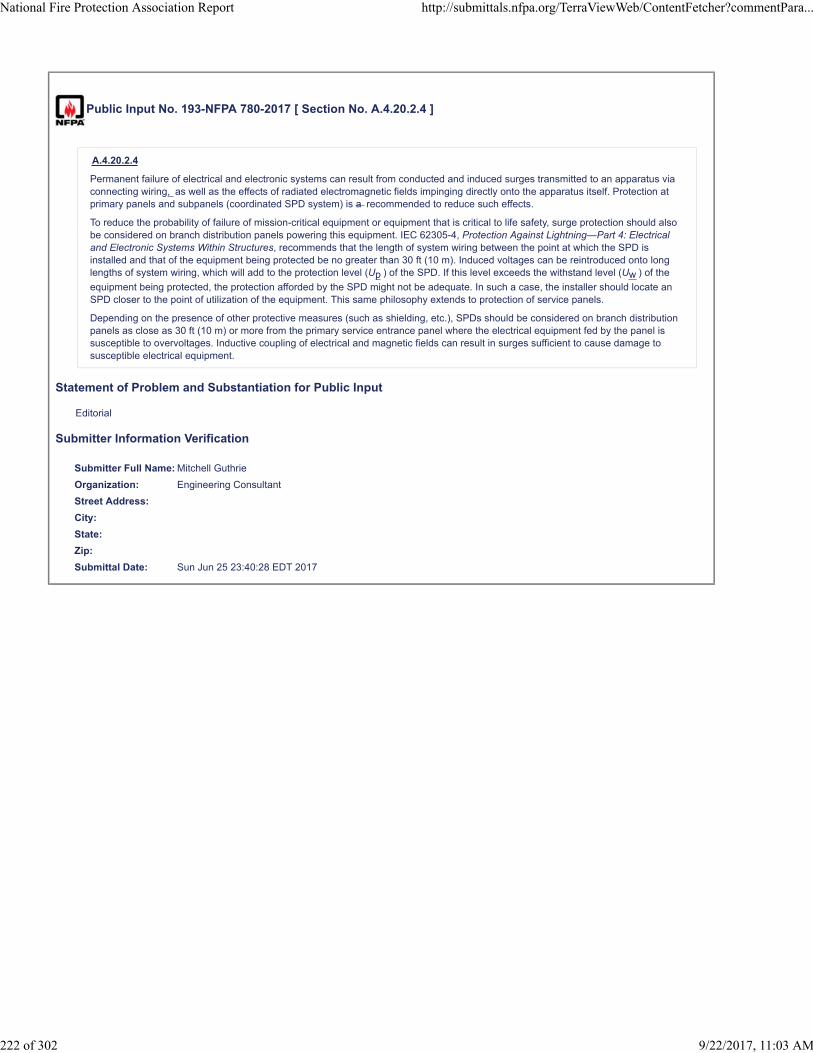
Public Input No. 193-NFPA 780-2017 [ Section No. A.4.20.2.4 ]
A.4.20.2.4
Permanent failure of electrical and electronic systems can result from conducted and induced surges transmitted to an apparatus viaconnecting wiring, as well as the effects of radiated electromagnetic fields impinging directly onto the apparatus itself. Protection atprimary panels and subpanels (coordinated SPD system) is a recommended to reduce such effects.
To reduce the probability of failure of mission-critical equipment or equipment that is critical to life safety, surge protection should alsobe considered on branch distribution panels powering this equipment. IEC 62305-4, Protection Against Lightning—Part 4: Electricaland Electronic Systems Within Structures, recommends that the length of system wiring between the point at which the SPD isinstalled and that of the equipment being protected be no greater than 30 ft (10 m). Induced voltages can be reintroduced onto longlengths of system wiring, which will add to the protection level (Up ) of the SPD. If this level exceeds the withstand level (Uw ) of the
equipment being protected, the protection afforded by the SPD might not be adequate. In such a case, the installer should locate anSPD closer to the point of utilization of the equipment. This same philosophy extends to protection of service panels.
Depending on the presence of other protective measures (such as shielding, etc.), SPDs should be considered on branch distributionpanels as close as 30 ft (10 m) or more from the primary service entrance panel where the electrical equipment fed by the panel issusceptible to overvoltages. Inductive coupling of electrical and magnetic fields can result in surges sufficient to cause damage tosusceptible electrical equipment.
Statement of Problem and Substantiation for Public Input
Editorial
Submitter Information Verification
Submitter Full Name: Mitchell Guthrie
Organization: Engineering Consultant
Street Address:
City:
State:
Zip:
Submittal Date: Sun Jun 25 23:40:28 EDT 2017
National Fire Protection Association Report http://submittals.nfpa.org/TerraViewWeb/ContentFetcher?commentPara...
222 of 302 9/22/2017, 11:03 AM

Public Input No. 335-NFPA 780-2017 [ Section No. A.4.20.2.5 ]
A.4.20.2. 5 6
Most services to facilities will require discrete surge suppression devices installed to protect against damaging surges. Occasionally,services will be located in an area or a manner where the threat from lightning-induced surges and overvoltage transients might benegligible. For example, the requirements in 4.20.2.3(also see A.4.20.6.1) exempt services less than 100 ft (30 m) in length that arerun in grounded metal conduit between buildings requiring surge protection. Other examples where SPDs might not be required to beinstalled at each service entrance are those applications where fiber optic transmission lines (with no conducting members) areused. The standard recognizes that there can be acceptable exceptions and consequently allows for such exceptions to therequirements for surge suppression on electrical utility, data, and other signal lines, provided a competent engineering authority hasdetermined that the threat is negligible or that the system is protected in a manner equivalent to surge suppression.
Allowance in this standard for the exemption of surge suppression at specific locations is not intended as a means to provide a broadexemption simply because surge suppression might be considered inconvenient to install. Rather, this allowance recognizes that allpossible circumstances and configurations, particularly those in specialized industries, cannot be covered by this standard.
Determinations made by an engineering authority for exempting installation of SPDs should focus on the likelihood of lightning activityin the region, the level of damage that might be incurred, and the potential loss of human life or essential services due to inadequateovervoltage protection.
Four methods of analysis are commonly used for this determination, although other equivalent analysis can be used. The fourmethods are the following:
(1) A risk assessment could be performed in accordance with IEC 62305-2, Protection Against Lightning—Part 2: RiskManagement, and surge protection requirements could be waived if justified by the assessment.
(2) The lightning flash density/risk analysis is an analysis to determine the frequency of lightning activity in the geographic area ofthe facility. As a rule of thumb, if the flash density exceeds one flash per square kilometer per year, surge suppression or otherphysical protection should be considered. Lightning energy can indirectly couple to services at ranges greater than 0.6 mi (1 km)to create potentially damaging overvoltages.
(3) Plant/facility statistical or maintenance records can also be used for risk analysis. If these records can demonstrate the lack ofdamage on a service due to surges, they can be used to justify low risk of surge damage to a particular system or facility.
(4) The lightning electromagnetic environment analysis starts with a threat electromagnetic field from a nearby lightning strike andcomputes the magnitude and rise-time characteristics of transients coupled into services feeding a structure or facility. Based onthe computed threat, SPDs can be sized appropriately or omitted, as warranted. This analysis is typically performed for criticalcommunications facilities and in military applications. Electromagnetic environments for such an analysis can be found in MIL-STD-464C, Interface Standard Electromagnetic Environmental Effects Requirements for Systems, and IEC 62305-4, ProtectionAgainst Lightning—Part 4: Electrical and Electronic Systems Within Structures.
In all cases, the criticality of continued operation, potential life hazard to persons and essential services, and the consequence offacility damage or shutdown should be factors in the analysis. If a hazardous condition results from a surge causing temporaryshutdown without permanent damage (e.g., through the disabling of a computer or communication system), then the requirements forsurge suppression as articulated by Section 4.20 should not be exempted.
Statement of Problem and Substantiation for Public Input
The Existing Structures Task Group renumbers this section, and all sections that reference it, if the existing 4.20.2.5 is renumbered due to the acceptance of a news 4.20.2.5
Related Public Inputs for This Document
Related Input Relationship
Public Input No. 333-NFPA 780-2017 [Section No. 4.20.2.5]
Submitter Information Verification
Submitter Full Name: Stephen Humeniuk
Organization: Warren Lightning Rod Company
Affilliation: ULPS, The Existing Structures Task Group
Street Address:
City:
State:
Zip:
Submittal Date: Wed Jun 28 15:51:24 EDT 2017
National Fire Protection Association Report http://submittals.nfpa.org/TerraViewWeb/ContentFetcher?commentPara...
223 of 302 9/22/2017, 11:03 AM

Public Input No. 313-NFPA 780-2017 [ Section No. A.4.20.4 ]
A.4.20.4
The measured limiting voltages of the SPD should be selected to limit damage to the service or equipment protected.
Devices rated in accordance with the 3rd the 4th edition of ANSI/UL 1449, Standard for Surge Protective Devices, reflect that thevoltage rating test in this edition utilizes a 3 kA peak current instead of the 500 A current level previously used in the SVR test of the2nd edition of UL 1449, Standard for Safety for Transient Voltage Surge Suppressors .
Statement of Problem and Substantiation for Public Input
The reference to SVR and the TVSS requirements of UL 1449 Edition 2 was removed as it has now been over 10 years since the transition to Edition 3 so SVR is no longer relevant.
Submitter Information Verification
Submitter Full Name: Mitchell Guthrie
Organization: Engineering Consultant
Street Address:
City:
State:
Zip:
Submittal Date: Wed Jun 28 13:41:07 EDT 2017
National Fire Protection Association Report http://submittals.nfpa.org/TerraViewWeb/ContentFetcher?commentPara...
224 of 302 9/22/2017, 11:03 AM

Public Input No. 289-NFPA 780-2017 [ Section No. A.7.3.7 ]
A.7.3.7
A 20 ft (6 m
A 20 ft (6 m ) diameter or larger vertical cylindrical tank resting on earth or concrete or
50 ft
50 ft (
15 m)
15 m) 10 ft (3 m) diameter or larger flat bottom vertical cylindrical tank resting on bituminous pavement can be substituted forthe ground ring electrode.
Statement of Problem and Substantiation for Public Input
The dimensions in this section may be changed by 7.3.7.1.
Submitter Information Verification
Submitter Full Name: Bruce Kaiser
Organization: Lightning Master Corporation
Affilliation: Chapter 7 task group
Street Address:
City:
State:
Zip:
Submittal Date: Tue Jun 27 17:15:25 EDT 2017
National Fire Protection Association Report http://submittals.nfpa.org/TerraViewWeb/ContentFetcher?commentPara...
225 of 302 9/22/2017, 11:03 AM

Public Input No. 122-NFPA 780-2017 [ Section No. A.8.3.5 ]
A.8.3.5
The spacing dimensions of strike termination devices based upon the 100 ft (30 m) rolling sphere method (RSM), with terminals12 in. (300 mm) tall, are 25 ft (7.6 m) at the center of the roof, 20 ft (6.1 m) at the roof perimeter, and 2 ft (0.6 m and 24in. (600 mm )set back from the outer end of roof ridges. For terminals 24 in. (600 mm) tall, the dimensions increase to 35 ft (12 m) at the center ofthe roof, 20 ft (6.1 m) at the roof perimeter, and 24 in. (600 mm) set back from the outer end of roof ridges.
Statement of Problem and Substantiation for Public Input
The Editorial Task Group proposes this change to add consistency. Also the smaller unit of measure is more accurate.
Submitter Information Verification
Submitter Full Name: Stephen Humeniuk
Organization: Warren Lightning Rod Company
Affilliation: ULPA, Editorial Task Group
Street Address:
City:
State:
Zip:
Submittal Date: Mon Jun 19 16:23:24 EDT 2017
National Fire Protection Association Report http://submittals.nfpa.org/TerraViewWeb/ContentFetcher?commentPara...
226 of 302 9/22/2017, 11:03 AM
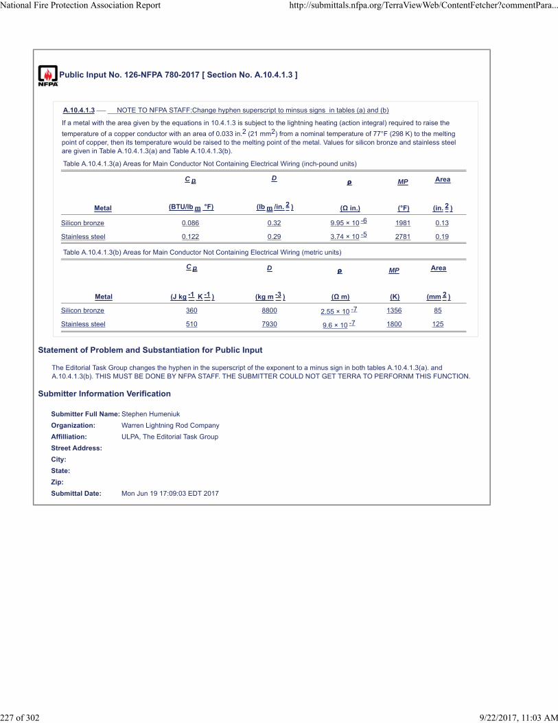
Public Input No. 126-NFPA 780-2017 [ Section No. A.10.4.1.3 ]
A.10.4.1.3 NOTE TO NFPA STAFF:Change hyphen superscript to minsus signs in tables (a) and (b)
If a metal with the area given by the equations in 10.4.1.3 is subject to the lightning heating (action integral) required to raise the
temperature of a copper conductor with an area of 0.033 in.2 (21 mm2) from a nominal temperature of 77°F (298 K) to the meltingpoint of copper, then its temperature would be raised to the melting point of the metal. Values for silicon bronze and stainless steelare given in Table A.10.4.1.3(a) and Table A.10.4.1.3(b).
Table A.10.4.1.3(a) Areas for Main Conductor Not Containing Electrical Wiring (inch-pound units)
Metal
C p
(BTU/lb m °F)
D
(lb m /in. 2 )
ρ
(Ω in.)
MP
(°F)
Area
(in. 2 )
Silicon bronze 0.086 0.32 9.95 × 10 -6 1981 0.13
Stainless steel 0.122 0.29 3.74 × 10 -5 2781 0.19
Table A.10.4.1.3(b) Areas for Main Conductor Not Containing Electrical Wiring (metric units)
Metal
C p
(J kg -1 K -1 )
D
(kg m -3 )
ρ
(Ω m)
MP
(K)
Area
(mm 2 )
Silicon bronze 360 8800 2.55 × 10 -7 1356 85
Stainless steel 510 7930 9.6 × 10 -7 1800 125
Statement of Problem and Substantiation for Public Input
The Editorial Task Group changes the hyphen in the superscript of the exponent to a minus sign in both tables A.10.4.1.3(a). and A.10.4.1.3(b). THIS MUST BE DONE BY NFPA STAFF. THE SUBMITTER COULD NOT GET TERRA TO PERFORNM THIS FUNCTION.
Submitter Information Verification
Submitter Full Name: Stephen Humeniuk
Organization: Warren Lightning Rod Company
Affilliation: ULPA, The Editorial Task Group
Street Address:
City:
State:
Zip:
Submittal Date: Mon Jun 19 17:09:03 EDT 2017
National Fire Protection Association Report http://submittals.nfpa.org/TerraViewWeb/ContentFetcher?commentPara...
227 of 302 9/22/2017, 11:03 AM

Public Input No. 250-NFPA 780-2017 [ Section No. A.10.4.6.2 ]
A.10.4.6.2
The area of a conductor of uniform cross-section that has the same resistance per unit length as a main conductor is given by the
equation in A.10.4.1.4. For connecting a main conductor, the areas are 0.49 in.2 (315 mm2) for silicon bronze and 1.8 in.2
(1200 mm2) for stainless steel. For connecting a bonding conductor, the required areas are 0.19 in.2 (125 mm2) for silicon bronze
and 0.73 in.2 (470 mm2) for stainless steel.
Equating resistances for a copper conductor of area ACu, resistivity ρCu, and length LCu and a metal connector of area A, resistivity
ρ, and length L gives a maximum allowable length for the metal connector as follows:
[A.10.4.6.2]
where:
L = length of metal connector
L Cu = length of copper conductor
A = area of metal connector
ACu = area of copper conductor
ρCu = resistivity of copper conductor
ρ = resistivity of metal connector
The length is the same for both main and bonding conductors and is 6.5 in. (165 mm) for silicon bronze and 2.5 in. (63.5 mm) forstainless steel when LCu = 2 ft (0.6 m).
Statement of Problem and Substantiation for Public Input
Change rho sub Cu from italics to match the other uses of the Greek letter in the clause.
Submitter Information Verification
Submitter Full Name: Mitchell Guthrie
Organization: Engineering Consultant
Street Address:
City:
State:
Zip:
Submittal Date: Mon Jun 26 20:16:59 EDT 2017
National Fire Protection Association Report http://submittals.nfpa.org/TerraViewWeb/ContentFetcher?commentPara...
228 of 302 9/22/2017, 11:03 AM

Public Input No. 67-NFPA 780-2017 [ Section No. A.11.1.1 ]
A.11.1.1
Chapter 11 pertains to lightning protection of airfield lighting systems. These systems are installed underground in both paved (i.e.,full-strength pavement and shoulder pavement) and unpaved areas. The protected components include in-pavement fixtures,elevated fixtures, airfield signs, underground power, communications systems, control and signal circuits, and components of runway,taxiway, and apron lighting systems. These systems are installed on the portions of an airport that encompass the approach,departure, landing, takeoff, taxiing, and parking areas for aircraft and include runways, taxiways, and other parts of an airport used fortaxiing, takeoff, and landing of aircraft; loading ramps; and parking areas exclusive of building-mounted helipads, approach lightstructures, and antennas. This chapter could also apply to other areas with airfield lighting systems.
There are two generally accepted methods for providing lightning protection for airfield lighting circuits: equipotential and isolation.The equipotential method, which is described in 11.4.2.6.1, is shown in Figure A.11.1.1(a). The isolation method, which is describedin 11.4.2.6.2 is shown in Figure A.?11.1.1(b). The two methods should not be employed on a single circuit. The designer shouldselect the installation method based upon sound engineering practices and the success of the selected method in previousinstallations.
Figure A.11.1.1(a) Equipotential Method.
Figure A.11.1.1(b) Isolation Method for Elevated Edge Lights Installed in Turf or Stabilized Soil.
Additional Proposed Changes
File Name Description Approved
Figure_A.11.1.1_b_.pdf revised figure A.11.1.1(b)
Statement of Problem and Substantiation for Public Input
National Fire Protection Association Report http://submittals.nfpa.org/TerraViewWeb/ContentFetcher?commentPara...
229 of 302 9/22/2017, 11:03 AM
Figure 11.4.2.6.2 shows an elevated fixture. Figure A.11.1.1(b) is a provides a plan view of Figure 11.4.2.6.2. Fixtures installed in a turf or stabilized soil area would typically be an elevated edge light fixture. Revised text matches figure and typical installation practices.
Paragraph and figure number revision in Figure A.11.1.1(b) notes section provides corrected reference.
Related Public Inputs for This Document
Related Input Relationship
Public Input No. 66-NFPA 780-2017 [Section No. 11.4.2.6.2 [Excluding any Sub-Sections]] denoting " edge light fixtureselevated"
Public Input No. 66-NFPA 780-2017 [Section No. 11.4.2.6.2 [Excluding any Sub-Sections]]
Submitter Information Verification
Submitter Full Name: Carl Johnson II
Organization: AVCON, Inc.
Street Address:
City:
State:
Zip:
Submittal Date: Tue Apr 25 10:52:04 EDT 2017
National Fire Protection Association Report http://submittals.nfpa.org/TerraViewWeb/ContentFetcher?commentPara...
230 of 302 9/22/2017, 11:03 AM

NFPA 780-2017 Standard for the Installation of Lightning Protection Systems
FIGURE A.11.1.1(b) Isolation Method for Elevated Edge Lights Installed in Turf or Stabilized Soil.

Public Input No. 68-NFPA 780-2017 [ Section No. A.11.4.1.1 ]
A.11.4.1.1
The copper counterpoise conductor size should be determined by the Engineer of Record based upon sound engineering practices.A 2 AWG bare, solid copper counterpoise conductor is recommended.
The following factors should be evaluated when considering a larger size counterpoise conductor:
(1) The airport’s ability to maintain airport operations after an airfield lighting circuit or system failure
(2) Accessibility of the copper counterpoise conductor for repairs if testing or repair; for example if the counterpoise conductor isinstalled in or under pavement
(3) Availability of qualified persons to perform airfield lighting system repairs
(4) Life cycle cost of the larger size counterpoise conductor, including consideration of counterpoise conductor replacement prior tothe end of an expected 20-year life
(5) Results of a lightning risk assessment performed in accordance with Annex L
(6) Past performance of the airfield lighting counterpoise system at the airport or geographic area
The AHJ can determine and approve the size of the copper counterpoise conductor.
Statement of Problem and Substantiation for Public Input
The existing text needed clarification.The revised text better describes some of the problems created when the counterpoise is not accessible.
Submitter Information Verification
Submitter Full Name: Carl Johnson II
Organization: AVCON, Inc.
Street Address:
City:
State:
Zip:
Submittal Date: Tue Apr 25 11:36:03 EDT 2017
National Fire Protection Association Report http://submittals.nfpa.org/TerraViewWeb/ContentFetcher?commentPara...
231 of 302 9/22/2017, 11:03 AM

Public Input No. 106-NFPA 780-2017 [ New Section after A.11.4.2.4 ]
TITLE OF NEW CONTENT
A.11.4.2.1 The maximum distance permitted between the counterpoise conductor grounding electrodes is typically set by the AHJ. The FAA sets this distance from 90 ft (30 m) to 500 ft (150 m) depending upon the application. The AHJ should be consulted todetermine the maximum spacing of the grounding electrodes.
Statement of Problem and Substantiation for Public Input
The section sets the maximum spacing interval requirement. The Air Force and Army are in the process of changing their maximum recommended spacing to 2000 feet. Annex A material was added to address the requirements of other AHJs.
Related Public Inputs for This Document
Related Input Relationship
Public Input No. 105-NFPA 780-2017 [Section No. 11.4.2.1] corresponding mandatory text
Public Input No. 105-NFPA 780-2017 [Section No. 11.4.2.1]
Submitter Information Verification
Submitter Full Name: Carl Johnson II
Organization: AVCON Inc
Affilliation: NFPA 780 Airfield Lighting Task Group
Street Address:
City:
State:
Zip:
Submittal Date: Sat Jun 17 17:12:58 EDT 2017
National Fire Protection Association Report http://submittals.nfpa.org/TerraViewWeb/ContentFetcher?commentPara...
232 of 302 9/22/2017, 11:03 AM

Public Input No. 108-NFPA 780-2017 [ New Section after A.11.4.2.4 ]
TITLE OF NEW CONTENT
A.11.4.2.6 The two methods are not listed in preferred order.
Statement of Problem and Substantiation for Public Input
The text is necessary to ensure that the standard does not imply a preferred method.
Related Public Inputs for This Document
Related Input Relationship
Public Input No. 107-NFPA 780-2017 [Section No. 11.4.2.6.1] annex material in support of mandatory text changes
Public Input No. 107-NFPA 780-2017 [Section No. 11.4.2.6.1]
Submitter Information Verification
Submitter Full Name: Carl Johnson II
Organization: AVCON Inc
Affilliation: NFPA 780 Airfield Lighting Task Group
Street Address:
City:
State:
Zip:
Submittal Date: Sat Jun 17 17:54:49 EDT 2017
National Fire Protection Association Report http://submittals.nfpa.org/TerraViewWeb/ContentFetcher?commentPara...
233 of 302 9/22/2017, 11:03 AM
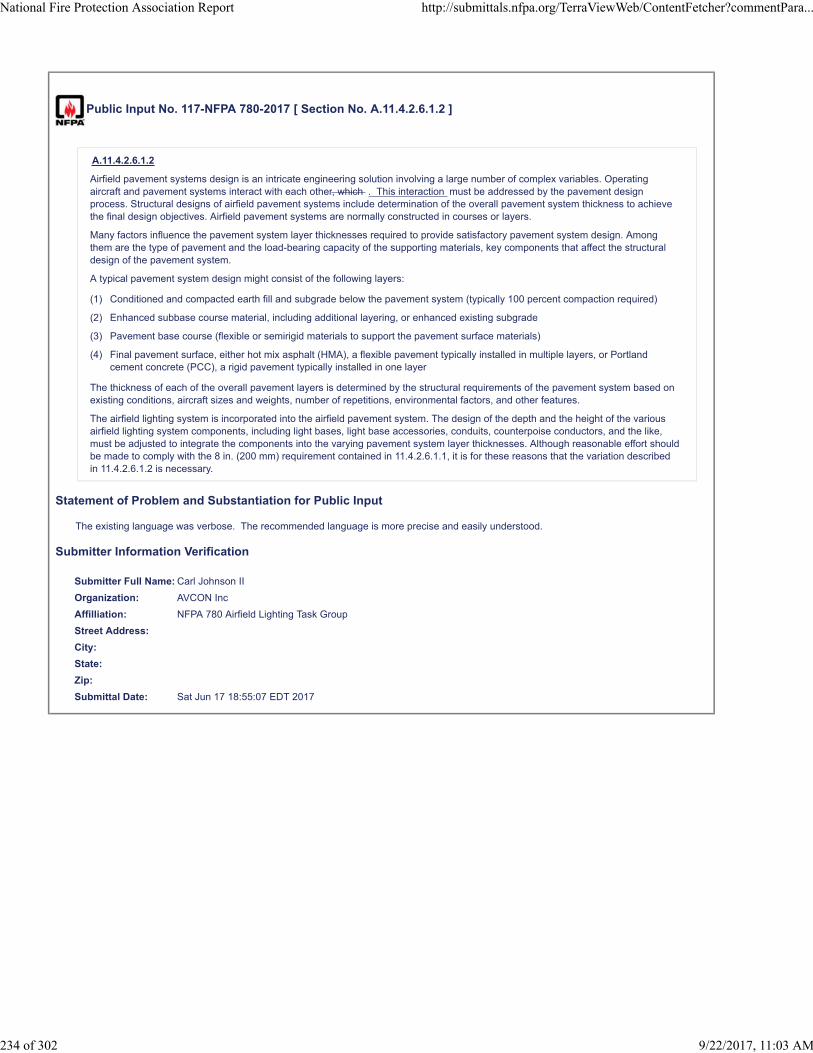
Public Input No. 117-NFPA 780-2017 [ Section No. A.11.4.2.6.1.2 ]
A.11.4.2.6.1.2
Airfield pavement systems design is an intricate engineering solution involving a large number of complex variables. Operatingaircraft and pavement systems interact with each other, which . This interaction must be addressed by the pavement designprocess. Structural designs of airfield pavement systems include determination of the overall pavement system thickness to achievethe final design objectives. Airfield pavement systems are normally constructed in courses or layers.
Many factors influence the pavement system layer thicknesses required to provide satisfactory pavement system design. Amongthem are the type of pavement and the load-bearing capacity of the supporting materials, key components that affect the structuraldesign of the pavement system.
A typical pavement system design might consist of the following layers:
(1) Conditioned and compacted earth fill and subgrade below the pavement system (typically 100 percent compaction required)
(2) Enhanced subbase course material, including additional layering, or enhanced existing subgrade
(3) Pavement base course (flexible or semirigid materials to support the pavement surface materials)
(4) Final pavement surface, either hot mix asphalt (HMA), a flexible pavement typically installed in multiple layers, or Portlandcement concrete (PCC), a rigid pavement typically installed in one layer
The thickness of each of the overall pavement layers is determined by the structural requirements of the pavement system based onexisting conditions, aircraft sizes and weights, number of repetitions, environmental factors, and other features.
The airfield lighting system is incorporated into the airfield pavement system. The design of the depth and the height of the variousairfield lighting system components, including light bases, light base accessories, conduits, counterpoise conductors, and the like,must be adjusted to integrate the components into the varying pavement system layer thicknesses. Although reasonable effort shouldbe made to comply with the 8 in. (200 mm) requirement contained in 11.4.2.6.1.1, it is for these reasons that the variation describedin 11.4.2.6.1.2 is necessary.
Statement of Problem and Substantiation for Public Input
The existing language was verbose. The recommended language is more precise and easily understood.
Submitter Information Verification
Submitter Full Name: Carl Johnson II
Organization: AVCON Inc
Affilliation: NFPA 780 Airfield Lighting Task Group
Street Address:
City:
State:
Zip:
Submittal Date: Sat Jun 17 18:55:07 EDT 2017
National Fire Protection Association Report http://submittals.nfpa.org/TerraViewWeb/ContentFetcher?commentPara...
234 of 302 9/22/2017, 11:03 AM

Public Input No. 65-NFPA 780-2017 [ Section No. A.11.4.2.6.1.2 ]
A.11.4.2.6.1.2
Airfield pavement systems design is an intricate engineering solution involving a large number of complex variables. Operatingaircraft and pavement systems interact with each other, which must be addressed by the pavement design process. Structuraldesigns of airfield pavement systems include determination of the overall pavement system thickness to achieve the final designobjectives. Airfield pavement systems are normally constructed in courses or layers.
Many factors influence the pavement system layer thicknesses required to provide satisfactory pavement system design. Amongthem Two key components that affect the strctural design of the pavement system are the type of pavement and the load-bearingcapacity of the supporting materials, key components that affect the structural design of the pavement system .
A typical pavement system design might consist of the following layers:
(1) Conditioned and compacted earth fill and subgrade below the pavement system (typically 100 percent compaction required)
(2) Enhanced subbase course material, including additional layering, or enhanced existing subgrade
(3) Pavement base course (flexible or semirigid materials to support the pavement surface materials)
(4) Final pavement surface, either hot mix asphalt (HMA), a flexible pavement typically installed in multiple layers, or Portlandcement concrete (PCC), a rigid pavement typically installed in one layer
The thickness of each of the overall pavement layers is determined by the structural requirements of the pavement system based onexisting conditions, aircraft sizes and weights, number of repetitions, environmental factors, and other features.
The airfield lighting system is incorporated into the airfield pavement system. The design of the depth and the height of the variousairfield lighting system components, including light bases, light base accessories, conduits, counterpoise conductors, and the like,must be adjusted to integrate the components into the varying pavement system layer thicknesses. Although reasonable effort shouldbe made to comply with the 8 in. (200 mm) requirement contained in 11.4.2.6.1.1, it is for these reasons that the variation describedin 11.4.2.6.1.2 is necessary.
Statement of Problem and Substantiation for Public Input
The original sentence did not read well. The revised sentence more clearly states the intent.
Submitter Information Verification
Submitter Full Name: Carl Johnson II
Organization: AVCON, Inc.
Street Address:
City:
State:
Zip:
Submittal Date: Tue Apr 25 10:32:19 EDT 2017
National Fire Protection Association Report http://submittals.nfpa.org/TerraViewWeb/ContentFetcher?commentPara...
235 of 302 9/22/2017, 11:03 AM
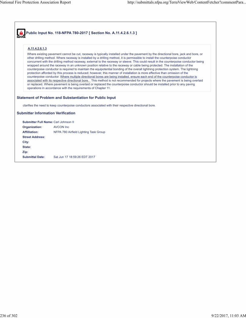
Public Input No. 118-NFPA 780-2017 [ Section No. A.11.4.2.6.1.3 ]
A.11.4.2.6.1.3
Where existing pavement cannot be cut, raceway is typically installed under the pavement by the directional bore, jack and bore, orother drilling method. Where raceway is installed by a drilling method, it is permissible to install the counterpoise conductorconcurrent with the drilling method raceway, external to the raceway or sleeve. This could result in the counterpoise conductor beingwrapped around the raceway in an unknown position relative to the raceway or cable being protected. The installation of thecounterpoise conductor is required to maintain the equipotential bonding of the overall lightning protection system. The lightningprotection afforded by this process is reduced; however, this manner of installation is more effective than omission of thecounterpoise conductor. Where multiple directional bores are being installed, ensure each end of the counterpoise conductor isassociated with its respective directional bore. This method is not recommended for projects where the pavement is being overlaidor replaced. Where pavement is being overlaid or replaced the counterpoise conductor should be installed prior to any pavingoperations in accordance with the requirements of Chapter 11.
Statement of Problem and Substantiation for Public Input
clarifies the need to keep counterpoise conductors associated with their respective directional bore.
Submitter Information Verification
Submitter Full Name: Carl Johnson II
Organization: AVCON Inc
Affilliation: NFPA 780 Airfield Lighting Task Group
Street Address:
City:
State:
Zip:
Submittal Date: Sat Jun 17 18:59:26 EDT 2017
National Fire Protection Association Report http://submittals.nfpa.org/TerraViewWeb/ContentFetcher?commentPara...
236 of 302 9/22/2017, 11:03 AM

Public Input No. 69-NFPA 780-2017 [ Section No. A.11.4.2.6.1.8 ]
A.11.4.2.6.1.8
The intent of 11.4.2.6.1.8 is that all metallic light bases, metallic fixtures, metal manhole cover/frames, and the like be bonded to thecounterpoise conductor. The phrase “output side of the constant current regulator (CCR) or power source” refers to the field circuit.The input power to the CCR or airfield lighting power source should be grounded in be provided with an equipment groundingconductor (EGC) in accordance with NFPA 70.
Statement of Problem and Substantiation for Public Input
The term grounded could imply one phase of the AC source is to be grounded at the CCR. The NEC requires an equipment grounding conductor (EGC) be provided.The proposed change corrects the terms to comply with NEC definitions.
Submitter Information Verification
Submitter Full Name: Carl Johnson II
Organization: AVCON, Inc.
Street Address:
City:
State:
Zip:
Submittal Date: Tue Apr 25 11:42:26 EDT 2017
National Fire Protection Association Report http://submittals.nfpa.org/TerraViewWeb/ContentFetcher?commentPara...
237 of 302 9/22/2017, 11:03 AM

Public Input No. 119-NFPA 780-2017 [ Section No. A.11.4.6.5 ]
A.11.4.6.5
Some components requiring bonding are only accessible during fabrication or construction. Care should be exercised to ensure allrequired components are bonded. Fixtures with exposed metal parts that might present a shock hazard should be bonded to theairfield lighting counterpoise system.
Statement of Problem and Substantiation for Public Input
This statement provides additional emphasis that items requiring bonding may not be accessible after construction.
Submitter Information Verification
Submitter Full Name: Carl Johnson II
Organization: AVCON Inc
Affilliation: NFPA 780 Airfield Lighting Task Group
Street Address:
City:
State:
Zip:
Submittal Date: Sat Jun 17 19:06:54 EDT 2017
National Fire Protection Association Report http://submittals.nfpa.org/TerraViewWeb/ContentFetcher?commentPara...
238 of 302 9/22/2017, 11:03 AM
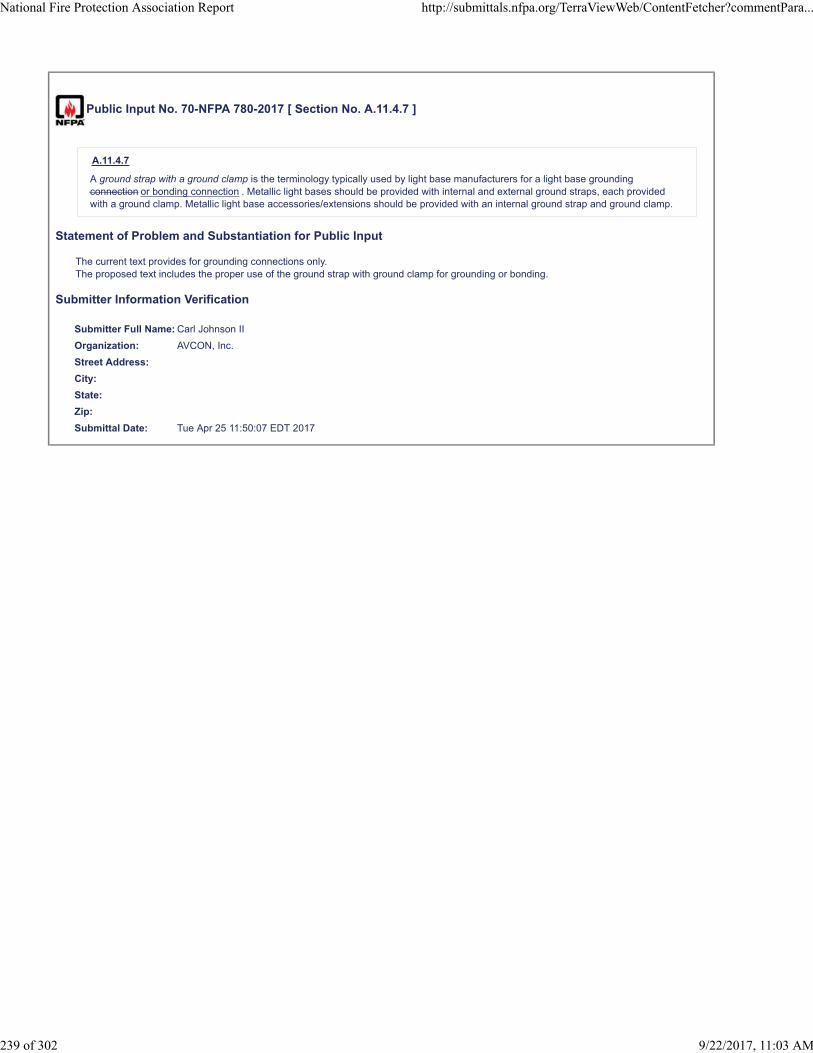
Public Input No. 70-NFPA 780-2017 [ Section No. A.11.4.7 ]
A.11.4.7
A ground strap with a ground clamp is the terminology typically used by light base manufacturers for a light base groundingconnection or bonding connection . Metallic light bases should be provided with internal and external ground straps, each providedwith a ground clamp. Metallic light base accessories/extensions should be provided with an internal ground strap and ground clamp.
Statement of Problem and Substantiation for Public Input
The current text provides for grounding connections only.The proposed text includes the proper use of the ground strap with ground clamp for grounding or bonding.
Submitter Information Verification
Submitter Full Name: Carl Johnson II
Organization: AVCON, Inc.
Street Address:
City:
State:
Zip:
Submittal Date: Tue Apr 25 11:50:07 EDT 2017
National Fire Protection Association Report http://submittals.nfpa.org/TerraViewWeb/ContentFetcher?commentPara...
239 of 302 9/22/2017, 11:03 AM

Public Input No. 71-NFPA 780-2017 [ Section No. A.11.4.8.6 ]
A.11.4.8.6
Exothermic welding is not the recommended method of connecting the counterpoise conductor to a galvanized steel light base. Referto FAA Advisory Circular 150/5340-30F 30J , Design and Installation Details for Airport Visual Aids, Part 12.5.
Statement of Problem and Substantiation for Public Input
Revision F as shown is outdated.Revision J was issued for public review on March 30, comments due by May 1, 2017.
Submitter Information Verification
Submitter Full Name: Carl Johnson II
Organization: AVCON, Inc.
Street Address:
City:
State:
Zip:
Submittal Date: Tue Apr 25 11:53:51 EDT 2017
National Fire Protection Association Report http://submittals.nfpa.org/TerraViewWeb/ContentFetcher?commentPara...
240 of 302 9/22/2017, 11:03 AM

Public Input No. 187-NFPA 780-2017 [ Section No. B.4.4.1 ]
B.4.4.1
In the first case, if the soil is of normal resistivity of from 4000 ohm 40 ohm -centimeters meters to 50,000 ohm 500 ohm -centimeters meters , the resistance of a ground connection made by extending the conductor 10 ft (3 m) into the ground will be fromabout 15 ohms to 200 ohms, and two such ground connections on a small rectangular building have been found by experience to besufficient. Under these favorable conditions, providing adequate means for collecting and dissipating the energy of a flash withoutserious chance of damage is a simple and comparatively inexpensive matter.
Statement of Problem and Substantiation for Public Input
For consistency with other lightning protection texts, earth resistivity should be expressed in ohm-meters instead of ohm-centimeters.
Submitter Information Verification
Submitter Full Name: Mitchell Guthrie
Organization: Engineering Consultant
Affilliation: Chair, Grounding and Bonding Task Group
Street Address:
City:
State:
Zip:
Submittal Date: Sun Jun 25 16:23:27 EDT 2017
National Fire Protection Association Report http://submittals.nfpa.org/TerraViewWeb/ContentFetcher?commentPara...
241 of 302 9/22/2017, 11:03 AM

Public Input No. 176-NFPA 780-2017 [ Section No. B.4.6 ]
B.4.6
Where practicable, each grounding electrode connection should extend or have a branch that extends below and at least 2 ft(0.6 m 24 in. (600 mm ) away from the foundation walls of the building in order to minimize the likelihood of damage to foundationwalls, footings, and stemwalls.
Statement of Problem and Substantiation for Public Input
The Editorial Task Group changes values from feet to inches for accuracy and to maintain consistency throughout the standard
Submitter Information Verification
Submitter Full Name: Stephen Humeniuk
Organization: Warren Lightning Rod Company
Affilliation: ULPA, The Editorial Task Group
Street Address:
City:
State:
Zip:
Submittal Date: Fri Jun 23 18:15:48 EDT 2017
National Fire Protection Association Report http://submittals.nfpa.org/TerraViewWeb/ContentFetcher?commentPara...
242 of 302 9/22/2017, 11:03 AM

Public Input No. 341-NFPA 780-2017 [ New Section after D.1.3 ]
D.1.3.1 The Relevance of Ground Resistance Test Reading and the Variables to be Considered
See the text in the attached document
Additional Proposed Changes
File Name Description Approved
NFPA_Ground_test_annex_.docx
Statement of Problem and Substantiation for Public Input
Ground test results are ambiguous. This proposal is made to provide information to bring clarity to the relevance of ground test results.
Submitter Information Verification
Submitter Full Name: Stephen Humeniuk
Organization: Warren Lightning Rod Company
Affilliation: ULPA
Street Address:
City:
State:
Zip:
Submittal Date: Wed Jun 28 16:46:30 EDT 2017
National Fire Protection Association Report http://submittals.nfpa.org/TerraViewWeb/ContentFetcher?commentPara...
243 of 302 9/22/2017, 11:03 AM

D.1.3.1 The Relevance of Ground Resistance Test Readings and the Variables to be Considered
D.1.3.1.1 Multiple ground testing methods and devices are available for ground resistance testing; all have merit and value for the tests they are designed to perform. Several questions must be asked prior to testing: What information is needed to meet code and AHJ requirements? What tests will accurately provide this information? Do I have the proper test equipment, i.e., is this test equipment listed for my intended use? Are the equipment manufacturer's instructions being followed? Have weather conditions from previous tests been reviewed and compared to the current results? (This could eliminate unnecessary concerns over poor test results) Will this testing become the basis for testing on a facility that has not previously been tested? D.1.3.1.2 The relevance of results from grounding electrode testing is sometimes misunderstood. Testing of grounding electrodes reveals the ability of the grounding electrode or grounding system to conduct a charge or temporary current to earth. The same test is an indication of soil resistance at the time the test is conducted. A single ground resistance test is not an indication of the physical condition of a grounding electrode or grounding system but an unusually high resistance-to-ground reading is an indication that further inspection may be required. Considerations for unusually high resistance-to-ground readings include soil condition (excessively drier than in past readings?), humidity and ambient temperature (for exposed grounding conductors), loose connections, condition of conductor insulation, meter input receptacles and training of personnel using the meter.
D.1.3.1.2.1 The significance of ground test results is increased by the benefit of trend analysis – comparing readings of the last six test cycles to determine either a trend to deterioration or to reveal a possible anomaly due to a significant weather change or some other drastic change in testing conditions. Soil resistivity is dynamic, so readings fluctuate. This fluctuation is primarily due to moisture content, the interaction of water with the soil composition, and the subterranean geography. Distilled water does not conduct electricity. The minerals and their various ions in the water conduct electrical current. A little moisture may improve conductivity, depending on the type and percentage of conductive elements in the soil and their interaction with each other. A lot of moisture may increase resistivity. This is frequently the case, when the ground reaches the saturation point due to rain. Moisture content is not just impacted by the composition of the soil. Subterranean geography is an important factor dramatically affecting the soils ability to hold moisture. For example, water will rapidly seep through silica sand mixed with gravel. But a “perched water table” due to underlying clay strata will hold water above the saturation zone of the normal water table. In this case, high moisture content may be present for a considerable amount of time, so the conductivity depends upon the amount of total dissolved solids, particularly the percentage of conductive salts (salinity).
D.1.3.1.2.2 Temperature is another factor impacting conductivity. Electrical conductivity varies with the ions in solution and their activity. Ion activity changes with temperature. Generally, soil conductivity improves as temperature rises, but only to a point. Once the soils start to dry out, the impact of moisture on conductivity changes accordingly. The conductivity of soil tends to diminish with cooling and deteriorates rapidly around freezing. Ice is nonconductive, so frozen ground profoundly impacts ground resistance reading. None of these variables can be controlled but some may be influenced.
D.1.3.1.2.3 Due to all these variables, vulnerable facilities such as those handling explosive and those with extensive electronics, require periodic test during different times of year. This is the source of the six cycles mentioned above. Typically, the date, time and weather are required as part of those test reports. The importance of this data may be lost on those gathering it, if not on those requiring it; even those

interpreting it. All variables should be considered when reviewing test data. Unfortunately, a quick comparison to a numeric value is usually the prime consideration. Resistance values recommended without consideration of site conditions are arbitrary if they cannot be achieved at that particular location. But the standard values for ground electrode resistivity must be specific to the location and established as a normative range with the statistical median number established as the baseline and the standard deviation being the extreme. For this reason the AHJ’s at vulnerable facilities often require extensive records of ground resistance readings.
Simply put, if a reading is a little above what is normal it is likely to be due to the variables already describe. If the value is way above normal, it indicates a deterioration of the grounding electrode system.
D.1.3.1.2.4 Vulnerable facilities should do extensive soil and site conductivity and resistance testing prior to construction. It is far easier to improve a facilities ability to dissipate an electrical energy before and during construction than it is afterwards. Imported soils (fill dirt) will probably have a different ability to conduct electricity that could change the electrical characteristics of the entire site. This could be used to improve soil conductivity particularly in areas with little load bearing significance. Everything in the ground changes the electrical characteristics of the site. All buried media will impact ground electrode resistance readings! However, all buried media should be considered as a permanent part of the site. Electrical energy will dissipate over all grounded media, not just the ground electrodes installed specifically for that purpose.
D.1.3.1.2.5 The relevance of test results from a single ground electrode is another misconception. Single ground electrode must be separated from the rest of the grounding electrode system to be tested separately, so a fitting to disconnect the electrode must be provided. The disconnect itself becomes variable. The concept of equalizing electrical potential is based on all grounded media being tied together. According to the codes and standard practices, a single ground will never dissipate electrical energy by itself, unless it is the only ground, so this reading is irrelevant unless that ground electrode is thought to be deteriorated. Even then test data alone is not definitive evidence of the electrode’s condition.
D.1.3.1.2.6 Test wells are frequently specified at each ground location. However, the condition of a ground electrode cannot be determined by visual inspection since the functional section of the electrode is the part that is buried. The only way to definitively determine the physical condition of a ground electrode is to dig it up.
Test wells provide access to concealed systems for testing. If the intent is to test the entire grounding electrode system from a single location, then one is enough. On an exposed system, test the resistance of the grounding electrode system by attaching the testing device to an exposed down lead.
D.1.3.1.2.7 Another variable of ground testing is the location of the test electrodes. Collected data would be far more relevant if test wells we located at the test electrode locations so the ground electrode test is performed to the exact same location each time it is tested.
D.1.3.1.3 Moisture related variables are not specific to a particular site but are regional in nature. They do not happen to just one grounding system but to an entire community. This is the reason why lightning protection systems employ such an extensive grounding electrode system. When lightning strikes, it will

be conducted on the lightning protection system to ground by the integral interconnection of the grounding electrode system. Once to ground the lightning will dissipate, making the condition of the ground electrodes more important than the ground resistance reading.
D.1.3.1.4 Synopsis:
The ground electrode testing does not tell the condition of a single ground electrode or the ground electrode system.
Short of exhuming the electrode, the functional condition of electrodes is determined through the observation of extreme variations from baseline readings.
Preconstruction ground resistance/conductance testing is recommended for vulnerable facilities.
Electrodes are tied together to function as a unit. Testing them as a unit more accurately simulates actual conditions.
Baseline testing can be established through the records of previous tests.
D.1.3.1.5 A simplified test for determining the functional condition of lightning protection grounding electrode system.
Choose a testing method. The test method and device do not matter. The comparison of the readings is the desired result.
Lay out the test electrodes according to the test parameters. Install a spare test electrode 25 ft. (7.6m) laterally from the lightning protection (LP) electrode/ down conductor, to be test.
Run your test to determine the resistivity to earth from the spare test electrode. Check connections to the all electrodes, and repeat the test until the readings are the same. This reading is the resistivity of the ground as measured by that test from the spare electrode. Use it as a baseline
Without moving any test electrodes, disconnect the lead from the spare electrode and attach it to the LP Electrode/ Down lead.
Run the test. Check connections and repeat test until the readings are the same. This is the resistance of the entire ground electrode system to the same test electrodes using the same test and the same equipment. The only variable is the ground electrode system.
The resistance to ground from the grounding electrode system should be similar to or better than the resistivity of the ground reading. A substantially higher reading indicates a problem.
In future testing use the same test, method and equipment. Where possible use the same test locations in subsequent tests for consistency and relevance.


Public Input No. 354-NFPA 780-2017 [ Section No. F.2.1 ]
F.2.1 Conductors.
Conductors should conform to the requirements of Chapter 4 for bonding for main conductors.
Statement of Problem and Substantiation for Public Input
Change is made to revert back to previous editions of this document that required main conductors. This change is made to keep all down conductors sizes consistent throughout the document.Of note, if accepted the diagram will also need to be revised.
Submitter Information Verification
Submitter Full Name: Mark Morgan
Organization: East Coast Lightning Equipment
Street Address:
City:
State:
Zip:
Submittal Date: Wed Jun 28 22:03:19 EDT 2017
National Fire Protection Association Report http://submittals.nfpa.org/TerraViewWeb/ContentFetcher?commentPara...
244 of 302 9/22/2017, 11:03 AM

Public Input No. 185-NFPA 780-2017 [ Section No. G.1.1.3 ]
G.1.1.3 Grounding.
Grounding terminations should be installed as specified in Chapter 4, with the following additional guidance:
(1) For existing concrete floors, a ground ring should be installed. As an additional precaution, radial grounding is recommended tobe installed at points around the periphery.
(2) The grounding grid should be constructed of main-size interconnected copper conductors at no greater than 3 ft (0.9 m 36 in.(900 mm ) spacing between conductors. The periphery of the grid should be interconnected. Burial of the grid should be at adepth of no less than 6 in. (150 mm) and no greater than 18 in. (450 mm).
(3) The grid perimeter should be connected to grounding electrodes with radial grounding extensions recommended.
Statement of Problem and Substantiation for Public Input
The editorial Task Group changes value from feet to inches for accuracy and to maintain consistency throughout the standard
Submitter Information Verification
Submitter Full Name: Stephen Humeniuk
Organization: Warren Lightning Rod Company
Affilliation: ULPA, The Editorial Task Group
Street Address:
City:
State:
Zip:
Submittal Date: Fri Jun 23 18:41:06 EDT 2017
National Fire Protection Association Report http://submittals.nfpa.org/TerraViewWeb/ContentFetcher?commentPara...
245 of 302 9/22/2017, 11:03 AM

Public Input No. 128-NFPA 780-2017 [ Section No. H.2.2 ]
H.2.2 Iron Posts.
Ground connections can be made by inserting galvanized-iron posts, such as are ordinarily used for farm fencing, at intervals andattaching in electrical contact all the wires of the fence. Grounding can also be achieved by driving a length of not less than 1⁄2 in.(12.7 mm) in diameter galvanized-iron pipe beside the fence and attaching the wires by ties of galvanized-iron wire. If the ground isnormally dry, the intervals between metal posts should not exceed 150 ft (45 m). If the ground is normally damp, the metal posts canbe placed up to 300 ft (92 m 90 m ) apart.
Statement of Problem and Substantiation for Public Input
The editorial Task Group changes the SI dimension to be consistent with the rest of the document. It is also a more stringent requirement in this application.
Submitter Information Verification
Submitter Full Name: Stephen Humeniuk
Organization: Warren Lightning Rod Company
Affilliation: ULPA, The Editorial Task Group.
Street Address:
City:
State:
Zip:
Submittal Date: Mon Jun 19 17:20:53 EDT 2017
National Fire Protection Association Report http://submittals.nfpa.org/TerraViewWeb/ContentFetcher?commentPara...
246 of 302 9/22/2017, 11:03 AM

Public Input No. 188-NFPA 780-2017 [ Section No. H.2.2 ]
H.2.2 Iron Posts.
Ground connections can be made by inserting galvanized-iron posts, such as are ordinarily used for farm fencing, at intervals andattaching in electrical contact all the wires of the fence. Grounding can also be achieved by driving a length of not less than 1⁄2 in.(12.7 mm) in diameter galvanized-iron pipe beside the fence and attaching the wires by ties of galvanized-iron wire. If the ground isnormally dry, the intervals between metal posts should not exceed 150 ft (45 m). If the ground is normally damp, the metal posts canbe placed up to 300 ft (92 m 90 m ) apart.
Statement of Problem and Substantiation for Public Input
Revise for consistency with 150 ft conversion in the preceding sentence.
Related Public Inputs for This Document
Related Input Relationship
Public Input No. 189-NFPA 780-2017 [Section No. 4.7.9]
Submitter Information Verification
Submitter Full Name: Mitchell Guthrie
Organization: Engineering Consultant
Street Address:
City:
State:
Zip:
Submittal Date: Sun Jun 25 16:31:01 EDT 2017
National Fire Protection Association Report http://submittals.nfpa.org/TerraViewWeb/ContentFetcher?commentPara...
247 of 302 9/22/2017, 11:03 AM

Public Input No. 177-NFPA 780-2017 [ Section No. H.2.3 ]
H.2.3 Depth of Grounds.
Pipes should be extended into the ground at least 2 ft (0.6 m 24 in. (600 mm ).
Statement of Problem and Substantiation for Public Input
The Editorial Task Group changes valued from feet to inches for accuracy and to maintain consistency throughout the standard
Submitter Information Verification
Submitter Full Name: Stephen Humeniuk
Organization: Warren Lightning Rod Company
Affilliation: ULPA, The Editorial Task Group
Street Address:
City:
State:
Zip:
Submittal Date: Fri Jun 23 18:18:31 EDT 2017
National Fire Protection Association Report http://submittals.nfpa.org/TerraViewWeb/ContentFetcher?commentPara...
248 of 302 9/22/2017, 11:03 AM
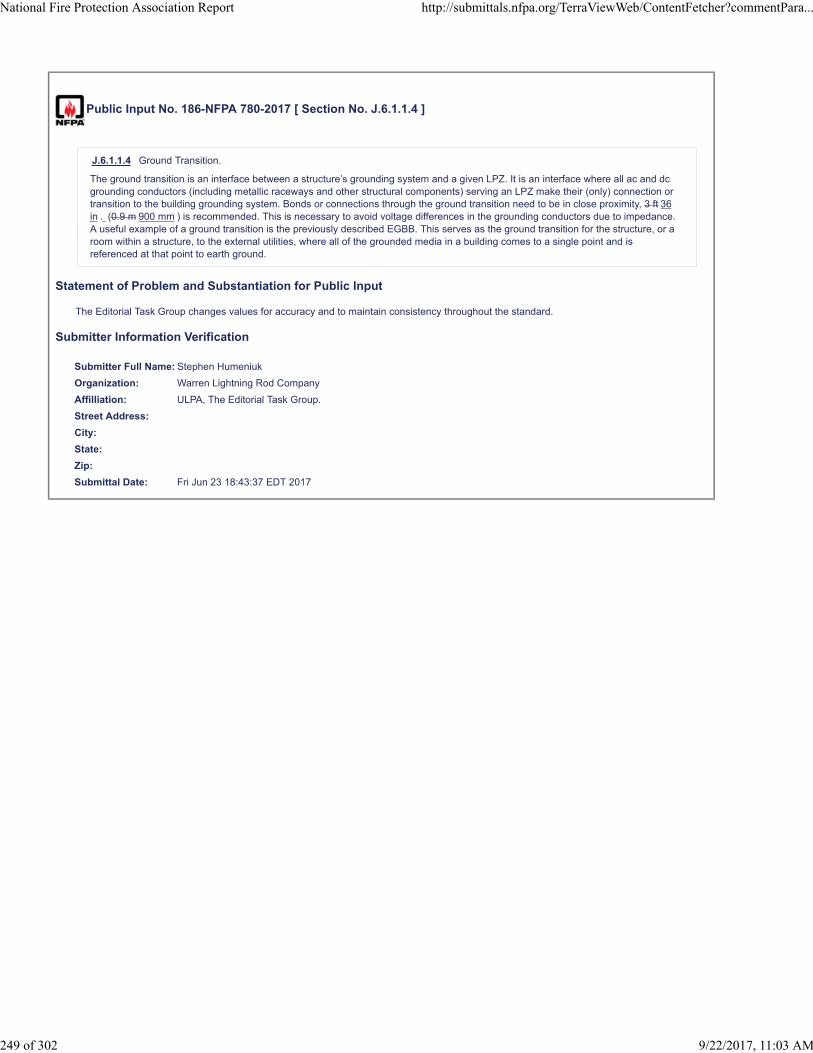
Public Input No. 186-NFPA 780-2017 [ Section No. J.6.1.1.4 ]
J.6.1.1.4 Ground Transition.
The ground transition is an interface between a structure’s grounding system and a given LPZ. It is an interface where all ac and dcgrounding conductors (including metallic raceways and other structural components) serving an LPZ make their (only) connection ortransition to the building grounding system. Bonds or connections through the ground transition need to be in close proximity, 3 ft 36in . (0.9 m 900 mm ) is recommended. This is necessary to avoid voltage differences in the grounding conductors due to impedance.A useful example of a ground transition is the previously described EGBB. This serves as the ground transition for the structure, or aroom within a structure, to the external utilities, where all of the grounded media in a building comes to a single point and isreferenced at that point to earth ground.
Statement of Problem and Substantiation for Public Input
The Editorial Task Group changes values for accuracy and to maintain consistency throughout the standard.
Submitter Information Verification
Submitter Full Name: Stephen Humeniuk
Organization: Warren Lightning Rod Company
Affilliation: ULPA, The Editorial Task Group.
Street Address:
City:
State:
Zip:
Submittal Date: Fri Jun 23 18:43:37 EDT 2017
National Fire Protection Association Report http://submittals.nfpa.org/TerraViewWeb/ContentFetcher?commentPara...
249 of 302 9/22/2017, 11:03 AM

Public Input No. 121-NFPA 780-2017 [ Section No. J.9.3.1 ]
J.9.3.1 Detail.
Automatic gate openers are susceptible to the threat of damage from lightning. Typically, the gate is remote from the structure itservices. Power, telephone, data, and CCTV conductors are run to the gate providing electricity and communication signals foractuators, motors, cameras, card readers, key pads, motion detectors, infrared sensors and telephones. If any of those conductorsfeed from sources other than the structure, a difference in potential is created between the ground at source of that feed and theground at the structure. When lightning energy is dissipated near the conductors, current can be injected into those conductors, orcurrent induced upon them. Either way, damage to the devices that control and operate the gate opener is likely.
Similarly, even if all of those conductors feed from the same building and are appropriately bonded together at the structure, damageis likely at the gate. This can happen because devices at the gate could experience different voltages on the grounding conductors ofthe different services if not made equipotential they do not have the same electrical potential , i.e., establish an a LightningProtective Zone( LPZ) . In addition, the gate could be closer to the point of the lightning strike and provide an easier, shorter path forlightning energy to equalize the difference in potential between those services than the bond in the building.
For example, a telephone line is used to communicate with the phone box outside the gate and to signal the motor on the gateactuator to open the gate. The motor controller is connected to the phone line and the electric service. If the grounding conductorsare not bonded to create equipotential, current will flow between the telephone ground and the electric utility ground through themotor controller. It is likely that this current will damage the controller.
Statement of Problem and Substantiation for Public Input
The changes are made to bring clarity.
Submitter Information Verification
Submitter Full Name: Stephen Humeniuk
Organization: Warren Lightning Rod Company
Affilliation: ULPA
Street Address:
City:
State:
Zip:
Submittal Date: Mon Jun 19 15:16:22 EDT 2017
National Fire Protection Association Report http://submittals.nfpa.org/TerraViewWeb/ContentFetcher?commentPara...
250 of 302 9/22/2017, 11:03 AM

Public Input No. 227-NFPA 780-2017 [ Section No. L.2 ]
L.2 Lightning Flash Density (NG).
Lightning flash density, the yearly number of flashes to ground per square kilometer, can be found in Figure L.2. A color version ofthis map with resolution of 2 km can be found at http://www.vaisala.com/VaisalaImages/Lightning/avg_fd_2005-2014_CONUS_2km_grid.png.
Figure L.2 2005–2014 Average 2 2005–2016 Average U.S. Lightning Flash Density Map (Flashes per Square Kilometer perYear).(Courtesy Vaisala, Inc.)
Additional Proposed Changes
File Name Description Approved
avg_fd_2005-2014_CONUS_2km_grid.png updated flash density map
Statement of Problem and Substantiation for Public Input
The map is revised to reflect the latest flash density statistics.
Submitter Information Verification
Submitter Full Name: Mitchell Guthrie
Organization: Engineering Consultant
Street Address:
City:
State:
Zip:
Submittal Date: Mon Jun 26 09:22:06 EDT 2017
National Fire Protection Association Report http://submittals.nfpa.org/TerraViewWeb/ContentFetcher?commentPara...
251 of 302 9/22/2017, 11:03 AM

Public Input No. 226-NFPA 780-2017 [ Section No. L.3 ]
L.3 Annual Threat of Occurrence (ND).
The yearly The average annual threat of occurrence occurrence (lightning strike frequency) ( ND) to a structure is determined by
the following equation:
[L.3]
where:
ND = yearly lightning average lightning strike frequency to the structure or object
NG = lightning ground flash density in flashes/km2/year
AD = the equivalent collection area of the structure (m2)
CD = environmental coefficient location factor
Statement of Problem and Substantiation for Public Input
Yearly and annual are redundant so yearly should be deleted. Average is added to identify this is a statistical prediction and not a factual value as could be suggested by the wording “the annual threat is determined by the following …” Lightning strike frequency can be easily mistaken for ground flash density Ng and it adds no additional clarification so it should be deleted.In the equation, it is also suggested that consideration be given to remove “potential” if the change from "yearly" to "average" is accepted..
Finally, Equation L.3 legend lists CD as the “environmental coefficient” but in L.4.2 and Table L.4.2 it is referred to as “location factor.” Location factor is the accurate descriptor. It is suggested that this is changed in the legend in L.3.
Submitter Information Verification
Submitter Full Name: Mitchell Guthrie
Organization: Engineering Consultant
Affilliation: NFPA 780 Risk Assessment Task Group
Street Address:
City:
State:
Zip:
Submittal Date: Mon Jun 26 08:00:01 EDT 2017
National Fire Protection Association Report http://submittals.nfpa.org/TerraViewWeb/ContentFetcher?commentPara...
252 of 302 9/22/2017, 11:03 AM

Public Input No. 228-NFPA 780-2017 [ Section No. L.4 [Excluding any Sub-Sections] ]
A D refers to the equivalent ground area having the equivalent lightning flash vulnerability as the structure collection area for lightning
flashes as ifit was an isolated structure on flat ground . It is an area adjusted for the structure that includes the effect of the height andlocation of the structure.
Statement of Problem and Substantiation for Public Input
The proposal makes an editorial correction by changing the A in AD to italics and brings the description of the term in line with that in IEC 62305-2.
Submitter Information Verification
Submitter Full Name: Mitchell Guthrie
Organization: Engineering Consultant
Affilliation: Technical Advisor, USNC/IEC TC 81 TAG
Street Address:
City:
State:
Zip:
Submittal Date: Mon Jun 26 09:45:02 EDT 2017
National Fire Protection Association Report http://submittals.nfpa.org/TerraViewWeb/ContentFetcher?commentPara...
253 of 302 9/22/2017, 11:03 AM

Public Input No. 229-NFPA 780-2017 [ Section No. L.6.4.1 ]
L.6.4.1 Direct Strikes to a Structure.
RA indicates injuries caused is associated with the risk of injuries or death caused by strikes to a structure (touch and step
potentials). RB indicates damage is associated with the risk of physical damage to a structure due to a direct strike. RC indicates
failure is associate with the risk of failure of internal systems due to a strike to a structure.
Statement of Problem and Substantiation for Public Input
Risk does not “identify” injury, damage, or failure; it is a prediction associated with the occurrence of such events. Death is included in RA description to ensure it is considered an extreme level of injury and "physical" is added to RB to be clear what type of damage is included in this risk component.
Submitter Information Verification
Submitter Full Name: Mitchell Guthrie
Organization: Engineering Consultant
Street Address:
City:
State:
Zip:
Submittal Date: Mon Jun 26 10:08:13 EDT 2017
National Fire Protection Association Report http://submittals.nfpa.org/TerraViewWeb/ContentFetcher?commentPara...
254 of 302 9/22/2017, 11:03 AM

Public Input No. 231-NFPA 780-2017 [ Section No. L.6.4.2 ]
L.6.4.2 Strikes near a Structure.
RM indicates failure is associated with the failure of internal systems due to a strike near a structure.
Statement of Problem and Substantiation for Public Input
Risk does not “identify” injury, damage, or failure; it is a prediction associated with the occurrence of such events.
Submitter Information Verification
Submitter Full Name: Mitchell Guthrie
Organization: Engineering Consultant
Street Address:
City:
State:
Zip:
Submittal Date: Mon Jun 26 11:29:35 EDT 2017
National Fire Protection Association Report http://submittals.nfpa.org/TerraViewWeb/ContentFetcher?commentPara...
255 of 302 9/22/2017, 11:03 AM

Public Input No. 232-NFPA 780-2017 [ Section No. L.6.4.3 ]
L.6.4.3 Strike to a Service Connected to a Structure.
RU indicates injury due is associated with the risk of injury or death due to strikes to a service connected to the structure. RVindicates damage is associated with physical damage to a structure due to strikes to a service connected to the structure. RWindicates failure W is associated with the risk of failure of internal systems or equipment due to a strike to a service connected to the
structure.
Statement of Problem and Substantiation for Public Input
Risk does not “identify” injury, damage, or failure; it is a prediction associated with the occurrence of such events. Death is added to RU to ensure it is considered as an extreme level of injury and “physical” is added to RV to clarify the specific type of damage considered in that risk component.
Submitter Information Verification
Submitter Full Name: Mitchell Guthrie
Organization: Engineering Consultant
Street Address:
City:
State:
Zip:
Submittal Date: Mon Jun 26 11:32:39 EDT 2017
National Fire Protection Association Report http://submittals.nfpa.org/TerraViewWeb/ContentFetcher?commentPara...
256 of 302 9/22/2017, 11:03 AM

Public Input No. 233-NFPA 780-2017 [ Section No. L.6.4.4 ]
L.6.4.4 Strikes near a Service Connected to the Structure.
RZ indicates is associated with the risk of failure of internal systems or equipment due to strikes near a service connected to the
structure.
Statement of Problem and Substantiation for Public Input
Risk does not “identify” injury, damage, or failure; it is a prediction associated with the occurrence of such events.
Submitter Information Verification
Submitter Full Name: Mitchell Guthrie
Organization: Engineering Consultant
Street Address:
City:
State:
Zip:
Submittal Date: Mon Jun 26 11:40:15 EDT 2017
National Fire Protection Association Report http://submittals.nfpa.org/TerraViewWeb/ContentFetcher?commentPara...
257 of 302 9/22/2017, 11:03 AM

Public Input No. 234-NFPA 780-2017 [ Section No. L.6.5 ]
L.6.5 Procedure for Risk Assessment and Management.
The procedure for the risk assessment is to first define the extent of the facility the facility or structure being assessed. The structureor facility The facility will be stand a stand -alone in structure in most cases. The structure The facility could also encompass abuilding and its associated outbuildings or equipment support structures. One must then determine all relevant physical,environmental, and service installation factors applicable to the structure .
The second step is to identify all the types of loss relevant to the structure or facility. For each type of loss relevant to the structure,the relevant loss factors should be chosen and associated probability is to be selected .
Next, the risk for each relevant type of loss for the structure should be structure is determined by identifying the components (RX)
that make up the risk, calculate the identified components of risk, and add these to calculate the total risk due to lightning (R) usingthe following relationships:
R = R1 + R2 + R3 + R4
R1 = RA + RB + R C* + RM*, + RU + RV + RW* + RZ*
R2 = RB + RC + RM + RV + RW + RZ
R3 = RB + RV
R4 = RA** + RB + RC + RM + RU** + RV + RW + RZ
*RC, RM, RW, and RZ in R1 are applicable only for structures with risk of explosion, for structures with life-critical electrical
equipment (such as hospitals), or other structures where the failure of internal systems immediately endangers human life.
**RA and RU in R4 are applicable only for structures where animals might be injured.
Risk factors are defined in L.6.6.
Compare the total risk (R) with the maximum tolerable risk (RT) for each type of loss relevant to the structure. If R < RT for each type
of loss relevant to the structure, then lightning protection might not be needed.
Statement of Problem and Substantiation for Public Input
The predominate number of proposed changes are editorial. Most of these involve changing "should be" to "is" as the text is identifying a procedure to be used and not a choice that may be selected by the user. It also confirms the nature of assessing a facility versus a single structure.
Submitter Information Verification
Submitter Full Name: Mitchell Guthrie
Organization: Engineering Consultant
Street Address:
City:
State:
Zip:
Submittal Date: Mon Jun 26 11:46:28 EDT 2017
National Fire Protection Association Report http://submittals.nfpa.org/TerraViewWeb/ContentFetcher?commentPara...
258 of 302 9/22/2017, 11:03 AM

Public Input No. 235-NFPA 780-2017 [ Section No. L.6.6.1.2 ]
L.6.6.1.2
The annual threat of occurrence due to strikes near a structure (NM) is given by the following equation (see Figure L.6.6.1.2):
[L.6.6.1.2]
where:
NG = lightning ground flash density in flashes/km2/year (see Section L.2)
AM = collection area of flashes near the structure (m2) (see Figure L.6.6.1.2)
AD = equivalent collection area of the structure (m2) (see Figure L.6.6.1.2)
CD = environmental coefficient (see Table L.4.2)
The collection area ( A M ) for flashes near the structure includes ( A M ) includes the area extending a distance of 500 m (1640 ft)
around the perimeter of the structure. For cases where NM is negative, a value of 0 is assigned to NM.
Figure L.6.6.1.2 Collection Areas (AD, AM, AL, ADJ, AI). (Source: IEC.)
Statement of Problem and Substantiation for Public Input
AM is the collection area for flashes near the structure so the symbol should appear after the description, not in the middle of the description.
Submitter Information Verification
Submitter Full Name: Mitchell Guthrie
Organization: Engineering Consultant
Affilliation: NFPA 780 Risk Assessment Task Group
Street Address:
City:
State:
Zip:
Submittal Date: Mon Jun 26 12:37:18 EDT 2017
National Fire Protection Association Report http://submittals.nfpa.org/TerraViewWeb/ContentFetcher?commentPara...
259 of 302 9/22/2017, 11:03 AM

Public Input No. 237-NFPA 780-2017 [ Section No. L.6.6.1.2 ]
L.6.6.1.2
The annual threat of occurrence due to strikes near a structure (NM) is given by the following equation (see Figure L.6.6.1.2):
[L.6.6.1.2]
where:
NG = lightning ground flash density in flashes/km2/year (see Section L.2)
AM = collection area of flashes near the structure (m2) (see Figure L.6.6.1.2)
AD = equivalent collection area of the structure (m2) (see Figure L.6.6.1.2)
CD = environmental coefficient (see Table L.4.2)
The collection area (AM) for flashes near the structure includes the area extending a distance of 500 m (1640 ft) around the
perimeter of the structure. For cases where NM is negative, a value of 0 is assigned to NM.
Figure L.6.6.1.2 Collection Areas (AD, AM, AL, ADJ, AI). (Source: IEC.)
Additional Proposed Changes
File Name Description Approved
Fig_L-6-6-1-2_w_highlighter.pdf Revision of Figure L.6.6.1.2
Statement of Problem and Substantiation for Public Input
The arrow showing the dimension of AM should originate at the structure, not at the boundary of AD as currently shown. The attached pdf file highlights the actual length of the dimensioning arrow.The value of AM should be reduced from 500 to 350 measured from the corner of the structure (as shown in the modified figure) to compensate for the overlap with AD. It was not possible to make this correction on the figure.
Submitter Information Verification
Submitter Full Name: Mitchell Guthrie
Organization: Engineering Consultant
Affilliation: NFPA 780 Risk Assessment Task Group
Street Address:
City:
State:
Zip:
Submittal Date: Mon Jun 26 13:47:11 EDT 2017
National Fire Protection Association Report http://submittals.nfpa.org/TerraViewWeb/ContentFetcher?commentPara...
260 of 302 9/22/2017, 11:03 AM


Public Input No. 239-NFPA 780-2017 [ Section No. L.6.6.1.3 ]
L.6.6.1.3
The annual threat of occurrence due to a strike to an incoming service (NL) is characterized by the following formula:
[L.6.6.1.3]
where:
NG = lightning ground flash density in flashes/km2/year (see Section L.2)
AL = collection area of flashes striking the service (m2) (see Figure L.6.6.1.2)
CD E = environmental coefficient of the 9+ incoming service (same as for structures per see Table L.4 6 .2 7.1 )
CT = correction factor for the presence of an HV/LV transformer located between the point of strike and the structure
Where the value of LL (used in the determination of AL) is not known, a value of 1 km is assumed for the assessment. A default value
of 500 Ωm can be used for soil resistivity (ρ) where this value cannot be determined.
If the installation incorporates underground cables run underneath a ground mesh, AI could be assumed to be 0 for that cable set (NL= 0).
CT applies to line sections between the transformer and the structure. A value of 0.2 is applicable for installations having a
transformer located between the strike and the structure. Otherwise, a value of 1 is assigned to this variable.
Where:
AL = 40 × LL
LL = the length of the incoming service (see Figure L.6.6.1.2)
Statement of Problem and Substantiation for Public Input
The revision corrects the descriptor designation for the environmental coefficient for incoming lines to CE, identifies the correct table to identify the values for the coefficient and deletes the typographical error "9+."
Submitter Information Verification
Submitter Full Name: Mitchell Guthrie
Organization: Engineering Consultant
Affilliation: NFPA 780 Risk Assessment Task Group
Street Address:
City:
State:
Zip:
Submittal Date: Mon Jun 26 15:48:27 EDT 2017
National Fire Protection Association Report http://submittals.nfpa.org/TerraViewWeb/ContentFetcher?commentPara...
261 of 302 9/22/2017, 11:03 AM
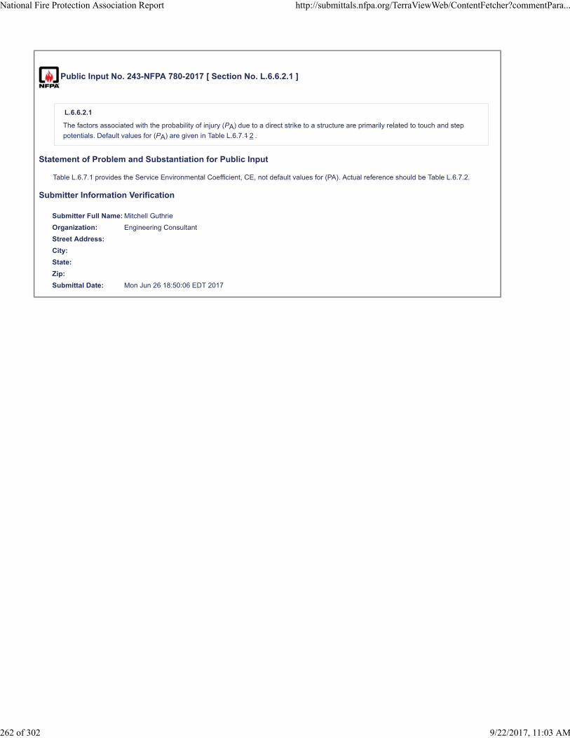
Public Input No. 243-NFPA 780-2017 [ Section No. L.6.6.2.1 ]
L.6.6.2.1
The factors associated with the probability of injury (PA) due to a direct strike to a structure are primarily related to touch and step
potentials. Default values for (PA) are given in Table L.6.7.1 2 .
Statement of Problem and Substantiation for Public Input
Table L.6.7.1 provides the Service Environmental Coefficient, CE, not default values for (PA). Actual reference should be Table L.6.7.2.
Submitter Information Verification
Submitter Full Name: Mitchell Guthrie
Organization: Engineering Consultant
Street Address:
City:
State:
Zip:
Submittal Date: Mon Jun 26 18:50:06 EDT 2017
National Fire Protection Association Report http://submittals.nfpa.org/TerraViewWeb/ContentFetcher?commentPara...
262 of 302 9/22/2017, 11:03 AM

Public Input No. 244-NFPA 780-2017 [ Section No. L.6.6.2.2 ]
L.6.6.2.2
The factors associated with the probability of physical damage (PB) due to a direct strike to a structure are primarily related to the
type of protection provided. Default values for (PB) are given in Table L.6.7.2 3 .
Statement of Problem and Substantiation for Public Input
Table L.6.7.2 provides Values of Probability (PA) That a Flash to a Structure Will Cause Shock to Living Beings Due to Dangerous Touch-and-Step Voltages, not default values for (PB). Actual reference should be Table L.6.7.3.
Submitter Information Verification
Submitter Full Name: Mitchell Guthrie
Organization: Engineering Consultant
Street Address:
City:
State:
Zip:
Submittal Date: Mon Jun 26 18:55:29 EDT 2017
National Fire Protection Association Report http://submittals.nfpa.org/TerraViewWeb/ContentFetcher?commentPara...
263 of 302 9/22/2017, 11:03 AM

Public Input No. 245-NFPA 780-2017 [ Section No. L.6.6.2.3 ]
L.6.6.2.3
The factors associated with the probability of failure of internal systems due to a direct strike (PC) are primarily related to the surge
protection measures provided. Default values for PC are given in Table L.6.7.3 4 . SPD protection is effective to reduce PC only in
structures protected by a lightning protection system or in structures with a continuous metal or reinforced concrete frame.
Statement of Problem and Substantiation for Public Input
Correcting table reference. Actual reference should be Table L.6.7.4.
Submitter Information Verification
Submitter Full Name: Mitchell Guthrie
Organization: Engineering Consultant
Street Address:
City:
State:
Zip:
Submittal Date: Mon Jun 26 19:06:55 EDT 2017
National Fire Protection Association Report http://submittals.nfpa.org/TerraViewWeb/ContentFetcher?commentPara...
264 of 302 9/22/2017, 11:03 AM

Public Input No. 248-NFPA 780-2017 [ Section No. L.6.6.2.4 ]
L.6.6.2.4
The probability that a strike near a structure will cause failure of internal systems (PM) depends on the lightning protection measures
implemented. These measures are characterized by a factor, KS, that takes into consideration protective measures such as the
shielding effectiveness of the structure, any internal shielding provided, characteristics of internal wiring, and the rated impulsewithstand voltage level (i.e., withstand voltage) of the system to be protected. Where SPDs are not installed at utilization equipment ,or the SPDs at the utilization equipment are not properly coordinated with those installed at the service entrances, the value of PM to
be used in the equation for the risk of failure of internal systems due to a strike near a structure (PM) can be taken from Table
L.6.7.4 5 . Where coordinated SPDs are installed at the utilization equipment, the value of PM used in the computation of PM is the
lower value between PC and PM. For internal systems with equipment having rated impulse withstand voltage levels that are
unknown or are less than 1.5 kV, a value of PM = 1 should be used in the assessment.
The value of KS is calculated using the following equation:
[L.6.6.2.4a]
where:
KS1 = factor relating to the shielding effectiveness of the structure, lightning protection system, or other shields at the exteriorboundary of the structure
KS2 = factor relating to the shielding effectiveness of shields internal to the structure
KS3 = factor relating to the characteristics of the internal wiring
KS4 = factor relating to the rated impulse withstand voltage level of the system to be protected
For continuous metal shields with a thickness of 0.1 to 0.5 mm, KS1 and KS2 should be assigned the value of 10-4 to 10-5 (scaled
linearly). Where not otherwise known, the value of KS1 and KS2 can be evaluated by the following relationship as long as the
equipment is located a distance, w, from the boundary shield:
[L.6.6.2.4b]
where:
W w M = distance measured in meters and given by a mesh grid spacing, the spacing between down conductors, or the spacingbetween structural steel columns, or rebar spacing in reinforced concrete structures and/or footers.
In those structures where it is ensured that steel reinforcing bars are interconnected and terminated by approved groundingelectrodes,W w is the spacing between the reinforcing bars.
If the equipment is located closer to the applicable boundary than the distance, W w M, the values of KS1 and KS2 should be
doubled. In those cases where multiple internal boundaries exist, the resulting value of KS2 is the product of each individual value of
KS2.
Table L.6.7.5 provides values that can be selected for factor KS3 based on the configuration of internal wiring. For wiring contained in
continuous metallic conduit that is properly bonded to the lightning protection grounding system, the selected value of KS3 from the
table is multiplied by a factor of 0.1.
The value of factor KS4 is evaluated by the following formula:
[L.6.6.2.4c]
where:
UW = lowest rated impulse withstand voltage of the individual components in the system under consideration
Statement of Problem and Substantiation for Public Input
Revise L.6.6.2.4 as follows to make the intent clear and correct table references. The spacing between conductors (or mesh spacing) should be a lower case w in italics for consistency with other lightning risk assessments that use the parameter.Reconsideration of the limitation of application of the determination of the value of PM to cases where SPDs are not installed at utilization equipment is recommended.
Submitter Information Verification
Submitter Full Name: Mitchell Guthrie
Organization: Engineering Consultant
Affilliation: NFPA 780 Risk Assessment Task Group
Street Address:
National Fire Protection Association Report http://submittals.nfpa.org/TerraViewWeb/ContentFetcher?commentPara...
265 of 302 9/22/2017, 11:03 AM

City:
State:
Zip:
Submittal Date: Mon Jun 26 19:44:12 EDT 2017
National Fire Protection Association Report http://submittals.nfpa.org/TerraViewWeb/ContentFetcher?commentPara...
266 of 302 9/22/2017, 11:03 AM

Public Input No. 252-NFPA 780-2017 [ Section No. L.6.6.3 [Excluding any Sub-Sections] ]
The value of LT, LF, and LO can be determined in terms of the relative number of victims from the following approximate relationship:
[L.6.6.3]
where:
LA = value for loss of human life
nZ = number of possible endangered persons (victims)
nT = expected total number of persons (in the structure)
tZ = time in hours per year for which the persons are present in a dangerous place, outside of the structure (LT only) or inside the
structure (LT, LF, and LO)
Typical mean values of LT, LF, and LO, for use when the determination of nZ, nT, and tZ is uncertain or difficult, are given in Table
L.6.7.8 9 .
Statement of Problem and Substantiation for Public Input
Table L.6.7.8 is the Values of the Probability (PZ) as a Function of the Resistance of the Cable Shield and the Withstand Voltage (UW) of the Equipment. The proper reference should be Table L.6.7.9
Submitter Information Verification
Submitter Full Name: Mitchell Guthrie
Organization: Engineering Consultant
Street Address:
City:
State:
Zip:
Submittal Date: Tue Jun 27 06:20:05 EDT 2017
National Fire Protection Association Report http://submittals.nfpa.org/TerraViewWeb/ContentFetcher?commentPara...
267 of 302 9/22/2017, 11:03 AM

Public Input No. 254-NFPA 780-2017 [ Section No. L.6.6.3.2 ]
L.6.6.3.2 Physical Damage.
The following equation calculates the value of loss from physical damage to the structure:
[L.6.6.3.2]
where:
LB = value of loss due to direct strike to the structure
LV = value of loss due to strike to incoming service
rP = reduction factor for provisions taken to reduce consequences of fire (see Table L.6.7.10 11 )
rF = reduction factor for risk of fire to structure (see Table L.6.7.11 12 )
hZ = factor for the kinds of hazard in the structure (see Table L.6.7.12 13 )
LF = mean value of physical damage loss (see Table L.6.7.8 9 )
Statement of Problem and Substantiation for Public Input
The references to Tables are incorrect. They all should be incremented by 1. Reconsideration should also be given to the presentation of the equations as LB is not the same as LV.
Submitter Information Verification
Submitter Full Name: Mitchell Guthrie
Organization: Engineering Consultant
Street Address:
City:
State:
Zip:
Submittal Date: Tue Jun 27 07:18:32 EDT 2017
National Fire Protection Association Report http://submittals.nfpa.org/TerraViewWeb/ContentFetcher?commentPara...
268 of 302 9/22/2017, 11:03 AM

Public Input No. 256-NFPA 780-2017 [ Section No. L.6.6.3.3 ]
L.6.6.3.3 Failure of Internal Systems.
The following equation calculates the value of loss due to failure of internal systems:
[L.6.6.3.3]
where:
L C = value of loss due to direct strike to the structure
L M = value of loss due to a strike near the structure
L W = value of loss due to a strike to a service connected to the structure
L Z = value of loss due to a strike near a service connected to the structure
L O = mean value of loss of internal system (see Table L.6.7.8)
Statement of Problem and Substantiation for Public Input
Editorial. Loss L should be in italics.
Submitter Information Verification
Submitter Full Name: Mitchell Guthrie
Organization: Engineering Consultant
Street Address:
City:
State:
Zip:
Submittal Date: Tue Jun 27 08:01:50 EDT 2017
National Fire Protection Association Report http://submittals.nfpa.org/TerraViewWeb/ContentFetcher?commentPara...
269 of 302 9/22/2017, 11:03 AM

Public Input No. 255-NFPA 780-2017 [ Section No. L.6.7.4 ]
L.6.7.4
Table L.6.7.4 provides values for the probability PC of failure of internal systems as a function SPD protection.
Table L.6.7.4 Values of Probability (PC) as a Function of SPD Protection Provided
SPD Protection Provided PC
No SPD protection 1
SPDs provided in accordance with Section 4.20 0.03
Notes:
(1) SPD protection is effective to reduce PC only in structures protected by an LPS or in structures with a continuous metal or
reinforced concrete frame where bonding and grounding requirements of Section 4.20 are met.
(2) Shielded internal systems fed by wiring in lightning protective cable ducts or metallic conduits can be used in lieu of SPDprotection.
(3) Smaller values of PCcan be used where SPDs above and beyond those required by Section 4.20 and SPDs having better
protection characteristics (higher current withstand capability, lower protective level, etc.) than the minimum specified in Section 4.20.(See Annex B of IEC 62305-2, Protection Against Lightning — Part 2: Risk Management, for additional information).
(4) For PV applications, the reduction in the value of P C must comply with the requirements of Section 12.4.2 and/or 4.12.3.
Statement of Problem and Substantiation for Public Input
Section 4.20 does not address surge protection for PV arrays. The addition of Note 4 provides the proper link to Chapter 12 for the assessment of PV arrays.
Submitter Information Verification
Submitter Full Name: Mitchell Guthrie
Organization: Engineering Consultant
Street Address:
City:
State:
Zip:
Submittal Date: Tue Jun 27 07:28:41 EDT 2017
National Fire Protection Association Report http://submittals.nfpa.org/TerraViewWeb/ContentFetcher?commentPara...
270 of 302 9/22/2017, 11:03 AM

Public Input No. 303-NFPA 780-2017 [ Section No. L.6.7.8 ]
L.6.7.8
Table L.6.7.8 provides values of probability PZ of failure of internal systems due to a strike near a service to a structure. PZ is a
function of the resistance of the cable shield and the withstand voltage (UW) of the equipment.
Table L.6.7.8 Values of the Probability (PZ) as a Function of the Resistance of the Cable Shield and the Withstand Voltage (UW) of
the Equipment
Line Type Withstand Voltage U
w
W (kV)
1 1.5 2.5 4 6
Power lines 1 0.6 0.3 0.16 0.1
Telecom lines 1 0.5 0.2 0.08 0.04
Note: Values for UW can be obtained from manufacturers and equipment suppliers. If the actual values are not readily available from
other sources the following typical values can be utilized:
For structures containing computer equipment: UW= 1.5 kV
For a typical residential structure: UW= 2.5 kV
For a typical business, hotel, hospital, etc., structure: UW = 2.5 kV
For a typical light industrial structure: UW = 4.0 kV
For a typical heavy industrial structure: UW = 6.0 kV
Default value: UW = 1.5 kV
Statement of Problem and Substantiation for Public Input
Editorial. W in table heading changed to subscript to be consistent with the rest of the table.
Submitter Information Verification
Submitter Full Name: Mitchell Guthrie
Organization: Engineering Consultant
Street Address:
City:
State:
Zip:
Submittal Date: Wed Jun 28 09:45:05 EDT 2017
National Fire Protection Association Report http://submittals.nfpa.org/TerraViewWeb/ContentFetcher?commentPara...
271 of 302 9/22/2017, 11:03 AM

Public Input No. 251-NFPA 780-2017 [ Section No. L.6.7.10 ]
L.6.7.10
Table L.6.7.10 provides values of the reduction factor rT t as a function of the type of surface soil or floor.
Table L.6.7.10 Values of Reduction Factor (r T t ) as a Function of the Type of Surface of Soil or Floor
Type of Surface Contact Resistance (kΩ*) r
T
t
Soil, concrete < 1 10 -2
Marble, ceramic 1–10 10 -3
Gravel, carpets 10–100 10 -4
Asphalt, linoleum, wood > 100 10 -5
*Values measured between a 4000 mm2 electrode compressed with force of 500 N at a point of infinity.
Statement of Problem and Substantiation for Public Input
The proposed revision brings the descriptor for the reduction factor associated with the type of surface (rt) in line with other lightning risk assessments that recognize the factor. It changes the subscript to lower case t and corrects the case in the Table caption where the r was not in italics,
Submitter Information Verification
Submitter Full Name: Mitchell Guthrie
Organization: Engineering Consultant
Street Address:
City:
State:
Zip:
Submittal Date: Mon Jun 26 21:20:36 EDT 2017
National Fire Protection Association Report http://submittals.nfpa.org/TerraViewWeb/ContentFetcher?commentPara...
272 of 302 9/22/2017, 11:03 AM
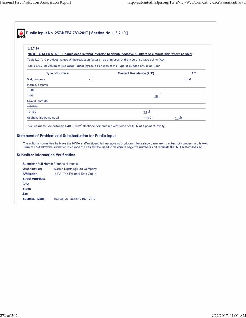
Public Input No. 257-NFPA 780-2017 [ Section No. L.6.7.10 ]
L.6.7.10
NOTE TO NFPA STAFF: Change dash symbol intended to denote negative numbers to a minus sign where needed.
Table L.6.7.10 provides values of the reduction factor rT as a function of the type of surface soil or floor.
Table L.6.7.10 Values of Reduction Factor (rT) as a Function of the Type of Surface of Soil or Floor
Type of Surface Contact Resistance (kΩ*) r T
Soil, concrete < 1 10 -2
Marble, ceramic
1–10
1-10 10 -3
Gravel, carpets
10–100
10-100 10 -4
Asphalt, linoleum, wood > 100 10 -5
*Values measured between a 4000 mm2 electrode compressed with force of 500 N at a point of infinity.
Statement of Problem and Substantiation for Public Input
The editorial committee believes the NFPA staff misidentified negative subscript numbers since there are no subscript numbers in this text. Terra will not allow the submitter to change the dah symbol used to designate negative numbers and requests that NFPA staff does so.
Submitter Information Verification
Submitter Full Name: Stephen Humeniuk
Organization: Warren Lightning Rod Company
Affilliation: ULPA, The Editorial Task Group
Street Address:
City:
State:
Zip:
Submittal Date: Tue Jun 27 08:55:40 EDT 2017
National Fire Protection Association Report http://submittals.nfpa.org/TerraViewWeb/ContentFetcher?commentPara...
273 of 302 9/22/2017, 11:03 AM

Public Input No. 253-NFPA 780-2017 [ Section No. L.6.7.12 ]
L.6.7.12
Table L.6.7.12 provides values of the reduction factor rF as a function of risk of fire for the structure.
Table L.6.7.12 Values of Reduction Factor (rF) as a Function of Risk of Fire for a Structure
Risk of Fire r F
Explosion a 1
High b 0.1
Ordinary c 0.01
Low d 0.001
None e 0
aStructures with risk of explosion or structures that contain explosive mixtures of gases, dusts, or materials.
bStructures with significant quantities of combustible materials and/or storage of significant quantities of flammable and combustibleliquids (e.g., large warehouses, shipping terminals, big box stores, industrial facilities with flammable and combustible processes,printing, saw mills, plastics processing, paint dipping and spraying).
cStructures with moderate quantities of combustible materials with minor storage areas that produce significant amounts of smoke,but no flammable or combustible liquids (e.g., small warehouses, mercantile, post offices, electronic plants, ordinary chemical plants,restaurant service areas, wood product assembly).
dStructures with limited quantities of combustible materials and generally noncombustible construction (e.g. , residences, churches,educational buildings, institutional, museums, offices, theaters).
eNoncombustible construction with no exposed combustible contents.
Statement of Problem and Substantiation for Public Input
Typical residences and churches are generally made of wood construction which should not be considered noncombustible construction when subjected to a direct strike. Residences and offices could contain more than limited quantities of combustible materials. Inclusion of these in the examples could infer a lower than actual risk.
Submitter Information Verification
Submitter Full Name: Mitchell Guthrie
Organization: Engineering Consultant
Street Address:
City:
State:
Zip:
Submittal Date: Tue Jun 27 06:43:41 EDT 2017
National Fire Protection Association Report http://submittals.nfpa.org/TerraViewWeb/ContentFetcher?commentPara...
274 of 302 9/22/2017, 11:03 AM

Public Input No. 230-NFPA 780-2017 [ Section No. L.6.8 ]
National Fire Protection Association Report http://submittals.nfpa.org/TerraViewWeb/ContentFetcher?commentPara...
275 of 302 9/22/2017, 11:03 AM

L.6.8
National Fire Protection Association Report http://submittals.nfpa.org/TerraViewWeb/ContentFetcher?commentPara...
276 of 302 9/22/2017, 11:03 AM

Figure L.6.8 provides a worksheet for detailed risk assessment.
Figure L.6.8 Detailed Risk Assessment Worksheet.
ATTENTION NFPA STAFF: Change Annual Threat Of Occurence. Correct the spelling of Occurrence in the second cell on the leftside of the table on (p.1 of 3)
National Fire Protection Association Report http://submittals.nfpa.org/TerraViewWeb/ContentFetcher?commentPara...
277 of 302 9/22/2017, 11:03 AM

Statement of Problem and Substantiation for Public Input
The Editorial Task Group REQUESTS THAT NFPA STAFF MAKE THIS CHANGE. The Figures can not be altered using Terra. The change id made to correct a spelling error. Correct the spelling of the word "Occurrence" in the second Cell on the Left side of (p.1 of 3)
Submitter Information Verification
Submitter Full Name: Stephen Humeniuk
Organization: Warren Lightning Rod Company
Affilliation: ULPA, THe Editorial Task Group
Street Address:
City:
State:
Zip:
Submittal Date: Mon Jun 26 10:56:29 EDT 2017
National Fire Protection Association Report http://submittals.nfpa.org/TerraViewWeb/ContentFetcher?commentPara...
278 of 302 9/22/2017, 11:03 AM

Public Input No. 90-NFPA 780-2017 [ Section No. M.2.1 ]
M.2.1
Most lightning strike victims are struck before or after the rain that usually accompanies thunderstorms. This would indicate that mostpeople have the good sense to get out of the rain, but are not as conscious of the life-threatening hazards presented by lightning.Atmospheric conditions that cause lightning can be measured and the probability of a lightning event predicted. However, it is notpossible to predict the exact location where lightning will strike since it has been known to attach to earth beyond the visible horizon.
Lightning is extremely dangerous, and unnecessary exposure should be avoided. The following recommendations are advisable:
(1) When possible, plan outdoor activities around the weather forecast. Although it is difficult to know exactly if a storm will occur, theconditions that create lightning storms, such as the meeting of high- and low-pressure systems, are predicted days in advance.On days when such weather patterns are forecast, avoid planning activities where shelter is not readily available, such asboating or camping.
(2) Check the forecast the night before and the morning of planned outdoor activities to see if lightning is a possibility.
(3) Check Internet web site weather maps before you leave. Most weather sites have recent satellite and radar images of the area ofyour activity.
(4) When you arrive at the area of your activity, devise a plan on where to go in the event of an approaching lightning storm. Tell allpersons in your party, especially children, where to go in accordance with M.2.2. Also, tell your party where you will meet a halfhour after thunder is last heard, since you may not be together when the threat of a storm arises.
(5) Carry a weather radio with an Alert feature to alert feature or set your cellular telephone to receive severe weather warnings.
(6) Respond accordingly when warnings are issued.
Statement of Problem and Substantiation for Public Input
This comment makes an editorial changes. The capital 'A' in 'Alert" should be a small 'a'. Also, adding cellular telephones as a source of warning to recommended practices list updates the annex making it more culturally relevant.
Submitter Information Verification
Submitter Full Name: Stephen Humeniuk
Organization: Warren Lightning Rod Company
Affilliation: ULPA
Street Address:
City:
State:
Zip:
Submittal Date: Thu Jun 15 14:03:46 EDT 2017
National Fire Protection Association Report http://submittals.nfpa.org/TerraViewWeb/ContentFetcher?commentPara...
279 of 302 9/22/2017, 11:03 AM
Public Input No. 95-NFPA 780-2017 [ New Section after M.2.2 ]
M.2.2.1
If a preferred shelter is not accessible, seek shelter in one o the following.
(1) Large unprotected buildings
(2) Underground Shelters such as subways,tunnels, and caves
Statement of Problem and Substantiation for Public Input
The Personal Safety Task Group submits this as a Committee Proposal. Breaking these places of shelter out into a separate section differentiates them as less safe, and less desirable than the locations cited in the preceding section.
Submitter Information Verification
Submitter Full Name: Stephen Humeniuk
Organization: Warren Lightning Rod Company
Affilliation: ULPA, The Personal Safety Task Group.
Street Address:
City:
State:
Zip:
Submittal Date: Thu Jun 15 15:41:41 EDT 2017
National Fire Protection Association Report http://submittals.nfpa.org/TerraViewWeb/ContentFetcher?commentPara...
280 of 302 9/22/2017, 11:03 AM

Public Input No. 96-NFPA 780-2017 [ New Section after M.2.2 ]
M.2.2.2
Being on the water during a thunderstorm greatly increases the threat of a lightning strike. Get to shore and seek shelter on land.Remaining on the water should not be consider unless you are inside of:
(1) Enclosed metal boats or ships
(2 Enclosed boats protected against lightning
Statement of Problem and Substantiation for Public Input
The personal Safety Task Group Submits this as a Committee Proposal. The language identifies the threat of being struck by lightning on the water and encourage sheltering on shore, while providing direction for safe spaces on the water.
Submitter Information Verification
Submitter Full Name: Stephen Humeniuk
Organization: Warren Lightning Rod Company
Affilliation: ULPA, Personal Safety Task Group.
Street Address:
City:
State:
Zip:
Submittal Date: Thu Jun 15 15:53:40 EDT 2017
National Fire Protection Association Report http://submittals.nfpa.org/TerraViewWeb/ContentFetcher?commentPara...
281 of 302 9/22/2017, 11:03 AM

Public Input No. 94-NFPA 780-2017 [ Section No. M.2.2 ]
M.2.2
If you hear thunder, seek shelter immediately. Do not try to predict how close lightning is by counting the time between the flash oflightning and the sound of thunder. Stay indoors until one-half hour after you last heard thunder. Seek shelter in
structures
a preffered structure such as
the
one of the following:
(1) Dwellings or other buildings that are protected against lightning
Underground shelters such as subways, tunnels, and caves
(1) Large metal-frame buildings
Large unprotected buildings
(1) Enclosed automobiles, buses, and other vehicles with metal tops and bodies .
(2) Enclosed metal trains and street cars
Enclosed metal boats or ships
Boats that are protected against lightning
City streets shielded by nearby buildings
Statement of Problem and Substantiation for Public Input
The Personal Safety Task Group Submits this as a Committee Proposal. Clearer direction is provided as to the best place to seek shelte, while eliminating confusion on sheltering outdoors.
Submitter Information Verification
Submitter Full Name: Stephen Humeniuk
Organization: Warren Lightning Rod Company
Affilliation: ULPA, Personal Safety Task Group.
Street Address:
City:
State:
Zip:
Submittal Date: Thu Jun 15 14:58:18 EDT 2017
National Fire Protection Association Report http://submittals.nfpa.org/TerraViewWeb/ContentFetcher?commentPara...
282 of 302 9/22/2017, 11:03 AM

Public Input No. 91-NFPA 780-2017 [ Section No. M.2.4 ]
M.2.4
Certain locations are extremely hazardous during thunderstorms and should be avoided if at all possible. Approaching thunderstormsshould be anticipated and the following locations avoided when thunderstorms are in the immediate vicinity:
(1) Hilltops and ridges
(2) Areas on top of buildings
(3) Open fields, athletic fields, and golf courses
(4) Parking lots and tennis courts
(5) Swimming pools (indoor or outdoor), lakes, and rivers, and seashores
(6) Near wire fences, clotheslines, overhead wires, and railroad tracks
(7) Under isolated trees
(8) Near electrical appliances, telephones, plumbing fixtures, and metal or electrically conductive objects
Statement of Problem and Substantiation for Public Input
The Personal Safety Task Group submits this change as a Committee Proposal. The additional text is more inclusive adding further clarification.
Submitter Information Verification
Submitter Full Name: Stephen Humeniuk
Organization: Warren Lightning Rod Company
Affilliation: ULPA,The Personal Saftey Task Group
Street Address:
City:
State:
Zip:
Submittal Date: Thu Jun 15 14:07:00 EDT 2017
National Fire Protection Association Report http://submittals.nfpa.org/TerraViewWeb/ContentFetcher?commentPara...
283 of 302 9/22/2017, 11:03 AM

Public Input No. 120-NFPA 780-2017 [ New Section after M.2.6 ]
M.2.6 (5)
Run! If you are in good enough health, run to find shelter. When running, only one foot is on the ground some of the time, with nocontact with the ground part of the time. Running mitigates the threat of step potential. It also diminishes the likelihood of a directstrike, since contact with earth is necessary for the ionization of an upward streamer propagate over your body.
Statement of Problem and Substantiation for Public Input
This Personal SafetyTask Group proposal is added to give further options and guidance on what can be done when no shelter is available. Someone is better off running they would be waiting in an exposed area for the threat of lightning to subside.
Submitter Information Verification
Submitter Full Name: Stephen Humeniuk
Organization: Warren Lightning Rod Company
Affilliation: ULPA, Personal Safety Task Group
Street Address:
City:
State:
Zip:
Submittal Date: Mon Jun 19 10:28:39 EDT 2017
National Fire Protection Association Report http://submittals.nfpa.org/TerraViewWeb/ContentFetcher?commentPara...
284 of 302 9/22/2017, 11:03 AM

Public Input No. 92-NFPA 780-2017 [ Section No. M.2.6 ]
M.2.6
If caught in a lightning storm with no shelter available, the following recommendations should be observed:
(1) Seek depressed areas — avoid mountaintops, hilltops, peaks, ridges, and other high places.
(2) Seek dense woods — avoid isolated trees.
(3) If caught in an exposed area, crouch position yourself as low and as low small as possible to minimize risk of direct strike;kneel . Kneel on the ground, keep your feet together, and put and do not place your hands on your thighs in contact wih earth .
(4) Minimize the risk of step potential hazards by minimizing the area of your body in contact with the ground. Do not lie flat. It isbest not to have any body parts in contact with earth. If a foam pad or an inflated air mattress is readily available, kneel or sit onit, leaving no body parts touching the ground. Sit or kneel on a backpack after placing the frame side down on the ground. If anybody part must touch the ground, feet are preferred. Do not put hands in contact with earth.
Statement of Problem and Substantiation for Public Input
The Personal Safety Task Group submits this change as a Committee Proposal to add clarity to the existing text.
Submitter Information Verification
Submitter Full Name: Stephen Humeniuk
Organization: Warren Lightning Rod Company
Affilliation: ULPA, The Personal Safety Task Group
Street Address:
City:
State:
Zip:
Submittal Date: Thu Jun 15 14:11:48 EDT 2017
National Fire Protection Association Report http://submittals.nfpa.org/TerraViewWeb/ContentFetcher?commentPara...
285 of 302 9/22/2017, 11:03 AM

Public Input No. 130-NFPA 780-2017 [ Section No. M.3.1 ]
M.3.1
Remain inside a closed boat, as far as practical, during a During a lightning storm; , do not dangle arms or legs in the water. Ifpossible remain inside an enclosed cabin on the boat.
Statement of Problem and Substantiation for Public Input
The Editorial Task Group suggests this change for clarity and readability.
Submitter Information Verification
Submitter Full Name: Stephen Humeniuk
Organization: Warren Lightning Rod Company
Affilliation: ULPA, The Editorial Task Group
Street Address:
City:
State:
Zip:
Submittal Date: Mon Jun 19 17:36:14 EDT 2017
National Fire Protection Association Report http://submittals.nfpa.org/TerraViewWeb/ContentFetcher?commentPara...
286 of 302 9/22/2017, 11:03 AM

Public Input No. 129-NFPA 780-2017 [ Section No. M.3.2 ]
M.3.2
To the extent consistent with safe handling and navigation of the boat during During a lightning storm, avoid making contact withany items connected to a lightning protection system, especially in such a way as to bridge between these items. For example, it isundesirable for an operator to be in contact with reversing gear levers and a spotlight control handle at the same time it isundesirable to be in contact with different components of the vessel that are attached to the lightning protection system.Such contactcould equalize the difference in electrical potential between those components by flowing through your body. To the extent consistentwith the safe handing and navigation of the vessel, simultaneous contact between multiple components should be avoided .
Statement of Problem and Substantiation for Public Input
The Editorial Task Group recommends the change for clarity and readability.
Submitter Information Verification
Submitter Full Name: Stephen Humeniuk
Organization: Warren Lightning Rod Company
Affilliation: ULPA, The Editorial Task Group
Street Address:
City:
State:
Zip:
Submittal Date: Mon Jun 19 17:23:47 EDT 2017
National Fire Protection Association Report http://submittals.nfpa.org/TerraViewWeb/ContentFetcher?commentPara...
287 of 302 9/22/2017, 11:03 AM

Public Input No. 100-NFPA 780-2017 [ Section No. M.4 ]
M.4 Lightning Safety for Outdoor Workers.
M4.1 Add a Lightning safety Plan
(See Commitee Proposal)
M.4. 1 2 Preplan Safe Locations
(See Commitee Proposal)
M.4.3 Detection.
Lightning conditions are to be monitored continuously. In most cases, a combination of a lightning network subscription service, aprofessional-grade lightning warning system, and a high-quality handheld detector is suggested. However, if thunder is heard, thedanger from lightning is close enough to suspend operations and seek refuge.
M.4. 2 4 Notification.
M.4. 2 4 .1
Suspension and resumption of work activities should be planned in advance, through policies and training. Information can betransmitted by some or all of the following methods:
(1) Sirens
(2) Strobe lights
(3) Text messages
(4) 2-way radios
(5) Telephones
M.4. 2 4 .2
A conservative warning threshold could be the following:
Yellow condition: Lightning is in the 20–40 mi (30–60 km) range and the threat could exist.
Orange condition: Lightning is in the 10–20 mi (16–30 km) range and the threat is nearby.
Red Alert: Lightning is in the 0–10 mi (0–16 km) range and no personnel are allowed outdoors. All outside personnel must seeksafety in a designated shelter that is equipped with a lightning protection system that complies with this standard. If not available,seek shelter in the structures listed in M.2.2.
M.4. 3 5 Reassess the Threat.
Wait until one-half hour after thunder is no longer heard before resuming outdoor activities. Be extra cautious during this storm phase,as lightning can still be a significant hazard.
M.4. 4 6 Policies, Procedures, Education, and Training.
Organizations should create, publish, and train personnel on appropriate lightning safety guidelines in accordance with therecommendations in Annex M.
Statement of Problem and Substantiation for Public Input
The Personal Safety Task Group submits this as a Committee Proposal. Renumber the entire section to accommodate the added sections
Related Public Inputs for This Document
Related Input Relationship
Public Input No. 98-NFPA 780-2017 [New Section after M.4.1]
Public Input No. 99-NFPA 780-2017 [New Section after M.4.1]
Public Input No. 98-NFPA 780-2017 [New Section after M.4.1]
Public Input No. 99-NFPA 780-2017 [New Section after M.4.1]
Submitter Information Verification
Submitter Full Name: Stephen Humeniuk
Organization: Warren Lightning Rod Company
Affilliation: ULPA, the Personal Safety Task Group
Street Address:
City:
State:
National Fire Protection Association Report http://submittals.nfpa.org/TerraViewWeb/ContentFetcher?commentPara...
288 of 302 9/22/2017, 11:03 AM

Zip:
Submittal Date: Thu Jun 15 17:07:02 EDT 2017
National Fire Protection Association Report http://submittals.nfpa.org/TerraViewWeb/ContentFetcher?commentPara...
289 of 302 9/22/2017, 11:03 AM

Public Input No. 98-NFPA 780-2017 [ New Section after M.4.1 ]
M.4.2 Preplan Safe Locations
Make provisions for outdoor works to have access to lightning safe spaces before the threat of lighting by providing one of thefollowing:
(1) Engineer lightning safe work environments
(2) Provide protected structures
(3) Stage metallic vehicles with hard tops in close proximate to the work site.
(4) Identify protected structures near by
(5) Identify substantial near by structures
Statement of Problem and Substantiation for Public Input
The Personal Safety Task Group submits this as a Committee Proposal. This language provides specific recommendations on arranging for, or providing outside workers shelter from lightning.
Related Public Inputs for This Document
Related Input Relationship
Public Input No. 100-NFPA 780-2017 [Section No. M.4]
Public Input No. 99-NFPA 780-2017 [New Section after M.4.1]
Public Input No. 99-NFPA 780-2017 [New Section after M.4.1]
Public Input No. 100-NFPA 780-2017 [Section No. M.4]
Submitter Information Verification
Submitter Full Name: Stephen Humeniuk
Organization: Warren Lightning Rod Company
Affilliation: ULPA, the Personal Safety Task Group
Street Address:
City:
State:
Zip:
Submittal Date: Thu Jun 15 16:32:21 EDT 2017
National Fire Protection Association Report http://submittals.nfpa.org/TerraViewWeb/ContentFetcher?commentPara...
290 of 302 9/22/2017, 11:03 AM

Public Input No. 99-NFPA 780-2017 [ New Section after M.4.1 ]
M.4.1 Add a Lighting Safety Plan
Add a lightning safety plan to the employee site safety program. Give specific training and direction to outside workers on how torespond to the treat of lighting, including accessing the threat, when to stop work, where to get shelter, and when it s safe tocommence working.
Statement of Problem and Substantiation for Public Input
The Personal Safety Task Group submits this as a Committee Proposal. This text delineates specific recommendations that will reduce the threat from lightning to outdoor workers.
Related Public Inputs for This Document
Related Input Relationship
Public Input No. 98-NFPA 780-2017 [New Section after M.4.1]
Public Input No. 100-NFPA 780-2017 [Section No. M.4]
Public Input No. 98-NFPA 780-2017 [New Section after M.4.1]
Public Input No. 100-NFPA 780-2017 [Section No. M.4]
Submitter Information Verification
Submitter Full Name: Stephen Humeniuk
Organization: Warren Lightning Rod Company
Affilliation: ULPA, the Personal Safety Task Group
Street Address:
City:
State:
Zip:
Submittal Date: Thu Jun 15 16:50:55 EDT 2017
National Fire Protection Association Report http://submittals.nfpa.org/TerraViewWeb/ContentFetcher?commentPara...
291 of 302 9/22/2017, 11:03 AM

Public Input No. 97-NFPA 780-2017 [ New Section after M.4.2 ]
M.4.1 Preplanned Safe Locations
Provide safe spaces for outdoor employees to seek shelter before the threat of lightning is present with one of the following:
(1) Engineer, design,and implement protective measure that provide protection against lightning.
(2) Provide protected structures.
(3) Identify protected nearby structures that allow public access
(4) Stage hard top metal vehicles in close proximity to outside workers
(5) Identify accessible substantial buildings
Statement of Problem and Substantiation for Public Input
The personal Safety Task Group submit this as a Committee Proposal. This language provides greater detail of provisions that can be made for outside workers to seek shelter when presented with the threat of Lightning.
Submitter Information Verification
Submitter Full Name: Stephen Humeniuk
Organization: Warren Lightning Rod Company
Affilliation: ULPA, the Personal Safety Task Group
Street Address:
City:
State:
Zip:
Submittal Date: Thu Jun 15 16:08:17 EDT 2017
National Fire Protection Association Report http://submittals.nfpa.org/TerraViewWeb/ContentFetcher?commentPara...
292 of 302 9/22/2017, 11:03 AM

Public Input No. 93-NFPA 780-2017 [ Section No. M.4.2.2 ]
M.4.2.2
A conservative warning threshold could be the following:
Yellow condition: Lightning is in the 20–40 mi (30–60 km) range and the threat could exist.
Orange condition: Lightning is in the 10–20 mi (16–30 km) range and the threat is nearby. Personnel should consider moving to adesignated shelter
Red Alert: Lightning is in the 0–10 mi (0–16 km) range and no personnel are allowed outdoors. All outside personnel must seeksafety in a designated shelter that is equipped with a lightning protection system that complies with this standard. If not available,seek shelter in the structures listed in M.2.2.
Statement of Problem and Substantiation for Public Input
The 780 Personal Safety Task Group submits this as a Committee Proposal. The change provide further recommendation and direction.
Submitter Information Verification
Submitter Full Name: Stephen Humeniuk
Organization: Warren Lightning Rod Company
Affilliation: ULPA, The Personal Safety Task Group
Street Address:
City:
State:
Zip:
Submittal Date: Thu Jun 15 14:17:55 EDT 2017
National Fire Protection Association Report http://submittals.nfpa.org/TerraViewWeb/ContentFetcher?commentPara...
293 of 302 9/22/2017, 11:03 AM
Public Input No. 328-NFPA 780-2017 [ New Section after M.5.1 ]
Annex X: Bridges and Piers.
See uploaded Word document for annex text.
Additional Proposed Changes
File Name Description Approved
Bridges_Piers_Annex_Draft.docx The annex text for Bridges & Piers.
Statement of Problem and Substantiation for Public Input
We don't address any specific requirements for bridges and piers. Hence the suggested annex.
Submitter Information Verification
Submitter Full Name: Simon Larter
Organization: Dobbyn Lightning Protection
Street Address:
City:
State:
Zip:
Submittal Date: Wed Jun 28 15:16:41 EDT 2017
National Fire Protection Association Report http://submittals.nfpa.org/TerraViewWeb/ContentFetcher?commentPara...
294 of 302 9/22/2017, 11:03 AM
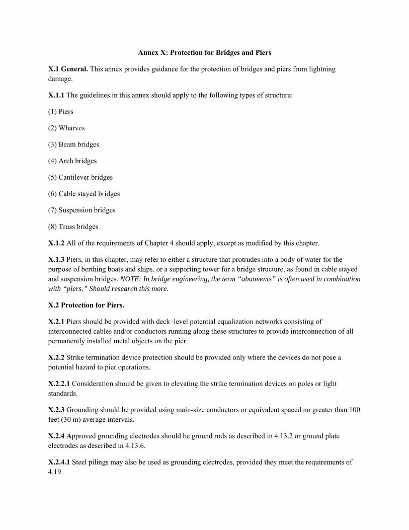
Annex X: Protection for Bridges and Piers
X.1 General. This annex provides guidance for the protection of bridges and piers from lightning damage.
X.1.1 The guidelines in this annex should apply to the following types of structure:
(1) Piers
(2) Wharves
(3) Beam bridges
(4) Arch bridges
(5) Cantilever bridges
(6) Cable stayed bridges
(7) Suspension bridges
(8) Truss bridges
X.1.2 All of the requirements of Chapter 4 should apply, except as modified by this chapter.
X.1.3 Piers, in this chapter, may refer to either a structure that protrudes into a body of water for the purpose of berthing boats and ships, or a supporting tower for a bridge structure, as found in cable stayed and suspension bridges. NOTE: In bridge engineering, the term “abutments” is often used in combination with “piers.” Should research this more.
X.2 Protection for Piers.
X.2.1 Piers should be provided with deck–level potential equalization networks consisting of interconnected cables and/or conductors running along these structures to provide interconnection of all permanently installed metal objects on the pier.
X.2.2 Strike termination device protection should be provided only where the devices do not pose a potential hazard to pier operations.
X.2.2.1 Consideration should be given to elevating the strike termination devices on poles or light standards.
X.2.3 Grounding should be provided using main-size conductors or equivalent spaced no greater than 100 feet (30 m) average intervals.
X.2.4 Approved grounding electrodes should be ground rods as described in 4.13.2 or ground plate electrodes as described in 4.13.6.
X.2.4.1 Steel pilings may also be used as grounding electrodes, provided they meet the requirements of 4.19.

X.3 Protection for Wharves
X.3.1 I don’t think this is a valid class of structure for protection, since a wharf is technically a collection of structures that provides docking and processing for ships—including piers, quays, buildings, etc. I feel as though we should take the “wharves” reference out of chapter 8 as well.
X.4 Protection for Bridges
X.4.1 Where required by construction, down conductors and grounding electrodes should be permitted to be spaced at greater than the 100 foot (30 m) average required by 4.9.10.
X.4.2 Grounding electrodes should be placed at each end of the bridge, and at intermediate locations where possible.
X.4.3 Bridges should be provided with deck–level potential equalization networks consisting of interconnected cables and/or conductors running along these structures to provide interconnection of all permanently installed metal objects on the bridge.
X.4.4 Where expansion joints are installed on a bridge, adequate jumpers should be provided such that the lightning protection will not be damaged by thermal movement of the bridge components.
X.4.4 Beam bridges.
X.4.4.1 Consideration should be given to protecting beam bridges with elevated strike termination devices on poles or light standards.
X.4.4.2 Handrails and/or guardrails should be permitted to serve as strike termination devices, subject to the requirements of section 4.7.
X.4.5 Arch bridges.
X.4.5.1 Where the supporting arch is of any material other than structural metal that meets the requirements of section 4.19, strike termination devices should be provided.
X.4.6 Cantilever bridges.
X.4.6.1 Cantilever bridges should be protected in the same manner as simple beam bridges.
X.4.7 Cable stayed bridges.
X.4.7.1 Where the supporting piers are of any material other than structural metal that meets the requirements of 4.19, strike termination devices should be provided.
X.4.7.2 Strike termination devices should be provided to protect appurtenances on top of the piers, including aircraft hazard lights, antennas, railings, etc.
X.4.7.3 Strike termination devices should not be required on the uppermost cable stay where their provision would interfere with the operation or maintenance of the bridge.
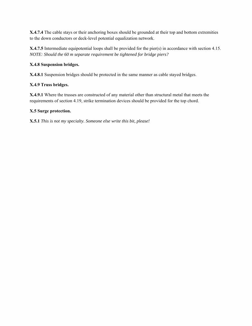
X.4.7.4 The cable stays or their anchoring boxes should be grounded at their top and bottom extremities to the down conductors or deck-level potential equalization network.
X.4.7.5 Intermediate equipotential loops shall be provided for the pier(s) in accordance with section 4.15. NOTE: Should the 60 m separate requirement be tightened for bridge piers?
X.4.8 Suspension bridges.
X.4.8.1 Suspension bridges should be protected in the same manner as cable stayed bridges.
X.4.9 Truss bridges.
X.4.9.1 Where the trusses are constructed of any material other than structural metal that meets the requirements of section 4.19, strike termination devices should be provided for the top chord.
X.5 Surge protection.
X.5.1 This is not my specialty. Someone else write this bit, please!

Public Input No. 307-NFPA 780-2017 [ Section No. O.1.2.2 ]
O.1.2.2 CENELEC Publications
CEN-CENELEC Management Centre, 17, Avenue Marnix, 1000 Brussels, Belgium.
CLC/TS 50539-12, Low-voltage surge protective devices — Surge protective devices for specific application including d.c. —Part 12: Selection and application principles. SPDs connected to photovoltaic installations, 2013
EN 50539-11, Low-voltage surge protective devices — Surge protective devices for specific application including d.c — Part 11:Requirements and tests for SPDs in photovoltaic applications, 2013
Statement of Problem and Substantiation for Public Input
The CENELEC documents are no longer relevant and the subjects are covered by IEC 61643-31 and 61643-32 in O.1.2.4.
Submitter Information Verification
Submitter Full Name: Mitchell Guthrie
Organization: Engineering Consultant
Street Address:
City:
State:
Zip:
Submittal Date: Wed Jun 28 12:01:51 EDT 2017
National Fire Protection Association Report http://submittals.nfpa.org/TerraViewWeb/ContentFetcher?commentPara...
295 of 302 9/22/2017, 11:03 AM
Public Input No. 73-NFPA 780-2017 [ Section No. O.1.2.3 ]
O.1.2.3 Federal Aviation Administration (FAA) Publications.
U.S. Department of Transportation, Subsequent Business Office, Ardmore East Business Center, 3341 Q 75th Avenue, Landover,MD 20785. FAA Advisory Circulars are also available at http://www.faa.gov/airports/resources/advisory_circulars/.
FAA Advisory Circular 150/5340-30F 30J , Design and Installation Details for Airport Visual Aids, September 29 May 1 , 2011 2017 .
FAA Advisory Circular 150/5345-42F 42H , Specification for Airport Light Bases, Transformer Housings, Junction Boxes, andAccessories, October 17 November 6 , 2006 2015 .
Statement of Problem and Substantiation for Public Input
FAA AC references out of date.Proposed text updates AC editions.
Submitter Information Verification
Submitter Full Name: Carl Johnson II
Organization: AVCON, Inc.
Street Address:
City:
State:
Zip:
Submittal Date: Tue Apr 25 12:18:24 EDT 2017
National Fire Protection Association Report http://submittals.nfpa.org/TerraViewWeb/ContentFetcher?commentPara...
296 of 302 9/22/2017, 11:03 AM

Public Input No. 308-NFPA 780-2017 [ Section No. O.1.2.4 ]
O.1.2.4 IEC Publications.
International Electrotechnical Commission, 3, rue de Varembé, P.O. Box 131, CH-1211 Geneva 20, Switzerland.
IEC 61643-11, Low-Voltage Surge Protective Devices — Part 11: Surge Protective Devices Connected to Low-Voltage PowerDistribution Systems — Requirements and Test Methods, 2011.
IEC 61643-31, Low-Voltage Surge Protective Devices for D.C. Specific Application - Part 31: Surge Protective Devices Connected tothe D.C. Side of Photovoltaic Installations - Requirements and Test Methods, July 11, 2014.
IEC 61643-32, Low-Voltage Surge Protective Devices for D.C. Specific Application - Part 32: Selection and Application Principles -SPDs Connected to Photovoltaic Installations, September 2014.
IEC 62305-1, Protection Against Lightning — Part 1: General Principles, edition 2, 2010.
IEC 62305-2, Protection Against Lightning — Part 2: Risk Management, edition 2, 2010.
IEC 62305-3, Protection Against Lightning — Part 3: Physical Damage to Structures and Life Hazard, edition 2, 2010.
IEC 62305-4, Protection Against Lightning — Part 4: Electrical and Electronic Systems Within Structures, edition 3, (81/456/DC),March 14, 2014 2, 2010 .
IEC/TS 62561-8, Lightning Protection System Components (LPSC) - Part 8: Requirements for Components for Isolated LPS,February 28, 2014.
Statement of Problem and Substantiation for Public Input
IEC 62305-4, Edition 3 has not yet been published. The referenced IEC 81/456/DC is not a publicly available document. The proposed change brings IEC 62305-4 in line with Parts 1, 2, and 3.
Submitter Information Verification
Submitter Full Name: Mitchell Guthrie
Organization: Engineering Consultant
Affilliation: Technical Advisor, USNC/IEC TC 81 TAG
Street Address:
City:
State:
Zip:
Submittal Date: Wed Jun 28 12:13:05 EDT 2017
National Fire Protection Association Report http://submittals.nfpa.org/TerraViewWeb/ContentFetcher?commentPara...
297 of 302 9/22/2017, 11:03 AM

Public Input No. 131-NFPA 780-2017 [ Section No. O.1.2.6 ]
O.1.2.6 Military Publications.
The following military standard is standards are available from the Naval Publications and Forms Center, 5801 Tabor Avenue,Philadelphia, PA 19120; Headquarters, Army Material Command Code DRXAM-ABS, Alexandria, VA; or Air Force PublicationsCenter, Baltimore, MD.
MIL-STD-464C, Interface Standard Electromagnetic Environmental Effects Requirements for Systems, 2010.
DA PAM 385-64, Ammunition and Explosives Safety Standards, Department of the Army, Washington DC, October 10, 2013.
Statement of Problem and Substantiation for Public Input
There are more than one standard listed.The Editorial Task Group recommends the change from singular to plural.
Submitter Information Verification
Submitter Full Name: Stephen Humeniuk
Organization: Warren Lightning Rod Company
Affilliation: ULPA, The Editorial Task Group
Street Address:
City:
State:
Zip:
Submittal Date: Mon Jun 19 17:40:30 EDT 2017
National Fire Protection Association Report http://submittals.nfpa.org/TerraViewWeb/ContentFetcher?commentPara...
298 of 302 9/22/2017, 11:03 AM
Public Input No. 149-NFPA 780-2017 [ Section No. O.1.2.7 ]
O.1.2.7 UL Publications.
Underwriters Laboratories Inc., 333 Pfingsten Road, Northbrook, IL 60062-2096.
ANSI/UL 96, Standard for Lightning Protection Components, 2005 2016 .
ANSI/UL 467, Grounding and Bonding Equipment, 2007 2013 .
UL 497, Standard for Safety Protectors for Paired-Conductor Communications Circuits, Seventh Edition, July 19, 2001, Revised2013.
ANSI/UL 1449, Standard for Safety for Transit Voltage Surge Suppressors , 2nd Edition, 1996.ANSI/UL 1449, Standard for SurgeProtective Devices , 2006, with revisions through July 11, 2012 for Surge Potectie Devices , 2016 .
Statement of Problem and Substantiation for Public Input
Update Standards
Related Public Inputs for This Document
Related Input Relationship
Public Input No. 148-NFPA 780-2017 [Section No. 2.3.3]
Submitter Information Verification
Submitter Full Name: Kelly Nicolello
Organization: UL LLC
Street Address:
City:
State:
Zip:
Submittal Date: Thu Jun 22 15:32:05 EDT 2017
National Fire Protection Association Report http://submittals.nfpa.org/TerraViewWeb/ContentFetcher?commentPara...
299 of 302 9/22/2017, 11:03 AM

Public Input No. 309-NFPA 780-2017 [ Section No. O.1.2.7 ]
O.1.2.7 UL Publications.
Underwriters Laboratories Inc., 333 Pfingsten Road, Northbrook, IL 60062-2096.
ANSI/CAN/ UL 96, Standard for Lightning Protection Components, 2005 2016 .
ANSI/UL 467, Grounding and Bonding Equipment, 2007.
UL 497, Standard for Safety Protectors for Paired-Conductor Communications Circuits, Seventh Edition, July 19, 2013.
ANSI/UL 1449, Standard for
Safety for Transit Voltage
Surge
Suppressors, 2nd Edition, 1996.ANSI/UL 1449, Standard for Surge
Protective Devices ,
2006, with revisions through July 11, 2012
4th Edition, 2016 .
Statement of Problem and Substantiation for Public Input
The proposed change updates the listed standards and removes the reference to the TVSS standard that is no longer relevant to NFPA 780.
Submitter Information Verification
Submitter Full Name: Mitchell Guthrie
Organization: Engineering Consultant
Street Address:
City:
State:
Zip:
Submittal Date: Wed Jun 28 12:27:09 EDT 2017
National Fire Protection Association Report http://submittals.nfpa.org/TerraViewWeb/ContentFetcher?commentPara...
300 of 302 9/22/2017, 11:03 AM
Public Input No. 132-NFPA 780-2017 [ Section No. O.2.5 ]
O.2.5 Other Publications.
Cotton, I., and N. Jenkins. “Lightning Protection of Wind Turbines, Lightning Protection 98, Buildings, Structures and ElectronicEquipment,” International Cotton, I. and Jenkins, N. International Conference and Exhibition, Paper 6.1, Solihull, West Midlands, UK,May 6–7, 1998.
D’Alessandro, and “Electrical Grounding of Wind Turbines,” D'Alessandro, F. and Havelka , M. Havelka. “Electrical Grounding ofWind Turbines,” EEA Annual Conference, Auckland, New Zealand, June 17–18, 2005.
Statement of Problem and Substantiation for Public Input
The Editorial Task Group make this change in accordance with the Manual of Style section 3.6.2.3
Submitter Information Verification
Submitter Full Name: Stephen Humeniuk
Organization: Warren Lightning Rod Company
Affilliation: ULPA, The Editorial Task Group
Street Address:
City:
State:
Zip:
Submittal Date: Mon Jun 19 17:52:51 EDT 2017
National Fire Protection Association Report http://submittals.nfpa.org/TerraViewWeb/ContentFetcher?commentPara...
301 of 302 9/22/2017, 11:03 AM
Public Input No. 225-NFPA 780-2017 [ New Section after O.3 ]
Annex P.
Requirements and Test Methods for BCAT.
Additional Proposed Changes
File Name Description Approved
Annex_P-requirement_and_test_method_of_BCAT20170626_Eng_.1498474958028.docx
Statement of Problem and Substantiation for Public Input
Add the requirements and test methods for BCAT to the Annex
Related Public Inputs for This Document
Related Input Relationship
Public Input No. 199-NFPA 780-2017 [New Section after 3.3.1]
Public Input No. 210-NFPA 780-2017 [Section No. 4.7.1.4]
Submitter Information Verification
Submitter Full Name: Youngki Chung
Organization: Omni Lps
Street Address:
City:
State:
Zip:
Submittal Date: Mon Jun 26 06:54:10 EDT 2017
National Fire Protection Association Report http://submittals.nfpa.org/TerraViewWeb/ContentFetcher?commentPara...
302 of 302 9/22/2017, 11:03 AM
Reference 14 Functional Requirements of the BCAT
Introduction
1. Scope
2. References
3. Terms and definitions
4. Requirements
5. Test
6. Structure and contents of test report
Annex A. (informative) Summary of the requirements and corresponding tests
Annex B. Conditioning/ageing for connection components
Bibliography

INTRODUCTION This test standard is to provide test methods to verify the function of BCAT, which is installed
in order to prevent direct lightning strikes.

1. Scope
This document specifies the requirements and performance tests for the BCAT and its accessories used as air termination system of a lightning protection system to reduce the probability of lightning strikes. This document does not cover the test in an explosive atmospheric environment.
2. Normative reference
The following documents, in whole or in part, are normatively referenced in this document and are indispensable for its application. For dated references, only the edition cited applies. For undated references, the latest edition of the referenced document (including any amendments) applies.
IEC 60068-2-52:1996, Environmental testing – Part 2-52: Tests – Test Kb: Salt mist, cyclic (sodium chloride solution)
IEC 62305-1, Protection against lightning – Part 1: General principles
IEC 62561-1, Lightning protection system components (LPSC) – Part 1: Requirements for connection components
IEC 62561-2, Lightning protection system components (LPSC) – Part 2: Requirements for conductors and earth electrodes
ISO 6988:1985, Metallic and other non-organic coatings – Sulfur dioxide test with general condensation of moisture
IEC 60060-01: 2010 High-voltage test techniques Part 1: General definitions and test requirements
3. Terms and definition
3.1 Bipolar Conventional Air terminal; BCAT
A conventional air terminal with a floating conductor for bipolar function.
3.2 Impulse current (Iimp)
It is defined by three parameters, a current peak value Ipeak, a charge Q and a specific energy W/R.
waveform is 10/350 ㎲.
3.3 Flashover voltage
The voltage when a disruptive discharge occurs between electrode and specimen separated by an insulating material. This discharge may occur around or along the surface of said insulator. Also
called spark over voltage
3.4 Corona discharge current
The current when a corona discharge occurs. Corona discharge is an electrical discharge brought on by the ionization of a fluid such as air surrounding conductor that is electrically charged.
3.5 Impulse
Intentionally applied aperiodic or oscillating transient voltage or current, which usually rises rapidly to a peak value and then its enveloping curve falls more slowly to zero. Impulses with front duration up to 20 µs are defined as lightning impulse
3.6 Corona Discharge Current Measuring System
A system to measure the Corona discharge current during operation of BCAT, which is comprising measuring sensor (Shunt resister), recording device (eg. oscilloscope) and controlling device.
3.7 Connection Components of an Air Terminal
Connection components of an air terminal in order to conduct lightning current smoothly. The
connection components of a BCAT include the joint of the rod cap(① in Figure 1) on top and the
mast(⑥ in Figure 1) and the connecting part of the main body of BCAT(⑥ in Figure 1)and the
supporting base(⑧ in Figure 1).
3.8 Test Joints
Joint designed to facilitate electrical testing and measurement of BCAT.
3.9 Type test
Test required to be made before supplying a type of material covered by this standard on a general commercial basis, in order to demonstrate satisfactory performance characteristics to meet the intended application
4. Requirements
4.1 General
BCAT shall be designed in such a manner that when they are installed in accordance with NFPA 780 its performance shall be reliable, stable and safe for persons and surrounding equipment.
NOTE A summary of the requirements and their corresponding tests is given in Annex A.
4.2 Installation instructions
The manufacturer of the connection components shall provide at least the following information:
– the classification of the component;
– the range of conductor sizes and materials;
– the connection configuration.
Compliance is checked by inspection.
4.3 Lightning current carrying capability

A BCAT shall have sufficient lightning current carrying capability. A BCAT shall have a sufficient withstand capability against test waveform of 10/350 us of 100 kA. Compliance is checked in accordance with 5.3.
4.4 Static mechanical stress
A BCAT shall have a sufficient withstand capability against static mechanical stresses.
Compliance is checked in accordance with 5.4.
4.5 Screwed connection
Where screws and/or nuts are used as the connection of BCAT and joints, the design shall be such that the conductor and/or the metal installation is always securely fastened.
Compliance is checked in accordance with 5.3.
4.6 Dismantling of test points
It shall be possible to dismantle the test joints after lightning current stress.
Compliance is checked in accordance with 5.3.
4.7 Safe connection
Connection components shall guarantee safe connection within the connection range declared
by the manufacturer.
Compliance is checked in accordance with 5.3.
4.8 Terminals of conductor
The input terminals of conductor used for lightning protection installations shall have a diameter of connection equal to or greater than 6 mm.
4.9 Markings
A BCAT shall be marked at least with the following:
a) manufacturer’s or responsible vendor’s name or trade mark;
b) identifying symbol (picture, product number etc.);
Where this proves to be impractical, the marking in accordance with a) and b) may be given
on the smallest packing unit.
The marking shall be durable and legible.
NOTE Marking can be applied for example by moulding, pressing, engraving, printing adhesive labels or water slide transfers.
Compliance is checked in accordance with 5.5.

5. Test
5.1 General conditions for tests
The tests in accordance with this standard are type tests.
• Unless otherwise specified, tests are carried out with the specimens assembled and installed as in normal use according to the manufacturer's or supplier's installation instructions
• All tests are carried out on new specimens.
• Unless otherwise specified, three specimens are subjected to the tests and the requirements are satisfied if all the tests are met.
• If only one of the specimens does not satisfy a test due to an assembly or a manufacturing fault, that test and any preceding one which may have influenced the results of the test shall be repeated. The tests which follow shall also be carried out in the required sequence on another full set of specimens, all of which shall comply with the requirements.
• The electrical test shall be carried out in the order given after conditioning/ageing of the arrangement of the specimen in accordance with 6.2.2.
The applicant, when submitting the sets of specimens, may also submit an additional set of specimens which may be necessary should one specimen fail. The testing station will then, without further request, test the additional set of specimens and will reject only if a further failure occurs. If the additional set of specimens is not submitted at the same time, the failure of one specimen will entail rejection.
5.2 Test preparation
5.2.1 Arrangement of the specimen
If not otherwise specified by the manufacturer, the conductors and the specimens shall be cleaned by using a suitable degreasing agent followed by cleaning in demineralizing water and drying. They shall then be assembled in accordance with the manufacturer’s instructions, e.g. with the recommended conductors and tightening torques.
The BCAT shall be tested in all the connection configurations declared by the manufacture.
The appearance and arrangement of the specimens is shown in Figure 1. And 2.

Figure 1. Appearance of BCAT specimen
1. ④ on the upper art shall be connected to ③ by bolts.
2. Test point ④ shall be connected to electric test equipment.
3. ③ and ④ shall be completely tightened to connect the upper electrode and the
specimen.
Figure 2. BCAT Connection for an Electrical Characteristic Test (example)
5.2.2 Conditioning/ageing
Following the manufacturer’s declaration for the location of the BCAT, the arrangement of the specimen shall be subjected to a conditioning/ageing, as per Annex B, consisting of a salt mist treatment as specified in B.1 followed by a humid sulphurous atmosphere treatment as specified in B.2, and an additional ammonia atmosphere treatment for specimens made of copper alloy with

copper content less than 80 % as specified in B.3.
After the treatment, the arrangement is fixed on an insulated plate, taking care to avoid any damage to the specimen due to handling.
5.3 Electrical test
5.3.1 Electrical Stress Test (Impulse withstand test)
After 5.2.2 (conditioning/ageing) and without cleaning the arrangement, the specimen shall be stressed three times by a test current as given in Table 1. The time interval between individual shots shall allow the arrangement of the specimen to cool down to approximately ambient temperature.
The impulse discharge current passing through the device under test is defined by the crest value Iimp, and the specific energy W/R. The impulse current shall show no reversal and reach Iimp within 50 μs. The transfer of the specific energy W/R shall be dissipated within 5 ms.
Table 1 ― Lightning impulse current (Iimp) parameters
The BCAT is deemed to have passed the test if:
a) the contact resistance, measured with a source of at least 10 A as close as possible to the
connection component is equal to or less than 1 mW. In the case where the connection
component or the conductor(s) are of stainless steel, a value of 2,5 mΩ is allowed;
b) it does not exhibit any crack to normal or corrected vision without magnification nor does it
have any loose parts or deformation impairing its normal use
c) The measurement of the contact resistance of the connection components is performed
between the ends 3-5 and 5-6a as close possible to the components (See Figure 2).
5.3.2 Insulation Breakdown Test
After 5.2.2 (conditioning/ageing) and without cleaning the arrangement, the specimen shall be tested 5 times with the upper plate electrode applied with DC 80 kV in the negative insulation breakdown test set-up as given in Figure 3. The distance between the upper plate electrode and the specimens shall be 1 m. The breakdown voltage shall be measured and recorded.
The 1.2/50 voltage impulse is used. The interval between individual impulses shall be long enough for the sample to cool down to ambient temperature.
The BCAT is deemed to have passed the test if:
a) it does not exhibit any crack to normal or corrected vision without magnification nor does it
have any loose parts or deformation impairing its normal use;.

b) the average value measures is greater than 550 kV;
Figure 3. Structure of Test Set-up for Flashover Voltage Measurement
5.3.3 Corona Discharge Current Measurement Test
After 5.2.2 (conditioning/ageing) and without cleaning the arrangement, the Corona Discharge Current at the grounded part shall be measured 5 times and recorded with the upper plate electrode applied with DC 200 kV in the test set-up as given in Figure 4. The distance between the upper plate electrode and the specimen shall be 0.35 m. The interval between each measurement shall be shorter than 1 minute.
Figure 4. Test measurement diagram of corona discharge current
The BCAT is deemed to have passed the test if the average value of Corona Discharge Current measured is greater than 1000 mA.
5.4 Static mechanical test
A second set of three new specimens shall be arranged according to the manufacturer’s or supplier’s installation instructions.
Each conductor of the specimen assemblies shall be subjected independently to a mechanical tensile force of 900 N ± 20 N for 1 min. Each conductor shall be tested independently for multiple conductor connectors.

The connection component is deemed to have passed the test if there is less than 1 mm movement of the conductor during the test and no damage on the connector or conductor.
5.5 Marking test
The marking is checked by inspection and by rubbing it by hand for 15 s with a piece of cloth soaked with water and again for 15 s with a piece of cloth soaked with white spirit/mineral spirit.
NOTE Markings made by moulding, pressing or engraving are not subjected to this test.
The specimen is deemed to have passed the test if the marking remains legible.
6 Structure and content of the test report
6.1 General
The purpose of this clause is to provide general requirements for laboratory test reports. It is intended to promote clear, complete reporting procedures for laboratories submitting test reports.
The results of each test carried out by the laboratory shall be reported accurately, clearly, unambiguously and objectively, in accordance with any instructions in the test methods. The results shall be reported in a test report and shall include all the information necessary for the interpretation of the test results and all information required by the method used.
Particular care and attention shall be paid to the arrangement of the report, especially with regard to presentation of the test data and ease of assimilation by the reader. The format shall be carefully and specifically designed for each type of test carried out, but the headings shall be standardized as indicated below.
The structure of each report shall include at least the following information contained in 6.2 to 6.10.
6.2 Report identification
a) A title or subject of the report;
b) Name, address and email or telephone number of the test laboratory;
c) Name, address and email or telephone number of the sub test laboratory where the test was
carried out if different from the company which has been assigned to perform the test;
d) Unique identification number (or serial number) of the test report;
e) Name and address of the vendor;
f) Report shall be paginated and the total number of pages indicated;
g) Date of issue of report;
h) Date(s) of performance of test(s);
i) Signature and title, or an equivalent identification of the person(s) authorized to sign for the
testing laboratory for the content of the report;
j) Signature and title of person(s) conducting the test.

6.3 Specimen description
a) Sample description;
b) Detailed description and unambiguous identification of the test sample and/or test assembly;
c) Characterization and condition of the test sample and/or test assembly;
d) Sampling procedure, where relevant;
e) Date of receipt of test items;
f) Photographs, drawings or any other visual documentation, if available.
6.4 Conductor
a) Conductor material;
b) Nominal cross-section area, dimensions and shape. It is recommended that the actual cross-
sectional area should also be given.
6.5 Standard and references
a) Identification of the test standard used and the date of issue of the standard;
b) Other relevant documentation with the documentation date.
6.6 Test procedure
a) Description of the test procedure;
b) Justification for any deviations from, additions to or exclusions from the referenced standard;
c) Any other information relevant to a specific test such as environmental conditions;
d) Configuration of testing assembly;
e) Location of the arrangement in the testing area and measuring techniques.
6.7 Testing equipment description
Description of equipment used for every test conducted, i.e. generator, conditioning/ageing device.
6.8 Measuring instruments description
Characteristics and calibration date of all instruments used for measuring the values specified in the standard i.e. radius gauge, shunts, tensile testing machine, extensometer, ohmmeter, torque meter, thickness caliper gauge, etc.
6.9 Results and parameters recorded
The measured, observed or derived results shall be clearly identified at least for:
a) Current;
b) charge;
c) specific energy;

d) front time of the impulse;
e) duration of the impulse;
f) ohmic resistance;
g) tightening torque;
h) loosening torque.
The above shall be presented in tables, graphs, drawings, photographs or other documentation of visual observations as appropriate.
6.10 Statement of pass/fail
A statement that the specimen passed or failed the tests shall be reported. If the specimen has failed a description of failure is necessary.

Annex A
(informative) Summary of the requirements and corresponding tests Table A.1 – Requirements and corresponding tests
Test sequence
Requirements Requirements in accordance with
Compliance is checked by
1 Installation instructions
4.2 Inspection
2 Lightning current carrying capability
4.3 5.3
3 Impulse breakdown
immunity 4.3 5.3
4 Corona discharge
capability 4.3 5.3
5 Static mechanical
test 4.4 5.4
6 Screwed connection 4.5 Inspection and 5.3
7 Dismantling of test
joint 4.6 5.3
8 Safe connection 4.7 5.3 9 Marking 4.8 Inspection and 5.5

Annex B (Informative)
Conditioning/ageing for connection components
C.1 Salt mist treatment Salt mist treatment shall be in accordance with IEC 60068-2-52:1996, except for Clauses 7, 10 and 11 which are not applicable. The test is carried out using severity (2). If the salt mist chamber can maintain the temperature conditions as specified in 9.3 of IEC 60068-2-52:1996 and a relative humidity of not less than 90 %, then the specimen may remain in it for the humidity storage period. C.2 Humid sulphurous atmosphere treatment Humid sulphurous atmosphere treatment shall be in accordance with ISO 6988:1985 with seven cycles with a concentration of sulphur dioxide of 667 ´ 10–6 (in volume) ± 25 ´ 10–6, except for Clauses 9 and 10 which are not applicable. Each cycle which has duration of 24 h is composed of a heating period of 8 h at a temperature of 40 °C ± 3 °C in the humid saturated atmosphere which is followed by a rest period of 16 h. After that, the humid sulphurous atmosphere is replaced. If the test chamber maintains the temperature conditions as specified in 6.5.2 of ISO 6988:1985 then the specimen may remain in it for the storage period. C.3 Ammonia atmosphere treatment Ammonia atmosphere treatment shall be in accordance with ISO 6957:1988 for a moderate atmosphere with the pH value 10 except for 8.4 and Clause 9, which are not applicable.