agenda - purdue engineering...even, odd, stick, or no parity bits ... of the uart interrupt and...
TRANSCRIPT
Getting Started With the Stellaris EK-LM4F120XL LaunchPad Workshop - UART 12 - 1
UART
Introduction
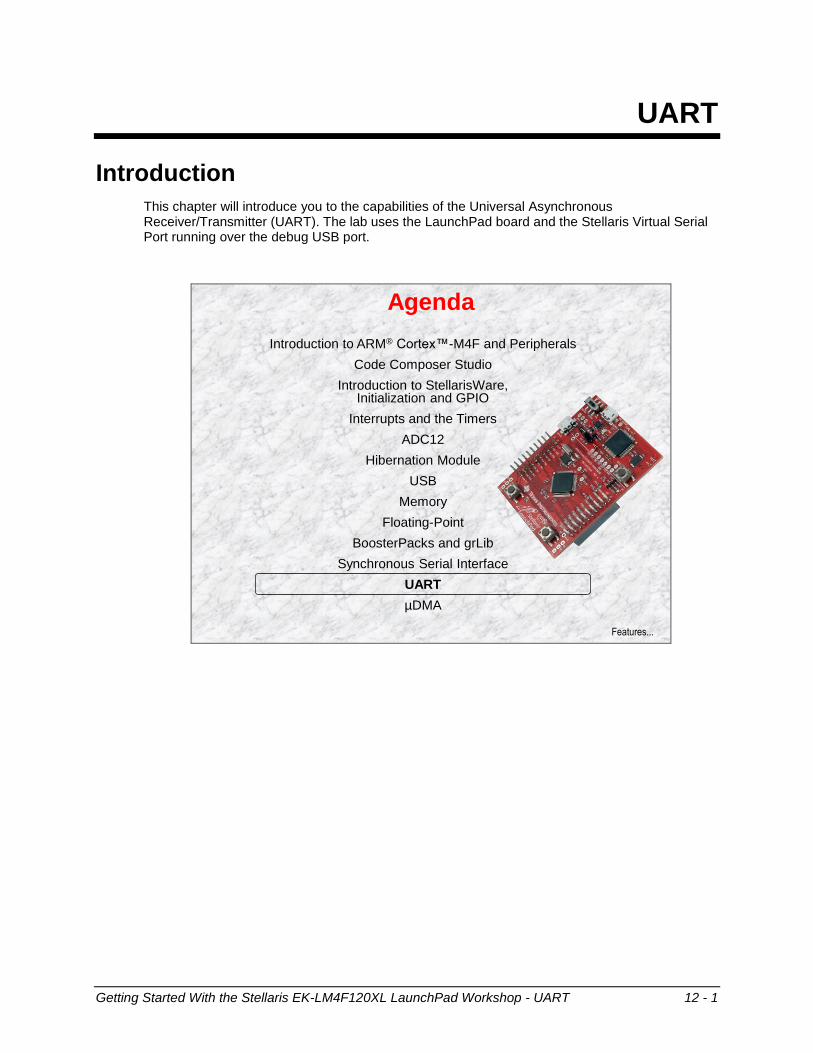
This chapter will introduce you to the capabilities of the Universal Asynchronous Receiver/Transmitter (UART). The lab uses the LaunchPad board and the Stellaris Virtual Serial Port running over the debug USB port.
Agenda
Introduction to ARM® Cortex™-M4F and Peripherals
Code Composer Studio
Introduction to StellarisWare, Initialization and GPIO
Interrupts and the Timers
ADC12
Hibernation Module
USB
Memory
Floating-Point
BoosterPacks and grLib
Synchronous Serial Interface
UART
µDMA
Features...

UART Features and Block Diagram
12 - 2 Getting Started With the Stellaris EK-LM4F120XL LaunchPad Workshop - UART
Chapter Topics
UART .......................................................................................................................................... 12-1
UART Features and Block Diagram ........................................................................................ 12-3
Basic Operation ....................................................................................................................... 12-4
UART Interrupts and FIFOs .................................................................................................... 12-5
UART “stdio” Functions and Other Features .......................................................................... 12-6
Lab 12 ..................................................................................................................................... 12-7 Objective ............................................................................................................................. 12-7
UART Features and Block Diagram
Getting Started With the Stellaris EK-LM4F120XL LaunchPad Workshop - UART 12 - 3
UART Features and Block Diagram
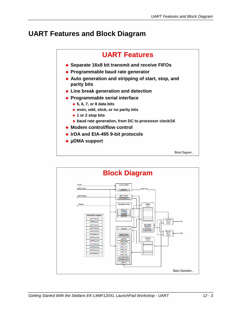
UART Features
Separate 16x8 bit transmit and receive FIFOs
Programmable baud rate generator
Auto generation and stripping of start, stop, and
parity bits
Line break generation and detection
Programmable serial interface
5, 6, 7, or 8 data bits
even, odd, stick, or no parity bits
1 or 2 stop bits
baud rate generation, from DC to processor clock/16
Modem control/flow control
IrDA and EIA-495 9-bit protocols
µDMA support
Block Diagram...
Block Diagram
Basic Operation...

Basic Operation
12 - 4 Getting Started With the Stellaris EK-LM4F120XL LaunchPad Workshop - UART
Basic Operation
Basic Operation
Initialize the UART Enable the UART peripheral, e.g.
SysCtlPeripheralEnable(SYSCTL_PERIPH_UART0);
SysCtlPeripheralEnable(SYSCTL_PERIPH_GPIOA);
Set the Rx/Tx pins as UART pinsGPIOPinConfigure(GPIO_PA0_U0RX);
GPIOPinConfigure(GPIO_PA1_U0TX);
GPIOPinTypeUART(GPIO_PORTA_BASE, GPIO_PIN_0 | GPIO_PIN_1);
Configure the UART baud rate, data configurationROM_UARTConfigSetExpClk(UART0_BASE, ROM_SysCtlClockGet(), 115200,
UART_CONFIG_WLEN_8 | UART_CONFIG_STOP_ONE |
UART_CONFIG_PAR_NONE));
Configure other UART features (e.g. interrupts, FIFO)
Send/receive a character Single register used for transmit/receive
Blocking/non-blocking functions in driverlib:UARTCharPut(UART0_BASE, ‘a’);
newchar = UARTCharGet(UART0_BASE);
UARTCharPutNonBlocking(UART0_BASE, ‘a’);
newchar = UARTCharGetNonBlocking(UART0_BASE);
Interrupts...
UART Interrupts and FIFOs
Getting Started With the Stellaris EK-LM4F120XL LaunchPad Workshop - UART 12 - 5
UART Interrupts and FIFOs
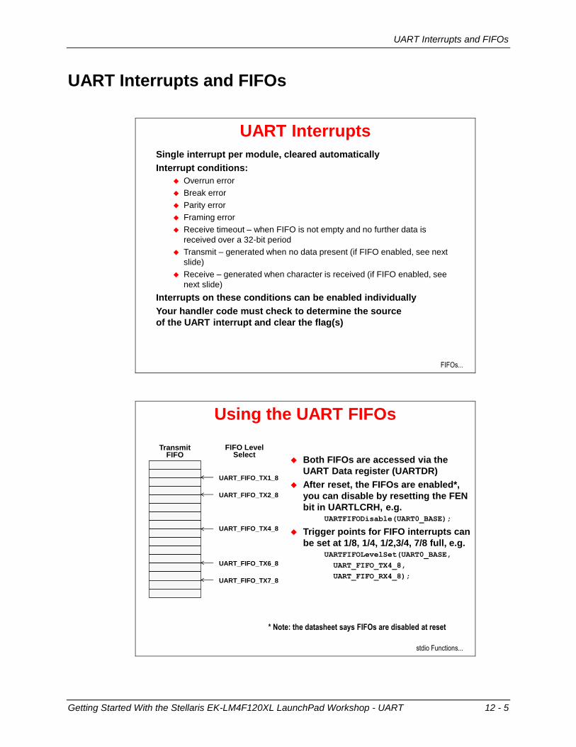
UART Interrupts
Single interrupt per module, cleared automatically
Interrupt conditions:
Overrun error
Break error
Parity error
Framing error
Receive timeout – when FIFO is not empty and no further data is
received over a 32-bit period
Transmit – generated when no data present (if FIFO enabled, see next
slide)
Receive – generated when character is received (if FIFO enabled, see
next slide)
Interrupts on these conditions can be enabled individually
Your handler code must check to determine the source
of the UART interrupt and clear the flag(s)
FIFOs...
Using the UART FIFOs
Both FIFOs are accessed via the
UART Data register (UARTDR)
After reset, the FIFOs are enabled*,
you can disable by resetting the FEN
bit in UARTLCRH, e.g.UARTFIFODisable(UART0_BASE);
Trigger points for FIFO interrupts can
be set at 1/8, 1/4, 1/2,3/4, 7/8 full, e.g.UARTFIFOLevelSet(UART0_BASE,
UART_FIFO_TX4_8,
UART_FIFO_RX4_8);
Transmit FIFO
UART_FIFO_TX4_8
UART_FIFO_TX1_8
UART_FIFO_TX2_8
UART_FIFO_TX6_8
UART_FIFO_TX7_8
FIFO Level Select
* Note: the datasheet says FIFOs are disabled at reset
stdio Functions...
UART “stdio” Functions and Other Features
12 - 6 Getting Started With the Stellaris EK-LM4F120XL LaunchPad Workshop - UART
UART “stdio” Functions and Other Features
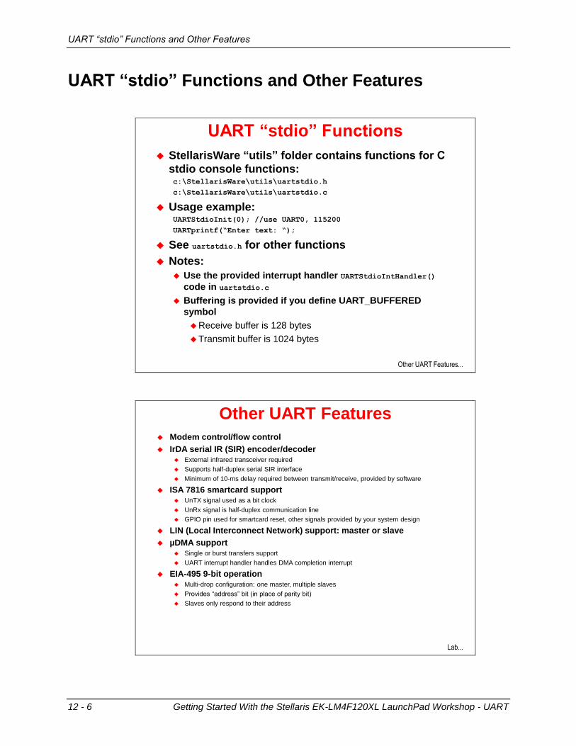
UART “stdio” Functions
StellarisWare “utils” folder contains functions for C
stdio console functions:c:\StellarisWare\utils\uartstdio.h
c:\StellarisWare\utils\uartstdio.c
Usage example:UARTStdioInit(0); //use UART0, 115200
UARTprintf(“Enter text: “);
See uartstdio.h for other functions
Notes:
Use the provided interrupt handler UARTStdioIntHandler()
code in uartstdio.c
Buffering is provided if you define UART_BUFFERED
symbol
Receive buffer is 128 bytes
Transmit buffer is 1024 bytes
Other UART Features...
Other UART Features
Modem control/flow control
IrDA serial IR (SIR) encoder/decoder
External infrared transceiver required
Supports half-duplex serial SIR interface
Minimum of 10-ms delay required between transmit/receive, provided by software
ISA 7816 smartcard support
UnTX signal used as a bit clock
UnRx signal is half-duplex communication line
GPIO pin used for smartcard reset, other signals provided by your system design
LIN (Local Interconnect Network) support: master or slave
µDMA support
Single or burst transfers support
UART interrupt handler handles DMA completion interrupt
EIA-495 9-bit operation
Multi-drop configuration: one master, multiple slaves
Provides “address” bit (in place of parity bit)
Slaves only respond to their address
Lab...
Lab 12
Getting Started With the Stellaris EK-LM4F120XL LaunchPad Workshop - UART 12 - 7
Lab 12
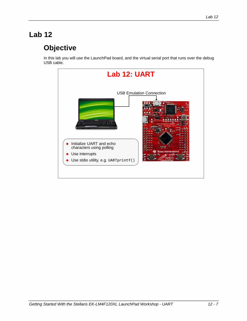
Objective
In this lab you will use the LaunchPad board, and the virtual serial port that runs over the debug USB cable.
Initialize UART and echo characters using polling
Use interrupts
Use stdio utility, e.g. UARTprintf()
Lab 12: UART
USB Emulation Connection
Lab 12
12 - 8 Getting Started With the Stellaris EK-LM4F120XL LaunchPad Workshop - UART
Procedure
Import Lab12
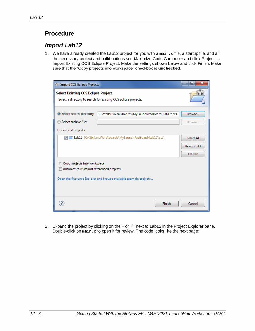
1. We have already created the Lab12 project for you with a main.c file, a startup file, and all
the necessary project and build options set. Maximize Code Composer and click Project Import Existing CCS Eclipse Project. Make the settings shown below and click Finish. Make sure that the “Copy projects into workspace” checkbox is unchecked.
2. Expand the project by clicking on the + or next to Lab12 in the Project Explorer pane. Double-click on main.c to open it for review. The code looks like the next page:
Lab 12
Getting Started With the Stellaris EK-LM4F120XL LaunchPad Workshop - UART 12 - 9
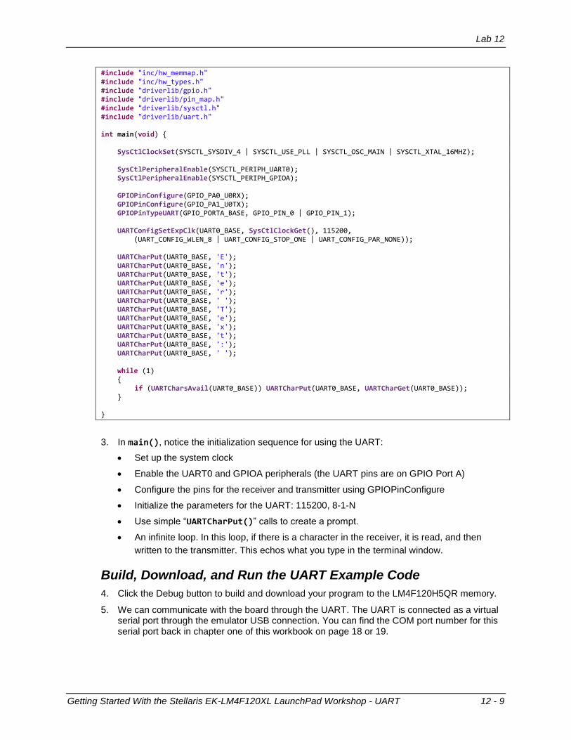
#include "inc/hw_memmap.h" #include "inc/hw_types.h" #include "driverlib/gpio.h" #include "driverlib/pin_map.h" #include "driverlib/sysctl.h" #include "driverlib/uart.h" int main(void) { SysCtlClockSet(SYSCTL_SYSDIV_4 | SYSCTL_USE_PLL | SYSCTL_OSC_MAIN | SYSCTL_XTAL_16MHZ); SysCtlPeripheralEnable(SYSCTL_PERIPH_UART0); SysCtlPeripheralEnable(SYSCTL_PERIPH_GPIOA); GPIOPinConfigure(GPIO_PA0_U0RX); GPIOPinConfigure(GPIO_PA1_U0TX); GPIOPinTypeUART(GPIO_PORTA_BASE, GPIO_PIN_0 | GPIO_PIN_1); UARTConfigSetExpClk(UART0_BASE, SysCtlClockGet(), 115200, (UART_CONFIG_WLEN_8 | UART_CONFIG_STOP_ONE | UART_CONFIG_PAR_NONE)); UARTCharPut(UART0_BASE, 'E'); UARTCharPut(UART0_BASE, 'n'); UARTCharPut(UART0_BASE, 't'); UARTCharPut(UART0_BASE, 'e'); UARTCharPut(UART0_BASE, 'r'); UARTCharPut(UART0_BASE, ' '); UARTCharPut(UART0_BASE, 'T'); UARTCharPut(UART0_BASE, 'e'); UARTCharPut(UART0_BASE, 'x'); UARTCharPut(UART0_BASE, 't'); UARTCharPut(UART0_BASE, ':'); UARTCharPut(UART0_BASE, ' '); while (1) { if (UARTCharsAvail(UART0_BASE)) UARTCharPut(UART0_BASE, UARTCharGet(UART0_BASE)); } }
3. In main(), notice the initialization sequence for using the UART:
Set up the system clock
Enable the UART0 and GPIOA peripherals (the UART pins are on GPIO Port A)
Configure the pins for the receiver and transmitter using GPIOPinConfigure
Initialize the parameters for the UART: 115200, 8-1-N
Use simple “UARTCharPut()” calls to create a prompt.
An infinite loop. In this loop, if there is a character in the receiver, it is read, and then
written to the transmitter. This echos what you type in the terminal window.
Build, Download, and Run the UART Example Code
4. Click the Debug button to build and download your program to the LM4F120H5QR memory.
5. We can communicate with the board through the UART. The UART is connected as a virtual serial port through the emulator USB connection. You can find the COM port number for this serial port back in chapter one of this workbook on page 18 or 19.
Lab 12
12 - 10 Getting Started With the Stellaris EK-LM4F120XL LaunchPad Workshop - UART
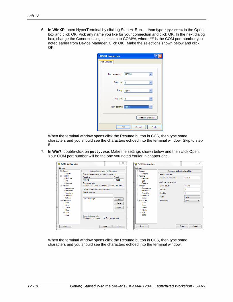
6. In WinXP, open HyperTerminal by clicking Start Run…, then type hypertrm in the Open:
box and click OK. Pick any name you like for your connection and click OK. In the next dialog box, change the Connect using: selection to COM##, where ## is the COM port number you noted earlier from Device Manager. Click OK. Make the selections shown below and click OK.
When the terminal window opens click the Resume button in CCS, then type some characters and you should see the characters echoed into the terminal window. Skip to step 8.
7. In Win7, double-click on putty.exe. Make the settings shown below and then click Open.
Your COM port number will be the one you noted earlier in chapter one.
When the terminal window opens click the Resume button in CCS, then type some characters and you should see the characters echoed into the terminal window.

Lab 12
Getting Started With the Stellaris EK-LM4F120XL LaunchPad Workshop - UART 12 - 11
Using UART Interrupts
Instead of continually polling for characters, we’ll make some modifications to our code to allow the use of interrupts to receive and transmit characters. In the first part of this lab, the only indication we had that our code was running was to open the terminal window to type characters and see them echoed back. In this part of the lab, we’ll add a visual indicator to show that we received and transmitted a character. So we’ll need to add code similar to previous labs to blink the LED inside the interrupt handler.
8. First, let’s add the code in main() to enable the UART interrupts we want to handle. Click on
the Terminate button to return to the CCS Edit perspective. We need to add two additional header files at the top of the file:
#include "inc/hw_ints.h" #include "driverlib/interrupt.h"
9. Now we need to add the code to enable processor interrupts, then enable the UART interrupt, and then select which individual UART interrupts to enable. We will select receiver interrupts (RX) and receiver timeout interrupts (RT). The receiver interrupt is generated when a single character has been received (when FIFO is disabled) or when the specified FIFO level has been reached (when FIFO is enabled). The receiver timeout interrupt is generated when a character has been received, and a second character has not been received within a 32-bit period. Add the following code just below the UARTConfigSetExpClk() function call:
IntMasterEnable(); IntEnable(INT_UART0); UARTIntEnable(UART0_BASE, UART_INT_RX | UART_INT_RT);
10. We also need to initialize the GPIO peripheral and pin for the LED. Just before the function UARTConfigSetExpClk() is called, add these two lines:
SysCtlPeripheralEnable(SYSCTL_PERIPH_GPIOF); GPIOPinTypeGPIOOutput(GPIO_PORTF_BASE, GPIO_PIN_2);
11. Finally, we can create an empty while(1) loop at the end of main by commenting out the
line of code that’s already there:
while (1) {
// if (UARTCharsAvail(UART0_BASE)) UARTCharPut(UART0_BASE,UARTCharGet(UART0_BASE)); }
12. Save the changes you made to main.c (but leave it open for making additional edits).
Lab 12
12 - 12 Getting Started With the Stellaris EK-LM4F120XL LaunchPad Workshop - UART
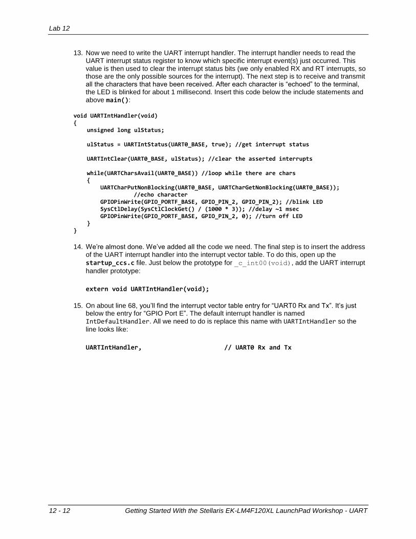
13. Now we need to write the UART interrupt handler. The interrupt handler needs to read the UART interrupt status register to know which specific interrupt event(s) just occurred. This value is then used to clear the interrupt status bits (we only enabled RX and RT interrupts, so those are the only possible sources for the interrupt). The next step is to receive and transmit all the characters that have been received. After each character is “echoed” to the terminal, the LED is blinked for about 1 millisecond. Insert this code below the include statements and above main():
void UARTIntHandler(void) { unsigned long ulStatus; ulStatus = UARTIntStatus(UART0_BASE, true); //get interrupt status UARTIntClear(UART0_BASE, ulStatus); //clear the asserted interrupts while(UARTCharsAvail(UART0_BASE)) //loop while there are chars { UARTCharPutNonBlocking(UART0_BASE, UARTCharGetNonBlocking(UART0_BASE)); //echo character GPIOPinWrite(GPIO_PORTF_BASE, GPIO_PIN_2, GPIO_PIN_2); //blink LED SysCtlDelay(SysCtlClockGet() / (1000 * 3)); //delay ~1 msec GPIOPinWrite(GPIO_PORTF_BASE, GPIO_PIN_2, 0); //turn off LED } }
14. We’re almost done. We’ve added all the code we need. The final step is to insert the address of the UART interrupt handler into the interrupt vector table. To do this, open up the
startup_ccs.c file. Just below the prototype for _c_int00(void), add the UART interrupt
handler prototype:
extern void UARTIntHandler(void);
15. On about line 68, you’ll find the interrupt vector table entry for “UART0 Rx and Tx”. It’s just below the entry for “GPIO Port E”. The default interrupt handler is named IntDefaultHandler. All we need to do is replace this name with UARTIntHandler so the
line looks like:
UARTIntHandler, // UART0 Rx and Tx

Lab 12
Getting Started With the Stellaris EK-LM4F120XL LaunchPad Workshop - UART 12 - 13
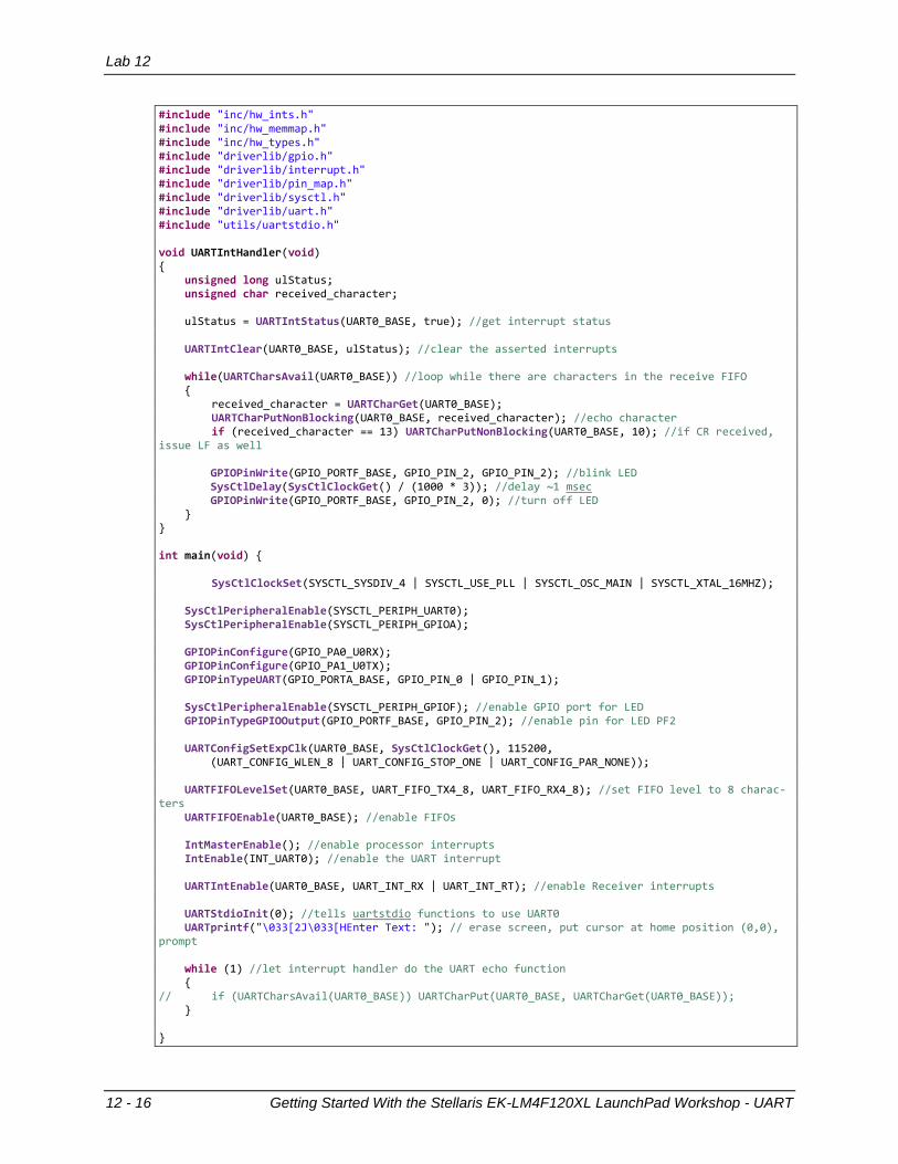
16. Save your work. Your main.c code should look like this.
#include "inc/hw_ints.h" #include "inc/hw_memmap.h" #include "inc/hw_types.h" #include "driverlib/gpio.h" #include "driverlib/interrupt.h" #include "driverlib/pin_map.h" #include "driverlib/sysctl.h" #include "driverlib/uart.h" void UARTIntHandler(void) { unsigned long ulStatus; ulStatus = UARTIntStatus(UART0_BASE, true); //get interrupt status UARTIntClear(UART0_BASE, ulStatus); //clear the asserted interrupts while(UARTCharsAvail(UART0_BASE)) //loop while there are chars { UARTCharPutNonBlocking(UART0_BASE, UARTCharGetNonBlocking(UART0_BASE)); //echo character GPIOPinWrite(GPIO_PORTF_BASE, GPIO_PIN_2, GPIO_PIN_2); //blink LED SysCtlDelay(SysCtlClockGet() / (1000 * 3)); //delay ~1 msec GPIOPinWrite(GPIO_PORTF_BASE, GPIO_PIN_2, 0); //turn off LED } } int main(void) { SysCtlClockSet(SYSCTL_SYSDIV_4 | SYSCTL_USE_PLL | SYSCTL_OSC_MAIN | SYSCTL_XTAL_16MHZ); SysCtlPeripheralEnable(SYSCTL_PERIPH_UART0); SysCtlPeripheralEnable(SYSCTL_PERIPH_GPIOA); GPIOPinConfigure(GPIO_PA0_U0RX); GPIOPinConfigure(GPIO_PA1_U0TX); GPIOPinTypeUART(GPIO_PORTA_BASE, GPIO_PIN_0 | GPIO_PIN_1); SysCtlPeripheralEnable(SYSCTL_PERIPH_GPIOF); //enable GPIO port for LED GPIOPinTypeGPIOOutput(GPIO_PORTF_BASE, GPIO_PIN_2); //enable pin for LED PF2 UARTConfigSetExpClk(UART0_BASE, SysCtlClockGet(), 115200, (UART_CONFIG_WLEN_8 | UART_CONFIG_STOP_ONE | UART_CONFIG_PAR_NONE)); IntMasterEnable(); //enable processor interrupts IntEnable(INT_UART0); //enable the UART interrupt UARTIntEnable(UART0_BASE, UART_INT_RX | UART_INT_RT); //only enable RX and TX interrupts UARTCharPut(UART0_BASE, 'E'); UARTCharPut(UART0_BASE, 'n'); UARTCharPut(UART0_BASE, 't'); UARTCharPut(UART0_BASE, 'e'); UARTCharPut(UART0_BASE, 'r'); UARTCharPut(UART0_BASE, ' '); UARTCharPut(UART0_BASE, 'T'); UARTCharPut(UART0_BASE, 'e'); UARTCharPut(UART0_BASE, 'x'); UARTCharPut(UART0_BASE, 't'); UARTCharPut(UART0_BASE, ':'); UARTCharPut(UART0_BASE, ' '); while (1) //let interrupt handler do the UART echo function { // if (UARTCharsAvail(UART0_BASE)) UARTCharPut(UART0_BASE, UARTCharGet(UART0_BASE)); } }
Lab 12
12 - 14 Getting Started With the Stellaris EK-LM4F120XL LaunchPad Workshop - UART
17. Click the Debug button to build and download your program to the LM4F120H5QR memory.
18. If you’ve closed it, open Hyperterminal or puTTY, and configure it as before.
19. Click the Resume button. Type some characters and you should see the characters echoed into the terminal window. Note the LED.
Lab 12
Getting Started With the Stellaris EK-LM4F120XL LaunchPad Workshop - UART 12 - 15
Add Formatting, Enable FIFOs, use UARTprintf
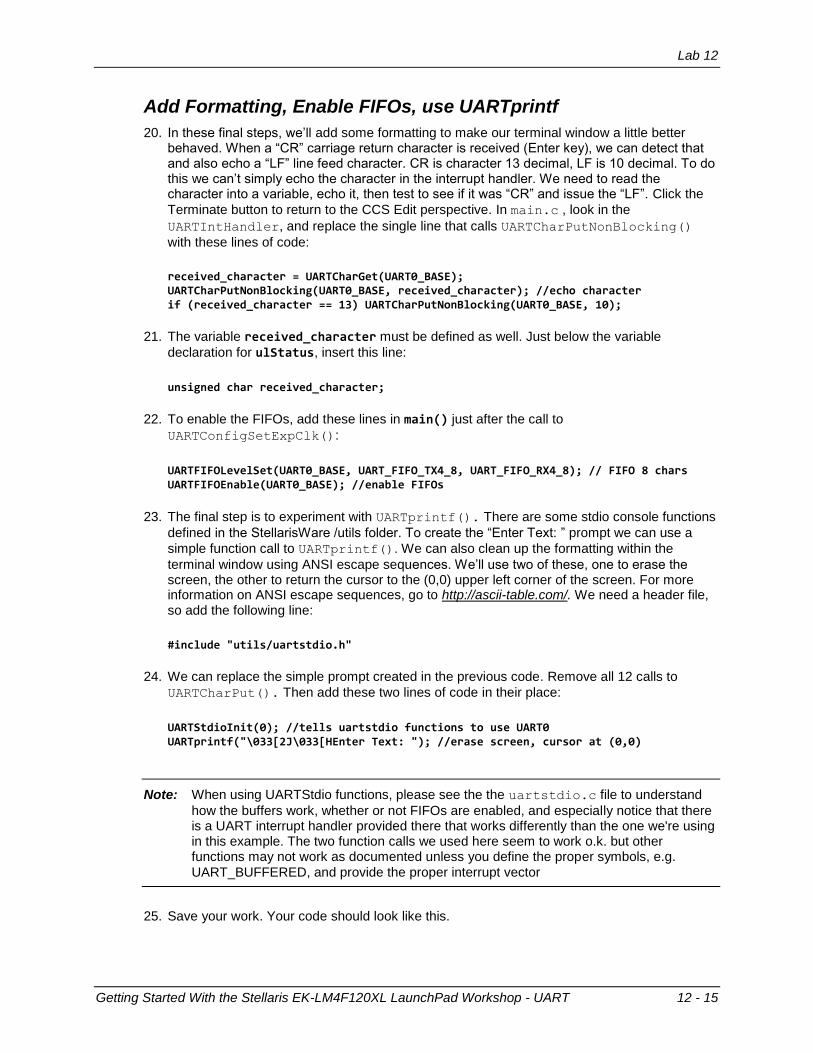
20. In these final steps, we’ll add some formatting to make our terminal window a little better behaved. When a “CR” carriage return character is received (Enter key), we can detect that and also echo a “LF” line feed character. CR is character 13 decimal, LF is 10 decimal. To do this we can’t simply echo the character in the interrupt handler. We need to read the character into a variable, echo it, then test to see if it was “CR” and issue the “LF”. Click the
Terminate button to return to the CCS Edit perspective. In main.c , look in the
UARTIntHandler, and replace the single line that calls UARTCharPutNonBlocking()
with these lines of code:
received_character = UARTCharGet(UART0_BASE); UARTCharPutNonBlocking(UART0_BASE, received_character); //echo character if (received_character == 13) UARTCharPutNonBlocking(UART0_BASE, 10);
21. The variable received_character must be defined as well. Just below the variable
declaration for ulStatus, insert this line:
unsigned char received_character;
22. To enable the FIFOs, add these lines in main() just after the call to
UARTConfigSetExpClk():
UARTFIFOLevelSet(UART0_BASE, UART_FIFO_TX4_8, UART_FIFO_RX4_8); // FIFO 8 chars UARTFIFOEnable(UART0_BASE); //enable FIFOs
23. The final step is to experiment with UARTprintf(). There are some stdio console functions
defined in the StellarisWare /utils folder. To create the “Enter Text: ” prompt we can use a
simple function call to UARTprintf(). We can also clean up the formatting within the
terminal window using ANSI escape sequences. We’ll use two of these, one to erase the screen, the other to return the cursor to the (0,0) upper left corner of the screen. For more information on ANSI escape sequences, go to http://ascii-table.com/. We need a header file, so add the following line:
#include "utils/uartstdio.h"
24. We can replace the simple prompt created in the previous code. Remove all 12 calls to
UARTCharPut(). Then add these two lines of code in their place:
UARTStdioInit(0); //tells uartstdio functions to use UART0 UARTprintf("\033[2J\033[HEnter Text: "); //erase screen, cursor at (0,0)
Note: When using UARTStdio functions, please see the the uartstdio.c file to understand
how the buffers work, whether or not FIFOs are enabled, and especially notice that there is a UART interrupt handler provided there that works differently than the one we're using in this example. The two function calls we used here seem to work o.k. but other functions may not work as documented unless you define the proper symbols, e.g.
UART_BUFFERED, and provide the proper interrupt vector
25. Save your work. Your code should look like this.
Lab 12
12 - 16 Getting Started With the Stellaris EK-LM4F120XL LaunchPad Workshop - UART
#include "inc/hw_ints.h" #include "inc/hw_memmap.h" #include "inc/hw_types.h" #include "driverlib/gpio.h" #include "driverlib/interrupt.h" #include "driverlib/pin_map.h" #include "driverlib/sysctl.h" #include "driverlib/uart.h" #include "utils/uartstdio.h" void UARTIntHandler(void) { unsigned long ulStatus; unsigned char received_character; ulStatus = UARTIntStatus(UART0_BASE, true); //get interrupt status UARTIntClear(UART0_BASE, ulStatus); //clear the asserted interrupts while(UARTCharsAvail(UART0_BASE)) //loop while there are characters in the receive FIFO { received_character = UARTCharGet(UART0_BASE); UARTCharPutNonBlocking(UART0_BASE, received_character); //echo character if (received_character == 13) UARTCharPutNonBlocking(UART0_BASE, 10); //if CR received, issue LF as well GPIOPinWrite(GPIO_PORTF_BASE, GPIO_PIN_2, GPIO_PIN_2); //blink LED SysCtlDelay(SysCtlClockGet() / (1000 * 3)); //delay ~1 msec GPIOPinWrite(GPIO_PORTF_BASE, GPIO_PIN_2, 0); //turn off LED } } int main(void) { SysCtlClockSet(SYSCTL_SYSDIV_4 | SYSCTL_USE_PLL | SYSCTL_OSC_MAIN | SYSCTL_XTAL_16MHZ); SysCtlPeripheralEnable(SYSCTL_PERIPH_UART0); SysCtlPeripheralEnable(SYSCTL_PERIPH_GPIOA); GPIOPinConfigure(GPIO_PA0_U0RX); GPIOPinConfigure(GPIO_PA1_U0TX); GPIOPinTypeUART(GPIO_PORTA_BASE, GPIO_PIN_0 | GPIO_PIN_1); SysCtlPeripheralEnable(SYSCTL_PERIPH_GPIOF); //enable GPIO port for LED GPIOPinTypeGPIOOutput(GPIO_PORTF_BASE, GPIO_PIN_2); //enable pin for LED PF2 UARTConfigSetExpClk(UART0_BASE, SysCtlClockGet(), 115200, (UART_CONFIG_WLEN_8 | UART_CONFIG_STOP_ONE | UART_CONFIG_PAR_NONE)); UARTFIFOLevelSet(UART0_BASE, UART_FIFO_TX4_8, UART_FIFO_RX4_8); //set FIFO level to 8 charac-ters UARTFIFOEnable(UART0_BASE); //enable FIFOs IntMasterEnable(); //enable processor interrupts IntEnable(INT_UART0); //enable the UART interrupt UARTIntEnable(UART0_BASE, UART_INT_RX | UART_INT_RT); //enable Receiver interrupts UARTStdioInit(0); //tells uartstdio functions to use UART0 UARTprintf("\033[2J\033[HEnter Text: "); // erase screen, put cursor at home position (0,0), prompt while (1) //let interrupt handler do the UART echo function { // if (UARTCharsAvail(UART0_BASE)) UARTCharPut(UART0_BASE, UARTCharGet(UART0_BASE)); } }

Lab 12
Getting Started With the Stellaris EK-LM4F120XL LaunchPad Workshop - UART 12 - 17
26. Before we can compile/build this example, we need to add the uartstdio.c file from the
/utils folder into our project. Click on Project Add files…. Then navigate to c:\StellarisWare\utils and select uartstdio.c. Then click Open.
When you are asked how to import the file, make the selections below and click OK.
Lab 12
12 - 18 Getting Started With the Stellaris EK-LM4F120XL LaunchPad Workshop - UART
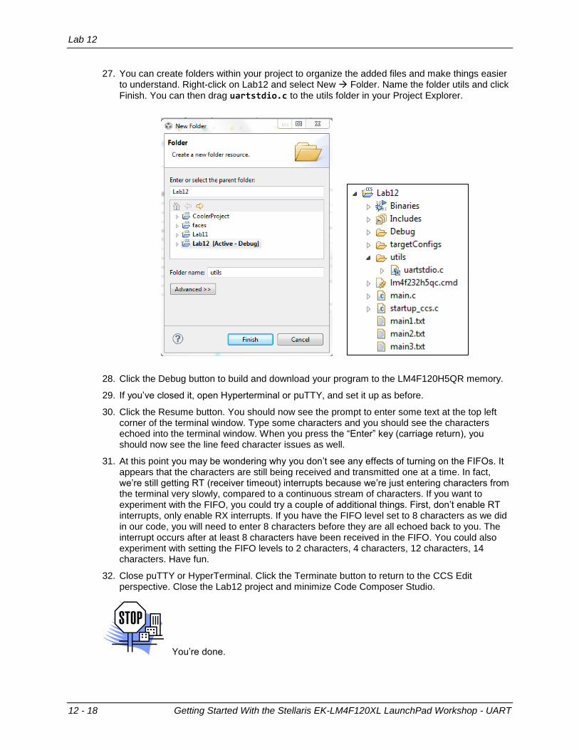
27. You can create folders within your project to organize the added files and make things easier to understand. Right-click on Lab12 and select New Folder. Name the folder utils and click Finish. You can then drag uartstdio.c to the utils folder in your Project Explorer.
28. Click the Debug button to build and download your program to the LM4F120H5QR memory.
29. If you’ve closed it, open Hyperterminal or puTTY, and set it up as before.
30. Click the Resume button. You should now see the prompt to enter some text at the top left corner of the terminal window. Type some characters and you should see the characters echoed into the terminal window. When you press the “Enter” key (carriage return), you should now see the line feed character issues as well.
31. At this point you may be wondering why you don’t see any effects of turning on the FIFOs. It appears that the characters are still being received and transmitted one at a time. In fact, we’re still getting RT (receiver timeout) interrupts because we’re just entering characters from the terminal very slowly, compared to a continuous stream of characters. If you want to experiment with the FIFO, you could try a couple of additional things. First, don’t enable RT interrupts, only enable RX interrupts. If you have the FIFO level set to 8 characters as we did in our code, you will need to enter 8 characters before they are all echoed back to you. The interrupt occurs after at least 8 characters have been received in the FIFO. You could also experiment with setting the FIFO levels to 2 characters, 4 characters, 12 characters, 14 characters. Have fun.
32. Close puTTY or HyperTerminal. Click the Terminate button to return to the CCS Edit perspective. Close the Lab12 project and minimize Code Composer Studio.
You’re done.