agc 200 advanced gen-set controller operator’s manual manual.pdf · agc 200 advanced gen-set...
TRANSCRIPT

AGC 200 Advanced Gen-set Controller OPERATOR’S MANUAL
• Display readings • Push-button functions • Alarm handling • Log list
Document no.: 4189340607A SW version 3.5X.X or later

AGC 200 Operator’s Manual
DEIF A/S Page 2 of 22
Table of contents
1. ABOUT THIS DOCUMENT....................................................................................................3 GENERAL PURPOSE......................................................................................................................3 INTENDED USERS..........................................................................................................................3 CONTENTS/OVERALL STRUCTURE..................................................................................................3
2. WARNINGS AND LEGAL INFORMATION ...........................................................................4 LEGAL INFORMATION AND RESPONSIBILITY.....................................................................................4 ELECTROSTATIC DISCHARGE AWARENESS .....................................................................................4 SAFETY ISSUES ............................................................................................................................4 DEFINITIONS ................................................................................................................................4
3. AGC 200 VARIANTS..............................................................................................................5 ISLAND, AGC 212/232/242 ..........................................................................................................5 AUTOMATIC MAINS FAILURE, AGC 213/223 ...................................................................................5 MAINS, AGC 245 .........................................................................................................................6 MAINS AND TIE BREAKER, AGC 246 ..............................................................................................6 BUS TIE BREAKER, AGC 244.........................................................................................................7
4. DISPLAY PUSH-BUTTONS AND LEDS ...............................................................................8 PUSH-BUTTON FUNCTIONS ............................................................................................................8 LED FUNCTIONS.........................................................................................................................11
5. DISPLAY AND MENU STRUCTURE...................................................................................13 LCD DISPLAY .............................................................................................................................13 MENU STRUCTURE......................................................................................................................13 STATUS LINE TEXT ......................................................................................................................15 RUNNING MODES........................................................................................................................20
6. ALARM HANDLING AND LOG LIST...................................................................................21 ALARM HANDLING .......................................................................................................................21 LOG LIST....................................................................................................................................22

AGC 200 Operator’s Manual
DEIF A/S Page 3 of 22
1. About this document
General purpose This document is the Operator’s Manual for DEIF’s Advanced Gen-set Controllers, the AGC 200 series. The document mainly includes general product information, display readings, push-button and LED functions, alarm handling descriptions and presentation of the log list. The general purpose is to give the operator important information to be used in the daily operation of the unit.
Intended users This Operator’s Manual is mainly intended for the daily user. On the basis of this document, the operator will be able to carry out simple procedures such as start/stop and control of the generator set.
Contents/overall structure The document is divided into chapters, and in order to make the structure simple and easy to use, each chapter will begin from the top of a new page.
Please make sure to read this handbook before working with the Multi-line 2 controller and the gen-set to be controlled. Failure to do this could result in damage to the equipment or human injury.

AGC 200 Operator’s Manual
DEIF A/S Page 4 of 22
2. Warnings and legal information
Legal information and responsibility DEIF takes no responsibility for installation or operation of the generator set. If there is any doubt about how to install or operate the generator set controlled by the unit, the company responsible for the installation or the operation of the set must be contacted.
Electrostatic discharge awareness Sufficient care must be taken to protect the terminals against static discharges during the installation. Once the unit is installed and connected, these precautions are no longer necessary.
Safety issues Installing the unit implies work with dangerous currents and voltages. Therefore, the installation should only be carried out by authorised personnel who understand the risks involved in working with live electrical equipment.
Definitions Throughout this document a number of notes and warnings will be presented. To ensure that these are noticed, they will be highlighted in order to separate them from the general text.
Notes
Warnings
The notes provide general information which will be helpful for the reader to bear in mind.
The warnings indicate a potentially dangerous situation which could result in death, personal injury or damaged equipment, if certain guidelines are not followed.
Be aware of the hazardous live currents and voltages. Do not touch any AC measurement inputs as this could lead to injury or death.
The units are not to be opened by unauthorised personnel. If opened anyway, the warranty will be lost.
AGC 200 Operator’s Manual
DEIF A/S Page 5 of 22
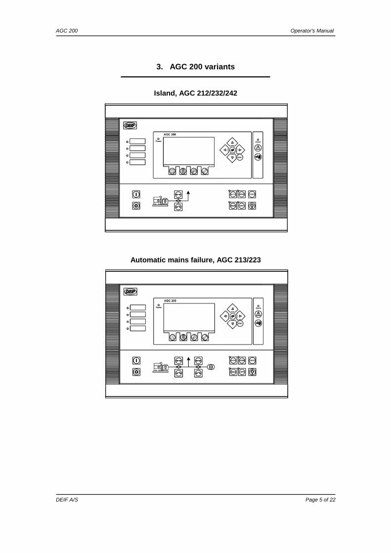
3. AGC 200 variants
Island, AGC 212/232/242
Automatic mains failure, AGC 213/223

AGC 200 Operator’s Manual
DEIF A/S Page 6 of 22
Mains, AGC 245
Mains and tie breaker, AGC 246

AGC 200 Operator’s Manual
DEIF A/S Page 7 of 22
Bus tie breaker, AGC 244

AGC 200 Operator’s Manual
DEIF A/S Page 8 of 22
4. Display push-buttons and LEDs
Push-button functions The display unit holds a number of push-button functions which are described below. Shifts the display to show the alarm list. Resets horn output. Tools. The tools are a number of windows for commissioning as well as some
special settings which are not accessible via the PC utility software. Please refer to the Designer’s Reference Handbook for details.
Shifts the display to viewing of measured values. There are 20 different views. Scroll through the views using the or button.
Shifts the display to show the event and alarm list. There are four lists to select
from: Event log, alarm log, battery test log and engine interface alarm log (CAN J1939 engine controller interface).
Parameter list selection. Moves the cursor left for manoeuvring in the menus. Increases the value of the selected setpoint (in the setup menu). In the daily use
display, this button function is used for scrolling the displaying of generator values.
Selects the entry in the display. Decreases the value of the selected setpoint (in the setup menu). In the daily
use display, this button function is used for scrolling the displaying of generator values.
Moves the cursor right for manoeuvring in the menus. ESC Jumps one step backwards in the menu (to previous display or to the entry
window). START Start of the gen-set if ‘SEMI-AUTO’ or ‘MANUAL’ is selected. STOP Stop of the gen-set if ‘SEMI-AUTO’ or ‘MANUAL’ is selected. Manual activation of close breaker sequence if ‘SEMI-AUTO’ is selected. Manual activation of open breaker sequence if ‘SEMI-AUTO’ is selected. AUTO Selects AUTO running mode. SEMI Selects SEMI-AUTO running mode. Push-button commands are used for
start/stop, etc.

AGC 200 Operator’s Manual
DEIF A/S Page 9 of 22
MAN Selects MANUAL running mode. Like SEMI, but regulators are OFF. OFF Selects OFF mode. All functions except protections are switched off. TEST Selects TEST RUN of the generator. Lamp test.

AGC 200 Operator’s Manual
DEIF A/S Page 10 of 22
The push-buttons are placed as follows:
AUTO mode.
MANUAL mode.
SEMI-AUTO mode.
OFF mode.
TEST mode.
Lamp test.
Close/open MB.
START: Start of the gen-set if ‘SEMI-AUTO’ or ‘MANUAL’ is selected.
STOP: Stop of the gen-set if ‘SEMI-AUTO’ or ‘MANUAL’ is selected.
View of measured values.
Log lists.
Alarm list.
Close/open GB.
Parameter settings.
Tools.
Silence horn.
Enter.
Step backwards.

AGC 200 Operator’s Manual
DEIF A/S Page 11 of 22
LED functions The display unit holds 10 LED functions. Dependent on the situation, the colour of the LEDs is green, red or a combination. Alarm: LED flashing indicates that unacknowledged alarms are present. LED steady light indicates that ALL alarms are acknowledged, but some are still
present. Power: LED indicates that the auxiliary supply is switched on. If it is green, the AGC 200
is operational. If it is red, the self-check has failed. Run: LED indicates that the generator is running. Hz/V OK: LED green light indicates that the voltage/frequency is present and OK. GB ON: LED indicates that the generator breaker is closed. MB ON: LED indicates that the mains breaker is closed. Mains OK: LED is green if the mains is present and OK. LED is red at a mains failure. LED is flashing green when the mains returns during the ‘mains OK delay’ time. AUTO: LED indicates that auto mode is selected. MAN: LED indicates that manual mode is selected. SEMI: LED indicates that SEMI AUTO mode is selected. OFF: LED indicates that OFF mode is selected. Annunciator: 4 x LEDs with selectable indication function. Selection is made in M-logic.

AGC 200 Operator’s Manual
DEIF A/S Page 12 of 22
The display LEDs indicate the following:
Mains breaker ON.
Manual mode.
Alarm.
Generator breaker ON.
Generator frequency/voltage.
Engine running.
Mini-annunciator.
AUTO mode.
SEMI-AUTO.
OFF mode.

AGC 200 Operator’s Manual
DEIF A/S Page 13 of 22
5. Display and menu structure
LCD display The display is a backlit LCD graphical display. The display light intensity, LED indication and contrast can be adjusted from menu 9150. Basically, all measured and calculated values can be read in the display. These may be selected via the PC utility software (USW).
Menu structure The display includes two menu systems which can be used without password entry:
View menu system This is the commonly used menu system. 20 windows are configurable and can be entered by using the arrow push-buttons. Setup menu system (not commonly used by the operator) This menu system is used to set up the unit, and if the operator needs detailed information that is not available in the view menu system. Changing of parameter settings is password protected.
Entry window When the unit is powered up, an entry window appears. The entry window is the first window of the view menu system. It can always be accessed by pressing the BACK push-button three times.
For selection of values, please refer to the Designer’s Reference Handbook.
MAINS FAILURE U-Supply 24.1 V G 0.00I PF 0 kW G 0kVA 0 kVAr Energy Total 0 kWh Run absolute 0 hrs
AGC 200 Operator’s Manual
DEIF A/S Page 14 of 22
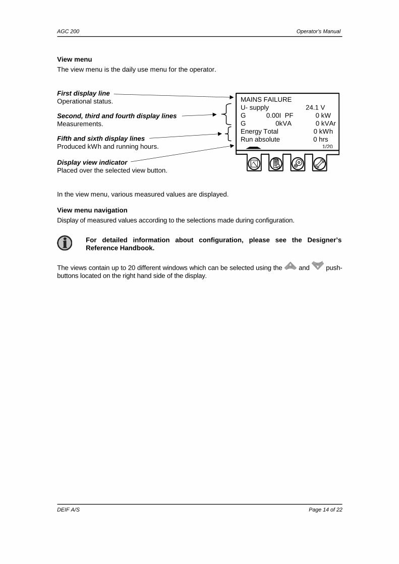
View menu The view menu is the daily use menu for the operator. First display line Operational status. Second, third and fourth display lines Measurements. Fifth and sixth display lines Produced kWh and running hours. Display view indicator Placed over the selected view button. In the view menu, various measured values are displayed.
View menu navigation Display of measured values according to the selections made during configuration.
The views contain up to 20 different windows which can be selected using the and push-buttons located on the right hand side of the display.
For detailed information about configuration, please see the Designer’s Reference Handbook.
MAINS FAILURE U- supply 24.1 V G 0.00I PF 0 kW G 0kVA 0 kVAr Energy Total 0 kWh Run absolute 0 hrs
1/20
AGC 200 Operator’s Manual
DEIF A/S Page 15 of 22
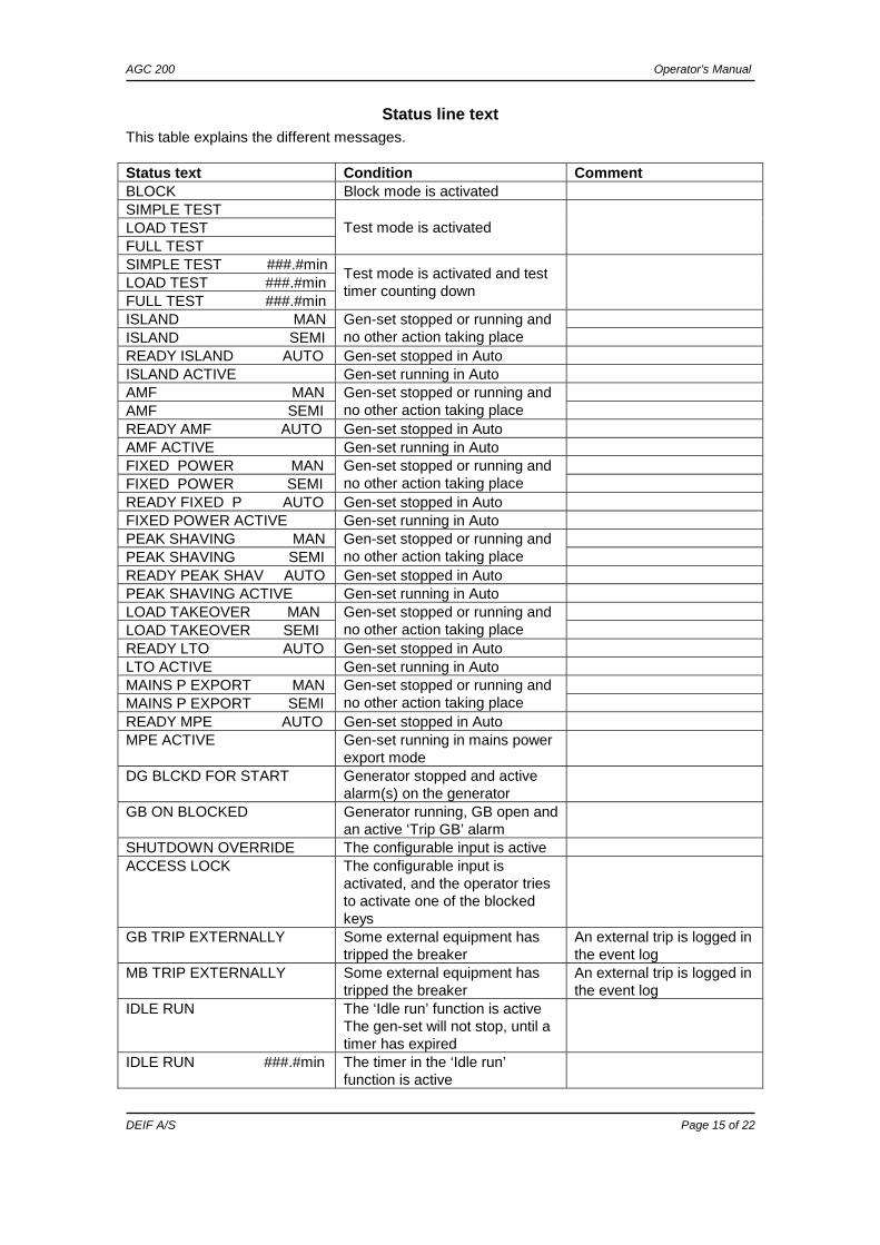
Status line text This table explains the different messages. Status text Condition Comment BLOCK Block mode is activated SIMPLE TEST LOAD TEST FULL TEST
Test mode is activated
SIMPLE TEST ###.#min LOAD TEST ###.#min FULL TEST ###.#min
Test mode is activated and test timer counting down
ISLAND MAN ISLAND SEMI
Gen-set stopped or running and no other action taking place
READY ISLAND AUTO Gen-set stopped in Auto ISLAND ACTIVE Gen-set running in Auto AMF MAN AMF SEMI
Gen-set stopped or running and no other action taking place
READY AMF AUTO Gen-set stopped in Auto AMF ACTIVE Gen-set running in Auto FIXED POWER MAN FIXED POWER SEMI
Gen-set stopped or running and no other action taking place
READY FIXED P AUTO Gen-set stopped in Auto FIXED POWER ACTIVE Gen-set running in Auto PEAK SHAVING MAN PEAK SHAVING SEMI
Gen-set stopped or running and no other action taking place
READY PEAK SHAV AUTO Gen-set stopped in Auto PEAK SHAVING ACTIVE Gen-set running in Auto LOAD TAKEOVER MAN LOAD TAKEOVER SEMI
Gen-set stopped or running and no other action taking place
READY LTO AUTO Gen-set stopped in Auto LTO ACTIVE Gen-set running in Auto MAINS P EXPORT MAN MAINS P EXPORT SEMI
Gen-set stopped or running and no other action taking place
READY MPE AUTO Gen-set stopped in Auto MPE ACTIVE Gen-set running in mains power
export mode
DG BLCKD FOR START Generator stopped and active alarm(s) on the generator
GB ON BLOCKED Generator running, GB open and an active ‘Trip GB’ alarm
SHUTDOWN OVERRIDE The configurable input is active ACCESS LOCK The configurable input is
activated, and the operator tries to activate one of the blocked keys
GB TRIP EXTERNALLY Some external equipment has tripped the breaker
An external trip is logged in the event log
MB TRIP EXTERNALLY Some external equipment has tripped the breaker
An external trip is logged in the event log
IDLE RUN The ‘Idle run’ function is active The gen-set will not stop, until a timer has expired
IDLE RUN ###.#min The timer in the ‘Idle run’ function is active

AGC 200 Operator’s Manual
DEIF A/S Page 16 of 22
Status text Condition Comment COMPENSATION FREQ. Compensation is active The frequency is not at the
nominal setting Aux. test ##.#V ####s Battery test activated DELOAD Decreasing the load of the gen-
set in order to open the breaker
START DG(s) IN ###s The start gen-set setpoint is exceeded
STOP DG(s) IN ###s The stop gen-set setpoint is exceeded
START PREPARE The start prepare relay is activated
START RELAY ON The start relay is activated START RELAY OFF The start relay is deactivated
during the start sequence
MAINS FAILURE Mains failure and mains failure timer expired
MAINS FAILURE IN ###s Frequency or voltage measurement is outside the limits
The timer shown is the mains failure delay Text in mains units
MAINS U OK DEL ####s Mains voltage is OK after a mains failure
The timer shown is the mains OK delay
MAINS f OK DEL ####s Mains frequency is OK after a mains failure
The timer shown is the mains OK delay
Hz/V OK IN ###s The voltage and frequency of the gen-set is OK
When the timer runs out it is allowed to operate the generator breaker
COOLING DOWN ###s Cooling down period is activated GEN-SET STOPPING This info is shown when cooling
down has finished
EXT. STOP TIME ###s PROGRAMMING LANGUAGE This info is shown if the
language file is downloaded from the PC utility software
Generator is synchronising The dot marks the actual generator phase angle position in the synchronisation When the dot is at 12 o’clock, the generator and busbar are in synchronism The second dot indicates when the relay output for the generator or mains breaker is activated
Generator running too slow during synchronising
Generator running too fast during synchronising
EXT. START ORDER A planned AMF sequence is activated
There is no failure on the mains during this sequence

AGC 200 Operator’s Manual
DEIF A/S Page 17 of 22
Status text Condition Comment SELECT GEN-SET MODE Power management has been
deactivated and no other gen-set mode has been selected
AGC 24x only
QUICK SETUP ERROR Quick setup of the application failed
MOUNT CAN CONNECTOR Connect the power management CAN line
ADAPT IN PROGRESS The AGC 200 is receiving the application that it has just been connected to
SETUP IN PROGRESS The new AGC is being added to the existing application
SETUP COMPLETED Successful update of the application in all AGC units
REMOVE CAN CONNECTOR Remove the power management CAN lines
RAMP TO #####kW The power ramp is ramping in steps, and the next step that will be reached after the timer has expired will be displayed
DERATED TO #####kW Displays the ramp down setpoint
AGC 200 Operator’s Manual
DEIF A/S Page 18 of 22
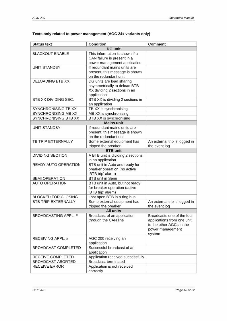
Texts only related to power management (AGC 24x variants only) Status text Condition Comment
DG unit BLACKOUT ENABLE This information is shown if a
CAN failure is present in a power management application
UNIT STANDBY If redundant mains units are present, this message is shown on the redundant unit
DELOADING BTB XX DG units are load sharing asymmetrically to deload BTB XX dividing 2 sections in an application
BTB XX DIVIDING SEC. BTB XX is dividing 2 sections in an application
SYNCHRONISING TB XX TB XX is synchronising SYNCHRONISING MB XX MB XX is synchronising SYNCHRONISING BTB XX BTB XX is synchronising
Mains unit UNIT STANDBY If redundant mains units are
present, this message is shown on the redundant unit
TB TRIP EXTERNALLY Some external equipment has tripped the breaker
An external trip is logged in the event log
BTB unit DIVIDING SECTION A BTB unit is dividing 2 sections
in an application
READY AUTO OPERATION BTB unit in Auto and ready for breaker operation (no active ‘BTB trip’ alarm)
SEMI OPERATION BTB unit in Semi AUTO OPERATION BTB unit in Auto, but not ready
for breaker operation (active ‘BTB trip’ alarm)
BLOCKED FOR CLOSING Last open BTB in a ring bus BTB TRIP EXTERNALLY Some external equipment has
tripped the breaker An external trip is logged in the event log
All units BROADCASTING APPL. # Broadcast of an application
through the CAN line Broadcasts one of the four applications from one unit to the other AGCs in the power management system
RECEIVING APPL. # AGC 200 receiving an application
BROADCAST COMPLETED Successful broadcast of an application
RECEIVE COMPLETED Application received successfully BROADCAST ABORTED Broadcast terminated RECEIVE ERROR Application is not received
correctly

AGC 200 Operator’s Manual
DEIF A/S Page 19 of 22
View menu example View reading (20 views) Log reading Parameter settings Press Press Press Press Press Press
The scrollbar indicates that more readings are available below
MAINS FAILURE U- supply 24.1 V G 0.00I PF 0 kW G 0kVA 0 kVAr Energy Total 0 kWh Run absolute 0 hrs 1/20
MAINS FAILURE Event log . Alarm log Battery test log
MAINS FAILURE Setup menu 1000 Protection . 2000 Synchronisation 2500 Regulation 3000 Binary input
MAINS FAILURE P 0kW 0 % Q 0kVAr 0 % S 0kVA 0 % Energy Total 0 kWh Run absolute 0 hrs
MAINS FAILURE MAINS FAILURE . Wed Sept 23 13:36:23 MB OFF Wed Sept 23 13:36:33
MAINS FAILURE Setup menu 1000 G –P> 1 . 1010 G –P> 2 1030 G I> 1 1040 G I> 2
MAINS FAILURE 1000 G –P> 1 Setpoint: -9.0% . Timer: 10.2s Output A: Not used Output B: Not used

AGC 200 Operator’s Manual
DEIF A/S Page 20 of 22
Running modes The running modes are selected using the buttons as follows: Mode Description SEMI - The display push-buttons (START, STOP, GB ON, GB OFF) are active and can
be used by the operator. - The regulators are also active, i.e. the speed control will bring the generator to
nominal speed upon start. - When pushing a breaker button for closing, the AGC 200 will synchronise (if
allowed) the breaker. When the breaker closes, the controls stop. TEST - The unit will start the generator, carry out the test sequence (predefined time
period) and stop the generator again. Subsequently, the generator will return to AUTO or SEMI-AUTO mode. The mains breaker will remain closed, and the generator breaker will remain open. NOTE: The test running can be: Simple test: Starting the gen-set without closing the GB; Load test: Parallel to the mains and take load to a predefined value; Full test: Transfer the load to the gen-set and open the MB.
AUTO - The unit will automatically carry out the control type selected (AMF, fixed power, etc.).
- The display control push-buttons (START, STOP, GB ON, GB OFF) are disabled.
- If the selected running mode is fixed power, mains power export, load takeover or island, timer start/stop (week watch) or binary input, then start/stop can be used.
MAN - The display push-buttons (START, STOP) are active and can be used by the operator.
- The regulators are not active, i.e. speed (and voltage) control has to take place using external controls for generator speed and possibly generator voltage control.
- The breakers will be able to open or close at any time. A synchronisation check will always be performed to ensure safe closing of the breakers.
BLOCK - The unit will not be able to start. BLOCK mode can be selected during standstill and the password is needed to leave BLOCK mode. If the BLOCK mode is selected while the gen-set is running, the mode will have no effect until the gen-set is stopped. To select another mode after the BLOCK mode, the password must be entered.

AGC 200 Operator’s Manual
DEIF A/S Page 21 of 22
6. Alarm handling and log list
Alarm handling When an alarm occurs, the unit will automatically go to the alarm list, if selected (setting 6900 Alarm jump) for display of the alarm. If setting 6900 is OFF, you have to press to enter the alarm list. If reading of the alarms is not desired, use the ESC push-button to exit the alarm list. If you decide to enter the alarm list later, use the push-button to jump directly to the alarm list reading. The alarm list contains both acknowledged and unacknowledged alarms provided that they are still active (i.e. the alarm condition is still present). Once an alarm is acknowledged and the condition has disappeared, the alarm will no longer be displayed in the alarm list. This means that if there are no alarms, the alarm list will read ‘No alarms’. This display example indicates an unacknowledged alarm. The display can show only one alarm at a time. Therefore, all other alarms are hidden. To see the other alarms, use the and push-buttons to scroll in the display. To acknowledge an alarm, place the cursor (grey area) over the channel number and then press .
MAINS FAILURE Alarm list : Ch 1300 UNACK BB U< 1 09-09-23 15:20:21:0
1/1 alarm(s)

AGC 200 Operator’s Manual
DEIF A/S Page 22 of 22
Log list The log is divided into three different lists:
1. Events 2. Alarms 3. Battery test
The log list contains up to 150 events, the alarm list contains up to 30 historical alarms and the battery test list contains up to 52 historical battery tests. An event is e.g. closing of breaker and starting of engine. An alarm is e.g. overcurrent or high cooling water temperature. A battery test is e.g. test OK or test failed. To enter the log list:
1. Press . 2. Select the needed list by using the and push-buttons (move the highlight of the
list) and press the push-button.
DEIF A/S reserves the right to change any of the above