aft crane mcd sow - · pdf filethis change also alters the contract specified fixed towing...
TRANSCRIPT

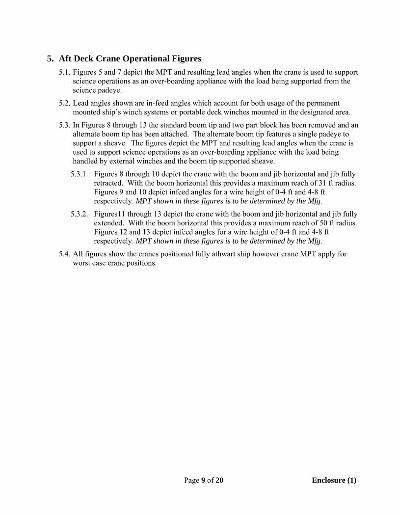
ECP‐034 Aft Cranes Maximum Capabilities Document (MCD) SOW Encl: (1) Preliminary Aft Deck Crane Maximum Capability Document (2) Appleton Marine proposal to MMC dated May 20, 2011 1. Reason For Change When supporting science operations both cranes will periodically be used to conduct off‐board lifts to and from the sea surface using the crane’s winch. Additionally, both cranes will be used as over‐boarding booms for deployment of science packages using wires from installed and portable winches. Science winch wires will be deployed overboard via sheaves hung from the boom of either crane at 20 foot (existing padeye), 30 foot (boom tip) or 50 foot radius (boom tip). The science winch wires may be deployed via the crane booms vertically or in a towing mode. To safely conduct these operations the load limitations of the cranes are needed when being used for other than onboard or pier side lifts. Enclosure (1) is a preliminary draft version of a maximum capability document that UAF will develop using the additional capability documentation. 2. Description of Change This change is to document, but not modify, the load capacity of the cranes in multiple situations, initially not covered in the primary design requirements. This additional information will be used to determine the limitations of crane use to support science. This change also alters the contract specified fixed towing padeye from a welded mount to a bolt‐on mount. This change does not affect ongoing design/manufacturing other than the incorporation of the bolt on towing padeye. Execute Alternate No. 001 and Alternate No. 002 described in the Appleton Marine proposal MMC provided to UAF (Encl. (2)). Perform the calculations necessary to fill in the ‘Allowable Load’ column of the attached spreadsheets for the 36 load cases associated with the starboard crane and the 30 load cases associated with the port crane. The drawing of the main deck that follows the two spreadsheets shows the four areas on the deck where a portable winch may be placed. The wire departure point from a portable winch for determining the infeed wire angle to the sheave could be from somewhere within the areas shown on the drawing. The drawing only shows a science winch wire with a sheave at the 20 foot radius. Depending upon the needs of science, the sheave could also be located at the end of the boom at a 30 foot radius or a 50 foot radius. The boom head for the 30 foot and 50 radius is not specified. The current crane head would not be used for lifting or towing from the boom tip via the science winches (fixed or portable). For all the load calculations assume the crane boom is horizontal and not subject to loading from wave slap hitting the boom. The wire angle during towing may vary as much as 60 degrees off of vertical and 45 degrees off of the longitudinal axis while turning. Wire angles while towing
45⁰ 45⁰60⁰
Boom Head
Water Surface

CRANE LOAD CASES
STARBOARD CRANE
Load Case
Winch Location (wire origination
point)
Winch Type Boom
Padeye Position Mode
Allowable Load (lbs) Notes
1
Stbd Flag (Fwd Winch Room)
Fixed
20 ft Vertical 2 Towing Contract Required Location
3 30 ft
Vertical
4 Towing
5 50 ft
Vertical
6 Towing
7
Port Flag (Aft Winch Room)
Fixed
20 ft Vertical
8 Towing
9 30 ft
Vertical
10 Towing
11 50 ft
Vertical
12 Towing
13
Fwd Stbd Area Portable
20 ft Vertical
Base on worst case load based on wire leading from anywhere within this area and vertically from the deck to 4 ft above the deck.
14 Towing
15 30 ft
Vertical
16 Towing
17 50 ft
Vertical
18 Towing
19
Aft Stbd Area Portable
20 ft Vertical
Base on worst case load based on wire leading from anywhere within this area and vertically from the deck to 4 ft above the deck.
20 Towing
21 30 ft
Vertical
22 Towing
23 50 ft
Vertical
24 Towing
25
Fwd Stbd Area Portable
20 ft Vertical
Base on worst case load based on wire leading from anywhere within this area and vertically from 4 ft above the deck to 8 ft above the deck.
26 Towing
27 30 ft
Vertical
28 Towing
29 50 ft
Vertical
30 Towing
31
Aft Stbd Area Portable
20 ft Vertical
Base on worst case load based on wire leading from anywhere within this area and vertically from 4 ft above the deck to 8 ft above the deck.
32 Towing
33 30 ft
Vertical
34 Towing
35 50 ft
Vertical
36 Towing
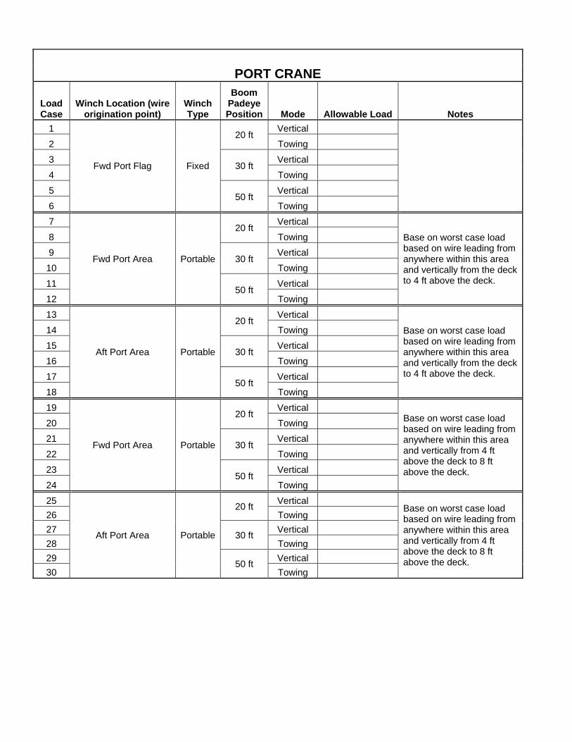
PORT CRANE
Load Case
Winch Location (wire origination point)
Winch Type
Boom Padeye Position Mode Allowable Load Notes
1
Fwd Port Flag Fixed
20 ft Vertical
2 Towing
3 30 ft
Vertical
4 Towing
5 50 ft
Vertical
6 Towing
7
Fwd Port Area Portable
20 ft Vertical
Base on worst case load based on wire leading from anywhere within this area and vertically from the deck to 4 ft above the deck.
8 Towing
9 30 ft
Vertical
10 Towing
11 50 ft
Vertical
12 Towing
13
Aft Port Area Portable
20 ft Vertical
Base on worst case load based on wire leading from anywhere within this area and vertically from the deck to 4 ft above the deck.
14 Towing
15 30 ft
Vertical
16 Towing
17 50 ft
Vertical
18 Towing
19
Fwd Port Area Portable
20 ft Vertical
Base on worst case load based on wire leading from anywhere within this area and vertically from 4 ft above the deck to 8 ft above the deck.
20 Towing
21 30 ft
Vertical
22 Towing
23 50 ft
Vertical
24 Towing
25
Aft Port Area Portable
20 ft Vertical
Base on worst case load based on wire leading from anywhere within this area and vertically from 4 ft above the deck to 8 ft above the deck.
26 Towing
27 30 ft
Vertical
28 Towing
29 50 ft
Vertical
30 Towing
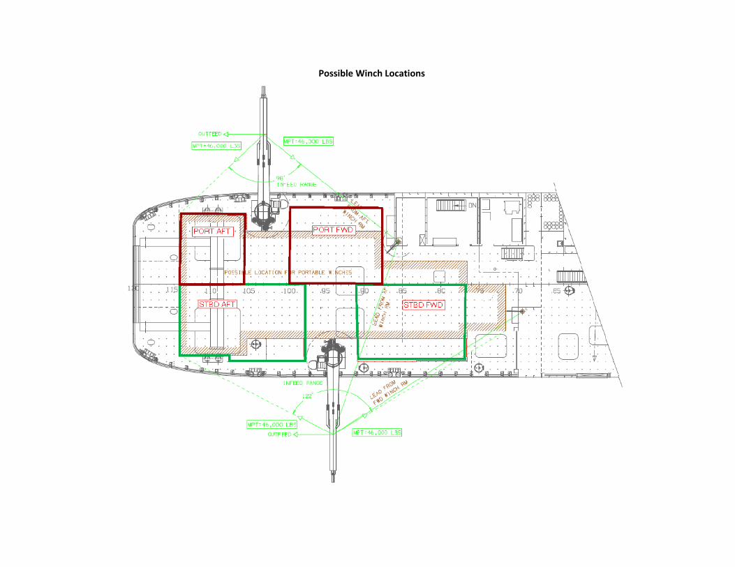
Possible Winch Locations

Page 1 of 20 Enclosure (1)
AFT DECK CRANE
R/V SIKULIAQ
Maximum Capability Document
Manufactured By: Appleton Marine, Inc.
Model: KEB190-50-30
Reference Drawing Number: BMD-0643
Prepared By: [Company Name]
[Engineer’s Name/Stamp]
[Date]

Page 2 of 20 Enclosure (1)
1. Abbreviations
MCD Maximum Capability Document MPT Maximum Permissible Tension NBL Nominal Breaking Load NSF National Science Foundation UNOLS University-National Oceanographic Laboratory System
2. Purpose
This document describes the general arrangement of the Aft Deck Cranes installed onboard the vessel R/V Sikuliaq and it establishes the guidelines for their usage with respect to load capacities and reeving.
Both cranes can be used in two configurations, hoisting in the traditional sense, as a weight handling crane or, as an overboarding appliance for science winches providing over-the-side deployment or towing of science packages. In the hoisting configuration the load is handled entirely by the crane and its winch system. In the over-the-side deployment configuration the load is handled by the crane structure, used as an overboarding boom, and an independent winch located elsewhere on the vessel.
For hoisting operations the document will establish the maximum capacity of the crane for two environmental operating conditions, pier side or in protected waters, and in the open ocean up through Sea State 5 for both onboard and offboard lifts. A separate capacity is also established when using the crane to handle personnel.
This document sets the Maximum Permissible Tensions (MPT) under the various operational loading conditions as required by the UNOLS RVSS, Appendix B when the crane is used to support over-the-side operations for science. Operational conditions will include various crane positions, load geometries and companion winch locations.
The Aft Deck Cranes are intended for “Lifting and Towing, Deep Water” per Section B.3.5 of Appendix B.
The external tension member employed over the removable sheave is considered a component of the entire handling system and shall be used in accordance with Appendix A. The NBL of the tension member shall be less than the MPT for the given operation, or the maximum tension otherwise limited, as described below.
Likewise, all shackles and blocks attached to the crane’s towing padeye are considered components and must have their MCD documents provided for full system evaluation.
3. General
3.1. Description
The port and starboard aft deck cranes are knuckle-boom type, pedestal mounted electro-hydraulic cranes designed to support both dockside mobilization and at-sea operations. At sea the cranes are designed for usage up through sea state 5 and can be used to launch, recover, and/or tow a wide variety of science packages from the ship’s main deck, over the rail and into the water and to the bottom. Figure 1 depicts the general arrangement of the stowed crane. In addition to the boom and jib, the jib features a hydraulically powered extension to provide additional reach. The jib extension terminates with a bolting flange to which the boom tip is

Page 3 of 20 Enclosure (1)
attached. As required the tip can be removed and replaced with docking heads or other appliances for lifting or towing operations.
For other over-the-side operations the cranes are also fitted with a science padeye on the underside of the jib. A 36” diameter instrumented sheave may be fitted to this padeye and used in conjunction with either one of the ship’s permanently mounted winch systems or a temporary deck mounted winch. This allows either crane to vertically deploy or tow science packages outboard of the vessel. The jib also features an auxiliary winch foundation which can accommodate an additional winch to be used in conjunction with one of the alternate boom tips such as a docking head.
Figure 1 Aft Deck Crane General Arrangement-Stowed
Figure 2 depicts the working range of the crane for all angles and jib extensions. Figure 3 depicts an elevation view showing the maximum hook height of 66’- 4” above the main deck when the crane boom and jib are raised to their highest angle and the jib is at full extension. Figure 4 depicts the plan view of the aft deck showing the maximum reach at full jib extension for the crane two part block as well as maximum reach for the boom mounted science padeye.

Page 4 of 20 Enclosure (1)
While towing and handling loads suspended from a sheave attached to science padeye, the crane can be used with a wire/cable having a maximum NBL of 46,000 LBS (23 S.Tons).
3.2. Reference Documents
3.2.1. UNOLS Rope and Cable Safe Working Load Standards, Appendix A.
3.2.2. UNOLS Overboard Handling Systems Design Standards Criteria for the Design and Operations of Overboard Handling Systems, Appendix B.
3.2.3. A-frame General Arrangement Drawing. CS Controls drawing number xxx.
3.2.4. Shipboard installation General Arrangement Drawing. MMC Overside Handling Arrangement Rev B drawing number 07096-714-01.
3.2.5. 36” Sheave and Shackle Installation Drawing. ACME mfg drawing number xxx.
4. Crane Operational Requirements
4.1. Crane used for normal hoisting.
When used for normal hoisting (no attachments to the science padeye) the maximum load that can be lifted by the crane is determined by the radius of the hook and the environmental operating conditions as shown in Table 1.
Table 1
KEB190-50-30 Load Capacity Chart
Radius Sea State 5 Onboard Capacity
Sea State 5 Offboard Capacity
Dock Side Capacity
Personnel Rated
Capacity
(ft) (lbf)
8.72 35,437 tbd 35,437 tbd
10.00 35,437 35,437
15.00 35,437 35,437
20.00 35,437 35,437
25.00 28,846 35,437
30.00 23,846 28,000
35.00 19,230 23,000
40.00 15,625 20,000
45.00 12,500 17,000
50.00 9,357 15,000

Page 5 of 20 Enclosure (1)
4.1.1. Sea State 5 Onboard Capacity refers to all lifts made from and to the deck of the vessel while operating at sea in up through Sea State 5.
4.1.2. Sea State 5 Offboard Capacity refers to all lifts made from or to the sea while the vessel is operating in up through Sea State 5 conditions. Deploying an AUV over the side would be an example of an Offboard lift.
4.1.3. Dock Side Capacity refers to all lifts performed while the vessel is dock side or in sheltered waters.
4.1.4. Personnel Rated Capacity refers to all lifts used for handling personnel
Figure 2 Model KEB190-50-30 Working Range

Page 6 of 20 Enclosure (1)
4.1. Crane Used as an Over-boarding Appliance
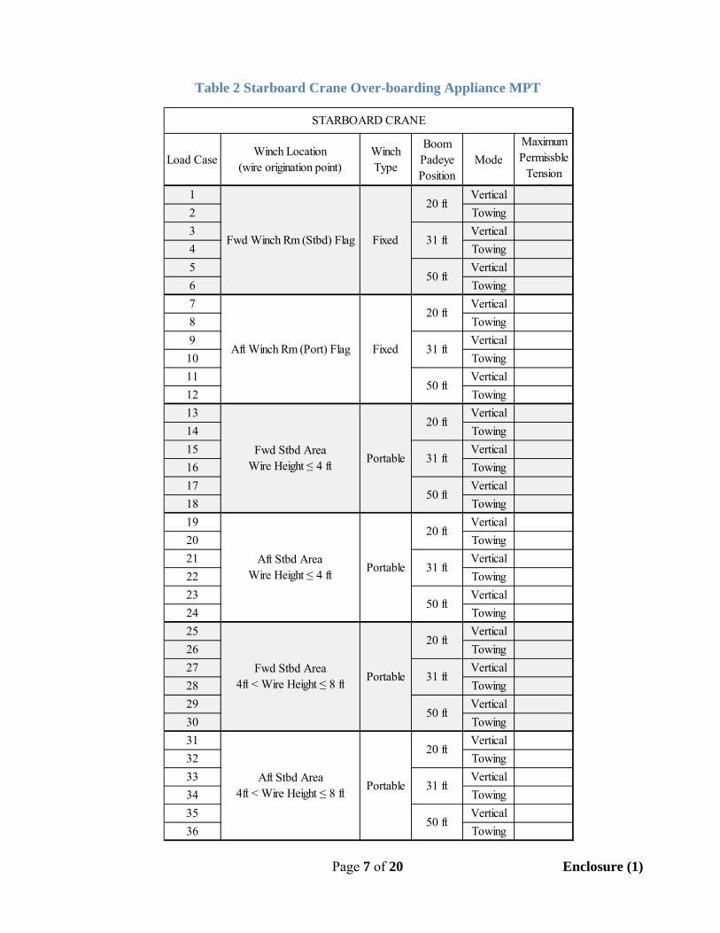
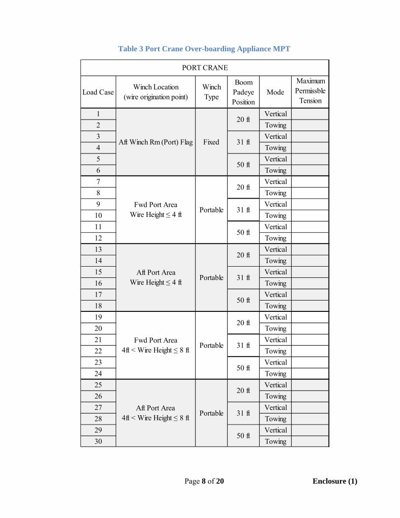
When the crane is outfitted with the boom tip padeye or a sheave on the science padeye, and thus used in conjunction with an external winch system the maximum capacity of the crane is dependent on a number of variables. Tables 2 and 3 provide the MPT for the wire or cable which is to be used in conjunction with the cranes for both permanent and portable winch systems as well as various boom configurations. Table 2 is for the Starboard crane while Table 3 is for the Port crane.
The variables addressed in the tables are:
4.1.1. Location of the external winch being used Location of the external winch determines one component of the load applied to the crane. For portable winches used with the crane the location can vary over the area of the back deck. To simplify the analysis procedure the back deck is divided up into four regions, Port Fwd, Port Aft, Stbd Fwd and Stbd Aft. A portable winch placed in one of these quadrants will use the corresponding load chart.
4.1.2. Portable winch wire height When portable deck winches are used the height at winch the wire exits the winch relative to the crane must be considered. For the purposes of this document the wire height is divided into two categories. The first category covers all winches in which the height of the wire leaving the drum relative to the main deck is four feet or less. The second category covers all winches in which the wire height is greater than four feet and less than or equal to eight feet.
4.1.3. Length of boom extension when using the boom tip padeye
Two boom extension positions are considered in determining crane capacity. When the jib is fully retracted the radius from the boom tip to the crane centerline is 31 feet. When the jib is fully extended the boom tip to the crane centerline is 50 feet.
4.1.4. Direction of the out-feed cable or wire
The direction of the out-feed cable or wire is the angle the cable or wire takes measured from vertical. In the towing category that angle is considered to be 45 to 90 degrees while for the vertical category the angle is considered to be 0 to 45 degrees.
4.2. Use of crane winch while towing from Science Padeye When used in the towing configuration the maximum simultaneous hook load that can be lifted by the crane’s two part block is limited to XXX lbs
Page 7 of 20 Enclosure (1)
Table 2 Starboard Crane Over-boarding Appliance MPT
Load CaseWinch Location
(wire origination point)Winch Type
Boom Padeye Position
Mode
Maximum Permissble
Tension (lbf)1 Vertical
2 Towing
3 Vertical
4 Towing
5 Vertical
6 Towing
7 Vertical
8 Towing
9 Vertical
10 Towing
11 Vertical
12 Towing
13 Vertical
14 Towing
15 Vertical
16 Towing
17 Vertical
18 Towing
19 Vertical
20 Towing
21 Vertical
22 Towing
23 Vertical
24 Towing
25 Vertical
26 Towing
27 Vertical
28 Towing
29 Vertical
30 Towing
31 Vertical
32 Towing
33 Vertical
34 Towing
35 Vertical
36 Towing
Fwd Winch Rm (Stbd) Flag Fixed
Aft Winch Rm (Port) Flag Fixed
20 ft
31 ft
50 ft
20 ft
31 ft
50 ft
20 ft
PortableFwd Stbd Area
Wire Height ≤ 4 ft31 ft
50 ft
STARBOARD CRANE
Portable
Portable
Fwd Stbd Area4ft < Wire Height ≤ 8 ft
Aft Stbd Area4ft < Wire Height ≤ 8 ft
20 ft
31 ft
50 ft
20 ft
31 ft
50 ft
Portable
20 ft
31 ft
50 ft
Aft Stbd AreaWire Height ≤ 4 ft
Page 8 of 20 Enclosure (1)
Table 3 Port Crane Over-boarding Appliance MPT
Load CaseWinch Location
(wire origination point)Winch Type
Boom Padeye Position
Mode
Maximum Permissble
Tension (lbf)1 Vertical
2 Towing
3 Vertical
4 Towing
5 Vertical
6 Towing
7 Vertical
8 Towing
9 Vertical
10 Towing
11 Vertical
12 Towing
13 Vertical
14 Towing
15 Vertical
16 Towing
17 Vertical
18 Towing
19 Vertical
20 Towing
21 Vertical
22 Towing
23 Vertical
24 Towing
25 Vertical
26 Towing
27 Vertical
28 Towing
29 Vertical
30 Towing
20 ft
31 ft
50 ft
PORT CRANE
31 ft
Aft Port Area Wire Height ≤ 4 ft
Portable
Portable
Portable
Fwd Port Area 4ft < Wire Height ≤ 8 ft
Aft Port Area 4ft < Wire Height ≤ 8 ft
20 ft
31 ft
50 ft
20 ft
Fixed
Portable
Aft Winch Rm (Port) Flag
Fwd Port Area Wire Height ≤ 4 ft
20 ft
31 ft
50 ft
20 ft
31 ft
50 ft
50 ft
Page 9 of 20 Enclosure (1)
5. Aft Deck Crane Operational Figures
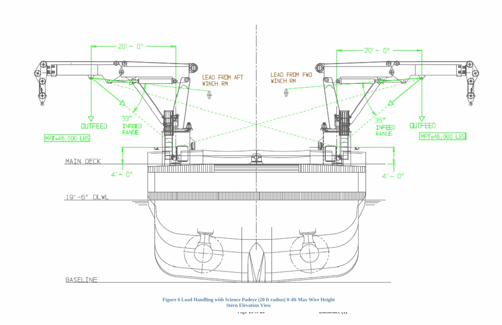
5.1. Figures 5 and 7 depict the MPT and resulting lead angles when the crane is used to support science operations as an over-boarding appliance with the load being supported from the science padeye.
5.2. Lead angles shown are in-feed angles which account for both usage of the permanent mounted ship’s winch systems or portable deck winches mounted in the designated area.
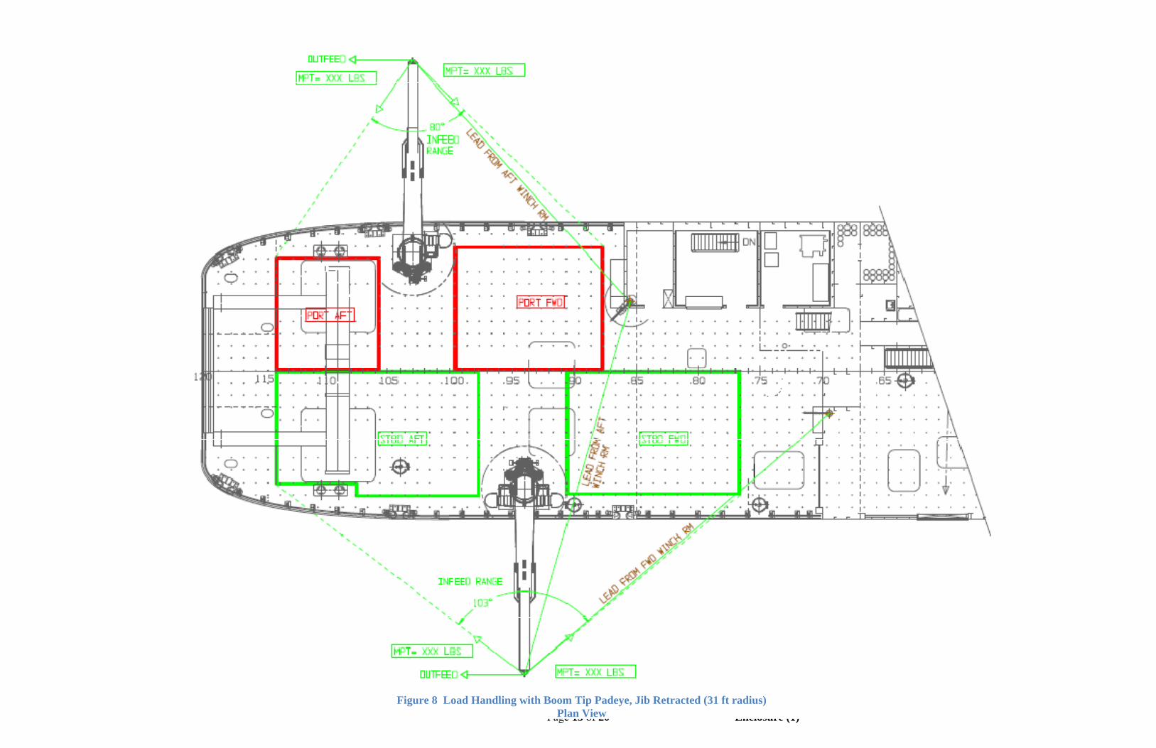
5.3. In Figures 8 through 13 the standard boom tip and two part block has been removed and an alternate boom tip has been attached. The alternate boom tip features a single padeye to support a sheave. The figures depict the MPT and resulting lead angles when the crane is used to support science operations as an over-boarding appliance with the load being handled by external winches and the boom tip supported sheave.
5.3.1. Figures 8 through 10 depict the crane with the boom and jib horizontal and jib fully retracted. With the boom horizontal this provides a maximum reach of 31 ft radius. Figures 9 and 10 depict infeed angles for a wire height of 0-4 ft and 4-8 ft respectively. MPT shown in these figures is to be determined by the Mfg.
5.3.2. Figures11 through 13 depict the crane with the boom and jib horizontal and jib fully extended. With the boom horizontal this provides a maximum reach of 50 ft radius. Figures 12 and 13 depict infeed angles for a wire height of 0-4 ft and 4-8 ft respectively. MPT shown in these figures is to be determined by the Mfg.
5.4. All figures show the cranes positioned fully athwart ship however crane MPT apply for worst case crane positions.

Page 10 of 20 Enclosure (1)
Figure 3 Aft Deck Machinery General Arrangement & Maximum Hook Height
Outboard Elevation View

Page 11 of 20 Enclosure (1)
Figure 4 Aft Deck Machinery General Arrangement & Maximum Hook Reach
Plan View

Page 12 of 20 Enclosure (1)
Figure 5 Load Handling with Science Padeye Plan View
Page 13 of 20 Enclosure (1)
Figure 6 Load Handling with Science Padeye (20 ft radius) 0-4ft Max Wire Height Stern Elevation View

Page 14 of 20 Enclosure (1)
Figure 7 Load Handling with Science Padeye (20 ft radius) 4-8ft Max Wire Height Stern Elevation View
Page 15 of 20 Enclosure (1)
Figure 8 Load Handling with Boom Tip Padeye, Jib Retracted (31 ft radius)
Plan View

Page 16 of 20 Enclosure (1)
Figure 9 Load Handling with Boom Tip Padeye, Jib Retracted (31 ft radius) 0-4ft Max Wire Height Stern Elevation View

Page 17 of 20 Enclosure (1)
Figure 10 Load Handling with Boom Tip Padeye, Jib Retracted (30 ft radius) 4-8 ft Max Wire Height Stern Elevation View

Page 18 of 20 Enclosure (1)
Figure 11 Load Handling with Boom Tip Padeye, Jib Extended (50 ft radius) Plan View

Page 19 of 20 Enclosure (1)
Figure 12 Load Handling with Boom Tip Padeye, Jib Extended (50 ft radius) 0-4 ft Max Wire Height Stern Elevation View

Page 20 of 20 Enclosure (1)
Figure 13 Load Handling with Boom Tip Padeye, Jib Extended (50 ft radius) 4-8 ft Max Wire Height Stern Elevation View


NOTES: + 0+ 0.000
Material cost consists of Appleton quote for overboard load calcs and incorporation into monitoring system, plus additional 200 hours of engineering to complete the MCD.
UAF Estimate
SCHEDULE IMPACT: -
COST TO PREP$: $ 4,493
TOTAL COST $: $77,000
TOTAL DIRECT HRS: 354.8
lbs increase
feet in KG
UAF SSPO
Change Request Summary Sheet
ARRV- Sikuliaq Change Order # CR-034 Aft Cranes MCD
Date: 6/21/2011
MATERIAL $: $45,097
$8,218 PROFIT $:
$23,384 LABOR $:
FCCM $: $301