afosr spring review 2013 test and evaluation (t&e) · • ultra high performance concrete –...
TRANSCRIPT

1 Distribution A: Approved for public release; distribution is unlimited
Integrity Service Excellence
AFOSR Spring Review 2013
Test and Evaluation (T&E)
4 March 2013
Dr. Michael Kendra Program Officer
AFOSR/RTA Air Force Research Laboratory

Report Documentation Page Form ApprovedOMB No. 0704-0188
Public reporting burden for the collection of information is estimated to average 1 hour per response, including the time for reviewing instructions, searching existing data sources, gathering andmaintaining the data needed, and completing and reviewing the collection of information. Send comments regarding this burden estimate or any other aspect of this collection of information,including suggestions for reducing this burden, to Washington Headquarters Services, Directorate for Information Operations and Reports, 1215 Jefferson Davis Highway, Suite 1204, ArlingtonVA 22202-4302. Respondents should be aware that notwithstanding any other provision of law, no person shall be subject to a penalty for failing to comply with a collection of information if itdoes not display a currently valid OMB control number.
1. REPORT DATE 04 MAR 2013 2. REPORT TYPE
3. DATES COVERED 00-00-2013 to 00-00-2013
4. TITLE AND SUBTITLE Test and Evaluation (T&E)
5a. CONTRACT NUMBER
5b. GRANT NUMBER
5c. PROGRAM ELEMENT NUMBER
6. AUTHOR(S) 5d. PROJECT NUMBER
5e. TASK NUMBER
5f. WORK UNIT NUMBER
7. PERFORMING ORGANIZATION NAME(S) AND ADDRESS(ES) Air Force Office of Scientific Research ,AFOSR/RTA,875 N. Randolph,Arlington,VA,22203
8. PERFORMING ORGANIZATIONREPORT NUMBER
9. SPONSORING/MONITORING AGENCY NAME(S) AND ADDRESS(ES) 10. SPONSOR/MONITOR’S ACRONYM(S)
11. SPONSOR/MONITOR’S REPORT NUMBER(S)
12. DISTRIBUTION/AVAILABILITY STATEMENT Approved for public release; distribution unlimited
13. SUPPLEMENTARY NOTES Presented at the AFOSR Spring Review 2013, 4-8 March, Arlington, VA.
14. ABSTRACT
15. SUBJECT TERMS
16. SECURITY CLASSIFICATION OF: 17. LIMITATION OF ABSTRACT Same as
Report (SAR)
18. NUMBEROF PAGES
28
19a. NAME OFRESPONSIBLE PERSON
a. REPORT unclassified
b. ABSTRACT unclassified
c. THIS PAGE unclassified
Standard Form 298 (Rev. 8-98) Prescribed by ANSI Std Z39-18

2 Distribution A: Approved for public release; distribution is unlimited
NAME: Dr. Michael Kendra BRIEF DESCRIPTION OF PORTFOLIO: The T&E program supports basic research which will build the foundation for future revolutionary capabilities that address the identified needs of the T&E Community. LIST SUB-AREAS IN PORTFOLIO: The T&E Program encompasses five broadly-defined, overlapping thrust areas: • Hypersonics • Aerodynamics • Sensors and Electromagnetics • Information and Data Fusion • Enabling Materials.
2013 AFOSR SPRING REVIEW 3002T PORTFOLIO OVERVIEW

3 Distribution A: Approved for public release; distribution is unlimited
T&E: The Science of Test • 2009 – Last T&E Spring Review • AFOSR Technical Strategic Plan • Technology push versus pull – role of PM’s and TD’s • AFRL role – LRIR, STTR, tech transition • T&E Thrust Teams – strengthen and expand • TCTTA – Test Center Technology Transition Advisors
Partnerships and Collaborations • AFTC, 412th TW, 96th TW, AEDC, RCC • AFRL RY, RW, RX, RI • OSD TRMC T&E/S&T Program • UK DSTL T&E • Ultra High Performance Concrete – HSST, AFRL/RW, Army ERDC, DTRA, AFOSR IO • DoD Environmental Security Technology Certification Program ( ESTCP)
T&E Spring Review Summary
relevant environment
(or bigger lab)
lab
system integration

4 Distribution A: Approved for public release; distribution is unlimited
PAYOFF STRATEGY
MOTIVATION 5 Thrust Areas focused on Test Center Missions
• Creation of a network of AFRL S&E partners to support T&E future requirements. • Exploration of parallel scalable computing/quantum
computing using advanced fluid flow algorithms • Transition of new materials that run hotter and last
longer to enhance existing test facilities. • Implementation of techniques for nano-scale
machine, sensor, and electronics measurement and quality assessment
AFOSR Test and Evaluation Overview
• Future air, space and cyber platforms will have integrated materials, sensors and information systems that will exceed present day T&E capabilities
• AF Test Centers will require new technologies to fulfill their mission –
• The speed at which data must be processed and exploited has dramatically increased.
• T&E capabilities must now interweave computational tools into traditional physical testing and analysis capabilities.
AFOSR, AFTC, AEDC, 412TW, 96TW
Enabling Materials
Data &
Information Fusion
Aeroelasticity &
Aerodynamics Hypersonics
Sensors & Electro-
magnetics
• Advanced Test Center capabilities for better, faster, more effective T&E
• Superior intramural T&E capabilities to support future AF systems
• Opportunity to recruit and train the next generation T&E workforce

5 Distribution A: Approved for public release; distribution is unlimited
Aero14%
Hyper15%
I&DM&F31%
Mat9%
Sensors31%
T&E FY12 Thrust Area Investment
CORE8%
Lab Task27%
STTR 132%
STTR 233%
T&E FY12 Investment
AFOSR T&E FY12 Investment
CORE – University Grant STTR – Small Business Technology Transfer LRIR (Labtask) – Laboratory Research Independent Research
T&E FY13 Investment 3 CORE 11 STTR Phase 1 8 LRIR 13 STTR Phase 2

6 Distribution A: Approved for public release; distribution is unlimited
AFOSR discovers, shapes, and champions basic science to profoundly impact the future Air Force
TODAY’S BREAKTHROUGH SCIENCE FOR TOMORROW’S AIR FORCE
AFOSR Mission and Strategic Plan
AFOSR Technical Strategic Plan Strategic Goal 1: Identify opportunities for significant scientific advancements and breakthrough research here and abroad Strategic Goal 2: Rapidly bring to bear the right researchers and resources on these opportunities in the interest of fostering revolutionary basic research for Air Force needs Strategic Goal 3: Enable the Air Force to exploit these opportunities at the appropriate time transitioning revolutionary science to DoD and industry
Distribution A: Approved for public release; distribution is unlimited

7 Distribution A: Approved for public release; distribution is unlimited
Air Force T&E Organization
Secretary of the Air Force
ASAF (Acquisition) Chief of Staff AF/TE PEO
PM AF Materiel Command (AFMC)
AF Operational T&E Center (AFOTEC)
Major Commands (MAJCOM)
T&E Organizations AF Test Center
Logistics Centers
Product Centers
AF Research Laboratory
412 Test Wing Arnold Engineering Development Complex
96 Test Wing
Adapted from DAU TST102 Fundamentals of Test and Evaluation - Test and Evaluation Management p 12 Air Force Test and Evaluation Organization
Test Center Technology Transition Advisors (TCTTAs)
AFOSR LRIR $ LRIR (Labtask) – Laboratory Research Independent Research
AFOSR I 61-7 revised to allow AFRL TD collaborative funding to USAFA, AFIT, and AFMC Test Centers
8 Distribution A: Approved for public release; distribution is unlimited
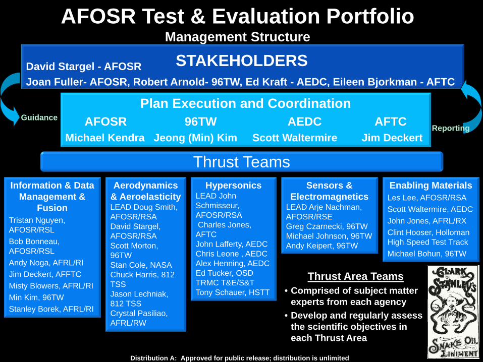
AFOSR Test & Evaluation Portfolio Management Structure
David Stargel - AFOSR Joan Fuller- AFOSR, Robert Arnold- 96TW, Ed Kraft - AEDC, Eileen Bjorkman - AFTC
Plan Execution and Coordination AFOSR 96TW AEDC AFTC
Michael Kendra Jeong (Min) Kim Scott Waltermire Jim Deckert
Guidance Reporting
Enabling Materials Les Lee, AFOSR/RSA Scott Waltermire, AEDC John Jones, AFRL/RX Clint Hooser, Holloman High Speed Test Track Michael Bohun, 96TW
Hypersonics LEAD John Schmisseur, AFOSR/RSA Charles Jones, AFTC John Lafferty, AEDC Chris Leone , AEDC Alex Henning, AEDC Ed Tucker, OSD TRMC T&E/S&T Tony Schauer, HSTT
Aerodynamics & Aeroelasticity LEAD Doug Smith, AFOSR/RSA David Stargel, AFOSR/RSA Scott Morton, 96TW Stan Cole, NASA Chuck Harris, 812 TSS Jason Lechniak, 812 TSS Crystal Pasiliao, AFRL/RW
Sensors & Electromagnetics
LEAD Arje Nachman, AFOSR/RSE Greg Czarnecki, 96TW Michael Johnson, 96TW Andy Keipert, 96TW
Information & Data Management &
Fusion Tristan Nguyen, AFOSR/RSL Bob Bonneau, AFOSR/RSL Andy Noga, AFRL/RI Jim Deckert, AFFTC Misty Blowers, AFRL/RI Min Kim, 96TW Stanley Borek, AFRL/RI
Thrust Teams
Thrust Area Teams • Comprised of subject matter
experts from each agency • Develop and regularly assess
the scientific objectives in each Thrust Area
Distribution A: Approved for public release; distribution is unlimited
STAKEHOLDERS

9 Distribution A: Approved for public release; distribution is unlimited
• Multi-year effort supported by AFOSR T&E and Hypersonics Programs, OSD T&E/S&T HSST
• 3+ faculty, 10-12 students (grad and undergrad)
• Offices and lab co-located at Tunnel 9 in White Oak MD
• Take advantage of unused capacity and piggybacking
• Focus on hypersonics workforce revitalization
• Students starting to exit pipeline (DARPA, Naval Air Warfare Center)
Temp-sensitive paints
Focused Schlieren
Unsteady shocks
Hypersonics Workforce Revitalization UMd and AEDC Tunnel 9
PI Professor Ken Yu University of Maryland
Distribution A: Approved for public release; distribution is unlimited
Best Poster Award

10 Distribution A: Approved for public release; distribution is unlimited
Faculty Workshops
• Research Opportunities Workshops 26-28 June 2012 AFFTC Edwards Air Force Base, CA 24-26 July 2012 46 TW Eglin Air Force Base, FL
• More than 70 research professors and 5-10 students
• Presentations AF T&E leadership and workforce, OSD TRMC T&E/S&T, AFRL, AFIT, U Md, NASA, HR
• Site and facility visits

11 Distribution A: Approved for public release; distribution is unlimited
T&E Collaboration - Rapid Prototyping and Risk Sharing (RAPARS)
University
AFOSR $ 1 yr overlapping
Mini CORE Grant 6.1
Mini LRIR 6.1 (not seedling) AFRL 6.2-6.3 BAA 6.3-6.6
OSD TE/ST Proposal
Test Center Tech Transition
OSD TE/ST $
AF Labs
AFOSR $ 1+ yr overlapping
AF Labs
AFOSR Proposal
AFOSR Proposal
AF Labs
AFRL $ overlapping as needed
Goal – rapid tech transition to Test Centers • Early basic research risk assumed by AFOSR (6.1) • Early applied research risk assumed by AFRL (6.2-6.3) • Advanced applied research risk assumed by OSD T&E/S&T (6.3+)
AFOSR 6.1
AFRL 6.2-6.3
6.3-6.6 OSD
Tunable Diode Laser Absorption Spectroscopy (TDLAS) Temperature Sensor for High Pressure and High Temperature Air • PI Professor Ron Hanson (Stanford U) • Dr. Mike Brown AFRL/RQHS • Ed Tucker, Wade Burfitt, Carrie Reinholtz AEDC

Distribution A: Approved for public release; distribution is unlimited
Mathematical Model Based Control System for Wind Tunnels Dr. Alan Cain, Innovative Technology Applications Company, [email protected]
PI Dr. Mark Rennie, University of Notre Dame, [email protected]
Objective To develop accurate mathematical models for improved control and simulation of wind tunnels.
Neural Networks (NN) ˃ NN are ideal for organizing large databases and for
“extracting” complicated relationships from those databases. ˃ e.g., a NN is used to compute the model drag area CDS from
routinely-measured data. This idea was developed in Phase I and will be experimentally validated in Phase II.
˃ In Phase II, NN will also be used to test for signal failure, and to compute all data required by the mathematical model for model-based control of the wind tunnel.
Phase II Progress (to April 2012) ˃ Mathematical models for wind speed and temperature
behavior have been completed and the test-bed wind tunnel has been instrumented for good control.
˃ A control demonstration is tentatively planned for the mid-term review at the end of 2012.
Model-based Control ˃ Mathematical model is
used to predict required control inputs (i.e. to fan and heat exchanger in this case) for improved control of test-section flow conditions.
˃ Data from wind tunnel sensors are continually acquired during testing and stored in a database, which is used to update neural networks and monitor tunnel performance.
Flow
Mathematical Modeling 1) Divide wind-tunnel circuit into
sections. 2) Apply conservation of mass,
momentum, energy, head-loss, plus auxiliary equations to each component.
3) Combine equations in the sense that the flow exiting each section is equal to the flow entering the section downstream.
4) Time step through the solution, or eliminate time-derivative terms and compute steady-state solution directly.
Approach ˃ Formulate mathematical models to simulate the wind-speed
and temperature behavior of wind tunnels by applying the conservation equations for 1-D constant-property flow.
˃ Acquire a database of wind-tunnel operating conditions, and develop methods to compute parameters required by the mathematical model from the database.
˃ Use neural networks to organize and manipulate the database
˃ Develop error-management methods to protect against noise and signal failure, and integrate the approach into the control system of a wind tunnel.

13 Distribution A: Approved for public release; distribution is unlimited
AFRL Behavioral Model
Physics Based Model
Most accurate model in literature Building blocks for neuromorphic computing
Neuron/ CMOS
Synapse / Memristor
PCB Prototype
Trainable neuromorphic circuit
Synapse / Memristor
Reconfigurable building block
To
Neuromorphic Systems
PI Clare Thiem and Dr. Bryant Wysocki AFRL/RI AFRL Memristor Research
Models for Simulation
AF Patent 8,249,838 AF Patent 7,902,857
AF Patent 8,275,728

14 Distribution A: Approved for public release; distribution is unlimited
Model Development for a Solid State Neural Device Based Energy Management System
McKinley Climatic Laboratory, Eglin AFB
Potential partners include the Environmental Security Technology Certification Program (ESTCP )
Operates 24/7/365 -65 F to 165 F Manual Control Room Ops Rotating Shifts Largest Power Consumer Last Major Upgrade 1990’s Push from AFOSR Push from STTR contractor Push from Norte Dame Push from AFRL/RI Pull from Eglin

15 Distribution A: Approved for public release; distribution is unlimited
• Highly Efficient Powering of Embedded Sensors • Professor Stavros Georgakopoulos, Florida International University • AFOSR HBCU/MI Program
• Strongly Coupled Magnetic Resonance (SCMR) Challenges • Model development • Antennae geometry for maximum efficiency • Conductor material selection • Frequency • Scaling and miniaturization
• T&E Payoff
• Wireless powering of instruments during test • Transmission through most materials (metals, composites, concrete) • Control signal and data transmission • Weight – potential to eliminate miles of wiring during test • Time - potential to reduce test preparation time
Highly Efficient Powering of Embedded Sensors PI Professor Stavros Georgakopoulos, Florida International University

16 Distribution A: Approved for public release; distribution is unlimited
PI Dr. Crystal Pasiliao AFRL/RW TCTTA Jason Lechniak 412 TW Edwards AFB Characterization Of Aero-Structural Interaction (CFD) Expanded: technical contribution PI Dr. Don Dorsey AFRL/RX TCTTA Dr. Jim Nichols AEDC Tools for Nanoelectronics T&E Space Environment Chamber test Andy Keipert 96 TW Eglin AFB – EMP test PI Dr. Kris Kim AFRL/RY TCTTA Jim Deckert 412 TW Edwards AFB Bistatic Radar Cross-Section Benefield Anechoic Chamber test PI Tony Quach AFRL/RY TCTTA Ed Utt 96 TW Eglin AFB High Power & Efficient Waveform-Agile Transmitter Tom Young 412 TW Edwards AFB - T&E/S&T Spectrum Efficiency
AFRL PI and Test Center Technology Transition Advisor Collaboration
Understanding built-up from atomic scale
Materials degradation rates quantified
Assured mission operation

17 Distribution A: Approved for public release; distribution is unlimited
Thank You!
AFR~I

18 Distribution A: Approved for public release; distribution is unlimited
• Novel measurement techniques, materials, and instruments that enable accurate, rapid, and reliable test data collection
• Accurate, fast, robust, integratable models of the aforementioned that reduce requirements to test or help provide greater understanding of test results
• Advanced algorithms and computational techniques that are applicable to new generations of computers
• Advanced algorithms and test techniques that allow rapid and accurate assessment of devices and software to cyber vulnerability
• New processes and devices that increase bandwidth utilization and allow rapid, secure transfer of test data to control facilities during test
• Advanced mathematical techniques that improve design of experiment or facilitate confident comparison of similar but disparate tests
• Advanced models of test equipment and processes that improve test reliability and efficiency
• Basic research in other T&E technical areas that advances the science of test and contributes to the development of knowledge, skills, and abilities (KSA) of the established or emerging AF T&E workforce
2013 AFOSR SPRING REVIEW 3002T PORTFOLIO OVERVIEW

19 Distribution A: Approved for public release; distribution is unlimited
HOW IT WORKS:• Utilize high fidelity unsteady fluid-
structure reaction/ interaction (FSR/FSI) CFD solutions of full-scale airframes on HPC resources.
MAIN ACHIEVEMENTS:• Unsteady, viscous, rigid-body FSR sims
show evidence of shock oscillations, shock-induced separation, & phase lags.
• Unsteady, Euler, FSI sims predict accurate LCO onset speeds with “slowly diverging flutter” behavior.
• Lissajous illustrates non-sinusoidal tracking of Cp w.r.t. A/C motion.
• Wavelets key in identifying localized frequency differences at any point in time
Lissajous Analysis
Structural Response
Wavelet Analysis
Existing theories are insufficient to provide analytical means for direct characterization of aero-structural-induced interactions, such as Limit Cycle Oscillation (LCO). • Methods do not account for aerodynamic
and stiffness nonlinearities; therefore missing the fundamental physics bounding the flutter mechanism.
Limit Cycle Oscillations (LCO’s) are self-sustained oscillations of an airframe that achieve a constant amplitude for stabilized flight conditions.• The fundamental physics of LCO cannot
be characterized by direct theoretical methods.
• Nonlinear behavior requires development of pertinent nonlinear analysis methods.
• Classical linear flutter analyses fail to provide insight into LCO behavior (e.g. onset speed and response amplitude).
• Cannot account for aerodynamic and structural nonlinearities (bounding mechanisms).
• Flight testing is only way to assess LCO characteristics.
Planned Impact• Successful development of advanced
numerical technologies to progress the fundamental understanding of physics associated with and driving aero-structural interactions (ASI).
• Use of high fidelity aerodynamic characterization to quickly, robustly and accurately predict ASI driven events.
• Increased agility, maneuverability, and lethality for weapon development.
Research Goals• New computational-based method
capable of characterizing nonlinear ASI phenomena induced by weapons configurations on fighter aircraft.
• Characterization of flow physics that interact with the structure and contribute to aeroelastic mechanism.
• Feedback into the design of weapons to either avoid or exploit the mechanism.
• Provide the ability to "virtually fly" missions before actual tests.
STAT
US
QU
ON
EW
INSI
GH
TS
QU
AN
TITAT
IVE
IMPA
CT
EN
D-O
F-PHA
SE G
OA
L
x ls
ycoff
U∞
cs
ea
lw
cw
Characterization Of Aero-Structural Interaction Flow-Field Physics
PI Dr. Crystal L. Pasiliao AFRL/RW

20 Distribution A: Approved for public release; distribution is unlimited
Tools for Test and Evaluation of Emerging Nanoelectronics
PI Dr. Donald L. Dorsey AFRL/RX Current Impact• Availability of device cross-sections andnanoscale characterization techniques aresparking joint studies of degradationmechanisms with U. Florida, Ga.Tech, UCSanta Cruz/Purdue and others• Sample preparations techniques developedare broadly applicable for other electronicdevice and materials technologies (beyondGaN High Electron Mobility Transistors(HEMTs)
Long Term Goals• Extend work to other SPM modes (ScanningMicrowave Microscopy, Kelvin ProbeMicroscopy)• Perform systematic studies of damageaccumulation during device operation andmodel the mechanism• Incorporate damage models into in-housedevice simulator• Correlate experimental and model resultswith NDE measurements- Electrical (I-V curves, transconductance, etc.)- Thermal (Raman, IR Camera)- Optical (Photoemission, Photoluminescence)
Planned Impact•Detailed, physically & chemically accuratemodels combined with NDE measurements toenable real-time state assessment ofremaining useful lifetime of nanoelectronics• Eliminate/dramatically reduce anomalies infielded electronics; Improve logistics
Future military systems will depend on high density electronics with sub 100nm feature size (nanoelectronics)Current NDE techniques will not be adequate due to:• Limited spatial resolution • Lack of physicalunderstanding of materials degradationbehavior in operating devices • Relevantdefects not always known (structure,properties, behavior); hard to measure(buried under multiple layers)
Tools exist to develop NDE approach to assess emerging nanoelectronics:• Electronics operational models exist but don’t include degradation mechanisms• Can use these models to correlate NDE measurements to damage buried inside nanoelectronic devices (not accessible to direct measurement)• Missing piece: nanoscale damage detection to discover & model degradation mechanisms • Scanning Probe Microscopy (SPM) and micro-optical techniques can provide this
MAIN ACHIEVEMENTS:
• Routinely cleaving devices by multiple methods (mechanical, polishing, 3-beam ion milling) to surface qualities adequate for useful SPM imaging • Preliminary surface potential measurements made including impact of electrically biasing the device • Preliminary microRaman measurements made on device cross-sections
SHORT TERM GOALS:• Optimize cleaving technique for surface quality –Challenge: smearing of metal contacts across the surface• Explore further surface optimization using low-energyargon ion mill• Validate surface quality using surface potential andelectrostatic force microscopy (EFM)• Use EFM to test for evidence of charge build-up in theGaN buffer layer as suggested in some models as apotential device degradation mechanism• Solve issues with the thermal stability of the cross-sectioned sample for micro-Raman and micro-PLmeasurements
END-O
F-PHASE GO
AL N
EW IN
SIG
HTS
GaN Transistor cross-sectioncreated by a combination ofpolishing and 3-beam Ar ionmilling
~ 5µm
AFM Topology ofGaN Transistor
NDE – Thermoreflectance-based thermal transient imaging of an operating GaN power transistor with 50ns temporal resolution
Surface Potential map for biased GaN transistor
21 Distribution A: Approved for public release; distribution is unlimited
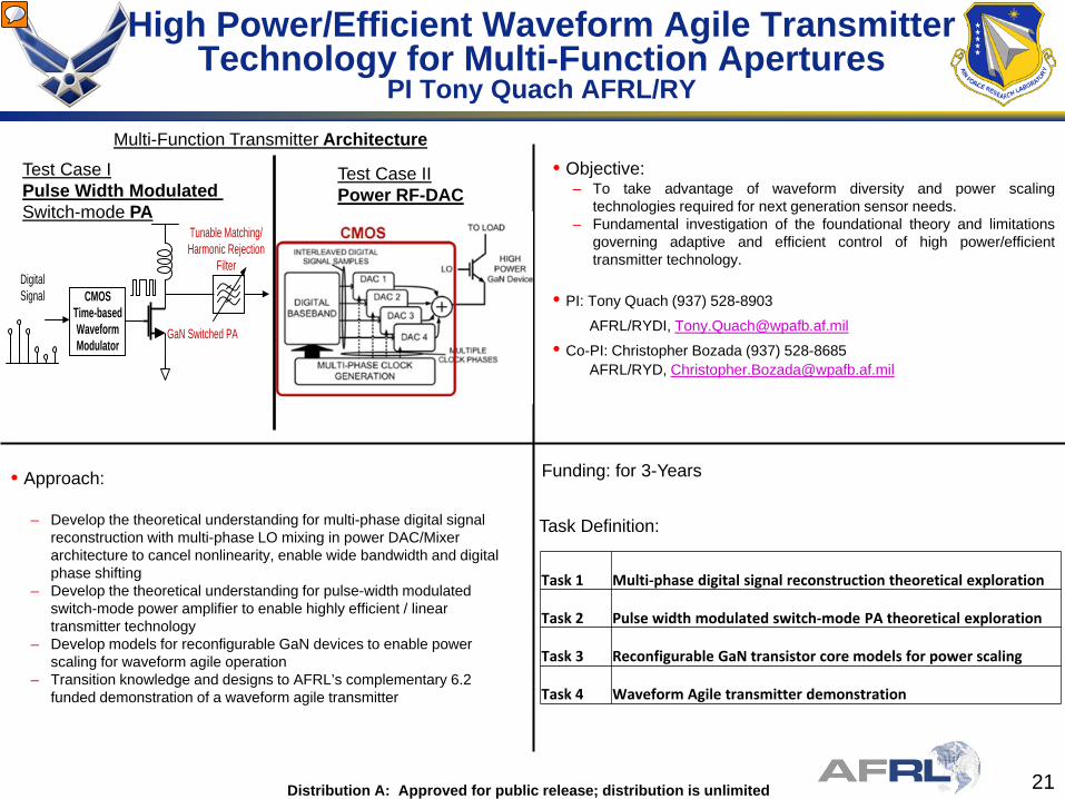
• Objective: – To take advantage of waveform diversity and power scaling
technologies required for next generation sensor needs. – Fundamental investigation of the foundational theory and limitations
governing adaptive and efficient control of high power/efficient transmitter technology.
• PI: Tony Quach (937) 528-8903
AFRL/RYDI, [email protected] • Co-PI: Christopher Bozada (937) 528-8685 AFRL/RYD, [email protected]
• Approach:
– Develop the theoretical understanding for multi-phase digital signal reconstruction with multi-phase LO mixing in power DAC/Mixer architecture to cancel nonlinearity, enable wide bandwidth and digital phase shifting
– Develop the theoretical understanding for pulse-width modulated switch-mode power amplifier to enable highly efficient / linear transmitter technology
– Develop models for reconfigurable GaN devices to enable power scaling for waveform agile operation
– Transition knowledge and designs to AFRL’s complementary 6.2 funded demonstration of a waveform agile transmitter
Funding: for 3-Years
Multi-Function Transmitter Architecture
Task 1 Multi-phase digital signal reconstruction theoretical exploration
Task 2 Pulse width modulated switch-mode PA theoretical exploration
Task 3 Reconfigurable GaN transistor core models for power scaling
Task 4 Waveform Agile transmitter demonstration
Task Definition:
Test Case I Pulse Width Modulated Switch-mode PA
Test Case II Power RF-DAC
GaN Switched PA
Tunable Matching/Harmonic Rejection
Filter
CMOS Time-based Waveform Modulator
Digital Signal
High Power/Efficient Waveform Agile Transmitter Technology for Multi-Function Apertures
PI Tony Quach AFRL/RY

22 Distribution A: Approved for public release; distribution is unlimited
Advanced Computational Methods for Study of Electromagnetic Compatibility
PI Professor Catalin Turc NJIT and Mathematical Systems & Solutions currently be displayed.

Distribution A: Approved for public release; distribution is unlimited
Highly Scalable Computational-Based Engineering Algorithms for Emerging Parallel Machine Architectures • PI Dimitri Mavriplis and Jay Sitaraman • University of Wyoming and Scientific
Simulations LLC Task 1: Investigate hierarchical
parallel partitioning strategies Task 2: Demonstrate combined space-time parallelism (time-spectral or other) Task 3: Implement parallel CSD approaches Task 4: Demonstrate efficient parallel scalability for fully coupled CFD/CSD problem Task 5: Unified programming model for GPU/CPU architectures
Space-time MPI for time spectral method
Scalability of CFD/CSD solver using beam model on AePW model (HIRENASD)
GPU speedup for unstructured mesh solver
Scalability of CFD solver @4000 cpus
HIRENASD Model AIAA Aeroelastic Prediction Workshop (April 2012)

Distribution A: Approved for public release; distribution is unlimited
Nonintrusive Diagnostics for Off-Body Measurements in Flight Experiments Dr. Alan Cain, Innovative Technology Applications Company, [email protected]
PI Dr. Mark Rennie, University of Notre Dame, [email protected]
Objective Develop new methods for in-flight, nonintrusive measurements of off-body, aerothermodynamic flow parameters.
Approach Determine flow parameters from the optical aberrations produced by density variations in the flow, i.e. from “aero-optic” measurements. Generate a reference light source using the emitted light from a laser-induced breakdown (LIB) spark for a fully nonintrusive method. The region of high-temperature air generated by the LIB spark is also used for computation of detailed flow velocities using a “thermal tufting” approach.
Aero-optic measurements “Thermal tufting”
Determined from regional cross-correlation of sequential wavefront measurements through a compressible shear layer
Concept Instruments
Features Measurement
Aero-optic measurements of boundary layer
Regional cross-correlation of
two sequentially-measured aero-optic wavefronts
Convection of high-temperature air created by LIB spark
Intensity of LIB spark Spectrum of LIB spark
Flow Parameter Boundary-layer thickness, freestream density, mean freestream velocity Detailed velocity flow field (for primarily 2-D flows) Local flow velocity Local air pressure Chemical composition of flow Sampling rate using LIB spark is ~200 Hz, but optical measurements up
to ~100 kHz or more can be achieved using a continuous LED beacon.
Detailed Flowfield Measurement Example

Distribution A: Approved for public release; distribution is unlimited
AFOSR STTR Phase I Project FA9550-12-C-0045 (topic AF11-BT25) Computational Model for Electrode Erosion by High-Pressure Moving Arcs
PI: Dr Vladimir Kolobov: CFD Research Corporation – 215 Wynn Drive, Suite 501, Huntsville, AL 35805 Academic Partner: Dr A.Fridman, Dr A.Rabinovich, Drexel Plasma Institute
• Arc heaters provide high-temperature airflows needed for simulating extreme conditions for space vehicles and hypersonic weapon systems
• This project aims to develop theory and validated computational model of electrode erosion by high- pressure moving arcs
• Understand effects of different factors on material removal rates to help increasing lifetime of arc heaters by improved electrode design
Challenges & Innovations • Physics of arc attachment and electrode erosion by
high-pressure moving arcs is poorly understood
• Existing models and computational tools do not take into account all the important factors
• CFDRC Solution: high-fidelity physical models and dynamically adaptive mesh technology for accurate and efficient simulations of arc motion and electrode erosion by the plasma
• Unified multi-phase solver for solid, liquid, gas, and plasma using different physical models for different phases
• Validate and fine-tune models vs experiments
Simulation of moving arc with dynamically adaptive Cartesian mesh
Commercialization • New tool will help better understand electrode erosion process by high-pressure moving arcs
• Help AEDC extend the run time and increase usable lifetime of arc heaters in hypersonic facilities
• Market new tool’s capabilities to DoD and NASA facilities using arc heaters for hypersonic testing and other applications • Offer improved capabilities for simulating multi-phase processes involving gas, plasma, solid and liquid, proven difficult to measure and control experimentally.
Problem & Technical Objectives gliding arc

26 Distribution A: Approved for public release; distribution is unlimited
AFOSR's mission is to discover, shape, and champion basic science that profoundly impacts the future Air Force. Air Force Test Center's mission: "conduct and support research, development, test and evaluation of aerospace systems from concept to combat.“ AEDC mission “Develop, test and evaluate weapon, propulsion, aerodynamic and space systems at realistic conditions for the nation through modeling, simulation and ground test facilities” The 96th TW executes developmental test and evaluation enabling the warfighter to put weapons on target in all battlespace media.
Mission
Distribution A: Approved for public release; distribution is unlimited

27 Distribution A: Approved for public release; distribution is unlimited
96 TW7
AEDC5
412 TW4
AFRL5
NASA1
AFOSR8
T&E Thrust Team Composition
AFOSR T&E Thrust Teams
Hyper AFOSRAFFTCAEDCAEDCAEDCAEDC96 TW
I&DM&F AFOSRAFOSRAFRLAFFTCAFRL96 TWAFRL
Sensors AFOSR96 TW96 TW96 TW
Aero AFOSRAFOSR96 TWNASAAFFTCAFFTCAFRL
Mat AFOSRAFOSRAEDCAFRL96 TW

28 Distribution A: Approved for public release; distribution is unlimited
AF Workforce Pipelines
USAJOBS
AFPC
S&E Graduates
S&E Workforce
AFOSR
ACQ Workforce
DAU Universities
Advanced Degrees
Career path selection and KSA development
Courses