aerostructural optimization of nonplanar lifting surfaces
TRANSCRIPT

Aerostructural Optimization of Nonplanar Lifting Surfaces
Peter W. Jansen∗
University of Toronto, Toronto, Ontario M3H 5T6, Canada
Ruben E. Perez†
Royal Military College of Canada, Kingston, Ontario K7K 7B4, Canada
and
Joaquim R. R. A. Martins‡
University of Michigan, Ann Arbor, Michigan 48109
DOI: 10.2514/1.44727
Nonplanar lifting surfaces can lower the induced drag relative to planar surfaces by redistributing vorticity.Other
sources of drag, such as viscous drag, as well as nonaerodynamic considerations, such as structural weight, also play
an important role in assessing the overall efficiency of such lifting surfaces. In this paperwe solve a series of problems
tofindoptimal nonplanar lifting surfaces and to explain the various factors and tradeoffs at play.Apanelmethod and
an equivalent beam finite-elementmodel are used to explore nonplanar lifting surfaces, while taking into account the
coupling and design tradeoffs between aerodynamics and structures. Both single-discipline aerodynamic
optimization andmultidisciplinary aerostructural optimization problems are investigated. The design variables are
chosen to give the lifting-surface arrangement as much freedom as possible. This is accomplished by allowing a
number of wing segments to vary their area, taper, twist, sweep, span, and dihedral, with the constraint that they
must not intersect each other. Because of the complexity of the resulting design space and the presence of multiple
local minima, an augmented Lagrangian particle swarm optimizer is used to solve the optimization problems.When
only aerodynamics are considered, closed lifting-surface configurations, such as the box wing and joined wing,
are found to be optimal. When aerostructural optimization is performed, a winglet configuration is found to be
optimal when the overall span is constrained, and a wing with a raked wingtip is optimal when there is no such
constraint.
Nomenclature
b = projected wing semispan, ftbi = span of lifting-surface segment i, ftCD = drag coefficientCL = lift coefficientCLcruise = cruise lift coefficientCLmvr
= maneuver lift coefficientCLstall = reference stall lift coefficientc = thrust specific fuel consumption, lb=�lbf-h�cd = airfoil viscous drag coefficientcl = airfoil lift coefficientcr = root chord, ftD = total drag, lbfd = diameter of circular cross section of spar, in.h = projected wing height, fti = ith lifting-surface segmentj = jth vortex panel or beam elementL = total lift, lbfnsegs = number of lifting-surface segmentsRe = local Reynolds numbert = spar wall thickness, inV = cruise speed, ktsWfuel = fuel weight burned during cruise, lbWinitial = initial cruise weight, lb
� = angle of attack, deg� = dihedral angle, deg� = tip twist angle, deg� = leading-edge sweep, deg� = taper� = von Mises stress, ksi�yield = material yield stress, ksi
I. Introduction
N ONPLANAR lifting surfaces can offer significant gains inaerodynamic efficiency relative to conventional planar lifting
surfaces for the same span and lift by lowering the total induced drag[1]. Numerous nonplanar wing concepts have been proposed. Theseconcepts differ in the general arrangement of the lifting-surfacegeometries and the resulting aerodynamic characteristics.
Lift-induced drag is an important factor in the design of aircraft.For conventional airliners at the cruise condition, induced dragaccounts for about 40% of the total drag. One way to reduce induceddrag is to increase the wingspan of the aircraft. However, wingstructural weight increases with the span, negating the reducedinduced drag beyond a certain span. There can also be practicalconstraints on span imposed by the existing airport infrastructure.
One of the first nonplanar wingtip modifications was the additionof an end plate [2,3]. Whitcomb [4] called these end plates wingletsand showed that they improve the lift-to-drag ratiowhen compared towingtip extensions. The wing root bending moment of the two caseswas matched in this study, but the wing was not redesigned.
Flechner and Jones [5] conducted studies on several transportaircraft configurations using the root bending moment to estimatestructural weight. Their conclusion was that “the ratios of the relativeaerodynamic gain over the relative structural weight penalty forwinglets are 1.5 to 2.5 times those for wingtip extensions.” On theother hand, based on a similar investigation, Jones and Lasinski [6]concluded that the addition of a winglet does not provide a decisiveadvantage over a tapered wing extension. This was also the conclu-sion of Asai [7], who included viscous drag in his computational
Received 2 April 2009; revision received 6 May 2010; accepted forpublication 30May 2010. Copyright © 2010 by the authors. Published by theAmerican Institute of Aeronautics and Astronautics, Inc., with permission.Copies of this paper may be made for personal or internal use, on conditionthat the copier pay the $10.00 per-copy fee to theCopyright Clearance Center,Inc., 222RosewoodDrive, Danvers,MA01923; include the code 0021-8669/10 and $10.00 in correspondence with the CCC.
∗Graduate Student, Institute for Aerospace Studies. Student MemberAIAA.
†Assistant Professor, Department of Mechanical and AerospaceEngineering. Member AIAA.
‡Associate Professor, Department of Aerospace Engineering. SeniorMember AIAA.
JOURNAL OF AIRCRAFT
Vol. 47, No. 5, September–October 2010
1490

study, stating that tip extensions can provide a slight improvementover winglets. The reduction of induced drag by winglets is offset bythe addition of wetted area (and hence parasitic drag) that does notcontribute to lift.
Another type of nonplanar lifting-surface configuration is amultiplane arrangement. This includes vertically staggered wings(such as biplanes) and horizontally staggered wings (such as tandemwings). These configurations can exhibit lower induced drag, morelaminar flow, and higher drag divergence Mach numbers [8].However, considerations such as internal fuel volume, structuralweight, and low Reynolds number effects have constrained their usein practice.
Closed configurations such as ring wings [9], box wings [10], andjoined wings [11,12] are other examples of nonplanar lifting-surfaceconfigurations. Closed lifting-surface arrangements aim to reducethe influence of the wingtip vortices. Among all nonplanar config-urations, the box wing has been shown to achieve the minimuminduced drag for a given lift, span, and vertical extent [1,13].C-wings, which can be seen as a compromise between a box-wingand a winglet configuration, provide a reduction in induced drag thatapproaches that of the closed configurations, without the viscousdrag penalty incurred by a large wetted area [14].
Previous efforts in the analysis and optimization of nonplanarlifting surfaces have mostly focused on the aerodynamic aspects ofthese configurations. A systematic optimization of nonplanar liftingsurfaces with the objective of minimizing induced drag wasperformed by Gage [15], which led to the discovery of the C-wingconfiguration.
Two more recent efforts focused on the tradeoff between tipextensions and winglets. The numerical study performed byVerstraeten and Slingerland [16] included viscous drag and rootbending moment for structural considerations. They concluded thatwinglets only provide a benefit for wings with a span constraint andthey did not find C-wings to be advantageous.
Ning and Kroo [17] added area dependency to the weightcalculation and highlighted the fact that the wing loading at themaneuver condition can be significantly different from the cruisecondition wing loading, affecting the tradeoff between theaerodynamics and the structures. They also investigated the effectof viscous drag and stall constraints. They found that when wingswere required to sustain higher maneuver loads, winglets performedslightly better than tip extensions. This study also addressed C-wingsand concluded that they may have slightly lower drag compared towinglets, especially for designs with span constraints.
In spite of all these investigations,morework is needed in this area,since there is still no definite consensus on which wing config-urations are truly optimal. The present work differs from previousefforts in three main aspects.
The first aspect is that this investigation gives as much freedom tothe optimizer as possible. This is accomplished by representing thewing by a number of segments whose area, taper, twist, sweep, span,and dihedral can vary arbitrarily, subject only to a self-intersectionconstraint. The optimization with respect to such a wide range ofdesign variables is made possible by the use of a gradient-freeoptimizer.
The second aspect is that aerostructural deflections are taken intoaccount: Rather than optimizing the flying shape, we optimize the jigshape and compute the aerodynamic performance of the flying shapeat cruise. The structure is sized based on amaneuver condition,whichexhibits yet another wing shape.
Finally, the effect of structural sizing on the design optimization ofthe wing configurations is explored. Structural sizing affects thestiffness of the wing, and thus its flying shape, and its weight as well.This provides the optimizer with the means to exploit aerostructuraltradeoffs by varying structural and aerodynamic design variablessimultaneously.
The aerostructural model used in this work is described in thefollowing section. Twomain sets of results are then presented: a set ofaerodynamic optimizations and a set of aerostructural optimizations.Within each of these sets, the problems differ in the set of designvariables used, the components of drag considered, andwhether span
is constrained. The results of these investigations are summarized inthe last section.
II. Model Description
While high-fidelity methods can provide accurate aerostructuralanalysis [18], limitations in the computational fluid dynamicsvolume grid generation prevent the optimization of generalnonplanar shapes [19]. On the other hand, lower-fidelity models,such as aerodynamic panel methods, can quickly analyze arbitrarynonplanar configurations. Because of the wide range of allowabledesigns in the present work, the problem exhibits multiple localoptima and thus a gradient-free optimization method is used.
A. Aerodynamics
The aerodynamic forces and moments are computed by a panelmethod that is based on potential flow theory and governed byLaplace’s equation [20]. The lifting surfaces and the wake arediscretized in the spanwise direction by vortex rings. The wakevortex rings close at the Trefftz plane. The panel method by itself canonly compute the induced drag.
Viscous drag is a significant fraction of total drag, especiallyduring the cruise segment. The main effect of considering viscousdrag is that it adds a penalty to wetted area increases, particularly forsurfaces that do not contribute to lift, such as winglets. Thus,considering viscous drag is particularly important for anoptimization that allows the wing planform area to vary.
Several approaches can be used to extend the linear aerodynamicmodel to include viscous drag. One such approach consists incoupling the potential flow solver with a boundary-layer solver [20].Amuch less computationally costly approach uses the drag polars forthe airfoil and relates its section lift coefficients to the section dragcoefficients [21]. It is assumed that the viscous drag coefficient of theairfoil varies quadratically with the section lift coefficient [16,17],i.e.,
cd � cd0�Re� � cd1�Re�cl � cd2�Re�c2l (1)
where the three coefficients in this equation depend on the airfoilcharacteristics and the local Reynolds number at the midspan of eachaerodynamic panel. The coefficients are determined by interpolatingthe results for the airfoil at different Reynolds numbers and liftcoefficients.
This approach is validated againstwind tunnel tests for awingwitha NACA 65-210 airfoil. The wing geometry and test conditions arethe same used by Sivellis [22]. The experimental and calculated dragpolars are shown in Fig. 1. The agreement between the experimentaland calculated results is sufficient for our purposes: The root-mean-
Fig. 1 Experimental and calculated drag polar.
JANSEN, PEREZ, AND MARTINS 1491

square error between the experimental data and our estimate is 1.2%.At low lift coefficients, the approximation overpredicts the overalldrag by up to 14.8%. For such low lift coefficients, viscous drag is thedominant part of the total drag and the simple quadratic approxi-mation cannot provide the required accuracy. Discrepancies alsoexist for the high lift-coefficient ranges, since flow separation is notpredicted by the panel method.
B. Structures
The wing structure is modeled using an equivalent beam finiteelement approach. For lifting surfaces, equivalent beam represent-ations have shown to adequately approximate stiffness and deflectionbehavior of the real wing [23,24]. As with the aerodynamic model,the computational cost of this structural model is modest, which is arequirement in the present work. The model uses space beamelements based on Euler–Bernoulli beam theory [25]. Each elementhas two nodes, each of which has 6 degrees of freedom: threedisplacements and three rotations. The spanwise discretization isbased on the same intervals as those of the panel methoddiscretization and thus the total number of vortex panels and beamelements (nelems) is the same. The centroidal axis of the structure canbe specified to be at any chordwise location at a given segmentconnection. Figure 2 shows the geometry of the beam and theaerodynamic panels for a simple wing. The beammodel represents athin-walled circular section sparwith diameterd andwall thickness t.
C. Aerostructural Analysis
To obtain the aerostructural solutions, the aerodynamic analysispasses the external forces to the structural analysis, and the structuresin turn passes the displaced shape of the wing back to theaerodynamic analysis. These force and displacement transfers areperformed using a consistent and conservative scheme [26]. Thesystem is converged using a fixed point iteration. Once theaerostructural analysis has converged, the wing drag and aircraftweight are passed to a module that computes the range. The stressesare computed with another aerostructural analysis at a maneuvercondition. The range and element stresses are returned to theoptimizer to determine the next design step.
D. Optimizer
The design space for nonplanar lifting surfaces is very complexandmay includemultiple local minima [1,15]. Therefore, a gradient-free optimizer that increases the probability of finding the globaloptimum is used. The optimizer is a parallel augmented Lagrangemultiplier particle swarm optimizer (ALPSO), which enforces theconstraints directly [27]. Particle swarm optimization (PSO) isinspired by the social behavior of insects in swarms, who adjust theirflight paths to avoid predators, and to seek the best food sources[28,29]. The PSO algorithm is robust and well suited to handlenonlinear, nonconvex design spaces with discontinuities. Comparedto other global design optimization methods, PSO has been shown torequire fewer function evaluations and to yield results that are betteror at least as good as the other methods [30–32]. Furthermore, formultimodal design spaces, the PSO algorithm is able to simulta-neously find multiple local minima. The results for this paper areobtained by using the ALPSO algorithm run on an SGI Altix parallelcomputer equipped with Intel Itanium processors. To ensure that the
solutions are local minima and to further refine the results, everyproblem is also solved using the gradient-based optimizer SNOPT[33] with the ALPSO result as the starting point.
E. Test Case
We chose to optimize the main lifting surface of a typicalcommercial aircraft at the cruise condition, with an added maneuvercondition at which structural constraints are enforced. Thespecifications for this particular configuration are listed in Table 1and are based on the Boeing 737-900 aircraft. A NACA 64A212airfoil was used for all problems. Note that the geometry constraintsare only enforced in certain optimization problems. Thevariouswingdesign optimization problems and corresponding results arepresented in the following sections.
III. Aerodynamic Optimization
The purpose of solving the aerodynamic optimization problemsthat follow is to compare the results to what has been previouslypublished, in order to validate our approach. In addition, theseaerodynamic optimization results complement the aerostructuralresults presented in a later section by providing a motivation and byhelping explain the final results.
A. Design Variables
The wing is represented by up to four segments. The geometry ofeach segment is defined by six design variables: span, area, taper,twist, sweep and dihedral. The segments must form a continuouslyconnected wing, where the tip chord of each segment is the same asthe root chord of the next segment. The discretization of the wholesurface is performed automatically, for both the aerodynamic paneland beam models. Four possible geometries are shown in Fig. 3 todemonstrate the design freedom allowed in these optimizationproblems.
The leading edge of the first segment root is fixed at the globalcoordinate system’s origin. The addition of new segments is notallowed during the optimization, since this would change the numberof overall designvariables during the optimization process andmightresult in a prohibitively large number of possible configurations.
Using a set of four segments can produce a wide variety ofplanform configurations, while keeping the number of designvariables at a manageable level for a gradient-free method. Thenumber of aerodynamic panels in each segment (which coincideswith the number of structural finite elements) depends on thesegment’s contribution to the overall continuous span. This ensuresthat all aerodynamic panels and structural finite elements have asimilar width, which is desired for these models.
B. Geometric Constraints
Somewing segment arrangements are problematic to solve using apanelmethod. If two panels intersect or a vortex line lies too close to acontrol point, the aerodynamic influence coefficient matrix becomesill-conditioned. In addition, when two panels lie on top of each other(i.e., the relative dihedral between two consecutive panels is180 deg), the linear system of equations no longer has a uniquesolution.
These limitations require the introduction of additional constraintson the planform geometry. Before performing the aerodynamicanalysis for a given design point, the planform geometry is checkedto ensure that wing segments do not intersect or lie on top of eachother and that vortex lines are not too close to a control point.
Designs that fail any of these checks cannot be analyzed using thepanel code and are thus considered infeasible. Such designs arerejected by the ALPSO algorithm. However, the optimizer continuesupdating the swarm information toward feasible designs.
Without geometric or structural constraints, the span tends toincrease indefinitely. If the span is constrained, nothing prevents theheight from increasing indefinitely as well. To ensure that theaerodynamic optimization problems are well posed, the projected
X
0
1020
30
Y
010
2030
4050
Z
0
5
Fig. 2 Aerostructural wing model.
1492 JANSEN, PEREZ, AND MARTINS

span and height are constrained to lie within a bounding box byspecifying a maximum span and a maximum height.
C. Induced Drag
The first optimization problem is the aerodynamic optimization ofrectangular lifting-surface segments for which only lift-induced dragis considered. The optimization problem is formulated as follows:
min�;bi;�i ;�i
Dinduced
subject to
8>>>>>>>>>>><>>>>>>>>>>>:
L� Ltarget
b � 60
h � 12
�15 � � � 15
0 � �i � 190
�15 � �i � 15
(2)
where i� 1; . . . ; nsegs. The twist distribution varies linearly from theroot to the tip for each lifting-surface segment. The lift constraintensures that the wing matches the required total lift. The projectedspan and height constraints ensure that the configuration stays withina bounding box.
Figure 4 shows the optimal configuration for rectangular liftingsurfaces obtained by solving this problem. The optimal configurationis a closed boxwingwithmaximum span and height. This is the sameresult as that predicted by lifting-line theory. The span reduces theinduced drag, and so does the height, by reducing the downwashinduced by the two planar wing segments on each other. The liftdistribution for the obtained wing is shown in Fig. 5a. Both planarwing segments carry approximately the same lift, and the verticalsegment connecting the two planar segments does not contribute tolift. The elliptical lift distribution for the same total lift is also shown.The induced drag of this configuration is 24% lower than an optimalplanar reference wing. This reference wing was obtained by solvingthe optimization problem (2) with the segment dihedrals fixed to
zero. The twist distribution for the lifting-surface segments is shownin Fig. 5b.
D. Compressibility Drag
The optimization problem described above uses only rectangularlifting surfaces and allows the optimizer to change only the span and
X
-60
-40
-20
0
20 Y0
1020
3040
50
Z
0
5
10
X
05
1015
2025
30
Y
05
1015
2025
3035
4045
Z
-15
-10
-5
0
X
05
1015
2025
3035
4045
Y
010
2030
4050
60
Z
0
5
10
X
05
1015
20
Y
010
2030
4050
60Z
0
5
10
Fig. 3 Sample of possible wing geometries.
X
05
1015
20
Y
010
2030
4050
Z
0
5
10
X
0
5
10
15
20
Y0 10 20 30 40 50 60
Y
Z
0
5
10
0 10 20 30 40 50 60
Fig. 4 Minimum-induced-drag solution.
JANSEN, PEREZ, AND MARTINS 1493
dihedral of each lifting-surface segment, but not the overall planformgeometry. To obtain more practical planform geometries for thelifting surfaces that can be used for typical jet airliners, drag due tocompressibility effects is added to the drag computation.
The sweep and taper of each segment are now included as designvariables. Sweep plays a major role in reducing the wave drag.Including taper as a design variable can lead to very small tip chords.These small tip chords can result in high local lift coefficients thatexceed the maximum section lift coefficients. Thus, a lift-coefficientconstraint is added to prevent stall. The new optimization problem isas follows:
min�;bi;�i;�i;�i;�i;
Dinduced �Dcompressibility
subject to
8>>>>>>>>>>>>>>>>>>><>>>>>>>>>>>>>>>>>>>:
L� Ltarget
cljCLstall � clmax
b � 60
h � 12
�15 � � � 15
0 � �i � 190
�15 � �i � 15
�60 � �i � 60
0:05 � �i � 5
(3)
To impose section lift-coefficient constraints, the cl is evaluatedfor each panel at the condition corresponding to a reference stall liftcoefficient CLstall and constrained to be lower than or equal to amaximum lift coefficient of the airfoil, clmax
. If these constraints arenot active, then the wing can produce more lift without stalling.
The root chord of the wing is fixed throughout the optimization.Large chords reduce the section lift coefficient and the local dragcoefficient. If the optimizer were allowed to vary the root chord of thefirst lifting-surface segment, then this would result in unreasonablylarge chords, since there is no penalty for wetted area or structuralweight in this problem. Both sweep and taper are bounded, to keepthem within reasonable ranges. Note that taper is allowed to begreater than one.
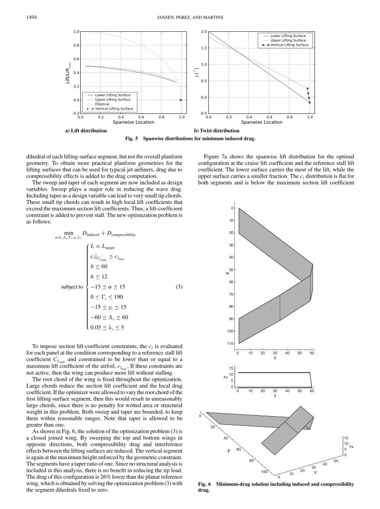
As shown in Fig. 6, the solution of the optimization problem (3) isa closed joined wing. By sweeping the top and bottom wings inopposite directions, both compressibility drag and interferenceeffects between the lifting surfaces are reduced. The vertical segmentis again at themaximum height enforced by the geometric constraint.The segments have a taper ratio of one. Since no structural analysis isincluded in this analysis, there is no benefit in reducing the tip load.The drag of this configuration is 26% lower than the planar referencewing,which is obtained by solving the optimization problem (3)withthe segment dihedrals fixed to zero.
Figure 7a shows the spanwise lift distribution for the optimalconfiguration at the cruise lift coefficient and the reference stall liftcoefficient. The lower surface carries the most of the lift, while theupper surface carries a smaller fraction. The cl distribution is flat forboth segments and is below the maximum section lift coefficient
γ
a) Lift distribution b) Twist distribution
Fig. 5 Spanwise distributions for minimum induced drag.
X
0
20
40
60
80
100 Y0
1020
3040
50
Z
051015
Y0 10 20 30 40 50 60
Y0 10 20 30 40 50 60
Z
0
5
10
15
X50
100
0
40
30
20
10
60
70
80
90
110
Fig. 6 Minimum-drag solution including induced and compressibility
drag.
1494 JANSEN, PEREZ, AND MARTINS

constraint. The twist distribution for the lifting-surface segments isshown in Fig. 7b.
E. Viscous Drag
The optimizations performed so far have considered only inducedand compressibility drag. While including viscous drag has usuallyonly a small effect on the optimal loading on a planar wing, it has apronounced impact when considering nonplanar lifting surfaces. Inthis case, one can add surface area that does not contribute to lift butdecreases induced drag.
The viscous drag is computed by using airfoil data, as explained inSec. II.A, and then added to the total drag. The optimization problemis the same as the previous problem (3), except for the addition of thisnew source of drag and one additional design variable. Since there isnow a penalty for a surface area increase, the root chord of the firstsegment, cr, is included as a design variable.
The solution of this problem is the C-wing shown in Fig. 8. Allsegments are tapered, which reduces the viscous drag for a givenspan. An inspection of the cl distribution at cruise revealed that forsome of the panels around two-thirds of the semispan, the stallconstraint is active. The remaining outboard sections of the mainwing are close to the maximum section lift coefficient.
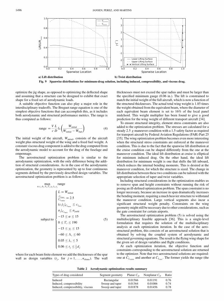
The spanwise lift distribution for the C-wing is shown in Fig. 9a.The top horizontal lifting surface carries a small amount of liftrelative to the main wing. Since the viscous drag is dependent on thesection lift coefficient, this results in low viscous drag from thissegment.
The area of nonplanar segments now carries a viscous dragpenalty, which needs to be offset by a reduction in induced drag. TheC-wing configuration provides an induced drag reduction similar tothat of a box-wing or joined-wing configuration, but significantlyreduces the wetted area of the wing. The root chord is 4% larger thanthe fixed root chord of the previous cases. The larger chords and thetaper of the wing segments can be explained by considering thefactors affecting viscous drag. A larger chord can reduce the drag,since larger Reynolds numbers result in smaller friction dragcoefficients. Theviscous drag coefficient also increases quadraticallywith the section lift coefficient, which is decreased when the chordincreases for a given section lift. On the other hand, the viscous dragincreases with wetted area. These effects work against each other,resulting in a particular optimal chord distribution and total wettedarea.
The C-wing configuration achieves a drag reduction of 22%relative to the optimal planar reference wing. The twist distributionfor the lifting-surface segments is shown in Fig. 7b.A localminimumcorresponding to a wing with a winglet is also found when startingfrom a different set of design points. The drag of the C-wing is 5%lower than the winglet local minimum.
Table 2 summarizes the results for the three different aerodynamicoptimization problems. The drag coefficient values are calculatedwith respect to the fixed reference area for all cases. As previously
explained, the planar wing configuration reference values for eachcase are obtained by solving the respective problem with theadditional restriction that the dihedral for all segments be zero, whichresults in a planar wing in the x-y plane.
IV. Aerostructural Optimization
The aerodynamic optimization results presented in the previoussection are not representative of actual wing design, because theeffect of the spanwise lift distribution on thewing structural weight isnot considered. By modeling the wing structure and optimizing withrespect to structural sizing, we can perform interdisciplinarytradeoffs that are representative. In addition, it is more appropriate to
γ
a) Lift distribution b) Twist distribution
Fig. 7 Spanwise distributions for minimum-drag solution, including induced and compressibility drag.
X
0
20
40 Y
0
20
40
60
Z
0
5
10
Y200 40 60
Z
0
5
10
X
0
20
40
Y200 40 60
Fig. 8 Minimum-drag solution including induced, compressibility, and
viscous drag.
JANSEN, PEREZ, AND MARTINS 1495
optimize the jig shape, as opposed to optimizing the deflected shapeand assuming that a structure can be designed to exhibit that exactshape for a fixed set of aerodynamic loads.
A suitable objective function can also play a major role in theinterdisciplinary tradeoffs. The Breguet range equation is one of thesimplest objective functions that can accomplish this, as it includesboth aerodynamic and structural performance metrics. The range isthus computed as follows:
range � Vc
L
Dln�
Winitial
Winitial �Wfuel
�(4)
The initial weight of the aircraft, Winitial, consists of the aircraftweight plus structural weight of the wing and a fixed fuel weight. Aconstant viscous drag component is added to the drag computed fromthe aerodynamic model to account for the drag of the fuselage andempennage.
The aerostructural optimization problem is similar to theaerodynamic optimization, with the only difference being the addi-tion of structural considerations. As in the case of the aerodynamicoptimization, the geometry is represented by up to four continuoussegments defined by the previously described design variables. Theaerostructural optimization problem is as follows:
max�;cr;bi;�i ;�i;�i;�i;tj
range
subject to
8>>>>>>>>>>>>>>>>>>>>>>><>>>>>>>>>>>>>>>>>>>>>>>:
L�Winitial
CLmvr
CLcruise� 2:5
�cl�jjCLmvr� clmax
�jjCLmvr� �yield
�15 � � � 15
0 � �i � 190
�15 � �i � 15
�60 � �i � 60
0:05 � �i � 5
0:06 � tj � 12dj
(5)
where for each beam finite element we add the thicknesses of the sparwall as design variables (tj, for j� 1; . . . ; nelems). The wall
thicknesses must not exceed the spar radius and must be larger thanthe specified minimum gauge (0.06 in.). The lift is constrained tomatch the initial weight of the full aircraft, which is now a function ofthe structural thicknesses. The actual total wing weight is 1.85 timestheweight obtained from the equivalent beam, where the diameter ofeach equivalent beam element is set to 16% of the local panelmidchord. This weight multiplier has been found to give a goodprediction for the wing weight of different transport aircraft [34].
To ensure structural integrity, element stress constraints are alsoadded to the optimization problem. The stresses are calculated for asteady 2:5 gmaneuver condition with a 1.5 safety factor as requiredfor transport aircraft by Federal Aviation Regulations (FAR) Part 25[35]. Thewing optimization problem becomes evenmore interestingwhen the structural stress constraints are enforced at the maneuvercondition. This is due to the fact that the spanwise lift distribution atthe cruise condition can be shaped differently from the one at themaneuver condition. The ideal lift distribution at cruise is ellipticalfor minimum induced drag. On the other hand, the ideal liftdistribution for minimum weight is one that shifts the lift inboard,which reduces the internal bending moments. This is desired at themaneuver condition, for which the structure is sized. The change inlift distribution between these two conditions can be tailored with theappropriate selection of taper and twist variables.
Including structural considerations in the optimization enables usto remove span and height constraints without running the risk ofposing an ill-defined optimization problem. The span constraint is nolonger necessary, because an increase in span dramatically increasesthe bendingmoment, requiring amuch heavier structure towithstandthe maneuver condition. Large vertical segments also incur asignificant structural weight penalty. Constraints on the winggeometrymight still be necessary due to other considerations, such asthe gate constraint for certain airports.
The aerostructural optimization problem (5) is solved using themultidisciplinary feasible approach [36]. This is a single-levelformulation that requires the solution of the multidisciplinaryanalysis at each optimization iteration. In the case of the aero-structural problem, this consists of an aerostructural solution that isobtained by solving the coupled system of aerodynamic andstructural governing equations. The result is theflyingwing shape forthe given set of design variables and flight conditions.
At each optimization iteration, the objective function andconstraints corresponding to the aerostructural solution are returnedto the optimizer. Note that two aerostructural solutions are required:one at CLcruise and another at CLmvr
. The former yields the range (the
γ
a) Lift distribution b) Twist distribution
Fig. 9 Spanwise distributions for minimum-drag solution, including induced, compressibility, and viscous drag.
Table 2 Aerodynamic optimization results summary
Types of drag considered Segment geometry Planar CD Nonplanar CD Ratio
Induced Rectangular 0.01566 0.01191 0.76Induced, compressibility Sweep and taper 0.01364 0.01006 0.74Induced, compressibility, viscous Sweep and taper 0.01878 0.01456 0.78
1496 JANSEN, PEREZ, AND MARTINS

objective function), and the latter is used to compute the structuralstress constraints.
A. Constrained Span
As mentioned above, a span constraint is no longer required toavoid an ill-defined optimization problem. However, it may be
necessary to impose a span constraint due to airport operationalrequirements. Thus, we solve the aerostructural optimizationproblem (5) with the projected wingspan constraint, b � 60.
1. Induced Drag
This problem is first solved by considering only induced drag inthe aerodynamic analysis. The optimal solution found by theoptimizer is a wing configuration with awinglet, as shown in Fig. 10.The main lifting surface consists of two lifting-surface segments,while the winglet is represented by a single segment. The fourthsegment was removed by the optimizer. Thewinglet is swept and hasa dihedral angle of 76�. Since the projected span is constrained, thisresults in a smaller span for the planar segment than would bepossible for a 90� winglet.
The load distribution, shown in Fig. 11a, is closer to elliptical at thecruise condition, which reduces the induced drag. At the maneuvercondition, the lift is shifted inboard, which alleviates the bendingmoment at the critical flight condition. This reduces the structuralweight of themain segment and offsets theweight incurred by addingthe winglet.
The taper of the lifting surfaces affects the diameters of the beamelements, which are dependent on the local chord. For a taperedsegment the beam is thicker at the root for the same area and can resista higher root bending moment. The sweep of the wing segmentsresults in a reduced loading of the tip and the lift distribution is shiftedinboard, due to the negative twist of the swept beam at higher loadingconditions.
The thickness of the beam elements decreases from the root to thetip, resulting in fully stressed elements, as shown in Figs. 11c and11d, respectively. Only the tip element of the winglet reaches theminimum gauge thickness. The twist distribution is shown inFig. 11b for the jig shape, as well as for the 1 and 2:5 g flight condi-tions. Because of sweep, the wing twist decreases with increasedloading.
X
0
10
20
Y
010
2030
4050
60Z
0
5
Z
0
5
Y0 10 20 30 40 50 60
Y0 10 20 30 40 50 60
X
0
10
20
Fig. 10 Maximum-range solution with span constraint, includinginduced drag.
γ
a) Lift distribution b) Twist distribution
c) Thickness distribution d) Stress distribution
Fig. 11 Spanwise distributions for span-constrained maximum range, including induced drag.
JANSEN, PEREZ, AND MARTINS 1497

2. Viscous and Compressibility Drag
Viscous and compressibility drag are now included. Addingviscous drag decreases the sensitivity of the aircraft performance tochanges in induced drag.Hence, a higher reduction in induced drag is
required to offset the same increase in structural weight, assuming theviscous drag can be kept constant. The optimal solution is again awinglet configuration, as shown in Fig. 12. The height of the wingletis 30% larger when compared to the previous case.
The lift distribution shown in Fig. 13a exhibits a similar behaviorto the previous case. Again, the load is shifted toward the root at themaneuver condition to reduce the bending moment distribution.Since the loading on the winglet is low, its structural thickness isdriven to the minimum gauge value.
The root chord of this configuration is 10% larger than in theprevious case, forwhich only induced drag is considered. Comparingthewing planform shape as awhole, thewing chords are larger, sincethey simultaneously increase the Reynolds number (hencedecreasing the friction drag coefficient) and decrease the sectionlift coefficients (which also decrease the viscous drag). On the otherhand, it does not pay off to increase the chord indefinitely, since theincrease in viscous drag due to increased wetted area eventuallycatches up with these effects. At the same time, an increase in chordresults in an increase in the spar diameter, which allows for a thinnerwall, but beyond a certain diameter, an increase in structural weight isinevitable.
In Sec. III we found that the aerodynamic minimum-dragsolutions, which were span-constrained, were a box wing when onlyinduced drag is considered and a C-wing when viscous drag wasadded. The results in this section show that when structuralconsiderations are added to the span-constrained optimization prob-lem, the solutions for maximum range are winglet configurations.Winglet configurations provide lower drag than the planar config-urations of the same span without adding substantial weight to thewing structure. The box-wing and the C-wing configurations, onthe other hand, addmoreweight than their respective drag reductionscan compensate for. Thus, a winglet configuration provides thebest tradeoff between aerodynamics and structures when span isconstrained.
X
05
1015
2025
30
Y
010
2030
4050
60
Z
0
5
X
0
5
10
15
20
25
30
Y0 10 20 30 40 50 60
Z
0
5
Y0 10 20 30 40 50 60
Fig. 12 Maximum-range solution with span constraint, including
induced, compressibility, and viscous drag.
γ
a) Lift distribution b) Twist distribution
c) Thickness distribution d) Stress distribution
Fig. 13 Spanwise distributions for span-constrained maximum range, including induced, compressibility, and viscous drag.
1498 JANSEN, PEREZ, AND MARTINS

B. Unconstrained Span
The aerostructural optimization problem (5) is also solved with nospan constraint. As before, two problems are compared: oneconsidering only induced drag and another for which viscous drag isadded.
1. Induced Drag
Since there is no constraint in the span, the only factor limiting thespan is the tradeoff between the increase in weight due to an increasein bending moment and the reduction in induced drag.
Figure 14 shows the resulting optimum geometry, which exhibitssegments with increasingly higher sweep toward the tip: i.e., a rakedwingtip. Raked wingtips reduce the induced drag by interacting withthe wing vortex wake, while providing a structural benefit byreducing the tip loads. As in the case of winglets, this effect becomesmore pronounced at the critical maneuver condition, as can be seen inthe lift distribution in Fig. 15a. Because the lift-curve slope decreaseswith sweep, the lift at the rakedwingtip increases less rapidly than theother sections as the angle of attack is increased. This results in aspanwise lift distribution that is structurally more favorable at thehigher angle of attack of the maneuver condition without sacrificingthe cruise lift distribution significantly.
The projected semispan of the raked-wingtip configurationincreases by 18% when compared to the span-constrained solution.
This increase in span results in a higher structural weight but alsohigher aerodynamic efficiency. The range of the raked-wingtipsolution with an unconstrained span is 2% higher than the range ofthe optimal solution with the constrained span.
Another minimum was discovered by the optimizer: the wingletconfiguration whose lift distribution is shown in Fig. 15b. Thisconfiguration produces a more dramatic shift of the lift inboard, andthe span is 9% smaller, which results in an overall reduction instructural weight of 5.1%. The lift-to-drag ratio of the raked wingtipis 1% higher compared to the winglet configuration. A marginallybetter value for the maximum range (0.5% higher) is obtained for theraked-wingtip configuration. The loaded and unloaded twistdistribution of the raked-wingtip configuration is shown in Fig. 16a.The raked segments showvery high twist under increased load due tothe high sweep angle of these segments. The thickness and stressdistributions for the raked-wingtip configuration are shown inFigs. 16b and 16c, respectively. Under the maneuver loadingcondition, all elements are fully stressed except the tip element,which is at the minimum gauge thickness.
2. Viscous and Compressibility Drag
The same optimization problem is now analyzed with viscouseffects included in the drag calculations. Figure 17 shows the optimalwing obtained with this optimization, which again exhibits a rakedwingtip. The raked wingtip incorporates a significantly smallerportion of the overall span compared to the previous case. Thewingtip is highly swept, with a sweep angle of 52�.
As with the induced-drag minimization problem, a local optimumin the form of a winglet configuration was found (see Fig. 18). Thedifference in span between the two configurations is small (3.8%).
As in the previous cases for which viscous drag was considered,the root chords are larger than when only induced drag wasconsidered. The root chords are 11 and 12% larger for the raked-wingtip andwinglet configurations, respectively. This also allows fora larger projected span, since the diameter of the beam elements isdetermined from the local chord of the respective panels. The spanof the raked-wingtip and winglet configurations are 6.2 and 9.3%larger than the respective cases for which only induced drag wasconsidered.
The lift distributions for the raked-wingtip and winglet config-urations are shown in Figs. 19a and 20a, respectively. They show asimilar trend to the previous case. The winglet configurationexperiences a higher loading toward the root of the main wing at themaneuver condition when compared to the raked-wingtip config-uration. The difference between the critical maneuver lift distributionfor the two configurations is small.
All beam elements are fully stressed, except for the tip element,whose stress is just under the material yield stress, as shown inFig. 19d. The winglet beam element thicknesses are reduced to theminimum gauge thickness. The loaded and unloaded twistdistributions for the two configurations are shown in Figs. 19b and
X
05
1015
2025
30
Y
0
20
40
60
Z
0
5
Z
0
5
Y200 40 60
Y200 40 60
X
0
5
10
15
20
25
30
Fig. 14 Maximum-range solution without span constraint, includinginduced drag.
a) Raked-wingtip solution b) Winglet solutionFig. 15 Spanwise lift distributions comparison for maximum-range solutions without span constraint, including induced drag.
JANSEN, PEREZ, AND MARTINS 1499

20b, respectively. The raked wingtip experiences high torsioncompared to the winglet configuration, due to the high sweep. Thisresults in a weight difference between the two configurations that issmaller than when viscous drag is not considered (2.1% versus5.1%). The raked-wingtip configuration has a 2.2% higher lift-to-
drag ratiowhen compared to thewinglet configuration. However, theraked-wingtip configuration results in a higher range.
The numerical results from the different optimization trials aresummarized in Table 3. The structural weights listed in the tablecorrespond to half of the wing and are based on the weight of the
γ
a) Twist distribution b) Thickness distribution
c) Stress distribution
Fig. 16 Spanwise distributions for maximum-range solution (raked wingtip) without span constraint, including induced drag.
X
0
10
20
Y
0
20
40
60
Z
0
5
Z
0
5
Y0 20 40 60
Y
200 40 60
X
0
5
10
15
20
25
Fig. 17 Maximum-range solution (raked wingtip) without span
constraint, including induced, compressibility, and viscous drag.
Y200 40 60
X
0
5
10
15
20
25
Y200 40 60
Z
0
5
10
X
05
1015
2025
Y
0
20
40
60
Z
0
5
10
Fig. 18 Maximum-range solution (winglet) without span constraint,
including induced, compressibility, and viscous drag.
1500 JANSEN, PEREZ, AND MARTINS

γ
a) Lift distribution b) Twist distribution
c) Thickness distribution d) Stress distribution
Fig. 19 Spanwise distributions for maximum-range solution (raked wingtip) without span constraint, including induced, compressibility, and viscous
drag.
γ
a) Lift distribution b) Twist distribution
c) Thickness distribution d) Stress distribution
Fig. 20 Spanwise distributions for maximum-range solution (winglet) without span constraint, including induced, compressibility, and viscous drag.
JANSEN, PEREZ, AND MARTINS 1501

beam model multiplied by the correction factor that was previouslyexplained.
V. Conclusions
In this study we found optimal nonplanar lifting-surfaceconfigurations by solving a series of wing design optimizationproblems. The problems differed in the disciplines that wereconsidered (aerodynamics alone versus aerodynamics and struc-tures), the enforcement of a span constraint, and the types of dragincluded in the aerodynamic model (starting with only induced drag,then adding compressibility drag and viscous drag).
For the aerodynamic optimization, box-wing or joined-wingconfigurations were found to be optimal when only induced dragwasconsidered. When viscous drag was added, these configurationsincurred a drag penalty due to the large surface area, and a C-wingconfiguration was preferred. In all cases, the nonplanarconfigurations provided a significant reduction in drag comparedto the planar reference case. The reduction in drag was similar for allthree cases, ranging from 26% for the joined wing to 22% for theC-wing configuration.
The aerostructural model developed herein accounts for theinteraction between the aerodynamics and the structure of the wing.The jig shape of the wing was designed while taking into account itsflying shape and performance for both cruise and maneuverconditions. Aerodynamic shape and structural sizes were optimized,allowing the optimizer to perform the correct tradeoffs between thetwo disciplines. This was a significant improvement over previousapproaches, where structural performancewas considered by simplyconstraining the root bending moment.
The optimal solution for the aerostructural problem with a spanconstraint was a winglet configuration. The winglet allowed for anear-elliptical lift distribution at the cruise condition, whilealleviating the tip loads by shifting lift distribution inboard at thecritical maneuver condition and hence reducing material needed tosatisfy the stress constraints. At the same time, the winglet providedan aerodynamic advantage by increasing the effective wingspan.
When thewingspan was not constrained, the optimal solution wasa raked-wingtip extension. As in the case of the winglet con-figuration, the lift distribution shifted inboard at the maneuvercondition, but to a lesser degree, resulting in a higher weight than thewinglet configurations. At the same time, the aerodynamic perfor-mance of the extended wing provided a higher lift-to-drag ratio,resulting in a longer range for the raked-wingtip configuration. Thedifference in range between the winglet configuration and the raked-wingtip configuration was only 0.5% for the case in which onlyinduced drag is considered. When viscous drag was included, theraked-wingtip configuration outperformed the winglet configurationby 2.2%.
References
[1] Kroo, I., “NonplanarWing Concepts for Increased Aircraft Efficiency,”Innovative Configurations and Advanced Concepts for Future Civil
Aircraft, VKI Lecture Series, von Karman Inst., Rhode-Saint-Genèse,Belgium, June 6–10 2005.
[2] Hemke, P., “Drag of Wings With End Plates,” NASA, TechnicalReport NASATR 267, 1928.
[3] Mangler, W., “The Lift Distribution of Wings with End Plates,” NASATM 856, 1938.
[4] Whitcomb, R., “ADesign Approach and SelectedWind Tunnel Resultsat High Subsonic Speeds for Wing-Tip Mounted Winglets,”NASATND-8260, 1976.
[5] Flechner, S., and Jacobs, P., “Experimental Results ofWinglets on First,Second, and Third Generation Jet Transports,” CTOL Transport
Technology, Vol. 2, NASA CP-2036-PT-2, Hampton, VA, 1978,pp. 553–569.
[6] Jones, R., and Lasinski, T., “Effect of Winglets on the Induced Drag ofIdeal Wing Shapes,” NASA, TM 81230, 1980.
[7] Asai, K., “Theoretical Considerations in Aerodynamic Effectiveness ofWinglets,” Journal of Aircraft, Vol. 22, No. 7, July 1985, pp. 635–637.doi:10.2514/3.45177
[8] Downie, D., The Complete Guide to Rutan Aircraft, Tab Books, BlueRidge Summit, PA, 1984.
[9] Terry, J., “Aerodynamic Characteristics of Ring Wings: ABibliography,” Redstone Scientific Information Center, Rept. RSIC-285, Redstone Arsenal, AL, 1964.
[10] Miranda, L., “Boxplane Configuration for Conceptual Analysis andInitial Experimental Verification,” Lockheed California Co., Rept. LR25180, Burbank, CA, 1972.
[11] Wolkovitch, J., “The Joined Wing: An Overview,” Journal of Aircraft,Vol. 23, 1986, pp. 161–178.doi:10.2514/3.45285
[12] Lee, H., Kim, Y., Park, G., Kolonay, R., Blair, M., and Canfield, R.,“Structural Optimization of a Joined Wing Using Equivalent StaticLoads,” Journal of Aircraft, Vol. 44, No. 4, 2007, pp. 1302–1308.doi:10.2514/1.26869
[13] Hicken, J. E., “Efficient Algorithms for Future Aircraft Design:Contributions to Aerodynamic Shape Optimization,” Ph.D. Thesis,Univ. of Toronto, Inst. for Aerospace Studies, Toronto, 2009.
[14] McMasters, J., and Kroo, I., “Advanced Configurations for Very LargeTransport Airplanes,” Aircraft Design, Vol. 1, 1998, pp. 217–242.doi:10.1016/S1369-8869(98)00018-4
[15] Gage, P., “New Approaches to Optimization in Aerospace ConceptualDesign,” Ph.D. Thesis, Stanford Univ., Stanford, CA, Dec. 1994.
[16] Verstraeten, J. G., and Slingerland, R., “Drag Characteristics forOptimally Span-Loaded Planar, Wingletted, and C-Wings,” Journal ofAircraft, Vol. 46, No. 3, 2009, pp. 962–971.doi:10.2514/1.39426
[17] Ning, S. A., and Kroo, I., “Multidisciplinary Considerations in theDesign of Wings and Wing Tip Devices,” Journal of Aircraft, Vol. 47,No. 2, 2010, pp. 534–543.doi:10.2514/1.41833
[18] Martins, J., Alonso, J., and Reuther, J., “High-Fidelity AerostructuralDesignOptimization of a Supersonic Business Jet,” Journal of Aircraft,Vol. 41, No. 3, 2004, pp. 523–530.doi:10.2514/1.11478
[19] Johnson, F., Tinoco, E., and Yu, N., “Thirty Years of Development andApplication of CFD at Boeing Commercial Airplanes, Seattle,” AIAAComputational Fluid Dynamics Conference, AIAA Paper 2003-3439,Orlando, FL, June 23–26 2003.
[20] Katz, J., and Plotkin, A., Low-Speed Aerodynamics, 2nd ed.,Cambridge Univ. Press, Cambridge, England, U.K., 2001.
[21] Liersch, C., and Wunderlich, T., “A Fast Aerodynamic Tool forPreliminary Aircraft Design,” 12th AIAA/ISSMO MultidisciplinaryAnalysis and Optimization Conference, AIAA Paper 2000-3901,Victoria, BC, Canada, Sept. 2008.
[22] Sivellis, C., “Experimental and Calculated Characteristics of ThreeWings ofNACA64-210 and 65-210Airfoil Sections,”NACATN1422,1947.
[23] Hajela, P., “PreliminaryWeight Estimation of Conventional and JoinedWings Using Equivalent Beam Models,” Journal of Aircraft, Vol. 25,No. 6, 1988, pp. 574–576.doi:10.2514/3.45625
[24] Kuttenkeuler, J., and Ringertz, U., “Aeroelastic Design Optimizationwith Experimental Verification,” Journal of Aircraft, Vol. 35, No. 3,1998, pp. 505–507.doi:10.2514/2.2330
[25] Przemieniecki, J., Theory of Matrix Structural Analysis, Dover, NewYork, 1985.
[26] Martins, J. R.R.A.,Alonso, J. J., andReuther, J. J., “ACoupled-AdjointSensitivity Analysis Method for High-Fidelity Aero-StructuralDesign,” Optimization and Engineering, Vol. 6, No. 1, March 2005,pp. 33–62.doi:10.1023/B:OPTE.0000048536.47956.62
Table 3 Aerostructural optimization results summary
Weight, lb L=D Range, nm cr, ft b, ft
Span constrained with induced drag
Winglet 7,716 24.69 5,872 19.37 60.0Span constrained with induced and viscous drag
Winglet 6,389 17.74 4,243 21.41 60.0Span unconstrained with induced drag
Winglet 9,795 26.41 5,936 19.14 66.31Raked wingtip 10,330 26.50 5,967 19.39 70.82
Span unconstrained with induced and viscous drag
Winglet 8,877 18.49 4,386 21.43 72.47Raked wingtip 9,064 18.01 4,482 21.59 75.22
1502 JANSEN, PEREZ, AND MARTINS

[27] Perez, R. E., and Behdinan, K., “Particle Swarm Optimization inStructural Design, Swarm Intelligence: Focus on Ant and Particle
SwarmOptimization, 1st ed., I-Tech Education and Publishing, Vienna,Dec. 2007, pp. 373–394.
[28] Eberhart, R., and Kennedy, J., “New Optimizer Using Particle SwarmTheory,” Sixth International Symposium onMicroMachine andHuman
Science, Nagoya, Japan, 1995, pp. 39–43.[29] Kennedy, J., and Eberhart, R., “Particle Swarm Optimization,”
IEEE International Conference on Neural Networks, Vol. 4, Inst.of Electrical and Electronics Engineers, Piscataway, NJ, 1995,pp. 1942–1948.
[30] Hu, X., Eberhart, R., and Shi, Y., “Engineering Optimization withParticle Swarm,” IEEE Swarm Intelligence Symposium 2003 (SIS
2003), Inst. of Electrical and Electronics Engineers, Piscataway, NJ,2003, pp. 53–57.
[31] Perez, R. E., and Behdinan, K., “Particle Swarm Approach forStructural Design,” Computers and Structures, Vol. 85, Oct. 2007,pp. 1579–1588.doi:10.1016/j.compstruc.2006.10.013
[32] Hassan, R., Cohanim, B., de Week, O., and Venter, C., “AComparisonof Particle Swarm Optimization and the Genetic Algorithm,” 1st AIAAMultidisciplinary Design Optimization Specialist Conference, AIAAPaper 2005-1897, Austin, TX, April 2005.
[33] Gill, P.,Murray,W., and Saunders,M., “SNOPT:An SQPAlgorithm forLarge-Scale Constraint Optimization,” SIAM Journal on Optimization,Vol. 12, No. 4, 2002, pp. 979–1006.doi:10.1137/S1052623499350013
[34] Perez, R. E., Jansen, P. W., and Martins, J. R. R. A., “AerostructuralOptimization of Non-Planar Lifting Surfaces,” 12th AIAA/ISSMOMultidisciplinaryAnalysis andOptimizationConference, Victoria, BC,Canada, AIAA Paper 2008-5967, Sept. 2008.
[35] “Airworthiness Standards: Transport Category Airplanes,” FederalAviation Administration, Federal Aviation Regulations, Part 25,Feb. 2009.
[36] Cramer, E. J., Dennis, J. E., Frank, P. D., Lewis, R. M., and Shubin,G. R., “Problem Formulation for Multidisciplinary Optimization,”SIAM Journal on Optimization, Vol. 4, No. 4, 1994, pp. 754–776.doi:10.1137/0804044
JANSEN, PEREZ, AND MARTINS 1503