aerospace linear variable differential transformers … · metallic materials properties...
TRANSCRIPT

Datasheet
Aerospace Linear Variable Differential TransformersSingle Channel, Dual Parallel, & Dual Tandem Series
DESCRIPTIONAerospace Design Engineers working on flight controls, engines, nose wheel steering and pilot control applications have a need for continuous position monitoring. Honeywell’s Linear Variable Differential Transformers (LVDT) provide solutions for each of these applications, and more.
Honeywell’s new aerospace LVDT provides infinite resolution linear position solutions designed for use in harsh environments. They are an ideal product to be used on next generation aircraft which require expedited design cycle time from an experienced, stable supplier with an extensive aerospace product install base.
VALUE TO CUSTOMERS• Pre-validated configurable LVDT platform approach to
reduce design cycle time and get to market faster
• Honeywell has an established legacy of providing high quality products within the aerospace industry
• Reduced installation time by engineering design: rig point position eliminates shimming
FEATURES• Pre-validated platform approach: Single channel, dual
channel, and dual tandem offerings ensure a wide-variety of configurations and applications can be accommodated
• Rig point position eliminates need to shim during installation
• Enhanced reliability: Improved mean time between failure (MTBF) through industry-leading winding techniques, high-strength materials, and industry-leading design
• Supplier stability: Minimizes cost to serve and ensures supply
• Global engineering and application expertise: customers with a global footprint can rest assured that there is local support for new applications and troubleshooting
POTENTIAL APPLICATIONS• Aerospace and defense - Flight controls (PFC/SFC) - Engines (mechanisms/valves) - Nose-wheel steering - Pilot controls
DIFFERENTIATION• Pre-validated configurable platform approach to reduce
cycle time and get to market faster
• Honeywell has a strong legacy of providing high-quality products within the aerospace industry
• Decreased failure rate through industry-leading design
PORTFOLIOHoneywell’s aerospace LVDTs are part of a comprehensive line of aerospace sensors, switches, and value-added solutions. To view Honeywell’s complete product offering, click here.
Sensing and Internet of Things
000820Issue 1

2 sensing.honeywell.com
Aerospace LVDT, Single Channel, Dual Parallel, & Dual Tandem Series
Table 1. SpecificationsCharacteristic Parameter
Product type Aerospace LVDT: linear ac-ac
Range 8,89 mm to 35,56 mm [0.35 in to 1.4 in] stroke
Housing material 17-4 PH stainless steel
Electrical connectors EN2997YE01005MN, M83723/88P1005N, D38999/27YB5XN
Accuracy ±0.5% of the full stroke gain from 0 % to 100 % of the LVDT stroke @ 21 °C [70 °F]
MTBF 1 million hours min.
Current consumption 11 mA max.
Input impedance 650 ohms min. @ 3000 Hz
Output impedance 2000 ohms max. @ 3000 Hz
Mechanical stroke 0,254 mm [0.010 in] (additional to electrical stroke)
Normal operating pressure 2000 psi
Proof pressure 3000 psi
Burst pressure 4000 psi
Pressure cycles 50,000 cycles from 0 psig to 2000 psig @ 200 °C [392 °F]
Altitude sea level to 55000 ft
Life requirements 1,000,000 hours min.
Normal operating temp. range -55 °C to 200 °C [-67 °F to 392 °F]
Full scale gain ±0.5 V/V @ extreme strokes
Phase shift between primary to secondary
15° max. @ room temperature
Phase shift between secondary to secondary
5° max. @ room temperature
Temperature coefficient 0.25 % for every 100 °F change in temperature in addition to 0.5 % room temperature accuracy
Sum voltage (V1+V2) shall be 4.45 VRMS min. to 5.54 VRMS max.
Room temperature 21° C ±5° C [70° F ±10°F]
Insulation resistance 100 megohms min. at 500 Vdc
Mechanical endurance 100,000 mechanical cycles (fully extended-fully retracted-fully extended) min.
Vibration 60 G @ 5 Hz to 2000 Hz
Dielectric strength 1500 V RMS min. at 60 Hz
Excitation 7.07 ±0.14 V RMS sinusoidal wave at 3000 Hz ±50 Hz
Electrical grounding and bonding
5 milliohms max.
Crosstalk less than 0.0010 V/V
Channel tracking less than 0.36 % of full scale at all stroke positions and across normal operating temperature
Weight 0.22 lb to 2.1 lb

Sensing and Internet of Things 3
Aerospace LVDT, Single Channel, Dual Parallel, & Dual Tandem Series
Table 2. Government and Military StandardsDescription Standard
Reliability prediction of electronic equipment MIL-HDBK-217F Notice 2
Environmental Test Methods MIL-STD 810G
Jet A-1 w/Additives and Jet A-1 w/o Additives ASTM D 1655
Requirements for Soldered Electrical and Electronic Assemblies IPC J-STD-001B
Requirements for Electronic Grade Solder Alloys and Fluxed and Non-Fluxed Solid Solders for Electronic Soldering Applicants
IPC J-STD-006
Wire, electrical, fluoropolymer-insulated, cross linked modified ETFE, lightweight, silver-coated, high-strength copper alloy, 200°C, 600 volt
AS22759/33 or Equivalent
Magnet Wire NEMA MW1000
Environmental Conditions and Test Procedures for Airborne Equipment RTCA DO-160G
Metallic Materials Properties Development and Standardization MMPDS
Operating Altitude RTCA-DO-160G, Section 4, Category F3
VibrationRTCA-DO-160G, Section 8, Category R, Curve W with an amplification Q factor of 3
Shock and Crash SafetyRTCA-DO-160G, Section 7.2.1 (operational shock)RTCA-DO-160G, Section 7.3.1 (crash safety impulse)RTCA-DO-160G, Section 7.3.3 (crash safety sustained)
Fungus RTCA-DO-160G, Section 13, Category F
Humidity RTCA-DO-160G, Section 6, Category B
Sand and Dust RTCA-DO-160G, Section 12, Category D
Salt Spray RTCA-DO-160G, Section 14, Category T
Icing RTCA-DO-160G, Section 24, Category A
Water proofness RTCA-DO-160G, Section 10, Category S
Temperature variation RTCA-DO-160G, Section 5, Category A
Temperature shock MIL-STD-810G, Method 503.5 for 100 cycles
Explosive atmosphere RTCA-DO-160G, Section 9, Category E

4 sensing.honeywell.com
Aerospace LVDT, Single Channel, Dual Parallel, & Dual Tandem Series
Figure 1. Single-Channel Product Nomenclature
1LVT
Series
1LVT Aerospace
LVDT
S
Channels
S Singlechannel
A
B
A Threaded
Mounting
Flanged
A
A EN2997YE01005MN
Termination
B
A
A 0.138-32threaded
ProbeFitting Reserved
M83723/88P1005N
C D38999/27YB5XN
D Pigtail (flying leads)
B 0.164-32threaded
035
035 8,89 mm[0.35 in]
Stroke
050 12,7 mm[0.50 in]
070 17,78 mm[0.70 in]
100 25,4 mm[1.0 in]
140 35,56 mm[1.40 in]
1LVT
Series
1LVT Aerospace
LVDT
T
Channels
T Dualtandem
A
B
A Threaded
Mounting
Flanged
D
D Flyingleads
Termination
B
B 0.164-32threaded
ProbeFitting Reserved
035
035 8,89 mm[0.35 in]
Stroke
050 12,7 mm[0.50 in]
070 17,78 mm[0.70 in]
100 25,4 mm[1.0 in]
140 35,56 mm[1.40 in]
1LVT
Series
1LVT Aerospace
LVDT
P
Channels
070
P Dualparallel
A
B
A Threaded
MountingStroke
Flanged
D
A EN2997YE01005MN*
Termination
B
A
A 0.138-32threaded
ProbeFitting Reserved
M83723/88P1005N*
C D38999/27YB5XN*
D Pigtail(flying leads)
B 0.164-32threaded
070 17,78 mm[0.70 in]
100 25,4 mm[1.0 in]
140 35,56 mm[1.40 in]
*only available withflanged mounting type
Figure 2. Dual-Tandem Product Nomenclature
Figure 3. Dual-Parallel Product Nomenclature
Sensing and Internet of Things 5
Aerospace LVDT, Single Channel, Dual Parallel, & Dual Tandem Series
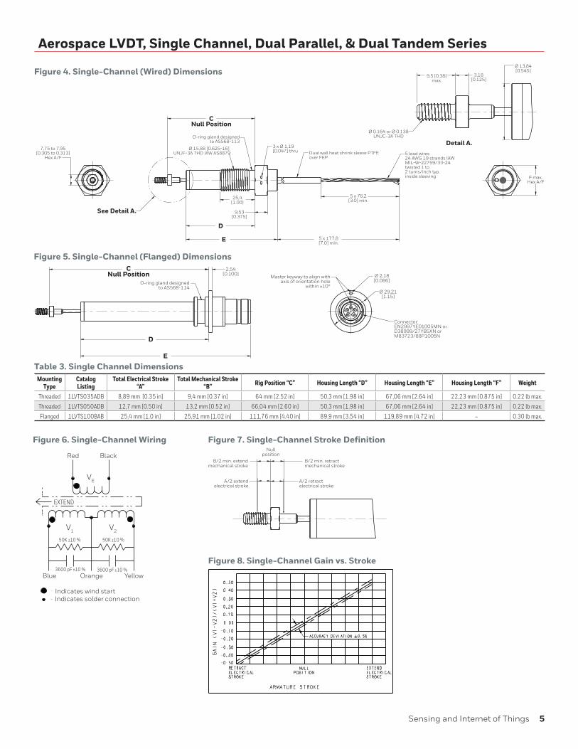
Figure 4. Single-Channel (Wired) Dimensions
Red Black
Blue Orange Yellow
V1 V2
Indicates wind startIndicates solder connection
EXTEND
50K ±10 %50K ±10 %
3600 pF ±10 % 3600 pF ±10 %
VE
Figure 6. Single-Channel Wiring Figure 7. Single-Channel Stroke Definition
Figure 8. Single-Channel Gain vs. Stroke
See Detail A.
D
E
CNull Position
5 x 76,2[3.0] min.
Dual wall heat shrink sleeve PTFEover FEP
5 lead wires24 AWG 19 strands IAWMIL-W-22759/33-24twisted 1 to 2 turns/inch typ.inside sleeving
O-ring gland designedto AS568-113
3 x Ø 1,19[0.047] thru
5 x 177,8[7.0] min.
25,4[1.00]
9,53[0.375]
F max.Hex A/F
7,75 to 7,95[0.305 to 0.313]
Hex A/F
Ø 15,88 [0.625-16] UNJF-3A THD IAW AS8879
Detail A.
Ø 13,84[0.545]
3,18[0.125]
9,5 [0.38]max.
Ø 0.164 or Ø 0.138UNJC-3A THD
Figure 5. Single-Channel (Flanged) DimensionsC
Null PositionO-ring gland designed
to AS568-114
D
E
2,54[0.100] Ø 2,18
[0.086]
Ø 29,21[1.15]
Master keyway to align withaxis of orientation hole
within ±10°
Connector:EN2997YE01005MN orD38999/27YB5XN orM83723/88P1005N
B/2 min. retractmechanical stroke
A/2 retractelectrical stroke
B/2 min. extendmechanical stroke
A/2 extendelectrical stroke
Nullposition
Table 3. Single Channel DimensionsMounting
TypeCatalog Listing
Total Electrical Stroke “A”
Total Mechanical Stroke “B” Rig Position “C” Housing Length “D” Housing Length “E” Housing Length “F” Weight
Threaded 1LVTS035ADB 8,89 mm [0.35 in] 9,4 mm [0.37 in] 64 mm [2.52 in] 50,3 mm [1.98 in] 67,06 mm [2.64 in] 22,23 mm [0.875 in] 0.22 lb max.
Threaded 1LVTS050ADB 12,7 mm [0.50 in] 13,2 mm [0.52 in] 66,04 mm [2.60 in] 50,3 mm [1.98 in] 67,06 mm [2.64 in] 22,23 mm [0.875 in] 0.22 lb max.
Flanged 1LVTS100BAB 25,4 mm [1.0 in] 25,91 mm [1.02 in] 111,76 mm [4.40 in] 89,9 mm [3.54 in] 119,89 mm [4.72 in] – 0.30 lb max.

6 sensing.honeywell.com
Aerospace LVDT, Single Channel, Dual Parallel, & Dual Tandem Series
Figure 9. Dual-Tandem Dimensions mm [in]
Figure 12. Dual-Tandem Gain vs. Stroke
Figure 10. Dual-Tandem Wiring Figure 11. Dual-Tandem Stroke Definition
45° x 0,762 [0.03]
Ø 3,66[0.144]
Ø 4,17 [0.164] UNJC-3A THDrolled thread IAW AS8879
Ø 3,43[0.135]
RodØ 2,03[0.080]
max.
1,52 ±0,05[0.060 ±0.002]
3,18[0.125]
2 x R 0,51 [0.02]
2,23[0.088]
Ø 11,05[0.435]
Ø 13,84[0.545]
25,65[1.01] max.
21,78[0.875] hexacross flats
9,17[0.361]
7,95[0.313]
hex
2 x Ø 21,34[0.84]
9,53[0.375]
Ø 15,88 [0.625-16] UNJF-3A THD IAW AS8879
45° ±5°
9,53[0.375]
32,39[1.275]
46,22[1.82]max.
Channel A
Channel B
2 x dual wall heat shrink sleevePTFE over FEP
10 x 177,8 [7.00] min. 10 x 76,2
[3.00] min.
Ø 13,84[0.545] max.
2 x 5 lead wires24 AWG 19 strands IAWMIL-W-22759/33-24twisted 1 to 2 turns/inch typ.inside sleeving
10 x 177,8 [7.00] min.
10 x 76,2[3.00] min.
Ø 13,84[0.545] max.
Channel AChannel B
2 x dual wall heat shrink sleevePTFE over FEP
2 x 5 lead wires24 AWG 19 strands IAWMIL-W-22759/33-24twisted 1 to 2 turns/inch typ.inside sleeving
See Detail A.
Detail A.
CNull Position
E F
CNull Position
D
Ø 7,95[0.313]
O-ring glanddesigned toAS568-113
O-ring glanddesigned toAS568-114
Red Black Red/White Black/White
Blue Orange Yellow Blue/White
Orange/White
Yellow/White
Channel A Channel B
VEVE
V1 V2 V1 V2
Indicates wind startIndicates solder connection
EXTEND
50K ±10 % 50K ±10 % 50K ±10 %50K ±10 % 50K ±10 %
3600 pF ±10 % 3600 pF ±10 % 3600 pF ±10 % 3600 pF ±10 %
B/2 min. retractmechanical stroke
A/2 retractelectrical stroke
B/2 min. extendmechanical stroke
A/2 extendelectrical stroke
Nullposition
Table 4. Dual-Tandem DimensionsMounting
Type Catalog Listing Total Electrical Stroke “A” Total Mechanical Stroke “B” Rig Position “C” Front Housing Length for
Threaded Config “D”Front Housing Length for
Flanged Config “E”Rear Housing Length for
Flanged Config “F”Threaded 1LVTT140ADB 35,56 mm [1.40 in] 36,07 mm [1.42 in] 168,96 mm [6.652 in] 142,24 mm [5.60 in] – –
Flanged 1LVTT140BDB 35,56 mm [1.40 in] 36,07 mm [1.42 in] 121,97 mm [4.802 in] – 95,25 mm [3.75 in] 93,22 mm [3.67 in] max.
Threaded 1LVTT070ADB 17,78 mm [0.7 in] 18,29 mm [0.72 in] 138,73 mm [5.462 in] 122,43 mm [4.82 in] – –

Sensing and Internet of Things 7
Aerospace LVDT, Single Channel, Dual Parallel, & Dual Tandem Series
Figure 13. Dual-Parallel (Wired) Dimensions
Figure 17. Dual-Parallel Gain vs. Stroke
Figure 15. Dual-Parallel Wiring
Figure 16. Dual-Parallel Stroke Definition
Wire Color
Pin Number Channel A Channel B
1 Red Red
2 Black Black
3 Blue Blue
4 Orange Orange
5 Yellow Yellow
Ø 28,3[1.114]
max.
Channel A
Channel B
11,68[0.46]
O-ring glad designedto AS568-119
0.190-32 UNF-3A THD
2 X 4,06[0.16]
10 x 123[5]
10 x 76,2[3.00] min.
2 x 5 lead wires24 AWG 19 strands IAWMIL-W-22759/33-24twisted 1 to 2 turns/inch typ.inside sleeving
CNull Position
D
Ø 23,1[0.91]max.
Ø 15,21[0.599]
Channelidentification
16,4[0.65]
7,6[0.30]
Probe fitting0.138 or 0.164 UNC thread
2,794 [0.110]A/F socket hex
Figure 14. Dual-Parallel (Flanged) Dimensions
See Detail C.
CNull Position
D
Channelidentification
49,1[1.933]
Master keyway to align withaxis of connector
within 10°
Connector:EN2997YE01005MN orD38999/27YB5XN orM83723/88P1005N
Ø 53,34[2.10]
Ø 6,6 [0.26]thru, equally spaced
55,9 [2.2]max.
Red
Black
Orange
Yellow
Blue
Channel A
Channel B
VE
V1V2
V1V2
Indicates wind startExtendIndicates solder connection
EXTEND 50K ±10 %
50K ±10 %
50K ±10 %
50K ±10 %
3600 pF ±10 %
3600 pF ±10 %
3600 pF ±10 %
3600 pF ±10 %
Red
Black
Yellow
Orange
Blue
Blue
B/2 retractmechanical stroke
A/2 retractelectrical stroke
B/2 extendmechanical stroke
A/2 extendelectrical stroke
Nullposition
Table 5. Dual-Parallel DimensionsMounting
TypeCatalog Listing
Total Electrical Stroke “B”
Total Mechanical Stroke “C” Rig Position “C” Housing Length Weight
Threaded 1LVTP140ADA 35,56 mm [1.40 in] 4,06 mm [0.16 in] 135,1 mm [5.335 in] 100,33 mm [3.95 in] 0.55 lb max.
Flanged 1LVTP070BAA 17,78 mm [0.7 in] 18,29 mm [0.72 in] 94,16 mm [3.707 in] 68,58 mm [2.70 in] 1.00 lb max.

000820-1-EN IL50 GLO May 2017© 2017 Honeywell International Inc. All rights reserved.
m WARNINGPERSONAL INJURYDO NOT USE these products as safety or emergency stop devices or in any other application where failure of the product could result in personal injury.
Failure to comply with these instructions could result in death or serious injury.
m WARNINGMISUSE OF DOCUMENTATION• The information presented in this product sheet is for
reference only. Do not use this document as a product installation guide.
• Complete installation, operation, and maintenance information is provided in the instructions supplied with each product.
Failure to comply with these instructions could result in death or serious injury.
Find out moreHoneywell serves its customers
through a worldwide network
of sales offices, representatives
and distributors. For applica-
tion assistance, current specifi-
cations, pricing or name of the
nearest Authorized Distributor,
contact your local sales office.
To learn more about Honey-
well’s sensing and switching
products,
call +1-815-235-6847 or 1-800-537-6945, visit sensing.honeywell.com, or e-mail inquiries to
ADDITIONAL MATERIALSThe following associated literature is available at sensing.honeywell.com:
• Product range guide
• Installation instructions
• Application Note
• Technical note
Honeywell Sensing and Internet of Things9680 Old Bailes Road
Fort Mill, SC 29707
honeywell.com
Warranty/RemedyHoneywell warrants goods of its manufacture as being free of defective materials and faulty workmanship during the appli-cable warranty period. Honeywell’s standard product warranty applies unless agreed to otherwise by Honeywell in writing; please refer to your order acknowledgment or consult your local sales office for specific warranty details. If warranted goods are returned to Honeywell during the period of coverage, Honeywell will repair or replace, at its option, without charge those items that Honeywell, in its sole discretion, finds defec-tive. The foregoing is buyer’s sole remedy and is in lieu of all other warranties, expressed or implied, including those of merchantability and fitness for a particular purpose. In no event shall Honeywell be liable for consequential, special, or indirect damages.
While Honeywell may provide application assistance personally, through our literature and the Honeywell web site, it is buyer’s sole responsibility to determine the suitability of the product in the application.
Specifications may change without notice. The information we supply is believed to be accurate and reliable as of this writing. However, Honeywell assumes no responsibility for its use.