aeronautical information services aeronautical chart user’s guide terminal … · ·...
TRANSCRIPT

Aeronautical Information Services
Aeronautical Chart User’s Guide
Terminal Procedure Publications
Effective as of 29 March 2018
Federal AviationAdministration


Table of ContentsWHAT’S NEW? ..................................................................................................... 5VFR CHARTS ..............................................................................................................................5IFR ENROUTE CHARTS ............................................................................................................5TERMINAL PROCEDURE PUBLICATIONS (TPPS) ...................................................................5
INTRODUCTION ................................................................................................... 7KEEP YOUR CHARTS CURRENT .............................................................................................7EFFECTIVE DATE OF CHART USER’S GUIDE AND UPDATES ..............................................7COLOR VARIATION ....................................................................................................................7REPORTING CHART DISCREPANCIES ....................................................................................7
U.S. TERMINAL PROCEDURES PUBLICATION ................................................ 9EXPLANATION OF TPP TERMS AND SYMBOLS .....................................................................9INSTRUMENT APPROACH PROCEDURE CHART .................................................................10PLANVIEW ................................................................................................................................16NAVAIDS ...................................................................................................................................19MISSED APPROACH INFORMATION ......................................................................................24PROFILE VIEW .........................................................................................................................25LANDING MINIMUMS ...............................................................................................................28AIRPORT SKETCH ...................................................................................................................30AIRPORT DIAGRAMS ..............................................................................................................31DEPARTURE PROCEDURES (DPs) ........................................................................................33STANDARD TERMINAL ARRIVAL (STARs) CHARTS ..............................................................33CHARTED VISUAL FLIGHT PROCEDURE (CVFP) CHARTS .................................................34
U.S. TERMINAL PROCEDURES PUBLICATION SYMBOLS ........................... 35GENERAL INFORMATION ........................................................................................................35LEGEND - STANDARD TERMINAL ARRIVAL (STAR) CHARTS - DEPARTURE PROCEDURE (DP) CHARTS ....................................................................................................................................35APPROACH LIGHTING SYSTEM .............................................................................................36AIRPORT DIAGRAM/AIRPORT SKETCH ................................................................................38PLANVIEW SYMBOLS..............................................................................................................39PROFILE VIEW .........................................................................................................................41COLD TEMPERATURE AIRPORTS..........................................................................................42
REFERENCES .................................................................................................... 43
ABBREVIATIONS ............................................................................................... 45A ................................................................................................................................................45B ................................................................................................................................................45C ................................................................................................................................................45D ................................................................................................................................................45E ................................................................................................................................................45F ................................................................................................................................................45G ................................................................................................................................................45H ................................................................................................................................................45I..................................................................................................................................................45
3
FAA C
hart User’s G
uide - Table of Contents

K ................................................................................................................................................46L .................................................................................................................................................46M ................................................................................................................................................46N ................................................................................................................................................46O ................................................................................................................................................46P ................................................................................................................................................46R ................................................................................................................................................46S ................................................................................................................................................46T ................................................................................................................................................47U ................................................................................................................................................47V ................................................................................................................................................47W ...............................................................................................................................................47
Table of Contents
4
FAA
Cha
rt U
ser’s
Gui
de -
Tabl
e of
Con
tent
s

WHAT’S NEW?Update as of 29 March 2018
A new feature to the Chart User’s Guide is this What's New section which will highlight new charting symbology and other changes to charts.
The following charting items have been added to the Online Chart User’s Guide since the Guide was last published on 1 February 2018:
VFR CHARTS
No Changes Applied
IFR ENROUTE CHARTS
No Changes Applied
TERMINAL PROCEDURE PUBLICATIONS (TPPS)
BRIEFING STRIP INFORMATION
Procedure Equipment Requirements Notes Box
Addition of equipment requirements notes box to the IAP briefi ng strip. For more information see TPP Terms > Briefi ng Strip Information > Middle Briefi ng Strip > Notes Box section.
(Single Equipment Box) (Two Equipment Boxes)
5
FAA C
hart User’s G
uide - What’s N
ew

6
FAA
Cha
rt U
ser’s
Gui
de -
Wha
t’s N
ew

INTRODUCTIONThis Chart User's Guide is an introduction to the Federal Aviation Administration's (FAA) aeronautical charts and publica-tions. It is useful to new pilots as a learning aid, and to experienced pilots as a quick reference guide.
The FAA is the source for all data and information utilized in the publishing of aeronautical charts through authorized publishers for each stage of Visual Flight Rules (VFR) and Instrument Flight Rules (IFR) air navigation including training, planning, and departures, enroute (for low and high altitudes), approaches, and taxiing charts. Digital charts are available online at:
• VFR Charts - https://www.faa.gov/air_traffi c/fl ight_info/aeronav/digital_products/vfr/• IFR Charts - https://www.faa.gov/air_traffi c/fl ight_info/aeronav/digital_products/ifr/• Terminal Procedures Publication - http://www.faa.gov/air_traffi c/fl ight_info/aeronav/digital_products/dtpp/• Chart Supplements - https://www.faa.gov/air_traffi c/fl ight_info/aeronav/digital_products/dafd/
Paper copies of the charts are available through an FAA Approved Print Provider. A complete list of current providers is available at http://www.faa.gov/air_traffi c/fl ight_info/aeronav/print_providers/
The FAA Aeronautical Information Manual (AIM) Pilot/Controller Glossary defi nes in detail, all terms and abbreviations used throughout this publication. Unless otherwise indicated, miles are nautical miles (NM), altitudes indicate feet above Mean Sea Level (MSL), and times used are Coordinated Universal Time (UTC).
The Notices to Airmen Publication (NOTAM) includes current Flight Data Center (FDC) NOTAMs. NOTAMs alert pilots of new regulatory requirements and refl ect changes to Standard Instrument Approach Procedures (SIAPs), fl ight restrictions, and aeronautical chart revisions. This publication is prepared every 28 days by the FAA, and is available by subscription from the Government Printing Offi ce. For more information on subscribing or to access online PDF copy, http://www.faa.gov/air_traffi c/publications/notices/
In addition to NOTAMs, the Chart Supplement and the Safety Alerts/Charting Notices page of the Aeronautical Information Services website are also useful to pilots
KEEP YOUR CHARTS CURRENT
Aeronautical information changes rapidly, so it is impor-tant that pilots check the effective dates on each aeronau-tical chart and publication. To avoid danger, it is important to always use current editions and discard obsolete charts and publications.
To confi rm that a chart or publication is current, refer to the next scheduled edition date printed on the cover. Pilots should also check Aeronautical Chart Bulletins and NOTAMs for important updates between chart and publi-cation cycles that are essential for safe fl ight.
EFFECTIVE DATE OF CHART USER’S GUIDE AND UPDATES
All information in this guide is effective as of 29 March 2018. All graphics used in this guide are for educational purposes. Chart symbology may not be to scale. Please do not use them for fl ight navigation.
The Chart User’s Guide is updated as necessary when there is new chart symbology or changes in the depiction of information and/or symbols on the charts. When there are changes, it will be in accordance with the 56-day aeronautical chart product schedule.
COLOR VARIATION
Although the digital fi les are compiled in accordance with the charting specifi cations, the fi nal product may vary slightly in appearance due to differences in printing techniques/pro-cesses and/or digital display techniques.
REPORTING CHART DISCREPANCIES
Your experience as a pilot is valuable and your feedback is important. We make every effort to display accurate informa-tion on all FAA charts and publications, so we appreciate your input. Please notify us concerning any requests for changes, or potential discrepancies you see while using our charts and related products.
FAA, Aeronautical Information ServicesCustomer Operations Team1305 East-West HighwaySSMC4 Suite 4400Silver Spring, MD 20910-3281
Telephone Toll-Free 1-800-638-8972E-mail: [email protected]
7
FAA C
hart User’s G
uide - Introduction

8
FAA
Cha
rt U
ser’s
Gui
de -
Intro
duct
ion

U.S. TERMINAL PROCEDURES PUBLICATIONThe U.S. Terminal Procedures Publication (TPPs) includes the Instrument Approach Procedures (IAPs), Departure Proce-dures (DPs) charts, Standard Terminal Arrival (STAR) charts, Charted Visual Flight Procedure (CVFP) charts, and Airport Diagrams. Also included are Takeoff Minimums, (Obstacle) Departure Procedures, Diverse Vector Area (RADAR Vectors), RADAR and Alternate Minimum textual procedures.
EXPLANATION OF TPP TERMS AND SYMBOLS
The information and examples in this section are based primarily on the IFR (Instrument Flight Rules) Terminal Proce-dures Publication (TPP). The publication legends list aeronautical symbols with a brief description of what each symbol depicts. This section will provide more detailed information of some of the symbols and how they are used on TPP charts.
FAA Terminal charts are prepared in accordance with specifi cations of the Interagency Air Committee (IAC) and their sup-porting technical groups for the purpose of standardization, which are approved by representatives of the Federal Aviation Administration (FAA), and the Department of Defense (DoD).
The Terminal Procedure Publication is made up of the following charts:
• Instrument Approach Procedure (IAP) Charts• Airport Diagrams• Departure Procedures (DP)• Standard Terminal Arrival (STAR) Charts• Charted Visual Flight Procedure (CVFP) Charts
9
FAA C
hart User’s G
uide - Terminal P
rocedures Publication (TP
P) - Term
s

INSTRUMENT APPROACH PROCEDURE CHART
The IAPs (charts) are divided into various sections:
Margin Identifi cation Information Profi le View Briefi ng Strip Information Landing Minimums Planview Airport Sketch Missed Approach Information
Pla
nv
iew
Bri
efi
ng
Str
ip
Info
rma
tio
n
Pro
file
La
nd
ing
Min
imu
ms
Ma
rgin
Id
en
tifi
cati
on
Info
rma
tio
n
Air
po
rt
Sk
etc
hNOT FOR NAVIGATION
SE
-3 , 03 MA
R 2 01 6 to 3 1 M
AR
2016S
E-3
, 03
MA
R 2
016
to 3
1 M
AR
201
6
10
FAA
Cha
rt U
ser’s
Gui
de -
Term
inal
Pro
cedu
res
Pub
licat
ion
(TP
P) -
Ter
ms

Margin Identifi cation Information
The margin identifi cation at the top, bottom, and sides of the chart provides information about the airport location, proce-dure identifi cation, and chart currency. The charts are organized by city fi rst, then airport name and state, with the excep-tion of military charts, which are organized by airport name. Going from the top of the chart, reading from left to right, and going down the chart, Margin Identifi cation Information is organized in the following way.
Top Margin Information:
The city and state with which the airport is associated is located on both the top and bottom margins.
At the center of the top margin is the FAA numbering system. This Approach and Landing (AL) number is followed by the organization responsible for the procedure in parentheses, e.g., AL-18 (FAA), AL-227 (USAF).
The procedure title is located on both the top and bottom margins. It is derived from the type of navigational facility that is providing the fi nal approach course guidance. The title is abbreviated, e.g. ILS, RNAV, NDB, etc. For airports with parallel runways and simultaneous approach procedures, “L”, “R” or “C” follows the runway number to distinguish between left, right, and center runways.
11
FAA C
hart User’s G
uide - Terminal P
rocedures Publication (TP
P) - Term
s

The airport name is shown on both the top and bottom margins below the procedure title. The airport identifi er is shown in parentheses following the airport name. Airports outside the contiguous United States will be shown with the FAA desig-nated identifi er followed by the ICAO location identifi er.
The Date of Latest Revision is shown on the top margin above the procedure title. The Date of Latest Revision identifi es the Julian date the chart was last revised for any reason. The fi rst two digits indicate the year, the last three digits indicate the day of the year (001 to 365/6).
Year|Day of Year
Side Margin Information:
The side margins show the volume identifi cation, i.e. SW-3, followed by the current issue date and the next issue date, e.g. SW-3, 21 JUL 2016 to 15 SEP 2016.
Bottom Margin Information:
The FAA Procedure Amendment Number, located on the left bottom margin below the City, State, represents the most current amendment of a given procedure. The Procedure Amendment Effective Date represents the AIRAC cycle date on which the procedure amendment was incorporated into the chart. Updates to the amendment number and effective date represent procedural/criteria revisions to the charted procedure, e.g., course, fi x, altitude, minima, etc.
Example: Original Procedure Date
Example: Amendment Procedure Date
The coordinates for the airport reference point are located at the center of the bottom margin.
BRIEFING STRIP INFORMATION
At the top of every TPP is the Briefi ng Strip which consists of three stacked strips of information immediately above the planview. Information varies depending upon the type of procedure.
Top Briefing Strip
Middle Briefing Strip
Communications Briefing Strip
12
FAA
Cha
rt U
ser’s
Gui
de -
Term
inal
Pro
cedu
res
Pub
licat
ion
(TP
P) -
Ter
ms

Top Briefi ng Strip
The top briefi ng strip contains procedural information in three separate boxes, in the following sequence from left to right:
1 2 3
NAVAIDInfo
• Box 1: Primary Procedure Navigation Information: The primary navigation type (VOR, LOC, NDB, RNAV, etc.) with its identifi er and frequency/channel. If applicable, WAAS, the WAAS Channel Number, and the WAAS Refer-ence Path indicator are shown stacked top to bottom. If the primary navigation type is LAAS, then the following information is shown, stacked top to bottom: LAAS, CH NNNN, RPI XXXX. If there is not a primary Navigation Box required, the fi rst box is removed.
• Box 2: Final Approach Course Information. The inbound Approach Course (APP CRS) is shown.
• Box 3: Runway Landing Information: Stacked top to bottom, the runway landing distance (Rwy Ldg), the Touchdown Zone Elevation (TDZE) or Threshold Elevation (THRE), and the Airport Elevation (Apt Elev) are shown. Rwy Ldg may not refl ect full runway length due to displaced thresholds and shorter declared distances.
Top Briefi ng Strip Examples:
Ground based NAVAID:
RNAV-WAAS:
LAAS:
No Primary NAVAID box:
Circling Approach:
13
FAA C
hart User’s G
uide - Terminal P
rocedures Publication (TP
P) - Term
s

Sidestep Procedure:
Middle Briefi ng Strip
The middle briefi ng strip may contain information in up to three separate boxes, when available, in the following sequence from left to right:
1 2 3
NOTES BOXMISSED APPROACH
PROCECURE TEXT BOX
APPROACH
LIGHTING
SYSTEM
• Box 1: Notes Box: contains procedure notes, Equipment/Requirements Notes box and Takeoff, Alternate, RA-DAR, WAAS, and/or Cold Weather indicators (details provided below under Notes Box).
• Box 2: Approach Lighting System Box (when applicable): shows the approach lighting system name and charting icon. Multiple approach lighting systems may be shown for approaches that have straight-in minimums for parallel runways.
• Box 3: Missed Approach Procedure Text Box: The full textual description of the missed approach procedure is provided here.
Notes Box
Procedure Equipment Requirements Notes Box
Users will begin to see Performance-Based Navigation (PBN) Requirements and ground-based Equipment Requirements prominently displayed in separate, standardized notes boxes. For procedures with PBN elements, the PBN box will con-tain the procedure’s navigation specifi cation(s); and, if required: specifi c sensors or infrastructure needed for the naviga-tion solution; any additional or advanced functional requirements; the minimum Required Navigation Performance (RNP) value and any amplifying remarks. Items listed in this PBN box are REQUIRED. The separate Equipment Requirements Box will list ground-based equipment requirements.
On procedures with both PBN elements and ground-based equipment requirements, the PBN requirements box will be listed fi rst.
14
FAA
Cha
rt U
ser’s
Gui
de -
Term
inal
Pro
cedu
res
Pub
licat
ion
(TP
P) -
Ter
ms
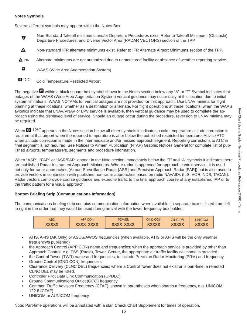
Notes Symbols
Several different symbols may appear within the Notes Box:
Non-Standard Takeoff minimums and/or Departure Procedures exist. Refer to Takeoff Minimum, (Obstacle) Departure Procedures, and Diverse Vector Area (RADAR VECTORS) section of the TPP
Non-standard IFR alternate minimums exist. Refer to IFR Alternate Airport Minimums section of the TPP.
Alternate minimums are not authorized due to unmonitored facility or absence of weather reporting service.
WAAS (Wide Area Augmentation System)
Cold Temperature Restricted Airport
The negative within a black square box symbol shown in the Notes section below any “A” or “T” Symbol indicates that outages of the WAAS (Wide Area Augmentation System) vertical guidance may occur daily at this location due to initial system limitations. WAAS NOTAMs for vertical outages are not provided for this approach. Use LNAV minima for fl ight planning at these locations, whether as a destination or alternate. For fl ight operations at these locations, when the WAAS avionics indicate that LNAV/VNAV or LPV service is available, then vertical guidance may be used to complete the ap-proach using the displayed level of service. Should an outage occur during the procedure, reversion to LNAV minima may be required.
When appears in the Notes section below all other symbols it indicates a cold temperature altitude correction is required at that airport when the reported temperature is at or below the published restricted temperature. Advise ATC when altitude correction is made in the intermedicate and/or missed approach segment. Reporting corrections to ATC in fi nal segment is not required. See Notices to Airmen Publication (NTAP) Graphic Notices General for complete list of pub-lished airports, temperature/s, segments and procedure information.
When “ASR”, “PAR” or “ASR/PAR” appear in the Note section immediately below the “T” and “A” symbols it indicates there are published Radar Instrument Approach Minimums. Where radar is approved for approach control service, it is used not only for radar approaches (Airport Surveillance Radar [ASR] and Precision Approach Radar [PAR]) but is also used to provide vectors in conjunction with published non-radar approaches based on radio NAVAIDs (ILS, VOR, NDB, TACAN). Radar vectors can provide course guidance and expedite traffi c to the fi nal approach course of any established IAP or to the traffi c pattern for a visual approach.
Bottom Briefi ng Strip (Communications Information)
The communications briefi ng strip contains communication information when available, in separate boxes, listed from left to right in the order that they would be used during arrival with the tower frequency box bolded:
• ATIS, AFIS (AK Only) or ASOS/AWOS frequencies (when available, ATIS or AFIS will be the only weather frequency/s published)
• the Approach Control (APP CON) name and frequencies; when the approach service is provided by other than Approach Control, e.g. FSS (Radio), Tower, Center, the appropriate air traffi c facility call name is provided.
• the Control Tower (TWR) name and frequencies, to include Precision Radar Monitoring (PRM) and frequency• Ground Control (GND CON) frequencies• Clearance Delivery (CLNC DEL) frequencies; where a Control Tower does not exist or is part-time, a remoted
CLNC DEL may be listed.• Controller Pilot Data Link Communication (CPDLC)• Ground Communications Outlet (GCO) frequency• Common Traffi c Advisory Frequency (CTAF), shown in parentheses when shares a frequency, e.g. UNICOM
122.8 (CTAF)• UNICOM or AUNICOM frequency
Note: Part-time operations will be annotated with a star. Check Chart Supplement for times of operation.15
FAA C
hart User’s G
uide - Terminal P
rocedures Publication (TP
P) - Term
s

PLANVIEW
The planview of the IAP charts provides an overhead view of the entire instrument approach procedure.
The data on the planview is shown to scale, unless concentric rings, scale breaks or an inset have been used.
Approach Segments Hydrography NAVAIDs International Boundary Restrictive Airspeeds Obstacles (Man-made, Terrain and Vegetation) Restrictive Altitudes Special Use Airspace Holding Patterns and Procedure Turns Minimum Safe Altitude Airports Terminal Arrival Areas Relief (Terrain Features)
Approach Segments
The planview includes a graphical depiction of procedure entry through missed approach.
NE
-3 , 18 AU
G 2 01 6 to 15 S
EP
2016N
E- 3
, 18
AU
G 2
0 16
to 1
5 S
EP
201
6
NOT FORNAVIGATION
Sample IAP ExampleLegend
Feeder Route Initial Approach Intermediate Approach Final Approach Course Missed Approach
16
FAA
Cha
rt U
ser’s
Gui
de -
Term
inal
Pro
cedu
res
Pub
licat
ion
(TP
P) -
Ter
ms
SW
- 1, 1 8 AU
G 2 01 6 to 15 S
EP
2 0 16S
W-1
, 18
AU
G 2
016
to 1
5 S
EP
201
6
NOT FOR NAVIGATION
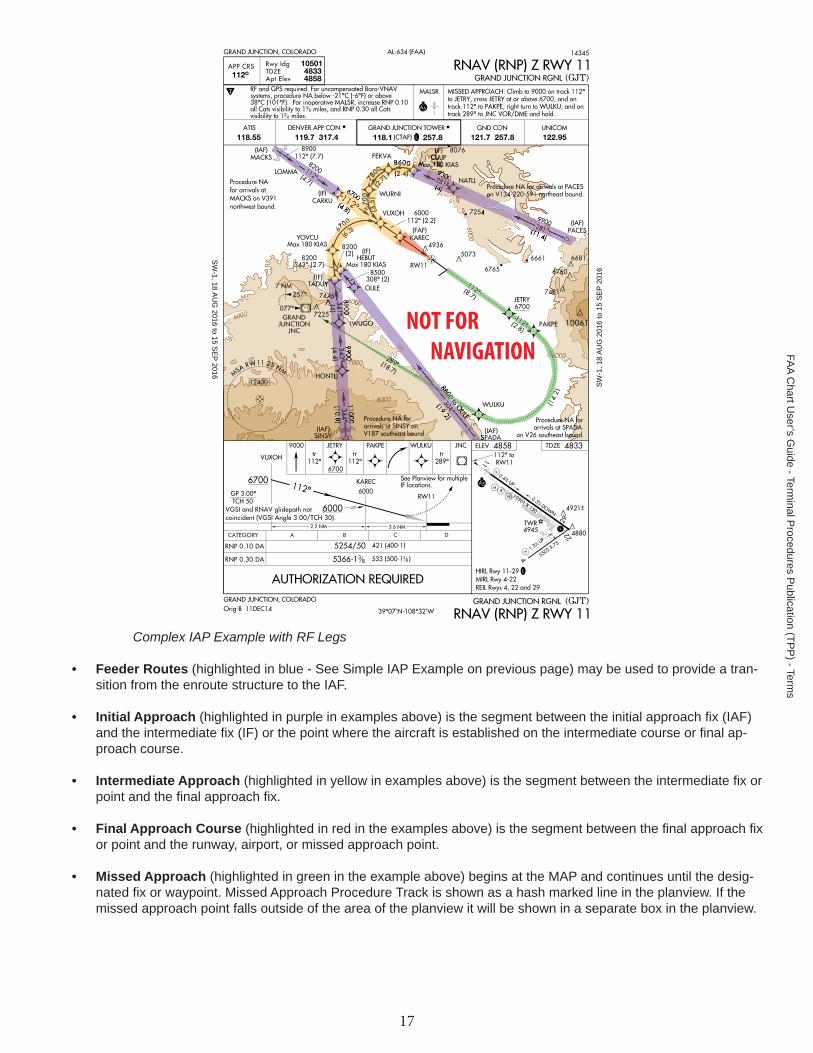
Complex IAP Example with RF Legs
• Feeder Routes (highlighted in blue - See Simple IAP Example on previous page) may be used to provide a tran-sition from the enroute structure to the IAF.
• Initial Approach (highlighted in purple in examples above) is the segment between the initial approach fi x (IAF) and the intermediate fi x (IF) or the point where the aircraft is established on the intermediate course or fi nal ap-proach course.
• Intermediate Approach (highlighted in yellow in examples above) is the segment between the intermediate fi x or point and the fi nal approach fi x.
• Final Approach Course (highlighted in red in the examples above) is the segment between the fi nal approach fi x or point and the runway, airport, or missed approach point.
• Missed Approach (highlighted in green in the example above) begins at the MAP and continues until the desig-nated fi x or waypoint. Missed Approach Procedure Track is shown as a hash marked line in the planview. If the missed approach point falls outside of the area of the planview it will be shown in a separate box in the planview.
17
FAA C
hart User’s G
uide - Terminal P
rocedures Publication (TP
P) - Term
s

• DME arcs or Radius-to-Fix legs (RF) are shown as smooth arcs from a designated start point to a designated terminus.
• Visual Approach Track is shown on procedures that are authorized to proceed visually such as on procedures that terminate or have missed approaches to the airport.
Traditional (NAVAID) Approach RNAV Approach
18
FAA
Cha
rt U
ser’s
Gui
de -
Term
inal
Pro
cedu
res
Pub
licat
ion
(TP
P) -
Ter
ms

NAVAIDS
NAVAIDs used on ground based charts will show the appropriate symbol accompanied by a data box that contains the facility name, frequency, identifi er and Morse code. A NAVAID box with a heavy line indicates the primary NAVAID used for the approach.
NAVAIDs used on GPS based charts show the appropriate symbol identifi ed with the name and identifi er.
Primary NAVAID - LOC Secondary NAVAID - VORDME
Primary NAVAID - NDB/DME Secondary NAVAID - NDB/DME
NAVAID - ILS Approach NAVAID - RNAV Approach
Localizer Depiction
The localizer is depicted in the Planview using the following symbol. The size of the charted localizer symbol does not serve as an indication of the service volume.
Restrictive Airspeeds Along the Procedure Track
Restrictive airspeeds along the procedure track are shown paired with their respective fi x/facility.
Type Description ExampleRecommended Speed Recommended speed is depicted with no lines above or below itMinimum Speed Minimum speed is depicted as a number with a line below it
Maximum Speed Maximum speed is depicted as a number with a line above it
Mandatory Speed Mandatory speed is depicted as a number with a line above and below it
19
FAA C
hart User’s G
uide - Terminal P
rocedures Publication (TP
P) - Term
s

Altitudes
Restrictive altitudes along the procedure track are shown paired with their respective fi x/ facility. Minimum, Maximum, Mandatory and Recommended Altitudes are shown.
Type Description ExampleRecommended Altitude Recommended altitude is depicted with no lines above or below itMinimum Altitude Minimum altitude is depicted as a number with a line below it
Maximum Altitude Maximum altitude is depicted as a number with a line above itMandatory Altitude Mandatory altitude is depicted as a number with a line above itMandatory Block Altitude
Mandatory block altitude is depicted with a minimum and a maximum altitude.
Holding Patterns and Procedure Turns
Holding Patterns are used for many reasons, including deteriorating weather or high traffi c volume. Holding might also be required following a missed approach. Each holding pattern has a fi x, a direction to hold from the fi x, and an airway, bear-ing, course, radial, or route on which the aircraft is to hold. These elements, along with the direction of the turns, defi ne the holding pattern.
Missed Approach In Lieu of Procedure Turn Hold with Leg Length Arrival
If a holding pattern has a non-standard speed restriction, it will be depicted by an icon with the limiting air speed shown inside the holding pattern symbol. These elements, along with the direction of the turns, defi ne the holding pattern. If two types of holds are located at the same point, the procedural holding pattern will be shown in lieu of arrival or missed ap-proach holding patterns.
Waypoints designated as a holding fi x are shown as fl y-by, without the circle around the symbol. However, in the event the holding fi x/waypoint is also designated in some other part of the procedure (i.e., IAF) with a fl y-over function, then the holding fi x/waypoint will be charted as a fl y-over point.
A procedure turn is the maneuver prescribed to perform a course reversal to establish the aircraft inbound on an inter-mediate or fi nal approach course. The procedure turn or hold-in-lieu-of procedure turn is a required maneuver when it is depicted on the approach chart. However, the procedure turn or the hold-in-lieu-of PT is not permitted when the symbol “NoPT” is depicted on the initial segment being fl own, when a RADAR VECTOR to the fi nal approach course is provided, or when conducting a timed approach from a holding fi x. The procedure turn will be shown in the planview and in the profi le of the chart.
20
FAA
Cha
rt U
ser’s
Gui
de -
Term
inal
Pro
cedu
res
Pub
licat
ion
(TP
P) -
Ter
ms

Airports
The primary approach airport is shown to scale by a pattern of all the runways. Airports other than the primary approach airport may be shown with an airport pattern and name when in close proximity to the primary airport.
Relief (Terrain Features)
Terrain is depicted in the planview portion of all IAPs at airports that meet the following criteria:
If the terrain within the planview exceeds 4,000 feet above the airport elevation, orIf the terrain within a 6.0 nautical mile radius of the Airport Reference Point (ARP) rises to at least 2,000 feet above the airport elevation.
When an airport meets either of the above criteria, terrain will be charted by use of contours, spot elevations, and gradient tints of brown on all IAPs for that airport. Contour layers will be shown in no more than fi ve brown tints, with consecutively darker tints used for consecutively higher elevation contour layers.
21
FAA C
hart User’s G
uide - Terminal P
rocedures Publication (TP
P) - Term
s

Hydrography (Water)
Water Depiction is depicted in grey, in the planview portion of IAPs. See previous example. The following hydrographic features are shown:
• Oceans• Signifi cant rivers and streams• Signifi cant lakes - If only one river or one small lake is involved, not located in the immediate airport vicinity, the
hydrographic information requirement may be waived.
International Boundary When the planview includes a boundary of another country the International boundaries are shown by a dashed line. International boundaries are identifi ed with country name within the country area.
Obstacles (Man-made, Terrain and Vegetation)
Obstacles are shown as when they are man-made or vegetation or as a when they are terrain. The highest obsta-cle, whether man-made or terrain is depicted with a bolder and larger symbol along with larger elevation font size. Any ob-stacle which penetrates a slope of 67:1 emanating from any point along the centerline of any runway shall be considered for charting within the area shown to scale. Obstacles specifi cally identifi ed by the approving authority for charting shall be charted regardless of the 67:1 requirement.
Unverifi ed obstacles shall be indicated by a doubtful accuracy symbol following the elevation value.
On non-precision approaches, obstacles should be considered when determining where to begin descent from the MDA.
Highest Point - Obstacle Highest Point - Terrain Unverifi ed Obstacle - Obstacle Special Use Airspace (SUA) SUAs consists of that airspace wherein activities must be confi ned because of their nature, or wherein limitations are imposed upon aircraft operations that are not a part of those activi-ties, or both. These are prohibited areas, restricted areas, warning areas, Military Operations Areas (MOAs), and alert areas. SUA that falls within the area of coverage of the instrument approach procedure chart are shown only when designated by the approving authority.
Air Defense Identifi cation Zone (ADIZ)
ADIZ is an area of airspace in which the identifi cation, location, and control of aircraft is re-quired in the interest of national security. When designated by the approving authority, ADIZ boundaries that fall within the area of coverage of the chart are shown.
22
FAA
Cha
rt U
ser’s
Gui
de -
Term
inal
Pro
cedu
res
Pub
licat
ion
(TP
P) -
Ter
ms

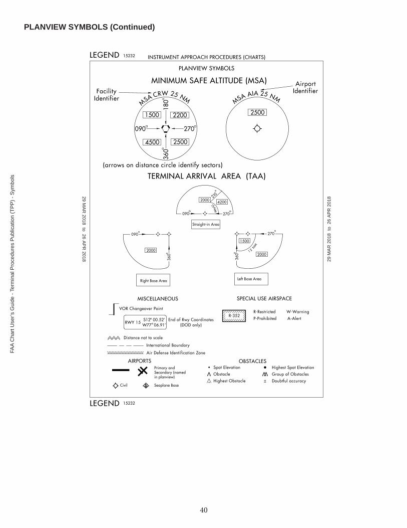
Minimum Safe Altitude (MSA)
MSAs are published for emergency use on IAP charts. MSAs appear in the planview of all IAPs except on approaches for which a Terminal Arrival Area (TAA) is used. The MSA is based on the primary NAVAID, waypoint, or airport reference point on which the IAP is predicated. The MSA depiction on the approach chart contains the identifi er of the NAVAID/way-point/airport used to determine the MSA altitudes. MSAs are expressed in feet above mean sea level and normally have a 25 NM radius; however, this radius may be expanded to 30 NM if necessary to encompass the airport landing surfaces. Ideally, a single sector altitude is established and depicted on the planview of approach charts; however, when necessary to obtain relief from obstructions, the area may be further sectored and as many as four MSAs established. When estab-lished, sectors may be no less than 90° in spread. MSAs provide 1,000 feet clearance over all obstructions but do not necessarily assure acceptable navigation signal coverage.
Single MSA Multiple MSA’s
Terminal Arrival Areas (TAAs)
The TAA icons will be positioned in the planview relative to their relationship to the procedure. The icon will not have feeder routes, airways, or radar vectors depicted. The TAA provides a transition from the enroute structure to the terminal environment with little required pilot/air traffi c control interface for aircraft equipped with Area Navigation (RNAV) systems. A standard TAA has three areas: straight-in, left base, and right base. The arc boundaries of the three areas of the TAA are published portions of the approach. A TAA provides minimum altitudes with standard obstacle clearance when operat-ing within the TAA boundaries. TAAs are primarily used on RNAV approaches but may be used on an ILS approach when RNAV is the sole means for navigation to the IF; however, they are not normally used in areas of heavy concentration of air traffi c.
Example of Standard TAA
23
FAA C
hart User’s G
uide - Terminal P
rocedures Publication (TP
P) - Term
s

Non-standard TAAs may also be published; i.e., one base leg, no base legs.
Example of Non-Standard TAA
MISSED APPROACH INFORMATION
Missed approach information is shown in 3 locations on the chart:
• The Middle Briefi ng Strip - The complete textual missed approach instructions are provided at the top of the ap-proach chart in the middle pilot briefi ng strip.
• The Planview - The missed approach track is drawn using a thin, hash marked line with a directional arrow. If the missed approach point is off the chart, the missed approach track shall extend to the chart border.
• The Profi le Box - Missed Approach Icons will be depicted in the upper left or upper right of the profi le box. The Missed Approach Icons are intended to provide quick, at a glance intuitive guidance to the pilot, to supplement the textual missed approach instructions in the briefi ng strip. Space permitting, all textual missed approach in-structions will be graphically depicted in sequence. If space does not permit the depiction of all missed approach icons, only the fi rst four icon boxes will be shown.
24
FAA
Cha
rt U
ser’s
Gui
de -
Term
inal
Pro
cedu
res
Pub
licat
ion
(TP
P) -
Ter
ms

Example Missed Approach Icons Missed Approach TextMISSED APPROACH: Climb to 13000 on RIL VOR/DME R-250 to TEKGU INT/RIL 19 DME and on EKR VOR/DME R-179 to WOKPA/EKR 44.2 DME and hold, continue climb-in-hold to 13000.MISSED APPROACH: Climbing left turn to 8000 via SVC R-128, then reverse course to SVC VOR/DME and hold.
MISSED APPROACH: Climb to 9000 on track 112° to JETRY, cross JETRY at or above 6700, and on track 112° to PAKPE, right turn to WULKU, and on track 289° to JNC VOR/DME and hold.MISSED APPROACH: Climb to 14000 via 174° course to HOMDU and via 160° track to DEVEC and 160° track to FTI VORTAC and hold.
MISSED APPROACH: Climb to 5800, then climbing left turn to 10000 via heading 190° and SVC VOR/DME R-193 to KUNRE INT/SVC VOR/DME 24.1 DME and hold.
PROFILE VIEW
A profi le diagram of the instrument approach procedure is shown below the planview. The published descent profi le and graphical depiction of the vertical path using those facilities, intersections, fi xes, etc. identifi ed in the procedure to the runway are shown. A profi le view of the procedure track is shown. The approach track begins toward the top of the pri-mary facility line, unless otherwise dictated by the procedure, and shall descend to where the fi nal approach ends and the missed approach begins.
25
FAA C
hart User’s G
uide - Terminal P
rocedures Publication (TP
P) - Term
s

Precision Approaches
On precision approaches, the glideslope (GS) intercept altitude is illustrated by a zigzag line and an altitude. This is the minimum altitude for GS interception after completion of the procedure turn. Precision approach profi les also depict the GS angle of descent, threshold crossing height (TCH) and GS altitude at the outer marker (OM) or designated fi x.
Traditional (NAVAID) Approach RNAV Approach
Non-Precision Approaches
On nonprecision approaches, the fi nal segment begins at the Final Approach Fix (FAF) which is identifi ed with the Maltese cross symbol . When no FAF is depicted, the fi nal approach point is the point at which the aircraft is established inbound on the fi nal approach course. Stepdown fi xes may also be provided between the FAF and the airport for authorizing a lower minimum descent angle (MDA) and are depicted with the fi x or facility name and a dashed line. On RNAV proce-dures without precision minima i.e., DAs, the approach track descends to the MDA or VDP point, thence horizontally to the missed approach point. On non-RNAV procedures without precision minima, the horizontal segment is shown from the VDP, when it exists, or the MDA when there is no VDP, and a vertical glide angle/TCH is provided.
Traditional (NAVAID) Approach RNAV Approach
Visual Decent Point (VDP)
The Visual Descent Point (VDP), is shown by a bold letter “V” positioned above the procedure track and centered on the accompanying dashed line. (See example below.) The VDP is a defi ned point on the fi nal approach course of a non-precision straight-in approach procedure from which normal descent from the MDA to the runway touchdown point may be commenced.
26
FAA
Cha
rt U
ser’s
Gui
de -
Term
inal
Pro
cedu
res
Pub
licat
ion
(TP
P) -
Ter
ms

Visual Descent Angle (VDA) and Threshold Crossing Heights (TCH)
A VDA and TCH may be published on non-precision approaches. The VDA is strictly advisory and provides a means to establish a stabilized descent to the MDA. The presence of a VDA does not guarantee obstacle protection in the visual segment. If there are obstacles in the visual segment that could cause an aircraft to destabilize the approach between MDA and touchdown, the profi le will not show a VDA and will instead show a note that states either “Descent Angle NA” or “Descent Angle NA-Obstacles”.
Visual Flight Path
Instrument approach procedures that terminate or have missed approaches prior to the airport, and are authorized to pro-ceed visual, shall be shown by the dashed line symbol from the missed approach point to the airport. The note “Fly visual” along with the bearing and distance shall be shown leadered to the visual fl ight path.
RNAV charts sometimes have visual fl ight for LNAV/VNAV minima which do not start at the missed approach point. An ad-ditional note indicating “LNAV/VNAV” will be placed above the note.
Chart Examples
Traditional (NAVAID) Approach RNAV Approach ILS Glide Slope and RNAV Glidepath
A note providing the glide slope (GS) or glidepath (GP) angle and the threshold crossing height (TCH), are positioned in the lower half of the profi le box
• GS will be shown on all ILS procedures.• GP will be shown GLS procedures and all RNAV procedures with a published decision altitude
Threshold Crossing Height (TCH) has been traditionally used in “precision” approaches as the height of the glide slope above threshold. With publication of LNAV/VNAV minimums and RNAV descent angles, including graphically depicted descent profi les, TCH also applies to the height of the “descent angle,” or glidepath, at the threshold.
34:1 Surface Clear Stipple Symbol
On RNAV approach charts, a small shaded arrowhead shaped symbol from the end of the VDA to the runway indicates that the 34:1 Obstacle Clearance Surface (OCS) for the visual segments is clear of obstacles. (See example in VDP Sec-tion.)
27
FAA C
hart User’s G
uide - Terminal P
rocedures Publication (TP
P) - Term
s

LANDING MINIMUMS
The landing minimums section is positioned directly below the profi le. This section gives the pilot the lowest altitude and visibility requirements for the approach. There are two types of landing minimums: Straight-in landing or Circling. Straight-in landing minimums are the MDA and visibility, or DH and visibility, required for a straight-in landing on a specifi ed run-way. Circling minimums are the MDA and visibility required for the circle-to-land maneuver.
The minimums for straight-in and circling are located under each aircraft category. When there is not a division line be-tween minimums for each category, the minimums apply to two or more categories.
A second category of straight-in minimums called "sidestep" may be depicted where parallel runways exist.
The terms used to describe the minimum approach altitudes differ between precision and nonprecision approaches. Preci-sion approaches use DH, which is referenced to the height above threshold elevation (HAT). Nonprecision approaches use MDA, referenced to “feet MSL.” The MDA is also referenced to HAT for straight-in approaches, or height above airport (HAA) for circling approaches. The fi gures listed parenthetically are for military operations and are not used in civil avia-tion.
The visibility values are shown after the DA/DH or MDA. They are provided in statue miles or runway visual range (RVR). RVR is reported in hundreds of feet. If the visibility is in statute miles, there is an altitude number, hyphen, whole or frac-tional number, e.g. 530-1. This indicates 530 feet MSL and 1 statute mile of visibility. The RVR value is separated from the minimum altitude with a slash, e.g., 1540/24. This indicates 1540 feet MSL and RVR of 2400 feet.
28
FAA
Cha
rt U
ser’s
Gui
de -
Term
inal
Pro
cedu
res
Pub
licat
ion
(TP
P) -
Ter
ms

When a reference mark (*, **, #, etc.) is shown on a line of minimums, the qualifying footnote is provided in the notes sec-tion.
Circling Minimums
There was a change to the TERPS criteria in 2012 that affects circling area dimension by expanding the areas to provide improved obstacle protection. To indicate that the new criteria had been applied to a given procedure, a is placed on the circling line of minimums. The new circling tables and explanatory information is located in the Legend of the TPP.
The approaches using standard circling approach areas can be identifi ed by the absence of the on the circling line of minima.
Apply Standard Circling Approach Maneuvering Radius Table
Apply Expanded Circling Approach Maneuvering Airspace Radius Table
29
FAA C
hart User’s G
uide - Terminal P
rocedures Publication (TP
P) - Term
s
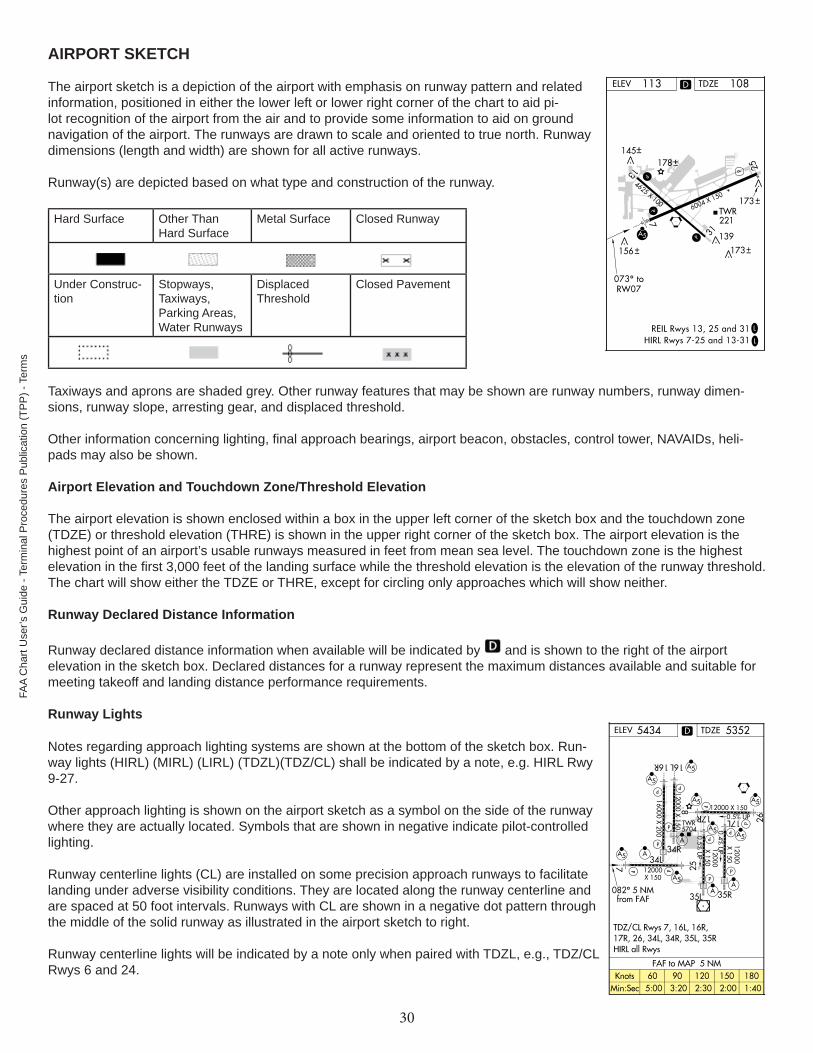
AIRPORT SKETCH
The airport sketch is a depiction of the airport with emphasis on runway pattern and related information, positioned in either the lower left or lower right corner of the chart to aid pi-lot recognition of the airport from the air and to provide some information to aid on ground navigation of the airport. The runways are drawn to scale and oriented to true north. Runway dimensions (length and width) are shown for all active runways.
Runway(s) are depicted based on what type and construction of the runway.
Hard Surface Other Than Hard Surface
Metal Surface Closed Runway
Under Construc-tion
Stopways, Taxiways, Parking Areas, Water Runways
Displaced Threshold
Closed Pavement
Taxiways and aprons are shaded grey. Other runway features that may be shown are runway numbers, runway dimen-sions, runway slope, arresting gear, and displaced threshold.
Other information concerning lighting, fi nal approach bearings, airport beacon, obstacles, control tower, NAVAIDs, heli-pads may also be shown.
Airport Elevation and Touchdown Zone/Threshold Elevation
The airport elevation is shown enclosed within a box in the upper left corner of the sketch box and the touchdown zone (TDZE) or threshold elevation (THRE) is shown in the upper right corner of the sketch box. The airport elevation is the highest point of an airport’s usable runways measured in feet from mean sea level. The touchdown zone is the highest elevation in the fi rst 3,000 feet of the landing surface while the threshold elevation is the elevation of the runway threshold. The chart will show either the TDZE or THRE, except for circling only approaches which will show neither.
Runway Declared Distance Information
Runway declared distance information when available will be indicated by and is shown to the right of the airport elevation in the sketch box. Declared distances for a runway represent the maximum distances available and suitable for meeting takeoff and landing distance performance requirements.
Runway Lights
Notes regarding approach lighting systems are shown at the bottom of the sketch box. Run-way lights (HIRL) (MIRL) (LIRL) (TDZL)(TDZ/CL) shall be indicated by a note, e.g. HIRL Rwy 9-27.
Other approach lighting is shown on the airport sketch as a symbol on the side of the runway where they are actually located. Symbols that are shown in negative indicate pilot-controlled lighting.
Runway centerline lights (CL) are installed on some precision approach runways to facilitate landing under adverse visibility conditions. They are located along the runway centerline and are spaced at 50 foot intervals. Runways with CL are shown in a negative dot pattern through the middle of the solid runway as illustrated in the airport sketch to right.
Runway centerline lights will be indicated by a note only when paired with TDZL, e.g., TDZ/CL Rwys 6 and 24.
30
FAA
Cha
rt U
ser’s
Gui
de -
Term
inal
Pro
cedu
res
Pub
licat
ion
(TP
P) -
Ter
ms

Time/Distance Table
When applicable, a Time/Distance Table is provided below the airport sketch. The table provides the distance and time that is required from the fi nal approach fi x to the missed approach point for select groundspeeds.
AIRPORT DIAGRAMS
Airport Diagrams are specifi cally designed to assist in the movement of ground traffi c at locations with complex runway/taxiway confi gurations. Airport Diagrams are not intended for use in approach and landing or departure operations. An airport diagram assists pilots in identifying their location on the airport, thus reducing requests for “progressive taxi instruc-tions” from controllers.
Airport Diagram Features:
1. Runways
a. complete with magnetic headings (including magnetic variation and epoch year) and identifi ers.b. Runways under construction shall also be shown.c. Runway dimensions, displaced thresholds, runway end elevations.d. Runway surface compositione. Weight bearing capacity (landing gear confi guration or Pavement Classifi cation Number)f. Land and Hold Short (LAHSO) lines, ILS hold lines, Localizer/Glide Slope Critical Areas.g. Arresting Gear. To include Engineered Materials Arresting System (EMAS).
2. Taxiways, with identifi ers. Taxiways under construction shall also be shown.
3. Hot Spot locations.
4. Parking areas, run-up pads, alert areas, landing pads, “Non-Movement” areas (where pilot is NOT under air traffi c control), ramps, aprons and hold pads.
5. Turnarounds, blast pads, stopways, overruns, and clearways (include dimensions when known)
6. Large tanks, including fueling area.
7. Control towers (include tower height).
8. Airport beacon.
9. Helicopter pads.
10. Radar refl ectors.
11. Highest obstruction within diagram boundary.
12. Any building that pilot can taxi to. Other buildings to include terminal/administration and Base operations, fi re sta-tion, NWS, AFSS, FAA, FSDO, ANG, USCG, FBO.
13. Comm Frequencies.
Note: Star when used in the Comm Frequencies indicates part-time status. Check Chart Supplement for times of operation.
31
FAA C
hart User’s G
uide - Terminal P
rocedures Publication (TP
P) - Term
s

Runway Construction
Runway construction is depicted as follows:
Hard Surface
Other Than Hard Surface
Metal Surface
Closed Runway
Closed Pavement
Under Construction
Stopways, Taxiways, Parking Areas, Water Runways
Displaced Threshold
32
FAA
Cha
rt U
ser’s
Gui
de -
Term
inal
Pro
cedu
res
Pub
licat
ion
(TP
P) -
Ter
ms
Hot Spots
Hot Spots are a runway safety related problem area or intersection on an airport. Typically it is a complex or confus-ing taxiway/taxiway or taxiway/runway intersection. A confusing condition may be compounded by a miscommunication between a controller and a pilot, and may cause an aircraft separation standard to be compromised. The area may have a history of surface incidents or the potential for surface incidents.
Hot Spots are indicated on the Airport Diagram with a brown open circle or polygon leadered to a Hot Spot number, e.g., HS 1. The number corresponds to a listing and description on the Hot Spot page in the front the TPP. More information and location of Hot Spots can be found at http://www.faa.gov/airports/runway_safety/hotspots/hotspots_list/.
DEPARTURE PROCEDURES (DPs)
Departure Procedures (DPs) are designed specifi cally to assist pilots in avoiding obstacles during the climb to the mini-mum enroute altitude, and/or airports that have civil IFR takeoff minimums other than standard. There are two types of DPs: Obstacle Departure Procedures (ODPs), printed either textually or graphically and Standard Instrument Departures (SIDs), always printed graphically. SIDs are primarily designed for system enhancement and to reduce pilot/controller workload, and require ATC clearance. ODPs provide obstruction clearance via the least onerous route from the terminal area and may be fl own without ATC clearance. All DPs provide the pilot with a safe departure from the airport and transi-tion to the enroute structure.
Generally, DP charts are depicted “not to scale” due to the great distances involved on some procedures or route seg-ments. A “to scale” portrayal may be used if readability is assured.
The DP will show the departure routing, including transitions to the appropriate enroute structure. All routes, turns, alti-tudes, NAVAIDs, facilities forming intersections and fi xes, and those facilities terminating the departure route are shown. A textual description of the departure procedure is also provided. For RNAV DPs, the transition text consists of the transition name and associated computer code. On non-RNAV DPs, the transition text will also include the description of all turns, altitudes, radials, bearings and facilities/fi xes needed to guide the user from the common departure point to the terminat-ing facility fi x.
STANDARD TERMINAL ARRIVAL (STARs) CHARTS
STARs are pre-planned Instrument Flight Rule (IFR) air traffi c control arrival procedures for pilot use in graphic and/or tex-tual form. STARs depict prescribed routes to transition the aircraft from the enroute structure to a fi x in the terminal area from which an instrument approach can be conducted. STARs reduce pilot/controller workload and air-ground communi-cations, minimizing error potential in delivery and receipt of clearances.
STAR charts generally shall be depicted ‘not to scale’ due to the great distances involved on many procedures and route segments. A ‘to scale’ depiction may be used only if readability is assured.
The STAR will show the arrival routing, including transitions from the appropriate enroute structure. All routes, turns, altitudes, NAVAIDs, facilities forming intersections and fi xes, and those facilities/fi xes terminating or beginning the arrival route shall be shown in the graphic depiction. A textual description of the arrival procedure is also provided. For RNAV STARs, transition text will consist of the transition name and associated computer code. For non-RNAV STARs, the transi-tion text will also include a description of all turns, altitudes, radials, bearings and facilities/fi xes needed to guide the user from the entry point to the common facility/fi x.
33
FAA C
hart User’s G
uide - Terminal P
rocedures Publication (TP
P) - Term
s
CHARTED VISUAL FLIGHT PROCEDURE (CVFP) CHARTS
CVFPs are charted visual approaches established for environmental/noise considerations, and/or when necessary for the safety and effi ciency of air traffi c operations. The approach charts depict prominent landmarks, courses, and recommend-ed altitudes to specifi c runways. CVFPs are designed to be used primarily for turbojet aircraft. CVFPs are not instrument approaches and do not have missed approach segments.
CVFPs are named for the primary landmark and the specifi c runway for which the procedure is developed, such as: RIVER VISUAL RWY 18, STADIUM VISUAL RWY 24. The CVFP charts are divided into planview and notes sections separated by a bar scale in 1 NM increments. The planview of the CVFP includes the portrayal of visual approach proce-dures information, such as landmarks, NAVAIDs, visual track, hydrography, special use airspace and cultural features, as applicable.
CVFPs originate at or near, and are designed around, prominent visual landmarks and typically do not extend beyond 15 fl ight path miles from the landing runway. Visual tracks start at a geographical point or landmark where the procedure must be fl own visually to the airport. The visual track is indicated by a dashed line. Visual tracks may include the track value, distance and minimum or recommended altitudes.
34
FAA
Cha
rt U
ser’s
Gui
de -
Term
inal
Pro
cedu
res
Pub
licat
ion
(TP
P) -
Ter
ms

U.S. TERMINAL PROCEDURES PUBLICATION SYMBOLS
GENERAL INFORMATION
Symbols shown are for the Terminal Procedures Publication (TPP) which includes Standard Terminal Arrival (STARs) Charts, Departure Procedures (DPs), Instrument Approach Procedures (IAP) and Airport Diagrams.
LEGEND - STANDARD TERMINAL ARRIVAL (STAR) CHARTS - DEPARTURE PROCEDURE (DP) CHARTS
35
29 MA
R 2018 to 26 A
PR
2018 29 M
AR
201
8 to
26
AP
R 2
018
FAA C
hart User’s G
uide - Terminal P
rocedures Publication (TP
P) - S
ymbols
36
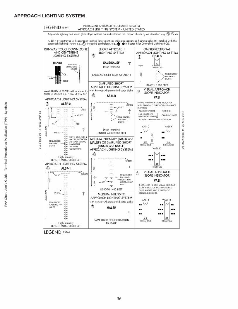
APPROACH LIGHTING SYSTEM
29 MA
R 2018 to 26 A
PR
2018 29 M
AR
201
8 to
26
AP
R 2
018
FAA
Cha
rt U
ser’s
Gui
de -
Term
inal
Pro
cedu
res
Pub
licat
ion
(TP
P) -
Sym
bols

37
APPROACH LIGHTING SYSTEM (Continued)
29 MA
R 2018 to 26 A
PR
2018 29 M
AR
201
8 to
26
AP
R 2
018
FAA C
hart User’s G
uide - Terminal P
rocedures Publication (TP
P) - S
ymbols

38
AIRPORT DIAGRAM/AIRPORT SKETCH
29 MA
R 2018 to 26 A
PR
2018 29 M
AR
201
8 to
26
AP
R 2
018
FAA
Cha
rt U
ser’s
Gui
de -
Term
inal
Pro
cedu
res
Pub
licat
ion
(TP
P) -
Sym
bols

39
PLANVIEW SYMBOLS
29 MA
R 2018 to 26 A
PR
2018 29 M
AR
201
8 to
26
AP
R 2
018
FAA C
hart User’s G
uide - Terminal P
rocedures Publication (TP
P) - S
ymbols
40
PLANVIEW SYMBOLS (Continued)
29 MA
R 2018 to 26 A
PR
2018 29 M
AR
201
8 to
26
AP
R 2
018
FAA
Cha
rt U
ser’s
Gui
de -
Term
inal
Pro
cedu
res
Pub
licat
ion
(TP
P) -
Sym
bols

41
PROFILE VIEW
29 MA
R 2018 to 26 A
PR
2018 29 M
AR
201
8 to
26
AP
R 2
018
FAA C
hart User’s G
uide - Terminal P
rocedures Publication (TP
P) - S
ymbols

42
COLD TEMPERATURE AIRPORTS
FAA
Cha
rt U
ser’s
Gui
de -
Term
inal
Pro
cedu
res
Pub
licat
ion
(TP
P) -
Sym
bols

REFERENCESThere are several references available from the FAA to aid pilots and other interest parties to learn more about FAA Charts and other aspects of aviation.
Publication FAA Publication IDAeronautical Information Manual (AIM)
URL: http://www.faa.gov/air_traffi c/publications/
Airplane Flying Handbook
URL: http://www.faa.gov/regulations_policies/handbooks_manuals/aircraft/air-plane_handbook/
FAA-H-8083-3A
Helicopter Flying Handbook
URL: http://www.faa.gov/regulations_policies/handbooks_manuals/aviation/heli-copter_fl ying_handbook/
FAA-H-8083-21A
Instrument Procedures Handbook
URL: http://www.faa.gov/regulations_policies/handbooks_manuals/aviation/in-strument_procedures_handbook/
FAA-H-8083-16B
Instrument Flying Handbook
URL: http://www.faa.gov/regulations_policies/handbooks_manuals/aviation/me-dia/FAA-H-8083-15B.pdf
FAA-H-8083-15B
Pilot's Handbook of Aeronautical Knowledge
URL: http://www.faa.gov/regulations_policies/handbooks_manuals/aviation/me-dia/pilot_handbook.pdf
FAA-H-8083-25B
Remote Pilot - Small Unmanned Aircraft Systems Study Guide
URL: http://www.faa.gov/regulations_policies/handbooks_manuals/aviation/me-dia/remote_pilot_study_guide.pdf
FAA-G-8082-22
43
FAA C
hart User’s G
uide - References

44
FAA
Cha
rt U
ser’s
Gui
de -
Ref
eren
ces

A
AAS - Airport Advisory ServiceAAUP - Attention All Users PageADF - Automatic Direction FinderADIZ - Air Defense Identifi cation ZoneADS - Automatic Dependent SurveillanceADS-B - Automatic Dependent Surveillance-BroadcastAdvsry - AdvisoryAFIS - Automatic Flight Information ServiceAFS - Air Force StationAGL - Above Ground LevelAIM - Aeronautical Information ManualAIRAC - Aeronautical Information Regulation And ControlAPP - ApproachApt - AirportAPV - Approaches with Vertical GuidanceARP - Airport Reference PointARTCC - Air Route Traffi c Control CenterASDA - Accelerate-Stop Distance AvailableASDE-X - Airport Surface Detection Equipment-Model XASOS - Automated Surface Observing StationASR - Airport Surveillance RadarATC - Air Traffi c ControlATIS - Automatic Terminal Information ServiceATS - Air Traffi c ServiceAUNICOM - Automated Aeronautical Advisory StationAWOS - Automated Weather Observing Station
B
Baro-VNAV - Barometric Vertical NavigationBS - Broadcast Station
C
CAC - Caribbean Aeronautical ChartCAT - CategoryCFA - Controlled Firing AreasCFR - Code of Federal RegulationsCLNC DEL - Clearance DeliveryCH - ChannelCNF - Computer Navigation FixCOP - Changeover PointCPDLC - Controller Pilot Data Link CommunicationCRS - CourseCT - Control TowerCTAF - Common Traffi c Advisory FrequencyCVFP - Charted Visual Flight Procedure
D
DA - Decision AltitudeDA - Density AltitudeD-ATIS - Digital Automatic Terminal Information ServiceDH - Decision HeightDoD - Department of Defense
DME - Distance Measuring EquipmentDP - Departure ProcedureDT - Daylight Savings TimeDVA - Diverse Vector Area
E
E - EastEFAS - Enroute Flight Advisory ServiceEFB - Electronic Flight BagElev - Elevation
F
FAA - Federal Aviation AdministrationFAF - Final Approach FixFAP - Final Approach PointFAR - Federal Aviation RegulationFIR - Flight Information RegionFL - Flight LevelFLIP - Flight Information PublicationFMS - Flight Management SystemFREQ - FrequencyFRZ - Flight Restricted ZoneFSDO - Flight Standards District Offi ceFSS - Flight Service Station
G
GBAS - Ground-Based Augmentation SystemGCO - Ground Communications OutletGLS - GBAS Landing SystemGND - GroundGNSS - Global Navigation Satellite SystemGPS - Global Positioning SystemGS - Ground Speed
H
HAA - Height Above Airport HAR - High Altitude Redesign HAT - Height Above TouchdownHF - High FrequencyHIWAS - Hazardous Infl ight Weather Advisory Service
I
IAC - Interagency Air CommitteeIACC - Interagency Air Cartographic CommitteeIAF - Initial Approach FixIAP - Instrument Approach ProcedureICAO - International Civil Aviation AuthorityIDT - Identifi erIF - Intermediate FixIFR - Instrument Flight RulesILS - Instrument Landing SystemIMC - Instrument Meteorological Conditions
ABBREVIATIONS
45
FAA C
hart User’s G
uide - Abbreviations

INS - Inertial Navigation SystemIR - Instrument RouteIRU - Inertial Reference Unit
K
KIAS - Knots
L
LAAS - Local Area Augmentation SystemLAHSO - Land and Hold ShortLAA - Local Airport AdvisoryLAAS - Local Area Augmentation SystemLDA - Localizer-type Directional AidLDA - Landing Distance AvailableLdg - LandingLF - Low FrequencyLNAV - Lateral NavigationLOC - LocalizerLOM - Locator Outer MarkerLPV - Localizer Performance with Vertical GuidanceLRRS - Long Range Radar StationLTP - Landing Threshold Point
M
MAA - Maximum Authorized AltitudeMAP - Missed Approach PointMCA - Minimum Crossing AltitudeMDA - Minimum Descent AltitudeMDH - Minimum Descent HeightMEA - Minimum Enroute AltitudeMEF - Maximum Elevation FigureMF - Medium FrequencyMIA - Minimum IFR AltitudeMOA - Military Operations AreasMOCA - Minimum Obstruction Clearance AltitudeMORA - Minimum Off-Route AltitudeMRA - Minimum Reception AltitudeMSA - Minimum Safe AltitudeMSL - Mean Sea LevelMTA - Minimum Turning AltitudeMTR - Military Training RouteMVA - Minimum Vector Altitude
N
N - NorthN/A - Not ApplicableNA - Not AuthorizedNAS - National Airspace SystemNAVAID - Navigational Aid (Ground based)NDB - Non-Directional RadiobeaconNextGen - Next Generation Air Transportation SystemNFDC - National Flight Data CenterNFPO - National Flight Procedures Offi ceNM - Nautical MileNOAA - National Oceanic and Atmospheric Administration
NO A/G - No Air-to-Ground CommunicationNOTAM - Notice to AirmanNoPT - No Procedure TurnNPA - Non-Precision ApproachNTAP - Notices to Airman PublicationNWS - National Weather Service
O
OAT - Outside Air TemperatureOBS - Omni Bearing SelectorOCA - Ocean Control AreaOCS - Obstacle Clearance SurfaceODP - Obstacle Departure ProcedureOROCA - Off Route Obstruction Clearance Altitude
P
PA - Precision ApproachPAR - Precision Approach RadarPRM - Precision Runway MonitorPT - Procedure TurnPTP - Point-to-PointPvt - Private
R
R - RadialR - ReceiveR - Restricted Area (Special Use Airspace)RCO - Remote Communications OutletRF - Radius-to-FixRNAV - Area NavigationRNP - Required Navigation PerformanceRNP AR - Required Navigation Performance Authorization RequiredROC - Required Obstacle ClearanceRVR - Runway Visual RangeRVSM - Reduced Vertical Separation MinimumRwy - Runway
S
S - SouthSAAAR - Special Aircraft and Aircrew Authorization RequiredSAAR - Special Aircraft and Aircrew RequirementsSATNAV - Satellite NavigationSDF - Simplifi ed Directional FacilitySER - Start End of RunwaySFAR - Special Flight Rules AreaSFRA - Special Flight Rules AreaSFC - SurfaceSIAPS - Standard Instrument Approach ProceduresSID - Standard Instrument DepartureSM - Statute MileSMAR - Special Military Activity RoutesSMGCS - Surface Movement Guidance and Control System
46
FAA
Cha
rt U
ser’s
Gui
de -
Abb
revi
atio
ns

SOIA - Simultaneous Offset Instrument ApproachesSSV - Standard Service VolumeSTAR - Standard Terminal Arrival ProcedureSUA - Special Use AirspaceSVFR - Special Visual Flight Rules
T
TA - Travel AdvisoryTAA - Terminal Arrival AreaTAC - Terminal Area ChartTACAN - Tactical Air NavigationTAS - True Air SpeedTCH - Threshold Crossing HeightTDZ - Touchdown ZoneTDZE - Touchdown Zone ElevationTERPS - U.S. Standard for Terminal Instrument ProceduresTFR - Temporary Flight RestrictionTHRE - Threshold ElevationTIBS - Telephone Information Briefi ng ServiceTIS-B - Traffi c Information Service - BroadcastTOC - Top of ClimbTOD - Top of DescentTODA - Takeoff Distance AvailableTOGA - Takeoff/Go AroundTORA - Takeoff Runway AvailableTPP - Terminal Procedures PublicationTRSA - Terminal Radar Service AreaTWEB - Transcribed Weather BroadcastTWR - Tower
U
UC - Under ConstructionUHF - Ultra High FrequencyUIR - Upper Information RegionUNICOM - Universal CommunicationsU.S. - United StatesUSAF - United States Air ForceUTA - Upper Control Area
V
VCOA - Visual Climb Over Airport / Airfi eldVDA - Visual Descent AngleVDP - Visual Decent PointVFR - Visual Flight RulesVGSI - Visual Glide Slope IndicatorVHF - Very High FrequencyVMC - Visual Meteorological ConditionsVNAV - Vertical NavigationVOR - VHF Omnidirectional Radio RangeVORTAC - VHF Omnidirectional Radio Range/Tactical Air NavigationVPA - Vertical Path AngleVR - Visual Route
W
W - Warning Area (Special Use Airspace)W - WestWAAS - Wide-Area Augmentation SystemWAC - World Aeronautical ChartWP - WaypointWX CAM - Weather Camera (Alaska)
47
FAA C
hart User’s G
uide - Abbreviations