aeroelastic tailoring via tow steered composites - nasa · aeroelastic tailoring via tow steered...
TRANSCRIPT

September 2014
NASA/TM–2014-218517
Aeroelastic Tailoring via Tow Steered Composites
Bret K. Stanford Langley Research Center, Hampton, Virginia
Christine V. Jutte Craig Technologies, Inc., Cape Canaveral, Florida
https://ntrs.nasa.gov/search.jsp?R=20140012777 2018-05-29T19:40:18+00:00Z

NASA STI Program . . . in Profile
Since its founding, NASA has been dedicated to the advancement of aeronautics and space science. The NASA scientific and technical information (STI) program plays a key part in helping NASA maintain this important role.
The NASA STI program operates under the auspices of the Agency Chief Information Officer. It collects, organizes, provides for archiving, and disseminates NASA’s STI. The NASA STI program provides access to the NASA Aeronautics and Space Database and its public interface, the NASA Technical Report Server, thus providing one of the largest collections of aeronautical and space science STI in the world. Results are published in both non-NASA channels and by NASA in the NASA STI Report Series, which includes the following report types:
• TECHNICAL PUBLICATION. Reports of completed research or a major significant phase of research that present the results of NASA Programs and include extensive data or theoretical analysis. Includes compilations of significant scientific and technical data and information deemed to be of continuing reference value. NASA counterpart of peer-reviewed formal professional papers, but having less stringent limitations on manuscript length and extent of graphic presentations.
• TECHNICAL MEMORANDUM. Scientific and technical findings that are preliminary or of specialized interest, e.g., quick release reports, working papers, and bibliographies that contain minimal annotation. Does not contain extensive analysis.
• CONTRACTOR REPORT. Scientific and technical findings by NASA-sponsored contractors and grantees.
• CONFERENCE PUBLICATION. Collected papers from scientific and technical conferences, symposia, seminars, or other meetings sponsored or co-sponsored by NASA.
• SPECIAL PUBLICATION. Scientific, technical, or historical information from NASA programs, projects, and missions, often concerned with subjects having substantial public interest.
• TECHNICAL TRANSLATION.English-language translations of foreign scientific and technical material pertinent to NASA’s mission.
Specialized services also include organizing and publishing research results, distributing specialized research announcements and feeds, providing information desk and personal search support, and enabling data exchange services.
For more information about the NASA STI program, see the following:
• Access the NASA STI program home page at http://www.sti.nasa.gov
• E-mail your question to [email protected]
• Fax your question to the NASA STI Information Desk at 443-757-5803
• Phone the NASA STI Information Desk at 443-757-5802
• Write to: STI Information Desk NASA Center for AeroSpace Information 7115 Standard Drive Hanover, MD 21076-1320

National Aeronautics and Space Administration
Langley Research Center Hampton, Virginia 23681-2199
Septemeber 2014
NASA/TM–2014-218517
Aeroelastic Tailoring via Tow Steered Composites
Bret K. Stanford Langley Research Center, Hampton, Virginia
Christine V. Jutte Craig Technologies, Inc., Cape Canaveral, Florida

Available from:
NASA Center for AeroSpace Information 7115 Standard Drive
Hanover, MD 21076-1320 443-757-5802

Aeroelastic Tailoring via Tow Steered Composites
Bret K. Stanford NASA Langley Research Center, Hampton, VA, 23681
Christine V. Jutte Craig Technologies, Inc., Cape Canaveral, FL, 32920
The use of tow steered composites, where fibers follow prescribed curvilinear paths within a laminate, can improve upon existing capabilities related to aeroelastic tailoring of wing structures, though this tailoring method has received relatively little attention in the literature. This paper demonstrates the technique for both a simple cantilevered plate in low-speed flow, as well as the wing box of a full-scale high aspect ratio transport configuration. Static aeroelastic stresses and dynamic flutter boundaries are obtained for both cases. The impact of various tailoring choices upon the aeroelastic performance is quantified: curvilinear fiber steering versus straight fiber steering, certifiable versus non-certifiable stacking sequences, a single uniform laminate per wing skin versus multiple laminates, and identical upper and lower wing skins structures versus individual tailoring.
I. Introduction Historically, the most prominent type of aeroelastic tailoring is arguably the use of composite laminates in wing
structures [1]. The basic tailoring concepts can be seen in the laminate stiffness matrix of Eq. 1, where is the vector of in-plane (membrane) loads on a laminated plate- or shell-like structure, is a vector of bending/twisting moments, is the resulting mid-plane strains, and the mid-plane curvatures. By altering the stacking sequence of a laminate, the members of the stiffness matrix ( , , and are the extensional stiffness matrix, flexural stiffness matrix, and the bending-extension coupling matrix) will change, and various couplings become available. From an aeroelasticity/wing structures perspective, some of these couplings are desirable, other undesirable. An example of the latter is embedded in the matrix, where transverse loads along a wing lead to both the typical bending curvatures ( ) as well as an atypical in-plane extension ( ), which can be large and nonlinear. This matrix is easily set to zero by utilizing a symmetric stacking sequence. An example of the former is the bend-twist coupling found within the matrix: this is the most well-known and heavily-utilized strategy for composites-based aeroelastic tailoring. (1)
Bend-twist coupling in a straight (non-swept) plate-like wing structure is seen in Figure 1, taken from Ref. [1].
The matrix is a 3×3 matrix, where the first column is associated with chord-wise bending of the wing, the second column with span-wise bending, and the final column with wing torsion. The figure provides 3 scenarios for the coupling terms (traditionally called and , though located in the (1, 3) and (2, 3) cells of the matrix). For an isotropic material or strictly orthotropic material, these terms are exactly zero. In response to a transverse aerodynamic loading, a straight wing will bend but not twist (notwithstanding any pitching moments inherent within the flight loads during straight and level flight). Alternatively, a negative bend-twist coupling (wash-out) may exist, which is characterized by an alleviation of the aerodynamic loads. This is known to be beneficial for leading-edge control effectors, static divergence, maneuver load/drag alleviation, etc. Finally, if these coupling terms are positive (along with the rest of the matrix), positive bend-twist coupling exists (wash-in), along with an augmentation of the flight loads: beneficial for trailing edge control effectors, lift effectiveness, and flutter. The aeroelastic benefits obtained in either coupling scenario comes at the expense of the benefits in the opposite scenario, necessitating a series of compromises during the tailoring process. The largest bend-twist coupling exists for unbalanced laminates. For balanced laminates, and are small, but non-zero: mathematically they will tend to zero, however, as the number of layers in the laminate increases.

2
Figure 1. Various bend-twist coupling strategies, adapted from Ref. [1].
In conventional laminate structures, all fibers in a ply are straight and parallel, with a given orientation. Alternatively, one may consider tow steered laminates, where the fiber orientation within a ply varies continuously throughout the structure. This provides tailored load paths within the laminate, which may now be termed “variable-stiffness”. Tow steering is enabled by computer-numerically-controlled (CNC) fiber tow placement machines, as drawn in Figure 2. These machines place precise courses (or tows) of pre-impregnated carbon fiber along commanded curvilinear paths, along a tooling surface. If the paths are strongly curved, adjacent courses will overlap at certain points in the structure. These overlaps can either be allowed to occur (providing a build-up in the local laminate thickness), or tow cutters can be used to adaptively “drop” portions of the current course being laid down on the surface, to maintain a uniform thickness. For all of the results given in this report, the latter situation is assumed.
Figure 2. CNC fiber placement machine, courtesy of Cincinnati Machine.
A significant amount of work can be found in the existing literature regarding the mechanics and design of tow steered structures (see for example Ref. [2], and the additional papers cited therein), including recent work conducted at NASA LaRC [3], though only limited work has been done for aeroelastic tailoring (see recent Refs. [4] and [5]), which is the goal of the current work. Two aeroelastic problems are developed: a cantilevered flat plate, and a built-up wing box structure of the Common Research Model (CRM) concept [6], a high aspect ratio subsonic transport configuration. Various methods to parameterize the composite laminate structures will be discussed, as well as methods to sample the design space. The resulting framework can then be used to answer a series of questions pertaining to the efficacy, feasibility, and limits of tow steered aeroelastic tailoring. First, what are the benefits of using non-steered, straight-fiber laminates for wing structures? The answer to this question will not necessarily be a novel one: as noted above, these methods have been in use for decades. But for each new wing configuration that is discussed (and there are two used here), the exact quantitative benefits of non-steered tailoring need to be obtained before the answer to the second question can be put into perspective: what additional benefit can be obtained by introducing tow steering into the problem?
In assessing the benefits of tow steering, the relevant comparison is not between tow steered wing structures and metallic structures, but between tow steered structures and non-steered (conventional laminate) structures. Tow steering is probably best seen as an augmentation to conventional laminate-based tailoring, and so the questions need to be answered in the order given above. A third question is: if the available ply angle choices were limited to

3
a few discrete choices (i.e., required for certification), what penalty would be paid in terms of aeroelastic performance? Final issues that are discussed: what benefits can be obtained if the upper and lower skins of a wing box have different laminates? What if more than one laminate is used per skin? What is the impact of using low-order steering concepts from wing root to tip, as opposed to higher-order interpolation schemes? A thorough examination of each of these questions, provided here, should provide a clear understanding of the various trade-offs, benefits, and limitation associated with tow steered aeroelastic tailoring.
II. Flat Plate Aeroelastic Tailoring The first case to be discussed is for a simple aeroelastic flat plate problem. This problem’s low computational
cost, simple structural configuration, and small number of designable plies, lends it to a rapid and near-comprehensive sampling of the design space. The resulting insight will be thorough, but limited in the sense that this problem is of an academic nature.
A. Problem Description This problem is taken directly from Ref. [7]: an un-swept rectangular flat plate of chord 76.2 mm and a semi-
span of 305 mm (aspect ratio of 8) which is fully-clamped at its root, and subjected to low-speed flow over both surfaces. The plate is comprised of 6 layers of uni-directional graphite/epoxy, whose material properties are given in Table 1. Aeroelastic analysis is conducted in NASTRAN, via two modules. First, static aeroelastic behavior is explored. The plate-wing is placed at a fixed angle of attack of 5° and a flow velocity of 20 m/s. SOL144 is used to find the deformed configuration at which internal elastic forces balance external aerodynamic loads. Tsai-Wu failure indices are then computed for each ply within each finite element, using the strength metrics in the right column of Table 1. Next, the aeroelastic stability boundary of the plate is determined using SOL145, by marching the flow velocity from 1 m/s to 100 m/s, and identifying the critical speed at which the plate becomes statically unstable (divergence) or dynamically unstable (flutter). For SOL144 and SOL145 analysis, the finite element mesh is discretized into 12×48 squares, each of which is divided into 2 linear triangular elements (CTRIAR) elements. A 12×48 aerodynamic doublet lattice mesh is used, and an 18×72 finite plate spline (FPS) mesh is used to communicate force and displacement data between the two modules. Every third finite element node communicates with the FPS mesh (i.e., is used for splining).
Table 1. Material properties for the aeroelastic flat plate problem.
Property Value Property Value 98.0 GPa 1314 MPa 7.9 GPa 1220 MPa 0.28 43 MPa 5.6 GPa 168 MPa
Ply thickness 0.134 mm 48 MPa Density 1520 kg/m3
The laminates for this flat plate case (like all of the laminates in this work) are symmetric, leaving 3 designable
layers. Steering concepts are illustrated in Figure 3, where the fiber paths for a single layer of the 6-ply laminate are shown. Simply, the fiber angle at the wing root and at the wing tip are specified, with a linear variation in between these two control points. This results in a curvilinear fiber path, explicitly given in Ref. [2]. A minor addition to this parameterization is given in the tilting parameter Φ, which defines a local coordinate system . Fiber angle is a linear function of , and constant along the direction. This tilting rotation varies continuously between 0° (span-wise steering from root to tip), and 90° (chord-wise steering from leading edge to trailing edge). Each of these parameters can be defined independently for each layer in the laminate, resulting in 9 total design variables. If steering is not considered ( = 0°, = ), then there are only 3 total design variables for this conventional, straight-fiber laminate design problem. The fiber angle convention noted in Figure 3 is used for the entirety of this work: a 0° fiber is parallel to the flow velocity vector (from leading to trailing edge), and a 90° fiber travels from wing root to tip.
B. Solution Methodology The method used here to explore the design space is a multi-objective genetic algorithm: NSGA-II [8]. Given
appropriate resources, the algorithm will find the global Pareto front within the design space, which is the set of non-

4
dominated designs. Two objectives are considered: large flutter speeds (SOL145), and low values for the peak Tsai-Wu failure metric found throughout the finite element mesh during static aeroelastic deformations (SOL144). These two metrics are expected to conflict, creating a Pareto front. The GA ranks designs, not based explicitly on aeroelastic performance metrics, but by non-domination. A design is non-dominated (Pareto optimal) if no other design exists which out-performs it in every metric. For a given set of designs, the Pareto front is rank 1, the next layer is rank 2, etc. Low-rank designs have the greatest probability of propagating their characteristics onto the next generation.
Figure 3. Steering concepts for a single layer of the flat plate laminate.
Though this method is a true optimizer, care must be taken in interpreting many of the results given here as “optimal”. This is partly due to a lack of computational resources (a true limitation for the CRM work given below, but less so for the flat plate problem, which is relatively inexpensive and operates in a smaller design space), and partly due to the fact that the current work is more concerned, at this stage, with identifying trends and limitations of the tailoring scheme, rather than locating the global optimum. The NSGA-II algorithm merely provides a diverse sampling throughout the design space, with clustering towards the non-dominated portion of that space (and less wasted samples in the heavily-dominated portion). As the number of design variables decreases and/or the computational cost drops (or the computational resources are increased) our confidence in actually obtaining the true global Pareto front increases as well. The interested reader is referred to Ref. [9] for additional details of using these algorithms with limited resources and interpreting the results.
It is further noted that the current work does not represent true “design” work in any sense either. This is obviously true for the flat plate problem, owing to the academic nature of the problem. Even for the CRM problem, however, a large number of load cases (longitudinal and lateral maneuvers, gust loads, taxi bumps, etc.) would need to be added to the 2 cases already considered (flutter and a single static aeroelastic configuration), as well as additional geometric detail, drag-based metrics, etc., for this work to qualify as a design effort. As noted, the current focus is on identifying underlying trends, the limits of a tailoring tool, and comparing disparate tailoring methods.
Results for this flat plate problem are organized as follows. First, aeroelastic tailoring for un-steered fibers is considered, where fiber angles can take any continuous value. The study is then repeated with steered fibers. This is done for aeroelastic flutter metrics (section II-C) and aeroelastic strength (II-D). Next, fiber angles are restricted to a few discrete choices in section II-E, with and without tow steering, for direct comparison with the previous continuous ply angle problem.
C. Flutter Results First, the GA seeks to find the design with the highest flutter speed, for un-steered laminates (i.e., laminates
with straight fibers). This design space is defined by only 3 design variables, so there is a high likelihood that the final design is the true global optimum. This design is seen in Figure 4, where layer 1 is the top layer, and layer 6 is the bottom, and is defined as [-50.7° / 43.2° / 39.3°]s. The laminate is symmetric, by design, and unbalanced. The resulting eigenvalue migration behavior for this structure is given in Figure 5. The migration, with increasing flow velocity, of the first four aeroelastic modes is shown, which roughly correspond to a first bending mode (1B), second bending (2B), first torsion (1T), and second torsion (2T). For a flow velocity close to zero, the imaginary portions of each eigenvalue (frequency) are equal to the natural vibration frequencies. Even at this point, each mode is only roughly identified with the labels given above, due to the stiffness coupling of the unbalanced laminate which alters the typical bending and torsion mode shapes. As the flow velocity increases and the aerodynamic interactions strengthen, the mixing of mode shapes increases.

5
The first bending mode becomes non-oscillatory at a speed of 45.02 m/s, but does not destabilize (diverge). The system flutters shortly after, at 45.98 m/s. Both the second bending mode and the first torsion mode flutter when the real parts of their eigenvalues (damping) go from negative damping (stable) to positive damping (unstable, un-bounded growth). The first flutter mechanism is brought about by a mild approach of the 1B and 2B frequencies, the second mechanism by a mild approach of the 2B and 1T frequencies. These two flutter mechanisms occur at nearly the same speed, which is not a coincidence. It is well-known that the most efficient structures are those that engage as many failure modes as possible, at the same time (e.g., a fully-stressed design). The optimal design in Figure 4 is the best performer found by the GA, in terms of flutter, presumably for this reason. The second bending mode flutters more aggressively than the torsion mode, the latter of which becomes a hump mode, and eventually re-stabilizes.
Figure 4. Un-steered flat plate laminate with the highest flutter speed.
Figure 5. Flutter behavior for the flat plate laminate of Figure 4.
The above exercise is repeated, this time including tow steering in the structural parameterization, as seen graphically in Figure 3. The best flutter result returned by the GA of the 9-design variable problem is shown in Figure 6. Even though the design space has been given a wide-range of steering paths to take advantage of, it does not: the best flutter result utilizes only mild steering from root to tip. The greatest spatial variation in steering angle is seen for the inner layers 3 and 4, but the stiffness of these layers is only of minor importance for a plate undergoing bending deformations (i.e., dominated by the , rather than the matrix). The flutter behavior of this

6
structure is shown in Figure 7, and bears many similarities to that of the previous case. One distinct difference is that the bending mode becomes non-oscillatory much sooner (38.2 m/s), and the resulting real roots are less stable (but still non-critical) than before. Otherwise, dual flutter modes are still seen, occurring at a speed of 46.83 m/s.
The advent of tow steering for this problem has brought about only a mild improvement in the performance: a 1.84% increase in the flutter speed. This is presumably a configuration-dependent result, in the sense that with two modes fluttering simultaneously, any design change which improves one flutter point (e.g., 2B) will make the other worse (e.g., 1T), and vice-versa. This is a hard corner of the design space, and the introduction of new variables (tow steering) cannot improve the situation much. It is also noted that none of the steering patterns in Figure 6 make use of chord-wise steering, with the bulk of the weak fiber gradient in the span-wise direction (i.e., Φ is nearly 0°).
Figure 6. Steered flat plate laminate with the highest flutter speed.
Figure 7. Flutter behavior for the steered flat plate laminate of Figure 6.
D. Strength Results Attention is now turned to static aeroelastic behavior (SOL144), specifically the Tsai-Wu failure index for each
layer (6 in total) of each finite element. This is a simpler problem in the sense that statically-deformed wing behavior is simpler than a dynamic flutter mechanism, but potentially more complex due to the chosen objective function. The location of the peak failure index may change from one element to another (or even change from one layer to another within a given element, although the outer layers are usually expected to be critical), and is thus a discontinuous function of the design space, slowing the convergence of the genetic algorithm. The un-steered

7
design with the lowest peak failure index (flutter is ignored in this section), as located by the GA, is seen in Figure 8, and is defined by: [94.3° / 102.2° / 82.4°]s. The failure index for each layer of each element is also shown.
As before, this laminate is symmetric and unbalanced, but only mildly. Layers 2 and 3 form a near ±θ pair, and layer 1 is almost parallel to the wing itself (94.3°). Indeed, all of the layers are relatively close to 90°, which suggests that this design metric places less of an emphasis on aeroelastic tailoring via coupling for load alleviation, and more upon just providing the stiffest possible plate. That there are some deviations from 90° is either indicative of a secondary need for tailored coupling, or due to the non-uniform aerodynamic pressure distribution over the plate. The failure metrics are small: the largest value is 0.0346. Any value over unity is considered to have elastically failed, not including any safety factor. As would be expected, stresses grow as one travels from the inner layers to the outer layers, and peak stress occurs at the wing root. Asymmetries between the top and the bottom halves of the plate (layer 1 vs. layer 6, for example) are indicative of the mixed bending/torsion loading.
Figure 8. Un-steered flat plate laminate with the highest strength, and the corresponding failure indices.
Repeating this exercise with tow steering does finally obtain a design that utilizes heavily-steered laminates, Figure 9. Fiber angles at the root are nearly parallel to the leading edge, but curve upwards by about 45° as one travels to the wing tip. This results in a significant reduction in the peak failure index to 0.0260, a drop of 24.85%. The steering is able to draw the peak stresses out from the root over a greater portion of the wing, similar to a fully-stressed design methodology. Though both the steered result and the un-steered result have failure indices far below unity, the dynamic pressure over the wing was chosen somewhat arbitrarily. If that value were increased by a factor of 10, the stresses would increase similarly; the difference between the two strategies is of importance, not the actual value. Furthermore, even for the dynamic pressure used in the current results, there are several laminates in the design space which do fail. This is either because they are too weak in the span-wise direction (0° plies, for example), or because they are statically unstable: the flow velocity chosen is above the divergence speed. Finally, it is noted that most of the steering seen in Figure 9 is span-wise ( = 0°). Some mild chord-wise steering is noted at the root of layers 3 and 4, but these inner layers have a minor effect on the aeroelastic strength.
E. Structural Certification Considerations The previous results of this section have allowed the fiber angle for each layer to be a continuous design
variable, capable of taking on any value between specific bounds. Historically however, aerospace design with composite materials has made use of only four discrete choices: 0°, 90°, 45°, and -45°. There are several reasons for this, related to convenience and manufacturability, but the main reason is due to certification: most available laminate data (via experimental testing) is limited to these ply angles. Certifiable laminates not only are limited to these discrete ply angle choices, but must also be symmetric and balanced. While this is a very real limitation in present-day aircraft structures, it does not necessarily need to be adhered to for this work, whose aeroelastic wing tailoring strategies may not be fully realized for many years (by which time, certification-by-analysis may be

8
possible, rather than relying on costly and therefore limited experimentation). It is worthwhile, however, to ascertain the penalty that is paid, in terms of aeroelastic performance, when one restricts the design space to only a few choices.
Figure 9. Steered flat plate laminate with the highest strength, and the corresponding failure indices.
Tow steering is still possible when limited to only 0°, 90°, and ±45° ply angles, but each layer in the stacking sequence can no longer be steered individually, as done in Figure 3. Now, a core laminate is defined (some combination of 0°, 90°, and ±45° plies), as well as a single steering path. The core laminate is merely rotated with the steering path, as seen in the top of Figure 10. The “90° fibers” remain parallel to the steering path, the “0° fibers” are always perpendicular to this path, etc. Globally, the fiber angles at every point in the plate wing can take any value, but locally (i.e., with respect to the other plies), they only take values of 0°, 90°, and ±45°. For a core laminate without any 90° plies (a stacking sequence of [45° / 0° / 0°]s for example), none of the fibers in the laminate will actually follow the prescribed steering path. The total number of design variables for this scenario is 6: the core laminate is defined by 3 discrete variables (one for each designable layer), and the single steering path is defined by 3 continuous variables: , , and .
Figure 10. Tow steering concepts when limited to 0°, 90°, and ±45° fiber angles.

9
The flutter results of Figure 4 through Figure 7 are repeated here using these discrete ply concepts, and summarized in Table 2. The previous best flutter result without steering was [-50.7° / 43.2° / 39.3°]s. The new best result within the discrete design space, is [-45° / 45° / 45°]s which is simply the previous laminate rounded to the nearest available choice (though the design is actually found via an exhaustive search through the GA). In moving from the continuous design space to the discrete one, a 6.41% penalty is paid in flutter performance. This may not be an acceptable decrease in flutter, depending on how close the original design’s flutter boundary was to some conceptual flight envelope. The previous best result with tow steering included is seen in Figure 6. When this exercise is repeated using the steering concepts of Figure 10, the best design found by the GA uses the same core laminate as the non-steered case [-45° / 45° / 45°]s, and steers this laminate along the mildly-curved path given in Figure 11. The performance penalty (due to the restricted design space) between the two cases is very small (0.17%), which would indicate that the discrete ply angle problem benefits from tow steering far more than the continuous ply angle problem. It is also noted that because the core laminate in Figure 11 contains no 90° plies, none of the fibers in the plate follow the shown steering path, but instead intersect these curves at angles of ±45°.
Table 2. Penalties in the flutter speed when ply angles are limited to discrete choices.
Case Laminate Steering Objective Penalty Continuous ply
angles w/o steering [-50.7° / 43.2° / 39.3°]s - 45.98 m/s 6.41% Discrete ply angles
w/o steering [-45° / 45° / 45°]s - 43.03 m/s
Continuous ply angles with steering Figure 6 Figure 6 46.83 m/s
0.17 % Discrete ply angles with steering [-45° / 45° / 45°]s Figure 11 46.75 m/s
Figure 11. Steering path for the laminate with the highest flutter speed: core laminate = [-45° / 45° / 45°]s.
This exercise can be repeated for the strength-based metrics in Figure 8 and Figure 9, and is summarized in Table 3. The previous best strength result as found in [94.3° / 102.2° / 82.4°]s, which has a peak failure index of 0.0346. If one simply rounds each of these ply angles to the nearest discrete choice [90° / 90° / 90°]s, this laminate has a failure index of 0.0631. A cursory search of the design space via the GA returns a better design with a lower failure index of 0.0527: [90° / -45° / 0°]s. The outer layer ply angle (and the most influential for bending deformations) for both wings is 90°, but some minor differences are seen in the inner layers. Regardless, the penalty paid when restricting the design space to discrete choices (0°, 90°, ±45°) is significant: a 52.3% increase in the peak stress. While the failure index for both wing structures is much lower than unity (and therefore very safe), it is the delta between the two which is of greater interest, as these absolute performance metrics will scale with the arbitrarily-chosen dynamics pressure over the wings.
Table 3. Penalties in the peak Tsai-Wu failure index when ply angles are limited to discrete choices.
Case Laminate Steering Objective Penalty Continuous ply
angles w/o steering [94.3° / 102.2° / 82.4°]s - 0.0346 52.3% Discrete ply angles
w/o steering [90° / -45° / 0°]s - 0.0527
Continuous ply angles with steering Figure 9 Figure 9 0.02603
~ 0% Discrete ply angles with steering [90° / 90° / 90°]s Figure 12 0.02604

10
Finally, the best steering result for Tsai-Wu failure through the continuous design space is given in Figure 6, while the best result for the discrete design space uses a core laminate of [90° / 90° / 90°]s (which, unlike the flutter results in Table 2., is not the same core laminate as used by the un-steered case) and a steering path of Figure 12. This aeroelastic structure has practically the same peak failure index as the previous best result: there is no appreciable penalty. As noted above, the discrete problem benefits more from tow steering than the continuous problem. Put another way, while there is a penalty associated with moving from continuous ply angles to discrete ply angles, the introduction of tow steering can make up for most, if not all, of this gap. Even for the discrete ply angle problem, the use of tow steering re-introduces an element of spatial continuousness into the problem, with significant performance benefits. It is finally noted that, because each layer of the laminate in Figure 12 is 90°, every fiber in the structure follows the path shown. There are many practical reasons not to use a [90° / 90° / 90°]s laminate (it is very weak in the matrix direction, and it is also inadvisable to use so many identical plies stacked adjacently, owing to matrix cracking issues [10]), but the GA is wholly unaware of these issues, and should not distract from the demonstrated benefits of tow steered laminates.
Figure 12. Steering path for the laminate with the highest strength: core laminate = [90° / 90° / 90°]s.
III. CRM Tailoring The second case discussed here is a more complex built-up wing box problem, specifically for the CRM
configuration. This problem has a much larger computational cost and more designable plies than the above flat plate problem, and so the GA results will present a less-comprehensive picture of the design space, owing to computational resource limitations.
A. Problem Description The CRM model used here is a full-scale 777-derivative wing with span of 192.8 ft, an aspect ratio of nine, a
taper ratio of 0.275, a leading edge sweep angle of 35°, and a break along the trailing edge at 37% of the semi-span [6]. The wing box lies between 10% and 70% of the local chord: an exploded view is given in Figure 13. It is important to note which portions of this structure are being tailored in this work, and which are not. The all-aluminum internal support structure (ribs, spars, stringers, stiffeners) is left un-touched, aeroelastic tailoring is only considered in the composite laminate upper and lower wing skins. While there is certainly some benefit to the use of composite materials for the internal substructure (ribs, spars, stringers, etc.) with or without tow steering, these concepts are not explored here.
Figure 13. Exploded view of the CRM wing box structure.
Full-depth aluminum spars (2024-T3 alloy) are placed at the box leading edge, trailing edge, and one-third of the distance between the two. The thickness of the spars is linearly tapered from 0.75 inches at the root to 0.1 inches at the tip. Thirty-seven straight aluminum ribs are evenly distributed from root to tip, each aligned with the airflow,

11
and linearly tapered from a thickness of 0.12 inches to 0.063 inches. Seven pairs of aluminum stringers (one on each skin, not shown in the figure) travel from root to tip: two pairs are evenly distributed between the leading edge spar and the inner spar, and five pairs between the inner and trailing edge spar. These stringers have a rectangular cross section, with a depth of 2.95 inches and a thickness of 0.18 inches. A full-depth aluminum rib stiffener exists at each stringer-rib intersection, each with a depth of 2.64 inches and a thickness of 0.18 inches.
The skins, spars, and ribs are modeled with triangular shell finite elements, stringers and rib stiffeners are modeled with beam elements, and the displacement degrees of freedom of all nodes at the wing-root of Figure 13 are fixed to zero. The inertial impact of leading and trailing edge control effectors are modeled as lumped masses, connected to the leading and trailing edge spars via un-weighted interpolation elements. Six 320 lb masses are used along the inboard leading edge, and three additional of 240 lbs outboard. Similarly, six 840 lb masses and three 140 lb masses are used along the trailing edge. These mass values were calculated by scaling data from a similar commercial transport.
All of the composite wing skin tailoring results presented below are compared against the performance of an all-metallic baseline wing. This wing box consists of the metallic substructure described above (ribs, spars, stringers, stiffeners), as well as aluminum wing skins. This thickness of these skins linearly tapers from 0.25 inches to 0.05 inches at the tip. The flutter dynamic pressure and the weight of this wing are both used to normalize values obtained during composite tailoring. Material properties for these tailorable composite skins are given in Table 4.
The static aeroelastic analysis and flutter analysis are conducted in NASTRAN. MATLAB scripts generate input files for the analyses and extract the data from the output files to compare performance metrics and assess the aeroelastic tailoring concepts. Flat-plate aerodynamic paneling is utilized for both steady and unsteady air loads, with a 10×10 mesh of boxes for the inboard section of the wing, and a 10×40 mesh outboard. Finite element nodes located at intersections of the upper skins and ribs, or the upper skins and spars, are used to interpolate between the structural and aerodynamic meshes.
Static aeroelastic wing deformation is computed at an angle of attack of 6°, a Mach number of 0.85, and an altitude of 35 kft. A flutter analysis (p-k method) is then performed with 20 structural dynamic modes at a Mach number of 0.85, and using the speed of sound at sea level, the velocity is computed and fixed. The dynamic pressure varies from 0 to 14.8 psi, divided into 250 increments by varying the flow density: zero-damping cross-over points indicate flutter.
Table 4. Material properties for the Common Research Model wing skins.
Property Value Property Value 20.44 Msi 19.06 Msi 1.41 Msi 17.76 Msi 0.35 0.62 Msi 0.68 Msi 2.43 Msi
Ply thickness 0.005 in 0.69 Msi Density 0.058 lb/in3
B. Solution Description The previous flat plate laminate problem had only 3 designable layers, which meant that one design variable (or
more, if tow steering was considered) could be assigned to each layer. The resulting design space is relatively low-dimensional, and is well-explored with the GA. A transport wing skin, on the other hand, may have 50-100 layers of carbon fiber, particularly at the root (where the bending moments are high) of the upper skin (where buckling is a concern): attaching design variables to each layer is no longer feasible. Such a large-variable design space can only be explored with gradient-based optimization; see Ref. [11], for example. Otherwise, two alternatives are commonly seen in the literature. The first directly uses members of the and matrices as design variables (assuming a symmetric laminate: ). Care must be taken that these stiffness matrices actually correspond to some stacking sequence (an inverse process), and so the feasible design space must be derived a-priori. An example of this approach for aeroelastic wing design can be seen in Ref. [12].
Alternatively, one may exploit the geometry of the wing box. If the depth of the wing box (airfoil thickness) is much larger than the thickness of the upper and lower wings skins, then it is known that skin stresses due to mid-plane strains are much larger than those due to the mid-plane curvatures (referencing Eq. 1). This would mean the extensional stiffness matrix is far more important than the flexural stiffness matrix . The preceding is true for global deformations, such as wing bending and twisting: for local deformations (panel buckling, e.g.), both terms

12
contribute. As is only computed from the number of plies at each orientation (rather than the exact stacking sequence, which is used to compute ), this can enable significant reductions in the number of design variables.
Under these conditions, permutations of the same stacking sequence for the skins will give very similar aeroelastic results for the CRM: e.g., [-30° / 70° / 20° / -30°]s, [70° / -30° / -30° / 20°]s, etc. On a top level, only the discrete variables associated with each available ply angle need to be stored: = 2, = 1, = 1. At the NASTRAN level (within the PCOMP cards) one can use any stacking sequence, as long as the expected wing deformations are of a global nature. One possible parameterization would be to discretize the ply angles by steps of 5°: . This results in 28 discrete design variables per laminate, which is still a high-dimensional design space. Alternatively, one could discretize into steps of 45°: , which is only 4 design variables. Finally, one could use just 3 variables: , where each variable creates twice the number of plies in the laminate for balancing purposes.
This final 3-design variable space will be used for the CRM tailoring work. While its limited nature is not expected to provide as highly-performing designs as the 28-variable option, several considerations apply. First, the 28-variable problem is too large of a design space to be considered by any method except gradient-based optimization. This issue is compounded by the likely situation that more than one laminate is used per wing. Secondly, the 3-variable problem creates designs that are automatically balanced (due to the term), and thus certifiable. Finally, the previous work on the flat plate problem indicated that the aeroelastic performance of a laminate with limited ply angle choices could be greatly improved (compared to a laminate with unlimited choices) by the introduction of tow steering, a trend which may continue in the CRM problem. Once the number of each ply angles is decided upon in each laminate, the permutation problem could be solved at the local panel level to determine a stacking sequence that will satisfy buckling constraints (whose local deformations will depend on the matrix, and hence the stacking sequence). This is not considered here, but the technique is demonstrated in Ref. [13].
As only tow steering was explored for the flat-plate problem, and not the possible addition or deletion of entire plies, the mass of the plate-wing was assumed constant. This is no longer true for the current parameterization, and so within the context of the multi-objective NSGA-II algorithm, a Pareto front spanning 3 objectives is sought: minimum mass, maximum flutter speed, and minimum stress-based failure index. Previously, the largest Tsai-Wu failure index across the plate was identified and exposed to the GA as an objective. A more refined approach is used here: the Kreisselmeier-Steinhauser (KS) function [14]. The KS function is a stress aggregate function which compresses each failure index throughout the finite element model (every Tsai-Wu failure index from each ply of each composite element, as well as each Von Mises failure index from each metallic element) into a single scalar via a nonlinear weighting function. Highly-stressed elements have a greater weight than others, which is controlled via a tuning parameter. For the purposes of this work, a KS value greater than unity would indicate that some element in the mesh has failed elastically, notwithstanding a safety factor (though a degree of conservatism is built into the KS function, as dictated by the same tuning parameter).
The remainder of this section utilizes eight different design scenarios, with increasing levels of tailorability. The first four scenarios are for straight, non-steered laminates, splitting the wing into multiple segments to vary the locations of the different tailored laminates on the wings. First, the same un-steered laminate is applied to both the upper and lower wing skins (section III-C). Then different un-steered laminates are used for the upper and lower skins (section III-D). Next, each of the 4 skin segments have different laminates from root to tip but the upper and lower skins are the same; and finally each of the 4 skin segments have different laminates from root to tip with different upper and lower skins. The next four scenarios (section III-E) follow the same approach of keeping laminates the same on top and bottom and splitting the wing into multiple segments for more refined span-wise tailoring, but also introduce the ability to steer the tow angles within the plane of the laminate instead of holding the fibers straight and parallel. Thus, the tow steered scenarios are: same laminates for upper and lower skins, steered from root to tip; different laminates for upper and lower skins, steered from root to tip; 5 control points steered from root to tip but same laminates on upper and lower skins; and 5 control points steered from root to tip and different laminates on upper and lower skins.
C. Single Laminate Design The first design scenario considered here is where the entire upper skin of the CRM is covered with a single
laminate, and this same laminate covers the entire lower skin as well. This leaves 3 total design variables, as described above. The terms and are both allowed to lie between 0 and 4, whereas must lie between 1 and 4. In order to retain the presence of a wing skin, one of these 3 variables must have a lower bound greater than 0: the ±45° plies are a natural choice, as these plies are typically utilized on the exposed surface of wing

13
structures [10]. Given that each of these variables creates 2 plies, and further multiplying by 2 to create a symmetric laminate, the thinnest structure has 4 layers total, while the thickest has 48 total (where the first number is , the second is , and the third is ). The Pareto front returned by the GA for this design space is shown in Figure 14. The three-dimensional surface has been plotted in two separate figures, where wing weight and flutter are both normalized by the baseline parameters.
Several data points in Figure 14, when viewed in a two-dimensional space, appear to be dominated (i.e., non-Pareto optimal). On the left side of the plot, for example, several points appear to have higher KS values and higher weight than others. When viewed in a true three-dimensional context however, each of these data points will have higher flutter boundaries than the others, and so are indeed Pareto optimal. For this case, there is a strong trade-off between wing weight and wing flutter. The heaviest design is the safest, in terms of the normalized flutter dynamic pressure, while the lightest design has the worst flutter behavior, with a very aggressive instability boundary. While there are bands of constant weight (which are due to the fact that each variable is discrete, and so there are only 12 possible weight values) within which the flutter speed can be moderately increased by making changes to each variable, gross changes to the flutter boundary necessitate the addition of more weight to the wing.
Figure 14. CRM Pareto front: single laminate for entire skin, identical upper and lower skin structures.
The flutter results for design can be seen in Figure 15, where dynamic pressure is normalized by the flutter dynamic pressure of the baseline structure. Several interesting discrepancies exist between this vibration behavior and those of the flat plate in Figure 5. First, a predominately edge-wise bending mode (1E, or fore-aft bending vibration) can be seen at a relatively low frequency, though its aeroelastic interactions with the unsteady flow are minimal: its frequency does not change with increasing dynamic pressure, and (more telling) its aerodynamic damping is nearly zero. Work on high-aspect ratio wings (see Ref. [15], for example) has identified interactions between edgewise and flapwise (1B, 2B) bending, as well as torsional modes (1T) as the main driver for post-flutter limit cycle oscillations, which may be of interest for future work. Secondly, the flutter mechanism in Figure 15 is the typical bending-torsion coalescence, and only a single mode flutters. This mechanism is remarkably consistent for a wide variety of structural configurations, though the actual flutter dynamic pressure can vary significantly, as shown in Figure 14. Though two hump modes appear, both driven by the second bending mode, neither is ever seen to actually destabilize, regardless of the tailoring strategy. This is in stark contrast to the flat plate problem: different laminates can lead to 1B divergence, 2B flutter, or 1T flutter, as also seen in Ref. [7].
A final note of interest from Figure 15 is the appearance of an aerodynamic lag root at a normalized dynamic pressure of 1.05. This root is a manifestation of the unsteady doublet-lattice aerodynamics through the structural vibration modes; the first-order aerodynamic terms translate into a non-oscillatory root. The root itself is not of significant interest, as it never destabilizes to become the critical divergence mode, but NASTRAN’s SOL145 is unable to track all the existing modes as well as this new mode. The algorithm abandons 1B to track the lag root instead, then loses 1E, and then loses 1T. This final torsion mode is permanently lost, which is probably related to the fact that an oscillatory root also appears with the non-oscillatory lag root shown in Figure 15 (but NASTRAN does not capture), which eventually collides with the torsional root, annihilating each other [16]. Given that the root which ultimately flutters (1B) is temporarily dropped by the flutter algorithm, there may be some doubt as to the
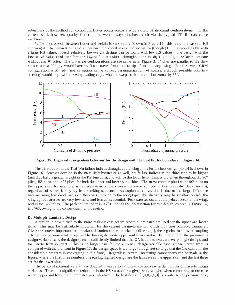
14
robustness of the method for computing flutter points across a wide variety of structural configurations. For the current work however, quality flutter points were always obtained, each via the typical 1T-1B coalescence mechanism.
While the trade-off between flutter and weight is very strong (shown in Figure 14), this is not the case for KS and weight. The heaviest design does not have the lowest stress, and vice-versa (though is very flexible with a large KS value): indeed, relatively low-weight designs can be found with low KS values. The design with the lowest KS value (and therefore the lowest failure indices throughout the mesh) is , a 32-layer laminate without any 0° plies. The ply-angle configurations are the same as in Figure 3: 0° plies are parallel to the flow vector, and a 90° ply would have its fibers travel from root to tip of an un-swept wing. For the swept CRM configuration, a 60° ply (not an option in the current parameterization, of course, although possible with tow steering) would align with the wing leading edge, which is swept back from the horizontal by 35°.
Figure 15. Eigenvalue migration behavior for the design with the best flutter boundary in Figure 14.
The distribution of the Tsai-Wu failure indices throughout the wing skins for the best design is shown in Figure 16. Stresses develop in the metallic substructure as well, but failure indices in the skins tend to be higher (and thus have a greater weight in the KS function), and will be the focus here. Indices are given throughout the 90° plies, 45° plies, and -45° plies, for both the upper and lower wing skins. The stress contour plot for the 90° plies on the upper skin, for example, is representative of the stresses in every 90° ply in this laminate (there are 16), regardless of where it may lay in a stacking sequence. As explained above, this is due to the large difference between wing box depth and skin thickness. Owing to the wing taper, this disparity may be smaller towards the wing tip, but stresses are very low here, and less consequential. Peak stresses occur at the yehudi break in the wing, within the -45° plies. The peak failure index is 0.721, though the KS function for this design, as seen in Figure 14, is 0.767, owing to the conservatism of the metric.
D. Multiple Laminate Design Attention is now turned to the more realistic case where separate laminates are used for the upper and lower
skins. This may be particularly important for the current parameterization, which only uses balanced laminates. Given the known importance of unbalanced laminates for aeroelastic tailoring [1], these global bend-twist coupling effects may be somewhat recaptured by having disparate upper and lower surface laminates. For the previous 3-design variable case, the design space is sufficiently limited that the GA is able to evaluate every single design, and the Pareto front is exact. This is no longer true for the current 6-design variable case, whose Pareto front is compared with the old front in Figure 17: the design space is too large (though not so large that the GA cannot make considerable progress in converging to this front). Regardless, several interesting comparisons can be made in the figure, where the first three numbers of each highlighted design are the laminate of the upper skin, and the last three are for the lower skin.
The bands of constant weight have doubled, from 12 to 24, due to the increase in the number of discrete design variables. There is a significant reduction in the KS values for a given wing weight, when comparing to the case where upper and lower skin laminates were identical. The best design is similar to the previous best,

15
except on the upper skins is decreased by two. Reviewing Figure 16, the stresses in these plies are relatively low, and so removing them is in accordance with a fully stressed design strategy. The failure indices for this design (Figure 18) do show a greater distribution in peak stress over more of the layers (especially in the upper skin), but peak values are still concentrated at the break. Unlike in the flat plate case (Figure 9), where peak stresses are spread out over more of the wing, it appears that the details of the CRM’s planform geometry are a greater driver of stress distribution than detailed tailoring can overcome.
Figure 16. Skin stress distribution for the design with the lowest KS function in Figure 14.
Figure 17. CRM Pareto front: single laminate for entire skin, separate upper and lower skin structures.
More spatially-detailed laminate concepts may be pursued, as summarized in Figure 19. The upper left of this plot shows the design with the lowest KS function in Figure 14, and the upper right the lowest KS function in Figure 17. As already noted, the latter design is able to decrease both the KS function and the weight, though the flutter

16
boundary becomes worse. Alternatively, the wing skins may be divided into four laminates, but the upper and lower skins still constrained to be identical. In this situation, the best KS result as returned by the GA is given in the lower left of Figure 19: peak thickness is near the yehudi break, where stresses are highest, and the typical thickness taper is evident towards the root. The final result in this figure (lower right) has different laminates between upper and lower skins. Between these four results, the number of design variables increases from 3 to 6 to 12 to 24, and the performance of the best KS result found by the GA progressively drops from 0.767 to 0.714 to 0.709 to 0.694, as would be expected (though the movement of flutter dynamic pressure and weight of these designs is inconsistent).
As the dimensionality of the design space increases, the computational resources available to the GA become less adequate. Indeed, the decrease in KS function value between the last 3 designs is not as large as might be expected with a progressive doubling of the number of design variables: it seems likely that far superior designs exist, especially for the lower two structures in Figure 19. An extreme case of the approach taken in this figure may be to identify a separate laminate for each panel (where a panel is defined as wing skin bordered by rib and spar intersections), as done in Ref. [13]. This may be expected to give the best Pareto fronts, but would require formal gradient-based optimization, and is beyond the scope of the current work. Finally, it is noted that the best flutter design is always found to be the heaviest 48-ply laminate, regardless of the ply orientations in the laminate. The lightest design, of course, is always the 4-ply laminate ( = 1).
Figure 18. Skin stress distribution for the design with the lowest KS function in Figure 17.
E. Steering Results The tow steering concepts used for the CRM are similar to those used above for the flat plate in Figure 3 and
Figure 10. A steering angle is specified at the wing root ( ) and the tip ( ), with a linear variation in between. As above, this results in a curvilinear tow path. As the tilting angle was found above to have a minor impact on the problem, it is omitted from this section. Then, the core laminate, as defined by , , and , is rotated with the steering path, where 90° fibers (if any) are those that will remain parallel to the path, as in Figure 10. A steering angle ( or ) of 90° means than a laminate is locally un-steered, and an angle of 60° would align the 90° fibers (if any) approximately with the leading edge of the swept CRM planform. The wing structure in the upper left of Figure 19 is used for all of the initial results in this section. Though better results have been obtained (as seen by the progression in that figure), will be used here for its simplicity, and to aid the interpretation of results. Using this laminate for both the upper and lower skins, Figure 20 displays the KS function (contour plot) when and are independently swept from 30° to 150°. Steering patterns are shown for various data points along the perimeter of the plot moving in a counter-clockwise direction: (30°,-30°), (90°,-30°), (150°,-30°), (150°,-90°), (150°,-150°), (90°,-150°), (30°,-150°), and (30°,-90°), starting at the lower left. It is further noted that each of these

17
designs has the same weight (equal to the normalized value of 0.888 from the un-steered structure in Figure 19): tow steering merely re-orients existing material, and is not additive.
Figure 19. Designs with the lowest KS function under various spatial laminate parameterizations.
The data point at (90°,-90°) which corresponds to the center of the figure is entirely un-steered, and gives the exact same performance as the structure in the upper left of Figure 19 (KS = 0.767). Any design along the line
(the diagonal) is un-steered in the sense that there are no curvilinear fibers, but the entire stacking sequence is rotated uniformly from root to tip, as drawn in the lower left (30°,-30°) and upper right (150°,-150°) subplots. Only when and are unequal do curvilinear paths emerge, the best of which (in terms of the lowest KS value, and hence the lowest stresses) is (50°,-150°), which has a performance improvement of 9.6% over the un-steered case (90°,-90°). As may be expected, this high-performing steering path is nearly aligned with the CRM leading edge at the wing root, and perpendicular to it at the wing tip.
Similar data is given in Figure 21 for the normalized flutter dynamic pressure of each case. The best flutter point is located at (150°,-150°) (a 52.3% increase in the flutter speed), which uniformly rotates all the fibers counterclockwise by 60°, nearly perpendicular to the leading edge. Like the flat plate problem discussed in Figure 7, aeroelastic flutter metrics for this CRM case are largely impervious to the advent of curvilinear tow paths. For the flat plate, the likely reason was due to a bi-modal flutter point that presented a hard constraint boundary in the design space. The flutter mechanism for this CRM case is similar in nature to Figure 15: its uni-modal nature should not present a similarly hard boundary. Though some beneficial flutter behavior due to tow steering will be shown below, the insensitivity noted to this point may be simply due to the fact that curvilinear steering is a spatially-local tailoring scheme with a minor impact upon a global flutter mode. The wing stresses, on the other hand, are a local metric (albeit due to global wing deformations) which can bear improvement from steering.

18
Figure 20. KS function for different root ( ) and tip ( ) steering: = 4, = 4, and = 0 for both the entire upper and the lower skin laminate.
Figure 21. Normalized flutter dynamic pressure for different root ( ) and tip ( ) steering: = 4, = 4, and = 0 for both the entire upper and the lower skin laminate.

19
Next, different steering patterns are considered for the upper and lower skins, though the core laminate for each is the same as before. The root steering angle is fixed at an arbitrary value of 90° (to reduce the design space), while the tip steering angles for the upper and lower skins are independently varied through 10° increments. Results for the KS function and the normalized flutter dynamic pressure are given in Figure 22 and Figure 23, respectively. As before, select steering patterns are drawn for various designs along the perimeter, where the red lines are the paths along the upper skin, and the blue lines are for the lower skin. These paths are identical at the wing root, of course, because is fixed at 90° for both. The design at (90°,-90°) is entirely un-steered, as before, and identical to the case in the upper left of Figure 19 (KS = 0.767, normalized flutter = 0.614).
Any design in these figures along the unit slope (US LS ) has no difference in the steering patterns between the upper and lower skins. Any design along the vertical line US 90° has no steering in the upper skins, and any design along the horizontal line LS 90° has no steering in the lower skins. The design with the lowest KS function (Figure 22) is found at (140°, 30°), which presents a 13.5% drop as compared to the baseline. This is superior to what was found in Figure 20; presumably even better designs exist if one drops the restriction that
90°, and conducts an exhaustive search through the 4-dimensional space. The best flutter result (Figure 23) is found at (30°,-30°), a design which improves the flutter point by 40.4%. This design has no differences in the steering between upper and lower skins, and a better, entirely un-steered result, was found in Figure 21.
Figure 22. KS function with a root of 90°, and different upper skin tip (US ) and lower skin tip (LS ) steering: = 4, = 4, and = 0 for both the entire upper and the lower skin laminate.
As may be expected, the trends shown in these four figures are strongly dependent upon the underlying core laminate. The previous 4 figures are repeated for the laminate where = 4, = 4, and = 4, which is the structure with the best flutter point in Figure 14 and Figure 17. KS and flutter results are given in Figure 24 and Figure 25 for identical upper and lower skin steering, and in Figure 26 and Figure 27 for separate steering. For identical upper-lower steering, the KS steering results show some similarities between the two laminates, though tow steering becomes less advantageous, as the best design is only mildly steered. The flutter results between the two laminates are completely out of phase, though steered laminates still have no benefit over un-steered. Similar observations may be made for the case where the upper and lower skins have different steering patterns. Wing stresses show less benefit from curvilinear paths, and flutter trends are largely opposite, as compared to the previous results. This reinforces the overall tailoring issues discussed above: the impact of tow steering is heavily dependent on the un-steered laminate design, and can only be put in context if conducted sequentially.

20
Figure 23. Normalized flutter dynamic pressure for a root of 90°, and different upper skin tip (US ) and lower skin tip (LS ) steering: = 4, = 4, and = 0 for the upper and the lower skins.
Figure 24. KS function for different root ( ) and tip ( ) steering: = 4, = 4, and = 4 for both the entire upper and the lower skin laminate.

21
Figure 25. Normalized flutter dynamic pressure for different root ( ) and tip ( ) steering: = 4, = 4, and = 4 for both the entire upper and the lower skin laminate.
Figure 26. KS function with a root of 90°, and different upper skin tip (US ) and lower skin tip (LS ) steering: = 4, = 4, and = 4 for both the entire upper and the lower skin laminate.

22
Figure 27. Normalized flutter dynamic pressure for a root of 90°, and different upper skin tip (US ) and lower skin tip (LS ) steering: = 4, = 4, and = 4 for the upper and the lower skins.
All of the previous work in this section have used steering concepts with only two control points (wing root and tip), and a linear variation in-between. The final result in this section expands on this idea, with 5 control points total, and a piece-wise linear variation along the span. The core laminate chosen for this exercise is shown in the lower right corner of Figure 28, a Pareto-optimal design (in terms of weight, KS, and flutter) found above, when each wing skin was broken into 4 laminates, but the upper and lower skin laminates were chosen to be identical. This design shows the expected taper towards the wing tip, and the inner two panels happen to have the same thickness (though different laminates). For this exercise, the core laminate is fixed, and a steering control point (design variable) is placed at the edge of each panel. The NSGA-II algorithm is then used to find the 2-D Pareto front between KS and flutter (as above, steering leaves the wing weight unchanged) when the upper and lower skin steering is identical (5 continuous design variables), or distinct (10 continuous design variables).
An asterisk in Figure 28 marks the performance of the un-steered structure, which is dominated (i.e., higher stress and lower flutter point) by both Pareto fronts. For both sets of GA results, steering patterns are drawn into the plot along various regions of the fronts; for the case where upper and lower skin steering is distinct, red lines correspond to the upper skin and blue to the lower skin. The results of Figure 28 provide the only results in this work that show a flutter-based benefit to curvilinear tow steering. The steering path for these high-flutter designs do not take strong advantage of the higher-ordered curves available to it (i.e., the steering angle variation from wing root to tip is weakly nonlinear), and so the flutter-benefit seen here, but not above, may be largely due to the tapered underlying laminate (i.e., thinner shell at the tip than at the root).
Furthermore, there is little separation between the two Pareto fronts in the high-flutter region, which does echo previous results: flutter has only minor benefit from separate steering strategies between the upper and lower skins. Of course, this conclusion may be shifted by a situation where different core laminates are used in the two skins. The 10-design variable space is also large enough to cast doubt that the Pareto front given in Figure 28 is the true front (due to computational limitations), and further GA iterations may provide some separation between the two fronts. In the low-stress (and thus low flutter, due to the strong trade-off) region, however, there is noticeable benefit to using different steering strategies between the upper and lower skins. By allowing separate steering, the flutter point may be improved with no penalty in wing stresses, or vice-versa. It is also noted that these designs with separate steering and low stresses are the only ones that show a noticeable nonlinear steering angle variation from root to tip. Significant undulations are particularly seen in the lower skins. It may be that increasing the rib

23
separation within the wing box, and thus increasing the level of local panel vibration/deformation seen during aeroelastic behavior, may increase the need for significant variations in the local steering angle along the wing. Of course, this set of conclusions, as already noted, may be heavily biased by the core laminate chosen for this exercise.
Figure 28. CRM Pareto front: multiple laminates per skin with higher-order steering concepts.
IV. Conclusions Several interesting conclusions may be drawn from the above studies. For the flat-plate problem (section II),
the non-steered laminate (allowing each fiber angle to take any value) with the best flutter behavior experiences two modes which flutter at nearly the same speed. This is consistent with known attributes of efficient structures, which engage as many failure modes as possible at the same time. Any substantial design changes to the structure to make one flutter point better will degrade the other, leading to a hard corner in the design space. The advent of tow steering is unable to make significant improvements to this situation: in other words, increasing the design space to include curvilinear tow paths has a muted effect. Tsai-Wu failure stresses found in plate deformations due to steady aeroelastic loads, contrastingly, do show a significant improvement when tow steering is included in the problem. The overall stress level can be decreased, and peak stresses are spread out over a greater portion of the plate (similar to a fully stressed design methodology), whereas previously they had been located largely at the wing root.
Restricting the available ply angles to only four discrete choices (0°, 90°, 45°, and -45°) may be considered for flight certification. For the un-steered case, it is found that there is a penalty (degradation in aeroelastic performance) within this restricted design space. Tow steering may still be considered, but when restricted to discrete fiber angle choices, it is no longer possible to steer each layer independently. Instead, a core laminate (composed of only the four available angles) is simply rotated along a single steering path throughout the wing. For both flutter and stress metrics, it is found that, while there is a penalty when the ply angles are restricted in the un-steered case, the penalty can be made up for (in some cases, almost entirely), when tow steering is introduced into

24
the problem. In other words, when comparing the un-steered discrete ply angle problem with the un-steered continuous ply angle problem, the former benefits far more from tow steering.
For the CRM wingbox (section III), it is found that, due to the large disparity between the depth of the wingbox and the thickness of the skins, the stacking sequence of the skins is largely unimportant. Given that the laminate parameterization used for the flat plate problem (where a few design variables are attached to each layer) is only possible due to the 3 designable layers (as opposed to the 50-100 which are typical of transport wing problems), a different parameterization was used which exploited the insensitivity to the stacking sequence. The number of plies at each angle is sufficient to describe the structure, rather than the exact stacking sequence. This work down-selects to just 3 variables per laminate: . This provides an automatically-balanced laminate and a reasonably-sized design space for sampling purposes.
Progressively better designs, in terms of the stresses that develop throughout the wing (via the KS function) are obtained as more geometric detail is given to the wing structure. Specifically, different laminates may be considered between the upper and lower wing skins, and more than one laminate may be considered per skin. The peak stress is typically seen near the yehudi break of the planform, and this value does not have a strong trade-off with the weight of the wing. Flutter, on the other hand, is strongly conflicting with wing weight; the flutter mechanism itself is fairly consistent however (though the actual flutter point can shift substantially), typically consisting of the usual bend-twist coalescence. The best flutter design found during this process was always the heaviest, independent of how many laminates were allowed per wing.
In many cases, both KS and (to a lesser extent) flutter were shown to benefit from the addition of tow steering. As above, different steering strategies for the upper and lower skins, or higher-ordered steering curves from root to tip, showed enhanced improvements. The trends and conclusions drawn from these CRM studies, however, are strongly dependent upon the core laminate used to construct the wing skins. In several cases, changing this core laminate in only moderate ways led to substantial changes in the trends, if not a complete reversal. The obvious solution is to replicate the strategy used for the flat plate problem: provide a GA with the ability to change both the core laminate and the steering path at the same time. The high cost of each CRM evaluation, as well as the large design space encountered in that scenario, make this undertaking largely impossible under current computational resource limitations. However, future work may consider it within the context of gradient-based optimization, which scales well under problems with large numbers of design variables. It may also be possible to relax the requirement that each ply angle take only discrete values, and quantify the associated penalty, as done in Table 3 for the flat plate.
Acknowledgements This work is funded by the Fixed Wing project under NASA’s Fundamental Aeronautics Program.
References [1] Shirk, M., Hertz, T., Weisshaar, T., “Aeroelastic Tailoring – Theory, Practice, Promise,” Journal of Aircraft,
Vol. 23, No. 1, pp. 6-18, 1986. [2] Alhajahmad, A., Abdalla, M., Gürdal, Z., “Optimal Design of Tow-Placed Pressurized Fuselage Panels for
Maximum Strength with Buckling Considerations,” Journal of Aircraft, Vol. 47, pp. 775-782, 2010. [3] Wu, K., Stanford, B., Hrinda, G., Wang, Z., Martin, R., Kim, H., “Structural Assessment of an Advanced
Composite Tow-Steered Shell,” AIAA Structures, Structural Dynamics, and Materials Conference, Boston, MA, April 2013.
[4] Haddadpour, H., Zamani, Z., “Curvilinear Fiber Optimization Tools for Aeroelastic Design of Composite Wings,” Journal of Fluids and Structures, Vol. 33, pp. 180-190, 2012.
[5] Stodiek, O., Cooper, J., Weaver, P., Kealy, P., “Improved Aeroelastic Tailoring Using Tow-Steered Composites,” Composite Structures, Vol. 106, pp. 703-715, 2013.
[6] Vassberg, J., DeHaan, M., Rivers, S., Wahls, R., “Development of a Common Research Model for Applied CFD Studies.” AIAA Applied Aerodynamics Conference, Honolulu, HI, August, 2008.
[7] Hollowell, S., Dugundji, J., “Aeroelastic Flutter and Divergence of Stiffness Coupled, Graphite/Epoxy Cantilevered Plates, Journal of Aircraft, Vol. 21, No. 1, pp. 69-76, 1984.
[8] Deb, K., Pratap, A., Agarwal, S., Meyarivan, T., “A Fast and Elitist Multiobjective Genetic Algorithm,” IEEE Transactions on Evolutionary Computations, Vol. 6, No. 2, pp. 182-197, 2002.
[9] Goel, T., Stander, N., Lin, Y., “Efficient Resource Allocation for Genetic Algorithm Based Multi Objective Optimization with 1,000 Simulations,” Structural and Multidisciplinary Optimization, Vol. 41, No. 3, pp. 421-432, 2010.

25
[10] Niu, M., Airframe Structural Design, Conmilit Press Ltd., Hong Kong, 1988. [11] Kennedy, G., Martins, J., “A Comparison of Metallic and Composite Aircraft Wings using Aerostructural
Design Optimization,” AIAA Paper 2012-5475. [12] Dillinger, J., Klimmek, T., Abdalla, M., Gürdal, Z., “Stiffness Optimization of Composite Wings with
Aeroelastic Constraints,” Journal of Aircraft, Vol. 50, No. 4, pp. 1159-1168, 2013. [13] Liu, B., Haftka, R., Akgün, M., “Two-Level Composite Wing Stuctural Optimization Using Response
Surfaces,” Structural and Multidisciplinary Optimization, Vol. 20, No. 3, pp. 87-96, 2000. [14] Kreisselmeier, G., Steinhauser, R., “Systematic Control Design by Optimizing a Vector Performance Index”,
International Federation of Active Controls Symposium on Computer-Aided Design of Control Systems, Zurich, Switzerland, 1979.
[15] Tang, D., Dowell, E., “Experimental and Theoretical Study on Aeroelastic Response of High-Aspect Ratio Wings,” AIAA Journal, Vol. 39, pp. 1430-1441, 2001.
[16] van Zyl, L., Maserumule, M., “Divergence and the p-k Flutter Equation,” Journal of Aircraft, Vol. 38, No. 3, pp. 584-586, 2001.

REPORT DOCUMENTATION PAGE Form ApprovedOMB No. 0704-0188
2. REPORT TYPE Technical Memorandum
4. TITLE AND SUBTITLE
Aeroelastic Tailoring via Tow Steered Composites
5a. CONTRACT NUMBER
6. AUTHOR(S)
Stanford, Bret K.; Jutte, Christine V.
7. PERFORMING ORGANIZATION NAME(S) AND ADDRESS(ES)NASA Langley Research CenterHampton, VA 23681-2199
9. SPONSORING/MONITORING AGENCY NAME(S) AND ADDRESS(ES)National Aeronautics and Space AdministrationWashington, DC 20546-0001
8. PERFORMING ORGANIZATION REPORT NUMBER
L-20443
10. SPONSOR/MONITOR'S ACRONYM(S)
NASA
13. SUPPLEMENTARY NOTES
12. DISTRIBUTION/AVAILABILITY STATEMENTUnclassified - UnlimitedSubject Category 02Availability: NASA CASI (443) 757-5802
19a. NAME OF RESPONSIBLE PERSON
STI Help Desk (email: [email protected])
14. ABSTRACT
The use of tow steered composites, where fibers follow prescribed curvilinear paths within a laminate, can improve upon existing capabilities related to aeroelastic tailoring of wing structures, though this tailoring method has received relatively little attention in the literature. This paper demonstrates the technique for both a simple cantilevered plate in low-speed flow, as wellas the wing box of a full-scale high aspect ratio transport configuration. Static aeroelastic stresses and dynamic flutter boundaries are obtained for both cases. The impact of various tailoring choices upon the aeroelastic performance is quantified:curvilinear fiber steering versus straight fiber steering, certifiable versus noncertifiable stacking sequences, a single uniform laminate per wing skin versus multiple laminates, and identical upper and lower wing skins structures versus individual tailoring.
15. SUBJECT TERMS
Aeroelasticity; High aspect ratio; Laminate; Steering; Wings18. NUMBER OF PAGES
3019b. TELEPHONE NUMBER (Include area code)
(443) 757-5802
a. REPORT
U
c. THIS PAGE
U
b. ABSTRACT
U
17. LIMITATION OF ABSTRACT
UU
Prescribed by ANSI Std. Z39.18Standard Form 298 (Rev. 8-98)
3. DATES COVERED (From - To)
5b. GRANT NUMBER
5c. PROGRAM ELEMENT NUMBER
5d. PROJECT NUMBER
5e. TASK NUMBER
5f. WORK UNIT NUMBER
432938.11.01.07.43.40.08
11. SPONSOR/MONITOR'S REPORT NUMBER(S)
NASA/TM-2014-218517
16. SECURITY CLASSIFICATION OF:
The public reporting burden for this collection of information is estimated to average 1 hour per response, including the time for reviewing instructions, searching existing data sources, gathering and maintaining the data needed, and completing and reviewing the collection of information. Send comments regarding this burden estimate or any other aspect of this collection of information, including suggestions for reducing this burden, to Department of Defense, Washington Headquarters Services, Directorate for Information Operations and Reports (0704-0188), 1215 Jefferson Davis Highway, Suite 1204, Arlington, VA 22202-4302. Respondents should be aware that notwithstanding any other provision of law, no person shall be subject to any penalty for failing to comply with a collection of information if it does not display a currently valid OMB control number.PLEASE DO NOT RETURN YOUR FORM TO THE ABOVE ADDRESS.
1. REPORT DATE (DD-MM-YYYY)09 - 201401-