aeroelastic tailoring of a plate wing with functionally...
TRANSCRIPT

Aeroelastic Tailoring of a Plate Wing with Functionally Graded Materials (Abbreviated title: Aeroelastic Tailoring with FGM)
Peter D. Dunning,a Bret K. Stanford,b H. Alicia Kimc and Christine V. Jutted a Corresponding author: National Institute of Aerospace, Hampton, VA 23666, USA.
[email protected], (+01)7578645825 b NASA Langley Research Center, Hampton, VA 23681, USA. [email protected]
c University of Bath, Bath, United Kingdom, BA2 7AY. UK. [email protected] d Craig Technologies, Inc., Cape Canaveral, FL 32920. USA. Jutte, [email protected]
Abstract A functionally graded material (FGM) provides a spatial blend of material properties throughout a structure. This paper studies the efficacy of FGM for the aeroelastic tailoring of a metallic cantilever plate-like wing, wherein a genetic algorithm provides Pareto trade-off curves between static and dynamic aeroelastic metrics. A key comparison is between the effectiveness of material grading, geometric grading (i.e., plate thickness variations), and using both simultaneously. The introduction of material grading does, in some cases, improve the aeroelastic performance. This improvement, and the physical mechanism upon which it is based, depends on numerous factors: the two sets of metallic material parameters used for grading, the sweep of the plate, the aspect ratio of the plate, and whether the material is graded continuously or discretely. Keywords: Functionally graded materials; aeroelastic tailoring; plate wing; doublet lattice method; flutter; genetic algorithm. 1. Introduction
Achieving the lightest possible structure is fundamental to aircraft design. However, the design must comply with structural strength and dynamic instability criteria, both of which are related to the wing’s aeroelastic response in flight. Aeroelastic tailoring is a passive approach to achieve lightweight airframe designs through load alleviation and tuned dynamic properties. Aeroelastic tailoring has been defined as “the embodiment of directional stiffness into an aircraft structural design to control aeroelastic deformation, static or dynamic, in such a fashion as to affect the aerodynamic and structural performance of that aircraft in a beneficial way” (Shirk et al. 1986). In addition to stiffness, mass distribution also has an effect on the dynamic properties of a structure, although it is typically considered less during initial design efforts and more to mitigate harmful unforeseen dynamics found later in the design process. Today, enhanced fabrication processes, advanced materials, and unique structural designs offer new design possibilities for aeroelastic tailoring that have not been fully exploited. A review of the current state-of-the-art in aeroelastic tailoring is given by Jutte and Stanford (2014), and includes novel design concepts such as variable-stiffness plates and plies, selectively reinforced materials, curvilinearly-reinforced members and topologically-optimized cross-sections. The focus of the current paper is one such novel aeroelastic tailoring concept: functionally graded materials (FGM).
Functionally graded materials have continuously varying properties by spatially varying the distribution of two (or more) materials, which facilitates designs with tailored stiffness within a continuous metallic structure (Miyamoto et al. 1999). New manufacturing processes, such as electron beam freeform fabrication (EBF3), an additive manufacturing process (Taminger and Hafley 2003), are helping to enable the fabrication of functionally graded metals and making FGMs accessible to aircraft design. FGMs offer two potentially advantageous design capabilities. First, they enable continuous changes in material properties (elastic modulus, density, yield stress, etc.) throughout a structure, allowing local properties to be tuned. Second, they enable changes in structural stiffness without necessarily requiring a geometric change in the structural geometry, such as an increase in thickness.
In spite of their potential to improve the state-of-the-art in high-performance aircraft structures, few examples of FGMs in an aerospace setting are available in the literature (Birman and Byrd 2007). Most of the existing work details the use of FGM for elastic panels subject to supersonic flows (and thus, aerodynamic heating): see (Marzocca et al. 2011; Navazi and Haddadpour 2007; Sohn and Kim 2008). Gradual material grading is particularly beneficial to high-temperature applications since it can eliminate discrete changes in the coefficient of thermal expansion, which would introduce stress concentrations at

2
material boundaries (Marzocca et al. 2011). FGMs have been shown in these papers to improve the aerothermoelastic panel flutter boundaries as well. For subsonic structures, Librescu and Maalawi (2007) use material grading to optimize the material distribution of a cantilevered wing (maximization of torsional divergence stability under a mass constraint). Linear, parabolic, and piecewise material grading distributions along the wing span are all considered. Although the paper used fiber volume fractions of composite materials (rather than metallic grading, which is the emphasis of the current work), it is notable as one of very few papers that consider subsonic aeroelastic tailoring via material grading. Therefore, the present paper aims to fill a gap in the literature pertaining to FGM-based aeroelastic tailoring, by considering a metallic wing in low-speed (subsonic) conditions.
Figure 1. Overview of the study.
The model used in the study is a simple plate-like wing clamped at the root and immersed in subsonic
flow. The effect of the planform on the optimal design is investigated by varying its sweep angle and aspect ratio. The material grading strategies considered for the FGM are limited to continuous bi-linear distributions of two materials over the wing planform. A discrete material grading strategy is also considered. Bi-linear geometric grading of the wing through plate thickness variation is also considered part of the design space. An overview of the wing planform and geometric and material tailoring strategies is shown in Figure 1. The aeroelastic performance of the wing is assessed using two metrics: the flutter and divergence speeds (whichever is lower and more critical) and the maximum von Mises failure criteria in the wing resulting from the deformation under a steady flight condition at a specified angle of attack. To evaluate the potential of FGM for aeroelastic tailoring, the aeroelastic performance of uniform material designs are compared to FGM designs, where all wing designs have equal mass. The wing model used in this study is simple and the number of design metrics considered is limited. However, the scope of the study allows us to uncover some physical mechanisms that allow FGM to be exploited for aeroelastic tailoring.
The paper is organized as follows. Section 2 details the aeroelastic model and performance metrics used in the study. Section 3 considers simple FGM and thickness-graded design concepts. A simple parameter sweep is used to demonstrate the changes in aeroelastic physics for different grading strategies. Section 4 considers more complex design concepts and the design space is explored using a genetic algorithm. Section 5 summarizes the main conclusions from the study. 2. Aeroelastic Solution Methodology
The modeling tools used to characterize the aeroelastic behavior of the plate-wings are described in this section. These tools have been extensively verified against the aeroelastic solvers in NASTRAN, although for brevity details of the verification process have been omitted from the paper. The wing structure is modeled using discrete Kirchhoff triangular (DKT) plate elements (Cook et al. 2002) with consistent mass matrices. The wing is fully clamped at the root (cantilevered). The properties of the functionally graded material are approximated using the rule of mixtures. The percentage of each material within an element is taken as the percentage at the element center. The Doublet Lattice Method (DLM) (Blair 1992, Rodden et al. 1998) is used to model the subsonic unsteady aerodynamics of the wing. For the cases considered here, the flow velocities are relatively small and therefore the Mach number is fixed at zero.

3
The Finite Plate Spline (FPS) method (Appa 1989) is used to transfer information between the DLM and finite element plate model in a work-equivalent manner, thus creating a fully coupled aero-structural model. The premise of the FPS method is to create a plate finite element mesh that lies between the DLM and finite element discretizations and to transfer displacement and force information through this mesh by formulating constraints at locations that coincide with the DLM box centers and a subset of the structural nodes. DKT elements are also used to create the FPS mesh and the constraint equation is solved using the Lagrange multiplier method (Cook et al. 2002).
The p-k method is used to compute the flutter and divergence speed of the wing and obtain velocity-damping curves. In this work we use the form of the p-k aeroelastic equation suggested by Rodden et al. (1979), where the aerodynamic matrix is split into its real and imaginary parts and the imaginary part is used to improve the approximation of the damping:
{ (V / b)2 ⋅ p2 ⋅ M − (V / b) ⋅ p ⋅ ( ½ ⋅ ρ ⋅ V ⋅ b ⋅ Im(A(ik)) / k ) + K – q ⋅ Re(A(ik)) } ⋅ v = 0 (1)
where M is the mass matrix, K is the stiffness matrix of the wing, Re(A(ik)) and Im(A(ik)) are the real and imaginary parts of the aerodynamic matrix, respectively, q is the dynamic pressure, ρ is the air density, v is the eigenvector written in terms of the degrees of freedom of the wing structure, V is the airspeed, b is a reference length (taken here as half of the root chord), i is the imaginary number and k is the reduced frequency:
k = ω ⋅ b / V (2)
where ω is frequency (rad/s). The eigenvalue p is written as p = g + ik, where the real part g is the aerodynamic damping imparted from the unsteady aerodynamics, and the imaginary part is the reduced frequency.
A reduced order method is used to decrease the degrees of freedom in Eq. 1 to a small number of generalized degrees of freedom. In this work the first ten free vibration modes of the structure are used as a basis for the reduced order model (Cook et al. 2002). For example, the reduced mass matrix is:
Mr = ΦT ⋅ M ⋅ Φ (3) where Mr is the reduced mass matrix and Φ is a matrix where the ith column contains the ith eigenvector corresponding to the ith free vibration mode of the structure. Reduced stiffness and aerodynamic matrices are obtained using the same method. The eigenvectors in Φ are normalized so that the reduced mass matrix becomes the identity matrix. The reduced stiffness matrix Kr is thus also diagonal, containing the squared natural frequencies of each free vibration mode. In our implementation the free vibration eigenvalue problem is solved using ARPACK (Lehoucq et al. 1998). To obtain the roots of Eq. 1 using a general eigenvalue analysis, the p-k flutter equation is placed in standard first-order form:
!! · 𝑝 · 𝐈 0
0 𝐈 − 0 𝐈𝑞 · 𝑅𝑒(𝐀 𝑖𝑘 )! − 𝐊! 0.5 · 𝜌 · 𝑉 · 𝑏 · 𝐼𝑚(𝐀 𝑖𝑘 )!/𝑘
·𝐯
𝑉 𝑏 · 𝑝 · 𝐯 = 0 (4)
The highly-nonlinear dependence of the aerodynamic matrices on the reduced frequency complicates the
p-k eigenvalue analysis. A valid solution to Eq. 4 is only obtained when the reduced frequency input into the aerodynamic matrices is exactly equal to the imaginary part of the eigenvalue: k = Im(p). These solutions are found using a non-iterative frequency sweeping technique (van Zyl 2001). For a set speed and dynamic pressure, k is incrementally increased and the corresponding eigenvalue p is monitored until a crossing with the unit-slope line (in the Im(p) - k space) is noted. The match-point solution for k = Im(p) is then obtained by linear interpolation. The real part of the eigenvalue indicates the damping, g, of the associated mode and positive damping indicates an unstable aeroelastic mode where oscillatory wing deformations become unbounded. An instability point is located whenever g = 0 with increased velocity. If the reduced frequency at this point is also equal to zero, then this point represents static divergence. Otherwise, the instability is a flutter point. A critical aspect of the frequency sweep approach is the tracking of eigenvalues as k is

4
increased and also as speed is increased. Mode tracking is performed using an eigenvector orthogonality correlation method (van Zyl 1993). A correlation matrix is formed by computing scalar products between the current eigenvectors and the converged eigenvectors from the previous step. The values in the matrix are then used to re-correlate the modes.
Static aeroelastic analysis is performed using the same tools as the dynamic flutter analysis; namely DKT elements to model the structure, the DLM to model the aerodynamics and the FPS method to transfer information between the structural and aerodynamic models. The aerodynamic matrix is computed for zero reduced frequency and the following linear equation is solved to obtain the static deformed shape of the wing in steady flight:
K ⋅ u = f + A0 ⋅ u (5)
where u is the deformed shape of the wing in terms of the structural degrees of freedom, A0 is the aerodynamic matrix evaluated for zero frequency and f is the force acting on the rigid wing set at a specified angle of attack. Reduced order modeling is not used for the static aeroelastic analysis and Eq. 5 is solved using the full order matrices.
Three different plate-like wing designs are considered for the majority of this study: an un-swept, aft-swept, and a forward-swept wing, each with a semi-span of 0.305 m and a chord of 0.0762 m. The un-swept case is identical to the planform used by Hollowell and Dugundji (1984), chosen because it is a well-known and relatively simple test case, which nonetheless exhibits rich subsonic aeroelastic behavior. The sweep angle for the aft and forward swept wings is 20°. For the material graded designs a uniform thickness is used to meet the target mass of the wing. For the thickness graded designs, the thickness values are chosen such that the wing has the same mass as the material graded designs. In addition, higher aspect ratios are also considered, but the total planform area of the wing is always maintained to be equal to this aspect ratio 8 model.
Two metrics are used to assess the performance of each wing design. The first is the critical aeroelastic speed:
Ucrit = min(Uf , Ud) (6)
where Ucrit is the critical aeroelastic speed, Uf the flutter speed and Ud the divergence speed. A higher critical speed is desired to reduce the risk of the wing failure due to flutter or divergence. Note that a zero angle of attack was used when computing the critical aeroelastic speed.
The second performance metric is based on a yield stress failure criterion:
fs = max(σVM / σY ) (7) where 𝑓! is the failure metric, σVM is the von Mises stress and σY is the yield stress, which is a spatial function dictated by the grading strategy. The ratio, (σVM / σY ) is evaluated at the center of each finite element. A volume-weighted average is used to compute the yield stress in an element composed of two materials. This simple approximation is sufficient for the present study, although more sophisticated failure models for FGM may be developed and used in future studies. The von Mises stress is computed from the aeroelastic deformation under a steady flight condition, where the air density is 1.225 kg/m3 and angle of attack of 5°. The airspeed used for the static aeroelastic analysis for the un-swept and aft swept wings is 15 m/s, whereas 10 m/s is used for the forward swept wing. The lower speed is used for the forward swept wing due to the occurrence of divergence (static instability) below 15 m/s. The stress failure metric is representative of many quasi-static aeroelastic design cases, such as gust and maneuver cases. In the following examples the failure metric is often well below 1.0. However, as the static load case is only representative, we are simply interested in comparing the relative values of the metric. There are also many other design criteria that should be considered for practical FGM wing designs, including fatigue and intermolecular cohesion. In this study we chose two key aeroelastically driven criteria to investigate the potential for FGM as an aeroelastic tailoring technology.

5
3. Parametric Studies A parametric study is used as the starting point for the investigation into using FGM for aeroelastic
tailoring of a plate-like wing. There are two main goals of the parametric study. The first is to compare the aeroelastic performance metrics (both the critical aeroelastic speed given by Eq. 6 and the stress failure metric given by Eq. 7), using continuous and discrete material grading strategies. The second is to compare the aeroelastic performance of continuous material grading, using an FGM, with continuous geometric grading, by varying the plate thickness. The mass of all wing designs is equal allowing a direct comparison of aeroelastic performance at a specific wing weight. For the parametric study, the FGM is composed of two isotropic materials: an Aluminum alloy (Al-alloy) and Aluminum with Silicon Carbide particulates (AlSiC). Both materials have approximately the same density, Table 1, therefore, a change in material distribution modifies the local stiffness, but not the local mass (or inertia). This allows for designs with varying stiffness without changing the mass distribution. The density used for both materials during the study is the average of the two: 2784 kg/m3.
Table 1. Material properties of Al and AlSiC.
Property Al-alloy AlSiC density (kg/m3) 2768 2800 elastic modulus (GPa) 74 107 Poisson’s ratio 0.33 0.33 yield stress (MPa) 276 434
The following discretizations are used during the parametric study (Figure 2). The wing structure mesh
is composed of 20 × 80 squares, where each square is divided into two DKT elements. The DLM mesh is composed of 16 × 32 boxes in the chord and span-wise directions, respectively. The FPS mesh is composed of 30 × 120 squares, again each square is divided into two DKT elements. A subset of 126 structural nodes (6 × 21) is chosen to formulate the constraints on the FPS mesh, in order to transfer information between the DLM and FEA meshes.
Figure 2. Wing discretization: a) FEA mesh, dots indicate nodes used in FPS method, b) DLM boxes.
The parametric study uses a simple linear grading strategies in the chord-wise, Figure 3a, and span-wise,
Figure 3b, directions. For the material distribution cases, a diagonal grading strategy is also considered, which has 100% of one material at the trailing edge root and leading edge tip and 100% of the other material at the other two corners, Figure 3c. The fraction of each material is then interpolated using standard bi-linear shape functions. In addition, a discrete material grading strategy is defined from the equivalent continuous grading using a step function:
md x =1.0, mc x > 0.50.5, mc x = 0.50.0, mc x < 0.5
(8)

6
where 𝑥 is a center point of a finite element, mc(x) is the fraction of the material for a continuous grading and md(x) is the equivalent material fraction for a discrete grading. The realization of discrete material grading in practice can be enabled by a FGM strategy where the discrete jump is smoothed over a short distance, or via a mechanical weld of two different pieces. It is important to note that our numerical model of the FGM is idealized and does not account for any microstructural effects from manufacturing processes. 3.1 Continuous vs. Discrete Material Grading
The results for discrete and continuous material grading strategies are shown in Table 2, Table 3, and
Table 4 for the un-swept, aft swept and forward swept wings, respectively. In general, the comparison between continuous and discrete material grading for the same wing designs shows little difference in the performance metrics. The difference in the critical aeroelastic speed is less than 3%. The exception is the chord-wise grading from AlSiC to Al-alloy for the un-swept wing (Table 2), where the critical speed for the discrete grading is much lower than the equivalent continuous grading. This is because the flutter mode for the two designs is different and the lower flutter speed for the discrete grading design is due to the emergence of a hump mode.
Figure 3. Material grading across the plate-wing: (a) linear chord-wise, (b) linear span-wise, (c) bi-
linear diagonal.

7
Table 2. Un-swept wing: continuous versus discrete material grading.
Material(s) A àB (Table 1)
Grading direction
Grading type 𝑈!"#$ (m/s) 𝑓!
Al-alloy (uniform) None Uniform 20.61 0.507 AlSiC (uniform) None 24.78 0.257
Al-alloy à AlSiC Span-wise Span-wise
Continuous
21.97 0.461 AlSiC àAl-alloy 23.46 0.271 Al-alloy à AlSiC Chord-wise 22.62 0.373 AlSiC àAl-alloy Chord-wise 22.95 0.318 Al-alloy à AlSiC Diagonal 22.72 0.374 AlSiC àAl-alloy Diagonal 22.84 0.318 Al-alloy à AlSiC Span-wise
Discrete
21.28 0.486 AlSiC àAl-alloy Span-wise 23.85 0.265 Al-alloy à AlSiC Chord-wise 22.52 0.398 AlSiC àAl-alloy Chord-wise 17.74 0.308 Al-alloy à AlSiC Diagonal 22.59 0.398 AlSiC àAl-alloy Diagonal 22.85 0.309
Again, comparing the continuous and discrete designs, the maximum change between the stress failure metric is
7%, except for the span-wise grading from Al-alloy to AlSiC for the forward swept wing (
Table 4), where the discrete grading failure metric is 26.5% greater than the continuous value. In this case the discrete grading design has a lower bending stiffness compared with the continuous grading design. Thus, the discrete design deflects more under the aerodynamic loading. This in turn increases the load on the forward swept wing, due to its natural wash-in (twist with leading edge up). As both designs have a divergence speed near the flight speed, the difference in loading is magnified, resulting in the difference in the failure metric. For all three wings, the best material grading design has a lower critical speed than the best uniform material design, which is 100% of the stiffer AlSiC material in all cases. Also, with the exception of the aft swept wing, the lowest failure metric for the FGM wing designs is greater than that for the uniform AlSiC design. For the aft swept wing, the lowest stress failure metric is for the continuous span-wise grading from AlSiC to Al-alloy design, which is slightly lower than the failure metric for the uniform AlSiC material design.
Table 3. Aft swept wing: continuous versus discrete material grading.
Material(s) A àB (Table 1)
Grading direction
Grading type 𝑈!"#$ (m/s) 𝑓!
Al-alloy (uniform) None Uniform 18.33 0.204 AlSiC (uniform) None 22.04 0.149
Al-alloy à AlSiC Span-wise
Continuous
19.58 0.209 AlSiC àAl-alloy Span-wise 20.81 0.146 Al-alloy à AlSiC Chord-wise 20.07 0.167 AlSiC àAl-alloy Chord-wise 20.46 0.179 Al-alloy à AlSiC Diagonal 20.24 0.165 AlSiC àAl-alloy Diagonal 20.29 0.181 Al-alloy à AlSiC Span-wise
Discrete
19.05 0.204 AlSiC àAl-alloy Span-wise 21.03 0.148 Al-alloy à AlSiC Chord-wise 19.96 0.166 AlSiC àAl-alloy Chord-wise 20.56 0.181 Al-alloy à AlSiC Diagonal 20.16 0.166

8
AlSiC àAl-alloy Diagonal 20.27 0.181
Table 4. Forward swept wing: continuous versus discrete material grading.
Material(s) A àB (Table 1)
Grading direction
Grading type 𝑈!"#$ (m/s) 𝑓!
Al-alloy (uniform) None Uniform 11.00 1.051 AlSiC (uniform) None 13.22 0.275
Al-alloy à AlSiC Span-wise
Continuous
11.61 0.707 AlSiC àAl-alloy Span-wise 12.65 0.314 Al-alloy à AlSiC Chord-wise 11.98 0.510 AlSiC àAl-alloy Chord-wise 12.33 0.392 Al-alloy à AlSiC Diagonal 11.98 0.518 AlSiC àAl-alloy Diagonal 12.34 0.387 Al-alloy à AlSiC Span-wise
Discrete
11.22 0.895 AlSiC àAl-alloy Span-wise 12.91 0.292 Al-alloy à AlSiC Chord-wise 11.90 0.542 AlSiC àAl-alloy Chord-wise 12.41 0.377 Al-alloy à AlSiC Diagonal 11.84 0.553 AlSiC àAl-alloy Diagonal 12.44 0.374
The results in these tables show little or no benefit of using an FGM composed of Al-alloy and AlSiC,
compared with a uniform material wing made from AlSiC. However, if we consider the FGM as a reinforcement of the Al-alloy design using the AlSiC material, then some useful observations can be made. For all three wings span-wise material grading is the best for both performance metrics, when the root is reinforced with the stiffer material. This seems reasonable as the aerodynamic loading, bending moments and torsion induced shear all generally increase towards the root. Thus, reinforcing this area would be expected to provide more benefit to the aeroelastic performance of the wing. Chord-wise grading with leading edge reinforcement is also a good strategy, with performance metrics often close to those obtained with span-wise grading.
3.2 Thickness vs. Material Grading
The two best continuous material grading strategies for the plate-like wing are now compared against similar geometric grading strategies using plate thickness variations. The two grading strategies considered are the span-wise and chord-wise grading with root or leading edge reinforcement, respectively. The material used for all thickness grading designs is the Al-alloy. For each wing, the performance metrics are computed for a range of thickness grading designs, characterized by the thickness of the plate at the root, or leading edge. The corresponding thickness at the tip, or trailing edge, is computed to maintain the total mass of the wing. The results for the un-swept, aft swept and forward swept wings are shown in Figure 4, Figure 5, and Figure 6, respectively. The figures show how the two aeroelastic metrics (Ucrit, which is the lower of the flutter and divergence speeds, Eq. 6, and fs, which is the stress failure metric, Eq. 7) change as the thickness grading of the plate-wing changes. This is either an increase in leading edge thickness, with corresponding decrease in trailing edge thickness (chord-wise grading) or an increase in root thickness, with decrease in tip thickness (span-wise grading).

9
Figure 4. Un-swept wing thickness grading, (a) Span-wise, (b) Chord-wise.
Figure 5. Aft swept wing thickness grading, (a) Span-wise, (b) Chord-wise.
For the un-swept wing, the maximum critical aeroelastic speed achieved with the span-wise thickness grading is 23.0 m/s (Figure 4a) compared with 23.5 m/s for a similar material grading using the FGM (Table 2). However, all designs for span-wise thickness grading with a root thickness of 0.56 mm or more have a lower stress failure metric than the equivalent material grading design. For chord-wise thickness grading, the un-swept wing has better performance for both metrics when the leading edge thickness is 0.74 mm or more. However, these designs are quite extreme, as the trailing edge is very thin, with a thickness of 0.14 mm or below. These results suggest that there may be situations where a combination of material and thickness grading would yield a better design in at least one of the performance metrics, compared with a uniform thickness or uniform material design. The discontinuity in the critical aeroelastic speed for the chord-wise grading (Figure 4b) is caused by the emergence of a hump mode, which significantly reduces the flutter speed.
For the aft swept wing with span-wise thickness grading the large drop in the critical aeroelastic speed between root thickness values of 0.74 mm to 0.76 mm is due to a switching of the critical flutter mode from 2nd bending to
1st torsion, Figure 5a. However, designs with a root thickness between 0.64 mm and 0.76 mm have better performance metrics compared with the equivalent material grading designs, Table 3. For an aft swept wing with chord-wise thickness grading, designs with a leading edge thickness of 0.56 mm or more have better performance metrics than the equivalent material grading designs, Figure 5b and Table 3. Span-wise thickness grading for the forward swept wing with a root thickness of 0.56 mm or more has better performance with respect to both
metrics, (Figure 6a), compared with the equivalent material grading design using the FGM,

10
Table 4. For the chord-wise grading, designs with a leading edge thickness of 0.68 mm or more have better performance compared with the equivalent material grading design, as seen in Figure 6b and
Table 4. This suggests that thickness grading will out-perform material grading for a forward swept wing.
Figure 6. Forward swept wing thickness grading, (a) Span-wise, (b) Chord-wise.
Comparing span-wise to chord-wise thickness grading, these figures show that span-wise grading can produce designs with lower failure metric, but chord-wise designs can have a higher critical aeroelastic speed. There appear to be three main methods to reduce the failure metric. The first is to move the elastic axis (EA) forward. For the forward swept wing, this reduces the natural wash-in effect (twist with leading edge up) of the wing under static aerodynamic loading. Therefore, the local angle of attack is reduced towards the wing tip as the EA is moved forward. This in turn reduces the total load on the wing. The wash-in effect is also often present for an aerodynamically loaded un-swept wing, as the EA is usually behind the aerodynamic center. For the aft swept wing, moving the EA forward increases the natural wash-out (twist with leading edge down), which also helps reduce the load (Weisshaar et al. 1998). The load alleviation effect caused by moving the EA forward contributes to the reduction of the failure metric when increasing the leading edge thickness, or using a stiffer material at the leading edge with chord-wise grading. The failure metric can also be reduced using two forms of reinforcement. The first is to use a stiffer material to oppose bending (hence reduce the magnitude of the wash-in effect) and the second is to use a material with higher yield stress in high stress areas, especially near the wing root. However, reinforcement by using higher yield stress material is not necessarily an aeroelastic tailoring effect, in that the bend-twist coupling of the wing is not explicitly altered.
The critical aeroelastic speed for the un-swept and aft swept wings is flutter, rather than a static divergence. The success of chord-wise thickness grading in increasing the flutter speed can be attributed to a mass balancing effect, as the center of gravity (CG) of the wing is moved forward (Bisplinghoff et al. 1996). Another strategy for increasing the flutter speed is to add mass to the tip in order to separate the natural frequencies associated with the bending and torsion modes, which are often involved with the flutter mode.
The overall comparison of thickness grading with material grading for aeroelastic tailoring shows that thickness grading can produce designs with a lower stress failure metric or higher critical aeroelastic speed, compared with equivalent material grading design using a FGM composed of AlSiC and Al-alloy. In part this can be explained by the flexural rigidity of a plate being proportional to thickness cubed, but linearly proportional to elastic modulus. Therefore, for this example, thickness variations have a greater impact on the location of the EA. Also, the two materials used in the FGM for this exercise have the same density, therefore the mass distribution and CG are not affected by the distribution of the two materials and mass balancing cannot be used to improve the flutter speed of the design. However, there may be situations where a combination of thickness and material grading will produce a superior design, compared with a uniform material design using only thickness grading. This is investigated further in the next section.

11
4. Optimization with a Genetic Algorithm
To investigate aeroelastic tailoring with both thickness and material grading, a genetic algorithm (GA) optimization tool is used. A GA is a heuristic optimization approach where the design space is explored using a process based on natural selection and is an ideal approach for complex problems with few design variables (Goldberg 1989). The initial investigation considers the un-swept aft swept and forward swept wings and optimizes for both the stress failure metric, fs and critical aeroelastic speed. The multi-objective optimization problem is:
min( fs ) and max ( Ucrit ) such that: M ≤ Mt (9)
where M is the mass of the wing and Mt is the target mass of the wing, which is the same as the wing mass used in the parametric study. The aeroelastic design of the plate-wing has two conflicting objectives, thus the optimal trade-off between the objectives is sought. This is achieved by finding the Pareto front, which is the set of designs where each design improves upon either of the objectives, but not both, compared to all other designs in the set. The design variables are the fraction of the Al-alloy material and the plate thickness at each corner of the wing planform. The thickness and material distributions are defined from the corner values using standard bi-linear shape functions. However, given the thickness at three corners, the fourth value (tip leading edge) can be computed such that M = Mt , thus eliminating the need for the mass constraint in Eq. 9. As such, only three thickness design variables need to be considered. The material fraction variables are constrained to be between 0 and 1 and the thickness variables are constrained to be between 0.3 and 0.55 mm. However, the eliminated thickness variable at the leading edge tip could go below the lower limit in order to meet the mass constraint, although it could not become negative.
A GA is computationally expensive. Therefore, a model with slightly coarser discretization than the model from the parametric study is used, Figure 7. The performance metrics obtained with the coarse model are within 5% of those obtained using the finer model. For the coarse model, the wing structure mesh is composed of 15 × 60 squares, where each square is divided into two DKT elements. The DLM mesh is composed of 12 × 24 boxes in the chord and span-wise directions, respectively. The FPS mesh is composed of 45 × 180 squares, again each square is divided into two DKT elements. A subset of 248 structural nodes (8 × 31) is chosen to formulate the constraints on the FPS mesh. The problem is solved using a non-sorting genetic algorithm (NSGA2) (Deb et al. 2002), which is a multi-objective GA that aims to produce a population of designs that have a good spread along the Pareto front. For problems involving higher aspect ratios, the number of elements in the span direction (for each mesh) is increased so as to retain square elements.
Figure 7. Coarse wing discretization: a) FEA mesh, dots indicate nodes used in FPS method, b) DLM
boxes.
4.1 Initial Optimization Results
The optimization problem in Eq. 9 is solved three times for each wing. First the problem is solved using both thickness and material distribution as the design variables. Then the thickness variables are all set to

12
0.44 mm (in order to meet the mass constraint M = Mt ) and only the material fraction values are used as design variables. Finally, the material variables are set to 100% of the AlSiC material and only the thickness variables are used as design variables. In each case the GA optimization is run with a population of 100 for 100 generations. The Pareto fronts for each optimization scenario are obtained and compared. Figure 10, and Figure 13 for the un-swept, aft swept and forward swept wings, respectively.
The results the un-swept wing are shown in Figure 8. The Pareto front obtained when both thickness and material are used as design variables is coincident with the front when only thickness is considered. This is not surprising, as all the optimal designs on the Pareto front are made from 100% of the stiffer AlSiC material. The trade-off along the front is between chord-wise thickness grading and span-wise thickness grading, Figure 9. The design with the highest critical aeroelastic speed has chord-wise grading, Figure 9a, whereas the design with the lowest stress failure metric has span-wise grading, Figure 9c. This correlates well with the results from the parametric study in Figure 4. The optimal design when only the material distribution is considered is also made from 100% of the AlSiC material and the Pareto front collapses to a single design point. These results show that, within the scope of this study, there is no potential for aeroelastic tailoring of the un-swept wing when using a FGM composed of the Al-alloy and AlSiC materials via a bilinear distribution.
For the aft swept wing the Pareto fronts obtained when both thickness and material are used as design variables is partly coincident with the front when only thickness is considered, Figure 10. However, in contrast to the un-swept wing, the Pareto front that uses both material and thickness as design variables extends further to the left and contains optimal designs that use the FGM. The knee in the Pareto front is due to the thickness variables hitting their side limits (variable bounds). Thus, any further failure metric reduction from thickness grading is stopped and the optimizer found further reduction from material grading instead. The designs with the FGM are in the extended left part of the Pareto front and have a lower critical aeroelastic speed, by up to 3%, but a slightly lower failure metric, by approximately 1%, compared with the designs to the right of the knee, which are made from 100% of the AlSiC material. The FGM designs all have the same thickness grading, but there is an increasing amount of the Al-alloy material at the tip trailing edge that corresponds to the reduction in the failure metric, Figure 11c. This reduction is due to a load alleviation effect, as the elastic axis near the tip is moved forward by the introduction of the less stiff Al-Alloy material at the tip trailing edge. Therefore, the natural wash-out (twist with leading edge down) of the aft swept wing is increased, which results in a decrease in angle of attack near the tip and a decrease in the loading. The load alleviation effect of the natural wash-out for the aft swept wing can also be seen in the lower failure metric for the aft swept wing designs compared with the un-swept and forward swept wings designs.
Figure 8. Un-swept plate-wing Pareto fronts.

13
Figure 9. Un-swept plate-wing optimal designs, a) best flutter design, b) design with 𝑼𝒄𝒓𝒊𝒕 = 28.3 m/s, c)
lowest failure design. Color shading shows fraction of Al-alloy.
Figure 10. Aft swept plate-wing Pareto fronts.
Figure 11. Aft swept plate-wing optimal designs, a) best flutter design, b) lowest failure design using
AlSiC only, c) lowest failure design using FGM. Color shading shows fraction of Al-alloy.
Figure 12 shows that the tip twist under the static aerodynamic loading varies linearly with the fraction
of the Al-alloy material at the tip trailing edge, where a positive tip twist corresponds to leading edge up and increased local angle of attack. This demonstrates that, for an aft swept wing, a FGM composed of Al-alloy and AlSiC can be used as part of an aeroelastic tailoring strategy. However, the optimal designs along the Pareto front obtained when only material distribution is used as the design variable all have worse performance metrics compared with the optimal designs when thickness is a design variable (Figure 10) and the load alleviation effect is small. This suggests that thickness variation has a greater potential benefit for aeroelastic tailoring than material distribution.

14
Figure 12. Aft swept wing, tip twist under static aerodynamic loading, relating to Figure 10.
Figure 13. Forward swept plate wing, all designs.
The results for the forward swept wing are less interesting, as the Pareto front for each scenario collapses to a single optimal design, which is the stiffest possible design available (Figure 13) and each optimal design is composed of 100% of the stiffer AlSiC material. Note that Figure 13 shows the performance of all designs analyzed during the optimization. When the thickness distribution is a design variable, the thickness values for the optimum designs are maximum at the root and tip trailing edge and minimum at the tip leading edge. This result is not surprising, as the critical aeroelastic failure mode for the forward swept wing is divergence, which is a static mechanism and therefore often behaves in a similar way to the static aeroelastic solution. This is highlighted in Figure 13, which shows that in general, design changes that improve one performance metric, also improve the other.
The optimization is rerun using a discrete material distribution, where the discrete distribution is defined from the equivalent continuous grading using Eq. 8. For the un-swept and forward swept wings there is no difference compared with the results obtained using continuous material grading. This is because the optimal designs all have 100% of the AlSiC material and did not use any material grading. The comparison of discrete and continuous material grading strategies for the aft swept wing is shown in Figure 14. The discrete distribution designs do show some advantage in lowering the failure metric, a further 8% reduction compared

15
with continuous grading, but there is no improvement in the maximum available critical aeroelastic speed through the design space. Also, for the same value of the failure metric a slight improvement (~0.5%) in the critical aeroelastic speed is obtained along part of the Pareto front. In both cases, the improved designs take advantage of the discrete grading strategy to place the less stiff Al-alloy material along the trailing edge, Figure 15. Thus, the optimizer finds benefit from locally controlling the stiffness of the wing when using the discrete material grading strategy. This is in contrast to the continuous grading strategy, where any change in the material design variables will affect the properties at every point in the wing: an important difference between the grading strategies considered in this work. This suggests that the effect of choosing discrete or continuous grading will depend on whether local or global effects have more impact on the performance metrics.
Figure 14. Aft swept wing, continuous versus discrete material distribution.
Figure 15. Aft swept plate-wing optimal designs with discrete material grading, a) best flutter design,
b) design with 𝑼𝒄𝒓𝒊𝒕 = 24.9 m/s, c) lowest failure design. Color shading shows fraction of Al-alloy.
4.2 Effect of Aspect Ratio
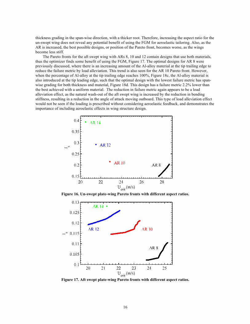
The wing designs considered so far have an aspect ratio (AR) of 8. However, the use of FGM may become more or less beneficial when the aspect ratio is increased. The effect of wing aspect ratio is investigated for the un-swept and aft swept wings. The optimization problem (Eq. 9) is again solved using the NSGA2 optimization method, as discussed above. In each case both material and thickness distributions are considered as design variables during the optimization. If using FGM is beneficial for aeroelastic tailoring, then designs along the Pareto fronts should contain significant amount of both the Al-alloy and AlSiC materials. The higher aspect ratio wings are designed to maintain the total area of the wing. Therefore, as the aspect ratio is increased the chord length is decreased accordingly. The results for the un-swept and aft swept wings are shown in Figure 16 and Figure 17, respectively.
For the un-swept wing with an aspect ratio of 10 or above the Pareto front collapses to a single design point, Figure 16. In each case the optimal design is composed of 100% of the AlSiC material and has a
16
thickness grading in the span-wise direction, with a thicker root. Therefore, increasing the aspect ratio for the un-swept wing does not reveal any potential benefit of using the FGM for aeroelastic tailoring. Also, as the AR is increased, the best possible designs, or position of the Pareto front, becomes worse, as the wings become less stiff.
The Pareto fronts for the aft swept wing with ARs 8, 10 and 12 contain designs that use both materials, thus the optimizer finds some benefit of using the FGM, Figure 17. The optimal designs for AR 8 were previously discussed, where there is an increasing amount of the Al-alloy material at the tip trailing edge to reduce the failure metric by load alleviation. This trend is also seen for the AR 10 Pareto front. However, when the percentage of Al-alloy at the tip trailing edge reaches 100%, Figure 18c, the Al-alloy material is also introduced at the tip leading edge, such that the optimal design with the lowest failure metric has span-wise grading for both thickness and material, Figure 18d. This design has a failure metric 2.2% lower than the best achieved with a uniform material. The reduction in failure metric again appears to be a load alleviation effect, as the natural wash-out of the aft swept wing is increased by the reduction in bending stiffness, resulting in a reduction in the angle of attack moving outboard. This type of load alleviation effect would not be seen if the loading is prescribed without considering aeroelastic feedback, and demonstrates the importance of including aeroelastic effects in wing structure design.
Figure 16. Un-swept plate-wing Pareto fronts with different aspect ratios.
Figure 17. Aft swept plate-wing Pareto fronts with different aspect ratios.

17
Figure 18. AR 10 aft swept plate-wing optimal designs, a) best flutter design, b) design with 𝑼𝒄𝒓𝒊𝒕 = 23.0 m/s, c) design with 𝑼𝒄𝒓𝒊𝒕 = 22.4 m/s, d) lowest failure design. Color shading shows fraction of Al-alloy.
The trends observed for the AR 10 wing are also observed for the AR 12 wing. However, the
introduction of the Al-alloy material occurs much earlier and there is only one design with 100% of the AlSiC material, Figure 19a, which also has the highest critical aeroelastic speed. This is because there is no trade-off in thickness grading and all designs on the Pareto front have chord-wise thickness grading, Figure 19. The design at the left of the Pareto front has a failure metric 5.4% lower than the uniform material design at the right of the Pareto front. For the AR 14 wing the trend breaks down and the Pareto front collapses to a single optimal design that is made from 100% of the AlSiC material and has chord-wise thickness grading. At this point the advantage gained by allowing the wing to bend more and thus increase the load alleviation effect of the natural wash-out is overtaken by the disadvantage of the decreased bending stiffness. This shows that there is a limit to the load alleviation effect obtained by reducing the bending stiffness to increase wash-out. These results show that, for an aft swept wing up to a certain aspect ratio, FGM material using Al-alloy and AlSiC can be used as part of an aeroelastic tailoring strategy to reduce the failure metric by load alleviation. The results also demonstrate that aspect ratio is an important consideration when using FGM for aeroelastic tailoring.
Figure 19. AR 12 aft swept plate-wing optimal designs, a) best flutter design, b) design with 𝑼𝒄𝒓𝒊𝒕 = 21.2
m/s, c) lowest failure design. Color shading shows fraction of Al-alloy.
4.3 Different Material Combinations
So far, this study has only considered a FGM composed of two materials with similar density, but one material has a 45% increase in elastic modulus and a 57% increase in yield stress, Table 1. To begin to understand the implications of using other materials, with more diverse properties, two additional materials are considered. These are a steel material and a titanium alloy (Ti-alloy) whose properties are summarized in Table 5. These materials are used to create two new material pairs for the FGM. The first used the AlSiC material and the Ti-alloy. These two materials have similar elastic moduli (107 and 114 GPa respectively), but the Ti-alloy has 60% lower density and approximately double the yield stress. The second FGM material pair is Al-alloy and steel. These two materials are chosen as they have the greatest range in both modulus and density.
Table 5. Additional material properties used for grading studies.

18
Property Steel Ti-alloy density (kg/m3) 7833 4430 elastic modulus (GPa) 200 114 Poisson’s ratio 0.32 0.34 yield stress (MPa) 517 880
The density of the steel and Ti-alloy materials is significantly greater than the density of the aluminum
materials. Therefore, the lower limit for the thickness variables is decreased to 0.1 mm. Also, due to the disparity in material density, it is difficult to use one of the thickness variables to eliminate the wing mass constraint in the optimization problem Eq. 9, when using both thickness and material as the design variables. For these cases, the constraint is actively used in the optimization algorithm, and all four thickness variables are considered, alongside the four material fraction variables. Also, when optimizing for the material distribution only, a uniform thickness plate is used, where the thickness is computed to meet the mass constraint. The mass constraint is the same as that for the initial optimization study discussed above. A series of Pareto fronts are found for the un-swept and aft swept wings at AR 8 and using different design variables.
The Pareto fronts for the un-swept wing using the AlSiC / Ti-alloy FGM are shown in Figure 20. The first observation is that the designs that use only Ti-alloy have much worse performance than the optimal design that uses only AlSiC. This is because the density of the Ti-alloy is greater than that of the AlSiC material, but their stiffness values are similar. Thus, to meet the mass constraint the Ti-alloy designs are thinner and therefore have significantly lower flexural rigidity, which is proportional to thickness cubed. The Pareto front for thickness optimization using only AlSiC collapses to a single design point. This design has near minimum thickness at the tip trailing edge, but maximum thickness at the other four corners, Figure 21b. This design lies on the Pareto front obtained when both material and thickness are considered as design variables. However, the Pareto front has designs with slightly higher critical aeroelastic speeds and lower failure metric. This is due to the addition of Ti-alloy through use of the FGM. The design with the highest critical aeroelastic speed has a small amount (10%) of Ti-alloy at the tip leading edge and similar thickness grading to the optimal AlSiC design, Figure 21a. The divergence and flutter speeds for these designs are very close, within one speed increment (0.2 m/s) in the p-k analysis. The design with the lowest failure metric has an increasing amount of Ti-alloy towards the root leading edge and decreased thickness at the tip leading edge, compared with the optimal AlSiC design, Figure 21c. In this case, the reduction in the failure metric is mainly due to the reinforcement of the high stress area near the root leading edge by the material with the higher yield stress and is not an aeroelastic tailoring effect.
For the aft swept wing using the AlSiC / Ti-alloy FGM (Pareto front shown in Figure 22), the optimal design using only AlSiC has the highest critical aeroelastic speed of all designs, and the thickness grading is similar to the optimal design for the un-swept wing, Figure 23a. Again, the optimal AlSiC design is part of the Pareto front obtained when both thickness and material are used as the design variables. In this case, the introduction of the Ti-alloy material using the FGM allows designs with a lower failure metric compared with the optimal uniform material design. This is achieved mainly through increasing the amount of Ti-alloy at the root, then leading edge, combined with a decrease in the trailing edge thickness, Figure 23b and c. The introduction of the Ti-alloy at the root helps reduce the failure metric as it has a higher yield stress than the AlSiC material and is not an aeroelastic tailoring effect. However, the accompanying thickness reduction at the trailing edge moves the CG forward, which helps increase the critical aeroelastic speed.
The optimization results that used the AlSiC and Ti-alloy materials demonstrate that an FGM composed of these two materials can improve the performance of both un-swept and aft swept wings. This performance increase from the FGM is mainly for a reduction in the failure metric through reinforcement of the high stress areas using the higher yield stress material and is not an aeroelastic tailoring effect.

19
Figure 20. Un-swept plate-wing GA optimization using an AlSiC / Ti-alloy FGM.
Figure 21. Un-swept plate-wing optimal designs using AlSiC / Ti-alloy FGM, a) best flutter design, b)
best AlSiC material design, c) lowest failure design. Color shading shows fraction of AlSiC.
Figure 22. Aft swept plate-wing GA optimization using an AlSiC / Ti-alloy FGM.
The Pareto fronts for the un-swept wing using the Al-alloy/steel FGM are shown in Figure 24. The performance of the uniform material designs that used the steel material are not shown, as the optimizer fails to find any designs that are stable during the static aeroelastic analysis. These designs are much thinner than the Al-alloy designs, as steel is much denser and there is a mass constraint that needs to be satisfied. Steel does have a higher elastic modulus than Al-alloy, but flexural rigidity is proportional to thickness cubed and

20
only varies linearly with modulus. Thus, the steel designs were significantly less stiff and their critical aeroelastic speed is always lower than the flight speed of 15 m/s. The optimal design using the Al-alloy material, Figure 25b, lies near the Pareto front obtained when both thickness and material are considered. However, in contrast to previous results, the optimal uniform material design does not lie at the extreme right of the Pareto front and designs that used the FGM attained either a higher critical aeroelastic speed, or lower failure metric. Designs with higher critical aeroelastic speed have a significant amount (around 50 - 60%) of the steel material at the root leading edge, less (0-15%) at the tip leading edge and chord-wise thickness grading, Figure 25a.
Figure 23. Aft swept plate-wing optimal designs using AlSiC / Ti-alloy FGM, a) best flutter design, b)
design with 𝑼𝒄𝒓𝒊𝒕 = 20 m/s, c) lowest failure design. Color shading shows fraction of AlSiC.
Figure 24. Un-swept plate-wing GA optimization using an Al-alloy / Steel FGM.
Figure 25. Un-swept plate-wing optimal designs using Al-alloy / Steel FGM, a) best flutter design, b)
best Al-alloy design, c) lowest failure design. Color shading shows fraction of Al-alloy.
For these designs, the critical aeroelastic speed is flutter. The difference between the 2nd and 3rd natural frequencies (which corresponds to the bending and torsion modes involved in the flutter mode) is 68.3 rad/s for the design with the highest flutter speed, compared with 52.7 rad/s for the optimal design using thickness grading only. This suggests that the introduction of the steel when using the FGM helps increase the flutter speed by separating these modes. Also, the introduction of the steel material along the leading edge when

21
using the FGM has a mass balancing effect that moves the CG forward, which also helps increase the flutter speed compared with the uniform material design (Bisplinghoff et al. 1996). Furthermore, the critical flutter mode for the uniform material design is the 2nd bending mode, Figure 26a. However, the 1st torsion mode almost flutters at a lower speed, before becoming more stable. This behavior is known as a suppressed hump mode. The situation is reversed for the FGM design with the best flutter speed, where the 1st torsion mode is critical for flutter, Figure 26b. Although these designs are optimal for a deterministic problem, the presence of the suppressed hump mode is not a reliable design, as a small change in the design or operating conditions could have a significant adverse effect on the flutter speed.
The designs with a lower failure metric have less steel at the root leading edge (around 20%) and mostly span-wise thickness grading, with some chord-wise thickness grading nearer the tip, Figure 25c. The steel at the root reduces the failure metric by reinforcing the high stress region with a material with a higher yield stress. In addition, the chord-wise thickness grading at the tip reduces the wash-in of the un-swept wing, resulting in load alleviation.
Figure 26. U-g diagrams relating to Figure 25, a) best Al-alloy design, b) best flutter design. The first
bending (1B), second bending (2B) and first torsion (1T) modes are indicated.
For the aft swept wing using the Al-alloy / steel FGM, the optimal design for critical aeroelastic speed is an Al-alloy uniform material design, Figure 27, which has minimum thickness at the tip trailing edge and maximum thickness at the other three corners, Figure 28a. This design lies on the Pareto front obtained when using both thickness and material as design variables. The designs along the front benefit from the FGM composed of Al-alloy and steel. The steel material is introduced at the root leading edge, Figure 28b, and the design with the lowest failure metric has almost 100% steel at this location, Figure 28c. This suggests that the reduction in failure metric is achieved by adding material with a higher yield stress to the high stress region: not an aeroelastic tailoring effect.

22
Figure 27. Aft swept plate-wing GA optimization using an Al-alloy / steel FGM.
The optimal designs obtained using the Al-alloy and steel materials demonstrate that a FGM composed of these two materials can improve the performance of both un-swept and aft swept wings. For the un-swept wing the FGM material could be used to improve either the critical aeroelastic speed through mass balancing or the failure metric through reinforcement. For the aft swept wing, on the other hand, the improvement is solely due to a reduction of the failure metric though reinforcement.
Figure 28. Aft swept plate-wing optimal designs using Al-alloy / steel FGM, a) best flutter design, b)
design with 𝑼𝒄𝒓𝒊𝒕 = 20 m/s, c) lowest failure design. Color shading shows fraction of Al-alloy.
4.4 Material Grading Excluding Yield Stress Variation
In the above examples the reduction seen in the failure metric when using the FGM often involves a load alleviation mechanism due to an aeroelastic tailoring effect. However, reinforcing the high stress areas near the root with the higher yield stress material also helps reduce the failure metric. To investigate the effect of the aeroelastic tailoring alone, a further study is conducted where the two materials in the FGM have the same yield stress, but either different density or elastic modulus. The baseline material used for this study is the Al-alloy. This is paired with a fictitious material with double the elastic modulus and another with double the density. Although the double density material is fictitious, its effect could be approximated (e.g., for a wind tunnel test model) by adding non-structural mass to the wing. Using these two new FGMs the optimization problem in Eq. 9 is solved using the GA considering material grading, thickness grading and both as design variables. Only the aft swept wing is considered, as the results so far show this to be the most promising for using FGM for aeroelastic tailoring.
The Pareto fronts for the FGM using Al-alloy and a double density material are shown in Figure 29. The fronts are close when using thickness only (using the lower density material) and both thickness and material as the design variables. The two fronts have similar trends for the thickness variation. The best design for the critical aeroelastic speed has minimum thickness at the tip trailing edge and maximum thickness at the other corners. The thickness of the plate is reduced at the tip leading edge and root trailing edge to reduce the failure metric. Figure 30 shows a general correlation between the tip twist and the failure metric. This suggests that the failure metric is partly reduced by an aeroelastic load alleviation effect caused by an

23
increase of the natural wash-out of the aft swept wing. This aeroelastic tailoring is achieved using thickness grading, as the material distribution does not affect the stiffness or the strength of the wing and thus does not affect the failure metric. The designs on the Pareto front obtained using both material and thickness as design variables do contain some of the double density material. The double density material is introduced along the leading edge, primarily at the tip, but also at the root, which suggests that the slight increase in critical aeroelastic speed is due to a mass balancing effect, as the CG is moved forward. This mass balancing effect helps move the Pareto front slightly to the right and results in a small gain in the critical aeroelastic speed, by up to 5% for the same value of the failure metric.
The Pareto fronts for the FGM using Al-alloy and a double elastic modulus material are shown in Figure 31. The front for thickness variation only (using the double stiffness material) is a single point, which has minimum thickness at the tip trailing edge and maximum thickness at the other corners, Figure 32a. This is also the design with the highest critical aeroelastic speed. The front obtained when both thickness and material are considered as design variables contains designs with a lower failure metric by using the FGM. The front can be split into two parts. The first part starts from the best critical aeroelastic speed design and introduces the lower stiffness Al-alloy material at the root trailing edge until it reaches nearly 100%; this point corresponds to the kink in the front, Figure 32b. Then the lower stiffness material is introduced at all four corners until the design with the lowest failure metric has 100% Al-alloy at the root trailing edge and tip leading edge, 86% at the tip trailing edge and 19% at the root leading edge, Figure 32c. The final reduction in the failure metric using the FGM, compared with the uniform material design, is 27.6%. The yield stress of the two materials is the same, thus the reduction in the failure metric must be an aeroelastic tailoring effect. Figure 33 shows a clear correlation between the tip twist and the failure metric. This suggests that the failure metric is reduced by a load alleviation effect caused by an increase in the natural wash-out of the aft swept wing. The thickness distribution for all designs on the Pareto front is the same, Figure 32, therefore the reduction in the failure metric is purely an aeroelastic tailoring effect though distribution of stiffness using the FGM.
Figure 29. Aft swept plate-wing Pareto fronts using an Al-alloy and a double density material.

24
Figure 30. Aft swept plate-wing, tip twist under static aerodynamic loading, relating to Figure 29.
It is also useful to compare the aft swept wing result using the Al-alloy / double modulus FGM, Figure 31, with that previously obtained using the Al-alloy / AlSiC FGM, Figure 10. For the Al-alloy / AlSiC FGM the reduction in failure metric through load alleviation is due to the introduction of the less stiff Al-alloy material at the tip trailing edge, resulting in an overall 1% reduction compared with the best a uniform material design. This is in contrast to the trend for the Al-Alloy / double modulus FGM, where the less stiff material is first introduced at the root trailing edge and the best design attained a 27.6% reduction in the failure metric. The key difference between the two is that the AlSiC material has a higher yield stress than the Al-alloy material. This suggests that the benefit of reducing the loading through aeroelastic tailoring is countered by the reduction in yield stress when replacing the AlSiC material with Al-alloy at the root trailing edge. Therefore, the optimizer favors introducing the less stiff Al-alloy material at the tip, rather than root, trailing edge when using the Al-alloy / AlSiC FGM.
Figure 31. Aft swept plate-wing Pareto fronts using an Al-alloy and a double modulus material.

25
Figure 32. Aft swept plate-wing optimal designs using Al-alloy / double modulus material FGM, a) best flutter design, b) design at kink in Figure 31, c) lowest failure design. Color shading shows fraction of
lower stiffness Al-alloy.
Figure 33. Aft swept plate-wing, tip twist under static aerodynamic loading, relating to Figure 31.
5. Conclusions This paper investigates the use of material and thickness grading for aeroelastic tailoring of a
cantilevered plate-like wing, where the basic geometry and flow conditions are largely taken from Hollowell and Dugundji (1984). The study explores different aspect ratios and sweep angles, as well as a range of different material combinations, and a study of discrete versus continuous material grading. A simple bilinear grading strategy across the wing planform (no grading through the depth of the structure) is used for both material and thickness values. A multiobjective genetic algorithm is used to explore the ensuing design space, where the optimal trade-off curve (Pareto front) between two conflicting metrics is of interest: static aeroelastic stresses, and dynamic aeroelastic flutter.
The main conclusion is that an FGM can be used to improve the performance of a plate-like wing compared with a uniform material design. This benefit is often seen as a reduction in the failure metric. In some cases the reduction is due to a reinforcement of high stress areas using a material with a higher yield stress, which is not an aeroelastic tailoring effect. However, for aft swept wings, the failure metric is also reduced using aeroelastic load alleviation by modifying the stiffness to decrease the local angle of attack of the deformed wing shape under the static aerodynamic load condition. There is also one case for the un-swept wing where an FGM design has a significantly higher critical aeroelastic speed compared with the optimal uniform material design. This is possible as there is a large difference in the densities of the two materials used to form the FGM. This permits a mass balancing effect to separate the frequencies of bending and torsion modes involved in the flutter mode and move the CG forward. Both of these effects are known to help increase the flutter speed.
However, the introduction of FGM does not always produce an improvement for the plate-like wings, and the potential benefit of using a FGM for aeroelastic tailoring is dependent on several factors. The most significant factor appears to be the choice of material pair used for the FGM, as the trends are not consistent when different materials are used. The wing sweep and aspect ratio are also important factors. Depending on the sweep or aspect ratio, the use of FGM for aeroelastic tailoring may become more or less beneficial. Note

26
that our study did not observe benefits for a forward swept wing. Also, there is a small difference when comparing discrete material grading with bilinear material grading, which sometimes results in an improved performance for discrete grading designs. However, the realization of discrete material grading in practice can be enabled by a FGM strategy where the discrete jump is smoothed over a short distance. This may prove to be more durable than the alternative: mechanically welding two different materials together where stress concentrations may arise.
Acknowledgements This work is funded by the Fixed Wing project under NASA’s Fundamental Aeronautics Program. The
authors would also like to thank Dr. Maxwell Blair for providing his DLM code.
References Appa, K., 1989. Finite-Surface Spline, Journal of Aircraft 26, 495-496. Birman, V., Byrd, L., 2007. Modeling and Analysis of Functionally Graded Materials and Structures,
Applied Mechanics Reviews 60, 195-216. Blair, M., 1992. A Compilation for the Mathematics Leading to the Doublet Lattice Method, Report No. WL-
TR-92-3028, Wright-Patterson Air Force Base, Ohio. Bisplinghoff, R., Ashley, H., Halfman, R., 1996. Aeroelasticity, Dover Publications, Mineola, NY. Cook, R., Malkus, D., Plesha, M., Witt, R., 2002. Concepts and Applications of Finite Element Analysis,
John Wiley & Sons, New York. Deb, K., Pratap, A., Agarwal, S., Meyarivan, T., 2002. A Fast and Elitist Multiobjective Genetic Algorithm,
IEEE Transactions on Evolutionary Computations 6 182-197. Goldberg, D.E., 1989. Genetic Algorithms in Search, Optimization and Machine Learning, Addison-Wesley
Longman Publishing Co., Inc. Boston, MA, USA. Jutte, C.V., Stanford, B.K., 2014. Aeroelastic Tailoring of Transport Aircraft Wings: State-of-the-Art and
Potential Enabling Technologies. NASA/TM-2014-218252. Lehoucq, R.B., Sorensen, D.C., Yang, C., 1998. ARPACK Users Guide: Solution of Large-Scale Eigenvalue
Problems with Implicitly Restarted Arnoldi Methods. SIAM, Philadelphia. Librescu, L., Maalawi, K., 2007. Material Grading for Improved Aeroelastic Stability in Composite Wings,
Journal of Mechanics of Materials and Structures 2, 1381-1394. Hollowell, S., Dugundji, J., 1984. Aeroelastic Flutter and Divergence of Stiffness Coupled, Graphite/Epoxy
Cantilevered Plates, Journal of Aircraft 21, 69-76. Marzocca, P., Fazelzadeh, S., Hosseini, M., 2011. A Review of Nonlinear Aero-Thermo-Elasticity of
Functionally Graded Panels, Journal of Thermal Stresses 34, 536-568. Miyamoto, Y., Kaysser, W., Rabin, B., Kawasaki, A., Ford, R., 1999. Functionally Graded Materials: Design
Processing and Applications, Kluwer Academic, Dordrecht, The Netherlands. Navazi, H., Haddadpour, H., 2007. Aero-Thermoelastic Stability of Functionally Graded Plates, Composite
Structures 80, 580-587. Rodden, W., Harder, R., Bellinger, E., 1979. Aeroelastic Addition to NASTRAN, NASA CR 3094. Rodden, W.P, Taylor, P.F., McIntosh Jr., S.C., 1998. Further Refinement of the Subsonic Doublet-Lattice
Method, Journal of Aircraft 35, 720-727. Shirk, M., Hertz, T., Weisshaar, T., 1986. Aeroelastic Tailoring – Theory, Practice, Promise, Journal of
Aircraft, 23, 6-18. Sohn, K., Kim, J., 2008. Structural Stability of Functionally Graded Panels Subjected to Aero-Thermal
Loads, Composite Structures 82, 317-325. Taminger, K., Hafley, R., 2003. Electron Beam Freeform Fabrication: A Rapid Metal Deposition Process,
Proceedings of the 3rd Annual Automotive Composites Conference, Troy, MI, September 9-10. van Zyl, L., 2001. Aeroelastic Divergence and Aerodynamic Lag Roots, Journal of Aircraft 38, 586-588. van Zyl, L., 1993. Use of Eigenvectors in the Solution of the Flutter Equation, Journal of Aircraft 30, 553-
554. Weisshaar, T., Nam, C., Batista-Rodriguez, A., 1998. Aeroelastic Tailoring for Improved UAV Performance,
AIAA Structures, Structural Dynamics, and Materials Conference, Long Beach, CA, April 20-23.