aerodynamic design studies of conventional and...
TRANSCRIPT

American Institute of Aeronautics and Astronautics
1
25th Applied Aerodynamics Conference, 5-8 June. 2006, San Francisco, CA, USA,
Aerodynamic Design Studies of Conventional & Unconventional Wings with Winglets
Dr. R. K. Nangia Dr. M. E. Palmer Mr. R. H. Doe Nangia Aero Research Associates,
WestPoint, 78-Queens Road, BRISTOL, BS8 1QX, UK. Tel: +44 (0)117-987 3995 Fax: +44 (0)117-987 3995
In the pursuit of efficiency there is continued and developing interest in the subject of winglets and novel designs such as Blended Wing Body and Oblique Flying Wing. Winglets may exist in many modes, ranging from endplates, through folded wing tips to complex upper and lower surface partial chord devices.
We have developed a design process that is directly applicable to the design of wings and winglet combinations. A set of target conditions is established. These may be, for example, minimum lift-induced drag, minimum wave drag, a known structural loading or pitching moment control. The design process is iterative and, in general, is driven towards the idealised spanwise load distribution for minimum drag. A degree of pitch control has also been demonstrated on selected configurations.
The method may be used to design from “scratch” or in the corrective sense to optimise a current design for new requirements at the design point.
The method has been applied to the design of several configurations of current interest, conventional A340 type wing, Blended Wing Body and Oblique Flying Wing. Winglets have been simulated by folding the outer wing through various angles.
The technique has proved to be easy to use. It is enlightening as it gives, at every stage, a feel for what is happening in terms of camber development, pressure distributions and Centre of Pressure location. Favourable characteristics of the configuration can be enhanced whereas those that are not beneficial can be minimised or avoided as the design progresses.
Nomenclature AR Aspect Ratio b = 2 s, Wing span c Local Wing Chord cav = cref = S/b, Mean Geometric Chord CA = Axial force/(q S), Axial Force Coefficient CAL Local Axial Force Coefficient CD = Drag Force /(q S), Drag Coefficient (CDi+ CD0) CDi Lift Induced Drag Coefficient CDL Local Drag Coefficient CG Centre of Gravity CL = Lift Force/(q S), Lift Coefficient CLL Local Lift Coefficient Cm = m/(q S cav), Pitching Moment Coefficient CmL Local Pitching Moment Coefficient CP Coefficient of Pressure LE, TE Leading Edge, Trailing Edge LEF, TEF Leading Edge Flap, Trailing Edge Flap L/D Lift to Drag ratio m Pitching moment M Mach Number q = 0.5 ρ V2, Dynamic Pressure RBM Root Bending Moment (typically of wing about fuselage side) Re Reynolds Number, based on cav s, S semi-span, Wing Area V Free-stream Velocity
24th Applied Aerodynamics Conference5 - 8 June 2006, San Francisco, California
AIAA 2006-3460
Copyright © 2006 by Dr R K Nangia. Published by the American Institute of Aeronautics and Astronautics, Inc., with permission.

American Institute of Aeronautics and Astronautics
2
xAC Chordwise position of Aerodynamic Centre xCP Chordwise location of Centre of Pressure yCP Spanwise location of Centre of Pressure α AoA, Angle of Attack ß √ (M2-1) λ Taper Ratio, ct/cr Λ LE Sweep Angle η = y/s, Non-dimensional spanwise distance ρ Air Density
I. INTRODUCTION he benefits of fitting winglets to existing wing designs have been appreciated for some time, Refs.1-7. The Airbus A340 wing (conventional), designed with winglets, is shown in Fig.1. The theory leading to the advantages is illustrated in Fig.2 (from Ref.1). The winglets act like small sails having a thrust component that
reduces drag. They also reduce the tip vortex strength, reducing induced drag. However, their presence naturally increases viscous drag and the forces acting on them increases wing bending which may require additional strengthening, increasing weight and thereby negating the benefits. The exact aerodynamics giving rise to the benefits have been difficult to understand. The Reynolds number has a significant impact on the flow structure around the winglet. There has not been good correlation between wind tunnel (low Re) and flight test (high Re) results. CFD has been used to analyse the flow mechanisms and optimise winglet design.
There are many different facets to winglet design and variations on this theme. These range from early ideas of using end-plates to minimise tip flow, through folded tips to reduce wave drag at high speed or enhance lift at low-speed in-ground-effect, to the addition of winglets already described. It is encouraging to note that there is continued interest in the subject. One of the approaches applicable to winglet design is described in Ref.8. As a result of this and previous work on wing design (low speed / high lift, Refs.9-12, supersonic, Refs.13-18, unconventional planforms, Refs.19-27, inverse design, Ref.28) we have developed a design process that is directly applicable to the design of wings and winglet combinations. As a starting point, we have applied the method to a range of wing planforms of current interest. Winglets, of various angles, have been simulated by folding the outer portions of the wing upwards. The design has then been driven towards the idealised spanwise load distribution for minimum drag.
Cases Considered
The method has been applied to several configurations currently of interest. We begin with a conventional civil aircraft wing (A340 planform type, Fig.1). Simple winglets are represented by folding the wing (tip upwards), about y/s = 0.875, through a range of fold angles (30o, 45o, 60o & 75o).
As we strive for greater aerodynamic efficiency in the civil aircraft world, the Blended Wing Body (BWB) concept, Fig.3, continues to offer potential, Refs.29-31. We present results for a typical BWB planform with winglets represented by folds (0o & 45o) about y/s = 0.9. For this case, stability issues have been addressed.
The Oblique Flying Wing concept (OFW), Fig.4, Ref.32, is also receiving renewed interest in both civil and military applications. We present results for a 30o swept Oblique wing with 75o winglet at 0.875 of the span, trailing tip.
In each case, the analysis begins with an assessment of the planar, uncambered wing. This establishes the design target and is used as a guide to the success of the design process. For stability and wing bending moments we monitor the location of the Centre of Pressure (xCP, yCP). For the conventional wing, the effect of winglet setting angle on drag is also monitored.
II. APPROACH AND DESIGN METHODOLOGY Fig.5 shows the “Flow” diagram of the approach. This assumes that the starting conditions are very basic, i.e. neither the camber nor twist distributions are known for the wing or winglet. This represents the complete and hardest design problem, i.e. starting from “scratch”. There are three main processes operating between the Target and Evaluation phases. The target conditions can come from the 2-D (cross-flow) Trefftz-plane analysis and can include all sorts of geometry, body, propulsion, structural and aerodynamic constraints. In this case, the differences between the target and the starting conditions (uncambered – untwisted) wings are usually large. These arise due to non-linearities that are essentially ignored in the 2-D Trefftz-plane analysis. For unconventional designs, this is probably the route to follow. Symmetric and asymmetric (e.g. oblique wings) can be handled. If we were to begin with a known wing / winglet combination (i.e. with a reasonable knowledge of camber and twist), then the “flow” diagram operates in a simpler “corrective” sense. The differences between target and the starting condition are likely to be smaller. This might well be the preferred way of doing things on conventional designs. The whole process is set up as cyclic leading towards convergence. Experience suggests that 3-6 cycles are needed on the simpler cases / configurations. Currently for the sake of expedience, we are confining our work using Panel codes, Ref.33. Cases evaluated with Euler codes, Ref.34, will be next.
T

American Institute of Aeronautics and Astronautics
3
III. CONVENTIONAL WING The conventional wing (A340 planform type, Fig.1) is initially assessed in its planar, no camber, condition. The
wing is then designed for a known CL and Mach combination. Simple winglets are represented by folding the wing (tip upwards), about y/s = 0.875, through a range of fold angles. The wetted surface area is therefore constant for all cases, conventional wing and wing with winglets. The projected wing area varies but a constant reference area has been used for all cases. At this preliminary design stage, very simple aerofoils were used.
We have found the whole process very interesting as it gives at every stage, a feel for what is happening in terms of camber development, pressure distributions and Centre of Pressure location.
III.1. Conventional Wing, no winglet, no camber, Mach 0.8 Fig.6 (a-c) refers to a “conventional” wing layout. The planar, non-cambered, geometry is shown in (c). At this
stage, the aerofoils chosen are fairly simple sections. The spanwise loadings, lift and drag, without and with c/cav factor, over an incidence range 0o to 5o, are shown in (a). The Cp – x, chordwise loadings (b) indicate that the tip area is highly loaded, and prone to separation. For the planar wing (no camber) an incidence of 4.0o achieves a CL of 0.494.
This establishes the design problem. We select a design CL of 0.5 at Mach 0.8. In general, we may then choose to design for minimum drag (elliptic loading), a predetermined level of stability or a compromise between the two.
III.2. Conventional Wing, no winglet, Mach 0.8, CL= 0.5 design
Fig.7 (a-f) refers to a “conventional” wing layout without winglets. Here the target was simple “optimum” minimum drag loading from Trefftz-plane basis. With a highly loaded wing tip area, this is a fairly “challenging” case. It can be seen from (a) and (b) that the target distribution has been achieved within five design cycles. The spanwise loadings show the small region of suction force at the tip, Ref.2.The resultant camber distribution (c) is smooth and consistent. At the root, the camber profile is “S” shaped with 3.9o of twist. At the tip the section is twisted by 0.8o. The “peaky” Cp-x distributions near the tip have been ameliorated (e). The Cp graphs including contours from Euler compare well as envisaged. The CL – � and Cm – CL relationships for the planar and design cases are shown in (f).
This minimum drag wing design was very unstable. A design, with a certain degree of stability can be achieved with the wing in isolation. However, the effects of fuselage and the contribution of the tail components need to be considered before any in-depth design is undertaken. At this stage, stability issues have not been dealt with for the isolated, conventional wing case. The design process easily accommodates stability requirements as will be seen for the Blended-Wing-Body (BWB) configuration.
III.3. Conventional Wing with 45o Winglet, Mach 0.8, CL= 0.5 Design
Before starting the design process, preliminary calculations were made on the planar, non-cambered configuration. As in the case of the planar wing without winglet, the 45o winglet planar case is highly loaded near the tip and is prone to flow separation. Again this is a fairly “challenging” case.
Fig.8 (a-f) refers to a “conventional” wing with 45o winglet. Again, the target was simple “optimum” minimum drag loading from Trefftz-plane basis. The sequence of figures, (a-f) are consistent with those for the conventional wing. The spanwise loadings in (a) are presented in the unfolded sense. The increase in fold angle has enlarged the suction force area at the tip. It is this effect which needs to be exploited to gain the full benefit of folded tips and winglets. The target distribution has been achieved within five design cycles, (a) and (b). The resultant camber distribution is smooth and consistent. Less positive camber is required at the tip than for the design without winglet. At the root, the camber profile is “S” shaped with 4.2o of twist. The “peaky” Cp-x distributions near the tip have been ameliorated (e). The Cp contours (Euler) and Cp distributions (Panel code) show continuity across the fold-line as envisaged. The CL – � and Cm – CL relationships for the planar and design cases are shown in (f).
Further winglet angles (30o, 60o and 75o) on the conventional wing have also been assessed. Results for the 75o winglet are now discussed.
III.4. Conventional Wing with 75o Winglet, Mach 0.8, CL= 0.5 design
Results for the “conventional” wing with 75o winglet are presented in Fig.9 (a-f) with the spanwise loadings, (a) and (b) presented in the unfolded sense. Again, the target was simple “optimum” minimum drag loading from Trefftz-plane basis. As for the previous planar (not designed) cases, the tip area is highly loaded and is prone to flow separation, a fairly “challenging” design case.
The target distribution has been achieved within five design cycles, (a) and (b). The resultant camber distribution is smooth and consistent. The camber distribution over the 75o winglet is noticeably different from that of the 45o case, (c). At the root, the camber profile is “S” shaped with 4.3o of twist. The “peaky” Cp-x distributions near the tip have been ameliorated (e). The CL – � and Cm – CL relationships for the planar and design cases are shown in (f).
III.5. Effect of Winglet Setting Angle on Drag and Wing Bending Moment
A brief analysis of the effect of Winglet Angle on Drag, Centre of Pressure location (xCP, yCP) and Wing Bending Moment, at CL = 0.5 and Mach 0.8, is shown in Fig.10.

American Institute of Aeronautics and Astronautics
4
The variation of CDi with winglet angle for the Mach 0.8, CL = 0.5, designed cases is shown in Fig.10(a). As winglet angle increases, CDi also increases. This arises due to greater degrees of twist and camber being required on the unfolded part of the wing to achieve the design CL. The effect of winglet angle on the Centre of Pressure location (xCP, yCP) at the design condition (Mach 0.8, CL = 0.5) is shown in Fig.10(b). The effects are also shown for +1o and -1o incidence, CL = 0.63 and 0.38 respectively. As the Winglet angle increases the Centre of Pressure moves inboard (and forward), effectively reducing wing bending moment.
We derive CDo for the basic wing (winglet at 0o) assuming L/D = 18, at Mach 0.8, CL=0.5. This CDo term is added to CDi for each winglet case to give CD (total Drag coefficient) at the design condition. Wing Root Bending Moment (RBM) at the fuselage side (y/s = 0.1) for each winglet is determined. RBM and Drag for each winglet angle are non-dimensionalised by corresponding values for the basic wing (winglet at 0o). These non-dimensionalised values are plotted for each winglet angle in (c). This type of graph highlights the reductions in RBM that can be achieved with winglets at the expense of relatively small increases in overall drag. Reduced RBM could result in a lighter, smaller wing with lower CDi and less skin friction drag. Further detailed analysis is required to fully understand the overall benefits to be gained from winglets.
IV. BLENDED WING BODY The BWB , Fig.3, is initially assessed in its planar, no camber, condition. The wing is then designed for a known
CL and Mach combination. Simple winglets are represented by folding the wing (tip upwards), about y/s = 0.9, through a range of fold angles. The wetted surface area is therefore constant for all cases, conventional wing and wing with winglets. The projected wing area varies but a constant reference area has been used for all cases. At this preliminary design stage, very simple aerofoils were used.
We have found the whole process very interesting as it gives at every stage, a feel for what is happening in terms of camber development, pressure distributions and Centre of Pressure location.
IV.1. BWB Layout, no winglet, no camber, Mach 0.8
Fig.11 (a-c) refers to a BWB layout. The planar, non-cambered, geometry is shown in (c). The spanwise (a) and chordwise loadings (b) indicate that the tip area is highly loaded, and prone to separation, and that the root area is lightly loaded. For the planar wing (no camber) an incidence of 3.658o achieves a CL of 0.3. The chordwise distributions near the tip are very “peaky” (b).
IV.2. BWB Layout with 45o Winglet, no camber, Mach 0.8
Results for the planar BWB layout with 45o winglets are shown in Fig.12 (a-c). The winglet geometry is evident in (c). For the planar wing (no camber) an incidence of 3.705o achieves a CL of 0.3. At this condition, the tip area is highly loaded (a) and (b) and is prone to flow separation.
This establishes the design problem. We select a design CL of 0.3 at Mach 0.8. We may then choose to design for minimum drag (elliptic loading), a predetermined level of stability or a compromise between the two. Again, this is a fairly “challenging” case. It has been seen that CLL near the tip may be extremely high. It may be necessary to limit theses values in transonic flight to control the onset of shock induced separation.
IV.3. BWB Layout with 45o Winglet, Mach 0.8, CL = 0.3, without and with CLL constraint
Fig.13 (a-e) refers to a BWB layout with 45o winglet, designed for CL=0.3 at Mach 0.8. The target, as before, was simple “optimum” minimum drag loading from Trefftz-plane basis. There is no CLL constraint and the wing tips remain highly loaded. The target distribution has been achieved within five design cycles, (a) and (b). The resultant camber distribution (c) is smooth and consistent. At the root, the camber profile is “S” shaped with 3.0o of twist. The 3-D geometry is shown in (d). The “peaky” Cp-x distributions near the tip of the planar case have been ameliorated (e). The Cp contours (Euler) and Cp distributions (Panel code) show continuity across the fold-line as envisaged. At the design CL this case was 11.9% cav unstable about the M=0.2 NP (with winglet), Fig.15.
This minimum drag wing design is very unstable. The design process easily accommodates stability requirements. By limiting CLL to a predetermined maximum value, a degree of pitch control is achieved.
Fig.14 (a-e) refers to the same BWB layout with 45o winglet. For the target, we have invoked a simple CLLmax = 0.534 constraint. This affects the outer wing as shown. The sequence of figures, (a-e) are as before. The spanwise loadings in (a) are presented in the unfolded sense. The target distribution has been achieved within five design cycles, (a) and (b). The resultant camber distribution is smooth and consistent. Note the changes in camber near the LE and TE kinks and the fold line. The “peaky” Cp-x distributions near the tip have been ameliorated (e). The Cp contours (Euler) and Cp distributions (Panel code) show continuity across the fold-line as envisaged.
For the BWB with 45o winglet, designing for Mach 0.8, CL=0.3 and minimum drag resulted in an unstable configuration. By limiting CLLmax across the span a degree of pitch control has been achieved as shown in Fig.15. Additional limits on local distributions would further modify the CP location and provide the required degree of pitch control.

American Institute of Aeronautics and Astronautics
5
V. OBLIQUE FLYING WING As a result of DARPA activities, there is revived interest in Oblique Flying Wings (OFW), Fig.4. It is perhaps a
useful check case for the current approach.
V.1 Oblique Flying Wing with 75o Winglet, Mach 0.8, CL = 0.3 Fig.16 (a-e) refers to an OFW flying at 30o sweep with 75o winglet which acts also as a vertical fin (deflection
capability). The first problem is to see what its cambered shape would be when designed for particular conditions. The target as before, was simple “optimum” minimum drag loading from Trefftz-plane basis. There is no CLL constraint. The spanwise loadings, for the first and fifth cycles, with target, are shown in (a) and (b) and are presented in the unfolded sense.
The current approach has, within five cycles, developed a reasonable camber surface (c) for this, rather unique, design problem. The resultant Cp-x (e) distributions at the design condition are well behaved. The distributions on the winglet are slightly more “peaky” than elsewhere. Stability and control analysis for this case will prove to be interesting and it is anticipated, well within the capabilities of the technique. This provides an additional yaw and sideslip challenge.
VI. GENERAL INFERENCES
The main features of the design method are that it is easy to use, both in the “absolute” design mode, starting from scratch, or in a corrective mode to fine tune existing designs. The process is enlightening as it gives, at every stage, a feel for what is happening in terms of camber development, pressure distributions and Centre of Pressure location. Favourable characteristics of the configuration can be enhanced whereas those that are not beneficial can be minimised or avoided as the design progresses.
Although the approach needs further development and verification in several aspects, the results obtained so far are reasonable and are very encouraging. An indication of versatility has been given both within individual design schemes and the scope of geometries accommodated. As we strive for greater efficiency, the technique offers a valuable insight into the process of designing fully integrated winglets on civil aircraft designs to reduce drag and enhance lift. The technique is readily applicable to unique configurations that are currently under consideration, for example Blended Wing Bodies and Oblique Flying Wings. Stability and control factors can be “designed-in” from a very early stage in the design process. Similarly, the inclusion of Reynolds number effects would be advantageous and easily assimilated.
Possible Future Work Several avenues for future work have arisen. The technique requires further development and validation against
other design methods. The method needs to be assessed with other “core” solvers. The capability of the method to design for minimum drag or specified stability levels has been shown. This needs to be extended to other design targets such as shock location control. The ability to design in the presence of other lifting surfaces and “non-lifting” bodies needs to be explored. Many more valuable enhancements can be readily incorporated.
The application of the method to specific projects e.g. optimisation of winglets, design of UAV / UCAV and morphing structures (not just wings) would be advantageous. The design method is eminently suitable for rapid assessment of proposed geometries from the early stages of project selection and continued developments.
VII. ACKNOWLEDGEMENTS The authors have pleasure in acknowledging helpful technical discussions with Mr. R. H. Doe. The work
reported is a part of in-house R & D activities. Opportunities for collaboration are invited.
REFERENCES 1. McCORMICK, B.W. "Aerodynamics Aeronautics and Flight Mechanics", Wiley. 2. KUCHEMANN, D. "The Aerodynamic Design of Aircraft", Pergamon. 3. JUPP, J., “Wing aerodynamics and the Science of Compromise", RAeS Lanchester Lecture, 2001. 4. JONES, R.T., "Wing Theory", Princeton. 5. CARLSON, H.W., SHROUT, S.L., & DARDEN, C.M., “Wing Design with Attainable Leading-Edge Thrust Considerations”.,
AIAA Jo. of Aircraft, Vol.22, No.3, pp 244-8, Marc 1985. 6. RAYMER, D.P., “Aircraft Design – A Conceptual Approach”, AIAA, 2003. 7. JENKINSON et al, “Civil Jet Aircraft Design”, Arnold, 1999 8. LAMAR, J.E., “A vortex Lattice Method for the mean Camber shapes of Trimmed Noncoplanar Trimmed Planforms with
Minimum Vortex Drag”, NASA TN D-8090, 1976. 9. NANGIA, R.K., "The Design of Manoeuvrable" Wings using Panel Methods, Attained Thrust & Euler Codes", ICAS-92.

American Institute of Aeronautics and Astronautics
6
10. NANGIA, R.K. & GALPIN, S.A., "Towards Design of High-Lift Krueger Flap Systems with Mach & Reynolds No. Effects for Conventional & Laminar Flow Wings", CEAS European Forum, Bath, UK, 1995.
11. NANGIA, R. K. & GALPIN, S.A., "Prediction of LE & TE Devices Aerodynamics in High-Lift Configurations with Mach & Reynolds No. Effects", ICAS-1996-2.7.6.
12. NANGIA, R.K., "Low Speed Performance Optimisation of Advanced Supersonic Civil Transport with Different LE & TE Devices", EAC'94, Toulouse, France, Oct.94.
13. NANGIA, R.K. & MILLER, A.S. "Vortex Flow Dilemmas & Control on Wing Planforms for High Speeds", RTO AVT Symposium, Loen, Norway, May 2001.
14. NANGIA, R.K., PALMER, M.E. & DOE, R.H., “A study of Supersonic Aircraft with Thin Wings of Low Sweep”, AIAA 2002-0709, Jan.2002.
15. NANGIA, R.K., PALMER, M.E. "Unconventional Joined-Wing Concept for Supersonic Aircraft", Paper 24, RTO-AVT-99 Conference, Brussels, April 2003.
16. NANGIA, R.K., PALMER, M.E. & IWANSKI, K.P. (AFRL), “Towards Design of Long-range Supersonic Military Aircraft”, AIAA Paper, 2004-5071, Providence Rhode Island, USA, 2004.
17. NANGIA, R.K., PALMER, M.E. & DOE, R.H., “Towards Design of Mach 1.6+ Cruise Aircraft”, AIAA Paper, 2004-5070, Providence, RI, USA, 2004
18. NANGIA, R.K., PALMER, M.E. & IWANSKI, K.P. (AFRL), “Towards Design of Long-range Supersonic "Large" Military Aircraft”, RAeS Paper 16, Sept. 2004, London, UK.
19. NANGIA, R.K., PALMER, M.E. & GREENWELL. D.I., "Design of Conventional & Unconventional Wings for UAV's", RTO-AVT Symposium, "UV for Aerial & Naval Military Operations", Ankara, Turkey, Oct. 2000.
20. NANGIA, R.K., PALMER, M.E. & TILMANN, C.P. (AFRL), "Design of High Aspect Ratio “Lambda-Wings” Incorporating Laminar Flow ", AIAA-2004-1245, 42nd AIAA Aerospace Sciences Meeting, Reno, January 2004.
21. NANGIA, R.K., PALMER, M.E. & TILMANN, C.P. (AFRL), "Design of High Aspect Ratio Double-crank “Lambda-Wings” Incorporating Laminar Flow ", AIAA Paper, 2004-2141 for 34th AIAA Fluid Dynamics 28th June – 1st July 2004, Portland, Oregon, USA.
22.. NANGIA, R.K., PALMER, M.E. & TILMANN, C.P., “Towards Design and Optimisation of Unconventional High Aspect Ratio Joined-Wing Type Aircraft Configurations”, CEAS Conference, June 2002, Cambridge UK.
23. NANGIA, R.K., PALMER, M.E. & TILMANN, C.P., “On Design of Unconventional High Aspect Ratio Joined-Wing Type Aircraft Configurations”, ICAS 2002-25R2, Toronto, Canada.
24. NANGIA, R.K., PALMER, M.E. & TILMANN, C.P., “Unconventional High Aspect Ratio Joined-Wing Aircraft with Aft- & Forward- Swept Wing-Tips", AIAA-2003-0605, Jan. 2003, Reno, USA.
25. NANGIA, R.K., PALMER, M.E. & TILMANN, C.P., “Unconventional High Aspect Ratio Joined-Wing Aircraft Incorporating Laminar Flow”, AIAA-2003-3927, June 2003, Orlando, USA.
26. NANGIA, R.K., "Towards Designing Novel High-Altitude Joined-Wing Sensor-Craft (HALE-UAV)", AIAA Paper 2003-2695, AIAA/ICAS Wright Brothers. Centennial, Dayton, OH, USA, July 2003.
27. NANGIA, R.K., PALMER, M.E. & TILMANN, C.P., "Towards Design of a Novel High-Altitude Joined-Wing Sensor-Craft (HALE-UAV)”, 19th Bristol Unmanned Air Vehicle Systems Conference, 29-31 March 2004.
28. NANGIA, R.K., "Development of an Inverse Design Technique using 3-D Membrane Analogy", Future Paper. 29. LIEBECK, R.H., PAGE, M.A. & RAWDON. B.K., "Blended-Wing-Body Subsonic Commercial Transport", AIAA-98-0438,
Jan. 1998. 30. ROMAN, D., ALLEN, J.B. & LIEBECK, R.H., "Aerodynamic Design Challenges of the Blended-Wing-Body Subsonic
Transport", AIAA-2000-4335, Jan. 2000. 31. NANGIA, R.K. & PALMER, M.E., “FLYING WINGS (Blended Wing Bodies) WITH AFT- & FORWARD- SWEEP,
Relating Design Camber & Twist to Longitudinal Control”, AIAA-2002-4616, August 2002. 32. NANGIA, R.K. & GREENWELL, D.I., "Wing Design of an Oblique-Wing Combat Aircraft", ICAS-2000-1.6.1.
33. PLOTKIN, A. & KATZ, J. “Low-Speed Wing Theory”, Wiley, (Formalized Theory for Panel Codes).
34. GUPTA, K.K. & MEEK, J.L., "Finite Element Multidisciplinary Analysis", AIAA, 2000.
© Dr. R.K. Nangia 2006. Published by the AIAA with permission. All Rights reserved.

American Institute o
Fig. 1 CONVENTIONAL WINGS e.g. A340 with Winglets
Fig. 3 FLYING WINGS, BWB
Fig. 2 WINGLET DESIGN THEORY from Ref.1
f Aeronautics and Astronautics
7
Fig. 4 OBLIQUE FLYING WINGS, OFW

Wing Planform Geometry
START Trefftz-Plane Wake
Geometry with Winglets Include Body, prop.
Process 1 2-D Cross-flow Approach
Constraints Structural BM Aero e.g. CLL
Assess k, BM etc.
CLc/cav & CLL Distbn TARGETS
Process 2 Relating Cp to z
3-D Surface Approach
Chordwise loadings shape, Cm
Thin or Thick
Predict Mean camber surface
Predict Aerofoil surfaces
Process 3 Evaluation Stage
Panel Euler NS
CLc/cav & CLL Distbn. Compare with TARGETS
Cp Distbn.
Differences Appreciable *
* Differences small OPTIONAL Aerofoil
Shock/Tailoring, Inverse
Fig. 5 Possible Scheme
(c) 3-D Surfaces
(a) Spanwise Distbns, Cm about xac
American Institute of Aeronautics and Astrona
8
Fig. 6 Conventional PLANAR Wing, No Wingle
(b) Cp Distributions at CL = 0.5
utics
t, Mach 0.8

American Institute of Aeronautics and Astronautics
9
(a) Spanwise Loadings at Start
(c) Mean Camber surface (unfolded)
Planar
Design
(b) Spanwise Loadings after 5 cycles
(d) 3-D Surfaces
Start
Start
Target
Target
5 cyc & Target
y
z
x
(f) Total Loads, CL – α, α,α,α, Cm - CL
(e) Cp Distributions on Unfolded Surface, Euler & Panel Method
Fig. 7 Conventional Wing (No Winglet), Minimum Drag design, Mach 0.8, CL = 0.5

(a) Spanwise Loadings at Start (b) Spanwise Loadings after 5 cycles
(c) Mean Camber surface (unfolded) (d) 3-D Surfaces
(f) Total Loads, CL – α, α, α, α, Cm - CL
Design
Planar
(e)
Start
Start
Target
Target
5 cyc & Target
y
z
x
Fig. 7 Conventional Wing (No Winglet), Minimum Drag design, Mach 0.8, CL = 0.5
Cp Distributions on Unfolded Surface, Euler & Panel Method
American Institute of Aeronautics and Astronautics
10

(a) Spanwise Loadings at Start (b) Spanwise Loadings after 5 cycles
Start
Target
(f) Total Loads, CL � AoA, Cm - CL
Design
Start
Target
Planar
(c) Mean Camber surface (unfolded) (e)
5 cyc & Target
Fig. 8 Conventional Wing + 45o Winglet, Minimum Drag design, Mach 0.8, CL = 0.5
(e) Cp Distributions on Unfolded Surface, Euler & Panel Method
American Institute of Aeronautics and Astron
11
Cp Distributions on Unfolded Surface, Panel Method
autics

Root
(b) Spanwise Loadings after 5 cycles (a) Spanwise Loadings at Start
(c) Mean Camber surface (unfolded) (e)
(f) Total Loads, CL � AoA, Cm - CL
Start
Start
Target
Target 5 cyc & Target
Design
Planar
y
z
x
Fig. 9 Conventional Wing + 75o Winglet, Minimum Drag design, Mach 0.8, CL = 0.5
(d) 3-D Surfaces
American Institute of Aeronautics and Astronaut
12
Cp Distributions on Unfolded Surface, Panel Method
ics

Effect
CDi
Fo
(b) Effect of Winglet Angle onCentre of Pressure Location
(a) Effect of Winglet Angle on CDiAmerican I
Fig. 10 Conve of Winglet Angle on Cen
(b) Effect of Wing
ld
nstitute of Aeronautics and Astronautics
13
ntional Wing + Winglets, Mach 0.8, CL = 0.5 tre of Pressure Location, Drag and Root Bending Moment
let Angle on Drag and Root Bending Moment
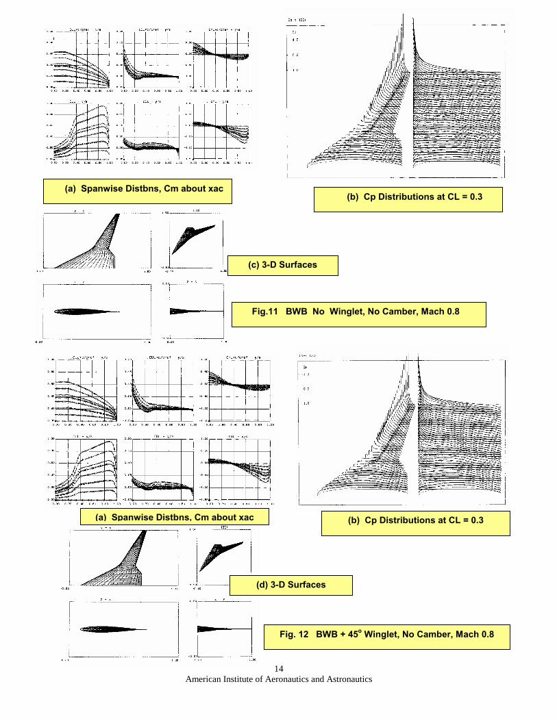
Fig.11 BWB No Winglet, No Camber, Mach 0.8
(b) Cp Distributions at CL = 0.3 (a) Spanwise Distbns, Cm about xac
(b) Cp Distributions at CL = 0.3
(c) 3-D Surfaces
(a) Spanwise Distbns, Cm about xac
American Institute of Aeronautics and Astronautics
14
(d) 3-D Surfaces
Fig. 12 BWB + 45o Winglet, No Camber, Mach 0.8

Root
(c)
(b) Spanwise Loadings after 5 cycles (a) Spanwise Loadings at Start
(d) 3-D Surfaces
Start
Start
Target
Target
5 cyc & Target
y
z
x
Mean Camber surface
American Institute of Aeronautics and Astronautics
15
Fig.13 BWB + 45o Winglet, No CLL constraint, Mach 0.8, CL = 0.3
(e) Cp Distributions on Unfolded Surface, Euler & Panel Method

American Institute of Aeronautics and Astronautics
16
Root
(c) Mean Camber surface (unfolded)
Fig. 14 BWB + 45o Winglet, CLL constraint, Mach 0.8, CL = 0.3
(e) Cp Distributions on Unfolded Surface, Euler & Panel Method
(b) Spanwise Loadings after 5 cycles (a) Spanwise Loadings at Start
(d) 3-D Surfaces
Start
Start
Target
Target
5 cyc & Target
y
z
x

(a) Total Loads, C
Fig. 15 BWB + 45o
Design
Planar
CLLlimDesign
Min Drag Design
M0.2
M0.8
American Institute of Aeronautics and Astronautics
17
L � AoA, Cm - CL
Winglet, CLL constraint, CL = 0.3, CL � AoA, Cm - CL , xCP - CL, Mach 0.8
(b) xCP - CL variation
Min Drag Design
Neutral Point, 45o Fold M0.2 M0.8
CLLlim Design

A
(c) Mean Camber surface (unfolded)
Fig. 16 30o
(e) Cp Distributions on Unfolded Surface, Panel Method
(b) Spanwise Loadings after 5 cycles (a) Spanwise Loadings at Start
Start
Start
Target
Target
5 cyc & Target
y
z
x
(d) 3-D Surfaces
merican Institute of Aeronautics and Astronautics
18
OFW + 75o Winglet, No CLL constraint, Mach 0.8, CL = 0.3