aemo technical specification - var dispatch participant interfaces … documents/var... · ·...
TRANSCRIPT

AEMO TECHNICAL SPECIFICATION - VAR DISPATCH PARTICIPANT INTERFACES
2016 15 FEBRUARY 2016
Version: 1.0
Version: 1.0 Change Notice Series N/A © 2016 Australian Energy Market Operator Ltd (AEMO). All rights reserved.
AEMO Technical Specification - VAR Dispatch participant interfaces 2016 Important Notice
© 2016 AEMO i
Important Notice
AEMO has prepared this AEMO Technical Specification - VAR Dispatch participant interfaces 2016 (Technical Specification) to provide guidance on the use of the MVAR Dispatch, February 2016 under the National Gas or Electricity Rules (Rules), as at the date of publication.
No Reliance or warranty
This Technical Specification does not constitute legal or business advice, and should not be relied on as a substitute for obtaining detailed advice about the National Gas or Electricity Law, the Rules or any other applicable laws, procedures or policies. While AEMO has made every effort to ensure the quality of the information in this Technical Specification, neither AEMO, nor any of its employees, agents and consultants make any representation or warranty as to the accuracy, reliability, completeness, currency or suitability for particular purposes of that information.
Limitation of liability
To the maximum extent permitted by law, AEMO and its advisers, consultants and other contributors to this Technical Specification (or their respective associated companies, businesses, partners, directors, officers or employees) are not liable (whether by reason of negligence or otherwise) for any errors, omissions, defects or misrepresentations in this document, or for any loss or damage suffered by persons who use or rely on the information in it.
Copyright
Copyright Australian Energy Market Operator Limited. The material in this publication may be used in accordance with the copyright permissions on AEMO’s website.
Trademark notices
Microsoft, Windows and SQL Server are either registered trademarks or trademarks of Microsoft Corporation in the United States and/or other countries. Oracle and Java are registered trademarks of Oracle and/or its affiliates.
Distribution
Commercial-in-confidence with NEM participants
Document identification
Title: AEMO Technical Specification - VAR Dispatch participant interfaces 2016 Version: 1.0 Release: MVAR Dispatch, February 2016 Responsible Department: PMO Documentation Team Last Update: Monday, 15 February 2016 Notes: no notes. Documents made obsolete: The release of this document changes only the version of the AEMO Technical Specification MVAR Dispatch 2015 No documents are made obsolete by releasing this document version 1.0.
Revision history
Date Person Version Description
6-Jul-15 K. Rodrigues 0.10 Draft
9-Jul-15 K. Rodrigues 0.2 Updated screen shots of Web Portal. Added Revision History table. Other minor additions / corrections.
14-Jul-15 K. Rodrigues 0.3 Added option for Windfarms in AVR mode to receive Voltage setpoint targets. Also AVR mode status.
10-Oct-15 T. Butterworth Changed sample Instruction file references from 'VAR,INSTRUCTION' and 'VAR,INSTRUCTION_TRK' to 'VOLTAGE_INSTRUCTION_INSTRUCTION' and 'VOLTAGE_INSTRUCTION_TRACK' respectively
16-Oct-15 K. Rodrigues 0.4 Added Conformance flow diagram Added Web Portal screen behaviour and alarms table
22-Jan-16 K. Rodrigues 0.5 Switching instructions changed from digital multi-state to an analog type in SCADA.
AEMO Technical Specification - VAR Dispatch participant interfaces 2016 Contents
© 2016 AEMO ii
Date Person Version Description
Control types only sent from one SCADA production site at a time. Added table of default IDs for VDS SCADA. Changes in sections 4.1.2 and 4.2
25-Jan-16 M. Strong SCADA review
29-Jan-16 S. Hang Web Portal section 4.4 update
15-Feb-16 K. Rodrigues 1.0 Edits reviewed. Links added for Dashboard website and Web Portal user guide doc. Reviewed by Chris Stewart.
Further information
For further information, please visit AEMO’s website www.aemo.com.au or contact:
AEMO Information and Support Hub Phone: 1300 AEMO 00 (1300 236 600) and follow the prompts. Email: [email protected]
AEMO Technical Specification - VAR Dispatch participant interfaces 2016 Contents
© 2016 AEMO iii
Contents
1 Introduction ................................................................................................................ 1 1.1 Intended Audience ............................................................................................... 1
1.2 Project Scope ...................................................................................................... 1
1.3 Systems list .......................................................................................................... 1
1.4 Definitions ............................................................................................................ 2
1.5 Summary of Device Types and Instruction Types ................................................ 2
1.6 Request for feedback ........................................................................................... 3
1.7 Live website ......................................................................................................... 3
2 Project Schedule ........................................................................................................ 4 2.1 Proposed timeline ................................................................................................ 4
3 Executive summary – Project implications ................................................................. 5 3.1 Summary ............................................................................................................. 5
3.2 Benefits ................................................................................................................ 5
3.3 Business Impact .................................................................................................. 5
3.4 Risks associated with the change ........................................................................ 6
4 Technical information: VAr Dispatch Project Implementation .................................... 7 4.1 Common Components ......................................................................................... 7
4.1.1 AEMO VAr dispatch system: ................................................................................ 7 4.1.2 AEMO to RPO communication interface .............................................................. 7
4.1.2.1 Control instructions by Device Type ...................................................... 7 4.1.2.2 VAr Dispatch Signal (cycle phases) ...................................................... 9 4.1.2.3 Conformance Status.............................................................................. 9
4.1.3 RPO to AEMO communication interface ............................................................ 11 4.1.3.1 Reactive Device Availability Status ..................................................... 11 4.1.3.2 AVR Mode Status (optional) ................................................................ 11
4.1.4 RPOs systems (basic functional requirements) ................................................. 11
4.2 Control NET (SCADA) Interface ......................................................................... 12 4.2.1 Control Instructions to NSPs using ICCP protocol ............................................. 12
4.2.1.1 Conversion of analogs to control types for forwarding to Generators and Windfarms. .......................................................................................... 13
4.2.2 VAR Dispatch Signal (cycle phases) .................................................................. 13 4.2.3 Conformance ...................................................................................................... 14 4.2.4 Device Availability ............................................................................................... 14 4.2.5 AVR Mode Status (optional) ............................................................................... 14 4.2.6 Redundant SCADA paths (duplication) .............................................................. 15 4.2.7 Changes to be done by RPOs Intending to use SCADA Interface .................... 15
4.3 EMMS Data Interchange Interface ..................................................................... 16 4.3.1 MMS Data Model 4.24 ........................................................................................ 16 4.3.2 Control Instructions ............................................................................................. 17 4.3.3 VAr Dispatch Signal (cycle phases) ................................................................... 17
AEMO Technical Specification - VAR Dispatch participant interfaces 2016 Tables
© 2016 AEMO iv
4.3.4 Conformance ...................................................................................................... 18 4.3.5 Device Availability ............................................................................................... 18 4.3.6 Changes to be done by RPOs intending to use EMMS interface ...................... 18
4.4 EMMS Web Portal – MVAR Dispatch Web Interface .......................................... 18 4.4.1 Control Instructions ............................................................................................. 18 4.4.2 VAr Dispatch Signal (cycle phases) ................................................................... 20 4.4.3 Conformance ...................................................................................................... 20 4.4.4 Screen behaviour and Alarms ............................................................................ 21 4.4.5 Device Availability ............................................................................................... 21 4.4.6 Changes to be done by RPOs intending to use Web Portal interface ............... 21
4.5 Network Outage Scheduler (NOS) ..................................................................... 21 4.5.1 NOS for RPOs equipment names ...................................................................... 22 4.5.2 NOS for equipment availability status ................................................................. 22
5 References ...............................................................................................................23 5.1 AEMO CSV data format standard ...................................................................... 23
5.2 AEMO’s website................................................................................................. 23
5.3 aseXML standards ............................................................................................. 24
5.4 Consultations ..................................................................................................... 24
5.5 Information and Support Hub ............................................................................. 24
Appendix A: VAR MMS Data Model changes ..............................................................25 A.1 New Package: VOLTAGE_INSTRUCTIONS ........................................................ 25
A.2 Participant interfaces changes .............................................................................. 26
A.3 File interface changes ........................................................................................... 26
Tables
Table 1: VAr Dispatch definition of terms ......................................................................................................... 2 Table 2: Summary of Device Types and Instruction Types .............................................................................. 2 Table 3: VAr Project proposed timeline ............................................................................................................ 4 Table 4: Reactive Device Types under VDS control ........................................................................................ 7 Table 5: Meaning of numbers sent as Switching Instructions .......................................................................... 8 Table 6: Default VDS SCADA IDs ................................................................................................................... 12 Table 7: Conformance Indicators sent via SCADA points .............................................................................. 14 Table 8: Reactive device availability status .................................................................................................... 14 Table 9: EMMS MVar Web Screen Information ............................................................................................. 19 Table 10: EMMS Web Portal Alarms .............................................................................................................. 21
Figures
Figure 1: Example Signal for VDS in Auto Mode .............................................................................................. 9 Figure 2: Flow diagram for Conformance Status ............................................................................................. 10 Figure 3: SCADA flow and prototcols .............................................................................................................. 13 Figure 4. Example screen shot of webpage .................................................................................................... 19 Figure 5: Example of webscreen – cycle phases ............................................................................................ 20 Figure 6: Example of webscreen – conformance ............................................................................................ 21
AEMO Technical Specification - VAR Dispatch participant interfaces 2016 Introduction
© 2016 AEMO 1
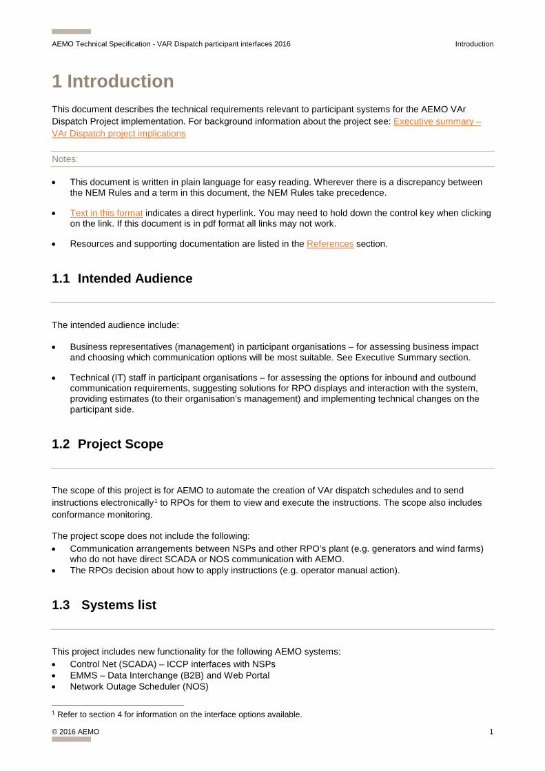
1 Introduction This document describes the technical requirements relevant to participant systems for the AEMO VAr Dispatch Project implementation. For background information about the project see: Executive summary – VAr Dispatch project implications
Notes:
• This document is written in plain language for easy reading. Wherever there is a discrepancy between the NEM Rules and a term in this document, the NEM Rules take precedence.
• Text in this format indicates a direct hyperlink. You may need to hold down the control key when clicking on the link. If this document is in pdf format all links may not work.
• Resources and supporting documentation are listed in the References section.
1.1 Intended Audience
The intended audience include:
• Business representatives (management) in participant organisations – for assessing business impact and choosing which communication options will be most suitable. See Executive Summary section.
• Technical (IT) staff in participant organisations – for assessing the options for inbound and outbound communication requirements, suggesting solutions for RPO displays and interaction with the system, providing estimates (to their organisation’s management) and implementing technical changes on the participant side.
1.2 Project Scope
The scope of this project is for AEMO to automate the creation of VAr dispatch schedules and to send instructions electronically1 to RPOs for them to view and execute the instructions. The scope also includes conformance monitoring.
The project scope does not include the following: • Communication arrangements between NSPs and other RPO’s plant (e.g. generators and wind farms)
who do not have direct SCADA or NOS communication with AEMO. • The RPOs decision about how to apply instructions (e.g. operator manual action).
1.3 Systems list
This project includes new functionality for the following AEMO systems: • Control Net (SCADA) – ICCP interfaces with NSPs • EMMS – Data Interchange (B2B) and Web Portal • Network Outage Scheduler (NOS)
1 Refer to section 4 for information on the interface options available.

AEMO Technical Specification - VAR Dispatch participant interfaces 2016 Introduction
© 2016 AEMO 2
1.4 Definitions
Table 1 explains some of the acronyms and terminology used in conjunction with this project.
Table 1: VAr Dispatch definition of terms
Definition Version Description
VAr Volt-Ampere reactive
RPO Reactive Plant Operator: A participant who accepts and responds to reactive plant instructions from AEMO
VDS System
VAr Dispatch Scheduling System. It implies the set of software components at AEMO that will provide the functionality included in the project scope
ICCP Inter Control Centre Protocol (for SCADA communications)
NEM National Electricity Market
NOS AEMO’s Network Outage Scheduler, used for the programming and scheduling of transmission equipment outages.
EMS Energy Management System
EMMS Electricity Market Management System
NSP Network Service Provider (TNSP and DSNP for Transmission and Distribution respectively)
PSO AEMO Power System Operations
RTO AEMO Real Time Operations
1.5 Summary of Device Types and Instruction Types
Table 2: Summary of Device Types and Instruction Types
Device Type Instruction Type
Shunt Capacitor ON / OFF / Do Nothing
Shunt Reactor ON / OFF / Do Nothing
Transformer AVR Voltage Setpoint Delta in kV
Transformer Delta Tap Position
Generator AVR Voltage Setpoint Delta in kV
Synchronous Condenser AVR Voltage Setpoint Delta in kV
Synchronous Condenser Commit/ Decommit / Do Nothing
Generator or Synchronous Condenser Group Reference Bus Voltage setpoint Delta in kV
Wind Farm MVAr Setpoint Delta in MVAr
SVC AVR Voltage Setpoint Delta in kV
AEMO has issued a list of all reactive devices to be included in the automated VAr Dispatch. To request copy please email [email protected].
AEMO Technical Specification - VAR Dispatch participant interfaces 2016 Introduction
© 2016 AEMO 3
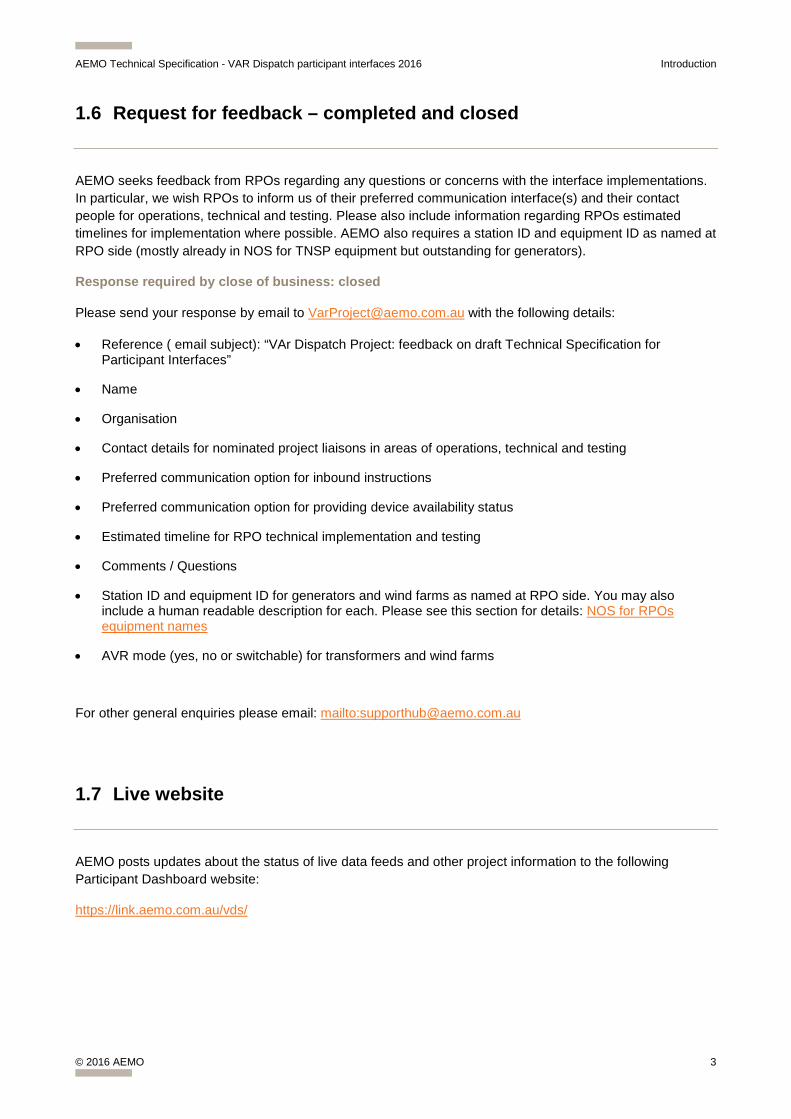
1.6 Request for feedback – completed and closed
AEMO seeks feedback from RPOs regarding any questions or concerns with the interface implementations. In particular, we wish RPOs to inform us of their preferred communication interface(s) and their contact people for operations, technical and testing. Please also include information regarding RPOs estimated timelines for implementation where possible. AEMO also requires a station ID and equipment ID as named at RPO side (mostly already in NOS for TNSP equipment but outstanding for generators).
Response required by close of business: closed
Please send your response by email to [email protected] with the following details:
• Reference ( email subject): “VAr Dispatch Project: feedback on draft Technical Specification for Participant Interfaces”
• Name
• Organisation
• Contact details for nominated project liaisons in areas of operations, technical and testing
• Preferred communication option for inbound instructions
• Preferred communication option for providing device availability status
• Estimated timeline for RPO technical implementation and testing
• Comments / Questions
• Station ID and equipment ID for generators and wind farms as named at RPO side. You may also include a human readable description for each. Please see this section for details: NOS for RPOs equipment names
• AVR mode (yes, no or switchable) for transformers and wind farms
For other general enquiries please email: mailto:[email protected]
1.7 Live website
AEMO posts updates about the status of live data feeds and other project information to the following Participant Dashboard website:
https://link.aemo.com.au/vds/
AEMO Technical Specification - VAR Dispatch participant interfaces 2016 Project Schedule
© 2016 AEMO 4
2 Project Schedule
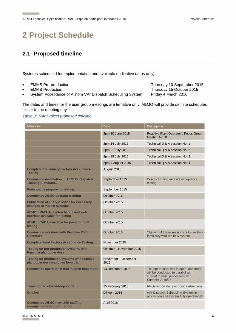
2.1 Proposed timeline
Systems scheduled for implementation and available (indicative dates only):
• EMMS Pre-production: Thursday 10 September 2015 • EMMS Production: Thursday 15 October 2015 • System Acceptance of Alstom VAr Dispatch Scheduling System Friday 4 March 2016
The dates and times for the user group meetings are tentative only. AEMO will provide definite schedules closer to the meeting day. Table 3: VAr Project proposed timeline
Milestone Date Description
2pm 30 June 2015 Reactive Plant Operator’s Focus Group Meeting No. 8
2pm 14 July 2015 Technical Q & A session No. 1
2pm 21 July 2015 Technical Q & A session No. 2
2pm 28 July 2015 Technical Q & A session No. 3
2pm 4 August 2015 Technical Q & A session No. 4
Complete Preliminary Factory Acceptance Testing
August 2015
Commence installation in AEMO’s Dispatch Training Simulator..
September 2015 Conduct tuning and site acceptance testing
Participants prepare for testing. September 2015
Commence AEMO operator training October 2015
Publication of change notice for necessary changes to market systems
October 2015
AEMO EMMS data interchange and web interface available for testing
October 2015
AEMO SCADA available for point to point testing
October 2015
Commence sessions with Reactive Plant Operators
October 2015 The aim of these sessions is to develop familiarity with the new system
Complete Final Factory Acceptance Testing November 2015
Testing on pre-production systems with Reactive plant operators
October – November 2015
Testing on production systems with reactive plant operators and open loop trial
November – December 2015
Commence operational trial in open-loop mode 14 December 2015 The operational trial in open-loop mode will be conducted in parallel with current manual processes over Summer 2015/16
Transition to closed-loop mode 15 February 2016 RPOs act on Var electronic instructions
Go Live 04 April 2016 VAr Dispatch Scheduling System in production and system fully operational
Commence AEMO new shift staffing arrangements in control room
April 2016

AEMO Technical Specification - VAR Dispatch participant interfaces 2016 Executive summary – Project implications
© 2016 AEMO 5
3 Executive summary – Project implications
3.1 Summary
VAr dispatch is a term used for issuing instructions to achieve stable voltage control of the electricity grid. These instructions typically request changes to reactive plant, which are able to increase or decrease the VAr contribution to the grid. Capacitors, reactors and generating units are typical examples of devices with VAr capability.
The intended recipients of VAr dispatch instructions relating to reactive power devices will be Generator Control Rooms and Network Operators who control the reactive power devices (i.e. RPOs). Generator Traders may also be interested in viewing VAr instructions.
Currently RPOs receive voltage control instructions from AEMO via telephone. The scope of this project is to automate the creation of VAr dispatch schedules and to send instructions electronically2 to RPOs, as well as to monitor conformance.
This automated process would aim to achieve the same level of automation that currently exists for MW dispatch except that AEMO will not send control signals directly to plant, but rather send instructions that an RPO (person) can read on screen.
AEMO requires reactive plant availability status from RPOs3.
3.2 Benefits
The VAr Dispatch Scheduling System Implementation Project is an initiative to improve NEM real time operations processes by automating the production of VAr dispatch schedules and transmission of instructions electronically. The objective is to reduce the number of AEMO control room operator positions from 5 down to 4 without materially increasing operational risk. The benefits are improved processes and reduced cost.
3.3 Business Impact
The business impact on AEMO includes the following (resources, cost and scheduling): • Project implementation and rollout. • Roster and role/responsibility changes for NEM control room staff (1 PSO controller to manage
voltage control for the entire NEM). The timing of these changes is driven by the retirement of certain RTO staff. The impact on staff is also a consideration.
• Update procedures • Training requirements for PSO controller as well as technical support staff. • Implement VAr Dispatch in EMS Dispatch Training Simulator environment for training and tuning
purposes.
2 Refer to section 4 for information on the interface options available. 3 Refer to the relevant section on Device Availability for each of the interface options.
AEMO Technical Specification - VAR Dispatch participant interfaces 2016 Executive summary – Project implications
© 2016 AEMO 6
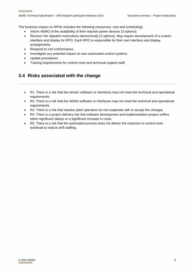
The business impact on RPOs includes the following (resources, cost and scheduling): • Inform AEMO of the availability of their reactive power devices (3 options). • Receive VAr dispatch instructions electronically (3 options). May require development of a custom
interface and display for RPO. Each RPO is responsible for their own interface and display arrangements.
• Respond to non-conformance. • Investigate any potential impact on own automated control systems • Update procedures • Training requirements for control room and technical support staff.
3.4 Risks associated with the change
• R1. There is a risk that the vendor software or interfaces may not meet the technical and operational requirements.
• R2. There is a risk that the AEMO software or interfaces may not meet the technical and operational requirements.
• R3. There is a risk that reactive plant operators do not cooperate with or accept the changes • R4. There is a project delivery risk that software development and implementation project suffers
either significant delays or a significant increase in costs. • R5. There is a risk that the automated process does not deliver the reduction in control room
workload to reduce shift staffing.

AEMO Technical Specification - VAR Dispatch participant interfaces 2016 Technical information: VAr Dispatch Project Implementation
© 2016 AEMO 7
4 Technical information: VAr Dispatch Project Implementation
4.1 Common Components
4.1.1 AEMO VAr dispatch system:
• Determination of VAr dispatch schedule for voltage control • Var Dispatch Instructions for reactive plant sent electronically to RPOs. • Monitoring of Conformance. This process will compare actual state of the system (state estimated)
with the current instruction. A status flag for conformance (per device) will also be sent electronically. • Resolving Non- Conformance will be
o an automated notification process to alert RPOs when they are not conforming to instructions,
o automated adjustment of the schedule if non-conformance is not addressed (i.e. the non-conforming device is flagged as such at AEMO’s end and therefore excluded from subsequent schedules and will require operator intervention to return it to being available).
• Full integration with the AEMO simulator environment for training and tuning purposes.
4.1.2 AEMO to RPO communication interface
AEMO is making 3 interface options available to participants for receiving VAr instructions: • ControlNET (SCADA) interface • EMMS Data Interchange interface • EMMS Web Portal
It is important to note that it is at the participants’ discretion to choose the preferred interface for the receipt of VAr Dispatch instructions. Any one of these interface methods is available for the participant to use.
The current EMMS release includes the data model changes (structures) required for the MVar Dispatch project release. The data content was available prior to the commencement of the trial in December 2015. Simulated data was available from October 2015.
The sections below provide the details of each of these options.
4.1.2.1 Control instructions by Device Type
Table 4 explains the different types of reactive devices that can receive targets from the VDS.
Table 4: Reactive Device Types under VDS control
Device Type Instruction Type
SCADA Type
Instruction Description
Shunt Capacitor
OFF / ON / NO CHANGE
Analog *See Table 5: Meaning of numbers sent as Switching Instructions
Shunt Reactor
OFF / ON / NO CHANGE
Analog *See Table 5: Meaning of numbers sent as Switching Instructions
Transformer AVR Voltage Setpoint
Analog An analog representing the requested change in the voltage setpoint of a transformer (delta kV). For SCADA a zero will be transmitted if no change is required in this cycle. For EMMS the field will be null if no change is required in this cycle. If the RPO intends
AEMO Technical Specification - VAR Dispatch participant interfaces 2016 Technical information: VAr Dispatch Project Implementation
© 2016 AEMO 8
Device Type Instruction Type
SCADA Type
Instruction Description
to be able to swap between receiving voltage setpoints or tap change instruction then we also recommend a SCADA status to be sent to AEMO to indicate AVR mode. See AVR Mode Status (optional)
Transformer Tap Position Analog An analog representing the requested change (delta position) of tap position of a transformer. A negative value implies step down and a positive value implies step up. For SCADA a zero will be transmitted if no change is required in this cycle. For EMMS the field will be null if no change is required in this cycle.
Generator AVR Voltage Setpoint
Analog An analog representing the requested change in the voltage setpoint of a generating unit (delta kV). For SCADA a zero will be transmitted if no change is required in this cycle. For EMMS the field will be null if no change is required in this cycle.
Synchronous Condenser
AVR Voltage setpoint
Analog An analog representing the requested change in the voltage setpoint of a synchronous condenser (delta kV). For SCADA a zero will be transmitted if no change is required in this cycle. For EMMS the field will be null if no change is required in this cycle.
Synchronous Condenser
De-commit / Commit / NO CHANGE
Analog *See Table 5: Meaning of numbers sent as Switching Instructions. A “Commit” instruction will be issued together with an AVR Voltage setpoint instruction within the same instruction set.
Generator or Synchronous Condenser Group
Reference bus Voltage Setpoint
Analog An analog representing the requested change in voltage of the nominated reference bus (delta kV). For SCADA a zero will be transmitted if no change is required in this cycle. For EMMS the field will be null if no change is required in this cycle.
Wind Farm MVAr Setpoint
Analog An analog representing the requested change in the MVAr output of a wind farm as measured at the KV level where the generator is modelled in AEMOs EMS. A positive MVAr value is in the sense that the device exports MVAr’s to the power system. The delta MVAr value will indicate by how much more the device will export MVAr to the power system to raise its voltage. For SCADA a zero will be transmitted if no change is required in this cycle. For EMMS the field will be null if no change is required in this cycle.
Wind Farm AVR Voltage Setpoint
Analog An analog representing the requested change in the voltage setpoint of a wind farm (delta kV). For SCADA a zero will be transmitted if no change is required in this cycle. For EMMS the field will be null if no change is required in this cycle. If the wind farm intends to be able to swap between receiving voltage or MVAr setpoints then we also require a SCADA status to be sent to AEMO which indicates AVR mode. See AVR Mode Status (optional)
SVC AVR Voltage Setpoint
Analog An analog representing the requested change in the voltage setpoint of a static VAr compensator (delta kV). For SCADA a zero will be transmitted if no change is required in this cycle. For EMMS the field will be null if no change is required in this cycle.
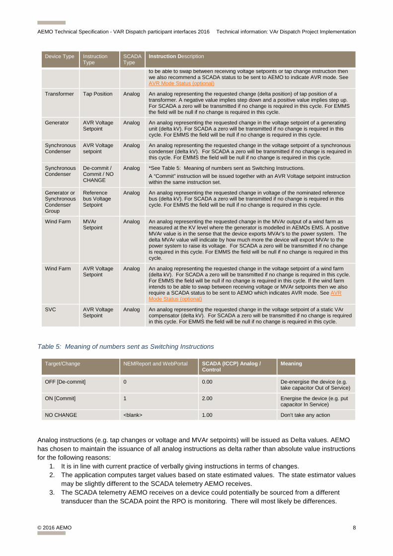
Table 5: Meaning of numbers sent as Switching Instructions
Target/Change NEMReport and WebPortal SCADA (ICCP) Analog / Control
Meaning
OFF [De-commit] 0 0.00 De-energise the device (e.g. take capacitor Out of Service)
ON [Commit] 1 2.00 Energise the device (e.g. put capacitor In Service)
NO CHANGE <blank> 1.00 Don’t take any action
Analog instructions (e.g. tap changes or voltage and MVAr setpoints) will be issued as Delta values. AEMO has chosen to maintain the issuance of all analog instructions as delta rather than absolute value instructions for the following reasons:
1. It is in line with current practice of verbally giving instructions in terms of changes. 2. The application computes target values based on state estimated values. The state estimator values
may be slightly different to the SCADA telemetry AEMO receives. 3. The SCADA telemetry AEMO receives on a device could potentially be sourced from a different
transducer than the SCADA point the RPO is monitoring. There will most likely be differences.
AEMO Technical Specification - VAR Dispatch participant interfaces 2016 Technical information: VAr Dispatch Project Implementation
© 2016 AEMO 9
Switching instructions will be issued as a three state status. This will allow for instructions that request the device to be switched ON, the device to be switched OFF as well as the device to remain in its current state (i.e. no instruction).
AEMO has issued a spreadsheet containing all reactive devices that are to be included in the VAr dispatch schedule (for another copy please email [email protected]).
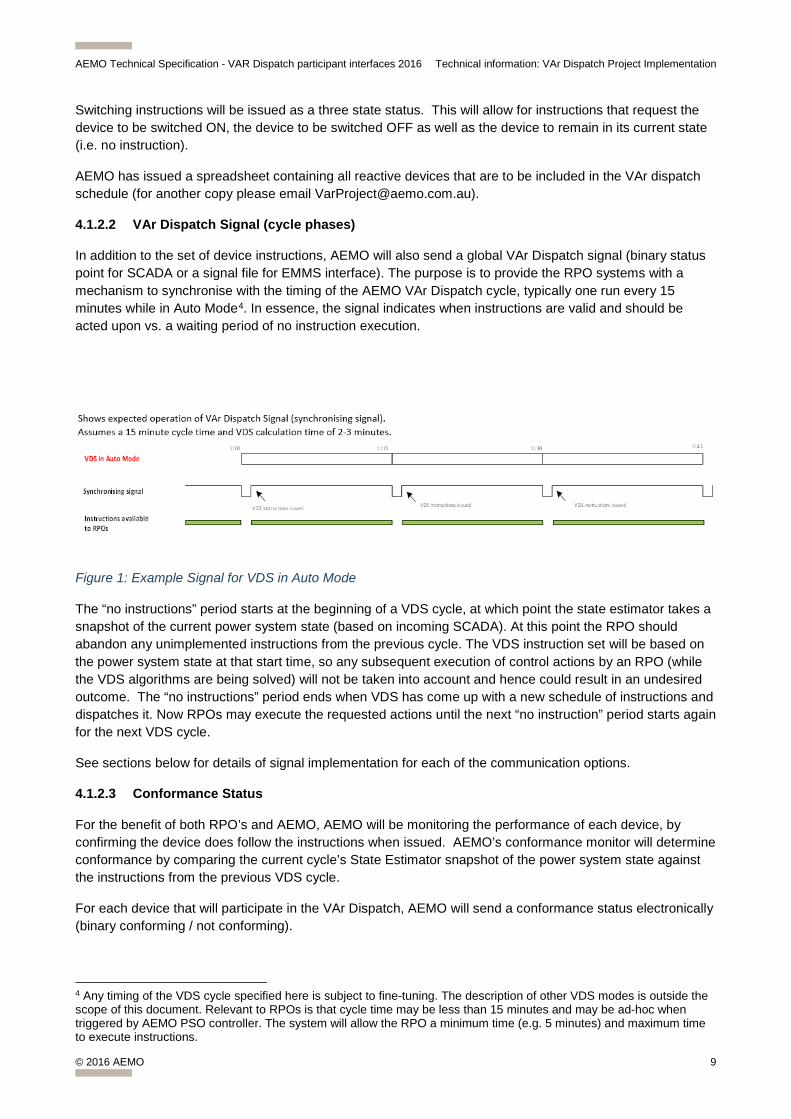
4.1.2.2 VAr Dispatch Signal (cycle phases)
In addition to the set of device instructions, AEMO will also send a global VAr Dispatch signal (binary status point for SCADA or a signal file for EMMS interface). The purpose is to provide the RPO systems with a mechanism to synchronise with the timing of the AEMO VAr Dispatch cycle, typically one run every 15 minutes while in Auto Mode4. In essence, the signal indicates when instructions are valid and should be acted upon vs. a waiting period of no instruction execution.
Figure 1: Example Signal for VDS in Auto Mode
The “no instructions” period starts at the beginning of a VDS cycle, at which point the state estimator takes a snapshot of the current power system state (based on incoming SCADA). At this point the RPO should abandon any unimplemented instructions from the previous cycle. The VDS instruction set will be based on the power system state at that start time, so any subsequent execution of control actions by an RPO (while the VDS algorithms are being solved) will not be taken into account and hence could result in an undesired outcome. The “no instructions” period ends when VDS has come up with a new schedule of instructions and dispatches it. Now RPOs may execute the requested actions until the next “no instruction” period starts again for the next VDS cycle.
See sections below for details of signal implementation for each of the communication options.
4.1.2.3 Conformance Status
For the benefit of both RPO’s and AEMO, AEMO will be monitoring the performance of each device, by confirming the device does follow the instructions when issued. AEMO’s conformance monitor will determine conformance by comparing the current cycle’s State Estimator snapshot of the power system state against the instructions from the previous VDS cycle.
For each device that will participate in the VAr Dispatch, AEMO will send a conformance status electronically (binary conforming / not conforming).
4 Any timing of the VDS cycle specified here is subject to fine-tuning. The description of other VDS modes is outside the scope of this document. Relevant to RPOs is that cycle time may be less than 15 minutes and may be ad-hoc when triggered by AEMO PSO controller. The system will allow the RPO a minimum time (e.g. 5 minutes) and maximum time to execute instructions.
AEMO Technical Specification - VAR Dispatch participant interfaces 2016 Technical information: VAr Dispatch Project Implementation
© 2016 AEMO 10
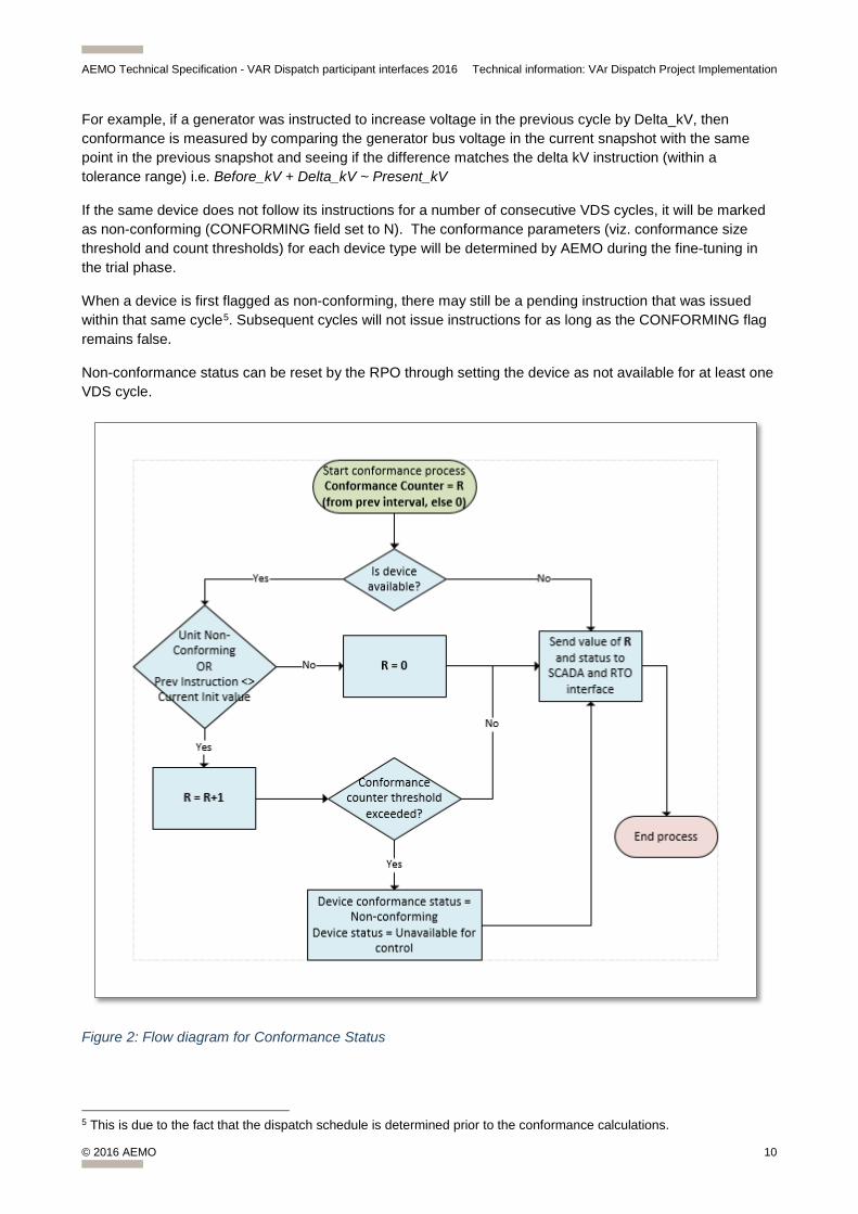
For example, if a generator was instructed to increase voltage in the previous cycle by Delta_kV, then conformance is measured by comparing the generator bus voltage in the current snapshot with the same point in the previous snapshot and seeing if the difference matches the delta kV instruction (within a tolerance range) i.e. Before_kV + Delta_kV ~ Present_kV
If the same device does not follow its instructions for a number of consecutive VDS cycles, it will be marked as non-conforming (CONFORMING field set to N). The conformance parameters (viz. conformance size threshold and count thresholds) for each device type will be determined by AEMO during the fine-tuning in the trial phase.
When a device is first flagged as non-conforming, there may still be a pending instruction that was issued within that same cycle5. Subsequent cycles will not issue instructions for as long as the CONFORMING flag remains false.
Non-conformance status can be reset by the RPO through setting the device as not available for at least one VDS cycle.
Figure 2: Flow diagram for Conformance Status
5 This is due to the fact that the dispatch schedule is determined prior to the conformance calculations.
AEMO Technical Specification - VAR Dispatch participant interfaces 2016 Technical information: VAr Dispatch Project Implementation
© 2016 AEMO 11
4.1.3 RPO to AEMO communication interface
4.1.3.1 Reactive Device Availability Status
Each RPO is required to indicate to AEMO whether a reactive device is available for control. The default assumption is that plant is available unless otherwise indicated. AEMO is making 3 options available to participants for submitting plant availability information:
1. SCADA status indicating availability of the device for reactive control in real time. See section: Device Availability
2. Entry in AEMO’s Network Outage Scheduler (NOS)6 for periods when plant will be unavailable (excluding generators). See section: Network Outage Scheduler (NOS) for Device Availability
3. Verbal advice to AEMO control room.7
The sections below provide the details of each of these options.
Note that the EMMS interfaces are not two-way communication mechanisms and cannot be used by participants to inform AEMO of device availability.
4.1.3.2 AVR Mode Status (optional)
AEMO’s model contains a status to indicate if devices such as transformers and wind farms are operating in AVR mode or not. For the majority of devices that will permanently operate in one mode, it is acceptable to set these up as part of the model. AEMO requests the RPO’s to verify the correct settings for all reactive plant taking part in VAr dispatch.
In other cases, where the RPO may wish to change the AVR mode of particular devices in real time (e.g. some wind farms that are operated in more than one control mode), AEMO requests that the real-time AVR status be telemetered to AEMO via SCADA.
If a wind farm is in AVR mode, then VDS will send a voltage setpoint (delta kV) instruction. If it is not in AVR mode, it will receive a MVAr setpoint (delta MVAr) instruction.
If a transformer is in AVR mode it will receive a voltage setpoint (delta kV). If it is not in AVR mode it will receive a tap change instruction (delta tap position).
For those devices that may switch their operating mode, two different instructions will appear in the dispatch to represent either operating mode, but only one instruction will request a change at any one time that is appropriate to the mode of operation.
4.1.4 RPOs systems (basic functional requirements)
The RPO will need (as a minimum): • One or more displays to show the instructions and conformance status sent by AEMO. • The ability to change the availability status of plant (which should subsequently be communicated to
AEMO) • [Assumed existing functionality] The ability to implement the instructions, i.e. execute required
changes to reactive plant (e.g. switching, setpoint control or tap changes)
6 This option is only available to TNSP’s who use the Network Outage Scheduler. 7 This option will be only be for devices that rarely require communication that they are unavailable and will be at AEMO’s discretion.
AEMO Technical Specification - VAR Dispatch participant interfaces 2016 Technical information: VAr Dispatch Project Implementation
© 2016 AEMO 12
The sections following below provide the details of each option depending on the chosen method of communication (see subheadings starting with “Changes to be done by RPOs…”)
4.2 Control NET (SCADA) Interface
This section deals with the transmission of VAr Dispatch instructions over the ControlNet (SCADA) interface. This is one of the three methods available for the receipt of instructions from AEMO. It is also one of three options for sending device availability to AEMO.
If a RPO chooses to utilise the SCADA option for communication with AEMO, analog and status points will be sent /received via the ICCP method across existing links to Network Service Providers (TNSPs or DNSPs). This document does not specify the mode of communication between the NSP and the RPO in the case where the NSP is acting as a 3rd party gateway.
4.2.1 Control Instructions to NSPs using ICCP protocol
For a definition of all instructions see: Control instructions by Device Type
Conformance and Timing signal will be standard ICCP status point type (binary).
Delta setpoints and tap changes will be standard ICCP analog type.
All switching instructions will be issued as three-state analog values to indicate OFF / ON / DO Nothing. See Table 5: Meaning of numbers sent as Switching Instructions.
The GENGRP device type for aggregated generators will require SCADA points to be associated with the regulated bus, which is common to all the generators, i.e. device type bus / node. If there are cases where the choice of bus is not obvious please contact AEMO for advice.
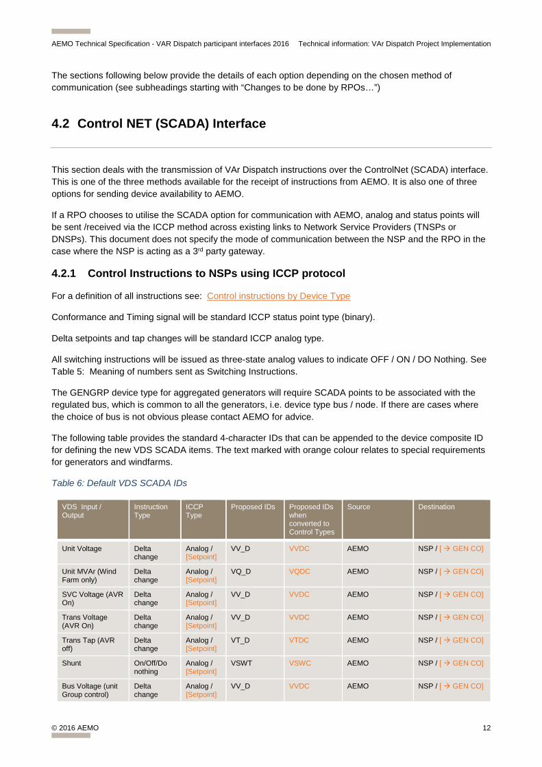
The following table provides the standard 4-character IDs that can be appended to the device composite ID for defining the new VDS SCADA items. The text marked with orange colour relates to special requirements for generators and windfarms.
Table 6: Default VDS SCADA IDs
VDS Input / Output
Instruction Type
ICCP Type
Proposed IDs Proposed IDs when converted to Control Types
Source Destination
Unit Voltage Delta change
Analog / [Setpoint]
VV_D VVDC AEMO NSP / [ GEN CO]
Unit MVAr (Wind Farm only)
Delta change
Analog / [Setpoint]
VQ_D VQDC AEMO NSP / [ GEN CO]
SVC Voltage (AVR On)
Delta change
Analog / [Setpoint]
VV_D VVDC AEMO NSP / [ GEN CO]
Trans Voltage (AVR On)
Delta change
Analog / [Setpoint]
VV_D VVDC AEMO NSP / [ GEN CO]
Trans Tap (AVR off)
Delta change
Analog / [Setpoint]
VT_D VTDC AEMO NSP / [ GEN CO]
Shunt On/Off/Do nothing
Analog / [Setpoint]
VSWT VSWC AEMO NSP / [ GEN CO]
Bus Voltage (unit Group control)
Delta change
Analog / [Setpoint]
VV_D VVDC AEMO NSP / [ GEN CO]
AEMO Technical Specification - VAR Dispatch participant interfaces 2016 Technical information: VAr Dispatch Project Implementation
© 2016 AEMO 13
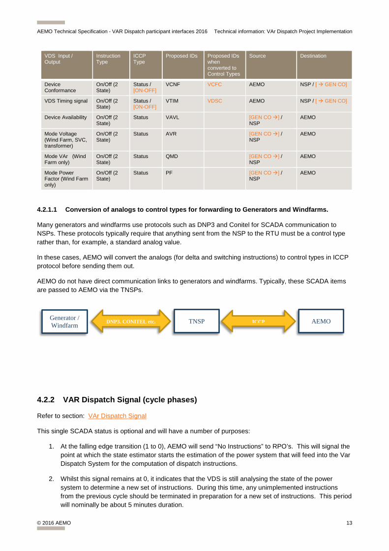
VDS Input / Output
Instruction Type
ICCP Type
Proposed IDs Proposed IDs when converted to Control Types
Source Destination
Device Conformance
On/Off (2 State)
Status / [ON-OFF]
VCNF VCFC AEMO NSP / [ GEN CO]
VDS Timing signal On/Off (2 State)
Status / [ON-OFF]
VTIM VDSC AEMO NSP / [ GEN CO]
Device Availability On/Off (2 State)
Status VAVL [GEN CO ] / NSP
AEMO
Mode Voltage (Wind Farm, SVC, transformer)
On/Off (2 State)
Status AVR [GEN CO ] / NSP
AEMO
Mode VAr (Wind Farm only)
On/Off (2 State)
Status QMD [GEN CO ] / NSP
AEMO
Mode Power Factor (Wind Farm only)
On/Off (2 State)
Status PF [GEN CO ] / NSP
AEMO
4.2.1.1 Conversion of analogs to control types for forwarding to Generators and Windfarms.
Many generators and windfarms use protocols such as DNP3 and Conitel for SCADA communication to NSPs. These protocols typically require that anything sent from the NSP to the RTU must be a control type rather than, for example, a standard analog value.
In these cases, AEMO will convert the analogs (for delta and switching instructions) to control types in ICCP protocol before sending them out.
AEMO do not have direct communication links to generators and windfarms. Typically, these SCADA items are passed to AEMO via the TNSPs.
4.2.2 VAR Dispatch Signal (cycle phases)
Refer to section: VAr Dispatch Signal
This single SCADA status is optional and will have a number of purposes:
1. At the falling edge transition (1 to 0), AEMO will send “No Instructions” to RPO’s. This will signal the point at which the state estimator starts the estimation of the power system that will feed into the Var Dispatch System for the computation of dispatch instructions.
2. Whilst this signal remains at 0, it indicates that the VDS is still analysing the state of the power system to determine a new set of instructions. During this time, any unimplemented instructions from the previous cycle should be terminated in preparation for a new set of instructions. This period will nominally be about 5 minutes duration.
AEMO ICCP TNSP Generator / Windfarm DNP3, CONITEL etc.
AEMO Technical Specification - VAR Dispatch participant interfaces 2016 Technical information: VAr Dispatch Project Implementation
© 2016 AEMO 14
3. At the rising edge transition (0 to 1), a new set of dispatch instruction will be determined and sent to the RPO. This event could be used to trigger calculations on the RPO’s SCADA system if desired.
4. Whilst this signal remains at 1, it indicates that a valid set of instructions are available and should be implemented as instructed. It will nominally be 10 minutes duration in this state before the next cycle commences.
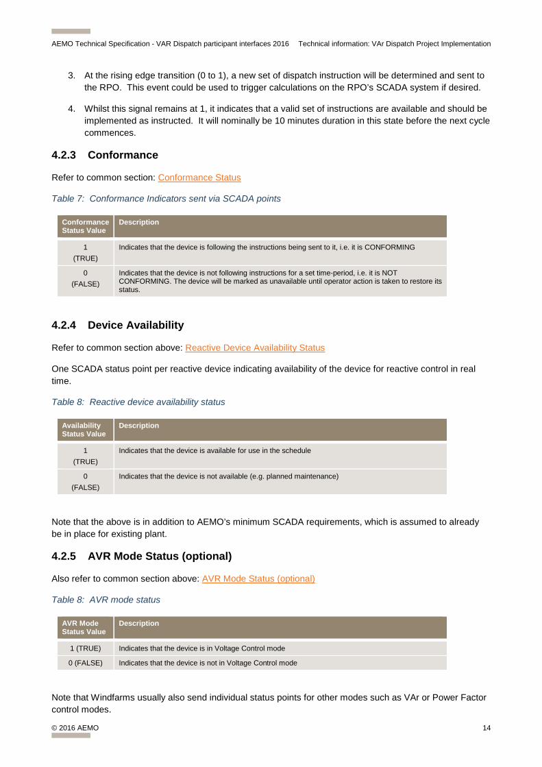
4.2.3 Conformance
Refer to common section: Conformance Status
Table 7: Conformance Indicators sent via SCADA points
Conformance Status Value
Description
1 (TRUE)
Indicates that the device is following the instructions being sent to it, i.e. it is CONFORMING
0 (FALSE)
Indicates that the device is not following instructions for a set time-period, i.e. it is NOT CONFORMING. The device will be marked as unavailable until operator action is taken to restore its status.
4.2.4 Device Availability
Refer to common section above: Reactive Device Availability Status
One SCADA status point per reactive device indicating availability of the device for reactive control in real time.
Table 8: Reactive device availability status
Availability Status Value
Description
1 (TRUE)
Indicates that the device is available for use in the schedule
0 (FALSE)
Indicates that the device is not available (e.g. planned maintenance)
Note that the above is in addition to AEMO’s minimum SCADA requirements, which is assumed to already be in place for existing plant.
4.2.5 AVR Mode Status (optional)
Also refer to common section above: AVR Mode Status (optional)
Table 8: AVR mode status
AVR Mode Status Value
Description
1 (TRUE) Indicates that the device is in Voltage Control mode
0 (FALSE) Indicates that the device is not in Voltage Control mode
Note that Windfarms usually also send individual status points for other modes such as VAr or Power Factor control modes.

AEMO Technical Specification - VAR Dispatch participant interfaces 2016 Technical information: VAr Dispatch Project Implementation
© 2016 AEMO 15
4.2.6 Redundant SCADA paths (duplication)
To ensure high availability of SCADA there are two redundant communication paths to AEMO’s control centres in Brisbane and Sydney. Data sent from the two sites will be identical.
The RPO will need to determine how they wish to accommodate the duplicate sources of data. For generators, this may involve liaising with a TNSP to combine the two sources into one before passing this on to the power station (e.g. if an item from one site is marked as suspect the good value from the other site should be used). Alternatively, the Reactive Plant Operator may choose to receive both sources of each point and combine them at their site.
In the case of SCADA items being converted to control types for the sake of accommodating protocols other than ICCP, these controls will only be sent from one AEMO site at a time. This will always be the same site as where the existing Automatic Generation Control instructions are being sent from, i.e. Brisbane or Sydney.
4.2.7 Changes to be done by RPOs Intending to use SCADA Interface
AEMO has issued a spreadsheet containing all reactive devices that are to be included in the VAr dispatch schedule (for another copy please email [email protected]).
A reactive plant operator, receiving VAr Dispatch instructions will need to do the following:
1. Configure local SCADA interface and communication channels to receive the SCADA points identified in above sections for each item of plant that can potentially receive VAr instructions from AEMO. Generators may have to initiate negotiations with their NSP to allow for their SCADA to be linked to AEMO.
a. For generators, this would include generator transformer tap positions changes and generator AVR setpoint changes.
b. For TNSP’s, this would include reactive shunt devices status, system transformer AVR setpoint changes or tap position changes, and SVC voltage setpoint changes.
c. For wind farms, this would include MVAr setpoint changes.
2. Configure SCADA points to send availability information to AEMO for each of their reactive devices that normally receive verbal instructions.
3. Determine how they wish to accommodate the duplicate sources of SCADA data. For generators, not receiving converted control instructions this may involve liaising with a TNSP to combine the two sources into one before passing this on to the power station. Alternatively, the Reactive Plant Operator may choose to receive both sources of each point and select best quality at their site (either). For generators receiving SCADA that has converted into controls, these will only be sent from one link at a time and no combination is required.
4. Determine if and how they may want to use the VAr Dispatch Signal to indicate that a new set of VAr Dispatch instructions is about to arrive or has been received.
5. Provide a means by which instructions sent via SCADA can be viewed by their local operator in order to initiate the requested action. It may also be necessary to alert the local operator that there are pending instructions to be implemented.
6. Provide a means by which the local operator can set or reset availability of their own reactive equipment, when being communicated via SCADA.

AEMO Technical Specification - VAR Dispatch participant interfaces 2016 Technical information: VAr Dispatch Project Implementation
© 2016 AEMO 16
7. Provide a mechanism by which their local operator is alerted to and can view non-conformance issues (identified by the non-conformance status sent by AEMO), and take appropriate action.
8. Develop procedures that will;
a. Enable the RPO to implement the requested instructions when it arrives.
b. Prevent unapplied instructions from being implemented when the VAr Dispatch Signal is reset to the waiting period. Note that all pending instructions in SCADA are also reset when the VAr Dispatch Signal resets.
9. Create a test plan for verifying the above changes before the commencement of the trial period (started in December 2015).
Wind farms can receive voltage setpoint changes (if the AVR status is true), or they can receive MVAr setpoint target changes. If the wind farm is operating in constant power factor mode or similar, the MVAr setpoint will need to be converted to the equivalent in its current operating mode and applied at the time the instruction is issued.
4.3 EMMS Data Interchange Interface
This section discusses details relating to the market systems file interchange method of communication.
4.3.1 MMS Data Model 4.24
The MMS Data Model released with the EMMS May 2015 release includes changes to support the MVAR Dispatch project.
The data model changes are included in the EMMS May 2015 Technical Specification document, which was previously issued. Please refer to Appendix for a copy of the relevant tables as well as a copy of the full pdf file: Appendix A: VAR MMS Data Model changes
Change Notice 923 - EMMS Technical Specification - May 2015 issued on 16 March 2015.
This project adds one new package with two new tables to the MMS Data Model:
• Package VOLTAGE_INSTRUCTIONS – voltage instructions
• Table VOLTAGE_INSTRUCTION_TRK – tracking for voltage instructions (parent records)
• Table VOLTAGE_INSTRUCTION – data for voltage instructions (child records)
Data Interchange software and associated documentation is available for current and new participants, as follows:
• Current participants can use FTP to the participant file server in the Releases directory to download all supported Data Interchange software. EMMS PreProduction participant file share (FTP): 146.178.211.25 Directory: /Releases/MMS Data Model/Production/v4.24/ Filename: Change Notice 923 - EMMS Technical Specification - May 2015.pdf
• New participants who do not yet have their access to the web portal can obtain the latest versions of Data Interchange bundles on AEMO’s website: http://aemo.com.au/About-the-Industry/Information-Systems/Data-Interchange.
AEMO Technical Specification - VAR Dispatch participant interfaces 2016 Technical information: VAr Dispatch Project Implementation
© 2016 AEMO 17
The data definitions for the voltage tables can be found in the EMMS May 2015 Technical Specification. See References for the EMMS May 2015 Technical Specification for the data definitions. For your convenience a full copy of this document is in Appendix A, as well as a copy of the tables relevant to VAr Dispatch only.
The EMMS CSV file format is defined in section 5.1.
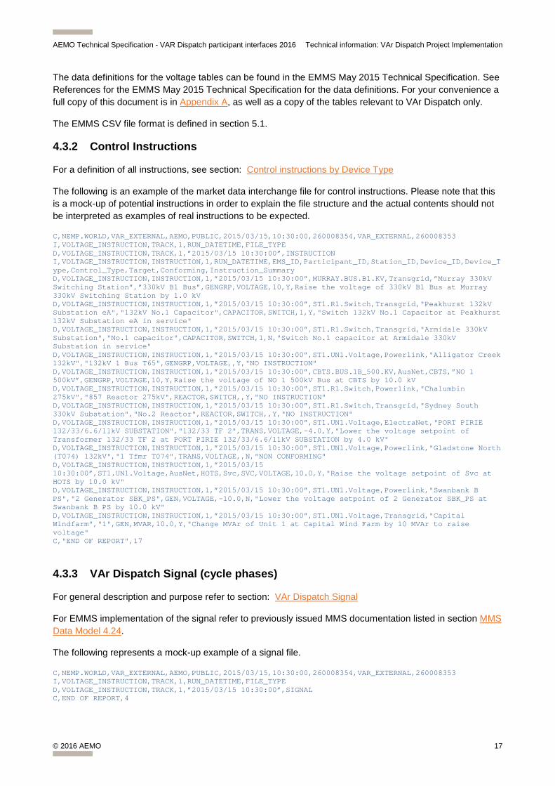
4.3.2 Control Instructions
For a definition of all instructions, see section: Control instructions by Device Type
The following is an example of the market data interchange file for control instructions. Please note that this is a mock-up of potential instructions in order to explain the file structure and the actual contents should not be interpreted as examples of real instructions to be expected.
C,NEMP.WORLD,VAR_EXTERNAL,AEMO,PUBLIC,2015/03/15,10:30:00,260008354,VAR_EXTERNAL,260008353 I,VOLTAGE_INSTRUCTION,TRACK,1,RUN_DATETIME,FILE_TYPE D,VOLTAGE_INSTRUCTION,TRACK,1,”2015/03/15 10:30:00”,INSTRUCTION I,VOLTAGE_INSTRUCTION,INSTRUCTION,1,RUN_DATETIME,EMS_ID,Participant_ID,Station_ID,Device_ID,Device_Type,Control_Type,Target,Conforming,Instruction_Summary D,VOLTAGE_INSTRUCTION,INSTRUCTION,1,”2015/03/15 10:30:00”,MURRAY.BUS.B1.KV,Transgrid,”Murray 330kV Switching Station”,”330kV B1 Bus”,GENGRP,VOLTAGE,10,Y,Raise the voltage of 330kV B1 Bus at Murray 330kV Switching Station by 1.0 kV D,VOLTAGE_INSTRUCTION,INSTRUCTION,1,”2015/03/15 10:30:00”,ST1.R1.Switch,Transgrid,"Peakhurst 132kV Substation eA","132kV No.1 Capacitor",CAPACITOR,SWITCH,1,Y,"Switch 132kV No.1 Capacitor at Peakhurst 132kV Substation eA in service" D,VOLTAGE_INSTRUCTION,INSTRUCTION,1,”2015/03/15 10:30:00”,ST1.R1.Switch,Transgrid,"Armidale 330kV Substation","No.1 capacitor",CAPACITOR,SWITCH,1,N,"Switch No.1 capacitor at Armidale 330kV Substation in service" D,VOLTAGE_INSTRUCTION,INSTRUCTION,1,”2015/03/15 10:30:00”,ST1.UN1.Voltage,Powerlink,"Alligator Creek 132kV","132kV 1 Bus T65",GENGRP,VOLTAGE,,Y,"NO INSTRUCTION" D,VOLTAGE_INSTRUCTION,INSTRUCTION,1,”2015/03/15 10:30:00”,CBTS.BUS.1B_500.KV,AusNet,CBTS,”NO 1 500kV”,GENGRP,VOLTAGE,10,Y,Raise the voltage of NO 1 500kV Bus at CBTS by 10.0 kV D,VOLTAGE_INSTRUCTION,INSTRUCTION,1,”2015/03/15 10:30:00”,ST1.R1.Switch,Powerlink,"Chalumbin 275kV","857 Reactor 275kV",REACTOR,SWITCH,,Y,"NO INSTRUCTION" D,VOLTAGE_INSTRUCTION,INSTRUCTION,1,”2015/03/15 10:30:00”,ST1.R1.Switch,Transgrid,"Sydney South 330kV Substation","No.2 Reactor",REACTOR,SWITCH,,Y,"NO INSTRUCTION" D,VOLTAGE_INSTRUCTION,INSTRUCTION,1,”2015/03/15 10:30:00”,ST1.UN1.Voltage,ElectraNet,"PORT PIRIE 132/33/6.6/11kV SUBSTATION","132/33 TF 2",TRANS,VOLTAGE,-4.0,Y,"Lower the voltage setpoint of Transformer 132/33 TF 2 at PORT PIRIE 132/33/6.6/11kV SUBSTATION by 4.0 kV" D,VOLTAGE_INSTRUCTION,INSTRUCTION,1,”2015/03/15 10:30:00”,ST1.UN1.Voltage,Powerlink,"Gladstone North (T074) 132kV","1 Tfmr T074",TRANS,VOLTAGE,,N,"NON CONFORMING" D,VOLTAGE_INSTRUCTION,INSTRUCTION,1,”2015/03/15 10:30:00”,ST1.UN1.Voltage,AusNet,HOTS,Svc,SVC,VOLTAGE,10.0,Y,"Raise the voltage setpoint of Svc at HOTS by 10.0 kV" D,VOLTAGE_INSTRUCTION,INSTRUCTION,1,”2015/03/15 10:30:00”,ST1.UN1.Voltage,Powerlink,"Swanbank B PS","2 Generator SBK_PS",GEN,VOLTAGE,-10.0,N,"Lower the voltage setpoint of 2 Generator SBK_PS at Swanbank B PS by 10.0 kV" D,VOLTAGE_INSTRUCTION,INSTRUCTION,1,”2015/03/15 10:30:00”,ST1.UN1.Voltage,Transgrid,"Capital Windfarm","1",GEN,MVAR,10.0,Y,"Change MVAr of Unit 1 at Capital Wind Farm by 10 MVAr to raise voltage" C,"END OF REPORT",17
4.3.3 VAr Dispatch Signal (cycle phases)
For general description and purpose refer to section: VAr Dispatch Signal
For EMMS implementation of the signal refer to previously issued MMS documentation listed in section MMS Data Model 4.24.
The following represents a mock-up example of a signal file.
C,NEMP.WORLD,VAR_EXTERNAL,AEMO,PUBLIC,2015/03/15,10:30:00,260008354,VAR_EXTERNAL,260008353 I,VOLTAGE_INSTRUCTION,TRACK,1,RUN_DATETIME,FILE_TYPE D,VOLTAGE_INSTRUCTION,TRACK,1,”2015/03/15 10:30:00”,SIGNAL C,END OF REPORT,4
AEMO Technical Specification - VAR Dispatch participant interfaces 2016 Technical information: VAr Dispatch Project Implementation
© 2016 AEMO 18
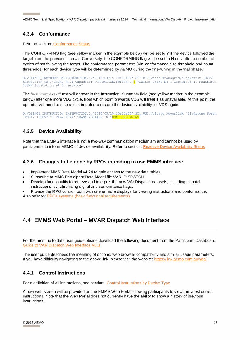
4.3.4 Conformance
Refer to section: Conformance Status
The CONFORMING flag (see yellow marker in the example below) will be set to Y if the device followed the target from the previous interval. Conversely, the CONFORMING flag will be set to N only after a number of cycles of not following the target. The conformance parameters (viz. conformance size threshold and count thresholds) for each device type will be determined by AEMO during the fine-tuning in the trial phase.
D,VOLTAGE_INSTRUCTION,INSTRUCTION,1,”2015/03/15 10:30:00”,ST1.R1.Switch,Transgrid,"Peakhurst 132kV Substation eA","132kV No.1 Capacitor",CAPACITOR,SWITCH,1,Y,"Switch 132kV No.1 Capacitor at Peakhurst 132kV Substation eA in service"
The “NON CONFORMING“ text will appear in the Instruction_Summary field (see yellow marker in the example below) after one more VDS cycle, from which point onwards VDS will treat it as unavailable. At this point the operator will need to take action in order to restore the device availability for VDS again.
D,VOLTAGE_INSTRUCTION,INSTRUCTION,1,”2015/03/15 10:30:00”,ST1.UN1.Voltage,Powerlink,"Gladstone North (T074) 132kV","1 Tfmr T074",TRANS,VOLTAGE,,N,"NON CONFORMING"
4.3.5 Device Availability
Note that the EMMS interface is not a two-way communication mechanism and cannot be used by participants to inform AEMO of device availability. Refer to section: Reactive Device Availability Status
4.3.6 Changes to be done by RPOs intending to use EMMS interface
• Implement MMS Data Model v4.24 to gain access to the new data tables. • Subscribe to MMS Participant Data Model file VAR_DISPATCH • Develop functionality to retrieve and interpret the new VAr Dispatch datasets, including dispatch
instructions, synchronising signal and conformance flags. • Provide the RPO control room with one or more displays for viewing instructions and conformance. Also refer to: RPOs systems (basic functional requirements)
4.4 EMMS Web Portal – MVAR Dispatch Web Interface
For the most up to date user guide please download the following document from the Participant Dashboard: Guide to VAR Dispatch Web Interface V0.3 The user guide describes the meaning of options, web browser compatibility and similar usage parameters. If you have difficulty navigating to the above link, please visit the website: https://link.aemo.com.au/vds/
4.4.1 Control Instructions
For a definition of all instructions, see section: Control instructions by Device Type
A new web screen will be provided on the EMMS Web Portal allowing participants to view the latest current instructions. Note that the Web Portal does not currently have the ability to show a history of previous instructions.

AEMO Technical Specification - VAR Dispatch participant interfaces 2016 Technical information: VAr Dispatch Project Implementation
© 2016 AEMO 19
The EMMS Web Portal is simply a method to display the same information that is captured in the files that will be sent out via the EMMS Data Interchange. Therefore, the information contained in the section above is also relevant to the Web Portal.
By default all reactive devices taking part in VAr Dispatch will be displayed in the list, even if they have no instruction (the Target field will be blank).
Below is an example screen shot of the web page (indicative only, the production version may vary slightly). Please also note that the sample contents are not indicative of real instructions.
Figure 4. Example screen shot of webpage
The following information will be included on the web page: • Will show only the latest instructions • Will allow filtering on one or more Participant ID by clicking inside the text box • Will allow filtering on stations based on what Participant IDs are selected • Will allow filtering on only those devices that have received a target • Will allow automatic refresh (10 second intervals) • Highlights non-conforming devices (entire row will be coloured red) • Shows the issued date/time (top right corner of the page). The date box will be green for normal
operation and red when no new instruction set has been issued for more than 15 minutes. This indicates to the RPO that there may be VDS system or communication issues in which case AEMO control room will revert to telephonic instructions.
• Will alarm when receives new instructions for filtered on device • Will alarm when VDS has been inactive for more than 30 minutes • Will alarm when unable to contact AEMO web servers
Table 9: EMMS MVar Web Screen Information
The information fields (in top right corner of the page): Information Field Description
Instruction/Signal Indicates whether instructions are currently active or a signal has been issued to clear instructions.
AEMO Technical Specification - VAR Dispatch participant interfaces 2016 Technical information: VAr Dispatch Project Implementation
© 2016 AEMO 20
Information Field Description
Run Date/Time MVAr Interval – a timestamp of when instructions issued
The filter fields are:
Filter Field Description
Participant The NEM id of the participant who owns the equipment
Station The station names grouped under Participant ID
Show only devices with Targets Only displays devices that have been issued a target
Description of fields in the table
Field Name Description
EMS ID The unique identifier for reference within AEMO –matches equipment names between NOS and EMS
Participant ID The NEM id of the participant who owns the equipment
Station ID The company/participant preferred name of the substation the equipment is located at
Device ID The company/participant preferred name of an equipment
Device Type One of REACTOR, CAPACITOR, GEN, SVC, TRANS or GENGRP but may be extended to other types
Control Type The type of issued control
Target Instruction for the device for this interval – null denotes no instruction.
Instruction Verbose summary of instruction
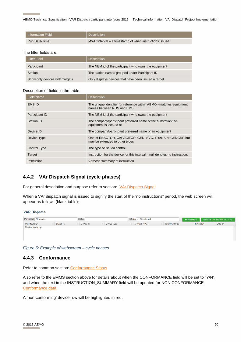
4.4.2 VAr Dispatch Signal (cycle phases)
For general description and purpose refer to section: VAr Dispatch Signal
When a VAr dispatch signal is issued to signify the start of the “no instructions” period, the web screen will appear as follows (blank table):
Figure 5: Example of webscreen – cycle phases
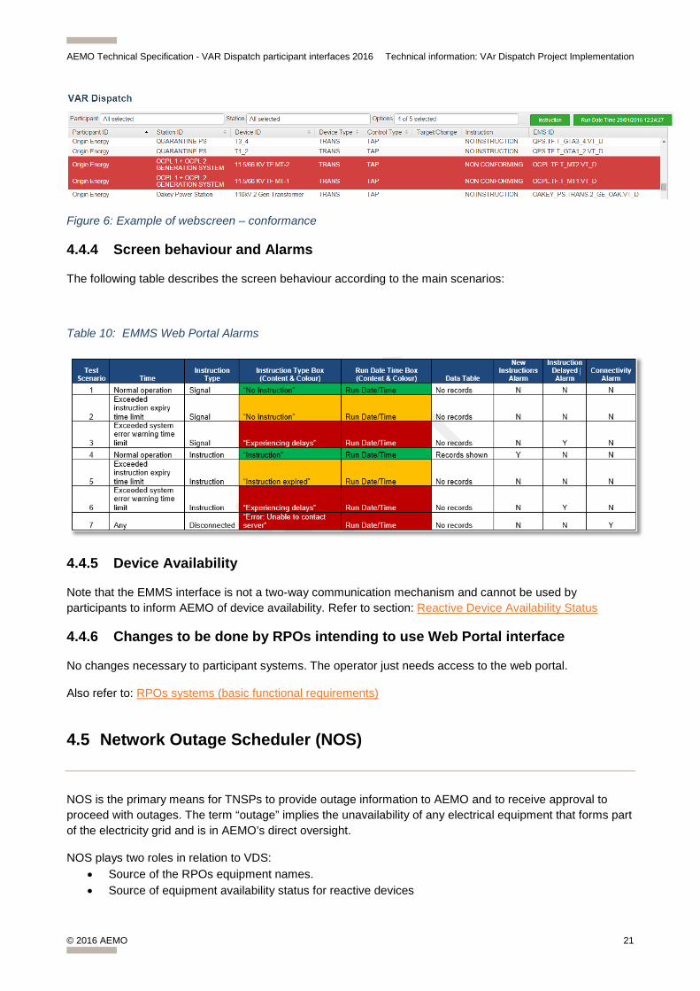
4.4.3 Conformance
Refer to common section: Conformance Status
Also refer to the EMMS section above for details about when the CONFORMANCE field will be set to “Y/N”, and when the text in the INSTRUCTION_SUMMARY field will be updated for NON CONFORMANCE: Conformance data
A ‘non-conforming’ device row will be highlighted in red.
AEMO Technical Specification - VAR Dispatch participant interfaces 2016 Technical information: VAr Dispatch Project Implementation
© 2016 AEMO 21
Figure 6: Example of webscreen – conformance
4.4.4 Screen behaviour and Alarms
The following table describes the screen behaviour according to the main scenarios:
Table 10: EMMS Web Portal Alarms
4.4.5 Device Availability
Note that the EMMS interface is not a two-way communication mechanism and cannot be used by participants to inform AEMO of device availability. Refer to section: Reactive Device Availability Status
4.4.6 Changes to be done by RPOs intending to use Web Portal interface
No changes necessary to participant systems. The operator just needs access to the web portal.
Also refer to: RPOs systems (basic functional requirements)
4.5 Network Outage Scheduler (NOS)
NOS is the primary means for TNSPs to provide outage information to AEMO and to receive approval to proceed with outages. The term “outage” implies the unavailability of any electrical equipment that forms part of the electricity grid and is in AEMO’s direct oversight.
NOS plays two roles in relation to VDS: • Source of the RPOs equipment names. • Source of equipment availability status for reactive devices
AEMO Technical Specification - VAR Dispatch participant interfaces 2016 Technical information: VAr Dispatch Project Implementation
© 2016 AEMO 22
4.5.1 NOS for RPOs equipment names
VDS will use company equipment names specified in NOS to identify equipment in the schedule of instructions by the names that the RPO is familiar with (i.e. their own IDs/names). These names are usually entered into NOS by the TNSP when they add new equipment.
The RPOs of generators are requested to email these names through to AEMO as generators are not already users of NOS. Alternatively, NOS will be populated with names from AEMO’s Energy Management System (EMS), which may not have exactly the same meaning to RPO control room staff.
Four fields are stored in NOS: StationID, StationName, EquipmentID, EquipmentName A spreadsheet containing all the names from AEMO’s EMS for generator station and equipment names is available to RPOs. This may be used to complete the RPO names and IDs. If you have not previously received this spreadsheet from AEMO please contact us. Please use the following email address to submit these names to AEMO for entry into NOS: [email protected]
4.5.2 NOS for equipment availability status
NOS is provided as an option to NSPs to provide availability of reactive devices for the VAr schedule in order to avoid double effort on the NSP side. A device will automatically be deemed “unavailable” by VDS for the period specified in a standard equipment outage submission. I.e. the NSP will not need to do anything over and above their normal outage notification process.
Note that this option is not currently available to generators or other plant operators who do not already use NOS. Some DNSPs may have the option.
AEMO Technical Specification - VAR Dispatch participant interfaces 2016 References
© 2016 AEMO 23
5 References Documents referenced in this Technical Specification are current at the time of publication. All readers are encouraged to use these reference points for updates, with due care for the relevance and application in any particular set of circumstances. Some of the published material may not be effective until a future date; some may be a correction or clarification to current material; and some is historical.
If further changes to any of the key reference documents cause a significant change to this document, a new version will be issued soon after AEMO determines the impacts.
If you have questions on the business aspects of these changes, please see your organisation’s business team involved in the various reference groups.
The following key reference documents are primary resources, and take precedence over this document.
Refer also the May 2016 Release Notes attached in Appendix A.
5.1 AEMO CSV data format standard
The CSV data is structured as per the AEMO CSV Data Format Standard.
• Guide to AEMO CSV Data Format Standard, http://aemo.com.au/About-the-Industry/Information-Systems/~/media/Files/Other/energy%20market%20information%20systems/AEMO_CSV_Data_Format_Standard_v3_01.ashx (Home > About the Industry > Information Systems > Using Energy Market Information Systems).
5.2 AEMO’s website
Other relevant documents and information are available the Information Systems web page:
• “Data Interchange”, http://www.aemo.com.au/About-the-Industry/Information-Systems/Data-Interchange (Home > About the Industry > Information Systems > Data Interchange).
• “EMMS May 2015 Technical specification”, See attachment in appendix A.
• Guide to User Rights Management, http://www.aemo.com.au/About-the-Industry/Information-Systems/Using-Energy-Market-Information-Systems/User-Rights-Management (Home > About the Industry > Information Systems > Using Energy Market Information Systems).
• “Information Systems”, http://www.aemo.com.au/About-the-Industry/Information-Systems (Home > About the Industry > Information Systems).
• “IT Assistance”, http://www.aemo.com.au/About-the-Industry/Information-Systems/IT-Assistance (Home > About the Industry > Information Systems > IT Assistance).
• “Market Management System MMS Data”, http://www.aemo.com.au/Electricity/Data/Market-Management-System-MMS (Home > Electricity > Data > Market Management System MMS).
• “Using Energy Market Information Systems”, http://www.aemo.com.au/About-the-Industry/Information-Systems/Using-Energy-Market-Information-Systems (Home > About the Industry > Information Systems > Using Energy Market Information Systems).
AEMO Technical Specification - VAR Dispatch participant interfaces 2016 References
© 2016 AEMO 24
5.3 aseXML standards
The ASWG arranges for publication of the aseXML standards and schemas on AEMO’s website. See http://www.aemo.com.au/About-the-Industry/Information-Systems/aseXML-Standards (Home > About the Industry > Information Systems > aseXML Standards).
In particular, see:
• “aseXML Guidelines”, The Guidelines for the Development of A Standard for Energy Transactions in XML (aseXML) for guidance and advice to parties who are designing aseXML documents and applications for processing aseXML documents, http://www.aemo.com.au/About-the-Industry/Information-Systems/aseXML-Standards/aseXML-Guidelines.
• “Schemas”, http://www.aemo.com.au/About-the-Industry/Information-Systems/aseXML-Standards/aseXML-Schemas.
• “Sample Files”, http://www.aemo.com.au/About-the-Industry/Information-Systems/aseXML-Standards/aseXML-Document-Samples.
• “AseXML Standards Working Group”, for details about the ASWG, including membership, http://www.aemo.com.au/About-the-Industry/Working-Groups/Energy-Market-IT-Steering-Committee/aseXML-Standards-Working-Group-ASWG.
5.4 Consultations
AEMO consultations are key reference documents and take precedence over this document. For all AEMO’s consultations, either currently open or recently closed, see:
• “Consultations”, http://www.aemo.com.au/Consultations.
5.5 Information and Support Hub
AEMO Information and Support Hub:
phone 1300 AEMO 00 (1300 236 600),
email [email protected].
Note that any communication specifically related to the implementation and testing of this project may be sent to [email protected]
AEMO Technical Specification - VAR Dispatch participant interfaces 2016 Appendix A: VAR MMS Data Model changes
© 2016 AEMO 25
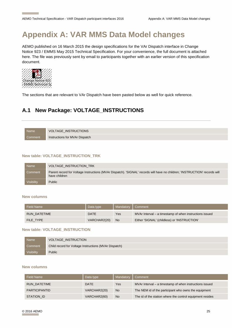
Appendix A: VAR MMS Data Model changes AEMO published on 16 March 2015 the design specifications for the VAr Dispatch interface in Change Notice 923 / EMMS May 2015 Technical Specification. For your convenience, the full document is attached here. The file was previously sent by email to participants together with an earlier version of this specification document.
Change Notice 923 - EMMS Technical Sp
The sections that are relevant to VAr Dispatch have been pasted below as well for quick reference.
A.1 New Package: VOLTAGE_INSTRUCTIONS
Name VOLTAGE_INSTRUCTIONS
Comment Instructions for MVAr Dispatch
New table: VOLTAGE_INSTRUCTION_TRK
Name VOLTAGE_INSTRUCTION_TRK
Comment Parent record for Voltage Instructions (MVAr Dispatch). 'SIGNAL' records will have no children; 'INSTRUCTION' records will have children
Visibility Public
New columns
Field Name Data type Mandatory Comment
RUN_DATETIME DATE Yes MVAr Interval – a timestamp of when instructions issued
FILE_TYPE VARCHAR2(20) No Either 'SIGNAL' (childless) or 'INSTRUCTION'
New table: VOLTAGE_INSTRUCTION
Name VOLTAGE_INSTRUCTION
Comment Child record for Voltage Instructions (MVAr Dispatch)
Visibility Public
New columns
Field Name Data type Mandatory Comment
RUN_DATETIME DATE Yes MVAr Interval – a timestamp of when instructions issued
PARTICIPANTID VARCHAR2(20) No The NEM id of the participant who owns the equipment
STATION_ID VARCHAR2(60) No The id of the station where the control equipment resides
AEMO Technical Specification - VAR Dispatch participant interfaces 2016 Appendix A: VAR MMS Data Model changes
© 2016 AEMO 26
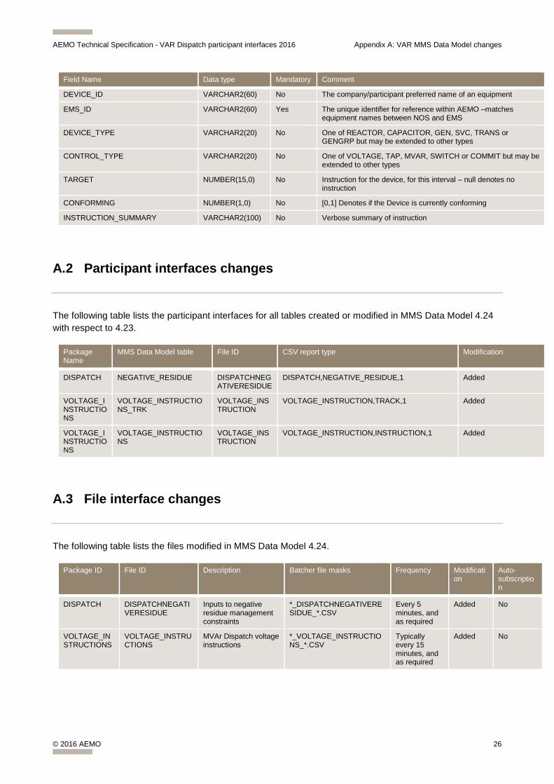
Field Name Data type Mandatory Comment
DEVICE_ID VARCHAR2(60) No The company/participant preferred name of an equipment
EMS_ID VARCHAR2(60) Yes The unique identifier for reference within AEMO –matches equipment names between NOS and EMS
DEVICE_TYPE VARCHAR2(20) No One of REACTOR, CAPACITOR, GEN, SVC, TRANS or GENGRP but may be extended to other types
CONTROL_TYPE VARCHAR2(20) No One of VOLTAGE, TAP, MVAR, SWITCH or COMMIT but may be extended to other types
TARGET NUMBER(15,0) No Instruction for the device, for this interval – null denotes no instruction
CONFORMING NUMBER(1,0) No [0,1] Denotes if the Device is currently conforming
INSTRUCTION_SUMMARY VARCHAR2(100) No Verbose summary of instruction
A.2 Participant interfaces changes
The following table lists the participant interfaces for all tables created or modified in MMS Data Model 4.24 with respect to 4.23.
Package Name
MMS Data Model table File ID CSV report type Modification
DISPATCH NEGATIVE_RESIDUE DISPATCHNEGATIVERESIDUE
DISPATCH,NEGATIVE_RESIDUE,1 Added
VOLTAGE_INSTRUCTIONS
VOLTAGE_INSTRUCTIONS_TRK
VOLTAGE_INSTRUCTION
VOLTAGE_INSTRUCTION,TRACK,1 Added
VOLTAGE_INSTRUCTIONS
VOLTAGE_INSTRUCTIONS
VOLTAGE_INSTRUCTION
VOLTAGE_INSTRUCTION,INSTRUCTION,1 Added
A.3 File interface changes
The following table lists the files modified in MMS Data Model 4.24.
Package ID File ID Description Batcher file masks Frequency Modification
Auto-subscription
DISPATCH DISPATCHNEGATIVERESIDUE
Inputs to negative residue management constraints
*_DISPATCHNEGATIVERESIDUE_*.CSV
Every 5 minutes, and as required
Added No
VOLTAGE_INSTRUCTIONS
VOLTAGE_INSTRUCTIONS
MVAr Dispatch voltage instructions
*_VOLTAGE_INSTRUCTIONS_*.CSV
Typically every 15 minutes, and as required
Added No