aeg¯is experiment: measuring the acceleration g of the ... · aegis experiment: measuring the...
TRANSCRIPT

AEgIS Experiment: Measuring the acceleration g of the earth’sgravitational field on antihydrogen beam
M. A. Subieta Vasquez1,2,a, S.Aghion3,4, O. Ahlén5, C. Amsler6, A. Ariga6, T. Ariga6, A. S. Belov7,G. Bonomi1,2, P. Bräunig8, J. Bremer5, R. S. Brusa9, L. Cabaret10, M. Caccia4, C. Canali11,R. Caravita12,4, F. Castelli12,4, G. Cerchiari12,4, S. Cialdi12, D. Comparat10, G. Consolati3,4, L.Dassa1, J. H. Derking5, S. Di Domizio13, L. Di Noto9, M. Doser5, A. Dudarev5, A. Ereditato6, R.Ferragut3,4, A. Fontana2, P. Genova5, M. Giammarchi12,4, A. Gligorova14, S. N. Gninenko7, S.Heider5, S. D. Hogan15, T. Huse16, E. Jordan17, L. V. Jørgensen5, T. Kaltenbacher5, J. Kawada6,A. Kellerbauer17, M. Kimura6, A. Knecht5, D. Krasnický13,18, V. Lagomarsino13,18, S. Mariazzi9, V.A. Matveev19, F. Merkt20, F. Moia3,4, G. Nebbia21, P. Nédélec22, M. K. Oberthaler8, N. Pacifico14,V. Petrácek23, C. Pistilo6, F. Prelz4, M. Prevedelli24, C. Regenfus11, C. Ricardi2,25, O. Røhne16, A.Rotondi2,25, H. Sandaker14, P. Scampoli6,26, J. Storey6, M. Špacek23, G. Testera13, D. Trezzi4, R.Vaccarone13, F. Villa12, and S. Zavatarelli13
1Università Degli Studi di Brescia, Dipartimento di Ingegneria Meccanica e Industriale, Via Branze 38, 25133Brescia,Italy2Istituto Nazionale di Fisica Nucleare, Sez. di Pavia, Via Agostino Bassi 6, 27100 Pavia, Italy3Politecnico di Milano, Piazza Leonardo da Vinci 32, 20133 Milan, Italy4Istituto Nazionale di Fisica Nucleare, Sez. di Milano, Via Celoria 16, 20133 Milan, Italy5European Organization for Nuclear Research, Physics Dept., 1211 Geneva 23, Switzerland6Albert Einstein Center for Fundamental Physics, Laboratory for High Energy Physics, University of Bern,3012 Bern, Switzerland7Institute for Nuclear Research of Russian Academy of Sciences, Moscow 117312, Russia8University of Heidelberg, Kirchoff Institute for Physics, Im Neuenheimer Feld 227, 69120 Heidelberg, Ger-many9Dipartimento di Fisica, Università di Trento & INFN, Gruppo Collegato di Trento, Via Sommarive 14, 38050Povo, Trento, Italy10Laboratoire Aimé Cotton, CNRS, Université Paris Sud, ENS Cachan, Bâtiment 505, Campus d’Orsay,91405 Orsay Cedex, France11University of Zurich, Physics Institute, Winterthurerstrasse 190, 8057 Zurich, Switzerland12Università Degli Studi di Milano, Dipartimento di Fisica, Via Celoria 16, 20133 Milan, Italy13Istituto Nazionale di Fisica Nucleare, Sez. di Genova, Via Dodecaneso 33, 16146 Genova, Italy14University of Bergen, Institute of Physics and Technology, Alleegaten 55, 5007 Bergen, Norway15University College London, Dept. of Physics and Astronomy, Gower Street, London WC1E 6BT, UK16University of Oslo, Dept. of Physics, Semælands vei 24, 0371 Oslo, Norway17Max Plank Institute for Nuclear Physics, Saupfercheckweg 1, 69117 Heidelberg, Germany18Università Degli Studi di Genoa, Dipartimento di Fisica, Via Dodecaneso 33, 16146 Genova, Italy19Joint Institute for Nuclear Research, 141980 Dubna, Russia20ETH Zurich, Laboratory for Physical Chemistry, 8093 Zurich, Switzerland21Istituto Nazionale di Fisica Nucleare, Sez. di Padova, Via Marzolo 8, 35131 Padova, Italy22Claude Bernard University Lyon 1, Institut de Physique Nucléaire de Lyon, 4 Rue Enrico Fermi, 69622
ae-mail: [email protected]
DOI: 10.1051/C© Owned by the authors, published by EDP Sciences, 2014
,/
0012 (2014)201epjconf
EPJ Web of Conferences4710012
71 88
This is an Open Access article distributed under the terms of the Creative Commons Attribution License 2.0, which permits unrestricted use, distribution, and reproduction in any medium, provided the original work is properly cited.
Article available at http://www.epj-conferences.org or http://dx.doi.org/10.1051/epjconf/20147100128
source: https://doi.org/10.7892/boris.68649 | downloaded: 13.3.2017

Villeurbanne, France23Czech Technical University in Prague, FNSPE, Brehová 7, 11519 Praha 1, Czech Republic24Università Degli Studi di Bologna, Dipartimento di Fisica, Via Irnerio 46, 40126 Bologna, Italy25Università Degli Studi di Pavia, Dipartimento di Fisica Nucleare e Teorica, Agostino Bassi 6, 27100 Pavia,Italy26Università di Napoli Federico II, Dipartimento di Fisica, Via Cinthia, 80126 Napoli, Italy
Abstract. The AEgIS experiment [1] aims at directly measuring the gravitational accel-
eration g on a beam of cold antihydrogen (H) to a precision of 1%, performing the first
test with antimatter of the (WEP) Weak Equivalence Principle. The experimental appa-
ratus is sited at the Antiproton Decelerator (AD) at CERN, Geneva, Switzerland. After
production by mixing of antiprotons with Rydberg state positronium atoms (Ps), the H
atoms will be driven to fly horizontally with a velocity of a few 100 ms−1 for a path length
of about 1 meter. The small deflection, few tens of μm, will be measured using two ma-
terial gratings (of period ∼ 80 μm) coupled to a position-sensitive detector working as a
moiré deflectometer similarly to what has been done with matter atoms [2]. The shadow
pattern produced by the H beam will then be detected by reconstructing the annihilation
points with a spatial resolution (∼ 2 μm) of each antiatom at the end of the flight path by
the sensitive-position detector. During 2012 the experimental apparatus has been com-
missioned with antiprotons and positrons. Since the AD will not be running during 2013,
during the refurbishment of the CERN accelerators, the experiment is currently working
with positrons, electrons and protons, in order to prepare the way for the antihydrogen
production in late 2014.
1 Introduction
One of the foundations of Albert Einstein’s General Relativity theory is the Weak Equivalence Prin-
ciple (WEP), which states that acceleration imparted to a body by the presence of a gravitational field
is independent of the nature of the body. This principle up to now was tested with a precision down
to the 10−13 level [3] but, it has not been tested yet with antimatter. Nevertheless, various intents of
testing WEP by using antiprotons and positrons have been attempted, but they failed due to the impos-
sibility to reduce electromagnetic disturbances. Nowdays, with past experience in the production of
antihydrogen for the first time achieved in 2002 by ATHENA collaboration [4] and after by ATRAP
collaboration [5], opens the possibility to test WEP with H atoms as well as to improve the H pro-
duction respect to past experiments, by applying new techniques, as the case of AEgIS experiment.
The main goal of the AEgIS experiment is the direct measurement of the gravitational acceleration gon cold antihydrogen beam to a precision of 1%, in order to test with antimatter the validity of the
WEP principle, but first we have to overcome many challenging steps. In the following sections will
be described the AEgIS apparatus, the physics concepts and will be also presented the results of the
commissioning period of the apparatus.
2 AEgIS apparatus and physics
The antiproton decelerator AD delivers ∼ 3 × 10⁷ antiprotons with kinetic energy 5.3 MeV every
∼ 120s. Once p are injected into the experiment line, are slowed down by thin aluminum foils and
a silicon beam counter (BC), which have been inserted in their path (most of the main components
of the AEgIS apparatus are shown in figure 2). Therefore, degraded p are captured and accumulated
EPJ Web of Conferences
00128-p.2

Figure 1. In the figure are shown: on top left side, a schematic view of the Ps formation and diffusion in the nano
porous silica target, on top right side, a picture of the formation region trap and the e+/Ps converter, on bottom
left side, an schematic view of the Ps formation and excitation, as well as the H∗production and acceleration
and finally on bottom right side, an schematic view of the moiré deflectometer coupled to a position sensitive
detector. The so-called "formation region trap" is about 10 cm long with several tiny holes on the top, which will
permit the access of Ps∗ atoms onto the antihydrogen formation region.
by using Penning-Malberg traps located inside the 5T superconducting magnet at pressures down of
10−13 mbar and cryogenic temperatures abut 4.2 K. The p cloud is cooled to sub-K temperatures by
loading electrons (prior to p arrival) into a deep potential well (∼ 120 V), this procedure is known as
Electron Cooling (EC). On the other hand, positrons produced by the radioactive 22Na β+ source, are
stored by using Surko-type trap plus Penning-Malberg accumulator [6], during the accumulation time
of ∼ 120s are stored ∼ 7 − 8 × 10⁶ e+, after that, they are transferred by the 0.1T magnetic field of
the so-called transfer line into the 5T region. Once positrons reach the 5T trap, they are accumulated
and stored prior to be transported into the 1T traps. Once positrons are transfered to the 1T they are
guided by an off-axis trap onto the e+/Ps converter (target) in order to start the production of cold
positronium (Ps) atoms by the injection of e+ with kinetic energy within [1 keV - 10 keV] in a nano-
porous silica material [7] kept at cryogenic temperatures ∼ 70 K. The implanted e+ are slowing down
through the collisions with the atoms of the target, losing their kinetic energy to few eV (reaching the
near thermal energy). Thereby, positrons can either capture a bound molecular electron or recombine
with free electrons to form positronium atoms. Once Ps are formed, they start to diffuse with a few
eV within [1 eV - 3 eV] of kinetic energy colliding with the porous material walls up to reach the
thermal equilibrium with the environment material. Once Ps atoms reach the surface target a cooled
fraction may scape into the vacuum [8] (a schematic view of the Ps formation is shown on top left
ICNFP 2013
00128-p.3

side in figure 1). In light to produce positronium at Rydberg states (Ps∗) within [n∗Ps > 25 - n∗Ps = 35],
two laser excitation steps is needed [9]. The first step is a UV (λ = 205 nm) pulsed laser excitation
whereas the second step is a IR (λ ≈ 1670 nm) pulsed laser. In the first case, the energy required to
saturate the quantum transition from n = 1 to n = 3 is 32 μJ, instead in the second case, the energy
required to pass from n = 3 to Rydberg states is 350 μJ. Once Ps∗ reach the ultra-cold trap at the
formation region, it interact with p by a charge exchange reaction [10] given by the equation 1, in
order to produce ultra-cold Rydberg antihydrogen H∗.
Ps∗ + p = H∗+ e−, (1)
The kinetic energy expected of the H∗cloud will depend of the temperature of p cloud and it
will determine its radial velocity, which for ultra-cold temperatures close to 100 mK is approximately
50 ms−1. A variation of this technique was already tested in 2004 [11]. Once H∗is formed, it will
be accelerated to axial velocities (∼ 400 ms−1) by using an inhomogeneous electric field, which
interacts with the strong electric field dipole of the Rydberg antihydrogen. This technique is known as
Stark acceleration [12] (a schematic view of the antihydrogen formation and acceleration is shown on
bottom left side of figure 1). Then the pulsed cold antihydrogen beam produced by the acceleration,
will pass through a moiré deflectometer, which consist in two gratings (of period ∼ 80 μm each)
coupled with a position-sensitive detectors, separated a distance L each, as is shown in figure 1 (bottom
right). The deflectometer acts as collimator making that incoming antihydrogen atoms form a fringe
pattern which can be displayed by a position-sensitive detector. In the presence of a force acting on
the antihydrogen atoms, it will lead to a vertical displacement denoted here as (Δy) of the imaged
fringe pattern, which can be calculated by the formula:
Δy = −g(L
v
)2, (2)
where v is the velocity and t2 = L2
v2 is the time-of-flight of the antihydrogen atoms. After the
registration of the time-of-flight and the annihilation vertex on the position-sensitive detector (with
spatial resolution ∼ 2 μm), the acceleration g on antihydrogen atoms can be determined. The position-
sensitive detectors as well as the moiré deflectometer are currently under study and construction. In
the next section will be presented preliminary results of various test done with prototype detectors.
2.1 Internal and external scintillators
The Fast Annihilation Cryogenic tracking (FACT) detector [13] is located around the ultracold (≈ 100
mK) H formation region. It consist in 800 scintillating fibers which operate at 4K, the fibers will be
used to reconstruct the annihilation vertexes of each H atom with ∼ 2 mm of spatial resolution. As
external detectors we use a set of plastic scintillators coupled with photomultipliers placed as follows:
1 (HPD) parallel to the end of the AD line at the beginning of the 5T cryostat and 12 around the
two magnets (four on 5T cryostat and eight on 1T cryostat). The HPD gives the trigger signal of the
arrival antiprotons from the AD line onto the 5T traps, whereas the last 12 scintillators coupled with
24 photomultipliers (PMT’s) are used to detect mainly the annihilations of p when they are realised
toward the degrader foils, after been caught.
EPJ Web of Conferences
00128-p.4
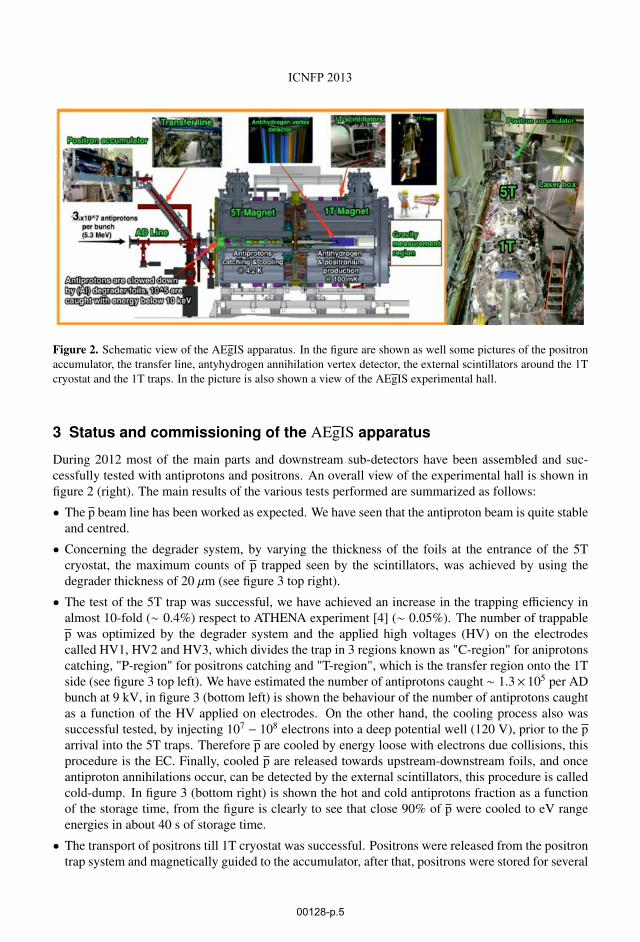
Figure 2. Schematic view of the AEgIS apparatus. In the figure are shown as well some pictures of the positron
accumulator, the transfer line, antyhydrogen annihilation vertex detector, the external scintillators around the 1T
cryostat and the 1T traps. In the picture is also shown a view of the AEgIS experimental hall.
3 Status and commissioning of the AEgIS apparatus
During 2012 most of the main parts and downstream sub-detectors have been assembled and suc-
cessfully tested with antiprotons and positrons. An overall view of the experimental hall is shown in
figure 2 (right). The main results of the various tests performed are summarized as follows:
• The p beam line has been worked as expected. We have seen that the antiproton beam is quite stable
and centred.
• Concerning the degrader system, by varying the thickness of the foils at the entrance of the 5T
cryostat, the maximum counts of p trapped seen by the scintillators, was achieved by using the
degrader thickness of 20 μm (see figure 3 top right).
• The test of the 5T trap was successful, we have achieved an increase in the trapping efficiency in
almost 10-fold (∼ 0.4%) respect to ATHENA experiment [4] (∼ 0.05%). The number of trappable
p was optimized by the degrader system and the applied high voltages (HV) on the electrodes
called HV1, HV2 and HV3, which divides the trap in 3 regions known as "C-region" for aniprotons
catching, "P-region" for positrons catching and "T-region", which is the transfer region onto the 1T
side (see figure 3 top left). We have estimated the number of antiprotons caught ∼ 1.3× 10⁵ per AD
bunch at 9 kV, in figure 3 (bottom left) is shown the behaviour of the number of antiprotons caught
as a function of the HV applied on electrodes. On the other hand, the cooling process also was
successful tested, by injecting 107 − 108 electrons into a deep potential well (120 V), prior to the p
arrival into the 5T traps. Therefore p are cooled by energy loose with electrons due collisions, this
procedure is the EC. Finally, cooled p are released towards upstream-downstream foils, and once
antiproton annihilations occur, can be detected by the external scintillators, this procedure is called
cold-dump. In figure 3 (bottom right) is shown the hot and cold antiprotons fraction as a function
of the storage time, from the figure is clearly to see that close 90% of p were cooled to eV range
energies in about 40 s of storage time.
• The transport of positrons till 1T cryostat was successful. Positrons were released from the positron
trap system and magnetically guided to the accumulator, after that, positrons were stored for several
ICNFP 2013
00128-p.5

Figure 3. The figure shows: on left top side, a drawing of the 5T trap in which are visible the 3 trapping regions
divided by the HV electrodes, on right top side, a plot of the scintillator counts as a function of the degrader
thickness, on left bottom side, a plot of the number of p trapped as a function of the HV applied and finally on
right bottom side, a plot of the hot and cold p fraction as a function of the storage time.
seconds (∼ 120 s), and then released (∼ 8×10⁶ positrons) and transported by using the transfer line
onto the 5T cryostat and then from the 5T to the 1T cryostat respectively. The external scintillators
have been used to tracking the path of positrons by detecting the annihilations signals produced
during their passage through both magnets (see figure 4).
3.1 Detectors
In light to develop a set up of detectors for the gravity measurement region, were tested various nuclear
emulsion films and silicon base detectors in order to design a suitable sensitive-detector to measure
the position of each antihydrogen annihilation point with precision of (∼ 1 μm). Since antiprotons not
caught have passed through 2 μm thick titanium foil at the exit of the 1T magnet into the detector test
chamber, thereby, either emulsions and silicon pixel detectors were directly exposed to (≤ 500 keV)
antiprotons. In figure 5 (top left) is shown a picture of the chamber where were placed the detectors.
A typical image of the emulsion exposed to antiprotons is shown in figure 5 (top right), where are
clearly visible the spots of the p annihilation vertexes. The main results and a detailed description of
the emulsions films has been published (see references [[14],[15],[16]]).
EPJ Web of Conferences
00128-p.6

Figure 4. The figure shows a picture of the oscilloscope signals of the accumulator extraction trigger (yellow
line) and the scintillators signal due to the positron annihilation in some where of the 1T cryostat (blue and violet
lines).
Moreover have been tested two pixel detectors, a 3D sensor and a very thin sensor with active area
15 μm, known as Mimotera detector. Detailed studies of low antiproton annihilations in silicon, based
in comparisons between experimental data and simulated produced by using the package GEANT4,
was done. The main results as well as the technical details are well described in an article which is
currently in press. In figure 5 (bottom left) is shown a typical plot of the Mimotera detector, where is
possible to see the spots of the antiproton annihilations.
3.1.1 Mini moiré deflectometer test
Has been developed a small prototype of the moiré deflectometer called mini moiré, in order to de-
velop tests with antiprotons. The complete set consisted in a mini moiré with period fringes of 40
μm and an emulsion detector, which was installed behind of the mini moiré deflectometer. Both were
directly exposed to antiprotons for 420 minutes. The results of the data analysis was very promising,
we have found that antiproton pattern shifts respect with the light pattern which was used as compar-
ison pattern (see figure 5 bottom right), which means that there was the presence of a force acting on
antiprotons. This tiny force was estimated in 520 aN which could correspond to a residual magnetic
filed of about ∼ 10G at that region test. An article describing this very interesting results is currently
under revision by the NATURE refeeres.
4 Conclusions & outlooks
AEgIS is a challenging and multidisciplinary physics experiment. During the antiproton beam time
periods (April-June) and (October-December) 2012, have been tested successfully large parts of the
apparatus. On the other hand, prototype sensitive-position detectors and prototype mini moiré deflec-
tometer have been tested providing essential information for the final design of the complete set to
perform the gravity measurement. Due to the long-shutdown period of the proton synchrotron (PS)
which is a key component of the CERN’s accelerator complex, no antiprotons will be able till PS
ICNFP 2013
00128-p.7

Figure 5. In the figure are shown: On top left, the chamber test used to place in the detectors, On the top right,
a typical image of the emulsion film about 20 μm thick, in which are clearly visible the spots of the antiproton
annihilation, On bottom left, a image of the Mimotera detector showing the spots of the antiproton annihilations
which corresponds to the blue dark points, and finally on bottom right, the antiproton pattern produced by the
passage through the mini moiré defletometer, which shifts respect to the light pattern in about 8.6 μm.
will return operational next late 2014. Meanwhile a proton source will be installed and tested in the
next months, in order to tuning the apparatus by producing hydrogen in light to produce efficiently in
the future antihydrogen. Moreover, the complete installation of the apparatus with the gravity mea-
surement region will be ready late 2014, allowing us to develop the first measurements during the
antiproton beam time period early 2015.
References
[1] AEgIS proposal, CERN-SPSC
(http://cdsweb.cern.ch/search?of=hd=reportnumber:CERN-SPSC-2007-017), (2007).
[2] M. K. Oberthaler, et al., Phys. Rev. A, 54, (1996) 3165.[3] E. G. Adelberg, et al., Progress in Particle and Nuclear Physics, 62, (2009) 102.[4] M. Amoretti, et al., Nature, 419, (2002) 456.
EPJ Web of Conferences
00128-p.8
[5] G. Gabrielse, et al., Phys. Rev. Lett, 89, (2009) 213401.[6] R. G. Greaves and C. M. Surko, Phys. Rev. Lett, 85, (2000) 1883.[7] S. Mariazzi et al., Phys. Rev. B, 81, (2010) 235418.[8] S. Mariazzi et al., Phys. Rev. Lett, 104, (2010) 243401.[9] S. Cialdi, et al., Nucl. Instr. and Meth. B, 269, (2011) 1527.[10] M. Charlton, Phys. Lett. A, 143, (1990) 143.[11] J. Storry, et al., Phys. Rev. Lett, 93, (2004) 263401.[12] E. Vliegen and F. Merkt, J. Phys. B: At. Mol. Opt. Phys., 39, (2006) L241.[13] J. Storey, et al., Nucl. Instr. and Meth. A, in press (2013)
[14] C. Amsler, et al., J. of Instr. 8, (2013) P02015.[15] AEgIS Collaboration, J. of Instr. 8, (2013) P08013.[16] AEgIS Collaboration, Nucl. Instr. and Meth. A, in press (2013)
ICNFP 2013
00128-p.9