aea pk-232 operatingmanual g. pk-232 operatingmanual g.pdf · voltmeter handy, you might have the...
TRANSCRIPT

ADVANCED ELECTRONIC APPLICATIONS, INC.
PAKRATT ™MODEL PK-232
Multi-Mode Data Controller
Operating Manual
REVISION G 7/89

PK-232 OPERATING MANUAL PREFACE
1
PREFACE TO THE PK-232 DATA CONTROLLER
Please read this preface in its entirety. It contains information about how to receive warranty ser-vice from AEA, the current software installed in your PK-232, AEA's software update policy andhow to get involved in the digital radio community.
RF interference Information To User
This PK-232 has been certified under Subpart J of Part 15 of the FCC rules.
This equipment generates and uses radio frequency energy. If it is not installed and used properly,that is, in strict accordance with AEA's instructions, it may cause interference to radio and TV re-ception. It has been type-tested and has been found to comply with the limits of a Class B comput-ing device in accordance with the specifications in Subpart J of Part 15 of the FCC rules, which aredesigned to provide reasonable protection against such interference will not occur in a particularinstallation. If this equipment does cause interference to radio or TV reception, which can be de-termined by turning the PK-232 on and off, the user is encouraged to try and correct the interfer-ence using one or more of the following measures:
Reorient the antenna of the device receiving interference.Relocate the computer with respect to this device.Plug the computer into a different outlet so the computer and the device are on differentbranch circuits.
USE SHIELDED CABLE FOR ALL RS-232 CONNECTIONS !
As part of its continuing program of product improvement, AEA reserves the right to make changesin this product's specifications. Changes will be made periodically to the information in this docu-ment. These changes will be incorporated in new issues of this manual.
There may be technical inaccuracies or typographical errors in this document. Please address com-ments and corrections to AEA Incorporated, PO Box C2160, Lynnwood, WA 98036-0918. AEA re-serves the right to incorporate and issue any information thus supplied in whatever manner itdeems suitable without incurring any obligations whatever.
Software Release 25. JUN 87 Checksum $E3Copyright 1986, 1987 by Advanced Electronic Applications, Inc.FIFTH ISSUE (JUNE 1987)

PK-232 OPERATING MANUAL PREFACE
2
Welcome
Congratulations!! You've purchased another fine AEA product.
PLEASE, before we go any further, may we ask you to FILL OUT AND RETURN the Warranty Regis-tration Card, which has been packed with your PK-232 system.
WE WILL NOT BE ABLE TO FURNISH YOU WITH ANY UPDATES TO THE SOFTWARE IF YOU DONOT RETURN THE ABOVE DOCUMENT. AS NEW FEATURES ARE DEVELOPED, WE ARE SURE YOUWILL WANT TO BE ABLE TO OBTAIN THEM.
If you call for any kind of customer assistance, we'll ask you for the serial number on you warrantycard. Because of the numerous situations in which our product is used by an unauthorized thirdparty, we MUST verify that you are the licensed user. We may choose to call you at the phonenumber listed in our records to verify your identity. THANK YOU for your patience.
Product Update Policy
From time to time AEA will make available updates to the design of its products. These sometimesare made available to the user who has previously purchased its products. We can only tell youabout these updates if we have your warrant card. PLEASE SEND IT IN if you have not alreadydone so. Future versions of software for the PK-232 will most likely become available. AEA willmake these updates available, if possible.
In Case of Trouble
Application and troubleshooting assistance may be had by calling AEA during our 8:00–12:00,1:00–4:30 working hours in Seattle WA. Ask for the Customer Service Department. The phonenumber is (206 775-7373. Please have your product serial number and version date of the soft-ware available. The version date is on the first screen that comes up when you turn on the PK-232.We will also need to know the nature of any other equipment connected to the PK-232.
Please attempt to solve problems locally, using other hams or an AEA dealer. Substituting a PK-80or other TNC that you know is working properly for your questionable one is a diagnostic techni-que that will check out the rest of your station. Also try running your PK-232 in another station.
Many of the AEA products that are sent to us for repair are in perfectly good order when we re-ceive them. Please perform whatever steps are applicable from the information on installation andtroubleshooting.
If you call for assistance, please have your PK-232 up an running beside the phone. Our servicetechnician will likely ask you to perform certain keyboard routines to aid in diagnosis. If you have avoltmeter handy, you might have the PK-232 open so you can report measurements to the servicetechnician.
PLEASE DO NOT RETURN THE PK-232 TO US WITHOUT CONTACTING US FOR PERMISSIONFIRST. WE WOULD LIKE THE OPPORTUNITY TO TROUBLESHOOT THE PROBLEM OVER THEPHONE FIRST, SAVING YOU BOTH TIME AND MONEY.
If the unit must be sent in, we will give you a Return to Manufacturer Authorization (RMA) numberover the telephone. This number allows us to better track your unit with our computer, so we cantell you its' exact status over the telephone.

PK-232 OPERATING MANUAL PREFACE
3
If you send us the PK-232 by UPS it must be sent to the street address - not the post office boxnumber. The street address is:
AEA. Inc.206 196th St. SWLynnwood, WA 98036USA
We will need YOUR street address for UPS return - be sure and send it.
NOTE
IF YOU DECIDE TO RETURN YOUR PK-232 TO THE FACTORY FOR SERVICE,PLEASE REMOVE THE BATTERIES BEFORE SHIPMENT.
UPS Surface (Brown Label) takes 7-8 days, Blue takes 2-3 days and Red is presently available onthe West Coast only. Red is an overnight service and it is expensive. Send the PK-232 in a way thatit can be traced if we cannot verify receipt of shipment. We suggest UPS or insured postal ship-ment.
If the PK-232 is still under the original owners warranty, AEA will pay the cost of the return ship-ment. The current policy is that it will be returned Brown if received Brown or by US Mail; returnedBlue if received Blue or by overnight service; or returned as the owner sates in his letter if he fur-nishes the return cost for the method he selects.
If the PK-232 is out of warranty, it will be returned by UPS Brown COD unless:
1) It was received UPS Blue/Red in which case it will go back UPS Blue COD, or2) If you designate billing to VISA or MASTERCARD, or3) you enclose a BLANK personal check endorsed 'not to exceed $...$', or4) you specify some other method of return.
Typically, we will typically service the product in two or three days if we have all the facts. If wemust call you, it may take longer. PLEASE, if you send it in, include a letter stating the problem andwere you can be reached. If you can be reached by phone in the evening on the east coast, let usknow where. Our current rate for non-warranty service is $40/hour with a 3/4 hour minimum.Parts and shipping are extra. AEA is not responsible for damage such as caused by lightning, nonprofessional alterations, poor storage/handling, etc.
Should your warranty card not be on file at AEA, you need to send the proof of purchase date toreceive warranty service. Typically a copy of your bill of sale from an AEA dealer will suffice.
The warranty is for original owner only and is not transferable.

PK-232 OPERATING MANUAL PREFACE
4
INTRODUCTION
Welcome to the exciting world of digital Amateur Radio! You've joined the ranks of the fastestgrowing modes in Amateur Radio since the FM repeater.
Your AEA PK-232 Data Controller is the connection between your computer and radios. The PK-232performs all the 'magic' of establishing data and text communications between your station andmany other communication facilities equipped for digital communications.
With packet-Radio and AMTOR, you'll have a 'private channel' while sharing a frequency with otherpacket and AMTOR stations; you'll be able to 'read the mail' of other Morse, RTTY and AMTORQSOs. log on to computer-based 'bulletin board' or 'mailbox' stations, handle message traffic – inshort, you're now equipped to enjoy the advantages of digital communications and error-correctingradio techniques in your ham shack.
Your new AEA PK-232 is the heart of your digital radio station. The PK-232's packet system soft-ware is derived from the original TAPR TNC; it presents many of the advanced features of that de-sign, coupled with significant enhancements based on the experience gained by thousands ofTAPR-equipped amateur packet stations worldwide.
This manual is your guide into the realm of digital Amateur Radio.
Join a Packet Club - Sbscribe To Newsletters - Join a Voice Net
Join a Packet-Radio club - they exist in all states as of this writing. You might also subscribe to theARRL publication 'Gateway', which describes all the 'going on' in Packet-Radio, and to the TAPR'Packet Status Register', which describes the technically interesting happenings in the movement.There are many voice nets on VHF and HF; they usually meet weekly. They are usually dedicatedto making the newcomer feel at home.
Acknowledgement
AEA, Inc. gratefully acknowledges the Tucson Amateur Packet-Radio Corporation, Tucson, AZ forpermission to include excerpts from their TNC-2 documentation in this manual.
Norm Sternberg (W2JUP) and Barbara Argilo developed, wrote and edited this User's Guide to thePK-232 on an IBM Displaywriter using TextPack 6, and on Tandy 1000HD and 1000SX computersusing IBM's Display-Write 3 V1.1 program. Our special gratitude also to Dr. Alan Chandler (K6RFK),Steve Stuart (N6IA), Joe Schimmel (W2HPM), Paul Newland (AD7I), Jeff Jacobsen (WA7MBL) andSteve Zopfi (KZ7G), for their invaluable help..
AEA, Inc. dedicates itself to the development of digital radio communications.

PK-232 OPERATING MANUAL PREFACE
5
BATTERY BACK-UP
NOTE: Your PK-232 uses to batteries to back up the user-programmable values in the system. Ifyou don't install batteries, you'll have to re-enter all of your personal system settings eachtime you turn on the PK-232. Your PK-232 will operate normally in all modes but will not re-tain your personalized parameters such as your call sign, until you install three AA-size bat-teries in the battery holder inside the chassis cover. We recommend that you choose alka-line batteries for this application.
Remove the four screws from the sides and the two screws from the rear of the chas-sis. Then lift off the PK-232's cover. Take care not to disturb the black or red wires thatattach the battery holder to the printed circuit board.
Find the positive and negative symbols embossed on the inside of the battery holder.Insert each battery, carefully matching the positive symbols on the battery with the pos-itive symbol on the holder.
Replace the cover and the six screws.
The battery back-up retains all the parameters except the time-of-day clock and theMHEARD (Monitor Heard) list. These two functions are controlled by the microprocessor.

PK-232 OPERATING MANUAL TABLE OF CONTENTS
TOC 1 7
TABLE OF CONTENTS
Paragraph Page
CHAPTER 1 – INTRODUCTION
1.1 Introduction ................................................................................................ 1-1 181.2 Scope ......................................................................................................... 1-1 181.3 General ....................................................................................................... 1-1 181.3.1 Application ....................................................................................... 1-1 181.3.2 Specifications .................................................................................... 1-1 181.3.2.1 Description ............................................................................ 1-1 181.3.2.2 Modem Characteristics ............................................................ 1-2 191.3.2.3 Processor System ................................................................... 1-2 191.3.2.4 Input/Output Connections ....................................................... 1-2 191.3.2.5 Controls and Indicators ........................................................... 1-3 201.3.2.6 General ................................................................................. 1-3 201.3.3 Features ........................................................................................... 1-3 201.4 System Components .................................................................................... 1-4 211.4.1 Input/Output Devices ........................................................................ 1-4 211.4.2 System Transmitter-Receiver Performance Requirements ...................... 1-4 21
CHAPTER 2 - INSTALLATION
2.1 'Quick Start' Installation ............................................................................... 2-1 222.1.1 Equipment Required .......................................................................... 2-1 222.1.2 Battery Installation for RAM Backup..................................................... 2-1 222.1.3 Radio and Power Connections............................................................. 2-1 222.2 Computer Connections ................................................................................. 2-2 232.3 System Quick-Check .................................................................................... 2-3 242.3.1 System Startup and Loopback Test ..................................................... 2-3 242.4 Radio Connection ........................................................................................ 2-5 262.4.1 PTT (Push-to-Talk) Configuration ........................................................ 2-5 262.4.1.1 Positive PTT ........................................................................... 2-6 272.4.1.2 Negative PTT .......................................................................... 2-6 272.4.2 FM Installation and Adjustment .......................................................... 2-6 272.4.3 SSB Installation and Adjustment ......................................................... 2-7 282.4.4 Connections for Direct FSK Operation on RTTY ..................................... 2-9 302.4.5 CW Installation and Adjustment ......................................................... 2-10 312.4.5.1 DC Keying .............................................................................. 2-10 312.4.5.2 AFSK CW Keying ..................................................................... 2-10 312.4.6 Oscilloscope Connections ................................................................... 2-10 312.5 Set Your Identifiers ...................................................................................... 2-11 322.5.1 Packet Call Sign ................................................................................ 2-11 322.5.2 AMTOR SELCAL (Selective Call) .......................................................... 2-11 322.6 Commands and Displays .............................................................................. 2-12 332.6.1 Display Complete Command List ......................................................... 2-12 332.6.2 Display Partial Command Lists ............................................................ 2-12 332.6.3 Display Asynchronous Port Parameters ................................................ 2-12 332.6.4 Display Special Characters ................................................................. 2-13 342.6.5 Display Facsimile Parameters .............................................................. 2-13 342.6.6 Display Identification Parameters ........................................................ 2-13 342.6.7 Display Link Parameters ..................................................................... 2-14 352.6.8 Display Monitor Parameters ................................................................ 2-14 35

PK-232 OPERATING MANUAL TABLE OF CONTENTS
TOC 2 8
Paragraph Page
2.6.9 Display Morse/RTTY/AMTOR Parameters ............................................. 2-15 362.6.10 Display Timing Parameters ................................................................. 2-15 362.7 Immediate Commands ................................................................................. 2-16 372.8 Detailed Connections for Specific Computers .................................................. 2-16 372.8.1 Available Serial Interfaces .................................................................. 2-17 382.8.2 Computers with Specific Serial Interfaces ............................................ 2-17 382.8.3 Commodore 64, 64C, 128, Vic 20 ....................................................... 2-17 382.8.4 IBM PCjr ........................................................................................... 2-18 392.8.5 Tandy Color Computer ....................................................................... 2-18 392.8.6 Tandy Model 100/102 and NEC 8201 .................................................. 2-18 392.8.7 Other Computers with 25-Pin RS-232-C Ports ...................................... 2-18 392.8.8 Other Computers with Non-Standard Serial Ports ................................. 2-19 402.9 Terminal (Modem) Software for Specific Computers ........................................ 2-19 402.9.1 Apple Macintosh ............................................................................... 2-20 412.9.2 Apple II, II+, IIE and IIC ................................................................... 2-20 412.9.3 Commodore 64, 64C, 128, Vic 20 ....................................................... 2-20 412.9.4 IBM PCjr ........................................................................................... 2-20 412.9.5 Tandy Color Computer ....................................................................... 2-20 412.9.6 Tandy Model 100/102 and NEC 8201 .................................................. 2-20 412.9.7 IBM PCs, 'Clones' and True Compatibles .............................................. 2-20 412.10 Packet Bulletin Board Program Compatibility .................................................. 2-21 42
CHAPTER 3 - BASIC OPERATION
3.1 Exploring the PK-232 Program ...................................................................... 3-1 433.2 LED Status and Mode Indicators ................................................................... 3-1 433.2.1 Status Indicator LEDs ........................................................................ 3-1 433.2.2 Mode Indicator LEDs ......................................................................... 3-2 443.2.2.1 The DCD LED - Data Carrier Detect .......................................... 3-2 443.2.3 LEDs at System Start ......................................................................... 3-2 443.2.4 Tuning Indicator ................................................................................ 3-3 443.3 PK-232 Commands ...................................................................................... 3-3 453.3.1 Entering Commands .......................................................................... 3-3 453.3.2 Command Responses ........................................................................ 3-3 453.3.3 Error Messages ................................................................................. 3-4 463.3.4 Command Names .............................................................................. 3-5 473.3.5 Default Values .................................................................................. 3-5 473.3.6 Parameters, Arguments and Values .................................................... 3-5 473.3.7 Using Commands Without Arguments ................................................. 3-7 493.3.8 PK-232 Controller Messages ............................................................... 3-7 493.3.8.1 General Messages ................................................................... 3-7 493.3.8.2 Command Mode Error Messages .............................................. 3-8 503.3.8.3 Link Status Messages .............................................................. 3-9 513.3.9 Special Keyboard Control Codes ......................................................... 3-11 533.3.9.1 Morse Code .............................................................................3-11 533.3.9.2 Packet Mode .......................................................................... 3-12 543.3.9.3 Baudot and ASCII RTTY .......................................................... 3-12 543.3.9.4 AMTOR Mode ......................................................................... 3-12 543.3.9.5 Clear String Commands ........................................................... 3-12 543.3.10 Detailed Command Descriptions ......................................................... 3-13 553.4 General Operating Information ..................................................................... 3-13 553.4.1 Signal Function Commands ................................................................ 3-13 553.4.1.1 Invert Received Data (RXREV) ................................................. 3-13 55

PK-232 OPERATING MANUAL TABLE OF CONTENTS
TOC 3 9
Paragraph Page
3.4.1.2 Invert Transmitted Data (TXREV) ............................................. 3-13 553.4.1.3 Return to Receive Mode <CTRL-D> ......................................... 3-13 553.4.1.4 Send Time of Day <CTRL-T> ................................................... 3-13 553.4.1.5 CW Identifier <CTRL-F> ......................................................... 3-14 563.4.1.6 Wideshift (WIDESHFT) ............................................................ 3-14 563.4.1.7 Answerback (AAB) .................................................................. 3-14 563.4.1.8 WRU? (Who Are You?) ............................................................ 3-15 573.4.2 Formatting Commands ...................................................................... 3-15 573.4.2.1 Screen Line Length (ACRDISP n) ............................................. 3-15 573.4.2.2 Monitor Echo (ECHO) .............................................................. 3-15 573.4.2.3 Automatic Word/Character Output (WORDOUT) ........................ 3-15 573.4.2.4 Line Feed <CTRL-J> ............................................................... 3-16 583.4.2.5 Carriage Return <CTRL-M> ..................................................... 3-16 583.4.2.6 Automatic Carriage Return (ACRRTTY n) .................................. 3-16 583.4.2.7 Automatic Line Feed (ALFRTTY) ............................................... 3-16 583.4.2.8 Backspace and Delete <DEL> ................................................. 3-17 593.4.2.9 Escape Functions <ESC> ........................................................ 3-17 593.4.2.10 Echo as Sent (EAS) ................................................................. 3-17 593.4.2.11 Clear Transmit Buffer (TCLEAR) ............................................... 3-17 593.4.3 Summary of Automatic Carriage Returns and Line Feeds ...................... 3-17 593.4.3.1 Automatic Carriage Returns ..................................................... 3-18 603.4.3.2 Automatic Line Feeds .............................................................. 3-18 603.4.4 PK-232-to-TNC-2 Command Cross-Reference ....................................... 3-19 61
CHAPTER 4 - OPERATING MODES
4.1 General Information ..................................................................................... 4-1 624.1.1 Morse Code ...................................................................................... 4-1 624.1.2 Baudot RTTY ..................................................................................... 4-1 624.1.3 ASCII RTTY ...................................................................................... 4-1 624.1.4 AMTOR ............................................................................................ 4-2 624.1.5 Packet Radio ..................................................................................... 4-2 634.2 Morse Code Operation ................................................................................. 4-2 634.2.1 Transmit/Receive Function Keys ......................................................... 4-4 654.2.2 Speed Change .................................................................................. 4-4 654.2.3 Speed Lock ....................................................................................... 4-5 664.2.4 Special Morse Characters ................................................................... 4-5 664.2.5 Morse Code Practice .......................................................................... 4-5 664.3 Baudot RTTY Operation ................................................................................ 4-5 664.3.1 Baudot RTTY Operating Tips .............................................................. 4-6 674.3.2 A Typical Baudot RTTY Contact ........................................................... 4-6 674.3.3 Transmit/Receive Function Keys ......................................................... 4-7 684.3.4 Baud Rate (Speed) Change ................................................................ 4-8 694.3.5 CCITT On/Off ................................................................................... 4-8 694.3.6 Unshift-On-Space .............................................................................. 4-9 704.4 ASCII RTTY Operation .................................................................................. 4-9 704.4.1 ASCII Operating Tips ......................................................................... 4-9 704.4.2 A Typical ASCII RTTY Contact ............................................................. 4-10 714.4.3 Transmit/Receive Function Keys ......................................................... 4-10 714.4.4 Baud Rate (Speed) Change ................................................................ 4-10 714.4.5 General Use of Control Key Functions ................................................. 4-11 724.5 AMTOR Operation ........................................................................................ 4-12 734.5.1 Transmit/Receive Function Keys ......................................................... 4-12 73

PK-232 OPERATING MANUAL TABLE OF CONTENTS
TOC 4 10
Paragraph Page
4.5.2 Speed Change Not Permitted ............................................................. 4-12 734.5.3 SELCAL (Selective Call) ...................................................................... 4-12 734.5.3.1 First SELCAL Installation ......................................................... 4-13 744.5.3.2 Prevent Duplicate SELCALs ...................................................... 4-13 744.5.4 Mode A (ARQ) Call - Start the Contact (ARQ Command) ....................... 4-14 754.5.4.1 LED Status and Mode Indicators .............................................. 4-14 754.5.4.2 Mode A (ARQ) Changeover (+? Command) .............................. 4-15 764.5.4.3 Mode A (ARQ) Break-in (ACHG Command) ............................... 4-15 764.5.4.4 End the Mode A (ARQ) Contact, Return to AMTOR Standby ....... 4-16 774.5.5 Mode A (ARQ) Listen Mode - Start Monitoring (ALIST Command) .......... 4-16 774.5.6 Mode B (FEC) Call - Start the Contact (FEC Command) ........................ 4-16 774.5.6.1 LED Status and Mode Indicators .............................................. 4-17 784.5.6.2 Mode B (FEC) Changeover ...................................................... 4-17 784.5.6.3 End the Mode B (FEC) Contact - Return to ARQ Standby ........... 4-18 794.5.7 Echo-As-Sent (EAS Command) ........................................................... 4-18 794.5.8 AMTOR Switching-Time Considerations ............................................... 4-19 804.5.9 Suggested AMTOR Trial Operating Techniques ..................................... 4-19 804.5.10 Possible Areas for AMTOR Performance Improvement .......................... 4-19 804.6 Packet Radio Operation ................................................................................ 4-20 814.6.1 Change Radio Link Data Rate ............................................................. 4-20 814.6.2 Station Identification ......................................................................... 4-21 824.6.2.1 MYCALL Required at System Start-up ....................................... 4-21 824.6.2.2 Substation Identifiers (SSIDs) .................................................. 4-21 824.6.2.3 Automatic Identification .......................................................... 4-21 824.6.3 Set Up Loopback Test Circuit .............................................................. 4-22 834.6.4 'Connect' and 'Disconnect' ................................................................. 4-22 834.6.5 LED Status and Mode Indicators ......................................................... 4-22 834.6.5.1 LEDs at System Start or Restart ............................................... 4-22 834.6.6 System Quick-Check - Loopback Test Connection ................................. 4-23 844.6.6.1 Connect Message ................................................................... 4-23 844.6.6.2 Send Packet Character ............................................................ 4-23 844.6.6.3 Return to Command Mode ...................................................... 4-23 844.6.6.4 Return to Converse Mode ........................................................ 4-24 854.6.6.5 Terminate the Link - Disconnect ............................................... 4-24 854.6.7 Your First Packet QSO! ...................................................................... 4-24 854.6.7.1 System Cable and Switch Check .............................................. 4-24 854.6.7.2 Starting the QSO .................................................................... 4-24 854.6.7.3 What If? ................................................................................ 4-25 864.6.8 Automatic Operation ......................................................................... 4-26 874.6.8.1 Beacon Operation ................................................................... 4-26 874.6.8.2 Will You Accept Connections? .................................................. 4-26 874.6.8.3 Are You Available to Chat? ...................................................... 4-28 894.6.8.4 Do You Want to Transmit? ....................................................... 4-28 894.6.9 Digipeater Details .............................................................................. 4-28 894.6.9.1 Are You a Digipeater? ............................................................. 4-29 904.6.9.2 Do You Want to be a Digipeater? ............................................. 4-29 904.6.10 Unsuccessful Connections and Retries ................................................. 4-30 914.6.10.1 Retries While Connected ......................................................... 4-30 914.6.11 Monitoring Activity on the Channel ..................................................... 4-31 924.6.11.1 Monitoring Other Stations ....................................................... 4-31 924.6.11.2 Monitoring Digipeaters - The MRPT Command .......................... 4-32 934.6.11.3 Monitoring Other Stations While Connected .............................. 4-32 934.6.12 Selective Monitoring .......................................................................... 4-33 94

PK-232 OPERATING MANUAL TABLE OF CONTENTS
TOC 5 11
Paragraph Page
4.6.12.1 The MFROM Command ........................................................... 4-33 944.6.12.2 The MTO Command ................................................................ 4-34 954.6.12.3 The MCON Command ............................................................. 4-35 964.6.12.4 The MFILTER Command .......................................................... 4-35 964.6.12.5 The MHEARD Monitor Buffer ................................................... 4-35 964.6.12.6 MSTAMP - The Monitor Time-Stamp Command ......................... 4-36 974.6.12.7 DAYTIME - Set the Real-Time Clock ......................................... 4-36 974.6.13 Packet Formatting ............................................................................. 4-37 984.6.13.1 PACLEN - Long or Short? ......................................................... 4-37 984.6.13.2 Backspace and Delete ............................................................. 4-37 984.6.13.3 Cancel Line ............................................................................ 4-37 984.6.13.4 Redisplay ............................................................................... 4-38 994.6.13.5 XON/XOFF, START/STOP - Display Flow Control ......................... 4-38 994.6.13.6 The PASS Character ................................................................ 4-38 994.6.13.7 More Carriage Returns and Line Feeds ..................................... 4-38 994.6.14 Multiple Connects .............................................................................. 4-39 1004.6.14.1 Default Multiple-Connect Conditions ......................................... 4-39 1004.6.14.2 Multiple-Connects YES - the USERS Parameter. ......................... 4-39 1004.6.14.3 Select the CHSWITCH Character .............................................. 4-40 1014.6.14.4 Display Multiple-Connect Call Signs - The CHCALL Command ..... 4-40 1014.6.14.5 Display Doubled Characters - The CHDOUBLE Command ........... 4-40 1014.6.15 Tips on Channel Switching and Multiple Connects ................................ 4-40 1014.6.15.1 The CSTATUS Command ......................................................... 4-42 1034.6.15.2 The MULT LED ....................................................................... 4-42 1034.6.16 Understanding Monitor Level 6 ........................................................... 4-43 1044.6.16.1 The <C> Connect Command (SABM Frame) ............................. 4-43 1044.6.16.2 The <UA> Unnumbered Acknowledge Frame ........................... 4-43 1044.6.16.3 The <I> Information Frame .................................................... 4-44 1054.6.16.4 The <RR> Receive Ready (Acknowledge) Frame ....................... 4-44 1054.6.16.5 The <RJ> Reject Command Frame .......................................... 4-45 1064.6.16.6 The <DM> Disconnected Mode Frame ..................................... 4-45 1064.6.16.7 The <D> Disconnect Command Frame ..................................... 4-45 1064.6.16.8 The <UI> Unnumbered Information Frame .............................. 4-46 1074.7 Reception of Non-Amateur RTTY Signals ........................................................ 4-46 1074.7.1 Frequency Shift and Tuning ............................................................... 4-46 107
CHAPTER 5 - ADVANCED PACKET OPERATION
5.1 Introduction ................................................................................................ 5-1 1095.1.1 Using Hex Notation ........................................................................... 5-1 1095.2 Operating Modes ......................................................................................... 5-1 1095.2.1 Command Mode ................................................................................ 5-1 1095.2.1.1 Special Characters in Command Mode ...................................... 5-1 1095.2.1.2 Display Control in Command Mode ........................................... 5-2 1105.3 Flow Control ................................................................................................ 5-2 1105.3.1 Type-in Flow Control ......................................................................... 5-2 1105.3.2 Data Flow Control ............................................................................. 5-3 1115.3.2.1 XON/XOFF (Software) Flow Control .......................................... 5-3 1115.3.2.2 Hardware Flow Control ............................................................ 5-4 1125.4 Data Transfer Modes .................................................................................... 5-4 1125.4.1 Converse Mode ................................................................................. 5-5 1135.4.1.1 SENDPAC Character ................................................................ 5-5 1135.4.1.2 CANPAC Character .................................................................. 5-5 113

PK-232 OPERATING MANUAL TABLE OF CONTENTS
TOC 6 12
Paragraph Page
5.4.1.3 Special Characters in Converse Mode ....................................... 5-6 1145.4.1.4 Display Features in Converse Mode .......................................... 5-6 1145.4.2 Transparent Mode ............................................................................. 5-6 1145.4.2.1 Input Editing and Packet Timing .............................................. 5-7 1155.4.2.2 Display Features in Transparent Mode ...................................... 5-7 1155.4.2.3 Escape or Exit from Transparent Mode ..................................... 5-7 1155.5 Commands That Affect Protocol .................................................................... 5-7 1155.5.1 AX.25L2V2 - On or Off? ..................................................................... 5-7 1155.5.2 UNPROTO Who? ............................................................................... 5-8 1165.5.3 PASSALL - The 'Junque Mode' ............................................................ 5-8 1165.5.4 Packet Timing Functions .................................................................... 5-8 1165.5.4.1 TXDELAY ............................................................................... 5-8 1165.5.4.2 AXDELAY and AXHANG ........................................................... 5-9 1175.5.4.3 FRACK and RETRY .................................................................. 5-9 1175.5.4.4 DWAIT .................................................................................. 5-10 1185.5.4.5 MAXFRAME ............................................................................ 5-11 1195.5.4.6 CHECK ................................................................................... 5-11 1195.5.4.7 RESPTIME .............................................................................. 5-11 1195.5.4.8 PACTIME ............................................................................... 5-11 1195.6 Packet Bulletin Board Operation .................................................................... 5-12 1205.6.1 Special Default Considerations ........................................................... 5-12 120
CHAPTER 6 - COMMAND SUMMARY
6.1 Introduction ................................................................................................ 6-1 1216.1.1 Entering Commands .......................................................................... 6-1 1216.1.2 Command Responses ........................................................................ 6-1 1216.1.3 Error Messages ................................................................................. 6-2 1226.2 Command List ............................................................................................. 6-3 1236.2.1 Command Names .............................................................................. 6-3 1236.2.2 Default Values .................................................................................. 6-3 1236.3 Parameters, Arguments and Values ............................................................... 6-3 1236.3.1 Parameters ....................................................................................... 6-4 1246.3.1.1 Boolean Parameters ................................................................ 6-4 1246.3.1.2 Numeric Parameters ............................................................... 6-4 1246.3.1.3 Text or String Parameters ........................................................ 6-5 1256.3.2 Using Commands Arguments Without Arguments ................................ 6-6 1266.4 Controller Messages ....................................................................................... 6-6 1266.4.1 General ..................................................................................................... 6-6 1266.4.2 Command Mode Error Messages ................................................................. 6-7 1276.4.3 Link Status Messages ................................................................................. 6-8 1286.5 Special Keyboard Control Codes ..................................................................... 6-10 1306.5.1 Morse Code ............................................................................................... 6-10 1306.5.2 Baudot and ASCII RTTY ............................................................................. 6-11 1316.5.3 AMTOR Mode ............................................................................................ 6-11 1316.5.4 Clear String Commands .............................................................................. 6-11 1316.6 Specific Commands ...................................................................................... 6-12 132

PK-232 OPERATING MANUAL TABLE OF CONTENTS
TOC 7 13
Command Page
8BITCONV ........................................................ 6-13 133AAB .................................................................. 6-13 / P-2 133 / 265ABAUD ............................................................. 6-13 133ACHG ............................................................... 6-14 134ACRDISP .......................................................... 6-14 / P-2 134 / 265ACRPACK .......................................................... 6-15 135ACRRTTY ......................................................... 6-15 135ADELAY ............................................................ 6-16 136AFILTER ........................................................... O-3 258ALFDISP ........................................................... 6-17 137ALFPACK ........................................................... 6-17 137ALFRTTY ........................................................... 6-17 137ALIST ............................................................... 6-18 138AMTOR ............................................................. 6-18 138ARQ ................................................................. 6-18 138ARQTMO .......................................................... 6-19 139ASCII ............................................................... 6-19 139ASPECT ............................................................ M-9 235AUDELAY .......................................................... P-2 265AWLEN ............................................................. 6-19 139AX25L2V2 ......................................................... 6-20 140AXDELAY .......................................................... 6-20 140AXHANG ........................................................... 6-21 141BAUDOT ........................................................... 6-21 141BBSMSGS ......................................................... O-3 258BEACON ........................................................... 6-21 141BITINV ............................................................. N-3 252BKONDEL ......................................................... 6-22 142BTEXT .............................................................. 6-22 142CALIBRAT ......................................................... 6-23 143CANLINE .......................................................... 6-24 144CANPAC ............................................................ 6-24 144CASEDISP ......................................................... 6-25 145CBELL .............................................................. 6-25 / O-4 145 / 259CCITT ............................................................... 6-26 / N-3 146 / 252CFROM ............................................................. 6-27 147CHCALL ............................................................ 6-28 148CHDOUBLE ....................................................... 6-29 149CHECK .............................................................. 6-29 149CHSWITCH ....................................................... 6-30 150CMDTIME ......................................................... 6-30 150CMSG ............................................................... 6-31 151CODE ............................................................... N-3 / O-4 252 / 259COMMAND ........................................................ 6-31 151CONMODE ........................................................ 6-32 152CONNECT ......................................................... 6-32 152CONOK ............................................................. 6-33 153CONPERM ......................................................... 6-33 153CONSTAMP ....................................................... 6-34 154CONVERSE ....................................................... 6-34 154CPACTIME ........................................................ 6-35 155CRADD ............................................................. 6-35 155CSTATUS .......................................................... 6-36 156

PK-232 OPERATING MANUAL TABLE OF CONTENTS
TOC 8 14
Command Page
CTEXT............................................................... 6-37 157CUSTOM ........................................................... P-3 266CWID................................................................ 6-37 157DAYTIME........................................................... 6-38 / P-4 158 / 267DAYSTAMP......................................................... 6-39 159DCDCONN......................................................... 6-39 159DELETE............................................................. 6-40 160DFROM.............................................................. 6-40 160DIGIPEAT........................................................... 6-41 161DIDDLE ............................................................ P-4 267DISCONNE......................................................... 6-41 161DISPLAY............................................................. 6-41 / M-10 161 / 236DWAIT............................................................... 6-42 162EAS................................................................... 6-43 163ECHO................................................................ 6-44 164ESCAPE............................................................. 6-44 164FAX .................................................................. M-10 236FAXNEG ............................................................ M-10 236FEC................................................................... 6-44 164FLOW................................................................ 6-45 165FRACK............................................................... 6-45 165FSPEED ............................................................ M-10 236FULLDUP............................................................ 6-46 166GRAPHICS ........................................................ M-11 237HBAUD.............................................................. 6-46 166HEADERLN......................................................... 6-46 166HELP................................................................. 6-47 167HID................................................................... 6-47 167HOST................................................................. 6-48 / O-4 168 / 259ID..................................................................... 6-48 168ILFPACK............................................................ 6-48 168JUSTIFY ........................................................... M-12 237KISS.................................................................. 6-49/O-5/P-4 169 / 260 / 267LEFTRITE ......................................................... M-12 238LOCK................................................................. 6-49 / M-12 169 / 238MARSDISP......................................................... 6-49 169MAXFRAME........................................................ 6-50 170MBELL............................................................... 6-50 170MBX.................................................................. 6-51 / P-5 171 / 268MCON............................................................... 6-52 172MDIGI............................................................... 6-52 172MFILTER............................................................ 6-53 / O-5 173 / 260MFROM............................................................. 6-53 173MHEARD............................................................ 6-54 174MID ................................................................. P-5 268MONITOR.......................................................... 6-55 175MORSE.............................................................. 6-55 175MPROTO............................................................ 6-55 175MRPT................................................................. 6-56 176MSPEED............................................................ 6-56 176MSTAMP............................................................. 6-56 176MTO.................................................................. 6-57 177MWEIGHT ......................................................... P-6 269

PK-232 OPERATING MANUAL TABLE OF CONTENTS
TOC 9 15
Command Page
MYALIAS .......................................................... 6-58 178MYALTCAL ........................................................ 6-58 178MYCALL ............................................................ 6-58 / P-6 178 / 269MYSELCAL ......................................................... 6-59 179NAVMSG ........................................................... O-6 261NAVSTN ........................................................... O-6 261NAVTEX ............................................................ O-7 262NEWMODE ........................................................ 6-60 180NOMODE .......................................................... 6-60 180NUCR ............................................................... 6-61 181NULF ................................................................ 6-61 181NULLS .............................................................. 6-61 181NUMS ............................................................... P-6 269OK ................................................................... N-6 255OPMODE .......................................................... 6-62 / M-13 182 / 239PACKET ............................................................ 6-62 182PACLEN ............................................................ 6-62 182PACTIME .......................................................... 6-63 183PARITY ............................................................. 6-63 183PASS ................................................................ 6-64 184PASSALL ........................................................... 6-64 184PERSIST ........................................................... 6-65 185PPERSIST ......................................................... 6-66 186PRCON ............................................................. M-13 239PRFAX .............................................................. M-13 239PROUT ............................................................. M-14 240PRTYPE ............................................................ M-14 / O-7 240 / 262RBAUD ............................................................. 6-66 186RCVE ................................................................ 6-66 / M-21 186 / 247RECEIVE ........................................................... 6-67 187REDISPLA ......................................................... 6-67 187RELINK ............................................................. 6-67 187RESET .............................................................. 6-68 188RESPTIME ........................................................ 6-68 188RESTART .......................................................... 6-68 188RETRY .............................................................. 6-68 188RFEC ................................................................ 6-69 189RXREV .............................................................. 6-69 189SELFEC ............................................................. 6-69 189SENDPAC .......................................................... 6-70 190SIGNAL ............................................................ N-6 255SLOTTIME ........................................................ 6-70 190SQUELCH ......................................................... 6-70 190SRXALL ............................................................ 6-71 191START .............................................................. 6-71 191STOP ................................................................ 6-71 191TBAUD ............................................................. 6-72 192TCLEAR ............................................................ 6-72 192TIME ................................................................ 6-72 192TRACE .............................................................. 6-73 / M-22 193 / 248TRANS ............................................................. 6-73 193TRFLOW ........................................................... 6-74 194TRIES ............................................................... 6-74 194

PK-232 OPERATING MANUAL TABLE OF CONTENTS
TOC 10 16
Command Page
TXDELAY .......................................................... 6-75 195TXFLOW ........................................................... 6-75 195TXREV .............................................................. 6-76 196UNPROTO ......................................................... 6-76 196USERS .............................................................. 6-77 197USOS ............................................................... 6-77 197VHF .................................................................. 6-77 197WHYNOT .......................................................... P-6 269WIDESHFT ....................................................... 6-78 198WORDOUT ....................................................... 6-78 198WRU ................................................................ 6-78 / P-7 198 / 270XFLOW ............................................................. 6-79 199XMIT ................................................................ 6-79 / M-22 199 / 248XMITOK ............................................................ 6-79 199XOFF ................................................................ 6-80 200XON ................................................................. 6-80 200

PK-232 OPERATING MANUAL TABLE OF CONTENTS
TOC 11 17
Page
APPENDICES
APPENDIX A PK-232 COMMAND LIST ..................................................................... 201APPENDIX B BIBLIOGRAPHYAPPENDIX C INTERNATIONAL HF AMTOR CALLING FREQUENCIES .......................... 205APPENDIX D AMTOR OPERATING SUGGESTIONS FROM G3PLX ............................... 206APPENDIX E AMTOR THEORY ............................................................................... 212APPENDIX F ASYNCHRONOUS VERSUS SYNCHRONOUS TRANSMISSION ................. 215APPENDIX G DATA TRANSMISSION CODES ............................................................ 216APPENDIX H SCHEMATIC DIAGRAMS ..................................................................... 220APPENDIX I PARTS PICTORIAL ............................................................................. 222APPENDIX J PARTS LIST ...................................................................................... 223APPENDIX K SPECIFIC RADIO CONNECTIONS ........................................................ 225APPENDIX M FACSIMILE OPERATION ..................................................................... 227APPENDIX N SIAM OPERATION ............................................................................. 250APPENDIX O FIRMWARE REVISION SUPPLEMENT 23-FEB-88 ................................... 256APPENDIX P FIRMWARE REVISION SUPPLEMENT 30-DEC-88 .................................. 264APPENDIX Q ANSWERS TO COMMONLY QUESTIONS AND SPECIAL NOTES
TO PC-PAKRATT AND COM PAKRATT USERS ........................................ 277

PK-232 OPERATING MANUAL INTRODUCTION
1-1 18
CHAPTER 1 – INTRODUCTION
1.1 Introduction
The User's Guide to the PK-232 describes the general characteristics and operation of yourAEA PK-232 Data Controller. Your User's Guide will help you to install, adjust and operatesthe system.
1.2 Scope
Your User's Guide provides general information on installation and operation of the PK-232.The Guide describes the PK-232's features, system components and basic operation inMorse, Baudot and ASCII RTTY, AMTOR and Packet-Radio. Technical information on theoryof operation, hardware and software descriptions, protocols and troubleshooting instructionsare available in AEA's optional Technical Manual for the PK-232 System.
1.3 General
The PK-232 is designed and manufactured by AEA, Inc. for use with any standard communi-cations terminal or computer equipped with an RS-232C serial data port and an appropriatecommunications program or terminal emulator. For information on operation with nonstan-dard interfaces or terminals, please contact AEA.
1.3.1 Application
Your PK-232 Data Controller is the connection between your radios and computer or ter-minal. The PK-232 provides all of the decoding, encoding and transmitter control routinesneeded to send and receive Morse code, Baudot and ASCII RTTY (RadioTeleTypewriter),AMTOR and Packet-Radio. You can use your computer or data terminal with the samecommunications program or terminal emulator that you use with a telephone line modem.
1.3.2 Specifications
As part of its program of product improvement, AEA reserves the right to make changesin this product's specifications. Changes will be made to the information in this documentand incorporated in revisions to this manual. Specifications are subject to change withoutnotice.
1.3.2.1 Description
AEA's Model PK-232 is a multi-mode protocol converter and data controller that includesbuilt-in modems for all modes for all modes. Your PK-232 converts Morse, Baudot andASCII RTTY, AMTOR/SITOR and AX.25 Packet-Radio to ASCII data and communicateswith your terminal or computer via an EIA standard RS-232-C serial port.
Operating Modes:Morse, Baudot, ASCII, AMTOR/SITOR and half- or full-duplex Packet-Radio in accordance with the AX.25 protocols.

PK-232 OPERATING MANUAL INTRODUCTION
1-2 19
1.3.2.2 Modem Characteristics
Demodulator: Limiter-discriminator type, preceded by an eight-pole Cheby-shev 0.5 db-ripple bandpass filter.
Receive Bandpass: Automatically switched by operating mode.VHF Packet: Center frequency 1700 Hz, Bandwidth 2600 HzHF (except CW): Center frequency 2210 Hz, Bandwidth 450 HzCW: Center frequency 800 Hz, bandwidth 200 Hz
Modulator: Low-distortion AFSK sine wave function generator, phase-con-tinuous AFSK.
Output Level: 5 to 100 millivolts RMS, adjustable by rear-panel control.
1.3.2.3 Processor System
Protocol conversion: Zilog Z-80 microprocessorRAM: 16 kilobytesROM: Up to 48 kilobytes of ROM may be usedHardware HDLC: Zilog 8530 SCC
1.3.2.4 Input/Output Connections
Radio Interface: Two five-pin TTL connectors, selectable on the front panelInput/output Lines: Receive audio
Transmit audioPush-To-Talk (PTT)External squelch inputGround
External modemconnector: Five-pin TTL - TXD, RXD, DCD, PTT, Ground
Direct FSK Outputs: Normal and reverseOscilloscope Outputs:Mark (Stop) and Space (Start)CW keying Outputs: Positive: +100 VDC max. at up to 100 mA
Negative: -30 VDC max. at up to 20 mATerminal Interface: Standard RS-232C 25-pin DB25 connector Input/Output: RS-232 with full handshake (hardware and software)
Use only wires 1-8 and 20Terminal Data Rates: Auto-baud selection of 300, 1200, 2400, 4800 and 9600 BPS.
TBAUD adds 110, 150, 200 and 600 BPS.

PK-232 OPERATING MANUAL INTRODUCTION
1-3 20
1.3.2.5 Controls and Indicators
Front Panel Controls: Power SwitchRadio Selector SwitchThreshold Adjust
Indicators: Ten-segment discriminator-type bargraph indicator for HFtuning.DCD LED (Data Carrier Detect)
Status and Mode Indicators: Mode Group Status GroupBAUDOT STBYASCII PHASEPKT IDLEMORSE ERROR/CONVCHECK OVERFEC TFC/TRANSARQ RQ/CMDMODE L CONSTBY STA
MULTSEND
1.3.2.6 General
Power Requirements: +13 VDC (12 to 16 VDC) at 700 mAMechanical: Overall 11" × 8.25" × 2.5" (279.4 × 209.6 × 63.5 mm)
Weight 3 pounds (1.36 kilograms)
1.3.3 Features
The PK-232 presents all of the features most frequently demanded by the modern ama-teur operator:
o Packet-Radio using the AX.25 international packet protocolo Host Mode, including raw HDLC modeo KISS TNC Mode for TCP/IP protocol packet serviceo Link and terminal data rates to 9600 bits per secondo AMTOR error-correcting RTTY operation in Mode A (ARQ), Mode B (FEC), Mode L
(ARQ 'Listen') and SELFEC (selective FEC)o Baudot RTTY at standard speeds 45, 50, 57, 75 and 100 bauds (60, 66, 75, 100 and
132 WPM)o Baudot RTTY Unshift-On-Space (USOS)o CCITT International Telegraph Alphabet #2 keyboard conversiono ASCII RTTY at 45, 50, 57, 75, 100, 110, 150, 200 and 300 baudso WRU? Activation and Answerback Responseo Dual-polarity direct FSK outputso Dual-polarity CW keying outputso Monitor oscilloscope outputo Time-of-day clocko Automatic Morse operation from 5 to 99 WPM (Words per Minute)o Farnsworth Morse operation below 15 WPMo Morse speed locko Front-panel selectable dual radio connector portso LED discriminator-type tuning displayo 'Autobaud' selection: 300, 1200, 2400, 4800 and 9600 BPS

PK-232 OPERATING MANUAL INTRODUCTION
1-4 21
1.4 System Components
Your PK-232 Data Controller package contains the following items:
o One PK-232 Data Controllero Cables to connect your PK-232 to two separate radioso PK-232 Operating Manual
NOTE: A special 'Y' Facsimile cable is supplied for connecting the PK-232 to a computer orTerminal and optionally to a graphics printer.
1.4.1 Input/Output Devices
Your PK-232 can be used with a standard ASCII communications terminal or computerequipped with an RS-232 serial data port and any ASCII communications program or ter-minal emulator. Data and control signals are exchanged between the PK-232 and the com-puter or terminal at standard RS-232C (CCITT V.24/V.28) levels.
Your computer and terminal program and their associated tape, disk and printer I/O devi-ces provide the means to store messages received and retrieve messages for transmis-sion. Although highly desirable, these peripheral or I/O devices are not needed for PK-232operation.
NOTE: In this Operating Manual, we'll use the terms 'computer' and 'terminal' tomean the same thing - the keyboard and monitor you use to communicatewith your PK-232.
1.4.2 System Transmitter-Receiver Performance Requirements
Most modern radio transceivers are capable of excellent performance in Morse, Baudotand ASCII RTTY, AMTOR and Packet-Radio. Although AMTOR Mode A (ARQ) operation im-poses more demanding switching speed requirements than the other operation modes,most radios will operate in either AMTOR mode without any modifications. Radio switchingtimes are less critical in Packet-Radio operation. See the AMTOR operating section for fur-ther details on timing requirements.
Your PK-232 provides software-controlled timing variations that permits operation withnearly all the HF and VHF/UHF radios in general use today.

PK-232 OPERATING MANUAL INSTALLATION
2-1 22
CHAPTER 2 – INSTALLATION
2.1 'Quick Start' Installation
You'll probably want to get your PK-232 connected and operating as soon as possible. Thissection contains instructions for a 'generic' installation and system checkout to install andverify your PK-232's operation. Information on specific computer interfaces is presented insection 2.9 at the end of this chapter. More detailed installation and system checkout in-structions follow later in this chapter.
2.1.1 Equipment Required
You need the following:
o your PK-232 Data Controller;o three type AA 1.5-Volt alkaline batteries for RAM battery back-up;o two AEA-supplied shielded cables for connecting your PK-232 to your radio;o an AEA-supplied cable to connect your PK-232 to an external power supply;o a 13.6-Volt, 1 Ampere regulated DC power supply;o your computer;o a terminal emulator or communication program for your computer;o your radio and its power supply;o the microphone connectors required by your radios;o the supplied 'Y' Facsimile cable, or a shielded RS-232-C cable to connect the
PK-232 to your computer.
2.1.2 Battery Installation for RAM Backup
o Remove the six screws that hold the gray PK-232 top-chassis in place and carefullyseparate it from the PK-232.
o Install the batteries in the holder located inside the PK-232's top cover. Make surethe RED wire goes to the POSITIVE battery terminal and the BLACK wire to theNEGATIVE terminal.
o Carefully re-assemble the PK-232 being careful not to bind the battery wiresbetween the chassis and the top-cover.
A more detailed description is available on Page 'v' in the Preface.
2.1.3 Radio and Power Connection
o Connect the POSITIVE voltage to the center pin of the coaxial power plug.o Wire your microphone plug to the end of the cable that has the five-pin plastic
connectors; see the connection drawings in Appendix K at the end of this manual.The pinout is shown below.
Pin Signal Name Wire Color Description
12345
Receive audioMicrophone audioSquelch inputGroundPush-To-Talk
GreenWhiteBlackBrownRed
AFSK from receiver to PK-232AFSK from PK-232 to transmitterOptional squelch input from radioAudio and PTT common returnPK-232 keys transmitter
Table 2-1 J4 and J6 Radio Port Connectors

PK-232 OPERATING MANUAL INSTALLATION
2-2 23
2.2 Computer Connections (See Table 2-2)
IMPORTANT NOTE
Do NOT use an RS-232-C cable with all 25 wires in it. DO NOT CONNECT any pins otherthan pins 1 through 8 and pin 20! Connection of all 25 wires will cause improper operationof, and may damage your PK-232.
Connect your PK-232's 'RS-232 I/O' receptacle to your computer using the 'Y' Facsimile cableor a shielded RS-232 cable just like you would connect a standard telephone modem. The'end' of the cable with 2 wires coming out of it connects to the PK-232 and the other 25-pinconnector connects to your computer or terminal. The 36-pin connector plugs into a parallelgraphics printer for Facsimile operation as described in Appendix M of this manual.
Pin Signal Name Description
237
Transmit DataReceive DataSignal Ground
Serial data from computer to PK-232Serial data from PK-232 to computerCommon ground for both data lines
Table 2-2 Minimum Serial Port Connections Required by PK-232
Please refer to section 2.9 for more information on connections to specific computers andAPPENDIX K for connections to specific radios.
The following two figures (Figures 2-1 and 2-2) show the front and rear panel controls, con-nectors and indicators. Please take a moment to familiarize yourself with them, as we will bereferring to them throughout this manual.
Figure 2-1 PK-232 Front Panel Controls and Indicators

PK-232 OPERATING MANUAL INSTALLATION
2-3 24
Figure 2-2 PK-232 Rear Panel Connections and Controls
2.3 System Quick-Check
Verify that you've done these initial steps before going any further:
o the ROM backup batteries are installed in the PK-232o your PK-232 is connected to your computer via the RS-232-C cable;o ONLY PINS 1 THROUGH 8 and PIN 20 are connected;o your PK-232 is connected to a regulated 13.6-Volt DC supply.
2.3.1 System Startup and Loopback Test
1. Don't connect any cables to your radio yet !
2. Set the RADIO-1/RADIO-2 switch to RADIO-1.
3. Connect a wire jumper between pins 1 and 2 on the PK-232's RADIO 1 (J4) recepta-cle or plug your PK-232-to-microphone jack cable into the RADIO 1 socket on the PK-232's rear panel, strip and short the green and white wires on the radio cable. Set thiscable aside for another loopback test in Chapter 4.
4. Turn on your computer. Load and run your communications program.
5. Set your computer's terminal program to:o 1200 bauds (if available);o even parity;o seven-bit word.
6. Press the PK-232's power switch to the ON position.
The four LEDs clustered at the left side of the panel will be lit briefly and then the BAUDOT LED will be lit. If your serial port is operating at 1200 bauds, you'll see thefollowing message:
Please type a star (*) for auto-baud routine.
If this message appears, go to Step 8 now.

PK-232 OPERATING MANUAL INSTALLATION
2-4 25
7. If your screen shows only 'junque' characters, go to step 8 now.
8. Type several asterisks (*) at one-second intervals. When the PK-232 has 'recognized'your computer's data rate and set itself accordingly, the CMD and PKT LEDs will belit. Your screen will then display the sign-on message:
PK-232 is using default values.
AEA PK-232 Data ControllerCopyright (C) 1986, 1987 byAdvanced Electronic Applications, Inc.Release DD.MMM.YYChecksum $nncmd:
9. Type MY AAA followed by a <RETURN> (or ENTER key). Your monitor should display:
MYCALL was PK232MYCALL now AAA
10. Adjust the THRESHOLD control until the DCD LED just goes out. This should occurbetween the 2-o'clock and 4-o'clock position.
11. Type C AAA followed by a <RETURN>. After a few moments, your monitor should dis-play:
*** CONNECTED to AAA
12. Type a few characters, any character, followed by a <RETURN>. After a few moments,your monitor should echo the same characters that you've just typed.
13. Type <CTRL-C> (type C while pressing the CONTROL key down). Your monitor shouldrespond with:
cmd:
14. Type VHF OFF followed by a <RETURN>. Your monitor should respond with:
VHF was ONVHF now OFF
15. Type HB 300 followed by a <RETURN>. Your monitor should respond with:
HBAUD was 1200HBAUD now 300
16. Type K followed by a <RETURN>. Type any characters. Your monitor should echo thecharacters you've just typed.
17. Type <CTRL-C>. Your monitor should respond with:
cmd:

PK-232 OPERATING MANUAL INSTALLATION
2-5 26
18. Type D followed by a <RETURN>. Your monitor should respond with:
*** DISCONNECTED: (AAA)
If you've done all the above steps successfully, you've completed the system quick-check and are ready to begin operating.
If you have problems with the steps shown above, return to step 1 AFTER checkingall cables and connectors. Read each step again carefully. The most common prob-lems are in trying to connect to a call different from MYCALL, leaving the DCD LEDon which inhibits transmit or not having the loopback installed correctly.
If you still have problems, shut down your PK-232 and contact AEA's Customer Serv-ice Department as suggested in the front of this Operating Manual.
2.2 Radio Connection
TURN OFF ALL POWER BEFORE MAKING ANY CONNECTIONS. Refer to Appendix K at therear of this Operating Manual for hints on connections for YOUR specific radio.
This section is split into separate procedures for FM and SSB radios. In the following steps,you're going to:
o verify that your radio and PK-232 are connected as shown in Table 2-1 earlier in thismanual and Figure 2-3 below;
o feed the PK-232's AFSK audio output to your radio's microphone receptacle;o adjust the PK-232's rear panel output-level control for proper modulation;o take the receiver's audio output from a speaker jack and feed the audio directly to
the PK-232.
Insert the five-pin plastic connector in RADIO 1 socket and connect the microphone plugto your radio's microphone jack.
IMPORTANT NOTE
MAKE SURE THAT THE RADIO CABLES EXIT 'DOWNWARD' FROM THE TWO RADIO JACKSON THE REAR PANEL. ALTHOUGH NO DAMAGE WILL OCCUR FROM REVERSE CONNEC-TION. YOUR PK-232 AND RADIO WILL NOT OPERATE CORRECTLY!
2.2.1 PTT (Push-to-talk) Configuration
The PK-232 is configured for positive PTT at the factory so it will operate with most equip-ment without changes. However, if necessary, you can change the polarity of the PTT con-figuration on either or both RADIO 1 and RADIO 2 ports. Follow these steps:
o Remove four screws from the sides and two screws from the rear of the PK-232chassis cover and lift off the cover. Be careful not to disturb the black and red wiresthat connect the battery holder to the printed circuit board.
o Jumper posts JMP2 and JMP3 are located next to the RADIO 1/RADIO 2 switchSW2. JMP2 and JMP3 are 3-pin jumper posts on which you install a slip-on jumperto connect the center pin to one of this outside pins.
o Use JMP2 to configure RADIO 1 port; use JMP3 to configures RADIO 2 port.

PK-232 OPERATING MANUAL INSTALLATION
2-6 27
NOTE: This is especially useful if you want to configure one radio port for positivePTT and the other for negative PTT.
2.2.1.1 Positive PTT
Place the slip-on jumper across the center pin and the pin nearest the front of the unit.Replace the cover and six screws.
2.2.1.2 Negative PTT
Place the slip-on jumper across the center pin and the pin nearest the rear of the unit.Replace the cover and six screws.
2.2.2 FM Installation and Adjustment
1. Turn on your computer and PK-232 and start your terminal program.
2. Connect the radio to a dummy load, be prepared to monitor your transmissions withanother nearby radio.
3. Verify that your PK-232 and FM radio are connected as shown in Figure 2-3 below.
Figure 2-3 Radio-to-PK-232 Connection
4. Enter the Calibrate mode by typing: CAL <Enter>.
NOTE: In the Calibrate mode only, the K key toggles the transmitter PTT line onand off. The 'SPACE BAR' toggles the PK-232's tone generator from 'Mark'(the lower pitched tone) to 'Space' (the higher pitched tone). The PK-232has a transmit watchdog timer circuit that unkeys your transmitter automati-cally after sixty (60) seconds. As you perform the following adjustments, un-key periodically, then rekey the transmitter by typing K.
5. Press the K key on the keyboard to key the transmitter. You should hear a continu-ous tone in the monitor receiver.
6. Tap the space bar several times until the higher pitched of the two tones ('space')is heard.
7. Press K again to unkey the transmitter.
8. With the PK-232 keying the transmitter and sending the higher of the two tones, ad-just the transmit audio level as follows:
o Listen to the monitor receiver; turn the PK-232's rear panel AFSK OutputLevel adjustment screw clockwise (CW) until you hear no increase in outputlevel in the monitoring receiver.

PK-232 OPERATING MANUAL INSTALLATION
2-7 28
o Rotate the AFSK Output Level adjustment screw counterclockwise (CCW) un-til the audio signal on the monitoring receiver is slightly but noticeably re-duced from the maximum level.
9. Type K to return to receive mode.
10. Type Q to 'Quit' (exit) the calibration routine.
You've now set your FM transmitter's deviation to an approximate level which will beadequate for initial operation.
If your transmitter has an easily accessible microphone gain control, try reducingthe sensitivity of the transmitter microphone circuit and increasing the signal levelfrom your PK-232 to minimize hum or other noise problems.
11. With your radio OFF, turn the THRESHOLD control fully clockwise. Note, that theDCD LED is now on.
12. Slowly turn the THRESHOLD control counter-clockwise just until the DCD LEDgoes out.
13. Turn on the radio and set to the receive mode.
14. Turn the volume and squelch fully counter-clockwise. Make sure that turning thevolume counter clockwise just enough to turn the DCD LED OFF.
15. Look again at the DCD LED. If turning on the radio caused the DCD LED to light,then turn the threshold counter-clockwise just enough to turn the DCD LED OFF.
16. Slowly turn the volume clockwise until the DCD LED lights.
17. Slowly turn the squelch clockwise until the DCD LED just goes out.
(Correction by AEA Service Bulletin July 1989)
2.2.3 SSB Installation and Adjustment
Installation and adjustment of your PK-232 with SSB radios is usually simpler than withFM equipment. You'll use the same kind of cables and connectors that you use with yourFM gear.Digital modes with SSB radio require some different settings of the radio's operating con-trols for proper AMTOR and packet operation. Be sure to observe the following precau-tions:
o Set VOX to OFF.o Set speech compression to OFF.o Set AGC to FAST (if available).o Disconnect the ALC cables between your SSB radio and any external RF amplifier
you wish to use in AMTOR or Packet-Radio service.
Remember – Baudot, ASCII RTTY and Node B (FEC) AMTOR are continuous key-downconditions – your radio's duty cycle is 100 % for the duration of each transmission. Ifyour SSB radio isn't designed for continuous full-power operation, you must operateyour radio at reduced output power. Consult the manufacturer's specifications for de-tails on the operating duty cycle.

PK-232 OPERATING MANUAL INSTALLATION
2-8 29
NOTE: Make all connections with all power off.
1. Connect your PK-232 and SSB radio as shown in Figure 2-3.
2. Turn on your PK-232 and your computer and start your terminal program.
3. Connect your SSB radio to a dummy load.
4. If your SSB radio has a 'monitor' facility, i.e., an audio output that lets you listen tothe audio signals entering the microphone or phone patch jacks, turn that monitorcircuit on.
5. Set the radio's MODE selector to LSB (lower sideband).
6. Set the radio's meter switch to the 'ALC' position. If the radio doesn't have an 'ALC'indication, set the meter switch to 'Ip' to read plate current. If a plate current readingisn't available, set the meter to indicate power output.
NOTE: In the calibrate mode only, the K key toggles the transmitter PTT line onand off. The SPACE BAR toggles the PK-232's AFSK tone generator from'Mark' (the lower pitched tone) to 'SPACE' (the higher pitched tone). ThePK-232 has a transmit watch dog timer circuit that unkeys your transmitterautomatically after 60 (sixty) seconds. As you perform the following adjust-ments, unkey periodically, then rekey the transmitter by typing K.
7. Enter the Calibrate mode by typing CAL <RETURN>.
8. Press the K key on the keyboard to key the transmitter. You should hear a continuoustone in the radio's monitor output.
9. Tap the space bar several times until you hear the lower pitched of the two tones('mark').
10. Press K again to unkey the transmitter.
11. With the PK-232 keying the transmitter and transmitting the lower of the two tones,adjust the transmit audio level as follows:
o Rotate the microphone gain control clockwise to about one-quarter open.
o Turn the PK-232's rear-panel AFSK Output Level adjustment screw clockwise(CW) until the ALC meter shows a small deflection from the unmodulatedreading. Check the radio's plate current or output power indicators.
EXAMPLE: If the manufacturer's plate current specification for CW operation is200 mA, set the AFSK Output Level control and your microphone gaincontrol so that the plate current indicates approximately 75 mA.
12. Type K to return to receive mode.
13. Type Q to 'Quit' (exit) the calibration routine.

PK-232 OPERATING MANUAL INSTALLATION
2-9 30
You have now set the PK-232's transmit audio output level and your SSB radio's mi-crophone gain control to an approximate correct level for all operating modes.
NOTE: For CW, Mode A (ARQ) AMTOR and Packet-Radio operation, the radio'smicrophone gain control can be adjusted to produce the full-power outputplate current recommended by the radio manufacturer. These modes are'bursty' modes; the transmitter is keyed on and off automatically by the PK-232. The resulting duty cycle is much less than 100 % and full-power opera-tion is generally acceptable.
14. With your radio in receive mode, tune the receiver to a clear, unoccupied frequency.
15. Set the receiver's volume control (AF GAIN) to the position you would normally usefor CW reception. This is the approximate receiver audio output level for best receiveperformance from your PK-232's modem.
16. Turn the PK-232's front panel THRESHOLD control clockwise until the DCD LED islit by the noise output from your receiver, then slowly counterclockwise until theDCD LED is no longer lit.
2.2.4 Connections for Direct FSK Operation on RTTY
Some HF SSB radios provide direct FSK (Frequency-Shift Keying) for RTTY operation. ThePK-232's FSK driver circuits are active in Baudot and ASCII RTTY, AMTOR and Packet oper-ation. FSK operation can be used on AMTOR and Packet and may be an advantage espe-cially with radios that automatically acquire a CW or narrow band IF filter. This can some-times provide better results at lower Baudot and ASCII RTTY data speeds, although verynarrow filters can limit your data rate. Results will vary depending on the switching andrecovery characteristics of your radio. Some HF transceivers are known to work well inFSK even on Packet at 300 bauds.
To install and operate your PK-232 and radio in the FSK mode:
1. Connect a shielded cable from the PK-232's J7 (DIN) receptacle, pins 1 or 4, to theradio's FSK input.
NOTE: Polarity of the FSK signals, which are DC rather than audio, is not standar-dized by the radio manufacturers. We have observed that ICOM radios mostoften use FSK, while Kenwood radios most often use FSKR. Consult yourtransceiver's manual to identify the proper polarity.
2. Connect the FSK lines from the PK-232 to your radio's FSK input in accordance withyour radio's requirements. See Figure 2-4 below.
Figure 2-4 Connector J7 FSK Connections

PK-232 OPERATING MANUAL INSTALLATION
2-10 31
NOTE: When using FSK for Baudot and ASCII RTTY, and AMTOR FEC (Mode B), thesame power and duty cycle restrictions apply as cited earlier for AFSK opera-tion. Some radios provide lower output power when in FSK mode. Consultyour radio's operating manual.
2.2.5 CW Installation and Adjustment
Your PK-232 permits CW operation in either of two ways:
o Direct DC keying of your radio's CW KEY circuits.o Simulated CW keying using AFSK in upper or lower sideband.
2.2.5.1 DC Keying
If you choose the DC keying method, consult your radio's instruction manual to deter-mine if your radio uses negative or positive keying polarity.
o Connect a two-wire shielded cable from the PK-232's positive (J9) or negative (J10)keying jacks to your radio's CW key input connector.
o Set your radio's Mode Selector switch to the 'CW' position and operate the radio asthough you were using a manual or hand key. Your PK-232 will key the radio inMorse without requiring any additional wiring.
2.2.5.2 AFSK CW Keying
If you choose the audio keying method, you'll use the same cables and connections tothe microphone input circuits previously described for RTTY, AMTOR and Packet.
o Connect your radio to a dummy load.
o Set your radio's Mode Selector switch to the 'USB' or 'LSB' position. Your PK-232will key the PTT line and send a keyed single audio tone to the radio's microphoneinput.
o Type random letters at your keyboard, adjust the radio's microphone gain controluntil the radio's plate current or output power levels are correct according to themanufacturer's ratings for CW operation.
o All other radio and PK-232 adjustments are the same as in RTTY, AMTOR andPacket.
2.2.6 Oscilloscope Connections
You can use an ordinary oscilloscope as a tuning indicator to obtain an accurate 'X-Y tun-ing display'. The 'scope need not be expensive or sophisticated. Any low-cost or surplus'scope capable of displaying audio signals can be used.
o Connect the oscilloscope to Pins 3 (mark) and 5 (space) on rear-panel SCOPE/FSKconnector.
o Connect the oscilloscope ground to Pin 2 of SCOPE/FSK .

PK-232 OPERATING MANUAL INSTALLATION
2-11 32
Figure 2-5 Connector J7 Tuning Scope Connections
NOTE: If your Oscilloscope cannot be AC coupled, you must place a 0.1 µF disc ca-pacitor in series with your connections to both pin-3 and pin-5 of J7.
2.3 Set Your Identifiers
Packet-Radio and AMTOR require that your PK-232 know exactly WHO you are in order tooperate properly.
Your PK-232 will not allow you to try a Packet-Radio connection or try a contact in AMTORuntil you have done the following steps:
2.3.1 Packet Call Sign
Type <CTRL-C> to verify that your PK-232 is in Command Mode. Your PK-232 will respondwith:
cmd:
Type MYCALL (or just MY) followed by your call sign and then press the ENTER or RE-TURN key on your keyboard. You can type in either upper or lower case - it doesn't mat-ter here. For example:
cmd:my dc7xj
MYCALL was AAAMYCALL now DC7XJ
2.3.2 AMTOR SELCAL (Selective Call)
Type MYSELCAL (or just MYS) followed by your selective calling code. (See the MYSELCALcommand in Chapter 6 for details on how to chose your SELCAL.)
cmd:mys dcxj
MYSELCAL wasMYSELCAL now DCXJ
Actually, at this point, you're ready (electrically speaking) to begin operating your PK-232in all of its operating modes.
We suggest you read through the following information on Commands and Displays, andthen proceed to Chapter 3, Basic Operation.

PK-232 OPERATING MANUAL INSTALLATION
2-12 33
2.4 Commands and Displays
Type the command word display. Your screen will show:
DISPLAY A,C,F,I,L,M,R,T,Z
2.4.1 Display Complete Command List
At the cmd: prompt, type the command word DISPLAY Z. The PK-232 displays the entire
list as shown in APPENDIX A.
The DISPLAY Z command shows the complete command list and the ROM default values
installed at time of manufacture, assigned to those parameters that take values. The de-fault shown, below are in effect when the PK-232 is turned on for the first time and eachtime that you type the RESET command.
2.4.2 Display Partial Command Lists
The command list can be displayed in sections according to the class of parameter orfunction you wish to see. The DISPLAY function is divided into the following six classes:
A Asynchronous port parametersC Special charactersF Facsimile parametersI Identification parametersL Link parametersM Monitor parametersR RTTY parameters (includes Morse, Baudot, ASCII and AMTOR)T Timing parametersZ All parameters displayed
The following paragraphs list the commands by class with a brief explanation of eachcommand's function.
2.4.3 Display Asynchronous Port Parameters
cmd:disp a
8BITCONV OFF Strip bit 7 in CONVERSE
ACRDISP 80 Screen width
ALFDISP ON Send <LF> after <CR> to terminal
AWLEN 7 Data bits per word, to terminal
CASEDISP 0 (as is) Display case (as is / lower / upper)
DCDCONN OFF RS-232 pin 8 follows CON LED (connected)
ECHO ON Echo typed keyboard characters
ESCAPE OFF Send ESC character $1B as $24
FLOW ON Stop echo to screen while typing
ILFPACK ON Ignore line feeds in Packet transmit
NUCR OFF Nulls to terminal after <CR>
NULF OFF Nulls to terminal after <LF>
NULLS 0 Number of nulls for NUCR & NULF
PARITY 3 (even) Terminal program parity (0-3)
TBAUD 1200 Terminal baud rate

PK-232 OPERATING MANUAL INSTALLATION
2-13 34
TRFLOW OFF Terminal flow control - Transparent
TXFLOW OFF PK-232 flow control - Transparent
XFLOW ON Software flow control
2.4.4 Display Special Characters
cmd:disp c
BKONDEL ON Send <BS> <SP> <BS> for DELETE character
CANLINE $18 CTRL-X LINE DELETE character
CANPAC $19 CTRL-Y PACKET DELETE character
CHCALL OFF Show call sign after channel ID
CHDOUBLE OFF Show CHSWITCH character twice
CHSWITCH $00 Channel-select (Link) character
COMMAND $03 CTRL-C Character escape to COMMAND Mode
CWID $06 CTRL-F Command to send CWID (in text)
DELETE OFF Use <BS> ($08). not <DEL> ($7F)
PASS $16 CTRL-V Pass input editing character
RECEIVE $04 CTRL-D Receive mode character in text
REDISPLA $12 CTRL-R Re-display current input buffer
SENDPAC $0D CTRL-M Character that 'sends' a packet
START $11 CTRL-Q Resume sending data to terminal
STOP $13 CTRL-S Stop sending data to terminal
TIME $14 CTRL-T Insert 'send time' in text
XOFF $13 CTRL-S Stop sending data to terminal
XON $11 CTRL-Q Resume sending data to terminal
2.4.5 Display Facsimile Parameters
cmd:dips f
ASPECT 2 (576) Facsimile Aspect Ratio
FAXNEG OFF Invert facsimile printing
FSPEED 2 (120) Facsimile scan speed
GRAPHICS 1 (120) Printer Dot Density setting
LEFTRITE ON Left-to-Right or Right-to-Left printing
PRCON OFF Parallel printer connected to the PK-232
PROUT OFF All characters echoed to the printer
PRTYPE 2 Type of Graphics printer connected
2.4.6 Display Identification Parameters
cmd:disp i
UNPROTO CQ Path/adress to send UI frames
AAB PK-232 0 - 17 character answerback (WRU?)
BEACON EVERY 0 Set beacon timing (×10 seconds)
BTEXT (empty) 120-byte BEACON message text
CBELL OFF Connect bell
CMSG OFF Send CTEXT message to caller
CTEXT AEA PK-232 120-byte CONNECT message text
HID OFF Send ID UI packet every 9.5 mins
MYALIAS none Alternate MYCALL

PK-232 OPERATING MANUAL INSTALLATION
2-14 35
MYCALL PK232 Your call sign for packet address
MYSELCAL (empty) Your AMTOR SELCAL
MYALTCAL (empty) Alternate AMTOR SELCAL
WRU OFF Turn on answerback
2.4.7 Display Link Parameters
cmd:disp l
CONNECT Link state is: DISCONNECTEDACRPACK ON Add <CR> to Packet
ALFPACK OFF Send <LF> after <CR>, Packet
AX25L2V2 OFF Operate as AX.25 Version 1.0
CFROM all Connect requests from list
CONMODE CONVERSE Mode to enter when link starts
CONPERM OFF Never disconnect this link
DFROM all Digipeat these call signs only
FULLDUP OFF Full-Duplex terminal operation
HBAUD 1200 Packet link (radio) baud rate
MAXFRAME 4 Maximum un-ACK'd frames allowed
NEWMODE ON Return to Command Mode at DISC
NOMODE OFF Never switch modes
PACLEN 128 # of user-typed bytes in Packet
PASSALL OFF Ignore CRC in HDLC ('Junk Mode')
RELINK OFF Try to reconnect after timeout
RETRY 10 Maximum number of frame repeats
TRIES 0 Show or force retry count
USERS 1 # of multi-connections allowed
VHF ON Packet - wide or narrow shift
XMITOK ON PTT line can be keyed
2.4.8 Display Monitor Parameters
cmd:disp m
CONSTAMP OFF Mark connections with time/date
DAYSTAMP OFF Include DATE in time-stamp
HEADERLN ON Insert <CR> after headers
MBELL OFF Rings bell when station is heard
MBX none Monitor channel without headers
MCON 0 Monitor while connect (0-6)
MDIGI OFF Monitor digipeated frame
MFILTER $07, $13 Filter received characters
MFROM all Don't monitor MFROM call signs
MONITOR 4 Monitor mode level select (0-6)
MPROTO OFF Only monitor all PID packets
MRPT ON Show digipeaters in headers
MSTAMP OFF Time-stamp monitored frames
MTO none Don't monitor MTO call signs
TRACE OFF Hex dump of packet frame

PK-232 OPERATING MANUAL INSTALLATION
2-15 36
2.4.9 Display Morse/RTTY/AMTOR Parameters
cmd:disp r
ABAUD 110 ASCII baud rate
ACRRTTY 71 Auto <CR> column in RTTY
ADELAY 4 AMTOR transmit delay (×10 ms)
ALFRTTY ON Send <LF> after <CR>, RTTY
ARQTMO 90 AMTOR ARQ SELCAL timeout in secs.
BITINV $00 Baudot Bit inversion mask (SIAM)
CCITT ON Select CCITT ITA #2 or US Baudot
CODE 0 Recognized character set (SIAM)
CRADD OFF Allow <CR><CR><LF> in RTTY Modes
EAS OFF Echo as sent, non-Packet modes
MARSDISP OFF Translate received LTRS and FIGS
MSPEED 20 Set Morse speed in WPM (5-99)
RBAUD 45 Baudot RTTY baud rate
RFEC ON Receive FEC in AMTOR Standby
RXREV OFF Reverse received data sense
SQUELCH OFF Select receiver squelch polarity
TXREV OFF Reverse transmitter data sense
USOS OFF RTTY 'Unshift On Space'
WIDESHIFT OFF RTTY - wide or narrow shift
WORDOUT OFF RTTY - word or character output
2.4.10 Display Timing Parameters
cmd:disp t
AXDELAY 0 Repeater key-up delay (×10 ms)
AXHANG 0 Repeater hang time (×10 ms)
CHECK 30 Idle link timeout (×10 seconds)
CMDTIME 1 Transparent Mode escape timer
CPACTIME OFF Use Packet timeout in Converse
DWAIT 16 Delay for digi repeat (× 10 ms)
FRACK 3 Time (×1 sec) to wait for ACK
PACTIME AFTER 10 Packet transmit timer (×100 ms)
PERSIST 127 Ppersistance random number threshold
PPERSIST OFF Ppersistance CSMA
RESPTIME 10 (1000 msec.) Minimum delay before sending ACK
SLOTTIME 10 (100 msec.) Ppersistant time interval setting
TXDELAY 30 (300 msec.) PTT key-to-data delay (×10 ms)

PK-232 OPERATING MANUAL INSTALLATION
2-16 37
2.5 Immediate Commands
The 'immediate' commands do not have default values.
These commands take effect as soon as you type them (and a <RETURN>), to start, stop oractivate a specific PK-232 function.
NOTE: Like all other PK-232 commands, the immediate commands can be typed using ashort mnemonic or abbreviated form. See the complete description of commands inthe Command Summary.
ACHG Force AMTOR ARQ Changeover (break-in)ALIST Start AMTOR Listen modeAMTOR Start AMTOR mode in ARQ standbyARQ Start AMTOR ARQ call (SELCAL)ASCII Start ASCII RTTY modeBAUDOT Start Baudot RTTY modeCALIBRAT Start calibrate modeCONNECT Send connect request to <call>CONVERSE Start Converse Mode from CommandCSTATUS Show status of channels (links)DISCONNE Send DISC to distant stationDISPLAY Show PK-232 parameters/classesFAX Start Facsimile Mode in FAX StandbyFEC Start AMTOR FEC transmissionHELP Show brief HELP menuID Force ID Packet via Unproto pathK Start Converse Mode (same as CONVERSE)MHEARD Display call signs heardLOCK Morse receive speed lockMHEARD Display call signs heardMORSE Start Morse ModeOPMODE Display current operating modePACKET Start Packet ModeRCVE Switch to receive, Morse/RTTY/AMTORRESET RESET bbRAM to factory defaultsRESTART Same as power-on/off resetSELFEC Start AMTOR Selective FEC call (SELCAL)TCLEAR Non-Packet clear Transmit BufferTRANS Start Transparent Data ModeXMIT Start transmission - key PTT
2.6 Detailed Connections for Specific Computers
Many Computers require a serial port adapter card that incorporates the necessary interfacecircuitry. Some popular computers in this category are the Apple II series, the IBM PC (andmany compatibles), the Tandy 1000, 1200 and 3000-series computers and the Sanyo MBC-55X series. If you are using one of these computers refer to the section "Other Computerswith Nonstandard Serial Ports".
Computers that do not have a serial port and do not permit use of a suitable adapter or lev-el converter cannot be used with the PK-232.

PK-232 OPERATING MANUAL INSTALLATION
2-17 38
2.6.1 Available Serial Interfaces
Most manufacturers of personal and desktop computers can provide optional serial inter-face boards that can be installed by the user. Here is a partial list of these makes andmodels:
MANUFACTURER MODEL
Apple Macintosh ™Apple II, II+, II-E and II-GS
Commodore Vic 20 ™64 ™64/C ™128 ™
IBM PCjr ™PC-XTPC-ATMost compatibles and clones
Tandy Color Computer ™1000, 1000HD, 1000EX, and 1000SX, 1200, 2000, 3000HL,3000, Model 100 ™, Model 102 ™
NEC 8201
2.6.2 Computers with Specific Serial Interfaces
Apple Macintosh
The Macintosh serial port is compatible with the RS-422 standard, but can be used withthe RS-232-C port on your PK-232.
Wire a cable as shown below:
MACINTOSH (DB9P) PK-232 (DB25P)
1 ...................................... 15 ...................................... 29 ...................................... 33 ...................................... 77 ...................................... 86 ...................................... 20
Note that pin 1 is not connected inside the Macintosh. Use a shielded serial cable andconnect both pins numbered '1' to the shield. Connect pin 1 at the Macintosh end to themain ground on the computer.
2.6.3 Commodore 64, 64C, 128, Vic 20
Although you can use almost any terminal program with your computer. AEA now sells theCom Pakratt ™ program cartridge and Level Converter for the Commodore 64, 64C and128 computers. Com Pakratt ™ provides a split-screen display as well as on-screen statesindication. See your AEA dealer if you are interested in this program.
Commodore and either manufacturers sell a signal level converter that is installed in theUser Port Connector on the rear of the computer. The converter changes the computer's

PK-232 OPERATING MANUAL INSTALLATION
2-18 39
internal TTL voltage levels to the proper RS-232-C voltage levels and polarities. Unlessyou are very familiar with the inner working of your computer, you should purchase a lev-el converter rather than trying to 'do it yourself'.
2.6.4 IBM PCjr
The PCjr uses standard RS-232-C voltage levels; however, the connector is not standardand is sometimes hard to find. Pin-out information can be found in the "IBMjr TechnicalReference Manual".
Some computer dealers sell a IBM PCjr Adapter Cable for Serial Devices that converts theconnector on the PCjr to standard RS-232-C. The cable is attached directly between thePCjr and the PK-232. The cable is only about three inches long; you may want to get amale-to-female RS-232-C extension cable.
2.6.5 Tandy Color Computer
The CoCo series (except for the Micro Color Computer) uses a four-pin DIN-Connector forits serial interface. Wire a cable as shown below. All necessary parts should be availablefrom your Radio Shack dealer.
CoCo PK-232 (DB25P)
4 ........................ 2 2 ........................ 3 3 ........................ 7
2.6.6 Tandy Model 100/102 and NEC 8201
The Model 100/102 and NEC 8201 have built-in standard RS-232-C serial ports which arecompatible with the PK-232. You'll need a standard male-to-male RS-232-C extension ca-ble to connect the computer and the PK-232.
2.6.7 Other Computers with 25-Pin RS-232-C Ports
If your computer has a 25-pin RS-232-C port, consult your computer or accessory manualto see which pins are used for Send and Receive data, as well as which pin is used for sig-nal common. Read the manufacturer's recommendations for connecting the serial port toa modem and connect your PK-232 in the same way.
Your PK-232 is configured as Data Communications Equipment (DCE), the technical termfor an RS-232-C modem. Most computers and terminals are configured as Data TerminalEquipment (DTE).
o If your computer is configured as DTE:Wire pin 2 of the PK-232 connector to pin 2 of the computer's RS-232-C port, pin 3to pin 3 and pin 7 to pin 7. Use a standard 3-wire male to female or male-to-male(depending on whether your computer has a DB25S or DB25P connector) RS-232-Cextension cable.
o If you computer is configured as DCE:Wire pin 2 of the PK-232 to pin 3 of the computer connector. Wire pin 3 of the PK-232 to pin 2 of the computer and pin 7 to pin 7.

PK-232 OPERATING MANUAL INSTALLATION
2-19 40
Some computers require pin 5 of the computer's serial port connector to be connected toan appropriate signal. Others may require connections for pin 8 and pin 20. You can usethe computer's output signals on pin 4 and 6 as indicated below:
PK-232 COMPUTER
2 ........................ 2 3 ........................ 3 7 ........................ 7
: ....... 4: ....... 5
: ....... 6: ....... 8: ....... 20
2.6.8 Other Computers with Non-Standard Serial Ports
Computers with non-standard serial ports must meet the following condition:
o The signal levels must be compatible with RS-232-C. The PK-232 requires the volt-age levels from the computer be greater than about +3 V in one state and less than0 V in the other state.
o The signal polarity must conform to the RS-232-C standard. The low-voltage statemust correspond to logical '1' and the high-voltage state to logical '0'.
o The computer must be able to correctly receive a signal that meets RS-232-C speci-fications. The PK-232 supplies signals that meet this specifications.
Make or buy a cable that provides the following connections:
o The computer's serial port common pin must be connected to the PK-232's serialconnector pin 7.
o The pin on which the computer SENDS data must be connected to the PK-232's con-nector pin 2.
o The pin on which the computer RECEIVES data must be connected to the PK-232'sconnector pin 3.
If your computer requires any other signals, you must arrange to provide them. The docu-mentation provided with your computer or serial card should clarify any special require-ments.
2.7 Terminal (Modem) Software for Specific Computers
Any communications program that enables your computer to emulate or act as an ASCII ter-minal with a telephone modem should work with your PK-232. If you have a familiar pro-gram you have used successfully, use it to communicate with your PK-232.

PK-232 OPERATING MANUAL INSTALLATION
2-20 41
2.7.1 Apple Macintosh
Apple dealers sell a communication program called MacTerminal that will work well withthe PK-232. Set the program options as listed below:
COMPATIBILITY: 1200 bauds, 7 bits/character, even parity, Handshake XON/XOFF,Modem connection, 'telephone' port.
TERMINAL: VT100, ANSI, UNDERLINE, US, 80 columns, ON LINE, AUTOREPEAT.
2.7.2 Apple II, II+, IIE and IIC
The PK-232 operates well with the Apple II family of computers using both Apple-suppliedand third-party serial interface cards. Terminal programs used successfully include ASCIIEXPRESS PRO, Hayes SMARTCOMM IIE and Datacapture 4.0.
2.7.3 Commodore 64, 64C, 128, Vic 20
A BASIC communications program is printed in the Programmer's Reference Guide pub-lished by Commodore. Use the program listing for 'True ASCII'; Commodore computers in-ternally use a modified ASCII format. We suggest you operate your PK-232 at 300 baudswith these computers to avoid possible data speed difficulties.
2.7.4 IBM PCjr
The PCjr's BASIC cartridge contains a terminal program. Start the program by typing'TERM'. Refer to the PCjr's BASIC manual for details on the program. For best results withthe PCjr do not run the PK-232's serial port baud rate faster than 1200 bauds.
2.7.5 Tandy Color Computer
Several terminal programs are available for the CoCo. We suggest that you use a commer-cial program rather than writing your own. The CoCo's 'software UART' may be difficult toprogram in BASIC.
2.7.6 Tandy Model 100/102 and NEC 8201
The Model 100, 102 and NEC 8201 have built-in terminal programs in ROM. Consult thecomputer documentation for instructions in their use.
2.7.7 IBM PCs, 'Clones' and True Compatibles
Although you can use almost any terminal program with your IBM PC or close compatible,AEA sells the PC-PAKRATT ™ program which provides many features not available in 'tele-phone modem' programs. See your AEA dealer for the most current information on PC-PAKRATT.
There are many commercial, 'shareware' and public-domain communications and terminalprograms available for the IBM family and compatible MS-DOS computers. Almost any ofthese programs can be used successfully with your PK-232. In addition, specialized termi-nal programs for Packet-Radio and Packet bulletin board service can be found throughoutthe amateur radio community and can be downloaded from Compuserve, GEnie and frommany telephone bulletin boards.

PK-232 OPERATING MANUAL INSTALLATION
2-21 42
A partial list of PC programs tested successfully with the PK-232 includes:
CROSSTALK-XVI, SMARTCOM, RELAY, PROCOMM, BITCOM, QMODEM, PC-TALK, CTERM,HAMCOM, PACKCOM, PACKTALK, HAMPAC and YAPP.
2.8 Packet Bulletin Board Program Compatibility
The PK-232 is used successfully with PBBS (Packet Bulletin Board) program written for thePC/MS-DOS computers by W0RLI and VE3GYQ, WA7MBL and KA2BQE.
Please contact the authors directly for information on operating your PK-232 with their PBBSprograms. AEA's Customer Service Department cannot provide information on these applica-tions.
The following default parameters are recommended for PBBS operation:
8BITCONV ONACRDISP 0ALFDISP OFFAWLEN 8AX25L2V2 ONCHSWITCH $00DCDCONN ON *DELETE OFFECHO OFFFLOW OFFNEWMODE OFFNOMODE ONPARITY 0RELINK OFFSTART $00STOP $00TXFLOW OFFXFLOW OFFXOFF $00XON $00
* WA7MBL's Version 3.12 PBBS code requires that Pin 8, 'DCD' (Data CarrierDetect) must be wired between the computer and the PK-232. DCDCONN'must be ON to force Pin 8 to follow the PK-232's connect status. NOMODEmust be ON.

PK-232 OPERATING MANUAL BASIC OPERATION
3-1 43
CHAPTER 3 – BASIC OPERATION
3.1 Exploring the PK-232 Program
This chapter shows you how to use your PK-232 in each of its operating modes, describesthe keyboard commands you'll use to 'talk' to your PK-232, and the answers, prompts anderror messages you'll receive from your PK-232.
3.2 LED STATUS and Mode Indicators
Your PK-232's front-panel LEDs show you the operating mode and system status at any mo-ment. Each LED is marked with an abbreviated name. Some LEDs have two name markings.All markings referring to Packet operation are below the LEDs. All other mode markings areabove the LEDs. Starting at the upper left corner, scan your PK-232's front-panel as we re-view the LEDs and their meanings.
3.2.1 Status Indicator LEDs
ERROR ARQ Error Lit when system receives errors from the distant sta-tion. AMTOR only.
IDLE ARQ/FEC Idle Lit when system sends synchronizing or idle charac-ters. AMTOR only.
PHASE ARQ Phasing Lit when system sends SELCAL or phasing signals todistant station. AMTOR only.
STBY ARQ Standby Lit when system is available to answer ARQ SELCALfrom distant station. AMTOR only.
RQ ARQ Repeat Lit when distant station requests repeat of previous in- Request formation blocks. AMTOR only.
TFC ARQ/FEC Traffic Lit when system sends information. AMTOR only.
OVER ARQ Changeover Lit when system sends changeover command to dis-tant station. AMTOR only.
MULT Multiple Lit when multiple connections exist. PACKET only
SEND Send Lit when PTT line is active. All modes.
CONV Converse Lit when in Converse Mode. All modes except AMTOR.
CMD Command Lit when in Command Mode. All modes except AMTOR.
TRANS Transparent Lit when in Transparent Mode. All modes exceptAMTOR.
PKT Packet Lit when in Packet Mode.

PK-232 OPERATING MANUAL BASIC OPERATION
3-2 44
3.2.2 Mode Indicator LEDs
STBY ARQ/FEC Standby Lit when AMTOR ARQ or FEC Mode
MODE L ARQ - Listen Lit when system is in AMTOR Listen Mode
FEC FEC - Mode B Lit when system is in AMTOR FEC Mode
ASCII ASCII Code Lit when system is in ASCII RTTY Mode
BAUDOT Baudot/CCITT Code Lit when system is in Baudot RTTY Mode
ARQ ARQ - Mode A Lit when system is in AMTOR ARQ Mode
CHECK Undefined Reserved for possible future application
PKT Packet Lit when system is in Packet Mode
MORSE Morse Code Lit when system is in Morse Mode
3.2.2.1 The DCD LED - Data Carrier Detect
Use the DCD LED as an indication of channel activity. Your PK-232 detects activity onthe channel (busy condition) by monitoring the demodulator's lock-detect signal andlighting the DCD LED when a valid signal exists. When the other station transmits, theDCD LED on your PK-232 should be lit for the duration of the received Packet
frame.
If the DCD LED is lit by random noise, rotate the THRESHOLD control counterclock-wise until the DCD LED is extinguished. Valid received packets will almost always lightthe DCD LED, although your PK-232 may actually decode packets too weak to lightthe DCD LED.
3.2.3 LED at System Start
You PK-232 always starts in the Command Mode. At system start-up, or each time youtype the RESTART command, your PK-232 shows its status on the front-panel LEDs:
STATUS: CMD lit
3.2.4 Tuning Indicator (See Figure 3-1)
Two center bars are lit when a tone is not present. When a 'mark' tone is received, thebars at the left side of the display will be lit. Received 'space' tones will light bars at theright side of the display. A properly-tuned signal is symmetrically divided, with the brightbars at the ends of the display. A properly-tuned CW signal shifts the lit bars from thecenter to the right side of the display in rhythm with the Morse keying.

PK-232 OPERATING MANUAL BASIC OPERATION
3-3 45
In FM, tones are set by the sending station and can't be changed by the received station.
Figure 3-1 Bar-graph Tuning Indicator Display
3.3 PK-232 Commands
The PK-232 Data Controller is a command driven system. All control functions are are per-formed by typing single- and multiple-character command from your computer's keyboard.Menus are not used.
Commands can specify the variable values of the parameters that affect the PK-232's gene-ral operation and its performance during specific actions.
3.3.1 Entering Commands
Commands are entered after the Command Mode prompt: cmd:.
NOTE: Type <CTRL-C> if cmd: is not displayed.
You'll use English-like words or abbreviations to change the value of parameters and issueinstructions to the PK-232.
o Commands are keywords or mnemonics (special abbreviations that trigger yourmemory) composed of strings of characters chosen by the user.
You'll probably never change the values of some parameters; however, each user hasmaximum flexibility to adapt the PK-232 to the local environment and operating condi-tions.
o Use either upper case (capital letters) or lower case (small letters) when enteringcommands.
o End the command with a carriage return <CR>. Carriage returns are not shown inthe examples below.
o Correct your typing mistakes or cancel the line completely before you type the final<CR> of your command.
o See Chapter 4 for a discussion of line editing.
We'll use UPPER CASE throughout this chapter to show you the commands, and lowercase to explain the text.
3.3.2 Command Responses
Whenever the PK-232 accepts a command that changes a value, the PK-232 respondswith the previously stored value. For example, if you type
XFLOW OFF

PK-232 OPERATING MANUAL BASIC OPERATION
3-4 46
and XFLOW was ON you'll see the display
XFLOW was ON
This message tells you that the value has been changed successfully.
3.3.3 Error Messages
If your PK-232 can't understand what you've typed, you'll get an error message in Englishtelling you the nature of the error.
o If you type an unrecognized command:?What?
o If the command name is correct, but the arguments are wrong:?bad
o If you type a numerical value that is not within the proper range for that parameter:?range
o If you set the BEACON timing too often for busy channels:WARNING: BEACON too often
o If you try to enter an improper SELCAL:?call sign
Here are a few more examples:
cmd:ASDFASDF
?What? - This isn't a command.
cmd:BEACON E
?bad - A parameter was left out.
cmd:PACLEN 265
?range - Unacceptable numerical value.
cmd:DAY
?clock not set - You didn't set the PK-232's clock.
cmd:x
?not while in PACKET - Command is not valid for the mode in use.
cmd:C N6IA
?not while in MORSE - Command is not valid for the mode in use.
cmd:C N6IA
?not while in ASCII - Command is not valid for the mode in use.
cmd:C N6IA
?not while in BAUDOT - Command is not valid for the mode in use.

PK-232 OPERATING MANUAL BASIC OPERATION
3-5 47
3.3.4 Command Names
The command name is the full word you can type to tell your PK-232 to execute this com-mand. You can also give instructions to your PK-232 by typing a minimum abbreviationcalled a 'mnemonic' instead of the full word. You may always type out the entire com-mand word, or any abbreviation longer than the minimum abbreviation. For example:
o The command MYCALL can be entered by simply typing MY.
The abbreviation M is not enough (and will interpreted as another command), but MY,MYC, MYCA, MYCAL or MYCALL are acceptable.
If a command requires parameters, the type of parameter is indicated after the commandname as well as the default value. For example:
o n means the command takes a numerical parameter value.
3.3.5 Default Values
Some commands have initial values that your PK-232 assumes as defaults or 'used mostoften'. These defaults are stored in EPROM and loaded into RAM when the system is firstpowered up – or when you give the RESET command.
3.3.6 Parameters, Arguments and Values
Some commands need additional information before they can be executed. This type ofcommand has 'parameters' or requires 'arguments'.
For example, a command such as FULLDUP has a Boolean parameter;
o The value that fill this parameter is either ON or OFF.
When you type FULLDUP ON, FULLDUP is the command, ON is its argument the value youwant the PK-232 to use to execute the command FULLDUP.
o Immediate commands such as ID have no parameters. Typing only ID causes thePK-232 to execute the command.
Some commands such as CONNECT have optional parameters.
o If you enter CONNECT without an argument, the PK-232 displays the current statusof the link.
However, if you enter CONNECT N7ML, the PK-232 issues the connect request and tries toestablish the link to N7ML.
Some commands such as MFILTER can use several arguments at the same time. MFILTERaccepts from 1 to 4 numerical arguments. You can type MFILTER 12 or MFILTER 12, 26.Both are legal commands.
Three different types of parameters are used: Boolean, numeric and text or string.

PK-232 OPERATING MANUAL BASIC OPERATION
3-6 48
o Boolean Parameters
Boolean parameters have only two possible values, such as ON and OFF, YES or NO,or EVERY and AFTER. When a parameter is Boolean, its two possible choices areshown separated by a vertical bar.
o Numeric Parameters
A parameter designated as n is a numeric value. Numeric values can be enteredas the familiar decimal numbers, or optionally, as hexadecimal numbers. Whenusing hexadecimal notation, you must prefix the number you type with a $ cha-racter.
The PK-232 displays some of these numeric parameters (those which set specialcharacters) in hexadecimal format. Here's a brief explanation of 'hex' numbers:
The 'digits' of a hex number represent powers of 16 in the same manner as thepowers of 10 represented by a decimal number. The decimal number 10 through 15are hexadecimal digits A trough F. For example:
$1B = (1 × 16) + (11 × 1) = 27 (decimal)$120 = (1 × 256) + (2 × 16) + (0 × 1) = 288 (decimal)
You'll find a decimal-to-hexadecimal conversion table at the end of this manual inthe Appendices.
o Text or String Parameters
A parameter designated as text, such as the argument or 'message' for BTEXT(your 'beacon' message) or CTEXT ('connect' message), can be entered in upper orlower case.
A text parameter can include numbers, spaces and punctuation. The text is ac-cepted exactly as you type it.
Some commands require call signs as parameters. These parameters are usuallyamateur call signs, but may be any string of numbers and at least one letter up tosix characters; the character strings identify stations sending and receiving packets.
A call sign can also include a sub-station identifier (SSID), a decimal number from 0to 15 used to distinguish two or more stations on the air with the same amateur call(such as a base station and a digital repeater or 'digipeater').
The call sign and SSID are entered and displayed as 'call-n', e.g., 'WX1AAA-3'. If anSSID is not entered, the system sets it to 0 (zero); SSID '0' is not displayed by thePK-232.
Certain commands have parameters which are actually lists of call signs:
o The CFROM and DFROM commands allow you to specify from one to eightcall signs for selective monitoring.
o You must separate multiple call sign lists with either blank spaces or com-mas.

PK-232 OPERATING MANUAL BASIC OPERATION
3-7 49
Some examples will help you understand these explanations.
o BEACON EVERY|AFTER n
The BEACON command requires both Boolean and numeric arguments. Youmust specify either EVERY or AFTER (abbreviated to E or A), followed by anargument n chosen from some range of values.
An appropriate entry would be BEACON EVERY 180 (this tells your PK-232 tosend a beacon every 180 × 10 seconds, every 30 minutes), or BEACONEVERY 0 (tells your PK-232 to never send the beacon at all).
o CONNECT call1 [VIA call2[,call3...,call9]]
The CONNECT command requires a string argument 'call1'.
You may optionally include the keyword VIA, followed by a list of from one toeight call signs, 'call2' through 'call9'.
Multiple call signs in the list
3.3.7 Using Commands Without Arguments
If you type a command name without an argument, the current value of the command'sargument is displayed. For example:
cmd:MDIGI Y Sets the value to YES (ON)
MDIGI WAS OFF Displays the previous value
cmd:MDIGI Command with no argument
MDIGI ON Displays the present value
NOTE: The DISPLAY command shows you the values of all parameters or groups arelated parameters.
3.3.8 PK-232 Controller Messages
Your PK-232 will frequently send you messages during normal operating sessions. Thissection shows you typical messages and discusses the circumstances under which theycan appear.
3.3.8.1 General Messages
AEA PK-232 Data ControllerCopyright (C) 1986 byAdvanced Electronic Applications, Inc.Release DD.MMM.YYChecksum $nncmd:
This is the sign-on message that appears when you turn on your PK-232 with batteriesinstalled or when you type the RESTART command after having done the autobaud rou-tine. The release number will be updated whenever the firmware is changed by AEA.The checksum is a hex number which you can compare against the correct checksum
PK-232 OPERATING MANUAL BASIC OPERATION
3-8 50
given for the firmware version you are using. Checksum information for each specificfirmware release can be obtained from AEA.
PK-232 is using default values.
This message appears along with the sign-on message above if the bbRAM checksumverification fails at power-on time, causing the PK-232 to load the default parametersfrom the ROM. (This is the message you receive the first time you turn on your PK-232.) This message also appears if the PK-232 loads the defaults in response to the RE-SET command.
cmd:
This is the Command Mode prompt. When this prompt appears, the PK-232 is waitingfor you to issue a command. Anything you type after this prompt is read by the PK-232's command interpreter as a command to the PK-232. If a monitored packet is beingshown, the prompt may not be visible, even trough you are in Command Mode. If thishappens, type the redisplay-line character (set by the REDISPLA command) to retypethe prompt.
?What?
Your PK-232 didn't understand you at all! This will happen at any time that you giveyour PK-232 an invalid command that is a complete mystery to its command interpreter.
was
Whenever you change the value of one of the PK-232's parameters, the previous valueis displayed. This confirm that the PK-232 properly interpreted your command, and re-minds you of what you have done.
3.3.8.2 Command Mode Error Messages
An error massage will displayed if you make a mistake typing a command to the PK-232. Depending on the type of error you've made, you may see the following messag-es:
?bad
You typed a command correctly, but the parameters, arguments or values in the com-mand line couldn't be interpreted.
?VIA
You tried to enter more than one call sign for the CONNECT or UNPROTO commandswithout the VIA keyword.
?callsign
You entered a call sign in a way that does not meet the PK-232's requirements for callsigns. A call sign may be any string of numbers and letters, including at least one letter.Punctuation and spaces are not allowed. The sub-station ID, if given, must be a (deci-mal) number from 0 to 15, separated from the call by a hyphen.

PK-232 OPERATING MANUAL BASIC OPERATION
3-9 51
?clock not set
You gave the command DAYTIME to display the date and time, but you haven't previ-ously set the clock. DAYTIME sets the clock if it is given with the daytime parametersand displays the date and time if its given without parameters.
?not enough
You didn't give enough arguments for a command that expects several parameters.
?need ALL/NONE/YES/NO
You didn't give the arguments needed for CFROM, DFROM, MFROM and MTO.
?too many
You gave too many arguments for a command that expects several parameters. For ex-ample, MFILTER can have up to 4 arguments.
cmd:MFILTER $1B,$0C,$1A,$03,$07
?too many
?too long
You typed a command line that is too long; the line was ignored. This might happen ifyou try to enter a BTEXT or CTEXT message using more than 120 characters. If you getthis specific error message, the previous entry hasn't been changed and your new entryhas been ignored.
?not while connected
You attempted to change MYCALL or AX25L2V2 while in a connected or connectingstate.
?range
You gave a numeric argument too large for that specific command.
too many packets outstanding
You'll get this massage after a CONVERSE or TRANS command, if you've already typedpacket data and filled the outgoing buffer and then tried to return to the CommandMode. You'll be allowed to enter the mode after some of the packets have been suc-cessfully transmitted.
3.3.8.3 Link Status Messages
Link status messages show you the status of Packet AX.25 connections in which yourPK-232 may be involved. You can ask for link status at any time from the CommandMode by typing the CONNECT commands without parameters.
If you type a CONNECT command while your PK-232 is in the connected state, yourmonitor will display the link status but your PK-232 won't take any other action.

PK-232 OPERATING MANUAL BASIC OPERATION
3-10 52
The following messages appear in response to the CONNECT command.
o Link state is: CONNECTED to call1 [VIA call2[,call3...,call9]]
Your station is connected to a distant station – you'll see the digipeater path in use,if any. The call sign sequence is the same sequence you would type to initiate theconnection.
o Link state is: DISCONNECTED
No link or connection exists right now. You may type the CONNECT command to ini-tiate a connection.
o Link state is: DISCONNECT in progress
You've typed a disconnect request, but the acknowledgment from the other stationhas not been received. If you type a second DISCONNE command, the PK-232 im-mediately goes to the disconnected state.
o Link state: FRMR in progress
Your PK-232 is connected to a distant station, but a protocol error has occurred.This should never happen when two AEA AX.25 systems are connected. An improp-er implementation of the AX.25 protocol could cause this condition. Your PK-232 willtry to re-synchronize frame numbers with the PK-232 on the other end, although adisconnect may result. Connections are invalid in this state; a disconnect commandstarts the disconnect process.
o *** CONNECTED to: call1 [VIA call2[,call3...,call9]]
This message appears when your PK-232 switches from the 'disconnected' or 'con-
nect in progress' state to the connected state. The connection may be a result of aCONNECT command typed by you, or a connect request packet received from a dis-tant station.
o *** Connect request: call1 [VIA call2[,call3...,call9]]
Your PK-232 has received, but not accepted, a connect request from a distant sta-tion. This can happen if you have set CFROM to NONE, or if you are already con-nected to another station.
When your PK-232 displays this message, it also sends a DM packet (busy signal) tothe station that initiated the connect request. If your PK-232 rejects a connect re-quest because you've set CFROM to NONE, you can issue your own connect requestto the other station.
o *** DISCONNECTED: <call sign>
Your PK-232 has switched to the disconnected state from any other link state. This

PK-232 OPERATING MANUAL BASIC OPERATION
3-11 53
message may be preceded by a message explaining the reason for the disconnect,as shown below.
o *** Retry count exceeded*** DISCONNECTED: <call sign>
Your PK-232 has been disconnected because of a retry failure, rather than a discon-nect request from one of the stations.
o *** <call sign> busy*** DISCONNECTED: <call sign>
Your connect request was rejected by a DM packet (busy signal) from the other sta-tion. You PK-232 will reject a connect request if CFROM is set to NONE, or if you arealready connected to another station.
o FRMR sent: xx xx xx
Your PK-232 is connected but a protocol error has occurred. Your PK-232 has trans-mitted a special FRMR packet and is trying to re-synchronize frame numbers withthe distant station's Packet system. The string xx xx xx is replaced with the hex co-des for the three bytes sent in the information part of the FRMR frame. This mes-sage will not appear if your PK-232 is in Transparent Mode.
o FRMR rcvd: xx xx xx
Your PK-232 has received an FRMR (protocol error as described above), This mes-sage will not appear if your PK-232 is in Transparent Mode.
3.3.9 Special Keyboard Control Codes
Except for Packet operation, each operating mode assigns special uses for certain key-board characters. The assigned function depends on the mode, and, except where noted,is typing from the Command Mode.
3.3.9.1 Morse Code
From Command Mode:
L Locks to speed of the received signal.MO Unlocks from speed of received signal.R Switches the system to receive mode, unlocks received speed, forces receive
speed to equal transmit speed.X Switches system to transmit mode.
3.3.9.2 Packet Mode
Characters L, R and X do not have a special function in Packet operation.

PK-232 OPERATING MANUAL BASIC OPERATION
3-12 54
3.3.9.3 Baudot and ASCII RTTY
In Baudot RTTY:From Command Mode:
L Forces LETTERS caseR Switches system to receive mode, forces LETTERS case.X Switches system to transmit mode.K Enters Converse mode to preload Transmit buffer (Type Ahead)
Embedded in transmitted text:
<CTRL-O> Sends LETTERS character.<CTRL-N> Sends FIGURES character.<CTRL-D> End transmission (Go back to receive)<CTRL-F> End transmission, then send CW ID
In ASCII RTTY:From Command Mode:
R Switches system to receive mode, forces LETTERS case.X Switches system to transmit mode and forces immediate entry into Converse
Mode.
3.3.9.4 AMTOR Mode
From Command Mode:
L Forces LETTERS case.R Stops transmission in progress, forces AMTOR Standby.AM Stops transmission in progress, forces AMTOR Standby.AL In ALIST (AMTOR mode A Listen), forces re-synchronization.ARQ The 'ARQ /SELCAL)' and 'FEC' commands force immediate entry and end of
phasing at the start of an FEC transmission.K Enter Converse Mode to preload Transmit buffer.
Embedded in transmitted text:
<CTRL-O> Sends LETTERS shift character.<CTRL-N> Sends FIGURES shift character.
3.3.9.5 Clear String Commands
While in Command Mode the following commands can be cleared by typing the com-mand word followed by a single percent sign (%), an ampersand (&) or N, NO, NONE,OFF as the command's argument.
BTEXT CTEXT MBX MYALIAS MHEARDMFROM MTO CFROM DFROM
3.3.10 Detailed Command Descriptions
Chapter 6, "Command Summary", presents detailed descriptions of each command con-tained in the PK-232's operating system software. You'll find more information on the

PK-232 OPERATING MANUAL BASIC OPERATION
3-13 55
meaning, use and effects of each command, its parameters, default values and argu-ments. Examples of command usage are included.
3.4 General Operating Information
Before we discuss the specifics of each your PK-232's five operating modes, we'll presentsome ideas and command concepts that apply to all of the operating modes.
3.4.1 Signal Function Commands
These commands affect transmitted signals by allowing you to change data polarity andset automatic function commands.
3.4.1.1 Invert Received Data (RXREV)
The RXREV command reverses the mark and space (stop and start) tones in Baudotand ASCII RTTY and AMTOR reception. The polarity of the transmitted data is not af-fected. Use this option if you can't receive with the opposite sideband to match a sta-tion that is sending inverted data.
3.4.1.2 Invert Transmitted Data (TXREV)
The TXREV command reverses the mark and space (stop and start) tones in Baudotand ASCII RTTY and AMTOR transmission. The polarity of the received data is not af-fected. Use this option if you can't transmit with the opposite sideband to match a sta-tion that is receiving inverted data.
3.4.1.3 Return to Receive Mode <CTRL-D>
In the Baudot and ASCII RTTY modes, you can insert the RECEIVE command <CTRL-D> as you type 'live' into the PK-232's transmit buffer, or you can write <CTRL-D> in apre-typed message stored on disk or tape. As soon as your PK-232 reads this com-mand, it immediately shuts off your rig and returns you to the Command Mode.
o Type X to start another transmission.
3.4.1.4 Send Time and Day <CTRL-T>
Use the character specified by the TIME command (default <CTRL-T>) to insert thetime of day in the text you type into the transmit buffer or into a text file stored ondisk.
The PK-232 reads the control code and sends the time to your radio in the data trans-mission code in use at that time, in format HH:MM, where 'HH' is the hour in the 24-hour system and 'MM' is the minute. The 'colon' is transmitted in all codes, includingMorse.
In Packet Mode, the <CTRL-T> command can be embedded in message text sent ortyped while connected in Converse Mode, but will have no effect in Transparent Mode.
The PK-232's DAYTIME value will be sent as part of the Packet data.
If DAYSTAMP is ON the date is included with the time.

PK-232 OPERATING MANUAL BASIC OPERATION
3-14 56
o Note: The TIME command cannot be embedded in the CTEXT message.
3.4.1.5 CW Identifier <CTRL-F>
In the Baudot and ASCII RTTY modes, you can insert the character specified by theCWID command (default <CTRL-F>) as you type 'live' into the PK-232's transmit buffer,or you can write <CTRL-F> in a pre-typed message stored on disk or tape. When yourPK-232 reads <CTRL-F>, it switches to the Morse Mode, sends your previously storedcall sign in Morse code prefixed by 'DE', turns off your transmitter and returns to Com-mand Mode.
NOTE: In the U.S.A., the requirement for identifying your station in Morse code hasbeen eliminated. U.S. amateurs may now identify in whatever mode they areoperating. Check local government requirements.
3.4.1.6 Wide Shift (WIDESHFT)
Use the WIDESHFT command to select wide (1000 Hz) or narrow (200 Hz) shifts. MARSStations will find WIDESHFT generally compatible with MARS 850-Hz shift Baudot RTTYoperations. Nearly all amateur radio VHF and HF Baudot and ASCII RTTY operators use170-Hz shift. The PK-232's 200-Hz shift is within the passband and filter tolerances ofany RTTY demodulator in general service.
NOTE: The use of shifts up to 1000 Hz on HF radio is authorized in FCC Part 97.69.
Type WIDESHFT ON<CR> to select 1000-Hz shift. The PK-232 will respond with:
Wideshft was OFFWideshift now ON
3.4.1.7 Answerback (AAB)
The answerback and WRU? functions are widely used in low-speed Baudot TTY, telex,ASCII and AMTOR/SITOR services to confirm that the traffic is being received by theproper station and is probably being received correctly.
You can store up to 17 characters in your answerback field. The text string can bewhatever suits your needs. For example, if you handle traffic using Baudot RTTY or AM-TOR, you can type in a 'QSL' string:
o Type AAB QSL DE MYCALL<RETURN>
If the station sending traffic to you starts and ends his transmission with the WRU?character 'FIGS D', '$' in Baudot and AMTOR, or <CTRL-E> in ASCII, your PK-232 willturn on your transmitter, send the message '<CR><LF>QSL DE MYCALL' stored in theAnswerback field (AAB) and then turn your transmitter off and return to the receive sta-tus.
Note: The <CR><LF> sequence is created by the PK-232 – don't type it as part ofyour answerback text.
3.4.1.8 WRU? (Who Are You)
Use the WRU? feature in Baudot and AMTOR to enable or disable your PK-232's auto-

PK-232 OPERATING MANUAL BASIC OPERATION
3-15 57
matic answerback feature. The default value is OFF.
If WRU? is set ON, your PK-232 send your answerback on receipt of a distant station'sWRU? request character 'FIGS D' or '$' in Baudot and AMTOR, or <CTRL-E> in ASCII.
Your PK-232 turns on your transmitter, sends the text string stored in the answerbackfield (AAB) and then turns your transmitter off and returns to receive status.
These related features can be used in message handling in either direction to confirmthat:
o you are sending to the proper station;o the distant station is probably receiving your traffic successfully.
3.4.2 Formatting Commands
These commands affect transmitted or displayed signals, or both.
3.4.2.1 Screen Line Length (ACRDISP n)
The ACRDISP command (default 80) formats your computer's screen display. A <CR><LF> sequence is sent to your computer at the end of a line when n characters havebeen displayed. If your computer automatically formats output lines, set ACRDISP to 0(zero) to disable this function.
3.4.2.2 Monitor Echo (ECHO)
The ECHO command controls local echo by your PK-232 in all modes except Packet-Ra-dio's Transparent Mode. If the characters you type are correctly displayed, the ECHOfunction is set properly.
o If you don't see your typing on your display, set ECHO to ON.o If you see each typed character doubled, set ECHO to OFF.
3.4.2.3 Automatic Word/Character Output (WORDOUT)
In Morse, Baudot, ASCII RTTY and AMTOR, the WORDOUT command permits you totoggle between two different ways of outputting your hand-typed characters. If WORD-OUT is set ON, you have a limited form of editing of your typing errors.
o If WORDOUT is OFF: each character you type will be transmitted as soon as youtype it as it enters the PK-232's transmit buffer.
o If WORDOUT is ON: nothing will be sent until you type a <SPACE> character (spacebar), a <RETURN> or any punctuation mark such as parentheses, plus sign, aste-risk, etc. This gives you the opportunity to correct your spelling or even changewords before the transmit buffer's contents are transmitted (even though the trans-mit buffer has been emptied).
3.4.2.4 Line Feed <CTRL-J>
<CTRL-J> is part of the standard terminal keyboard <RETURN> or <ENTER> key oper-ation and is normally send with a carriage return.

PK-232 OPERATING MANUAL BASIC OPERATION
3-16 58
You can insert <CTRL-J> in any text where you need an isolated line feed function with-out an associated carriage return. This is known as an 'index' function in word process-ing, and can be useful when formatting text files in your buffers.
3.4.2.5 Carriage Return <CTRL-M>
<CTRL-M> is part of the standard terminal keyboard <RETURN> or <ENTER> key op-eration and is normally transmitted together with a line feed.
You can insert <CTRL-M> in any text where you need an isolated carriage return func-tion without an associated line feed. This is also known as a 'Zero-Index Carriage Re-turn (ZICR)' function in word processing, and can be useful when formatting text filesin your message buffers.
3.4.2.6 Automatic Carriage Return (ACRRTTY n)
If the ACRRTTY is set ON, when transmitting Baudot or ASCII RTTY, a carriage return<CR> character is sent automatically at the first space after n characters (default is71). After the carriage return is sent, the character counter resets to 0 (zero).
Use this option when you are hand-typing text into the transmit buffer and don't wantthe bother of watching the screen to see when you come to the end of a line.
NOTE: There are several cases in which you should not use this option:
o Don't use this option when retransmitting text, such as ARRL RTTY bulletins re-ceived from another station – the received text already contains the carriage re-turns. Thus, enabling 'Automatic CR' sends double or triple line feeds which lookvery strange to the distant station.
o Many stations using electromechanical teleprinter and Teletype machines habituallysend the traditional line ending sequence of <CR><CR><LF><LTRS> needed toallow the slower machines to return to the left margin. The double <CR> will pro-duce a double line feed if you set set ARCRTTY at less then the number of columnsor characters-per-line used by the originating station. The default value of 71 is ac-ceptable for most received traffic. If you want to be certain that automatic carriagereturn is disabled, set ACRRTTY to 255.
o When sending RTTY pictures, you want everything exactly as typed.
3.4.2.7 Automatic Line Feed (ALFRTTY)
If ALFRTTY is set ON, when transmitting Baudot or ASCII RTTY, a line feed character issent automatically after a <RETURN> is typed. Use this option when you are hand-typ-ing text into the transmit buffer and don't want the bother of watching the screen tosee when you come to the end of a line. The same restriction apply to this option as tothe automatic carriage return option described above.
3.4.2.8 Backspace and Delete <DEL>
Use your keyboard's <BACKSPACE> to backspace. Depending on how you've set theBKONDEL and DELETE parameters, your <BACKSPACE> key may be a 'destructive'backspace key.

PK-232 OPERATING MANUAL BASIC OPERATION
3-17 59
o If DELETE is ON, typing <BACKSPACE> erases the characters from the screen andfrom the transmit buffer as well.
3.4.2.9 Escape Functions <ESC>
The echoed ESCAPE character can be either your keyboard's ESCAPE ($1B, ASCII 27)key, or the '$' dollar sign character ($24, ASCII 36). The default is the ESCAPE key.
This option is provided because some terminals and computer terminal emulator pro-grams may interpret the ESCAPE character as a special command prefix. These termi-nals change display functions depending on the characters that follow the ESCAPE key.
o If your computer presents this problem, set ESCAPE to ON.
o See the MFILTER command which lets you strip or filter out any received charactersand prevent them from reaching your computer or terminal.
3.4.2.10 Echo As Sent (EAS)
The Echo-As-Sent (EAS) command can be used in all modes but Packet. EAS permitsyou to choose the type of data displayed on your screen or printer.
Set EAS ON when operating Morse, Baudot RTTY and AMTOR – these modes don't uselower case characters. You can operate in a relaxed and normal manner, typing entirelyin lower case if that's easier for you. With EAS ON, your PK-232 translates your lowercase typing into UPPER CASE Morse or Baudot/CCITT characters.
When EAS is ON when operating Morse, Baudot and AMTOR, only UPPER CASE charac-ters appear on your screen, representing the data sent to the distant station. Eachcharacter appaers on the screen at the time it is sent on the air.
Type EAS OFF to see your typing exactly as you type the characters or send from a diskfile. The PK-232 responds with:
EAS was ON
Type EAS ON to see the data as it appears on the air. The PK-232 responds with:
EAS was OFF
3.4.2.11 Clear transmit Buffer (TCLEAR)
Use the TCLEAR command to clear your PK-232's transmit buffer and cancel any furthertransmission of data.
Type TCLEAR or TC followed by <RETURN>.
o You must be in the Command Mode to use TCLEAR.o Use <CTRL-C> (default) command to return to Command Mode.
o Type TCLEAR<RETURN> or TC<RETURN> to clear the transmit buffer.

PK-232 OPERATING MANUAL BASIC OPERATION
3-18 60
3.4.3 Summary of Automatic Carriage Return and Line Feed Commands
The PK-232's text and display formatting commands provide great flexibility in text andmessage handling. The following paragraphs summarize the various combinations of for-mat commands available and describe their effects on typed text and messages.
3.4.3.1 Automatic Carriage Return – ACRDSIP, ACRRTTY, ACRPACK and CRADD
ACRDISP affects the data flowing from the radio or the TNC to the user's terminal. Theargument is a number 0 – 255, signifying the screen width of the terminal. The default
80 means that an automatic CR is inserted after the 80th consecutive non-CR character.An argument of 0 means the feature is disabled.
ACRRTTY affects the data flowing from the terminal to the radio in Baudot, ASCII andAMTOR Modes. The argument is a number 0 – 255, signifying the assumed screenwidth of the distant station. The default of 71 means that a CR is substituted for the
first space after 66 consecutive non-CR characters, or insert after the 71st consecutivenon-CR character, whichever comes first. An argument of 0 means the feature is disa-bled.
ACRPACK affects the data flowing from the terminal to the radio in Packet Mode.
o ACRPACK OFF – the SENDPAC character is not added to outgoing packets.o ACRPACK ON (default) – the SENDPACK character itself is added to the end of the
packet.
CRADD affects the data flowing from the terminal to the radio in Baudot.
o CRADD OFF (default) – the data is not modified.o CRADD ON – each CR from the terminal is transmitted followed by a second insert-
ed CR.
With CRADD ON and ALFRTTY ON, a CR typed at the terminal yields the CR-CR-LF se-quence favored by MARS operators.
3.4.3.2 Automatic Linefeeds – ALFDISP, ALFPACK, ILFPACK and ALFRTTY
ALFDISP affects the data flowing from the radio or the TNC to the user's terminal. ALF-DISP OFF means that this command does not modify the data.
o ALFDISP ON (default) – in Packet Mode, all received LFs are ignored and every re-ceived CR is passed to the terminal followed by an inserted LF. In Baudot, ASCII andAMTOR all received CR are ignored and each received LF is passed to the terminalpreceded by an inserted CR.
ALFDISP ON inserts LF after every automatic CR caused by ACRDISP.
ALFPACK affects the data flowing from the terminal to the radio in Packet Mode.
o ALFPACK OFF (default) – the data is not modified.o ALFPACK ON – LFs from the terminal are ignored and each CR from the terminal is
transmitted followed by an inserted LF.
ILFPACK affects the data flowing from the terminal to to the radio in Packet Mode.

PK-232 OPERATING MANUAL BASIC OPERATION
3-19 61
o ILFPACK OFF (default) – all LFs are passed without modification.o ILFPACK ON – all LFs from the terminal are ignored; this would be useful for send-
ing computer files that contain LFs.
ALFPACK ON overrides ILFPACK
ALFPACK ILFPACK Action:CR LF––––––––––––––––––––––––––––––––––––– OFF OFF CR LF OFF ON CR –– ON OFF CRLF –– ON ON CRLF ––
ALFRTTY affects the data flowing from the terminal to the radio on Baudot, ASCII andAMTOR.
o ALFRATTY OFF – the data is not modified.o ALFRTTY ON (default) – all LFs from the terminal are ignored and each CR from the
terminal is transmitted followed by an inserted LF.
ALFRTTY ON inserts LF after every automatic CR caused by ACRRTTY.
Command Direction Action: CR LF–––––––––––––––––––––––––––––––––––––––––––––––––––––––––ALFDISP ON (Packet) Terminal � Radio CRLF ––ALFDISP ON (RTTY) Terminal � Radio –– CRLFALFPACK ON Terminal � Radio CRLF ––ILFPACK ON Terminal � Radio CR ––ALFRTTY ON Terminal � Radio CRLF ––
3.4.4 PK-232-to-TNC2 Command Cross-Reference
The following table of equivalent commands will help those operators who are familiarwith formatting commands used in the TAPR TNC-2 Packet TNC and its commercial clonesto gain a clearer view of the differences in command words and their equivalent functions.
PK-232 TNC-2
ACRDISPACRPACKACRRTTYCRADDALFDISPALFPACKALFRTTYILFPACK
SCREENLNCR--
AUTOLFLFADD
-LFIGNORE

PK-232 OPERATING MANUAL OPERATING MODES
4-1 62
CHAPTER 4 – OPERATING MODES
4.1 General Information
Five modes of operation are available with the PK-232.
o Morse Codeo Baudot RTTYo ASCII RTTYo AMTORo Packet-Radio
4.1.1 Morse Code
Morse is still the foundation of amateur radio operation. Morse contacts are greatly im-proved by computer-based operation. Messages that used to be handled manually cannow be sent at much higher speeds, with greater ease of operation. Computer-basedMorse operation automatically creates and maintains a permanent record of your Morsecommunications – a major advantage over manual operation.
All amateurs are familiar with CW operation (?). However, there are some differences be-tween manual and automatic Morse operation. As a rule, computer based Morse needsstronger signals to achieve the lowest number of errors when automatically decoding re-ceived text. Computers are not forgiving or tolerant of a 'bad fist'! Trying to decode poorlysent Morse Code with any computer system is like the 'GIGO' rule - Garbage In, GarbageOut! Even the best computers will send garbled characters to the screen or printer whentrying to decipher CW in which the dot-dash lengths, intervals and ratios are inter-charac-ter and inter-word spacing are really out of the normal specifications.
Don't expect your PK-232 to do miracles and produce good copy from bad fists!
4.1.2 Baudot RTTY
Computer-based Baudot operation is growing daily. The economical personal computerand the amateur radio station opens new vistas of enjoyment and provide better methodsof handling message traffic in the amateur radio service.
The Baudot/Murray code, also known as International Telegraph Alphabet Number 2, is afive-bit asynchronous text transmission code for text or message transmission when youdon't need the full ASCII character set. The Baudot/Murray code is still the most widelyused RTTY code format in the amateur radio service in the world. Your PK-232 providesBaudot RTTY at all standard speeds in use today, including all commercial Baudot speedsup to 300 bauds.
4.1.3 ASCII RTTY
The ASCII (American Standard Code for Information Interchange) code is also known asInternational Alphabet Number 5. ASCII is a seven-bit asynchronous transmission codeused to send text or data traffic that requires a more complete character set than thatprovided by older, less sophisticated Baudot code. The ASCII code is generally suitable forany form of data transfer and is required for transmission of computer program listingsand executable or binary code files.

PK-232 OPERATING MANUAL OPERATING MODES
4-2 63
The PK-232 provides RTTY operation in the ASCII code at 110, 150, 200 and 300 bauds,corresponding to approximately 100, 150, 200 and 300 words per minute (WPM).
4.1.4 AMTOR
The PK-232 provides AMTOR operation in accordance with FCC Part 97.69 and CCIR Re-commendations 476-2/476-3, Mode A (ARQ) and Mode B (FEC) in normal, semiautomaticand fully automatic modes.
AMTOR, an adaptation of the SITOR system used in high-seas ship telex, uses a uniqueseven-bit synchronous code for error detection and error correction. AMTOR has beenwidely used overseas since 1977 and is growing rapidly among U.S. amateurs who wish toobtain almost error-free RTTY under the worst-case conditions found in HF radio.
AMTOR Mode A (ARQ) is the considered to be the most error-free method of HF radio-gram message and text transmission available in the amateur radio service today.
o Use AMTOR Mode A (ARQ - Automatic Request for Repetition) to answer anotherstation's CQ call, or to set up a synchronous, interactive link with error detectionand correction.
With EAS set ON in Mode A you can 'see' the quality of the path, the circuit link and bandconditions, watch the flow of the data and accurately estimate the 'throughput' rate.
o Use AMTOR Mode B (FEC) to call CQ and to transmit information to more than onestation at the same time ('round-table' mode).
We strongly urge that, before operating AMTOR, you read APPENDIX D, written by J. Pe-ter Martinez, G3PLX, the 'father' of AMTOR, and published in this manual with his permis-sion.
4.1.5 Packet-Radio
Packet-Radio, one of the newest forms of communication, offers a major improvement inreliability of text and data transmission. Your PK-232 uses the AX.25 Packet protocol.AX.25 is based on the international CCITT X.25 protocols standardized throughout the te-lephone networks, as modified within our fraternity for use in amateur radio.
4.2 Morse Code Operation
From the Command Mode, type MORSE or MO followed by a <RETURN> to enter the Morsemode. the PK-232 responds with the previous mode:
OPMODE was PACKETOPMODE now MORSE
Type WIDESHIFT OFF followed by a <RETURN>. The PK-232 responds with the previousmode:
WIDESHIFT was OFF (or ON, if you had previously set it on)
WIDESHIFT now OFF
Your PK-232's front panel will show the CMD and MORSE LEDs lit.

PK-232 OPERATING MANUAL OPERATING MODES
4-3 64
o Type X to turn on your transmitter.o Type K to enter the Converse Mode and begin the contact.o Type <CTRL-D> to shut off your transmitter and return to Command Mode or,o Type <CTRL-C> to return to the Command Mode.o Type R to shut down your transmitter and end the contact.
You can use either the CW or LSB Mode for Morse operation. The PK-232 provides both di-rect keying and tone modulation keying at the same time. The PK-232's CW filters are tunedto 800 Hz. When using your transceiver's CW mode, you can usually switch in additional fil-tering to improve selectivity.
For tone-modulated CW, place your transceiver in the LSB mode. Your PK-232 simulates CWby turning a 1200-Hz tone on and off.
If you use LSB, remember that you are transmitting a 1200-Hz tone and receiving an 800-Hztone. Therefore, you need to use the RIT control because of the offset between transmitand receive tones.
The PK-232's automatic speed -tracking features monitors and speed of the received signal.
o Use the L command from the Command Mode to LOCK the receive speed after get-ting good copy from a CW station.
This minimizes the effects of static crashes and interference from other stations causingspeed tracking to lock to a different speed. This is particularly helpful when the band isnoisy or cluttered with many stations.
o Use the MO command from the Command Mode to unlock the LOCK command.
This places the PK-232 back into its 'free running' mode in which it tracks CW speed auto-matically.
o To start a CW transmission, type X<RETURN> from the Command Mode.
The PK-232 keys your radio's PTT circuit; the SEND , CONV and MORSE LEDs are lit.
o To end a CW transmission and return to the receiving mode, type <CTRL-D>
The setting of WORDOUT determines the way your typed characters will be grouped andsent.
o Set WORDOUT OFF to send your typed characters as you enter them.
o Set WORDOUT to ON characters to allow you to edit typing errors. No characters aresent until you press either the space bar, type a carriage return or type any standardkeyboard punctuation.
You may wish to copy your signal in your head and use the PK-232 as a CW keyboard. Thisprocedure works only when using CW keying via the KEY OUT jacks on the rear of the PK-232.

PK-232 OPERATING MANUAL OPERATING MODES
4-4 65
o Disconnect your microphone cable from from the PK-232 to the radio so that the ra-dio does not hang in transmit.
o Place your transceiver in VOX or QSK mode.
o Set WORDOUT to OFF.
o Start a CW transmission by typing X as above.
The PK-232 is now in MORSE SEND mode.
4.2.1 Transmit/Receive Function Keys
From the Command Mode:
L Locks system to the speed of incoming signal.R Switches system to receive mode, unlocks receive speed, forces receive
speed to equal transmit speed.X Switches system to transmit mode and forces immediate entry into Converse
mode.K Loads the Transmit type ahead buffer.MO Unlocks the Morse receive speed.
Characters embedded in transmitted text:
<CTRL-D> Shut off transmitter immediately and go to Command Mode.
4.2.2 Speed Change
Use the MSPEED command to change Morse keying speed.
Type MSPEED<Return> or MSP<RETURN> to read the present Morse speed. The PK-232responds with:
MSPEED 20
Type MSPEED followed by one or two digits from 5 to 99 and a <RETURN>. The PK-232responds with the previous Morse speed.
MSPEED was 20MSPEED Now xx (whatever new speed digits you typed)
The number you enter becomes the new transmit speed and replaces the value previouslystored in the program. The slowest available Morse speed is 5 words per minute. A num-bers lower than 5 is ignored and the program then uses 5 words per minute.
For speeds from 5 to 14 words per minute, the transmitted code is sent in Farnsworthspacing; the characters are sent at 15 words per minute while the spaces between char-acters are lengthened to yield an overall code transmission rate of 5 to 14 words per mi-nute.

PK-232 OPERATING MANUAL OPERATING MODES
4-5 66
4.2.3 Speed Lock
The LOCK command locks the system to the speed of the received signal. Reception ofMorse code in the presence of noise can be enhanced this way. To unlock the speed, typeR or MO, followed by a <RETURN>.
4.2.4 Special Morse Characters
The PK-232's Morse program contains special keystrokes that you can use to make trans-mission easier, faster and more enjoyable. The most frequently used Morse 'prosigns' arecoded into the keyboard with keys that have no direct representation in standard Morse.These special 'reserved' keys are listed below:
Keystroke Abbreviation Meaning
* SK End of QSO& AS Wait+ AR End of message( KN Go only= BT Break or pause> AA New line! SN Understand% KA Attention
4.2.5 Morse Code Practice
Use your computer and your PK-232 to develop and improve your manual CW sendingand receiving skills.
Set your PK-232 for Morse receive operation and operate the handkey attached to your ra-dio. In most typical installations, if your radio has an 'input monitor' or 'sidetone' output,your hand keying will be sent to the PK-232 and displayed on your monitor. Send testwords for a few minutes to familiarize yourself with the relationship between your handkeying at various speeds; observe how the system decodes your 'fist'. You may be a bitunhappy or surprised at the quality of your keying. After a few sessions, you'll notice animprovement in your keying.
4.3 Baudot RTTY Operation
From the Command Mode, typing BAUDOT or BA, followed by a <RETURN> to enter theBaudot RTTY mode. The PK-232 will respond with the previous mode:
OPMODE was MORSEOPMODE now BAUDOT
Set the following commands and typical values for Baudot operation:
RBAUD 45 (or whatever speed you wish)RXREV OFFTXREV OFFWIDESH OFF
Your PK-232's front panel will show the CMD and BAUDOT LEDs lit.

PK-232 OPERATING MANUAL OPERATING MODES
4-6 67
o Type X to turn on your transmitter.o Type K to enter the Converse Mode and begin the contact.o Type <CTRL-D> to shut off your transmitter and return to the Command Mode, oro type <CTRL-F> to send your callsign in Morse and shut off your transmitter and re-
turn to Command Mode, oro type <CTRL-C> to return to the Command Mode.o Type R to shut down your transmitter and end the contact.
4.3.1 Baudot RTTY Operating Tips
Operate your radio in LSB mode. If your radio has IF shift or passband tuning, center bothcontrols. Tune the transceiver so, that no signals are heard. Set the AF GAIN control to anormal listening level. Turn the THRESHOLD control fully clockwise, then counterclock-wise until the DCD LED is extinguished.
Turn your radio to a Baudot signal. Try to get a tuning indication as shown in Figure 2-1.
The DCD LED should now be on and your screen or printer should show readable text. Ifyou're getting 'garbage' or the text isn't readable, the sending station may be using a dif-ferent speed than the speed you've selected, or it may be sending on the opposite side-band.
The PK-232 cannot automatically determine the speed of the received signals. However,you can step the system through all the available receiving speeds. Assume you've beenreceiving at 45 bauds and wish to increase the baud rate in steps. From the CommandMode, type RB U followed by a <RETURN>. The PK-232 responds with:
RBAUD was 45RBAUD now 50
RB U increases the RBAUD value one step each time you type it. For example, If RBAUDwas 45, RB U increases it to 50. Increase RBAUD one step at a time until you can copythe desired station.
If you suspect that the distant station is using the other sideband, type RXREV T followedby a <RETURN>. The PK-232 will respond with:
RXREV was OFFRXREV now ON
RXREV T toggels the RXREV parameter from OFF to ON or ON to OFF. You can now usethe RBAUD D command to decrease RBAUD one notch at a time until you can copy thestation.
Many amateur RTTY stations operate at 45 bauds (RBAUD), although the number of sta-tions using higher speeds is increasing rapidly. Many RTTY mail box stations and MSOs op-erate at 75 bauds. You'll find lots of Baudot signals in the RTTY portions of each amateurband.
4.3.2 A Typical Baudot RTTY Contact
Let's assume you hear KZ7G calling CQ. Wait until he completes his CQ and turns histransmitter off before doing the following:

PK-232 OPERATING MANUAL OPERATING MODES
4-7 68
o Type X to key your transmitter and start the PK-232 sending.
o Call the other station by giving his call followed by your call (KZ7G DE N7BIT). Youcan start the transmission with a line of RYs as a tuning signal for the distant sta-tion. Here's a typical callup sequence:
RYRYRYRYRYRYRYRYRYRYRYRYRYRYRYRKZ7G KZ7G KZ7G DE N7BIT N7BIT N7BITKZ7G KZ7G KZ7G DE N7BIT N7BIT N7BITKZ7G KZ7G KZ7G DE N7BIT N7BIT N7BIT<CTRL-D><RETURN>
(If the other station can't copy these four lines of text, the chances are he won'tcopy any more of that. No need to waste time and bandwidth by typing 15 or 20lines of the same thing.)
o Type <CTRL-D><RETURN> at the end of your call. The <CTRL-D> puts both yourradio and the PK-232 into the receive mode.
Always end every transmission with a carriage return to force the distant station's screencursor or teleprinter back to the left margin of a new line. It's a good operating habit thatkeeps things neat.
o Wait a bit to see if you get a response. If not, you can repeat the above procedure.
<CTRL-D> makes the PK-232 turns off the transmitter, Otherwise, you'd have to wait untilyou 'thought' the PK-232 was finished transmitting. You'd have to return the PK-232 toCommand Mode manually by typing <CTRL-C>. Then you'd have to type R to force thePK-232 into the Receive Mode regardless of any other text to be transmitted.
4.3.3 Transmit/Receive Function Keys
From the Command Mode:
L Forces LETTERS case.R Switches system to receive mode, forces LETTERS case.X Switches system to transmit mode and forces immediate entry into Converse
Mode.K Load Transmit type ahead buffer.
Embedded in transmitted text:
<CTRL-O> Sends LETTERS shift character.<CTRL-N> Sends FIGURES shift character.<CTRL-D> Shut off transmitter immediately.<CTRL-F> Send call sign in Morse and shut off transmitter.
The PK-232 provides RTTY operation in the Baudot/Murray code at 45, 50, 57, 75, 100,110, 150, 200 and 300 bauds, corresponding to approximately 60, 66, 75, 100, 132, 145,198, 264 and 396 words per minute (WPM).

PK-232 OPERATING MANUAL OPERATING MODES
4-8 69
4.3.4 Baud Rate (Speed) Change
Use the RBAUD command to change the Baudot data rate.
Type RBAUD<RETURN> or RB<RETURN> to read the present baud rate. The PK-232 re-sponds with:
RBAUD 45
Type RBAUD followed two or three digits and a <RETURN>. The PK-232 responds withthe new baud rate:
RBAUD was 45RBAUD now 75 (or whatever new speed you've selected)
The number you enter becomes the new data rate and replaces the value previously stor-ed in the program.
o RB n can be any of the following speed options: 45, 50, 57, 75, 100, 150, 200 or300 bauds.
NOTE: The expression 'words per minute' (WPM) is no longer used in commercialtelegraphy. Baudot speeds are now generally specified by baud rates. TheBaudot 'WPM' speeds generally used in amateur radio relate to baud rates asfollows:
Words per Minute Baud Rate
60 45 bauds66 50 bauds75 57 bauds100 75 bauds132 100 bauds
4.3.5 CCITT On/Off
Use the CCITT command when operating Baudot RTTY to select the correct charactertranslation between the standard 'American keyboard' and the internationally standardizedkeyboard used outside the U.S.A.
CCITT ON translates your typing into International Telegraph Alphabet Number 2 (ITA #2)to avoid character conflicts when working stations overseas. (Incidentally, Part 97.69 ofthe FCC Rules specifies ITA #2 code when operating Baudot RTTY.)
o With CCITT ON, characters typed on the keyboard or loaded from disk files aretranslated into CCITT ITA #2 before being sent.
o With CCITT OFF, characters sent to the PK-232 are not translated into CCITT ITA#2, but remain in the American standard Baudot format (typically Western Union).For a description of the keyboard configurations, see the CCITT command in Chap-ter 5, Command Summary.
PK-232 OPERATING MANUAL OPERATING MODES
4-9 70
4.3.6 Unshift-On-Space (USOS)
Unshift on space automatically changes the received Baudot/Murray code characters tothe LETTERS or lower case condition after the 'space' character is received.
When operating Baudot RTTY under poor HF receiving conditions, a received LETTERS-SHIFT character can be garbled, or another character can be wrongly interpreted as aFIGURES-SHIFT character. Many otherwise good characters received after this point wouldbe interpreted as 'upper case' (number and punctuations), rather than the lower case let-ters typed by the originating station.
USOS helps reduce reception errors under these conditions. However, be aware that somecommercial, weather and utility RTTY services send consecutive groups of numbers sepa-rated by spaces.
When receiving such non-amateur signals, USOS set to ON may produce bad results bydisplaying lower case characters when the originator may have intended the data to beupper case characters.
4.4 ASCII RTTY Operation
From the Command Mode, type ASCII or AS, followed by a <RETURN> to enter theASCII RTTY mode. The PK-232 will respond with the previous mode:
OPMODE was BaudotOPMODE now ASCII
Set the following commands and typical values for ASCII operation:
ABAUD 110 (or whatever speed you wish)RXREV OFFTXREV OFFWIDESH OFF
Your PK-232's front panel will show the CMD and ASCII LEDs lit.
o Type X to turn on your transmitter and enter Converse mode.o Type <CTRL-D> to shut off your transmitter and return to the Command Mode, oro type <CTRL-F> to send your callsign in Morse and shut off your transmitter and re-
turn to Command Mode, oro type <CTRL-C> to return to the Command Mode.o Type R to shut down your transmitter and end the contact.
4.4.1 ASCII Operating Tips
ASCII RTTY operation is generally similar to Baudot RTTY except for a greater tendency toreceive errors under conditions of noise or interference. Because the ASCII code uses sev-en bits to define a character (instead of the five bits used in the Baudot/Murray code), themathematical probability of receiving errors is somewhat higher. For these reasons, ASCIIis not used widely on the HF amateur bands. However, some commercial and military HFstations do use ASCII. Some VHF Bulletin Boards and MSOs use ASCII at 110 and 300bauds, most commonly on two meters.

PK-232 OPERATING MANUAL OPERATING MODES
4-10 71
Follow the general operating procedure shown in section 4.3.1 for Baudot RTTY. As inBaudot operation, you can step the system through all the available receiving speeds.
Assume you've been receiving at 110 bauds and wish to increase the baud rate in steps.From the Command Mode, type AB U followed by a <RETURN>. The PK-232 respondswith:
ABAUD was 110ABAUD now 150
AB U increases the ABAUD value one step each time you type it. For example, if ABAUDwas 110, AB U increases it to 150. Increase ABAUD one step at a time until you can copythe desired station.
See section 4.3.2 for additional general operating tips.
4.4.2 A Typical ASCII RTTY Contact
There is no major difference between Baudot and ASCII RTTY operation other than theability to type both upper and lower case characters in the ASCII code. You can also sendcertain control codes and special characters that don't exist in Baudot/Murray code. Seesection 4.3.2 for typical operating suggestions.
4.4.3 Transmit/Receive Function Keys
From the Command Mode:
R Switches system to receive mode.X Switches system to transmit mode and forces immediate entry into Converse
Mode.
Characters embedded in transmitted text:
<CTRL-D> Shut off transmitter immediately.<CTRL-F> Send call sign in Morse and shuts off the transmitter.
The PK-232 provides RTTY operation in ASCII code at 45, 50, 57, 75, 100, 110, 150, 200and 300 bauds.
4.4.4 Baud Rate (Speed) Change
Use the ABAUD command to change the ASCII data rate.
Type ABAUD<RETURN> or AB<RETURN> to read the present baud rate. The PK-232 re-sponds with:
ABAUD 110
Type ABAUD followed two or three digits and a <RETURN>. The PK-232 responds withthe new baud rate:
ABAUD was 110ABAUD now 150 (or whatever new speed you've selected)
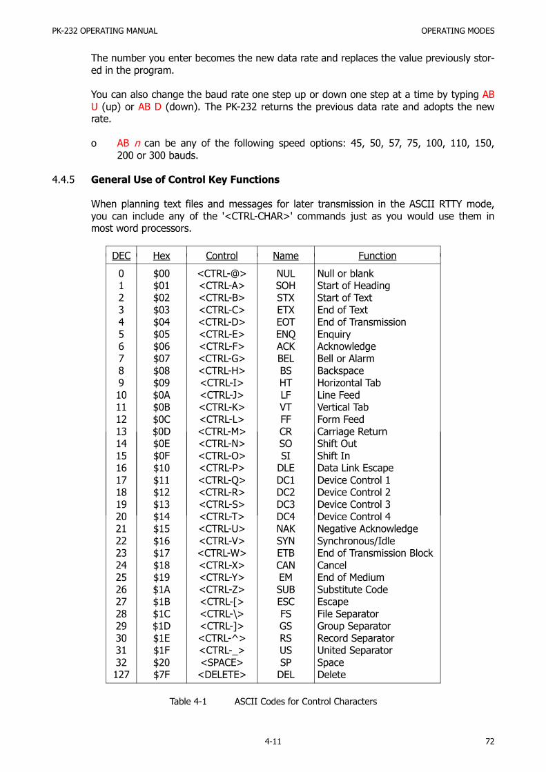
PK-232 OPERATING MANUAL OPERATING MODES
4-11 72
The number you enter becomes the new data rate and replaces the value previously stor-ed in the program.
You can also change the baud rate one step up or down one step at a time by typing ABU (up) or AB D (down). The PK-232 returns the previous data rate and adopts the newrate.
o AB n can be any of the following speed options: 45, 50, 57, 75, 100, 110, 150,200 or 300 bauds.
4.4.5 General Use of Control Key Functions
When planning text files and messages for later transmission in the ASCII RTTY mode,you can include any of the '<CTRL-CHAR>' commands just as you would use them inmost word processors.
DEC Hex Control Name Function
01234567891011121314151617181920212223242526272829303132127
$00$01$02$03$04$05$06$07$08$09$0A$0B$0C$0D$0E$0F$10$11$12$13$14$15$16$17$18$19$1A$1B$1C$1D$1E$1F$20$7F
<CTRL-@><CTRL-A><CTRL-B><CTRL-C><CTRL-D><CTRL-E><CTRL-F><CTRL-G><CTRL-H><CTRL-I><CTRL-J><CTRL-K><CTRL-L><CTRL-M><CTRL-N><CTRL-O><CTRL-P><CTRL-Q><CTRL-R><CTRL-S><CTRL-T><CTRL-U><CTRL-V><CTRL-W><CTRL-X><CTRL-Y><CTRL-Z><CTRL-[><CTRL-\><CTRL-]><CTRL-^><CTRL-_><SPACE><DELETE>
NULSOHSTXETXEOTENQACKBELBSHTLFVTFFCRSOSI
DLEDC1DC2DC3DC4NAKSYNETBCANEMSUBESCFSGSRSUSSP
DEL
Null or blankStart of HeadingStart of TextEnd of TextEnd of TransmissionEnquiryAcknowledgeBell or AlarmBackspaceHorizontal TabLine FeedVertical TabForm FeedCarriage ReturnShift OutShift InData Link EscapeDevice Control 1Device Control 2Device Control 3Device Control 4Negative AcknowledgeSynchronous/IdleEnd of Transmission BlockCancelEnd of MediumSubstitute CodeEscapeFile SeparatorGroup SeparatorRecord SeparatorUnited SeparatorSpaceDelete
Table 4-1 ASCII Codes for Control Characters

PK-232 OPERATING MANUAL OPERATING MODES
4-12 73
4.5 AMTOR Operation
From the Command Mode, type AMTOR or AM, followed by <RETURN> to enter theAMTOR mode. The PK-232 will respond with the previous mode:
OPMODE was ASCIIOPMODE now AMTOR
Your PK-232's front panel will show both STBY LEDs lit.
4.5.1 Transmit/Receive Function Keys
From the Command Mode:
ARQ (SELCAL) Starts Mode A selective call and forces ConverseFEC Starts Mode B transmission and forces ConverseSELFEC (SELCAL) Starts Selective Mode B transmissionR Stops transmission immediately, forces AMTOR Standby, clears
the transmit buffer of all remaining dataAM Stops transmission, forces AMTOR Standby, clears the transmit
buffer of all remaining dataAL Forces re-synchronization in ALIST (AMTOR Mode A Listen) L Forces LETTERS caseX Not used in AMTOR
Embedded in transmission text:
<CTRL-O> Sends LETTERS character<CTRL-N> Sends FIGURES character<CTRL-F> Sends call sign in Morse and shuts off transmitter<CTRL-D> Stops sending when the transmit buffer is empty
4.5.2 Speed Change Not Permitted
In accordance with FCC Part 97.69 and international regulations, AMTOR is operated atone speed only – 100 bauds. The PK-232 does not permit AMTOR operation at any otherspeed.
4.5.3 SELCAL (Selective Sequential Calling)
AMTOR operating modes require a SELCAL (Selective Sequential Calling) code. Thisunique character sequence must contain four alphabetic characters normally derived fromyour call sign.
The convention originated by the early European AMTOR pioneers, and later adopted byamateurs around the world, was broadly based on the most common 'one-by-three' callsigns, and used the first and the last three letters of the call sign. However, with the re-cent changes and expansions of the call sign systems in many countries, some commentand explanation may be in order here.

PK-232 OPERATING MANUAL OPERATING MODES
4-13 74
Some call sign groupings now in use are:
GROUP CALL SELCAL GROUP CALL SELCAL
1 by 2 W1AB WWAB 2 by 1 AB1Z AABZ1 by 3 W1ABC WABC 2 by 2 AB1YZ ABYZ
2 by 3 KA1XYZ KXYZ
For '1 by 2' call signs, the first letter is doubled, e.g., 'N7ML' becomes 'NNML'. In mostcases this method is acceptable.
4.5.3.1 First SELCAL Installation
Type MYSELCAL or MYS to load your SELCAL into the PK-232:
cmd:myselcal nnml
The PK-232 will respond with:
MYSELCAL was
The 'blank' response occurs the first time you use the PK-232. There is no defaultSELCAL.
Type MYS to confirm your SELCAL is properly loaded:
cmd:mys
The PK-232 will respond with:
MYSELCAL NNML
4.5.3.2 Prevent Duplicate SELCALs
Because the same call sign sequences are assigned in ten districts, it is possible thatyour SELCAL could be the same as that used by another station. Using the standardconvention, 'N1ML', 'N2ML', 'N3ML', etc., would all derive the same SELCAL, 'NNML'. Ifyou think a station in another call district or zone is also active on AMTOR and may beusing the same SELCAL, you can derive your own unique SELCAL by substituting aletter for your call district number. Use the letter corresponding to the call district num-ber as it appears on the keys of a standard typewriter or Baudot RTTY keyboard.
Let's assume that your call sign is N7ML. You discover that there is another station withthe call N?ML. Change your SELCAL to NUML, according to the following table:
1 = Q 2 = W 3 = E 4 = R 5 = T6 = Y 7 = U 8 = I 9 = O 0 = P

PK-232 OPERATING MANUAL OPERATING MODES
4-14 75
4.5.4 Mode A (ARQ) Call - Start the Contact (ARQ Command)
Type ARQ<SELCAL> to start the AMTOR selective calling sequence or answer a Mode B(FEC) CQ call from a distant station.
Type <CR> after you've typed the fourth letter (a valid SELCAL must have four charac-ters) – your transmitter will be keyed on and off in the typical ARQ three-character burstsequence. After your PK-232 has locked or synchronized with the distant station, type K toenter the Converse Mode and begin your conversation.
4.5.4.1 LED Status and Mode Indicators
After selecting AMTOR, the PK-232 displays system status on its LEDs:
STATUS: STBY litMODE: STBY lit
Type ARQ {SELCAL of distant station}. The LEDs change to:
STATUS: SEND lit, PHASE litMODE: ARQ lit
These LEDs show that your transmitter is in the SEND condition, in the 'phasing' part ofan ARQ selective call. Your transmitter will key on and off sending the distant station'sSELCAL. As soon as your PK-232 is synchronized with the distant station, the LEDschange:
STATUS: SEND lit, TFC and IDLE lit alternately by data flowMODE: ARQ lit
Verify the link by typing a few <RETURN>; watch the display. Your traffic will now be-gin to flow as you type characters. If EAS is set ON, your typed characters will be dis-played as they are acknowledged by the distant station. The IDLE and TFC LEDs willchange back and forth when you pause in your typing.
If EAS is ON, the delay between your typing and the appearance of your characters onthe screen indicates the quality of the radio link quite accurately. The better the link be-tween you and the distant station, the faster your typed characters will scroll acrossyour screen.
If your typing does not appear on your screen, the distant station is not receiving validdata from you and the automatic error-detection and error-correction features of theAMTOR ARQ mode begin to control the link. Depending on how band conditions affectthe link, the ERROR and RQ LEDs may light occasionally. If errors occur on the linkand the distant station sends RQ (Request for Repeat), the LEDs show:
STATUS: SEND lit, ERROR and/or RQ litMODE: ARQ lit
ERROR lit: Your PK-232 has detected errors in the signals received from the dis-tant station
RQ lit: Your PK-232 has received a 'request for repeat' code from the distantstation

PK-232 OPERATING MANUAL OPERATING MODES
4-15 76
If the link fails and you lose synchronization with the distant station, your PK-232 auto-matically tries to re-establish synchronization with the distant station. The LEDs changeto show:
STATUS: SEND lit, PHASE lit, ERROR and RQ alternately litMODE: ARQ lit
4.5.4.2 Mode A (ARQ) Changeover (+? Command)
When you finish typing your comments or traffic to the other station and wish the dis-tant station to transmit to you:
o Don't type KKK or anything like that!
o Do type a plus sign immediately followed by a question mark (+?)
+? is a software changeover command that switches your system from 'InformationSending Station' (ISS) to 'Information Receiving Station' (IRS) and switches the distantsystem from 'Information Receiving Station' receive to 'Information Sending Station'.Your distant partner will see the +? and begin typing comments or traffic.
NOTE: When discussing ARQ operation, we use the terms 'Information SendingStation' and 'Information Receiving Station' instead of 'transmit' and 're-ceive'. In AMTOR ARQ operation both stations are rapidly switching betweentransmit and receive. When you send 'information', the distant station sendsback 'control' signals that tell your PK-232 how your signals are being re-ceived, how the link is behaving.
o Don't bother with multiple call signs and 'over-to-you' routines used in Baudot andASCII RTTY operation. Don't bother with 'KKK' at the end of your turn – the systemdoes it all for you when you type +?.
The FCC requires station identification once every ten minutes. It's sufficient to beginwith QRA (mycall) or end your transmission with QRA (mycall) before the +? change-over code.
4.5.4.3 Mode A (ARQ) Break-in (ACHG Command)
In Mode A (ARQ), when you're the 'Information Receiving Station', you can use theACHG command to break or interrupt the distant station's comments.
ACHG is a software command that forces both systems to reverse the 'Information Re-ceiving' and 'Information Sending' status at both ends of the ARQ link. As the 'Informa-tion Receiving Station', you normally rely on the distant station to send the +? com-mand to do the changeover at the end of his comments.
The use of this command can be rather disconcerting to the operator at the other endof the link.
o Use the ACHG command only when really needed to interrupt the distant station.

PK-232 OPERATING MANUAL OPERATING MODES
4-16 77
4.5.4.4 End the Mode A (ARQ) Connect, Return to AMTOR Standby
When you've finished you 'final finals' to the distant station and both stations are readyto end the Mode A (ARQ) contact, you can end the contact and terminate the link inseveral different ways:
o Type <CTRL-C> to return to Command Mode. Then type R to break the link.
The R command breaks the ARQ link and returns your system to AMTOR Standby –your station can be accessed by a distant station's transmission of your SELCAL.R can also be used to stop sending a SELCAL while trying to access a distant sta-tion.
o Type <CTRL-F> to break the link and send your Morse ID.
Your PK-232 switches in the Morse Mode, sends your call sign at the speed set byMSPEED and then shuts off your transmitter.
o Type <CTRL-D> to stop sending when the transmit buffer is empty.
o Type <CTRL-C> and then the letter R if you need an 'emergency shutdown', or inany case when you want to take your transmitter off the air immediately.
4.5.5 ARQ Listen Mode – Start Monitoring (ALIST Command)
Use the ALIST command to monitor ARQ traffic flowing between two stations linked in anARQ contact. Your PK-232 tries to synchronize with whichever of the two linked ARQ sta-tions is the Information Sending Station at the moment.
Mode A Listen operation does not give you error detection or error correction; your PK-232 is not part of the synchronizing 'handshake' between the other two stations locked toeach other. If the other two stations are enjoying a good link, you will probably get goodcopy from that link.
If the stations you're monitoring are sending error codes and RQ codes and repeatingblocks of characters across their link, you may see some repeated character blocks. YourPK-232 will not print a block of data if that block contains the same information as theprevious block. If the 'ISS' (Information Sending Station) is repeating the same block, youwon't print it twice, unless you receive an error. If they're having link problems, the dataon your screen can look very strange indeed, although the two synchronized stations aregetting error-free copy.
4.5.6 Mode B (FEC) Call – Starting the Contact (FEC Command)
After selecting AMTOR from the Command Mode, type FEC<RETURN> to enter the AM-TOR FEC mode. (You can start an FEC transmission from any other mode simply by typingFE.)
o Type FE to turn on your transmitter.o type <CTRL-F> to send your call sign in Morse and shut off your transmitter, oro type <CTRL-C> to return to the Command Mode.o Type R to shut down your transmitter and end the contact.

PK-232 OPERATING MANUAL OPERATING MODES
4-17 78
Type FEC to start the AMTOR Mode B call or transmission, or answer a Mode B (FEC) CQcall from a distant station. You don't have to type a SELCAL. Your transmitter will beturned on and kept on continuously, sending synchronous idle control characters.
Mode B (FEC) is recommended for calling CQ in AMTOR.
o Sending CQ in Mode A (ARQ) gives the distant stations no clue as to who you are,or what your SELCAL might be. See APPENDIX D for more comments by G3PLX.
o Don't send long CQ calls with many lines of repeated call signs. FEC eliminates theneed for long CQ calls. A simple '3 by 3' sequence is all you need in FEC. Here'sone example:
CQ CQ CQ DE W2JUP W2JUP W2JUP (WJUP)CQ CQ CQ DE W2JUP W2JUP W2JUP (WJUP)CQ CQ CQ DE W2JUP W2JUP W2JUP (WJUP)QRR ARQ/FEC SELCAL WJUP KKK
IMPORTANT NOTE
Do not start an FEC transmission with 'RYs' as in conventional RTTY. The distant stationcannot synchronize with RY characters.
o The distant station must receive several seconds of synchronous idle control charac-ters in order to synchronize to your typed characters.
Your PK-232 waits several seconds before sending your traffic! You don't need to 'wait' forthe PK-232; it will send the necessary idle characters the distant station needs for acquir-ing synchronization.
The synchronous idle control signals are mark-to-space tone shifts and can be used by thedistant station for tuning.
4.5.6.1 LED Status and Mode Indicators
After typing FEC, your PK-232 displays system status on its LEDs:
STATUS: SEND lit, IDLE lit, TFC lit only brieflyMODE: FEC lit
Your Transmitter is now keyed and sending the FEC 'idle' signals. As you type your com-ments or traffic, the IDLE LED is extinguished; the TFC LED is lit during the momentswhen your PK-232 is sending your data characters. Whenever you stop typing charac-ters, the TFC LED is extinguished and the IDLE LED is lit.
STATUS: SEND lit, TFC and IDLE lit alternately by data flowMODE: FEC lit
4.5.6.2 Mode B (FEC) Changeover
FEC operation is very similar to conventional RTTY. You can tell your partner at the dis-tant station that you're ready for him to send by typing the same 'K', 'KN' or 'BTU' sig-nals.

PK-232 OPERATING MANUAL OPERATING MODES
4-18 79
Except for the short delay in starting before sending your traffic, you can operate FECusing the same typing and receiving techniques as in CW or conventional Baudot andASCII RTTY. The FEC mode does not use interaction or 'handshaking' between your sta-tion and the distant station.
o The +? changeover command has no effect in FEC operation.
4.5.6.3 End the Mode B (FEC) Contact, Return to ARQ Standby
You can end the FEC contact in several different ways:
o Type <CTRL-C> to return to Command Mode. Then type R break the link.
The R function stops the FEC transmission, turns off your transmitter and returnsyour PK-232 to AMTOR Standby. You can be accessed by any distant station's trans-mission of your SELCAL.
o Without returning to Command Mode, type <CTRL-F> to send your Morse ID andshut off your transmitter.
Your PK-232 switches to the Morse Mode, sends your call sign at the speed set byMSPEED, and then shuts off your transmitter.
o Without returning to Command Mode, type <CTRL-D> to stop transmission immedi-atly. Your transmitter will shut down but the PK-232 transmit buffer is not clear.
Your PK-232 is now in AMTOR Standby, ready for SELCAL access by any distant station.Your monitor is ready to display any FEC signals received on the channel.
4.5.7 Echo as Sent (EAS)
EAS has special significance in AMTOR Mode A (ARQ). If EAS is ON, no matter how fastyou type characters on our keyboard, you will see them echoed on your screen only afterthe distant station, partner in the AMTOR link, has validated (Ack'd) your block of threecharacters.
With EAS ON, the characters will appear on your screen or printer only as the distant sta-tion acknowledges them, three at a time.
o If the data scrolls across your monitor at a nice even rate, in rhythm with your typ-ing speed, you can assume that you have a good ARQ link.
o If the data hesitates or scrolls in 'jerky' intermittent fashion, that's generally a signthat the radio link is not too good.
o If the characters stop appearing on your monitor, the link is failing or has failed.
NOTE: Use this Mode to prevent the PK-232's internal buffer from overflowing,when you are transmitting long messages from a buffer or disk drive.

PK-232 OPERATING MANUAL OPERATING MODES
4-19 80
4.5.8 AMTOR Switching-Time Considerations
For operation in AMTOR Mode A (ARQ), your transceiver or transmitter-receiver combina-tion must be able to change between transmit and receive within 20 milliseconds. Mostsemiconductor-based radios can easily meet this specification. Many older tube-type ra-dios that use electromechanical relays operate very well in AMTOR Mode A (ARQ).
If the changeover from transmit to receive is too long, the minimum working distance isextended; the signal to the distant station will arrive before the station has switched backto receive. However, if the transmitting station is further away, the transmission time overthe propagation path will delay the arrival of the signal until after the station has switchedto receive.
If the receiving station's changeover from transmit to receive is too slow, the transmittingstation delay between 'PTT' and 'data send' can be extended. See the ADELAY commandin the Command Summary for information on adjusting the PK-232's AMTOR timing char-acteristics to compensate for this effect.
See the March 1987 issue of 'QEX' for an article by Paul Newland, AD7I, for a test proce-dure for measuring HF transceiver switching.
4.5.9 Suggested AMTOR Trial Operating Techniques
If you have trouble synchronizing with another AMTOR ARQ station, try some of the fol-lowing operating tips before calling AEA or deciding that your radio equipment needsmodifications:
o Try to work the distant station on Mode B (FEC) to establish that the other station'ssystem is fully functional.
o Don't use VOX control – use the PTT line from your interface.
o Turn off the AGC circuit – use the RF gain control to prevent receiver blocking onstronger signals.
o Turn off all compression or other audio processing.
o Keep the AFSK audio input level to the microphone circuit as low as possible – avoidoverdriving the audio input stages.
o Disable the ALC circuit or reduce excessive ALC action; use more effective RF anten-na loading to adjust output power levels.
APPENDIX D was written by Peter Martinez, G3PLX, 'father' of AMTOR. Peter offers de-tailed operating hints for getting started on AMTOR. It's worth your reading time.
4.5.10 Possible Areas for AMTOR Performance Improvement
If switching-time problems persist, you may have to make changes in the radio to elimi-nate excessive time delays:
o Remove large decoupling capacitors from the push-to-talk line to allow faster PTT(transmitter) activation;

PK-232 OPERATING MANUAL OPERATING MODES
4-20 81
o Improve power supply decoupling, especially in audio stages.
o Do not use squelch.
In case you can't solve your radio's switching-time problems, please call AEA CustomerService telephone (see front of this manual) for further helpful suggestions.
NOTE: AMTOR Mode B (FEC) operation is similar to conventional RTTY in its dutycycle; the transmitter operates continuously without the on/off switchingcharacteristic of AMTOR Mode A (ARQ).
4.6 Packet-Radio Operation
This section describes basic Packet operation. You'll learn quite a bit about your PK-232'sPacket features and control operation without really sending anything over the air. For yourfirst Packet practice, the PK-232 will be connected in a 'loopback' circuit so that it will 'talk toitself'. You'll have a chance become familiar with Packet operation before you actually go onthe air.
We'll describe the commands you'll use for everyday Packet operations. These commandswill get you ready for the section 'Your First Packet QSO'. The 'Special Input Characters' sec-tion contains information on editing from your keyboard and discusses other special charac-ters used by the PK-232.
If you intend to use your Packet station for advanced applications, such as a Bulletin BoardSystem or binary file transfers, read the chapter on 'Advanced Packet Operation'.
Most commands can be abbreviated by typing only the first two or three characters. The'mnemonics' or minimum abbreviations for each command as shown in the "Command Sum-mary" chapter, along with a full description of each command.
Your PK-232 automatically enters the Packet Mode when you first turn on the power or typethe RESET command. If you've been in any other mode, Type PACKET or PA followed by a<RETURN>. The PK-232 answers with:
OPMODE was (whatever mode you were in)
OPMODE now PACKET
4.6.1 Change Radio Link Data Rate
Your PK-232 provides link rates of 45,50, 57, 75, 100, 110, 150, 200, 300, 600, 1200,2400, 4800 and 9600 BPS. The default data rate is 1200 BPS when you start your PK-232for the first time.
Use the HBAUD command to read or change the packet link data rate.
To read the present baud rate, type HBAUD<RETURN> or HB<RETURN>. The PK-232 re-sponds with:
HBAUD 1200
To change the link rate, type HBAUD followed two or three digits and a <RETURN>.
HBAUD 300<RETURN>

PK-232 OPERATING MANUAL OPERATING MODES
4-21 82
The PK-232 accepts the new baud rate and responds with the old baud rate:
HBAUD was 1200HBAUD now 300
The number you enter becomes the new data rate and replaces the value previously stor-ed in the program. You can also change the baud rate one step up or down one step at atime by typing HB U or HB D respectively. The PK-232 returns the previous data rate andadopts the new rate.
4.6.2 Station Identification
You must use the MYCALL command to install your your station identification (call sign) inyour PK-232's memory (see next section). If you intend to operate more than one stationwith the same call sign, the stations must use some means of telling the difference be-tween two operations under that same call sign – two stations cannot have identical sta-tion identifications. if they do, Packet protocol will fail.
4.6.2.1 MYCALL Required at System Start-Up
When you start your PK-232 for the first time, the system is loaded from ROM. All sys-tem parameters and values are those loaded at time of manufacture. MYCALL is loadedwith the default 'PK-232'. You must use the MYCALL command to install your call sign inyour PK-232. You cannot operate in Packet Mode until you've done this. If you try toconnect to a station without installing your call sign, your PK-232 will not transmit, butsends you the following error message instead:
?need MYCALL
4.6.2.2 Substation Identifiers (SSIDs)
You can identify additional stations with the 'secondary station ID' or SSID – a numberfrom 0 to 15, appended to the call sign by a dash:
cmd:MYCALL WX2BBB-1
If you don't specify the SSID extension, the PK-232 retains its default value of 0 (zero)and the SSID is not displayed. You must specify the SSID to connect to a station with aSSID other than 0 or to use such a station as a digipeater:
cmd:CONNECT WX3CCC-2
orcmd:CONNECT WX1AAA VIA WB2BBB-2
4.6.2.3 Automatic Identification
Your PK-232 can send automatic ID packet every 9½ minutes when your station is ope-rating as a digipeater. You can tune this feature on with the command HID ON. IDpackets are displayed like this:
WX2BBB-1>ID:WX2BBB digipeateror
WX2BBB-1<ID:(MYALIAS) digipeater

PK-232 OPERATING MANUAL OPERATING MODES
4-22 83
When you shut down, you can command a final ID with the ID command. The PK-232sends these ID packets only if it has been digipeating.
4.6.3 Set Up Loopback Test Circuit
Do these steps in the exact order shown:
1. Get the shielded radio cable you set aside in Chapter 2.2. Strip an tin the wires at the 'radio' end of the cable.3. Join the green and white wires coming from pins 1 and 2.4. Insert the plastic plug end of the cable into J6, the RADIO 2 connector on the PK-
232's rear panel. Be sure that the plug is insert with the cable running downward. 5. Set the front-panel 'Radio 1/Radio 2' switch to RADIO 2 .
You've connected your PK-232's transmit audio output to its receive audio input. Your PK-232 can now 'talk to itself' in 'loopback'.
4.6.4 'Connect' and 'Disconnect'
Packet-Radio contacts begin with a connect process that sets up the 'handshaking' be-tween the two stations to insure error-free communications. Contacts or 'connections' areended by a disconnect process that leaves both stations free to start new contacts.
Packet connections can also use digipeaters – other Packet stations that relay packets au-tomatically from one station to another over a specified route. We're going to 'connect'your PK-232 to itself to see how this works. You've already set the PK-232 up in loopback;therefore, your PK-232 will receive all the packets that it sends.
4.6.5 LED Status and Mode Indicators
Your PK-232's front-panel LEDs show you the operating mode and system status at anymoment. Each LED is marked with an abbreviated name. Some LEDs have two namemarkings. All markings referring to Packet Operation are below the LEDs.
MULT Multiple Lit when multiple connections exist SEND Send Lit when PTT line is activeCONV Converse Lit when in the Converse Mode CMD Command Lit when in the Command ModeTRANS Transparent Lit when in the Transparent ModePKT Packet Lit when in the Packet-Radio ModeDCD Data Carrier Detect Lit when valid data signals received
4.6.5.1 LEDs at System Start or RESET
At system start-up or after selecting Packet, your PK-232 shows its status on the front-panel LEDs:
STATUS: CMD litMODE: PKT lit

PK-232 OPERATING MANUAL OPERATING MODES
4-23 84
4.6.6 System Quick-Check – Loopback Test Connection
Try this using your own call sign. Type CONNECT {MYCALL}.
cmd:CONNECT {MYCALL}
*** CONNECTED to {MYCALL}
The LEDs change to show your PK-232 in Packet Mode, in CONNECTED state and in CON-VERSE Mode.
STATUS: CONV lit, CON litMODE: PKT lit
Your PK-232 sends special packets to set up a connection. These packets are now leavingyour PK-232 on J7's Pin 1 and returning on Pin 2 without being transmitted over your ra-dio.
4.6.6.1 Connect Message
*** CONNECTED to {MYCALL} shows that the connection is established. The
CON LED is now lit; the cmd: prompt doesn't appear on the next line. You're connect-
ed to yourself in Converse Mode, ready to start talking. Try it. Type your message, end-ing the line with a <CR>:
Hello, there.Hello, there.
4.6.6.2 Send Packet Character
<CR> tells your PK-232 to form your typed characters in a packet and transmit them.(We'll explain in the "Command Summary" chapter how you can use a different charac-ter to send packets.) In the Converse Mode, everything you type is assembled into apacket addressed and sent to the station to which you're connected. If no connection(QSO) exists, the packet is addressed to "CQ", or whatever address you've typed intothe UNPROTO field.
Your PK-232 automatically entered Converse Mode when the connection was establish-ed. You can also command the PK-232 to move back and forth between CommandMode and Converse Modes.
4.6.6.3 Return to Command Mode
Type <CTRL-C> (or whatever character you've previously set ($00-$7F)) to return toCommand Mode. The PK-232 doesn't echo the <CTRL-C>, but you should immediatelysee a Command Mode prompt.
You can return to Command Mode with the <BREAK> key. BREAK is a break in trans-mission (not an ASCII character) – your keyboard may have it.
If <CTRL-C> interferes with or stops your terminal program and you can't send theBREAK signal, change the character that returns you to Command Mode. See "COM-MAND" in the "Command Summary" chapter.

PK-232 OPERATING MANUAL OPERATING MODES
4-24 85
4.6.6.4 Return to Converse Mode
Type CONVERSE to return to Converse Mode.
<CTRL-C>cmd:CONVERSE
Whatever I type in Converse Mode is transmitted.Whatever I type in Converse Mode is transmitted.<CTRL-C>cmd:
4.6.6.5 Terminate the Link – Disconnect
Type DISCONNE (or D) to terminate the link or connection. Your PK-232 transmits aspecial packet that ends the contact and notifies you when the link is disconnected:
cmd:DISCONNE
*** DISCONNECTED: {call sign}
An actual QSO may be terminated by the other station. In that case, you'll see the*** DISCONNECTED {call sign} message without having typed the command
at your station.
You've now run through the basic operations of a Packet QSO:
o You connected to the desired station to begin the QSO.o You sent and received messages.o You disconnected from that station at the end of the QSO.
4.6.7 Your First Packet QSO
There are more features you should be familiar with for comfortable Packet operation –but you're probably eager to get on the air and try your PK-232, so here goes!
Try to arrange with an experienced Packet operator to help you get started. Be sure thatyour partner is close enough to ensure solid noise-free copy for your first 'on-the air' QSO.
4.6.7.1 System Cable and Switch Check
Before actually trying your first connection (QSO), take one more minute to verify yoursystem setup:
1. Remove the loopback test cable from the RADIO 2 connector.2. Set the front-Panel "RADIO 1/RADIO 2" switch to RADIO 1 .3. Connect your radio to your PK-232 using the RADIO 1 jack.4. Be sure you've adjusted your PK-232 and your radio using the 'Quick Start' proce-
dure described earlier in this manual.
4.6.7.2 Starting the QSO
You're ready to try connecting! We'll use WX2BBB in place of your call sign, andWX6FFF for your partner's call sign. Type <CTRL-C> to verify that you're in CommandMode. Now type CONNECT WX6FFF after the cmd: prompt. After a moment you
should see:

PK-232 OPERATING MANUAL OPERATING MODES
4-25 86
*** CONNECTED to WX6FFF
You've begun your first QSO! Both you and your partner will be automatically switchedto Converse Mode. Your partner will see:
*** CONNECTED to WX2BBBExchange several messages to get the feel of Packet-Radio. Watch your radio's transmitindicators and if possible, listen to the audio from both radios; you'll get a better idea ofwhat's happening. Your radio is inactive the most of the time, even while you're actuallytyping.
When you get to the end of a line and type <CR>, your radio is keyed briefly. Yourpartner hears 'brrrrraaaap' on this speaker. As your message is displayed on his com-puter, his radio will be keyed for an even shorter burst; you'll hear 'brraap' on yourspeaker. This is ACK, the packet acknowledgment coming back.
Your PK-232 notes that the packet was received correctly, but displays nothing on yourscreen. This is normal operation. If your system still had any unacknowledged packetsoutstanding, your PK-232's STA (Status) LED would be lit – but it's not. (Unless youset MONITOR to a value higher then '4', you won't display the 'ACK' frames.)
4.6.7.3 What If ... ?
If you have trouble connecting, take a few minutes to check each of the followingitems. Verify that:
o Your PK-232's AFSK Output Level control, you microphone gain and deviation are setproperly as shown and discussed in Section 2.5.
o All cables and connectors are properly installed.o The RADIO 1/RADIO 2 switch is set for your cable to radio setup.o Your radio's volume and squelch are set for local conditions.o You're in Command Mode. (Type <CTRL-C> to confirm this. You must see the
cmd: prompt.)
o If the cmd: prompt doesn't appear, press the PK-232's POWER switch off and on
again. You should get the normal sign-on message.o Your PK-232 is in Packet Mode. Type OP to confirm this.o HB is 1200 if on VHF, 300 if on HF.o CFROM is set to ALL.o Move to an unused channel for 'on-the-air' testing (simplex FM!).
Ask one of your area's more experienced Packet operators to listen your transmissionsand monitor with his TNC. Both you and your partner should set MONITOR and MCONto 5, enter Converse Mode and send some packets. Each station should display packetssent by the other.
o If only one station is 'hearing' properly, concentrate on the modulator and transmit-ter of that station and the demodulator and receiver of the other station.
o Experiment with the TXDELAY timing parameter for the sending TNC. Set TXDELAY64 for a longer delay. If this solves the problem, decrease TXDELAY to the smallestvalue that works all the time.
PK-232 OPERATING MANUAL OPERATING MODES
4-26 87
4.6.8 Automatic Operation
Your PK-232 offers a variety of automatic operating features including beacon operation,digipeater function and auto-answer messages.
Your Packet station can be a digipeater for relaying packets to a more remote destination.Functions like the 'connect message' take care of situations not readily solved in modesother than Packet. See the "Command Summary" chapter for full details on your PK-232'scommands.
4.6.8.1 Beacon Operation
Your PK-232 can send an automatic 'Beacon' message at specified time intervals. A bea-con can send special announcements, or send the 'mail for' list in a bulletin board oper-ation. The values '0' to '250' set the beacon timing in 10-second intervals. '0' turns offthe beacon.
o Set your beacon text using the BTEXT commend.o Set the beacon timing interval using the BEACON EVERY or BEACON AFTER com-
mand.
For example, to transmit your beacon at 15-minute (15 × 60 seconds) intervals,type:
cmd:BEACON EVERY 90 (Beacon is sent every 900 seconds)
cmd:BEACON EVERY 0 (Beacon is disabled)
EVERY sends your beacon text at regular intervals. AFTER sends your beacon once af-ter the specified time interval without any packet activity on the channel.
A beacon frame may be sent directly, and also sent via digipeat addresses specified bythe UNPROTO command.
Proper beacon timing avoids cluttering a busy channel with unnecessary transmissions.In the early days of Packet-Radio, the beacon was very useful to show your presenceon the empty Packet channels. With the growth of Packet-Radio, many users feel thatthe beacons have outlived their usefulness and may be a source of interference to goodtraffic flow. Use your beacon with consideration for other on the channel.
If you set the BEACON timing at a value considered to small for busy channels (lessthen '90'), you'll see:
WARNING: BEACON too often
This warning appears in the Command Mode each time you type a command to remindyou that your beacon interval is too short; your beacon may be bothering other channelusers and it needs your attention.
4.6.8.2 Will You Accept Connections?
CFROM determines:
o if any call requests are to be accepted or rejected at allo or specifies whose call requests are to be accepted or rejected.

PK-232 OPERATING MANUAL OPERATING MODES
4-27 88
CFROM works with four arguments: ALL/NONE or YES(list)/NO(list).
'ALL' and 'NONE' are used alone and work this way:
o ALL – your PK-232 accepts connect requests from any callers;o NONE – your PK-232 rejects connect requests from all callers.
'ALL' and 'NONE' work with a list of call signs:
o ALL – your PK-232 accept connect requests from any caller.o NONE – your PK-232 rejects connect requests from all callers.
'YES' and 'NO' works with a list of call signs:
o YES (list) – up to eight call signs whose call requests are to be accepted;o NO (list) – up to eight call signs whose call requests are to be rejected.
CFROM's default argument is 'all'. When CFROM is set to ALL your PK-232 will normallyaccept connect requests from any station that sends you a connect request.
Type CFROM NONE to reject connect requests from all stations. If your PK-232 receivesa connect request when CFROM is set to NONE, your monitor displays:
*** Connect Request: {call sign}
Your PK-232 sends the calling station a DM packet, or 'busy signal'. The caller sees:
*** {MYCALL} busy*** DISCONNECTED: {call sign}
You can set the CFROM field to accept or reject call requests from specific stations.
To accept calls from one or more specific stations:
o Type CFROM YES (plus a list of call signs). Connect requests are accepted from list-ed callers only.
To reject calls from one or more specific stations:
o Type CFROM NO (plus a list of call signs). Connect requests are rejected from thelisted stations.
Type CFROM to display ALL/NONE/YES list/NO list status of station call signs to be re-jected or accepted. You can use the abbreviated command form or mnemonic:
cmd:cfrom
CFROM: allor
cmd:cf
CFROM: yes WX1AAA,WX2BBB,WX3CCC,WX4DDD
You can include SSIDs as -n after the call sign. If CFROM is set to no W2JUP or yes

PK-232 OPERATING MANUAL OPERATING MODES
4-28 89
W2JUP, any combination W2JUP, W2JUP-1,...W2JUP-15 will be matched and processed.If CFROM is set to yes W2JUP-1 or no W2JUP-1, then
4.6.8.3Are You Available to Chat?
Set CMSG ON (default is OFF) and use the CTEXT command to enter the sort of mes-sage you might put in a telephone answering-machine. If you're not available to answerconnect requests, your PK-232 automatically sends the CTEXT message to each stationthat connects to your system.
The CTEXT message can be any text string up to 120 characters. You can include<CR>s by prefixing them with the pass character (<CTRL-V> is the default):
cmd:CTEXT Sorry, I can't talk right now.<CTRL-V><CR>
I'll be on air again after 8 PM.<CTRL-V><CR>Joe
CFROM must be set to ALL (default) so that the connection takes place in order thatthis message be sent to stations connecting to you.
4.6.8.4 Do You Want to Transmit?
If you want to leave your station on to monitor and perhaps record the activity on thechannel, but prevent your station from transmitting, set XMITOK OFF. In this case, youwould probably want to set CFROM to NONE as well.
Type XMITOK OFFType CFROM NONE
4.6.9 Digipeater Details
You may wish to connect to a Packet station that is beyond your direct radio range. If athird Packet station is on the air and both you and the station you want to talk to are inrange of that third station, the third station can relay or 'digipeat' your packets. You setup the 'digipeater routing when you request the connection. Your PK-232 automatically in-cludes the necessary routing information in the transmitted packets. Here's a sketch thatshows how digipeating can solve problems:
WX2BBB / \
WX1AAA_____/ \_____WX3CCC
You are station WX1AAA – you want to have a Packet QSO with WX3CCC. But there's amountain between you and WX3CCC; you're out of simplex range each other. However,you know that there's a Packet station located on the ridge – WX2BBB – which is in rangeof you and W3CCC.
Instruct your PK-232 to set up a connection to WX3CCC using WX2BBB as an intermediatedigipeater. After the cmd: prompt, type CONNECT WX3CCC VIA WX2BBB.
You can specify a routing list of up to eight intermediate stations. For example, consider amodification of the example above:

PK-232 OPERATING MANUAL OPERATING MODES
4-29 90
___ / \
WX1AAA_____/ \_____WX3CCC · · · ·WX4DDD . . . . . . . . . . . . WX5EEE
WX2BBB has turned off his station, but you can still contact WX3CCC by going around themountain through WX4DDD and WX5EEE. This time, type the connect command like this:
cmd:CONNECT WX3CCC VIA WX4DDD,WX5EEE
Type the digipeaters' call signs in the exact order of the intended path from your stationto the station with which you wish to connect.
4.6.9.1 Are You a Digipeater?
Your Packet station can be a digipeater for other stations. You don't have to anything –your PK-232 digipeats other stations – unless you tell it not to do! (See the DFROMcommand in the Command Summary.)
The default argument of DFROM is 'ALL'. If your transmitter is keyed when you're notusing it, or during lulls in your own conversations, you're being used as a digipeater bysome other stations. This won't bother your chat with your partner.
Set MDIGI to ON (default is OFF). The packet headers on your monitor will show thecall signs of the stations using you as a digipeater, and the data being transmitted.
If MRPT is ON (default), you'll also see your call sign in the packet header, showing theexact digipeater path in which you are included. the call sign of the station whose pack-et is being decoded is flagged with as asterisk. Here's a sample taken with Monitor 4(default), MDIGI ON and MRPT ON:
W2HPM*>W2JUP-2>W2PEE: What time is the meeting?W2PEE*>W2JUP-2>w2HPM <RR>
4.6.9.2 Do You want to be a Digipeater?
Many packeteers allow (and even encourage) the use of their stations as digipeaters toprovide a simple form of 'networking' for the area's Packet community. If local circum-stances prevent you from being a digipeater, you can disable the digipeat function.
DFROM's default argument is ALL. this means that your PK-232 will normally repeatpackets from any station that includes your station's call sign in their digipeat path.
Type DFROM NONE if you don't want to be used as a digipeater.
DFROM determines if your station will digipeat other stations and which stations pack-ets will be digipeated.
DFROM works with four arguments: ALL/NONE, YES(list)/NO(list).
ALL and NONE are used alone and work this way:
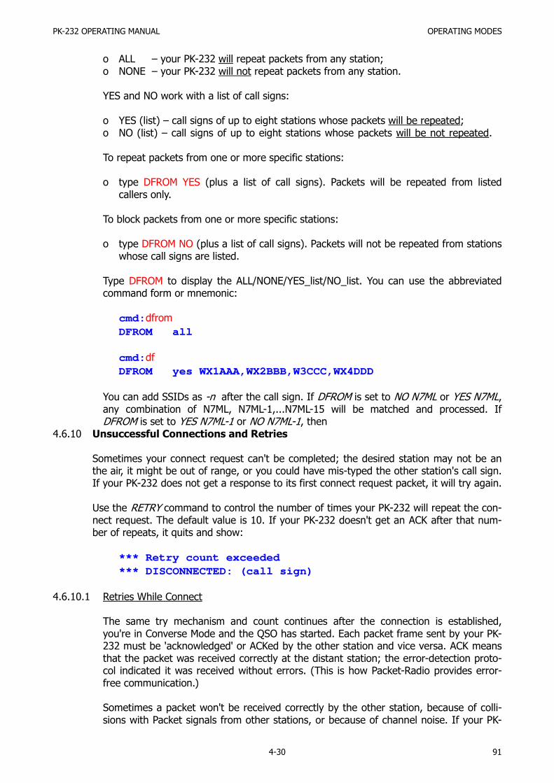
PK-232 OPERATING MANUAL OPERATING MODES
4-30 91
o ALL – your PK-232 will repeat packets from any station;o NONE – your PK-232 will not repeat packets from any station.
YES and NO work with a list of call signs:
o YES (list) – call signs of up to eight stations whose packets will be repeated;o NO (list) – call signs of up to eight stations whose packets will be not repeated.
To repeat packets from one or more specific stations:
o type DFROM YES (plus a list of call signs). Packets will be repeated from listedcallers only.
To block packets from one or more specific stations:
o type DFROM NO (plus a list of call signs). Packets will not be repeated from stationswhose call signs are listed.
Type DFROM to display the ALL/NONE/YES_list/NO_list. You can use the abbreviatedcommand form or mnemonic:
cmd:dfrom
DFROM all
cmd:df
DFROM yes WX1AAA,WX2BBB,W3CCC,WX4DDD
You can add SSIDs as -n after the call sign. If DFROM is set to NO N7ML or YES N7ML,any combination of N7ML, N7ML-1,...N7ML-15 will be matched and processed. IfDFROM is set to YES N7ML-1 or NO N7ML-1, then
4.6.10 Unsuccessful Connections and Retries
Sometimes your connect request can't be completed; the desired station may not be anthe air, it might be out of range, or you could have mis-typed the other station's call sign.If your PK-232 does not get a response to its first connect request packet, it will try again.
Use the RETRY command to control the number of times your PK-232 will repeat the con-nect request. The default value is 10. If your PK-232 doesn't get an ACK after that num-ber of repeats, it quits and show:
*** Retry count exceeded*** DISCONNECTED: (call sign)
4.6.10.1 Retries While Connect
The same try mechanism and count continues after the connection is established,you're in Converse Mode and the QSO has started. Each packet frame sent by your PK-232 must be 'acknowledged' or ACKed by the other station and vice versa. ACK meansthat the packet was received correctly at the distant station; the error-detection proto-col indicated it was received without errors. (This is how Packet-Radio provides error-free communication.)
Sometimes a packet won't be received correctly by the other station, because of colli-sions with Packet signals from other stations, or because of channel noise. If your PK-

PK-232 OPERATING MANUAL OPERATING MODES
4-31 92
232 doesn't get an ACK within a specific time, it sends the same packet again and in-crements the retry count. If the count set by RETRY is exceeded, your PK-232 discon-nects and displays:
*** Retry count exceeded*** DISCONNECTED: (call sign)
The automatic disconnect feature avoids excessive retransmission of unless packets. If,for example, the other operator turns off his station without disconnecting, or your pathis trough a digipeater that is shut down, or the RF channel deteriorates to the point ofbeing unusable, the disconnect prevents a 'hopeless' condition from trying up the chan-nel.
If you are operating under special conditions such as a marginal HF channel, you canset RETRY to 0 (zero) to disable all automatic disconnects – the retry attempt is not li-mited.
4.6.11 Monitoring Activity on the Channel
In addition to displaying data from the station to which you're connected, you can monitorall packet activity on the channel, 'read the mail', display packets 'flying' between otherstations. Your PK-232 will also keep track of stations heard on the channel. This sectiondescribes the monitor function.
4.6.11.1 Monitoring Other Stations
Use the MONITOR parameter to determine how monitoring is to be done; what stationswill or will not be monitored and the type and amount of information shown by themonitor.
MONITOR takes a numerical value between 0 (zero) and 6. Each higher number addsmore detail to your monitoring. As the value of MONITOR settings is increased, addi-tional functions are includes in the monitoring sequences.
The meaning of the MONITOR numbers are:
0 Monitor is disabled.
1 Only unnumbered, 'unconnected' frames are displayed. Use this for an 'unproto',round-table type QSO. Other connected stations using the frequency are not dis-played This setting will also display beacons.
2 Numbered (I) frames are also displayed. I-Frames are numbered in order of genera-tion and appear in a connected transmission. Use this to monitor connected conver-sations in progress.
3 Connect request (C) frames and disconnect (D) frames are also displayed with theheaders.
4 This is your PK-232's default value. Unnumbered acknowledgement (UA) of connectand disconnect frames are also displayed with either the characters 'UA' or 'DM'and a header.
5 Receive Ready (RR), Receive Not Ready (RN), Reject (RJ), Frame Reject (FR) and I-Frames are also displayed.

PK-232 OPERATING MANUAL OPERATING MODES
4-32 93
6 Poll/Final bit and sequence number are also displayed.
Before this next step, verify that your loopback test cable is still connected to the PK-232's RADIO 2 rear-panel receptacle, and that the front-panel RADIO 1/Radio 2 switchis still set to RADIO 2 .
Type: <CTRL-C>D<Return> to make sure you're DISCONNECTED.
Type: MONITOR 4 Your PK-232 responds with: MONITOR was 4
Type: CONVERSE, then type: This is a test packet.
Your Monitor now shows:
{MYCALL}>CQ:This is a test packet.
Because the UNPROTO parameter is defaulted to the address 'CQ', your packets aresent to 'CQ' – you're not connected to any other station. Your packet was 'heard' byyour PK-232 and displayed with the packet header containing the sending station's callsign and the destination.
4.6.11.2 Monitoring Digipeaters – The MRPT Command
Set MRPT ON to see any digipeater stations being used. This feature is useful if youwant to connect to a station you're monitoring and need to know a digipeater rout inorder to reach it. For example, you might see the following:
WX1AAA*>WX2BBB>WX3CCC:Hello Bill!
This packet went from WX1AAA via WX2BBB to WX3CCC. The * shows you which sta-
tion you actually heard. If your PK-232 had decoded the packet from WX2BBB, the dis-play would have shown:
WX1AAA>WX2BBB*>WX3CCC:Hello Bill!
If several digipeaters are active, or if the message lines are long, the display may bedifficult to read. You can put the header on a separate line from the text by sendingHEADERLN ON:
WX1AAA*>WX2BBB>WX3CCC:Hello Bill!
NOTE: When MRPT is OFF, digipeater paths will not appear in connect requests orconnect and disconnect monitor functions.
4.6.11.3 Monitoring Other Stations While Connected
Use the MCON command for selective monitoring of other traffic on the channel whileconnected to a distant station. MCON works like MONITOR, but affects your displaywhile in the connected state. As the value of MCON is increased, additional functionsare included in the monitoring sequences.You PK-232's default (MCON 0) tells your system not to show packets from other sta-tions while you are connected to any station. This lets you converse without interrupt-

PK-232 OPERATING MANUAL OPERATING MODES
4-33 94
ing and confusion caused by the mixture of everyone else's packets and those of yourpartner.
You might use MCON set to 1 to monitor the 'mail list' beacons from a PBBS while hold-ing connected conversations with your partners on the channel. Whenever a beacon issent, that message is displayed while you're connected to another station. (See previ-ous sections.)
4.6.12 Selective Monitoring
The MFROM, MTO and MONITOR commands provide monitor features not previouslyavailable. You can use these commands in combination to display or mask traffic to andfrom any stations or combination of stations as required. One example would be inhibitdisplay of a busy PBBS while you're monitoring other conversations.
4.6.12.1 The MFROM Command
MFROM uses arguments to determine how your PK-232 monitors Packet channels anddisplays information – which stations' packets will be displayed and which stations'packets will be masked or hidden.
MFROM is set to ALL when you start your PK-232 for the first time.
Type MFROM to display the ALL/NONE/YES_list/NO_list status of call signs of stationsfrom whom packets will or will not be displayed. You can use the abbreviated commandform or mnemonic:
cmd:mfrom
MFROM all
cmd:mf
MFROM yes WX1AAA,WX2BBB,WX3CCC,WX4DDD
To stop any packets from being displayed, type MFROM NONE. This has the same effectas setting MONITOR to 0 (zero).
To display packets from one or more specific stations only, type MFROM YES (followedby a list of call signs). Only packets from stations whose call signs are listed after YESwill be displayed.
To hide or mask packets from one or more specific stations type MFROM NO (followedby a list of call signs). Packets from stations whose call signs are listed after NO willnot be displayed.
You can add optional SSIDs specified as '-n' after the call sign. If MFROM is set to 'noN6IA' or 'yes N6IA' any combination of N6IA, N6IA-1,...N6IA-15 will be matched andprocessed. If MFROM is set to 'yes N6IA-1' or 'no N6IA-1' then only N6IA-1 will matchand be processed.
When MFROM and MTO contain different types of arguments, to avoid any possibleconflict, the arguments take the following priority:
ALL, NO list, YES list, NONE

PK-232 OPERATING MANUAL OPERATING MODES
4-34 95
Clear the MFROM field by typing %, & or OFF as arguments.
Error messages result from invalid commands. Here are some examples:
cmd:mfrom all w2jup
?too many (calls not allowed with ALL or NONE)
cmd:mfrom no
?not enough (NO and YES require call sign list)
cmd:mfrom w2jup
?need ALL/NONE/YES/NO (Calls must follow YES or NO)
4.6.12.2 The MTO Command
MTO determine how your PK-232 monitors the Packet channels and displays informa-tion – which stations' packets will be displayed and which stations' packets will bemasked or hidden. MTO is set to NONE when you start your PK-232 for the first time.
Type MTO to display the ALL/NONE/YES_list/NO_list status of call signs of stations towhom packets will or will not be displayed. You can use the abbreviated command formor mnemonic:
cmd:mto
MFROM all
cmd:mt
MTO yes WX1AAA,WX2BBB,WX3CCC,WX4DDD
To stop packets addressed to all stations from being displayed, type MTO NONE.
To display only packets addressed to one or more specific stations, type MTO YES (fol-lowed by a list of call signs). Only packets addresses to stations whose call signs arelisted after YES will be displayed.
To hide or mask packets addressed to one or more specific stations, type MTO NO (fol-lowed by a list of call signs). Only packets addressed to stations whose call signs arelisted after NO will be hidden or masked.
You can add optional SSIDs specified as -n after the call sign. If MTO is set to 'noWB9FLW or 'yes WB9FLW' any combination of WB9FLW, WB9FLW-1....WB9FLW-15 willbe matched and processed. If MTO is set to 'yes WB9FLW-1' or 'no WB9FLW-1' then on-ly WB9FLW-1 will match and be processed.
When MFROM and MTO contain different types of arguments, to avoid any possibleconflict, the arguments take the following priority:
ALL, NO list, YES list, NONE
Clear MTO with %, &, or OFF as arguments.Error messages result from invalid commands. Here are some examples:

PK-232 OPERATING MANUAL OPERATING MODES
4-35 96
cmd:mto all w2jup
?too many (calls not allowed with ALL or NONE)
cmd:mto no
?not enough (NO and YES require call sign list)
cmd:mto w2jup
?need ALL/NONE/YES/NO (Calls must follow YES or NO)
4.6.12.3 The MCON Command
Use the MCON command for selective monitoring of other traffic on the channel whileconnected to a distant station. Use this feature to have your PK-232 'listen' for a specif-ic station while you are connected to and conversing with someone else.
Set MCON to 0 (zero) or OFF to monitor packet activity when your station is not con-nected, but have all monitoring automatically cease when you are connected to some-one.
MCON works like MONITOR but affects your display while connected. As MCON settingsare increased, more functions are added in monitoring sequences. The meaning of theparameters values are identical to those shown under the MONITOR command.
4.6.12.4 The MFILTER Command
Use the MFILTER command to 'filter' selected characters from packets received. For ex-ample, you can command your PK-232 system to filter out form feeds, bell charactersor extra <LF> that may be sent by the station with which you're connected, but whichmay interfere with your display or otherwise disturb your operations. You can specify upto four characters by giving the ASCII character code in hex or decimal. Some examplesfollow:
o To prevent a <CTRL-L> character from clearing your screen, set MFILTER to 12.o To eliminate <CTRL-Z> characters, which some computer interpret as end-of-file
markers, set MFILTER to 26.o To prevent <CTRL-G> characters from 'beeping' your computer or terminal, set
MFILTER to 7.
Enter the ASCII or hexadecimal values of the selected characters separating each valuewith a comma:
cmd:MFILTER $07,$13
4.6.12.5 The MHEARD Monitor Buffer
Use the MHEARD command to display a list of stations heard since the last time yourPK-232 was powered up, or since the last time the MHEARD buffer was cleared.
Clear the MHEARD buffer by typing either a 'percent sign' (%), an ampersand (&), N,NO, NONE or OFF after the command word.
o Stations that are heard directly are marked with a *.
o Stations heard through a digipeater are not marked.

PK-232 OPERATING MANUAL OPERATING MODES
4-36 97
Entries in the 'heard' report are also time stamped if the date and time has been set.The PK-232's time is updated continuously as long as it is powered.
4.6.12.6 MSTAMP – The Monitor Time-Stamp Command
Monitored packets can be time-stamped if DAYTIME has been set. to enable this func-tion, set MSTAMP ON. You can also time-stamp connect and disconnect messages withto command CONSTAMP ON.
o If DAYSTAMP is OFF, CONSTAMP and MSTAMP show only TIME.o If DAYSTAMP is ON, the DATE is included in CONSTAMP an MSTAMP.
Set DAYSTAMP ON when you want a dated record of Packet channel activity, or whenyou're unavailable for local Packet operation.
4.6.12.7 DAYTIME – Set the Real-Time Clock
Use the DAYTIME command to set the PK-232's real-time clock. After the clock hasbeen set, you can show the time by typing DAYTIME.
When the PK-232 is turned on, the DAYTIME command displays the following errormessage:
?clock not set
You must reset DAYTIME each time you turn on the PK-232. Otherwise CONSTAMP andMSTAMP won't 'stamp' the time. If you type DAYTIME without a parameter, the PK-232displays current date and time information. The format of the display isdd-mm-yy hh:mm:ss.
DAYTIME 08-Jul-86 06:57:33
The format for entering the date and time is 'yymmddhhmm', where:
yy is the last two digits of the year (00-99)mm is the two-digit month code (01-12)dd is the date (01-31)hh is the hour (00-23)mm is the minutes after the hour (00-59)
Example: cmd:daytime 8607080657
Use either [SPACE], /, : or ; as a separator or delimiter. The PK-232 confirms the dateand time entry by echoing the new setting.
4.6.13 Packet Formatting
The PK-232 uses some special characters to control its operations. Many of these specialcharacters can be used to 'edit' commands and text as you type. You can 'personalize'

PK-232 OPERATING MANUAL OPERATING MODES
4-37 98
these features to suit you and your computer. Most of the special input characters are ac-tive in both Command and Converse Modes; any exceptions will be noted.
Some of your PK-232's command parameters affect how your packets are formatted –how your typing appears to the rest of the world. Other commands let you correct typingerrors before your packet is sent, cancel lines, cancel entire packets if necessary.
If the default command character is unsuitable for your computer's terminal program, youcan redefine each function using any ASCII character appropriate to your needs.
See the "Command Summary" chapter for full details on how to define these formattingand control features and commands.
4.6.13.1 PACLEN – Long or Short?
PACLEN sets the maximum length of your packet – the largest number of typed charac-ters that can fit in one packet. If you type more than the maximum number of charac-ters (default 128) without typing a 'send-packet' character (default <CR>), your PK-232will send a maximum-length packet.
In Transparent Mode, a packet is sent if the maximum number of characters is typedbefore the delay set by PACTIME forces a packet to be sent.
NOTE: Some other packet systems may not be able to accept packets longer than128 characters.
4.6.13.2 Backspace and Delete
You can erase typing errors with your <BACKSPACE> key. If your terminal lacks<BACKSPACE>, set DELETE ON to erase characters with the <DELETE> key; set DE-LETE OFF to use the <BACKSPACE> key.
You'll probably want to use the same key your computer normally uses to 'rub-out' typ-ing. <BACKSPACE> is more common than <DELETE> on personal computers. If youaren't sure what your rub-out key does, try both settings of the DELETE command andsee which work.
When you rub out typing errors, your PK-232 tries to correct the screen display. Thisworks with most computers and display-type terminals. It won't work for hardcopy-typeterminals. If your display doesn't look right after you rub out a character, try settingBKONDEL OFF. Your PK-232 won't correct the display but will show the rub-out with a \character (<BACKSLASH>). Restore the display correction by setting BKONDEL ON.
4.6.13.3 Cancel Line
If you make several mistakes in a line, or if you change your mind, you can cancel thewhole line rather than rubbing out the characters one at a time. Your monitor displays a<BACKSLASH> and a <CR>.
Type <CTRL-X> to cancel the line. If you're in Command Mode, a new prompt ap-pears:
cmd:Hi, John, how are you?<CTRL-X>\
[You started typing text while in Command Mode.]

PK-232 OPERATING MANUAL OPERATING MODES
4-38 99
cmd:CONVERSE
Hi, John, how are you?
4.6.13.4 Redisplay
If you've erased and retyped lots of characters, you may want to see 'fresh' input, espe-cially if BKONDEL is OFF. Your PK-232 shows the line you're entering when you type<CTRL-R>:
cmd:CONNECT KB7\\\WA7<CTRL-R>\
[You mis-typed the call sign.]cmd:CONNECT WA7GXD
Here you mis-typed the first letters of the call and rubbed them out. The PK-232 dis-played \ for each letter erased. You then retyped the call and re-displayed the charac-
ters on the new line.
4.6.13.5 XON/XOFF, START/STOP – Display Flow Control
Type <CTRL-S> to stop the display if your monitor scrolls the data faster than you canread it. Type <CTRL-Q> to resume output from the PK-232 to your computer.
4.6.13.6 The PASS Character
You may want to include a special input character in a packet. For example, to send se-veral lines in the same packet, you must include <CR> at the end of each line, bypass-ing its 'send-Packet' function except at the intended end of the packet. You can includeany character in a packet (including all special characters) by prefixing that characterwith the pass character, <CTRL-V>:
I wasn't at the meeting.<CTRL-V><CR>What happened?
Without the PASS character, this message would go as two packets. By prefixing thefirst <CR> with <CTRL-V>, you send it all at once, but maintain the <CR> in the text.
4.6.13.7 More Carriage Returns an Line Feeds
If you've set the 'send-packet' character to <CR>, you'll probably want the <CR> to beincluded in the packet for display at the other end.
If you set the send-packet character to a non-printing character, you'll probably wantthat character to be treated only as a command. The ACRPACK command determineswhether the 'send-packet' character is echoed and included in the packet.
You can add a <LF> after the <CR> in your packets by setting ALFPACK ON. If the oth-er station reports that the lines are overprinted on his display and he can't change it athis end, set ALFPACK to ON.
These formatting features and commands are described in full detail in the "CommandSummary" chapter.
4.6.14 Multiple Connections
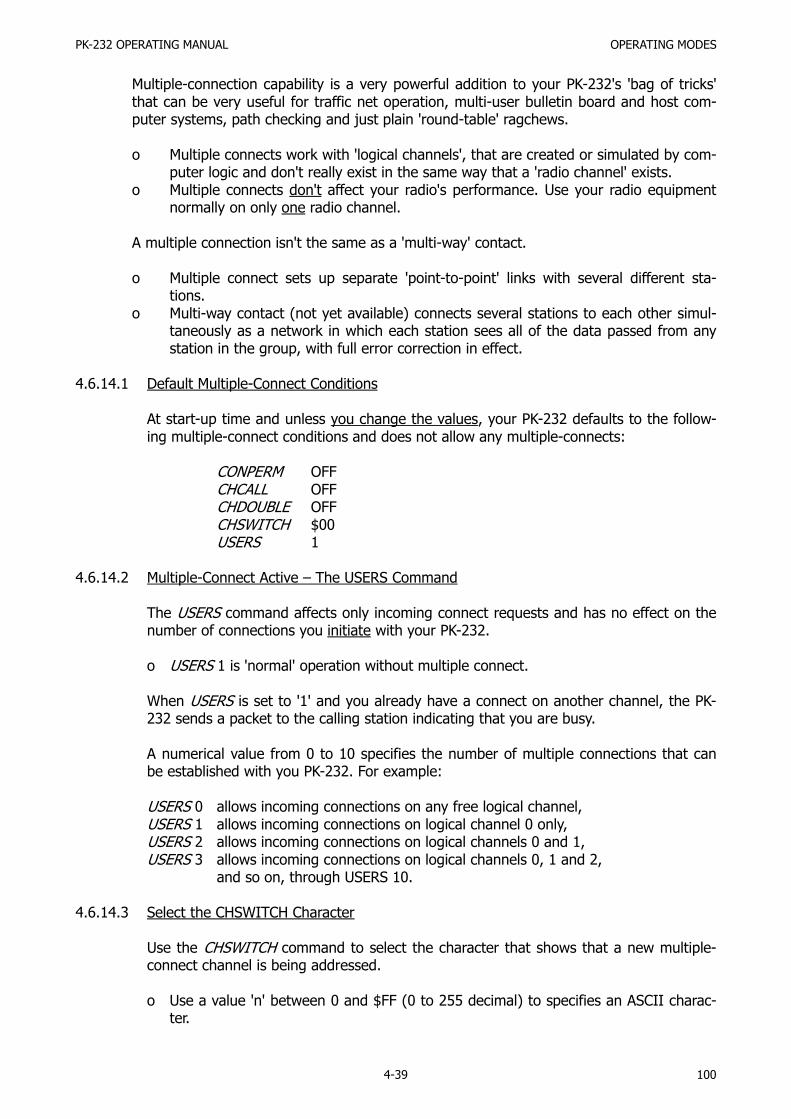
PK-232 OPERATING MANUAL OPERATING MODES
4-39 100
Multiple-connection capability is a very powerful addition to your PK-232's 'bag of tricks'that can be very useful for traffic net operation, multi-user bulletin board and host com-puter systems, path checking and just plain 'round-table' ragchews.
o Multiple connects work with 'logical channels', that are created or simulated by com-puter logic and don't really exist in the same way that a 'radio channel' exists.
o Multiple connects don't affect your radio's performance. Use your radio equipmentnormally on only one radio channel.
A multiple connection isn't the same as a 'multi-way' contact.
o Multiple connect sets up separate 'point-to-point' links with several different sta-tions.
o Multi-way contact (not yet available) connects several stations to each other simul-taneously as a network in which each station sees all of the data passed from anystation in the group, with full error correction in effect.
4.6.14.1 Default Multiple-Connect Conditions
At start-up time and unless you change the values, your PK-232 defaults to the follow-ing multiple-connect conditions and does not allow any multiple-connects:
CONPERM OFFCHCALL OFFCHDOUBLE OFFCHSWITCH $00USERS 1
4.6.14.2 Multiple-Connect Active – The USERS Command
The USERS command affects only incoming connect requests and has no effect on thenumber of connections you initiate with your PK-232.
o USERS 1 is 'normal' operation without multiple connect.
When USERS is set to '1' and you already have a connect on another channel, the PK-232 sends a packet to the calling station indicating that you are busy.
A numerical value from 0 to 10 specifies the number of multiple connections that canbe established with you PK-232. For example:
USERS 0 allows incoming connections on any free logical channel,USERS 1 allows incoming connections on logical channel 0 only,USERS 2 allows incoming connections on logical channels 0 and 1,USERS 3 allows incoming connections on logical channels 0, 1 and 2,
and so on, through USERS 10.
4.6.14.3 Select the CHSWITCH Character
Use the CHSWITCH command to select the character that shows that a new multiple-connect channel is being addressed.
o Use a value 'n' between 0 and $FF (0 to 255 decimal) to specifies an ASCII charac-ter.

PK-232 OPERATING MANUAL OPERATING MODES
4-40 101
o CHSWITCH characters must not be one of the channel numbers (0 to 9).
Your PK-232's default value for CHSWITCH is $00, which disables the function. This de-fault was selected to prevent conflicts with the characters frequently found in packetnetwork maps. If you're using your PK-232 as the TNC for a Packet Bulletin Board Sys-tem (PBBS), the default value of $00 is recommended.
o Suggestion: Set the CHSWITCH character to any hexadecimal value from $80 to$FF, for any character that you won't normally use. You can switch 'logical channels'in a multiple-connect situation by typing the CHSWITCH character even when inConverse Mode.
The CHSWITCH character can be PASSed in CONVERSE mode and is always ignored asa user-initiated channel switch in TRANSPARENT mode; it just flows through as data.However, the outgoing channel cannot be changed while active or 'on-line' in TRANS-PARENT mode.
4.6.14.4 Display Multiple-Connect Call Signs – The CHCALL Command
CHCALL displays the call sign of the 'connected-to' station after the channel identifier.CHCALL is especially useful when operating with multiple connections. Using CHCALL issimilar to using MRPT to show digipeat paths when monitoring the channel.
Set CHCALL ON if you intend to operate multiple connections.
4.6.14.5 Display Doubled Characters – The CHDOUBLE Command
When CHDOUBLE is set ON, your monitor displays received characters as doubled char-acters if are the same as your CHSWITCH character.
Set CHDOUBLE ON when operating with multi connections to tell the difference be-tween CHSWITCH characters received from other stations and CHSWITCH charactersgenerated by your PK-232.
4.6.15 Tips on Channel Switching and Multiple Connects
The PK-232 offers ten logical channels on which you can hold more than one conversationat a time. In effect, multiple connect operation is much like a 'ten-button' telephone witha 'hold' button.
Depending upon the status of USERS, you can be linked to one station on logical channel1, connect to another on logical channel 2 and accept a connect request on logical chan-nel 3.
o Use the CHSWITCH character to change the logical channels.
Make sure that the CHSWITCH character you select is not one you use in everyday con-versation. The next number you type after entering the CHSWITCH character is interpret-ed as the channel number to which you want to switch.
For example, if you've selected 'A' as your CHSWITCH character and type Mike is an A1class operator, the PK-232 thinks you have given the command 'to switch to channel 1'.

PK-232 OPERATING MANUAL OPERATING MODES
4-41 102
o The CHSWITH character is active in both Converse and Command Modes. You don'thave to return to the Command mode to change channels.
Let's choose the CHSWITCH character '@' by typing the ASCII value, decimal or hex, of'@' to CHSWITCH.
CHSWITCH $40 (hex) orCHSWITCH 64 (decimal)
After you have defined CHSWITCH, the PK-232 changes logical channels whenever youtype @ followed by a number (0–9).
o Choose the 'equals' sign (=) as your switch character.
Type CHSWITCH $3D to select the equals sign. Your monitor displays:
CHSWITCH was $00CHSWITCH now $3D (=)
o To see the call signs of the stations with whom you're connected, type CHCALL ON.
o To accept the maximum number of permissible multi-connects, type USER 10.
o Assume you want to connect to WX1AAA and WX2BBB. From Command Mode type:
=0 CONNECT WX1AAAand
=1 CONNECT WX2BB
o After you're are connected, you can tell who's talking to you:
=0:WX1AAA: Hi Ralph.=1:WX2BBB: Long time no see!
o To chat with WX1AAA in Converse Mode, type:
=0 Hi Chuck!
o To chat with WZ2BBB, do the same thing for his channel:
=1 Hello Bert.
o To disconnect from WX1AAA, type:
<CZTL-C>=0DISCONNECT
4.6.15.1 The CSTATUS Command
CSTATUS is an immediate command that shows you the status of all 10 channels.
o Use the CSTATUS command to find out what logical channel you're using.For example, assume you're connected to KZ7G on channel 0, trying to connect toN7BTI on channel 1 and have issued a disconnect request for N7ML on channel 3 which

PK-232 OPERATING MANUAL OPERATING MODES
4-42 103
also happens to be the channel you are using.
The CSTATUS command shows:
CH 0- CONNECTED TO KZ7G; V2; 3 UN ACKEDCH 1- CONNECT IN PROGRESSCH 2- DISCONNECTEDCH 3- I/O DISCONNECT IN PROGRESSCH 4- DISCONNECTEDCH 5- DISCONNECTEDCH 6- DISCONNECTEDCH 7- DISCONNECTEDCH 8- DISCONNECTEDCH 9- DISCONNECTED
You now know that:
o your PK-232 is connected to KZ7G on logical channel 0 using Version 2 protocol andthere are three unacknowledged packets outstanding;
o a connect is in progress on logical channel 1;o a disconnect is in progress on logical channel 3, which is also the channel to which
you're actually connected and where the Input/Output activity is now occurring.
Don't select a CHSWITCH character that can be usually found in text. If by chance youreceive the selected CHSWITCH character in text, the PK-232 interprets the next char-acter received as the logical channel to which it should switch activity. If that characteris a number, the PK-232 will change logical channels. The chances are that the next re-ceived character will be a letter rather than a number. Your system will display the errormessage ?CHANNEL MUST BE 0-9.
4.6.15.2 The MULT LED
The MULT LED is lit when you have established a multiple connect.
o If USERS is set to a value greater than '1', more than one connect is permitted.
o The MULT LED is lit when you establish a second connect or when another stationconnects to you after you have a connect on another channel.
NOTE: The MULT LED will blink if the PK-232's receive buffer is filled. This canhappen if your computer is not connected to the PK-232, or if for some rea-son, your communications program no longer can accept any further in-bound data. The blinking effect is not related to multiple-connect operation.
4.6.16 Understanding Monitor Level 6
When MONITOR is set to '6', your PK-232 displays all packet frames received on the chan-nel to which you're tuned. 'MONITOR 6' provides information that can frequently be usedto identify the exact nature of the packet communication in progress and diagnose linkproblems. Packet frame identifiers are displayed at the end of each packet header re-ceived and decoded by the PK-232. The identifier letters are enclosed in either < > or [ ]brackets.
<C> indicates a Connect Command received with AX25L2V2 set OFF[C] indicates a Connect Command received with AX25L2V2 set ON.

PK-232 OPERATING MANUAL OPERATING MODES
4-43 104
In all cases, the <> or [ ] indicates the version of the protocol in use by the station send-ing the packets.
Monitor 6 sets your PK-232 to display and identify ten different types of packet frames:
C Connect Command (also known as a 'SABM' frame)D Disconnect CommandI Information Command and ResponseUA Unnumbered Acknowledgment ResponseUI Unnumbered Information FrameRR Receive Ready Command and ResponseRJ Reject Command and ResponseRNR Receive Not Ready Command and ResponseFRMR Frame Reject ResponseDM Disconnected Mode Response
In these next paragraphs, we'll show some examples of these frame identifiers and howthey appear in various packet link situations. We'll assume that stations KZ7G and N7BTIare working these links.
4.6.16.1 The <C> Connect Command <SABM Frame>
Let's assume that KZ7G is using AX25L2V2 set to OFF, and has typed the C N7BTI com-mand. His PK-232 sends a Connect Command frame to N7BTI, the Station to whom hewants to connect. The header will look like this:
KZ7G>N7BTI <C,P>
o The <> indicates that V2 is OFF;
o The C indicates a Connect Command (SABM Frame);
o The P indicates that the 'Poll' bit is set and that a 'Final' bit is expected in response.
4.6.16.2 The <UA> Unnumbered Acknowledgment Frame
Assuming that N7BTI's system is available and responds with the normal acknowledg-ment, the next header will look like this:
N7BTI>KZ7G <UA,F>
o The UA indicates an Unnumbered Acknowledgment Frame that says that
N7BTI's System is alive and well and accepts the Connect Command fromKZ7G;
o The F indicates that the 'Final' bit is set, the proper response to the 'P' bit
received;o On receipt of this 'UA' frame, KZ7G's screen will show the usual *** CON-
NECTED TO N7BTI message.
The two Systems are now connected and ready to exchange Information.
4.6.16.3 The <I> Information Frame
Let's assume that KZ7G types Hi John!. If HEADERLN set ON, the frame for that line of

PK-232 OPERATING MANUAL OPERATING MODES
4-44 105
Information looks like this:
KZ7ON7BTI <I;0,0>: Hi John!
o The I indicates an Information Frame containing KZ7G's typed data;
o The first number is the number of the frame that KZ7G's System expects to receivenext from N7BTI's System;
o The second number is the number of this specific frame that KZ7G is now sendingto N7BTI.
The next frame typed by KZ7G would look like:
KZ7G>N7BTI <I;0,1>: 'TEXT OR INFORMATION'
When N7BTI types information on his keyboard, his system sends an information frameto KZ7G, which looks like:
N7BTI>KZ7G <I;2,0>: 'TEXT OR INFORMATION'
N7BTI's system has sent an information frame to KZ7G. The numbers in the informationframe indicate that:
o N7BTI's system expects KZ7G's next information frame to be number 2o This frame from N7BTI is number 0
N7BTI's next information frame would look like:
N7BTI>KZ7G <I;2,1>: 'TEXT OR INFORMATION'
4.6.16.4 The <RR> Receive Ready (Acknowledgment) Frame
The <RR> Receive Ready frame acknowledges that a frame has been received correct-ly. If the frame is not correctly received, the receiving system does nothing. The send-ing system waits for a set time interval until it decides that the last frame wasn't re-ceived and sends it again, until either the frame is acknowledged or until the sendingsystem 'times out' on excessive retries.
To acknowledge a frame, the receiving system sends an 'RR' frame including the num-ber of the next frame it expects to receive. Using the example above:
N7BTI>KZ7G <I;2,1>: 'TEXT OR INFORMATION'
KZ7G's system would send the following to acknowledge this frame:
KZ7G>N7BTI <RR;2>
KZ7G's system acknowledges Information frame number 1 from N7BTI by tellingN7BTI's system that it's 'READY TO RECEIVE' his next frame number 2. This wouldcause N7BTI's system to send it's next frame number 2. KZ7G's system would acknowl-edge this by sending:
KZ7G>N7BTI <RR;3>

PK-232 OPERATING MANUAL OPERATING MODES
4-45 106
4.6.16.5 The <RJ> Reiect Command Frame
Let's assume that some other Station sends a packet that collides with KZ7G's acknowl-edge packet and N7BTI misses the acknowledgment. N7BTI's system would send thepacket again because it has not heard an acknowledgment packet:
N7BTI>KZ7G <I;2,2>: 'TEXT OR INFORMATION'
KZ7G's system has already seen and acknowledged this specific frame. To indicate thatit doesn't want the same frame again, KZ7G's system sends a Reject Frame with a num-ber that teils N7BTI's system exactly what frame it expects to see next. KZ7G's systemwould send:
KZ7G>N7BT1 <RJ, 3>
This teils N7BTI's system to send frame number 3.
4.6.16.6 The <DM> Disconnected Mode Frame
Let's assume that, in the above example, N7BTI's system receives a connection requestfrom N7ML but N7BTI has USERS set to 1. N7BTI's system will not accept any moreconnections and therefore will send a Disconnected Mode frame (Busy Packet) toN7ML:
N7BTI>N7ML <DM>
This teils N7ML that N7BTI's system is busy and should cause N7ML to disconnect.
4.6.16.7 The <D> Disconnect Command Frame
When KZ7G and N7BTI have finished their conversation they must disconnect andbreak the link. If KZ7G issues the disconnect packet it will look like:
KZ7G>N7BTI <D,P>
Again we see the poll bit with the disconnect frame. N7BTI's screen would display*** DISCONNECTED: KZ7G and at the same time send an unnumbered acknowl-
edgment response frame:
N7BTI>KZ7G <UA,F>
The <UA> frame tells KZ7G's system to disconnect and again we see the FINAL bit.When KZ7G;s system receives the <UA>frame, his screen will display *** DISCON-NECTED: N7BTI.
4.6.16.8 The <UI> Unnumbered Information Frame
The <UI> frame is unique to amateur radio. It provides the means by which we cansend beacons and other Information without protocol.
If N7BTI wanted to call CQ after the previous contact, he'd first have to enter Conversemode by typing CONVERSE or K.N7BTI could then type a short CQ message such as CQ de John. Assuming N7BTI's UN-PROTO address had the default setting 'CQ', the resulting <UI> frame would look like:

PK-232 OPERATING MANUAL OPERATING MODES
4-46 107
N7BTI>CQ <UI>CQ de John
The 'UI' in the above packet indicates this is an unnumbered Information frame. Thistype of frame does include a packet number.
4.7 Reception of Non-Amateur RTTY Signals
One of the most interesting uses for your PK-232 is looking for and monitoring stations out-side the amateur bands. A general coverage receiver is helpful, but it is possible to findquite a few stations within the out-of-band tuning range of many amateur-band only radios.
As a general rule, you must identify five variables before you can make sense out of manynon-amateur stations:
o the data code in use;o the baud rate;o the frequency shift;o the sideband (upper or lower);o possible signal encryption.
You must 'guess' the first three values and set them into your PK-232. You can determinethe values by trial and error or by following the procedure below. You can also consult oneof the many press teletype listings available from your amateur radio dealer. The listingscontain the time, frequency, baud rate, frequency shift, and whether a station is using upperor lower sideband. The books save a lot of time; however, some of the stations listed are us-ing signal encryption and bit inversion. In such cases, it's not possible to decode the re-ceived signals.
4.7.1 Frequency Shift and Tuning
Set WIDESHFT to ON as a first step.
o Set WIDESHFT to OFF to copy a station using 170-Hz shift.o Set WIDESHFT to ON to copy a station using at 850-Hz shift.
With WIDESHFT OFF, the PK-232 uses filter tone settings at 2110 Hz and 2310 Hz to de-modulate 200 Hz frequency shift.
With WIDESHFT ON, the PK-232 uses filter tone settings at 1200 Hz and 2200 Hz to de-modulate a 1000-Hz frequency shift.
Many press and weather stations using 425-Hz shift can be copied with WIDESHFT set ateither ON or OFF. The bandwidth of the WIDESHFT OFF filter is 450 Hz. Therefore the fil-ter begins to attenuate shifts greater than 450 Hz. 425-Hz shift is within the filter roll-offfrequencies and should work well here.
You can also copy 425-Hz shift signals in the WIDESHFT ON position because of the band-width characteristics. Usually 425-Hz shift signals are copied better using WIDESHFT OFFto reduce the effects of noise and QRM.
o When you toggle between WIDESHFT ON and WIDESHFT OFF, you are changingthe resonant frequency of the filters in the PK-232; therefore, retune the VFO on

PK-232 OPERATING MANUAL OPERATING MODES
4-47 108
your radio after toggling between WIDESHFT.o If the sending station's shift is unknown, start with WIDESHFT OFF and try to tune
the station to the display similar to Figure 2-1.o If you can't get that display, the station is probably using a wider shift than the
WIDESHFT OFF position can handle. If so, set WIDESHFT to ON and retune the ra-dio again.
o If neither method works, the station may not be sending the usual telegraphy co-des. It could be facsimile or some form of multiplex code.
After you've got the station tuned in, you need to know its baud rate. Assuming the sta-tion is sending in Baudot/Murray code, set RBAUD to its lowest setting of 45.
o Use the RB U command to increase RBAUD one step at a time. RBAUD U increasesRBAUD to its next highest value, up to 300 bauds.
If you can't copy after stepping through all the speeds, the station may be using the op-posite sideband.
o Use the RXREV T command to reverse the polarity of the received signals. After tog-gling, decrease RBAUD to its next lowest value by using RBAUD D.
o If you cannot copy after stepping through all possible settings of RBAUD andRXREV, you can assume the station is using encryption and cannot be copied.
You can try the same general sequence of operation using ASCII and AMTOR. A largenumber of coastal stations use SITOR (sometimes known and identified in Morse as 'RA-DIO TELEX' or 'RTTY TELEX'. See the sections on ASCII and AMTOR for general operatingmethods.

PK-232 OPERATING MANUAL ADVANCED PACKET OPERATION
5-1 109
CHAPTER 5 – ADVANCED PACKET OPERATION
5.1. Introduction
This chapter describes special aspects and advanced concepts not used in everyday conver-sational operation. Read this chapter carefully if you intend to use your PK-232 for:
o A Packet bulletin board system (PBBS)o Binary file transfero A 'host' programo HF or OSCAR operationo Special timing or other requirements needed by your radio
5.1.1. Using Hex Notation
Observe some simple rules if you choose to reassign parameter values in hexadecimalnumbers. Begin the number with a '$'. The 'digits' of a hex number represent multiples ofpowers of 16. The value 10 trough 15 are represented by the letters A trough F. The let-ters can be typed in upper or lower case. For example:
$1B = (1 × 16) + (11 × 1) = 27 (decimal)
5.2. Operation Modes
Your PK-232 has three operating modes. We discussed the Command and Converse Modesvery briefly in Chapter 4. The third mode, Transparent Mode, is a data mode like ConverseMode, but is intended primarily for computer data interchange rather than human conversa-tion.
5.2.1. Command Mode
Command Mode provides the communication or dialogue between your keyboard andyour PK-232; nothing goes to the 'outside world'. You must use Command Mode to entercommands which alter the PK-232's operating parameters. When your PK-232 is in Com-mand Mode prompt is shown at the beginning of each input line.
cmd:
(Note that the cmd: prompt may have scrolled off the screen if your PK-232 has received
and displayed packets.)
Your PK-232 always enters Command Mode after RESTART, RESET or a power cycle. Aftera power-off/power-on sequence, resident software reinitializes the PK-232's operating pa-rameters with values stored in RAM.
After the RESET command is issued all operating parameters are reset to the default val-ues stored in EPROM. The values of most parameters are stored in RAM and can be easilychanged.
5.2.1.1. Special Characters Used in Command Mode
The following commands set special characters which are active Command Mode. Seethe detailed descriptions of these commands "Command Summary" Chapter.

PK-232 OPERATING MANUAL ADVANCED PACKET OPERATION
5-2 110
COMMAND DESCRIPTION
CANLINE Cancel current lineCANPAC Cancel packet outputDELETE Delete character with destructive backspacePASS Insert after special characterREDISPLA Re-display current typed lineSTART, STOP Computer flow control characters (sent to PK-232)XOFF, XON PK-232 flow control characters (sent to computer
5.2.1.2. Display Control in Command Mode
The following commands affect display features which are active in the CommandMode. See the detailed descriptions of these commands in the "Command Summary"chapter.
COMMAND DESCRIPTION
ALFDISP Add <LF> after <CR> in data sent to terminalBKONDEL Echo after character deletionECHO Automatic echo of serial port inputFLOW Type-in flow controlLCOK Lower case translationNUCR Nulls after <CR>NULF Nulls after <LF>NULLS Null countACRDISP Automatic <CR> insertion after n characters
5.3. Flow Control
Whenever data are transferred between computers or terminals the data may be receivedfaster than the receiving system can handle it. Some programs try to deal with this by pro-viding data buffers for storing incoming data until the program is ready for it. However, thismerely postpones the problem; all buffers have size limitations.
To prevent loss of data, the computer controls data flow by telling the other device to stopsending data until the computer can empty its buffer. When the computer's buffer has beenflushed and is available again, the computer tells the other device to resume sending data.If you use a personal computer you're probably already familiar with flow control that allowsyou to stop the output from the computer while you read the data and restart the outputwhen you are ready for more.
5.3.1. Type-in Flow Control
Type-in flow control (set by the FLOW command) is a display feature. When FLOW is setON, your PK-232 cannot interrupt you with incoming packets while typing a commandword or an outgoing packet.
As soon as you type the first character of a word (except for echoing your typing) yourPK-232 'holds' output towards the computer. This 'hold' remains in effect until you type<CR> to end the command, or a send-packet character to mark the end of a packet, oruntil you erase or re-display the line you've started.
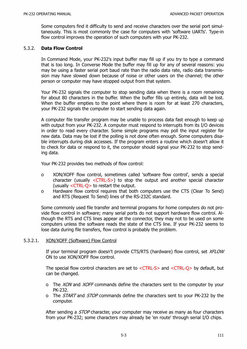
PK-232 OPERATING MANUAL ADVANCED PACKET OPERATION
5-3 111
Some computers find it difficulty to send and receive characters over the serial port simul-taneously. This is most commonly the case for computers with 'software UARTs'. Type-inflow control improves the operation of such computers with your PK-232.
5.3.2. Data Flow Control
In Command Mode, your PK-232's input buffer may fill up if you try to type a commandthat is too long. In Converse Mode the buffer may fill up for any of several reasons: youmay be using a faster serial port baud rate than the radio data rate, radio data transmis-sion may have slowed down because of noise or other users on the channel; the otherperson or computer may have stopped output from that system.
Your PK-232 signals the computer to stop sending data when there is a room remainingfor about 80 characters in the buffer. When the buffer fills up entirely, data will be lost.When the buffer empties to the point where there is room for at least 270 characters,your PK-232 signals the computer to start sending data again.
A computer file transfer program may be unable to process data fast enough to keep upwith output from your PK-232. A computer must respond to interrupts from its I/O devicesin order to read every character. Some simple programs may poll the input register fornew data. Data may be lost if the polling is not done often enough. Some computers disa-ble interrupts during disk accesses. If the program enters a routine which doesn't allow itto check for data or respond to it, the computer should signal your PK-232 to stop send-ing data.
Your PK-232 provides two methods of flow control:
o XON/XOFF flow control, sometimes called 'software flow control', sends a specialcharacter (usually <CTRL-S>) to stop the output and another special character(usually <CTRL-Q> to restart the output.
o Hardware flow control requires that both computers use the CTS (Clear To Send)and RTS (Request To Send) lines of the RS-232C standard.
Some commonly used file transfer and terminal programs for home computers do not pro-vide flow control in software; many serial ports do not support hardware flow control. Al-though the RTS and CTS lines appear at the connector, they may not to be used on somecomputers unless the software reads the state of the CTS line. If your PK-232 seems tolose data during file transfers, flow control is probably the problem.
5.3.2.1. XON/XOFF (Software) Flow Control
If your terminal program doesn't provide CTS/RTS (hardware) flow control, set XFLOWON to use XON/XOFF flow control.
The special flow control characters are set to <CTRL-S> and <CTRL-Q> by default, butcan be changed.
o The XON and XOFF commands define the characters sent to the computer by yourPK-232.
o The START and STOP commands define the characters sent to your PK-232 by thecomputer.
After sending a STOP character, your computer may receive as many as four charactersfrom your PK-232; some characters may already be 'en route' through serial I/O chips.

PK-232 OPERATING MANUAL ADVANCED PACKET OPERATION
5-4 112
A STOP/START character sent to your PK-232 will be ignored when the PK-232 is al-ready stopped/started. If the STOP and START characters are identical, that character'toggles' the output, turning it off when it is on and on when it is off.
You can disable XON/XOFF flow control in one direction only by setting the appropriateflow control characters to 0 (zero). Your PK-232 automatically uses CTS flow control tostop input from the computer.
XON/XOFF flow control is normally disabled in Transparent Mode; all characters aretreated as data. If DTR/RTS flow control is not available, set TXFLOW ON and XFLOWON to activate the XON and XOFF characters (the command from your PK-232 to theterminal).
Set TRFLOW ON to activate the START and STOP characters (the commands to yourPK-232 from the terminal) in Transparent Mode. Note that this mode is no longer truly'transparent' when the flow-control feature is enabled.
5.3.2.2. Hardware Flow Control
RS-232 RTS and CTS lines are normally used for flow control control signals in Transpar-ent Mode. Hardware flow control is usually less dependent on the way a given commu-nication terminal program is written.
The XFLOW OFF command activates hardware flow control in Converse Mode and Com-mand Mode. Your computer may receive as many as two characters after it signals yourPK-232 to stop sending; some characters may be 'en route' already through serial I/Ochips. Refer to AEA's PK-232 Technical Manual for hardware flow control interface re-quirements.
5.4. Data Transfer Modes
A data transfer mode can be entered several ways from Command Mode.
o Type CONVERS (or just K) to enter Converse Mode.o Type TRANS (or just T) to enter Transparent Mode.
If you're in Command Mode when another station connects to your station, your PK-232 au-tomatically switches to a data transfer mode. Use the CONMODE command to specify thedata transfer mode to be used at automatic entry.
o CONMODE TRANS automatically selects Transparent Mode.o CONMODE CONVERS returns to the default choice of Converse Mode.
Timing of automatic entry into data transfer mode depends upon which station in the linkinitiated the connection.
If your PK-232 receives and accepts a connect request, your system always enters the datatransfer mode at the moment your PK-232 sends the connect acknowledgement (ACK) anddisplays the *** CONNECT to {call sign} message. Your PK-232 always switches
to the data transfer mode at the moment of connection unless NOMODE is set ON.

PK-232 OPERATING MANUAL ADVANCED PACKET OPERATION
5-5 113
Any text sent to your PK-232 is queued into packets waiting for a successful connection be-fore being sent. If the connect attempt fails, your system returns to Command Mode. Thesystem also automatically returns to Command Mode when either station disconnects andends the QSO.
5.4.1. Converse Mode
Converse Mode is the data transfer mode most often used for ordinary conversations andmessage handling. Your PK-232 assembles your typed data into packets and sends the da-ta to the radio.
To return to Command Mode from Converse Mode type the Command Mode entry charac-ter (default <CTRL-C>), or send a BREAK signal to the serial port.
Although 'BREAK' is not a regular ASCII character, it can frequently be sent by typing aspecial key on the keyboard. A BREAK signal is a continuous 'mark' (or 1) signal on theserial port's Transmit Data line lasting approximately 200 milliseconds. The timing of theBREAK signal is not critical; most serial ports will recognize a BREAK if the 'mark' signallasts significantly longer than the time required for transmission of a character.
Because the BREAK signal is simple, it's easy to generate a BREAK with circuitry outsidethe computer, thus guaranteeing return to Command Mode in automatic station operation.
5.4.1.1. SENDPAC Character
The 'send-packet' character packetizes the typed characters for transmission. If youtype a full-length packet of characters (the default) value is 128 character) without typ-ing the send-packet character, your input is packetized and sent after the 128th
(PACLEN value) typed character.
Use the SENDPAC command to select a character for use as the 'send-packet' com-mand. <CR> is the default character. You can elect to include or not include the send-packet character in the transmitted packet.
If <CR> is the send-packet character, it's natural to include it in the packet as part ofthe text as well as interpreting <CR> as a command.
o Set ACRPACK ON to send the <CR>.
If you use some other character to force packet transmission, you may want to setACRPACK OFF and inhibit transmission of the send-packet character.
5.4.1.2. CANPAC Character
If you set the send-packet character to something other than <CR>, use the 'cancel-packet' character to cancel packets of more than one line.
Use the CANPAC command to select the cancel-packet character.
Single-line packets can be canceled with either the cancel-line character or the cancel-packet character.

PK-232 OPERATING MANUAL ADVANCED PACKET OPERATION
5-6 114
5.4.1.3. Special Characters in Converse Mode
The following commands set special characters which are active in Converse Mode. Seethe detailed descriptions of the commands in the "Command Summary" chapter.
COMMAND DESCRIPTION––––––––––––––––––––––––––CANLINE Cancel current lineCANPAC Cancel current packetCOMMAND Command Mode entryDELETE Character deletion with destructive backspaceMFILTER Characters to be filtered in monitored packetsPASS Insert following special characterREDISPLA Re-display current lineSENDPAC Send current packetSTART, STOP Computer's flow control characters (Sent to PK-232)XOFF, XON PK-232 flow control characters (sent to terminal)
5.4.1.4. Display Features in Converse Mode
The following commands activate the display features which are active in ConverseMode. Refer to the discussions of these commands for details in the "Command Sum-mary" chapter.
COMMAND DESCRIPTION––––––––––––––––––––––––––8BITCONV Retain high-order bit from serial portALFDISP Add <LF> after <CR>BKONDEL Echo after character deletionECHO Automatic echo of serial inputESCAPE <ESCAPE> translationFLOW Type-in flow controlLCOK Lower case translationNUCR Nulls after <CR>NULF Nulls after <LF>NULLS Null countACRDISP Automatic <CR> insertion after n characters
5.4.2. Transparent Mode
Packet-Radio is an ideal means of transferring data between computers. Converse Modeworks well for transferring ASCII text files. However, some files use all eight bits of eachbyte, rather than the seven bits used in ASCII code.
In addition, executable code files, such as CP/M '.CMD' or '.COM' and PC/MS-DOS '.COM'or '.EXE' files, contain characters that conflict with the control characters used in ConverseMode. Listings of BASIC programs and documents written with word processors that don'tcreate ASCII files can also pose this problem.
Use the Transparent Mode to transfer these type of files.
Like Converse Mode, Transparent Mode is a data transfer mode. But, in Transparent Modespecial' characters do not exist – everything you type (or everything your computer sendsto your PK-232) is transmitted exactly as it is received by your PK-232.

PK-232 OPERATING MANUAL ADVANCED PACKET OPERATION
5-7 115
5.4.2.1. Input Editing and Packet Timing
Transparent Mode does not permit input editing. The send-packet character does notexist. Packets are sent at specific regular intervals, or when a full packet of information(PACLEN = 128 bytes) is ready.
Use the PACTIME command to set the time intervals at which the data is packetized.
5.4.2.2. Display Features in Transparent Mode
Transparent Mode modifies your PK-232 monitor display characteristics. Data are sentto the computer exactly as received over the radio, with all eight bits of each byte re-ceived. Features such as auto-linefeed insertion and screen wrap are disabled, as is theechoing of input characters.
The parameter controlling these latter features in the Command and Converse Modeare not changed on entry into Transparent Mode; all display features are re-establishedwhen your PK-232 is returned to Command Mode.
Transparent Mode also disables most of the link status messages that appear as yourPK-232 cycles between the disconnected and connected states.
5.4.2.3. Escape or Exit from Transparent Mode
In order for the Command Mode entry character (default = <CTRL-C>) to be transmit-ted freely in Transparent Mode, escaping or exiting from Transparent Mode to Com-mand Mode becomes a bit more complicated.
o Use BREAK to return to Command Mode, just as in Converse Mode.o Use the Command Mode entry character (<CTRL-C>) as follows:
- Wait a moment after typing the last character being sent. The minimum re-quired wait is set by the CMDTIME command.
- Type three Command Mode entry characters (<CTRL-C>) within an intervalCMDTIME of each other.
After a final CMDTIME interval during which no characters are typed, you'll see thecommand prompt. The default value of CMDTIME is one second. Note that you cannotescape from Transparent Mode using this second procedure if CMDTIME is set to zero.
If any characters are typed during this interval (even Command Mode entry characters),the escape will be aborted; all Command Mode entry characters you've typed are sentas Packet data.
5.5. Commands That Affect Protocol
Certain commands affect the operation of the Packet protocol. A full copy of the AX.25 pro-tocol appears in the AEA's Technical Manual for your PK-232.
5.5.1. AX25L2V2 – ON or OFF?
Your PK-232 uses the AX.25 Level 2 protocol, the rules by which your PK-232 communi-cates with other Packet systems.

PK-232 OPERATING MANUAL ADVANCED PACKET OPERATION
5-8 116
o Set AX25L2V2 ON to operate in Version 2.0.o Set AX25L2V2 OFF to operate in Version 1.0.
Digipeating may not work if a Version 2.0 packet is sent through a digipeater using anolder TNC.
The CHECK command controls a timing function that depends on the protocol version se-lected.
5.5.2. UNPROTO Who?
UNPROTO permits you to address 'unconnected' packets, as well as route your beaconand ID packets through digipeaters. The format is similar to that of the CONNECT com-mand:
cmd:UNPROTO QST VIA NK6K
For example, if you set UNPROTO to 'QST', other stations will see your beacon like this:
{MYCALL}>QST
The default address for unconnected packets is CQ.
5.5.3. PASSALL – The 'Junque Mode'
PASSALL is sometimes known as the 'garbage' mode. PASSALL is useful in diagnosing con-nection failures and protocol problems. It's really not very useful in ordinary packet ope-rations.
If PASSALL is ON, your PK-232 ignores error-checking. That function of the protocol is dis-abled for all packets monitored. If you set PASSALL ON, any 'packet' is displayed thatmeets the following conditions:
o The packet must start with a flag field.o The packet must contain an integral number of 8-bit bytes, up to 330 bytes.
5.5.4. Packet Timing Functions
Your PK-232 obeys a series of timing instructions built in to the protocol; timing is adjusta-ble to compensate for variable conditions and local circumstances. The default values ofthese instructions can be changed at any time for experimentation, and then returned totheir original values, if required.
Don't be afraid to try other values in these parameters. You won't hurt your PK-232 bychanging timing values. On the contrary, you may improve your packet performance.
5.5.4.1. TXDELAY
Radios vary greatly in the time delays that occur when switching from receive to trans-mit and from transmit to receive. These switching-time delays affect both ends of thePacket link:

PK-232 OPERATING MANUAL ADVANCED PACKET OPERATION
5-9 117
o Time delay between the moment that your PK-232 keys your transmitter's PTT lineand your transmitter delivers power to your antenna.
o Time required for the distant station's receiver to recover full sensitivity and over-come squelch/AGC rise-time characteristics.
o Transmitter and receiver phase-lock loop settling times at both ends of the link.
If your PK-232 starts sending data before your transmitter is up to power, or beforeyour receiver has recovered from transmitting and locked up on the incoming signal,the packet will not be received properly at the distance end.
TXDELAY must be taken into account in cases where external amplifiers use RF-drivenswitching.
TXDELAY controls the delay between your transmitter's key-up and the moment whenyour PK-232 starts sending data. During the period in which your PK-232 is holding PTTactive but not sending data, your PK-232 transmits a series of contiguous synchronizingsignals (flags).
5.5.4.2. AXDELAY and AXHANG
When sending packets through an audio repeater you may require a longer key-up de-lay than is normally needed for direct communications. However, the extra key-up delayis not required if the repeater has not had time to 'drop' since the last transmission.
o The AXDELAY command adds more key-up delay in your PK-232 so that the repea-ter receiver and transmitter have time to lock up.
o The AXHANG command sets the time your PK-232 assumes is needed for the re-peater to drop.
If your PK-232 has detected channel activity recently enough so that the repeater trans-mitter might still be on, it will wait only TXDELAY time before sending data, rather thanadding AXDELAY time as well.
TXDELAY, AXDELAY and AXHANG set times in units of 10 milliseconds. If AXDELAY is ineffect, the total key-up delay is:
Key-up delay = (TXDELAY + AXDELAY) × 10 milliseconds.
If activity has been heard more rencently than AXHANG × 10 milliseconds ago, the key-up delay is only:
Key-up delay = TXDELAY × 10 milliseconds.
5.5.4.3. FRACK and RETRY
The AX.25 protocol calls for retransmission of packets when an acknowledgement is notreceived from the distant end of the link within a specified period of time. A packetmight not be acknowledged because of channel noise or 'collision' with another packettransmission. If other stations are using the same channel, the receiving station maynot be able to acknowledge the received packet immediately.
The FRACK command (FRame ACKnowledge time sets the time lapse allowed beforethe originating station retransmits the packet.

PK-232 OPERATING MANUAL ADVANCED PACKET OPERATION
5-10 118
You may want to increase FRACK several seconds when using HF. Bear in mind that theFRACK time is really counted from the instant when your PK-232 begins sending aframe and that your data rate is four times slower when using HF at 300 bauds.
The RETRY command sets the maximum number of re-transmissions before the origi-nating station abandons further retries and terminates the connection. The maximumnumber of packet transmissions is RETRY + 1; the initial transmission does not count asa re-transmission. Setting RETRY to 0 (zero) specifies an infinite number of retries.
FRACK is automatically corrected for the additional time required for digipeating. Thetime interval before your PK-232 retransmits an unacknowledged packet is
Retry interval = FRACK × (2 × n + 1) seconds
where n is the number of digipeaters used for this connection.
5.5.4.4. DWAIT
Digipeated packets require an end-to-end acknowledgment. Digipeaters don't acknowl-edge the packets they relay. If a link includes several digipeaters, the chances of loss ofeither the original packet or the acknowledgment increase drastically.
To help alleviate this problem, an automatic wait time can be imposed on any stationnot transmitting a digipeated packet. Stations waiting for a clear channel to transmitpackets wait for this time interval after the channel clears before transmitting. This waitdoes not apply if the station is transmitting one or more digipeated packets. This usual-ly gives the digipeater a clear chance at the channel.
The DWAIT command sets your PK-232's wait time in ten-millisecond intervals. If digi-peating is not being done by anyone in your local area, this parameter can be set to 0(zero). In any event it should be set to the same value by all members of a local areapacket group.
To minimize unnecessary retries, the PK-232 applies a collision-avoidance strategy to allpackets except those being digipeated. On the second and subsequent transmissions ofa given packet, your PK-232 waits an additional random time after detecting a clearchannel before transmitting. This prevents repeated collisions of transmissions by thesame two stations. The random time in a multiple (0 to 15) of the TXDELAY time.
For the first transmission of a packet, the time between your PK-232's detection of lossof carrier and activation of the PTT line is:
Wait time = DWAIT × 10 milliseconds
For retries of the same packet, the interval is:
Wait time = (DWAIT + r ×TXDELAY) × 100/16 milliseconds
where r is a random number from 1 to 15. Therefore, the longest amount of time add-ed randomly is 0.094 × TXDELAY seconds. For the default value of TXDELAY = 30, thelongest time added is 2.8 seconds.

PK-232 OPERATING MANUAL ADVANCED PACKET OPERATION
5-11 119
5.5.4.5. MAXFRAME
The AX.25 protocol permits the transmission of several packets without waiting for anacknowledgment. The number of packets that can be sent before acknowledgment isknown as the 'window'. The window concept permits more efficient channel use if largeamounts of data are being transferred.
The MAXFRAME command sets the maximum number of packets which your PK-232 willsend before waiting for acknowledgment. (This doesn't mean that your PK-232 will waituntil several packets have been typed before transmitting.)
MAXFRAME, in combination with the PACLEN command (which sets the maximum num-ber of characters in a packet), determines how much information can be sent in a sin-gle burst transmission. The best combination for efficient data transfer depends uponchannel quality and the rate at which the terminal can process data.
When use a 1200-baud terminal data rate, begin with a combination that producesabout 300 characters outstanding at one time.
5.5.4.6. CHECK
The CHECK command sets a connection timeout specified in multiples of ten-second in-tervals. This timeout function prevents your PK-232 from remaining connected to a dis-tant station when the other station disappears for longer than the specified time. YourPK-232 uses this time somewhat differently, depending on the setting of AX25L2V2.
If AX25L2V2 is OFF (a pre-Version 2.0 connection), the link can be preserved by initiat-ing a reconnect call if the command RELINK is ON. The PK-232 returns to the 'connect-in-progress' state and sends connect request (SABM) frames. In addition, the PK-232adds a random time of up to 30 seconds each time CHECK occurs in a given connec-tion. If RELINK is OFF, the PK-232 will simply go to a 'disconnected' state without tryingto reconnect if the link has timed out.
5.5.4.7. RESPTIME
The RESPTIME command sets the delay between the receipt of a packet and the trans-mission of the acknowledgment packet. This delay is used to prevent collision betweenan acknowledgment and another packet from the sending station. RESPTIME is mainlynecessary in file transfers. For normal service, RESPTIME is best set to 0 (zero) by thestation sending the file.
The station receiving the file in a file transfer should set RESPTIME to 10 (default) or12.
5.5.4.8. PACTIME
The PACTIME command sets packets transmission timing in the Transparent Mode. Youcan choose the way packet transmission is timed. If you're typing manually to a remotecomputer, it's best to send packets at regular intervals.
If your computer is operating a remote-host or bulletin board program, PACTIME sendspackets after an interval without further input from the host or computer.
Use the CPACTIME command to enable PCTIME in Converse Mode.

PK-232 OPERATING MANUAL ADVANCED PACKET OPERATION
5-12 120
5.6. Packet Bulletin Board Operation
Your PK-232 can be used as the TNC or Data Controller with several of the PBBS (Packet Bul-letin Board System) programs presently available in the Amateur Radio community. Your PK-232's system compatibility has been field-proven with the following programs:
o W0RLI's Version 11.6 CP/M-based PBBS for the Xerox 820 Systemso WA7MBL's Version 2.04 PBBS for the IBM PCs and compatibleso WA7MBL's Version 3.12 PBBS for the IBM PCs and compatibleso W0RLI/VE3GYQ Version 2.0 CBBS for the IBM PCs and compatibleso KA2BQE's Version .90 CBBS for the IBM PCs and compatibles
NOTE: These programs are available from the authors. AEA does not currently distributeany PBBS code or operating programs.
5.6.1. Special Default Considerations
The following default parameters are recommended for PBBS operation:
8BITCONV ON NEWMODE OFFACRDISP 0 NOMODE ONALFDISP OFF PARITY 0AWLEN 8 RELINK OFFAX25L2V2 ON START $00CHSWITCH $00 STOP $00DCDCONN ON * TXFLOW OFFDELETE OFF XFLOW OFFECHO OFF XOFF $00FLOW OFF XON $00
* WA7MBL's Version 3.12 PBBS code requires that Pin 8, 'DCD' (Data CarrierDetect) must be wired between the computer and the PK-232. 'DCDCONN'must be ON to force Pin 8 to follow the PK-232's connect status.
Please consult the authors directly for additional information on operating your PK-232with their PBBS programs. AEA's Customer Service Department cannot provide informa-tion on.

PK-232 OPERATING MANUAL COMMAND SUMMARY
6-1 121
CHAPTER 6 – COMMAND SUMMARY
6.1. Introduction
Chapter 6 explains and illustrates all the PK-232's commands. You'll use certain commandsto affect the PK-232's performance under specific conditions, and other s to specify the val-ues of parameters used during the PK-232's general operation.
Your PK-232 is a 'command-driven' system, that is, a system that does not use 'menus'. Youcontrol the functions of the PK-232 by typing single- or multiple-character commands atyour computer's keyboard.
6.1.1. Entering Commands
Commands are entered after the Command Mode prompt:
cmd:
You'll use English-like words or abbreviations to change the value of parameters and issueinstructions to the PK-232.
o Commands are either keywords or mnemonics (special abbreviations that jog yourmemory) made up of strings of characters that you type.
You'll may not change the values of some parameters; however, you have maximum flexi-bility to adapt the PK-232 to your local environment and operating conditions.
o Use either UPPER CASE (capital letters) or lower case (small letters) when enteringcommands.
o End the command with a carriage return <CR>. Carriage returns are not shown inthe examples below.
o Correct your typing mistakes or cancel the line completely before you type the final<CR> of your command.
o See Chapter 4 for a discussion of line editing.
We'll use UPPER CASE throughout this chapter to show you the commands, and lowercase to explain the text.
6.1.2. Command Responses
Whenever the PK-232 accepts a command that changes a value, the PK-232 respondswith the previously stored value. For example, assume that XFLOW is ON and you typeXFLOW OFF - you'll see the display:
XFLOW was ONXFLOW now OFF
This message tells you that the value has been changed successfully.

PK-232 OPERATING MANUAL COMMAND SUMMARY
6-2 122
6.1.3. Error Messages
If your PK-232 can't understand what you've typed, you'll get an error message in Englishreporting the nature of the error.
o If you type a command your PK-232 can't understand – you'll see:
?What?
o If you type a correct command with a wrong argument:
?bad
o If you type a numerical value outside a parameter's range:
?range
o If you set the BEACON timing too short for busy channels:
WARNING: BEACON too often
o If you type an improper SELCAL:
?call sign
Here are a few more examples:
cmd:ASDFASDF
?What? – This isn't a command
cmd:BEACON E
?bad – A parameter was left out
cmd:PACLEN 265
?range – Unacceptable numerical value
cmd:DAY
?clock not set – You didn't set the PK-232's clock
cmd:x – Command is invalid for the mode in use
cmd:C N6IA
?not while in PACKET – Command is invalid for the mode in use
cmd:C N6IA
?not while in MORSE – Command is invalid for the mode in use
cmd:C N6IA
?not while in ASCII – Command is invalid for the mode in use
cmd:C N6IA
?not while in BAUDOT – Command is invalid for the mode in use

PK-232 OPERATING MANUAL COMMAND SUMMARY
6-3 123
6.2. Command List
Commands are listed alphabetically in the following command descriptions. Each commandentry contains several sections:
o Command nameo Command abbreviation or mnemonico Default valueo Parameters
6.2.1. Command Names
The command name at the beginning of the description is the full word you can type inorder to have your PK-232 execute this command. Next to the command you'll see theminimum abbreviation or the mnemonic that you can use instead of the full word. Ofcourse, you can always type out the entire command word, or any abbreviation longerthan the minimum abbreviation. For example:
o You can enter the command MYCALL by simply typing MY.
The abbreviation 'M' is not sufficient (and will be interpreted as a different command), butMY, MYC, MYCA, MYCAL or MYCALL are all acceptable.
If a command requires parameters, the type of parameter is indicated after the commandname as well as the default value. For example:
o n means the command takes a numerical parameter value.
6.2.2. Default Values
Almost all commands and parameters have initial values that are stored in EPROM andloaded into RAM when the PK-232 is first turned on – or when you type the RESET com-mand. The PK-232 assumes these defaults or values 'used most often' to the best suitedfor the average amateur station's operation.
There is no hard and fast rule that says 'you must use the defaults'. You can (and should)change the default values as required for your individual operating and equipment condi-tions.
6.3. Parameters, Arguments and Values
Some commands need additional information before they can be executed. This type ofcommand has 'parameters' or requires 'arguments'. For example, a command such asFULLDUP has a Boolean parameter. When you type FULLDUP ON, FULLDUP is the command,ON is its argument – the value you want the PK-232 to use to execute the command FULL-DUP.
o The values that fill this parameter are either ON or OFF.o Immediate commands such as 'ID' have no parameters. Typing only ID causes the
PK-232 to execute the command.

PK-232 OPERATING MANUAL COMMAND SUMMARY
6-4 124
Some commands such as CONNECT have optional parameters.
o If you type CONNECT without an argument, the PK-232 displays the current statusof the link.
However, if you type CONNECT N7ML, the PK-232 issues the connect request and tries toestablish the link to N7ML.
Some commands such as MFILTER can use several arguments at the same time. MFILTERaccepts from 1 to 4 numerical arguments. You can type MFILTER 12 or MFILTER 12,26. Bothare legal commands.
6.3.1. Parameters
Three different types of parameters are used: Boolean, numeric and text or string.
6.3.1.1. Boolean Parameters
Boolean parameters use one value out of a choice of only two possible values, such asON or OFF, YES or NO or EVERY or AFTER. Boolean parameters can also be toggledwith an argument of 'TOGGLE' or 'T'. This is useful, for example, in the case of RXREVand TXREV.
o When a parameter is Boolean, its two possible choices are shown separated by avertical bar.
6.3.1.2. Numeric Parameters
A parameter designated as n is a numeric value.
o Numeric values can be entered by typing familiar decimal numbers or optionally inhexadecimal numbers.
When using hexadecimal notation, you must prefix the number you type with a $ char-acter.
The PK-232 displays some of these numeric parameters (those which set special charac-ters) in hexadecimal format. Here's a brief explanation of 'hex' numbers:
o The 'digits' of a hex number represent powers of 16 in the same manner as thepower of 10 represented by a decimal number.
o The numbers 10 through 15 are indicated by hexadecimal digits A through F. Forexample:
$1B = (1 × 16) + (11 × 1) = 27 (decimal)$120 = (1 × 16 × 16) + (2 × 16) + (0 × 1) = 288 (decimal)
For numeric parameters in the range 0 to 255, arguments 'ON' or 'Y' set the value ofthe parameter to their ROM default values. Arguments 'OFF' or 'N' set the value to 0(zero).
Baud-rate parameters can use arguments UP (U) or DOWN (D) to select the next higheror lower baud rate. This is useful with RBAUD and ABAUD in RTTY reception.

PK-232 OPERATING MANUAL COMMAND SUMMARY
6-5 125
6.3.1.3. Text or String Parameters
A text parameter such as the argument or 'message' for BTEXT (your 'beacon' mes-sage) or CTEXT (your 'connect' message), can be typed in upper or lower case.
o A text parameter can include numbers, spaces and punctuation.o The text is accepted exactly as you type it.
Some commands require call signs as parameters. These parameters are usually ama-teur call signs, but may be any string of numbers and at least one letter up to six char-acters; character strings are used to identify stations sending and receiving packets.
A call sign can also include a sub-station identifier (SSID), decimal numbers from 0 to15 used to distinguish two or more stations on the air with the same call (such as abase station and a 'digipeater').
The call sign and SSID are typed in and displayed as 'call-n', e.g., 'K0PFX-3'. If an SSIDis not entered, the system assumes 0 (zero); SSID '0' is not normally displayed by thePK-232.
Some commands have parameters which are actually lists of call signs:
o The CFROM command allows you to specify from one to eight call signs for selectivemonitoring.
o You must separate multiple call signs with either blank spaces or commas.
The following examples will help you understand these explanations.
o BEACON EVERY|AFTER n
The BEACON command requires an argument;
o You must specify either EVERY or AFTER (abbreviated to E or A), followed byan argument n which you may choose from a range of values.
A typical appropriate entry would be BEACON EVERY 180 (a beacon is sent ever 180times 10 seconds, every 30 minutes), or BEACON EVERY 0 (the beacon is not trans-mitted).
o CONNECT call1 (VIA call2[,call3...,call9])
The CONNECT command requires a call sign argument 'call1'.
o You may optionally include the keyword VIA, followed by a list of oneto eight call signs, 'call2' trough 'call9'.
o Multiple call signs in the list must be separated by commas (asshown) or by blank spaces.
An acceptable entry would be: C WX1AAA V WX2BBB,WX3CCC

PK-232 OPERATING MANUAL COMMAND SUMMARY
6-6 126
6.3.2. Using Commands Without Arguments
If you type the command name without its arguments, the current value of the com-mand's arguments is displayed. For example:
cmd:VHF Y – Sets the value to YES (ON)
VHF was OFF – Displays the previous value
cmd:VHF – Command with no arguments
VHF ON – displays the present value
NOTE: The DISPLAY commands shows you the values of all parameters or groups ofrelated parameters.
6.4. Controller Messages
This section describes your PK-232's messages and the circumstances under which they canappear.
6.4.1. General
Sign-On Message
AEA PK-232 Data ControllerCopyright (C) 1986, 1987 byAdvanced Electronic Applications, Inc.Release DD-MM-YYChecksum $nncmd:
The sign-on message appears when you turn on your PK-232 or when you type RESTARTand after system RESET and autobaud routine. The release number is updated wheneverthe firmware is changed The checksum is a hex number which you can compare againstthe correct checksum given for the firmware version you're using.
PK-232 is using default values
This message appears along with the sign-on message above if the bbRAM checksumverification fails at power-on time, causing the PK-232 to load the default parameters fromROM. (This happens the first time you turn on your PK-232.)
This message also appears if the PK-232 loads the defaults in response to the RESET com-mand.
cmd:
This is the Command Mode prompt. When this prompt appears, the PK-232 is waiting foryou to issue a command. Anything you type after this prompt, up to and including thefirst <CR> is interpreted as a command to the PK-232. If a monitored packet has beendisplayed, the prompt may not be visible, even though you are in Command Mode. Youcan type the redisplay-line character (set by REDISPLA) to retype the prompt.
wasnow

PK-232 OPERATING MANUAL COMMAND SUMMARY
6-7 127
Whenever you change one of the PK-232's parameter, the previous value will be dis-played. This confirm that the PK-232 properly interpreted your command and reminds youof what you have done.
too many packets outstanding
This message appears in response to the CONVERS or TRANS command, under specialcircumstances. This message would appear if you've already typed packet data and filledthe outgoing buffer in the Converse Mode or Transparent Mode and then tried to return tothe Command Mode. You'll be allowed to enter one of these modes when some of thepackets have been successfully transmitted.
6.4.2. Command Mode Error Messages
An error message is displayed if you make a mistake typing a command to the PK-232.
?bad
You typed a command correctly, but the remainder of the command line couldn't be inter-preted.
?call sign
You typed a call sign that does not meet the PK-232's requirements for call signs. A callsign may be any string of numbers and letters. Punctuation and spaces are not allowed.The SSID, if given, must be a (decimal) number from 0 to 15, separated from the call bya hyphen.
?clock not set
You typed the command DAYTIME to display the date and time, but you haven't yet setthe clock! DAYTIME sets the clock if it is given with the daytime parameter and displaysthe date and time if it is given without parameters.
?What?
Your first entry is not a command or a command abbreviation – your PK-232 did not un-derstand your instructions!
?not enough
You didn't type enough arguments for a command that expects several parameters. Forexample, CONNECT W2JUP VIA.
?not while connected
You attempted to change MYCALL or AX25L2V2 while in a connected or connecting state.
?range
You typed a numeric argument too large or too small for the specific command.
?too long

PK-232 OPERATING MANUAL COMMAND SUMMARY
6-8 128
You typed a command line that is too long, so the line is ignored. For example, if you tryto type too long a BTEXT or CTEXT message, you'll receive this message. When you getthis specific error message, the previous text entry is not changed.
?too many
You typed too many arguments for a command that expects several parameters. For ex-ample, MFILTER can have up to 4 arguments.
cmd:MFILTER $1B,$0C,$1A,$03,$07
?too many
?VIA
You typed more than one call sign for the CONNECT or UNPROTO commands without theVIA keyword.
?not while disconnected
You tried to set CONPERM while disconnected.
?channel must be 0-9
You typed an invalid channel character after the CHSWITCH character.
?already connected
You tried to CONNECT a station to which you're already connected.
?different connectees
You tried to CONNECT to more than one station on the same logical channel.
?different connectees
You tried to CONNECT to more than one station on the same logical channel.
6.4.3. Link Status Messages
Link status messages show you the status of AX.25 connections in which your PK-232may be involved.
o You can ask for link status at any time from the Command Mode by typing theCONNECT command without parameters.
If you attempt a connection when your PK-232 is not in the disconnected state, yourmonitor displays the link status but takes no other action.
The following messages appear in response to the CONNECT command:
Link state is: CONNECTED to call1 (VIA call2[,call3...,call9])

PK-232 OPERATING MANUAL COMMAND SUMMARY
6-9 129
Your station is connected to a distant station – you'll see the digipeater path in use, if any.The call sign sequence is the same sequence you would type to initiate the connection.
Link state is: CONNECTED to call1; v2; 2 unACKed [VIA call2[,call3...,call9]]
You are connected to a station using version 2; two frames remain unacknowledged.
Link state is: DISCONNECTED
No link or connection exists right now. You may type the CONNECT command to initiate aconnection.
Link state is: CONNECT in progress
You've already typed a connect request, but the acknowledgment from the other stationhas not been received. If you type the DISCONNE command, the connect process will becanceled.
Link state is: DISCONNECT in progress
You've typed a disconnect request, but the acknowledgment from the other station hasnot been received. If you type a second DISCONNECT command, the PK-232 will go im-mediately to the disconnected state.
Link state is: FRMR in progress
Your PK-232 is connected to a distant station, but a protocol error has occurred. Thisshould never happen when two AEA AX.25 systems are connected. An improper imple-mentation of the AX.25 protocol could cause this condition. Your PK-232 will try to re-syn-chronize frame numbers with the PK-232 on the other end, although a disconnect may re-sult. Connections are not valid in this state; a disconnect will start the disconnect process.
Your PK-232 will tell you whenever the link status changes. The link status may change inresponse to a command you've given the PK-232 (CONNECT or DISCONNECT), a connector disconnect request packet from a distant station, a disconnect because of the retrycount being exceeded, an automatic time-out disconnect (CHECK) or a protocol error.
*** CONNECTED to: call1 (via call2[,call3...,call9])
This message appears when your PK-232 switches from the 'disconnected' or 'connect inprogress' state to the connected state. The connection may be a result of a CONNECTcommand typed by you, or a connect request packet received from a distant station.
*** Connect request: call1 (via call2[,call3...,call9])
Your PK-232 has received but not accepted a connect request from a distant station. Thiscan happen if you've set CFROM to NONE, or if you are already connected to another sta-tion.
When your PK-232 displays this message, it also sends a DM packet (busy signal) to thestation that initiated the connect request. If your PK-232 rejects a connect request be-cause you've set CFROM to NONE or OFF, you can issue your own connect request to theother station.

PK-232 OPERATING MANUAL COMMAND SUMMARY
6-10 130
*** DISCONNECTED: {call sign}
Your PK-232 has switches to the disconnected state from any other link state. This mes-sage may be preceded by a message explaining the reason for the disconnect, as shownbelow.
*** Retry count exceeded*** DISCONNECTED: {call sign}
Your PK-232 has been disconnected because of a retry failure, rather than a disconnectrequest from one of the stations.
*** {call sign} busy*** DISCONNECTED: {call sign}
Your connect request was rejected by a DM packet (busy signal) from the other station.Your PK-232 will reject a connect request if CFROM is set to NONE, or if you are alreadyconnected to another station.
FRMR sent: xx xx xx
Your Your PK-232 is connected but a protocol error has occurred. Your PK-232 has trans-mitted a special FRMR packet and is trying to re-synchronize frame numbers with the dis-tant station's Packet system. The string xx xx xx is replaced with the hex codes for thethree bytes sent in the information part of the FRMR frame. This message will not appearif your PK-232 is in Transparent Mode.
FRMR rcvd: xx xx xx
Your PK-232 has received an FRMR (protocol error as described above) and shows this fol-lowed by a display of the FRMR packet in hexadecimal format. This message does not ap-pear if the PK-232 is in Transparent Mode.
6.5. Special Keyboard Control Codes
Except for Packet operation, each mode uses specific characters for special functions. Thesefunctions vary with the mode and unless noted, are typed from the Command Mode.
6.5.1. Morse Code
From Command Mode:
L Locks to speed of the incoming signal.R Switches the system to receive mode, unlocks received speed, forces re-
ceived speed to equal transmit speed.X Switches system to transmit mode and forces immediate entry into Converse
Mode.MO Unlocks the Morse received speed.

PK-232 OPERATING MANUAL COMMAND SUMMARY
6-11 131
6.5.2. Baudot and ASCII RTTY
From Command Mode:
L Forces LETTERS case (Baudot only).R Switches system to receive mode, forces LETTERS (if Baudot) case.X Switches system to transmit mode and forces immediate entry into Converse
Mode.K Enters Converse Mode for Entering data into Transmit buffer.
Characters embedded in transmitted text:
<CTRL-O> Sends LETTERS shift character (if Baudot)<CTRL-N> Sends FIGURES character (if Baudot)<CTRL-D> Shuts off transmitter immediately<CTRL-F> Sends callsign in Morse and shuts off transmitter
6.5.3. AMTOR Mode
From Command Mode:
ARQ <SELCAL> Starts Mode A selective call and forces ConverseFEC Starts Mode B transmission and forces ConverseSELFEC <SELCAL> Starts Selective Mode B transmissionR Stops sending immediately, forces AMTOR Standby, clears the
transmit buffer of all remaining dataAM Stops transmission, forces AMTOR Standby, clears the transmit
buffer of all remaining dataAL Forces re-synchronization in ALIST (AMTOR Mode A Listen)L Forces LETTERS case
Characters embedded in transmitted text:
<CTRL-O> Sends LETTERS character<CTRL-N> Sends FIGURES character<CTRL-F> Sends callsign in Morse and shuts off transmitter<CTRL-D> Stops sending when the transmitter buffer is empty
6.5.4. Clear String Commands
While in Command Mode, the following commands can be cleared by typing the commandword followed by a single percent sign (%), an ampersand (&) or N, NO, NONE, OFF asthe command's argument.
BTEXT CTEXT MBX MYALIAS MHEARD MFROM MTO CFROM DFROM

PK-232 OPERATING MANUAL COMMAND SUMMARY
6-12 132
6.6. Specific Commands
The following section contains detailed descriptions of the meaning, use and effects of eachcommand, its parameters, default values and arguments. Examples of command usage areincluded.
o Type X to turn on your transmitter and enter Converse Mode.o Type <CTRL-D> to shut off your transmitter and return to the Command Mode, or o type <CTRL-F> to send your call sign in Morse and shut off your transmitter and re-
turn to Command Mode, oro type <CTRL-C> to return to the Command Mode.o Typr R to shut down your transmitter and end the contact.

PK-232 OPERATING MANUAL COMMAND SUMMARY
6-13 133
8BITCONV ON|OFF Mnemonic: 8B Default: OFFMode: Packet
Parameters: ON - The high-order bit IS NOT stripped in Converse Mode.OFF - The high-order bit IS stripped in Converse Mode.
8BITCONV permits packet transmission of 8-bit data in Converse Mode.
When 8BITCONV is OFF, the high-order bit (bit seven) of characters received from the terminal isremoved before the characters are transmitted in a packet.
The standard ASCII character set requires only seven bits – the eighth or final bit is used as a pa-rity bit or ignored.
Setting bit seven in text characters transmitted over the air may cause confusion at the otherend.
If you need to transmit eight-bit data but don't want all the features of Transparent Mode, set8BITCONV ON and AWLEN 8. This may be desirable if you're using a special non-ASCII characterset.
Because commands require only the standard seven-bit ASCII character set, bit seven is always re-moved in Command Mode.
AAB text Mnemonic: AA Default: PK-232Mode: Baudot, ASCII, AMTOR
Parameters: text - Any combination of characters up to a maximum of 17 characters.
Use the AAB command to enter an acknowledgment text in the ANSWERBACK section of the PK-232's memory. AAB sends automatic confirmation in Baudot, ASCII and AMTOR operation in re-sponse to a distant station's WRU? command, AAB is not related to the CTEXT and BTEXT messag-es used only in the Packet Mode. Set WRU? ON to activate your answerback.
Type AAB {17-character text} to store your answerback in memory.
ABAUD n Mnemonic: AB Default: 110 baudsMode: ASCII
Parameters: n - Specifies the ASCII data rate or signaling speed in bauds from your PK-232to your radio.
The available n ASCII data rates are: 45, 50, 57, 75, 100, 110, 150, 200 300, 600, 1200, 2400,4800 and 9600 bauds.
Example: ABAUD 300
ABAUD sets the radio ('on air') baud rate only in the ASCII operating mode. This value has no rela-tionship to your computer or terminal program's baud rate.
ASCII RTTY operation requires that both you and the distant station to use the same speed or datarate.

PK-232 OPERATING MANUAL COMMAND SUMMARY
6-14 134
As a general rule, the higher the baud rate, the greater the probability of data errors caused by in-terference and noise. Best results in the worst-case conditions will usually be obtained at lowerbaud rates. The modem in the PK-232 cannot handle data rates faster than 1200 bauds.
NOTE: The term 'WPM' is generally considered obsolete. Signaling speed are now univer-sally referred to as 'bauds' in FSK and AFSK operations using monobit data. In thesecases, the terms 'bauds' and 'bits per second' may be used interchangeably.
ACHG Mnemonic: AC Immediate CommandMode: AMTOR
ACHG is an immediate command used in AMTOR by the receiving station to interrupt the sendingstation's transmissions.
ACHG forces a changeover from receive to transmit if it is necessary to interrupt the sending sta-tion's transmission.
As the receiving station, you usually rely on the distant station, your partner in the ARQ 'hand-shake', to send the +? command to do the changeover. However, in ARQ (Mode A), you can usethe ACHG command to 'break in' on the sending station's transmission.
Use the ACHG command with care and only in situations where it essential to do so.
Recovery from this kind of interruption can result in garbled copy at one end of the contact, espe-cially 'FIGS' garble. If possible, wait until the other station is idling before breaking in.
If the other station breaks in to your transmission, you can use the TCLEAR command to canceltransmission of any unsent text that might not 'fit' the meaning of the break-in text.
ACRDISP n Mnemonic: ACRD Default: 0Mode: ALL
Parameters: n - 0 to 255 specifies the screen or printer width, in number of columns or char-acters.
0 (zero) disables this function.
The numerical value n sets the proper terminal output format for your specific needs. Your PK-232sends a <CR><LF> sequence to your computer or terminal at the end of a line in the Commandand Converse Modes when n characters have been printed.
If your computer or terminal automatically formats output lines, set ACRDISP to '0' (zero) toavoid conflict between the two formats.

PK-232 OPERATING MANUAL COMMAND SUMMARY
6-15 135
ACRPACK ON|OFF Mnemonic: ACRP Default: ONMode: Packet
Parameters: ON - The send-packet character, normally <CR>, IS added to all packets sent inConverse Mode.
OFF - The send-packet character is NOT added to packets.
When ACRPACK is ON, all packets sent in Converse Mode include, as the last character of thepacket, the send-packet character which forces the packet to be sent.
When ACRPACK is OFF, the send-packet character is interpreted only as a command to your PK-232, not as data to be included in the packet; the character is not echoed to the terminal.
Set ACRPACK ON and SENDPAC $0D to produce natural conversational mode.
Each line is sent when a <CR> is entered, and arrives at its destination with a <CR> at the end ofthe line.
If the distant station reports overprinting of lines on his display, set ALFPACK ON or the otherstation can set ALFDISP ON or suggest that the other station set his ALFDISP ON.
ACRRTTY n Mnemonic: ACRR Default: 71 (69 in AMTOR)Mode: Baudot/ASCII RTTY
Parameters: n - 0 – 255 specifies the number of characters on a line after which a carriagereturn <CR> is automatically inserted in your transmitted text. This insertionoccurs after the last space character before n columns across the screen orpage.0 (Zero) disables the function.
When sending Baudot or ASCII RTTY, the ACRRTTY feature automatically inserts and sends a car-riage return at the first space character following the nth character or column.
After the line ending sequence is sent, the character counter is reset to 0 (zero) and the countstarts again.
Use this option when you are hand-typing into the transmit buffer and don't want to be both-ered by watching the screen or worrying about line length or to see when you are coming tothe end of a line.
There are several cases in which you should NOT use this option:
When retransmitting text received from another station; for example, ARRL RTTY Bulletins.
The received text already contains the necessary line-ending sequence characters. If this option isenabled, your transmission will have double, perhaps even triple line feeds and look very strangeat the distant station.
Many stations using the older electromechanical teleprinter and Teletype machines habitually senda traditional line-ending sequence consisting of <CR><CR><LF><LTRS>, which was needed to al-low the older, slow machines to return to the left margin. The double <CR> routine will produce adouble line if this option is selected ON by setting the value of n greater than zero length.
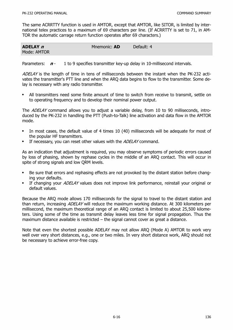
PK-232 OPERATING MANUAL COMMAND SUMMARY
6-16 136
The same ACRRTTY function is used in AMTOR, except that AMTOR, like SITOR, is limited by inter-national telex practices to a maximum of 69 characters per line. (If ACRRTTY is set to 71, in AM-TOR the automatic carrage return function operates after 69 characters.)
ADELAY n Mnemonic: AD Default: 4Mode: AMTOR
Parameters: n - 1 to 9 specifies transmitter key-up delay in 10-millisecond intervals.
ADELAY is the length of time in tens of milliseconds between the instant when the PK-232 acti-vates the transmitter's PTT line and when the ARQ data begins to flow to the transmitter. Some de-lay is necessary with any radio transmitter.
All transmitters need some finite amount of time to switch from receive to transmit, settle onto operating frequency and to develop their nominal power output.
The ADELAY command allows you to adjust a variable delay, from 10 to 90 milliseconds, intro-duced by the PK-232 in handling the PTT (Push-to-Talk) line activation and data flow in the AMTORmode.
In most cases, the default value of 4 times 10 (40) milliseconds will be adequate for most ofthe popular HF transmitters.If necessary, you can reset other values with the ADELAY command.
As an indication that adjustment is required, you may observe symptoms of periodic errors causedby loss of phasing, shown by rephase cycles in the middle of an ARQ contact. This will occur inspite of strong signals and low QRM levels.
Be sure that errors and rephasing effects are not provoked by the distant station before chang-ing your defaults.If changing your ADELAY values does not improve link performance, reinstall your original ordefault values.
Because the ARQ mode allows 170 milliseconds for the signal to travel to the distant station andthan return, increasing ADELAY will reduce the maximum working distance. At 300 kilometers permillisecond, the maximum theoretical range of an ARQ contact is limited to about 25,500 kilome-ters. Using some of the time as transmit delay leaves less time for signal propagation. Thus themaximum distance available is restricted – the signal cannot cover as great a distance.
Note that even the shortest possible ADELAY may not allow ARQ (Mode A) AMTOR to work verywell over very short distances, e.g., one or two miles. In very short distance work, ARQ should notbe necessary to achieve error-free copy.

PK-232 OPERATING MANUAL COMMAND SUMMARY
6-17 137
ALFDISP ON|OFF Mnemonic: ALFD Default: ONMode: All
Parameters: ON - A line feed character <LF> is sent to the terminal after each <CR>.OFF - A <LF> is not sent to the terminal after each <CR>.
ALFDISP controls the display of carriage return characters received in packets as well as echoingthose that are typed in.
When ALFDISP is ON, your PK-232 adds a line feed <LF> to each carriage return <CR> receivedif needed. If a line feed was received either immediately before or after a carriage return, ALFDISPwill not add another line feed. Use the PK-232's sign-on message to determine how carriage re-turns are being displayed.
Set ALFDISP ON if the PK-232's sign-on message lines are typed over each other.Set ALFDISP OFF if the PK-232's sign-on message is double spaced.
ALFDISP is set correctly if the PK-232's sign-on message is single spaced. ALFDISP affects your lo-cal display. It does not affect the data sent in any mode.
Use the ALFPACK command if you want to add line feed characters to outgoing packets.
ALFPACK ON|OFF Mnemonic: ALFP Default: OFFMode: Packet
Parameters: ON - A <LF> character is added to outgoing packets following each <CR> trans-mitted in the packets.
OFF - A <LF> is not added to outgoing packets.
ALFPACK is similar to ALFDISP, except that the <LF> characters are added to outgoing packets,rather than only to text displayed locally.
ALFPACK is included to maintain compatibility with other Packet-Radio Controllers.
If the person you are talking to reports overprinting of packets from your station, set ALFPACKON. ALFPACK is disabled in Transparent Mode.
ALFRTTY ON|OFF Mnemonic: ALFR Default: ONMode: Baudot/ASCII RTTY
Parameters: ON - A line feed character <LF> is sent after each carriage return <CR>.OFF - A <LF> is not sent after each <CR>.
If ALFRTTY is set ON when transmitting Baudot or ASCII RTTY, a line feed character is added andtransmitted automatically after each <CR> character you type.
Use this option when you are hand-typing into the transmit buffer and don't want to be both-ered by watching the screen or worrying about line length, or to see when you are coming tothe end of a line.
There are several cases in which you should NOT use this option:
When transmitting text received from another station; for example, ARRL RTTY Bulletins.

PK-232 OPERATING MANUAL COMMAND SUMMARY
6-18 138
The received text already contains the necessary line-ending sequence characters. If this option isenabled, your transmission will have double, perhaps even triple line feeds and look very strangeat the distant station.
Many stations using the older electromechanical teleprinter and Teletype machines habitually senda traditional line-ending sequence consisting of <CR><CR><LF><LTRS>, which was needed to al-low the older, slow machines to return to the left margin. The double <CR> routine will produce adouble line if this option is selected ON by setting the value of n greater than zero length.
ALFRTTY has no effect in AMTOR; a line feed is automatically added after each carriage return.
ALIST Mnemonic: AL Immediate CommandMode: AMTOR
ALIST is an immediate command that switches your PK-232 into the ARQ Listen mode.
You can usually monitor a contact between two linked stations by using the ARQ Listen mode (alsocalled Mode L). This mode may need a few seconds to phase or acquire synchronization with theother stations. Your ability to synchronize with the master station depends on operating conditionssuch as interference.
Your monitor display all the retries if the link stations that you are monitoring are experiencingARQ errors and retries.
Type ALIST (or AL) repeatedly if you lose synchronization.
AMTOR Mnemonic: AM Immediate CommandMode: Command
AMTOR is an immediate command that switches your PK-232 into the AMTOR mode. Your PK-232is automatically placed in ARQ Standby condition.
Your station is then available for automatic access by and response to any AMTOR station thatsends your SELCALL.
Your monitor will now display any inbound FEC (Mode B) transmissions on the received channelwithout any additional action on your part.
You must set MYSELCAL before you can use the AMTOR command.
ARQ aaaa Mnemonic: AR Immediate CommandMode: AMTOR
Parameters: aaaa - The distant station's SELective CALling code.
ARQ is an immediate command that starts an AMTOR Mode A (ARQ) SELCALL (SELective CALL) toa distant station.
Example: ARQ DCXJ
The SELCAL started by the ARQ command is the proper method of responding to another station'sMode B (FEC) CQ call.

PK-232 OPERATING MANUAL COMMAND SUMMARY
6-19 139
To begin the Mode A (ARQ) selective call:
Type ARQ followed by the other station's four-character SELCAL.
The distant station's SELCAL code is normally seen as part of the his/her CQ call sequence.
As soon as a <CR> is typed, your PK-232 will begin keying your transmitter in the three-characterAMTOR ARQ burst sequence. If the distant station receives and decodes your selective call suc-cessfully, the two AMTOR systems synchronize and begin the Mode A (ARQ) AMTOR 'handshaking'process.
See 'SELCAL' for information on the derivation and structure of the selective calling code.
You don't have to type the SELCAL a second time if you intend to call the same station again rightaway.
ARQTMO n Mnemonic ARQT Default: 90Mode: AMTOR
Parameters: n - 0 to 250 specifies the number of seconds to send an ARQ SELCAL before au-tomatic transmitter shutdown.
ARQTMO sets the length of time during which your ARQ SELCAL call will be sent, e.g., how longyour system will call a distant station before shutting down automatically. As a general rule, if youcan't activate another AMTOR station in the default time of 90 seconds, you can probably assumethat the other station can't hear your transmission.
ASCII Mnemonic: AS Immediate CommandMode:
ASCII is an immediate command that switches your PK-232 into the ASCII mode.
ASCII is the proper mode to use if you wish to use RTTY to transmit text, data or other informationcontaining lower case and special characters not present in the Baudot/Murray and ITA #2 alpha-bets or character sets.
Because the ASCII character set requires a minimum of seven bits to define the identity of eachtransmitted or received character, under worst-case conditions, ASCII is sometimes more subjectto data errors and garbled text than Baudot/ITA#2 at the same data rate.
AWLEN n Mnemonic: AW Default: 7Mode: All
Parameters: n - 7 or 8 specifies the number of data bits per word.
The parameter value defines the digital word length used by the serial input/output (I/O) terminalport and your computer or terminal program.
Set AWLEN to 7 for most packet operations, such as conversation, bulletin board operation andtransmission of ASCII files.
If eight-bit words are sent to the PK-232 in the Command or Converse Mode, the eighth bit is nor-mally removed, leaving a standard ASCII character, regardless of the setting of AWLEN.

PK-232 OPERATING MANUAL COMMAND SUMMARY
6-20 140
All eight data bits of each character must be retained to send executable files or other special da-ta.
Set AWLEN to 8 and use Transparent Mode.
You can also use Converse Mode and set AWLEN 8 and 8BITCONV ON. However, you must pre-cede the Converse Mode special characters with the PASS character in the data you send.
The RESTART command must be issued before a change in word length will take effect.
AX25L2V2 ON|OFF Mnemonic: A Default: ONMode: Packet
Parameters: ON - The PK-232 uses AX.25 Level 2 Version 2.0 protocol.OFF - The PK-232 uses AX.25 Level 2 Version 1.0 protocol.
Some implementations of the earlier version of AX.25 protocol won't properly digipeat Version 2.0AX.25 packets. This command exists to provide compatibility with these other TNCs until their soft-ware has been updated. For best results during this transition period set AX25L2V2 OFF.
For best results during this transition period set AX25L2V2 OFF.
After your local area TNCs have been updated to the newer protocol version, set AX25L2V2 ON.
AXDELAY n Mnemonic: AXD Default: 0Mode: Packet
Parameters: n - 0 to 180 specifies a key-up delay for voice repeater operation in ten-milli-second intervals.
AXDELAY specifies the period of time the PK-232 will wait – in addition to the delay set by TXDE-LAY – after keying the transmitter and before data is sent.
Packet groups using a standard 'voice' repeater to extend the range of the local area network mayneed to use this feature.
Repeaters with slow electromechanical relays, split sites, auxiliary links (or other circuits which de-lay transmission after the RF carrier is present) require some finite amount of time to get RF onthe air.
Try various values to find the best value for n if you're using a repeater that hasn't been used forPacket operations before.
If other Packet stations have been using the repeater, check with them for the proper setting.
AXDELAY acts in conjunction with AXHANG.

PK-232 OPERATING MANUAL COMMAND SUMMARY
6-21 141
AXHANG n Mnemonic: AXH Default: 0Mode: Packet
Parameters: n - 0 to 20 specifies voice repeater 'hang time' in 100-millisecond intervals.
The numeric value can be used to increase channel efficiency when an audio repeater has a hangtime greater than 100 milliseconds. For a repeater with a long hang time, it is not necessary towait for the repeater keyup delay after keying the transmitter if the repeater is still transmitting.
When the PK-232 has heard a packet sent within the hang period, it does not add the repeaterkeyup delay (AXDELAY) to the key-up time.
If you are using a repeater that hasn't been used for packet operations before, try various valuesto find the best value for n. If other packet stations have been using the repeater, check with themfor the proper setting.
BAUDOT Mnemonic: BA Immediate CommandMode: Command
BAUDOT is an immediate command that switches the PK-232 into the Baudot RTTY Mode.
Baudot operation is still the most common form of RTTY operation in use around the world, and isthe basis of the worldwide telex network and most radio press, weather and point-to-point nes-sage services.
The Baudot/Murray and ITA #2 character sets do not contain lower case or the special punctua-tion, formatting and control characters found in the ASCII character set.
Because the Baudot/ITA #2 code requires only five information bits to define each transmitted orreceived character, under worst-case conditions, Baudot RTTY will generally suffer fewer errorsthan ASCII code at the same data rate.
BEACON EVERY|AFTER n Mnemonic: B Default: EVERY 0Mode: Packet
Parameters: EVERY - Send the beacon at regular intervals.AFTER - Send the beacon after the specified time interval without Packet ac-
tivity.n - 0 to 250 sets beacon timing in ten-second intervals.0 - Zero turns off the beacon (default).
The BEACON command sets the conditions under which your Packet beacon will be transmitted.
A beacon frame contains the text that you've typed into the BTEXT message in a packet ad-dressed to 'CQ' or other UNPROTO address.A beacon frame may be sent directly, and also sent via the digipeat addresses specified by theUNPROTO command.
When the keyword EVERY is specified, a beacon packet is sent every n times ten seconds. Thismode can be used to transmit packets for testing purposes.
When AFTER is specified, a beacon is sent after n times ten seconds have passed without packetactivity.

PK-232 OPERATING MANUAL COMMAND SUMMARY
6-22 142
The beacon is sent only once until further activity is detected.
This mode can be used to send announcements or test messages only when Packet stations areon the air.
Proper choice of n avoids cluttering a busy channel with lots of unnecessary transmissions.
Beacon frames from other Packet stations can be monitored by setting MONITOR in the range 1-6.
If you set the BEACON timing less than '90', a value judged by most authoritative sources astoo small for busy channels, you'll see the message:
WARNING: BEACON too often
The warning message appears in the Command Mode each time a new command is typed.
BKONDEL ON|OFF Mnemonic: BK Default: ONMode: All
Parameters: ON - The sequence <BACKSPACE><SPACE><BACKSPACE> is echoed when acharacter is deleted from the input line.
OFF - The <BACKSLASH> character <\> is echoed when a character is deleted.
BKONDEL determines how character deletion is displayed in Command or Converse Mode.
The <BACKSPACE><SPACE><BACKSPACE> sequence updates the video display screen.
Set BKONDEL ON if you're using a video display terminal or computer.
On a printing terminal the <BACKSPACE><SPACE><BACKSPACE> sequence will result in overtyp-ed text.
Set BKONDEL OFF if you have a paper-output display, or if your terminal does not respond tothe <BACKSPACE> character <CTRL-H>.
The PK-232 displays a <BACKSLASH> for each character you delete. You can get a display of thecorrected input by typing the REDISPLAY-line character set by the command REDISPLA.
BTEXT text Mnemonic: BT Default: Empty (Null string)Mode: Packet
Parameters: text - Any combination of characters up to a maximum length of 120 characters.
BTEXT is the content of the data portion of a beacon packet. The default text is an empty string(no message). Beacon packets are discussed in more detail under the BEACON command.
Although the beacon subject is controversial in Packet circles, you can use beacon texts intelligent-ly and benefit the Packet community.
Don't type your call sign in BTEXT - the normal packet header show it for you.
Don't fill BTEXT with screen graphics such as asterisks, colons and semicolons, parentheses,etc. Use BTEXT for meaningful data such as meeting announcements, weather warnings, etc.

PK-232 OPERATING MANUAL COMMAND SUMMARY
6-23 143
Don't use BTEXT to tell the world that your 'DIGIPEAT IS ON' and 'BUFFER SAVE TO DISK ISENABLED' - put this information in your CTEXT message so that it is seen by the station thatconnects to you - the only station that really can use that information.After you've beaconed for a week or two and the Packet community has learned who andwhere you are, follow the practice used by more experienced packeteers: SET BEACON EVERY0!
You can send multiple-line messages in your beacon by including <CR> characters in the text.<CR> is inserted by typing the PASS character before the <CR>.
The PASS character is set in the PASS command.
If you enter a text string longer than 120 characters, the command is ignored and the following er-ror message appears:
?too long
A Packet bulletin board (PBBS) program may set the beacon text to a message like this, updatingthe text after each connection:
MAIL for: WB9FLW AD7I K9NG N7ML W2JUP WB2NNF WA7MBL W0RLI
Use a %, &, N, NO, NONE, or OFF as the first characters in the text to clear the BTEXT textwithout issuing the RESET.
Although the beacon subject is controversial in Packet circles, you can use beacon texts intelligent-ly and benefit the Packet community.
CALIBRATE Mnemonic: CAL Immediate CommandMode: Command
CALIBRATE is an immediate command that starts the modem calibration routine.
The PK-232 provides a continuous on-screen display of AFSK generator tone frequencies in Hertz.The frequency is displayed in vertical 'scroll' fashion approximately twice per second, with the partnumber of the potentiometer associated with that tone.
Calibration may be checked at any time without altering the state of the existing link. However, thetime-of day clock (DAYTIME) will not advance until you quit the calibration routine.
Commands available in the calibration routine are:
K Toggles your transmitter's PTT line between ON and OFF.Q Quits the calibration routine.H Toggles the transmitted audio tones between wide shift (1000 Hz) and narrow shift
(200 Hz) shift.<SPACE> Toggles the audio tone between 'mark' (low) and 'space' (high) tones.D Alternates the transmitted mark and space tones at a rate set by the radio baud
(HB) rate.

PK-232 OPERATING MANUAL COMMAND SUMMARY
6-24 144
Calibration of the modem tones and adjustment of the PK-232's tone output levels for propertransmitter modulation are described in the modem calibration section of AEA's Technical Manualfor the PK-232.
NOTE: Set D OFF to transmit a continuous mark or space tone.
CANLINE n Mnemonic: CAN Default: $18 <CTRL-X>Mode: All
Parameters: n - 0 to $7F (0 to 127 decimal) specifies an ASCII character code.
CANLINE changes the CANCEL-LINE input editing command character.
The parameter n is the ASCII code for the character you want to use to cancel an input line.
You can enter the code in either hex or decimal.
For example:
CANLINE $15 (hex)CANLINE 21 (decimal)
Either sets the cancel-line character to <CTRL-U>.
When you use the CANLINE character to cancel an input line in Command Mode, the line is termi-nated with a \ character and a new prompt (cmd:) appears.
When you cancel a line in Converse Mode, only a \ and a new line appear.
You can cancel only the line you are currently typing.Once <CR> has been typed, you cannot cancel an input line using the cancel-line character.
NOTE: If your send-packet character is not <CR>, the cancel-line character cancels onlythe last line of a multi-line packet.
Like all other input editing features, line cancellation is disabled in Transparent Mode.
CANPAC n Mnemonic: CANP Default: $19 <CTRL-Y>Mode: Packet
Parameters: n - 0 to $7F (0 to 127 decimal) specifies an ASCII character code.
CANPAC changes the CANCEL-PACKET input editing command character.
The parameter n is the ASCII code for the character you want to type in order to cancel an inputpacket.
You can enter the code in either hex or decimal.
When you cancel a packet in Converse Mode, the line is terminated with a <BACKSLASH> charac-ter and a new line.
You can only cancel the packet that is currently being entered.

PK-232 OPERATING MANUAL COMMAND SUMMARY
6-25 145
Once you have typed the send-packet character, or waited PACTIME (if CPACTIME is enabled), thepacket cannot be canceled even if it has not been transmitted.
Like other input editing features, packet cancellation is disabled in Transparent Mode.
The CANCEL-PACKET character also cancels the display output in Command Mode. If you are inCommand Mode and type the CANCEL-PACKET character, any characters that would be typed onthe screen (except those echoed) are 'thrown away' by the PK-232.
Typing the cancel-output character a second time restores normal output.To see how this works, type DISPLAY, then type a <CTRL-Y>.
The command list display will stop. You won't see any response from the PK-232 to commands.
To verify that the display is back to normal, type <CTRL-Y> and then type DISPLAY again.
Use the CANCL-DISPLAY feature if you inadvertently do something that causes the PK-232 to gen-erate large amounts of output to the terminal, such as giving the DISPLAY command or settingTRACE ON.
If you are in Converse or Transparent Mode and want to cancel display output, you must exitto Command Mode and then type the CANCEL-PACKET character.
CASEDISP n Mnemonic: CAS Default: 0 (as is)Mode: Packet
Parameters: n - 0 to 2 specifies how your PK-232 sends characters to your terminal.
CASEDISP allows you to set the case of the characters your PK-232 sends to your terminal. Thismay be helpful with certain terminal programs.
CASEDISP offers three possible modes:
CASEDISP 0 'As is' - characters are not changed.CASEDISP 1 'lower' - characters are displayed in lower case only.CASEDISP 2 'UPPER' - characters are displayed in upper case only.
CASEDISP has no effect on your transmitted data.
CBELL ON|OFF Mnemonic: CB Default: OFFMode: Packet
Parameters: ON - Three BELL characters <CTRL-G> ($07) are sent to your terminal with the*** CONNECTED to or DISCONNECTED from {call sign} message.
OFF - BELLS are NOT sent with the CONNECTED or DISCONNECTED message.
Set CBELL ON if you want to be notified when someone connects to your station.
IF CBELL is ON and MFILTER contains the character ($07), you can be sure that whenever yourterminal beeps there is a connection for you. At no other time will you hear a beep while youare in Packet Mode.

PK-232 OPERATING MANUAL COMMAND SUMMARY
6-26 146
CCITT ON|OFF Mnemonic: CC Default: ONMode: Baudot RTTY
Parameters: ON - Characters typed on the keyboard or loaded from disk files are translated in-to CCITT International Telegraph Alphabet #2 before being sent.
OFF - Characters sent to the PK-232 are not translated into CCITT ITA #2, but re-main in the American standard Baudot format (typically Western Union).
Your computer or terminal will probably send a full ASCII character set to the PK-232. Althoughthere is no absolute standard, the following keyboard is typical of the IBM PC and compatibles.
LOWER CASE SET UPPER CASE SET
1 2 3 4 5 6 7 8 9 0 - = ! @ # $ % & * ( ) _ +q w e r t y u i o p [ ] Q W E R T Y U I P { }a s d f g h j k l ; ' A S D F G H J K L : "Z X C V B N M , . / Z X C V B N M < > ?
If you set CCITT OFF, the PK-232 transmits the following character set in the Baudot Mode (seeNOTE below!):
LOWER CASE SET UPPER CASE SET
1 2 3 4 5 6 7 8 9 0 - ! # $ & ( )Q W E R T Y U I O P Q W E R T Y U I O PA S D F G H J K L ; ' A S D F G H J K L : "Z X C V B N M , . / Z X C V B N M , . ?
If you set CCITT ON, the PK-232 sends International Telegraph Alphabet #2 character set in Bau-dot and AMTOR Modes:
LOWER CASE SET UPPER CASE SET
1 2 3 4 5 6 7 8 9 0 - = ? ? ? ? ? ? ? ( ) ? +Q W E R T Y U I O P ? ? Q W E R T Y U I O P ?A S D F G H J K L ? ' A S D F G H J K L : ?Z X C V B N M , . / Z X C V B N M , . ?
NOTE: FCC Part 97.69(b)(1) calls for the use of International Telegraph Alphabet Number 2(commonly known as Baudot); a single channel, five unit (start-stop) teleprintercode conforming to the International Telegraph Alphabet Number 2 with respect toall letters and numerals (including the slant sign or fraction bar);;" etc. The charac-ters '$', '#' and '&' are not permitted in international Baudot RTTY.

PK-232 OPERATING MANUAL COMMAND SUMMARY
6-27 147
CFROM all,none,yes/no call1[,call2..] Mnemonic: CF Default: allMode: Packet
Parameters: call - all, none, YES list, NO list.List of up to eight call signs, separated by commas.
CFROM uses arguments to determines how your PK-232 responds to connect requests – whichcalls are accepted and which calls are rejected. CFROM is set to 'all' when you start your PK-232for the first time.
Type CFROM to display the ALL/NONE/YES list/NO list status of station call sign to be rejected oraccepted. You can use the abbreviated command form or mnemonic:
cmd:cfromCFROM all
orcmd:cfCFROM yes WX1AAA,WX2BBB,WX3CCC,WX4DDD
To reject all call requests, type CFROM NONE. Your PK-232 sends the calling station a DM packet,or 'busy signal'. The caller sees:
*** {MYCALL} busy*** DISCONNECTED: {MYCALL}
Your PK-232 notifies you of these call requests:
*** Connect request: WX1AAA
To accept calls from one or more specific stations, type CFROM YES (followed by a list of callssigns). Connect requests will be accepted from stations whose call signs are listed after CFROMYES.
To reject calls from one or more specific stations, type CFROM NO (followed by a list of call signs).Connect requests will be rejected from stations whose call signs are listed after CFROM NO.
You can include optional SSIDs specified as '-n' after the call sign. If CFROM is set to 'no W2JUP',or'yes W2JUP', any combination W2JUO, W2JUO-1, ... W2JUP-15 will be matched and processed. IfCFROM is set to 'yes W2JUP-1', or 'no W2JUP-1', then only W2JUP-1 will match and be processed.
You can send your own connect command if you wish to chat with the calling station even thoughthis/her call request has been rejected.
Clear CFROM with %, & or OFF as arguments.
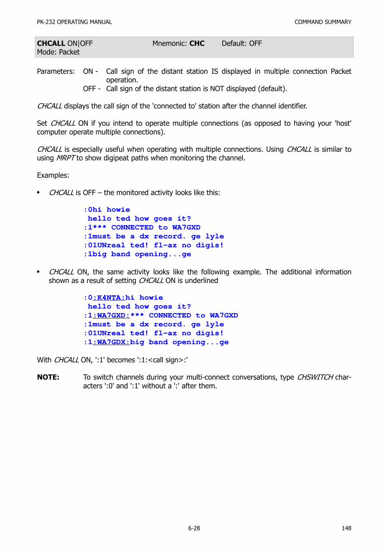
PK-232 OPERATING MANUAL COMMAND SUMMARY
6-28 148
CHCALL ON|OFF Mnemonic: CHC Default: OFFMode: Packet
Parameters: ON - Call sign of the distant station IS displayed in multiple connection Packetoperation.
OFF - Call sign of the distant station is NOT displayed (default).
CHCALL displays the call sign of the 'connected to' station after the channel identifier.
Set CHCALL ON if you intend to operate multiple connections (as opposed to having your 'host'computer operate multiple connections).
CHCALL is especially useful when operating with multiple connections. Using CHCALL is similar tousing MRPT to show digipeat paths when monitoring the channel.
Examples:
CHCALL is OFF – the monitored activity looks like this:
:0hi howie hello ted how goes it?:1*** CONNECTED to WA7GXD:1must be a dx record. ge lyle:01UNreal ted! fl-az no digis!:1big band opening...ge
CHCALL ON, the same activity looks like the following example. The additional informationshown as a result of setting CHCALL ON is underlined
:0:K4NTA:hi howie hello ted how goes it?:1:WA7GXD:*** CONNECTED to WA7GXD:1must be a dx record. ge lyle:01UNreal ted! fl-az no digis!:1:WA7GDX:big band opening...ge
With CHCALL ON, ':1' becomes ':1:<call sign>:'
NOTE: To switch channels during your multi-connect conversations, type CHSWITCH char-acters ':0' and ':1' without a ':' after them.

PK-232 OPERATING MANUAL COMMAND SUMMARY
6-29 149
CHDOUBLE ON|OFF Mnemonic: CHD Default: OFFMode: Packet
Parameters: ON - Received CHSWITCH characters appear twice (doubled).OFF - Received CHSWITCH characters appear once (not doubled).
CHDOUBLE ON displays received CHSWITCH characters as doubled characters.
In the following example CHDOUBLE is ON and CHSWITCH is set to '|' ($7C):
|| this is a test.
The sending station actually transmitted:
| this is a test.
The same frame received with CHDOUBLE OFF would be displayed as:
| this is a test.
Set CHDOUBLE ON when operating with multiple connections to tell the difference betweenCHSWITCH characters received from other stations and CHSWITCH characters generated byyour PK-232.
NOTE: CHSWITCH characters must not be one of the channel numbers (0 to 9).
CHECK n Mnemonic: CH Default: 30 (300 sec.)Mode: Packet
Parameters: n - 0 to 250 specifies the check time in ten-second intervals.0 (Zero) disables this feature.
CHECK sets a time-out value for a packet connection and depends on the setting of AX25L2V2.
Without the CHECK feature, if your PK-232 were linked or 'connected' to another station and theother station seemed to 'disappear', your PK-232 would remain connected indefinitely, refusingconnections from other stations.
This might happen if propagation changes unexpectedly or an intermediate digipeater station failsor is shut down while you and the distant station are connected 'via' that digipeater.
Your PK-232 tries to prevent this sort of 'lockup' from occurring by sending a new connect requestpacket when the specified time elapses without any packets being heard from the other TNC.
If a pre-Version 2 link is inactive for (CHECK times 10 seconds), your PK-232 tries to save the linkby starting a reconnect sequence. The PK-232 enters the 'connect in progress' state and sendsSABM (Connect Request) frames. In addition, the PK-232 adds a random time of up to 30 secondseach time CHECK is used.
If AX25L2V2 is ON and packets have not been heard from the distant end for n times 10 sec-onds, your PK-232 sends a 'check packet' to test if the link still exists to the other station.

PK-232 OPERATING MANUAL COMMAND SUMMARY
6-30 150
The 'check' packet frame contains no information, but is interpreted by the distant station's TNC tosee if it is still connected. If the distant station's TNC is still connected, the distant station sends anappropriate response packet.
If your PK-232 initiates the 'check' and does not get an answer after RETRY+1 attempts, your PK-232 starts a reconnect sequence just as if you had typed the CONNECT command.
If AX25L2V2 is OFF and the other station has nit been heard for n times 10 seconds, your PK-232 does not test the link to the distant station; your PK-232 sends a reconnect packet just asif you had typed the CONNECT command if REKINK is ON. If RELINK is OFF, the PK-232 willimmiately go to the 'disconnected' state.
CHSWITCH n Mnemonic: CHS Default: $00Mode: Packet
Parameters: n - 0 to $FF (0 to 255 decimal) specifies an ASCII character code.
CHSWITCH selects the character used by both the PK-232 and the user to show that a new con-nection channel is being addressed.
The character can be PASSed in Converse Mode. The character is always ignored as a user-initiat-ed channel switch in Transparent Mode; it just flows through as data.
The outgoing channel cannot be changed while active or 'on-line' in Transparent Mode.To switch channels, ESCAPE to Command Mode, then enter Converse Mode to use theCHSWITCH command.
NOTE: If your PK-232 is being used as the TNC for a PBBS (Packet Bulletin Board System),change the CHSWITCH character to $00 to avoid possible conflict or problems withthe characters frequently found in Packet network maps.
See CHDOUBLE and CHCALL for further information on the use of CHSWITCH.
CMDTIME n Mnemonic: CM Default: 1Mode: Packet
Parameters: n - 0 to 250 specifies timeout value in one-second intervals while in TRANSPA-RENT Mode
If n is 0 (zero), exit from Transparent Mode requires sending the BREAK signal or interruption ofpower to the PK-232.
CMDTIME sets the time-out value in Transparent Mode. A guard time of n seconds allows escapeto Command Mode from Transparent Mode, while permitting any character to be sent as data.
The same Command Mode entry character COMMAND (default <CTRL-C>) is used to exit from theConverse Mode is used to exit Transparent Mode, although the procedure is different.

PK-232 OPERATING MANUAL COMMAND SUMMARY
6-31 151
The Command Mode entry characters is set by COMMAND.Three Command Mode entry characters must be entered less than n seconds apart, with no in-tervening characters, after a delay of n seconds following the last characters typed.After a final delay of n seconds, the PK-232 exits Transparent Mode and enters CommandMode.You will then see the normal Command Mode prompt: cmd:
The following diagram illustrates this timing:
CMSG ON|OFF Mnemonic: CMS Default: OFFMode: Packet/AMTOR
Parameters: ON - The recorded CTEXT message is sent as the first packet after a connection isestablished by a connect request from a distant station or in response to a'WRU?' command in AMTOR.
OFF - The text message is not sent at all
CMSG enables or disables automatic transmission of the CTEXT message when your PK-232 ac-cepts a connect request from another station, or when a distant AMTOR station transmits a 'WRU?'character (FIGS D).
Set CMSG ON to tell callers that you're not available to answer calls manually when they con-nect to your PK-232.Set CMSG OFF when available to operate or answer calls manually.
COMMAND n Mnemonic: COM Default: 03 <CTRL-C>Mode: All
Parameters: n - 0 to $7F (0 to 127 decimal) specifies an ASCII character code.
COMMAND is used to change the Command Mode entry character. You can enter the code eitherhex or decimal.
Type the COMMAND character to enter Command Mode from the Converse Mode. No response isseen if you type the Command Mode entry character while you are already in Command Mode.
Enter Converse Mode by typing: CONVERSE
Now, all characters typed on the keyboard and characters send from a disk or tape file are trans-mitted as Packet data.

PK-232 OPERATING MANUAL COMMAND SUMMARY
6-32 152
Type <CTRL-C>. The Command Mode prompt appears, indicating successful exit to CommandMode. The display might look like this:
cmd:CONVERSE
Hello World! I'm on the air on Packet-Radio! [type <CTRL-C>]
cmd:
See CMDTIME or the discussion of Transparent Mode for instructions on the Command Mode entrycharacter to escape from Transparent Mode.
CONMODE CONVERSE|TRANS Mnemonic: CONM Default: CONVERSMode: Packet
Parameters: CONVERSE - Your PK-232 enters Converse Mode when a connection in established.TRANS - Your PK-232 enters Transparent Mode when a connection is estab-
lished.
CONMODE selects the mode your PK-232 uses after entering the CONNECTED state.
The connection may result either from a connect request received from a distant station, or a con-nection initiated by a CONNECT command that you've typed.
Set CONMODE to CONVERS for most Packet operations.Set CONMODE to TRANS if you are using Transparent Mode for a bulletin board program, sothat the correct mode will be entered when your bulletin board receives a connect request.If the PK-232 is already in Converse or Transparent Mode when the connection is completed,the mode will not be changed.
CONNECT call1 (VIA call2(,call3 .... call9) Mnemonic: C Immediate CommandMode: Packet
Parameters: call1 - Call sign of the distant station to which you wish to be connected.call2 - Optional call sign(s) of up to eight digipeaters via which you'll be repeated to
reach the distant station.
CONNECT sends a connect request to station 'call1', directly or via one or more digipeaters. Eachcall sign can include an optional SSID -n immediately after the call sign.
The part of the command line shown in brackets below is optional. The double-bracketed text',call3...,call9' is also optional and is used only when 'VIA call2' is used, that is, when connectingthrough one or more digipeaters. (The breaks and quotation marks are used in this text only forclarity – please don't type them!)
VIA call2[, call3 .... ,call9]
Type the digipeater fields in the exact sequence you wish to use to route your packets to desti-nation station 'call1'.
If you type CONNECT while your PK-232 is connected, or trying to connect to or disconnect from adistant station, your monitor displays:
Link state is: CONNECT in progress

PK-232 OPERATING MANUAL COMMAND SUMMARY
6-33 153
If the distant station doesn't 'ack' your connect request after the number of tries specified by RE-TRY, the CONNECT command is canceled. Your monitor displays:
cmd:*** Retry count exceededDISCONNECTED: (call sign)
To connect directly to WX1AAA, you would type:
CONNECT WX1AAA (or C WX1AAA)
To connect to WX1AAA using WX2BBB (with whom you can easily connect) and WX3CCC (who isnear AAA) as digipeaters, you would type:
CONNECT WX1AAA VIA WX2BBB,WX3CCC
Type CONNECT or C without arguments to see the link status and the number of unacknowledged,outstanding packets.
CONOK ON|OFF Mnemonic: CONO Default: ONMode: Packet
Parameters: ON - Connect requests from other stations will be accepted if CFROM is set toALL.
OFF - Connect requests from other stations will not be accepted if CFROM is set toALL or NONE.
CONOK is included only to maintain upward compatibility with the TAPR TNCs and some BBS soft-ware that depends on this command being there. The command CFROM is much more versatileand should be used instead of CONOK.
Make sure that CFROM is set to ALL if your software needs CONOK.
CONPERM ON|OFF Mnemonic: CONP Default: OFFMode: Packet
Parameters: ON - The current connection on the current channel is not allowed to enter thedisconnected state.
OFF - The current channel can be connected and disconnected from the other sta-tions.
When ON, CONPERM forces the PK-232 to maintain the current connection, even when frames tothe other station exceed RETRY attempts for an acknowledgment. RESTART and power off/on cy-cling do not affect this connected state.
CONPERM works only when a connection is established. It functions on a channel-by-channel basiswhen multiple connections are allowed.
CONPERM allows connections on other channels to operate normally. For example, automatic dis-connect based on RETRY, when used under conditions such as:

PK-232 OPERATING MANUAL COMMAND SUMMARY
6-34 154
Certain networking applicationsMeteor scatterOther noisy, less reliable links
CONPERM ON may be advantageous when using full-duplex continuous mail forwarding or trafficlinks.
CONSTAMP ON|OFF Mnemonic: CONS Default: OFFMode: Packet
Parameters: ON - Connect status messages are time stamped.OFF - Connect status messages are not time stamped.
CONSTAMP activates time stamping of *** CONNECTED status messages.
If CONSTAMP is ON and DAYTIME (the PK-232's internal clock) is set, date and time informationgenerated in the PK-232 is available for bulletin board board programs or other host computer ap-plications.
Date and time must be set initially by the DAYTIME command before time stamping will occur. Forexample, if CONSTAMP is ON and the date and time have been set in the PK-232, a connect anddisconnect sequence appears as follows:
cmd:connect w2jup
cmd:10:55:23 *** CONNECTED to W2JUPcmd:disconnect
cmd:10:55:59 *** DISCONNECTED: W2JUP
The CONNECT and DISCONNECT command can be abbreviated as shown below. The results areidentical.
cmd:c w2jup
cmd:10:55:23 *** CONNECTED to W2JUPcmd:d
cmd:10:55:59 *** DISCONNECTED: W2JUP
CONVERSE Mnemonic: CONV or K Immediate CommandMode: All
CONVERSE is an immediate command that causes the PK-232 to switch from the Command Modeinto the Converse Mode.
Link connections in Packet or AMTOR modes are not affected.
In Packet mode and AMTOR, once the PK-232 is in Converse Mode, all characters typed from thekeyboard or send from a disk file are processed and transmitted by your radio.
To return the PK-232 to the Command Mode from the Converse Mode, type the CommandMode entry character (default is <CTRL-C>).

PK-232 OPERATING MANUAL COMMAND SUMMARY
6-35 155
CPACTIME ON|OFF Mnemonic: CP Default: OFFMode: Packet
Parameters: ON - Packet transmit timer IS used in Converse Mode.OFF - Packet transmit timer is NOT used in Converse Mode.
CPACTIME activates automatic, periodic transmission of packets while in the Converse Mode.
CPACTIME may be used for several types of computer communications such as bulletin board orhost computer operation when full Transparent Mode features are not desired.
When CPACTIME is ON, characters are packetized and transmitted periodically as they are inTransparent Mode. Local keyboard editing and display features of the Converse Mode are available;software flow control can be used.
See the PACTIME command (which controls the rate and mode of packet assembly) for a dis-cussion of how periodic packetizing works.Set ACRPACK OFF in this mode. When ACRPACK is ON, the send-packet character is inserted inthe data being packetized even though it was not typed.To include <CR> characters in transmitted packets, set SENDPAC to a character not normallyused (e.g., <CTRL-P>); the PK-232 then treats a <CR> as an ordinary character.Set CPACTIME ON for a mode of operation similar to full break-in CW.
Setting CPACTIME ON transmits your text soon after you type it, in short bursts of a few charac-ters. The other station may break in at will. Some operators find it easier to chat in this mode;long delays are eliminated while long packets are being typed.
CRADD ON|OFF Mnemonic: CRA Default: OFFMode: Baudot RTTY
Parameters: ON - Send <CR><CR><LF> in Baudot RTTY.OFF - Send <CR><LF> in Baudot RTTY (default).
The CRADD command permits you to set the PK-232's 'newline' sequence so that an additional car-riage return is automatically ADDed at the end of each typed line.
When CRADD is ON the line-end sequence is <CR><CR><LF>.
When CRADD is OFF the line-end sequence is <CR><LF>.
The double carriage return is required in some RTTY services such as MARS operation.
CRADD has no effect on received data.

PK-232 OPERATING MANUAL COMMAND SUMMARY
6-36 156
CSTATUS Mnemonic: CS Immediate CommandMode: Packet
CSTATUS is an immediate command used in multiple connections. When CSTATUS is typed, yourmonitor displays:
The number of each logical channel.The link state of all ten logical channels.The current input/output channel – the one you're using.Whether each channel connection is 'permanent'. (See CONPERM)
Depending on your use of multiple connections and the USERS command, CSTATUS will show youthe following displays:
NOT CONNECTED TO ANY STATION CONNECTED TO ONLY 1 STATIONS
cmd:cs cmd:cs
Ch. 0 - IO DISCONNECTED Ch. 0 - IO CONNECTED to WX1AAACh. 1 - DISCONNECTED Ch. 1 - DISCONNECTEDCh. 2 - DISCONNECTED Ch. 2 - DISCONNECTEDCh. 3 - DISCONNECTED Ch. 3 - DISCONNECTEDCh. 4 - DISCONNECTED Ch. 4 - DISCONNECTEDCh. 5 - DISCONNECTED Ch. 5 - DISCONNECTEDCh. 6 - DISCONNECTED Ch. 6 - DISCONNECTEDCh. 7 - DISCONNECTED Ch. 7 - DISCONNECTEDCh. 8 - DISCONNECTED Ch. 8 - DISCONNECTEDCh. 9 - DISCONNECTED Ch. 9 - DISCONNECTED
If you're connected to several stations, the CSTATUS command shows your connect status as fol-lows:
CONNECTED TO SEVERAL STATIONS
cmd:cs
Ch. 0 - IO CONNECTED to WX1AAACh. 1 - CONNECTED to WX2BBB PCh. 2 - CONNECTED to WX3CCCCh. 3 - CONNECTED to WX4DDDCh. 4 - CONNECT in progressCh. 5 - DISCONNECTEDCh. 6 - DISCONNECTEDCh. 7 - CONNECTED to WX5EEE via WX6FFFCh. 8 - DISCONNECTEDCh. 9 - DISCONNECTED
This sample display shows that:
CHANNEL 0 has the input and output channels – you're using it!CHANNEL 1 is connected to WX2BBB 'permanently'.All other channels' states are shown as they might appear with multiple connections.

PK-232 OPERATING MANUAL COMMAND SUMMARY
6-37 157
CTEXT text Mnemonic: CT Default: See sampleMode: Packet
Parameters: text - Any combination of characters up to a maximum of 120 characters.
CTEXT is the 'automatic answer' text you type into a special section of the PK-232's memory.
The default text says 'Please leave a message, then disconnect.'
If CMSG is set ON:
The CTEXT message is sent as soon as another station connects to your station.
To type multiple-line CTEXT messages and include a carriage return (<CR>) character in your text,use the PASS character (<CTRL-V> is the default value) immediately preceding the carriage return(see the PASS command).
A typical CTEXT message might be:
"I'm not available right now.<CTRL-V><CR>Please leave a message, then disconnect.<CR>"
If you enter a text string longer than 120 characters, an error message appears and the com-mand is ignored.
?too longcmd:
Use a percent sign (%), an ampersand (&), N, NO, NONE or OFF as the first sign in the CTEXTmessage to clear the previous message without having to type a RESET command.
CWID n Mnemonic: CW Default: $06 <CTRL-F>Mode: Baudot/ASCII RTTY/AMTOR
The CWID command lets you change the 'send CWID' control character typed at the end of yourBaudot and ASCII RTTY keyboard dialogue or text file stored on disk.
When the PK-232 reads this specific character embedded at the end of the text or keyboard input,it switches to the Morse Mode and sends your call sign, in Morse code, at the keying speed set bythe MSPEED command.
As soon as your call sign has been sent in Morse, the PK-232 turns off your transmitter and returnsto Baudot or ASCII RTTY receive in the Command Mode.
Type CWID (or just CW) to display the current value of the CWID command:
cmd:cwid cmd:cw
CWID $06 CTRL-F CWID $06 CTRL-Fcmd: cmd:

PK-232 OPERATING MANUAL COMMAND SUMMARY
6-38 158
Type CWID followed by either the decimal or hexadecimal value of the new character you wishto use the CWID trigger command.
cmd:cwid 27
CWID was $06 CTRL-Fcmd:
Type CWID or CW again to verify the new command character:
cmd:cwid
CWID $1B CTRL-[
You can return to the original or default value at any time by typing the following:
cmd:cwid $06
CWID was $1B CTRL-[
You can also use the command CWID ON or CWID OFF to activate or deactivate the function. Ineither case, your PK-232 responds with the previous state:
cmd:cwid onCWID was $00
DAYTIME date & time Mnemonic: DA Default: noneMode: All
Parameters: date & time - Current DATE and TIME to set.
DAYTIME sets the PK-232's internal clock current date and time. The date & time parameter isused in Packet Mode by the commands CONSTAMP and MSTAMP to 'time stamp' received andmonitored messages.
Entries in the 'heard' (displayed by MHEARD) are also time stamped if date & time has been set.The PK-232's time is updated continuously, as long as it is powered up.
The clock is not set when the PK-232 is turned on. The DAYTIME command displays the followingerror message:
cmd:day
?clock not set
You must reset date and time each time you turn on the PK-232. Otherwise CONSTAMP andMSTAMP won't 'stamp' the time.
If you type DAYTIME without a parameter, the PK-232 displays current date and time information.The format of the display is:
dd-mm-yy hh:mm:ss
cmd:day
DAYTIME 08-Jul-86 06:57:33

PK-232 OPERATING MANUAL COMMAND SUMMARY
6-39 159
The format for entering the day&time is:
yymmddhhmmcmd:daytime 8607080659
where:yy is the last two digits of the yearmm is the two-digit month code (01-12)dd is date (01-31)hh is the hour (00-23)mm is the minutes after the hour (00-59)
Example: cmd:daytime 19 05 11 18 36
You can insert separators or delimiters such as <SPACE>, /, : or ;. Successful data and time entryis confirmed when the PK-232 echoes the new setting.
Enter the number 0-9 with leading zeros; codes must be exactly two digits.Be aware of the month when you set the date – the PK-232 does not check for the correctnumber of days in a month.
DAYSTAMP ON|OFF Mnemonic: DAYS Default: OFFMode: All
Parameters: ON - The DATE is included in CONSTAMP and MSTAMP.OFF - Only the TIME is included in CONSTAMP and MSTAMP.
DAYSTAMP activates the date in CONSTAMP and MSTAMP.
Set DAYSTAMP ON when you want a dated record of packet channel activity, or when you'reunavailable for local packet operation.
DCDCONN ON|OFF Mnemonic: DC Default: OFFMode: Packet/AMTOR
Parameters: ON - RS-232 cable Pin 8 follows the state of the CON LED.OFF - The RS-232 cable Pin 8 is permanently set high (active)
DCDCONN defines how the DCD (Data Carrier Detect) signal affects pin 8 in the RS-232 interfaceto your computer or terminal.
Set DCDCONN ON to emulate the DCD interface found in the TAPR TNC-2, AEA PK-80 and equiva-lent TNC/DCE systems.
Some applications programs require that the DCD signal on pin 8 follow the PK-232's connect sta-tus.
For example, WA7MBL's Version 3.12 PBBS program will not work properly with your PK-232 unlessDCDCONN is set ON.
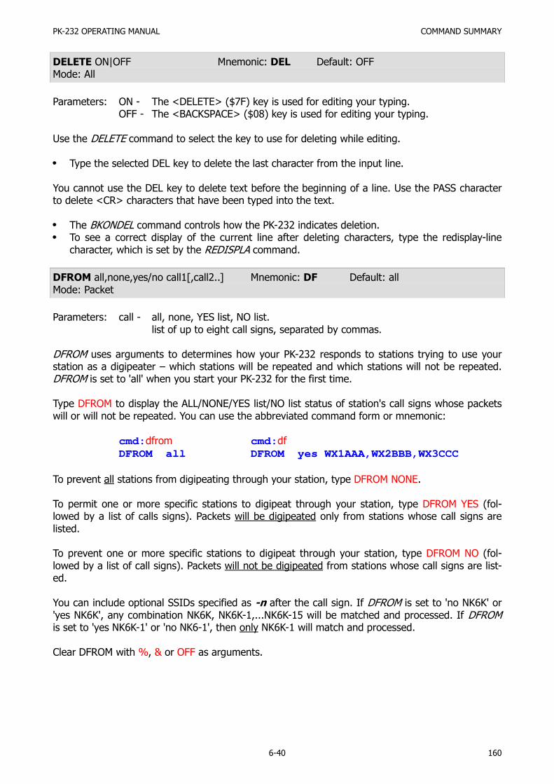
PK-232 OPERATING MANUAL COMMAND SUMMARY
6-40 160
DELETE ON|OFF Mnemonic: DEL Default: OFFMode: All
Parameters: ON - The <DELETE> ($7F) key is used for editing your typing.OFF - The <BACKSPACE> ($08) key is used for editing your typing.
Use the DELETE command to select the key to use for deleting while editing.
Type the selected DEL key to delete the last character from the input line.
You cannot use the DEL key to delete text before the beginning of a line. Use the PASS characterto delete <CR> characters that have been typed into the text.
The BKONDEL command controls how the PK-232 indicates deletion.To see a correct display of the current line after deleting characters, type the redisplay-linecharacter, which is set by the REDISPLA command.
DFROM all,none,yes/no call1[,call2..] Mnemonic: DF Default: allMode: Packet
Parameters: call - all, none, YES list, NO list.list of up to eight call signs, separated by commas.
DFROM uses arguments to determines how your PK-232 responds to stations trying to use yourstation as a digipeater – which stations will be repeated and which stations will not be repeated.DFROM is set to 'all' when you start your PK-232 for the first time.
Type DFROM to display the ALL/NONE/YES list/NO list status of station's call signs whose packetswill or will not be repeated. You can use the abbreviated command form or mnemonic:
cmd:dfrom cmd:df
DFROM all DFROM yes WX1AAA,WX2BBB,WX3CCC
To prevent all stations from digipeating through your station, type DFROM NONE.
To permit one or more specific stations to digipeat through your station, type DFROM YES (fol-lowed by a list of calls signs). Packets will be digipeated only from stations whose call signs arelisted.
To prevent one or more specific stations to digipeat through your station, type DFROM NO (fol-lowed by a list of call signs). Packets will not be digipeated from stations whose call signs are list-ed.
You can include optional SSIDs specified as -n after the call sign. If DFROM is set to 'no NK6K' or'yes NK6K', any combination NK6K, NK6K-1,...NK6K-15 will be matched and processed. If DFROMis set to 'yes NK6K-1' or 'no NK6-1', then only NK6K-1 will match and processed.
Clear DFROM with %, & or OFF as arguments.

PK-232 OPERATING MANUAL COMMAND SUMMARY
6-41 161
DIGIPEAT ON|OFF Mnemonic: DIG Default: ONMode: Packet
Parameters: ON - The PK-232 will digipeat packets from all other stations if DFROM is set toALL.
OFF - The PK-232 will NOT digipeat packets from other stations if DFROM is set toALL or NONE.
DIGIPEAT is included only to maintain upward compatibility with the TAPR TNCs and some BBSsoftware that depends on this command being there. The command DFROM is much more versa-tile and should be used instead of DIGIPEAT.
Make sure that DFROM is set to ALL if your software needs DIGIPEAT.
DISCONNE Mnemonic: D Immediate CommandMode: Packet
DISCONNE is an immediate command that initiates a disconnect request to the distant station towhich you are connected.
If your disconnect command is successful, your monitor will display:
*** DISCONNECTED: {call sign}
Other commands can be entered while a disconnect is in progress. New connections are not al-lowed until the disconnect is completed.
If the retry count is exceeded while waiting for the distant station to acknowledge your discon-nect command, your PK-232 switches to the disconnected state.If another disconnect command is entered while your PK-232 is trying to disconnect, the retrycount is immediately set to the maximum number. In either case, your monitor displays:
*** Retry count exceeded*** DISCONNECTED: {call sign}
Disconnect messages are not displayed when your PK-232 is in the Transparent Mode.
DISPLAY [class] Mnemonic: DISP Immediate CommandMode: Command
Parameters: class - Optional parameter identifier, one of the following:
(A)sync display asynchronous port parameters(C)haracter display special characters(F)ax display Facsimile parameters(I)d display ID parameters(L)ink display link parameters(M)onitor display monitor parameters(R)TTY display Baudot/ASCII RTTY, AMTOR and Morse parameters(T)iming display timing parameters(Z) display the entire command/parameter list
DISPLAY is an immediate command.

PK-232 OPERATING MANUAL COMMAND SUMMARY
6-42 162
When DISPLAY is typed without a parameter, the PK-232 responds with:
DISPLAY A,C,F,I,L,M,R,T,Zcmd:
You can display subgroups of related system parameters by specifying the optional class parame-ter:
cmd:disp a
8BITCONV OFFACRDISP 80ALFDISP OFFAWLEN 7ECHO ONESCAPE OFFFLOW ONLCOK ONNUCR OFFNULF OFFNULLS 0PARITY 3TRFLOW OFFTXFLOW OFFXFLOW ONcmd:
Individual system parameter values can be displayed by entering the parameter name without op-tions.
cmd:mycall cmd:fr cmd:dw cmd:mys
MYCALL DC7XJ FRACK 3 DWAIT 16 MYSELCAL DCXJ
DWAIT n Mnemonic: DW Default: 16Mode: Packet
Parameters: n - 0 to 250 specifies wait time in ten-millisecond intervals.
DWAIT helps to avoid collisions with digipeated packets.
Unless the PK-232 is waiting to transmit digipeated packets, DWAIT forces your PK-232 to pauseafter last hearing data on the channel, for the duration of the DWAIT (Default wait) time, before itbegins its transmitter keyup sequence.
Where ever possible, the value of DWAIT should be agreed on by all stations in a local area whendigipeaters are used in the area. The best value will be determined by experimenting.
DWAIT is a function of the keyup time (TXDELAY) of the digipeater stations and help alleviate thedrastic reduction of throughput that occurs on a channel when digipeating packets suffer collision.
DWAIT is necessary because digipeated packets are not retried by the digipeater, but are alwaysrestarted by the originating station. When all stations specify a Default Wait time and the right val-ue of n is chosen, the digipeater captures the frequency every time it has data to send – digipeat-ed packets are sent without this delay.

PK-232 OPERATING MANUAL COMMAND SUMMARY
6-43 163
Recommended settings of DWAIT for different types of Packet station operation are:
TYPE OF OPERATION TIME (in ms) DWAIT VALUE
DigipeatersLocal keyboardsPBBSe, HostsFile transfers
0160320480
016 (default)
3248
EAS ON|OFF Mnemonic: EAS Default: OFFMode: Baudot/ASCII RTTY, AMTOR and Morse
Parameters: ON - Display characters as actually sent on the air by the PK-232.OFF - Display characters as sent to the PK-232 by the computer.
The ECHO-AS-SENT (EAS) command functions in all modes except Packet. EAS permits you tochoose the type of data displayed on your monitor screen or printer.
To display your typing exactly as you are typing the keyboard characters or sending from a diskfile, set EAS OFF.To see the actual data being sent from your PK-232 to your radio and transmitted on the air,set EAS ON.
EAS is convenient when operating Morse and Baudot RTTY – these modes don't use lower casecharacters. You can operate in a relaxed and normal manner, typing entirely in lower case if that'seasier for you. Your PK-232 translates your lower case typing into upper case Morse or Bau-dot/CCITT characters.
When EAS is ON, you'll see only UPPER CASE characters on your screen, representing the data ac-tually transmitted to the distant station.
EAS has special significance in AMTOR Mode A (ARQ). If EAS is ON – no matter how fast you typecharacters on your keyboard – you'll see them echoed on your screen only after the distant station(your partner in the AMTOR link) has validates (ack'd) your block of three characters.
With EAS ON, the characters will appear on your screen or printer only as the distant station ac-knowledges them, three at a time.
If the data scrolls across your monitor at a nice even rate, in rhythm with your typing speed,you can assume that you have a good ARQ link.If the data hesitates or scrolls in 'jerky' intermittent fashion, that's generally a sign that the ra-dio link is not too good.If the characters stop appearing on your monitor, the link is failing or has failed.

PK-232 OPERATING MANUAL COMMAND SUMMARY
6-44 164
ECHO ON|OFF Mnemonic: E Default: ONMode: All
Parameters: ON - Characters received from the terminal ARE echoed by the PK-232.OFF - Characters are NOT echoed.
The ECHO command controls local echoing by the PK-232 when it is in Command or ConverseMode. Local echoing is disabled in Transparent Mode.
Set ECHO ON if you don't see your typing appear on your display.Set ECHO OFF if you see each character you type doubled.
ECHO is set correctly when you see the characters you type displayed correctly.
ESCAPE ON|OFF Mnemonic: ES Default: OFFMode: All
Parameters: ON - The <ESCAPE> character ($1B) is output as '$' ($24).OFF - The <ESCAPE> character is output as <ESCAPE> ($1B) (default).
The ESCAPE command selects the character to be output when an <ESCAPE> character is to besent to the terminal. The <ESCAPE> translation is disabled in Transparent Mode.
The ESCAPE character selection is provided because some computers and terminals interpret the<ESCAPE> character as a special command prefix. Such terminals may alter their displays depend-ing on the characters following the <ESCAPE>.
Set ESCAPE ON if you have such terminal to avoid unexpected text strings from other packe-teers.See the MFILTER command for information on character stripping (rather than character trans-lation) in monitored packets.
FEC Mnemonic: FE Immediate CommandMode: AMTOR Mode B
FEC is an immediate command that starts an AMTOR FEC (Mode B) transmission.
Use FEC for CQ calls. Distant stations cannot identify you in an ARQ CQ call.Include your SELCAL code in your CQ message so that the distant station can call you back inARQ with your SELCAL. If you want replies only on FEC (for example for contacts via a longpath), include that information in your CQ call (see sample below).Use FEC if the desired range is longer than 22,000 miles, such as in 'long path' contacts orhigh-orbit satellite contacts.Use FEC for all round table contacts.Don't start typing right away! Let your PK-232 begin each transmission with three to five sec-onds of idling. Under poor conditions, this may help the distant station to tune your signal.Avoid the RTTY practice of transmitting a line of RYRYRY to allow the distant station to tune in– this is wrong on FEC. Distant stations cannot synchronize until the end of the RYRYRY se-quence. The normal FEC idle-signal can be used for tuning.To aid formatting the distant station's screen and printer copy, always start FEC transmissionwith a new line sequence by sending a <CR>.You can signify the end of your FEC transmission by typing the ARQ changeover sign +?, inter-nationally recognized as the RTTY equivalent of KKK. However, in FEC, +? is not a software

PK-232 OPERATING MANUAL COMMAND SUMMARY
6-45 165
command. You still have to un-key your transmitter manually as you would in conventionalRTTY.
You can terminate your FEC transmission several ways:
Type the RCVE (R) command;Type the AMTOR (AM) command;Insert the RECEIVE command (default <CTRL-D>) character in your typing or disk file.
FLOW ON|OFF Mnemonic: F Default: ONMode: All
Parameters: ON - Type-in flow control IS active.OFF - Type-in flow control is NOT active.
When FLOW is ON, type-in flow control is active. Any character typed on your keyboard causesoutput from the PK-232 to the terminal to stop until any of the following conditions exist:
A packet is forced (in Converse Mode)A line is completed (in Command Mode)The packet length (See PACLEN) is exceededThe terminal output buffer fills up
Canceling the current command or packet or typing the redisplay-line character also causes outputto resume. Type-in flow control is not used in Transparent Mode.
Setting FLOW ON prevents inbound or received data from interfering with your keyboard data en-try. If you (and the person you're talking to) normally wait for a packet from the other end beforestarting to respond, you can set FLOW OFF.
Some Packet bulletin board programs (PBBS) may work best with FLOW set to OFF.Some computers with 'software UARTs' may be unable to send and receive data at thesame time. If you're using that type of computer, set FLOW to ON.
NOTE: When FLOW is ON, text will no longer be released to the terminal if the channel ischanged when multi-connected.
FRACK n Mnemonic: FR Default: 3Mode: Packet
Parameters: n - 1 to 15, specifying FRame ACKnowledgment time-out in 1 second intervals.
FRACK is the FRame ACKnowledgment time in seconds that your PK-232 will wait for acknowledg-ment of the last-sent protocol frame before resending or 'retrying' that frame.
After sending a packet requiring acknowledgment, the PK-232 waits for FRACK seconds before in-crementing the retry counter and sending another frame. If the packet address includes digipeatinstructions, the time between retries is adjusted to:
Retry interval (in seconds) = n × (2 × m + 1)(where m is the number of intermediate relay stations.)
When a packet is retried, a random wait time is added to any other wait times in use. This avoidslockups which two Packet stations repeatedly collide with each other.

PK-232 OPERATING MANUAL COMMAND SUMMARY
6-46 166
FULLDUP ON|OFF Mnemonic: FU Default: OFFMode: Packet
Parameters: ON - Full duplex mode is ENABLED.OFF - Full duplex mode is DISABLED.
When full-duplex mode is disabled, the PK-232 makes use of the DCD (Data Carrier Detect) signalfrom its modem to avoid collisions; the PK-232 acknowledges multiple packets in a single transmis-sion with a single acknowledgment.
When full-duplex mode is enabled, the PK-232 ignores the DCD signal and acknowledges packetsindividually.
Full-duplex operation is useful for full-duplex radio operation, such as through OSCAR 10. It shouldnot be used unless both your station and the distant station can operate in full-duplex.
You may also find full-duplex mode useful for some testing operations, such as analog- or digital-loopback tests.
HBAUD n Mnemonic: HB Default: 1200 baudsMode: Packet
Parameters: n - values specifying the rate or signaling speed in bauds from the PK-232 tothe radio.
Available HDLC packet data rates n include 45, 50, 57, 75, 100, 110, 150, 200, 300, 600, 1200,2400, 4800 and 9600 bits per second.
Example: HBAUD 300
HBAUD sets the radio ('on-air') baud rate only in the Packet operating mode. HBAUD has no rela-tionship to your computer terminal program's baud rate.
You must use the same radio data rate as the distant station.
NOTE: Modern commercial and amateur terminology no longer refers to the speeds or datarates in 'WPM'. The term 'bauds' is now universally accepted for FSK and AFSKoperating using monobit data. In these cases, the terms 'bauds' and 'bits persecond' mean the same thing. Either term may be used.
HEADERLN ON|OFF Mnemonic: HE Default: ONMode: Packet
Parameters: ON - The header in a monitored packet is printed on a separate line from the text.OFF - The header and text of monitored packets are printed on the same line.
HEADERLN affects the display of monitored packets. When HEADERLN is OFF, the address informa-tion is shown on the same line as the packet text:
WX1AAA>WX2BBB: Go ahead and transfer the file.

PK-232 OPERATING MANUAL COMMAND SUMMARY
6-47 167
When HEADERLN is ON (default), the address is shown, followed by a <CR><LF> that puts thepacket text on a separate line:
WX1AAA>WX2BBB:Go ahead and transfer the file.
If MRPT or MSTAMP are ON, set HEADERLN ON; long headers may extend across your screen orpage when these functions are active.
HELP Mnemonic: H Immediate CommandMode: Command
While in Command Mode, type the command H to read the abbreviated on-line HELP file.
Your monitor displays the following brief list:
cmd:help
AMTOR PACKET ASCII ARQ CONNECT BAUDOT
ALIST DISCONNE MOrse FEC MHEARD DISPLAY
ACHG CSTATUS CALIBRATCONVERSE TRANSXMIT RCVERESTART RESETTCLEARcmd:
You can exit from your present operating mode and enter Command Mode at any time to list theHELP text. This won't affect AMTOR or Packet operation.
HID ON|OFF Mnemonic: HI Default: OFFMode: Packet
Parameters: ON - Your PK-232 sends HDLC identification as a digipeater.OFF - Your PK-232 does not send HDLC identification.
The HID command activates or disables your PK-232's automatic periodic transmission of identifi-cation packets when operating as a digipeater. This identification consists of an unsequenced I-frame with your station identification (MYCALL) and MYALIAS in the data field.
Set HID ON to force your PK-232 to send an ID packet every 9.5 minutes when it's being usedas a digipeater.Set HID OFF to stop your PK-232 from sending any ID packets.The HID identification packet is addressed to ID.Your station identification is the call sign you've set with the MYCALL command, with 'digipeat-er' appended.
NOTE: You cannot change the 9.5-minute automatic interval timing.

PK-232 OPERATING MANUAL COMMAND SUMMARY
6-48 168
HOST ON|OFF Mnemonic: HOST Default: OFFMode: Packet
Parameters: ON - The PK-232 operates with a host computer or other special applicationprogram.
OFF - The PK-232 operates as a normal TNC.
The HOST command permits the PK-232 to operate in the Host Mode, a 'computer-friendly' com-munication mode, over the RS-232 link between the PK-232 and a host computer.
In the Host Mode, the PK-232 sends data to the computer only when the computer requests data.The data are prefaced with a special header that identifies the type of information being sent.
To cancel HOST mode, send 3-<CTRL-C> characters as for exiting the Transparent mode or type<CTRL-A>O H O N>CTRL-W>.
With the 25. JUN. 87 Firmware release, sending a Break signal will no longer exit the PK-232 fromHOST Mode.
See AEA's PK-232 Technical Manual for full information on Host Mode.
ID Mnemonic: I Immediate CommandMode: Packet
ID is an immediate command that sends a special identification packet. The ID command allowsyou to send a final identification packet when you're taking your station off the air. Note that HIDmust be set ON.
ID forces a final identification packet to be sent when a digipeater station is being taken off the air.The identification consists of a unnumbered I-frame, with its data field containing your MYALIAS(if any) and your MYCALL station identification and the word 'digipeater'.
The ID packet is sent only if the digipeater has transmitted since the last automatic identifica-tion.The ID identification packet is addressed to 'ID'.Your station identification is the call sign you've set with the MYCALL command, with yourMYALIAS, your main call sign and the word 'digipeater' appended. The following example isshown as seen with and without a MYALIS, with MONITOR set to 6:
W2JUP-9*>ID <UI> W2JUP-9*>ID <UI>W2JUP digipeater BHTC, W2JUP digipeater
ILFPACK ON|OFF Mnemonic: IL Default: ONMode: Packet
Parameters: ON - The PK-232 ignores all line-feed characters received from the computer orterminal.
OFF - The PK-232 transmits all line-feed characters received from the computer orterminal.
The ILFPACK command permits you to control the way the PK-232 handles line-feed characters re-ceived from your computer. This feature is especially useful when sending certain types of comput-er programs in text form.
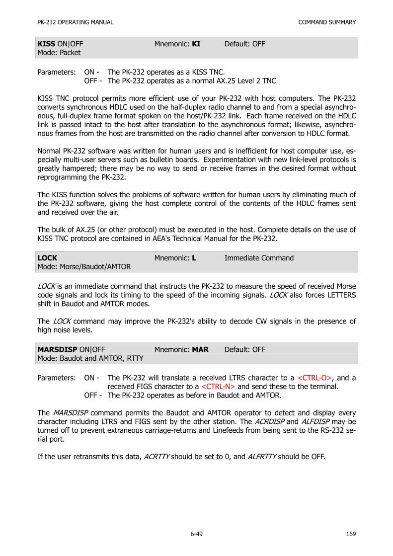
PK-232 OPERATING MANUAL COMMAND SUMMARY
6-49 169
KISS ON|OFF Mnemonic: KI Default: OFFMode: Packet
Parameters: ON - The PK-232 operates as a KISS TNC.OFF - The PK-232 operates as a normal AX.25 Level 2 TNC
KISS TNC protocol permits more efficient use of your PK-232 with host computers. The PK-232converts synchronous HDLC used on the half-duplex radio channel to and from a special asynchro-nous, full-duplex frame format spoken on the host/PK-232 link. Each frame received on the HDLClink is passed intact to the host after translation to the asynchronous format; likewise, asynchro-nous frames from the host are transmitted on the radio channel after conversion to HDLC format.
Normal PK-232 software was written for human users and is inefficient for host computer use, es-pecially multi-user servers such as bulletin boards. Experimentation with new link-level protocols isgreatly hampered; there may be no way to send or receive frames in the desired format withoutreprogramming the PK-232.
The KISS function solves the problems of software written for human users by eliminating much ofthe PK-232 software, giving the host complete control of the contents of the HDLC frames sentand received over the air.
The bulk of AX.25 (or other protocol) must be executed in the host. Complete details on the use ofKISS TNC protocol are contained in AEA's Technical Manual for the PK-232.
LOCK Mnemonic: L Immediate CommandMode: Morse/Baudot/AMTOR
LOCK is an immediate command that instructs the PK-232 to measure the speed of received Morsecode signals and lock its timing to the speed of the incoming signals. LOCK also forces LETTERSshift in Baudot and AMTOR modes.
The LOCK command may improve the PK-232's ability to decode CW signals in the presence ofhigh noise levels.
MARSDISP ON|OFF Mnemonic: MAR Default: OFFMode: Baudot and AMTOR, RTTY
Parameters: ON - The PK-232 will translate a received LTRS character to a <CTRL-O>, and areceived FIGS character to a <CTRL-N> and send these to the terminal.
OFF - The PK-232 operates as before in Baudot and AMTOR.
The MARSDISP command permits the Baudot and AMTOR operator to detect and display everycharacter including LTRS and FIGS sent by the other station. The ACRDISP and ALFDISP may beturned off to prevent extraneous carriage-returns and Linefeeds from being sent to the RS-232 se-rial port.
If the user retransmits this data, ACRTTY should be set to 0, and ALFRTTY should be OFF.

PK-232 OPERATING MANUAL COMMAND SUMMARY
6-50 170
MAXFRAME n Mnemonic: MAX Default: 4Mode: Packet
Parameters: n - 1 to 7 signifies a number of packet frames.
MAXFRAME sets an upper limit on the unacknowledged packets your PK-232 permits on the radiolink at any one time. MAXFRAME also sets maximum number of contiguous packets your PK-232will send during any given transmission.
If some, but not all, of the outstanding packets are acknowledged, a smaller number may betransmitted the next time, or new frames may be included in the retransmission, so that the totalnumber of unacknowledged packet frames does not exceed n.
The 'best' value of MAXFRAME depends on your local channel conditions. In most cases of key-board-to-keyboard direct or local operation (links that don't require going through digipeaters),you can use the default value MAXFRAME 4.
When the amount of traffic, the path in use, the digipeaters involved – or other variables not un-der your control – make Packet operation difficult (as shown by lots of retries!), you can actuallyimprove your throughput by reducing MAXFRAME.
If Packet traffic is heavy or the path is poor, reduce MAXFRAME to 3 or 2.If you're sharing the channel with several PBBSs and digipeaters or when working a PBBSs orother types of host computers, reduce MAXFRAME to 1.If the radio link is good, an optimal relationship exists between the parameter set by thesecommands, so that the maximum number of characters outstanding doesn't exceed the receivebuffer space of the TNC receiving the data.Use MAXFRAME 1 for best results on HF Packet.
MBELL ON|OFF Mnemonic: MBE Default: OFFMode: Packet
Parameters: ON- Will send 3 BELL characters to the terminal when the callsign(s) of the station(s) monitored match the MFROM and MTO lists.
OFF- As is, that is the PK-232 will not send any BELL characters to the terminaldue to MONITORED packets.
MBELL can be used to alert the user to the presence of particular station(s) on the packet frequen-cy. For example if you want to be alerted when N7ML comes on frequency you would set the fol-lowing:
MBELL ONMONITOR 4MFROM yes N7MLMTO NONE
Now that MBELL is ON, any packet that matches MFROM or MTO will cause the BELL character tobe output to the terminal. Since MTO is NONE, and MFROM is set to YES N7ML, only the presenceof N7ML on frequency will cause the BELL character to be sent.
When MBELL is ON, packets from and to all stations are displayed, but only those packets match-ing the MFROM and MTO lists cause the bell to ring.

PK-232 OPERATING MANUAL COMMAND SUMMARY
6-51 171
As another example, if you wish to detect the presence of packets addressed to CQ or BEACON,simply enter the following commands:
MBELL ONMONITOR 4MFROM NONEMTO yes CQ,BEACON
Now, only packets addressed to CQ and BEACON will cause the BELL character to be output to theterminal. To return to normal operation simply turn MBELL OFF, and return the MFROM, MTO andMONITOR commands to your preferred settings.
MBX call1[,call2][-n] Mnemonic: MB Default: emptyMode: Packet
Parameters: call - The call signs of one or two stations to be monitored.-n - 0 to 15, indicating an optional SSID.
The MBX command permits you to read or record useful or needed data without having to connector log on to the source station(s). Channel occupancy and bandwidth are conserved on busy chan-nels.
MBX filters the received packet data so that only packets from the selected station(s) are shown,without headers, codes or repeated frames. MBX overrides normal monitor functions and can showone or both sides of a conversation. You can enter a single call sign, or two call signs, separatedby a comma:
cmd:MBX W1AW-4
orcmd:MBX W2JUP-4,W2HPM-4
(NOTE: These stations must be connected to each other for this feature towork. Use two call signs if you suspect that your target station maybe in multiple connection.)
Use the MBX feature to:
Read or record transmissions from any Packet station, without any extraneous material;Read or record transmissions from a PBBS (Packet Bulletin Board System) while another stationis downloading files or messages;Read or record dialog between two connected Packet stations or two PBBSs during mail for-warding operations.
The resulting information is free of all headers, frame identifier codes, repeats and improperly-se-quenced lines. You won't need to edit or manually purge the recorded information.
NOTE: When using the MBX feature, your station is not part of the protocol handshake be-tween the originating and receiving stations. If your local conditions (such as noisebusts or interfering packets) collide with the data being transferred between the twodistant stations, you may miss one or more packets and lose one or more lines oftext.
Use the MBX feature when channel conditions are at their best and the source station originatingthe transmission is strong. Clear MBX with %, &, N, NO, NONE or OFF as argument.

PK-232 OPERATING MANUAL COMMAND SUMMARY
6-52 172
MCON n Mnemonic: MC Default: 0 (zero)Mode: Packet
Parameters: n - 0 to 6 signifies various levels of monitor indications.
Use MCON for selective monitoring of other packet traffic while connected to a distant station.
MCON works in similar fashion to MONITOR, but affects your display only while in the connectedstate.
As the value of MCON settings is increased, additional functions are included in the monitoring se-quences.
If MCON is set to a value between '1' and '5,' frames meant for you are displayed as though moni-toring was OFF. You'll see only the data. If MCON is set to '6,' frames meant for you are displayedas any other monitored frame. The headers appear together with the data.
The meanings of the parameter values are:
0 Monitoring while connected is disabled.
1 Only unnumbered (UI) frames resulting from an unconnected transmission are displayed.Use this for an 'unproto,' roundtable type QSO. Other mutually connected stations usingthe frequency are also displayed. This setting also display beacons.
2 Numbered (I) frames are also displayed. I-frames are numbered in order of generation andresult from a connected transmission. Use this to monitor connected conversations in prog-ress.
3 Connect request (SABM or 'C') frames and disconnect (DISC or 'D') frames are also dis-played with the headers.
4 Unnumbered acknowledgment (UA) of connect- and disconnect-state frames are also dis-played with either the characters 'UA' or 'DM' and a header.
5 Receive Ready (RR), Receive Not Ready (RNR), Reject (RJ), Frame Reject (FRMR) and(I)-Frames are also displayed.
6 Poll/Final bit, PID and sequence numbers are also displayed.
MDIGI ON|OFF Mnemonic: MD Default: OFFMode: Packet
Parameters: ON - I and UI frames having your call sign (MYCALL or MYALIAS) as the next digi-peater in the field are displayed, whether you are connected or discon-nected.
OFF - Normal monitoring as determined by the monitoring mode commands.
MDIGI permits you to display packet frames that your monitor would normally not show when an-other station uses your station as a digipeater. MDIGI helps you to better understand the digipeat-ing paths that may involve your station, even when you've been unaware of what's happening onthe channel.

PK-232 OPERATING MANUAL COMMAND SUMMARY
6-53 173
Use MDIGI to see why your transmitter is being keyed when you're not actively involved in a com-munication session or when your system is more active than you would expect.
When MDIGI is OFF you'll see those frames that include your station as one of the digipeaters, ifyour monitor modes have been set this way. If your monitor modes have not been set so you cansee these frames, set MDIGI ON to display them.
MFILTER n1[,n2[,n3[,n4]]] Mnemonic: MFI Default: $07,$13Mode: Packet
Parameters: n - 0 to $80 (0 to 128 decimal) specifies an ASCII character code. Up to fourcharacters may be specified separated by commas.
Use MFILTER to select characters to be 'filtered' or excluded from monitored packets. Parameters'n1,', 'n2', etc., are the ASCII codes for the characters you want to filter. You can enter up to fourcharacters in either hex or decimal.
The special (default) value of $80 (128) filters all control-characters except for carriage-return($0D) and linefeed ($0A) as well as the character $80 (128) and above.
To prevent a <CTRL-L> character from clearing your screen, set MFILTER 12.To eliminate <CTRL-G> characters, which beep your computer or terminal, set MFILTER 7.
MFROM ALL/NONE, YES/NO call1[,call2..] Mnemonic MF Default: ALLMode: Packet
Parameters: call - ALL/NONE, YES list/NO list(list of up to eight call signs, separated by commas).
MFROM uses arguments to determine how your PK-232 monitors the Packet channels and displayinformation – which stations' packet will be displayed and which stations' packet will be masked orhidden. MFROM is set to all when you start your PK-232 for the first time.
Type MFROM to display the ALL/NONE/Yes_list/NO_list status of station call sign whose packetswill or will not be displayed. You can use the abbreviated command form or mnemonic:
cmd:mfrom
orMFROM allcmd:mf
MFROM yes WX1AAA,WX2BBB,WX3CCC,WX4DDD
To stop any packets from being displayed, type MFROM NONE.
To display packets from one or more specific stations, type MFROM YES followed by a list of callsigns. Packets will be displayed only from stations whose call signs are listed after YES.
To hide or mask packets from one or more specific stations, type MFROM NO followed by a list ofcall signs. Packets from stations whose call signs are listed after NO will not be displayed.
You can include optional SSIDs specified as '-n' after the call sign. If MFROM is set to 'NO N6IA,' or'YES N6IA' any combination N6IA, N6IA-1,...N6IA-15 will be matched and processed. If MFROM isset to 'YES N6IA-1' or 'NO N6IA-1', then only N6IA-1 will match and be processed.

PK-232 OPERATING MANUAL COMMAND SUMMARY
6-54 174
When MFROM and MTO contain different types of arguments, to avoid any possible conflict, thearguments take the following priority:
1. ALL, 2. NO list, 3. YES list, 4. NONE
Clear MFROM with %, & or OFF as arguments.
MHEARD Mnemonic: MH Immediate CommandMode: Packet
MHEARD is an immediate command that displays a list of stations heard since the last timeMHEARD buffer was cleared.
Use a percent sign (%), an ampersand (&), N, NO, NONE or OFF after the command word to clearthe MHEARD buffer.
The maximum number of heard stations that can be logged is 18. If more stations are heard, earli-er entries are discarded.
Stations that are heard directly are marked with a * in the heard log.
Stations that have been repeated by a digipeater are not marked.If you clear the list of stations heard at the beginning of a session, you can use this commandto keep track of stations that are active during that period.Logging of stations heard is disabled when PASSALL is ON.
When DAYTIME has been used to set the date and time, entries in the heard log are time stamp-ed. When DAYSTAMP is ON, the date is also shown before the time. Here is an actual sample ofthe MHEARD function with the clock set:
DAYSTAMP ON DAYSTAMP OFF
cmd:mh cmd:mh05-Jul-86 21:42:27 WA1FJW 21:42:27 WA1FJW05-Jul-86 21:42:24 WA1IXU* 21:42:24 WA1IXU*05-Jul-86 21:32:18 K2AAA-5 21:32:18 K2AAA-505-Jul-86 21:27:57 W2HPM-4* 21:27:57 W2HPM-4*05-Jul-86 21:26:41 K2AAA-4 21:26:41 K2AAA-405-Jul-86 21:26:38 W2JUP-9 21:26:38 W2JUP-905-Jul-86 21:21:24 KA1EOU* 21:21:24 KA1EOU*05-Jul-86 21:21:23 W2JUP-4* 21:21:23 W2JUP-4*05-Jul-86 20:56:40 KB1H 20:56:40 KB1H05-Jul-86 14:45:57 WA2SNA-1 14:45:57 WA2SNA-105-Jul-86 14:45:53 KY1P 14:45:53 KY1P05-Jul-86 14:45:47 W6AXM 14:45:47 W6AXM05-Jul-86 14:28:16 KB2ANH 14:28:16 KB2ANH05-Jul-86 14:23:32 WB2NYC 14:23:32 WB2NYC05-Jul-86 14:23:19 WB2EUL 14:23:19 WB2EUL05-Jul-86 13:55:26 N2FWE 13:55:26 N2FWE05-Jul-86 13:50:28 W1GB-1* 13:50:28 W1GB-1*cmd: cmd:

PK-232 OPERATING MANUAL COMMAND SUMMARY
6-55 175
MONITOR n Mnemonic: M Default: 4Mode: Packet
Parameters: n - 0 to 6 signifies various levels on monitor indications.
As the value of MONITOR settings is increased, additional functions are included in the monitoringsequence.
The meanings of the parameter values are:
0 All packet monitoring functions are disabled.
1 Only unnumbered (UI) frames resulting from an unconnected transmission are displayed.Use this for an 'unproto', round-table type QSO. Other mutually connected stations usingthe frequency are not displayed. This setting also displays beacons.
2 Numbered (I) frames are also displayed. I-frames are numbered in order of generation andresult from a connected transmission. Use this to monitor connected conversations in prog-ress.
3 Connect request (SABM or 'C') frames and disconnect (DISC or 'D') frames are also dis-played with the headers.
4 Unnumbered acknowledgment (UA) of connect- and disconnect-state frames are also dis-played with either the characters 'UA' or 'DM' and a header.
5 Receive Ready (RR), Receive Not Ready (RNR), Reject (RJ), Frame Reject (FRMR) and(I)-Frames are also displayed.
6 Poll/Final bit, PID and sequence numbers are also displayed.
MORSE Mnemonic: MO Immediate CommandMode: Command
MORSE is an immediate command that switches your PK-232 into the Morse Mode.
Unless you change MSPEED, your PK-232 uses the default Morse transmit speed value of 20 WPM.
When receiving clear text only, use the LOCK command to lock the PK-232's Morse receivingspeed to the incoming signals.
MPROTO ON|OFF Mnemonic: MP Default OFFMode: Packet
Parameters: ON - Monitors all I and UI frames as before.OFF - Monitors only those I and UI frames with a PID byte of $F0.
This is in response to NET/ROM, which sends frames that have a PID of $CF and that contain con-trol characters. If you want to monitor every frame including those used by NET/ROM, you mustturn MPROTO ON.
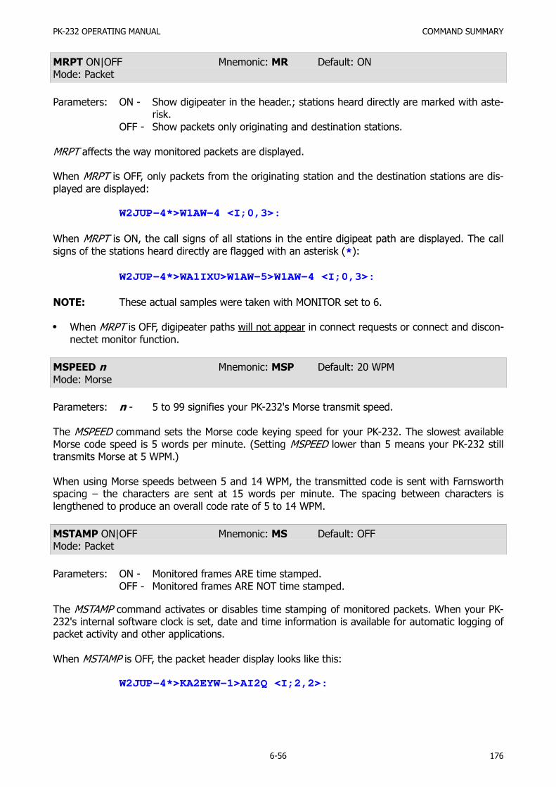
PK-232 OPERATING MANUAL COMMAND SUMMARY
6-56 176
MRPT ON|OFF Mnemonic: MR Default: ONMode: Packet
Parameters: ON - Show digipeater in the header.; stations heard directly are marked with aste-risk.
OFF - Show packets only originating and destination stations.
MRPT affects the way monitored packets are displayed.
When MRPT is OFF, only packets from the originating station and the destination stations are dis-played are displayed:
W2JUP-4*>W1AW-4 <I;0,3>:
When MRPT is ON, the call signs of all stations in the entire digipeat path are displayed. The callsigns of the stations heard directly are flagged with an asterisk (*):
W2JUP-4*>WA1IXU>W1AW-5>W1AW-4 <I;0,3>:
NOTE: These actual samples were taken with MONITOR set to 6.
When MRPT is OFF, digipeater paths will not appear in connect requests or connect and discon-nectet monitor function.
MSPEED n Mnemonic: MSP Default: 20 WPMMode: Morse
Parameters: n - 5 to 99 signifies your PK-232's Morse transmit speed.
The MSPEED command sets the Morse code keying speed for your PK-232. The slowest availableMorse code speed is 5 words per minute. (Setting MSPEED lower than 5 means your PK-232 stilltransmits Morse at 5 WPM.)
When using Morse speeds between 5 and 14 WPM, the transmitted code is sent with Farnsworthspacing – the characters are sent at 15 words per minute. The spacing between characters islengthened to produce an overall code rate of 5 to 14 WPM.
MSTAMP ON|OFF Mnemonic: MS Default: OFFMode: Packet
Parameters: ON - Monitored frames ARE time stamped.OFF - Monitored frames ARE NOT time stamped.
The MSTAMP command activates or disables time stamping of monitored packets. When your PK-232's internal software clock is set, date and time information is available for automatic logging ofpacket activity and other applications.
When MSTAMP is OFF, the packet header display looks like this:
W2JUP-4*>KA2EYW-1>AI2Q <I;2,2>:

PK-232 OPERATING MANUAL COMMAND SUMMARY
6-57 177
When MSTAMP is ON and DAYSTAMP is OFF, the display looks like this:
22:51:33 W2JUP-4*>KA2EYW-1>AI2Q <I;2,2>:
When both MSTAMP and DAYSTAMP are ON, the display looks like this:
10-Jul-86 22:54:25 W2JUP-4*>KA2EYW-1>AI2Q <I;2,2>:
Set the date and time with the DAYTIME command.
Set MSTAMP ON increase the length of the address display.
Set HEADERLN ON to display this information on a separate line.
MTO ALL/NONE,YES/NO call1[,call2..] Mnemonic: MT Default: noneMode: Packet
Parameters: call - ALL/NONE, YES list/NO list(list of up to eight call signs, separated by commas).
MTO uses arguments to determine how your PK-232 monitors the Packet channels and displays in-formation – which stations' packets will be displayed and which stations' packets will be masked orhidden. MTO is set to NONE when you start your PK-232 for the first time.
Type MTO to display the ALL/NONE, YES list/NO list status of call signs of the stations to which ad-dressed packets will or will not be displayed. You can use the abbreviated command form or mne-monic.
cmd:mto
MTO allor
cmd:mt
MTO yes WX1AAA,WX2BBB,WX3CCC,WX4DDD
To stop packets addressed to all stations from being displayed, type MTO ALL.
To display only packets addressed to one or more specific stations, type MTO YES followed by a listof call signs. Packets will be displayed only if addressed to stations whose call signs are listed afterYES.
To hide or mask packets addressed to one or more specific stations, type MTO NO followed by alist of call signs. Packets addressed to stations whose call signs are listed after NO will not be dis-played.
You can include optional SSIDs specified as '-n' after the call sign. If MTO is set to 'NO N6IA,' or'YES N6IA' any combination N6IA, N6IA-1,...N6IA-15 will be matched and processed. If MTO is setto 'YES N6IA-1' or 'NO N6IA-1', then only N6IA-1 will match and be processed.
When MFROM and MTO contain different types of arguments, to avoid any possible conflict, thearguments take the following priority:
1. ALL, 2. NO list, 3. YES list, 4. NONE
Clear MTO with %, &, or OFF as arguments.

PK-232 OPERATING MANUAL COMMAND SUMMARY
6-58 178
MYALIAS call[-n] Mnemonic: MYA Default: emptyMode: Packet
Parameters: call - Alternate identity of your PK-232n - 0 to 15, an optional substation ID (SSID)
MYALIAS specifies an alternate call sign (in addition to the call sign specified in MYCALL) for use asa digipeater only.
MYALIAS permits both normal HID identification and an alias alternate, repeater-only 'call-sign'.
In some areas wide-coverage digipeater operators change their call sign to a shorter and (usually)easier to remember identifier.
Identifiers used include International Civil Aviation Organization (ICAO) airport IDs, sometimescombined with telephone area codes.
MYALTCAL aaaa Mnemonic: MYALT Default: emptyMode: AMTOR
Parameters: aaaa - Your alternate SELective CALling code (SELCALL)
Use the MYALTCAL command to specify an your alternate SELCALL which, under certain condi-tions, may be convenient or necessary.
You can enter an additional SELCALL code not related to your call sign. The alternate SELCALL canbe any four alphabetical characters, or can be numeric strings of either four or five characters.Your PK-232 automatically translates your numeric MYALTCAL input according to CCIR Recommen-dation 491, Direct-Printing Telegraph in the Maritime Mobile Service.
MYALTCAL is generally used for special applications such as receiving network or group broadcastsin AMTOR Mode B Selective (Bs or SELFEC). The sending station must address all stations by onecommon SELCAL. Any other type of all 'ships and stations' operation using special or group SEL-CALs can be handled with MYALTCAL.
MYCALL call [-n] Mnemonic: MY Default: PK232Mode: Packet
Parameters: call - Your call signn - 0 - 15, indicating an optional substation ID, (SSID)
NOTE: Your PK-232 will not operate in the Packet Mode until you have installed your owncall sign in place of 'PK-232'.
Use the MYCALL command to load your call sign into your PK-232's RAM. Your call sign is insertedautomatically in the FROM address field for all packets originated by your PK-232. MYCALL is alsoused for identification packets (see HID and ID).
Your PK-232 accepts connect request frames with your MYCALL in the TO field and repeats frameswith this call sign in the digipeated field.
The 'PK232' default call sign is present in your PK-232's ROM when the system is manufactured.This 'artificial call' must be changed for proper operation of the Packet and AMTOR protocols.
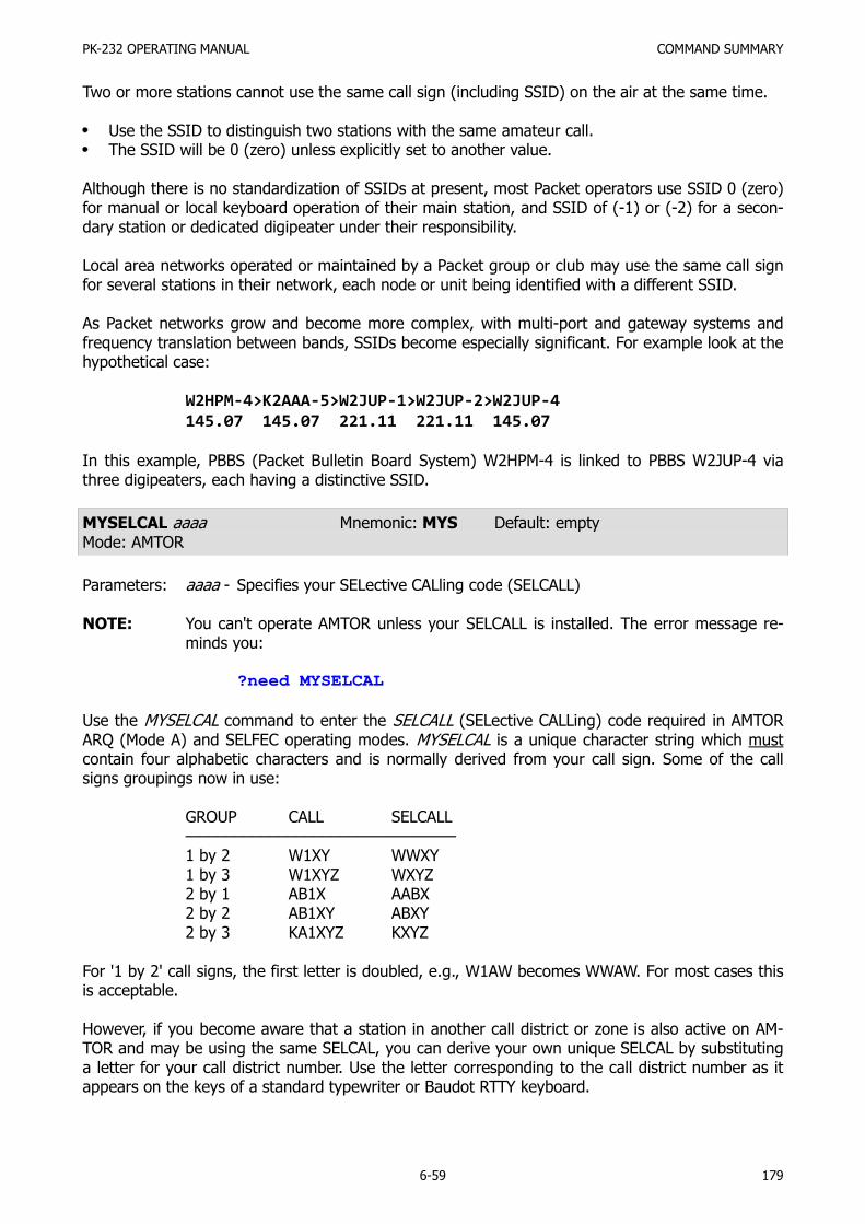
PK-232 OPERATING MANUAL COMMAND SUMMARY
6-59 179
Two or more stations cannot use the same call sign (including SSID) on the air at the same time.
Use the SSID to distinguish two stations with the same amateur call.The SSID will be 0 (zero) unless explicitly set to another value.
Although there is no standardization of SSIDs at present, most Packet operators use SSID 0 (zero)for manual or local keyboard operation of their main station, and SSID of (-1) or (-2) for a secon-dary station or dedicated digipeater under their responsibility.
Local area networks operated or maintained by a Packet group or club may use the same call signfor several stations in their network, each node or unit being identified with a different SSID.
As Packet networks grow and become more complex, with multi-port and gateway systems andfrequency translation between bands, SSIDs become especially significant. For example look at thehypothetical case:
W2HPM-4>K2AAA-5>W2JUP-1>W2JUP-2>W2JUP-4145.07 145.07 221.11 221.11 145.07
In this example, PBBS (Packet Bulletin Board System) W2HPM-4 is linked to PBBS W2JUP-4 viathree digipeaters, each having a distinctive SSID.
MYSELCAL aaaa Mnemonic: MYS Default: emptyMode: AMTOR
Parameters: aaaa - Specifies your SELective CALling code (SELCALL)
NOTE: You can't operate AMTOR unless your SELCALL is installed. The error message re-minds you:
?need MYSELCAL
Use the MYSELCAL command to enter the SELCALL (SELective CALLing) code required in AMTORARQ (Mode A) and SELFEC operating modes. MYSELCAL is a unique character string which mustcontain four alphabetic characters and is normally derived from your call sign. Some of the callsigns groupings now in use:
GROUP CALL SELCALL–––––––––––––––––––––––––––––––1 by 2 W1XY WWXY1 by 3 W1XYZ WXYZ2 by 1 AB1X AABX2 by 2 AB1XY ABXY2 by 3 KA1XYZ KXYZ
For '1 by 2' call signs, the first letter is doubled, e.g., W1AW becomes WWAW. For most cases thisis acceptable.
However, if you become aware that a station in another call district or zone is also active on AM-TOR and may be using the same SELCAL, you can derive your own unique SELCAL by substitutinga letter for your call district number. Use the letter corresponding to the call district number as itappears on the keys of a standard typewriter or Baudot RTTY keyboard.

PK-232 OPERATING MANUAL COMMAND SUMMARY
6-60 180
Let's assume that your call sign is N7ML. You discover that there is another station with the callN?ML. Change your SELCAL to NUML, according to the following table:
1 = Q 3 = E 5 = T 7 = U 9 = O2 = W 4 = R 6 = Y 8 = I 0 = P
Although the convention is to form the SELCALL from the call sign, your PK-232 is capable of in-cluding any AMTOR character in the SELCALL, including digits 0 through 9. In accordance withCCIR Recommendation 491, four- or five-digit numbers may be entered; the PK-232 automaticallytranslate the numeric entry to your four-letter alpha SELCALL.
NEWMODE ON|OFF Mnemonic: NE Default: ONMode: Packet
Parameters: ON - The PK-232 automatically returns to the Command Mode at disconnect.OFF - The PK-232 does not return to Command Mode at disconnect.
NEWMODE determines how your PK-232 behaves when the link is broken.
Your PK-232 always switches to a data transfer mode at the time of connection, unless NOMODE isON.
Set NEWMODE for the type of operation most suitable to your needs.
If NEWMODE is OFF and the link is disconnected, your PK-232 remains in Converse or TransparentMode unless you have forced it to return to Command Mode.
When NEWMODE is ON and the link is disconnected, or if the connect attempt fails, your PK-232returns to Command Mode.
Bulletin Board or other host computer programs designed to operate with earlier TNC systems mayrequire NEWMODE to be set OFF.
NOMODE ON|OFF Mnemonic: NO Default: OFFMode: Packet
Parameters: ON - The PK-232 switches modes (Command, Converse, Transparent) only uponexplicit command. NEWMODE function is ignored.
OFF - The PK-232 changes modes according to NEWMODE.
When NOMODE is ON your PK-232 never switches from Converse or Transparent Mode to Com-mand Mode (or vice versa) by itself. Only specific commands (CONVERSE, TRANS, or <CTRL-C>)typed by you change the operating mode.
When NOMODE is OFF, your PK-232 switches modes automatically according to the way NEW-MODE is set.
Some applications programs may require NOMODE set ON. WA7MBL's PBBS Version 3.12 programis one such example.

PK-232 OPERATING MANUAL COMMAND SUMMARY
6-61 181
NUCR ON|OFF Mnemonic: NU Default: OFFMode: All
Parameters: ON - <NULL> characters ARE sent to the terminal following <CR> characters.OFF - <NULL> characters ARE NOT sent to the terminal following <CR> charac-
ters.
Some of the older electromechanical terminals (Teletype™ machines) and printer-terminals requiresome extra time for the printing head to do a line feed and return to the left margin. NUCR ON sol-ves this problem by making your PK-232 send <NULL> characters (ASCII code $00) to your com-puter or terminal. This introduces any necessary delay after any <CR> sent to the terminal.
The NULLS command sets the number of individual <NULL> characters that are to be sent whenNUCR is ON.
Set NUCR ON if your terminal or printer misses one or more characters after responding to a<CR>. if this is the case, you will sometimes see overtyped lines.
NULF ON|OFF Mnemonic: NUL Default: OFFMode: All
Parameters: ON - <NULL> characters are sent to the terminal following <LF> characters.OFF - <NULL> characters are not sent to the terminal following <LF>s.
Some of the older electromechanical terminals (Teletype™ machines) and printer-terminals requiresome extra time for the printing head to do a line feed and return to the left margin. NULF ON sol-ves this problem by making your PK-232 send <NULL> characters (ASCII code $00) to your com-puter or terminal. This introduces any necessary delay after any <LF> sent to the terminal.
The NULLS command sets the number of individual <NULL> characters that are to be sent whenNULF is ON.
Set NULF ON if your terminal or printer misses one or more characters at the beginning of anew line after responding to a <LF>.
NULLS n Mnemonic: NULL Default: 0 (zero)Mode: All
Parameters: n - 0 to 30 specifies the number of <NULL> characters to be sent to your com-puter or terminal after <CR> or <LF> when NUCR or NULF are set ON.
NULLS specifies the number of <NULL> characters (ASCII $00) to be sent to the terminal after a<CR> or <LF> is sent.
NUCR and/or NULF must be set to indicate whether nulls are to be sent after <CR>, <LF> orboth.
Devices requiring nulls after <CR> are typically hard-copy devices requiring time for carriagemovement. Devices requiring nulls after <LF> are typically CRTs that scroll slowly.
The null characters are sent from your PK-232 to your computer only in Converse and CommandModes.

PK-232 OPERATING MANUAL COMMAND SUMMARY
6-62 182
OPMODE Mnemonic: O Immediate CommandMode: Command
OPMODE is an immediate command that shows the PK-232's current mode of operation and sys-tem status.
Use the OPMODE command ('O') at any time when your PK-232 is in the Command Mode to dis-play the present operating mode. Here is a typical indications:
cmd:o
OPMODE ASCII RCVE
cmd:op
OPMODE PACKET
cmd:OP
OPMODE BAUDOT SEND : :OPMODE MORSE RCVE 20OPMODE ALIST PHAS RCVEOPMODE FEC IDLE SENDOPMODE AMTOR STBY RCVEOPMODE ARQ TFC SEND
PACKET Mnemonic: PA Immediate CommandMode: Command
Use the PACKET command to switch your PK-232 into Packet-Radio mode from any other operatingmode. Your PK-232 automatically enters the Packet Mode at first power-up, or after a RESTARTcommand.
PACLEN n Mnemonic: PACL Default: 128Mode: Packet
Parameters: n - 0 to 255 specifies the maximum length of the data portion of a packet.0 - Zero is equivalent to 256.
PACLEN sets the maximum number of data bytes to be carried in each packet's 'information field'.'User data' means the characters you actually type at your keyboard (or send from a stored file).
Your PK-232 automatically sends a packet when the number of characters you type for a packetequals n. This value is used in both Converse and Transparent Modes.
Most keyboard-to-keyboard operators use the default value of 128 bytes for routine VHF/UHFpacket services.
Experiment with different values for MAXFRAME and PACLEN to find the combination best suitedto your operating conditions – especially if you are transferring files.

PK-232 OPERATING MANUAL COMMAND SUMMARY
6-63 183
The lower the value of PACLEN, the greater the probability of getting packets though the linkwithout 'hits' or retries.Increase PACLEN to 256 if transferring files to a nearby station over a high quality path.Reduce PACLEN to 64, or even 32 when working 'difficult' HF radio paths.If the radio link is good and optimal relationship will exist between the parameter set by thesecommands. Set PACLEN so that the maximum number of characters outstanding doesn't ex-ceed the receive buffer space of the TNC receiving the data.
NOTE: It is not necessary that two TNCs be set to the same PACLEN value to exchangedata; however, some TNCs may not be compatible when frames contain more than128 data characters.
PACTIME EVERY/AFTER n Mnemonic: PACT Default: AFTER 10Mode: Packet
Parameters: n - 0 to 250 specifies 100-millisecond intervals.EVERY - Packet time-out occurs every n times 100 milliseconds.AFTER - Packet time-out-occurs when n times 100 milliseconds elapse with-
out input from the computer or terminal.
A PACTIME parameter is always used in Transparent Mode. PACTIME is also used in ConverseMode if CPACTIME is ON.
When EVERY is specified, the characters you type or send from disk are packaged and queuedfor transmission every n times 100 milliseconds.When AFTER is specified, the characters you type or send from disk are packaged when inputfrom the terminal stops for n times 100 milliseconds.
A zero-length packet will never be produced. The timer is not started until the first character orbyte is entered.
A value of 0 (zero) for n is allowed; zero means packets are sent with no wait time.
PARITY n Mnemonic: PAR Default: 3 (even)Mode: All
Parameters: n - 0 to 3 selects a parity option from the table below.
PARITY sets the PK-232's data parity for terminal or computer data transfer according to the tablebelow:
0 = no parity 1 = odd parity 2 = no parity 3 = even parity
The parity bit, if present, is stripped automatically on input and is not checked in Command andConverse Modes.
In Transparent Mode all eight bits (including parity) are transmitted in packets. When 'no parity' isset and AWLEN is 7, the eighth bit is set to 0 (zero).

PK-232 OPERATING MANUAL COMMAND SUMMARY
6-64 184
PASS n Mnemonic: PAS Default: $16 <CTRL-V>Mode: Packet
Parameters: n - 0 to $7F (0 to 127 decimal) specifies an ASCII character code.
PASS selects the ASCII character used for the 'pass' input editing commands.
The parameter n is the numeric ASCII code for the character you'll used to signal that the charac-ter immediately following it is to be included in a packet or text string.
You can enter the code in either hex or decimal.
Use the PASS character (default <CTRL-V>) to send characters that usually have special functions.
A common use for the PASS character is to allow <CR> to be included in the BTEXT and CTEXTmessages so that the transmitted information appears on several short lines rather than a singlelonger line.
Use the PASS character to insert <CR> at the end of a short line:
BT Notice:<CTRL-V<CTRL-M>Meeting at the Firehouse tonight <CTRL-V><CTRL-M>at 8:00 PM. All welcome!<CR>
The distant station's monitor shows:
Notice:Meeting at the Firehouse tonightat 8:00 PM. All welcome!
Without the PASS character, the message would probably look like this:
Notice: Meeting at the Firehouse tonight at 8:00 PM. All welcome!
In the same way, you can include <CR> in text when you are in Converse Mode, to send multi-linepackets. (The default send-packet character is <CR>.)
PASSALL ON|OFF Mnemonic: PASSA Default: OFFMode: Packet
Parameters: ON - Your PK-232 will accept packets with invalid CRCS.OFF - Your PK-232 will only accept packets with valid CRCs.
PASSALL permits the PK-232 to display packets received with invalid CRC fields; the error-detectingmechanism is turned off.
Packets are accepted for display despite CRC errors if they consist of an even multiple of eight bitsand are up to 330 bytes. The PK-232 attempts to decode the address field and displays the callsign(s) in the standard monitor format, followed by the text of the packet.
PASSALL is normally turned off; therefore, the protocol ensures that received packets data is error-free by rejecting packets with invalid CRC fields.
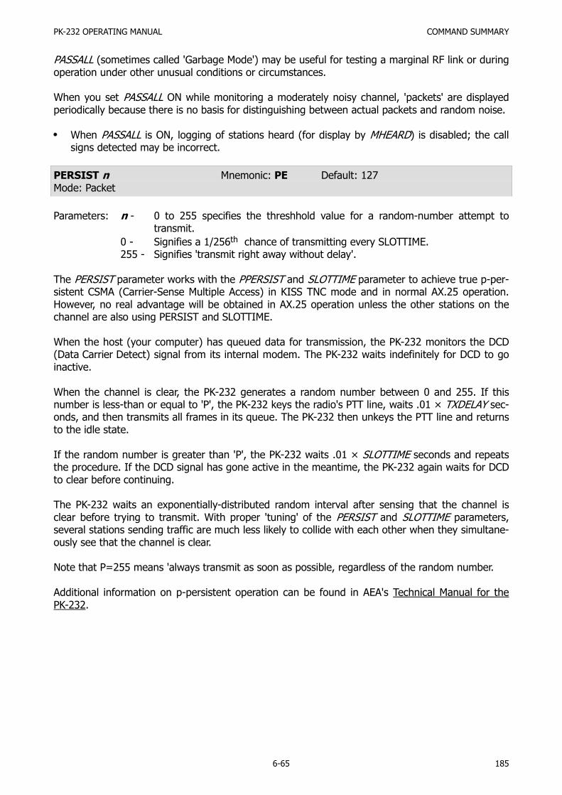
PK-232 OPERATING MANUAL COMMAND SUMMARY
6-65 185
PASSALL (sometimes called 'Garbage Mode') may be useful for testing a marginal RF link or duringoperation under other unusual conditions or circumstances.
When you set PASSALL ON while monitoring a moderately noisy channel, 'packets' are displayedperiodically because there is no basis for distinguishing between actual packets and random noise.
When PASSALL is ON, logging of stations heard (for display by MHEARD) is disabled; the callsigns detected may be incorrect.
PERSIST n Mnemonic: PE Default: 127Mode: Packet
Parameters: n - 0 to 255 specifies the threshhold value for a random-number attempt totransmit.
0 - Signifies a 1/256th chance of transmitting every SLOTTIME.255 - Signifies 'transmit right away without delay'.
The PERSIST parameter works with the PPERSIST and SLOTTIME parameter to achieve true p-per-sistent CSMA (Carrier-Sense Multiple Access) in KISS TNC mode and in normal AX.25 operation.However, no real advantage will be obtained in AX.25 operation unless the other stations on thechannel are also using PERSIST and SLOTTIME.
When the host (your computer) has queued data for transmission, the PK-232 monitors the DCD(Data Carrier Detect) signal from its internal modem. The PK-232 waits indefinitely for DCD to goinactive.
When the channel is clear, the PK-232 generates a random number between 0 and 255. If thisnumber is less-than or equal to 'P', the PK-232 keys the radio's PTT line, waits .01 × TXDELAY sec-onds, and then transmits all frames in its queue. The PK-232 then unkeys the PTT line and returnsto the idle state.
If the random number is greater than 'P', the PK-232 waits .01 × SLOTTIME seconds and repeatsthe procedure. If the DCD signal has gone active in the meantime, the PK-232 again waits for DCDto clear before continuing.
The PK-232 waits an exponentially-distributed random interval after sensing that the channel isclear before trying to transmit. With proper 'tuning' of the PERSIST and SLOTTIME parameters,several stations sending traffic are much less likely to collide with each other when they simultane-ously see that the channel is clear.
Note that P=255 means 'always transmit as soon as possible, regardless of the random number.
Additional information on p-persistent operation can be found in AEA's Technical Manual for thePK-232.

PK-232 OPERATING MANUAL COMMAND SUMMARY
6-66 186
PPERSIST ON|OFF Mnemonic: PP Default: OFFMode: Packet
Parameters: ON - The PK-232 uses PERSIST and SLOTTIME parameters in executing p-persis-tent CSMA (Carrier Sense Multiple Access).
OFF - The PK-232 uses DWAIT for TAPR-type 1-persistent CSMA.
When PPERSIST is set ON, the PK-232 uses the PERSIST and SLOTTIME parameters for p-persis-tent CSMA instead of the normal TAPR-type DWAIT procedure to achieve CSMA operation. PPSER-SIST can be used in both KISS TNC and normal AX.25 operation. See PERSIST and SLOTTIME.
RBAUD n Mnemonic: RB Default: 45 bauds (60 WPM)Mode: Baudot RTTY
Parameters: n - Specifies the rate or signaling speed in bauds from the PK-232 to the radio.
RBAUD sets the radio ('on-air') baud rate only in the Baudot-CCITT International Telegraph Alpha-bet #2 operating mode. This value has no relationship to your computer or terminal program'sbaud rate.
Available Baudot/CCITT ITA#2 data rates include 45, 50, 57, 75, 100,110, 150, 200 and 300 bauds(60, 66, 75, 100, 132, 145, 198, 264 and 396 WPM).
Example: RBAUD 75
Use RBAUD UP (RB U) to go to the next highest Baudot speed or RBAUD DOWN (RB D) to go tothe next lowest Baudot speed. This is useful when you are trying various combinations of RBAUDand RXREV to decode an unknown Baudot signal.
NOTE: Modern commercial and amateur radio operations no longer refer to the operatingspeeds or data rates in 'WPM'. The term 'bauds' is now universally accepted for FSKand AFSK operations using monobit data. The term 'bauds' and 'bits per second'may be used interchangeably in such cases.
RCVE Mnemonic: R Immediate CommandMode: Command
RCVE is an immediate command, used in Command Mode, to switch your PK-232 from transmit toreceive when operating Baudot and ASCII RTTY.
You must return to the Command Mode to use the RCVE command.
Type <CTRL-C> to enter the Command Mode.

PK-232 OPERATING MANUAL COMMAND SUMMARY
6-67 187
RECEIVE n Mnemonic: REC Default: $04 <CTRL-D>Mode: Baudot/ASCII/Morse/AMTOR
Parameters: n - 0 to $7F (0 to 127 decimal) specifies an ASCII character code.
The RECEIVE command allows you to insert a character (default <CTRL-D>) in your typed text ordisk file; when read by your PK-232, your system is switched from transmit to receive and returnsto the Command Mode.
Type the RECEIVE Command character at the end of your text or message while recording adisk file or on the air typing into the PK-232 transmit buffer.
REDISPLA n Mnemonic: RED Default: $12 <CTRL-R>Mode: All
Parameters: n - 0 to $7F (0 to 127 decimal) specifies an ASCII character code.
REDISPLA changes the redisplay-line input editing character.
Parameter n is the numeric ASCII code for the character you'll use when you want to re-displaythe current input line. You can enter the code in either hex or decimal.
Type the REDISPLA character to re-display a line you've just typed. The following things happen:
Type-in flow control is temporarily turned off (if it had been active). Any incoming packets thatare pending are displayed.A <BACKSLASH> is appended to the line you've just typed and the line is shown below it. Onlythe final form of the line is shown if you have deleted or changed any characters.
You can now continue typing where you left off.
Use the redisplay-Line character to see a 'clean' copy of your input if you are using a printing ter-minal and you have deleted characters.
If BKONDEL is set OFF, deletions are designated with <BACKSLASH> characters, rather than bytrying to correct the input line display. The re-displayed line is the corrected text.
Use the REDISPLA character if a packet is received while you're typing a message in ConverseMode. You can see the incoming message before you send your packet without canceling your in-put.
RELINK ON|OFF Mnemonic: REL Default: OFFMode: Packet
Parameters: ON - The PK-232 will try to automatically reconnect the distant station after thelink has timed out on retries.
OFF - The PK-232 will not attempt to re-establish the failed link.
Set RELINK to OFF when using the PK-232 with host computer applications, computer-based mes-sage systems and programs such as WA7MBL's Version 3.12 Packet Bulletin Board (PBBS) soft-ware.

PK-232 OPERATING MANUAL COMMAND SUMMARY
6-68 188
RESET Mnemonic: RESET Immediate CommandMode: Command
RESET is an immediate command that resets all parameters to default settings and reinitializes thePK-232.
WARNING:All parameters customizing and monitor lists are lost.
To reinitialize the PK-232 using the parameter values in bbRAM, turn the PK-232 OFF then ON,or use the RESTART command.
RESPTIME n Mnemonic: RES Default: 10Mode: Packet
Parameters: n - 0 to 250 specifies 100-millisecond intervals.
RESPTIME adds a minimum delay before your PK-232 sends acknowledgment packets. This delaymay run concurrently with the default wait time set by DWAIT and any random wait in effect.
Use RESPTIME delay to increase throughput during operations such as file transfer when send-ing TNC usually sends the maximum number of full-length packets.
Occasionally, the sending TNC may not have a packet ready in time to prevent transmission frombeing stopped temporarily, with the result that the acknowledgement of earlier packets collideswith the final packet of the series.
These collisions can be avoided if the receiving TNC sets RESPTIME to 10.
RESTART Mnemonic: RESTART Immediate CommandMode: Command
RESTART is an immediate command that reinitializes the PK-232 using the defaults stored in thePK-232's bbRAM. The effect of the RESTART command is the same as turning the PK-232 OFF,then ON again.
RESTART does not reset the parameter values in bbRAM. See the RESET command.
RETRY n Mnemonic: RE Default: 10Mode: Packet
Parameters: n - 0 to 15 specifies the maximum number of packet retries.
The AX.25 protocol uses retries – the retransmission of frames that have not been acknowledged.Frames are retransmitted n times before the link is disconnected. A value of 0 for n specifies an in-finite number of retries.
The time between retries is specified by the command FRACK. See the FRACK command.
If the number of retries is exceeded, the PK-232 enters either the "connect in progress" or "discon-nected" state depending on the setting of RELINK.

PK-232 OPERATING MANUAL COMMAND SUMMARY
6-69 189
If you are not in Transparent Mode, the following message is displayed:
*** Retry count exceeded*** DISCONNECTED: {call sign}
RFEC ON|OFF Mnemonic: RF Default: ONMode: AMTOR
Parameters: ON: - Mode B (FEC) signals are displayed in AMTOR Standby.OFF - Mode B (FEC) signals are not displayed in AMTOR Standby.
Use the RFEC command to prevent the reception and display of all FEC signals received while inAMTOR Standby.
RXREV ON|OFF Mnemonic: RXR Default: OFFMode: Baudot and ASCII RTTY/AMTOR
Parameters: ON - Received data polarity is reversed (mark-space reversal).OFF - Received data polarity is normal.
Use the RXREV Command to invert the polarity of the data demodulated from the received markand space tones.
In some cases, you may be trying to copy a station that's transmitting 'upside down' but receivingyour signals correctly.
Set RXREV ON to reverse the data sense of received signals.
Type RXREV TOG (RXR T) to 'toggle' the polarity of received signals. This is useful when trying var-ious combinations of RBAUD and RXREV to decode an unknown Baudot signal.
SELFEC aaaa Mnemonic: SEL Default: emptyMode: AMTOR FEC
Parameters: aaaa - Specifies your SELective CALling code (SELCALL).
The SELFEC command starts a SELective FEC (Mode Bs) transmission to a specific distant stationwhen you enter that station's SELCALL (SELective CALLing) code.
The SELFEC command must be a unique character sequence that contains four alphabetic charac-ters. It is normally derived from the call sign of the distant station.
See MYSELCAL for further information on the derivation and use of SELCALs.To end your SELFEC transmission, return to the Command Mode by typing <CTRL-C> (defaultvalue) and then typing R to switch back to receive mode.
You don't have to type the SELCAL a second time if you intend to call the same station again rightaway.

PK-232 OPERATING MANUAL COMMAND SUMMARY
6-70 190
SENDPAC n Mnemonic: SE Default: $0D <CTRL-M>Mode: Packet
Parameters: n - 0 to $7F (0 to 127 decimal) specifies an ASCII character code.
Use the SENDPAC command to select the character used to force a packet to be sent in ConverseMode. The parameter n is the numeric ASCII code for the character you want to use to force yourinput to be packetized and queued for transmission. You can enter the code in either hexadecimalor decimal numbers.
Use default SENDPAC value $0D for ordinary conversation with CR ON to send packets at naturalintervals with <CR> included in the packet.
When setting CPACTIME ON, set SENDPAC to a value not ordinarily used (for example, <CTRL-A>), with CR OFF. This setting forces packets to be sent without extra <CR> characters in thetext.
SLOTTIME n Mnemonic: SL Default: 10 (100 sec.)Mode: Packet
Parameters: n - 0 to 250 specifies the time interval during which the PK-232 waits betweengenerating random numbers to see if it can transmit.
The SLOTTIME parameter works with the PPERSIST and PERSIST parameters to achieve true p-persistent CSMA (Carrier-Sense Multiple Access) in KISS TNC Mode and in normal AX.25 operation.However, no real advantage will be obtained in AX.25 operation unless the other stations on thechannel are also using PERSIST and SLOTTIME.
SQUELCH ON|OFF Mnemonic: SQ Default: OFFMode: Packet
Parameters: ON - Your PK-232 responds to positive-going squelch voltage.OFF - Your PK-232 responds to negative-going squelch voltage.
Normally, to decide if the channel is clear so that it can transmit, your PK-232 uses its CSMA (Carri-er Sense Multiple Access) circuit by sensing audio mark and space tones from your Packet receiver.
If there are non-packet signals on the channel you're using(such as voice operation), it's possiblethat your PK-232 might not be quite as polite as it is normally and double with the other signals.
The PK-232 can use true RF-carrier CSMA by monitoring the squelch line voltage from your radio.This line can be easily connected in many radios to the 'busy' light or indicator on the radio's frontpanel, or to other circuit locations that indicate the presence or absence of carrier or received sig-nals. Because your carrier-sensing signal can be active-low or active-high (depending on the indi-vidual radio manufacturer's design), you can set your PK-232 to sense either positive or negativesquelch voltages.

PK-232 OPERATING MANUAL COMMAND SUMMARY
6-71 191
SRXALL ON|OFF Mnemonic: SRX Default: OFFMode: AMTOR
Parameters: ON - Receive ALL selective (SELFEC) transmissions.OFF - Receive only SELCALL-addressed SELFEC transmissions.
SRXALL permits the reception of selectively-coded inverse FEC signals normally not available fordecoding.
Set SRXALL ON to activate this feature.
START n Mnemonic: STA Default: $11 <CTRL-Q>Mode: All
Parameters: n - 0 to $7F (0 to 127 decimal) specifies an ASCII character code.
Use the START command to choose the user START character you want to use to restart outputfrom the PK-232 to the terminal after it has been halted by typing the user STOP character.
The User Stop character is set by the STOP command.You can enter the value in either hex or decimal.
If the User Start and User Stop characters are set to $00, software flow control to the PK-232 isdisabled; the PK-232 will only respond to hardware flow control (CTS).
If the same character is used for both the User Start and User Stop character, the PK-232 alter-nately starts and stops transmission on receipt of the character ('toggels').
STOP n Mnemonic: STO Default: $13 <CTRL-S>Mode: All
Parameters: n - 0 to $7F (0 to 127 decimal) specifies an ASCII character code.
Use the STOP command to select the user STOP character you want to use to stop output fromthe PK-232 to the terminal. Type this character to halt the PK-232's output to your monitor so thatyou can read the received text before it scrolls off your screen display.
Output is restarted with the User Start character.
The User Start character is set by the START command.You can enter the value in either hex or decimal.
If the User Start and User Stop characters are set to $00, software flow control to the PK-232 isdisabled; the PK-232 will only respond to hardware flow control (CTS).
If the same character is used for both the User Start and User Stop character, the PK-232 alter-nately starts and stops transmission on receipt of the character ('toggels').

PK-232 OPERATING MANUAL COMMAND SUMMARY
6-72 192
TBAUD n Mnemonic: TB Default: 1200 baudsMode: All
Parameters: n - Specifies the rate or signaling speed, in bauds, on the serial I/O port.
TBAUD displays the baud rate set by the auto-baud routine when you first apply power to the PK-232, or after typing RESET.
Use TBAUD to set terminal rates not covered by the auto-baud routine, such as 110 and 600bauds.
Use TBAUD to specify a terminal baud rate that will become active at the next power-on or RE-START. A warning message reminds you of this.
If you plan to change terminals, but want to retain all the RAM parameters values, set TBAUD,AWLEN and PARITY to the new terminals's characteristics while you are still connected to the oldterminal. Next, turn off the PK-232, change the terminal and turn the PK-232 on again.
TCLEAR Mnemonic: TC Immediate CommandMode: Command
The TCLEAR command clears your PK-232's transmit buffer and cancels any further transmission ofdata when in the Baudot, ASCII, AMTOR or Morse operating modes. In Packet Mode, all data iscleared except for a few remaining packets.
You must be in the Command Mode to use TCLEAR.Use the <CTRL-C> (default) command to return to Command Mode.Type TC to clear the transmit buffer.
TIME n Mnemonic: TI Default: $14 <CTRL-T>Mode: All
Parameters: n - 0 to $7F (0 to 127 decimal) specifies an ASCII character code.
The TIME command specifies a control character in the text you type into the transmit buffer or in-to a text file stored on disk.
Type <CTRL-T> to embed the TIME command in your message text or file.
At transmit time, the PK-232 reads the embedded control code (default <CTRL-T>), reads thetime-of-day from the PK-232's internal clock and then sends the time to the radio in the data trans-mission code in use at that time. When DAYSTAMP is set ON, the date is transmitted with the time.
When DAYSTAMP is set ON, the date is transmitted with the time.
NOTE: The TIME command cannot be embedded in CTEXT, BTEXT or AAB.

PK-232 OPERATING MANUAL COMMAND SUMMARY
6-73 193
TRACE ON|OFF Mnemonic: TRAC Default: OFFMode: Packet, FAX
Parameters: ON - Trace function is activated.OFF - Trace function is disabled.
The TRACE command activates the AX.25 protocol display. If TRACE is ON all received frames aredisplayed in their entirety, including all header information.
NOTE: Be careful using the mnemonic – don't use TRA ! The PK-232 will change to Trans-parent Mode!
The TRACE display is shown as it appears on an 80-column display. The following monitored frameis a sample:
W2JUP*>TESTER <UI>:This is a test message packet.
Byte Hex Shifted ASCII ASCII000: A88AA6A8 8AA460AE 6494AAA0 406103F0 TESTER0W2JUP 0.x ......`[email protected]: 54686973 20697320 61207465 7374206D *449.49.0.:29:.6 This is a test m020: 65737361 67652070 61636B65 742E0D 299032.80152:.. essage packet...
The byte column shows the offset into the packet of the first byte of the line.
The hex display column shows the next 16 bytes of the packet, exactly as received, in standardhex format. The shifted ASCII column decodes the high-order seven bits of each byte as an ASCIIcharacter code.
The ASCII column decodes the low-order seven bits of each byte as an ASCII character code.
In a standard AX.25 packet,
the call sign address field is displayed correctly in the shifted ASCII column;a text message is displayed correctly in the ASCII column;non-printing and control characters are displayed in both ASCII fields as a period ( . ).
You can examine the hex displayed field to see the contents of the SSID byte and the controlbytes used by the protocol.
TRANS Mnemonic: T Imediate commandMode: Packet
TRANS is an immediate command that switches the PK-232 switch from the Command Mode toTransparent Mode. The current state of the radio link is not affected.
Transparent Mode is primarily useful for computer communications. In Transparent Mode 'humaninterface' features such as input editing, echoing of input characters, and type-in flow control aredisabled.
Use Transparent Mode for transferring binary or other non-text files.

PK-232 OPERATING MANUAL COMMAND SUMMARY
6-74 194
TRFLOW ON|OFF Mnemonic: TRF Default: OFFMode: All
Parameters: ON - Software flow control for the computer or terminal can be activated in Trans-parent Mode.
OFF - Software flow control for the computer or terminal is disabled in TransparentMode.
When TRFLOW is ON, the type of flow control used in Transparent Mode is determined by howSTART and STOP are set.
When TRFLOW is OFF, only 'hardware' flow control (CTS, RTS) is available to the computer and allcharacters received by the PK-232 are transmitted as data.
If START and STOP are set to $00 the User Stop and User Start characters are disabled – hardwareflow control must be used by the computer.
If TRFLOW is ON, and START and STOP are set to values other than zero, software flow control isenabled for the user's computer or terminal. The PK-232 responds to the User START and UserSTOP characters (set by START and STOP) while remaining transparent to all other characters fromthe terminal.
Unless TXFLOW is also ON, only hardware flow control is available to the PK-232 to control outputfrom the terminal.
TRIES n Mnemonic: TRI Default: 0Mode: Packet
Parameters: n - 0 to 15 specifies the current RETRY level on the selected input channel.
TRIES retrieves (or forces) the count of 'tries' on the data channel presently selected.
If you type TRIES without an argument, the PK-232 returns the current number of tries if an out-standing unacknowledged frame exists. If no outstanding unacknowledged frame exists, the PK-232 returns the number of tries required to get an ACK for the previous frame.
If RETRY is set to 0 (zero), the TRIES command always returns 0 (zero).
Use TRIES for gathering statistics on a given path or channel. TRIES is especially useful for com-pute operating stations (such as automatic message-forwarding stations) using less than-optimal,noisy HF or satellite channels or paths.
Using TRIES under these conditions automatically optimizes the PACLEN and MAXFRAME parame-ters.
If you type TRIES with an argument the 'tries' counter is forced to the entered value. Using thiscommand to force a new count of tries is not recommended.

PK-232 OPERATING MANUAL COMMAND SUMMARY
6-75 195
TXDELAY n Mnemonic: TXD Default: 30 (300 msec.)Mode: Packet
Parameters: n - 0 to 120 specifies ten-millisecond intervals.
The TXDELAY command tells your PK-232 how long to wait before sending packet frame data afterkeying your transmitter's PTT line.
All transmitters need some amount of start-up time to put a signal on the air; some need more,some need less. Some general rules apply to these radios:
Crystal-controlled radios with diode antenna-switching don't need much time.Synthesized radios need time for their phase-lock-loops (PLLs) to lock up and settle on to theoperating frequency.Radios with mechanical transmit/receive relays need time for the physical movement of the re-lays.External amplifiers using RF-driven relay switching frequently require that you increase TXDE-LAY to allow for the additional delays.
Experiment to determine the best TXDELAY value for a specific radio.
TXDELAY can also compensate for certain characteristics of the radio used by the station withwhom you're communicating.
If the distant station's radio has slow AGC recovery or squelch release times when switchingfrom transmit to receive, increasing your TXDELAY may reduce retries and actually improvethroughput by retarding the start of your data until the distant station's receiver has reachedfull sensitivity.
TXFLOW ON|OFF Mnemonic: TXF Default: OFFMode: Packet
Parameters: ON - Software flow control for the PK-232 can be activated in Transparent Mode.OFF - Software flow control for the PK-232 is disabled in Transparent Mode.
When TXFLOW is ON, the setting of XFLOW determines the type of flow control used in Transpar-ent Mode.
When TXFLOW is OFF, the PK-232 uses only hardware flow control; all data sent to the terminalremains fully transparent.
When TXFLOW and XFLOW are ON, the PK-232 uses the Start and Stop characters (set by XONand XOFF) to control the input from the terminal.
Unless TRFLOW is also ON, only hardware flow control is available to the computer or terminal tocontrol output from the PK-232.
If the PK-232 Start and Stop characters are set to $00, hardware flow control is always selected,regardless of the setting of TXFLOW.

PK-232 OPERATING MANUAL COMMAND SUMMARY
6-76 196
TXREV ON|OFF Mnemonic: TXR Default: OFFMode: Baudot/ASCII/AMTOR
Parameters: ON - Transmit data polarity is reversed (mark-space reversal).OFF - Transmit data polarity is normal.
Use the TXREV Command to invert the polarity of the data sent to the PK-232's AFSK tone genera-tor, thus reversing mark and space in the transmitted AFSK and FSK signals.
In some cases, the station you're working may be receiving inverted data although it is transmit-ting in correct polarity.
Set TXREV ON to reverse the sense of your transmitted signals.
UNPROTO call1 [VIA call2[,call3...,call9]] Mnemonic: U Default: CQMode: Packet
Parameters: call1 - Call sign to be placed in the TO address field.call2–9 - Optional digipeater call list, up to eight calls.
UNPROTO sets the digipeat and destination address fields of packets sent in the unconnected (un-protocol) mode.
Unconnected packets are sent as unsequenced I-frames with the destination and digipeat fieldstaken from 'call1' through 'call9' options. When a destination is not specified, unconnected packetsare sent to 'CQ'.
Unconnected packets sent from other packet stations can be monitored by setting MONITOR to avalue greater than '1' and setting MFROM to ALL.
The digipeater list can also be used for beacon packets.
To send your beacon message through one or more digipeaters, type the following:
UNPROTO BEACON VIA WX1AAA,WX2BBB,WX3CCC
Your beacon is routed to and repeated by each of the digipeaters in the order listed.
Some PBBSs and other types of host computer systems may use this form of UNPROTO address-ing to disseminate their traffic or mail lists over the channel to a wider audience.
To address a PBBS mail list through one or more digipeaters, type the following:
UNPROTO MAIL VIA WX1AAA,WX2BBB,WX3CCC
The resulting 'unproto' beacon may look like this:
W2JUP-4>MAIL:QTC {List of callsigns with mail waiting in the PBBS}

PK-232 OPERATING MANUAL COMMAND SUMMARY
6-77 197
USERS n Mnemonic: US Default: 1MODE: Packet
Parameters: n - 0 to 10 specifies the number of active simultaneous connections that can beestablished with your PK-232.
USERS only affects the way that incoming connect requests are handled. It does not affect thenumber of connections you initiate with your PK-232. For example:
USERS 0 allows incoming connections on any free logical channelUSERS 1 allows incoming connections on logical channel 0 onlyUSERS 2 allows incoming connections on logical channels 0 and 1USERS 3 allows incoming connections on logical channels 0, 1 and 2, and so on, through
USERS 10.
USOS ON|OFF Mnemonic: USO Default: OFFMode: Baudot RTTY
Parameters: ON - Letters (LTRS) case IS forced after a space character.OFF - Letters (LTRS) is NOT forced after a space character.
Use the USOS Command when you want your PK-232 to automatically change from figures to let-ters after receiving a space character.
When using Baudot RTTY in poor HF receiving conditions, a received character can be incorrectlyinterpreted as a FIGURES-SHIFT character, forcing the received data into the wrong case. Manyotherwise good characters received after this will be interpreted as figures (numbers and punctua-tion), not as the letters sent by the distant station.
USOS ON helps reduce these receiving errors.
NOTE: Some weather, commercial, point-to-point and utility stations use Baudot RTTY tosend consecutive groups of numbers separated by spaces. USOS ON produces unac-ceptable results by forcing the system into letters case when the originator mayhave intended the information to be in figures case.
VHF ON|OFF Mnemonic: V Default: ONMode: Packet
Parameters: ON - Packet tones are shifted 1000 Hz.OFF - Packet tone are shifted 200 Hz.
Use the VHF Command for immediate software control of the PK-232's modem tones. Changingcomponents or switch settings is not required.
Set VHF OFF for HF packet operation.Set VHF ON for VHF operation.
NOTE: Be sure to change HB to 300 bauds when operating below 28 MHz.

PK-232 OPERATING MANUAL COMMAND SUMMARY
6-78 198
WIDESHFT ON|OFF Mnemonic: WI Default: OFFMode: Baudot/ASCII RTTY
Parameters: ON - RTTY tones are shifted 1000 Hz.OFF - RTTY tones are shifted 200 Hz (emulates 170-Hz shift).
The WIDESHFT command permits you to use the PK-232 on VHF or HF with either wide (1000 Hz)or narrow (200 Hz) shifts.
Nearly all amateur radio VHF and HF Baudot and ASCII RTTY operators use 170-shift. The PK-232's 200-Hz shift is well within the passband and filter tolerances of any RTTY demodulator ingeneral service.
MARS stations will find WIDESHFT generally compatible with standard MARS 850-Hz shift BaudotRTTY operations.
The WIDESHFT command has no effect in AMTOR operation.
WORDOUT ON|OFF Mnemonic: WO Default: OFFMode: Baudot/ASCII RTTY, AMTOR, Morse
Parameters: ON - Typed characters are held in the transmit buffer until a space character orpunctuation is typed.
OFF - Typed characters are sent directly to the transmitter.
Use the WORDOUT Command (in all modes except packet) to choose whether or not you can editwhile entering text for transmission.
When WORDOUT is ON, each character you type is held in a buffer until you type a space, a car-riage return, a line feed, or any punctuation mark – including parentheses, plus signs, asterisks,etc. You can correct spelling or change words before the transmit buffer's contents are sent to theradio.
When WORDOUT is OFF, each character you type is sent to the radio just as you typed it, withoutany delay.
Set WORDOUT ON to permit limited on-screen editing before each word is sent to the transmitter.
Set WORDOUT OFF to transmit each character immediately as it is typed.
WRU ON|OFF Mnemonic: WR Default: OFFMode: Baudot/ASCII/AMTOR ARQ
Parameters: ON - Your answerback is sent after a distant station's WRU?OFF - Your answerback is NOT sent after a distant station's WRU?
Use the WRU command in Baudot, ASCII and AMTOR to enable or disable your PK-232's automaticanswerback feature.
When WRU is ON, your PK-232 sends the answerback on receipt of a distant station's WRU? re-quest ('FIGS D' or '$' in Baudot and AMTOR, or <CTRL-E> in ASCII). Your PK-232 keys your trans-mitter, sends the text stored in the answerback field (AAB), then unkeys your transmitter and re-turns to receive status.

PK-232 OPERATING MANUAL COMMAND SUMMARY
6-79 199
In AMTOR ARQ operation, your answerback will automatically send the +? changeover commandto the distant station and maintain the link.
These related features can be used in message handling in either direction, to confirm that you aresending to the proper station and the distant station is probably receiving your traffic successfully.
XFLOW ON|OFF Mnemonic: XF Default: ONMode: All
Parameters: ON - XON/XOFF (software) flow control is activated.OFF - XON/XOFF flow control is disabled - hardware flow control is enabled.
When XFLOW is ON, software flow control is in effect – it's assumed that the computer or terminalwill respond to the PK-232's Start and Stop characters defined by the XON and XOFF commands.
When XFLOW is OFF, the PK-232 send hardware flow control commands via the RTS line.
For full hardware control in both directions, set START, STOP, XON and XOFF all to $00.
XMIT Mnemonic: X Immediate CommandMode: Command Mode in Baudot/ASCII/Morse
XMIT is an immediate command that keys your radio's PTT line and prepares the radio to receiveoutbound data and Morse characters from the PK-232.
The XMIT Command can only be used from the Command Mode.
Type <CTRL-C> (default) to enter Command Mode before typing the X.
XMIT switches your PK-232 to either Converse Mode or Transparent Mode, depending on the set-ting of CONMODE.
XMITOK ON|OFF Mnemonic: XMITO Default: ONMode: Packet
Parameters: ON - Transmit functions (PIT line) are active.OFF - Transmit functions (PTT line) are disabled.
When XMITOK is OFF, the PTT line to your transmitter is disabled – the transmit function is inhibit-ed. All other PK-232 functions remain the same. Your PK-232 generates and sends packets as re-quested, but does not key the radio's PTT line.
Use the XMITOK command at any time to ensure that your PK-232 does not transmit.
Set XMITOK OFF if you're absent and wish to leave your PK-232 on as a channel activity monitor.
Set XMITOK OFF for testing in loopback or direct wire connections when PTT operation is not re-quired.

PK-232 OPERATING MANUAL COMMAND SUMMARY
6-80 200
XOFF n Mnemonic: XO Default: $13 <CTRL-S>Mode: All
Parameters: n - 0 to $7F (0 to 127 decimal) specifies an ASCII character code
Use XOFF to select the Stop character to be used to stop input from the computer or terminal.
You can enter the code in either hex or decimal.
The Stop character default value is <CTRL-S> for computer data transfers.
If you're operating in Converse Mode, and there is a chance that activity might fill the PK-232'sbuffers, you can define the Stop character as <CTRL-G> ($07), the 'beep' character on many ter-minals.
XON n Mnemonic: XON Default: $11 <CTRL-Q>Mode: All
Parameters: n - 0 to $7F (0 to 127 decimal) specifies an ASCII character code.
XON selects the PK-232 Start character that is sent to the computer or terminal to restart inputfrom that device.
You can enter the code in either hex or decimal.
The Start character default value is <CTRL-Q> for computer data transfers.
If you're operating in Converse Mode, and there is a chance that activity might fill the PK-232'sbuffers, you can define the Stop character as <CTRL-G> ($07), the 'beep' on many terminals.

PK-232 OPERATING MANUAL COMMAND LIST
A-1 201
APPENDIX A – PK-232 COMMAND LIST
COMMAND MNEMONIC DEFAULT FUNCTION
8BITCONV 8B OFF Strip bit 7 in CONVERSEAAB AA PK-232 0-17 character answerback (WRU?)ABAUD AB 110 bauds ASCII baud rateACHG AC Immediate Command Force AMTOR ARQ ChangeoverACRDISP ACRD 80 Screen widthACRPACK ACRP ON Add <CR> to packetACRRTTY ACRR 71 Auto <CR> column in RTTYADELAY AD 4 AMTOR transmit delay, 10 ms.ALFDISP ALFD OFF Send LF after <CR> to terminalALFPACK ALFP OFF Send LF after <CR>, packetALFRTTY ALFR ON Send LF after <CR>, RTTYALIST AL Immediate Command Start AMTOR ARQ 'Listen' modeAMTOR AM Immediate Command Start AMTOR mode in ARQ standbyARQ AR Empty; enter SELCAL Start AMTOR ARQ call with SELCALARQTMO ARQT 90 AMTOR ARQ call timeout, secondsASCII AS Immediate Command Start ASCII RTTY modeAWLEN AW 7 Data bits per word, to terminalAX25L2V2 A ON Operate as AX. 25 Version 1.0AXDELAY AXD 0 (zero) Repeater key-up delay (×10 ms)AXHANG AXH 0 (zero) Repeater hang time (×10 ms)BAUDOT BA Immediate Command Start Baudot RTTY modeBEACON B EVERY 0 Set beacon timing (×10 seconds)BKONDEL BK ON Send BS SP BS for DELETE char.BTEXT BT (Empty) 120-byte BEACON message textCALIBRAT CAL Immediate Command Start calibrate modeCANLINE CAN $18 <CTRL-X> LINE DELETE characterCANPAC CANP $19 <CTRL-Y> PACKET DELETE characterCASEDISP CAS 0 (as is) Display case (as is/lower/UPPER)CBELL CB OFF Enable 'Connect' bellCCITT CC ON Select CCITT ITA#2 or US BaudotCFROM CF Empty; enter calls Connect request/accept listCHCALL CHC OFF Show call sign after channel IDCHDOUBLE CHD OFF Show CHSWITCH character twiceCHECK CH 30 Idle link timeout (XlO seconds)CHSWITCH CHS $00 Channel-select (Link) characterCMDTIME CM 1 Transparent Mode escape timerCMSG CMS OFF Send CTEXT message to callerCOMMAND COM $03 <CTRL-C> Character escape to COMMAND ModeCONMODE CONM CONVERSE Mode to enter when link startsCONNECT C Immediate Command Send connect request to <call>CONOK CONO ON Allow others to connect (TAPR)CONPERM CONP OFF Never disconnect this linkCONSTAMP CONS OFF Mark connections with time/dateCONVERSE CONV or K Immediate Command Start Converse Mode from CommandCPACTIME CP OFF Use packet timeout in ConverseCRADD CRA OFF Send <CR><CR><LF> in RTTY ModesCSTATUS CS Immediate Command Show status of channels (links)CTEXT CT (Sample Text) 120-byte CONNECT message textCWID CW $06 <CTRL-F> Command to send CWID (in text)DAYSTAMP DAYS OFF Include DATE in time-stamp

PK-232 OPERATING MANUAL COMMAND LIST
A-2 202
COMMAND MNEMONIC DEFAULT FUNCTION
DAYTIME DA None Set/read PK-232 internal clockDCDCONN DC OFF RS-232 Pin 8 follows DCD/CONDELETE DEL OFF Use BS ($08), not DEL ($7F)DFROM DF Empty; enter calls Digipeat call sign listDIGIPEAT DIG ON Allow digipeating (TAPR)DISCONNE D Immediate Command Send DISC to distant stationDISPLAY DISP Immediate Command Show PK-232 parameters/classesDWAIT DW 16 Delay for digi repeat (×10 ms)EAS EAS OFF Echo as sent, non-packet modesECHO E ON Echo typed keyboard charactersESCAPE ES OFF Send ESC character $1B as $24FEC FE Immediate Command Start AMTOR FEC transmissionFLOW F ON Stop echo to screen while typingFRACK FR 3 Time (×1 sec) to wait for ACKFULLDUP FU OFF Full-Duplex terminal operationHBAUD HB 1200 bauds Packet link (radio) baud rateHEADERLN HEA ON Insert <CR> after headersHELP H None Show brief HELP text on screenHID HI OFF Send ID UI packet every 9.5 minsHOST HOST OFF Host/terminal interfaceHPOLL HP ON Host poll, Packet modeID I Immediate Command Force ID packet via Unproto pathILFPACK IL OFF Ignore line feeds in packet xmitIO IO Enter hex addresses Read/write IO registerK K Immediate Command Same as CONVERSEKISS KI OFF Use KISS TNC host protocolLOCK L ON Morse receive speed lockMARSDISP MAR OFF Translate LTRS & FIGS charactersMAXFRAME MAX 4 Maximum un-ACK'd frames allowedMBELL MBE OFF Rings bell when station heardMBX MB none, (enter calls) Monitor channel without headersMCON MC 0 (zero) Monitor while connected (0-6)MDIGI MD OFF Monitor digipeated framesMFILTER MFI $07, $13 Filter received charactersMFROM MF Empty; enter calls Monitor MFROM call signsMHEARD MH Immediate Command Display call signs heardMONITOR M 4 (UA DM C D I UI) Monitor mode level select (0-6)MORSE MO Immediate Command Start Morse mode, unlock speedMPROTO MP OFF Monitor all packet protocolsMRPT MR ON Show digipeaters in headersMSPEED MSP 20 Set Morse speed in WPM (5-99)MSTAMP MS OFF Time-stamp monitored framesMTO MT Empty; enter calls Monitor MTO call signsMYALIAS MYA none ; enter yours Alternate MYCALLMYALTCAL MYALT Empty; enter yours Alternate AMTOR SELCALMYCALL MY PK232; enter yours Your call sign for packet addressMYSELCAL MYS Empty; enter yours Your AMTOR SELCAL, 4 lettersNEWMODE NE ON Return to Command mode at DISCNOMODE NO OFF Never switch modesNUCR NU OFF Nulls to terminal after <CR>NULF NUL OFF Nulls to terminal after <LF>NULLS NULL 0 (zero) Number of nulls for NUCR & NULF

PK-232 OPERATING MANUAL COMMAND LIST
A-3 203
COMMAND MNEMONIC DEFAULT FUNCTION
OPMODE O Immediate Command Display current operating modePACKET PA Immediate Command Start Packet ModePACLEN PACL 128 # of user-typed bytes in PacketPACTIME PACT AFTER 10 Packet transmit timer (×100 ms)PARITY PAR 3 (even) Terminal program parity (0-3)PASS PAS $16 <CTRL-V> Pass input editing characterPASSALL PASSA OFF Ignore CRC in HDLC ('Junk Mode')PERSIST PE 127 P-persistent CSMA threshholdPPERSIST PP OFF P-persistent/1-persistent CSMARAWHDLC RAW OFF Raw HDLC modeRBAUD RB 45 bauds (60 WPM) Baudot RTTY baud rateRCVE R Immediate Command Go to receive Morse/RTTY/AMTORRECEIVE REC $04 <CTRL-D> Receive Mode character in textREDISPLA RED $12 <CTRL-R> Re-display current input bufferRELINK REL OFF Re-connect after retrying outRESET RESET Immediate Command RESET bbRAM to factory defaultsRESPTIME RES 10 Minimum delay before sending ACKRESTART RESTART Immediate Command Same as power-on/off resetRETRY RE 10 Maximum number of frame repeatsRFEC RF ON Receive FEC in AMTOR StandbyRXREV RXR OFF Reverse received data senseSELFEC SEL Empty; enter SELCAL Start Selective FEC with SELCALSENDPAC SE $0D <CTRL-M> Character that 'sends' a packetSLOTTIME SL 10 P-persistent CSMA slot time, msSQUELCH SQ OFF Select receiver squelch polaritySRXALL SRX OFF SELFEC Receive SELECTIVE or ALLSTART STA $11 <CTRL-Q> Resume sending data to terminalSTOP STO $13 <CTRL-S> Stop sending data to terminalTBAUD TB 1200 bauds Set terminal data rateTCLEAR TC Immediate Command Non-packet clear Transmit BufferTIME TI $14 <CTRL-T> Insert 'send time' in textTRACE TRAC OFF Hex dump of packet frameTRANS T Immediate Command Start Transparent Data ModeTRFLOW TRF OFF Terminal flow ctrl - TransparentTRIES TRI 0 (zero) Show or force retry countTXDELAY TXD 30 PTT key-to-data delay (×10 ms)TXFLOW TXF OFF PK232 flow control - TransparentTXREV TXR OFF Reverse transmitted data senseUNPROTO U CQ Path/address to send UI framesUSERS US 1 # of multi-connections allowedUSOS USO OFF RTTY 'unshift on space'VHF V ON Packet - wide or narrow shiftWIDESHFT WI OFF RTTY - wide or narrow shiftWORDOUT WO OFF RTTY - word or character outputWRU WR OFF Turn on auto-answerback (AAB)XFLOW XF ON Software flow controlXMIT X Immediate Command Start transmission - key PTTXMITOK XMITO ON PTT line can be keyedXOFF XO $13 <CTRL-S> Stop sending data to terminalXON XON $11 <CTRL-Q> Resume sending data to terminal

USER'S GUIDE BIBLIOGRAPHY
B-1 204
APPENDIX B – BIBLIOGRAPHY

PK-232 OPERATING MANUAL INTERNATIONAL HF AMTOR CALLING FREQUENCIES
C-1 205
APPENDIX C – INTERNATIONAL HF AMTOR CALLING FREQUENCIES
Since the earliest days of AMTOR (around 1977), AMTOR operators around the world have agreedon the use of certain informal, internationally recognized calling channels. This is similar to theconventional operating methods of the commercial stations using SITOR the ancestor of AMTOR.
The Concept and the Need
The 'calling channel' concept is just that – worldwide recognition of channels reserved for stationsto make their initial calls. Stations transmit their CQ or other general broadcast calls on a frequen-cy established as the frequency to which all hands will remain tuned and monitoring.
In this way, any operator can know in advance that the station with which contact is desired canbe readily accessed - you can't raise another station by sending the SELCAL on a channel that thedistant station may not be actively monitoring.
The Discipline
After initial contact is made, both stations involved in the contact quickly move off to anotherchannel to continue their communication.
The calling channel should not be used as a working channel. Calling channels should not be usedfor testing or lengthy conversations. Automatic beacon transmissions should not be used on thecalling channel.
Stations wishing to operate computer-based message storage or mailbox systems on these callingchannels should provide automatic means of causing the system to change frequency and relocateboth the calling station and the mailbox to another channel, thus leaving the calling channel freefor other stations.
The Channels
80 METERS: 3588 3637.5
40 METERS: 7045 7075
30 METERS: 10143
20 METERS: 14075
15 METERS: 21075 21100 21115
10 METERS: 28075

PK-232 OPERATING MANUAL AMTOR OPERATING SUGGESTIONS FROM G3PLX
D-1 206
APPENDIX D - AMTOR OPERATING SUGGESTIONS FROM G3PLX
Introduction
The following text is reproduced verbatim from a letter from Peter Martinez, G3PLX, dated9/24/84, on the subject of good AMTOR operating practices. This paper is reproduced here by ex-press permission of the author and is offered as a guide to AMTOR operation from the one manmost responsible for bringing AMTOR into the amateur radio fraternity. Newcomers to AMTOR areinvited to give serious consideration to the ideas presented here.
Preface by Peter Martinez, G3PLX
Here are some thoughts on the subject of operating rules, etc., for AMTOR. They are in no particu-lar order and are written down exactly as they occurred to me as I sat in front of my typewriter.They represent aspects of AMTOR operating that have given rise to problems so far over here andsome (the hot QSY technique) which have been invented to complement the advantages of AM-TOR.
AMTOR OPERATING NOTESG3PLX September 1983
1. Legalities
Establish before operating whether you are authorized to do so. Most countries where there iscurrently AMTOR activity are permitted by general license regulations. Some countries requirethe licensee to apply for a special permit. Some countries do not permit AMTOR. In others, sta-tions are active!
2. Getting started on AMTOR for the first time
The most popular AMTOR mode is ARQ, since it is the most effective. However, do not attemptto make the first QSOs on ARQ until FEC has been tested and is known to be working. If thereis a fault in part of the system, no contact will result on ARQ at all, whereas at least in one di-rection (transmit or receive) is working, faults can be identified and cured with contact in FEC.The following step-by-step procedure will assist in finding faults during commissioning a newAMTOR station.
2.1. Check FEC receive first, with a known distant station sending in the correct shift-polarity.This will confirm the station receiver is working, and in the correct shift-polarity.
2.2. Check FEC transmit next, asking a distant receiving station to confirm that the transmitshift-polarity is correct.
2.3. Make a short transmission with an ARQ call, asking the distant station to use 'listen' or 'mon-itor' mode to check that the transmitter keying is functioning correctly. The most commonfault at this stage is a too-slow changeover from receive to transmit, resulting in missingtransmitted data at the start of the burst.
Some AMTOR units have a delay adjustment which may allow slow transmitters to be usedsuccessfully except for very long distance contacts. Some remedial work may be required onthe radio if this test fails.
2.4. If 2.3 is successful, ask the distant station to make an ARQ call to your SELCAL. Your stationshould respond and an ARQ contact should result.

PK-232 OPERATING MANUAL AMTOR OPERATING SUGGESTIONS FROM G3PLX
D-2 207
2.5. Finally, make an ARQ call to the distant station and attempt an ARQ contact with your sta-tion as master rather than, as in 2.4, as a slave. If no contact results, yet the distant stationindicates that he was replying to the call, then the problem is that the radio is too slow tochange from transmit to receive. Remedial work may be required to correct this. No adjust-ment to the 'delay' preset in the AMTOR unit, if fitted, will cure this problem. Consult thesupplier of your radio if remedial work is needed.
It is important to follow these steps in order. Unnecessary confusion, frustration, and inter-ference can result from a premature attempt to start an ARQ contact where the completecontact cannot be made until all the component parts are working correctly.
3. AMTOR operating techniques
AMTOR is sufficiently different from other modes that some of the operating practices tradi-tionally used on the air, are no longer appropriate, and some new techniques peculiar to AM-TOR need explaining.
3.1. FEC and ARQ. When to use them
ARQ is well-known to be the better of the two, but there are several situations where FEChas its advantages, and some where its use is essential.
3.1.1. Use ARQ for all two-way contacts.
3.1.2. Use FEC for all multi-way contacts.
3.1.3. Do not use ARQ for CQ calls. There are several reasons for this:
3.1.3.1. Listeners cannot identify the calling station in an ARQ CQ call. Thus they either mustrisk replying to a station with whom contact was not desirable, or suffer the embarrass-ment of having to terminate a contact if, for example, it turns out to be the station youhave just worked.
3.1.3.2. If a contact which resulted from a CQ call on ARQ subsequently runs into a re-phasingattempt, the resultant CQ call from the master station may attract a completely new re-ply from a third station, thus resulting in this new station 'stealing' the contact.
3.1.4. FEC will have to be used if the distance between the two stations is longer than about22,000 miles, such as in 'long path' contacts which travel more than halfway round theglobe, or some high orbit satellite contacts. Make sure you know in advance if the pathyou are attempting is in this category, and do not attempt ARQ under these conditions; itis very frustrating to be called on ARQ when it is known that the path is too long, andvery difficult to attract the attention of the caller to the problem.
3.2. Starting an AMTOR QSO
There is no need to explain how to start an FEC QSO, since the technique is identical to thaton other modes. However, since in ARQ mode it is necessary to know the other station'sSELCAL code before calling him, a new technique must sometimes be required.
3.2.1. If the other station's SELCAL code is already known, as in the case of a 'sked', then thereis no problem. Simply enter the required SELCAL code to the AMTOR unit, and if/whenthe desired station is on frequency, he will reply and the contact can proceed.
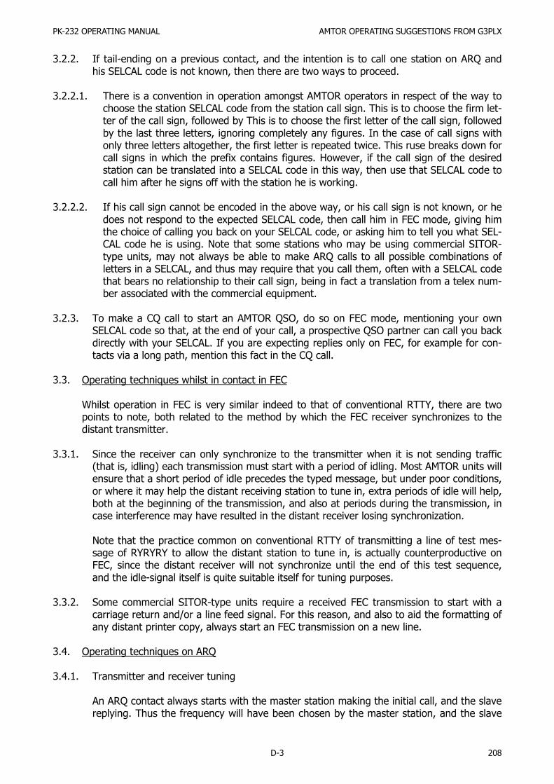
PK-232 OPERATING MANUAL AMTOR OPERATING SUGGESTIONS FROM G3PLX
D-3 208
3.2.2. If tail-ending on a previous contact, and the intention is to call one station on ARQ andhis SELCAL code is not known, then there are two ways to proceed.
3.2.2.1. There is a convention in operation amongst AMTOR operators in respect of the way tochoose the station SELCAL code from the station call sign. This is to choose the firm let-ter of the call sign, followed by This is to choose the first letter of the call sign, followedby the last three letters, ignoring completely any figures. In the case of call signs withonly three letters altogether, the first letter is repeated twice. This ruse breaks down forcall signs in which the prefix contains figures. However, if the call sign of the desiredstation can be translated into a SELCAL code in this way, then use that SELCAL code tocall him after he signs off with the station he is working.
3.2.2.2. If his call sign cannot be encoded in the above way, or his call sign is not known, or hedoes not respond to the expected SELCAL code, then call him in FEC mode, giving himthe choice of calling you back on your SELCAL code, or asking him to tell you what SEL-CAL code he is using. Note that some stations who may be using commercial SITOR-type units, may not always be able to make ARQ calls to all possible combinations ofletters in a SELCAL, and thus may require that you call them, often with a SELCAL codethat bears no relationship to their call sign, being in fact a translation from a telex num-ber associated with the commercial equipment.
3.2.3. To make a CQ call to start an AMTOR QSO, do so on FEC mode, mentioning your ownSELCAL code so that, at the end of your call, a prospective QSO partner can call you backdirectly with your SELCAL. If you are expecting replies only on FEC, for example for con-tacts via a long path, mention this fact in the CQ call.
3.3. Operating techniques whilst in contact in FEC
Whilst operation in FEC is very similar indeed to that of conventional RTTY, there are twopoints to note, both related to the method by which the FEC receiver synchronizes to thedistant transmitter.
3.3.1. Since the receiver can only synchronize to the transmitter when it is not sending traffic(that is, idling) each transmission must start with a period of idling. Most AMTOR units willensure that a short period of idle precedes the typed message, but under poor conditions,or where it may help the distant receiving station to tune in, extra periods of idle will help,both at the beginning of the transmission, and also at periods during the transmission, incase interference may have resulted in the distant receiver losing synchronization.
Note that the practice common on conventional RTTY of transmitting a line of test mes-sage of RYRYRY to allow the distant station to tune in, is actually counterproductive onFEC, since the distant receiver will not synchronize until the end of this test sequence,and the idle-signal itself is quite suitable itself for tuning purposes.
3.3.2. Some commercial SITOR-type units require a received FEC transmission to start with acarriage return and/or a line feed signal. For this reason, and also to aid the formatting ofany distant printer copy, always start an FEC transmission on a new line.
3.4. Operating techniques on ARQ
3.4.1. Transmitter and receiver tuning
An ARQ contact always starts with the master station making the initial call, and the slavereplying. Thus the frequency will have been chosen by the master station, and the slave

PK-232 OPERATING MANUAL AMTOR OPERATING SUGGESTIONS FROM G3PLX
D-4 209
station will have 'netted' onto that. It often happens that an offset at either station willthen result in the signal from the slave received at the master being a bit off tune. If themaster station then readjusts his transceiver main tuning dial to remedy this error, he willalso offset his transmitter, probably putting his signal off tune in the distant slave's receiv-er. A never ending series of readjustments can then take place. The equivalent problemon other modes rarely causes trouble since the retune operations only take place eachtime the transmission is passed from one station to the other. However, with the 'quick-break' operation of ARQ, such offsets can cause trouble. Thus a convention has beenadopted among AMTOR operators to prevent this situation arising.
This convention is that the master station must at all times keep his transmitter frequencyconstant. Thus if the master finds that the slave signal is not correctly tuned, he must ad-just only his receiver frequency to remove the error, leaving his transmitter frequency un-touched, by the use of the RIT control on the transceiver. The slave station, on the otherhand, may, if he finds his receiver off tune, make a correction by adjusting both receiverand transmitter frequencies together, by means of the main tuning dial.
This convention prevents any offset from accumulating, and is the frequency-domain ana-log to the time-domain synchronizations in which the master station clock determines thephasing for the contact.
3.4.2. Changing frequency during an ARQ QSO
Since both stations are 'listening-through,' if there is some interference on the frequency,or if a change of frequency is desirable for some other reason, for example, to clear a call-ing frequency, then both stations may wish to move together to another frequency.Whilst at first there may seem to be no reason to discuss such a simple operation, whichis very common and easy to perform on any other mode, there are problems if a QSY ismade in some ways in ARQ, and there are advantages in adopting a specific technique.
3.4.2.1. The easiest way of QSY-ing an ARQ QSO is to close it down, and restart it again on anew frequency, with the master station choosing the new frequency. This is referred toin AMTOR circles as a 'cold' QSY. This technique is the preferred one when moving off acalling frequency, and in other conditions where there is good copy between both sta-tions, so that an orderly close-down and start-up is anticipated.
3.4.2.2. If, however, the QSY is desired because of interference, then another technique is pos-sible, and if carried out in the right way, can have decided advantages, but if carriedout wrongly, can cause problems and offence to other band users. This is referred to asthe 'HOT' QSY technique.
In this, the master station, while in the re-phasing mode, moves off the old frequencyto the new one, and the slave then follows. It is important, while the master station isdoing this, for him to prevent his transmitter from radiating, in order to prevent unin-tentional interference to other band users, and also to disable the connection betweenthe receiver and the AMTOR, in order to prevent unintentional 'phantom sync.' to anyother ARQ signals which may be audible during the search for a new frequency. Suchphantom sync will result in spillage of traffic from the QSO in progress, or from the oth-er QSO, or both. It can only be the master station that leads in a 'hot' QSY. If the slavestation were to attempt to lead a QSY, then, in the event that it was not successfullycompleted before the contact timed-out into a re-phase operation, the slave would nolonger be transmitting, and there would be no way for the slave to establish a new fre-quency without restarting as a master and thus lose some traffic.

PK-232 OPERATING MANUAL AMTOR OPERATING SUGGESTIONS FROM G3PLX
D-5 210
3.4.3. Fixed-channel working
Since it is possible to leave an AMTOR station in 'standby' mode on a channel, and for anyother station to make a specific call to that station, a common practice in AMTOR is tomonitor such a specific frequency. The question arises as to what exactly is the 'frequen-cy' of an AMTOR emission. There are, unfortunately, two different conventions in use, onemore commonly used in amateur circles, and the other used universally by all non-ama-teur users.
3.4.3.1. The 'amateur' convention says that an AMTOR signal (and indeed any FSK signal) isspecified with reference to the frequency of the higher-frequency tone in the pair.Thus, if a sked, for example, is prearranged to occur on 14075 kHz, this is taken tomean that the two transmitted tones are on 14075.00 and 14074.83 kHz.
3.4.3.2. The 'commercial' convention, also increasingly by amateurs, says that the signal isspecified with respect to the frequency of the imaginary center-channel. This a signalsaid to be on 21100 kHz will have one tone on 21099.915 kHz and the other on21100.085 kHz, that is, 85 Hz either side of the nominal, rather than with one tone on,and the other tone 170 Hz below, the nominal. Note that it is assumed that the fre-quency-shift is universally accepted to be 170 Hz.
Thus, in any specification of a 'frequency' in connection with AMTOR working, due re-gard must be taken of the convention intended, at least until such time as one of theseconventions is dropped in favor of the other.
Another factor is significant in respect of setting frequencies on the dials of SSB trans-ceivers used on AMTOR with audio-frequency-shift tones used. Since the tones will re-sult in transmissions offset from the suppressed carrier frequency, the dial, which nor-mally indicates the suppressed carrier frequency, will not read correct. It will be neces-sary to add or subtract a fixed amount to the dial frequency in order to establish theactual frequency in use. For example, if the transceiver is in use or lower sideband,with audio tone frequencies of 2125 and 2295 Hz, then, to operate on an 'amateur' fre-quency of 14075, the transceiver dial must be set to 14077.125, that is, 2.125 kHzhigher than the desired frequency. The two radiated tones will then be on 14077.125-2.125 (14075) and 14077.125-2.295 (14074.83). Other offsets must be used if a 'com-mercial' channel is to be set up (2.210 Hz), and the offset will be in the other directionif upper sideband is to be used in the transceiver. The offset must be recalculated if thetone frequencies are different from those quoted.
Users of transceivers with an FSK connection, must consult the transceiver handbook orsupplier to establish if an offset has to be applied to the dial frequency. Even if thetransceiver supplier indicates that no offset is needed, it will be necessary to establish ifthe 'amateur' or 'commercial' convention is implied, or some other convention.
3.4.4. Use of the 'over' or 'break-in' facility
In ARQ mode, it is possible, by use of the 'over' or 'break-in' facility, to interrupt the send-ing of the other station. This facility should be used with care, and only in situationswhere it is essential to do so. The reason is that there are inherent reasons why recoveryfrom such an interruption can result in garbled copy at one end of the contact, in particu-lar in 'figs' garble.
If possible, wait until the other station is idling before breaking in, and if the other stationbreaks in to your transmission, it will probably help to use the 'clear buffer' facility if such

PK-232 OPERATING MANUAL AMTOR OPERATING SUGGESTIONS FROM G3PLX
D-6 211
exists to abort the later transmission of any unsent text which would be inappropriate tothe new context of the break-in.
3.4.5. The AMTOR alphabet, like the RTTY alphabet, consists of two sets of 30 characters, witha switch made between them by two 'shift' or 'case' codes. On inherent result of this tech-nique is that it is often not known which shift the distant receiving station is in at thecommencement of the contact. For this reason it is always good practice to send the ap-propriate shift code at the start of each contact, and indeed, at the start of each mes-sage, and perhaps at more frequent intervals. With terminals encoded in teleprinter code,there are always two keys labeled 'letters' and 'figures,' and so it is simply necessary tohit the appropriate one of these keys as required. However, on more modern terminals,these two keys may not exist, and the sending of the shift code may be 'hidden' from theuser.
However, since the distant terminal could still nevertheless be in the wrong shift, therewill always be the requirement to send the shift code at the start, to prevent the distantreceiver copying the first part of the text in the wrong shift. Consult the documentationwith your AMTOR unit or terminal in order to establish how to do this if there is no 'let-ters' or 'figures' key.
4. Format of the SELCAL Code
Although the convention is to form the SELCAL from the call sign, some AMTOR units have thepossibility to include any AMTOR character in the SELCAL. It is strongly recommended, howev-er, that only the 26 letters A-Z are used in SELCAL codes.

PK-232 OPERATING MANUAL AMTOR THEORY
E-1 212
APPENDIX E – AMTOR THEORY
1.1. Definition and Standards References
AMTOR (Amateur Teleprinting Over Radio) is a microprocessor-controlled, error-correctingdata communications system.
AMTOR is derived directly from the commercial practice known as SITOR (Simplex TelexOver Radio), as described in Recommendations 476-2 and 476-3 of the CCIR (InternationalConsultative Committee on Radio, an agency of the International Telecommunications Un-ion, and in turn, of the United Nations. These international commercial standards wereadapted for amateur use in 1977 by J. Peter Martinez, G3PLX.
AMTOR is now permitted in many countries, including the United States of America, as spe-cifically defined in Part 97.69 of the Rules of the Federal Communications Commission.
1.2. Application
Like SITOR, AMTOR uses synchronous transmission of a seven-bit information code to ach-ieve essentially error-free message and text communications. The transmit function encodesall characters with a mark-to-space polarity ratio, always as four ones and three zeros, thusallowing the receiving station's processor to check for that ratio.
There are two basic AMTOR modes. In the ARQ mode (also called Mode A), Station A sendsa block of three characters during an interval of 210 milliseconds. The sending system thenpauses for 240 milliseconds, during which Station B transmits a single acceptance code.
1.3. Mode A – ARQ
In the interactive ARQ mode, all transmitted characters are sent in blocks or groups, eachcontaining three characters. This mode operates between two synchronized or phased sta-tions.
If the receiving system's processor detects an incorrect mark-to-space (ones-to-zeros) polar-ity ratio, the receiving station's processor or computer sends a command back to the send-ing station's processor or computer to retransmit the invalid group of characters.
No data are displayed on the screen at the receiving site until it has passed this test, beenvalidated and is essentially error-free.
Data transmission is at 100 bauds, corresponding to a character length of 70 milliseconds.The overall cycle time for a three-character block and the control signal reply is 450 millisec-onds.
If the information has been received incorrectly, Station B issues a 'request for repetition'(RQ) code. Receiving the RQ code, Station A repeats the three-character block. This processrepeats until Station B transmits a second control code, an acceptance code, after which thenext three characters are sent as a. block.
Station A displays the transmitted text on its display device only after receiving the accept-ance code from Station B. This is called 'echoing.'
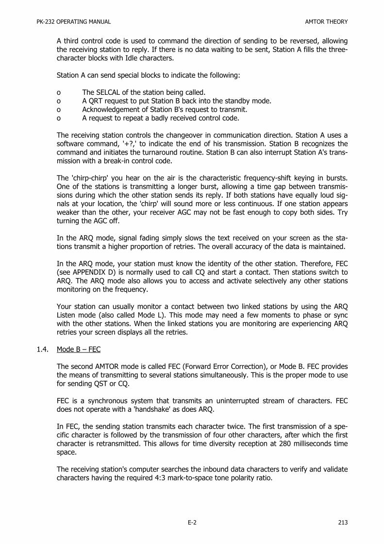
PK-232 OPERATING MANUAL AMTOR THEORY
E-2 213
A third control code is used to command the direction of sending to be reversed, allowingthe receiving station to reply. If there is no data waiting to be sent, Station A fills the three-character blocks with Idle characters.
Station A can send special blocks to indicate the following:
o The SELCAL of the station being called.o A QRT request to put Station B back into the standby mode.o Acknowledgement of Station B's request to transmit.o A request to repeat a badly received control code.
The receiving station controls the changeover in communication direction. Station A uses asoftware command, '+?,' to indicate the end of his transmission. Station B recognizes thecommand and initiates the turnaround routine. Station B can also interrupt Station A's trans-mission with a break-in control code.
The 'chirp-chirp' you hear on the air is the characteristic frequency-shift keying in bursts.One of the stations is transmitting a longer burst, allowing a time gap between transmis-sions during which the other station sends its reply. If both stations have equally loud sig-nals at your location, the 'chirp' will sound more or less continuous. If one station appearsweaker than the other, your receiver AGC may not be fast enough to copy both sides. Tryturning the AGC off.
In the ARQ mode, signal fading simply slows the text received on your screen as the sta-tions transmit a higher proportion of retries. The overall accuracy of the data is maintained.
In the ARQ mode, your station must know the identity of the other station. Therefore, FEC(see APPENDIX D) is normally used to call CQ and start a contact. Then stations switch toARQ. The ARQ mode also allows you to access and activate selectively any other stationsmonitoring on the frequency.
Your station can usually monitor a contact between two linked stations by using the ARQListen mode (also called Mode L). This mode may need a few moments to phase or syncwith the other stations. When the linked stations you are monitoring are experiencing ARQretries your screen displays all the retries.
1.4. Mode B – FEC
The second AMTOR mode is called FEC (Forward Error Correction), or Mode B. FEC providesthe means of transmitting to several stations simultaneously. This is the proper mode to usefor sending QST or CQ.
FEC is a synchronous system that transmits an uninterrupted stream of characters. FECdoes not operate with a 'handshake' as does ARQ.
In FEC, the sending station transmits each character twice. The first transmission of a spe-cific character is followed by the transmission of four other characters, after which the firstcharacter is retransmitted. This allows for time diversity reception at 280 milliseconds timespace.
The receiving station's computer searches the inbound data characters to verify and validatecharacters having the required 4:3 mark-to-space tone polarity ratio.

PK-232 OPERATING MANUAL AMTOR THEORY
E-3 214
If both appearances of the same character are mutilated and fail the polarity-ratio test, nodata are printed or displayed. Because the second appearance of the character occurs 280milliseconds after the first appearance, the mathematical probabilities are that noise burstswill not destroy both appearances of the character.
At the beginning of an FEC transmission, the message is preceded by ten Idle characters.After 28 characters of the message, a sequence of five Idle characters Is inserted in eachmessage space, giving the receiving stations a reference timing interval to which they canlock again if necessary.
The code sequence for the repeated idle string is different from the first idle string so thatthey are identified correctly. The sequence looks like this:
Idle 1 - Idle 2 - Idle 1 - Idle 2 - Idle 1, etc.
for ten occurrences. Then each character is transmitted interleaved with four sequentialcharacters and its own repetition.
Unlike ARQ (Mode A), in FEC (Mode B), the transmitter operates at 100% duty cycle. Con-sult the operating manual and duty-cycle specifications of your radio equipment for the cor-rect operating conditions suitable for RTTY and FEC operation. As a general rule, many re-cent transmitters must be operated at significantly reduced power levels to prevent exces-sive dissipation in the amplifier stages. A 50 % reduction in operating power is frequentlyrequired.
In FEC and ARQ, accurate synchronization or phasing is necessary. Each station sends phas-ing bursts at the beginning of each contact, with a crystal clock maintaining the timing rela-tionship during the contact. If the stations lose synchronization lock during the contact, theprogram provides automatic re-phase procedures.

PK-232 OPERATING MANUAL ASYNCHRONOUS VERSUS SYNCHRONOUS TRANSMISSION
F-1 215
APPENDIX F – ASYNCHRONOUS VERSUS SYNCHRONOUS TRANSMISSION
Since the beginning of electromechanical telegraphy and teleprinting, the problem of maintainingthe proper timing relationship between the sender and the receiver has been resolved by mechani-cal synchronization methods. These were based on the basic ideas of 'start-stop' telegraphy.
The original Baudot rotary distributor permitted the sending distributor to tell the receiving distrib-utor when the rotary contact was at a reference point in the rotation of the motor shaft. The dis-tributor created a start and stop pulse at the beginning and end of each character. In teleprinteroperation, each character has carried its own sync information in the form of the traditional 'start'element at the beginning of each character, and the 'stop' bit at the end of the character.
In some systems, the 'stop' element is one, one-and-one-half, or two bits. The result is reducedefficiency - each character has a fixed amount of 'overhead.' These housekeeping bits carry nouser information. They exist only to keep the sending and receiving machines in sync. This re-duced efficiency has kept a lid on higher data rates and has been a block in the constant searchfor faster ways of sending more information for more people.
As data processing requirements became more demanding newer forms of synchronizationevolved. A method was developed which applied a single synchronizing string to an entire string ofcharacters, rather than include sync information in each character. The 'overhead', or housekeep-ing bits previously inserted into each character for sync purposes were eliminated; higher datarates became practical without sacrificing data integrity. This newer method, called 'synchronous'transmission, is used in higher speed and specialized forms of transmission.
Unlike conventional Baudot and ASCII RTTY operation, both AMTOR modes, ARQ and FEC, usesynchronous, rather than asynchronous transmission.
Your computer keyboard sends asynchronous data to your PK-232 with start and stop bits in eachcharacter.
When you enter the AMTOR operating modes, the PK-232 program routines strip the start andstop bits from the characters and establish the synchronous transmission required in AMTOR.
The PK-232 has a versatile software program for digital communications techniques that gives youcomputer-based Morse code, and the choice of four different data transmission codes: Baudot, AS-CII, AMTOR, and Packet-Radio.
The question of transmission speed is discussed separately. It should be understood that thespeed at which a digital code is used has no real relationship to the choice of the code itself. As ageneral rule, any code can be used at any speed within the capacity of the system software.

PK-232 OPERATING MANUAL DATA TRANSMISSION CODES
G-1 216
APPENDIX G – DATA TRANSMISSION CODES
MYTHS AND MISUNDERSTANDINGS
1. 'RTTY' Means 'Baudot' – Not True!
'RTTY' does not mean 'Baudot'. 'RTTY' is a simple abbreviation for 'RadioTeleTypewriter.' Baudot,ASCII, AMTOR and packet radio are not exactly different modes. They are different languages andmethods within the same mode – RTTY. Think of them this way:
MODE: Human Speech RTTYCODES: English Baudot
French ASCIISpanish AMTORItalian Packet
2. 'Baudot Code is Obsolete' – Not True!
The largest record communications network in the world today (record communications systemsleave a permanent record of the traffic passed) is the International Telex Network. Worldwide,there are over one-and-one-half million regular telex subscribers connected to their domestic net-works, and, in turn, to the International Telex Network through gateway switching systems in eachcountry.
Telex is, by definition, a Baudot code system, operating at 50 bauds- (66 WPM) in CCITT Interna-tional Alphabet Number 2, the same code specified for the amateur radio service in Part 97.69 ofthe Commission's rules.
Although telex was invented in 1932 and the first automatic telex network established in 1933, un-til the recent advent of packet network transmission and switching standards, the telex networksof the world had been growing world-wide at an annual rate of about 22 % per year. This doesnot indicate obsolescence.
Here in the U.S.A. many of the commercial carriers are still enlarging their networks. Instead ofabandoning the Baudot code in favor of anything else, they are changing from the traditional 50-baud operating speed to 200- and 300-baud telex, still using Baudot, and generally working intostored program control computer-based telex switching exchanges. In many of these cases, theBaudot code is being retained in those applications where line and circuit noise is greater than theoptimal design goals, and not easily improved.
Many manufacturers are still producing Baudot telex and teleprinter systems. What has disap-peared is the electromechanical teleprinter. The older teleprinters are being replaced with all-elec-tronic systems using microprocessor-based terminals with video displays and various types of diskand tape storage. Internally, many of these terminals work with the ASCII and EBCDIC codes.
By means of code- and speed-conversion firmware, these terminals send the Baudot code to thetelex and telephone lines for integration into the telex and gentex networks and leased-line serv-ices.
At times, the Baudot code has certain advantages over other standardized codes. These advantag-es are discussed in detail later in these Appendices.
PK-232 OPERATING MANUAL DATA TRANSMISSION CODES
G-2 217
Some newcomers to digital radio are unsure which digital code is best to use on a given band un-der given conditions. This brief tutorial outlines some differences between Baudot and ASCII andexplains some of the advantages and disadvantages of both codes.
BAUDOT CODE
History
The Baudot/Murray code dates from about 1874, when Emile Baudot, a Lieutenant in the FrenchTelegraph Service, developed the Baudot distributor for telegraphy. This code uses a 'start' bit anda 'stop' bit to mark the beginning and end of each character, and five information or data bits toidentify each character.
With only five information bits, the total number of possible combinations equals 25 or 32. But ourEnglish language has 26 letters (counting upper case only!), 10 numerical digits and 9 commonpunctuation characters. That adds up to 45 alphanumeric characters. How can we transmit at least45 different characters if the available code only permits 32 code combinations?
The Baudot/Murray codes resolve this seeming paradox by the same stunt used on your old elec-tromechanical typewriter – you shift to FIGS or UPPER CASE. Now you have the numerical digits,the punctuations and other useful things like parentheses, cent sign, dollar sign, number sign, 'at'sign, asterisk, percent sign, ampersand, underscore, etc. You can handle 64 possibilities. That'sfine – if you never need to handle anything but text message traffic or connect to computers!
Code Variations
Over the years, different versions of the same code have evolved, creating some confusion in bothdomestic and international traffic. Western Union, the Bell System, the Weather Bureau, theF.A.A., the Armed Forces and the Associated Press all developed their own versions of the samecode. Some users couldn't get together on the same keyboard configurations.
When the International Telex Network was formed before World War II telex users had yet anoth-er version of the Baudot/Murray code - the International Telegraph Alphabet Number 2.
Limitations
Although it is the most widely used data transmission code in the world (the International TelexNetwork is still the largest of all record communications networks) the Baudot/Murray code hastwo serious drawbacks:
1. The code makes no provision for parity or any other built-in method of detecting transmissionor reception errors. This means the receiving system has no way of telling if an error has oc-curred;
2. The code is sequential --a specific control character defines the identity of the following seriesof characters for a period of time until a new control character is recognized. FIGURES SHIFTis an example.
The two control characters which identify the shift, or 'case' are 'LETTERS' and 'FIGURES'. Thosewho operated in the days of electromechanical teleprinters and Teletype™ machines know whathappened when the data was kicked into upper case by a noise hit, and how frustrating it was tohave lines of unintelligible stuff.

PK-232 OPERATING MANUAL DATA TRANSMISSION CODES
G-3 218
Applications
Baudot/Murray code is still the most widely used RTTY code in amateur radio, and this will proba-bly continue for some years to come. Even with its limitations, Baudot still has some advantagesfor the amateur operator.
ASCII – AMERICAN STANDARD CODE FOR INFORMATION INTERCHANGE
ASCII is an extension of the eight-bit code developed decades ago and used for years in the BellSystem TWX network. ASCII was published as a standard by ANSI, the American National Stand-ards Institute around 1963, in order to achieve some degree of compatibility for the newborn datacommunications field. ASCII is also known as International Alphabet Number 5, and is standar-dized for international traffic at various data rates.
ASCII uses seven bits to define each character. That give us a maximum of 27, or 128 possiblecombinations. We now have the ability to transmit upper case and lower case letters, all punctua-tions, ten digits and control codes such as 'start of text', 'end of text', 'horizontal tab', 'vertical tab','form feed', 'backspace' and many other control functions unavailable in Baudot.
ASCII is not an eight-bit code; the eighth bit is reserved for calculating parity – a form of error de-tection. However, many ASCII systems do not require the eighth bit for parity and operate wellwithout it.
OTHER DATA CODES
Baudot code was fine in the days when all communication was between humans. But as technolo-gy developed machines started to communicate with other machines without involving humans.Better and more efficient codes had to be developed for transmitting information so that the ma-chines themselves could evaluate the received information and request repeats if errors were re-ceived.
As data processing first evolved and data communication codes were developed, the data process-ing systems used their own codes. One of the first of these was 'BCD', Binary Coded Decimal. BCDwas used for internal calculations inside a data processing device. BCD has no alpha characters,only numbers, and thus was unsuitable as a communications code for use by humans.
BCDIC
Binary Coded Decimal Interchange Code was developed when the data processing systems had tocommunicate with humans using printed characters on a printing device. This code was fine forcommunication with humans, but was unsuitable for machine-to-machine communications becauseit lacked any form of parity or error-checking capabilities.
BCDIC had the same problem as Baudot – a machine couldn't tell when an error occurred in trans-mission.
EBCD
Extended Binary-Coded Decimal, developed for the IBM Selectric typewriter, solved the parityproblem. The Selectric principle allowed typing and printing of hard copy, while it could also gener-ate a unique code suitable for transmitting over a communications facility. Also known in the fieldas PTTC (Paper Tape Transmission Code), EBCD uses six information bits and a parity bit so thereceiving system can determine if an error has occurred in a specific character. But EBCD is a se-

PK-232 OPERATING MANUAL DATA TRANSMISSION CODES
G-4 219
quential code with upper and lower case characters. So, while parity could detect errors and pro-voke repeats, the sequential nature of the code made its efficiency rate less than desirable.
EBCDIC
Extended Binary-Coded Decimal Interchange Code was developed in 1962. It uses 8 bits whichmakes it capable of transmitting 256 characters. But for communications EBCDIC might bedeemed a backward step because it has no parity capability. Users who don't need all 256 charac-ters have redefined the code, using EBCDIC as a base and identifying particular characters withodd or even parity bits. Although there are occasional compatibility problems because of parity def-initions varying between users, EBCDIC is still widely used in data processing communications sys-tems.
Still Other Codes
Several other data codes are in use today, some of them dating back decades. Hollerith Code, de-veloped more that 80 years ago, is still used commercially and Is generally associated with punchcard systems. There are others such as Jaquard Code, Moore ARQ Code, Syntoc Code, AP Codeand others too numerous to list here.

PK-232 OPERATING MANUAL SCHEMATIC DIAGRAMS
H-1 220

PK-232 OPERATING MANUAL SCHEMATIC DIAGRAMS
H-2 221

PK-232 OPERATING MANUAL PARTS PICTORIAL
I-1 222
APPENDIX I – PARTS PICTORIAL

PK-232 OPERATING MANUAL PARTS LIST
J-1 223
APPENDIX J – PARTS LIST PK-232 PCB
DESCRIPTION REF. DESIG. DESCRIPTION REF. DESIG.
CAP MY 103P, 10%, 50VCAP MY 104P, 10%, 50VCAP MY 562P, 10%, 50VCAP MY 104P, 5%, 50VCAP MY 122P, 2%, 50VCAP MY 473P, 2%, 50VCAP MY 103P, 5%CAP CR 102P, 50VCAP CR 103P, 50VCAP CR 104P, 50VCAP VARIABLE, 5-40PCAP EL 106P RAD, 25V
CAP EL 107P RAD, 25VCAP EL 335P RAD, 100VCAP EL 476P RAD, 35VCAP EL 108P AX, 35VCAP PP 223P, 2%CAP PP 472P, 2%CAP PP 103P, 1%CAP SM 220PCAP SM 33PCAP SM 330PCAP SM 680PCAP SM 820P
RES ¼W 5% 10.00RES ¼W 5% 100.00RES ¼W 5% 1.00K
RES ¼W 5% 100.00KRES ¼W 5% 120.00RES ¼W 5% 12.00KRES ¼W 5% 15.00KRES ¼W 5% 18.00KRES ¼W 5% 200.00
RES ¼W 5% 2.00KRES ¼W 5% 20.00K
RES ¼W 5% 330.00
RES ¼W 5% 3.30KRES ¼W 5% 360.00RES ¼W 5% 430.00RES ¼W 5% 470.00RES ¼W 5% 4.70K
RES ¼W 5% 47.00KRES ¼W 5% 510.00RES ¼W 5% 5.10KRES ¼W 5% 510.00KRES ¼W 5% 68.00
C20, C21C18, C41, C45C88C47, C49C50C46C54C11-C16, C19C3, C4, C7, C8, C61-C64C27, C66, C68-87C53C22-25, C40, C44, C55-C57, C59, C60, C65, C67C1, C28C51C17, C29, C52C26C58C48C30-C39, C42, C43C2C6C5C10C9
R28R21-R24, R26, R27R3, R4, R5, R19, R20,R36, R124, R131, R140,R148, R181R30, R95, R108R172R166R162R163R91, R92, R106, R107,R126, R159R79R35, R93, R97, R110,R150R6, R13-R18, R133, R186R160R135R171R125R1, R2, R25, R29, R37,R141, R142, R144, R145,R149, R161, R169, R177,R180, R182, R183R127R134R9, R10, R132R80, R123, R128R170
RES ¼W 5% 680.00RES ¼W 5% 8.20KRES ¼W 5% 10.00K
RES ¼W 5% 100.00KRES ¼W 1% 1.10KRES ¼W 1% 11.00KRES ¼W 1% 1.69KRES ¼W 1% 16.90KRES ¼W 1% 1.78KRES ¼W 1% 174.00KRES ¼W 1% 18.70K
RES ¼W 1% 19.60KRES ¼W 1% 20.00KRES ¼W 1% 22.10KRES ¼W 1% 23.20K
RES ¼W 1% 243.00RES ¼W 1% 24.30KRES ¼W 1% 267.00KRES ¼W 1% 26.70KRES ¼W 1% 3.09KRES ¼W 1% 30.10KRES ¼W 1% 33.20KRES ¼W 1% 3.74KRES ¼W 1% 4.99KRES ¼W 1% 49.90KRES ¼W 1% 6.19KRES ¼W 1% 6.49KRES ¼W 1% 7.50KRES ¼W 1% 8.06KRES ¼W 1% 80.60KRES ¼W 1% 845.00RES ¼W 1% 95.30K
PNL POT .625 SQ 1K
POT TRM. .15L/S 10KPOT TRM. .15L/S 100KPOT TRM. .15L/S 20KPOT TRM. .15L/S 25KPOT TRM. .15L/S 500POT TRM. .15L/S 5K
DIODE SIG 1N448
DIODE PWR 1N4003DIODE PWR 1N4006DIODE ZNR 1N751
R151, R152R82R46, R57, R66, R76, R87,R89, R90, R102, R104,R105R78R138R119, R121R174R56R137R42, R52, R62, R72R48, R58, R67, R77, R88,R103,R84, R99R39R85R47, R55, R65, R75, R86,R101R31, R173R112, R114, R116R44, R51, R61, R71R43, R53, R63, R73R175R41, R50, R60, R70R118, R120R139R153, R154, R156, R158R45, R54, R64, R74R176R100R38, R40, R49, R59, R69R113, R115, R117R83, R98R32R68
R136
R164, R165, R168R96R167R155R157R81
D1-D9, D13-D26, D28,D33D10-D12, D29, D30D31, D32D27

PK-232 OPERATING MANUAL PARTS LIST
J-2 224
DESCRIPTION REF. DESIG. DESCRIPTION REF. DESIG.
LED RED MV5025LED 10 SEG BARGRAPH
XISTOR NPN 2N39114XISTOR NPN MPSA42XISTOR NPN MPS6521XISTOR NPN MPS6561XISTOR PFET VN10LMXISTOR PNP 2N3906
IC LM317LIC LM317TIC NE556NIC MC34074P
IC XR2206IC LM3914IC 74LS04IC 7406IC 74LS11IC 74LS32IC 7445IC 74HCT139IC 74LS164IC 74LS393IC 27128IC 27256IC 6264IC Z80A CPUIC Z8530IC Z8536IC 40668
IC MC1488IC MC1489
DS1-DS20, DS22DS21
Q6, Q7, Q10, Q11Q8Q3Q5Q1, Q2Q4, Q9
U41U21U13U23, U26, U28, U30,U32, U34U40U36U15, U16, U39U18, U37, U38U14U17U11, U12U10U9U8U3U2U4, U5U1U7U6U22, U24, U25, U27, U29,U31, U33, U35U20U19
DIP SOCK 20 PINDIP SOCK 28 PINDIP SOCK 40 PIN
HDR R/AX2.1 3 POSHDR R/A.10 5 POSHDR R/AX2.10 7 POSHDR STR.10 2 POSHDR STR .10 3 POSHDR R/A 'D' 25 POSJACK PWR 2.1MMJACK PHON 3.5MMJACK PHONO P.C.CONN R/A DIN 5 PIN
SW P-P 2P2TSW P-P 6P2T
X-TAL 2.4576 MHZX-TAL 4.000 MHZ
HEATSIN THM 60198KNB SW GRY .4 X .2FUSE CLIP PCBFUSE 1 AMPSHORT PLUG .10
DS21U2, U3, U4, U5U1, U6, U7
J12J4, J6, J8J11JP1JP2, JP3J2J1J3, J5J9, J10J7
SW1SW2
Y2Y1
U21SW1, SW2F1F1JP1, JP2, JP3

PK-232 OPERATING MANUAL SPECIFIC RADIO CONNECTIONS
K-1 225
APPENDIX K – SPECIFIC RADIO CONNECTIONS
MFG RADIO PIN OUT NOTES
ICOM 4 pin AFSK 1PTT 2GND 4
8 pin AFSK 1PTT 5GND 6, 7
RX audio available on pin 8 of some radios.
HTs RX audio available on tip of large conn.
YAESU 4 pin AFSK 2PTT 3GND 1
8 pin AFSK 8PTT 6GND 7
FT-270/2700 require mic DC block cap &series diode w/PTT
FT-x03FT-x09FT-727
RX audio available on tip of large conn.
FT-208 AFSK 1PTT 3GND 4
RX audio on pin 2.
KENWOOD 4 pin AFSK 1PTT 2GND 3, 4
5 pin AFSK 1PTT 2GND 4, 5
6 pin AFSK 1PTT 2GND 6
8 pin AFSK 1PTT 2GND 7, 8
TR-2500 RX audio available on tip of small conn.
TR-x600TH-x1
RX audio available on tip of small conn.

PK-232 OPERATING MANUAL SPECIFIC RADIO CONNECTIONS
K-2 226
TEN-TEC 4 pin AFSK 1PTT 3GND 2
1/4" stereo AFSK ringPTT tipGND sleeve
AZDEN 12 pin AFSK 12PTT 9GND 2, 11
8 pin AFSK 1PTT 7GND 2
DRAKE 4 pin AFSK 1PTT 2GND 3
1/4" stereo AFSK ringPTT tipGND sleeve
ALINCO ALR 206T Brown and Shield to Pin 7.External Speaker for Audio.
RADIO SHACK HTX 100 WHITE 1RED 2GREEN 6SHIELD 7BROWN 8
NOTE: On all radios, the shield should go to the same place as the brown wire, unless oth-erwise noted.
ICOM IC-751
Pin 1 Output from the discriminator circuitPin 2 13,8 VDC, switched with the front panel powerPin 3 RED, PTT when groundedPin 4 GREEN, Fixed level audio outPin 5 WHITE, Input for mic gain controlPin 6 8 VDC when transmitting, max. 5 mAPin 7 Input for external AGCPin 8 BROWN & SHIELD, GroundPin 9 FSK N. Input for RTTY, Mark High - Space LowPin 10 NCPin 11 Input for transverter controlPin 12 Output reference voltage for band switchingPin 13 Output for external band switching
This information has been obtained from various sources and AEA assumes no responsibility for ac-curacy. Please consult your particular transceiver operator's manual for confirmation.

PK-232 OPERATING MANUAL FACSIMILE OPERATION
M-1 227
FACSIMILE OPERATION
Overview
Weather Facsimile (WEFAX) is transmitted throughout the Short-Wave radio spectrum, primarily toprovide information to ships at sea. Typical stations you may find broadcast weather maps showingcurrent as well as predicted weather conditions and satellite photographs showing the cloud coverover a large area.
Not only weather information is transmitted, but also news photographs from the wire services(see the frequency list below). Many of the photographs you see in your local newspaper everynight are distributed via facsimile and some can be copied on your printer. Although a dot matrixprinter does not have the resolution of an expensive facsimile receiver, it can display reasonabledefinition.
The facsimile mode, or simply FAX, is fairly straight-forward, and a little background on its formatmay be helpful. A facsimile picture is usually sent by placing the original picture on the slowly-ro-tating drum of a facsimile transmitter where it is scanned horizontally at a pre-set rate. The infor-mation from each horizontal scan is converted into an audio frequency between 1,500 Hz and2,300 Hz, as shown below in Figure 1. 1,500 Hz represents pure black, and 2,300 Hz representspure white. In between these two frequencies lie varying shades of gray; the "gray scale" as it isoften called. Figure 1 shows a facsimile signal as it lies within the typical audio passband of a SSBreceiver.
Figure 1: Facsimile signal inside the audio passband of a typical SSB receiver
Dot-matrix printers and the PK-232 unfortunately cannot resolve shades of gray, and so cannotprint with photographic quality. The PK-232 uses its 1,000 Hz wideshift filters which have a centerfrequency of 1,700 Hz to copy facsimile transmissions. Since facsimile is transmitted using a maxi-mum of only 800 Hz shift, a FAX signal is tuned-in by "straddling" the 1,700 Hz center frequency ofthe PK-232's filters.
This means that when a facsimile signal is tuned-in, anything below 1,700 Hz will produce a blackdot on the page,and anything above 1,700 Hz will print nothing thus leaving a white area as dia-gramed in Figure 2 below. In this way the PK-232 decodes the gray-scale of a transmitted facsimilepicture allowing reasonably good resolution from a dot-matrix printer. WEFAX maps however onlycontain black and white, so excellent reproduction of weather charts is obtained using a dot-matrixprinter.
Figure 2: How the PK-232 receives and digitizes facsimile signals Finding Fax Frequencies
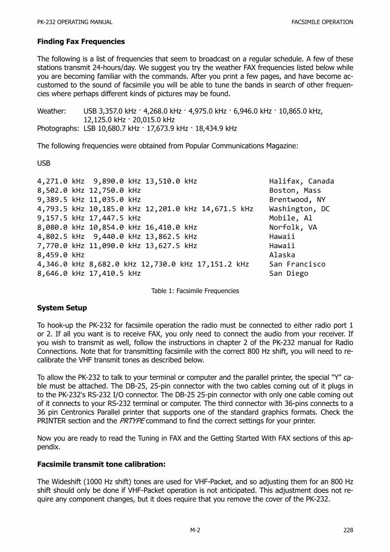
PK-232 OPERATING MANUAL FACSIMILE OPERATION
M-2 228
Finding Fax Frequencies
The following is a list of frequencies that seem to broadcast on a regular schedule. A few of thesestations transmit 24-hours/day. We suggest you try the weather FAX frequencies listed below whileyou are becoming familiar with the commands. After you print a few pages, and have become ac-customed to the sound of facsimile you will be able to tune the bands in search of other frequen-cies where perhaps different kinds of pictures may be found.
Weather: USB 3,357.0 kHz · 4,268.0 kHz · 4,975.0 kHz · 6,946.0 kHz · 10,865.0 kHz,12,125.0 kHz · 20,015.0 kHz
Photographs: LSB 10,680.7 kHz · 17,673.9 kHz · 18,434.9 kHz
The following frequencies were obtained from Popular Communications Magazine:
USB
4,271.0 kHz 9,890.0 kHz 13,510.0 kHz Halifax, Canada
8,502.0 kHz 12,750.0 kHz Boston, Mass
9,389.5 kHz 11,035.0 kHz Brentwood, NY
4,793.5 kHz 10,185.0 kHz 12,201.0 kHz 14,671.5 kHz Washington, DC
9,157.5 kHz 17,447.5 kHz Mobile, Al
8,080.0 kHz 10,854.0 kHz 16,410.0 kHz Norfolk, VA
4,802.5 kHz 9,440.0 kHz 13,862.5 kHz Hawaii
7,770.0 kHz 11,090.0 kHz 13,627.5 kHz Hawaii
8,459.0 kHz Alaska
4,346.0 kHz 8,682.0 kHz 12,730.0 kHz 17,151.2 kHz San Francisco
8,646.0 kHz 17,410.5 kHz San Diego
Table 1: Facsimile Frequencies
System Setup
To hook-up the PK-232 for facsimile operation the radio must be connected to either radio port 1or 2. If all you want is to receive FAX, you only need to connect the audio from your receiver. Ifyou wish to transmit as well, follow the instructions in chapter 2 of the PK-232 manual for RadioConnections. Note that for transmitting facsimile with the correct 800 Hz shift, you will need to re-calibrate the VHF transmit tones as described below.
To allow the PK-232 to talk to your terminal or computer and the parallel printer, the special "Y" ca-ble must be attached. The DB-25, 25-pin connector with the two cables coming out of it plugs into the PK-232's RS-232 I/O connector. The DB-25 25-pin connector with only one cable coming outof it connects to your RS-232 terminal or computer. The third connector with 36-pins connects to a36 pin Centronics Parallel printer that supports one of the standard graphics formats. Check thePRINTER section and the PRTYPE command to find the correct settings for your printer.
Now you are ready to read the Tuning in FAX and the Getting Started With FAX sections of this ap-pendix.
Facsimile transmit tone calibration:
The Wideshift (1000 Hz shift) tones are used for VHF-Packet, and so adjusting them for an 800 Hzshift should only be done if VHF-Packet operation is not anticipated. This adjustment does not re-quire any component changes, but it does require that you remove the cover of the PK-232.

PK-232 OPERATING MANUAL FACSIMILE OPERATION
M-3 229
After the cover of the PK-232 is removed, reconnect the power connector and the RS-232 cable toyour computer and turn the PK-232 on. When you see the cmd: prompt, type CAL to enter the
AFSK-tone calibration mode. The screen should now be continuously displaying the VHF Mark-tone(approximately 1200 Hz) followed by R167 which indicates the variable resistor that adjusts thetone frequency. If your display is substantially different, see the CALIBRATE description in the PK-232 manual. Locate the variable resistor R167 on the right side of the PK-232 circuit board nearthe internal heat-sink. With a small screwdriver begin adjusting R167 until the display reads nearly1300.
Hit the <Space bar> and observe that your display is now continuously reading somewhere near2200 followed by R165. This is the VHF Space-tone frequency, and R165 is the variable resistorthat controls it. Locate and adjust R165 until the display reads nearly 2100. Type a Q to exit thecalibration routine.
The Wideshift transmit tones have now been adjusted to an 800 Hz shift for facsimile transmitoperation. If it is desired to reset the tones to 1200 and 2200 Hz (1000 Hz shift) all that is neces-sary is to repeat the above procedure adjusting R167 for 1200 Hz, and R165 for 2200 Hz.
Tuning in FAX
Facsimile is most often found on Upper Sideband and sounds similar to monitoring an ARQ AMTORQSO with both stations being of equal signal strength. Since the most common facsimile signalsare WEFAX, we have set the PK-232 FAX default parameters to copy the weather charts and manysatellite photographs. We recommend that you start with one of the listed weather frequencies, orfrequencies from Popular Communications in Table 1 when first beginning to copy facsimile.
Upon tuning into a WEFAX signal, you will notice that the facsimile sound seems to repeat at therate of twice a second. This is the same as the horizontal scan frequency mentioned earlier and al-lows you to distinguish different facsimile services by speed. Common horizontal scan rates are 2lines per Second, which is typically used in weather facsimile broadcasts, 1-line per Second forphotographs, and 4-lines per second, for some foreign facsimile stations. Remember these repeti-tion rates and listen for them as you tune across the bands in search of new pictures to print.
The PK-232 uses the 1,000 Hz wideshift filters which have a center frequency of 1.7 kHz for copy-ing facsimile transmissions. As a result, you must tune 1.7 kHz lower than the frequencies listed inTable 1 when using Upper Sideband. Similarly, in Lower Sideband, one must tune 1.7 kHz higherthan the frequencies listed in Table 1.
Since facsimile is transmitted using a maximum of only 800 Hz shift, a FAX signal is tuned-in by"straddling" the 1.7 kHz center frequency of the PK-232's filters. The PK-232 LED bar-graph shouldbe tuned so that the facsimile signal is roughly centered in the display as shown in the middle ofFigure 3 below. If the audio frequency is too low, the bar-graph will look something like the left-most display. If the audio frequency is too high, it will look something like the right-most display,Facsimile tuning is not especially critical when copying WEFAX, but a properly tuned signal is nec-essary to produce an evenly distributed gray-scale when printing facsimile photographs.
Frequency too low Tuned In Frequency too High
Figure 3: Facsimile tuning indicator conditions for proper and improper FAX tuning

PK-232 OPERATING MANUAL FACSIMILE OPERATION
M-4 230
Compatible Printers
In the latest release of the PK-232 firmware we have tried to include most of the common graphicsformats supported by printer manufacturers. Supported in this release are Epson, IBM, Tandy/Ra-dio Shack, Okidata, and Apple, as well as a few others.
Before you can continue, you must set the PRTYPE command for your make and model of printer.In essence, this command tells the PK-232 what kind of printer is attached to the FAX cable. ThePRTYPE command section in this appendix lists the different settings available and their printercompatibility. See the Operating Manual Addendum for a list of printers, listed in order of printermanufacturer and the proper PRTYPE setting. If your exact printer is not listed you should checkthe PRTYPE command section of this appendix for instruction concerning the graphics formats sup-ported. Please note that not all the printers listed have been tested with the PK-232. According tothe information provided by the printer manufacturer the PRTYPE setting given should work prop-erly.
Getting Started With FAX
To start receiving WEFAX broadcasts on the PK-232 and your graphics compatible printer, you firstmust tell the PK-232 that there is a parallel printer connected to it by going to the command modeand issuing the command PRCON ON. (Don't forget to set the PRTYPE command for your printer.)The PK-232 will respond with:
PRCON was OFFPRCON now ON
At this point you will observe that the STA , CON , STBY and PKT LEDs are on. The MULT LED may also be on if the printer is "Off Line" or is not connected to the PK-232. This is normalwhenever the printer command PRCON is ON and is nothing to worry about. Remember to turnPRCON off when you are through printing facsimile to return the status LEDs to their normal func-tion.
Now all that is necessary is to put the PK-232 into FAX mode by typing FAX. The PK-232 will re-spond with:
OPMODE was XXXXXOPMODE now FAX
The PK-232 is now in the Facsimile Standby-Receive mode which means it is waiting for a synchro-nization signal from a facsimile transmitter to begin a new picture. Verify this by entering theOPMODE command. The PK-232 should respond with:
OPMODE FAX STBY RCVE
At this point make sure the THRESHOLD control is fully clockwise, otherwise the printer will notprint. If you do not want to wait for the beginning of a new picture, you may type LOCK.
This forces a synchronization-lock, and starts the printer printing regardless of what kind of signalis being monitored. Since this synchronization lock was not sent by the transmitting station, thepicture will probably not be correctly positioned on the page. Rather, it will likely appear to be splitin half with the left half of the picture on the right half of the page, and the right half of the pic-ture on the left half of the page.

PK-232 OPERATING MANUAL FACSIMILE OPERATION
M-5 231
To correct for this, a justification command has been included that allows the user to shift the en-tire image to the left in ½ inch increments. For example if the left-edge of the picture appearsroughly 4-½ inches away from the left edge of the paper, issuing the command JUSTIFY 9 willshift the left edge of the picture to the left 4-½ inches (9 × 0.5 inch) correcting its justification.The PK-232 will respond with:
JUSTIFY was 0JUSTIFY now 9
This procedure will not be necessary if the PK-232 synchronizes from the transmitted facsimile sig-nal. The PK-232 will always respond with JUSTIFY was 0 when a new justification parameter is
entered. In this way, the PK-232 always assumes that the left-hand margin of the picture has beenset to 0 inches.
To stop the printer, you may either exit the facsimile mode by changing to another mode or enterthe RCVE command, which puts the PK-232 back into facsimile standby receive. Standby receive isthe same as if you have just entered the FAX mode from another mode. The PK-232 will wait untilit receives the synchronization signal from a facsimile station before beginning to print again.
Weather FAX as well as most other facsimile prints from left to right, but occasionally you may finda station that is reversed. If you come across such a transmission, you may simply issue the com-mand LEFTRITE OFF to correct this. The PK-232 will respond with:
LEFTRITE was ONLEFTRITE now OFF
Similarly, you may come across a station that appears to be inverted; that is printing black whereyou expect white, and leaving white where you expect black. In this case you may issue the com-mand FAXNEG ON. The PK-232 will respond with:
FAXNEG was OFFFAXNEG now ON
What was before printing black will now be white, and vice versa.
How the graphics will look on your printer depends on the setting of the GRAPHICS command.There are 7 graphics commands providing horizontal dot densities from 480 dots to 1,920 dots hor-izontally across a page. The default setting of GRAPHICS 1 should work with most printers exceptsome OKIDATA models. See the GRAPHICS and PRTYPE commands section of this appendix formore information.
Printing Other Services
Most of the weather services at least in the US use a facsimile scan speed of 2-lines per Second,which corresponds to an FSPEED of 2 (Default). Facsimile photographs often use 1-line per Sec-ond, which is an FSPEED of 1. Some foreign services use speeds of 4-lines per Second, which is anFSPEED of 4. Speeds of 1.5 and 3-lines per Second are also supported. See the Command Summa-ry in the back of this appendix for more information on FSPEED.
When different horizontal scan speeds are used, the number of lines per vertical inch can alsovary. If nothing is done to change the number of lines printed by the printer, the pictures may ap-pear squashed or elongated. The ASPECT command resolves this by allowing from one to six linesto be printed out for every six lines received. The default setting is ASPECT 2 which means that 2out of 6, or 1 out of every 3 horizontal lines is printed. This is the most common setting you will

PK-232 OPERATING MANUAL FACSIMILE OPERATION
M-6 232
use for WEFAX, but other services may require using other values to print pictures without aspectratio distortions.
If your terminal program allows you to save non-ASCII files to disk for later transmission or print-ing, you can route the Facsimile data to the RS-232 port instead of the parallel printer by using thecommand PRFAX. Turning PRFAX OFF tells the PK-232 to send the graphics codes to the RS-232port, and not to the parallel printer port. The PK-232 will respond with:
PRFAX was ONPRFAX now OFF
When you are routing a facsimile signal to the RS-232 port you must be sure to have AWLEN setto 8, 8BITCONV ON, PARITY 0 and ACRDISP 0 before you turn on the file capture of your terminalprogram. Entering the TRANSPARENT mode before you turn the file-capture of your terminal pro-gram on will eliminate the need for setting the above except for AWLEN which must be set to 8. Ifthe TRANSPARENT Mode is used, make sure TRFLOW and TXFLOW are both OFF. Hardware flow-control is a must when transferring 8-bit files.
Not all terminal programs allow the user to capture 8-bit ASCII-files. You must make certain yourprogram will allow this if you are to successfully save the facsimile file. You must also make sureyour terminal program does not add Carriage returns or Linefeeds to the captured file. After thefile has been saved to disk, it should be able to be printed or retransmitted.
Transmitting FAX
Typing an X while in Command Mode puts the PK-232 into facsimile transmit. To correctly transferthe saved facsimile file on disk, AWLEN must be 8, PARITY must be 0, PRFax must be OFF and thePK-232 must be in Transparent Mode. TRFLOW should be off.
The PK-232 is set-up for 1,000 Hz shift transmit and receive, but commercial facsimile is sent using800 Hz shift as described earlier. The VHF transmit tones should be recalibrated for 800 Hz shift(1,300 Hz and 2,100 Hz) as described in the Setup section before you transmit facsimile.
When you type an X and begin to transmit, the PK-232 first sends a black tone for 5 Seconds, andthen a 300 Hz alteration of black and white tones for another 5 Seconds, during which time theOP-MODE will read:
OPMODE FAX STBY SEND
After the 10 Seconds have passed the PK-232 OPMODE will go from STBY SEND to SYNCSEND. At this time the PK-232 will transmit 30 seconds of synchronization pulses at the proper
rate determined by the FSPEED command. As soon as the sync pulses start, the PK-232 can acceptdot graphics from the computer. You must remember to wait until the OPMODE changes to SYNCSEND before entering the TRANSPARENT Mode and sending the facsimile graphics file to the PK-232.
You should be able to watch the progress of the facsimile data file you are sending to the PK-232from your terminal program. When the file has been completely sent to the PK-232 you have 3 op-tions to return to receive:
First; you may type a <CTRL-D> which will cause the PK-232 to send 5 Seconds of alteration be-tween black and white at a 450 Hz rate which signifies the end of the picture to the receiving sta-tion, and then return to receive.

PK-232 OPERATING MANUAL FACSIMILE OPERATION
M-7 233
Second; typing a <CTRL-F> will do the same as a <CTRL-D>, only adding a CW ID before return-ing to receive.
Third; typing an R while in Command Mode will force an immediate receive, sending neither anend of picture signal, nor a CW ID.
Remember you must identify every 10 minutes regardless of the length of the picture you aresending. Using a higher FSPEED setting will help speed transmission of facsimile pictures.
See the GRAPHICS and PRTYPE section of this appendix for descriptions of the codes the PK-232will acknowledge.
In Case of FAX Difficulty
Problem:Printer appears to be printing two pictures side by sideSolution:Reduce the FSPEED setting. Chances are you are trying to print a facsimile transmission that is be-ing sent at 240 lines per Minute with the FSPEED set at 120 Lines per Minute. Similarly the trans-mission may be at 120 lines per Minute with the FSPEED set at 60 lines per Minute.
Problem:Printer never printsSolution:Make sure the command PRCON is on, the THRESHOLD knob is fully clockwise and the DCD Light Emitting Diode is on.
Make sure the OPMODE is FAX SYNC RECEIVE, and if not place the PK-232 into FAX Mode by typ-ing FAX and then force a synchronization-lock by typing LOCK. If the printer does not begin toprint within a minute or so, do the following.
Issue the command PROUT ON which will cause all characters sent by the PK-232 to be echoed tothe printer. If you now see the correct characters printing on the printer, but still cannot get fac-simile to print, you need to check your PRTYPE setting and make sure your printer supports graph-ics.
Problem:Facsimile does not print straight down the page, but rather veers consistently to the left or to theright.Solution:If you observe this, it indicates the 4.0000 MHz master oscillator has drifted off frequency and willhave to be recalibrated. This is relatively simple and can be done with or without a frequencycounter as described below.
Without a frequency counter:1. Open the PK-232 by removing the six screws that hold the gray top-chassis in place and care-
fully separate it from the bottom chassis. Be careful that you do not strain of the wires to thebattery holder.
2. Reconnect the PK-232 to your radio, computer, printer and to +13 VDC, then turn it on and al-low it to warm-up for 30 minutes.
3. Locate and tune-in a strong facsimile signal.4. With the help of Figure 4 below, locate the variable capacitor C53 in the left-rear quadrant of
the PK-232 circuit board. It is the only variable capacitor on the circuit board and is immediate-ly to the right of Q1 and Q2.

PK-232 OPERATING MANUAL FACSIMILE OPERATION
M-8 234
5. Tune-in and start printing a strong facsimile signal. Let it print a few lines to observe the angleat which the facsimile picture deviates from vertical.
6. With a small screwdriver adjust C53 no more than 1/8 of a turn and then let the printer print afew more lines of the picture. Observe the printout to see if the adjustment has made thingsbetter or worse.
7. Repeat Steps 5 and 6 making smaller and smaller adjustments of C53 until you observe thefacsimile is printing vertically. Note that this may require quite a few adjustments before theoscillator is back on frequency.
If you have a frequency counter with a high-impedance input, you may do the following:
1. Open the PK-232 by removing the six screws that hold the gray top-chassis in place and care-fully separate it from the bottom chassis. Be careful that you do not strain the wires to the bat-tery holder.
2. Reconnect the PK-232 to +13 VDC, then turn it on, and allow it to warm up for 30 minutes.3. With the help of Figure 4 below, locate the variable capacitor C53 in the left-rear quadrant of
the PK-232 circuit board. It is the only variable capacitor on the circuit board and is immediate-ly to the right of Q1 and Q2.
4. Place the high-impedance probe of the frequency counter on pin-6 of the Z80 microprocessorwhich will provide a strong square-wave clock signal.
5. Adjust C53 until the frequency counter reads 4.00000 MHz ±10 Hz.
Figure 4: PK-232 circuit board layout showing the location of capacitor C53

PK-232 OPERATING MANUAL FACSIMILE OPERATION
M-9 235
Command Summary
The following commands have been added to the PK-232 firmware for use in the Facsimile Mode.Some existing commands that function in the Facsimile Mode are also listed here.
ASPECT n Mnemonic: ASP Default: 2Mode: FAX
Parameters: n - 1 to 6, specifying the number of FAX scan lines the PK-232 prints out of eve-ry 6 lines received.
ASPECT controls the aspect ratio of the length to the width of a FAX image. On most weathercharts, the default of ASPECT 2 keeps the shapes received hi the right proportion. On some othertransmissions, you may want more vertical resolution. To stretch the image down the page, use ahigher setting of ASPECT, such as 4.
The Index Of Cooperation, or IOC is an international measure of the aspect ratio. The formula forthe CCITT IOC is:
(vertical scan line density) × (horizontal width)––––––––––––––––––––––––––––––––––––––
3.14159
The IEEE Index Of Cooperation is simply the numerator of the CCITT IOC or:
(vertical scan line density) × (horizontal width)
Both the CCITT and the IEEE IOCs are given for each ASPECT setting below.
The figures given are for narrow and wide carriage printers.
ASPECT CCITT IOC (Narrow) CCITT IOC (Wide)
123456
1100550 (Weather Charts 576)367 (Wirephotos 352)275 (WEFAX Satellite 288)220183
1788894596 (Weather Charts 576)447358 (Wirephotos 352)298 (WEFAX Satellite)
Weather charts are transmitted at a nominal CCITT IOC of 576. ASPECT 2 is so close to this thatthe charts print with no noticeable distortion.
In receive, ASPECT 2 causes the PK-232 to sample 2 out of every six lines received. ASPECT 4makes it sample four of every six lines. In transmit, ASPECT 2 causes the PK-232 to send everyline three times. ASPECT 4 causes it to send even lines twice, and odd lines once. When sendingan image from one PK-232 to another, we recommend that aspect be set to the same number forboth units, and that ASPECT be set to 1, 2, 3, or 6 which provide symmetrical repetition patterns.Otherwise it is possible that the receiving unit will miss lines, and double the lines it does receive.
Please note that high settings of ASPECT such as 6 may generate data so often that your printercan not handle the high data rate.

PK-232 OPERATING MANUAL FACSIMILE OPERATION
M-10 236
DISPLAY (Class) Mnemonic: DISP Immediate CommandMode: Command
Parameters: Class - A new parameter identifier has been added: (F)ax displays the FAX relatedparameters
DISPLAY is an immediate command.
When DISPLAY is typed without a parameter, the PK-232 responds with:
DISPLAY A, C, F, I, L, M, R, T, Zcmd:
FAX Mnemonic: FA Immediate CommandMode: Command
FAX is an immediate command that switches your PK-232 into the Facsimile Mode. The unit startsout in FAX standby, waiting to detect sync pulses that start a frame.
FAXNEG ON|OFF Mnemonic: FAXN Default: OFFMode: FAX
Parameters: ON - The white and black senses are reversedOFF - The white and black senses are normal
One might use FAXNEG ON when receiving an image consisting mostly of black, as in a satellitephoto. In this case it might help to save your printer ribbon, as well as accentuating features suchas cloud cover.
Note: FAXNEG ON is NOT the same as RXREV ON. RXREV reverses the entire signal, including thesync pulses. FAXNEG keeps the sync pulses so that they can be recognized, but reversesthe image data. When copying a reversed signal, you should switch sidebands or useRXREV ON rather than using FAXNEG ON. This way, the PK-232 can still receive the syncpulses properly. Switching sidebands may be easier since in this case, white will still be thehigher pitch frequency and appear on the right (Space) side of the bar-graph indicator.
FSPEED n Mnemonic: FS Default: 2 (2 lines/sec)Mode: FAX
Parameters: n - 0 to 4 selects the FAX horizontal scan rate in lines per minute from the tablebelow
FSPEED (Highest Print Density Usable) narrow carriage wide carriage
12340
1 line/Second2 lines/Second3 lines/Second4 lines/Second1.5 lines/Second
60 lines/Minute120 lines/Minute180 lines/Minute240 lines/Minute90 lines/Minute
275 dpi138 dpi92 dpi69 dpi183 dpi
169 dpi85 dpi56 dpi42 dpi113 dpi
You can tell the scan rate by listening to the signal. Most weather charts are transmitted at 2lines/Second (default), or 120 lines/Minute. Some facsimile photographs and Japanese news issent at 60 lines/minute. You may also find satellite photos being sent at 240 lines/Minute.

PK-232 OPERATING MANUAL FACSIMILE OPERATION
M-11 237
GRAPHICS n Mnemonic: GR Default: 1 (960 dots)Mode: FAX
Parameters: n - 0 to 6 selects the FAX horizontal graphics dot density printed on the printerfrom the table below
Density in dots/inch as a function of GRAPHICS and PRTYPE.
GRAPHICS
PRTYPE 0 1 2 3 4 5 6
0-34-78-9
12-1920-2124-2728-2932-35
3640-4344-4748-51
6060601366060606060607280
1201201201206012012012060120144160
12012014414460144
·1206012014480
24024020016060240
·240601207280
808080806060·
8060607280
727272727272·
7260727280
909010096100
··
90601447280
In reading and using the various GRAPHICS densities above, the user should be aware that not allcombinations of parameters work, especially with slower printers (100 CPS or less). For example, acombination of PRTYPE 2, FSPEED 4, GRAPHICS 1 and ASPECT 4 would require the printer to printa pattern of dots 8 by 960 every 3 seconds, which would mean trouble for a 100 CPS printer. Onthe other hand, a combination of PRTYPE 2, FSPEED 1, GRAPHICS 0 and ASPECT 2 would alwayswork, as it results in a pattern of bots 8 by 480 every 24 seconds. We know the following combina-tions of dot densities and FSPEED cause trouble.
(s = sluggish response to commands)(x = can't work; disabled)
FSPEED, 8" width FSPEED, 13" width
Dot Density 0 1 2 3 4 0 1 2 3 4
60 dpi
72 dpi s
80 dpi X
90 dpi X
96 dpi s X
100 dpi s X
120 dpi s X X
136 dpi X X X
144 dpi X s X X
160 dpi s x X X X X X
200 dpi X X X X X X X
240 dpi s X X X X X X X

PK-232 OPERATING MANUAL FACSIMILE OPERATION
M-12 238
GRAPHICS determines the horizontal print density of the parallel printer. Changing the GRAPHICSsetting in the middle of an image causes the unit to print a few lines of garbage while it adjusts tothe new setting.
JUSTIFY n Mnemonic: JU Immediate CommandMode: FAX
Parameters: n - 0 to 25 specifies the number of half-inches the facsimile image will be movedcloser to the edge of the paper.
The number 0-25 is in units of half-inches, or 1/16 of standard paper width. In most cases LEFT-RITE will be ON, so entering JUSTIFY 1 will move the image one half-inch to the left. If LEFTRITEis OFF, then the JUSTIFY will move the image to the right n half-inches.
You may want to first try entering a number one less than the number of half-inches the image isaway from the edge of the paper. For example if you measure that the left-hand edge of the imageis 4-½ inches away from the edge of the paper, first try the entering JUSTIFY 8 This will move theimage 4 inches to the left. If this is found to be not enough, you can always enter JUSTIFY 1,which will move the image the additional half-inch to the left.
JUSTIFY should only be needed after a manual start has been issued by using the Lock command.If the PK-232 is allowed to synchronize by itself, JUSTIFY should not be needed.
LEFTRITE ON|OFF Mnemonic: LE Default: ONMode: FAX
Parameters: ON - The signal is scanned from left to rightOFF - The signal is scanned from right to left
Occasionally you may come across images that are obviously backwards. Turning LEFTRITE OFF ortoggling it by issuing the command LEFTRITE TOG will reverse the scanning direction. This com-mand is useful for printing wirephotos.
LOCK Mnemonic: L Immediate CommandMode: FAX
LOCK is an immediate command that tells the PK-232 to start printing regardless of whether or notthe facsimile sync pulses have been detected.
This is a manual start command for FAX. Normally the transmitting station starts out a FAX imagewith sync pulses so that the receiver can line-up the image with the edge of the paper. The syncpulses consist of lines of 5 % white, and 95 % black with the beginning of the white pulse signify-ing the left edge of the following image. The PK-232 detects the sync pulses on a good signal andlines-up the image accordingly. If you tune-in on a signal too late, or there is so much noise thatthe sync pulses are not detected, you can start the printer manually with the LOCK command. Ifyou issue a LOCK to the PK-232, you will probably need to use the JUSTIFY command to properlyalign the image.

PK-232 OPERATING MANUAL FACSIMILE OPERATION
M-13 239
OPMODE Mnemonic: O Immediate CommandMode: Command
OPMODE is an immediate command that shows the PK-232's current mode of operation and sys-tem status. The four following indications have been added to the OPMODE command to displayfacsimile related status:
OPMODE FAX STBY RCVEOPMODE FAX SYNC RCVEOPMODE FAX STBY SENDOPMODE FAX SYNC SEND
In receive, STBY means the PK-232 is searching for sync pulses to start printing the next image.SYNC means the PK-232 has detected the sync pulses, or that synchronization has been forcedwith the LOCK command, and the PK-232 should be starting to print the next image.
In transmit, STBY means that the PK-232 is idling or sending the 300 Hz motor start tone before itsends the sync pulses, or that it is sending the 450 Hz stop tone. SYNC means that the unit issending either sync pulses, or image dots. If the computer has not yet sent image data to the PK-232, the unit will transmit the white tone continuously, and the status will show SYNC SEND.
PRCON ON|OFF Mnemonic: PRC Default: OFFMode: FAX
Parameters: ON - A parallel printer is connected to the PK-232 via the special cable. The modeLEDs are disabled and may stay lit or flash randomly.
OFF - There is no parallel printer connected, or it is not currently in use. The modeLEDs are enabled and correctly show operating mode and status.
PRCON tells the PK-232 whether or not a parallel printer is connected to it via the special "Y" fac-simile cable. When PRCON is ON, the mode and status LEDs are disabled, and do not perform theirproper function. Some LEDs may remain lit, and others may flash randomly from time to time.
This is normal, and should be no cause for alarm. When you are through printing facsimile pic-tures, remember to turn PRCON OFF and the status LEDs will return to normal operation.
PRFAX ON|OFF Mnemonic: PRF Default: ONMode: FAX
Parameters: ON - FAX bit-graphics are sent to the parallel printer for immediate printing ifPRCON is also on.
OFF - FAX bit-graphics are sent to the terminal via the serial port using the printerescape codes, as set by PRTYPE and GRAPHICS.
PRFAX should be set to ON if a parallel printer is connected to the PK-232 and in use for printingfacsimile pictures. If you wish to save the facsimile graphic data to disk for later retrieval, simplyturn PRFAX OFF and make sure AWLEN is set to 8 to allow 8-bit data to be sent to the serial port.
Some terminal programs act upon escape codes instead of receiving the data, so be careful whenusing this command when in the FAX mode.
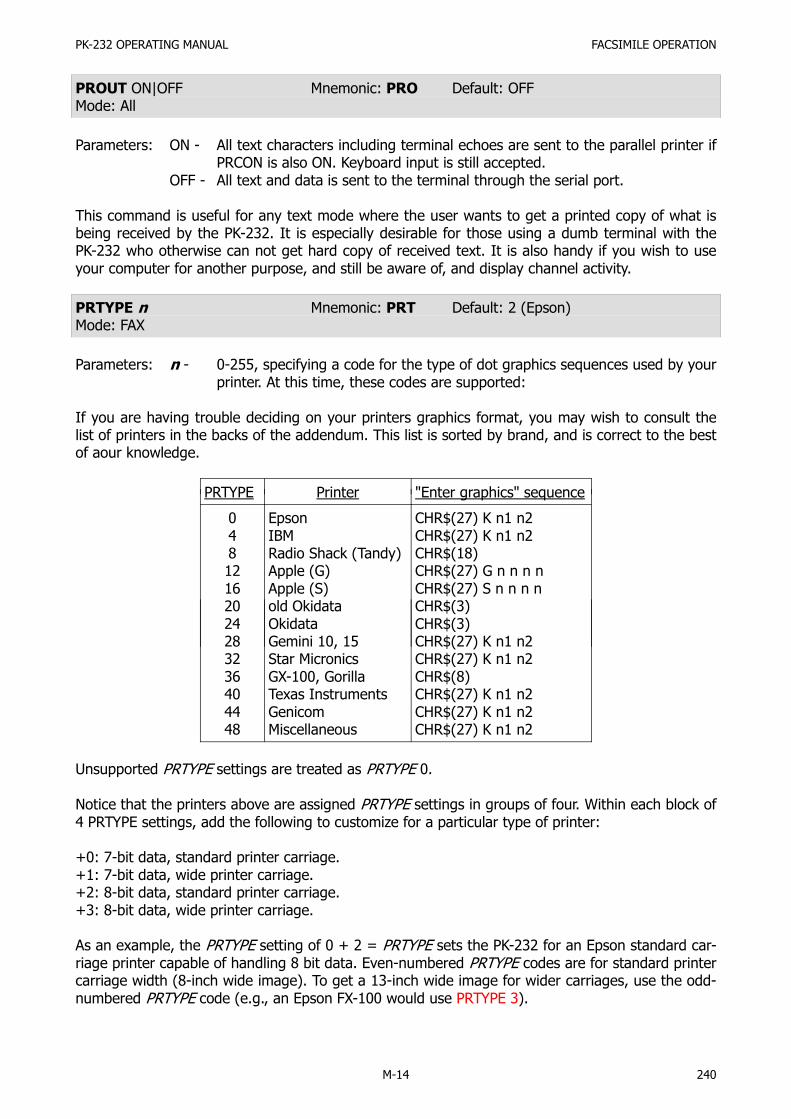
PK-232 OPERATING MANUAL FACSIMILE OPERATION
M-14 240
PROUT ON|OFF Mnemonic: PRO Default: OFFMode: All
Parameters: ON - All text characters including terminal echoes are sent to the parallel printer ifPRCON is also ON. Keyboard input is still accepted.
OFF - All text and data is sent to the terminal through the serial port.
This command is useful for any text mode where the user wants to get a printed copy of what isbeing received by the PK-232. It is especially desirable for those using a dumb terminal with thePK-232 who otherwise can not get hard copy of received text. It is also handy if you wish to useyour computer for another purpose, and still be aware of, and display channel activity.
PRTYPE n Mnemonic: PRT Default: 2 (Epson)Mode: FAX
Parameters: n - 0-255, specifying a code for the type of dot graphics sequences used by yourprinter. At this time, these codes are supported:
If you are having trouble deciding on your printers graphics format, you may wish to consult thelist of printers in the backs of the addendum. This list is sorted by brand, and is correct to the bestof aour knowledge.
PRTYPE Printer "Enter graphics" sequence
04812162024283236404448
EpsonIBMRadio Shack (Tandy)Apple (G)Apple (S)old OkidataOkidataGemini 10, 15Star MicronicsGX-100, GorillaTexas InstrumentsGenicomMiscellaneous
CHR$(27) K n1 n2CHR$(27) K n1 n2CHR$(18)CHR$(27) G n n n nCHR$(27) S n n n nCHR$(3)CHR$(3)CHR$(27) K n1 n2CHR$(27) K n1 n2CHR$(8)CHR$(27) K n1 n2CHR$(27) K n1 n2CHR$(27) K n1 n2
Unsupported PRTYPE settings are treated as PRTYPE 0.
Notice that the printers above are assigned PRTYPE settings in groups of four. Within each block of4 PRTYPE settings, add the following to customize for a particular type of printer:
+0: 7-bit data, standard printer carriage.+1: 7-bit data, wide printer carriage.+2: 8-bit data, standard printer carriage.+3: 8-bit data, wide printer carriage.
As an example, the PRTYPE setting of 0 + 2 = PRTYPE sets the PK-232 for an Epson standard car-riage printer capable of handling 8 bit data. Even-numbered PRTYPE codes are for standard printercarriage width (8-inch wide image). To get a 13-inch wide image for wider carriages, use the odd-numbered PRTYPE code (e.g., an Epson FX-100 would use PRTYPE 3).

PK-232 OPERATING MANUAL FACSIMILE OPERATION
M-15 241
PRTYPE 0-3, Epson:
Typical graphics code: <ESC>'K' n1 n2New-line code (7 bits): <ESC>'A' 7 LFNew-line code (8 bits): <ESC>'A' 8 LFPrinter reset code: <ESC>'@' CR LF
(Note: Epson MX-80 with Graftrax-80 uses PRTYPE 40 or 42).
Dot density
GRAPHICS PRTYPE 0, 2 PRTYPE 1, 3 Code
0123456
60 dpi120 dpi
fast 120 dpi240 dpi80 dpi72 dpi90 dpi
60 dpi120 dpi
fast 120 dpi
80 dpi72 dpi90 dpi
ESC 'K'ESC 'L'ESC 'Y'ESC 'Z'
ESC '*' 4ESC '*' 5ESC '*' 6
For Epson printers, not all GRAPHICS settings are implemented on each model:
GRAPHICSdots/inch:
060
1120
2120
3240
480
572
690
FX-80:RX-80:
yesyes
yesyes
yesyes
yesyes
yesyes
yes·
yesyes
PRTYPE 4-7, IBM:
Typical graphics code: <ESC>'K' n1 n2New-line code (7 bits): <ESC>'A' 7 <ESC> '2' LFNew-line code (8 bits): <ESC>'A' 8 <ESC> '2' LFPrinter reset code: CR LF
Dot density
GRAPHICS PRTYPE 4, 6 PRTYPE 5, 7 Code
0123456
60 dpi120 dpi
fast 120 dpi240 dpi80 dpi72 dpi90 dpi
60 dpi120 dpi
fast 120 dpi
80 dpi72 dpi90 dpi
ESC 'K'ESC 'L'ESC 'Y'ESC 'Z'
ESC '*' 4ESC '*' 5ESC '* 6

PK-232 OPERATING MANUAL FACSIMILE OPERATION
M-16 242
PRTYPE 8-9, Radio Shack (Tandy):
Typical graphics code: <ESC>19 18New-line code: CR 30Printer reset code: <ESC> 19 CR LF
Note that the Radio Shack DMP-130 printer may be used with PRTYPE 4 (IBM) if these DIPswitches are ON: 1-1, 1-3 and 1-6. To use PRTYPE 8, set all DIP switches OFF.The Radio Shack DMP-400, -420 and -500 should have the DIP switch for DMP-series emulation,not LP-series.
Dot density
GRAPHICS PRTYPE 8 PRTYPE 9 Code
0123456
60 dpi120 dpi144 dpi200 dpi80 dpi72 dpi100 dpi
60 dpi120 dpi144 dpi
80 dpi72 dpi100 dpi
ESC 19ESC 23ESC 19ESC 20ESC 19ESC 23ESC 20
Not all densities apply to each Radio Shack printer:
GRAPHICSdots/inch:
060
1120
2144
3200
480
572
6100
LP VIILP VIIIDMP-100DMP-105DMP-110DMP-120:DMP-130:DMP-200:DMP-400:DMP-420:DMP-500:DMP-2100:CGP-220:
yesyesyesyes
yes
yesyesyesyes
yesyes
yes yes
yes
yes
yes
yes
yesyesyes
yesyesyes

PK-232 OPERATING MANUAL FACSIMILE OPERATION
M-17 243
PRTYPE 12-15, Apple (G):
Typical graphics code: <ESC> 'N' <ESC> 'G0640'New-line code (7 bits): <ESC> 'T14' LF CRNew-line code (8 bits): <ESC> 'T16' LF CRPrinter reset code: <ESC> 'N' CR LF
The "G" refers to the graphics escape code used. Most Apple printers respond to both the Escape-G and Escape-S codes in exactly the same way. For those printers that use only the Escape-S com-mand, use PRTYPE 16-19.
(Note: We don't know of any Apple printer that has a parallel interface. Either connect the PK-232's serial port directly to the Apple printer and turn PRFAX OFF, or use a parallel-to-serial con-verter.)
GRAPHICS PRTYPE 12, 14 PRTYPE 13, 15 Code
0123456
136 dpi120 dpi144 dpi160 dpi80 dpi72 dpi96 dpi
136 dpi120 dpi144 dpi
80 dpi72 dpi96 dpi
ESC 'Q'ESC 'q'ESC 'p'ESC 'P'ESC 'N'ESC 'n'ESC 'E'
PRTYPE 16-19, Apple (S)
Typical graphics code: <ESC> 'N' <ESC> 'S0640'New-line code (7 bits): <ESC> 'T14' LF CRNew-line code (8 bits): <ESC> 'T16' LF CRPrinter reset code: <ESC> 'N' CR LF
The "S" refers to the graphics escape code used. Some printers are mostly compatible with Applegraphics escape codes, except they use the Escape-S sequence but not the Escape-G sequence.The C. Itoh 1550 and 8510 printers are in this category. Except for the graphics escape sequence,PRTYPE 16-19 works exactly the same as PRTYPE 12-15 (Apple G). Refer to your printer manualfor the graphics escape code used.

PK-232 OPERATING MANUAL FACSIMILE OPERATION
M-18 244
PRTYPE 20-21, Old Okidata:
Typical graphics code: 30 3New-line code: 3 14 3 2Printer reset code: 24 CR LF
Okidata 82A and 83A: Okigraph I EPROMs must be installed.
GRAPHICS: 0 5 6
Code:Density, dpi:Okidata ML 82A:Okidata ML 83A:Okidata ML 92:Okidata ML 93:
3060yesyesyesyes
2872··yesyes
29100yesyes
PRTYPE 24-27, Okidata:
Typical graphics code: 30 <ESC> 'P' 3New-line code: 3 14 3 2Printer reset code: <ESC> 24 CR LF
PRTYPE 26 and 27 are for the Okidata 192 and 193 with 8-bit APA graphics selected. In 7-bitmode, these printers also accept PRTYPE 20, 21,24 and 25.
PRTYPE 24 and 25 are similar to PRTYPE 20 and 21, except that 24 and 25 use the ESC-P andESC-R codes.
Okidata 192,193: In the printer's Menu Select Mode, select "CH SET NORM". For 7-bit data(PRTYPE 24 and 25), select "7/8 BIT 7 and "APA-7/8" 7. For 8-bit data (PRTYPE 26 and 27), select"7/8 BIT" 8 and "APA-7/8" 8. Also, "APA-UNT Y gives better print quality.
Dot density
GRAPHICS PRTYPE 26, 28 PRTYPE 25, 27 Code
01236
60 dpi120 dpi144 dpi240 dpi72 dpi
60 dpi120 dpi144 dpi
72 dpi
30 ESC 'P'30 ESC 'R'28 ESC 'R'
ESC '*' $71 $5828 ESC 'P'
Note: When switching from GRAPHICS 3 to some other GRAPHICS setting, type R to stop the im-age and reset the printer, change GRAPHICS, and then type L to start the image again. Or, if youdo not want to lose sync, change the GRAPHICS setting, turn the printer off and then turn it onagain.
Not all Okidata printers respond to all the available GRAPHICS settings. The table below showswhich settings are supported.

PK-232 OPERATING MANUAL FACSIMILE OPERATION
M-19 245
GRAPHICSdots/inch:
060
1120
2144
3240
460
572
6100
Okidata 82A:Okidata 83A:Okidata 92:Okidata 93:Okidata 192:Okidata 193:
yesyesyesyesyesyes
yesyes
yesyes
yesyes
yesyesyesyesyesyes
yesyesyesyes
yesyes
PRTYPE 28-29, Star Gemini:
Typical graphics code: <ESC> 'K' n1 n2New-line code: <ESC> '1'Printer reset code: <ESC> '@' CR LF
PRTYPE 28 and 29 are for the older Star Gemini 10 and 15. The Gemini 10X and 15X use PRTYPE32 and 33. The Star Micronics SG-10 and SG-15 use PRTYPE 4-7 (IBM) or 32-33 (Star).
GRAPHICS Dot density Code
01
60 dpi120 dpi
ESC 'K'ESC 'L'
PRTYPE 32-35, Star Micronics:
Typical graphics code: <ESC> 'K' n1 n2New-line code (7 bits): <ESC> 'J' 14 CRNew-line code (8 bits): <ESC> 'J' 16 CRPrinter reset code: <ESC> '@' CR LF
This set of PRTYPE codes would be used for various printers manufactured by Star Micronics, in-cluding these:
Delta 10, 15 – Radix 10, 15 – Gemini 10X, 15X – SD-10, SD-15 in Star Mode – SG-10, SG-15 inStar Mode – SR-10, SR-15 in Star Mode
These Star printers use other PRTYPE settings:
Gemini 10, 15 PRTYPE 28-29SB-10 PRTYPE 0-3?SD-10, SD-15 in IBM Mode PRTYPE 4-7SG-10, SG-15 in IBM Mode PRTYPE 4-7SR-10, SR-15 in IBM Mode PRTYPE 4-7NB-15 in 9-wire emulation mode PRTYPE 4-7Gemini 10XPC, 15XPC PRTYPE 4-7Delta 10PC, 15PC PRTYPE 4-7Radix 10PC, 15PC PRTYPE 4-7Gemini 10X Plus, 15X Plus PRTYPE 0-3Delta 10 Plus, 15 Plus PRTYPE 0-3Radix 10 Plus, 15 Plus PRTYPE 0-3NL-10, NL-15 w/ std. cartridge PRTYPE 0-3NL-10, NL-15 w/ IBM cartridge PRTYPE 4-7

PK-232 OPERATING MANUAL FACSIMILE OPERATION
M-20 246
GRAPHICS PRTYPE 32, 34 PRTYPE 33, 35 Code
0123456
60 dpi120 dpi
fast 120 dpi240 dpi80 dpi72 dpi90 dpi
60 dpi120 dpi
fast 120 dpi
80 dpi72 dpi90 dpi
ESC 'K'ESC 'L'ESC 'y'ESC 'z'
ESC 'g' 4ESC 'g' 5ESC 'g' 6
PRTYPE 36, GX-100/Gorilla:
Typical graphics code: 8<ESC> 16 0 0New-line code: LF 15Printer reset code: 16 '00' LF
PRTYPE 36 covers the Commodore 1525, Leading Edge Gorilla Banana, Seikosha GX-100, and C.Hoh GX-100.
GRAPHICS Dot density Code
0 60 dpi 8 ESC 16 0 0
These printers have a vertical dot density of 63 dpi, which changes the aspect ratio as follows:
ASPECT CCITT IOC IEE IOC
123456
963481321241193160
302515111008757606503
PRTYPE 40-43, Texas Instruments:
Typical graphics code: <ESC> 'K' n1 n2New-line code (7 bits): <ESC> 'A' 7 LFNew-line code (8 bits): <ESC> 'A' 8 LFPrinter reset code: <ESC> '@' CR LF
Texas Instruments 850 and 855 in DP Mode.Epson MX-80 with Graftrax-80 (GRAPHICS 0-2 only).
GRAPHICS Dot density Code
01256
60 dpi120 dpi
fast 120 dpi72 dpi144 dpi
ESC 'K'ESC 'L'ESC 'J'ESC 'N'ESC 'O'

PK-232 OPERATING MANUAL FACSIMILE OPERATION
M-21 247
PRTYPE 44-47, Genicom:
Typical graphics code: <ESC> 'K' n1 n2New-line code (7 bits): <ESC> 'A' 7 <ESC> '2' LFNew-line code (8 bits): <ESC> 'A' 8 <ESC> '2' LFPrinter reset code: CR LF
Genicom 3310 and 3320 in IBM-GP Mode.
GRAPHICS Dot density Code
012
72 dpi144 dpi
fast 144 dpi
ESC 'K'ESC 'L'ESC 'Y'
PRTYPE 48-51, Miscellaneous:
Typical graphics code: <ESC> 'K' n1 n2New-line code (7 bits): <ESC> 'A' 7 LFNew-line code (8 bits): <ESC> 'A' 8 LFPrinter reset code: <ESC> '@' CR LF
BMC BX-80, Blue Chip 120/10, Mannesmann Tally Spirit 80
GRAPHICS PRTYPE 48, 50 PRTYPE 49, 51 Code
01
60 dpi120 dpi
60 dpi120 dpi
ESC 'K'ESC 'L'
RCVE Mnemonic: R Immediate CommandMode: Command
RCVE is an immediate command that places the PK-232 in receive when issued from the commandmode. <CTRL-D> will also return the PK-232 to receive without first having to enter the commandmode. <CTRL-D> sends the stop signal before returning to receive which will stop the receivingstations printer. <CTRL-F> is the same as <CTRL-D> only in addition performs a CW ID for youbefore going back to receive.

PK-232 OPERATING MANUAL FACSIMILE OPERATION
M-22 248
TRACE ON|OFF Mnemonic: TRAC Default: OFFMode: Packet and FAX
The TRACE command has been enhanced to include Facsimile mode. When the OPMODE is FAX,TRACE is ON, and PRFAX is OFF, the graphics escape sequences and dot data are sent to the ter-minal with each byte expanded to two Hexadecimal characters. This will help get around the limi-tations of many terminal programs that do not allow 8-bit data to be saved to disk as an ASCII file.Interspersed command prompts and even the L and R commands would have no effect on the fi-nal data, because you would re-translate the hex back to a binary file with a program like this onefor the IBM-PC:
10 INPUT "FILENAME OF HEX INPUT?", FH$
15 INPUT "FILENAME OF BINARY OUTPUT?",FB$20 OPEN FH$ FOR INPUT AS #1
30 OPEN FB$ FOR OUTPUT AS #240 LINE INPUT #1,C$:CL=LEN(C$)
50 GOSUB 300:I=A*1660 GOSUB 300:PRINT #2,CHR$(I+A);:GOTO 50
300 IF CIXL THEN A$=C$:CL=0:GOTO 330310 IF CL=0 THEN IF EOF(l) THEN 999:ELSE LINE INPUT #1,C$:CL=LEN(C$)
320 A$=LEFT$(C$,1):CL=CL-1:C$=RIGHT$(C$,CL)330 A=ASC(A$)-48:IF A <0 GOTO 300
335 IF A <10 THEN RETURN340 A=A-7:IF A <10 GOTO 300
350 IF A >15 GOTO 300360 RETURN
999 CLOSE #1:CLOSE #2:END
XMIT Mnemonic: X Immediate CommandMode: Command
XMIT is an immediate command that keys your radio's PTT line and prepares the radio to receiveoutbound data.
Before transmitting, PRFAX must be turned OFF, AWLEN must be set to 8, and PARITY should be0. Read the Facsimile transmit section before you begin to transmit so that you set the propercommands, and send data at the appropriate time.

PK-232 OPERATING MANUAL FACSIMILE OPERATION
M-23 249

PK-232 OPERATING MANUAL SIAM OPERATION
N-1 250
SIAM ™ Appendix
Overview
As you tune across the High-Frequency bands these days you find an ever increasing number ofdigital signals. These signals range from the simple Murray Baudot code, to ASCII and even packe-tized data communication. With the large number of speeds, formats and shifts now in use, it isdifficult to say the least, to determine what kind of signal you are listening to. Even with a goodknowledge of digital communications, it is still time consuming to set the communication parame-ters correctly.
SIAM stands for Signal Identification and Acquisition Mode, and allows a wide variety of digital sig-nals to be automatically analyzed so they can be easily copied with the PK-232. SIAM will "listen"to a signal for a few seconds and then display the type of signal and its speed to the user. Theuser can then decide whether or not to copy the signal, or simply go on to the next.
SIAM makes the PK-232 more useful to the Amateur Radio Operator and the Short-Wave Listeneralike. Whether tuning across 20 meters, or searching the Short-Wave bands, when you find a sig-nal SIAM will help you decide what it is, and tune it in without time consuming trial and error.
SIAM Operation
When preparing to tune-in a digital signal, the only decision the operator needs to make beforeentering the Signal analysis mode is whether the signal is narrow or wide shift. The commandWIDESHFT determines whether or not the filters in the PK-232 are set for copying signals with afrequency-shift greater than 200 Hz (WIDESHFT ON) or a shift of 200 Hz or less (WIDESHFT OFF).Inside the Amateur bands most signals will be using 170 or 200 Hz shift and so WIDESHFT shouldbe OFF. Outside the Amateur bands most stations will be using a frequency shift of more than 200Hz and so WIDESHFT should be set ON.
After correctly tuning in a signal as described in chapters 2 and 3 of the manual, you are ready toenter the SIGNAL command. The PK-232 will respond with:
OPMODE was XXXXXOPMODE now SIGNAL
Make sure the THRESHOLD is adjusted so that the DCD LED is illuminated, then after about 10seconds the PK-232 should respond with a baud rate indication and confidence factor similar to theone shown below.
0.47: 50 Baud,
After another 15 seconds or so, the PK-232 should respond with one of the following signal classesand tell whether or not the signal is reversed by giving the status of the command RXREV:
ASCII, AMTOR, ALIST, Baudot, synchronous, noise, 6-bit
The complete information from the PK-232 signal analysis will look something like the following:
0.47: 50 Baud, Baudot, RXREV OFF
This means that the PK-232 has determined the signal to be a 50-Baud Baudot signal that is notinverted since RXREV is OFF. The 0.47 means that the PK-232 is only 47 % sure that this analysisis correct.

PK-232 OPERATING MANUAL SIAM OPERATION
N-2 251
SIAM can identify and copy ASCII, ARQ and FEC AMTOR, and Baudot signals. To begin printingone of these signals, all that must be done is to type the command OK after the analysis has beencompleted. You should immediately begin to see text appear on your screen.
If the PK-232 determined the signal to be synchronous, 6-bit or noise which it cannot decode, typ-ing OK will cause the PK-232 to respond with:
?bad
The SIGNAL routine will run repeatedly until the operating mode is changed either by typing OK,or forcing a change to another mode. If you tune to a different signal during an analysis, simplytype SIGNAL again to restart the analysis routine.
If the text is not plain, but appears to be encoded, you can try different settings of the BITINVcommand. BITINV will Exclusive-OR a number from $00 to $1F with the received character of aBaudot signal thus inverting specific bits. By varying BITINV from 0 through 31, you will be testingall the different bit-inversion possibilities that may be used to encode a Baudot signal. If only sim-ple bit-inversion is being used, one of the settings of BITINV should cause the transmission to printin plain text. If however, none of the 32 possibilities reveal plain text, then the transmitting stationis likely using a more sophisticated encryption technique.

PK-232 OPERATING MANUAL SIAM OPERATION
N-3 252
SIAM Commands
The following commands have been added to the PK-232 firmware for use in the SIAM mode. Afew of these commands have different functions in other modes.
BITINV n Mnemonic: BI Default: $00Mode: RTTY
Parameters: n - 0 to $1F, (0 to 31 decimal) specifies a number to be exclusive-ORed with ev-ery received Baudot character.
Bit inversion has been used to prevent the casual listener from reading the content of some Bau-dot transmissions. Usually either two or three bits of each Baudot character are inverted to givethe appearance of an encrypted transmission. Try different settings of BITINV on an unknown sig-nal after the baud rate and signal class have been determined. BITINV also accepts the commandsUP and DOWN to increase and decrease its value.
Under the default setting of BITINV 0 no inversion takes place, which prints plain text.
CCITT ON|OFF Mnemonic: CC Default: ONMode: Baudot RTTY
Parameters: ON - If Code is 0, the PK-232 uses the CCITT ITA #2 code in Baudot.OFF - If Code is 0, the PK-232 uses the U.S. teleprinter code in Baudot..
The command CCITT has been retained for compatibility reasons, although with the new CODEcommand, CCITT has become redundant. CCITT is used only in Baudot, and has meaning only ifCODE is 0 as shown below:
CODE CCITT Meaning
00123
ONOFFXXX
ITA #2US teleprinterUS teleprinterCyrillicTransliterated Cyrillic
CODE n Mnemonic: COD Default: 0Mode: Baudot, AMTOR, Morse
Parameters: n - 0 to 5 specifies a code from the list below.
CODE Meaning Morse Baudot AMTOR
012345
InternationalUS teleprinterCyrillicTransliterated CyrillicKatakanaTransliterated Katakana
RX/TX
RXRX
RX/TXRX
RX/TXRX/TX
RXRX
RX/TX
RXRX
Note that not all the codes in the list above can be transmitted. In the Morse, Baudot and AMTORcolumns, RX means receive only, and RX/TX means both transmit and receive are enabled.

PK-232 OPERATING MANUAL SIAM OPERATION
N-4 253
CODE 0: International
In Morse, this means the International or Continental Morse Code. For Baudot and AMTOR, thismeans the ITA #2 teleprinter code, which is internationally recommended for Baudot and TORcommunications.
CODE 1: US Teleprinter
In Morse, this has no effect. The unit will use the International Morse Code and NOT the AmericanMorse code. In AMTOR, CODE 1 has no effect; the code used in AMTOR will still be ITA #2. InBaudot, the US teleprinter code is used. The differences between ITA #2 and US teleprinter codesare listed below:
Character ITA #2 U.S.
FIGS-DFIGS-HFIGS-JFIGS-SFIGS-VFIGS-Z
WRU
BELL'=+
$#'
BELL;"
CODE 2: Cyrillic
This code causes a translation to an artificially extended version of ASCII, so that all received char-acters are converted to single ASCII characters. The extended characters are:
ASCII English pronunciation
$40 @$5B [$5C \$5D ]$5E ^
EYACHYUSH
(RTTY only)
(Morse only)
In Morse, the four characters that are displayed as double characters in International are shown assingle ASCII in Cyrillic:
Character CODE 0 CODE 2
·-·----···------
aa
oe
ue
ch
$5B [
$5C \
$5D ]
$5E ^
In Baudot and AMTOR, Russian transmitters use a third register to transmit Cyrillic characters inaddition to the LTRS and FIGS. They use LTRS to transmit the Roman alphabet. As LTRS and FIGScharacters are used to access the first and second registers, they use the BLK or NUL character(00) to access the third register. The PK-232 displays the third-register characters as if they werein the LTRS case, and all FIGS characters as in CODE 0 with the following exceptions:
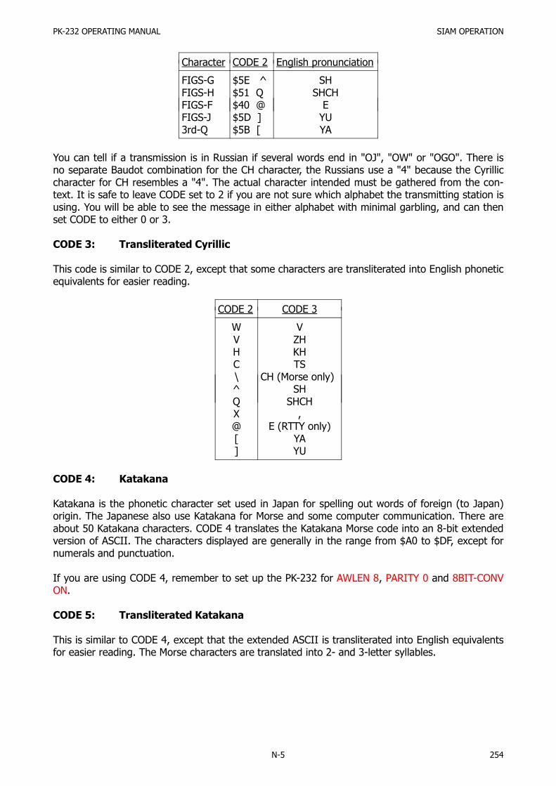
PK-232 OPERATING MANUAL SIAM OPERATION
N-5 254
Character CODE 2 English pronunciation
FIGS-GFIGS-HFIGS-FFIGS-J3rd-Q
$5E ^$51 Q$40 @$5D ]$5B [
SHSHCH
EYUYA
You can tell if a transmission is in Russian if several words end in "OJ", "OW" or "OGO". There isno separate Baudot combination for the CH character, the Russians use a "4" because the Cyrilliccharacter for CH resembles a "4". The actual character intended must be gathered from the con-text. It is safe to leave CODE set to 2 if you are not sure which alphabet the transmitting station isusing. You will be able to see the message in either alphabet with minimal garbling, and can thenset CODE to either 0 or 3.
CODE 3: Transliterated Cyrillic
This code is similar to CODE 2, except that some characters are transliterated into English phoneticequivalents for easier reading.
CODE 2 CODE 3
WVHC\^QX@[]
VZHKHTS
CH (Morse only)SH
SHCH,
E (RTTY only)YAYU
CODE 4: Katakana
Katakana is the phonetic character set used in Japan for spelling out words of foreign (to Japan)origin. The Japanese also use Katakana for Morse and some computer communication. There areabout 50 Katakana characters. CODE 4 translates the Katakana Morse code into an 8-bit extendedversion of ASCII. The characters displayed are generally in the range from $A0 to $DF, except fornumerals and punctuation.
If you are using CODE 4, remember to set up the PK-232 for AWLEN 8, PARITY 0 and 8BIT-CONVON.
CODE 5: Transliterated Katakana
This is similar to CODE 4, except that the extended ASCII is transliterated into English equivalentsfor easier reading. The Morse characters are translated into 2- and 3-letter syllables.

PK-232 OPERATING MANUAL SIAM OPERATION
N-6 255
OK Mnemonic: OK Immediate CommandMode: SIGNAL
This command normally follows the SIGNAL command after it has determined the class and speedof the station being monitored. Typing OK will change the commands RXREV, RBAUD or ABAUDand OPMODE to their proper value.
For example if the SIGNAL command has determined that the station being monitored is transmit-ting Baudot, typing OK should display the following:
OPMODE was SIGNALOPMODE now BAUDOT
If the SIGNAL command did not reveal any useful information, typing OK will produce the re-sponse:
?bad
SIGNAL Mnemonic: SI Immediate CommandMode: ASCII, AMTOR, Baudot
SIGNAL is an immediate command that causes the PK-232 to enter the SIAM Signal Analysismode. The PK-232 will respond with:
OPMODE was BAUDOTOPMODE now SIGNAL
About 10 seconds after the user types the SIGNAL command, the screen will display the predictedsignal and a confidence factor. The confidence factor is a number between 0.10 and 0.99, where0.99 means the PK-232 is 99 % sure the signal is of the type indicated. The signal type may beone of the following:
ASCII, AMTOR, ALIST, Baudot, synchronous, noise, 6-bit
After about 25 seconds the state of signal inversion is determined. As an example, if you tune into50 baud Baudot signal that is not reversed, the SIGNAL command should reveal something like thefollowing:
0.47: 50 baud, Baudot, RXREV OFF
The confidence level will probably be different, but the idea is the same.
The SIGNAL routine will run repeatedly until the operating mode is changed either by typing OK,or by forcing a change to another mode. If you tune to a different signal during an analysis, simplytype SIGNAL again to restart the analysis routine.

PK-232 OPERATING MANUAL Firmware Revision 23-FEB-88
O-1 256
PK-232 Firmware Revision Supplement23-FEB-88
To keep the PK-232 the best multimode data controller available, A.E.A. constantly works on thesoftware to add the features you the users request the most. The following pages describechanges and enhancements we have made in the 23-FEB-88 firmware release for the PK-232.
These enhancements have been made to the PK-232 Firmware since the 25-JUN-87 release descri-bed in Revision-E of the PK-232 operating manual. Since these enhancements are for the mostpart additions to the Revision-E Operating Manual, they appear as the following supplement.
The following is an outline of the features and enhancements in the PK-232 23-FEB-88 firmwarethat are covered in this supplement. Look up the capitalized command in the COMMAND SUMMA-RY section for more information about a particular feature.
NAVTEX Mode: NAVTEX is a relatively new marine weather broadcast service that is rapidly beinginstalled in coastal areas around the world. Operating on a standard frequency of 518 kHz, NAV-TEX broadcasts navigation and weather information to ships.
AFILTER Command: AFILTER is an ASCII Filter that works the way MFILTER does, only in allmodes to prevent unwanted ASCII characters from ever being sent to the terminal or computer.
BBSMSGS Command: BBSMSGS strips some of the unwanted "friendliness" from the command re-sponses generated by the PK-232, making it compatible with older versions bulletin board softwaresuch as that from W0RLI and WA7MBL.
CBELL now sends three BELL characters on DISCONNECT as well as CONNECT.
MFILTER $80 no longer filters the TAB character (ASCII $09).
PRTYPE has been expanded to support more printers including the Anadex, Citizen, NEC and theHP-Thinkjet.
Five Morse Code Characters that are useful for Swedish and German Morse have been added tothe National Morse alphabets CODE Command.
In the KISS and Raw HDLC modes, activity on the RS-232 link is now shown via the STA and CON LEDs.
In Morse, Baudot and ASCII, the delay at the end of a transmission before going back to receivehas been shortened from 1 sec to 0.2 sec.
The TAB character (ASCII $09, CTRL-I) is now accepted as a delimiter in command strings, sameas space and comma always have been.
Defaults Changed: The parameters MPROTO, RESPTIME, PERSIST and PPERSIST have had theirdefault settings changed.

PK-232 OPERATING MANUAL Firmware Revision 23-FEB-88
O-2 257
The NAVTEX Mode:
NAVTEX is an international system which stands for NAVIGATIONAL TELEX. It is a direct printingservice designed to distribute navigational and meteorological warnings and other urgent informa-tion to ships.
Since NAVTEX is a relatively new service, it not fully operational in all areas of the world at thistime. Currently, NAVTEX covers most of Europe, and the east coast of the United States. Stationsto cover the west coast of the U.S. are under construction and scheduled to be operational in1988.
NAVTEX is broadcast in Mode-B AMTOR (SITOR) on a frequency of 518 kHz. This frequency hasbeen agreed upon as the world wide standard. NAVTEX may be selectively monitored, so the ves-sel would see only the information of interest as well as never seeing the same message twice. Itis this unique feature of NAVTEX that the PK-232 uses along with the NAVSTN and NAVMSG com-mands to allow the user to monitor only those messages of importance.
All NAVTEX messages are prefaced by the four characters "ZCZC" and then a four character Pre-amble as diagrammed below.
ZCZC AA99 │││└─ Serial Number 2nd Digit ││└── Serial Number 1st Digit │└─── Message Classification (A to Z) └──── NAVTEX Station Identification (A to Z)
The first character of the Preamble is a letter that identifies the NAVTEX transmitter. TransmitterIdentification letters can be any of the characters A through Z. This limits the number of NAVTEXstations in an area to 26. The NAVSTN Command can be used to selectively monitor or reject cer-tain NAVTEX transmitters.
The second character of the Preamble is the NAVTEX Message Classification. Currently the lettersA through J define a message class, while the letters K through Z are reserved for future use. TheNAVMSG command may be used to selectively monitor or reject certain NAVTEX message classes.
The last two numbers form a serial number from 00 through 99 that is different for each NAVTEXmessage. The PK-232 remembers the Preamble of the 200 most recent messages and will not re-print a message that has the same preamble if it has already been received without many errors.
Currently Europe has a lead on the United States in the number of NAVTEX stations. There arehowever active NAVTEX stations on the east-coast and stations under construction in other partsof the U.S.
In the U.S. and Canada there are currently stations in:
Sydney, Nova Scotia; Boston Massachusetts; Portsmouth, Virginia; Miami, Florida; New Orleans,Louisiana.
Some of the planned stations are:San Francisco, California; Long Beach, California; Astoria, Oregon; Kodiak, Alaska; Adak, Alaska;Honolulu, Hawaii.

PK-232 OPERATING MANUAL Firmware Revision 23-FEB-88
O-3 258
PK-232 COMMAND SUMMARY ADDENDUM
The following is the list of commands that are either new or have changed in the 23-FEB-88 re-lease of PK-232 firmware.
AFILTER ON|OFF Mnemonic: AF Default: OFFMode: ALL Host: AZ
Parameters: ON - The ASCII characters specified in the MFILTER are filtered out and neversent to the terminal or computer.
OFF - Characters in MFILTER list are only filtered from monitored packets.
Some terminals and computers use special characters to clear the screen or perform other "spe-cial" functions. Placing these characters in the MFILTER list, and turning AFILTER ON will keepthem from being sent by the PK-232.
Exception: When ECHO is ON, and the terminal or computer sends a filtered character, the PK-232will echo it back to the terminal or computer.
AFILTER works regardless of mode or CONNECT/CONVERSE/TRANSPARENT status. One must becareful to leave AFILTER OFF during Binary file transfers.
BBSMSGS ON|OFF Mnemonic: BBS Default: OFFMode: Packet Host: BB
Parameters: ON - Makes the PK-232 status messages look like the TAPR-style output.OFF - The PK-232 status messages work as before.
When BBSMSGS is ON, some of the status messages change or are suppressed which may im-prove operation of the PK-232 with some BBS software. The following AEA status messages fromthe PK-232 are suppressed if BBSMSGS is ON:
No "(parm) now (value)"Connect messages: No "; v2; 1 unACKed"No "xxx in progress: (dest) via (digis)"No space after comma in digipeater lists"VIA" in upper case
If MRPT is ON, digi paths are displayed in TAPR formatWhen BBSMSGS is ON, the following status messages are deleted or changed:
No "*** connect request:"No "*** retry count exceeded"Sends carriage return before all other "#**"No "(parm) was (value)"No "(callsign) busy" message

PK-232 OPERATING MANUAL Firmware Revision 23-FEB-88
O-4 259
CBELL ON|OFF Mnemonic: CB Default: OFFMode: Packet Host: CU
Parameters: ON - Three BELL characters <CTRL-G> ($07) are sent to your terminal with the*** CONNECTED to or *** DISCONNECTED from {call sign}message'.
OFF - BELLS are NOT sent with the CONNECTED or DISCONNECTED message.
CBELL now sends BELL characters on DISCONNECT as well as CONNECT. In the 25-JUN-87 releaseof firmware the BELLs were only sent upon a CONNECT.
All other aspects of the CBELL command are described in Revision-E of the PK-232 Operating Man-ual.
CODE n Mnemonic: COD Default: 0Mode: Baudot, AMTOR, Morse HOST: Cl
Parameters: n - 0 to 5 specifies a code from the list in the SIAM chapter of the Revision-E ofthe PK-232 Operating manual.
For the International Morse alphabet (CODE 0), the following characters have been added since25-JUN-87 for receiving and transmitting:
$40 @ ··-··$5B [ ·-·- Formerly received as aa
$5C \ ---· Formerly received as oe
$5D ] ·--·-$5E ^ ··-- Formerly received as ue
These are for the Swedish alphabet, but have applications for German also. Chapter 4 and theSIAM appendix of the PK-232 manual further describe Morse.
HOST ON|OFF Mnemonic: HO Default: OFFMode: All HOST: HO
Parameters: ON - The PK-232 operates with a Host computer or other special application pro-gram.
OFF - The PK-232 operates as a normal TNC.
Turning the PK-232 on or doing a RESTART command while in the HOST Mode (HOST ON) causesthe TNC to issue a RESTART response ($01 $4F R T $00 $17).
All other aspects of the HOST command are described in the PK-232 Operating and Technical Man-uals.

PK-232 OPERATING MANUAL Firmware Revision 23-FEB-88
O-5 260
KISS ON|OFF Mnemonic: KI Default: OFFMode: Packet HOST: KI
Parameters: ON - The PK-232 operates as a KISS TNC.OFF - The PK-232 operates as a normal AX.25 Level 2 TNC.
In KISS and Raw HDLC Modes, communication activity on the RS-232 link is shown by illuminationthe STA and CON LEDs as follows:
Host to TNC Communication: STA LED illuminated.TNC to host Communication: CON LED illuminated.
The most popular use of the KISS mode is running Phil Karn's TCP/IP. Turning KISS ON is not theonly command that must be set to enable TCP/IP operation.
The following three commands must be entered only if the terminal word length and parity issomething other than 8-bits and No parity.
AWLEN 8PARITY 0RESTART
The next four commands must be entered if they have been changed from default:
TRACE OFFHID OFFBEACON EVERY 0PACKET
The next six commands must be entered with the HOST ON command entered last:
CONMODE TRANSPPERSIST ONRAW ONHPOLL OFFKISS ONHOST ON
Other aspects of KISS operation are described in the PK-232 Technical Manual.
MFILTER n1[,n2[,n3[,n4]]]] Mnemonic: MFI Default: $80Mode: Morse, Baudot ASCII, AMTOR and Packet HOST: MI
Parameters: n1 - 0 to $80 (0 to 128 decimal) specifies an ASCII character code. Up to fourcharacters may be specified.
With the special value of $80, all characters in the range of $80 to $FF as well as the Control char-acters, except for Carriage-return ($0D), Linefeed ($0A), and TAB ($09) are filtered out.
It is the subtraction of the TAB character from the characters that MFILTER $80 filters out that haschanged from the 25-JUN-87 firmware release.
All other aspects of the MFILTER command are described in Revision-E of the PK-232 OperatingManual.

PK-232 OPERATING MANUAL Firmware Revision 23-FEB-88
O-6 261
NAVMSG all, none, Yes|No (letters) Mnemonic: NAVM Default: AllMode: NAVTEX HOST: NM
Parameters: letters - all, none, YES List, NO List. List of up to 13 letters which may or maynot be separated by spaces, commas or TABs.
NAVMSG uses Letter arguments to determine which type of NAVTEX messages your PK-232 willprint.
NAVTEX messages are grouped into into classes by the second letter in the Preamble. The classifi-cations currently defined are as follows:
A. Navigational WarningsB. Meteorological Warnings (Storm Warnings)C. Ice ReportsD. Search and Rescue InformationE. Weather ForecastsF. Pilot Service MessagesG. DECCA System InformationH. LORAN-C System InformationI. Omega Systems MessagesJ. SATNAV System MessagesK.-Z. Reserved for future use
The NAVMSG Command allows ALL, NONE or a list of up to 13 letters representing message typesto be Monitored or Rejected.
The exception to this is that message classes A, B and D CANNOT be excluded and will always becopied if the transmitting station is enabled by NAVSTN.
As an example, let's say that you are not interested in SATNAV or Omega System messages (mes-sage classes I and J), you should enter the following command:
NAVMSG NO IJ
This will cause the PK-232 to ignore message classes I and J from all NAVTEX transmitting stationswhile copying all others.
The letters in the list (I and J in the above example) may be separated by spaces, commas orTABS, although they may be typed in with no spaces as well.
NAVMSG may be cleared with %, & or OFF as arguments.
NAVSTN all, none, Yes|No (letters) Mnemonic: NAVS Default: AllMode: NAVTEX HOST: NS
Parameters: letters - all, none, YES List, NO List. List of up to 13 letters which may or maynot be separated by spaces, commas or TABs.
NAVTEX stations are identified by the first letter in the Preamble.
The NAVSTN Command allows ALL, NONE or a list of up to 13 letters representing NAVTEX trans-mitting stations to be Monitored or Rejected.

PK-232 OPERATING MANUAL Firmware Revision 23-FEB-88
O-7 262
As an example, let's say that you are only interested in NAVTEX stations E, G, and C, because theyare near you. You should enter the following command:
NAVSTN YES EGC
This will cause the PK-232 to monitor only messages from NAVTEX transmitters C, E, and G and ig-nore messages from all others.
The letters in the list (E, G, and C in the above example) may be separated by spaces, commas orTABS or typed in with no spaces if desired.
NAVSTN may be cleared with %, & or OFF as arguments.
NAVTEX Mnemonic: NA Immediate CommandMode: Command HOST: NA
NAVTEX is an immediate command that switches your PK-232 into the NAVTEX receive mode.Currently, NAVTEX stations are found on 518 kHz.
NAVTEX is a special form of Mode B (FEC) SITOR that does not output data to the computer orprinter until "ZCZC" and a preamble are received intact. The preamble consists of 2 letters and 2numerals. The PK-232 will print until the end of message indicator "NNNN" is received.
The first two letters of the preamble define the transmitting station and the message class respec-tively. The following two numerals form a serial number that is remembered by the PK-232 when amessage is copied intact. The PK-232 remembers the preambles of the last 200 printed messagesand will not reprint a message with the same preamble with the following exceptions:
Any preamble with a serial number of 00 is considered an Emergency message and will always beprinted. Also, any message with more than 1/8 of its characters received in error, will not be savedso that it may be re-printed. To clear the preamble memory, simply exit and then re-enter NAVTEXmode.
The PK-232 can accept only, or lock-out certain message classes and transmitting stations with theNAVMSG and NAVSTN commands described above.
For logging purposes, NAVTEX Mode uses the setting of DAYTIME to print the date and/or time infront of the preamble if MSTAMP and/or DAYSTAHP are ON.
PRTYPE n Mnemonic: PRT Default: 2 (Epson)Mode: FAX HOST: PY
Parameters: n - 0-255, specifying a code for the type of dot graphics sequences used by yourprinter. At this time, the codes shown below are supported.
New values of PRTYPE from 52 to 61 have been added to support additional printers since the 25-JUN-87 version of PK-232 firmware.

PK-232 OPERATING MANUAL Firmware Revision 23-FEB-88
O-8 263
PRTYPE 48-51 (Miscellaneous): Supports the HP ThinkJet printer as well.
PRTYPE Printer "Enter graphics" sequence
525660
CitizenNECAnadex
CHR$(27) K n1 n2CHR$(27) > CHR$(27) M CHR$(27) S0960CHR$(28)
The new values of PRTYPE that have been added are as follows:
PRTYPE 52-55: Citizen
Same as PRTYPE 0-3 (Epson), except:New-line code (7 bits): <ESC> 'A' 7 (no LF)New-line code (8 bits): <ESC> 'A1 8 (no LF)
PRTYPE 56-59: NEC
Typical graphics code: <ESC> '>' <ESC> 'M' <ESC> 'S0960'New-line code (7 bits): <CR> <ESC> 'Til1 <LF>New-line code (8 bits): <CR> <ESC> 'T131 <LF>Printer reset code: <ESC> 'A' <ESC> ']' <CR> <LF>
GRAPHICS PRT 56, 58 PRT 57, 59 Code
134
120 dpi160 dpi80 dpi
120 dpi
80 dpi
ESC '>' ESC 'M'ESC '>' ESC 'M'ESC '>' ESC 'D'
PRTYPE 60-61: Anadex
Typical graphics code: 28New-line code (6 bits): '6'Printer reset code: 29 <CR> <LF>
GRAPHICS PRT 60 PRT 61 Printers
05
60 dpi75 dpi
60 dpi75 dpi
DP-9000, DP-9500DP-9001, DP-9501
The following Parameter Default Settings have been changed since 25-JUN-87
MPROTO now ON was OFFPERSIST now 63 (25 %) was 127 (50 %)PPERSIST now ON was OFFRESPTIME now 5 was 10

PK-232 OPERATING MANUAL Firmware Revision 30-DEC-88
P-1 264
PK-232 Firmware Revision Supplement30-DEC-88
The following briefly describes the changes that we have made in the PK-232 firmware since the23-FEB-88 release. A more detailed description follows in the Command Summary.
Added the command WHYNOT. Sometimes packet data will be received by the PK-232 but not dis-played to the screen. Turning WHYNOT on causes the PK-232 to generate a message explainingwhy the data was not displayed.
Added the command CUSTOM. This command allows some customizing of the PK-232.
Turning KISS ON now sets all packet parameters for TCP/IP operation.
Added AUDELAY to allow for a delay from PTT to applied AFSK audio. An appropriate setting of AU-DELAY will help prevent spurious emissions and arcing of amplifier relay contacts.
Added the command DIDDLE. When in transmit, the PK-232 sends the LTRS character in Baudotand the NULL character in ACSII, during idling when DIDDLE is on.
Added the command MWEIGHT. This will allow the user to vary the Morse dot to space ratio fromthe default of 1:1.
If the MYCALL parameter is left at the default value of PK-232 then no Packet transmissions will beallowed.
If DAYTIME has not been set pressing a <CTRL-T> will cause an asterisk (*) to be sent.
Added the command NUMS. This will force the PK-232 into the figures case in AMTOR and Baudotreceive.
WRU is now always ON in AMTOR, however in Baudot and ASCII, WRU is on|off selectable.
The ABB default has been changed to none.
When in a Packet link all left over data will not be transmitted as UI frames should a disconnect oc-cur.
MBX has been enhanced to accept the argument of ALL.
The MPROTO default is now off.
Added a Morse ID in the Packet Mode (required in England). This is NOT required in the UnitedStates, and it is advised to leave this set to zero.
In Morse, received data is broken up on word boundaries depending on the setting of ACRDISP,similar to word wrap.
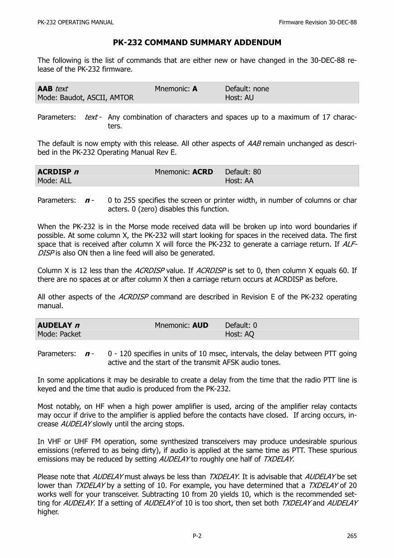
PK-232 OPERATING MANUAL Firmware Revision 30-DEC-88
P-2 265
PK-232 COMMAND SUMMARY ADDENDUM
The following is the list of commands that are either new or have changed in the 30-DEC-88 re-lease of the PK-232 firmware.
AAB text Mnemonic: A Default: noneMode: Baudot, ASCII, AMTOR Host: AU
Parameters: text - Any combination of characters and spaces up to a maximum of 17 charac-ters.
The default is now empty with this release. All other aspects of AAB remain unchanged as descri-bed in the PK-232 Operating Manual Rev E.
ACRDISP n Mnemonic: ACRD Default: 80Mode: ALL Host: AA
Parameters: n - 0 to 255 specifies the screen or printer width, in number of columns or characters. 0 (zero) disables this function.
When the PK-232 is in the Morse mode received data will be broken up into word boundaries ifpossible. At some column X, the PK-232 will start looking for spaces in the received data. The firstspace that is received after column X will force the PK-232 to generate a carriage return. If ALF-DISP is also ON then a line feed will also be generated.
Column X is 12 less than the ACRDISP value. If ACRDISP is set to 0, then column X equals 60. Ifthere are no spaces at or after column X then a carriage return occurs at ACRDISP as before.
All other aspects of the ACRDISP command are described in Revision E of the PK-232 operatingmanual.
AUDELAY n Mnemonic: AUD Default: 0Mode: Packet Host: AQ
Parameters: n - 0 - 120 specifies in units of 10 msec, intervals, the delay between PTT goingactive and the start of the transmit AFSK audio tones.
In some applications it may be desirable to create a delay from the time that the radio PTT line iskeyed and the time that audio is produced from the PK-232.
Most notably, on HF when a high power amplifier is used, arcing of the amplifier relay contactsmay occur if drive to the amplifier is applied before the contacts have closed. If arcing occurs, in-crease AUDELAY slowly until the arcing stops.
In VHF or UHF FM operation, some synthesized transceivers may produce undesirable spuriousemissions (referred to as being dirty), if audio is applied at the same time as PTT. These spuriousemissions may be reduced by setting AUDELAY to roughly one half of TXDELAY.
Please note that AUDELAY must always be less than TXDELAY. It is advisable that AUDELAY be setlower than TXDELAY by a setting of 10. For example, you have determined that a TXDELAY of 20works well for your transceiver. Subtracting 10 from 20 yields 10, which is the recommended set-ting for AUDELAY. If a setting of AUDELAY of 10 is too short, then set both TXDELAY and AUDELAYhigher.

PK-232 OPERATING MANUAL Firmware Revision 30-DEC-88
P-3 266
CUSTOM nnnn Mnemonic: CU Default: $0015Mode: Packet Host: Cu
Parameters: n - 0 to $40 (0 to 64 decimal) specifies a four digit hex value, where each bitcontrols a different function.
Bit 0, position $0001: If bit 0 is set to 1 (default setting), then the PK-232 will discard a receivedpacket if the signal is too weak to cause the DCD LED to light. If set to 0,packets will be received regardless of the setting of the THRESHOLD con-trol.
Bit 1, position $0002: If bit 1 is set to 0 (default setting), then setting the MONITOR command toeither ON or YES will result in a MONITOR value of 4. If bit 1 is set to I, thensetting MONITOR to ON or YES will force the MONITOR value to 6. PBBS Sy-sOps may want to set CUSTOM to $0017 (23 decimal).
Bit 2, position $0004: If bit 2 is set to 1 (default setting), a break on the RS-232 line will put thePK-232 into the Command Mode (except from Host Mode). If set to 0, abreak on the RS-232 line will not affect the PK-232.
Bit 3, position $0008: If bit 3 is set to 0 (default setting), Packet channel numbers will be num-bered from 0-9. If bit 3 is set to one, then Packet channel numbers are la-beled A-J. Lower case a-j are also accepted.
Bit 4, position $0010: This function affects only Baudot transmit. If bit 4 is set to 1 (default set-ting), then the PK-232 will insert the figures shift character after a space,just prior to sending any figures, <space><FIGS><number>. This is tocompensate for the use of USOS at the receiving end. This in turn will permitthe receiving station to correctly decode several groups of figures separatedby spaces. If bit 4 is set to 0, then the PK-232 will not insert the FIGS char-acter after each space, <space><number>. MARS operators may want toset this bit to 0 for literal operation.
Bit 5, position $0020: If bit 5 is set to one, then the PK-232 when powered on, will stay in the lastmode it was in, i.e., converse, command, or transparent. If bit 5 is set to 0,(default mode) the PK-232 will always power up in the Command Mode.
Bit 6, position $0040: If bit 6 is set to 1, then monitoring is active in the transparent mode. TheMFROM, MTO, MRPT, MONITOR, MCON, MPROTO, MSTAMP, CONSTAMP,and MBX are all active. If bit 6 is set to 0, (default setting), then monitoringis disabled in the Transparent Mode.
Bits 7-15 are all unused at the present time. To return the CUSTOM command to the default set-ting, type CU Y or CU ON at the command prompt.
A discussion here describing the default settings and how the $0015 setting was derived may as-sist you with understanding the CUSTOM parameter.
The default setting for Bits 0-6 is noted below:Bit 0 is set to 1, Bit 1 is set to 0, Bit 2 is set to 1, Bit 3 is set to 0, Bit 4 is set to 1, Bit 5 is set to 0,and Bit 6 is set to 0. The following chart indicates the same information.
Bit Position 7 6 5 4 3 2 1 0Setting 0 0 0 1 0 1 0 1

PK-232 OPERATING MANUAL Firmware Revision 30-DEC-88
P-4 267
Looking at just the setting row in the chart, the binary number 00010101 becomes evident. Thebinary number 00010101 equals the decimal number 21, and the hexadecimal equivalent is $0015hence the reason the default setting for CUSTOM is $0015.
Let us say, for example, that you have decided that as a MARS operator you want to change bit 4from the default of 1 to a setting of 0. The chart below reflects this change.
Bit Position 7 6 5 4 3 2 1 0Setting 0 0 0 0 0 1 0 1
This results in a binary number of 00000101 which is a decimal number 5. The hex equivalent is$0005, therefore, to change bit Position 4 to a setting of zero, leaving the others unchanged, willrequire a CUSTOM setting of $0005.
The CUSTOM command will accept arguments in decimal format. For example, the default is$0015, however if you enter decimal 21, the PK-232 will accept this. The PK-232 will display on thescreen the hexadecimal equivalent.
A brief discussion of Hexadecimal notation can be found in the PK-232 Operating Manual, Section5.1.1.
DAYTIME date & time Mnemonic: DA Default: noneMode: All Host: DA
Parameters: date & time - Current DATE and TIME to set.
All DAYTIME functions remain the same as described in the PK-232 users guide. Rev E, EXCEPT forthe following. If the DAYTIME has not been set, and a <CTRL-T> is pressed, the PK-232 will sendan asterisk (*).
DIDDLE: ON|OFF Mnemonic: DID Default: OFFMode: Baudot, ASCII Host: DD
Parameters: ON - In Baudot, the PK-232 will send the LTRS character when idling. In ASCII thePK-232 sends the NULL (00) character.
OFF - No characters are sent when idling in transmit.
In the RTTY modes, it may be desirable to continue sending some sort of data while paused at thekeyboard. With DIDDLE on, the PK-232 will send idle characters when waiting for keyboard entry.
KISS ON|OFF Mnemonic: KI Default: OFFMode: Packet Host: KI
Parameters: ON - The PK-232 operates as a KISS TNC.OFF - The PK-232 operates as a normal AX.25 Level 2 TNC.
Turning KISS ON now has a temporary effect on several other parameters. KISS ON temporarilyforces HPOLL OFF, PPERSIST ON, RAWHDLC ON, and HOST ON. RAWHDLC ON temporarily forcesCONMODE TRANS, TRACE OFF, HID OFF, and no BEACON. HOST ON temporarily forces 8BITCONVON, AWLEN 8, PARITY 0, and no software flow control.
This change makes going into the KISS much easier!

PK-232 OPERATING MANUAL Firmware Revision 30-DEC-88
P-5 268
To exit KISS, you must type three <CTRL-C> all within one second. Also, no data can be receivedby the PK-232 during this operation or it will not work, and you will remain in KISS Mode.
HOST OFF (3× <CTRL-C>) will force KISS OFF. The PK-232's CMD and PKT LEDs will be lit, con-firming exit from KISS Mode.
"Temporarily forcing" a function means that the PK-232 will behave as if the function is set thatway, although the function setting does not actually change.
MBX call1, call2, -n Mnemonic: MB Default: noneMode: Packet Host: MB
Parameters: call - The call sign of one or two stations to be monitored-n - 0-15, indicating an optional SSID.
The MBX command will now accept the argument of ALL. There are no changes in the functions ofthe arguments that have been permitted previously. The operation of MBX command is as follows.
MBX NONE (Default setting) All monitored frames are shown with their packet headers.See MFROM, MTO, MONITOR, CONSTAMP, MSTAMP, and MPROTO.
MBX ALL Only the data fields in the I-frames and UI frames are shown; no headers orother types of frames are shown. Data from retried frames will be showneach time such a frame is monitored. The MFROM and MTO commands areactive.
MBX CALL 1 Only the data fields in the I and UI frames to or from CALL 1 are shown.CALL 1 can be in either the source or destination address field of the frame.Retried frames are not shown. The MFROM and MTO commands are ignored.
MBX CALL 1 CALL 2 Only the data fields in the I and UI frames are shown when
CALL 1 is the source and CALL 2 is the destination, or
CALL 1 is destination and CALL 2 is the source.
Retried frames are not shown. The MFROM and MTO commands are ignored.
A Packet connection on any channel inhibits monitoring, if MBX is not set to "none". MCON will on-ly work if MBX is set to "none".
MID n Mnemonic: MI Default: 0Mode: Packet Host: Mi
Parameters: n - 0 - 250 specifies the Morse ID timing in units of 10 second intervals.0 - (zero) disables this function.
A setting of 0 (default) disables this function. If n is set to some value between 1 and 250, thenthe Packet Mode, the PK-232 will periodically issue a 20 WPM Morse ID. A Morse ID consists of 0.5seconds of idle, the call sign in MYCALL, without the SSID, followed by 0.5 seconds of idle. For ex-ample, an MID of 177 seconds would cause a Morse ID every 1,77 seconds, or every 29.5 minutes.The Morse ID will only be issued if a packet was sent since the last Morse ID. The Morse ID usesTXDELAY, PPERSIST, and DCD.

PK-232 OPERATING MANUAL Firmware Revision 30-DEC-88
P-6 269
The ID command has now changed. If HID is ON, ID will cause the HDLC ID to be transmitted im-mediately, which is the same as before. If MID is set to a value other than 0, ID will force a MorseID immediately. If both HID and MID are both active, the Morse ID will be sent first.
The PK-232 generates Morse code by switching from the mark tone to the space tone. This pre-vents other TNCs from accidentally transmitting and colliding with a CW ID.
MWEIGHT n Mnemonic: MW Default: 10Mode: All except Packet Host: Mw
Parameters: n - 5 to 15 specifies roughly 10 times the ratio of one dot length to one inter-element space length.
A value of 10 (default) results in a 1:1 dot-space ratio. A setting of 5 (minimum) results in a 0.5:1ratio, while a setting of 15 (maximum) results in a 1.5:1 ratio.
Changing the MWEIGHT may be desirable to counteract the switching delays of SOME transmitterswhen operating at high speeds. MWEIGHT applies only to the Morse mode and the CW ID in allmodes except packet. MWEIGHT does not affect the code output by the MID command.
MYCALL call -n Mnemonic: MY Default: PK-232Mode: Packet Host: ML
Parameters: call - Your call sign.-n - 0 - 15, indicating an optional substation ID, (SSID)
If MYCALL has not been changed from the default value of PK-232, the TNC will not transmit or ac-knowledge any packets. This will prevent the call sign "PK-232" from being transmitted. A warningmessage, ?need MYCALL is issued for attempts to use the CONNECT, CONVERSE, K, TRANS
and ID commands. No warning will be given for attempts to use HID or BEACON.
All other aspects of MYCALL remain unchanged as described in the PK-232 Users Guide, Rev E.
NUMS Mnemonic: N Immediate CommandMode: Baudot, AMTOR Host: NX
In Baudot and AMTOR receive, this command will force the PK-232 into the FIGS case.
WHYNOT ON|OFF Mnemonic: WHY Default: OFFMode: Packet Host: WN
Parameters: ON - PK-232 will generate a reason why a received packet was not displayed tothe screen.
OFF - This function is disabled.
During Packet operation, the PK-232 may receive many packets that are not displayed to thescreen. Turning WHYNOT on will cause the PK-232 to display a message explaining the reason thereceived packet was not displayed to the screen.
The messages and their meanings are shown below:

PK-232 OPERATING MANUAL Firmware Revision 30-DEC-88
P-7 270
Bit residue: The frame ended in the middle of a byte. A weak packet signal might cause this, or,more likely, random noise that triggered the start of packet reception. Also, this mayoccur after a genuine frame has been received.
PASSALL: The received packet frame had errors, and PASSALL was off, thereby preventing thepacket from being displayed to the screen.
DCD Threshold: The THRESHOLD control was set to far counter clockwise. The DCD LED wasoff when the packet was received.
MONITOR: The MONITOR value was set to low to receive this type of frame.
MCON: MCON was set too low to receive this type of frame.
MPROTO: MPROTO was set to off, and the received packet was probably a NET/ROM orTCP/IP frame.
MFROM/MTO: The frame was blocked by the setting of either the MFROM or MTO command.
MBX: The call sign of the sending station does not match the call sign setting in the MBXcommand.
MBX Sequence: The packet frame has been received out of sequence, probably a retry.
WRU ON|OFF Mnemonic: WR Default: OFFMode: Baudot, ASCII, AMTOR ARQ Host: WR
Parameters: ON - Your answerback is sent after a distant station's WRU?OFF - Your answerback is NOT sent after a distant station's WRU?
When in AMTOR, WRU is no longer ON|OFF selectable, WRU is now always ON in AMTOR. All oth-er aspects of WRU remain unchanged as described in the PK-232 Operating Manual, Rev E.
The following Parameter Default Setting has been changed since 23-FEB-88.
The MPROTO command default is set to OFF.
The AAB text string default is now empty.

PK-232 OPERATING MANUAL Firmware Revision 30-DEC-88
P-8 271
PK-232 PRTYPE Settings for Facsimile Printing with Various Printers
The following is a list of printers by brand, with the corresponding PRTYPE(s) we have determinedshould print Facsimile with the PK-232. Please note that not all these printers have actually beentested, but according to the best available data, the indicated setting(s) of PRTYPE should work.
We do not guarantee that all graphics modes that a particular printer is capable of are supported.All graphics modes that we support are listed in the Facsimile Appendix to the PK-232 manual, so itshould be possible to determine if a particular printer will work without actually trying it.
If you try a particular PRTYPE and it does not work, you may try other values of PRTYPE that areused by that same manufacturer on a different model. If you still cannot get Facsimile to printproperly, check your printer manual to see if there is another graphics mode you can select.
We recommend that you use an Epson graphics mode or an IBM graphics mode if you have thatoption available on your particular printer.
If all else fails, then call or write AEA and give us a complete description of your printer and itsproblem. If possible have the manual for your printer available when you call. This will allow us tomore quickly get your PK-232 and printer set up for Facsimile operation.
From time to time, printer manufacturers change their own firmware which may create problemsfor Facsimile printing with the PK-232. So again, we cannot guarantee that a particular printer list-ed will work with the PK-232 using the listed PRTYPE. We are however interested in any incompati-bilities that are found. The easiest way for us to solve a compatibility problem is to get a copy ofthe printer manual that describes the graphics commands the printer will accept. Only then can wepossibly affect changes in a future release of PK-232 firmware.
K-PAX and COM-FAX users:
Both of these programs will print directly to a printer that is attached to the computer. When usingthese programs, the printer port on the 'Y' cable is not used. These programs will only work if thePRTYPE has been set to a DEFAULT VALUE OF TWO.
Anadex DP-9500 PRTYPE 60Antex ADS-2000 PRTYPE 0, 2
Apple Dot Matrix PRTYPE 12, 14Apple Imagewriter I PRTYPE 12, 14Apple Imagewriter II PRTYPE 12, 14Apple Prowriter PRTYPE 12, 14
Apple printers are serial devices which require a Parallel to Serial Converter.
BMC BX-80 PRTYPE 48, 50BMC BX-100 PRTYPE 48-51?
Blue Chip M120/10 PRTYPE 48, 50Blue Chip M120/15 PRTYPE 48-51
Brother M-1009 PRTYPE 4, 6Brother M-1109 (Mode I) PRTYPE 0, 2Brother M-1109 (Mode II) PRTYPE 4, 6Brother M-1509 PRTYPE 0, 2

PK-232 OPERATING MANUAL Firmware Revision 30-DEC-88
P-9 272
Brother M-1709 PRTYPE 0, 2Brother Twinwriter 5 PRTYPE 0, 2
Cal-Abco Legend 800 PRTYPE 0, 2
Canon A1200 PRTYPE 12, 14Canon PW-1156A PRTYPE 0-3
Centronics GLP PRTYPE 0, 2Centronics H-80 PRTYPE 0, 2Centronics H136A PRTYPE 0, 2Centronics 351 PRTYPE 0-3Centronics 352 PRTYPE 0-3Centronics 353 PRTYPE 0-3
Citizen MSP-10 (IBM mode) PRTYPE 4, 6, or 52, 54Citizen MSP-15 (IBM mode) PRTYPE 4-7 or 52-55Citizen MSP-20 (IBM mode) PRTYPE 4, 6, or 52, 54Citizen MSP-25 (IBM mode) PRTYPE 4-7 or 52-55
Commodore 1525 PRTYPE 36Requires a Parallel to Serial Converter
Copal SC-1200 PRTYPE 0, 2Copal SC-1500 PRTYPE 0, 2Copal SC-5500 PRTYPE 0, 2
Dataproducts Prism 8050 PRTYPE 20?Dataproducts 8070 PRTYPE 20?
Datasouth Personal Printer I PRTYPE 0, 2Datasouth Personal Printer II PRTYPE 0, 2
DECwriter LA35 (Graphics II)DECwriter LA36 (Graphics II)DECwriter LA120 PRTYPE 4-7
Diablo 34LQ PRTYPE 4, 6
Epson EX-800 PRTYPE 0, 2Epson EX-1000 PRTYPE 0-3Epson FX-70 PRTYPE 0, 2Epson FX-80 PRTYPE 0, 2Epson FX-85 PRTYPE 0, 2Epson FX-100 PRTYPE 0-3Epson FX-185 PRTYPE 0-3Epson FX-286 PRTYPE 0-3Epson JX-80 PRTYPE 0, 2Epson LQ-800 PRTYPE 0, 2Epson LQ-1500 PRTYPE 0, 2Epson LX-80 (Homewriter 10) PRTYPE 0, 2Epson LX-86 PRTYPE 0, 2Epson MX-70 PRTYPE 0, 2Epson MX-80 III PRTYPE 0, 2

PK-232 OPERATING MANUAL Firmware Revision 30-DEC-88
P-10 273
Epson MX-80 with Graftrax 80 PRTYPE 40, 42Epson MX-85 PRTYPE 0, 2Epson MX-100 PRTYPE 0-3Epson MX-185 PRTYPE 0, 2Epson P-80 PRTYPE 0, 2Epson RX-70 PRTYPE 0, 2Epson RX-80 PRTYPE 0, 2Epson RX-85 PRTYPE 0, 2Epson RX-100 PRTYPE 0-3Epson RX-185 PRTYPE 0, 2
Genicom 3014 PRTYPE 0, 2Genicom 3024 PRTYPE 0, 2Genicom 3310 (IBM-GP mode) PRTYPE 44-47Genicom 3320 (IBM-GP mode) PRTYPE 44-47
Hewlett Packard ThinkJet PRTYPE 48-51
IBM Color PRTYPE 4, 6IBM Graphics PRTYPE 4, 6IBM Proprinter PRTYPE 4, 6
IDS Prism 80 PRTYPE 8?IDS Prism 132 PRTYPE 8?
Inforunner Riteman PRTYPE 0, 2
C. Itoh Gorilla GX-100 PRTYPE 36C. Itoh Riteman II PRTYPE 0, 2C. Itoh Prowriter 1550 PRTYPE 16-19C. Itoh 7500 PRTYPE 12-15C. Itoh Prowriter 8510 A PRTYPE 16-19C. Itoh Prowriter 8510 B PRTYPE 16, 18C. Itdh Prowriter 8510 S PRTYPE 16, 18C. Itoh Prowriter 8510 SC PRTYPE 16, 18C. Itoh Prowriter 8510 SEP PRTYPE 4, 6
Leading Edge Gorilla Banana PRTYPE 36
Legend 880 PRTYPE 0, 2?Legend 1000 PRTYPE 0, 2?Legend 1080 PRTYPE 0, 2?Legend 1081 PRTYPE 0, 2?Legend 1200 PRTYPE 0, 2?Legend 1500 PRTYPE 0. 2?Legend 1380 PRTYPE 0, 2?Legend 1385 PRTYPE 0. 2?
Mannesmann Tally 85 (Epson mode) PRTYPE 0. 2Mannesmann Tally 85 (IBM mode) PRTYPE 4, 6Mannesmann Tally 86 (Epson mode) PRTYPE 0, 2Mannesmann Tally 86 (IBM mode) PRTYPE 4, 6Mannesmann Tally 160L PRTYPE 0, 2Mannesmann Tally 180L PRTYPE 0, 2?

PK-232 OPERATING MANUAL Firmware Revision 30-DEC-88
P-11 274
Mannesmann Tally MT-290 (Epson) PRTYPE 0. 2Mannesmann Tally MT-290 (IBM) PRTYPE 4, 6Mannesmann Tally MT-490 PRTYPE 0, 1, 4, 5Mannesmann Tally Spirit 80 PRTYPE 48, 50Mannesmann Tally 1602 PRTYPE 0, 2?Mannesmann Tally 1605 PRTYPE 0. 2?Mannesmann Tally 1800 PRTYPE 0, 2?
Matra SCANSET PRTYPE 4-7
NEC Pinwriter P6 PRTYPE 0, 2NEC Pinwriter P7 PRTYPE 0-3NEC 8023 PRTYPE 12, 14
Okidata Okimate 20 (IBM mode) PRTYPE 4-7Okidata ML82A with Okigraph I PRTYPE 20Okidata ML83A with Okigraph I PRTYPE 20-21Okidata ML84 (IBM mode) PRTYPE 4-7Okidata ML92 (IBM mode) PRTYPE 4Okidata ML92 (Oki mode) PRTYPE 20Okidata ML93 (IBM mode) PRTYPE 4-7Okidata ML93 (Oki mode) PRTYPE 20, 21Okidata ML182 (IBM mode) PRTYPE 4, 6Okidata ML183 (IBM mode) PRTYPE 4-7Okidata 192 PRTYPE 24, 26Okidata 193 PRTYPE 24-27
Olivetti DM-280 PRTYPE 0, 2Olivetti DM-290 PRTYPE 0-3
Panasonic KX-P10801 PRTYPE 0, 2Panasonic KX-P1090 PRTYPE 0, 2Panasonic KX-P1091 PRTYPE 0, 2Panasonic KX-P1092 PRTYPE 0, 2Panasonic KX-P1592 PRTYPE 0-3
Personal Micro DMP-85 PRTYPE 12, 14Printers Plus NLQ PRTYPE 0, 2
Radio Shack Lineprinter VII PRTYPE 8Radio Shack Lineprinter VIII PRTYPE 8Radio Shack DMP-100 PRTYPE 8Radio Shack DMP-105 PRTYPE 8Radio Shack DMP-110 PRTYPE 8Radio Shack DMP-120 PRTYPE 8Radio Shack DMP-130 PRTYPE 8, 4, 6Radio Shack DMP-200 PRTYPE 8Radio Shack DMP-400 (DMP emul.) PRTYPE 8Radio Shack DMP-420 (DMP emul.) PRTYPE 8Radio Shack DMP-430 PRTYPE 4, 6Radio Shack DMP-500 (DMP emul.) PRTYPE 8Radio Shack DMP-2100 PRTYPE 4, 6Radio Shack DMP-2110 PRTYPE 8Radio Shack DMP-2200 PRTYPE 4-9

PK-232 OPERATING MANUAL Firmware Revision 30-DEC-88
P-12 275
Radio Shack CGP-220 PRTYPE 8
Sakata SP-1000 PRTYPE 0, 2Sakata SP-1500 PRTYPE 0, 2
Seikosha GP-100 PRTYPE 36Seikosha GX-100 PRTYPE 36Seikosha SP-1000 A PRTYPE 0, 2Seikosha SP-1000 VC (E-64) PRTYPE 36Seikosha SP-1000 IBM PRTYPE 4, 6Seikosha SP-1000 AS PRTYPE 0, 2
Smith Corona D-100 PRTYPE 0, 2Smith Corona D-200 (Standard) PRTYPE 0, 2Smith Corona D-200 (IBM) PRTYPE 4, 6Smith Corona D-300 (Standard) PRTYPE 0, 2Smith Corona D-300 (IBM) PRTYPE 4, 6Smith Corona Fastext 80 PRTYPE 0, 2Smith Corona TP-1000 PRTYPE 0, 2, 4, 6
Star Delta 10 PRTYPE 32, 34Star Delta 15 PRTYPE 32-35Star Delta 10 PC PRTYPE 4, 6Star Delta 15 PC PRTYPE 4-7Star Delta 10 Plus PRTYPE 0, 2Star Delta 15 Plus PRTYPE 0-3Star Geinini 10 PRTYPE 28Star Gemini 15 PRTYPE 28-29Star Gemini 10X PRTYPE 32, 34Star Gemini 15X PRTYPE 32-35Star Gemini 10XPC PRTYPE 4, 6Star Gemini 15XPC PRTYPE 4-7Star Gemini 10X Plus PRTYPE 0, 2Star Gemini 15X Plus PRTYPE 0-3Star Micronics SG-10 (Star mode) PRTYPE 32, 34Star Micronics SG-15 (Star mode) PRTYPE 32-35Star Micronics SG-10 (IBM mode) PRTYPE 4, 6Star Micronics SG-15 (IBM mode) PRTYPE 4-7Star Micronics SD-10 (Star mode) PRTYPE 32, 34Star Micronics SD-15 (Star mode) PRTYPE 32-35Star Micronics SD-10 (IBM mode) PRTYPE 4, 6Star Micronics SD-15 (IBM mode) PRTYPE 4-7Star Micronics SR-10 (Star mode) PRTYPE 32, 34Star Micronics SR-15 (Star mode) PRTYPE 32-35Star Micronics SR-10 (IBM mode) PRTYPE 4, 6Star Micronics SR-15 (IBM mode) PRTYPE 4-7Star Micronics NB-15 (9-wire emulation) PRTYPE 4-7Star Micronics NL-10 (std. cartridge) PRTYPE 0, 2Star Micronics NL-10 (IBM cartridge) PRTYPE 4, 6Star Micronics NL-15 (std. cartridge) PRTYPE 0-3Star Micronics NL-15 (IBM cartridge) PRTYPE 4-7Star Radix 10 PRTYPE 32, 34Star Radix 15 PRTYPE 32-35Star Radix 10 PC PRTYPE 4, 6

PK-232 OPERATING MANUAL Firmware Revision 30-DEC-88
P-13 276
Star Radix 15 PC PRTYPE 4-7Star Radix 10 Plus PRTYPE 0, 2Star Radix 15 Plus PRTYPE 0-3
Texas Instruments 850 (DP mode) PRTYPE 40-43Texas Instruments 855 (DP mode) PRTYPE 40-43
Transtar T315 PRTYPE 12, 14

PK-232 OPERATING MANUAL FAQ
Q-1 277
APPENDIX QANSWERS TO COMMONLY ASKED QUESTIONS AND
SPECIAL NOTES TO PC-PAKRATT AND COM PAKRATT USERS
The PK-232 can be used with a multitude of computers, and computer programs. This can lead tosome confusion as to how to properly connect, access certain features and configure the PK-232.The following questions and answers may help you without having to make a long-distance phonecall to AEA's Technical Support,
QUESTION: How do I use the "Y" cable that came with my PK-232, and how is it connected?ANSWER: The "Y" cable has three connectors attached to it: Two 25-pin connectors, and one
36-pin connector. The male 25-pin connector should be attached directly to the PK-232, and the female end should be connected to the serial port of the computer.The 36-pin end is generally hooked up only if you are using a dumb terminal or adumb terminal program. It is hooked directly to a Centronics-type parallel printer. Itis intended primarily for printing received facsimile signals directly to the printer inthe dumb terminal mode.
Dumb terminal mode is defined by working from a command prompt (cmd:). You
cannot print files from your computer through the "Y" cable; you can only print re-ceived information "off-the-air" by turning the parameters PRCON and PROUT toON. If you wish to print received FAX pictures, first you must enter the properPRTYPE for your printer, turn PRCON to ON, PROUT to OFF, PRFAX to ON and typein FAX from a command prompt. Please refer to Appendix M for complete details.
PC-PAKRATT, PK-FAX, COM PAKRATT, COMFAX, and MACRATT with FAX all supportthe use of the printer port on the computer. When using one of these programs, youdo not need to connect the 36-pin end of the "Y" cable to your printer. Similarly, ifyou are using another program that supports the printer port, you do not need toconnect the 36-pin end of the "Y" cable. Connect the computer's printer port to yourprinter. The "Y" cable is constructed with pins 1-8 and 20 hooked up between themale and female 25-pin connectors for connection between a PK-232 and a comput-er's serial port This is referred to on page 2-2 of this manual. You can hook the fe-male end directly to a computer's serial port, or to a gender changer, 25 to 9-pin, 25to 8-pin etc. adaptor with no worries. Just make sure you are connecting it to anRS-232 serial port.
QUESTION: How do I connect my PK-232 to my radio?ANSWER: The radio cable supplied with the unit is described in Table 2-1 on page 2-2 of the
manual and in figure 2-3 on page 2-7 of the manual. For specific radio connections,refer to Appendix K of the manual. Always connect the shield wire (non-insulatedbare wire) to the ground wire (brown) on the radio end, unless otherwise instructedin Appendix K. If you are unsure about your radio connections, refer to the sectionin the manual for your radio describing the microphone and its connections.
You may have received one 10-foot long cable with a 5-pin connector on each endwith your PK-232. Simply cut this cable in half for your two radio cables. AEA hasstarted manufacturing the radio cable this way so we can test the cable prior toshipment. The radio cable(s) you have received with your PK-232 may or may notbe cut. In either case, you can be assured that the cable was tested.

PK-232 OPERATING MANUAL FAQ
Q-2 278
QUESTION: Do I connect the green wire AND the Rx-IN audio input to my radio?ANSWER: No! The green wire, and the Rx-IN jack are the same thing. They are directly wired
together inside the PK-232. You use one OR the other. A cable is supplied with thePK-232 that allows you to connect the Rx-IN jack easily. The best place to get theaudio from the radio is from the EXTERNAL SPEAKER OUT jack, especially if youplan to decode MORSE or FAX. Many transceivers have other places you can get re-ceiver audio from, but sometimes they are simply not strong enough signals to drivethe PK-232 in these modes. See Chapter 2 and Appendix K for more informationabout radio connections.
QUESTION: Do I install batteries in my PK-232, or do I leave them out?ANSWER: This depends mainly on what computer program you are going to use. The best
thing to do regardless of what program you are using is to leave them out until youget comfortable with the unit. The batteries are used if you wish to save your callsign and parameters you might change after power to the PK-232 has been turnedoff. If you are using a program that saves parameters to disk, such as PC-PAKRATTor PK-FAX, generally it is best to leave the batteries out. This is because if the pa-rameters conflict, the program may appear not to work. If you are using COM PAK-RATT, COM FAX, MACRATT with FAX or any terminal program that does not supportautomatically saving parameters to disk, you will probably want to install batteriesso the PK-232 can store parameters. This allows parameters such as your call sign(MYCALL) to be stored in its internal RAM even with the power OFF. The only way tochange all of your parameters back to default is to issue a RESET command from acommand prompt (cmd:), or to remove the battery power by lifting JP-1, or remov-
ing the batteries from their holder.
Some customers have expressed a desire to use several different programs, but donot wish to change their parameters every time they switch. This can be done by in-stalling batteries. One word of caution is that TERMINAL BAUD RATE of all programsmust match to do this. PK-FAX uses a terminal baud rate of 4800 baud to workproperly. This cannot be changed, and it is suggested that you use this baud ratewith all other programs if you wish to have batteries installed, and switch betweenprograms. For example, if you are using PC-PAKRATT at a terminal baud rate of4800 baud (selectable from the "Welcome To" opening screen) and wish to go to aprogram such as PROCOMM1, first exit PC-PAKRATT, and then bring up PROCOMM.Turn off your PK-232, and set PROCOMM to 4800 N, 8, 1. Then turn on your PK-232. You may see the message ORT which is explained next. Send the PK-232 three
<CTRL-C> within one second, and a command prompt will be displayed. PROCOMMmust be in the terminal mode for this to work. You can now access all the com-mands of the PK-232, but the parameters should be the same as used by PC-PAK-RATT.
QUESTION: Sometimes I get the message ORT on my screen. What does this mean?
ANSWER: This is the PK-232 sign-on message in Host Mode language. It means that when youturned off your PK-232, you were in the host mode, and now you are trying to com-municate with it in the terminal mode. This is common if you are using the COMPAKRATT program, and you have the batteries installed. You can send three <CTRL-C> within one second, get a command prompt, and take it from there. Or, if you areusing COM PAKRATT, you can turn the computer off and then back on to get to theopening screen again. Then, instead of striking T for terminal mode, strike the RE-TURN key to immediately bring up the split screen operation. Remember, if youhave batteries installed, the PK-232 "remembers" the parameters when you last
1 PROCOMM is a registered trademark of DATASTORM TECHNOLOGIES, INC.

PK-232 OPERATING MANUAL FAQ
Q-3 279
turned it off. See Question 2 in "SPECIAL NOTES FOR COM PAKRATT WITH FAXUSERS."
QUESTION: How do I find the DATECODE and CHECKSUM Of my PK-232 firmware?ANSWER: You must always be in the terminal mode to find this. First, whatever program you
are using, escape to the terminal mode so you are displaying a command prompt(cmd:). Now type in the command RESTART. The PK-232 will now display the sign-
on message which includes the DATECODE and CHECKSUM of your firmware. This isimportant information and should be written down on the first page of your manualin case you should have to call for technical assistance. We will want to know whatthe DATECODE and CHECKSUM of your firmware is, as well as the type of computerand the radio being used.
QUESTION: How can I use my PK-232 in the unattended mode, where people can connect tome, leave messages and also digipeat through me?
ANSWER: In order to accomplish this, the first step is to set the MONITOR parameter to 0, setCMSG ON, and put a message in your CTEXT buffer indicating you are not there,but to leave a message and disconnect. It is important to set MONITOR to 0, as oth-erwise you will store all packet activity on the channel. The receive buffer is 2.3 k insize, and this can easily be exceeded if you are monitoring all activity. If the buffersize is exceeded, the front panel MULT LED will start blinking, and you will not beable to store any more incoming data. If you are handling quite a few connects, andoverrunning your buffer, you may wish to turn DAYSTAMP and CONSTAMP off sojust the message is stored. You may also wish to turn the parameter MDIGI to OFF,and MCON to 0, to save buffer space.
MONITOR set to 0 will disable the monitor function of the unit. Since monitor doesnot affect the "connectibility" of the PK-232, you will still be able to accept connectrequests from any station, unless you have that station listed in the CFROM parame-ter.
Lastly, send a <CTRL-S> to the PK-232 if you are using a dumb terminal program.If you are using PC-PAKRATT, or COM PAKRATT in the split screen mode, this is notnecessary. You just simply exit the program using X for PC-PAKRATT or C= Q forCOM PAKRATT.
At this time, power down the computer. In most cases, the serial cable may be leftconnected to the computer and the PK-232 permanently. We have had a few cus-tomers indicate that they must disconnect the cable from the PK-232 at this point toprevent noise and/or characters from being sent to the PK-232 when they power uptheir computer. This is only necessary if you find yourself losing the data that hasbeen left for you when you turn on your computer. We have been unable to dupli-cate this so far. If this is done, first turn on the computer and then connect the seri-al cable you are using to the 25-pin connector on the PK-232. Again, in most instan-ces, disconnecting the serial cable is unnecessary.
When you return to the computer, bring up the Terminal Program you were last us-ing and send a <CTRL-Q> to the PK-232. Again, this is not necessary with PC-PAK-RATT or COM PAKRATT in the split screen mode. With these programs, you simplybring up the program, and the stored data is displayed.
With a dumb terminal program, this data is displayed once, and is non-retrievable.In this case, you will need to enable your computer's capture buffer, or printer, BE-FORE you enter the <CTRL-Q> if you want to save the data.

PK-232 OPERATING MANUAL FAQ
Q-4 280
Even though the computer is turned off, the PK-232 will still perform as a digipeater.This is especially nice because you do not have to leave the entire system on tofunction as a packet station.
* NOTE * Unattended operation is presently restricted below 50 MHz. While it is al-lowed above 50 MHz, third party traffic is not allowed on any frequency without thestation operator present to control the system. Please keep this in mind regardingthe above information.
QUESTION: My PK-232 is not working – HELP!ANSWER: The best thing to do if your PK-232 does not seem to be working is to start at the
beginning. If you have the batteries in, take them out, or if you are using a terminalprogram, make a new working copy from the original disk. If the problem is serious,such as the four LEDs on the left of the PK-232 stay on, or no LEDs are lit, it is bestto take the cover off and inspect your PK-232. Remove all cables and connectors,and remove the six Phillips head screws that hold the chassis down. Carefully re-move the top chassis from the bottom.
If no LEDs are lit, check the fuse. Take the fuse out of its holder and check with anOhmmeter. This is preferable to a visual inspection. It should measure as a short(zero Ohms). If the fuse is bad, replace it with a one amp fuse. NEVER REPLACETHE FUSE WITH ONE THAT IS RATED ABOVE ONE AMP! If the fuses continue toblow, check the power cable. The tip of the power connector should go to the posi-tive side of the power supply. Also check the power cable for shorts. ALWAYS DIS-CONNECT THE POWER CABLE FROM THE POWER SOURCE WHEN TESTING WITHAN OHMETER.
If power is getting to the board and you have a good indication that the power issatisfactory (such as LEDs being lit), a good place to start is with the five Volt regu-lator, U21, on the right hand side of the board. It is located inside the heatsink.There are two screws that hold it down. The one that we are concerned with goesthrough the tab of the voltage regulator (LM 317T). If this screw gets loose, it willdisrupt the five Volt line and cause problems. Tighten the screw firmly with a Phillipshead screwdriver; just don't tighten it so hard you strip the screw threads.
Then inspect the socketed IC chips for bent-out or bent-under pins. If this looksgood, then use your thumb to press down firmly on all the socketed ICs. Re-installthe top cover. The next thing to check is your power supply. A common problem isthat the power supply is no longer supplying sufficient current to run the PK-232.The PK-232 is looking for 12 VDC UNDER LOAD and at least 800 mA of current withless than two volts peak to peak of ripple A good sign that your power supply is notproviding enough current is that with only the power cable hooked up to your PK-232, your TUNE bargraph window will light up more than one or two segments. Itis also a very good idea to closely inspect all interconnecting cables, and clean anycontact connections. If all else fails. please call AEA and ask for Technical Support.
QUESTION: My PK-232 is not keying my radio properly. What's wrong?ANSWER: It is possible to disable your PTT line in software. Turn ON the parameter called
XMITOK.
If this is set properly, the next thing to do is to check your cable. The best way todo this is to unplug the small 5-pin connector from the RADIO PORT on the PK-232,leaving it connected to your radio. Then hook the GROUND pin and the PTT pin to-gether. These are pins four and five respectively, and are the BROWN and RED

PK-232 OPERATING MANUAL FAQ
Q-5 281
wires. If it does not key your radio, your cable is bad, or your radio is bad. CheckMIC operation. If the microphone keys your radio, check the configuration of thePTT jumpers inside the PK-232 for proper configuration. This is covered on pages 2-6 through 2-7 of the manual.
If your radio is keyed all the time, use the above procedure starting with removingthe cable. If unplugging the cable un-keys the transmitter, it is possible that the PTTtransistor is shorted. This is Q5, and is located close to the RADIO 1/2 switch onthe PK-232 PCB. Replacing Q5, and possibly Q4 also, should cure this problem. If itstill persists, please call AEA and ask for Technical Support.
* NOTE * ONLY REPLACE THE TRANSISTORS IF YOU HAVE HAD PRIOR EXPERI-ENCE WORKING ON DOUBLE-SIDED GLASS EPOXY PCB ASSEMBLIES !
IF YOU DAMAGE THE BOARDS, YOU MAY RISK NOT BEING COVERED UNDER THEAEA WARRANTY.
QUESTION: The manual is so big, I can't find what I need quickly. Where do I look?ANSWER: The first place to look is the TABLE OF CONTENTS in the front of the manual. Each
chapter has a title that explains what it covers. Refer to the chapter that applies toyour question, For example, if you have a question on a specific mode. Chapter 4 istitled "OPERATING MODES". Look up the particular mode in question and refer tothe page number listed. This is an excellent way to find information you requirequickly. Another approach to finding information is to refer to APPENDIX A in theback of the manual. This covers all of the commands the PK-232 uses in alphabeti-cal order and gives a brief description of their function and default setting. Chapter6 describes these commands in full detail and can be an invaluable source of infor-mation.
QUESTION: I have never installed batteries, but my PK-232 appears to hold its parameters aftera power down. What gives?
ANSWER: The newer PK-232's come with a lithium battery installed inside the unit. Check JP-1to see if it is OFF or ON. It uses a small shorting plug to short the two pins of JP-1together. ON means the shorting plug is on both pins of JP-1, and the battery is en-abled. OFF means the shorting plug is not on both pins of JP-1, and the battery isdisabled.

PK-232 OPERATING MANUAL FAQ
Q-6 282
SPECIAL NOTES FOR PC-PAKRATT WITH FAX USERS
1. PC-PAKRATT contains a file named README.DOC that includes information and applicationnotes that may be useful. To create a hardcopy of this file to your printer, type the followingcommand at the DOS prompt followed by a carriage return:
copy readme.doc prn
You can obtain information on this file or a hardcopy by contacting AEA's Technical Support.
2. If you wish to access parameters in the PK-232 such as SIGNAL (SIAM), WHYNOT, etc., youmust enter the DUMB TERMINAL mode. This is accessed from the main menu by pressing theF8 function key. If you don't see the parameter you are looking for in the parameter or statusscreen of the PC-PACKRATT split screen mode, (press [F9] after picking a mode, press again),go to the dumb terminal mode to change it.
If you try to change a parameter that already exists in the split screen mode from the dumbterminal mode, such as MYCALL, the split screen mode takes precedence over the dumb termi-nal mode and the parameter will be set to the value chosen in split screen mode. Always makesure you are at a command prompt (cmd:) in the dumb terminal mode before you strike the
escape key to return to split screen mode. Failure to do so may result in a lock-up of the pro-gram, or an RS-232 Link-Error.
3. When going between PC-PAKRATT AND PK-FAX, after you exit the program, and before youbring up the other, it is a good idea to turn OFF your PK-232 for at least 10 seconds to let it re-turn to DEFAULT parameters. This is indicated by only the BAUDOT LED being lit on the frontpanel of the PK-232 when you turn it on. Setting PC-PAKRATT for 4800 baud operation at theopening screen will ease switching between programs.
4. If you should get the message UNABLE TO ESTABLISH COMMUNICATIONS... etc., ob-
serve if the BAUDOT LED is still lit, and also if any other LEDs besides BAUDOT were lit whileit was trying to communicate with your PK-232. If the LEDs did move around while the pro-gram was running, this means the program "saw" your PK-232 but could not link up with it.Remove any memory-resident (TSR) programs you may be using. You may also run the com-mand "CHKDSK" from a DOS prompt to make sure you have over 384,000 bytes free of RAM.Try another computer or serial port.
5. If the LEDs did not move at all, this means the program most likely did not "see" the PK-232.Check your serial cable for proper configuration. Also check if your serial port is configured as aDCE or a DTE. If the serial port is configured as a DCE, you will want to swap the TRANSMITand RECEIVE data lines. Refer to Chapter 2, page 23, section 2.8.7 of this manual concerningthis. Chapter 2 also has some detailed connections for specific computers starting on page 21,section 2.8. Try another computer or serial port. If you have any other terminal programs,bring one up and see if you can "talk" to the PK-232. If you can, make a new copy of the mal-functioning program from the original disk and try again. Trying your PK-232 on another work-ing system is an excellent way to find the problem also. Please call AEA's Technical Support ifproblems persist.

PK-232 OPERATING MANUAL FAQ
Q-7 283
SPECIAL NOTES FOR COM PAKRATT WITH FAX USERS
1. Always use your keyboard overlays that came with the package! Channel 0 on the top (upper)overlay lines up with the left-reading arrow key on the computer keyboard, and Channel 1 linesup over the "1" on the keyboard, etc. This will greatly simplify operation, and ease of use. Becareful of pressing C= F7 instead of <CTRL-F7> when in PACKET mode. By doing this you areturning the parameter XMITOK to OFF instead of going between VHF and HF packet. See ques-tion 9 in "COMMONLY ASKED QUESTIONS". Also, always press C= Q when quitting either pro-gram in the HOST mode. All quotation marks are used for clarification, and are NOT to be typ-ed in.
2. There are two ways to start either program. You can press T for terminal mode, or press theRETURN key to go directly to HOST Mode. You MUST turn it ON the way you turned it OFF, ifyou have the batteries installed. If you turned it off in the terminal mode, first press T, andthen turn on the PK-232. If you turned it off in the split screen mode using C=Q, you musthave your PK-232 powered on, and then press RETURN at the opening screen. Both proce-dures are done presuming you have your computer ON with either cartridge installed and themain menu is being displayed. Also refer to question 5 in "COMMONLY ASKED QUESTIONS".

PK-232 OPERATING MANUAL FAQ
Q-8 284
DECEMBER 30, 1988, FIRMWARE
At this time, the most recent release of firmware for the PK-232 is dated 30 DEC 1988. With thisrelease, Packet Operation has changed slightly.
When running this firmware in its default state, low level packets that are received by the PK-232,but too low to light the DCD LED, will NOT be displayed to the screen. Only received packets thatcause the DCD LED to light will be displayed to the screen.
This is normal for this release of firmware. Please refer to the Command CUSTOM as described inthe documentation for this firmware.
When performing a loopback test, it is quite possible that the AFSK level used to drive the PK-232may be too low to light the DCD LED, which would indicate a failure of the loopback test when, infact, the PK-232 was operating normally. It is our recommendation that the AFSK level be set highenough to light the DCD LED, or the loopback test will not work.
RADIO CABLE AND MISSING U-47
As of February 21, 1989, some PK-232's are missing integrated circuit U-4. This is normal. SomePK-232's used two 8K RAMs, while some may use one 32K RAM.
The 8K RAM chips are in short supply, forcing us to use the more popular 32K RAM chips. This isthe chip used at location U-3, and U-4 is empty. The PK-232's with the 32K RAM chip do not doanything that the earlier PK-232's did.
You may notice that there is a 10-foot long cable with a five-pin connector on each end. These areyour two radio cables. Simply cut the 10-foot long cable in half. The radio cable is manufacturedthis way to allow us to test the cable prior to shipment. The particular cables in your PK-232 mayor may not be cut. In either case, you can be assured that the cable has been tested.
THE SPECIAL FAX CABLE
Instructions for installing the special cable are given in the Setup Section of the FAX Manual ap-pendix. The connector on the cable that is used to connect the PK-232 to your computer or termi-nal may be the wrong gender. Two methods can be used to change the gender of the connector.You may remove the existing connector and replace it with the proper connector, or a gender-changer can be purchased from Radio Shack.
Part Number 26-1495 Cost $14.95