adverse weather diversion model divmet - muk.uni · pdf fileadverse weather diversion model...
TRANSCRIPT

Journal of Aerospace Operations 2 (2013) 115–133DOI 10.3233/AOP-130037IOS Press
115
Adverse weather diversion model DIVMET
Thomas Hauf∗, Ludmila Sakiew and Manuela SauerInstitut fur Meteorologie und Klimatologie, Leibniz Universitat Hannover, Hannover, Germany
Abstract. Concept and first results are presented of a model development DIVMET for providing guidance for two-dimensional,horizontal navigation of an aircraft on an arbitrary prescribed flight level around or through adverse weather. In this paper wefocus on thunderstorms but a later model development will allow for other weather hazards such as icing or volcanic ash.Adverse weather is represented as impermeable polygons on vertically staggered horizontal planes. The model concept mapsthe joint decision making process of pilot and air traffic controller into an algorithm, which encompasses (1) the recognitionof thunderstorms within the pilot’s field of view. The latter may consist either of the typical on-board weather radar display ofvarying range, or of the visible range determined by atmospheric conditions, or of the spatially unlimited “full view”. DIVMETthen (2), in accordance with international flight rules, applies a minimum safety distance to any recognized adverse weatherobject, and (3) determines a reasonably short route not only around a single weather object but also through a whole field ofthem. Finally (4), DIVMET moves the aircraft purely kinematic along the previously determined diverted route ignoring so farany potential aircraft-aircraft conflicts. That movement may also be achieved by an externally coupled air traffic model whichthen also avoids the latter conflicts, accounts for aircraft performance and thus enables to study the combined effect of weatherand traffic. Here we present the concept of the path finding through a storm field from a meteorological perspective and outlineits potential applications.
Keywords: Air Traffic Management (ATM), Collaborative Decision Making (CDM), thunderstorm, horizontal circumnavigation
1. Introduction
It is a well-known fact that adverse weather such as e.g. thunderstorms affects safety and efficiencyof air traffic. This impact is observed en-route but also at airports and in the terminal manoeuvringarea. Its dimension varies significantly, ranging from minor impacts, such as the increased roll pathfor wet runways, to that of large-scale events. One of such rare events was the eruption of the volcanoEyjafjallajokull on Iceland in spring 2010 which set a new impact record on European air traffic. BetweenApril 14 and 21, more than 100000 flights were cancelled, with more than $1.7 billion lost revenues forairlines and more than 10 million stranded passengers [6].
The weather impact also varies significantly from airport to airport, with seasons and with geographicalregion. Some airports such as Frankfurt and Munich report weather caused delays in winter months inabout 70–96% of all cases [9–12], while other airports in a more benign environment suffer significantlyless by weather. Half of all punctuality fluctuations at airports can be traced back to weather [24] and asa consequence, weather related costs in Europe currently amount to about 900–1000 Million D per year[14], while older figures from the US revealed already even higher values of about 3 billion $ per year [15].
∗Corresponding author: Prof. Dr. Thomas Hauf, Institut fur Meteorologie und Klimatologie, Leibniz Universitat Han-nover, Herrenhauser Str. 2, 30419 Hannover, Germany. Tel.: +49 511 7622678; Fax: +49 511 7624418; E-mail: [email protected].
ISSN 2211-002X/13/$27.50 © 2013 – IOS Press and the authors. All rights reserved

116 T. Hauf et al. / Adverse weather diversion model DIVMET
With respect to safety we find that in about 10–30% of all aircraft accidents and incidents, weather is atleast a contributing factor [5, 16, 23].
The ACARE vision 2020: ”As we cannot change the weather, we have to live with it” suggests thedevelopment of mitigation measures to minimize the impact of adverse weather. One obvious and pow-erful strategy is the detection and subsequent avoidance of adverse weather phenomena. The IntegratedTerminal Weather System (ITWS) e.g. serves this purpose. It has been installed in the past twenty yearsat 32 US airports and already after the first years in service yielded a monetary benefit of e.g. 7322avoided delay hours at Atlanta International Airport [1]. Similar numbers can be found for other airports.The avoidance of already existing hazards mostly by circumnavigation or flight plan change represents atactical measure on the time scale of about 1 hour. Following the same idea, DeLaura et al. [8] and Martinet al. [25] forecasted the upcoming adverse weather and the related capacity reduction of air corridorsand airports for the next 24 hours and then optimized the overall traffic flow.
The FLYSAFE project (2005–2009) investigated the benefits from weather information provided to thecockpit to increase the pilots’ hazard awareness. Inflight tests as well as simulator tests showed clearlyimprovements of the latter. Arneson and Bloomy [2] scheduled ground delay and airborne holdings byusing linear models for airport departure rates and holdings to minimize the total delays originating fromthe uncertainty of route capacity, e.g. by weather. Sheth et al. [35] assessed the behaviour of aircraft inthe vicinity of a field of forecasted weather probabilities, and Sheth et al. [36] used those probabilitiesfor routing optimization.
Obviously, there is a need for tactical and strategic adverse weather avoidance and guidance tools.Kamgarpour et al. [18] addressed exactly the same problem from a more general, air traffic managementpoint of view. Their intention is the “decentralized conflict resolution of aircraft in the presence ofstorms and hazardous weather”. They start from a multiple aircraft conflict free situation and introducedynamic weather. The latter, however, is approximated so far by horizontal ellipsoid obstacles, whichare considered as “no-go” zones. The objective is to generate a conflict-free trajectory. Kamgarpouret al. [18] also give an extensive review on that subject.
In this paper we present a weather avoidance model DIVMET serving two major objectives. First,DIVMET is intended to support pilots and controllers in planning and guidance under adverse weatherconditions. One application for it, which is described below, intends to improve the situation at Hong KongInternational Airport when approaching traffic has to be guided through a field of thunderstorms advancingalso the airport. Hereby the storms were monitored with conventional weather radar. Second and withidentical objectives as Kamgarpour et al. [18], DIVMET supports the 4D-trajectory management underadverse weather conditions. Aircraft 4D-trajectories are the key building block of the future air trafficsystem in Europe within the SESAR Joint Undertaking comparable with its US counterpart NEXTGEN.
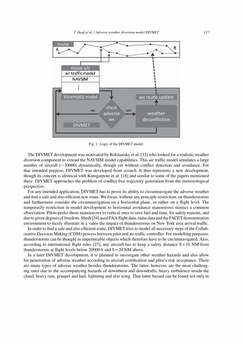
Figure 1 shows the logic of the DIVMET model. The given route from A to B is checked for impactingadverse weather (“check adverse wx” in the flow chart). If there is no adverse weather obstructing theplanned flight path (“no” in the flow chart), the aircraft will continue along that route. If there is adverseweather (“yes” in the flow chart), DIVMET will de-conflict the route and updates it. The movement alongthe route is either done by a purely kinematical model without any reference to aircraft performance orby an external air traffic model with a dynamical aircraft model. Such models may be, for instance,SIMMOD (http://www.atac.com/simmod-pro.html), AIRTOP (http://www.airtopsoft.com/), TrafficSim[3], Rams Plus (ISA-Software) or NAVSIM [33], to mention but a few. In their current versions, theytypically do not allow for the inclusion of adverse weather, except in a very simple and basic way. AsKamgarpour et al. [18] emphasized, conflict detection and subsequent conflict resolution are key tasksin air traffic management.
T. Hauf et al. / Adverse weather diversion model DIVMET 117
Fig. 1. Logic of the DIVMET model.
The DIVMET development was motivated by Rokitansky et al. [33] who looked for a realistic weatherdiversion component to extend the NAVSIM model capabilities. This air traffic model simulates a largenumber of aircraft (∼30000) dynamically, though yet without conflict detection and avoidance. Forthat intended purpose, DIVMET was developed from scratch. It thus represents a new development,though its concept is identical with Kamgarpour et al. [18] and similar to some of the papers mentionedthere. DIVMET approaches the problem of conflict free trajectory generation from the meteorologicalperspective.
For any intended application, DIVMET has to prove its ability to circumnavigate the adverse weatherand find a safe and also efficient new route. We focus, without any principle restriction, on thunderstormsand furthermore consider the circumnavigation on a horizontal plane, or rather on a flight level. Thetemporarily restriction in model development to horizontal avoidance manoeuvres mimics a commonobservation. Pilots prefer those manoeuvres to vertical ones to save fuel and time, for safety reasons, anddue to given degrees of freedom. Sheth [34] used FAA flight data, radar data and the FACET demonstrationenvironment to nicely illustrate in a video the impact of thunderstorms on New York area arrival traffic.
In order to find a safe and also efficient route, DIVMET tries to model all necessary steps of the Collab-orative Decision Making (CDM) process between pilot and air traffic controller. For modelling purposes,thunderstorms can be thought as impermeable objects which therefore have to be circumnavigated. Also,according to international flight rules [27], any aircraft has to keep a safety distance S = 10 NM fromthunderstorms at flight levels below 20000 ft and S = 20 NM above.
In a later DIVMET development, it is planned to investigate other weather hazards and also allowfor penetration of adverse weather according to aircraft certification and pilot’s risk acceptance. Thereare many types of adverse weather besides thunderstorms. The latter, however, are the most challeng-ing ones due to the accompanying hazards of downburst and downdrafts, heavy turbulence inside thecloud, heavy rain, graupel and hail, lightning and also icing. That latter hazard can be found not only in

118 T. Hauf et al. / Adverse weather diversion model DIVMET
thunderstorms but theoretically in all super-cooled liquid water clouds in the temperature range between0◦C and −40◦C. Ice accretion on the wings and other parts of the fuselage causes substantial reductionof aircraft performance. In spite of heating, melted ice may refreeze further downstream. This recentlyfully recognized risk affects air intakes, pitot probes, engines but also may occur along the wing chord.Volcanic ash on impact may damage heavily the engines, scratch windows and paint, and may block inletsand tubes. Clear air turbulence affects the air traffic en-route by unexpected turbulence outside clouds.It is responsible for the highest number of accidents and incidents with injuries of passengers and cabincrew en-route [17]. Once DIVMET has been successfully applied to thunderstorms, it can be expandedin a straight forward manner also to account for the other aforementioned weather hazards.
This paper is structured as follows. First, we discuss the presentation of weather (Section 2) and thesafety problem (Section 3). In Section 4 we explain step by step the typical processes while deviatingaround adverse weather, beginning with detection of storms, decision making and the resulting newroute. As the weather changes with time, the latter processes have to be continuously repeated whichis discussed in Section 5. How the interaction with other traffic will be treated in future, is outlined inSection 6. Diagnostics for the original and the diverted route are presented in Section 7. Summary andconclusions follow in Section 8, together with an outlook how the model might be applied in future.
2. Adverse weather presentation
Adverse weather air spaces are considered as contiguous spaces. They might be seen as being composedof horizontal layers with outlined adverse weather regions (see Fig. 2). Those regions might be thoughtof “no-go” zones which the pilots are not allowed to enter. At a later stage of the development, we mightconsider them as permeable, depending on the accepted risk by the pilot or for certified aircraft only. If,for instance, in-flight icing is investigated, then only aircraft which are certified for e.g. moderate icingare allowed to enter those regions.
The two dimensional adverse weather regions are given by polygons and are referred to as weatherobjects. The terminology arises from the FLYSAFE project, where information about weather objectswas sent to the cockpit and displayed there [26]. For that purpose, polygons turned out to be superior tothe classical two-dimensional raster fields of radar reflectivity, temperatures, wind components etc. thatare used for example by Krozel et al. [21], as their transmission from the ground requires a significantlylower data rate, and as they are easier to display by conventional vector graphics. Figure 3a shows atypical weather object.
The polygons are issued at a certain time and are given by a two-dimensional vector with latitude andlongitude in geographical coordinates. The weather object is thought to represent a plane at a given flightlevel Li, if we consider the circumnavigation as a 2D-problem. In 3D it can be thought as a layer ofthickness � on the curved earth surface at a given flight level Li, with � = Li+1 - Li.
Weather objects can be provided either as abstract objects or can be derived from observed weather.Naturally, for the purpose of real-time simulations weather objects should be best approximations of realobserved adverse weather phenomena. For thunderstorms weather objects may be derived from groundbased weather radar observations and from satellite observations. The latter monitor thunderstorms fromabove and, therefore, are suitable to determine the horizontal structure of an anvil, while ground basedweather radar provide information about the main thunderstorm updraft.
Pradier-Vabre et al. [29] combined both data and created a simplified and archetypical thunderstormstructure, comprised of a “top volume” and a “bottom volume”. Weather hazards in the top volume,

T. Hauf et al. / Adverse weather diversion model DIVMET 119
Fig. 2. A cumulonimbus cloud is considered as composed of horizontal layers at the various flight levels with different spatialextent.
Fig. 3. (a) A typical two dimensional weather object defined by a polygon, which is given as a set of geographical coordinates.The weather object is surrounded by a safety margin at a minimum distance S (dotted line) and a convex hull (dashed line).(b) Aircraft at A along its direct route to B (thin line) which intersects a storm is guided around the latter (thick line) keepingthereby a minimum safety distance S.
the anvil, are: (1) the congestion of engines by high level ice concentration, (2) icing (at temperaturesabove −40◦C), and (3) lightning. Furthermore, we find (4) turbulence within an anvil, especially abovethe main updraft, (5) gravity waves and turbulence everywhere above the anvil, generated either by (6)breaking gravity waves or also by (7) turbulence at the edge of a jet stream above, with the jet streamsteering the storm. All those latter hazards (4)–(7) contribute to what is referred as convectively inducedturbulence (CIT). The main updraft combines all thunderstorm hazards such as high liquid water content,turbulence, hail, lightning, icing, and downbursts. In this paper we do not discriminate between the two

120 T. Hauf et al. / Adverse weather diversion model DIVMET
hazard regions and assume that the respective weather object represents one layer of a 3D-thunderstormobject, either as part of the top or of the bottom volume, depending on the flight level (see Fig. 2).
Update times of both radar and satellite data range between 5 minutes minimum and 30 minutesmaximum, plus a delay time of a couple of minutes due to the necessary data processing time. Weatherobject data will be stored and used by DIVMET to generate a moving field of adverse weather, stepwise intime corresponding to the update rate of weather data. DIVMET lets the aircraft respond to that – stepwise– dynamic weather, similarly as the pilot does to the – continuously – changing weather. Typically, manyatmospheric phenomena, such as clouds and storms, move with a speed of about 10 m/s which equalsin general the background wind speed at 500 hPa, for what reason that level is also referred to as thesteering level. For a weather data update cycle of 5 minutes, a background speed of 10 m/s equals ahorizontal displacement of 3 km. Aircraft motion might be discretized in the model at a time step of ∼3 s.Thus, aircraft speed and weather object speed relate approximately as 100 m/s : 10 m/s, the update ratesratio of 3 s : 300 s leads to corresponding travel distances as 300 m : 3 km. But for a given time interval of5 min the travel distances of aircraft and weather relate as 30 km : 3 km. Thus and with respect to the fleetof aircraft, weather can be seen as a slow moving field to which the trajectories have continuously beupdated. If for special applications shorter weather update times are requested, weather object positiondata at intermediate times might be linearly interpolated in space. Following [20], the change of shapemight be modelled by a morphing algorithm. This method applies to past, observed data. If, however,DIVMET should be applied to forthcoming weather through which a trajectory has to be determined,weather object position and shape data are needed for future times. One applicable method to achievethose data is nowcasting, with Rad-TRAM [20] being a typical representative. The generation of newstorm cells cannot be forecasted, and those cells can only be followed once they have been detected.Dissipating cells are typically monitored over the full forecast time range, e.g. 1 hour in the case ofRad-TRAM. In contrast to Krozel et al. [22] and similar to Kamgarpour et al. [18], weather in DIVMETis fully dynamic. The use of nowcast data is in progress.
Important to note is that in reality for the pilot adverse weather exists only if it can be seen either by eyeor by radar. The spatial range of adverse weather recognizable by eye is governed by atmospheric visibilityconditions. Minimum visibility values may be as small as only a couple of metres in moonless nights, infog or during heavy snowfall, but under fair weather conditions the visibility may exceed several hundredkilometres. Obviously, the human eye discloses the 3D structure of a cloud in parts only. Especially, thepilot cannot see through a cloud and may underestimate its horizontal extent. On-board weather radar onthe other hand, with which most aircraft are equipped, provide storm information with, however, limitedextend. The radar field of view equals a circular sector (see Fig. 4a) with a radius ranging between 80 NMto 180 NM and an aperture of about 115◦. If the instrument has a vertical tilt option (mostly up to ± 20◦)the field of view expands to a spherical rectangle. The pilot, in contrast, very often gets a larger view ofthe vertical cloud extent. In DIVMET we assume a radar field of view with a horizontal circular sectordescribed by the two parameters aperture and range. These parameters may be adjusted to simulate agiven aircraft. For an infinite range and an aperture of 360◦ we simulate a “full view”, sometimes alsoreferred to as “God’s view”, and are able to investigate the effect of unlimited information (see alsoFig. 4). That mode can be envisaged in the near future when satellite and other global information areavailable without restriction to the cockpit. Though the pilot’s view differs from the radar field of view,we use both terms in the following synonymously and as defined by the DIVMET algorithm describedabove.
It should be noted that DIVMET only reacts to weather objects within the field of view and, conse-quently, the generated trajectory also avoids only those. A finite field of view also implies a reduced

T. Hauf et al. / Adverse weather diversion model DIVMET 121
Fig. 4. Various circular sector fields of view of the on-board weather radar (a,b,c) and their effect on the originally planned routefrom A to B. In case of (a), only the first cloud is recognized by the radar and subsequently diverted while the further route toB traverses the second as well as the third cloud. De-confliction will occur here at a later time. A larger field of view as shownin (b) leads to a diversion of the first two clouds but leaves out the de-confliction of the third cloud. Just a radar field of viewwhich reaches beyond point B (c) or a kind of full view could determine a diversion route that de-conflicts all relevant objectsalready for the aircraft at position A.
number of considered objects compared with those existing in the full view case. While the aircraft flyingalong its route new weather objects move into its field of view. One might refer to the field of view alsoas a receding horizon. While Kamgarpour et al. [18] and Bellingham et al. [4] introduce this concept tosave computing time, we use physical arguments.
3. Risk and safety
Naturally, all adverse weather air spaces, respectively weather objects, require some safety measuresto be taken by the pilot. Precise instructions are, for instance, laid down in regulatory manuals like theUK AIC [27]. Safety measures range from “no-go” zones, as discussed above, to air spaces which canbe flown through by certain certified aircraft. They also comprise separation distances such as fromthunderstorms, as well as conditions to overfly a storm. We, therefore, do calculate a safety margin Saround any recognized weather object. This margin enlarges a weather object by 10 NM below 20000 ftand by 20 NM above, as stated by NATS [27]. It also changes its outline, with concave sections beingsmoothed, filled and even changed to convex shapes (see dashed line in Fig. 3a). Note that this procedure isalways done only around the recognizable part of all weather objects, which are the ones seen by the pilot.They are mathematically given by the intersection of the field of view with the weather objects polygons.The resulting polygons are then referred to as risk areas. Though a safety distance to thunderstorms ismandatory, DeLaura and Evans [7], in a study on pilots circumnavigating thunderstorms within an aircorridor in the US, found surprising results. Safety distances kept by individual pilots follow a distributionrather than a step function. It also was found that human factors such as the personality, the proximity ofthe home base of the pilot and other not easy quantifiable parameters determine the pilot’s attitude. Weassume in the following, however, a fixed safety distance, but will look further into that matter in a laterstage of our research. One possibility is to introduce an individual risk factor R which increases (R > 1)or decreases the safety distance S (0 < R < 1) to R × S. One should note that if the distance between twostorms undercuts the twofold safety distance value, the two risk areas will merge to one (see Fig. 5). In that

122 T. Hauf et al. / Adverse weather diversion model DIVMET
Fig. 5. (a) Distance between two weather objects undercuts the twofold safety distance value. (b) Both weather objects mergeto one risk area and have to be circumnavigated as one unity.
case, the pilot will not fly between the two storms, except he takes that risk with R < 1. See discussion inSection 4.4.
4. Methodology
4.1. Basic methodology
The DIVMET model simulates the circumnavigation process through a given field of thunderstormsalong a given route from A to B, the original route. As previously stated, it may be operated in a stand-alone-mode or in a coupled mode. In the former mode, the aircraft is moved stepwise by DIVMET ina kinematic way, while in the latter an external model, such as NAVSIM, moves the aircraft accordingto aircraft performance data by applying a dynamic aircraft model. In the following and if not otherwisestated DIVMET is operated in the stand-alone mode. The circumnavigation process consists basically oftwo steps (see Fig. 1):
(1) moving the aircraft to a new position along the current route;(2) checking for adverse weather; de-conflicting the situation by proposing a corrected route, which is
also referred to as diversion route, (Fig. 3b). This is done by the MET2ROUTE algorithm whichis explained below in Section 4.3.
This procedure is repeated at time steps of typically 3 s, corresponding to a flown distance of about300 m. After each step, the diversion route becomes the planned route, the aircraft is moved along thatroute and according to the then weather object situation, a new diversion route is calculated.
With the aircraft advancing from A to B, new routes are determined subsequently as described in detailin Section 4.4. Figures 4 and 7 show clearly the strong dependence of the deviation routes on the riskareas, which are those parts of the weather objects only recognizable for pilots.
When the modelled aircraft has finally reached point B, DIVMET performs a posteriori route analysis(extra time, distance, fuel etc.) and compares it with the originally planned trajectory.

T. Hauf et al. / Adverse weather diversion model DIVMET 123
Fig. 6. (a) Weather object circumnavigation to the left and to the right with the right wise detour being seemingly much longerthan the left wise one. (b) Decision aid for the left or right wise circumnavigation via comparison of the detectable horizontalextension of the weather object left and right of the original route. The detected object’s part right of the original route is muchlarger so that the new route is initiated to the left.
4.2. Moving the aircraft
Stand-alone-mode. The aircraft is moved on the currently valid route with a previously defined constantflight velocity over a distance according to the general time step, e.g. 3 s. No structural or aerodynamicalrestrictions are considered.
Coupled mode. More complex dynamical models and traffic models as listed above, e.g. NAVSIM,may be used and coupled to DIVMET to account for aircraft performance.
4.3. The MET2ROUTE algorithm
How is the new route determined? This is done by an algorithm MET2ROUTE for which the inputparameters are:
(i) the original route,(ii) the starting point A and the return to route point B,
(iii) the risk areas (enlarged weather objects plus convex hulls).
A route is determined around individual risk areas towards the final destination point B. This route alsoincludes passages between those areas. The route is determined based on geometrical considerations.It follows the common ideas of robot path finding (see e.g. the review by Weinan and Vanden-Eijnden[37]). The resulting route is a seemingly short route, but not necessarily the shortest one. Keeping in mindthat the number of potential routes around n objects is ∼2n, it is left to future investigations to relate thefound route to the shortest one. Another important decision to be made internally within MET2ROUTEconcerns the question, whether a given risk area is circumnavigated to the left or to the right (Fig. 6a).Naturally, from a pilots view, he (or she) will prefer the seemingly shortest route around the adverseweather. In other words, based on his visual impression he will prefer the left wise circumnavigation ifthe adverse weather occupies more airspace on the right, and vice versa. This tendency is even more likelyif the risk area is not fully encompassed by the field of view and seems to extend over the edge of the latter.Figure 6b gives an example and illustrates how the decision is made in MET2ROUTE. The algorithm
124 T. Hauf et al. / Adverse weather diversion model DIVMET
calculates the area sum of the intersected risk areas left and right of the original route. Please note thatonly the recognized part of the object is regarded for the calculation. Right wise circumnavigation willbe chosen, if the area sum right of the route is smaller than the one left of the route, and vice versa. Thisdecision rule is a heuristic one. Others may be suggested and tested.
In summary, the MET2ROUTE algorithm claims to deliver at any instant a safe and reasonably shortroute from A to B. As noted by Kamgarpour et al. [18], the generation of a trajectory for multiple aircraftis similar to the problem of control of multiple agents through obstacles, for which Kamgarpour et al.[18] gave an extensive overview.
4.4. Modelling the circumnavigation
Now, the conceptional modelling of the interaction between pilot and controller is described step by step.Here, we introduce several parameters, the impacts of which, however, are left to future investigations.This detailed separation into many steps results from the intended coupling to the traffic model NAVSIM.
(1) Weather free flight.Within the field of view and at a given time t1 no weather objects are recognizable. The flight willbe continued without any change (Fig. 7a).
(2) Weather object detected.Within the field of view a weather object is detected at time t2. It might be fully visible or onlypartially. In both cases a polygon is calculated describing the detected part of the weather object. Asafety margin S is calculated around the weather object and a new object is generated (Fig. 7b and c).
(3) Weather conflict detection.If the route crosses any risk area, a conflict exists (Fig. 7d, e). Otherwise the flight might becontinued along the current route (Fig.7b–c). No other reaction by the pilot is taken at that moment,though the potential hazard as such is recognized.
(4) Decision making.
In case of conflict the pilot will check various action options. Among them are:
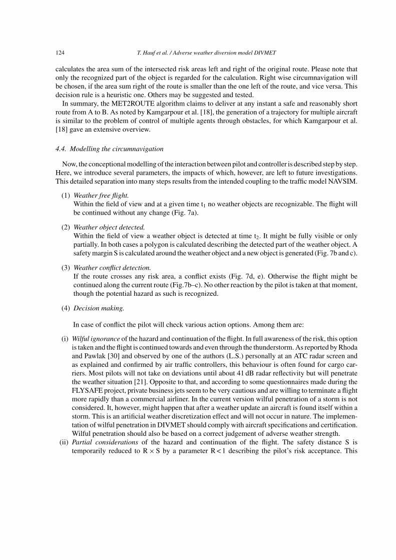
(i) Wilful ignorance of the hazard and continuation of the flight. In full awareness of the risk, this optionis taken and the flight is continued towards and even through the thunderstorm. As reported by Rhodaand Pawlak [30] and observed by one of the authors (L.S.) personally at an ATC radar screen andas explained and confirmed by air traffic controllers, this behaviour is often found for cargo car-riers. Most pilots will not take on deviations until about 41 dB radar reflectivity but will penetratethe weather situation [21]. Opposite to that, and according to some questionnaires made during theFLYSAFE project, private business jets seem to be very cautious and are willing to terminate a flightmore rapidly than a commercial airliner. In the current version wilful penetration of a storm is notconsidered. It, however, might happen that after a weather update an aircraft is found itself within astorm. This is an artificial weather discretization effect and will not occur in nature. The implemen-tation of wilful penetration in DIVMET should comply with aircraft specifications and certification.Wilful penetration should also be based on a correct judgement of adverse weather strength.
(ii) Partial considerations of the hazard and continuation of the flight. The safety distance S istemporarily reduced to R × S by a parameter R < 1 describing the pilot’s risk acceptance. This

T. Hauf et al. / Adverse weather diversion model DIVMET 125
Fig. 7. (a) The upcoming weather object is not yet recognizable in the radar field of view at time t1. For times t2 - t3 parts ofthe weather object are detected (b, c). For times t4 - t6 subsequent diversion tours are determined (d - g). In (h) the final routereturning to B has been calculated.

126 T. Hauf et al. / Adverse weather diversion model DIVMET
Fig. 8. Smaller (a) and larger (b) safety margins result in different routes.
Fig. 9. Options after a successful circumnavigation: Direct return to the original route (a) or maintaining the current heading (b).
situation might occur when the pilot tries to fly in between two storms, where the safety distance toat least one storm is under-run. The pilot is tempted to continue the flight between the two cloudsif a free and open space can be seen or assumed behind the narrow passage between the storms(Fig. 8). Depending on the nature of the convective weather field, especially on the mean distancebetween two adjacent weather objects, an increase of the safety margin leads to a nonlinear growthof contiguous objects and finally to a blocking of the airspace. For moving weather objects onemight increase the safety distance on the leeward side and decrease it on the windward side as thiscorresponds to typical pilot behaviour.
(iii) Circumnavigation decided with safety distance fixed.(iv) Wait and see. The continuation along the planned route may result for tactical reasons, as with
approaching any adverse weather, more details of its structure can be identified and the futureposition at a time of potential conflict is less uncertain (Fig. 7b–h). It also simply could be thatthe pilot needs some time for the decision making. The use of this parameter will be explored infuture.

T. Hauf et al. / Adverse weather diversion model DIVMET 127
(v) Holding. If there is no conflict free route with respect to other traffic seen ahead or the airport istemporally closed for any reason aircraft might enter a holding pattern. According to air trafficcontrollers, however, holdings are rarely forced only by weather rather than by controllers due tothe traffic situation. Controllers also made the statement “a pilot would rather go for any detourthan to stay in a holding pattern”. On that account holdings are not yet implemented in DIVMET.
(vi) Return to base. The very last solution in case of an apparent impermeable adverse weather frontis the evasion to an alternate airport or even the return to the home base. This option is neither berealised in DIVMET yet.
(5) Diversion route determination.The MET2ROUTE algorithm is called with the initial waypoint A, the final one B and the originalplanned route from A to B. MET2ROUTE determines a diversion route through the whole field ofweather objects within the field of view while taking into account the safety margin S. This routecomprises the circumnavigation of individual weather objects but also the flight between two ofthem. The starting point A equals the actual position of the aircraft, while the final point B has tobe set before and could be a fixed point near the destination airport, or an arbitrary waypoint onthe originally planned route.
(6) Circumnavigation.The diversion route is passed back from the MET2ROUTE algorithm to the DIVMET model andthe aircraft is moved along that route by the common time step. In case of full view this step isrepeated until point B is reached or a weather update is available. In the latter case or in pilot’sview steps (1) to (6) are performed once or at any time step, respectively.
5. Moving weather
Static weather means that during the circumnavigation the weather objects do not move. Dynamicweather, in contrast, assumes that new weather object information has to be provided to DIVMET. Withradar data an update time of minimum 5 minutes may be achieved.
Fig. 10. Moving or developing objects force the airplane to deviate. In case of a slow moving object and a fast aircraft (a), forany time ti the new route can be modelled and flown directly from A to B without any further adjustment. In case of a fastmoving object and a slow aircraft the new route has to be updated with any change in object position and/or shape (b).

128 T. Hauf et al. / Adverse weather diversion model DIVMET
A slow moving aircraft, hypothetically, in a rapidly changing environment (Fig. 10b) requires a con-tinuous adaption of the planned route at times ti (i = 0, 1, 2, 3). In contrast, a fast moving aircraft in aslowly changing environment requires for given times ti only one new route calculation (Fig. 10a). Inany case, the modelled stepwise dynamic weather update generates a similar stepwise response of theaircraft. Increasing update rates or a continuous space-time interpolation of weather objects between twosubsequent time steps will result in a smoother adaption of the route. Dynamic weather with radar stormdata as input is implemented in DIVMET.
Whenever new weather information is available, the steps described in Section 4.4 have to be repeatedin order to check whether the currently planned route is weather conflict free.
6. Interaction with traffic
6.1. Modes of operation
In its current version, DIVMET so far tries to solve the weather-aircraft conflict only. The calculateddiversion route ignores potential conflicts with other aircraft. In the algorithm of Pannequin et al. [28],however, a solution for multiple aircraft de-conflicted path planning in the presence of weather constraintsis already provided.
As stated above, in the stand-alone mode of DIVMET the aircraft is moved by a simple kinematic model.Even in that mode and without any ac-ac de-confliction, a number of interesting questions can alreadybe investigated, such as: (i) finding a diversion route through adverse weather (the original question),(ii) sensitivity studies with respect to safety distance, risk acceptance, left-right decision making etc.,(iii) worst case weather scenarios, (iv) development of flight strategies due to the uncertainty of adverseweather motion and evolution and/or decaying of weather objects, (v) provision of guidance for controllerand/or pilots to circumnavigate through a field of storms, e.g. in or close to the terminal manoeuvringarea. To account for dynamical aircraft performance, for more aircraft and also for ac-ac interaction,DIVMET has to be coupled to a more elaborated traffic model.
6.2. The NAVSIM traffic model
NAVSIM is a very advanced research based global air traffic simulation tool. It was developed byRokitansky and his group at the University of Salzburg and emerged from future aeronautical communi-cation requirements [31–33]. NAVSIM simulates the detailed air traffic from runway to runway, includingStandard Instrument Departures, Standard Arrival Routes with transitions, all instrument approaches anden-route segments with up to e.g. 30000 flights per day and the capability to handle global simulationswith more than several ten thousands of aircraft simultaneously. NAVSIM can be run for all kind of sce-narios. For the concept of adverse weather avoidance NAVSIM will use 4D-trajectories. It furthermoresupports concept evaluations of CDM in cases in which deviations of executed trajectories are required,as it is also the case for adverse weather. The NAVSIM tool was intensively used in the context of the fol-lowing projects: VHF Digital Link Mode 2 (Eurocontrol Study, 2002 – 2005), Broadband-VHF (EU-FP6project, 2004 – 2006), Broadband-AMC (Eurocontrol Study, 2007 – 2008), L-DACS1 (Eurocontrol study,2008 – 2009), NEWSKY (EU-FP6 project, 2007 – 2009), Iris/ARTES-10 (ESA, since 2007). NAVSIMincludes full dynamic aircraft behaviour, but so far no ac-ac de-confliction. The latter feature is underdevelopment.

T. Hauf et al. / Adverse weather diversion model DIVMET 129
6.3. Coupling of DIVMET with NAVSIM
Depending on the application, the coupling experiment design has to be decided. Several parameterssuch as radius and aperture of the field of view, the domain size, the involved aircraft, time of day, area,initial flight plans etc. have to be set. The coupling is in detail as follows:
(1) NAVSIM determines at a given rate of maximum 1/(3 s) the position of all engaged aircraft. Forthe time being and for computational time reasons, only a few (< 5) aircraft are considered. Futurestudies will focus also on real traffic situations where significantly more aircraft become involved.
(2) DIVMET checks for each aircraft, whether there is an aircraft-weather conflict based on the latestweather information. Such a conflict exists – as detailed above – if the planned route from A to Btouches or intersects with a risk area within the field of view.
(3) In case that there is a weather conflict, DIVMET determines a complete deviation route from A toB around or through the current respective weather situation.
(4) The waypoints along the deviation route are passed back to NAVSIM, which takes care of aircraftdynamics, particularly in turns. Similar to Krozel et al. [21], DIVMET calculates polygonal pathswith turn points that technically have zero radii as approximations of the exact route. While passinga simple heading change to an aircraft in NAVSIM would very likely result in a lateral displacementbetween aircraft flight path and determined deviation route, we decided to pass waypoints instead.In case of static weather the MET2ROUTE algorithm generates the next waypoint as close aspossible to the weather object.
(5) NAVSIM moves the aircraft according to the DIVMET advice to the generated way points. Thesame procedure is repeated for all the other aircraft. Though the ac-ac conflict identification andresolution is not implemented yet, the basic idea is as follows. Two different cases might occur.First, in an ac-ac conflict-free situation the new route is accepted and the aircraft is moved to thenew position. Second, in case of a conflict with another aircraft the requested route is denied and –similarly as in the real world CDM process between pilot and controller – DIVMET has to providea new solution. The weather is updated and steps (2) to (5) are repeated.
The procedure outlined above is identical for coupling of DIVMET with other traffic models. DIVMETis, hence, and in principle not confined to NAVSIM.
7. Diagnostics
There are two final outputs for a DIVMET call for each aircraft and each deviation route, irrespectivelyof whether DIVMET is operated in a stand-alone mode or coupled to NAVSIM. First a final deviationroute is provided from the given point A to point B. This final route is composed of individual flownsegments along the respective past deviation route resulting from the weather at the same time. And,second, each final deviation route is analysed posteriori by comparing with the original, detour free routefrom A to B. The applied diagnosis tool calculates the extra distance, the extra time, the related extrafuel consumption and its accompanying CO2 and other emissions of interest. For that, the diagnosisdetermines not only the additional costs but also the already attained ones along the flown route. Thediagnostic tool may be expanded in future to e.g. account for noise exposure, ATC sector occupancy,related ATC handling costs, risk and other interesting quantities.

130 T. Hauf et al. / Adverse weather diversion model DIVMET
8. Summary, conclusions and outlook
A new modelling tool, DIVMET, is presented which simulates the flight around thunderstorms and alsothrough a field of the latter from a meteorological perspective. DIVMET determines a new route underthe requirements of safety and efficiency if the original route is blocked by adverse weather. The proposedroute keeps a safety distance from each storm according to international regulations [26]. DIVMET alsotries to find a reasonably short route through the storm field. How this route relates to the minimumpossible route and whether the former can be optimized is left to future research on the MET2ROUTEalgorithm.
Adverse weather is modelled at each flight level as a so called weather object. It is a two-dimensionalcontiguous area which is described mathematically by a polygon. Physically, the weather polygon canbe thought as a column, impermeable to an aircraft, with a polygonal baseline and reaching to the nextflight level (in 3D, whereas it is only used in 2D by now). Thus the aircraft is forced to circumnavigatethe weather object. The problem of path finding and circumnavigating an object is by itself old and thereare numerous algorithms proposed, see e.g. the Dijkstra algorithm [13] as a first approach and Weinanand Vanden-Eijnden [37] for a review. Here, we prepare a solution for the aircraft-weather case where(a) the safety margin and (b) the weather object motion were taken into account. DIVMET considersstatic but also dynamic weather which forces a continuous adjustment of the circumnavigation procedure.Currently, radar based storm data at 5 minutes time intervals are used. A space-time interpolation betweentwo subsequent update times allows for a more continuous weather provision, if needed. In future andfor real-time applications, DIVMET will use nowcast data to determine the future position of weatherobjects at the time the aircraft will be there.
DIVMET divides the circumnavigation process into several steps, which reflect the pilot’s action andalso the CDM process between pilot and controller. The proposed route around a thunderstorm or througha field of storms is determined by the MET2ROUTE algorithm. It is based on a conventional convex hullapproach. For any final deviation route a diagnostic tool is applied which calculates the additional distance,time, fuel, CO2 emission, and also, in the future, the risk. MET2ROUTE will be described in an upcomingpaper in more detail.
DIVMET allows for many applications the results of which will be published elsewhere. As a stand-alone model, it may be used for basic studies on the impact of various weather situations and geometrics.Taking into account the uncertainty related to the generation of new cells or the decay of existing ones,and also of the storm motion, optimum strategies may be developed which account for that uncertainty.Kim et al. [19] also took into account the uncertainty of weather forecasts, but focused on the impact onen-route airspaces.
In the second operational mode, DIVMET is coupled to a traffic model, as which NAVSIM was chosen.That coupling, however, can also be done with any other similar air traffic model.
One application is the development of a tool for air traffic controllers when a thunderstorm fieldhas to be navigated through during the approach phase towards an airport. Figure 11 shows the areaaround Hong Kong International Airport. A thunderstorm field is approaching from east. The arrivaltraffic from east has to deviate from their planned routes to fly through the storm field. The controllerwants to give the incoming pilot some guidance how to find a safe way through the storm field. The keyelements here are: (1) the forecast of the thunderstorm field, (2) the actual approaching traffic, (3) theapplication of the DIVMET model. In this case, the motion of both, aircraft and storms, are essential, asthe gaps between the storms which might be used can close within a couple of minutes. The intentionis to find a safe and efficient route to the airport. No coupling with an air traffic model is needed, as the

T. Hauf et al. / Adverse weather diversion model DIVMET 131
Fig. 11. Thunderstorms outlined by radar reflectivity contours (grey shaded) and lightning (crosses) move from east (right)towards Hong Kong International Airport. Approaching aircraft with flight number indicated and short flight tracks look for aroute through the thunderstorm field. Some aircraft on the left side depart.
controller takes care of the potential conflicts with other aircraft. Results will be published in a forthcomingpaper.
Another application is the forecasted sector occupancy change when aircraft are diverted by weather.This usually poses a severe problem for ATC personnel. A case study on the effect of a thunderstormsquall line on the air traffic in July 2010 in Austria together with Austro Control is being investigated.
The Hong Kong case may also be used to qualitatively validate DIVMET and MET2ROUTE. For that,the controllers’ judgement whether the simulated routes are realistic or not will be used.
Future work will focus on the interaction of adverse weather with multiple aircraft. Two lines of thoughtwill be pursued here. First, the coupling with NAVSIM, where aircraft-aircraft interaction will be handledby the latter, while DIVMET makes only proposals for the weather related circumnavigation. Thus thetraffic conflicts are separated from the weather conflict. Secondly, in a stand-alone mode, DIVMET willconsider other aircraft also as impermeable objects and shall determine a safe route through the fieldof storms and through the fields of other aircraft. In that way both, weather and traffic, are simulatedsimultaneously. But it will first still be a pairwise solution to the more general problem of optimum4D-trajectory management rather than a simultaneous multiple aircraft de-conflicted solution as done byPannequin et al. [28].
The DIVMET model also may be applied to the volcanic ash problem. To do so, the volcanic ash cloudmust be given as a 3D object. Depending on the aircraft certification for flying through a volcanic ashcloud of given composition, and on the ash cloud composition and concentration, DIVMET will calculatea route around that cloud. For that purpose it has to be extended to 3D.
In view of the SESAR philosophy with the 4D-trajectory based free-flight, adverse weather represents anon-communicating and in parts chaotically behaving element. Any successful 4D-trajectory managementhas to deal with the weather problem. DIVMET provides a first approach for the needed solution.

132 T. Hauf et al. / Adverse weather diversion model DIVMET
References
[1] S. Allan and J. Evans, Operational benefits of the Integrated Terminal Weather System (ITWS) at Atlanta, Project ReportATC-320, Massachusetts Institute of Technology, Lincoln Laboratory, 2005, p. 149.
[2] H. Arneson and M. Bloemy, A method for scheduling air traffic with uncertain en route capacity constraints, AIAAGuidance, Navigation, and Control Conference, Chicago, Illinois, 2009.
[3] AT-ONE, Air Traffic Simulator, Technical Note, AT-One the ATM Research Alliance, Germany, Netherlands, 2007, p. 4.[4] J. Bellingham, A. Richards and J.P. How, Receding horizon control of autonomous aerial vehicles, in Proceedings of the
American Control Conference, Anchorage, AK, 2001, pp. 3741–3746.[5] Boeing Inc, Statistical summary of commercial jet airplane accidents worldwide operations 1959 – 2010 Aviation safety,
Technical Note, Seattle, Washington, 2011, p. 27.[6] T. Bolic and Z. Sivcev, Eruption of eyjafjallajökull in Iceland – experience of european air traffic management, Journal
of the Transportation Research Board 2214 (2011), 136–143.[7] R. DeLaura and J. Evans, An exploratory study of modeling enroute pilot convective storm flight deviation behaviour,
12th Conference on Aviation, Range, and Aerospace Meteorology (ARAM), Atlanta, Georgia, 2006.[8] R.A. DeLaura, M. Robinson, M.L. Pawlak and J.E. Evans, Modeling convective weather avoidance in enroute airspace,
13th Conference on Aviation, Range, and Aerospace Meteorology (ARAM), New Orleans, Lousiana, 2008.[9] DFS, ATFM delay report for December 2011, Technical Note, Deutsche Flugsicherung GmbH, Langen, Germany, 2011,
p. 5.[10] DFS, ATFM delay report for February 2011.‘ Technical Note, Deutsche Flugsicherung GmbH, Langen, Germany, 2011,
p. 5.[11] DFS, ATFM delay report for January 2009.‘ Technical Note, Deutsche Flugsicherung GmbH, Langen, Germany, 2011,
p. 5.[12] DFS, ATFM delay report for January 2011.‘ Technical Note, Deutsche Flugsicherung GmbH, Langen, Germany, 2011,
p. 5.[13] E.W. Dijkstra, A note on two problems in connexion with graphs, in Numerische Mathematik 1, A. Householder, R. Sauer,
E. Stiefel, J. Todd and A. Walther, ed., Springer-Verlag, Berlin, 1959, pp. 269–271.[14] Eurocontrol, Aviation Meteorology (MET) Workshop #1, MET support to ATM, Brussels, Belgium, 2009.[15] J.E. Evans, Safely reducing delays due to adverse terminal weather, in Modelling and Simulation in Air Traffic Manage-
ment, L. Bianco, P. Dell’Olmo and A. Odoni, ed., Springer-Verlag, Berlin, pp. 185–202.[16] FAA, Weather-related aviation accident study 2003 – 2007, Technical Note, Federal Aviation Administration, p. 71.[17] T. Hauf, H. Leykauf and U. Schumann, ed., Luftverkehr und Wetter, Statuspapier 2004, Mitteilung 2004-02. Arbeitskreis
Luftverkehr und Wetter. Oberpfaffenhofen, German Aerospace Center, 2004.[18] M. Kamgarpour, V. Dadok and C. Tomlin, Trajectory generation for aircraft subject to dynamic weather uncertainty, 49th
IEEE Conference on Decision and Control, Atlanta, Georgia, 2010.[19] J. Kim, J. Zou and J.S.B. Mitchell, Sensitivity of capacity estimation results subject to convective weather forecast errors,
AIAA Guidance, Navigation, and Control Conference, Chicago, Illinois, 2009.[20] K. Kober and A. Tafferner, Tracking and nowcasting of convective cells using remote sensing data from radar and satellite,
Meteorologische Zeitschrift 1(18) (2009), 75–84.[21] J. Krozel, C. Lee and J. Mitchell, Turn-constrained route planning for avoiding hazardous weather, Air Traffic Control
Quarterly 14(2), 159–182.[22] J. Krozel and S. Penny, Comparison of algorithms for synthesizing weather avoidance routes in transition airspace, AIAA
Guidance, Navigation, and Control Conference, Providence, Rhode Island, 2004.[23] G. Kulesa, Weather and aviation: How does weather affect the safety and operations of airports and aviation, and how does
FAA work to manage weather-related effects? in The Potential Impacts of Climate Change on Transportation Workshop,Washington, D.C., 2002.
[24] D. Markovic, U. Spehr and T. Hauf, A statistical study of the weather impact on punctuality at Frankfurt Airport, Germany,Meteorological Applications 15(2) (2008), 293–303.
[25] B. Martin, J. Evans and R. DeLaura, Exploration of a model relating route availability in en route airspace to actual weathercoverage parameters, 12th Conference on Aviation, Range, and Aerospace Meteorology (ARAM), Atlanta, Georigia, 2006.
[26] A.K. Mirza, C. Page and S. Geindre, FLYSAFE – an approach to safety – using GML/XML objects to define hazardousvolumes of aviation space, 13th Conference on Aviation, Range, and Aerospace Meteorology, New Orleans, Lousiana,2008.

T. Hauf et al. / Adverse weather diversion model DIVMET 133
[27] NATS, The effect of thunderstorms and associated turbulence on aircraft operations, Technical Note AIC: P 056/2010,Hounslow, Middlesex, UK Aeronautical Information Service, 2010, p. 10.
[28] J.J. Pannequin, A.M. Bayen, I.M. Mitchel, H. Chung and S. Sastry, Multiple aircraft deconflicted path planning withweather avoidance constraints, AIAA Conference on Guidance, Control and Dynamics, Hilton Head, South Carolina,2007.
[29] S. Pradier-Vabre, C. Forster, W.W.M. Heesbeen, C. Page, S. Senesi, A. Tafferner, I. Bernard-Bouissieres, O. Caumont, A.Drouin, V. Ducrocq, Y. Guillou and P. Josse, Description of convective-scale numerical weather simulation use in a flightsimulator within the Flysafe project, Meteorology and Atmospheric Physics 103 (2009), 127–136.
[30] D. Rhoda and M. Pawlak, An assessment of thunderstorm penetrations and deviation by commercial aircraft in the terminalarea, Project Report NASA/A-2, Massachusetts, Institute of Technology, Lincoln Laboratory, 1999, p. 77.
[31] C. Rokitansky, VDL Mode 2 Capacity Analysis through Simulations: WP3.B – NAVSIM Overview and Validation Results,Eurocontrol, 2005.
[32] C. Rokitansky, NAVSIM: Detailgenaue Simulation des heutigen/zukunftigen Flugverkehrs (Europa/weltweit) zur Bew-ertung von SESAR Konzepten und Wetterszenarien, Presentation, Hannover, 2009, p. 52.
[33] C.H. Rokitansky, M. Ehammer and T. Graupl, NEWSKY – Novel simulation concepts for future air traffic, in Proceedingsof 1st CEAS European Air and Space Conference, Berlin, Germany, 2007, pp. 611–618.
[34] K. Sheth, A day in the life of air traffic over the United States, 2006, http://www.youtube.com/watch?v=d9r3H4iHFZk[Accessed Nov 2013].
[35] K.S. Sheth, T.J. Amis and S. Gutierrez-Nolasco, Analysis of probabilistic weather forecasts for use in air traffic manage-ment, Aviation, Range and Aerospace Meteorology, Special Symposium on Weather Air Traffic Management Integration,Phoenix, Arizona, 2009.
[36] K. Sheth, B. Sridhar and D. Mulfinger, Application of probabilistic convective weather forecasts for flight routing decisions,7th AIAA Aviation Technology, Integration and Operations Conference, Belfast, Northern Ireland, 2007.
[37] E. Weinan and E. Vanden-Eijnden, Transition-path theory and path-finding algorithms for the study of rare events, AnnualReview of Physical Chemistry 61 (2010), 391–420.